KDI EER: The Extended ER Model Fausto Giunchiglia and Mattia Fumagallli University of Trento 0/ 61

Welcome message from author
This document is posted to help you gain knowledge. Please leave a comment to let me know what you think about it! Share it to your friends and learn new things together.
Transcript
KDIEER: The Extended ER Model
Fausto Giunchiglia and Mattia FumagallliUniversity of Trento
0/61
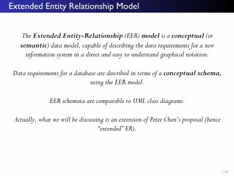
Extended Entity Relationship Model
The Extended Entity-Relationship (EER) model is a conceptual (or semantic) data model, capable of describing the data requirements for a new
information system in a direct and easy to understand graphical notation.
Data requirements for a database are described in terms of a conceptual schema, using the EER model.
EER schemata are comparable to UML class diagrams.
Actually, what we will be discussing is an extension of Peter Chen’s proposal (hence “extended” ER).
1/61
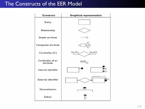
The Constructs of the EER Model
2/61
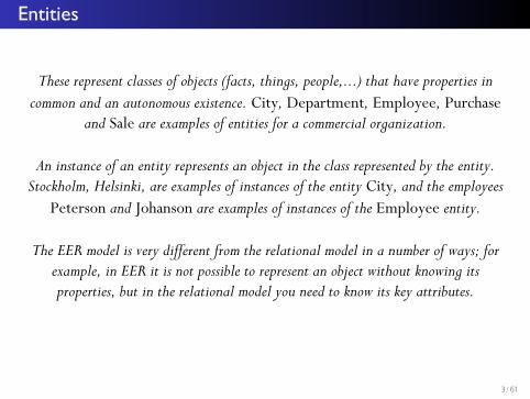
Entities
These represent classes of objects (facts, things, people,...) that have properties in common and an autonomous existence. City, Department, Employee, Purchase
and Sale are examples of entities for a commercial organization.
An instance of an entity represents an object in the class represented by the entity. Stockholm, Helsinki, are examples of instances of the entity City, and the employees
Peterson and Johanson are examples of instances of the Employee entity.
The EER model is very different from the relational model in a number of ways; for example, in EER it is not possible to represent an object without knowing its properties, but in the relational model you need to know its key attributes.
3/61
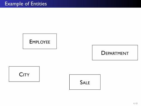
Example of Entities
4/61
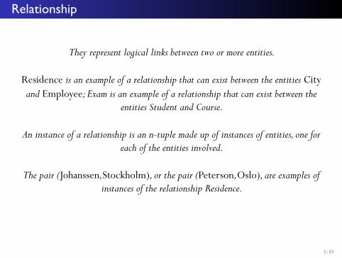
Relationship
They represent logical links between two or more entities.
Residence is an example of a relationship that can exist between the entities City and Employee; Exam is an example of a relationship that can exist between the
entities Student and Course.
An instance of a relationship is an n-tuple made up of instances of entities, one for each of the entities involved.
The pair (Johanssen,Stockholm), or the pair (Peterson,Oslo), are examples of instances of the relationship Residence.
5/61
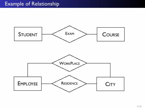
Example of Relationship
6/61
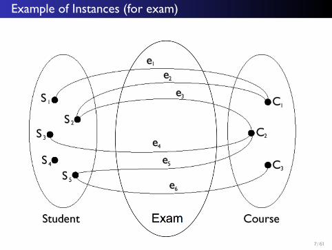
Example of Instances (for exam)
7/61
Recursive relationship
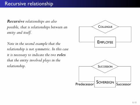
Recursive relationships are also possible, that is relationships between an entity and itself.
Note in the second example that the relationship is not symmetric. In this case it is necessary to indicate the two roles that the entity involved plays in the relationship.
8/61
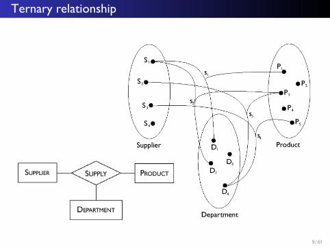
Ternary relationship
9/61
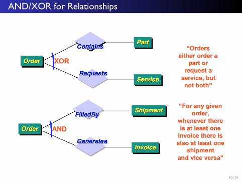
AND/XOR for Relationships
10/61
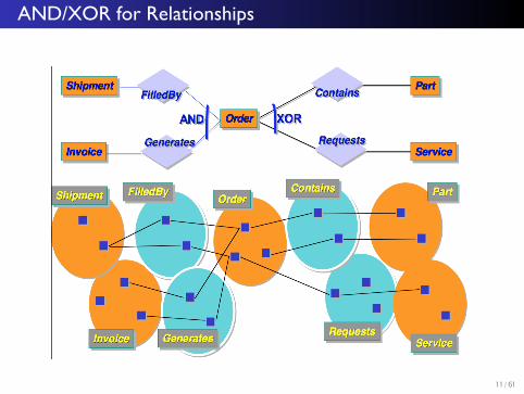
AND/XOR for Relationships
11/61
Attributes
Attribute describe the elementary properties of entities or relationships.
For example, Surname, Salary and Age are possible attributes of the Employee entity, while Date and Mark are possible attributes for the relationship Exam
between Student and Course.
An attribute associates with each instance of an entity (or relationship) a value belonging to a set known as the domain of the attribute.
The domain contains the admissible values for the attribute.
12/61
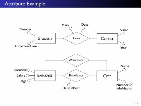
Attribute Example
13/61
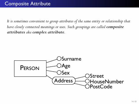
Composite Attribute
It is sometimes convenient to group attributes of the same entity or relationship that have closely connected meanings or uses. Such groupings are called composite attributes aka complex attribute.
14/61
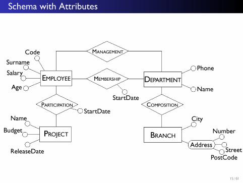
Schema with Attributes
15/61
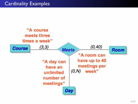
Cardinalities
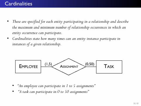
• These are specified for each entity participating in a relationship and describe the maximum and minimum number of relationship occurrences in which an entity occurrence can participate.
• Cardinalities state how many times can an entity instance participate in instances of a given relationship.
• “An employee can participate in 1 to 5 assignments”• “A task can participate in 0 to 50 assignments”
16/61
Cardinalities
In principle, a cardinality is any pair of non-negative integers (n,m) such that n≤m. or a pair of the form (n,N) where N means “any number”.
If minimum cardinality is 0, we say that entity participation in a relationship is optional. If minimum cardinality is 1, we say that entity participation in a relationship is mandatory.
If maximum cardinality is 1, each instance of the entity is associated at most with a single instance of the relationship; if maximum cardinality is N, then each instance of the entity is associated with an arbitrary number of instances of the relationship.
17/61
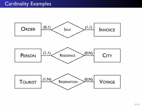
Cardinality Examples
18/61
Cardinality Examples
19/61
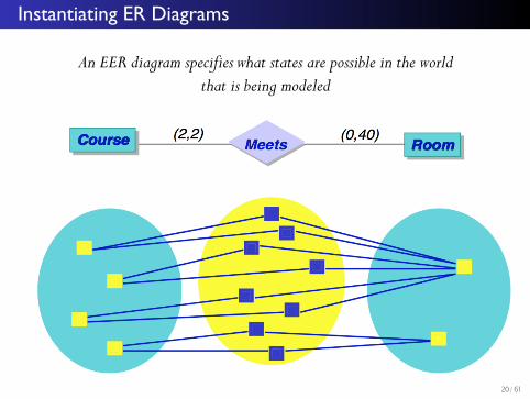
Instantiating ER Diagrams
An EER diagram specifies what states are possible in the worldthat is being modeled
20/61
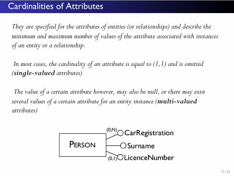
Cardinalities of Attributes
They are specified for the attributes of entities (or relationships) and describe the minimum and maximum number of values of the attribute associated with instances of an entity or a relationship.
In most cases, the cardinality of an attribute is equal to (1,1) and is omitted (single-valued attributes)
The value of a certain attribute however, may also be null, or there may exist several values of a certain attribute for an entity instance (multi-valued attributes)
21/61
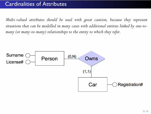
Cardinalities of Attributes
Multi-valued attributes should be used with great caution, because they representsituations that can be modelled in many cases with additional entities linked by one-to-many (or many-to-many) relationships to the entity to which they refer.
22/61
Identifiers
Identifiers (or keys) consist of one or more attributes which identify uniquely instances of an entity.
In many cases, an identifier is formed by one or more attributes of the entity itself: in this case we talk about an internal identifier.
Sometimes, however, the attributes of an entity are not sufficient to identify its instances unambiguously and other entities are involved in the identification. Identifiers of this type are called external identifiers.
An identifier for a relationship consists of identifiers for all the entities it relates. For example, the identifier for the relationship (Person-) Owns(-Car) is a combination of the Person and Car identifiers.
23/61
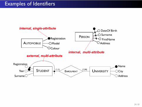
Examples of Identifiers
24/61
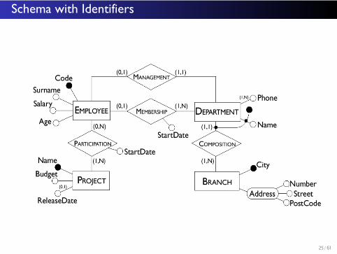
Schema with Identifiers
25/61
Generalizations
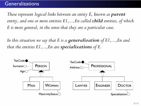
These represent logical links between an entity E, known as parent entity, and one or more entities E1,...,En called child entities, of which E is more general, in the sense that they are a particular case.
In this situation we say that E is a generalization of E1,...,En and that the entities E1,...,En are specializations of E.
26/61
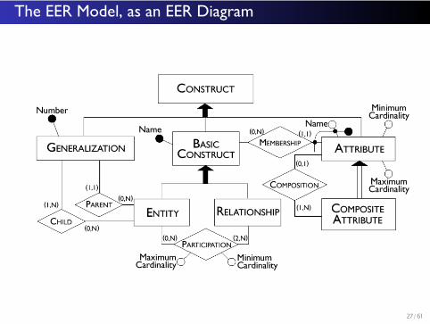
The EER Model, as an EER Diagram
27/61
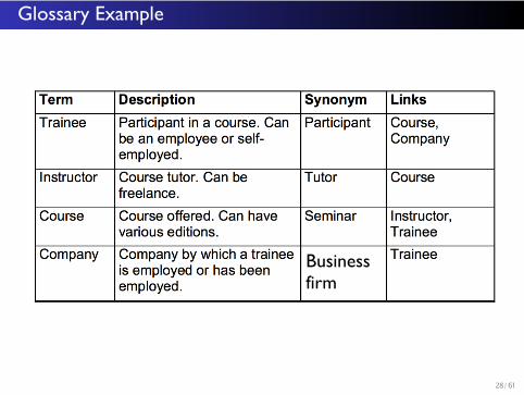
Glossary Example
Business firm
28/61
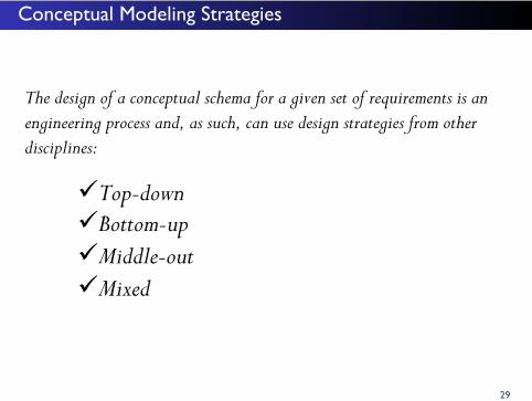
Conceptual Modeling Strategies
The design of a conceptual schema for a given set of requirements is an engineering process and, as such, can use design strategies from other disciplines:
üTop-down üBottom-up üMiddle-out üMixed
29
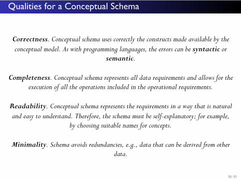
Qualities for a Conceptual Schema
Correctness. Conceptual schema uses correctly the constructs made available by the conceptual model. As with programming languages, the errors can be syntactic or
semantic.
Completeness. Conceptual schema represents all data requirements and allows for the execution of all the operations included in the operational requirements.
Readability. Conceptual schema represents the requirements in a way that is natural and easy to understand. Therefore, the schema must be self-explanatory; for example,
by choosing suitable names for concepts.
Minimality. Schema avoids redundancies, e.g., data that can be derived from other data.
30/61
References
qhttp://www.cs.toronto.edu/~jm/2507S/Notes04/EER.pdfq[Atzeni99] Atzeni, P., Ceri, S., Paraboschi, S., and Torlone, R.,. Database Systems, McGraw-Hill, 1999. q[Chen76] P. Chen, P., “The Entity-Relationship Model: Towards a Unified View of Data,” ACM Transactions on Database Systems 1(1), 1976.
31/61
Related Documents