© Katana Foundations | V 02 08 2022 1 | 74

Welcome message from author
This document is posted to help you gain knowledge. Please leave a comment to let me know what you think about it! Share it to your friends and learn new things together.
Transcript
© Katana Foundations | V 02 08 2022 1 | 74

The Performance GuideContents
Introduction to Katana Foundations 3
Katana Screw Pile Overview 5
Technical Speci�cation & Performance 10
How to Design with the Katana Screw Pile 28
Installation & Certi�cation 48
Appendix A: Screw Capacity for Uplift Loads 63
Appendix B: Capacity of Edge Beam Connector 64
Appendix C: Lateral Load Capacity Tables 66
Revision Control 70
Installer Certi�cation Questions and Answers 71
© Katana Foundations | V 02 08 2022 2 | 74

1.0 Katana Foundations
IN THIS SECTION:
Introduction
Katana Helical Plate Screw Pile Overview
Katana Helical Plate Design Features
Product Range
Pile Options
Accessories and Connectors
Introduction
At Katana Foundations, we strive to lead with best practice in everything we do. The Katana Helical Plate
Screw Pile Performance Guide demonstrates our commitment to transparency and collaboration with the
various businesses that work with our products.
This document is primarily for use by our installers and suppliers but also as a guide for our customers and
the engineers and building professionals that our clients engage with.
It is intended that this document will provide information for compliant design, testing, installation and
certi�cation of screw piles. We trust this document will assist in your understanding and the proper
application of screw piles within the residential and light commercial building sector.
© Katana Foundations | V 02 08 2022 3 | 74

Should you have any questions or require further information, please feel free to contact us directly or
access our additional resources below:
Email us [email protected]
Our blog is packed withhelpful design and engineering tips,
application info and morekatanafoundations.com.au/news
Our websitehas all technical product
information and brochureskatanafoundations.com.au
Our YouTube channelhelps you learn faster with our
“how-to” videos
Our LinkedIn Pageis up to date with the latest
company news at Katana
Our Facebook pageis the best way to follow ourcontent as it gets published
© Katana Foundations | V 02 08 2022 4 | 74

Katana Helical Plate Screw Pile Overview
The patented Katana Helical Plate Screw Pile, is a twin-helical plate design foundation steel screw pile. It is
made with high-tensile steel to deliver high-performance foundations.
Screw piles transfer the structural loads to a �rm stratum, providing a signi�cantly stronger foundation.
The Top Plate / Drive nut
The top of the pile is capped with a 16mm thick plate with a
36mm threaded hole to accept various Katana pile accessories.
The top plate, when used with the Katana drive tool, has the
safety bene�t of engaging the pile to reduce the likelihood of
the pile falling out of the drive head during the drilling process.
The Pipe
The pipe section (shaft) is made from Grade 400 (min)
high-tensile steel. It comes in a range of thicknesses, diameters
and lengths to suit various applications and drilling depths.
The Twin Helical Plates
The helix has been symmetrically designed to be one of the
most ef�cient cutting devices for a screw pile. The result is a
screw pile that can be drilled faster and deeper into harder
soils. The helix diameter ranges from 250mm to 350mm,
depending on the pile size.
The Cutting Comb
As the �rst point of contact with the soil, the cutting comb serves two purposes. Firstly it makes drilling
easier by the design of the teeth and being able to cut through hard material. Secondly it makes vertical
alignment more accurate by the symmetry of the cutting teeth and twin �n helical blades.
© Katana Foundations | V 02 08 2022 5 | 74

Katana Helical Plate Design Features
Most types of foundations try to wrestle mother nature into submission – and lose. We designed the
Katana Screw Pile to work with the earth, so it would deliver superior connection between the structure
and �rm stratum below ground level. The Katana Screw Pile provides foundations that are more
predictable, stable, quanti�able, cost effective and low risk.
Australian Owned &
Manufactured
Fabricated from Australian made
pipe and plateCodeMarked across Australia and
New Zealand
Special mill 400+ MPa
high-tensile yield feedA full range of piles: 80kN, 100kN
and 150kN
Stock �ttings for raised �oor and
prefabricated modular projects
No spoil during drilling and no
cartage/disposal costs
No unsafe open augered holes
requiring covers or fencing
Cheaper than concrete bored
piers and easier to install
No concrete pumping, labour and
overruns
Accurate veri�cation of capacity
by torque
Low noise and minimal vibration
Longer life - options to cap,
galvanise or electroplate
Complete installation certi�cation
For more on the features and
bene�ts of the Katana Screw Pile,
see the “Katana Foundations
Brochure”
https://katanafoundations.com.au
/foundation-systems/technical-re
sources/
© Katana Foundations | V 02 08 2022 6 | 74
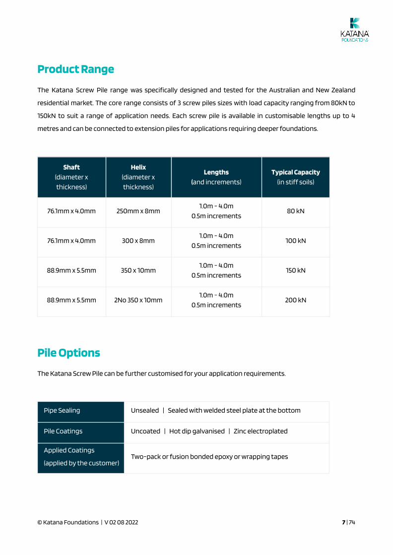
Product Range
The Katana Screw Pile range was speci�cally designed and tested for the Australian and New Zealand
residential market. The core range consists of 3 screw piles sizes with load capacity ranging from 80kN to
150kN to suit a range of application needs. Each screw pile is available in customisable lengths up to 4
metres and can be connected to extension piles for applications requiring deeper foundations.
Shaft
(diameter x
thickness)
Helix
(diameter x
thickness)
Lengths
(and increments)
Typical Capacity
(in stiff soils)
76.1mm x 4.0mm 250mm x 8mm1.0m - 4.0m
0.5m increments80 kN
76.1mm x 4.0mm 300 x 8mm1.0m - 4.0m
0.5m increments100 kN
88.9mm x 5.5mm 350 x 10mm1.0m - 4.0m
0.5m increments150 kN
88.9mm x 5.5mm 2No 350 x 10mm1.0m - 4.0m
0.5m increments200 kN
Pile Options
The Katana Screw Pile can be further customised for your application requirements.
Pipe Sealing Unsealed | Sealed with welded steel plate at the bottom
Pile Coatings Uncoated | Hot dip galvanised | Zinc electroplated
Applied Coatings
(applied by the customer)Two-pack or fusion bonded epoxy or wrapping tapes
© Katana Foundations | V 02 08 2022 7 | 74
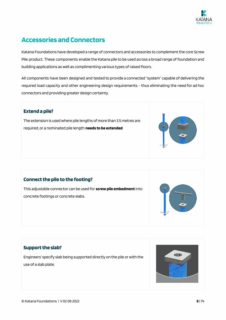
Accessories and Connectors
Katana Foundations have developed a range of connectors and accessories to complement the core Screw
Pile product. These components enable the Katana pile to be used across a broad range of foundation and
building applications as well as complimenting various types of raised �oors.
All components have been designed and tested to provide a connected “system” capable of delivering the
required load capacity and other engineering design requirements - thus eliminating the need for ad hoc
connectors and providing greater design certainty.
Extend a pile?
The extension is used where pile lengths of more than 3.5 metres are
required, or a nominated pile length needs to be extended.
Connect the pile to the footing?
This adjustable connector can be used for screw pile embedment into
concrete footings or concrete slabs.
Support the slab?
Engineers' specify slab being supported directly on the pile or with the
use of a slab plate.
© Katana Foundations | V 02 08 2022 8 | 74

Cut a Pile?
These adaptors are used where
piles are cut on-site.
Raised Floor?
Various options for bracing and
connecting bearers to the pile
Do you need a different connector?
If you have an application that is not supported by the above connectors and
accessories, get in touch with us, as we may be able to fabricate a bespoke
connector for your particular foundation. We’re always interested in helping
people use the Katana Screw Pile in new ways and for new building
applications.
© Katana Foundations | V 02 08 2022 9 | 74

2.0 Katana Helical Plate Screw PileTechnical Speci�cation and Performance
IN THIS SECTION:
CodeMark
Materials and Manufacturing
Key Technical Speci�cations
Engineering Details
Compression Load Capacity
Concrete Bearing Stress
Torque Capacity
Tension Load Capacity
Lateral Load Capacity
Performance Summary of uncut and cut piles
Corrosion
Fill Material
CodeMark
Katana Foundations are the only Australian or New Zealand screw pile company to have achieved
CodeMark certi�cation for their screw pile - the product, fabrication and installation.
Read more about the importance and advantages of CodeMark:
https://www.abcb.gov.au/Product-Certi�cation/CodeMark-Certi�cation-Scheme
Download a copy of the Katana Aus or NZ CodeMark:
https://katanafoundations.com.au/foundation-systems/technical-resources/
Materials and Manufacturing
Katana Foundations source special high strength feed for the
Katana Screw Pile from the Bluescope Steel Mill
http://www.bluescopesteel.com.au/. This is then sent to one of
© Katana Foundations | V 02 08 2022 10 | 74
two rolling mills in Brisbane to be rolled into CHS pipe.The minimum yield strength of the pipe is 400 MPa.
The pipe is shipped to Stoddart https://www.stoddart.com.au/, our manufacturing partner, where the piles
and accessories are fabricated for dispatch around Australia and New Zealand.
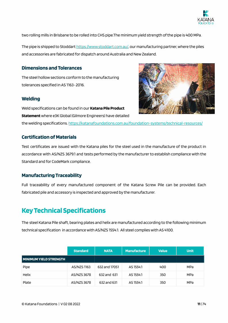
Dimensions and Tolerances
The steel hollow sections conform to the manufacturing
tolerances speci�ed in AS 1163‐2016.
Welding
Weld speci�cations can be found in our Katana Pile Product
Statement where e3K Global (Gilmore Engineers) have detailed
the welding speci�cations. https://katanafoundations.com.au/foundation-systems/technical-resources/
Certi�cation of Materials
Test certi�cates are issued with the Katana piles for the steel used in the manufacture of the product in
accordance with AS/NZS 3679.1 and tests performed by the manufacturer to establish compliance with the
Standard and for CodeMark compliance.
Manufacturing Traceability
Full traceability of every manufactured component of the Katana Screw Pile can be provided. Each
fabricated pile and accessory is inspected and approved by the manufacturer.
Key Technical Speci�cations
The steel Katana Pile shaft, bearing plates and helix are manufactured according to the following minimum
technical speci�cation in accordance with AS/NZS 1554.1. All steel complies with AS 4100.
Standard NATA Manufacture Value Unit
MINIMUM YIELD STRENGTH
Pipe AS/NZS 1163 632 and 17051 AS 1554.1 400 MPa
Helix AS/NZS 3678 632 and 631 AS 1554.1 350 MPa
Plate AS/NZS 3678 632 and 631 AS 1554.1 350 MPa
© Katana Foundations | V 02 08 2022 11 | 74
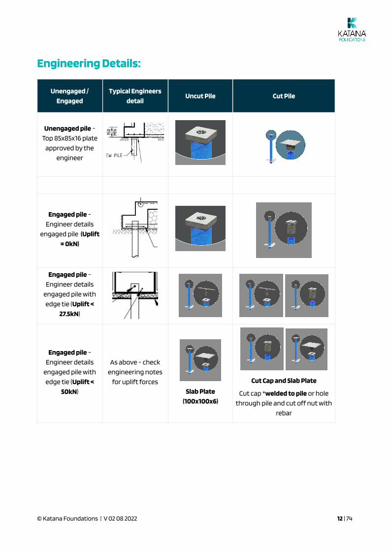
Engineering Details:
Unengaged /
Engaged
Typical Engineers
detailUncut Pile Cut Pile
Unengaged pile -
Top 85x85x16 plate
approved by the
engineer
Engaged pile -
Engineer details
engaged pile (Uplift
= 0kN)
Engaged pile -
Engineer details
engaged pile with
edge tie (Uplift <
27.5kN)
Engaged pile -
Engineer details
engaged pile with
edge tie (Uplift <
50kN)
As above - check
engineering notes
for uplift forces
Slab Plate
(100x100x6)
Cut Cap and Slab Plate
Cut cap *welded to pile or hole
through pile and cut off nut with
rebar
© Katana Foundations | V 02 08 2022 12 | 74
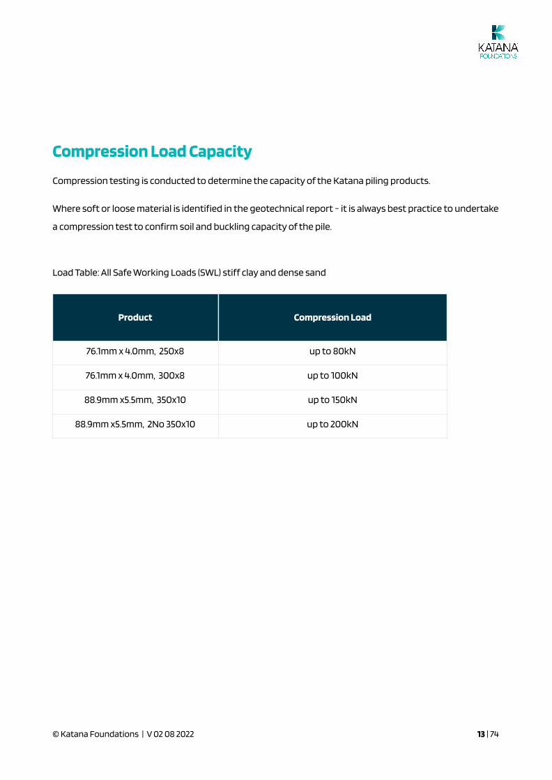
Compression Load Capacity
Compression testing is conducted to determine the capacity of the Katana piling products.
Where soft or loose material is identi�ed in the geotechnical report - it is always best practice to undertake
a compression test to con�rm soil and buckling capacity of the pile.
Load Table: All Safe Working Loads (SWL) stiff clay and dense sand
Product Compression Load
76.1mm x 4.0mm, 250x8 up to 80kN
76.1mm x 4.0mm, 300x8 up to 100kN
88.9mm x5.5mm, 350x10 up to 150kN
88.9mm x5.5mm, 2No 350x10 up to 200kN
© Katana Foundations | V 02 08 2022 13 | 74

Concrete Bearing Stress SWL = 80kN
Bearing Surface of Pile Bearing Surface of Pile Bearing Stress
Cut Pile
76.1mm x 4.0mm, 80kN
4mm thick steel 76.1mm in DIA
Area: 900 mm2
SWL Bearing Stress: 90 MPa
Drive Nut Plate
76.1mm x 4.0mm, 80kN
85 x 85x 16 mm plate
Area: 6,200 mm2
SWL Bearing Stress: 13 MPa
Torque Capacity
Torque Vs Compression Load
Our pile performance analysis (which is based on compression testing) indicates that when a torque of
4000Nm is reached on our 76x250 pile, a safe working load of 80kN is achieved in stiff soils.
The torque of 4000Nm is related back to hydraulic drive pressure which is shown on the pressure vs
torque chart of an ED10,000 at 96 bar (converted to 1400psi).
It is important to note the torsional capacity of the Katana Pile. Katana Piles are made from high strength
steel with increased torsional capacity.
Torsion capacity = Ø 0.6 fy 2 (π(do^4-di^4)/32) /do
AS4100. Ø = design capacity factor, fy = design yield stress, do = outside diameter, di = inside diameter.
For a 101mm Ø pipe at 4mm thick: assume 250MPa - 350MPa* yield strength steel from a mill (Ø = 0.9)
● Torsion capacity in theory is 7600Nm - 10700Nm
For a 76.1mm 400MPa - 500MPa high strength steel from a mill with QA (Ø = 0.989)
● Torsion capacity in theory is 7300Nm - 9200Nm
© Katana Foundations | V 02 08 2022 14 | 74
The higher yield strength makes a big difference to being able to get your pile in the ground without the
need to pre-drill.
Because our "special" steel is not one of the "of�cial" grades in AS1163 - the mill does not state that on the
test certi�cate as it is a C400L0 product, however test certi�cates contain the results of regular testing
carried out of the steel.
In 2019, Katana Foundations undertook a torsional study involving two masters groups from the
University of Melbourne. The Torsion Paper is available on our website.
https://katanafoundations.com.au/foundation-systems/technical-resources
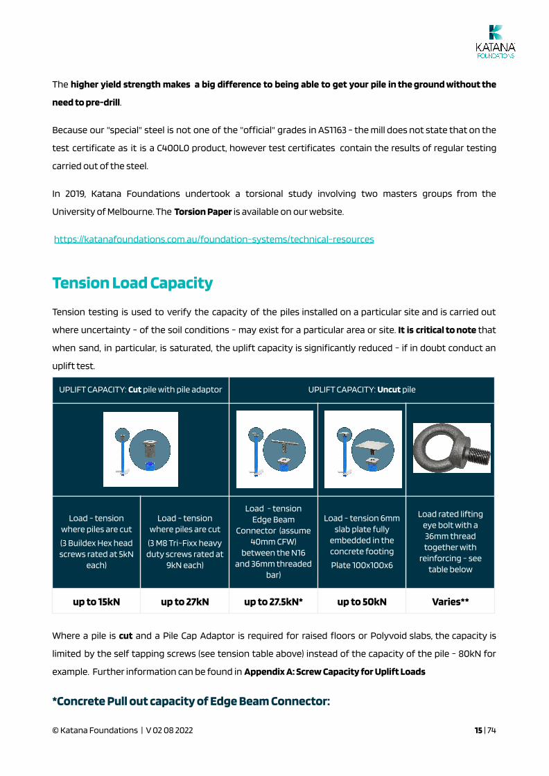
Tension Load Capacity
Tension testing is used to verify the capacity of the piles installed on a particular site and is carried out
where uncertainty - of the soil conditions - may exist for a particular area or site. It is critical to note that
when sand, in particular, is saturated, the uplift capacity is signi�cantly reduced - if in doubt conduct an
uplift test.
UPLIFT CAPACITY: Cut pile with pile adaptor UPLIFT CAPACITY: Uncut pile
Load - tensionwhere piles are cut
(3 Buildex Hex headscrews rated at 5kN
each)
Load - tensionwhere piles are cut
(3 M8 Tri-Fixx heavyduty screws rated at
9kN each)
Load - tensionEdge Beam
Connector (assume40mm CFW)
between the N16and 36mm threaded
bar)
Load - tension 6mmslab plate fully
embedded in theconcrete footing
Plate 100x100x6
Load rated liftingeye bolt with a36mm threadtogether with
reinforcing - seetable below
up to 15kN up to 27kN up to 27.5kN* up to 50kN Varies**
Where a pile is cut and a Pile Cap Adaptor is required for raised �oors or Polyvoid slabs, the capacity is
limited by the self tapping screws (see tension table above) instead of the capacity of the pile - 80kN for
example. Further information can be found in Appendix A: Screw Capacity for Uplift Loads
*Concrete Pull out capacity of Edge Beam Connector:
© Katana Foundations | V 02 08 2022 15 | 74
As the reinforcing has combined actions of tension and shear, the Edge Beam Connector was tested, seeand achieved a SWL of 27.5kN. Further information can be found in Appendix B: Capacity of Edge BeamConnector.
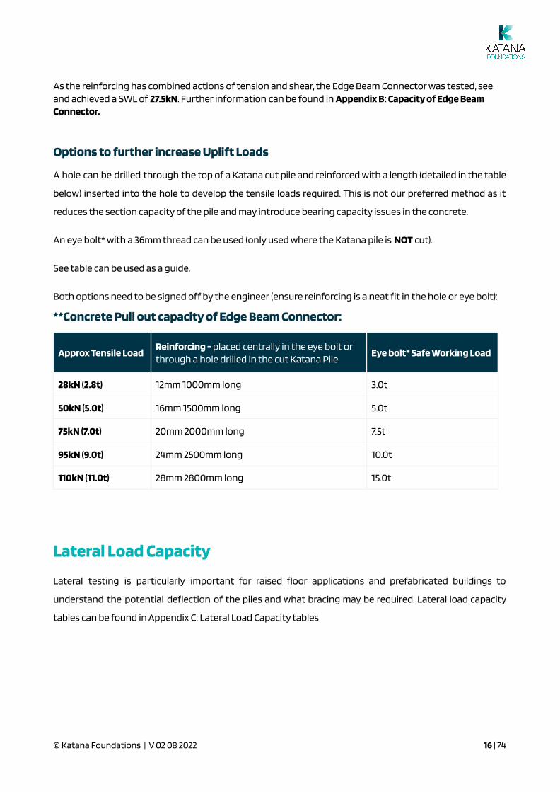
Options to further increase Uplift Loads
A hole can be drilled through the top of a Katana cut pile and reinforced with a length (detailed in the table
below) inserted into the hole to develop the tensile loads required. This is not our preferred method as it
reduces the section capacity of the pile and may introduce bearing capacity issues in the concrete.
An eye bolt* with a 36mm thread can be used (only used where the Katana pile is NOT cut).
See table can be used as a guide.
Both options need to be signed off by the engineer (ensure reinforcing is a neat �t in the hole or eye bolt):
**Concrete Pull out capacity of Edge Beam Connector:
Approx Tensile LoadReinforcing - placed centrally in the eye bolt orthrough a hole drilled in the cut Katana Pile
Eye bolt* Safe Working Load
28kN (2.8t) 12mm 1000mm long 3.0t
50kN (5.0t) 16mm 1500mm long 5.0t
75kN (7.0t) 20mm 2000mm long 7.5t
95kN (9.0t) 24mm 2500mm long 10.0t
110kN (11.0t) 28mm 2800mm long 15.0t
Lateral Load Capacity
Lateral testing is particularly important for raised �oor applications and prefabricated buildings to
understand the potential de�ection of the piles and what bracing may be required. Lateral load capacity
tables can be found in Appendix C: Lateral Load Capacity tables
© Katana Foundations | V 02 08 2022 16 | 74
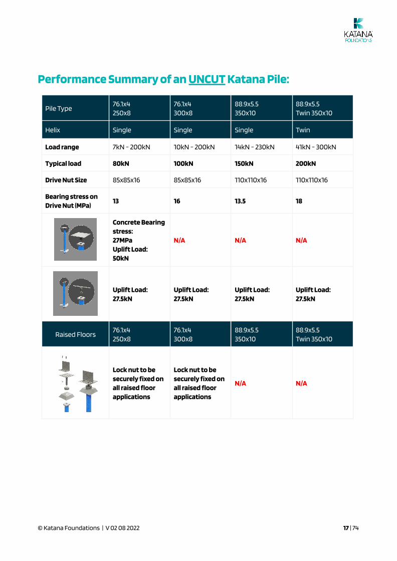
Performance Summary of an UNCUT Katana Pile:
Pile Type76.1x4250x8
76.1x4300x8
88.9x5.5350x10
88.9x5.5Twin 350x10
Helix Single Single Single Twin
Load range 7kN - 200kN 10kN - 200kN 14kN - 230kN 41kN - 300kN
Typical load 80kN 100kN 150kN 200kN
Drive Nut Size 85x85x16 85x85x16 110x110x16 110x110x16
Bearing stress onDrive Nut (MPa)
13 16 13.5 18
Concrete Bearingstress:27MPaUplift Load:50kN
N/A N/A N/A
Uplift Load:27.5kN
Uplift Load:27.5kN
Uplift Load:27.5kN
Uplift Load:27.5kN
Raised Floors76.1x4250x8
76.1x4300x8
88.9x5.5350x10
88.9x5.5Twin 350x10
Lock nut to besecurely �xed onall raised �oorapplications
Lock nut to besecurely �xed onall raised �oorapplications
N/A N/A
© Katana Foundations | V 02 08 2022 17 | 74

Performance Summary of a CUT Katana Pile:
Where the pile can no longer be driven into the soil/rock or has reached the required depth, it will be cut
and a cap provided to the top of the pile.
Pile Type76.1x4250x8
76.1x4300x8
88.9x5.5350x10
88.9x5.5Twin 350x10
Helix Single Single Single Twin
Load range 7kN - 200kN 10kN - 200kN 14kN - 230kN 41kN - 300kN
Typical load 80kN 100kN 150kN 200kN
Drive Nut 85x85x16 85x85x16 110x110x16 110x110x16
Bearing stress onDrive Nut (MPa)
13 16 13.5 18
Uplift Load:15kN - Hex head27kN - Tri �xx
Uplift Load:15kN - Hex head27kN - Tri �xx
Uplift Load:15kN - Hex head27kN - Tri �xx
Uplift Load:15kN - Hex head27kN - Tri �xx
Concrete BearingStress:19MPa
Concrete BearingStress:24MPa
N/A N/A
Concrete BearingStress:19MPa
Concrete BearingStress:24MPa
N/A N/A
© Katana Foundations | V 02 08 2022 18 | 74

Corrosion
Steel Katana piles have been designed in accordance with AS 2159 Section 6.3 with an allowance for
sectional loss based on the site corrosion classi�cation and design life. Refer Katana Corrosion Report by
e3k Global. https://katanafoundations.com.au/foundation-systems/technical-resources/
Where the client provides a geotechnical report indicating the exposure classi�cation of the site, the
expected lifetime of the pile is able to be calculated according to AS2159.
Typical results from a Geotechnical site investigation report are as per the table below.
Chlorides, pH and Resistivity are used in AS 2159 (Table 6.5.2) to determine the in-ground Exposure
Classi�cation of steel piles:
.
© Katana Foundations | V 02 08 2022 19 | 74

Sulfates and pH are used in AS 2870 to determine the in-ground Exposure Classi�cation of concrete:
© Katana Foundations | V 02 08 2022 20 | 74

AS 2159 provides guidance on the treatment of contaminated sites - see note 6 under table 6.4.2 (Severe
and Very Severe). For these conditions, we can provide thicker steel, galvanising and even cathodic
protection.
Note: Piles in seawater are considered Severe and Very Severe which means salinity should be considered
in determining the life of the piles.
The client’s geotechnical and/or chemical engineer are required to determine the exposure classi�cation of
the soil as in the example below and recommend the protection required. Predicting the corrosion rates,
especially on contaminated sites should be undertaken by appropriately quali�ed Geotechnical Engineers.
Expected IN GROUND Life
The life expectancy of a pile is directly related to the Exposure Classi�cation in AS2159 and the thickness of
the steel section. Best practice is for a suitably quali�ed Geotechnical Engineer to determine the Exposure
Classi�cation of the soil in order to provide an estimated life of the piles.
Assumptions:
● Ground water well below ground level
● No moisture at ground level
● At end of life - the pile has half its section thickness
● Refer Table 6.4 AS2159
© Katana Foundations | V 02 08 2022 21 | 74
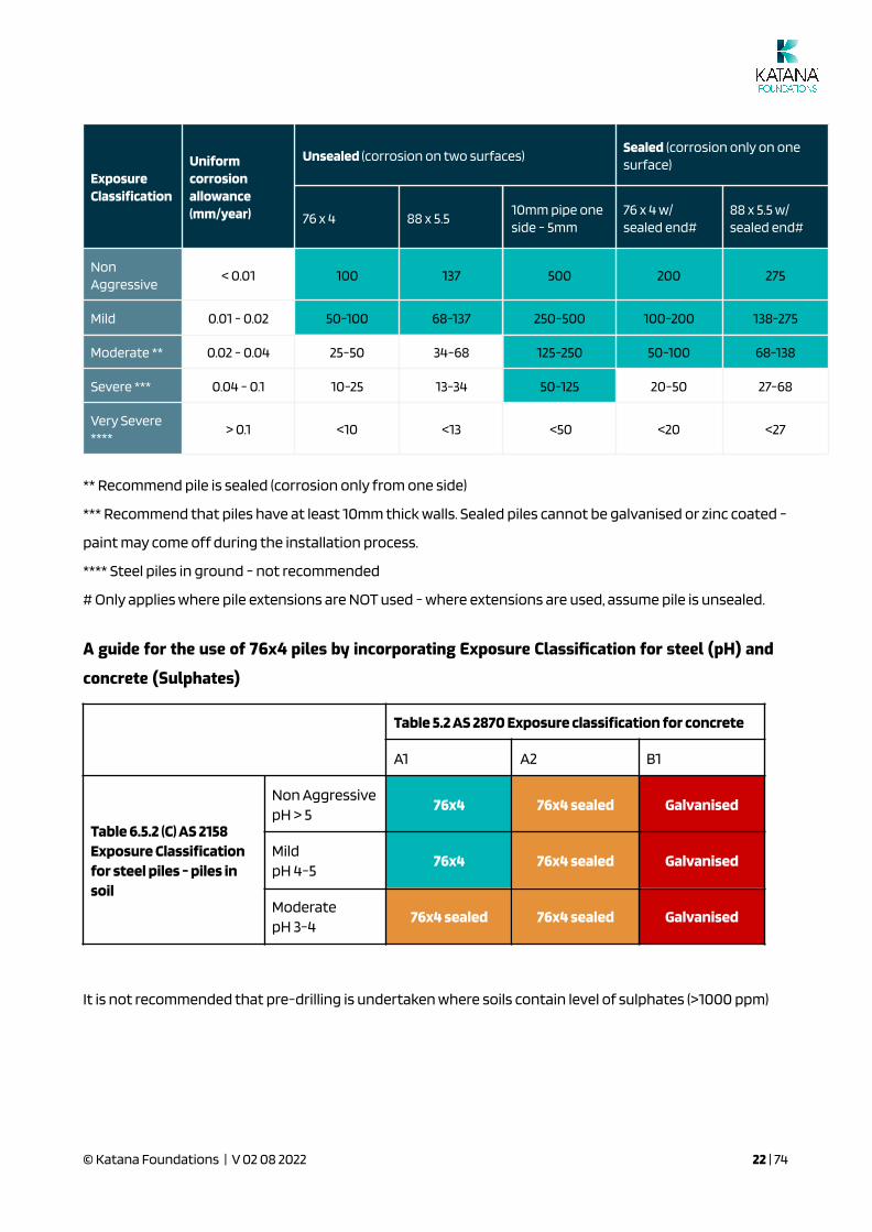
ExposureClassi�cation
Uniformcorrosionallowance(mm/year)
Unsealed (corrosion on two surfaces)Sealed (corrosion only on onesurface)
76 x 4 88 x 5.510mm pipe oneside - 5mm
76 x 4 w/sealed end#
88 x 5.5 w/sealed end#
NonAggressive
< 0.01 100 137 500 200 275
Mild 0.01 - 0.02 50-100 68-137 250-500 100-200 138-275
Moderate ** 0.02 - 0.04 25-50 34-68 125-250 50-100 68-138
Severe *** 0.04 - 0.1 10-25 13-34 50-125 20-50 27-68
Very Severe****
> 0.1 <10 <13 <50 <20 <27
** Recommend pile is sealed (corrosion only from one side)
*** Recommend that piles have at least 10mm thick walls. Sealed piles cannot be galvanised or zinc coated -
paint may come off during the installation process.
**** Steel piles in ground - not recommended
# Only applies where pile extensions are NOT used - where extensions are used, assume pile is unsealed.
A guide for the use of 76x4 piles by incorporating Exposure Classification for steel (pH) and
concrete (Sulphates)
Table 5.2 AS 2870 Exposure classi�cation for concrete
A1 A2 B1
Table 6.5.2 (C) AS 2158Exposure Classi�cationfor steel piles - piles insoil
Non AggressivepH > 5
76x4 76x4 sealed Galvanised
MildpH 4-5
76x4 76x4 sealed Galvanised
ModeratepH 3-4
76x4 sealed 76x4 sealed Galvanised
It is not recommended that pre-drilling is undertaken where soils contain level of sulphates (>1000 ppm)
© Katana Foundations | V 02 08 2022 22 | 74

Expected ABOVE GROUND Life
Where piles are located above ground, Katana Foundations recommends the use of an appropriate
corrosion protection system - giving consideration to the expected life of the structure and exposure
conditions - to be determined by the design engineer.
An example of a corrosion protection system that
may be speci�ed is the Denso SteelGard 400
(Butyl-based adhesive):
Denso-Butyl Tapes
© Katana Foundations | V 02 08 2022 23 | 74
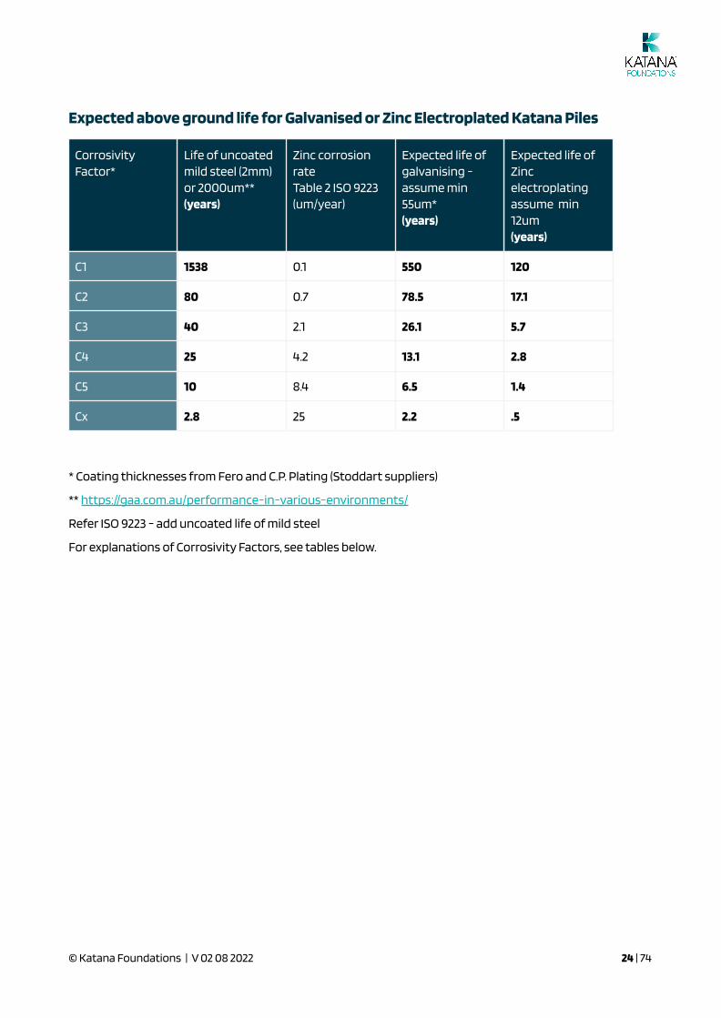
Expected above ground life for Galvanised or Zinc Electroplated Katana Piles
CorrosivityFactor*
Life of uncoatedmild steel (2mm)or 2000um**(years)
Zinc corrosionrateTable 2 ISO 9223(um/year)
Expected life ofgalvanising -assume min55um*(years)
Expected life ofZincelectroplatingassume min12um(years)
C1 1538 0.1 550 120
C2 80 0.7 78.5 17.1
C3 40 2.1 26.1 5.7
C4 25 4.2 13.1 2.8
C5 10 8.4 6.5 1.4
Cx 2.8 25 2.2 .5
* Coating thicknesses from Fero and C.P. Plating (Stoddart suppliers)
** https://gaa.com.au/performance-in-various-environments/
Refer ISO 9223 - add uncoated life of mild steel
For explanations of Corrosivity Factors, see tables below.
© Katana Foundations | V 02 08 2022 24 | 74

© Katana Foundations | V 02 08 2022 25 | 74

© Katana Foundations | V 02 08 2022 26 | 74
Fill Material
Fill material is a complex issue. Our default position is to attempt to pile through the �ll, as �ll can change
the torque capacity relationship signi�cantly. i.e. �ll can result in very high torque readings which can be
misinterpreted as suf�cient capacity, however there may still be a risk that the piles may settle
differentially over time.
Questions are:
● What is the depth of �ll? What is the likelihood of settlement?
● What is the �ll material? How will it change the torque / capacity relationship?
● What is the type of construction (ability to articulate)?
● What is the compaction of the �ll? Can it be veri�ed with penetrometer testing?
● Is there variability in material and compactive effort?
● Will there be any differential settlement over the structure?
● Can the slab be stiffened? i.e. can a stiffer slab like BIAX + piles be used?
© Katana Foundations | V 02 08 2022 27 | 74

3.0 How to Design
with the Katana Helical Plate Screw Pile
IN THIS SECTION:
Calculation of Building Loads
Soil Capacity
Steel Capacity
Design Methods
Determining the Appropriate Depth
AS2870 and the Hs Rule
Pre-Drilling
Designing for Raised Floors
Designing for Retaining Walls
Calculation of Building Loads
Calculation of Live and Dead structure loads
Ultimate Load Transmitted to Edge Beam, kN/m
Based on the typical dead loads (G), live loads (Q), and ultimate limit state loads (U) transmitted to the edge
beam, the following line loads can be calculated.
a. Roof loads
● Live load = 6m x 0.25kPa = 1.5kN/m (Q).
● Concrete tile roof DL = 6m x 0.9kPa = 5.4kN/m (G).
● Metal sheet roof DL = 6m x 0.4kPa = 2.4kN/m (G).
● Ultimate tile roof load = 1.2G + 1.5Q = 1.2 x 5.4 + 1.5 x 1.5 = 8.73kN/m (U).
Or 1.35G = 1.35 x 5.4 = 7.29kN/m (U).
● Ultimate metal roof load = 1.2G + 1.5Q = 1.2 x 2.4 + 1.5 x 1.5 = 5.13kN/m (U).
Or 1.35G = 1.35 x 2.4 = 3.24kN/m (U).
b. Brick veneer loads
● Single storey = 3m x 2.44kPa = 7.32kN/m (G).
● Double storey = 6m x 2.44kPa = 14.64kN/m (G).
© Katana Foundations | V 02 08 2022 28 | 74
● Ultimate single storey load = 1.2G = 1.2 x 7.32 = 8.78kN/m (U).
Or 1.35G = 1.35 x 7.32 = 9.88kN/m (U).
● Ultimate double storey load = 1.2G = 1.2 x 14.64 = 17.57kN/m (U).
Or 1.35G = 1.35 x 14.64 = 19.76kN/m (U).
c. Timber / light gauge steel suspended �oor loads –
● Live load = 3m x 1.5kPa = 4.5kN/m (Q).
● Timber suspended �oor DL = 3m x 0.9kPa = 2.7kN/m (G).
● Ultimate single storey load = 1.2G + 1.5Q = 1.2 x 2.7 + 1.5 x 4.5 = 9.99kN/m (U).
Or 1.35G = 1.35 x 2.7 = 3.65kN/m (U).
d. Ground �oor void slab
● Live load = 1.5m x 1.5kPa = 2.25kN/m (Q).
● Dead loads are slab self‐weight = 3kPa
+ partition allowance = 0.5kPa
+ �oor tile allowance = 0.5kPa
● Total dead load = 4.0kPa x 1.5m = 6.0kN/m (G).
● Ultimate ground �oor load = 1.2G + 1.5Q = 1.2 x 6.0 + 1.5 x 2.25 = 10.58kN/m (U).
Or 1.35G = 1.35 x 6.0 = 8.10kN/m (U).
Various Line Loads to Edge Beam (Ultimate limit state) (Examples)
Single, Storey, Tile Roof, Brick Veneer Wall
Element 1.2G + 1.5Q 1.35G
Roof tiles 8.73kN/m 7.29kN/m
Brick veneer (3m) 8.78kN/m 9.88kN/m
Ground �oor slab 10.58kN/m 8.10kN/m
Line load (ULS) 28.09kN/m 25.27kN/m
Controlling line load (ULS) = 1.2G + 1.5Q = 28.09kN/m.
Single Storey, Metal Sheet Roof, Brick Veneer Wall
Element 1.2G + 1.5Q 1.35G
Sheet roof 5.13kN/m 3.24kN/m
Brick veneer (3m) 8.78kN/m 9.88kN/m
Ground �oor slab 10.58kN/m 8.10kN/m
Line load (ULS) 24.49kN/m 21.22kN/m
© Katana Foundations | V 02 08 2022 29 | 74
Controlling line load (ULS) = 1.2G + 1.5Q = 24.49kN/m.
Double, Storey, Tile Roof, Brick Veneer Wall
Element 1.2G + 1.5Q 1.35G
Roof tiles 8.73kN/m 7.29kN/m
Brick veneer (6m) 17.57kN/m 19.76kN/m
Timber suspended �oor 9.99kN/m 3.65kN/m
Ground �oor slab 10.58kN/m 8.10kN/m
Line load (ULS) 46.87kN/m 38.80kN/m
Controlling line load (ULS) = 1.2G + 1.5Q = 46.87kN/m.
Double Storey, Metal Sheet Roof, Brick Veneer Wall
Element 1.2G + 1.5Q 1.35G
Sheet roof 5.13kN/m 3.24kN/m
Brick veneer (6m) 17.57kN/m 19.76kN/m
Timber suspended �oor 9.99kN/m 3.65kN/m
Ground �oor slab 10.58kN/m 8.10kN/m
Line load (ULS) 43.27kN/m 34.75kN/m
Controlling line load (ULS) = 1.2G + 1.5Q = 43.27kN/m.
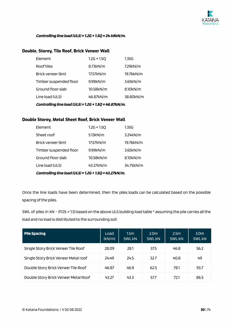
Once the line loads have been determined, then the piles loads can be calculated based on the possible
spacing of the piles.
SWL of piles in kN - (FOS = 1.5) based on the above ULS building load table * assuming the pile carries all the
load and no load is distributed to the surrounding soil:
Pile Spacing Load(kN/m)
1.5mSWL kN
2.0mSWL kN
2.5mSWL kN
3.0mSWL kN
Single Story Brick Veneer Tile Roof 28.09 28.1 37.5 46.8 56.2
Single Story Brick Veneer Metal roof 24.49 24.5 32.7 40.8 49
Double Story Brick Veneer Tile Roof 46.87 46.9 62.5 78.1 93.7
Double Story Brick Veneer Metal Roof 43.27 43.3 57.7 72.1 86.5
© Katana Foundations | V 02 08 2022 30 | 74

Soil Capacity
A good general guide is the Practice Note 28 “Screw Piles: Guidelines for Design, Construction &
Installation. Engineers New Zealand (IPENZ)
One theoretical approach is by Donald J. Clayton “Basic Helical Screw Pile Design”.
Some rules of thumb are:
● Where piles are relatively long in loose soils (Penetrometer tests indicate loose material), reduced
buckling capacity must be considered
● Screw pile helix are individually effective when spaced more than 3 helix diameters apart
N = Bearing capacity factors (Terzaghi 1943 and Meyerhof 1951)
Capacity of a cohesionless sand = (area of helix) x (overburden) x Nq
For sand Nq is derived from the internal angle of friction phi
Capacity of a cohesive clay = (area of helix) x (shear strength) x Nc
For clay or phi=0 Nc = 9 (Skempton 1951)
© Katana Foundations | V 02 08 2022 31 | 74
Several other theories exist such as Perko, Winkler, Walsh, Mitchell etc. Whatever theory the reader decides
to adopt - it is always prudent to take the most conservative theoretical calculation.
Calculating the theoretical capacity of a screw pile is helpful to design the pile shaft, number and thickness
of plates/helices, shaft diameter but it is only an approximation of what will occur in the �eld.
Pull up or compression testing on site or in the �eld, in areas where there may be uncertainty is always
recommended by the screw piling company.
Steel Capacity
The Pipe
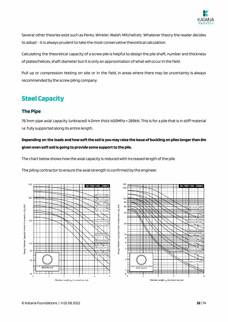
76.1mm pipe axial capacity (unbraced) 4.0mm thick 400MPa = 289kN. This is for a pile that is in stiff material
i.e. fully supported along its entire length.
Depending on the loads and how soft the soil is you may raise the issue of buckling on piles longer than 8m
given even soft soil is going to provide some support to the pile.
The chart below shows how the axial capacity is reduced with increased length of the pile.
The piling contractor to ensure the axial strength is con�rmed by the engineer.
© Katana Foundations | V 02 08 2022 32 | 74

The Helical Plates
Basic plate bending analysis with both plates contributing 4kN of SWL mostly at the leading edge.
Ultimate load testing was then carried out on various soil types and the helixes inspected for any bending.
In loose / soft soils the strength of the plate / helix will always be more than the founding soil.
In the case of dense / hard soils, over time, the soil above the helix consolidates and the helix acts more in
shear along the shaft rather than in bending.
Design Methods:
1. Calculating Load Capacity, by Donald J. Clayton
There are numerous theories dealing with the calculation of screw piles load capacity. A working example
of one theory is provided below. Calculating pile capacities by using a number of theories will give different
answers and ultimately these calculations should be veri�ed in the �eld by testing.
Ultimate load testing was carried out on various soil types and the helixes inspected for any bending.
Katana Pile load table for various soil types - remember CAPACITY = Sum of areas of the helical plates (q Nq
OR c Nc) + skin friction ignored:
Reference:
Basic Helical Screw Pile Design, Donald J. Clayton, P.E.
https://geotecheng.com/publications/guidelines/
© Katana Foundations | V 02 08 2022 33 | 74
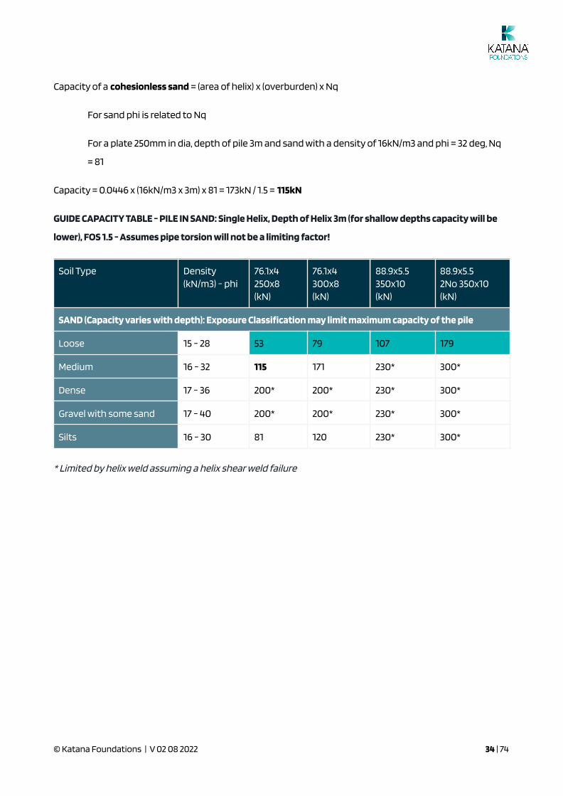
Capacity of a cohesionless sand = (area of helix) x (overburden) x Nq
For sand phi is related to Nq
For a plate 250mm in dia, depth of pile 3m and sand with a density of 16kN/m3 and phi = 32 deg, Nq
= 81
Capacity = 0.0446 x (16kN/m3 x 3m) x 81 = 173kN / 1.5 = 115kN
GUIDE CAPACITY TABLE - PILE IN SAND: Single Helix, Depth of Helix 3m (for shallow depths capacity will be
lower), FOS 1.5 - Assumes pipe torsion will not be a limiting factor!
Soil Type Density(kN/m3) - phi
76.1x4250x8(kN)
76.1x4300x8(kN)
88.9x5.5350x10(kN)
88.9x5.52No 350x10(kN)
SAND (Capacity varies with depth): Exposure Classi�cation may limit maximum capacity of the pile
Loose 15 - 28 53 79 107 179
Medium 16 - 32 115 171 230* 300*
Dense 17 - 36 200* 200* 230* 300*
Gravel with some sand 17 - 40 200* 200* 230* 300*
Silts 16 - 30 81 120 230* 300*
* Limited by helix weld assuming a helix shear weld failure
© Katana Foundations | V 02 08 2022 34 | 74
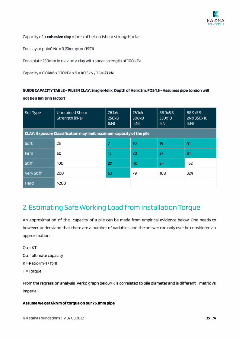
Capacity of a cohesive clay = (area of helix) x (shear strength) x Nc
For clay or phi=0 Nc = 9 (Skempton 1951)
For a plate 250mm in dia and a clay with shear strength of 100 kPa
Capacity = 0.0446 x 100kPa x 9 = 40.5kN / 1.5 = 27kN
GUIDE CAPACITY TABLE - PILE IN CLAY: Single Helix, Depth of Helix 3m, FOS 1.5 - Assumes pipe torsion will
not be a limiting factor!
Soil Type Undrained ShearStrength (kPa)
76.1x4250x8(kN)
76.1x4300x8(kN)
88.9x5.5350x10(kN)
88.9x5.52No 350x10(kN)
CLAY: Exposure Classi�cation may limit maximum capacity of the pile
Soft 25 7 10 14 41
Firm 50 13 20 27 81
Stiff 100 27 40 54 162
Very Stiff 200 53 79 108 324
Hard >200
2. Estimating Safe Working Load from Installation Torque
An approximation of the capacity of a pile can be made from empirical evidence below. One needs to
however understand that there are a number of variables and the answer can only ever be considered an
approximation.
Qu = KT
Qu = ultimate capacity
K = Ratio (m-1 / ft-1)
T = Torque
From the regression analysis (Perko graph below) K is correlated to pile diameter and is different - metric vs
imperial.
Assume we get 6kNm of torque on our 76.1mm pipe
© Katana Foundations | V 02 08 2022 35 | 74
K=27
Qu = ultimate load = 27 x 6kNm = 162kN
Our true blue pipe could be torqued to between 7.3kNm and 9.2kNm - above 160kN.
For our 88.9mm pipe assume a torque of 13kNm: Qu = 23 x 13kNm = 300kN
The governing factor is usually always the bearing capacity of the soil.
In the chart, there is clearly a variance in K and that is because torque and ultimate capacity can be
affected by:
Pile: number and Helix diameter, helix thickness, helix pitch, shaft shape, connection detail
Soil: type, strength, stiffness, water table Installation: rotation rate, advance rate, down force
Testing: Load rate and increments, waiting time, interpretation
Care should be taken with K - but by all means use it to approximate the capacity of what your piling
contractor has installed in the �eld.
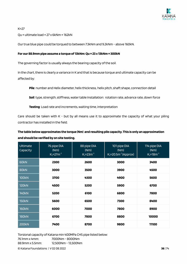
The table below approximates the torque (Nm) and resulting pile capacity. This is only an approximation
and should be veri�ed by on site testing.
UltimateCapacity
76 pipe DIA(Nm)
K1=27m-1
88 pipe DIA(Nm)
K1=23m-1
101 pipe DIA(Nm)
K1=20.5m-1 (Approx)
114 pipe DIA(Nm)
K1=18m-1
60kN 2300 2600 3000 3400
80kN 3000 3500 3900 4500
100kN 3700 4300 4900 5600
120kN 4500 5200 5900 6700
140kN 5200 6100 6800 7800
150kN 5600 6500 7300 8400
160kN 6000 7000 7800 8900
180kN 6700 7800 8800 10000
200kN 7400 8700 9800 11100
Torsional capacity of Katana min 400MPa CHS pipe listed below:76.1mm x 4mm: 7000Nm - 8000Nm88.9mm x 5.5mm: 12,500Nm - 13,500Nm
© Katana Foundations | V 02 08 2022 36 | 74

References:
“Helical Piles - A Practical Guide to the Design and Installation” Howard A. Perko 2009
Figure 6.6 page 179
Practice Note 28: Screw Piles – Guidelines for Design, Construction and Installation (2015)
Figure 6.5 page 16
https://www.engineeringnz.org/engineer-tools/engineering-documents/practice-notes-and-guidelines/
© Katana Foundations | V 02 08 2022 37 | 74
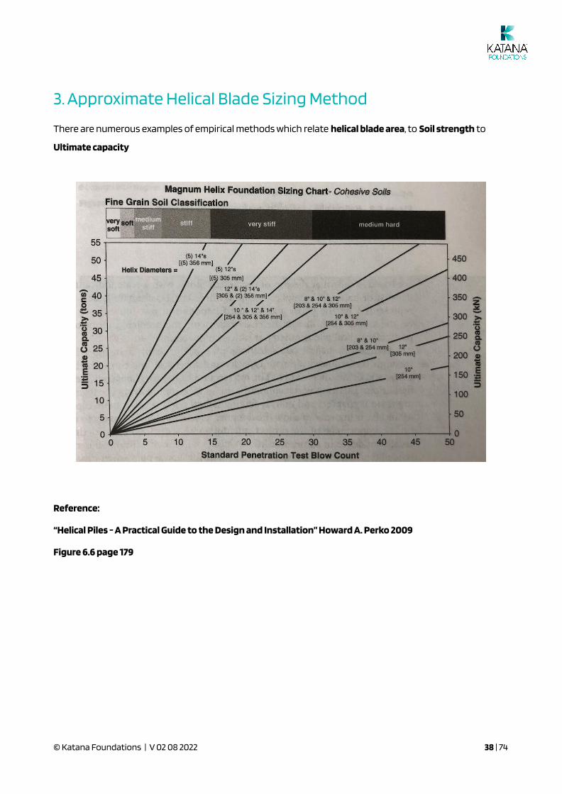
3. Approximate Helical Blade Sizing Method
There are numerous examples of empirical methods which relate helical blade area, to Soil strength to
Ultimate capacity
Reference:
“Helical Piles - A Practical Guide to the Design and Installation” Howard A. Perko 2009
Figure 6.6 page 179
© Katana Foundations | V 02 08 2022 38 | 74

Determining the Depth of the Pile
© Katana Foundations | V 02 08 2022 39 | 74

AS2870 and the Hs Rule
Katana’s position is to consider the risk of movement where piles are not driven to 1.25Hs as per G6.3 of
AS2870 - this clause applies 1.25Hs to all “reactive” soils irrespective of their reactivity or consideration of
the likely movement below the pile.
© Katana Foundations | V 02 08 2022 40 | 74

Engineers and Katana Foundations will consider the likely movement of the pile referring to the reactivity
of the soil below the pile and other factors such as tree effects..
Katana Foundations should rely on the design engineer to specify the depth of the pile or the certi�er that
certi�es the pile installation.
Pre-DrillingClause G7 of AS2870 allows drilling to 90% of the min pile diameter.
We have found with tension testing that within a few weeks of the pile being installed, the ground around
the pile has consolidated signi�cantly and the pile performs to its capacity.
Where there is a concern that moisture may accelerate corrosion due to pre-drilling, we assume that good
building practice will direct water away from the slab and it is good practice for the client to carry out
testing as per AS2159 to con�rm the exposure classi�cation according to AS2159.
During the normal process of piling the ground for the helix diameter is disturbed in any event - predrilling
only disturbs the ground marginally more than with no pre-drilling.
© Katana Foundations | V 02 08 2022 41 | 74

Designing for Raised Floors
Responsibility for design?
Katana Foundations are not design engineers and for any raised �oor application, Katana’s expectation is
that the engineer designing the structure will undertake the design for the piles and related bracing above
ground level.
Katana can provide the following:
1. Approximate screw pile lateral capacity by soil type at ground level2. Drawings for bracing, bearer plates etc which the engineer may include in their design3. A referral to consulting engineers that are familiar with the Katana Piling system for the builder to
obtain a quotation for a design of the piles above the ground supporting the structure
How high can I have my building out of the ground?
Typically around 1.5 to 2m. The issue is really around trying to have one pilot pile (rather than extending the
pile as this introduces movement into the system). A 5.5t excavator may only be able to install a 3.5m long
pile.
The next consideration is the buckling capacity of the pile and the engineer may choose to use a
88.9mmx5.5mm pile rather than a 76.1mmx4mm pile.
It may be possible to have longer piles out of the ground but the engineer may want to consider a rigid /
welded connection at ground level and a comprehensive bracing system.
Lateral Loading
Piles more than 500mm above the ground or in soft soil should be braced.
Improving the lateral capacity of the pile is possible with:
● Bracing piles
● Piles drilled on an angle and connected to the structure
● Horizontal cross bracing
● Concrete footings at ground level
It is always preferred to have piles that are only one piece with no extensions.
A full risk assessment and Safe Working Method must be developed by the client when sliding buildings on
screw piles.
© Katana Foundations | V 02 08 2022 42 | 74

When buildings are “slid” into place, there is a concern about the lateral capacity of the pile and any
eccentricity introduced on the pile.
In Australia rails are used on top of the piles to slide buildings into place.
In other circumstances a temporary steel beam can be used to slide buildings - which is removed when the
building is in place by jacking the building to release the beam - however the piles need to be laterally
supported during the sliding process.
Horizontal bracing or a permanent beam can also be used.
Rubber mats should be used between steel members to avoid the possibility of any sliding and higher
corrosion rate between different steel materials.
Axial loading
All loads must be located on the centre line of the piles. A MAXIMUM load of 80kN SWL is allowed for the
Katana raised �oor system.
In the Technical Docs and Product Guide folder, there are some calculations for bearer plate capacity that
can be used as a guide - subject to the engineer signing them off.
MUST BE CONFIRMED BY ENGINEER - Allowable bearer and slab plate loads
Where loads are eccentric to the centre of the pile, the appropriate bearer plate and supports must be
designed for the additional bending moments introduced by the eccentric loads.
Connection details
Below are the standard bearer plate and connector plate options which can be provided to suit the 20mm
plate at the top of the Katana Pile.
© Katana Foundations | V 02 08 2022 43 | 74

The bearer plate connector (backing plate) may clash with the chassis in the corner and joists in certain
locations.
FIX: Engineer to reposition piles away from the edges and joists to avoid this clash or avoid the use of the
backing plate as detailed below.
© Katana Foundations | V 02 08 2022 44 | 74

Bracing
Katana can provide a bracing system for raised �oors. Ideally the raised �oor is installed and the
measurements taken in order to fabricate the bracing.
Alternatively the length of each member can be provided to Katana and Katana will label each member
with an individual tag.
Bracing should be undertaken along continuous lines along the building (to minimise de�ection at the top
of the piles) and tightened only once the piles are under load.
A guide to lateral loading and de�ection graphs for the Katana piles can be found in our Katana Pile
Product Statement. https://katanafoundations.com.au/foundation-systems/technical-resources/
Structural engineers are free to use our bracing product but can also specify welding or bolting angle/RHS
bracing etc to the piles - the engineer just needs to check any loss of section capacity with any bolting
through to our piles.
The other option is a horizontal bracing system (acting as beams on ground) which will introduce bending
moments into the piles.
© Katana Foundations | V 02 08 2022 45 | 74

.
The design engineer speci�es the tek screws to be used according to the bracing loads.
Tolerance
As the tolerance of the pile may vary up to ± 25mm, the 200mm plate will accommodate this, but will need
to be cut on site to match the outside edge of the chassis. The plate will need to be coated with an
appropriate coating after it has been cut.
Raised �oor summary
● The builder's engineer is responsible for the design of the connection details and bracing for the
raised �oor system. A MAXIMUM of 80kN SWL allowed for the Katana raised �oor system.
● Lock nut is required to be installed on each pile on all raised �oor systems.
● Katana Foundations can provide lateral capacity graphs and standard accessories, which must be
designed by the builder's engineer.
● Katana Foundations default coating system for raised �oors is galvanising.
● The builder takes full responsibility for any alternate coating systems speci�ed.
● The builder is to provide set-out for the piling contractor and check the position of the piles during
and subsequent to the installation being completed.
● Piles will be loose when �rst installed and it will take 1-2 weeks for material around the piles to
settle and provide support to the pile. Where piles are pre drilled and / or extensions are used the
builder may be required to install concrete pads around the screw piles, as designed by the
builder's engineer.
● The builder is to �x and connect all bearers and bracing to the piles according to the builder's
engineers details.
© Katana Foundations | V 02 08 2022 46 | 74

● Where piles are required to be cut on a raised �oor system, please refer to Katana to determine any
risk with uplift loads
Designing for Retaining Walls
Piles can be driven into the retained material and tied to the wall of the retaining wall or they can be
staggered as per the example below in order to create a footing with the required moment capacity
(working with axial tension and compression loads) to support the retaining wall.
© Katana Foundations | V 02 08 2022 47 | 74

4.0 Katana Helical Plate Screw PileInstallation and Certi�cation
IN THIS SECTION:
Introduction
Materials
Site Preparation
Installation Method
Installation Procedure
Pile refusal Procedure
On Site Installation issues
Conclusion
Introduction
The Katana piles shall be installed using specialised equipment correctly calibrated to allow torque reading
to be monitored and recorded for each pile during installation.
The Katana piles shall be installed by an experienced accredited “Katana Piling” contractor.
Katana Pile installation tolerances
The maximum variation shall be no more than ± 25mm from the plan position as shown on the drawings.
The Katana pile shaft shall be installed vertically with a variation of not more than 4% from the vertical.
The maximum variation of the cut‐off level shall be ± 25mm from that shown on the drawings.
The most common method adopted today in determining the installation depth of screw piles is purely
based on the torque of the pile at the time of being installed. It has been identi�ed that large
inconsistencies can occur between the results of the site investigation and the �nal screw pile depth
achieved when only using this method. This can clearly have large implications on the �nal cost of the pile
installation, thus impacting on the �nal overall cost of the foundation system as a whole.
© Katana Foundations | V 02 08 2022 48 | 74

The Katana Pile has been developed as a concrete pier replacement to be installed to a nominated target
depth as identi�ed within the soil test and foundation design report. Rather than rely purely on torque as a
means of measure, the installation depth of a Katana Pile may be determined/ con�rmed by an onsite
Uplift Load Test eliminates the possibility of installing piles, beyond what depth is required, thereby
avoiding unnecessary cost.
This manual presents the minimum procedures for the nationwide conduct of the installation of the
Katana Pile in accordance with the speci�cations and requirements of AS2159-2009 and meeting the
minimum design parameters set out by the designing engineer within the soil test and foundation design
report.
Scope
The scope of this document is focussed on the installation of the Katana pile for the purpose of residential
and light industrial/commercial construction as outlined within AS2870-2011 ‘Residential Slabs and
Footings’.
Construction uses outside the scope of this manual include but are not limited to the following:
● Commercial/ civil buildings or structures and associated applications
● Free standing retaining walls
● Light poles, signs etc.
● Roads, bridges and civil works
● Embankment stability
Questions to ask your piling contractor
1. Product development documentation - compression testing
2. Steel mill test results - is there traceability
3. Product drawings / corrosion reports
4. Observation of the product (welds, steel)
5. On site testing - pull out test
6. Auger calibration and torque/pressure
7. Independent third party accreditation - CodeMark / 9001
© Katana Foundations | V 02 08 2022 49 | 74

Builders responsibility
All service locations must be identi�ed on site by the builder. It is the builders responsibility to clearly
identify and notify Katana Foundations of all underground services, prior to screw piling works being
conducted.
Should the locations of any underground services/works be within the engineered screw pile locations,
Katana Foundations accepts no responsibility for any damage, time delays or costs incurred for
recti�cation of such services/works.
Materials
Equipment register
The following outlines the minimum information and equipment that all Certi�ed Katana Installers must
have on site at the time of installation:
1. Latest Version of Architectural Drawings including siting plan and �oor plans.
2. A full copy of the soil/ geotechnical test and foundation design report.
3. Installation Record Checklist.
4. Installation and Testing Manual
5. Uplift Testing and Installation Record Data Sheets (refer appendix).
6. Digital Camera or Phone for high resolution images.
7. Pile Uplift Load Testing Unit with Hand Pump and calibrated Bar Pressure Gauge. Approved testing
devices only to be used. Devices are available from Katana Foundations.
8. Minimum 5 tonne Excavator or equivalent.
9. Appropriate earth drill/ drive motor attachment to suit excavator �ow
10. Laser and receiver instrumentation to asses pad and pile levels
11. Perpendicular instrumentation for vertical alignment
12. Bar/ PSI pressure gauge for excavator
13. Pipe Cutting Device/ Reciprocator Saw or similar
14. Katana Pile Installation Adapter Tool
15. Appropriate number of Katana Piles to meet requirements of installation layout
16. Spare Katana Pile Extensions to gain adequate depth
17. Appropriate number of proprietary accessories as per engineering detail plan
© Katana Foundations | V 02 08 2022 50 | 74

18. Other consumables to assist with site survey, marking out, identi�cation or cleaning.
Site Preparation
Site identi�cation
Clearly it is imperative that the correct site be identi�ed prior to any works being undertaken on any given
site. It is the responsibility of the Certi�ed Katana Installer to ensure the correct site has been identi�ed.
The following should be checked prior to commencement on site:
● Assessment and completion of site speci�c SWMS
● Suf�cient access for plant to gain entry
● Any spoil, debris, obstacles, steep slopes or other trades preventing the scope of work to start
● All surveying pegs and marks are visually identi�able
On-site preparation
Prior to the installation of any Katana Pile, the following site preparations must be undertaken to ensure
the pile installed meets the requirements of the foundation method adopted within the design.
© Katana Foundations | V 02 08 2022 51 | 74

The Certi�ed Katana Installer must be satis�ed the ground pad is level (+ or - 100 mm) with con�rmation
from the builder/client.
Check and con�rm that the peg layout on site matches the Architectural and Engineering Drawings
supplied. Where these differ, do not proceed with installation until such time the builder and engineer are
contacted for appropriate advice.
Upon con�rmation that the peg layout is consistent with architectural and engineering drawings, mark
out the screw pile locations in accordance with the engineering drawings taking into consideration
possible step down levels within the future concrete slab.
Mark out the location of any excavated strip footings or isolated pad footings incorporated into the
engineered design. Depth and width of footings are to be speci�ed on engineering detail plans.
Review the soil test report and foundation design report to gain an understanding of the soil conditions
and the minimum target depth required by the designing engineer. If in doubt, the installer must contact
the designing engineer to clarify prior to installation.
Using PP, kPA, SWL, kN, DCP values are all relevant data to evaluate prior to con�rming the type and length
of the Katana pile with the nominated engineer.
Installation
What to look for in a geotechnical report
● Depth of undisturbed natural soil - ideally piles should be embedded in natural soil
● Boreholes should be deeper than the expected depth of the piles
● If there is a signi�cant layer of �ll - the piling contractor should request advice on the �ll. Is it
controlled? What settlement can be expected below the depth of the pile?
● In wet clays - the piling contractor will either provide additional helixes or drill deeper as they may
not get the required minimum torque to verify capacity.
● In wet sands - the piling torque will generally be lower than expected due to the liqui�cation of the
sand during drilling, however sand is known to have good bearing capacity.
● Is information on Chlorides, resistivity, Ph, Acid Sulphates provided to determine the expected life
of the piles.
● What is the depth of the water table?
© Katana Foundations | V 02 08 2022 52 | 74

● Is there any rock that may prove dif�cult to drill piles into.
Expand on what Katana can do to access previous drills in the area
With a database of many thousands of installations undertaken across Australia and sound relationships
with many Geotechnical and Consulting Engineers - Katana is likely to have access to extensive
information concerning a site where drilling is proposed to be undertaken.
Good piling practice guidelines (veri�ed on site by an uplift or compression test)
Australian soils: Geotechnical report provides an indication of dense/stiff natural soil with a
bearing capacity of 100kPa.
76.1x4250x8
76.1x4300x8
88.9x5.5350x10
88.9x5.52No 350x10
Safe Working Load (kN) Torque (Nm)
60kN 3000 3500 3000
80kN 4000 4500 4000
100kN 5000* 5500 5000 5000
150kN 6000 6000
200kN 9000
*must be in stiff / dense natural soil or rock
New Zealand soils: Geotechnical report provides an indication of dense/stiff natural soil with
a bearing capacity of 100kPa.
76.1x4250x8
76.1x4300x8
88.9x5.5350x10
88.9x5.52No 350x10
Safe Working Load (kN) Torque (Nm)
60kN 4000 4500 4000
80kN 5000* 5500 5000
100kN 6000 6000
150kN 9000
*must be in stiff / dense natural soil or rock
© Katana Foundations | V 02 08 2022 53 | 74
In highly reactive soils we should comply with the "climatic zone of in�uence - Hs" - G6.3 of AS2870. 1.25xHs
- however the Design Engineer may specify a shallower depth.
Piles to be founded in NATURAL ground - or well controlled �ll (only as directed by the Design Engineer) so
there are no surprises beyond the pile depth.
Where the depth cannot be reached as per the engineering notes - the piling contractor must take written
instruction from the engineer and advise the builder/client of the necessary action.
Without written approval of a shallower drill depth from the engineer, the piling contractor may run the
risk of the occupancy permit not being granted for the home or for potential damage to the home due to
settlement.
Where there is a signi�cant difference in torque readings across a site, consideration should be given as to
the reasons for the differences and any potential differential SETTLEMENT which may result.
Where the ground is particularly loose - i.e. penetration tests indicate the soil is loose - consideration
should be given to the potential reduction in SWL due to buckling.
The piling contractor should also understand at which point the piles may yield in torsion. Torsional yield
depends on yield strength, diameter and thickness of the shaft of the pile.
* Helical piles should NEVER be unscrewed if they are too low - a pocket of loose material will remain below
the pile - always add an extension and cut to the required height.
Installation Procedure
The installation process is to be undertaken by a two-man crew as a minimum, the Certi�ed Katana
Installer and an experienced offsider. All piling contractors installing the Katana Pile must be Certi�ed by
© Katana Foundations | V 02 08 2022 54 | 74

Katana Foundations Australia Pty Ltd and certi�ed as required by any state or local government speci�c
legislation.
Where the site has been correctly identi�ed and nominated site preparations have been completed and
con�rmed, installation of the Katana pile may be undertaken as follows:
Step 1: Attach drive head
Attach the appropriate Katana drive head to the excavator drill.
Step 2: Check pile length
Con�rm that pile length supplied is consistent with the minimum requirements set out within the supplied
engineering design.
Example 80kN, 100kN, 150kN @ 1M-4M length
Where in doubt contact the engineer prior to continuing installation.
Step3: Choose location for �rst pile
Once pile size and length is con�rmed, choose a suitable location for the initial pile, preferably at the rear of
the site �rst working the way out to the street. The initial screw pile being undertaken is about
determining the cut/ �ll line and how much �ll has been introduced after the original soil test was
conducted. This method will con�rm if the soil pro�le is consistent with the soil test investigation report or
whether some changes in incremental size will be necessary to adjust.
Step 4: Commence �rst pile install
Commence the installation of the �rst Katana Pile to the minimum target depth as nominated, recording
the pressure reading reached on the machine gauge using the Katana ‘record sheet’.
Step 5: Uplift test
Once the target depth of the �rst pile has been achieved, the uplift load of the pile may be tested using the
approved ‘rapid uplift test device’ in accordance with the procedures outlined. This process is required to
be documented by video and photographic evidence.
Pile Uplift Load Testing Procedure
© Katana Foundations | V 02 08 2022 55 | 74

The uplift test has been developed to be used in material where - e.g. due to liquefaction of the
sand, single graded sand, wet silts, the required torque is unable to be achieved but where the
material has good bearing capacity.
Decision process:
1. Torque Achieved (1400psi - 4000Nm - 250mm helix)? No - proceed to 2.
2. Min depth 2m? Yes proceed to 3.
3. Pro�le the site to get an understanding of the torque’s being achieved and understand if
there will be an issue with differential settlement.
4. Perform a pull-up test (seek sign off from engineers at Katana and STA). Type of
construction type (i.e. single story construction supported by material with good bearing
capacity is less of a risk than double storey supported by material with poor bearing
capacity)
5. NOTE - the de�ection during the uplift test must be noted but it is only a function of the
looseness of the material above the helix, not the bearing capacity of the material below
the helix.
6. Compression test (anything less than 1200psi - 250mm helix)
The On Site Rapid Load Test can only be performed by an Certi�ed Katana Installer. The procedure
outlined below may be implemented upon the installation of the initial Katana pile as described
above. The testing procedures are as follows:
Step 6: Achieve minimum target depth
Install the �rst Katana Pile to the minimum target depth as nominated within the foundation design
report.
Step 7: Record pressure
Record the pressure achieved on the machine gauge at installation when at the required target depth.
Step 8: Perform rapid load test
Place the Rapid Load Testing Device over the Katana Pile, ensuring a level �rm base under the test unit.
Note - Test is not suitable on piles installed at less than 2.0 meters depth.
© Katana Foundations | V 02 08 2022 56 | 74

Step 9: Attached connect threaded rod
Screw in the connecting threaded rod, placing the hollow cylinder jack over and securing with a washer
and locking nut. As per illustrations below.
Step 10: Connect hand pump unit
Connect the hand pump unit (complete with calibrated bar pressure gauge) as shown in �gure 2 below.
Step 11: Jack the ram
Jack the ram (contains 100mm stroke) pre-loading the test device allowing for potential settlement at
base of the testing unit. This may vary depending on the extent of soils beneath the test unit. All persons
should be located a minimum of 3 meters clear of the testing unit prior to jacking.
Step 12: Jack until required capacity achieved
Once pre loading is completed and there is no further settlement observed, continue jacking the ram until
such time the required PSI capacity nominated by the engineer has been achieved. Typically the measured
uplifting load is ~ 100 % of the calculated load-bearing capacity of the pile.
RCH-20100 for 80kN / 8 Tonne pile must read 4,000psi
RCH-30100 for 80kN / 8 Tonne pile must read 2,700psi
© Katana Foundations | V 02 08 2022 57 | 74

Step 13: Maintain pressure for 5 mins
Maintain minimum constant pressure on the pile at load capacity requirement for a minimum of 5 minutes
ensuring the pile does not displace.
Step 14: Record pressure
Record bar pressures achieved on the supplied record sheets (refer appendix) and document using
photographs or video evidence.
© Katana Foundations | V 02 08 2022 58 | 74

Step 15: Pass conditions
Where the tested pile continues to hold the required load capacity with no displacement for the minimum
time speci�ed, it can be con�rmed the screw has passed the load requirements nominated.
Step 16: If the pile fails
Where the tested pile fails to hold the required load capacity, that is to say the pile HAS displaced under
load, the test has failed, con�rming the pile has NOT achieved the required load capacity. In this situation,
the pile depth is to be extended using Katana Pile Extensions, then repeat the test as described until such
time the required load capacities have been achieved.
Step 17: Install remaining piles
With test pile complete and target depth con�rmed, the remaining piles are to be installed to the
nominated target depth as outlined within the soil test and foundation design report and as con�rmed
with the initial test pile. Note, the pressure to which the remaining piles are installed must match or better
the bar pressure achieved at the time of the test pile. In the event that the pressure reading value is lower
than that of the initial test pile, the Uplift Load Test must be repeated to ensure the bar pressure acquired
meets the minimum load capacity required.
Step 18: If further fails occur
Where any pile fails to meet the required load capacity, pile extensions must be added until the required
load capacity is achieved.
Step 19: Documentation
Record and document the installation of all piles including the pile number, �nal depth achieved for each
pile, length of pile used to include any extensions and minimum bar pressure achieved at �nal installation
depth.
Step 20: Final inspection
Upon completion of the pile installation and prior to leaving the site, the piling contractor must inspect/
review all piles installed to con�rm that the correct number ,location and �nal height of piles have been
installed in accordance with the engineering drawings and architectural plans supplied.
© Katana Foundations | V 02 08 2022 59 | 74
Pile Refusal Procedures
Where dif�culties are experienced in achieving the minimum required pile depth due to very stiff to hard
soils, cobble or contaminated ground, the pre-drilling of a pilot hole for the Katana pile prior to installation
may be required.
This is to involve drilling a 150mm diameter specialised auger in the location of the required screw pile,
extending the hole to the target depth, or until such time the unfavourable ground has been penetrated.
Once drilled, continue to install the screw pile as required.
In the instance where the screw pile installation refuses onto the natural rock pro�le, it can be assumed
that the pile has reached the typical 80kN load capacity required, therefore the testing of individual piles is
not considered necessary - refer this scenario to the engineer for their approval.
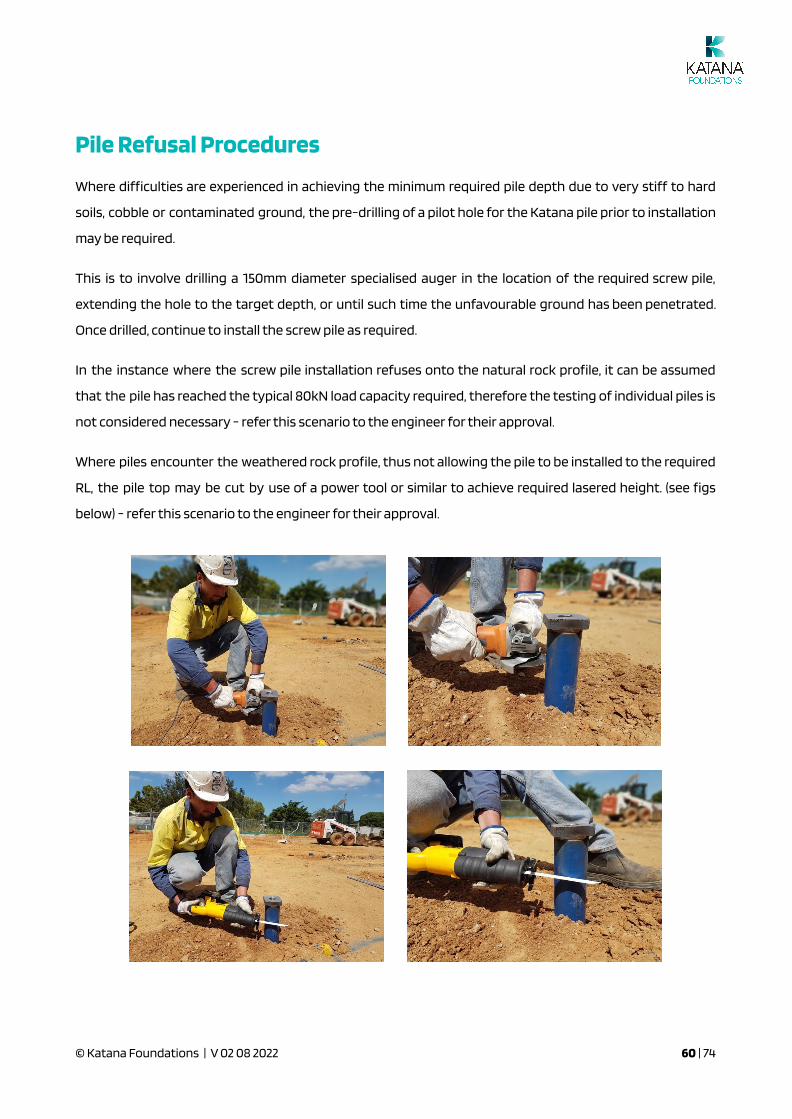
Where piles encounter the weathered rock pro�le, thus not allowing the pile to be installed to the required
RL, the pile top may be cut by use of a power tool or similar to achieve required lasered height. (see �gs
below) - refer this scenario to the engineer for their approval.
© Katana Foundations | V 02 08 2022 60 | 74

On Site Installation Issues
Differential settlement
One of the most important factors with residential piling is differential settlement. Where a site is cut on
one half and �lled on the other half and the installation torques during installation re�ect this, then
potentially there could be a concern around how the home will settle and where the cracking will take
place.
As on site soil conditions can vary considerably over relatively short distances, particularly within Australia,
some issues can arise from time to time with regards to the installation of screw piles.
Issues pertaining to torque or depth requirements must be directed to the engineer, this includes any
design issues pertaining to the requirements of the foundation design as a whole.
Where issues pertaining to the supply or delivery of the Katana Pile or Accessories, these queries are to be
directed to the manufacturer.
The checklist below are the minimum requirements that must be recorded and supplied by the Certi�ed
Katana Installer to the engineer in order for �nal certi�cation to be issued on the installation of the Katana
Pile. This information is to be recorded on the approved Screw Pile Installation Checklist (refer appendix)
Document job details including the following:
● Site Address
● Certi�ed Katana Installer
● Engineer Report Job No.
● Installation Date
● Principal Contractor
Document details of the pile type used including the following:
● Pile Type
● Design Load
● Pipe Diameter
● Founding Material
● Helix Size
© Katana Foundations | V 02 08 2022 61 | 74

Site photographic evidence is required for record keeping.
Results of the initial Uplift Load test which are to be recorded on the supplied record data sheet.
Video footage or photographs of the initial Uplift Load test are to be taken. Showing clear gauge read and
surrounding location.
Record and document the installation of all piles including the pile number, �nal depth achieved for each
pile, length, extensions, pressure, accessory and any cut increments also.
A corresponding layout is to be provided showing the location and the number allocated to the screw pile
installed.
Photograph the site and accessories left on site upon completion of installation. A minimum of 4
photographs are required.
Approved Piling Contractor must submit all documentation supplied.
Certi�cation
In order for �nal certi�cation to be issued with regards to the installation of the Katana Pile, the
information listed above must be supplied for certi�cation.
© Katana Foundations | V 02 08 2022 62 | 74
Appendix A: Screw Capacity for Uplift Loads
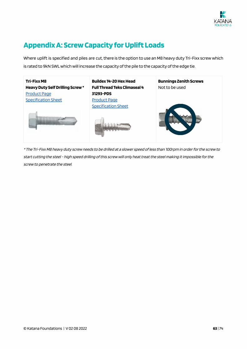
Where uplift is speci�ed and piles are cut, there is the option to use an M8 heavy duty Tri-Fixx screw which
is rated to 9kN SWL which will increase the capacity of the pile to the capacity of the edge tie.
Tri-Fixx M8
Heavy Duty Self Drilling Screw *
Product Page
Speci�cation Sheet
Buildex 14-20 Hex Head
Full Thread Teks Climaseal 4
31293-PDS
Product Page
Speci�cation Sheet
Bunnings Zenith Screws
Not to be used
* The Tri-Fixx M8 heavy duty screw needs to be drilled at a slower speed of less than 100rpm in order for the screw to
start cutting the steel - high speed drilling of this screw will only heat treat the steel making it impossible for the
screw to penetrate the steel.
© Katana Foundations | V 02 08 2022 63 | 74
Appendix B: Capacity of Edge Beam Connector
Some engineers may specify reinforcing through a hole in the top of the pile. The reinforcing is usually 29
diameters (29D) long to get full embedment of the reinforcing into the concrete.
Katana Foundations uses a N16 (250mm long) edge tie, embedded into the concrete footing.
We have tested piles to failure with the embedded edge tie and achieved a failure load of 55kN (Ultimate
load) in uplift per pile or 110kN for two piles or 27.5kN (SWL) - per pile.
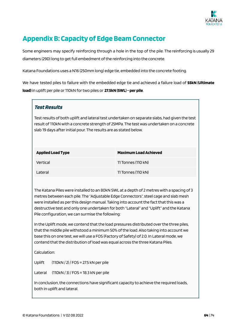
Test Results
Test results of both uplift and lateral test undertaken on separate slabs, had given the test
result of 110kN with a concrete strength of 25MPa. The test was undertaken on a concrete
slab 19 days after initial pour. The results are as stated below.
Applied Load Type Maximum Load Achieved
Vertical 11 Tonnes (110 kN)
Lateral 11 Tonnes (110 kN)
The Katana Piles were installed to an 80kN SWL at a depth of 2 metres with a spacing of 3
metres between each pile. The “Adjustable Edge Connectors”, steel cage and slab mesh
were installed as per this design manual. Taking into account the fact that this was a
destructive test and only one undertaken for both “Lateral” and “Uplift” and the Katana
Pile con�guration, we can surmise the following:
In the Uplift mode, we contend that the load pressures distributed over the three piles,
that the middle pile withstood a minimum 50% of the load. Also taking into account we
base this on one test, we will use a FOS (Factory of Safety) of 2.0. In Lateral mode, we
contend that the distribution of load was equal across the three Katana Piles.
Calculation:
Uplift (110kN / 2) / FOS = 27.5 kN per pile
Lateral (110kN / 3) / FOS = 18.3 kN per pile
In conclusion, the connections have signi�cant capacity to achieve the required loads,
both in uplift and lateral.
© Katana Foundations | V 02 08 2022 64 | 74
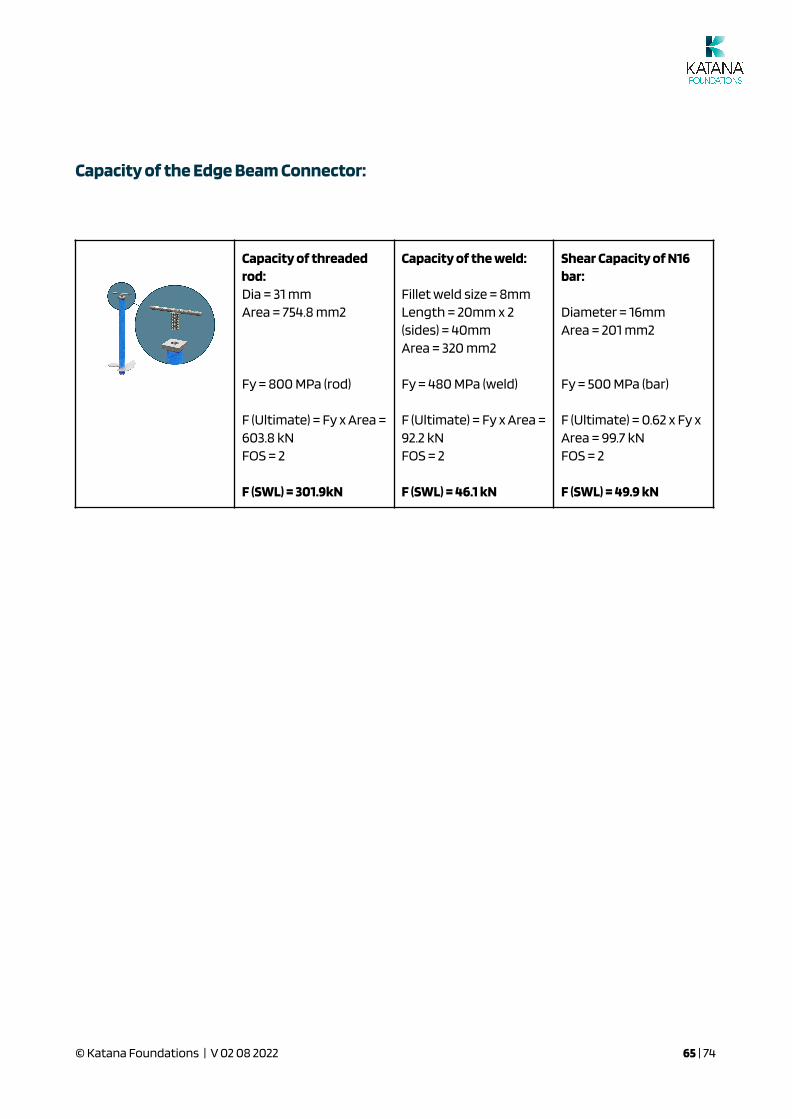
Capacity of the Edge Beam Connector:
Capacity of threadedrod:Dia = 31 mmArea = 754.8 mm2
Fy = 800 MPa (rod)
F (Ultimate) = Fy x Area =603.8 kNFOS = 2
F (SWL) = 301.9kN
Capacity of the weld:
Fillet weld size = 8mmLength = 20mm x 2(sides) = 40mmArea = 320 mm2
Fy = 480 MPa (weld)
F (Ultimate) = Fy x Area =92.2 kNFOS = 2
F (SWL) = 46.1 kN
Shear Capacity of N16bar:
Diameter = 16mmArea = 201 mm2
Fy = 500 MPa (bar)
F (Ultimate) = 0.62 x Fy xArea = 99.7 kNFOS = 2
F (SWL) = 49.9 kN
© Katana Foundations | V 02 08 2022 65 | 74

Appendix C: Lateral Load Capacity Tables
© Katana Foundations | V 02 08 2022 66 | 74
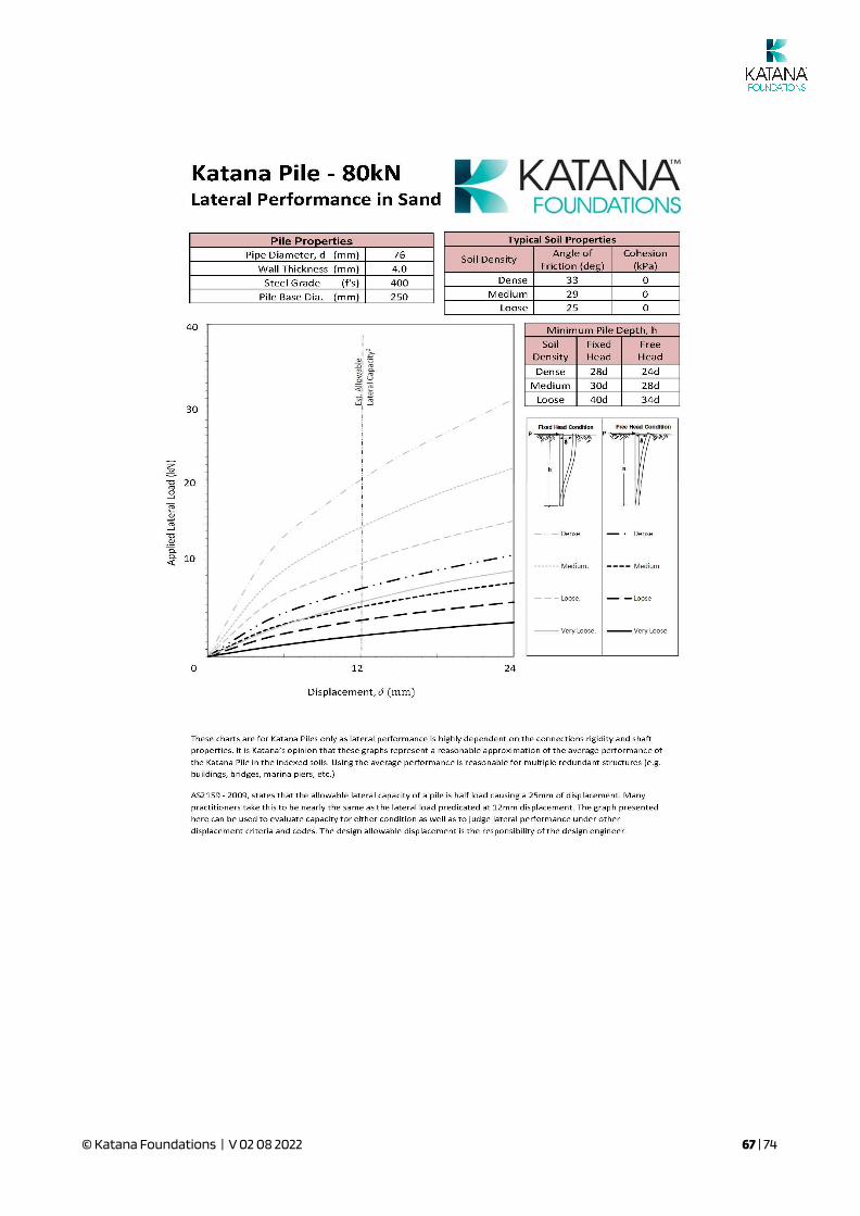
© Katana Foundations | V 02 08 2022 67 | 74

© Katana Foundations | V 02 08 2022 68 | 74
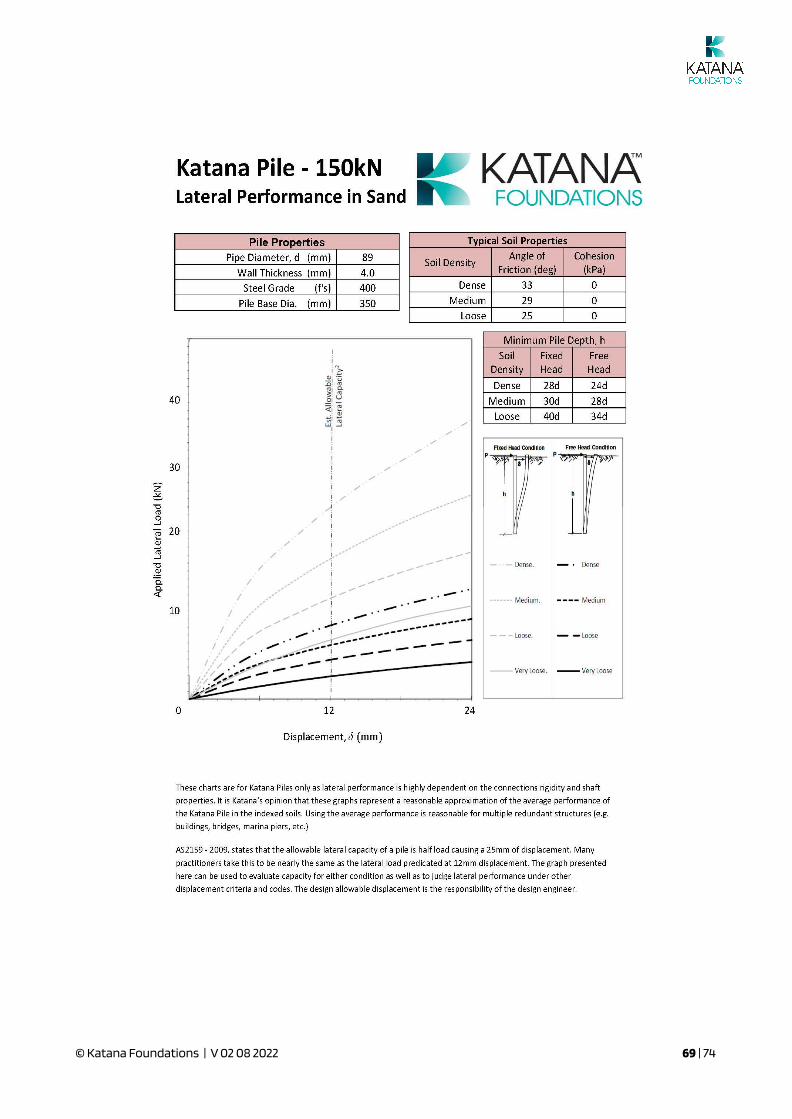
© Katana Foundations | V 02 08 2022 69 | 74

Revision Control
Date Revision
2 Aug 2022 Slab plates removed (redundant due to Uni of Melbourne study)
29 Mar 2022 Plastic slab plate added and appendices added
24 Jan 2022 Raised �oor notes modi�ed and Perko table revised
18 Jan 2022 Additional compliance questions added and Denso SteelGard 400 added
29 Sep 2021 Load torque guidelines added in the Installation & Certi�cation section
17 Sep 2021 Helix size error �xed in load table
18 Aug 2021 Engineering details added
28 Jul 2021 Bearing stress table updated
20 Jul 2021 Compliance questions added for certi�cation
10 Jun 2021 Bearing stress table updated
3 Jun 2021 Error �xed in load / spacing table
18 May 2021 Concrete bearing stress added
14 May 2021 Commentary on �ll material added
14 Apr 2021 Performance summary tables added for uncut and cut piles
9 Apr 2021Perko torsion table extended, approx torsional capacity of Katana Pipe
added below Perko table
22 Feb 2021 Clari�cation of Hs
© Katana Foundations | V 02 08 2022 70 | 74
Installer Certi�cation Questions and Answers:
Q: What Torque Nm or Hydraulic Pressure psi is required under normal circumstances to achieve a
minimum load of 80kN on a Katana Pile (250x8mm helix and 76.1x4mm shaft)?
A: _______________________________________________________________________________________
Q: What is the bene�t of using something like a Torque Hub on your digger for installing piles?
A: _______________________________________________________________________________________
Q: At what depth (*in very loose soils) for a 76mm DIA pile would you start to get concerned about thereduction in buckling capacity?
A: _______________________________________________________________________________________
Q: What is best practice when faced with a site with �ll material?
A: _______________________________________________________________________________________
Q: What test is the best way to demonstrate the load capacity of a screw pile?
A: _______________________________________________________________________________________
Q: What 4 things determine the exposure classi�cation in AS2159?
A: _______________________________________________________________________________________
Q: In reactive soils - what is the “Zone of In�uence” ?
A: _______________________________________________________________________________________
RAISED FLOORS:
Q: What coating system would you recommend for screw piles out of the ground supporting a raised �oor?
A: _______________________________________________________________________________________
Q: What should you check when you cut a Katana Pile for a slab and a raised �oor?
A: _______________________________________________________________________________________
Q: What is the maximum load on a Katana Foundations raised �oor per pile?
A: _______________________________________________________________________________________
© Katana Foundations | V 02 08 2022 71 | 74
Q: Where should the �oor bearer be located on a Katana bearer plate?
A: _______________________________________________________________________________________
Q: Who should do the setout and check the pile positions, once installed for a raised �oor?
A: _______________________________________________________________________________________
Q: Who should do the design of the bracing and check that the Katana bearer plates, L brackets etc aresuitable to carry the building loads for a raised �oor?
A: _______________________________________________________________________________________
Q: What is something you learned that you did not know before the compliance session?
A: _______________________________________________________________________________________
A: _______________________________________________________________________________________
A: _______________________________________________________________________________________
© Katana Foundations | V 02 08 2022 72 | 74

Installer Certi�cation (questions on the previous 2 pages are
required to be answered)
Accreditation of Certi�ed Katana Installers on behalf of
Katana Foundations Pty LtdABN 67 163 915 786
CERTIFIED KATANA INSTALLER:I have read and understood the contents of the Compliance Manual for the installation of “Katana” screwpiles
Date:___________________
Name:_______________________________________________
Company:____________________________________________
Signature: ____________________________________________
APPROVED KATANA FOUNDATIONS REPRESENTATIVE:I have explained the contents of the Compliance Manual for the installation of “Katana” screw piles andhereby certify the Katana Installer to undertake installations on behalf of Katana Foundations Pty Ltd
Date___________________
Name:_______________________________________________
Position:_____________________________________________
Signature: ___________________________________________
© Katana Foundations | V 02 08 2022 73 | 74
© Katana Foundations | V 02 08 2022 74 | 74
Related Documents