Welcome message from author
This document is posted to help you gain knowledge. Please leave a comment to let me know what you think about it! Share it to your friends and learn new things together.
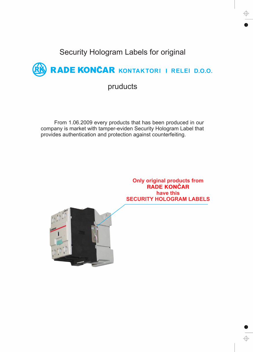
Transcript


CATALOGUE 2010/2011
MINI CONTACTORS
NEW CONTACTORS
1
1
THERMAL OVERLOAD RELAYS
PUSHBUTTONS AND INDICATOR LIGHTS
ROTARY CAM SWITCHES 3
5MOULDED CASE CIRCUIT BREAKERS
ELECTRONIC TIME RELAYS
TEMPERATURE MONITOR RELAYS
STAIRCASE LIGHTING CONTROLLER AND 6
4
2
CONTACTORS 1


1
Mini motor contactor type CM1, AC control circuit ......................................................1/1
Motor contactors type CNN 9 - CNN 12, AC control circuit .........................................1/1
Motor contactors type CNN 18 - CNN 40, AC control circuit ......................................1/2
Motor contactors type CNNB 9 - CNNB 25,
Motor contactors type CNM 9 - CNM 36, AC control circuit ........................................1/4
Motor contactors type CNM 45 - CNM 170, AC control circuit ....................................1/5
Motor contactors type CNM 200 - CNM 400, AC control circuit ..................................1/6
Motor contactors type CNB 9 - CNB 30
with DC solenoid system .............................................................................................1/7
Accessories for contactors and contactor relays ...............................................1/22,1/23
Spare parts for contactors and contactor relays.................................................1/24,1/25
Capacitor contactors type CNNK 10 - CNNK 30 .......................................................1/15
Capacitor contactors type CNKM 40 - CNKM 60 ......................................................1/16
DC Contactors type CNO, AC control circuit .............................................................1/17
DC Contactors type CNO, DC control circuit .............................................................1/18
Motor contactors type CNM 36 - CNM 170,
with DC control circuit ..................................................................................................1/8
Motor contactors type CNM 200 - CNM 400
with DC control circuit ..................................................................................................1/9
Reversing contactors type MBCM1 - MBCNN 9 - MBCNN 40...................................1/12
Reversing contactors type MBCNM 12 - MBCNM 400...............................................1/13
Contactors type TK 65 - TK 175 for switching resistive loads ...................................1/14
Contactor assemblies in enclosures and direct - on line starters for
contactors CNM 9 - CNM 30......................................................................................1/10
Enclosures -type PN and PNT from insulation material.............................................1/11
Contactor relays type CP0 for auxiliary circuit switching, AC control circuit..............1/19
Contactor relays for auxiliary circuit switching,type CNP AC control circuit ............1/19
Contactors with FAST-ON terminals ..........................................................................1/21
Order for contactors ..................................................................................................1/21
TECHNICAL INFORMATION
Contactors, Application, Installation, Standards, .......................................................1/26
Electrical endurance of contacts..............................................................1/26, 1/27, 1/28
CONTACTORS
Contactor relays type CNB, DC solenoid system ......................................................1/20
with DC solenoid system .............................................................................................1/3
1
1/IV
TECHNICAL DATA
Motor contactors type CM1 and type CNN ................................................................1/36
Motor contactors type CNNB .......................................................................... 1/38, 1/39
Auxiliary contact blocks BP0, BP1,BP2, BP3 and BP4..............................................1/37
Motor contactors type CNM and type CNB .............................................1/40, 1/41, 1/42
Motor contactors type CNM
AC opereted or DC opereted ...................................................................1/43, 1/44, 1/45
Contactors type TK for switching resistive loads .......................................................1/46
Control of lighting circuits ..........................................................................................1/47
Table of technical characteristics for lighting switching ....................................1/48, 1/49
Capacitor contactors type CNNK 10 - CNKM 60 .............................................1/50, 1/51
DC Contactors type CNO ..........................................................................................1/52
Mini contactor relay type CPO ............................................................................... ..1/53
Contactor relays type CNP and type CNB. ................................................................1/54
Wiring diagrams.........................................................................................................1/55
Schematic diagrams for AC operated contactors ......................................................1/56
Schematic diagrams for DC operated contactors. ....................................................1/57
Wiring diagrams, Schematic diagrams for AC and DC
operated contactors for CNO.....................................................................................1/58
Dimension drawings ..........................................................................................1/59-1/65
Utilization categories of contactors ............................................................................1/29
Degrees of Protection of enclosed equipment............................................................1/30
Over voltage limiter.....................................................................................................1/31
Voltage drop in main circuits and current transformers ............................................. 1/32
Auxiliary current circuits..............................................................................................1/33
Cable capacity ...........................................................................................................1/34
Squirred-cage induction motors rated motor current .................................................1/35
1
1/1
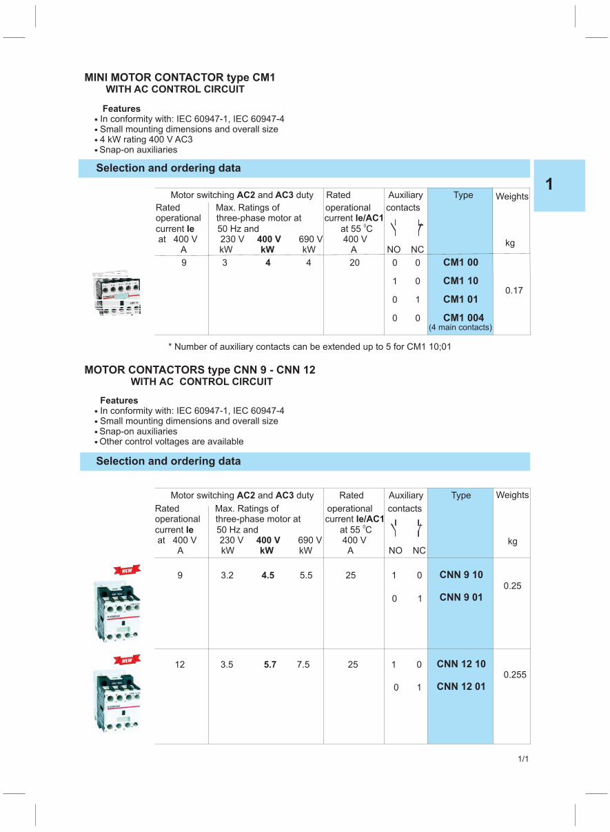
MINI MOTOR CONTACTOR type CM1WITH AC CONTROL CIRCUIT
FeaturesIn conformity with: IEC 60947-1, IEC 60947-4
4 kW rating 400 V AC3Small mounting dimensions and overall size
Snap-on auxiliaries
Motor switching and duty RatedAC2 AC3 Auxiliary Type
0 0
1 0
0 1
0 0
9 3 4 204 CM1 00
CM1 10
CM1 01
CM1 004(4 main contacts)
Weights
kg
0.17
Rated Max. Ratings of operational contactsoperationalcurrent 50 Hz and 55 C
400 V 230 V 690 V 400 VA kW kW A NO NC
three-phase motor at current Ie/AC1Ie
400 VkW
0at
at
* Number of auxiliary contacts can be extended up to 5 for CM1 10;01
Selection and ordering data
Selection and ordering data
Motor switching and duty RatedAC2 AC3 Auxiliary Type
Rated Max. Ratings of operational contactsoperationalcurrent 50 Hz and 55 C
400 V 230 V 690 V 400 VA kW kW A NO NC
three-phase motor at current Ie/AC1Ie
400 VkW
0at
at
9 3.2 5.5 25 1 0
0 1
4.5 CNN 9 10
CNN 9 01
12 3.5 7.5 255.7 1 0
0 1
CNN 12 10
CNN 12 01
MOTOR CONTACTORS type CNN 9 - CNN 12WITH AC CONTROL CIRCUIT
FeaturesIn conformity with: IEC 60947-1, IEC 60947-4
Other control voltages are available
Weights
kg
0.25
0.255
Small mounting dimensions and overall sizeSnap-on auxiliaries
NEW
NEW
1
1/2
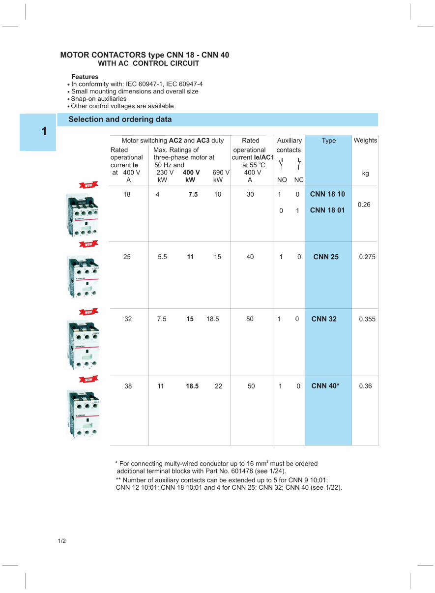
* For connecting multy-wired conductor up to 16 mm must be orderedadditional terminal blocks with Part No. 601478 (see 1/24).
2
Selection and ordering data
Motor switching and duty RatedAC2 AC3 Auxiliary Type
Rated Max. Ratings of operational contactsoperationalcurrent 50 Hz and 55 C
400 V 230 V 690 V 400 VA kW kW A NO NC
three-phase motor at current Ie/AC1Ie
400 VkW
0at
at
25 5.5 15 40 1 011 CNN 25
038 11 22 50 1518.
32 7.5 18.5 5015 1 0 CNN 32
MOTOR CONTACTORS type CNN 18 - CNN 40WITH AC CONTROL CIRCUIT
FeaturesIn conformity with: IEC 60947-1, IEC 60947-4
Other control voltages are available
CNN 40*
Weights
kg
0.275
0.355
0.36
Small mounting dimensions and overall sizeSnap-on auxiliaries
* Number of auxiliary contacts can be extended up to 5 for CNN 9 10;01;CNN 12 10;01; CNN 18 10;01 and 4 for CNN 25; CNN 32; CNN 40*
(see 1/22).
0
0 1
18 4 10 30 17.5 CNN 18 10
CNN 18 010.26
NEW
NEW
NEW
NEW

MOTOR CONTACTORS type CNNB 9-25WITH DC CONTROL SYSTEM
Selection and ordering data
Motor switching and duty RatedAC2 AC3 Auxiliary Type
9 2.2 5.5 25 1 0
0 1
4 1
1
CNNB 9 10
CNNB 9 01
12 3.5 7.5 255.7 1 0
0 1
1
1
CNNB 12 10
CNNB 12 01
18 4 10 30 1 0
0 1
7.5 1
1
CNNB 18 10
CNNB 18 01
25 5.5 11 40 1 011 1CNNB 25
Weights
kg
0.54
0.54
0.55
0.60
Rated Max. Ratings of operational contactsoperationalcurrent 50 Hz and 55 C
400 V 230 V 690 V 400 VA kW kW A NO NC
three-phase motor at current Ie/AC1Ie
400 VkW
0at
at
1
2
Available from february 2010Number of auxiliary contacts can be extended up to 5 for CNNB 9 10;01;CNNB 12 10;01; CNNB 18 10;01 and 4 for CNNB 25;
In conformity with: IEC 60947-1, IEC 60947-4
Other control voltages are available
Small mounting dimensions and overall sizeSnap-on auxiliaries
Features
1
1/3
NEW
NEW
NEW
NEW

1
1/4
MOTOR CONTACTORS type CNM 9 - CNM 36WITH AC CONTROL CIRCUIT
Features� In conformity with: IEC 60947-4� With fixed auxiliary contacts� Rugged construction� Other control voltages are available
Selection and ordering data
Motor switching and dutyAC2 AC3 Rated Auxiliary Type Weights
operational contacts
current Ie/AC1
at 550C
400 V 230 V 400 V 690 V 400 V
A kW kW kW A NO NC kg
Rated Max. Ratings of
operational three-phase motor at
current atIe 50 Hz
9 2.2 4 5.5 20 1 0 CNM 9 10
0 1 0.37CNM 9 01
0 0 CNM 9 004(4 main contacts)
12 3 5.5 7.5 20 1 0 CNM 12 10
0 1 CNM 12 01 0.38
0 0 CNM 12 004(4 main contacts)
12 3 5.5 7.5 20 1 1 CNM 12 11
0.47
2 2 CNM 12 22
16 4 7.5 11 30 1 1 CNM 16 11
0.50
2 2 CNM 16 22
22 5.5 11 11 30 1 1 CNM 22 11
0.51
2 2 CNM 22 22
30 7.5 15 15 35 1 1 CNM 30 11
0.52
2 2 CNM 30 22
36 11 18.5 26 45 2 2 0.63CNM 36 22
4 4 0.73CNM 36 44
1
1/5
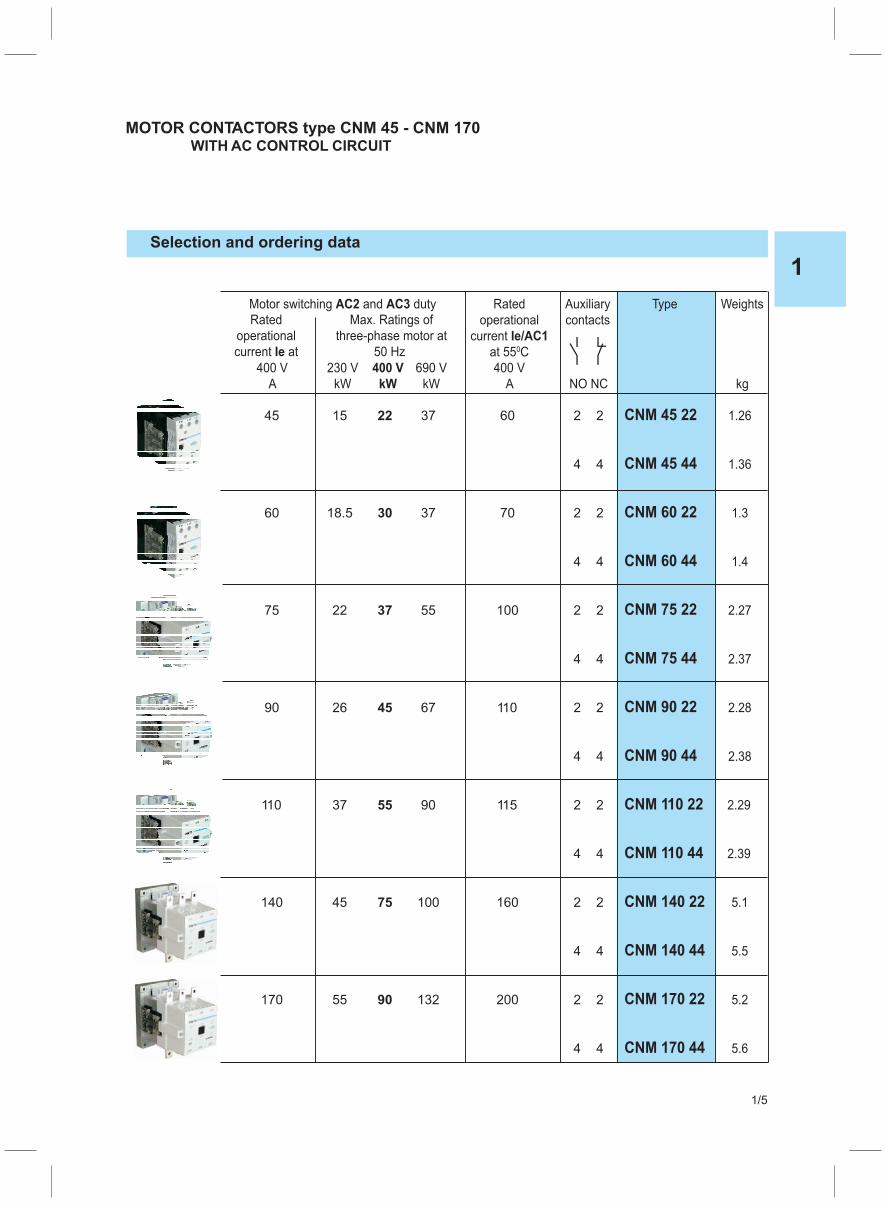
MOTOR CONTACTORS type CNM 45 - CNM 170WITH AC CONTROL CIRCUIT
Selection and ordering data
Motor switching and dutyAC2 AC3 Rated Auxiliary Type Weights
operational contacts
current Ie/AC1
at 550C
400 V 230 V 400 V 690 V 400 V
A kW kW kW A NO NC kg
Rated Max. Ratings of
operational three-phase motor at
current atIe 50 Hz
45 15 22 37 60 2 2 CNM 45 22 1.26
4 4 CNM 45 44 1.36
60 18.5 30 37 70 2 2 CNM 60 22 1.3
4 4 CNM 60 44 1.4
75 22 37 55 100 2 2 CNM 75 22 2.27
4 4 CNM 75 44 2.37
90 26 45 67 110 2 2 CNM 90 22 2.28
4 4 CNM 90 44 2.38
110 37 55 90 115 2 2 CNM 110 22 2.29
4 4 CNM 110 44 2.39
140 45 75 100 160 2 2 CNM 140 22 5.1
4 4 CNM 140 44 5.5
170 55 90 132 200 2 2 CNM 170 22 5.2
4 4 CNM 170 44 5.6
1
1/6
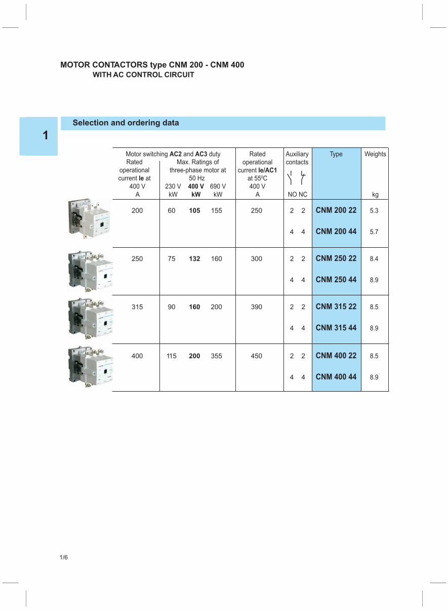
MOTOR CONTACTORS type CNM 200 - CNM 400
WITH AC CONTROL CIRCUIT
Selection and ordering data
Motor switching and dutyAC2 AC3 Rated Auxiliary Type Weights
operational contacts
current Ie/AC1
at 550C
400 V 230 V 400 V 690 V 400 V
A kW kW kW A NO NC kg
Rated Max. Ratings of
operational three-phase motor at
current atIe 50 Hz
200 60 105 155 250 2 2 CNM 200 22 5.3
4 4 CNM 200 44 5.7
250 75 132 160 300 2 2 CNM 250 22 8.4
4 4 CNM 250 44 8.9
315 90 160 200 390 2 2 CNM 315 22 8.5
4 4 CNM 315 44 8.9
400 115 200 355 450 2 2 CNM 400 22 8.5
4 4 CNM 400 44 8.9
1
1/7
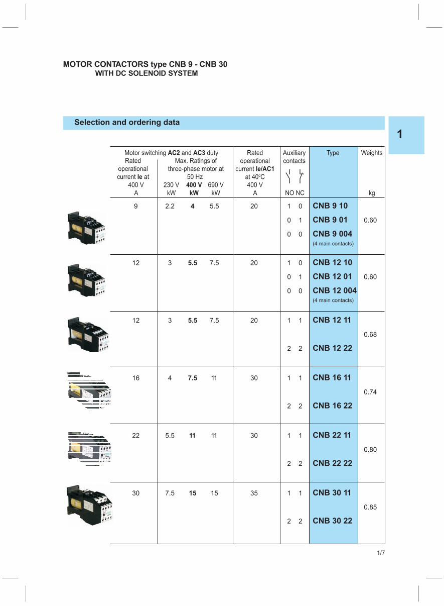
MOTOR CONTACTORS type CNB 9 - CNB 30WITH DC SOLENOID SYSTEM
Selection and ordering data
Motor switching and dutyAC2 AC3 Rated Auxiliary Type Weights
operational contacts
current Ie/AC1
at 400C
400 V 230 V 400 V 690 V 400 V
A kW kW kW A NO NC kg
Rated Max. Ratings of
operational three-phase motor at
current atIe 50 Hz
9 2.2 4 5.5 20 1 0 CNB 9 10
0 1 CNB 9 01 0.60
0 0 CNB 9 004(4 main contacts)
12 3 5.5 7.5 20 1 0 CNB 12 10
0 1 CNB 12 01 0.60
0 0 CNB 12 004(4 main contacts)
12 3 5.5 7.5 20 1 1 CNB 12 11
0.68
2 2 CNB 12 22
16 4 7.5 11 30 1 1 CNB 16 11
0.74
2 2 CNB 16 22
22 5.5 11 11 30 1 1 CNB 22 11
0.80
2 2 CNB 22 22
30 7.5 15 15 35 1 1 CNB 30 11
0.85
2 2 CNB 30 22
1
1/8
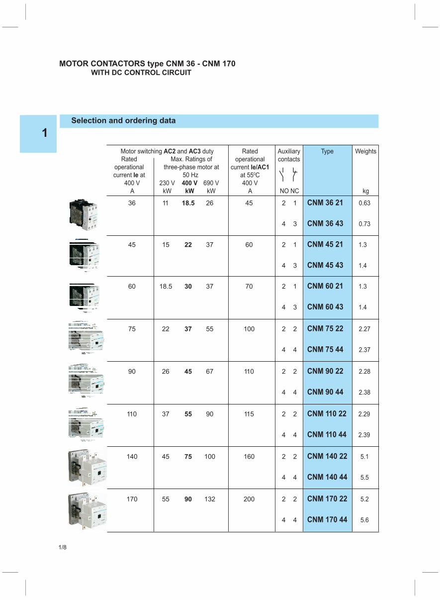
MOTOR CONTACTORS type CNM 36 - CNM 170WITH DC CONTROL CIRCUIT
Selection and ordering data
Motor switching and dutyAC2 AC3 Rated Auxiliary Type Weights
operational contacts
current Ie/AC1
at 550C
400 V 230 V 400 V 690 V 400 V
A kW kW kW A NO NC kg
Rated Max. Ratings of
operational three-phase motor at
current atIe 50 Hz
36 11 18.5 26 45 2 1 CNM 36 21 0.63
4 3 CNM 36 43 0.73
45 15 22 37 60 2 1 CNM 45 21 1.3
4 3 CNM 45 43 1.4
60 18.5 30 37 70 2 1 CNM 60 21 1.3
4 3 CNM 60 43 1.4
75 22 37 55 100 2 2 CNM 75 22 2.27
4 4 CNM 75 44 2.37
90 26 45 67 110 2 2 CNM 90 22 2.28
4 4 CNM 90 44 2.38
110 37 55 90 115 2 2 CNM 110 22 2.29
4 4 CNM 110 44 2.39
140 45 75 100 160 2 2 CNM 140 22 5.1
4 4 CNM 140 44 5.5
170 55 90 132 200 2 2 CNM 170 22 5.2
4 4 CNM 170 44 5.6
1
1/9
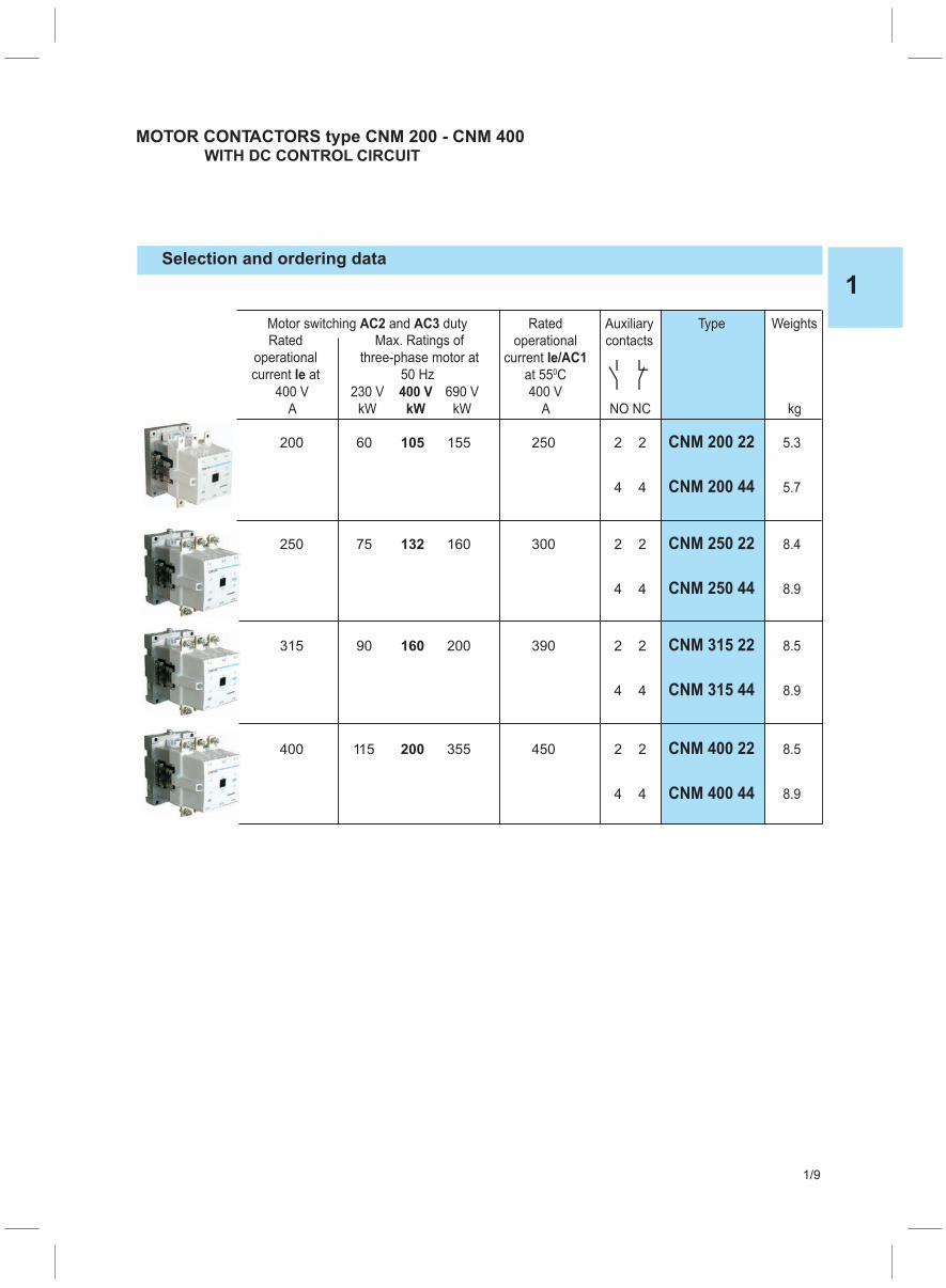
MOTOR CONTACTORS type CNM 200 - CNM 400WITH DC CONTROL CIRCUIT
Selection and ordering data
Motor switching and dutyAC2 AC3 Rated Auxiliary Type Weights
operational contacts
current Ie/AC1
at 550C
400 V 230 V 400 V 690 V 400 V
A kW kW kW A NO NC kg
Rated Max. Ratings of
operational three-phase motor at
current atIe 50 Hz
200 60 105 155 250 2 2 CNM 200 22 5.3
4 4 CNM 200 44 5.7
250 75 132 160 300 2 2 CNM 250 22 8.4
4 4 CNM 250 44 8.9
315 90 160 200 390 2 2 CNM 315 22 8.5
4 4 CNM 315 44 8.9
400 115 200 355 450 2 2 CNM 400 22 8.5
4 4 CNM 400 44 8.9
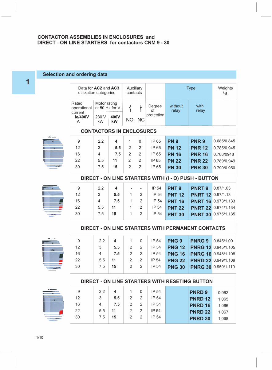
Selection and ordering data
Data for andAC2 AC3 Auxiliary Typeutilization categories contacts
Weightskg
0.685/0.845
0.87/1.03
0.97/1.13
0.973/1.133
0.974/1.134
0.975/1.135
0.845/1.00
0.945/1.105
0.948/1.108
0.949/1.109
0.950/1.110
0.962
1.065
1.066
1.067
1.068
0.785/0.945
0.788/0948
0.789/0.949
0.790/0.950
PN 9 PNR 9
PN 12 PNR 12
PN 16 PNR 16
PN 22 PNR 22
PN 30 PNR 30
Ratedoperationalcurrent
AIe/400V
Motor ratingat 50 Hz for V
230 VkW
400VkW NO NC
Degree without withof relay relay
protection
CONTACTORS IN ENCLOSURES
9 2.2 1 0 IP 65
12 3 2 2 IP 65
16 4 2 2 IP 65
22 5.5 2 2 IP 65
30 7.5 2 2 IP 65
4
5.5
7.5
11
15
DIRECT - ON LINE STARTERS WITH (I - O) PUSH - BUTTON
9 2.2 - - IP 54
12 3 1 2 IP 54
16 4 1 2 IP 54
22 5.5 1 2 IP 54
30 7.5 1 2 IP 54
4
5.5
7.5
11
15
PNG 9 PNRG 9
PNG 12 PNRG 12
PNG 16 PNRG 16
PNG 22 PNRG 22
PNG 30 PNRG 30
DIRECT - ON LINE STARTERS WITH PERMANENT CONTACTS
9 2.2 1 0 IP 54
12 3 2 2 IP 54
16 4 2 2 IP 54
22 5.5 2 2 IP 54
30 7.5 2 2 IP 54
4
5.5
7.5
11
15
PNRD 9
PNRD 12
PNRD 16
PNRD 22
PNRD 30
DIRECT - ON LINE STARTERS WITH RESETING BUTTON
9 2.2 1 0 IP 54
12 3 2 2 IP 54
16 4 2 2 IP 54
22 5.5 2 2 IP 54
30 7.5 2 2 IP 54
4
5.5
7.5
11
15
CONTACTOR IN ENCLOSURES andDIRECT - ON LINE STARTERS for contactors CNM 9 - 30
ASSEMBLIES
1
1/10
PNT 9 PNRT 9
PNT 12 PNRT 12
PNT 16 PNRT 16
PNT 22 PNRT 22
PNT 30 PNRT 30

PN
PNT
Desing Degree ofprotection
ENCLOSURES - type PN and PNTfrom insulation material
Enclosures without push-buttons
With "I" make and "O" breake push button
IP 65
IP 54
Type
ORDER:
Type
Standard control voltages AC 24, 48, 110, 220/230,380/400 V
For AC control: 50 Hz or 60 Hz
Seting range for thermal overload relay (Upper value)
Example:
PNT 16 220/230 V 50 Hz.
Motorstarter type PNT 16 control voltage 220/230 V, 50 Hz
Example:
PNRT 16 220/230 V 50 Hz 16A
Motorstarter type PNRT 16 control voltage 220/230 V, 50 Hz, thermal overload relay typeTRM 22, current range (10-16)A
Selection and ordering data
PN
Weightskg
0.315
0.500
1
1/11
1
1/12
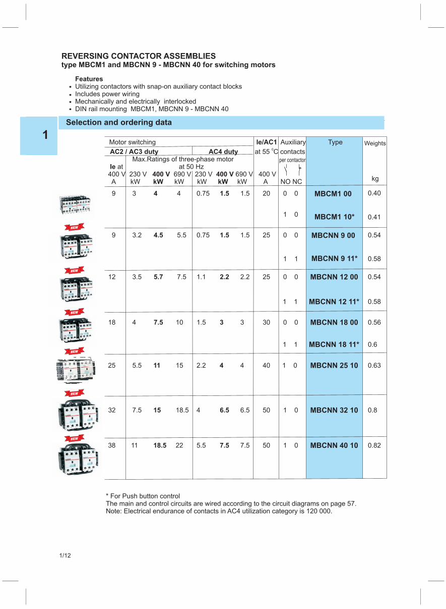
REVERSING CONTACTOR ASSEMBLIEStype MBCM1 and MBCNN 9 - MBCNN 40 for switching motors
Selection and ordering data
Motor switching Ie/AC1 Auxiliary Type
contactsMax.
400 V 230 V 690 V 400 VA kW kW kW kW A NO NC
AC2 / CAC3 duty A 4 duty
400 V
at 55 CRatings of three-phase motor
at 50 Hz230 V 690 V
0
atIe400 VkW kW
9 3 4 4 0.75 1.5 1.5 20 0 0
1 0
9 3.2 4.5 5.5 0.75 1.5 1.5 25 0 0
1 1
MBCNN 12 00
18 4 7.5 10 1.5 3 3 30 MBCNN 18 00
MBCNN 18 11*
MBCNN 25 10
32 7.5 15 18.5 4 6.5 6.5 50
38 11 18.5 22 5.5 7.5 7.5 50
MBCNN 32 10
MBCNN 40 10
MBCNN 9 00
MBCNN 9 11*
MBCM1 00
MBCM1 10*
MBCNN 12 11*
25 5.5 11 15 2.2 4 4 40
kg
Weights
0.40
0.41
0.54
0.58
0.54
0.58
0.82
0.8
0.63
0.56
0.6
12 3.5 5.7 7.5 1.1 2.2 2.2 25 0 0
1 1
0 0
1 0
1 0
1 0
1 1
* For Push button controlThe main and control circuits are wired according to the circuit diagrams on page 57.Note: Electrical endurance of contacts in AC4 utilization category is 120 000.
per contactor
FeaturesUtilizing contactors with sIncludes power wiringMechanically and electrically interlockedDIN rail mounting MBCM1, MBCNN 9 - MBCNN 40
nap-on auxiliary contact blocks
NEW
NEW
NEW
NEW
NEW
NEW
1
1/13
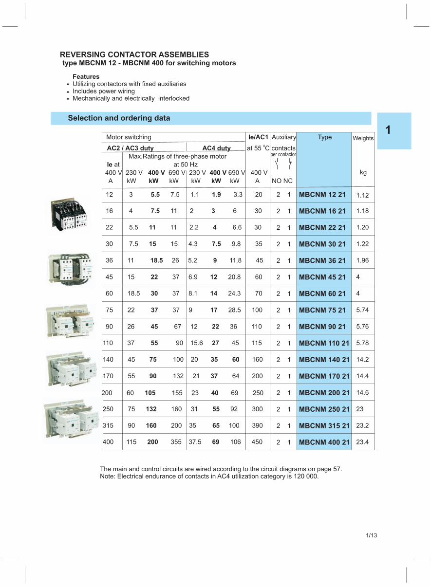
REVERSING CONTACTOR ASSEMBLIEStype MBCNM 12 - MBCNM 400 for switching motors
Selection and ordering data
Motor switching Ie/AC1 Auxiliary Type
contacts
Max.
400 V 230 V 690 V 400 V
A kW kW kW kW A NO NC
AC2 / CAC3 duty A 4 duty
400 V
at 55 C
Ratings of three-phase motor
at 50 Hz
230 V 690 V
0
atIe
400 V
kW kW
MBCNM 12 21
16 4 11 2 6 307.5 3
MBCNM 22 21
30 7.5 15 4.3 9.8 3515 7.5 MBCNM 30 21
MBCNM 36 21
MBCNM 45 21
MBCNM 60 21
MBCNM 75 21
MBCNM 90 21
MBCNM 110 21
MBCNM 140 21
MBCNM 170 21
MBCNM 200 21
MBCNM 250 21
MBCNM 315 21
MBCNM 400 21
MBCNM 16 21
22 5.5 11 2.2 6.6 3011 4
kg
Weights
1.22
1.96
4
4
5.74
5.76
5.78
14.2
14.4
14.6
23
23.2
23.4
1.20
1.18
1.1212 3 7.5 1.1 3.3 205.5 1.9
36 11 26 5.2 11.8 4518.5 9
45 15 37 6.9 20.8 6022 12
60 18.5 37 8.1 24.3 7030 14
75 22 37 9 28.5 10037 17
90 26 67 12 36 11045 22
110 37 90 15.6 45 11555 27
140 45 100 20 16075 35 60
170 55 132 21 64 20090 37
200 60 155 23 69 250105 40
250 75 160 31 92 300132 55
315 90 200 35 100 390160 65
400 115 355 37.5 106 450200 69
2 1
2 1
2 1
2 1
2 1
2 1
2 1
2 1
2 1
2 1
2 1
2 1
2 1
2 1
2 1
2 1
The main and control circuits are wired according to the circuit diagrams on page 57.Note: Electrical endurance of contacts in AC4 utilization category is 120 000.
per contactor
FeaturesUtilizing contactors withIncludes power wiringMechanically and electrically interlocked
fixed auxiliaries

1
1/14
CONTACTORS type TK 25 - TK 175for SWITCHING RESISTIVE LOADS
Features�With fixed auxiliary contacts�Rugged construction�Other control voltage are available
Selection and ordering data
AC coil operation
Rating utilization categoryAC1 Auxiliary Type Weights
Switching resistive load at 55oC contacts
le/AC1 230 V 400 V
A kW kW NO NC kg
Operational current Ratings of three-phase loads at
65 25 43 2 2 TK 65 22 0.59
85 32 56 2 2 TK 85 22 0.70
115 44 76 2 2 TK 115 22 1.5
130 50 85 2 2 TK 130 22 2.42
175 67 115 2 2 TK 175 22 2.42
Selection and ordering data
NO NC
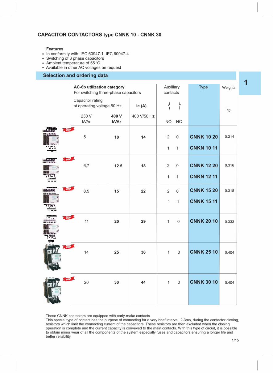
CAPACITOR CONTACTORS type CNNK 10 - CNNK 30
2
2
0
0
CNNK 10 20
CNKN 10 11
CNNK 12 20
CNKN 12 11
AC-6b utilization category Auxiliary Type
contactsFor switching three-phase capacitors
Features
In conformity with: IEC 60947-1, IEC 60947-4Switching of 3 phase capacitorsAmbient temperature of 55 C
0
Available in other AC voltages on request
Weights
kg
0.314
0.316
1 1
1 1
Capacitor rating
at operating voltage 50 Hz Ie (A)
400 V/50 Hz230 V 400 V
kVAr kVAr
145 10
186,7 12.5
1 0 CNNK 20 10 0.3332911 20
1
1
0
0
CNNK 25 10
CNNK 30 10
0.404
0.404
3614 25
4420 30
2 0 CNNK 15 20
CNNK 15 11
0.318
1 1
228.5 15
These CNNK contactors are equipped with early-make contacts.This special type of contact has the purpose of connecting for a very brief interval, 2-3ms, during the contactor closing,resistors which limit the connecting current of the capacitors. These resistors are then excluded when the closingoperation is complete and the current capacity is conveyed to the main contacts. With this type of circuit, it is possibleto obtain minor wear of all the components of the system especially fuses and capacitors ensuring a longer life andbetter reliability.
1
1/15
NEW
NEW
NEW
NEW
NEW
NEW
Selection and ordering data
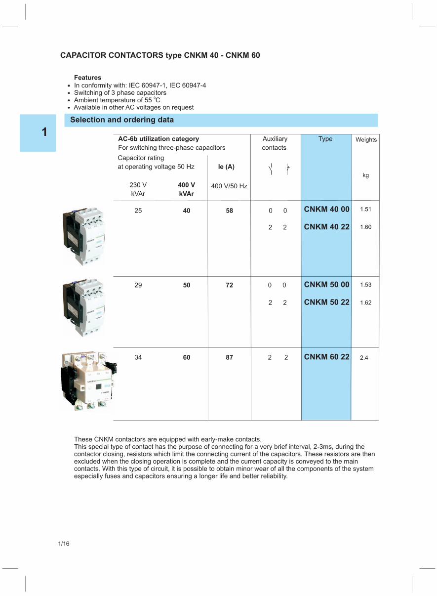
CAPACITOR CONTACTORS type CNKM 40 - CNKM 60
0 0
2 2
CNKM 50 00
CNKM 50 22
CNKM 60 22
AC-6b utilization category Auxiliary Type
contactsFor switching three-phase capacitors
0 0 CNKM 40 00
CNKM 40 22
Weights
kg
1.51
1.60
1.53
1.62
2.4
2 2
2 2
These CNKM contactors are equipped with early-make contacts.This special type of contact has the purpose of connecting for a very brief interval, 2-3ms, during thecontactor closing, resistors which limit the connecting current of the capacitors. These resistors are thenexcluded when the closing operation is complete and the current capacity is conveyed to the maincontacts. With this type of circuit, it is possible to obtain minor wear of all the components of the systemespecially fuses and capacitors ensuring a longer life and better reliability.
72
87
58
Capacitor rating
at operating voltage 50 Hz Ie (A)
230 V 400 V 400 V/50 HzkVAr kVAr
29 50
34 60
25 40
Features
In conformity with: IEC 60947-1, IEC 60947-4Switching of 3 phase capacitorsAmbient temperature of 55 C
0
Available in other AC voltages on request
1
1/16
1
1/17

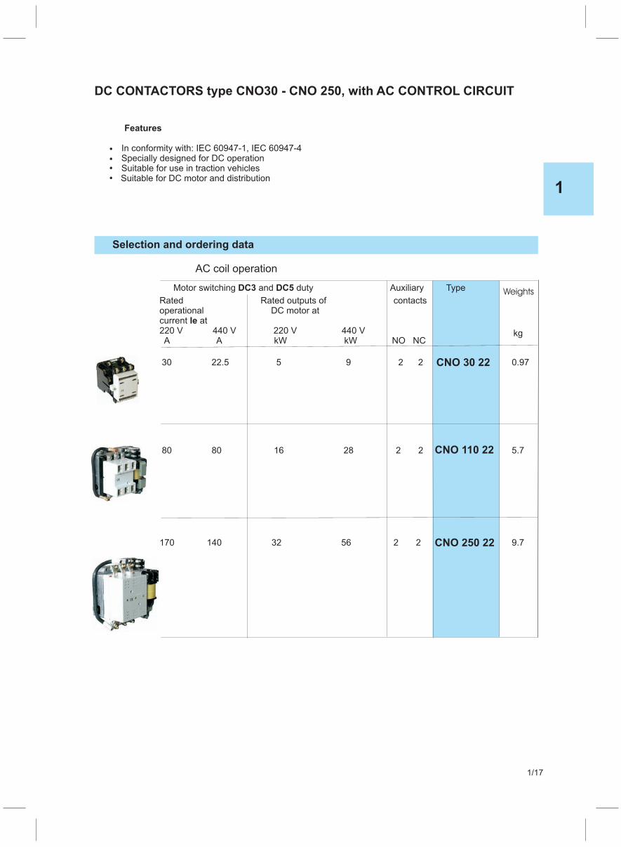
Example: Motor contactor type CNO 30 with two NO and two NC auxiliary contacts, control voltage 220V DC, for pushbutton control “UT”
CNO 30 22 220V DC UT
CNO 250 22*
CNO 110 22*
CNO 30 22*
(*)For DC control through push button the number of free auxiliary contacts are minus 1NO.For DC control through permanent contact control the number of free auxiliary contacts isminus 1NO and 1NC
1
1/18
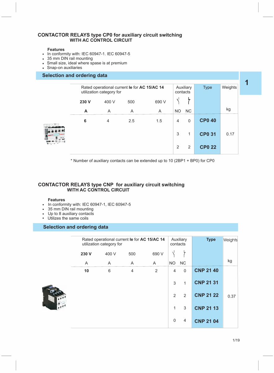
CONTACTOR RELAYS type CP0 for auxiliary circuit switchingWITH AC CONTROL CIRCUIT
FeaturesIn conformity with: IEC 60947-1. IEC 60947-5
Small size, ideal where spase is at premium35 mm DIN rail mounting
Snap-on auxiliaries
Selection and ordering data
Rated operational current forIe AC 15/AC 14 Auxiliary Typeutilization category for contacts
400 V 500 690 V
A A A NO NC
230 V
A
4 2.5 1.5 4 0
3 1
2 2
6 CP0 40
CP0 31
CP0 22
Weights
kg
0.17CP0 10
CONTACTOR RELAYS type CNP for auxiliary circuit switchingWITH AC CONTROL CIRCUIT
FeaturesIn conformity with: IEC 60947-1, IEC 60947-5
Up to 8 auxiliary contacts35 mm DIN rail mounting
Utilizes the same coils
Selection and ordering data
Rated operational current forIe AC 15/AC 14 Auxiliaryutilization category for contacts
Type
400 V 500 690 V
A A A A NO NC
230 V
10 6 4 2 4 0
3 1
2 2
1 3
0 4
CNP 21 40
CNP 21 31
CNP 21 22
CNP 21 13
CNP 21 04
Weights
kg
0.37
* Number of auxiliary contacts can be extended up to 10 (2BP1 + BP0) for CP0
1
1/19

Selection and ordering data
Rated operational current forIe AC 15/AC 14 Auxiliaryutilization category for contacts
Type
400 V 500 690 V
A A A A NO NC
230 V
10 6 4 2 8 0
7 1
6 2
5 3
4 4
CNP 31 80
CNP 31 71
CNP 31 62
CNP 31 53
CNP 31 44
Weights
kg
0.43
CONTACTOR RELAYS type CNB for auxiliary circuit switchingwith DC SOLENOID SYSTEM
Features
In conformity with: IEC 60947-1, IEC 60947-535 mm DIN rail mounting
Utilizes the same coilsUp to 8 auxiliary contacts
Selection and ordering data
Rated operational current for AC 15/AC 14 Auxiliary Typeutilization category for contacts
400 V 500 690 V
A A A A NO NC
230 V
6 4 2 4 010
3 1
2 2
1 3
0 4
6 4 2 8 010
7 1
6 2
5 3
4 4
CNB 31 80
CNB 31 71
CNB 21 40
CNB 21 31
CNB 21 22
CNB 21 13
CNB 21 04
Weights
kg
0.60
0.66CNB 31 62
CNB 31 53
CNB 31 44
1
1/20

Description
FAST-ON TERMINALS (spade terminals) comply toregulations DIN 46245 and DIN 46247.To each terminal can be attached 2 FAST-ONconectors 6.3 mm by means of multi-core wire1.5-2.5 mm or 4 FAST-ON connectors 2.8 mm bymeans of multi-core wire 0.25-1 mm .Contactors with FAST-ON terminals can be used forvoltages up to 500 V A.C.Other charcteristics of contactors are identical to those ofcontactors without FAST-ON terminals.
2
2
Type
CNP 21 F
CNP 31 F
CNB 21 F
CNB 31 F
Weightskg
0,38
0,44
0,61
0,67
CONTACTOR RELAYS type CNP .. Ffor auxiliary circuit switching
with FAST-ON TERMINALS
WITH AC CONTROL CIRCUIT
ORDER-CONTACTORS
Type
Number of NO contactsVersion
Number of NC contacts
Standard control voltages AC/DC 24, 48, 110, 220/230,380/400 V
For DC control: DC (For contactors CNM 140 to CNM 400 for DC control throughpermanent switchhing device, an additional auxiliary contactor type CNP 21 EG must be ordered
For AC control: 50 Hz or 60 Hz
Example:
CNM 16 2 2 220/230 V 50 Hz.
Motor contactor type CNM 16 with two NO and two NC auxiliary contacts, controlvoltage 220/230 V, 50 Hz
Example:
CNN 18 1 0 220 V 50 Hz.
Motor contactor type CNN 18 with one NO and zero NC auxiliary contacts, controlvoltage 220 V, 50 Hz
Example:
CNB 21 2 2 220 V DC
Auxiliary contactor type CNB 21 with two NO and two NC auxiliary contacts, controlvoltage 220 V, DC
Selection and ordering data
1
1/21
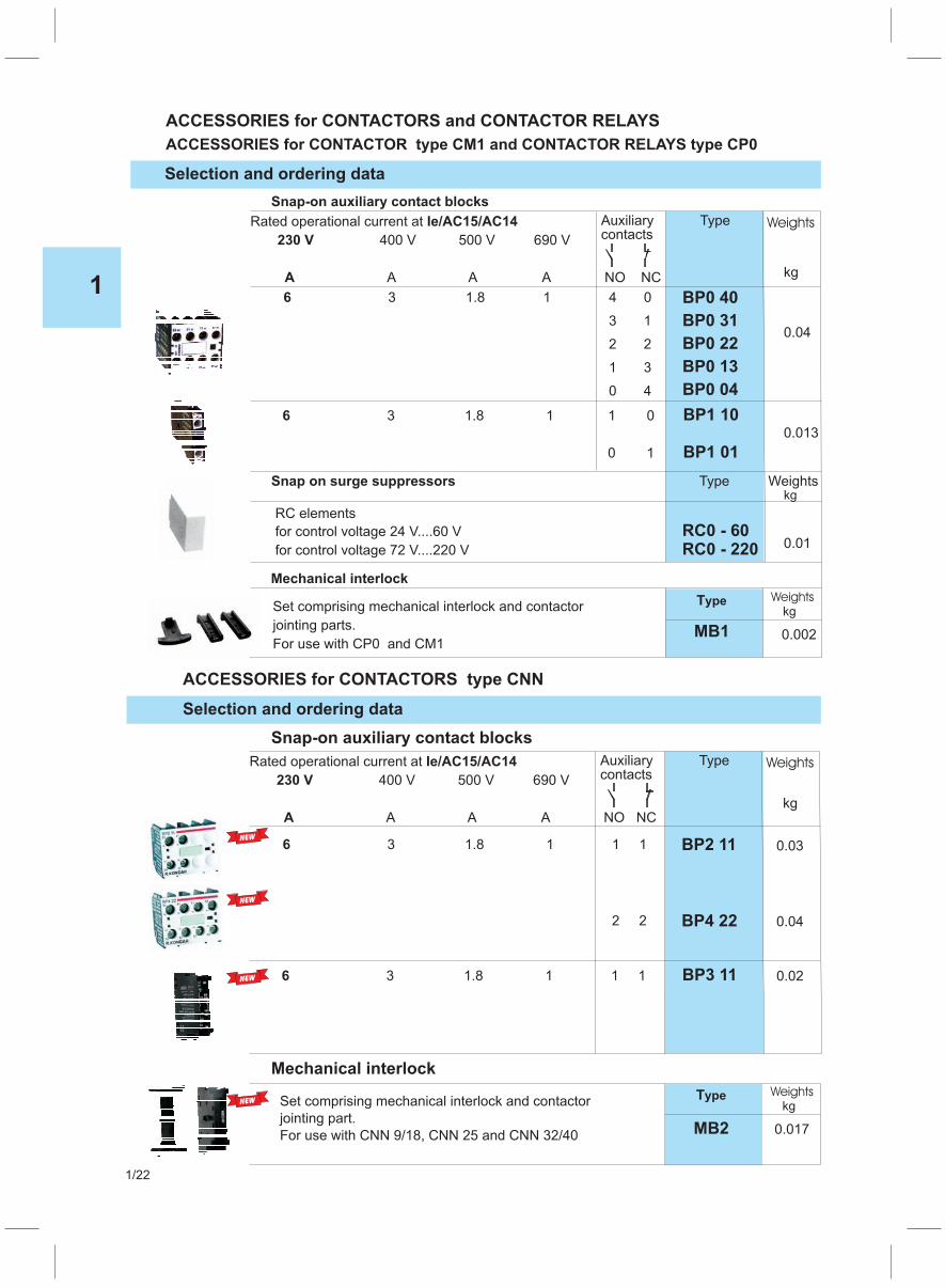
ACCESSORIES for CONTACTORS and CONTACTOR RELAYS
ACCESSORIES for CONTACTOR type CM1 and CP0CONTACTOR RELAYS type
ACCESSORIES for CONTACTORS type CNN
Selection and ordering data
Selection and ordering data
Snap-on auxiliary contact blocks
Rated operational current at
400 V 500 V 690 V
A A A NO NC
Ie/AC15/AC14
230 V
A
Auxiliary Typecontacts
BP0 40
BP0 31
BP0 22
BP0 13
BP0 04
3 1.8 1 4 0
3 1
2 2
1 3
0 4
6
BP1 10
BP1 01
3 1.8 1 1 0
0 1
6
RC elements
for control voltage 24 V....60 V
for control voltage 72 V....220 V
RC0 - 60RC0 - 220
Mechanical interlock
TypeSet comprising mechanical interlock and contactor
jointing parts.
For use with CP0 and CM1MB1
Weights
Snap on surge suppressors Type Weights
Weights
kg
kg
kg
0.04
0.013
0.01
0.002
Snap-on auxiliary contact blocks
Rated operational current at
400 V 500 V 690 V
A A A NO NC
Ie/AC15/AC14
230 V
A
Auxiliary Typecontacts
BP2 11
BP4 22
3 1.8 1 1 16
2 2
BP3 113 1.8 1 1 16
Mechanical interlock
Weights
kg
0.04
0.03
0.02
WeightsTypeSet comprising mechanical interlock and contactor
jointing part.
For use with CNN 9/18, CNN 25 and CNN 32/40
kg
MB2 0.017
1
1/22
NEW
NEW
NEW
NEW

Kits for assembling CNNK contactorsTo optimise contactor stock management, a kit is available to transform normal three-pole contactorsinto CNNK types for power factor correction.The table to the below indicates which kits to purchase depending on the standard contactor in stock.
CNN 9 BPK1 CNNK 10
TYPE of CONTACTOR TYPE ofCAPACITOR BLOCK
TYPE ofCAPACITOR CONTACTOR
CNN 12 BPK1 CNNK 12
CNN 18 BPK1 CNNK 15
CNN 25 BPK1 CNNK 20
BPK1
ACCESSORIES for CONTACTORS type CNN
Selection and ordering data
Selection and ordering data
Surge supressors
Additional terminal blocks
For contactor Description Part No.
For contactor Description Part No.
CN(B, P) 21
CN(B, P) 31
CN(B, M) 9 - 30
CNM 16 - CNM 36
CNN 32 - CNN 40
601478
601479
603311
CNM 45 - CNM 60
CNM 75 - CNM 110
RC elementsfor control voltage 24....60 V
for control voltages 110...240 V
for mounting on the front cover: B
for mounting on the coil: Afor mounting on the front cover: B
for mounting on the coil: A
739968
739908
739914
739913
Set of 2 additional terminal blocksfor connecting bare cables 25 mm
2
Set of 2 additional terminal blocksfor connecting bare cables 35 mm
2
Set of 6 terminal covers forprotection against inadvertentcontact with the exposed busbarconnections(DIN VDE 0106 Part 100)
Weights
Weights
0.210
0.070
0.07
kg
kg
ACCESSORIES for CONTACTORS type CNM
0.014
0.0150.020
0.019
1
1/23
NEW

SPARE PARTS for CONTACTORS and CONTACTOR RELAYES
SPARE PARTS CONTACTOR RELAYES typefor CONTACTOR type CM1 and CP0
SPARE PARTS for CONTACTORS type CNN
Selection and ordering data
Selection and ordering data
AC
AC
coils
coils
Rated frequency
Rated frequency
Control voltage
Control voltage
Hz
Hz
50 / 60
50 / 60
50 / 60
Vfor
for V
CNN 9
CM1CP0
-CNN 25 Coil
Coil
603028 / 603029
S32617 / 503645
603030 / 603031
S32619 503644/
603032 / 603033
S32620 503643/
603034 / 603035
S32621 / 501729
603036 / 603037
501432 / 503642
603038 / 603039
S32622 503641/
2448
110220230380400
2448
110220230380400
603040 / 603041
503639 / 503640
CNN 32 - CNN 40 Coil 603042 / 603043603044 / 603045603046 / 603047603048 / 603049603050 / 603051603052 / 603053
2448
110220230380400 603054 / 603055
Part N.
Part N.
Weights
Weights
kg
kg
0.050
0.042
0.150
Selection and ordering data
Auxiliary contact blocks
SPARE PARTS for CONTACTORS CNM 36 - CNM 400
For contactor Description Part N.
For contactor Description Part N.
CNM 36 - CNM 110
CNM 36 - CNM 110
Block with auxiliary contacts left, 1NO+1NC
Block with auxiliary contacts right, 1NO+1NC
Add.l block with auxiliary contacts left, 1NO+1NC
Add. block with auxiliary contacts right,1NO+1NC
733889S
733890S
733891S
733892S
Block with auxiliary DC contacts right, 1NO+1NC 733888S
CNM 140 - CNM 400
,
155129S
155113S
Block with auxiliary contacts left, 1NO+1NC
Block with auxiliary contacts right, 1NO+1NC
Add. block with auxiliary contacts left,
Add. block with auxiliary contacts right
1NO+1NC
1NO+1NC
155089S
155087S
CNM 75 733845S
CNM 90 733846S
CNM 110 733847S
CNM 140 155101S
CNM 170 155102S
CNM 200 155103S
CNM 250 155588S
CNM 315 155527S
CNM 400 155506S
Arc chamber
Weights
Weights
kg
kg
0.042
0.075
0.48
0.48
0.48
1.16
1.16
1.16
1.88
1.88
1.88
NEW
1
1/24
NEW
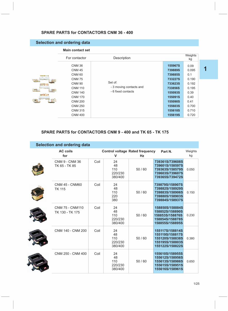
SPARE PARTS for CONTACTORS CNM 9 - 400 and TK 65 - TK 175
Selection and ordering data
AC coils
for
TK 65 - TK 85
TK 115
TK 130 - TK 175
CNM 9 - CNM 36 Coil 739361S/739608S739601S/158597S739363S/158579S739603S/739607S
2448
110220/230380/400 739365S/739472S
CNM 45 - CNM60 Coil 739879S/158907S739882S/158929S739883S/158906S739880S/158903S
2448
110220380 739884S/158937S
CNM 75 - CNM110 Coil 158850S/158884S158852S/158890S158853S/158876S158854S/158878S
2448
110220/230380/400 158855S/158895S
CNM 140 - CNM 200 Coil 155117S/158814S155119S/158817S155120S/158838S155195S/158803S
2448
110220/230380/400 155122S/158822S
CNM 250 - CNM 400 Coil 155610S/158955S155612S/158956S155613S/158986S155615S/158951S
2448
110220/230380/400
Part N. Weights
kg
0.050
0.150
0.230
0.380
0.650
Rated frequencyControl voltage
Hz
50 / 60
50 / 60
50 / 60
50 / 60
50 / 60
V
155616S/158961S
For contactor Description
Main contact set
CNM 36 155967S
Set of:
- 3 moving contacts and
- 6 fixed contacts
CNM 45 739889S
CNM 60 739885S
CNM 75 733227S
CNM 90 733623S
CNM 110 733856S
CNM 140 155093S
CNM 170 155091S
CNM 200 155090S
CNM 250 155603S
CNM 315 155618S
CNM 400 155619S
kgWeights
0.09
0.095
0.190
0.192
0.195
0.39
0.40
0.710
0.720
0.1
0.41
0.700
SPARE PARTS for CONTACTORS CNM 36 - 400
Selection and ordering data
1
1/25
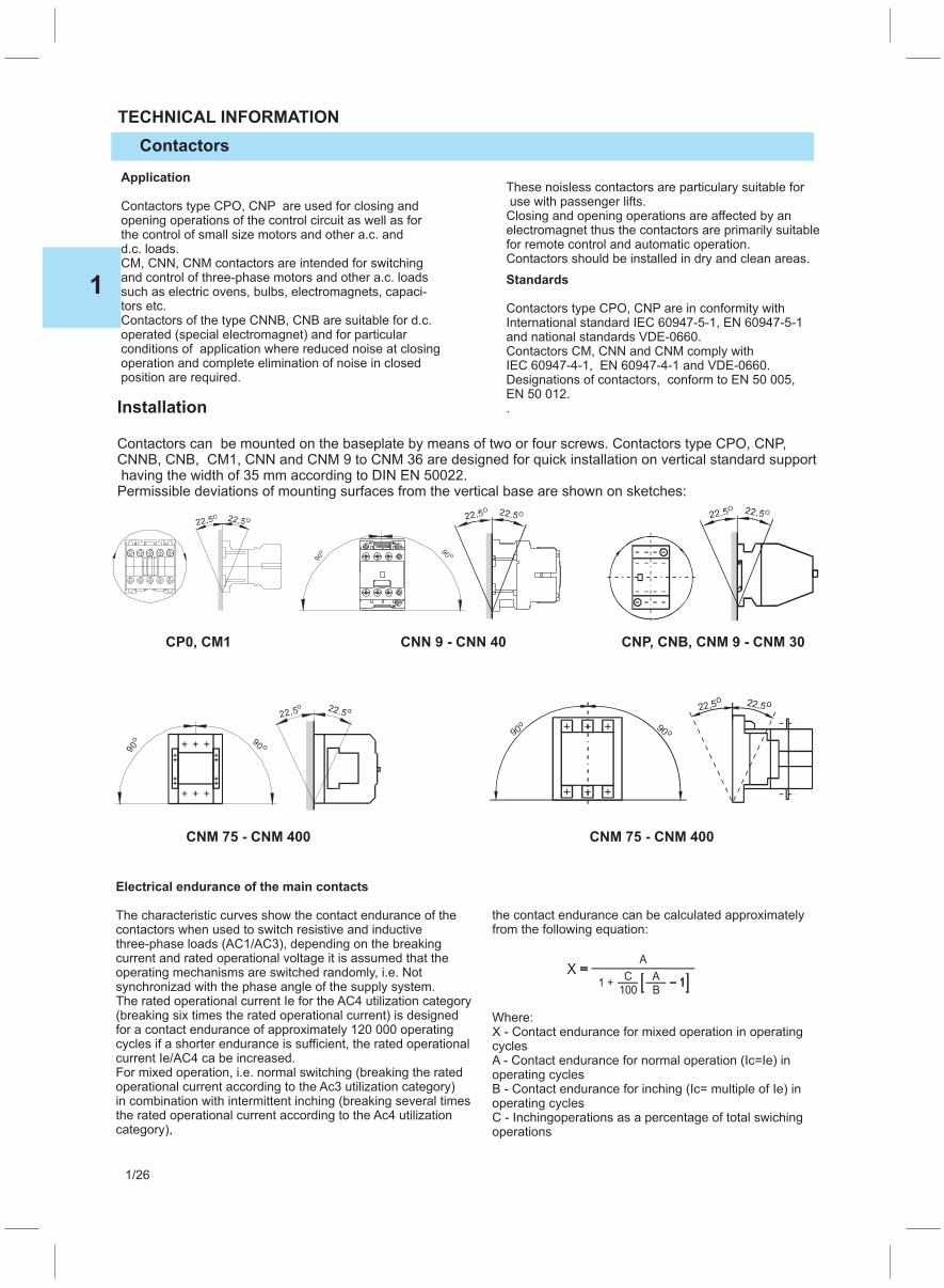
Application
Contactors type CPO, CNP are used for closing andopening operations of the control circuit as well as forthe control of small size motors and other a.c. andd.c. loads.CM, CNN, CNM contactors are intended for switchingand control of three-phase motors and other a.c. loadssuch as electric ovens, bulbs, electromagnets, capaci-tors etc.Contactors of the type CNNB, CNB are suitable for d.c.operated (special electromagnet) and for particularconditions of application where reduced noise at closingoperation and complete elimination of noise in closedposition are required.
These noisless contactors are particulary suitable foruse with passenger lifts.Closing and opening operations are affected by anelectromagnet thus the contactors are primarily suitablefor remote control and automatic operation.Contactors should be installed in dry and clean areas.
Standards
Contactors type CPO, CNP are in conformity withInternational standard IEC 60947-5-1, EN 60947-5-1and national standards VDE-0660.Contactors CM, CNN and CNM comply withIEC 60947-4-1, EN 60947-4-1 and VDE-0660.Designations of contactors, conform to EN 50 005,EN 50 012..
Contactors can be mounted on the baseplate by means of two or four screws. Contactors type CPO, CNP,CNNB, CNB, CM1, CNN and CNM 9 to CNM 36 are designed for quick installation on vertical standard supporthaving the width of 35 mm according to DIN EN 50022.Permissible deviations of mounting surfaces from the vertical base are shown on sketches:
Installation
CP0, CM1 CNN 9 - CNN 40 CNP, CNB, CNM 9 - CNM 30
CNM 75 - CNM 400CNM 75 - CNM 400
TECHNICAL INFORMATION
Contactors
Electrical endurance of the main contacts
The characteristic curves show the contact endurance of thecontactors when used to switch resistive and inductivethree-phase loads (AC1/AC3), depending on the breakingcurrent and rated operational voltage it is assumed that theoperating mechanisms are switched randomly, i.e. Notsynchronizad with the phase angle of the supply system.The rated operational current Ie for the AC4 utilization category(breaking six times the rated operational current) is designedfor a contact endurance of approximately 120 000 operatingcycles if a shorter endurance is sufficient, the rated operationalcurrent Ie/AC4 ca be increased.For mixed operation, i.e. normal switching (breaking the ratedoperational current according to the Ac3 utilization category)in combination with intermittent inching (breaking several timesthe rated operational current according to the Ac4 utilizationcategory),
the contact endurance can be calculated approximatelyfrom the following equation:
Where:X - Contact endurance for mixed operation in operatingcyclesA - Contact endurance for normal operation (Ic=Ie) inoperating cyclesB - Contact endurance for inching (Ic= multiple of Ie) inoperating cyclesC - Inchingoperations as a percentage of total swichingoperations
1
1/26

0.2
1.1 1.5 2.2 3 4 5.5 7.57.5 11 15 18.5
0.5
0.5
1
1
2
2
5
5
10
10
CNN 9
CM1
CNN 9
CM1
CNN 12
CNN 18
CNN 18
CNN 25
CNN 32
CNN 32
CNN 40
AC3 - 400V Rated motor power Pn (kW)
Ele
ctr
ical endura
nce (
x10
op.c
.)6
Ele
ctr
ica
l e
nd
ura
nce
(x1
0o
p.c
.)5
Diagram of electrical endurance of CM, CNN contactors - AC3
Diagram of electrical endurance of CM, CNN contactors - AC4
0.2
1.10.750.5 1.5 2.2 3 4 6.5 7.5
CNN 12 CNN 25 CNN 40
AC4 - 400V Rated motor power Pn (kW)
Diagram of electrical endurance of CP0 and CNP contactor relayes
Ic --- breaking current
Utilization category AC15
1
1/27
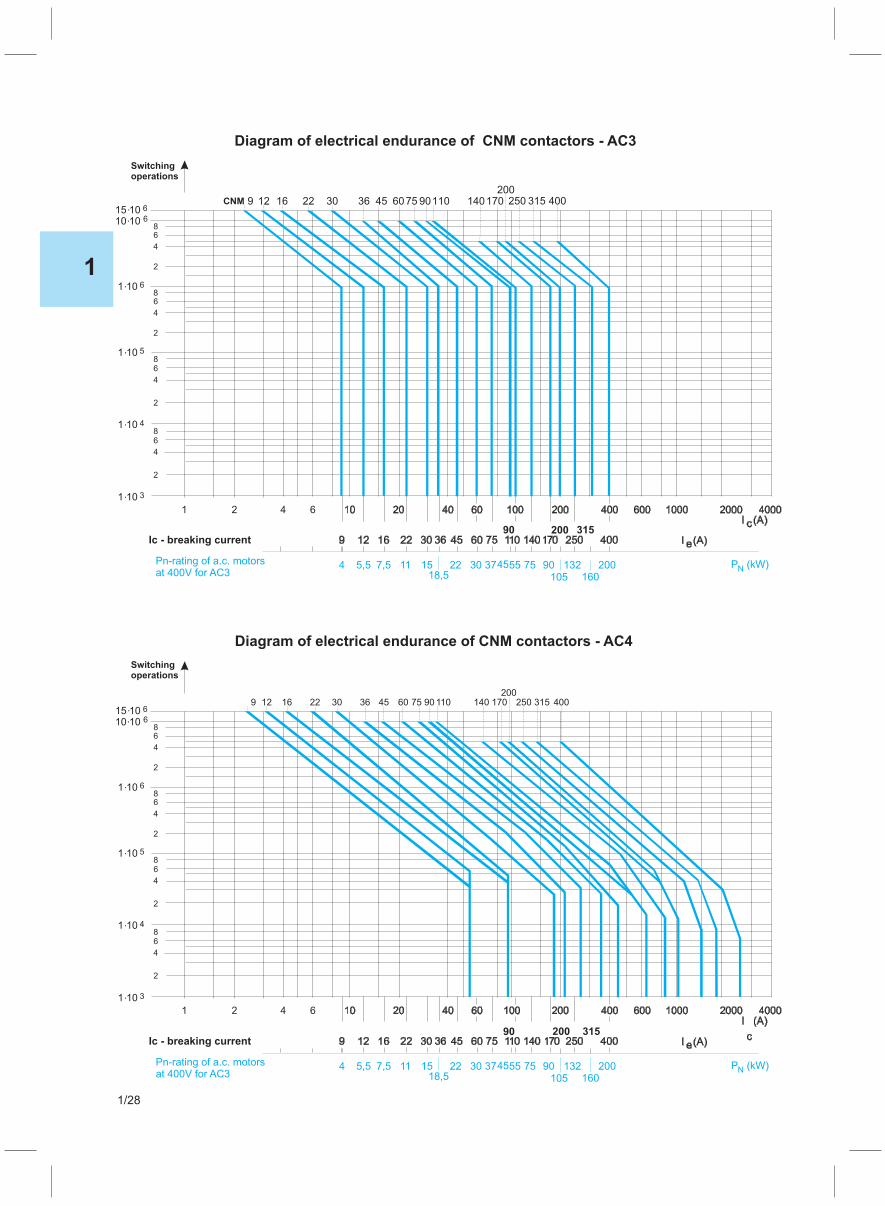
CNM
Switchingoperations
1 2 4 6
15.10 6
10.10 68
8
8
8
6
6
6
6
4
4
4
4
2
2
2
2
1.10 6
1.10 5
1.10 4
1.10 3
200315 4001701401109075604536302216129 250
90 200 315Ic - breaking current
4 5,5 7,5 11 1518,5
22 30 37 55 75 90 132 200 P (kW)NPn-rating of a.c. motorsat 400V for AC3
45
160105
Diagram of electrical endurance of CNM contactors - AC3
Switchingoperations
1 2 4 6
15.10 6
10.10 68
8
8
8
6
6
6
6
4
4
4
4
2
2
2
2
1.10 6
1.10 5
1.10 4
1.10 3
400315250200
1701401109075604536302216129
Ic - breaking current
4 5,5 7,5 11 1518,5
22 30 37 55 75 90 132 200 P (kW)NPn-rating of a.c. motorsat 400V for AC3
90
45
160105
315200
Diagram of electrical endurance of CNM contactors - AC4
1
1/28
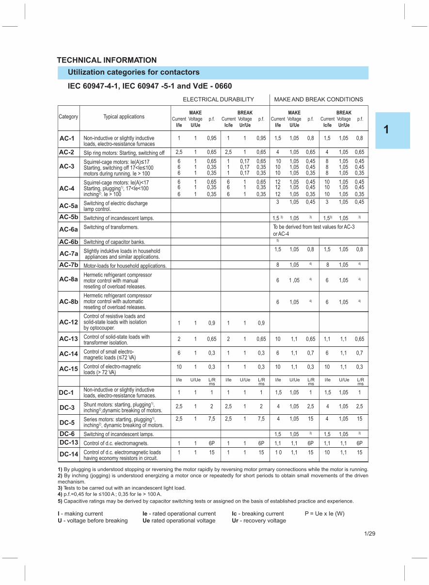
Utilization categories for contactors
TECHNICAL INFORMATION
IEC 60947-4-1, IEC 60947 -5-1 and VdE - 0660
ELECTRICAL DURABILITY MAKE AND BREAK CONDITIONS
Category Typical applicationsMAKE
Current Voltage p.f.
I/Ie U/Ue
BREAK
Current Voltage p.f.
Ic/Ie Ur/Ue
MAKE
Current Voltage p.f.
I/Ie U/Ue
BREAK
Current Voltage p.f.
Ic/Ie Ur/Ue
Non-inductive or slightly inductiveloads, electro-resistance furnaces
Slip ring motors: Starting, switching off
Squirrel-cage motors: Ie(A) 17≤
Starting, switching off 17<Ie 100≤
motors during running. Ie > 100
Squirrel-cage motors: Ie(A)<17Starting, plugging , 17<Ie<1001)
inching . Ie > 1002)
Switching of electric dischargelamp control.
Switching of incandescent lamps.
Switching of transformers.
Switching of capacitor banks.
Slightly induktive loads in householdappliances and similar applications.
Motor-loads for household applications.
Hermetic refrigerant compressormotor control with manualreseting of overload releases.
Hermetic refrigerant compressormotor control with automaticreseting of overload releases.
Control of resistive loads andsolid-state loads with isolationby optocouper.
Control of solid-state loads withtransformer isolation.
Control of small electro-magnetic loads ( 72 VA)≤
Control of electro-magneticloads (> 72 VA)
Non-inductive or slightly inductiveloads, electro-resistance furnaces.
Shunt motors: starting, plugging ,1)
inching ,dynamic breaking of motors.2)
Series motors: starting, plugging ,1)
inching , dynamic breaking of motors.2)
Switching of incandescent lamps.
Control of d.c. electromagnets.
Control of d.c. electromagnetic loadshaving economy resistors in circuit.
1 1 0,95 1 1 0,95 1,5 1,05 0,8 1,5 1,05 0,8
2,5 1 0,65 2,5 1 0,65 4 1,05 0,65 4 1,05 0,65
6 1 0,65 1 0,17 0,65 10 1,05 0,45 8 1,05 0,456 1 0,35 1 0,17 0,35 10 1,05 0,45 8 1,05 0,456 1 0,35 1 0,17 0,35 10 1,05 0,35 8 1,05 0,35
6 1 0,65 6 1 0,65 12 1,05 0,45 10 1,05 0,456 1 0,35 6 1 0,35 12 1,05 0,45 10 1,05 0,45
6 1 0,35 6 1 0,35 12 1,05 0,35 10 1,05 0,35
3 1,05 0,45 3 1,05 0,45
1,5 3) 1,05 3) 1,53) 1,05 3)
To be derived from test values for AC-3
or AC-45)
1,5 1,05 0,8 1,5 1,05 0,8
8 1,05 4) 8 1,05 4)
6 1 ,05 4) 6 1,05 4)
6 1,05 4) 6 1,05 4)
1 1 0,9 1 1 0,9
2 1 0,65 2 1 0,65 10 1,1 0,65 1,1 1,1 0,65
6 1 0,3 1 1 0,3 6 1,1 0,7 6 1,1 0,7
10 1 0,3 1 1 0,3 10 1,1 0,3 10 1,1 0,3
1 1 1 1 1 1 1,5 1,05 1 1,5 1,05 1
2,5 1 2 2,5 1 2 4 1,05 2,5 4 1,05 2,5
2,5 1 7,5 2,5 1 7,5 4 1,05 15 4 1,05 15
1,5 1,05 3) 1,5 1,05 3)
1 1 6P 1 1 6P 1,1 1,1 6P 1,1 1,1 6P
1 1 15 1 1 15 1 0 1,1 15 10 1,1 15
1) By plugging is understood stopping or reversing the motor rapidly by reversing motor prmary connectioons while the motor is running.
2) By inching (jogging) is understood energizing a motor once or repeatedly for short periods to obtain small movements of the driven
mechanism.
3) Tests to be carred out with an incandescent light load.
4) p.f.=0,45 for Ie 100 A ; 0,35 for Ie > 100 A.≤
5) Capacitive ratings may be derived by capacitor switching tests or assigned on the basis of established practice and experience.
I - making current Ie - rated operational current Ic - breaking current P = Ue x Ie (W)
U - voltage before breaking Ue rated operational voltage Ur - recovery voltage
l/le U/Ue L/Rms
l/le U/Ue L/Rms
l/le U/Ue L/Rms
l/le U/Ue L/Rms
AC-1
AC-2
AC-3
AC-4
AC-5a
AC-5b
AC-6a
AC-6b
AC-7a
AC-7b
AC-8a
AC-8b
AC-12
AC-13
AC-14
AC-15
DC-1
DC-3
DC-5
DC-6
DC-13
DC-14
1
1/29
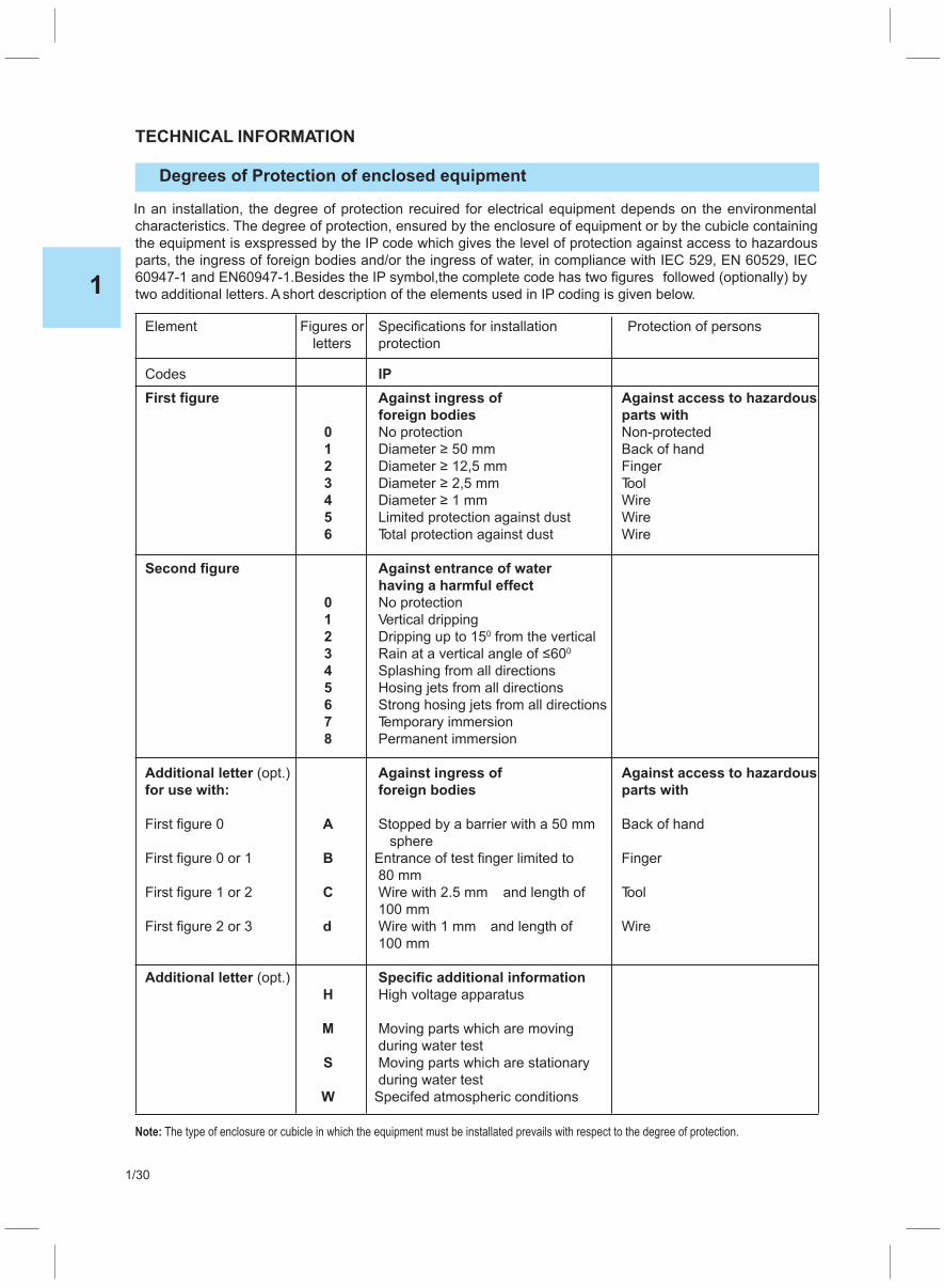
Degrees of Protection of enclosed equipment
TECHNICAL INFORMATION
In an installation, the degree of protection recuired for electrical equipment depends on the environmental
characteristics. The degree of protection, ensured by the enclosure of equipment or by the cubicle containing
the equipment is exspressed by the IP code which gives the level of protection against access to hazardous
parts, the ingress of foreign bodies and/or the ingress of water, in compliance with IEC 529, EN 60529, IEC
60947-1 and EN60947-1.Besides the IP symbol,the complete code has two figures followed (optionally) by
two additional letters. A short description of the elements used in IP coding is given below.
Element Figures or Specifications for installation Protection of persons
letters protection
Codes IP
First figure Against ingress of Against access to hazardous
foreign bodies parts with
0 No protection Non-protected
1 Diameter 50 mm≥ Back of hand
2 Diameter 12,5 mm≥ Finger
3 Diameter 2,5 mm≥ Tool
4 Diameter 1 mm≥ Wire
5 Limited protection against dust Wire
6 Total protection against dust Wire
Second figure Against entrance of water
having a harmful effect
0 No protection
1 Vertical dripping
2 Dripping up to 15 from the vertical0
3 Rain at a vertical angle of 60≤0
4 Splashing from all directions
5 Hosing jets from all directions
6 Strong hosing jets from all directions
7 Temporary immersion
8 Permanent immersion
Additional letter (opt.) Against ingress of Against access to hazardous
for use with: foreign bodies parts with
First figure 0 A Stopped by a barrier with a 50 mm Back of hand
sphere
First figure 0 or 1 B Entrance of test finger limited to Finger
80 mm
First figure 1 or 2 C Wire with 2.5 mm and length of Tool
100 mm
First figure 2 or 3 d Wire with 1 mm and length of Wire
100 mm
Additional letter (opt.) Specific additional information
H High voltage apparatus
M Moving parts which are moving
during water test
S Moving parts which are stationary
during water test
W Specifed atmospheric conditions
Note: The type of enclosure or cubicle in which the equipment must be installated prevails with respect to the degree of protection.
1
1/30

Over voltage limiter (surge suppressors)
TECHNICAL INFORMATION
When cutting off the inductive circuits the over voltage appears. The over voltage can damage used equip -
ment that is why it is useful to limit the amplitudes and duration of the over voltage with some of the blocking
sistems. In practice this overvoltages may disconnect the coil of the contactor. Cutting off the coil (wounding)
is connected with high frequencies and remarkable amplitudes (several KV) but regularly with short duration.
With reference to the place of the implementation, it is frequently necessary to limit the over voltage, because
they can cause problems such as:
� Radio interference
� Interference with the electronic devices and components (programmable automation)
� Damage of the electronic systems and components (diodes, bridges, etc.)
The most often used systems for over voltage blockade are:
� R-C elements
� Varistors
� Diodes (with or without resistor in serial)
The advantages and disadvantages when using these elements are following:
R-C Advantages
� Theoretically can be used with AC and DC circuits
� Big limitation of voltage peaks
� Time stability of R-C elements
Disadvantages
� Resonance
� Limitedinfuenceontheperiodofactivatingcontactor
� Contactors with DC magnets without current limiting resistor, diffculties with limiting over voltage
due to big powers.
Varistors Advantages
� Very short period of cutting off, so that there is no infuence on the contactor activity
� Without resonance
� Usage in AC and DC circuits
Disadvantges
� Not enough limitation of voltage peaks
� Growing old equipment because of prolonged thermal loading
Diodes Advantages
� Optimalmuffing
Disadvantges
� Delay when cutting off
� Only DC circuits
1
1/31

Voltage drop in main circuits and current transformers
TECHNICAL INFORMATION
Voltage drop in main circuitsWhen the distance between the energy source and the consumer is long, it is advisable to calculate the
voltage drop for example at the moment of starting the motor (when tripping current gets peak value)
and to check if the remaining voltage is in the consumers working limits.
For calculating the voltage drop the following formula has been used:
ΔV = Δ V *L*I0
Where ΔV = voltage drop in Volts
ΔV = unit voltage drop from table0
L = cable length in km
I = current
This formula is valid for calculating the voltage drop for motors, when in suffcient voltage can disable
running up of the motor.
In the table below are listed active and reactive resistances of the cables for calculating the voltage drop
when the power factor is different from 0.8. In that case it should be used the following formulas :
Single phase ΔV = 2 I*L (cos f + X sinf)l
Three phase ΔV = 3 I*L (cos f + X sinf)l
Rated Single wire cable Two and three wire cable
cross-section active reactive DC AC cos = 0,8f active reactive DC AC cos = 0,8f
resistance resistance 1 fase 3 fases resistance resistance 1 fase 3 fases
r x ΔV ΔV ΔV r x ΔV ΔV ΔV[mm ]2 [V/Akm] [V/Akm] [V/Akm] [V/Akm] [V/Akm] [V/Akm]
1 22.1 0.176 44.2 35.6 30.8 22.5 0.125 45.0 36.1 31.3
1.5 14.8 0.168 29.7 23.9 20.7 15.1 0.118 30.2 24.3 21.0
2.5 8.91 0.155 17.8 14.4 12.5 9.08 0.109 18.2 14.7 12.7
4 5.57 0.143 11.1 9.08 7.87 5.68 0.101 11.4 9.21 7.98
6 3.71 0.135 7.41 6.10 5.28 3.78 0.0955 7.56 6.16 5.34
10 2.24 0.119 4.47 3.72 3.22 2.27 0.0861 4.55 3.73 3.24
16 1.41 0.112 2.82 2.39 2.07 1.43 0.0817 2.87 2.39 2.07
25 0.889 0.106 1.78 1.55 1.34 0.907 0.0813 1.81 1.55 1.34
35 0.641 0.101 1.28 1.15 0.993 0.654 0.0783 1.31 1.14 0.988
50 0.473 0.101 0.947 0.878 0.760 0.483 0.0779 0.966 0.866 0.750
70 0.328 0.0965 0.655 0.641 0.555 0.334 0.0751 0.667 0.624 0.541
95 0.236 0.975 0.472 0.494 0.428 0.241 0.0762 0.482 0.476 0.472
120 0.187 0.0939 0.373 0.413 0.358 0.190 0.0740 0.381 0.394 0.342
150 0.152 0.0928 0.304 0.356 0.308 0.156 0.0745 0.311 0.341 0.295
185 0.122 0.0908 0.243 0.306 0.265 0.124 0.0742 0.247 0.289 0.250
240 0.0933 0.0902 0.185 0.259 0.224 0.0954 0.0752 0.188 0.245 0.212
Current transformersTypical for the current transformers is that the power on the secondary has got infuence on the preci-
sion of the transmitting ratio as big as the phase angle.
The power of the secondary in the current transformer is made by the impendence of cables and at-
tached instruments. The cable consumption is shown in the table below.
Secondary Consumption per meter of the two-wire cable at 20 C0
coil for different cross section
1 mm2 1,5 mm2 2,5 mm2 4,5 mm2 6 mm2 10 mm2 16 mm2
A VA VA VA VA VA VA VA
5 1 0,685 0,41 0,254 0,169 0,0975 0,062
1 0,04 0,0274 0,0164 0,0102 0,0068 0,0039 0,0025
NOTE: Each temperature increased for 10 C is followed by increasing of the consumption in VA for 4%.0
Consumption of instruments is idefned by the producer.Here are listed just informative values for some instru-
ments.
Electromagnetic ammetar 1,1 VA Cos f - meter 0,5 VA Counter 0,5 VA
Wattmeter - Varmeter 0,5 VA Ammeter - printer 0,5-1,5-2,5 VA Wattmeter - printer 0,5 VA
1
1/32

Auxiliary current circuits
TECHNICAL INFORMATION
Voltage drop in auxiliary current circuit
The maximal cable length with allowed maximal voltage drop of 5 % forAC and DC circuits is calculated
from the formula:
L = L / P where is:0
L = Maximal cable length in km
L0=Cable coeffcient depending on the voltage drop and the cross section
P = Active load power when tripping (for AC=VA cosf)
The maximal length of the cable depends on the allowed voltage drop and it is changing proportion-
ally.
Ex. for 10 % voltage drop the cable length has been doubled.
NOTE: The voltage drop is not dependent only on the length and the cross section of the cable, but as
well on all other resistances (clamps, contacts), which are connected in the auxiliary circuit.
Rated
cross-section 24V 48V 110V 220/230V 380/400V 500V
[mm ]2 [ kmW] [kmW] [ kmW] [kmW] [ kmW] [kmW]
1,5 1,08 4,32 22,7 90,8 272 471
2,5 1,80 7,20 37,8 151 453 785
4 2,88 11,5 60,5 242 725 1260
Coeffcient L0
1
1/33
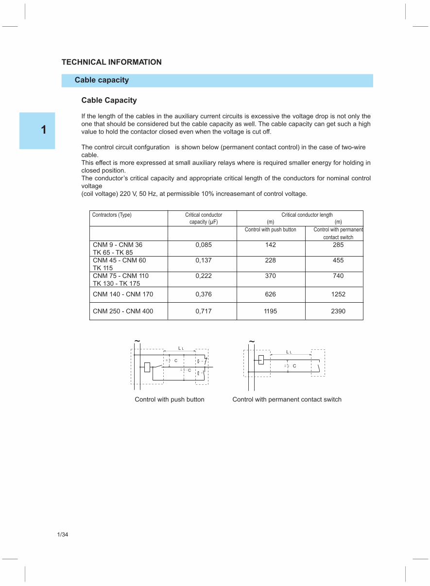
Cable capacity
TECHNICAL INFORMATION
Cable Capacity
If the length of the cables in the auxiliary current circuits is excessive the voltage drop is not only the
one that should be considered but the cable capacity as well. The cable capacity can get such a high
value to hold the contactor closed even when the voltage is cut off.
The control circuit confguration is shown below (permanent contact control) in the case of two-wire
cable.
This effect is more expressed at small auxiliary relays where is required smaller energy for holding in
closed position.
The conductor’s critical capacity and appropriate critical length of the conductors for nominal control
voltage
(coil voltage) 220 V, 50 Hz, at permissible 10% increasemant of control voltage.
Contractors (Type) Critical conductor Critical conductor length
capacity ( F)μ (m) (m)
Control with push button Control with permanent
contact switch
CNM 9 - CNM 36 0,085 142 285
TK 65 - TK 85
CNM 45 - CNM 60 0,137 228 455
TK 115
CNM 75 - CNM 110 0,222 370 740
TK 130 - TK 175
CNM 140 - CNM 170 0,376 626 1252
CNM 250 - CNM 400 0,717 1195 2390
Control with push button Control with permanent contact switch
1
1/34
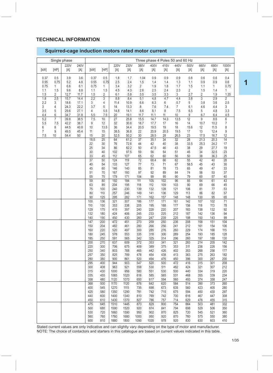
Squirred-cage induction motors rated motor current
TECHNICAL INFORMATION
Single phase Three phase 4 Poles 50 and 60 Hz
220V 240V 220V 230V 380V 400V 415V 440V 500V 660V 690V 1000V
[kW] [HP] [A] [A] [kW] [HP] [A] [A] [A] [A] [A] [A] [A] [A] [A] [A]
0.37 0.5 3.9 3.6 0.37 0.5 1.8 1.7 1.04 0.9 0.9 0.9 0.8 0.6 0.6 0.4
0.55 0.75 5.2 4.8 0.55 0.75 2.5 2.4 1.5 1.4 1.4 1.3 1.1 0.9 0.9 0.6
0.75 1 6.6 6.1 0.75 1 3.4 3.2 2 1.9 1.8 1.7 1.5 1.1 1 0.75
1.1 1.5 9.6 8.8 1.1 1.5 4.5 4.3 2.6 2.5 2.4 2.3 2 1.5 1.4 1
1.5 2 12.7 11.7 1.5 2 6.1 5.8 3.5 3.5 3.3 3 2.7 2 1.9 1.35
1.8 2.5 15.7 14.4 2.2 3 8.8 8.4 5.1 4.8 4.7 4.4 3.8 3 2.9 2
2.2 3 18.6 17.1 3 4 11.4 10.9 6.6 6.3 6 5.7 5 3.8 3.6 2.5
3 4 24.3 22.2 3.7 5 14 13.3 8 7.6 7.4 7 6.1 4.6 4.4 3
3.5 5 29.6 27.1 4 5.5 14.8 14.1 8.6 8.1 8 7.5 6.5 5 4.8 3.3
4.4 6 34.7 31.8 5.5 7.5 20 19.1 11.7 11.1 11 10 9 6.7 6.4 4.5
5.2 7 39.8 36.5 7.5 10 27 25.8 15.5 14.7 14.3 13.5 12 9 8.6 6
5.5 7.5 42.2 38.7 9 12 32 30.6 18.7 17.7 17 16 14 10.7 10.2 7
6 8 44.5 40.8 10 13.5 36 34.4 20.5 19.5 19 18 15.6 12 11.5 8
7 9 49.5 45.4 11 15 38.5 36.8 22 20.9 20.5 19.5 17 13 12.4 9
7.5 10 54.4 50 15 20 52.5 50.2 30 28.5 28 26.5 23 17.5 16.7 12
18.5 25 64 61.2 37 35.1 34 32 28 21.3 20.3 14
22 30 76 72.6 44 42 40 38 33.5 25.3 24.2 17
25 34 86 82.2 50 47.5 46 43 38 29 27.7 19
30 40 102 97.5 59 56 54 51 45 34 32.5 23
33 45 112 107 65 62 60 56 50 38 36.3 25
37 50 124 119 72 68.4 66 62 55 42 40 28
40 54 133 127 77 73 71 67 58.5 45 43 30
45 60 146 140 85 81 78 73 65 49 47 33
51 70 167 160 97 92 89 84 74 56 53 37
55 75 179 171 104 99 95 90 79 60 57 40
59 80 192 184 111 105 102 96 85 64 61 43
63 85 204 195 118 112 109 103 90 69 66 45
75 100 240 230 139 132 128 121 106 81 77 53
80 110 257 246 149 141 136 129 113 86 82 57
90 125 295 282 171 162 157 148 148 130 95 65
100 136 321 307 186 177 171 161 142 107 102 71
110 150 353 338 205 195 188 177 156 118 113 78
129 175 415 397 240 228 220 207 183 138 132 92
132 180 424 406 245 233 225 212 187 142 136 94
140 190 450 430 260 247 239 225 198 150 143 99
147 200 472 451 273 259 250 236 208 158 151 104
150 204 482 461 280 266 256 241 212 161 154 106
160 220 520 497 300 285 276 260 229 174 166 115
180 245 578 553 335 318 306 289 254 193 185 128
185 250 591 565 342 325 314 296 260 197 188 130
200 270 637 609 372 353 341 321 283 214 205 142
220 300 706 675 409 389 375 353 311 236 226 156
250 340 803 768 465 442 426 402 353 268 256 177
257 350 825 789 478 454 438 413 363 275 263 182
280 380 900 861 520 494 476 450 396 300 287 200
295 400 944 903 547 520 500 472 416 315 301 208
300 408 963 921 558 530 511 482 424 321 307 212
315 430 1000 956 580 551 530 500 440 334 319 220
335 455 1065 1020 616 585 565 531 468 355 339 234
358 480 1120 1070 650 617 594 560 493 374 358 247
368 500 1170 1120 676 642 620 584 514 390 373 260
400 545 1270 1115 735 698 673 635 560 423 405 280
425 580 1350 1290 781 742 715 675 594 450 430 297
440 600 1400 1340 810 769 742 700 616 467 447 308
450 610 1430 1370 827 786 757 714 629 476 455 315
475 645 1510 1445 873 829 800 754 664 503 481 332
500 680 1590 1520 920 874 841 794 698 529 506 350
530 720 1660 1590 950 902 870 825 720 545 521 360
560 760 1760 1680 1000 950 920 870 760 575 550 380
600 810 1880 1800 1090 1035 978 920 830 630 603 410
Stated current values are only indicative and can slightly vary depending on the type of motor and manufacturer.
NOTE: The choice of contactors and starters in this catalogue are based on current values indicated in this table.
1
1/35
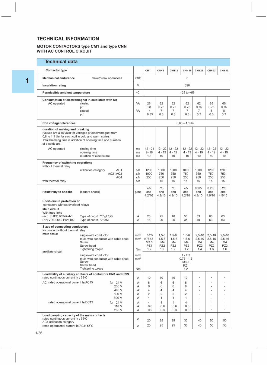
Technical data
TECHNICAL INFORMATION
CM1 CNN 18CNN12CNN9 CNN 40CNN32
MOTOR CONTACTORS type CM1 and type CNN
WITH AC CONTROL CIRCUIT
Contactor type
Mechanical endurance make/break operations x106 5
Insulation rating V 690
Permissible ambient temperature oC - 25 to +55
Consumption of electromagnet in cold state with Un
AC operated closing VA 26 62 62 62 62 65 65
p.f. 0.8 0.75 0.75 0.75 0.75 0.75 0.75
closed VA 4 7 7 7 7 8 8
p.f. 0.35 0.3 0.3 0.3 0.3 0.3 0.3
Coil voltage tolerances
duration of making and breaking
(values are also valid for voltages of electromagnet from
0,8 to 1,1 Un for each coil in cold and warm state).
Total breaking time is addition of opening time and duration
of electric arc.
AC operated closing time ms 12 - 21 12 - 22 12 - 22 12 - 22 12 - 22 12 - 22 12 - 22
opening time ms 9 -18 4 - 19 4 - 19 4 - 19 4 - 19 4 - 19 4 - 19
duration of electric arc ms 10 10 10 10 10 10 10
Frequency of switching operations
without thermal relay
utilization category AC1 s/h 1200 1000 1000 1000 1000 1200 1200
AC2 ; AC3 s/h 1000 750 750 750 750 750 750
AC4 s/h 250 250 250 250 250 250 250
with thermal relay s/h 15 15 15 15 15 15
7/5 7/5 7/5 7/5 8.2/5 8.2/5 8.2/5
Resistivity to shocks (square shock) g/ms and and and and and and and
4.2/10 4.2/10 4.2/10 4.2/10 4.9/10 4.9/10 4.9/10
Short-circuit protection of
contactors without overload relays
Main circuit
With fuse links
-acc. to IEC 60947-4-1 Type of coord. "1" gL/gG A 20 25 40 50 63 63 63
DIN VDE 0660 Part 102 Type of coord. "2" aM A 16 20 25 35 40 63 63
Sizes of connecting conductors
for contact without thermal relay
main circuit single-wire conductor mm2 1-2.5 1,5-6 1,5-6 1,5-6 2,5-10 2,5-10 2,5-10
multi-wire conductor with cable shoeScrew
Screw
Screw head
Screw head
Tightening torque
Tightening torque
mm2 0,75-1,5M3.5 M4PZ1 PZ2PZ2 PZ2 PZ2 PZ2 PZ21.2 1.21.2 1.4 1.61.2 1.6
1,5-6M4 M4 M4 M4 M4
1,5-6 1,5-6 2,5-10 2,5-16 2,5-16
auxiliary circuit
single-wire conductor mm2 1 - 2,5multi-wire conductor with cable shoe mm2 0,75 - 1,5
M3.5PZ11.2
Loadability of auxiliary contacts of contactors CM1 and CNN
Load carrying capacity of the main contacts
rated continuous current I ; 35 Ctho
rated continuous current I ; 55 Ctho
A 10
20
10
25 25
10 10
30 40 50 50
- - -
AC rated operational current Ie/AC15
rated operational current Ie/AC1; 55 C0
AC1 utilization category
rated operational current Ie/DC13
for
for
230
110
24 V
24 V
V
V
A
A
A
A
A
400 V
230 V
A
A
A
6
0.6 0.6 0.6 0.6
4
0.2 0.3 0.3 0.3
6
20
4 4 4 4
6
4 4 4 -
-
-
-
-
-
2 2 2 - - -
1 1 1 - - -
6
25 25
6
6
6
6
30 40 50 50
-
-
-
-
-
-
-
-
-
-
-
-
500 V A 2
690 V A 1
Nm
Nm
0,85 —1,1Un
CNN25
1
1/36

V 690Insulation rating
AC2 and AC3 utilization categories See tables for orders page 1/1 and 1/2
(slip-ring and cage motors)
AC4 utilization category(electrical endurance of contacts:120.000 (80.000 for CM1))
rated current Ie/AC4 A 4
1.5 1.5 2.2 3 4 6.5 7.5
1.5 1.5 2.2 3 4 6.5 7.5
1.5 1.5 2.2 3 4 6.5 7.5
4.5 5 6.7 8.5 13.5 15.8
ratings of squirrel-cage motors at 50 c/s for 230 V kW 0.75 0.75 1.1 1.5 2.2 4 5.5
400 V kW
500 V kW
690 V kW
max. permissible rated current Ie/AC4 ; 400 V A 9 9 12 18 25 32 38
Technical data
TECHNICAL INFORMATION
MOTOR CONTACTORS type CM1 and type CNN
CM1 CNN 18CNN12CNN9 CNN 40CNN32Contactor type CNN25
Loadability by direct current
DC1 utilization category, non-inductive loads L/R 1 ms�
rated operational current I , 55 Ce o
through one polefor 24 V A 20 20 35 35 45 55
48 V A 20 20 20 20 20 23
110 V A 2.1 2.1 4.5 4.5 4.5 4.5
220 V A 0.6
1.5
10
12
0.8 0.8 1 1 1 1
440 V A 0.42 0.6 0.6 0.4 0.4 0.4 0.4
600 V A 0.42 0.6 0.6 0.25 0.25 0.25 0.25
through three poles connected in series for 24 V A 16 20 20 35 45 5535
48 V A 16 20 20 35 45 4535
110 V A 10 20 20 35 45 4535
220 V A 15 20 20 35 45 4535
440 V A 0.9 1.3 1.3 2.9 2.9 2.92.9
600 V A 0.7 1 1 1.4 1.4 1.41.4utilization categories DC2 to DC5
series and shunt motors (L/R 15 ms)�
rated operational current I , 55 Ce o
through one pole
for 24 V A 7 20 20 20 20 35 35
60 V A 6 0.5 0.5 5 5 6 6
110 V A 1 0.15 0.15 2.5 2.5 2.5 2.5
220 V A - 0.75 0.75 1 1 1 1
440 V A - - - 0.09 0.09 0.1 0.1
600 V A - - - 0.06 0.06 0.06 0.06
through three poles connected in series for 24 V A 10 20 20 35 35 80 80
60 V A 10 20 20 35 35 80 80
110 V A 5 20 20 35 35 80 80
220 V A 1.2 1.75 6 10 10 25 25
440 V A 0.14 0.2 0.2 0.6 0.6 0.6 0.6
600 V A 0.14 0.2 0.2 0.6 0.6 0.35 0.35
AUXILIARY CONTACT BLOCKS BP0; BP1; BP2; BP3 and BP4
Technical data
Block type BP0 BP1 BP2 BP3 BP4
C - 25 to +55Permissible ambient temperatureo
Loadability of auxiliary contacts of blocks
Short-circuit protection - max. fuse rating gL
rated continuous current Ith ; 35 C Ao
AC rated operational current Ie/AC15 for 24V A230V A400V A690V A
rated operational current Ie/DC13 for 24V A110V A230V A400V A
20
106641
40.60.20.15
ScrewScrew headTightening torque
Sizes of connecting conductorssingle-wire conductor mm2 1 - 2,5multi-wire conductor with cable shoe mm2 0,75 - 1,5
M3.5PZ11.2Nm
WITH AC CONTROL CIRCUIT
1
1/37
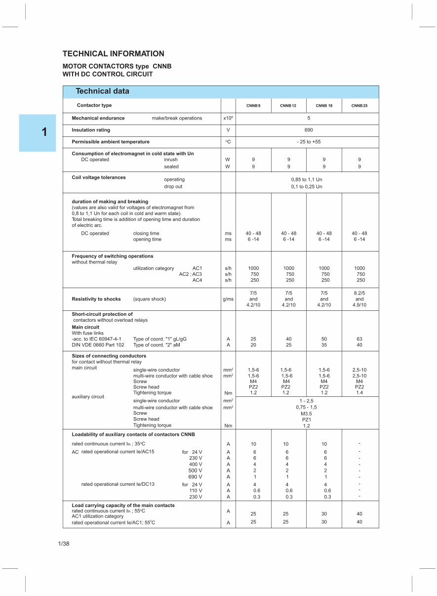
Technical data
TECHNICAL INFORMATION
CNNB 18CNNB12CNNB9
MOTOR CONTACTORS type CNNB
WITH DC CONTROL CIRCUIT
Contactor type
Mechanical endurance make/break operations x106
Insulation rating V 690
Permissible ambient temperature oC - 25 to +55
Consumption of electromagnet in cold state with Un
DC operated inrush
operating
W 9 9 9 9
sealed
drop out
W 9 9 9 9
Coil voltage tolerances
duration of making and breaking
(values are also valid for voltages of electromagnet from
0,8 to 1,1 Un for each coil in cold and warm state).
Total breaking time is addition of opening time and duration
of electric arc.
DC operated closing time ms 40 - 48 40 - 48 40 - 48 40 - 48
opening time ms 6 -14 6 -14 6 -14 6 -14
Frequency of switching operations
without thermal relay
utilization category AC1 s/h 1000 1000 1000 1000
AC2 ; AC3 s/h 750 750 750 750
AC4 s/h 250 250 250 250
7/5 7/5 7/5 8.2/5
Resistivity to shocks (square shock) g/ms and and and and
4.2/10 4.2/10 4.2/10 4.9/10
Short-circuit protection of
contactors without overload relays
Main circuit
With fuse links
-acc. to IEC 60947-4-1 Type of coord. "1" gL/gG A 25 40 50 63
DIN VDE 0660 Part 102 Type of coord. "2" aM A 20 25 35 40
Sizes of connecting conductors
for contact without thermal relay
main circuit single-wire conductor mm2 1,5-6 1,5-6 1,5-6 2,5-10
multi-wire conductor with cable shoeScrew
Screw
Screw head
Screw head
Tightening torque
Tightening torque
mm2
M4PZ2PZ2 PZ2 PZ21.21.2 1.41.2
1,5-6M4 M4 M4
1,5-6 1,5-6 2,5-10
auxiliary circuitsingle-wire conductor mm2 1 - 2,5
multi-wire conductor with cable shoe mm2 0,75 - 1,5
M3.5
PZ1
1.2
Loadability of auxiliary contacts of contactors CNNB
Load carrying capacity of the main contacts
rated continuous current I ; 35 Ctho
rated continuous current I ; 55 Ctho
A 10
25 25
10 10
30 40
-
AC rated operational current Ie/AC15
rated operational current Ie/AC1; 55 C0
AC1 utilization category
rated operational current Ie/DC13
for
for
230
110
24 V
24 V
V
V
A
A
A
A
A
400 V
230 V
A
A
A
0.6 0.6 0.6
0.3 0.3 0.3
4 4 4
6
4 4 4 -
-
2 2 2 -
1 1 1 -
6
25 25
6
6
6
6
30 40
-
-
-
-
500 V A
690 V A
Nm
Nm
0,85 to 1,1 Un
0,1 to 0,25 Un
CNNB25
5
1
1/38

V 690Insulation rating
AC2 and AC3 utilization categories See tables for orders page 1/3
(slip-ring and cage motors)
AC4 utilization category
(electrical endurance of contacts 120.000)rated current
Ie/AC4 A
1.5 2.2 3 4
1.5 2.2 3 4
1.5 2.2 3 4
4.5 5 6.7 8.5
ratings of squirrel-cage motors at 50 c/sfor 230 V kW 0.75 1.1 1.5 2.2
400 V kW
500 V kW
690 V kW
max. permissible rated current Ie/AC4 ; 400 V A 9 12 18 25
Technical data
Contactor type
Loadability by direct current
DC1 utilization category, non-inductive loads L/R 1 ms�
rated operational current I , 55 Ce o
through one polefor 24 V A 20 20 35 35
48 V A 20 20 20 20
110 V A 2.1 2.1 4.5 4.5
220 V 0.8 0.8 1 1
440 V 0.6 0.6 0.4 0.4
600 V 0.6 0.6 0.25 0.25
through three poles connected in series for 24 V A 20 20 3535
48 V A 20 20 3535
110 V A 20 20 3535
220 V A 20 20 3535
440 V A 1.3 1.3 2.92.9
600 V A 1 1 1.41.4utilization categories DC2 to DC5
series and shunt motors (L/R 15 ms)�
rated operational current I , 55 Ce o
through one pole
for 24 V A 20 20 20 20
60 V A 0.5 0.5 5 5
110 V A 0.15 0.15 2.5 2.5
220 V A 0.75 0.75 1 1
440 V A - - 0.09 0.09
600 V A - - 0.06 0.06
through three poles connected in series for 24 V A 20 20 35 35
60 V A 20 20 35 35
110 V A 20 20 35 35
220 V A 1.75 6 10 10
440 V A 0.2 0.2 0.6 0.6
600 V A 0.2 0.2 0.6 0.6
AUXILIARY CONTACT BLOCKS BP2; BP3 and BP4
Technical data
Block type BP2 BP3 BP4
C - 25 to +55Permissible ambient temperatureo
Loadability of auxiliary contacts of blocks
Short-circuit protection - max. fuse rating gL
rated continuous current Ith ; 35 C Ao
AC rated operational current Ie/AC15 for 24V A230V A400V A690V A
rated operational current Ie/DC13 for 24V A110V A230V A400V A
20
106641
40.60.20.15
ScrewScrew headTightening torque
Sizes of connecting conductorssingle-wire conductor mm2 1 - 2,5multi-wire conductor with cable shoe mm2 0,75 - 1,5
M3.5PZ11.2Nm
TECHNICAL INFORMATION
MOTOR CONTACTORS type CNNB
WITH DC CONTROL CIRCUIT
CNNB 18CNNB12CNNB9 CNNB25
1
1/39
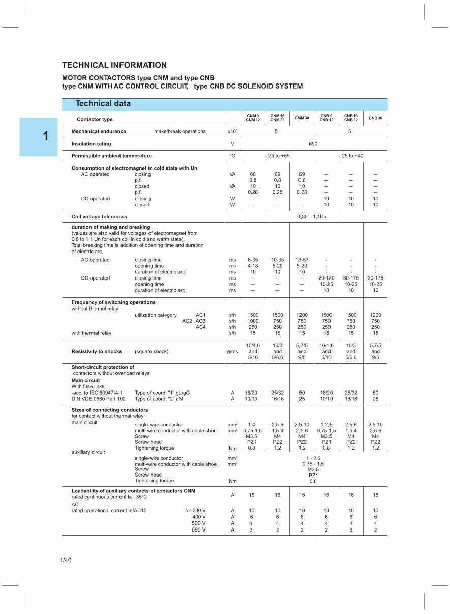
Technical data
TECHNICAL INFORMATION
CNM9CNM12
CNB9CNB12
CNM30CNM16CNM22
CNB16CNB22 CNB30
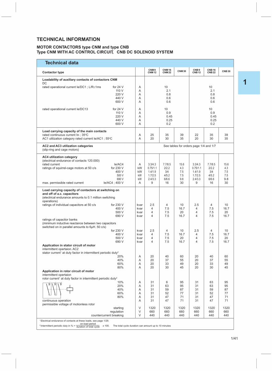
MOTOR CONTACTORS type CNM and type CNB
type CNM WITH AC CONTROL CIRCUIT, type CNB DC SOLENOID SYSTEM
Contactor type
Mechanical endurance make/break operations x106 5 5
Insulation rating V 690
Permissible ambient temperature oC - 25 to +55 - 25 to +40
Consumption of electromagnet in cold state with Un
AC operated closing VA 68 69 69 — — —
p.f. 0.8 0.8 0.8 — — —
closed VA 10 10 10 — — —
p.f. 0.28 0.28 0.28 — — —
DC operated closing W — — — 10 10 10
closed W — — — 10 10 10
Coil voltage tolerances
duration of making and breaking
(values are also valid for voltages of electromagnet from
0,8 to 1,1 Un for each coil in cold and warm state).
Total breaking time is addition of opening time and duration
of electric arc.
AC operated closing time ms 8-35 10-35 13-57 - - -
opening time ms 4-18 5-20 5-20 - - -
duration of electric arc ms 10 10 10 - - -
DC operated closing time ms — — — 20-170 30-175 30-175
opening time ms — — — 10-25 10-25 10-25
duration of electric arc ms — — — 10 10 10
Frequency of switching operations
without thermal relay
utilization category AC1 s/h 1500 1500 1200 1500 1500 1200
AC2 ; AC3 s/h 1000 750 750 750 750 750
AC4 s/h 250 250 250 250 250 250
with thermal relay s/h 15 15 15 15 15 15
10/4.6 10/3 5,7/5 10/4,6 10/3 5,7/5
Resistivity to shocks (square shock) g/ms and and and and and and
5/10 5/6,6 9/5 5/10 5/6,6 9/5
Short-circuit protection of
contactors without overload relays
Main circuit
With fuse links
-acc. to IEC 60947-4-1 Type of coord. "1" gL/gG A 16/20 25/32 50 16/20 25/32 50
DIN VDE 0660 Part 102 Type of coord. "2" aM A 10/10 16/16 25 10/10 16/16 25
Sizes of connecting conductors
for contact without thermal relay
main circuit single-wire conductor mm 1-42 2,5-6 2,5-10 1-2,5 2,5-6 2,5-10
multi-wire conductor with cable shoeScrew
Screw
Screw head
Screw head
Tightening torque
Tightening torque
mm 0,75-1,52
M3.5 M3.5PZ1 PZ1PZ2 PZ2 PZ2 PZ20.8 0.81.2 1.21.2 1.2
1,5-4M4 M4 M4 M4
2,5-6 0,75-1,5 1,5-4 2,5-6
auxiliary circuit
single-wire conductor mm2 1 - 2,5multi-wire conductor with cable shoe mm2 0,75 - 1,5
M3.5PZ10.8
Loadability of auxiliary contacts of contactors CNM
rated continuous current I ; 35 Ctho A 16 16 16 16 16 16
AC
rated operational current Ie/AC15 for 230 V A 10 10 10 10 10 10
400 V A 6 6 6 6 6 6
500 V A 4 4 4 4 4 4
690 V A 2 2 2 2 2 2
Nm
Nm
0,85 —1,1Un
1
1/40
Contactor type
Loadability of auxiliary contacts of contactors CNM
DC
rated operational current Ie/DC1 ; L/R 1ms� for 24 V A 10 10
110 V A 2.1 2.1
220 V A 0.8 0.8
440 V A 0.6 0.6
600 V A 0.6 0.6
rated operational current Ie/DC13 for 24 V A 10 10
110 V A 0.9 0.9
220 V A 0.45 0.45
440 V A 0.25 0.25
600 V A 0.2 0.2
Load carrying capacity of the main contacts
rated continuous current I ; 35 Cth o A 25 35 39 22 35 39
AC1 utilization category rated current Ie/AC1 ; 55 Co A 20 30 35 20 30 35
AC2 and AC3 utilization categories See tables for orders page 1/4 and 1/7
(slip-ring and cage motors)
AC4 utilization category
(electrical endurance of contacts 120.000)
rated current Ie/AC4 A 3.3/4.3 7.7/8.5 15.6 3.3/4.3 7.7/8.5 15.6
ratings of squirrel-cage motors at 50 c/s for 230 V kW 0.75/1.1 2/2.2 4.3 0.75/1.1 2/2.2 4.3
400 V kW 1.4/1.9 3/4 7.5 1.4/1.9 3/4 7.5
500 V kW 1.7/2.5 4/5.2 7.5 1.7/2.5 4/5.2 7.5
690 V kW 2.4/3.3 6/6.6 9.8 2.4/3.3 6/6.6 9.8
max. permissible rated current Ie/AC4 ; 400 V A 9 16 30 9 16 30
Load carrying capacity of contactors at switching on
and off of a.c. capacitors
(electrical endurance amounts to 0.1 million switching
operations)
ratings of individual capacitors at 50 c/s for 230 V kvar 2.5 4 10 2.5 4 10
400 V kvar 4 7.5 16.7 4 7.5 16.7
500 V kvar 4 7.5 20 4 7.5 20
690 V kvar 4 7.5 16.7 4 7.5 16.7
ratings of capacitor banks
(minimum inductive reactance between two capacitors
switched on in parallel amounts to 6μH. 50 c/s)
for 230 V kvar 2.5 4 10 2.5 4 10
400 V kvar 4 7.5 16.7 4 7.5 16.7
500 V kvar 4 7.5 20 4 7.5 20
690 V kvar 4 7.5 16.7 4 7.5 16.7
Application in stator circuit of motor
intermittent opertaion. AC2
stator current at duty factor in intermittent periodic duty1 2
20% A 20 40 60 20 40 60
40% A 20 37 55 20 37 55
60% A 20 33 49 20 33 49
80% A 20 30 45 20 30 45
Application in rotor circuit of motor
intermittent opertaion
rotor current at duty factor in intermittent periodic duty1 2
10% A 31 6 95 31 63 95
20% A 31 63 95 31 63 95
40% A 31 59 87 31 59 87
60% A 31 52 77 31 52 77
80% A 31 47 71 31 47 71
continuous operation A 31 47 71 31 47 71
permissible voltage of motionless rotor
starting V 1320 1320 1320 1320 1320 1320
regulation V 660 660 660 660 660 660
countercurrent breaking V 440 440 440 440 440 440
Technical data
TECHNICAL INFORMATION
CNM9CNM12
CNB9CNB12
CNM30CNM16CNM22
CNB16CNB22 CNB30
MOTOR CONTACTORS type CNM and type CNB
Type CNM WITH AC CONTROL CIRCUIT, CNB DC SOLENOID SYSTEM
1
2
Electrical endurance of contacts at these loads, see page 1/29.
Intermittent periodic duty in % = x 100. The total cycle duration can amount up to 10 minuteson-load period
duration of total cycle
1
1/41

Contactor type
Loadability by direct current
DC1 utilization category, non-inductive loads L/R 1 ms�
rated operational current Ie, 55 Co
through one pole for 24 V A 20 30 45 20 30 45
60 V A 20 20 30 20 20 30
110 V A 2.1 4.5 6 2.1 4.5 6
220 V A 0.8 1 1 0.8 1 1
440 V A 0.6 0.4 0.4 0.6 0.4 0.4
600 V A 0.6 0.25 0.25 0.6 0.25 0.25
through three poles connected in series for 24 V A 20 30 45 20 30 45
60 V A 20 30 45 20 30 45
110 V A 20 30 45 20 30 45
220 V A 20 30 45 20 30 45
440 V A 1.3 2.9 2.9 1.3 2.9 2.9
600 V A 1 1.4 1.4 1 1.4 1.4
utilization categories DC2 to DC5
series and shunt motors (L/R 15 ms)�
rated operational current Ie, 55 Co
through one pole for 24 V A 1.2 5 5 1.2 5 5
60 V A 0.5 2 2 0.5 2 2
110 V A 0.15 0.75 0.75 0.15 0.75 0.75
220 V A — 0.2 0.2 — 0.2 0.2
440 V A — 0.09 0.1 — 0.09 0.1
600 V A — 0.06 0.08 — 0.06 0.08
through three poles connected in series for 24 V A 20 30 45 20 30 45
60 V A 20 30 45 20 30 45
110 V A 20 30 45 20 30 45
220 V A 1.75 3.5 3.5 1.75 3.5 3.5
440 V A 0.2 0.6 0.6 0.2 0.6 0.6
600 V A 0.1 0.3 0.35 0.1 0.3 0.35
Technical data
TECHNICAL INFORMATION
MOTOR CONTACTORS type CNM and type CNB
Type CNM WITH AC CONTROL CIRCUIT, CNB DC SOLENOID SYSTEM
CNM9CNM12
CNB9CNB12
CNM30CNM16CNM22
CNB16CNB22 CNB30
1
1/42

Technical data
TECHNICAL INFORMATION
MOTOR CONTACTORS type CNM
AC CONTROL CIRCUIT or DC CONTROL CIRCUIT
CNM36CNM45CNM60
CNM75CNM90CNM110
CNM140CNM170CNM200
CNM250CNM400
CNM315Contactor type
Mechanical endurance make/break operations x106 5 3
Insulation rating V 690 750 1000
Permissible ambient temperature oC - 25 to +55
Consumption of electromagnet in cold state with Un
AC operated closing VA 68 206 300 580 1340 1340
p.f. 0.8 0.6 0.5 0.45 0.46 0.41
closed VA 10 26 26 44 84 84
p.f. 0.28 0.29 0.24 0.24 0.23 0.25
DC operated closing W 130 270 690 550 1180 1180
closed W 3 3.5 4 5 8 8
Coil voltage tolerances
(values are also valid for voltages of electromagnet from
0,8 to 1,1 U for each coil in cold and warm state).n
Total breaking time is addition of opening time and duration
of electric arc.
AC operated closing time ms 13-57 15-40 20-50 20-50 20-50 20-50
opening time ms 5-10 5-25 8-30 10-30 10-30 10-30
duration of electric arc ms 10 10-15 10-15 10-15 10-15 10-15
DC operated closing time ms 10-25 15-40 20-50 20-50 25-80 30-100
opening time ms 10-16 100-120 150-190 22-35 15-30 15-30
duration of electric arc ms 10 10-15 10-15 10-15 10-15 10-15
Frequency of switching operations
without thermal relay
utilization category AC1 s/h 1200 1500 1000 1000 1000 1000
AC2 ; AC3 s/h 700 750 500 500 500 500
AC4 s/h 200 250 250 250 250 250
with thermal relay s/h 15 15 15 15 15 15
5,7/5 9,2/5 10/5 10/5,5 10/5,6 10/5,6
Resistivity to shocks (square shock) g/ms and and and and and and
9/5 5,4/10 5/10 5/12 5/12 5/12
Short-circuit protection
of contactors without overload relays
Main circuit
With fuse links
-acc. to IEC 60947-4-1, Type of coord. "1" gL/gG A 63 80/100 125/160/200 250/315 400 500/ 630
DIN VDE 0660 Part 102 Type of coord. "2" aM A 32 40/50 63/80/100 125/160 200 400/500
Sizes of connecting conductors
for contact without thermal relay
main circuitsingle-wire conductor mm2 2,5 -10 6 -16 — — — —
multi-wire conductor with cable shoe mm2 2,5 -10 4-25 — — — —
stranded with cable lug mm2 — — 25 -70 70 -150 2x150
— — 25-50 50 -120
fatbar mm — — 15x3 25x3 2x25x3
— 15x3
15x2,5
20x3protective conductor with cable lugScrew
Screw
Screw head
Screw head
Tightening torque
Tightening torque
mm2
Nm
Nm
— — — 35 -7025 -70 50 -120
auxiliary circuit
single-wire conductor mm2
multi-wire conductor with cable shoe mm2
0,85 — 1,1 Un
Duration of making and breaking
6-35
M5
Pz2
2
M5 M6 M8 M10 M10
Pz2
2 2,5
0,75 — 1,5
3,5 4 4
M3,5PZ10,8
1 —2,5
1
1/43

Contactor type
Loadability of auxiliary contacts of contactors CNM
rated continuous current I ; 35 Cth O A 16 16 16 16 16 16
AC
rated operational current I /AC15e for 230 V A 6 6 6 6 6 6
400 V A 4 4 4 4 4 4
500 V A 2.5 2.5 2.5 2.5 2.5 2.5
690 V A 2.5 2.5 2.5 2.5 2.5 2.5
DC
rated operational current I /DC1 ; L/R 1mse � for 24 V A 10 10 10 10 10 10
110 V A 3.2 3.2 3.2 8 8 8
220 V A 0.9 0.9 0.9 2 2 2
440 V A 0.33 0.33 0.33 0.6 0.6 0.6
600 V A 0.22 0.22 0.22 0.4 0.4 0.4
rated operational current I /DC13e
for 24 V A 10 10 10 10 10 10
110 V A 1.8 1.8 1.8 2.4 2.4 2.4
220 V A 0.9 0.9 0.9 1.1 1.1 1.1
440 V A 0.27 0.27 0.27 0.32 0.32 0.32
600 V A 0.18 0.18 0.18 0.21 0.2 0.21
Load carrying capacity of the main contacts
rated continuous current I ; 35 Cth o A 55 63/72 100/110/115 160/200/250 350 390/450
AC1 utilization category
rated current I /AC1 ; 55 Ce o A 45 60/70 100/110/115 160/200/250 300 350/400
AC2 and AC3 utilization categories
(slip-ring and cage motors)
AC4 utilization category
(electrical endurance of contacts 120.000)
rated current I /AC4e A 18.5 24/28 34/38/42 68/72/75 100 125/150
ratings of squirrel-cage motors at 50 c/s for 230 V kW 5.2 6,9/8,1 7,7/11/12 20/21/23 31 35/ 37,5
400 V kW 9 12/14 17/20/22 35/37/40 55 65/69
500 V kW 9 15,8/18,4 22/25/27 46/48/50 72 76/85,5
690 V kW 11.8 20,8/24,3 28,5/32/36 60/64/69 92 100/106
max. permissible rated current I /AC4;e 400 V A 36 45/60 75/90/110 140/170/200 250 350/400
Load carrying capacity of contactors at
switching on and off of a.c. capacitors
(electrical endurance amounts to 0,1 million switching operations)
ratings of individual capacitors at 50 c/s for 230 V kvar 12 17 24 35/40/58 87 90/115
400 V kvar 16.7 30 40 40/60/100 150 150/ 200
500 V kvar 25 35 50 50/ 80/130 190 190/265
690 V kvar 16.7 30 40 40/60/100 150 150/200
ratings of capacitor banks
(minimum inductive reactance between two capacitors
switched on in parallel amounts to 6μH, 50 c/s)
for 230 V kvar 12 17 24 30/37/40 66 66/85
400 V kvar 16.7 30 40 50/50/70 115 115/150
500 V kvar 25 35 50 66/65/90 145 145/195
690 V kvar 16.7 30 40 50/70/70 115 115/150
Application in stator circuit of motor
intermittent opertaion, AC2
stator current at duty factor in intermittent periodic duty1 2
20% A 60 103 153 245/308/308 462 462/617
40% A 55 98 122 195/245/245 367 367/490
60% A 49 87 109 174/218/218 327 327/436
80% A 45 80 100 160/200/200 300 300/400
Technical data
TECHNICAL INFORMATION
MOTOR CONTACTORS type CNM
AC CONTROL CIRCUIT or DC CONTROL CIRCUIT
CNM36CNM45CNM60
CNM75CNM90CNM110
CNM140CNM170CNM200
CNM250CNM400
CNM315
See tables for orders page 1/4, 1/5, 1/6, 1/8 and 1/9
1
1/44
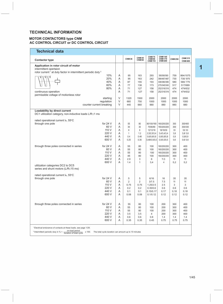
Contactor type
Application in rotor circuit of motor
intermittent opertaion
rotor current at duty factor in intermittent periodic duty1 2
10% A 95 163 293 395/560/560 759 864/1075
20% A 95 163 242 388/487/487 730 730/ 975
40% A 87 155 193 308/380/380 580 580/ 775
60% A 77 138 173 275/345/345 517 517/689
80% A 71 127 158 252/316/316 474 474/632
continuous operation A 71 127 158 252/316/316 474 474/632
permissible voltage of motionless rotor
starting V 1320 1500 2000 2000 2000 2000
regulation V 660 750 1000 1000 1000 1000
counter current breaking V 440 660 880 880 880 880
Loadability by direct current
DC1 utilization category, non-inductive loads L/R 1 ms�
rated operational current I , 55 Ce o
through one pole for 24 V A 55 80 90/100/160 160/200/200 300 300/400
60 V A 30 30 75/80/80 160/200/200 300 300/330
110 V A 6 6 12/12/18 18/18/30 33 33/ 33
220 V A 1 1.2 2,5/2,5/3,4 3,4/3,4/3,4 3,8 3,8/ 3,8
440 V A 0.4 0.48 0,6/0,6/0.8 0,8/0,8/0,8 0,9 0,9/0,9
600 V A 0.25 0.35 0,48/0,5/0,5 0,5/0,5/0,5 0,6 0,6/ 0,6
through three poles connected in series for 24 V A 55 80 100 160/200/200 300 400
60 V A 55 80 100 160/200/200 300 400
110 V A 55 80 100 160/200/200 300 400
220 V A 45 80 100 160/200/200 300 400
440 V A 2.9 3 6 11,5 11 11
600 V A 1.4 1 3,4 4 5,2 5,2
utilization categories DC2 to DC5
series and shunt motors (L/R 15 ms)�
rated operational current I , 55 Ce o
through one pole for 24 V A 5 5 6/16 16 35 35
60 V A 2 2 3/7.5 7.5 11 11
110 V A 0.75 0.75 1.25/2.5 2.5 3 3
220 V A 0.2 0.2 0.35/0.6 0.6 0.6 0.6
440 V A 0.1 0.1 0.15/0.17 0.17 0.18 0.18
600 V A 0.08 0.08 0.1/0.12 0.12 0.12 0.12
through three poles connected in series for 24 V A 55 80 100 200 300 400
60 V A 55 80 100 200 300 400
110 V A 55 80 100 200 300 400
220 V A 3.5 3.5 4 200 300 400
440 V A 0.6 0.6 0.8 1.4 1.4 1.4
600 V A 0.35 0.35 0.45 0.75 0.75 0.75
Technical data
TECHNICAL INFORMATION
MOTOR CONTACTORS type CNM
AC CONTROL CIRCUIT or DC CONTROL CIRCUIT
CNM36CNM45CNM60
CNM75CNM90CNM110
CNM140CNM170CNM200
CNM250CNM400
CNM315
on-load period
duration of total cycle
Electrical endurance of contacts at these loads, see page 1/29.
Intermittent periodic duty in % =
1
2 x 100. The total cycle duration can amount up to 10 minutes
1
1/45

CONTACTORS TYPE TK for SWITCHING RESISTIVE LOADS
Technical data
Contactor type
Mechanical endurance make/break operations x106 5
Insulation rating 690
Permissible ambient temperature oC - 25 to +40
Consumption of electromagnet in cold state with Un
AC operated closing VA 68 68 206 350 350
0.8 0.8 0.6 0.5 0.5
10 10 26 26 26
p.f. 0.28 0.28 0.29 0.24 0.24
Coil voltage tolerances 0,85 — 1,1 Un
Degree of protection per IEC 60947 - 1 IP 00
Rated control voltages AC V 24-500 at 50 Hz; standard voltages: 24, 48, 110, 220/230, 380/400
Frequency of switching operations
without thermal relay
utilization category AC1 s/h 650 650 650 650 650
Ac2 / AC3 s/h 750 750 750 500 500
Maximum permissible fuse ratings
for contactors without relays
main circuit gL/gG A 100 160 200 250 315
Electrical endurance x106 0,5
Sizes of connecting conductors
for contact without thermal relay
main circuit
multi-wire conductor with cable shoe mm2
multi-wire conductor mm2 16 25 3550 70
Terminal screw M5 M5 M8 M8 M8
Terminal screw M3.5
Screw head Hexagon socket
Screw head Pz1
Tightening torqu Nm 2 2 4 3.5 3.5
Tightening torque Nm 0.8
auxiliary circuitsingle-wire conductor mm2 1 - 2,5multi-wire conductor with cable shoe mm2 0,75 - 1,5
AC-1 utilization category, switching resistive load
Rated operational currents Ie at 40 0 C A 65 85 115 130 175
Ratings of 230 25 32 44 50 67
three-phase loads with 400 43 56 76 85 115
p.f.=1
AC-2 and AC-3 utilization categoriesRated operational currents Ie at 400/380 V A 30 36 60 90 110
Ratings of motors 230 /220 V kW 7.5 11 18.5 26 37
400 /380 V 15 18.5 30 45 55
500 V kW 15 22 37 59 75
690 /660 V 15 36 37 67 90
TK85TK65 TK175TK 130
TECHNICAL INFORMATION
TK115
1
1/46

Control of lighting circuits
TECHNICAL INFORMATION
General
� Contactor choice criteria for control of lighting circuits are as follows:
� Type, power rating and number of lamps
� Conection mode
� Current values on closing and in steady state
� Power factor cosf of the lamps
� Presence or not of compensation capacitors
Lighting circuits
In a given circuit,the number and power rating of lamps are defned and cannot result in overload.Only
short-circuit protection has to be provided. GG fuses or modular circuit-breakers will be chosen for this
purpose.The lamps have very specifc technical data,according to their construction type.
Incandescent lamps have a very high current on clossing: more than 15 times normal current.
They do not introduce a large phase displacement beween current and voltage.
� Fluorescent tubes are equipped with a ballast whose purpose is two-fold: conttrbute to ignition and limit
curreent to nominal value once steady state is reached. This ballast is a reactor that considerably lowers
the power factor. It may or may not be compensated.
Individual compennsation Serial compensation in dual
mounting
Choice of contactors
The following tables indicate, for each contactor type, the maximum permissible number of lamps per
phase.
Air temperature, near the contactor, must be limited to 55 C.0
Number are given for a 230 V voltage distributed between phase and neutral: single-phase (phase +
neutral) or three-phase (3 phases + neutral) distribution.
In the case of a three-phase supply without neutral, 230 V phase- to-phase, the permissible number of
lamps per phase will be that given in the tables multiplied by 0,58.
�
1
1/47

Type of lamps compensation Start cos ϕ Starting Important for choosing
curret time contactor type
x In1 s
Light gas lamp connection without 1 0,5 -
with 20 0,9 - Start current le
Lamps with mercury vapour - without 1,6 0,4-0,6 < 5
High pressure lamps
with 2 0,95 < 5 Start current le (A)
DUO-wiring (most frequent 1 1 - Rated continuous current
applied wiring) lth2 (A)
Serial wiring without 1 0,5
(Tandem connection)
with 20 0,9 Start current le (A)
Lighting gas lamps without without 1 0,5 -
starter
Halogen - metal vapour without 1 0,4-0,6 -
lamps
with 1 0,4-0,6 -
215 W - High capacity lighting without 1,4 0,5 5...12 70% Rated continuous
gas lamps 380 V current Ith2 (A)
(High pressure vapour lamps)
(Low pressure vapour lamps) without 1 0,3 5...12 70% Rated Continuous
current Ith2 (A)
High pressure sodium vapour without 1,6 0,4-0,6 5...8
lamps
with 20 0,95 5..8 70% Rated continuous
current Ith (A) and
Start current le (A)
Table of technical characteristics for lighting switching
TECHNICAL INFORMATION
Rated continuous current
lth2 (A)
Rated continuous current
lth2 (A)
Rated continuous current
lth2 (A)
Rated continuous current
lth2 (A)
Rated continuous current
lth2 (A)
Rated continuous current
lth2 (A)
70% Rated continuour
current Ith2 (A)
with 20 0,95 5...12
with 20 0,95 5...12
1 In = Rated lamp current2 Ith = Rated continuous contactor current
1
1/48
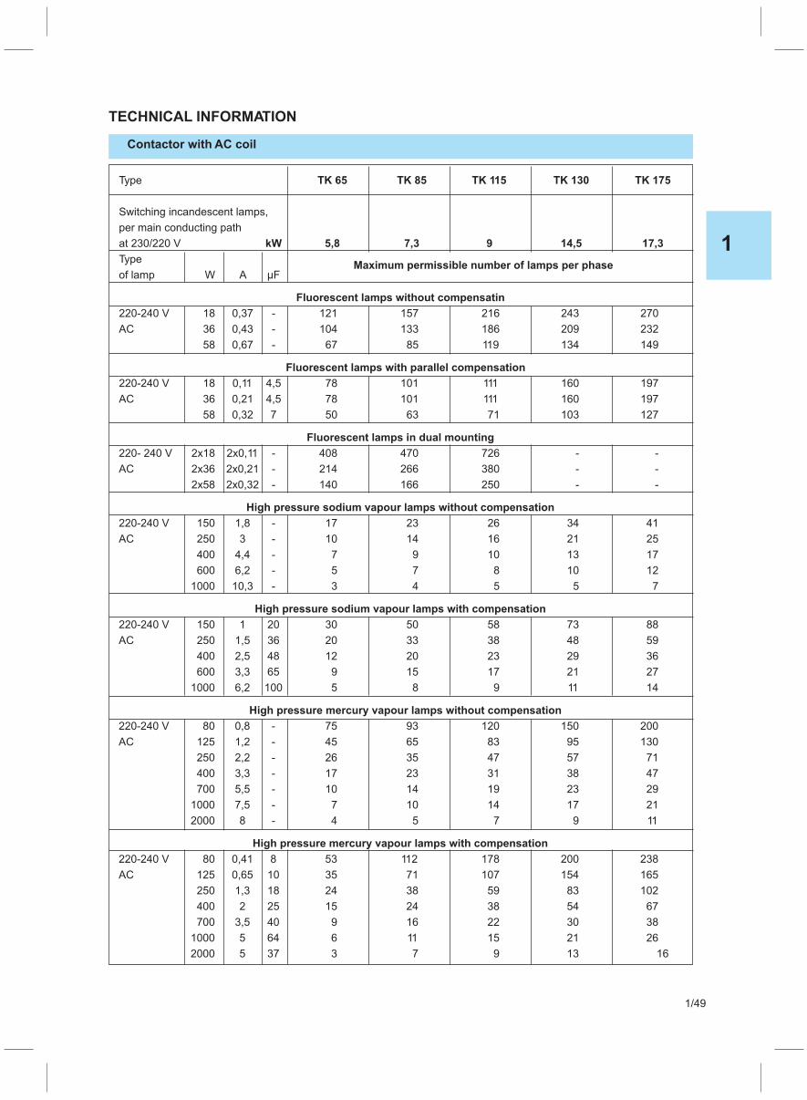
Type TK 65 TK 85 TK 115 TK 130 TK 175
Switching incandescent lamps,
per main conducting path
at 230/220 V kW 5,8 7,3 9 14,5 17,3
TypeMaximum permissible number of lamps per phase
of lamp W A μF
Fluorescent lamps without compensatin
220-240 V 18 0,37 - 121 157 216 243 270
AC 36 0,43 - 104 133 186 209 232
58 0,67 - 67 85 119 134 149
Fluorescent lamps with parallel compensation
220-240 V 18 0,11 4,5 78 101 111 160 197
AC 36 0,21 4,5 78 101 111 160 197
58 0,32 7 50 63 71 103 127
Fluorescent lamps in dual mounting
220- 240 V 2x18 2x0,11 - 408 470 726 - -
AC 2x36 2x0,21 - 214 266 380 - -
2x58 2x0,32 - 140 166 250 - -
High pressure sodium vapour lamps without compensation
220-240 V 150 1,8 - 17 23 26 34 41
AC 250 3 - 10 14 16 21 25
400 4,4 - 7 9 10 13 17
600 6,2 - 5 7 8 10 12
1000 10,3 - 3 4 5 5 7
High pressure sodium vapour lamps with compensation
220-240 V 150 1 20 30 50 58 73 88
AC 250 1,5 36 20 33 38 48 59
400 2,5 48 12 20 23 29 36
600 3,3 65 9 15 17 21 27
1000 6,2 100 5 8 9 11 14
High pressure mercury vapour lamps without compensation
220-240 V 80 0,8 - 75 93 120 150 200
AC 125 1,2 - 45 65 83 95 130
250 2,2 - 26 35 47 57 71
400 3,3 - 17 23 31 38 47
700 5,5 - 10 14 19 23 29
1000 7,5 - 7 10 14 17 21
2000 8 - 4 5 7 9 11
High pressure mercury vapour lamps with compensation
220-240 V 80 0,41 8 53 112 178 200 238
AC 125 0,65 10 35 71 107 154 165
250 1,3 18 24 38 59 83 102
400 2 25 15 24 38 54 67
700 3,5 40 9 16 22 30 38
1000 5 64 6 11 15 21 26
2000 5 37 3 7 9 13 16
TECHNICAL INFORMATION
Contactor with AC coil
1
1/49

CAPACITOR CONTACTORS TYPE
CNNK 10 - CNNK 30, CNKM 40 - CNKM 60
Special contactors for power factor correction capacitors
Main characteristics
These contactors are equipment with early - make contacts. This special type of contact
has the purpose of connecting for a very brief interval, 2-3 ms, during the contactor closing,
resistances which limit the connecting current of the capacitors. These resistances are
excluded when the closing operation is complete and the current capacity is
the main contacts.
then
conveyed to
Type designation
Capacitor rating at 230V kvar
400V kvar
CNNK 12 20CNNK 12 11
CNNK 10 20CNNK 10 11
CNNK 25 10 CNNK 30 10 CNKM 50 00CNKM 50 22
CNKM 60 22CNKM 40 00CNKM 40 22
6.75 1411 29 342520
12.510
1814
25
36
20
29
50
72
60
87
40
58
30
44
Insulation rating V
Nm
Rated operational currentIe/AC6b et 400 V A
Permissible ambienttemperature C
0
Coil voltage tolerances
Maximum permissible fuseratingsmain circuit gL/gG Aauxilliary circuit A
Frequency of switchingoperations s/h
Electrical endurance
Terminal screw
Screw head
Tightening torque
Sizes of connecting conductorsmain circuit
mm
with cable shoe
multi-wire conductormulti-wire conductor
2
mm2
690 750 1000
- 25 to + 55
0,85 - 1,1 Un
2516
3516
5016
120 100
8016
10016
100.000150.000200.000
1.5-6
M4 M4 M4 M4 M5 M5 M8 M8 M8
PZ2 PZ2 PZ2 PZ2 Hexagon socket
1,2 1,2 1,2 1,4 2 2 4 4 3,5
1.5-6 1.5-6 2.5-10 6-25
12516
16016
TECHNICAL INFORMATION
CNNK 15 20CNNK 15 11
CNNK 20 10
8,5
15
22
240
6-25 16-35 16-35
5016
6316
CONNECTION DIAGRAMS AND TERMINAL MARKINGS
1 3 5 13
L1 L2 L3
T1 T2 T3
A1
R
R
R
R
R
R
A2 2 4 6 14
C
1 3 5 13 21 31 43
L1 L2 L3
T1 T2 T3
A1
R
R
R
R
R
R
A2 2 4 6 14 22 32 44
C
1 3 5 13 21 31 43
L1 L2 L3
T1 T2 T3
A1R
R
R
R
A2 2 4 6 14 22 32 44
C
1 3 5
L1 L2 L3
T1 T2 T3
A1
R
R
R
R
R
R
A2 2 4 6
C
CNNK 20 10, CNNK 25 10CNNK 30 10,
CNKM 40 00;CNKM 50 00
CNKM 40 22, CNKM 50 22 CNKM 60 22CNNK 10; CNNK 12; CNNK 15
20
33
34
1 3 5 13
L1 L2 L3
T1 T2 T3
A1
R
R
R
R
R
R
A2 2 4 6 14
C
11
3321
3422
1
1/50
50-70
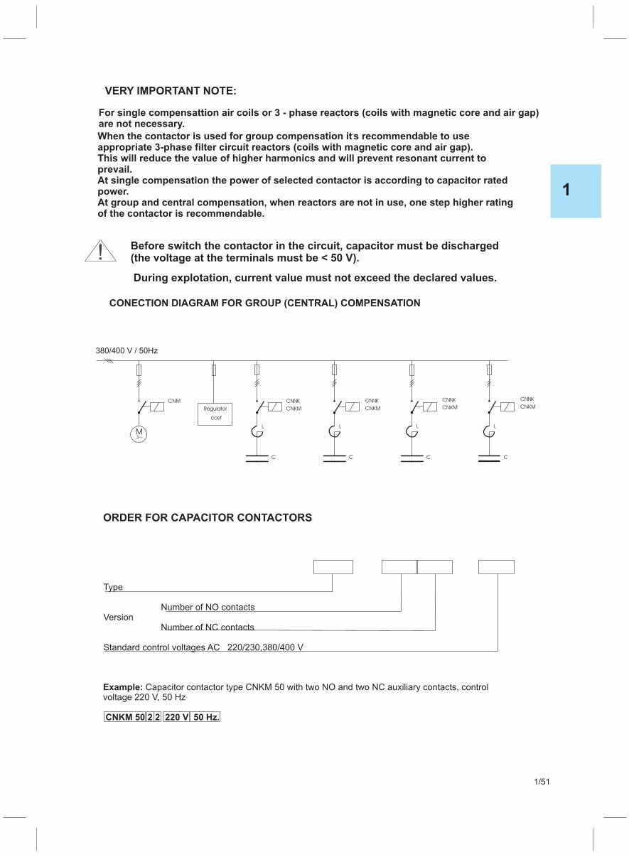
1
1/51
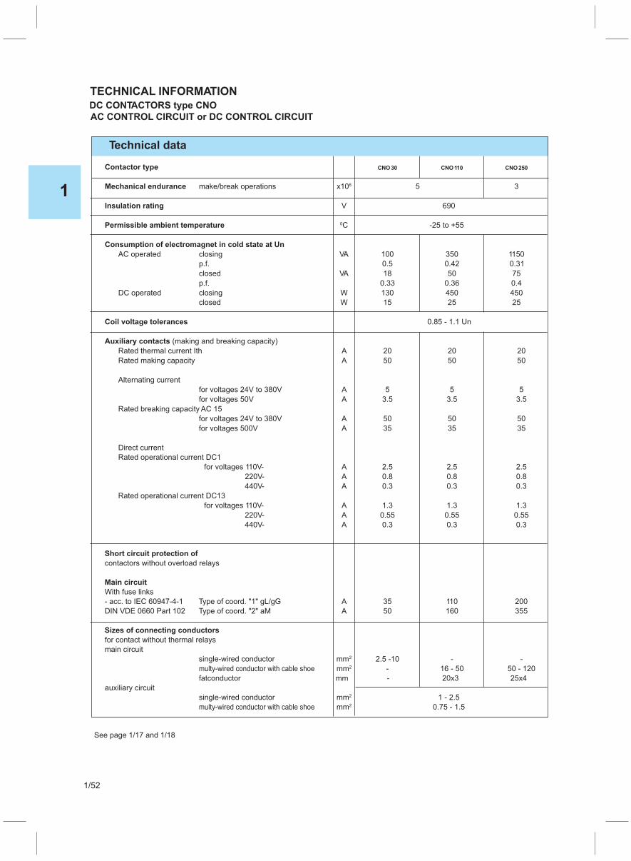
Contactor type
Mechanical endurance make/break operations x106 5 3
Insulation rating V 690
Permissible ambient temperature 0C -25 to +55
Consumption of electromagnet in cold state at Un
AC operated closing VA 100 350 1150
p.f. 0.5 0.42 0.31
closed VA 18 50 75
p.f. 0.33 0.36 0.4
DC operated closing W 130 450 450
closed W 15 25 25
Coil voltage tolerances 0.85 - 1.1 Un
Auxiliary contacts (making and breaking capacity)
Rated thermal current Ith A 20 20 20
Rated making capacity A 50 50 50
Alternating current
for voltages 24V to 380V A 5 5 5
for voltages 50V A 3.5 3.5 3.5
Rated breaking capacity AC 15
for voltages 24V to 380V A 50 50 50
for voltages 500V A 35 35 35
Direct current
Rated operational current DC1
for voltages 110V- A 2.5 2.5 2.5
220V- A 0.8 0.8 0.8
440V- A 0.3 0.3 0.3
Rated operational current DC13
for voltages 110V- A 1.3 1.3 1.3
220V- A 0.55 0.55 0.55
440V- A 0.3 0.3 0.3
Short circuit protection of
contactors without overload relays
Main circuit
With fuse links
- acc. to IEC 60947-4-1 Type of coord. "1" gL/gG A 35 110 200
DIN VDE 0660 Part 102 Type of coord. "2" aM A 50 160 355
Sizes of connecting conductors
for contact without thermal relays
main circuit
single-wired conductor mm2 2.5 -10 - -
multy-wired conductor with cable shoe mm2 - 16 - 50 50 - 120
fatconductor mm - 20x3 25x4
auxiliary circuit
single-wired conductor mm2 1 - 2.5
multy-wired conductor with cable shoe mm2 0.75 - 1.5
Technical data
TECHNICAL INFORMATION
DC CONTACTORS type CNO
AC CONTROL CIRCUIT or DC CONTROL CIRCUIT
CNO30 CNO110 CNO250
See page 1/17 and 1/18
1
1/52

(values are also valid for voltages of electromagnet from 0,8 to 1,1 U for each coil in cold andn
warm state). Total breaking time is addition of opening time and duration of electric arc.
Technical data
TECHNICAL INFORMATION
MINI CONTACTOR RELAY type CP0
Contactor type CP0
Mechanical endurance make/break operations x106 5
Insulation rating V 690
Permissible ambient temperatureoC - 25 to +55
Consumption of electromagnet in cold state with Un
AC operated closing VA 26
p.f. 0,9
closed VA 4
p.f. 0,34
Coil voltage tolerances 0,8 —1,1 Un
duration of making and breaking
AC operated closing time ms 7 - 12
opening time ms 6 -10
duration of electric arc ms 3
Frequency of switching operations
without thermal relay utilization category AC 15 s/h 1200
with thermal relay s/h 15
Resistivity to shocks (square shock) g/ms 7/5 and 4/10
Maximum permissible fuse rating for contactors without relays
max short circuit current 10 kA
main circuit fuse-links, time-lagging A 10
fuse-links, quick-acting A 16
Sizes of connecting conductors for contactors without thermal relay
main circuit single-wire conductor mm2 1 —2,5
multi-wire conductor with cable shoe mm2 0,75 —1,5
Loadability of auxiliary contacts of contactor CP0
rated continuous current I ; 35 Cth o A 16
AC rated operational current I /AC15e for 230 V A 6
400 V A 4
500 V A 2,5
690 V A 1,5
rated operational current I /DC13e for 24 V A 4
110 V A 0.6
220 V A 0,2
Terminal screw M3.5Screw head Pz1Tightening torque Nm 0.8
1
1/53

Contactor type
Mechanical endurance make/break operations x106 10 5
Insulation rating V 690
Permissible ambient temperature oC - 25 to +55 - 25 to +40
Consumption of electromagnet in cold state with Un
AC operated closing VA 68 —
p.f. 0.8 —
closed VA 10 —
p.f. 0.28 —
DC operated closing W — 10
closed W — 10
Coil voltage tolerances 0,8 — n1,1 U
duration of making and breaking
AC operated closing time ms 8 - 35 —
opening time ms 4 - 18 —
duration of electric arc ms 10 —
DC operated closing time ms — 20 - 170
opening time ms — 10 - 25
duration of electric arc ms — 10
Frequency of switching operations
without thermal relay
utilization category AC 15 s/h 3600 3600
AC1 s/h 2000 1000
AC2 ; AC3 s/h 1000 250
AC4 s/h 250 250
with thermal relay s/h 15 15
Resistivity to shocks (square shock) g/ms 10/4 and 5/8 10/4 and 5/8
Maximum permissible fuse rating for contactors without relays
max short circuit current 1 kA
main circuit fuse-links, time-lagging A 16 16
fuse-links, quick-acting A 20 20
high-rupturing capacity fuses A 16 16
Sizes of connecting conductors
for contactors without thermal relay
main circuit single-wire conductor mm2 1 —2,5
multi-wire conductor with cable shoe mm2 0,75 —1,5
Loadability of auxiliary contacts of contactors CNP and CNB
rated continuous current I ; 35 Cth o A 16 16
AC rated operational current I /AC15e for 230 V A 10 10
400 V A 6 6
500 V A 4 4
690 V A 2 2
DC rated operational current I /DC1 ; L/R 1mse � for 24 V A 10 (10)1
(with series connection of 3 current paths)1) 110 V A 2.1 (10)1
220 V A 0.8 (10)1
440 V A 0.6 (1,3)1
600 V A 0.6 (1)1
rated operational current I /DC13e for 24 V A 10 (10)1
(with series connection of 3 current paths)1) 110 V A 0.9 (10)1
220 V A 0.45 (2)1
440 V A 0.25 (0,9)1
600 V A 0.2 (0,8)1
Motor ratings for utilization categories AC2, AC3
at 230 V kW 2,2
400 V kW 4
500 V kW 4
690 V kW 4
CONTACTOR RELAYS type CNP and type CNB
Type CNP WITH AC CONTROL CIRCUIT, type CNB DC SOLENOID SYSTEM
CNB31CNB21
CNP31CNP21
Technical data
TECHNICAL INFORMATION
1
1/54

10
01
00400
11
22
44
DC coil operation
CM1, CNN 9, CNN 12, CNN 18CNM 9, CNM 12
CM1, CNN 9, CNN 12, CNN 18CNM 9, CNM 12
CM1, CNM 9, CNM 12CNN 25, CNN 32, CNN 40
CNM 12, CNM 16, CNM 22, CNM 30
CNM 12, CNM 16, CNM 22, CNM 30,
CNM 36, CNM 45, CNM 60, CNM 75,
CNM 90, CNM 110, CNM 140, CNM 170,
CNM 200, CNM 250, CNM 315, CNM 400
CNM 36, CNM 45, CNM 60, CNM 75,
CNM 90, CNM 110, CNM 140, CNM 170,
CNM 200, CNM 250,CNM 315, CNM 400
10
CNB 9, CNB 12
22
CNM 36, CNM 45, CNM 60, CNM 75,CNM 110
44
CNM 45, CNM 60, CNM 75,CNM 110
22
CNM 140, CNM 170, CNM 200,CNM 250,CNM 315, CNM 400
44
CNM 140, CNM 170, CNM 200,CNM 250,CNM 315, CNM 400
Snap-on auxiliarycontakt blocks
40
31
22
04
13
11
22
BP1
10
01
BP0
BP4
BP2
40
71
62
53
44
CP0, CNP 21, CNB 21
004
CNB 9, CNB 12
22
CP0, CNP 21, CNB 21
11
CNB 12, CNB 16, CNB 22, CNB 30
13
CNP 21, CNB 21
CNB 12, CNB 16, CNB 22, CNB 30
22 04
CNP 21, CNB 21
CNP 31, CNB 31
80
CNP 31, CNB 31
CNP 31, CNB 31
CNP 31, CNB 31
CNP 31, CNB 31
Auxiliary contactors
AC coil operation AC and DC coil operation
CP0, CNP 21, CNB 21
01
CNB 9, CNB 12
31
33
33 63
34
34 64
41
41 51
42
42 52
BP3
11
1
1/55
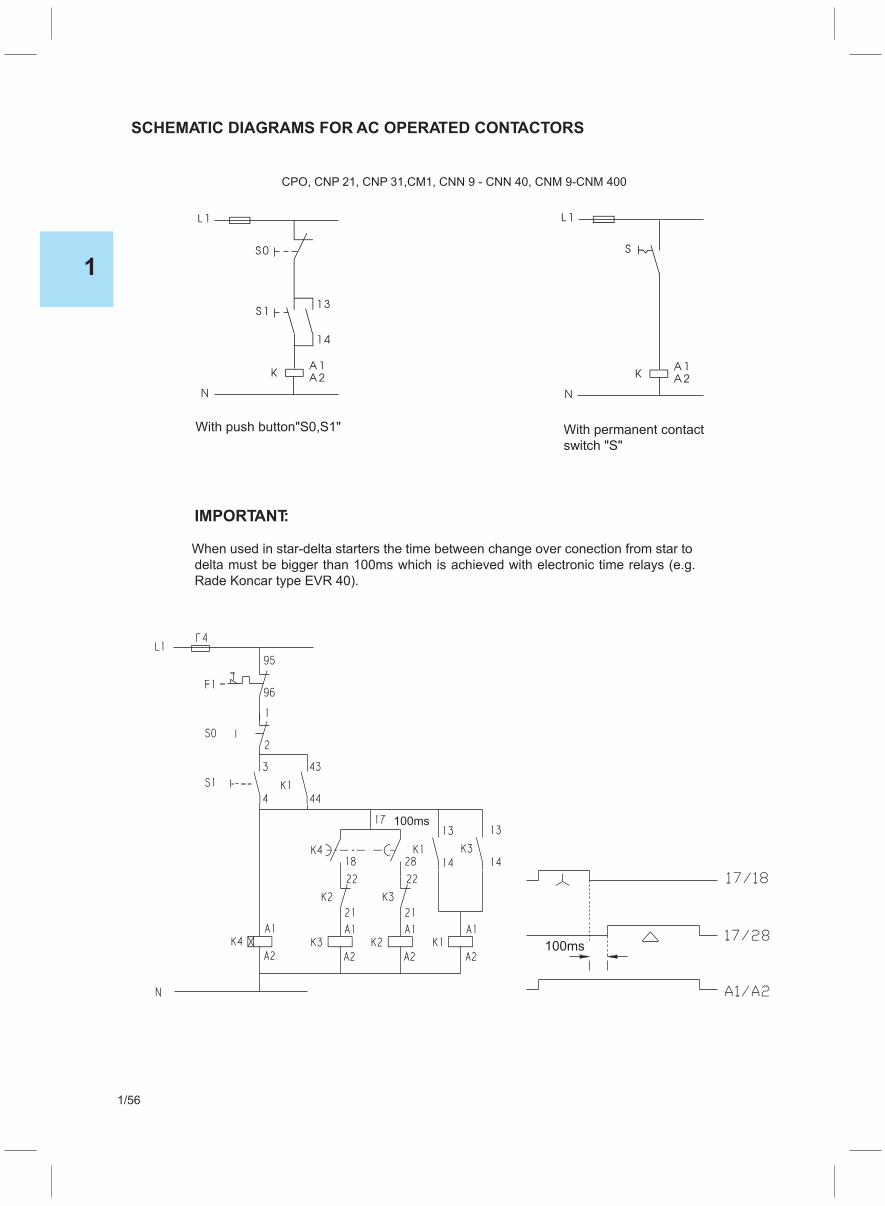
With permanent contact
switch "S"
With push button"S0,S1"
When used in star-delta starters the time between change over conection from star to
IMPORTANT:
delta must be bigger than 100ms which is achieved with electronic time relays (e.g.
Rade Koncar type EVR 40).
SCHEMATIC DIAGRAMS FOR AC OPERATED CONTACTORS
CPO, CNP 21, CNP 31,CM1, CNN 9 - CNN 40, CNM 9-CNM 400
1
1/56

AVR
MBCM1, MBCNN 9 - MBCNN 40, MBCNM 12 -MBCNM 400
1
1/57
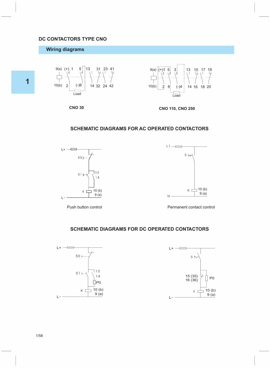
DC CONTACTORS TYPE CNO
Wiring diagrams
SCHEMATIC DIAGRAMS FOR AC OPERATED CONTACTORS
SCHEMATIC DIAGRAMS FOR DC OPERATED CONTACTORS
1
1/58
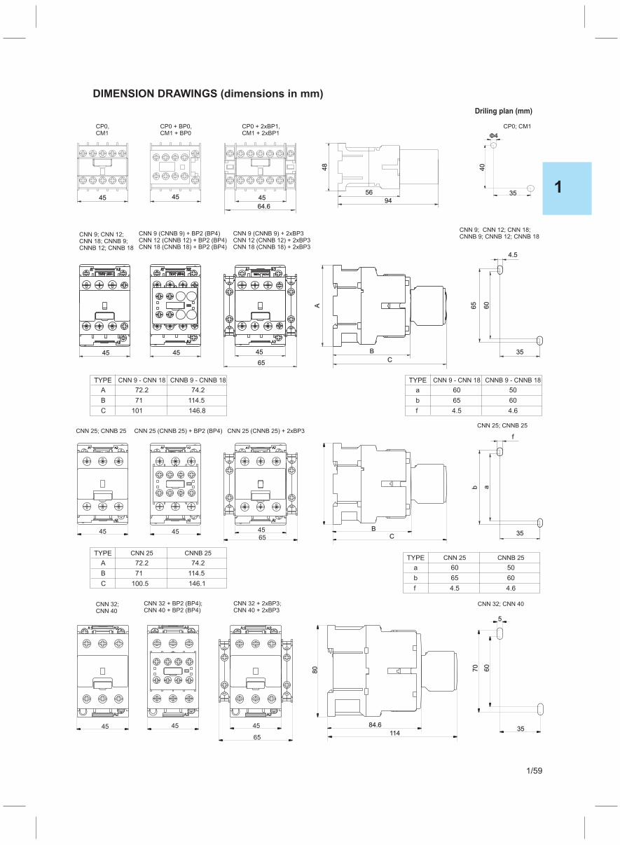
DIMENSION DRAWINGS (dimensions in mm)
35
40
CNN 25; CNNB 25
CP0,CM1
CP0 + BP0,CM1 + BP0
CP0 + 2xBP1,CM1 + 2xBP1
CP0; CM1
CNN 32;CNN 40
CNN + BP2 (BP4)25 (CNNB 25)
CNN 32 + BP2 (BP4);CNN 40 + BP2 (BP4)
CNN + 2xBP325 (CNNB 25)
CNN 32 + 2xBP3;CNN 40 + 2xBP3
CNN 9; CNN 12;CNN 18; CNNB 9;CNNB 12; CNNB 18
CNN 9 (CNNB 9) + BP2 (BP4)
+ BP2 (BP4)CNN 12 (CNNB 12) + BP2 (BP4)CNN 18 (CNNB 18)
CNN 9 (CNNB 9) + 2xBP3
+ 2xBP3CNN 12 (CNNB 12) + 2xBP3CNN 18 (CNNB 18)
CNN 9; CNN 12; CNN 18;CNNB 9; CNNB 12; CNNB 18
CNN 25; CNNB 25
CNN 32; CNN 40
45 B
C
A
45
65
45
60
65
35
4.5
ab
35
f
45 45 BC
45
65
45 45 45
65
35
60
70
5
Driling plan (mm)
80
114
84.6
45 45 45
64.6
56
94
48
TYPE
TYPE
TYPE
TYPE
CNN 9 - CNN 18
CNN 25
CNN 9 - CNN 18
CNN 25
A
A
72.2
72.2
74.2
74.2
a
a
60
60
50
50
C
C
101
100.5
146.8
146.1
f
f
4.5
4.5
4.6
4.6
B
B
71
71
114.5
114.5
b
b
65
65
60
60
CNNB 9 - CNNB 18
CNNB 25
CNNB 9 - CNNB 18
CNNB 25
1
1/59

DIMENSION DRAWINGS (mm)
1
1/60

1
1/61

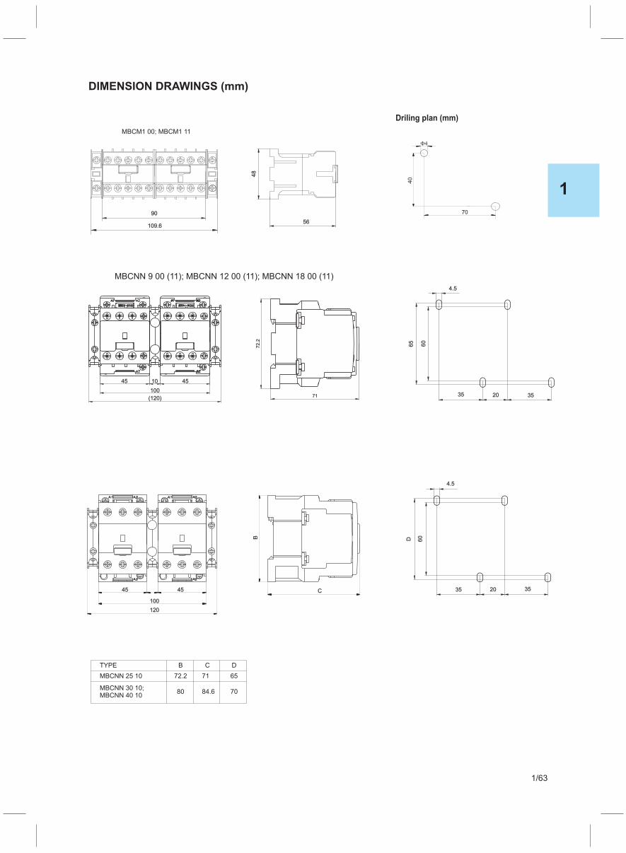
60
65
35 20
4.5
35
72
.2
71
4545 10
100
(120)
MBCNN 9 00 (11); 00 (11)MBCNN 12 00 (11); MBCNN 18
60D
35 20
4.5
35C
B
100
45 45
120
70
40
MBCM1 00; MBCM1 11
Driling plan (mm)
109.6
90
56
48
MBCNN 30 10;MBCNN 40 10
MBCNN 25 10
TYPE B
72.2
80
C
71
84.6
D
65
70
DIMENSION DRAWINGS (mm)
1
1/63
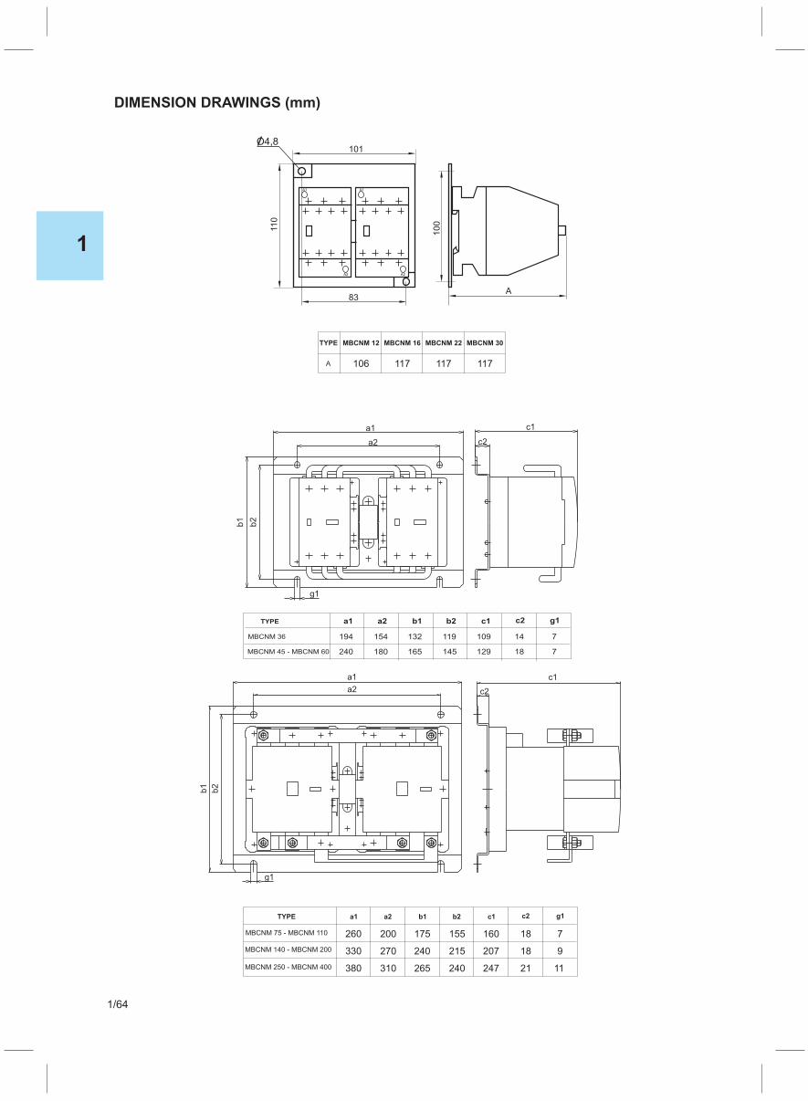
DIMENSION DRAWINGS (mm)
A1
A2
A1
A2
83A
101
11
0
10
0
O4,8
TYPE a1
MBCNM 36
MBCNM 45 - MBCNM 60
a2 b1 b2 c1 c2 g1
194
240
154
180
132
165
119
145
109
129
14
18
7
7
TYPE a1
MBCNM 75 - MBCNM 110
MBCNM 140 - MBCNM 200
MBCNM 250 - MBCNM 400
a2 b1 b2 c1 c2 g1
260
330
380
200
270
310
175
240
265
155
215
240
160
207
247
18
18
21
7
9
11
TYPE MBCNM 12
A
MBCNM 16 MBCNM 22 MBCNM 30
106 117 117 117
c1
b2
b1
g1
a2
a1
c2
c1
b1
b2
g1
c2a2
a1
1
1/64

DIMENSION DRAWINGS (mm)
1
1/65
2
2/1
THERMAL OVERLOAD RELAYS
Thermal overload relays TM ..........................................................................................................2/1
Thermal overload relays TRM ..............................................................................................2/2, 2/3
Order-thermal overload relays .....................................................................................2/3
Adaptor for separate installation ASM 40, ASM 22, ASM 75 .......................................2/3
Application, standards and installation ......................................................................2/4
Current time curves, ....................................................................................................2/4
Technical data..............................................................................................................2/4
Contactors with termal overload relays ................................................................2/5, 2/6
Dimension drawings ...................................................................................................2/7

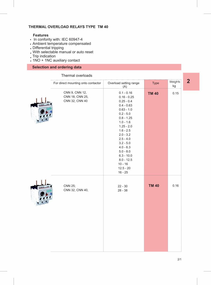
2
2/1
Selection and ordering data
Thermal overloads
For direct mounting onto contactor Overload setting range Type (A)
TM 40 0.1 - 0.16
0.16 - 0.25
0.25 - 0.4
0.4 - 0.63
0.63 - 1.0
0.2 - 5.0
0.8 - 1.25
1.0 - 1.6
1.25 - 2.0
1.6 - 2.5
2.0 - 3.2
2.5 - 4.0
3.2 - 5.0
4.0 - 6.3
5.0 - 8.0
6.3 - 10.0
8.0 - 12.5
10 - 16
12.5 - 20
16 - 25
22 - 30
28 - 38
CNN 9, CNN 12,
CNN 18, CNN 25,
CNN 32, CNN 40
TM 40
THERMAL OVERLOAD RELAYS TYPE TM 40
FeaturesIn confority with: IEC 60947-4Ambient temperature compensated
Differential tripping With selectable manual or auto reset Trip indication 1NO + 1NC auxiliary contact
Weights
kg
0.15
0.16CNN 25;
CNN 32, CNN 40,
0.16 - 0.25
0.25 - 0.4
0.4 - 0.63
0.63 - 1.0
0.2 - 5.0
0.8 - 1.25
1.0 - 1.6
22 - 30
28 - 38
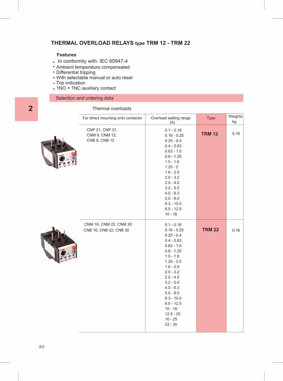
zIn conformity with: IEC 60947-4
2
2/2
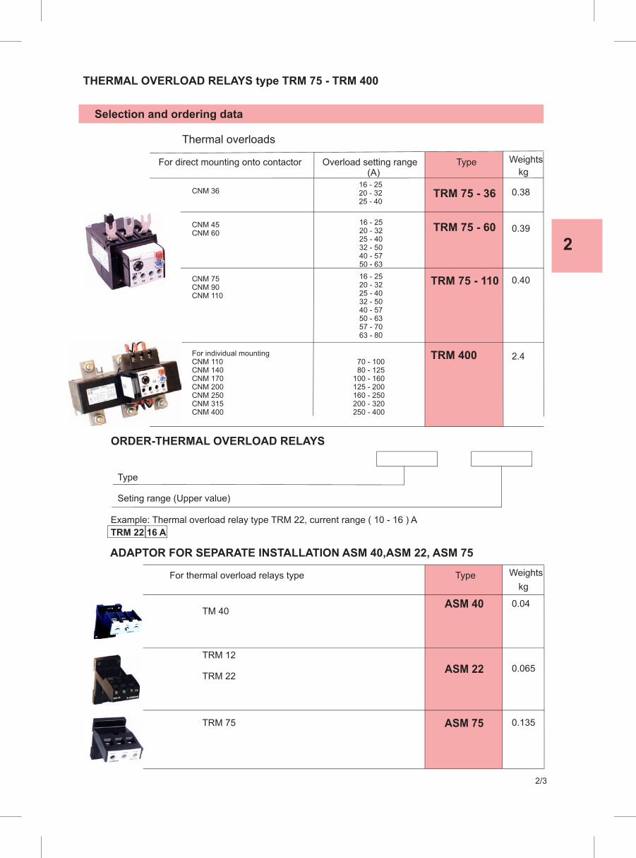
2
2/3
THERMAL OVERLOAD RELAYS type TRM 75 - TRM 400
Selection and ordering data
Thermal overloads
For direct mounting onto contactor Overload setting range Type (A)
CNM 36 16 - 25 20 - 32 25 - 40
TRM 75 - 36
CNM 45CNM 60
16 - 25 20 - 32 25 - 40 32 - 50 40 - 57 50 - 63
TRM 75 - 60
CNM 75CNM 90CNM 110
16 - 25 20 - 32 25 - 40 32 - 50 40 - 57 50 - 63 57 - 70 63 - 80
TRM 75 - 110
70 - 100 80 - 125 100 - 160 125 - 200 160 - 250 200 - 320 250 - 400
For individual mountingCNM 110CNM 140CNM 170CNM 200CNM 250CNM 315CNM 400
TRM 400
ORDER-THERMAL OVERLOAD RELAYS
Type
Seting range (Upper value)
Example: Thermal overload relay type TRM 22, current range ( 10 - 16 ) A
TRM 22 16 A
For thermal overload relays type Type
ADAPTOR FOR SEPARATE INSTALLATION ASM 40,ASM 22, ASM 75
ASM 22
ASM 40
TRM 12
TRM 22
TM 40
TRM 75 ASM 75
Weights
kg
0.38
0.39
0.40
2.4
Weights
kg
0.065
0.04
0.135

THERMAL OVERLOAD RELAYS TM and TRM
Application, standards and installation
Thermal overload relays TRM are intended to protect low voltage motors and other consumers against nonpermissible overloads and phase-failure operation.Relays are in conformity with IEC 60947-4-1, EN 60947-4-1 and VDE 0660. They are normally intended for mounting on our contactors see ordering table. Individual screw mounting of the TM 40, TRM 12 and TRM 22 relays on plane surface or snap-on fastening to 35 mm mounting rail (according to DIN EN 50022) is possible by using a special adaptor type ASM 40 and ASM 22.The relay TRM 400 is intended for individual screw mounting.
Current time curves
The current time curves give correlation between the tripping time and the multi-plifcator of the present current I e. They are presented for a cold initial state of the relay. For relays warmed by 1,0 x Ie load, the tripping times are lower by 25%.The curve 2 is given for 3-phase operation. The curve 1 is given for 2-phase op-eration. For the protection of a 1-phase, or DC motor, serial conection of the main circuit of relays is necessary. For that connection the tripping curve 2 is valid.
TRM 400TM 40 TRM 12 TRM 22 TRM 75
class 10 (release time 4 s ... 10 sat 7,2 x Ie from cold state)
Technical data
Relay type
Insulation rating Ui V 690 1000 690
Permissible ambient temperature oC - 25 to +55
Degree of protection IP00
Releasetimeclassifcation
Temperature compensation + + + + +
Phase failure protection by differential phase shift + + + + +
Test button + + + + +
Reset button + + + + +
Switch position indicator + + + + +
Changeover to hand or automatic reseting + + + + +
Vibration resistance g 8 8 8 8 8
Main circuit rated operational current (AC 50 to 400 Hz or DC) A 38 16 30 80 400 conductor cross - section solid or stranded mm2 2,5 - 10 2,5 - 6 2,5 - 6 2,5 - 35 120/24 fnely stranded with end sleeve
Screw/Screw head Tightening torque Nm
Screw/Screw head Tightening torque Nm
mm2 1,5 - 6
M4/PZ2 M4/PZ2
M3.5/PZ1
M4/PZ2 M6 M101.6 1.2
0.8
1.2 2.5
1,5 - 4 1,5 - 4 1,5 - 25
Power input per pole max. at setting range min. W/VA 0,9 0,9 0,9 2,6 5 max. at setting range max. W/VA 2,25 2,25 2,25 4 12
Auxiliary circuit
number and type of contacts
1 NO + 1 NC (galvanically separated)
conductor cross - section
solid or stranded
mm2 2 x (1 - 2,5)
fnely stranded with end sleeve
mm2 2 x (0,75 - 1,5)
rated thermal current
Ith ; 35oC A 6
rated insulation voltage AC:
unequal potential (NO + NC) V 400
equal potential (NO + NC) V 690
rated current
Ie/AC15 for 24 V A 2
60 V A 1.5
230 V A 1.15
400 V A 1.1
500 V A 1 rated current
Ie/DC13 for 24 V A 1
60 V A 0.4
110 V A 0.22
220 V A 0.1
2
2/4

2
2/5
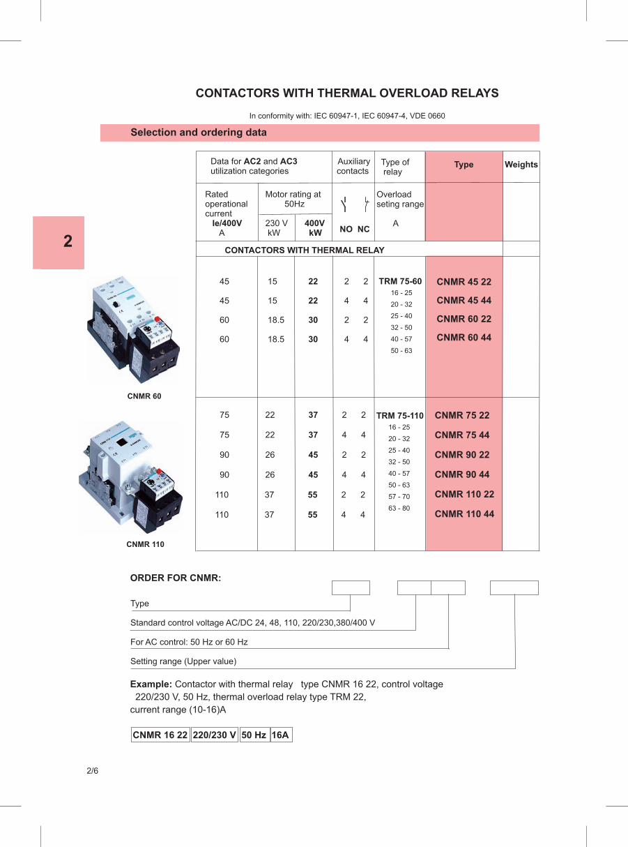
2
2/6

TRM 75 ASM 75 +
Type
TRM 22 + CNM 16, 22, 30
TRM 12 + CNM 12
TRM 12 + CNM 9
TRM 12 + CNB 9
TRM 12 + CNB 12
TRM 22 + CNB 16, 22, 30
40
178
11
0
90
65
653
112
180
60
127.3
75
50
60
9895 96 97
TRM 75
2T1 6T34T2
Tip
142 86.5
Type
TM 40 + CNN 32, 40
TM 40 + CNN 25
TM 40 + CNN 9; 12; 18 132.2 71 74 101 31 60-65 4.5
75,5 101 32.8 60-65 4.5
86 114 43.5 60-70 5
71
84.5143.5
134
F G
B
E
D
C
CNN
TM 40
A
35
65
F
45
G
81.4
89.3
45.2
35
66
TM 40 + ASM 40
2
2/7


3
BS 10, BS 20 BS 25 BS 32 BS 40 BS 50, BS 63 BS 80, BS 100K

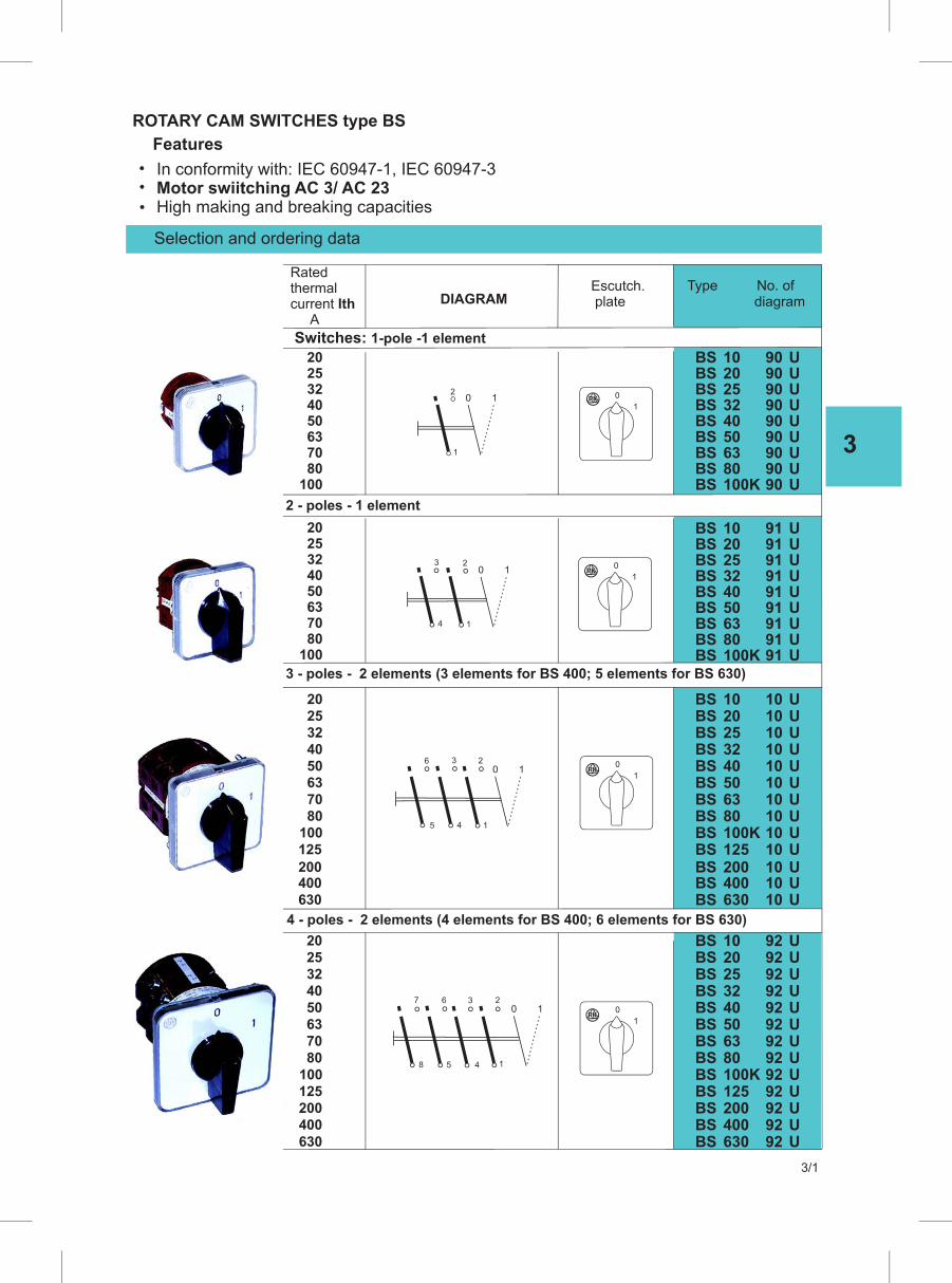
3
3/1
ROTARY CAM SWITCHES type BS
Features
In conformity with: IEC 60947-1, IEC 60947-3 Motor swiitching AC 3/ AC 23 High making and breaking capacities
Selection and ordering data
Escutch. plate diagram
2025324050637080
100
2025324050637080
100
2 - poles - 1 element
0 1
1
2
1
0
9191
UU
91 U91 U9191
UU
91 U91 U91 U
0 1
1
2
4
3
1
0
3 - poles - 2 elements (3 elements for BS 400; 5 elements for BS 630)
125
200400630
1
00 1
1
2
4
3
5
6
4 - poles - 2 elements (4 elements for BS 400; 6 elements for BS 630)
324050637080
100125200400630
1
00 1
1
2
4
3
5
67
8
DIAGRAM
Ratedthermalcurrent Ith
A
Type No. of
Switches: 1-pole -1 element
BSBS
2010
9090
UU
BS 25 90 UBS 32 90 UBS 40 90 U
BS 100K 90 UBS 80 90 UBSBS
6350
BSBS
2010
BS 25 BS 32 BS 40
BS 100K BS 80 BSBS
6350
BSBSBSBSBSBSBSBS
1020253240506380
BS 100K
BSBS
2010
BS 25 BS 32 BS 40
BSBS
100KBS 80 BSBS
6350
9090
UU
125BS 200 10 UBS 400 10 UBS 10 U
10 U10 U
10 U10 U10 U
10 U
10 U10 U
10 U10 U
BS 630 92 UBS 400 92 U
BS 125 92 UBS 200 92 U
92 U92 U92 U92 U92 U92 U92 U92 U92 U
2025324050637080
100
2025
630

3
3/2
Selection and ordering data
Escutch. plate diagramDIAGRAM
Ratedthermalcurrent Ith
A
Type No. of
2-poles -2 elements (4 elements for BS 400; 6 elements for BS 630)
52 U52 U52 U52 U52 U52 U52 U52 U52 U
BS 125 52 UBS 200 52 UBS 400 52 UBS 630 52 U
3 - poles - 3 elements (6 elements for BS 400; 9 elements for BS 630)
53 U53 U53 U53 U53 U53 U 53 U 53 U53 U
BS 125 53 UBS 200 53 UBS 400 53 UBS 630 53 U
4 - poles - 4 elements
2
0
11 2
6,7
1
2,3
04 5 8
2
0
1
2
0
1
1 2
10,11
5
6,7
08 9 121 4
2,3
1 2
10,11
5
6,7
08 9 121 4
2,3 14,15
13 16
Changeover switches with zero position1-pole - 1 element
1 2
2,3
4 012
0
1
100
3240
70
5063
80
2025
125200
400
630
3240
70
5063
80100
2025
125
200
400
630
3240
70
5063
80100
2025
3240
70
5063
80100
2025
51 U51 U51 U51 U51 U51 U
51 U51 U51 U
BSBS
2010
BS 25 BS 32 BS 40
BS 100K BS 80 BSBS
6350
75 UBS 20 75 UBS 10
75 UBS 25 75 UBS 32 75 UBS 40
75 UBS 100K 75 UBS 80 75 UBS 63 75 UBS 50
BSBS
2010
BS 25 BS 32 BS 40
BS 100K BS 80 BSBS
6350
BSBS
2010
BS 25 BS 32 BS 40
BS 100K BS 80 BSBS
6350
ROTARY CAM SWITCHES type BS
Features
In conformity with: IEC 60947-1, IEC 60947-3 Motor swiitching AC 3/ AC 23 High making and breaking capacities
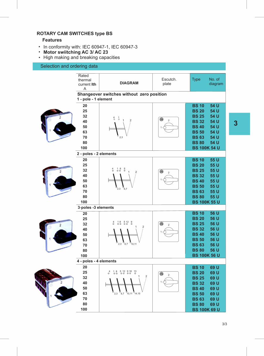
3
3/3
Selection and ordering data
Escutch. plate diagramDIAGRAM
Ratedthermalcurrent Ith
A
Type No. of
3-poles -3 elements
4 - poles - 4 elements
BS 10 56 UBS 20 56 UBS 25 56 UBS 32 56 UBS 40 56 UBS 50 56 UBS 63 56 UBS 80 56 UBS 100K 56 U
BS 10 69 UBS 20 69 UBS 25 69 UBS 32 69 UBS 40 69 UBS 50 69 UBS 63 69 UBS 80 69 UBS 100K 69 U
2
1
2
1
1 2
10,116,72,3
4 5 121 8 9
1 2
14,1510,116,72,3
9 165 12 134 1 8
25
20
32
40
50
63
70
80
100
25
20
32
40
50
63
70
80
100
25
20
32
40
50
63
70
80
100
2 - poles - 2 elements
BS 10 54 UBS 20 54 UBS 25 54 UBS 32 54 UBS 40 54 UBS 50 54 UBS 63 54 UBS 80 54 UBS 100K 54 U
BS 10 55 UBS 20 55 UBS 25 55 UBS 32 55 UBS 40 55 UBS 50 55 UBS 63 55 UBS 80 55 UBS 100K 55 U
1 - pole - 1 elementShangeover switches without zero position
1 2
2,3
14
2
1
2
1
1 2
6,7
5
2,3
4 1 8
25
20
32
40
50
63
70
80
100
ROTARY CAM SWITCHES type BS
Features
In conformity with: IEC 60947-1, IEC 60947-3 Motor swiitching AC 3/ AC 23 High making and breaking capacities
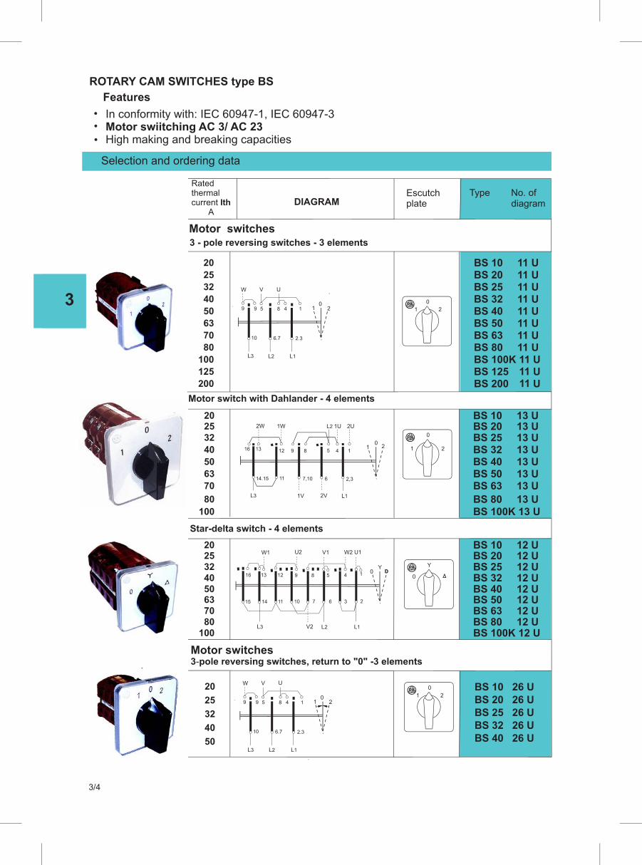
3
3/4
Selection and ordering data
20
25
32
40
50
BS 10 26 UBS 20 26 UBS 25 26 UBS 32 26 UBS 40 26 U
0
6.7 2.3
1 2
V U
8 45 1
10
9 9
W
L3 L2 L1
2
0
1
Escutch plate diagramDIAGRAM
Ratedthermalcurrent Ith
A
Type No. of
Motor switches3-pole reversing switches, return to "0" -3 elements
3 - pole - 3 elementsreversing switches
32
40
50
63
70
100
80
125
200
BS 10 11 UBS 20 11 UBS 25 11 UBS 32 11 UBS 40 11 UBS 50 11 UBS 63 11 UBS 80 11 UBS 100K 11 UBS 125 11 UBS 200 11 U
Motor switch with Dahlander - 4 elements
2520
32
40
50
63
70
80
BS 20 13 UBS 10 13 U
BS 25 13 UBS 32 13 UBS 40 13 UBS 50 13 UBS 63 13 U
BS 80 13 UBS 100K 13 U
32405063
8070
100
BS 20 12 UBS 10 12 U
BS 25 12 UBS 32 12 UBS 40 12 UBS 50 12 UBS 63 12 UBS 80 12 UBS 100K 12 U
Star-delta switch - 4 elements
Motor switches
0
6.7 2.3
1 2
V U
8 45 1
10
9 9
W
L3 L2 L1
2
0
1
0
2,3
1
6
1V
14.15 11
12
L2
7,10
8 16 5 1
2U
4
2V L1
2
1U
9
1W 2W
13
L3
0
1 2
Y0
15
W1
11
U2
16 5
14 10 7 6 3 2
V2
13 9 8 4 1DD
V1 W2 U1
12
L3 L2 L1
Y
0
20
25
2520
100
ROTARY CAM SWITCHES type BS
Features
In conformity with: IEC 60947-1, IEC 60947-3 Motor swiitching AC 3/ AC 23 High making and breaking capacities
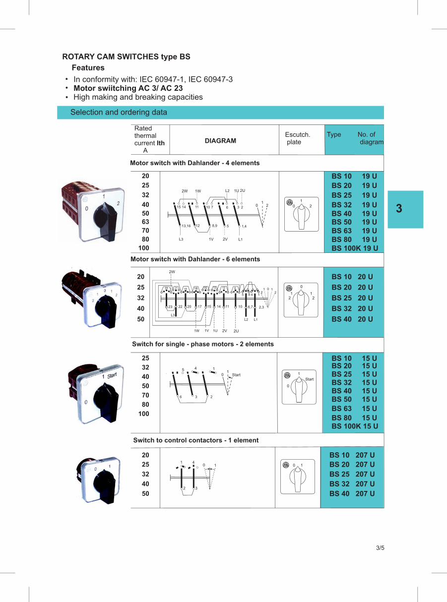
3
3/5
Selection and ordering data
Escutch. plate diagramDIAGRAM
Ratedthermalcurrent Ith
A
Type No. of
Motor switch with Dahlander - 4 elements
25
20
32
40
50
63
70
80
100
BS 20 19 U
BS 10 19 U
BS 25 19 U
BS 32 19 UBS 40 19 UBS 50 19 UBS 63 19 UBS 80 19 UBS 100K 19 U
Switch for single - phase motors - 2 elements
25
32
40
50
70
80
100
BS 10 15 UBS 20 15 UBS 25 15 UBS 32 15 UBS 40 15 UBS 50 15 U
BS 63 15 U
BS 80 15 UBS 100K 15 U
20
25
32
40
50
BS 20 207 U
BS 10 207 U
BS 25 207 U
BS 32 207 U
BS 40 207 U
Switch to control contactors - 1 element
1
3 2
0 Start
5
6
4 1
Start
0
1
1
32
01 4
10
1
1,4
0
5
1V
13,16 12
L2
8,9
11 6 2
1W 1U
3
L3 L1 2V
2U
2
2W
15 14 10 7 2
1
0
Motor switch with Dahlander - 6 elements
20
25
32
40
50
BS 20 20 U
BS 10 20 U
BS 25 20 U
BS 32 20 U
BS 40 20 U
22 17 14 2,323
12
1024 19 16
L2
1W 1U
21
20
182
13
1V
15 11 10 6,7
12 9
5 8 4
2U2V
2W
1
L3
L1
0
1 12 2
ROTARY CAM SWITCHES type BS
Features
In conformity with: IEC 60947-1, IEC 60947-3 Motor swiitching AC 3/ AC 23 High making and breaking capacities
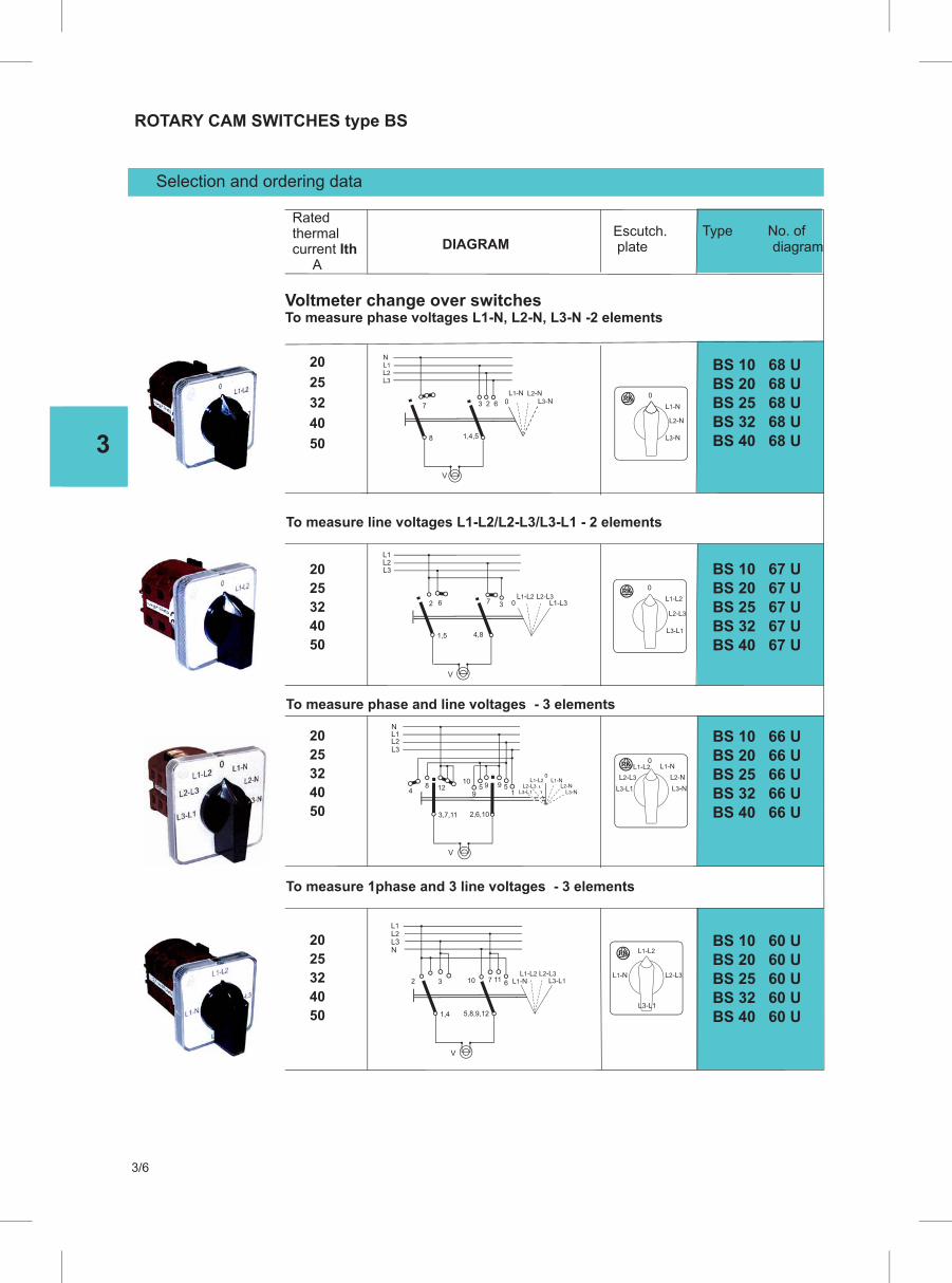
3
3/6
ROTARY CAM SWITCHES type BS
Selection and ordering data
20
25
32
40
50
To measure line voltages L1-L2/L2-L3/L3-L1 - 2 elements
BS 10 68 UBS 20 68 UBS 25 68 UBS 32 68 UBS 40 68 U
20
25
32
40
50
20
25
32
40
50
BS 10 67 UBS 20 67 UBS 25 67 UBS 32 67 UBS 40 67 U
BS 10 66 UBS 20 66 UBS 25 66 UBS 32 66 UBS 40 66 U
20
25
32
40
50
BS 10 60 UBS 20 60 UBS 25 60 UBS 32 60 UBS 40 60 U
4,8
2
1,5
7
V
06 3L2-L3
L1-L3L1-L2
L2L1
L3
L1-N
L2-N
L3-N
0
L2-L3
L3-L1
0
L1-L2
To measure phase and line voltages - 3 elements
2,6,103,7,11
V
12
N
10
148 5995
9
0
L2L1
L3
L2-L3L1-L2 L1-N
L3-NL2-N
L3-L1
0
L2-L3
L1-L2 L1-N
L3-N
L2-N
L3-L1
5,8,9,121,4
7
V
3 610 112
L2L1
NL3
L1-L2 L2-L3L1-N L3-L1
To measure 1phase and 3 line voltages - 3 elements
Escutch. plate diagramDIAGRAM
Ratedthermalcurrent Ith
A
Type No. of
Voltmeter change over switchesTo measure phase voltages L1-N, L2-N, L3-N -2 elements
L1-L2
L1-N L2-L3
L3-L1
V
1,4,5
7
8
L2L1N
3 2 6 0L1-N L2-N
L3-N
L3
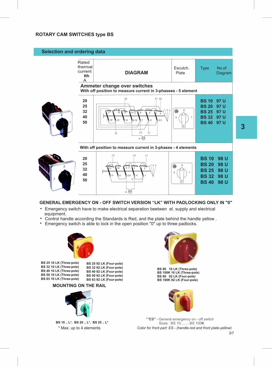
3
3/7
ROTARY CAM SWITCHES type BS
Selection and ordering data
Escutch. Type No.of
Ratedthermalcurrent
Ith A
20
25
32
40
50
With off position to measure current in 3-phases - 4 elements
BS 10 97 UBS 20 97 UBS 25 97 UBS 32 97 UBS 40 97 U
20
25
32
40
50
BS 10 98 UBS 20 98 UBS 25 98 UBS 32 98 UBS 40 98 U
DIAGRAM
11 9 5,8 4 1
L2 L1
10 6 71 2 30
23
L3
12
A
3
0
1
2
3
0
1
2
18 16 14 9,12 7 6 2,3
k2 k1 k3
l2 L3 L1
17 15 13 10 11 8 1
1 2 30
45
A
Ammeter change over switchesWith off position to measure current in 3-phasees - 5 element
equipment.
GENERAL EMERGENCY ON - OFF SWITCH VERSION “LK” WITH PADLOCKING ONLY IN "0"
k
BS 25 10 LK (Three-pole)
BS 32 10 LK (Three-pole)
BS 40 10 LK (Three-pole)BS 50 10 LK (Three-pole)
BS 63 10 LK (Three-pole)
BS 25 92 LK (Four-pole)
BS 32 92 LK (Four-pole)
BS 40 92 LK (Four-pole)BS 50 92 LK (Four-pole)
BS 63 92 LK (Four-pole)
BS 10 .. L*, BS 20 .. L*, BS 25 .. L*
* Max. up to 4 elements
Plate Diagram
*"ES" - General emergency on - off switch Sizes : BS 10; .... ; BS 100K
Color for front part: ES - (handle-red and front plate-yellow)
BS 80 10 LK (Three-pole)BS 100K 10 LK (Three-pole)BS 80 92 LK (Four-pole)BS 100K 92 LK (Four-pole)
MOUNTING ON THE RAIL
Emergency switch is able to lock in the open position "0" up to three padlocks. Control handle according the Standards is Red, and the plate behind the handle yellow .
Emergency switch have to make electrical separation beetwen el. supply and electrical

3
3/8
ROTARRY CAM SWITCHES WITH TITLE type BS ....N
Selection and ordering data
20
25
32
40
50
63
70
80
100
BS 10 .. . N
BS 20 .. . N
BS 25 .. . N
BS 32 .. . N
BS 40 .. . N
BS 50 .. . N
BS 63 .. . N
BS 80 .. . N
BS 100K .. . N
DescriptionRatedthermalcurrent Ith A
Type
NOTES: - 1.Technical date and drilling plan are same as the standard version of the model “BS”
No. Of diagram are as the standard version of the model “BS”
Front mounting “U”, Rear mounting “O”
Extended front plate with titleStandard colour - Black
Extended front plate with title
DIMENSIONAL DRAWIINGS (mm) DRILLING PLATE
BS 10 .. N
BS 20 .. N
A B E
48 60 24
48 60 24
65
65
80
80
32,5
32,5
65 80 32,5
90
90
110
110
45
45
26
26 38.6
38.6
45.2
45.2
53
61
68.6
84
84
38.6
38.6
38.6
38.6
38.6
56.4
56.4
80
80
33
33
33
41
41
C D
BS 25 .. N
BS 40 .. N
BS 80 .. N
BS 100K .. N
BS 50 .. N
BS 63 .. N
BS 32 .. N
BSB 20 ..N
BSB 25 ..N
48
48
60
60
24
24
26
26
TYPE MARKING
A
01
E
B
CL
P
ØGD
f
f
a
a
d
b
BS 32 .. N
BS 40 .. N
BS 50 .. N
BS 63 .. N
BS 80 .. N
BS 100K .. N
BSB 20 .. N
BSB 25 .. N
48
36
36
10 4.2
72 14 5.3
10 4.2
a b d f
BS 10 .. N
BS 20 .. N
BS 25 .. N
30 10 4.2
TYPE
OG

3
3/9
“BAYONET” ROTARY CAM SWITCHES type BSB
Selection and ordering data
2025 32 40
BSB 10 .. . .BSB 20 .. . .BSB 25 .. . .BSB 32 .. . .
DescriptionRated thermalcurrent Ith A
Type
No.of diagram are as the standard version of the model “BS”
Mounting form
- for front “U”
Front part: P - (handle and front plate - blue) C - (handle and front plate - black)
BL
P
ØDCA
0
1
DIMENSIONAL DRAWINGS (mm)
NOTES: 1.Technical date and drilling plan are same as the standard version of the model “BS” 2.The selection of the color for the front parts for “BS” is same as previus case for “BSB”
TYPETYPE MARKING NUMBER OF ELEMENTS (L/mm)
BSB 20
BSB 10
A B
51,2
51,2
51,2
27,2
27,2
27,2
45,2
53
38,6
38,6
38,6
38,6
12,8
12,8
12,8
39,5
44
39,5
52,3
56,8
52,3
65,1
69,6 82,4 95,2 108 120,8 133,6 146,4 159,2 172 184,8
65,1
77,9
77,9
90,7
90,7
103,5
103,5
116,3
116,3
129,1
129,1
141,9
141,9
154,7
154,7
167,5
167,5
180,3
180,3
C P 1 2 3 4 5 6 7 8 9 10 11 12 ØD
BSB 25
BSB 32

3
3/10
DIMENSIONAL DRAWINGS (mm)
TYPETYPE MARKING NUMBER OF ELEMENTS (L/mm)
BS 20 BS 10
A B
51,2
51,2
72
72
72
105
105
27,2
27,2
33
33
33
41
41
45,2
38,6
61
68,6
53
84
84
38,6
38,6
38,6
56,4
56,4
80
80
12,8
12,8
12,8
32,5
37
32,5
50,6
42,5
67,5
67,5
45,3
49.8
45,3
68,1
63
92,5
92,5
58,1
62.6
58,1
85,6
83,5
117,5
117,5
70,9
75,4
70,9
103,1
104
142,5
142,5
83,7
88,2
83,7
120,6
124,5
167,5
167,5
96,5
101
96,5
138,1
145
192,5
192,5
109,3
113,8
109,3
155,6
165,5
217,5
217,5
122,1
126,6
122,1
173,1
186
242,5
242,5
134,9
139,4
134,9
190,6
206,5
267,5
267,5
147,7
152,2
147,7
208,1
227
292,5
292,5
160,5
165
160,5
225,6
247,5
317,5
317,5
173,3
177,8
173,3
243,1
268
342,5
342,5
17,5
20,5
25
25
C P 1 2 3 4 5 6 7 8 9 10 11 12 ØD
BS 25
BS 40
BS 80
BS 100K
BS 50
BS 63
BS 32
BS 125
BS 400
BS 630
BS 200 130 62 110 110
30
39
39
39
91
100
100
-
139
139
139
121
178
178
178
151
217
217 - 295
_ 256 295 - - 412
181
BL
P
ØDCA
0
1
BS 32
BS 50 BS 40
BS 63
BS 80
BS 100K
BS 125
BS 400
BS 630
BS 200
58 48 10 4.2
85 14 5.3 68-74
90 30 18 5.3
TYPE a b a1 b1 c d f
FR
ON
T M
OU
NT
ING
"U
"F
RO
NT
MO
UN
TIN
G "
M"
1-5
DRILLING PLAN
DRILLING PLAN
DRILLING PLAN
1-5
k
RE
AR
MO
UN
TIN
G "
O"
TYPE
BS 10
BS 20
h d g
13.5 8
10 3.5
16.2 10 4
20 14 4.5
BS 25
BS 32
BS 40
BS 63
BS 50
BS 80
BS 100K
TYPE a b f k
58
58
48
48
4.5
4.5
85 68 5.3 20.5
BS 40
BS 50
BS 63
BS 80
BS 100K
17
BS 10 BS 20 4.2 15.5
BS 25
36 36
BS 32
BS 10 BS 20
BS 25
32-39 30 8
10 3.2
f
f
f
a
a
b
d
c
ba1
f b1
f
f
a
ab
b
d
g
h
h
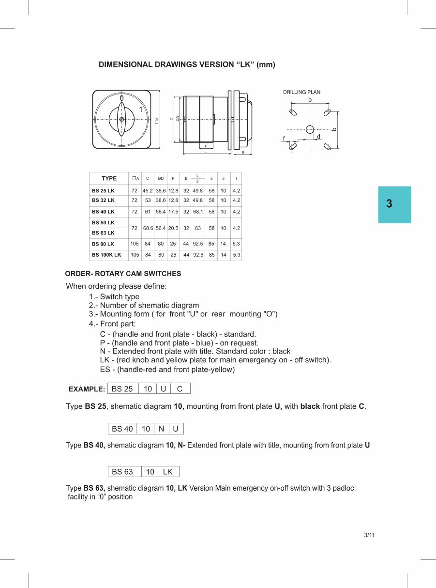
3
3/11
When ordering please define:
1.- Switch type2.- Number of shematic diagram3.- Mounting form ( for front "U" or rear mounting "O")
4.- Front part:
EXAMPLE: BS 25 10 U C
Type BS 25, shematic diagram 10, mounting from front plate U, with black front plate C.
ORDER- ROTARY CAM SWITCHES
BS 40 10 N U
Type BS 40, shematic diagram 10, N- Extended front plate with title, mounting from front plate U
DIMENSIONAL DRAWINGS VERSION “LK” (mm)
DRILLING PLAN
BL
P
ØDCA
0
1
f
b
d
b
TYPE
BS 40 LK
BS 50 LK
BS 32 LK
BS 25 LK
BS 63 LK
BS 80 LK
72
72
72
72
A ØDC
105
105
P B
BS 100K LK
L
2b d f
32
32
32
32
44
44
10
10
10
10
14
14
58
58
58
58
85
85
61
68.6
53
45.2
84
84
80
80
56.4
56.4
38.6
38.6
17.5
20.5
12.8
12.8
25
25
4.2
4.2
4.2
4.2
5.3
5.3
92.5
92.5
68.1
63
49.8
49.8
P - (handle and front plate - blue) - on request.C - (handle and front plate - black) - standard.
LK - (red knob and yellow plate for main emergency on - off switch).ES - (handle-red and front plate-yellow)
N - Extended front plate with title. Standard color : black
BS 63 10 LK
Type BS 63, shematic diagram 10, LK Version Main emergency on-off switch with 3 padloc facility in “0” position

3
3/12
TECHNICAL DATA
SWITCH TYPE BS 10 BS 20 BS 25 BS 32 BS 40 BS 50 BS 63
U i V 690Rated insulation voltage
Uimp kV 6Rated impulse withstand voltage
A 20 25 32 50 63 40 70 Rated thermal current Ith
V 480
Main switch Max.value of rated
operational voltage
Rated impulse wiythstand voltage kV 4
A 20 25 32 50 63 40 70 Max. fuse size for short circuit protection gL 10 kA
1 sek A 200 250 400 800
3 sek A 120 150 250 700 Icw
10 sek A 70 80 140 350
Rated Short-time
30 sek A 40 50 90 250
Withstand current
60 sek A 30 40 70
800 800 600
530 640 400
290 320 240
200 230 150
150 150 120 150
Rated operational current I AC1 / AC21e
Rated operational current I A 15e C
110 V A 8 10 20 40 45 25 50
220/230 V A 6 8 20 30 35 25 40
380/400 V A 4 6 16 25 32 20 40
660/690 V A 8 8.5 9 8,5 10
Motor switch in utilization category
AC3
AC23
AC4
9 10
9 10
7.5
8
11
15
3-phase
3-phase
3-phase
15 16
18.5 20
11
15
18.5
22
19 20
22 25
15
18.5
22
30
110V
110 V
kW
kW
0.8 0.8
0.8 0.8
1.5
1.5
2.5
2.5
2.5 3
3 3
3
3.5
1-phase
1-phase
2-poles
2-poles
220/230 V
220/230 V
kW
kW
1.5 2.2
1.7 2.5
3
3.7
4.8
5
5.5 5.5
6 7
6
9
380/400 V
380/400 V
kW
kW
2.2 3
3 3.7
5.5
5.5
6.5
7.5
7.5 9
9 11
11
15
Mechanical endurance swit. cycles
Terminal screw
Screw head
Tightening torque
Cable cross-section rigid
flexible
A 10 20 25 40 50 6332
610 3 3 3 3 3 3 2
M3.5
PZ2 PZ2 PZ2 PZ2 PZ2 PZ2 PZ1
0.8 0.8 1.2 1.8 2 2 0.8
M3.5 M5 M5 M4 M5
2 mm
2x(1-2.5) 2x(1-2.5)
2x(1-2.5) 2x(1-2.5)
1-6* 1-10*
1-10*
2x(2.5-10) 2x(4-16) 2x(4-16)
2x(2.5-10) 2x(4-16) 2x(4-16)
2-4* 2-4*
2-4* 2-4*
220/230 V
220/230 V
kW
kW
2.5 3
3 5
5.5
6.5
380/400 V
380/400 V
kW
kW
4 5
6 7.5
7.5
11
500/690 V
500/690 V
kW
kW
11
11 - -
8 9 5.5 11
kW 1.5 1.5 2.5 5 5.5 3 6
4
kW 4 8 9 7.5 11
220/230 V
380/400 V kW
500/690 V
2 3
400
2x(1-4) 2x(2,5-6)
2x(1-4) 2x(2,5-6)
M3.5
(1)
4
(1) Valid for neutral earthed systems, overvoltage category III, polution degree 3.
(*) Only for diagrams without inside links.
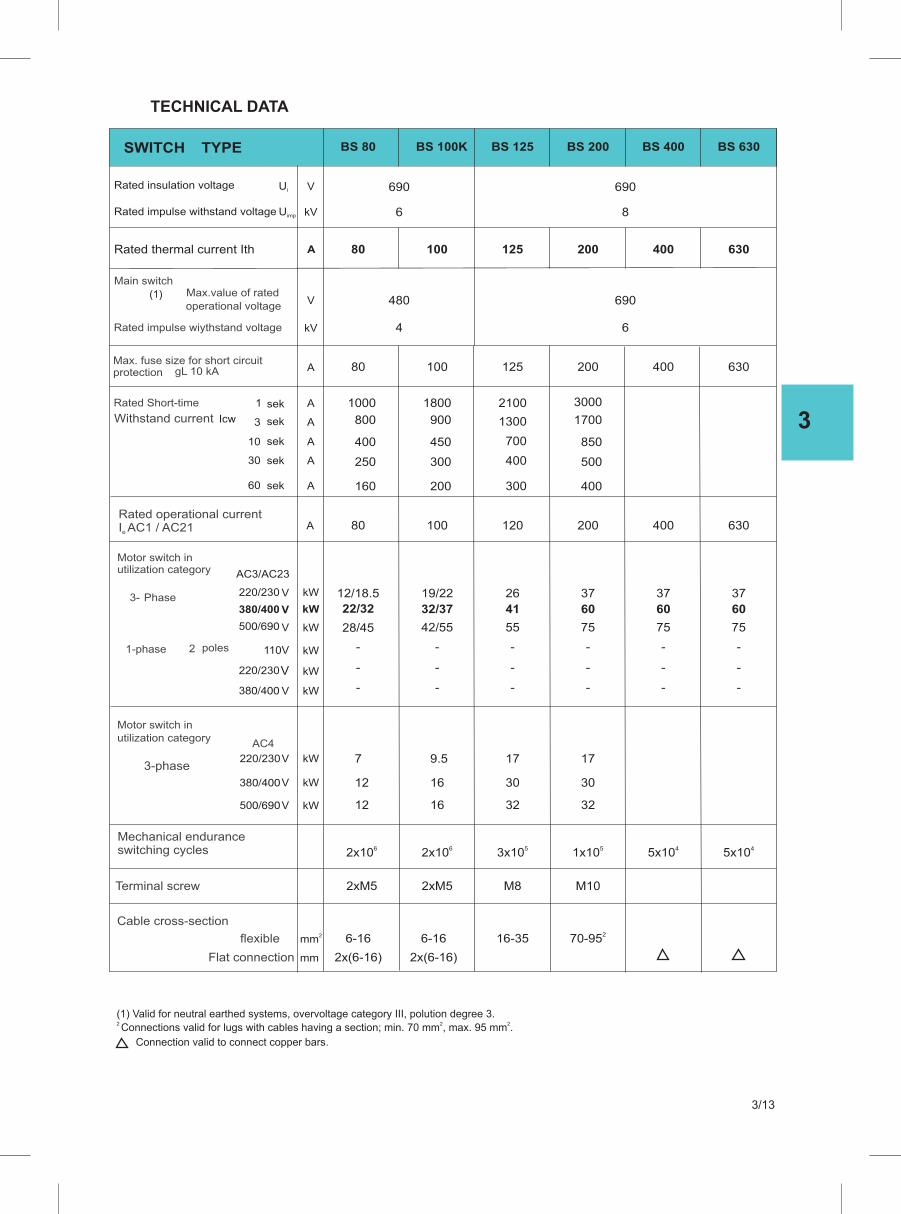
3
3/13
SWITCH TYPE
U i V Rated insulation voltage
Uimp kV Rated impulse withstand voltage
A Rated thermal current Ith
V
Main switch Max.value of rated
operational voltage
Rated impulse wiythstand voltage kV
A Max. fuse size for short circuit protection gL 10 kA
1 sek A
3 sek A Icw
10 sek A
Rated Short-time
30 sek A
Withstand current
60 sek A
Rated operational current I AC1 / AC21e
A
BS 125 BS 100K BS 80 BS 200 BS 400 BS 630
12510080 200 400 630
12510080 200 400 630
12010080 200 400 630
6 4
690690
86
690480
3000
1300
700
300
400
1700900800
850450400
500300250
400200160
2100 1800 1000
(1)
Motor switch in utilization category AC3/AC23
Phase
110V kW 1-phase 2 poles
220/230 V kW
380/400 V kW
Mechanical endurance switching cycles
Terminal screw
Cable cross-section
flexible
Flat connection
2 mm
mm
220/230 V kW 3- 380/400 V kW
500/690 V kW
Motor switch in utilization category
AC4
kW 3-phase
kW
220/230 V
380/400 V kW
500/690 V
12/18.5
22/32
28/45
2619/22
4132/37
5542/55
--
--
--
37
60
75
-
-
-
37
60
75
-
-
-
37
60
75
-
-
-
-
-
-
30 30 16 12
17 17 9.5 7
32321612
53x1062x1062x10 51x10 45x1045x10
M8 2xM5 2xM5 M10
16-356-166-16
2x(6-16) 2x(6-16)
270-95
(1) Valid for neutral earthed systems, overvoltage category III, polution degree 3.2 2 2Connections valid for lugs with cables having a section; min. 70 mm , max. 95 mm .
Connection valid to connect copper bars.
TECHNICAL DATA
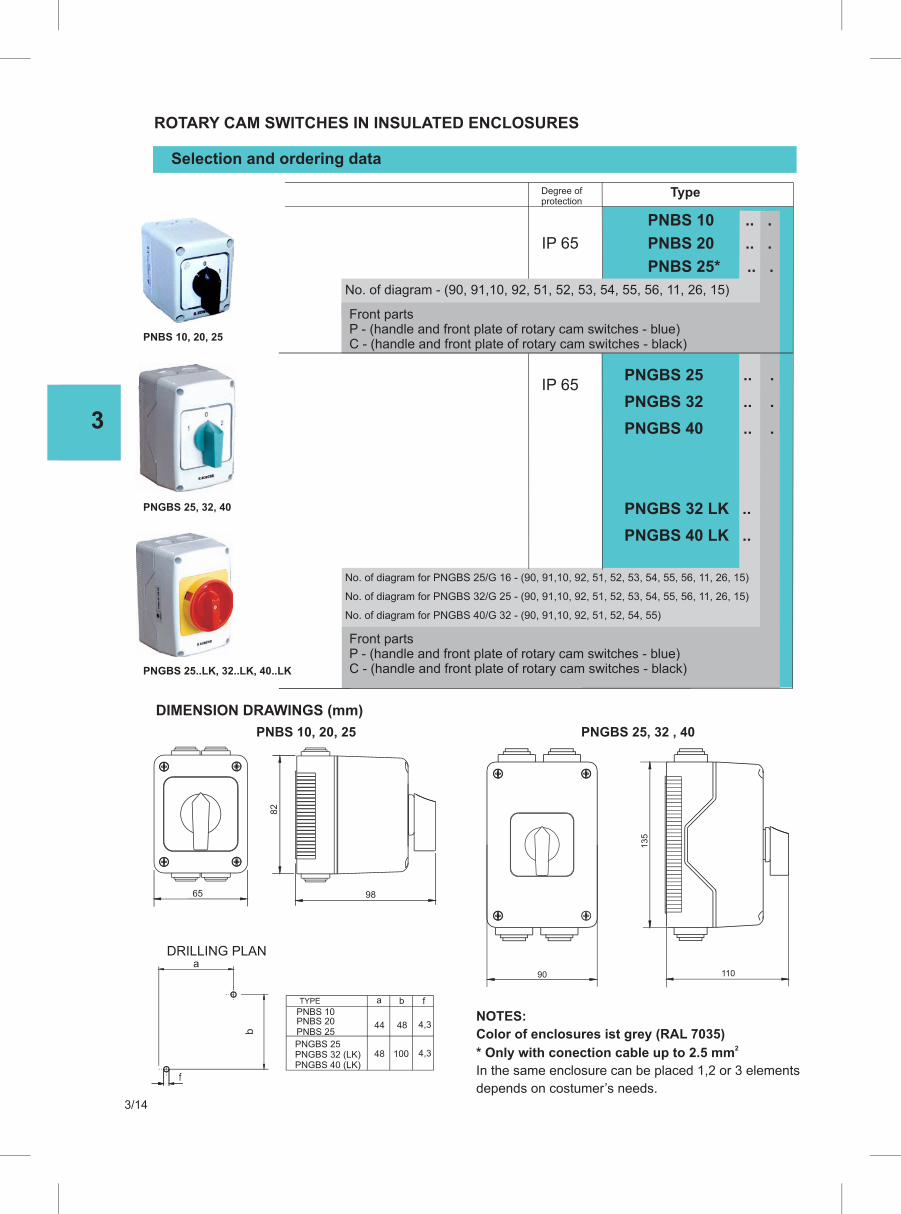
3
3/14
Selection and ordering data
ROTARY CAM SWITCHES IN INSULATED ENCLOSURES
IP 65
IP 65
TypeDegree of protection
DIMENSION DRAWINGS (mm)
PNBS 10, 20, 25 PNGBS 25, 32 , 40
PNBS 10, 20, 25
PNGBS 25, 32, 40
PNGBS 25..LK, 32..LK, 40..LK
DRILLING PLAN
b
a
f
No. of diagram - (90, 91,10, 92, 51, 52, 53, 54, 55, 56, 11, 26, 15)
No. of diagram for PNGBS 25/G 16 - (90, 91,10, 92, 51, 52, 53, 54, 55, 56, 11, 26, 15)
No. of diagram for PNGBS 32/G 25 - (90, 91,10, 92, 51, 52, 53, 54, 55, 56, 11, 26, 15)
No. of diagram for PNGBS 40/G 32 - (90, 91,10, 92, 51, 52, 54, 55)
Front parts P - (handle and front plate of rotary cam switches - blue) C - (handle and front plate of rotary cam switches - black)
Front parts P - (handle and front plate of rotary cam switches - blue) C - (handle and front plate of rotary cam switches - black)
PNBS 10 .. .
PNBS 20 .. .
PNBS 25* .. .
PNGBS 25 .. .
PNGBS 32 .. .
PNGBS 40 .. .
PNGBS 32 LK ..
PNGBS 40 LK ..
65 98
82
90 110
135
NOTES:
Color of enclosures ist grey (RAL 7035)2* Only with conection cable up to 2.5 mm
In the same enclosure can be placed 1,2 or 3 elements
depends on costumer’s needs.
PNBS 20PNBS 10
PNBS 25
TYPE a
44 48 4,3
48 100 4,3
b f
PNGBS 25PNGBS 32 (LK)PNGBS 40 (LK)
Front parts
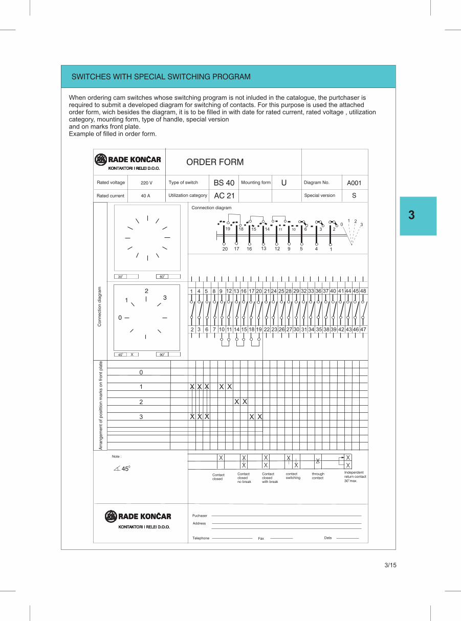
3
3/15
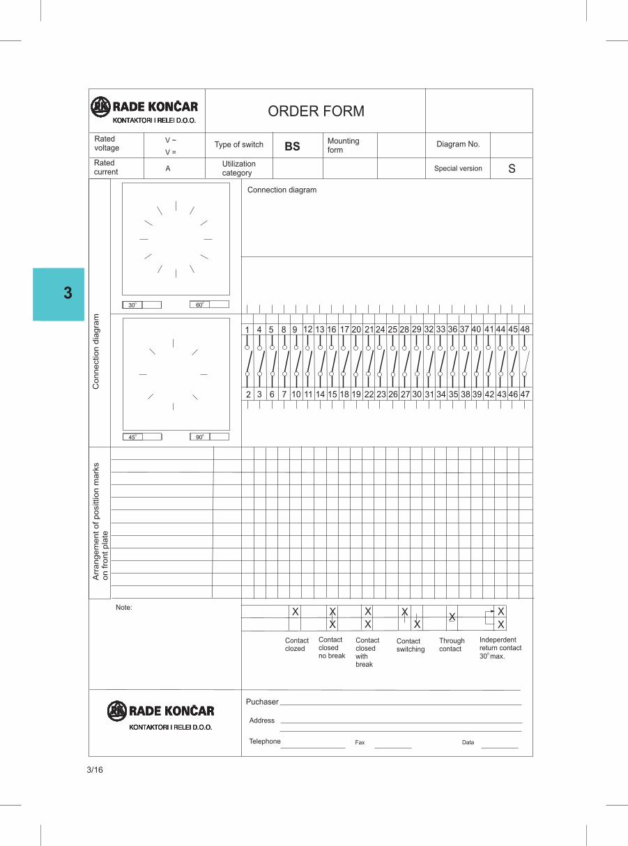
3
3/16


4
PUSHBUTTONS AND INDICATOR LIGHTS
Pushbuttons, non-illuminated PB 22-1- ...............................................................4/1
Pushbuttons, non-illuminated PB 22-2- ..............................................................4/1
Mushroom Pushbuttons PB 22-4- ......................................................................4/1
Toggle switches PB 22-6- ......................................................................... 4/2..........
Pushbuttons, illuminated PB 22-8- ........................................................... 4/2..........
Pilot lights and buzzer PB 22-31 .............................................................. 4/2..........
Selector switches, non-illuminated PB 22-11- .......................................... 4/2..........
Selector switches, non-illuminated PB 22-13- .......................................... 4/3..........
Selector switches, non-illuminated PB 22-12- .......................................... 4/3..........
Selector switches, non-illuminated PB 22-16- .......................................... 4/3..........
Selector switches, illuminated PB 22-25- ................................................. 4/3..........
Selector switches, illuminated PB 22-14- ................................................. 4/3..........
Selector switches, illuminated PB 22-26 - ................................................ 4/3..........
Selector switches, illuminated PB 22-17- ................................................. 4/3..........
Selector switches, illuminated PB 22-24- ................................................. 4/3..........
Double pushbuttons, illuminated PB 22-42- ............................................. 4/4..........
Double pushbuttons, non-illuminated PB 22-41- ...................................... 4/4..........
Elements which are delivered separatly ................................................... 4/4..........
Technical data ........................................................................................... 4/5..........
Dimenzional drawings .............................................................................. 4/6..........
Pushbutton in insulated enclosures type PNPB ........................................ 4/7..........

4
MOUNTING INSTRUCTION
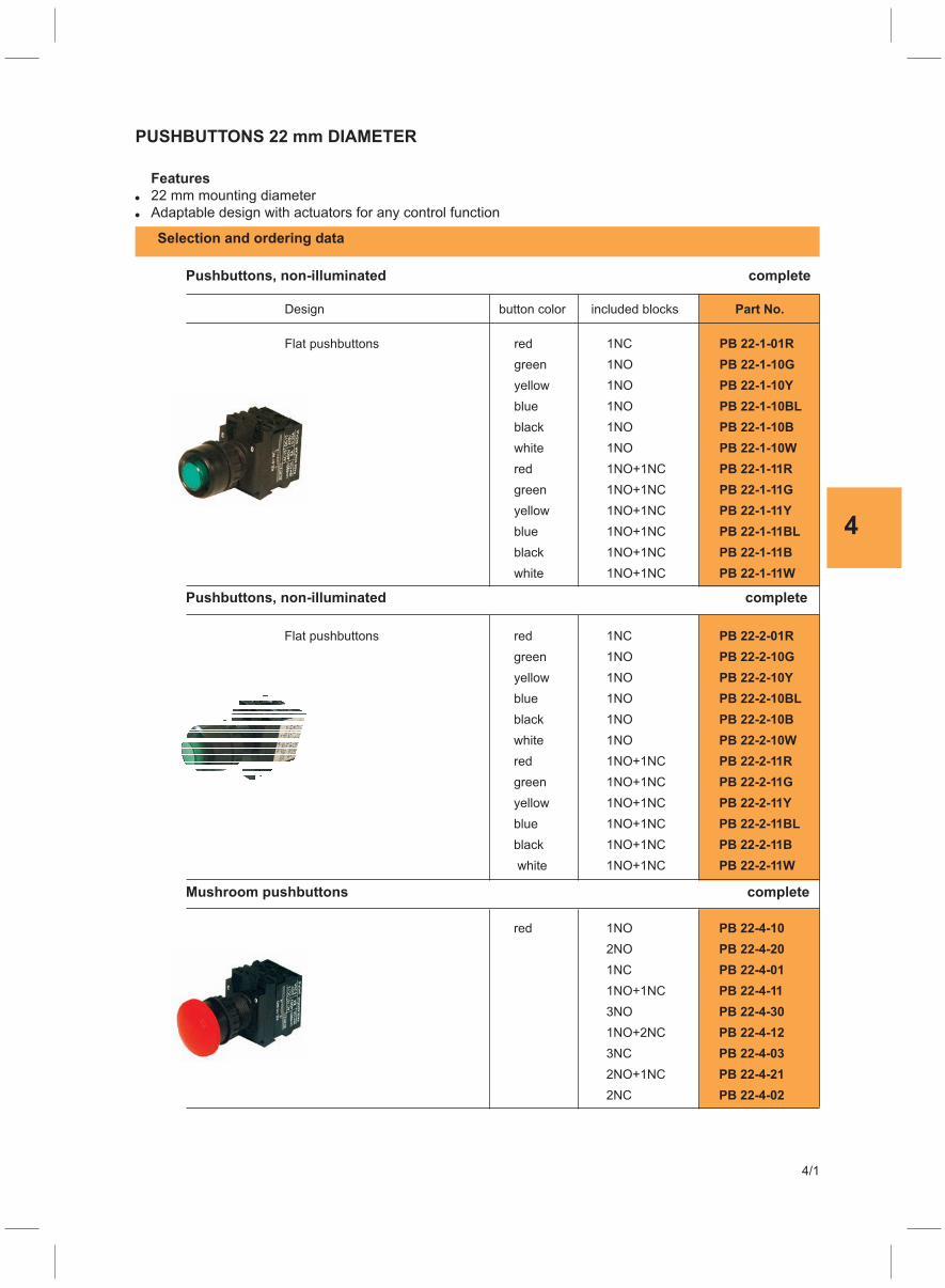
4
4/1
PUSHBUTTONS 22 mm DIAMETER
Features
� 22 mm mounting diameter
� Adaptable design with actuators for any control function
Selection and ordering data
Design button color included blocks Part No.
Flat pushbuttons red 1NC PB 22-1-01R
green 1NO PB 22-1-10G
yellow 1NO PB 22-1-10Y
blue 1NO PB 22-1-10BL
black 1NO PB 22-1-10B
white 1NO PB 22-1-10W
red 1NO+1NC PB 22-1-11R
green 1NO+1NC PB 22-1-11G
yellow 1NO+1NC PB 22-1-11Y
blue 1NO+1NC PB 22-1-11BL
black 1NO+1NC PB 22-1-11B
white 1NO+1NC PB 22-1-11W
Flat pushbuttons red 1NC PB 22-2-01R
green 1NO PB 22-2-10G
yellow 1NO PB 22-2-10Y
blue 1NO PB 22-2-10BL
black 1NO PB 22-2-10B
white 1NO PB 22-2-10W
red 1NO+1NC PB 22-2-11R
green 1NO+1NC PB 22-2-11G
yellow 1NO+1NC PB 22-2-11Y
blue 1NO+1NC PB 22-2-11BL
black 1NO+1NC PB 22-2-11B
white 1NO+1NC PB 22-2-11W
red 1NO PB 22-4-10
2NO PB 22-4-20
1NC PB 22-4-01
1NO+1NC PB 22-4-11
3NO PB 22-4-30
1NO+2NC PB 22-4-12
3NC PB 22-4-03
2NO+1NC PB 22-4-21
2NC PB 22-4-02
Pushbuttons, non-illuminated complete
Pushbuttons, non-illuminated complete
Mushroom pushbuttons complete
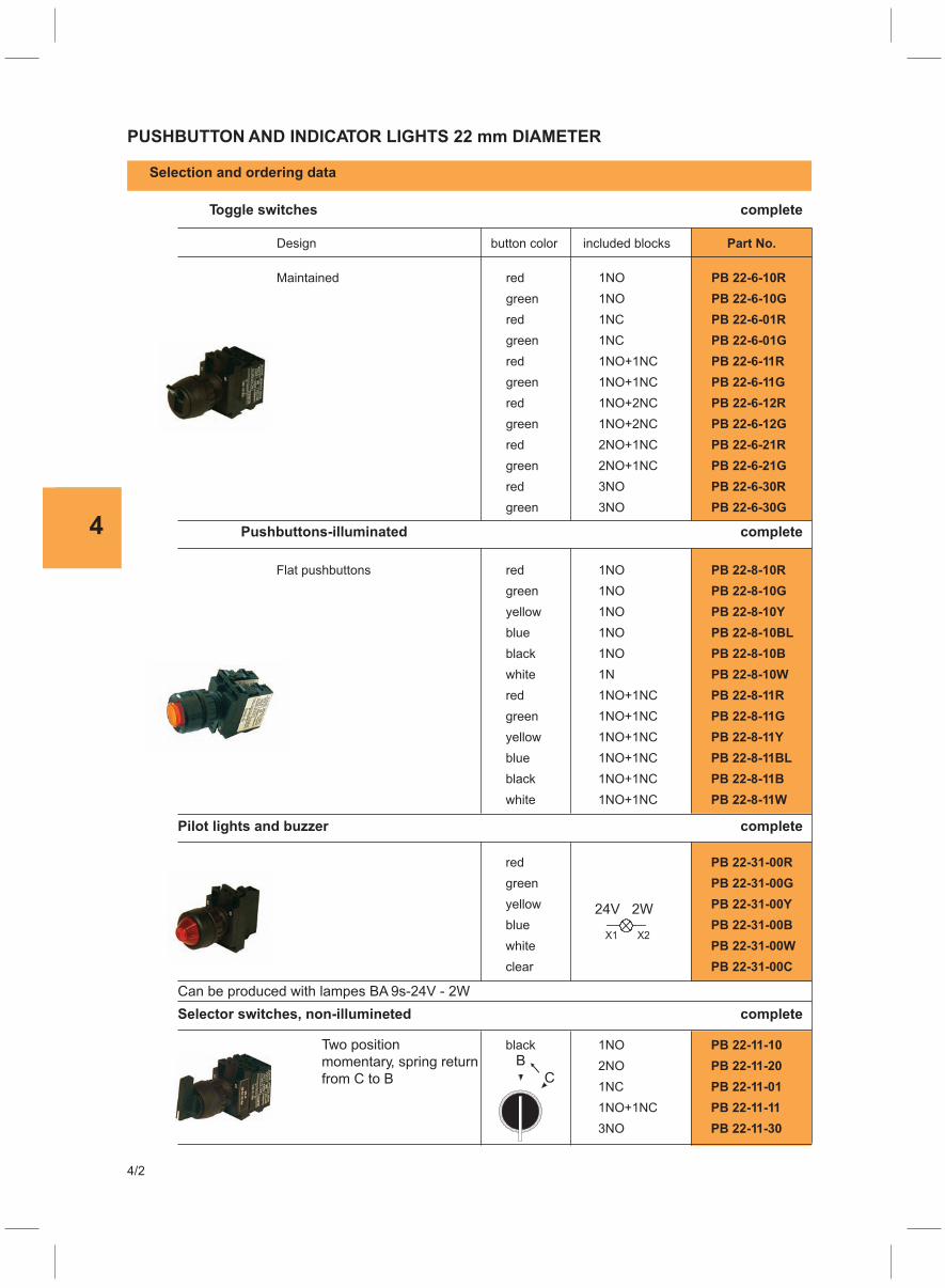
4
4/2
PUSHBUTTON AND INDICATOR LIGHTS 22 mm DIAMETER
Selection and ordering data
Design button color included blocks Part No.
Maintained red 1NO PB 22-6-10R
green 1NO PB 22-6-10G
red 1NC PB 22-6-01R
green 1NC PB 22-6-01G
red 1NO+1NC PB 22-6-11R
green 1NO+1NC PB 22-6-11G
red 1NO+2NC PB 22-6-12R
green 1NO+2NC PB 22-6-12G
red 2NO+1NC PB 22-6-21R
green 2NO+1NC PB 22-6-21G
red 3NO PB 22-6-30R
green 3NO PB 22-6-30G
Flat pushbuttons red 1NO PB 22-8-10R
green 1NO PB 22-8-10G
yellow 1NO PB 22-8-10Y
blue 1NO PB 22-8-10BL
black 1NO PB 22-8-10B
white 1N PB 22-8-10W
red 1NO+1NC PB 22-8-11R
green 1NO+1NC PB 22-8-11G
yellow 1NO+1NC PB 22-8-11Y
blue 1NO+1NC PB 22-8-11BL
black 1NO+1NC PB 22-8-11B
white 1NO+1NC PB 22-8-11W
red PB 22-31-00R
green PB 22-31-00G
yellow PB 22-31-00Y
blue PB 22-31-00B
white PB 22-31-00W
clear PB 22-31-00C
black 1NO PB 22-11-10
2NO PB 22-11-20
1NC PB 22-11-01
1NO+1NC PB 22-11-11
3NO PB 22-11-30
Toggle switches complete
Pushbuttons-illuminated complete
Pilot lights and buzzer complete
Selector switches, non-illumineted complete
Can be produced with lampes BA 9s-24V - 2W
Two position
momentary, spring return
from C to B
24V 2W
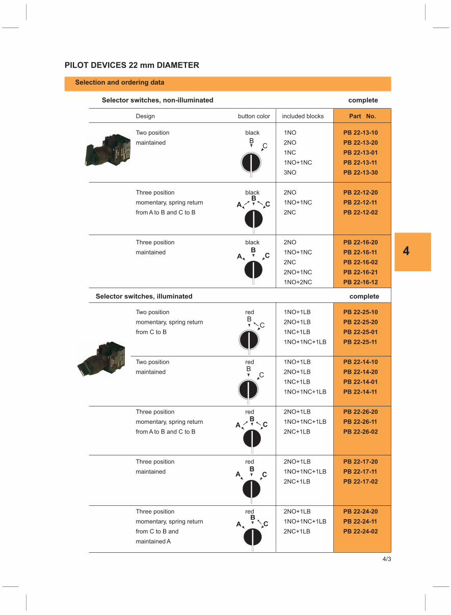
4
PILOT DEVICES 22 mm DIAMETER
Selection and ordering data
Design button color included blocks Part No.
Two position black 1NO PB 22-13-10
maintained 2NO PB 22-13-20
1NC PB 22-13-01
1NO+1NC PB 22-13-11
3NO PB 22-13-30
Three position black 2NO PB 22-12-20
momentary, spring return 1NO+1NC PB 22-12-11
from A to B and C to B 2NC PB 22-12-02
Three position black 2NO PB 22-16-20
maintained 1NO+1NC PB 22-16-11
2NC PB 22-16-02
2NO+1NC PB 22-16-21
1NO+2NC PB 22-16-12
Two position red 1NO+1LB PB 22-25-10
momentary, spring return 2NO+1LB PB 22-25-20
from C to B 1NC+1LB PB 22-25-01
1NO+1NC+1LB PB 22-25-11
Two position red 1NO+1LB PB 22-14-10
maintained 2NO+1LB PB 22-14-20
1NC+1LB PB 22-14-01
1NO+1NC+1LB PB 22-14-11
Three position red 2NO+1LB PB 22-26-20
momentary, spring return 1NO+1NC+1LB PB 22-26-11
from A to B and C to B 2NC+1LB PB 22-26-02
Three position red 2NO+1LB PB 22-17-20
maintained 1NO+1NC+1LB PB 22-17-11
2NC+1LB PB 22-17-02
Three position red 2NO+1LB PB 22-24-20
momentary, spring return 1NO+1NC+1LB PB 22-24-11
from C to B and 2NC+1LB PB 22-24-02
maintained A
Selector switches, non-illuminated complete
Selector switches, illuminated complete
4/3
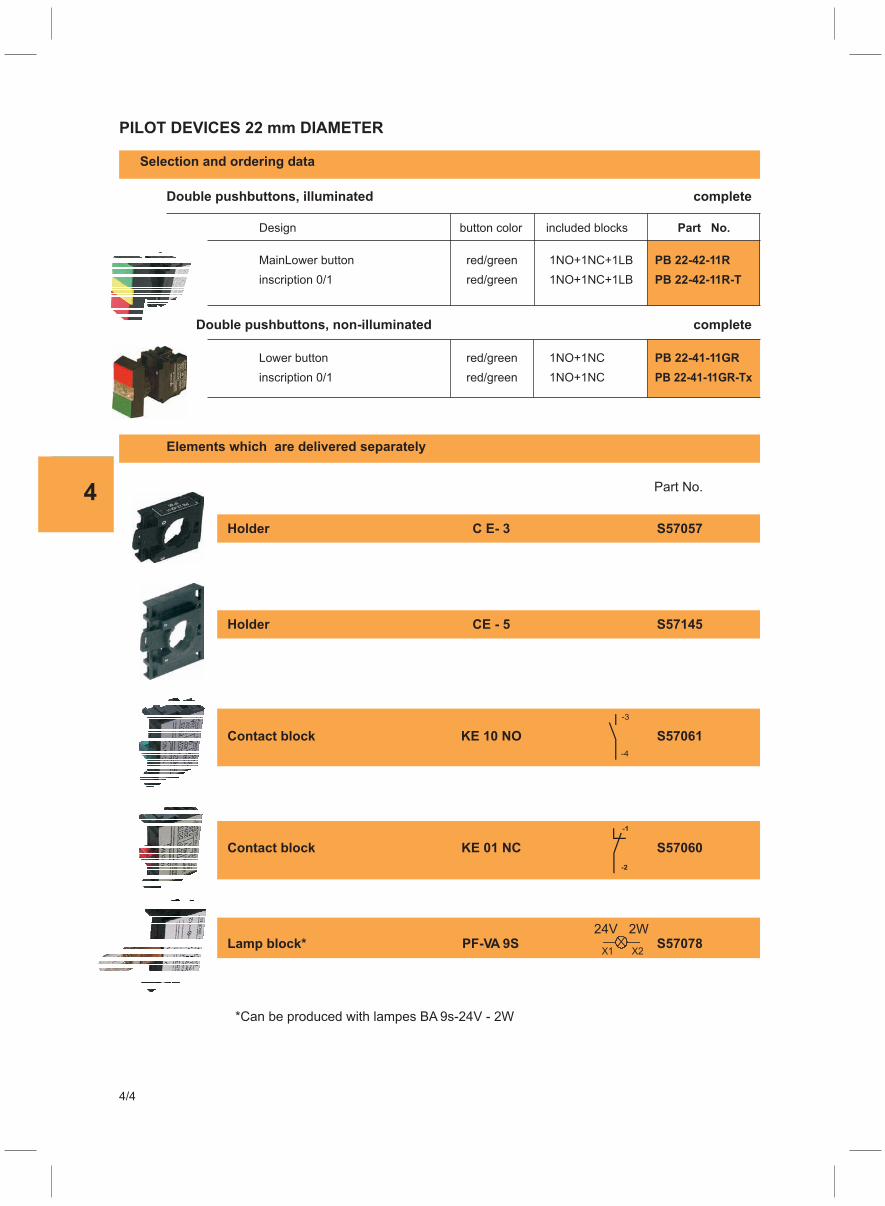
4
4/4
PILOT DEVICES 22 mm DIAMETER
Selection and ordering data
Design button color included blocks Part No.
MainLower button red/green 1NO+1NC+1LB PB 22-42-11R
inscription 0/1 red/green 1NO+1NC+1LB PB 22-42-11R-T
Lower button red/green 1NO+1NC PB 22-41-11GR
inscription 0/1 red/green 1NO+1NC PB 22-41-11GR-Tx
Double pushbuttons, illuminated complete
Double pushbuttons, non-illuminated complete
Elements which are delivered separately
Holder C E- 3 S57057
Holder CE - 5 S57145
Contact block KE 10 NO S57061
Contact block KE 01 NC S57060
Lamp block* PF-VA 9S S57078
Part No.
*Can be produced with lampes BA 9s-24V - 2W
24V 2W
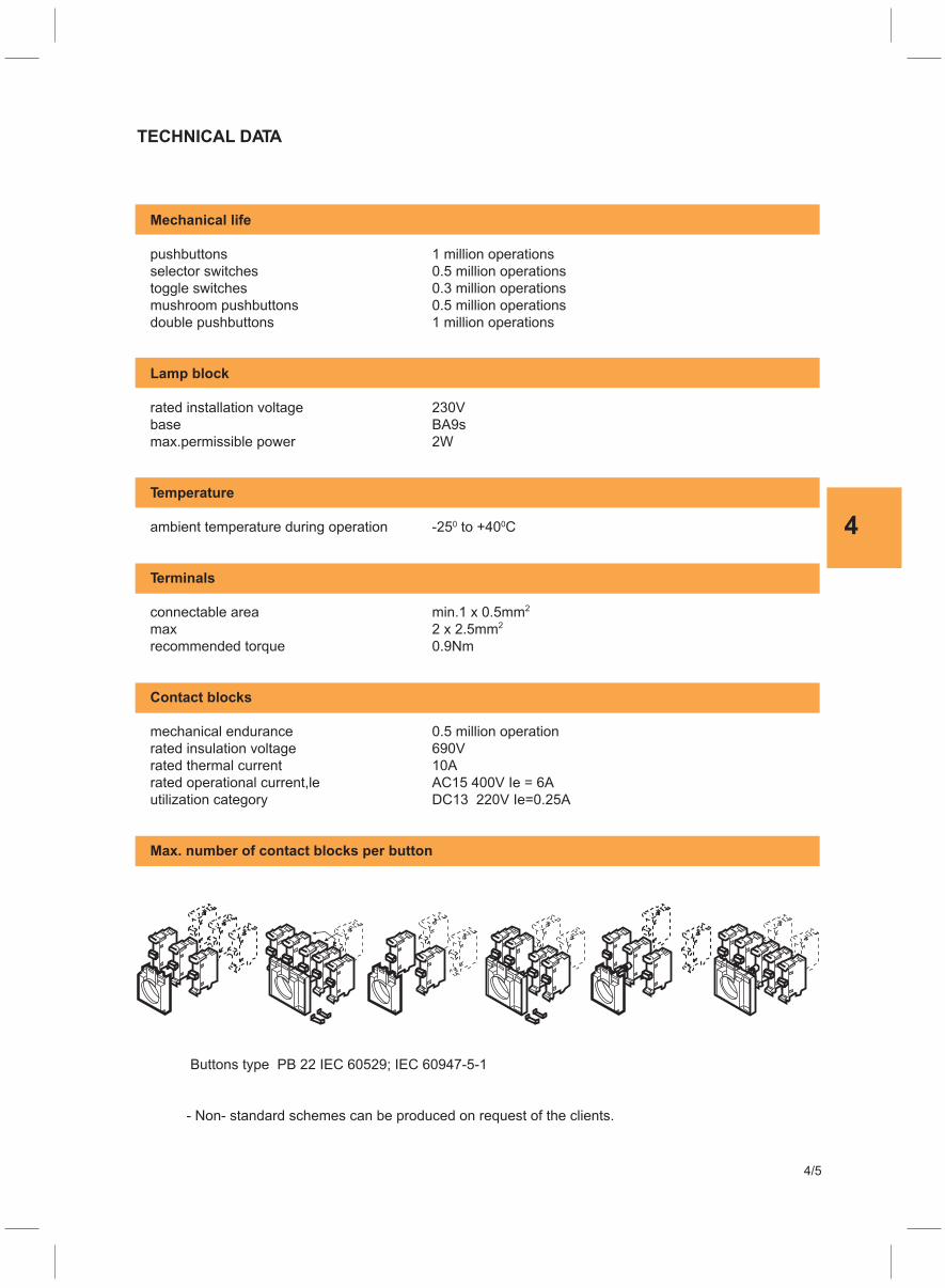
4
Mechanical life
pushbuttons 1 million operations
selector switches 0.5 million operations
toggle switches 0.3 million operations
mushroom pushbuttons 0.5 million operations
double pushbuttons 1 million operations
Lamp block
rated installation voltage 230V
base BA9s
max.permissible power 2W
Temperature
ambient temperature during operation -25 to +40 C0 0
Terminals
connectable area min.1 x 0.5mm
max
2
2 x 2.5mm
recommended torque
2
0.9Nm
Contact blocks
mechanical endurance 0.5 million operation
rated insulation voltage 690V
rated thermal current 10A
rated operational current,le AC15 400V Ie = 6A
utilization category DC13 220V Ie=0.25A
Max. number of contact blocks per button
TECHNICAL DATA
Buttons type PB 22 IEC 60529; IEC 60947-5-1
- Non- standard schemes can be produced on request of the clients.
4/5
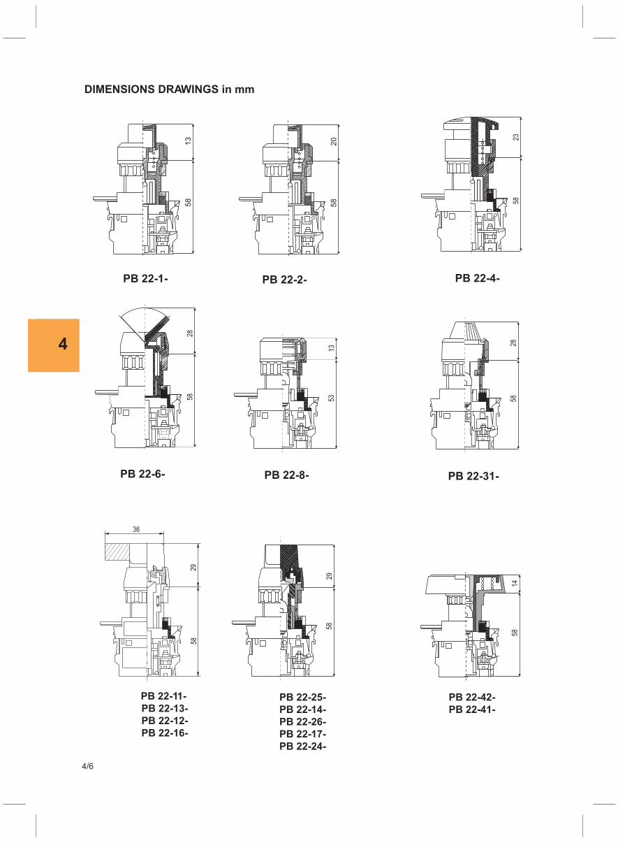
4
4/6
DIMENSIONS DRAWINGS in mm
PB 22-11-
PB 22-13-
PB 22-12-
PB 22-16-
PB 22-25-
PB 22-14-
PB 22-26-
PB 22-17-
PB 22-24-
PB 22-42-
PB 22-41-
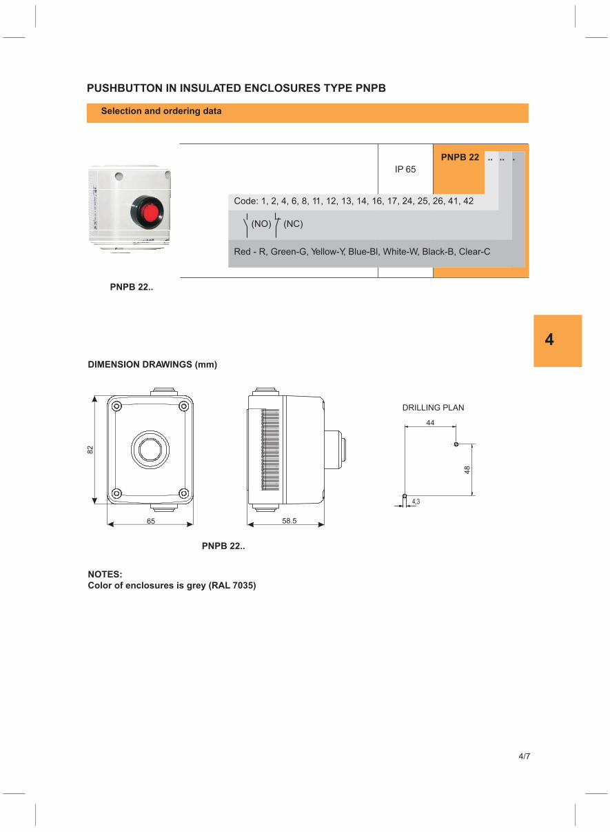
4
PUSHBUTTON IN INSULATED ENCLOSURES TYPE PNPB
Selection and ordering data
PNPB 22 .. .. .
IP 65
PNPB 22..
DIMENSION DRAWINGS (mm)
NOTES:
Color of enclosures is grey (RAL 7035)
Code: 1, 2, 4, 6, 8, 11, 12, 13, 14, 16, 17, 24, 25, 26, 41, 42
Red - R, Green-G, Yellow-Y, Blue-Bl, White-W, Black-B, Clear-C
(NO) (NC)
PNPB 22..
4/7
DRILLING PLAN

5
5/1
6


5
5/1
THREE POLE MOULDED CASE CIRCUIT BREAKERS
Features
In conformity with: IEC 60947-2 Wide range from (25 - 1250) A Compact dimensions, thus consumes less panel space
Selection and ordering data
No. of poles
KP 125-N 25A 3PKP 125-N 40A 3PKP 125-N 63A 3PKP 125-N 100A 3PKP 125-N 125A 3P
KP 125-M 25A 3PKP 125-M 40A 3PKP 125-M 63A 3PKP 125-M 100A 3PKP 125-M 125A 3P
KP 250-N 63A 3PKP 250-N 100A 3PKP 250-N 160A 3PKP 250-N 200A 3PKP 250-N 250A 3P
KP 250-M 63A 3PKP 250-M 100A 3PKP 250-M 160A 3PKP 250-M 200A 3PKP 250-M 250A 3P
Rated current at 040 C
A
Part No.
Type KP 125-N (25 -125 ) A
Type KP 125-M (25 -125 ) A
Breaking capacity (Icu) kA at 415 V AC
25 3 18
25 3 25
63 3 25
100 3 25
160 3 25
63 3 36
100 3 36
200 3 25
160 3 36
200 3 36
250 3 25
250 3 36
KP 800 400A 3P
KP 800 500A 3P
KP 800 630A 3P
KP 800 800A 3P
40 3 18
40 3 25
63 3 18
63 3 25
100 3 18
100 3 25
125 3 18
125 3 25
Type KP 250-N (63-250 ) A
Type KP 250-M (63-250 ) A
400 3 50
500 3 50
630 3 50
800 3 50
Type KP 800 (400 - 800 ) A
Weight
Kg
0.80
0.85
2.90
2.85
2.90

5
5/2
Selection and ordering data
No. of poles
KP 125-FN 25A 3PKP 125-FN 32A 3PKP 125-FN 40A 3PKP 125-FN 50A 3PKP 125-FN 63A 3PKP 125-FN 80A 3PKP 125-FN 100A 3P
KP 250-FN 100A 3PKP 250-FN 160A 3P
KP 250-FN 200A 3P
KP 250-FN 250A 3P
KP 250-FM 100A 3P
KP 250-FM 160A 3P
KP 250-FM 200A 3P
KP 250-FM 250A 3P
Rated current at 040 C
A
Part No.
Type KP 125-FN (25 -100 ) A
Breaking capacity (Icu) kA at 415 V AC
25 3 18
25 3 25
32 3 18
100 3 25
100 3 36
160 3 25
200 3 25
160 3 36
250 3 25
200 3 36
250 3 36
40 3 18
50 3 18
Type KP 125-FM (25-100 ) A
Type KP 250-FN (100-250 ) A
Type KP 250-FM (100-250 ) A
Weight
Kg
2.80
2.90
KP 125-FM 25A 3PKP 125-FM 32A 3PKP 125-FM 40A 3PKP 125-FM 50A 3PKP 125-FM 63A 3PKP 125-FM 80A 3PKP 125-FM 100A 3P
63 3 25
80 3 25
50 3 25
32 3 25
0.85
THREE POLE MOULDED CASE CIRCUIT BREAKERS WITH THERMAL AND MAGNETIC PROTECTION FIXED
40 3 25
63 3 18
80 3 18
100 3 18
100 3 25
0.80
0.85

5
5/3
KP 250-N 100A 4P
KP 250-N 100A 3P+N
KP 250-N 160A 4P
KP 250-N 160A 3P+N
KP 250-N 250A 4P
KP 250-N 250A 3P+N
KP 250-M 100A 4P
KP 250-M 100A 3P+N
KP 250-M 160A 4P
KP 250-M 160A 3P+N
KP 250-M 250A 4P
KP 250-M 250A 3P+N
KP 250-(N,M) (100-250A) 4P
KP 800 (400-630A) 4PKP 250-(N,M) (100-250A) 3P+N
100 4 25
100 4 36
160 4 25
160 4 36
250 4 25
250 4 36
KP 800 400A 4P
KP 800 630A 4P
KP 800 800A 4P
Type KP 250-N (100-250 ) A
Type KP 250-M (100-250 ) A
400 4 50
630 4 50
800 4 50
Type KP 800 (400 - 800 ) A
3.6
3.7
11,6
No. of polesRated current at 040 C
A
Part No. Breaking capacity(Icu) kA at 415V AC
Weight
Kg
FOUR POLE MOULDED CASE CIRCUIT BREAKERS
Features
In conformity with: IEC 60947-2Wide range from (100 - 800) A
Compact dimensions, thus consumes less panel space
Selection and ordering data
642N
531N
I>I>I>
642N
531N
I>I>I>

5
5/4
THREE POLE MOULDED CASE CIRCUIT BREAKERS
VERSION WITH BUILT- IN LOCKING MECHANISM
Features
Wide range from (25 - 250) A
In conformity with: IEC 60947-2
Compact dimensions, thus consumes less panel space
Uniform front escutcheon plate
Selection and ordering data
No. of poles
KP 125-ZN 25A 3P
KP 125-ZN 40A 3P
KP 125-ZN 63A 3P
KP 125-ZN 100A 3P
KP 125-ZN 125A 3P
KP 125-ZM 25A 3P
KP 125-ZM 40A 3P
KP 125-ZM 63A 3P
KP 125-ZM 100A 3P
KP 125-ZM 125A 3P
KP 250-ZN 100A 3P
KP 250-ZN 160A 3P
KP 250-ZN 250A 3P
KP 250-ZM 100A 3P
KP 250-ZM 160A 3P
KP 250-ZM 250A 3P
Rated current at 040 C
A
Part No.
Type KP 125-ZN (25 -125 ) A 3P
Type KP 125-ZM (25 -125 ) A 3P
Breaking capacity(Icu) kA at 415 V AC
25
25
3
3
18
25
100 3 25
100 3 36
160 3 25
160 3 36
250 3 25
250 3 36
40
40
3
3
18
25
63
63
3
3
18
25
100
100
3
3
18
25
125
125
3
3
18
25
Type KP 250-ZN (100-250 ) A 3P
Type KP 250-ZM (100-250 ) A 3P
KP 125-Z(N,M) 3P and KP 250-Z(N,M) 3P ist version with built - in locking mechanism.
This version have possibility of locking in open position.
Technical date and dimension drawings are same as the basic model.
Weight
Kg
0.85
0.85
2.9
2.9
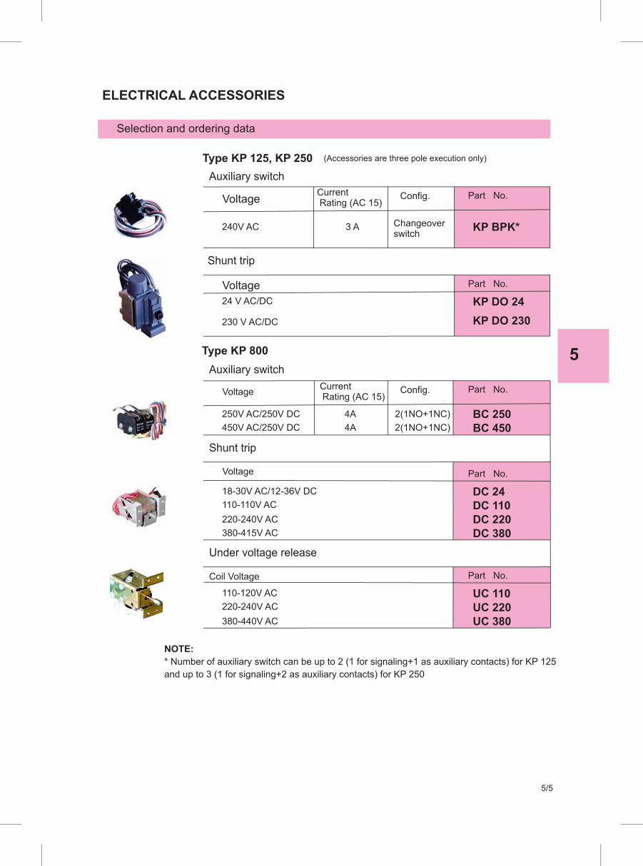
5
5/5
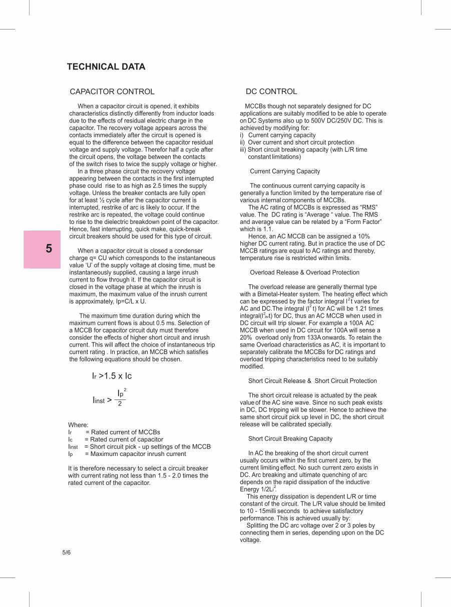
5
5/6

5
5/7

5
5/8

5
5/9

5
5/10
Standard conformity IEC 60947-2
No. of poles 3P 3P or 4P 3P or 4P
Standard current range/ratings In A 25,40,63,100,125(25,32,40,50,63,80,100)**
100, 160, 200, 250 400, 630, 800
Rated operational voltage Ue~ V 690 690
Rated operational voltage Ue= V 250 250
Rated insulation voltage Ui~ V 690 690
Rated impulse withstand U imp kV 6 8
Category of use A A
Degree of protection:Standard appliance with terminal shieldsAppliaance in enclosure with front plate
Polution degree
Humidity working condition
Ambient temperature 0C -10 to + 70
TECHNICAL DATA
8
3
18
12 15
4 8
25 25
25
kA
kA
kA
kA
kA
kA
Ultimate breaking capacity Icu*
230/240 V ~
400/415 V ~
440 V ~
480/500 V ~
690 V ~
250 V -
22 35 35 60
18 25 25 36
10 18 18 30
16
36
electrical
mechanical
Standard breaking capacity Ics (%Icu)* 75 50 75 75
Rated closing capacity on short-circuit (400 V~) 36 52.5 52.5 75.6
Endurance (o.c. cycle) ≥ 10 000 ≥ 10 000
≥ 4 000
(0,7 - 1)Infixed In for FN and FM
(0,7 - 1)Infixed In for FN and FM
(0,7 - 1)In
10xIn for 125 A
10xIn for 100 A
15xIn for 63 A
20xIn for 40 A
17xIn for 50 A
25xIn for 25 A
≥ 4 000
- -
- -
- -
-
-
-
-
-
-
-
(3,5 - 10)In (4 - 10)In
TYPE CIRCUIT BREAKERS KP 800
Magnetic adjustable
Type of protection
35
690
250
8
A
Direct control IP 30
Direct control IP 40
IP 00
IP 40
III III
080% at 30 C 0-90%
-5 to + 40
50
105
4 000
1000
70
50
690
27
16
OTHER CARACTERISTICS
*The LINE side is the upper side. LOAD is to be connected on the down side.**Valid only for fixed protectionFN, FM - Thermal and Magnetic protection fixed
Thermal adjustable
Magnetic fixed
Connection cross-sections
125 12 - - 5x12 70 50
250
800
25
40
95-120
-
95-120
-
A 8 - 120
-
M8
M12
4x25
2x(5x40)
185
-
150
-
Head devices Connection via teriminal2
(mm )Connection via bars (mm)
Connection via cage terminals2 (mm )
Max.Widthon term.
copper cable Cable shoe Terminal screwaluminium cable rigid cable flexible cable(mm)KP
KP 125-NKP 125-FN
KP 250-NKP 250-FN
KP 250-MKP 250-FM
KP 125-MKP 125-FM

5
5/11
Currents in amps in accordance with ambient temperature
Thermal adjustmentType0
20 C0
30 C0
45 C0
10 C 040 C 050 C 060 C 070 C
In = 25 A
In = 32 A
In = 40 A
In = 50 A
In = 63 A
In = 80 A
In = 100 A
In = 125 A
In = 63 A
In = 100 A
In = 160 A
In = 200 A
In = 250 A
In = 400 A
In = 630 A
In = 800 A
min. min.min. max. max.max. min. min. min. min. min.max. max. max. max. max.
19
24
60
30
38
20
25
63
32
39KP 125
KP 250
KP 800
27
34
86
43
54
28
36
89
45
55
17
22
56
28
35
16
21
53
27
33
16
20
51
26
32
16
20
48
25
30
18
23
58
29
36
25 17 25
32 22
28
34
43
40
68
106
130
168
-
-
-
54
68
85
32
40
48
61
78
58
98
123
96
153
190
240
-
-
-
80
40
50
24
30
76
38
47
23
29
73
37
46
22
28
70
36
48
26
33
83
42
52
48
76
49
79
68
108
70
112
44
70
42
67
40
64
38
61
46
73
63
100
60
96
58
92
55
88
66
104
9598 135140 87 84 80 7691 125 120 115 110130
64
82
74
88
83
118
93
127
44
70
31
63
22
56
17
52
54
76
63
100
53
91
43
82
33
73
73
109
133
180
143
200
190
240
205
260
112
140
100
120
90
100
80
100
122
160
160
200
145
180
130
160
115
140
175
220
202
316
498
633
216
336
529
672
290
452
712
904
310
480
756
960
175
280
440
560
160
260
410
520
142 125189
300
472
599
250
400
630
800
230
372
586
744
210 190270
428
674
856
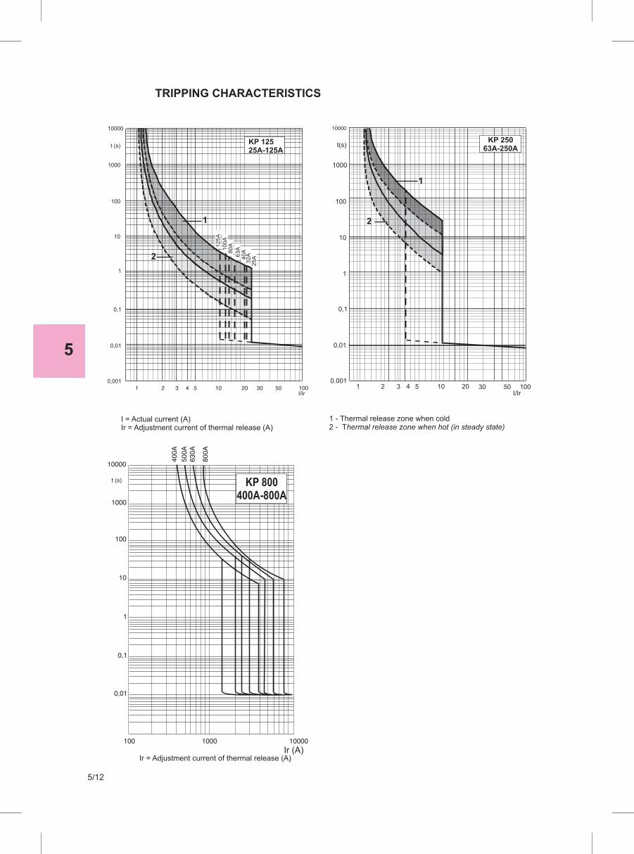
5
5/12
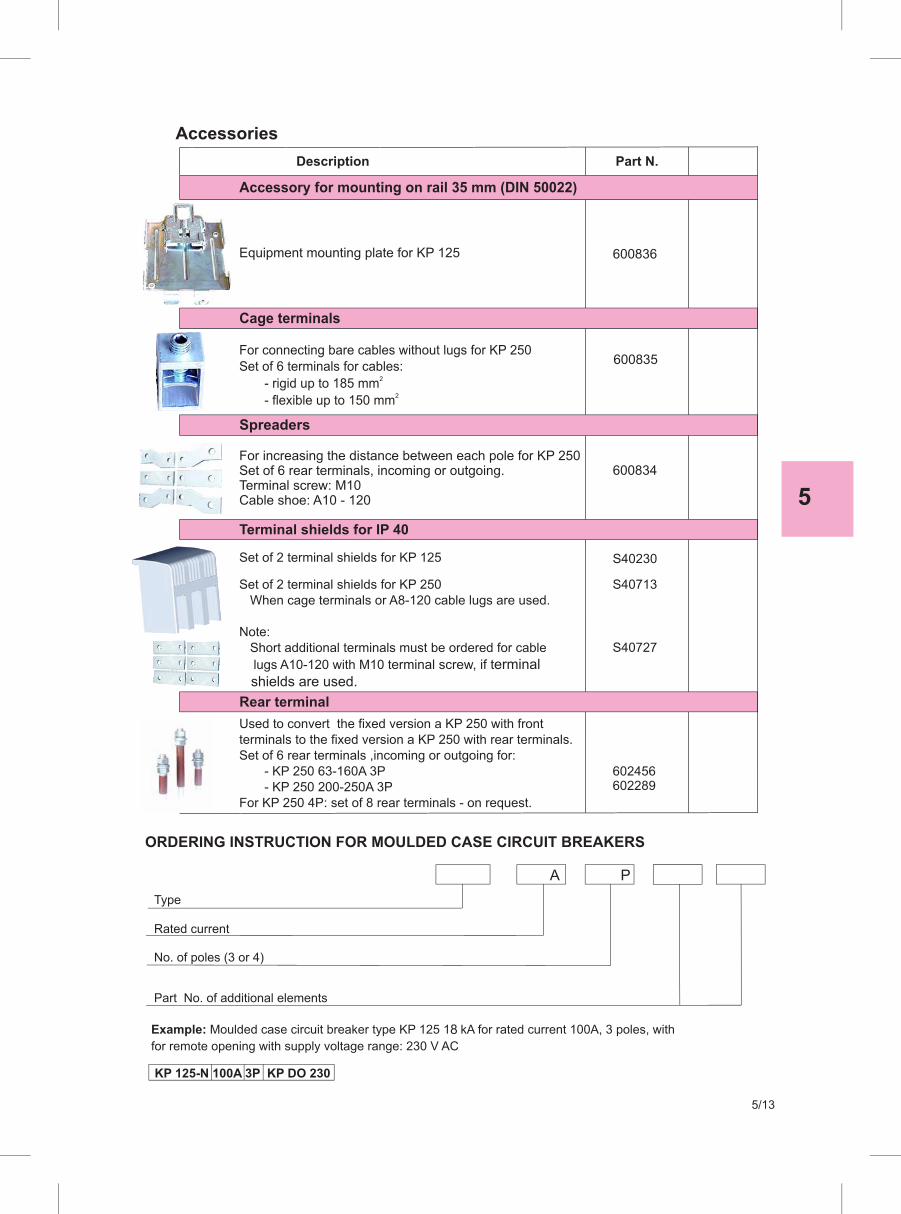
5
5/13
8

5
5/14
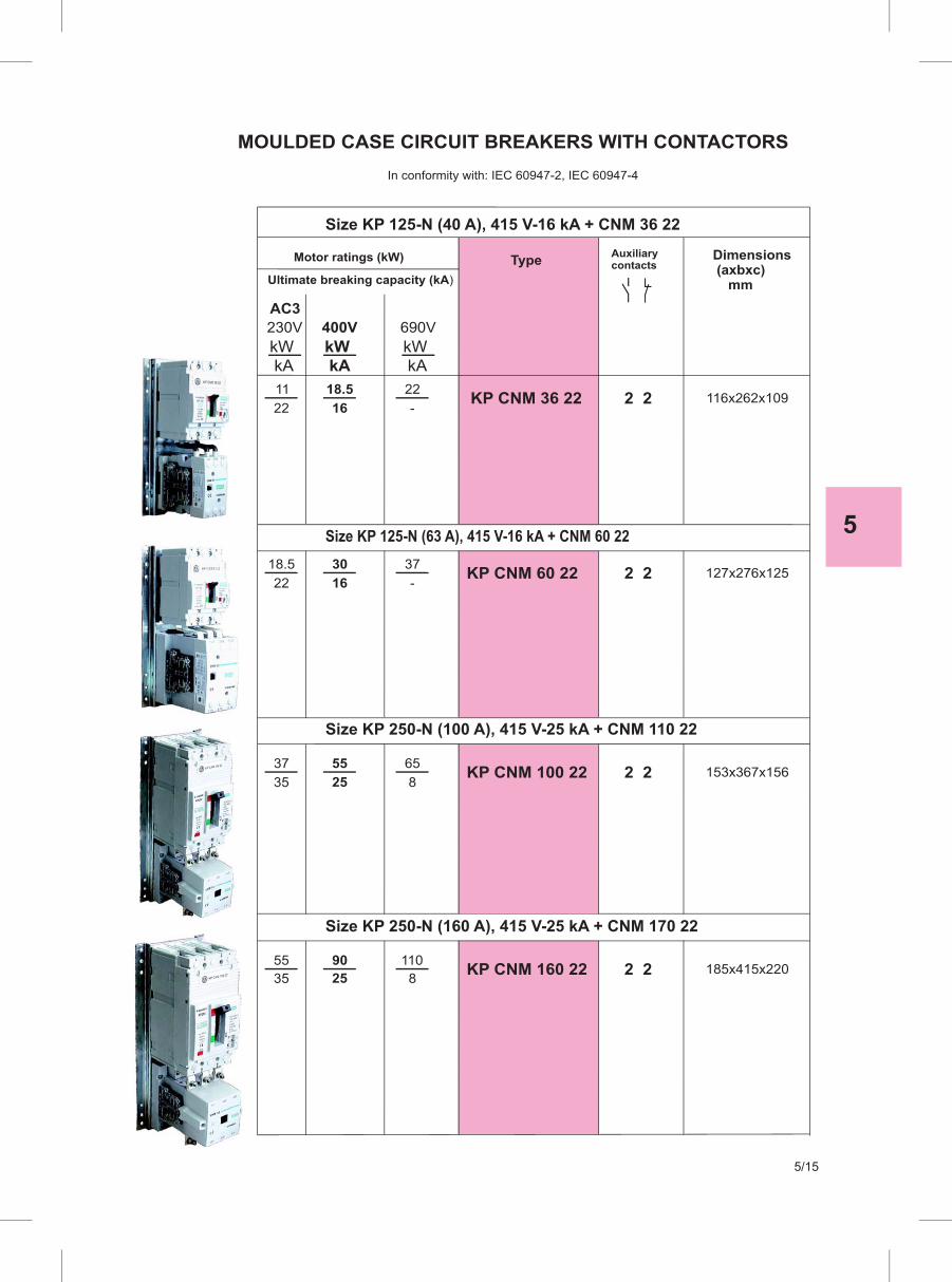
5
5/15
6
6/1
ELECTRONIC TIME RELAYS, STAIRCASE LIGHTING CONTROLLER ANDTEMPERATURE MONITOR RELAYS
Electronic time relays type EVR,
Staircase lighting controller type ESA 11 and
Thermistor protection type ETZM 6/1, 6/2, 6/3 and 6/4


6
6/1
ELECTRONIC TIME RELAYS TYPE EVR
Application, standards and installation
Electronic time relays EVR are used for operations in the feld
of automation and industrial plants, energetics, traffc etc. They
could be used in installations with hard working conditions such as
ships, cranes, heavy industry and similar since they are resistant
to vibrations and high temperatures. The outlet relay with contacts
of AgCdO provides stable control of almoust all devices used in
operating technics.
Electronic time relays are designed for fast and easy installation
on standard rail support TH 35 - 7,5 according to DIN EN 50022 or
installation with screws on standard plate according to DIN 46121.
When they are used in rooms with increased humidity and dust,
relays should be installed in closed cases.
Wiring of the relays is by fexible cores with cable shoe or with full
cores made of copper, cross section from 1 to 2,5 mm².
STAIRCASE LIGHTING CONTROLLER
TYPE ESA 11
APPLICATION
The staircase lighting controller ESA11 is intended for time delayed
switching of light.
The staircase lighting controller ESA11 is assembled in an insulated
CONSTRUCTION
housing made of polycarbonat with a compact width of 22,5mm
which gives full protection to the personnel against touching of live
parts according to VDE 01106T.100. The time is adjustable from
0,6 to 6 minutes with the help of a potentiometer mounted on the
front of the relay.
DIMENSIONS (mm)
EVR ESA 11
ETZM
A continous ON position of the light is reached by inserting a short
circuiting conductor between the terminsls B1-B2. The integrated
circuits inside the ESA11 are in C-MOS technology and all the
components are carefully selected to provide high performances
and rellability. the supply voltage is 220VAC. Other supply voltages
will be offered on special demand.
The staircase lighting controller ESA11 is intended for fast and easy
INSTALLATION
installation on standard rail support TH35-7,5 according to DIN
EN50022 or installation with screws 2xM4 on standard plate, ac-
cording to DIN 46121. When they are used in rooms with increased
humidity and dust the relays should be installed in closed cases.
Wiring of the relays is by fexible cores with cable shoe or with full
cores made of copper, cross section from 1 to 2,5mm².
TEMPERATURE MONITOR RELAYS TYPE
ETZM
Application, standards and installation
Relays ETZM in combination with thermistor probes (PTC) are
devices for complete temperature protection of motors and other
machines.
Thermistor motor protection consist of thermistor probes embeded
in stator winding, with special characteristics of varying the electric
resistance of temperature.
Relay ETZM is supervozir of the electrical resistance of the ther-
mistor probes. Output relay switches off, after the resistance of the
thermistor circuit, assumed certain value. Relays ETZM can not be
adjusted, therefore the output function is determined entirely by the
reference temperature of the thermistors.
Temperature "NIT" is chosen according to temperature class
insulation of the motor.
Relays ETZM are predicted for fast and simple installation with
connectible cables (cross-section 1 to 2,5 mm²). They should be
installed in dry and clean rooms. For use in areas with increased
wetness, the relays should be built in enclosed boards.
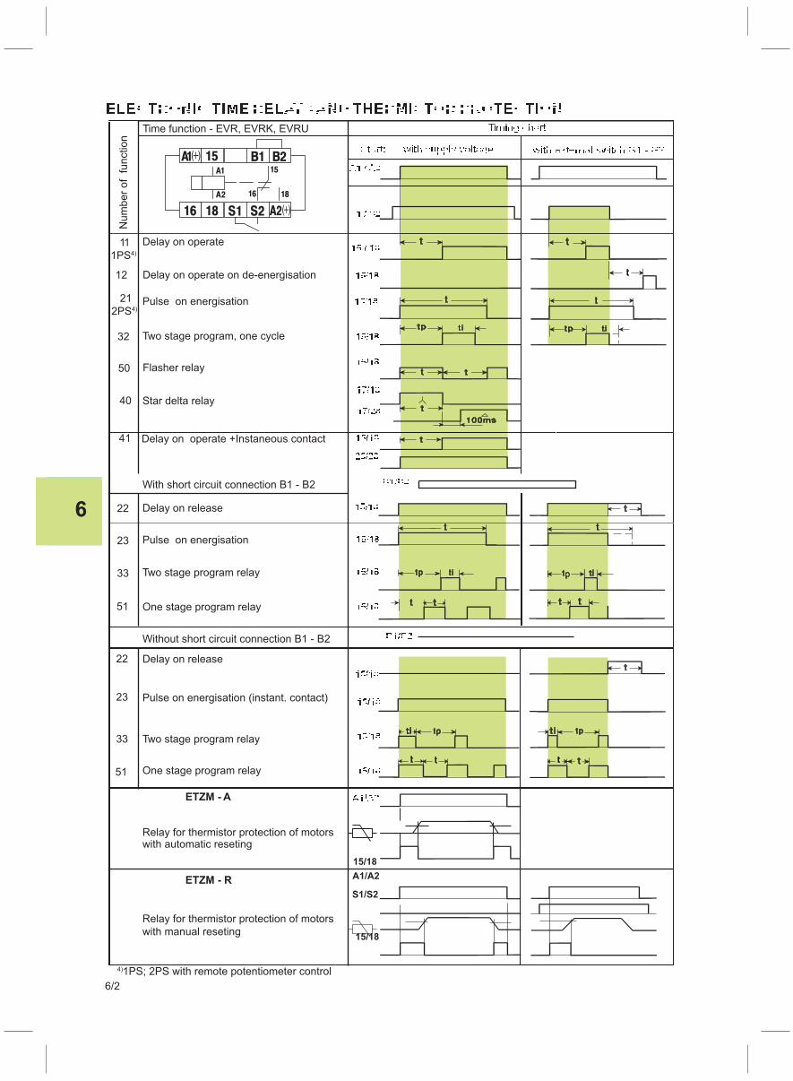
6
6/2
ETZM - R
Relay for thermistor protection of motors
with manual reseting
11
1PS4)
33
51
22
23
33
51
23
22
Delay on operate on de-energisation12
21
2PS4)
32
Flasher relay50
41
15/18
40
15/18
A1/A2
S1/S2
Time function - EVR, EVRK, EVRU
Pulse on energisation
Two stage program, one cycle
Star delta relay
One stage program relay
Two stage program relay
Pulse on energisation (instant. contact)
Delay on release
Without short circuit connection B1 - B2
One stage program relay
Two stage program relay
Pulse on energisation
Delay on release
With short circuit connection B1 - B2
1PS; 2PS with remote potentiometer control4)
Delay on operate
Delay on operate +Instaneous contact
ETZM - A
Relay for thermistor protection of motorswith automatic reseting
Num
ber
of function
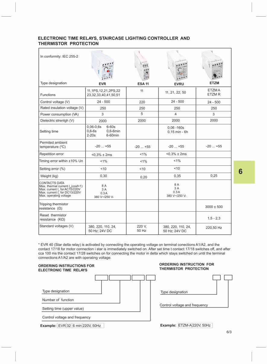
6
6/3
* EVR 40 (Star delta relay) is activated by connecting the operating voltage on terminal conections A1/A2, and the
contact 17/18 for motor connection i star is immediately switched on. After set time t contact 17/18 switches off, and after
cca 100 ms the contact 17/28 switches on for connecting the motor in delta which stays switched on until the terminal
connections A1/A2 are with operating voltage.
Type designation
Number of function
Setting time (upper value)
Control voltage and frequency
Type designation
In conformity: IEC 255-2
Functions
Control voltage (V)
Power consumption (VA)
Dielectric strentgh (V)
Setting time
Repetition error
Setting error (%)
Weight (kg)
Example: ETZM-A 220V, 50HzExample: EVR 32 6 min 220V, 50Hz
ORDERING INSTRUCTION FOR
THERMISTOR PROTECTION
Timing error within ±10% Un
Permited ambient
temperature ( C)0
Type designation
Control voltage and frequency
ETZM A
ETZM R
ETZM
0,06 -160s
0,15 min - 6h
EVRU
11,1PS,12,21,2PS,22
23,32,33,40,41,50,51
ESA 11EVR
24 - 500 24 - 500
0,30 0,35
<10<10
<1% <1%
<0,3% ± 2ms<0,3% ± 2ms
-20 ... +55 -20 ... +55 -20 ... +55
200020002000
43
250250250
24 - 500
11, 21, 22, 50
0,06-0,6s 6-60s
0,6-6s 0,6-6min
2-20s 6-60min
ORDERING INSTRUCTIONS FOR
ELECTRONIC TIME RELAYS
3
ELECTRONIC TIME RELAYS, STAIRCASE LIGHTING CONTROLLER AND
THERMISTOR PROTECTION
Rated insulation voltage (V)
Standard voltages (V)
Tripping thermistor
resistance (Ω)
Reset thermistor
resistance (KΩ)
380, 220, 110, 24,
50 Hz; 24V DC380, 220, 110, 24,
50 Hz; 24V DC
1,5 - 2,3
3000 ± 500
0,25
220,50 Hz
11
220
250
5
2000
-20 ... +55
<1%
<1%
<10
0,20
220 V,
50 Hz
CONTACTS DATAMax. thermal current I (cosf=1)
thMax. current I for AC15/220V
eMax. current I for DC13/220V
eMax. operating voltage
8 A
3 A
0.3 A
380 V~/250 V-
8 A
3 A
0.3 A
380 V~/250 V-
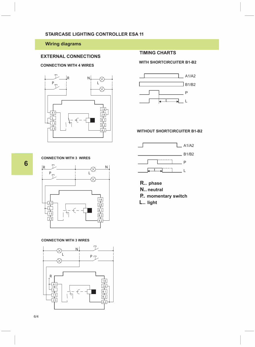
6
6/4
TIMING CHARTS
WITH SHORTCIRCUITER B1-B2
WITHOUT SHORTCIRCUITER B1-B2
R..
N..
P..
L..
phase
neutral
momentary switch
light
CONNECTION WITH 3 WIRES
CONNECTION WITH 3 WIRES
EXTERNAL CONNECTIONS
STAIRCASE LIGHTING CONTROLLER ESA 11
CONNECTION WITH 4 WIRES
Wiring diagrams

Related Documents


![$La' {*n,gft*rt - Mörth Marinemarine-moerth.com/Katalog2010/Ankertest.pdf · -gnc-z€ elp 3c ireluv uellec;ue8nd pu[l u]essu,{aD uep ur oslu sa ... sowic clcr CQll Nachbiru nit](https://static.cupdf.com/doc/110x72/5b407aaa7f8b9a4b3f8d522b/la-ngftrt-moerth-marinemarine-gnc-z-elp-3c-ireluv-uellecue8nd.jpg)