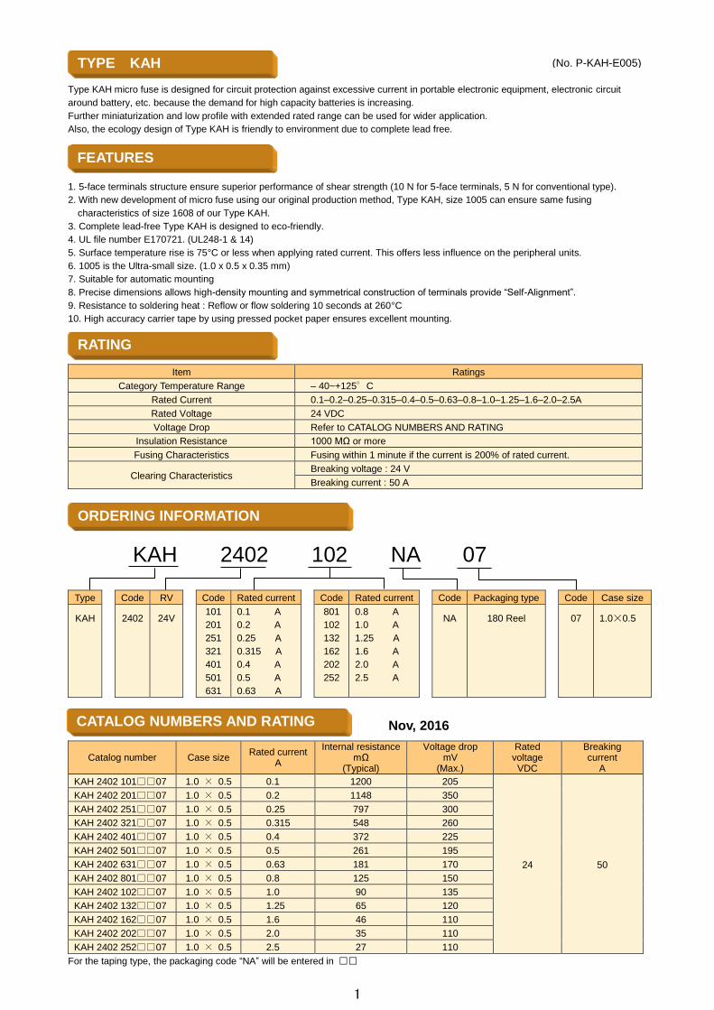
Type KAH micro fuse is designed for circuit protection against excessive current in portable electronic equipment, electronic circuit around battery, etc. because the demand for high capacity batteries is increasing. Further miniaturization and low profile with extended rated range can be used for wider application. Also, the ecology design of Type KAH is friendly to environment due to complete lead free. 1. 5-face terminals structure ensure superior performance of shear strength (10 N for 5-face terminals, 5 N for conventional type). 2. With new development of micro fuse using our original production method, Type KAH, size 1005 can ensure same fusing characteristics of size 1608 of our Type KAH. 3. Complete lead-free Type KAH is designed to eco-friendly. 4. UL file number E170721. (UL248-1 & 14) 5. Surface temperature rise is 75°C or less when applying rated current. This offers less influence on the peripheral units. 6. 1005 is the Ultra-small size. (1.0 x 0.5 x 0.35 mm) 7. Suitable for automatic mounting 8. Precise dimensions allows high-density mounting and symmetrical construction of terminals provide “Self -Alignment”. 9. Resistance to soldering heat : Reflow or flow soldering 10 seconds at 260°C 10. High accuracy carrier tape by using pressed pocket paper ensures excellent mounting. Item Ratings Category Temperature Range – 40~+125°C Rated Current 0.1–0.2–0.25–0.315–0.4–0.5–0.63–0.8–1.0–1.25–1.6–2.0–2.5A Rated Voltage 24 VDC Voltage Drop Refer to CATALOG NUMBERS AND RATING Insulation Resistance 1000 MΩ or more Fusing Characteristics Fusing within 1 minute if the current is 200% of rated current. Clearing Characteristics Breaking voltage : 24 V Breaking current : 50 A KAH 2402 102 NA 07 Type Code RV Code Rated current Code Rated current Code Packaging type Code Case size KAH 2402 24V 101 201 251 321 401 501 631 0.1 A 0.2 A 0.25 A 0.315 A 0.4 A 0.5 A 0.63 A 801 102 132 162 202 252 0.8 A 1.0 A 1.25 A 1.6 A 2.0 A 2.5 A NA 180 Reel 07 1.0×0.5 Catalog number Case size Rated current A Internal resistance mΩ (Typical) Voltage drop mV (Max.) Rated voltage VDC Breaking current A KAH 2402 101□□07 1.0 × 0.5 0.1 1200 205 24 50 KAH 2402 201□□07 1.0 × 0.5 0.2 1148 350 KAH 2402 251□□07 1.0 × 0.5 0.25 797 300 KAH 2402 321□□07 1.0 × 0.5 0.315 548 260 KAH 2402 401□□07 1.0 × 0.5 0.4 372 225 KAH 2402 501□□07 1.0 × 0.5 0.5 261 195 KAH 2402 631□□07 1.0 × 0.5 0.63 181 170 KAH 2402 801□□07 1.0 × 0.5 0.8 125 150 KAH 2402 102□□07 1.0 × 0.5 1.0 90 135 KAH 2402 132□□07 1.0 × 0.5 1.25 65 120 KAH 2402 162□□07 1.0 × 0.5 1.6 46 110 KAH 2402 202□□07 1.0 × 0.5 2.0 35 110 KAH 2402 252□□07 1.0 × 0.5 2.5 27 110 For the taping type, the packaging code “NA” will be entered in □□ FEATURES CATALOG NUMBERS AND RATING Nov, 2016 RATING ORDERING INFORMATION TYPE KAH (No. P-KAH-E005) 1

Welcome message from author
This document is posted to help you gain knowledge. Please leave a comment to let me know what you think about it! Share it to your friends and learn new things together.
Transcript
Type KAH micro fuse is designed for circuit protection against excessive current in portable electronic equipment, electronic circuit
around battery, etc. because the demand for high capacity batteries is increasing.
Further miniaturization and low profile with extended rated range can be used for wider application.
Also, the ecology design of Type KAH is friendly to environment due to complete lead free.
1. 5-face terminals structure ensure superior performance of shear strength (10 N for 5-face terminals, 5 N for conventional type).
2. With new development of micro fuse using our original production method, Type KAH, size 1005 can ensure same fusing
characteristics of size 1608 of our Type KAH.
3. Complete lead-free Type KAH is designed to eco-friendly.
4. UL file number E170721. (UL248-1 & 14)
5. Surface temperature rise is 75°C or less when applying rated current. This offers less influence on the peripheral units.
6. 1005 is the Ultra-small size. (1.0 x 0.5 x 0.35 mm)
7. Suitable for automatic mounting
8. Precise dimensions allows high-density mounting and symmetrical construction of terminals provide “Self-Alignment”.
9. Resistance to soldering heat : Reflow or flow soldering 10 seconds at 260°C
10. High accuracy carrier tape by using pressed pocket paper ensures excellent mounting.
Item Ratings
Category Temperature Range – 40~+125°C
Rated Current 0.1–0.2–0.25–0.315–0.4–0.5–0.63–0.8–1.0–1.25–1.6–2.0–2.5A
Rated Voltage 24 VDC
Voltage Drop Refer to CATALOG NUMBERS AND RATING
Insulation Resistance 1000 MΩ or more
Fusing Characteristics Fusing within 1 minute if the current is 200% of rated current.
Clearing Characteristics Breaking voltage : 24 V
Breaking current : 50 A
KAH 2402 102 NA 07
Type Code RV Code Rated current Code Rated current Code Packaging type Code Case size
KAH
2402
24V
101
201
251
321
401
501
631
0.1 A
0.2 A
0.25 A
0.315 A
0.4 A
0.5 A
0.63 A
801
102
132
162
202
252
0.8 A
1.0 A
1.25 A
1.6 A
2.0 A
2.5 A
NA
180 Reel
07
1.0×0.5
Catalog number Case size Rated current
A
Internal resistance mΩ
(Typical)
Voltage drop mV
(Max.)
Rated voltage VDC
Breaking current
A
KAH 2402 10107 1.0 × 0.5 0.1 1200 205
24 50
KAH 2402 20107 1.0 × 0.5 0.2 1148 350
KAH 2402 25107 1.0 × 0.5 0.25 797 300
KAH 2402 32107 1.0 × 0.5 0.315 548 260
KAH 2402 40107 1.0 × 0.5 0.4 372 225
KAH 2402 50107 1.0 × 0.5 0.5 261 195
KAH 2402 63107 1.0 × 0.5 0.63 181 170
KAH 2402 80107 1.0 × 0.5 0.8 125 150
KAH 2402 10207 1.0 × 0.5 1.0 90 135
KAH 2402 13207 1.0 × 0.5 1.25 65 120
KAH 2402 16207 1.0 × 0.5 1.6 46 110
KAH 2402 20207 1.0 × 0.5 2.0 35 110
KAH 2402 25207 1.0 × 0.5 2.5 27 110
For the taping type, the packaging code “NA” will be entered in
FEATURES
CATALOG NUMBERS AND RATING
Nov, 2016
RATING
ORDERING INFORMATION
TYPE KAH
(No. P-KAH-E005)
1
MARKING
CONSTRUCTION
Catalog numbers are approved by UL and cUL. (File No. E170721)
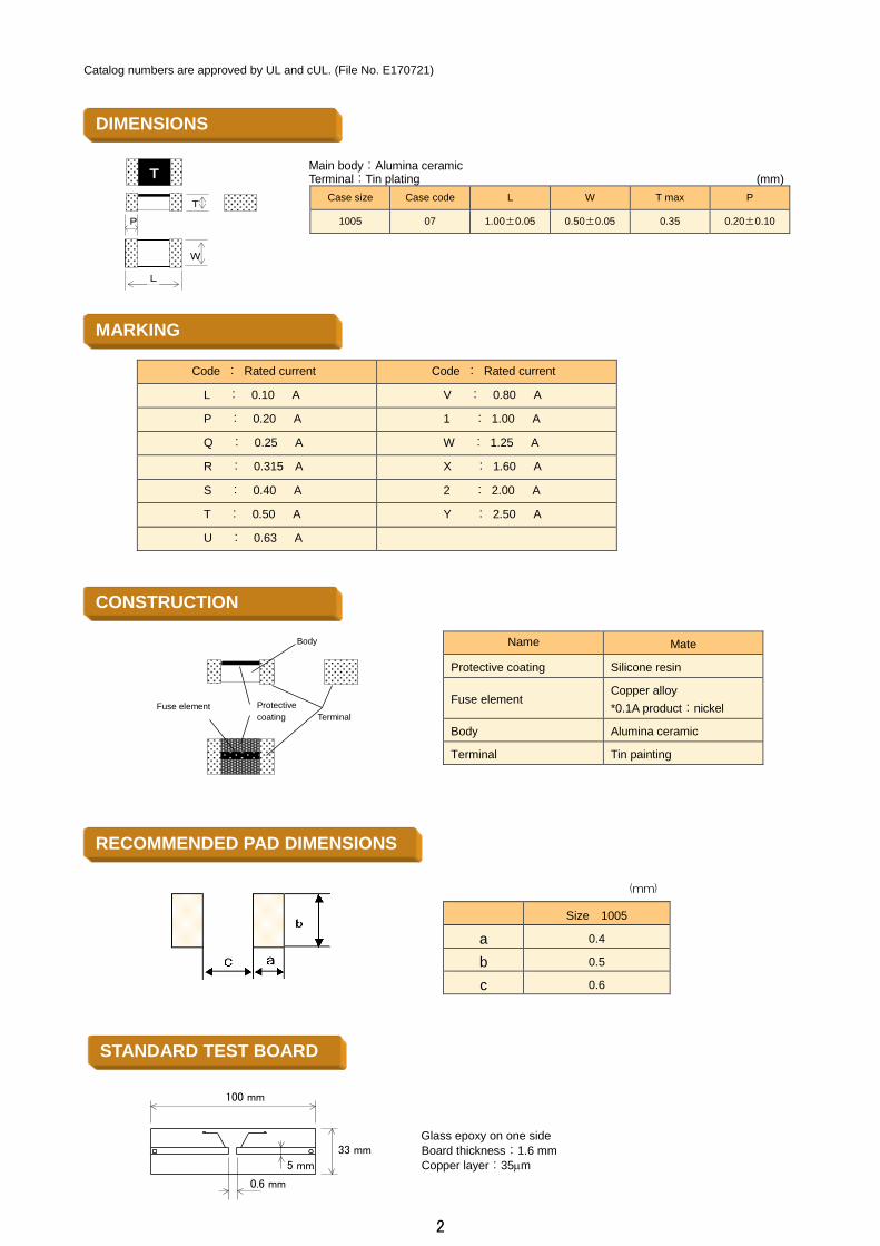
Main body:Alumina ceramic Terminal:Tin plating (mm)
Case size Case code L W T max P
1005 07 1.00±0.05 0.50±0.05 0.35 0.20±0.10
Code : Rated current Code : Rated current
L : 0.10 A V : 0.80 A
P : 0.20 A 1 : 1.00 A
Q : 0.25 A W : 1.25 A
R : 0.315 A X : 1.60 A
S : 0.40 A 2 : 2.00 A
T : 0.50 A Y : 2.50 A
U : 0.63 A
Name Mate
Protective coating Silicone resin
Fuse element Copper alloy
*0.1A product:nickel
Body Alumina ceramic
Terminal Tin painting
(mm)
Size 1005
a 0.4
b 0.5
c 0.6
Glass epoxy on one side
Board thickness:1.6 mm
Copper layer:35m
DIMENSIONS
STANDARD TEST BOARD
RECOMMENDED PAD DIMENSIONS
P
L
W
T
T
Body
Fuse element Protective
coating
c
Terminal
100 mm
33 mm
5 mm
0.6 mm
2
No. Item Performance Test method
1 Temperature rise Temperature rise shall not exceed 75. Apply rated current.
2 Current-carrying
capacity Shall not open within 1 hour. Apply rated current.
3 Clearing characteristics Arc shall not be continued.
Marking shall be legible.
Breaking voltage:24 V
Breaking current:50 A
4 Voltage drop Voltage drop is below the value specified in CATALOG
NUMBERS AND RATING. Apply rated current.
5 Fusing characteristics Fusing within 1 min. Apply 200% of rated current.
(Ambient temperature:10–30°C
6 Insulation resistance 1000 MΩ or more Insulation resistance between terminals and case
(alumina ceramic)
7 Electrode strength
(Bending)
No mechanical damage.
Resistance change after the test shall be within ± 20%.
Board supporting width:90 mm
Bending speed:Approx. 0.5 mm/sec.
Duration:30 sec.
Bending:3 mm
8 Shear test No mechanical damage.
Resistance change after the test shall be within ± 20%.
Applied force:10 N (1.02 kgf)
Duration:10 sec.
Tool:R0.5
Direction of the press:side face
9 Substrate bending test No mechanical damage.
Resistance change after the test shall be within ± 20%.
Supporting dimension:0.5 mm
Applied force:5 N (0.51 kgf)
Tool:R0.5
Direction of the press:thickness direction of product.
10 Solderability
(Solder Wetting time) Solder Wetting time : within 3sec.
Solder : Sn–3Ag–0.5Cu Temperature : 245 ± 3°C
meniscograph method
Solder : JISZ3282 H60A, H60S, H63A Temperature : 230 ± 2°C
meniscograph method
11
Solderability
(new uniform coating of
solder)
The dipped surface of the terminals shall be covered
more than 95% with new solder.
Solder : Sn–3Ag–0.5Cu Temperature : 245 ± 3°C
Dipping : 3 sec.
Solder : JISZ3282 H60A, H60S, H63A Temperature : 230 ± 2°C
Dipping : 3 sec.
12 Resistance to soldering
heat
Marking shall be legible.
No mechanical damage.
Resistance change after the test shall be within ± 20%.
Dipping (1 cycle)
Preconditioning:100 to 150°C, 60 sec.
Temperature:265 ± 3°C /6–7 sec.
Reflow soldering (2 cycles)
Preconditioning:1–2 min, 180°C or less
Peak:250 ± 5°C, 5 sec.
Holding:230–250°C, 30–40 sec.
Cooling:more than 2 min.
Manual soldering
Temperature:350 ± 10°C
Duration:3–4 sec.
Measure after 1 hour left under room temp. and humidity.
13 Solvent resistance
Marking shall be legible.
No mechanical damage.
Resistance change after the test shall be within ± 20%.
Dipping rinse
Solvent:Isopropyl alcohol
Duration:90 sec.
14 Ultrasonic Cleaning
Marking shall be legible.
No mechanical damage.
Resistance change after the test shall be within ± 20%.
Ultrasonic : 20mW/cm2 28kHz
Solvent:Isopropyl alcohol
Duration:60 sec.
15 Vibration No mechanical damage.
Resistance change after the test shall be within ± 20%.
Frequency range:10–55–10 Hz/min
Vibration amplitude:1.5 mm
Duration:2 hours in each of XYZ directions
(total:6 hours)
16 Shock No mechanical damage.
Resistance change after the test shall be within ± 20%.
Peak value:490 m/s2 (50 G)
Duration:11 m sec.
6 aspects 3 times (total:18 times)
17 Thermal shock No mechanical damage.
Resistance change after the test shall be within ± 20%.
–55 ± 3°C : 30 min.
Room temperature:2–3 min or less 125 ± 2°C 30 min
Room temperature:2–3 min or less Repeat above step for
10 cycles.
18 Atomizing salt water No mechanical damage.
Resistance change after the test shall be within ± 20%.
Temperature : 35 ± 2°C Concentration (weight ratio) : 5 ± 1%
Duration : 24 hours
19 Moisture resistance No mechanical damage.
Resistance change after the test shall be within ± 20%.
Temperature:85 ± 3°C
Humidity:85 ± 5% RH
Duration:1000 hours
20 Load life No mechanical damage.
Resistance change after the test shall be within ± 20%.
Temperature:85 ± 2°C
Applied current:Rated current 70%
Duration:1000 hours
21 Stability No mechanical damage.
Resistance change after the test shall be within ± 20%.
Temperature:125 ± 2°C
Duration:1000 hours
22 Accelerated damp heat
steady state
No mechanical damage.
Resistance change after the test shall be within ± 20%.
Temperature:85 ± 3°C
Humidity:85 ± 5% RH
Applied current : Rated current 70%
Duration:1000 hours
PERFORMANCE
3
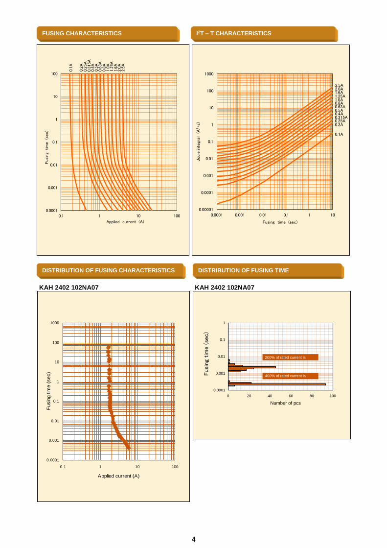
KAH 2402 102NA07
KAH 2402 102NA07
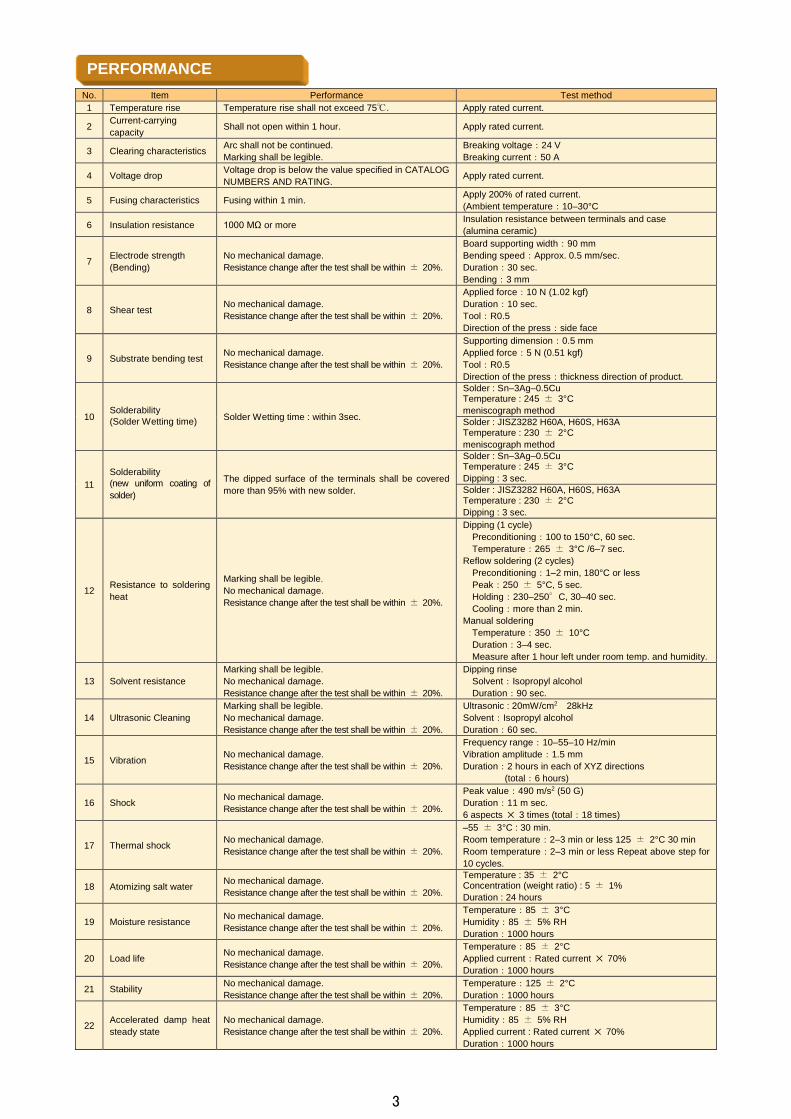
FUSING CHARACTERISTICS
I2T – T CHARACTERISTICS
DISTRIBUTION OF FUSING CHARACTERISTICS
DISTRIBUTION OF FUSING TIME
0.0001
0.001
0.01
0.1
1
10
100
1000
0.1 1 10 100
Applied current (A)
Fusin
g tim
e (
sec)
0.0001
0.001
0.01
0.1
1
0 20 40 60 80 100
200% of rated current is
400% of rated current is
applied
Number of pcs
Fus
ing
tim
e (s
ec)
0.0001
0.001
0.01
0.1
1
10
100
0.1 1 10 100
Fus
ing
tim
e(s
ec)
Applied current (A)
0.1A
0.2A
0.25
A
0.8A
1.25
A1.
6A2.
0A2.
5A
0.63
A0.
5A0.
4A0.
315A
1.0A
0.00001
0.0001
0.001
0.01
0.1
1
10
100
1000
0.0001 0.001 0.01 0.1 1 10
Jou
lein
tegr
al(A
2・s
)
Fusing time (sec)
0.5A0.63A0.8A1.0A1.25A1.6A
2.5A
0.25A0.2A
0.1A
2.0A
0.315A0.4A
4
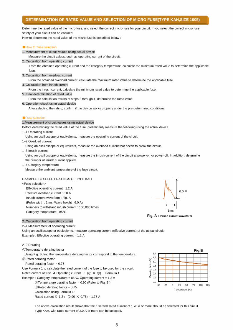
Fig.B
Determine the rated value of the micro fuse, and select the correct micro fuse for your circuit. If you select the correct micro fuse,
safety of your circuit can be ensured.
How to determine the rated value of the micro fuse is described below :
Flow for fuse selection
1. Measurement of circuit values using actual device
Measure the circuit values, such as operating current of the circuit.
2. Calculation from operating current
From the obtained operating current and the category temperature, calculate the minimum rated value to determine the applicable
fuse.
3. Calculation from overload current
From the obtained overload current, calculate the maximum rated value to determine the applicable fuse.
4. Calculation from inrush current
From the inrush current, calculate the minimum rated value to determine the applicable fuse.
5. Final determination of rated value
From the calculation results of steps 2 through 4, determine the rated value.
6. Operation check using actual device
After selecting the rating, confirm if the device works properly under the pre-determined conditions.
Fuse selection
1.Measurement of circuit values using actual device
Before determining the rated value of the fuse, preliminarily measure the following using the actual device.
1–1 Operating current
Using an oscilloscope or equivalents, measure the operating current of the circuit.
1–2 Overload current
Using an oscilloscope or equivalents, measure the overload current that needs to break the circuit.
1–3 Inrush current
Using an oscilloscope or equivalents, measure the inrush current of the circuit at power-on or power-off. In addition, determine
the number of inrush current applied.
1–4 Category temperature
Measure the ambient temperature of the fuse circuit.
EXAMPLE TO SELECT RATINGS OF TYPE KAH
<Fuse selection>
Effective operating current : 1.2 A
Effective overload current : 6.0 A
Inrush current waveform : Fig. A
(Pulse width : 1 ms, Wave height : 6.0 A)
Numbers to withstand inrush current : 100,000 times
Category temperature : 85°C
2. Calculation from operating current
2–1 Measurement of operating current
Using an oscilloscope or equivalents, measure operating current (effective current) of the actual circuit.
Example : Effective operating current = 1.2 A
2–2 Derating
①Temperature derating factor
Using Fig. B, find the temperature derating factor correspond to the temperature.
②Rated derating factor
Rated derating factor = 0.75
Use Formula 1 to calculate the rated current of the fuse to be used for the circuit.
Rated current of fuse ≧ Operating current / (① ②) ... Formula 1
Example : Category temperature = 85°C, Operating current = 1.2 A
①Temperature derating factor = 0.90 (Refer to Fig. B.)
②Rated derating factor = 0.75
Calculation using Formula 1 :
Rated current ≧ 1.2/ (0.90 0.75) = 1.78 A
The above calculation result shows that the fuse with rated current of 1.78 A or more should be selected for this circuit.
Type KAH, with rated current of 2.0 A or more can be selected.
Fig. A : Inrush current waveform
DETERMINATION OF RATED VALUE AND SELECTION OF MICRO FUSE(TYPE KAH,SIZE 1005)
1ms
6.0 A
0.0
0.2
0.4
0.6
0.8
1.0
1.2
1.4
-50 -25 0 25 50 75 100 125
Temperature ()
Dera
ting facto
r (%
)
5
3. Calculation from overload current
3–1 Measurement of overload current
Using an oscilloscope or equivalents, measure the overload current that needs to break the circuit.
Example : Effective overload current = 6.0 A
3–2 Calculation from overload current
Determine the rated current so that the overload current can be 2 times larger than the rated current.
Use Formula 2 to calculate the rated current of the fuse.
Rated current of fuse ≦ Overload current /2.0 ... Formula 2
Example : Overload current = 6.0 A
Use Formula 2 to calculate the rated current.
Rated current ≦ 6.0/2.0 = 3.0 A
The above calculation result shows that the fuse with rated current of 3.0 A or less should be selected for this circuit.
Type KAH, with rated current of 2.5 A or less can be selected.
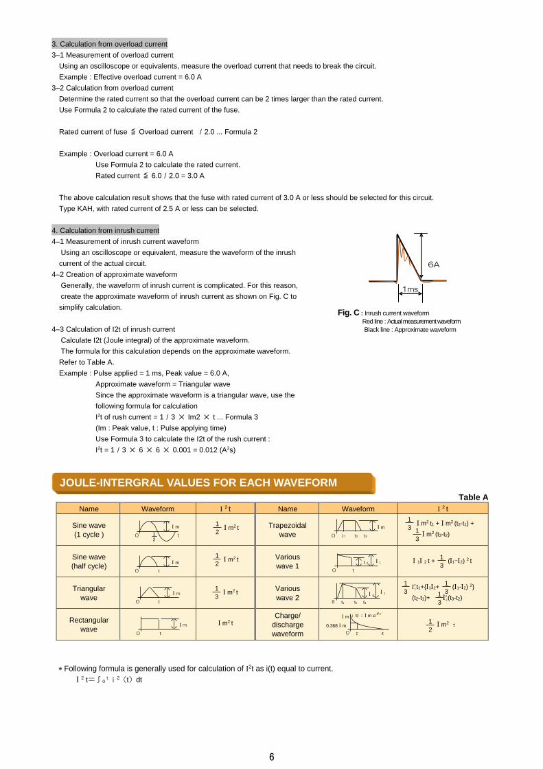
4. Calculation from inrush current
4–1 Measurement of inrush current waveform
Using an oscilloscope or equivalent, measure the waveform of the inrush
current of the actual circuit.
4–2 Creation of approximate waveform
Generally, the waveform of inrush current is complicated. For this reason,
create the approximate waveform of inrush current as shown on Fig. C to
simplify calculation.
4–3 Calculation of I2t of inrush current
Calculate I2t (Joule integral) of the approximate waveform.
The formula for this calculation depends on the approximate waveform.
Refer to Table A.
Example : Pulse applied = 1 ms, Peak value = 6.0 A,
Approximate waveform = Triangular wave
Since the approximate waveform is a triangular wave, use the
following formula for calculation
I2t of rush current = 1/3 Im2 t ... Formula 3
(Im : Peak value, t : Pulse applying time)
Use Formula 3 to calculate the I2t of the rush current :
I2t = 1/3 6 6 0.001 = 0.012 (A2s)
* Following formula is generally used for calculation of 2t as i(t) equal to current.
2 t=∫0ti2(t)dt
Name Waveform 2 t Name Waveform 2 t
Sine wave
(1 cycle )
Trapezoidal
wave
Sine wave
(half cycle)
Various
wave 1
Triangular
wave
Various
wave 2
Rectangular
wave
Charge/
discharge
waveform
JOULE-INTERGRAL VALUES FOR EACH WAVEFORM
1ms
6A
Fig. C : Inrush current waveform
Red line : Actual measurement waveform
Black line : Approximate waveform
1
3 m2 t1 + m2 (t2-t1) +
m2 (t3-t2) 1
3
2
1t1+12+ (1-2) 2
(t2-t1)+ 2
2(t3-t2)
1
3
1
3 1
3
m
t 0 1
2
t
m
0
0 t
m
0 t
m
0 -t τ
i (t) = m e-t/τ m
0.368 m
1
3 m2 t
m2 t 1
2
m2 t 1
2
m2 t
t2 t3
m
0 t1
t
2
0
1
t2 0 t1 t3
2 1
m2 τ 1
2
1 2 t + (1-2) 2 t 1
3
Table A
6
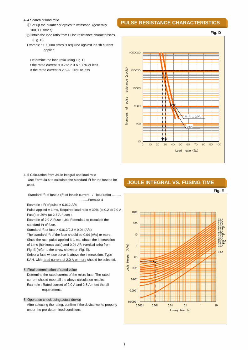
4–4 Search of load ratio
①Set up the number of cycles to withstand. (generally
100,000 times)
②Obtain the load ratio from Pulse resistance characteristics.
(Fig. D)
Example : 100,000 times is required against inrush current
applied.
Determine the load ratio using Fig. D.
f the rated current is 0.2 to 2.0 A : 30% or less
If the rated current is 2.5 A : 26% or less
4–5 Calculation from Joule integral and load ratio
Use Formula 4 to calculate the standard I2t for the fuse to be
used.
Standard I2t of fuse > (I2t of inrush current / load ratio) ..........
..........Formula 4
Example : I2t of pulse = 0.012 A2s,
Pulse applied = 1 ms, Required load ratio = 30% (at 0.2 to 2.0 A
Fuse) or 26% (at 2.5 A Fuse) :
Example of 2.0 A Fuse : Use Formula 4 to calculate the
standard I2t of fuse.
Standard I2t of fuse > 0.012/0.3 = 0.04 (A2s)
The standard I2t of the fuse should be 0.04 (A2s) or more.
Since the rush pulse applied is 1 ms, obtain the intersection
of 1 ms (horizontal axis) and 0.04 A2s (vertical axis) from
Fig. E (refer to the arrow shown on Fig. E).
Select a fuse whose curve is above the intersection. Type
KAH, with rated current of 2.0 A or more should be selected.
5. Final determination of rated value
Determine the rated current of the micro fuse. The rated
current should meet all the above calculation results.
Example : Rated current of 2.0 A and 2.5 A meet the all
requirements.
6. Operation check using actual device
After selecting the rating, confirm if the device works properly
under the pre-determined conditions.
Fig. D
Fig. E
PULSE RESISTANCE CHARACTERISTICS
JOULE INTEGRAL VS. FUSING TIME
10
100
1000
10000
100000
1000000
0 10 20 30 40 50 60 70 80 90 100
Num
bers
of
puls
ere
sis
tanc
e(
cycle)
Load ratio(%)
0.1A to 2.0A
2.5A
0.00001
0.0001
0.001
0.01
0.1
1
10
100
1000
0.0001 0.001 0.01 0.1 1 10
Jou
lein
tegr
al(A
2・s
)
Fusing time (s)
0.5A0.63A0.8A1.0A1.25A1.6A
2.5A
0.25A0.2A
0.1A
2.0A
0.315A0.4A
7
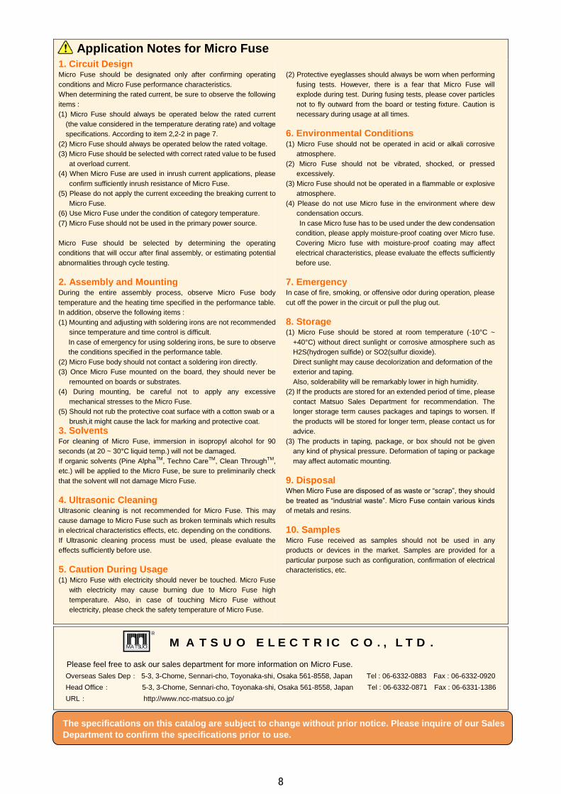
Application Notes for Micro Fuse
1. Circuit Design Micro Fuse should be designated only after confirming operating
conditions and Micro Fuse performance characteristics.
When determining the rated current, be sure to observe the following
items :
(1) Micro Fuse should always be operated below the rated current
(the value considered in the temperature derating rate) and voltage
specifications. According to item 2,2-2 in page 7.
(2) Micro Fuse should always be operated below the rated voltage.
(3) Micro Fuse should be selected with correct rated value to be fused
at overload current.
(4) When Micro Fuse are used in inrush current applications, please
confirm sufficiently inrush resistance of Micro Fuse.
(5) Please do not apply the current exceeding the breaking current to
Micro Fuse.
(6) Use Micro Fuse under the condition of category temperature.
(7) Micro Fuse should not be used in the primary power source.
Micro Fuse should be selected by determining the operating
conditions that will occur after final assembly, or estimating potential
abnormalities through cycle testing.
2. Assembly and Mounting During the entire assembly process, observe Micro Fuse body
temperature and the heating time specified in the performance table.
In addition, observe the following items :
(1) Mounting and adjusting with soldering irons are not recommended
since temperature and time control is difficult.
In case of emergency for using soldering irons, be sure to observe
the conditions specified in the performance table.
(2) Micro Fuse body should not contact a soldering iron directly.
(3) Once Micro Fuse mounted on the board, they should never be
remounted on boards or substrates.
(4) During mounting, be careful not to apply any excessive
mechanical stresses to the Micro Fuse.
(5) Should not rub the protective coat surface with a cotton swab or a
brush,it might cause the lack for marking and protective coat.
3. Solvents For cleaning of Micro Fuse, immersion in isopropyl alcohol for 90
seconds (at 20 ~ 30°C liquid temp.) will not be damaged.
If organic solvents (Pine AlphaTM, Techno CareTM, Clean ThroughTM,
etc.) will be applied to the Micro Fuse, be sure to preliminarily check
that the solvent will not damage Micro Fuse.
4. Ultrasonic Cleaning Ultrasonic cleaning is not recommended for Micro Fuse. This may
cause damage to Micro Fuse such as broken terminals which results
in electrical characteristics effects, etc. depending on the conditions.
If Ultrasonic cleaning process must be used, please evaluate the
effects sufficiently before use.
5. Caution During Usage (1) Micro Fuse with electricity should never be touched. Micro Fuse
with electricity may cause burning due to Micro Fuse high
temperature. Also, in case of touching Micro Fuse without
electricity, please check the safety temperature of Micro Fuse.
(2) Protective eyeglasses should always be worn when performing
fusing tests. However, there is a fear that Micro Fuse will
explode during test. During fusing tests, please cover particles
not to fly outward from the board or testing fixture. Caution is
necessary during usage at all times.
6. Environmental Conditions (1) Micro Fuse should not be operated in acid or alkali corrosive
atmosphere.
(2) Micro Fuse should not be vibrated, shocked, or pressed
excessively.
(3) Micro Fuse should not be operated in a flammable or explosive
atmosphere.
(4) Please do not use Micro fuse in the environment where dew
condensation occurs.
In case Micro fuse has to be used under the dew condensation
condition, please apply moisture-proof coating over Micro fuse.
Covering Micro fuse with moisture-proof coating may affect
electrical characteristics, please evaluate the effects sufficiently
before use.
7. Emergency In case of fire, smoking, or offensive odor during operation, please
cut off the power in the circuit or pull the plug out.
8. Storage (1) Micro Fuse should be stored at room temperature (-10°C ~
+40°C) without direct sunlight or corrosive atmosphere such as
H2S(hydrogen sulfide) or SO2(sulfur dioxide).
Direct sunlight may cause decolorization and deformation of the
exterior and taping.
Also, solderability will be remarkably lower in high humidity.
(2) If the products are stored for an extended period of time, please
contact Matsuo Sales Department for recommendation. The
longer storage term causes packages and tapings to worsen. If
the products will be stored for longer term, please contact us for
advice.
(3) The products in taping, package, or box should not be given
any kind of physical pressure. Deformation of taping or package
may affect automatic mounting.
9. Disposal When Micro Fuse are disposed of as waste or “scrap”, they should
be treated as “industrial waste”. Micro Fuse contain various kinds
of metals and resins.
10. Samples Micro Fuse received as samples should not be used in any
products or devices in the market. Samples are provided for a
particular purpose such as configuration, confirmation of electrical
characteristics, etc.
Please feel free to ask our sales department for more information on Micro Fuse.
Overseas Sales Dep: 5-3, 3-Chome, Sennari-cho, Toyonaka-shi, Osaka 561-8558, Japan Tel : 06-6332-0883 Fax : 06-6332-0920
Head Office: 5-3, 3-Chome, Sennari-cho, Toyonaka-shi, Osaka 561-8558, Japan Tel : 06-6332-0871 Fax : 06-6331-1386
URL: http://www.ncc-matsuo.co.jp/
The specifications on this catalog are subject to change without prior notice. Please inquire of our Sales
Department to confirm the specifications prior to use.
R
MATSUO M A T S U O E L E C T R IC C O . , L T D .
8
Related Documents