KAERI/TR-2461/2003 7H W-# *lEh 7| u>x|^ STii $ eiass&i mai Design and Safety Analysis Report of Facilities for Research and Development of ti s( a ?±

Welcome message from author
This document is posted to help you gain knowledge. Please leave a comment to let me know what you think about it! Share it to your friends and learn new things together.
Transcript

KAERI/TR-2461/2003
7H W-#*lEh 7| u>x|^
STii $ eiass&i mai
Design and Safety Analysis Report of Facilities for Research and Development of
ti s( a ?±
g MHAiS “°| =§ 7^# ^1 °> 7|uhA|^” 4*i| ^
^Oi 2002ti 4*11 7|#MHAi^ Ai|*#u| cK
Ai|^ : S|=# “0U[Aj ?m# ^1 °> 7|uhA|^ ^7i| gj 2i@^^A4filAj
2003. 03.
4 £ A|- : §
£1 a a
HI- -1 5! s
o| a
HI- Al
o
^ahm o|01==o| ^i^ai-^ #^# ^i#
# 4r Si-^ April 7^ 4 £|°t^°| ?m ^o^| r^e °f*j£
#M# ^l^oi 0|Ako| §§c7[ °x\t ^E|5|^ Clean Room
# "o A| &|| °f^#-^ ^#A|^ m ^fg xfti|°| i+2_7{ @^AiO|cP ^A^ *1 x\
^(^|A1-^ “0U|Aj °|°t-o| ^ ° C Qjtij. o|ot^o| ^ °£|. yol ^^o|ot^
a||^7|^(GMR: Good Manufacturing Practice)# ^#^1-^ A|^of|A-j A||°|
Si°ni, GMP A|^oj|Ai Ai|^# °|Y^
sm slop zi&m ?mv[x\ °i°^#°i %ii^#
x^il gj GMP ^Zd# ^#A|^o| #M5|%| °>of- “URy o|°t- xil
i xi| °t# ti>o^Arcp
■& MHAi-^ #^I^^^#A|^ Lllofl °|=# “Upy ^
^1^^ Xili o4^ps ^| of “I-AI-AJ x[n 71^4 GMP SZdeJ SS 71^# ^
e ##A|^o| M7i | 04^ 7|#^5l°°i, # A|^e ^LH 7|°jxi| §J
7|^f#o| g# A^## Sftfft 7H«^lo^Ai ^LH urx^ o|ot- xil^s
^1 of °4#7H^# Mof #^m^#7| *|°f 7|HfA|-M^Ai ##@cp
SUMMARY
For production and research for practical use of radio-pharmaceuticals using
for medical treatment and diagnosis, the complex facility offer shield and
clean environment is basically required for protecting personnel from radiation,
and the product from contamination. The facilities was designed for research
and development of medical radioisotopes. This facility was designed to
comply with GMP(Good Manufacturing Practice) requirements and safety
requirements against radiation. In this technical report, technical requirements
and design summary for construction of hot cell and clean room are
described. And also, This facility will be utilized for production of Tc-99m
generator and R. & D. of other radio-pharmaceuticals(Ho-166 etc.).
n
4 l # 4 #----------------------------------------------------------------------------- 1
4 2# 4&# #442 4## 44# 4#4# #4------------------------4
4 14 4# ---------------------------------------------------------------------------- 4
4 2# 4&# #442 42444 #4 4#------------------------------- 5
1. #44 44 44 ------------------------------------------------------------5
2. 44# 42# 4# GMP 44----------------------------------------------9
4 3 4 44 4##4 4 #4# 44 44 -----------------------------------15
1. 4 4---------------------------------------------------------------------------15
2. 44 4 ##4----------------------------------------------------------------18
3. 44# 4# 44 4#---------------------------------------------------- 21
4 4 1 44 4#-----------------------------------------------------------------------24
1. 44 #4 # 44 ----------------------------------------------------------24
2. 444# 4#--------------------------------------------------------------- 28
3. 4 444 4444 ------------------------------------------------------ 28
4. 444 # 2##4 44------------------------------------------------ 36
5. #44 4444------------------------------------------------------------52
6. #444 # 4444 --------------------------------------------------- 53
7. #7] 44 --------------------------------------------------------------------- 65
8. 4444 -----------------------------------------------------------------------73
9. 444-5.-----------------------------------------------------------------------75
4 3# 444 444 #4 # 447}-------------------------------------------- 78
4 14 4# -----------------------------------------------------------------------78
in
784 2 4 444 7144 44
1. 42: 7144 -------------------------------------------------------------- 78
2. 44 7144 -------------------------------------------------------------- 83
3. #4 44=^7}---------------------------------------------------------------- 86
4 3 4 KINS 71471-----------------------------------------------------------------97
1. 71471 44 ------------------------------------------------------------------- 97
2. 71^7} 44------------------------------------------------------------------ 101
#3.^4--------------------------------------------------------------------------------------105
44& 7l444r4^5%4 44 44- (11.3. ^442: 4444)
KINS 14 44444 44 444
KINS 24 44^44 #44
KINS 24 44^44 ^7} ^.4 444
KINS 34 44444 44 444
44 l.
44 2.
44 3.
44 4
44 5.
- iv -
=L a ^ *1
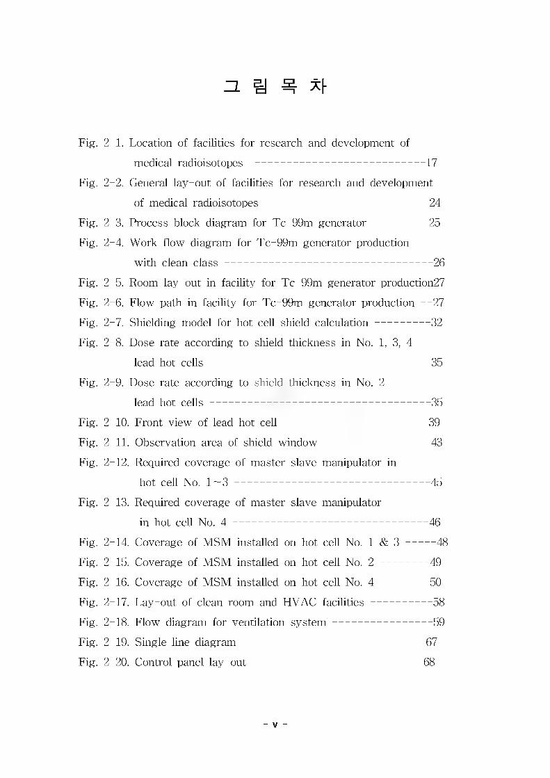
Fig. 2-1. Location of facilities for research and development of
medical radioisotopes --------------------------------------------------17
Fig. 2-2. General lay-out of facilities for research and development
of medical radioisotopes------------------------------------------------ 24
Fig. 2-3. Process block diagram for Tc-99m generator---------------- 25
Fig. 2-4. Work flow diagram for Tc-99m generator production
with clean class------------------------------------------------------------- 26
Fig. 2-5. Room lay-out in facility for Tc-99m generator production27
Fig. 2-6. Flow path in facility for Tc-99m generator production —27
Fig. 2-7. Shielding model for hot cell shield calculation---------------- 32
Fig. 2-8. Dose rate according to shield thickness in No. 1, 3, 4
lead hot cells----------------------------------------------------------------- 35
Fig. 2-9. Dose rate according to shield thickness in No. 2
lead hot cells----------------------------------------------------------------- 35
Fig. 2-10. Front view of lead hot cell------------------------------------------ 39
Fig. 2-11. Observation area of shield window------------------------------- 43
Fig. 2-12. Required coverage of master slave manipulator in
hot cell No. 1 — 3----------------------------------------------------------45
Fig. 2-13. Required coverage of master slave manipulator
in hot cell No. 4--------------------------------------------------------- 46
Fig. 2-14. Coverage of MSM installed on hot cell No. 1 & 3-------- 48
Fig. 2-15. Coverage of MSM installed on hot cell No. 2--------------49
Fig. 2-16. Coverage of MSM installed on hot cell No. 4--------------50
Fig. 2-17. Lay-out of clean room and HVAC facilities------------------58
Fig. 2-18. Flow diagram for ventilation system----------------------------- 59
Fig. 2-19. Single line diagram------------------------------------------------------67
Fig. 2-20. Control panel lay-out--------------------------------------------------68
- v
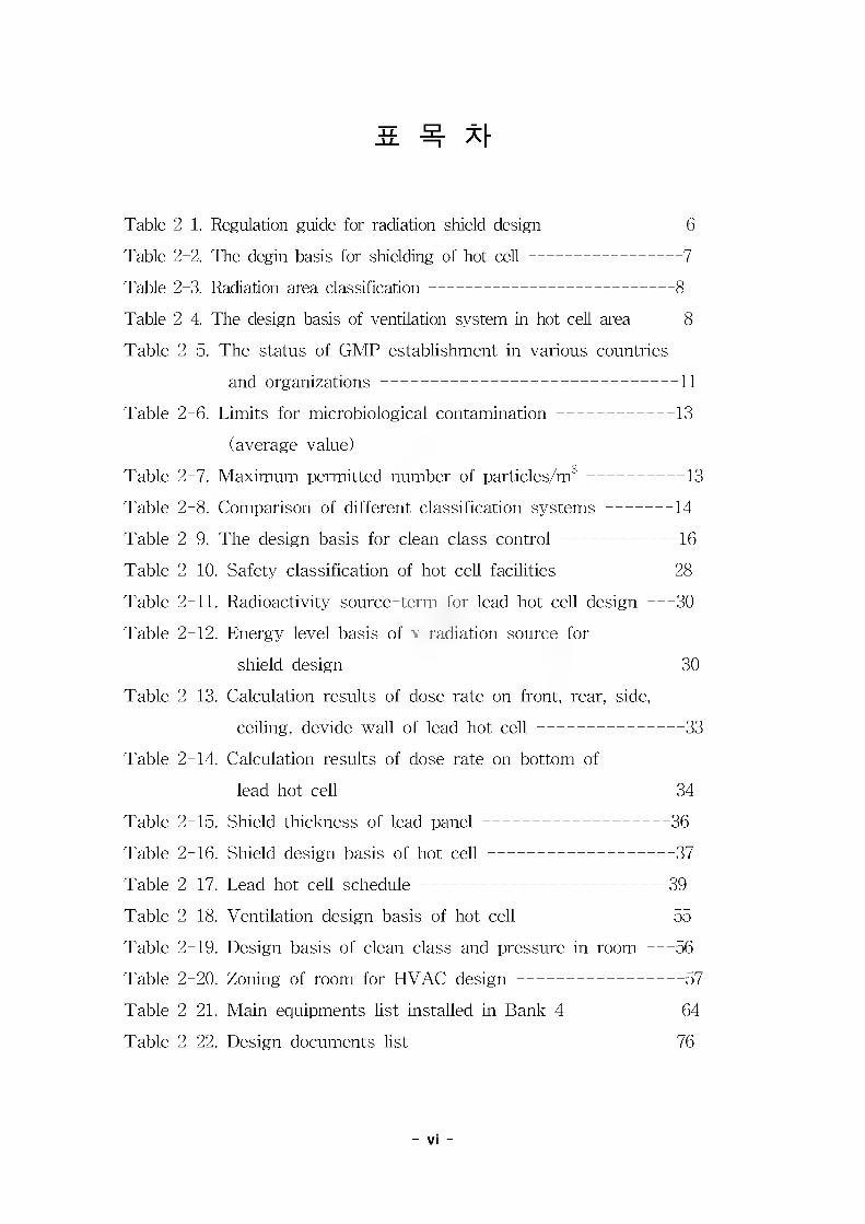
Table 2-1. Regulation guide for radiation shield design------------------------- 6
Table 2-2. The degin basis for shielding of hot cell-----------------------------7
Table 2-3. Radiation area classification----------------------------------------------8
Table 2-4. The design basis of ventilation system in hot cell area--------8
Table 2-5. The status of GMP establishment in various countries
and organizations-------------------------------------------------------- 11
Table 2-6. Limits for microbiological contamination---------------------- 13
(average value)
Table 2-7. Maximum permitted number of particles/m3------------------13
Table 2-8. Comparison of different classification systems-------------14
Table 2-9. The design basis for clean class control---------------------- 16
Table 2-10. Safety classification of hot cell facilities-------------------- 28
Table 2-11. Radioactivity source-term for lead hot cell design-----30
Table 2-12. Energy level basis of v radiation source for
shield design------------------------------------------------------------- 30
Table 2-13. Calculation results of dose rate on front, rear, side,
ceiling, devide wall of lead hot cell--------------------------- 33
Table 2-14. Calculation results of dose rate on bottom of
lead hot cell------------------------------------------------------------- 34
Table 2-15. Shield thickness of lead panel-----------------------------------36
Table 2-16. Shield design basis of hot cell-----------------------------------37
Table 2-17. Lead hot cell schedule---------------------------------------------- 39
Table 2-18. Ventilation design basis of hot cell--------------------------- 55
Table 2-19. Design basis of clean class and pressure in room-----56
Table 2-20. Zoning of room for HVAC design------------------------------- 57
Table 2-21. Main equipments list installed in Bank 4--------------------64
Table 2-22. Design documents list------------------------------------------------ 76
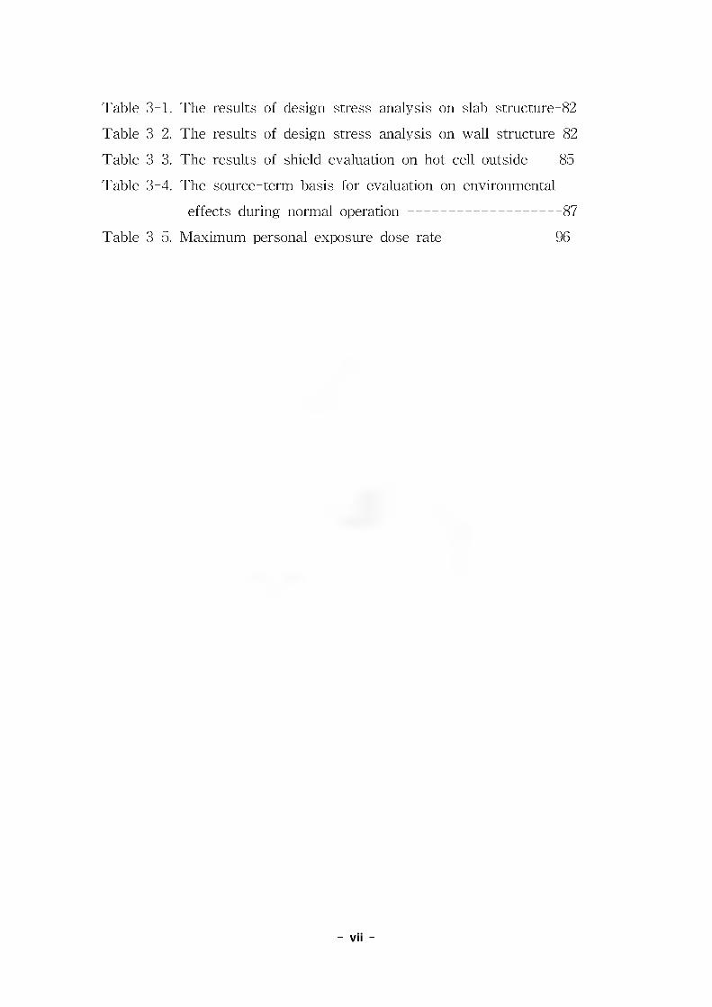
Table 3-1.
Table 3-2.
Table 3 3.
Table 3-4.
Table 3 5.
The results of design stress analysis on slab structure-82
The results of design stress analysis on wall structure-82
The results of shield evaluation on hot cell outside-----85
The source-term basis for evaluation on environmental
effects during normal operation-----------------------------------87
Maximum personal exposure dose rate----------------------- 96
- vii -
*11 1 #
44 4 #3 #4 ### 4# 44# 4443# 44# 4:
4471 ##33# 344##4 1#3 4-0-43- 434 44^ ## 44
443 344 44# 44# # 44. 444 4# #4# 1-0-4# PET 4 444 44 44 44443 #443 37}# 444 44#33#o]
#343 4444 #44# 4443# 4-0-444 433 44 4 43 til .7} 317>o]#. 444 #333 44# 4 44# 444 43# 44#
44434 7H43 SPECT4 4-0-4 4# #7}# 3133 4443 44.3944-011 444 %4 47}# #443# 196044444 44 ###
44434 44 44 444 443443 196044 4444 #3#4 7H#4 4444 196744 4#33 444 #4# 4 4 44 3tii#A}# -0-4, capsule #4 437} 7}#e}# 4434 #4 #3#4 70% ### 433 4# #4 7HtM 433 44-. 1970444 344 ^Tc33 34 4 4^}# 4 4=#4 #44 4#444 ^14- #4 3 -0-37} 34 ##4
ti} Tc-99m# 140 keV4 Photon# 4#4## 4# 44 4##3 ## 444
444 44 3# 4# 3## 4443 #44 44444, 444 c4 4
7} 4#4 S14 434 444 44 ##33 7}#47l#4 4# 44#4 34
# 743 44. 3 44#33 444 447} 44# 7143341-+7) 4# 4
4# 344444 4137} 7}#44 4.43#, 344#, 14#, 444# ##
444 44# 4% ^944- ^/}o]i /}#4# #44. 4#3##4 44 #
3 #44 ##& 44 4# 4#3 014 4344 444# 44# 4 4# 4
$14
#3# #7}# 44=^33 7}^s]3 ## #44 4# #4# ^P, ^Sr,
^Y, ^1, ^Sm, ^y, %%Ho, #33# ^e# #44 3# ###443## ## g-334 444# 7}#^4 4^4 4^ ^o_
3 #444 ^o(-CHICO) #4 44 4-0-4 4## #4 444 444
44 4 4## 44, 44 444 4# #37} ##4 #3#3# 4##
#3 44.### 4#4 44# 44#4 44# 144 4## 44 4#4# 3
- 1 -
## ##33 4### 4# 4### #4 #44 43, #
#3 3# 4##33##4 444# 43# #44#4 44, #4, 444 4:44 4444 ## # radio-pharmacy4 4:44 #3 4#4 #4
4 ^ ## #7}34 ### 3.444] 4 #4. 44 4433 413# 44
44 ;]]#, 444 4-44 47} 4# 4443 #44-3 #3# 4#4 4
34 e #44 7} 3344 44 337} 43 337] 4 4 434 347}
## 434 34 3444443 337] 4 4 4# 434 43443 4
4 #7}3# 433 4334. 3 4^44 #44 4 4## 4344 4
4 444 4# 4## 4#4# 444 44 ^ #4# 44# 444 4
#4# 444 4^433 #44 4##4 434 444 44 447} &
# #33 # # 444# 4#3 ###.
44## 444 3# 43413# 4#43 ## 4#4 444 #44
4 4##4 7} 4, 44 43 44# #34 #444 4# ##43 44
## 43 #44 ;]]#4## 444^ #44 #4 4## 44=# 4##
4# ##4##434#(GMP)4 344 clean room 4## #44 ##
4#444 #37} ##4##. 4m# ##47} #3, \-
4# ###33 #4444#4 ^1^. 40]]^ 44 7}4 #44 4## 4
7] 4 4 #444 4 4 #4] #4# 7} 4 3 hume hood# hot cell4 4#4
3 ##. ## 44## #44 #3# 4444# 444# ##(negative
pressnre)33 44 #^}4##4 4#3# #4# 4# 44 3###. 3
4 4 4# #4 344 4444# 4#4 #444 3-44# 4# #7] #4 444 -o'7]H 3444 #44# #4"(positive pressure)33 4#44 3###. #4444# 444^ 4 ### 34# #443
3 4444 4]## #4 34 4 #47}# #44 344# 44# #4
4 44# #343 #444 4# #4# 4## 4444 43# 434
## #3###3 #7] 3 #7}###.
#44 3 3# #44 44#4 434 #4 4# 7}## #44 44
4 ##37} #3|]443} 44444 ##44# '43# #44 #44#
711## 44 7]#44'4 44# #4 444 44 ##33 44444.
4 44# 47}##434 #44# 49444 4 #44# 4#] ^443
4 #4 4## 4#4 # 44# #4# #4, 444 ## 43# #4
- 2 -

4^4 4^4 #4 ;ij#4 ###o_&4 #44 44=# 421 44# #4 4# # #4 ^4-.
4 ^j%444# '4&# #44 #4#^ ;li## 44 4#44'4 4 4 _- 4#, 44# 44 4444 # 4444, 444 #44 #44 #4 # KINS #44-4 #44 4## _&# 4444 4# 44 #44- 4# 444 444 ### # #^# 4#4.
- 3 -
*11 2 # 7ms 7|y-A|>M
S7i|
4] 1 ^ 4 S
444 4^ 7}^-c|] 4#7H# #4# 44, 44 ^ 44#4, 44 44 4 444 #44144 44°1 7>444 44 4 4# 444
4 444 44 #44 44 #444 4#7H# #7}& 444 444 44
#4# 4^ #444 44 ##4 444 4444 4^ ##4 4#44
#4, 444## 444 444 44 44/114 #4# ##44 4444
4# 4 44 44 4# 444# 44 4444.
#4, 4&# #44# 44444 4# 444 #44## 4444 44# # 4# 444 44 7H#4 4 4# 4 #44 444 #44 4# 44
4 4## 444 4 4#4 44 ## 444 44#7} 44, 444#
GMP(Good Manufacturing Practice) 4 4# #4°H 4#4 4 # 4# 44^ 444 4^7} 4#444. 44444# GMP 4444 4#4 444 4^40] 4^ 444 jE# 4#4#4 4#4# 44 7}#44 4# 7H4#4#7]-## 4444 44 4 4# 4 4## GMP 4444 4## 4 #44# 4#4 444 4 4# 4 4## 444## 444# 44# 44, 444 4 4## 44 4 4#4 4# GMP 4# 44444 4## 4#4 4# 44 4444 #44.
#444# 4/1144 44444#4 ^4 4 4# 4# ^ #444 4#4 444# 44 4# 44 41## 4# #4## KGMP4 4e4 4## 4# 444# 44 44. zz_44 4# #7}444# 4#4444 444# 4444# 4 KGMP 4e4 #4# 444#& 4# 4# 4#4# 4#4, # KGMP4 4 ## 4#4# 4444 4## 41444 4## #44#4 7^4# 44# 4# '4## #44# 7H#& 4% 44444 44^ #4# 444/11 444# 4# 4444 444 #4 KGMP #4# 4#4# 4444 44# #4944 4 44.
- 4 -
444 4 44 4444# 444 #44#: 7H## 44 44:44'
4 ## ### 444 #4-44 J%444 44-4 44 444^4.- Tc-99m generator 43: # 4444, 43-4 Tc-99m 4444# 44
- Ho-166 4 44 444 444# 44
- 44 4&4 444 #44^(Sr-89, Sm-153, Cr-51, Ir-192 #) 7H#
- 714 4 5--o" v-radiation source 44 4 4
4] 2 ^ ^4] 7W
l. 444 44 7114444 444## 4^ ^A}4 s4 #4 444 44444 ##&#
4 5L#47l 444 44444 4444 444 #44 444711 444 4 4#4 #44 444 4444, 444 44444 44 7fl## 4# 4 4# 44## #4# 44 44431 4444.
- 444 s# #444 444 44444 #44 #44# 44# 444711 44453# 444# 444 #4 44 ## 4444 4#4# 4444 44 ##4 44## 4# #4# 44453# 44.
- 444# 444 #4# 4-44 #44 #44 44 4# s# 4##. & 444 4444(444) 444 44453# 44.
- 444 44#4 444 444# 444 #44 #4 4 44# ##44 #4# 4e4.
- 44 # 414# ###3. #4 4 53# 44.- 444# 4 #71^:## activity7> ## 4 4###4 ## 4 4##
3:^3# 44.- 4-4# 4###4 471## #7i# 44431 activity# 444 #4
44# 4##33# 44.- #4# 444# #4# #444 4#44 4# 44
44.
- 5 -
7}. 44 4#
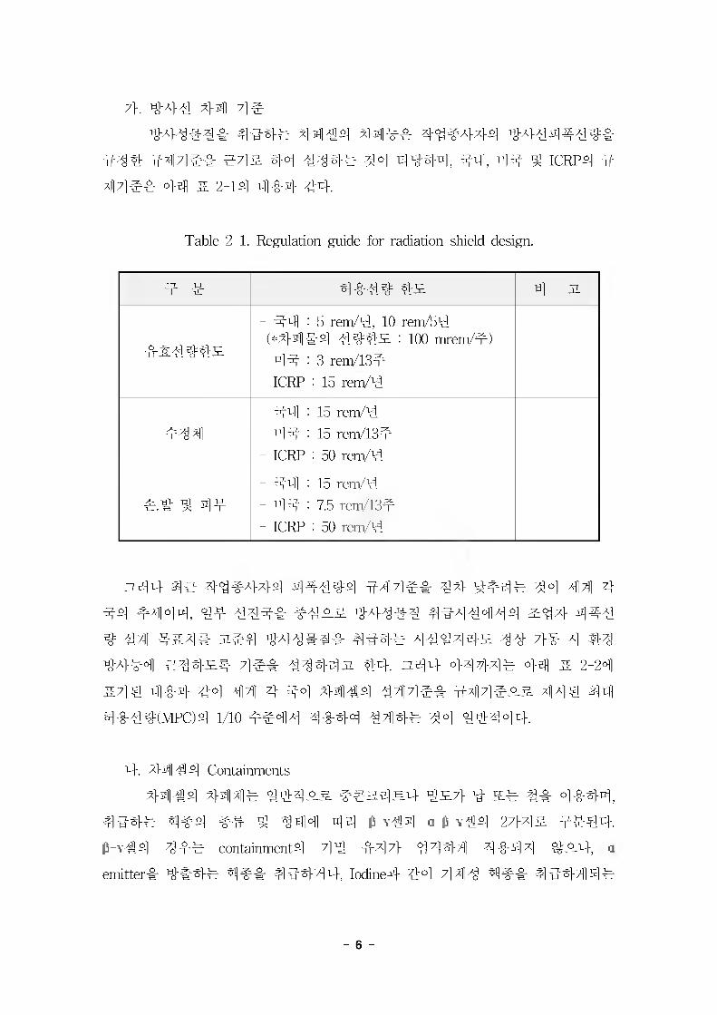
444# 44 #4 44 4444444^
444 444e& #4& 44 4444 44 4444, 44, 44 4 ICRP4 447]#4 44 5. 2-14 444 44.
Table 2-1. Regulation guide for radiation shield design.
# # 4#44 4# 4 31
##444#
- 44 : 5 rem/4, 10 rem/54 (*###4 444# : 100 mrem/m)
- 44 : 3 rem/13m- ICRP : 15 rem/4
#44- 44 : 15 rem/4- 44 : 15 rem/13m- ICRP : 50 rem/4
#.4 ^ 4m- #4 : 15 rem/4- 44 : 7.5 rem/134- ICRP : 50 rem/4
n44 4# 44#444 44444 444e& 44 4f4# 44 44 4 44 f 444, 44 444& m4^-& 444#4 4444444 &44 444 4 44 4&4# 3%#4 444444 4#4# 44444^ 44 7}# 4 #3 4444 #44^4 4#& 44443% 44. ^-44 4444# 44 & 2-24 &4# ### 44 44 4 44 44144 444## 444e^.g. 444 44 4#44(MPC)4 1/10 #e44 4444 444# 44 44444.
4. 4444 Containments44 #4 4414# 444## ##a4m4 4 #7} 4 a# 44 4444,
444# 4#4 #4 4 444 44 M€4 a-M44 27}4s 4444
&-V-44 44# containment4 4 * * 714 #47]- 4444 4444 4#4, a
emitter#- 4#4# 4## 4#444, Iodine# 4°1 7]#^ 4## 44444#
- 6 -
o-p-v#4 4## containment# 7]n] #xl7} 4# ###4.
44 ## hot laboratories5- #4 4#4# shielded box# #35l3 #5:4 hot
cells, ##44, #44 ## #44# shielded box# 7]n] #47} #444 a
p-v## ## #### #4 7}###4 S32]s ##4 hot cellar a & y€
SL ###71 # 4 7^ 4 #4 ##4 steel box #44 containment# #7}S_ ##
#4# #4. 3-43 Q-tight sealing# ## #dMir#SL air leak rate# 50
mmAq## #4 #4 4^^=# 1 %/min 4 hi, ####S_ #4## #4##
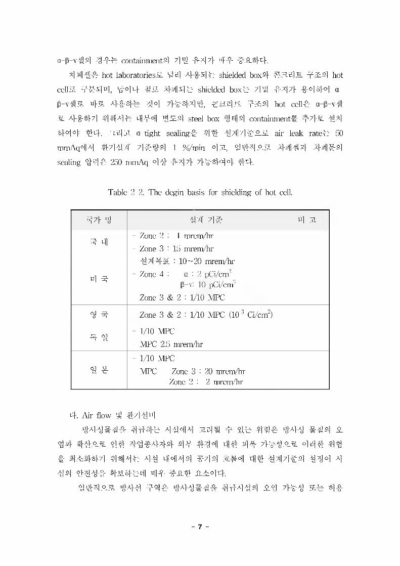
sealing #4# 250 mmAq 4# #47} 7}##4 4 #4.
Table 2-2. The degin basis for shielding of hot cell.
47} 4 #4 4e 4 3
4 4- Zone 2 : 1 mrem/hr
- Zone 3 : 15 mrem/hr
4 4
- #44# : 10~20 mrem/hr- Zone 4 : a : 2 pCi/cm2
P >: 10 pCi/cm2
- Zone 3 & 2 : 1/10 MFC
4 4 - Zone 3 & 2 : 1/10 MFC (10^ Ci/cnf)
4 #- 1/10 MFC
- MFC 2.5 mrem/hr
# #- 1/10 MFC
- MFC Zone 3 : 20 mrem/hrZone 2 : 2 mrem/hr
4. Air flow # #71# n]
###### ##-## ##4# 34# # $1# ### 44# ### #
4# #### 4# #4#### 4# #44 4# 4# 7}###s. 44# 4#
# ####7] 447^# ## 44A|# #7]# ##4 4# #44#4 #44 4
#4 #### ##.##4 4# ^## #^44.##4#s. #4# #4# #4#### ####4 #-3 7}## s# 4#
- 7 -
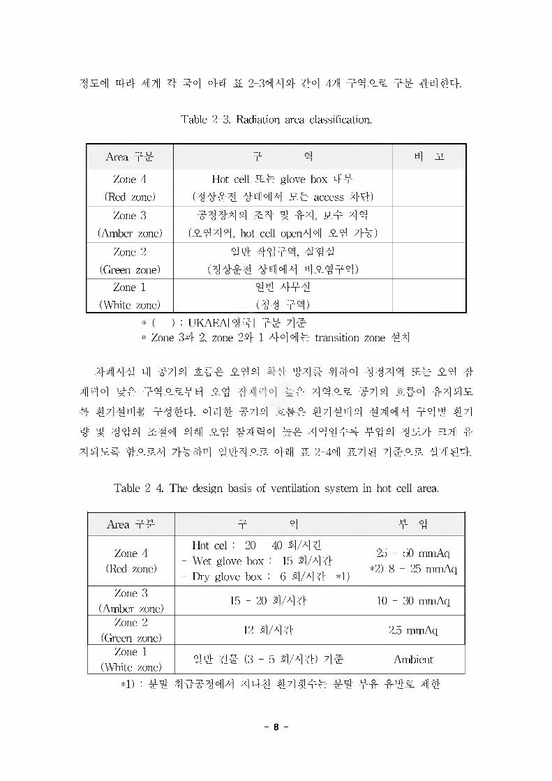
42# 44 44 4 44 44 5. 2-3444 #4 4?} 4422 44 #444.
Table 2-3. Radiation area classification.
Area 4# 4 4 4 2
Zone 4(Red zone)
Hot cell 24 glove box 44 (4444 4444 24 access 44)
Zone 3(Amber zone)
44444 2# 4 #4, 24 44 (2444, hot cell open#4 24 44)
Zone 2(Green zone)
44 #444, #4#(4#4# #444 42444)
Zone 1(White zone)
4# 44#(#4 44)
* ( ) : UKAEA[44] 44 4e* Zone 34 2, zone 24 1 4°H14 transition zone 44
W44 4 444 2## 244 #4 #4# 444 4444 24 #^44 44 442244 24 44M4 ^4 4422 444 2#4 #4 #2 4 4444# 4444. 444 444 ##4 44444 4444 444 44 # # 444 244 4# 44 4^44 ^4 4444# 444 427} a# 4 442# #o_24 7}##4 4442# 44 2 2-44 #44 4422 4444.
Table 2-4. The design basis of ventilation system in hot cell area.
Area 44 4 4 4 4
Zone 4 (Red zone)
- Hot cel : 20 - 40 4/44:- Wet glove box : 15 4/4#- Dry glove box : 6 4/44 *1)
25 - 50 mmAq *2) 8-25 mmAq
Zone 3 (Amber zone)
15-20 4/4# 10 - 30 mmAq
Zone 2 (Green zone)
12 4/4# 2.5 mmAq
Zone 1 (White zone)
4# ## (3 - 5 4/4#) 44 Ambient
*1) : #4 444444 44# #4^## #4 4# #42 4#
- 8 -
*2) : IAEA #31 #4* Transition zone# 44 2#4 4 4 7]#
44 44 CM 4 471 #4# ##2##4# one-through 2##4 °1 42
#44##4 #4## 444# 7}#^0] ## 44# 4#4#2
one-thmugh ###4& 4##4 ### 24#^4 #422 4% 44 4 24
2 ### #4431, #####4# #,##4 #2# 444 444 44# 4#
4 ##422 4### 4 #2 #2# o] 4^ #44# 4444 44 #4
##444 44. n44 hot cell 444 44422 4447} 4444 44 4s
2 4,444 #244 #4422 #2#4 WS.S2, one-through 2##4# 4
444 44 44444.
2. 44# 42# 44 GMP 7i|4
7}. GMP 4# 44 44 ^ # #4 GMP 4#
195044 44 #4 4- 2^444 #44444 44# 44 2# #
4 7} 4 4 44 19584 444444 (PhRMA: Pharmaceutical Research and
Manufactures of America)# 44244 44 (QA Committee)# 44 44
4##4 42# #4444 4# 4#4 ##, 196144 444 4444
GMP# #444#.
GMP## #4# 4# 447} 44# 4#. 4## # ###4(Food.
Drug and Cosmetic Act) 4 4 #24 “44# 7} 4 4 (Kefauver-Harris
Amendments)4 4 #22 ###4#4 32 4## "45012 - current good
manufacturing practice4 4##4 °}44r #422 42# 4 ### ##
4 ##(adulterated drugs)22 ##"5}# 4 4 4#. 4 #4## 196324
FDA-GMP# 44 #2#W 19644## #4##2# 197244# GMP 4
2 #44 4244 #4# 4 4=# 4 #4#4# #2#4#.
X)14 24 7] #(WHO : World Health Organization)# 19674 4204 #4
44 GMP 42# #4# ## 44#2 44 4# ##44444
WHO-GMP# #4#4 19694 422# #444 4# 7}##3i 7}4#4
444 GMP 42# 44## #44 44#4 #4 4 44 444 GMP
- 9 -
44# #7(3 % #443# #34334 GMP7} 4^44711 5j^4. ^1
# 44 ## ^-7M 71-44 GMP# 444714 WHO-GMP#
4^3# EC, BETA, PIC, ASEAN# 44714443 GMP# % #34
7] 4 4# 4 4 4.
#444# EFT A (European Free Trade Association: #4 4-## 4 44)
7} 19704 EFTA-GMP# 44443, 4## 4^4 4#4 4:4 434
#4 4 43#4# #433 EFTA 7M 77114-# 344 147H#o] 1933^
PIC (Convention for the Mutual Recognition of Inspection in Respect of
the manufacture of Pharmaceutical Products: 4 4443:4-44 4##44
44 444)# 4443. PIC-GMP# 444SS4.
EC (European Community: # 4 # # 4) # 19894 4 44°H14#
ASEAN(Association of Southeast Asian Nations: #444 ##71-44)4
198844 4-4 GMP# 444^4.
GMP 7H4#4# 114 WHO# 19754 4 4=#4 #4434 44 44
4 4 4 (philosophy and policy)4 ##44 #444 (quality management)
4 7H4# #44# 4# #43 44 7H44 4 434, 444#4 #444 #4 4# 4 • 7(144 47l-/#4 71 #4 GMP 4 ISO (International
Organization for Standardization: 44##4-71 #)4 ##3#7l|4 (ISO 9000
series)4 3## 4#4 GMP7} 4444 4 4#4 #44
44 #4#3j 4 #4 444 4371- 43# 44 444 GMP 7H44 4
34# 4443. 19894 WHO-GMP # 44 Guideline 4 4^#^4 4#
44 19944 5# WHO #444 7H440] ^44^4. o] 71^44#
WHO-GMP7} 7H#^#44 4#4# 4# 3.444 ##44 4#3# 4
44Til 71 #444.
4 #3 4 4#4^#44 4444 4 4# 4 444# #4-444 44
44 WHO-GMP7} 7H44 4# 4444 validation 7H44 34, #444
##4 44444 “as necessary", "as appropriate"# 4# °H44 #44
44 ## #43 a}# 7M4# 4#44.
44# WHO-GMP7} 7H4443 444 3## 4* #37} 44# 4 444 GMP 7lM^# ##44 199444 7H4## #4, 3###4 ;H4
4 34# validation, #7144, 4#44 ## 444 444. 444 GMP
-10-
# #44# 19944 ^ GMP 3#
# 7H3343 ##3#44# 3-#37] 443 4#%4 37}^_4j ##
tij-4%4.
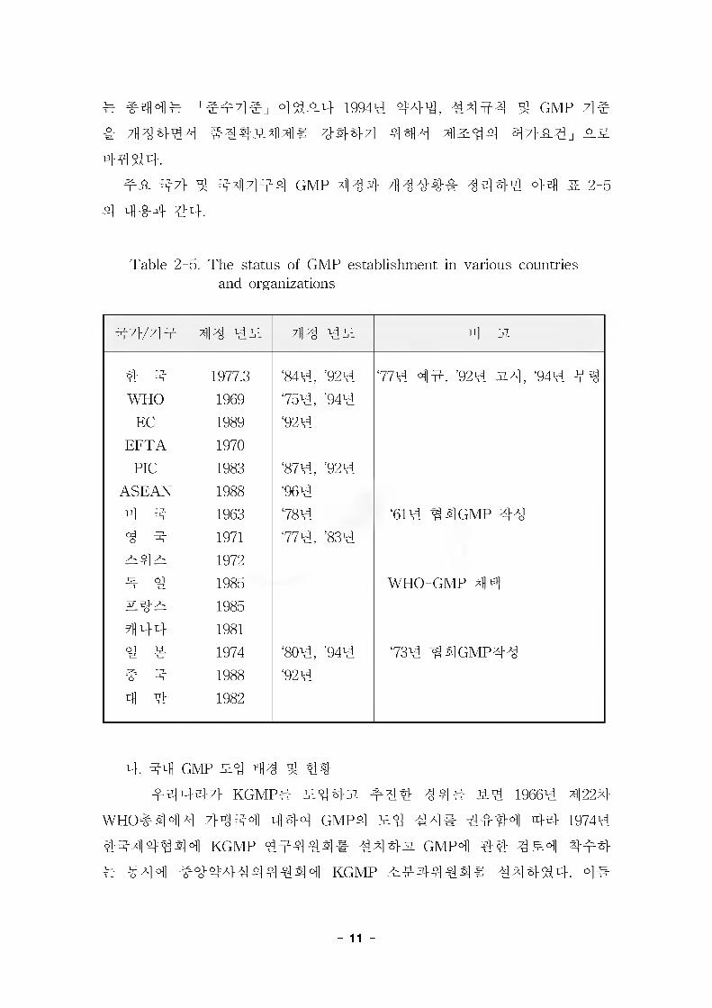
#^. #7} 4 #4 3 #4 GMP 434 43### 3334 44 & 2-5
4 444 44.
Table 2-5. The status of GMP establishment in various countries and organizations
#7}/7l4 43 4# 43 4# til A
4 # 1977.3 '844, '924 '774 4#, '924 #3, '944 #3
WHO 1969 '754, '944
EC 1989 '924
EFT A 1970
PIC 1983 '874, '924
ASEAN 1988 '964
4 # 1963 '784 '614 #4 GMP 33
3 # 1971 '774, '834
#4# 1972
# 4 1985 WHO-GMP 44
#4# 1985
444 1981
4 4 1974 '804, '944 '734 MGMP33
# 4 1988 '924
4 4 1982
4. 44 GMP 43 4 44
#343-7} KGMP# #44 34# 514 19664 4224
WHO#4 4 4 7M441 444 GMP4 w% 44# 4444 44 19744
4444444 KGMP 44444# #33-51 gmp4 44 4 £4 444
# #44 #444444444 KGMP ##4444# #3444. 4#
-11
4#4 4#4 42-### "##44=# 42 ^ ###44e(KGMP)"# 2##4# 4# 437322 1977# 3#4 4#4^2#, ## 6# 28# WHO?} 4# . ^### GMP 44 ##424 #7l-#4#^#.
2 1982#4# 4 4# 42# 2 KGMP 444# #7}&# 4444
2, 198444# KGMP# 711444 KGMP #44# #7}44# 2##2
KGMP #71-444# 4444 19854 8444 KGMP #4 #2# 7}# 44
4711 4%#. 24#, #2 #44# 4444444 444 44=444 #
4444 43% 4444 KGMP4 44# 4#W4 444 KGMP# 4#
44 #2 ^ 44 ### 444e#(4### 4136372, 1992. 5. 6)22
#4431, 24 # 44# KGMP(2##4# 3%4 41992-442, 1992. 5. 20)
& #4, ##44 4# 42# KGMP 422 4^4-.
#444# 4444 #4-44### ^o. ^ ^ #444 4#4444# ## ## #4 42# 4# 2#22 KGMP4 4e4 4## 4# 4-44# SM #2#, #4 WHO, 4# FDA, EU, 4# #4 #4444## 4 #2 4# 44#4 #4# GMP 4^4 4## 4#4#2 #2#, #444 # 444 #44 44#4 4## 4 4=# 42 ^ ###4 4#4 4W# # 4 ## 4442 #4444# 424444 #442 ##44#4 GMP 4e 4 #4# 4# 4e# 4# 4# 431431 $14.
4. GMP 444#l) 444 444#
4 4# 4244444 GMP 4#4 ^2 #4# 424# 4##
44=#4 ###2 4- ##4 4424 ## 2# ## #42 #442
#44# #22 ### 24# 4 4=# 44# 4#4 444 42444
##2# 44=#4 ###2 ##422 47M4 ##22 ##42, 42#
#4 4# #444# ##### 444#4 2# ## # 44 2# #### ## #42 #4 4#4 4 44 24# categories2 ##44 #442
# 42 $1# WHO expert committee 4 guide line# 44 4 #4 ##4
2 ##.
### 2## 4 4=# 44# 4#4# 44444 4# 244 44 4
7>4 ### 44 7l#4# 44 # 2-64 4## ##. 4714 Grade A 4
- 12 -
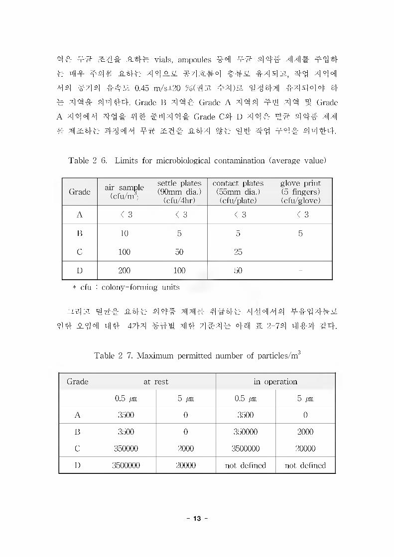
4 -cr #5" 3:4# #4# vials, ampoules #4 #5" 4 4:# 4 4 # #4 4
# 4# #4# #4# 44^-& #4^#o] ^]5jJL, 44 444
44 ^7] 4 4-#^ 0 45 m/s±20 %(^JL #4)& 4444 4-4444 4
#4 4# 4444. Grade B 4 4# Grade A 4 44 #4 44 ^ Grade
A 4 444 44# 4% #44 4# Grade C# D 4 4# 4^" 4 4=# 44
# 4^4# 4444 ^4# #44 4# 44 #4# 44%4-.
Table 2-6. Limits for microbiological contamination (average value)
Grade air-sample (cfu/nr j
settle plates (90mm dia.)
(cfu/4hr)
contact plates (55mm dia.) (cfu/plate)
glove print (5 fingers) (cfu/glove)
A < 3 < 3 < 3 < 3
B 10 5 5 5
C 100 50 25 -
D 200 100 50 -
* cfu : colony-forming units
ZL^JL Tg^e #4# 4 4# 44# 4#4# 44444 ##44#&
44 4.44 44 4?M 4% 4^4^ 4^ ^ 2-74 4#4 44.
Table 2-7. Maximum permitted number of particles/m3
Grade at rest in operation
0.5 jm 5 jM 0.5 jm 5 jM
A 3500 0 3500 0
B 3500 0 350000 2000
C 350000 2000 3500000 20000
D 3500000 20000 not defined not defined
- 13 -
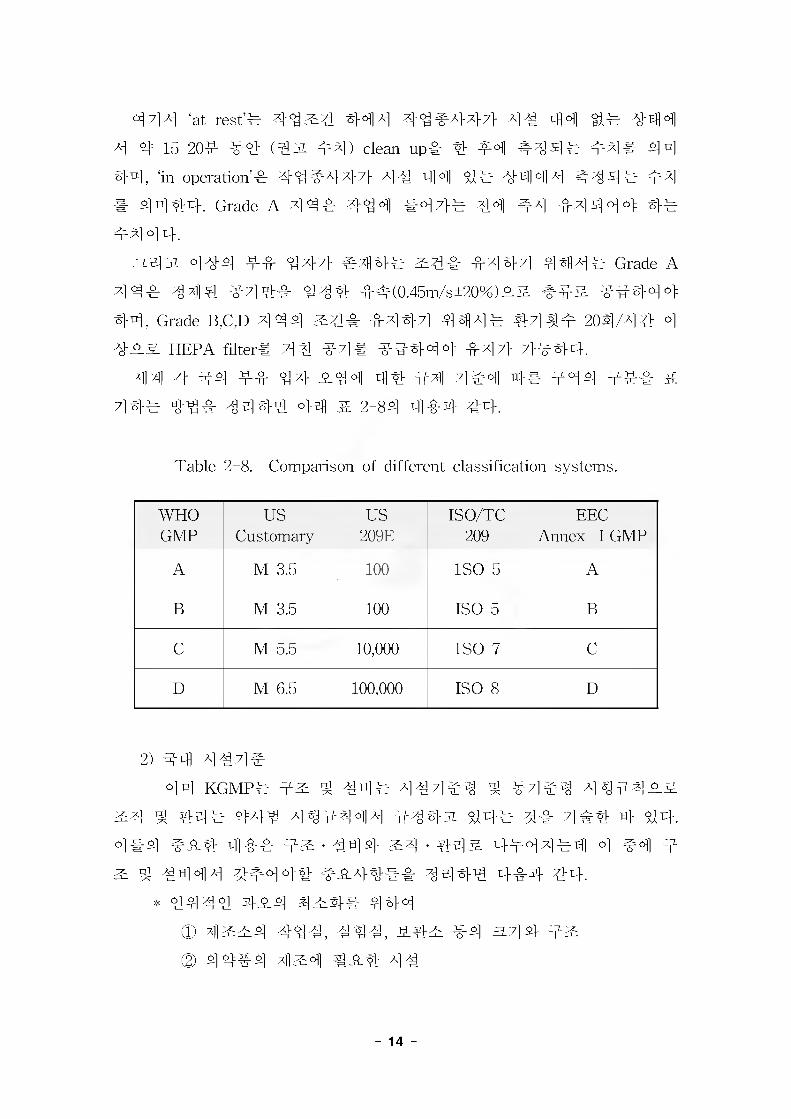
444 ‘at rest‘d #4#4 44 4 44 #4-44- 44 44 4# 4-44
4 4= 15-20# #4 (€JL #4) clean-up# 4 #4 #44# #4# 44
44, ‘in operation’# 44#444 44 44 4# 4444 #44# 44
# 4444. Grade A 4 4# 444 #44# 44 #4 #4444 4#
#4 4 4.
^4 A 444 ## 444 #44# #4# #444 444# Grade A
4 4# 444 #44# 444 ##(0.45m/s+20%)## ### ##444
44, Grade B,C,D 4 44 ^4# #444 4414# #4^# 204/44 4
### HEPA filter# 44 #4# #4444 #44- 4-#44\
#141 4 44 ## 4 4 #44 44 #4 4#4 4# #44 ### S
44# 44# 4444 44 # 2-84 4#4 44.
Table 2-8. Comparison of different classification systems.
WHO US US ISO/TC EECGMP Customary 209E 209 Annex I GMP
A M 3.5 100 ISO 5 A
B M 3.5 100 ISO 5 B
C M 5.5 10,000 ISO 7 C
D M 6.5 100,000 ISO 8 D
2) #4 444#
44 KGMP# ^ #4# 444#^ ^ #4#^ 4^#4##
^4 ^ 44# 444 4^4444 #4#w 44# 4# 4#4 4 44.
4#4 ### 4## ## • 444 #4 • 44# ##44#4 4 #4 #
^ ^ #444 3^#44# ##44## 4444 4#4 44.
* 4444 4#4 4#4# 444CD 444, #44, ### #4 a.4#@) 4 4#4 4^4 ##4 44
_14_
® 4% ## 4# #4, 44, 4# #4 44
* #4 ^ #^44 #4# 444
(D #4#4 4#
@) #4# ^ #4#4 44# # - ## #4 O 44^4-0]] 4# ##44 #4 4#® 444 #4 ^ 44(5) 44 ' #7] &## 4^
(g) 44# - #4#4 %© #^#
(B) 44# ^ #44#* ####444 ### 444
CD 44# - #4 #4 #444 414
© #4#4# 4% ##(444, ##, ####)4 #444 #4
© #4 4-4=4 444® A]^5j #-# #^-
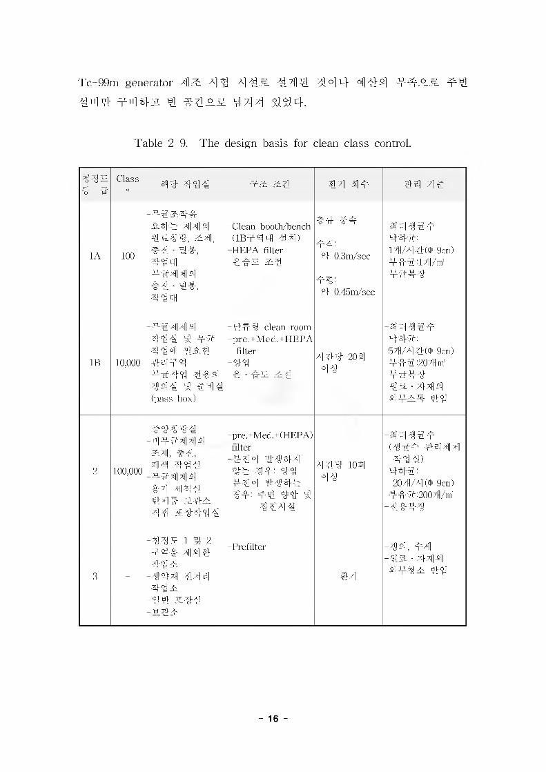
zLsiji KGMP44 #4#3% ## 4 4=# 4## 4# 44#4 #4#
44 ## 44# #4 ^ 444## 44 & 2-94 44-4- #4.:%44 444# 4444 #444 4=#4 4# GMP 4 #4 #4 #sig.
4#44 44 ^=31 ##4, 4# 44 4# #_&4# 44#3i 4 44 4 #
444 4=#4 4414# 4# 4 4=#4 ### GMP 4# 4## 4# 4#
###31 4# #444.
4] 3 ^ ^4] 7]^r^ ^ 4]^
1. 7H #
'4&# #4## 7H## 4# 44:4#'# 44 ^-4 2-14 #44 44
#4 #4 444 44# 44 44 4#44 ## #4# #44# 4#4
#(RIPF: Radioisotope Production Facilities)4 1#4 4 #4## #4 4
# BANK-44 #44^4. 4 #4# RIPF 4# #4 fission Mo-99/
- 15 -
Tc-99m generator 414: 4 'll 4 413. -4414. 5l0l14 4 4-^44- 4^.
444 ^-n]-s\jl y 4M4 444.
Table 2-9. The design basis for clean class control.
IMS 4 4
Class* am# 4"W# Ts #4 2|# 44 44
1A 100
-4$&4& l-slb 44#
&4,#4 - %444
-4444 s]#4 - %444
-Clean booth/bench (1B444 44)
-HEPA filter-4^S S4
44 44
44:4 0.3m/sec
44:4 0.45m/sec
-4bH#4444:14/4 4(b 9cm) 444:14/nf-4444
IB 10,000
-44 4141s]444 4 44 444 4 A# 4444
-4444 4-§-# 444 # #44 (pass box)
-#44 clean room -pre.+Med.+HEPA
filter-44-4 - ^s &4
444 203]44
444:54/4 9cm)444:204 m' -4444 -4& - 444 44^4 #4
2 100,000
-#4M44-TTT4]4]s]&4], 44,44 444
-TT4l4]s]-§-7] -4M41
-hi4]# S4T -44 S4444
-pre.+Med.+(HEPA)filter
-444 #444 44 44: 4#
-4 44 #444 44: 4# 4# 4
4444
444 103]44
-44^44 (^44 4444 444)
#44:204/4 ('1* 9cm)
444:2004/m' -4444
3 -
-IMS 1 4 2 T4& 414% 44^
-444 444 44^
-44 S44 -chi
-Prefilter
#4
-44, 44 -4& - 444 #44^E #4
- 16 -

44-4 4 44 4## 4s.# 44 44 44 444 4 43. ^44 (#4
44)44 4 s7} 7}44 4 444 s 447]## 4#4# 4 4 S7} #44
4 4 444# 444s, 47]]4 v-type 4 444# 44, ##44 444
4 444, 444(clean room) 4 44 44, #7]#ti] # #44til4 44
4 ### #44- KINS #4 7}# 44 44 4#4 # 434 44# 344
#4 # SAR(Safety Analysis Report)# 4444,4. #4 4 44 7} 4&
4 #444 4, KGMP s# #444 GMP 4# 4# #4 # ##4# 4
## 4#4s# 44 4 %4.
Fig. 2-1. Location of facilities for research and development of medical radioisotopes.
# 4#4 #44 #4 44 4# #4# 444 44.
- Bank 4# ### 4 4S #4, 45] 7> 7>## 4 4#4
-47]# v-type 4 44#
(4 44# 37]# 44S class 10,000, 1?]# 44s class 100)
- 4 44 # s# ##(MSM, 44 4, s# 31 #A] panel 4)
- Shield Clean Bench #ti] (4 4 S class 100)
- #^4"4, 44s 34 - GMP
- 17 -
- 92: 4# 44 (Bank 4# 44 4# #4)
- 99 Utility 94- #4 44- 944 44 #9 /kin]
- Radiation monitoring 94
2. 44 4 4 ##9
7]-. 44 ?1] 444 44
4 4414 44 49 4414 994# 40 444 4, 4 4 4 # 7%7] e# #44# -&-4J1, 4 4994 g-x) 15138- 191 # 44 3g_a_gL 44r 4
2:4&# 444 #44^#4, 49#7)- 44 4 4 #4 4 9 44 -^4#
9#4 4 #44 414# 444## 4^4. #4 31 o).# 4^# 4### 44 44 4:4 444## 4534-.
1) 4 9# 4 9 ?)# ^4 3:4 4 s# 4## ?)# Jg:4 cq^ 4x1.4x| 44 4444 4-^=. 44
44 444 7]# 44^-4# 4s4 2:444 interface 443"# 44431 4
44 944## 4#4.2!) 4 4 4 #4 4 4
4 444 440% 44 4 #49^- 99931, 444 #4, #4, II , 494 14 4 #4 41 ti 4 7]] 4## -#4 4 4-, 44 <8 ## #4;4##
4534.
3) 4#44 4 (System Description) 44
# 4x14 /g4 4 ^ 444 14119: 44 44 4 #4 44 #9-44, 4
4 §1 4 ^-44 94 7] 7], 7] 7] 44r, 44 iqi xix] x] 314 4% 44 x]
4# 314 49 9# #444 7]443i 9# 9 444 7]9 447H44 4
49 7] 44## 994.4) 7] 7] 9 9 (General Arrangement)
7] 7] 449 44#, 4 944 9 GMP 94, 9##4 94 #4, # 47} 444# 444## 9 412] # 47} 5)3:4 453,4-.
- 18 -
#. 4 4#(Clean Room) # 444^1 #t]] 2-4
1) 1313 4=1 (Class 100, 10,000 S# 100,000), #441, #^# #4 # 4
41 a- 4- 4-4 cq=A}tg cl] A] 4-^ at31 ## 4# e44(jf^4 A]])
4 A]]44 it 4 414e 31 #4#4 ?ie 2.4 (KGM?)# 414431, #R1 4449 4 10 444 44 444 4444 GMP 4# 2.4# 44# 4 %ls. 4 444^4 444. n43i 447}7} 45]4 4# 4#(71444, 44^, XU&/#^, &:4, 44, 44SL, 4444, 4#4 4 4)4 4444 44^4 19 2] aMl 44 ^5:4 ###. n4 31 #4419 444 444 444 44 42:# # 4 4# 2.4 a} ##4 # 444 ##4 7]# 2.4 4 4 4 4 4 444 71471144 4 ##31 »H1 4# 7l#4 44°1 7}## logic 44 4#
4444, 44# 444 444 44 7}## 3144^4.- 447}#o] 7]] 44# 4 4 3: 7]# # #4 44^ a]] <M4444 4
42:# ## A] Ag ^ 4##S] 7] ^ J&.4
- 4# 447]7](#<g4, an7]4, #44, ^47]7] an#, 4# 4#,
44 *1# 4)
- 4 44 44 4R:4 44 44
- #44 4(2441} #4, 44#4 401)- 19 4 4 #( 444, #4, 44 #]- 13 4 4144 4<g4 4- 13444 42: 4-4(42: 4SL #)- 444 44-44- #4 §1 44, 2L4 44 10"
2) #2: 4-4- #2:4-4 # 442:01179 4#^# 4 4 S. 2.4# ###3i, 10 4 411
4-4 4 3%4 4 4#.- #2:4## 41- 4 4.4 44 4 # 73 # #4 ##4 4 ## 4-4 #
3144^4-.
- #2.4 2:# # 4## 42:4-# # 4# 1113 4-4# #### 13 # 374###.
- #7i # 47i 4## 7ie 444 4714til 444- 4444 44#
###4, 4# 47l## 44#4 7}-g-43i; 44, #444 444 #
- 19 -
4 #44 Cross Contamination 4 7}# 4# 4 it # 4^# 4## #4 4
3) 44-
- 4^# 4 (g o] o]7g- A)7§
- #4 4##4# #4%& #44^# 4^4.- 4 #7} #4444: 44, Trap# 4 4 4 4 4 41 431, 4# 44#
7] # 44 #<% #A}4 3% 7] =. ^^4. <gZ|s| 3:# 4^#.
- 2.4 4 ### 13 #7} -0-0] S}J7 4 7} 7] 7] 4^4.
- 13414) #4 41# #4 -MM# #44^# 4^4.- 4## #4 4 ### 44 4 # Sis.# # 44^# 4#4.- 4 4s 4" 4 4 ##4 ## 4"4 (Pass Box, Shoe Cleaner, Relief
Damper #)7> 444 4^14444 3%4444.
4. V 44# (Lead Hot Cell)1) 44 4 4- 47] 4 # 7]_3|] 4] o, a# 1313 S. 10,000 O-isL nr73 444 4 4
4 Id 4 S3 S.# 4# o_4, o] ^ 37] 4 4 44] ## Mo-994 til<8, 444, #
44 Tc-99m Generator# 42:## 44 444 444 #3:5- 314444. 3X431 144 4 44 ## Tc-99m Generator4 43: 4# 0344 #a#
4#4# 4# 314444. #4, Tc-99m Generator# #44 #4 44 4
4^44 444 4 4# 4 10 # 44 44# #3- 4#4 4 4=13 4 44#4 44 #4 4 ##4 4114 4#.# _a_#433. 44 4=#tg 0]] *3 i^-
44^. 44 44 #44 (#44 4 )4 43:# 4 4 4 4 4# 4 ##44 7] ## 4#(KGMP)44, 443:7]- 4^4# 4# 7|] 3)44 _&.#(##=, 44 J&.
4, a.7], 7]#, 4 4 iE #)# ##4SL# # 4 4 %4.
2) # 44 # 4## ###7]- 444# 44^(Class 100 s# 10,000)
# #4# nr %1# #3: system# ##SL# a]-31, # 44 4 #3:# 4 e]%
_&## 4#4# #3:# 4SL# #4 4 %#4, #3. ^ 7] #4 4-4- # 4^]
IS #3L ##4 o_3L 134SL# 4-2^1 374 4#4.
3) # 444# 44 43.4 SL #3:#4 444 4 #4 4 # 4# #3%
# 31444 4444,4.
4) # 444# 4, 4#&4 4& ##, ## 4 4#4 #44 #44
- 20 -
31, 444 9^14- 42:# 444 3%4444.
3. #4 0 Aj 4 44
7}. 4# 44
- 44 2:4 4# SL4 4&
- 4 4 7] #4 4 4
- 4444 4 (system description) 44
- 7] 7] 4 7] (General Arrangement)
- 7] 7] 44444
- 4 4.44 444
- 44 §i 44 #4 444 ^ O/M 4 4 4
- 44 7} SL4 44/4 #4 4
- ^447} 4#
4. 444 44
- 444 4444- 4 444 42:^
- Radiation Zone Map
- Source Term 44
- 444 444 414 (4444 IS] 43%4)
4. 44/42: 44
- 44 44
- 4# 42:# 42: 44
■ 4# 4444- 4 7j]T5]-#a] 4 a] 4 2:# 4
- £4
■ 44534
■ Hot Cell support structure & foundation
■ Structure frame work
- 21
■ #2: V# M ta # #~f- layout & detail it'#)
■ ## #4 V# M ta # -Or# layout & detail X#)
■ #2:# #4 XX 2#
#. 7] Til #°>
- #dl dl#- 7]#0_& 7] 7]^-# 7ll#(#, 7}X, ##-#7], #)
■ ## Utility systemsl dl#
■ HVAC air volume # air balancing dl#
- #olz ^ 2|.olz Til#
■ ## ## #
■ Utility 7l 7l-g-# #Til Til#
■ HVAC system
■ ## utility systemsl AMI dl#
■ Pipe design (line sizing, support & hanger design)
- V#
- P&ID(HVAC, Utility, X##sl)
■ flMlv
■ rU##til V#■ ## 2#U1M2, ##, sj#, ^#, #Tlly=)
■ Manipulator/Radiation window Coverage
■ Duct Plan / Detail
■ Plumbing plan & detail
■ Piping plan & section & detail
■ Isometric drawing
■ Piping arrangement
■ Hanger & support location drawing
4. #7) ^ Til###
- #711 711#
. ## ##xsi ^ rn# -!1#(###:E, 3.##
- 22 -
4^^ ^^^(Set Point) iM
Cable, wiring, tray & conduit schedule
SlS. diet
^*ls.ei ^ 7]7], ^-4 diet ^^1
Fire protection system
etw, et^ 7]^c
et7l tysl 5lS£
Control system configuration diagram
Instrument control!field instrument, control valve w)
Fire protection system
UPS system
etei
?tei
7l 7l flfl^lS.
Radiation monitoring system
Raceway
Electrical equipment 4 x] LI
Cable schedule
Inter connection wiring diagram
Control logic diagram
Sequence diagram
- 23 -
4 4^ 41^
1. 4^1 44 4 44
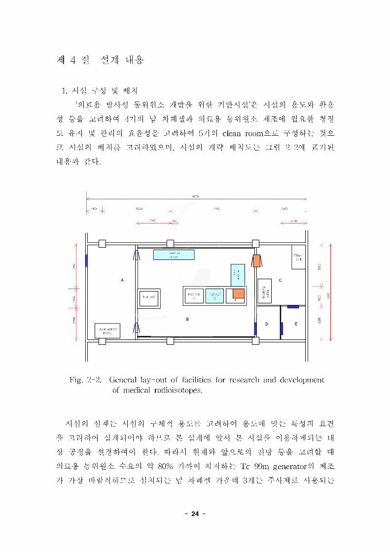
^-4^ ;m# 4% 7]M}AN'^ AN4 -0-34 #^-
^ 3444 4?M V 44 #4 45-#- ^443 4^4 #3% 4^§
3 44 ^ #44 3&^& 3444 544 clean room33 444^ 43
& 4#4 44# 344^34, 4#4 7]j4 443# 34 2-24 34^
44-4 44.
19400
^1400 1, 6000 7500 4, 4500
3000
Fig. 2-2. General lay-out of facilities for research and development of medical radioisotopes.
444 #4# 444 444 33# 3.444 -0-34 4# 444- 3# 4 3444 44444 435. 4 444 #4 4 444 444444 4 4 444 44444 44. 444 444- ^354 44 3# 34# 4
4&4- #4 #3 434 4 80% 7}44 444# Tc-99m generator4 43
7> 7}4 444435 4444 4 444 7}^4 344 4443 4444
- 24 -
Tc-99m generator^] 4] 2:# 44 a—3- 44]S] <%P_n], 44 X1 17]4 %l ^
7li#€ Ho-1664 4 if S]&^- 444 444^4 Sr-89, Sm-153, Cr-51,
Ir-192 44 4]2: ^4# 4 4 4^# 4^4 $^4.
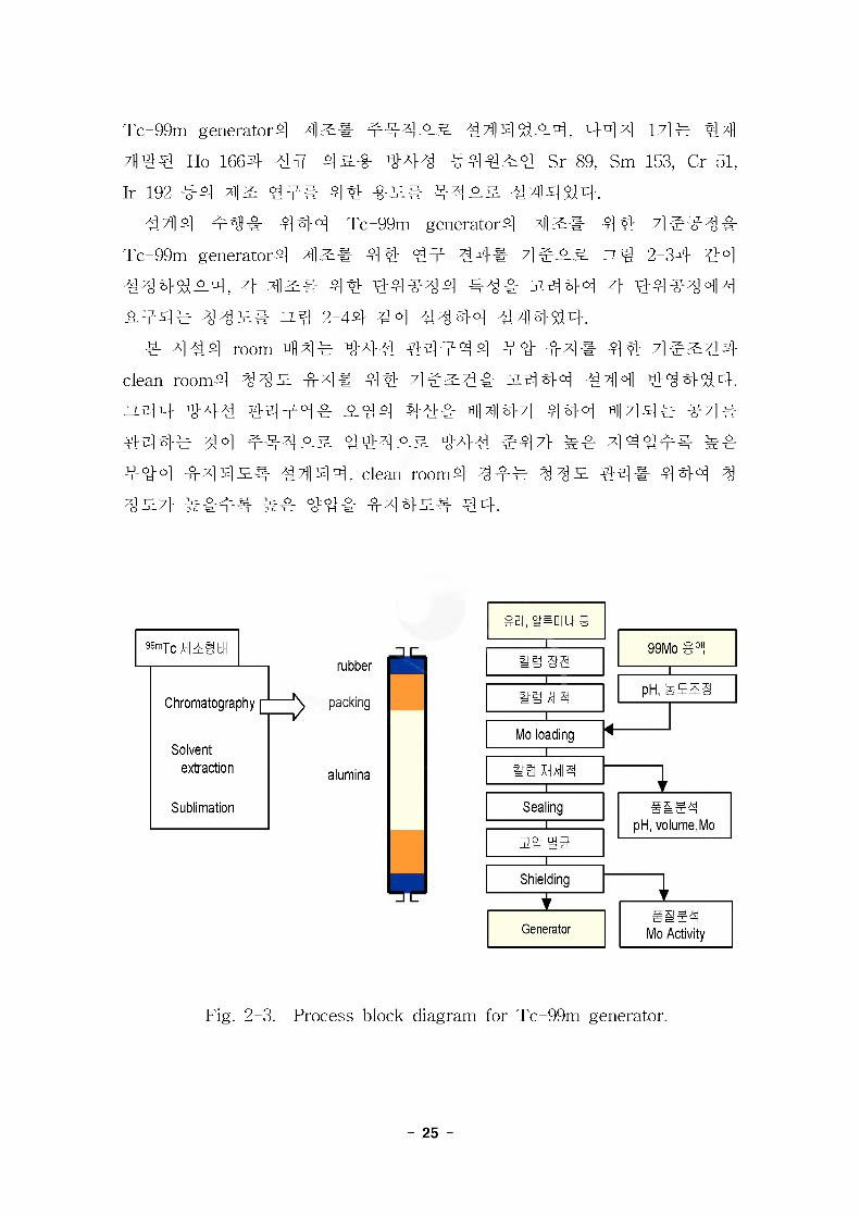
44]s] 4s3lr 444 Tc-99m generators] 4] 2:# 4ft 7]#-g-4&
Tc-99m generators] 4]Zi# 4 ft 44 44# 7]#43- 73-4 2-34 44
444^#4, 4 2]]^# 44 44#^4 #4# J%444 z]- 44#^44
^-44# ^4^# ZL^ 2-44 44 4^44 4?]]4^4.
# 4#4 room 44# 44# tLor ^.x]# 4# 4#^44clean rooms] 4 -fr4# 44 7]#2:4-S- 3% 4 44 -#414 44 444.ZZ-44 ti0>A>Al 4444# #44 S-A># ^4] 4 7] 4 #4 ti]] 7] 4 # ^4#^r44# 44 4 Mi### ^4# #44 ## 444#^
44°! 444#444, clean rooms] 44# 4 4^. #5]# 444 4
4^7} #### ## 44#r 444^# €4.
99mTcl58EH
Chromatography
Solventextraction
Sublimation
>
rubber
packing
alumina
Mo loading
Shielding
Generator
Sia4pH, volume,Mo
Mo Activity
Fig. 2-3. Process block diagram for Tc-99m generator.
- 25 -
cold container
Rlcolumn, vial
g^|°l conditioningcolumn assembly
Clean room 1 00,000
Clean room 10,000
clean zone 100
Hot ce
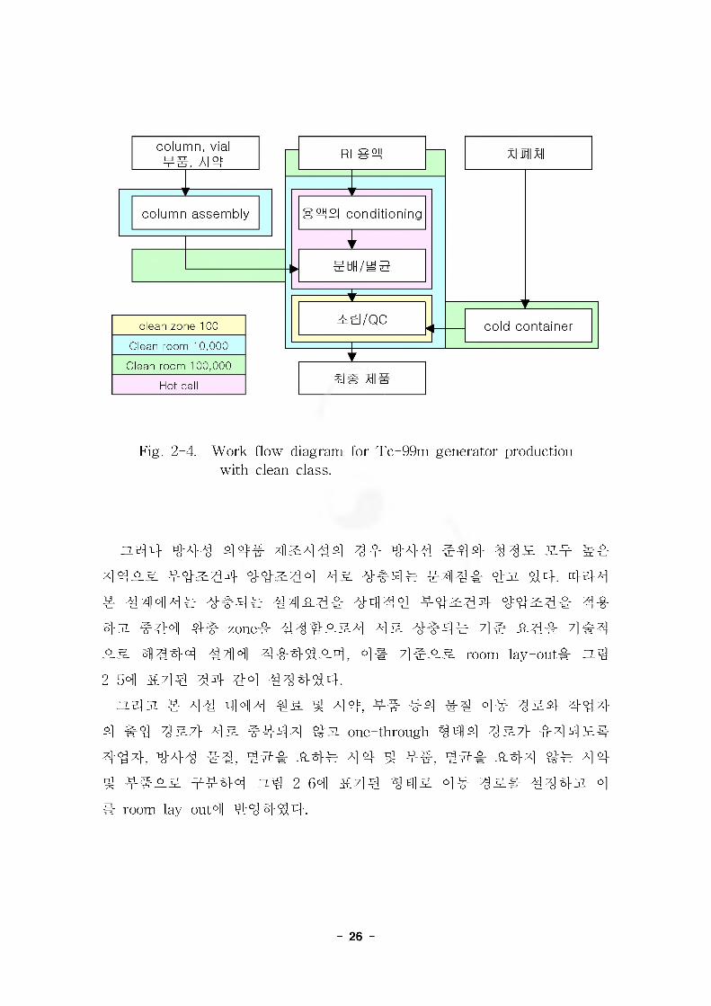
Fig. 2-4. Work flow diagram for To-99m generator production with clean class.
del 4 #A}4 ^4=^ 4^444 4=4 #44 ^4# 2.#
#4^-& 4#^## ##^44 4^ #44# #w ##. 444
4 44^14^ #4^-4# 4444 #4^4# ##^4# 4#
#w 444 44 zone# 44#^-&4 4& 4444 4# _&4# 444
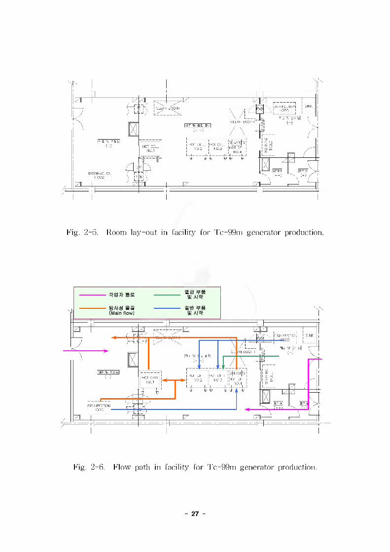
4#44 444 44453-0 4, 4# 44^-& room lay-out# zt.4
2-54 &44 44 #4 444SS4.d^d 4 44 444 #& ^ 4 4, 4# 44 ## 44 4&# #4#
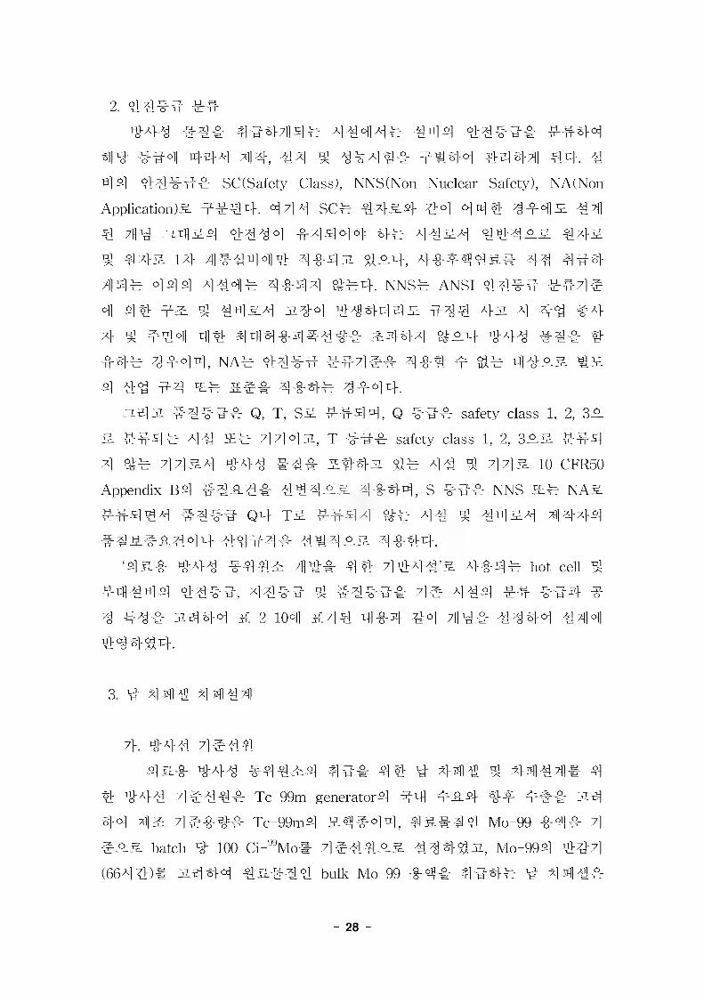
4 #4 4& 4444 one-throngh 444 4^7} 444^#
44#, #44 ##, #^# ^-#4 4# ^ 44, #^# ^-#4 ^4 4#
^ 4444 zt.4 2-64 &44 44 4&# 44#w 4
# room lay-out0!! #4 #4#.
- 26 -
'HOT CELL ''HOT CELL NO.2 NO.3
'HOT CELL] NO. 1
DISINFECTION I HOOD
Fig. 2-5. Room lay-out in facility for Tc-99m generator production.
ea(Main flow)
DISINFECTIONJ------HGOD
CL AN BOOTH
HOT CELL' |HOT CELlj_|
DISINFECTION ' HOOD '■
Fig. 2-6. Flow path in facility for Tc-99m generator production.
- 27 -
2. 44## ###44 #4# 4#444# 4444# 444 44### ##44
414- ##4 444 44, 44 4 4444# 4444 4444 44. 4
4 4 44# 4# SC (Safety Class), NNS(Non Nuclear Safety), NA(Non
Application)5. 4444. 444 SC# 445-4 4°1 444 4 #4 3 44
4 ;H# zLrii&4 4444 #4444 4# 4434 44433 44& 4 44& 14 4#4444 4#43 434, 4##443# 44 4#4 44# 444# 4#44 ^#4. NNS# ANSI #4## #44#4 44 #3 4 4434 3.44 4^4443 444 43 4 44 #4 4 4 #44 44 aM4#4#44# 3444 ^34 444 #4# 4 #4# 4#44, NA# 44## #44## 4## # 4# 4433 #3 4 44 #4 3# 3## 4#4# 4#44.
3.43 #4### Q, T, S3 #444, Q ### safety class 1, 2, 33
3 #44# 44 3# 7] 7] 4 ji; T ### safety class 1, 2, 333 #44
4 ^# 4434 444 #4# 3443 4# 44 ^ 443 10 CFR50
Appendix B4 #434# 44433 4#44, S ### NNS 3# NA3
#4444 #4## Q4 T3 #444 ^# 44 ^ 4434 4444 443#3444 44#4# 44433 4#44.
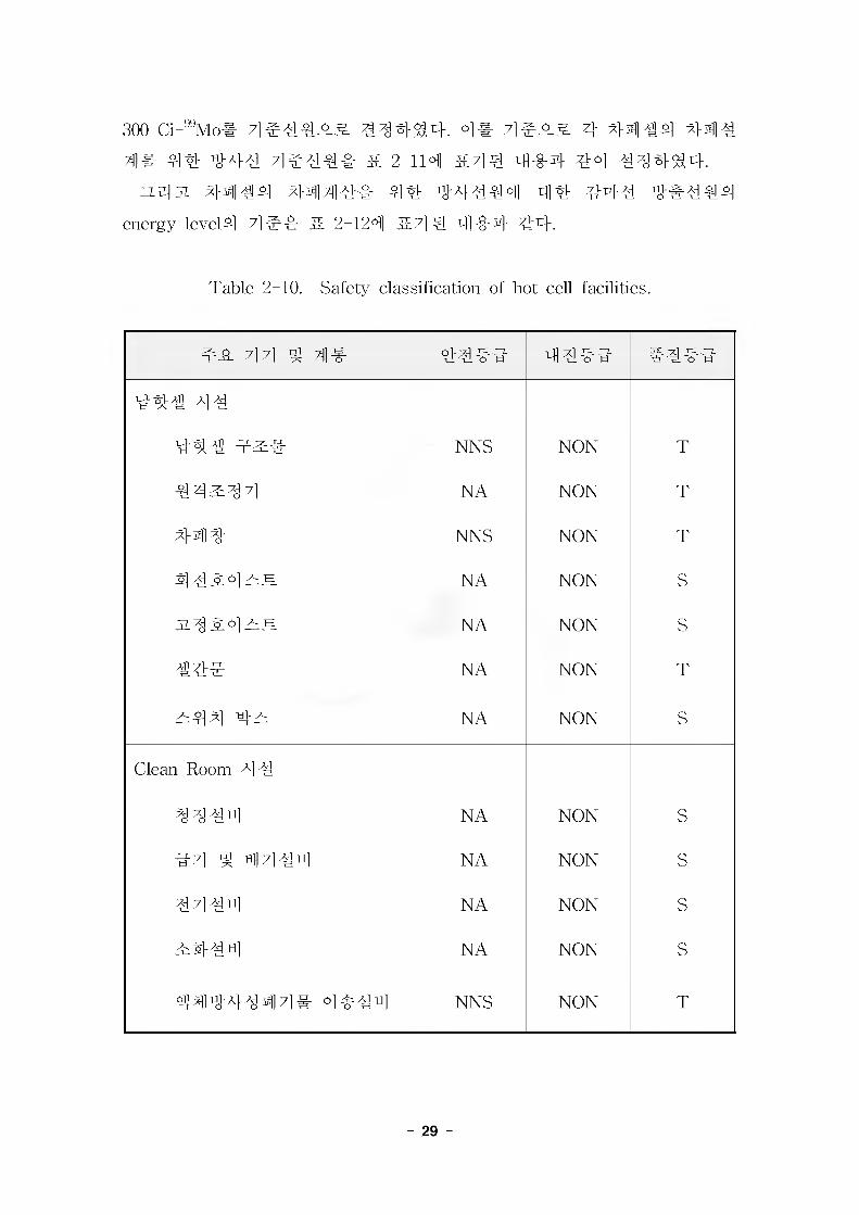
'43# #44 #44# ;H4#r 44 44443. 4#4# hot ceU ^
#4444 44##, 44## 4 #4### 4# 444 ## ##4 # 4 #4# 3444 3 2-104 344 4#4 44 44# 4444 444 44444.
3. # 444 4444
7}. #44 4 #44
43# #44 #4434 4## 44 # 444 ^ 4444# 4
4 444 7]#44# Tc-99m generator4 #4 #34 4# ### 34
44 43 7]e#4# Tc-99m4 34#44, 43##4 Mo-99 #4# 7]
#33 batch # 100 Ci-^Mo# 7] #4433 #4443, Mo-994 4#4
(664#)# 3444 43#44 bulk Mo-99 #4# 4#4# # 444#
- 28 -
300 Ci-^Mo# 7]e%4#& #^4^4. O]# 7]e_o& 4 44 #4 44%
4# 44% 44% 7]e%4# & 2-114 &44 4-0-4 44 %44^4.^431 4444 444%# 4% 44444 4% 44% 4#%%4
energy level4 7]#4- j£ 2-124 5%] 4. 444 %4.
Table 2-10. Safety classification of hot cell facilities.
4% 7] 7] 4 4# %%#% 4%#%
44% 4%
44% 4^# NNS NON T
44^44 NA NON T
44% NNS NON T
4 %#°] —H NA NON S
NA NON S
%%# NA NON T
^44 4^ NA NON S
Clean Room 4%
4 4 % 4 NA NON S
%7] 4 4 7]%4 NA NON s
4444 NA NON s
Ri%%4 NA NON s
4444447]# o]%#ti] NNS NON T
- 29 -
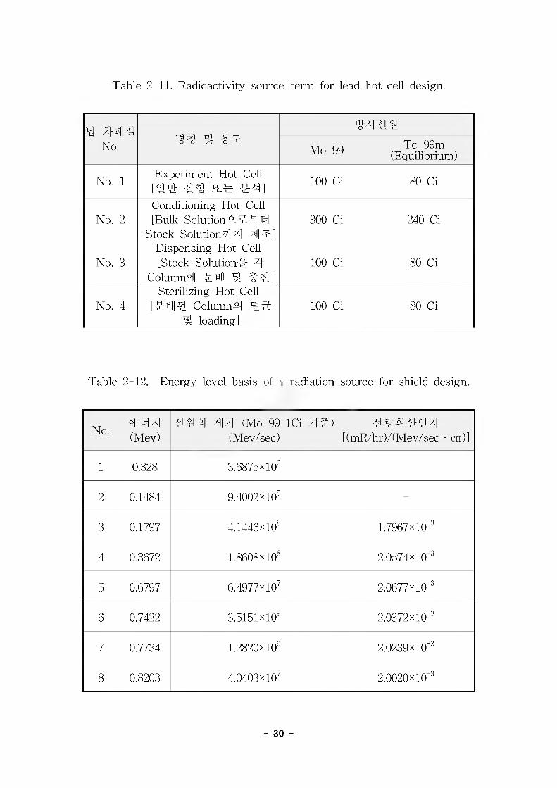
Table 2-11. Radioactivity source-term for lead hot cell design.
bb 44 Ai No.
4444
Mo-99 Tc-99m(Equilibrium)
No. 1Experiment Hot Cell [Hti> 4^ JTCr ##] 100 Ci 80 Ci
No. 2Conditioning Hot Cell [Bulk SolutionT-S-^f^l
Stock Solution 4 x] 4 Sl]300 Ci 240 Ci
No. 3Dispensing Hot Cell [Stock Solution# 4
Column°ll #4 4 vrTl]100 Ci 80 Ci
No. 4Sterilizing Hot Cell
[#44 Column 4 45" 4 loading]
100 Ci 80 Ci
Table 2-12. Energy level basis of v radiation source for shield design.
No.4 x]
(Mev)444 ^7] (Mo-99 ICi 7]#)
(Mev/sec)444444
[(mR/hr)/( Mev/sec • cnf)]
1 0.328 3.6875*109 -
2 0.1484 9.4002x10⁵ -
3 0.1797 4.1446x10⁸ 1.7967xl0"8
4 0.3672 1.8608x10⁸ 2.0574xl0'9
5 0.6797 6.4977x10? 2.0677x10⁹
6 0.7422 S.SlSlxlO^ 2.0372x10⁻⁹
7 0.7734 1.2820x10⁹ 2.0239x10⁻⁹
8 0.8203 4.0403x10? 2.0020x10⁻⁹
- 30 -
4. 44 44
# 44# V 444# 44& #4##, No. 1 44# 44 44 #
#4 # #4 44#31, No. 2 ~ No. 4 44# Tc-99m Generator# 444
7] #4 ##44. ^#3i ## ## 444# #444# Mo-99 #444.
Hi# No. 3 44# 44# #44 Generator Column Assembly# 4444
# #4 44 ### 4#445.& #4#(Dividing WaU)# No. 2 ##44
No. 4 44# 44#A 44 44444 4# 4444# 44454 #41
#44.
1) 414 4#4 44# 4 444# 44441# #4 4444# QAD-CG 44
555^# 4#4^4.
7# e^.7M
- #4 44 #444 4444# 444(Point Source) #4.
- 4 #4# #5 ^ 44##44# # 2-124 ##4 4## 4
#4^4.
- 4444# 444 ##=## 44# #4 #4 #5 4###
Mo-99 #4# ##431, Mo-995## #### 4444# 4
4# 4 4## # 2-124 ##4 4## 4#4SS4.
- 444 44# Pb(3% Sb)5 45# 11.0 g/cm^ #4.
- #444# ### ##55#Bi 30cm cm ### #45 44.
4, #4 44# 4444# 44 44 4 4# 44 #44#
455 #4.
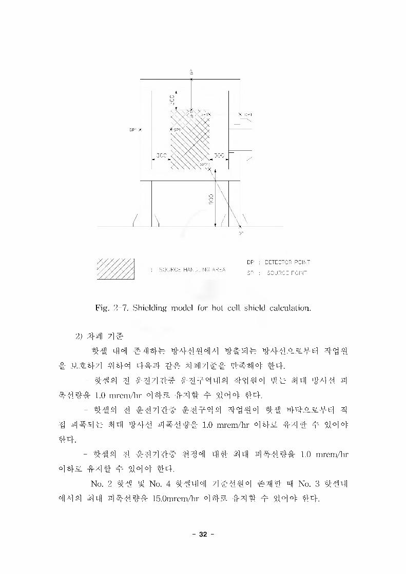
4) 445.4#4# 444 4444 5.4# #4# ## 44#4# 4#4
# 4444##, 444#(Source Point) 4 #### (Detector Point)# #
## ZL# 2-74 #7] # 4#- 44. :i# 5 4444# 5.### 5.447]
#4# #44455## ##### ### 444 44# 7}# ## ## 44444.
- 31
-4" DP1
DP : DETECTOR POINTSOURCE HANDLING AREA
SR : SOURCE POINT
Fig. 2-7. Shielding model for hot cell shield calculation.
2) #41 7]#
#4 44 #44444 #44_o&44
4 list## 444 444 44 44 7144 4444 44.
- #44 4 44444 444444 4444 44 44 444 4
4444 1.0 mrem/hr °145. 444 4 444 44.
- 444 4 44444 44444 4444 44 44^-&44 4
4 44#^ 44 444 44444 1.0 mrem/hr 4#& 44# 4 #44
44.
- 444 4 447144 444 44 44 44444 1.0 mrem/hr
4#& 4-4# 4 #44 44-.
- No. 2 #4 # No. 4 #444 4 #440] #4# 41 No. 3 #44
414 4 4 4 44444 15.0mrem/hr 4 #3. 44 # 4 #4 4 #4.
- 32 -
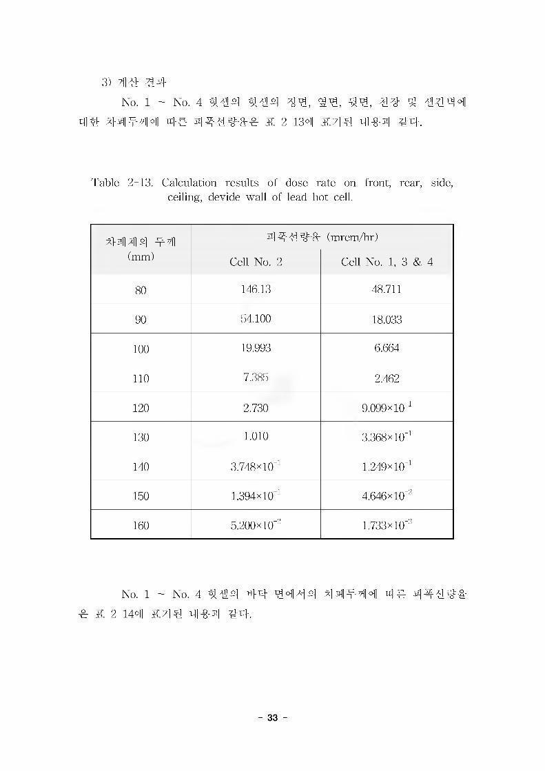
3) #4
- No. 1 - No. 4 4#4 4#4 4#, g#, ##, #4 ^ #444
44 44444 44 444444 & 2-134 444 444 44.
Table 2-13. Calculation results of dose rate on front, rear, side, celling, devide wall of lead hot cell.
4444 44(mm)
44444 (mrem/hr)
Cell No. 2 Cell No. 1, 3 & 4
80 146.13 48.711
90 54.100 18.033
100 19.993 6.664
110 7.385 2.462
120 2.730 9.099% 10^
130 1.010 3.368% 10^
140 3.748% 10"i 1.249% 10^
150 1.394x10⁻¹ 4.646x10"
160 5.200x10" 1.733x10"
- No. l - No. 4 4#4 44 4444 444-44 4# 44#4&
& 2-144 a44 444 44.
- 33 -
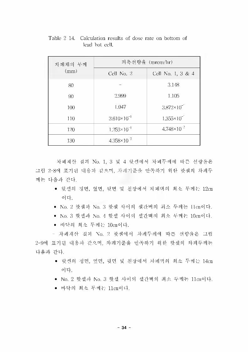
Table 2-14. Calculation results of dose rate on bottom of lead hot cell.
4444 54(mm)
44454 (mrem/hr)
Cell No. 2 Cell No. 1, 3 & 4
80 - 3.148
90 2.999 1.105
100 1.047 3.872x10'!
110 3.610x10^ 1.355xl0'i
120 1.253xl0'i 4.748x10"
130 4.358x10" -
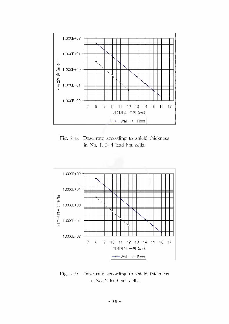
- 4444 #4 No. 1, 3 5 4 4444 54544 4# 44444
zz.^ 2-84 4714 444 454, 447144 44471 44 444 545
44 444 44.
• 444 ^§4, #4 ^ 4444 4444 45 444 12cm
44.
• No. 2 444 No. 3 44 444 4444 45 444 11cm44.
• No. 3 444 No. 4 44 444 4444 45 444 10cm44.
• 444 4 5 444 10cm4 4.
- 4444 44 No. 2 4444 44444 4# 4444 zz_4
2-94 5714 454 454, 447154 44471 44 444 44544
454 44.
• 444 ^§4, 44, #4 4 4444 4444 45 545 14cm
44.
• No. 2 444 No. 3 44 444 4444 45 545 11cm44.
• 444 45 545 lion°14.
- 34 -
1.000E+02 a
1.000E+01 -
CCLE 1 nnnp+nn _
ouuiffo
%
14 ——
1 .uuuc7 8 9 10 11 12 13 14
Null M n| t74I (cm)15 16 17
—»—Wall -o - Floor
Fig. 2-8. Dose rate according to shield thickness in No. 1, 3, 4 lead hot cells.
1.000E+02
1.000E+01
S 1.000E+00
n|r 1.000E-01
1.000E-029 10 11 12 13 14 15 16 17
m\nz\ (cm)
Wall ■ ■ -o- - - Floor
Fig. *-9. Dose rate according to shield thickness in No. 2 lead hot cells.
- 35 -

4. 4 44# 44
4444 #4# 7]#_og. z| 4 44311 444 44# & 2-15
4 #4 #^^^4.
Table 2-15. Shield thickness of lead panel.
(44 mm)
44# No. Front Rear Side Roof Floor til 31
No. 1 130 130 130 130 110
No. 2 150 150 150 150 110
No. 3 130 130 130 130 110
No. 4 130 130 130 130 110
3-fi]jl 244 34 44 A}o] ns]31 344 44 #4 Dividing wall#
110mm&
4. 44# ^ ^444 #4
7}. #44e
l) #4 44 ^
4 44^4 44, ^A} ^ 444 444^ 44 ^ &e#
444 44.
ANSI B31.1 : Power piping
ANSI N512 : Protective coating (paints) for the nuclear industry
API Standard 650 : Welded steel tanks for oil storage
ASTM B29 : Standard specification for lead pig
ASTM A36 : Structural steel
ASTM A193 : Alloy steel and stainless steel bolting material for
high temperature service
- 36 -
ASTM A240 : Heat resisting chromium - nickel steel plate, sheet
and strip for pressure vessel
ASTM A480 : Flat-rolled stainless and heat-resisting steel plate,
sheet and strip
AISC : Specification for the design, fabrication and erection of
structural steel for building
AWS Dl.l : Structural welding
AWS A5.4 : Corrosion-resisting chromium and chromium - nickel
steel welding electrode
AWS A5.4 : Corrosion-resisting chromium and chromium - nickel
bare and composition metal cored and standard arc welding electrode and
welding rod
AWS A5.22 : Flux cored corrosion-resisting chromium and
chromium-nickel steel electrode
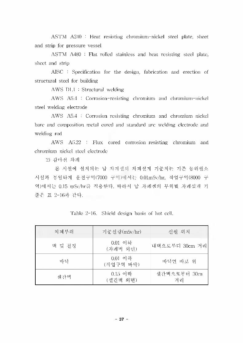
2) #4# 44
4 a] AH 4444 bb 4444 a}$il AM] w 7]# 444T:
444 ^44 ^444(7000 44)444 O.OlmSv/hr, 4444(8000 4
4)444 0.15 mSv/hr# 4444. 444 bb 4444 44# 4444 7]
#4 & 2-164 44.
Table 2-16. Shield design basis of hot cell.
4444 4 444(mSv/hr) 44 44
4 4 44 0.01 44 (444 44)
44W&44 30cm 44
44 0.01 44 (4444 44) 444 4& 4
444 0.15 44 (444 44)
444W&44 30cm44
- 37 -
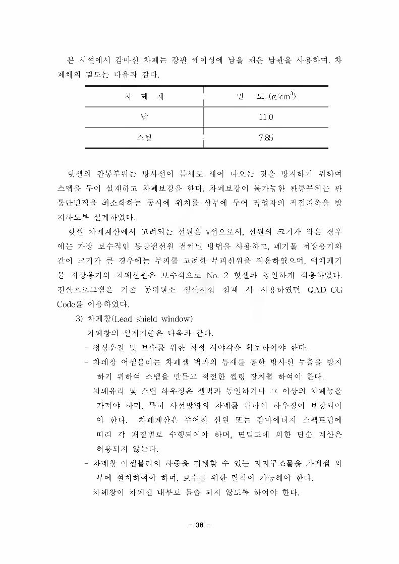
# A] ^ 0^1 A) ^-T3]-A1 #4# #4 ^OjAj^] U--S. 4#44, 4
4 4 4 4 s# 4#4 44.
4 4 4 4 S (g/cm3)
4 11.0
Al| 7.85
4#4 4##4# 4444 #4# 44 4## 4# 4444 444
#4# 44 44431 44 #4# 44. 44S.44 4-444 44444 4
#444# 44444 444 44# 444 44 4444 4444# 4
44s# 444^4.
44 444444 3%44# 44# \4ss4, 444 a?]7} 4# 4#
4# 7}4 ##44 #4444 444 44# 4#43i, 44# 44444 44 a47} e 4#4# #4# 3144 #444# 4#44#4, 4444
# 44444 4444# S#4#s No. 2 #44 #444 4#444.
44#sn^# 4# #44# 4444 44 4 4#444 QAD-CG
Code# 4 #444.
3) 44#(Lead shield window)
4444 444## 4#4 44.
- 44#4 ^ #4# 44 44 444# 4#444 44.
- 44# 4 4#4# 444 444 #4# #4 #44 ### #4
44 444 4#3i 444 44 #4# 444 44.
- 44#4 ^ 4#4# 444 #4444 n 444 44##
444 44, #4 44444 4^]# 444 4#4 °1 #444
4 44. 4444# #44 44 s# 44444 #4s44
44 4 444s #4444 44, 44s°ll 44 4# 44#
4 #4 4 ^#4.
- 44# 4##44 4## 4## # 4# 44#s## 44# 4
#4 44444 44, ### 44 444 4#44 44.
- 4444 444 4#s ## 44 #s# 444 44.
- 38 -

4)
44 #^4^] #44## 4#4 ^4.
- 44 4 444 44444 444 Coverage# ##44 4 44.
- Wall Tube# 4 44 #o] ^^]^o]o]= ^r}.
- #4# 444 Slave Arm# 4#4 44# #4 4 #4# # 4
44 #4.
- Master Arm4 Handle4 Cold Side# ##4 4 4# 4444 4
444 4## 4444.
4. 44# #44 44 #4 44(444 t,ox4 44 7]#) a?] #, 7}##
4# 4#4 44.
- No. 1 44 # : l,494mm(W) x l,194mm(D) x l,259mm(H)
- No. 2 44 # : l,494mm(W) x l,154mm(D) x l,239mm(H)
- No. 3 44 # : l,494mm(W) x l,194mm(D) x l,259mm(H)
- No. 4 44 # : l,264mm(W) x l,194mm(D) x l,259mm(H)
4 4444 444 3.7]# 444 & 2-174 #7] 4 "Lead hot cell
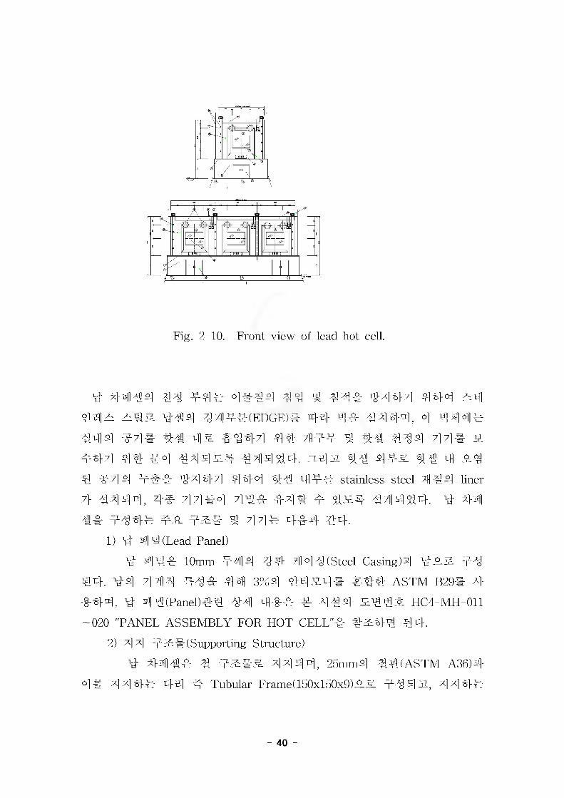
schedule"4 *<§444 4#4, 44#4 44# 4 front view# 3-4 2-10
4 #7]4 44 44. #4# 44#4 4##, 4##, ###, 44# #4
#4 #44 44 4&# 4 444 44#4 43 HC4-MH-002-0084 4
44s. lb4 Vi# HC4M010 'Technical specification for lead hot cell'#
4#44 44.
Table 2-17. Lead hot cell schedule, (unit : mm)
CellNo. Usage
Hot cell internal size
Liner box internal size Lead panel thickness
W D H W D H front rear side roof floor divid.
1 Experiments 1530 1230 1280 1494 1194 1259 130 130 130 130 1102 Conditioning 1530 1190 1280 1494 1154 1239 150 150 150 150 110
110110
3 Dispensing 1530 1230 1280 1494 1194 1259 130 130 130 130 1104 Sterilizing 1300 1230 1280 1264 1194 1259 130 130 130 130 110
- 39 -
A , ®
Fig. 2-10. Front view of lead hot cell.
4 4^]#4 44 #4# 4##4 44 ^ 44# 4444 444 #4
44# 2z#& ##4 4 4##(EDGE)# 44 4# 4444, 4 4444 444 47]# 4# 4# 44471 44 7fl## 4 44 444 44# #
4471 44 44 444## 444 44. #4# 44 44# 44 4 #44 #7] n] ### 44 471 444 4 s 44# stainless steel 7|]#n] liner
7} 4444, 4# 44#4 4## #4# 4 ^1## #44%4. 4 44] 4# 444# ## 4## ^ 44# 4#4 ##.
1) 4 4 4 (Lead Panel)
4 44 10mm #44 44 44 4 (Steel Casing)# ### 44
#4 444 #4# 44] 3%4 44#4# #44 ASTM B29# 4
444, 4 4#(Panel)44 44 444 4 444 #44# HC4-MH-011
— 020 "PANEL ASSEMBLY FOR HOT CELL"# 4#44 44.
2) 44 ###(Supporting Structure)
4 4414# 4 #### 4444, 25mm4 44(ASTM A36)4 °1# 444# 44 4 Tubular Frame) 150x150x9)## #44#-, 444#
- 40 -
41# 11 444 44 Plate4 4444 #44^4 14 4 41^4 44
2H2# 144^4.
44 4 42# 44 4-4 41! ! 444 21 HC4-AD-001-005
"HOT CELL SUPPORT STRUCTURE"! #241 44.
3) 44 4 (Liner)
41 4444- 4 444 4! 44 1444 stainless steel 4!
4 1221 444, 44^44, 4# ;H1# 1# 44 4!## 414.
4 4!##! 2!144, o-4 122 1444 1#1, 2!#1
# 14 41# 4 12# 2.44 1 ## ##! 4!2 4414. 444
4 44 4 414 4& 4444, 44 4444 514 44 table! 44
1 LL+900 44 44. 4444 41 1 44 411 1 414 4444 1
4! 15mm2 4442# 14414.
- 41 : STS 304
- 44] : 3 mm
- 44 : No.4 LINISH, ASTM A480
444 41 14 414 ! 414 211! HC4-MH-031-039
"LINER BOX LOR HOT CELL"! #241 14.
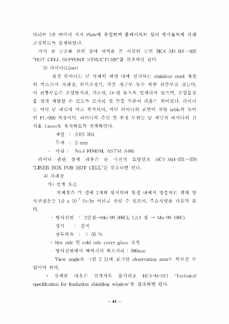
4) #41
7}) 1?]] 214411 4 14 144 1441 41 441 !#4! 44 1
411!! 1.0 x 10^ Sv/hr 142 #1 m 121, #241! 444 1
4.
- 1411 : 2ll^Mo-99 300C1, 1,3,4 1 Mo-99 100C1
- 1! : 1!
- !#4# : > 50 %
- Hot side 1 cold side cover glass 1#
- 141141 1414 4 2 7] 4 : 300mm
- View angle! 2-1 2-114 57] 1 observation area# #2# 4
144 44.
* 144 41! 1442 #112 HC4-M-011 'Technical
specification for lradiation shielding window'# #2## 14.
- 41

LINERS.STL
NORMALOUT-OF-OBSERVATION AREA
EXTREMEOUT-OF-OBSERVATION AREA
WINDOW
NOTE
SEE DATA SHEET FOR DIMENSION A,B,C,D,E,F AND G
HORIZONTAL SECTION
WINDOW <L
WORKING TABLE
VERTICAL SECTION
Fig. 2-11. Observation area of shield window.
- 42 -
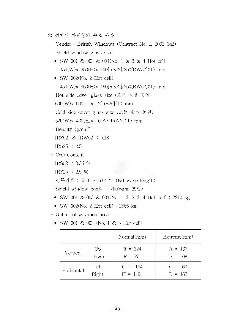
2) 44 € 44^-4 4^- 44
- Vendor : British Windows (Contract No. L-2001-342)
- Shield window glass size
* SW-001 & 003 & 004(No. 1 & 3 & 4 Hot ceU)
450(W)x 350(H)x 100[RS52]/250[RW52](T) mm
* SW-002(No. 2 Hot cell)
450(W)x 350(H)x 160[RS52]/250[RW52](T) mm
- Hot side cover glass size (S-C 44 4 s)
600(W)x 500(H)x 12[RS25](T) mm
- Cold side cover glass size (54 44 4 s)
520(W)x 420(H)x 10[AMIRAN](T) mm
- Density (g/cm3)
[RS52] & [RW52] : 5.18
[RS25] : 2.5
- CeO Content
[RS52] : 0.35 %
[RS25] : 2.5 %
- 4444 : 55.4 ~ 63.4 % (Nd wave length)
- Shield window box4 44 (frame S4)
* SW-001 & 003 & 004(No. 1 & 3 & 4 Hot cell) : 2210 kg
* SW-002(No. 2 Hot cell) : 2565 kg
- Out of observation area
SW-001 & 003 (No. 1 & 3 Hot cell)
Normal (mm) Extreme (mm)
VerticalUp
Down
E = 324
F = 771
A = 167
B = 108
HorizontalLeft
Right
G = 1194
H = 1194
C = 162
D = 162
- 43 -
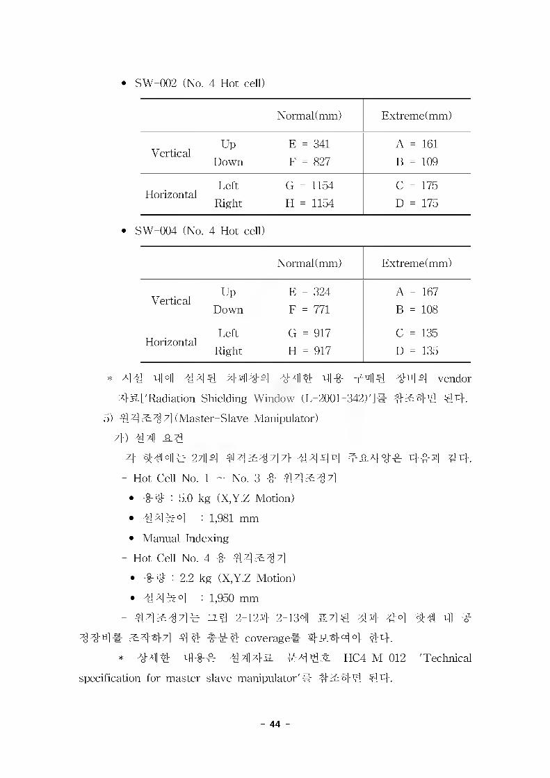
* SW-002 (No. 4 Hot cell)
Normal (mm) Extreme (mm)
VerticalUp
Down
E = 341
F = 827
A = 161
B = 109
HorizontalLeft
Right
G = 1154
H = 1154
C = 175
D = 175
SW-004 (No. 4 Hot cell)
Normal (mm) Extreme (mm)
VerticalUp
Down
E = 324
F = 771
A = 167
B = 108
HorizontalLeft
Right
G = 917
H = 917
C = 135
D = 135
* A1 4 t-R °)1 444 4444 44 4 44 444 44 V] vendor
4 S-['Radiation Shielding Window (L-2001-342)']# 42:44 44.
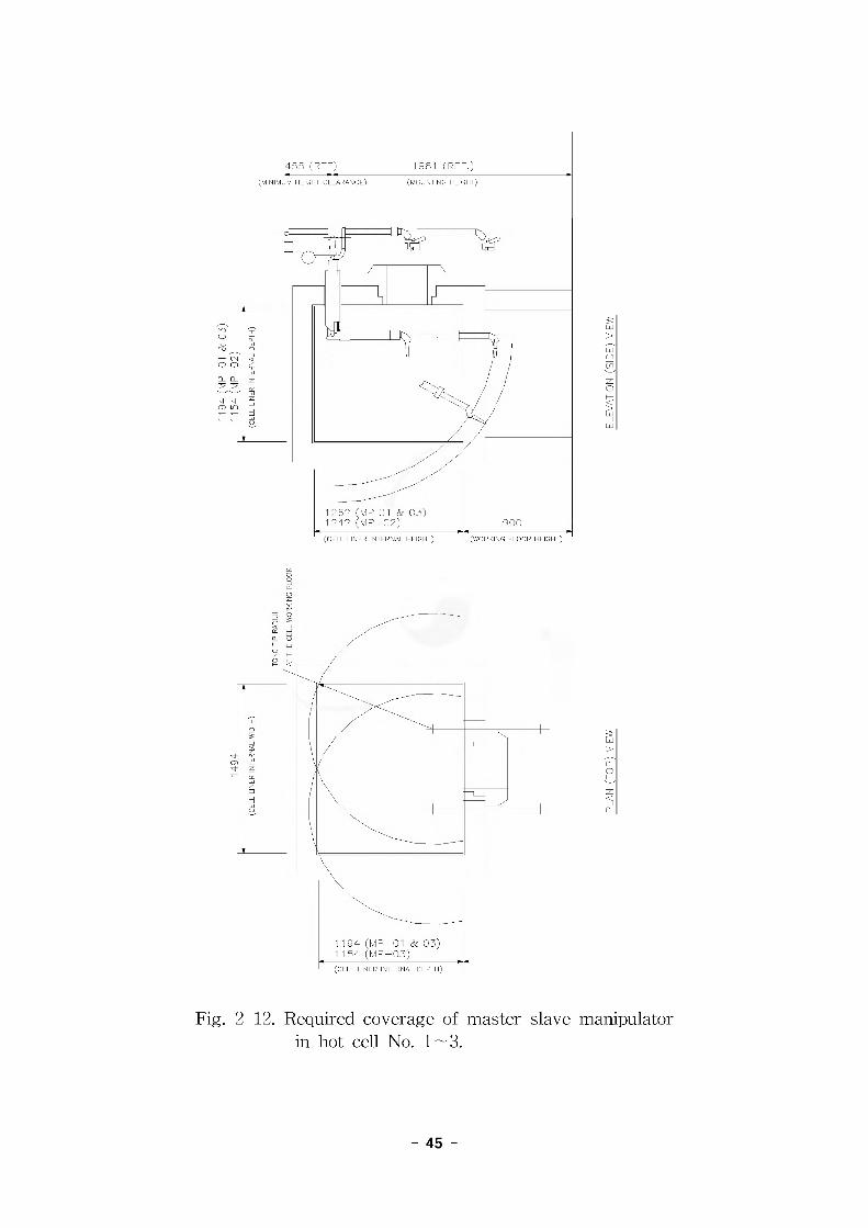
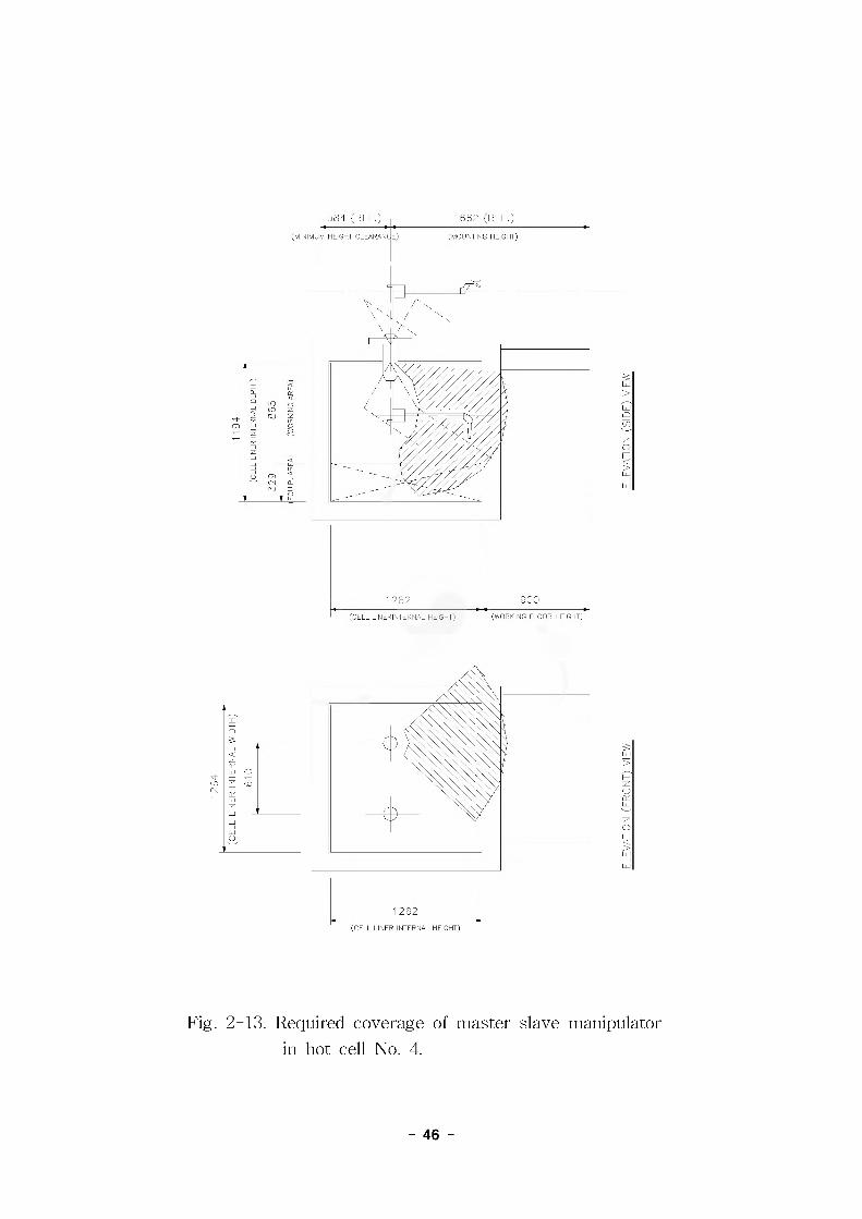
5) 442:4 7] (Master-Slave Manipulator)
7}) 4?1] 4.4
4 2;M 44^447} #444 44.
- Hot Cell No. 1 - No. 3 -0- 44^34]
• -0-3= : 5.0 kg (X,Y.Z Motion)
• 444°1 : 1,981 mm
• Manual Indexing
- Hot Cell No. 4 4 44^34]
• -0-3= : 2.2 kg (X,Y.Z Motion)
• 44 #4 : 1,950 mm
- 44^44# 2-124 2-134 &44 314 44 4:4 4 ^
44"^1# 2:447] 44 444 coverage# 4444 4 44.
* 4M4 4## 444& #44^ HC4-M-012 'Technical
specification for master slave manipulator'# #2:44 44.
- 44 -
|455 (REFj)
(MINIMUM HEIGHT CLEARANCE)
1981 (REF.)(MOUNTING HEIGHT)
MP 01 & 03)1262
(CELL LINER INTERNAL HEIGHT) (WORKING FLOOR HEIGHT)
194 (MP-01 & 03)54 (ivlP —03)
(CELL LINER INTERNAL DEPTH)
Fig. 2-12. Required coverage of master slave manipulator in hot cell No. 1 — 3.
- 45 -
584 (REF.) 662 (REF.)
(MINIMUM HEIGHT CLEARANCE) (MOUNTING HEIGHT)
1262(WORKING FLOOR HEIGHT)(CELL LINERINTERNAL HEIGHT)
1262(CELL LINER INTERNAL HEIGHT)
Fig. 2-13. Required coverage of master slave manipulator in hot cell No. 4.
- 46 -
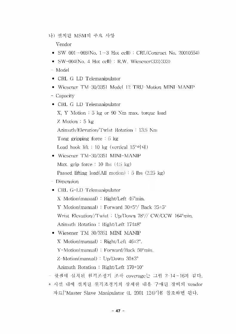
4) 444 MSM4 44
- Vendor
• SW-001-003(No. 1-3 Hot cell) : CRL(Contract No. 20010554)
• SW-004(No. 4 Hot cell) : R.W. Wiesener(332/333)
- Model
• CRL G-LD Telemanipulator
• Wiesener TM-30/3351 Model 12 TRU-Motion MINI-MANIP
- Capacity
• CRL G-LD Telemanipulator
X, YMotion : 5 kg or 90 Nm max. torque load
Z Motion : 5 kg
Azimuth/Elevation/Twist Rotation : 13.5 Nm
Tong gripping force : 5 kg
Load hook lift : 10 kg (vertical 15°°14)
• Wiesener TM-30/3351 MINI-MANIP
Max. grip force : 10 lbs (4.5 kg)
Passed lifting load(All motion) : 5 lbs (2.25 kg)
- Dimension
• CRL G-LD Telemanipulator
X-Motion (manual) : Right/Left 45°min.
Y-Motion (manual) : Forward 30+5°/ Back 25+5°
Wrist Elevation//Twist : Up/Down 78°// CW/CCW 164°min.
Azimuth Rotation : Right/Left 174+8°
• Wiesener TM-30/3351 MINI-MANIP
X-Motion(manual) : Right/Left 46+2°.
Y-Motion (manual) : Forward/Back 50°min.
Z - Motion (manual) : Up/Down 30+3°
Azimuth Rotation : Right/Left 170+10°
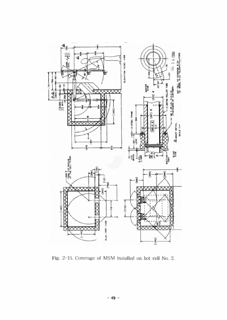
- 444 444 44^44 ^4 coverage^ zz.^ 2-14-164 4:4.
* A14 44 444 443:444 444 44 444 444 vendor
45.['Master Slave Manipulator (L-2001-124)']# 43:44 44.
- 47 -

Fig. 2-14. Coverage of MSM installed on hot cell No. 1 & 3.
- 48 -
i I S3
- 49 -
I
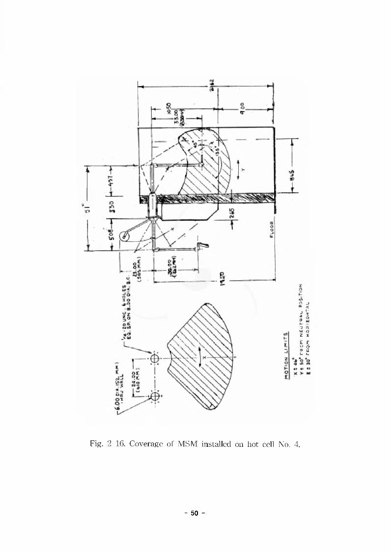
Fig. 2-16. Coverage of MSM installed on hot cell No. 4.
- 50 -
1-53
Iu«TA
..
6) #4#
4 ### #### M# ###^#4, ^4#4r 4
w4 4#. 4, 44 ### 4# ### 44# 4##& ##44 #4444.
- tyr 37} : 570 mm(W) x 650 mm(H)
- 7H## 37} : 750 mm(W) x 790 mm(H)
- 43114 : 4 (444 444 #4 j£4 #44 444- 4444.)
- ###4 : 44
#44 44 44 #44 HC4-MH-040, 41 "Maintenance door
assembly"# #2:4-4 44.
7) 4# 4 ##/# 7} 3
4.#4 4m/#4#4 l, 2, 44 44 #444 4#4 #4
4 44 ^oi^e# oi^-ei-4 #4#4, 4 #44# #444
##4 Mo Bulk Solution #4 4 Tc-99m generator, 4 5. #7l #4 4#
44 4#44. 4 Port# 44 4 ### ##4 44 4#4, 444 4#
# 44# #4 4 # 4#4(HC4MH050 "Loading & unloading facility")
4 4444 %14.
8) 4M 4## 4
No. 3 4# 44# #444 #44# 4#4# 44# 4 4#?i#
# 4 4444 4444 Cart 44 #44 44. 444 4 7 liter# 4, #
#7} 44444 1714 Stand-by ##4. 4M 4##4 4 4414 #41# 4
#4 441 #414 #4# 150mm #4.
41# 4 4#4 44 #41 #4# HC4-MH-044 "LIQUID RADWASTE
STORAGE VAULT"# 4l##4# ##44 #4.
9) # 4. #### (Swivel hoist)
No. 1, 2, 4# ### 0.2 ton ##4 4 4 ^#^#71- 17H# #4#
#. No. 2 ##### Bulk Solution Cask##si ### H| ##4 Bulk
Solution #4# #### 41 #4:1# 7fl4l##41 ##4-4, No. 4 ###
4# Tc-99m generator# 4# 4 4 #4 Hi #31 ### ####. # 4
4. ####4 ##### ## 44 441 #44#, 4 4 4 4#(hoisting)
# 5L# 5.4# 4# ##44. #4# ### 41#### #2:4-4 ##.
- 51
10) ### (Pass-Thru Door)
No. 3 ^#4 No. 44 ##44# 144 ###4 #4
44 ^# # #44 4#4 4444, 44 2.4 #### 4444. #4
4 444# 44 444 444 Dust barrier4 #444. Dust barrier#
444 4 444 44 #44 444# #2:44. 4444 4### 4#
200mm, 45-100mm4 4, 4444 4#4# 50mm°131 stainless steel 44
# casing4 44. 44# 44 44#4# HC4-MH-047 "PATH-THRU
DOOR FOR NO.3 & NOT HOT CELL"# #^44 44.11) 7]# #ti]
4 ### 4#4 #4#4 #444 44.-- 444 4#### 4# ##
- ^4# 4## # ^ 44#
- 4#5 44 44 44 #4 444 1711
- 4444(inlet filter) 44 #4 444 #1)
- Incell filter 4 Out let filter
- Heat detector/ Thermal detector) 444# #)
- ## 44 44###
- 4# 4#4 44# ##44 4 4# 41# #
5. 44# #4##
7}. #44#
# 4## 4# #44# ##4 #444 4;H4 444#4## #
44, 71 4#-L 4#4 #4.
#4 #444 4 4 4 # 4 (mSv/hr) 4 #4 4
6000 4*114# 4 < 6.25x10"^ ni 4 #
7000 44 #4#4 < 1.25x10" 404 #/#
8000 #4 #4#4 < 0.5 7)144#
9000 #4 414#4 > 0.5 -
- 52 -

1) 6000444 3344-^-5# 4# #4###4 4# #4### ^1 45- 44 4 4 4 44 44 44.
2) 7000, 8000 ^ 9000444 444 #444^-5# 444 444 4
4 #4#e#7} ##_ #444 444 444 445 4# #5# 444
44 4 4444 44 44.
- 700044 :##4#44- 800044 : ##4#445&# ##4# ^ 5.## 444 ##5
& #44 #444 44- 900044 : 4# 445# 44 #44 #4# 4 %4 44
44, 4 444 4 4444 44# ^ 4# 444## 444 44.
44 #4# 5.%#5 4# 5.4#5
7000 < 1 (MPC)air < 1 MFC
8000 < 20 (MPC)air < 10 MFC
9000 > 20 (MPC)air > 10 MFC
% (MPC)air ^ MFC# 444 3.# #98-125# ###.
4. #44 44444 #4
4 444 #44 44444 444 #4 444 5.4 9000 444
4443., 4444 44 #4144 5.4 room# ##43444 41##4
7000 444 4444, 44 4## 4#4 #44 rear door# 44 344
4 #44 #444 #4 B#(45 ^ ###4#)#4 4444444 4
#44 8000 444 #4#5# #44%#.
6. #### ^ #4#u]
7}. #44#
1) #444 ^ 4#
ASHRAE 52 Method of Testing Air Cleaning Devices Used in
General Ventilation for Removing Particulate Matter
- 53 -
AMCA 210 Test Code for Air Moving Devices
AMCA 500 Test Method for Louvers, Dampers, and Filters
ANSI N101.1 Efficiency Testing of Air Cleaning System
Containing Devices for Removal of Particles
ANSI N509 Nuclear Power Plant Air Cleaning Units and
Components
ANSI N45.2.2 Packaging, Shipping, Receiving, Fabricating Hand
ANSI N510 Testing of Nuclear Air Cleaning Systems
ERDA 76-21 Design, Construction, and Testing of High
Efficiency Cleaning for Nuclear Application
SMACNA A-30 Sheet Metal and Air Conditioning Contractor's
National Association
SMACNA 3-2 Round Duct Specifications
KS D 3506 44^44, 4^4 4&
4392. 4 4=#42 4 #4444#
2) 24
7}) 4] 7] 24431# 44 24# 44 #44 7]^M(ASHRAE)4
4 #44 444 (TACM4 #444 44 24224 #44 44 #44
#444 44 #2#4 #2 #44 7}# ##(4#) #2 #2244 #4
44 2.5 %4 4444 #2# 4444 #2# 4 #22 #7] 24 ###
4444 444 TAG 2.5 % ##2 24# 44# 44 ##2 4 #242
& 444- 44 44444.
4 44# #2CC DB)
#4 #2CC WB)
44 #2 (% RH)
4 # 32 °C 29 70
74 4 -12 r - -
4) 44 ##2 2444# 44 44 ##2 24# 4444 24# 2444 44
- 54 -
#^444# 4# 4 #44444 44^ #4# ^4 44 #44 o]^^ #4## #444 444 44 444##444^4.
4 44# 4#
## rc DB)
44#^ (% RH)
## rc DB)
44#^ (% RH)
4# 4 #4444 23+2 50+5 23+2 50+5
4#4 444 4 26+3 50+10 20+3 50+10
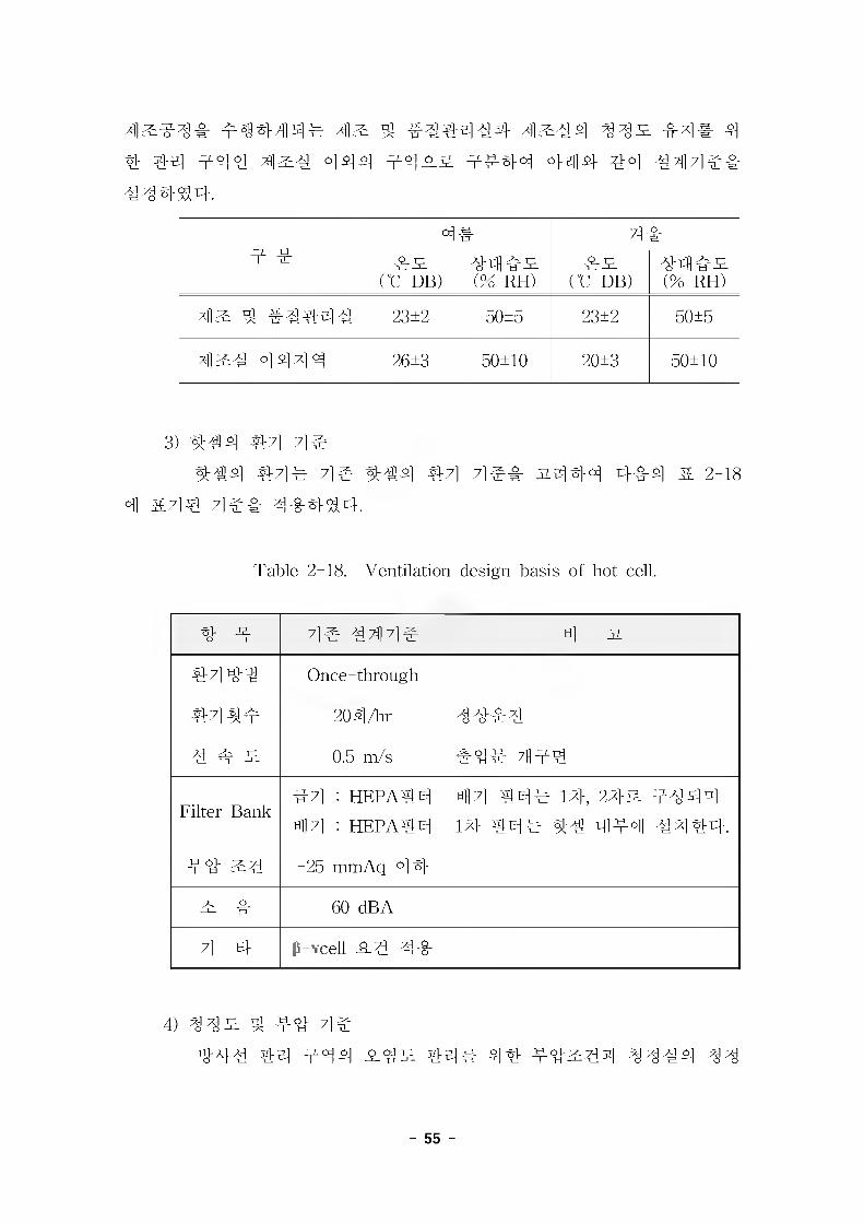
3) 444 #4 7]#
444 #7]^ 7] 444 #7] 7] 31444 444 & 2-18
4 it 44 7] ## 4#^1-44.
Table 2-18. Ventilation design basis of hot cell.
4 4 4# 444# 4 A
4444 Once-through
444# 204/hr 44#4
4 # si 0.5 m/s #4# 444
Filter Bank44 : HEP A 4 4
44 : HEP A 4 4
44 44# 14, 24-# #44414 44# 44 444 4444.
#4 #4 -25 mniAq °14
# # 60 dBA
7l 4 (S-vcell A 4 44
4) 44^ ^ 44 4444 44 444 O <24—l- T3 - 44# 44 44^44 4444 44
- 55 -
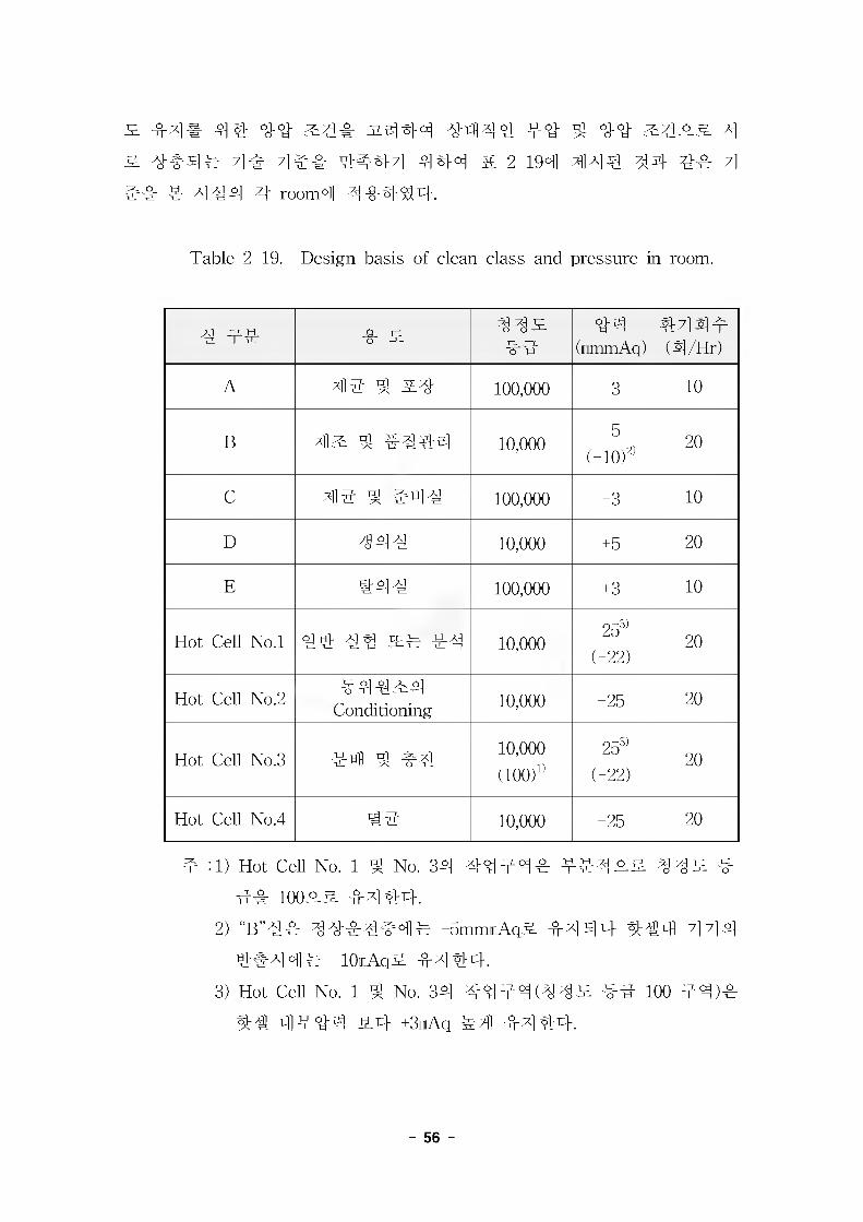
^ #4# 44 ## ^44 3.444 4444 #4 4 44 ^435. 4
& 4#4# 4^ 7]## 4:444 444 & 2-194 44€ 44 4# 4
#4 4 444 4 room4 44444.
Table 2-19. Design basis of clean class and pressure in room.
4 #4 4 344344
#4(iimmAq)
44^14(4/Hr)
A 4^ 4 34- 100,000 -3 10
B 43 4 #444 10,000-5
(-10#20
C 4^ 4 #44 100,000 -3 10
D 7344 10,000 +5 20
E #44 100,000 +3 10
Hot Cell No.l 44 44 3# 44 10,000-25^'
(-22)20
Hot Cell No.2#44^4
Conditioning 10,000 -25 20
Hot Cell No.3 44 4 4410,000(100#
-25^'
(-22)20
Hot Cell No.4 #4 10,000 -25 20
4 :1) Hot Cell No. 1 4 No. 34 44444 44435. 443 4
4# 10035 4444.
2) “B”44 4444444 -5mmmAq5 4444 444 7] 7] 4
4#4 br -10iAq5 44 44.
3) Hot Cell No. 1 4 No. 34 44 #4 (4 4 3 44 100 44)^
44 4444 5.4 +3iAq 44 4444.
- 56 -
4. 4# 44 1) 4# #4
7}) 4 #4 4 4 44^ #4^## 44# #### ###& 4 #4 4# ###3, o]o]] #4 ^ 44^## ##71 444 ##444 4
4 4 #44 Panel# #444 #44 #2:# 4#v# e}^4. 32431 #
v4 47l#ti] 4o] 7]e #71444 °J4 #7]4# 44431 #7>## 4
##4&4 #4^# #4444, s-44 47]#4 ##& GMP 44# 4
4 4^4 444.
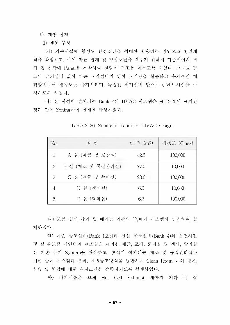
4) 4 4#4 4444 Bank-44 HVAC 4#^# & 2-204 &44 44 #°1 Zoning44 444 44444.
Table 2-20. Zoning of room for HVAC design.
No. 4 4 # 4 (m2) 44S. (Class)
1 A 4 (4# 4 #44) 42.2 100,000
2 B 4 (4^ # #4444) 77.0 10,000
3 C 4 (4# # #4#) 23.6 100,000
4 D 4 #M#) 6.2 10,000
5 E 4 (#44) 6.2 100,000
4) v# 44 #7i # 47i# 7i#4 #,afl7l 4Zz#4 4444 4 44^4.
4) 4# #^44 (Bank-1,2,3)4 44 #^44(Bank-4)4 #444
4 4 #^# 4444 4^## 444 4#, #4, #44 # 44, #44
# 4# #7l System# ###3, 444 444# 4^ # #4444#
71# CM Al^Tg# #4, 7H4#2:44# 4444 Clean Room 44 4#,
4# ^ 444 44 #4^4# ##44^4 4^1444.4) 4 714## 3-4 Hot Cell Exhaust 444 714 4 4
- 57 -
(A,B,C,D,E) Exhaust ##4^4.4d A# 4 B# 4°1 4 # Showering Type 4 Pass Box# #4 44
444 444 Clean Room^_& #44# 4# #44^# 4^4.4) #4# 4 #4 #4 44 Door4# Interlock# ##44 4#4
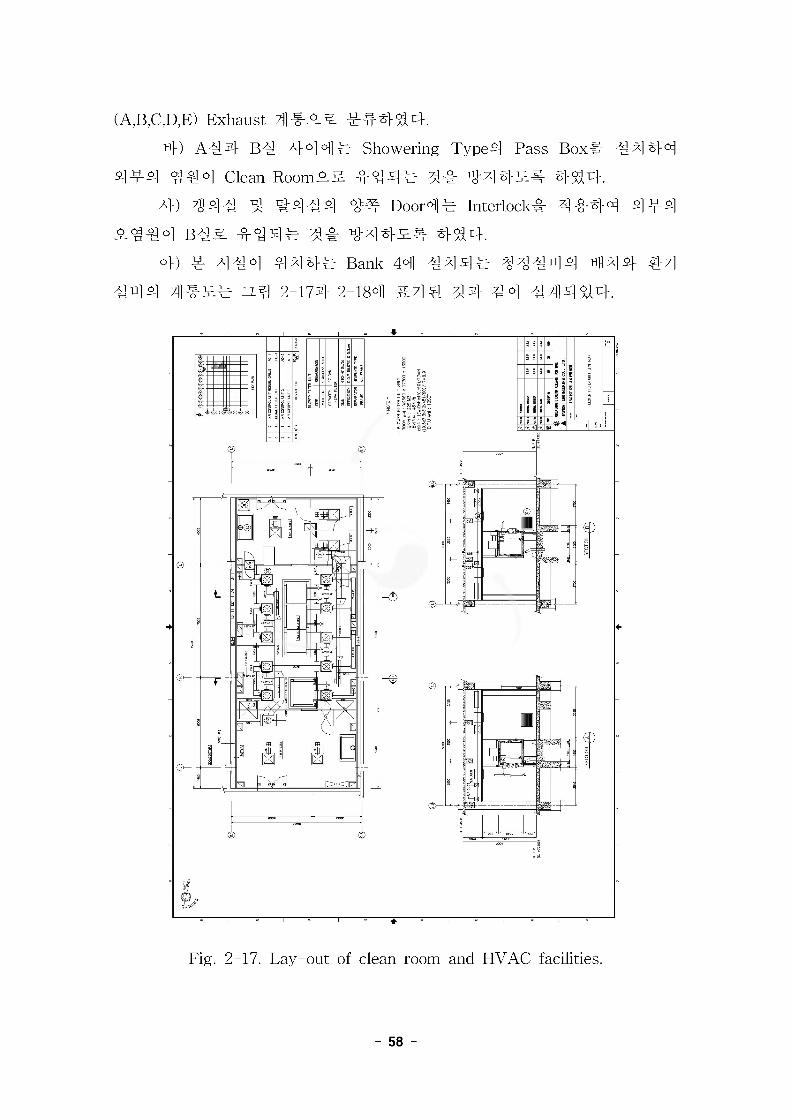
#444 B#& #44# 31# #44^# 444.°» # ##4 444# Bank 44 #44# 4 4#44 444- 44
#44 4#^# 2-174 2-184 #44 44 #4 #4444.
Fig. 2-17. Lay-out of clean room and HVAC facilities.
- 58 -
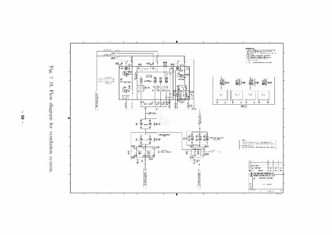
Fig. 2-18. Flow diagram for ventilation system.
2) A, C, D, E# (41# ^ #4#, 41# ^ #4#, #4^, #4^)
7}) #4547]# -o"2:^ti]# #7l System# ##44 #5# #7l# ##4
4 #41 #,#51 2:## #444, 7]#4 # #4#5## #7]#4 ###
44# # 4^ #4 ^ ^4 4 4 5# 544^1 444 Blow Filter
Unit (HEP A Filter 4#)# #44## 444.
4) #4 ^ #444 4431# #444 44 Blow Filter Unit# 444 HEPA
Filter# #44 Filtering# #7]# ##44, #7]# ## #7]# Return
Panel# Hood# #44 Once through 44# 4#4^4 47]## #7]#
Filter Bank(MOD + HEPA Filter)4 4 Filtering 4 #, 4# 4 4 4 5 4 ##44 4 7] # 51# 4#4.
Clean room# 4#4 #44 4444# 444 444## 44(Positive pressure)# #4444 44, # #44 444 ### 4#45-5- 44 # ## 4444 444 #4(Negative Pressure)# ###5# 44, 4# 4 4 44#4 Damper# #445 ##5#4 #44# #4# MOD Filter Unit# 4# #4#5# #44.
#45 #44 #4 4 31# Exhaust Fan# VVVF Control# 444 44 #4# 5#44, 100% #44 Fan# 24 #444 14^ stand-by45# 4SS4. 543. Filter Bank4# 44 #4 ^ 4#44, Fan 55# 444 44-5447} #445 44 #4444 44 Exhaust Fan# Control 45# #414^4.
4) ##7]7l
- Blow Filter Unit : Fan & Motor, HEPA Filter
- -#71 #4 Damper : Relief Damper
- MOD Filter Unit
- Return Panel : Room 4 71- Hood : Disinfection, Fume
- Filter Bank : MOD + HEPA Filter
- Exhaust Fan
- 60 -

3) Big (#2: ^ #4444) ^ 44
7}) #4^#-
7]# #2:## s) #7l System# ##44 43# #7l# Air
Control Unit# 4443 ACU(Air Control Unit)4 ## B## ## #,#
3 3## #7]# # ^3# ^-#, 4#44. B## ^44 #4 ^ 4 #3
4 #34 #4# ACU# #4 4# 4## 4 Duct# #4 3444 z} #
# # ### #71 # Blower Unit 4 # # boosting # 4 HEP A Filter# ##
4 433 44# 4 4# ACU3 #444# ##33 4#44 4 # Hot
Cell# #44 # #3# 4#4.4) #4 # #4
#4 4 4 3# #7] #7] 4 4 Air Control Unit# Filter Unit#-
4" Blower Unit# #4 #7] 4 HEP A Filter# #44 Filtering 4 #7] # #
3# #4 ##44, 4# 47]# #4 till7]# Return Panel# #44 Once
through ##33 4#44. ti||7] ## 44# Filter BanMMOD + HEPA
Filter)# 4 Filtering# #, 7)# ti|| 7l #3# 4##4 #71### 444.
Hot Cell# #7)# Air Control Unit# Punching Plate Duct# # ####
44# Hot Cell ### MOD 4 HEPA Filter# #4 Filtering 4 # 44
#4, till7l# Hot Cell ## ### PRE Filter# 4# 1#, 27} Filter
Bank (HEPA Filter)# #44 24## Filtering 4 #, 4# h} 7l#3# 0}
444 Hi) 7) # 3# 444.
Hot Cell# ti|M# Cell Door# ;1M14 ## 4#4 #333 50% #4
# Fan# 3# 4#43. WVF Control 44 Hot CeU 4 ### ##44.
17}, 27} Filter Bank## 7}# #4 # 43##, Fan 33# #44 7}#
3# #7} #7l#jL 7}# #444# #4 Exhaust Fan# Control #4.
4) ###71
- Air Control Unit : Heating, Cooling, Humidifying
- Blower Unit with HEPA Filter Unit
- Return Panel : Room # ?|
- #714# Damper : Relief Damper
- Filter Bank : HEPA Filter
- Exhaust Fan
- 61
4. #4
7>) Low-Filter(LOW)
- 4 4" : 3:7] - 10 mmWG
#4 - 25 mmWG
- 3L # : 25 ~ 30% (ASHRAE stain test)
4) Moderate Filter (MOD)
- 4 4" : 2:7] - 10 mmWG
#4 - 25 mmWG
- 3L # : 50 ~ 55% (ASHRAE stain test)
4) High Efficiency Particulate Air (HEPA) Filter
HEPA #4# 0.3/m 4 #44 444 4^ 99.97% 44%## ^
#44 4^o]n)_.
4) 4 7] 4
4# ^ 44# MOD ^ HEPA# 4# 4?]# #4#^##
444 #444^# #4 4#44 44 44^0] ^4
#4. #4 ### 4?]^# 4# ##4 ;]]4-4 4#^ 0.5m/sec# 444
7] 44 24 7}4#5i 44 4444.
4) Air Control Unit (ACU)
#4^44 4#7]4# 44 4# 444 44444 444 #4#
4 #44. Line Type# Supply Duct# 444 ##4 7}4# 444. #7]
4 ##4 4444.
4) Clean Booth
"B"#4 ^#4444# 44^ ## 100# #444 444 244
Clean Booth# #444. 44^# #44 #4# ws##4# 44 #4
44-O-g-# #444. 4 Clean Booths]# ##-4 44^ 444 a## 4
#4 44.
- Clean Booth 1 : 250mm x 250mm (4 4 #4), 1,000mm x5000mm (4444)
- Clean Booth 2 : 250mm x 250mm
4) Fan Filter Unit(FFU)
No.l 4 No. 3 4#4 4444# 44^ ## 100# #444 4
44 4#RM A## Filter7} R]#4 FFU# #444 4#44 #4# #
- 62 -
#4 4XX# #44 -0-7]# ###4-. 4 # #4 #4 4 3.7] # 250mm
(L)x250m(W)xl50m(H)44 ## 444 #4"4 4 4 #4.
°}) Pass Box
3-4# #4 XX ##, 4# #4 #4# ^]#^] X444 clean
RoomXA #44# 31# 4"447] 44# #"4 44-. ##4 #44# Pass
Box4 #4# 4#4 #4.
- "A"#<-»"B"# Pass Box : Showering Type, Double Door
- “B”#^5‘C”# Pass Box : Non-showering Type, Double Door
Pass Box 4 rfl## Ap] *] ei|A All 3045. d]### Showering Type 4
Pass Box# Fan4 44 HEPA #4# 44 ##4 #7]# #####-.
40 Disinfection Hood
##4 44 #, 7}A#4 #4## #4 ##44 #4x# #4 ^
##XX4 4#x# #4#4. 4#4 #44# Hood4 #4# 4-#4 #4.
- “A”# (1 EA) : Disinfection (Exhaust FanX#)
- “C”# (1 EA) : Disinfection (Exhaust FanX#)
#) Steam Sterilizer
4##x4 #4 x# 444444 44# 4#44 44 4#44 4 44 Steam Sterilizer# #4 44. 4 Sterilizer4 44# 4#4 44.
Pass Box# SterilizerChamber #4 : 20044Steam A 4 : 1.5kg/cnf, 126.8 °CDoor Type : Swing, Both SideSteam 44 : Electrical#444 : "C"#^"B"#4 44 #4Column SterilizerChamber #4 : 254 4Steam A# : 1.5kg/cnf, 126.8 °CDoor Type : Sliding (Inflation Seal)Steam 44 : Electrical#444 : Hot Cell No. 4 4 #4 4#4
- 63 -
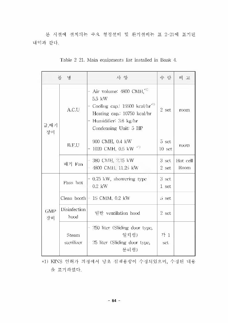
4^4 ^ 3444 ^ #7)^4^ & 2-214 &4^
444 44.
Table 2-21. Main equipments list installed in Bank 4.
# 3 4 4 4 4 4 31
4,4 4 44
A.C.U
- Air volume: 4800 CMH,^'
5.5 kW- Cooling cap.: 15500 kcaFhr*1)
- Heating cap.: 10750 kcal/hr
- Humidifier: 3.6 kg/hr
- Condensing Unit: 5 HP
2 set room
B.F.U- 900 CMH, 0.4 kW- 1020 CMH, 0.5 kW ^
5 set
10 setroom
4 7] Fan- 380 CMH, 2.25 kW
- 4800 CMH, 11.25 kW
3 set
2 set
Hot cellRoom
GMP44
Pass box- 0.75 kW, showering type
- 0.2 kW
3 set
1 set
Clean booth - 15 CMM, 0.2 kW 5 set
Disinfection
hood44 ventilation hood 2 set
Steam
sterilizer
- 250 liter (Sliding door type,
444)
- 25 liter (Sliding door type,
^r44)
4 l
set
*1) KINS 447} 4444 4^ 44-0-3=4 4344^4, m34 4-0-
- 64 -
7. 44 44
7}. 4444 ^
^7] nl 3. ^ti] o] 444 4# 4 #4 ^<>fl 444
444 4444 4 K44 4#4.
Korea Electric Power Corporation Standards and Prestandards
Korean Industrial Standards (KS)
International Electrotechnical Commission(IEC)
Korea Fire Protection Code and Relevant Regulation
American National Standards Institute (ANSI)
Illuminating Engineering Society (IES)
Institute of Electrical and Electronics Engineers (IEEE)
Insulated Cable Engineers Association (ICEA)
National Electrical Manufactures Association (NEMA)
National Fire Protection Association (NFPA)
American Society for Testing and Material (ASTM)
Underwriters Laboratories (UL)
4. 44 4444 44, 44 444 44 44, 44 ^ 444 44 444
4 44.
4 4 ^4 44, 4444
- 4 4 460V/220V, 4444 44
- 44 ^ 444 220/110V, 444 44
4. Ri444 44
44 4 ^ 44^ 4# ^44^ 49444 4 44 ^444^4-4 4444 44.
- 65 -
1) 460V 4#4 4M4(MCC)
7}) 460V MCC4 NEMA ICS2, CLASS E, TYPE C S# #
#44°-# #:i S] ## NEMA TYPE 1 GASKETED Hi# TYPE 12 ##
## 4-31, MCC# #44 444 4^4 4##g. ^#4 # 4^
# 4#4.
4) MCC 4 4^71 44714 7144^4 444 444 44 444
47M^ s# 444 7M^4&, 444(MCCB), 444#4, ^4 444
71144& 44444.
4) 4##44 ##4 444# #444 s# #44444& 44
44 4444 7H4# 4444 44 4444(OFF-DELAY RELEASE) 4
34 444# 444^4 444.
4) MCC 4444 44444: MCC4 44444 44 444 #4
4 4444# 7}4 4# 4#4^4 4^#4, 4 MCC v.44 4444#
600A4 800A# &e_o& 43. 4#4 4 2.44 4^% #44 ^TlMl 4
4 444^4 444.
4) 15HP444 4#7l4 30A 444 4 4#7l 444 44431 #
^7} 4^# 44444.
4) 4^4(COMBINATION STARTER)4 a4^ 4#44 #4 4
#444# 31444 NEMA A# 4e(4# ##4)4 44 4
4 44444 ##444 #4^.& 4^4 4^4.
4 #4 4 a.4(NEMA A#4#) 4 4
0 4444 18A444 444
1 10HP44 4 4#4
2 15HP44 25HP44 4 4#4
3 30HP44 50HP444 4#4
4 60HP44 100HP44 4 4#4
4) a.# 4#4 444# 44 4 20%4 44444(4^4 ^4) ^
#4# 4^.4^4 4^4.4) # 444 444# 7l 7l 4 44 #4# 44 44#(single line
- 66 -
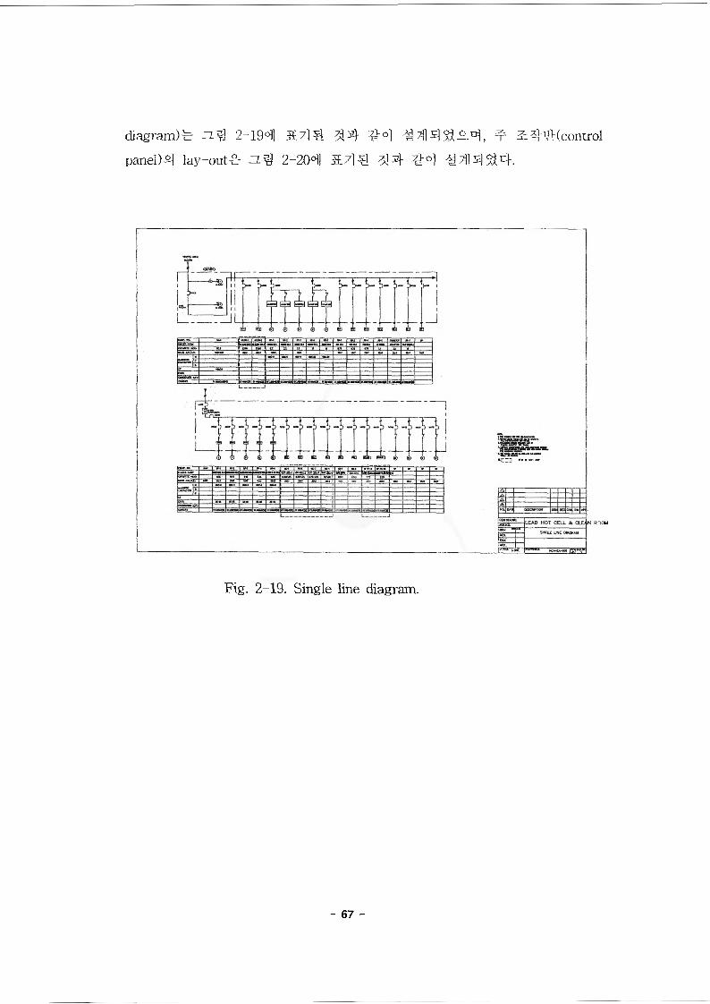
diagram)^ 2-194 334 ^4 ^44$3^4, ^ ^44(control
panel)4 lay-out^ 2-204 &44 334 ^4 ^44 $34.
arm
Fig. 2-19. Single line diagram.
- 67 -
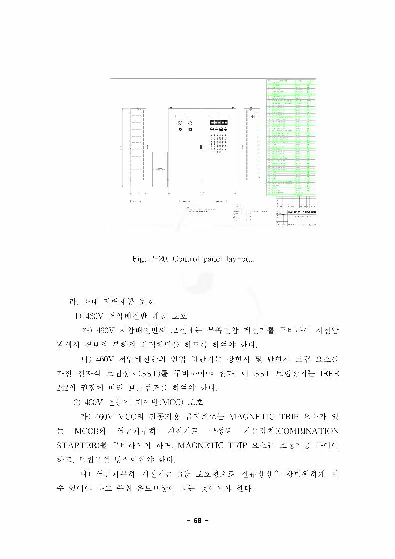
B B'll
STAINLESS STEEL 0 HUT CELL & CLEAN HOOI
Fig. 2-20. Control panel lay-out.
eh 44 444# t^jr
1) 460V xi 4444 4#
7» 460V A] 4hH 44-1 2-444 4444 447]# #^144 4 44
f^l 4#4 #44 4444# 42# #4 a|: 44.
4) 460V 4<5411444 44 4-444 4-#4 4 444 24 4^#
7} 4 4^1-4 ^444 (SST)# 44444 44. 4 SST 2444#
2424 444 44 4412:4 444 44.
2) 460V 4#7] 444(MCC) 22.
7}) 460V MCC4 4#4# #4^12# MAGNETIC TRIP #27} 4
4 MCCB4 4#4#4 3] 4 4 2 444 4 #44 (COMBINATION
STARTER)# 44444 44, MAGNETIC TRIP #2# 2:47}# 444
4#, 2444 44 444 44.4) 4#444 444# 34 22122 4444# 44444 #
4 444 4# #4 #224-0] 44 4444 44.
- 68 -
4. 4#4
1) V-# 4#4^] 44, 44 ^ 44# IEC 34 ^ 4# 4# 7}#%
4# ^ #4 ### 4-^^a 4^4-.
2) V.# 2)# 4#4# A)# 120V 44444 441 3E# 4#44 44
44# 44 4e# 4##^#.
- MOV4 4#4# V-# 4#4 : 460V, 34, 60Hz
- 1/3HP 444 447] (MOV 44) : 460V, 34, 60Hz
- 1/2HP44 250HP 444 444 : 460V, 34, 60Hz
3) 1/2HP 444 a# 4#4# 44 444 44, 4444444
4 7}4S# 414# ^47} 444^4 444-.
4) a.# 4#4# 4#4 4444-4 80%44^ 100% 4-4# 4 #43.
7}#44 # 4^# 444-.
5) a.# a# 4#44 4 #4## 4#4 4^.4 650%44& 444^#
4n, 4# 4#7]s] 4#4## 7}4% 4 44444 250% 4 4 s 4 #4^#
4^4-.6) 30HP 444 4#4# 4-44 ^44# 3HP444 4#44# 4-^
4^4# #44^# 4-jL, 4-?4^44 4444-# 220V4 4#4"4# 120V
& 444-.7) 4#4# ^4 ^ #4^44 4#4# 44] ## 44-4 (TEFC),
IP PROOF GUARDED 4, NEMA WP TYPE R, i£# NEC if 5004 #
4# 4##^# 444-.
4. 44-44
1) 460V 4#
a.# 460V 44-4 #44# 44 44-4 44 444^# 4SS4-.
2) 460/220V 4#, 220V/120V 4#
- 460/220V ^ 220/120V 44444 444 444 #44# 44 4
4 4 si# 4SS4.
- 220/120V 4# : a# 44# #44 44 ^ 444 444 #4
4# 444 4^# 4-SS4-.
3) 4# 4## 444& 4^4-.
- 69 -
4. 44, 44 4 44 44 ### 44#
1) 444(THERMOCOUPLE)# 2:44 44# 444 ## £4# B
#(ASTM. B8) 44##, 4#4 4# 44## 4##^# 444.
- 600V 4^# 44# (CV)
- 600V #4# 44 (IV)
- 600V 44# 44# (CW)
- 4444 4## 44# (CWS ) ^ ## 44#
- #44## 44# (44##44 : HIV, ## : 4444#)
2) ## 4^ 4 4 #4 4#4## ICEA P-46-426, ICEA P-54-440 ^
NFPA 704 444 4444, 44# ^4# 444 ##7} cv 44#4 4#
90°c# ^444 ^JL, 444 250°c# ^444 ^#4 444#, 4# 44#
4 4# 4444 #44 4# 4##4## 44# #44 ^#4 4SS4.3) 44# 44## 600V 444 44## 4#4# #4## 90U4 4
4# ## #44## 44444-. #4# ## 444#4# 4# 44##
4-0-40! 44(FLAME RETARDANT) 4## 7}4 4#4 44# 7}44 #
4 ^ 44#4# KSC 33304 #4#, 44# 44# #44 ^4^ ^#4
2.0ninr# 4#4## 444.
4) 4##zL 4#44 4## 44## 4-44, #4 ^ #44## 44,
#444# 47] 44-4-4 #44 4# 44# #4-4-4 444 44# 7}##
4 4-444## 4#4## 4^4. 44 ^ 4# 4## 44# 44# 4
#4 ##44, 44#o. 4#44 4## #44 ^4^ 1.25mnf (16AWG)
44-4 #4 ^ 444 4 4## 4^4.
5) ## #4 4## #4 44# 4 #4 444 125% 4## #4#
4 4.# 471 # 44,4-
6) 44#44 #444#, 444, 44-44# ^ 4#444#4 ##4
44# 44- 44# l%# #444 44, 4#4 ^ 44- 44-0- 4-4
44# 44- 44# 3%# #444 ^#4 444.
7) 44#4 #444 ^ 44#4 4### #44## IEEE422,
IEEE525, ICEA P-54-440, ICEA P-46-426 ^ NEC ART.310# 4#o_&
444.
- 70 -
4. 3441) 23 °1 343 3 3 43 °17"l 4 3:4 344 34 344, 4
# 344 44 4232 344# 34324 3SS3.2) 344 4334 43 3444 44 332# 44344, 34 3
444 ?32]e 33 3444 KS-84313 M-VE 24 KS-84553 FEP4 4 4324 444.
3. 331) 2.4 34 24 344 3343 344 4443# 34324 3
33.
2) 343 434 32^24 44 loomm 444 4 7>334 4332 4 3434# 44 323 3344 333324 432.3, 4 343 34 2.4 333 3 3343 33324 434.
3) 343 433, 333, 332 33, MCC, 33 433, 23 433, 344, 334 233, a.3 3 33 4 43 33 43 44 4244 3 34 4 3342# 333.
4) 24 33333, 343 3333# 43 33 244 43434 4 2 3324 4 434 lOOnuir 33422 44 424 24 443 433 3 332# 433 33 344 3332# 333.
5) 42# 333! 43 33 244 24 4 #34 6(W 434 33 42 3333 3334 33. 34 343 33 4 334 333 334 3334 33324 333.
6) 33 334 233 32 ^3 3 33344 IEEE 142 3 ANSI/ IEEE 6653 4324 333.
3. 23 341) 23 344 4323 34 3 3323 3422 4433, 34
3344334 34324 333.2) 4333 4233 43 33#3 434 33433 125%# 33
# 4 324 324 333.3) 333 2# 33433 3334 23434 3#3 43 3 24
- 71
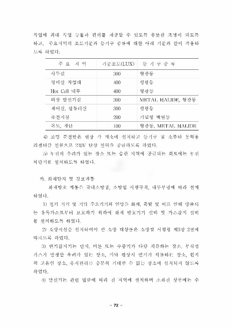
4^4 2M 4^ ##4 4## 4 ^Tgo] Sj^a
#3%, ##4 44 ##4e# ^44 444 4% 44 7] #4 44 4-8-4 ## 444.
##44 4#^^(Lux) # 4 ^ #
4## 300 44#444-444 400 ^4#Hot Cell 44 400 ^4#44 #444 300 METAL HALIDE, 4 4#44#, 444# 300 ^4#444# 200 4#^ 4####, 44 100 44#, METAL HALIDE
4) #4 #44# 44 4 ;H#4 4443% 444 4 ##4 #4#
4 #4# 44## 220V 44 44# ##### 4^4.
5) 444 #47} ## 4# s# #4 4 44 #44# 4 #4# #44#7]# ^4x14es. 4^14-.
7}. 4444 4 4#4#
#7i]4-^ 44# #4#44, #44 4^#4, 44444 44 #44^4.
1) 44 44 4 44- 4#44# 44# #7ii, a.# 4 o]^ 4#4
# 447}^&44 #^44 444 4-7H 4^44 44 4 7}^44 #4
# 444^4 444.
2) #44## 44444 4 #4 44## #44 4^M 4134 244
4 = 514 444.
3) 44444# 44, 4# s# ##47} 44 4144# 4#, #44
7}#7} 44# #47} 4# 4#, 44 444 447} 4### 4#, 44
4 31#4 4#, #444# ##4 44# # gl# 4#4 4444 4^4.
4) 444# 44 444 44 4 4 44 #444 #44 444# 4
- 72 -
# ##7] 4 &#^# #44## 444.5) 4# 7] 4## 4-0-sj 4 ### ^1 ##4 441 #4
##7} 4^### 444.
4. ##4# : ## 4## 4#4 ### o]_§_ 4^4s# 444.
8. #4##
7>. #4## 4 4 7] e1) 4-0- 44 4 &#
#4## 4#4 44, 44 4 444 4^44# #e#& 7}4 ##4 4^4 44if4 ^ &# ## o]^. ^^443. ##4 4# ^ & #4 ^44 44 7]e# 4^-4## 444.
7}) 4##4^ ^ 44^4#4^ # 17 # # l 4 ^ # 30 # # l 4#4^ 44^ 4 28 ^ 4 4 4#4 4^4#4 44 44 4 59 # 44 4 63 ^444 31 a] 41995 - 284(4 4 #44*114 44 4 444444^7]#) 4 6 #(#4 4444 44)
4) 44444# (KS)44 444 4# 44(KS D 3562)
2) 444#
#4## 444 447> 44# 44 44# #7] 4444 #44 4# 44, 4444 #444# 4### 44# 4# M44 4 444 ## 4## 4 4## #4444.
7}) 4# #4 : 44 4# 444) 4#4 #4 4#
27H 4## 471144 4 7} 444 #4444 ^44^7} 4###
4 44431, 4447-I #### #44 4 4# ### #4444.4) 44444 44#4
iM## ^4# ##4 44# 4 ### 444, 4#4 444
- 73 -
44 #3# #4 §}# #33 #3 #### 44# 44 44. 34 444 44] 4^] 444 444 444^ 4# #4 4#33 4 47}^4 4 ^3 3 44 #44 #44 #3 44. 444 4444 444 45.4 4444 #44 4444 4 4#4e4, #44 #4 44 44# 4#443# 444.
4) 4444 44444 44 44 444 43# #4 44 444 444 44 3# #433 4 #4 3# 4444, 44 444 3# 44 4 444 444 45- #444 4# 3443# 4^4.
4. 34-44 44# 444 3#44# 4# 444 444 4# 1301 344=4# 4
#4-3# 4^5-4, Bank-44 4444 444# 4#4 #444 4# 3 444# 44-43., 44 44 3#44# 4444 4# 1301 3#44# #443# #44.
1) 444 4# 3444# 4#4 4# 44# #443# 444.- 44447] ^ 4444- 4# ##3#4 ^ 4# 4-#34#- #4434-4
4# #444 4 3#2) 4# 4 4# 3444# 4#4 4# 44# #443# 4##.
- #4444 ^ #444- 4# 1301 444 444
(254445kg ##444, ##34#, ##4344 # 3#)* 44 3433 43# #4# 1044/7kg #444, 4944# 4
#4 43#4# 3444 43 44#434 34 444%4.## #44# 4 3#
4. #7]]44 7] 4 441) 4444
- 44= 4#4 333# 444- 4444= 344 #33|] #44 4# #4# #3### 4444
- 74 -
- ^4"44^ : 4 44444^-^
2) 44447]- : 4^44 4^44=^ 44444- 4444 : #4^4 444 4-W^ 4^r44 44 4#& 44
44- 44444 : 4 4#444^-^
4. #e ^4444 44- ## 44444 4-7} 44 7] 4 444 44 4444 4471444
4 444 4444 4444444 44] ^-444.- #7]] 44 7] 7} 4444 4444 444 4444 4444, 444
4 44=4:&444 4443- 444 #444^4. 4444 #4 447} 7]] 444 ^4-7}^7} 4#44 44, 444 4#&444 4444.
- ##7M4r 4#;]] 4^4-4 30^ 444 444 444 4#44.
9. 444&4 444 44 44 € 444& 444 & 2-224 4^44 4^-4,
44 4^ 4444 ^4 44 444 444%_02_g. 47]] ^44 444 £44 44£44 4444 44 44444.
- 75 -
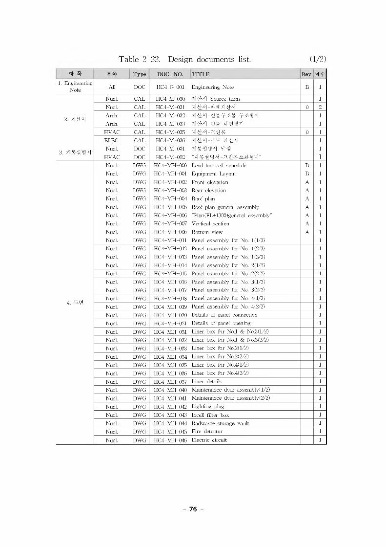
Table 2-22. Design documents list. (1/2)
* # #4 Type DOC. NO. TITLE Rev.
1. Engineering Note All DOC HC4-G-001 Engineering Note B 1
Nucl. CAL HC4-M-030 4] LM -Source term 1
Nucl. CAL HC4-M-031 0 2
2. 4]4MArch. CAL HC4-M-032 1
Arch. CAL HC4-M-033 TIMM# 1
HVAC CAL HC4-M-035 0 1
ELEC. CAL HC4-M-036 414H-&V. 4] tM 1
3.Nucl. DOC HC4-M-001 1
HVAC DOC HC4-M-002 " 4] #44 ^4-a ^ fisfl " 1
Nucl. DWG HC4-MH-000 Lead hot cell schedule B 1
Nucl. DWG HC4-MH-001 Equipment Layout B 1
Nucl. DWG HC4-MH-002 Front elevation A 1
Nucl. DWG HC4-MH-003 Rear elevation A 1
Nucl. DWG HC4-MH-004 Roof plan A 1
Nucl. DWG HC4-MH-005 Roof plan general assembly A 1
Nucl. DWG HC4-MH-006 "Plan(FL+1300 (general assembly" A 1
Nucl. DWG HC4-MH-007 Vertical section A 1
Nucl. DWG HC4-MH-008 Bottom view A 1
Nucl. DWG HC4-MH-011 Panel assembly for No. 1(1/3) 1
Nucl. DWG HC4-MH-012 Panel assembly for No. 1(2/3) 1
Nucl. DWG HC4-MH-013 Panel assembly for No. 1(3/3) 1
Nucl. DWG HC4-MH-014 Panel assembly for No. 2(1/2) 1
Nucl. DWG HC4-MH-015 Panel assembly for No. 2(2/2) 1
Nucl. DWG HC4-MH-016 Panel assembly for No. 3(1/2) 1
Nucl. DWG HC4-MH-017 Panel assembly for No. 3(2/2) 1
4. MMNucl. DWG HC4-MH-018 Panel assembly for No. 4(1/2) 1
Nucl. DWG HC4-MH-019 Panel assembly for No. 4(2/2) 1
Nucl. DWG HC4-MH-020 Details of panel connection 1
Nucl. DWG HC4-MH-021 Details of panel opening 1
Nucl. DWG HC4-MH-031 Liner box for No.l & No.3(l/2) 1
Nucl. DWG HC4-MH-032 Liner box for No.l & No.3(2/2) 1
Nucl. DWG HC4-MH-033 Liner box for No.2(l/2) 1
Nucl. DWG HC4-MH-034 Liner box for No.2(2/2) 1
Nucl. DWG HC4-MH-035 Liner box for No.4(l/2) 1
Nucl. DWG HC4-MH-036 Liner box for No.4(2/2) 1
Nucl. DWG HC4-MH-037 Liner details 1
Nucl. DWG HC4-MH-040 Maintenance door assembly) 1/2) 1
Nucl. DWG HC4-MH-041 Maintenance door assembly) 2/2) 1
Nucl. DWG HC4-MH-042 Lighting plug 1
Nucl. DWG HC4-MH-043 Incell filter box 1
Nucl. DWG HC4-MH-044 Radwaste storage vault 1
Nucl. DWG HC4-MH-045 Fire detector 1
Nucl. DWG HC4-MH-046 Electric circuit 1
- 76
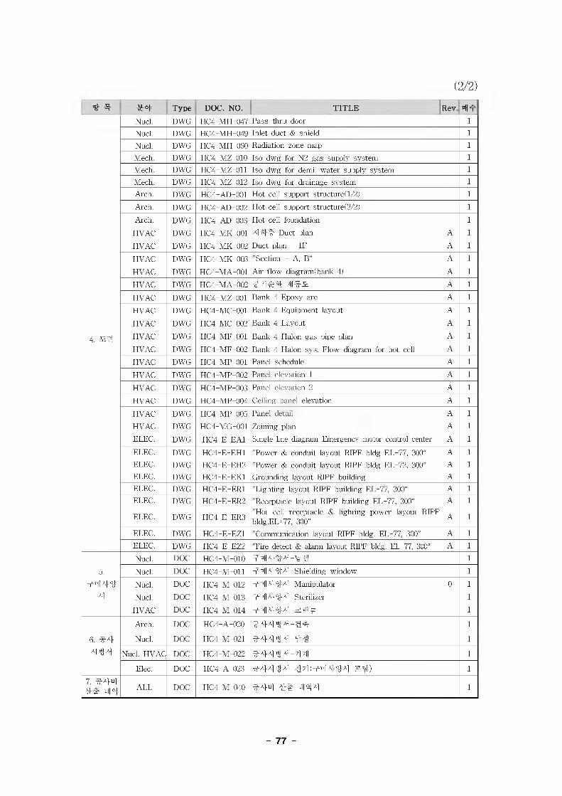
(2/2)
4 3 3-4 Type DOC. NO. TITLE Rev. 44
4. M4
Nucl. DWG HC4-MH-047 Pass-thru door l
Nucl. DWG HC4-MH-049 Inlet duct & shield l
Nucl. DWG HC4-MH-060 Radiation zone map l
Mech. DWG HC4-MZ-010 Iso dwg for N2 gas supply system l
Mech. DWG HC4-MZ-011 Iso dwg for demi. water supply system l
Mech. DWG HC4-MZ-012 Iso dwg for drainage system l
Arch. DWG HC4-AD-001 Hot cell support structure! 1/2) l
Arch. DWG HC4-AD-002 Hot cell support structure! 2/2) l
Arch. DWG HC4-AD-003 Hot cell foundation l
HVAC DWG HC4-MK-001 4 44 Duct plan A l
HVAC DWG HC4-MK-002 Duct plan - IF A l
HVAC DWG HC4-MK-003 "Section - A, B" A l
HVAC DWG HC4-MA-001 Air flow diagram! bank 4) A l
HVAC DWG HC4-MA-002 4 7] 44 A l
HVAC DWG HC4-MZ-001 Bank 4 Epoxy are A l
HVAC DWG HC4-MC-001 Bank 4 Equipment layout A l
HVAC DWG HC4-MC-002 Bank 4 Layout A l
HVAC DWG HC4-MF-001 Bank 4 Halon gas pipe plan A l
HVAC DWG HC4-MF-002 Bank 4 Halon sys. Flow diagram for hot cell A l
HVAC DWG HC4-MP-001 Panel schedule A l
HVAC DWG HC4-MP-002 Panel elevation 1 A l
HVAC DWG HC4-MP-003 Panel elevation 2 A l
HVAC DWG HC4-MP-004 Ceiling panel elevation A l
HVAC DWG HC4-MP-005 Panel detail A l
HVAC DWG HC4-MG-001 Zoining plan A l
ELEC. DWG HC4-E-EA1 Single line diagram-Emergency motor control center A l
ELEC. DWG HC4-E-EH1 "Power & conduit layout RIPE bldg EL+77, 300" A l
ELEC. DWG HC4-E-EH2 "Power & conduit layout RIPE bldg EL+72, 300" A l
ELEC. DWG HC4-E-EK1 Grounding layout RIPE building A l
ELEC. DWG HC4-E-ER1 "Lighting layout RIPE building EL+77, 300" A l
ELEC. DWG HC4-E-ER2 "Receptacle layout RIPE building EL+77, 300" A l
ELEC. DWG HC4-E-ER3"Hot cell receptacle & lighting power layout RIPE bldg.EL+77, 300"
A l
ELEC. DWG HC4-E-EZ1 "Communication layout RIPE bldg. EL+77, 300" A l
ELEC. DWG HC4-E-EZ2 "Fire detect & alarm layout RIPE bldg. EL+77, 300" A l
5.
4444
4
Nucl. DOC HC4-M-010 44444-44 l
Nucl. DOC HC4-M-011 44 444 -Shielding window l
Nucl. DOC HC4-M-012 44 444 -Manipulator 0 l
Nucl. DOC HC4-M-013 44 444 -Sterilizer l
HVAC DOC HC4-M-014 44444-^44 l
6. 3-4
4 44
Arch. DOC HC4-A-020 3-4444-4^ l
Nucl. DOC HC4-M-021 3-4444-4# l
Nucl. HVAC DOC HC4-M-022 44444-714 l
Elec. DOC HC4-A-023 3-4444-44(44444 Z41 l
7. 3-444# 44 ALL DOC HC4-M-040 3-44 4* 4 44 l
- 77
*11 3 # A|^o| oj-AjAj^AH nj o|^7[.
4] 1 ^ ^
#44# 4 ^4 4 (RIPF) 4 Bank 44 '4&# #44# 7H## 44 4
444'# #7}g. 4447] 444# 4 444 44 4-0-4 444 44 #
444 4#4 ^^44 #4 #^4 44 4444 45_4SS#44 44
444 4444 444 444 4 45.4%## 44444 44.444 444 444 4 444 444 441 444444 #443- 4
4 KINS 447}# 44 4^ _a_4#&4 444 % 444, 44 444
4 4 444 7}#3g. 01^. 44-444 444# 5_#4 7M 4-3.4 #4
444 4% 4-444 4## 4444, 444 444 45. 44# 444
3, 434 444 5.4# 44 444 444 44444 44.444 4 444# 4 444 44 444 #4 4#4 KINS 4444
444 44 4-0-# 4444 4 ^4^4.
4] 2 ^ ^4
1. #2: 4444 44444 #2:44# RIPF 4#4 Bank 44 #7>s 444# 4
444(471)7} % RIPF 4#4 #^4 444 44# #4% #^44 4 4 44# ##4#4 4#, #7M# # 4444 #^4 444 4 #5-4 4#4# 44444.
444 #^444 4 4e# 7]# 444 ^#^ 4#3& #^44#
#444 #^#4 444# 47}444. #4 RIPF 4#4 4# 44& 4 #4# #4 4444# 44 4471#°1 static analysis# 4#444.
- 78 -
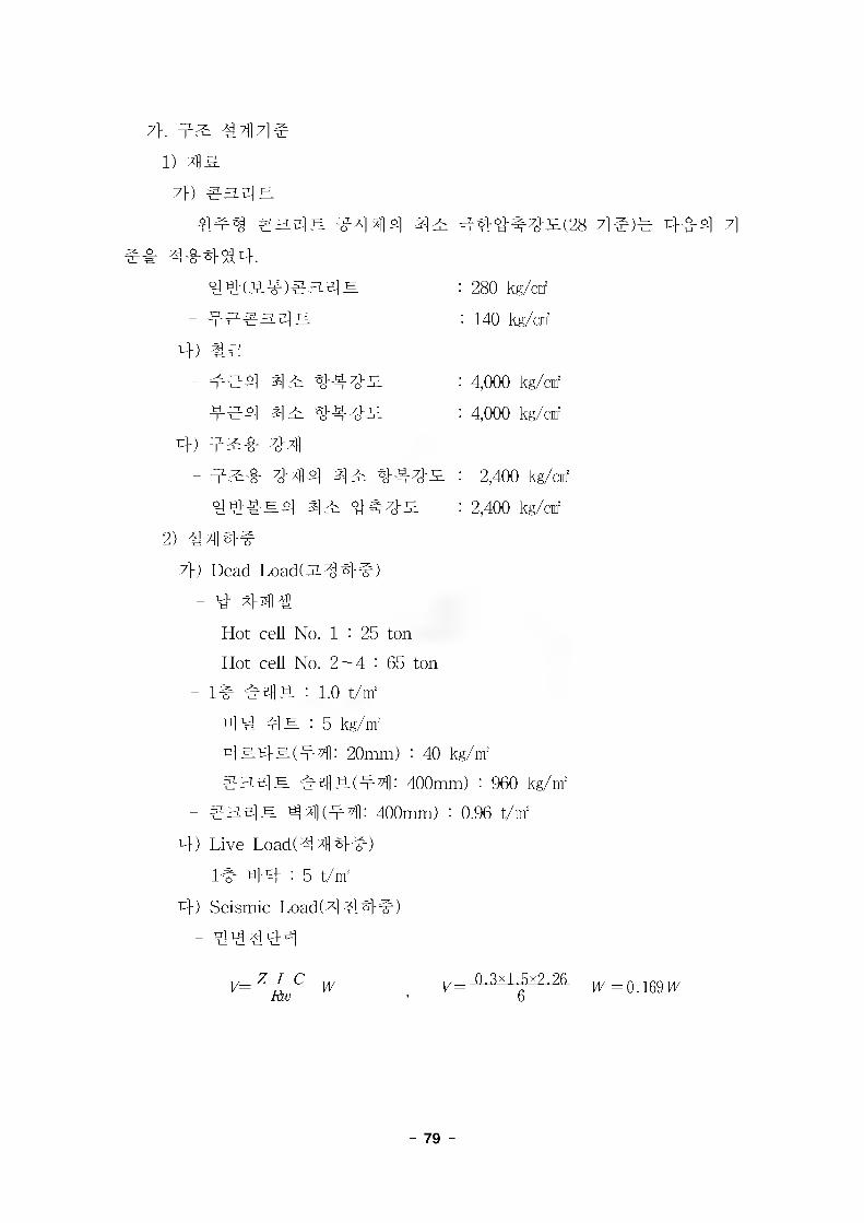
7>. 42: 4 ll 7]
1)
7» gaslE
%44 ^
# 444SS4.
a4
44(44)^3.5].
'444 ^2: 44444^(28 7l#)^ 444 7]
: 280 kg/cnf
: 140 kg/cnr
4) la- ^44 ^2: 444^
- 444 ^2: 444^
4) 4^4 444 47114 44: 444^
- 444^4 44 447J-52
2) 47114#
7>) Dead Load) 3 4 4#)
4,000 kg/cnf
4,000 kg/cnf
2,400 kg/cnf
2,400 kg/cnf
4 44 Ai
Hot cell No. 1 : 25 ton
Hot cell No. 2 — 4 : 65 ton
- 14 444 : 1.0 t/nf
44 43 : 5 kg/nf
4 343(44: 20mm) : 40 kg/m!
145iJH 444(t/1: 400mm) : 960 kg/nf
- 43513 ^ 4 (4 4 400mm) : 0.96 t/m!
4) Live Load!44144)
14 44 : 5 t/nf
4) Seismic Load)4 444)
- 44444
v= 0 3x1 5x2 256 W = 0.169 H7
- 79 -
4) 4#&4
1) #a4u
#4#^ 44^# 4#4SS4.(ACI 318.)
U = 1.4 D + 1.7 L
U = 0.9 D + 1.43 EX
U = 0.9 D + 1.43 EY
U = 1.05 D + 1.275 L +1.4025 EX
U = 1.05 D + 1.275 L +1.4025 EY
2) 4# 4^#
4# 4^# 44# 4##^44^# 4#4SS4.(AISC 95.)
S = (D + EX)/1.33
S = (D + EY)/1.33
4)44 4Building Code Requirements for Reinforced Concrete : ACI 318
Uniform Building Code : UBC
American Institute of Steel Construction : AISC 95
American Welding Society : AWS
American National Standard : ANSI
Korean Building Regulation & Codes : KBC
4. 44 4444W4444 4# 4# 444 444 RIPE bank 44 44
4 4 444 444 250 ton44 4 444 444 4444 44 4 44 44 4## 90 ton# 4#44 44 444 4# 4^44 444 4#4 4#4 45144 44 4 160 ton4 4#4%4. ^4 3. 444#4 ^4## 4# 444 4#4 4## 444^^4, 444## 4#4^44 444 4#4 #7}44 44444 44 44 UBC 4## 4# 4^4.
- 4 4 444Z) = UBC ZONE 3
- #4-51 4t(I) = 1.5
- 80 -
- #-§-#4 ^It(Rw) - 6.0
- = 1.0
- ##7^(0 = (1.25S)/T2/3
- 7]^^1^^7](T) = Ct(hn)3/4=0.035 (27.03)3/4 = 0.41
4. 4444
#44 44# 344#& 2.## 44 7] ### 44 4
44 #4441 #4^.# 4144##. #44^#4, ##4144 4-0- ##a
44 MIDAS-GEN44.
4. 44 44 4 a
1) 4#4#4a
- 4 if 444# : 0.19/0.3m = 0.63t
- 7] # 4 44# : 1.37t(Refer to Document No. KM-221-DC-H006,
Sheet No.3-16)
* 4# Hot ceU 4## 296t, 4 if Hot cell 4## 90t, 3.24 4^4
4#4 44 444#4 2.174 4^4534.
2) #4# 44#4 4a
44 # 3-14 44# 7fl4444 #7} 444 #4#4 #44 7]
#444 ^4444 #4#4 #4# 4444 4a% #444. 4if ##
44 #4 7fl## 444 4# 44 #4# #7f4 444# 7] 444 4
4## 4a 4#4 44 ##4 ###4 444 4 4#4 4## 444
%4.
3) 44 #7l]#4 4a
44 #7l]#44 414 #4# & 3-24 4#4 ##4, 444144
#7)1-0-4 0] 4#444 4144 #7)i-§-4^4- 4^ 4## 4x140]
###4 #44 4 4#4 4## 4144^4.
- 81

Table 3-1. The results of design stress analysis on slab structure.
5-4U(t.m) 1 Stifle til 31
71'sfl Id
4.37t
(Refer to Document No. KM-221-DC- H006, Sheet No.3-16)
(Refer to Document No. KM-221-DC-H003, Sheet No.3-44)
*s|T: 4UAS
As(min)=0.018x100x200=
3.6cnf/m
41 if44 5.95t 44 44
Table 3-2. The results of design stress analysis on wall structure.
(t.m)44:4
7ie
4.37t 1.37t 1) Min. reinforcement for vertical direction As(min)-0.0015xl00x40-6.0cnr/mUse D13@200 (6.35cnf/m)-each face
2) Min. reinforcement for horizontal direction As(min)=0.0025xl00x40=10.0cnf/mUse D16@200 (9.95cnf/m)-each face
(Refer to Document No. M-221-DC-
HOQ6, Sheet No.3-16)
4444
1.74t 1.56t
44 44SheetNo.44
SheetNo.42
- 82 -

4. ##
# 44# 4#4 7]e4 #444 ##4^P-4,4# #4 M. Tilt}44 444 4#*1 4# 424144 4444 4444 44#4 444# 444 444$^## #4 # # 444, #7}4_og. 4 4 SUPP0RT4 4444# 4# #444 7H447} 4# #444 4iM 4 44 44444 7l# 4444 44 4711 44444 7l t}4#7]#44 4s, 4## #4 44# 444 445144. 444 RIPF 4# 4 bank 44 444# # 44# 4# 4 444 #4#4 444 4 #44 %## 4## # 444.
2. 44 #4#4447}# 44 4 44444 44# 44# 444 44#4# 4#
4444 ^ #4# 4##4 4# 44444 ###s #7144 44. 444## 444# 4#4 ## 444&4 4^.44, # 4#4 #4 4# ##4 44 #7}# 4# #4 4&^ 4 2 4, 4 4 #, 3.4 '# 44 # 441 #4'4 4^5]4 4SP.& 4# #s4# 44.
- 4444 (#7}44 ^444 444 ^]7l)- 4444 7^
- 4444 71444*1 42- 44444 #4, 44 ^ 4 #7}# 44
44 4# 444&# *1## 44#7}# 44 4## 4##&zL4# 4 #44 #4##4 # 4#4# QAD-CG ##^&ZL^& 4##44.
7}. QAD-CGQAD-CG 4#5£3-J2-4# Los Alamos Scientific Laboratory# 44
7H#4 4#4 Point Kernel CodeS# 44 7}# 444# 4% ###44 4 4444 #4#4# 4### 22^4*14. *1# #4 444 QAD-P5code7} 44# ^ ##7} 4447} S444 QAD-P5AS 7H444S4, QAD P5A4 Combinational Geometry Version°1 QAD-CG Code*! 4. °122ZZ.4# #4# #44 4444 42# 4 444 s###S2# 4# #*1 444 22^4*14.
- 83 -
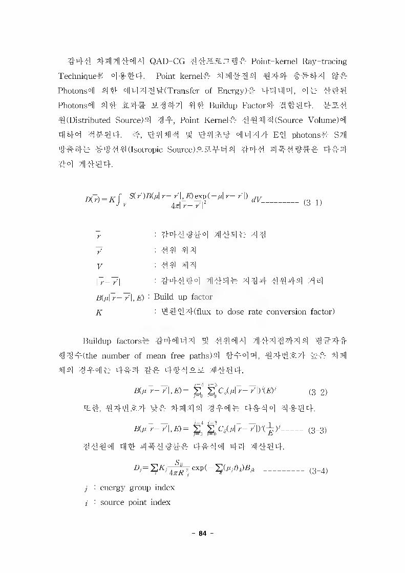
44# 44 4 #4 4 QAD-CG ####:%## Point-kernel Ray-tracing
Technique# 4 ##4. Point-kernel# 44 #4 4 444 ##44 4#
Photons°ll 4# 4 4 4 #4 (Transfer of Energy)# 4444, °1 # ##4
Photons°ll 4# SL## PL4471 4# Buildup Factor# #444. ###
4(Distributed Source)# 4#, Point Kernel# #44 4 (Source Volume)4
444 ##44. #, 444# ^ 44^4 4447} E# photons# S7H
4# 4# #4# 4 (Isotropic Source)#### 4 #4# 4##### 4#4
#4 4## 4.
= r- r# aexo(-^l r- /I)1 An\r-r'\
: 44#4#4 4 #4# 44 : #4 44 : #4 44
: 44##4 4#4# 444 ##44 44Build up factor
: 44#4(flux-to-dose rate conversion factor)
Buildup factors# 44444 4 #44 # 4444444 444#
sS4#(the number of mean free paths)# ##44, 4 44 #7} ## 4#
44 4 #4# 4#4 4# 444## 4#44.
B(fj.\ r- r\,E)= 2 4y(4 r- r\)XE)’----------(3-2))= 0 ?=u
s#, #44^7} 4# 4444 4#4# 4#4 4 ##44.
544-/1,4= 2Q §Q<4(4 r- /1/(^4--------(3-3)
4#44 4# 4##4## 4#44 44 4#44.
4= Z# 2 exp(-^(///)j5^ ---------------- (g_^)
j : energy group index
i : source point index
r
V
I r— r
5(4 r— r\,E)
K
- 84 -
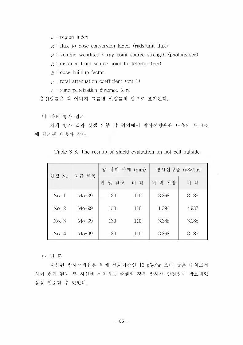
k : region index
K : flux-to-dose conversion factor (r ads/unit flux)
5 : volume-weighted v-ray point source strength (photons/sec)
r : distance from source point to detector (cm)
B : dose buildup factor
p. : total attenuation coefficient (cm-1)
t : zone penetration distance (cm)
4 o]]u|x] ZL## 44#4
4. 44 47} #4
44 47} #4 4# 44 4 4444 4444&4r 44-4 & 3-3
4 &7]4 444 44.
Table 3 3. The results of shield evaluation on hot cell outside.
44 No. 44 4#4 44 44 (mm) 44444 (|]Sv/hr)
4 ^ 44 4 4 4 ^ 44 4 4
No. 1 Mo-99 130 110 3.368 3.185
No. 2 Mo-99 150 110 1.394 4.937
No. 3 Mo-99 130 110 3.368 3.185
No. 4 Mo-99 130 110 3.368 3.185
4. 4 4444 44444 444#4 10 :JSv/hr J14 44 44
44 47} #4 ^ 44 4444 ^44 4 m 444 444 4 4^4$^
- 85 -
3. #4 4447}
#4 4447}# # 4 #4 f7}SM 7}#^ 55 44 ## #44 #4
4 #44 4#5 4# 44# 47}#4 #4 5## ##440} #4. #4
4447}# 44#44# 4^45 ##44 4 7}# 4#.
7}. 44#44 4#4# 444 #44 44 #4 4447}4 44# 44444 4 4444 4444 445. 544 44 #
455 4#4# 444##4 44 4444 4#4# 47}#4#4, 4 444 44# ### 44.
- 44#44 4444 444# ##444#44 4#- 44 471444 44 44# 3144 54# #4 44#54 4#4
- 54# #4 47]5 4#4 444444 44#4- #44 4 7] 4 44 4444 44444 44
4 4444 444# 444### 4454 4#4 #4# #4 445
4#4#5 444444# #55 #444 ^5 445 #4447}7}&#
0)44^54, #4 4447}# 4#4 445 444#453%44 444 4
^4 44#4, 47} 44# 44 GASDOS ###55^# 4#44#. ZL
431 4 4444 44#44 4#4# 4# 4444# 4444 444 # 4444 44 Tc-99m generator# 4#4# 4## 7}4" 5#4 4 4
45 7}44##4, 4 4# 444# Mo-99 (444 66 44)4 ^-4 7}^ #4 Tc-99rn (444 644)4 4## # 44. 4## 4^}445 4#4 #5 4# #4 44 4444 44 4# 44 HEPA 4444 44 444 4. 444 4455 54, 44445 44 4# 44 ##4# 4# 4# 44 # 4%44. 4# 4#4# Mo-99# 4# 4444 44 44 ##4 4 18,000 Ci455 #### 4 720 Ci44, 4 44 HEPA 4444 44 44^4 ^#455 g## 44 4## 4#4# 4# 0.22 Ci/yr44. 4 4:# #44 444444 445## #4# 444. 444 4# 4# 4 4# 4#444 444 4#4 # 4444 #7} 4#4# 4#44# 5444 44#44 #44# ##4444 4#4# 4#44# & 3-44
#44 4## #4 #444#.
- 86 -
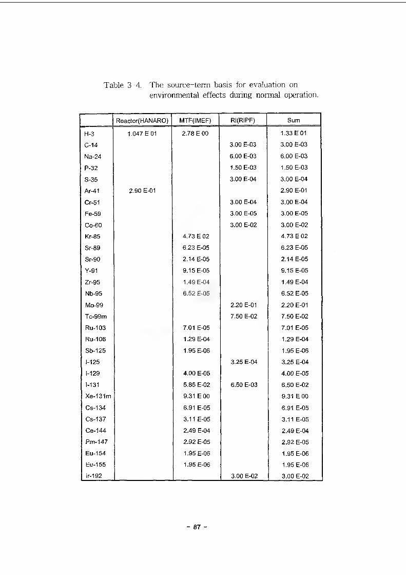
Table 3-4. The source-term basis for evaluation onenvironmental effects during normal operation.
Reactor(HANARO) MTF(IMEF) RI(RIPF) Sum
H-3 1.047 E 01 2.78 E 00 1.33 E 01
C-14 3.00 E-03 3.00 E-03
Na-24 6.00 E-03 6.00 E-03
P-32 1.50 E-03 1.50 E-03
S-35 3.00 E-04 3.00 E-04
Ar-41 2.90 E-01 2.90 E-01
Cr-51 3.00 E-04 3.00 E-04
Fe-59 3.00 E-05 3.00 E-05
Co-60 3.00 E-02 3.00 E-02
Kr-85 4.73 E 02 4.73 E 02
Sr-89 6.23 E-05 6.23 E-05
Sr-90 2.14 E-05 2.14 E-05
Y-91 9.15 E-05 9.15 E-05
Zr-95 1.49 E-04 1.49 E-04
Nb-95 6.52 E-05 6.52 E-05
Mo-99 2.20 E-01 2.20 E-01
Tc-99m 7.50 E-02 7.50 E-02
Ru-103 7.01 E-05 7.01 E-05
Ru-106 1.29 E-04 1.29 E-04
Sb-125 1.95 E-06 1.95 E-06
1-125 3.25 E-04 3.25 E-04
1-129 4.00 E-05 4.00 E-05
1-131 5.85 E-02 6.50 E-03 6.50 E-02
Xe-131m 9.31 E 00 9.31 E 00
Cs-134 6.91 E-05 6.91 E-05
Cs-137 3.11 E-05 3.11 E-05
Ce-144 2.49 E-04 2.49 E-04
Pm-147 2.92 E-05 2.92 E-05
Eu-154 1.95 E-06 1.95 E-06
Eu-155 1.95 E-06 1.95 E-06
lr-192 3.00 E-02 3.00 E-02
- 87 -
4. 43-^ 444 #4 44=47}4 444 43a] #433 4#4# 444444 44 4444 4
44# 47}444. 343. 4444 44444 4444 GASDOS 443 &3^& A}_§_s}#34, ^#4 #4# 4#4 #4-.
- A}JLA] 4^0]]^ ##444#44 4#
- A}ji^go]]4 ^1^-3 4#4# 44^444 4- A}jiA] ### 44^#4& 44 4444 44444 44
4 444 44# 44 44 44433 A} 3.7] ### 444#4& 4 4 4444 44444 4444 44#4 444444-&# o]^e}4 # 44^34, 4# 444 434 4#4# 4#444 4 4444 4#4# 4 #44# #7}44 444-^4-.
44 43^ 44 4444 444 443# #44 443 44 444
44 4#43, 3##33 14 4444 444 ##44 44 44 44# #4 44as 4#4# 4# 4 #33 414%## 44 444 HEPA 44 44 44 ##444 99.97%7} 444# #33 7}44^4. 4 4# #3
4 #### 1 batch 4## 60 Ci3 444SS34, #4334 4#4# 4 4# 1.8x10 " Ci3 444^4.
3 4# #3# #44 44 44-71 #7]^ 14 ^7] 44-47} #444 4444 #444 44 #4# 4#4 44# #4# #4 #433 4#4# 4## 444#4 HEPA 4444 44 ##444 99.97%7} 4 44# #33 7}44^4. 4 4# l batch 4## 60 Ci, 4##4 i#4# 4## 4 1# an 4 444 2^44 4=4 7_3 0134 #4334 4#4# 44# 7.3 C13 444 %4.
4. GASDOS 44333^GASDOS# 44 NEC4 4 Regulatory Guide 1.1094 44 444
CASPAR 33ZL^# #4144-4 7}# ^ 4##434# 4444 #4, 344 #33 44-44434 44#44 443 4#4# 444- #A}^ #44 444 47}4443 #4 #44 4# 4 #4 4# 4444 44 33:2 444.
GASDOS44 344# 4#43# 34 4# 67}43 4#444.
- 88 -
- 4"44#°ll 2] fir 4 ^^^(Noble Gas)- 444 4 444 44 4 44 # (Particulates)- 5L^°ll 2) ft rfl ^5) ^(Particulates, H-3)- #4#(#4, % 44# #)4 444 44 4#4#
(Particulates, C-14, H-3)- ^(4)5171, 5flxl317l, #317] #-)2] # # <4] ## 4#4#
(Particulates, C-14, H-3)- ##(##, 4=#)4 444 44 4#4#(Particulates, C-14, H-3)
GASDOS44# 44, ^#7)7]]^ 4, 44, 44, 444, 4, 4# # 87>x] 7)44 r]]#ti] 44#4(#4, ±o}, #4, 4 4), 4#4&4 7D4s]r]]2]444=4 445]4 ^-X] 80km4 # 4^#o] 4^ 444444 # 44 44 44 NEPA 444444=4 4444.
GASDOS444 44-444 FORTRAN V44 MAIN^&ZL^# 20 ;l]4 # 444 44 4444 44.
44= 444 444 44=44444 Dose Factor Library5. #4 7}4 444444 444 ### 7]4x}&^ 444 44# 44 Data File& # 4?M4 44 44# # 44 44 44.
4444=4 44# 444 4#4# 444## 4#4 444- 44.1) 4 4-4 #4# 7]]#;
444444=# ##444 ^#4 44 4#4# 44=4 444 ^#4 444 4#4# 44=_o& #444 4444.
- ##4444 44 44 4 4# 4444=444 ##4 7] 4 4"# (Uniform Semi-infinite Cloud)4 44#3-
4 44 444444=# 4#4 4°1 4444.DTa = Y>caiDTat --------------------------------------------------------------------------- (3-5)
-Dj : 4444= (mrem/yr)
Dli '■ 4444= #444 (mrern-m3/pCi-yr)
444 ##444] ^#4] 44^-&4 4# 444444= 444# 4# 4 44 47]#4.
- 89 -
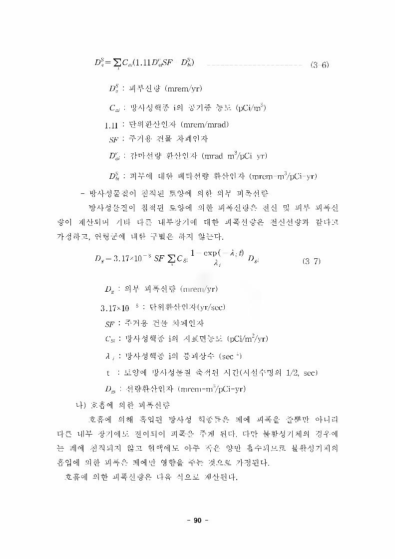
Z)!=ZCs,(l.llD:,SF+z4) (3-6)
Dsa : 4444 (mrem/yr)
: 44444 i4 444 4^ (pC^m3)
1.11 : 444444 (mrenVmrad)
SF : #44 4# 4444
Drai : 4444 4444 (mrad-m3/pCi-yr)
Dsbi : 444 44 4444 4444 (mrem-m3/pCi-yr)
- 444444 444 S44 44 44 4444
444444 444 S44 44 4444=4 44 # 44 444
4=4 4444 44- 4# 44444 44 4#44=4 4444=4 443i
7/4431, 44^4 44 4#4 44 ^=#4.
D, = 3.17* 10 -8 SF S Cs, 1 ~ 6X^ ~A‘t) D„ ------------- ,3-7)
Dg : 44 4444= (mrem/yr)
3.17x10_3 : 444447}(yr/sec)
SF : #44 4# 4-444-
CSi : 444 44 i4 4i£4#£ (pCi/m2/yr)
2, : 444^4 i4 444# (sec4
t : S44 4-44 #4 #44 4 4(4 4#^ 4 1/2, sec)
Dgi : 44=4444 (mrem -m3/pCi - yr)
4) 44 4444=
44) &44 4-44 ^##4 44 4## ##4 444
44 44 444£ 4444 444 44 44. 44 444 4 44 444
4 4H1 4444 431 144^ 44 44 44 444ss ##4 4 44
444 44 4## 444 44# 44 7/444.
^&4 44 44444 4# 4_o& 4444.
- 90 -
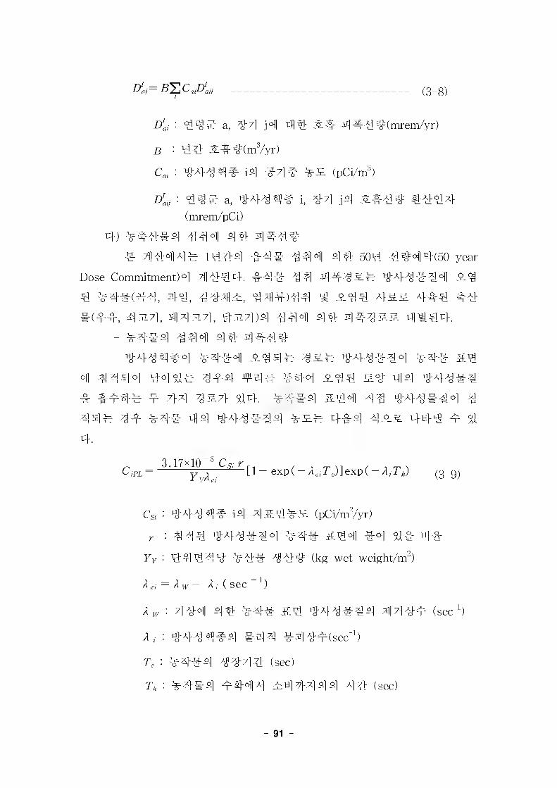
(3-8)Dlaj — 52 Ca0aij
E?ai '■ 44# a, #7) jofl rl)4 4#4#(mrem/yr)
B : 44 #T!r#(m3/yr)
: #44^9# i4 #4# ## (pC^m3)
Diy : 4## a, #44^9# i, #7) j4 3L&4# #444 (mrem/pCi)
4) ##4#4 444 44 44444 44444 1444 #4# 444 44 504 4444(50 year
Dose Commitment)°1 4444. 44# 44 4445-4 444#44 #4 4 #4#(#4, #4, 4#4^, 4 44)44 ^ #44 4&# 444 4# #(44, 4317], 443171, 43171)4 444 44 4#4&& 4444.
- #4#4 444 4# 444##44444 ###4 #44# ### #44#44 ### &4
4 4444 #44# 444 f4# #44 #44 ## 44 #44#4 # &### # 7M ^^7} 44. ###4 &44 44 #44#44 4 44# 44 #4# 44 #44#44 ### 444 4## 444 m 44.
CjPL ~3.17x10"*
yuMe,[1- exp(- A^/TjlexpC- A/T,,) (3-9)
CSi : #444# i4 4it### (pCi/m2/yr)^ : 444 #44#44 #4# &44 #4 4# 4#
Yv : 4444# #4# 44# (kg wet weight/m2)
A ei = A w + A ,• ( sec 1)
A^ : 4#4 ^14 #4# &4 #44#44 44#m (sec#
A, : #444#4 #5)4 #4#m(sec4
T, : #4#4 4#4# (sec)
T„ : #4#4 m#44 #44444 44 (sec)
- 91
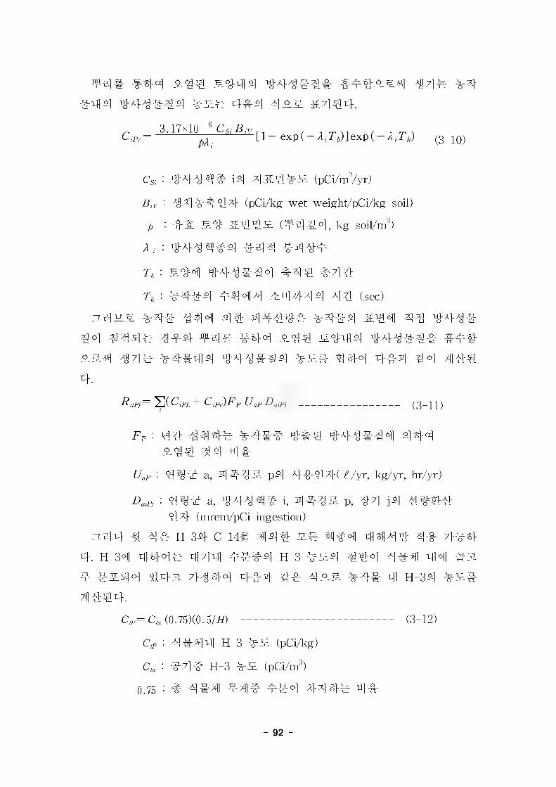
f4# #44 ^.44 S#44 ^4# ^4-#44 ### 4-#4 4^-# &7]^4.
C jPr —3.17x10-» C„ B,
[1 exp(- 2, T&)] exp(- 2, T,,)__ (g-iQ)
CSi : 444 4# i# 4 iL4#£ (pCi/m2/yr)
BtV : #4 ##44 (pCi/kg wet weight/pCi/kg soil)
2 : 4% S# &44# (f 444, kg soil/m")
2, : #433^4 #44 #4##
T, : S#4 #4###4 #44 #4#
r„ : #4# 4 #444 #4444 44 (sec)
:%4#-# 44# 444 4# 4444# #4# 4 &44 44 444#
44 444# 444 44# #44 #44 #444 444### ###
##4 44# #4#44 444#44 ### 444 4#4 44 4#4
4.Rapj= 2(CjPL + ClP))Fp Uop DaiPj ----------------------------- (3-11)
74 : 44 444# #4## 4#4 444#44 444 #44 44 4#
UaP : 44# a, 444# p4 4#44( iVyr, kg/yr, hr/yr)
: 44# a, #444# i, 4#4# p, 44 j4 44##44 (mrem/pCi ingestion)
ZL44 4 4# H-34 C-14# 444 ## 4#4 4444 4# 7}#4
4. H-34 444# 444 ###4 H-3 ##4 #44 4#4 44 #31
4 ##44 44-3% 7M44 4#4 4# 4## #4# 4 H-34 ###
4444.
(#=(#,(0.75X0.5/#) -------------------------------------------- (3-12)
CtP : 4 #4 4 H-3 #53 (pCi/kg)
Cta : #7]# H-3 ## (pCi/m3)
0.75 - # 4#4 #4# ##4 44 4# 4#
- 92 -
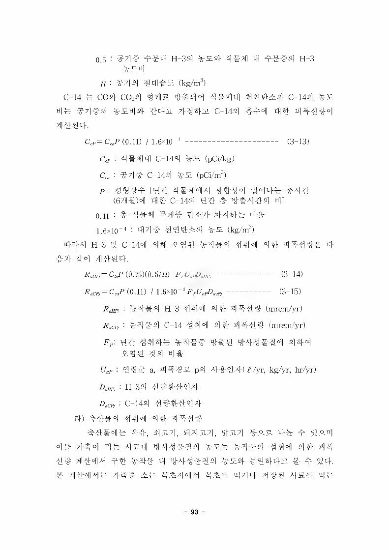
o
0.5 : #4# H-34 #^4 4 #4 4 m##4 H-3
#44 #4## (kg/m3)C-14 # C04 COo4 ^4# 4#44 4444 444#4 C-144
4# #444 #^44 4431 7} 443. C-144 #44 4% 44444
4444.
C,f=C^f (0.11) / 1.6x10'"--------------------------------------- (3-13)
<#p : 4#4N C-144 (pCi/kg)
Cca : #7l# C-144 #5: (pCi/m3)
p : ^^4# [44 444144 4444 #44# #44 (641)4 44 C-144 4# # 4#444 4]
o.n - # 4#4 #4# 4^7> 44 4# ti]-#1.6x10“4 : 4171# 4444:4 ## (kg/m3)
444 H-3 4 C-144 441 -S-44 #4#4 444 44 4444# 4#4 44 41444.
^=C^f (0.75X0.5/^) ---------------------- (3-14)
(0.11) / 1.6x10-" FpC/apD^----------------- (3-15)
RclHPj : #444 H-3 444 44 4#44 (mrem/yr)
Racpj : #444 C-14 444 44 4#44 (mrem/yr)
Ff: 44 4444 44## 4#4 444444 444 44# 44 4#
UaP : 44# a, 4#4S- p4 4-o-4xH //yr, kg/yr, hr/yr)
: H-34 444444
: C-144 #44444
4) #444 444 44 4#44
#4#4 4 m-fr, 4^171, 443171, 4-314 4# 4 4#4
4# 7>^oi rtiy A}£1]] TOtio] #53# #4#4 444 44 4#
4# 4444 #4 #4# 4 444#44 ##4- #444-31 # 4 44-. 4 4444# 7}## 4^44# 4^4 4714 444 4## 4#
- 93 -
#31 7>4431 4# #4# 4 31 4"4431 ?M€4-###4 #4# #4 4## 4# ### 44 44#^9#4 #^4 4
4 4#4 44 44 444 4 44.RaiPj= C{p UapDaiPj (3-16)
RaiPj : ###4 #44 44 4444 (mrem/yr)
: #4# 4 444^44 (pcy^, pCi/kg)4 (5-16)44 4:27], #444 444 #44 #^(pCi/^, pCi/kg)#
444 44 444 4 44.CjP= F;pQp[ C8ipfpfp+ Cfp(/p(l — fp) + (1 —/p))exp(l — A/Ts)]
x exp( - A iTh) -------------------------------------------------------------------- (3-17)
: 44^ ^#4 4&##4 ####4 44 44 (day/kg,day/^)
Op : 44 #4 4 (kg/day)
C&, : #^(4&)4 44#^# (pCi/kg)
fP : 444 ##444 # #44 44#
^ : ## #444 7}44 #^44 4# 4 #44# 4#
:: 44 7} &4 44# 444 (pCi/kg)
A/ : 44# 39 44 #4# #44#
Ts : 444# H4 44 (sec)
Th : #44 # ^4444 44 (sec)44317], 431714 4444 444 4# ### #3i 44431 7}444
4 4 314, 4314 4 #4#4#4 #^(pCi/kg)# 4#4 #4 44 &4# 4 44.
Cip= FipQpC/prexp( — A;Ts) exp(1 — A,-T/,) (3-18)
###4 H-3, C-144 ##4 #4 4##44 #4# 4 #44 44 4
##4 4#4# #44 #4# 4 H-3, C-144 44#^4 #^# #44 4 4444, 44##4# 31444 4#4. s# 7}#4s^ #4 H-3,
- 94 -
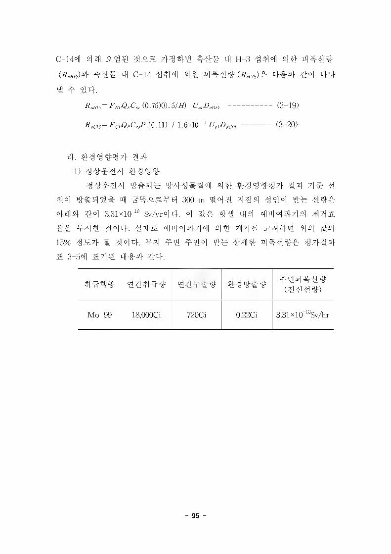
C-144 44) 7}# 44 44# 4 H-3 444 44 4444(#W4 #4# 4 C-14 444 44 4444 (^,)4 4#4 4^] L}Ej-4 f 44.
RaHPj= FHPQpCta (0.75X0. 5/H) UapDaHPj (3-19)
^m=^cp0fC^(O.ll) / 1.6x10-" C/^cf,------------ (3-20)
4. 44 4447} #4
1) 44444 44 44
44444 4#4# 444#44 44 44 4447} #4- 7]e 4 44 4#### 4 300 m #44 444 444 4# 44#
444- 4:4 3.31x10"^ Sv/yr44. 4 4:# 4# 44 444444 44% ## 444 444. 44% 44 4444 44 44# 31444 44 ^4 15% 4%7} # 444. #4 44 444 4:4 444 4444# 47}#4 & 3-54 &44 444 44.
44^4 44444 44##4 444#4 444444(4444)
Mo-99 18,000Ci 720Ci 0.22C1 3.31x10 "^Sv/hr
- 95 -
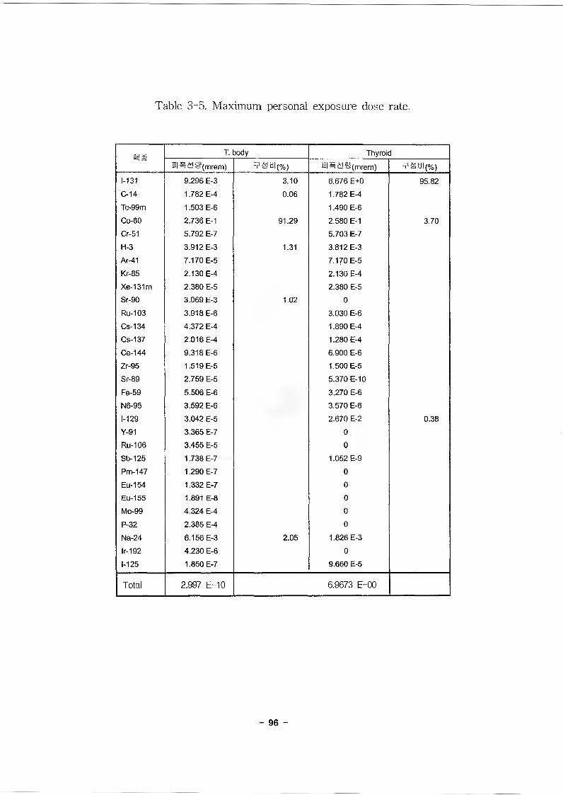
Table 3-5. Maximum personal exposure dose rate.
SHS T. body Thyroidul^<y&t(mrem) =?8ti|(o/o) ii|#^jg(mrem) T£d!(%)
1-131 9.296 E-3 3.10 6.676 E+0 95.82C-14 1.782 E-4 0.06 1.782 E-4Tc-99m 1.503 E-6 1.490 E-6Co-60 2.736 E-1 91.29 2.580 E-1 3.70Cr-51 5.792 E-7 5.703 E-7H-3 3.912 E-3 1.31 3.812 E-3Ar-41 7.170 E-5 7.170 E-5Kr-85 2.130 E-4 2.130 E-4Xe-131m 2.380 E-5 2.380 E-5Sr-90 3.069 E-3 1.02 0Ru-103 3.918 E-6 3.030 E-6Cs-134 4.372 E-4 1.890 E-4Cs-137 2.016 E-4 1.280 E-4Ce-144 9.318 E-6 6.900 E-6Zr-95 1.519 E-5 1.500 E-5Sr-89 2.759 E-5 5.370 E-10
Fe-59 5.506 E-6 3,270 E-6N6-95 3.592 E-6 3.570 E-61-129 3.042 E-5 2.670 E-2 0.38
Y-91 3.365 E-7 0Ru-106 3.455 E-5 0Sb-125 1.738 E-7 1.052 E-9Pm-147 1.290 E-7 0Eu-154 1.332 E-7 0
Eu-155 1.891 E-8 0
Mo-99 4.324 E-4 0P-32 2.385 E-4 0
Na-24 6.156 E-3 2.05 1.826 E-3lr-192 4.230 E-6 0
1-125 1.850 E-7 9.660 E-5
Total 2.997 E-10 6.9673 E-00
- 96 -
2) 43.A]
43# ##4# #4^1 44 43 4 ##7} #4 #4 #4 #44 4# 44444 444 44.
43 ## 4#4# ### 434## #44#4#(444#)
#3##43 Mo-99 300Ci 1.08x10 "^Ci 1.68x10 "^Sv/hr
444443 Mo-99 43.8C1 43.8C1 6.72x10 "^Sv/hr
4. 4 4
43 3##7} #4 44444 44 4# 4#4#4 3.31xio^Sv/hr
334 44 44 444 2000444 3## 3# 6.61 10"^ mSv/yr34 4
47]#4 0.05 mSv/yr# #4 4444 #43 44#34, 434 444#
44443 10CFR Part 10044 4444 244 7]e 4444 250 mSv#
7144 4 444 4434 4 444 7}#33 44 44 44 4 44 4 44 444# 444 4 444.
3] 3 ^ KINS ^1^7}
1. 447} 44
20024 14 294(44 71231-92)4 '443 #443 4444 344 444 44.44 4447} 43' M#44 : 4#4 721-197(2002. 1. 12)]3
3 447} 44# 4#444.4# 44 #44344444 443 44443 44 ^ #447}# #
4^333 # 444 #7}3 44 447}3 443 ^ #444 44.#3 4447}3 444447] 4344.
4 #4 4 ## 4#4 #4.
- 97 -
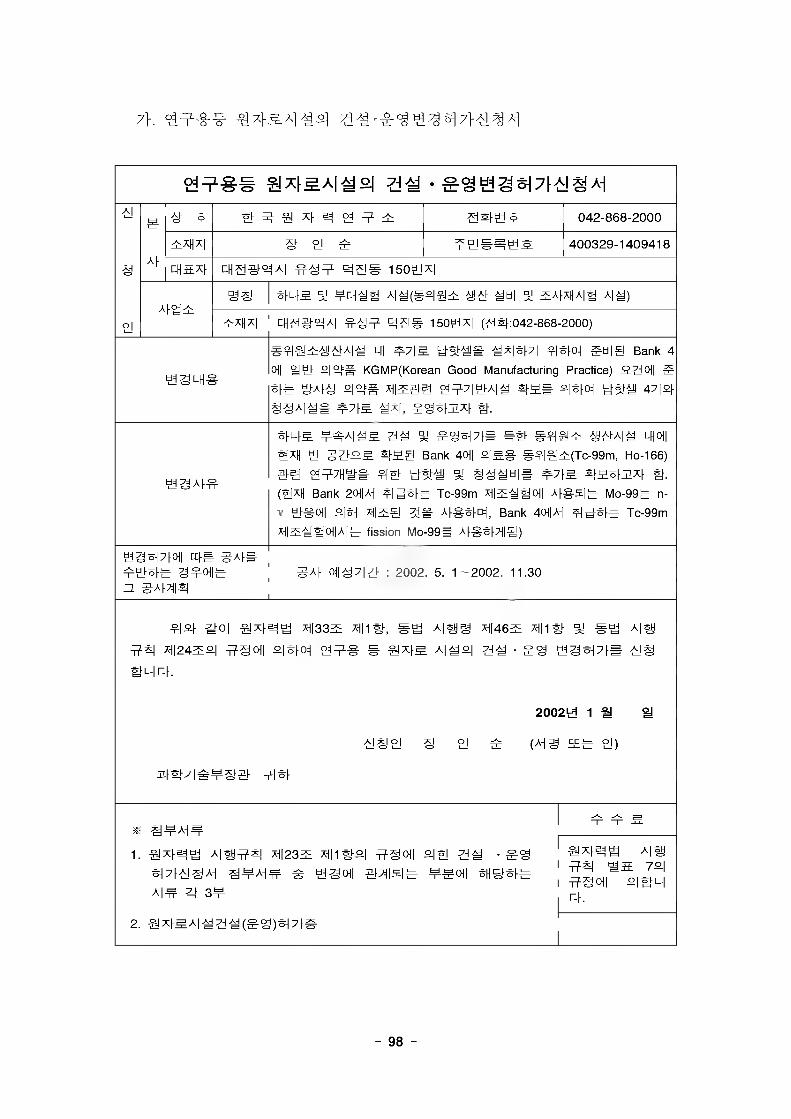
9¥ 9 A s ^ a 4 5-i oj ? i 999 m 042-868-2000
Af¥x||x| S PJ ¥ 400329-1409418
9 CHS.X) cH 999^1 ¥9¥ 99S I50tix|
Af'gBSS tms a! ¥^H^a A|y(#f|@x. ahaf yti| 5; 5A)xHa|1 a|^)
PJ ¥xnx| ^agaxi #9¥ as# 150tix| (99:042-868-2000)
Ojf## S*^A|^o| 71M .°gbjg5^[A|§Ai
ygLH^
y$tti# M*m?\ 5H|@ Bank 4
oil Uti" P| a# KGMP(Korean Good Manufacturing Practice) 52>! oil g ¥¥ o|or= xiB^Ei 04^7|HtA|^ Stye yStti 47 |P)§§A|y# ^A|, #°BBX) #.
5Wi tA|1 % ¥2B)7)# SB ^^A|^ LHOfl
ti§AM
@XH HI §7ioS Styg Bank 40i| °|¥S #^|#¥(Tc-99m, Ho-166)
¥9 ^is- y$t-s a! ss^uie ¥7)s a.(SxH Bank 20i|A) Tc-99m xiB=Soi| AfgEB Mo-99¥ n-
V Hfsoil °|SH X)B@ Afg^B, Bank 40i|A) Tc-99m
xlBeS°f|A)^ fission Mo-99# Afg^BI#)
@35)7)011 #Afithj% g¥<*i¥ZL #A)7j|sl
}A[ 0f|g7|y : 2002. 5. 1-2002. 11.30
¥¥ x)|24^°| flgofl °B)o^ off@ # x|y°| y-y#¥ c).
A|AH ?l xr PI
-g yge-i7» 99
2002 td 1 a a
(A)S EE¥ pl)
aa7ia¥99 9 a
* 9¥A)¥1. SxfB^w A|y^y X1I235 xin#o| ifgofl °|& • ¥S
¥7B§A-j 9¥a)¥ # ygcMI 971l¥¥ ¥¥<MI SH&sfe a)¥ zt 3¥
2. SA)SA|yyy(SS)e-i7)5
SxfB^w A|y ¥9 Ws 7°| flSofl ¥&¥ ¥.
- 98 -
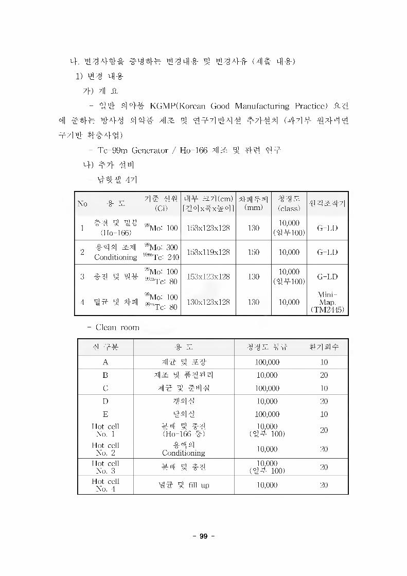
4. #344# #34# #34# 3 #34# (4# 4#)l) #3 4#
7}) ;]] #
- 3# 4 44 KGMP(Korean Good Manufacturing Practice) it44 #44 #43 4 4# 4^ 3 #44444 #7}34 (444 #7}# 3 44# 4#4#)
- Tc-99m Generator / Ho-166 413: 4 ## ##
4) #7} 44
- 343 44
No # 3 4# 33 (Ci)
4m 3.7](cm)[34 x#x# 41
44 m3(mm)
33^(class) 34^34
1 #3 3 3# (Ho-166)
^Mo: 100 153x123x128 13010,000
(3#100)G-LD
2 #44 34Conditioning
^Mo: 300 99mrpc: 240 153x119x128 150 10,000 G-LD
3 #3 3 3#^Mo: 100s^Tc: gQ 153x123x128 130 10,000
(34300)G-LD
4 33 4 44^Mo: 100 ^Tc: 80 130x123x128 130 10,000
Mini-Map.
(TM2445)
- Clean room
3 #3 # 3 33^ #3 344#
A 100,000 10
B 43 3 #334 10,000 20
C 43 3 #43 100,000 10
D 7343 10,000 20
E 343 100,000 10Hot cell
No. 1#3 3 #3 (Ho-166 #)
10,000 (3# 100) 20
Hot cellNo. 2
#44Conditioning 10,000 20
Hot cellNo. 3 #3 3 #3 10,000
(3# 100) 20
Hot cellNo. 4 33 3 fill up 10,000 20
- 99 -
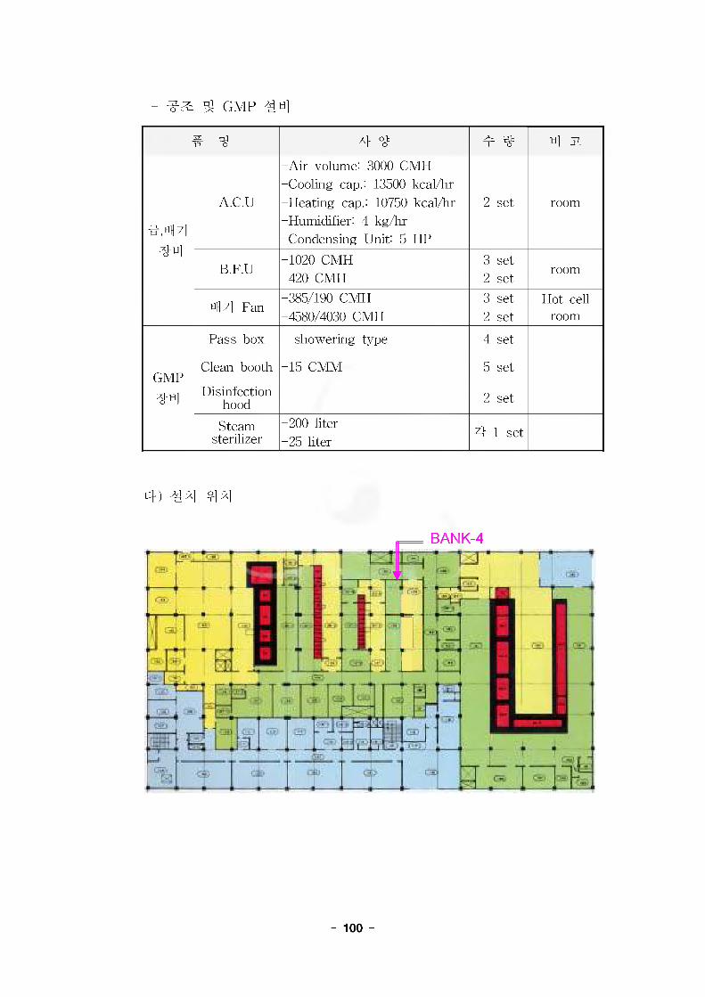
- ^ ^ GMP 44
# 4 4 4 4 4 til JL
id" 7l44
A.C.U
-Air volume: 3000 CMFi -Cooling cap.: 13500 kcal/hr -Heating cap.: 10750 kcal/hr -Humidifier: 4 kg/hr -Condensing Unit: 5 HP
2 set room
B.F.U-1020 CMH-420 CMH
3 set2 set
room
till 7l Fan-385/190 CMH -4580/4030 CMH
3 set2 set
Hot cellroom
GMP
44
Pass box showering type 4 set
Clean booth -15 CMM 5 set
Disinfectionhood 2 set
Steamsterilizer
-200 liter-25 liter
4 1 set
4) 44 44
- 100 -
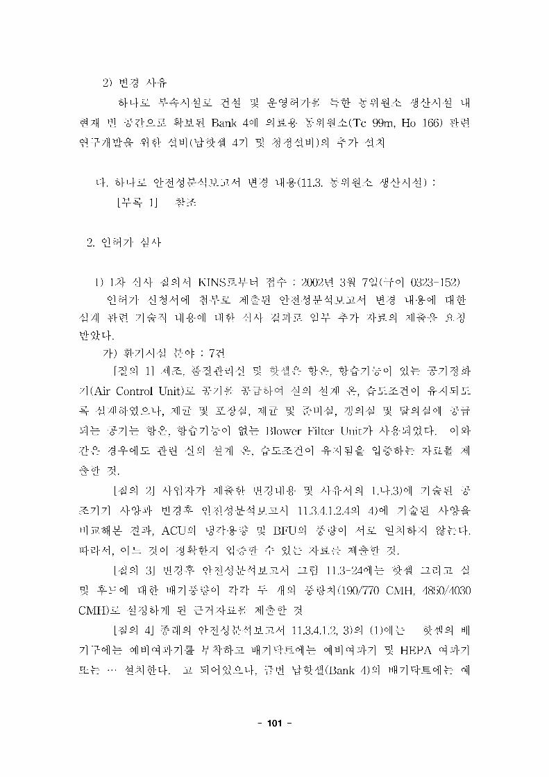
2) 444-44& ####& ## # #447}# 44 #4#^ ##4# 4
#4 # ###& #5-4 Bank 44 4&# #4#^(Tc-99m, Ho-166) ##
444## #4 #4(### 47] ^ ###4)4 47} 4#
4. 44& #####5_5i4 ## 4#(11.3. 44#4 ####) :
[44 l] #&
2. 447} 44
1) 14 44 #44 KINS&44 4# : 20024 3# 7#(#4 0323-152)
447} 4444 44& 4#4 #####5-5i4 #4 444 44
44 44 4## 440]] 44 44 #4& 44 #7} #&4 4## _&#
#44.7}) #444 #4= : yg
[#4 1] 4^, #4444 4 44# 4#, ##7]#o] ## #7]##7] (Air Control Unit)5. #7]# -o"444 44 44 #, #£2:4°] 44 4 5.
# 444^#4, 4# # #44, 4# # #44, ^g## ^ #444 ##
4# #7]4 ##, 4#7]4°] §14 Blower Filter Unit7} 444 44. 44
## ##4^ 44 44 4?]] #, #^^#4 #4## 4444 4&# 4
## 4.[#4 2] 7}^4?} 4]## ##4# # 4444 l.#.3)4 4## ^
^7] 7] A}8}3} #####5-5l4 11.3.4.1.2.44 4)4 7]## ###
4574]# #4, ACU4 ####= # BFU4 ##4 4& 4444 ^#4-. 444, 44 #4 4444 4## # 4^ 7}&# 4## #.
[#4 3] #44 444445.514 3.# 11.3-244# 44 ns]51 #
4 #^4 44 4 7] #44 ## # ;]]4 #44(190/770 CMH, 4850/4030
CMH)& ##44 # #7]7}&# 4## #
[#4 4] #44 444445-514 11.3.4.1.2, 3)4 (1)44 444 471444 44 44-7]# #4-451 47l4n44 44 44-7] 4 hepa 44-7]
s# -- ####. 51 44 #5.#, #-# ###(Bank 4)4 47]#m4^ 4
- 101
4444 #4 HEPA 447] 4# 444 4## 44# 4.
[44 5] #43 44434334 11.3.4.1.2.4, 2)4 (2)43 433#
44 443447} 4444-3. 4 #4 4 4#. 444, 44-3447} 34
433 4# 4#4 33434# ## 4.
[44 6] #44- 44434334 11.3.4.1.2.44 2) 4 3)4 4^4 (2) - #4#4#44 44 ^44# 4444-. 3 4-0-# ##43 ##
44 4# 44#4#44 4444- 4##4 444# 4444-3 #33 4-0-# 4#44 4^# 4.
[44 7] #4# 44434334 11.3.4.1.2.4, 3)4 (2) - #44#
7)7} 44-4 HEPA 44-7] •■■ # •■■ #7] 44-7] 4 44-4 HEPA 44-7]
- & #44 3##
4) 4444-3 4 47]4 4444 : 64
[44 l] #443444# 44-44 4443 4 37} 44 #^}44
# 44 4^-4 7]^# 4
[44 2] 44 44444 44 V 444 4# 4 44444 444
4# 44 44-# 44# 4
[44 3] Ho-1664 444 4 44 444# 44#3, # #44 4
444# 44 Ho-1664 44444 344434 4^-4 4^# 4
[44 4] ##43-44 4444# #3 4 4 #44 #44 ^ 34
344444 44 444# #3 44# 44# 4
[44 5] #44 44## #-0-4-4 44 4344 ##43 4# 4
4 #444# ##3 4# #4 # 43##4 443 4## 44 # 7}
4# 3##4 3 #7}### 4## #
[44 6] #443 444444 #44 #4#4 #4444# ^ 4 #4 4444#34#44 #4444 #44 444444 444# 44 3# 43##4 444 4## 4
#) #4#4 3# : 14[44 1] 443 4444 #444 4444(4) 44# 4
4-) #3444 34 : 34
[44 1] 4 ## # 44444 4443 #443 494444 44
##, 44## 4 #4### 4444#
- 102 -
[#4 2] v #4 Support #44 44, %#4 #4 4 4144-##
#4 #3, #3#4 44# 44= 47}44(#3#44 #7} # 4447} 4 4)# 4#44 #.
[44 3] 7]# #3#4 ^3 44444(Document No. KM-221-DC
-H003 # H006)# 4 #44 3.
2) 1# 44 444 44 444 4#: 2002# 3# 30#(4#7] 721-875)
44 #44 4-0-4 44 ^4=# KINS ##7}# #4 # ##
4 # #7} 4&# 4444 4 #4# 4. [4# 2] #33) 24 44 #44 KINS3#4 44: 20024 7# 44(4# 0323-147)
14 44 #44 44 444 4# # #7} 44 4-0- 44 7}) 44 4 4 4:4= : 64
[44 1] 7]#4 44444 4# # ###, 4# # #44, 444# #444 44 #4# ##4-## #44### 4### 7}& s# 4 4 4 44 44 #,#33# 4 #44# 4### 444 #S7}& 44
[44 2] #4# ##4#4#344 ## zz.43 ##4 #4# ## #3 4 44 4 4 #4=4 ##44, ###&(& 1, 2 # 3)4- 4850/4030
CMH4 44 4 4 #4 #4 3## #4 3#7}&[44 3] # #44 47]#eo^i 44447]# #4## #33 ##
##7} ### ##4#4#34 4#(#) 414[#4 4] ### ##4#4#34 11.3.4.1.2.4, 2)4 (2)44 # #, #
#4 #4-33# ##344# #4- ##44 ## 334# ##4 4#
4 #3# #4 44[#4 5] ### ##4#4334 11.3.4.1.2.44 2) # 3)4- ##44
44## #444# 4# 4# ## ## 444 ###47} 44# #4
4# 44 44
[#4 6] #4# ##4#4#34 11.3.4.1.2.4, 3)4 ##### "... #
444-44 44-# HEPA 44-4 ..."3 #4# ##4#4334 44(#)
44
4) #444-3 # 414# #4 ## : 1#
[44 l] ##43-44 44 # #4444 4# #7]34#-44, 7]
447]# 4-## #4 #4 44=47} 4-0-4 4447]# 44444 4#
- 103 -
#44## M# ####4^3x4 4### 4444#.4) 24- 44 #44 44 444 4#: 20024 114 21#(4#4 721
-3157)
44 444 ## 4#4 441 ### KINS 44-44 #4 # ##
4 4 #7} 4&# 4444 4#444. 44 4444 #444 44 4- & 4# 4 44, 44 44 ## ## ### 4-# 444^4.
[## 3]
5) 24 44 444 4# 444 4# # #444 #4 KINS 4444 ##4 4# f7} 444 4# : 20024 12# 13#(##4 721 -3367)
- #44# #4 : 44 [44 4] #2:
6) #44# #4 KINS 4444 4& ## ##4 44 f4 444 4# : 20034 01# 234(4^ 4# SM 4#)
- #44# #4 : 447) ^7} 4A} #^4 KINS&44 ##: 20034 3# 44(4# 0323-161)
- #44# #4 : 24[44 l] 4^ 4 ###, 4^ # #4#, 44# # #4#4 ##7]
# ##4 #4 #,#^^## 4### 4### 444-&# 4#44#-[#4 2] 4- #44 ###4# 4# ### #### 3x#4# 4#
444-. 444, 4# 4# ###4 31444 44^ #44 44# 44 A] 2-
8) #7} 4A} #^4 44 44 7}& 4#: 2003# 3# 14#(4#4 721
-761)
#44# #4 244 4# 4# 4&# 4# 4####4 #4 #47> #&4$^4. [## 5]
- 104 -
[% JL & 4]
1. KGMP 444, 3444 m (1998).
2. WHO GMP, 'Guide to good manufacturing practices for phamaceutical
products', (1992).
3. FDA GMP Part 210/211-Current good manufacturing practice
4. 443 4 4444# 444^ 7])# (KAERI-RR-1320/94)
5. TRS 36th Report, WHO Expert Committee on Specifications for
Pharmaceutical Preparations, 14. JUL. (1999).
6. Rules and Guidance for phamaceutical Manufacturers (1993).
7. V.P. Grochev, D.I.Magrath, 'GMP for biological products', WHO
meeting, (1999).
8. W. S. Yoon, "Medical Isotope Market Study (2001-2020), NE-70, U.S. DOE,
(6/2000)
9. 443 44444334(114 34 #443 4444) (KAERI/TR-
710/96)
10. 443 4 Fission Mo-99 444#7lj4 4 #334 (KAERI-RR-2008
/99)
11. 4 34W4444 4#334, 4444444(#)
(2001/9).
- 105 -

¥•■>!- 1.
-S^! ifl-g-
(11.3.
#4^ ifi-8-
(11.3.
2002. 01.
£l <?1;?^£-^JluL^ $3^-8-
1-1
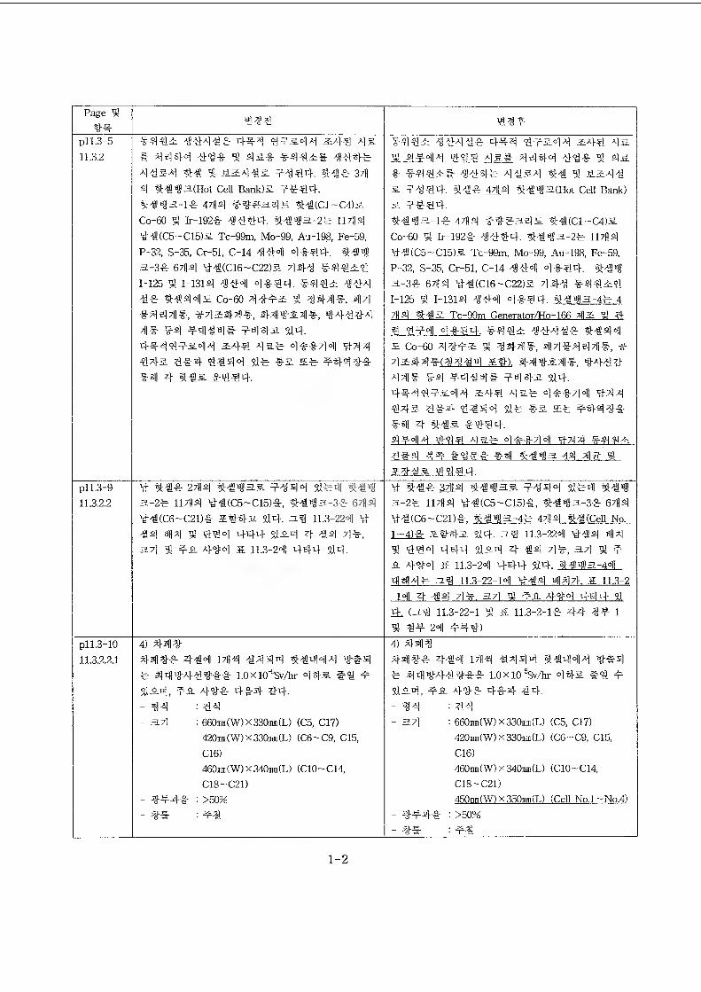
Page 3a-s-
pl 1.3-5 *4*2 ******3*
4i^li429*' 2:4^ 4 a11.3.2 * 4*44 *9* 4a* *4*2# **4*
**2* 3* % 22**2 f**4. 44* 371
4 4€43.(Hot Cell Bank)a 4444.3*3a-l* 4/H4 ##ea.sjE 3*(ci-C4)2
99**4*2 4444* 444 9224* 24* 4a 3 44414 994 4a# 4444 43* 3 4a
* #4*2# 9*4* 44a4 44 9{ 22**
a 2*94. 44* M4 3#93(Hot Cell Bank) a 2294.
Co-60 4 Ir-192* 4444. 4443-24 1M4
9*(C5-C15)2 Tc-99m, Mo-99, Au-198, Fe-59,
P-% S-35, Cr-51, C-14 444 4*44. 4449 3-3* 6714 9*(C16-C22)a 444 *9929
1-125 4 1-1314 444 4*44. *9*2 444
4* 4444a Co-60 *922 4 444*. 44
*444*, *7124^14-, 4492*9, #4444 4* *4 *444* *443 544.
4**9224* 244 4a* 4**44 444 44-a 91-4 9444 9* *a a* *44**
*4 4 44a *994.
44*3-1* 4714 ft€3e)E 9*(C1~C4)2
Co-60 Ir-192* *444. 44*3-2* 117149*(C5-C15)2 Tc-99m, Mo-99, Au-198, Fe-59, P-32, S-35, Cr-51, C-14 *44 4*44. 4** 3-3* 6714 9*(C16-C22)2 44* *4429
1-125 5 1-1319 *44 4*44. 4**3-4* 4 719 9-@2 Tc~99m Generator/Ho-166 42 9) 4
9 4?4 4*44. *492 *4*4* 3:444
a Co-60 *9*2 3 *44*. 44**44*, * *244#(9**4 24). 44*24*, 94*9
*4* *9 *444* 2443 94. 44*9224* 249 4 a* 4**44 944
442 9*4 4944 9* *2 a* *449**4 4 3*a *994.4*44 499 4a* 4**44 944 *442
9*4 44 *9*29*2 9994.
pi 1.3-9 11.3.2.2
t-i- * 2714 3**32 2*44 9*4 3*9 3-2* 11714 9*(C5-C15)4, 3*93-3* 6714
9*(C6-C2D* 2943 94. 3% 11.3-224 9
*4 44 3 949 444 924 4 *4 4*, 37] §2 fa 494 a 11.3-24 444 94.
9 3**323.4 3**3& *944 9*4 3*9 3-2* 11714 9*(C5-C15)*, 3*93-3* 6714 9*(C6-C21)*, 3*43-4* 4714 3*(Cell No.1-4)* 2943 94. 39 11.3-224 9*4 44 ^ 499 444 924 4 *4 4*, 37] 4 f
a A}94 2 11.3-24 444 94. 3*43-44 444* 39 11.3-22-14 4*4 447k a 11.3-2
-14 4 *4 4*. 37] 4 fa 494 444 94, (39 11.3-22-1 4 a 11.3-2-1* 2)4 1
% 3-9- 24 4=49)
pll.3-10
11.3.2.2.1
4) 4-49449* 4*4 1714 *444 3*444 9*4 * 4494*9** l.OxiO^Sv/k- 44-2 #9 f
924, *a 4#* 4*4 94.
-34 : *4- 37] : 660m(W)x330m(L) (C5, C17)
420mm(W)x330m(L) (C6-C9, CIS,
C16)460m(W)x340mm(L) (C10-C14, C18-C21)
- 944# = >50%_ m-m. ■
4) 449449* 4*4 1714 *444 3*44* 9*4 * 4494*9** 1.0xio^Sv/hr 442 *9 2
924, *a 49* 4*4 94.
-94 = 9*- 37] : 660m(W)x330mm(L) (C5, C17)
420mm(W)x330mi(L) (C6-C9, CIS,
C16)460m(W)x340mm(L) (C10-C14, C18-C21)450mm (W) x 350mm (L) (Cell No.l — No.4)
- 944* : >50%-
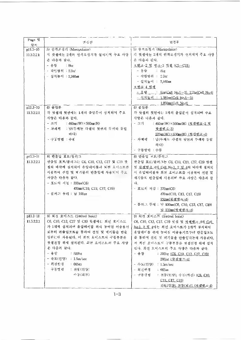
Page 443*
pi 1.3-10 11.3.2,2.1
5) $4 2: *7] (Manipulator)4 %-@4* 2;{4 4.4^447} *444 4* 4"** 4*4 44.- *4 : 8kg- : 2.3m'- *4*4 : 2,160mm
5) (Manipulator)4 %*4|* 27H4 44&37l7y *444 45 44 * 4*4 44.o4a-2 4 4a-3 4* (C5-C21)- *4 : 8kg- 4444 : 2.3m'- -84*4 : 2,160m
O ns 3.-4 4*- *4 : 5kg(CelI No.l-3). 2.2k*(Cell No.4)- *4*4 : L981rai(Ce.U No.l ~3)
1.950mm(Cdl No.4)pll.3-10113.2.2.1
6)4 #-@4 ^44* 17^4 *"9*4 4444 4* 44-° 4-0-4 44.- 371 : 460sni(W) x560mm(H)- 444 : tf^M!* 444 444 444 ¥il
44)- 4*^^ : 4*
6) #944 %*4 ^44* i;H4 *4*4 *444 45 44* 4*4 *4.- 3.7} ■ 460mm (W)x560b»(H) (»4$43-2 5
44142-3)570mm(W)x650mm(H) (4442-4)
- *44 : #(44* 4*4 444 4944)
- ***3 = 4*pi 1.3-1111.3*2.1
8) 4*4 £S./*4n4#4 ie/i«|3fe C6, CIO, Cl3, C17 $ C19 4 *4 444 *444 *4*14*4 44 544*44 ## 44#-4 ^*<94 4*44 4544* 4*4 *4.- £5.2} 4^ : 370mm(C6)
470mm(C10, CIS, C17, C19)- *B)3i 44) : y- IOOjjbi
8) 4*% SS/fsl3##9 C6, CIO, C13, C17, C19 %*g %*4a-44 CeU No.l. 2 $ 44 444 *444 *444*4 44 4*44 44 $n 71*4 4*44 4*44 45 44* 4*4 *4.- amaj a|;g : 370mm(C6)
470m(C10, C13, C17, C19)150mni (4 -# Bl 3 -4)
- #43 44 : 4 100mm(C6, CIO, C13, C17, C19)4 110mm (4-S'3)! 3-4)
pll.3-1111.3.2.2.1
9) 44 54—5 (Swivel hoist)C6, CIO, C13, C17 $ C19 444* 44 54^=57|- 17M 4444 *#44# 44 »44 4**4 544 4*4IS| #4^ 4 44#* 4*44*4 4*44. 4 44 54^54 **44 44 *444. 44 £4^54 tA 44 * 4*4- #4.- ** : 500kg- *5(4#) : L5m/sec- * 444 : 665mm- 44MM : ^*(44)
**(44)
9) 44 .5:4—5- (Swivel hoist)C6. CIO. C13. C17. C19 *4 9) SHMa-44 Cell No.l. 2 9 44* 4 4 242S.7)- 444»l*444* 44 ¥44 4**4544 4*955 * *44 *4 2 44** si*■94*1-11 4*€4.4 54^54 4*4#* 44 *444. 44 54^59 44 4#* 4*4 *4.- ** : 500kg (C6. CIO. C13. C17. C19)
200kg (##4a-4)- *5(9#) : 1.5m/sec- 49#^ : 665m- 4**3 : 3*(9#). 4*(^9) (C6. CIO.
C13. C17. C19)94(9#). 9*(^9) (4443-4
1-3
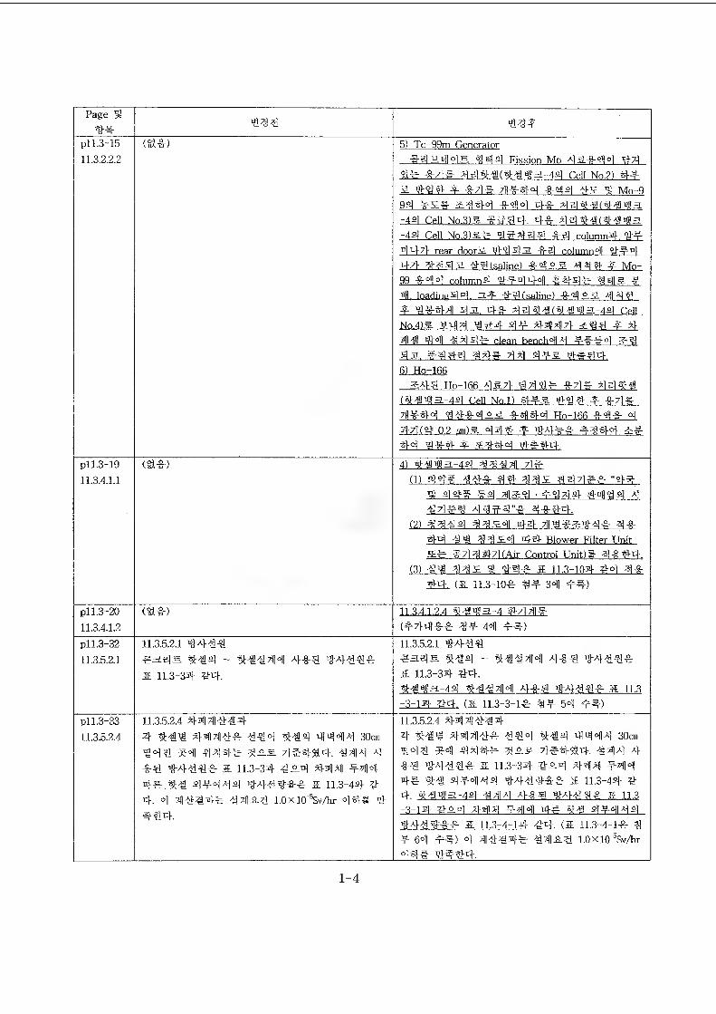
Page i!4f
444 43*
pll.3-1511.32.2.2
(gif) 5) Tc-99m Generator#4^.445 444 Fission Mo 4Sf44 44
%lf f## 3444(4-0$a-44 Cell No.2) 44-a 39# 4 f## 7)1*44 f 44 45 ^ Mo-994 *5# 5344 f44 4f 444-9(4-943-44 Cell No.3)5 fg##. 4f 4449(4^43-44 Cell No.3)5* W444 f 4 column# #*44-71 rear doorS. 49 43 f 4 column4 4-#-44-4- 4-443 4-4 (saline) f 414 4 * Mo-99 f 44 column4 ##44-4 $441- 445. *4. loading44. 3# 49.(saline) f 435 9144# 4*4711 43. #f 444-9(4-943-44 C41No.4)5 5414 W*# 4* 44)9171 5^4 * 441-9 44 94 4rr clean bench44 *f *4 5W43. #934 94* 714 4*5 4*44.6) Ho-166
3:43 Ho-166 3571 34 f## 444-9(4-943-44 Cell No.l) §1*5 49 4 * *7]*7«*44 44*455 *444 Ho-166 *4*#71(4= 02 nm)5 4#4 # 44ff *444 3*44 %*4 * 3444 4*44.
pll.3-1911.3.4.1.1
(Slf) 4) 4-8$3-49 4344 7ie
(1) 44* *4* 44 335 ##7]#*rt 49==. f.$\ • *4## 4=11-39 444#$ 3944"* 4*4#.
(2) 33-94 3354 4-4- 44*544* 3f§14 4W 3354 4-4 Blower Filter UnitSf f 7] 3 #7] (Air Control Unit)# 3f 44.
(3) 44 335 9* #4* & 11.3-10# #4 3*44. (a U.3-10f 3-?- 34 *#)
pll.3-2011.3.4.1.2
(gif) 11.3.4.1.2.4 4-9 $3-4 #7191-#-(*7l4ff ** 44 **)
pll.3-3211.3.5.2.1
11.352.1 4444$3# 5 4^9 _ 4444f
a 11.3-34 #4.
11.3.5.2.1 3-444$34^. 4-04 - 4-0444 4f4 3444f5 11.3-3# 44.4-9.33-44 4-9444 4-f# a 11.3-3-1# #4. (a 11.3-3-1* 3* 54 **)
pi 1.3-3311.3.5.2.4
11.35.2.4 #4444#
4 4-04 ##44f 444 4-04 4444 30cm 444 ^4 4444 #55 7ie45&4. 443 4 f# 4444* 5. 11.3-34 #5# #44 *44 4# *4 4*444 444fff & 11.3-44 44. 4 4iM#f 44-8.3 1.0xi0^Sv/hr 443 4 #4#.
1155.2.4 #444^#
4 4-04 #444* 444 4-94 4443 30cm 444 f4 44#* 355 7]##a#. 443 # *4 3-#44f & 115-3# #54 #44 *44 4# 4-0 4*434 #44*f* & 11.3-4# ##. 4-943-44 443 3-&# $-714#$ & 11.3-3-1# *54 #491 *44 ## 4-9 4*434#713#** a 115-4-1# ##. (a 11.3-4-1* 9 * 64 *#) 4 44*#* 44.8.4 1.0xl0^Sv/hr
94# 4*4#.
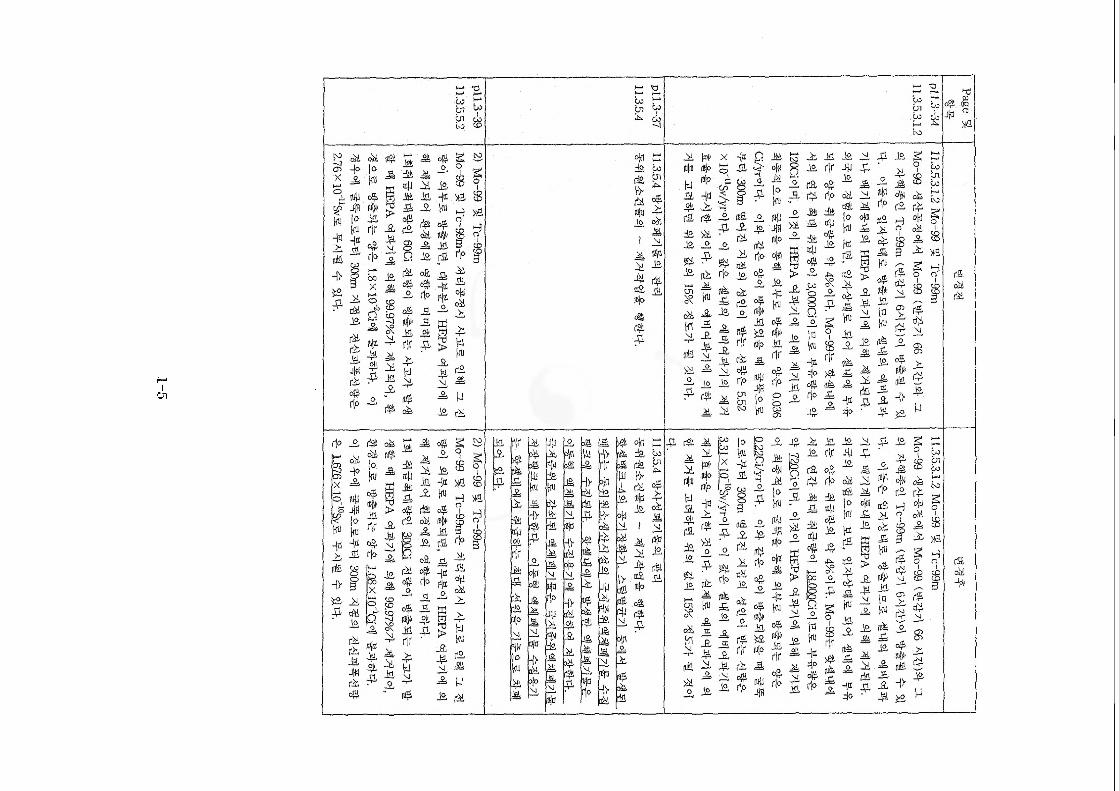
1-5
gi W
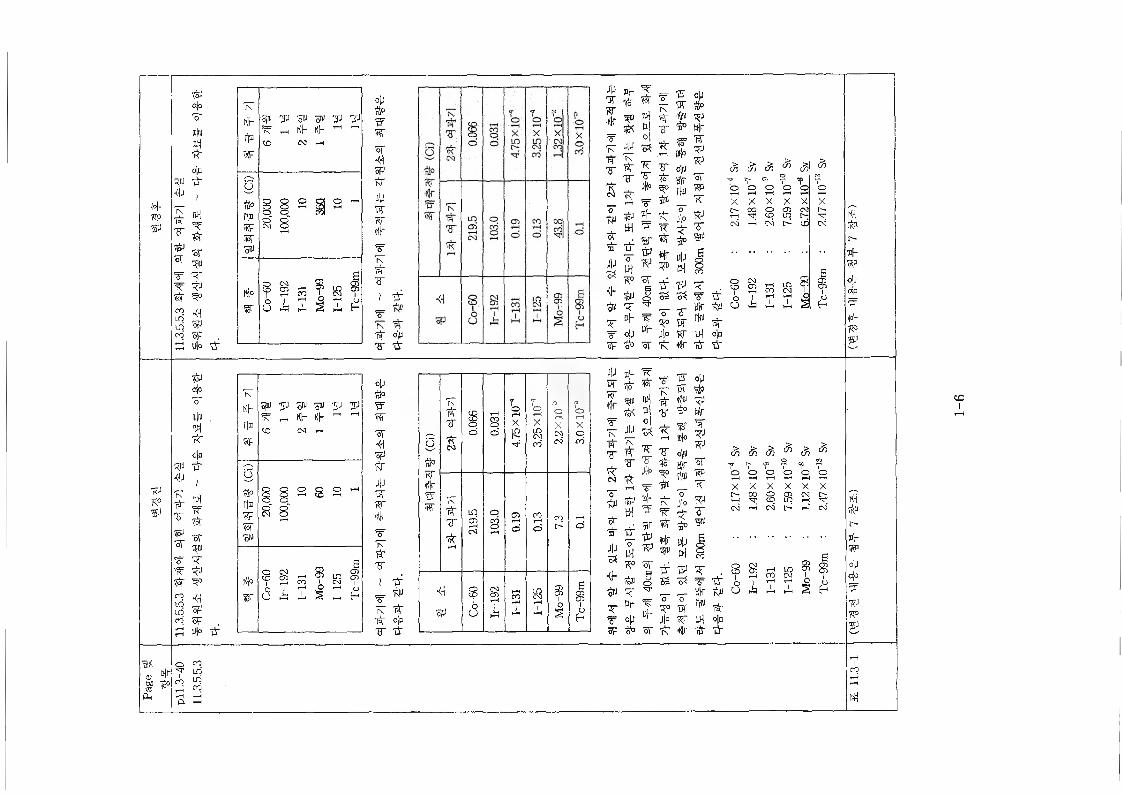
't°p79V
79K°V
d'K<U2
R®•dJ79ti"Tti®
sr
ro"itnCO
R®•dJ
pTT#of
■R"*sin
dpo'#■ft-
o|ntir
I
ml*ti"
R®Tti®
<4of15F .* fi"
tfJa|o'o'Itl|#Ml7<"o|ntir
IMlif*ofrid
ti"ti®
<4spSF .D)o *
coLO10CO
l\KPrjstiF
spu yj gu o® 'JJ TJ ^ _ KP KP -1 ^CO CO
(co
' 20,000 100,
000 10 360 10 1
w Co-
00Ir-
192
1-13
1
Mo-
991-
125
Tc~9
9m
op
WwST<479tiT4pti"Rr#TIN
#
I tif
tir o|oT tir
IN
KPPB
W
Si® JJ S® 0® y 79^ ^ KP KP -1
CO N •—
(13)
Q o o o o ^ 8 8^^"
Ki°tir C
o-60
Ir-19
21-
131
Mo-
991-
125
Tc~9
9m
opnt°w5CST<4Sptir
JUww*’TNtifT
1 if r *"79 'A" W 4>S" ti"
O
Rr#Ww
79■ti"Tt
0.06
6
0.03
1 oX
S
7oX
goXCON
'oXpCO
7\*tirVtir
1 0 Cbo
cr>o d
K4 1 §
A21 S
2? #
h
4|4ti"Rr#
WIN
•PfV
5
tiPtirn"4pS3<h
o»
T’rsr
tiJB4
tirO
w7^-
mlnl°l:S379T&
W®P
Wti®
V
TTo?■pin7nw*•HrRffl
Sirrf»€~
Iup
tVHrW9®RJSTRB79TpTR®
S
C% £ &) do c%Y ? V «p
o o o o O Ot-HX X X X X Xt> 00 o <5 CM
2 p P l>CM CM t> CD CM
if w * V Tti® o S3 tir< XT __ Sir tipBp wuL.
o 0ti" H® ti"
op ur Jl° 79 Ul o|b3° sr r£-N ■K|r tif tir
S 2 CO Cl ! $5 i rH2 s t
K4tipc-®PWopa|o?tf79?4
JPwRr■HP
In
ti"Ts
o~tinti"ti"JPS3KP0®TTSF
t
JPINtirT
tirmld|o|S379S"*
»P
tirti®
TP
To111)0
o|«Sir
Tof#rR®
op#R®Hrti"
T9srRB7979T1®
I
c% & 3 3 " Sv
7 ro o o o o Oi—4X X X X X Xr~ CO Q CD CM l>P P r-4CM r-K CM o i-4 CM
R°ti®
sr1 tir
S3T9S3
ti"T *
! §1
3 g 1 ?u
T TTTti"
BP tipi o X z S £hDp w
iiLoR°
rt®tir
op Mr Jl° RT 94 o)n3° of 7n ■Kir tir u"
K4
c-®PWopojo?R®79ti®
hN
1-6
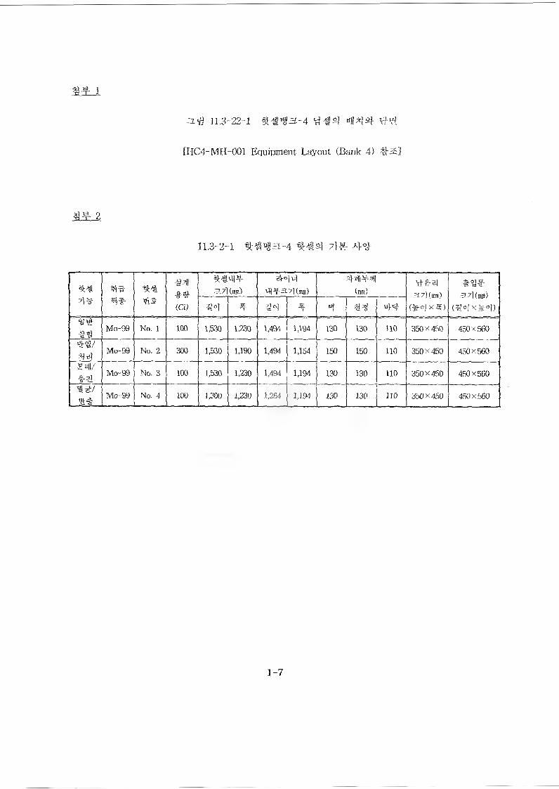
11.3-22-1
[HC4-MH 001 Equipment Layout (Bank 4) #5]
3L3r 2
11.3-2-1 ^4^ 7]^- 4^
41^4# (Ci)
a?l414(mm)
el°N41 -r 3.7] (mm) (ran) 3.7)(m®)
1^4 x 4)a7)(m)
(^o)X^o))4 ^6} 4 4 44
Mo-99 No. 1 too 1^30 1^30 1,494 1,194 130 130 110 360X 450 450x 560
Mo-99 No. 2 300 1^30 1,190 1,494 1,154 150 150 no 350 X 450 450 X 560
Mo-99 No. 3 100 1^30 1,230 1,494 1,194 130 130 110 350X 450 450 x 560
4^/ Mo-99 No. 4 100 1^00 1,230 1,264 1,194 130 130 no 350X450 450X560
1-7
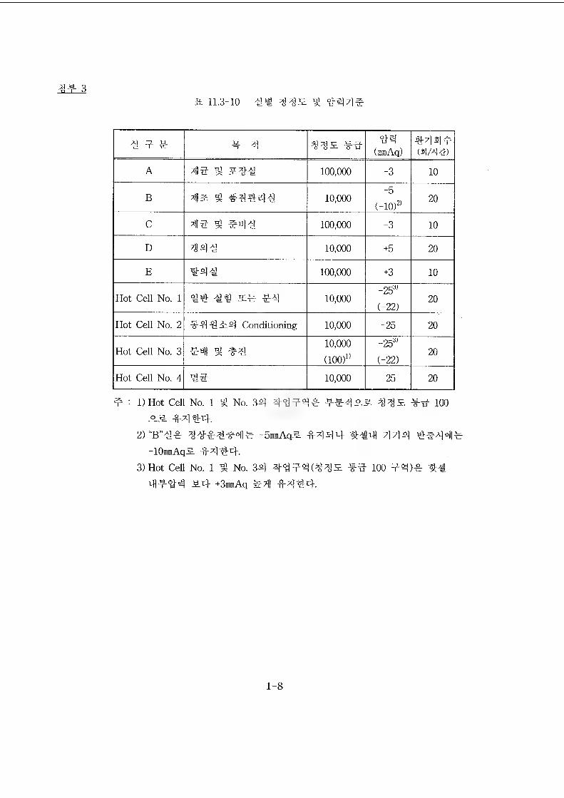
3# 3a 11.3-10 44 iMiE ^
4 4# 4 4 345L #4 "44(iiiinAq)
#44#(4/4^1)
A 44 ^ 544 100,000 -3 10
B *l]5 3 #4444 10,000-5
(-10f 20
C *115 4 #44 100,000 -3 10
D %944 10,000 +5 20
E 444 100,000 +3 10
Hot Cell No. 1 44 44 5# #4 10,000-25"(-22)
20
Hot Cell No. 2 #4 4 A 4 Conditioning 10,000 -25 20
Hot Cell No. 310,000(100)"
-25^(-22)
20
Hot Cell No. 4 44 10,000 -25 20
# : l)Hot Cell No. 1 4 No. 34 444^4 4#4AS %%Sl -#4 100 AS. f-4 44-.
2) "B"4# -SmmAqS ^-444 444 4 7] 4-lOmmAqS -44 44.
3) Hot Cell No. 1 ^ No. 34 44f 4(^4^ #4 100 #4)# 44 4 #4-4 A4 +3mmAq -fM44.
1-8
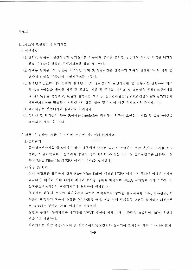
4
11.3.4.1.2.4 ###£-4 *441#
1) 3#*#
(1) 34# #**£^#4## 34#** 4**4 3&# 34* 33*4 44# *3# 444 *-& 4**4 #*# ^444s* 44#*.
(2) #&* *##£# ^*4 ^.3## #4 ^ ^4&4* ###7] #4# ^#«ga-4# *41 $
#34 43* ^-#*4 *3432:* 4#4.
(3) ##4a-l,2,3# ^&^**. *#«ga-4# 32:### ##434 3 #*£* #3*4 42:
3 #*#*#* 44# 43 3 2##, 43 3 #*#, 44# 3 ###* *3*^*4#
4 344** #-§-#3., #44 444c 42: 3 *##*** *3#^**4## 344**
7H33&3** *###4 **#4# **, #3 3 44-4 4# *42:*# *^4**.
(4) 4441*# ##444- #44* *4*4.
(5) 44# 4 #4#4 4=# £44c Interlock* 4**4 4*4 £4*4 4& 3 *#*##£
*4 4 c 4* *4*4-.
2) 43 3 ^*#, 43 ^ ###, 44#, #4#4 #44*
(1) 34^*
*3*2:**4# 3&##* 34 4*44 3^3 34* 33*4 #4 *,#£ &*# *4
*4, t 34*£44 #4*4 33# 4# 44# * 4c 4# 3 3444s* £#-*4 4
*4 Blow Filter UnitCHEPA 444 4#)* #4*#.
(2) 44 3 #4
#4 44£* *4*4 44 Blow Filter Unit4 44# HEPA 444* **4 44* 34*
33*4, 44c #4 44* 4*4- **-* **4 4444 HEPA 44-44 44 44-y
***£*#4#* #444£4 43*4 44##.
**#* #*# £3* #334* **4 ###££ *3# *4*44 **, #*###4
*#* ^4*4 4*4 *3# 34*£# *4, 4* 441 34*3 3## #4*3. 4#&# 4 #3*c 34c MOD 4*4* 4###.##£ #34 #4*£* 44#* WVF 444 4*4 44 ##* &#*4, 100% **#
4* 24 4*#*.
4*44* #3 **/444 3 *3^*4/#£#47i. #444 £*34 ^3 4*4# m#|
1-9
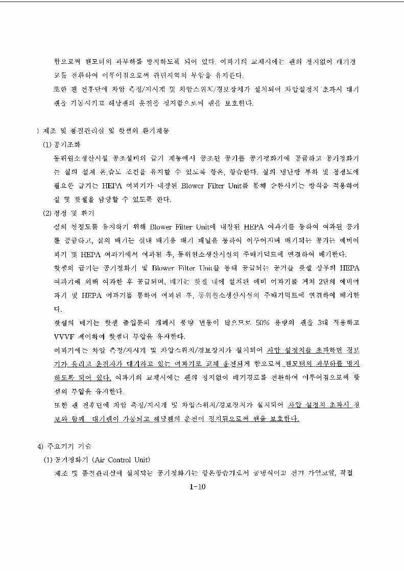
42.44 4*4* 3^442# 44 4444 2444# ^»4 34^4 443
&# 3#44 4*43234 44444 *3# 4444.
2# 31 3*#4 44- #4/444 ^ 44-244/323471- 4444 4-4444 #44 44
## 71-4442 3I33E4 #4# 343224 ## ##44.
) %]]2 ^ #4444 ^ ##4 #431#-
(D44&#
#4323*4# *2#44 #4 31444 4## 44# 444#44 444-# *4344
# 44 431 #,#2 &3# #44 * 112# 4#, ###4. 44 444 #4 9^ 3323|
#2# 44# HEPA <34-717} 444 Blower Filter Unit* #4) ##44# 44# 4444
4 3 44# 4-4-# * 112# #4.
(2) #4 #4
44 332* #444 44 Blower Filter Unit‘d 444 HEPA 444# #4# 444 #4
* ##4#, 44 44# 4PI tifl4# tifl7] 414# #44 4#444 «H44# #4# 444
44 ^ HEPA 44444 44# *, *4323#4#4 *tifl44Eo|] #^44 44#c)..
##4 #4# #4 4 #4 g Blower Filter Unit* *31 *#4# #4# ## #*4 HEPA
4444 44 44# * ##44, tifl7]# ## 44 #44 44 444* 44 2#4 444
44 g HEPA 444* #4-4 44# 4, *4#23#4#4 #444^4 4##4 44#
4.
##4 44# ## #11*4 71144 #3 #*4 #-9-2.3. 50% *44 4# 34 3**2
WVF 4444 ##4 *4# #4 #4.
4444# 4# #3/444 3 44-244/32*471- #444 4-# #34* &4## 33.
7l7V #S#I *4471 4442 4* 4443. 231 #44 4 *234 42.44 4*4# 44
4-s.#- 44 44. 4444 23144# #4 34^4 011443.# 3##4 4*433.34 #
44 44-# #4 #4.
2# ^1 4^*4 44- #3/4441 4 4*244/323-47} #444 44 #34 &44 3
34 #31 rfl7l#o] 71*431 311444 #4 4 34 33.34 ## M?4.
4) *-8-714 4#
(1) #7134-71 (Air Control Unit)
42 ^ #344#4 #44# *444-4# #*##434 *3342 44 7}4a4, 33
1-10
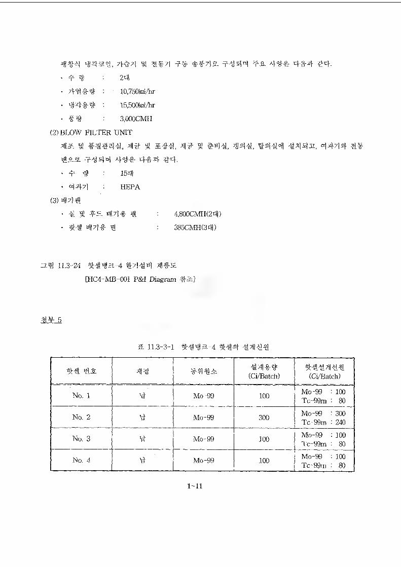
7}*w?} 53 FI97] 99 if97l 5L 99 44 9 A 4 49 4"lr4 #4-
' 9 9 • 24
- : 10,750W/hr
- '- 15,500ka|/hr
- : 3,000CMH
(2) BLOW FILTER UNIT
41^ 51 #^44^, 43" 53 4]^- 53 #4^, 7g44, ^4^4 -M44JI, 44/14 4^
#A.& 9^44 44^ 4&4 ^4-
- 9 4 : 154
• 447) : HEPA
(3) 44#
. g 9= 44-8- # ; 4,800CMH(24)
- w])4#. # : 385CMHC34)
zz.^ 11.3-24 %##a-4 4/1^4 4#-^
[HC4-MB-001 P&I Diagram #&]
.^T
& 11.3-3-1 9r##a-4 %€4
4^ 4^ (Ci/Batch) (Ci/Batch)
No. 1 Mo-99 100 Mo-99 : 100 Tc-99m - 80
No. 2 Mo-99 300 Mo-99 : 300 Tc-99m : 240
No. 3 Mo-99 100 Mo-99 : 100 Tc-99m : 80
No. 4 4 Mo-99 100 Mo-99 : 100 Tc~99m • 80
1-11
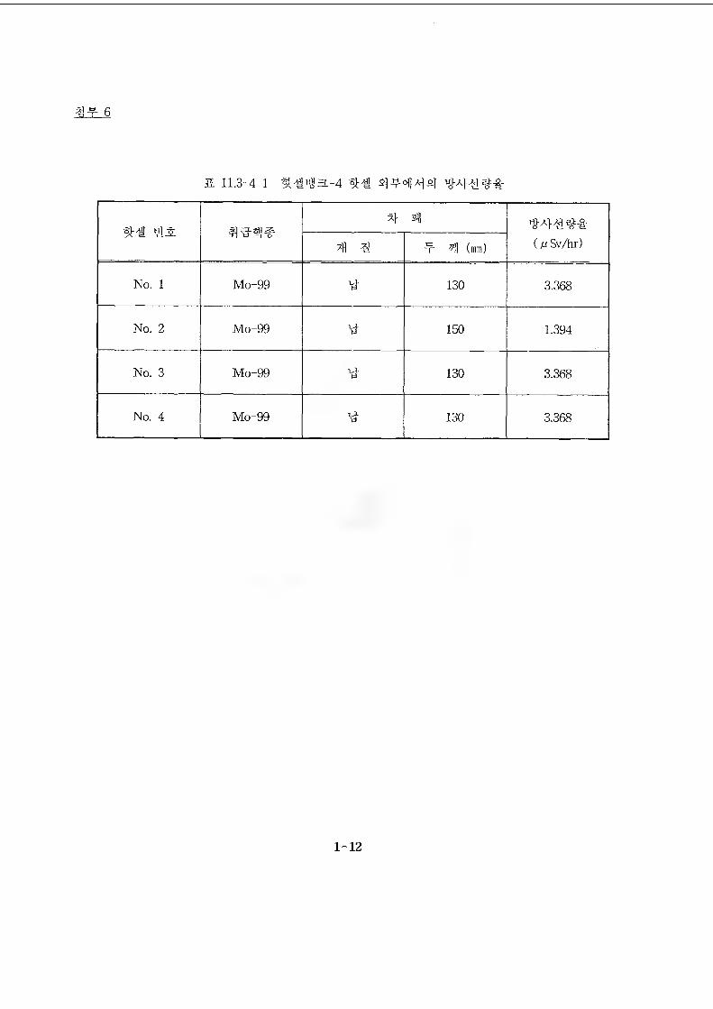
%#(A Sv/hr)41 3 -t" 41 (mm)
No. 1 Mo-99 130 3.368
No. 2 Mo-99 150 1.394
No. 3 Mo-99 130 3.368
No. 4 Mo-99 y- 130 3.368
1-12
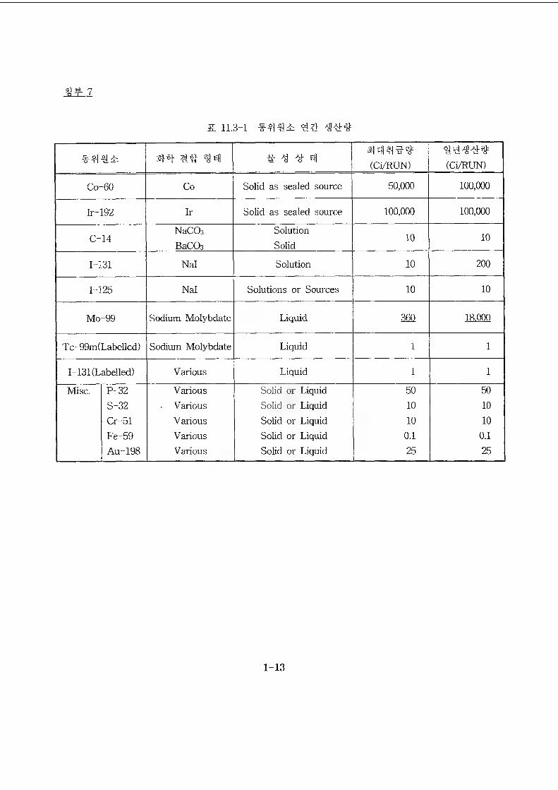
7
& 11.3-1 ## 49##
Z4-# 4# #91 # # # 91a|9M##(Ci/RUN)
IN 41## (Ci/RUN)
Co--60 Co Solid as sealed source 50,000 100,000
Ir-192 Ir Solid as sealed source 100,000 100,000
c-14NaCCbBaCOs
SolutionSolid
10 10
1-131 Nal Solution 10 200
1-125 Nal Solutions or Sources 10 10
Mo-99 Sodium Molybdate Liquid m 18,000
Tc-99m(LabelIed) Sodium Molybdate Liquid i 1
I-131 (Labelled) Various Liquid i 1
Misc. P-32 Various Solid or Liquid 50 50S-32 . Various Solid or Liquid 10 10Cr-51 Various Solid or Liquid 10 10Fe-59 Various Solid or Liquid 0.1 0.1Au-198 Various Solid or Liquid 25 25
1-13
11.3.4.3.3 3) #94
3) #7)^.3397)
^.7)^.3337)# #333 D)44## - #3933 94# 444##S34 34.
:7)^.9#443 44444 ##7)4 ### 4#4 33.
- ###a #1 #399
- #^#a #2 #393
###a #3 #399
###a #4 #399
#7)o)#3^) #33
94
34
34 #^
M4
4, 4d: ^ 4 #4 31
11.3.5.3.1.8 44S-444 7)41417]# ##& 99 #39##7l (97M#)
944# ###a.-43 444 ##3# 443 494 4# 4#4## 37}434. 4 444
3494# 4414 #44#3# s.9 4#3 44^3 ^4# #3) 9#^.& ##34. 444 9-93)
4# ##4a-43 #34 ##3# #447)3)43# ^99 44s. 44) 443 ###4433) 4
# 94933 9#44# 471434. 4# 34 4443 3 #7l#g# 44499-0-34S.3 34
3334^.3-43 "5.4 #4#9#"3| 7)#3 44 #943) 4-0-434.
1) ##3443
4-4*33.-43 944 ##39 #447)4)433 97>s. 34 44s. 44443 ###4939
S 11.3-104 94.
2) 4)4#3 3 7M4#
44s 34493 ###4434) 4# 93 993 ;))43] 44 33 999# 314# 99 9)4
#^, 7l#4# ^ 9144) 4-0-3 49 94 31439 7) #9 44499s. 999##7l^a43| 4
-0-3 4# #947)) 4-0-94.
3) 4444-
9#ags.-43 #34 ##99 #447)3)43# 994 44s. 331443 ###4433) 4#
99 993 7))34| 49 94 444# #7l#3# & 11.3-114- 34.
1-14
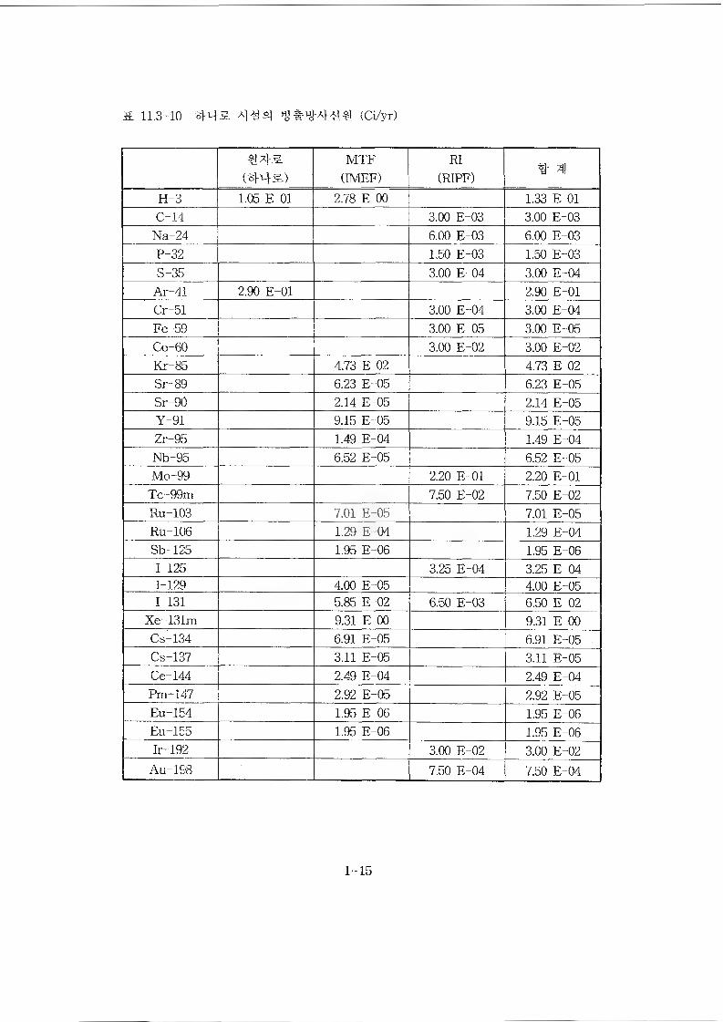
& 11.3-10 #43. ### (Ci/yr)
MTF(IMEF)
RI(RIPF) # 31
H-3 1.05 E 01 2.78 E 00 1.33 E 01C-14 3.00 E-03 3.00 E-03
Na-24 6.00 E-03 6.00 E-03P-32 1.50 E-03 1.50 E-03S-35 3.00 E-04 3.00 E-04
Ar-41 2.90 E-01 2.90 E-01Cr-51 3.00 E-04 3.00 E-04Fe-59 3.00 E-05 3.00 E-05Co-60 3.00 E-02 3.00 E-02Kr-85 4.73 E 02 4.73 E 02Sr-89 6.23 E-05 6.23 E-05Sr-90 2.14 E-05 2.14 E-05Y-91 9.15 E-05 9.15 E-05Zr-95 1.49 E-04 1.49 E-04Nb-95 6.52 E-05 6.52 E-05Mo-99 2.20 E-01 2.20 E-01
Tc-99m 7.50 E-02 7.50 E-02Ru-103 7.01 E-05 7.01 E-05Ru-106 1.29 E-04 1.29 E-04Sb-125 1.95 E-06 1.95 E-061-125 3.25 E-04 3.25 E-041-129 4.00 E-05 4.00 E-051-131 5.85 E-02 6.50 E-03 6.50 E-02
Xe-131m 9.31 E 00 9.31 E 00Cs-134 6.91 E-05 6.91 E-05Cs-137 3.11 E-05 3.11 E-05Ce-144 2.49 E-04 2.49 E-04Pm-147 2.92 E-05 2.92 E-05Eu-154 1.95 E-06 1.95 E-06Eu-155 1.95 E-06 1.95 E-06Ir-192 3.00 E-02 3.00 E-02
Au-198 7.50 E-04 7.50 E-04
1-15
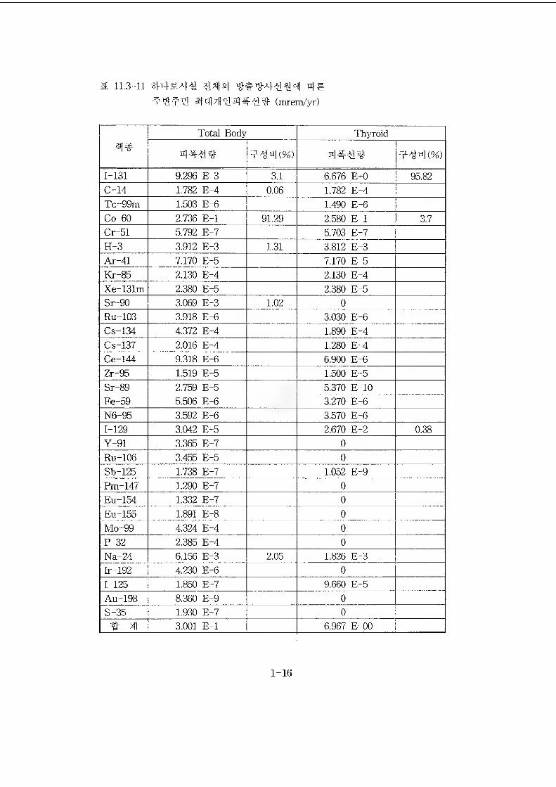
a 11.3-11 #43-4^ 4#t’St1?] (mrem/yr)
Total Body Thyroid
1-131 9.296 E-3 3.1 6.676 E+0 95.82C-14 1.782 E-4 0.06 1.782 E-4Tc-99m 1.503 E-6 1.490 E-6Co-60 2.736 E-l 91.29 2.580 E-l 3.7Cr-51 5.792 E-7 5.703 E-7H-3 3.912 E-3 1.31 3.812 E-3Ar-41 7.170 E-5 7.170 E-5Kr-85 2.130 E-4 2.130 E-4Xe-131m 2.380 E-5 2.380 E-5Sr-90 3.069 E-3 E02 0Ru-103 3.918 E-6 3.030 E-6Cs-134 4.372 E-4 1.890 E-4Cs-137 2.016 E-4 1.280 E-4Ce-144 9.318 E-6 6.900 E-6Zr-95 1.519 E-5 1.500 E-5Sr-89 2.759 E-5 5.370 E-10Fe-59 5.506 E-6 3.270 E-6N6-95 3.592 E-6 3.570 E-61-129 3.042 E-5 2.670 E-2 0.38Y-91 3.365 E-7 0Ru-106 3.455 E-5 0Sb-125 1.738 E-7 1.052 E-9Pm-147 1.290 E-7 0Eu-154 1.332 E-7 0Eu-155 1.891 E-8 0Mo-99 4.324 E-4 0P-32 2.385 E-4 0Na-24 6.156 E-3 2.05 1.826 E-3Ir-192 4.230 E-6 01-125 1.850 E-7 9.660 E-5Au-198 8.360 E-9 0S-35 1.930 E-7 0
3.001 E-l 6.967 E-00
1-16
® Page 11.3-37
11.3.5.4 M*44#4 44
*44^4*4 ^4# #4^1** *44^ 4*44 *4# ^4* 44#4 444*44 ##
4** *44-3# *444 $14. *** 4444 ^ 4*4 4444#* 4* 44* *4
** 4^4 **44, 3* 444a* **4 444-7} **a}4 ** *4 44421, 44444 4
*7}# **7}##44 4444 444 44447} JisM4. 44 444 #*#* #*444#*
**#44 **44, **-47} #* #44^4 44* 44 4444 4-4*44 **-*-34 444
2i, 4* 4*444 #** *##7l4 *44 o^oi^qa., 47l##-*44 44* 7}## 4 4*
444.
44-7]# 444-* *#43, 45.4 *##4 4*44*4 *4* 44 4444: 4*-#4. 5
# 4* *47} *4* * 4* 44-71#* 444444 *49a}4 *44-4 44-714 447}
#5# 4* #4-# #47} 447}*# #43. #4* 4?M 44-* #, 44*4* 4*4.
*44a-44 *# *4444 *44* *444-4, 3** #4 *44 *44 4** *4 434
*4*4 ^-4*44444# **4=t4 4=444. **4144 #4# 441414** 4*4 444
4# *4*44 *44-4 4**4-. *4*43 *44 44414#* ^4*4^41414* 4*4a
3 4**4-. 4** 4444# *4*4* SHM44 4*4-* 44 44* 4*33 4-444 4
IL
1-17
KINS 12} #sH 41# ##4
1.
^jA^o|A^| CHoj- tiSA|
: 9P0| 0323-152 (2002. 03. 07 '#4^ gj -^qiA|-gd M.
SS 5|7( HS^l7( AI^OII [4# ^A^OJ’)
2002. 03.
2-1
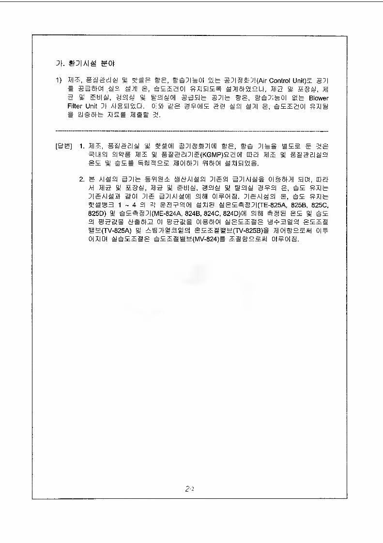
j\. sot
1) IE, gl@£ll % 51#g Sg, »e:IW0| %b 3X|§§lX|(Air Control Unit)E 3X|* 33510I 1°| g, £EE30| 8X|E|EI| HSISELI, 13 gy 5§i, 1 3 gy Still, g2|! % B°I10|| 33EIS SXIS #8, SAXIbOl gib Blower Filter Unit XI Algg&Cl. 0|£1 mg 380IIE @0 12| lXj| S, BEEgOI gXI0# 2J SSIS X1EB Xiiew 51.
[&H] 1. xhie, gi@Bii m st a oil sxigsixioii ws, ms xis# see s mg 3lh°i sietM IE sy siaBPig(KGMP)saoii m-e-h xhie gy siaBiiigE % s£i glJSjEE 10151X1 915101 lx! El 210.
2. g A|l°l 5X|0 #9|@E 061AI12I X|g£| 5X|A|1S 0IS511 EDI, gBl AH 13 % 5S1, 13 % Still, 39 2|! ^ W°ll 3¥°l g, sE gX|gxigAiia moi xia 3x1x11011 °|5H oi#ois. xisaiii g, #E gxisSIM^B 1-410 SSE^OII lx|@ lgE#§X|(TE-825A, 825B, 825C, 825D) gy BE=§X|(ME-824A, 824B, 824C, 824D)01I °|5H #@E SE Si sE £1 S3SS 610513 01 @30# 0105101 IgEElg @03121 0EE1 BE(TV-825A) §y EijXH3i|2| gEEl#E(TV-825B)S 10ISEEMH 01# OH XI OH IBEElg BEE1#E(MV-824)B El SEEA| 0|#01S.
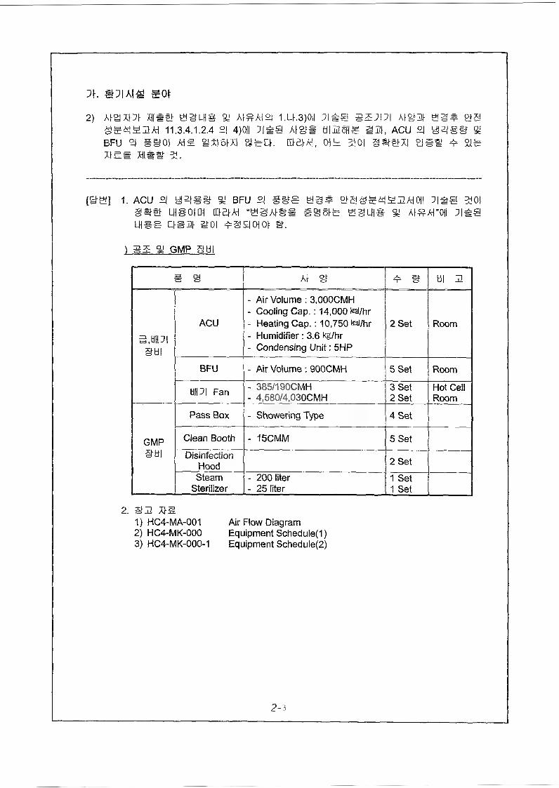
J\. EOt
2) Atamm Hi#& i.u.3)oii ;i#@ sz;i;i mgtm et6!S^yHAi 11,3.4.1.2.4 2| 4)CHI ]|#@ AfgfS tilSSHS 33I, ACU £| y|2tg§? BFU °l gifOl A|S HxIsHI HECK QRtAI, DIB: %0| @##X| HgS 4 21ms« hi mm 5i.
terei 1. acu si angir h bfu °i ses eg# eigss*U£2Aioii ]|#@ 301 LHSoiDi OBiA “BSAiws @@eis % a^atoii
lhss asm hoi 4§aaot g.
1 sm H GMP SHI
# s At H 4^ 9 til 2
S.tiHOI§ti|
ACU
- Air Volume : 3,000CMH- Cooling Cap.: 14,000 tai/hr- Heating Cap.: 10,750 teal/hr- Humidifier: 3.6 kg/hr- Condensing Unit: 5HP
2 Set Room
BFU - Air Volume : 900CMH 5 Set Room
tiHOI Fan - 385/190CMH- 4,580/4,030CMH
3 Set2 Set
Hot Cell Room
Pass Box - Showering Type 4 Set
GMP Clean Booth - 15CMM 5 SetS Id] Disinfection
Hood 2 Set
SteamSterilizer
- 200 liter- 25 liter
1 Set1 Set
2. S3 ms1) HC4-MA-001 Air Flow Diagram2) HC4-MK-000 Equipment Scheduled)3) HC4-MK-000-1 Equipment Scheduled)
2-3
nr m
rM
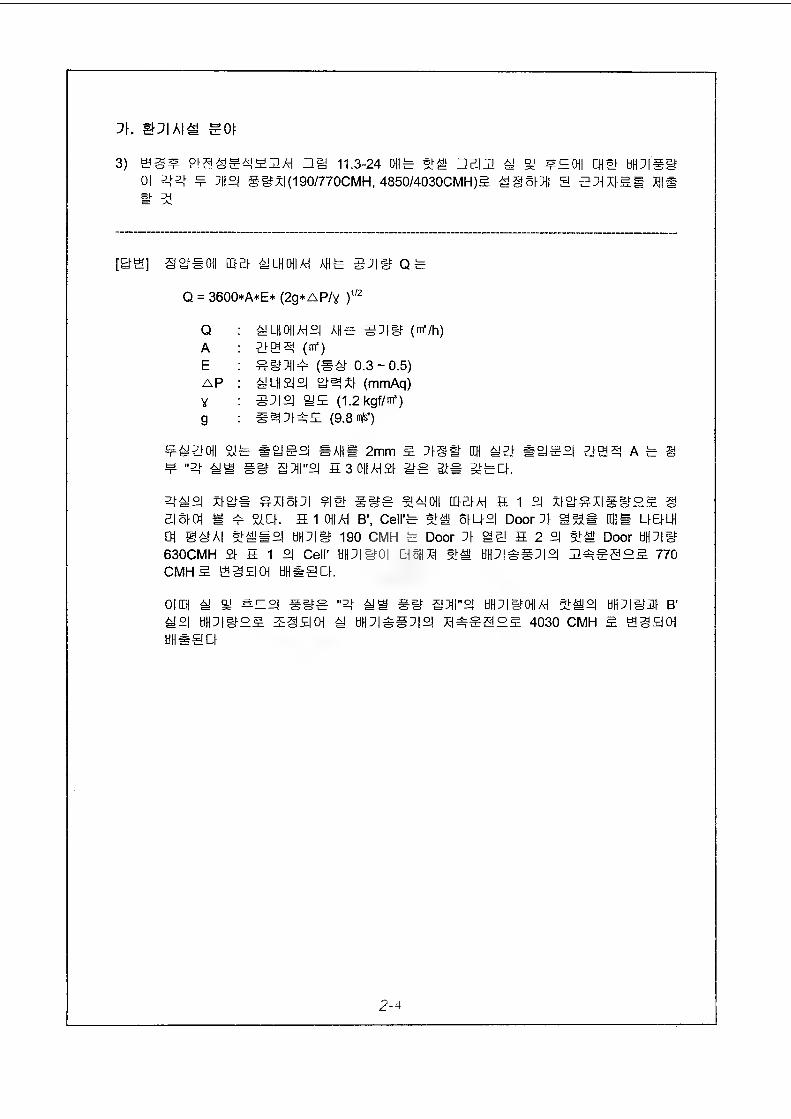
1\. S^IAIS S0|:
3) Sgf Sag SASHA! Hii 11.3-24 OHS SS HBII1 g g ¥50|| □ §! UPlgif Ol 2*3* ¥ :H2| Sifx|(190/770CMH, 4850/4030CMH)5 g§5fT|| g STHXfB# Mmm a
[B@] gg#0|| COBf ^ LH CHI AH AHS SXig Qfe
Q = 3600*A*E* (2g*AP/y )1/2
Q : ELH01I/HS AHS 3TI3 (m’/h)A : ZiBA (me)E : ¥3XII¥ (S3 0.3-0.5)AP : gLH2|°| gAxf (mmAq)Y : ST|°| gE (1.2kgf/m‘)g ; #ATfAE (9.8 m/s’)
¥^yOII 21S #2JSSI SAHE 2mm E Tfg# EH gB #g¥°| BBA ASS ¥ "A #if 3XII"°I S 3 0||AH2f KS StS gSU.
gg°l xfg# ¥X|ofT| ¥E 3ifS S40H DM AH H 1 °l xfg¥X|gifSE § BISfOl B ¥ gOf. 5 1 011 AH B\ Cell'S 91M 5fU£| Door Xf ggS HUE UEHH 01 @#A| 91*16°! tiHTISf 190 CMH S Door J\ gg 5 2 £| 915! Door UHXlif 630CMH 21 5 1 2| Cell' WHXI30I B5HX1 915! tiHXIASXIS HASSEE 770cmh 5 sggoH tiueacf.
0| EH g g #Eg #if¥ "A gB ii M'S HHTlifOHAH 91#S OH XI331 B' g°l WHXlifEE E@SO| g HHX|AgX|°| XHASSSE 4030 CMH 5 S3£|0i tiHSaCf
2-4
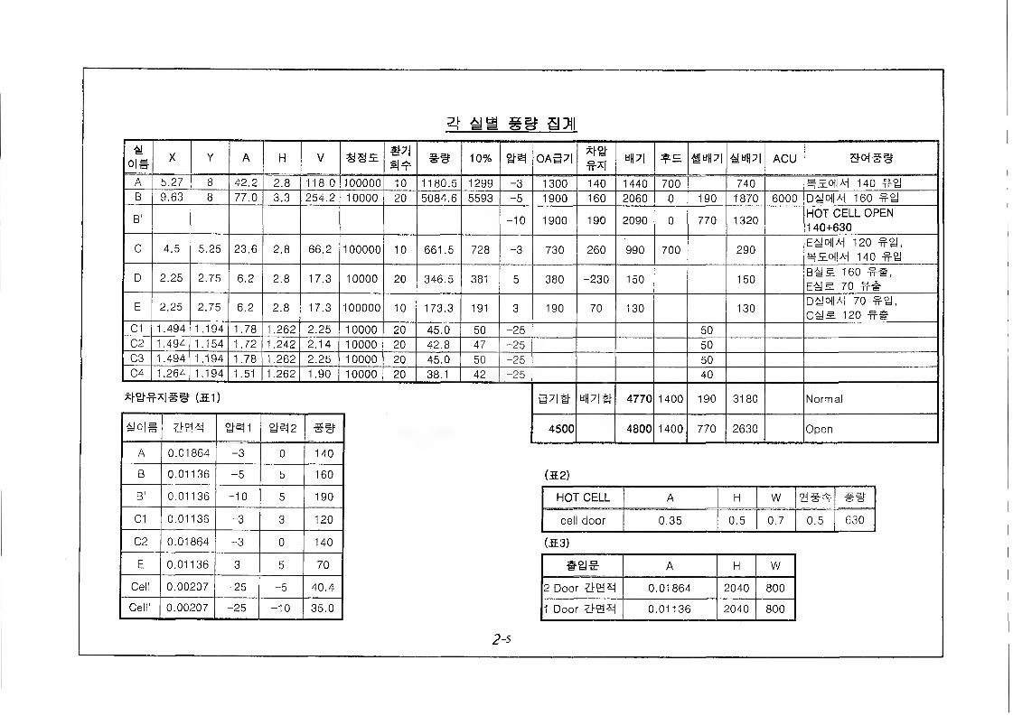
gi: urn §a aai
X Y A H V @95
iooooo
mSI 4=
## 10% 0A37|w
«PI 3£E. ACU eqee
A 5.27 8 42.2 2.8 118.0 10 1180.5 1299 -3 1300 140 1440 700 740 ^50IW 140B 9.63 8 77.0 3.3 254.2 10000 20 5084.6 5593 -5 1900 160 2060 0 190 1870 6000 DAIoM 160
B‘ -10 1900 190 2090 0 770 1320HOT CELL OPEN140+630
C 4.5 5.25 23.6 2.8 66.2 100000 10 661.5 728 -3 730 260 990 700 290E^ CH|Ai 120
140
D 2.25 2.75 6.2 2.8 17.3 10000 20 346.5 381 5 380 -230 150 150B^m 160 ee,E-M5. 70 ff#
E 2.25 2.75 6.2 2.8 17.3 100000 10 173.3 191 3 190 70 130 130D^OllAi 70 #£J,c-ys. 120
C1 1.494 1.194 1.78 1.262 2.25 10000 20 45.0 50 -25 50C2 1.494 1.154 1.72 1.242 2.14 10000 20 42.8 47 -25 50C3 1.494 1.194 1.78 1.262 2.25 10000 20 45.0 50 -25 50C4 1.264 1.194 1.51 1.262 1.90 10000 20 38.1 42 -25 40
**&**!*» (51) uplS 4770 1400 190 3180 Normal
^o|# £HN1 yej2 4500 4800 1400 770 2630 Open
A 0.01864 -3 0 140
B 0.01136 -5 5 160 (52)
B' 0.01136 -10 5 190 HOT CELL
cell door
A H W
C1 0.01136 -3 3 120 0.35 0.5 0.7 0.5 630
C2 0.01864 -3 0 140 (53)E 0.01136 3 5 70 A H W
Cell 0.00207 -25 -5 40.4 2 Door 0.01864 2040 800
Cell' 0.00207 -25 -10 35.0 1 Door 0.01136 2040 800
2-5
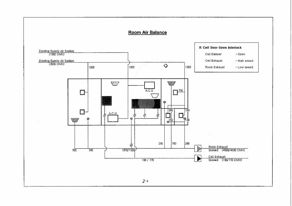
Room Air Balance
Existing Supply Air System(1900 CMH)
Existing, Supply Air System:
Room Exhaust1870/1320- 2speed (4580/4030 CMH)
Cell Exhaust190/ 770 2speed (190/770 CMH)
5*5 Cell Door Open Interlock
Cell Damper
Cell Exhaust
Room Exhaust
- Open
- High speed
- Low speed
A.C.U
A.C.U
2-6
J\. mD\MM EOt
4) SEH3 BSSS^SHAi 11.3.4.1.2, 3)3 (1)0|lfer "$S2I bH3|30)lbr 0||d|0133|» ¥ Sl-sm tiHDI'REoii^ OtldlOOPI $ HEPA 01331 SEb - Sx|tiD.”H Q(H2l°U, Sti USE#(Bank 4)2] HIPR^Oilte 0IIUIO133I £101 HEPA 01331 BE Sxlei OIS
[BSj S AISB tiH3IBEoj|E 3|gA|#3 HPReg. HEPA 01331 SB01IHEPA 01331 e$g 0110101331* ^xltt 3S|gJ. C03AH 3SSAH3 S3E Oil HI01331# tixl93^ 4-SS 3Sj°i.
2-7
I\>I
ffCrs
2 ± 0® VJ Oil jo
mism
01m
id oh nr y _ r° >hi
u J*01>H>
2 VJ
2 2
P
^ fOhru nrO
- 10 - wVjj 0> KU H (UW
sSgss
ID HO JlH' R HR 2 y QM pj 2ti g HE m B HU Q^reOk!2 y % oin M m J6- ox io ^
Jk! ^ HU nrp
lo yi Hu i$ £ 2 re vy
Hu jo rs0> g iuioffi ^ -U
m2 ffl
illnrti
12 HH le a do ini
2 f>UJ
nr
hoID2HIK)l'02
J2
cn
*e no rs hi® n oti^ U Ho|i
VJ fO
mix rejn &2 m
ss>
2co2
»i12l>dO2d!VJ
dJ
JM10HUremio
2me2
HI|0|ion
nr>Hmini
k>2
2
s2nrisKr|0|imini40r®
a2i>doaVJ
2
105 P
MYI
CB
'\c
J\. @X|A|^ gOt
6) as? 11.3.4.1.2.4 21 2) ai 3)o\\ xi#E “(2) - *2^3 sxiw 2sH BH^ieis xiioiea."g mm# sislh¥ #e 21x12s *2#§#xi2 ssxm 0#8101 BHOIES X1I01EC1E #2^ LH-gg @#8121 X|#* 9.
[B@] 11.3.4.1.2.4 2 2) W 3)(HI X|## LHSS CIS* SOI ¥##.
“oiiiixioiie xis #§, ges-xi % xibe?ixixi sxieci. 0121x12 xisoi 1 xissxioii ebsixii ye sei gBim o\m oisixie hxheck xiboi ##8101 2x1 flSXIOII 2*8121 20 *2291x1X1- bHX|@!2 2El* §X|A|X1 2 El 2 B1¥81* SXI&CK”
i4. y m?\m sbieoi:
D 2i¥0\\M ESIEIte A|g]^ Oi@ g|A^Si#2]XI o| J\\ 5!
[&S] 2|^0)lA1 E4E|-fe AIS2I ^A^ffil|g mo-99 (NaMo04 SEH) #2#°^ 4R0IIA1 44 OllSOIffl, 44mi Cask oil 444 SEEIH 13 SILHSEgOI 300 Ci ■ $4 SI XI yferCh
2-ii
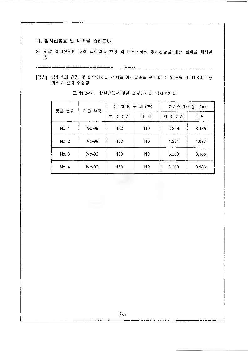
u. y Hpim seisoi
2) mm 18 mission men 'dmmm s§ j tii&ioiiAisi mi& a ms xiiais-
[3H] ys.^21 SS ft! ti|q01IAH£| d#S 711^3#* 5St ¥ £|E# £ 11.3-4-1 8oibhsi aoi mmm
£ 11.3-4-1 SiS3-4 £| ¥ 0|| AH £| §HA^0#
mm es fia sisy Xl mi ¥ M (mm) SMITHS (|^Sv/hr)
¥ ft SIS til ^ ¥ ft SIS tilR
No. 1 Mo-99 130 110 3.368 3.185
No. 2 Mo-99 150 110 1.394 4.937
No. 3 Mo-99 130 110 3.368 3.185
No. 4 Mo-99 150 110 3.368 3.185
2-12
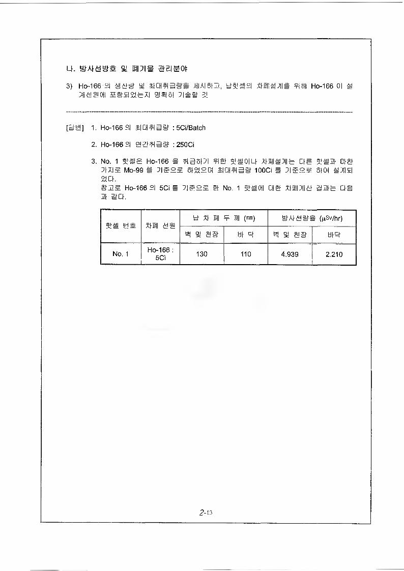
LK 91 BIPIE @Bigot:
3) Ho-166 °j % SlCHfia&t# mi m3, U%#°l xUS^IIB ¥|6H Ho-166 oi m^laaoii seg&axi @#6i :i## %
[BS] 1. Ho-166 £| : 5Ci/Batch
2. Ho-166 °l gymsy : 250CI
3. No. 1 SiSS Ho-166 S S35PI ?IS I^OIU DS SSPt 0|SMo-99 * 3E°E §IS°0| 3CHS5E 100CI # SK>I ti3IE|
St OKS3E Ho-166 £| 5Ci « ]|E3g. s_h No. 1 %#0t| CHS xHHS SBE CISm mot.
xm tiay X\ EH ¥ ffll (mm) y(gSv/hr)
w aj gg tit q ^ at as- tdR
No. 1 Ho-166 : 5Ci 130 110 4.939 2.210
2-13
U. 31 MJ\m SBISOI:
4) oil ^xiaoio^ mE xisaA^d^APi »i gxiessAPioii cx^ ^xioiESB 511 SIS MMW 51
[BH] 1. Il^aANs! ^APIsaaa4 one oioi 2 ;ng xis^mdSAPid sxieioi &em (eddEdSPAH 11.3.4.3.3, 1) SS) S AISOIIE 0| SAPI* A|gW 5||S!°j
2. SJISSSAPIsesaa-4 oiie Sd % sis^isiisi §:i# ess #§# 4 aie se essAPie Mxm^m xusigcH ^steoKeadSdeeAi 11.3.4.3.3, 3) s£), Old sa?sa4 3[ Fission Mo-99 °l ^IdS ?I5H dAl^gg* flgSfE* 5j|Sj£|(M CHS0I2, 0| S5ISSSAPIE SXH Sx|£IO| 91X\ STS.3au aaaa-4 e ean°i 5hsi2fe bbi °iss sgsd(Tc-99m m Ho-i66)£i ^ds ¥I6H a^ss ixise^ sxid S5ies°i #§eg sew aeg sea cm, taa/H %#^e-4 one sxid seeseAPie sxi# xnstOl
«J ^oJ»
(IN #m m.50»
K10 Mfor RBI^o^ 00In
FR 5
nr w
A" oini
som i-$0^
m
s sraw on
oW oini
1KJ su *o
a) Zc SO
Fp 5 A!
omi iio 21
n 010 °
m < s
m
I|0j EE3cJ °JSO
g DTJ 5,K
< R0 ROSO SJ «J
ZJ urT
BK s
m rT
si so SO RD y «j
"° iuiioJ n- oF sj
Rron oir 5 u
SoVwr1=4
oTKU
JIJlD
5m
oCU iioD
K4
. HUJ ^'io0 5 51 _
■is! HH
iKO r(“w*
^ oT 0)0 ^IkO
ffl r-Sffl
CM
SI oJ < M A HI
SO OS l0 Kh B DS RIU uS
# DH W SJ <1 0)0 FR lbSO if® n£ Kb Ff < 00 m
cxi CO
SJUB
2-15
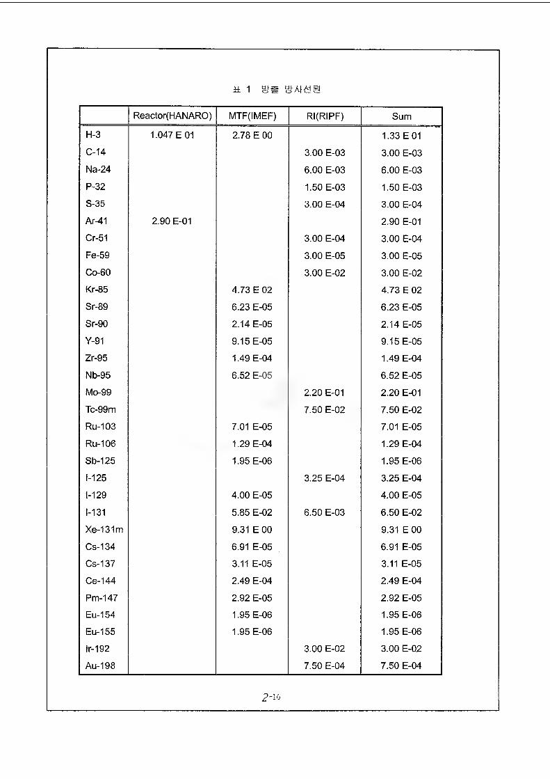
h 1 mm
Reactor(HANARO) MTF(IMEF) RI(RIPF) Sum
H-3 1.047 E 01 2.78 E 00 1.33 E 01
C-14 3.00 E-03 3.00 E-03
Na-24 6.00 E-03 6.00 E-03
P-32 1.50 E-03 1.50 E-03
S-35 3.00 E-04 3.00 E-04
Ar-41 2.90 E-01 2.90 E-01
Cr-51 3.00 E-04 3.00 E-04
Fe-59 3.00 E-05 3.00 E-05
Co-60 3.00 E-02 3.00 E-02
Kr-85 4.73 E 02 4.73 E 02
Sr-89 6.23 E-05 6.23 E-05
Sr-90 2.14 E-05 2.14 E-05
Y-91 9.15 E-05 9.15 E-05
Zr-95 1.49 E-04 1.49 E-04
Nb-95 6.52 E-05 6.52 E-05
Mo-99 2.20 E-01 2.20 E-01
Tc-99m 7.50 E-02 7.50 E-02
Ru-103 7.01 E-05 7.01 E-05
Ru-106 1.29 E-04 1.29 E-04
Sb-125 1.95 E-06 1.95 E-06
1-125 3.25 E-04 3.25 E-04
1-129 4.00 E-05 4.00 E-05
1-131 5.85 E-02 6.50 E-03 6.50 E-02
Xe-131m 9.31 E 00 9.31 E 00
Cs-134 6.91 E-05 6.91 E-05
Cs-137 3.11 E-05 3.11 E-05
Ce-144 2.49 E-04 2.49 E-04
Pm-147 2.92 E-05 2.92 E-05
Eu-154 1.95 E-06 1.95 E-06
Eu-155 1.95 E-06 1.95 E-06
lr-192 3.00 E-02 3.00 E-02
Au-198 7.50 E-04 7.50 E-04
2~ 16
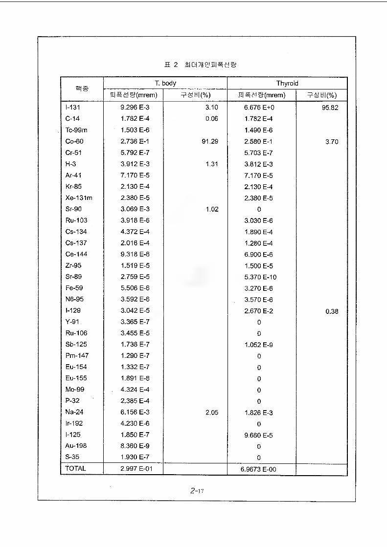
H 2 S[»eJE| = £jW
@1#T. body Thyroid
^(mrem) ul^<y W(mrem)
1-131 9.296 E-3 3.10 6.676 E+0 95.82
C-14 1.782 E-4 0.06 1.782 E-4
Tc-99m 1.503 E-6 1.490 E-6
Co-60 2.736 E-1 91.29 2.580 E-1 3.70
Cr-51 5.792 E-7 5.703 E-7
H-3 3.912 E-3 1.31 3.812 E-3
Ar-41 7.170 E-5 7.170 E-5
Kr-85 2.130 E-4 2.130 E-4
Xe-131m 2.380 E-5 2.380 E-5
Sr-90 3.069 E-3 1.02 0
Ru-103 3.918 E-6 3.030 E-6
Cs-134 4.372 E-4 1.890 E-4
Cs-137 2.016 E-4 1.280 E-4Ce»144 9.318 E-6 6.900 E-6
Zr-95 1.519 E-5 1.500 E-5Sr-89 2.759 E-5 5.370 E-10Fe-59 5.506 E-6 3.270 E-6
N6-95 3.592 E-6 3.570 E-6
1-129 3.042 E-5 2.670 E-2 0.38Y-91 3.365 E-7 0Ru-106 3.455 E-5 0Sb-125 1.738 E-7 1.052 E-9Pm-147 1.290 E-7 0Eu-154 1.332 E-7 0Eu-155 1.891 E-8 0Mo-99 4.324 E-4 0P-32 2.385 E-4 0Na-24 6.156 E-3 2.05 1.826 E-3lr-192 4.230 E-6 01-125 1.850 E-7 9.660 E-5Au-198 8.360 E-9 0S-35 1.930 E-7 0TOTAL 2.997 E-01 6.9673 E-00
2-17
8I-J
'#l2iK I-0I3SHA aEBBS SiuPJiftRoicraRt siciBiKboissi-YE bpmybs
H0IC§S4=3IC|BIKE 3ft SIRS
iceikho bsiye * srate ess£iilYlfrft less KH9
IB IK oSICIBIKho BSS hYUOSHlPhl
lo^lYBS^#l#12 IK K) 15124= llOESBft IIIC IB IK to 1*5 lYE
MCE IK HO 53 BSS I-YIIOE Eiw MlClC B6I5SB 4 [fig]
IYH2E IK) BSS IK 45 12IK SB BE IK)I iCSBftSlClBIKto BSIO m SIClBSlYS
ft ##IClie IB IKE eSS hY IK) Hi fit IS BI25 IK)1*3 KYE es4 KYHOBlYBS 51fei (9
E)SM SICE m W^SIYhB 12
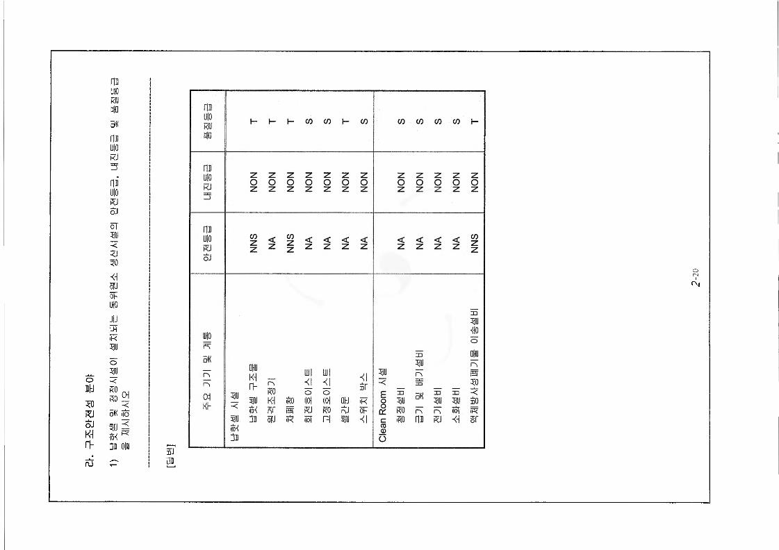
mUIORIUW5'KmUIOkJ5niuio
oJ
oTgu<
50
<\oFJot-LHO
JIJnriK5ID
m50R]oJK4r>
04
o 330 -<RO iRO < o'H ijo
FjB OIIU
nJ
CO CO CO CO I-
o o o o o o o o o o o o
Ok) K
BOB
o<N
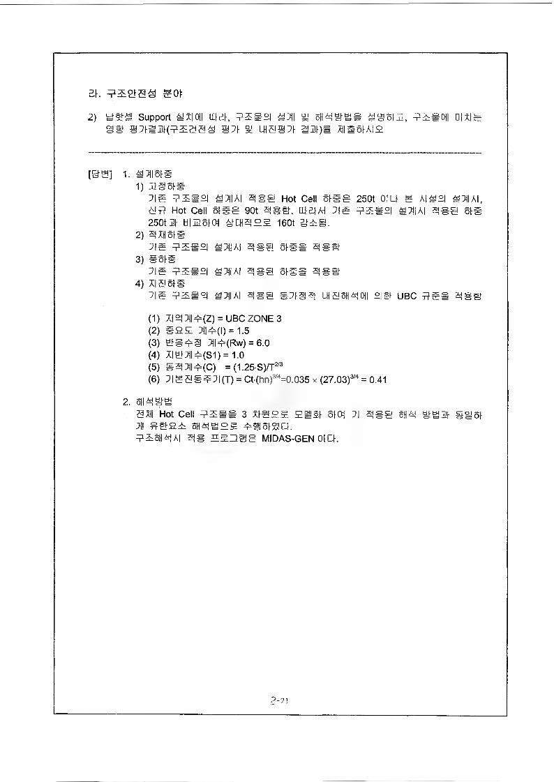
Eh SOI:
2) w-ai-ai Support S X| Oil Ehgt sxiamtsmaas @5i
i°l *5||Lna@;i
% 0H3SSS 19SIB,am)* mssiai2
I Oil Olxll
[&B] 1- in m sis1) 3351#
515 mms°l *5||A| 3S@ Hot Cell SISS 250t 0|L| g A|^2| iOlAI, Aim Hot Cell SISS got 3*1. El El AH 515 5ES°| M51IAI 250tm tilHSIOt 3CH3B5 160t gii.
2) 3 AH SI#
3*1 oh
5|5 EES3) #51#
515 SB#4) xi a sis
515 EES°I
SI S5IIAI 3*1 SIS* 3SSI-
SI S5||A| 3*1 SIS* 3*1
*5j|A| 3*1 #5133 LH5SH31 mi UBC 2 XHssr
(1) XI3 5j| 5(Z) = UBC ZONE 3(2) S2B 5||5(l) = 1.5(3) 1*53 5||5(Rw) = 6.0(4) XI151I5(S1) = 1.0(5) S3 5115(C) =(1.25-S)/T2/3(6) 5|55S55|(T) = Ct-(hn)3/4=0.035 x (27.03)2 3'4 = 0.41
2. SH3SSaxil Hot Cell ?5iS 3 xlSES Bill S|01 5| 3*1 SH3 S3 HI SIS! 5H! 1125 5H3B2S 5#SiaC|.5E5H3AI 3# EE3SS MIDAS-GEN 0|C|.
2-21
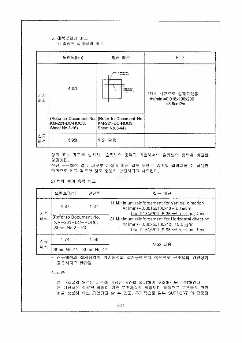
3. giaam°i Him 1) SSIH SmHim
4.37t
As(min)=0.018x100x200 =3.6cm2/m
(Refer to Document No. KM-221-DC-H006, Sheet No.3-16)
(Refer to Document No. KM-221-DC-H003, Sheet No.3-44)
ami se ms¥ sxiai ;isma°i #%H2| sas turns-amoict.am Emma am mma asm me i¥ mss amxiB ]| a ms Be°£ Him ssa- am sssi sasicim Atsact.2) ^x(i am Him
ag!B(t-m) IE HUE
7|g
ma
4.37t 1.37t1) Minimum reinforcement for Vertical direction
As (min)=0.0015x100x40=6.0 cnf/m
Use D13@200 (6.35 cnf/m)-each face
2) Minimum reinforcement for Horizontal direction
As (min)=0.0025x100x40=10.0 ctf/m
Use D16@200 (9.95 cnf/m)-each face
(Refer to Document No.
KM-221 - DC—H006,Sheet No.3-16)
am
ma
1.74t 1.56t9M EE
Sheet No.44 Sheet No.42
* EEmasi 7iEmaa ammm Em#°i aaaoieeaam B&i
4. as
s sms°i s nag ]ieoii ass me oil amsiai smmas assisia. s ms ah oil ass sieoi ;is smmaa siesci asms sms°i as as sssi a a mm m a stm, s;iams s¥ support °i ggsi
2-22
fUw ou ii Qd rJD igO rn ^ “ ffl -U 0# 10 HE It HU iS
E;$> hM »
Eh mot
3) SIS a AH (Document No. KM-221-DC-H003 % H006)B 1SSIAI£.
[9S] S¥ S3
1) KM-221-DC-H0032) KM-221-DC-H006
2-24
JH 3.
KINS 24 44444 4% 444
I-S
(Slk -g-kftir ft lb ft‘fyfr ^-h{s, WZO‘2002) ZH-C280 #ft : k-Bftft 'I
kS-& ftb
HeklsMvR- Psft fek {^tsfcSi <^kF>^‘R'{k is-h-k
03ICO
N4
44
Aoftl4Arfar|»
4
iffi.A
lie J2,Tib4
*Nr&
-frokr£parin4Ha|tl|o
4o2i4,4
($4
Aoj»4nir*_£,4I#'444
U4hJH>
rfa44okH®4faKJ4
44
ioj»4
4rSL44
<44r|r
Ha44
H>ok4
44okHa4fa
b£opo(ll|»
4ri,
44oj»W|o4o£4
44obHa41*%
4rjam|o4444jo
Hu44
440&40-3,N
xa4AJIL4itija4444
44
rS,
— 0$,
4 rbc& «£Hi N-
i4^4
4
xaa,4
4 4xa r$ H» ^o£44o
4nr°N4H>tifL444
4A
44
444
4
(###4)
4- #7l#ti)l) #4 #4 2]^ ##44 4-4 4^# 4M44S.(7» 7] 3:2] *7]* #4 ## ^ 3L#4, 4l# ^ *4*, 44# ^ #
4#4 4|# #7] 5. ###£3 ^41##^ II **3 *3.#7] 7] #2] #41 3,^5.S7jo] *##3 ##* !&#&
(##)
#- *#4 #44fe ##Bg 3.-41- ** ^-7] 3 7]3 #414] **44 #e
44. [KM-793-MC-003, T & ID OF HVAC SYSTEM FOR R.I.
BLDG (HOT CELL AREA-1) *S]#415. ###4*#* 4#44l44r #44 41S # #**4#* KGMP
(*4l 2]## 4| S * ###s]7)e) S#4 4# #3 #3 7]-^ #5.5.
#414 #1-44.^44 41# # S*#, 41# # *4#, #o]# ^ #2] #2] 3 3£ 2=3g
3 #Af# A>37 4;#om- ##4 #* ^4^4^ *#4#4 3### #4 fr4 #44# 3L5]S]3 SS44. A)# Lfl ##o] #A] ##o] d># *A]#
*4 4^5. #*gs)B-5. 244# *4& 4 AS #3 A]## #3 5]#2] 3 wS. s#3 ### 4 S3 #437 #4# 4 4.
44# ##eg 3-4* 4* *7144 s #414 314# *4*^ 4** #4
#7]#44 33^ ^#3 3415. #4-43 #0] 444# 4L5 *4# 44.
* *4#^ *# #4 44 3^c*£• 15-28 °C, *41 30-65 %
[#^1- 4* 71231-776 (2002.10.01 ‘44M#-*##7> 34* ** ##*# is#4 **)
3-3
(4444)
4. 47)4«11) 444^)4 4444 44 4^1- 4 4 44.$..(4) 44^ 444#-45.jl44 44 ^e|2 44°1 444 4 4
4 44 4 4 #44 4444, 444^-(S 1, 2 ^ 3)4
4850/4030 CMBMl 4)4 44 #4 f-o) =44 44 5.44^.
-g- n
(44)
44 4)44 4444 4#4# 445.4 444 44 2.4 4)44
44 4 #44 4.
3-4
(4444)
4. #7)44l) #4444 ##44 44 4-3.1: #444-£.(4) #44(Bank 4)4 4)7)4^^ 4)44#4# #44# 4^.5. ##
##7> 444#4M4 71)4(4)
(#4)
#7) 444 ##44 #44# 4#4 #4# 444#45.514 7H(4)
44* #4# 44 3.4 #4 ###44. 0.42. ### 4#4#-45.^
4# 44## # 44-7} #3.# ## ### s.# 4#-!- #444 ##4
2.4444.
3-5
(4444)
4. #4441) #4444 4444 °H 45.# *ll444-£-.(4) 44# 444#45.314 11.3.4.1.2.4, 2)4 (2)44 # 4, #44
44"—5.4 44^44# #4 4#4 4 4# M4# 444 4 n 445-4 44
(44)
444°)]# 44 #4 4 45.444 #444 444 ## 4# 4 5.44
7} 4#4 jl, 44444# -2.4 45-3.4 45.44 4#4# 44 45.4 #
444#44. 215)37 44 4# 44# 4#4 44 3.4 #44 444#
45.314 44(4) 4#4 #444#4 4-
3-6
(4M44)
4. 44441) #7)^0) 4 #€#4 44 41444-*..
(4) 44^ 444^-45:2.4 11.3.4.1.2.44 2) 4 3)4 4444 »H4 #& 44444 %4 44 44 44 444 44-8-44- 444 44 44 44
(44)
4444 &-& 44—5. 44 4441: 24# 4)^ 44 44 44 Stand-by43! 4^ »H4 444 line°-5 44 45.44: 44#^-5_4 44 44 444 44 -9-4-1- M434 444- zz.43. 44 44 4-S-i-4-9-4 44 3.4 4^44 444524 44(4) 4-1-4 4444^44.
3-7
4. #4441) #4344- #344 44) 4&# *114442-.
(4) 343 344342314 11.3.4.1.2.4, 3)4 44443 "... 34
4444 44# IIEP A 444 ...”5. 44# 344342314 4
4(4)
(44)
44 434 4444 4343 434 44# 344 342314 44(3)3
43# 44 3.4 434 44 4#344. 242. 34# 344 342314
43 34)33 3 444 #s# 34 44# 2.3 333 3444 4)34
314444.
3-8
34 1.
© Page 11.3-29
11.3.4.3.3 4 #94
3) 94 9# 4471
97)93447)^ 9444 49499 - 94944 949 44499344 44.971344717M 34444 4#44 999 494 44.
- 9HMa #1 9494 : 3%1- %3»3a #2 9494 : 34- %3#a #3 9494- #3#a #4 9494
- 97M944 943
<94 ^ 4^
3L4
<84, 9^ ^ 9444
© Page 11.3-36
11.35.3.1.8 443434 4X1XI4# 3-#3 43 3443=^71 (47M9)
4449 33#a-44 944 3#49 444 4941 4# 44444- 444^4. 4 444
#49% 444 3-713949 39 4#4 4434 ^49 #41 #3 o.& 3#44. 444 934
49 #3#a-44 944 3-#49 4^44444€& 443 44 4^4 3-#3-7l93X| 4
9 93-944 4#3#9 371444. 4* 44 44-44 4 371439 4#449437la.4 #3
"34471-113.44 "5.4 44^44"4| 7l#4 44 #34X1 44444.
1) 4# 4^1-4 4
4^4@a-44 947) 4#49 3-71371X1334 97l& 44 443 4X1^134 ##3-^1339
5. 11.3-104 44.
2) 4443 3 7144-#
44& 44444 4#44-43M 4# 93 944 ;D4X) 44 44 4444 44# 44 4)4
43, 7134# 3 XI3XI Ai-g-g 4# 44 444^ 4#4 44449-3 44 44^71^.3.^1^ # -§-4 39 444X1 3|444.
3) 37144-
#33a-44 444 ##49 #71371X1349 944 443 44444 ###71334 49
94 934 434 44 44 4944 37134-9 9 11.3-114 #4.
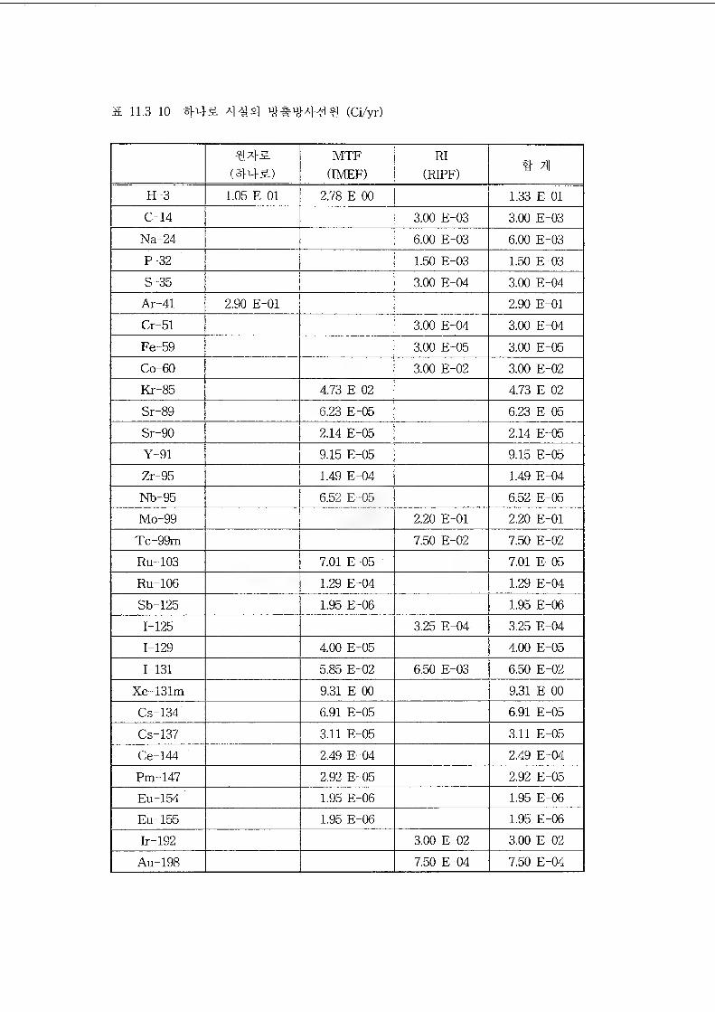
& 11.3-10 (Ci/yr)
MTF(IMEF)
RI(RIFF) # XI
H-3 1.05 E 01 2.78 E 00 1.33 E 01C-14 3.00 E-03 3.00 E-03
Na-24 6.00 E-03 6.00 E-03P-32 1.50 E-03 1.50 E-03S-35 3.00 E-04 3.00 E-04
Ar-41 2.90 E-01 2.90 E-01Cr-51 3.00 E-04 3.00 E-04Fe-59 3.00 E-05 3.00 E-05Co-60 3.00 E-02 3.00 E-02Kr-85 4.73 E 02 4.73 E 02Sr-89 6.23 E-05 6.23 E-05Sr-90 2.14 E-05 2.14 E-05Y-91 9.15 E-05 9.15 E-05Zr-95 1.49 E-04 1.49 E-04Nb-95 6.52 E-05 6.52 E-05Mo-99 2.20 E-01 2.20 E-01
Tc-99m 7.50 E-02 7.50 E-02Ru-103 7.01 E-05 7.01 E-05Ru-106 1.29 E-04 1.29 E-04Sb-125 1.95 E-06 1.95 E-061-125 3.25 E-04 3.25 E-041-129 4.00 E-05 4.00 E-051-131 5.85 E-02 6.50 E-03 6.50 E-02
Xe-131m 9.31 E 00 9.31 E 00Cs-134 6.91 E-05 6.91 E-05
Cs-137 3.11 E-05 3.11 E-05Ce-144 2.49 E-04 2.49 E-04Pm-147 2.92 E-05 2.92 E-05Eu-154 1.95 E-06 1.95 E-06Eu-155 1.95 E-06 1.95 E-06Ir-192 3.00 E-02 3.00 E-02
Au-198 7.50 E-04 7.50 E-04
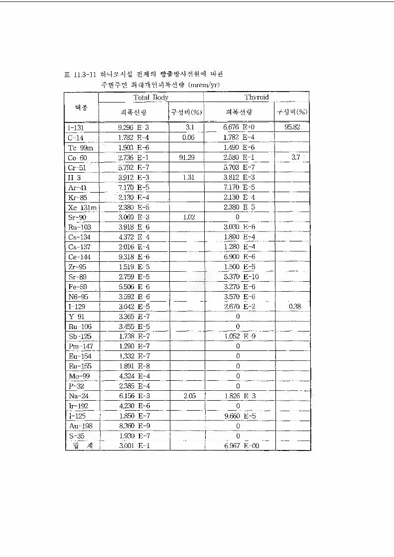
a 11.3-11 #43.4-# 4#
44)7111! 4#-id (mrem/yr)Total Body Thyroid
1-131 9.296 E-3 3.1 6.676 E+0 95.82C-14 1.782 E-4 0.06 1.782 E-4Tc-99m 1.503 E-6 1.490 E-6Co-60 2.736 E-l 91.29 2.580 E-l 3.7Cr-51 5.792 E-7 5.703 E-7H-3 3.912 E-3 1.31 3.812 E-3Ar-41 7.170 E-5 7.170 E-5Kr-85 2.130 E-4 2.130 E-4Xe-131m 2B80 E-5 2.380 E-5Sr-90 3.069 E-3 1.02 0Ru-103 3.918 E-6 3.030 E-6Cs-134 4.372 E-4 1.890 E-4Cs-137 2.016 E-4 1.280 E-4Ce-144 9.318 E-6 6.900 E-6Zr-95 1.519 E-5 1.500 E-5Sr-89 2.759 E-5 5.370 E-10Fe-59 5.506 E-6 3.270 E-6N6-95 3.592 E-6 3.570 E-61-129 3.042 E-5 2.670 E-2 0.38Y-91 3.365 E-7 0Ru-106 3.455 E-5 0Sb-125 1.738 E-7 1.052 E-9Pm-147 1.290 E-7 0Eu-154 1.332 E-7 0Eu-155 1.891 E-8 0Mo-99 4.324 E-4 0P-32 2.385 E-4 0Na-24 6.156 E-3 2.05 1.826 E-3Ir-192 4.230 E-6 01-125 1.850 E-7 9.660 E-5Au-198 8.360 E-9 0S-35 1.930 E-7 0
3.001 E-l 6.967 E-00
® Page 11.3-37
11.3.5.4 *4*44*4
44* *214** *4*^ 4*44 *** *4* 44*4 444*44 *#
^-* 3|4& *4*^4 *444 %14. *4* 4444 ^ 4*4 4444** 4* 4**
** 4a_4 **44, ae 4**a* **-Aj 4*4-7} *e*4 ^ *4 ^44-2., **4*4 3)- *4-4 *e7}***4 *44* 44* *4*47} jl454. ** 444 **** **444#* **#44 **44, *7*47} ## *4*^4 *4* 44 **4*; 4-4*4# *#*-2.4 ###
a., %* 4^444 *##44 #44 ol=.(^7:]S.a., 44#**44 4## 7}** # 4^3}#4.
4471* 44*-* ##4^, tilHA] *^#4 #**4*4 *3]* 44 ***# 4#*c}. 3E*4* *4-* *47} #4* * 4.* 44-7]*# 4)7144714 *^#4 *444 4444 4147}
*# #** *47} *-#7}*# *4* *4# 444 4#-# *, 44**# 4*4
**4a-44 4* *44 44 *44* *4*3}7l. ^##*4 #44 #44 41** *4*
^444*4 *4*44444* *4^a4 *444. **41414 #** 4444** 4**
4444* *4*44 **44 44*4. 44*45- 444 44144** *4*44444*
4#4a& 4**4. 4** 4444* 4-4*4* **444 4*** 44 *4* 4#o&
4444 a!4.
#5 3.
® Page 11-35
11.3.4.1.2.
4) #44#
(1) 5544
- 545 *45^444*4 54#4# 4*44 *4# #544 445 444
#* 4*44 51-a] yfl7li>4.
- 4&* *44^4 ^#4 ^.545 54 5 54^4# 5#44 444 4#5a-44 44 g
454 45# #444 454#^* 4#4.
- 4#5a-i,2,34 #2:^44 4#4a-44 #^#44 -2:5454 ^ ##s* 5544 4^
5 ###45* 444 4# 3 a##, 4a 5 #44, 5 #44-2: #44^4444
4 57)4#* #-§-4-^1, #-#4 444# 4& % #4544# #44^44444 57)4*4
4##&44* *84-4-4 54444 5#, 45 5 454 44 #4^4* ##444.
- 47)4** 4*47)4 #44* 5-444.
- 544 5 #444 5# 1E44* Interlock# 4*44 4*4 3454 5 #4444&
#44# 4# 5444.
(2) 45 ^ S54, 5a 5 #44, 7g44, #444 #44#
- 5 7)2:4#45^5444 #^444 #4 4544 #a=# #4* #544 44 #,#5. &5# #4
44, * 57)4^-44 5444 #5# 45 44* * 5# 55 ^ #444s# ^.544 4
44 Blow Filter Unit(HEPA 4 44 44)* 4444.
- 54 ^ #7l
44 45s* #444 44 Blow Filter Unit4 444 HEPA 444* *44 444 *4*
#444, 44# 44 44# 444 #s* 544 47)44 HEPA 4444 44 445 4,
*4€SAM4#4 5tig4 4H4 4444 47)44.
54## 4*4 .2.4.5 4454* 444 444 o_g. 4=4-# #4444 44.^ ^44#^^
##* #444 444 *5# 544s.# 44, 4* 45 *4*5 ^4* #443. 4*&*
4 #44# *4# MOD 444* 4*44.
##& 554 #443* 44#* VWF 444 444 44 *## ^#44, 100% *54
#* 24 4*44.
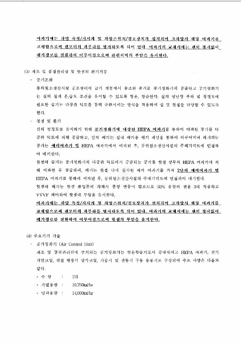
447M# W #4/4441 ^ 4^44/^S^47} #444 s444 m*Z 444#
a^l#S&4 #&44 4^-## ^4#S# 4 4 914. 444# a*fl4 4# #4 4 4 Si 4
all 4 4 S# ###<4 4 #4 4 S.g-4 #^444 #-<## #444.
(3) X|2: ^ ###4# 91 %#4 #43]#
- #7]2:#
#fl#^##4# ^#44 #7] #4# #4#444 #^4^ ?4^44
# #4 #,<&s #4# ^ ^S. ##, #e#4 #4 ig\}^ #4 g 4#s4
^4# 4^ 4s# ^ ^#44# 4"#& ##44 # ^ 4## 44# 4" sis#
#4.
- 44 9l #444 44s# 4447] 44 47144-71 <31 xfl^ hepa 4471# #44 444 44# 4
44 4s<3| 4®B 444s, 44 47]4 ^q] afl7]-g- a])7] 4]^# #44 4#444 4444
47]4 44447] 4 HEPA 44444 444 f, #4#^4#4#4 #4714^4 444
4 *H4#4.
444 444 #7]447]4 444 4S4I4 #44# 44# 4# 444 HEPA 4444 4
4 44-# 4 4444, al#]# ## 44 #44 44 444# 44 24-4 ^94 44-7] 4
HEPA 444# #44 444 4, 444^##4#4 ^h1I44ji4] 4#44 an7]#4.
##4 *114# ## #4^-4 ;M4 #4 ##4 50% #44 #& 34 4#4s
WVF 4444 #44 #4# #4 #4.
447M# 4# #4/4441 4 44-^44/4^^-471- #444 s#^4 ^ o]^]#
a4l#S&4 #S44 444# 4h44s# 44 44. 44714 a^|A]ofl# #4 44SM
aH44&# 4##4 4^-44A-g-4 #44 4SI& -B-4#4.
(4) 4-S4 7] 7]#
#7] 4 S]-7] (Air Control Unit)
91 #4^4#4 #44#
44 4 4# 44a#
#4.
• # 4 : 24
- 7M-&4 : 10,750kal/hr
- 44-#4 : 14,000kal/hr
#444-4# ###^7]a.A] #444s HEPA 444, 44
7^4 91 4#4 f# ##4s #444 es. 44=^ 4&4
3.000CMH
BLOW FILTER UNIT
4^ 3 ^ #4^, ;g44, #4^4 444^, 44714 4
4#4 #4.
' ^r 4 : 54
- #4 : 900CMH
47M
' ^ ^ 44-§- ^ : 4,580CMH(24)
471-8- # : 385CMH04)
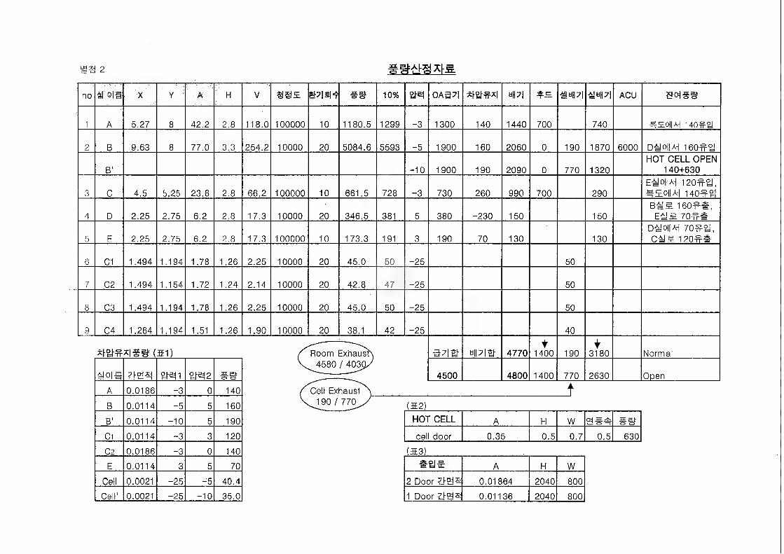
ns 2
no o|fi X Y A H V mm 39 10% OA5S np| 9“PI AMS ACU &oi39
1 A 5.27 8 42.2 2.8 118.0 100000 10 1180.5 1299 -3 1300 140 1440 700 740 ^soiis i4o#a
2 B 9.63 8 77.0 3.3 254.2 10000 20 5084.6 5593 -5 1900 160 2060 0 190 1870 6000 D#cH|Ai 160#^
B1 -10 1900 190 2090 0 770 1320HOT CELL OPEN
140+630
3 C 4.5 5.25 23.6 2.8 66.2 100000 10 661.5 728 -3 730 260 990 700 290
E-feJoUl 120^a, ^EOIW 140^2)
4 D 2.25 2.75 6.2 2.8 17.3 10000 20 346.5 381 5 380 -230 150 150160^3,
E#S 70#@
5 E 2.25 2.75 6.2 2.8 17.3 100000 10 173.3 191 3 190 70 130 130D^oilAi 70ea, C4!3. 120^#
6 C1 1.494 1.194 1.78 1.26 2.25 10000 20 45.0 50 -25 50
7 C2 1.494 1.154 1.72 1.24 2.14 10000 20 42.8 47 -25 50
8 C3 1.494 1.194 1.78 1.26 2.25 10000 20 45.0 50 -25 50
9 C4 1.264 1.194 1.51 1.26 1.90 10000 20 38.1 42 -25 40
*h£H?*l99 (51) /''Room Exhaust') as# tipia- 4770t
1400 190t
3180 Normal
i!o|# sas %M1 SHN2 #0
(4580/403g/
4500 4800 1400 770 2630 Open
A 0.0186 -3 0 140 Cell Exhaust ' ^190 / 770^/
..> k
B 0.0114 -5 5 160 (32)
B' 0.0114 -10 5 190 HOT CELL A H W a 39
C1 0.0114 -3 3 120 cell door 0.35 0.5 0.7 0.5 630
C2 0.0186 ”3 0 140 (23)
E 0.0114 3 5 70 aae A H W
Cell 0.0021 -25 -5 40.4 2 Door 0.01864 2040 800
Cell' 0.0021 -25 -10 35.0 1 Door titis 0.01136 2040 800
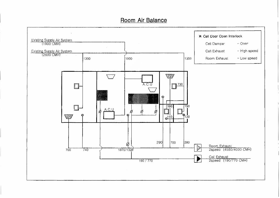
Room Air Balance
Existing Supply Air System(1900 CMH)
Existing Supply Air System(2600 CMH)
-r—
1300 1900
A.C.U
A.C.U
^ \ \
700 740
©
290
1870/13
730
380
J50
1300
* Cell Door Open Interlock
Cell Damper - Open
Cell Exhaust - High speed
Room Exhaust - Low speed
190
©
700
130
280
190/770
Room Exhaust2speed (4580/4030 CMH)
Cell Exhaust2speed (190/770 CMHF
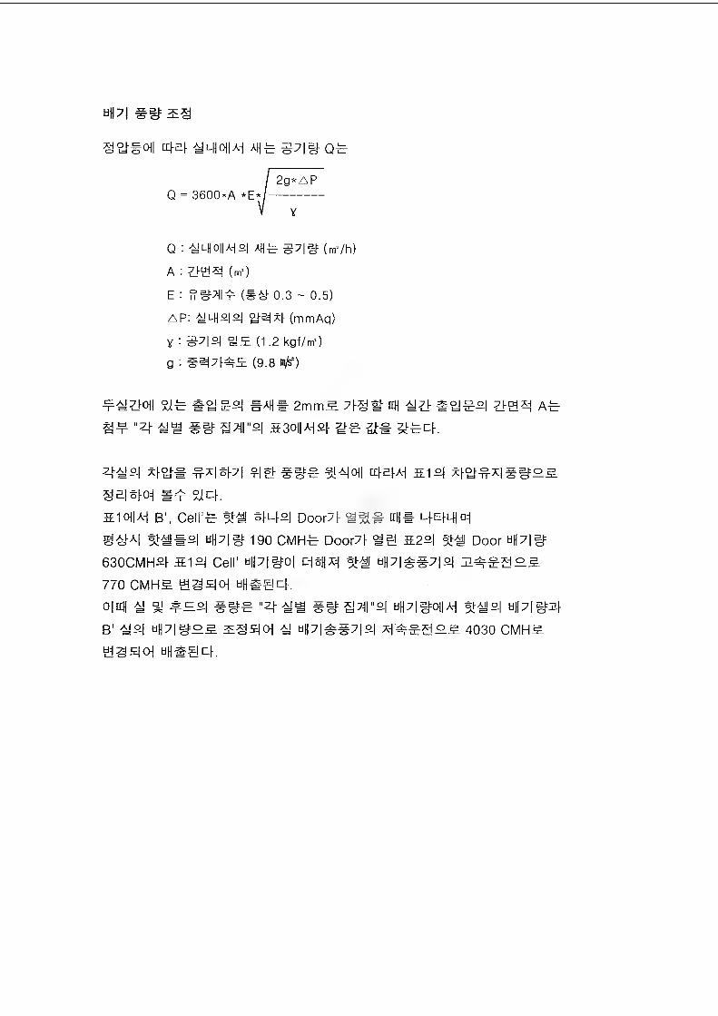
tipi ##
a^#oj| um\M ot
I 2g*APQ = 3600*A *E*/-------------------
V y
Q : ^ 1_H CHI AH o| ah - g7|at (m./h)
A : Z>g^ (m.)
E : (## 0.3 ~ 0.5)
AP: ^lHs|2| ye^f. (mmAq)
y : 37|2| (1.2 kgf/m*)
g : (9.8 m/s2)
#AH* 2mm5. 7^# nH A-
H¥ *zt ## s3t>iiAi^ a#
Z|^o| x^oj-@ ^%|#7| %AIOj| Oj-aw 51 sj A)OJ°X|f|fo^
SaloFoi $icK
OilA-i B1, Cell'-c ®ms| Doo^4 4eHI“I
^AU| %##°| uH7|g= 190 CMHt Door4 S24 Door 44#
630CMHSI- 514 Cell' up|^o| c#|jx^ %# hH7|^#7|°| 5#£*lo^
770 CMHS tiS4»| 4®@4.
o|nH U % ##e "4 um Spiral bH7|#0||A-{ $-i°| tiH7|iH
B' ^2-1 uplifS^ # UH7|##7[2| X-i^go^ 4030 CMH^
#344 tiUSScK
44 4.
kins 24 4442M 414 44 44 444

4%
1. #^7) : if# 0323-147 (2002.07.04.
7} 41 iM 4M1 7f|#)
4-1
(%4%4)
4. %7)%«11) %7i%«)4 %%%4 44 7>3.t- 41% %%_$_. (7» 7l^Sl ^-7171^0] %% ^ 3L%%, 41% £ *4%, 44% 9? %
4%4 41% %7iJE. %%^-s.s. %%s)4-h- «g^>^ %jl 24%4 7)%% %41 %,^22%o] %-%%% <y^%^ %%% ^5.7>s.
(%%)
% 7) %o) %%%^ %44ga-4# 41% Ta"7] xr 7]# %4H %44% 4lr 44- [KM-793-MC-003, P & ID OF HVAC SYSTEM FOR R.I. BLDG (HOT CELL AREA-1) %2]%4|3. %%%44#& %44 *\]2i ^ w%%4%% KGMP(%4l 44# 42 ^ #%%4%e) J3L%*11 %# %# %# 7)^& %25L #7) %2# %4]4 %-g-v) 4.^-44 41% ^ i%%, 4|% ^ #4%, 44% ^ %4%4 2%
# %%-% 7>3i ^oi4 4#4 #4 #%5-4^ %47}#4 4M% %% %7i 4% °il 7-1 244Lt -S.2<>14. %% 4 4«yo] %% %<yo) 44 %%%
44 41^5. ^44-5.5. 244% 44# %-8-3. %%4 %% %%4 #,#2 2%ir %4% %42 %%444.44-tI %%«ga-4# 41% %%445. %4N 2. 712.4%%
‘Calculation for HVAC System of RIPF BLDG', %% 3. ’Bank 4 %7] 2% %%%) #%%2 4%4%4 %7l%Hl% %e2 2%& ZLrflS. %#%tt % °1 444% %A5- %%444. (* #4%2 %# %4 4% %^2 2% : %2 15-28 °C, 441 #2 30-65%)412 4 #%%4%4 ##2^ 244 %7l%$}7]4 44 -ff%44, %%% %7l %^2 2%<% %4 ##2 7ie# %#%47] 44 %7l%#7l4 ^14,000kcal/hri7l 15,000kcal/hr2 %%% (%% 4.dml '%24 #%%4% ^4#% 4l%7f %2)
[%2]- %% 71231-776 (2002.10.01 ‘442%% %^47} 44% %% %4
%2 %2%4 =&%-)4-2
(4444)
4. #7] 44l) #71444 #444 4-5)) 4^.# 41444.$..
(4) 4444:45-^44 44 3.4ji 444 #4# 4 ^ #3=4 44 47]#44 #444, #44^(5. 1, 2 ^ 3)4 4850/4030 CMH4 44 44^7) f-4 i## #4 S.##5.
(44)
#7] xfl-i-4 #444 W4# 44-S-# 7}^# 44# ^4 5.4 4-§-4 #4 4#444.
4-3
(4414)
4. 44141) 471144- 44 #4 6>5fl 7}g.# 4|4«M,Sl.(4) 444 444 £4 5.314 11.3.4.1.2.4, 2)4 (2)44 4 4, 444
4-15.3.4 41^44# 44 4^-44 4i- #441 rfl# 14
(14)
€ 4f44 41 41/414 1 44^4 4/4 5.44 7> 1444 €4
°14 #14 47144- 7>^-4431 4^44 4-14: 4415.3.4 44: 5.
J:45.4 144#w44. 44 1-4 44-4- 444 #4 1.4 4
44 444445.314 44(4) 44-4 ^7>41^44.
4-4
(^4-44)
4. 4:7)44
1) #444# #4#4 °H 4-3.1- 4I44-4-5L.(4) #44 4444-43LJL*| 11.3.4.1.2.4# 2) 4
#-& 47)7)7)# #4 ^4 44 #4 4## 44 41% 4)4
3)4 #44# 4 7)
^-4-n-7)7> #4#
(#4)
# 4444 #-#- #4/7)44 # ##-><4 4/4 514-4 7} 44## 4# o]
4- M4 4)71^0.5. 4-^- 4 #4 33.4 4-4 4)«. sl# ##4## ^-4
i- 4#4 33. #44314 #44. ri5)3i 44 4-6- 4)#& 444 44 i. 4 ^44 #443517) 414(4) 4)M f7}##e#4.
4-5
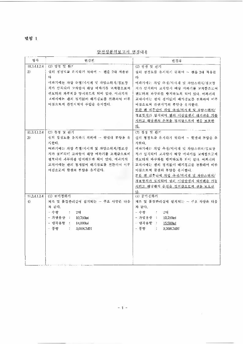
i
#4 #33 43*11.3.4.1.2.42)
(2)33 3 3333 33s# 3343 344 - #3 24 334434341# 44 43/344 4 44243/323 44 3333 3.443 44 443# 2314254 #3.34 444# 334s# 43 44. 3434 S433# #4 3343 433s# 4443 3# 33253 44344 #$1* #344.
(2) 33 91 4344 33S# #343 443 - ## 23 3*443434# 4# 43/333 93 44-243/323 33- #343 2333 44 343# 23425.3 4se)4 4*4# 434s# 43 $14. 3434 2^33# %4 33813 333s# 3443 3* 33254 44344 *3* #344.S4 3*441 34- 43/333 91 4*244/323471 3343 #4 34*33 433* 7l*332 #13*4 *3# 33425.4 4* SS44,
11.3.4.1.2.43)
0)33 3 43#4 33s# #343 443 - 9HM *"3* # 344.3433# 4# #3/333 3 43-243/3S3 33 #343 2.343 43 343# 231425-4 #se)3 4#4# 434s# 43 $14. 3434
a*||33# #4 33813 433s# 3443 3* 33254 4#4 *3# #344.
0)33 3 43-M4 33s# #343 443 ~ 9HM *4* # 344.34341# 44 43/3331 91 4*244/323 33 -M343 2443 44 343# 2Ml425.4 #S4 4 4*4# 434s# 43 94. 3434 2aM4|# #4 33813 433s# 3443 3* 33254 4#4 *"3# #344.S4 91 3*43 4* #3/333 91 4*244/323471 4443 #4 34*33 4331* 4#332 314*4 #3* 334254 #* SS4jeL
11.3.4.1.2.44)
(1) #33433s 5 #44333 334# ~ #2 42.4 3-4.- *3= : 23)- 7)-##%= : 10,750W- 34*3= = 14.000W- #4 : 3.000CMH
(1) #33433s * #344#41 #44# ~ *2 44# 4#4 44.
= 24- 7l*#3 = 10,750W- 34*3= : l&ROOkd- #3= = 3.000CMH
1 -
r
set XMRR Document No. : XI4-7 93-DC-H0 0 2
i.
;
CALCULATION
FOR
HVAC SYSTEM
OF
RIPF BLDG
COMPLETION'92.12. 3(M 44^1^
-§.<a ^ oto]a)3-^4 ISSUED
0 FINAL REVIEW'?z/V-.H
A A-lw(?- n
ff-u
REVNO
TITLE ORIG |DATE OLE DATE EDM DATEj PQE DATS pe r DATEDESCRIPTION R EV IEWy APR ROYAL
A HYUNDAI ENGINEERING CO.,LTD.
. 'H i r - - ;xvi“>:rv
~r & 8 L & Co-*J
/— /
r</ Q , & ~j~"s4&e “C
/
^ ^ P&-£f<Sr^ c^/7-e7?/>9-------------------------------------z-/'
4/^ £> G^G^C'Zr------------------------------------- ------------ 4^—/
/: o //€<7- X--------------------------
^^ Q y6^ yf ^7 ~ 0^4 (A^ <5*^vZ 1 ̂ — ---- — — —— — — —----- —— — — — S#-e I
Xk.v.
O
0
o
o
/
/
a/
arrywanz:ENGJNEH3INS r^ —s?*??- —P c —//<ro 2
R0^, aJq , y/ •€
^ / /-/
TT'b r'£ cRcCt/Yyt i'pf <r 5 RRt CckRcj^R&P&Jt? O.
fl-es^ /o-»V y4y Rc~j>p ayf ~r£<z- tCMA/R _
"7"-4-V Cai/ciAja^PRn ^cVLw^T RtzzR /cx*.*R
of P izp p. &/<s/j ,

2' /
z-one 2Z. r s*//^^‘-er/y ct/e/- ^re^ssur-e
Zo9)Z £ 3 »?9r7 — - A W9W
S-P'fiQ ^ ^ —/0?r> m /?■£ — —2 0 m », 42^
Zf 976 JV 'N - z~-7Ti7n4$ — _ >-=■ wvYiAg-
/) 7©x^«Aa^A€.
■S-^weA ,' j5»c , Af/.
^(.^7-6^- ,' —/Z^C
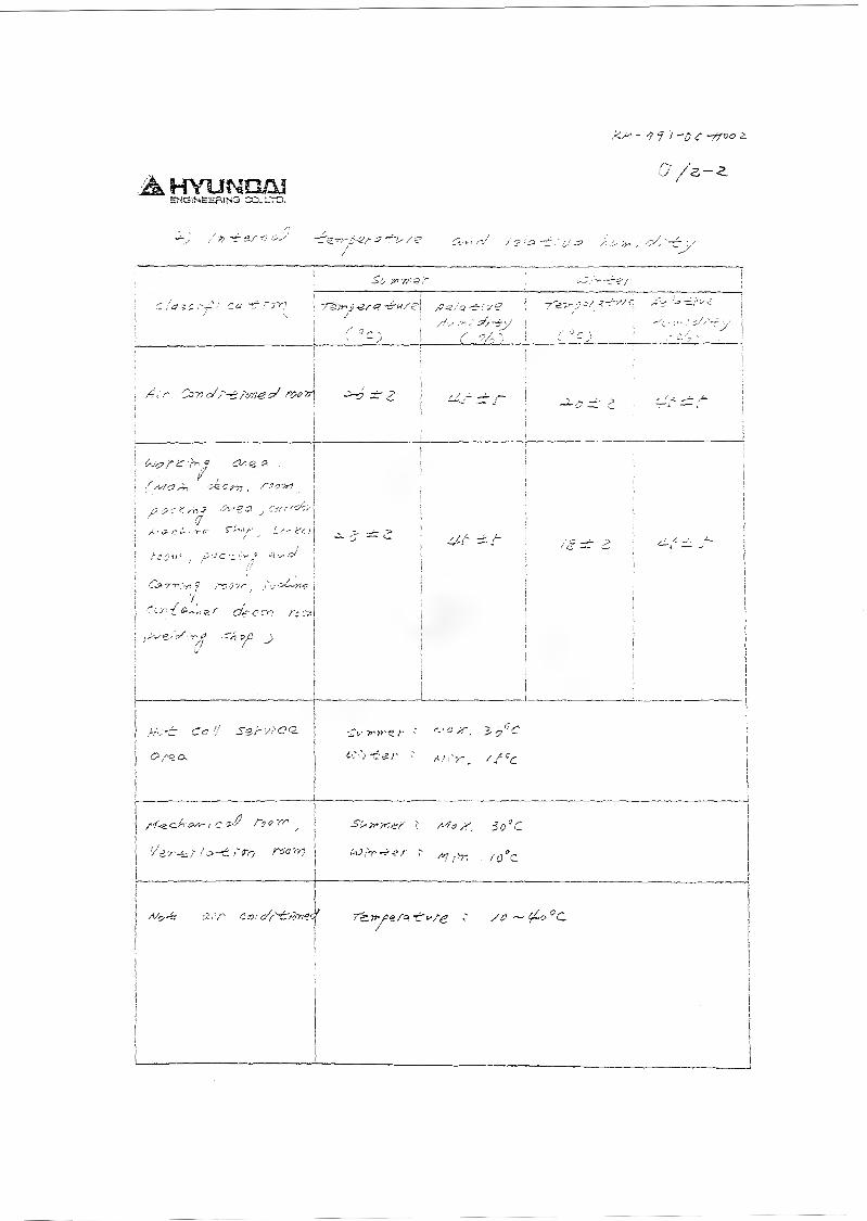
!<m - •y i )
5HG1NEER1N3 CQ-L.TD.
£<•►; -y /' ■ ' /■■■>>*,' "T" V
■
7~e7?'0-&r<? -r-w/f
f 3c;
yvS/Q -CrC f?
r o/;:;
T'e.Trfa,’ l-T-s/e xV •'•» 1y i
!........ ■■"•■ .... .
,
/,'r
i; !
' , / ,
ij I
! I,? -> r < yn v >- - —
(7/. ■ <? r i- ■ ->• c S‘'"‘>/'
j a! iX ./.
■’ Orr.V? J~TOTr /tv4jfc
C5/-2 a.
^ P}0’r^ j
/3/ -L/- /a-d 7^9 ,
:£V *'»’«.>• '
f-'v-d-gr ' /•/,'>-. //c<:
c do'cLO ^r> ~ir e /'
' ^ ,-hn . /y c
/vk-6 a,'r c r>> af{'-&rtrecf 7e.TrfiS.fa -f^/e ' /£>~^-o°C

,\4
i
a .40
.V,
o(.)
a
s£5zZ)
o
ROOM LOAD SVMPIARY ( )
%f)OMROOM MAM IT.
"'(S VOL. PEO-
j=t
wn ; . AIR VOL. (i,« ^/Lr) HEAT
LOSS(Kcal/ln:
REMARK?NO. SENS . LAT . TOTAL
HSIII™ (nA) M.,15 REQ'D' ACTUAl SUPPLY mANsnai OTiAusr
/?/ /><n rk/r <? V."Ar>’ / ' t) JC/o <? 7 // 7") f
/:/'/ O j'': / / «:f-: o jl.It/o ?? A (> .>■» f 0
/^/' /'<""/ //Co / O • ? p U1 o 4 o '■-■ //' o
/:::/ ' ' v/ /,’ > ». ■ ->,’> > 71 /..Li;, 3M»0 /A/') /> /
<< .71 > /()/,) /<■■{ / i o •’ -
••■■ 6'? /> .> -: /) sv 4/a•/- / /•• 0j- '? o r> // '^-D
/-" A o/ f/ / \YO ,: / v ,. u /oc#
,' >■ 6 y'-'o ,M'/o ^ f o — 3/0 c;- /• O
/ ?• V Cop ya/M) - n /Ufa J ->■■ / -- // JT>"- V- h 0 ~ °'6 o Ya;V
b i
TOTAL3^/V'T /-"7.v7
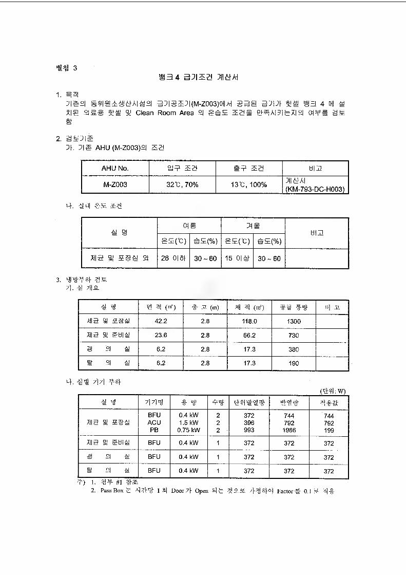
3S3 4 35I5S M/d
1. ^
:|gS| S?|@E*5iA|i89 3]|g2E:|(IVI-ZOO3)0i|Ai SS@ SEE SIS! S3 4 011 M x|@ °ISS 9J Clean Room Area °l g#E 52* a^A|5iaX|^ OI¥« S5
2. SEEEXL ]|g AHU (M-Z003)°l 52
AHU No. SJE 52 *E S3 ti|E
M-Z003 32C,70% 13°C, 100%(KM-793-DC-H003)
t4, #4| as sti
ni>
Ofi
01* xieHIE
5E(°C) h£(%) SEfC) bE(%)
M3 m 5S^ SI 28 0| ol- 30-60 15 0|# 30-60
3.7>. -a 7Bs
^ 3 (nf) # S (m) all 3 (nf) 8] Jl
HIS g ssa 42.2 2.8 118.0 1300
HI3 S Etil*J 23.6 2.8 66.2 730
^ °l # 6.2 2.8 17.3 380
g 2| ^ 6.2 2.8 17.3 190
L}. €1 7] 7] Jf§f
(%44:W)7|?M
BFU 0.4 kW 2 372 744 744HI 3 g 5Si ACU 1.5 kW 2 396 792 792
PB 0.75 kW 2 993 1986 199
HI3 ® Stiliy BFU 0.4 kW 1 372 372 372
a °| ^ BFU 0.4 kW 1 372 372 372
g °| # BFU 0.4 kW 1 372 372 372
E) 1. #12. PassBoxa Door7} Open 5]# 7^44 Factor# 0.1 S
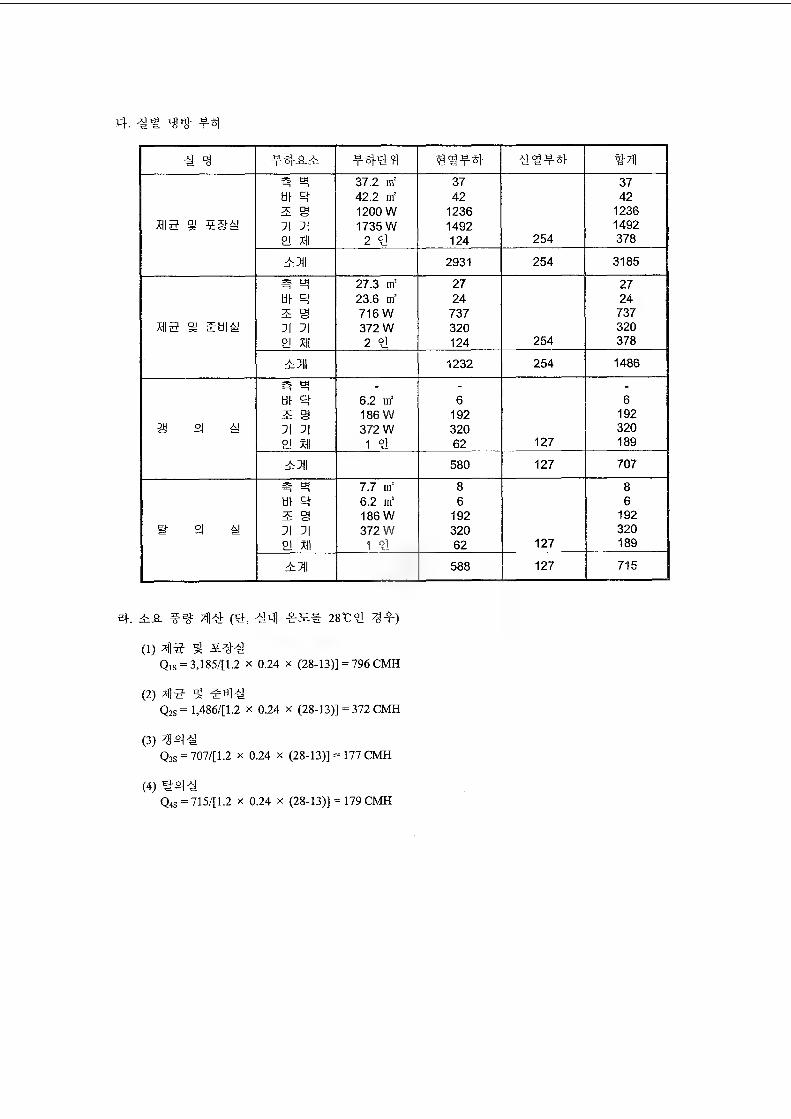
4. ig# 44
4 4 44-0-4 4444] 4344 4344 4d|
3& to 37.2 nf 37 37til 4 42.2 nf 42 424 S 1200 W 1236 1236
mg si 71 7| 1735 W 1492 14922! M 2 4 124 254 378
4:711 2931 254 3185
2| to 27.3 nf 27 27tit R 23.6 nf 24 244 @ 716 W 737 737
mg s 4hi^ 71 71 372 W 320 320
2! mi 2 <y 124 254 378
4711 1232 254 1486
& w - - -
til R 6.2 nf 6 6186 W 192 192
a 21 g 71 71 372 W 320 320
2J mi 1 4 62 127 189
47|| 580 127 707
# » 7.7 nf 8 8til R 6.2 nf 6 64 a 186 W 192 192
i- 21 £ 71 71 372 W 320 320
el mi 1 "9 62 127 189
4711 588 127 715
4. 4^. ^4 (4, 44] 28C4 ^4)
(1) >«a ^ 3E44Qis = 3,185/[l.2 x 0.24 x (28-13)] = 796 CMH
(2) ^14 ^ $44Q2S = 1,486/(1.2 x 0.24 x (28-13)] = 372 CMH
(3) ^44Qjs = 707/[1.2 x 0.24 x (28-13)] = 177 CMH 4
(4) 444Q4s = 715/[1J x 024 x (28-13)] = 179 CMH
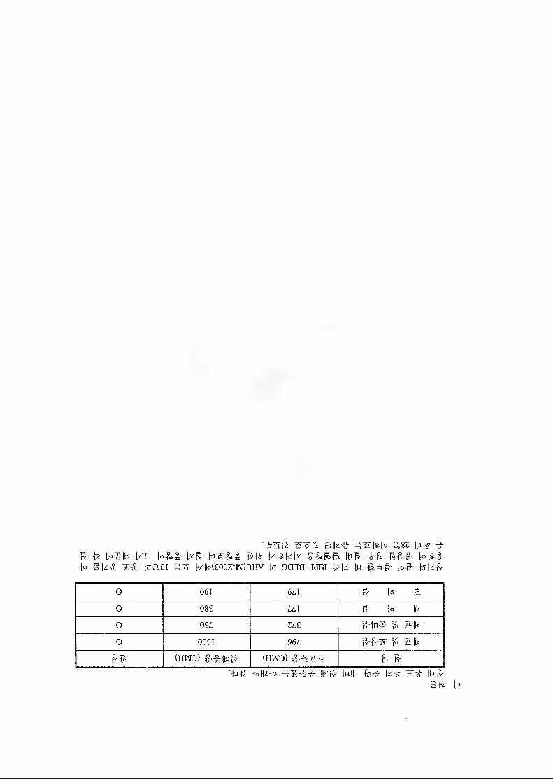
w-oK mk-w- asz ^E*" -k Ib-Q-Dn I£T= [o^-S: [k^- is|o k(s|-z[k [hil' "o"k -6--St Ik k>{s~§~k #ke T^r kasi ^3 kUp(Eooz-M)nHv k oma aaia #k -(« -&s& |o# #k-k
0 061 6 LI R- k #o 08E LLl & k Ik0 0%, ZLZ ^ elk0 00£I 966 ^ etk
k# (HMD) &^|k^ (HMD) k #-W #Kz{o ^3E=&& lk^ kW: k-tl- 3^ Ihg-
##
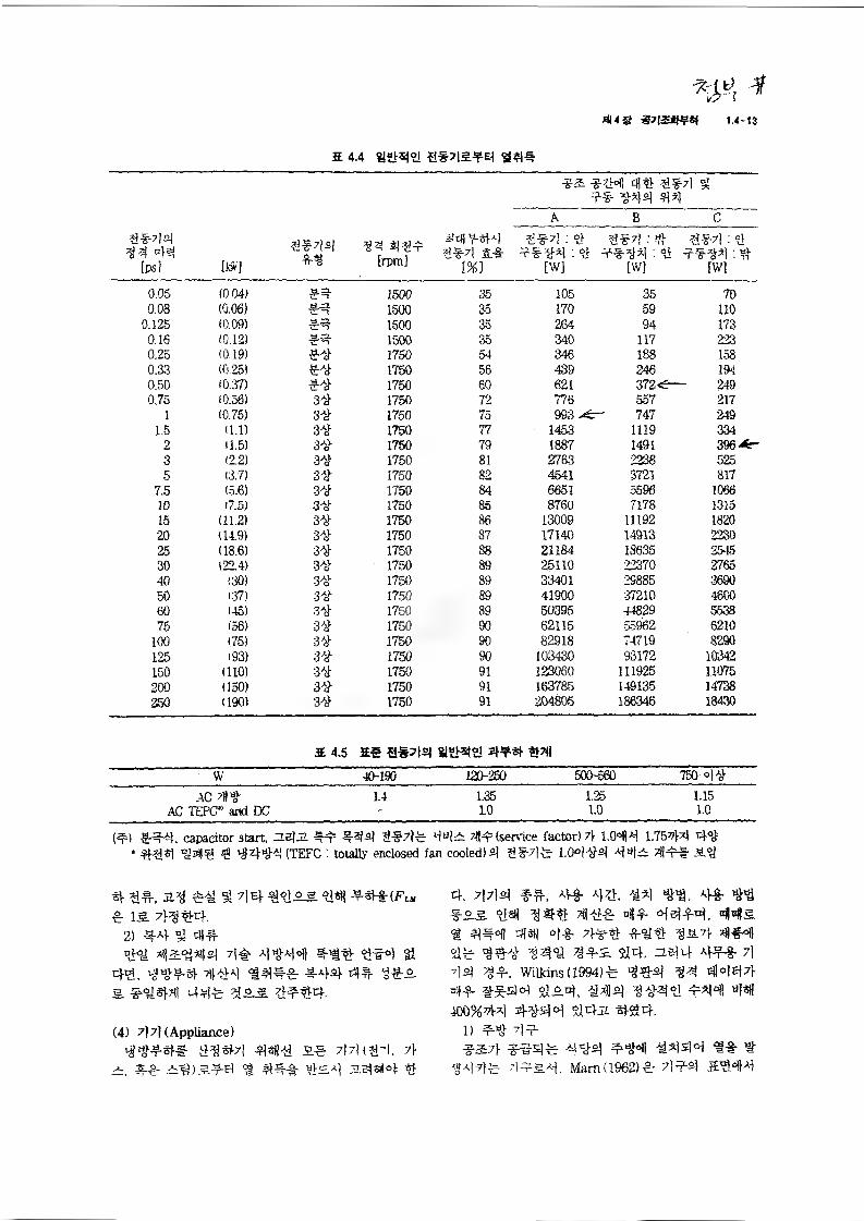
2 4.4 S*7|£*E}
W, *
*fl<S *7|5S^if 1.4-13
ti*7j°j^4 4#
[ps] m
a*7i4*g
33 434= :[rpm] d*?l &*
[%]
*2 *34 4% 3*4 g ** 344 44
ABC
3*4.% 3*4:3 3*4:3**34:3 **34.% **34:3
[W] [W] [W]
0.05 (0.04) ** 1500 35 105 36 700.08 (0.06) ** 1500 35 170 69 110
0.125 (0.09) 1500 35 264 94 1730.16 (0.12) 1500 35 340 117 2230.25 (0.19) ** 1750 54 346 188 1580.33 (0.25) 1750 56 439 246 1940.50 (0.37) ** 1750 60 621 372 <7- 2490.75 (0.56) 3* 1750 72 776 557 217
1 (0.75) 3* 1750 75 993 >d=- 747 2491.5 (1.1) 3* 1750 77 1453 1119 334
2 U.5) 3* 1750 79 1887 1491 396 *r3 (22) 3* 1750 81 2763 2238 5255 (3.7) 3* 1750 82 4541 3721 817
7.5 (5.6) 3* 1750 84 6651 5596 1066
10 (7.5) 3* 1750 86 8760 7178 131515 (11.2) 3* 1750 86 13009 11192 182020 (14.9) 3* 1750 87 17140 14913 223025 (18.6) 3* 1750 88 21184 18635 254530 (224) 3* 1750 89 25110 22370 276540 (30) 3* 1750 89 33401 29886 369050 '37) 3* 1750 89 41900 '37210 460060 (45) 3* 1750 89 50395 44829 563875 (56) 3* 1750 90 62115 55962 6210
100 (75) 3* 1750 90 82918 74719 8290125 (93) 3* 1750 90 103430 93172 10342150 (110) 3* 1750 91 123060 111925 11075200 (150) 3* 1750 91 163785 149135 14738250 (190) 3* 1750 91 204805 186346 18430
E 4.5 ES S*7|sj 81%$t2) 4*4
W 40-190 120-250 500-560 750ac 1.4 1.35 1.25 1.15
AC TEPC and DC - L0 1.0 1.0
(f) ftSf-ij. capacitor start, 0.5}Jl #4= =)*7)* 44^ 314= (service factor)7> 1.0414 1.7544 44' 444 4^4 4 4444 (TEFC : totally enclosed fan cooled) 4 g*/}^ 1.0444 44^ 44=* *4
4 4#, 2.4 M §1 44 €71.2-5 ysi) e is 7i4 €4.
2) 44 9i 44°}<M 424144 7}# 4444 44% 444 #
4%. 444L# Til*a} 4AM 44 $&£.5. #€#3| 44* 7i*2 44*4. 4 * *
(4) 7)7} (Appliance)^^*4# €€*7} 4sR* a.4 7|7|(€4. 7}
2. 44 2€)244 € 444 *2* 2.sW°|: *
4. 7)7)4 *#, 4*. ^ ^*25- *4% 31** ”D-r 4444, 44s.4 4*41 4sH 4* 7l** 44* 4*4** %14. 25)4 Al** 7)7)4 g*. WUMns(19941* €^4 4447)-4* #*sl4 $124, *44 4=441 44400% 44 4-4-44 %)42 4$) 4.
1) 4^ €**2:7)- *#4* 4#4 *444 *-& *
<M4* 7)f&A), Wam(1962)* 7)*4
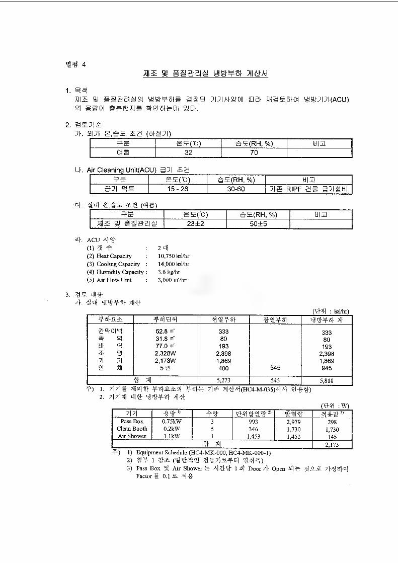
H4 4aia a yg*¥st ja&m
1. #4sis % sssbi^£| ymvsis asa :piai°h
°i g^oi sssxie srasfeQi si a0}B| XHg¥5K)1 ygPPI(ACU)
2. 3£Xi4. 21:1 s,bE sa (sn:i)
SE(°C) sE(RH, %) HIEOIS 32 70
U. Air Cleaning Unit(ACU) 3:1 22EM SEfC) h£(RH, %) HIE
15-28 30-60 ripf 2@ se-shi
4. #X] ¥,es (##)ES @E(t) h£(RH, %) HIE
xii2 a! saaEia 23+2 50+5
4, ACU #4(1) 3! 4=(2) Heat Capacity(3) Cooling Capacity(4) Humidity Capacity(5) Air Flow Unit
3. as. 4|-g-7}. ^4¥4 73#
2 tfl10,750 W/br14.000 kal/hr 3.6 kg/hr3.000 m’/hr
(#4 : kal/hr)¥4-8-2 ¥4#4 4#¥4 ##¥4 44¥4 XI
E140I4 52.8 nf 333 333tti 31.8 nf 80 804 4 77.0 nf 193 1932: S 2.328W 2,398 2,398:i :i 2,173W 1,869 1,8692! %| 521 400 545 945
4 X| 5,273 545 5,818¥) 1. 7] 7l# xlM# J
2. 7|?M 4# ^4¥4 XI#-4^ 7|# ^l##(HC4-M-035)44 #-8-4)
(#4 : W)#7] -8-4') ¥4 #4444^ 4#4
cjo
RT
Pass Box 0.75kW 3 993 2,979 298Clean Booth 0.2kW 5 346 1,730 1,730Air Shower l.lkW 1 1,453 1,453 145
4 XI 2,173¥) 1) Equipment Schedule (HC4-MK-000, HC4-MK-000-1)
2) a¥ i #2 (##4# #^7]a.¥4 #X|¥)3) Pass Box 5 Air Shower ¥ A| #4 1 4 Door 7} Open #¥ 3i -++ 44
Factor # 0.1 5. #-8-
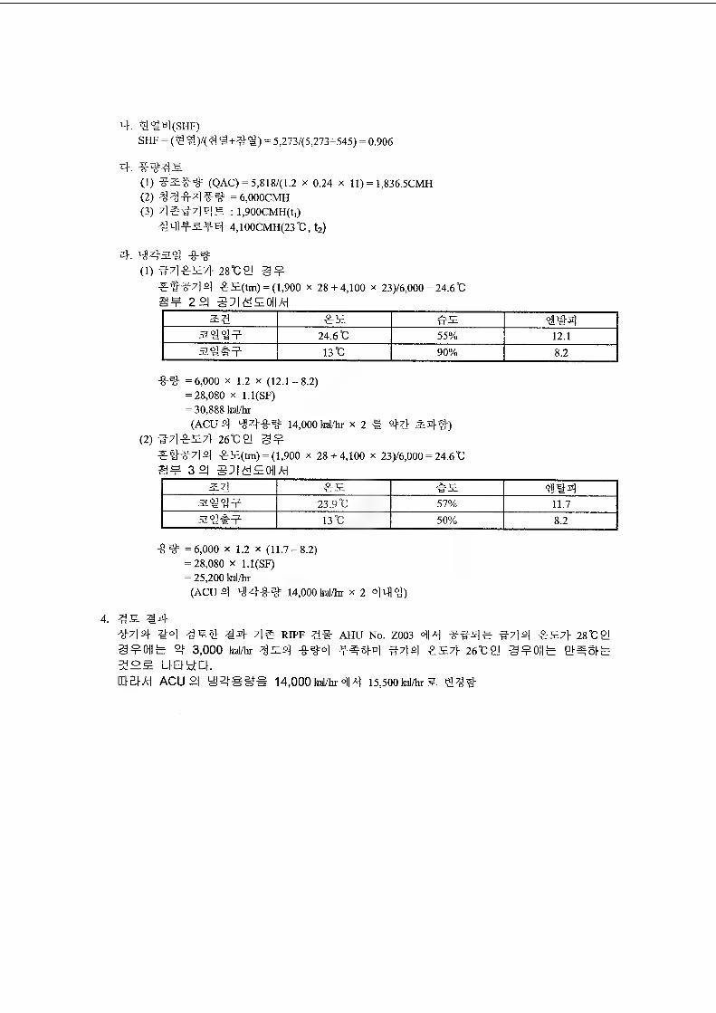
4. 3!%4(SHF)SHF = (3) #)/(?) #+4%) = 5,273/(5,273+545) = 0.906
4. %-%=%&(1) ?5¥%= (QAC) = 5,818/(1.2 x 0.24 x 11) = 1,836.5CMH(2) %%#4%-%= = 6,000CMH(3) 4#3-7)45 : l,900CMH(t,)
+3lH-t-5.-t-4 4,100CMH(23°C, t2)
4. 44a% %-%(1) #7) #57} 28°C2J @¥
# W7] 4 #5(tm) = (1,900 X 28+4,100 x 23)/6,000 = 24.6°C8¥ 22|
54 #5 #52 4 #424.6t 55% 12.1
13 "C 90% 8^
-8-%= =6,000 x 1.2 x (12.1-8.2)= 28,080 x l.l(SF)= 30,888 kal/hr(ACU4 44-8-%= 14,000 kd/hr x 2 @ 44 A4%")
(2)#7)#57}26t:2l @¥###7)4 #5(tm) = (1,900 X 28+4,100 x 23)/6,000 = 24.6“C @¥32
2:4 #5 #5 =84423.9 “C 57% 11.7
13 °C 50% 8.2
%-%= =6,000 x IJ x (11.7-8^)= 28,080 x l.l(SF)= 25,200 kal/hr(ACU4 44-8-%= 14,000kd/hr x 2 24%)
444-7)4 42 4S4 44 7)# RIPF 4# AHU No. Z003 <^4 ##4# #7)4 #57)- 2842)3 ¥0)1# 4= 3,000 kdAr %54 -8-%=2 #7)4 #57} 26%: 2! @¥0||# BIAS)#
32? UEMdCKID si A) ACU °| ^2|g@=@ 14,000 kal/hr 24 15,500 kal/hr 5
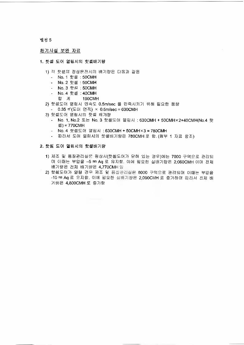
5
a#
1. St# E0| a#A|2| St#HIPISJ
1) at E#2| §ESSA|£| till 71 #E u#m mg- No. 1 St# : 50CMH- No. 2 St# : 50CMH- No. 3 St# : 50CMH- No. 4 St# : 40CMH
tl J\\ 190CMH2) St#ECH SilAI 0#E 0.5m/sec « 0#A|7|7| ?|8H I! EE S8
- 0.35 m=(ECH 0$!) x 0.5m/sec = 630CMH3) 5t#ECH g#A|2| St#
- No. 1, No.2 Eg No. 3 St#ECH a#A| : 630CMH + 50CMHx2+40CMH(No.4 St #) = 770CMH
- No. 4 St#E0i SlAI : 630CMH + 50CMHx3 = 780CMH- El El AH ECH ag'A|£| St#HH7|gfg 780CMH E It. (S¥ 1 XIE §E)
2. St# EOt Si!A|£| St# till 7|#
1) hie a sa@£i#s @#Ai(st#Eot7t get %g 3S)oiig 7000 e^ee seieOlffHg gets -5 mm Aq E ^XIE. 0|0)| SEE #tiH7lilg 2.060CMH Olffl SHI
tiH7|#S SHI till7|its 4.770CMH 02) st#Eot:i ay s? hie a sastEias sooo e«ee eei#™ oirag gas
-10 mm Aq E SXIE. OIOII SEE #tiH7|g=g 2,090CMH E #718101 III El AH SHI till 7IBS 4,800CMH E #71#
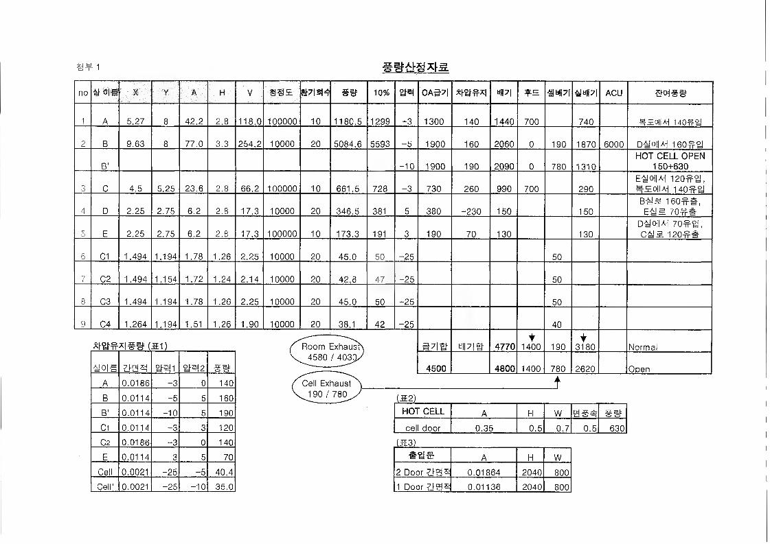
§# 1
no 4! 0|U X Y A H V 8S5 E)7|$I4 ee 10% 2M 0A57I in •a any aPI ACU
1 A 5.27 8 42.2 2.8 118.0 100000 10 1180.5 1299 -3 1300 140 1440 700 740 MEoliy 140# tJ
2 B 9.63 8 77.0 3.3 254.2 10000 20 5084.6 5593 -5 1900 160 2060 0 190 1870 6000 DmiM 160# a
B' -10 1900 190 2090 0 780 1310HOT CELL OPEN
150+630
3 C 4.5 5.25 23.6 2.8 66.2 100000 10 661.5 728 -3 730 260 990 700 290Em\M i2o#y, #SolW 140#
4 D 2.25 2.75 6.2 2.8 17.3 10000 20 346.5 381 5 380 -230 150 150Bti^ 160##, E^S 70##
5 E 2.25 2.75 6.2 2.8 17.3 100000 10 173.3 191 3 190 70 130 130D41 oll^ 70#gj,
120##
6 C1 1.494 1.194 1.78 1.26 2.25 10000 20 45.0 50 -25 50
7 C2 1.494 1.154 1.72 1.24 2.14 10000 20 42.8 47 -25 50
8 C3 1.494 1.194 1.78 1.26 2.25 10000 20 45.0 50 -25 50
9 04 1.264 1.194 1.51 1.26 1.90 10000 20 38.1 42 -25 40
WFFISS (51) ''Room Exhausb ay# 4770t
1400 1904
3180 Normal
tiolS yen 2M2 ##4580/403#/
4500 4800 1400 780 2620 Open
A 0.0186 -3 0 140 Cell Exhaust ) ^190 / 780^/
t k
B 0.0114 -5 5 160 (52)
B' 0.0114 -10 5 190 HOT CELL A H W y@4
C1 0.0114 -3 3 120 cell door 0.35 0.5 0.7 0.5 630
02 0.0186 “3 0 140 (53)
E 0.0114 3 5 70 A H W
Cell 0.0021 -25 -5 40.4 2 Door 0.01864 2040 800
Cell' 0.0021 -25 -10 35.0 1 Door yy* 0.01136 2040 800
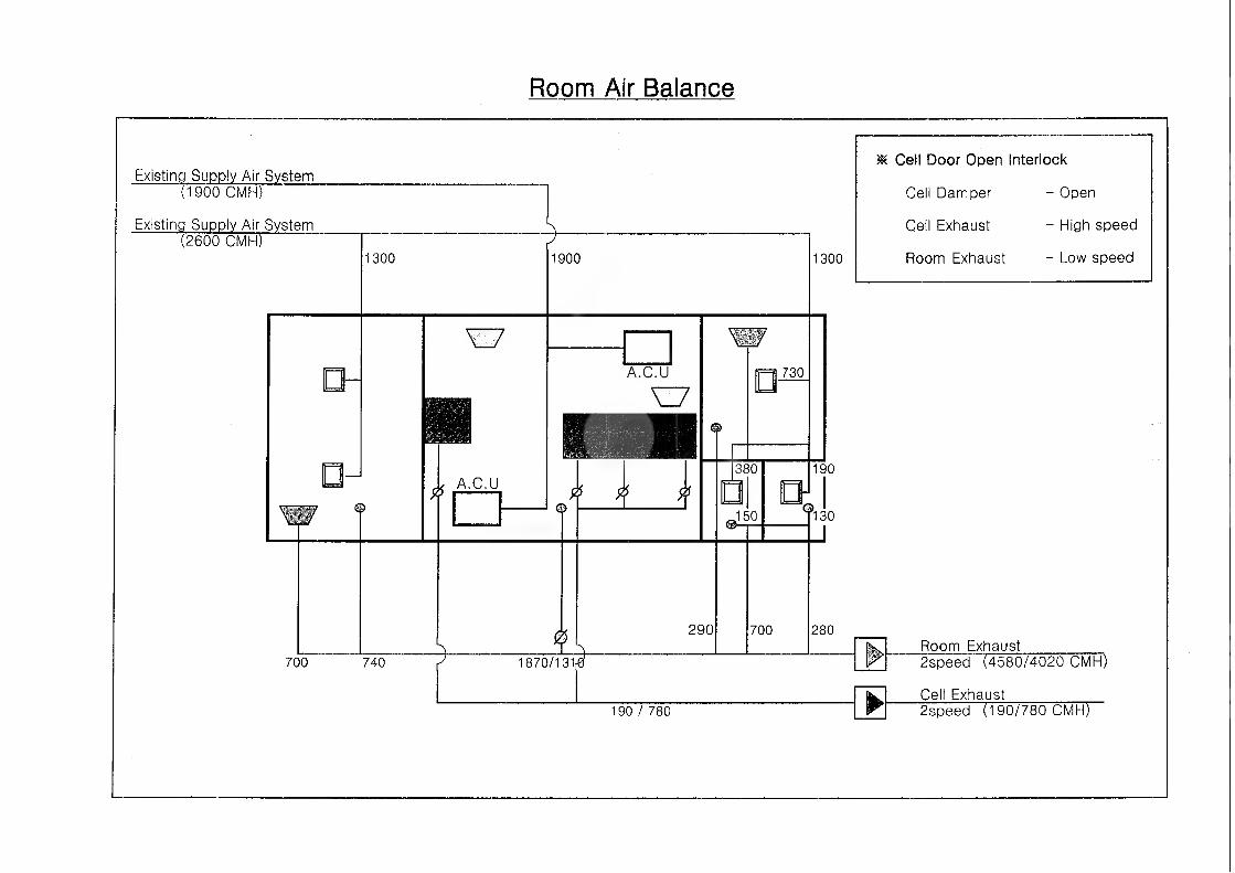
Room Air Balance
Existing Supply Air System(1900 CMH)
Existing Supply Air System(2600 CMH)
□-
1300
t
A
77
0 A.C.U
1900
©
□ 730
380
#.150
1300
190,l
130
* Cell Door Open Interlock
Cell Damper - Open
Cell Exhaust - High speed
Room Exhaust - Low speed
L Kf
►
Room Exhaust700 740 / 1870/131 <6 2speed (4580/4020 CMH)
Cell Exhaust190/780 2speed (190/780 CMH)
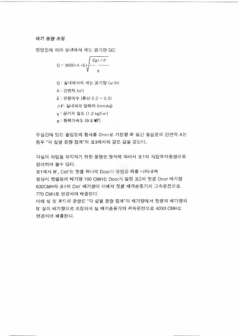
uH7i
I 2g*APQ = 3600*A *E*j---------------
V V
Q : s!LH01a-)£.) Atj^ #7|# (m’/h)
A (m')
E : ##01 f (S# 0.3 - 0.5)
AP: 6Wjs]2j ye^xl- (mmAq)
% : S7|o| me (12 kgf/m-)
g : (9.8
$j# e^SrOl §AH* 2mmS 7(g# ttH #oi ~o| yysj A#
4^ ## asoiws} K
i ##e %4oii 4&W S12-I
9Blew ## $Wh510ljAi B1, Cell c %# sms] Door7( 01# 4E(L||o^
^A^A| %##oj dH7|# 190 CMH^ Door?!^ &2s| Door w||7|#
630CMH2I-512I Cell' w|j7|#o| cisfjxi Hp|^§7|°| 24^3°^
770 CMH5. tigsfOj tifl@@c(.0|njj A! qj f co, #BCS "Zj-Ajig ##g7(|"o| tiH7|aro||Ai %#SL| UH7|#2|
B' -W&l tip|ai:oS ^g5|Oi ^ tiH7|^#7|2| X(^2£ 4030 CMH#
tiS^W tiiisgcK
JMf- 5.
KINS 34 44444 4% ^-84
#v}"3- #7] 4)
4j% f7} JLQ 7>s.
1. : fl-o] 0323-161 (2003.03.04)
5-1
£74# 1.
43 $ £44, 43 # *44, 444 $ #444 *44# 444 44 5-,*£54* 4*4* 4*4* 444s.*7)1 #^M1 £-
03^)
BANK 4 4^ ^ 4 -§-,4^7] ^5L %5L*) 4#
5-2

BANK4 ^15 ^ 4 ¥,-81-^71
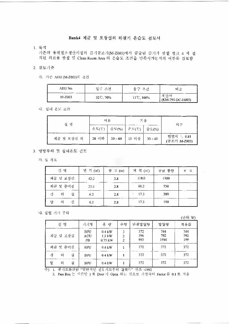
Bank4 4lS ^ #^7)
1. nr47]^ €^<44^^ 47)4^7)(M-Z003)4|7l 44€ #7]7l- «j)a 4 4) /#
4^.-0- 3 Clean Room Area ^) o)^#
2. ^S.7l§
7}. 7le AHU (M-Z003)4 54
AHU No. 9? 2:4 3:4 4 31
M-Z003 3212,7094 134,100% ^144(KM-793-DC-H003)
4. 44| frS 3:4
4 tg4# 7)4
ti]3Z42(0 ^2(%) 42(U) ?2(%)
4)4 ^ 244 ^
loooo<N 30-60 15 44 30-60 444 = o.8i(43:7] M-Z003)
3. ^#4# ^ 44142
7h 4 7fl_8_
4 4 4 4 (of) 4 31 (m) 41 4 (m') 44 44 ti) 31
414 4 244 42.2 2.8 118.0 1300
4)4 4 #44 23.6 2.8 66.2 730
4 4 4 6.2 2.8 ! 17.3 380
# 4 4 6.2 2.8 17.3 190
4. 41 7)71 4#(44: W)
4 4 7)7)10 4 # #4 #44:4%= 44# 4-8-a
BFU 0.4 kW 2 372 744 7444)4 ^ 244 ACU 1.5 kW 2 396 792 792
PB 0.75 kW 2 993 1986 199
7)14 ^ #44 BFU 0.4 kW 1 372 372 372
4 4 BFU 0.4 kW 1 372 372 372
4 4 4 BFU 0.4 kW 1 372 372 372
t) i. 4-7)3:31-44 “4444 4^7]afs) 444” #2 -19922. Pass Box 4 444 1 4 Door 7} Open 44 4-33. 7>4 44 Factor # 0.1 3 44
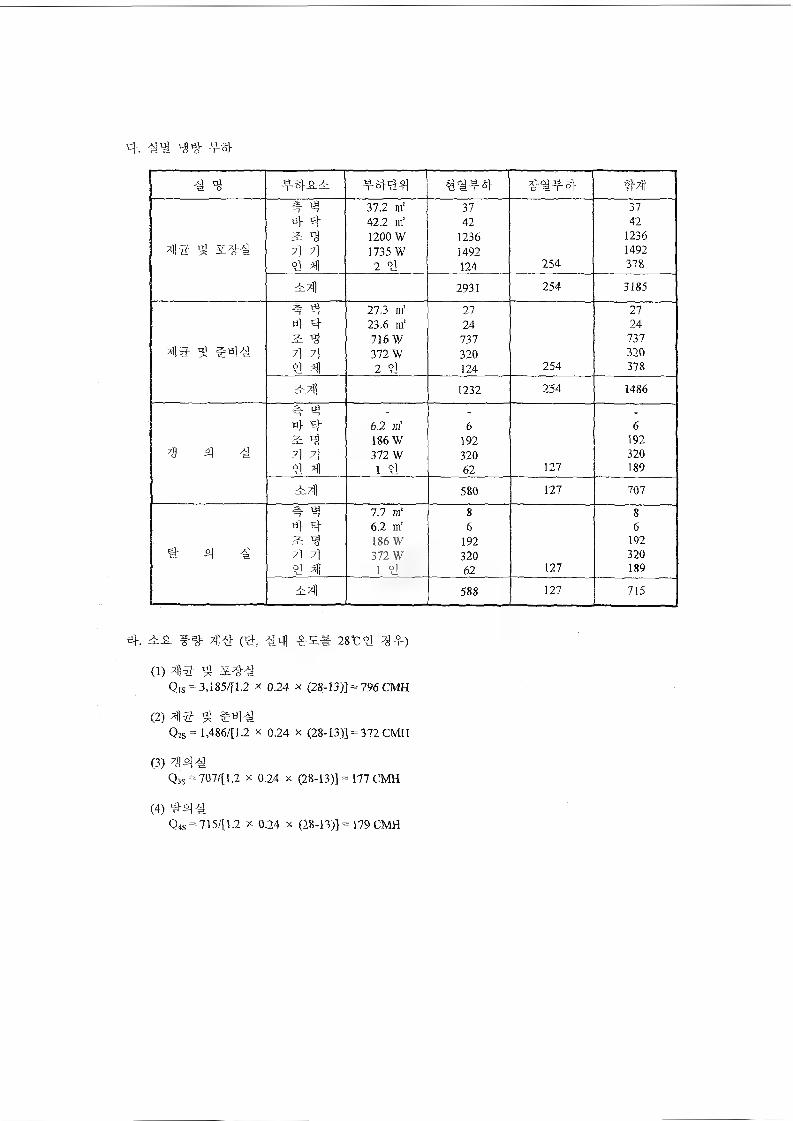
4. 44 ^4 ^-4
4 4 4444 4444 4444 444 4 37.2 m! 37 37
42.2 m' 42 42a 3 1200 W 1236 1236
43 ^ &44 7) 7] 1735 W 1492 1492
°J 4 2 4 124 154 378
i4 2931 254 3185
"1 "7 27.3 m' 27 274 4 23.6 nf 24 24^ 4 716W 737 737
43 ^ $44 7] 7] 372 W 320 320
4 4 2 4 124 254 378
1232 254 1486
4 4«> 4 6.2 m1 6 6& <9 186 W 192 192
4 4 4 7| 7] 372 W 320 3204 4 1 4 62 127 189
1* 580 127 707
4 4 7.7 m" 8 8«} 4 6.2 m' 6 6a ^ 186 W 192 192
4 a] -g 7] 7] 372 W 320 3209 4 1 4 62 127 189
£4 588 127 715
4. ^ #4 44 (4, 44 281:4 ^f)
(1) 43 &44Q,s =3,185/[1.2 x 0.24 x (28-13)] = 796 CMH
(2) 43 ^Qs=l,486/[1.2 % 0.24 x (28-13)] = 372 CMH
(3) 444Q3s = 707/[1.2 x 0.24 x (28-13)] = 177 CMH
(4) 444
Q4s =715/[1.2 x 0.24 x (28-13)] = 179 CMH
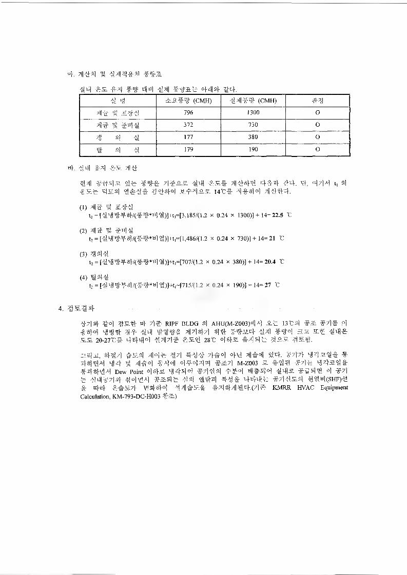
4. 4] #4 g #4# #4 ###
#4 #3 #4 ## 44 #4 #### 444- #4.
# 4 33## (CMH) #4]## (CMH) ##
4# 2 3## 796 1300 0
4# g #4# 372 730 0
7g 4 # 177 380 0
# 4 # 179 190 0
4. 44 44 #3 44
44 ##4^- 44 ### 4#33 44 #3# 4444 4#4 44. 4, 444 t, 4
#3# 434 #### 4444 34=433 I4t* 4444 4444.
(1) 44 3##t2 = [#4#-T-4/(##*4#)]+t,=[3,185/(12 X 024 X 1300)]+ 14=22.5 t
(2) 44 ^ #4#tz = [####4/(##*4#)]+t,=[1,486/(12 X 024 x 730)]+ 14=21 C
(3) 4 ^ 4tz = [#'i##4/(##*4#)]+ti=[707/(12 x 024 X 380)]+ 14= 20.4 t
(4) #44t2 = [#44#4V(##*4#)]+t,=[715/(1.2 x 0.24 x 190)]+ 14= 27 "C
4-714- ^o] gs.4 4 7]e RIPF BLDG 4 AHU(M-Z003)44 3# 13C4 #3 47]# P]
#44 -g4 #444 T|]7]^7] 44 #434- €4 #44 33. 5# ^4#33 20-27TC* 4444 4^7]# #34 28C 4#3 #44# ^33 454.
343, 447] #34 414# 47] #44 7^4 4\i 4]#4 #4. #47]- #4-444 44 # 4#4 4441 4#444 #&7] M-Z003 3 #44 #4# ^4a4# #4-444 Dew Point 443 4444 #7]44 4=#4 4*44 443 ##44 4 #4# ^4#44- #444 #34# #4 ##4 ### 44-4# #4434 4^4(SHF)4# 4-4 ##37> 44-44 #41 #3# #4 44 44.(7] e KMRR HVAC EquipmentCalculation, KM-793-DC-H003 #3)
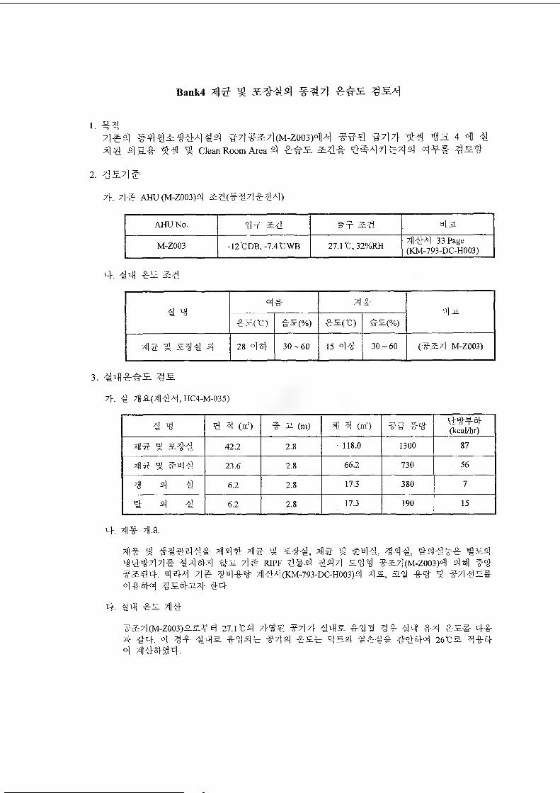
Bank4 4 S' 5 ^7]
1. 447)#4 #4#^tMiE!4 47)42:7)(M-Z003)44 44€ 447} ^3 4 4)^4^1 4-§-"8" "Sr'S 9J Clean Room Area 4 4"1=r52 3=3i-& °>^a| 7] ^-x] 4 4-r-S
2.
7)-. 7]# AHU(M-Z003)4 &#(*#7)*#4)
AHU No. 44 3^4 #4 2&4 ti]3.
M-Z003 -12°CDB, -7.4°CWB 27.lC,32%RH 4144 33 Page(KM-793-DC-H003)
4. #4 ^
4 44# 44
4%*S(C) h"E(%) w^(%)
44 9; 3E#* 4 28 44 30 ~ 60 15 44 30-60 (43:7) M-Z003)
3.
7}. 4 7))A(444,HC4-M-035)
4 4 # 4 (m') 4 a (m) 4 4 (m') 44 4# 4#44(kcal/hr)
44 9! 4## 42.2 2.8 118.0 1300 87
44 # #4# 23.6 2.8 66^ 730 56
4 4# 6.2 2.8 17.3 380 7
#4 41 6.2 2.8 17.3 190 15
4. 4# ;HA
4# ^ 44# 4$ ^ 3E#*, 44 ^ #4#, 44#, #4#*^ #&444r#7)7)#- #444 ^ 7]^ RIPF ##4 #47) 52#^ 4&7)(M-Z003)4 44 43:€4. 44-4 7]# #43-# 4#4(KM-793-DC-H003)4 4a, a# -§-# # 44 #S# 4444 4s.4-a4 #4
4. 44) 4^ 414
4&4(M-Z003)^.^-4 27.HC4 7}#4 447} #4^ 44# 44- 44 #4 4-32* 44
4 44. 4 34 44& 4444 444 4S.4 44:44 26t& 4444 444#4
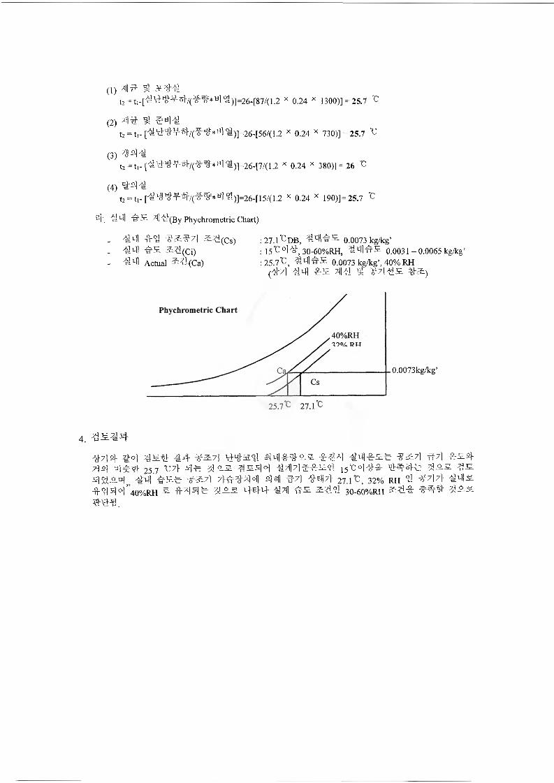
(1) 41 $ gt2 = tl-[^1d'tio1'Jf8l'/(^:^*til s)]=26-[87/(1.2 x 0.24 x 1300)] = 25.7 °C
(2) 4|if * #aH
t2 = t,-[^4^f#/(?^*4#)]=26-[56/(12 x 0.24 x 730)] =25.7 ^
(3) 73 41t2 = tl- [1444<l)]=26-[7/(1.2 x 0.24 x 380)] = 26 °C
(4) #41t2 = ti-['^l3w3-:T-3'f/(-f ^*al<i)]=26-[15/(1.2 x 0.24 x 190)]= 25.7 °C
4. s1! hS 7]] 4(By Phychrometric Chart)
. 4^ ^4 #&^7] #l(Cs) _ 4qi es #l(Ci)
#4 Actual #l(Ca)
:27.rcDB, 0.0073 kg/kg’: 15^44, 30-60%RH, 44#S 0.0031-0.0065 kg^cg' :25.7"C, 44^S 0.0073 kg/kg', 40% RH
(47] #q] IrS 7|]4 ^ 47] 4# 4#)
Phychrometric Chart
0.0073kg/kg'
4. ^^#4
-#?]4 y-o] 7^5.4 14- ?27] 44#4 s^-g-^# g #14 4q]-8:S# ^#7] -g-7] ##4
7\4 «]$4 25.7 ‘C7> 4# 1## 1#44 147]#15191 15"cm mi 3J9.S 1#44 is.# ##7] 4 44 #7] 4-47]- 27.fc, 32% rh 4 4 7] 7} 44#
#444'4o%rh s tM41 is# 444 4X1 #s #191 3o-6o%rh #4# 1##

4 444 4444# W #44 ^444 444
44. 444, 4# 44 -SL41-4 J%444 &d>5- #44 4
## H44-S-
2.
(44)
44 44# 44 #4 4S.4 4 44 e4 4& 4#
5-3

=un
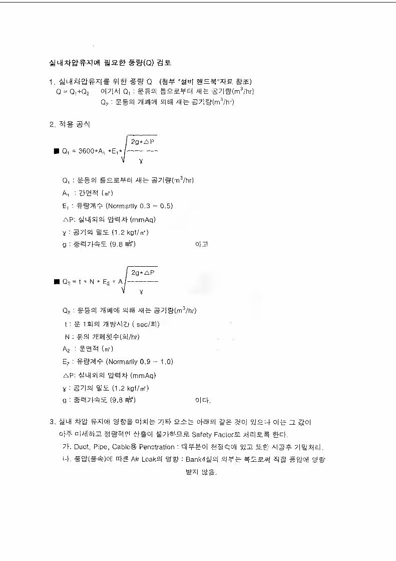
satfg(Q) gjE
1. ## q "^tii ®=n*n5. #s)Q = Q1+Q2 o^7|A-{ 0^ : e#s| #o^E| g7|^(m^/hr)
Qg: e#2| ;nm|0ll 2|6H A|j^ g7|^(m^/hr)
2.
I 2g*AP■ Qn = 3600*A1 *En* /-------------------
V Y
Q1 : e#2j Atj^ g7|#(m^/hr)Ai : (m»)
E, : (Normarily 0.3 ~ 0.5)
AP: -ym&laS (mmAq)
Y : as (1.2kgf/m')g:#^7|^S(9.6i^) 0|2
| 2g*AP■ 02 = t * N * E2 * A /---------------
V Y
Q2 : e#2) 7H9IOII SM AHet : S 1S|2| ( sec/S|)
N : eaj 7Hmi&!4:(2l/hr)
A2 : -EBg (m')
E2 ■' -mcMI^ (Normarily 0.9 ~ 1.0)
AP: 4ims|2j y^x|- (mmAq)
Y : #7|2j (1.2 kgf/m')g:#e|;dSS(9.8i#) o|ck
3. aWj ^°j-^x|o|| o|x|^ 7|E|- o|-E|js|-^-g^o| a°^o|^zz.^o|
o(nr o|A|l#S {4#o| #7|-S|-om Safety Factor^ g-ck
7k Duct, Pipe, Cable# Penetration : cH4*-#o| g@^o|| A|g^ 7|°j^a|.
Lf. #a-(#4:)oll Air Leaks| : Bank4^jsj 2)4^ 4S^ 2|g
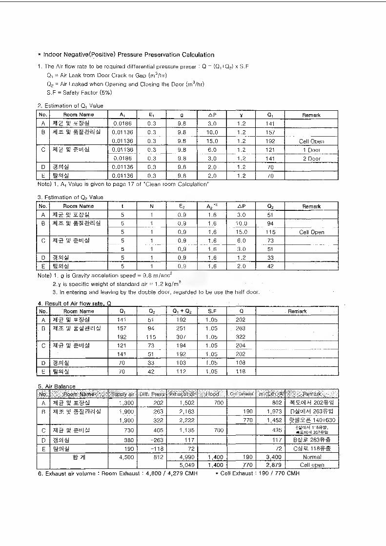
* Indoor Negative(Positive) Pressure Preservation Calculation
1. The Air flow rate to be required differential pressure preset: Q = (Q1+Q2) x S.F Q, = Air Leak from Door Crack or Gap (m3/hr)Q2 = Air Leaked when Opening and Closing the Door (m3/hr)S.F = Safety Factor (5%)
2. Estimation of Q, ValueNo. Room Name Ai Ei g AP V Qi RemarkA 7112 32 Z&4! 0.0186 0.3 9.8 3.0 1.2 141B a #4i#94i 0.01136 0.3 9.8 10.0 1.2 157
0.01136 0.3 9.8 15.0 1.2 192 Cell OpenC *115 3! 594! 0.01136 0.3 9.8 6.0 1.2 121 1 Door
0.0186 0.3 9.8 3.0 1.2 141 2 DoorD 99# 0.01136 0.3 9.8 2.0 1.2 70E #94! 0.01136 0.3 9.8 2.0 1.2 70
Note) 1. A, Value is given to page 17 of "Clean room Calculation"
3. Estimation of Q2 ValueNo. Room Name t N e2 A,"2 AP q2 RemarkA 3! MSHW 5 1 0.9 1.6 3.0 51B *i|2L 3! ###94! 5 1 0.9 1.6 10.0 94
5 1 0.9 1.6 15.0 115 Cell OpenC xii5 §y 594! 5 1 0.9 1.6 6.0 73
5 1 0.9 1.6 3.0 51D 994! 5 1 0.9 1.6 1.2 33E #941 5 1 0.9 1.6 2.0 42
Note) 1. g is Gravity accelation speed = 9.8 m/sec22. y is specific weight of standard air = 1.2 kg/m33. In entering and leaving by the double door, regarded to be use the half door.
4. Result of Air flow rate, QNo. Room Name Qi q2 Qi + p2 S.F Q . RemarkA X1I5 3! 141 51 192 ; 1.05 202B x|| z S! #41 #9 4! 157 94 251 1.05 263
192 115 307 ' 1.05 322C X1I5 S 594! 121 73 194 1.05 204
141 51 192 1.05 202D 994! 70 33 103 1.05 108E #941 70 42 112 1.05 118
5. Air BalanceNO. Room Name Supply air Diff. Press Exhaust air: Hood Ceil Exhaust m. Exli. A' Remark.
A xii-g % sg-4! 1,300 202 1,502 700 802 9E0l|A-i 202# 9
B 93= S! 1,900 263 2,163 190 1,973 D4!oM 263
1,900 322 2,222 770 1,452 140+630
C x|| 5 3! 594! 730 405 1,135 700 435 E-yoM ns^y, 2B7#B
D 994! 380 -263 117 117 B4I^ 263##E #94! 190 -118 72 72 C4!^ 118##
nn 4,500 812 4,990 1,400 190 3,400 Normal5,049 1,400 770 2,879 Cell open
6. Exhaust air volume : Room Exhaust : 4,800 / 4,279 CMH * Cell Exhaust : 190 / 770 CMH

7. Result of Calculation
- ?IS 7||>4A-|oj R00m Exhasut fan #go| 220 4,580 CMHO||A-j 4,800 CMH5. §7|-©K>jo|:
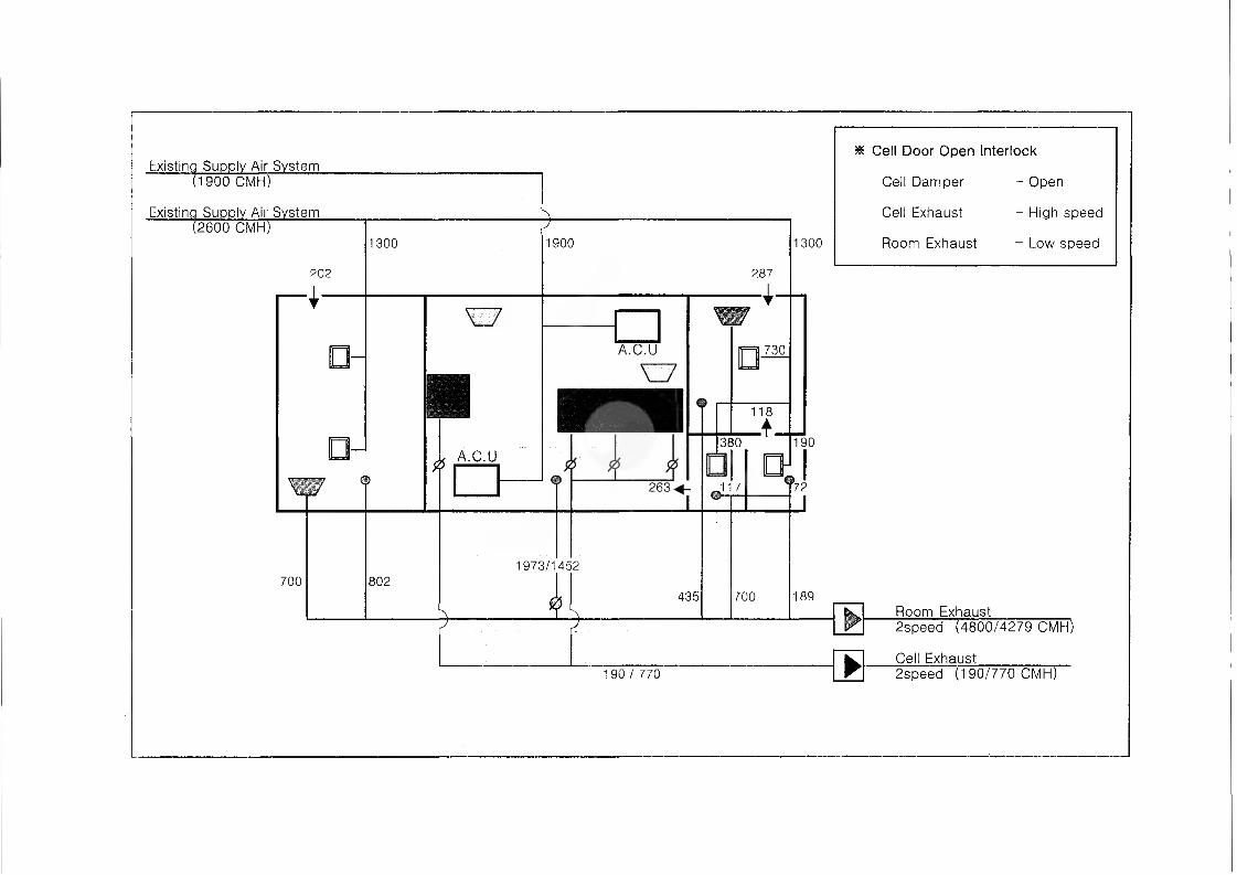
Existing Supply Air System(1900 CMH)
Existing Supply Air System(2600 CMH)
202
4-
1300
700
XZ7
A.C.U
802
1900
287
-I-
1973/1452
435
730
380
118
J17□H
1300
* Cell Door Open Interlock
Cell Damper - Open
Cell Exhaust - High speed
Room Exhaust - Low speed
190
700 189Room Exhaust
190/770
2speed (4800/4279 CMH)
Cell Exhaust2speed (190/770 CMH)
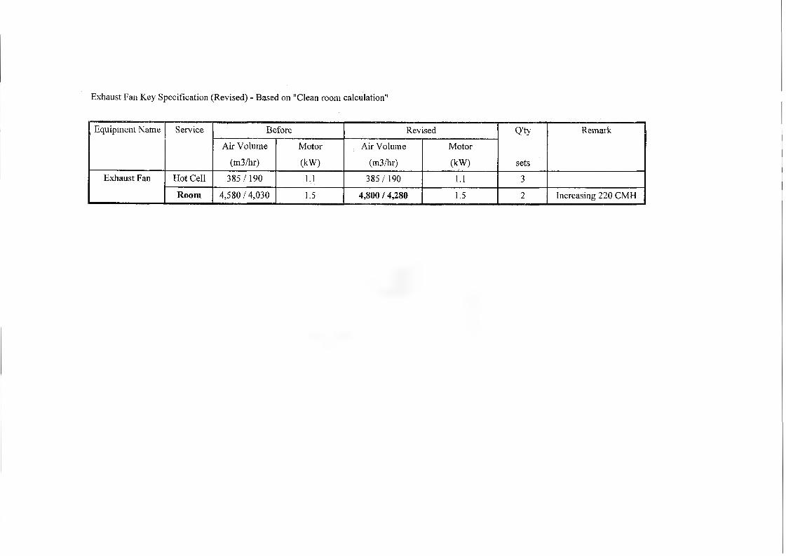
Exhaust Fan Key Specification (Revised) - Based on "Clean room calculation"
Equipment Name Service Before Revised Q'ty Remark
Air Volume Motor Air Volume Motor
(m3/hr) (kW) (m3/hr) (kW) setsExhaust Fan Hot Cell 385/ 190 1.1 385/190 1.1 3
Room 4,580/4,030 1.5 4,800 / 4,280 1.5 2 Increasing 220 CMH
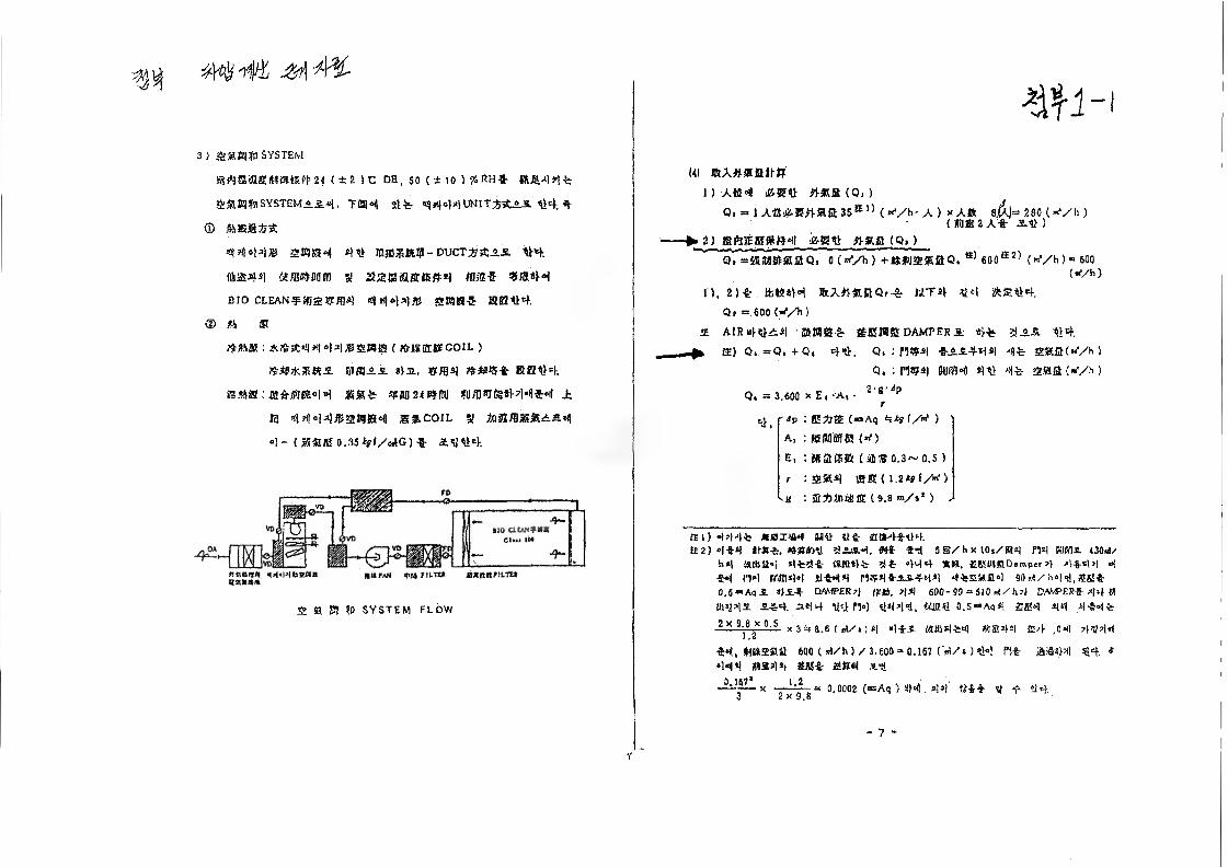
3) SYSTEM
(±2 5C DH, 50 ( ± 10 ) % «H«- *KWt^
SYSTEM =.14. T@4 St'fe 4
®
4444* SMS 4 4% liWM-DUCT ;»&.»£ tH.
#@44 ii/BOtMflfl 3! SSSiiflfitfiifM «!&•& «®«H
BIO CLEAN^ffiaS®*! 4 444* SMS-3: KE44.
© #1 ®
: *2frsC4 444*SH!8 ( AIK8$BE COIL )
?$-iii*5Rtts mass *u, vm4 **%* KBtHema;a*«K44 4= mm*? in ?u/imite4-4»ii'M j=
13 4 *144*216184 UNCOIL 9
4- (55safl!0.35*?!/e*G)-S- &y44.
fitxeir*! n^«|*MUsfln***** MU PAN W4 PILTt*
S m m ?0 SYSTEM FLOW
W-|(41 IRX^IKfilf-IT
1) ABM! iCHBtl Mfi (9, )Q. = l Afl*®n«fi35E1) («*/h-A) x A« 8.(1]= 280 (-*/!))
(mm2A-fr )4-IKR (Q, )
Q, =3S(iae)5U5Qs 0 (**/h) + MISSUS Q* S) 600S2) (»Vh ) <= 600(tf/h)
n. 2)ir ttiK*H %A?)ABQ,-& WT4 %4 ifcetM.Q, = 600 (y/h)
A A1R«HA4 fflMfi gr SEWS DAMPERS ^AS ?V4.
ffi) Qi. =>Qi +■ Q» 44, Q, : n«4 -S-AA4-44 4-fc- SHfl(«Vh ) 9. : ms| BUM4 44 4t 2«ffi («'/»>)
O. = 3,600 X El A| • 2 S ip
41 'jp : E AS (*»Aq #4y I/W ) A, : KIOTO! <*0
E, : Mflffft (iifiS Q.3~ 0,5 )
t : 2»4 «ffl< \.2*9i/*t)<8 ■. S AIMS ( 9.8 m/s* ) j
31) 444t UsSJIUM 8141 ti-e- 1QH4-8-44.32) 4*4 II**, •sntoll «* *4 5@/hx 10iZ@5| rW BUM3. 430M/
h»| Httilloi 4*t!-fr «m«t* 444 *», ffiKU»fiD«mper4 4-8-44 44H H4 m$!4 HM8 M*4*A&-M4 4*£afl4 90 4/gtgj*0.5-Aqi 4A-* DAMPER 4 (tti, 44 600-90 = 510 4/h4 DAMPER-? 44 fli1114’is A?4. se|4 314 514 4444, ttiiHt 0,5-Aq#l SK4 44 4 444
-llM—J. X 3 4 8.6 ( A/i 1 S| «li-i KH1S144 (v)Sl44 S4 ,011 4444
-$4, Hitts®it 600 ( 4/h ) Z 3,600 = 0.167 (4/s ) 44 PH A)844 44. * 444 *m4*t £«* iSifftil s-S
A 1 (it* 12 ,-■••"-■- x 0.0002 («Aq ) 44 44 ?**4- 4 4 4 4,
7
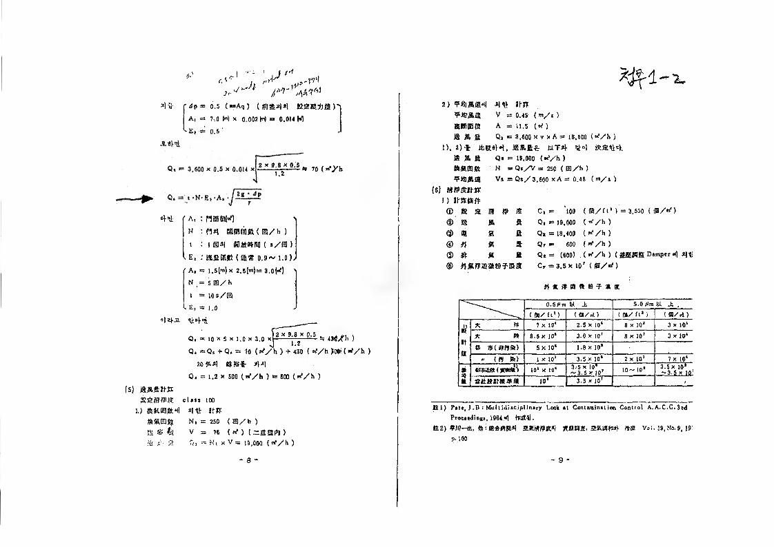
’I -3 dp = 6.5 (»Aq) ( ffl$44 $$8K*M)'i
A, = 1:0 M x a.002 N = 0.014 M
E, -» O.s '
2 * 1'8,!!M if 70 ( *f/h
44 'A, ipiffifitM K : M4 66MEB(B/h )t : 104 ( t/m )
- E, : aflKR (®« 0.9~ 1.0),
' A, = l.s(m) x 2.5(>")= 3.0M 'N ,= 5 0/h
t - lOs/B
' Ei = 1.0«|E|jl t>44 ___
Qi = 10 x 5 x 1.0 x 3.0 xp— k 4W)/fh )
Q. ~ Qi + Q, = 10 (rf/h ) + 430 ( h >0»(*Vh )
20% 4 «*&-£- 44Qt = 1.2 x 500 (^/h ) = 600 (if/h )
Is) a aft nsRsEMfUffi class 100
u 4t> ns#%0% N, = 250 < ®/b )
s m k v = 76 (*■) (-flafl >3 s'- >t Qi = Hi x V = 10,000 ( if/h )
2) ¥tiM8H 4% USv = o.4s (m/t)
SWffiffl A = 11,5 (if)
$a M ja Q. = a,600 x V X A= 18,600 (if/h )
1). 2)* ifcet*M, i&JRft-g: UT4 V4 *%44.m a a
(s) mtfBum i)® » s © 8 © a© 4® A
Q»N
Vi
■ 19,000 (if/h )
; Q»/V = 250 ( S
■ Qs/3.600 x A =
l/h )0.46 ( m/s )
aaaa
ffi C, = 100 ( ®/(l* ) = 3,530 ( m/if)
ft Qi *= 19,000 (if / h )
a Qt = 18,400 (if/ h)
ft Qr = 600 (”*/h )
ft Qt — (600) , ( /h ) (ISSMfi Dsmper 4 41i
4«S2£tSk»?ffla Cr = 3.5x 10’ (ffl/rf)
nmipmaB^aat
0.5 P ns fet Jt 5.0 /*m fel J: ,
( 68/ft1) ( £8/tA > ( IB/ h* ) UB/r4)
£
It
it
* t* 7 x 10* 2.5 x 10* a x io* 3 x 10*
A 0 8.5 X 10* 3.0 x 10’ 8 X 101 3 x 10*
» $ urn$6) 5X 10" 1.8 x 10* ■ "
" US fc> 1 x 10* 3.5 x 10* 2 x 10* 7 x 10*
1Wiest (*im\ 10* X 10* 3.-5 x 10*
"3.5 x 10T 10~ IO* 3.5 x 10*-3.5 x |0!
ottaita#ffl 10* 3.5 x 10* .
It l) P»t«, J ,B i Multidisciplinary Look it Contaroinil ion Control A.A.C.C.3rd
Proceedings, 19644 tfcSH).
62) #111-48, S*WiK4 Rfi£33t. 2SKW04 l*« Voi. 19, Me. 9, 19"p. 100
- 9 -
7 ASHRAE® HANDBOOK
UNDAMENTALS
SI Edition
American Society of Heating, Refrigerating and Air-Conditioning Engineers, Inc.1791 Tullie Circle, N.E., Atlanta, GA 30329
fa(404) 636-8400 http://www.a3 hrae.org
25.14 1997 ASHRAE Fundamentals Handbook (SI)
opening, the NPL tends to move to that level, which reduces the pressure across the opening.
11. Greatest flow per unit area of total opening is obtained by inlet and outlet openings of nearly equal areas. An inlet window smaller than the outlet creates higher inlet velocities. An outlet smaller than the inlet creates lower but more uniform airspeed through the room.
12. Openings with areas much larger than calculated are sometimes desirable when anticipating increased occupancy or very hot weather.
13. Horizontal windows are generally better than square or vertical windows. They produce more airflow over a wider range of wind directions and are roost beneficial in locations where prevailing wind patterns shift.
14. Window openings should be accessible to and operable by occupants.
15. Inlet openings should not be obstructed by indoor partitions. Partitions can be placed to split and redirect airflow but should not restrict flow between the building’s inlets and outlets.
16. Vertical airshafts or open staircases can be used to increase and take advantage of stack effects. However, enclosed staircases intended for evacuation during a fire should not be used for ventilation.
used synonymously, they are different, though related, quantities. Infiltration is the rate of uncontrolled air exchange through unintentional openings that occurs under given conditions, while air leakage area is a measure of the airtightness of the building shell. The greater the air leakage area of a building, the greater its infiltration rate, ail else (weather, exposure, and building geometry) being equal. Infiltration is the rate of air entering the structure and is equal to the exfiltration (the rate of air leaving the structure).
Infiltration may be reduced either by reducing the surface pressures driving the flow or by reducing the air leakage area of the shell. Surface pressures caused by the wind can be reduced by changing the landscaping in the vicinity of the building (Mattingly and Peters 1977). Stack pressures can be reduced by increasing the airflow resistance between floors and from floors to any vertical shafts within the building, although this is an issue almost exclusively reserved to tall buildings.
The infiltration rate of an individual building depends on weather conditions, equipment operation, and occupant activities. The rate can vary by a factor of five from weather effects alone (Malik 1978), When associating an infiltration rate with a building, it is important to either provide the corresponding weather conditions and equipment status or describe the rate as a seasonal or annual average.
Typical infiltration values in housing in North America vary by a factor of about ten, from tightly constructed housing with seasonal average air exchange rates of about 0.2 air exchanges per hour (ACH) to loosely constructed housing with air exchange rates as great as 2.0 ACH. Figure 10 and Figure 11 show histograms of infiltration rates measured in two different samples of North American housing (Grimsrud et al. 1982, Grot and Clark 1979). Figure 10 shows the average seasonal infiltration of 312 houses located in different areas in North America. The median infiltration value of this sample is 0.5 ACH. Figure 11 represents measurements in 266 houses located in 16 cities in the United States. The median value of this sample is 0.9 ACH. The group of houses contained in the Figure 10 sample is biased toward new, energy-efficient houses, while the group in Figure 31 represents older, low-income housing in the United States.
Additional studies have found average values for houses in regional areas. Palmiter and Brown (1989) and Parker et al.
45 --
40 --
35 --
e 30 - -
» 25 - -
INFILTRATION RATES, ACH
Fig. 10 Histogram of Infiltration Values— New Construction
45 --
40 - -
30 --
25 --
15 --
10 --
INFILTRATION RATES, ACH
Fig; 11 Histogram of Infiltration Values— Low-Income Housing
(1990) found a heating season average of 0.40 ACH (range; 0.13 to 1.11 ACH) for 134 houses in the Pacific Northwest. In a comparison of 292 houses incorporating energy-efficient features (including measures to reduce air infiltration and provide ventilation heat recovery) with 331 control houses, Parker et al. (1990) found an average of about 0,25 ACH (range: 0.Q2 to 1.63 ACH) for the energy-efficient houses versus 0.49 (range: 0.05 to 1.63 ACH) for the control. Ek et al. (1990) found an average of 0.5 ACH (range: 0.26 to 1.09) for 93 double-wide manufactured homes also in the Pacific Northwest. Canadian housing stock has been characterized by Yuiil and Comeau (1989) and Riley (1990). While these studies do not represent random samples of North American housing, they indicate the distribution of infiltration rates expected in a group of buildings.
Occupancy influences have not been measured directly and vary widely. Desrochers and Scott (1985) estimated that they add an average of 0.10 to 0.15 ACH to unoccupied values. Kvisgaard and Collet (1990) found that in i 6 Danish dwellings, the users on average provided 63% of the total air exchange rate.
RESIDENTIAL AIR LEAKAGEThe air leakage of a building characterizes the relationship
between the pressure difference across the building envelope and the airflow rate through the envelope (see the section on Airflow Through Openings). Building air leakage area is a physical
ilation and Infiltration 25.15
ty of a building determined by its design, its construction, deterioration over time. Although airtightness is just one
m determining the air exchange rate of a building, it is useful nparing buildings to one another or to airtightness standards, .iluating design and construction quality, and for studying ectiveness of airtightening retrofits. No simple relationship between a building’s airtightness and its air exchange rate, ,!eulation methods do exist (see the section on Simplified s).
urementtie tracer gas measurement procedures provide building air lge rates, they are somewhat expensive and dme-consum- : many cases, it is sufficient, or preferable, to measure the tkage of a building with pressurization testing (Strieker Tamura 1975, Kronvall 1978, Blomsterberg and Harrje Gadsby and Harrje 1985). Fan pressurization is relatively and inexpensive, and it characterizes building envelope air- ess independent of weather conditions. In this procedure, a san or blower is mounted in a door or window and induces a and roughly uniform pressure difference across the building CGSB 1986, ASTM Standard E 779). The airflow required main this pressure difference is then measured. The leakier hiding is, the more airflow is necessary to induce a specific r-outdoor pressure difference. The airflow rate is generally ared at a series of pressure differences ranging from about ; to 75 Pa.■e results of a pressurization test, therefore, consist of several inations of pressure difference and airflow rate data. An exam- typical data is shown in Figure 12. These data points charac-
■ the air leakage of a building and are generally converted to a »■ value that serves as a measure of the building’s airtightness. -- are several different measures of airtightness, most of which ve fitting the data to a curve in the form of Equation (34) (i.e., A//). The airtightness ratings are based on airflow rates pre-
J at particular reference pressures by Equation (34). The basic rence between the various airtightness ratings is the value of iference pressure.
tooo BOO
600
400
^ 200
1 °1 -200
-400
-600
-800
-1000
-90 -60 -30 0 30 60 90PRESSURE, Pa
12 Airflow Rate Versus Pressure Difference Data from Whole-House Pressurization Test
Airtightness RatingsIn some cases, the predicted airflow rate is convened to an equiv
alent or effective air leakage area by rearranging Equation (33):
Jp/2ApAl = 10000,=—=------ (39)
VDwhere
Al = equivalent or effective air leakage area, cm2 Qr = predicted airflow rate at Ap, (from curve fit to pressurization test
data). m-Vsp = air density, kg/m3
Ap, = reference pressure difference. Pa Cy = discharge coefficient
Ail the openings in the building shel I are combined into an overall opening area and discharge coefficient for the building when the equivalent or effective air leakage area is calculated. Some users of the leakage area approach set the discharge coefficient equal to 1. Others set CD s 0.6 (i.e., the discharge coefficient for a sharp-edged on fice). The air leakage area of a building is, therefore, the area of an orifice (with an assumed value of CD) that would produce the same amount of leakage as the building envelope at the reference pressure.
An airtightness rating, whether based on an air leakage area or a predicted airflow rate, is generally normalized by some factor to account for building size. Normalization factors include floor area, exterior envelope area, and building volume.
With the wide variety of possible approaches to normalization and reference pressure difference, and the use of the air leakage area concept, many different airtightness ratings are being used. Reference pressure differences include 4, 10, 25, 50, and 75 Pa. Reference pressure differences of 4 and 10 Pa are advocated because they are closer to the pressure differences that actually induce air exchange and, therefore, better model the flow characteristics of the openings. While this may be true, they are outside the range of measured values in the test; therefore, the predicted airflow rates at 4 and 10 Pa are subject to significant uncertainty. The uncertainty in these predicted airflow rates and the implications for quantifying airtightness are discussed in Persily and Grot (1985b), Chastain (1987), and Modern and Wilson (1990). Round robin tests by Murphy et al. (1991) to determine the repeatability and reproducibility of fan pressurization devices found that subtle errors in fan calibration or operator technique are greatly exaggerated when extrapolating the pressure versus flow curve out to 4 Pa, with errors as great as ±40%, mainly due to the fan calibration errors at low flow,
Some common airtightness ratings include the effective air leakage area at 4 Pa assuming C0= 1.0 (Sherman and Grimsmd 1980); the equivalent air leakage area at 10 Pa assuming CD = 0.611 (CGSB 1986); and the airflow rate at 50 Pa, divided by the building volume to give units of air changes per hour (Blomsterberg and Harrje 1979).
Conversion Between RatingsAir leakage areas at one reference pressure difference can be
converted to air leakage areas at some other reference pressure difference according to
x/t -0.5(40)
whereAr, = air leakage area at reference pressure difference Apr i, cm3 ,4,2 = air leakage area at reference pressure difference Ap,,, cm2
C,)A = discharge coefficient used to calculate A, ,C,u = discharge coefficient used to calculate A, 2
n - flow exponent from Equation (34)
25.16 1997 ASHRAE Fundamentals Handbook (Si
An air leakage area at one reference pressure difference can be converted to an airflow rate at some other reference pressure difference according to
(41)
where Qr 2 = airflow rate at reference difference Apr 2, m3/s.finally, an air leakage area may be converted to the flow coeffi
cient c in Equation (34) according to
e= 10~3 x CDAL(2/p)°'5(Apr)05-n (42)
Equations (40) through (42) require the assumption of a value of 12, unless it is reported with the measurement results. When wholebuilding pressurization test data are fitted to Equation (34), the value of n generally lies between 0.6 and 0.7. Therefore, using a value of n in this range is reasonable.
Building Air Leakage DataFan pressurization measures a building property that ideally
varies little with time and weather conditions. In reality, unless the wind and temperature differences during the measurement period are sufficiently mild, the pressure differences they induce during the test will interfere with the test pressures and cause measurement errors. Pcrsily (1982) and Modern and Wilson (1990) presented experimental studies of the effects of wind speed on pressurization test results. Several experimental studies have also shown variations on the order of 20 to 40% over a year in the measured airtightness in homes (Persily 1982, Kim and Shaw 1986, Warren and Webb 1986).
Several pressurization test results for residential buildings are presented in Figure 13 (Persily 1986). These results are in units of air changes per hour at 50 Pa and show the wide range in airtightness among houses, even houses of identical design. The data for passive solar and energy-efficient houses also show that houses expected to be relatively airtight are not necessarily very tight. The houses in Sweden—which has a residential building airtightness standard of 3 air changes per hour at 50 Pa for single-family detached houses (Swedish Building Code 1980)—are exceptionally tight, as are the houses in Canada
ASHRAE Standard 119 establishes air leakage performance levels for residential buildings. These levels are in terms of the normalized leakage area A„:
(43)
where
A„ = nonnalized leakage area, dimensionless Ai - effective leakage area ai 4 Pa (CD = 1.0), cm2 Af = gross floor area (within exterior walls), m2 fi - building height, m
H„ - reference height of one-story building = 2.5 m
Table 2 presents the leakage classes of Standard 119. The values of A „ in this table correspond approximately to annual average building air exchange rates in units of air changes per hour. Standard 119 specifies appropriate leakage classes for a building based on climate.
Air Leakage of Building ComponentsThe fan pressurization procedure discussed in the section on
Measurement enables the measurement of whole-building air leakage. The location and size of individual openings in building envelopes are extremely important because they influence the air
!
87 detached hemee In Seeketoon, **1-19*0
205 wood-frame homes. Mean plus and minus one standard deviation
12 Sghtweight concrete homes. Mean plus and minus one standard deviation
0 10 20 30 40 50AIR LEAKAGE AT 50 Pa (House volumes / hour)
Fig. 13 Comparison of Pressurization Test Results
Table 2 Leakage Classes Range of Normalized Leakage Area Leakage Class
< 0.10 A0.10 < A„ < 0.14 B0.14 S A„ < 0.20 • C0.20 5 A„ < 0.28 D0.28 < A„ < 0.40 E0.40 < A„ < 0.57 F0.57 < A„ < 0.80 G0.80 < A„ < 1.13 H1.13 S A„ < 1.60 11.60 < A„ 1
infiltration rate of a building as well as the heat and moisture tram fer characteristics of the envelope. Additional test procedures exit for pressure-testing individual building components such as wir dows, walls, and doors; they are discussed in ASTM Standard E 283 and E 783 for laboratory and field tests, respectively.
(Leakage Distributio^) 6^
Dickerhoff et at. (1982) and Harrje and Bom (1982) studied lh air leakage of individual building components and systems. The fol lowing points summarize the percentages of whole-building ai
Ventilation and Infiltration zs.n
leakage area associated with various components and systems. The values in parentheses include the range determined for each component and the mean of the range.
Walls (18 to 50%; 35%). Both interior and exterior walls contribute to the leakage of the structure. Leakage between the sill plate and the foundation, cracks below the bottom of the gypsum wall- board, electrical outlets, plumbing penetrations, and leaks into the attic at the top plates of wails all occur. Because interior walls are not filled with insulation, open paths connecting these walls and the attic permit the walls to behave like heat exchanger fins within the conditioned living space of the house.
Ceiling details (3 to 30%: 18%). Leakage across the top ceiling of the heated space is particularly insidious because it reduces the effectiveness of insulation on the attic floor and contributes to infiltration heat loss. Ceiling leakage also reduces the effectiveness of ceiling insulation in buildings without attics. Recessed lighting, plumbing, and electrical penetrations leading to the attic are some particular areas of concern.
Heating system (3 to 28%: 18%). The location of the furnace or ductwork in conditioned or unconditioned spaces, the venting arrangement of a fuel-burning device, and the existence and location of a combustion air supply all affect leakage. Modern et al. (1991) and Robison and Lambert (1989), among others, have shown that the variability of leakage in ducts passing through unconditioned spaces is high, the coefficient of variation being on the order of 50%. Field studies have also shown that in-situ repairs can eliminate one-quarter to two-thirds of the observed leakage (Cummings and Toojey 1989, Cummings ft al. 1990, Robison and Lambert 1989). The 18% contribution of ducts to total leakage significantly underestimates their impact because during system operation, the pressure differentials across the duct leaks are approximately ten times higher than typical pressure differences across the envelope leaks (Modern 1989, Modern ct al. 1991).
Windows and doors (6 to 22%; 15%). More variation in window leakage is seen among window types (e.g., casement versus double-hung) than among new windows of the same type from different manufacturers (Wcidt ct al. 1979). Windows that seal by compressing the weather strip ^casements, awnings) show significantly lower leakage than windows with sliding seals.
Fireplaces (0 to 30%; 12%). When a fireplace is not in use, pootiy fitting dampers allow air to escape. Glass doors reduce excess air while a fire is burning but rarely seal the fireplace structure more tightly than a closed damper does. Chimney caps or fireplace plugs (with signs that warn they are in place) effectively reduce leakage through a cold fireplace.
Vents in conditioned spaces <2 to 12%; 5%). Exhaust vents in conditioned spaces frequently have either no dampers or dampers that do not dose properly.
Diffusion through walls I %}. Diffusion, in comparison to infiltration through holes and other openings in the structure, is not an important flow mechanism. At 5 Pa, the permeability of building materials produces an air exchange rate of less than 0.01 ACH by wall diffusion in a typical house
Component leakage areas, fable 3 shows effective air leakage areas for a variety of residential building components at 4 Pa with Cq assumed equal to 1 (Collivct ct al. 1992). The values in the table present results in terms of air leakage area per unit component. Per unit component means per component, per unit surface area, or per unit length of crack or sash, whichever is appropriate. These air leakage areas may be convened to air leakage areas at other reference pressures, airflow rates, <v flow coefficients using Equations (40) through (42).
Multifamily Building LeakageLeakage distribution is pajrvulariy important in multifamily
apartment buildings. These buildings often cannot be treated as single zones due to the internal resistance between apartments. More
over, the leakage between apartments varies widely, tending to b\ small in modem construction, and ranging as high as 60% of ih< total apartment leakage in mm-of-the-century brick walk-up apartment buildings (Modern et al. 1991, Diamond ct al. 1986). Link information on interzonal leakage has been reported because of the difficulty and expense of these measurements.
Controlling Air LeakageNew Buildings. It is much easier to build a tight building than to
tighten an existing building. Elmrotb and Levin (1983), Eyre and Jennings (1983), Marbek Resource Consultants (1984), and Nelson etal. (1985) provide information and construction details on airtight building design for houses.
A continuous air infiltration retarder is one of the most effective means of reducing air leakage through walls, around window and door frames, and at joints between major building elements. The air infiltration retarder can be installed either on the inside of the wall framing, in which case it usually functions as a vapor retarder as well, or on the outside of the wall framing, in which case it should have a permeance rating high enough to permit diffusion of water vapor from the wall For a discussion of moisture transfei in building envelopes, see Chapter 22 and Chapter 23.
When the air infiltration retarder is also a continuous plastic film vapor retarder, particular care must be taken to ensure its continuity at all wall, floor, and ceilingjoints; at window and door frames; and at all penetrations of the retarder, such as electrical outlets and switches, plumbing connections, and utility service penetrations. Joints in the air-vapor retarder must be lapped and sealed. Plastic vapor retarders installed in the ceiling should be tightly sealed with the vapor retarder in the outside walls and should be continuous over the partition walls. A seal at the top of the partition walls prevents leakage into the attic; a plate on top of the studs generally gi ves a poor seal.
A continuous air infiltration retarder installed on the outside of wall framing can cover many difficult construction details associated with the installation of continuous air-vapor retarders. Interior air-vapor retarders must be lapped and sealed at electrical outlets and switches, at joints between walls and floors and between walls and ceilings, and at plumbing connections penetrating the wall's interior finish. The exterior air infiltration retarder can cover these problem areas continuously. Joints in the air infiltration retarder should be lapped and sealed or taped. Exterior air infiltration retard- -
‘ ers are generally made of a material stronger than plastic film and are more likely to withstand damage during construction- Sealing the wall against air leakage at the exterior of the insulation also cuts down on convection currents within the wall cavity, allowing insulation to retain more of its effectiveness.
Existing Buildings. The air leakage sites must first be located in order to tighten the envelope of an existing building. As discussed earlier, air leakage in buildings is due not only to windows and doors, but to a wide range of unexpected and unobvious construction defects. Many important leakage sites can be very difficult to find. A variety of techniques developed to locate leakage sites are described in ASTM Standard E 1186 and Charlesworth (1988).
Once leakage sites are located, they can be repaired with materials and techniques appropriate to the size and location of the leak. Harrje et a). (1979), Diamond et ai. (1982), and Energy Resource Center (1982) include information on airtightening in existing residential buildings. With these procedures, the air leakage of residential buildings can be reduced dramatically. Depending on the extent of the tightening effort and the experience of those doing the work, residential buildings can be lightened anywhere from 5% to more than 50% (Blomsterberg and Harrje 1979, Harrje and Mills 1980, Jacobson et a). 1986, Verschoor and Collins 1986, Giesbrecht and Proskiw 1986). Much less information is available for airtightening large, commercial buildings, but the same general principles apply (Parekhet al. 1991, Persily 1991).
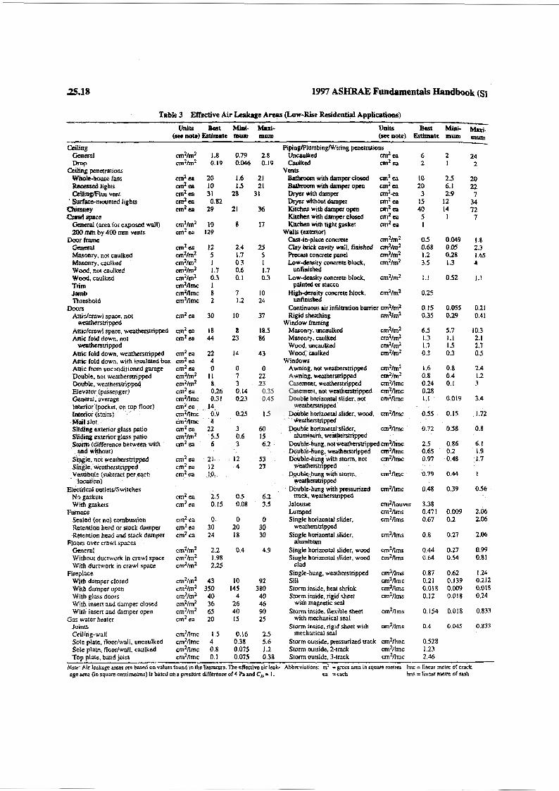
25.18 1997 ASHRAE Fundamentals Handbook (SI
Table 3 Effective Air Leakage Areas (Low-Rise Residential Applications)
Units Beet(see note) Estimate
Minimum
Maximum
Units (see note)
BestEstimate
Mini*toum
Mxxi-muai
Ceiling Piping/Plumbing/Wiring penetrationsGeneral 1.8 0.79 2.8 Uncaulked cm2 ea 6 2 24Drop cm2/m2 0.19 0.046 0.19 Caulked cm2 ea 2 I 2
Ceiling penetrations VentsWhole-house fans cm2 ea 20 1.6 21 Bathroom with damper closed cm2 ea 10 25 20Recessed lights cm2 ea 10 1.5 21 Bathroom with damper open cm2 ea 20 6.1 22Cetling/Flue vent cm2ea 31 28 31 Dryer with damper cm2ea 3 2.9 7
' Surface-mounted lights cm2ea 0.82 Dryer without damper cm2ea 15 12 34Chimney cm2ea 29 21 36 Kitchen with damper open cm2ea 40 14 72Crawl space Kitchen with damper closed cm2 ea 5 1 7
General (area for exposed wall) enri/nri 10 8 17 Kitchen with tight gasket cm2ea 1200 mm by 400 mm vents cm2ea 129 Walls (exterior)
Door frame Cast-in-place concrete cm2/m2 05 0.049 1.8Genera! cm2 ea 12 2.4 25 Clay brick cavity wall, finished cmVm2 0.68 0.05 2.3Masonry, not caulked ctrri/rrri 5 1.7 5 Precast concrete panel em'/m2 1.2 0.28 1.65Masonry, caulked crrri/rrri 1 0.3 1 Low-density concrete block, ctn2/mj 35 1.3 4Wood, not caulked cm2/m2 1.7 0.6 1.7 unfinishedWood, caulked enri/nri 0.3 0.1 0.3 Low-density concrete block, cm2/m2 1.1 0.52 i.iTrim cm2/lmc 1 painted or stuccoJamb cmz/lmc 8 7 10 High-density concrete block. cm2/m2 0.25Threshold cm1/! me 2 12 24 unfinished
Doors Continuous air infiltration barrier cm2/m2 0.15 0.055 0.21Attic/crawi space, not cm2 ea 30 10 37 Rigid sheathing cm2/m2 0.35 029 0.41
weatherstripped Window framingAttic/crawi space, weatherstripped cm2 ea 18 8 18.5 Masonry, uncaulked cm2/m2 65 5.7 10.3Attic fold down, not cm2ea 44 23 86 Masonry, caulked cmVm2 1.3 1.1 2.1
weatherstripped Wood, uncaulked cm2/m2 1.7 15 2.7Attic fold down, weatherstripped cm2 ea 22 14 43 Wood) caulked enr/m2 0.3 0.3 0.5Attic fold down, with insulated box cm2 ea 4 WindowsAttic from unconditioned garage cm2ea 0 0 0 Awning, not weatherstripped cm2/m2 1.6 0.8 2.4Double, not weatherstripped cm2/m2 II 7 22 Awning, weatherstripped cm2/m2 0.8 0.4 1.2Double, weatherstripped enri/nri 8 3 23 Casement, weatherstripped cm2/!mc 0.24 0.1 3Elevator (oassenger) cm2ea 0.26 0.14 0.35 Casement, not weatherstripped cm2/lmc 0.28General, average cm2/lmc 0.31 0.23 0.45 Double horizontal slider, not cm2/lmc U 0.019 3.4Interior (pocket, on top floor) cm2ea ... 14. weatherstrippedInterior (stairs) cm2/lmc 0.9 0.25 15 rouble horizontal slider, wood, cm2/lmc 0.55 0.15 1.72Mail slot . cm2/lmc 4 WeatherstrippedSliding exterior glass patio cm2 ea 22 . 3 60 Double horizontal slider, cm2/lmc 0.72 058 0.8Sliding exterior glass patio enri/m1 5.5 0.6 15 aluminum, wealberstrippeStems (difference between with etn2ea 6 3 6.2 Double-hung, not weatherstripped cm-Time 2.5 0.86 6.1
and without) Double-hung, weatherstripped cro2Amc 0.6$ 0.2 1.9Single, not weatherstripped cm2ea 21- 12 53 Double-hung with storm, not cm2/lmc 0.97 0.48 1.7Single . weatherstripped cm2ea 12 4 27 weatherstrippedVestibule (subtract per each cm2ea J.0: Double-hung wiih storm. cm2Zlmc 0.79 0.44 l
location) weatherstrippedElectrical outlets/Swilches Double-hung with pressurized cm2/lmc 0.48 0.39 056
No gaskets cm2ea 2.5 0.5 6.2 track, weatherstrippedWith gaskets cm2ea 0.15 0.08 3.5 Jalousie cro2rtouver 3.38
Furnace Lumped crnVlms 0.47! 0.009 2.06Sealed (or no) combustion cmzea 0 0 0 Single horizontal slider. cm2/lms 0.67 0.2 2.06Retention head or stack damper enrea 30 20 30 weatherstripped■Retention head and stack damper cm2ea 24 18 30 Single horizontal slider. cm2/lms 0.8 0.27 2.06
Floors over crawl spaces aluminumGeneral cm2/m2 2.2 0.4 4.9 Single horizontal slider, wood cm2/lms 0.44 0.27 0.99Without ductwork in crawl space enri/m2 1.98 Single horizontal slider, wood ctn2/lms 0.64 0.54 0.81With ductwork in crawl space cm^/m2 2.25 dad
Fireplace Single-hung, weatherstripped cnf/lms 0.87 0.62 1.24Wi£h damper dosed ■ cm2/m2 43 10 92 Sill cmVlmc 0.21 0.139 0.212With damper open cm2/m2 350 145 380 Storm inside, heat shrink cm2flms 0.018 0.009 0.018With glass doors enri/m* 40 4 40 Storm inside, rigid sheet cm2/lms 0.12 0.018 0.24With insert and damper closed cm2/m2 36 26 46 with magnetic sealWith insert and damper open cm2/m2 65 40 90 Storm inside, flexible sheet cm2/lms 0.154 0.018 0.833
Gas water healer cm2ea 20 15 25 with mechanical sealjoints Storm inside, rigid sheet with cm2/! ms 0.4 0.045 0.833Ceiling-wall cm2/lmc IS 0.16 2.5 mechanical sealSole plate, floor/wall, uncaulked cm2/lmc 4 0.38 5.6 Storm outside, pressurized track cm2/imc 0.528Sole plate, floor/wall. caulked cm2/lmc 0.8 0.075 1.2 Storm outside, 2-track cm2/lmc 1.23Top plate, band joist cm2/lmc 0.1 0.075 0.38 Storm outside, 3-track cm2/lmc 2.46
leakage areas ate based on values found in the literature. The effective air leak- Abbreviations: m2 = gross area in square metres Imc = linear metre of crackage az^a (in square centimetres) is based on a pressure difference of A Pa and C/> * 1. ea = each bns - linear metre of sash
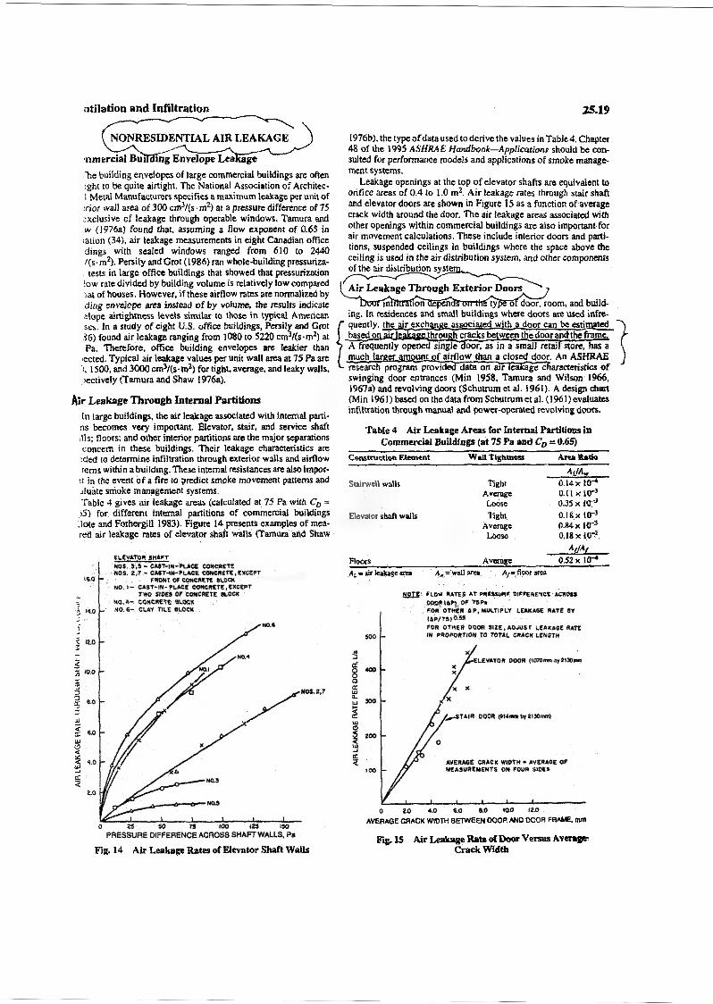
AIR LEA
KAGE
HAIfc IH
ROUUH SHAT I Y
Vrv u
, i.tv
iu i
itiiation and Infiltration 25,19
NONRESIDENTIAL AIR LEAKAGE
nmertial BrnI3mg Envelope LeaEage
"he building envelopes of large commercial buildings are often ;ght to be quite airtight. The National Association of Architcc- i Metal Manufacturers specifies a maximum leakage per unit of rior wall area of 300 cm3/(s • m2) at a pressure difference of 75
exclusive of leakage through operable windows. Tamuta and w (1976a) found that, assuming a flow exponent of 0.65 in lation (34), air leakage measurements in eight Canadian office dings with sealed windows ranged from 610 to 2440 /(s-m2). Persity and Grot (1986) ran whole-building pressuriza- tests in large office buildings that showed that pressurization
low rate divided by building volume is relatively low compared tat of houses. However, if these airflow rates are normalized by ding envelope area instead of by volume, the results indicate elope ai (tightness levels similar to those in typical American ses. In a study of eight U.S. office buildings, Persily and Grot .16) found air leakage ranging from 1080 to 5220 cm3/(s-m2) at Pa. Therefore, office building envelopes are leakier than
■ected. Typical air leakage values per unit wall area at 75 Pa are i. 1500, and 3000 cm3/(s - m2) for tight, average, and leaky walls, icctively (Tamura and Shaw 1976a).
Air Leakage Through Internal Partitions
In large buildings, the air leakage associated with internal parti- ns becomes very important. Elevator, stair, and service shaft ills; floors; and other interior partitions are the major separations concern in these buildings. Their leakage characteristics are
tried to determine infiltration through exterior walls and airflow terns within a building. These internal resistances are also impor-
tt in the event of a fire to predict smoke movement patterns and jluate smoke management systems.Table 4 gives air leakage areas (calculated at 75 Pa with CD = ;5) for different internal partitions of commercial buildings .late and Fothergill 1983). Figure 14 presents examples of mea- red air leakage rates of elevator shaft walls (Tamura and Shaw
ELEVATOR shaft
NOS. S,S - CAST-IN-PLACE CONCRETE NOS. 2,T - CAST-IN-PLACE CONCRETE,EXCEPT
FRONT OF CONCRETE SLOCK NO. 1- CAST-IN-PLACE CONCRETE, EXCEPT
TWO SIDES Of CONCRETE SLOCK NO. A- CONCRETE OLOCE NO. 6- CLAY TILE SLOCK
PRESSURE DIFFERENCE ACROSS SHAFT WALLS, Pa
Fig. 14 Air Leakage Rates of Elevator Shaft Walls
1976b), the type of data used to derive the values in Table 4. Chapter 48 of the 1995 ASHRAE Handbook—Applications should be consulted for performance models and applications of smoke management systems.
Leakage openings at the top of elevator shafts are equivalent to orifice areas of 0.4 to 1.0 m2. Air leakage rates through stair shaft and elevator doors are shown in Figure 15 as a function of average crack width around the door. The air leakage areas associated with other openings within commercial buildings are also important for air movement calculations. These include interior doors and partitions, suspended ceilings in buildings where the space above the ceiling is used in the air distribution system, and other components of the air distribution systen
Air Leakage Through Exterior Doors'mfifTRiflonTIepcntfToirthStypS'otdoorT room, and build
ing. In residences and small buildings where doors are used infrequently, the air exchange associated with a door can be estimated based on air leakage through cracks between the door and the frame. A frequently opened single-door, as in a small retail store, has a much larger amount of airflow than a closed door. An ASHRAE
"research program pTovidSTdata on air leakage characteristics of swinging door entrances (Min 1958, Tamura and Wilson 1966, 1967a) and revolving doors (Schutrum et al. 1961). A design chart (Min 1961) based on the data from Schutrum et al. (1961) evaluates infiltration through manual and power-operated revolving doors.
Table 4 Air Leakage Areas for Internal Partitions in Commercial Buildings (at 75 Pa and CD = 0.65)
Construction Element Wall Tightness Area Ratio
Stairwell walls Tight
AJAW0.14x10"*
Average o.iixur3Loose ojsxtr3
Elevator shaft walls Tight 0.I8X10"3Average 0.84 x ir3
Loose 0.18x10*.
Floors Average
AjjAf0.52 x KT*
Al = air leakage area - wal' area . Ay-- floor area
NOTE: FLOW RATES AT PREMURE DIFFERENCE ACROSSODOR tip) .OF TSPaFOR OTHER 4 R, MULTIPLY LEAKAGE RATE SVIAP/TS|0.S5
FOR OTHER DOOR SIZE, ADJUST LEAKAGE RATE IN PROPORTION TO TOTAL CRACK LENGTH
■ELEVATOR DOOR (1070mm Oy 21 Horn*.
^mSTAIR DOOR (GILmn* byaiOOmflR
AVERAGE CRACK WIDTH • AVERAGE OF MEASUREMENTS ON FOUR SIDES
AVERAGE CRACK WIDTH BETWEEN DOOR AND DOOR FRAME, null
Fig. IS Air Leakage Rate of Dour Versus Average Crack Width
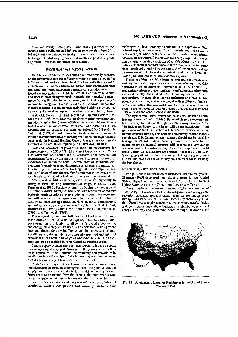
25.20 1997 ASHRAE Fundamentals Handbook (SI)
Grot and Persily (1986) also found that eight recently constructed office buildings had infiltration rates ranging from 0.1 to 0.6 ACH with no outdoor air intake. The infiltration rates of these buildings exhibited varying degrees of weather dependence, generally much lower than that measured in houses.
RESIDENTIAL VENTILATIONVentilation requirements for houses have traditionally been met
on the assumption that the building envelope is leaky enough that infiltration will suffice. Possible difficulties with this approach include low ventilation when natural forces (temperature difference and wind) me weak, unnecessary energy consumption when such forces are strong, drafts in cold climates, lack of control of ventilation rates to meet changing needs, potential for interstitial condensation from exfiltration in cold climates, and lack of opportunity to recover the energy used to condition the ventilation air. The solution to these concerns is to have a reasonably tight building envelope and a properly designed and operated mechanical ventilation system.
ASHRAE Standard 13 9 and the National Building Code of Canada (NRCC 1995) encourage the transition to tighter envelope construction. Hamlin (1991) shows a 30% increase in airtightness of tract- built Canadian houses between 1982 and 1989. Also, 82% of the newer houses bad natural airexchange rates below 0.3 ACH in March. Yuill et al. (1991) derived a procedure to show the extent to which infiltration contributes toward meeting ventilation rate requirements. As a result, the National Building Code of Canada has requirements for mechanical ventilation capability in all new dwelling units.
ASHRAE Standard 62 gives ventilation rate requirements for houses, essentially 0.35 ACH with at least 8 Us per occupant. Canadian Standards Association (CSA) Standard F326 expands the requirements for residential mechanical ventilation systems to cover air distribution within the house, thermal comfort, minimum temperatures for equipment and ductwork, system controls, pressurization and depressurization of the dwelling, installation requirements, and verification of compliance. Verification can be by design or by test, but the total rate of outside air delivery must be measured.
Mechanical ventilation is being used in houses, especially in energy-efficient housing demonstration programs (Riley 1990, Palmiter eta!. 1991). Possible systems can be characterized as local or central; exhaust, supply, or balanced; with forced-air or radiant/ hydronic heating/cooling systems; with or without heat recovery; and with continuous, occupant controlled, or demand controlled (i.c., by pollutant sensing) operation. Note that not all combinations are viable. Various options are described by Fisk et al.. (1984), Hekmat et al. (1986), Sibbitt and Hamlin (1991), Palmiter et al. (1991), and Ymlletal. (1991).
The simplest systems use bathroom and kitchen fans to augment infiltration. Noise, installed capacity, lifetime under continuous operation, distribution to all rooms (especially bedrooms), and energy efficiency issues need to be addressed. Many present bath and kitchen fans are ineffective ventilators because of poor installation and design. However, properly specified and installed exhaust fans can form part of good whole-house ventilation systems and are so specified in some Canadian building codes.
Central supply systems use a furnace blower to induce air from the outdoors and distribute it. However, if the blower is thermostatically controlled, it will operate intermittently and provide little ventilation in mild weather. If the blower operates continuously, cold drafts can be a problem when the furnace is off.
Central exhaust systems use leakage sites and, in some cases, intentional and controllable openings in the building envelope as the supply. Such systems are suitable for retrofit in existing houses. Energy can be recovered from the exhaust airstream with a heat pump to supplement domestic hot water and/or space heating.
For new houses with tightly constructed envelopes, balanced ventilation systems with passive heat recovery (air-to-air heat
exchangers or heat recovery ventilators) are appropriate. Fan- induced supply and exhaust air flows at nearly equal rates over a heat exchanger, where heat and sometimes moisture is transferred between the airstreams. This reduces the energy required to condition the ventilation air by typically 60 to 80% (Cutter 1981). It also reduces the thermal comfort problem that occurs when untempered air is introduced directly into the house. Airflow balance, leakage between streams, biological contamination of wet surfaces, and frosting are concerns associated with these systems.
Sibbitt Mid Hamlin (1991) found several low-cost mechanical systems that, with proper design and commissioning, met CSA Standard F326 requirements. Palmiter et al. (1991) found that mechanical systems provide significant ventilation only when operated continuously, met CSA Standard F326 requirements. A separate ventilation system (air-to-air heat exchanger or exhaust air heat pump) or an existing system integrated with multispeed fans can best accomplish continuous ventilation. Continuous central supply systems are not recommended for cold climates because they cause cold air drafts and condensation in the walls.
The type of ventilation system can be selected based on house leakage class as defined in Table 2. Balanced air-to-air systems with heat recovery are optimal for tight houses (leakage classes A-C). The leakier the house is, the larger will be the contribution from infiltration and the less effective will be heat recovery ventilation. In mild climates, these systems can also effectively be used in leakage classes D-F. Central exhaust systems should not be used for leakage classes A-C unless special provisions are made for air inlets; otherwise, internal pressure will become too low during operation and backdrafting through fossil-fueled appliances could occur. Central exhaust systems are optimal for leakage classes D-F. Ventilation systems are normally not needed for leakage classes G-J, but for those cases in which they are, central exhaust is usually the best choice.
Residential Ventilation ZonesFor guidance in the selection of residential ventilation systems,
Sherman (1995) developed .four climatic zones for the United States. These zones are shown in Figure 16 for the continental United States: Alaska is m Zone 1, and Hawaii is in Zone 4.
Zone 1 includes the severe climates of .the northern tier of states. A Zone 1 residence that meets airtightness and energy conservation standards probably cannot meet its ventilation needs through infiltration and will require forced (mechanical) ventilation. Zone'2 includes the moderate climates where careful design and, construction may allow buildings to simultaneously meet energy standards and ventilation needs through infiltration and
Fig. 16 Airtightness Zones for Residences in the United States (Sherman 1995)
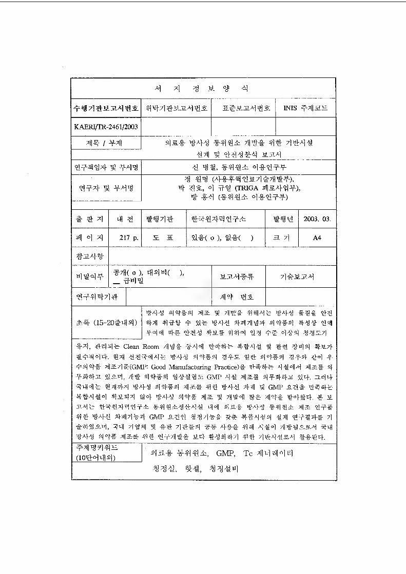
X| 3 9. # 3
9^444Gi4wl& 44713227^2: INIS #41SH
KAERI/TR-2461/2003
414- / 441 4 a* * 3-43 *442 7H#*- 43 4343341 4 343#4 aa4
49447} ^ #44 4^4, *442 4*499
497} W #7}Tg3 44 (a}*#4 <55.4#7lli>#),
4 42, 4 94 (TRIGA 412A}4#),3 *3 (*442 4*499)
% 7) 4 4 #34# t}947}q<99; iHW 2003. 03.
41 °1 4 217 p. S. 4*( O ), tl*( ) EL 7} A4
*7H( o), 444( _ 944
),o IT
414= 42
(15-201=44)
#A}^ 44#4 ^2 ^ 7j|3# 4413* *A},g #3# 33
4Til 49# 9 ti=W3 447H34 44#4 #3* 33
#33 4# 333 sa-ti# 33 91 334 3327}
*4, #44* Clean Room 7]]3* *3o|] ^#3.# ##3^ 3 44 344 *^7}*9334. 34 MM-S 44#4 4*2 "83 44#4 ^94- 33 9#44# 4l24#(GMP: Good Manufacturing Practice)# 314# 4344 494*2 323, yjj# GMP 43 42:# 4-9-44-a 34. 244#313* 3444 ^43 44#4 42:# 43 343 44 4 GMP 24# 314* 43434 31144 #4 343 44=# 42 3 434 3# 414=# 3434. 3- 2 24# 3434439-2 #4323343 44 4a# 343 #442 42 49* 43 343 44434 GMP 233 3343* 2# 43434 34 3934-* 4 #3824, 44 7]<g4 g #3 43*4 ** 4#* 44 434 7H3423.4 44 343 44=# 42# 43 397%#* 24 33334 43 434324 3*44.
4442.
(1Q44414) 4 a* *44 GMP, Tc 414414433^, 33^4
BIBLIOGRAPHIC INFORMATION SHEET
Performing Org. Report No.
Sponsoring Org. Report No.
Stamdard Report No. INIS Subject Code
KABRI/TR-2461/2003
Title / Subtitle Design and Safety Analysis Report of Facilities for
Research and Development of Medical RadioisotopesProject Manager and Department
Byung Chul Shin(Division of Radioisotopes and Radiation Application)
Researcher and Department
W.M.Choung (Division of Spent Fuel Management Tech.) J.H.Park, K.I.Lee (Division of Decon. & Decom. Tech.)
H.S.Bang (Division of Radioisotopes and Radiation Application)
PublicationPlace
Publisher KARRIPublication
Date2003. 3.
Page 217 p. HI. & Tab. Yes( O ), No ( ) Size A4
Note
Classified Open( O ), Restricted( ), Class Document
Report Type Technical report
Sponsoring Org. Contract No.
Abstract (15-20 Lines)For production and research for practical use of
radio-pharmaceuticals using for medical treatment and diagnosis, the complex facility offer shield and
clean environment is basically required for protecting personnel from radiation, and the product from contamination. The facilities was designed for research and development of medical radioisotopes. This facility was designed to comply with GMPCGood Manufacturing Practice) requirements and safety requirements against radiation. In this technical report, technical requirements and design summary for construction of hot cell and clean room are described. And also, This facility will be utilized for production of Tc-99m generator and R. & D. of other radio-pharmaceuticals (Ho-166 etc.).
Subject Keywords (About 10 words)
Radio-pharmaceuticals, Tc-99m generator, Hot cell
Clean room, GMP(KGMP), GMP facility
Related Documents