N219-E1-09 User's Manual K6CM Motor Condition Monitoring Device Monitoring and Setting with the EtherNet/IP Trouble shooting Nomenclature and Functions Overview Setting with the Motor condition monitoring Tool Installation and Wiring Mechanism of Measuring and Monitoring of the K6CM Devices Motor Monitoring and Operation with the K6CM Devices and the Motor condition monitoring Tool Internal Data List of the K6CM Devices 1 2 3 4 5 6 7 8 9

Welcome message from author
This document is posted to help you gain knowledge. Please leave a comment to let me know what you think about it! Share it to your friends and learn new things together.
Transcript

N219-E1-09
User's ManualK6CM
Motor Condition Monitoring Device
Monitoring and Setting with the EtherNet/IP
Trouble shooting
Nomenclature and Functions
Overview
Setting with the Motor condition monitoring Tool
Installation and Wiring
Mechanism of Measuring and Monitoring of the K6CM Devices
Motor Monitoring and Operation with the K6CM Devices and the Motor condition monitoring Tool
Internal Data List ofthe K6CM Devices
1
2
3
4
5
6
7
8
9

All rights reserved. No part of this publication may be reproduced, stored in a retrieval system, or transmitted, in any form, or by any means, mechanical, electronic, photocopying, recording, or otherwise, without the prior written permission of OMRON.
No patent liability is assumed with respect to the use of the information contained herein. Moreover, because OMRON is constantly striving to improve its high-quality products, the information contained in this manual is subject to change without notice. Every precaution has been taken in the preparation of this manual. Neverthe-less, OMRON assumes no responsibility for errors or omissions. Neither is any liability assumed for damages resulting from the use of the information contained in this publication.
• Microsoft, Windows is either registered trademarks or trademarks of Microsoft Corporation in the United States and other countries.
• ODVA, CIP, CompoNet, DeviceNet, and EtherNet/IP are trademarks of ODVA.
Other company names and product names in this document are the trademarks or registered trademarks of their respective companies.
Trademarks
Copyrights
NOTE
Microsoft product screen shots reprinted with permission from Microsoft Corporation.

1
Preface
K6CM Motor Condition Monitoring Device User’s Manual (N219)
Preface
Thank you for purchasing K6CM Motor Condition Monitoring Devices.
This manual describes how to use the K6CM. Read this manual thoroughly and be sure you under-stand it before attempting to use the K6CM correctly according to the information provided. Keep this manual in a safe place for easy reference.
PDF version of this manual can be downloaded from the OMRON website.
(http://www.omron.co.jp)

Terms and Conditions Agreement
2 K6CM Motor Condition Monitoring Device User’s Manual (N219)
Terms and Conditions Agreement
Exclusive Warranty
Omron’s exclusive warranty is that the Products will be free from defects in materials and workman-ship for a period of twelve months from the date of sale by Omron (or such other period expressed in writing by Omron). Omron disclaims all other warranties, express or implied.
Limitations
OMRON MAKES NO WARRANTY OR REPRESENTATION, EXPRESS OR IMPLIED, ABOUT NON-INFRINGEMENT, MERCHANTABILITY OR FITNESS FOR A PARTICULAR PURPOSE OF THE PRODUCTS. BUYER ACKNOWLEDGES THAT IT ALONE HAS DETERMINED THAT THE PRODUCTS WILL SUITABLY MEET THE REQUIREMENTS OF THEIR INTENDED USE.
Omron further disclaims all warranties and responsibility of any type for claims or expenses based on infringement by the Products or otherwise of any intellectual property right.
Buyer Remedy
Omron’s sole obligation hereunder shall be, at Omron’s election, to (i) replace (in the form originally shipped with Buyer responsible for labor charges for removal or replacement thereof) the non-com-plying Product, (ii) repair the non-complying Product, or (iii) repay or credit Buyer an amount equal to the purchase price of the non-complying Product; provided that in no event shall Omron be responsible for warranty, repair, indemnity or any other claims or expenses regarding the Products unless Omron’s analysis confirms that the Products were properly handled, stored, installed and maintained and not subject to contamination, abuse, misuse or inappropriate modification. Return of any Products by Buyer must be approved in writing by Omron before shipment. Omron Companies shall not be liable for the suitability or unsuitability or the results from the use of Products in combi-nation with any electrical or electronic components, circuits, system assemblies or any other materi-als or substances or environments. Any advice, recommendations or information given orally or in writing, are not to be construed as an amendment or addition to the above warranty.
See http://www.omron.com/global/ or contact your Omron representative for published information.
OMRON COMPANIES SHALL NOT BE LIABLE FOR SPECIAL, INDIRECT, INCIDENTAL, OR CON-SEQUENTIAL DAMAGES, LOSS OF PROFITS OR PRODUCTION OR COMMERCIAL LOSS IN ANY WAY CONNECTED WITH THE PRODUCTS, WHETHER SUCH CLAIM IS BASED IN CONTRACT, WARRANTY, NEGLIGENCE OR STRICT LIABILITY.
Further, in no event shall liability of Omron Companies exceed the individual price of the Product on which liability is asserted.
Warranty, Limitations of Liability
Warranties
Limitation on Liability; Etc
3
Terms and Conditions Agreement
K6CM Motor Condition Monitoring Device User’s Manual (N219)
Omron Companies shall not be responsible for conformity with any standards, codes or regulationswhich apply to the combination of the Product in the Buyer’s application or use of the Product. AtBuyer’s request, Omron will provide applicable third party certification documents identifying ratingsand limitations of use which apply to the Product. This information by itself is not sufficient for a com-plete determination of the suitability of the Product in combination with the end product, machine, sys-tem, or other application or use. Buyer shall be solely responsible for determining appropriateness ofthe particular Product with respect to Buyer’s application, product or system. Buyer shall take applica-tion responsibility in all cases. NEVER USE THE PRODUCT FOR AN APPLICATION INVOLVING SERIOUS RISK TO LIFE ORPROPERTY OR IN LARGE QUANTITIES WITHOUT ENSURING THAT THE SYSTEM AS A WHOLEHAS BEEN DESIGNED TO ADDRESS THE RISKS, AND THAT THE OMRON PRODUCT(S) ISPROPERLY RATED AND INSTALLED FOR THE INTENDED USE WITHIN THE OVERALL EQUIP-MENT OR SYSTEM.
Omron Companies shall not be responsible for the user’s programming of a programmable Product, orany consequence thereof.
Data presented in Omron Company websites, catalogs and other materials is provided as a guide forthe user in determining suitability and does not constitute a warranty. It may represent the result ofOmron’s test conditions, and the user must correlate it to actual application requirements. Actual perfor-mance is subject to the Omron’s Warranty and Limitations of Liability.
Product specifications and accessories may be changed at any time based on improvements and otherreasons. It is our practice to change part numbers when published ratings or features are changed, orwhen significant construction changes are made. However, some specifications of the Product may bechanged without any notice. When in doubt, special part numbers may be assigned to fix or establishkey specifications for your application. Please consult with your Omron’s representative at any time toconfirm actual specifications of purchased Product.
Information presented by Omron Companies has been checked and is believed to be accurate; how-ever, no responsibility is assumed for clerical, typographical or proofreading errors or omissions.
Application Considerations
Suitability of Use
Programmable Products
Disclaimers
Performance Data
Change in Specifications
Errors and Omissions

Safety Precautions
4 K6CM Motor Condition Monitoring Device User’s Manual (N219)
Safety Precautions
The following notation is used in this manual to provide precautions required to ensure safe usage of the K6CM Motor Condition Monitoring Devices.
The safety precautions that are provided are extremely important to safety. Always read and heed the information provided in all safety precautions.
The following notation is used.
Definition of Precautionary Information
CAUTION Indicates a potentially hazardous situation which, if not avoided, may result in minor or moderate injury or in property damage.
Symbols
Symbol Meaning
Caution
• General Caution
Indicates non-specific general cautions, warnings, and dangers.
• Electrical Shock Caution
Indicates possibility of electric shock under specific conditions.
Prohibition
• General Prohibition
Indicates non-specific general prohibitions.
• Disassembly Prohibition
Indicates prohibitions when there is a possibility of injury, such as from electric shock, as the result of disassembly.
Mandatory Caution
• General Caution
Indicates non-specific general cautions, warnings, and dangers.
CAUTIONThe following are common to the Motor Condition Monitoring Devices.
Electric shock or injury may occasionally occur. Follow the instructions below to use this product.
Electrical shock may cause minor injury. Do not touch the product except for the front-panel buttons while electricity is being supplied.
There is a risk of minor electrical shock, fire, or device failure. Do not allow any pieces of metal, conductors, or cutting chips that occur during the installation process to enter the product.
Explosions may cause minor injuries. Do not use the product in locations with inflammable or explo-sive gases.

5
Safety Precautions
K6CM Motor Condition Monitoring Device User’s Manual (N219)
There is a risk of minor electrical shock, fire, or device failure. Do not disassemble, modify, repair, or touch the inside of the product.
If the product fails, monitoring and alarm outputs may fail to operate. This may result in physical damage to the facilities, equipment, or other devices that are connected to it. To reduce this risk, inspect the product regularly. To make the product fail-safe, take alternative safety measures, such as the installation of monitoring devices on a separate circuit.
Incorrect wiring the input and output may occasionally result in fire and may occasionally occur resulting in property damage to connected equipment and machinery. Wire the input and output ter-minals correctly before power is supplied.
If installation of wiring material is shallow, material damage due to ignition may occur in rare cases.
When wiring, be sure to insert the wiring material all the way in.
The following are for K6CM-IS and K6CM-CI.
Electric shock may occasionally occur. Follow the instructions below to use this product.
Electric shock may occasionally occur.
Always turn OFF the power supply before connecting the CT or ZCT (IRT).
Electric shock may occasionally occur. As for the primary wire clamped with CT, be sure to use the covered wires at temperatures below 65°C that have 600 V or more basic insulation. When clamp-ing with conductive materials like busbar, use the CT after ensuring equal to or more than basic insolation e.g. covering with insolating objects.
Electric shock may occasionally occur. When wiring voltage input wires to ZCT (IRT), be sure to wire after checking that the system power supply is in non-energized state.
Electric shock may occasionally occur. As for the wires for clamping with ZCT (IRT), be sure to use the covered wires that have 600 V or more basic insulation.
Keep the secondary terminal cover of the special CT and ZCT (IRT) securely closed.
Touching any of electrode may result in electric shock.
CAUTION

Safety Precautions
6 K6CM Motor Condition Monitoring Device User’s Manual (N219)
Conformance to Safety Standards• Reinforced insulation is provided between input power supply, output, and between other termi-
nals.
• To install a recommended fuse for this product according to the instruction manual is necessary.
• If the equipment is used in a manner not specified by the manufacturer, the protection provided by the equipment may be impaired.
• Connect the wiring of ZCT (IRT) to the terminal block corresponding to the thickness of AWG 18 or more.
• K6CM must be installed within a control panel as an embedded device, if using as a UL certified product.
• K6CM will not conform to safety standards if attaching the vibration sensor with adhesive. In the case of disconnection, take safety measures such as fixing the cables.
Conformance to EN/IEC StandardsThis is a class A product. In residential areas it may cause radio interference, in which case the user may be required to take adequate measures to reduce interference.

7
Precautions for Safe Use
K6CM Motor Condition Monitoring Device User’s Manual (N219)
Precautions for Safe Use
Be sure to observe the following precautions to prevent malfunction or adverse affects on the perfor-mance or functionality of the product. Not doing so may occasionally result in unexpected events. Do not handle the K6CM in ways that exceed the ratings.
The following are common to the Motor Condition Monitoring Devices.:
(1) Do not use or store the product in the following locations:
• Locations subject to water or oil (for K6CM devices and K6CM-VBS1 sensor preamplifier)
• Outdoor or locations subject to direct sunlight
• Locations subject to dust or corrosive gases (particularly sulfurizing gases, ammonia, etc.)
• Locations subject to rapid temperature changes
• Locations prone to icing and dew condensation
• Locations subject to excessive vibration or shock
• Locations subject to rain and wind damage
• Locations subject to influence of static electricity and noise
• Locations subject to bugs and small animals
(2) Use and store the product in a location where the ambient temperature and humidity are within the
specified ranges. If applicable, provide forced cooling.
(3) Mount the product in the correct direction for installation.
(4) Check terminal polarity when wiring and wire all connections correctly. The power supply terminals
do not have polarity.
(5) Do not wire the input and output terminals incorrectly.
(6) Make sure the power supply voltage and loads are within the specifications and ratings for the
product.
(7) Make sure the crimp terminals for wiring are of the specified size.
(8) Do not connect anything to terminals that are not being used.
(9) Use a power supply that will reach the rated voltage within 1 second after the power is turned ON.
(10) In order to prevent inductive noise, wire the lines connected to the product separately from power
lines carrying high voltages or currents. Also, do not wire in parallel with or on the same cables as
power lines. Other measures for reducing noise are to separate from ducts including noisy lines.
(11) Do not install the product near equipment that generates high frequencies or surges.
(12) Do not use the product near radio wave receivers. Doing so may cause incoming radio wave inter-
ference.
(13) Install an external switch or a circuit breaker and label it clearly so that the operator can quickly turn
OFF the power supply.
(14) When discarding the product, properly dispose of it as industrial waste.
(15) Make sure the LCD and the LEDs for output indicators operate correctly. Depending on the appli-
cation environment, the indicators and other plastic parts may wear prematurely and become diffi-
cult to see. Check and replace these parts regularly.
(16) The maximum terminal temperature is 80°C. Use wires with a heat resistance of 80°C min to wire
the terminals.
(17) Don't use because it may be damaged inside the product when the product fall by mistake.
(18) Read this manual carefully before using the product.
(19) Install product so that the load doesn't span the product body.
(20) Be sure to use power terminals carefully, because power supply terminals have hazardous voltage.
(for K6CM devices only. Except for K6CM-VBS1 sensors input.)
(21) Only a professional with an understanding of electricity and electric devices must handle it.
(22) Confirm the wiring the input and output terminals correctly before power is supplied.

Precautions for Safe Use
8 K6CM Motor Condition Monitoring Device User’s Manual (N219)
(23) Do not install the product close contact with the heating element.
(24) Do not wire anything to the release holes.
(25) Do not tilt or twist a flat-blade screwdriver while it is inserted into a release hole on the terminal
block. The terminal block may be damaged.
(26) Insert a flat-blade screwdriver into the release holes at an angle. The terminal block. The terminal
block may be damaged if you insert the screwdriver straight in. When inserting a flat-blade screw
driver into the release holes, operate with a force of 15·N or less.
(27) Do not allow the flat-blade screwdriver to fall out while it is inserted into a release hole.
(28) The terminal block may be damaged if you insert a flat-blade screwdriver in the release hole with
excessive force.
(29) Do not bend a wire past its natural bending radius or pull on it with excessive force. Doing so may
cause the wire disconnection.
(30) Do not insert more than one wire into each terminal insertion hole.
(31) To prevent wiring materials from smoking or ignition, use the wiring materials given in the following
table.
(32) Use the wire given in this manual.
(33) When wiring, wire by enough length.
(34) Follow the directions indicated in the manual for connecting EtherNet/IPTM or the cable. It may
result in communication failure.
(35) If EtherNet/IPTM tag data links (cyclic communications) are used with a repeating hub, the commu-
nications load on the network will increase. This will increase collisions and may prevent stable
communications. Do not use repeating hubs on networks where tag data links are used. Use an
Ethernet switch instead.
(36) Do not continue to use the product if the front surface peels.
The followings are for K6CM-VB and K6CM-VBS1 sensors.
(37) Protection structure of the sensor head/cable
Do not use the product in the condition that the protection structure is deteriorated, e.g., swelling or
crack of housing material or sealing material. Continued use with deteriorated protective structure
will cause cutting oil to enter inside the product, possibly destroying or burning.
(38) Use the designated communications cable with the length between the sensor and the product
within specification requirements.
(39) Connect the preamplifier and the body after the power is turned OFF.
The followings are only for K6CM-CI.
(40) Open locking hook and clamp to each phase. After clamping, firmly engage until a sound is heard.
(41) Use the CTs and the CT cables that are specified by OMRON' s model number.
Specified CTs (The cable is included with the CT.):
K6CM-CICB005, K6CM-CICB025, K6CM-CICB100,
K6CM-CICB200, K6CM-CICB400, K6CM-CICB600
Wire type Wiring material Recommended wiresStripping length
Without ferrules
Solid/ Stranded wire Copper 0.25 to 1.5 mm2
AWG24 to AWG16
8 mm

9
Precautions for Safe Use
K6CM Motor Condition Monitoring Device User’s Manual (N219)
The followings are for K6CM-VB, K6CM-VBS1 sensors, K6CM-IS and ZCT(IRT).
(42) Do not connect or disconnect the cables between the sensor and the product while power is being
supplied. Doing so may result in malfunction or failure of the product.
(43) Do not place heavy objects on the cables between the sensor and the Product, and do not apply
excessive force to bend or pull the cables. Doing so may cause a failure.
The following is for K6CM-IS and K6CM-CI.
(44) The product is impossible to measure correctly in the state of open phase. Use the product in the
state of non-open phase.
The followings are only for K6CM-IS.
(45) Use the product within the range of specifications and the rated input voltage.

Precautions for Correct Use
10 K6CM Motor Condition Monitoring Device User’s Manual (N219)
Precautions for Correct Use
Observe the following operating methods to prevent failure and malfunction.
The followings are common to the K6CM.
(1) Use the power supply voltage, input power, and other power supplies and transformers with suit-
able capacities and rated outputs.
(2) When cleaning the product, do not use thinners or solvents. Use commercial alcohol.
(3) Confirm that wire does not stick up after wiring of stranded cable.
(4) In case of passage wiring, install these by 10 A per 1 terminal because when products are con-
nected more than one in parallel, quite many electric currents to be called off.
(5) The terminal block may be damaged if specialized tool is not used. Use a recommended flat-blade
screwdriver to inserted into a release hole on the terminal block.
(6) Do not apply excessive force to bend or pull the communications cables, and do not place heavy
objects on the cables. Doing so will damage the cables.
(7) Refer to the status information of the product on the data link communication and refer to the
received data only in case of no errors occur with the product.
The followings are for K6CM-VB and K6CM-VBS1 sensors.
(8) Wipe off the dirt on the mounting surface and screw mounting with 17 mm nominal size of wrench.
• Recommended mounting screw tightening torque: 4.4 to 5.4 N•m
• Mounting hole dimension: M6 holes (depth: 9 mm min.)
(9) The easy-positioning magnet is for the purpose of seeking the detected position. In the case of
using the product permanently, be sure to use it after it is mounted by screws.
(10) In the case of vertical mounting or reverse mounting with the easy positioning magnet, be careful
of the sensor falling.
(11) Refer to Installation of the Vibration Sensor Head on page 5-7 to install the sensor correctly. It may
be impossible to detect high frequency vibration.
(12) Do not disassemble the sensor. It may not operate correctly.
(13) Be careful of incorrect wiring or short circuit for wiring.
(14) Do not use the preamplifier connected to the other products.
(15) If there is a vibration reduction device such as dampers and rubbers between the vibration mea-
surement object and the sensor, it is difficult to detect the vibration and it will not be able to mea-
sure it correctly, so do not install as much as possible.
(16) In the case of insertion and removal of connector, be sure to do it by holding the connector with
hands.
(17) Do not remove the connector with holding the cable.
(18) Check the direction of the key groove before you use the connector.
(19) Do not wire with wet hands. It may result in operation failure or product damage when power is
being supplied to the product.
(20) When fitting the connector, be sure to do it with hands, not to use tools. It may result in damages if
the tool like plier is used.
(21) In the case of removal of the fitness of the connector between the sensor and the preamplifier, be
careful to do it not to adhere water or dirt on the fitting surface. It may result in faulty contact at the
connector.
(22) Install cables to avoid any force is applied to the connector. In case the any force is applied to the
connector, it causes that the performance of protection structure (IP67G) becomes incapable.
(23) Do not use the connector as a scaffold or put heavy objects on it. It may result in connector dam-
age.

11
Precautions for Correct Use
K6CM Motor Condition Monitoring Device User’s Manual (N219)
(24) Do not mount the way that the force is directly applied to the fitting part of the connector or the root
part of the cable connection. It may result in connector damage or cable disconnection.
(25) When bending cables, use cables with a minimum bending radius of 25 mm.
(26) Use preamplifier after it is fixed on the DIN rail or with screws. In case of using unfixed one, it is in
the condition that force is easily applied to the cable, and the cable may be broken.
(27) About oil-resistance of sensor head/cable; (Not tested by UL)
Follow the procedure below in case of using the product under the condition that uses cutting oil
since the life expectancy and the performance of the product are affected.
• Use the product in the specified condition for cutting oil
• Use the product at the dilution rate of cutting oil that is recommended by the cutting oil makers.
• Do not use the product in oil or water.
There are cases that the influence on the life expectancy of the product differs depending on the type of the use oil. Make sure in advance that there is no deterioration of the sealing material by the cutting oil, before using the product.
The followings are for K6CM-IS and K6CM-CI.
(28) Error will be large if the product is used for thyristor control.
(29) Do not use the alarm output function for control. This function can be used only to detect abnormal
conditions and to output the alarm.
(30) Avoid using the product in places near a radio, a television set, or a wireless device.
The product may result in radio disturbance for these devices.
(31) Make sure that the rating of the used CT and the CT setting of the product agree.
(32) Do not ground the specified CT. Doing so may cause instability when measuring failure.
(33) Do not clamp directly to the lines exceeding 480 VAC.
(34) Use ZCT (IRT) after fixing it with screws. If used without fixing, a load is easily applied on the cable,
and the cable may become disconnected.
The followings are only for K6CM-IS.
(35) ZCT (IRT) is an special product. Do not use it for any other purposes. Otherwise, failure may occur.
(36) When clamping wires with ZCT (IRT), do it in a right direction. If clamped in the wrong direction,
correct measurement cannot be taken.
(37) The distorted ratio of the input waveform should be 30% or less. If it is used in a circuit with large
distortion of waveform, it may cause unnecessary operation.
(38) Do not use in a circuit with the waveform is distorted. The error will increase due to the influence of
the distorted waveform.

Revision History
12 K6CM Motor Condition Monitoring Device User’s Manual (N219)
Revision History
A manual revision code appears as a suffix to the catalog number on the front cover of the manual.
Revision code Date Revised content
01 December 2017 Original production
02 December 2017 Added descriptions and corrected mistakes.
03 December 2017 Added descriptions and corrected mistakes.
04 April 2018 Added descriptions and corrected mistakes.
05 April 2018 Corrected mistakes.
06 June 2018 • Added descriptions about the selection function of the transistor output type with the version upgrade of the software tool Motor con-dition monitoring Tool (version 1.0.0.2 to 1.1.0.0)
• Added following functions according to the upgrade of the EIP CPU version (version 1.00 to 1.10) of the K6CM device
• Selection function of the transistor output type(Not that it can be selected only when using the software tool Motor condition monitoring Tool version 1.1.0.0 or higher.)
• Trigger function with the external input of the insulation resistance type K6CM-ISM device
• Corrected mistakes.
07 October 2018 • Added descriptions about the following functions according to the upgrade version of the software tool Motor condition monitoring Tool (version 1.1.0.0 to 1.2.0.0)
• Graph vertical axis scale setting
• Graph time axis movement
• IP address list display
• Added descriptions according to the adhesive attachment which is sold separately for a vibration sensor.
• Corrected mistakes.
• Added descriptions.
08 December 2018 • Deleted the descriptions of "Adhesive attachment will be released soon"
• Corrected mistakes.
09 December 2018 • Added descriptions on the multicast of tag data link.
• Added a side-view dimensions of adhesive attachment.
N219-E1-09Revision code
1 A
2
3
4
5
6
7
8
9
1 A
I
4
5
6
7
8
9
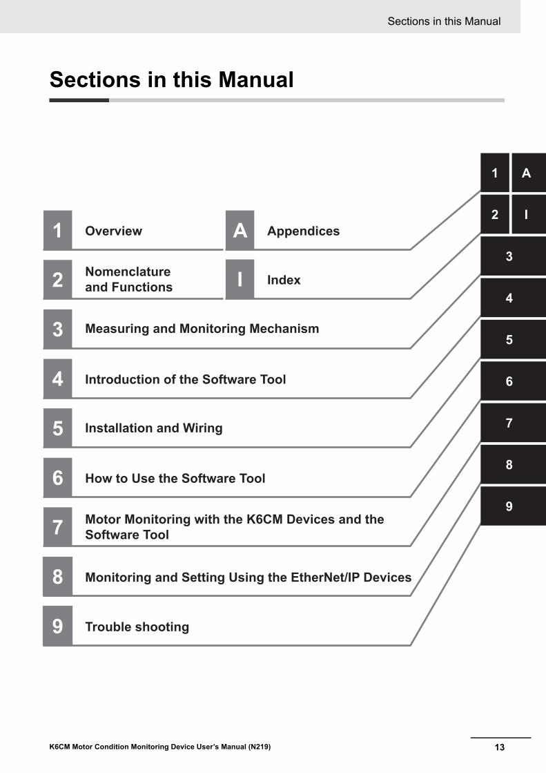
Overview
Nomenclature and Functions
Appendices
I Index
Measuring and Monitoring Mechanism
Introduction of the Software Tool
Installation and Wiring
Motor Monitoring with the K6CM Devices and the Software Tool
How to Use the Software Tool
Monitoring and Setting Using the EtherNet/IP Devices
Trouble shooting
3
2
13
Sections in this Manual
K6CM Motor Condition Monitoring Device User’s Manual (N219)
Sections in this Manual

CONTENTS
14 K6CM Motor Condition Monitoring Device User’s Manual (N219)
CONTENTS
Preface ......................................................................................................................1
Terms and Conditions Agreement ..........................................................................2Warranty, Limitations of Liability .................................................................................................................. 2Application Considerations .......................................................................................................................... 3Disclaimers .................................................................................................................................................. 3
Safety Precautions ...................................................................................................4Definition of Precautionary Information........................................................................................................ 4Symbols ....................................................................................................................................................... 4
Precautions for Safe Use.........................................................................................7
Precautions for Correct Use..................................................................................10
Revision History .....................................................................................................12
Sections in this Manual .........................................................................................13
CONTENTS..............................................................................................................14
Section 1 Overview
1-1 Overview and Features ......................................................................................................... 1-21-1-1 What is the K6CM Motor Condition Monitoring Devices For?..................................................... 1-21-1-2 Features...................................................................................................................................... 1-3
1-2 List of Models ........................................................................................................................ 1-5
1-3 System Configurations ......................................................................................................... 1-61-3-1 Overall System Configuration ..................................................................................................... 1-61-3-2 I/O Configuration by Monitor Type .............................................................................................. 1-7
1-4 Procedure............................................................................................................................. 1-10
Section 2 Nomenclature and Functions
2-1 K6CM Device.......................................................................................................................... 2-2
2-2 Vibration & Temperature Sensor.......................................................................................... 2-9
2-3 Insulation Resistance Sensor (ZCT (IRT)) ......................................................................... 2-12
2-4 Dedicated CT........................................................................................................................ 2-13
Section 3 Measuring and Monitoring Mechanism
3-1 Overview................................................................................................................................. 3-2
3-2 Measurement System............................................................................................................ 3-33-2-1 Sampling of measured values..................................................................................................... 3-33-2-2 Moving average........................................................................................................................... 3-43-2-3 Trigger Mode............................................................................................................................... 3-53-2-4 Maximum Value and Minimum Value of Measured Value ......................................................... 3-11
15
CONTENTS
K6CM Motor Condition Monitoring Device User’s Manual (N219)
3-3 Monitoring Mechanism ....................................................................................................... 3-133-3-1 Types of Individual Alarms........................................................................................................ 3-133-3-2 Comprehensive Alarm Judgment ............................................................................................. 3-133-3-3 Relationship Between Alarm and Display/Output ..................................................................... 3-143-3-4 Guide for Setting Alarm ............................................................................................................ 3-19
3-4 How the Self-Diagnosis Function Works .......................................................................... 3-23
3-5 How the Replacement Timing Notification (i.e., Running Time Function) Works ......... 3-25
3-6 Initialization of Setting Value.............................................................................................. 3-26
Section 4 Introduction of the Software Tool
4-1 Overview................................................................................................................................. 4-24-1-1 What is the Motor condition monitoring Tool (Software Tool) for? .............................................. 4-24-1-2 Functions and Specifications of the Software Tool ..................................................................... 4-34-1-3 Operating Environment of the Software tool............................................................................... 4-8
4-2 Installation and Uninstallation, Starting up....................................................................... 4-104-2-1 Installation................................................................................................................................. 4-104-2-2 Uninstallation Procedures......................................................................................................... 4-23
4-3 IP Address Setting............................................................................................................... 4-244-3-1 IP Address Setting of Your PC.................................................................................................. 4-244-3-2 IP Address Setting of the K6CM Devices ................................................................................ 4-26
Section 5 Installation and Wiring
5-1 Dimensions ............................................................................................................................ 5-25-1-1 K6CM device .............................................................................................................................. 5-25-1-2 Vibration & temperature Sensor ................................................................................................. 5-25-1-3 Insulation resistance sensor (ZCT (IRT)).................................................................................... 5-35-1-4 Dedicated CT.............................................................................................................................. 5-4
5-2 Installation.............................................................................................................................. 5-55-2-1 Precautions at installation........................................................................................................... 5-55-2-2 Installing the K6CM Device......................................................................................................... 5-55-2-3 Installation of the Vibration & Temperature sensor ..................................................................... 5-75-2-4 Installation of the insulation resistance sensor (ZCT (IRT) ....................................................... 5-125-2-5 Installation of the dedicated CT ................................................................................................ 5-15
5-3 How to Connect to the Push-In Plus Terminal Blocks ..................................................... 5-165-3-1 the Push-In Plus Terminal Block............................................................................................... 5-175-3-2 How to use the Push-In Plus Terminal Block ............................................................................ 5-175-3-3 Recommended Ferrules and Crimp Tools ................................................................................ 5-19
5-4 Diagram of Terminal Description ....................................................................................... 5-21
5-5 I/O wiring .............................................................................................................................. 5-22
5-6 EtherNet/IP Wiring ............................................................................................................... 5-26
Section 6 How to Use the Software Tool
6-1 Screens................................................................................................................................... 6-26-1-1 Start Screen ................................................................................................................................ 6-26-1-2 Monitoring Screen and Setting Screen....................................................................................... 6-56-1-3 Common Menu and Toolbar List............................................................................................... 6-166-1-4 Buttons on Device Setting ........................................................................................................ 6-186-1-5 Software Tool Version Display Screen...................................................................................... 6-22
CONTENTS
16 K6CM Motor Condition Monitoring Device User’s Manual (N219)
6-2 Setting of K6CM Devices .................................................................................................... 6-236-2-1 Settings for Each Monitor Type of K6CM devices..................................................................... 6-236-2-2 Setting Parameters ................................................................................................................... 6-266-2-3 Add a Device to an Existing Project .......................................................................................... 6-276-2-4 Motor (Device Group) Rename................................................................................................. 6-286-2-5 Save Overwriting Project........................................................................................................... 6-296-2-6 Exit Project ................................................................................................................................ 6-29
Section 7 Motor Monitoring with the K6CM Devices and the Soft-ware Tool
7-1 Motor Monitoring and Operation Procedure....................................................................... 7-2
7-2 Motor Monitoring Using the K6CM devices ........................................................................ 7-37-2-1 Start measurement...................................................................................................................... 7-37-2-2 Monitoring Type Switching .......................................................................................................... 7-57-2-3 Monitoring method ...................................................................................................................... 7-67-2-4 Measuring and Monitoring Completed ........................................................................................ 7-8
7-3 Motor Monitoring Using Software Tools.............................................................................. 7-97-3-1 Monitoring Procedure with Motor Condition Monitoring Tool....................................................... 7-97-3-2 Set the Monitoring Cycle............................................................................................................. 7-97-3-3 Start Monitoring ......................................................................................................................... 7-107-3-4 Saving Log Files........................................................................................................................ 7-117-3-5 Graph Vertical Axis Scale Setting ............................................................................................. 7-127-3-6 Graph Time Axis Movement...................................................................................................... 7-13
Section 8 Monitoring and Setting Using the EtherNet/IP Devices
8-1 Overview................................................................................................................................. 8-28-1-1 What is Monitoring Using EtherNet/IP?....................................................................................... 8-28-1-2 EtherNet/IP Communications Specifications............................................................................... 8-4
8-2 Monitoring Using the Tag Data Link ................................................................................... 8-58-2-1 Connection setting ...................................................................................................................... 8-58-2-2 Data to be Tag Data Link Target in the K6CM Device................................................................. 8-9
8-3 Monitoring and Setting Using the CIP Message Communications and Examples of Communications Instructions............................................................................................ 8-128-3-1 Datatype List of Variables ......................................................................................................... 8-128-3-2 Services Supported by Objects in K6CM.................................................................................. 8-128-3-3 Monitor Object (Class ID: 370 hex) ........................................................................................... 8-138-3-4 Setting Object (Class ID: 371 hex)............................................................................................ 8-188-3-5 Identity Object (Class ID: 01 hex) ............................................................................................. 8-238-3-6 TCP/IP Interface Object (Class ID: F5 hex) .............................................................................. 8-258-3-7 Examples of CIP Message Communications Instruction .......................................................... 8-27
8-4 Sample Program for the NJ/NX-series............................................................................... 8-298-4-1 Sample Program Overwiew ...................................................................................................... 8-298-4-2 Sample Program Processing Flow and Function Block Specifications ..................................... 8-318-4-3 Sample Program Execution Procedures................................................................................... 8-368-4-4 Sample Program Code Descriptions......................................................................................... 8-37
Section 9 Trouble shooting
9-1 K6CM Devices........................................................................................................................ 9-2
9-2 Using the Software tool......................................................................................................... 9-4
9-3 Using the EtherNet/IP............................................................................................................ 9-6
17
CONTENTS
K6CM Motor Condition Monitoring Device User’s Manual (N219)
Appendices
A-1 Specifications ........................................................................................................................A-2
A-2 Measured Values by Each Monitor Type .............................................................................A-3
A-3 K6CM Common Specifications ............................................................................................A-5
A-4 K6CM device Individual Specifications ...............................................................................A-8
A-5 Individual Specifications of the Dedicated Sensor ..........................................................A-10
A-6 Internal Data of K6CM Devices...........................................................................................A-14
A-7 Setting Values ......................................................................................................................A-15
A-8 Present Values .....................................................................................................................A-19
A-9 Tag Data Link Connection Setting Procedures.................................................................A-24A-9-1 Using the CS/CJ-series ............................................................................................................ A-24A-9-2 Using the NJ/NX-series ............................................................................................................ A-36
A-10 Expansion Error Code of the CIP Message Communications.........................................A-46A-10-1 General Status .......................................................................................................................... A-46A-10-2 Additional Status When General Status Is 01 hex ....................................................................A-48
Index

CONTENTS
18 K6CM Motor Condition Monitoring Device User’s Manual (N219)

1 - 1
1
K6CM Motor Condition Monitoring Device User’s Manual (N219)
This section describes an overview of the K6CM Motor Condition Monitoring Device.
1-1 Overview and Features . . . . . . . . . . . . . . . . . . . . . . . . . . . . . . . . . . . . . . . . . 1-21-1-1 What is the K6CM Motor Condition Monitoring Devices For? . . . . . . . . . . . . . . 1-2
1-1-2 Features . . . . . . . . . . . . . . . . . . . . . . . . . . . . . . . . . . . . . . . . . . . . . . . . . . . . . . 1-3
1-2 List of Models . . . . . . . . . . . . . . . . . . . . . . . . . . . . . . . . . . . . . . . . . . . . . . . . . 1-5
1-3 System Configurations . . . . . . . . . . . . . . . . . . . . . . . . . . . . . . . . . . . . . . . . . 1-61-3-1 Overall System Configuration . . . . . . . . . . . . . . . . . . . . . . . . . . . . . . . . . . . . . . 1-6
1-3-2 I/O Configuration by Monitor Type . . . . . . . . . . . . . . . . . . . . . . . . . . . . . . . . . . 1-7
1-4 Procedure . . . . . . . . . . . . . . . . . . . . . . . . . . . . . . . . . . . . . . . . . . . . . . . . . . . 1-10
Overview
1 Overview
1 - 2 K6CM Motor Condition Monitoring Device User’s Manual (N219)
1-1 Overview and Features
This section describes an overview and features of the K6CM.
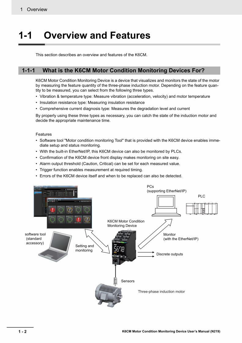
K6CM Motor Condition Monitoring Device is a device that visualizes and monitors the state of the motor by measuring the feature quantity of the three-phase induction motor. Depending on the feature quan-tity to be measured, you can select from the following three types.
• Vibration & temperature type: Measure vibration (acceleration, velocity) and motor temperature
• Insulation resistance type: Measuring insulation resistance
• Comprehensive current diagnosis type: Measures the degradation level and current
By properly using these three types as necessary, you can catch the state of the induction motor and decide the appropriate maintenance time.
Features
• Software tool "Motor condition monitoring Tool" that is provided with the K6CM device enables imme-diate setup and status monitoring.
• With the built-in EtherNet/IP, this K6CM device can also be monitored by PLCs.
• Confirmation of the K6CM device front display makes monitoring on site easy.
• Alarm output threshold (Caution, Critical) can be set for each measured value.
• Trigger function enables measurement at required timing.
• Errors of the K6CM device itself and when to be replaced can also be detected.
1-1-1 What is the K6CM Motor Condition Monitoring Devices For?
Sensors
Setting and monitoring
Discrete outputs
software tool(standard accessory)
K6CM Motor Condition Monitoring Device
PCs (supporting EtherNet/IP)
Monitor(with the EtherNet/IP)
Three-phase induction motor
PLC
1 - 3
1 Overview
K6CM Motor Condition Monitoring Device User’s Manual (N219)
1-1 Overview
and
Fe
atures
1
1-1-2 Fe
atures
K6CM Common Functions
• Two levels of warning failure and critical failure are prepared as alarm monitoring levels. Two out-puts of the transistor are possible when the alarm occurs.
• Trigger functions using an external input (*1) or internal set value comparison enable measuring and monitoring only when specified conditions such as startup of the motor are met.
• The software tool enables initial settings of the K6CMs and alarm monitoring of measurement val-ues. It also enables reading of measurement values at specified intervals and automatic data stor-age (with the CSV format).
• The K6CM device supports the EtherNet/IP network and can be monitored remotely with it.
• Multiple K6CM devices can be connected to one PLC or one PC, and multiple motor statuses can be monitored at one time.
• Measurement value and internal data can be read, and alarm setting values and other setting val-ues can be written (*2) with the PLC and PC via EtherNet/IP (i.e., tag data link, CIP message communications).
*1. For the insulation resistance type K6CM device, the trigger function using the external input can be supported for the EIP CPU version 1.10 or higher.
*2. Tag data link can be read only. Write not possible.
Vibration and Temperature Type
• Simultaneous measuring and monitoring of motor vibration (i.e., acceleration and velocity) and motor temperature are possible.
• Mainly bearing wears can be detected by the acceleration.
• Mainly load imbalance and misalignment can be detected by the velocity.
Insulation Resistance Type
• Insulation resistance can be measured and monitored.
• Resistance leakage current (Ior) can be measured (Alarm output cannot be performed.)
• Capacitive leakage current (Ioc) can also be measured (Can be read via EtherNet/IP. Unit display and alarm output cannot be performed.)
1-1-2 Features
1 Overview
1 - 4 K6CM Motor Condition Monitoring Device User’s Manual (N219)
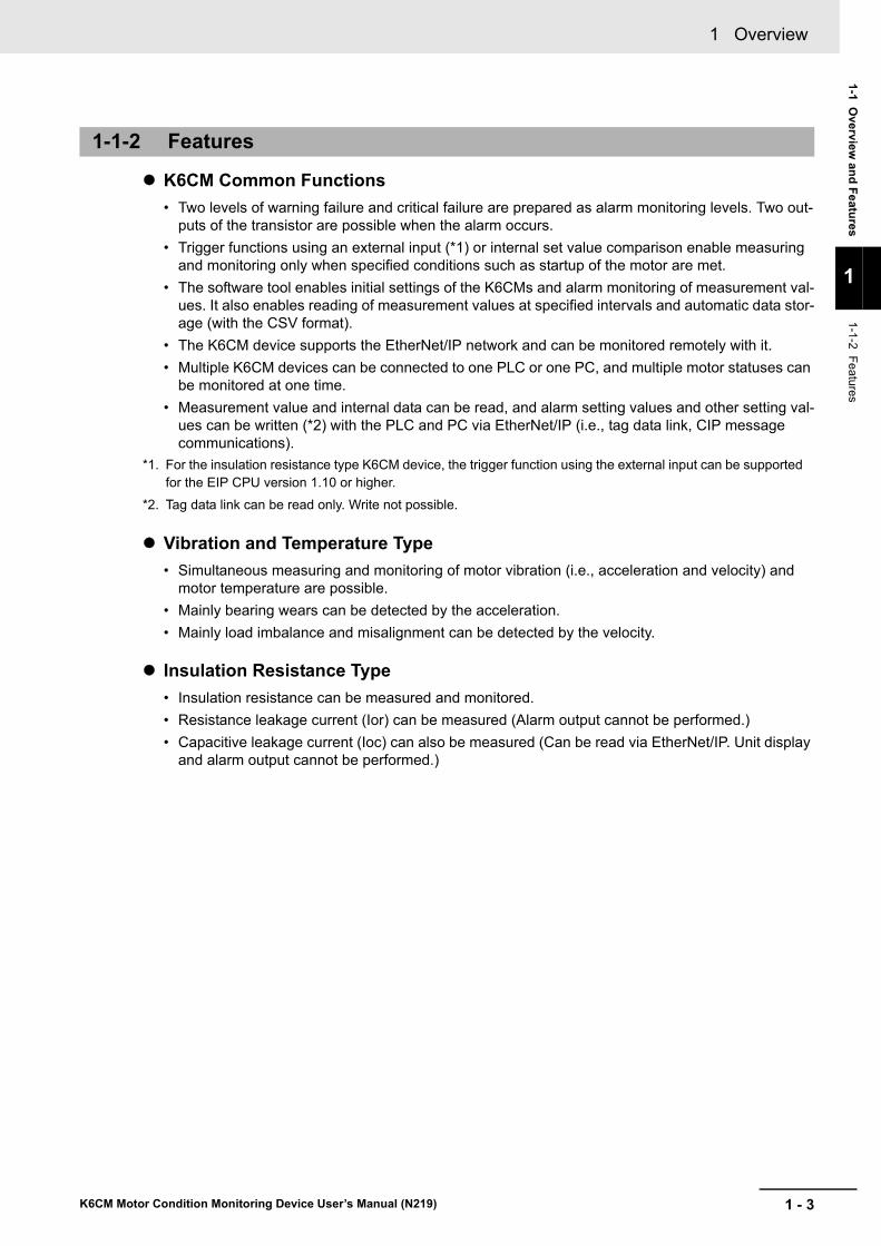
Comprehensive current diagnosis Type
• Motor malfunction (called "degradation level") can be detected by measuring and monitoring the current including harmonic components.
• The degradation level is the conversion of the degree of deviation of the current waveform between the normal motor and the abnormal motor in numerical values.
• The K6CM can also detect motor peripheral malfunctions affecting the rotating shaft of the motor.
(1) Motor and load are normal.Cross-sectional view of the motor
Cross-sectional view of the motor
(2) An abnormality is occurring.
The current is a smooth "sine wave".
"Noise" may come up in the current.
Smooth rotation
Abnormal vibration

1 - 5
1 Overview
K6CM Motor Condition Monitoring Device User’s Manual (N219)
1-2 List o
f Mo
dels
1
1-2 List of Models
This section shows the models of the K6CM device and the dedicated sensor.
Specifications
Vibration & Temperature Type
Insulation Resistance Type
Comprehensive Current Diagnosis Type
Model Specifications such as power supply voltage
K6CM device K6CM-VBMA-EIP 100 to 240 VAC
K6CM-VBMD-EIP 24 V AC/DC
Sensor (sensor head and pre-amplifier)*1
*1. The sensor head and the pre-amplifier are calibrated and inspected as a set at the factory shipment. Be sure to use them with the combination shipped.
K6CM-VBS1 Mounting: M6 screw
Model Specifications such as power supply voltage
K6CM device K6CM-ISMA-EIP 100 to 240 VAC
K6CM-ISMD-EIP 24 V AC/DC
Sensor (ZCT (IRT)) *1
*1. ZCT (IRT) stands for Zero Current Transformer (Insulation Resistance Transformer).
K6CM-ISZBI52 Rated voltage: 200 to 480 VAC, through hole diameter 52 mm
Model Specifications such as power supply voltage
K6CM device K6CM-CIMA-EIP 100 to 240 VAC
K6CM-CIMD-EIP 24 V AC/DC
Sensor (CT) K6CM-CICB005 Rated primary current: 5 A, rated voltage: 480 VAC
K6CM-CICB025 Rated primary current: 25 A, rated voltage: 480 VAC
K6CM-CICB100 Rated primary current: 100 A, rated voltage: 480 VAC
K6CM-CICB200 Rated primary current: 200 A, rated voltage: 480 VAC
K6CM-CICB400 Rated primary current: 400 A, rated voltage: 480 VAC
K6CM-CICB600 Rated primary current: 600 A, rated voltage: 480 VAC
1 Overview
1 - 6 K6CM Motor Condition Monitoring Device User’s Manual (N219)
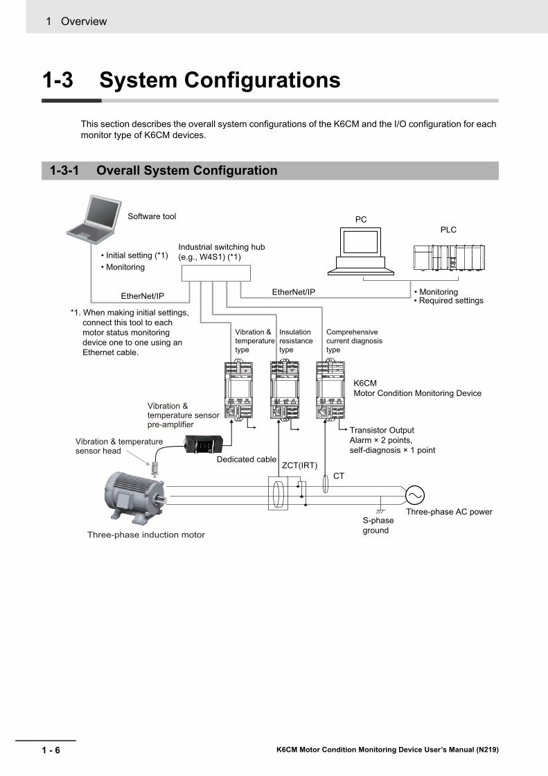
1-3 System Configurations
This section describes the overall system configurations of the K6CM and the I/O configuration for each monitor type of K6CM devices.
1-3-1 Overall System Configuration
ZCT(IRT)CT
Transistor OutputAlarm × 2 points, self-diagnosis × 1 point
Three-phase AC power
Industrial switching hub (e.g., W4S1) (*1)
Dedicated cable
S-phase ground
*1. When making initial settings, connect this tool to each motor status monitoring device one to one using an Ethernet cable.
Comprehensive current diagnosis type
• Required settings
Insulation resistance type
Vibration & temperature type
K6CMMotor Condition Monitoring Device
• Monitoring
• Monitoring• Initial setting (*1)
Software tool
EtherNet/IP EtherNet/IP
PLCPC
Vibration & temperature sensor head
Vibration & temperature sensor pre-amplifier
Three-phase induction motor

1 - 7
1 Overview
K6CM Motor Condition Monitoring Device User’s Manual (N219)
1-3 System
Co
nfig
uratio
ns
1
1-3-2 I/O C
onfiguration b
y Monitor Type
The input and output system configurations for each monitor types of K6CM devices are as follows.
*1. The dedicated cable between the sensor head and the pre-amplifier is 2.9 m long. It cannot be extended.The sensor head and the pre-amplifier are calibrated and inspected as a set at the factory shipment. Be sure to use them with the combination shipped. For details, refer to Installation of the Vibration Sensor Head on page 5-7.
*2. The dedicated attached cable between the pre-amplifier and the K6CM device is 1 m. It can be extended up to a maximum length of 100 m. Refer to A-5 Individual Specifications of the Dedicated Sensor on page A-10 for recommended cables.
Note When you use an inverter to drive the motor, you may not be able to check the degradation tendency of the motor. However, under the following conditions, changes in acceleration are more likely to be con-firmed.
• When the inverter driving frequency is 50 Hz or more and the frequency is stable
• When the carrier frequency of the inverter is 12.5 kHz or more and the frequency is stable
Use an inverter after trying according to your installation environment.
1-3-2 I/O Configuration by Monitor Type
K6CM-VB Vibration & Temperature Type
Vibration & temperature sensor pre-amplifier
Three-phase induction motor
Vibration & temperature sensor head
K6CM-VBMVibration & temperature type device
(When necessary)External trigger input Transistor Output
Self-diagnosis output
EtherNet/IP (Ethernet cable)
*2*1
To the software tool, PC software and/or PLC
Comprehensive alarm (failure warning) outputComprehensive alarm (failure critical) output
1 Overview
1 - 8 K6CM Motor Condition Monitoring Device User’s Manual (N219)
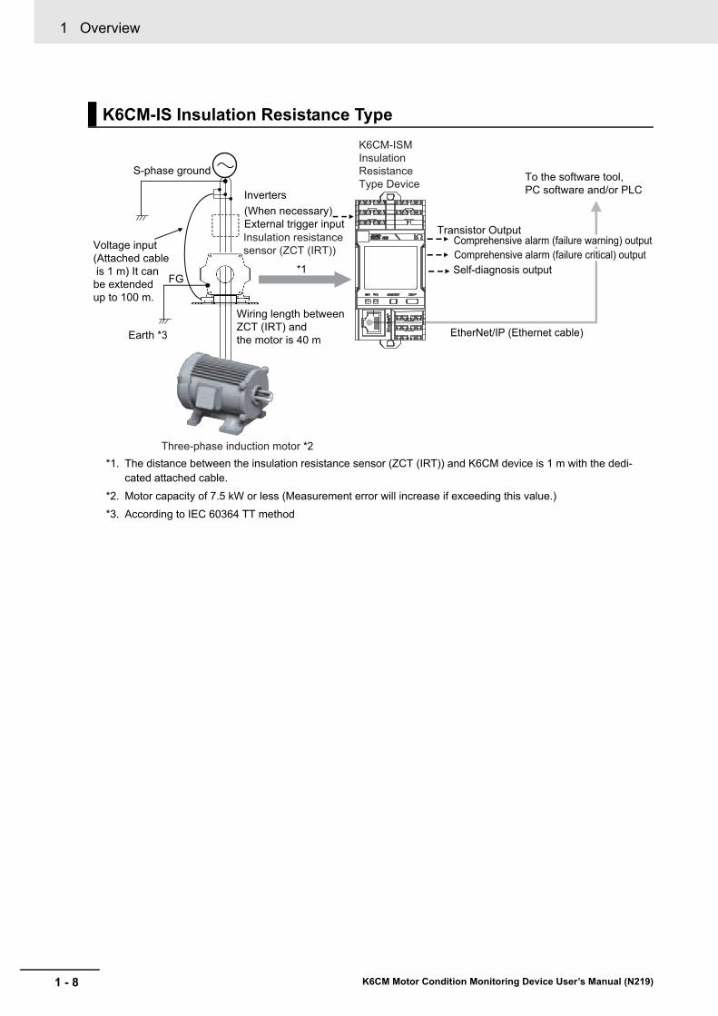
*1. The distance between the insulation resistance sensor (ZCT (IRT)) and K6CM device is 1 m with the dedi-cated attached cable.
*2. Motor capacity of 7.5 kW or less (Measurement error will increase if exceeding this value.)
*3. According to IEC 60364 TT method
K6CM-IS Insulation Resistance Type
FG
K6CM-ISMInsulation Resistance Type Device
Transistor Output
EtherNet/IP (Ethernet cable)
Inverters(When necessary) External trigger inputInsulation resistance sensor (ZCT (IRT))
S-phase ground
Wiring length between ZCT (IRT) and the motor is 40 mEarth *3
Three-phase induction motor *2
Voltage input(Attached cable is 1 m) It can be extended up to 100 m.
*1
To the software tool, PC software and/or PLC
Self-diagnosis output
Comprehensive alarm (failure warning) outputComprehensive alarm (failure critical) output

1 - 9
1 Overview
K6CM Motor Condition Monitoring Device User’s Manual (N219)
1-3 System
Co
nfig
uratio
ns
1
1-3-2 I/O C
onfiguration b
y Monitor Type
*1. The dedicated cable between the dedicated CT and the K6CM device is 2.9 m long. It cannot be extended. Also, there is no designation in the phase to be installed. Be careful of the installation direction stated on the CT label and mount it to any one phase.
Note The level of degradation may vary when the motor is driven by the inverter. In that case, slightly shift the inverter drive frequency.Also always measure and monitor the level of degradation at the same inverter drive frequency. Mount a dedicated CT between the motor and the inverter.
K6CM-CI Comprehensive Current Diagnosis Type
Three-phase induction motor
(When necessary)External trigger input
Dedicated CT *1
K6CM-CIMComprehensive current diagnosis Type Device
Transistor Output
EtherNet/IP (Ethernet cable)
To the software tool, PC software and/or PLC
Self-diagnosis output
Comprehensive alarm (failure warning) outputComprehensive alarm (failure critical) output

1 Overview
1 - 10 K6CM Motor Condition Monitoring Device User’s Manual (N219)
1-4 Procedure
The K6CMs can be used in the following procedure.
Step Procedures Reference
1. Initial setting on desk
Prepare a PC with Windows 7 or higher and Ethernet cables.
Install the software tool.
Section 4 Introduction of the Software Tool
↓
Start the software tool.
↓
Connect the software tool directly to the K6CM device via Ethernet cable.
Either order is acceptable
Turn ON the power to the K6CM device
↓
Select [Create Project],
• Set the IP address of each K6CM device
• Set default parameters
• Set other parameters (when necessary)
• Download IP address and (when necessary) parameters to K6CM device.
• (When necessary) Set the motor name (K6CM group name) of each K6CM.
2. Installation and Wiring
Install. Section 2 Nomencla-ture and Functions
Section 5 Installation and Wiring
↓
Wire.
3. Setting with actual sys-tem configu-ration (via hub)
Connect the software tool to the K6CM device (s) via hub. Section 6 How to Use the Software Tool↓
(When necessary) Change the parameters and download to each K6CM device.
↓
Turn ON the power of the K6CM again and activate the parameters.

1 - 11
1 Overview
K6CM Motor Condition Monitoring Device User’s Manual (N219)
1-4 Pro
cedu
re
1
4. Monitoring and operation
Start measuring using the K6CMs.Section 3 Measuring and Monitoring Mecha-nism
↓
Record measurement values from the host system (i.e., the software tool, PC, or PLC) to estimate an alarm set value to be used as the monitoring standard.
• With the software tool, set the "Monitoring cycle" by press-ing the [Option] Button, before monitor via EtherNet/IP and log the measurement values.
• With PC or PLC, Monitor via EtherNet/IP and log the mea-surement values.
Section 7 Motor Moni-toring with the K6CM Devices and the Soft-ware Tool
Section 8 Monitoring and Setting Using the EtherNet/IP Devices
↓
Estimate an alarm set values to be used as monitoring stan-dard, considering the relationship between the change in each measurement value and the fatal state of the motor.
↓
Determine the alarm set values as the monitoring standard based on the monitoring and operation results.
↓
Change the setting of the alarm set values and make main monitoring and operation.
5. Troubleshoot TroubleshootSection 9 Trouble shooting

1 Overview
1 - 12 K6CM Motor Condition Monitoring Device User’s Manual (N219)

2 - 1
2
K6CM Motor Condition Monitoring Device User’s Manual (N219)
This section describes the nomenclature and functions of the K6CM devices, the vibra-tion & temperature sensor, the insulation resistance sensor, and the dedicated current transformer.
2-1 K6CM Device . . . . . . . . . . . . . . . . . . . . . . . . . . . . . . . . . . . . . . . . . . . . . . . . . 2-2
2-2 Vibration & Temperature Sensor . . . . . . . . . . . . . . . . . . . . . . . . . . . . . . . . . 2-9
2-3 Insulation Resistance Sensor (ZCT (IRT)) . . . . . . . . . . . . . . . . . . . . . . . . . 2-12
2-4 Dedicated CT . . . . . . . . . . . . . . . . . . . . . . . . . . . . . . . . . . . . . . . . . . . . . . . . 2-13
Nomenclature and Functions
2 Nomenclature and Functions
2 - 2 K6CM Motor Condition Monitoring Device User’s Manual (N219)
2-1 K6CM Device
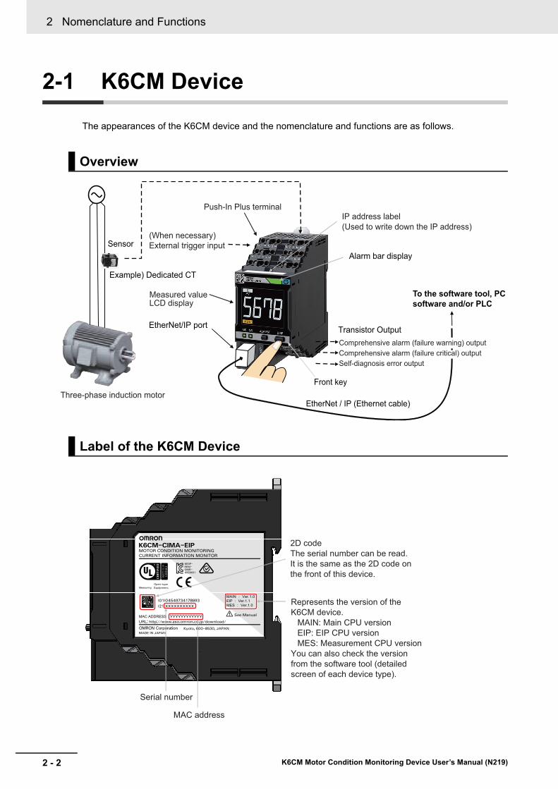
The appearances of the K6CM device and the nomenclature and functions are as follows.
Overview
Label of the K6CM Device
Sensor
Example) Dedicated CT
Three-phase induction motor
Push-In Plus terminalIP address label(Used to write down the IP address)
Measured value LCD display
(When necessary)External trigger input
EtherNet/IP port
Alarm bar display
EtherNet / IP (Ethernet cable)
Front key
To the software tool, PC software and/or PLC
Transistor OutputComprehensive alarm (failure warning) outputComprehensive alarm (failure critical) outputSelf-diagnosis error output
See Manual
Equipment.
Open-type
MOTOR CONDITION MONITORING
Kyoto, 600-8530, JAPANMADE IN JAPAN
URL: http://www.aso.omron.co.jp/download/
K6CM01OMR-REM-MSIP-
(01)04549734178693
CURRENT INFORMATION MONITOR
K6CM-CIMA-EIP
(21)XXXXXXXXXX
YYYYYYYYYYYY
2D codeThe serial number can be read.It is the same as the 2D code on the front of this device.
Serial number
MAC address
Represents the version of the K6CM device.
MAIN: Main CPU versionEIP: EIP CPU versionMES: Measurement CPU version
You can also check the version from the software tool (detailed screen of each device type).
2 - 3
2 Nomenclature and Functions
K6CM Motor Condition Monitoring Device User’s Manual (N219)
2-1 K6
CM
Device
2
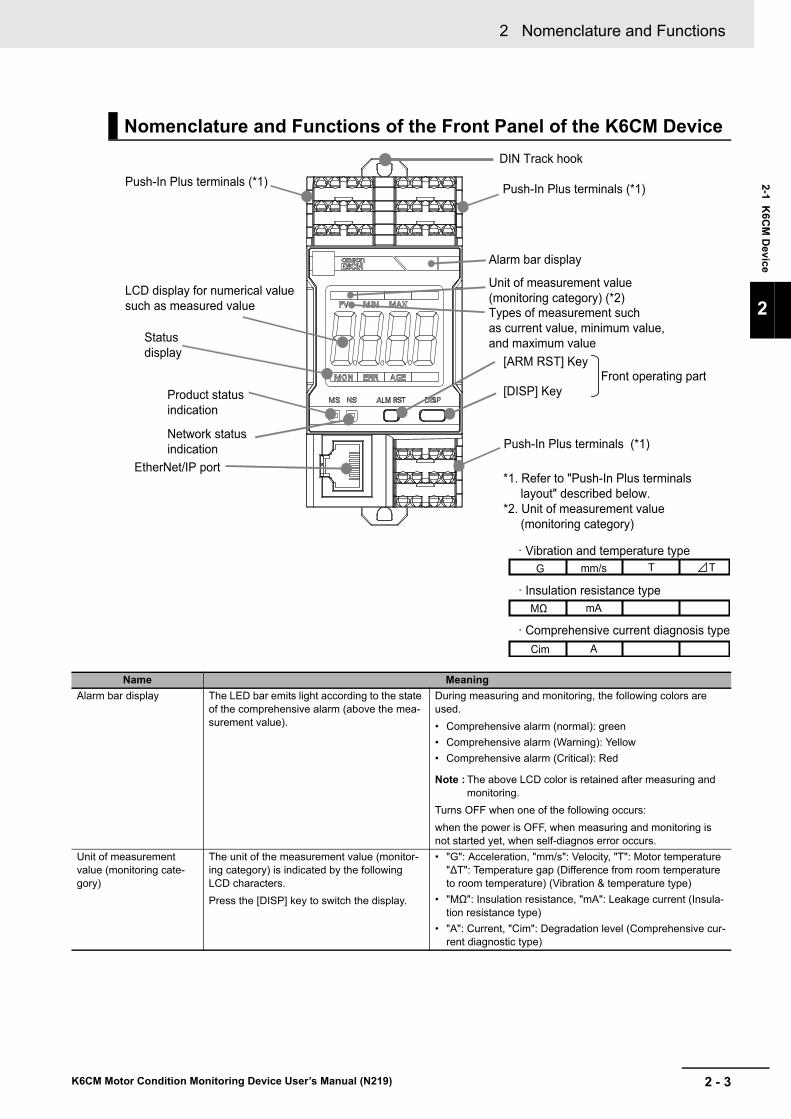
Nomenclature and Functions of the Front Panel of the K6CM Device
Name Meaning
Alarm bar display The LED bar emits light according to the state of the comprehensive alarm (above the mea-surement value).
During measuring and monitoring, the following colors are used.
• Comprehensive alarm (normal): green
• Comprehensive alarm (Warning): Yellow
• Comprehensive alarm (Critical): Red
Note : The above LCD color is retained after measuring and monitoring.
Turns OFF when one of the following occurs:
when the power is OFF, when measuring and monitoring is not started yet, when self-diagnos error occurs.
Unit of measurement value (monitoring cate-gory)
The unit of the measurement value (monitor-ing category) is indicated by the following LCD characters.
Press the [DISP] key to switch the display.
• "G": Acceleration, "mm/s": Velocity, "T": Motor temperature "∆T": Temperature gap (Difference from room temperature to room temperature) (Vibration & temperature type)
• "MΩ": Insulation resistance, "mA": Leakage current (Insula-tion resistance type)
• "A": Current, "Cim": Degradation level (Comprehensive cur-rent diagnostic type)
Types of measurement such as current value, minimum value, and maximum value
Alarm bar display
[DISP] Key
[ARM RST] Key
Unit of measurement value (monitoring category) (*2)
Front operating part
Push-In Plus terminals (*1)
DIN Track hook
Push-In Plus terminals (*1)
EtherNet/IP port
Product status indication
Network status indication
Status display
Push-In Plus terminals (*1)
LCD display for numerical value such as measured value
*1. Refer to "Push-In Plus terminals layout" described below.
*2. Unit of measurement value (monitoring category)
· Vibration and temperature type
· Insulation resistance type
· Comprehensive current diagnosis type
G
MΩ mA
Cim A
mm/s T T
2 Nomenclature and Functions
2 - 4 K6CM Motor Condition Monitoring Device User’s Manual (N219)
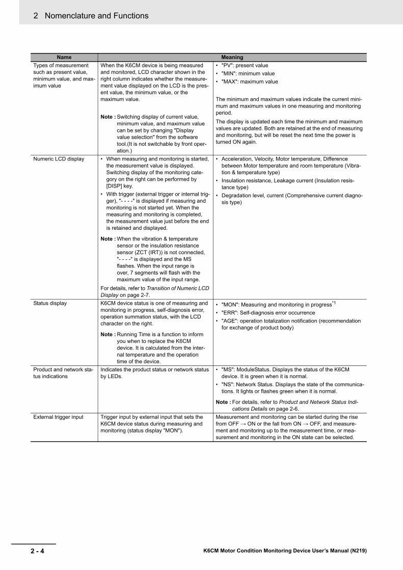
Types of measurement such as present value, minimum value, and max-imum value
When the K6CM device is being measured and monitored, LCD character shown in the right column indicates whether the measure-ment value displayed on the LCD is the pres-ent value, the minimum value, or the maximum value.
Note : Switching display of current value, minimum value, and maximum value can be set by changing "Display value selection" from the software tool.(It is not switchable by front oper-ation.)
• "PV": present value
• "MIN": minimum value
• "MAX": maximum value
The minimum and maximum values indicate the current mini-mum and maximum values in one measuring and monitoring period.
The display is updated each time the minimum and maximum values are updated. Both are retained at the end of measuring and monitoring, but will be reset the next time the power is turned ON again.
Numeric LCD display • When measuring and monitoring is started, the measurement value is displayed. Switching display of the monitoring cate-gory on the right can be performed by [DISP] key.
• With trigger (external trigger or internal trig-ger), "- - - -" is displayed if measuring and monitoring is not started yet. When the measuring and monitoring is completed, the measurement value just before the end is retained and displayed.
Note : When the vibration & temperature sensor or the insulation resistance sensor (ZCT (IRT)) is not connected, "- - - -" is displayed and the MS flashes. When the input range is over, 7 segments will flash with the maximum value of the input range.
For details, refer to Transition of Numeric LCD Display on page 2-7.
• Acceleration, Velocity, Motor temperature, Difference between Motor temperature and room temperature (Vibra-tion & temperature type)
• Insulation resistance, Leakage current (Insulation resis-tance type)
• Degradation level, current (Comprehensive current diagno-sis type)
Status display K6CM device status is one of measuring and monitoring in progress, self-diagnosis error, operation summation status, with the LCD character on the right.
Note : Running Time is a function to inform you when to replace the K6CM device. It is calculated from the inter-nal temperature and the operation time of the device.
• "MON": Measuring and monitoring in progress*1
• "ERR": Self-diagnosis error occurrence
• "AGE": operation totalization notification (recommendation for exchange of product body)
Product and network sta-tus indications
Indicates the product status or network status by LEDs.
• "MS": ModuleStatus. Displays the status of the K6CM device. It is green when it is normal.
• "NS": Network Status. Displays the state of the communica-tions. It lights or flashes green when it is normal.
Note : For details, refer to Product and Network Status Indi-cations Details on page 2-6.
External trigger input Trigger input by external input that sets the K6CM device status during measuring and monitoring (status display "MON").
Measurement and monitoring can be started during the rise from OFF → ON or the fall from ON → OFF, and measure-ment and monitoring up to the measurement time, or mea-surement and monitoring in the ON state can be selected.
Name Meaning

2 - 5
2 Nomenclature and Functions
K6CM Motor Condition Monitoring Device User’s Manual (N219)
2-1 K6
CM
Device
2
*1. "MON" always lights up when there is no trigger. When there is a trigger, it lights up during measuring and monitoring. It turns off after measuring and monitoring is not started yet, and after measuring and monitoring is completed (only when using the trigger function).
*2. The output state (ON/OFF) of the transistor is held at the end of measuring and monitoring (only when using the trigger function).
*3. The setting function of transistor output type can be used with EIP CPU version 1.10 or later. It is fixed to Normally closed with EIP CPU version less than 1.10.
Front operat-ing part
[ARM RST] Key
Release the alarm latch (cancellation by communication is impossible).
Note : Setting the alarm latch to "L" will latch the alarm condition of comprehensive alarm (Warning or Critical) (alarm bar, transistor outputs 1 and 2). Release this latched state.
If you press the [ALM RST] key during measuring and moni-toring, it returns to the comprehensive alarm state at that point (both the alarm bar and transistor outputs 1 and 2).
[DISP] Key Switch the unit of measurement value (moni-toring category)
Every time it is pressed, the unit of measurement value changes as follows.
• Vibration & temperature type: "G" → "mm/s" → "T" → "∆T" (→ "G")
• Insulation resistance type: "MΩ" → "mA" (→ "MΩ")
• Comprehensive current diagnosis type: "Cim" → "A" (→ "Cim")
Press the [ALM RST] and [DISP] Keys simulta-neously
When pressed at the same time for 5 seconds or more, initialize all settings of the K6CM device and restore the Factory default.
----
Transis-tor Out-put
Transistor Output 1
Warning output of comprehensive alarm.(*2)
Transistor output type can be set to Normally Closed or Normally Open. (* 3)
• Normally closed output type ON: Comprehensive alarm is normalOFF: Comprehensive alarm is warning or critical
• Normally open output type ON: Comprehensive alarm is warning or criticalOFF: Comprehensive alarm is normal
It turns OFF regardless of the output type in either of the fol-lowing cases.
• Measurement and monitoring is not started (only when using the trigger function).
• Self-diagnosis error
Transistor Output 2
Critical output of comprehensive alarm.(*2)
Transistor output type can be set to Normally Closed or Normally Open. (* 3)
• Normally closed output type ON: Comprehensive alarm is normalOFF: Comprehensive alarm is warning or critical
• Normally open output type ON: Comprehensive alarm is warning or criticalOFF: Comprehensive alarm is normal
It turns OFF regardless of the output type in either of the fol-lowing cases.
• Measurement and monitoring is not started (only when using the trigger function).
• Self-diagnosis error
Transistor Output 3
Self-diagnosis error output.
Transistor output type can be set to Normally Closed only.
* Self-diagnosis error is a function to detect errors of the K6CM device itself.
In the following cases, ON
• When Self-diagnosis error does not occur
In the following cases, OFF
• Self-diagnosis error occurrence
EtherNet/IP port Port for connecting Ethernet cable for com-munications with the software tool, PLC, and PC.
It is with straight / cross cable automatic discrimination func-tion.
Name Meaning

2 Nomenclature and Functions
2 - 6 K6CM Motor Condition Monitoring Device User’s Manual (N219)
Product and Network Status Indications Details
Note For the countermeasures for the above operation error, refer to Section 9 Trouble shooting.
Name Color Status Operating condition
MS Module Status Green Lit. Normal status
Red Lit. Damaged fault (Measurement CPU data flash error, Main CPU data flash error)
Flashing One of the following conditions
Vibration & temperature sensor not connected, Insulation resistance sen-sor (ZCT (IRT)) not connected, Measurement CPU error, Main CPU error, Present value input error, Maximum value input error, or Minimum value input error
-- Not lit. No power supply
NS Network Status Green Lit. Tag data link or message connection established
Flashing No tag data link or message connection established
Red Lit. IP address duplication status
Flashing The connection has timed out, or the BOOTP server connection error state
-- Not lit. No power supply

2 - 7
2 Nomenclature and Functions
K6CM Motor Condition Monitoring Device User’s Manual (N219)
2-1 K6
CM
Device
2
Transition of Numeric LCD Display
The numerical LCD display will transition as follows after turning ON the power supply or after soft-
ware reset *1.
*1. It depends on the Device reset button operation from the software tool or software reset command from Eth-erNet/IP.
Push-In Plus Terminals Layout
Power OFF
No lit.
10 seconds or less7 segment blinking
Measured value displayed"MON" goes on
"MON" goes on
"MON" goes off
"MON" goes off"ERR" goes on when the sensor is not connected.
Measurement and monitoring conditions were met.
"- - - -" displayedAll lit
After measuring and monitoring (only when using the trigger)
When the power supply is turned ON or the software reset *1 is done.
Input range over occurs.
Measurement and monitoring is not started yet
Measurement and monitoring is not done (only when using the trigger function)
When measurement and monitoring condition is met
Power supply to the device
Not used.Not used.
Transistor Output 1 (+)
Transistor Output 1 (-)Transistor Output 2 (+)Transistor Output 2 (-)
Transistor Output 3 (+)Transistor Output 3 (-)
CTK
IRT2: Supply to sensor 10 V (+)
IRT0:Sensor input (+)
VBS 1: Sensor input (-)VBS 3: Supply to sensor 10 V (-)
IRT1: Sensor input (-)IRT3:Supply to sensor 10 V (-)
CTL
External trigger input (+)External trigger input (-)
K6CM-VBVibration & temperature type
VBS 0: Sensor input (+)
VBS 2: Supply to sensor 10 V (+)
K6CM-ISInsulation resistance type
K6CM-CIVibration & temperature type
1 2
3
5 6
7 8
10
11 12
13 14
1817
1615
94
7 8
10
11 12
9
7 8
10
11 12
9
7 8
10
11 12
9

2 Nomenclature and Functions
2 - 8 K6CM Motor Condition Monitoring Device User’s Manual (N219)
Status of Alarm Bar, Status Indication, and Transistor Output for Each Status
Status Description Alarm barStatus dis-
playTransistor output 1
Transistor output 2
Transistor output 3
Measuring and monitoring Not yet
Measurement and monitoring are not completed until the measured value is set after the power is turned ON.
Not lit. Not lit. OFF OFF OFF
During mea-suring and monitoring
Compre-hensive alarm: nor-mal
All measurement values are in nor-mal condition.
Green “MON” ON*1
*1. This is the case when the transistor output type is set to Normally Closed. In the case of Normally Open, ON/OFF is op-posite to the above.
ON*1 ON
Compre-hensive alarm: Warning
There is no "Critical" in the measure-ment value, and even one of them has "Warning".
Yellow OFF*1 ON*1 ON
Compre-hensive alarm: Criti-cal
There is "Critical" in at least one measurement value.
Red OFF*1 OFF*1 ON
After measuringand monitoring(only when using the trig-ger function)
When using the trigger function (external trigger or internal trigger), the measuring and monitoring is completed.
The sta-tus at the
end is kept.
Not lit. The status at the end is
kept.
The status at the end is
kept.
ON
When the self-diagnosis error occurs
Self-diagnosis error is occurring regardless of measuring and moni-toring status.
Not lit. “ERR” OFF OFF OFF
When the power is OFF ---- Not lit. Not lit. OFF OFF OFF
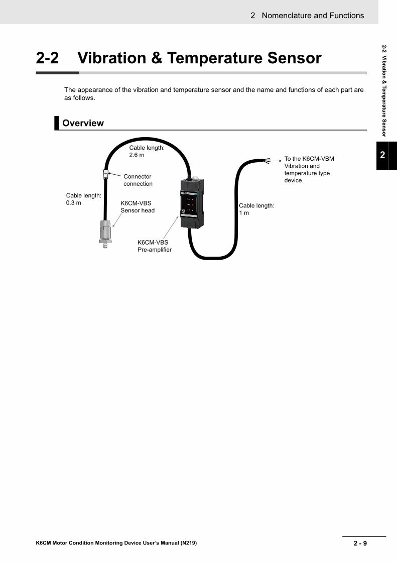
2 - 9
2 Nomenclature and Functions
K6CM Motor Condition Monitoring Device User’s Manual (N219)
2-2 Vib
ration
& Tem
peratu
re Sen
sor
2
2-2 Vibration & Temperature Sensor
The appearance of the vibration and temperature sensor and the name and functions of each part are as follows.
Overview
To the K6CM-VBM Vibration and temperature type device
K6CM-VBS Sensor head
Connector connection
Cable length: 0.3 m
Cable length: 2.6 m
Cable length: 1 m
K6CM-VBS Pre-amplifier

2 Nomenclature and Functions
2 - 10 K6CM Motor Condition Monitoring Device User’s Manual (N219)
Nomenclature and functions of the pre-amplifier
PWR LED
ERR LED
COM LED
To the sensor head
To the K6CM-VBM Vibration and temperature type device
LED Name Color Status Operating condition
PWR Pre-amplifier power supply
Green Lit. Normal status
---- Not lit. Power not supplied
ERR Pre-amplifier fault Red Lit. Self-diagnosis error occurred
COM Communication between pre-amplifier and K6CM
Yellow Lit. STX transmission, lit at reception 50 ms
Terminal number of the K6CM device
Vibration & temperature sensor side
Line color
7 VBS 0: Sensor input (+) Red and white
8 VBS 1: Sensor input (-) Red
9 VBS 2: Supply to sensor 10 V (+) Black
10 VBS 3: Supply to sensor 10 V (-) Black and white

2 - 11
2 Nomenclature and Functions
K6CM Motor Condition Monitoring Device User’s Manual (N219)
2-2 Vib
ration
& Tem
peratu
re Sen
sor
2
Mount the vibration sensor head on the shaft side exterior of the induction motor.
There are two ways to mount the vibration sensor head to the motor.
We recommend method 1 with high absolute accuracy, but if you cannot tap off the motor, use method 2.
An easy-mounting magnet (called "Sensor Easy mounting magnet") is included. It can be used to deter-mine the position to be measured. Note that measurement accuracy is not guaranteed in the case of magnet mounting.
The shapes of the easy-mounting magnet and the adhesive attachment are as follows.
These two shapes are similar. Be careful not to handle them by mistake.
Nomenclature and functions of the sensor head
Method Description
Method 1: Screw Mounting (recommended) At the top of the armor of the motor, cut the tap into which the M6 screw vertically enters, and screw the vibration sensor head into it.
Method 2: Adhesive Mounting (*1)
*1. K6CM will not conform to safety standards if attaching the vibration sensor with adhesive. In the case of dis-connection, take safety measures such as fixing the cables.
Secure the attachment which is sold separately to the exterior of the motor using adhesive. Screw the vibration sensor head into the fixed attachment.
To the pre-amplifier
Cable part
M6 screw
Detection direction (Z axis direction)
Sensor Easy mounting magnet Adhesive attachment

2 Nomenclature and Functions
2 - 12 K6CM Motor Condition Monitoring Device User’s Manual (N219)
2-3 Insulation Resistance Sensor (ZCT (IRT))
The appearance of the insulation resistance sensor ZCT (IRT)(*1) and the name and functions of each part are as follows.
*1. ZCT (IRT) stands for Zero Current Transformer (Insulation Resistance Transformer).
Nomenclature and functions of the Insulation resistance sensor (ZCT (IRT))
Voltage inputL1: R (black)L2: S (red)L3: T (white) Cable length:
1 m
Through-hole diameter: 52 mm
Insulation resistance sensorSplit-type
Cable length: 1 m
To the K6CM-ISM Insulation Resistance Type Device
Terminal number of the K6CM device
Insulation resistance sensor (ZCT (IRT)) side
Line color
7 IRT0: Sensor input (+) Red and white
8 IRT1: Sensor input (-) Red
9 IRT2: Supply to sensor 10 V (+) Black
10 IRT3: Supply to sensor 10 V (-) Black and white

2 - 13
2 Nomenclature and Functions
K6CM Motor Condition Monitoring Device User’s Manual (N219)
2-4 Ded
icated C
T
2
2-4 Dedicated CT
The appearance of the dedicated CT and the name and functions of each part are as follows.
Nomenclature and functions of the dedicated CT
K6CM-CIM Comprehensive current diagnosis type device
The dedicated CT has the mounting direction. Mount a dedicated CT to any one phase according to the mounting direction stated on the CT label when you mount it.
Ferrules
Load side (L)
Split/fastening hook
Cable for Dedicated CT (included)Cable length 2.9 m
Terminal cover on the secondary side of the CT
For fixing of binding band etc.
Power supply side (K)
Dedicated CTSplit-type
Terminal number of the K6CM device
Dedicated CT side
7 CTK
8 CTL

2 Nomenclature and Functions
2 - 14 K6CM Motor Condition Monitoring Device User’s Manual (N219)

3 - 1
3
K6CM Motor Condition Monitoring Device User’s Manual (N219)
This section describes the measuring and monitoring mechanism and other features of the K6CM devices.
3-1 Overview . . . . . . . . . . . . . . . . . . . . . . . . . . . . . . . . . . . . . . . . . . . . . . . . . . . . . 3-2
3-2 Measurement System . . . . . . . . . . . . . . . . . . . . . . . . . . . . . . . . . . . . . . . . . . 3-33-2-1 Sampling of measured values . . . . . . . . . . . . . . . . . . . . . . . . . . . . . . . . . . . . . 3-3
3-2-2 Moving average . . . . . . . . . . . . . . . . . . . . . . . . . . . . . . . . . . . . . . . . . . . . . . . . 3-4
3-2-3 Trigger Mode . . . . . . . . . . . . . . . . . . . . . . . . . . . . . . . . . . . . . . . . . . . . . . . . . . . 3-5
3-2-4 Maximum Value and Minimum Value of Measured Value . . . . . . . . . . . . . . . . .3-11
3-3 Monitoring Mechanism . . . . . . . . . . . . . . . . . . . . . . . . . . . . . . . . . . . . . . . . 3-133-3-1 Types of Individual Alarms . . . . . . . . . . . . . . . . . . . . . . . . . . . . . . . . . . . . . . . 3-13
3-3-2 Comprehensive Alarm Judgment . . . . . . . . . . . . . . . . . . . . . . . . . . . . . . . . . . 3-13
3-3-3 Relationship Between Alarm and Display/Output . . . . . . . . . . . . . . . . . . . . . . 3-14
3-3-4 Guide for Setting Alarm 3-19
3-4 How the Self-Diagnosis Function Works . . . . . . . . . . . . . . . . . . . . . . . . . . 3-23
3-5 How the Replacement Timing Notification (i.e., Running Time Function) Works . . . . . . . . . . . . . . . . . . . . . . . . . . . . . . . . . . . . . . . . . . . . . . . . . . . . . . 3-25
3-6 Initialization of Setting Value . . . . . . . . . . . . . . . . . . . . . . . . . . . . . . . . . . . 3-26
Measuring and Monitoring Mecha-nism

3 Measuring and Monitoring Mechanism
3 - 2 K6CM Motor Condition Monitoring Device User’s Manual (N219)
3-1 Overview
The measurement makes it possible to calculate the measurement value based on the input from the sensor. The calculation is executed inside the K6CM even in the unmeasured state before the trigger start, and the measurement display is updated when the trigger is established. The monitoring (alarm) captures the measured value when the trigger is established. The monitoring (alarm) involves first judg-ing the threshold value of the Warning/Critical for each measured value, and then judging whether each measured value is within the Warning/Critical level as an "individual alarm". Next, the OR logic is obtained for each "individual alarm" and Normal/Warning/Critical is judged for each monitor target as the "Comprehensive alarm". The "Comprehensive alarm" is displayed on the front LCD alarm bar of the K6CM device and transistor output is performed (*1). Both measurement and monitoring (alarm) are executed either always or when a trigger condition is satisfied.
*1. If the alarm latch is set to "Yes", the alarm status of the K6CM comprehensive judgment (such as alarm bar and transistor outputs 1 and 2) is held. Pressing the [ALM RST] key on the front of the device releases the latch. Also, the transistor output type of output 1 and output 2 can be set to Normally closed or Normally open.
As shown in the figure, it is as follows.
*1. It can be set to Normally open for EIP CPU version 1.10 or later of the K6CM device and the software tool version 1.1.0 or higher.
Measured value B
Update measurement display
Capture measured value
Sensor
Warning result
Transistor Output
Red OFF OFF
Yellow OFF ON
GreenNormal ON ON
Self-diagnosis error output OFF OFF
ON
External trigger input
Internal setting value
Software tool
EtherNet/IP
Sensor
PLC etc.
and/or
Alarm bar
Output 1 Output 2 Output 3
LCD (Not lit.)
Latch selection available
N.O. is selectable *1
OFF
Critical failure occurrence
Warning failure occurrence
Critical result
Warning result
Critical result
K6CM
Measured value A
Always, external trigger, or internal trigger
Individual alarm for each measured value
Comprehensive alarm output as a device
OR logic of each measured value
CriticalWarning
CriticalWarning

3 - 3
3 Measuring and Monitoring Mechanism
K6CM Motor Condition Monitoring Device User’s Manual (N219)
3-2 Meas
urem
ent S
ystem
3
3-2-1 Sam
pling of m
easured valu
es
3-2 Measurement System
The input from the sensor is given to the K6CM device as a measured value in every sampling period. The sampling period depends on the measured target as follows.
Also, until the next sampling is completed, the present measured value is held as the current value.
When the power is turned OFF, the held measurement value is reset.
Note The sampling of the measured value is performed internally even in the case of the unmeasured state before the trigger start.
3-2-1 Sampling of measured values
Monitor type Measurement target Sampling period
Vibration and tem-perature type
Acceleration 50 ms
Velocity 0.5 s
Temperature 0.5 s
Insulation resis-tance type
Insulation resistance 10 s (Normal mode)
60 s (Inverter special measurement mode)
Comprehensive cur-rent diagnosis type
Degradation level 5 s
Current 5 s
Measured value 1 is the current value until sampling of measured value 2 is completed.
Sampling period
Measured value 2
Measured value 1
Measured value 2 is the current value when sampling of measured value 2 is completed.

3 Measuring and Monitoring Mechanism
3 - 4 K6CM Motor Condition Monitoring Device User’s Manual (N219)
The moving average is the process of assuming the average value of past n times of measured values which includes the measured value of that time to be a current measured value each time the sampling of the measured value is performed. The moving average makes it possible to suppress the instanta-neous fluctuation of the measured value and make the tendency of the measured value easier to see. The image of moving average is shown below.
(a)Measurement result before moving average (b)After moving average of (a) (moving average times n = 4)
Note The sampling of the measured value is performed internally even in the case of the unmeasured state before the trigger start.
3-2-2 Moving average
Measured value of past 4 times
Current measured value Current measured value (after moving average)
Calculate the average value of measured values
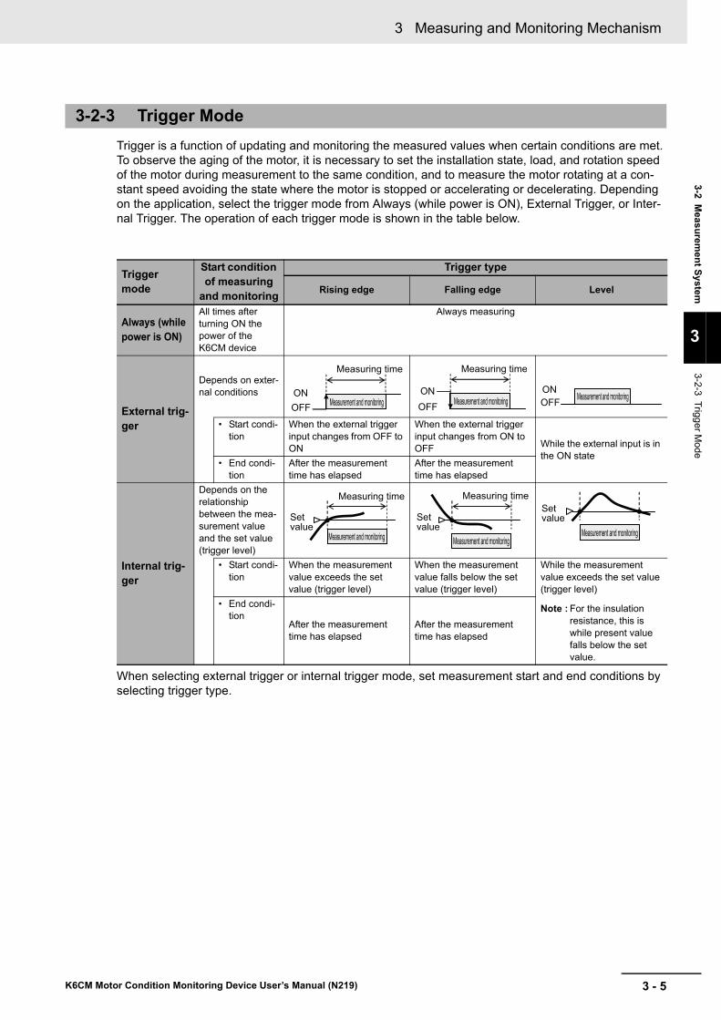
3 - 5
3 Measuring and Monitoring Mechanism
K6CM Motor Condition Monitoring Device User’s Manual (N219)
3-2 Meas
urem
ent S
ystem
3
3-2-3 Trigg
er Mode
Trigger is a function of updating and monitoring the measured values when certain conditions are met. To observe the aging of the motor, it is necessary to set the installation state, load, and rotation speed of the motor during measurement to the same condition, and to measure the motor rotating at a con-stant speed avoiding the state where the motor is stopped or accelerating or decelerating. Depending on the application, select the trigger mode from Always (while power is ON), External Trigger, or Inter-nal Trigger. The operation of each trigger mode is shown in the table below.
When selecting external trigger or internal trigger mode, set measurement start and end conditions by selecting trigger type.
3-2-3 Trigger Mode
Trigger mode
Start condition of measuring
and monitoring
Trigger type
Rising edge Falling edge Level
Always (while power is ON)
All times after turning ON the power of the K6CM device
Always measuring
External trig-ger
Depends on exter-nal conditions
• Start condi-tion
When the external trigger input changes from OFF to ON
When the external trigger input changes from ON to OFF While the external input is in
the ON state• End condi-
tionAfter the measurement time has elapsed
After the measurement time has elapsed
Internal trig-ger
Depends on the relationship between the mea-surement value and the set value (trigger level)
• Start condi-tion
When the measurement value exceeds the set value (trigger level)
When the measurement value falls below the set value (trigger level)
While the measurement value exceeds the set value (trigger level)
Note : For the insulation resistance, this is while present value falls below the set value.
• End condi-tion
After the measurement time has elapsed
After the measurement time has elapsed
ONOFF
Measuring time
Measurement and monitoringONOFF
Measuring time
Measurement and monitoringONOFF Measurement and monitoring
Measuring time
Measurement and monitoring
Set value
Measuring time
Measurement and monitoring
Set value
Set value
Measurement and monitoring

3 Measuring and Monitoring Mechanism
3 - 6 K6CM Motor Condition Monitoring Device User’s Manual (N219)
The operation of the K6CM device, trigger mode and state, and the operation results from the Motor condition monitoring Tool and EtherNet/IP are as follows.
Detailed information on trigger mode and behavior by status
Trigger mode
Status
K6CM device Operation
Measuring and monitoring sta-
tus*1
*1. The measuring and monitoring status can be confirmed by "K6CM status" from EtherNet/IP.
Front Numeric LCD Dis-play
Status dis-play
Motor condition monitoring Tool and read value with the Ether-
Net/IP
Always Measuring and monitoring Not yet (immediately after turning ON the power)
No measuring and monitoring
"- - - -" is displayed Not lit. The read value is 0
While the power is ON
Measurement and monitoring
Display measured value
(*2)
*2. The front LCD number can display either the present value, the minimum value, or the maximum value depending on the setting.
"MON" The present value, the minimum value, and the maximum value of the measurement value can be read out individually
External trigger Or Internal trig-ger
Measuring and monitoring Not yet
No measuring and monitoring
"- - - -" is displayed Not lit. The read value is 0
During measuring and monitoring
Measurement and monitoring
Display measured value
(*2)
"MON" The present value, the minimum value, and the maximum value of the measurement value can be read out individually
After measuring and monitoring
No measuring and monitoring
Holding and displaying values at the end of mea-suring and monitoring
Not lit. The held values are read out at the end of the measuring and monitor-ing
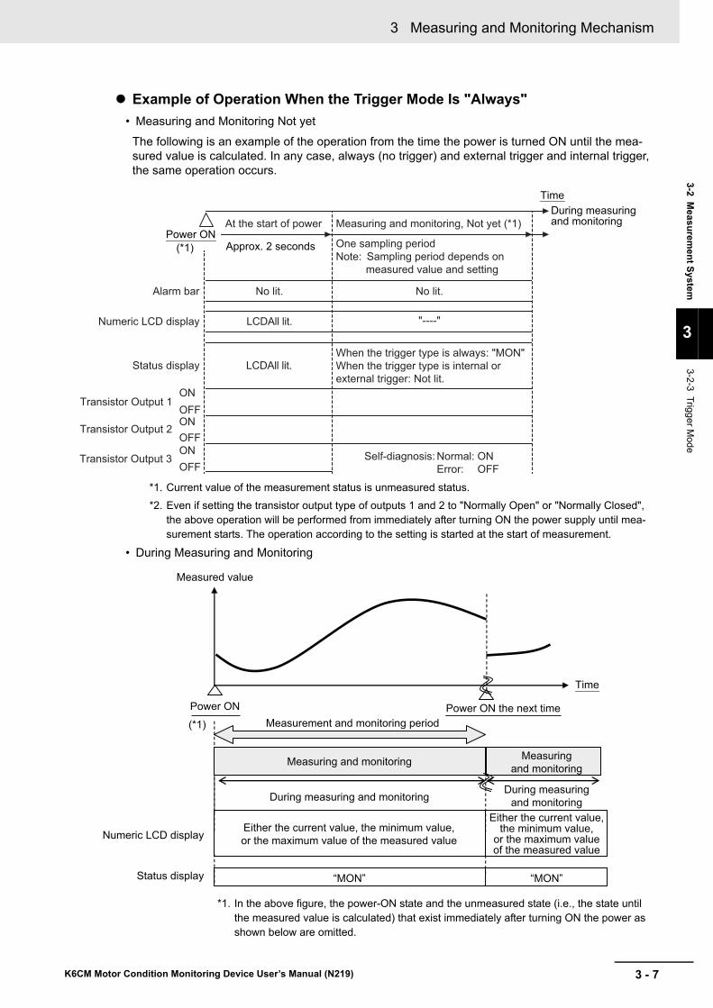
3 - 7
3 Measuring and Monitoring Mechanism
K6CM Motor Condition Monitoring Device User’s Manual (N219)
3-2 Meas
urem
ent S
ystem
3
3-2-3 Trigg
er Mode
Example of Operation When the Trigger Mode Is "Always"
• Measuring and Monitoring Not yet
The following is an example of the operation from the time the power is turned ON until the mea-sured value is calculated. In any case, always (no trigger) and external trigger and internal trigger, the same operation occurs.
*1. Current value of the measurement status is unmeasured status.
*2. Even if setting the transistor output type of outputs 1 and 2 to "Normally Open" or "Normally Closed", the above operation will be performed from immediately after turning ON the power supply until mea-surement starts. The operation according to the setting is started at the start of measurement.
• During Measuring and Monitoring
*1. In the above figure, the power-ON state and the unmeasured state (i.e., the state until the measured value is calculated) that exist immediately after turning ON the power as shown below are omitted.
Alarm bar
Status display
ONOFFONOFFONOFF
Numeric LCD display
Transistor Output 1
Transistor Output 2
Transistor Output 3 Self-diagnosis: Normal: ON Error: OFF
No lit.
"----"
Measuring and monitoring, Not yet (*1)At the start of power
No lit.
LCDAll lit.
LCDAll lit.
Approx. 2 secondsPower ON
(*1)
TimeDuring measuring and monitoring
One sampling periodNote: Sampling period depends on
measured value and setting
When the trigger type is always: "MON"When the trigger type is internal or external trigger: Not lit.
Status display
Measuring and monitoring
Time
Power ON
(*1) Measurement and monitoring period
Measured value
Numeric LCD display
“MON” “MON”
During measuring and monitoring
Power ON the next time
Either the current value, the minimum value, or the maximum value of the measured value
Either the current value, the minimum value,
or the maximum value of the measured value
During measuring and monitoring
Measuring and monitoring

3 Measuring and Monitoring Mechanism
3 - 8 K6CM Motor Condition Monitoring Device User’s Manual (N219)
Example of Operation When the Trigger Mode Is "External Trigger Input" or "Internal Trigger"
• Measuring and Monitoring Not yet
The operation is the same as the operation example when the trigger mode is "Always".
Refer to P. 3-7.
During and After Measuring and Monitoring
*1.In the above figure, the power-ON state and the unmeasured state (i.e., the state until the measured value is calculated) that exist immediately after turning ON the power as shown on page 3-7 are omitted.
Time
Measured value
Power ON Trigger start
(*1)
Numeric LCD display
Status display “MON”Not lit. Not lit.Not lit.
Measuring and monitoring, Not yet
Measurement and monitoring period
Measuringand monitoring
Power ON the next time
Measuring and monitoring Not yet
During measuring and monitoring
After measuringand monitoring
Either the current value, the minimum value, or the maximum value of the measured value
The status at the end keeps.
“- - - -“ “- - - -“

3 - 9
3 Measuring and Monitoring Mechanism
K6CM Motor Condition Monitoring Device User’s Manual (N219)
3-2 Meas
urem
ent S
ystem
3
3-2-3 Trigg
er Mode
To observe the aging of the motor, it is necessary to set the condition of the motor at measurement to the same condition, and to measure the motor in a stable state avoiding the state where the motor is stopped or accelerating or decelerating. Use trigger to start measurement at appropriate timing. Refer to the following.
1 Determination of trigger mode
Refer to 3-2-3 Trigger Mode on page 3-5 and decide the trigger mode and trigger type according to the application.
2 Determination of moving average times
Reducing the moving average times can help capture instantaneous fluctuations.
Increasing the moving average times can suppress the steep fluctuation of measured values and capture the overall trend.
Determine the moving average times of measured values according to the state of measured value.
3 Determination of trigger start timing (when trigger mode is external trigger or internal trigger)
To obtain the measured value when the state of the motor is stable, start the trigger after the sampling period * 1 × (moving average times + 1) has elapsed after the motor state became sta-ble.
(*1 The sampling period differs for each measured target. Refer to 3-2-1 for details).
Also, release the trigger during stable operation of the motor.
The following is an example of trigger without the moving average and also with the moving average.
Trigger example without moving average (moving average times = 1)
Trigger Settings
Can measure and monitor
Sampling period × 2
Motor
Measured value
Trigger timing
Can measure and monitorMeasured value 1
Trigger startSampling periodIf the trigger condition is satisfied during calculation of "Measured value 3", the measured value is updated with "Measured value 2" which has been calculated during startup of the motor.
If the trigger condition is satisfied after calculating the "Measured value 3", the measured value can be updated with the "Measured value 3" which is calculated during stable operation of the motor.If the trigger condition is satisfied after sampling period × 2, the measured value is a value secured after calculation of "Measured value 3".
Measured value 3
Sampling period × 2
During startup of the motor
Changing motor rotation speed During stable motor
operationDuring stable motor operation
Rotation speed
Measured value
Trigger startTrigger release
Measured value 2
Cannot measure and monitor
Cannot measure and monitor
Before operation of the motor

3 Measuring and Monitoring Mechanism
3 - 10 K6CM Motor Condition Monitoring Device User’s Manual (N219)
Trigger example with moving average (moving average times = 2)
As shown above, if the moving average times = 2, stable measured value can be measured when trig-ger is started after the sampling period × (moving average times + 1) = sampling period × 3 or more has elapsed after the motor entered stable operation.
Also, in accordance with the purpose and operating state of the motor, determine the measurement time as the number of seconds for which measurement is to be performed after trigger start (when the trigger type is Rising edge or Falling edge).
Stable measured values can be measured by making the settings so that the measurement time fits within the motor stable operation. Consider the timing of trigger release and determine the measure-ment time.
The sampling period differs for each measurement target. When you determine the trigger start timing, consider which sampling period of measurement target should be used according to the purpose.
Example) When the moving average times = 2 for the vibration & temperature typeSampling period of acceleration: 50 msSampling period of velocity: 0.5 sSampling period of temperature: 0.5 s
When you want to measure acceleration, velocity, and temperature at the same time, calculate the trigger start timing as follows using the sampling period 0.5 s of the speed and temperature which is the longest sampling period.Sampling period × (moving average times + 1) = 0.5 s × (2 + 1) = 1.5 s.If you want to measure only the acceleration, you can calculate the trigger start timing with sampling period 50 ms.
Note When the time during which the motor is performing stable running is short, you may not be able to release the trigger during stable motor operation if the measurement time is lengthened. Measure with long opera-tion time of the motor in accordance with the actual usage, or shorten the measurement time.
Can measure and monitor
Motor
Measured value after moving average
Trigger timing
Measurement and monitoring are possible.Measured value 3
Trigger startSampling period
If the trigger condition is satisfied during calculation of "Measured value 4", the measured value is updated with "Measured value 2 and 3" which have been calculated during startup of the motor.
If the trigger condition is satisfied after calculating "Measured value 4", the measured value can be updated with "Measured value 3 and 4" which is calculated during stable operation of the motor.If the trigger condition is satisfied after sampling period × 3, the measured value is a value secured after calculation of "Measured value 4".
Measured value 4
Sampling period × 3
During startup of the motor
Changing motor rotation speedBefore
operation of the motor
During stable motor operation
During stable motor operationRotation speed
Measured value
Trigger start Trigger release
Measuring time
Cannot measure and monitor
Sampling period × 3
Measured value 1
Measurement and monitoring are not possible.Measured value 2

3 - 11
3 Measuring and Monitoring Mechanism
K6CM Motor Condition Monitoring Device User’s Manual (N219)
3-2 Meas
urem
ent S
ystem
3
3-2-4 Maxim
um V
alue an
d Minim
um V
alue of Measured V
alue
The K6CM retains the maximum and minimum measured values during measurement and monitoring period as internal data. These can be read by the software tool or EtherNet/IP.
With this function, by reading the maximum or minimum value of the measured value for a certain period and comparing it with another period, it is possible to detect signs of Criticality of the motor.
Also, changing the setting allows you to set the display value of the front LCD of the K6CM device to the maximum value or the minimum value.
The software tool or EtherNet/IP can be used to reset the retained maximum and minimum values after measuring and monitoring by operating the "Max./min. reset" setting.
The measurement and monitoring period depends on the trigger mode. The maximum value and the minimum value also operate according to each trigger mode as follows.
Example of Operation When the Trigger Mode Is "Always"
*1.In the above figure, the power-ON state and the unmeasured state (i.e., the state until the measured value is calculated) that exist immediately after turning ON the power as shown on page 3-7 are omitted.
3-2-4 Maximum Value and Minimum Value of Measured Value
Trigger mode StatusMaximum and minimum measure-
ment values
When resetting the maximum and min-imum value with the software tool or
the EtherNet/IP
Always While the power is ON
Update the maximum and minimum val-ues of each measurement value after power-on.
The current value at that time is updated and then will be updated.
External trigger
Or
Internal trigger
Measuring and moni-toring Not yet
"- - - -" is displayed and 0 is retained.
During measuring and monitoring
Update the maximum and minimum val-ues of each measurement value from the measuring and monitoring start.
The current value at that time is updated and then will be updated.
After measuring and monitoring
Maximum and minimum values are retained.
Reset to 0.
B
A
B
A
Measured value
Minimum value
Maximum value
Present value Updated
Updated
Updated
Updated
Updated
Updated
Maximum value
Minimum valueTime
Measuringand monitoring
During measuring and monitoring
Measuringand monitoring
Power ON(*1)
Power ON the next time
During measuring and
monitoring

3 Measuring and Monitoring Mechanism
3 - 12 K6CM Motor Condition Monitoring Device User’s Manual (N219)
Example of Operation When the Trigger Mode Is "External Trigger Input" or "Internal Trigger"
*1.In the above figure, the power-ON state and the unmeasured state (i.e., the state until the measured value is calculated) that exist immediately after turning ON the power as shown on page 3-7 are omitted.
Measured value
Maximum value
Minimum value
←
←
A
B
C
Time
Maximum value
Minimum value
Present value
Updated
Updated
A A
B
C C
“- - - -“
“- - - -“
“- - - -“
“- - - -“
“- - - -“
“- - - -“
Updated
Power ON Trigger start(*1)
Power ON the next time
Measuring and monitoring, Not yet
Measuring and monitoring Not yet
After measuringand monitoring
Measuringand monitoring
During measuring and monitoring

3 - 13
3 Measuring and Monitoring Mechanism
K6CM Motor Condition Monitoring Device User’s Manual (N219)
3-3 M
on
itorin
g M
echan
ism
3
3-3-1 Types of Individual Alarm
s
3-3 Monitoring Mechanism
K6CM's individual alarm type and threshold setting range are as follows.
For individual alarms, it is possible to set the level of Warning and Critical, respectively.
Comprehensive alarms are judged as integrated OR logic with the priority order as "Critical" > "Warn-ing" > "Normal" for each individual alarm.
It is as follows.
Example: When the measurement value is two:
Note To specify the type of individual alarm that exceeds the alarm threshold, operate the DISP key in the front of the K6CM device to check the measured values by monitoring type.
3-3-1 Types of Individual Alarms
Monitor types Models Individual alarm typeUpper or
lower
limit *1
Threshold setting range
Level *1
*1. In the case of the upper limit alarm, it is necessary that the threshold of Critical > Warning is satisfied. If Critical threshold ≤ Warning threshold, the Warning threshold is ignored and only the Critical threshold exists.In the case of the lower limit alarm, it is necessary that the threshold of Critical <Warning is set. If Critical thresh-old ≥ Warning threshold, the Warning threshold is ignored and only the Critical threshold exists.
Warning Critical
Vibration & tempera-ture type
K6CM-VBM Acceleration alarm Upper 0.00 to 99.99 G Yes Yes
Velocity alarm Upper 0.00 to 99.99 ms Yes Yes
Motor temperature alarm Upper 0 to 9999 deg Yes Yes
Temperature gap alarm Upper 0 to 9999 deg Yes Yes
Insulation resistance type
K6CM-ISM Insulation resistance alarm
Lower 0.000 to 9.999 MΩ Yes Yes
Comprehensive cur-rent diagnosis type
K6CM-CIM Degradation level alarm Upper 0 to 999 Yes Yes
Current alarm Upper Rating 5 A: 00.00 to 99.99 A
Rating 25 A / 100 A / 200 A / 400 A / 600 A: 0.0 to 999.9 A
Yes Yes
3-3-2 Comprehensive Alarm Judgment
Types of comprehensive alarm Status
Normal When there is neither "Critical" nor "Warning" in the individual alarm.
WarningWhen there is not even one "Critical" level in the individual alarm, and at least one "Warn-ing" level.
Critical When there is at least one "Critical" level in the individual alarm.
Individual alarm Comprehensive alarm
Normal and Normal Normal
Warning and Normal Warning
Warning and Warning Warning
Critical and Normal Critical
Critical and Warning Critical
Critical and Critical Critical

3 Measuring and Monitoring Mechanism
3 - 14 K6CM Motor Condition Monitoring Device User’s Manual (N219)
The relationship between the state of comprehensive alarm (Warning, Critical), alarm bar, numeric LCD display, and transistor output 1, 2 is shown below.
Described below is the case where the alarm latch is disabled and the case where it is enabled.
If you set the alarm latch to Disable (no latch) using the software tool or EtherNet/IP, the alarm condition of Comprehensive alarm (Warning or Critical) will not be latched.
After the comprehensive alarm (Warning or Critical) occurs, if the measured value falls below the hys-teresis (i.e., 10% of the threshold setting value) of the Warning or Critical threshold (for the upper limit alarm) or higher (for the lower limit alarm), the state of the comprehensive alarm (alarm bar and transis-tor outputs 1 and 2) is canceled.
When the Trigger Mode Is "Always (no trigger)"
When power is turned ON, measuring and monitoring is started.
*1. In the above figure, the power-ON state and the unmeasured state (i.e., the state until the measured value is calculated) that exist immediately after turning ON the power as shown on page 3-7 are omitted.
*2. The transistor output type of output 1 and output 2 can also be set to "Normally Open". In the case of Normally Open, ON/OFF is opposite to the above.
3-3-3 Relationship Between Alarm and Display/Output
When the Alarm Latch is Disabled
Time
Measured value
10%
Power ON
Alarm bar Green Yellow Red Yellow Green
ON
OFF
ON
OFF
Measured value displayed
Status display
Critical level
Warning level
Numeric LCD display
Transistor Output 1(At the Normally closed * 2)
Transistor Output 2(At the Normally closed * 2)
“MON”
(*1)
10%
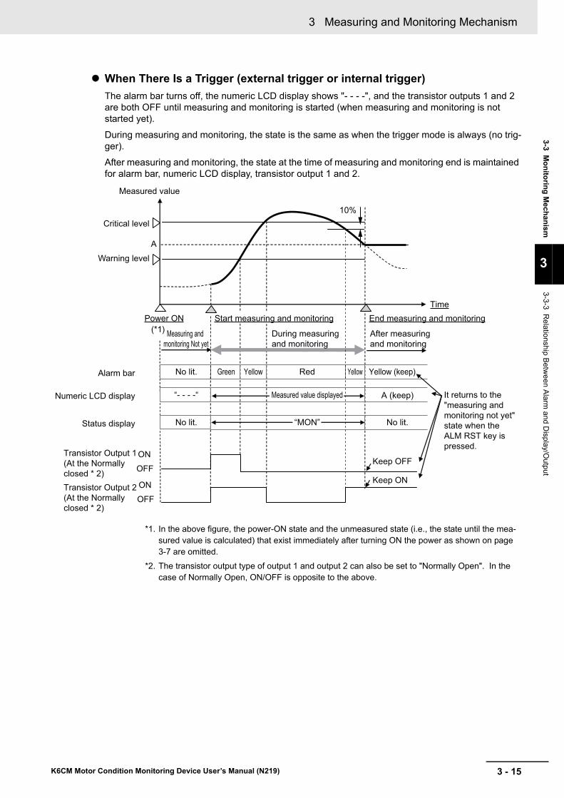
3 - 15
3 Measuring and Monitoring Mechanism
K6CM Motor Condition Monitoring Device User’s Manual (N219)
3-3 M
on
itorin
g M
echan
ism
3
3-3-3 Relationship B
etwe
en Alarm
and Display/O
utput
When There Is a Trigger (external trigger or internal trigger)
The alarm bar turns off, the numeric LCD display shows "- - - -", and the transistor outputs 1 and 2 are both OFF until measuring and monitoring is started (when measuring and monitoring is not started yet).
During measuring and monitoring, the state is the same as when the trigger mode is always (no trig-ger).
After measuring and monitoring, the state at the time of measuring and monitoring end is maintained for alarm bar, numeric LCD display, transistor output 1 and 2.
*1. In the above figure, the power-ON state and the unmeasured state (i.e., the state until the mea-sured value is calculated) that exist immediately after turning ON the power as shown on page 3-7 are omitted.
*2. The transistor output type of output 1 and output 2 can also be set to "Normally Open". In the case of Normally Open, ON/OFF is opposite to the above.
No lit.
Time
Measured value
Power ON
Alarm bar Green Yellow Red Yellow
ON
OFF
ON
OFF
No lit.
Start measuring and monitoring End measuring and monitoring
During measuring and monitoring
Yellow (keep)
Measuring and monitoring Not yet
Measured value displayed
A
Status display No lit.
It returns to the "measuring and monitoring not yet" state when the ALM RST key is pressed.
A (keep)
Transistor Output 2(At the Normally closed * 2)
Transistor Output 1(At the Normally closed * 2)
Numeric LCD display “- - - -“
Critical level
Warning level
After measuringand monitoring
Keep ON
Keep OFF
“MON”
(*1)
10%

3 Measuring and Monitoring Mechanism
3 - 16 K6CM Motor Condition Monitoring Device User’s Manual (N219)
Precautions for Correct Use
In the upper limit alarm, if Critical threshold ≤ Warning threshold, lower critical alarm, Critical threshold ≥ Warning threshold, Warning threshold is ignored and Critical threshold operation is performed when only the value exists. It is as follows.
The above is an example in which the alarm latch is disabled and the trigger mode is Always (without trigger), but in other cases the threshold of Warning is ignored.
*1. In the above figure, the power-ON state and the unmeasured state (i.e., the state until the measured value is calculated) that exist immediately after turning ON the power as shown on page 3-7 are omitted.
*2. The transistor output type of output 1 and output 2 can also be set to "Normally Open". In the case of Normally Open, ON/OFF is opposite to the above.
Time
Measured value
Power ON
Alarm bar
(*1)
Green Red Green
ONOFFONOFF
Measured value displayed
Status display
Critical level
Warning level
Numeric LCD display
Transistor Output 1(At the Normally closed * 2)Transistor Output 2(At the Normally closed * 2)
“MON”
it is the same operation as when Warning level does not exist.

3 - 17
3 Measuring and Monitoring Mechanism
K6CM Motor Condition Monitoring Device User’s Manual (N219)
3-3 M
on
itorin
g M
echan
ism
3
3-3-3 Relationship B
etwe
en Alarm
and Display/O
utput
Using the software tool or the EtherNet/IP, setting the alarm latch to "Enabled" will latch the alarm con-dition of comprehensive alarm (Warning or Critical).
After the occurrence of comprehensive alarm (Warning or Critical), even if the measurement value falls below the threshold of Warning or Critical by hysteresis (10% of the threshold setting value) (upper limit alarm) or higher (lower limit alarm), Hold (alarm latch) the state of comprehensive alarm (alarm bar and transistor outputs 1 and 2).
The alarm latch is released for the first time by pressing the [ALM RST] key on the front of the K6CM device.
The operation when pressing the [ALM RST] key varies depending on the push timing as follows.
When [ALM RST] Key Is Pressed during Measuring and Monitoring
If you press the [ALM RST] key during measurement and monitoring, both the alarm bar and transis-tor outputs 1 and 2 return to the comprehensive alarm state at that time.
*1. In the above figure, the power-ON state and the unmeasured state (i.e., the state until the measured value is calculated) that exist immediately after turning ON the power as shown on page 3-7 are omitted.
*2. The transistor output type of output 1 and output 2 can also be set to "Normally Open". In the case of Normally Open, ON/OFF is opposite to the above.
When Alarm Latch is Enabled
Measured value
Alarm bar Green
(*1)
Yellow Red Green
ONOFF
ONOFF
Status display
Critical level
Warning level
Numeric LCD display
Transistor Output 1(At the Normally closed * 2)Transistor Output 2(At the Normally closed * 2)
Remains OFF
Remains OFF [ALM RST] key is pressed
It returns to the alarm state ("normal" in this case) when the [ALM RST] key is pressed.
TimePower ON
Remains red
Measured value displayed
“MON”

3 Measuring and Monitoring Mechanism
3 - 18 K6CM Motor Condition Monitoring Device User’s Manual (N219)
When [ALM RST] Key Is Pressed After Measuring and Monitoring
When using the trigger function (i.e., external trigger or internal trigger), if you press the [ALM RST] key after measuring and monitoring, the alarm bar turns green and the transistor output turns on.
*1. In the above figure, the power-ON state and the unmeasured state (i.e., the state until the measured value is calculated) that exist immediately after turning ON the power as shown on page 3-7 are omitted.
*2. The transistor output type of output 1 and output 2 can also be set to "Normally Open". In the case of Normally Open, ON/OFF is opposite to the above.
Measuring and monitoring Not yet
No lit.
Measured value
Alarm bar
(*1)
Green Yellow Red
ONOFF
ONOFF
No lit. Green
Status display No lit.
Transistor Output 1(At the Normally closed * 2)Transistor Output 2(At the Normally closed * 2)
Numeric LCD display
Critical level
Warning level
Remains OFF [ALM RST] key is pressed
(ON)
(ON)
“MON”
Measured value displayed at the end of measurement“- - - -“
Time
Power ON
Remains OFF
Remains redMeasured value displayed
Start measuring and monitoring End measuring and monitoringAfter measuringand monitoring

3 - 19
3 Measuring and Monitoring Mechanism
K6CM Motor Condition Monitoring Device User’s Manual (N219)
3-3 M
on
itorin
g M
echan
ism
3
3-3-4 Guide for S
etting Ala
rm
Vibration & Temperature Type (K6CM-VBM)
For the Vibration & temperature type (K6CM-VB), the threshold setting method differs depending on the monitored object (i.e., acceleration, velocity) as follows.
In acceleration monitoring, you can generally monitor the bearing wears.
There are two threshold setting methods in accordance with the state of the motor.
Monitoring by relative value
Monitor by relative value is used when it can be determined that there is no abnormality in the motor (new or overhauled).
Set the alarm threshold value referring to the table below based on the initial value that is set after installation.
Monitoring by absolute value
Monitor by absolute value is used when the motor status is unknown.
The threshold guide value is determined from the shaft diameter D [mm] of the motor to be moni-tored and the rotation speed N [rpm].
Refer to the figure below and set the alarm threshold.
The default value of the alarm threshold is set as follows.
• Alarm threshold (Warning): 0.5 G
• Alarm threshold (Critical): 1.0 G
When the motor capacity is set to 11 kW, the shaft diameter is 42 mm, and when the 4 pole motoris are directly put in the power supply (60 Hz), the rotation number is 1800 rpm. 42 mm × 1800 rpm =
7.56 × 10⁴. Based on this result of the formula, the figures are set as rounded values.
3-3-4 Guide for Setting Alarm
Monitoring By Acceleration
Alarm Criteria
Warning 3 to 5 times the initial value after installation
Critical More than 5 times the initial value after installation
0.01
0.1
1
10
100
0 2 4 6 8 10 12 14 16 18 20
Acc
eler
atio
n [G
]
Warning
Critical
×104
Shaft diameter D [mm] X Rotation speed N [rpm]
A Area: Normal
B Area: Warning
C Area: Critical

3 Measuring and Monitoring Mechanism
3 - 20 K6CM Motor Condition Monitoring Device User’s Manual (N219)
In monitoring on monitoring, you can generally monitor the load imbalance, misalignment etc.
Set the alarm threshold from the class (i.e., capacity and installation status) of the motor to be moni-tored. Refer to the figure below and set the threshold value. (It will be set according to ISO 2372.)
The target motor class follows the table below.
The default value of the alarm threshold is set as follows.
• Alarm threshold (Warning): 40 mm / s
• Alarm threshold (Critical): 45 mm / s
Velocity reacts not only to vibrations but also to things like shocks. An alarm may be output due to unnecessary vibration or shock when mounting a vibration and temperature sensor. Therefore, the default value of the alarm threshold is set to a higher value. In actual use, set the alarm threshold to an appropriate value according to the monitor target.
Monitoring By Velocity
Equipment class Definition
I Small-sized machines (typical example: motor with output less than 15 kW)
II Medium-sized machine (typical example: motor with output of 15 kW to 75 kW or less and machine with 300 kW or less)
III Large-sized machines: machine installed on a heavy foundation with high rigidity.
IV Large-sized machines: machine installed on a foundation with soft rigidity.
Rmsvalue of vibration velocity Class I
A
B
C
D
A
B
C
D
A
B
C
D
A
B
C
D
Normal
Warning
Critical
Class II Class III JudgmentClass IV
0.71 mm/s
1.12 mm/s
1.80 mm/s2.80 mm/s
4.50 mm/s
7.10 mm/s
11.20 mm/s
18.00 mm/s

3 - 21
3 Measuring and Monitoring Mechanism
K6CM Motor Condition Monitoring Device User’s Manual (N219)
3-3 M
on
itorin
g M
echan
ism
3
3-3-4 Guide for S
etting Ala
rm
Refer to the following guideline to set the alarm threshold of the monitored degradation level in the Comprehensive current diagnosis type (K6CM-CI).
If the motor and load are abnormal, noise appears in the current waveform as shown below. A value that expresses this state numerically is the degree of degradation that can be monitored with the Comprehensive current diagnosis type.
Note The degradation level may appear differently depending on the failure condition of the motor or load, or depending on the installation condition.
Set the alarm threshold of the degradation level according to the actual motor conditions. Without inverter, set the following setting value to the alarm threshold of the degradation level.
• Degradation level alarm threshold (Warning): 20
• Degradation level alarm threshold (Critical): 50
Note The default value of alarm threshold (Warning) is set to 30, which is the above 20 plus 10.
Comprehensive Current Diagnosis Type (K6CM-CI)
Abnormality affecting degradation level Major factors
Misalignment Coupling abnormal, centering shortage, etc.
Load imbalance Unbalance of rotating objects such as fans
Motor insulation error Insulation deterioration inside the motor
Rotor abnormality Breakage inside the motor
Cavitation Vacuum bubbles in water stream
Overload Excessive rotational load
(1) Motor and load are normal.Cross-sectional view of the motor
Cross-sectional view of the motor
(2) An abnormality is occurring.
The current is a smooth "sine wave".
"Noise" may come up in the current.
Smooth rotation
Abnormal vibration
0 20 50 100
Initial setting value of the degradation level in the K6CM device
NormalNormal Maintenance requiredMaintenance required CriticalCriticalNormal Maintenance required Critical

3 Measuring and Monitoring Mechanism
3 - 22 K6CM Motor Condition Monitoring Device User’s Manual (N219)
With an inverter, the influence of the inverter control appears in the current waveform.
The degradation level will be measured to be larger than the actual value.
Therefore, shift the above initial setting value in the degradation level measured in a new product or the normal condition after overhauling before use.
Note The level of degradation may vary when the motor is driven by the inverter. In that case, slightly shift the inverter drive frequency.Also always measure and monitor the level of degradation at the same inverter drive frequency.Mount a dedicated CT between the motor and the inverter.
Example of actual measurement: Initially measured value of the degradation level is “51”.
Example:The degradation level measured at the beg-ging of use is “51” due to the influence of inverter control. However, it is not abnormal.In this case of using an inverter, this initially measured value “51” should be added to the alarm threshold.Therefore, alarm threshold of degradation level (Warning) should be “71” that is added “20” to this value. One of degradation level (Critical) should be “101” that is added “50” to this value. Perform trend monitoring after these settings.
Inverter Operation: 100%
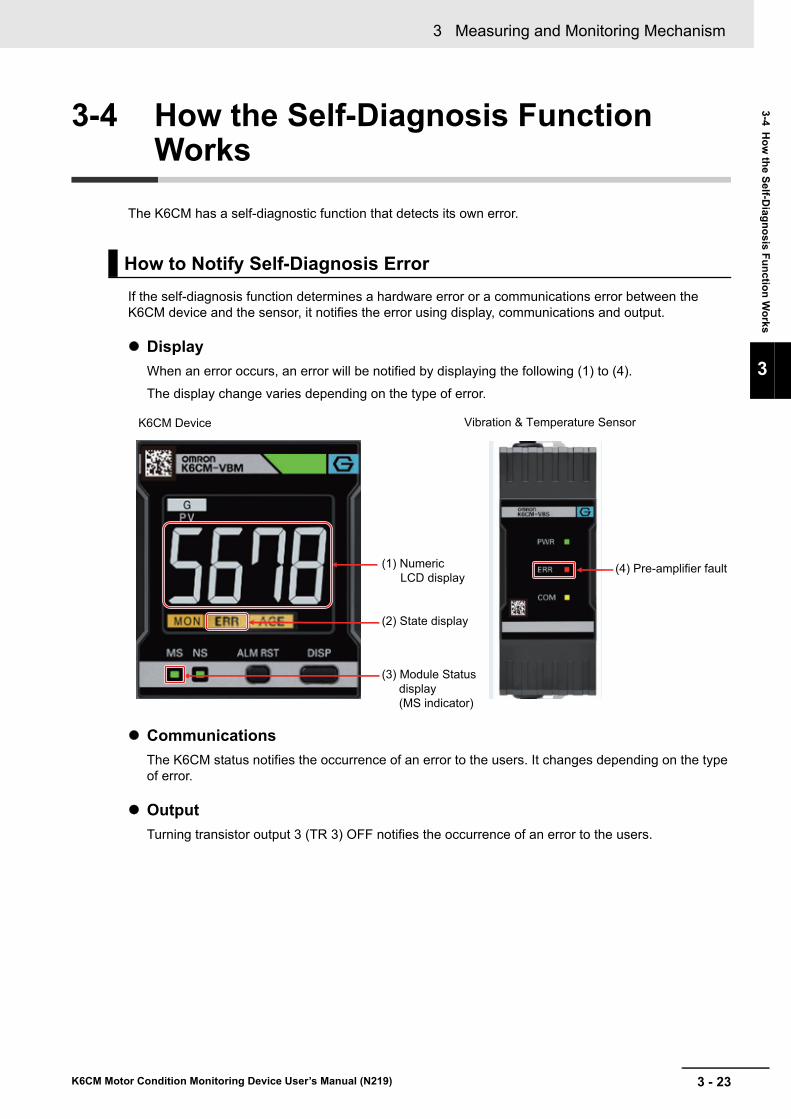
3 - 23
3 Measuring and Monitoring Mechanism
K6CM Motor Condition Monitoring Device User’s Manual (N219)
3-4 Ho
w th
e Self-D
iagn
osis F
un
ction
Wo
rks
3
3-4 How the Self-Diagnosis Function Works
The K6CM has a self-diagnostic function that detects its own error.
If the self-diagnosis function determines a hardware error or a communications error between the K6CM device and the sensor, it notifies the error using display, communications and output.
Display
When an error occurs, an error will be notified by displaying the following (1) to (4).
The display change varies depending on the type of error.
Communications
The K6CM status notifies the occurrence of an error to the users. It changes depending on the type of error.
Output
Turning transistor output 3 (TR 3) OFF notifies the occurrence of an error to the users.
How to Notify Self-Diagnosis Error
(1) NumericLCD display
K6CM Device Vibration & Temperature Sensor
(4) Pre-amplifier fault
(2) State display
(3) Module Statusdisplay (MS indicator)

3 Measuring and Monitoring Mechanism
3 - 24 K6CM Motor Condition Monitoring Device User’s Manual (N219)
K6CM Device
Vibration & Temperature Sensor
Behavior When Self-Diagnosis Error Occurs
Error statusNumeric LCD dis-
play
MS indica-
tor
ERR indi-cator
Tr3 output
K6CM status Corrective action
Hardware errors
---- lit Or 8888 flashing
Lit red Lit OFF Since the EtherNet/IP communica-tions cannot be per-formed, the K6CM status cannot be read.
Turn ON the power again. If it returns to normal, the influence of noise is possi-ble. Then, check whether noise is being generated.
If the condition does not restore, contact your OMRON representative.
Communica-tions error with Vibra-tion & Tem-perature sensor or Insulation Resistance sensor
---- lit Flash-ing red
Lit OFF Measure-ment CPU error turns ON.
• Make sure that wiring is correct.
• Turn ON the power again. If it returns to normal, the influence of noise is possible. Then, check whether noise is being generated.
If the condition does not restore, contact your OMRON representative.
Hardware error for run-ning time function
There is no state change due to error occur-rence.
Flash-ing red
Lit OFF Main CPU error turns ON.
• Make sure that the ambient tempera-ture of the K6CM device does not exceed the operating ambient tem-perature.
• Turn ON the power again. If it returns to normal, the influence of noise is possible. Then, check whether noise is being generated.
If the condition does not restore, contact your OMRON representative.
Error status Pre-amplifier fault indicator Corrective action
Hardware errors Lit Turn ON the power again. If it returns to normal, the influence of noise is possible. Then, check whether noise is being generated.
If the condition does not restore, contact your OMRON representative.

3 - 25
3 Measuring and Monitoring Mechanism
K6CM Motor Condition Monitoring Device User’s Manual (N219)
3-5 Ho
w th
e Re
placem
ent T
imin
g N
otificatio
n (i.e., R
un
-n
ing
Tim
e Fu
nctio
n) W
orks
3
3-5 How the Replacement Timing Notifi-cation (i.e., Running Time Function) Works
An electrolytic capacitor is built in the K6CM device. From the manufacturing point of time, the electro-lytic solution permeates through the sealing rubber and the evaporation of the electrolyte in the electro-lytic solution progresses with time. As a result, deterioration of characteristics such as decrease in capacitance occurs. Due to that, the K6CM device can not exhibit sufficient performance over time.
The replacement timing announcement function indicates a guideline period until the K6CM device is unable to achieve sufficient performance due to the deterioration of electrolytic capacitor characteris-tics. Also, when reaching the guideline value, K6CM device front display and communications status will change. You can use this function as a guideline to know when to replace the K6CM device.
Note The replacement timing announcement indicates a guideline that the K6CM device cannot achieve suffi-cient performance due to deterioration of the electrolytic capacitor. The guideline does not include failures caused by other factors.
When the K6CM device reaches the guideline of the replacement time, it will be notified by display and communications.
Display
AGE indicator lit to notify users when to replace.
Note Turn ON the Use Running Time, so that the AGE LED lights up when the guideline for the replacement time is reached. The default setting of the Use Running Time is OFF.
Communications
The Running Time bit ON in the K6CM status notifies users when to replace.
Also, you can see the percentage of achievement to the expected life using Running Time parame-ter. Running Time parameter sets the expected life to 100% and increases from 0% in 10% incre-ments. We recommend replacing the K6CM device if the parameter reaches 100%.
How to Notify When to Replace
State display

3 Measuring and Monitoring Mechanism
3 - 26 K6CM Motor Condition Monitoring Device User’s Manual (N219)
3-6 Initialization of Setting Value
This section describes how to initialize the setting values of the K6CM devices.
To initialize the setting value, press the [ALM RST] key and the [DISP] key at the same time for 5 sec-onds or more.
Press the keys at the same time for 5 seconds or more.While the keys are pressed at the same time, the numeric display LCD flashes.

4 - 1
4
K6CM Motor Condition Monitoring Device User’s Manual (N219)
This section describes the overview of the software tool and how to install it.
4-1 Overview . . . . . . . . . . . . . . . . . . . . . . . . . . . . . . . . . . . . . . . . . . . . . . . . . . . . . 4-24-1-1 What is the Motor condition monitoring Tool (Software Tool) for? . . . . . . . . . . . 4-2
4-1-2 Functions and Specifications of the Software Tool . . . . . . . . . . . . . . . . . . . . . . 4-3
4-1-3 Operating Environment of the Software tool . . . . . . . . . . . . . . . . . . . . . . . . . . . 4-8
4-2 Installation and Uninstallation, Starting up . . . . . . . . . . . . . . . . . . . . . . . . 4-104-2-1 Installation . . . . . . . . . . . . . . . . . . . . . . . . . . . . . . . . . . . . . . . . . . . . . . . . . . . . 4-10
4-2-2 Uninstallation Procedures . . . . . . . . . . . . . . . . . . . . . . . . . . . . . . . . . . . . . . . . 4-23
4-3 IP Address Setting . . . . . . . . . . . . . . . . . . . . . . . . . . . . . . . . . . . . . . . . . . . . 4-244-3-1 IP Address Setting of Your PC . . . . . . . . . . . . . . . . . . . . . . . . . . . . . . . . . . . . 4-24
4-3-2 IP Address Setting of the K6CM Devices . . . . . . . . . . . . . . . . . . . . . . . . . . . . 4-26
Introduction of the Software Tool

4 Introduction of the Software Tool
4 - 2 K6CM Motor Condition Monitoring Device User’s Manual (N219)
4-1 Overview
The software tool can display the setting of K6CM devices and the current value display, and automatic logging and history display.
Connect the Motor condition monitoring Tool (hereinafter referred to as software tool) to the K6CM device with an Ethernet cable, and then you can execute the following.
Setting up the K6CM devices
IP address, alarm setting, and other K6CM device settings are available.
Monitor current value of measurement value and alarm result
You can monitor the measured values and the current value of the alarm results for each motor, K6CM device, and monitoring category.
Automatic logging and history display
Automatically logs the measured value and alarm result to the computer.
At the time the project saved, the logging result is automatically output to a log file (CSV file).
Based on automatically logged data and log file (CSV file), history of measurement value and alarm result is displayed.
* The project is saved along with the log file.
The following settings of the K6CM device are possible.
4-1-1 What is the Motor condition monitoring Tool (Software Tool) for?
Overview
Setting up the K6CM Device
Setting type Screen for setting
IP address Create the project screen or Device setting screen
Alarm setting, and other K6CM device settings Create the project screen or Device setting screen
Software tool
• IP address• Alarm settings, other device settings
Download after creating projectOrDownload after device setup
Motor condition monitoring equipmentK6CM device
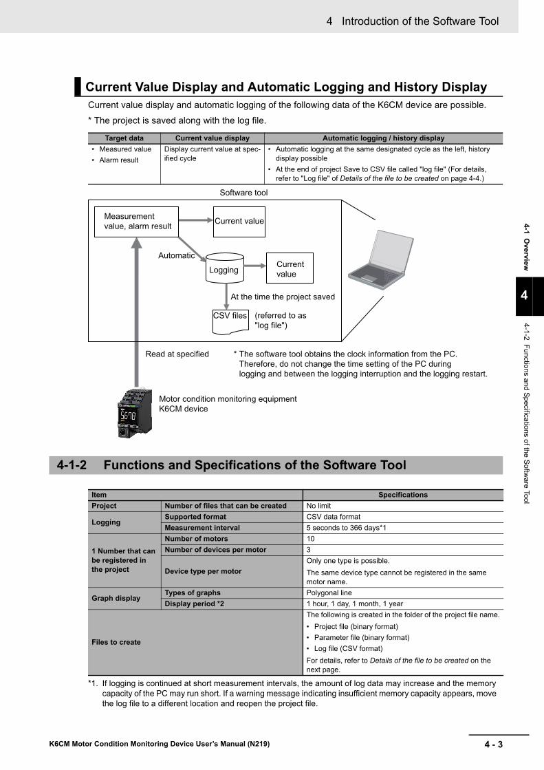
4 - 3
4 Introduction of the Software Tool
K6CM Motor Condition Monitoring Device User’s Manual (N219)
4-1 O
verview
4
4-1-2 Functions and S
pecifications of the S
oftware Tool
Current value display and automatic logging of the following data of the K6CM device are possible.
* The project is saved along with the log file.
Current Value Display and Automatic Logging and History Display
Target data Current value display Automatic logging / history display
• Measured value
• Alarm result
Display current value at spec-ified cycle
• Automatic logging at the same designated cycle as the left, history display possible
• At the end of project Save to CSV file called "log file" (For details, refer to "Log file" of Details of the file to be created on page 4-4.)
4-1-2 Functions and Specifications of the Software Tool
Item Specifications
Project Number of files that can be created No limit
LoggingSupported format CSV data format
Measurement interval 5 seconds to 366 days*1
*1. If logging is continued at short measurement intervals, the amount of log data may increase and the memory capacity of the PC may run short. If a warning message indicating insufficient memory capacity appears, move the log file to a different location and reopen the project file.
1 Number that can be registered in the project
Number of motors 10
Number of devices per motor 3
Device type per motor
Only one type is possible.
The same device type cannot be registered in the same motor name.
Graph displayTypes of graphs Polygonal line
Display period *2 1 hour, 1 day, 1 month, 1 year
Files to create
The following is created in the folder of the project file name.
• Project file (binary format)
• Parameter file (binary format)
• Log file (CSV format)
For details, refer to Details of the file to be created on the next page.
Software tool
Logging
Read at specified * The software tool obtains the clock information from the PC. Therefore, do not change the time setting of the PC during logging and between the logging interruption and the logging restart.
At the time the project saved
CSV files (referred to as "log file")
Measurement value, alarm result
Current value
Current value
Motor condition monitoring equipmentK6CM device
Automatic

4 Introduction of the Software Tool
4 - 4 K6CM Motor Condition Monitoring Device User’s Manual (N219)
Details of the file to be created
Precautions for Correct Use
Do not use project files which are created with the software tool with the new version if you use the software tool with the older version. The software tool may not operate correctly.
*2. In the software tool version 2.0.0 and earlier, the graph display period can be set by selecting the tabs (1 hour, 1 day, 3 months, 6 months, 1 year, 2 years, 5 years, 10 years, 20 years).
In the software tool version 1.2.0.0 and later, you can move the graph in the time axis direction using the graph time axis movement.
File typeExten-sion
Description Save position by default
Project file .k6cm Binary file including
• Device configuration information including motor group
• Device setting value
• Event log information
• Related log file information
C: \ OMRON \ Motor condi-tion monitoring Tool
Parameter data file
.k6pa Binary file of parameter values for each device Same as above
Log file .csv Automatic log file of monitored information.
It is used for graph display inside the tool.
It is CSV format, so it can be used by other applications.
Directly under the folder of the project file name | folder of the motor name
File name: Project name _IIIIII_TT_YYYYMMDD_NNNN.csv
IIIIII: Device ID (000000 to 999999)
TT: Monitor type (00 to 06)
00: acceleration, 01: velocity, 02: motor temperature, 03: temperature gap, 04: insulation resistance, 05 degradation level, 06: current
YYYY: Year
MM: Month (01 - 12)
DD: days (01 to 31)
NNNN: Serial number (the above-mentioned device ID, monitoring cate-gory, number for identifying the same date year / month / date)
The contents of the file are as follows. One record consists of the following two lines.
Line 1: [Device name], [Monitor type name]
From the second line: [Date and time], [Current value], [Threshold (Warn-ing)], [Threshold (Critical)], [K6CM status], [Measurement status]
• Device name:Any one of "K6CM_VB", "K6CM_IS", "K6CM_CI"
• Monitor type name?Any one of "acceleration", "velocity", "motor temperature", "temperature gap", "insulation resistance", "current", "degree of degradation"
• Date and time:A character string representing the date and time on the computer system when monitoring
• Current value, threshold (Warning), threshold (Critical):Monitoring form Character string expressing the current value, threshold value (Warning), threshold value (Critical) of K6CM device in decimal number with decimal point
• K6CM status, measurement status:Monitoring form Character string in hexadecimal representation of each of the 16 bits of the K6CM status and measurement status of the K6CM device (Refer to the next page for details on the CSV file content and sta-tus)

4 - 5
4 Introduction of the Software Tool
K6CM Motor Condition Monitoring Device User’s Manual (N219)
4-1 O
verview
4
4-1-2 Functions and S
pecifications of the S
oftware Tool
Log file .csv Save timing:
• When saving the project.
• Every hour during monitoring
• When monitoring is completed
• When you select to save log files and project files at the end of the soft-ware tool
*1 The project is saved along with the log file. When log file is open, data is not saved. If you want to open the log file during monitoring, we recom-mend copying it to another folder.
*2 The maximum number of lines of the log file is 10,000 lines. If it exceeds the maximum number of lines, create a new log file and save the log.
Directly under the folder of the project file name | folder of the motor name
File typeExten-sion
Description Save position by default

4 Introduction of the Software Tool
4 - 6 K6CM Motor Condition Monitoring Device User’s Manual (N219)
Log file example
The display example of the log file concerning the degradation level with the comprehensive current diagnosis type is shown below.
When the monitoring cycle setting of the software tool is set to 86,400 seconds (= 1 day) …
The degradation level (current value) exceeded the degradation level alarm (Warning) and an alarm was output. The K6CM status and the degradation level status have changed according to those states.
For the K6CM status and the individual measurement and monitoring status, refer to the table below.
K6CM status
Bit posi-tion
StatusBit contents
0 1
0 Measurement CPU error Not occurred Occurrence
1 Measurement CPU data flash error Not occurred Occurrence
2 Main CPU error Not occurred Occurrence
3 Main CPU data flash error Not occurred Occurrence
4 Reserved.
5 Reserved.
6 Reserved.
7 Reserved.
8 Running Time status Unreached Reached
9 Monitoring condition Measurement and monitoring stopped
During measure-ment and monitor-ing
10 Reserved.
11 Reserved.
12 Trigger input (ON/OFF state of the exter-nal trigger input)
OFF ON
13 TR 1 (transistor 1output state) OFF ON
14 TR 2 (transistor 2output state) OFF ON
15 TR 3 (transistor 3output state) OFF ON
Data is saved every day.
If the motor degrades
The status changes depending on the status of input/output and measured values.
The alarm values which are set in the K6CM device are displayed.
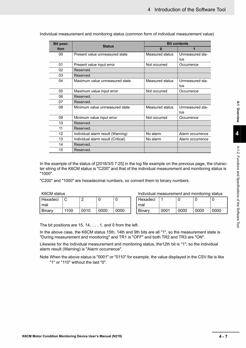
4 - 7
4 Introduction of the Software Tool
K6CM Motor Condition Monitoring Device User’s Manual (N219)
4-1 O
verview
4
4-1-2 Functions and S
pecifications of the S
oftware Tool
Individual measurement and monitoring status (common form of individual measurement value)
In the example of the status of [2018/3/5 7:25] in the log file example on the previous page, the charac-ter string of the K6CM status is "C200" and that of the individual measurement and monitoring status is "1000".
"C200" and "1000" are hexadecimal numbers, so convert them to binary numbers.
The bit positions are 15, 14, … , 1, and 0 from the left.
In the above case, the K6CM status 15th, 14th and 9th bits are all "1", so the measurement state is "During measurement and monitoring" and TR1 is "OFF" and both TR2 and TR3 are "ON".
Likewise for the individual measurement and monitoring status, the12th bit is "1", so the individual alarm result (Warning) is "Alarm occurrence".
Note When the above status is "0001" or "0110" for example, the value displayed in the CSV file is like "1" or "110" without the last "0".
Bit posi-tion
StatusBit contents
0 1
00 Present value unmeasured state Measured status Unmeasured sta-tus
01 Present value input error Not occurred Occurrence
02 Reserved.
03 Reserved.
04 Maximum value unmeasured state Measured status Unmeasured sta-tus
05 Maximum value input error Not occurred Occurrence
06 Reserved.
07 Reserved.
08 Minimum value unmeasured state Measured status Unmeasured sta-tus
09 Minimum value input error Not occurred Occurrence
10 Reserved.
11 Reserved.
12 Individual alarm result (Warning) No alarm Alarm occurrence
13 Individual alarm result (Critical) No alarm Alarm occurrence
14 Reserved.
15 Reserved.
K6CM status Individual measurement and monitoring status
Hexadecimal
C 2 0 0 Hexadecimal
1 0 0 0
Binary 1100 0010 0000 0000 Binary 0001 0000 0000 0000
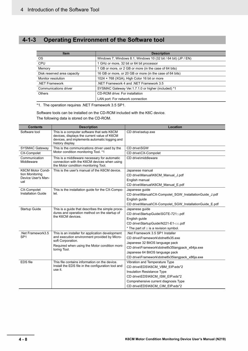
4 Introduction of the Software Tool
4 - 8 K6CM Motor Condition Monitoring Device User’s Manual (N219)
Software tools can be installed on the CD-ROM included with the K6C device.
The following data is stored on the CD-ROM.
4-1-3 Operating Environment of the Software tool
Item Description
OS Windows 7, Windows 8.1, Windows 10 (32 bit / 64 bit) (JP / EN)
CPU 1 GHz or more, 32 bit or 64 bit processor
Memory 1 GB or more, or 2 GB or more (in the case of 64 bits)
Disk reserved area capacity 16 GB or more, or 20 GB or more (in the case of 64 bits)
Monitor resolution 1024 × 768 (XGA), High Color 16 bit or more
.NET Framework .NET Framework 4 and .NET Framework 3.5
Communications driver SYSMAC Gateway Ver.1.7.1.0 or higher (included) *1
*1. The operation requires .NET Framework 3.5 SP1.
Others CD-ROM drive: For installation
LAN port: For network connection
Contents Description Location
Software tool This is a computer software that sets K6CM devices, displays the current value of K6CM devices, and implements automatic logging and history display.
CD drive\setup.exe
SYSMAC Gateway This is the communications driver used by the Motor condition monitoring Tool. *1
CD drive\SGW
CX-Compolet CD drive\CX-Compolet
Communication Middleware
This is a middleware necessary for automatic connection with the K6CM devices when using the Motor condition monitoring Tool.
CD drive\middleware
K6CM Motor Condi-tion Monitoring Device User's Man-ual
This is the user's manual of the K6CM device. Japanese manual
CD drive\Manual\K6CM_Manual_J.pdf
English manual
CD drive\Manual\K6CM_Manual_E.pdf
CX-Compolet Installation Guide
This is the installation guide for the CX-Compo-let.
Japanese guide
CD drive\Manual\CX-Compolet_SGW_InstallationGuide_J.pdf
English guide
CD drive\Manual\CX-Compolet_SGW_InstallationGuide_E.pdf
Startup Guide This is a guide that describes the simple proce-dures and operation method on the startup of the K6CM devices.
Japanese guide
CD drive\StartupGuide\SGTE-721.pdf
English guide
CD drive\StartupGuide\N221-E1-.pdf
* The part of is a revision symbol.
.Net Framework3.5 SP1
This is an installer for application development and execution environment provided by Micro-soft Corporation.
Required when using the Motor condition moni-toring Tool.
.Net Framework 3.5 SP1 Installer
CD drive\Framework\dotnetfx35.exe
Japanese 32 BitOS language pack
CD drive\Framework\dotnetfx35langpack_x64ja.exe
Japanese 64 BitOS language pack
CD drive\Framework\dotnetfx35langpack_x86ja.exe
EDS file This file contains information on the device. Install the EDS file in the configuration tool and use it.
Vibration and Temperature Type
CD drive\EDS\K6CM_VBM_EIP.eds*2
Insulation Resistance Type
CD drive\EDS\K6CM_ISM_EIP.eds*2
Comprehensive current diagnosis Type
CD drive\EDS\K6CM_CIM_EIP.eds*2

4 - 9
4 Introduction of the Software Tool
K6CM Motor Condition Monitoring Device User’s Manual (N219)
4-1 O
verview
4
4-1-3 Operating E
nvironment of the
Softw
are tool
Sample program for NJ/NX-series*2
This is a sample program for monitoring the motor condition using the NJ/NX-series Controller.
Sample program:
With Japanese comments:
CD drive \ SampleProgram \ Program \ SampleProgram_-J_V1_0_0.smc2
With English comments:
CD drive \ SampleProgram \ Program \ SamplePro-gram_E_V1_0_0.smc2
Function block (sample):
CD drive \ SampleProgram \ FunctionBlock \ SampleF-B_EN_K6CM_Read_V1_0_0.slr
*1. If you use the SYSMAC Gateway and the CX-Compolet for purposes other than using the Motor condition monitoring Tool, please pur-chase those licenses.
*2. It is added from the software tool Ver1.1.0.0 (production after June, 2018). For the version of the software tool, check the printing of CD-ROM. With the update program of our I-Web, you can update the software tool of the old version to the latest version.
Contents Description Location

4 Introduction of the Software Tool
4 - 10 K6CM Motor Condition Monitoring Device User’s Manual (N219)
4-2 Installation and Uninstallation, Start-ing up
This section describes how to install and uninstall the software tool and how to start it.
Installing .NET Framework 3.5 SP1
The software tool requires Microsoft .NET Framework 3.5 SP1 to run the program.
If .NET Framework 3.5 SP1 is not installed on your computer, install it manually.
It is installed as a standard on Windows 7 computer. Follow steps 2 to 4 below.
It is not installed as a standard on Windows 8.1 and Windows 10 computer.
When using on a computer with Windows 8.1 or Windows 10, perform the steps 2 to 4 after installing the .NET Framework 3.5 SP1 shown in the following step 1.
1 Install .NET Framework 3.5 SP1.
Installing by connecting the computer to the network
(1) Install it by "dotnetfx35.exe" in the Framework folder on the CD.
(2) Install the language pack with the following files in the Framework folder in the CD.
Japanese 32bit OS: "dotnetfx35langpack_x86ja.exe"
Japanese 64 Bit OS: "dotnetfx35langpack_x64ja.exe"
Installing without connecting the computer to the network
This procedure shows how to install the software tool (and attached software) on PCs (Windows 8.1 or Windows 10 OS) that cannot connect to the network.
What are required to prepare:
• Network connected computer
• Empty recording medium (USB memory of 8GB or more, HDD or DVD)
This procedure also details the resolution technique published on the following Microsoft official website.
Microsoft official website URL:https://msdn.microsoft.com/en-US/library/windows/hard-ware/dn898529(v=vs.85).aspx#nointerent
Note In Windows version 8.1 or later OS version, the "Microsoft .NET Framework 3.5" required for installing the above mentioned attached software is not installed in advance. Therefore, if you are using a com-puter with the above OS version and cannot connect to the network, you cannot acquire the above. NET and you cannot install the software included with the software tool.
4-2-1 Installation
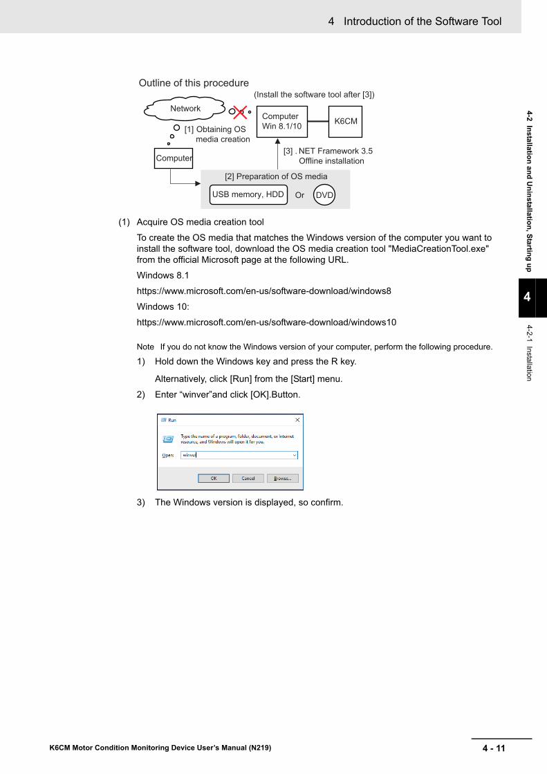
4 - 11
4 Introduction of the Software Tool
K6CM Motor Condition Monitoring Device User’s Manual (N219)
4-2 Installatio
n a
nd
Un
installa
tion
, Startin
g u
p
4
4-2-1 Installation
(1) Acquire OS media creation tool
To create the OS media that matches the Windows version of the computer you want to install the software tool, download the OS media creation tool "MediaCreationTool.exe" from the official Microsoft page at the following URL.
Windows 8.1
https://www.microsoft.com/en-us/software-download/windows8
Windows 10:
https://www.microsoft.com/en-us/software-download/windows10
Note If you do not know the Windows version of your computer, perform the following procedure.
1) Hold down the Windows key and press the R key.
Alternatively, click [Run] from the [Start] menu.
2) Enter “winver”and click [OK].Button.
3) The Windows version is displayed, so confirm.
Outline of this procedure(Install the software tool after [3])
Network
[1] Obtaining OSmedia creation
[3] . NET Framework 3.5Offline installation
[2] Preparation of OS media
OrUSB memory, HDD DVD
Computer
ComputerWin 8.1/10 K6CM

4 Introduction of the Software Tool
4 - 12 K6CM Motor Condition Monitoring Device User’s Manual (N219)
(2) OS media creation
Run the downloaded OS media creation tool.
Be sure to select "Create installation media of another PC" for the option after agreeing to the license terms.
In the selection screen of language, architecture, and edition, uncheck the check box at the bottom and select the same one as the computer you want to install the software tool.
Note If you do not know the architecture of your computer, perform the following procedure.
1) On the personal computer where you want to install the software tool, hold down the
Windows key and press the R key.
Alternatively, click [Run] from the [Start] menu.
2) Enter “cmd” and click OK. A command prompt is launched.
3) Enter “echo %processor_architecture%”and press Enter key.
4) 32 bits are displayed as x86, 64 bits are displayed as x64, and so on.

4 - 13
4 Introduction of the Software Tool
K6CM Motor Condition Monitoring Device User’s Manual (N219)
4-2 Installatio
n a
nd
Un
installa
tion
, Startin
g u
p
4
4-2-1 Installation
Select the media type to use.
When selecting "USB flash drive", be sure to prepare an empty recording medium (USB memory of 8 GB or more, HDD or DVD) without data.
At this point, connect the USB memory to your computer and select "Next" on the installa-tion screen. Confirm that the USB memory is normally recognized by the computer and dis-played as a removable drive as below and proceed with creating OS media.
(3) .NET Framework 3.5 Offline installation
Make the software tool recognize the created OS media on the PC you want to install (If you are using a USB memory or HDD, connect it to a PC, mount it on a PC if it is a DVD).
When the OS media is recognized correctly, the following popup will be displayed. In this example, you can see that the USB memory as the OS media has been assigned to D drive (D :).
As we will use the drive information we have confirmed in the later operation, be sure to check which drive the OS media is assigned to.
Note It is possible to check the media with other methods. Click the Explorer icon located at the bot-tom of the desktop screen.(If there is no icon, hold down the Windows key and press the E key to start the explorer screen)

4 Introduction of the Software Tool
4 - 14 K6CM Motor Condition Monitoring Device User’s Manual (N219)
Since the Explorer screen starts, click the drive icon displayed on the left side of the screen that started up.If the OS media is recognized correctly, the drive containing the following data will be displayed.
Execute the command prompt (shell script) with administrator privileges after confirming that the OS media was recognized correctly.
Hold down the Windows key while pressing the X key, the following screen will be dis-played, so select Windows PowerShell (Administrator).
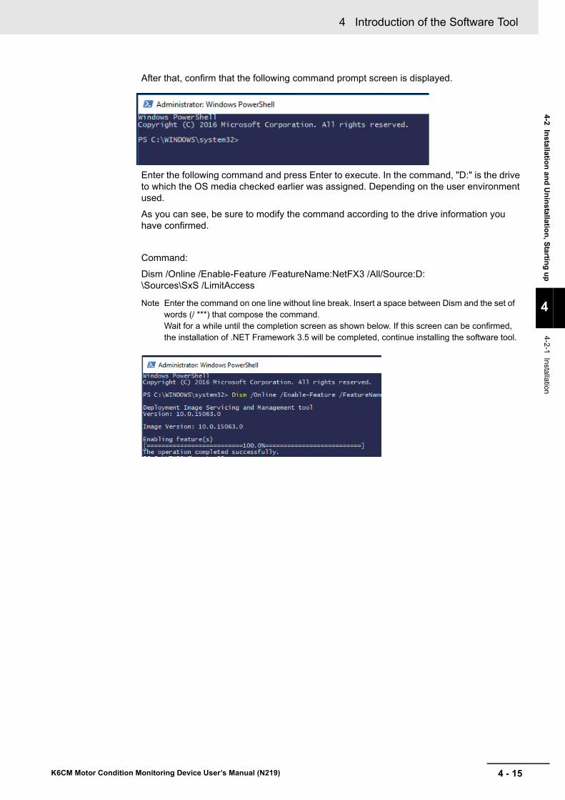
4 - 15
4 Introduction of the Software Tool
K6CM Motor Condition Monitoring Device User’s Manual (N219)
4-2 Installatio
n a
nd
Un
installa
tion
, Startin
g u
p
4
4-2-1 Installation
After that, confirm that the following command prompt screen is displayed.
Enter the following command and press Enter to execute. In the command, "D:" is the drive to which the OS media checked earlier was assigned. Depending on the user environment used.
As you can see, be sure to modify the command according to the drive information you have confirmed.
Command:
Dism /Online /Enable-Feature /FeatureName:NetFX3 /All/Source:D:\Sources\SxS /LimitAccess
Note Enter the command on one line without line break. Insert a space between Dism and the set of words (/ ***) that compose the command. Wait for a while until the completion screen as shown below. If this screen can be confirmed, the installation of .NET Framework 3.5 will be completed, continue installing the software tool.

4 Introduction of the Software Tool
4 - 16 K6CM Motor Condition Monitoring Device User’s Manual (N219)
2 Select "Program" from the Control Panel.
3 Turn on or off Windows functions.
4 Check the check box of "Microsoft .NET Framework 3.5.1" and click "OK".

4 - 17
4 Introduction of the Software Tool
K6CM Motor Condition Monitoring Device User’s Manual (N219)
4-2 Installatio
n a
nd
Un
installa
tion
, Startin
g u
p
4
4-2-1 Installation
This section shows the procedure for installing a new software tool.
Precautions for Correct Use
"User account control" may be displayed depending on computer settings during installation procedure. In that case, click "yes" if there is no problem.
1 Insert the attached CD in the computer and select "setup.exe" from the autoplay screen.If automatic playback was not done, double-click the "setup.exe" file under the CD drive.
The following [Select language setting] Dialog Box will be displayed.
Precautions for Correct Use
If the following message is displayed, the old version of CX-Compolet/SYSMAC Gateway has already been installed on the computer. In order to use software tool, upgrade of CX-Compo-let/SYSMAC Gateway is necessary.
Please read "3.5. Upgrade installation" of "CX-Compolet_SGW_InstallationGuide_E.pdf" in the Manual folder on the CD and uninstall the CX-Compolet/SYSMAC Gateway after backing up the data. Then re-perform step 1.
Installing the Software Tool

4 Introduction of the Software Tool
4 - 18 K6CM Motor Condition Monitoring Device User’s Manual (N219)
Precautions for Correct Use
If the following message is displayed, a newer version of the software tool than the launched installer has already been installed on your PC. Therefore, installation is unnecessary.
Precautions for Correct Use
If the following message is displayed, a software tool of the same version as the launched installer has already been installed in your PC.
[Modify] is used to change the function to be installed. Do not use it now for future expansion.
[Repair] is used to reinstall the software tool.
[Remove] is used to uninstall the software tool.

4 - 19
4 Introduction of the Software Tool
K6CM Motor Condition Monitoring Device User’s Manual (N219)
4-2 Installatio
n a
nd
Un
installa
tion
, Startin
g u
p
4
4-2-1 Installation
Precautions for Correct Use
If the following message is displayed, a older version of the software tool than the launched installer is installed on your PC.
To update the software tool, click [Next] Button. Start updating after clicking. When the update is completed, a completion message is displayed.
2 Select "Japanese" or "English" and click the [Next] Button.The following Dialog Box will be displayed.
* If you select Japanese on your PC with other than Japanese OS, depending on the environment of your PC, the characters during installation may not be displayed correctly, or the software tool may not work properly.
* After installation, you cannot change the language of the software tool. If you want to change the lan-guage, reinstall the software tool.
3 Click the [Next] Button.The License Agreement Dialog Box appears.

4 Introduction of the Software Tool
4 - 20 K6CM Motor Condition Monitoring Device User’s Manual (N219)
4 Please read "License Agreement" carefully and check "I accept the terms of the license agree-ment" and click the [Next] Button if you can agree to all the terms.The [User Information] Dialog Box appears.
5 Click the "Install" Button.Installation of the software tool starts.
6 Install the Communications Middleware. Select the language to display in the installation.If an old version of the Communications Middlware is already installed, select whether to update Communications Middlware.
If a new version of the Communications Middlware is already installed, go to step 15.
7 While the installation wizard is running, the [Windows Security] Dialog Box will be displayed.Click the [Install] Button.
"OMRON Corporation Modems" is installed and the following [Windows Security] Dialog Box will be displayed.
8 Click the [Install] Button."OMRON Corporation Ports (COM & LPT)" is installed.
9 Since a dialog box prompting you to install WinPcap which is a component of Communications Middleware is displayed, click the [OK] Button. If WinPcap is already installed, go to step 15.

4 - 21
4 Introduction of the Software Tool
K6CM Motor Condition Monitoring Device User’s Manual (N219)
4-2 Installatio
n a
nd
Un
installa
tion
, Startin
g u
p
4
4-2-1 Installation
10 Click the [Next] Button.
11 Click the [I Agree] Button.The Installation options Dialog Box appears.
12 Check "Automatically start the WinPcap driver at boot time" and click the [Install] Button. Installation of WinPcap will start.
13 Click the [Finish] Button.Installation of WinPcap is completed.

4 Introduction of the Software Tool
4 - 22 K6CM Motor Condition Monitoring Device User’s Manual (N219)
14 From the software tool, select the network card to be used for automatic connection to the K6CM device with the Ethernet cable from the pull-down list and click the [OK] Button.If Communications Middleware is already installed, go to step 15.
Network card configuration example
If there is only one wired LAN port of the computer and the Motor condition monitoring Tool com-municates with the K6CM device with that wired LAN port, select the following.
(If the name of the network connection has been changed, select the one with the changed name.)
• Windows 7
Select "Local Area Connection".
• Windows 8.1/Windows 10
Select "Ethernet".
15 Select the computer restart and click the [Finish] Button.Remove the CD after rebooting.

4 - 23
4 Introduction of the Software Tool
K6CM Motor Condition Monitoring Device User’s Manual (N219)
4-2 Installatio
n a
nd
Un
installa
tion
, Startin
g u
p
4
4-2-2 Uninstallation P
rocedures
This section shows the procedure for uninstalling software tool.
• Windows 7
1 From the Start menu, select Control Panel | Add or Remove Programs.The Add or Remove Programs Dialog Box appears.
2 Select "Motor condition monitoring Tool" and click the [Delete] Button.A Dialog Box will be displayed confirming complete deletion of "Motor condition monitoring Tool".
3 Click the [Yes] Button.After completion, the Uninstall Complete Dialog Box will be displayed.
4 Click the [Finish] Button.
• Windows 8.1/Windows 10
1 From the [Start] menu, select [Control Panel] | [Uninstall a Program].The [Uninstall/Change Program] Dialog Box will be displayed.
2 Select "Motor condition monitoring Tool" and click the [Delete] Button.A Dialog Box will be displayed confirming complete deletion of "Motor condition monitoring Tool".
3 Click the [Yes] Button.After completion, the Uninstall Complete Dialog Box will be displayed.
4 Click the [Finish] Button.
4-2-2 Uninstallation Procedures

4 Introduction of the Software Tool
4 - 24 K6CM Motor Condition Monitoring Device User’s Manual (N219)
4-3 IP Address Setting
Before starting this tool and monitoring and logging the K6CM device, it is necessary to set the IP address of the computer to the IP address of the same segment as the K6CM device. It shows the pro-cedure.
Note that when setting only the K6CM device (IP address and other settings) with an automatic connec-tion, it is not necessary to set the IP address on the computer side.
For the initial setting of K6CM, refer to "4-3-2 IP Address Setting of the K6CM Devices on page 4-26"
• Windows 7
1 Select [Start] | [Control Panel] | [Network and Sharing Center] | [Change Adapter Settings].
2 Right-click [Local Area Connection] and select [Properties].
3 Select [Internet Protocol Version 4 (TCP / IPv4)] and click [Properties].Check "Use next IP address" and manually set the IP address of the computer.
• Windows 8.1
1 Right-click [Start].
2 Select [Network connection].
3 Right-click [Ethernet], and click [Properties].
4 Select [Internet Protocol Version 4 (TCP / IPv4)] and click [Properties].Check "Use next IP address" and manually set the IP address of the computer.
• Windows 10
1 Click [Start] and select [Windows System Tools] | [Control Panel].
2 Select [Network and Sharing Center] | [Change adapter settings].
3 Right-click Ethernet and click Properties.
4 Select [Internet Protocol Version 4 (TCP/IPv4)] and click [Properties].Check "Use next IP address" and manually set the IP address of the computer.
4-3-1 IP Address Setting of Your PC

4 - 25
4 Introduction of the Software Tool
K6CM Motor Condition Monitoring Device User’s Manual (N219)
4-3 IP A
dd
ress S
etting
4
4-3-1 IP A
ddress Setting
of Yo
ur PC
IP Address Settings Example
When using Ethernet for the first time, if you set the IP address and subnet mask of the computer and K6CM device as below, it is possible to connect the software tool to the K6CM device.
When the subnet mask is "255.255.255.0", the range of IP addresses that can be set for the device is 192.168.250.1 to 192.168.250.254. Assign IP address in this range to each K6CM device.
The same IP address can not be assigned to more than one device.
The default value of the IP address of type K6CM device is "192.168.250.10" common to all models.
Device name IP address Sub-net mask Default gateway
Computer 192.168.250.100 255.255.255.0 Blank
K6CM device 1st Unit 192.168.250.1 255.255.255.0 No change required (0.0.0.0)
K6CM device 2nd Unit 192.168.250.2 255.255.255.0 No change required (0.0.0.0)
K6CM device 3rd Unit 192.168.250.3 255.255.255.0 No change required (0.0.0.0)
••
••
••
••
K6CM device 30th Unit 192.168.250.30 255.255.255.0 No change required (0.0.0.0)
With the subnet mask of all K6CM devices set to "255.255.255.0“, Ethernet communications can be performed because devices are in the same network (i.e., segment), if an IP address is between 192.168.250.1 and 192.168.250.254.
ComputerIP address 192.168.250.100
Ethernetcommunications cannot be performedbecause the K6CMdevices are in adifferent network.
Network of 192.168.249.×××
IP address 192.168.249.1
IP address 192.168.250.1
Network of 192.168.250.×××
K6CM device
K6CM device
Ethernet communicationscan be performed becausethe K6CM devices are inthe same network.

4 Introduction of the Software Tool
4 - 26 K6CM Motor Condition Monitoring Device User’s Manual (N219)
There are two ways to connect the software tool to the K6CM.
• Automatic connection (direct one-to-one connection)
• Fixed IP Connection (connection via hub)
Directly connect the computer and each K6CM device via the Ethernet cable without going through the hub.
In the case of direct connection, there are the following merits:
• Can be connected without specifying IP address of K6CM device.
Either straight type or cross type Ethernet cable is available.
Note If the IP address setting method of the K6CM device is set to BOOTP, auto connection can not be made until connecting to the BOOTP server.
4-3-2 IP Address Setting of the K6CM Devices
Automatic connection (direct one-to-one connection)
Create the projectIP address setting Parameter setting (as necessary)
Software tool
Ethernet cable(Straight or cross)
EtherNet/IP port
Motor condition monitoring equipmentK6CM device
100 to 240 VAC or24 V power supply (by type)

4 - 27
4 Introduction of the Software Tool
K6CM Motor Condition Monitoring Device User’s Manual (N219)
4-3 IP A
dd
ress S
etting
4
4-3-2 IP A
ddress Setting
of the K6C
M D
evices
Connect the computer and each K6CM device with an Ethernet cable via the hub.
In the case of fixed IP connection, there are the following merits.
Fixed IP Connection is a method to connect by specifying the IP address of the K6CM device you want to connect.
• Connectable with PC connected to multiple K6CM with Ethernet cable
Note Do not connect more than one K6CM device with the same IP address.IP address may become duplicated and communication may fail.
Either straight type or cross type Ethernet cable is available.
Fixed IP Connection (connection via hub)
Software tool
Motor condition monitoring equipmentK6CM device
Ethernet cableIndustrial switching hub(Such as W4S1)
Device setting screen
Parameter settings
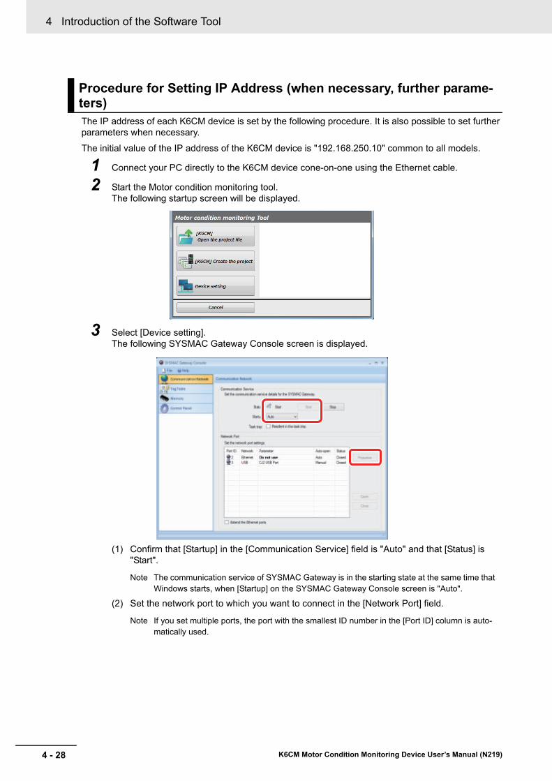
4 Introduction of the Software Tool
4 - 28 K6CM Motor Condition Monitoring Device User’s Manual (N219)
The IP address of each K6CM device is set by the following procedure. It is also possible to set further parameters when necessary.
The initial value of the IP address of the K6CM device is "192.168.250.10" common to all models.
1 Connect your PC directly to the K6CM device cone-on-one using the Ethernet cable.
2 Start the Motor condition monitoring tool.The following startup screen will be displayed.
3 Select [Device setting].The following SYSMAC Gateway Console screen is displayed.
(1) Confirm that [Startup] in the [Communication Service] field is "Auto" and that [Status] is "Start".
Note The communication service of SYSMAC Gateway is in the starting state at the same time that Windows starts, when [Startup] on the SYSMAC Gateway Console screen is "Auto".
(2) Set the network port to which you want to connect in the [Network Port] field.
Note If you set multiple ports, the port with the smallest ID number in the [Port ID] column is auto-matically used.
Procedure for Setting IP Address (when necessary, further parame-ters)
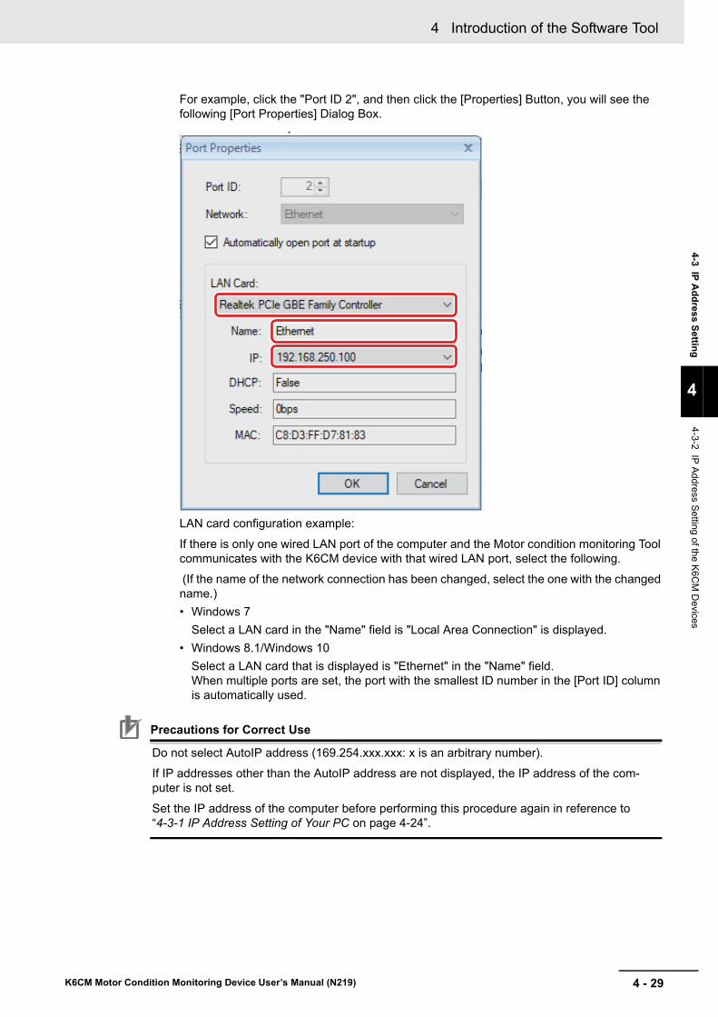
4 - 29
4 Introduction of the Software Tool
K6CM Motor Condition Monitoring Device User’s Manual (N219)
4-3 IP A
dd
ress S
etting
4
4-3-2 IP A
ddress Setting
of the K6C
M D
evices
For example, click the "Port ID 2", and then click the [Properties] Button, you will see the following [Port Properties] Dialog Box.
LAN card configuration example:
If there is only one wired LAN port of the computer and the Motor condition monitoring Tool communicates with the K6CM device with that wired LAN port, select the following.
(If the name of the network connection has been changed, select the one with the changed name.)
• Windows 7
Select a LAN card in the "Name" field is "Local Area Connection" is displayed.
• Windows 8.1/Windows 10
Select a LAN card that is displayed is "Ethernet" in the "Name" field. When multiple ports are set, the port with the smallest ID number in the [Port ID] column is automatically used.
Precautions for Correct Use
Do not select AutoIP address (169.254.xxx.xxx: x is an arbitrary number).
If IP addresses other than the AutoIP address are not displayed, the IP address of the com-puter is not set.
Set the IP address of the computer before performing this procedure again in reference to “4-3-1 IP Address Setting of Your PC on page 4-24”.
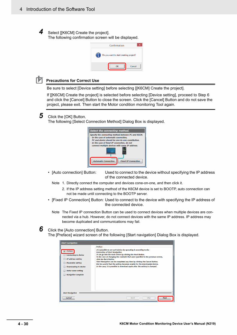
4 Introduction of the Software Tool
4 - 30 K6CM Motor Condition Monitoring Device User’s Manual (N219)
4 Select [[K6CM] Create the project].The following confirmation screen will be displayed.
Precautions for Correct Use
Be sure to select [Device setting] before selecting [[K6CM] Create the project].
If [[K6CM] Create the project] is selected before selecting [Device setting], proceed to Step 6 and click the [Cancel] Button to close the screen. Click the [Cancel] Button and do not save the project, please exit. Then start the Motor condition monitoring Tool again.
5 Click the [OK] Button.The following [Select Connection Method] Dialog Box is displayed.
• [Auto connection] Button: Used to connect to the device without specifying the IP address of the connected device.
Note 1. Directly connect the computer and devices cone-on-one, and then click it.
2. If the IP address setting method of the K6CM device is set to BOOTP, auto connection can not be made until connecting to the BOOTP server.
• [Fixed IP Connection] Button: Used to connect to the device with specifying the IP address of the connected device.
Note The Fixed IP connection Button can be used to connect devices when multiple devices are con-nected via a hub. However, do not connect devices with the same IP address. IP address may become duplicated and communications may fail.
6 Click the [Auto connection] Button.The [Preface] wizard screen of the following [Start navigation] Dialog Box is displayed.

4 - 31
4 Introduction of the Software Tool
K6CM Motor Condition Monitoring Device User’s Manual (N219)
4-3 IP A
dd
ress S
etting
4
4-3-2 IP A
ddress Setting
of the K6C
M D
evices
7 Click the [Next] Button.The following [Connecting to device] wizard screen will be displayed.
Version Information
With software tool version 1.2.0.0 or later, the column for displaying the IP addresses of your PC and registered devices are displayed.
8 Click the [connection] Button."Connecting" will be displayed on the line between the computer and the device on the following [Connecting to device] wizard screen.
The IP address selected in the [Port Properties] Dialog Box is displayed on the screen displayed by selecting [Device setting] on the startup screen.If IP address selection is incomplete (i.e., Network port param-eter is "Do not use"), "0.0.0.0" is displayed. If "0.0.0.0" is displayed, you can connect to the device if you set the connec-tion method to "Auto connection" in step 5, but if you set "Fixed IP connection" you cannot connect to the device.

4 Introduction of the Software Tool
4 - 32 K6CM Motor Condition Monitoring Device User’s Manual (N219)
When the connection is successful, the following [IP address setting] wizard screen will be dis-played.
Additional Information
Click the [Suspend] Button to abort the connection.
9 In the "Set the connecting means for the target device.", set the following.Check one of the following check boxes.
• Acquired from BOOTP server
• Fixed setting with IP address acquired from BOOTP server
• Fixed setting
When "Fixed setting" is checked, set the IP address, subnet mask, default gateway.
Note When "Fixed setting with IP address obtained from BOOTP server" or "Acquired from BOOTP server" is checked, set the IP address to be acquired from the BOOTP server here.If the device obtains a value different from that value from the BOOTP server, the Motor condition monitoring Tool will not be able to access that device. In that case, delete the relevant device with the [Delete device] Button of the tool buttons, and then re-register the device with the IP address obtained from the BOOTP server by the [Add device] Button.
Precautions for Correct Use
When setting the IP address of the K6CM to "Fixed setting", set the IP address of the computer to the IP address of the same segment as the K6CM.For details of the setting method, refer to4-3-1 IP Address Setting of Your PC on page 4-24.

4 - 33
4 Introduction of the Software Tool
K6CM Motor Condition Monitoring Device User’s Manual (N219)
4-3 IP A
dd
ress S
etting
4
4-3-2 IP A
ddress Setting
of the K6C
M D
evices
10 Click the [Next] Button. The following [Parameter setting] wizard screen will be displayed. (Set the parameters as nec-essary.) For details, refer to “6-2-1 Settings for Each Monitor Type of K6CM devices on page 6-23”.
Be sure to set the parameters in the table below before starting measurement.
Model Parameter name Setting value
Comprehensive cur-rent diagnosis type
Current range Input the set value according to CT to be used.
0: Rated CT 5 A is connected (K6CM-CICB005)
1: Rated CT 25 A is connected (K6CM-CICB025)
2: Rated CT 100 A is connected (K6CM-CICB100)
3: Rated CT200 A is connected (K6CM-CICB200)
4: Rated CT 400 A is connected (K6CM-CICB400)
5: Rated CT 600 A is connected (K6CM-CICB600)
Vibration & tempera-ture type
Temperature unit Select the temperature unit of motor temperature and Temperature gap.
0: °C
1: °F
Insulation resistance type
Applicable circuits Input the set value according to the motor drive method.
0: Three-phase three-wire S-phase ground
1: Three-phase four-wire N-phase ground, load side delta connection
Using inverter Input the set value according to the presence or absence of the inverter.
0: Without inverter
1: With inverter
Inverter special measurement
Input the set value according to the inverter frequency
0: Set when inverter frequency is far from commer-cial frequency
1: Set when inverter frequency is close to commer-cial frequency

4 Introduction of the Software Tool
4 - 34 K6CM Motor Condition Monitoring Device User’s Manual (N219)
11 If you do not want to set the parameters, click the [Skip] Button.The [Download to device] wizard screen of the following [Start navigation] Dialog Box is dis-played.
Note 1. If you click the [Skip] Button, the parameters will not be downloaded.If you set the parameters, click the [Next] Button. The [Download to device] wizard screen of the following [Start navigation] Dialog Box is displayed.
2. If you click the [Next] Button, the parameters will be downloaded.
12 Click the [OK] Button.The following [Downloading to device] wizard screen will be displayed.When the download is successful, the following [Motor name setting] wizard screen will be dis-played.
Note If the download fails, "Failed to download." is displayed on the "Download to device" wizard screen in the following [Start navigation] Dialog Box. After checking the connection, click the [Execute] Button, or click the [Return] Button and go back to one of the steps from step 4.

4 - 35
4 Introduction of the Software Tool
K6CM Motor Condition Monitoring Device User’s Manual (N219)
4-3 IP A
dd
ress S
etting
4
4-3-2 IP A
ddress Setting
of the K6C
M D
evices
13 In the field of "Motor name that the target devices belong to", set the motor name to which the target device belongs.The initial value is MotorName.
Precautions for Correct Use
• It is not possible to register the same type of device in the same motor name.
• Up to 3 devices can be registered in the same motor name.
14 Click the [OK] Button.The following [Navigating is completed] wizard screen is displayed.
The IP address of the registered device is displayed.

4 Introduction of the Software Tool
4 - 36 K6CM Motor Condition Monitoring Device User’s Manual (N219)
Continue to configure other devices
Turn ON the checkbox "Possible to continue the setting of another device"
15 Click the [End] Button.The Device Connection wizard screen of the following [Start Navigation] Dialog Box is displayed as in step 5.
16 Connect the Motor condition monitoring Tool directly to the other form K6CM one to one.
17 Perform the same operation as Step 8 and the following.
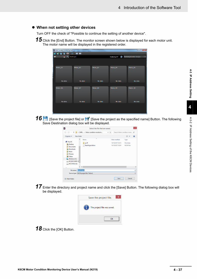
4 - 37
4 Introduction of the Software Tool
K6CM Motor Condition Monitoring Device User’s Manual (N219)
4-3 IP A
dd
ress S
etting
4
4-3-2 IP A
ddress Setting
of the K6C
M D
evices
When not setting other devices
Turn OFF the check of "Possible to continue the setting of another device".
15 Click the [End] Button. The monitor screen shown below is displayed for each motor unit.The motor name will be displayed in the registered order.
16 [Save the project file] or [Save the project as the specified name] Button. The following Save Destination dialog box will be displayed.
17 Enter the directory and project name and click the [Save] Button. The following dialog box will be displayed.
18 Click the [OK] Button.

4 Introduction of the Software Tool
4 - 38 K6CM Motor Condition Monitoring Device User’s Manual (N219)
If you want to check the IP address of the device registered on the project, perform the following opera-tions.
1 Select the device you want to change and click the [Device setting] Button on the setting screen tool button.The following [K6CM configuration setting] Dialog Box is displayed.
Note The IP address displayed here is the value registered in the project.
Version Information
With software tool version 1.2.0.0 or later, the column for displaying the IP addresses of your PC and registered devices are displayed.
When changing the IP address of the device
1 Select the device you want to change and click the [Device setting] Button on the setting screen tool button.The following [K6CM configuration setting] Dialog Box is displayed.
2 Change the IP address. Change the subnet mask and default gateway as necessary.
3 Click the [OK] Button.The IP address setting on the project is changed, and at the same time, the IP address of the actual device at the communication destination is automatically changed.
Version Information
With software tool version 1.2.0.0 or later, the column for displaying the IP addresses of your PC and registered devices are displayed.
When confirming the IP address of the registered device
When changing the IP address of the device

5 - 1
5
K6CM Motor Condition Monitoring Device User’s Manual (N219)
This section describes the installation and wiring of the K6CM devices.
5-1 Dimensions . . . . . . . . . . . . . . . . . . . . . . . . . . . . . . . . . . . . . . . . . . . . . . . . . . . 5-25-1-1 K6CM device . . . . . . . . . . . . . . . . . . . . . . . . . . . . . . . . . . . . . . . . . . . . . . . . . . 5-2
5-1-2 Vibration & temperature Sensor . . . . . . . . . . . . . . . . . . . . . . . . . . . . . . . . . . . . 5-2
5-1-3 Insulation resistance sensor (ZCT (IRT)) . . . . . . . . . . . . . . . . . . . . . . . . . . . . . 5-3
5-1-4 Dedicated CT . . . . . . . . . . . . . . . . . . . . . . . . . . . . . . . . . . . . . . . . . . . . . . . . . . 5-4
5-2 Installation . . . . . . . . . . . . . . . . . . . . . . . . . . . . . . . . . . . . . . . . . . . . . . . . . . . 5-55-2-1 Precautions at installation . . . . . . . . . . . . . . . . . . . . . . . . . . . . . . . . . . . . . . . . . 5-5
5-2-2 Installing the K6CM Device . . . . . . . . . . . . . . . . . . . . . . . . . . . . . . . . . . . . . . . . 5-5
5-2-3 Installation of the Vibration & Temperature sensor . . . . . . . . . . . . . . . . . . . . . . 5-7
5-2-4 Installation of the insulation resistance sensor (ZCT (IRT) . . . . . . . . . . . . . . . 5-12
5-2-5 Installation of the dedicated CT . . . . . . . . . . . . . . . . . . . . . . . . . . . . . . . . . . . 5-15
5-3 How to Connect to the Push-In Plus Terminal Blocks . . . . . . . . . . . . . . . 5-165-3-1 the Push-In Plus Terminal Block . . . . . . . . . . . . . . . . . . . . . . . . . . . . . . . . . . . 5-17
5-3-2 How to use the Push-In Plus Terminal Block . . . . . . . . . . . . . . . . . . . . . . . . . 5-17
5-3-3 Recommended Ferrules and Crimp Tools . . . . . . . . . . . . . . . . . . . . . . . . . . . 5-19
5-4 Diagram of Terminal Description . . . . . . . . . . . . . . . . . . . . . . . . . . . . . . . . 5-21
5-5 I/O wiring . . . . . . . . . . . . . . . . . . . . . . . . . . . . . . . . . . . . . . . . . . . . . . . . . . . . 5-22
5-6 EtherNet/IP Wiring . . . . . . . . . . . . . . . . . . . . . . . . . . . . . . . . . . . . . . . . . . . . 5-26
Installation and Wiring

5 Installation and Wiring
5 - 2 K6CM Motor Condition Monitoring Device User’s Manual (N219)
5-1 Dimensions
This section shows the external dimensions of the K6CM device and the sensors used.
5-1-1 K6CM device
5-1-2 Vibration & temperature Sensor
Pre-amplifier
Sensor head
(4)(1.9) 90
86
90
45
90 (40.7)2,400
3135
4
35
M12 (smart click connector)
M12 (smart click connector)
A
9 mm or more
M6 screw
Surface finish 20 mm dia. or more
Mounting hole dimensions
A-A´ cross section
A´
(44.7)318 30017
M6
17
17

5 - 3
5 Installation and Wiring
K6CM Motor Condition Monitoring Device User’s Manual (N219)
5-1 Dim
ensio
ns
5
5-1-3 Insulation resistance sensor (Z
CT
(IRT
))
Adhesive Attachment
5-1-3 Insulation resistance sensor (ZCT (IRT))
22
M6
24 dia.
12
C0.5C0.5
Material: Stainless steel
(152.5)
200
170
(150)(159)
170
110
36.4
5353
91
27.1
Four, M4
Four, M6
Two, M5
52 dia.
Mounting hole dimensions
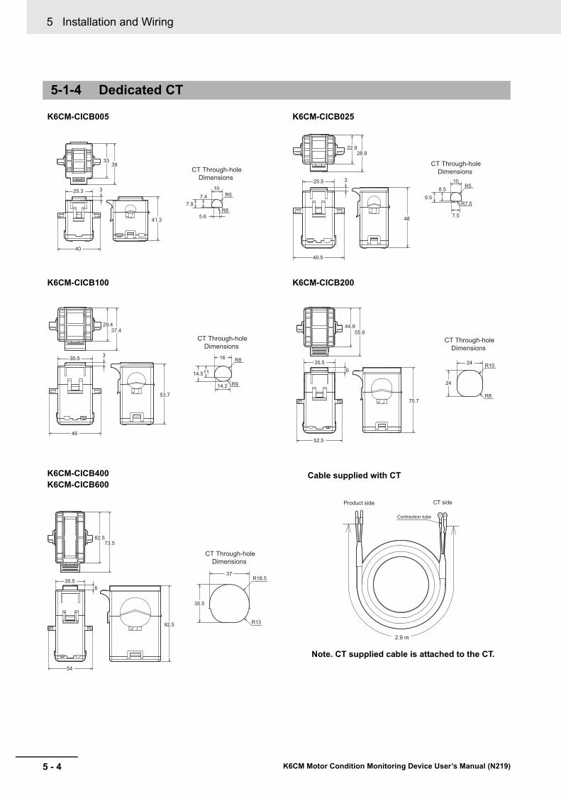
5 Installation and Wiring
5 - 4 K6CM Motor Condition Monitoring Device User’s Manual (N219)
5-1-4 Dedicated CT
3339
41.3
325.3
40
5.6
CT Through-holeDimensions
10
7.97.4
R8
R5
22.928.9
325.5
40.5
48
CT Through-holeDimensions
R5
7.5
10
9.58.5
R7.5
330.5
53.7
46
29.437.4
CT Through-holeDimensions
R816
14.511
14.2 R9
44.955.9
35.56
75.7
52.5
CT Through-holeDimensions
24
24
R10
R8
62.573.5
92.5
635.5
54
CT Through-holeDimensions
37
35.5
R13
R18.5
Product side CT side
Contraction tube
2.9 m
K6CM-CICB005 K6CM-CICB025
K6CM-CICB100 K6CM-CICB200
K6CM-CICB400K6CM-CICB600
Cable supplied with CT
Note. CT supplied cable is attached to the CT.

5 - 5
5 Installation and Wiring
K6CM Motor Condition Monitoring Device User’s Manual (N219)
5-2 Installatio
n
5
5-2-1 Precautions a
t installation
5-2 Installation
This section describes the installation of the K6CM devices.
Refer to the Precautions for Safe Use on page 7.
For installation of the K6CM device, it is possible to install it on the DIN rail or install it with screws on the wall.
Screw the DIN Track in three or more places in a control cabinet.
Recommended DIN Track
PFP-M End plate (2 pieces)
Installation Direction
There is no particular restriction on the mounting direction of the K6CM device, but install it securely in the horizontal or vertical direction as much as possible.
5-2-1 Precautions at installation
5-2-2 Installing the K6CM Device
When installing on DIN Track
Model Dimensions Manufacturer
PFP-100N 1,000 mm OMRON
PFP-50N 500 mm

5 Installation and Wiring
5 - 6 K6CM Motor Condition Monitoring Device User’s Manual (N219)
How to install the K6CM device
To mount the K6CM device to a DIN Track, hook the device onto the DIN Track and press the device in the direction of the arrow until you hear it lock into place.
How to remove the K6CM device
Pull down on the bottom hook with a flat-blade screwdriver and lift up on the product.
Leave at least 30 mm of space between the K6CM device and other devices to allow easy installa-tion and removal.
(1) Pull out 2 hooks in the K6CM device back outside until sound will be.
(2) Insert M3 screw in a hole of a hook and fix.
Note 1. Pull out the hooks to mount the K6CM device with screws.
2. Recommended tightening torque is 0.5 to 0.6 N·m.
3. Group mounting is not possible in the vertical direction.
Screw Mounting
(1) (2)
30 mm or more
(1)
(1)
(2)
(2)
108 mm
Mounting Hole Dimensions
Two, M3 holes orTwo, 3 dia.

5 - 7
5 Installation and Wiring
K6CM Motor Condition Monitoring Device User’s Manual (N219)
5-2 Installatio
n
5
5-2-3 Installation of the Vibration &
Temperature senso
r
The pre-amplifier used for Vibration & temperature type (K6CM-VBM) can be mounted on a DIN rail or mounted on a wall with an M3 screw.
The mounting method is the same as K6CM device.
The vibration sensor head for Vibration & temperature type (K6CM-VB) should be mounted to the motor to be monitored.
The pre-amplifier and the sensor head are removable, as they are connected with the Smartclick Con-nector. Install the sensor head on the motor after it has been removed from the pre-amplifier.
5-2-3 Installation of the Vibration & Temperature sensor
Installation of the Vibration Sensor Head
Vibration & temperature pre-amplifierK6CM-VBS1
Mounting with M3 screwor
DIN Track mounting
Mating mark

5 Installation and Wiring
5 - 8 K6CM Motor Condition Monitoring Device User’s Manual (N219)
For the K6CM-VBS1 (M6 × 8 mm), a magnet for easy-mounting of the sensor is included.
The easy-mounting magnet is used for positioning of measuring place. Note that measurement accu-racy is not guaranteed in the case of magnet mounting.
The connection between the pre-amplifier and the sensor head is a connector connection.
Mount the sensor head on the shaft side exterior of the induction motor.
There are two ways to mount the vibration sensor head to the motor.
We recommend Method 1 with a good absolute accuracy. However, if you cannot tap the motor, use Method 2.
Mounting Vibration Sensor Head Easily
Fixing the Vibration Sensor Head
Method Description
Method 1: Screw Mounting (recom-mended)
At the top of the armor of the motor, cut the tap into which the M6 screw vertically enters, and screw the vibration sensor head into it.
Method 2: Adhesive Mounting (*1)
*1. K6CM will not conform to safety standards if attaching the vibration sensor with adhesive. In the case of dis-connection, take safety measures such as fixing the cables.
Secure the attachment which is sold separately to the exterior of the motor using adhesive. Screw the vibration sensor head into the fixed attachment.
Sensor Easy mounting magnet23-mm dia.
Note: The Sensor Easy mounting magnet is similar in shape to an adhesive attachment. Be careful not to handle it by mistake.
Mount the vibration sensor head vertically to the upper shaft side of the motor
Three-phase induction motor
Load side

5 - 9
5 Installation and Wiring
K6CM Motor Condition Monitoring Device User’s Manual (N219)
5-2 Installatio
n
5
5-2-3 Installation of the Vibration &
Temperature senso
r
The measurement error when measuring with Method 1 or Method 2 is as follows.
Note The above is reference test data, and it is not guaranteed.
Fixing Vibration Sensor Head Using Screws
1 Turn the screw vertically to the upper side of the shaft side exterior of the induction motor, and mount the sensor head.
In general, bearings on the load side tend to malfunction, it is recommended to install it on the load side bearing position.
2 Mount the tip of the vibration sensor head to the screw hole. (Recommended tightening torque is 4.4 to 5.4 N•m)
-3.0 dB
-2.0 dB
-1.0 dB
0.0 dB
1.0 dB
2.0 dB
3.0 dB
1 kHz 2 kHz 3 kHz 4 kHz 5 kHz 6 kHz 7 kHz 8 kHz 9 kHz 10 kHz
Mea
sure
men
t err
orMethod 1 Screw Mounting
Method 2 Adhesive Mounting
Frequency
Axis
Bearing
Bearing
Three-phase induction motor
On the upper side of the shaft side of the motor, create a plane of 20 mm or more and tap off.
A
9 mm or more
M6 screw
Surface finish 20 mm dia. or more
Mounting holes should bedrilled with M6 depth of 9 mm or more.
A-A´ cross section
A´
Load side
Mounting vertically
Screw
M6 thread (coarse)

5 Installation and Wiring
5 - 10 K6CM Motor Condition Monitoring Device User’s Manual (N219)
3 Install the sensor head to the motor, and then connect to the pre-amplifier.
Fixing the Vibration Sensor Head Using Adhesive
1 Make a flat surface of φ25 mm or more on the motor.
In general, bearings on the load side tend to malfunction, it is recommended to install it on the load side bearing position.
2 Apply the adhesive thinly and evenly to both the adhesive attachment and the motor's flat sur-face.
Note The adhesive attachment is similar in shape to an easy-mounting magnet. Be careful not to handle it by mistake.
Mating mark
Axis
Bearing
Bearing
Remove rust and dirt such as oil of the flat.
Make a flat surface of φ25 mm or more on the shaft side upper part of the motor.
Three-phase induction motor
Load side
Motor's flat surface
Apply the adhesive thinly and evenly.
Adhesive attachment
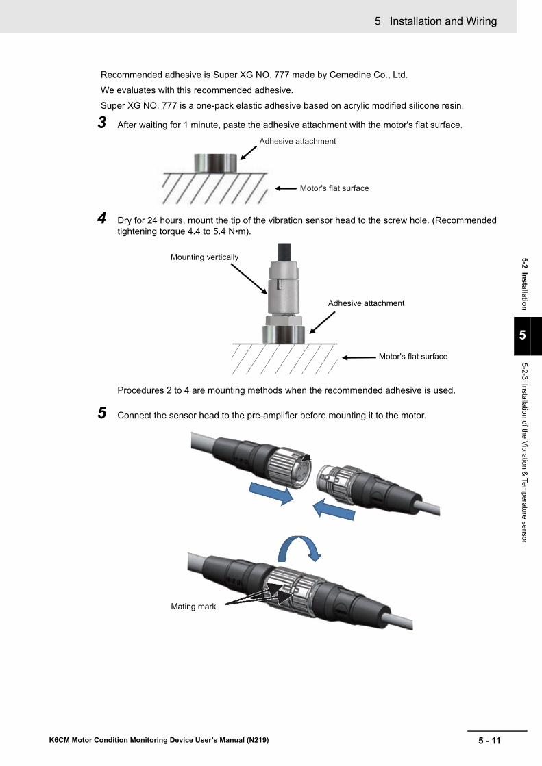
5 - 11
5 Installation and Wiring
K6CM Motor Condition Monitoring Device User’s Manual (N219)
5-2 Ins
tallation
5
5-2-3 Installation of the V
ibration & Tem
perature sensor
Recommended adhesive is Super XG NO. 777 made by Cemedine Co., Ltd.
We evaluates with this recommended adhesive.
Super XG NO. 777 is a one-pack elastic adhesive based on acrylic modified silicone resin.
3 After waiting for 1 minute, paste the adhesive attachment with the motor's flat surface.
4 Dry for 24 hours, mount the tip of the vibration sensor head to the screw hole. (Recommended tightening torque 4.4 to 5.4 N•m).
Procedures 2 to 4 are mounting methods when the recommended adhesive is used.
5 Connect the sensor head to the pre-amplifier before mounting it to the motor.
Motor's flat surface
Adhesive attachment
Mounting vertically
Adhesive attachment
Motor's flat surface
Mating mark
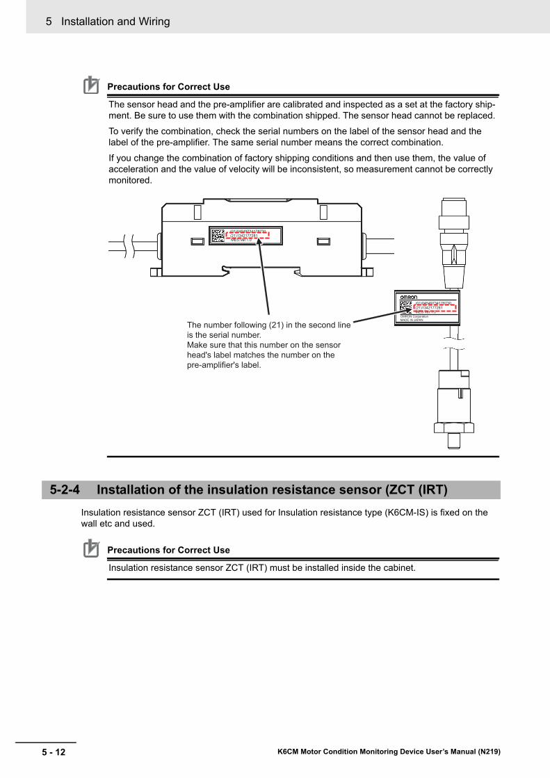
5 Installation and Wiring
5 - 12 K6CM Motor Condition Monitoring Device User’s Manual (N219)
Precautions for Correct Use
The sensor head and the pre-amplifier are calibrated and inspected as a set at the factory ship-ment. Be sure to use them with the combination shipped. The sensor head cannot be replaced.
To verify the combination, check the serial numbers on the label of the sensor head and the label of the pre-amplifier. The same serial number means the correct combination.
If you change the combination of factory shipping conditions and then use them, the value of acceleration and the value of velocity will be inconsistent, so measurement cannot be correctly monitored.
Insulation resistance sensor ZCT (IRT) used for Insulation resistance type (K6CM-IS) is fixed on the wall etc and used.
Precautions for Correct Use
Insulation resistance sensor ZCT (IRT) must be installed inside the cabinet.
5-2-4 Installation of the insulation resistance sensor (ZCT (IRT)
(01)04549734178730 (21)1342177281 MES:Ver.1.0
(21)1342177281 MES:Ver.1.0
(01)04549734178730
OMRON Corporation MADE IN JAPAN
The number following (21) in the second line is the serial number.Make sure that this number on the sensor head's label matches the number on the pre-amplifier's label.

5 - 13
5 Installation and Wiring
K6CM Motor Condition Monitoring Device User’s Manual (N219)
5-2 Installatio
n
5
5-2-4 Installation of the insulation resistance sensor (Z
CT
(IRT
)
Secure the ZCT (IRT) to the wall with screws.
Precautions for Correct Use
If it is used without fixing, the cable may become overloaded and the cable may be discon-nected.
Use ZCT (IRT) in the cabinet. (If you use it outside the panel, the error may increase due to the influence of noise.)
Since the measurement accuracy deteriorates due to the influence of the external magnetic field, install ZCT (IRT) more than 40 cm from the electric wire through which the large current flows. (It is a standard of 40 cm at 100 A, 10 cm at 40 A.)
Connect the voltage input line of ZCT (IRT) in parallel with the power line.
Precautions for Correct Use
Make sure that the wiring of the voltage input line of ZCT (IRT) is made sure that the system voltage is not energized.
Fastening of the Insulation resistance sensor (ZCT (IRT))
Connection of Voltage Input Line
Screw
170
53
4 × 6.5 dia. or4 × M6
Mounting Hole Dimensions
Power line
Voltage input line
RST
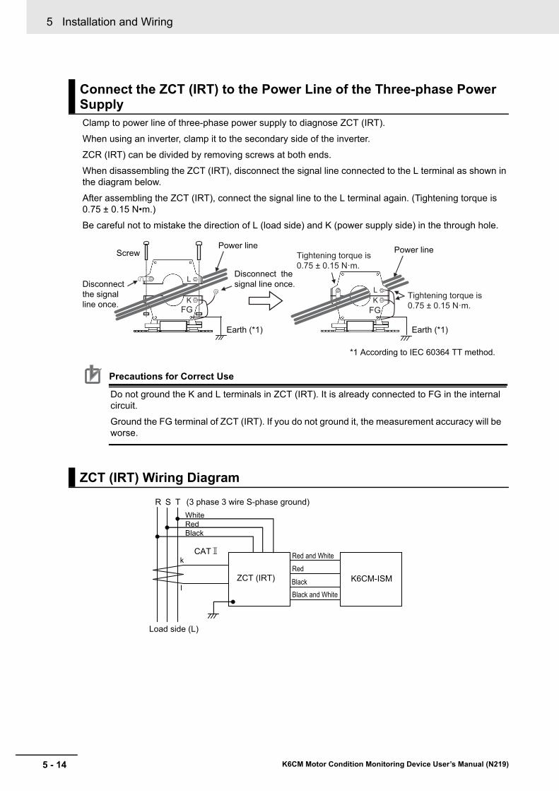
5 Installation and Wiring
5 - 14 K6CM Motor Condition Monitoring Device User’s Manual (N219)
Clamp to power line of three-phase power supply to diagnose ZCT (IRT).
When using an inverter, clamp it to the secondary side of the inverter.
ZCR (IRT) can be divided by removing screws at both ends.
When disassembling the ZCT (IRT), disconnect the signal line connected to the L terminal as shown in the diagram below.
After assembling the ZCT (IRT), connect the signal line to the L terminal again. (Tightening torque is 0.75 ± 0.15 N•m.)
Be careful not to mistake the direction of L (load side) and K (power supply side) in the through hole.
Precautions for Correct Use
Do not ground the K and L terminals in ZCT (IRT). It is already connected to FG in the internal circuit.
Ground the FG terminal of ZCT (IRT). If you do not ground it, the measurement accuracy will be worse.
Connect the ZCT (IRT) to the Power Line of the Three-phase Power Supply
ZCT (IRT) Wiring Diagram
Disconnect the signal line once.
Tightening torque is 0.75 ± 0.15 N·m.FG FG
L
KLK
ScrewPower line Power line
Disconnect the signal line once.
Earth (*1) Earth (*1)
*1 According to IEC 60364 TT method.
Tightening torque is 0.75 ± 0.15 N·m.
R S T (3 phase 3 wire S-phase ground)
Load side (L)
ZCT (IRT) K6CM-ISM
CAT
WhiteRedBlack
Red
Black
k
l
Red and White
Black and White
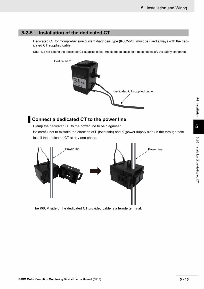
5 - 15
5 Installation and Wiring
K6CM Motor Condition Monitoring Device User’s Manual (N219)
5-2 Installatio
n
5
5-2-5 Installation of the dedicated C
T
Dedicated CT for Comprehensive current diagnosis type (K6CM-CI) must be used always with the ded-icated CT supplied cable.
Note Do not extend the dedicated CT supplied cable. An extended cable for it does not satisfy the safety standards.
Clamp the dedicated CT to the power line to be diagnosed.
Be careful not to mistake the direction of L (load side) and K (power supply side) in the through hole.
Install the dedicated CT at any one phase.
The K6CM side of the dedicated CT provided cable is a ferrule terminal.
5-2-5 Installation of the dedicated CT
Connect a dedicated CT to the power line
Dedicated CT
Dedicated CT supplied cable
Power line Power line

5 Installation and Wiring
5 - 16 K6CM Motor Condition Monitoring Device User’s Manual (N219)
5-3 How to Connect to the Push-In Plus Terminal Blocks
This section describes how to connect the K6CM devices to the Push-In Plus terminal blocks.
The following wiring terminals of the K6CM device are all push-in Plus terminals.
• Input wiring (sensor input, power supply input, external trigger input)
• Output wiring (transistor output)
Precautions for Safe Use
• To prevent wire materials from smoking or igniting, use the wiring materials given in the fol-lowing table.
• Make sure the crimp terminals for wiring are of the specified size.
• Do not insert more than one wire into each terminal insertion hole.
• Do not connect anything to terminals that are not being used.
• Do not wire anything to the release holes.
• Do not tilt or twist a flat-blade screwdriver while it is inserted into a release hole on the ter-minal block. The terminal block may be damaged.
• Insert a flat-blade screwdriver into the release holes at an angle. The terminal block may be damaged if you insert the screwdriver straight in.
• Do not allow the flat-blade screwdriver to fall out while it is inserted into a release hole.
• Keep wiring separate from high voltages and power lines that draw large currents. Do not place product wiring in parallel with or in the same path as high-voltage or high-current lines.
• Do not bend a wire past its natural bending radius or pull on it with excessive force. Doing so may cause the wire disconnection.
• When wiring the terminals, allow some leeway in the wire length.
Precautions for Correct Use
• When you are finished with wiring, make sure that no stranded wire comes loose.
• If you wire crossovers and connect terminal blocks in parallel, a large current will flow. Make sure that the current does not exceed 10 A.
• The terminal block may be damaged if the recommended tool is not used. Use the recom-mended flat-blade screwdriver to operate the release holes.
Recommended WireStripping length
(Without Ferrules)
0.25 to 1.5 mm2 (AWG24 to AWG16) 8 mm
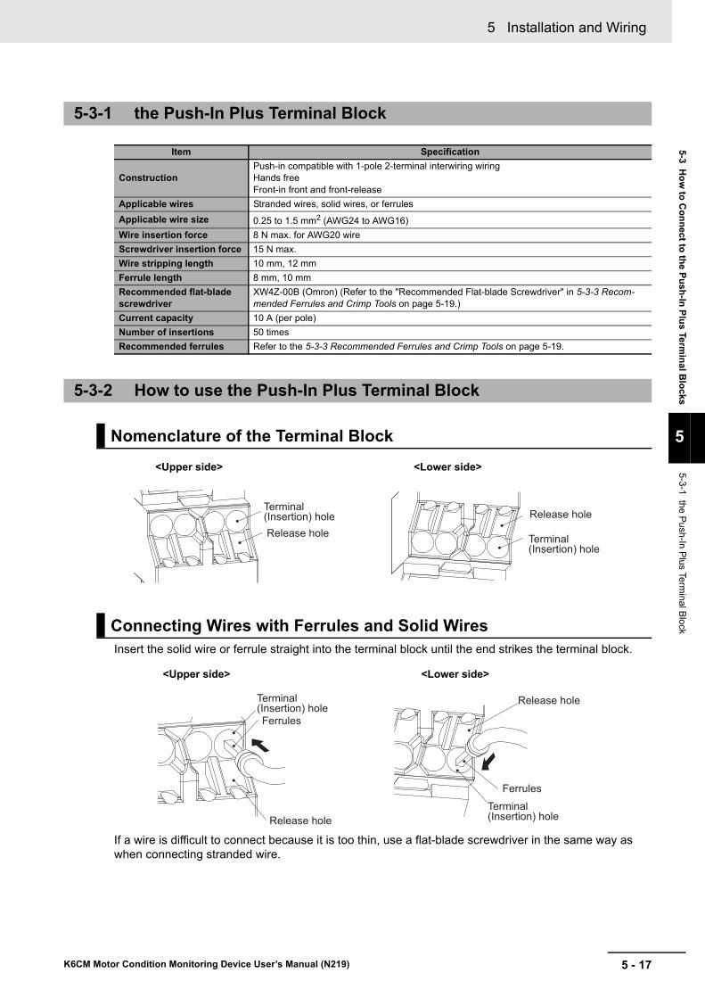
5 - 17
5 Installation and Wiring
K6CM Motor Condition Monitoring Device User’s Manual (N219)
5-3 Ho
w to
Co
nn
ect to th
e Pu
sh-In
Plu
s Term
inal B
locks
5
5-3-1 the Push-In P
lus Terminal B
lock
Insert the solid wire or ferrule straight into the terminal block until the end strikes the terminal block.
If a wire is difficult to connect because it is too thin, use a flat-blade screwdriver in the same way as when connecting stranded wire.
5-3-1 the Push-In Plus Terminal Block
Item Specification
ConstructionPush-in compatible with 1-pole 2-terminal interwiring wiringHands freeFront-in front and front-release
Applicable wires Stranded wires, solid wires, or ferrules
Applicable wire size 0.25 to 1.5 mm2 (AWG24 to AWG16)
Wire insertion force 8 N max. for AWG20 wire
Screwdriver insertion force 15 N max.
Wire stripping length 10 mm, 12 mm
Ferrule length 8 mm, 10 mm
Recommended flat-blade screwdriver
XW4Z-00B (Omron) (Refer to the "Recommended Flat-blade Screwdriver" in 5-3-3 Recom-mended Ferrules and Crimp Tools on page 5-19.)
Current capacity 10 A (per pole)
Number of insertions 50 times
Recommended ferrules Refer to the 5-3-3 Recommended Ferrules and Crimp Tools on page 5-19.
5-3-2 How to use the Push-In Plus Terminal Block
Nomenclature of the Terminal Block
Connecting Wires with Ferrules and Solid Wires
Terminal (Insertion) holeRelease hole Terminal
(Insertion) hole
Release hole
<Upper side> <Lower side>
Ferrules
Terminal (Insertion) hole
Release hole
FerrulesTerminal (Insertion) hole
Release hole
<Upper side> <Lower side>
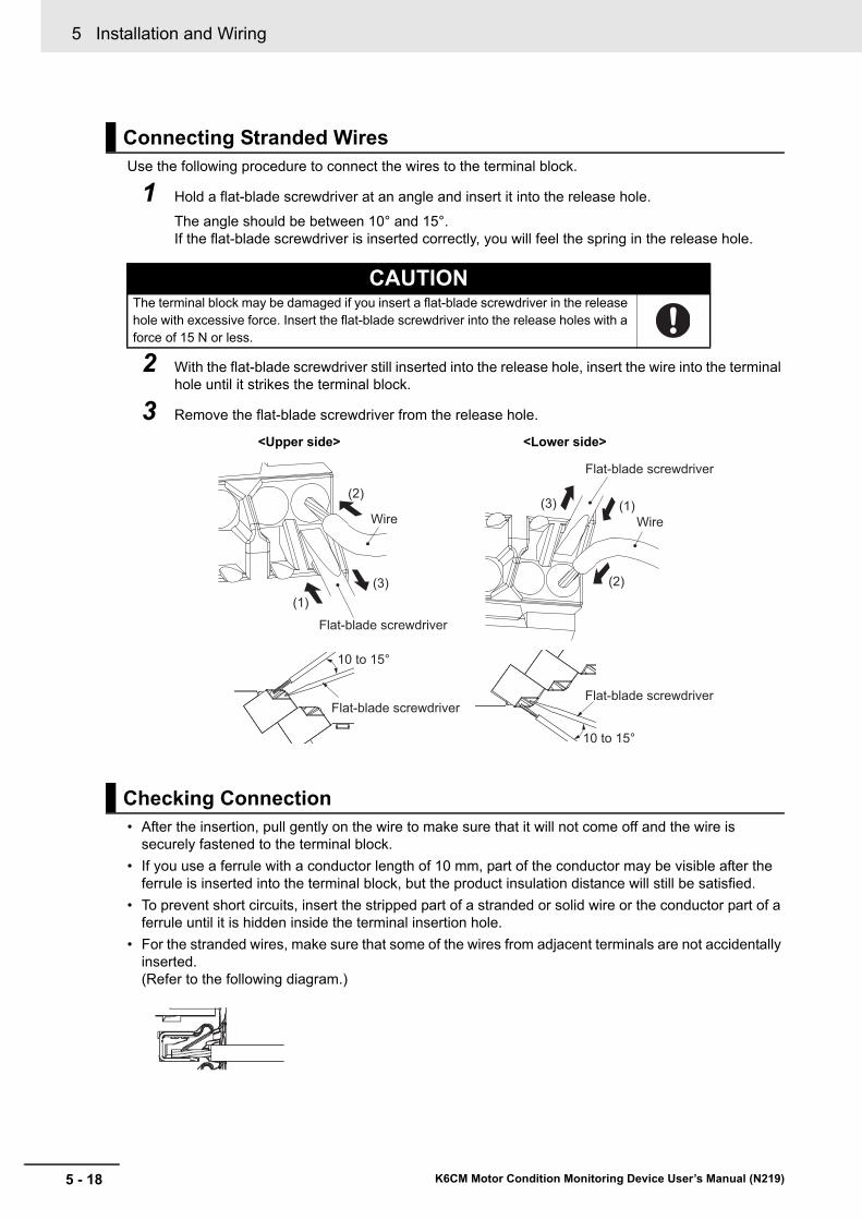
5 Installation and Wiring
5 - 18 K6CM Motor Condition Monitoring Device User’s Manual (N219)
Use the following procedure to connect the wires to the terminal block.
1 Hold a flat-blade screwdriver at an angle and insert it into the release hole.
The angle should be between 10° and 15°.If the flat-blade screwdriver is inserted correctly, you will feel the spring in the release hole.
2 With the flat-blade screwdriver still inserted into the release hole, insert the wire into the terminal hole until it strikes the terminal block.
3 Remove the flat-blade screwdriver from the release hole.
• After the insertion, pull gently on the wire to make sure that it will not come off and the wire is securely fastened to the terminal block.
• If you use a ferrule with a conductor length of 10 mm, part of the conductor may be visible after the ferrule is inserted into the terminal block, but the product insulation distance will still be satisfied.
• To prevent short circuits, insert the stripped part of a stranded or solid wire or the conductor part of a ferrule until it is hidden inside the terminal insertion hole.
• For the stranded wires, make sure that some of the wires from adjacent terminals are not accidentally inserted.(Refer to the following diagram.)
Connecting Stranded Wires
CAUTIONThe terminal block may be damaged if you insert a flat-blade screwdriver in the release hole with excessive force. Insert the flat-blade screwdriver into the release holes with a force of 15 N or less.
Checking Connection
Wire
(1)(3)
(2)
Flat-blade screwdriver
Wire(1)(3)
(2)
Flat-blade screwdriver
10 to 15°
10 to 15°
Flat-blade screwdriverFlat-blade screwdriver
<Upper side> <Lower side>

5 - 19
5 Installation and Wiring
K6CM Motor Condition Monitoring Device User’s Manual (N219)
5-3 Ho
w to
Co
nn
ect to th
e Pu
sh-In
Plu
s Term
inal B
locks
5
5-3-3 Recom
mended F
errules and Crim
p Tools
Use the following procedure to remove wires from the terminal block.
The same method is used to remove stranded wires, solid wires, and ferrules.
1 Hold a flat-blade screwdriver at an angle and insert it into the release hole.
2 With the flat-blade screwdriver still inserted into the release hole, remove the wire from the ter-minal insertion hole.
3 Remove the flat-blade screwdriver from the release hole.
Removing Wires from the Push-In Plus Terminal Block
5-3-3 Recommended Ferrules and Crimp Tools
Recommended ferrules
Applicable wireFerrule Conduc-tor length (mm)
Stripping length (mm)
(Ferrules used)
Recommended ferrules
(mm2) AWGManufactured
by Phoenix ContactManufacturedby Weidmuller
Manufacturedby Wago
0.25 24 8 10 AI 0,25-8 H0.25/12 FE-0.25-8N-YE
10 12 AI 0,25-10 ---- ----
0.34 22 8 10 AI 0,34-8 H0.34/12 FE-0.34-8N-TQ
10 12 AI 0,34-10 ---- ----
0.5 20 8 10 AI 0,5-8 H0.5/14 FE-0.5-8N-WH
10 12 AI 0,5-10 H0.5/16 FE-0.5-10N-WH
0.75 18 8 10 AI 0,75-8 H0.75/14 FE-0.75-8N-GY
10 12 AI 0,75-10 H0.75/16 FE-0.75-10N-GY
1/1.25 18/17 8 10 AI 1-8 H1.0/14 FE-1.0-8N-RD
10 12 AI 1-10 H1.0/16 FE-1.0-10N-RD
1.25/1.5 17/16 8 10 AI 1,5-8 H1.5/14 FE-1.5-8N-BK
10 12 AI 1,5-10 H1.5/16 FE-1.5-10N-BK
Recommended crimp tool CRIMPFOX6CRIMPFOX6T-FCRIMPFOX10S
PZ6 roto Variocrimp4
Wire
(1)(3)
(2)
Flat-blade screwdriver
(1)
(2)
(3)Wire
Flat-blade screwdriver
10 to 15°
10 to 15°
Flat-blade screwdriverFlat-blade
screwdriver
<Upper side> <Lower side>
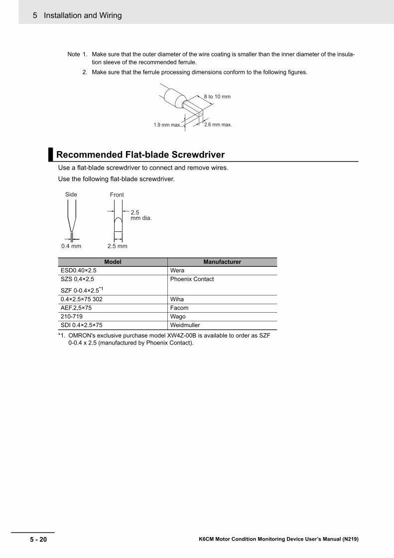
5 Installation and Wiring
5 - 20 K6CM Motor Condition Monitoring Device User’s Manual (N219)
Note 1. Make sure that the outer diameter of the wire coating is smaller than the inner diameter of the insula-tion sleeve of the recommended ferrule.
2. Make sure that the ferrule processing dimensions conform to the following figures.
Use a flat-blade screwdriver to connect and remove wires.
Use the following flat-blade screwdriver.
Recommended Flat-blade Screwdriver
Model Manufacturer
ESD0.40×2.5 Wera
SZS 0,4×2,5
SZF 0-0.4×2.5*1
*1. OMRON's exclusive purchase model XW4Z-00B is available to order as SZF 0-0.4 x 2.5 (manufactured by Phoenix Contact).
Phoenix Contact
0.4×2.5×75 302 Wiha
AEF.2,5×75 Facom
210-719 Wago
SDI 0.4×2.5×75 Weidmuller
8 to 10 mm
1.9 mm max. 2.6 mm max.
Side
0.4 mm
mm dia.
2.5 mm
Front
2.5

5 - 21
5 Installation and Wiring
K6CM Motor Condition Monitoring Device User’s Manual (N219)
5-4 Diag
ram o
f Termin
al Des
criptio
n
5
5-4 Diagram of Terminal Description
This section describes the wiring of the K6CM devices. Connect to the push-in Plus terminal blocks as follows.
Each transistor output terminal has the following functions.
Terminal number
Transistor output Function
13,14 1 Warning output of comprehensive alarm
15,16 2 Critical output of comprehensive alarm
17,18 3 Self-diagnosis error output
1 2 73 4 9
810
13 1415 1617 18
(2) Power voltage
A: 100 to 240 V AC D: 24 V AC/DC
1 2 1 2(No polarity)
External trigger input
Do not use
7 89 10
(1) Sensor input
VB: Vibration and temperature sensor input
IS: ZCT (IRT) input
K6CM-VBS (pre-amplifier)
7 89 10
K6CM-ISZ(ZCT(IRT))
7 8
CI: CT input
K6CM-CIC(CT)
Output function
Transistor output
13 14
Interior
15 16
Interior
17 18
Interior
White
Red/white
Black/white
Black
Red Red/white
Black/white
Black
Red
3 4
0 V5 V 680 Ω
Comparator+−
Black
K6CM- VB M A -EIP(1) (2)

5 Installation and Wiring
5 - 22 K6CM Motor Condition Monitoring Device User’s Manual (N219)
5-5 I/O wiring
This section describes input/output wiring, power supply wiring, external trigger input wiring and transis-tor output wiring of the K6CM devices.
Note When you use an inverter to drive the motor, you may not be able to check the degradation tendency of the motor. However, under the following conditions, it is comparatively easier to check changes in acceleration.• The inverter driving frequency is 50 Hz or more and the frequency is stable.• The carrier frequency of the inverter is 12.5 kHz or more and the frequency is stable.Use the device after testing in a similar environment as the installation environment during use.
Wiring Diagram of the Vibration & Temperature Type (K6CM-VB)
Monitor target (motor etc.)
K6CM-VBS(Pre-amplifier)
VBS0
VBS1VBS2VBS3
PLC etc.
PLC etc.
PLC etc.
Single phase power supply
Measurement trigger signal.
K6CM-VBM
789
10
131415161718
1234
LANEtherNet/IPComputer,
PLC etc. LAN
DO NOT USEDO NOT USE
fuse
PLC etc.
Connector
Transistor Output 1
Transistor Output 2
Transistor Output 3
Red and White
Black and White
RedBlack
K6CM-VBS
(Sensor h
ead)

5 - 23
5 Installation and Wiring
K6CM Motor Condition Monitoring Device User’s Manual (N219)
5-5 I/O w
iring
5
Three-phase Three Wire S-phase Grounded Delta Connection (With Inverter)
With the above wiring, set 0 for the Applicable circuit and 1 for the Using inverter of the K6CM-ISM *1.
Inverter special measurement setting changes according to inverter frequency (finv).
Example) When the commercial frequency f = 50 H
Method (1) (finv ≤ f - 4 Hz, f + 4 Hz ≤ finv)
• Inverter special measurement: Set to 0 (OFF) and start measurement.
Method (2) (f - 0.2 Hz ≤ finv ≤ f + 0.2 Hz)
• Inverter special measurement: Set to 0 (OFF) and start measurement.
• Switch the Inverter special measurement to 1 (ON) when the measured value falls below 0.5 MΩ. Measurement with higher accuracy will become possible.
Note In the case of f - 4 Hz < finv < f - 0.2 Hz, f + 0.2 Hz < finv <f + 4 HzIt can not be measured correctly. Do not use the K6CM device.
*1. For details on how to change the setting, refer to 6-2-1 Settings for Each Monitor Type of K6CM devices on page 6-23 and 6-2-2 Setting Parameters on page 6-26.
Wiring Diagram of the Insulation Resistance Type (K6CM-IS)
Single phase power supply
Measurement trigger signal
Monitor target (motor etc.)
K6CM-ISM
78910
131415161718
1234
LANEtherNet/IPComputer,
PLC etc. LAN
DO NOT USEDO NOT USE
K6CM-ISZ(ZCT(IRT))
fuse
IRT0IRT1IRT2IRT3
3 phase voltage
RST
Inverter
Zero phase current transformer(Part of K6CM-ISZ)
PLC etc.
PLC etc.
PLC etc.
Transistor Output 1
Transistor Output 2
Transistor Output 3
L1 L2 L3
*1
FG
EarthRed and White
Black and White
RedBlack
*1: According to IEC 60364 TT method
PLC etc.
50.2 Hz49.8 Hz46 Hz 54 Hz finv [Hz]
Method (1)Can not be measured. Method (2)
Can not be measured. Method (1)

5 Installation and Wiring
5 - 24 K6CM Motor Condition Monitoring Device User’s Manual (N219)
Three-phase Three Wire S-phase Grounded Delta Connection (Without Inverter)
*1. With the above wiring, set 0 for the Applicable circuit and 1 for the Using inverter of the K6CM-ISM, and start measurement.For details on how to change the setting, refer to 6-2-1 Settings for Each Monitor Type of K6CM devices on page 6-23 and 6-2-2 Setting Parameters on page 6-26.
Three-phase Four-wire N-phase Grounded Y-connection Load Side Delta Connection (Without Inverter)
*1. With the above wiring, set 0 for the Applicable circuit and 1 for the Using inverter of the K6CM-ISM, and start measurement.For details on how to change the setting, refer to 6-2-1 Settings for Each Monitor Type of K6CM devices on page 6-23 and 6-2-2 Setting Parameters on page 6-26.
Single phase power supply
Monitor target (motor etc.)
K6CM-ISM
789
10
131415161718
12
LANEtherNet/IPComputer,
PLC etc. LAN
DO NOT USEDO NOT USE
K6CM-ISZ(ZCT(IRT))
fuse
IRT0
IRT1IRT2IRT3
3 phase voltage
RST
Zero phase current transformer(Part of K6CM-ISZ)
PLC etc.
PLC etc.
PLC etc.
Transistor Output 1
Transistor Output 2
Transistor Output 3
L1 L2 L3
FG
EarthRed and White
Black and White
RedBlack
*1
Measurement trigger signal 34PLC etc.
*1: According to IEC 60364 TT method
Single phase power supply
Monitor target (motor etc.)
K6CM-ISM
78910
131415161718
12
LANEtherNet/IPComputer,
PLC etc. LAN
DO NOT USEDO NOT USE
K6CM-ISZ(ZCT(IRT))
fuse
IRT0
IRT1IRT2IRT3
3 phase voltage
RST
Zero phase current transformer(Part of K6CM-ISZ)
PLC etc.
PLC etc.
PLC etc.
Transistor Output 1
Transistor Output 2
Transistor Output 3
L1 L2 L3
FG
Red and White
Black and White
RedBlack
Earth
Measurement trigger signal 34PLC etc.
*1: According to IEC 60364 TT method
*1

5 - 25
5 Installation and Wiring
K6CM Motor Condition Monitoring Device User’s Manual (N219)
5-5 I/O w
iring
5Note The level of degradation may vary when the motor is driven by the inverter. In that case, slightly shift the
inverter drive frequency.Also always measure and monitor the level of degradation at the same inverter drive frequency. Mount a dedicated CT between the motor and the inverter.
Wiring Diagram of the Comprehensive Current Diagnosis Type (K6CM-CI)
Single phase power supply
Measurement trigger signal.
Monitor target (motor etc.)
K6CM-CIM
78
131415161718
1234
LANEtherNet/IPComputer,
PLC etc. LAN
DO NOT USEDO NOT USE
fuse
CTKCTL
3 phase voltage
Dedicated CT(K6CM-CIC)
PLC etc.
PLC etc.
PLC etc.
Transistor Output 1
Transistor Output 2
Transistor Output 3
PLC etc.
L(Black)K(White)
*1 Install the dedicated CT at any one phase.

5 Installation and Wiring
5 - 26 K6CM Motor Condition Monitoring Device User’s Manual (N219)
5-6 EtherNet/IP Wiring
This section describes the EtherNet/IP wiring of the K6CM devices.
Connect the K6CM devices with the software tool, PLC, or PC via the industrial switching hub with the Ethernet cables.
Use an STP (shielded twisted-pair) cable of Ethernet category 5 or higher. Either cross cables or straight cables can be used, as the K6CM device has the Auto-MDI/MDIX function.
Recommended Ethernet switches
Ethernet switches are recommended for use in environments that can be used in FA environments and devices that can use QoS (Packet Priority Control) dedicated to EtherNet/IP.
The following are recommended items.
Manufacturer Model Description
OMRON W4S1-03B Packet priority control (QoS): EtherNet/IP control data priority
Failure detection: Broadcast storm, LSI error detection, 100Base-TX, Auto negotiation
Number of ports: three for the W4S1-03B, or five each for the W4S1-05B and W4S1-05C
Failure detection output (W4S1-05C only)
W4S1-05B
W4S1-05C
Cisco Systems, Inc Consult the manufacturer.
http://www.cisco.com/web/JP/index.html
Contec USA, Inc. Consult the manufacturer.
http://www.contec.co.jp/
Phoenix Contact USA Consult the manufacturer.
https://www.phoenixcontact.com/online/portal/jp
Industrial switching hub (e.g., W4S1) *1
• Monitoring• Required settings
*1. When making initial settings, connect this tool to each motor condition monitoring device one to one using an Ethernet cable without a switching hub.
Comprehensive current diagnosis type
Insulation resistance type
Vibration & temperature type
K6CMMotor Condition Monitoring Device
• Monitoring• Initial setting *1
Software tool
EtherNet/IP EtherNet/IP
PLCPC

5 - 27
5 Installation and Wiring
K6CM Motor Condition Monitoring Device User’s Manual (N219)
5-6 Eth
erNet/IP
Wirin
g
5
Precautions for Correct Use
• Always use an Ethernet switch for tag data links in the network.If EtherNet/IP tag data links (cyclic communications) are used with a repeating hub, the com-munications load on the network will increase. This will increase collisions and may prevent stable communications.
• Do not bend the communications cables past its natural bending radius or pull on it with excessive force.
• Do not place heavy objects on top of the communications cables or other wiring lines.
• Do not exceed the communications distance that is given in the specifications and use the specified communications cable.
• Set the switching hub connected to the K6CM devices as follows.
(Best = Recommended; OK = Allowed; --- = Not allowed)
• A tag data link timeout may occur over a network system including nodes set for multicast communications. Use a switching hub with multicast blocking function to block multicast packets so that they do not reach the K6CM.The OMRON W4S1 series does not provide the multicast block function.
K6CMSwitching hub
AUTO-Nego
AUTO-Nego Best
100 Mbps fixed
FULL ---
HALF OK

5 Installation and Wiring
5 - 28 K6CM Motor Condition Monitoring Device User’s Manual (N219)

6 - 1
6
K6CM Motor Condition Monitoring Device User’s Manual (N219)
This section describes how to operate the software tool.
6-1 Screens . . . . . . . . . . . . . . . . . . . . . . . . . . . . . . . . . . . . . . . . . . . . . . . . . . . . . . 6-26-1-1 Start Screen . . . . . . . . . . . . . . . . . . . . . . . . . . . . . . . . . . . . . . . . . . . . . . . . . . . 6-2
6-1-2 Monitoring Screen and Setting Screen . . . . . . . . . . . . . . . . . . . . . . . . . . . . . . . 6-5
6-1-3 Common Menu and Toolbar List . . . . . . . . . . . . . . . . . . . . . . . . . . . . . . . . . . . 6-16
6-1-4 Buttons on Device Setting . . . . . . . . . . . . . . . . . . . . . . . . . . . . . . . . . . . . . . . 6-18
6-1-5 Software Tool Version Display Screen . . . . . . . . . . . . . . . . . . . . . . . . . . . . . . 6-22
6-2 Setting of K6CM Devices . . . . . . . . . . . . . . . . . . . . . . . . . . . . . . . . . . . . . . . 6-236-2-1 Settings for Each Monitor Type of K6CM devices . . . . . . . . . . . . . . . . . . . . . . 6-23
6-2-2 Setting Parameters . . . . . . . . . . . . . . . . . . . . . . . . . . . . . . . . . . . . . . . . . . . . . 6-26
6-2-3 Add a Device to an Existing Project . . . . . . . . . . . . . . . . . . . . . . . . . . . . . . . . 6-27
6-2-4 Motor (Device Group) Rename . . . . . . . . . . . . . . . . . . . . . . . . . . . . . . . . . . . . 6-28
6-2-5 Save Overwriting Project . . . . . . . . . . . . . . . . . . . . . . . . . . . . . . . . . . . . . . . . 6-29
6-2-6 Exit Project . . . . . . . . . . . . . . . . . . . . . . . . . . . . . . . . . . . . . . . . . . . . . . . . . . . 6-29
How to Use the Software Tool
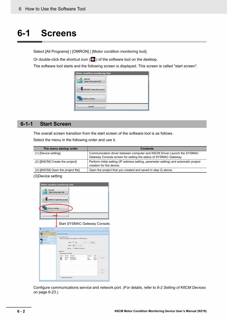
6 How to Use the Software Tool
6 - 2 K6CM Motor Condition Monitoring Device User’s Manual (N219)
6-1 Screens
Select [All Programs] | [OMRON] | [Motor condition monitoring tool].
Or double-click the shortcut icon ( ) of the software tool on the desktop.
The software tool starts and the following screen is displayed. This screen is called "start screen".
The overall screen transition from the start screen of the software tool is as follows.
Select the menu in the following order and use it.
(3)Device setting
Configure communications service and network port. (For details, refer to 6-2 Setting of K6CM Devices on page 6-23.)
6-1-1 Start Screen
The menu startup order Contents
(1) [Device setting] Communication driver between computer and K6CM Driver Launch the SYSMAC Gateway Console screen for setting the status of SYSMAC Gateway.
(2) [[K6CM] Create the project] Perform initial setting (IP address setting, parameter setting) and automatic project creation for the device.
(3) [[K6CM] Open the project file] Open the project that you created and saved in step 2) above.
Start SYSMAC Gateway Console.
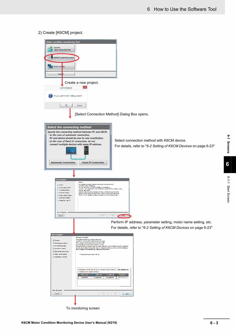
6 - 3
6 How to Use the Software Tool
K6CM Motor Condition Monitoring Device User’s Manual (N219)
6-1 S
creen
s
6
6-1-1 Start S
creen
2) Create [K6CM] project.
Create a new project.
[Select Connection Method] Dialog Box opens.
To monitoring screen
Select connection method with K6CM device.
For details, refer to "6-2 Setting of K6CM Devices on page 6-23"
Perform IP address, parameter setting, motor name setting, etc.
For details, refer to "6-2 Setting of K6CM Devices on page 6-23"

6 How to Use the Software Tool
6 - 4 K6CM Motor Condition Monitoring Device User’s Manual (N219)
3) Open the [K6CM] project file
The project consists of the following.
• Project file: This file defines the connection configuration of the K6CM.
• Setting file: This is a file for backing up and saving device setting values.
• Log file: The log of the monitoring result is saved.
Precautions for Correct Use
Be sure to select [Device setting] before selecting [[K6CM] Create the project].
If you select [[K6CM] Create the project] before selecting [Device setting], click the [Cancel] Button and close the screen. Click the [Cancel] Button and do not save the project, please exit. Then start the software tool again.
Open existing project file.
Select the project file and click [Open].
Monitoring screen with project saved starts.

6 - 5
6 How to Use the Software Tool
K6CM Motor Condition Monitoring Device User’s Manual (N219)
6-1 S
creen
s
6
6-1-2 Monitoring S
creen and Setting S
creen
The following screen types are supported.
Parameters displayed on the monitoring screen are as follows. Each parameter can be read with the software tool, it can also be read using the CIP message communications or the tag data link except for some parameters.
6-1-2 Monitoring Screen and Setting Screen
Screen type
Top level of screen Medium level of screen Lower level of screen
Monitoring screen
Monitor screen by motor
→←
Detailed status screen by motor
→←
Detailed status screen by device
↓↑Monitoring by monitoring cate-gory screen
→←
Bar display screen by moni-toring category
→←
Graph display screen by monitor-ing category
↓↑
Device setting screen
Vibration & temperature Type (K6CM-VBM)
Data type Data name Description
Reading method (Yes: supported, No: supported)
K6CM device
Motor con-dition
monitor-ing Tool
CIP mes-sage com-municatio
ns
Tag data link
Measure-ment Value
Acceleration (Present, Min., Max.)
0.00 to 9.99 G (K6CM display)Yes Yes Yes Yes
Velocity (Present, Min., Max.)
0.00 to 45.00 mm/s (K6CM display)Yes Yes Yes Yes
Motor temperature (Present, Min., Max.)
0 to 80°C (32 to 176°F) (K6CM display)Yes Yes Yes Yes
Temperature Gap (Dif-ference from the room temperature of Motor temperature) (Present, Min., Max.)
0 to 80°C (32 to 176°F) (K6CM display)
Yes Yes Yes Yes
Acceleration status Bit00: Present value unmeasured state
Bit01: Present value input error
Bit04: Maximum value unmeasured state
Bit05: Maximum value input error
Bit08: Minimum value unmeasured state
Bit09: Minimum value input error
Bit12: Individual alarm threshold setting (Warning)
Bit13: Individual alarm threshold setting (Critical)
No Yes Yes Yes
Velocity status No Yes Yes Yes
Motor temperature status
No Yes Yes Yes
Temperature Gap sta-tus
No Yes Yes Yes
Alarm Results
Comprehensive alarm (Warning)
In K6CM, there is no "Critical" in the measurement value, and even one of them has "Warning".
Transistor output, alarm bar (yellow) is reflected
Yes (Alarm bar, and transistor output)
No Yes (K6CM status or Measure-ment sta-
tus)
Yes (K6CM status or Measure-ment sta-
tus)
Comprehensive alarm (Critical)
Within K6CM, there is "Critical" even if at least one measured value.
Transistor output, reflected on alarm bar (red)
Yes (Alarm bar, and transistor output)
No Yes (K6CM status or Measure-ment sta-
tus)
Yes (K6CM status or Measure-ment sta-
tus)
Acceleration, High alarm (Critical and Warning)
ON, OFFNo Yes Yes Yes

6 How to Use the Software Tool
6 - 6 K6CM Motor Condition Monitoring Device User’s Manual (N219)
Alarm Results
Velocity, High alarm (Critical and Warning)
ON, OFFNo Yes Yes Yes
Motor temperature, High alarm (Critical and Warning)
ON, OFFNo Yes Yes Yes
Temperature Gap, High alarm (Critical and Warning)
ON, OFFNo Yes Yes Yes
Others
Measurement CPU version
Measurement part versionNo Yes Yes Yes
Main CPU version Main part version No Yes Yes Yes
EIP CPU version EtherNet/IP version No Yes Yes Yes
K6CM status
During measuring and monitoring, tran-sistor output 1, 2, 3 state, external trigger input state, etc.
It consists of the following contents.
No Yes Yes Yes
Monitoring condition
The state measured and monitored by K6CM. "MON" on the LCD display lights up.
In the case of an internal trigger or an exter-nal trigger, it is measured and monitored by a trigger. In case of no trigger, it is always mea-sured and monitored with power ON.
Note : There are no states that are measuring and not monitoring.
1: Measuring and monitoring
0: Measuring and monitoring stopped
Yes ("MON")
Yes Yes (part of K6CM sta-
tus)
Yes (part of K6CM sta-
tus)
Running Time status
Turns ON when running time reaches 100%. Accumulates the product of operation time and internal temperature, and detects abnor-mality when design life reaches.
1: Reached (running time reaches 100%)
0: Not reached (running time has not reached 100%)
Yes (according to "AGE"
indication)
Yes Yes (part of K6CM sta-
tus)
Yes (part of K6CM sta-
tus)
Trigger input (excluding K6CM-ISM)
State of external trigger input
1: ON
0: OFF
No Yes Yes (part of K6CM sta-
tus)
Yes (part of K6CM sta-
tus)
TR 1 (transistor 1 output state)
State of transistor 1 of K6CM
1: ON
0: OFF
No Yes Yes (part of K6CM sta-
tus)
Yes (part of K6CM sta-
tus)
TR 2 (transistor 2 output state)
State of transistor 2 of K6CM
1: ON
0: OFF
No Yes Yes (part of K6CM sta-
tus)
Yes (part of K6CM sta-
tus)
TR 3 (transistor 3 output state)
State of transistor 3 of K6CM
1: ON
0: OFF
No Yes Yes (part of K6CM sta-
tus)
Yes (part of K6CM sta-
tus)
Running Time
Coefficient indicating lifetime of the K6CM device based on the product of operation time and internal temperature.
It increases from 0% in 10% increments.
0000 to 0064 hex (0 to 100)
No Yes Yes Yes
Number of triggers
Total number of integration times of external trigger or internal trigger. Make +1 every 100 iterations.
0 to 65535
No Yes Yes Yes
Data type Data name Description
Reading method (Yes: supported, No: supported)
K6CM device
Motor con-dition
monitor-ing Tool
CIP mes-sage com-municatio
ns
Tag data link
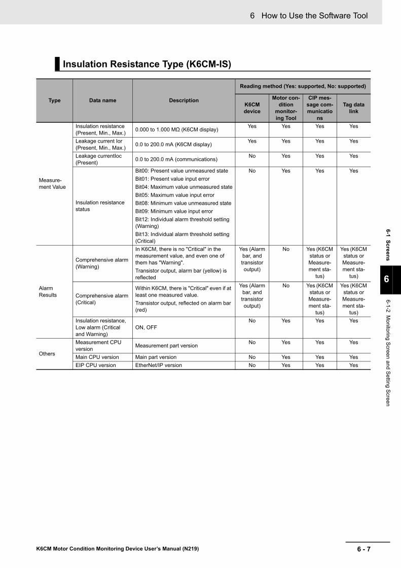
6 - 7
6 How to Use the Software Tool
K6CM Motor Condition Monitoring Device User’s Manual (N219)
6-1 S
creen
s
6
6-1-2 Monitoring S
creen and Setting S
creen
Insulation Resistance Type (K6CM-IS)
Type Data name Description
Reading method (Yes: supported, No: supported)
K6CM device
Motor con-dition
monitor-ing Tool
CIP mes-sage com-municatio
ns
Tag data link
Measure-ment Value
Insulation resistance (Present, Min., Max.)
0.000 to 1.000 MΩ (K6CM display)Yes Yes Yes Yes
Leakage current Ior (Present, Min., Max.)
0.0 to 200.0 mA (K6CM display)Yes Yes Yes Yes
Leakage currentIoc (Present)
0.0 to 200.0 mA (communications)No Yes Yes Yes
Insulation resistance status
Bit00: Present value unmeasured state
Bit01: Present value input error
Bit04: Maximum value unmeasured state
Bit05: Maximum value input error
Bit08: Minimum value unmeasured state
Bit09: Minimum value input error
Bit12: Individual alarm threshold setting (Warning)
Bit13: Individual alarm threshold setting (Critical)
No Yes Yes Yes
Alarm Results
Comprehensive alarm (Warning)
In K6CM, there is no "Critical" in the measurement value, and even one of them has "Warning".
Transistor output, alarm bar (yellow) is reflected
Yes (Alarm bar, and transistor output)
No Yes (K6CM status or Measure-ment sta-
tus)
Yes (K6CM status or Measure-ment sta-
tus)
Comprehensive alarm (Critical)
Within K6CM, there is "Critical" even if at least one measured value.
Transistor output, reflected on alarm bar (red)
Yes (Alarm bar, and transistor output)
No Yes (K6CM status or Measure-ment sta-
tus)
Yes (K6CM status or Measure-ment sta-
tus)
Insulation resistance, Low alarm (Critical and Warning)
ON, OFFNo Yes Yes Yes
Others
Measurement CPU version
Measurement part versionNo Yes Yes Yes
Main CPU version Main part version No Yes Yes Yes
EIP CPU version EtherNet/IP version No Yes Yes Yes

6 How to Use the Software Tool
6 - 8 K6CM Motor Condition Monitoring Device User’s Manual (N219)
Others
K6CM status
During measuring and monitoring, tran-sistor output 1, 2, 3 state, external trigger input state, etc.
It consists of the following contents.
No Yes Yes Yes
Monitoring condition
The state measured and monitored by K6CM. "MON" on the LCD display lights up.
In the case of an internal trigger or an external trigger, it is measured and moni-tored by a trigger. In case of no trigger, it is always measured and monitored with power ON.
Note : There are no states that are measuring and not monitoring.
1: Measuring and monitoring
0: Measuring and monitoring stopped
Yes ("MON")
Yes Yes (part of K6CM sta-
tus)
Yes (part of K6CM sta-
tus)
Running Time status
Turns ON when running time reaches 100%. Accumulates the product of oper-ation time and internal temperature, and detects abnormality when design life reaches.
1: Reached (running time reaches 100%)
0: Not reached (running time has not reached 100%)
Yes (according to "AGE"
indication)
Yes Yes (part of K6CM sta-
tus)
Yes (part of K6CM sta-
tus)
Trigger input (excluding K6CM-ISM)
State of external trigger input
1: ON
0: OFF
No Yes Yes (part of K6CM sta-
tus)
Yes (part of K6CM sta-
tus)
TR 1 (transistor 1 output state)
State of transistor 1 of K6CM
1: ON
0: OFF
No Yes Yes (part of K6CM sta-
tus)
Yes (part of K6CM sta-
tus)
TR 2 (transistor 2 output state)
State of transistor 2 of K6CM
1: ON
0: OFF
No Yes Yes (part of K6CM sta-
tus)
Yes (part of K6CM sta-
tus)
TR 3 (transistor 3 output state)
State of transistor 3 of K6CM
1: ON
0: OFF
No Yes Yes (part of K6CM sta-
tus)
Yes (part of K6CM sta-
tus)
Running Time
Coefficient indicating lifetime of the K6CM device based on the product of operation time and internal temperature.
It increases from 0% in 10% increments.
0000 to 0064 hex (0 to 100)
No Yes Yes Yes
Number of triggers
Total number of integration times of external trigger or internal trigger. Make +1 every 100 iterations.
0 to 65535
No Yes Yes Yes
Type Data name Description
Reading method (Yes: supported, No: supported)
K6CM device
Motor con-dition
monitor-ing Tool
CIP mes-sage com-municatio
ns
Tag data link

6 - 9
6 How to Use the Software Tool
K6CM Motor Condition Monitoring Device User’s Manual (N219)
6-1 S
creen
s
6
6-1-2 Monitoring S
creen and Setting S
creen
Comprehensive Current Diagnosis Type (K6CM-CIM)
Type Data name Description
Reading method (Yes: supported, No: supported)
K6CM device
Motor con-dition
monitor-ing Tool
CIP mes-sage com-municatio
ns
Tag data link
Measure-ment Value
Degradation level (Present, Min., Max.)
Degradation level of motor calculated by measuring current including harmonic components. Indicator of general current diagnosis.
0 to 999 (K6CM display)
Yes Yes Yes Yes
Current (Present, Min., Max.)
Current range = 0: 0.00 to 5.00 A
Current range = 1: 0.0 to 25.0 A
Current range = 2: 0.0 to 100.0 A
Current range = 3: 0.0 to 200.0 A
Current range = 4: 0.0 to 400.0 A
Current range = 5: 0.0 to 600.0 A
Yes Yes Yes Yes
Degradation level sta-tus
Bit00: Present value unmeasured state
Bit01: Present value input error
Bit04: Maximum value unmeasured state
Bit05: Maximum value input error
Bit08: Minimum value unmeasured state
Bit09: Minimum value input error
Bit12: Individual alarm threshold setting (Warning)
Bit13: Individual alarm threshold setting (Critical)
No Yes Yes Yes
Current status
No Yes Yes Yes
Alarm Results
Comprehensive alarm (Warning)
In K6CM, there is no "Critical" in the measurement value, and even one of them has "Warning".
Transistor output, alarm bar (yellow) is reflected
Yes (Alarm bar, and transistor output)
No Yes (K6CM status or Measure-ment sta-
tus)
Yes (K6CM status or Measure-ment sta-
tus)
Comprehensive alarm (Critical)
Within K6CM, there is "Critical" even if at least one measured value.
Transistor output, reflected on alarm bar (red)
Yes (Alarm bar, and transistor output)
No Yes (K6CM status or Measure-ment sta-
tus)
Yes (K6CM status or Measure-ment sta-
tus)
Degradation level, Low alarm (Critical and Warning)
ON, OFFON, OFF No Yes Yes
Current, High alarm (Critical and Warning)
ON, OFFON, OFF No Yes Yes
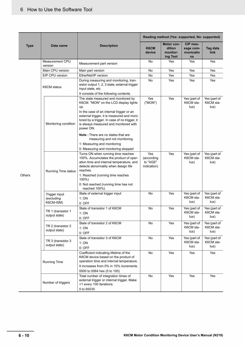
6 How to Use the Software Tool
6 - 10 K6CM Motor Condition Monitoring Device User’s Manual (N219)
Others
Measurement CPU version
Measurement part versionNo Yes Yes Yes
Main CPU version Main part version No Yes Yes Yes
EIP CPU version EtherNet/IP version No Yes Yes Yes
K6CM status
During measuring and monitoring, tran-sistor output 1, 2, 3 state, external trigger input state, etc.
It consists of the following contents.
No Yes Yes Yes
Monitoring condition
The state measured and monitored by K6CM. "MON" on the LCD display lights up.
In the case of an internal trigger or an external trigger, it is measured and moni-tored by a trigger. In case of no trigger, it is always measured and monitored with power ON.
Note : There are no states that are measuring and not monitoring.
1: Measuring and monitoring
0: Measuring and monitoring stopped
Yes ("MON")
Yes Yes (part of K6CM sta-
tus)
Yes (part of K6CM sta-
tus)
Running Time status
Turns ON when running time reaches 100%. Accumulates the product of oper-ation time and internal temperature, and detects abnormality when design life reaches.
1: Reached (running time reaches 100%)
0: Not reached (running time has not reached 100%)
Yes (according to "AGE"
indication)
Yes Yes (part of K6CM sta-
tus)
Yes (part of K6CM sta-
tus)
Trigger input (excluding K6CM-ISM)
State of external trigger input
1: ON
0: OFF
No Yes Yes (part of K6CM sta-
tus)
Yes (part of K6CM sta-
tus)
TR 1 (transistor 1 output state)
State of transistor 1 of K6CM
1: ON
0: OFF
No Yes Yes (part of K6CM sta-
tus)
Yes (part of K6CM sta-
tus)
TR 2 (transistor 2 output state)
State of transistor 2 of K6CM
1: ON
0: OFF
No Yes Yes (part of K6CM sta-
tus)
Yes (part of K6CM sta-
tus)
TR 3 (transistor 3 output state)
State of transistor 3 of K6CM
1: ON
0: OFF
No Yes Yes (part of K6CM sta-
tus)
Yes (part of K6CM sta-
tus)
Running Time
Coefficient indicating lifetime of the K6CM device based on the product of operation time and internal temperature.
It increases from 0% in 10% increments.
0000 to 0064 hex (0 to 100)
No Yes Yes Yes
Number of triggers
Total number of integration times of external trigger or internal trigger. Make +1 every 100 iterations.
0 to 65535
No Yes Yes Yes
Type Data name Description
Reading method (Yes: supported, No: supported)
K6CM device
Motor con-dition
monitor-ing Tool
CIP mes-sage com-municatio
ns
Tag data link
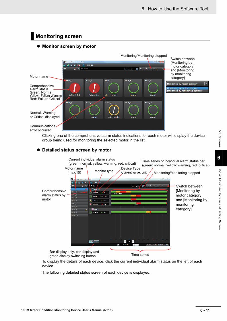
6 - 11
6 How to Use the Software Tool
K6CM Motor Condition Monitoring Device User’s Manual (N219)
6-1 S
creen
s
6
6-1-2 Monitoring S
creen and Setting S
creen
Monitor screen by motor
Clicking one of the comprehensive alarm status indications for each motor will display the device group being used for monitoring the selected motor in the list.
Detailed status screen by motor
To display the details of each device, click the current individual alarm status on the left of each device.
The following detailed status screen of each device is displayed.
Monitoring screen
Switch between [Monitoring by motor category] and [Monitoring by monitoring category]
Monitoring/Monitoring stopped
Motor name
Normal, Warning, or Critical displayed
Communications error occurred
Comprehensive alarm statusGreen: NormalYellow: Failure WarningRed: Failure Critical
Switch between [Monitoring by motor category] and [Monitoring by monitoring category]
Monitoring/Monitoring stoppedMotor name
(max.10)
Comprehensive alarm status by motor
Monitor typeDevice Type
Bar display only, bar display and graph display switching button Time series
Current value, unit
Current individual alarm status (green: normal, yellow: warning, red: critical)
Time series of individual alarm status bar (green: normal, yellow: warning, red: critical)

6 How to Use the Software Tool
6 - 12 K6CM Motor Condition Monitoring Device User’s Manual (N219)
Detailed status screen by device
Note 1. You can switch the bar display only, the bar display and the graph display by the following icon on the lower left of the motor status display screen.
2. The maximum value on the vertical axis of the graph automatically changes depending on the mea-sured value and alarm set value. With software tool version 1.2.0.0 or later, the vertical axis scale can be set arbitrarily.
3. The time series period can be switched to 1 hour / 1 day / 1 month / 1 year. If a period of more than 1 day is selected and displayed, data may be thinned out and displayed.
Device Type
Current valueIndividual alarm name
Time series
Measured value
Status
Graph display of measured value trend
Switch between [Monitoring by motor category] and [Monitoring by monitoring category]
Reset the Maximum and Minimum values of the device
Monitoring/Monitoring stopped
Icon at status ON
Icon at status OFF
Motor name
Bar display onlyBar display and graph display
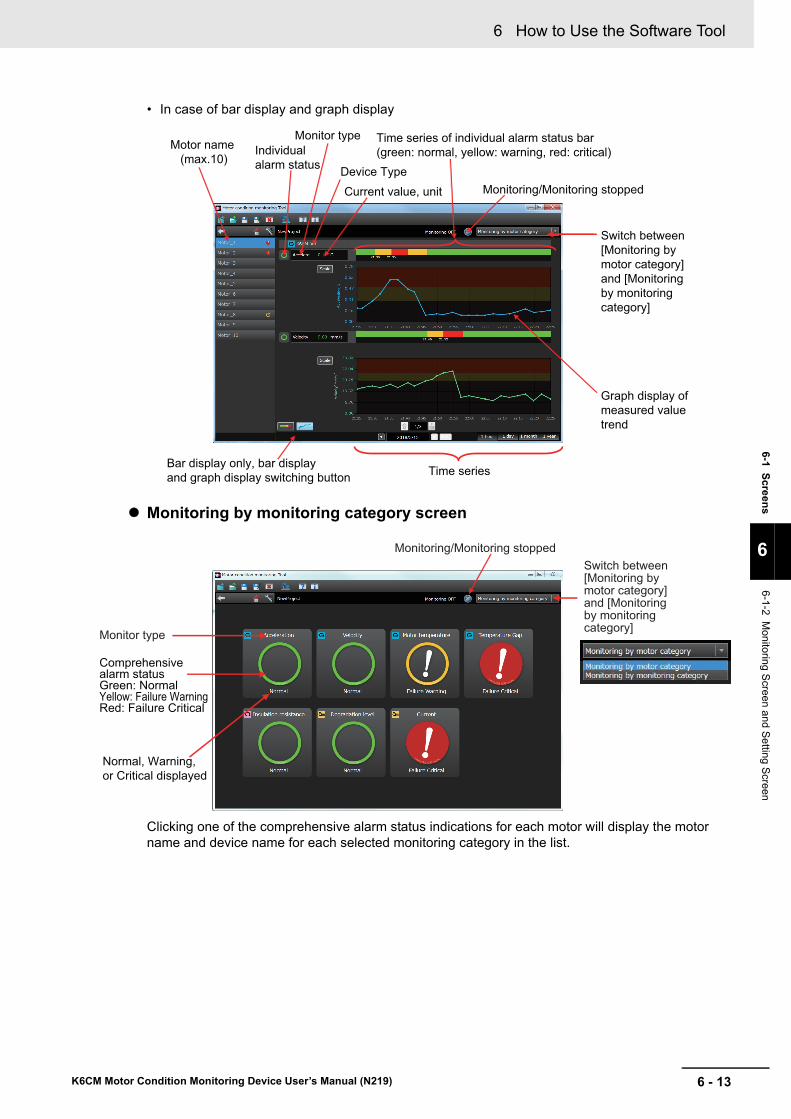
6 - 13
6 How to Use the Software Tool
K6CM Motor Condition Monitoring Device User’s Manual (N219)
6-1 S
creen
s
6
6-1-2 Monitoring S
creen and Setting S
creen
• In case of bar display and graph display
Monitoring by monitoring category screen
Clicking one of the comprehensive alarm status indications for each motor will display the motor name and device name for each selected monitoring category in the list.
Switch between [Monitoring by motor category] and [Monitoring by monitoring category]
Monitoring/Monitoring stopped
Motor name (max.10)
Individual alarm status
Monitor type
Device Type
Current value, unit
Time series of individual alarm status bar (green: normal, yellow: warning, red: critical)
Time seriesBar display only, bar display and graph display switching button
Graph display of measured value trend
Monitor type
Switch between [Monitoring by motor category] and [Monitoring by monitoring category]
Monitoring/Monitoring stopped
Normal, Warning, or Critical displayed
Comprehensive alarm statusGreen: NormalYellow: Failure WarningRed: Failure Critical
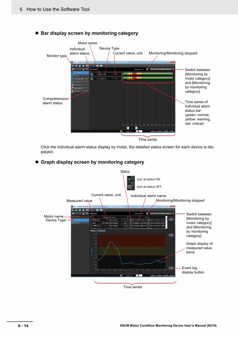
6 How to Use the Software Tool
6 - 14 K6CM Motor Condition Monitoring Device User’s Manual (N219)
Bar display screen by monitoring category
Click the individual alarm status display by motor, the detailed status screen for each device is dis-played.
Graph display screen by monitoring category
Comprehensivealarm status
Individual alarm status
Motor nameDevice Type
Current value, unit Monitoring/Monitoring stopped
Switch between [Monitoring by motor category] and [Monitoring by monitoring category]
Time series of individual alarm status bar (green: normal, yellow: warning, red: critical)
Monitor type
Time series
Switch between [Monitoring by motor category] and [Monitoring by monitoring category]
Motor nameDevice Type
Current value, unit Individual alarm nameMonitoring/Monitoring stopped
Time series
Event log display button
Graph display of measured value trend
Measured value
Status
Icon at status ON
Icon at status OFF

6 - 15
6 How to Use the Software Tool
K6CM Motor Condition Monitoring Device User’s Manual (N219)
6-1 S
creen
s
6
6-1-2 Monitoring S
creen and Setting S
creen
Event log display
You can display the following [Event log list] by pressing the [Event log display] Button.
You can check the occurrence history of individual alarms of the currently displayed device.
On the monitoring screen, click the [Device setting] Button. The following device setting screen Device setting screen is displayed.
Device setting screen
Device setting screen
Device Type Parameter name
Device reset button
Value, unit
Switch between [Monitoring by motor category] and [Monitoring by monitoring category]
Monitoring/Monitoring stopped
Motor name

6 How to Use the Software Tool
6 - 16 K6CM Motor Condition Monitoring Device User’s Manual (N219)
This section describes the following menu and toolbar in the upper left part common to the screen.
6-1-3 Common Menu and Toolbar List
Menu tool button
Buttons and tooltips Outline of operation Enable / disabled condition
Create new proj-ect
Display the screen for setting the configuration.
If the current project has not been saved, a message will be displayed.
Selectable during monitoring execution (grayed out)
Open project Display "Open file" dialog.
Equivalent to "Open project file" button when the software tool is started.
If the current project is not saved, a message will be displayed.
Selectable during monitoring execution (grayed out)
Save the project file
Save over the current project file.
If you create a new file, the Save File dialog will be displayed and it will be saved with a name.
Selectable during monitoring execution (grayed out)
Save the project as the specified name
The "Save file" dialog is displayed.
Save the project with the specified file name.
Selectable during monitoring execution (grayed out)
Exit Exit the software tool.
If the current project has not been saved, a message will be displayed.
Selectable during monitoring execution (grayed out)
Buttons and tooltips Outline of operation Enable / disabled condition
SYSMAC Gate-way Console
Launch the SYSMAC Gateway Console screen.
1. Make sure that "Startup" in the "Communication Service" field is "Automatic" and that "Status" is "Start".
2. In the [Network Port] field, configure the network port to be connected.
3. In the [Network Port] field, set the [Auto open] column of the network port to be used to "Automatic".
Selectable during monitoring execution (grayed out)
Buttons and tooltips Outline of operation Enable / disabled condition
Display help menu
Displays the User's Manual. ----
Version informa-tion
The version information screen is displayed. ----
Menu tool button
Monitoring bar

6 - 17
6 How to Use the Software Tool
K6CM Motor Condition Monitoring Device User’s Manual (N219)
6-1 S
creen
s
6
6-1-3 Com
mon M
enu and Toolba
r List
• Left end
• Center
• Right end
Monitoring Bar
Buttons and tooltips Outline of operation
Back You can return to the previous screen. However, it cannot be used on the monitoring screen.
Home Returns to the monitoring screen.
Device setting You will be transferred to the device setting screen.
For details of the device setting screen, see "Device setting screen" in 6-1-2 Monitoring Screen and Setting Screen on page 6-5.
Display Outline of operation
Indicates that monitoring is stopped.
The file name of the project is displayed on the left side (the same applies below).
"Stopped" is displayed on the right side.
Indicates that monitoring is in progress, and that the entire monitoring data is normal.
"Monitoring" is displayed on the right side.
It is currently being monitored and indicates that "Warning" has occurred in one of the monitoring data.
"Monitoring" is displayed on the right side.
It is currently being monitored, and "Critical" has occurred in one of the monitoring data.
"Monitoring" is displayed on the right side.
Buttons and tooltips Enable / disabled condition
Start monitoring Indicates that monitoring is stopped.
By pressing this button, monitoring will start.
Monitoring OFF It is currently being monitored.
By pushing this button, monitoring is stopped.
Left end Center Right end
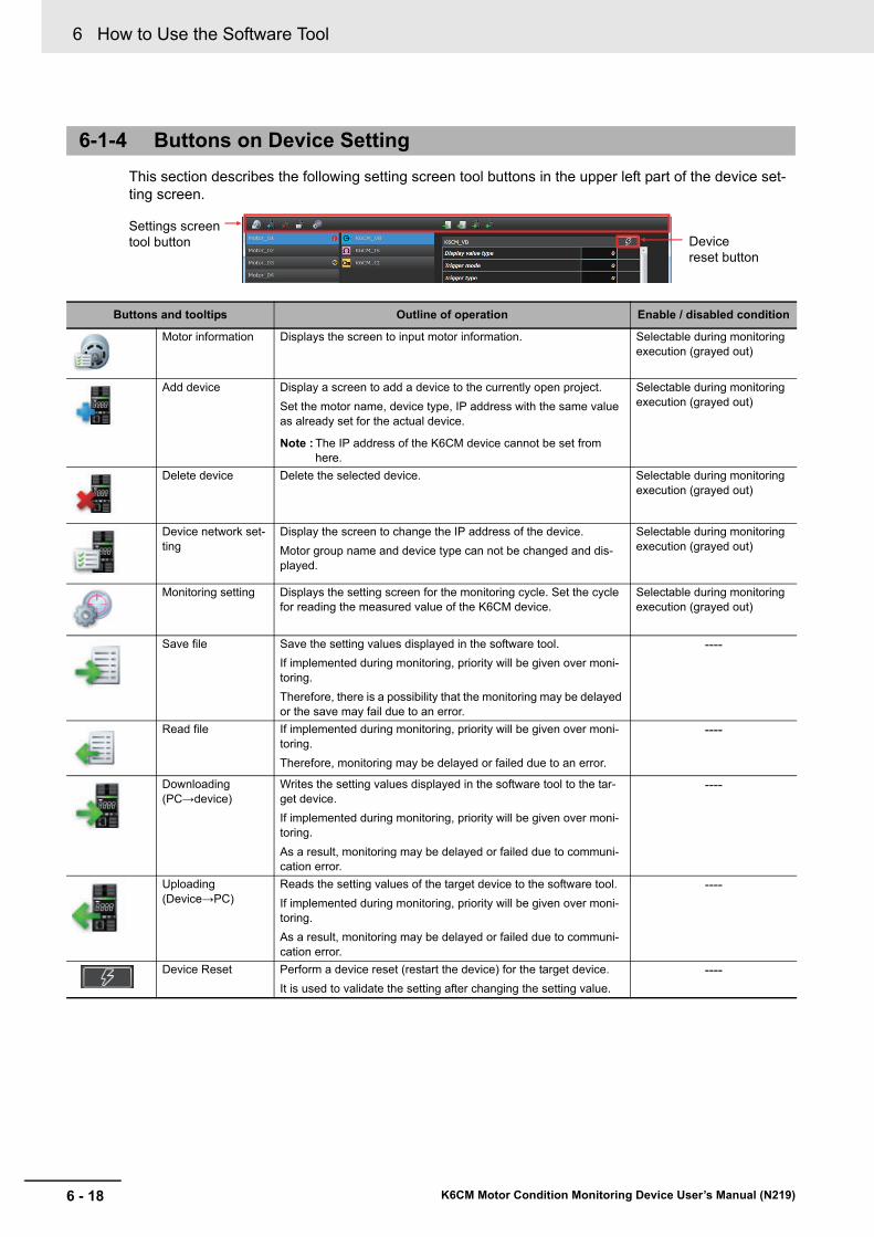
6 How to Use the Software Tool
6 - 18 K6CM Motor Condition Monitoring Device User’s Manual (N219)
This section describes the following setting screen tool buttons in the upper left part of the device set-ting screen.
6-1-4 Buttons on Device Setting
Buttons and tooltips Outline of operation Enable / disabled condition
Motor information Displays the screen to input motor information. Selectable during monitoring execution (grayed out)
Add device Display a screen to add a device to the currently open project.
Set the motor name, device type, IP address with the same value as already set for the actual device.
Note : The IP address of the K6CM device cannot be set from here.
Selectable during monitoring execution (grayed out)
Delete device Delete the selected device. Selectable during monitoring execution (grayed out)
Device network set-ting
Display the screen to change the IP address of the device.
Motor group name and device type can not be changed and dis-played.
Selectable during monitoring execution (grayed out)
Monitoring setting Displays the setting screen for the monitoring cycle. Set the cycle for reading the measured value of the K6CM device.
Selectable during monitoring execution (grayed out)
Save file Save the setting values displayed in the software tool.
If implemented during monitoring, priority will be given over moni-toring.
Therefore, there is a possibility that the monitoring may be delayed or the save may fail due to an error.
----
Read file If implemented during monitoring, priority will be given over moni-toring.
Therefore, monitoring may be delayed or failed due to an error.
----
Downloading (PC→device)
Writes the setting values displayed in the software tool to the tar-get device.
If implemented during monitoring, priority will be given over moni-toring.
As a result, monitoring may be delayed or failed due to communi-cation error.
----
Uploading (Device→PC)
Reads the setting values of the target device to the software tool.
If implemented during monitoring, priority will be given over moni-toring.
As a result, monitoring may be delayed or failed due to communi-cation error.
----
Device Reset Perform a device reset (restart the device) for the target device.
It is used to validate the setting after changing the setting value.
----
Settings screen tool button Device
reset button
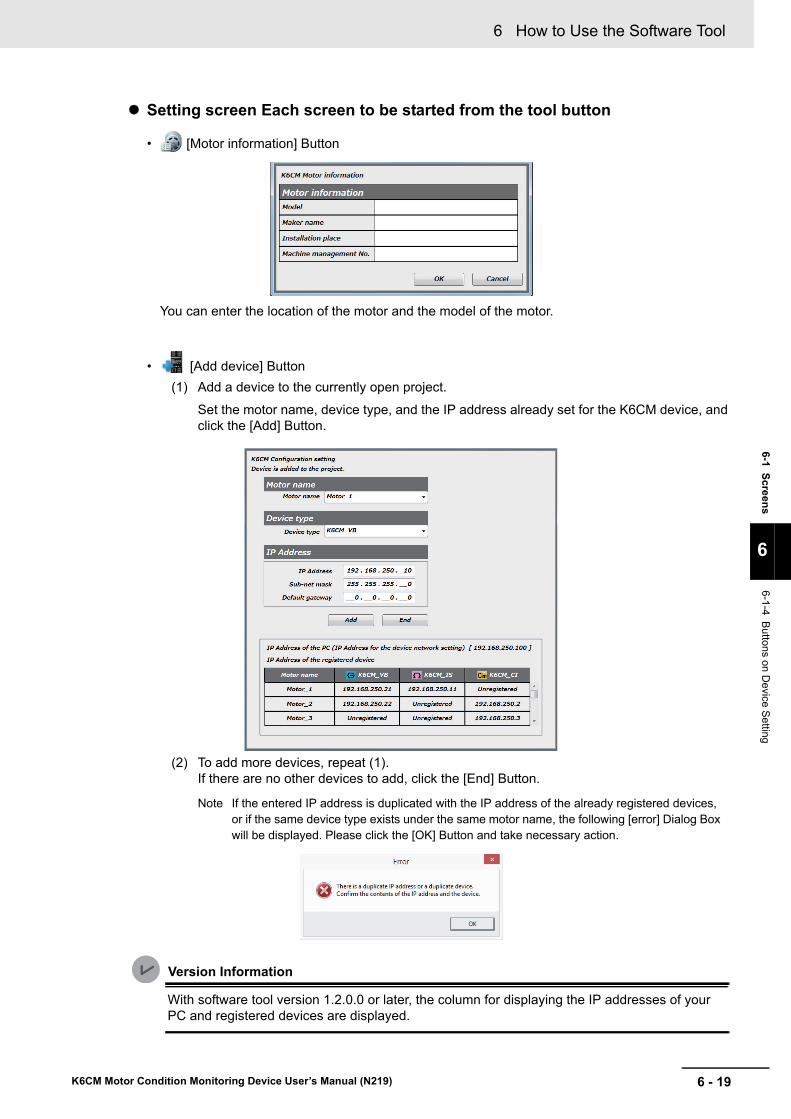
6 - 19
6 How to Use the Software Tool
K6CM Motor Condition Monitoring Device User’s Manual (N219)
6-1 S
creen
s
6
6-1-4 Buttons on D
evice Setting
Setting screen Each screen to be started from the tool button
• [Motor information] Button
You can enter the location of the motor and the model of the motor.
• [Add device] Button
(1) Add a device to the currently open project.
Set the motor name, device type, and the IP address already set for the K6CM device, and click the [Add] Button.
(2) To add more devices, repeat (1).If there are no other devices to add, click the [End] Button.
Note If the entered IP address is duplicated with the IP address of the already registered devices, or if the same device type exists under the same motor name, the following [error] Dialog Box will be displayed. Please click the [OK] Button and take necessary action.
Version Information
With software tool version 1.2.0.0 or later, the column for displaying the IP addresses of your PC and registered devices are displayed.

6 How to Use the Software Tool
6 - 20 K6CM Motor Condition Monitoring Device User’s Manual (N219)
• [Device setting] Button
Change the IP address of the device.
IP address, subnet mask, default gateway.
Version Information
With software tool version 1.2.0.0 or later, the column for displaying the IP addresses of your PC and registered devices are displayed.
• [Monitoring setting] Button
Change the monitoring cycle.
Can be set in the range of 5 seconds to 366 days. (The initial value is 600 seconds.)The monitoring cycle is the cycle at which the software tool collects measured values from the K6CM devices.
The measured values are collected by the software tool at that cycle, regardless of the K6CM device state such as the use of trigger or the determination of measured value.
Version Information
With software tool version 1.2.0.0 or later, the unit of monitoring cycle can be set.
Using this pull down list allows you to change the unit of monitoring cycle.Selectable units are seconds, minutes, hours, and days.

6 - 21
6 How to Use the Software Tool
K6CM Motor Condition Monitoring Device User’s Manual (N219)
6-1 S
creen
s
6
6-1-4 Buttons on D
evice Setting
• [Save file] Button
Specify the parameter save destination and click the [Save] Button.
• [Read file] Button
Specify the setting file and click the [Open] Button.
• [Downloading (PC→device)] Button
To write the setting value to the K6CM device, click the [OK] Button. If you do not want to write it, click the [Cancel] Button.
• [Uploading (Device→PC)] Button
To read the setting value from the K6CM device, click the [OK] Button. If you do not want to read it, click the [Cancel] Button.

6 How to Use the Software Tool
6 - 22 K6CM Motor Condition Monitoring Device User’s Manual (N219)
You can check the version of software tool by clicking (version information) Button.
6-1-5 Software Tool Version Display Screen

6 - 23
6 How to Use the Software Tool
K6CM Motor Condition Monitoring Device User’s Manual (N219)
6-2 Settin
g o
f K6C
M D
evices
6
6-2-1 Setting
s for Each
Monito
r Type of K6C
M de
vices
6-2 Setting of K6CM Devices
The setting of the K6CM device can be set by either of the following two methods:
• How to set in the start navigation of project creation
• How to set on the device setting screen after project creation
The setting values by monitor type are shown in a list.
Vibration and Temperature Type K6CM-VB
6-2-1 Settings for Each Monitor Type of K6CM devices
Setting parameter name Setting range Description Default
Display value type 0: PV, 1: MIN, 2: MAX Set which measured value is displayed in the K6CM device.
0: PV
Trigger mode 0: Always, 1: External trigger, 2: Internal trigger
Set the measurement mode. 0: Always
Trigger type
* Setting is not required when the trigger mode is "Always".
0: Rising, 1: Falling edge, 2: Level
For external trigger or internal trigger, set the starting condi-tion of the trigger measure-ment.
0: Rising
Trigger level
* Setting is not required when the trigger mode is "Always" or "External trigger".
0.00 to 99.99 For internal trigger, set the measurement value to start trigger measurement.
0.00
Monitoring time
* Setting is not required when the trigger mode is "Always" or the trigger type is "Level".
0.1 to 600.0 Set the time to continue the measurement when the trig-ger mode is set to "External trigger" or "Internal trigger" with the trigger type "Rising" or "Falling edge ".
0.1
Alarm latch 0: Disable, 1: Enable Set the latch function when an alarm is detected
1: Enable
Use Running Time 0: OFF, 1: ON Set the function to detect the life of the K6CM device?
0: OFF
Moving Average times 0: OFF, 1: 2 times, 2: 4 times, 3: 8 times, 4: 16 times, 5: 32 times
The averaging process is per-formed on the past n times of measured values.
Note n is the moving average number on the shown left col-umn.
0: OFF
Temperature unit 0: °C, 1: °F Sets the temperature unit. 0: °C
Acceleration alarm threshold (Warning)
0.00 to 99.99 Set a threshold value for out-putting individual alarm (Warning) of the acceleration.
0.50
Acceleration alarm threshold (Critical)
0.00 to 99.99 Set a threshold value for out-putting individual alarm (Criti-cal) of the acceleration.
1.00
Velocity alarm threshold (Warning)
0.00 to 99.99 Set a threshold value for out-putting individual alarm (Warning) of the velocity.
40.00
Velocity alarm threshold (Critical)
0.00 to 99.99 Set a threshold value for out-putting individual alarm (Criti-cal) of the velocity.
45.00
Motor temperature alarm threshold (Warning)
0 to 9999 Set a threshold value for out-putting individual alarm (Warning) of the motor tem-perature.
80

6 How to Use the Software Tool
6 - 24 K6CM Motor Condition Monitoring Device User’s Manual (N219)
Insulation Resistance Type K6CM-IS
Motor temperature alarm threshold (Critical)
0 to 9999 Set a threshold value for out-putting individual alarm (Criti-cal) of the motor temperature.
80
Temperature Gap alarm threshold (Warning)
0 to 9999 Set a threshold value for out-putting individual alarm
(Warning) of the temperature gap.
80
Temperature Gap alarm threshold (Critical)
0 to 9999 Set a threshold value for out-putting individual alarm (Criti-cal) of the temperature gap.
80
Transistor output type 0: Normally closed,
1: Normally open
Select transistor output type. 0
Setting parameter name Setting range Description Default
Display value type 0: PV, 1: MIN, 2: MAX Set which measured value is displayed in the K6CM device.
0: PV
Trigger mode 0: Always, 1: External trigger, 2: Internal trigger
Set the measurement mode. 0: Always
Trigger type
* Setting is not required when the trigger mode is "Always".
0: Rising, 1: Falling edge, 2: Level
For external trigger or internal trigger, set the starting condi-tion of the trigger measure-ment.
0: Rising
Trigger level
* Setting is not required when the trigger mode is "Always " or "External trigger".
0.00 to 99.99 For internal trigger, set the measurement value to start trigger measurement.
0.00
Monitoring time
*Setting is not required when the trigger mode is "Always" or the trigger type is "Level".
0.1 to 600.0 Set the time to continue the measurement when the trig-ger mode is set to "External trigger" or "Internal trigger" with the trigger type "Rising" or "Falling edge ".
0.1
Alarm latch 0: Disable, 1: Enable Set the latch function when an alarm is detected
1: Enable
Use Running Time 0: OFF, 1: ON Set the function to detect the life of the K6CM device?
0: OFF
Moving Average times 0: OFF, 1: 2 times, 2: 4 times, 3: 8 times, 4: 16 times, 5: 32 times
The averaging process is per-formed on the past n times of measured values.
Note n is the moving average number on the shown left col-umn.
0: OFF
Applicable circuit 0: Three-phase three-wire S-phase ground
1: Three-phase four-wire N-phase grounded load side delta connection
Set the applicable circuit according to the distribution method of the equipment to be monitored.
0: Three-phase three-wire S-phase ground
Using inverter 0: OFF, 1: ON Set according to the pres-ence or absence of the inverter of the equipment to be monitored.
0: OFF
Inverter special measurement 0: OFF, 1: ON Set according to the inverter frequency setting of the equipment to be monitored.
0: OFF
Insulation resistance alarm threshold (Warning)
0.000 to 9.999 Set a threshold value for out-putting individual alarm (Warning) of the insulation resistance.
0.800
Setting parameter name Setting range Description Default
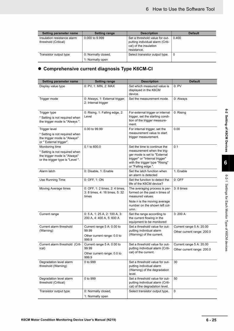
6 - 25
6 How to Use the Software Tool
K6CM Motor Condition Monitoring Device User’s Manual (N219)
6-2 Settin
g o
f K6C
M D
evices
6
6-2-1 Setting
s for Each
Monito
r Type of K6C
M de
vices
Comprehensive current diagnosis Type K6CM-CI
Insulation resistance alarm threshold (Critical)
0.000 to 9.999 Set a threshold value for out-putting individual alarm (Criti-cal) of the insulation resistance.
0.400
Transistor output type 0: Normally closed,
1: Normally open
Select transistor output type. 0
Setting parameter name Setting range Description Default
Display value type 0: PV, 1: MIN, 2: MAX Set which measured value is displayed in the K6CM device.
0: PV
Trigger mode 0: Always, 1: External trigger, 2: Internal trigger
Set the measurement mode. 0: Always
Trigger type
* Setting is not required when the trigger mode is "Always ".
0: Rising, 1: Falling edge, 2: Level
For external trigger or internal trigger, set the starting condi-tion of the trigger measure-ment.
0: Rising
Trigger level
* Setting is not required when the trigger mode is "Always" or " External trigger".
0.00 to 99.99 For internal trigger, set the measurement value to start trigger measurement.
0.00
Monitoring time
* Setting is not required when the trigger mode is "Always" or the trigger type is "Level ".
0.1 to 600.0 Set the time to continue the measurement when the trig-ger mode is set to "External trigger" or "Internal trigger" with the trigger type "Rising" or "Falling edge ".
0.1
Alarm latch 0: Disable, 1: Enable Set the latch function when an alarm is detected
1: Enable
Use Running Time 0: OFF, 1: ON Set the function to detect the life of the K6CM device?
0: OFF
Moving Average times 0: OFF, 1: 2 times, 2: 4 times, 3: 8 times, 4: 16 times, 5: 32 times
The averaging process is per-formed on the past n times of measured values.
Note n is the moving average number on the shown left col-umn.
3: 8 times
Current range 0: 5 A, 1: 25 A, 2: 100 A, 3: 200 A, 4: 400 A, 5: 600 A
Set the range according to the current flowing in the equipment to be monitored
3: 200 A
Current alarm threshold (Warning)
Current range 5 A: 0.00 to 99.99
Other current range: 0.0 to 999.9
Set a threshold value for out-putting individual alarm (Warning) of the current.
Current range 5 A: 20.00
Other current range: 200.0
Current alarm threshold (Crit-ical)
Current range 5 A: 0.00 to 99.99
Other current range: 0.0 to 999.9
Set a threshold value for out-putting individual alarm (Criti-cal) of the current.
Current range 5 A: 20.00
Other current range: 200.0
Degradation level alarm threshold (Warning)
0 to 999 Set a threshold value for out-putting individual alarm (Warning) of the degradation level.
30
Degradation level alarm threshold (Critical)
0 to 999 Set a threshold value for out-putting individual alarm (Criti-cal) of the degradation level.
50
Transistor output type 0: Normally closed,
1: Normally open
Select transistor output type. 0
Setting parameter name Setting range Description Default
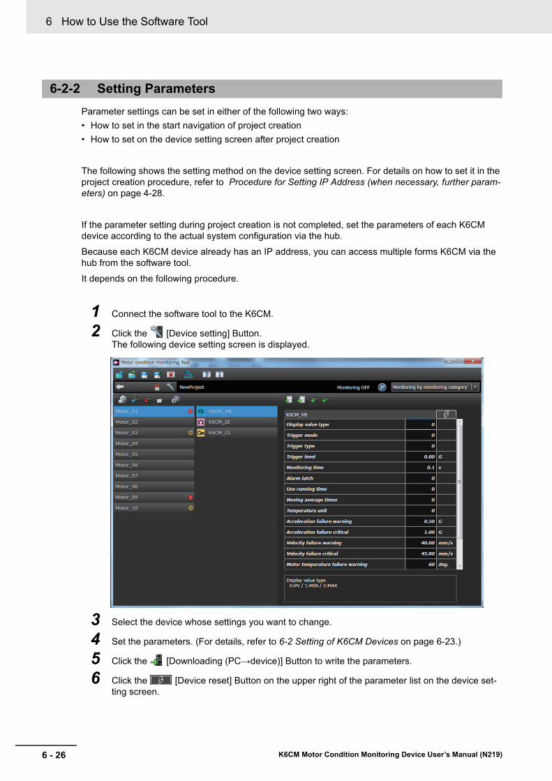
6 How to Use the Software Tool
6 - 26 K6CM Motor Condition Monitoring Device User’s Manual (N219)
Parameter settings can be set in either of the following two ways:
• How to set in the start navigation of project creation
• How to set on the device setting screen after project creation
The following shows the setting method on the device setting screen. For details on how to set it in the project creation procedure, refer to Procedure for Setting IP Address (when necessary, further param-eters) on page 4-28.
If the parameter setting during project creation is not completed, set the parameters of each K6CM device according to the actual system configuration via the hub.
Because each K6CM device already has an IP address, you can access multiple forms K6CM via the hub from the software tool.
It depends on the following procedure.
1 Connect the software tool to the K6CM.
2 Click the [Device setting] Button.The following device setting screen is displayed.
3 Select the device whose settings you want to change.
4 Set the parameters. (For details, refer to 6-2 Setting of K6CM Devices on page 6-23.)
5 Click the [Downloading (PC→device)] Button to write the parameters.
6 Click the [Device reset] Button on the upper right of the parameter list on the device set-ting screen.
6-2-2 Setting Parameters
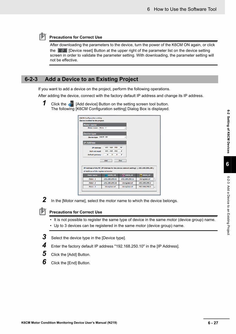
6 - 27
6 How to Use the Software Tool
K6CM Motor Condition Monitoring Device User’s Manual (N219)
6-2 Settin
g o
f K6C
M D
evices
6
6-2-3 Add a D
evice to an E
xisting Project
Precautions for Correct Use
After downloading the parameters to the device, turn the power of the K6CM ON again, or click
the [Device reset] Button at the upper right of the parameter list on the device setting screen in order to validate the parameter setting. With downloading, the parameter setting will not be effective.
If you want to add a device on the project, perform the following operations.
After adding the device, connect with the factory default IP address and change its IP address.
1 Click the [Add device] Button on the setting screen tool button.The following [K6CM Configuration setting] Dialog Box is displayed.
2 In the [Motor name], select the motor name to which the device belongs.
Precautions for Correct Use
• It is not possible to register the same type of device in the same motor (device group) name.
• Up to 3 devices can be registered in the same motor (device group) name.
3 Select the device type in the [Device type].
4 Enter the factory default IP address "192.168.250.10" in the [IP Address].
5 Click the [Add] Button.
6 Click the [End] Button.
6-2-3 Add a Device to an Existing Project

6 How to Use the Software Tool
6 - 28 K6CM Motor Condition Monitoring Device User’s Manual (N219)
7 Select the added device, click the [Device setting] Button on the setting screen tool button.The following [K6CM configuration setting] Dialog Box is displayed.
8 Change the IP address from the factory default value. Change the subnet mask and default gateway as necessary.It is recommended that you write the changed IP address on the IP address label.
9 Click the [OK] Button.The IP address setting on the project is changed, and the IP address of the actual device is automatically changed from the factory default value at the same time.
To change the name of the motor (device group) on the project, execute the following operation.
1 In the Device setting screen, left click on the position of the motor name and change it.
6-2-4 Motor (Device Group) Rename
IP address label
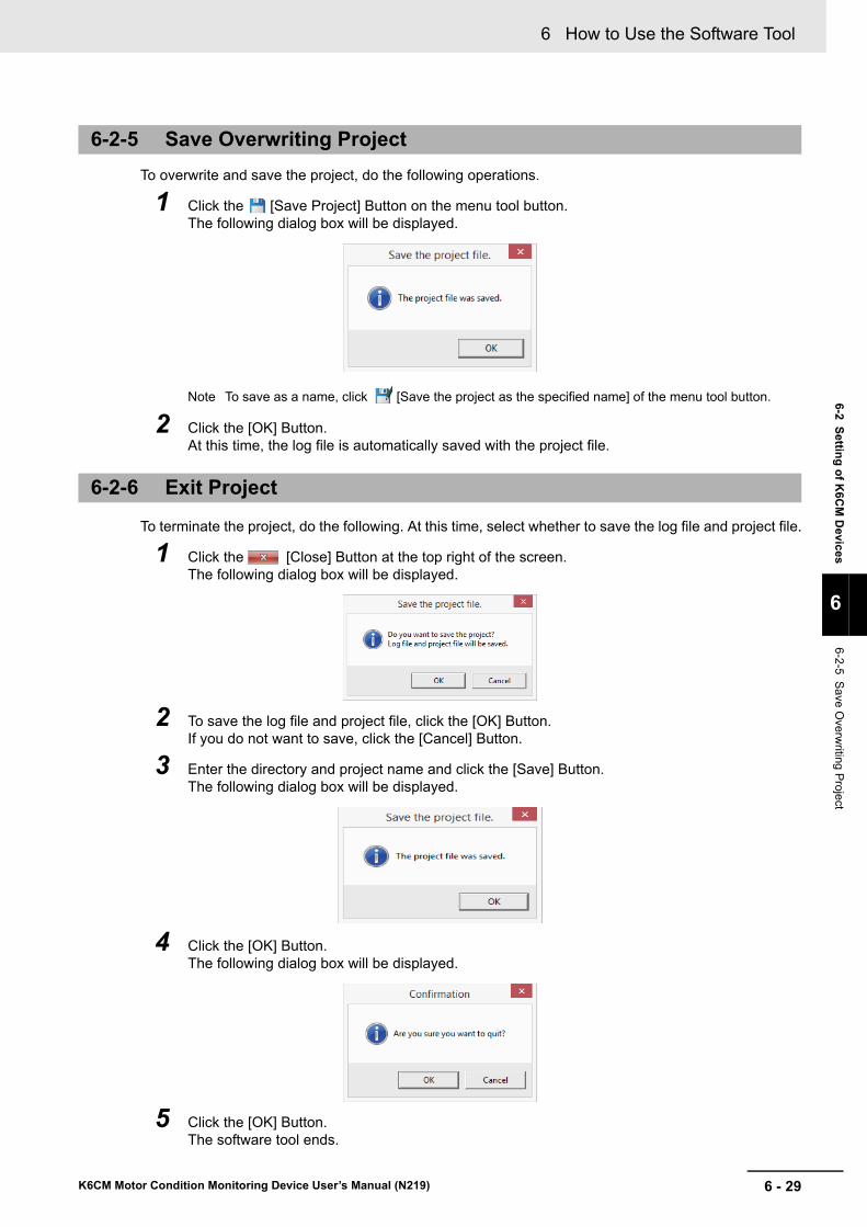
6 - 29
6 How to Use the Software Tool
K6CM Motor Condition Monitoring Device User’s Manual (N219)
6-2 Settin
g o
f K6C
M D
evices
6
6-2-5 Save O
verwriting P
roject
To overwrite and save the project, do the following operations.
1 Click the [Save Project] Button on the menu tool button.The following dialog box will be displayed.
Note To save as a name, click [Save the project as the specified name] of the menu tool button.
2 Click the [OK] Button.At this time, the log file is automatically saved with the project file.
To terminate the project, do the following. At this time, select whether to save the log file and project file.
1 Click the [Close] Button at the top right of the screen.The following dialog box will be displayed.
2 To save the log file and project file, click the [OK] Button.If you do not want to save, click the [Cancel] Button.
3 Enter the directory and project name and click the [Save] Button.The following dialog box will be displayed.
4 Click the [OK] Button.The following dialog box will be displayed.
5 Click the [OK] Button.The software tool ends.
6-2-5 Save Overwriting Project
6-2-6 Exit Project

6 How to Use the Software Tool
6 - 30 K6CM Motor Condition Monitoring Device User’s Manual (N219)

7 - 1
7
K6CM Motor Condition Monitoring Device User’s Manual (N219)
This section describes the motor monitoring and operation method using the K6CM devices and Motor condition monitoring Tool.
7-1 Motor Monitoring and Operation Procedure . . . . . . . . . . . . . . . . . . . . . . . . 7-2
7-2 Motor Monitoring Using the K6CM devices . . . . . . . . . . . . . . . . . . . . . . . . . 7-37-2-1 Start measurement . . . . . . . . . . . . . . . . . . . . . . . . . . . . . . . . . . . . . . . . . . . . . . 7-3
7-2-2 Monitoring Type Switching . . . . . . . . . . . . . . . . . . . . . . . . . . . . . . . . . . . . . . . . 7-5
7-2-3 Monitoring method . . . . . . . . . . . . . . . . . . . . . . . . . . . . . . . . . . . . . . . . . . . . . . 7-6
7-2-4 Measuring and Monitoring Completed . . . . . . . . . . . . . . . . . . . . . . . . . . . . . . . 7-8
7-3 Motor Monitoring Using Software Tools . . . . . . . . . . . . . . . . . . . . . . . . . . . 7-97-3-1 Monitoring Procedure with Motor Condition Monitoring Tool . . . . . . . . . . . . . . 7-9
7-3-2 Set the Monitoring Cycle . . . . . . . . . . . . . . . . . . . . . . . . . . . . . . . . . . . . . . . . . . 7-9
7-3-3 Start Monitoring . . . . . . . . . . . . . . . . . . . . . . . . . . . . . . . . . . . . . . . . . . . . . . . . 7-10
7-3-4 Saving Log Files . . . . . . . . . . . . . . . . . . . . . . . . . . . . . . . . . . . . . . . . . . . . . . . .7-11
7-3-5 Graph Vertical Axis Scale Setting . . . . . . . . . . . . . . . . . . . . . . . . . . . . . . . . . . 7-12
7-3-6 Graph Time Axis Movement . . . . . . . . . . . . . . . . . . . . . . . . . . . . . . . . . . . . . . 7-13
Motor Monitoring with the K6CM Devices and the Software Tool

7 Motor Monitoring with the K6CM Devices and the Software Tool
7 - 2 K6CM Motor Condition Monitoring Device User’s Manual (N219)
7-1 Motor Monitoring and Operation Pro-cedure
This section describes the monitoring and operating the motor using the K6CM.
Monitoring of the motor using the K6CM can be performed by simple monitoring with the K6CM devices only, monitoring with the software tool, or monitoring using the PCs or PLCs with the EtherNet/IP com-munications.
It is generally difficult to set the alarm setting (threshold) of the K6CM at the time of start of use.
Therefore, the actual motor monitoring and operation method depends on the following procedure.
Section 7 describes simple monitoring with the K6CM devices only and monitoring using software tool.
Section 8 describes monitoring using PCs or PLCs with EtherNet/IP communication.
STEP 1 Start simple monitoring with the K6CM only.
↓
STEP 2
Record measurement values from the host system (i.e., the software tool, PC, or PLC) to estimate an alarm set value to be used as the monitoring standard.
It depends on one of the following.
• Start monitoring and logging the measured value after setting the "monitoring cycle" of the soft-ware tool,
• Start monitoring and logging the measured value after connecting with PCs or PLCs by Ether-Net/IP communications.
↓
STEP 3 Estimate an alarm set values to be used as monitoring standard, considering the relationship between the change in each measurement value and the fatal state of the motor.
↓
STEP 4 Determine the alarm set values as the monitoring standard based on the monitoring and operation results.
↓
STEP 5 Change the setting of the alarm set values and make main monitoring and operation.

7 - 3
7 Motor Monitoring with the K6CM Devices and the Software Tool
K6CM Motor Condition Monitoring Device User’s Manual (N219)
7-2 Mo
tor M
on
itorin
g U
sing
the
K6C
M d
evices
7
7-2-1 S
tart measurem
ent
7-2 Motor Monitoring Using the K6CM devices
This section describes how to monitor with the K6CM devices.
1 Turn ON the power of the K6CM device. Depending on the "Trigger mode" and "Trigger type" set in advance in the parameter, the state of the K6CM device while power is ON will differ as follows.
Note 1. When an input exceeds the input range, 7 segments will blink.
2. "- - - -" is displayed even when measurement and monitoring conditions are met until the measured value is calculated from the time of power ON.
Measurement start and end conditions are as follows.
7-2-1 Start measurement
Trigger mode
State of the K6CM device while power is
ON
Status of the K6CM device
Numeric display LCD on the front
"MON" of the state display
Measuring and moni-toring
Always (while power is ON) Measurement value displayed Lit. Executed
External trigger
When condition is not met
"- - - -" displayed Not lit. Not executed
When condition is met Measurement value displayed Lit. Executed
Internal trigger
When condition is not met
"- - - -" displayed Not lit. Not executed
When condition is met Measurement value displayed Lit. Executed
Trigger modeStart condition of
measuring and monitoring
Trigger type
Rising edge Falling edge Level
Always (while power is ON)
All times after turning ON the power of the K6CM device
Always measuring
External trig-ger
Depends on the status of the exter-nal input
• Start condi-tion
When external input changes from OFF to ON
When external input changes from ON to OFF While the external input is in
the ON state• End condi-tion
After the measurement time has elapsed
After the measurement time has elapsed
Internal trig-ger
Depends on the relationship between the mea-surement value and the set value (trigger level)
• Start condi-tion
When the measurement value exceeds the set value (trigger level)
When the measurement value falls below the set value (trigger level)
While the measurement value exceeds the set value (trigger level)
Note : For the insulation resistance, this is while present value falls below the set value.
• End condi-tion
After the measurement time has elapsed
After the measurement time has elapsed
ONOFF
Measurement time
measuring and monitoring
ONOFF
Measurement time
measuring and monitoring
ONOFF
measuring and monitoring
Set value
measuring and monitoring
Measurement time
Set value
Measurement time
measuring and monitoring
Set value
measuring and monitoring

7 Motor Monitoring with the K6CM Devices and the Software Tool
7 - 4 K6CM Motor Condition Monitoring Device User’s Manual (N219)
2 When the trigger mode is "Always (while power is ON)", measuring and monitoring will be started.
Measured value is displayed on the numeric display LCD on the front of the device. At the same time, "MON" of the state display on the front of the device gets lit.
• When the trigger mode is "external trigger", operate the external input.
• When the trigger mode is "internal trigger", wait until the state of the measured value becomes the start condition of measuring and monitoring.
3 When measurement and monitoring are started after the power is turned ON, the numeric dis-play LCD in the front of the device switches from "- - - -" to the measured value display. At the same time, "MON" of the state display on the front of the device gets lit.
*1. In the factory default, "PV" is lit as the type of measurement such as present value, minimum value, and max-imum value. The numerical display shows "present value". When "Display value selection" is set to "minimum value" or "maximum value" with the software tool or EtherNet/IP, "MAX" or "MIN" is lit as the type of measure-ment such as present value, minimum value, and maximum value, and the numerical display shows "mini-mum value" or "maximum value".
Numeric LCD display
Unit of measurement value (Measurement type)
Changes from "- - - -" to the measurement value display. *1
Status display"MON": Measurement and
monitoring in progress
Types of measurement such as current value, minimum value, and maximum value. *1
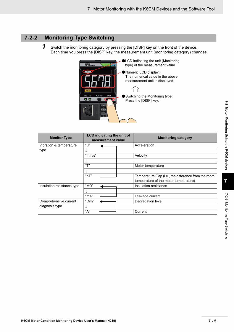
7 - 5
7 Motor Monitoring with the K6CM Devices and the Software Tool
K6CM Motor Condition Monitoring Device User’s Manual (N219)
7-2 Mo
tor M
on
itorin
g U
sing
the
K6C
M d
evices
7
7-2-2 M
onitoring Type S
witching
1 Switch the monitoring category by pressing the [DISP] key on the front of the device.Each time you press the [DISP] key, the measurement unit (monitoring category) changes.
7-2-2 Monitoring Type Switching
Monitor TypeLCD indicating the unit of
measurement valueMonitoring category
Vibration & temperature type
“G” Acceleration
↓
“mm/s” Velocity
↓
“T” Motor temperature
↓
“ΔT” Temperature Gap (i.e., the difference from the room temperature of the motor temperature)
Insulation resistance type “MΩ” Insulation resistance
↓
“mA” Leakage current
Comprehensive current diagnosis type
“Cim” Degradation level
↓
“A” Current
LCD indicating the unit (Monitoring type) of the measurement value
Switching the Monitoring type: Press the [DISP] key.
Numeric LCD display:The numerical value in the above measurement unit is displayed.

7 Motor Monitoring with the K6CM Devices and the Software Tool
7 - 6 K6CM Motor Condition Monitoring Device User’s Manual (N219)
When monitoring with the K6CM devices, it can be monitored by the following method.
• Front alarm bar
• Transistor output
When monitoring with front alarm bar, the following monitoring is available.
7-2-3 Monitoring method
Monitor with the Front Alarm Bar
Front alarm bar
Status display Status Meaning
Not lit. Not lit. Measuring and moni-toring Not yet
When using the trigger function (external trigger or internal trigger), measuring and monitoring is not started yet after the power is turned ON.
Green "MON" lit Comprehensive alarm: normal
All measured values are in nor-mal condition.
At the end of measuring and mon-itoring, the display of the front alarm bar is retained (only when using the trigger function).
Yellow Comprehensive alarm: Warning
There is no "critical" in the mea-surement value,
There is " warning " even if at least one state.
Red Comprehensive alarm: Critical
There is "critical" in even one measurement value.
Not lit. "ERR" lit When the self-diagno-sis error occurs
Self diagnostic error is occurring.
: Comprehensive alarm: Normal
: Comprehensive alarm: Warning
: Comprehensive alarm: Critical"MON": Measurement
and monitoring in progress
"ERR": Self-diagnosis error occurrence
Alarm bar
Status display:
: Self-diagnosis error. Or, measuring and monitoring, Not yet
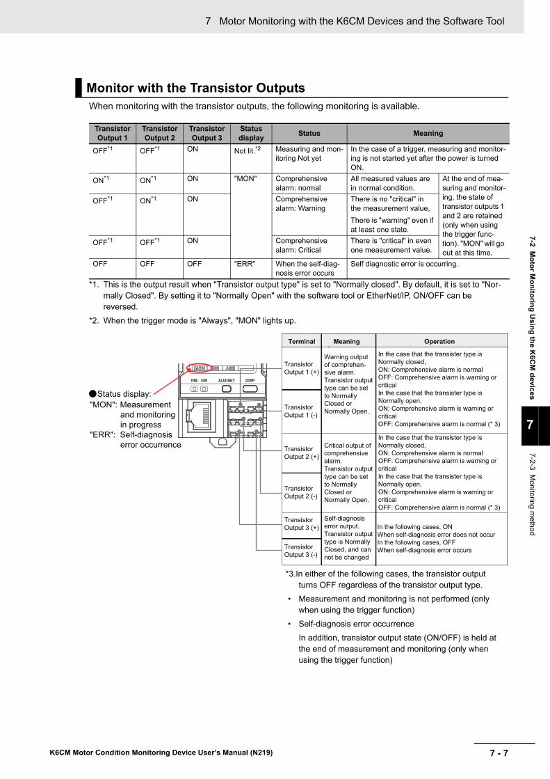
7 - 7
7 Motor Monitoring with the K6CM Devices and the Software Tool
K6CM Motor Condition Monitoring Device User’s Manual (N219)
7-2 Mo
tor M
on
itorin
g U
sing
the
K6C
M d
evices
7
7-2-3 M
onitoring m
ethod
When monitoring with the transistor outputs, the following monitoring is available.
*1. This is the output result when "Transistor output type" is set to "Normally closed". By default, it is set to "Nor-mally Closed". By setting it to "Normally Open" with the software tool or EtherNet/IP, ON/OFF can be reversed.
*2. When the trigger mode is "Always", "MON" lights up.
*3.In either of the following cases, the transistor output turns OFF regardless of the transistor output type.
• Measurement and monitoring is not performed (only when using the trigger function)
• Self-diagnosis error occurrence
In addition, transistor output state (ON/OFF) is held at the end of measurement and monitoring (only when using the trigger function)
Monitor with the Transistor Outputs
Transistor Output 1
Transistor Output 2
Transistor Output 3
Status display
Status Meaning
OFF*1 OFF*1 ON Not lit.*2 Measuring and mon-itoring Not yet
In the case of a trigger, measuring and monitor-ing is not started yet after the power is turned ON.
ON*1 ON*1 ON "MON" Comprehensive alarm: normal
All measured values are in normal condition.
At the end of mea-suring and monitor-ing, the state of transistor outputs 1 and 2 are retained (only when using the trigger func-tion). "MON" will go out at this time.
OFF*1 ON*1 ON Comprehensive alarm: Warning
There is no "critical" in the measurement value,
There is "warning" even if at least one state.
OFF*1 OFF*1 ON Comprehensive alarm: Critical
There is "critical" in even one measurement value.
OFF OFF OFF "ERR" When the self-diag-nosis error occurs
Self diagnostic error is occurring.
Transistor Output 1 (+)
In the following cases, ONWhen self-diagnosis error does not occurIn the following cases, OFFWhen self-diagnosis error occurs
OperationMeaning
Transistor Output 1 (-)
Transistor Output 3 (-)
Transistor Output 2 (+)
Transistor Output 2 (-)
Transistor Output 3 (+)
Terminal
"MON": Measurement and monitoring in progress
"ERR": Self-diagnosis error occurrence
Status display:
Warning output of comprehen-sive alarm.Transistor output type can be set to Normally Closed or Normally Open.
Critical output of comprehensive alarm.Transistor output type can be set to Normally Closed or Normally Open.
Self-diagnosis error output.Transistor output type is Normally Closed, and can not be changed
In the case that the transister type is Normally closed,ON: Comprehensive alarm is normalOFF: Comprehensive alarm is warning or criticalIn the case that the transister type is Normally open,ON: Comprehensive alarm is warning or criticalOFF: Comprehensive alarm is normal (* 3)
In the case that the transister type is Normally closed,ON: Comprehensive alarm is normalOFF: Comprehensive alarm is warning or criticalIn the case that the transister type is Normally open,ON: Comprehensive alarm is warning or criticalOFF: Comprehensive alarm is normal (* 3)

7 Motor Monitoring with the K6CM Devices and the Software Tool
7 - 8 K6CM Motor Condition Monitoring Device User’s Manual (N219)
When the trigger mode is "external trigger" or "internal trigger", when the termination condition of mea-surement and monitoring is satisfied, the measured value of the numerical display LCD on the front of the K6CM is retained. Also, the status at the end of measuring and monitoring is retained for the alarm bar and transistor outputs 1 and 2.
At this time, "MON" in the status display on the front of the K6CM goes out.
7-2-4 Measuring and Monitoring Completed
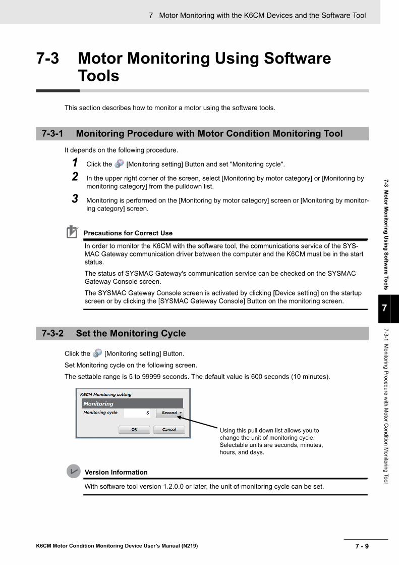
7 - 9
7 Motor Monitoring with the K6CM Devices and the Software Tool
K6CM Motor Condition Monitoring Device User’s Manual (N219)
7-3 Mo
tor M
on
itorin
g U
sin
g S
oftw
are
Too
ls
7
7-3-1 M
onitoring P
rocedure w
ith M
otor Co
ndition Monitoring Tool
7-3 Motor Monitoring Using Software Tools
This section describes how to monitor a motor using the software tools.
It depends on the following procedure.
1 Click the [Monitoring setting] Button and set "Monitoring cycle".
2 In the upper right corner of the screen, select [Monitoring by motor category] or [Monitoring by monitoring category] from the pulldown list.
3 Monitoring is performed on the [Monitoring by motor category] screen or [Monitoring by monitor-ing category] screen.
Precautions for Correct Use
In order to monitor the K6CM with the software tool, the communications service of the SYS-MAC Gateway communication driver between the computer and the K6CM must be in the start status.
The status of SYSMAC Gateway's communication service can be checked on the SYSMAC Gateway Console screen.
The SYSMAC Gateway Console screen is activated by clicking [Device setting] on the startup screen or by clicking the [SYSMAC Gateway Console] Button on the monitoring screen.
Click the [Monitoring setting] Button.
Set Monitoring cycle on the following screen.
The settable range is 5 to 99999 seconds. The default value is 600 seconds (10 minutes).
Version Information
With software tool version 1.2.0.0 or later, the unit of monitoring cycle can be set.
7-3-1 Monitoring Procedure with Motor Condition Monitoring Tool
7-3-2 Set the Monitoring Cycle
Using this pull down list allows you to change the unit of monitoring cycle.Selectable units are seconds, minutes, hours, and days.

7 Motor Monitoring with the K6CM Devices and the Software Tool
7 - 10 K6CM Motor Condition Monitoring Device User’s Manual (N219)
Click the [Start monitoring] Button.
Monitoring with the software tool is started.
There are a method of monitoring by motor (K6CM device group) and a method of monitoring by moni-toring category.
When monitoring by motor (K6CM device group), confirm the detailed information in the following order.
The time series period can be switched to 1 hour / 1 day / 1 month / 1 year.
If a period of more than 1 day is selected and displayed, data may be thinned out and displayed.
7-3-3 Start Monitoring
Monitoring by motor (K6CM device group)
Example: Switch to bar display and graph display
Example: What is the detailed status of this motor?
Example: What is the detailed status of this device?
Monitoring screen by motor screen
Individual motor (device group) monitoring screen
Time series display screen of individual devices
Individual device monitoring screen

7 - 11
7 Motor Monitoring with the K6CM Devices and the Software Tool
K6CM Motor Condition Monitoring Device User’s Manual (N219)
7-3 Mo
tor M
on
itorin
g U
sin
g S
oftw
are
Too
ls
7
7-3-4 S
aving Log Files
When monitoring by monitoring category, confirm the detailed information in the following order.
The log file is saved in the following cases.
• When to press the [Save Project] Button to save the project
• Every hour during monitoring
• When to complete monitoring
• When to select "Save log file and project file" at the end of the software tool
* Project files are also saved at the same time.
Monitoring by monitoring category
7-3-4 Saving Log Files
Monitoring screen by monitoring category
Example: What is the detailed status of "acceleration "?
Example: What is the detailed status of this device?
Individual monitor type monitoring screen
Individual device monitoring screen

7 Motor Monitoring with the K6CM Devices and the Software Tool
7 - 12 K6CM Motor Condition Monitoring Device User’s Manual (N219)
Click the Button on each graph display screen.
Make the settings on the following screen. The vertical axis scale can be set for each measured value of each K6CM.
Version Information
With software tool version 1.2.0.0 or later, the vertical axis scale can be set.
In earlier versions, the vertical axis scale of the graph changes automatically.
7-3-5 Graph Vertical Axis Scale Setting
No. Name Description
1 Auto or Fix select Button Auto: The vertical axis scale of the graph changes automatically.
0 to 1.3 times (*1) of the larger of the measured value or alarm value (Warn-ing/Critical)
Fix: The vertical axis scale of the graph is the value entered in the Maximum and Mini-mum value column.
*1. When the measured value is the insulation resistance value, it is fixed from 0 to 1.000 MΩ.
2 Maximum and Minimum value column
When "Fix" is selected, enter the scale maximum value and minimum value.
The maximum value must be greater than 10 digits (*2) than the minimum value.
*2. The "digit" represents the resolution. For example, if the resolution of the measured value is in increments of 1, the maximum value must be greater than the minimum value by 10 or more. If the resolution of the measured value is 0.1 increments, the maximum value must be at least 1.0 greater than the minimum value.
1
2

7 - 13
7 Motor Monitoring with the K6CM Devices and the Software Tool
K6CM Motor Condition Monitoring Device User’s Manual (N219)
7-3 Mo
tor M
on
itorin
g U
sin
g S
oftw
are
Too
ls
7
7-3-6 G
raph Tim
e Axis M
ovement
You can move the graph to be displayed in the time axis direction in section at
the bottom of the graph display screen.
The operation of each button and display column is as follows.
Version Information
With software tool version 1.2.0.0 or later, the graph time axis movement is available.
7-3-6 Graph Time Axis Movement
No. Name Description
1 Back Button When you click this button, the graph of the half-page new date and time is displayed rather than the graph being displayed. The time axis movement width becomes half of the displayed graph range.
2 Display of graph display year date and time
Displays the year, month, day of the right end of the graph being displayed.
3 Refresh Button When you click this button, the graph of the half-page new date and time is displayed rather than the displayed graph. The time axis movement width becomes half of the dis-played graph range.
4 Refresh Button Click this button to display the graph of the latest date and time.
If the latest graph is displayed, the button operation will be invalid.
1 2 3 4

7 Motor Monitoring with the K6CM Devices and the Software Tool
7 - 14 K6CM Motor Condition Monitoring Device User’s Manual (N219)

8 - 1
8
K6CM Motor Condition Monitoring Device User’s Manual (N219)
i
K6CM devices can also be monitored using EtherNet/IP compatible devices. This section describes how to monitor using the EtherNet/IP.
8-1 Overview . . . . . . . . . . . . . . . . . . . . . . . . . . . . . . . . . . . . . . . . . . . . . . . . . . . . . 8-28-1-1 What is Monitoring Using EtherNet/IP? . . . . . . . . . . . . . . . . . . . . . . . . . . . . . . 8-2
8-1-2 EtherNet/IP Communications Specifications . . . . . . . . . . . . . . . . . . . . . . . . . . 8-4
8-2 Monitoring Using the Tag Data Link . . . . . . . . . . . . . . . . . . . . . . . . . . . . . . 8-58-2-1 Connection setting . . . . . . . . . . . . . . . . . . . . . . . . . . . . . . . . . . . . . . . . . . . . . . 8-5
8-2-2 Data to be Tag Data Link Target in the K6CM Device . . . . . . . . . . . . . . . . . . . . 8-9
8-3 Monitoring and Setting Using the CIP Message Communications and Examples of Communications Instructions . . . . . . . . . . . . . . . . . . . . . . . 8-128-3-1 Datatype List of Variables . . . . . . . . . . . . . . . . . . . . . . . . . . . . . . . . . . . . . . . . 8-12
8-3-2 Services Supported by Objects in K6CM . . . . . . . . . . . . . . . . . . . . . . . . . . . . 8-12
8-3-3 Monitor Object (Class ID: 370 hex) . . . . . . . . . . . . . . . . . . . . . . . . . . . . . . . . . 8-13
8-3-4 Setting Object (Class ID: 371 hex) . . . . . . . . . . . . . . . . . . . . . . . . . . . . . . . . . 8-18
8-3-5 Identity Object (Class ID: 01 hex) . . . . . . . . . . . . . . . . . . . . . . . . . . . . . . . . . . 8-23
8-3-6 TCP/IP Interface Object (Class ID: F5 hex) . . . . . . . . . . . . . . . . . . . . . . . . . . 8-25
8-3-7 Examples of CIP Message Communications Instruction . . . . . . . . . . . . . . . . 8-27
8-4 Sample Program for the NJ/NX-series . . . . . . . . . . . . . . . . . . . . . . . . . . . . 8-298-4-1 Sample Program Overwiew . . . . . . . . . . . . . . . . . . . . . . . . . . . . . . . . . . . . . . 8-29
8-4-2 Sample Program Processing Flow and Function Block Specifications . . . . . . 8-31
8-4-3 Sample Program Execution Procedures . . . . . . . . . . . . . . . . . . . . . . . . . . . . . 8-36
8-4-4 Sample Program Code Descriptions . . . . . . . . . . . . . . . . . . . . . . . . . . . . . . . . 8-37
Monitoring and Setting Using the EtherNet/IP Devices

8 Monitoring and Setting Using the EtherNet/IP Devices
8 - 2 K6CM Motor Condition Monitoring Device User’s Manual (N219)
8-1 Overview
The K6CM device can communicate with a PLC that supports EtherNet/IP or commercially available PC software.
EtherNet/IP has the following two types of communications methods.
A tag data link timeout may occur over a network system including nodes set for multicast communica-tions. Use a switching hub with multicast blocking function to block multicast packets so that they do not reach the K6CM.The OMRON W4S1 series does not provide the multicast block function.
8-1-1 What is Monitoring Using EtherNet/IP?
Communications method
OutlineFor the K6CM devices
Monitoring Settings
Tag data link Multiple data such as measured values can be moni-tored without using a communications program.
For data that can be monitored, refer to "8-2-2 Data to be Tag Data Link Target in the K6CM Device on page 8-9".
Supported Not sup-ported
CIP message communi-cations
Individual data such as measured values can be read and written by using communications program. It can also be used during tag data link.
Supported Supported
PLC (supporting EtherNet/IP)PC software
Industrial switching hub
Tag data link: monitoring
CIP message communications: monitoring and setting
CIP message communications: monitoring and setting
EtherNet/IP
EtherNet/IP port
K6CM

8 - 3
8 Monitoring and Setting Using the EtherNet/IP Devices
K6CM Motor Condition Monitoring Device User’s Manual (N219)
8-1 Overview
8
8-1-1 W
hat is M
onitoring Using E
therNe
t/IP?
Multiple data such as measured values of the K6CM devices are periodically sent to the specified area of the PLC.
• PLC-side input tag set The PLC assigns I/O memory address or variables to the input tag set. The data size is fixed to 44 bytes (the internal data size of the K6CM).
• K6CM-side output tag set The K6CM device assigns the instance ID of the internal data to be tagged data link. The data size is fixed at 44 bytes.
Configuration tool
When configuring with OMRON controllers, the following setting tools for the tag data link should be used.
A CIP client such as the NJ/NX-series issues any CIP command in the Explicit message to the K6CM devices. This allows you to read and write all the data of the K6CM device.
Communications Instructions
When sending a CIP command with Explicit messages from OMRON PLCs or Controllers, use the following communications Instruction.
Tag Data Link
Device Configuration tool
CS/CJ-series Network Configurator
NJ/NX-series Network Configurator or Sysmac Studio
CIP Message Communications
Device Communications Instructions
CS/CJ-series Explicit message send commands (2810 hex) for CIP routing are issued by CMND instructions
NJ/NX-series CIPSend (Send Explicit Message Class 3) instruction
Or
CIPUCMMSend (Send Explicit Message UCMM) instruction

8 Monitoring and Setting Using the EtherNet/IP Devices
8 - 4 K6CM Motor Condition Monitoring Device User’s Manual (N219)
8-1-2 EtherNet/IP Communications Specifications
Item Specifications
Tag data link Class1 Supported.
Connection resource 1
Number of connected nodes 1
Number of tag sets 1
Packet interval (RPI) 250 ms to 10000 ms (default: 250 ms)
Timeout value Multiples of RPI (4 times, 8 times, 16 times, … , and 512 times)
Connection type Point To Point Connection (fixed)
Communications Specifications
Type UDP
Port number 2222
Explicit Message Class 3 Supported.
UCMM Supported.
Connection resource 2 (Class 3 server)
Number of clients that can communicate at one time with UCMM
2
Communications Specifications
Type TCP
Port number 44818
Conformance EtherNet/IP conformance test Conforms to CT14

8 - 5
8 Monitoring and Setting Using the EtherNet/IP Devices
K6CM Motor Condition Monitoring Device User’s Manual (N219)
8-2 Mo
nito
ring
Usin
g th
e Tag D
ata Lin
k
8
8-2-1 C
onnection setting
8-2 Monitoring Using the Tag Data Link
Precautions for Correct Use
If I/O memory addresses are specified for the communications areas, the information in the communications areas will be cleared when the operating mode of the PLC changes unless addresses in the Area, which are maintained, are specified.
8-2-1 Connection setting
Setting items Setting contents
Originator device (PLC) Input tag set Specify the tag set on the PLC side of 44 bytes. *1
*1. Create tag set of PLC side with size of 44 bytes.
Connection type Specify "Point to Point connection".
Target device
(K6CM device)
Output tag set Instance ID: 100, size is fixed to 44 bytes.
Packet interval (RPI) 250 ms to 10000 ms (default: 250 ms)
Timeout value Multiples of RPI (4 times, 8 times, 16 times, ..., 512 times)
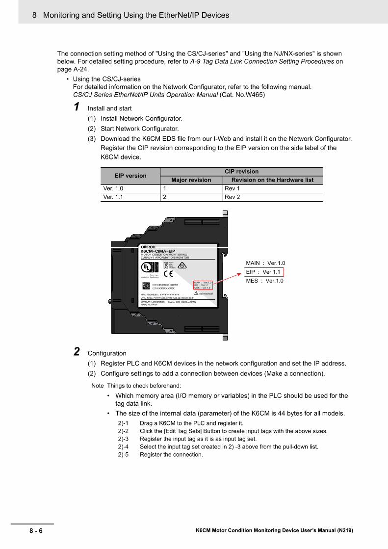
8 Monitoring and Setting Using the EtherNet/IP Devices
8 - 6 K6CM Motor Condition Monitoring Device User’s Manual (N219)
The connection setting method of "Using the CS/CJ-series" and "Using the NJ/NX-series" is shown below. For detailed setting procedure, refer to A-9 Tag Data Link Connection Setting Procedures on page A-24.
• Using the CS/CJ-seriesFor detailed information on the Network Configurator, refer to the following manual.CS/CJ Series EtherNet/IP Units Operation Manual (Cat. No.W465)
1 Install and start
(1) Install Network Configurator.
(2) Start Network Configurator.
(3) Download the K6CM EDS file from our I-Web and install it on the Network Configurator.
Register the CIP revision corresponding to the EIP version on the side label of the
K6CM device.
2 Configuration
(1) Register PLC and K6CM devices in the network configuration and set the IP address.
(2) Configure settings to add a connection between devices (Make a connection).
Note Things to check beforehand:
• Which memory area (I/O memory or variables) in the PLC should be used for the tag data link.
• The size of the internal data (parameter) of the K6CM is 44 bytes for all models.
EIP versionCIP revision
Major revision Revision on the Hardware list
Ver. 1.0 1 Rev 1
Ver. 1.1 2 Rev 2
2)-1 Drag a K6CM to the PLC and register it.2)-2 Click the [Edit Tag Sets] Button to create input tags with the above sizes.2)-3 Register the input tag as it is as input tag set.2)-4 Select the input tag set created in 2) -3 above from the pull-down list.2)-5 Register the connection.
See Manual
Equipment.MeasuringOpen-type
MOTOR CONDITION MONITORING
Kyoto, 600-8530, JAPANMADE IN JAPAN
MAC ADDRESS : URL: http://www.aso.omron.co.jp/download/
K6CM01OMR-REM-MSIP-
(01)04549734178693 EIP : Ver.1.1MAIN : Ver.1.0
CURRENT INFORMATION MONITOR
K6CM-CIMA-EIP
(21)XXXXXXXXXX MES : Ver.1.0
YYYYYYYYYYYY
EIP : Ver.1.1MAIN : Ver.1.0
MES : Ver.1.0
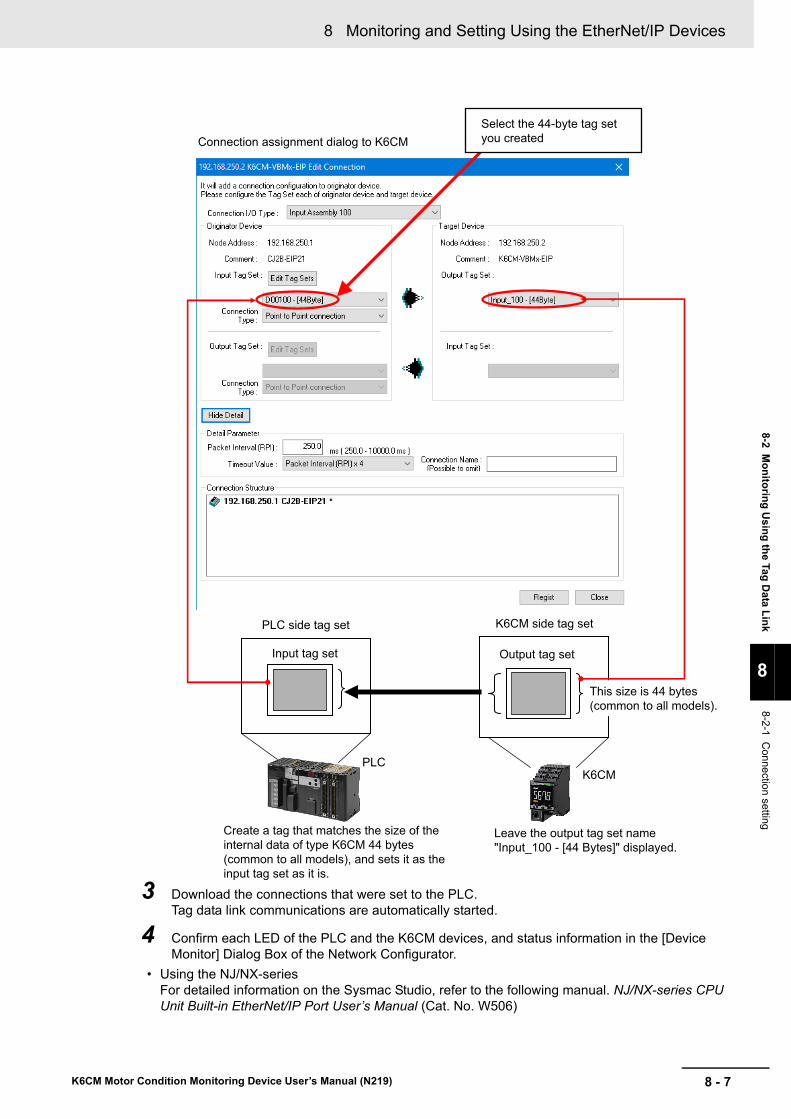
8 - 7
8 Monitoring and Setting Using the EtherNet/IP Devices
K6CM Motor Condition Monitoring Device User’s Manual (N219)
8-2 Mo
nito
ring
Usin
g th
e Tag D
ata Lin
k
8
8-2-1 C
onnection setting
3 Download the connections that were set to the PLC.Tag data link communications are automatically started.
4 Confirm each LED of the PLC and the K6CM devices, and status information in the [Device Monitor] Dialog Box of the Network Configurator.
• Using the NJ/NX-seriesFor detailed information on the Sysmac Studio, refer to the following manual. NJ/NX-series CPU Unit Built-in EtherNet/IP Port User’s Manual (Cat. No. W506)
Connection assignment dialog to K6CM
PLC side tag set K6CM side tag set
This size is 44 bytes (common to all models).
Output tag setInput tag set
PLCK6CM
Select the 44-byte tag set you created
Create a tag that matches the size of the internal data of type K6CM 44 bytes (common to all models), and sets it as the input tag set as it is.
Leave the output tag set name "Input_100 - [44 Bytes]" displayed.

8 Monitoring and Setting Using the EtherNet/IP Devices
8 - 8 K6CM Motor Condition Monitoring Device User’s Manual (N219)
1 Select [EtherNet/IP connection settings] from the [Tools] menu.
2 Right-click on the target device list in the tool box on the displayed Tab page and select the [Display EDS Library] menu.
3 Click the [Install] Button and import the EDS file of each K6CM device in the [EDS Library] Dialog Box.
4 Click [Add device] Button in [Toolbox] and select the K6CM device in the [Built-in Ether-Net/IP Port Settings Connection] Tab page.
5 Select the K6CM that has been added from the pull-down list in the [Target Device] column in "Connection" list in the Connection Tab Page of PLC side (i.e., originator side).
6 In the [Target Variable] column, press the [Ctrl] and [Space] keys at the same time and the available identification numbers are displayed on the pull down list, so select the identifica-tion number to use.
When you select an identification number, the size is automatically entered synchronously.
7 In the [Originator Variable] column, select the global variable of the NJ/NX-series CPU Unit. (Beforehand, it is necessary to register global variables whose network publish attribute is "Input" or "Output" in the global variable table.)
Select the K6CM is added to as a device. Press the Ctrl + Space Keys.
Select the ID 100 of the K6CM internal data.

8 - 9
8 Monitoring and Setting Using the EtherNet/IP Devices
K6CM Motor Condition Monitoring Device User’s Manual (N219)
8-2 Mo
nito
ring
Usin
g th
e Tag D
ata Lin
k
8
8-2-2 D
ata to be Tag D
ata Link Target in the K6C
M D
evice
The identification number (the instance ID of the Assembly object) and the size of internal data (Assem-bly object) to be tag data link target in the K6CM device are as follows.
The tag data link target data in the K6CM device is shown below.
For each K6CM device, it is as follows.
For detailed information on each data, refer to Section 6 Internal Data List of the K6CM Devices.
In both cases, it is possible to read from the K6CM device to the originator such as PLC.
All data is one word.
8-2-2 Data to be Tag Data Link Target in the K6CM Device
Identification Number and Size of Internal Data to be Tag Data Link
Identification number (Instance ID of Assembly object)
Size Direction of data
100 44 bytes common to all models Target (K6CM type) → Originator (such as PLC)
List of Internal Data to be Tag Data Link
Model Vibration & temperature type Insulation resistance typeComprehensive current diag-
nosis type
Word K6CM-VBM K6CM-ISM K6CM-CIM
+0 Measurement CPU version
+1 Main CPU version
+2 EIP CPU version
+3 K6CM status *1
+4 Running Time
+5 Number of triggers
+6 Acceleration status *2 Insulation resistance status *2 Current status *2
+7 Velocity (Present)Insulation resistance
(Present)Current (Present)
+8 Acceleration (Min.) Insulation resistance (Min.) Current (Min.)
+9 Acceleration (Max.) Insulation resistance (Max.) Current (Max.)
+10 Velocity status *2 Ior status *2 Degradation level status *2
+11 Velocity (Present) Ior (Present) Degradation level (Present)
+12 Velocity (Min.) Ior (Min.) Degradation level (Min.)
+13 Velocity (Max.) Ior (Max.) Degradation level (Max.)
+14 Motor temperature status *2 Ioc status
+15Motor temperature
(Present)Ioc (Present)
+16 Motor temperature (Min.)
+17 Motor temperature (Max.)
+18 Temperature Gap status *2
+19Temperature Gap
(Present)
+20 Temperature Gap (Min.)
+21 Temperature Gap (Max.)

8 Monitoring and Setting Using the EtherNet/IP Devices
8 - 10 K6CM Motor Condition Monitoring Device User’s Manual (N219)
*1. K6CM status
The K6CM status is handled as 2-byte data consisting of bit data in the table.
Example: TR1 to TR3 are "ON" and the measurement state is "During measurement and monitoring".
The 15th, 14th, 13th and 9th bits are all "1", so it is "1110 0010 0000 0000" in binary notation and "200" in hexadecimal notation. In the log file (CSV) of the Motor condition monitoring Tool, the K6CM status is in hexa-decimal notation.
Precautions for Correct Use
If the trigger function is used, when reading the measurement value with the tag data link, be sure to read it when the "Monitoring condition" bit (bit 09) of the K6CM status is 1 (ON).
If reading is performed when the "Measurement state" bit is 0 (OFF), there is a possibility that the value before measurement and monitoring (i.e., 0) or the value held after measurement and monitoring is being read.
Bit position StatusBit contents
0 1
00 Measurement CPU error Not occurred Occurrence
01 Measurement CPU data flash error Not occurred Occurrence
02 Main CPU error Not occurred Occurrence
03 Main CPU data flash error Not occurred Occurrence
04 Reserved.
05 Reserved.
06 Reserved.
07 Reserved.
08 Running Time status Unreached Reached
09 Monitoring condition Measuring and moni-toring is stopped
Measuring and moni-toring
10 Reserved.
11 Reserved.
12 Trigger input OFF ON
13 TR 1 (transistor 1output state) OFF ON
14 TR 2 (transistor 2output state) OFF ON
15 TR 3 (transistor 3output state) OFF ON

8 - 11
8 Monitoring and Setting Using the EtherNet/IP Devices
K6CM Motor Condition Monitoring Device User’s Manual (N219)
8-2 Mo
nito
ring
Usin
g th
e Tag D
ata Lin
k
8
8-2-2 D
ata to be Tag D
ata Link Target in the K6C
M D
evice
*2. Measurement status (common form of measured values)
The measurement status is handled as 2-byte data consisting of bit data in the table.
Example: The individual alarm result (Warning) is "ON".
The 12th bit is "1", so it is "0001 0000 0000 0000" in binary notation and "1000" in hexadecimal notation.
In the log file (CSV) of the Motor condition monitoring tool, the K6CM status is in hexadecimal notation.
Precautions for Correct Use
If there is no trigger, read the data when "Present value not measured" bit (bit 00) of the mea-surement status is 0.
There is a possibility that the value before measurement and monitoring (i.e., 0) is being read.
Bit position StatusBit contents
0 1
00 Present value unmeasured state Measured status Unmeasured status
01 Present value input error Not occurred Occurrence
02 Reserved.
03 Reserved.
04 Maximum value unmeasured state Measured status Unmeasured status
05 Maximum value input error Not occurred Occurrence
06 Reserved.
07 Reserved.
08 Minimum value unmeasured state Measured status Unmeasured status
09 Minimum value input error Not occurred Occurrence
10 Reserved.
11 Reserved.
12 Individual alarm result (Warning) OFF ON
13 Individual alarm result (Critical) OFF ON
14 Reserved.
15 Reserved.
8 Monitoring and Setting Using the EtherNet/IP Devices
8 - 12 K6CM Motor Condition Monitoring Device User’s Manual (N219)
8-3 Monitoring and Setting Using the CIP Message Communications and Examples of Communications Instructions
This section shows the contents of monitoring and setting using the CIP message communications and examples of communications instructions.
This section describes the data types of variables used in the CIP message communications.
The services supported by the objects in K6CM device are as follows.
8-3-1 Datatype List of Variables
Data type Description
USINT Unsigned 1 byte BIN
UINT Unsigned 1 word BIN
UDINT Unsigned 2 words BIN
BOOL 1 bit
SHORT_STRING Data size (1 byte) + 1 byte character string
STRING Data size (2 bytes) + 1 byte character string
WORD 1 word hex
DWORD 2 words hex
8-3-2 Services Supported by Objects in K6CM
Object name Class ID Contents
Monitor object 370 hex Reading the measurement values and other current values of the K6CM.
Setting object 371 hex Writing and reading the alarm setting values and other setting values of the K6CM.
Identity object 01 hex Reading the identification information of the K6CM.
Reading and resetting the state of the built-in EtherNet/IP port.
TCP/IP Interface object F5 hex Writing and reading of TCP/IP settings of the K6CM.
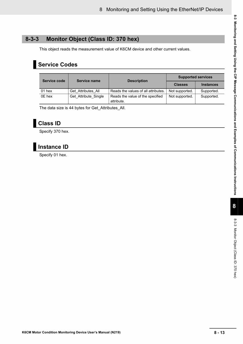
8 - 13
8 Monitoring and Setting Using the EtherNet/IP Devices
K6CM Motor Condition Monitoring Device User’s Manual (N219)
8-3 Mo
nito
ring
and
Settin
g U
sing
the C
IP M
essage C
om
mu
nicatio
ns an
d E
xamp
les of C
om
mu
nicatio
ns In
structio
ns
8
8-3-3 M
onitor O
bject (Class ID
: 370 hex)
This object reads the measurement value of K6CM device and other current values.
The data size is 44 bytes for Get_Attributes_All.
Specify 370 hex.
Specify 01 hex.
8-3-3 Monitor Object (Class ID: 370 hex)
Service Codes
Service code Service name DescriptionSupported services
Classes Instances
01 hex Get_Attributes_All Reads the values of all attributes. Not supported. Supported.
0E hex Get_Attribute_Single Reads the value of the specified attribute.
Not supported. Supported.
Class ID
Instance ID

8 Monitoring and Setting Using the EtherNet/IP Devices
8 - 14 K6CM Motor Condition Monitoring Device User’s Manual (N219)
Common to K6CM
*1. K6CM status
Precautions for Correct Use
If the trigger function is used, when reading the measurement value with the tag data link, be sure to read it when the "Monitoring condition" bit (bit 09) of the K6CM status is 1 (ON).
If reading is performed when the "Measurement state" bit is 0 (OFF), there is a possibility that the value before measurement and monitoring (i.e., 0) or the value held after measurement and monitoring is being read.
Attribute ID
Attri-bute ID
Parameter name DescriptionAttri-bute
Data
Data typeDefault value
64 hex Measurement CPU version
Measurement part version Read UINT Product specific
65 hex Main CPU version Main part version Read UINT Product specific
66 hex EIP CPU version EtherNet/IP part version Read UINT Product specific
67 hex K6CM status Displays the K6CM status
For details, refer to “K6CM status”. *1
Read WORD Depends on the con-dition.
68 hex Running Time Coefficient indicating lifetime of the K6CM device based on the product of operation time and internal temperature.
0000 to 0064 hex
Read UINT Depends on the con-dition.
69 hex Number of triggers Displays the total number of integration times of the trigger.
Make +1 every 100 iterations.
0 to 65535
Read UINT Depends on the con-dition.
69 hex or more: It depends on the K6CM model. Refer to the following and subsequent sections.
Bit position StatusBit contents
0 1
0 Measurement CPU error Not occurred Occurrence
1 Measurement CPU data flash error Not occurred Occurrence
2 Main CPU error Not occurred Occurrence
3 Main CPU data flash error Not occurred Occurrence
4 Reserved.
5 Reserved.
6 Reserved.
7 Reserved.
8 Running Time status Unreached Reached
9 Monitoring conditionMeasurement and monitoring stopped
During measurement and monitoring
10 Reserved.
11 Reserved.
12 Trigger input OFF ON
13 TR 1 (transistor 1output state) OFF ON
14 TR 2 (transistor 2 output state) OFF ON
15 TR 3 (transistor 3 output state) OFF ON

8 - 15
8 Monitoring and Setting Using the EtherNet/IP Devices
K6CM Motor Condition Monitoring Device User’s Manual (N219)
8-3 Mo
nito
ring
and
Settin
g U
sing
the C
IP M
essage C
om
mu
nicatio
ns an
d E
xamp
les of C
om
mu
nicatio
ns In
structio
ns
8
8-3-3 M
onitor O
bject (Class ID
: 370 hex)
Vibration & temperature type (K6CM-VBM)
*1. Depends on measured value.
Insulation resistance type (K6CM-ISM)
Attri-bute ID
Parameter name DescriptionAttri-bute
Data
Data type
Default value
6A hex Acceleration status Displays the measurement status.
For details, refer to "Measurement status
(common form of measured value)". *1
Read UINT Depends on the condition.
6B hex Acceleration (Present) Measured value of acceleration (present value)
Read UINT * 1
6C hex Acceleration (Min.) Measured value of acceleration (Min.) Read UINT * 1
6D hex Acceleration (Max.) Measured value of acceleration (Max.) Read UINT * 1
6E hex Velocity status Displays the measurement status.
For details, refer to "Measurement status
(common form of measured value)". *1
Read UINT Depends on the condition.
6F hex Velocity (Present) Measured value of velocity (present value) Read UINT * 1
70 hex Velocity (Min.) Measured value of velocity (Min.) Read UINT * 1
71 hex Velocity (Max.) Measured value of velocity (Max.) Read UINT * 1
72 hex Motor temperature sta-tus
Displays the measurement status.
For details, refer to "Measurement status
(common form of measured value)". *1
Read UINT Depends on the condition.
73 hex Motor temperature (Present)
Measured value of motor temperature (pres-ent value)
Read UINT * 1
74 hex Motor temperature (Min.) Measured value of motor temperature (Min.) Read UINT * 1
75 hex Motor temperature (Max.)
Measured value of motor temperature (Max.)
Read UINT * 1
76 hex Temperature Gap status Displays the measurement status.
For details, refer to "Measurement status
(common form of measured value)". *1
Read UINT Depends on the condition.
77 hex Temperature Gap (Pres-ent)
Measured value of temperature gap (pres-ent value)
Read UINT * 1
78 hex Temperature Gap (Min.) Measured value of temperature gap (Min.) Read UINT * 1
79 hex Temperature Gap (Max.) Measured value of temperature gap (Max.) Read UINT * 1
Attri-bute ID
Parameter name DescriptionAttri-bute
Data
Data type
Default value
6A hex Insulation resistance sta-tus
Displays the measurement status.
For details, refer to "Measurement status
(common form of measured value)". *1
Read UINT Depends on the condition.
6B hex Insulation resistance (Present)
Measured value of insulation resistance (present value)
Read UINT * 1
6C hex Insulation resistance (Min.)
Measured value of insulation resistance (Min.)
Read UINT * 1
6D hex Insulation resistance (Max.)
Measured value of insulation resistance (Max.)
Read UINT * 1
6E hex Ior status Displays the measurement status.
For details, refer to "Measurement status
(common form of measured value)". *1
Read UINT Depends on the condition.
6F hex Ior (Present) Measured value of Ior (present value) Read UINT * 1
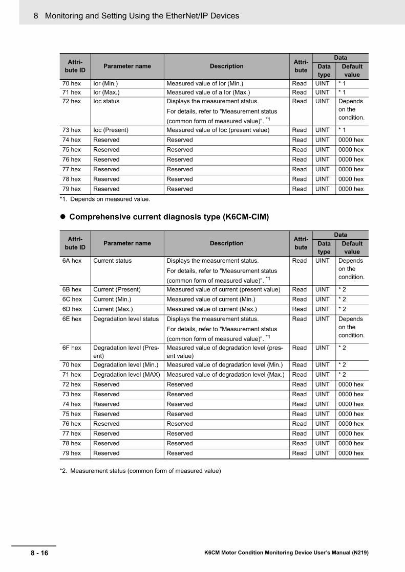
8 Monitoring and Setting Using the EtherNet/IP Devices
8 - 16 K6CM Motor Condition Monitoring Device User’s Manual (N219)
*1. Depends on measured value.
Comprehensive current diagnosis type (K6CM-CIM)
*2. Measurement status (common form of measured value)
70 hex Ior (Min.) Measured value of Ior (Min.) Read UINT * 1
71 hex Ior (Max.) Measured value of a Ior (Max.) Read UINT * 1
72 hex Ioc status Displays the measurement status.
For details, refer to "Measurement status
(common form of measured value)". *1
Read UINT Depends on the condition.
73 hex Ioc (Present) Measured value of Ioc (present value) Read UINT * 1
74 hex Reserved Reserved Read UINT 0000 hex
75 hex Reserved Reserved Read UINT 0000 hex
76 hex Reserved Reserved Read UINT 0000 hex
77 hex Reserved Reserved Read UINT 0000 hex
78 hex Reserved Reserved Read UINT 0000 hex
79 hex Reserved Reserved Read UINT 0000 hex
Attri-bute ID
Parameter name DescriptionAttri-bute
Data
Data type
Default value
6A hex Current status Displays the measurement status.
For details, refer to "Measurement status
(common form of measured value)". *1
Read UINT Depends on the condition.
6B hex Current (Present) Measured value of current (present value) Read UINT * 2
6C hex Current (Min.) Measured value of current (Min.) Read UINT * 2
6D hex Current (Max.) Measured value of current (Max.) Read UINT * 2
6E hex Degradation level status Displays the measurement status.
For details, refer to "Measurement status
(common form of measured value)". *1
Read UINT Depends on the condition.
6F hex Degradation level (Pres-ent)
Measured value of degradation level (pres-ent value)
Read UINT * 2
70 hex Degradation level (Min.) Measured value of degradation level (Min.) Read UINT * 2
71 hex Degradation level (MAX) Measured value of degradation level (Max.) Read UINT * 2
72 hex Reserved Reserved Read UINT 0000 hex
73 hex Reserved Reserved Read UINT 0000 hex
74 hex Reserved Reserved Read UINT 0000 hex
75 hex Reserved Reserved Read UINT 0000 hex
76 hex Reserved Reserved Read UINT 0000 hex
77 hex Reserved Reserved Read UINT 0000 hex
78 hex Reserved Reserved Read UINT 0000 hex
79 hex Reserved Reserved Read UINT 0000 hex
Attri-bute ID
Parameter name DescriptionAttri-bute
Data
Data type
Default value
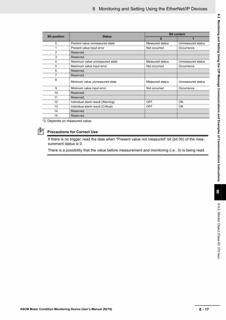
8 - 17
8 Monitoring and Setting Using the EtherNet/IP Devices
K6CM Motor Condition Monitoring Device User’s Manual (N219)
8-3 Mo
nito
ring
and
Settin
g U
sing
the C
IP M
essage C
om
mu
nicatio
ns an
d E
xamp
les of C
om
mu
nicatio
ns In
structio
ns
8
8-3-3 M
onitor O
bject (Class ID
: 370 hex)
*2. Depends on measured value.
Precautions for Correct Use
If there is no trigger, read the data when "Present value not measured" bit (bit 00) of the mea-surement status is 0.
There is a possibility that the value before measurement and monitoring (i.e., 0) is being read.
Bit position StatusBit content
0 1
0 Present value unmeasured state Measured status Unmeasured status
1 Present value input error Not occurred Occurrence
2 Reserved.
3 Reserved.
4 Maximum value unmeasured state Measured status Unmeasured status
5 Maximum value input error Not occurred Occurrence
6 Reserved.
7 Reserved.
8Minimum value unmeasured state Measured status Unmeasured status
9 Minimum value input error Not occurred Occurrence
10 Reserved.
11 Reserved.
12 Individual alarm result (Warning) OFF ON
13 Individual alarm result (Critical) OFF ON
14 Reserved.
15 Reserved.

8 Monitoring and Setting Using the EtherNet/IP Devices
8 - 18 K6CM Motor Condition Monitoring Device User’s Manual (N219)
This object sets up the K6CM device itself and sets up measurement and alarm.
*1. Be sure to set "0" to the attribute IDs: 64 hex and 65 hex.When you perform various resets, set with Set_Attribute_Single.
*2. Attribute IDs 64 to 6D hex and 6E to 78 hex are read.Functions implemented by upgrading such as A0 hex of attribute ID can not be read by Get_Attributes_All, but can be read by Get_Attribute_Single.
The data size is 42 bytes for Get_Attributes_All.
Specify 371 hex.
Specify 01 hex.
Common to K6CM
8-3-4 Setting Object (Class ID: 371 hex)
Service Code
Service code Service name DescriptionSupported services
Classes Instances
02 hex Set_Attributes_All Write values to all attributes.*1 Not supported. Supported.
10 hex Set_Attribute_Single Write the value of the speci-fied attribute.
Not supported. Supported.
01 hex Get_Attributes_All Reads the values of all attri-butes.
Not supported. Supported. *2
0E hex Get _Attribute_Single Reads the value of the speci-fied attribute.
Not supported. Supported.
Class ID
Instance ID
Attribute ID
Attri-bute ID
Parameter name
DescriptionAttri-bute
Data
Data type Default value
64 hex Software reset Restarts the K6CM device. It is used to validate the setting after changing the set-
ting value.*1
Rising from 0 to 1: Execute (soft reset)
Write UINT 0000 hex
65 hex Max./min. reset
Initializes the MAX / MIN value.
OFF to ON: Execute (initialize max. and min. value)
Write UINT 0000 hex
66 hex Display value type
Sets which measurement value is dis-played in the 7 segment display on the front of the K6CM.
0: PV
1: MIN
2: MAX
Write UINT 0000 hex

8 - 19
8 Monitoring and Setting Using the EtherNet/IP Devices
K6CM Motor Condition Monitoring Device User’s Manual (N219)
8-3 Mo
nito
ring
and
Settin
g U
sing
the C
IP M
essage C
om
mu
nicatio
ns an
d E
xamp
les of C
om
mu
nicatio
ns In
structio
ns
8
8-3-4 S
etting O
bject (Class ID
: 371 hex)
*1. If you execute the software reset after writing to the attribute ID 65 to 78 hex or A 0 hex, wait for about 1 sec-ond, considering the time until these setting values are saved, and then execute the software reset.
*2. Transistor output type is a function implemented by version upgrade.EIP CPU version: Implemented in the K6C device with version 1.10 or higher. The EIP CPU version can be confirmed by the following method.
• Confirm the description of the side label of the K6C device
• Confirmation the read data using the software tool or EtherNet/IP communication
Vibration & temperature type (K6CM-VBM)
67 hex Trigger mode Selects the trigger mode.
0: Always
1: External trigger
2: Internal trigger
Write UINT 0000 hex
68 hex Trigger type Sets the trigger type.
0: Rising
1: Falling edge
2: Level
Write UINT 0000 hex
69 hex Trigger level Sets the trigger level.
Note : Unit and decimal point position follow measured values. (Refer to Section 6 How to Use the Soft-ware Tool)
Write UINT 0000 hex
6A hex Monitoring time
Sets the monitoring time.
1 to 6000 (unit: 0.1 sec)
Write UINT 0001 hex (1)
(Unit: 0.1 sec-onds)
6B hex Alarm latch Sets enable/disable of alarm latch func-tion.
0: Disable (no latch)
1: Enable (with latch)
Write UINT 0001 hex
6C hex Use Running Time
Sets the usage or nonuse of K6CM remaining capacity function.
0: OFF (not used)
1: ON (use)
Write UINT 0000 hex
6D hex Moving aver-age times
Every time the measured value is sam-pled, the data of the past n times including the sampling data of that time is averaged.
0: OFF
1: 2 times
2: 4 times
3: 8 times
4: 16 times
5: 32 times
Write UINT Vibration & temperature type, Insulation resistance type: 0000 hex
Comprehen-sive current diagnosis type: 0003 hex
A0 hex Transistor out-
put type*2
Select transistor output type.
0: Normally closed
1: Normally open
Write UINT 0000 hex
Attri-bute ID
Parameter name
DescriptionAttri-bute
Data
Data type Default value
6E hex Temperature unit
Sets the temperature unit.
0: °C
1: °F
Write UINT 0000 hex
Attri-bute ID
Parameter name
DescriptionAttri-bute
Data
Data type Default value

8 Monitoring and Setting Using the EtherNet/IP Devices
8 - 20 K6CM Motor Condition Monitoring Device User’s Manual (N219)
Insulation resistance type (K6CM-ISM)
6F hex Reserved. Reserved. Write UINT 0000 hex
70 hex Reserved. Reserved. Write UINT 0000 hex
71 hex Acceleration alarm (Warn-ing)
Sets the acceleration alarm threshold (Warning).
0 to 9999 (Unit: 0.01 G)
(0000 to 270F hex)
Write UINT 0032 hex (50)
(Unit: 0.01 G)
72 hex Acceleration alarm (Critical)
Sets the acceleration alarm threshold (Critical).
0 to 9999 (Unit: 0.01 G)
(0000 to 270F hex)
Write UINT 0064 hex (100)
(Unit: 0.01 G)
73 hex Velocity alarm (Warning)
Sets the velocity alarm threshold (Warn-ing).
0 to 9999 (Unit: 0.01 mm/s)
(0000 to 270F hex)
Write UINT 0FA0 hex (4000)
(Unit: 0.01 mm/s)
74 hex Velocity alarm (Critical)
Sets the velocity alarm threshold (Critical).
0 to 9999 (Unit: 0.01 mm/s)
(0000 to 270F hex)
Write UINT 1194 hex (4500)
(Unit: 0.01 mm/s)
75 hex Motor tem-perature alarm (Warning)
Sets the motor temperature alarm thresh-old (Warning).
0 to 9999 (Unit: °C)
(0000 to 270F hex)
Write UINT 0050 hex (80)
(Unit: °C)
76 hex Motor tem-perature alarm (Critical)
Sets the motor temperature alarm thresh-old (Critical).
0 to 9999 (Unit: °C)
(0000 to 270F hex)
Write UINT 0050 hex (80)
(Unit: °C)
77 hex Temperature gap alarm (Warning)
Sets the temperature gap alarm (Warn-ing).
0 to 9999 (Unit: °C)
(0000 to 270F hex)
Write UINT 0050 hex (80)
(Unit: °C)
78 hex Temperature gap alarm (Critical)
Sets the temperature gap alarm (Critical).
0 to 9999 (Unit: °C)
(0000 to 270F hex)
Write UINT 0050 hex (80)
(Unit: °C)
Attri-bute ID
Parameter name DescriptionAttri-bute
Data
Data type Default value
6E hex Applicable circuit Sets the applicable circuit.
0: Three-phase three-wire S-phase ground
1: Three-phase four-wire N-phase grounded load side delta connection
Write UINT 0000 hex
Attri-bute ID
Parameter name
DescriptionAttri-bute
Data
Data type Default value
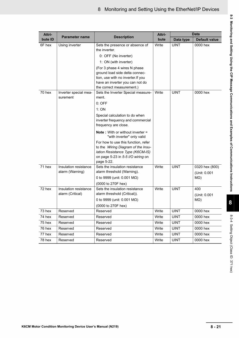
8 - 21
8 Monitoring and Setting Using the EtherNet/IP Devices
K6CM Motor Condition Monitoring Device User’s Manual (N219)
8-3 Mo
nito
ring
and
Settin
g U
sing
the C
IP M
essage C
om
mu
nicatio
ns an
d E
xamp
les of C
om
mu
nicatio
ns In
structio
ns
8
8-3-4 S
etting O
bject (Class ID
: 371 hex)
6F hex Using inverter Sets the presence or absence of the inverter.
0: OFF (No inverter)
1: ON (with inverter)
(For 3 phase 4 wires N phase ground load side delta connec-tion, use with no inverter.If you have an inverter you can not do the correct measurement.)
Write UINT 0000 hex
70 hex Inverter special mea-surement
Sets the Inverter Special measure-ment.
0: OFF
1: ON
Special calculation to do when inverter frequency and commercial frequency are close.
Note : With or without inverter = "with inverter" only valid
For how to use this function, refer to the Wiring Diagram of the Insu-lation Resistance Type (K6CM-IS) on page 5-23 in 5-5 I/O wiring on page 5-22.
Write UINT 0000 hex
71 hex Insulation resistance alarm (Warning)
Sets the insulation resistance alarm threshold (Warning).
0 to 9999 (unit: 0.001 MΩ)
(0000 to 270F hex)
Write UINT 0320 hex (800)
(Unit: 0.001 MΩ)
72 hex Insulation resistance alarm (Critical)
Sets the insulation resistance alarm threshold (Critical)).
0 to 9999 (unit: 0.001 MΩ)
(0000 to 270F hex)
Write UINT 400
(Unit: 0.001 MΩ)
73 hex Reserved Reserved Write UINT 0000 hex
74 hex Reserved Reserved Write UINT 0000 hex
75 hex Reserved Reserved Write UINT 0000 hex
76 hex Reserved Reserved Write UINT 0000 hex
77 hex Reserved Reserved Write UINT 0000 hex
78 hex Reserved Reserved Write UINT 0000 hex
Attri-bute ID
Parameter name DescriptionAttri-bute
Data
Data type Default value

8 Monitoring and Setting Using the EtherNet/IP Devices
8 - 22 K6CM Motor Condition Monitoring Device User’s Manual (N219)
Comprehensive current diagnosis type (K6CM-CIM)
Attri-bute ID
Parameter name
DescriptionAttri-bute
Data
Data type Default value
6E hex Current range Sets the current range.
0: 5 A
1: 25 A
2: 100 A
3: 200 A
4: 400 A
5: 600 A
Write UINT 0003 hex
6F hex Reserved. Reserved. Write UINT 0000 hex
70 hex Reserved. Reserved. Write UINT 0000 hex
71 hex Current alarm (Warning)
Sets the current alarm (Warning).
0 to 9999
(Unit in the 5 A range: 0.01 A)
(Unit in other ranges: 0.1 A)
(0000 to 270F hex)
Write UINT 07D0 hex (2000)
(Unit in the 5 A range: 0.01 A)
(Unit in other ranges: 0.1 A)
72 hex Current alarm (Critical)
Sets the current alarm (Critical).
0 to 9999
(Unit in the 5 A range: 0.01 A)
(Unit in other ranges: 0.1 A)
(0000 to 270F hex)
Write UINT 07D0 hex (2000)
(Unit in the 5 A range: 0.01 A)
(Unit in other ranges: 0.1 A)
73 hex Degradation level alarm (Warning)
Sets the degradation level alarm (Warn-ing).
0 to 999
(0000 to 03E7 hex)
Write UINT 001E hex (30)
74 hex Degradation level alarm (Critical)
Sets the degradation level alarm (Critical).
0 to 999
(0000 to 03E7 hex)
Write UINT 0032 hex (50)
75 hex Reserved Reserved Write UINT 0000 hex
76 hex Reserved Reserved Write UINT 0000 hex
77 hex Reserved Reserved Write UINT 0000 hex
78 hex Reserved Reserved Write UINT 0000 hex
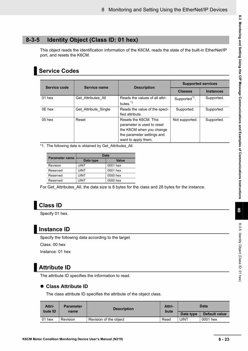
8 - 23
8 Monitoring and Setting Using the EtherNet/IP Devices
K6CM Motor Condition Monitoring Device User’s Manual (N219)
8-3 Mo
nito
ring
and
Settin
g U
sing
the C
IP M
essage C
om
mu
nicatio
ns an
d E
xamp
les of C
om
mu
nicatio
ns In
structio
ns
8
8-3-5 Identity O
bject (Class ID
: 01 hex)
This object reads the identification information of the K6CM, reads the state of the built-in EtherNet/IP port, and resets the K6CM.
*1. The following data is obtained by Get_Attributes_All.
For Get_Attributes_All, the data size is 8 bytes for the class and 28 bytes for the instance.
Specify 01 hex.
Specify the following data according to the target.
Class: 00 hex
Instance: 01 hex
The attribute ID specifies the information to read.
Class Attribute ID
The class attribute ID specifies the attribute of the object class.
8-3-5 Identity Object (Class ID: 01 hex)
Service Codes
Service code Service name DescriptionSupported services
Classes Instances
01 hex Get_Attributes_All Reads the values of all attri-
butes.*1Supported*1. Supported.
0E hex Get_Attribute_Single Reads the value of the speci-fied attribute.
Supported. Supported.
05 hex Reset Resets the K6CM. This parameter is used to reset the K6CM when you change the parameter settings and want to apply them.
Not supported. Supported.
Parameter nameData
Data type Value
Revision UINT 0001 hex
Reserved UINT 0001 hex
Reserved UINT 0000 hex
Reserved UINT 0000 hex
Class ID
Instance ID
Attribute ID
Attri-bute ID
Parameter name
DescriptionAttri-bute
Data
Data type Default value
01 hex Revision Revision of the object Read UINT 0001 hex

8 Monitoring and Setting Using the EtherNet/IP Devices
8 - 24 K6CM Motor Condition Monitoring Device User’s Manual (N219)
Instance Attribute ID
The instance attribute ID specifies the per-instance attribute.
*1. Product Codes
The number of characters (0D hex) is added to the beginning of the model name.
*2. Status of the EtherNet/IP Port
Attri-bute ID
Parameter name DescriptionAttri-bute
Data
Data type Default value
01 hex Vendor ID Vendor ID Read UINT 002F hex (Fixed value)
02 hex Device Type Device type Read UINT 0303 hex (Fixed value)
03 hex Product Code Product code Read UINT For details, refer to
"Product Codes". *1
04 hex Revision Device revision
Example: For Revision 1.01
Read Struct of - - -
Major Revision Major Revision = 1 Read USINT Product specific
Minor Revision Minor revision = 1 Read USINT Product specific
05 hex Status Status of the built-in Ether-Net/IP port
For details, refer to "Status of
the EtherNet/IP Port". *2
Read WORD - - -
06 hex Serial Number Serial number Read UDINT Product specific
(Serial number)
07 hex Product Name Model name Read SHORT_STRING
Product specificFor details, refer to
"Product Codes". *1
Product Code Model name
508 K6CM-VBMx-EIP
509 K6CM-ISMx-EIP
511 K6CM-CIMx-EIP
Bit Name Description
0 Owned Indicates when the built-in EtherNet/IP port has an open connection as the target of a tag data link.
1 Reserved. Always FALSE.
2 Configured Tag data link settings exist.
0: Disable (no latch)
1: Enable (with latch)
3 Reserved. Always FALSE.
4 to 7 Extended Device Status
Vendor specific setting area
Indicates the status of the built-in EtherNet/IP port.
0: Not used
1: Not used
2: One or more I/O connection failures
3: I/O connection is not established
4: Not used
5: Serious defect occurred (MS Criticality)
6: One or more I/O connections are established and one or more are in the RUN state
7: One or more I/O connections are established and all are idle
8 to 15: Unused
8 Minor Recoverable Fault
Vendor specific setting area
Always FALSE.
9 Minor Unrecoverable Fault
Vendor specific setting area
Always FALSE.

8 - 25
8 Monitoring and Setting Using the EtherNet/IP Devices
K6CM Motor Condition Monitoring Device User’s Manual (N219)
8-3 Mo
nito
ring
and
Settin
g U
sing
the C
IP M
essage C
om
mu
nicatio
ns an
d E
xamp
les of C
om
mu
nicatio
ns In
structio
ns
8
8-3-6 T
CP
/IP Interface O
bject (C
lass ID: F
5 hex)
This object is used to read and write settings such as the IP address, subnet mask, and default gate- way.
The data size is 96 bytes (by default) for Get_Attributes_All.
Specify F5 hex.
Specify 01 hex.
The attribute ID specifies the information to read.
Class Attribute ID
The class attribute ID specifies the attribute of the object class.
10 Major Recoverable Fault
Vendor specific setting area
When the MS indicator matches conditions of the flashing red: True
11 Major Unrecoverable Fault
Vendor specific setting area
When the MS indicator matches conditions of the flashing red: True
12 to 15 Reserved. Always FALSE.
8-3-6 TCP/IP Interface Object (Class ID: F5 hex)
Service Codes
Service code Service name DescriptionSupported services
Classes Instances
01 hex Get_Attributes_All Reads the values of all attri-butes.
Not supported. Supported.
0E hex Get_Attribute_Single Reads the value of the speci-fied attribute.
Supported. Supported.
10 hex Set_Attribute_Single Writes the value to the speci-fied attribute.
Not supported. Supported.
Class ID
Instance ID
Attribute ID
Attribute IDParameter
nameDescription Attribute
Data
Data type Default value
01 hex Revision Revision of the object Read UINT 0004 hex
Bit Name Description
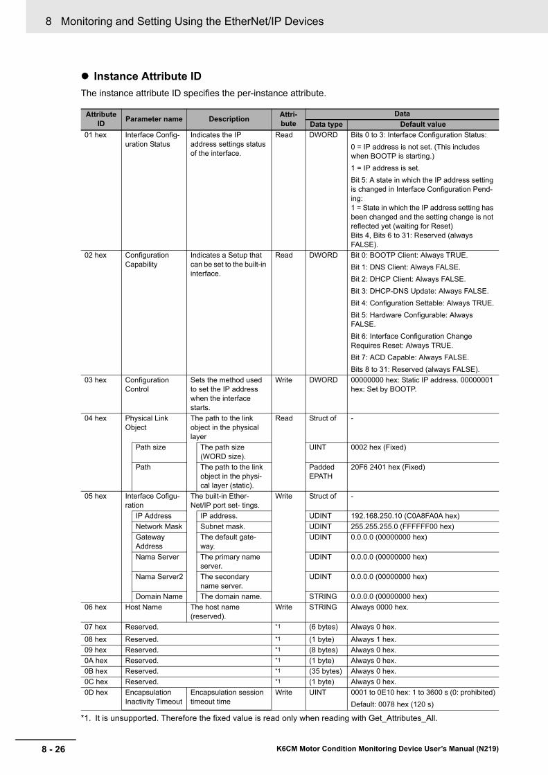
8 Monitoring and Setting Using the EtherNet/IP Devices
8 - 26 K6CM Motor Condition Monitoring Device User’s Manual (N219)
Instance Attribute ID
The instance attribute ID specifies the per-instance attribute.
Attribute ID
Parameter name DescriptionAttri-bute
Data
Data type Default value
01 hex Interface Config-uration Status
Indicates the IP address settings status of the interface.
Read DWORD Bits 0 to 3: Interface Configuration Status:
0 = IP address is not set. (This includes when BOOTP is starting.)
1 = IP address is set.
Bit 5: A state in which the IP address setting is changed in Interface Configuration Pend-ing: 1 = State in which the IP address setting has been changed and the setting change is not reflected yet (waiting for Reset)Bits 4, Bits 6 to 31: Reserved (always FALSE).
02 hex Configuration Capability
Indicates a Setup that can be set to the built-in interface.
Read DWORD Bit 0: BOOTP Client: Always TRUE.
Bit 1: DNS Client: Always FALSE.
Bit 2: DHCP Client: Always FALSE.
Bit 3: DHCP-DNS Update: Always FALSE.
Bit 4: Configuration Settable: Always TRUE.
Bit 5: Hardware Configurable: Always FALSE.
Bit 6: Interface Configuration Change Requires Reset: Always TRUE.
Bit 7: ACD Capable: Always FALSE.
Bits 8 to 31: Reserved (always FALSE).
03 hex Configuration Control
Sets the method used to set the IP address when the interface starts.
Write DWORD 00000000 hex: Static IP address. 00000001 hex: Set by BOOTP.
04 hex Physical Link Object
The path to the link object in the physical layer
Read Struct of -
Path size The path size (WORD size).
UINT 0002 hex (Fixed)
Path The path to the link object in the physi-cal layer (static).
Padded EPATH
20F6 2401 hex (Fixed)
05 hex Interface Cofigu-ration
The built-in Ether-Net/IP port set- tings.
Write Struct of -
IP Address IP address. UDINT 192.168.250.10 (C0A8FA0A hex)
Network Mask Subnet mask. UDINT 255.255.255.0 (FFFFFF00 hex)
Gateway Address
The default gate-way.
UDINT 0.0.0.0 (00000000 hex)
Nama Server The primary name server.
UDINT 0.0.0.0 (00000000 hex)
Nama Server2 The secondary name server.
UDINT 0.0.0.0 (00000000 hex)
Domain Name The domain name. STRING 0.0.0.0 (00000000 hex)
06 hex Host Name The host name (reserved).
Write STRING Always 0000 hex.
07 hex Reserved. *1
*1. It is unsupported. Therefore the fixed value is read only when reading with Get_Attributes_All.
(6 bytes) Always 0 hex.
08 hex Reserved. *1 (1 byte) Always 1 hex.
09 hex Reserved. *1 (8 bytes) Always 0 hex.
0A hex Reserved. *1 (1 byte) Always 0 hex.
0B hex Reserved. *1 (35 bytes) Always 0 hex.
0C hex Reserved. *1 (1 byte) Always 0 hex.
0D hex Encapsulation Inactivity Timeout
Encapsulation session timeout time
Write UINT 0001 to 0E10 hex: 1 to 3600 s (0: prohibited)
Default: 0078 hex (120 s)

8 - 27
8 Monitoring and Setting Using the EtherNet/IP Devices
K6CM Motor Condition Monitoring Device User’s Manual (N219)
8-3 Mo
nito
ring
and
Settin
g U
sing
the C
IP M
essage C
om
mu
nicatio
ns an
d E
xamp
les of C
om
mu
nicatio
ns In
structio
ns
8
8-3-7 E
xamples of C
IP M
essage C
omm
unications Instruction
The following is an example of reading the measurement value of the K6CM using the CIP message communications instruction of the NJ/NX-series Controller.
The CIPUCMMSend (Send Explicit Message UCMM) instruction is used a CIP message communica-tions instruction.
Send the following CIP message.
• Service code: 16#0E (Get_Attribute_Single: read the value of the specified attribute)
• Class ID: 370 hex
• Instance ID: 01 hex
• Attribute ID: 6F hex (degradation level (present value))
The CIPUCMMSend instruction sends the command data "ServiceDat" as a UCMM message corre-sponding to the service specified by the "ServiceCode".
The destination is specified by the route path "RoutePath". The request path is specified by "RqPath".
Set the following value to the input variable of the above communications instruction.
8-3-7 Examples of CIP Message Communications Instruction
Input variable of the commu-
nications instruction
SpecificationValue to pass to input variable
Meaning
RoutePath Route path specifi-cation
02\IPaddress "02" specifies the output from the NJ-series built-in EtherNet/IP port or the NX-series ibuilt-in EtherNet/IP port 1.
The IP address specifies the IP address of Comprehensive cur-rent diagnosis type (K6CM-CIM).
TimeOut Timeout time spec-ification
UINT#20 Timeout time is specified.
The integer "20" specifies 2.0 s as the timeout time. It is 0.1s unit.
ServiceCode Service code BYTE#16#0E 0EHex specifies "Service_Attribute_Single" as a service code which reads the value of the specified attribute.
Execution condition
Send Explicit Message UCMM instruction
Done
CIPUCMMSend
RespSizeErrorIDEx
ErrorErrorID
RoutePath
RqPathServiceDat
TimeOutServiceCode
SizeRespServiceDat
Execute
Response data sizeExpansion error codeError codeErrorBusyDone
Busy
User-defined variable to receive response data
UINT#0 (fixed)Not used (dummy variable)
User-defined variable indicating Request pathBYTE#16#0E
UINT#20 (when 2.0second)
02\IP address

8 Monitoring and Setting Using the EtherNet/IP Devices
8 - 28 K6CM Motor Condition Monitoring Device User’s Manual (N219)
RqPath Request path specification
Specified by user variable indicating the Request path
Specify a user-defined variable.
Use the data type "_sREQUEST_PATH" corresponding to the input variable "RqPath". You can use any variable name.
Specify the following.
Class ID, Instance ID, Attribute ID
Example) Deterioration degree (current value): Specify the fol-lowing.
• ClassID: = 370 hex (meaning "K6CM monitor object")
• InstanceID: = 01 hex (fixed)
• IsAttributeID: = TRUE (meaning to use an attribute ID)
AttributeID: = 6 FHex (meaning degradation level (Present))
ServiceDat Data to send Not used (dummy variable)
Since the service code is "read", specify a Dummy variable (any data type).
Size Number of ele-ments to send
UINT#0 Since the service code is "read", specify integer 0 (fixed).
RespService-Dat
Response data specification
Specified by user variable r variable to receive response data
Specify a user-defined variable.
Use the data type "ARRAY [0..10] OF BYTE" corresponding to the input/output variable "RespServiceDat". You can use any variable name.
Input variable of the commu-
nications instruction
SpecificationValue to pass to input variable
Meaning

8 - 29
8 Monitoring and Setting Using the EtherNet/IP Devices
K6CM Motor Condition Monitoring Device User’s Manual (N219)
8-4 Sam
ple P
rog
ram fo
r the N
J/NX
-series
8
8-4-1 S
am
ple Program
Overw
iew
8-4 Sample Program for the NJ/NX-series
This section describes the motor monitoring procedure using K6CM devices and NJ/NX-series.Control-ler.
The following processing can be executed using the sample program described here.
• Obtains measurement data of up to 100 K6CM devices with one PLC (NJ/NX series)
• Outputs the obtained measurement data as a CSV file to the SD Memory Card mounted on the PLC
The output CSV file name is determined from the date of data obtainment according to the internal clock of the PLC.
(Example: file name: K6CM_20171208-1520.CSV in the case of 15:20 on December 8, 2017)
The following are the parameters that can be set in this sample program, what to prepare, the network configuration example, and the output CSV file specifications.
What to Prepare
K6CM devices (Any model, up to 100 Units in total can be connected.)
Switching hub (SW hub)
STP cable (for Ethernet communications)
8-4-1 Sample Program Overwiew
Parameters that can be set in this sample program
ParametersInitial value
Remarks
Number of data collection devices [Units]
20 Set according to the number of K6CM devices to be used.
Up to 100 Units can be set.
Communications retry count [times]
1 Change as necessary.
Setting the number of retries is effective for communications failure due to irregular external noise. However, since wait time occurs correspondingly, the setting of the data collection cycle shown below will be affected.
Data collection cycle [sec] 30 If there is a K6CM device that does not respond to the communications, the follow-ing wait time will occur at maximum. Therefore, it is necessary to set it to a value larger than the expected maximum waiting time.
Maximum waiting time [sec] = (CIP timeout time × 4) × (1 + communications retry count) × number of cycles+ CSV output time
CIP timeout time: 1 s (initial value)
CSV output time: about 3 s
Number of cycles: An integer obtained by dividing the number of data collection devices by the number of parallel connection (initial value: 10) (The decimal point is rounded up.)
Example: calculation with initial value
Maximum waiting time = (1 × 4) × (1 + 1) × (20 ÷ 10) + 4 = 20 s ->
The data collection cycle requires 20 s or more with a margin
What to Prepar and Network Configuration Example

8 Monitoring and Setting Using the EtherNet/IP Devices
8 - 30 K6CM Motor Condition Monitoring Device User’s Manual (N219)
PC (Sysmac Studio installed)
PLC and SD Memory Card (operation confirmed in NJ/NX-series)
Sample program project file (***. Smc 2)
Network Configuration Example
Each setting is required to prevent the IP address duplication.
The specifications of the CSV file output to the SD Memory Card of the PLC are shown below.
At the beginning of the CSV file, there is a K6CM device profile data, and collection time stamps and collected data are output following it.
K6CM Device Profile Data
*1. Specific to the K6CM type
File Specifications of Output CSV
Common to K6CM all models
Spe-cific to
the K6C
M type
IP address
Prod-uct name
Mea-sure-ment CPU Ver-sion
Main CPU ver-sion
EIP CPU ver-sion
Soft-ware reset
Maxi-mum and Mini-mum Reset
Dis-play value type
Trig-ger mode
Trig-ger type
Trig-ger level
Moni-tor-ing time
Alarm latch
Use Run-ning Time
Mov-ing aver-age times
Tran-sistor out-put type
*1
K6CM-VBMx Temperature unit
K6CM-ISMx Applicable circuit Using inverter Inverter special measurement
K6CM-CIMx Current range
IP: 192.168.250.1
IP: 192.168.250.2
IP: 192.168.250.101 IP: 192.168.250.102 IP: 192.168.250.103
PC
PLC
SW hub
K6CM K6CM K6CM
SW hub
K6CM devices(Any number of Units)
K6CM device profile data
Collection timestamps
Collection datafor 1st K6CM
Collection datafor 2nd K6CM
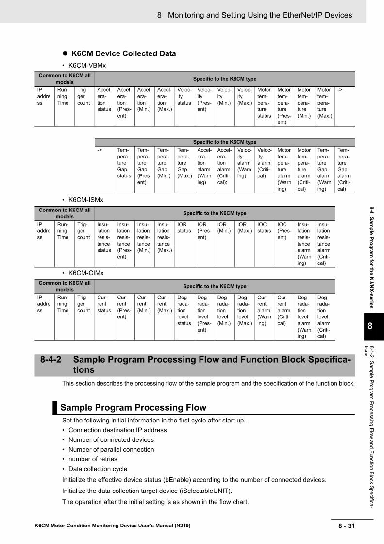
8 - 31
8 Monitoring and Setting Using the EtherNet/IP Devices
K6CM Motor Condition Monitoring Device User’s Manual (N219)
8-4 Sam
ple P
rog
ram fo
r the N
J/NX
-series
8
8-4-2 S
am
ple Program
Processing
Flow
and Function B
lock Specifica
-tions
K6CM Device Collected Data
• K6CM-VBMx
• K6CM-ISMx
• K6CM-CIMx
This section describes the processing flow of the sample program and the specification of the function block.
Set the following initial information in the first cycle after start up.
• Connection destination IP address
• Number of connected devices
• Number of parallel connection
• number of retries
• Data collection cycle
Initialize the effective device status (bEnable) according to the number of connected devices.
Initialize the data collection target device (iSelectableUNIT).
The operation after the initial setting is as shown in the flow chart.
Common to K6CM all models
Specific to the K6CM type
IP address
Run-ning Time
Trig-ger count
Accel-era-tion status
Accel-era-tion (Pres-ent)
Accel-era-tion (Min.)
Accel-era-tion (Max.)
Veloc-ity status
Veloc-ity (Pres-ent)
Veloc-ity (Min.)
Veloc-ity (Max.)
Motor tem-pera-ture status
Motor tem-pera-ture (Pres-ent)
Motor tem-pera-ture (Min.)
Motor tem-pera-ture (Max.)
->
Specific to the K6CM type
-> Tem-pera-ture Gap status
Tem-pera-ture Gap (Pres-ent)
Tem-pera-ture Gap (Min.)
Tem-pera-ture Gap (Max.)
Accel-era-tion alarm (Warning)
Accel-era-tion alarm (Criti-cal):
Veloc-ity alarm (Warning)
Veloc-ity alarm (Criti-cal)
Motor tem-pera-ture alarm (Warning)
Motor tem-pera-ture alarm (Criti-cal)
Tem-pera-ture Gap alarm (Warning)
Tem-pera-ture Gap alarm (Criti-cal)
Common to K6CM all models
Specific to the K6CM type
IP address
Run-ning Time
Trig-ger count
Insu-lation resis-tance status
Insu-lation resis-tance (Pres-ent)
Insu-lation resis-tance (Min.)
Insu-lation resis-tance (Max.)
IOR status
IOR (Pres-ent)
IOR (Min.)
IOR (Max.)
IOC status
IOC (Pres-ent)
Insu-lation resis-tance alarm (Warning)
Insu-lation resis-tance alarm (Criti-cal)
Common to K6CM all models
Specific to the K6CM type
IP address
Run-ning Time
Trig-ger count
Cur-rent status
Cur-rent (Pres-ent)
Cur-rent (Min.)
Cur-rent (Max.)
Deg-rada-tion level status
Deg-rada-tion level (Pres-ent)
Deg-rada-tion level (Min.)
Deg-rada-tion level (Max.)
Cur-rent alarm (Warning)
Cur-rent alarm (Criti-cal)
Deg-rada-tion level alarm (Warning)
Deg-rada-tion level alarm (Criti-cal)
8-4-2 Sample Program Processing Flow and Function Block Specifica-tions
Sample Program Processing Flow
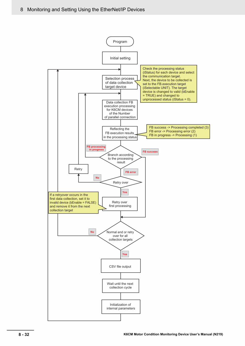
8 Monitoring and Setting Using the EtherNet/IP Devices
8 - 32 K6CM Motor Condition Monitoring Device User’s Manual (N219)
Program
Initial setting
FB success -> Processing completed (3)FB error -> Processing error (2)FB in progress -> Processing (1)
If a retryover occurs in the first data collection, set it to invalid device (bEnable = FALSE) and remove it from the next collection target
Selection process of data collection target device
Data collection FB execution processing
for K6CM devices of the Number
of parallel connection
Reflecting the FB execution results
in the processing status
Retry
Branch according to the processing
result
Retry over
Retry over first processing
Normal end or retry over for all
collection targets
CSV file output
Wait until the next collection cycle
Initialization of internal parameters
FB processing in progress
No
Yes
No
Yes
FB success
FB error
Check the processing status (iStatus) for each device and select the communication target.Next, the device to be collected is set to the FB.execution target (iSelectable UNIT). The target device is changed to valid (bEnable = TRUE) and changed to unprocessed status (iStatus = 0).

8 - 33
8 Monitoring and Setting Using the EtherNet/IP Devices
K6CM Motor Condition Monitoring Device User’s Manual (N219)
8-4 Sam
ple P
rog
ram fo
r the N
J/NX
-series
8
8-4-2 S
am
ple Program
Processing
Flow
and Function B
lock Specifica
-tions
The variables defined in the sample program are as follows.
(These are the main variables except instance related and work related variables etc. Refer to the actual sample program for details.)
*1. Device processing state 0 : Unprocessed1 :Processing (FB running)2 : Error (FB error occurred)3 : Collection completed (FB successful completion)4 : Retry over (missing measurement)
This FB reads data from the K6CM device whose IP address is specified in the input data, using the CIPUCMMSend command by rising of the Execute.
* Do not restart the FB by the Execute while FB is executing. Communication processing is initialized.
Variable name Variable data type Description
sIPAddress ARRAY[0..99] OF STRING[256] Connection destination IP Addresses 100 set-tings
iNumOfUnits UINT Number of connected devices (setting)
iNumOfParallel UINT Number of parallel connection (setting)
iRetryValue UINT Number of retries setting
tOutputCycle TIME Data output cycle (setting)
bCollecting BOOL During the collection of K6CM devices data
bOutput BOOL During output to the CSV file
iSelectableUNIT ARRAY[0..9] OF UINT FB execution target device No.
bExecute ARRAY[0..9] OF BOOL FB execution command
bDone ARRAY[0..9] OF BOOL FB completion state
bBusy ARRAY[0..9] OF BOOL FB processing in progress
bError ARRAY[0..9] OF BOOL FB error condition
wErrID ARRAY[0..99] OF WORD Device error code
bEnable ARRAY[0..99] OF BOOL Device enabled state (True: valid, False: invalid)
iStatus ARRAY[0..99] OF UINT Device processing state * 1
iRetryCnt ARRAY[0..99] OF UINT Device retry count
iProCode ARRAY[0..99] OF UINT Device type (1: VBM, 2: ISM, 3: CIM)
stRespServiceDat ARRAY[0..99] OF K6CM_ReadData Device reception data
Function Block Specifications
Instruction Name Graphic expression ST expression
K6CM_Read Read K6CM Devices Data
K6CM_Read_instance(
Execute,
IPAddress,
TimeOut,
Done,
Busy,
Error,
ErrorID,
ErrorIDEx,
ProductCode,
RespServiceDat );
Variable name:Input/out-
putData type Description
Execute IN BOOL Execution
K6CM_Read_instance
K6CM_ReadExecute Done
BusyError
ErrorIDErrorIDEx,
ProductCodeRespServiceDat
IPAddressTimeOut

8 Monitoring and Setting Using the EtherNet/IP Devices
8 - 34 K6CM Motor Condition Monitoring Device User’s Manual (N219)
*1. The response code of the CIP command request (CIPUCMMSend instruction) is returned to the error code.
*2. When the value of "ErrorID" is WORD#16#1C00 (i.e., Explicit error), CIP message error code is stored in "ErrorIDEx". For details of "ErrorIDEx", refer to "A-10 Expansion Error Code of the CIP Message Communica-tions on page A-46".
*3. Product code: The following values are returned according to the modelK6CM-VBM: 1K6CM-ISM: 2K6CM-CIM: 3Others: 0
Response data of the function block is a structure with the following members.
IPAddress IN STRING[256] Connection destination IP Address
TimeOut IN UINT CIP command timeout (x0.1 second)
Done OUT BOOL Successful completion
Busy OUT BOOL Executing
Error OUT BOOL Error end
ErrorID OUT WORD Error code *1
ErrorIDEx OUT DWORD Expansion error code *2
ProductCode OUT UINT Product code *3
RespServiceDat OUT K6CM_ReadData Response data
Name Data type Comment
K6CM_ReadData STRUCT
dtDataTime DATE_AND_TIME Data obtainment time
stIdentity Identity Identity Object
stMonCom MonCom Monitor object (Common)
stMonVBM MonVBM Monitor object (VBM)
stMonISM MonISM Monitor object (ISM)
stMonCIM MonCIM Monitor object (CIM)
stSetCom SetCom Setting object (Common)
stSetVBM SetVBM Setting object (VBM)
stSetISM SetISM Setting object (ISM)
stSetCIM SetCIM Setting object (CIM)
Identity STRUCT Identity Object
iVenderID UINT Vendor ID
iDeviceType UINT Device type
iProductCode UINT Product code
isMajorRevision USINT Major revision
isMinorRevision USINT Minor revision
wStatus WORD EtherNet/IP status
idSerialNo UDINT Serial number
sProductName STRING[256] Model name
MonCom STRUCT Monitor object (Common)
sMeasVer STRING[256] Measurement CPU version
sMainVer STRING[256] Main CPU version
sEIPVer STRING[256] EIP CPU version
wStatus WORD K6CM status
iRunningTime UINT Running Time
iTriggerCnt UINT Trigger count
MonVBM STRUCT Monitor object (VBM)
wAccStatus WORD Acceleration status
rAccValue REAL Acceleration (Present)
Variable name:Input/out-
putData type Description
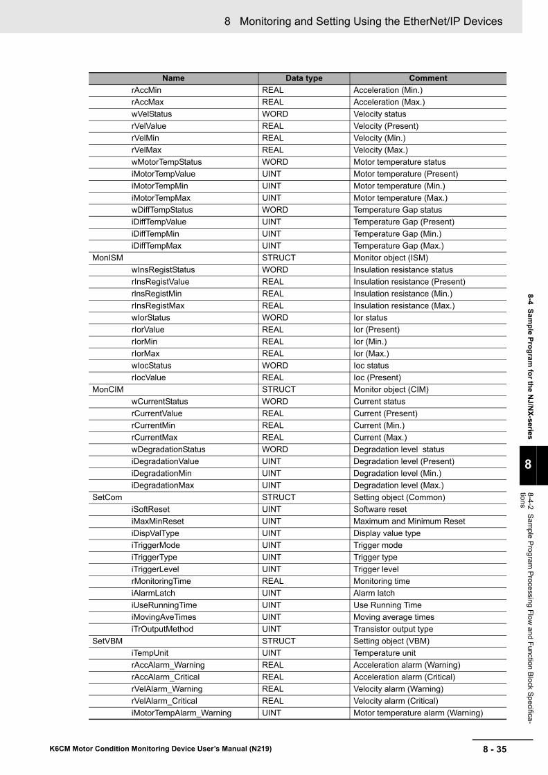
8 - 35
8 Monitoring and Setting Using the EtherNet/IP Devices
K6CM Motor Condition Monitoring Device User’s Manual (N219)
8-4 Sam
ple P
rog
ram fo
r the N
J/NX
-series
8
8-4-2 S
am
ple Program
Processing
Flow
and Function B
lock Specifica
-tions
rAccMin REAL Acceleration (Min.)
rAccMax REAL Acceleration (Max.)
wVelStatus WORD Velocity status
rVelValue REAL Velocity (Present)
rVelMin REAL Velocity (Min.)
rVelMax REAL Velocity (Max.)
wMotorTempStatus WORD Motor temperature status
iMotorTempValue UINT Motor temperature (Present)
iMotorTempMin UINT Motor temperature (Min.)
iMotorTempMax UINT Motor temperature (Max.)
wDiffTempStatus WORD Temperature Gap status
iDiffTempValue UINT Temperature Gap (Present)
iDiffTempMin UINT Temperature Gap (Min.)
iDiffTempMax UINT Temperature Gap (Max.)
MonISM STRUCT Monitor object (ISM)
wInsRegistStatus WORD Insulation resistance status
rInsRegistValue REAL Insulation resistance (Present)
rlnsRegistMin REAL Insulation resistance (Min.)
rInsRegistMax REAL Insulation resistance (Max.)
wIorStatus WORD Ior status
rIorValue REAL Ior (Present)
rIorMin REAL Ior (Min.)
rIorMax REAL Ior (Max.)
wIocStatus WORD Ioc status
rIocValue REAL Ioc (Present)
MonCIM STRUCT Monitor object (CIM)
wCurrentStatus WORD Current status
rCurrentValue REAL Current (Present)
rCurrentMin REAL Current (Min.)
rCurrentMax REAL Current (Max.)
wDegradationStatus WORD Degradation level status
iDegradationValue UINT Degradation level (Present)
iDegradationMin UINT Degradation level (Min.)
iDegradationMax UINT Degradation level (Max.)
SetCom STRUCT Setting object (Common)
iSoftReset UINT Software reset
iMaxMinReset UINT Maximum and Minimum Reset
iDispValType UINT Display value type
iTriggerMode UINT Trigger mode
iTriggerType UINT Trigger type
iTriggerLevel UINT Trigger level
rMonitoringTime REAL Monitoring time
iAlarmLatch UINT Alarm latch
iUseRunningTime UINT Use Running Time
iMovingAveTimes UINT Moving average times
iTrOutputMethod UINT Transistor output type
SetVBM STRUCT Setting object (VBM)
iTempUnit UINT Temperature unit
rAccAlarm_Warning REAL Acceleration alarm (Warning)
rAccAlarm_Critical REAL Acceleration alarm (Critical)
rVelAlarm_Warning REAL Velocity alarm (Warning)
rVelAlarm_Critical REAL Velocity alarm (Critical)
iMotorTempAlarm_Warning UINT Motor temperature alarm (Warning)
Name Data type Comment
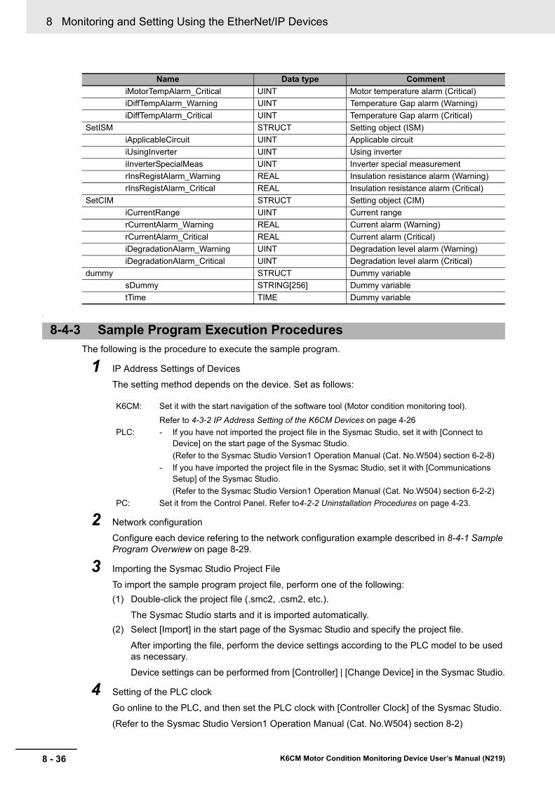
8 Monitoring and Setting Using the EtherNet/IP Devices
8 - 36 K6CM Motor Condition Monitoring Device User’s Manual (N219)
?
The following is the procedure to execute the sample program.
1 IP Address Settings of Devices
The setting method depends on the device. Set as follows:
2 Network configuration
Configure each device refering to the network configuration example described in 8-4-1 Sample Program Overwiew on page 8-29.
3 Importing the Sysmac Studio Project File
To import the sample program project file, perform one of the following:
(1) Double-click the project file (.smc2, .csm2, etc.).
The Sysmac Studio starts and it is imported automatically.
(2) Select [Import] in the start page of the Sysmac Studio and specify the project file.
After importing the file, perform the device settings according to the PLC model to be used as necessary.
Device settings can be performed from [Controller] | [Change Device] in the Sysmac Studio.
4 Setting of the PLC clock
Go online to the PLC, and then set the PLC clock with [Controller Clock] of the Sysmac Studio.
(Refer to the Sysmac Studio Version1 Operation Manual (Cat. No.W504) section 8-2)
iMotorTempAlarm_Critical UINT Motor temperature alarm (Critical)
iDiffTempAlarm_Warning UINT Temperature Gap alarm (Warning)
iDiffTempAlarm_Critical UINT Temperature Gap alarm (Critical)
SetISM STRUCT Setting object (ISM)
iApplicableCircuit UINT Applicable circuit
iUsingInverter UINT Using inverter
iInverterSpecialMeas UINT Inverter special measurement
rInsRegistAlarm_Warning REAL Insulation resistance alarm (Warning)
rInsRegistAlarm_Critical REAL Insulation resistance alarm (Critical)
SetCIM STRUCT Setting object (CIM)
iCurrentRange UINT Current range
rCurrentAlarm_Warning REAL Current alarm (Warning)
rCurrentAlarm_Critical REAL Current alarm (Critical)
iDegradationAlarm_Warning UINT Degradation level alarm (Warning)
iDegradationAlarm_Critical UINT Degradation level alarm (Critical)
dummy STRUCT Dummy variable
sDummy STRING[256] Dummy variable
tTime TIME Dummy variable
8-4-3 Sample Program Execution Procedures
K6CM: Set it with the start navigation of the software tool (Motor condition monitoring tool).
Refer to 4-3-2 IP Address Setting of the K6CM Devices on page 4-26
PLC: - If you have not imported the project file in the Sysmac Studio, set it with [Connect to Device] on the start page of the Sysmac Studio.
(Refer to the Sysmac Studio Version1 Operation Manual (Cat. No.W504) section 6-2-8)
- If you have imported the project file in the Sysmac Studio, set it with [Communications Setup] of the Sysmac Studio.
(Refer to the Sysmac Studio Version1 Operation Manual (Cat. No.W504) section 6-2-2)
PC: Set it from the Control Panel. Refer to4-2-2 Uninstallation Procedures on page 4-23.
Name Data type Comment
8 - 37
8 Monitoring and Setting Using the EtherNet/IP Devices
K6CM Motor Condition Monitoring Device User’s Manual (N219)
8-4 Sam
ple P
rog
ram fo
r the N
J/NX
-series
8
8-4-4 S
am
ple Program
Code D
escriptions
5 Parameter Settings of the Sample Program
Set the following parameters as shown in the "Sample Program Code Descriptions".
Number of data collection devices: Number of K6CM devices to be used
Data collection cycle: cycle for collecting data from K6CM devices
Connection destination IP address: IP address of the K6CM device to be connected
6 Going Online to the PLC
Select [Online] from [Controller] in the Sysmac Studio.
(Confirm that the PC and PLC are connected in advance.)
7 Changing to PROGRAM mode
Select [PROGRAM Mode] from [Controller] | [Mode] in the Sysmac Studio.
Check the contents of the caution window and select [Yes].
8 Download the sample program to PLC
Select [Transfer to Controller] from [Controller] in the Sysmac Studio.
Select [Execute] in the content confirmation window.
Select [Yes] in the execution confirmation window.
9 Changing to RUN mode
Select [RUN Mode] from [Controller] | [Mode] in the Sysmac Studio.
Check the contents of the caution window and select [Yes].
With the above operation, the sample program will be executed and data collection will be started.
The measured data of the K6CM devices will be output as a CSV file to the SD Memory Card mounted to the PLC.
(Note: To prevent measured data corruption, change to Program mode before you remove the SD Memory Card.)
This section shows the code descriptions of the sample program.
According to your system, set the parameter and the IP address that are described at the beginning of this program.
The subsequent codes are not required to edit unless there is special use.
8-4-4 Sample Program Code Descriptions
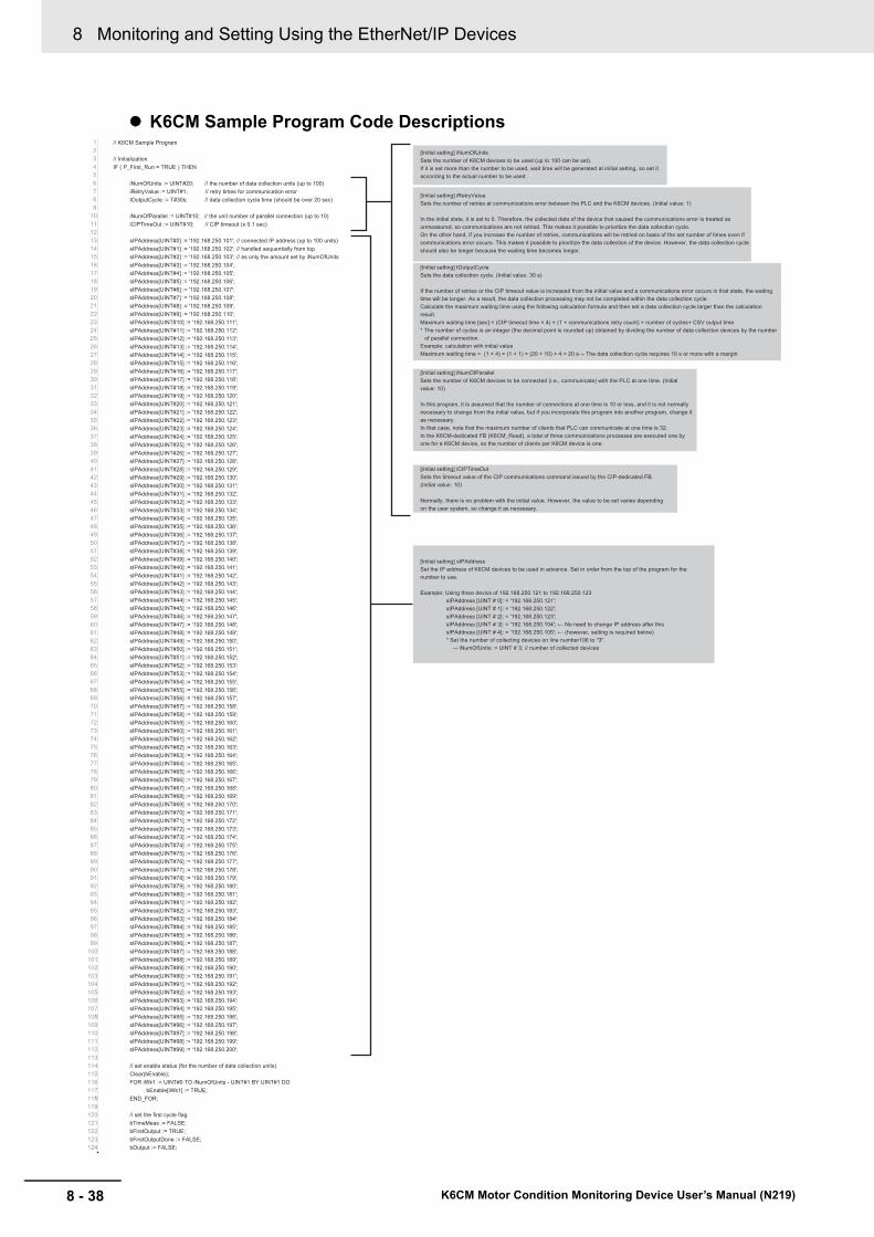
8 Monitoring and Setting Using the EtherNet/IP Devices
8 - 38 K6CM Motor Condition Monitoring Device User’s Manual (N219)
K6CM Sample Program Code Descriptions// K6CM Sample Program
// Initialization
IF ( P_First_Run = TRUE ) THEN
iNumOfUnits := UINT#20; // the number of data collection units (up to 100)
iRetryValue := UINT#1; // retry times for communication error
tOutputCycle := T#30s; // data collection cycle time (should be over 20 sec)
iNumOfParallel := UINT#10; // the unit number of parallel connection (up to 10)
iCIPTimeOut := UINT#10; // CIP timeout (x 0.1 sec)
sIPAddress[UINT#0] := '192.168.250.101'; // connected IP address (up to 100 units)
sIPAddress[UINT#1] := '192.168.250.102'; // handled sequentially from top
sIPAddress[UINT#2] := '192.168.250.103'; // as only the amount set by iNumOfUnits
sIPAddress[UINT#3] := '192.168.250.104';
sIPAddress[UINT#4] := '192.168.250.105';
sIPAddress[UINT#5] := '192.168.250.106';
sIPAddress[UINT#6] := '192.168.250.107';
sIPAddress[UINT#7] := '192.168.250.108';
sIPAddress[UINT#8] := '192.168.250.109';
sIPAddress[UINT#9] := '192.168.250.110';
sIPAddress[UINT#10] := '192.168.250.111';
sIPAddress[UINT#11] := '192.168.250.112';
sIPAddress[UINT#12] := '192.168.250.113';
sIPAddress[UINT#13] := '192.168.250.114';
sIPAddress[UINT#14] := '192.168.250.115';
sIPAddress[UINT#15] := '192.168.250.116';
sIPAddress[UINT#16] := '192.168.250.117';
sIPAddress[UINT#17] := '192.168.250.118';
sIPAddress[UINT#18] := '192.168.250.119';
sIPAddress[UINT#19] := '192.168.250.120';
sIPAddress[UINT#20] := '192.168.250.121';
sIPAddress[UINT#21] := '192.168.250.122';
sIPAddress[UINT#22] := '192.168.250.123';
sIPAddress[UINT#23] := '192.168.250.124';
sIPAddress[UINT#24] := '192.168.250.125';
sIPAddress[UINT#25] := '192.168.250.126';
sIPAddress[UINT#26] := '192.168.250.127';
sIPAddress[UINT#27] := '192.168.250.128';
sIPAddress[UINT#28] := '192.168.250.129';
sIPAddress[UINT#29] := '192.168.250.130';
sIPAddress[UINT#30] := '192.168.250.131';
sIPAddress[UINT#31] := '192.168.250.132';
sIPAddress[UINT#32] := '192.168.250.133';
sIPAddress[UINT#33] := '192.168.250.134';
sIPAddress[UINT#34] := '192.168.250.135';
sIPAddress[UINT#35] := '192.168.250.136';
sIPAddress[UINT#36] := '192.168.250.137';
sIPAddress[UINT#37] := '192.168.250.138';
sIPAddress[UINT#38] := '192.168.250.139';
sIPAddress[UINT#39] := '192.168.250.140';
sIPAddress[UINT#40] := '192.168.250.141';
sIPAddress[UINT#41] := '192.168.250.142';
sIPAddress[UINT#42] := '192.168.250.143';
sIPAddress[UINT#43] := '192.168.250.144';
sIPAddress[UINT#44] := '192.168.250.145';
sIPAddress[UINT#45] := '192.168.250.146';
sIPAddress[UINT#46] := '192.168.250.147';
sIPAddress[UINT#47] := '192.168.250.148';
sIPAddress[UINT#48] := '192.168.250.149';
sIPAddress[UINT#49] := '192.168.250.150';
sIPAddress[UINT#50] := '192.168.250.151';
sIPAddress[UINT#51] := '192.168.250.152';
sIPAddress[UINT#52] := '192.168.250.153';
sIPAddress[UINT#53] := '192.168.250.154';
sIPAddress[UINT#54] := '192.168.250.155';
sIPAddress[UINT#55] := '192.168.250.156';
sIPAddress[UINT#56] := '192.168.250.157';
sIPAddress[UINT#57] := '192.168.250.158';
sIPAddress[UINT#58] := '192.168.250.159';
sIPAddress[UINT#59] := '192.168.250.160';
sIPAddress[UINT#60] := '192.168.250.161';
sIPAddress[UINT#61] := '192.168.250.162';
sIPAddress[UINT#62] := '192.168.250.163';
sIPAddress[UINT#63] := '192.168.250.164';
sIPAddress[UINT#64] := '192.168.250.165';
sIPAddress[UINT#65] := '192.168.250.166';
sIPAddress[UINT#66] := '192.168.250.167';
sIPAddress[UINT#67] := '192.168.250.168';
sIPAddress[UINT#68] := '192.168.250.169';
sIPAddress[UINT#69] := '192.168.250.170';
sIPAddress[UINT#70] := '192.168.250.171';
sIPAddress[UINT#71] := '192.168.250.172';
sIPAddress[UINT#72] := '192.168.250.173';
sIPAddress[UINT#73] := '192.168.250.174';
sIPAddress[UINT#74] := '192.168.250.175';
sIPAddress[UINT#75] := '192.168.250.176';
sIPAddress[UINT#76] := '192.168.250.177';
sIPAddress[UINT#77] := '192.168.250.178';
sIPAddress[UINT#78] := '192.168.250.179';
sIPAddress[UINT#79] := '192.168.250.180';
sIPAddress[UINT#80] := '192.168.250.181';
sIPAddress[UINT#81] := '192.168.250.182';
sIPAddress[UINT#82] := '192.168.250.183';
sIPAddress[UINT#83] := '192.168.250.184';
sIPAddress[UINT#84] := '192.168.250.185';
sIPAddress[UINT#85] := '192.168.250.186';
sIPAddress[UINT#86] := '192.168.250.187';
sIPAddress[UINT#87] := '192.168.250.188';
sIPAddress[UINT#88] := '192.168.250.189';
sIPAddress[UINT#89] := '192.168.250.190';
sIPAddress[UINT#90] := '192.168.250.191';
sIPAddress[UINT#91] := '192.168.250.192';
sIPAddress[UINT#92] := '192.168.250.193';
sIPAddress[UINT#93] := '192.168.250.194';
sIPAddress[UINT#94] := '192.168.250.195';
sIPAddress[UINT#95] := '192.168.250.196';
sIPAddress[UINT#96] := '192.168.250.197';
sIPAddress[UINT#97] := '192.168.250.198';
sIPAddress[UINT#98] := '192.168.250.199';
sIPAddress[UINT#99] := '192.168.250.200';
// set enable status (for the number of data collection units)
Clear(bEnable);
FOR iWk1 := UINT#0 TO iNumOfUnits - UINT#1 BY UINT#1 DO
bEnable[iWk1] := TRUE;
END_FOR;
// set the first cycle flag
bTimeMeas := FALSE;
bFirstOutput := TRUE;
bFirstOutputDone := FALSE;
bOutput := FALSE;
[Initial setting] iNumOfUnits
Sets the number of K6CM devices to be used (up to 100 can be set).
If it is set more than the number to be used, wait time will be generated at initial setting, so set it
according to the actual number to be used.
[Initial setting] iRetryValue
Sets the number of retries at communications error between the PLC and the K6CM devices. (Initial value: 1)
In the initial state, it is set to 0. Therefore, the collected data of the device that caused the communications error is treated as
unmeasured, so communications are not retried. This makes it possible to prioritize the data collection cycle.
On the other hand, if you increase the number of retries, communications will be retried on basis of the set number of times even if
communications error occurs. This makes it possible to prioritize the data collection of the device. However, the data collection cycle
should also be longer because the waiting time becomes longer.
[Initial setting] tOutputCycle
Sets the data collection cycle. (Initial value: 30 s)
If the number of retries or the CIP timeout value is increased from the initial value and a communications error occurs in that state, the waiting
time will be longer. As a result, the data collection processing may not be completed within the data collection cycle.
Calculate the maximum waiting time using the following calculation formula and then set a data collection cycle larger than the calculation
result.
Maximum waiting time [sec] = (CIP timeout time × 4) × (1 + communications retry count) × number of cycles+ CSV output time
* The number of cycles is an integer (the decimal point is rounded up) obtained by dividing the number of data collection devices by the number
of parallel connection.
Example: calculation with initial value
Maximum waiting time = (1 × 4) × (1 + 1) × (20 ÷ 10) + 4 = 20 s→ The data collection cycle requires 10 s or more with a margin
[Initial setting] iNumOfParallel
Sets the number of K6CM devices to be connected (i.e., communicate) with the PLC at one time. (Initial
value: 10)
In this program, it is assumed that the number of connections at one time is 10 or less, and it is not normally
necessary to change from the initial value, but if you incorporate this program into another program, change it
as necessary.
In that case, note that the maximum number of clients that PLC can communicate at one time is 32.
In the K6CM-dedicated FB (K6CM_Read), a total of three communications processes are executed one by
one for a K6CM device, so the number of clients per K6CM device is one.
[Initial setting] iCIPTimeOut
Sets the timeout value of the CIP communications command issued by the CIP-dedicated FB.
(Initial value: 10)
Normally, there is no problem with the initial value. However, the value to be set varies depending
on the user system, so change it as necessary.
[Initial setting] sIPAddress
Set the IP address of K6CM devices to be used in advance. Set in order from the top of the program for the
number to use.
Example: Using three devics of 192.168.250.121 to 192.168.250.123
sIPAddress [UINT # 0]: = '192.168.250.121';
sIPAddress [UINT # 1]: = '192.168.250.122';
sIPAddress [UINT # 2]: = '192.168.250.123';
sIPAddress [UINT # 3]: = '192.168.250.104'; ← No need to change IP address after this
sIPAddress [UINT # 4]: = '192.168.250.105'; ← (however, setting is required below)
* Set the number of collecting devices on line number106 to "3".
→ iNumOfUnits: = UINT # 3; // number of collected devices

8 - 39
8 Monitoring and Setting Using the EtherNet/IP Devices
K6CM Motor Condition Monitoring Device User’s Manual (N219)
8-4 Sam
ple P
rog
ram fo
r the N
J/NX
-series
8
8-4-4 S
am
ple Program
Code D
escriptions
bOutputAgain := FALSE;
bInitUnitConf := TRUE;
bTimeUp := FALSE;
bCollecting := FALSE;
END_IF;
IF ( bInitUnitConf = TRUE ) THEN
// get current time and date --> make CSV file name (K6CM_YYYYMMDD-hhmm.CSV)
dtStartTime := GetTime();
DtToDateStruct(dtStartTime, stStartTime);
sFileName := CONCAT('K6CM_', UINT_TO_STRING(stStartTime.Year));
sWkStr := CONCAT('0', USINT_TO_STRING(stStartTime.Month));
sFileName := CONCAT(sFileName, RIGHT(sWkStr, 2));
sWkStr := CONCAT('0', USINT_TO_STRING(stStartTime.Day));
sFileName := CONCAT(sFileName, RIGHT(sWkStr, 2), '-');
sWkStr := CONCAT('0', USINT_TO_STRING(stStartTime.Hour));
sFileName := CONCAT(sFileName, RIGHT(sWkStr, 2));
sWkStr := CONCAT('0', USINT_TO_STRING(stStartTime.Min));
sFileName := CONCAT(sFileName, RIGHT(sWkStr, 2), '.CSV');
END_IF;
insF_TRIG_FirstOut( Clk := bFirstOutput, Q => bFirstOutput_pls );
IF bFirstOutput_pls = TRUE THEN
bFirstOutputDone := TRUE;
END_IF;
// generate time up signal every data cycle time
IF ( P_First_Run = FALSE ) AND ( bTimeUp = FALSE ) THEN
bTimeMeas := TRUE;
END_IF;
IF ( P_First_Run = FALSE ) AND ( bTimeMeas = FALSE ) THEN
bInitUnitConf := FALSE;
END_IF;
insTON(
In := bTimeMeas,
PT := tOutputCycle, // data collection cycle time
Q => bTimeUp );
// down the flag of collecting during time up of data collection
IF ( bTimeUP = TRUE ) THEN
// Devices carried over to the next cycle during FB processing or retry are treated as retry over
FOR iWk1 := UINT#0 TO iNumOfUnits - UINT#1 BY UINT#1 DO
IF iStatus[ iWk1 ] = UINT#1 OR iStatus[ iWk1 ] = UINT#2 THEN
iStatus[ iWk1 ] := UINT#4;
IF iProCode[ iWk1 ] = UINT#0 THEN // regard it as an invalid device if its product code has not been acquired
bEnable[ iWk1 ] := FALSE;
END_IF;
ELSE
iStatus[ iWk1 ] := UINT#0;
END_IF;
END_FOR;
bCollecting := FALSE;
bTimeMeas := FALSE;
END_IF;
// raise the flag of collecting during measuring of time up (bTimeMeas --> TRUE)
insR_TRIG( Clk := bTimeMeas, Q => bTimeMeas_pls );
IF ( bTimeMeas_pls = TRUE ) THEN
Clear(bExecute);
Clear(wErrID);
Clear(iSelectableUNIT);
Clear(iRetryCnt);
Clear(stRespServiceDat);
bCollecting := TRUE;
bOutput := FALSE;
END_IF;
// status handling of data collection
IF ( bCollecting = FALSE ) THEN
// off the K6CM FB except during data collection
FOR iWk1 := UINT#0 TO iNumOfParallel - UINT#1 BY UINT#1 DO
bExecute[ iWk1 ] := FALSE;
END_FOR;
ELSE
// K6CM FB execution setting 1 ( initialize index of execution target unit )
FOR iWk1 := UINT#0 TO iNumOfParallel - UINT#1 BY UINT#1 DO
IF ( iSelectableUNIT[ iWk1 ] < iWk1 ) THEN
iSelectableUNIT[ iWk1 ] := iWk1; // set initial value if initial status
END_IF;
END_FOR;
// K6CM FB execution setting 2 ( update index of next execution unit )
FOR iWk1 := UINT#0 TO iNumOfParallel - UINT#1 BY UINT#1 DO
// fix the status if invalid node
IF ( bEnable[ iSelectableUNIT[ iWk1 ] ] = FALSE ) THEN
iStatus[ iSelectableUNIT[ iWk1 ] ] := UINT#4;
bExecute[ iWk1 ] := FALSE;
END_IF;
// retry at abnormal completion with flag handled ( return temporary to untreated status )
IF ( iStatus[ iSelectableUNIT[ iWk1 ] ] = UINT#2 ) THEN
IF ( bExecute[ iWk1 ] = FALSE ) AND ( bEnable[ iWk1 ] = TRUE ) THEN
iStatus[ iSelectableUNIT[ iWk1 ] ] := UINT#0;
END_IF;
END_IF;
// search next untreated unit if successful completion or retry-over
IF ( iStatus[ iSelectableUNIT[ iWk1 ] ] = UINT#3 OR iStatus[ iSelectableUNIT[ iWk1 ] ] = UINT#4 ) THEN
IF ( bExecute[ iWk1 ] = FALSE ) THEN
// search next untreated unit
FOR iWk2 := UINT#0 TO iNumOfUnits - UINT#1 BY UINT#1 DO
IF ( iStatus[ iWk2 ] = UINT#0 AND bEnable[ iWk2 ] = TRUE ) THEN // search condition: untreated and not being treated on other session
FOR iWk3 := UINT#0 TO iNumOfParallel - UINT#1 BY UINT#1 DO
IF ( iSelectableUNIT[ iWk3 ] = iWk2 ) THEN
EXIT;
END_IF;
END_FOR;
IF ( iWk3 = iNumOfParallel ) THEN
iSelectableUNIT[ iWk1 ] := iWk2;
EXIT;
END_IF;
END_IF;
END_FOR;
END_IF;
END_IF;
// when abnormal completion with flag unhandled
IF ( iStatus[ iSelectableUNIT[ iWk1 ] ] = UINT#2 ) THEN
During the data collection cycle tOutputCycle, set bTimeMeas (i.e., data collection
in progress) to TRUE during time up measurement.
Once the data collection cycle has passed, set the time-up measurement in
progress to FALSE once and set the time-up measurement to TRUE again during
the data collection cycle.
When time-up measurement in progress bTimeMeas is TRUE,
set the data collection in progress flag bTimeMeas_pls to TRUE.
When the time-up measurement in progress flag is TRUE, set the
bCollectiong during data collection to TRUE.
When data collection in progress bCollectiong is TRUE, set the FB execution command
bExecute to TRUE according to the device processing state iStatus.
(The data collection status is held for each device)
Device processing state
0: Indicates that the data collection target is unprocessed.
If it is an unprocessed and valid state (bEnable = TRUE), the FB execution instruction is
set to TRUE.
1: Indicates that data is being collected during processing.
2: Indicates that an error occurred in error data collection. Set the FB execution command
to FALSE, add the number of retry times, and retry communications (once return the
device processing state to 0).
3: Indicates that completion data collection is completed. Set the FB execution command
to FALSE and search for the next unprocessed device.
4: Indicates that the upper limit of the retryover communications retry count has been
reached. Search for the next unprocessed device.

8 Monitoring and Setting Using the EtherNet/IP Devices
8 - 40 K6CM Motor Condition Monitoring Device User’s Manual (N219)
For the subsequent codes, refer to the actual sample program.
In accordance with the above status processing result, the K6CM-dedicated FB is called for each device.The collected data is stored in stRespServiceDat.
From here on, it is CSV file output processing.
IF ( bExecute[ iWk1 ] = TRUE ) THEN
// off the execute flag temporarily
bExecute[ iWk1 ] := FALSE;
IF ( iRetryCnt[ iSelectableUNIT[ iWk1 ] ] >= iRetryValue ) THEN // when retry over
IF (bInitUnitConf = TRUE) THEN
bEnable[ iSelectableUNIT[ iWk1 ] ] := FALSE; // disable the node if retry over at the first collectio
END_IF;
iStatus[ iSelectableUNIT[ iWk1 ] ] := UINT#4;
ELSE
iRetryCnt[ iSelectableUNIT[ iWk1 ] ] := iRetryCnt[ iSelectableUNIT[ iWk1 ] ] + UINT#1; // add count of retry
END_IF;
END_IF;
END_IF;
// when successful completion with flag unhandled
IF ( iStatus[ iSelectableUNIT[ iWk1 ] ] = UINT#3 ) THEN
IF ( bExecute[ iWk1 ] = TRUE ) THEN
// off the execute flag temporarily
bExecute[ iWk1 ] := FALSE;
// if product code is not applicable units, remove it as object of execution
IF (bInitUnitConf = TRUE) THEN
IF (iProCode[ iSelectableUNIT[ iWk1 ] ] = UINT#0) THEN
bEnable[ iSelectableUNIT[ iWk1 ] ] := FALSE;
END_IF;
END_IF;
END_IF;
END_IF;
END_FOR;
// setting of bExecute
FOR iWk1 := UINT#0 TO iNumOfParallel - UINT#1 BY UINT#1 DO
// raise the flag of FB execution if untreated and effective status
IF ( iStatus[ iSelectableUNIT[ iWk1 ] ] = UINT#0 AND bEnable[ iSelectableUNIT[ iWk1 ] ] = TRUE) THEN
IF ( bExecute[ iWk1 ] = FALSE ) THEN
bExecute[ iWk1 ] := TRUE;
END_IF;
END_IF;
END_FOR;
// finish data collecting (= begin CSV making) if all units are successful completion or retry over
FOR iWk1 := UINT#0 TO iNumOfUnits - UINT#1 BY UINT#1 DO
IF ( bEnable[ iWk1 ] = TRUE ) AND ( iStatus[ iWk1 ] <= UINT#2 ) THEN
EXIT;
END_IF;
END_FOR;
IF ( iWk1 = iNumOfUnits ) THEN
bCollecting := FALSE;
END_IF;
END_IF;
// K6CM data collection FB execution
FOR iWk1 := UINT#0 TO iNumOfParallel - UINT#1 BY UINT#1 DO
insK6CM_Read[ iWk1 ](
Execute := bExecute[ iWk1 ],
IPAddress := sIPAddress[ iSelectableUNIT[ iWk1 ] ],
TimeOut := iCIPTimeOut,
Done => bDone[ iWk1 ],
Busy => bBusy[ iWk1 ],
Error => bError[ iWk1 ],
ErrorID => wErrID[ iSelectableUNIT[ iWk1 ] ],
ErrorIDEx => dwErrIDEx[ iSelectableUNIT[ iWk1 ] ],
ProductCode => iProCodeWk,
RespServiceDat => stRespServiceDat[ iSelectableUNIT[ iWk1 ] ] );
// status setting along result of FB execution
// executing
IF ( bBusy[ iWk1 ] = TRUE ) THEN
iStatus[ iSelectableUNIT[ iWk1 ] ] := UINT#1;
END_IF;
// successful completion
IF ( bDone[ iWk1 ] = TRUE ) THEN
iStatus[ iSelectableUNIT[ iWk1 ] ] := UINT#3;
IF (bInitUnitConf = TRUE) THEN
iProCode[ iSelectableUNIT[ iWk1 ] ] := iProCodeWk;
END_IF;
END_IF;
// abnormal completion
IF ( bError[ iWk1 ] = TRUE ) THEN
iStatus[ iSelectableUNIT[ iWk1 ] ] := UINT#2;
END_IF;
END_FOR;
// data collection complete of all units --> raise the flag of CSV output
insF_TRIG( Clk := bCollecting, Q => bCollecting_pls );
IF ( bCollecting_pls = TRUE ) THEN
bOutput := TRUE;
iOutputSeq := UINT#0;
END_IF;
// output the data headers to CSV
IF ( bOutput = TRUE ) AND ( bInitUnitConf = FALSE ) THEN
CASE iOutputSeq OF
// instance initialization
UINT#0:
insFileOpen( Execute := FALSE );
insFilePuts( Execute := FALSE );
insFileClose( Execute := FALSE );
IF bCollecting = FALSE THEN
iOutputSeq := UINT#1;
END_IF;

9 - 1
9
K6CM Motor Condition Monitoring Device User’s Manual (N219)
This section describes troubleshooting when using the K6CM devices.
9-1 K6CM Devices . . . . . . . . . . . . . . . . . . . . . . . . . . . . . . . . . . . . . . . . . . . . . . . . 9-2
9-2 Using the Software tool . . . . . . . . . . . . . . . . . . . . . . . . . . . . . . . . . . . . . . . . . 9-4
9-3 Using the EtherNet/IP . . . . . . . . . . . . . . . . . . . . . . . . . . . . . . . . . . . . . . . . . . 9-6
Trouble shooting

9 Trouble shooting
9 - 2 K6CM Motor Condition Monitoring Device User’s Manual (N219)
9-1 K6CM Devices
This section shows how to troubleshoot the K6CM devices.
If the K6CM device does not operate properly, check the items below as required before repair is requested. If it still does not work properly, return it through our sales department.
Problems Cause Possible correction Reference
Measurement values are not displayed.
7-segments display of measured value are blinking.
The measured value is over the input range.
Check the connected sensor. 1-2 List of Models on page 1-5
Make sure that it is properly installed and wired
Section 5 Installa-tion and Wiring
"- - - -" is displayed. In the case of a trigger (exter-nal trigger or internal trigger), "- - - -" is displayed until the trigger condition is satisfied (while measuring and moni-toring is not yet done) after the power is turned ON.
Wait until the trigger condition is satisfied, or change the trigger mode at all times (without trigger).
3-2-3 Trigger Mode on page 3-5
The sensor is not properly connected and installed.
• When K6CM device is vibration & temperature type, confirm that the pre-amplifier is correctly con-nected.
• When K6CM device is Insulation resistance type, confirm that ZCT is con-nected correctly.Also, confirm whether the specified voltage is input.
Section 5 Installa-tion and Wiring
"8 8 8 8" is blinking displayed.
The K6CM device may be damaged.
Contact our sales or distribu-tor.
---
MS indicator blinking red.
The sensor is not properly connected and installed.
• When K6CM device is vibration & temperature type, confirm that the pre-amplifier is correctly con-nected.
• When K6CM device is Insulation resistance type, confirm that ZCT is con-nected correctly. Also, confirm whether the specified voltage is input.
Section 5 Installa-tion and Wiring
One of the following condi-tions:
Measurement CPU error, Main CPU error, Present value input error, Maximum value input error, Minimum value input error
• Turn ON the power of K6CM device again.
If it still occurs, contact our sales or distributor.
---
MS indicator is lit red. The K6CM device or the sen-sor may be damaged.
Contact our sales or distribu-tor.
---
The measured value is displayed, but the MS flashes in red and the main CPU error in the K6CM status is ON.
The hardware for running time function in the K6CM device may be faulty.
Contact our sales or distribu-tor.
---
Ambient temperature of the K6CM device exceeds the operating ambient tempera-ture.
Use within the operating ambient temperature range.
---

9 - 3
9 Trouble shooting
K6CM Motor Condition Monitoring Device User’s Manual (N219)
9-1 K
6CM
De
vices
9
The measured value dis-played is incor-rect.
The measured value is fixed and does not change.
In the case of a trigger (exter-nal trigger or internal trigger), the measurement value just before the end is held and displayed after measuring and monitoring is over.
Turn ON the power again or change the trigger mode at all times (without trigger).
3-2-3 Trigger Mode on page 3-5
(Insulation resistance type only)Even if the insulation resis-tance value exceeds 1 MΩ, 1 MΩ is displayed.
No problem. A-1 Specifications on page A-2
The measured value is the higher limit or the lower limit value.
Sensor installation and wiring is incorrect.
Check the installation and wiring.
Section 5 Installa-tion and Wiring
(Comprehensive current diag-nosis type only) The current cannot be measured correctly using a dedicated CT.
• Confirm the rating of CT and use the CT in the rat-ing.
• Set the current range according to CT.
A-1 Specifications on page A-26-2-2 Setting Parameters on page 6-26
(Insulation resistance type only) The circuit to be mea-sured does not match the set-tings of K6CM.
Correctly set the setting value of the Applicable circuit, the Using inverter, and the Inverter special measure-ment.
6-2-2 Setting Parameters on page 6-26
Transistor out-put 1, 2
Transistor output 1 or 2 does not return during measuring and monitoring despite the measured value that comprehensive alarm should be normal.
Alarm latch is set to "enable" Press the [ALM RST] key on the front of the K6CM device to release the alarm latch.
Alternatively, change the alarm latch to "disable (no latch)".
3-3-3 Relationship Between Alarm and Display/Out-put on page 3-14
The transistor output does not match the state of the warning alarm and the critical alarm.
In the case of a trigger (exter-nal trigger or internal trigger), transistor outputs 1 and 2 are turned OFF even when mea-suring and monitoring is not performed after power is turned ON.
If the trigger condition is satis-fied and the measurement is started, this condition will be resolved.
3-2-3 Trigger Mode on page 3-5
Transistor out-put 3
Transistor output 3 is OFF.Status display: "ERR”
• Self diagnostic error is occurring.
One of the following:Measurement CPU error, measurement data flash Criti-cality, Main CPU error, main CPU data flash error, or input section error
• Turn ON the power of K6CM device again.
• When K6CM device is vibration & temperature type, confirm that the pre-amplifier is correctly con-nected.
• When K6CM device is Insulation resistance type, confirm that ZCT is con-nected correctly.
If it still occurs, contact our sales or distributor.
---
Problems Cause Possible correction Reference

9 Trouble shooting
9 - 4 K6CM Motor Condition Monitoring Device User’s Manual (N219)
9-2 Using the Software tool
This section shows troubleshooting when using the software tool.
Problems Cause Possible correction Reference
Monitoring is impossi-ble with the K6CM from the software tool
The IP address of the computer is automatically acquired or fixedly set to a segment different from the IP address of the K6CM device.
Set the IP address of the computer to IP address of same segment as the K6CM device.
4-3 IP Address Setting on page 4-24
The IP address setting of the K6CM on the project (It can be confirmed by [SYSMAC Gate-way Console] Button) is different from the actual IP address
1. Click [Delete Device] to delete the device that you registered errone-ously.
2. Click Add device and add the device with the IP address that is actually connected.
6-1-4 Buttons on Device Setting on page 6-18
6-2-3 Add a Device to an Existing Project on page 6-27
The communications driver SYS-MAC Gateway between the com-puter and the K6CM is stopped
1. Click [Device setting] on the startup screen or click the [SYSMAC Gate-way Console] Button on the monitor-ing screen to launch the SYSMAC Gateway Console screen.
2. Click the Start button in the Com-munication Service field.
4-3-2 IP Address Set-ting of the K6CM Devices on page 4-26
The network port setting of SYS-MAC Gateway communications driver can not select the LAN card or IP address used for com-munications.
1. Click [Device setting] on the startup screen or click the [SYSMAC Gate-way Console] Button on the monitor-ing screen to launch the SYSMAC Gateway Console screen.
2. In the [Network Port] field, select the LAN card and IP address to use.
4-3-2 IP Address Set-ting of the K6CM Devices on page 4-26
Network port setting of SYSMAC Gateway communications driver, the IP address used for communi-cation is AutoIP address (169.254.xxx.xxx).
Set the IP address of the network port setting of the SYSMAC Gateway com-munications driver to an IP address other than AutoIP.
4-3-2 IP Address Set-ting of the K6CM Devices on page 4-26
[Start monitoring] Button is not clicked
Click the [Start monitoring] Button. 7-3-1 Monitoring Pro-cedure with Motor Con-dition Monitoring Tool on page 7-9
The measured value is displayed, but the value at a certain time is fixed and does not change
When using the trigger function (external trigger or internal trig-ger), the measurement value just before the end is held and dis-played after measuring and moni-toring is over.
Measure the trigger condition and start measurement.
3-2-3 Trigger Mode on page 3-5
Accidentally forcing to end (e.g., turning off the PC power) during monitoring
---- You can restore the logs from the backup until just before the forced ter-mination.
A confirmation message will be dis-played asking if you want to use the backup data at the next project launch, so use it as necessary.
----
The line graph is not displayed correctly.
The software tool obtains the clock information from the PC.
If the time information of the PC is incorrect, the dedicated tool records the measured value with an incorrect date and time, so it cannot display the correct graph.
Move the log file obtained with the wrong date and time to a different location and reopen the project file.
----

9 - 5
9 Trouble shooting
K6CM Motor Condition Monitoring Device User’s Manual (N219)
9-2 Usin
g th
e S
oftw
are too
l
9
When you open the project file, "Failed to read the graph file." is displayed.
The log file is opened in another application.
Close the log file opened by another application and reopen the project file.
----
The memory capacity of the PC is insufficient.
Move the log file to a different location and reopen the project file.
----
The log file is damaged. Move the suspected corruption log file to another location and reopen the project file.
----
The message "The available memory capacity becomes insuf-ficient. The operation may be delayed." is dis-played.
The memory capacity of the PC is insufficient.
Move the log file to a different location and reopen the project file.
----
Problems Cause Possible correction Reference

9 Trouble shooting
9 - 6 K6CM Motor Condition Monitoring Device User’s Manual (N219)
9-3 Using the EtherNet/IP
This section shows troubleshooting when using the EtherNet/IP.
Problems Cause Possible correction Reference
EtherNet/IP communica-tions can not be executed when using BOOTP mode
NS LED blinking red IP address has not been acquired from the BOOTP server
Check the connection between BOOTP server and the K6CM devices.
If you do not have a BOOTP server, press the [ALM RST] key and the [DISP] key at the same time for five seconds or more to initialize all set-tings of the K6CM device.
----
EtherNet/IP communica-tions are not possible.
NS indicator is lit red.
The IP address of the built-in EtherNet/IP port is also used as the IP address of another node.
Change the IP address set-ting to avoid duplication.
NS indicator is not lit.
An Ethernet link OFF was detected.
Check the connection between the switching hub and the K6CM devices to see if the following items are normal.
• Whether the Ethernet cable is broken, loose, or disconnected
• Power state of the switch-ing hub
• Communication settings of the switching hub
A timeout occurred in a tag data link.
NS indicator flashes red.
Communications with the originator device timed out.
Make sure the following items are normal on the communication route.
• Whether the Ethernet cable is broken, loose, or disconnected
• Power supply state and operation state of the orig-inator
• Power state of switching hub
• State of noise

A - 1
A
K6CM Motor Condition Monitoring Device User’s Manual (N219)
A-1 Specifications . . . . . . . . . . . . . . . . . . . . . . . . . . . . . . . . . . . . . . . . . . . . . . . . . A-2
A-2 Measured Values by Each Monitor Type . . . . . . . . . . . . . . . . . . . . . . . . . . . A-3
A-3 K6CM Common Specifications . . . . . . . . . . . . . . . . . . . . . . . . . . . . . . . . . . . A-5
A-4 K6CM device Individual Specifications . . . . . . . . . . . . . . . . . . . . . . . . . . . . A-8
A-5 Individual Specifications of the Dedicated Sensor . . . . . . . . . . . . . . . . . . A-10
A-6 Internal Data of K6CM Devices . . . . . . . . . . . . . . . . . . . . . . . . . . . . . . . . . . A-14
A-7 Setting Values . . . . . . . . . . . . . . . . . . . . . . . . . . . . . . . . . . . . . . . . . . . . . . . . A-15
A-8 Present Values . . . . . . . . . . . . . . . . . . . . . . . . . . . . . . . . . . . . . . . . . . . . . . . A-19
A-9 Tag Data Link Connection Setting Procedures . . . . . . . . . . . . . . . . . . . . . A-24A-9-1 Using the CS/CJ-series . . . . . . . . . . . . . . . . . . . . . . . . . . . . . . . . . . . . . . . . . A-24
A-9-2 Using the NJ/NX-series . . . . . . . . . . . . . . . . . . . . . . . . . . . . . . . . . . . . . . . . . A-36
A-10Expansion Error Code of the CIP Message Communications . . . . . . . . . A-46
A-10-1 General Status . . . . . . . . . . . . . . . . . . . . . . . . . . . . . . . . . . . . . . . . . . . . . . . . A-46
A-10-2 Additional Status When General Status Is 01 hex . . . . . . . . . . . . . . . . . . . . . A-48
Appendices

Appendices
A - 2 K6CM Motor Condition Monitoring Device User’s Manual (N219)
A-1 Specifications
This section shows the common specifications and the individual specifications of the K6CM, and the specifications of the used sensors.
Vibration & Temperature Type
Insulation Resistance Type
Comprehensive Current Diagnosis Type
List of Models
Model Specifications such as power supply voltage
k6CM device K6CM-VBMA-EIP 100 to 240 VAC
K6CM-VBMD-EIP 24 V AC/DC
Sensor (sensor head and pre-amplifier)*1
*1. The sensor head and the pre-amplifier are calibrated and inspected as a set at the factory shipment. Be sure to use them with the combination shipped.
K6CM-VBS1 Mounting: M6 screw
Model Specifications such as power supply voltage
k6CM device K6CM-ISMA-EIP 100 to 240 VAC
K6CM-ISMD-EIP 24 V AC/DC
Sensor (ZCT (IRT)) *1
*1. ZCT (IRT) stands for Zero Current Transformer (Insulation Resistance Transformer).
K6CM-ISZBI52 Rated voltage: 200 to 480 VAC , through hole diame-ter 52 mm
Model Specifications such as power supply voltage
k6CM device K6CM-CIMA-EIP 100 to 240 VAC
K6CM-CIMD-EIP 24 V AC/DC
Sensor (CT) K6CM-CICB005 Rated primary current: 5 A, rated voltage: 480 VAC
K6CM-CICB025 Rated primary current: 25 A, rated voltage: 480 VAC
K6CM-CICB100 Rated primary current: 100 A, rated voltage: 480 VAC
K6CM-CICB200 Rated primary current: 200 A, rated voltage: 480 VAC
K6CM-CICB400 Rated primary current: 400 A, rated voltage: 480 VAC
K6CM-CICB600 Rated primary current: 600 A, rated voltage: 480 VAC
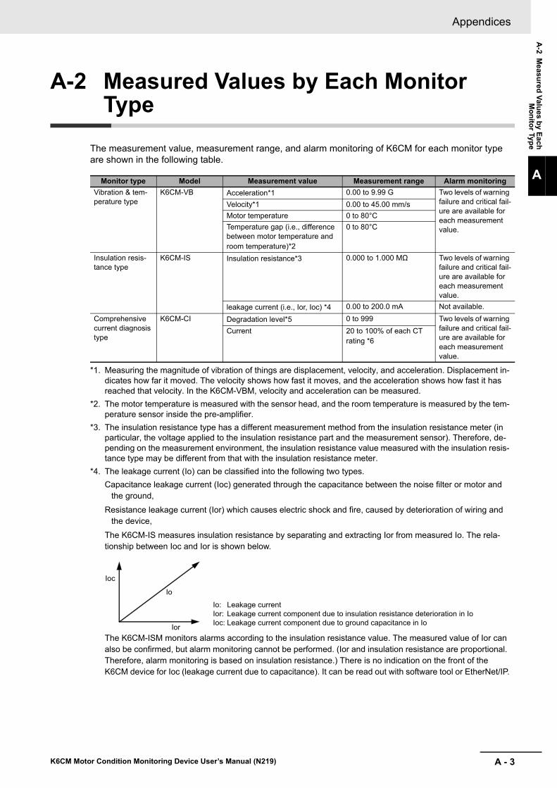
A - 3
Appendices
K6CM Motor Condition Monitoring Device User’s Manual (N219)
A-2 M
easure
d V
alues b
y Each
Mo
nito
r Type
A
A-2 Measured Values by Each Monitor Type
The measurement value, measurement range, and alarm monitoring of K6CM for each monitor type are shown in the following table.
Monitor type Model Measurement value Measurement range Alarm monitoring
Vibration & tem-perature type
K6CM-VB Acceleration*1
*1. Measuring the magnitude of vibration of things are displacement, velocity, and acceleration. Displacement in-dicates how far it moved. The velocity shows how fast it moves, and the acceleration shows how fast it has reached that velocity. In the K6CM-VBM, velocity and acceleration can be measured.
0.00 to 9.99 G Two levels of warning failure and critical fail-ure are available for each measurement value.
Velocity*1 0.00 to 45.00 mm/s
Motor temperature 0 to 80°C
Temperature gap (i.e., difference between motor temperature and room temperature)*2
*2. The motor temperature is measured with the sensor head, and the room temperature is measured by the tem-perature sensor inside the pre-amplifier.
0 to 80°C
Insulation resis-tance type
K6CM-IS Insulation resistance*3
*3. The insulation resistance type has a different measurement method from the insulation resistance meter (in particular, the voltage applied to the insulation resistance part and the measurement sensor). Therefore, de-pending on the measurement environment, the insulation resistance value measured with the insulation resis-tance type may be different from that with the insulation resistance meter.
0.000 to 1.000 MΩ Two levels of warning failure and critical fail-ure are available for each measurement value.
leakage current (i.e., Ior, Ioc) *4
*4. The leakage current (Io) can be classified into the following two types.
Capacitance leakage current (Ioc) generated through the capacitance between the noise filter or motor and the ground,
Resistance leakage current (Ior) which causes electric shock and fire, caused by deterioration of wiring and the device,
The K6CM-IS measures insulation resistance by separating and extracting Ior from measured Io. The rela-tionship between Ioc and Ior is shown below.
The K6CM-ISM monitors alarms according to the insulation resistance value. The measured value of Ior can also be confirmed, but alarm monitoring cannot be performed. (Ior and insulation resistance are proportional. Therefore, alarm monitoring is based on insulation resistance.) There is no indication on the front of the K6CM device for Ioc (leakage current due to capacitance). It can be read out with software tool or EtherNet/IP.
0.00 to 200.0 mA Not available.
Comprehensive current diagnosis type
K6CM-CI Degradation level*5 0 to 999 Two levels of warning failure and critical fail-ure are available for each measurement value.
Current 20 to 100% of each CT rating *6
Ioc
Ior
Io
Io: Leakage currentIor: Leakage current component due to insulation resistance deterioration in IoIoc: Leakage current component due to ground capacitance in Io

Appendices
A - 4 K6CM Motor Condition Monitoring Device User’s Manual (N219)
*5. The K6CM-CIM compares the current waveform of the motor with the smooth sine wave, and represents the degree of deviation from the smooth sine wave in numerical values as the "degradation level". The lower the degradation level, the more normal the state of the motor. However, when the inverter is used, even if the motor is normal, the current waveform may be changed by the inverter. Therefore the deviation from the ideal sine wave may become large.
The recommended frequency range is 20 to 80 Hz when measuring the level of degradation. The degradation tendency of the motor appears less likely at frequencies higher than 80 Hz.
*6. One CT for detecting the current flowing in the motor must be used for each motor.Use the following formula when you calculate the current value from the motor capacity.
Current value of motor (A) =Motor capacity (kW) × 1000
Motor voltage (V) × √ 3 × power factor (0.9) × efficiency (0.8)
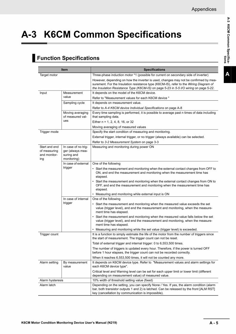
A - 5
Appendices
K6CM Motor Condition Monitoring Device User’s Manual (N219)
A-3 K
6CM
Co
mm
on
Sp
ecifica-tio
ns
A
A-3 K6CM Common Specifications
Function Specifications
Item Specifications
Target motor Three-phase induction motor *1 (possible for current on secondary side of inverter)
However, depending on how the inverter is used, changes may not be confirmed by mea-surement. For the Insulation resistance type (K6CM-IS), refer to the Wiring Diagram of the Insulation Resistance Type (K6CM-IS) on page 5-23 in 5-5 I/O wiring on page 5-22.
Input Measurement value
It depends on the model of the K6CM device.
Refer to "Measurement values for each K6CM device "
Sampling cycle It depends on measurement value.
Refer to A-4 K6CM device Individual Specifications on page A-8
Moving averaging of measured val-ues
Every time sampling is performed, it is possible to average past n times of data including that sampling data.
Either n = 1, 2, 4, 8, 16, or 32
Moving averaging of measured values
Trigger mode Specify the start condition of measuring and monitoring.
External trigger, internal trigger, or no trigger (always available) can be selected.
Refer to 3-2 Measurement System on page 3-3
Start and end of measuring and monitor-ing
In case of no trig-ger (always mea-suring and monitoring)
Measuring and monitoring during power ON
In case of external trigger
One of the following
• Start the measurement and monitoring when the external contact changes from OFF to ON, and end the measurement and monitoring when the measurement time has elapsed.
• Start the measurement and monitoring when the external contact changes from ON to OFF, and end the measurement and monitoring when the measurement time has elapsed.
• Measuring and monitoring while external input is ON
In case of internal trigger
One of the following
• Start the measurement and monitoring when the measured value exceeds the set value (trigger level), and end the measurement and monitoring, when the measure-ment time has elapsed.
• Start the measurement and monitoring when the measured value falls below the set value (trigger level), and end the measurement and monitoring, when the measure-ment time has elapsed.
• Measuring and monitoring while the set value (trigger level) is exceeded.
Trigger count It is a function to simply estimate the life of the motor from the number of triggers since the start of measurement. The trigger count can not be reset.
Total of external trigger and internal trigger: 0 to 6,553,500 times.
The number of triggers is updated every hour. Therefore, if the power is turned OFF before 1 hour elapses, the trigger count can not be recorded correctly.
When it reaches 6,553,500 times, it will not be counted any more.
Alarm setting By measurement value
It depends on K6CM device type. Refer to "Measurement values and alarm settings for each K6CM device type".
Critical level and Warning level can be set for each upper limit or lower limit (different depending on measurement value) of measured value.
Alarm hysteresis 10% width of threshold setting value (fixed)
Alarm latch Depending on the setting, you can specify None / Yes. If yes, the alarm condition (alarm bar, both transistor outputs 1 and 2) is latched. Can be released by the front [ALM RST] key (cancellation by communication is impossible).

Appendices
A - 6 K6CM Motor Condition Monitoring Device User’s Manual (N219)
Measuring and monitor-ing method
Individual alarm by measurement value
Compare the measured value with the alarm set value (Critical level and Warning level) and output an alarm (Critical, Warning).
Comprehensive alarm as K6CM device
When multiple alarms (Critical, Warning) occur, they are output by OR logic*2 with priority of Critical> Warning.
Output Output form Transistor output (normally closed)
Functions The following 3 outputs
• Transistor output 1: Comprehensive alarm (Warning) output (Output type*3 can be set to Normally open or Normally closed)
• Transistor output 2: Comprehensive alarm (Critical) output (Output type *3 can be set to Normally open or Normally closed)
• Transistor output 3: Self diagnostic error output*4 (Normally closed fixed. Self-diagno-sis error occurrence: OFF, self-diagnosis error not occurred: ON)
Output rating Contact configuration: NPN open collector
Rated voltage: 24 VDC
Maximum current: 50 mA
EtherNet/IP Connected device Software tool, or EtherNet/IP compatible equipment such as PC, PLC
Communications type
• CIP message communication: reception of CIP command
• Tag data link: Output only
*1. Motors other than three-phase induction motors (e.g., synchronous motor, single phase motor, servo motor, stepping motor) are excluded.
*2. Judgment of comprehensive alarm as a device:
Comprehensive alarm threshold setting (Warning) setting: A state in which "Critical" does not exist in the mea-surement value and "Warning" exists even in even one.
• Threshold (Critical) setting for comprehensive alarm: A state in which at least one of the measurement val-ues has "Critical".
*3. Each transistor output 1 and 2 can not be set differently.
*4. A self-diagnosis error occurs due to any one of the following reasons: Refer to Trouble shooting on page 9-1 when confirming self-diagnosis error.
Measurement CPU error
Measurement CPU data flash error
Main CPU error
Main CPU data flash error
Input unit error
Ratings
Item SpecificationsPower supply voltage K6CM-MA: 100 to 240 VAC, 50/60 Hz (Alternating current)
K6CM-MD: 24 VAC, 50/60 Hz, 24 VDC (Both direct and alternating current)
Allowable operating voltage range 85% to 110% of the rated power supply voltage
Power supply frequency range 45 to 65 Hz
Power consumption K6CM-VBM
24 VAC/24 VDC: 3.8 VA/2.1W max.
100 to 240 VAC: 7.1 VA max.
K6CM-ISM
24 VAC/24 VDC: 3.7 VA/2.0W max.
100 to 240 VAC: 6.2 VA max.
K6CM-CIM
24 VAC/24 VDC: 3.1 VA/1.6W max.
100 to 240 VAC: 6.0 VA max.
Item Specifications

A - 7
Appendices
K6CM Motor Condition Monitoring Device User’s Manual (N219)
A-3 K
6CM
Co
mm
on
Sp
ecifica-tio
ns
A
Startup time at power ON 10 s or less
Note : This is the time from power-ON until the measuring and monitoring start or "- - - -" is displayed.After that, the measurement value is displayed after the sampling time has elapsed.
LCD display 7 segment digital display and single light display Character height 14 mm
Indicators MS: red / green, NS: red / green, alarm bar: green / yellow / red
External trigger input No-voltage contact and open collector are possible.
Short circuit: Residual voltage 1.5 V or less
Open: Leakage current 0.1 mA or less
Short circuit current: approx. 7 mA
Minimum trigger time: 0.1 s
Transistor output Contact configuration: NPN open collector
Rated voltage: 24 VDC (maximum voltage: DC 26.4 V)
Maximum current: 50 mA
Leakage current: 0.1 mA max.
Residual voltage: 1.5 V max.
Communications Number of ports: 1
Physical layer Ethernet: RJ45 Connector
Type 100Base-TX
Transmission dis-tance (maximum cable length)
100 m (distance between hub and node)
Topology Star form
Ambient operating temperature -10 to 55 ° C (with no condensation or freezing)
humidity 25 to 85% RH (with no condensation)
Storage ambient temperature -20 to 65 ° C (with no condensation or freezing)
Storage humidity 25 to 85% RH (with no condensation)
Altitude 2,000 m or less
Recommended fuse (input) UL R/C, CSA Component Acceptance, FIH250V2A, NIPPON SEISEN CABLE LTD
Insulation resistance 20 MΩ min.
Between all external terminals and the case
Between all power supply terminals and all other terminals
Between all sensor connection terminals and trigger input terminal + output terminal + all EtherNet/IP ports
Dielectric strength 2,000 VAC for 1 minute
Between all external terminals and the case
Between all power supply terminals and all other terminals
Between all sensor connection terminals and trigger input terminal + output terminal + all EtherNet/IP ports
Vibration resistance Frequency: 10 to 55 Hz, 0.35-mm single amplitude, acceleration 50 m/s2
10 sweeps of 5 min each in X,Y, and Z directions
Shock resistance 100 m/s2, 3 times each in X, Y, and Z axes, 6 directions
Degree of protection IP20
Warranty period 1 year
Terminal type Push-In Plus
Exterior color Black (Munsell N 1.5)
Applicable standards Compliance standard:
EN 61010-2-030
Installation environment: overvoltage category II, measurement category II (CAT II CT input, ZCT (IRT) input), pollution degree 2 (according to EN 61010-030)
EMC: EN 61326 - 1 (EMI: Class A EMS: Indutrial Location)
Acceleration: ± 0.1 G, velocity: ± 2.25 mm/s, temperature: ± 6°C, insulation resistance: ± 35% rdg, current: ± 10% F. S.
Safety standards: UL 61010-2-030 (Listing), Korean Radio Law (Law No. 10564), RCM
Mounting DIN Rail mounting, or screw mounting
Weight Approx. 200 g
Item Specifications
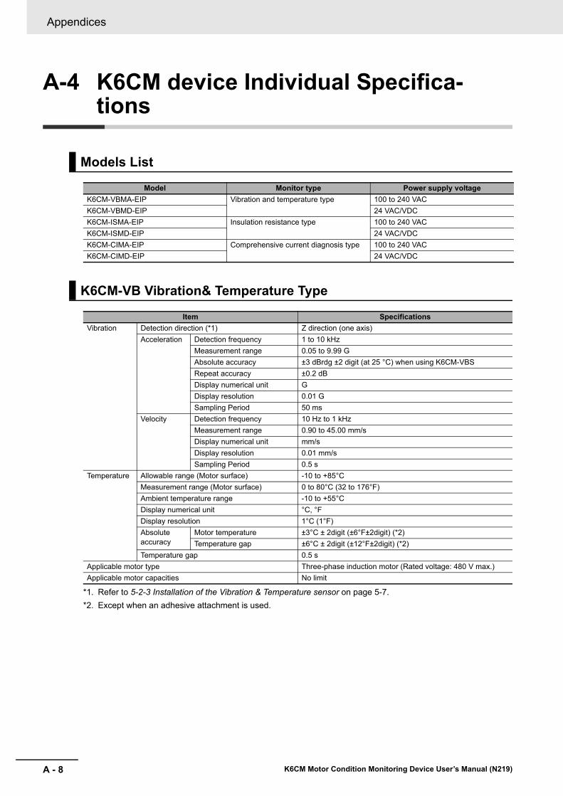
Appendices
A - 8 K6CM Motor Condition Monitoring Device User’s Manual (N219)
A-4 K6CM device Individual Specifica-tions
Models List
Model Monitor type Power supply voltage
K6CM-VBMA-EIP Vibration and temperature type 100 to 240 VAC
K6CM-VBMD-EIP 24 VAC/VDC
K6CM-ISMA-EIP Insulation resistance type 100 to 240 VAC
K6CM-ISMD-EIP 24 VAC/VDC
K6CM-CIMA-EIP Comprehensive current diagnosis type 100 to 240 VAC
K6CM-CIMD-EIP 24 VAC/VDC
K6CM-VB Vibration& Temperature Type
Item Specifications
Vibration Detection direction (*1)
*1. Refer to 5-2-3 Installation of the Vibration & Temperature sensor on page 5-7.
Z direction (one axis)
Acceleration Detection frequency 1 to 10 kHz
Measurement range 0.05 to 9.99 G
Absolute accuracy ±3 dBrdg ±2 digit (at 25 °C) when using K6CM-VBS
Repeat accuracy ±0.2 dB
Display numerical unit G
Display resolution 0.01 G
Sampling Period 50 ms
Velocity Detection frequency 10 Hz to 1 kHz
Measurement range 0.90 to 45.00 mm/s
Display numerical unit mm/s
Display resolution 0.01 mm/s
Sampling Period 0.5 s
Temperature Allowable range (Motor surface) -10 to +85°C
Measurement range (Motor surface) 0 to 80°C (32 to 176°F)
Ambient temperature range -10 to +55°C
Display numerical unit °C, °F
Display resolution 1°C (1°F)
Absolute accuracy
Motor temperature ±3°C ± 2digit (±6°F±2digit) (*2)
*2. Except when an adhesive attachment is used.
Temperature gap ±6°C ± 2digit (±12°F±2digit) (*2)
Temperature gap 0.5 s
Applicable motor type Three-phase induction motor (Rated voltage: 480 V max.)
Applicable motor capacities No limit

A - 9
Appendices
K6CM Motor Condition Monitoring Device User’s Manual (N219)
A-4 K
6CM
device In
divid
ual
Sp
ecification
s
A
K6CM-IS Insulation Resistance Type
Item Specifications
Insulation resistance
Insulation resistance
Display numerical unit MΩ
Measurement range 0.000 to 1.000 MΩ
Display resolution 0.001 MΩ
Leak current
(Both Ior and Ioc)
Display numerical unit mA
Measurement range 0.0 to 200.0 mA
Display resolution 0.1 mA
Accuracy ±35% rdg ± 2 digits (when insulation resistance is 0.2 MΩ or less), when using a motor of 200 V/7.5 kW or less
±35% rdg ± 2 digits (when insulation resistance is 0.4 MΩ or less), when using a motor of 400 V/7.5 kW or less
Wiring length of power line to ZCT (IRT) and motor 40m max.
Sampling period Normal mode: 10 s
Inverter special measurement mode: 60 s
Applicable circuits 1) Three-phase 3 wire, S-phase: ground
2) Three-phase four-wire, N-phase: grounding, load side: delta connection
Line penetrable to ZCT (IRT) Power lines
Rated input voltage 200 to 480 VAC (50/60 Hz)
Operating Input Voltage 170 to 528 VAC (45 to 65 Hz)
Applicable motor Three-phase induction motor (Rated voltage: 480 V max.)
Applicable motor capacities 0.75 to 7.5 kW
K6CM-CI Comprehensive Current Diagnosis Type
Item Specifications
Comprehen-sive current diagnosis
Rated input voltage 480 VAC (dedicated CT)
Rated input current 5, 25, 100, 200, 400, and 600 A (primary current of the dedi-cated CT)
Degree of degradation
Recommended frequency (*1)
*1. The degradation tendency of the motor hardly appears when the inverter is used at frequencies higher than 80 Hz.
20 to 80 Hz
Display numerical unit None (degree of degradation)
Measurement range 0 to 999
Resolution 1
Sampling period 5 s
Overcurrent Rated frequency 20 to 80 Hz
Display numerical unit A
Measurement range 1.00 to 5.00 A (at 5 A rating)
5.0 to 25.0 A (at 25 A rating)
20.0 to 100.0 A (at 100 A rating)
40.0 to 200.0 A (at 200 A rating)
80.0 to 400.0 A (at 400 A rating)
120.0 to 600.0 A (at 600 A rating)
Resolution 0.01 A (at 5 A rated)
0.1 A (at 25, 100, 200 and 400 A rated)
0.2 A (at 600 A rated)
Sampling period 5 s
Accuracy ±0.5% FS ±1 digit (at 10 to 30 ° C, not including CT variation)
Applicable motor type Three-phase induction motor (Rated voltage: 480 V max.)
Applicable motor capacities (*2)
*2. Current value can be calculated from the motor capacity. Refer to A-5 Individual Specifications of the Dedicated Sensor on page A-10.
0.75 to 300 kW (400 V)
0.75 to 150 kW (200 V)

Appendices
A - 10 K6CM Motor Condition Monitoring Device User’s Manual (N219)
A-5 Individual Specifications of the Dedi-cated Sensor
Rating/Performance
Note Vibration and temperature sensor consists of sensor head and pre-amplifier.The K6CM-VB1 is provided with a magnet for positioning of the vibration & temperature.
Rating/Performance
Vibration & Temperature Sensor
Model Screw diameter Connected K6CM device
K6CM-VBS1 M6 Vibration & temperature type (K6CM-VBM)
Power supply voltage Supplied from K6CM-VBM (Direct current)
Sensor head Max. acceleration 10 G
Ambient operating temperaturePre-amplifier: -10 to +55°C (with no condensation or icing)
Sensor head: -10 to +80°C (with no condensation or icing)
Storage temperaturePre-amplifier: -20 to +65°C (with no condensation or icing)
Sensor head: -20 to +90°C (with no condensation or icing)
Ambient operating humidity 25% to 85% RH (with no condensation)
Storage humidity 25% to 85% RH (with no condensation)
Altitude 2,000 m max.
Case colorPre-amplifier: Black
Sensor head: Silver
Case materialPre-amplifier: PC UL94-V0
Sensor head: ADC12 and ZDC2 (the threaded part is S45C)
WeightPre-amplifier: Approx. 210 g (including cable)
Sensor head: Approx. 40 g (including cable)
Mounting
Pre-amplifier: DIN rail mounting, Screw mounting
Sensor head: Screw mounting
Between pre-amplifier and sensor head: Connector connection
Wire length
Between pre-amplifier and sensor head: 2.9 m (cannot be extended)
Between pre-amplifier and K6CM device: 1 m (can be extended up to a maxi-mum length of 100 m)
Recommended cable between pre-ampli-fier and K6CM device
2464C BIOS-CL3-2402P-B (manufactured by Bando Densen Co., Ltd.)
Measurement range Measurement range is described in the K6CM Individual Specifications.
Applicable stan-dards
Conformingstandards
EN61010-2-030
Installation environment: Pollution degree 2, overvoltage category II, measure-ment category II
EMC EN61326-1 (EMI: Class A EMS: Industrial Location)
Safety standardsUL61010-2-030 (listing)
Korean Radio Waves Act (Act 10564), RCM
Insulation resistance 20 MΩ min.
Dielectric strength 500 VAC for one minute
Vibration resis-tance
Pre-amplifierVibration frequency 10 to 55 Hz, slice amplitude 0.35 mm in each of X, Y, Z directions 5 minute × 10 sweeps
Sensor headVibration frequency 10 to 55 Hz, slice amplitude 0.35 mm in each of X, Y, Z directions 5 minute × 10 sweeps
Shock resistancePre-amplifier 100 m/s2, 3 times each in 6 directions along 3 axes
Sensor head 100 m/s2, 3 times each in 6 directions along 3 axes
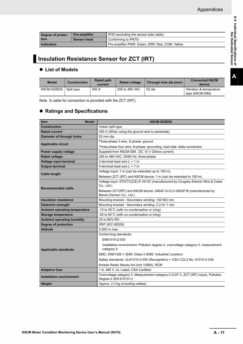
A - 11
Appendices
K6CM Motor Condition Monitoring Device User’s Manual (N219)
A-5 In
divid
ual S
pe
cification
s of
the D
edicated
Sen
sor
A
List of Models
Note A cable for connection is provided with the ZCT (IRT).
Ratings and Specifications
Degree of protec-tion
Pre-amplifier IP20 (excluding the sensor-side cable)
Sensor head Conforming to IP67G
Indicators Pre-amplifier PWR: Green, ERR: Red, COM: Yellow
Insulation Resistance Sensor for ZCT (IRT)
Model ConstructionRated path
currentRated voltage Through hole dia (mm)
Connected K6CM device
K6CM-ISZBI52 Split type 300 A 200 to 480 VAC 52 dia Vibration & temperature type (K6CM-ISM)
Item Model K6CM-ISZBI52
Construction Indoor split type
Rated current 300 A (When using the ground wire to penetrate)
Diameter of through holes 52 mm dia.
Applicable circuitThree-phase 3 wire, S-phase: ground
Three-phase four-wire, N-phase: grounding, load side: delta connection
Power supply voltage Supplied from K6CM-ISM , DC 10 V (Direct current)
Rated voltage: 200 to 480 VAC, 50/60 Hz, three-phase
Voltage input terminal 3-terminal lead wire L = 1 m
Output terminal 4-terminal lead wire L = 1 m
Cable lengthVoltage input: 1 m (can be extended up to 100 m)
Between ZCT (IRT) and K6CM device: 1 m (can be extended to 100 m)
Recommended cable
Voltage input: STO/TC(CE) # 18×3C (manufactured by Chugoku Electric Wire & Cable Co., Ltd.)
Between ZCT(IRT) and K6CM device: 2464C-S-CL3-2402P-B (manufactured by Bando Densen Co., Ltd.)
Insulation resistance Mounting bracket - Secondary winding: 100 MΩ min.
Dielectric strength Mounting bracket - Secondary winding: 2.2 kV 1 min
Ambient operating temperature -10 to 55°C (with no condensation or icing)
Storage temperature -20 to 65°C (with no condensation or icing)
Ambient operating humidity 25 to 85% RH
Degree of protection IP67 (IEC 60529)
Altitude 2,000 m max.
Applicable standards
Conforming standards:
EN61010-2-030
Installation environment: Pollution degree 2, overvoltage category II, measurement category II
EMC: EN61326-1 (EMI: Class A EMS: Industrial Location)
Safety standards: UL61010-2-030 (Recognition) + CSA C22.2 No. 61010-2-030
Korean Radio Waves Act (Act 10564), RCM
Adaptive fuse 1 A, 480 V, UL Listed, CSA Certified
Installation environmentOvervoltage category II, Measurement category II (CAT II, ZCT (IRT) input), Pollution Degree 2 (EN 61010-1)
Weight Approx. 2.3 kg (including cables)

Appendices
A - 12 K6CM Motor Condition Monitoring Device User’s Manual (N219)
Models
Note A dedicated CT is provided with a connecting cable.
Ratings and Specifications
The frequency characteristics of the CT are as follows.
Dedicated Current Transformer (CT)
Model Rated primary current Rated secondary current Connected K6CM device
K6CM-CICB005 5 A Dedicated output Comprehensive current diag-nosis type (K6CM-CIM)K6CM-CICB050 25 A
K6CM-CICB100 100 A
K6CM-CICB200 200 A
K6CM-CICB400 400 A
K6CM-CICB600 600 A
Item ModelK6CM
-CICB005K6CM
-CICB025K6CM
-CICB100K6CM
-CICB200K6CM
-CICB400K6CM
-CICB600
Primary-side rated cur-rent
5 A 25 A 100 A 200 A 400 A 600A
Rated voltage 480 VAC
Secondary winding 3000 turns 6000 turns 9000 turns
Insulation resistance Between output terminal and case: 50 MΩ min.
Dielectric strength Between output terminal and case: 2,300 V, 1 min
Protective element 7.5 V clamp element
Permissible attach-ment/removal fre-quency
100 times
Attachable wire diame-ter *1
*1. When using a flat wire, be sure to refer to the external dimensions drawing of the CT before selection. Use a dedicated CT with a larger diameter. However, use it within the range of rated current of CT.
7.9 mm dia. max.
9.5 mm dia. max.
14.5 mm dia. max.
24.0 mm dia. max.
35.5 mm dia. max.
Operating temperature / humidity range
-20 to +60°C, 85% max. (with no condensation)
Storage temperature / humidity range
-30 to +65°C, 85% max. (with no condensation)
Provided cable length 2.9 m
Terminal type for the provided cable
K6CM device side: Ferrule terminal
CT side: Round terminal
K6CM-CICB005 K6CM-CICB025
F.S
. err
or
Frequency [Hz]
1.00%
0.50%
0.00%
20 30 40 50 60 70 80
1 A
2 A
3 A
4 A
5 A-0.50%
-1.00%
F.S
. erro
r
Frequency [Hz]
1.00%
0.50%
0.00%
20 30 40 50 60 70 80
5 A
10 A
15 A
20 A
25 A-0.50%
-1.00%
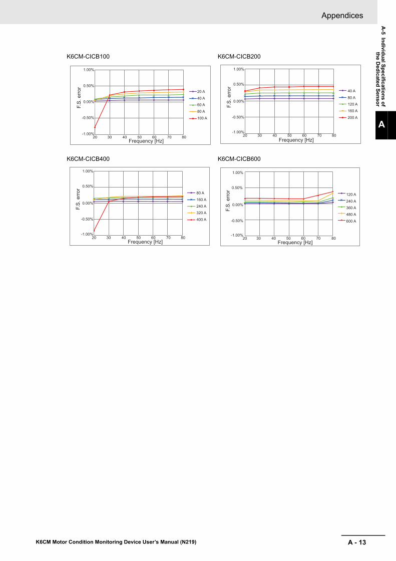
A - 13
Appendices
K6CM Motor Condition Monitoring Device User’s Manual (N219)
A-5 In
divid
ual S
pe
cification
s of
the D
edicated
Sen
sor
A
K6CM-CICB100 K6CM-CICB200
K6CM-CICB400 K6CM-CICB600
F.S.
erro
r
Frequency [Hz]
20 A
40 A
60 A
80 A
100 A
1.00%
0.50%
0.00%
20 30 40 50 60 70 80
-0.50%
-1.00%
F.S.
erro
r
Frequency [Hz]
40 A
80 A
120 A
160 A
200 A
1.00%
0.50%
0.00%
20 30 40 50 60 70 80
-0.50%
-1.00%
F.S.
erro
r
Frequency [Hz]
80 A
160 A
240 A
320 A
400 A
1.00%
0.50%
0.00%
20 30 40 50 60 70 80
-0.50%
-1.00%F.
S. e
rror
Frequency [Hz]
120 A
240 A
360 A
480 A
600 A
1.00%
0.50%
0.00%
20 30 40 50 60 70 80
-0.50%
-1.00%

Appendices
A - 14 K6CM Motor Condition Monitoring Device User’s Manual (N219)
A-6 Internal Data of K6CM Devices
This section describes the overview of the internal data of the K6CM devices.
The K6CM device has setting values and present values (i.e., measurement value and alarm results) as internal data.
You can write or read these setting values and current values in the following way.
For details of internal data, refer to A-7 Setting Values on page A-15 and A-8 Present Values on page A-19 below.
MethodInternal data of K6CM
ReferenceSetting value Present value
Motor condition moni-toring Tool (Software tool)
Writable, readable
(Note. depending on the item)
Readable
(Note. depending on the item)
Section 6 How to Use the Software Tool
7-3 Motor Monitoring Using Software Tools on page 7-9
CIP message commu-nications
Writable, readable Readable 8-3 Monitoring and Setting Using the CIP Message Com-munications and Examples of Communications Instructions on page 8-12
Tag data link Can not write Readable 8-2 Monitoring Using the Tag Data Link on page 8-5

A - 15
Appendices
K6CM Motor Condition Monitoring Device User’s Manual (N219)
A-7 S
etting
Valu
es
A
A-7 Setting Values
In this section, the setting values in the internal data of the K6CM devices are classified according to K6CM common and monitor type, and are shown in a list.
Precautions for Correct Use
In order to validate the setting value, it is necessary to turn the power supply ON again or per-form a soft reset after changing the set value.The alarm threshold settings are performed by integer values (e.g., 0 to 9999) regardless of the measurement range. Therefore, confirm the measurement range and units in the table shown below, and then set the alarm threshold.
Alarm Setting Values (threshold value)
Vibration & temperature Type (K6CM-VBM)
Data name Description
Writing method (Yes: supported, No: supported)
Software toolCIP message
communicationsTag data link
Acceleration, High alarm threshold (Critical and Warning)
0 to 9999 (unit: 0.01 G)
Yes Yes No
Velocity, High alarm threshold (Critical and Warning)
0 to 9999 (unit: 0.01 mm/s)
Yes Yes No
Motor temperature, High alarm threshold (Critical and Warning)
0 to 9999 (unit: °C)Yes Yes No
Temperature Gap, High alarm thresh-old (Critical and Warning)
0 to 9999 (unit: °C)Yes Yes No
Insulation Resistance Type (K6CM-ISM)
Data name Description
Writing method (Yes: supported, No: supported)
Software toolCIP message
communicationsTag data link
Insulation resistance, Low alarm threshold (Critical and Warning)
0 to 9999 (Unit: 0.001 MΩ)
Yes Yes No
Comprehensive Current Diagnosis Type (K6CM-CIM)
Data name Description
Writing method (Yes: supported, No: supported)
Software toolCIP message
communicationsTag data link
Degradation level, High alarm threshold (Critical and Warning)
0 to 999Yes Yes No
Current, High alarm threshold (Critical and Warning)
0 to 9999
Unit:
Current range = 0: 0.01 A
Current range = 1 to 5: 0.1 A
Yes Yes No

Appendices
A - 16 K6CM Motor Condition Monitoring Device User’s Manual (N219)
Other Setting Values
Common to the K6CM Devices
Data name Description
Writing method (Yes: supported, No: sup-ported)
Software tool
CIP mes-sage com-
municationsTag data link
K6CM IP address
Sets the IP address of the K6CM.
The initial value is "192.168.250.10" (common to models)
Yes Yes No
Software reset
Restarts the K6CM device. It is used to validate the setting after changing the setting value.
Rising from 0 to 1: Execute (soft reset)
Yes (Soft-ware reset
button)
Yes No
Max./min. reset
Initializes the MAX / MIN value.
OFF to ON: Execute (initialize max. and min. value)
Yes(Reset the maximum and mini-
mum value button)
Yes No
Display value type
Sets which measured value is displayed in the 7 segment dis-play of the K6CM.
0: PV
1: MIN
2: MAX
To see which measured value is displayed, you can check with the monitoring category display on the K6CM.
"PV": present value, "MIN": minimum value, "MAX": maximum value
Yes Yes No
Trigger mode
Selects either internal trigger, external trigger, constant mea-suring and monitoring (no trigger).
0: Always
1: External trigger
2: Internal trigger
Yes Yes No
Trigger type
For internal trigger or external trigger, select either rising, fall-ing, or level.
0: Rising
1: Falling edge
2: Level
• For internal trigger:
Rise: When the measured value exceeds the set value (trig-
ger level)
Falling edge: When the measured value falls below the set
value (trigger level)
Level: During the measured value exceeds the setting value (*1)
*1. In the case of "Insulation resistance" for the lower limit alarm, it oppositely means "lower" than the setting value.
• For external trigger:
Rise: When external input changes from OFF to ON
Falling edge: When external input changes from ON to OFF
Level: External input is in the ON state
Yes Yes No
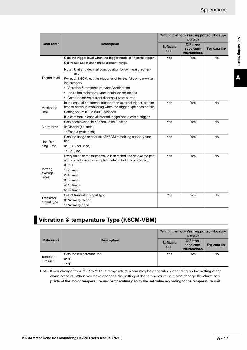
A - 17
Appendices
K6CM Motor Condition Monitoring Device User’s Manual (N219)
A-7 S
etting
Valu
es
A
Note If you change from "° C" to "° F", a temperature alarm may be generated depending on the setting of the alarm setpoint. When you have changed the setting of the temperature unit, also change the alarm set-points of the motor temperature and temperature gap to the set value according to the temperature unit.
Trigger level
Sets the trigger level when the trigger mode is "internal trigger".
Set value: Set in each measurement range.
Note : Unit and decimal point position follow measured val-ues.
For each K6CM, set the trigger level for the following monitor-ing category.
• Vibration & temperature type: Acceleration
• Insulation resistance type: Insulation resistance
• Comprehensive current diagnosis type: current
Yes Yes No
Monitoring time
In the case of an internal trigger or an external trigger, set the time to continue monitoring when the trigger type rises or falls.
Setting value: 0.1 to 600.0 seconds.
It is common in case of internal trigger and external trigger.
Yes Yes No
Alarm latch
Sets enable /disable of alarm latch function.
0: Disable (no latch)
1: Enable (with latch)
Yes Yes No
Use Run-ning Time
Sets the usage or nonuse of K6CM remaining capacity func-tion.
0: OFF (not used)
1: ON (use)
Yes Yes No
Moving average times
Every time the measured value is sampled, the data of the past n times including the sampling data of that time is averaged.
0: OFF
1: 2 times
2: 4 times
3: 8 times
4: 16 times
5: 32 times
Yes Yes No
Transistor output type
Select transistor output type.
0: Normally closed
1: Normally open
Yes Yes No
Vibration & temperature Type (K6CM-VBM)
Data name Description
Writing method (Yes: supported, No: sup-ported)
Software tool
CIP mes-sage com-
municationsTag data link
Tempera-ture unit
Sets the temperature unit.
0: °C
1: °F
Yes Yes No
Data name Description
Writing method (Yes: supported, No: sup-ported)
Software tool
CIP mes-sage com-
municationsTag data link

Appendices
A - 18 K6CM Motor Condition Monitoring Device User’s Manual (N219)
Insulation Resistance Type (K6CM-ISM)
Data name Description
Writing method (Yes: supported, No: sup-ported)
Software tool
CIP mes-sage com-
municationsTag data link
Applicable circuit
Sets the applicable circuit.
0: Three-phase three-wire S-phase ground
1: Three-phase four-wire N-phase grounded load side delta connection
Yes Yes No
Using inverter
Sets the presence or absence of the inverter.
0: OFF (No inverter)
1: ON (with inverter)
(For 3 phase 4 wires N phase ground load side delta connec-tion, use with no inverter.If you have an inverter you can not do the correct measurement.)
Yes Yes No
Inverter spe-cial mea-surement
Sets the Inverter Special measurement.
0: OFF
1: ON
Special calculation to do when inverter frequency and commer-cial frequency are close. For how to use this function, refer to the Wiring Diagram of the Insulation Resistance Type (K6CM-IS) on page 5-23 in 5-5 I/O wiring on page 5-22.
Note : With or without inverter = "with inverter" only valid
Yes Yes No
Comprehensive Current Diagnosis Type (K6CM-CIM)
Data name Description
Writing method (Yes: supported, No: sup-ported)
Software tool
CIP mes-sage com-
municationsTag data link
Current range
Sets the current range.
0: 5 A
1: 25 A
2: 100 A
3: 200 A
4: 400 A
5: 600 A
Yes Yes No

A - 19
Appendices
K6CM Motor Condition Monitoring Device User’s Manual (N219)
A-8 P
resent V
alues
A
A-8 Present Values
In this section, the present values in the internal data of the K6CM devices are classified according to K6CM common and monitor type, and are shown in a list.
Measurement Value
Vibration & temperature Type (K6CM-VBM)
Data name Description
Reading method (Yes: supported, No: sup-ported)
K6CM device
Software tool
CIP mes-sage com-
munications
Tag data link
Acceleration (Present, Min., Max.)
0.00 to 9.99 G (K6CM display)Yes Yes Yes Yes
Velocity (Present, Min., Max.)
0.00 to 45.00 mm/s (K6CM display)Yes Yes Yes Yes
Motor temperature (Present, Min., Max.)
0 to 80°C (32 to 176°F) (K6CM display)Yes Yes Yes Yes
Temperature Gap (Dif-ference from the room temperature of Motor temperature) (Present, Min., Max.)
0 to 80°C (32 to 176°F) (K6CM display)
Yes Yes Yes Yes
Acceleration status Bit00: Present value unmeasured state
Bit01: Present value input error
Bit04: Maximum value unmeasured state
Bit05: Maximum value input error
Bit08: Minimum value unmeasured state
Bit09: Minimum value input error
Bit12: Individual alarm threshold setting (Warning)
Bit13: Individual alarm threshold setting (Criti-cal)
No Yes Yes Yes
Velocity status No Yes Yes Yes
Motor temperature sta-tus
No Yes Yes Yes
Temperature Gap sta-tus
No Yes Yes Yes

Appendices
A - 20 K6CM Motor Condition Monitoring Device User’s Manual (N219)
Insulation Resistance Type (K6CM-ISM)
Data name Description
Reading method (Yes: supported, No: sup-ported)
K6CM device
Software tool
CIP mes-sage com-
munications
Tag data link
Insulation resistance (Present, Min., Max.)
0.000 to 1.000 MΩ (K6CM display)Yes Yes Yes Yes
Leakage current Ior (Present, Min., Max.)
0.0 to 200.0 mA (K6CM display)Yes Yes Yes Yes
Leakage currentIoc (Present)
0.0 to 200.0 mA (communications)No Yes Yes Yes
Insulation resistance status
Bit00: Present value unmeasured state
Bit01: Present value input error
Bit04: Maximum value unmeasured state
Bit05: Maximum value input error
Bit08: Minimum value unmeasured state
Bit09: Minimum value input error
Bit12: Individual alarm threshold setting (Warning)
Bit13: Individual alarm threshold setting (Criti-cal)
No Yes Yes Yes
Comprehensive Current Diagnosis Type (K6CM-CIM)
Data name Description
Reading method (Yes: supported, No: sup-ported)
K6CM device
Software tool
CIP mes-sage com-
munications
Tag data link
Degradation level (Present, Min., Max.)
Degradation level of motor calculated by measuring current including harmonic com-ponents. Indicator of general current diagno-sis.
0 to 999 (K6CM display)
Yes Yes Yes Yes
Current (Present, Min., Max.)
Current range = 0: 0.00 to 5.00 A
Current range = 1: 0.0 to 25.0 A
Current range = 2: 0.0 to 100.0 A
Current range = 3: 0.0 to 200.0 A
Current range = 4: 0.0 to 400.0 A
Current range = 5: 0.0 to 600.0 A
Yes Yes Yes Yes
Degradation level sta-tus
Bit00: Present value unmeasured state
Bit01: Present value input error
Bit04: Maximum value unmeasured state
Bit05: Maximum value input error
Bit08: Minimum value unmeasured state
Bit09: Minimum value input error
Bit12: Individual alarm threshold setting (Warning)
Bit13: Individual alarm threshold setting (Criti-cal)
No Yes Yes Yes
Current status
No Yes Yes Yes

A - 21
Appendices
K6CM Motor Condition Monitoring Device User’s Manual (N219)
A-8 P
resent V
alues
A
Common to the K6CM Devices
Data name Description
Reading method (Yes: supported, No: sup-ported)
K6CM device
Software tool
CIP mes-sage com-
munications
Tag data link
Measurement CPU version
Measurement part versionNo Yes Yes Yes
Main CPU ver-sion
Main part versionNo Yes Yes Yes
EIP CPU version EtherNet/IP version No Yes Yes Yes
K6CM statusDuring measuring and monitoring, transistor output 1, 2, 3 state, external trigger input state, etc.
It consists of the following contents.
No Yes Yes Yes
Monitoring condition
The state measured and monitored by K6CM. "MON" on the LCD display lights up.
In the case of an internal trigger or an external trig-ger, it is measured and monitored by a trigger. In case of no trigger, it is always measured and moni-tored with power ON.
Note : There are no states that are measuring and not monitoring.
1: Measuring and monitoring
0: Measuring and monitoring stopped
Yes ("MON")
Yes Yes (part of K6CM status)
Yes (part of K6CM status)
Running Time status
Turns ON when running time reaches 100%. Accu-mulates the product of operation time and internal temperature, and detects abnormality when design life reaches.
1: Reached (running time reaches 100%)
0: Not reached (running time has not reached 100%)
Yes (according to "AGE"
indication)
Yes Yes (part of K6CM status)
Yes (part of K6CM status)
Trigger input
State of external trigger input
1: ON
0: OFF
No Yes Yes (part of K6CM status)
Yes (part of K6CM status)
TR 1 (transis-tor 1 output state)
State of transistor 1 of K6CM
1: ON
0: OFF
No Yes Yes (part of K6CM status)
Yes (part of K6CM status)
TR 2 (transis-tor 2 output state)
State of transistor 2 of K6CM
1: ON
0: OFF
No Yes Yes (part of K6CM status)
Yes (part of K6CM status)
TR 3 (transis-tor 3 output state)
State of transistor 3 of K6CM
1: ON
0: OFF
No Yes Yes (part of K6CM status)
Yes (part of K6CM status)
Running Time
Coefficient indicating lifetime of the K6CM device based on the product of operation time and internal temperature.
It increases from 0% in 10% increments.
0000 to 0064 hex (0 to 100)
No Yes Yes Yes
Number of trig-gers
Total number of integration times of external trigger or internal trigger. Make +1 every 100 iterations.
0 to 65535
No Yes Yes Yes

Appendices
A - 22 K6CM Motor Condition Monitoring Device User’s Manual (N219)
Alarm Results
Common to the K6CM Devices
Data name Description
Reading method (Yes: supported, No: supported)
K6CM device
Software tool
CIP mes-sage com-
munications
Tag data link
Comprehensive alarm (Warning)
In K6CM, there is no "Critical" in the measurement value, and even one of them has "Warning".
Transistor output, alarm bar (yellow) is reflected
Yes (Alarm bar, and transistor output)
No Yes (K6CM status or Measure-
ment status)
Yes (K6CM status or Measure-
ment status)
Comprehensive alarm (Critical)
Within K6CM, there is "Critical" even if at least one measured value.
Transistor output, reflected on alarm bar (red)
Yes (Alarm bar, and transistor output)
No Yes (K6CM status or Measure-
ment status)
Yes (K6CM status or Measure-
ment status)
Vibration & temperature Type (K6CM-VBM)
Data name Description
Reading method (Yes: supported, No: supported)
K6CM device
Software tool
CIP mes-sage com-
munications
Tag data link
Acceleration, High alarm (Critical and Warning)
ON, OFFNo Yes Yes Yes
Velocity, High alarm (Critical and Warning)
ON, OFFNo Yes Yes Yes
Motor temperature, High alarm (Critical and Warn-ing)
ON, OFFNo Yes Yes Yes
Temperature Gap, High alarm (Critical and Warn-ing)
ON, OFFNo Yes Yes Yes
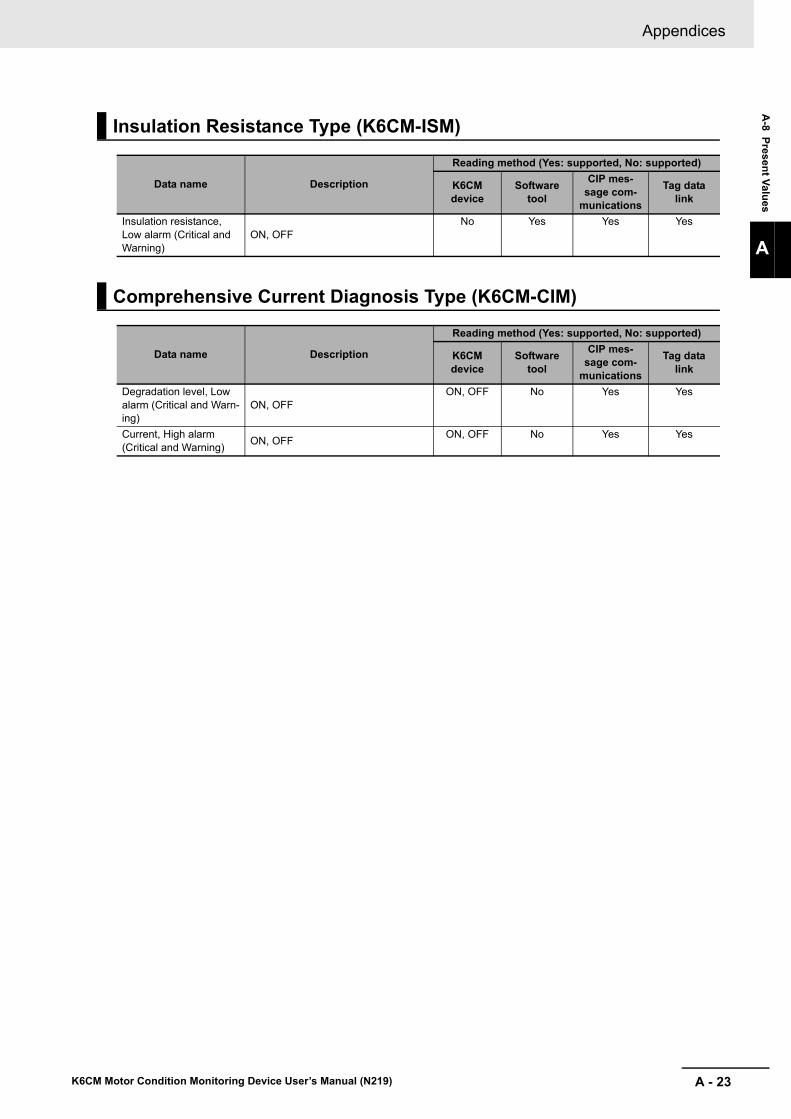
A - 23
Appendices
K6CM Motor Condition Monitoring Device User’s Manual (N219)
A-8 P
resent V
alues
A
Insulation Resistance Type (K6CM-ISM)
Data name Description
Reading method (Yes: supported, No: supported)
K6CM device
Software tool
CIP mes-sage com-
munications
Tag data link
Insulation resistance, Low alarm (Critical and Warning)
ON, OFFNo Yes Yes Yes
Comprehensive Current Diagnosis Type (K6CM-CIM)
Data name Description
Reading method (Yes: supported, No: supported)
K6CM device
Software tool
CIP mes-sage com-
munications
Tag data link
Degradation level, Low alarm (Critical and Warn-ing)
ON, OFFON, OFF No Yes Yes
Current, High alarm (Critical and Warning)
ON, OFFON, OFF No Yes Yes

Appendices
A - 24 K6CM Motor Condition Monitoring Device User’s Manual (N219)
A-9 Tag Data Link Connection Setting Procedures
You can set tag data link settings using the Network Configurator for EtherNet/IP.
When using the CS/CJ-series PLC as an originator, use the Network Configurator for EtherNet/IP supporting the model and version of the CPU Unit. Refer to the CS/CJ Series EtherNet/IP Units Operation Manual (Cat. No.W465) for the setting status of the setting tool.
The setting method when the CS/CJ-series PLC is an originator is as follows.
1 Starting the Network Configurator for EtherNet/IP
To start the Network configurator, select [All Programs] | [OMRON] | [Sysmac Studio] | [Network Configurator for EtherNetIP] | [ Network Configurator] from the Windows Start Menu.
The Main Window consists of a Hardware List and a Network Configuration Pane, as shown in the following diagram.
A-9-1 Using the CS/CJ-series
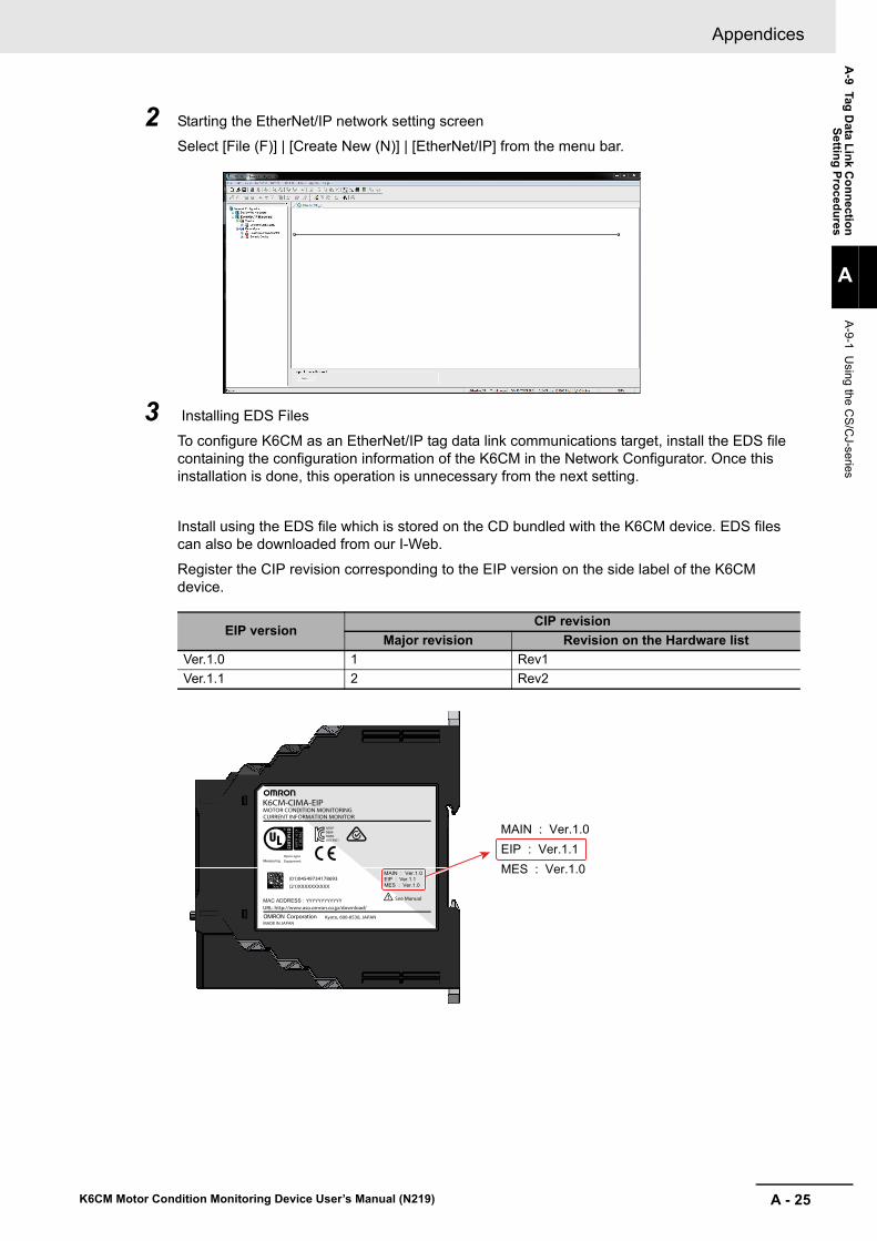
A - 25
Appendices
K6CM Motor Condition Monitoring Device User’s Manual (N219)
A-9 Tag
Data L
ink C
on
nectio
nS
ettin
g P
roc
edu
res
A
A-9-1 U
sing the CS
/CJ-series
2 Starting the EtherNet/IP network setting screen
Select [File (F)] | [Create New (N)] | [EtherNet/IP] from the menu bar.
3 Installing EDS Files
To configure K6CM as an EtherNet/IP tag data link communications target, install the EDS file containing the configuration information of the K6CM in the Network Configurator. Once this installation is done, this operation is unnecessary from the next setting.
Install using the EDS file which is stored on the CD bundled with the K6CM device. EDS files can also be downloaded from our I-Web.
Register the CIP revision corresponding to the EIP version on the side label of the K6CM device.
EIP versionCIP revision
Major revision Revision on the Hardware list
Ver.1.0 1 Rev1
Ver.1.1 2 Rev2
See Manual
Equipment.MeasuringOpen-type
MOTOR CONDITION MONITORING
Kyoto, 600-8530, JAPANMADE IN JAPAN
MAC ADDRESS : URL: http://www.aso.omron.co.jp/download/
K6CM01OMR-REM-MSIP-
(01)04549734178693 EIP : Ver.1.1MAIN : Ver.1.0
CURRENT INFORMATION MONITOR
K6CM-CIMA-EIP
(21)XXXXXXXXXX MES : Ver.1.0
YYYYYYYYYYYY
EIP : Ver.1.1MAIN : Ver.1.0
MES : Ver.1.0

Appendices
A - 26 K6CM Motor Condition Monitoring Device User’s Manual (N219)
Select [EDS File (S)] | [Install (I) ...] on the menu bar.
After selecting the following EDS file, click [Open] and install it.
At this time, an icon confirmation message will be displayed. Click [Yes (Y)].
After selecting the following ICON file, click [Open] and install it.
Model name of the K6CM EDS file name
K6CM-CIM K6CM_CIM_EIP_R2.eds
K6CM-ISM K6CM_ISM_EIP_R2.eds
K6CM-VBM K6CM_VBM_EIP_R2.eds
Model name of the K6CM ICON file name
K6CM-CIM 128x128.ico
K6CM-ISM
K6CM-VBM

A - 27
Appendices
K6CM Motor Condition Monitoring Device User’s Manual (N219)
A-9 Tag
Data L
ink C
on
nectio
nS
ettin
g P
roc
edu
res
A
A-9-1 U
sing the CS
/CJ-series
When the installation is completed, the device is added to the hardware list.
4 Registering devices
(1) Device registration to the network configuration
Register the EtherNet/IP devices which participate in the tag data links in the Network Con-figuration Window.
From the hardware list, you can register a PLC as an originator device and K6CM devices, by dragging and dropping each device at a time, or by selecting and double-clicking it.
As an example, register a CJ1W-EIP21 (Rev 3) in the "Communications Adapter" category as an originator device and register a K6CM-CIM as a target device.
Note Select the same model as the device you use and register it.
The device names and major CIP revisions (Rev ) are displayed in the hardware list.
The device name and the major CIP revision of the CS/CJ-series CPU Unit are as follows.
Device name in hard-ware list
Unit versionCIP revision
Major revi-sion
Revision name in hardware list
CJ2B-EIP21 Unit version.2.0 and 2.1 2 Rev2
Unit version.3.0 3 Rev3
CJ2M-EIP21 Unit version.2.0 and 2.1 2 None
CJ1W-EIP21 Unit version.1.0 1 Rev1
Unit version.2.0 and 2.1 2 Rev2
Unit version.3.0 3 Rev3
Drug

Appendices
A - 28 K6CM Motor Condition Monitoring Device User’s Manual (N219)
*1.This shows the case where the CJ1W-EIP21 Unit is mounted on the CJ2 CPU Unit.
(2) Device Node Address (IP Address) Setting
Set the node address (IP address) of the device to be used.
In the Network Configuration Window, click the device you want to change the node address (IP address), right click and select [Change Node Address (A) ...].
Enter the node address (IP address) of the device to be used actually, and click [OK].
5 EtherNet/IP Connection Settings
(1) Create Tag sets and Tags
Create tag sets and those members tags necessary for connection for the registered Etehr-Net/IP Unit. For tags, you can set the I/O memory address or network symbols used by the control program (CJ2H-CPU6-EIP21 and CJ2M-CPU3 only).
Additional Information
The setting contents depend on the originator device connecting the K6CM series.
For detailed settings, refer to the manual of the originator device.
• "SYSMAC CS/CJ Series EtherNet/IP Units Operation Manual (Cat. No.W465)"
Additional Information
Tag set names and tag names can also be created in advance using the CX-Programmer. When creating in advance, make them the same names as the tags to be created with the Net-workConfiguratior. You can also use them as symbol variables of PLC by sharing them with CX-Programmer by importing from or exporting to a file the tag set names and tag names of PLC edited with Network Configurator.
For detailed settings, refer to the manual of the originator.
(1)-1 Tag Editing
Select the device (e.g., CJ1W-EIP21) for editing the tag set and the tag.
Then right-click it and select [Parameter (P)] | [Edit (E) ...] or double-click it.
CS1W-EIP21 Unit version.1.0 1 Rev1
Unit version.2.0 and 2.1 2 Rev2
Unit version.3.0 3 Rev3
CJ1W-EIP21?CJ2?*1 Unit version.2.0 and 2.1 2 Rev2
Unit version.3.0 3 Rev3
Device name in hard-ware list
Unit versionCIP revision
Major revi-sion
Revision name in hardware list
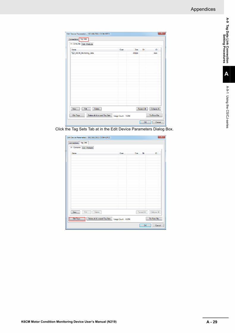
A - 29
Appendices
K6CM Motor Condition Monitoring Device User’s Manual (N219)
A-9 Tag
Data L
ink C
on
nectio
nS
ettin
g P
roc
edu
res
A
A-9-1 U
sing the CS
/CJ-series
Click the Tag Sets Tab at in the Edit Device Parameters Dialog Box.

Appendices
A - 30 K6CM Motor Condition Monitoring Device User’s Manual (N219)
Additional Information
If you have created network symbols, tag set names and tag names in advance with the CX-Programmer and have the exported file (.CSV), click [To/From File] at the lower right, select [ Import from File...]. By doing so, you can omit the following "(1) -1 Tag editing" and "(1) -2 Edit-ing tag set" below.
Click [Edit Tag (T) ...] in the Edit Device Parameters Dialog Box to edit tag sets.
To enter tags, there are tabs for Input (Consume) and Output (Produce), but set only the Input (Consume) tab when connecting the K6CM series. Select the [In - Consume] Tab and click [New (N) ...], the Edit Tags Dialog Box will be displayed.
Enter the tag name and its size (44 bytes), and click [Register (R)].
As a "tag name", enter the character string for the CPU Unit's I/O memory address or a net-work symbol (e.g., 100, W100, D0, Input_signal).
Addresses in the following I/O memory areas can be set.
Additional Information
Here, create a symbol that matches the name of the I/O memory address used in the PLC or the name of the network symbol (input).
CPU Unit’s data area Address (Text to input in Name Field.)
CIO Area 0000~6143
Holding Area H000~H511
Work Area W000~W511
DM Area D00000~D32767
EM Area Bank 0 hex E0_00000~E0_32767
··· ···
Bank 18 hex E18_00000~E18_32767

A - 31
Appendices
K6CM Motor Condition Monitoring Device User’s Manual (N219)
A-9 Tag
Data L
ink C
on
nectio
nS
ettin
g P
roc
edu
res
A
A-9-1 U
sing the CS
/CJ-series
Continue to edit tags. Click [Close (C)] to end tag editing.
As an example, register the tag with the tag name as "D00000" and the size as 44 bytes.
The tags registered are displayed in the the Edit Tag Dialog Box.
Click [OK] in the Edit Tag Dialog to register tags and complete tag editing,
At that time, if you have created a new tag, the following confirmation message will be dis-played. To register the tag name as it is as the tag set name, click [Yes (Y)].
If you register the tag name as it is as the tag set name, one tag is registered as one tag set. Here, when selecting [Yes (Y)], you can omit "(1) -2. Editing tag set" for the newly cre-ated tag.
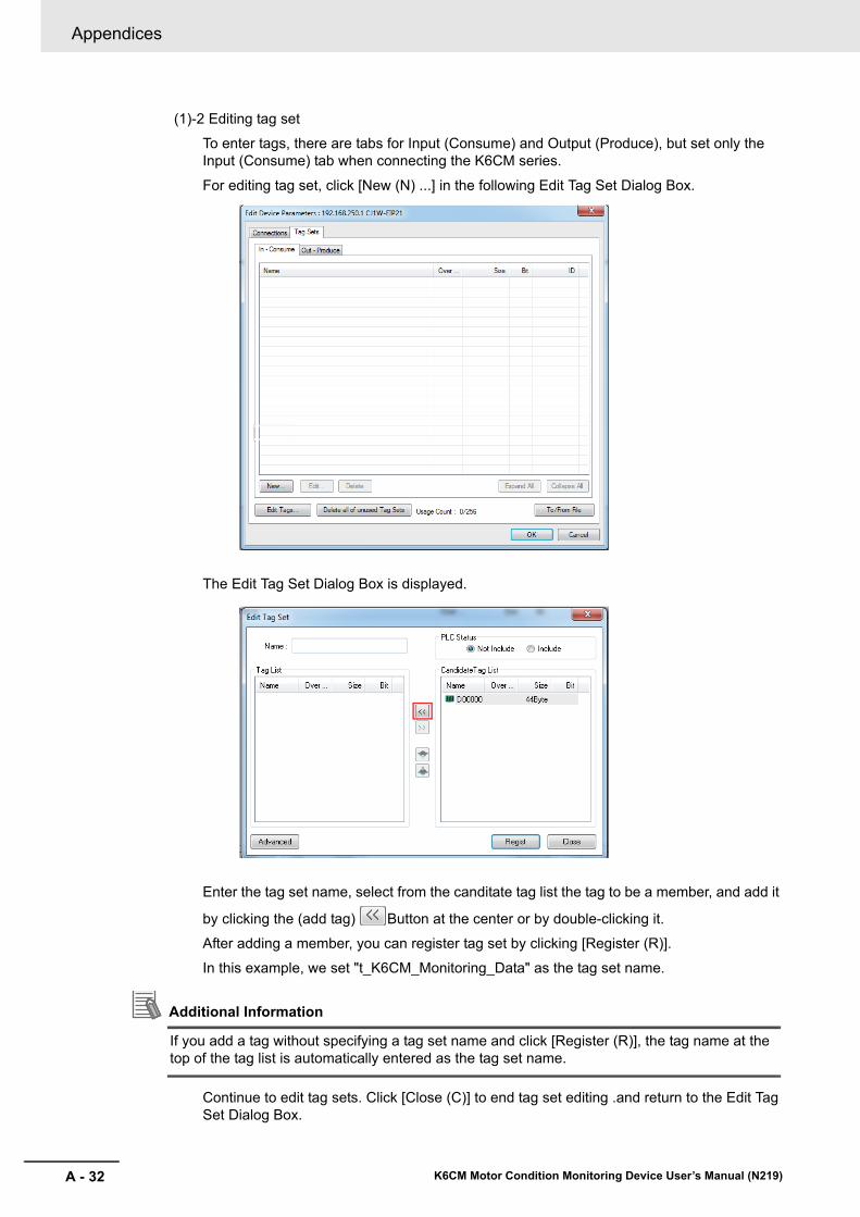
Appendices
A - 32 K6CM Motor Condition Monitoring Device User’s Manual (N219)
(1)-2 Editing tag set
To enter tags, there are tabs for Input (Consume) and Output (Produce), but set only the Input (Consume) tab when connecting the K6CM series.
For editing tag set, click [New (N) ...] in the following Edit Tag Set Dialog Box.
The Edit Tag Set Dialog Box is displayed.
Enter the tag set name, select from the canditate tag list the tag to be a member, and add it
by clicking the (add tag) Button at the center or by double-clicking it.
After adding a member, you can register tag set by clicking [Register (R)].
In this example, we set "t_K6CM_Monitoring_Data" as the tag set name.
Additional Information
If you add a tag without specifying a tag set name and click [Register (R)], the tag name at the top of the tag list is automatically entered as the tag set name.
Continue to edit tag sets. Click [Close (C)] to end tag set editing .and return to the Edit Tag Set Dialog Box.
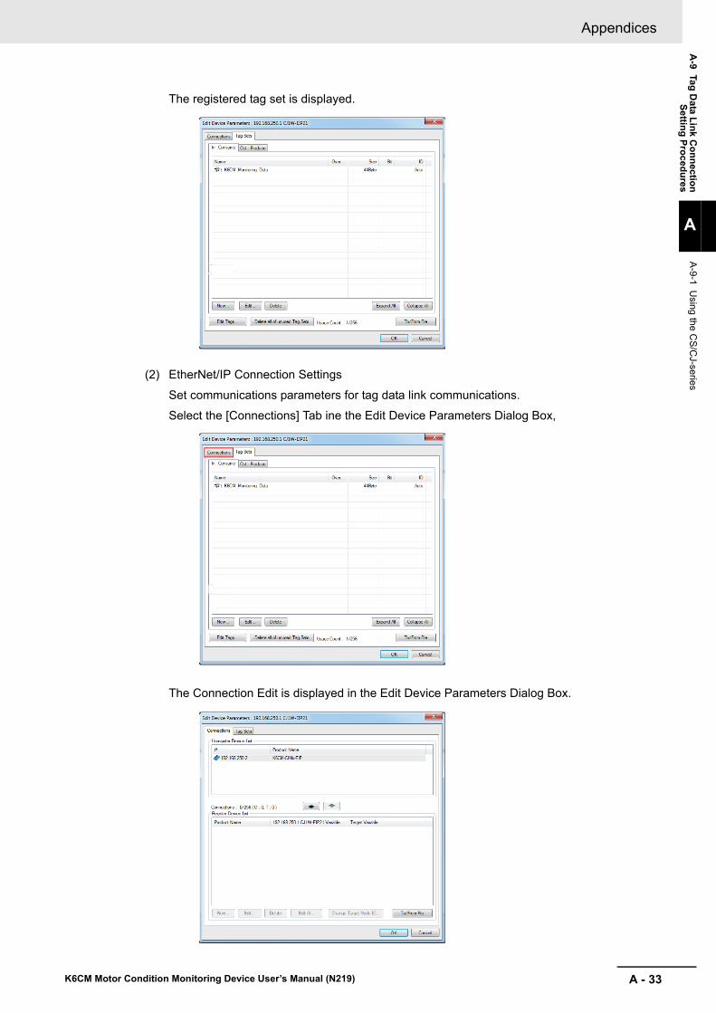
A - 33
Appendices
K6CM Motor Condition Monitoring Device User’s Manual (N219)
A-9 Tag
Data L
ink C
on
nectio
nS
ettin
g P
roc
edu
res
A
A-9-1 U
sing the CS
/CJ-series
The registered tag set is displayed.
(2) EtherNet/IP Connection Settings
Set communications parameters for tag data link communications.
Select the [Connections] Tab ine the Edit Device Parameters Dialog Box,
The Connection Edit is displayed in the Edit Device Parameters Dialog Box.

Appendices
A - 34 K6CM Motor Condition Monitoring Device User’s Manual (N219)
Select the K6CM series, and then click the middle (Add device) Button to register the connection in the tag data link.
Select the K6CM series displayed in the registered device list, click [New (N) ...] or dou-ble-click the device, the Connection Allocation Dialog Box will be displayed.
The default values of each parameter are displayed, and then set the following items.
• Input tag setSelect the tag set name edited in "(1) -2. Editing tag set" from the drop down list and set it.
• Packet Interval (RPI)From the setting range of K6CM (250 ms to 10000 ms), set the data send interval from K6CM according to the system.
• Timeout ValueSelect the timeout value at the occurrence of a communications error from the pull down list and set it. The value can be set by multiple of packet interval (RPI). (4 times, 8 times, 16 times, ..., 512 times)
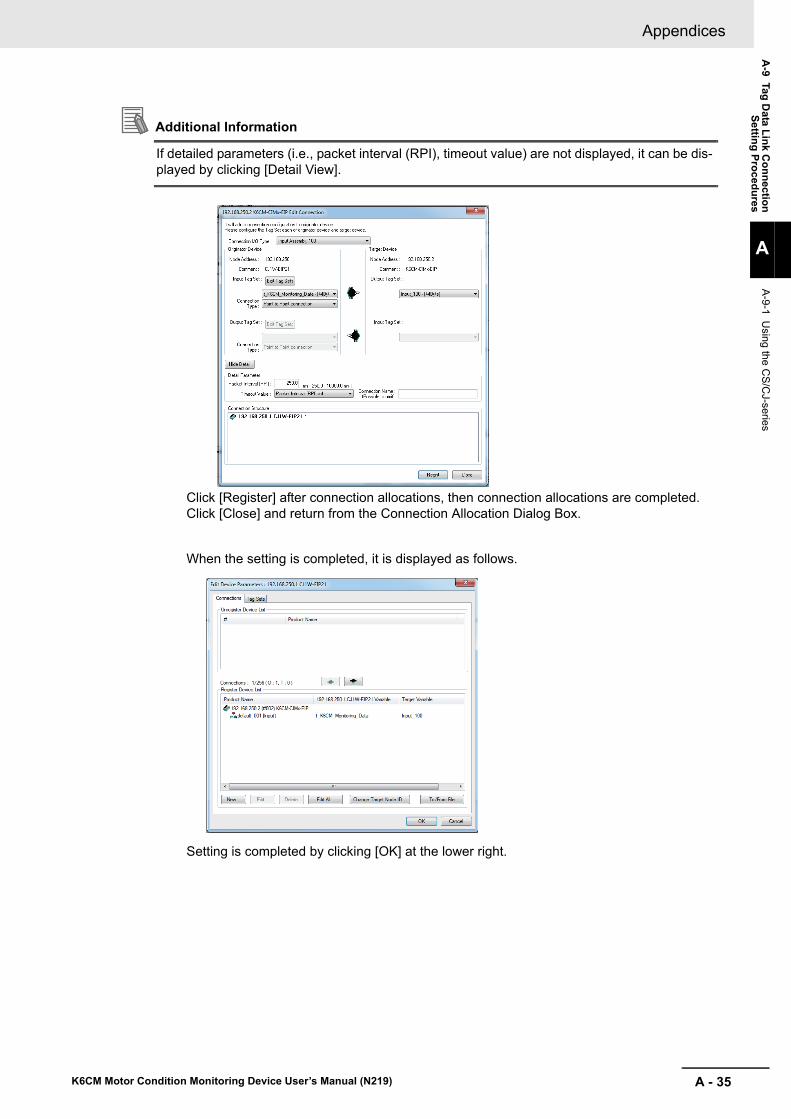
A - 35
Appendices
K6CM Motor Condition Monitoring Device User’s Manual (N219)
A-9 Tag
Data L
ink C
on
nectio
nS
ettin
g P
roc
edu
res
A
A-9-1 U
sing the CS
/CJ-series
Additional Information
If detailed parameters (i.e., packet interval (RPI), timeout value) are not displayed, it can be dis-played by clicking [Detail View].
Click [Register] after connection allocations, then connection allocations are completed. Click [Close] and return from the Connection Allocation Dialog Box.
When the setting is completed, it is displayed as follows.
Setting is completed by clicking [OK] at the lower right.

Appendices
A - 36 K6CM Motor Condition Monitoring Device User’s Manual (N219)
6 Downloading settings
Connect online to the originator device and download the configuration settings.
(The EtherNet/IP tag data link communications setting of the K6CM series is fixed, so you do not need to download it to the K6CM.)
(1) Online
Select the communications interface to use from [Option (O)] | [Select Interface (I)] on the menu bar. (This operation is unnecessary if interface is not changed after interface setting. )
Then, select [Network (N)] | [Connection (C) ...] on the menu bar or click (Online but-ton) to go online to the EtherNet/IP network.
After online, select the originator device (PLC) to download, right click it and select [Param-eter (P)] | [Download (D)] and download it.
Additional Information
For details on online and download operations, refer to the manual of the originator device.
For detailed settings, refer to the manual of the originator device.
• "SYSMAC CS/CJ Series EtherNet/IP Units Operation Manual (Cat. No.W465)"
With the Sysmac Studio Ver. 1.10 or higher, tag data link (EtherNet/IP connection) setting is pos-sible when using NJ/NX-series PLC as a tag data link originator.
Creating Network Variables (Input)
Create Input area in the PLC to receive Input data from K6CM devices.
The setting method for the NJ/NX-series PLC is shown below.
1 Starting the SysmacStudio
Start the SysmacStudio in one of the following ways.
• Double-click the shortcut icon of [Sysmac Studio] on the desktop.
• To start the Sysmac Studio, select [All Programs] | [OMRON] | [Sysmac Studio] | [Sysmac Studio] from the Windows Start Menu.
2 Creating Project File
Click [New Project] in the upper left in the start page.
To edit an existing project file, click [Open Project] and select the saved project.
A-9-2 Using the NJ/NX-series

A - 37
Appendices
K6CM Motor Condition Monitoring Device User’s Manual (N219)
A-9 Tag
Data L
ink C
on
nectio
nS
ettin
g P
roc
edu
res
A
A-9-2 U
sing the NJ/N
X-series
Enter the project name, author, and comment in the [Project Properties Dialog] Box, select the device category, the device (PLC model) to use and its version, and then click the [Create] But-ton. (Only the project name is required.)
When you finish setting [Project Properties], the following screen will be displayed.

Appendices
A - 38 K6CM Motor Condition Monitoring Device User’s Manual (N219)
3 Creating Network Variables (Input)
Create network variables to be the input area in the PLC.
The K6CM device sends 44 bytes as Input data, therefore the network variable must be created as a structure variable or an array variable.
This section shows how to create structure variables. (For array variables, the following "(1) data type registration" are unnecessary.)
(1) Registering Data Type
Create a structure type as a basis by the following procedure to create a structure type net-work variable (44 bytes) for receiving K6CM's Input data.
(1)-1 Opening the Data Types Tab Page
Double-click [Data Type] under [Programming] | [Data] in the Multiview Explorer, or right-click [Data Type] and select [Edit] from the menu.
(1)-2 Registrating structure Type
Click the [Structures] Side Tab in the Data Type Editor, and then the Structure Data Type Editor is displayed.
In the Data Type Editor, press the [Insert] key or right-click and select [Create New Data Type (N)], and enter a structure name. As an example, we set "t_K6CM_CIM" here. An error is displayed because there is no structure member registration at this time.

A - 39
Appendices
K6CM Motor Condition Monitoring Device User’s Manual (N219)
A-9 Tag
Data L
ink C
on
nectio
nS
ettin
g P
roc
edu
res
A
A-9-2 U
sing the NJ/N
X-series
(1)-3 Adding structure Members
Right-click the structure data type you just crated and select [Create New Member(M)] from the menu. Register members and data types to match data received from the K6CM device.
The registered Pane will be as follows. Data that are not defined as tag data link are regis-tered as reserved area. The total size is 44 bytes. The member name can be changed as appropriate.
(2) Network Variables (Input) Definition
(2)-1 Opening the Global Variable Tab Page
Double-click Global Variables under [Programming] | [Data] in the Multiview Explorer, or right-click [Global Variables] and select [Edit] from the menu.

Appendices
A - 40 K6CM Motor Condition Monitoring Device User’s Manual (N219)
(2)-2 Registering Network Variables (Input)
In the global variable table, press the [Insert] key or right-click and select [Create New (N)], and enter a variable name. Next, change [Data Type] to the structure type name created in "(1) Registering Data Type", and change the Network Publish attribute to [Input] from the pull down list. In this example, the name of the network variable (input) is set to "K6CM_CIM_Monitor_Data" and the data type is set to "t_K6CM_CIM" created in "(1) Reg-istering Data Type".
Associate the network variables created here with the tags used in the EtherNet/IP connection settings described below.
Additional Information
To process the input data as an array variable instead of a structure variable, create a 44-byte network variable with an array of UINT as [Data Type] in the following example.

A - 41
Appendices
K6CM Motor Condition Monitoring Device User’s Manual (N219)
A-9 Tag
Data L
ink C
on
nectio
nS
ettin
g P
roc
edu
res
A
A-9-2 U
sing the NJ/N
X-series
4 EtherNet/IP Connection Settings
After creating the network variables (input), perform setting the EtherNet/IP connection for Eth-erNet/IP tag data link communications.
(1) Opening the EtherNet/IP Device List Tab Page
Select [EtherNet/IP Connection Settings(N)] from the [Tools(T] from the menu bar.
(2) Opening the EtherNet/IP Connection Settings (Tag Set Display)
Select the EtherNet/IP originator device and double-click it, or right-click the originator device and select [Edit (E)]. If you use the built-in EtherNet/IP port, only the built-in Ether-Net port is displayed as an originator device. In that case select it, highlight it and then operate it.
(3) Rregistering the K6CM Devices to the Network
Make the following settings so that the K6CM device operates as a target.
(3)-1 Installing EDS Files
To configure K6CM as an EtherNet/IP tag data link communications target, install the EDS file containing the configuration information of the K6CM in the SysmacStudio. Once this installation is done, this operation is unnecessary from the next setting.
This operation is unnecessary because it is preinstalled if you use the SysmacStudio Ver.1.21 or higher. If you are using an earlier version, install it using the EDS file stored on the CD shipped with the K6CM device.

Appendices
A - 42 K6CM Motor Condition Monitoring Device User’s Manual (N219)
Right-click anywhere in the Target Device List in the Toolbox on the right of the EtherNet/IP Connection Setting Tab Page and select [Display EDS Library] from the menu.
Click the [Install] Button at the bottom left, select the following EDS file, click [Open] and install it.
When installation is completed, the category ”Motor Condition Monitoring Device” and the registered K6CM devices are displayed under the tree of the OMRON Corporation in the EDS Library Dialog Box.
(3)-2 Adding K6CM Devices to the Network
Click the (Add Target Device) Button in the [Toolbox] on the right of the EtherNet/IP Con-nection Setting Tab Page.
As in the example below, enter the node address (i.e. IP address) and select the model and revision from the pull down list.
Model name of the K6CM EDS file nameK6CM-CIM K6CM_CIM_EIP_R2.eds
K6CM-ISM K6CM_ISM_EIP_R2.eds
K6CM-VBM K6CM_VBM_EIP_R2.eds
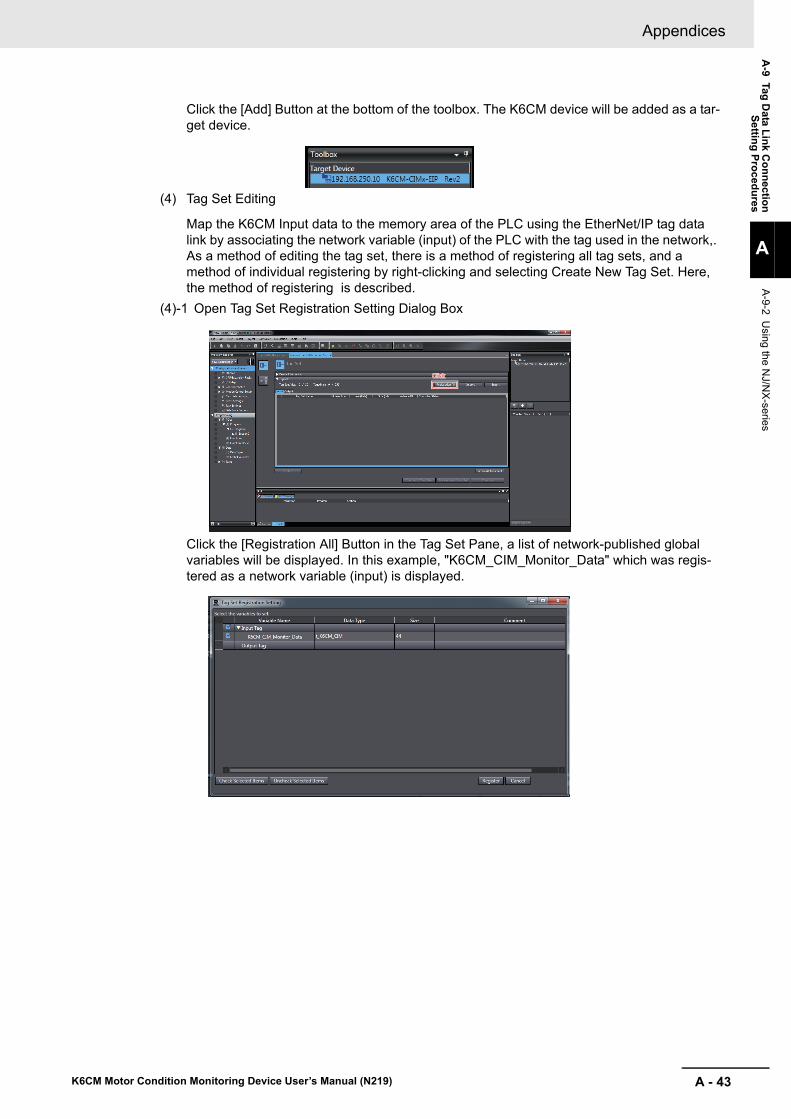
A - 43
Appendices
K6CM Motor Condition Monitoring Device User’s Manual (N219)
A-9 Tag
Data L
ink C
on
nectio
nS
ettin
g P
roc
edu
res
A
A-9-2 U
sing the NJ/N
X-series
Click the [Add] Button at the bottom of the toolbox. The K6CM device will be added as a tar-get device.
(4) Tag Set Editing
Map the K6CM Input data to the memory area of the PLC using the EtherNet/IP tag data link by associating the network variable (input) of the PLC with the tag used in the network,. As a method of editing the tag set, there is a method of registering all tag sets, and a method of individual registering by right-clicking and selecting Create New Tag Set. Here, the method of registering is described.
(4)-1 Open Tag Set Registration Setting Dialog Box
Click the [Registration All] Button in the Tag Set Pane, a list of network-published global variables will be displayed. In this example, "K6CM_CIM_Monitor_Data" which was regis-tered as a network variable (input) is displayed.
ClickClickClick

Appendices
A - 44 K6CM Motor Condition Monitoring Device User’s Manual (N219)
(4)-2 Registering All Tag Sets
Check the check box of the network variable to be used as the input tag among the net-work-published variables and click the [Register] Button, and then the specified tag is dis-played in the tag set Pane.
If you perform the registering all tag set, the tag set and the tag are displayed as the same name.
The tag set names displayed can be used as connection settings. (Use these tag set names, when configuring EtherNet/IP connections using the Network Configurator.)
You can change the tag set names as required.
Also, the tag name displayed under the tag set name must match the variable name regis-tered as a network variable (input).
Additional Information
If you create connection settings using the Network Configurator, you can share the tag set names and tag names of the PLC you edit here with the Network Configurator.
(5) Opening the EtherNet/IP Connection Settings (Connection Display)
Click the Connection Button at the upper left of the EtherNet/IP Connection Settings
(Tag Set Display) to display the Connection.
(6) Target Devices Registration to the Connection Settings of the Originator
Register the K6CM devices to the connection settings of the originator device (PLC).
Right click and select [Create New (A)] or click the (New) Button in the EtherNet/IP Connection Setting Tab Page, Then select the K6CM from the pull-down list as the target device. (This operation can also be performed by double clicking the K6CM in the [Target Device] Pane of the Toolbox.)
Next, when setting a target variable, if you press [Ctrl] + [space] key at the same time, the selectable ID number is displayed, so select the ID number to use.
For originator variables, select the tag set created in "(4) Editing tag set" from the pull down list and set it.
The timeout time when a communication error occurs can be calculated as follows.
Timeout time = RPI (ms) × multiple of RPI set by timeout value (4 times, 8 times, 16 times, ..., 512 times)

A - 45
Appendices
K6CM Motor Condition Monitoring Device User’s Manual (N219)
A-9 Tag
Data L
ink C
on
nectio
nS
ettin
g P
roc
edu
res
A
A-9-2 U
sing the NJ/N
X-series
This completes the tag data link setting. Go online to the originator device (PLC) and down-load the EtherNet/IP tag data link settings to the PLC by clicking [Transfer to Controller] Button.
(The EtherNet/IP tag data link communications setting of the K6CM series is fixed, so you do not need to download it to the K6CM.)

Appendices
A - 46 K6CM Motor Condition Monitoring Device User’s Manual (N219)
A-10 Expansion Error Code of the CIP Mes-sage Communications
This section describes the expansion error code when an explicit error occurs in the CIP message com-munications command.
The format of the expansion error code is as follows.
Value: 16#XXYYZZZZ
Data type: DWORD
(XX: General Status, YY: Additional Status size (unit: WORD), ZZZZ: Additional Status)
However, ZZZZ of Additional Status is enabled only when XX of General Status is 01 (hex). In other cases, size YY is 00 and ZZZZ of Additional Status does not exist.
A-10-1 General Status
General Sta-tus (hex)
Status Name Description of Status
00 Success Service was successfully performed by the object specified.
01 Connection failure A connection related service failed along the connection path.
02 Resource unavailable Resources needed for the object to perform the requested service were unavailable.
03 Invalid parameter value See Status Code 20 hex, which is the preferred value to use for this con-dition.
04 Path segment error The path segment identifier or the segment syntax was not understood by the processing node. Path processing shall stop when a path segment error is encountered.
05 Path destination unknown The path is referencing an object class, instance or structure element that is not known or is not contained in the processing node. Path processing shall stop when a path destination unknown error is encountered.
06 Partial transfer Only part of the expected data was transferred.
07 Connection lost The messaging connection was lost.
08 Service not supported The requested service was not implemented or was not defined for this Object Class/Instance.
09 Invalid attribute value Invalid attribute data detected.
0A Attribute list error An attribute in the Get_Attribute_List or Set_Attribute_List response has a non-zero status.
0B Already in requested mode/state The object is already in the mode/state being requested by the service.
0C Object state conflict The object cannot perform the requested service in its current mode/state.
0D Object already exists The requested instance of object to be created already exists.
0E Attribute not settable A request to modify a non-modifiable attribute was received.
0F Privilege violation A permission/privilege check failed.
10 Device state conflict The device's current mode/state prohibits the execution of the requested service.
11 Reply data too large The data to be transmitted in the response buffer is larger than the allo-cated response buffer.
12 Fragmentation of a primitive value
The service specified an operation that is going to fragment a primitive data value, i.e. half a REAL data type.
13 Not enough data The service did not supply enough data to perform the specified opera-tion.
14 Attribute not supported The attribute specified in the request is not supported.
15 Too much data The service supplied more data than was expected.
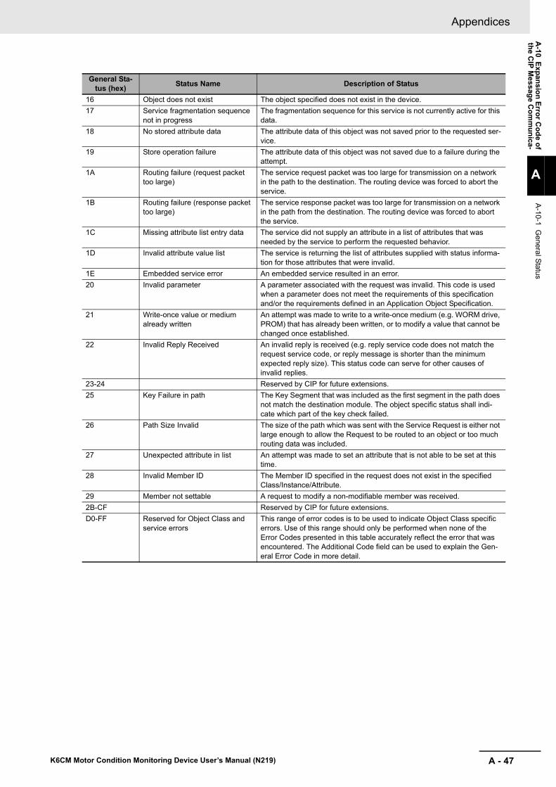
A - 47
Appendices
K6CM Motor Condition Monitoring Device User’s Manual (N219)
A-10 E
xpan
sion
Erro
r Co
de o
fth
e CIP
Me
ssage C
om
mu
nica-
A
A-10-1 G
eneral Status
16 Object does not exist The object specified does not exist in the device.
17 Service fragmentation sequence not in progress
The fragmentation sequence for this service is not currently active for this data.
18 No stored attribute data The attribute data of this object was not saved prior to the requested ser-vice.
19 Store operation failure The attribute data of this object was not saved due to a failure during the attempt.
1A Routing failure (request packet too large)
The service request packet was too large for transmission on a network in the path to the destination. The routing device was forced to abort the service.
1B Routing failure (response packet too large)
The service response packet was too large for transmission on a network in the path from the destination. The routing device was forced to abort the service.
1C Missing attribute list entry data The service did not supply an attribute in a list of attributes that was needed by the service to perform the requested behavior.
1D Invalid attribute value list The service is returning the list of attributes supplied with status informa-tion for those attributes that were invalid.
1E Embedded service error An embedded service resulted in an error.
20 Invalid parameter A parameter associated with the request was invalid. This code is used when a parameter does not meet the requirements of this specification and/or the requirements defined in an Application Object Specification.
21 Write-once value or medium already written
An attempt was made to write to a write-once medium (e.g. WORM drive, PROM) that has already been written, or to modify a value that cannot be changed once established.
22 Invalid Reply Received An invalid reply is received (e.g. reply service code does not match the request service code, or reply message is shorter than the minimum expected reply size). This status code can serve for other causes of invalid replies.
23-24 Reserved by CIP for future extensions.
25 Key Failure in path The Key Segment that was included as the first segment in the path does not match the destination module. The object specific status shall indi-cate which part of the key check failed.
26 Path Size Invalid The size of the path which was sent with the Service Request is either not large enough to allow the Request to be routed to an object or too much routing data was included.
27 Unexpected attribute in list An attempt was made to set an attribute that is not able to be set at this time.
28 Invalid Member ID The Member ID specified in the request does not exist in the specified Class/Instance/Attribute.
29 Member not settable A request to modify a non-modifiable member was received.
2B-CF Reserved by CIP for future extensions.
D0-FF Reserved for Object Class and service errors
This range of error codes is to be used to indicate Object Class specific errors. Use of this range should only be performed when none of the Error Codes presented in this table accurately reflect the error that was encountered. The Additional Code field can be used to explain the Gen-eral Error Code in more detail.
General Sta-tus (hex)
Status Name Description of Status

Appendices
A - 48 K6CM Motor Condition Monitoring Device User’s Manual (N219)
A-10-2 Additional Status When General Status Is 01 hex
General Status (hex)
Additional Sta-tus (hex)
Explanation
01 0100 Connection in Use or Duplicate Forward Open.
01 0103 Transport Class and Trigger combination not supported.
01 0106 Ownership Conflict.
01 0107 Connection not found at target application.
01 0108 Invalid Connection Type. Indicates a problem with either the Connection Type or Priority of the Connection.
01 0109 Invalid Connection Size.
01 0110 Device not configured.
01 0111 RPI not supported. May also indicate problem with connection time-out multiplier, or pro-duction inhibit time.
01 0113 Connection Manager cannot support any more connections.
01 0114 Either the Vendor Id or the Product Code in the key segment did not match the device.
01 0115 Product Type in the key segment did not match the device.
01 0116 Major or Minor Revision information in the key segment did not match the device.
01 0117 Invalid Connection Point.
01 0118 Invalid Configuration Format.
01 0119 Connection request fails since there is no controlling connection currently open.
01 011A Target Application cannot support any more connections.
01 011B RPI is smaller than the Production Inhibit Time.
01 0203 Connection cannot be closed since the connection has timed out.
01 0204 Unconnected Send timed out waiting for a response.
01 0205 Parameter Error in Unconnected Send Service.
01 0206 Message too large for Unconnected message service.
01 0207 Unconnected acknowledge without reply.
01 0301 No buffer memory available.
01 0302 Network Bandwidth not available for data.
01 0303 No Tag filters available.
01 0304 Not Configured to send real-time data.
01 0311 Port specified in Port Segment Not Available.
01 0312 Link Address specified in Port Segment Not Available.
01 0315 Invalid Segment Type or Segment Value in Path.
01 0316 Path and Connection not equal in close.
01 0317 Either Segment not present or Encoded Value in Network Segment is invalid.
01 0318 Link Address to Self Invalid.
01 0319 Resources on Secondary Unavailable.
01 031A Connection already established.
01 031B Direct connection already established.
01 031C Miscellaneous.
01 031D Redundant connection mismatch.
01 031E There are no more available reception resources in the sending module.
01 031F No connection resources exist for target path.
01 0320- 07FF unused.

I - 1
I
K6CM Motor Condition Monitoring Device User’s Manual (N219)
Index

I - 2 K6CM Motor Condition Monitoring Device User’s Manual (N219)
Index
Index
A
Add a Device to an Existing Project ............................. 6-27AGE ................................................................................ 2-4Alarm bar display ............................................................ 2-3alarm latch .................................................................... 3-14Alarm Setting Values (threshold value) ........................A-15ARM RST ....................................................................... 2-5
C
CIP message communications .............................. 8-3, 8-12comprehensive alarm ................................................... 3-13Comprehensive Current Diagnosis Type .................1-9, A-9Critical .......................................................................... 3-13CT (current transformer)
for Comprehensive Current Diagnosis Type ................ 5-4
D
Dedicated CT ............................................................... 2-13Dedicated Current Transformer (CT) ............................A-12Diagram of Terminal Description .................................. 5-21dimensions ..................................................................... 5-2
E
ERR ................................................................................ 2-4Ethernet switches recommended ................................. 5-26EtherNet/IP ..................................................................... 8-2EtherNet/IP Wiring ........................................................ 5-26
I
I/O wiring ...................................................................... 5-22Installation and Connection of Dedicated CT ............... 5-15Installation and Connection
of Insulation Resistance Sensor ZCT (IRT) ............... 5-12Installation of Vibration Sensor Head ............................. 5-7Installing ......................................................................... 5-5Insulation Resistance Sensor (ZCT (IRT)) ............ 2-12, 5-3Insulation Resistance Sensor for ZCT (IRT) ................A-11Insulation Resistance Type .....................................1-8, A-9IP address changing ..................................................... 4-38IP address initial value ................................................. 4-28
K
K6CM-CICB ..................................................................A-12K6CM-CIM ...............................................................1-9, A-9K6CM-ISM ...............................................................1-8, A-9K6CM-ISZB ..................................................................A-11K6CM-VBM .............................................................1-7, A-8K6CM-VBS ...................................................................A-10
L
Log file ..................................................................... 4-4, 4-5
M
maximum value and minimum value ..................... 2-4, 3-13MON ............................................................................... 2-4monitor with the front alarm bar ..................................... 7-6monitor with the transistor outputs ................................. 7-7monitoring category ........................................................ 2-3monitoring cycle ............................................................. 7-9Motor condition monitoring Tool ..................................... 4-2
N
Nomenclature and Functions ......................................... 2-2Normal .......................................................................... 3-13
P
Parameters setting ....................................................... 6-26Procedure ..................................................................... 1-10Project file ...................................................................... 4-4Push-In Plus Terminal Blocks ....................................... 5-16
S
Specifications .................................................................A-5System Configuration ..................................................... 1-6
T
tag data link ............................................................. 8-3, 8-5Trigger mode .............................................3-3, 3-4, 3-5, 7-3
U
Unit of measurement value ............................................ 2-3
V
Vibration & Temperature Sensor ...........................5-2, A-10Vibration & Temperature Type .................................1-7, A-8
W
Warning ........................................................................ 3-13


Authorized Distributor:
In the interest of product improvement, specifications are subject to change without notice.
Cat. No. N219-E1-09 1218
© OMRON Corporation 2017-2018 All Rights Reserved.
OMRON Corporation Industrial Automation Company
OMRON ELECTRONICS LLC2895 Greenspoint Parkway, Suite 200 Hoffman Estates, IL 60169 U.S.A.Tel: (1) 847-843-7900/Fax: (1) 847-843-7787
Regional HeadquartersOMRON EUROPE B.V.Wegalaan 67-69, 2132 JD HoofddorpThe NetherlandsTel: (31)2356-81-300/Fax: (31)2356-81-388
Contact: www.ia.omron.comKyoto, JAPAN
OMRON ASIA PACIFIC PTE. LTD.No. 438A Alexandra Road # 05-05/08 (Lobby 2), Alexandra Technopark, Singapore 119967Tel: (65) 6835-3011/Fax: (65) 6835-2711
OMRON (CHINA) CO., LTD.Room 2211, Bank of China Tower, 200 Yin Cheng Zhong Road, PuDong New Area, Shanghai, 200120, ChinaTel: (86) 21-5037-2222/Fax: (86) 21-5037-2200
Related Documents