Welcome message from author
This document is posted to help you gain knowledge. Please leave a comment to let me know what you think about it! Share it to your friends and learn new things together.
Transcript
RESTRICTED USE ONLY CIM, an “MF Group SpA” Division
Sunlight K3 Card Printer User Guide (Rev. 00) ii
Sunlight K3 Card Printer User Guide (Rev.00), property of “MF GROUP SpA”. All rights reserved. Exclusive permission is granted to authorized resellers of CIM products to reproduce and distribute this copyrighted document to authorized CIM customers, who have signed a “no disclosure agreement” regarding the restricted, proprietary use of said document.
The revision number for this document will be updated to reflect changes, corrections, updates and enhancements to this document.
Revision Control Number Date Document Title
Revision 00 30th June 2006 Sunlight K3 Card Printer User Guide
Any questions regarding changes, corrections, updates or enhancements to this document should be forwarded to:
CIM, an “MF GROUP SpA” Division Loc. BRAINE, 54/A 40040 RIOVEGGIO BO ITALY Phone +39 051 6465 011 Fax +39 051 6465 012 www.cimitaly.it E-mail: [email protected]
RESTRICTED USE ONLY CIM, an “MF Group SpA” Division
Sunlight K3 Card Printer User Guide (Rev. 00) iii
Table of Contents PART A. USER MANUAL Section 1: Introduction _____________________________________________________1-1
How to use the manual________________________________________________________________1-1 Safety Messages (review carefully) ______________________________________________________1-2 Sunlight K3 Card Printer Overview______________________________________________________1-3
Reviewing the Sunlight K3 Block Diagram _____________________________________________1-3 Reviewing the Sunlight K3 Sequence of Operations ______________________________________1-4 Reviewing the Sunlight K3 Boot up Sequence ___________________________________________1-7
Section 2: Specifications ____________________________________________________2-1 Regulatory Compliances ______________________________________________________________2-1 Agency Listings_____________________________________________________________________2-2 Technical Specifications ______________________________________________________________2-2 Functional Specifications______________________________________________________________2-5
Printer Components: Front Cover to USB Port __________________________________________2-6 Printer Components: Print Ribbons ___________________________________________________2-7 Printer Components: Resin-Only Print Ribbons _________________________________________2-8 Printer Components: Dye-Sublimation Print Ribbons _____________________________________2-9 Printer Components: Dye-Sublimation/Resin Print Ribbons_______________________________2-10 Printer Components: Blank Cards ___________________________________________________2-11 Printer Module: Flipper Table Module Assembly _______________________________________2-12
Section 3: Setup and Installation Procedures ___________________________________3-1 Printer Setup and Installation___________________________________________________________3-1
Choosing A Good Location _________________________________________________________3-1 About Moisture Condensation _______________________________________________________3-1 Unpacking and Inspection___________________________________________________________3-2 Reviewing the Printer (front view) ____________________________________________________3-2 Reviewing the Printer (front view; Cartridge being installed) _______________________________3-3 Connecting the Printer power ________________________________________________________3-4 Installing the Print Ribbon Cartridge __________________________________________________3-5 Installing Blank Cards into the Card Hopper ____________________________________________3-8 Lowering the Card Output Hopper ___________________________________________________3-11
Flipper Table Module Installation ______________________________________________________3-12 Installing the Flipper Table Module Assembly__________________________________________3-12
Printer Driver Installation ____________________________________________________________3-15 Installing the Printer Driver ________________________________________________________3-15 Printing a Test Print Image _________________________________________________________3-25
Printer Transport ___________________________________________________________________3-27 Moving the Printer to another location ________________________________________________3-27
Section 4: General Troubleshooting___________________________________________4-1 Safety Messages (review carefully) ______________________________________________________4-1 Communications Errors _______________________________________________________________4-2
Resolving the Communication Errors__________________________________________________4-2 Print Process Errors __________________________________________________________________4-4
Resolving a Card Not Fed Error (Cards will not feed off the Hopper) _________________________4-4 Resolving a Card Not Fed Error (Two (2) or more card feed at the same time)__________________4-7 Resolving a Ribbon RFID Error (Ribbon RFID Antenna is Corrupted)________________________4-9 Resolving a Ribbon RFID Error (Ribbon RFID Sensor is Corrupted) ________________________4-11 Resolving the Mag Verify Error _____________________________________________________4-12 Resolving the No Mag Installed Error ________________________________________________4-15 Resolving a Ribbon Sensor Error (Ribbon Miscue) ______________________________________4-17
RESTRICTED USE ONLY CIM, an “MF Group SpA” Division
Sunlight K3 Card Printer User Guide (Rev. 00) iv
Resolving a Ribbon Break Jam Error _________________________________________________4-19 Resolving a Ribbon Out Error ______________________________________________________4-21 Resolving a No Ribbon Installed Error________________________________________________4-22 Resolving a Invalid Ribbon Error ____________________________________________________4-24 Resolving a Wrong Ribbon Error ____________________________________________________4-26 Resolving a Card Jam Error ________________________________________________________4-28 Resolving a Headlift Motor or Sensor Error ____________________________________________4-30 Resolving the Cover Open Error Message _____________________________________________4-32 Resolving the Blank Output issues ___________________________________________________4-33
Flipper Table Module Assembly Problems _______________________________________________4-36 Resolving the No Flipper Table Module problem________________________________________4-36 Resolving the Flipper Jam Error _____________________________________________________4-37
Diagnosing Image Problems __________________________________________________________4-39 Resolving the Pixel Failure problems _________________________________________________4-39 Resolving the Card Surface Debris problems ___________________________________________4-40 Resolving the Incorrect Image Darkness problems_______________________________________4-41 Resolving Ribbon Wrinkle problems _________________________________________________4-43 Resolving the Excessive Resin Printing problems _______________________________________4-45 Resolving the Incomplete Resin Printing problems ______________________________________4-47 Resolving the Image Placement problems _____________________________________________4-48 Resolving the Poor Image Quality problems ___________________________________________4-51
Running the Self Test _______________________________________________________________4-52 Running the Standard Self Test Print _________________________________________________4-53 Running the Magnetic Self Test (HiCo Only) __________________________________________4-54
Section 5: Ethernet Option __________________________________________________5-1 Introduction _________________________________________________________________ 5-1
Technical Specification - Ethernet Option_________________________________________________5-1 Functional Specification - Ethernet Option ________________________________________________5-2 Network Services - Overview __________________________________________________________5-3
Reviewing the Print Server __________________________________________________________5-3 Reviewing the Web Page Server______________________________________________________5-3 Reviewing the Network Management Interface __________________________________________5-3 Reviewing the Telnet Server_________________________________________________________5-3
Network Management Interface ________________________________________________________5-4 Telnet Command Line Interface ________________________________________________________5-4
Initiating a Telnet Session___________________________________________________________5-4 Reviewing the Telnet Command Table_________________________________________________5-5
Ethernet Printer Troubleshooting Procedures ____________________________________ 5-12 Verifying the Printer Connection ____________________________________________________5-12 Verifying the Printer IP address _____________________________________________________5-13 Verifying that your PC can access the Printer using the ping command ______________________5-14 Printing a test page _______________________________________________________________5-15
Reviewing Frequently-asked Questions__________________________________________ 5-16 Glossary of Terms ___________________________________________________________ 5-22
Section 6: Printer Adjustments _______________________________________________6-1 Table of Contents____________________________________________________________________6-1 Safety Messages (review carefully) ______________________________________________________6-4 K3 Print Driver Options_______________________________________________________________6-5
Reviewing K3 Printer Drivers________________________________________________________6-5 Reviewing K3 Printer Drivers________________________________________________________6-5
Using the Card tab (Sunlight K3) _______________________________________________________6-6 Adjusting the Card Size Option ______________________________________________________6-6
RESTRICTED USE ONLY CIM, an “MF Group SpA” Division
Sunlight K3 Card Printer User Guide (Rev. 00) v
Adjusting the Orientation Option _____________________________________________________6-7 Selecting the number of copies _______________________________________________________6-8 Using the Diagnostics button under the Card tab _________________________________________6-9 Using the Clean Printer Option______________________________________________________6-10 Using the Test Print button _________________________________________________________6-12 Using the About button____________________________________________________________6-13
Using the Device Options tab (K3) _____________________________________________________6-14 Reviewing the Device Options tab ___________________________________________________6-14 Adjusting the Ribbon Type option ___________________________________________________6-15 Selecting the Auto Ribbon Select option ______________________________________________6-16 Changing the Color Profile Selection for the K3 ________________________________________6-17 Adjusting the Color Matching option _________________________________________________6-19 Adjusting for the Resin Dither ______________________________________________________6-20 Using the Print Both Sides option____________________________________________________6-21 Using the Split 1 Set of Ribbon Panels option __________________________________________6-22 Using the Print Back Side First option ________________________________________________6-23 Using the Print Back Side Only option________________________________________________6-24 Using the Rotate Front 180 Degrees or Rotate Back 180 Degrees options_____________________6-25 Using the Disable Printing option____________________________________________________6-26
Using the Image Color tab (K3)________________________________________________________6-27 Using the Resin Heat (K) option (Front and Back)_______________________________________6-28 Using the Overlay Heat (O) option ___________________________________________________6-29 Using the Color Matching option and Default button_____________________________________6-30
Using the Calibrate tab (Sunlight K3) ___________________________________________________6-31 Using the Image Position Controls ___________________________________________________6-32 Using the Sensors button___________________________________________________________6-34 Using the Settings button __________________________________________________________6-35
Using the Magnetic Encoding tab (Sunlight K3)___________________________________________6-36 Using the Magnetic Track Selection radio buttons _______________________________________6-37 Using the Magnetic Track Options radio buttons ________________________________________6-39 Using the Bit Density radio buttons __________________________________________________6-40 Using the Character Size radio buttons________________________________________________6-41 Reviewing the Enable MLE Support checkbox _________________________________________6-42 Using the ASCII Offset radio buttons_________________________________________________6-43 Using the LRC Generation radio buttons ______________________________________________6-44 Using the Character Parity radio buttons ______________________________________________6-44 Using the Shift Data Left checkbox __________________________________________________6-45 Reviewing the ISO Track Locations __________________________________________________6-46 Sending the Track Information ______________________________________________________6-47 Entering the Track Information______________________________________________________6-47 Reviewing Tracks 1, 2 and 3 (in table format) __________________________________________6-48 Reviewing the Track Data Note _____________________________________________________6-48 Reviewing the ASCII Code and Character Table ________________________________________6-49
Using the Overlay / Print Area tab (Sunlight K3) __________________________________________6-50 Enabling the Frontside and Backside options ___________________________________________6-51 Enabling the Frontside option (Overlay / Print Area) _____________________________________6-52 Enabling the Backside option (Overlay / Print Area) _____________________________________6-53 Using the Overlay / Print Area dropdown menu_________________________________________6-54 Using the Overlay / Print Area ______________________________________________________6-56 Using the Defined Area Option______________________________________________________6-58 Using Security Options (Visual Security Solutions) (Frontside option only) ___________________6-63 Selecting Orientation - Landscape under Card tab _______________________________________6-64 Selecting the Visual Security Solutions dropdown menu (A to D)___________________________6-65 Selecting Orientation - Portrait under Card tab__________________________________________6-66 Selecting the Visual Security Solutions dropdown menu (E to H) ___________________________6-67 Selecting the VeriMark radio button (Frontside option only) _______________________________6-68
RESTRICTED USE ONLY CIM, an “MF Group SpA” Division
Sunlight K3 Card Printer User Guide (Rev. 00) vi
Selecting the HoloMark radio button (Frontside option only) ______________________________6-69 Reviewing the Custom VeriMark Card (Custom Graphic in a 2D foil) _______________________6-70 Reviewing the Custom HoloMark Card (Custom Graphic in a 2D foil)_______________________6-71
Using the K Panel Resin tab (K3) ______________________________________________________6-72 Enabling the Frontside and Backside options ___________________________________________6-73 Enabling the Frontside option (K Panel Resin)__________________________________________6-74 Enabling the Backside option (K Panel Resin) __________________________________________6-75 Selecting from the Print All Black with K Panel options (Front and Back options)______________6-76 Selecting the Full Card option (Front and Back options) __________________________________6-77 Selecting the Defined Area(s) option (Front and Back options) _____________________________6-78 Selecting the Undefined Area(s) option (Front and Back options) ___________________________6-79 Selecting the Defined Area(s) function (Front and Back options) ___________________________6-80 Selecting the Print YMC under K and Print K Only options _______________________________6-87
Using the Printer Information tab (Sunlight K3) ___________________________________________6-88 Reviewing the Ribbon Information___________________________________________________6-89 Reviewing the Ribbon Level Indicator ________________________________________________6-90
Using the Printer Calibration Utility (Sunlight K3)_________________________________________6-91 Using the Image Darkness Option ___________________________________________________6-92 Using the Print Top of Form Option__________________________________________________6-93 Using the Print End of Form Option__________________________________________________6-94 Using the Print Left of Form Option__________________________________________________6-95 Using the Magnetic Encoder Voltage Offset Option _____________________________________6-96 Adjusting the Hi-Co Voltage Offset __________________________________________________6-97 Adjusting the Lo-Co Voltage Offset __________________________________________________6-98 Using the Mag Top of Form Option __________________________________________________6-99 Using the Ribbon Tension Option___________________________________________________6-101 Using the Flipper Home Offset Option_______________________________________________6-102 Using the Flipper Center Offset Option ______________________________________________6-102 Using the Flipper Smart Angle Offset Option _________________________________________6-103
Section 7: Cleaning ________________________________________________________7-1 Safety Messages (review carefully) ______________________________________________________7-1 Sunlight K3 Card Printer/Encoders Cleaning Cards _________________________________________7-2
Supplies_________________________________________________________________________7-2 Cleaning the Platen and the Card Feed Rollers _____________________________________________7-3 Cleaning the Printer’s Interior __________________________________________________________7-6 Cleaning the Printer’s Exterior _________________________________________________________7-6
Section 8: Packing the Card Printer___________________________________________8-1
Section 9: Board Level Diagnostics ___________________________________________9-1 Safety Messages (review carefully) ______________________________________________________9-1 Sensor and Motor____________________________________________________________________9-2
Reviewing the Sensor Location and Voltages____________________________________________9-2 Reviewing the Motor Voltages (when active)____________________________________________9-2
Section 10: Diagnostic Tool Utility___________________________________________10-1 Using the Diagnostic Tool Utility ______________________________________________________10-2
Selecting from the Printer Selection menu _____________________________________________10-2 Reviewing customized Diagnostic Utility tabs for your Printer _____________________________10-3 Selecting the Print Spooler tab in the Diagnostics Utility__________________________________10-4 Selecting the Firmware File ________________________________________________________10-9 Placing the Printer in the Upgrade Mode _____________________________________________10-10 Sending the Firmware File ________________________________________________________10-11 Selecting the Mechanics tab in the Diagnostics Utility___________________________________10-12 Selecting the Self Tests tab in the Diagnostics Utility ___________________________________10-22 Selecting the Card Samples tab in the Diagnostics Utility ________________________________10-23

RESTRICTED USE ONLY CIM, an “MF Group SpA” Division
Sunlight K3 Card Printer User Guide (Rev. 00) vii
Selecting the Magnetic Encoding tab in the Diagnostics Utility____________________________10-24 Selecting the About button in the Diagnostics Utility____________________________________10-26 Selecting the Exit button in the Diagnostics Utility _____________________________________10-27
Section 11: Glossary of Terms ______________________________________________11-1
Section 12: Index_________________________________________________________12-1
RESTRICTED USE ONLY CIM, an “MF Group SpA” Division
Sunlight K3 Card Printer User Guide (Rev. 00) viii
PART A. USER MANUAL
Section 1: Introduction How to use the manual The Sunlight K3 Card Printer User Guide (Rev.00) is, in fact, the troubleshooting and service manual for the entire card Printer. The manual is designed to provide Installers and Technicians with quick, efficient lookup of related procedures, components and terms. The manual can be used effectively either in soft or hard copy, depending on the preference of the Installer or Technician.
Manual Description
Sequence of Operations, Glossary of Terms and Technical/Functional Specifications (hyper-linked)
You can go directly to the Sequence of Operations, Glossary of Terms, Technical Specifications and Functional Specifications to learn how to use the processes, procedures, functions and windows for the card Printer within concise, correlative tables.
Table of Contents (hyper-linked)
You can use the automated Table of Contents to quickly locate, for example, an error message, a procedure, the index or an appendix.
Troubleshooting, Replacement, Removal, Diagnostic and Navigation Procedures (in hyper-linked Sections)
You can go directly to Specifications, General Troubleshooting, Printer Adjustments, Parts Replacement, Printer Packing, Board Level Diagnostics and Firmware Updates to find troubleshooting, removal and replacement procedures. The section titles are always labeled according to their function for consistent usage.
Cross-Referencing (hyper-linked)
You can use the cross-referencing links to quickly locate, for example, an error message or a procedure.
Comprehensive Index (hyper-linked)
You can use the COMPREHENSIVE INDEX to quickly locate information on the card Printer, relating to a specification, a procedural step, a window or screen, a component, a term, a qualifier or a related feature to this Printer.

RESTRICTED USE ONLY CIM, an “MF Group SpA” Division
Sunlight K3 Card Printer User Guide (Rev. 00) 1-2
Safety Messages (review carefully)
Symbol Critical Instructions for Safety purposes
Danger:
Failure to follow these installation guidelines can result in death or serious injury. Information that raises potential safety issues is indicated by a warning symbol (as shown to the left).
• To prevent personal injury, refer to the following safety messages before performing an operation preceded by this symbol.
• To prevent personal injury, always remove the power cord prior to performing repair procedures, unless otherwise specified.
•
To prevent personal injury, make sure only qualified personnel perform these procedures.
Caution:
This device is electrostatically sensitive. It may be damaged if exposed to static electricity discharges. Information that raises potential electrostatic safety issues is indicated by a warning symbol (as shown to the left).
• To prevent equipment or media damage, refer to the following safety messages before performing an operation preceded by this symbol.
• To prevent equipment or media damage, observe all established Electrostatic Discharge (ESD) procedures while handling cables in or near the Circuit Board and Printhead Assemblies.
• To prevent equipment or media damage, always wear an appropriate personal grounding device (e.g., a high quality wrist strap grounded to avoid potential damage).
• To prevent equipment or media damage, always remove the Ribbon and Cards from the Printer before making any repairs, unless otherwise specified.
• To prevent equipment or media damage, take jewelry off of fingers and hands, as well as thoroughly clean hands to remove oil and debris before working on the Printer.
RESTRICTED USE ONLY CIM, an “MF Group SpA” Division
Sunlight K3 Card Printer User Guide (Rev. 00) 1-3
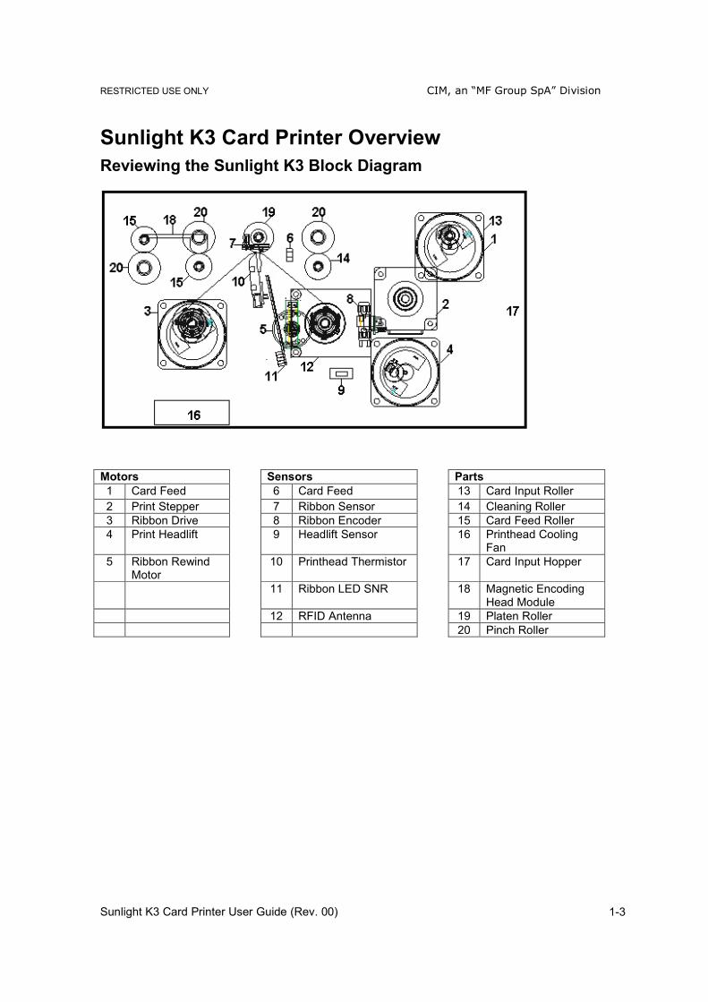
Sunlight K3 Card Printer Overview Reviewing the Sunlight K3 Block Diagram
Motors Sensors Parts 1 Card Feed 6 Card Feed 13 Card Input Roller 2 Print Stepper 7 Ribbon Sensor 14 Cleaning Roller 3 Ribbon Drive 8 Ribbon Encoder 15 Card Feed Roller 4 Print Headlift 9 Headlift Sensor 16 Printhead Cooling
Fan 5 Ribbon Rewind
Motor 10 Printhead Thermistor 17 Card Input Hopper
11 Ribbon LED SNR 18 Magnetic Encoding Head Module
12 RFID Antenna 19 Platen Roller 20 Pinch Roller
RESTRICTED USE ONLY CIM, an “MF Group SpA” Division
Sunlight K3 Card Printer User Guide (Rev. 00) 1-4
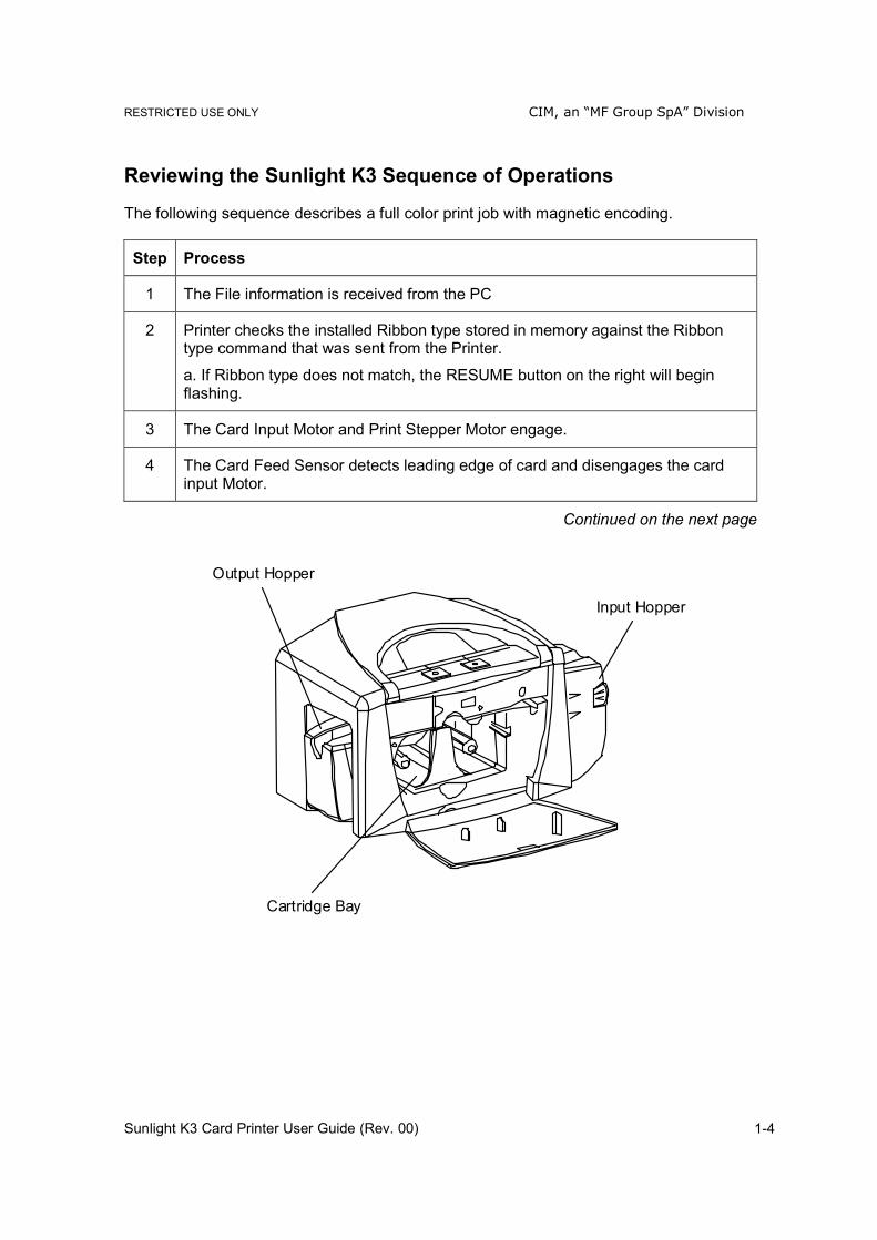
Reviewing the Sunlight K3 Sequence of Operations
The following sequence describes a full color print job with magnetic encoding.
Step Process
1 The File information is received from the PC
2 Printer checks the installed Ribbon type stored in memory against the Ribbon type command that was sent from the Printer.
a. If Ribbon type does not match, the RESUME button on the right will begin flashing.
3 The Card Input Motor and Print Stepper Motor engage.
4 The Card Feed Sensor detects leading edge of card and disengages the card input Motor.
Continued on the next page
Input Hopper
Output Hopper
Cartridge Bay
RESTRICTED USE ONLY CIM, an “MF Group SpA” Division
Sunlight K3 Card Printer User Guide (Rev. 00) 1-5
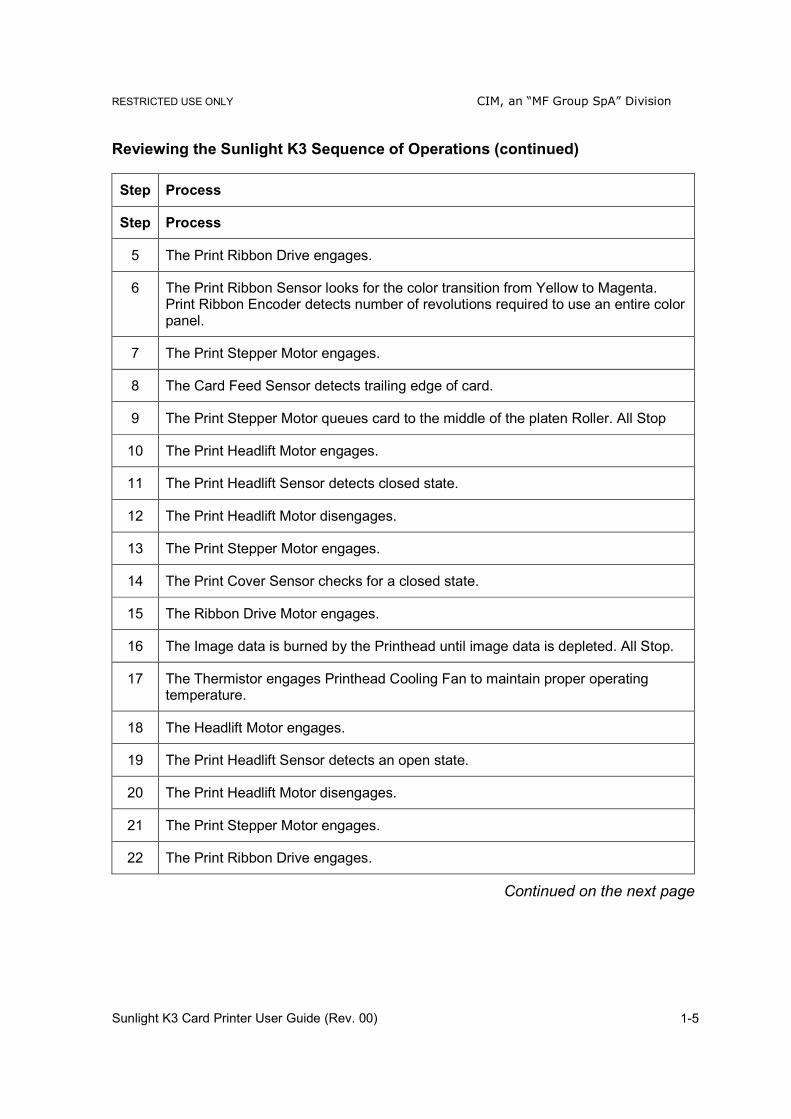
Reviewing the Sunlight K3 Sequence of Operations (continued)
Step Process
Step Process
5 The Print Ribbon Drive engages.
6 The Print Ribbon Sensor looks for the color transition from Yellow to Magenta. Print Ribbon Encoder detects number of revolutions required to use an entire color panel.
7 The Print Stepper Motor engages.
8 The Card Feed Sensor detects trailing edge of card.
9 The Print Stepper Motor queues card to the middle of the platen Roller. All Stop
10 The Print Headlift Motor engages.
11 The Print Headlift Sensor detects closed state.
12 The Print Headlift Motor disengages.
13 The Print Stepper Motor engages.
14 The Print Cover Sensor checks for a closed state.
15 The Ribbon Drive Motor engages.
16 The Image data is burned by the Printhead until image data is depleted. All Stop.
17 The Thermistor engages Printhead Cooling Fan to maintain proper operating temperature.
18 The Headlift Motor engages.
19 The Print Headlift Sensor detects an open state.
20 The Print Headlift Motor disengages.
21 The Print Stepper Motor engages.
22 The Print Ribbon Drive engages.
Continued on the next page
RESTRICTED USE ONLY CIM, an “MF Group SpA” Division
Sunlight K3 Card Printer User Guide (Rev. 00) 1-6
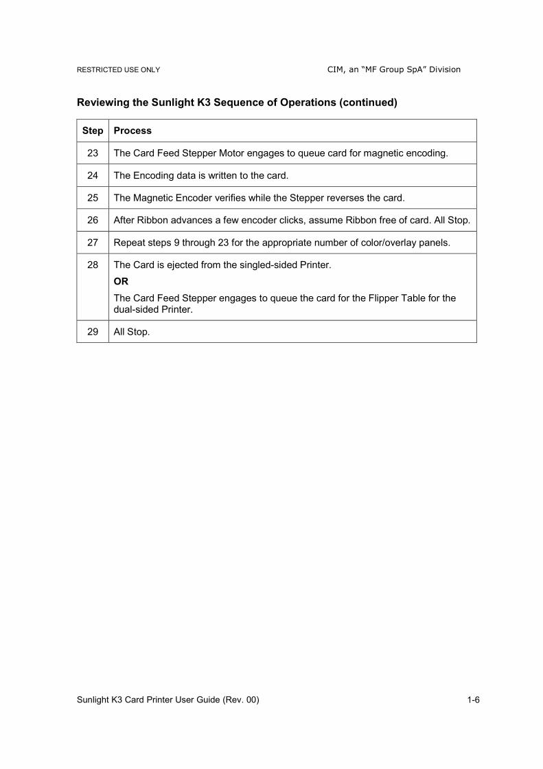
Reviewing the Sunlight K3 Sequence of Operations (continued)
Step Process
23 The Card Feed Stepper Motor engages to queue card for magnetic encoding.
24 The Encoding data is written to the card.
25 The Magnetic Encoder verifies while the Stepper reverses the card.
26 After Ribbon advances a few encoder clicks, assume Ribbon free of card. All Stop.
27 Repeat steps 9 through 23 for the appropriate number of color/overlay panels.
28 The Card is ejected from the singled-sided Printer.
OR The Card Feed Stepper engages to queue the card for the Flipper Table for the dual-sided Printer.
29 All Stop.
RESTRICTED USE ONLY CIM, an “MF Group SpA” Division
Sunlight K3 Card Printer User Guide (Rev. 00) 1-7
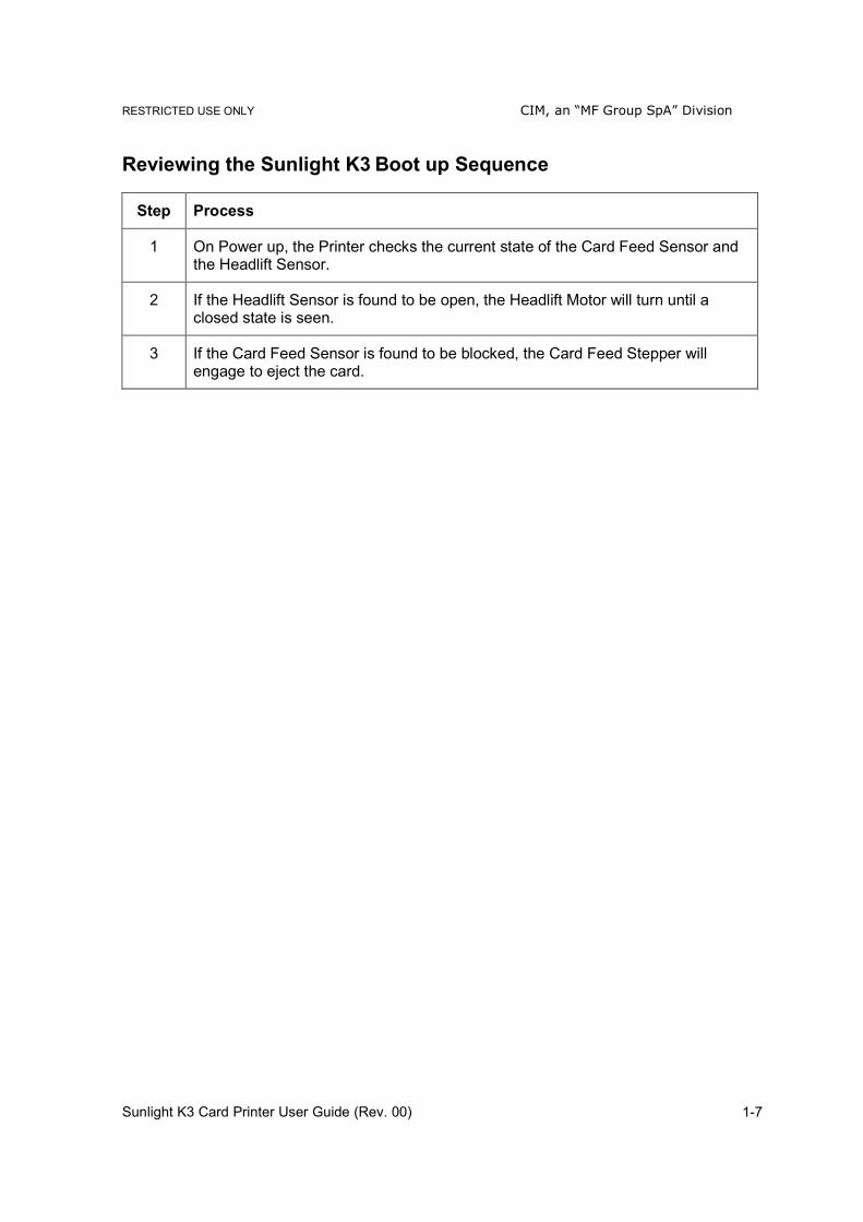
Reviewing the Sunlight K3 Boot up Sequence
Step Process
1 On Power up, the Printer checks the current state of the Card Feed Sensor and the Headlift Sensor.
2 If the Headlift Sensor is found to be open, the Headlift Motor will turn until a closed state is seen.
3 If the Card Feed Sensor is found to be blocked, the Card Feed Stepper will engage to eject the card.
RESTRICTED USE ONLY CIM, an “MF Group SpA” Division
Sunlight K3 Card Printer User Guide (Rev. 00) 2-1
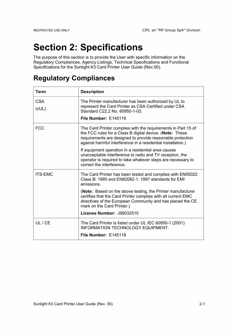
Section 2: Specifications The purpose of this section is to provide the User with specific information on the Regulatory Compliances, Agency Listings, Technical Specifications and Functional Specifications for the Sunlight K3 Card Printer User Guide (Rev.00).
Regulatory Compliances
Term Description
CSA
(cUL)
The Printer manufacturer has been authorized by UL to represent the Card Printer as CSA Certified under CSA Standard C22.2 No. 60950-1-03.
File Number: E145118
FCC The Card Printer complies with the requirements in Part 15 of the FCC rules for a Class B digital device. (Note: These requirements are designed to provide reasonable protection against harmful interference in a residential installation.)
If equipment operation in a residential area causes unacceptable interference to radio and TV reception, the operator is required to take whatever steps are necessary to correct the interference.
ITS-EMC The Card Printer has been tested and complies with EN55022 Class B: 1995 and EN82082-1: 1997 standards for EMI emissions.
(Note: Based on the above testing, the Printer manufacturer certifies that the Card Printer complies with all current EMC directives of the European Community and has placed the CE mark on the Card Printer.)
License Number: J99032510
UL / CE The Card Printer is listed under UL IEC 60950-1 (2001) INFORMATION TECHNOLOGY EQUIPMENT.
File Number: E145118
RESTRICTED USE ONLY CIM, an “MF Group SpA” Division
Sunlight K3 Card Printer User Guide (Rev. 00) 2-2
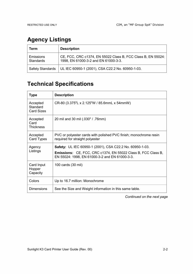
Agency Listings Term Description
Emissions Standards
CE, FCC, CRC c1374, EN 55022 Class B, FCC Class B, EN 55024: 1998, EN 61000-3-2 and EN 61000-3-3.
Safety Standards UL IEC 60950-1 (2001), CSA C22.2 No. 60950-1-03.
Technical Specifications
Type Description
Accepted Standard Card Sizes
CR-80 (3.375"L x 2.125"W / 85.6mmL x 54mmW)
Accepted Card Thickness
20 mil and 30 mil (.030" / .76mm)
Accepted Card Types
PVC or polyester cards with polished PVC finish; monochrome resin required for straight polyester
Agency Listings
Safety: UL IEC 60950-1 (2001), CSA C22.2 No. 60950-1-03.
Emissions: CE, FCC, CRC c1374, EN 55022 Class B, FCC Class B, EN 55024: 1998, EN 61000-3-2 and EN 61000-3-3.
Card Input Hopper Capacity
100 cards (30 mil)
Colors Up to 16.7 million: Monochrome
Dimensions See the Size and Weight information in this same table.
Continued on the next page
RESTRICTED USE ONLY CIM, an “MF Group SpA” Division
Sunlight K3 Card Printer User Guide (Rev. 00) 2-3
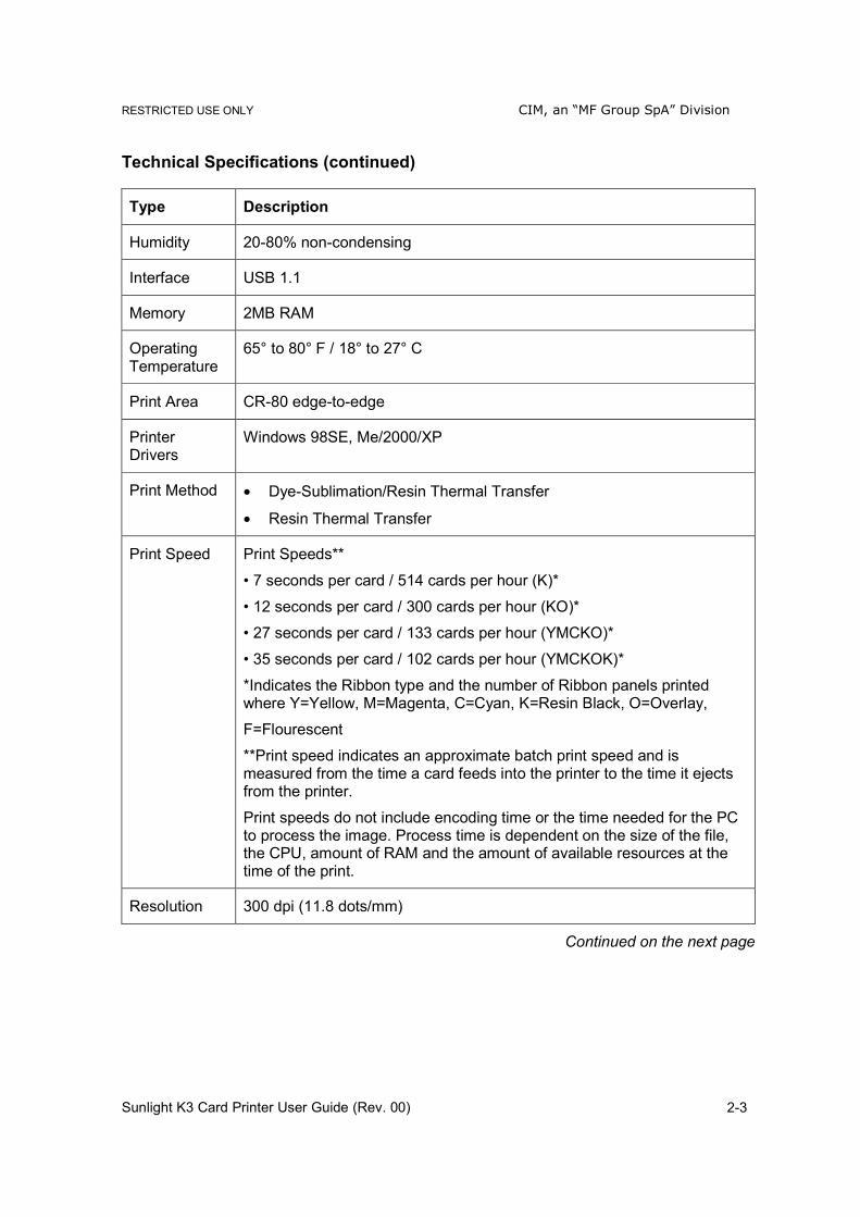
Technical Specifications (continued)
Type Description
Humidity 20-80% non-condensing
Interface USB 1.1
Memory 2MB RAM
Operating Temperature
65° to 80° F / 18° to 27° C
Print Area CR-80 edge-to-edge
Printer Drivers
Windows 98SE, Me/2000/XP
Print Method • Dye-Sublimation/Resin Thermal Transfer
• Resin Thermal Transfer
Print Speed Print Speeds**
• 7 seconds per card / 514 cards per hour (K)*
• 12 seconds per card / 300 cards per hour (KO)*
• 27 seconds per card / 133 cards per hour (YMCKO)*
• 35 seconds per card / 102 cards per hour (YMCKOK)*
*Indicates the Ribbon type and the number of Ribbon panels printed where Y=Yellow, M=Magenta, C=Cyan, K=Resin Black, O=Overlay,
F=Flourescent
**Print speed indicates an approximate batch print speed and is measured from the time a card feeds into the printer to the time it ejects from the printer.
Print speeds do not include encoding time or the time needed for the PC to process the image. Process time is dependent on the size of the file, the CPU, amount of RAM and the amount of available resources at the time of the print.
Resolution 300 dpi (11.8 dots/mm)
Continued on the next page
RESTRICTED USE ONLY CIM, an “MF Group SpA” Division
Sunlight K3 Card Printer User Guide (Rev. 00) 2-4
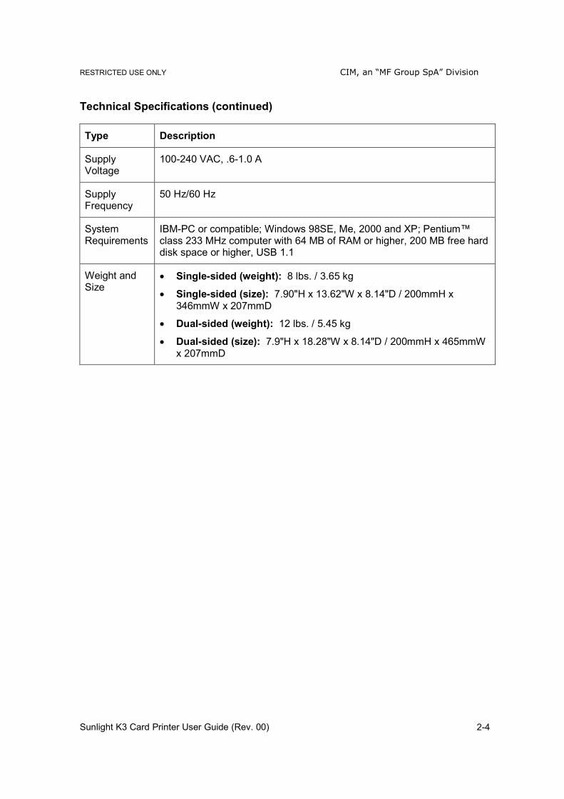
Technical Specifications (continued)
Type Description
Supply Voltage
100-240 VAC, .6-1.0 A
Supply Frequency
50 Hz/60 Hz
System Requirements
IBM-PC or compatible; Windows 98SE, Me, 2000 and XP; Pentium™ class 233 MHz computer with 64 MB of RAM or higher, 200 MB free hard disk space or higher, USB 1.1
Weight and Size
• Single-sided (weight): 8 lbs. / 3.65 kg
• Single-sided (size): 7.90"H x 13.62"W x 8.14"D / 200mmH x 346mmW x 207mmD
• Dual-sided (weight): 12 lbs. / 5.45 kg
•
Dual-sided (size): 7.9"H x 18.28"W x 8.14"D / 200mmH x 465mmW x 207mmD

RESTRICTED USE ONLY CIM, an “MF Group SpA” Division
Sunlight K3 Card Printer User Guide (Rev. 00) 2-5
Functional Specifications This Card Printer utilizes two different, yet closely related printing technologies to achieve its remarkable direct-to-card print quality for dye-sublimation and resin thermal transfer. The Card Printer will print from any IBM-PC® or compatible running Windows® 98SE, Me, Windows 2000 or Windows XP.
The following describes how each of these technologies works:
Function Description
Dye-Sublimation
Dye-Sublimation is the print method the Sunlight K3 uses to produce smooth, continuous-tone images that look truly photographic. (Note: This process uses a dye-based Ribbon roll that is partitioned by a number of consecutive color panels.)
The panels are grouped in a repeating series of these three process colors along the entire length of the print Ribbon: yellow, magenta and cyan or YMC.
The Printer always prints the yellow panel first, followed by the magenta panel and the cyan panel. (Note: As the print Ribbon passes beneath the Printhead, hundreds of thermal elements within the Printhead heat the dyes on the Ribbon. When these dyes are heated, they diffuse into the surface of the card. A separate pass is made for each of the three color panels on the Ribbon.)
By combining the colors of each panel and by varying the heat used to transfer these colors, it is possible to print up to 16.7 million different shades of color. (Note: This blends one color smoothly into the next, producing photo-quality images with absolutely no dot pattern.)
Resin Thermal Transfer
Resin Thermal Transfer is the print method the Printer uses to print sharp black text and crisp bar codes, which can be read by both infrared and visible-light bar code scanners.
• Used to print ultra-fast, one-color ID cards on the Sunlight K3. (Note: Like dye-sublimation, this process uses the same thermal Printhead to transfer color to a card from a resin-only print Ribbon or the resin black (K) panel of a full color print Ribbon.)
• Solid dots of resin-based ink are transferred and fused to the surface of the card. (Note: This produces durable, saturated printing.)
RESTRICTED USE ONLY CIM, an “MF Group SpA” Division
Sunlight K3 Card Printer User Guide (Rev. 00) 2-6
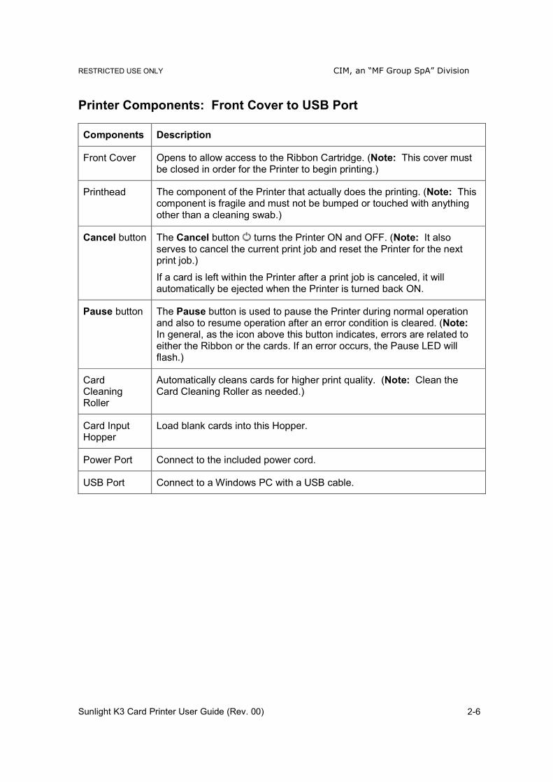
Printer Components: Front Cover to USB Port
Components Description
Front Cover Opens to allow access to the Ribbon Cartridge. (Note: This cover must be closed in order for the Printer to begin printing.)
Printhead The component of the Printer that actually does the printing. (Note: This component is fragile and must not be bumped or touched with anything other than a cleaning swab.)
Cancel button The Cancel button turns the Printer ON and OFF. (Note: It also serves to cancel the current print job and reset the Printer for the next print job.)
If a card is left within the Printer after a print job is canceled, it will automatically be ejected when the Printer is turned back ON.
Pause button The Pause button is used to pause the Printer during normal operation and also to resume operation after an error condition is cleared. (Note: In general, as the icon above this button indicates, errors are related to either the Ribbon or the cards. If an error occurs, the Pause LED will flash.)
Card Cleaning Roller
Automatically cleans cards for higher print quality. (Note: Clean the Card Cleaning Roller as needed.)
Card Input Hopper
Load blank cards into this Hopper.
Power Port Connect to the included power cord.
USB Port Connect to a Windows PC with a USB cable.
RESTRICTED USE ONLY CIM, an “MF Group SpA” Division
Sunlight K3 Card Printer User Guide (Rev. 00) 2-7
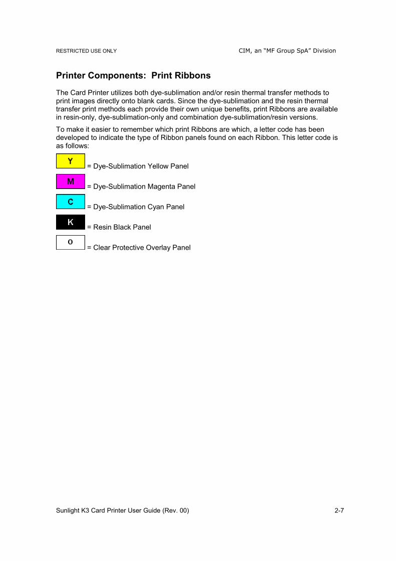
Printer Components: Print Ribbons
The Card Printer utilizes both dye-sublimation and/or resin thermal transfer methods to print images directly onto blank cards. Since the dye-sublimation and the resin thermal transfer print methods each provide their own unique benefits, print Ribbons are available in resin-only, dye-sublimation-only and combination dye-sublimation/resin versions.
To make it easier to remember which print Ribbons are which, a letter code has been developed to indicate the type of Ribbon panels found on each Ribbon. This letter code is as follows:
= Dye-Sublimation Yellow Panel
= Dye-Sublimation Magenta Panel
= Dye-Sublimation Cyan Panel
= Resin Black Panel
= Clear Protective Overlay Panel
RESTRICTED USE ONLY CIM, an “MF Group SpA” Division
Sunlight K3 Card Printer User Guide (Rev. 00) 2-8
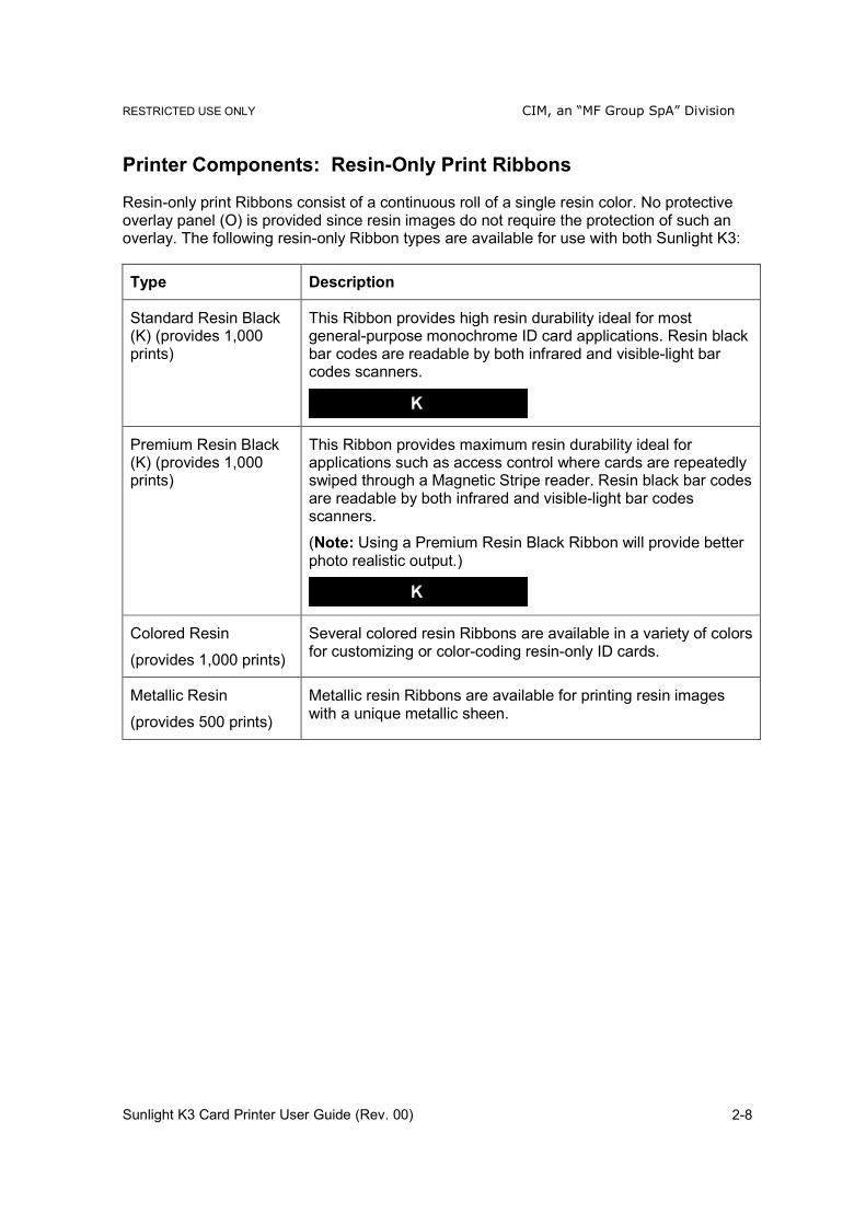
Printer Components: Resin-Only Print Ribbons
Resin-only print Ribbons consist of a continuous roll of a single resin color. No protective overlay panel (O) is provided since resin images do not require the protection of such an overlay. The following resin-only Ribbon types are available for use with both Sunlight K3:
Type Description
Standard Resin Black (K) (provides 1,000 prints)
This Ribbon provides high resin durability ideal for most general-purpose monochrome ID card applications. Resin black bar codes are readable by both infrared and visible-light bar codes scanners.
Premium Resin Black (K) (provides 1,000 prints)
This Ribbon provides maximum resin durability ideal for applications such as access control where cards are repeatedly swiped through a Magnetic Stripe reader. Resin black bar codes are readable by both infrared and visible-light bar codes scanners.
(Note: Using a Premium Resin Black Ribbon will provide better photo realistic output.)
Colored Resin
(provides 1,000 prints)
Several colored resin Ribbons are available in a variety of colors for customizing or color-coding resin-only ID cards.
Metallic Resin
(provides 500 prints)
Metallic resin Ribbons are available for printing resin images with a unique metallic sheen.
RESTRICTED USE ONLY CIM, an “MF Group SpA” Division
Sunlight K3 Card Printer User Guide (Rev. 00) 2-9
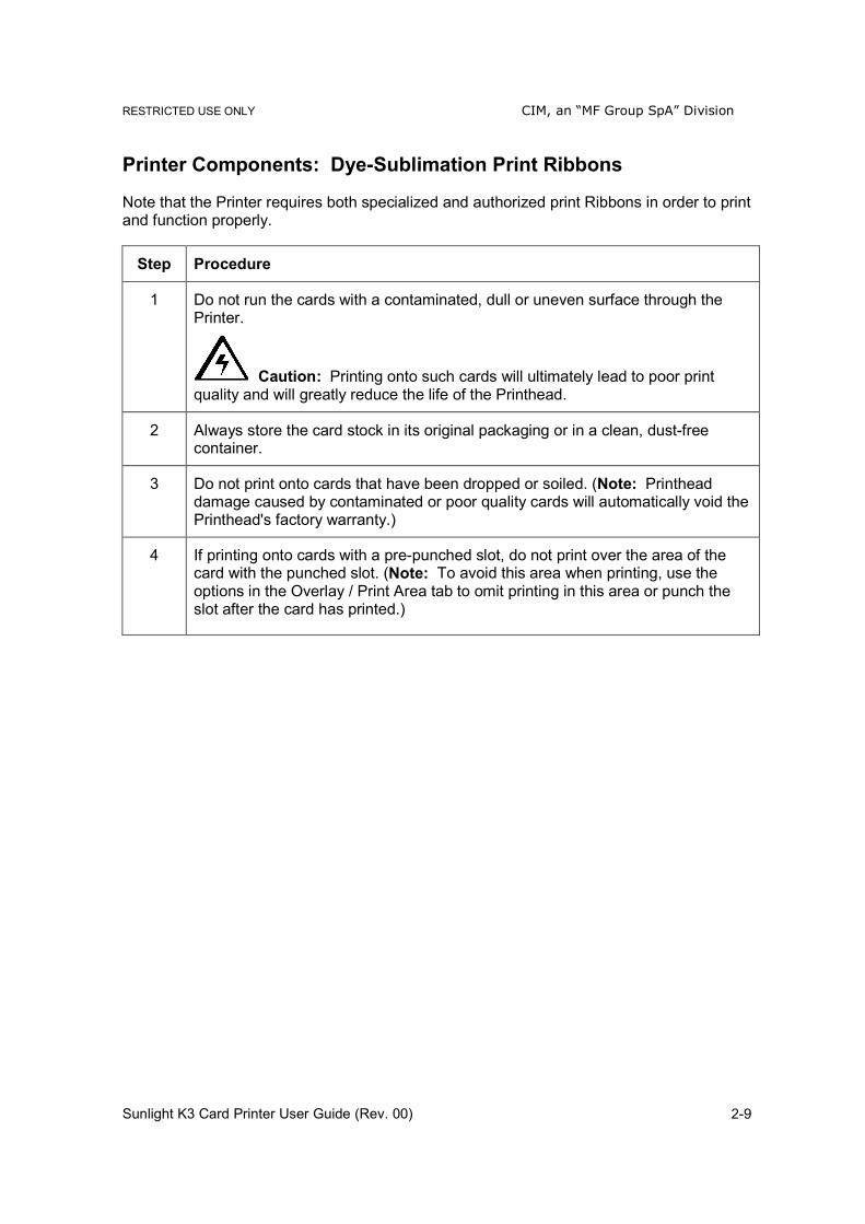
Printer Components: Dye-Sublimation Print Ribbons
Note that the Printer requires both specialized and authorized print Ribbons in order to print and function properly.
Step Procedure
1 Do not run the cards with a contaminated, dull or uneven surface through the Printer.
Caution: Printing onto such cards will ultimately lead to poor print quality and will greatly reduce the life of the Printhead.
2 Always store the card stock in its original packaging or in a clean, dust-free container.
3 Do not print onto cards that have been dropped or soiled. (Note: Printhead damage caused by contaminated or poor quality cards will automatically void the Printhead's factory warranty.)
4 If printing onto cards with a pre-punched slot, do not print over the area of the card with the punched slot. (Note: To avoid this area when printing, use the options in the Overlay / Print Area tab to omit printing in this area or punch the slot after the card has printed.)
RESTRICTED USE ONLY CIM, an “MF Group SpA” Division
Sunlight K3 Card Printer User Guide (Rev. 00) 2-10
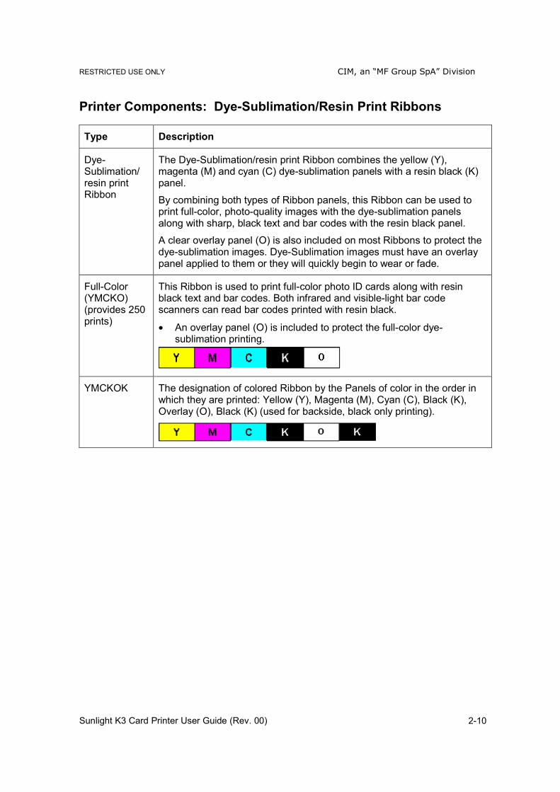
Printer Components: Dye-Sublimation/Resin Print Ribbons
Type Description
Dye-Sublimation/ resin print Ribbon
The Dye-Sublimation/resin print Ribbon combines the yellow (Y), magenta (M) and cyan (C) dye-sublimation panels with a resin black (K) panel.
By combining both types of Ribbon panels, this Ribbon can be used to print full-color, photo-quality images with the dye-sublimation panels along with sharp, black text and bar codes with the resin black panel.
A clear overlay panel (O) is also included on most Ribbons to protect the dye-sublimation images. Dye-Sublimation images must have an overlay panel applied to them or they will quickly begin to wear or fade.
Full-Color (YMCKO) (provides 250 prints)
This Ribbon is used to print full-color photo ID cards along with resin black text and bar codes. Both infrared and visible-light bar code scanners can read bar codes printed with resin black.
• An overlay panel (O) is included to protect the full-color dye-sublimation printing.
YMCKOK The designation of colored Ribbon by the Panels of color in the order in which they are printed: Yellow (Y), Magenta (M), Cyan (C), Black (K), Overlay (O), Black (K) (used for backside, black only printing).
RESTRICTED USE ONLY CIM, an “MF Group SpA” Division
Sunlight K3 Card Printer User Guide (Rev. 00) 2-11
Printer Components: Blank Cards
Type Description
Card Size The Card Printer accepts standard CR-80 sized and 20 mil. cards (3.370"L x 2.125"W / 85.6mmL x 54mmW) with a thickness of 30 mil (.030"/.762mm).
Card Design
The Printer will print onto any card with a clean, level and polished PVC surface.
Although the Printer is equipped with card cleaning Rollers, it is very important to always print onto cards specifically designed for direct-to-card dye-sublimation printing.
Card Surface
Suitable cards must have a polished PVC surface free of fingerprints, dust or any other types of embedded contaminants. In addition, cards must have a completely smooth, level surface in order for the Printer to achieve consistent color coverage.
Certain types of Proximity cards have an uneven surface that will inhibit consistent color transfer.
•
Certain types of smart card chips are raised slightly above the cards surface which also results in poor color transfer.
RESTRICTED USE ONLY CIM, an “MF Group SpA” Division
Sunlight K3 Card Printer User Guide (Rev. 00) 2-12
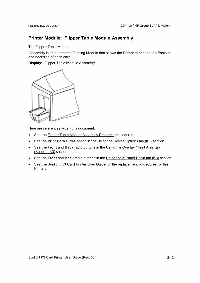
Printer Module: Flipper Table Module Assembly
The Flipper Table Module
Assembly is an automated Flipping Module that allows the Printer to print on the frontside and backside of each card.
Display: Flipper Table Module Assembly
Here are references within this document.
• See the Flipper Table Module Assembly Problems procedures.
• See the Print Both Sides option in the Using the Device Options tab (K3) section.
•
See the Front and Back radio buttons in the Using the Overlay / Print Area tab (Sunlight K3) section.
•
See the Front and Back radio buttons in the Using the K Panel Resin tab (K3) section.
• See the Sunlight K3 Card Printer User Guide for the replacement procedures for this Printer.
RESTRICTED USE ONLY CIM, an “MF Group SpA” Division
Sunlight K3 Card Printer User Guide (Rev. 00) 3-1
Section 3: Setup and Installation Procedures The following guide will walk you through the installation of the Sunlight K3 Card Printer Driver.
•
Time Requirement (software): This software installation process will require approximately 2 to 5 minutes (depending on the speed of your PC).
• Time Requirement (Printer): The time required to set up a standard Sunlight K3 Printer would be approximately 5 to 10 minutes.
The System Requirements are as follows:
IBM-PC or compatible, Windows® 98SE, Me/2000/XP, Pentium® class 233MHz computer with 64MB of RAM or higher, 200MB free hard disk space or higher, USB 1.1
Printer Setup and Installation Choosing A Good Location
Follow these guidelines:
• Place the unit in a location with adequate air circulation to prevent internal heat build up.
•
Use the Printer's dimensions as a guideline for the minimum clearances to the unit. (Note: Allow for adequate clearance in front of the unit to accommodate the unit with its Covers open.)
•
Do not install unit near heat sources such as radiators or air ducts or in a place subject to direct Sunlight, excessive dust, mechanical vibration or shock.
About Moisture Condensation
If the unit is brought directly from a cold to a warm location or is placed in a very damp room, moisture may condense inside the unit. Should this occur, print quality may not be optimum.
Leave the unit turned OFF in a warm, dry room for several hours before using. This will allow the moisture to evaporate.
RESTRICTED USE ONLY CIM, an “MF Group SpA” Division
Sunlight K3 Card Printer User Guide (Rev. 00) 3-2
Unpacking and Inspection
While unpacking your Printer, inspect the carton to ensure that no damage has occurred during shipping. Make sure that all supplied accessories are included with your unit.
Check that the following items are included:
•
Power Supply
• US / EU Power Cable
• Software Installation CD/User Guide
• User Guide
• Warranty Statement, Registration Card and Compliancy Document
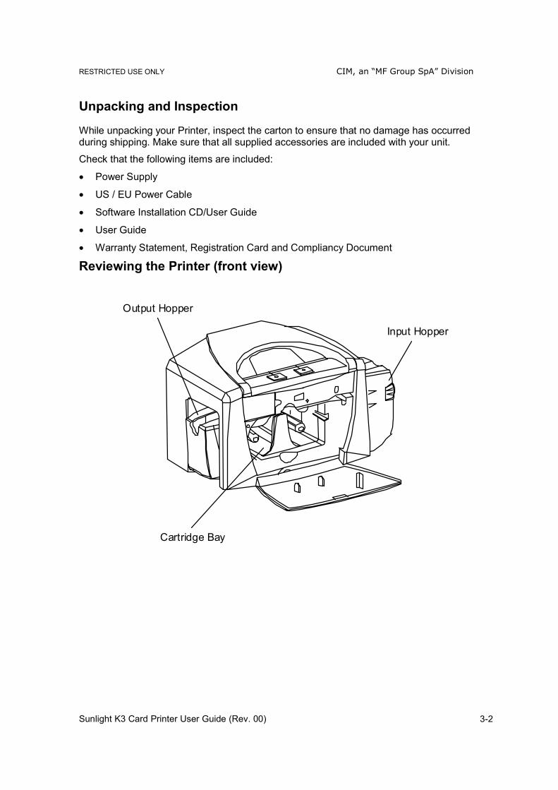
Reviewing the Printer (front view)
Input Hopper
Output Hopper
Cartridge Bay
RESTRICTED USE ONLY CIM, an “MF Group SpA” Division
Sunlight K3 Card Printer User Guide (Rev. 00) 3-3
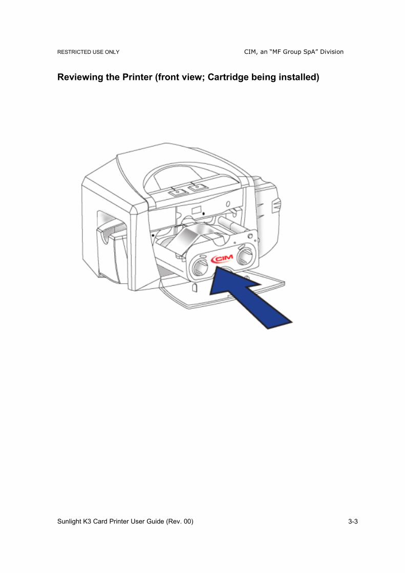
Reviewing the Printer (front view; Cartridge being installed)
RESTRICTED USE ONLY CIM, an “MF Group SpA” Division
Sunlight K3 Card Printer User Guide (Rev. 00) 3-4
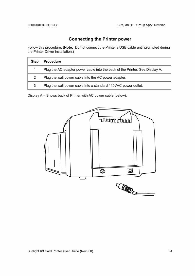
Connecting the Printer power
Follow this procedure. (Note: Do not connect the Printer’s USB cable until prompted during the Printer Driver installation.)
Step Procedure
1 Plug the AC adapter power cable into the back of the Printer. See Display A.
2 Plug the wall power cable into the AC power adapter.
3 Plug the wall power cable into a standard 110VAC power outlet.
Display A – Shows back of Printer with AC power cable (below).
RESTRICTED USE ONLY CIM, an “MF Group SpA” Division
Sunlight K3 Card Printer User Guide (Rev. 00) 3-5
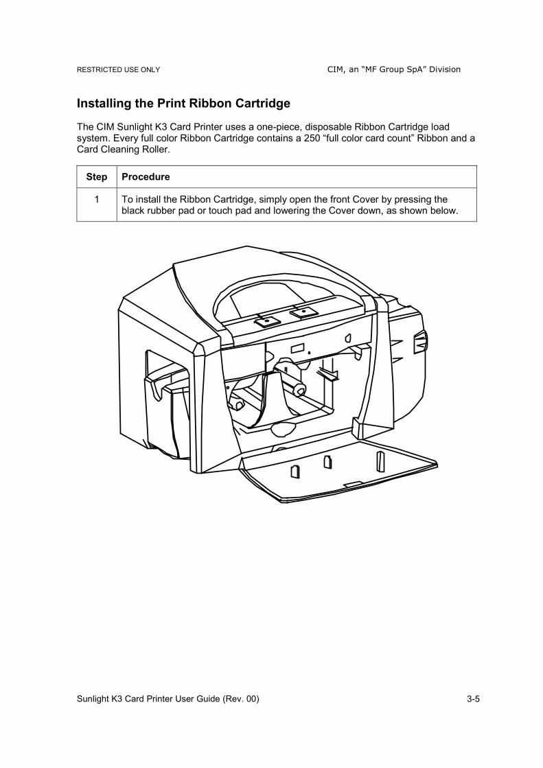
Installing the Print Ribbon Cartridge
The CIM Sunlight K3 Card Printer uses a one-piece, disposable Ribbon Cartridge load system. Every full color Ribbon Cartridge contains a 250 “full color card count” Ribbon and a Card Cleaning Roller.
Step Procedure
1 To install the Ribbon Cartridge, simply open the front Cover by pressing the black rubber pad or touch pad and lowering the Cover down, as shown below.
RESTRICTED USE ONLY CIM, an “MF Group SpA” Division
Sunlight K3 Card Printer User Guide (Rev. 00) 3-6
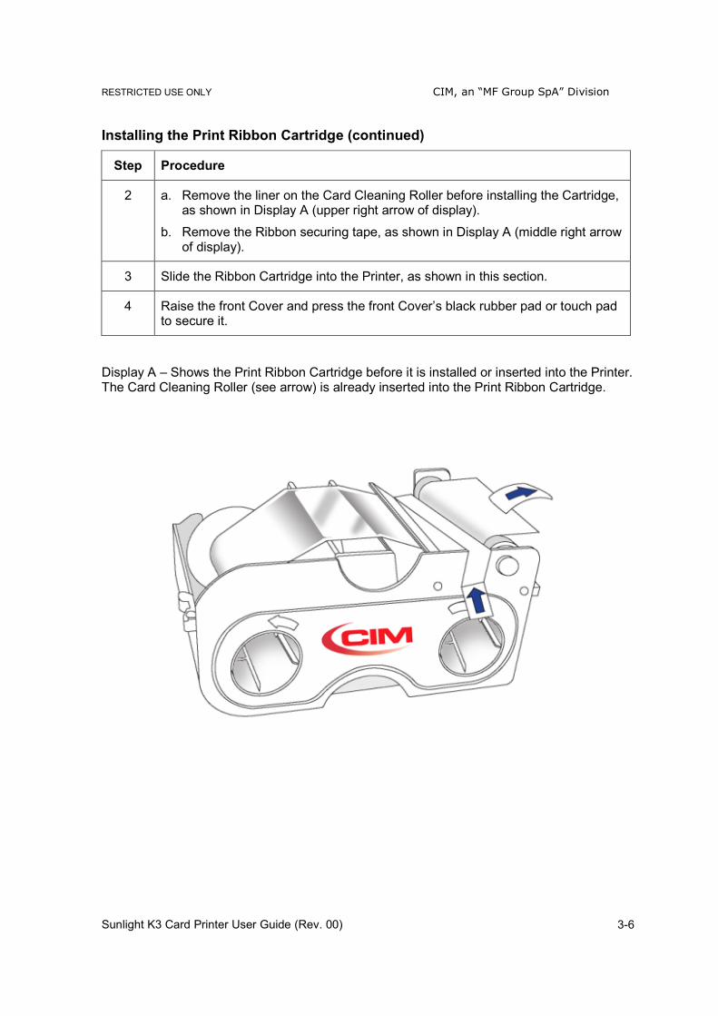
Installing the Print Ribbon Cartridge (continued)
Step Procedure
2 a. Remove the liner on the Card Cleaning Roller before installing the Cartridge, as shown in Display A (upper right arrow of display).
b. Remove the Ribbon securing tape, as shown in Display A (middle right arrow of display).
3 Slide the Ribbon Cartridge into the Printer, as shown in this section.
4 Raise the front Cover and press the front Cover’s black rubber pad or touch pad to secure it.
Display A – Shows the Print Ribbon Cartridge before it is installed or inserted into the Printer. The Card Cleaning Roller (see arrow) is already inserted into the Print Ribbon Cartridge.
RESTRICTED USE ONLY CIM, an “MF Group SpA” Division
Sunlight K3 Card Printer User Guide (Rev. 00) 3-7
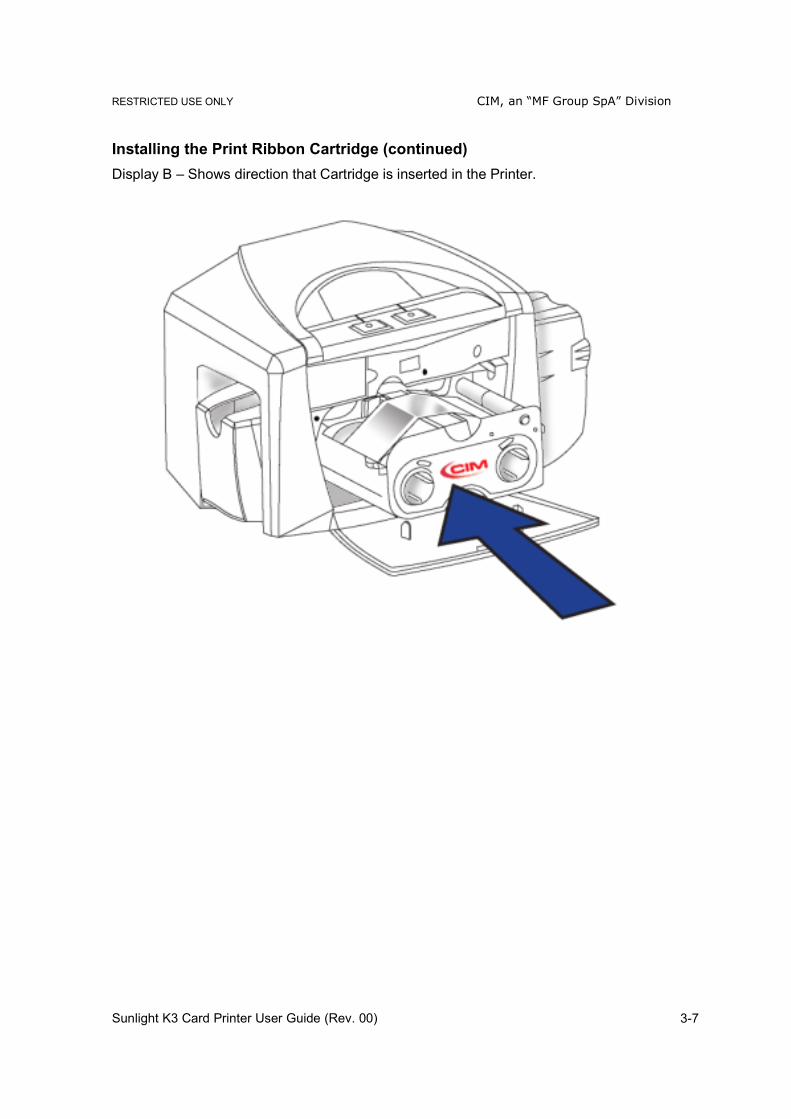
Installing the Print Ribbon Cartridge (continued) Display B – Shows direction that Cartridge is inserted in the Printer.
RESTRICTED USE ONLY CIM, an “MF Group SpA” Division
Sunlight K3 Card Printer User Guide (Rev. 00) 3-8
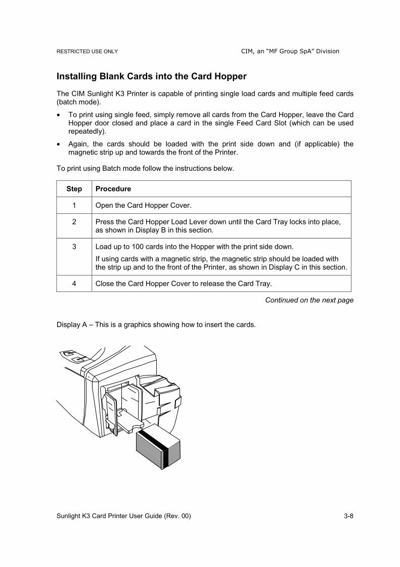
Installing Blank Cards into the Card Hopper
The CIM Sunlight K3 Printer is capable of printing single load cards and multiple feed cards (batch mode).
• To print using single feed, simply remove all cards from the Card Hopper, leave the Card Hopper door closed and place a card in the single Feed Card Slot (which can be used repeatedly).
• Again, the cards should be loaded with the print side down and (if applicable) the magnetic strip up and towards the front of the Printer.
To print using Batch mode follow the instructions below.
Step Procedure
1 Open the Card Hopper Cover.
2 Press the Card Hopper Load Lever down until the Card Tray locks into place, as shown in Display B in this section.
3 Load up to 100 cards into the Hopper with the print side down.
If using cards with a magnetic strip, the magnetic strip should be loaded with the strip up and to the front of the Printer, as shown in Display C in this section.
4 Close the Card Hopper Cover to release the Card Tray.
Continued on the next page
Display A – This is a graphics showing how to insert the cards.
RESTRICTED USE ONLY CIM, an “MF Group SpA” Division
Sunlight K3 Card Printer User Guide (Rev. 00) 3-9
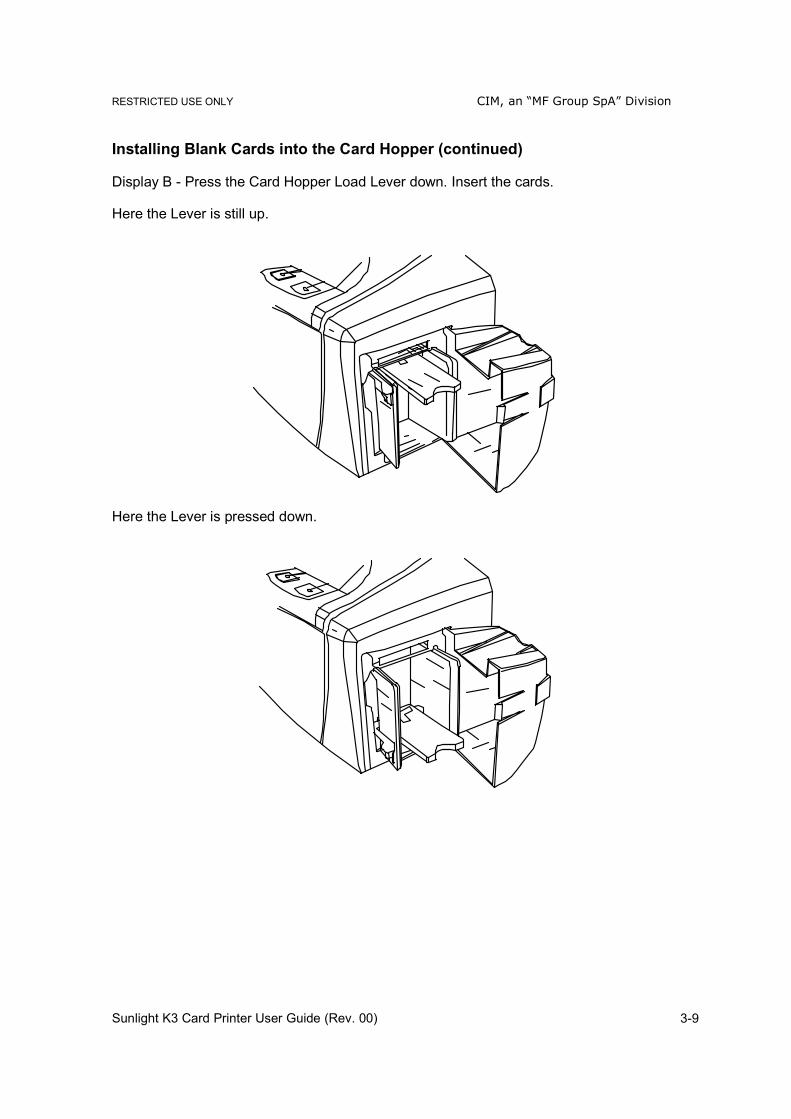
Installing Blank Cards into the Card Hopper (continued)
Display B - Press the Card Hopper Load Lever down. Insert the cards.
Here the Lever is still up.
Here the Lever is pressed down.
RESTRICTED USE ONLY CIM, an “MF Group SpA” Division
Sunlight K3 Card Printer User Guide (Rev. 00) 3-10
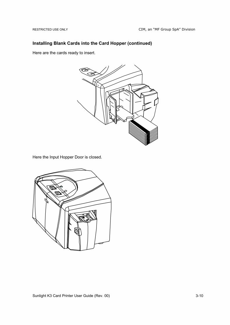
Installing Blank Cards into the Card Hopper (continued)
Here are the cards ready to insert.
Here the Input Hopper Door is closed.
RESTRICTED USE ONLY CIM, an “MF Group SpA” Division
Sunlight K3 Card Printer User Guide (Rev. 00) 3-11
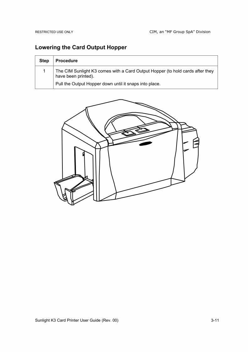
Lowering the Card Output Hopper
Step Procedure
1 The CIM Sunlight K3 comes with a Card Output Hopper (to hold cards after they have been printed).
Pull the Output Hopper down until it snaps into place.
RESTRICTED USE ONLY CIM, an “MF Group SpA” Division
Sunlight K3 Card Printer User Guide (Rev. 00) 3-12
Flipper Table Module Installation Additional, related links are provided below:
•
See the Flipper Table Module Assembly Problems procedures.
• See the Print Both Sides option in the Using the Device Options tab (K3) section.
• See the Front and Back radio buttons in the Using the Overlay / Print Area tab (Sunlight K3) section.
• See the Front and Back radio buttons in the Using the K Panel Resin tab (K3) section.
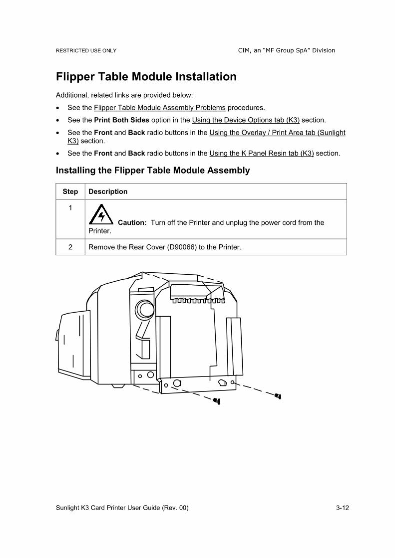
Installing the Flipper Table Module Assembly
Step Description
1
Caution: Turn off the Printer and unplug the power cord from the Printer.
2 Remove the Rear Cover (D90066) to the Printer.
RESTRICTED USE ONLY CIM, an “MF Group SpA” Division
Sunlight K3 Card Printer User Guide (Rev. 00) 3-13
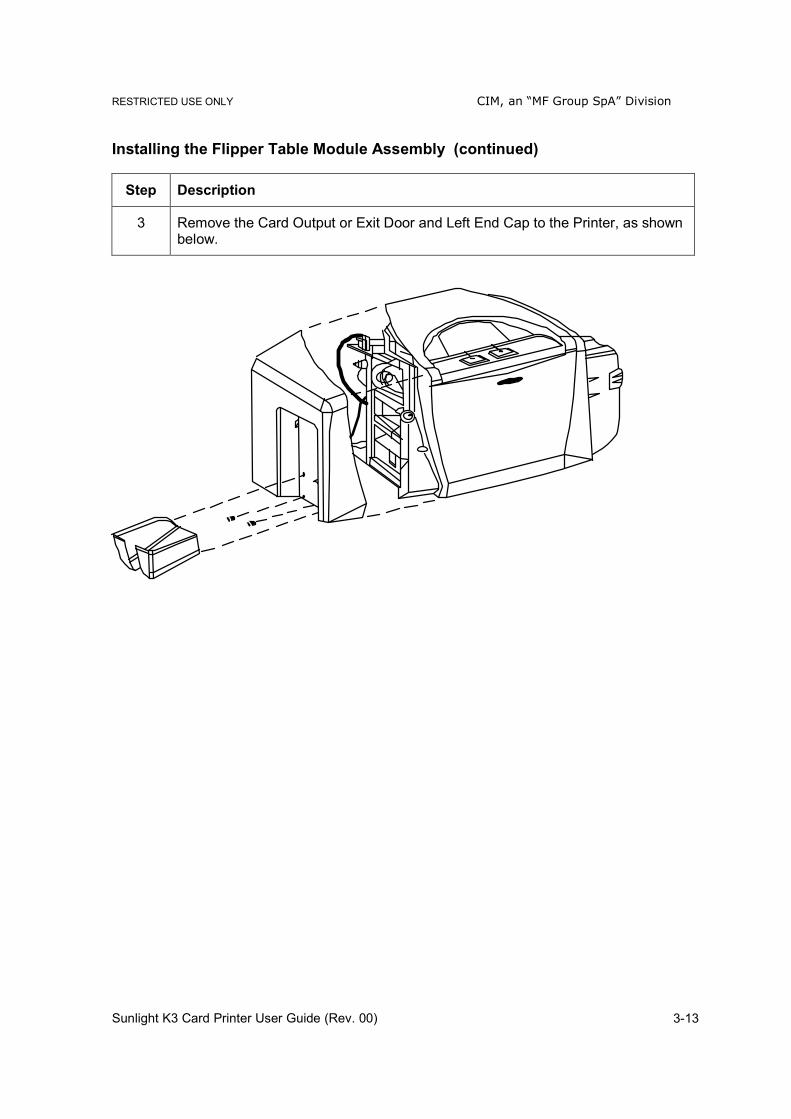
Installing the Flipper Table Module Assembly (continued)
Step Description
3 Remove the Card Output or Exit Door and Left End Cap to the Printer, as shown below.
RESTRICTED USE ONLY CIM, an “MF Group SpA” Division
Sunlight K3 Card Printer User Guide (Rev. 00) 3-14
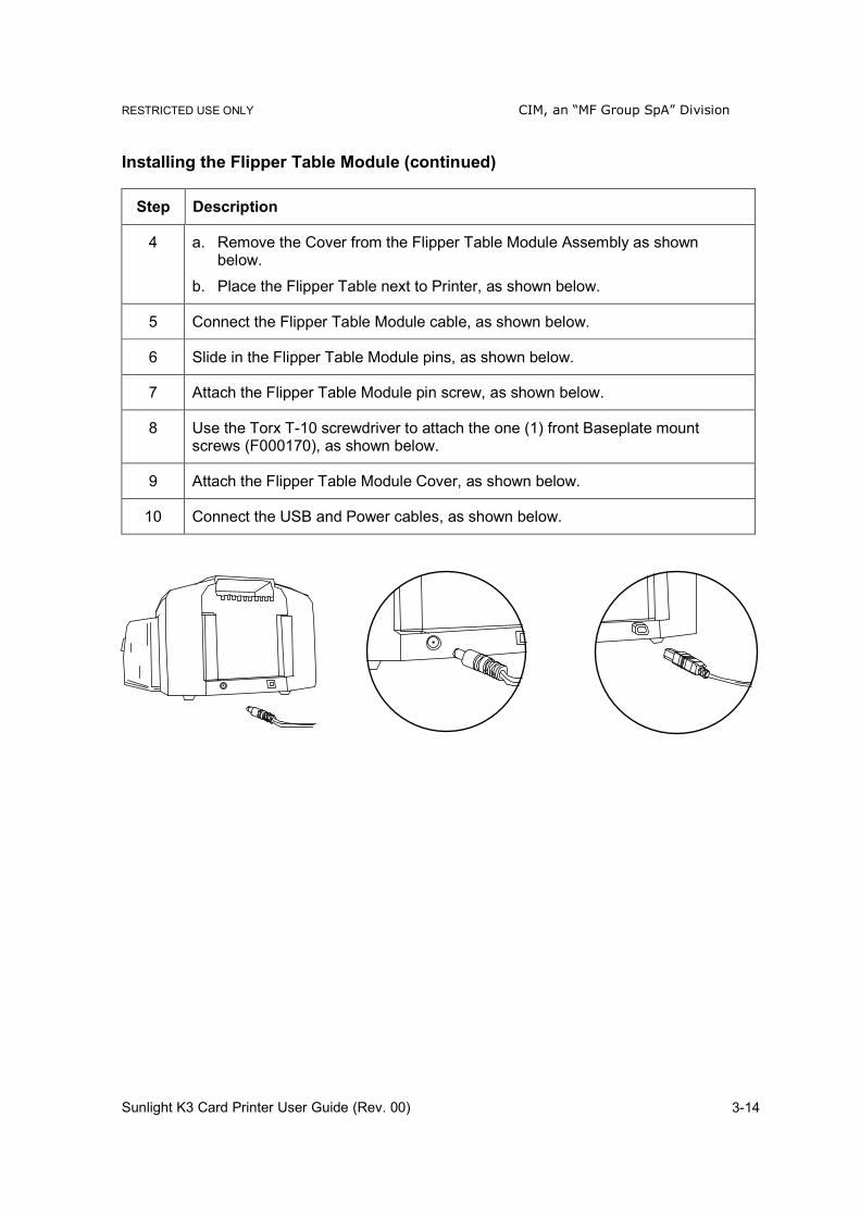
Installing the Flipper Table Module (continued)
Step Description
4 a. Remove the Cover from the Flipper Table Module Assembly as shown below.
b. Place the Flipper Table next to Printer, as shown below.
5 Connect the Flipper Table Module cable, as shown below.
6 Slide in the Flipper Table Module pins, as shown below.
7 Attach the Flipper Table Module pin screw, as shown below.
8 Use the Torx T-10 screwdriver to attach the one (1) front Baseplate mount screws (F000170), as shown below.
9 Attach the Flipper Table Module Cover, as shown below.
10 Connect the USB and Power cables, as shown below.
RESTRICTED USE ONLY CIM, an “MF Group SpA” Division
Sunlight K3 Card Printer User Guide (Rev. 00) 3-15
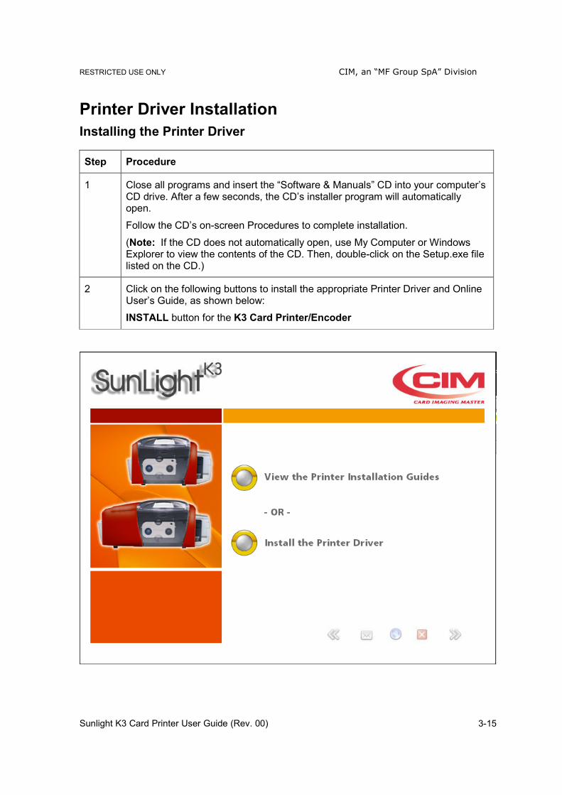
Printer Driver Installation Installing the Printer Driver
Step Procedure
1 Close all programs and insert the “Software & Manuals” CD into your computer’s CD drive. After a few seconds, the CD’s installer program will automatically open.
Follow the CD’s on-screen Procedures to complete installation.
(Note: If the CD does not automatically open, use My Computer or Windows Explorer to view the contents of the CD. Then, double-click on the Setup.exe file listed on the CD.)
2 Click on the following buttons to install the appropriate Printer Driver and Online User’s Guide, as shown below:
INSTALL button for the K3 Card Printer/Encoder
RESTRICTED USE ONLY CIM, an “MF Group SpA” Division
Sunlight K3 Card Printer User Guide (Rev. 00) 3-16
Installing the Printer Driver (continued)
Step Procedure
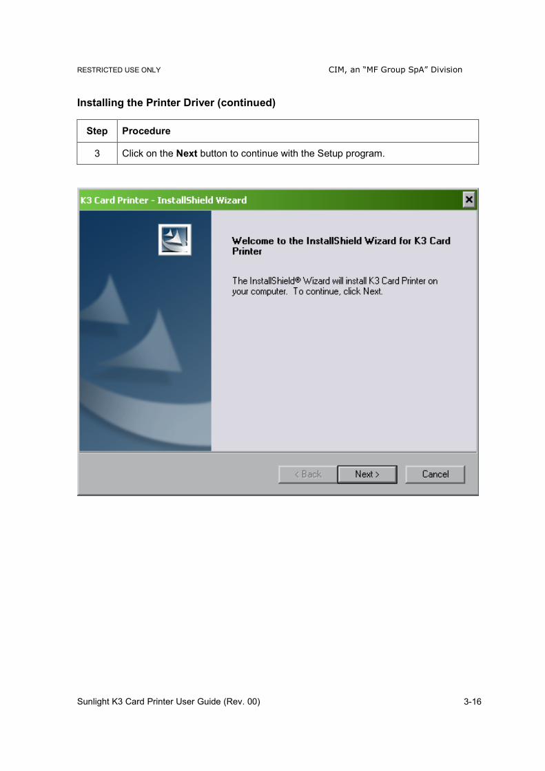
3 Click on the Next button to continue with the Setup program.
RESTRICTED USE ONLY CIM, an “MF Group SpA” Division
Sunlight K3 Card Printer User Guide (Rev. 00) 3-17
Installing the Printer Driver (continued)
Step Procedure
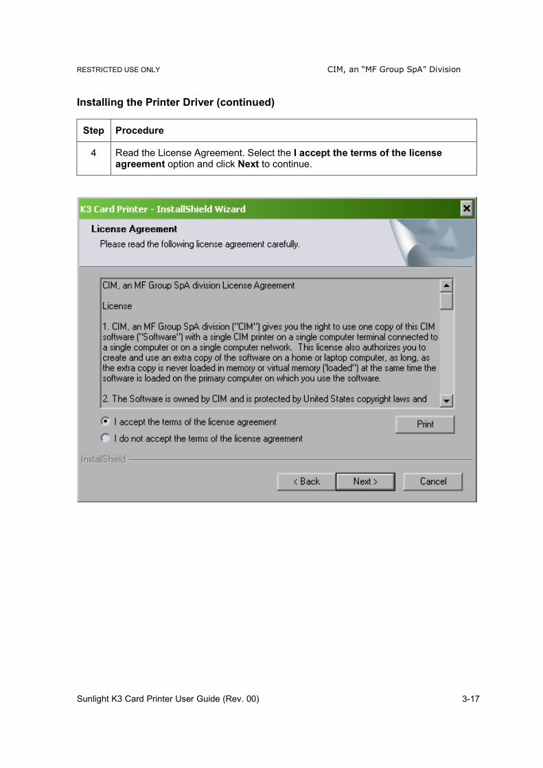
4 Read the License Agreement. Select the I accept the terms of the license agreement option and click Next to continue.
RESTRICTED USE ONLY CIM, an “MF Group SpA” Division
Sunlight K3 Card Printer User Guide (Rev. 00) 3-18
Installing the Printer Driver (continued)
Step Procedure
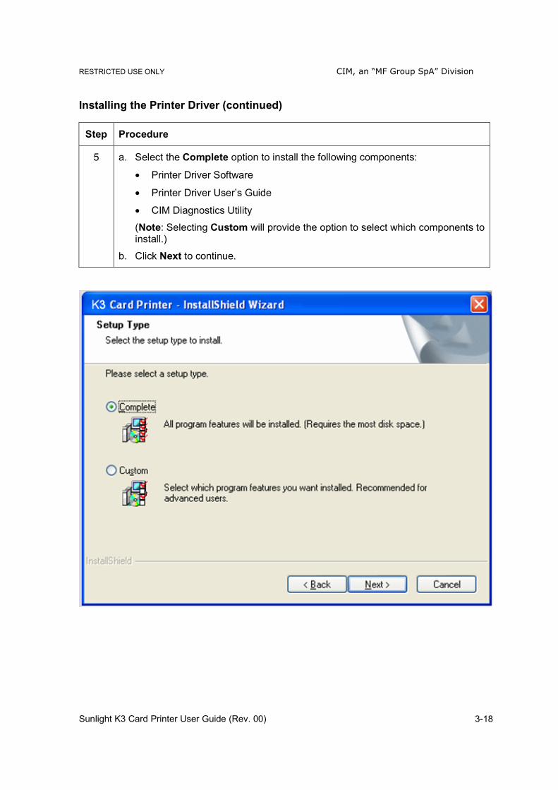
5 a. Select the Complete option to install the following components:
• Printer Driver Software
• Printer Driver User’s Guide
•
CIM Diagnostics Utility
(Note: Selecting Custom will provide the option to select which components to install.)
b. Click Next to continue.
RESTRICTED USE ONLY CIM, an “MF Group SpA” Division
Sunlight K3 Card Printer User Guide (Rev. 00) 3-19
Installing the Printer Driver (continued)
Step Procedure
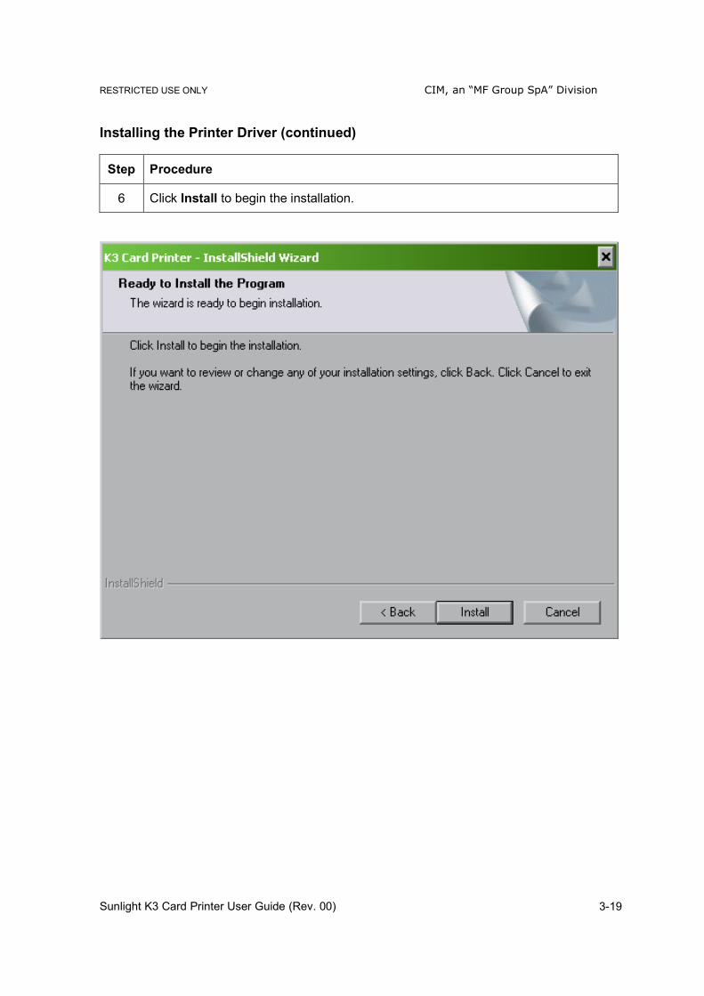
6 Click Install to begin the installation.
RESTRICTED USE ONLY CIM, an “MF Group SpA” Division
Sunlight K3 Card Printer User Guide (Rev. 00) 3-20
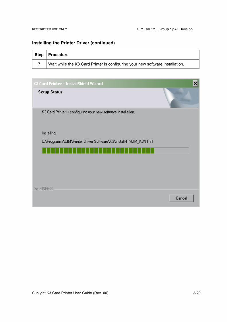
Installing the Printer Driver (continued)
Step Procedure
7 Wait while the K3 Card Printer is configuring your new software installation.
RESTRICTED USE ONLY CIM, an “MF Group SpA” Division
Sunlight K3 Card Printer User Guide (Rev. 00) 3-21
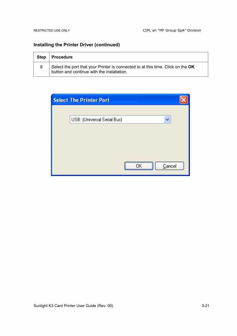
Installing the Printer Driver (continued)
Step Procedure
8 Select the port that your Printer is connected to at this time. Click on the OK button and continue with the installation.
RESTRICTED USE ONLY CIM, an “MF Group SpA” Division
Sunlight K3 Card Printer User Guide (Rev. 00) 3-22
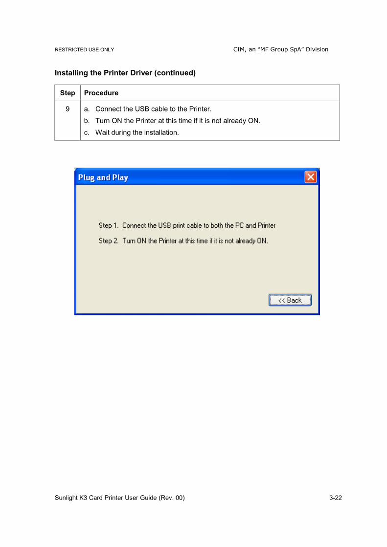
Installing the Printer Driver (continued)
Step Procedure
9 a. Connect the USB cable to the Printer.
b. Turn ON the Printer at this time if it is not already ON.
c. Wait during the installation.
RESTRICTED USE ONLY CIM, an “MF Group SpA” Division
Sunlight K3 Card Printer User Guide (Rev. 00) 3-23
Installing the Printer Driver (continued)
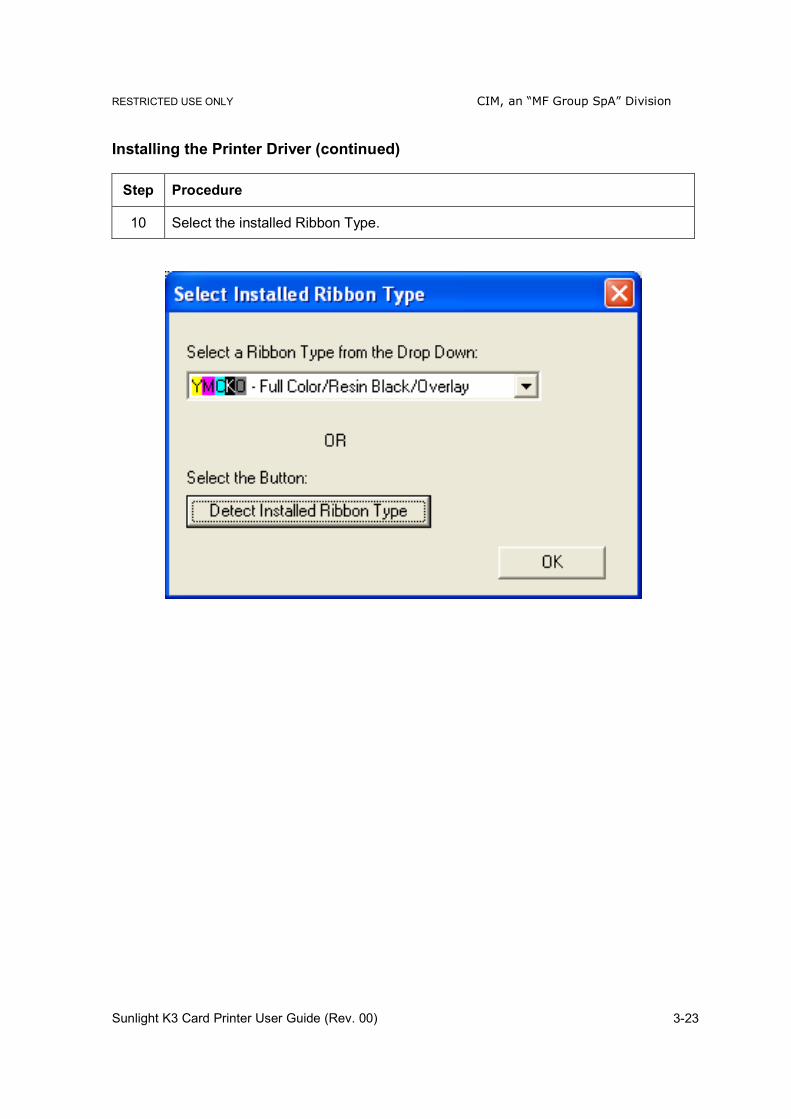
Step Procedure
10 Select the installed Ribbon Type.
RESTRICTED USE ONLY CIM, an “MF Group SpA” Division
Sunlight K3 Card Printer User Guide (Rev. 00) 3-24
Installing the Printer Driver (continued)
Step Procedure
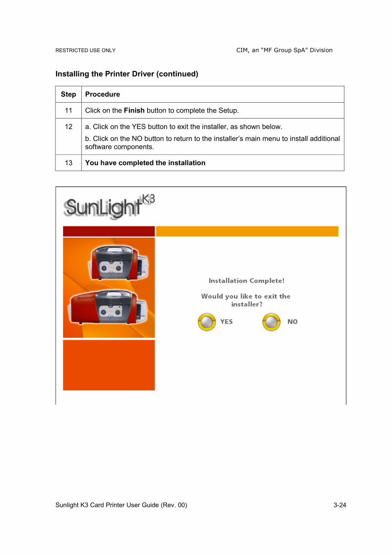
11 Click on the Finish button to complete the Setup.
12 a. Click on the YES button to exit the installer, as shown below.
b. Click on the NO button to return to the installer’s main menu to install additional software components.
13 You have completed the installation
RESTRICTED USE ONLY CIM, an “MF Group SpA” Division
Sunlight K3 Card Printer User Guide (Rev. 00) 3-25
Printing a Test Print Image
Step Procedure
1 a. From your computer’s startup menu, select Settings > Printers and Faxes (Windows XP) or > Printers (Windows 98SE, Me and 2000).
b. Double click on the Sunlight K3 Card Printer under the Printers window.
c. Select Printing Preferences under the Printer drop-down menu. This will bring up the Sunlight K3 Printing Preferences window.
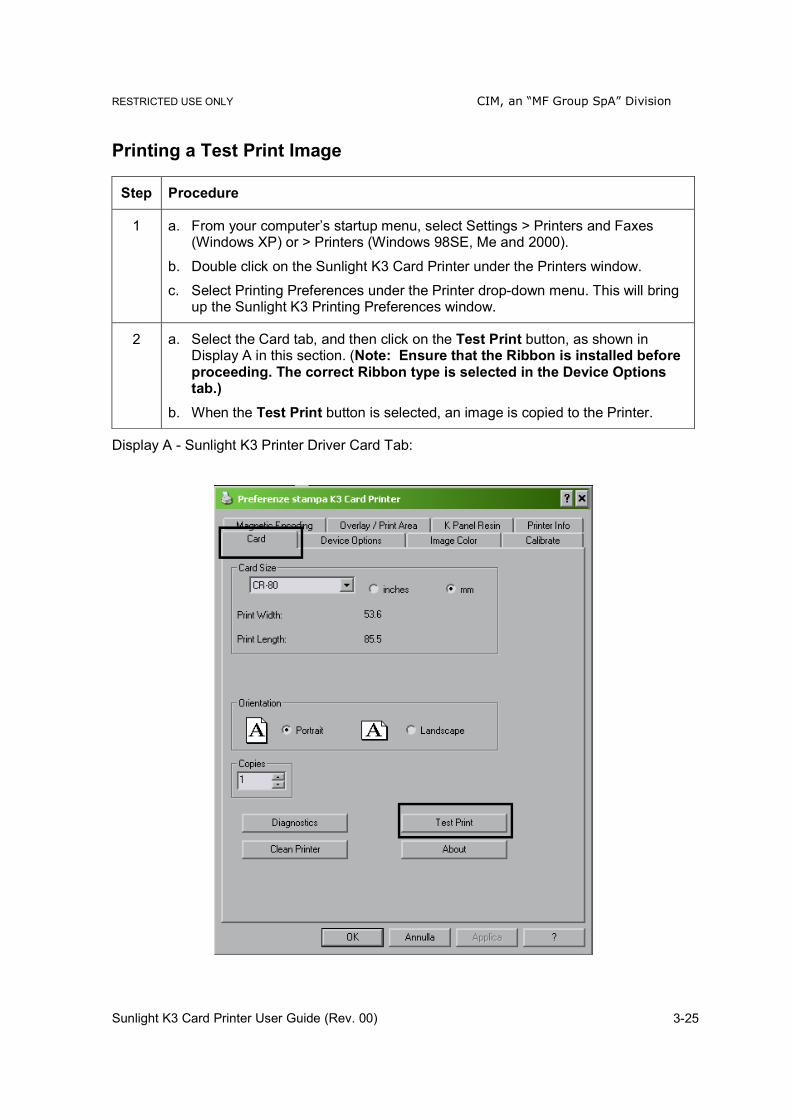
2 a. Select the Card tab, and then click on the Test Print button, as shown in Display A in this section. (Note: Ensure that the Ribbon is installed before proceeding. The correct Ribbon type is selected in the Device Options tab.)
b. When the Test Print button is selected, an image is copied to the Printer.
Display A - Sunlight K3 Printer Driver Card Tab:

RESTRICTED USE ONLY CIM, an “MF Group SpA” Division
Sunlight K3 Card Printer User Guide (Rev. 00) 3-26
Printing a Test Print Image (continued)
Step Procedure
3 This completes the Sunlight K3 Card Printer/Encoder Installation Guide.
For additional help regarding the Test Print and other related items, see the Sunlight K3 Card Printer/Encoders User Guide located under Start > Programs > CIM.
RESTRICTED USE ONLY CIM, an “MF Group SpA” Division
Sunlight K3 Card Printer User Guide (Rev. 00) 3-27
Printer Transport Moving the Printer to another location
Step Procedure
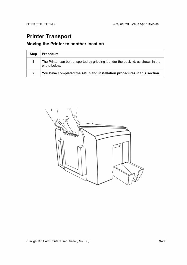
1 The Printer can be transported by gripping it under the back lid, as shown in the photo below.
2 You have completed the setup and installation procedures in this section.
RESTRICTED USE ONLY CIM, an “MF Group SpA” Division
Sunlight K3 Card Printer User Guide (Rev. 00) 4-1
Section 4: General Troubleshooting This section provides Troubleshooting procedures for this Printer for Communication Errors, Card Feed Errors, Print Process Errors, Card Jam Errors, Encoding Errors and Diagnosing Image Problems.
Safety Messages (review carefully) Symbol Critical Instructions for Safety purposes
Danger:
Failure to follow these installation guidelines can result in death or serious injury. Information that raises potential safety issues is indicated by a warning symbol (as shown to the left).
• To prevent personal injury, refer to the following safety messages before performing an operation preceded by this symbol.
• To prevent personal injury, always remove the power cord prior to performing repair procedures, unless otherwise specified.
• To prevent personal injury, make sure only qualified personnel perform these procedures.
Caution:
This device is electrostatically sensitive. It may be damaged if exposed to static electricity discharges. Information that raises potential electrostatic safety issues is indicated by a warning symbol (as shown to the left).
• To prevent equipment or media damage, refer to the following safety messages before performing an operation preceded by this symbol.
• To prevent equipment or media damage, observe all established Electrostatic Discharge (ESD) procedures while handling cables in or near the Circuit Board and Printhead Assemblies.
• To prevent equipment or media damage, always wear an appropriate personal grounding device (e.g., a high quality wrist strap grounded to avoid potential damage).
• To prevent equipment or media damage, always remove the Ribbon and Cards from the Printer before making any repairs, unless otherwise specified.
•
To prevent equipment or media damage, take jewelry off of fingers and hands, as well as thoroughly clean hands to remove oil and debris before working on the Printer.
RESTRICTED USE ONLY CIM, an “MF Group SpA” Division
Sunlight K3 Card Printer User Guide (Rev. 00) 4-2
Communications Errors Resolving the Communication Errors
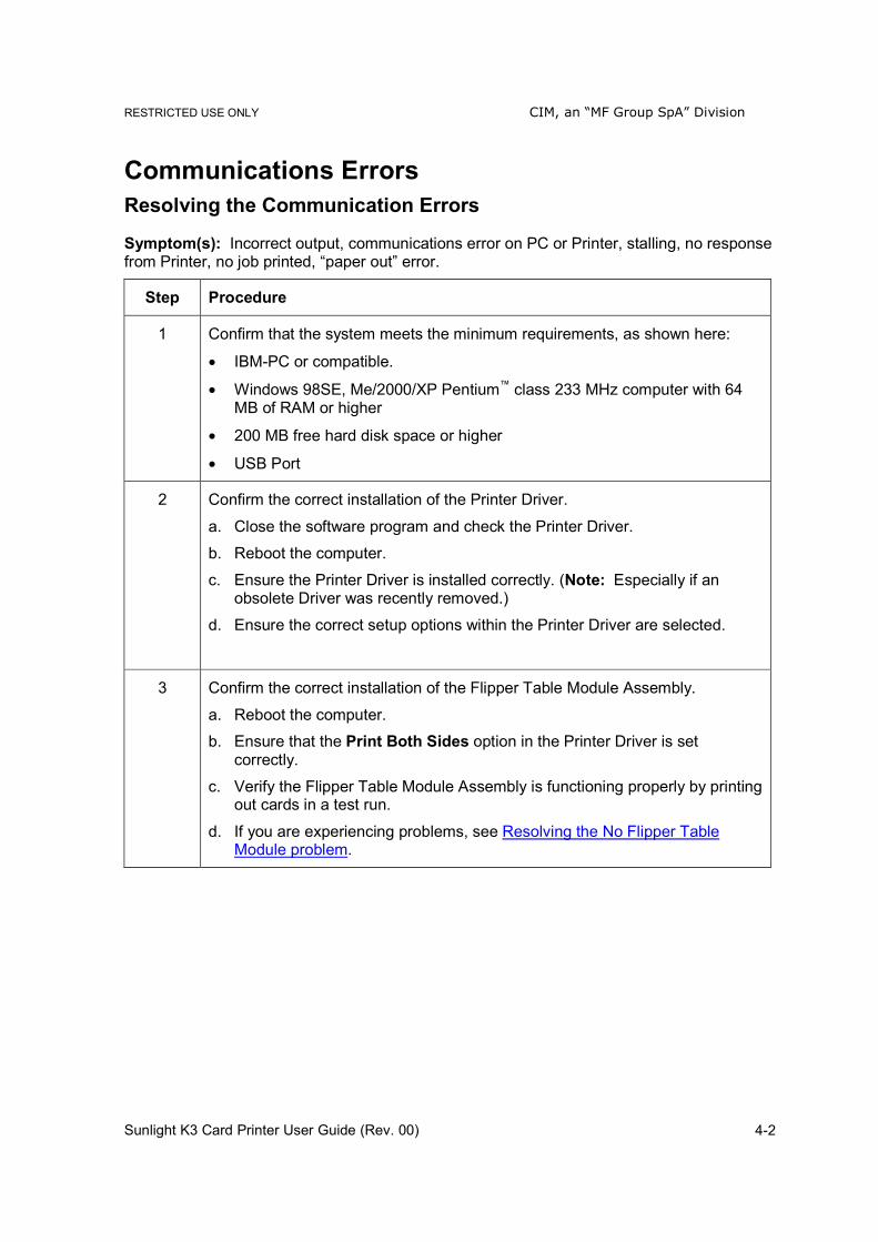
Symptom(s): Incorrect output, communications error on PC or Printer, stalling, no response from Printer, no job printed, “paper out” error.
Step Procedure
1 Confirm that the system meets the minimum requirements, as shown here:
•
IBM-PC or compatible.
• Windows 98SE, Me/2000/XP Pentium™ class 233 MHz computer with 64 MB of RAM or higher
• 200 MB free hard disk space or higher
• USB Port
2 Confirm the correct installation of the Printer Driver.
a. Close the software program and check the Printer Driver.
b. Reboot the computer.
c. Ensure the Printer Driver is installed correctly. (Note: Especially if an obsolete Driver was recently removed.)
d. Ensure the correct setup options within the Printer Driver are selected.
3 Confirm the correct installation of the Flipper Table Module Assembly.
a. Reboot the computer.
b. Ensure that the Print Both Sides option in the Printer Driver is set correctly.
c. Verify the Flipper Table Module Assembly is functioning properly by printing out cards in a test run.
d. If you are experiencing problems, see Resolving the No Flipper Table Module problem.
RESTRICTED USE ONLY CIM, an “MF Group SpA” Division
Sunlight K3 Card Printer User Guide (Rev. 00) 4-3
Resolving the Communication Errors (continued)
Step Procedure
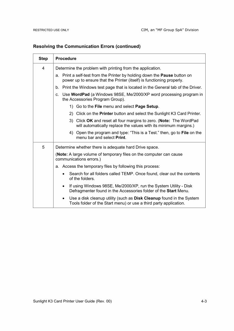
4 Determine the problem with printing from the application.
a. Print a self-test from the Printer by holding down the Pause button on power up to ensure that the Printer (itself) is functioning properly.
b. Print the Windows test page that is located in the General tab of the Driver.
c. Use WordPad (a Windows 98SE, Me/2000/XP word processing program in the Accessories Program Group).
1) Go to the File menu and select Page Setup. 2) Click on the Printer button and select the Sunlight K3 Card Printer.
3) Click OK and reset all four margins to zero. (Note: The WordPad will automatically replace the values with its minimum margins.)
4) Open the program and type: “This is a Test.” then, go to File on the menu bar and select Print.
5 Determine whether there is adequate hard Drive space.
(Note: A large volume of temporary files on the computer can cause communications errors.)
a. Access the temporary files by following this process:
• Search for all folders called TEMP. Once found, clear out the contents of the folders.
•
If using Windows 98SE, Me/2000/XP, run the System Utility - Disk Defragmenter found in the Accessories folder of the Start Menu.
•
Use a disk cleanup utility (such as Disk Cleanup found in the System Tools folder of the Start menu) or use a third party application.
RESTRICTED USE ONLY CIM, an “MF Group SpA” Division
Sunlight K3 Card Printer User Guide (Rev. 00) 4-4
Print Process Errors All Troubleshooting procedures assume that only factory-authorized supplies are in use in the Printer.
Resolving a Card Not Fed Error (Cards will not feed off the Hopper)
Step Procedure
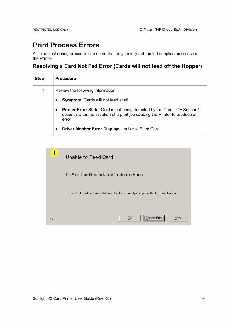
1 Review the following information.
• Symptom: Cards will not feed at all.
• Printer Error State: Card is not being detected by the Card TOF Sensor 11 seconds after the initiation of a print job causing the Printer to produce an error
• Driver Monitor Error Display: Unable to Feed Card
RESTRICTED USE ONLY CIM, an “MF Group SpA” Division
Sunlight K3 Card Printer User Guide (Rev. 00) 4-5
Resolving a Card Not Fed Error (Cards will not feed off the Hopper) (continued)
Step Procedure
2 Check the card quality / loading.
a. Remove cards from the Card Hopper.
b. Ensure that the cards are not sticking together by fanning them out and then lining them back together in a straight deck.
c. Press the Card Hopper Load Lever down until the Card Tray locks into place.
d. Load up to 100 cards into the Hopper with the print side down.
e. Close the Card Hopper Cover to release the Card Tray.
f. Press on the Resume button.
g. If the cards do not feed, continue to Step 3.
3 Press the Cancel Print button on the Driver Monitor Error Display Message.
4 Reboot the Printer by cycling the power.
5 Check the Card Feed Motor.
a. Remove all cards from the Hopper.
b. Press the Card Hopper Load Lever down until the Card Tray locks into place.
c. Using the CIM Diagnostic utility send a test print to the Printer. See the Using the Diagnostic Utility tabs.
d. Gently touch the Card Hopper Feed Roller to verify that it is turning
e. If Roller is NOT turning, continue to Step 7.
f. If Roller is turning, continue to Step 6.
6 Check Hopper Tray Spring Tension.
a. Open Card Hopper Cover.
b. Using the CIM Diagnostic utility, send a test print to the Printer. See the Using the Diagnostic Utility tabs.
c. When the Card Hopper Feed Roller engages, push up on the Card Hopper Tray.
d. If the cards feed, replace the Card Hopper Lift Spring.
e. If the cards do not feed, replace the Card Hopper Feed Roller.
RESTRICTED USE ONLY CIM, an “MF Group SpA” Division
Sunlight K3 Card Printer User Guide (Rev. 00) 4-6
Resolving a Card Not Fed Error (Cards will not feed off the Hopper) (continued)
Step Procedure
7 Card Hopper Feed Roller is not turning during a print job.
a. Remove the Printer rear cover.
b. Ensure that the Card Hopper Feed Motor power cable is securely connected to J-20 on the Printers Main Board.
c. Ensure that the Card Hopper Feed Motor power cable is securely connected to the Card Hopper Feed Motor.
d. Use the CIM Diagnostic utility to send a test print to the Printer. See the Using the Diagnostic Utility tabs.
e. If the Card Hopper Feed Motor is not moving, continue to Step 8.
8 Replace Card Hopper Feed Motor.
a. Replace the Card Hopper Feed Motor.
b. Use the CIM Diagnostic utility to send a test print to the Printer. See the Using the Diagnostic Utility tabs.
c. If the Card Hopper Feed Motor does not turn, replace the Main Board.
RESTRICTED USE ONLY CIM, an “MF Group SpA” Division
Sunlight K3 Card Printer User Guide (Rev. 00) 4-7
Resolving a Card Not Fed Error (Two (2) or more card feed at the same time)
All Troubleshooting procedures assume that only factory-authorized supplies are in use in the Printer.
Step Procedure
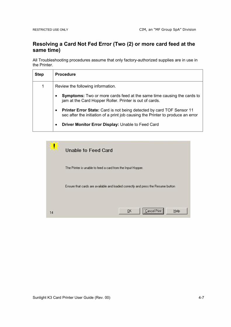
1 Review the following information.
• Symptoms: Two or more cards feed at the same time causing the cards to jam at the Card Hopper Roller. Printer is out of cards.
• Printer Error State: Card is not being detected by card TOF Sensor 11 sec after the initiation of a print job causing the Printer to produce an error
•
Driver Monitor Error Display: Unable to Feed Card

RESTRICTED USE ONLY CIM, an “MF Group SpA” Division
Sunlight K3 Card Printer User Guide (Rev. 00) 4-8
Resolving a Card Not Fed Error (Two (2) or more card feed at the same time) (continued)
Step Procedure
2 Check card quality / loading.
a. Remove cards from the Card Hopper.
b. Ensure that the cards are not sticking together by fanning them out and then lining them back together in a straight deck.
c. Press the Card Hopper Load Lever down until the Card Tray locks into place.
d. Load up to 100 cards into the Hopper with the print side down.
e. Close the Card Hopper Cover to release the Card Tray.
f. Press on the Resume button.
g. If the cards do not feed, continue to Step 3.
3 Press the Cancel Print button on the Driver Monitor Error Display Message.
4 Reboot the Printer by cycling the power.
5 Check Card Feed TOF Sensor.
a. Remove the Printers rear cover.
b. Use a digital volt meter to place the Positive lead to pin 9 of the J-4 Main Board connection and the negative lead to pin 12 of the J-4 Main Board connection.
•
The blocked Sensor should read +4.99 vdc.
• The open Sensor should read +1.5 vdc.
c. If the Card Feed TOF Sensor does not read properly, replace the Sensor.
6 Clean the Card Feed Roller.
RESTRICTED USE ONLY CIM, an “MF Group SpA” Division
Sunlight K3 Card Printer User Guide (Rev. 00) 4-9
Resolving a Ribbon RFID Error (Ribbon RFID Antenna is Corrupted)
All Troubleshooting procedures assume that only factory-authorized supplies are in use in the Printer.
Step Procedure
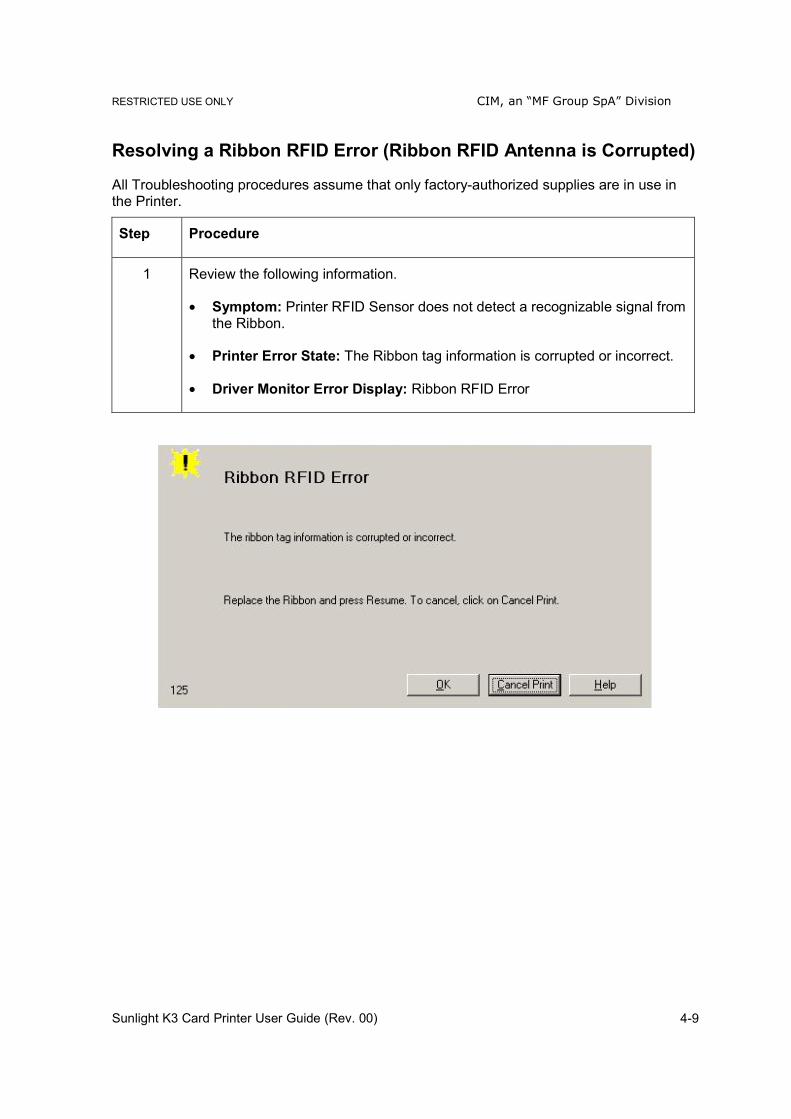
1 Review the following information.
• Symptom: Printer RFID Sensor does not detect a recognizable signal from the Ribbon.
•
Printer Error State: The Ribbon tag information is corrupted or incorrect.
• Driver Monitor Error Display: Ribbon RFID Error
RESTRICTED USE ONLY CIM, an “MF Group SpA” Division
Sunlight K3 Card Printer User Guide (Rev. 00) 4-10
Resolving a Ribbon RFID Error (Ribbon RFID Antenna is Corrupted) (continued)
Step Procedure
2 Replace the Print Ribbon
a. Replace the Print Ribbon Cartridge.
b. Press on the Resume button.
c. If the error continues, see Resolving the Ribbon RFID Error (Ribbon RFID Sensor is Corrupted) in this section.
RESTRICTED USE ONLY CIM, an “MF Group SpA” Division
Sunlight K3 Card Printer User Guide (Rev. 00) 4-11
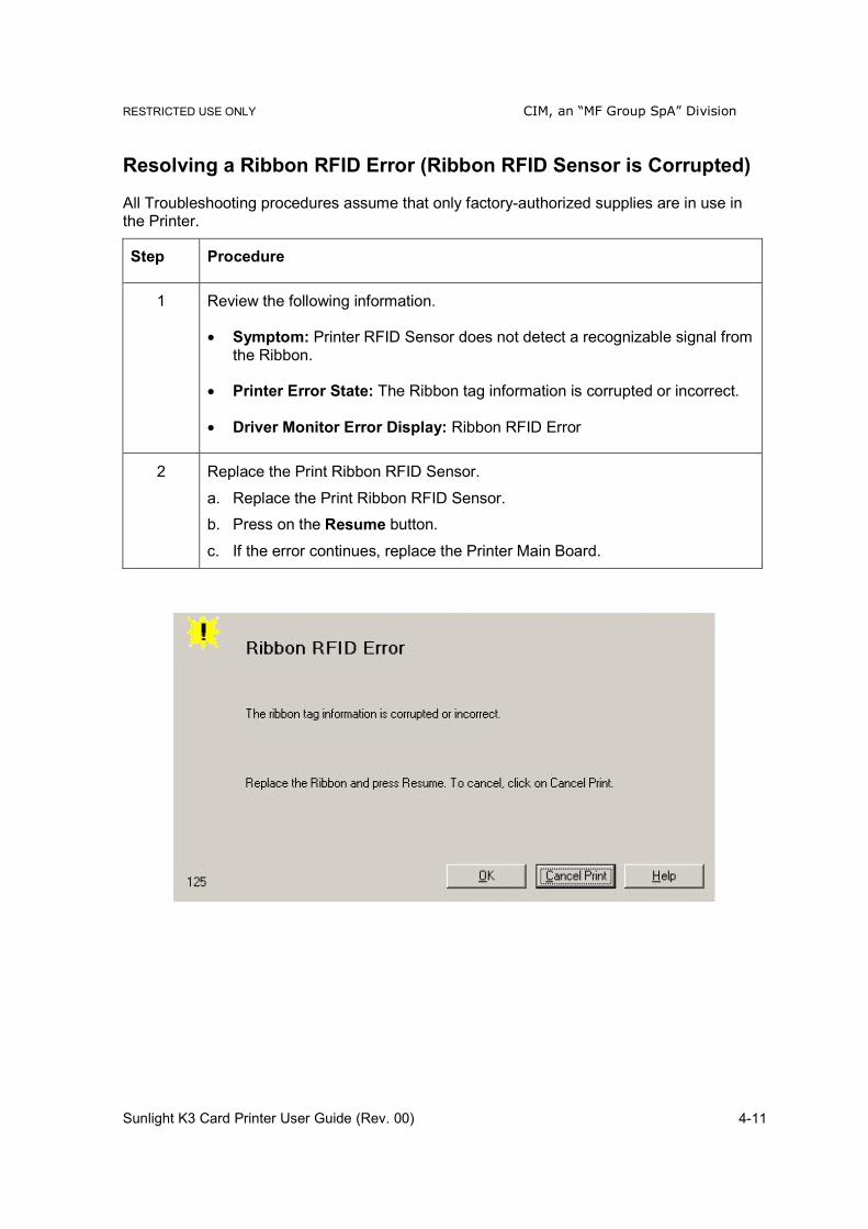
Resolving a Ribbon RFID Error (Ribbon RFID Sensor is Corrupted)
All Troubleshooting procedures assume that only factory-authorized supplies are in use in the Printer.
Step Procedure
1 Review the following information.
• Symptom: Printer RFID Sensor does not detect a recognizable signal from the Ribbon.
•
Printer Error State: The Ribbon tag information is corrupted or incorrect.
• Driver Monitor Error Display: Ribbon RFID Error
2 Replace the Print Ribbon RFID Sensor.
a. Replace the Print Ribbon RFID Sensor.
b. Press on the Resume button.
c. If the error continues, replace the Printer Main Board.
RESTRICTED USE ONLY CIM, an “MF Group SpA” Division
Sunlight K3 Card Printer User Guide (Rev. 00) 4-12
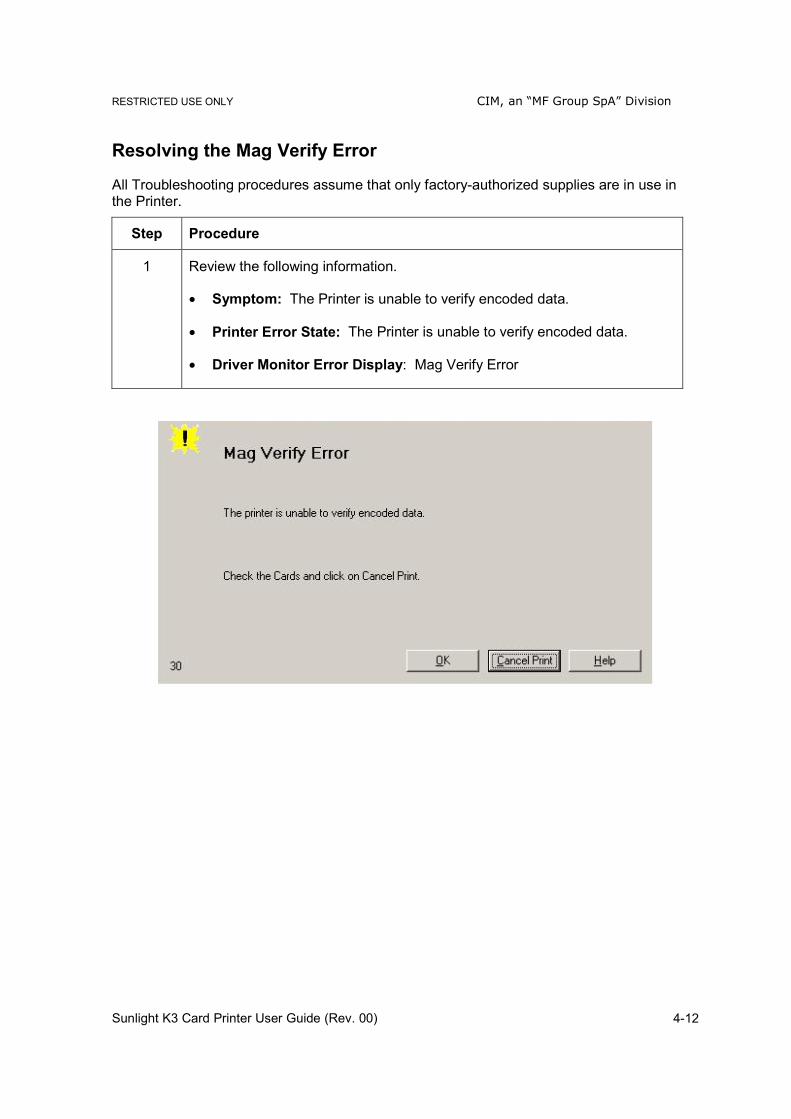
Resolving the Mag Verify Error
All Troubleshooting procedures assume that only factory-authorized supplies are in use in the Printer.
Step Procedure
1 Review the following information.
• Symptom: The Printer is unable to verify encoded data.
• Printer Error State: The Printer is unable to verify encoded data.
• Driver Monitor Error Display: Mag Verify Error
RESTRICTED USE ONLY CIM, an “MF Group SpA” Division
Sunlight K3 Card Printer User Guide (Rev. 00) 4-13
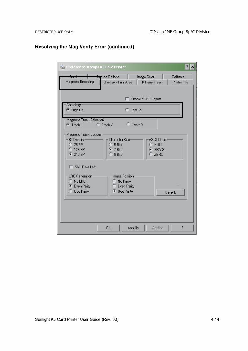
Resolving the Mag Verify Error (continued)
Step Procedure
2 Check to ensure that the cards are loaded with the Magnetic Stripe facing Up and towards the front of the Printer.
3 a. Press on the Resume button.
b. If the error continues continue to step 4
4 Verify the Driver settings if cards are loaded properly. See the Using the Magnetic Encoding tab (Sunlight K3) procedure.
5 Verify that data is being encoded to the Magnetic Stripe.
a. Clear any Error Messages by unplugging the Printer and reapplying power.
b. Remove the failed card.
c. Use a Magnetic Stripe reader or magnetic developer spray to determine if data is being written to the Magnetic Stripe.
d. If data is not being written to the Magnetic Stripe,
• Open the front cover.
•
Remove the Magnetic Module cover screw.
• Remove the Magnetic Module cover.
• Verify that the Magnetic Module is seated securely into the Magnetic Module docking station.
e. If the Magnetic Module is properly seated, replace the magnetic head (as needed). (Note: See the current Sunlight K3 User Guide for related instructions in the Parts Replacement Section.)
f. If data is being written to the Magnetic Stripe, the Magnetic Offset may need to be adjusted. See the Using the Mag Top of Form Option procedure.
6 Verify that the coercivity of the cards matches the Driver Settings.
RESTRICTED USE ONLY CIM, an “MF Group SpA” Division
Sunlight K3 Card Printer User Guide (Rev. 00) 4-14
Resolving the Mag Verify Error (continued)
RESTRICTED USE ONLY CIM, an “MF Group SpA” Division
Sunlight K3 Card Printer User Guide (Rev. 00) 4-15
Resolving the No Mag Installed Error
All Troubleshooting procedures assume that only factory-authorized supplies are in use in the Printer.
Step Procedure
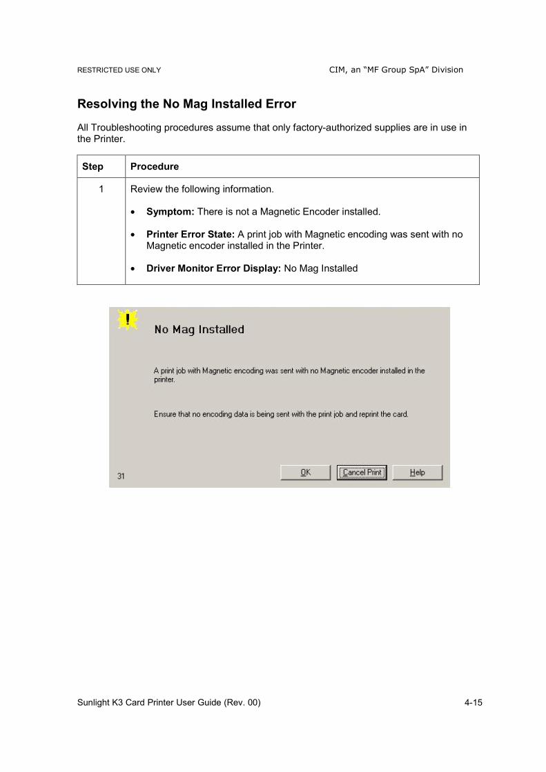
1 Review the following information.
• Symptom: There is not a Magnetic Encoder installed.
• Printer Error State: A print job with Magnetic encoding was sent with no Magnetic encoder installed in the Printer.
• Driver Monitor Error Display: No Mag Installed
RESTRICTED USE ONLY CIM, an “MF Group SpA” Division
Sunlight K3 Card Printer User Guide (Rev. 00) 4-16
Resolving the No Mag Installed Error (continued)
Step Procedure
2 Press the Cancel Print button on the Driver Monitor Error Display Message.
3 Reboot the Printer by cycling the power.
4 Verify that the Printer has a Magnetic Encoder installed.
a. Open the front cover.
b. Remove the Magnetic Module cover screw.
c. Remove the Magnetic Module cover.
d. Verify that the Printer has a Magnetic Module installed. (Note: If the Printer is equipped with a Magnetic Encoder Module, ensure that it is seated securely into the Magnetic Module docking station. If the issue persists, replace the Magnetic Module. See the Sunlight K3 service manual for replacement procedures.)
5 If the Printer has no Magnetic Encoder Module, verify that the encoding data was sent in error, check the appropriate software user’s manual for encoding instructions.
RESTRICTED USE ONLY CIM, an “MF Group SpA” Division
Sunlight K3 Card Printer User Guide (Rev. 00) 4-17
Resolving a Ribbon Sensor Error (Ribbon Miscue)
All Troubleshooting procedures assume that only factory-authorized supplies are in use in the Printer.
NOTE: Using the printer in direct Sunlight may adversely affect the ribbon sensor integrity.
Step Procedure
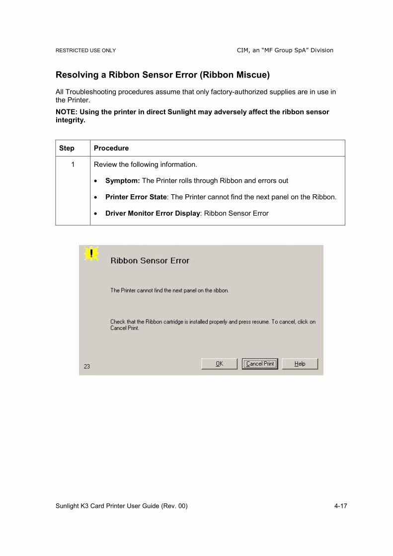
1 Review the following information.
• Symptom: The Printer rolls through Ribbon and errors out
•
Printer Error State: The Printer cannot find the next panel on the Ribbon.
• Driver Monitor Error Display: Ribbon Sensor Error
RESTRICTED USE ONLY CIM, an “MF Group SpA” Division
Sunlight K3 Card Printer User Guide (Rev. 00) 4-18
Resolving a Ribbon Sensor Error (Ribbon Miscue) (continued)
Step Procedure
2 Open the front cover and remove the Ribbon Cartridge.
a. Check that the Ribbon is in good condition and not wrinkled or broken.
b. If Ribbon is broke or wrinkled, repair the Ribbon and wind up the take-up roll 4-color panels past the damaged area.
3 Press on the Resume button.
If the issue persists, continue to Step 4.
4 Replace the Ribbon Cartridge.
a. Press on the Resume button.
b. If the issue persists, continue to Step 5.
5 Press the Cancel Print button on the Driver Monitor Error Display Message.
6 Reboot the Printer by cycling the power.
7 Use the Driver Calibration tab to calibrate the Ribbon Sensor. Cover the front of the printer to block the light while calibrating this sensor.
• If the issue persists, continue to Step 8.
8 Replace the Ribbon Sensor.
RESTRICTED USE ONLY CIM, an “MF Group SpA” Division
Sunlight K3 Card Printer User Guide (Rev. 00) 4-19
Resolving a Ribbon Break Jam Error
All Troubleshooting procedures assume that only factory-authorized supplies are in use in the Printer.
NOTE: Using the printer in direct Sunlight may adversely affect the ribbon sensor integrity.
Step Procedure
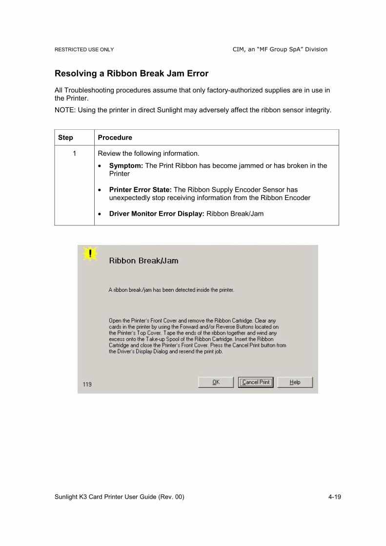
1 Review the following information.
• Symptom: The Print Ribbon has become jammed or has broken in the Printer
• Printer Error State: The Ribbon Supply Encoder Sensor has unexpectedly stop receiving information from the Ribbon Encoder
•
Driver Monitor Error Display: Ribbon Break/Jam
RESTRICTED USE ONLY CIM, an “MF Group SpA” Division
Sunlight K3 Card Printer User Guide (Rev. 00) 4-20
Resolving a Ribbon Break Jam Error (continued)
Step Procedure
2 Open the front cover and remove the Ribbon Cartridge.
• If Ribbon is broken, continue to Step 3.
• If Ribbon is in good condition, continue to Step 6.
3 Adjust the print offset. See the Using the Print Top of Form Option procedure.
If the issue persists, continue to Step 4.
4 Repair the Ribbon and wind up the take-up roll 4 color panels past the damaged area.
a. Press on the Resume button.
b. If the issue persists, continue to Step 5.
5 Use the CIM Diagnostic utility to cycle the Printhead to ensure proper printhead operation. See the Using the Diagnostic Utility tabs procedure.
•
If the Printhead does not cycle properly, see Resolving the Headlift Motor / Sensor Error.
•
If the Printhead functions properly, continue to Step 6.
6 Replace the Ribbon Cartridge.
a. Press on the Resume button.
b. If the issue persists, continue to Step 7.
7 Remove the rear cover in order to check that the Ribbon Encoder Sensor is securely connected to the J-4 Main Board connection and to the Encoder Sensor.
a. Press on the Resume button.
b. If the issue persists, replace the Encoder Sensor.
RESTRICTED USE ONLY CIM, an “MF Group SpA” Division
Sunlight K3 Card Printer User Guide (Rev. 00) 4-21
Resolving a Ribbon Out Error
All Troubleshooting procedures assume that only factory-authorized supplies are in use in the Printer.
NOTE: Using the printer in direct Sunlight may adversely affect the ribbon sensor integrity.
Step Procedure
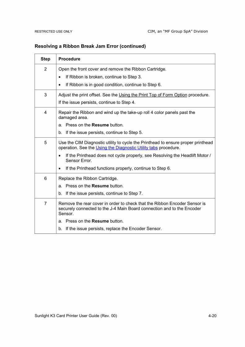
1 Review the following information.
• Symptom: Printer will not print.
•
Printer Error State: The Ribbon Sensor has detected the End Of Ribbon mark
• Driver Monitor Error Display: Ribbon Out
2 Replace the Ribbon Cartridge
a. Press on the Resume button.
RESTRICTED USE ONLY CIM, an “MF Group SpA” Division
Sunlight K3 Card Printer User Guide (Rev. 00) 4-22
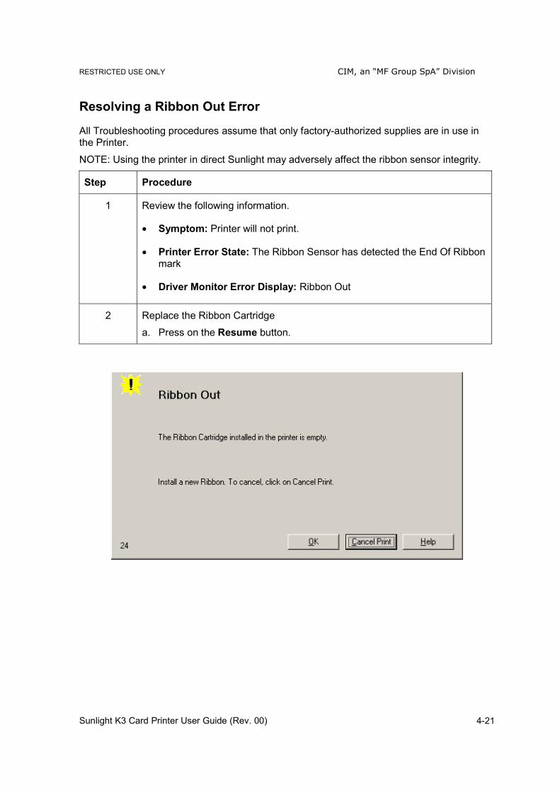
Resolving a No Ribbon Installed Error
All Troubleshooting procedures assume that only factory-authorized supplies are in use in the Printer.
Step Procedure
1 Review the following information.
• Symptom: Printer errors out as soon as it receives data from PC
• Printer Error State: The Printer RFID Sensor is not receiving a signal from the Ribbon
• Driver Monitor Error Display: No Ribbon Installed
RESTRICTED USE ONLY CIM, an “MF Group SpA” Division
Sunlight K3 Card Printer User Guide (Rev. 00) 4-23
Resolving a No Ribbon Installed Error (continued)
Step Procedure
2 Verify that a Ribbon Cartridge is installed in the Printer.
a. Press on the Resume button.
b. If the issue persists, continue to Step 3.
3 Remove the rear cover and check that the Ribbon RFID cable is securely connected to the Main Board (J-5) and the RFID Sensor.
• If the connections are loose, reattach them.
• Press on the Resume button.
• If the connections are good or if the issue persists, continue to Step 4.
4 Replace the Ribbon RFID Sensor.
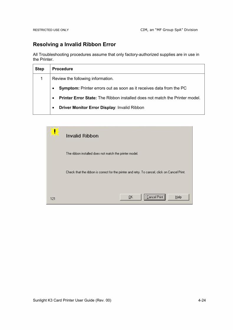
RESTRICTED USE ONLY CIM, an “MF Group SpA” Division
Sunlight K3 Card Printer User Guide (Rev. 00) 4-24
Resolving a Invalid Ribbon Error
All Troubleshooting procedures assume that only factory-authorized supplies are in use in the Printer.
Step Procedure
1 Review the following information.
• Symptom: Printer errors out as soon as it receives data from the PC
• Printer Error State: The Ribbon installed does not match the Printer model.
• Driver Monitor Error Display: Invalid Ribbon
RESTRICTED USE ONLY CIM, an “MF Group SpA” Division
Sunlight K3 Card Printer User Guide (Rev. 00) 4-25
Resolving a Invalid Ribbon Error (continued)
Step Procedure
2 Verify that the Ribbon Cartridge installed is designed for the correct Printer model.
3 Press on the Resume button.
If the issue persists, continue to Step 4.
4 Remove the rear cover and check that the Ribbon RFID cable is securely connected to the Main Board (J-5) and the RFID Sensor.
• If the connections are loose, reattach
• Press on the Resume button..
•
If the connections are good or if the issue persists, continue to Step 5.
5 Replace the Ribbon RFID Sensor.
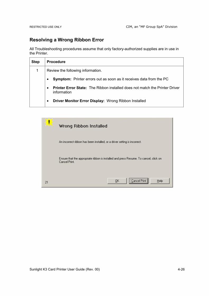
RESTRICTED USE ONLY CIM, an “MF Group SpA” Division
Sunlight K3 Card Printer User Guide (Rev. 00) 4-26
Resolving a Wrong Ribbon Error
All Troubleshooting procedures assume that only factory-authorized supplies are in use in the Printer.
Step Procedure
1 Review the following information.
• Symptom: Printer errors out as soon as it receives data from the PC
• Printer Error State: The Ribbon installed does not match the Printer Driver information
• Driver Monitor Error Display: Wrong Ribbon Installed
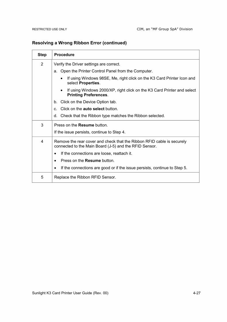
RESTRICTED USE ONLY CIM, an “MF Group SpA” Division
Sunlight K3 Card Printer User Guide (Rev. 00) 4-27
Resolving a Wrong Ribbon Error (continued)
Step Procedure
2 Verify the Driver settings are correct.
a. Open the Printer Control Panel from the Computer.
• If using Windows 98SE, Me, right click on the K3 Card Printer Icon and select Properties.
• If using Windows 2000/XP, right click on the K3 Card Printer and select Printing Preferences.
b. Click on the Device Option tab.
c. Click on the auto select button.
d. Check that the Ribbon type matches the Ribbon selected.
3 Press on the Resume button.
If the issue persists, continue to Step 4.
4 Remove the rear cover and check that the Ribbon RFID cable is securely connected to the Main Board (J-5) and the RFID Sensor.
• If the connections are loose, reattach it.
• Press on the Resume button.
•
If the connections are good or if the issue persists, continue to Step 5.
5 Replace the Ribbon RFID Sensor.
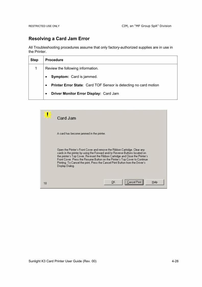
RESTRICTED USE ONLY CIM, an “MF Group SpA” Division
Sunlight K3 Card Printer User Guide (Rev. 00) 4-28
Resolving a Card Jam Error
All Troubleshooting procedures assume that only factory-authorized supplies are in use in the Printer.
Step Procedure
1 Review the following information.
• Symptom: Card is jammed.
• Printer Error State: Card TOF Sensor is detecting no card motion
• Driver Monitor Error Display: Card Jam
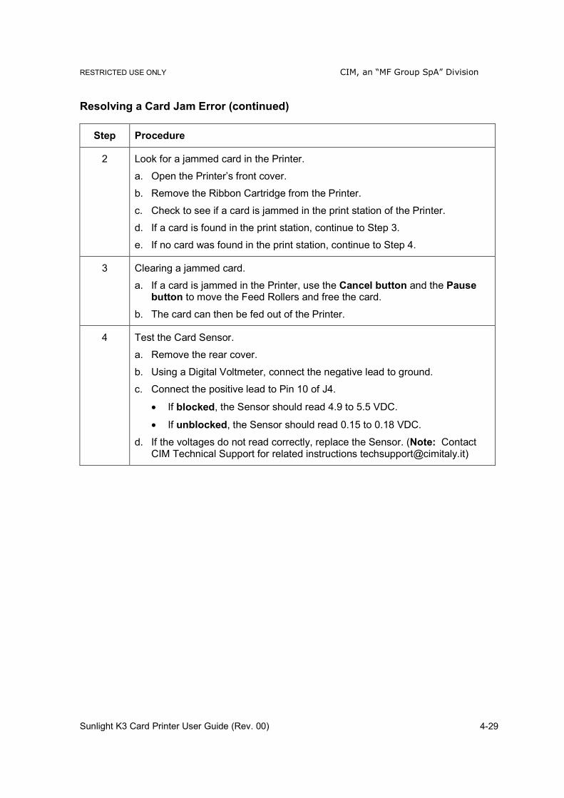
RESTRICTED USE ONLY CIM, an “MF Group SpA” Division
Sunlight K3 Card Printer User Guide (Rev. 00) 4-29
Resolving a Card Jam Error (continued)
Step Procedure
2 Look for a jammed card in the Printer.
a. Open the Printer’s front cover.
b. Remove the Ribbon Cartridge from the Printer.
c. Check to see if a card is jammed in the print station of the Printer.
d. If a card is found in the print station, continue to Step 3.
e. If no card was found in the print station, continue to Step 4.
3 Clearing a jammed card.
a. If a card is jammed in the Printer, use the Cancel button and the Pause button to move the Feed Rollers and free the card.
b. The card can then be fed out of the Printer.
4 Test the Card Sensor.
a. Remove the rear cover.
b. Using a Digital Voltmeter, connect the negative lead to ground.
c. Connect the positive lead to Pin 10 of J4.
•
If blocked, the Sensor should read 4.9 to 5.5 VDC.
• If unblocked, the Sensor should read 0.15 to 0.18 VDC.
d. If the voltages do not read correctly, replace the Sensor. (Note: Contact CIM Technical Support for related instructions [email protected])
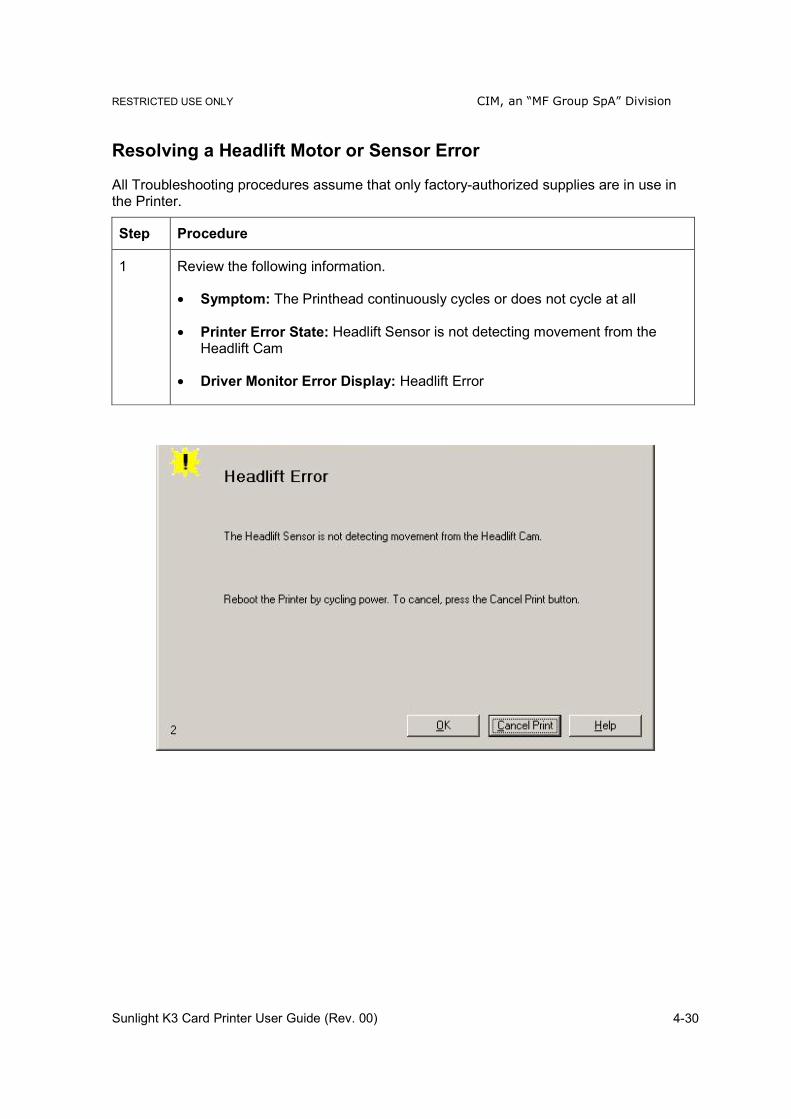
RESTRICTED USE ONLY CIM, an “MF Group SpA” Division
Sunlight K3 Card Printer User Guide (Rev. 00) 4-30
Resolving a Headlift Motor or Sensor Error
All Troubleshooting procedures assume that only factory-authorized supplies are in use in the Printer.
Step Procedure
1 Review the following information.
• Symptom: The Printhead continuously cycles or does not cycle at all
• Printer Error State: Headlift Sensor is not detecting movement from the Headlift Cam
• Driver Monitor Error Display: Headlift Error

RESTRICTED USE ONLY CIM, an “MF Group SpA” Division
Sunlight K3 Card Printer User Guide (Rev. 00) 4-31
Resolving a Headlift Motor or Sensor Error (continued)
Step Procedure
2 Press the Cancel Print button on the Driver Monitor Error Display Message.
3 Reboot the Printer by cycling the power.
4 Cycle the Headlift Motors.
a. Use the CIM Diagnostic utility to cycle the Printhead to ensure proper printhead operation. See the Using the Diagnostic Utility tabs.
a. Verify that the Headlift Motor turns.
b. If the Motor does not turn or jams, continue to Step 5.
5 Check the Headlift Motor Main Board Connection (J20).
a. Unplug the Printer.
b. Remove the back cover.
c. Verify that connection J20 is properly connected to the Main Board.
d. If the Motor does not turn, continue to Step 7.
6 Test the Headlift Sensor.
a. Remove the back cover.
b. Attach the positive lead from a Digital Voltmeter to Pin 1 of J9. Attach the negative lead to the Pin 3 of J9.
• If open, the Sensor should read 0.17 to 0.9 VDC.
•
If closed, the Sensor should read 4.9 to 5.5 VDC.
c. Replace the Sensor if the voltages do not read correctly. (Note: Contact CIM Technical Support for related instructions [email protected])
d. If the Motor does turn, continue to Step 7.
7 Replace the Headlift Motor. (Note: Contact CIM Technical Support for related instructions [email protected])
a. If the Motor does turn, continue to Step 8.
8 Replace the Main Board.
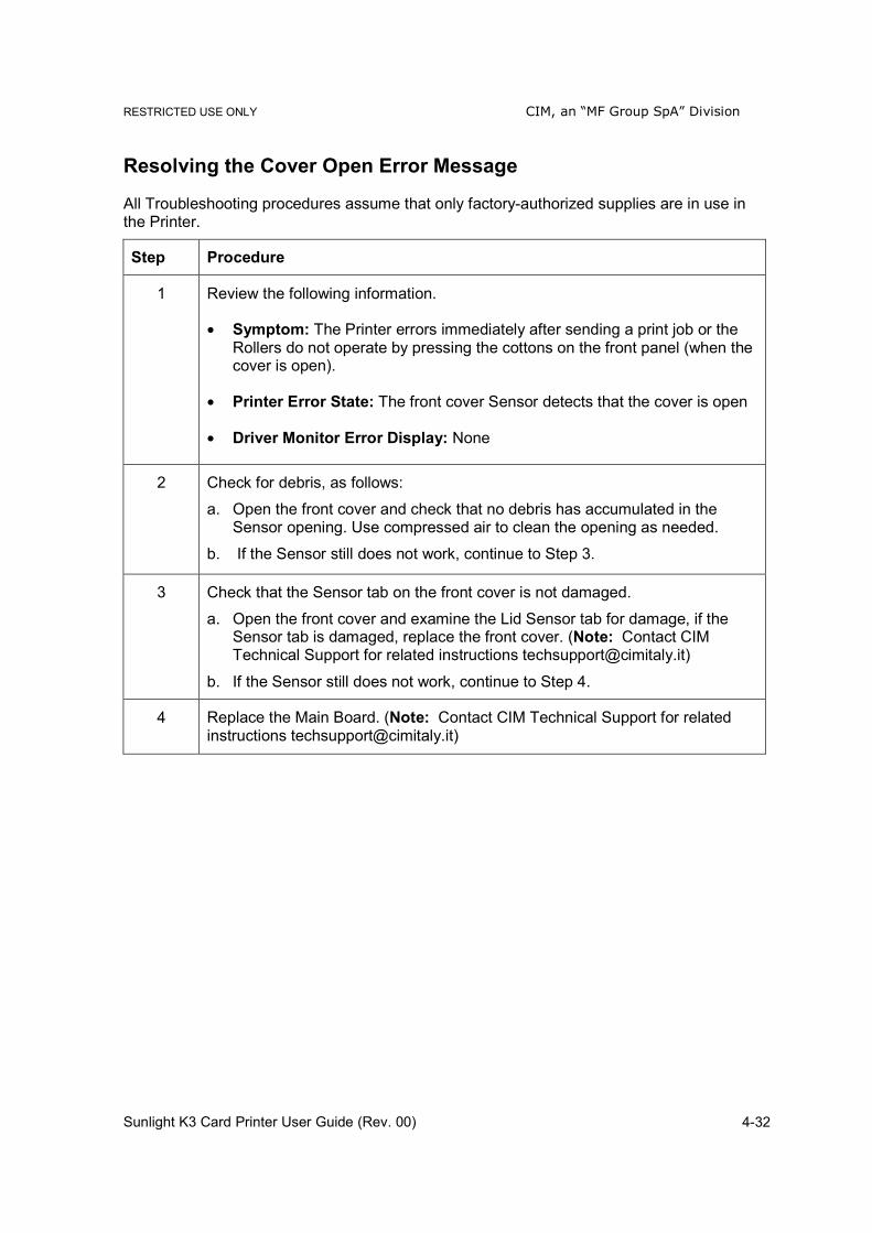
RESTRICTED USE ONLY CIM, an “MF Group SpA” Division
Sunlight K3 Card Printer User Guide (Rev. 00) 4-32
Resolving the Cover Open Error Message
All Troubleshooting procedures assume that only factory-authorized supplies are in use in the Printer.
Step Procedure
1 Review the following information.
• Symptom: The Printer errors immediately after sending a print job or the Rollers do not operate by pressing the cottons on the front panel (when the cover is open).
• Printer Error State: The front cover Sensor detects that the cover is open
• Driver Monitor Error Display: None
2 Check for debris, as follows:
a. Open the front cover and check that no debris has accumulated in the Sensor opening. Use compressed air to clean the opening as needed.
b. If the Sensor still does not work, continue to Step 3.
3 Check that the Sensor tab on the front cover is not damaged.
a. Open the front cover and examine the Lid Sensor tab for damage, if the Sensor tab is damaged, replace the front cover. (Note: Contact CIM Technical Support for related instructions [email protected])
b. If the Sensor still does not work, continue to Step 4.
4 Replace the Main Board. (Note: Contact CIM Technical Support for related instructions [email protected])
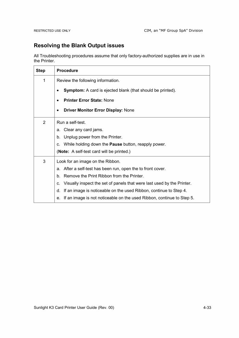
RESTRICTED USE ONLY CIM, an “MF Group SpA” Division
Sunlight K3 Card Printer User Guide (Rev. 00) 4-33
Resolving the Blank Output issues
All Troubleshooting procedures assume that only factory-authorized supplies are in use in the Printer.
Step Procedure
1 Review the following information.
• Symptom: A card is ejected blank (that should be printed).
• Printer Error State: None
• Driver Monitor Error Display: None
2 Run a self-test.
a. Clear any card jams.
b. Unplug power from the Printer.
c. While holding down the Pause button, reapply power.
(Note: A self-test card will be printed.)
3 Look for an image on the Ribbon.
a. After a self-test has been run, open the to front cover.
b. Remove the Print Ribbon from the Printer.
c. Visually inspect the set of panels that were last used by the Printer.
d. If an image is noticeable on the used Ribbon, continue to Step 4.
e. If an image is not noticeable on the used Ribbon, continue to Step 5.
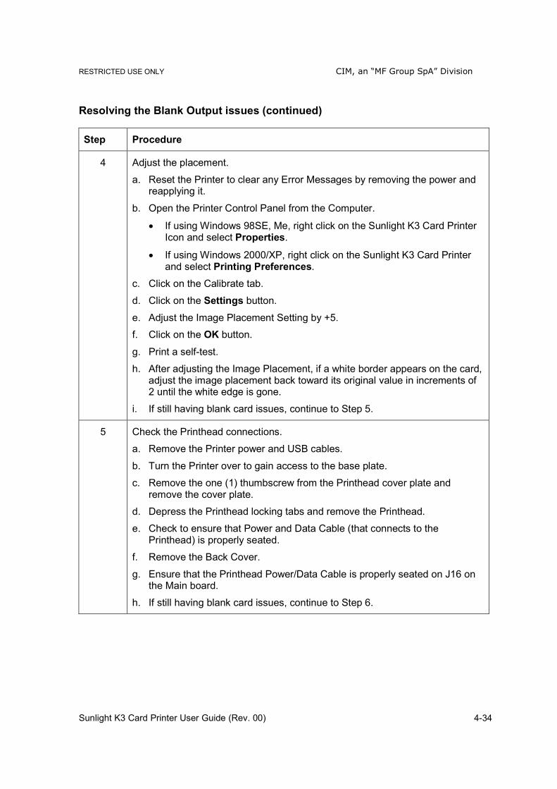
RESTRICTED USE ONLY CIM, an “MF Group SpA” Division
Sunlight K3 Card Printer User Guide (Rev. 00) 4-34
Resolving the Blank Output issues (continued)
Step Procedure
4 Adjust the placement.
a. Reset the Printer to clear any Error Messages by removing the power and reapplying it.
b. Open the Printer Control Panel from the Computer.
•
If using Windows 98SE, Me, right click on the Sunlight K3 Card Printer Icon and select Properties.
•
If using Windows 2000/XP, right click on the Sunlight K3 Card Printer and select Printing Preferences.
c. Click on the Calibrate tab.
d. Click on the Settings button.
e. Adjust the Image Placement Setting by +5.
f. Click on the OK button.
g. Print a self-test.
h. After adjusting the Image Placement, if a white border appears on the card, adjust the image placement back toward its original value in increments of 2 until the white edge is gone.
i. If still having blank card issues, continue to Step 5.
5 Check the Printhead connections.
a. Remove the Printer power and USB cables.
b. Turn the Printer over to gain access to the base plate.
c. Remove the one (1) thumbscrew from the Printhead cover plate and remove the cover plate.
d. Depress the Printhead locking tabs and remove the Printhead.
e. Check to ensure that Power and Data Cable (that connects to the Printhead) is properly seated.
f. Remove the Back Cover.
g. Ensure that the Printhead Power/Data Cable is properly seated on J16 on the Main board.
h. If still having blank card issues, continue to Step 6.
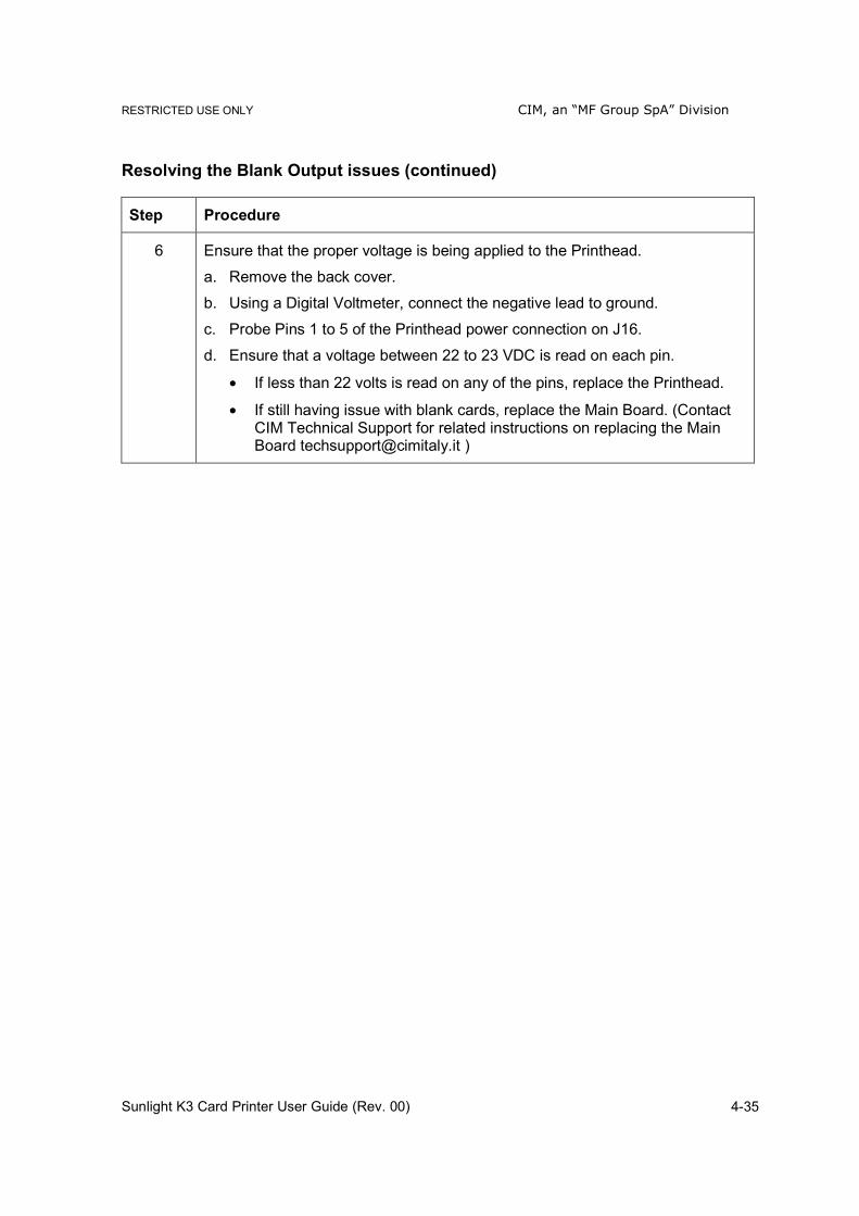
RESTRICTED USE ONLY CIM, an “MF Group SpA” Division
Sunlight K3 Card Printer User Guide (Rev. 00) 4-35
Resolving the Blank Output issues (continued)
Step Procedure
6 Ensure that the proper voltage is being applied to the Printhead.
a. Remove the back cover.
b. Using a Digital Voltmeter, connect the negative lead to ground.
c. Probe Pins 1 to 5 of the Printhead power connection on J16.
d. Ensure that a voltage between 22 to 23 VDC is read on each pin.
• If less than 22 volts is read on any of the pins, replace the Printhead.
• If still having issue with blank cards, replace the Main Board. (Contact CIM Technical Support for related instructions on replacing the Main Board [email protected] )
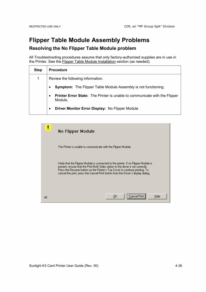
RESTRICTED USE ONLY CIM, an “MF Group SpA” Division
Sunlight K3 Card Printer User Guide (Rev. 00) 4-36
Flipper Table Module Assembly Problems Resolving the No Flipper Table Module problem
All Troubleshooting procedures assume that only factory-authorized supplies are in use in the Printer. See the Flipper Table Module Installation section (as needed).
Step Procedure
1 Review the following information.
• Symptom: The Flipper Table Module Assembly is not functioning.
• Printer Error State: The Printer is unable to communicate with the Flipper Module.
• Driver Monitor Error Display: No Flipper Module
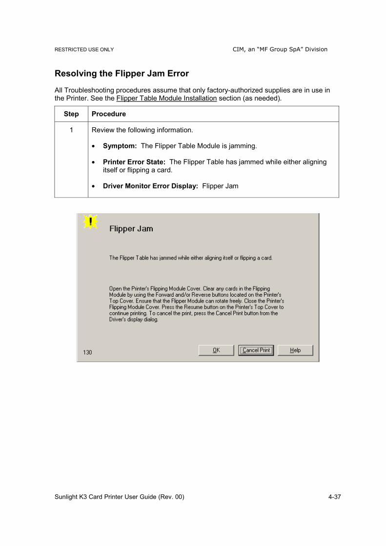
RESTRICTED USE ONLY CIM, an “MF Group SpA” Division
Sunlight K3 Card Printer User Guide (Rev. 00) 4-37
Resolving the Flipper Jam Error
All Troubleshooting procedures assume that only factory-authorized supplies are in use in the Printer. See the Flipper Table Module Installation section (as needed).
Step Procedure
1 Review the following information.
• Symptom: The Flipper Table Module is jamming.
• Printer Error State: The Flipper Table has jammed while either aligning itself or flipping a card.
• Driver Monitor Error Display: Flipper Jam
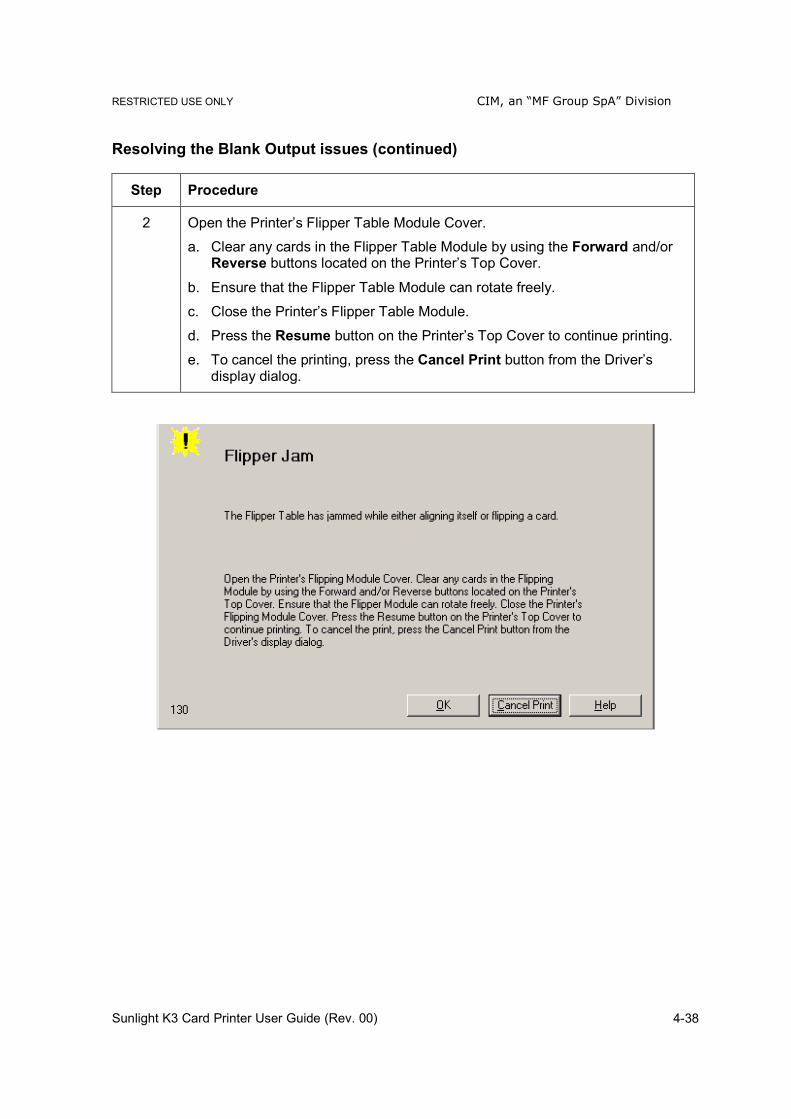
RESTRICTED USE ONLY CIM, an “MF Group SpA” Division
Sunlight K3 Card Printer User Guide (Rev. 00) 4-38
Resolving the Blank Output issues (continued)
Step Procedure
2 Open the Printer’s Flipper Table Module Cover.
a. Clear any cards in the Flipper Table Module by using the Forward and/or Reverse buttons located on the Printer’s Top Cover.
b. Ensure that the Flipper Table Module can rotate freely.
c. Close the Printer’s Flipper Table Module.
d. Press the Resume button on the Printer’s Top Cover to continue printing.
e. To cancel the printing, press the Cancel Print button from the Driver’s display dialog.
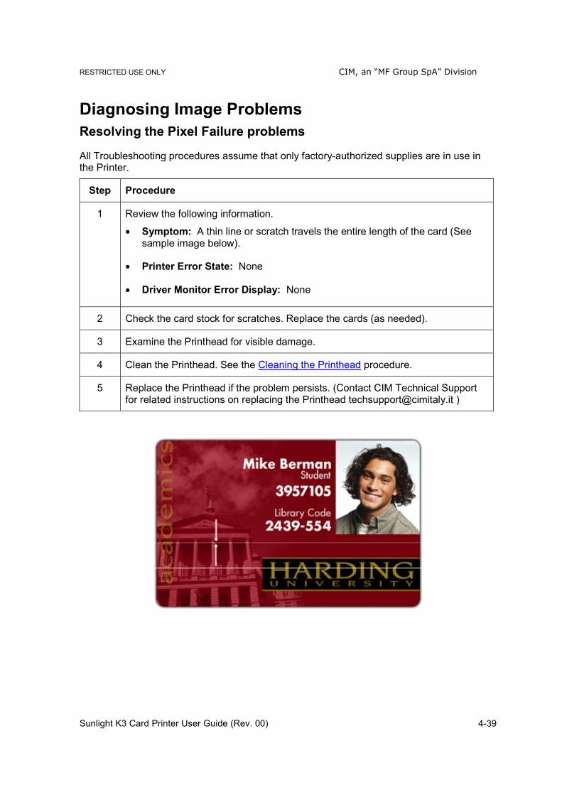
RESTRICTED USE ONLY CIM, an “MF Group SpA” Division
Sunlight K3 Card Printer User Guide (Rev. 00) 4-39
Diagnosing Image Problems Resolving the Pixel Failure problems
All Troubleshooting procedures assume that only factory-authorized supplies are in use in the Printer.
Step Procedure
1 Review the following information.
• Symptom: A thin line or scratch travels the entire length of the card (See sample image below).
• Printer Error State: None
•
Driver Monitor Error Display: None
2 Check the card stock for scratches. Replace the cards (as needed).
3 Examine the Printhead for visible damage.
4 Clean the Printhead. See the Cleaning the Printhead procedure.
5 Replace the Printhead if the problem persists. (Contact CIM Technical Support for related instructions on replacing the Printhead [email protected] )
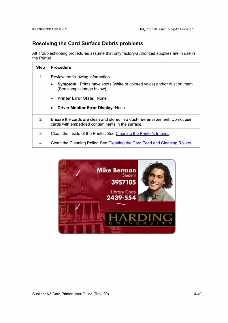
RESTRICTED USE ONLY CIM, an “MF Group SpA” Division
Sunlight K3 Card Printer User Guide (Rev. 00) 4-40
Resolving the Card Surface Debris problems
All Troubleshooting procedures assume that only factory-authorized supplies are in use in the Printer.
Step Procedure
1 Review the following information.
• Symptom: Prints have spots (white or colored voids) and/or dust on them (See sample image below).
• Printer Error State: None
•
Driver Monitor Error Display: None
2 Ensure the cards are clean and stored in a dust-free environment. Do not use cards with embedded contaminants in the surface.
3 Clean the inside of the Printer. See Cleaning the Printer's Interior.
4 Clean the Cleaning Roller. See Cleaning the Card Feed and Cleaning Rollers.
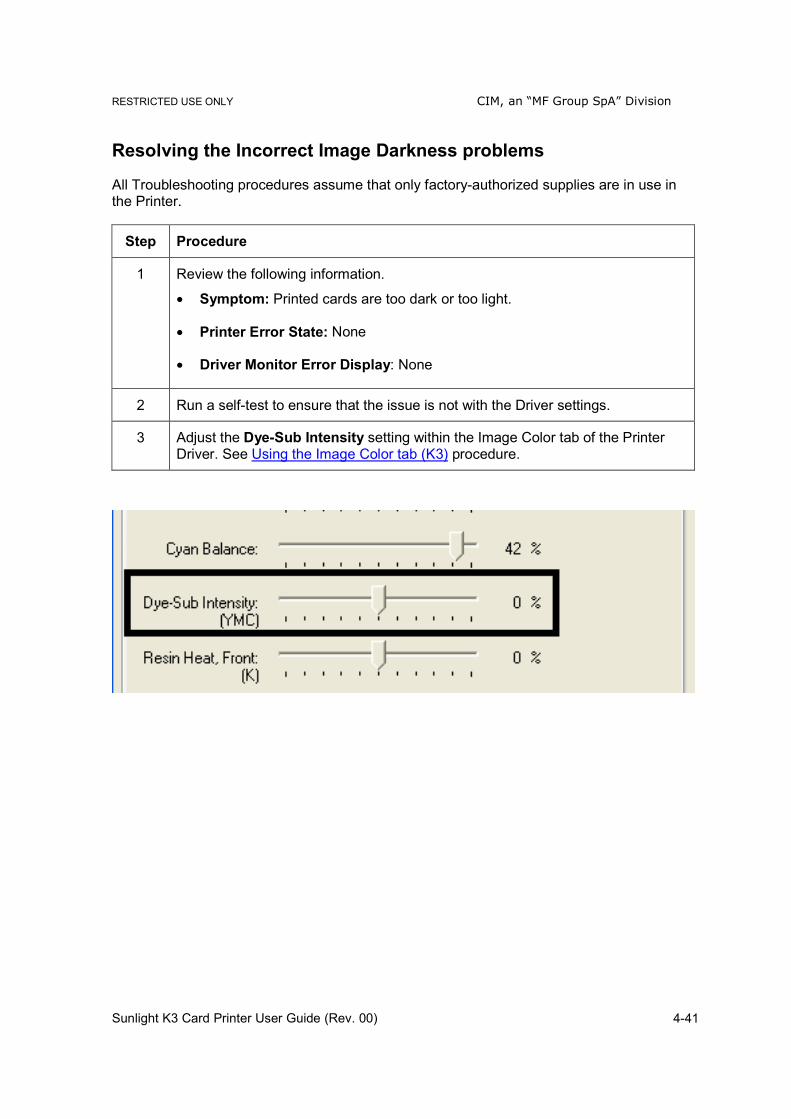
RESTRICTED USE ONLY CIM, an “MF Group SpA” Division
Sunlight K3 Card Printer User Guide (Rev. 00) 4-41
Resolving the Incorrect Image Darkness problems
All Troubleshooting procedures assume that only factory-authorized supplies are in use in the Printer.
Step Procedure
1 Review the following information.
• Symptom: Printed cards are too dark or too light.
• Printer Error State: None
• Driver Monitor Error Display: None
2 Run a self-test to ensure that the issue is not with the Driver settings.
3 Adjust the Dye-Sub Intensity setting within the Image Color tab of the Printer Driver. See Using the Image Color tab (K3) procedure.
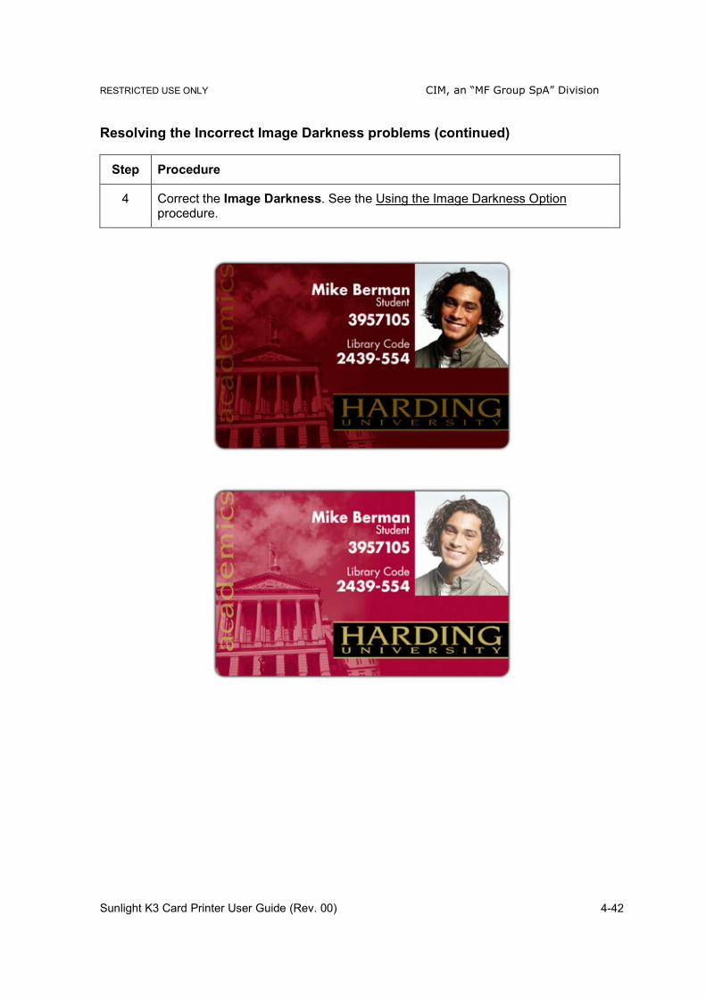
RESTRICTED USE ONLY CIM, an “MF Group SpA” Division
Sunlight K3 Card Printer User Guide (Rev. 00) 4-42
Resolving the Incorrect Image Darkness problems (continued)
Step Procedure
4 Correct the Image Darkness. See the Using the Image Darkness Option procedure.
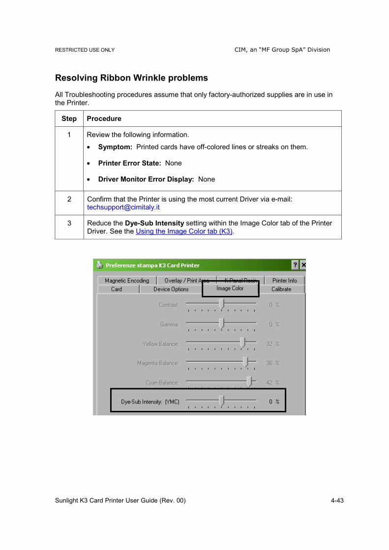
RESTRICTED USE ONLY CIM, an “MF Group SpA” Division
Sunlight K3 Card Printer User Guide (Rev. 00) 4-43
Resolving Ribbon Wrinkle problems
All Troubleshooting procedures assume that only factory-authorized supplies are in use in the Printer.
Step Procedure
1 Review the following information.
• Symptom: Printed cards have off-colored lines or streaks on them.
• Printer Error State: None
• Driver Monitor Error Display: None
2 Confirm that the Printer is using the most current Driver via e-mail: [email protected]
3 Reduce the Dye-Sub Intensity setting within the Image Color tab of the Printer Driver. See the Using the Image Color tab (K3).

RESTRICTED USE ONLY CIM, an “MF Group SpA” Division
Sunlight K3 Card Printer User Guide (Rev. 00) 4-44
Resolving Ribbon Wrinkle problems (continued)
Step Procedure
4 Reduce the Image Darkness. See the Using the Image Darkness Option procedure.
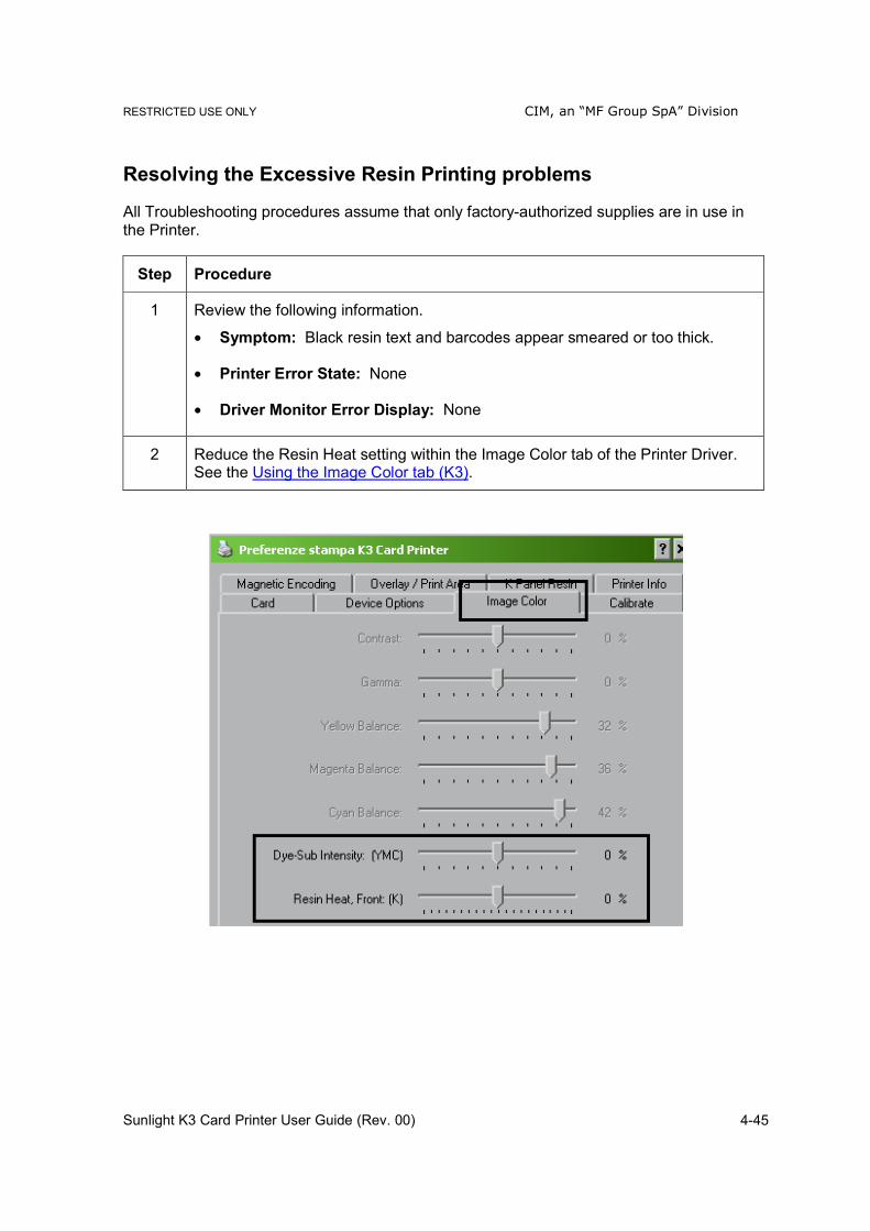
RESTRICTED USE ONLY CIM, an “MF Group SpA” Division
Sunlight K3 Card Printer User Guide (Rev. 00) 4-45
Resolving the Excessive Resin Printing problems
All Troubleshooting procedures assume that only factory-authorized supplies are in use in the Printer.
Step Procedure
1 Review the following information.
• Symptom: Black resin text and barcodes appear smeared or too thick.
• Printer Error State: None
• Driver Monitor Error Display: None
2 Reduce the Resin Heat setting within the Image Color tab of the Printer Driver. See the Using the Image Color tab (K3).
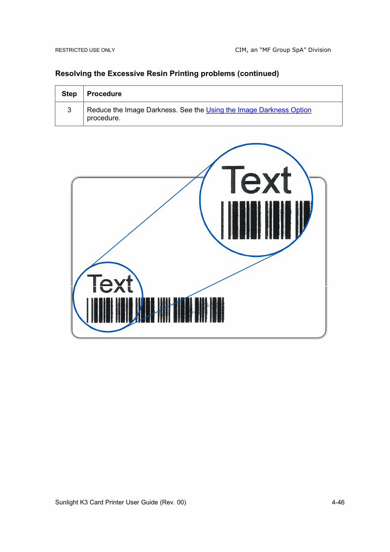
RESTRICTED USE ONLY CIM, an “MF Group SpA” Division
Sunlight K3 Card Printer User Guide (Rev. 00) 4-46
Resolving the Excessive Resin Printing problems (continued)
Step Procedure
3 Reduce the Image Darkness. See the Using the Image Darkness Option procedure.
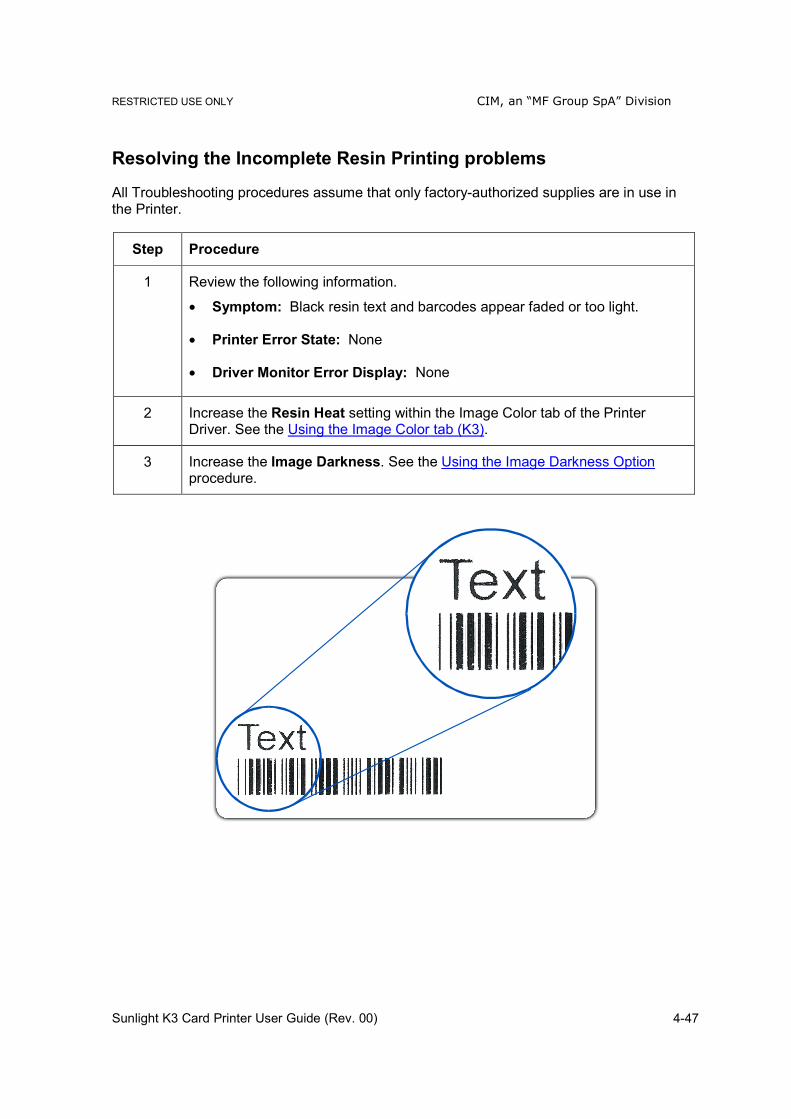
RESTRICTED USE ONLY CIM, an “MF Group SpA” Division
Sunlight K3 Card Printer User Guide (Rev. 00) 4-47
Resolving the Incomplete Resin Printing problems
All Troubleshooting procedures assume that only factory-authorized supplies are in use in the Printer.
Step Procedure
1 Review the following information.
• Symptom: Black resin text and barcodes appear faded or too light.
• Printer Error State: None
• Driver Monitor Error Display: None
2 Increase the Resin Heat setting within the Image Color tab of the Printer Driver. See the Using the Image Color tab (K3).
3 Increase the Image Darkness. See the Using the Image Darkness Option procedure.
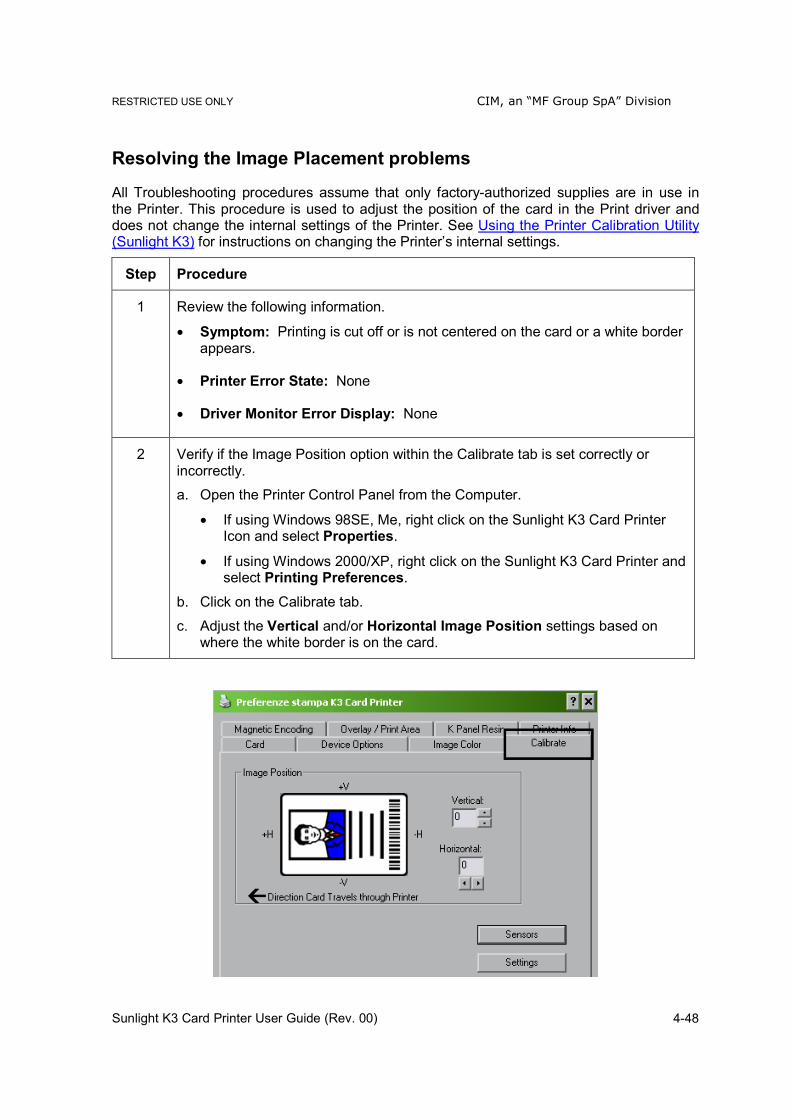
RESTRICTED USE ONLY CIM, an “MF Group SpA” Division
Sunlight K3 Card Printer User Guide (Rev. 00) 4-48
Resolving the Image Placement problems
All Troubleshooting procedures assume that only factory-authorized supplies are in use in the Printer. This procedure is used to adjust the position of the card in the Print driver and does not change the internal settings of the Printer. See Using the Printer Calibration Utility (Sunlight K3) for instructions on changing the Printer’s internal settings.
Step Procedure
1 Review the following information.
• Symptom: Printing is cut off or is not centered on the card or a white border appears.
• Printer Error State: None
•
Driver Monitor Error Display: None
2 Verify if the Image Position option within the Calibrate tab is set correctly or incorrectly.
a. Open the Printer Control Panel from the Computer.
• If using Windows 98SE, Me, right click on the Sunlight K3 Card Printer Icon and select Properties.
• If using Windows 2000/XP, right click on the Sunlight K3 Card Printer and select Printing Preferences.
b. Click on the Calibrate tab.
c. Adjust the Vertical and/or Horizontal Image Position settings based on where the white border is on the card.
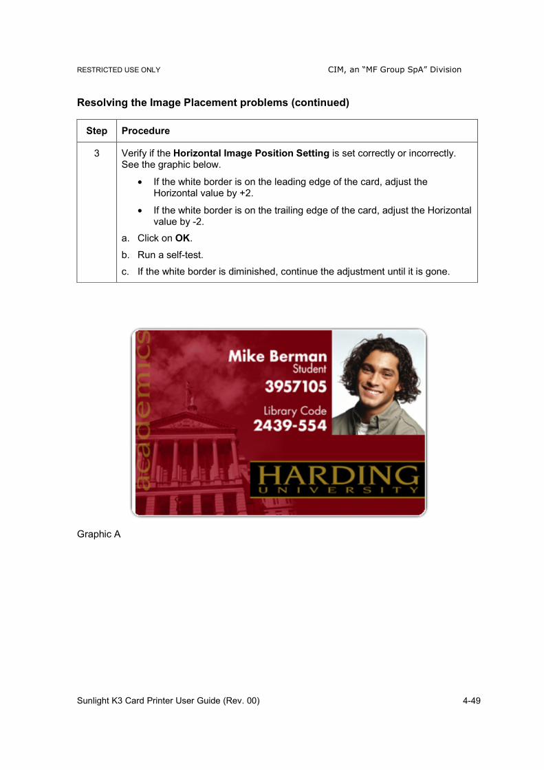
RESTRICTED USE ONLY CIM, an “MF Group SpA” Division
Sunlight K3 Card Printer User Guide (Rev. 00) 4-49
Resolving the Image Placement problems (continued)
Step Procedure
3 Verify if the Horizontal Image Position Setting is set correctly or incorrectly. See the graphic below.
• If the white border is on the leading edge of the card, adjust the Horizontal value by +2.
• If the white border is on the trailing edge of the card, adjust the Horizontal value by -2.
a. Click on OK.
b. Run a self-test.
c. If the white border is diminished, continue the adjustment until it is gone.
Graphic A

RESTRICTED USE ONLY CIM, an “MF Group SpA” Division
Sunlight K3 Card Printer User Guide (Rev. 00) 4-50
Resolving the Image Placement problems (continued)
Step Procedure
4 Verify if the Vertical Image Position Setting is set correctly or incorrectly. See the graphic below.
a. Adjust the value as described below:
• If the white border is on the top edge of the card, adjust the Vertical value by +2.
• If the white border is on the bottom edge of the card, adjust the Vertical value by -2.
b. Click on OK.
c. Run a self-test.
d. If the white border is diminished, continue the adjustment until it is gone.
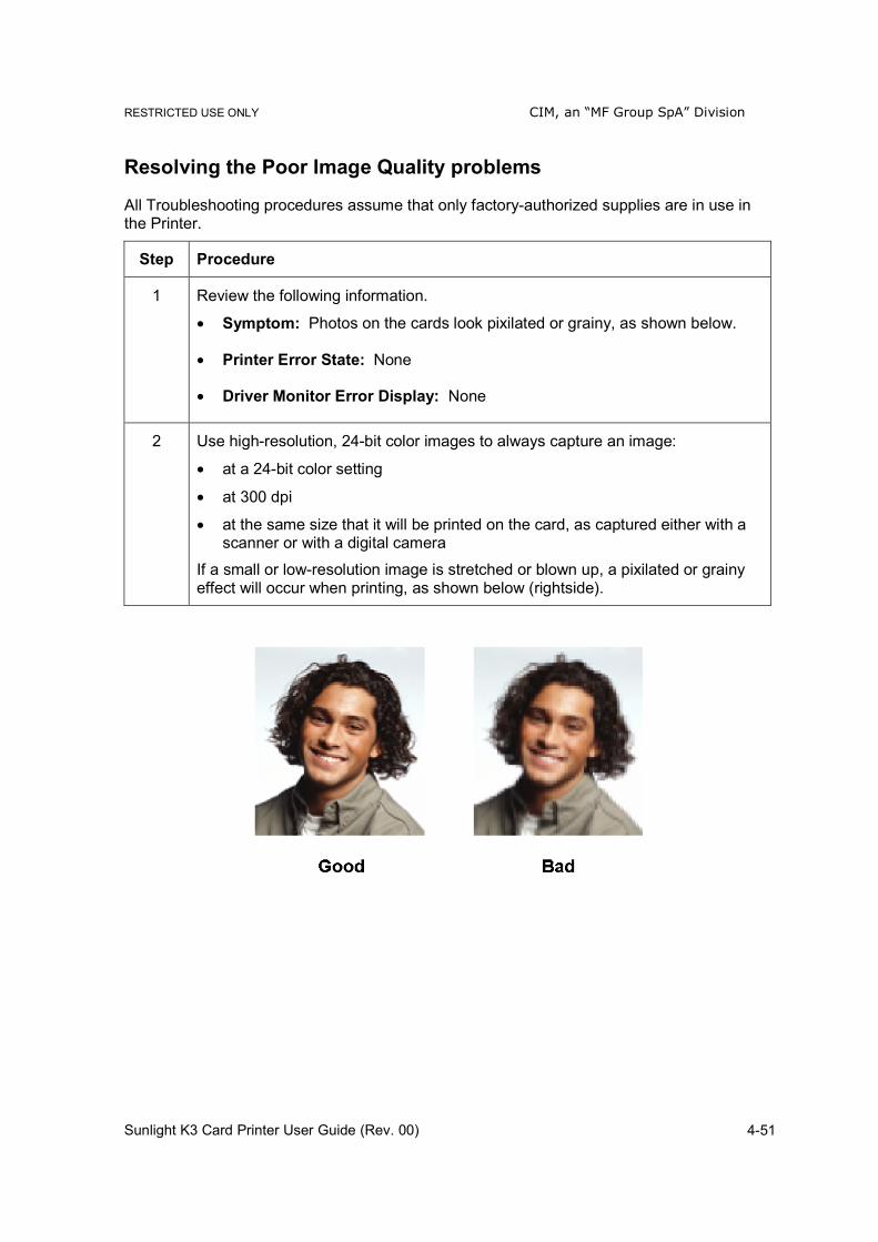
RESTRICTED USE ONLY CIM, an “MF Group SpA” Division
Sunlight K3 Card Printer User Guide (Rev. 00) 4-51
Resolving the Poor Image Quality problems
All Troubleshooting procedures assume that only factory-authorized supplies are in use in the Printer.
Step Procedure
1 Review the following information.
• Symptom: Photos on the cards look pixilated or grainy, as shown below.
• Printer Error State: None
• Driver Monitor Error Display: None
2 Use high-resolution, 24-bit color images to always capture an image:
• at a 24-bit color setting
• at 300 dpi
•
at the same size that it will be printed on the card, as captured either with a scanner or with a digital camera
If a small or low-resolution image is stretched or blown up, a pixilated or grainy effect will occur when printing, as shown below (rightside).
RESTRICTED USE ONLY CIM, an “MF Group SpA” Division
Sunlight K3 Card Printer User Guide (Rev. 00) 4-52
Running the Self Test Perform a self-test after (a) an initial setup of the Printer, (b) a calibration procedure has been conducted or (c) a part has been replaced to check for proper Printer operation.
Step Procedure
1 Verify that a full-color or Premium Resin Ribbon Cartridge is installed and that cards are properly loaded.
Caution: If the power is ON, disconnect the Power Cable from the Printer’s rear panel.
2 Press and hold the Pause/Resume button.
3 While holding down the Pause/Resume button, plug the power cable back into the Printer.
4 • Full Color Ribbon Cartridge installed: The Printer will print a 3-color process gray scale on the front of the card. The overlay pass is not printed during the Self-test. (See Display A below)
• Premium Resin Ribbon Cartridge installed: The Printer will print a single color gray scale on the front of the card. See Display B below)
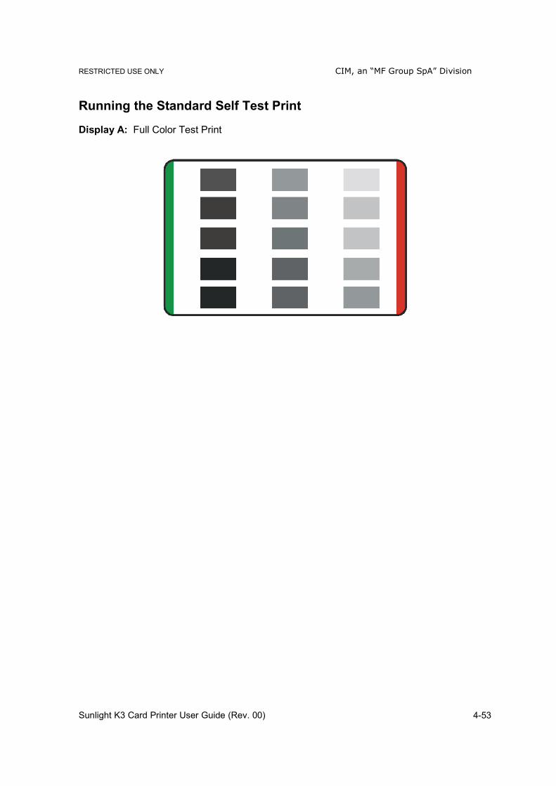
RESTRICTED USE ONLY CIM, an “MF Group SpA” Division
Sunlight K3 Card Printer User Guide (Rev. 00) 4-53
Running the Standard Self Test Print
Display A: Full Color Test Print

RESTRICTED USE ONLY CIM, an “MF Group SpA” Division
Sunlight K3 Card Printer User Guide (Rev. 00) 4-54
Running the Magnetic Self Test (HiCo Only)
Perform a self-test after (a) an initial setup of the Printer, (b) a calibration procedure has been conducted or (c) a part has been replaced to check for proper Printer operation.
Step Procedure
1 Remove Ribbon Cartridge from the Printer and close the front cover
Caution: If the power is ON, disconnect the Power Cable from the Printer’s rear panel.
2 Press and hold the Pause/Resume button.
3 While holding down the Pause/Resume button, plug the power cable back into the Printer.
4 The Printer will Encode magnetic information on all 3 magnetic tracks
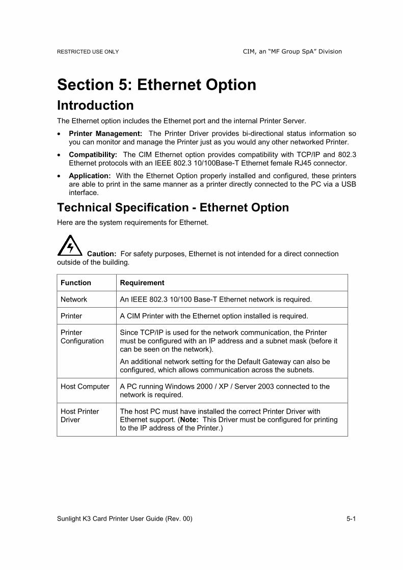
RESTRICTED USE ONLY CIM, an “MF Group SpA” Division
Sunlight K3 Card Printer User Guide (Rev. 00) 5-1
Section 5: Ethernet Option Introduction The Ethernet option includes the Ethernet port and the internal Printer Server.
• Printer Management: The Printer Driver provides bi-directional status information so you can monitor and manage the Printer just as you would any other networked Printer.
•
Compatibility: The CIM Ethernet option provides compatibility with TCP/IP and 802.3 Ethernet protocols with an IEEE 802.3 10/100Base-T Ethernet female RJ45 connector.
• Application: With the Ethernet Option properly installed and configured, these printers are able to print in the same manner as a printer directly connected to the PC via a USB interface.
Technical Specification - Ethernet Option Here are the system requirements for Ethernet.
Caution: For safety purposes, Ethernet is not intended for a direct connection outside of the building.
Function Requirement
Network An IEEE 802.3 10/100 Base-T Ethernet network is required.
Printer A CIM Printer with the Ethernet option installed is required.
Printer Configuration
Since TCP/IP is used for the network communication, the Printer must be configured with an IP address and a subnet mask (before it can be seen on the network).
An additional network setting for the Default Gateway can also be configured, which allows communication across the subnets.
Host Computer A PC running Windows 2000 / XP / Server 2003 connected to the network is required.
Host Printer Driver
The host PC must have installed the correct Printer Driver with Ethernet support. (Note: This Driver must be configured for printing to the IP address of the Printer.)
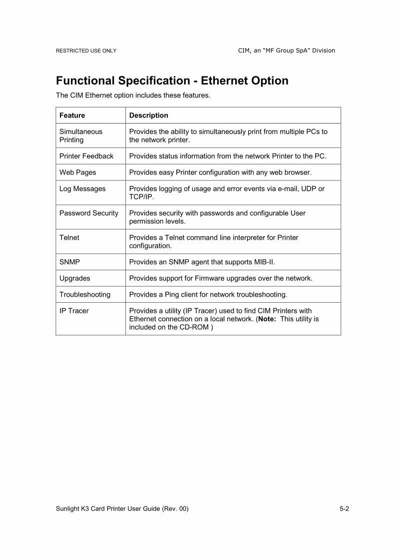
RESTRICTED USE ONLY CIM, an “MF Group SpA” Division
Sunlight K3 Card Printer User Guide (Rev. 00) 5-2
Functional Specification - Ethernet Option The CIM Ethernet option includes these features.
Feature Description
Simultaneous Printing
Provides the ability to simultaneously print from multiple PCs to the network printer.
Printer Feedback Provides status information from the network Printer to the PC.
Web Pages Provides easy Printer configuration with any web browser.
Log Messages Provides logging of usage and error events via e-mail, UDP or TCP/IP.
Password Security Provides security with passwords and configurable User permission levels.
Telnet Provides a Telnet command line interpreter for Printer configuration.
SNMP Provides an SNMP agent that supports MIB-II.
Upgrades Provides support for Firmware upgrades over the network.
Troubleshooting Provides a Ping client for network troubleshooting.
IP Tracer Provides a utility (IP Tracer) used to find CIM Printers with Ethernet connection on a local network. (Note: This utility is included on the CD-ROM )
RESTRICTED USE ONLY CIM, an “MF Group SpA” Division
Sunlight K3 Card Printer User Guide (Rev. 00) 5-3
Network Services - Overview The Ethernet option provides the services described in this section. (Note: Other additional services include a Ping client, address assignment and Printer discovery functions.)
Reviewing the Print Server
The Print Server provides printing services in the same manner as a printer connected directly to a USB interface except that the Printer is connected through the local area network to the client PC. The Print Server must be properly configured in order to provide this printing capability.
• The Print Server is capable of queuing up to eight (8) client PCs while printing. Communications between each PC and the Ethernet-enabled CIM Printer are implemented over a bi-directional TCP/IP interface.
• All clients are able to send print jobs to the Printer and monitor Printer jobs and errors with the standard Windows printing system using the CIM Printer Driver installed on their local PC.
In this way, the User knows whether or not a print job has been successful. Also, the User knows what problems have been encountered while processing the print job. Printing using Ethernet works in a manner similar to the USB-connected PC/printer.
Reviewing the Web Page Server
An HTTP service serves web pages that provide an interface through which to configure and monitor the Printer. (Note: Users may also monitor all print jobs that have been sent to the Printer from any client PC.)
Reviewing the Network Management Interface
The Ethernet-enabled Printer operates as an SNMP agent to allow central administrators to monitor and configure the network interface and the Printer. (Note: A standard host MIB-II is implemented to maximize the utility of the Printer on the network.)
Reviewing the Telnet Server
The Ethernet interface has a command line interpreter. (Note: The User can connect to the Printer using a Telnet session on their PC, issue commands to the Printer and receive response from the Printer.)
The Telnet commands are primarily used for network administration, and they will not be used by most Users. (Note: These commands will query the state of the Printer and configure various settings for the Printer. These include network settings, logging setting, User names and User passwords.)
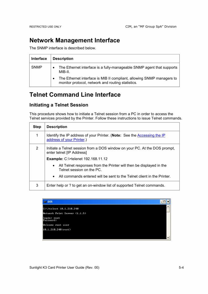
RESTRICTED USE ONLY CIM, an “MF Group SpA” Division
Sunlight K3 Card Printer User Guide (Rev. 00) 5-4
Network Management Interface The SNMP interface is described below.
Interface Description
SNMP •
The Ethernet interface is a fully-manageable SNMP agent that supports MIB-II.
•
The Ethernet interface is MIB II compliant, allowing SNMP managers to monitor protocol, network and routing statistics.
Telnet Command Line Interface Initiating a Telnet Session
This procedure shows how to initiate a Telnet session from a PC in order to access the Telnet services provided by the Printer. Follow these instructions to issue Telnet commands.
Step Description
1 Identify the IP address of your Printer. (Note: See the Accessing the IP address of your Printer.)
2 Initiate a Telnet session from a DOS window on your PC. At the DOS prompt, enter telnet [IP Address]
Example: C:\>telenet 192.168.11.12
•
All Telnet responses from the Printer will then be displayed in the Telnet session on the PC.
• All commands entered will be sent to the Telnet client in the Printer.
3 Enter help or ? to get an on-window list of supported Telnet commands.
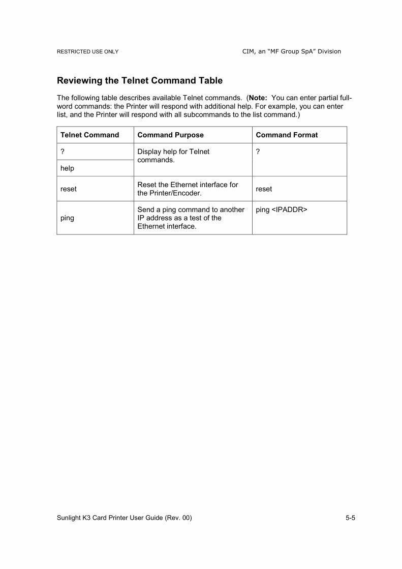
RESTRICTED USE ONLY CIM, an “MF Group SpA” Division
Sunlight K3 Card Printer User Guide (Rev. 00) 5-5
Reviewing the Telnet Command Table
The following table describes available Telnet commands. (Note: You can enter partial full-word commands: the Printer will respond with additional help. For example, you can enter list, and the Printer will respond with all subcommands to the list command.)
Telnet Command Command Purpose Command Format
?
help
Display help for Telnet commands.
?
reset Reset the Ethernet interface for the Printer/Encoder. reset
ping Send a ping command to another IP address as a test of the Ethernet interface.
ping <IPADDR>
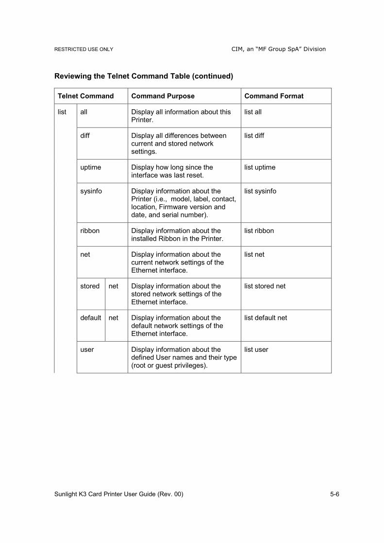
RESTRICTED USE ONLY CIM, an “MF Group SpA” Division
Sunlight K3 Card Printer User Guide (Rev. 00) 5-6
Reviewing the Telnet Command Table (continued)
Telnet Command Command Purpose Command Format
all Display all information about this Printer.
list all
diff Display all differences between current and stored network settings.
list diff
uptime Display how long since the interface was last reset.
list uptime
sysinfo Display information about the Printer (i.e., model, label, contact, location, Firmware version and date, and serial number).
list sysinfo
ribbon Display information about the installed Ribbon in the Printer.
list ribbon
net Display information about the current network settings of the Ethernet interface.
list net
stored net Display information about the stored network settings of the Ethernet interface.
list stored net
default net Display information about the default network settings of the Ethernet interface.
list default net
list
user Display information about the defined User names and their type (root or guest privileges).
list user
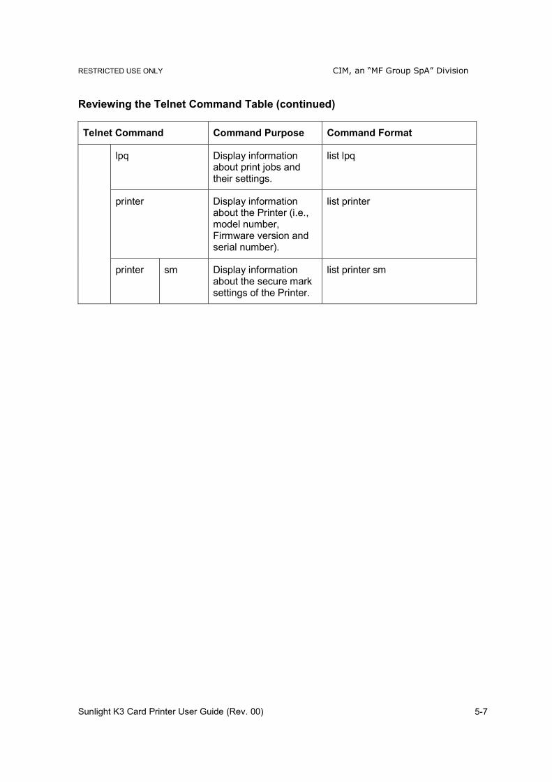
RESTRICTED USE ONLY CIM, an “MF Group SpA” Division
Sunlight K3 Card Printer User Guide (Rev. 00) 5-7
Reviewing the Telnet Command Table (continued)
Telnet Command Command Purpose Command Format
lpq Display information about print jobs and their settings.
list lpq
printer Display information about the Printer (i.e., model number, Firmware version and serial number).
list printer
printer sm Display information about the secure mark settings of the Printer.
list printer sm
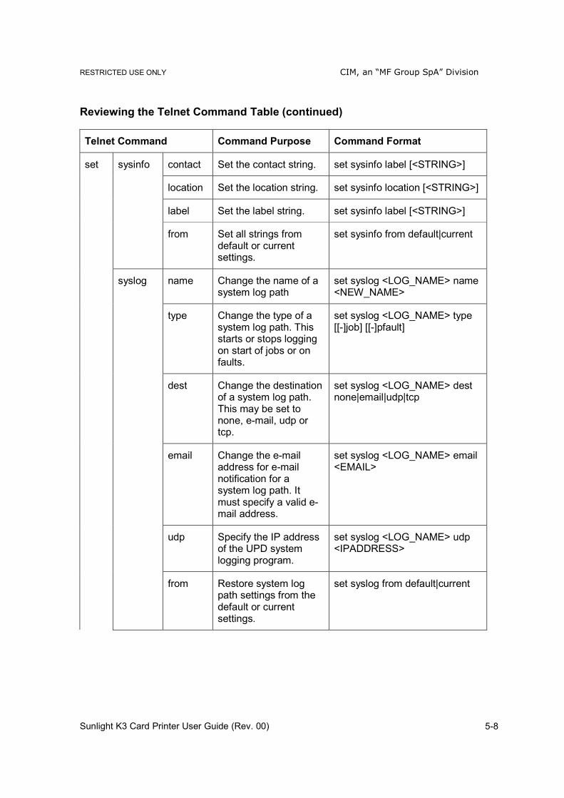
RESTRICTED USE ONLY CIM, an “MF Group SpA” Division
Sunlight K3 Card Printer User Guide (Rev. 00) 5-8
Reviewing the Telnet Command Table (continued)
Telnet Command Command Purpose Command Format
contact Set the contact string. set sysinfo label [<STRING>]
location Set the location string. set sysinfo location [<STRING>]
label Set the label string. set sysinfo label [<STRING>]
sysinfo
from Set all strings from default or current settings.
set sysinfo from default|current
name Change the name of a system log path
set syslog <LOG_NAME> name <NEW_NAME>
type Change the type of a system log path. This starts or stops logging on start of jobs or on faults.
set syslog <LOG_NAME> type [[-]job] [[-]pfault]
dest Change the destination of a system log path. This may be set to none, e-mail, udp or tcp.
set syslog <LOG_NAME> dest none|email|udp|tcp
email Change the e-mail address for e-mail notification for a system log path. It must specify a valid e-mail address.
set syslog <LOG_NAME> email <EMAIL>
udp Specify the IP address of the UPD system logging program.
set syslog <LOG_NAME> udp <IPADDRESS>
set
syslog
from Restore system log path settings from the default or current settings.
set syslog from default|current
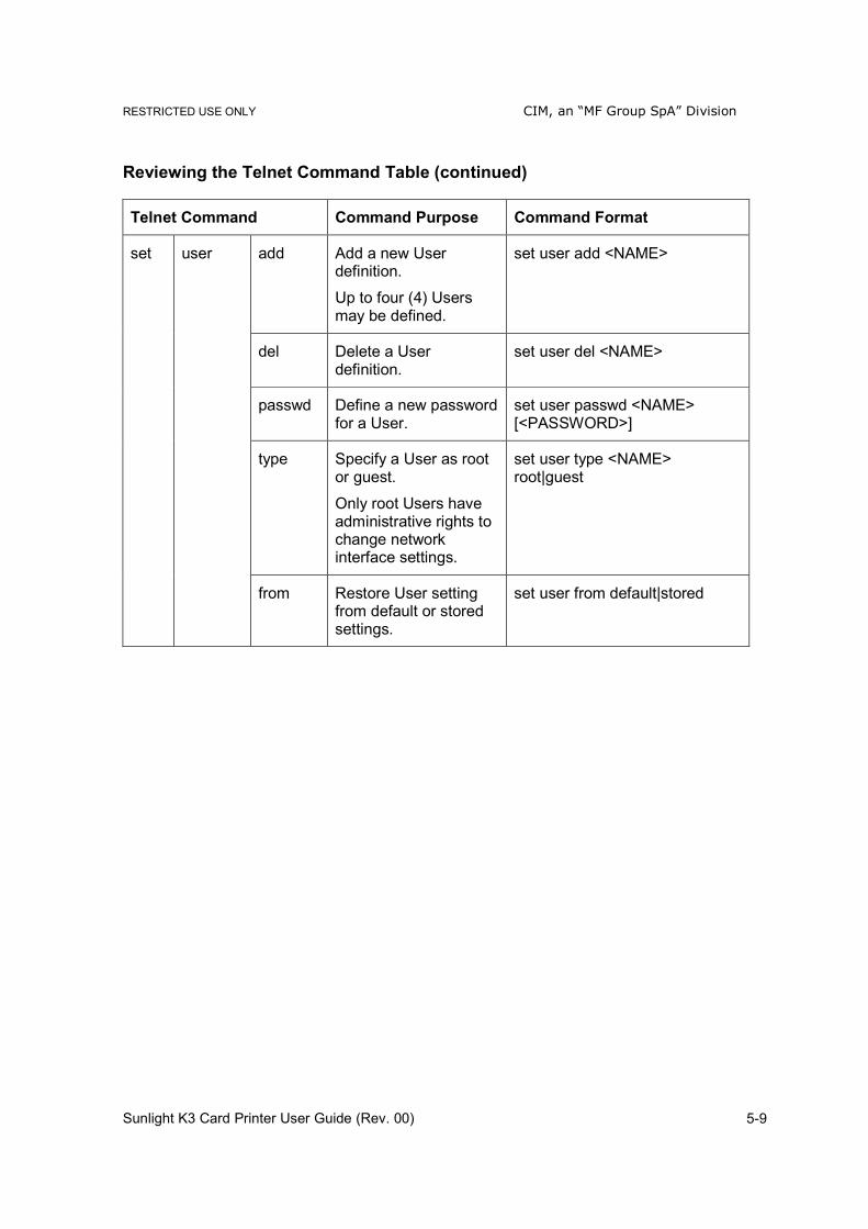
RESTRICTED USE ONLY CIM, an “MF Group SpA” Division
Sunlight K3 Card Printer User Guide (Rev. 00) 5-9
Reviewing the Telnet Command Table (continued)
Telnet Command Command Purpose Command Format
add Add a new User definition.
Up to four (4) Users may be defined.
set user add <NAME>
del Delete a User definition.
set user del <NAME>
passwd Define a new password for a User.
set user passwd <NAME> [<PASSWORD>]
type Specify a User as root or guest.
Only root Users have administrative rights to change network interface settings.
set user type <NAME> root|guest
set user
from Restore User setting from default or stored settings.
set user from default|stored
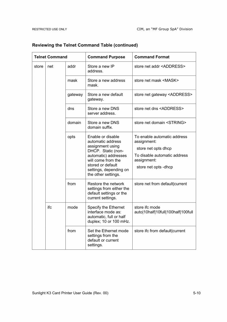
RESTRICTED USE ONLY CIM, an “MF Group SpA” Division
Sunlight K3 Card Printer User Guide (Rev. 00) 5-10
Reviewing the Telnet Command Table (continued)
Telnet Command Command Purpose Command Format
addr Store a new IP address.
store net addr <ADDRESS>
mask Store a new address mask.
store net mask <MASK>
gateway Store a new default gateway.
store net gateway <ADDRESS>
dns Store a new DNS server address.
store net dns <ADDRESS>
domain Store a new DNS domain suffix.
store net domain <STRING>
opts Enable or disable automatic address assignment using DHCP. Static (non-automatic) addresses will come from the stored or default settings, depending on the other settings.
To enable automatic address assignment:
store net opts dhcp
To disable automatic address assignment:
store net opts -dhcp
net
from Restore the network settings from either the default settings or the current settings.
store net from default|current
mode Specify the Ethernet interface mode as: automatic, full or half duplex; 10 or 100 mHz.
store ifc mode auto|10half|10full|100half|100full
store
ifc
from Set the Ethernet mode settings from the default or current settings.
store ifc from default|current

RESTRICTED USE ONLY CIM, an “MF Group SpA” Division
Sunlight K3 Card Printer User Guide (Rev. 00) 5-11
Reviewing the Telnet Command Table (continued)
Telnet Command Command Purpose Command Format
save Save all current settings as the stored settings in the permanent memory.
save
load Take the settings from the stored memory and make them the current settings.
load
lpstat Display information about the Printer status.
This includes the status and device response.
See the Printer web page description.
lpstat
cancel Cancel a specific print job from the print queue.
cancel 10
quit Stop the current Telnet session.
quit
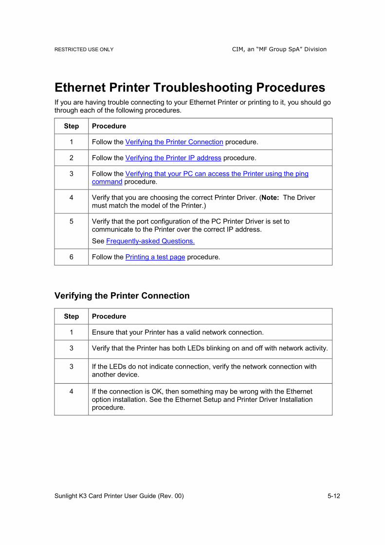
RESTRICTED USE ONLY CIM, an “MF Group SpA” Division
Sunlight K3 Card Printer User Guide (Rev. 00) 5-12
Ethernet Printer Troubleshooting Procedures If you are having trouble connecting to your Ethernet Printer or printing to it, you should go through each of the following procedures.
Step Procedure
1 Follow the Verifying the Printer Connection procedure.
2 Follow the Verifying the Printer IP address procedure.
3 Follow the Verifying that your PC can access the Printer using the ping command procedure.
4 Verify that you are choosing the correct Printer Driver. (Note: The Driver must match the model of the Printer.)
5 Verify that the port configuration of the PC Printer Driver is set to communicate to the Printer over the correct IP address.
See Frequently-asked Questions.
6 Follow the Printing a test page procedure.
Verifying the Printer Connection
Step Procedure
1 Ensure that your Printer has a valid network connection.
3 Verify that the Printer has both LEDs blinking on and off with network activity.
3 If the LEDs do not indicate connection, verify the network connection with another device.
4 If the connection is OK, then something may be wrong with the Ethernet option installation. See the Ethernet Setup and Printer Driver Installation procedure.
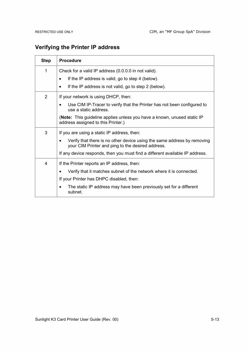
RESTRICTED USE ONLY CIM, an “MF Group SpA” Division
Sunlight K3 Card Printer User Guide (Rev. 00) 5-13
Verifying the Printer IP address
Step Procedure
1 Check for a valid IP address (0.0.0.0 in not valid).
•
If the IP address is valid, go to step 4 (below).
• If the IP address is not valid, go to step 2 (below).
2 If your network is using DHCP, then:
• Use CIM IP-Tracer to verify that the Printer has not been configured to use a static address.
(Note: This guideline applies unless you have a known, unused static IP address assigned to this Printer.)
3 If you are using a static IP address, then:
• Verify that there is no other device using the same address by removing your CIM Printer and ping to the desired address.
If any device responds, then you must find a different available IP address.
4 If the Printer reports an IP address, then:
• Verify that it matches subnet of the network where it is connected.
If your Printer has DHPC disabled, then:
• The static IP address may have been previously set for a different subnet.
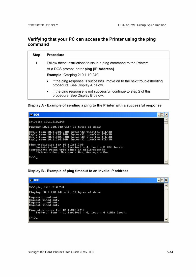
RESTRICTED USE ONLY CIM, an “MF Group SpA” Division
Sunlight K3 Card Printer User Guide (Rev. 00) 5-14
Verifying that your PC can access the Printer using the ping command
Step Procedure
1 Follow these instructions to issue a ping command to the Printer:
At a DOS prompt, enter ping [IP Address] Example: C:\>ping 210.1.10.240
• If the ping response is successful, move on to the next troubleshooting procedure. See Display A below.
• If the ping response is not successful, continue to step 2 of this procedure. See Display B below.
Display A - Example of sending a ping to the Printer with a successful response
Display B - Example of ping timeout to an invalid IP address
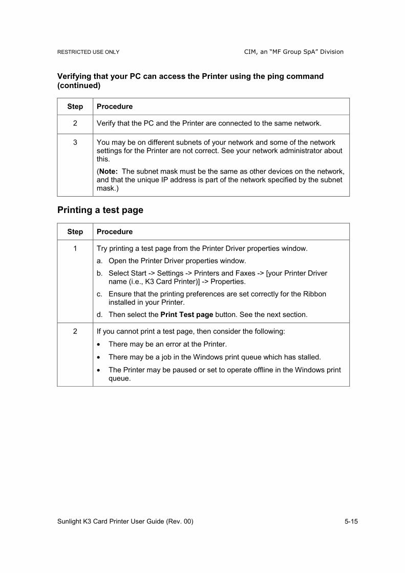
RESTRICTED USE ONLY CIM, an “MF Group SpA” Division
Sunlight K3 Card Printer User Guide (Rev. 00) 5-15
Verifying that your PC can access the Printer using the ping command (continued)
Step Procedure
2 Verify that the PC and the Printer are connected to the same network.
3 You may be on different subnets of your network and some of the network settings for the Printer are not correct. See your network administrator about this.
(Note: The subnet mask must be the same as other devices on the network, and that the unique IP address is part of the network specified by the subnet mask.)
Printing a test page
Step Procedure
1 Try printing a test page from the Printer Driver properties window.
a. Open the Printer Driver properties window.
b. Select Start -> Settings -> Printers and Faxes -> [your Printer Driver name (i.e., K3 Card Printer)] -> Properties.
c. Ensure that the printing preferences are set correctly for the Ribbon installed in your Printer.
d. Then select the Print Test page button. See the next section.
2 If you cannot print a test page, then consider the following:
• There may be an error at the Printer.
• There may be a job in the Windows print queue which has stalled.
•
The Printer may be paused or set to operate offline in the Windows print queue.
RESTRICTED USE ONLY CIM, an “MF Group SpA” Division
Sunlight K3 Card Printer User Guide (Rev. 00) 5-16
Reviewing Frequently-asked Questions Question Answer
How do I know if my Printer has the Ethernet option installed?
If your Printer has the RJ45 connector installed on the back of the Printer, then it has this Ethernet option installed.
Can my non-Ethernet-enabled Printer be upgraded to have an Ethernet interface?
No.
What PC operating systems work with my Ethernet Printer?
The Windows 2000/ XP / Server 2003 operating systems work with your Ethernet Printer.
How do I connect my Printer to my network?
You can connect from the RJ45 network connection on the back of your Printer to an available connection on your network (not directly to your PC).
You can use a good CAT-5 or better cable to make this connection.
How can I find the MAC address of my Ethernet Printer?
If you know the IP address of your Printer, you can access this through the home web page of the Print Server.
OR If you do not know the IP address or the Printer does not work with a usable IP address, then the MAC Address can be found using the tool CIM IP-Tracer
RESTRICTED USE ONLY CIM, an “MF Group SpA” Division
Sunlight K3 Card Printer User Guide (Rev. 00) 5-17
Reviewing Frequently-asked Questions (continued)
Question Answer
How can I find the IP address of my Ethernet Printer?
See Accessing the IP address of your Printer.
Can I print from my PC to multiple Ethernet Printers?
Yes. Follow this procedure:
1. You can install multiple Printer Drivers by using the add Printer wizard.
2. Run the CIM Add Printer Wizard program by choosing in from the Start menu: Go to the start -> Programs-> CIM -> CIM Add Printer Wizard.
3. Select Next on the first window.
4. On the second window, specify the type of CIM Printer you want and ask for a network connected Printer. Select Next.
5. Enter the IP address of your new Printer connection. Select Next.
6. Select Finish.
Can multiple PC’s print to my Ethernet Printer?
Yes. Each PC must install the Printer Driver software for the specific CIM Ethernet-enabled Printer and connect to the intended Printer, using the correct IP address.
Can I print from my PC to an Ethernet Printer on a different network segment?
Yes. If you know the IP address of the Printer on any segment of your network, you will be able to print to it.
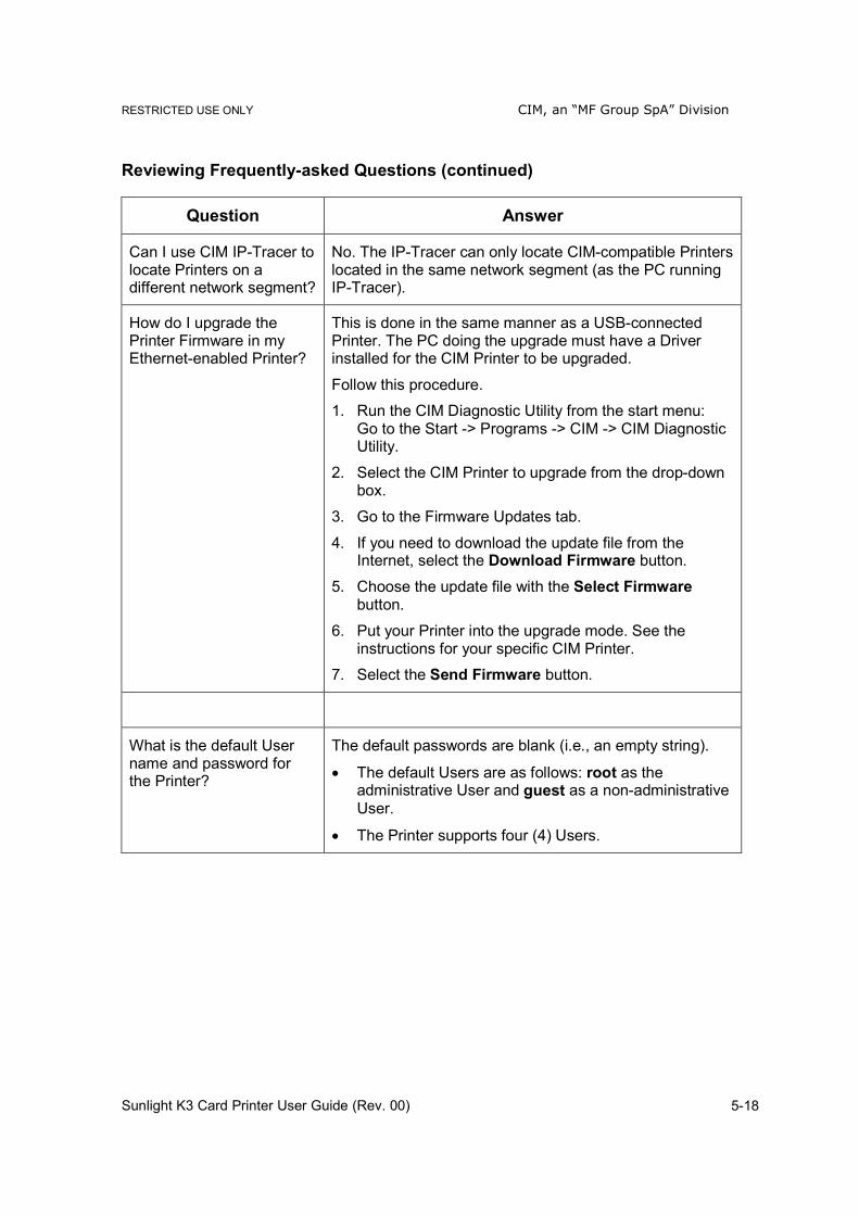
RESTRICTED USE ONLY CIM, an “MF Group SpA” Division
Sunlight K3 Card Printer User Guide (Rev. 00) 5-18
Reviewing Frequently-asked Questions (continued)
Question Answer
Can I use CIM IP-Tracer to locate Printers on a different network segment?
No. The IP-Tracer can only locate CIM-compatible Printers located in the same network segment (as the PC running IP-Tracer).
How do I upgrade the Printer Firmware in my Ethernet-enabled Printer?
This is done in the same manner as a USB-connected Printer. The PC doing the upgrade must have a Driver installed for the CIM Printer to be upgraded.
Follow this procedure.
1. Run the CIM Diagnostic Utility from the start menu: Go to the Start -> Programs -> CIM -> CIM Diagnostic Utility.
2. Select the CIM Printer to upgrade from the drop-down box.
3. Go to the Firmware Updates tab.
4. If you need to download the update file from the Internet, select the Download Firmware button.
5. Choose the update file with the Select Firmware button.
6. Put your Printer into the upgrade mode. See the instructions for your specific CIM Printer.
7. Select the Send Firmware button.
What is the default User name and password for the Printer?
The default passwords are blank (i.e., an empty string).
•
The default Users are as follows: root as the administrative User and guest as a non-administrative User.
•
The Printer supports four (4) Users.
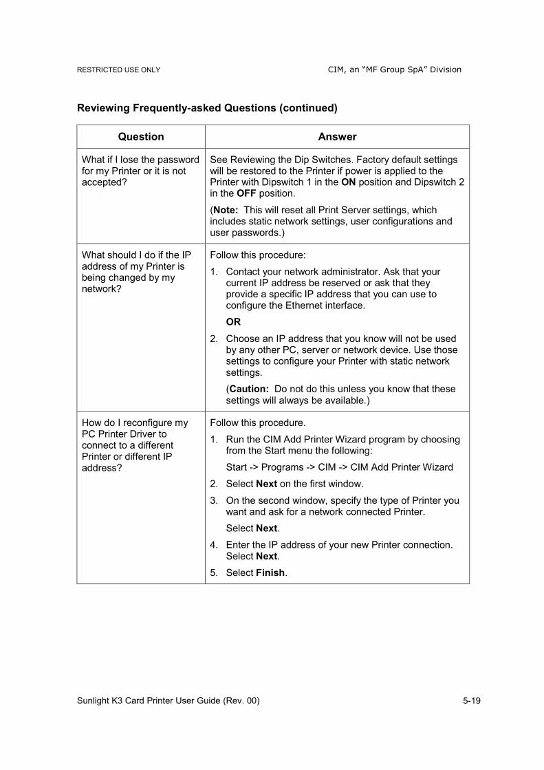
RESTRICTED USE ONLY CIM, an “MF Group SpA” Division
Sunlight K3 Card Printer User Guide (Rev. 00) 5-19
Reviewing Frequently-asked Questions (continued)
Question Answer
What if I lose the password for my Printer or it is not accepted?
See Reviewing the Dip Switches. Factory default settings will be restored to the Printer if power is applied to the Printer with Dipswitch 1 in the ON position and Dipswitch 2 in the OFF position.
(Note: This will reset all Print Server settings, which includes static network settings, user configurations and user passwords.)
What should I do if the IP address of my Printer is being changed by my network?
Follow this procedure:
1. Contact your network administrator. Ask that your current IP address be reserved or ask that they provide a specific IP address that you can use to configure the Ethernet interface.
OR 2. Choose an IP address that you know will not be used
by any other PC, server or network device. Use those settings to configure your Printer with static network settings.
(Caution: Do not do this unless you know that these settings will always be available.)
How do I reconfigure my PC Printer Driver to connect to a different Printer or different IP address?
Follow this procedure.
1. Run the CIM Add Printer Wizard program by choosing from the Start menu the following:
Start -> Programs -> CIM -> CIM Add Printer Wizard
2. Select Next on the first window.
3. On the second window, specify the type of Printer you want and ask for a network connected Printer.
Select Next. 4. Enter the IP address of your new Printer connection.
Select Next. 5. Select Finish.
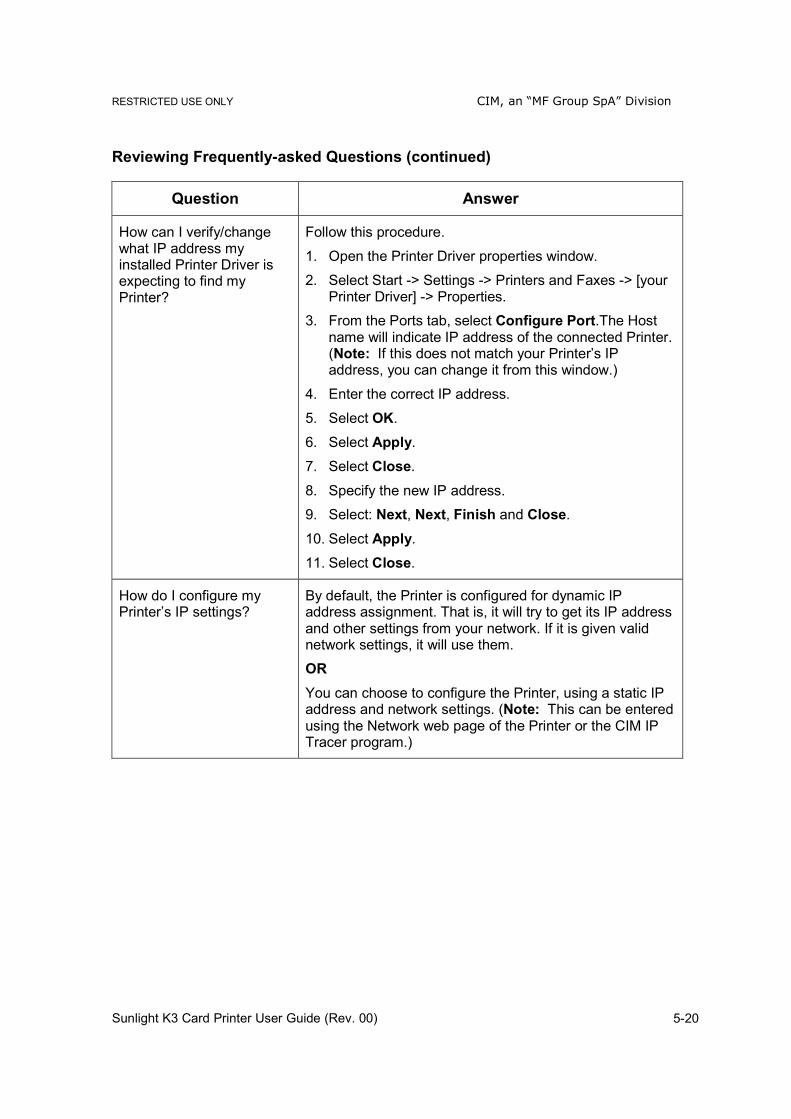
RESTRICTED USE ONLY CIM, an “MF Group SpA” Division
Sunlight K3 Card Printer User Guide (Rev. 00) 5-20
Reviewing Frequently-asked Questions (continued)
Question Answer
How can I verify/change what IP address my installed Printer Driver is expecting to find my Printer?
Follow this procedure.
1. Open the Printer Driver properties window.
2. Select Start -> Settings -> Printers and Faxes -> [your Printer Driver] -> Properties.
3. From the Ports tab, select Configure Port.The Host name will indicate IP address of the connected Printer. (Note: If this does not match your Printer’s IP address, you can change it from this window.)
4. Enter the correct IP address.
5. Select OK.
6. Select Apply.
7. Select Close.
8. Specify the new IP address.
9. Select: Next, Next, Finish and Close.
10. Select Apply.
11. Select Close.
How do I configure my Printer’s IP settings?
By default, the Printer is configured for dynamic IP address assignment. That is, it will try to get its IP address and other settings from your network. If it is given valid network settings, it will use them.
OR You can choose to configure the Printer, using a static IP address and network settings. (Note: This can be entered using the Network web page of the Printer or the CIM IP Tracer program.)
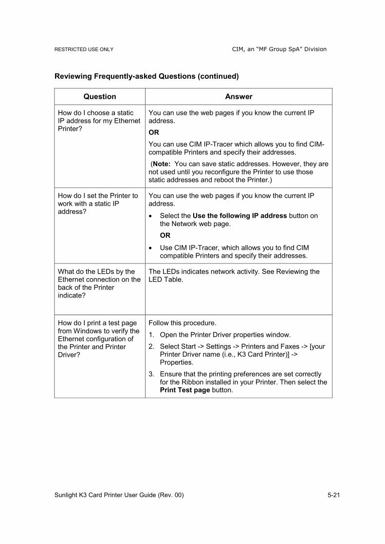
RESTRICTED USE ONLY CIM, an “MF Group SpA” Division
Sunlight K3 Card Printer User Guide (Rev. 00) 5-21
Reviewing Frequently-asked Questions (continued)
Question Answer
How do I choose a static IP address for my Ethernet Printer?
You can use the web pages if you know the current IP address.
OR You can use CIM IP-Tracer which allows you to find CIM-compatible Printers and specify their addresses.
(Note: You can save static addresses. However, they are not used until you reconfigure the Printer to use those static addresses and reboot the Printer.)
How do I set the Printer to work with a static IP address?
You can use the web pages if you know the current IP address.
•
Select the Use the following IP address button on the Network web page.
OR
• Use CIM IP-Tracer, which allows you to find CIM compatible Printers and specify their addresses.
What do the LEDs by the Ethernet connection on the back of the Printer indicate?
The LEDs indicates network activity. See Reviewing the LED Table.
How do I print a test page from Windows to verify the Ethernet configuration of the Printer and Printer Driver?
Follow this procedure.
1. Open the Printer Driver properties window.
2. Select Start -> Settings -> Printers and Faxes -> [your Printer Driver name (i.e., K3 Card Printer)] -> Properties.
3. Ensure that the printing preferences are set correctly for the Ribbon installed in your Printer. Then select the Print Test page button.
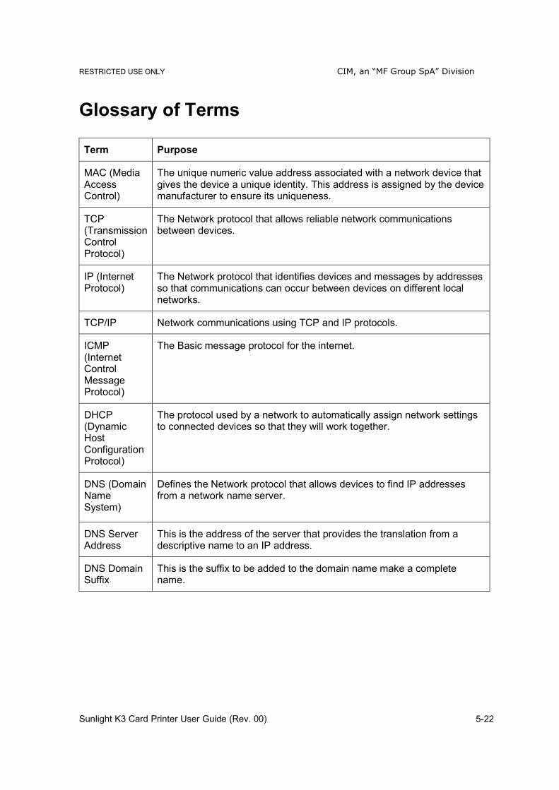
RESTRICTED USE ONLY CIM, an “MF Group SpA” Division
Sunlight K3 Card Printer User Guide (Rev. 00) 5-22
Glossary of Terms Term Purpose
MAC (Media Access Control)
The unique numeric value address associated with a network device that gives the device a unique identity. This address is assigned by the device manufacturer to ensure its uniqueness.
TCP (Transmission Control Protocol)
The Network protocol that allows reliable network communications between devices.
IP (Internet Protocol)
The Network protocol that identifies devices and messages by addresses so that communications can occur between devices on different local networks.
TCP/IP Network communications using TCP and IP protocols.
ICMP (Internet Control Message Protocol)
The Basic message protocol for the internet.
DHCP (Dynamic Host Configuration Protocol)
The protocol used by a network to automatically assign network settings to connected devices so that they will work together.
DNS (Domain Name System)
Defines the Network protocol that allows devices to find IP addresses from a network name server.
DNS Server Address
This is the address of the server that provides the translation from a descriptive name to an IP address.
DNS Domain Suffix
This is the suffix to be added to the domain name make a complete name.
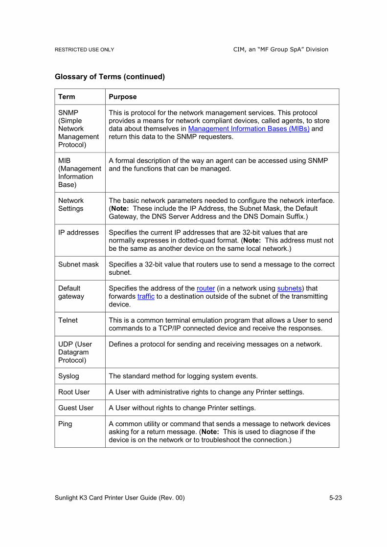
RESTRICTED USE ONLY CIM, an “MF Group SpA” Division
Sunlight K3 Card Printer User Guide (Rev. 00) 5-23
Glossary of Terms (continued)
Term Purpose
SNMP (Simple Network Management Protocol)
This is protocol for the network management services. This protocol provides a means for network compliant devices, called agents, to store data about themselves in Management Information Bases (MIBs) and return this data to the SNMP requesters.
MIB (Management Information Base)
A formal description of the way an agent can be accessed using SNMP and the functions that can be managed.
Network Settings
The basic network parameters needed to configure the network interface. (Note: These include the IP Address, the Subnet Mask, the Default Gateway, the DNS Server Address and the DNS Domain Suffix.)
IP addresses Specifies the current IP addresses that are 32-bit values that are normally expresses in dotted-quad format. (Note: This address must not be the same as another device on the same local network.)
Subnet mask Specifies a 32-bit value that routers use to send a message to the correct subnet.
Default gateway
Specifies the address of the router (in a network using subnets) that forwards traffic to a destination outside of the subnet of the transmitting device.
Telnet This is a common terminal emulation program that allows a User to send commands to a TCP/IP connected device and receive the responses.
UDP (User Datagram Protocol)
Defines a protocol for sending and receiving messages on a network.
Syslog The standard method for logging system events.
Root User A User with administrative rights to change any Printer settings.
Guest User A User without rights to change Printer settings.
Ping A common utility or command that sends a message to network devices asking for a return message. (Note: This is used to diagnose if the device is on the network or to troubleshoot the connection.)
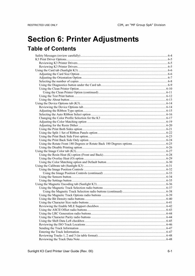
RESTRICTED USE ONLY CIM, an “MF Group SpA” Division
Sunlight K3 Card Printer User Guide (Rev. 00) 6-1
Section 6: Printer Adjustments Table of Contents
Safety Messages (review carefully) ............................................................................................................6-4 K3 Print Driver Options..............................................................................................................................6-5
Reviewing K3 Printer Drivers................................................................................................................6-5 Reviewing K3 Printer Drivers................................................................................................................6-5
Using the Card tab (Sunlight K3) ...............................................................................................................6-6 Adjusting the Card Size Option .............................................................................................................6-6 Adjusting the Orientation Option...........................................................................................................6-7 Selecting the number of copies ..............................................................................................................6-8 Using the Diagnostics button under the Card tab...................................................................................6-9 Using the Clean Printer Option ............................................................................................................6-10
Using the Clean Printer Option (continued)....................................................................................6-11 Using the Test Print button ..................................................................................................................6-12 Using the About button ........................................................................................................................6-13
Using the Device Options tab (K3)...........................................................................................................6-14 Reviewing the Device Options tab.......................................................................................................6-14 Adjusting the Ribbon Type option.......................................................................................................6-15 Selecting the Auto Ribbon Select option .............................................................................................6-16 Changing the Color Profile Selection for the K3 .................................................................................6-17 Adjusting the Color Matching option ..................................................................................................6-19 Adjusting for the Resin Dither .............................................................................................................6-20 Using the Print Both Sides option........................................................................................................6-21 Using the Split 1 Set of Ribbon Panels option .....................................................................................6-22 Using the Print Back Side First option.................................................................................................6-23 Using the Print Back Side Only option ................................................................................................6-24 Using the Rotate Front 180 Degrees or Rotate Back 180 Degrees options..........................................6-25 Using the Disable Printing option ........................................................................................................6-26
Using the Image Color tab (K3)................................................................................................................6-27 Using the Resin Heat (K) option (Front and Back)..............................................................................6-28 Using the Overlay Heat (O) option ......................................................................................................6-29 Using the Color Matching option and Default button..........................................................................6-30
Using the Calibrate tab (Sunlight K3) ......................................................................................................6-31 Using the Image Position Controls ......................................................................................................6-32
Using the Image Position Controls (continued) ..............................................................................6-33 Using the Sensors button......................................................................................................................6-34 Using the Settings button .....................................................................................................................6-35
Using the Magnetic Encoding tab (Sunlight K3)......................................................................................6-36 Using the Magnetic Track Selection radio buttons ..............................................................................6-37
Using the Magnetic Track Selection radio buttons (continued) ......................................................6-38 Using the Magnetic Track Options radio buttons ................................................................................6-39 Using the Bit Density radio buttons .....................................................................................................6-40 Using the Character Size radio buttons................................................................................................6-41 Reviewing the Enable MLE Support checkbox ...................................................................................6-42 Using the ASCII Offset radio buttons ..................................................................................................6-43 Using the LRC Generation radio buttons.............................................................................................6-44 Using the Character Parity radio buttons .............................................................................................6-44 Using the Shift Data Left checkbox .....................................................................................................6-45 Reviewing the ISO Track Locations ....................................................................................................6-46 Sending the Track Information ............................................................................................................6-47 Entering the Track Information............................................................................................................6-47 Reviewing Tracks 1, 2 and 3 (in table format).....................................................................................6-48 Reviewing the Track Data Note...........................................................................................................6-48
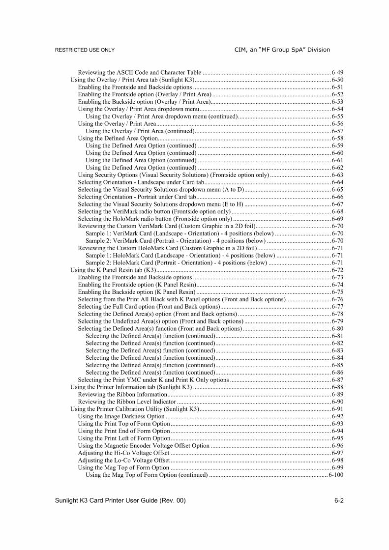
RESTRICTED USE ONLY CIM, an “MF Group SpA” Division
Sunlight K3 Card Printer User Guide (Rev. 00) 6-2
Reviewing the ASCII Code and Character Table ................................................................................6-49 Using the Overlay / Print Area tab (Sunlight K3).....................................................................................6-50
Enabling the Frontside and Backside options ......................................................................................6-51 Enabling the Frontside option (Overlay / Print Area) ..........................................................................6-52 Enabling the Backside option (Overlay / Print Area)...........................................................................6-53 Using the Overlay / Print Area dropdown menu..................................................................................6-54
Using the Overlay / Print Area dropdown menu (continued)..........................................................6-55 Using the Overlay / Print Area.............................................................................................................6-56
Using the Overlay / Print Area (continued).....................................................................................6-57 Using the Defined Area Option............................................................................................................6-58
Using the Defined Area Option (continued) ...................................................................................6-59 Using the Defined Area Option (continued) ...................................................................................6-60 Using the Defined Area Option (continued) ...................................................................................6-61 Using the Defined Area Option (continued) ...................................................................................6-62
Using Security Options (Visual Security Solutions) (Frontside option only) ......................................6-63 Selecting Orientation - Landscape under Card tab...............................................................................6-64 Selecting the Visual Security Solutions dropdown menu (A to D)......................................................6-65 Selecting Orientation - Portrait under Card tab....................................................................................6-66 Selecting the Visual Security Solutions dropdown menu (E to H) ......................................................6-67 Selecting the VeriMark radio button (Frontside option only) ..............................................................6-68 Selecting the HoloMark radio button (Frontside option only) .............................................................6-69 Reviewing the Custom VeriMark Card (Custom Graphic in a 2D foil)...............................................6-70
Sample 1: VeriMark Card (Landscape - Orientation) - 4 positions (below) ...................................6-70 Sample 2: VeriMark Card (Portrait - Orientation) - 4 positions (below) ........................................6-70
Reviewing the Custom HoloMark Card (Custom Graphic in a 2D foil)..............................................6-71 Sample 1: HoloMark Card (Landscape - Orientation) - 4 positions (below) ..................................6-71 Sample 2: HoloMark Card (Portrait - Orientation) - 4 positions (below) .......................................6-71
Using the K Panel Resin tab (K3).............................................................................................................6-72 Enabling the Frontside and Backside options ......................................................................................6-73 Enabling the Frontside option (K Panel Resin)....................................................................................6-74 Enabling the Backside option (K Panel Resin) ....................................................................................6-75 Selecting from the Print All Black with K Panel options (Front and Back options)............................6-76 Selecting the Full Card option (Front and Back options).....................................................................6-77 Selecting the Defined Area(s) option (Front and Back options) ..........................................................6-78 Selecting the Undefined Area(s) option (Front and Back options) ......................................................6-79 Selecting the Defined Area(s) function (Front and Back options) .......................................................6-80
Selecting the Defined Area(s) function (continued)........................................................................6-81 Selecting the Defined Area(s) function (continued)........................................................................6-82 Selecting the Defined Area(s) function (continued)........................................................................6-83 Selecting the Defined Area(s) function (continued)........................................................................6-84 Selecting the Defined Area(s) function (continued)........................................................................6-85 Selecting the Defined Area(s) function (continued)........................................................................6-86
Selecting the Print YMC under K and Print K Only options ...............................................................6-87 Using the Printer Information tab (Sunlight K3) ......................................................................................6-88
Reviewing the Ribbon Information......................................................................................................6-89 Reviewing the Ribbon Level Indicator ................................................................................................6-90
Using the Printer Calibration Utility (Sunlight K3)..................................................................................6-91 Using the Image Darkness Option .......................................................................................................6-92 Using the Print Top of Form Option ....................................................................................................6-93 Using the Print End of Form Option ....................................................................................................6-94 Using the Print Left of Form Option....................................................................................................6-95 Using the Magnetic Encoder Voltage Offset Option ...........................................................................6-96 Adjusting the Hi-Co Voltage Offset ....................................................................................................6-97 Adjusting the Lo-Co Voltage Offset ....................................................................................................6-98 Using the Mag Top of Form Option ....................................................................................................6-99
Using the Mag Top of Form Option (continued) .......................................................................... 6-100

RESTRICTED USE ONLY CIM, an “MF Group SpA” Division
Sunlight K3 Card Printer User Guide (Rev. 00) 6-3
Using the Ribbon Tension Option...................................................................................................... 6-101 Using the Flipper Home Offset Option.............................................................................................. 6-102 Using the Flipper Center Offset Option ............................................................................................. 6-102 Using the Flipper Smart Angle Offset Option ................................................................................... 6-103
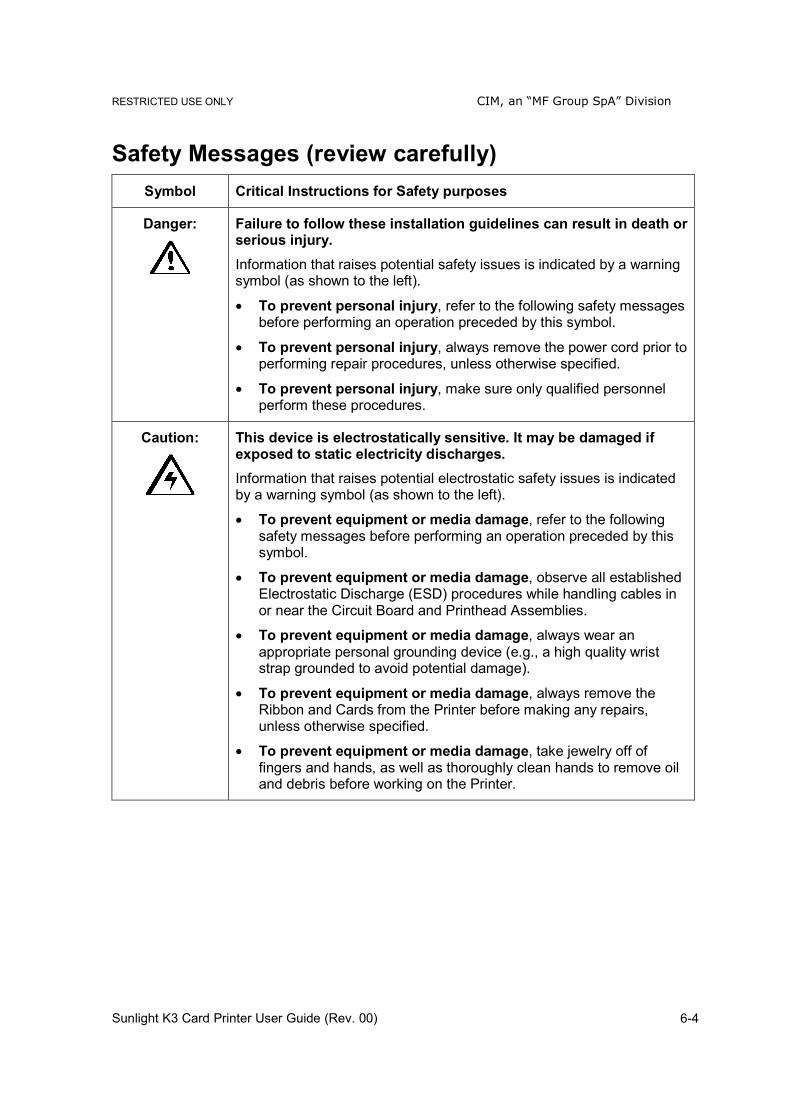
RESTRICTED USE ONLY CIM, an “MF Group SpA” Division
Sunlight K3 Card Printer User Guide (Rev. 00) 6-4
Safety Messages (review carefully) Symbol Critical Instructions for Safety purposes
Danger:
Failure to follow these installation guidelines can result in death or serious injury. Information that raises potential safety issues is indicated by a warning symbol (as shown to the left).
• To prevent personal injury, refer to the following safety messages before performing an operation preceded by this symbol.
• To prevent personal injury, always remove the power cord prior to performing repair procedures, unless otherwise specified.
• To prevent personal injury, make sure only qualified personnel perform these procedures.
Caution:
This device is electrostatically sensitive. It may be damaged if exposed to static electricity discharges. Information that raises potential electrostatic safety issues is indicated by a warning symbol (as shown to the left).
•
To prevent equipment or media damage, refer to the following safety messages before performing an operation preceded by this symbol.
•
To prevent equipment or media damage, observe all established Electrostatic Discharge (ESD) procedures while handling cables in or near the Circuit Board and Printhead Assemblies.
•
To prevent equipment or media damage, always wear an appropriate personal grounding device (e.g., a high quality wrist strap grounded to avoid potential damage).
• To prevent equipment or media damage, always remove the Ribbon and Cards from the Printer before making any repairs, unless otherwise specified.
• To prevent equipment or media damage, take jewelry off of fingers and hands, as well as thoroughly clean hands to remove oil and debris before working on the Printer.
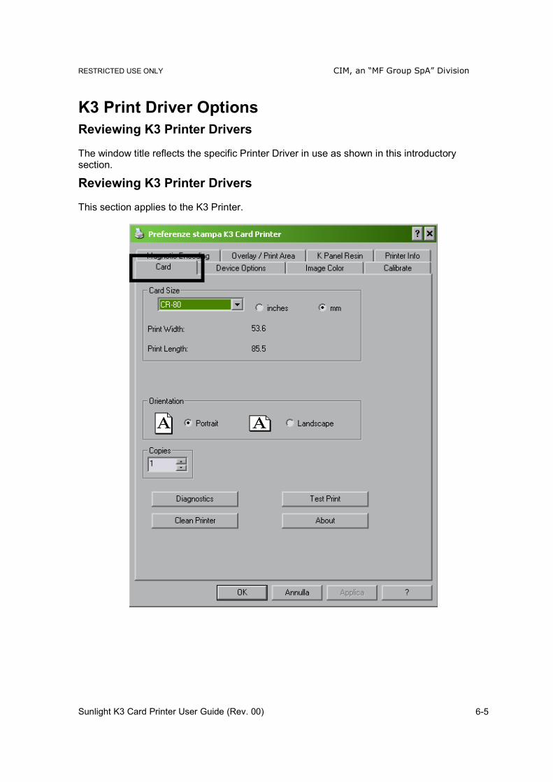
RESTRICTED USE ONLY CIM, an “MF Group SpA” Division
Sunlight K3 Card Printer User Guide (Rev. 00) 6-5
K3 Print Driver Options Reviewing K3 Printer Drivers
The window title reflects the specific Printer Driver in use as shown in this introductory section.
Reviewing K3 Printer Drivers
This section applies to the K3 Printer.
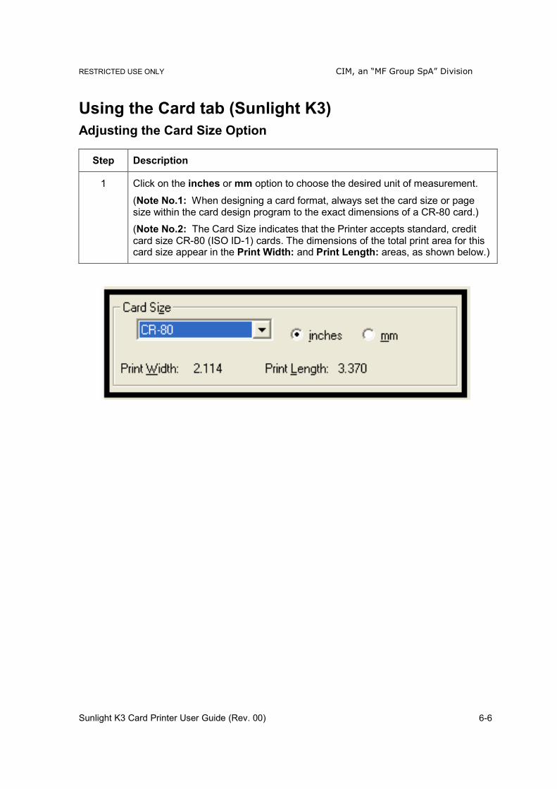
RESTRICTED USE ONLY CIM, an “MF Group SpA” Division
Sunlight K3 Card Printer User Guide (Rev. 00) 6-6
Using the Card tab (Sunlight K3) Adjusting the Card Size Option
Step Description
1 Click on the inches or mm option to choose the desired unit of measurement.
(Note No.1: When designing a card format, always set the card size or page size within the card design program to the exact dimensions of a CR-80 card.)
(Note No.2: The Card Size indicates that the Printer accepts standard, credit card size CR-80 (ISO ID-1) cards. The dimensions of the total print area for this card size appear in the Print Width: and Print Length: areas, as shown below.)
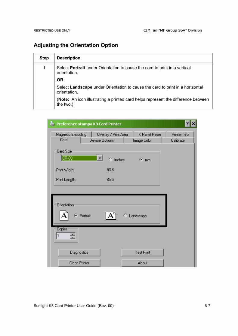
RESTRICTED USE ONLY CIM, an “MF Group SpA” Division
Sunlight K3 Card Printer User Guide (Rev. 00) 6-7
Adjusting the Orientation Option
Step Description
1 Select Portrait under Orientation to cause the card to print in a vertical orientation.
OR Select Landscape under Orientation to cause the card to print in a horizontal orientation.
(Note: An icon illustrating a printed card helps represent the difference between the two.)
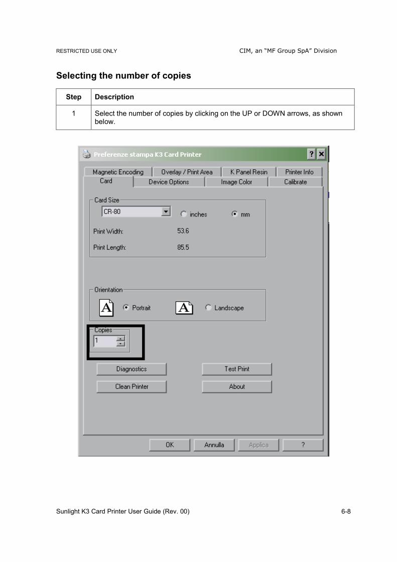
RESTRICTED USE ONLY CIM, an “MF Group SpA” Division
Sunlight K3 Card Printer User Guide (Rev. 00) 6-8
Selecting the number of copies
Step Description
1 Select the number of copies by clicking on the UP or DOWN arrows, as shown below.
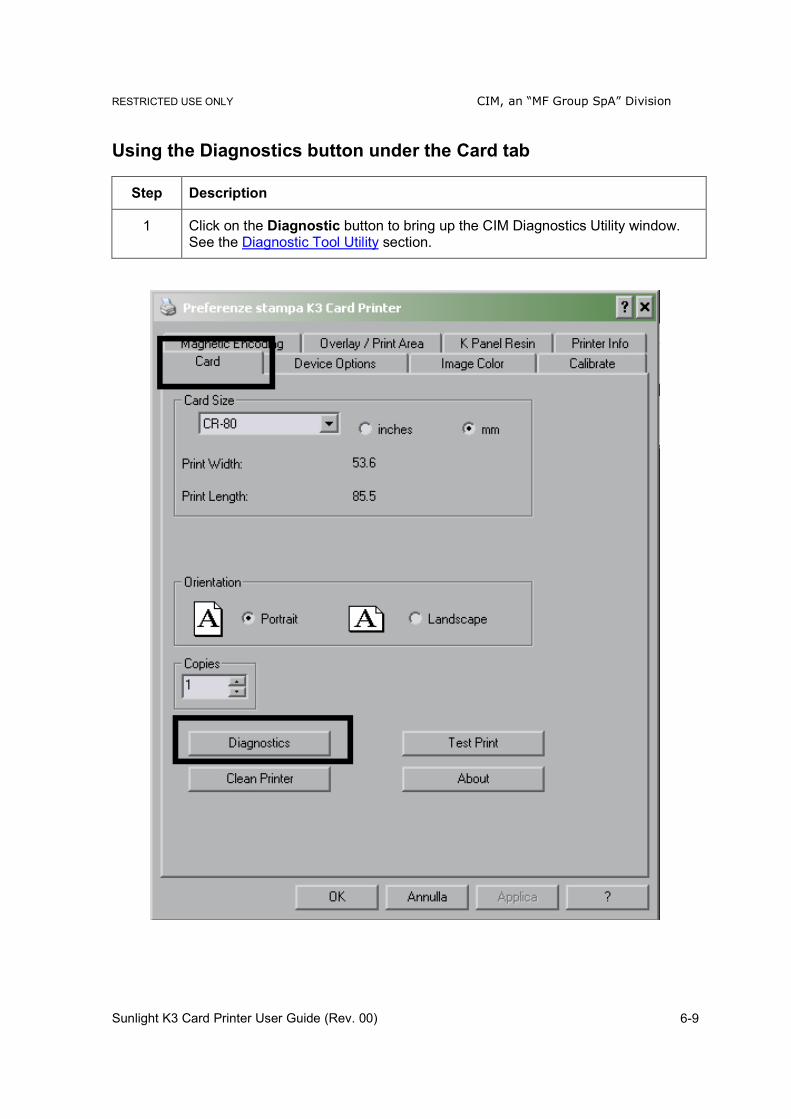
RESTRICTED USE ONLY CIM, an “MF Group SpA” Division
Sunlight K3 Card Printer User Guide (Rev. 00) 6-9
Using the Diagnostics button under the Card tab
Step Description
1 Click on the Diagnostic button to bring up the CIM Diagnostics Utility window. See the Diagnostic Tool Utility section.
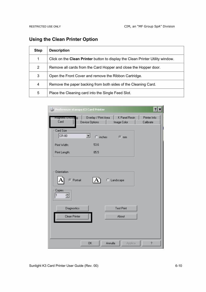
RESTRICTED USE ONLY CIM, an “MF Group SpA” Division
Sunlight K3 Card Printer User Guide (Rev. 00) 6-10
Using the Clean Printer Option
Step Description
1 Click on the Clean Printer button to display the Clean Printer Utility window.
2 Remove all cards from the Card Hopper and close the Hopper door.
3 Open the Front Cover and remove the Ribbon Cartridge.
4 Remove the paper backing from both sides of the Cleaning Card.
5 Place the Cleaning card into the Single Feed Slot.
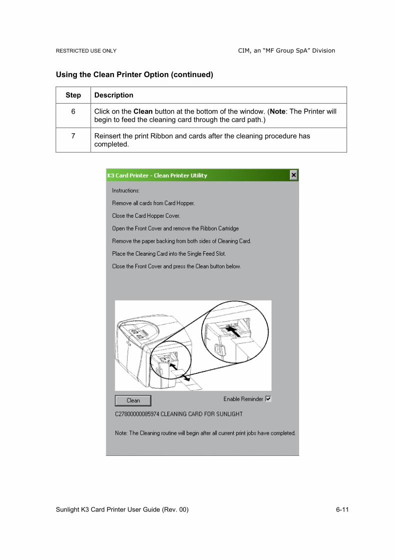
RESTRICTED USE ONLY CIM, an “MF Group SpA” Division
Sunlight K3 Card Printer User Guide (Rev. 00) 6-11
Using the Clean Printer Option (continued)
Step Description
6 Click on the Clean button at the bottom of the window. (Note: The Printer will begin to feed the cleaning card through the card path.)
7 Reinsert the print Ribbon and cards after the cleaning procedure has completed.
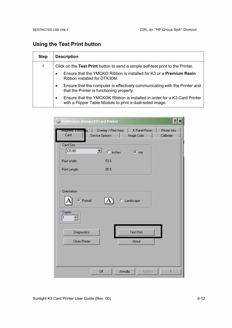
RESTRICTED USE ONLY CIM, an “MF Group SpA” Division
Sunlight K3 Card Printer User Guide (Rev. 00) 6-12
Using the Test Print button
Step Description
1 Click on the Test Print button to send a simple self-test print to the Printer.
•
Ensure that the YMCKO Ribbon is installed for K3 or a Premium Resin Ribbon installed for DTK30M.
•
Ensure that the computer is effectively communicating with the Printer and that the Printer is functioning properly.
• Ensure that the YMCKOK Ribbon is installed in order for a K3 Card Printer with a Flipper Table Module to print a dual-sided image.
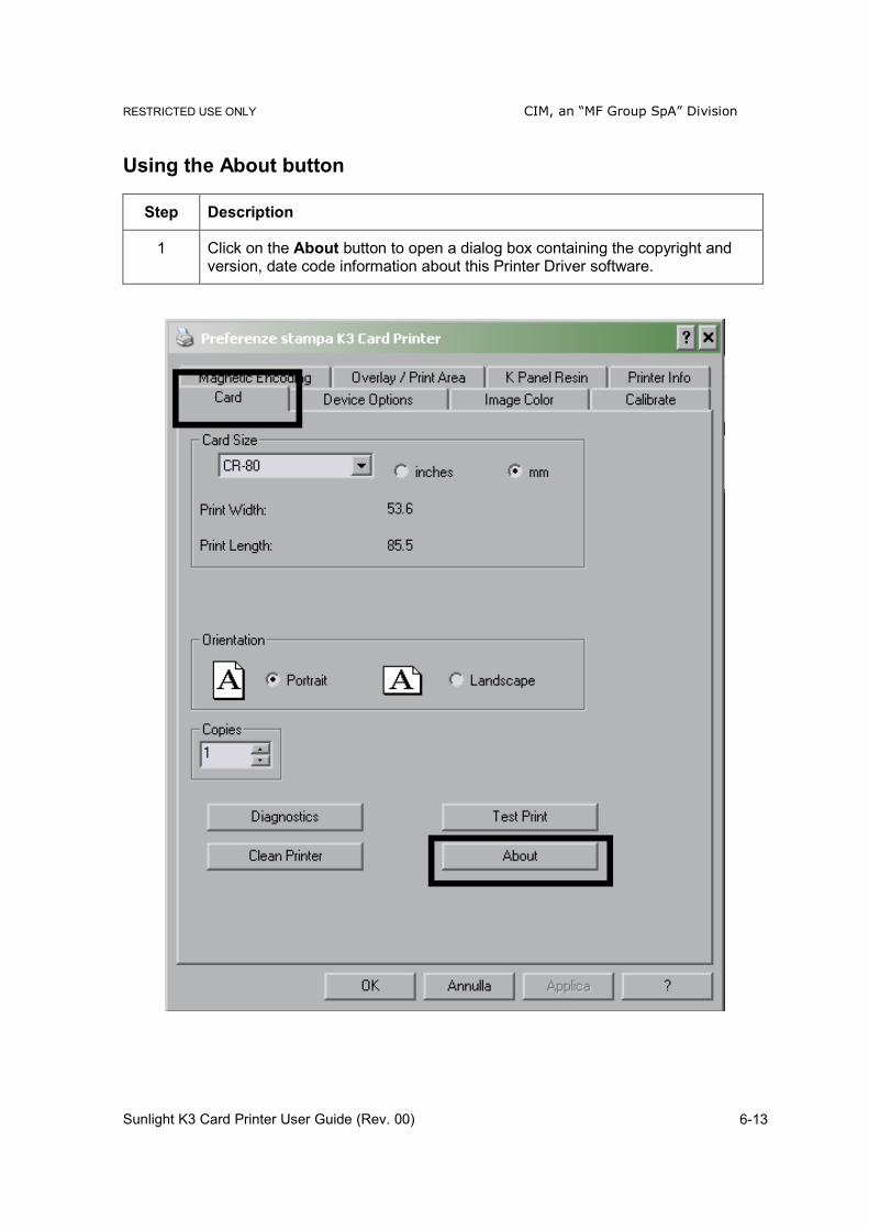
RESTRICTED USE ONLY CIM, an “MF Group SpA” Division
Sunlight K3 Card Printer User Guide (Rev. 00) 6-13
Using the About button
Step Description
1 Click on the About button to open a dialog box containing the copyright and version, date code information about this Printer Driver software.
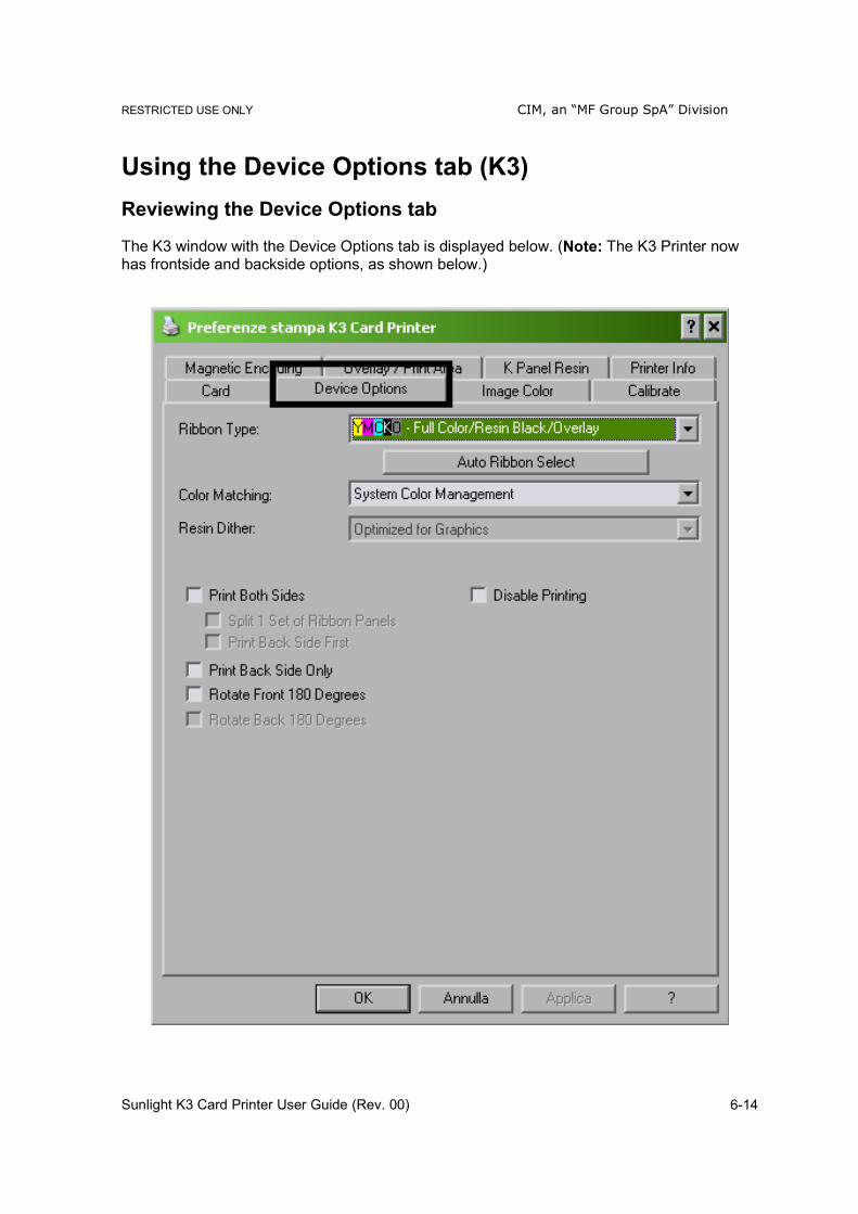
RESTRICTED USE ONLY CIM, an “MF Group SpA” Division
Sunlight K3 Card Printer User Guide (Rev. 00) 6-14
Using the Device Options tab (K3) Reviewing the Device Options tab
The K3 window with the Device Options tab is displayed below. (Note: The K3 Printer now has frontside and backside options, as shown below.)
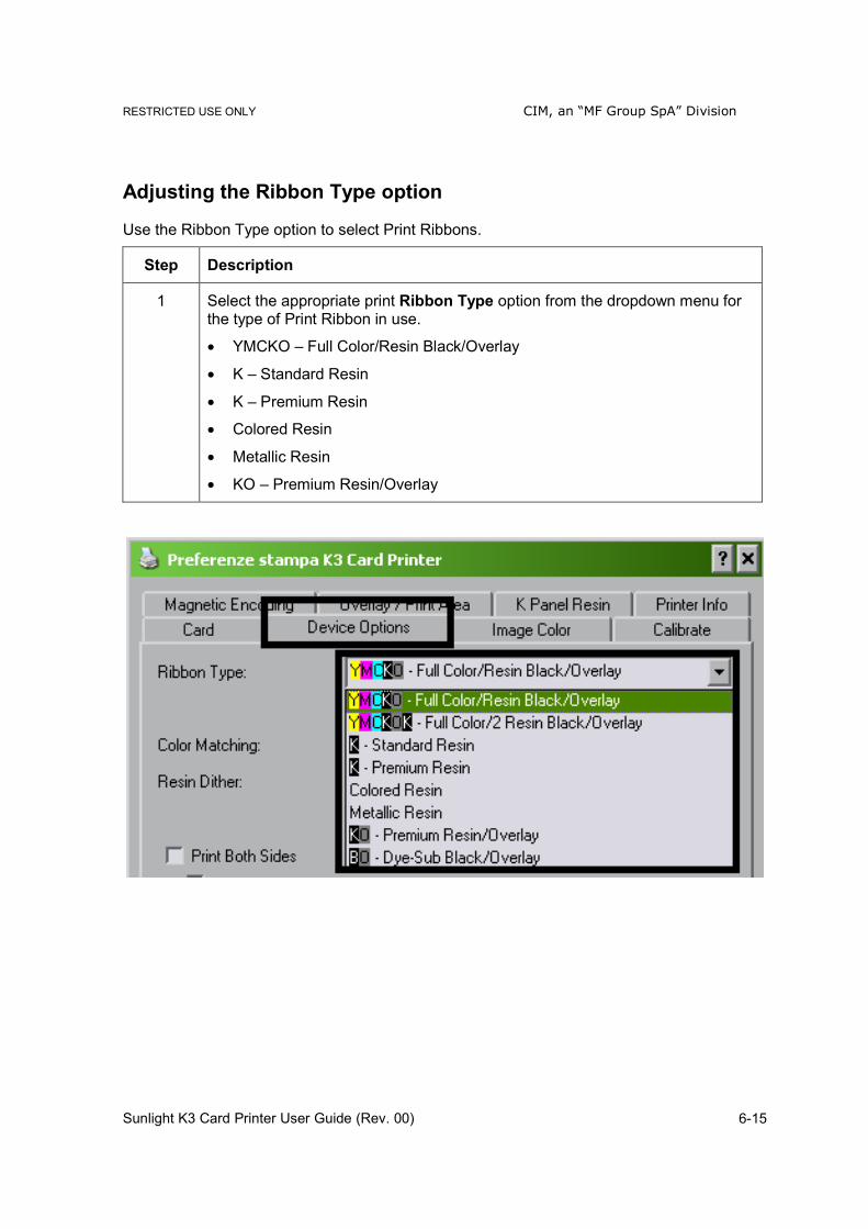
RESTRICTED USE ONLY CIM, an “MF Group SpA” Division
Sunlight K3 Card Printer User Guide (Rev. 00) 6-15
Adjusting the Ribbon Type option
Use the Ribbon Type option to select Print Ribbons.
Step Description
1 Select the appropriate print Ribbon Type option from the dropdown menu for the type of Print Ribbon in use.
•
YMCKO – Full Color/Resin Black/Overlay
• K – Standard Resin
• K – Premium Resin
•
Colored Resin
• Metallic Resin
• KO – Premium Resin/Overlay
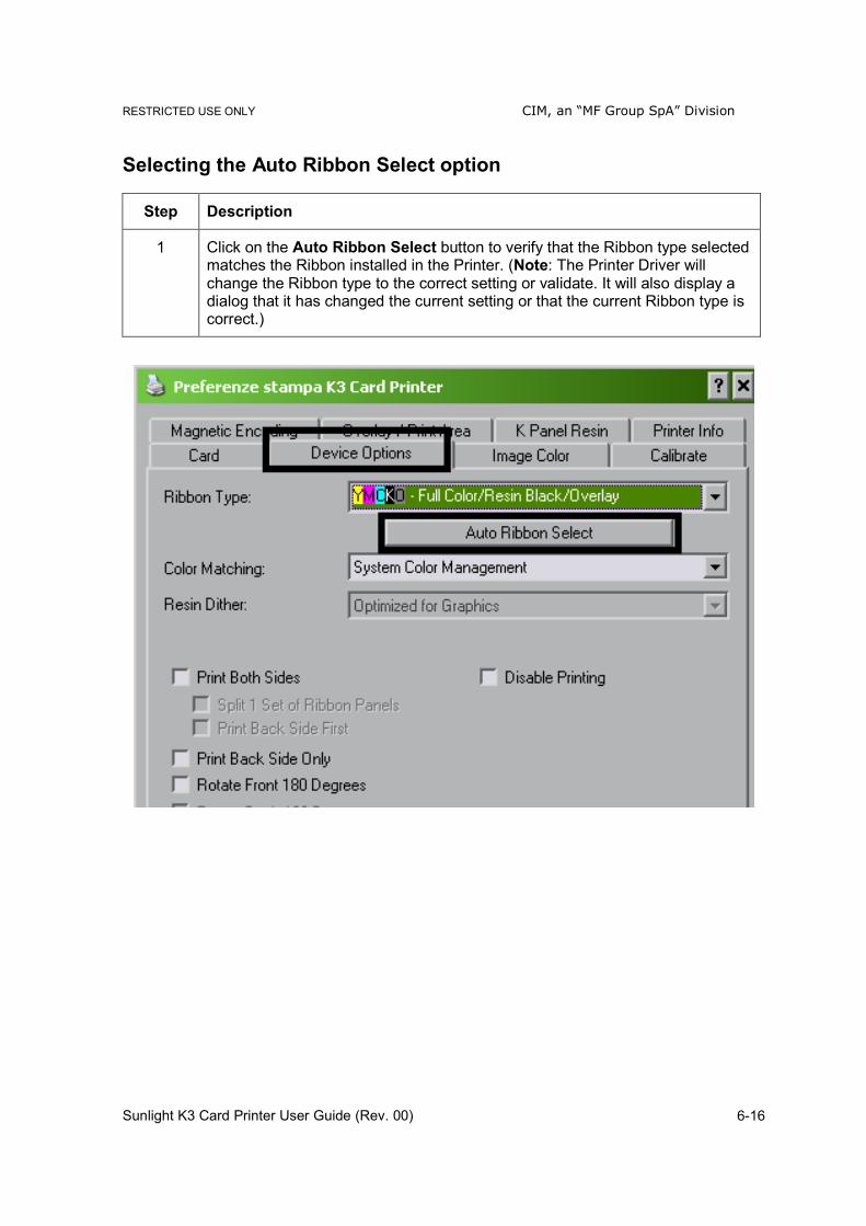
RESTRICTED USE ONLY CIM, an “MF Group SpA” Division
Sunlight K3 Card Printer User Guide (Rev. 00) 6-16
Selecting the Auto Ribbon Select option
Step Description
1 Click on the Auto Ribbon Select button to verify that the Ribbon type selected matches the Ribbon installed in the Printer. (Note: The Printer Driver will change the Ribbon type to the correct setting or validate. It will also display a dialog that it has changed the current setting or that the current Ribbon type is correct.)
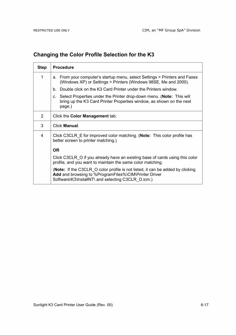
RESTRICTED USE ONLY CIM, an “MF Group SpA” Division
Sunlight K3 Card Printer User Guide (Rev. 00) 6-17
Changing the Color Profile Selection for the K3
Step Procedure
1 a. From your computer’s startup menu, select Settings > Printers and Faxes (Windows XP) or Settings > Printers (Windows 98SE, Me and 2000).
b. Double click on the K3 Card Printer under the Printers window.
c. Select Properties under the Printer drop-down menu. (Note: This will bring up the K3 Card Printer Properties window, as shown on the next page.)
2 Click the Color Management tab.
3 Click Manual.
4 Click C3CLR_E for improved color matching. (Note: This color profile has better screen to printer matching.) OR
Click C3CLR_O if you already have an existing base of cards using this color profile, and you want to maintain the same color matching.
(Note: If the C3CLR_O color profile is not listed, it can be added by clicking Add and browsing to %ProgramFiles%\CIM\Printer Driver Software\K3\InstallNT\ and selecting C3CLR_O.icm.)
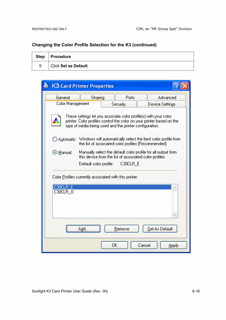
RESTRICTED USE ONLY CIM, an “MF Group SpA” Division
Sunlight K3 Card Printer User Guide (Rev. 00) 6-18
Changing the Color Profile Selection for the K3 (continued)
Step Procedure
5 Click Set as Default.
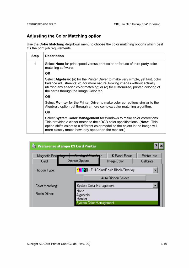
RESTRICTED USE ONLY CIM, an “MF Group SpA” Division
Sunlight K3 Card Printer User Guide (Rev. 00) 6-19
Adjusting the Color Matching option
Use the Color Matching dropdown menu to choose the color matching options which best fits the print job requirements.
Step Description
1 Select None for print speed versus print color or for use of third party color matching software.
OR Select Algebraic (a) for the Printer Driver to make very simple, yet fast, color balance adjustments; (b) for more natural looking images without actually utilizing any specific color matching; or (c) for customized, printed coloring of the cards through the Image Color tab.
OR Select Monitor for the Printer Driver to make color corrections similar to the Algebraic option but through a more complex color matching algorithm.
OR Select System Color Management for Windows to make color corrections. This provides a closer match to the sRGB color specifications. (Note: This option shifts colors to a different color model so the colors in the image will more closely match how they appear on the monitor.)
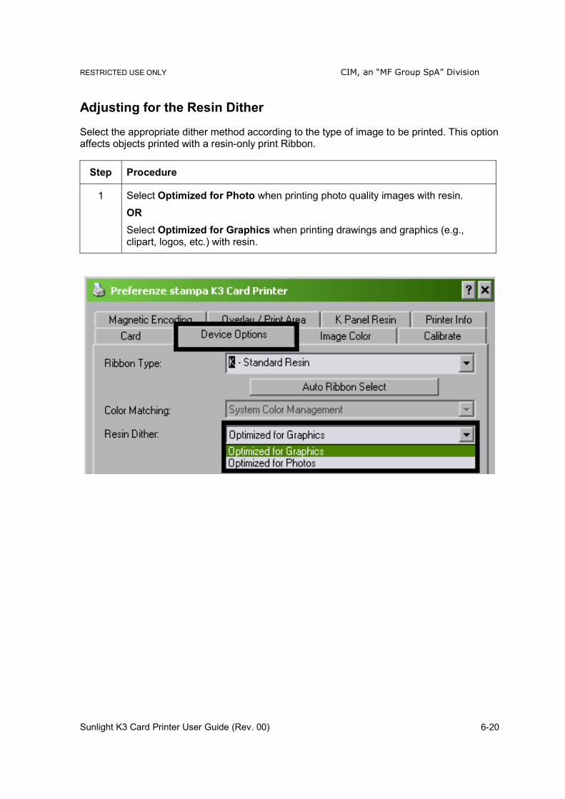
RESTRICTED USE ONLY CIM, an “MF Group SpA” Division
Sunlight K3 Card Printer User Guide (Rev. 00) 6-20
Adjusting for the Resin Dither
Select the appropriate dither method according to the type of image to be printed. This option affects objects printed with a resin-only print Ribbon.
Step Procedure
1 Select Optimized for Photo when printing photo quality images with resin.
OR Select Optimized for Graphics when printing drawings and graphics (e.g., clipart, logos, etc.) with resin.
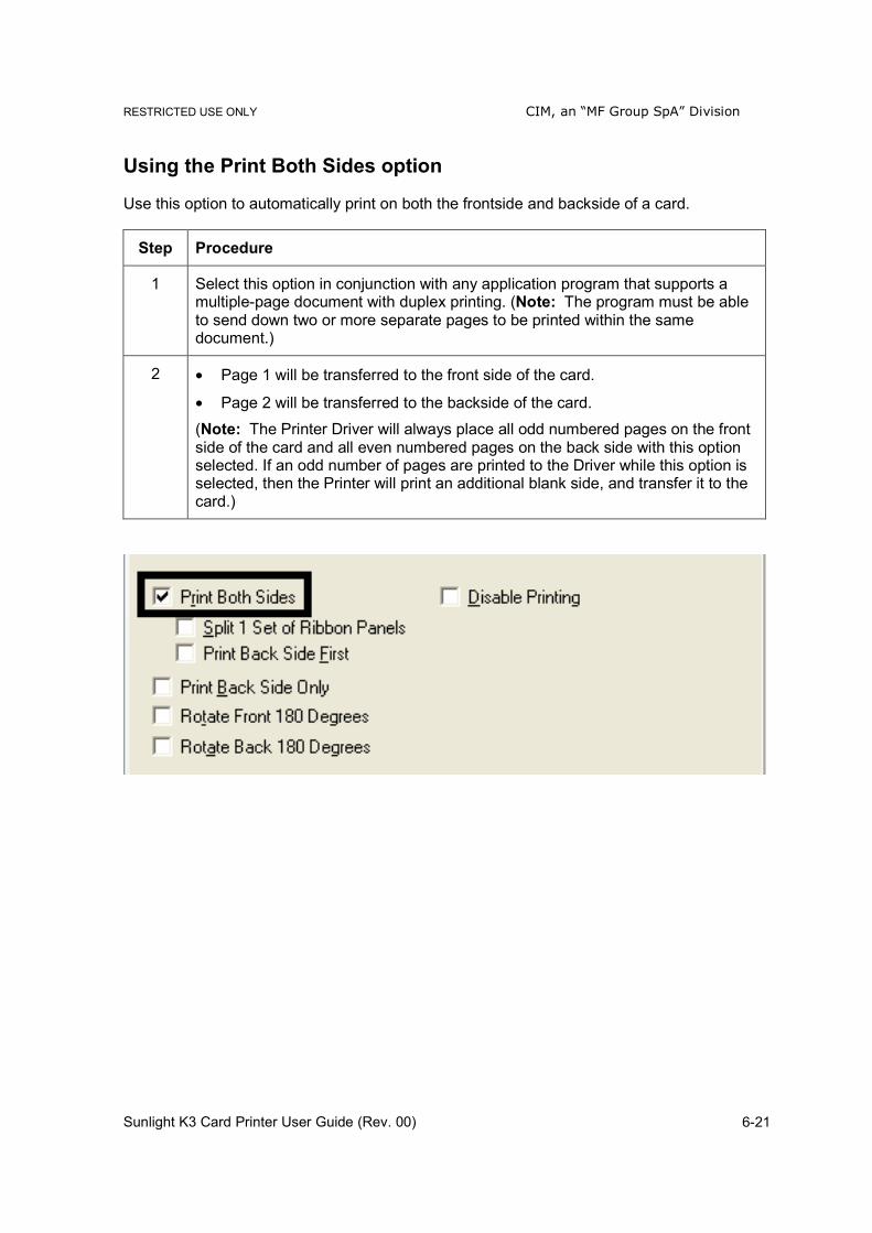
RESTRICTED USE ONLY CIM, an “MF Group SpA” Division
Sunlight K3 Card Printer User Guide (Rev. 00) 6-21
Using the Print Both Sides option
Use this option to automatically print on both the frontside and backside of a card.
Step Procedure
1 Select this option in conjunction with any application program that supports a multiple-page document with duplex printing. (Note: The program must be able to send down two or more separate pages to be printed within the same document.)
2 • Page 1 will be transferred to the front side of the card.
• Page 2 will be transferred to the backside of the card.
(Note: The Printer Driver will always place all odd numbered pages on the front side of the card and all even numbered pages on the back side with this option selected. If an odd number of pages are printed to the Driver while this option is selected, then the Printer will print an additional blank side, and transfer it to the card.)
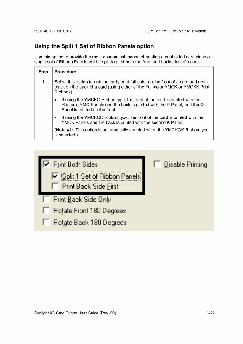
RESTRICTED USE ONLY CIM, an “MF Group SpA” Division
Sunlight K3 Card Printer User Guide (Rev. 00) 6-22
Using the Split 1 Set of Ribbon Panels option
Use this option to provide the most economical means of printing a dual-sided card since a single set of Ribbon Panels will be split to print both the front and backsides of a card.
Step Procedure
1 Select this option to automatically print full-color on the front of a card and resin black on the back of a card (using either of the Full-color YMCK or YMCKK Print Ribbons).
• If using the YMCKO Ribbon type, the front of the card is printed with the Ribbon's YMC Panels and the back is printed with the K Panel, and the O Panel is printed on the front.
• If using the YMCKOK Ribbon type, the front of the card is printed with the YMCK Panels and the back is printed with the second K Panel.
(Note #1: This option is automatically enabled when the YMCKOK Ribbon type is selected.)
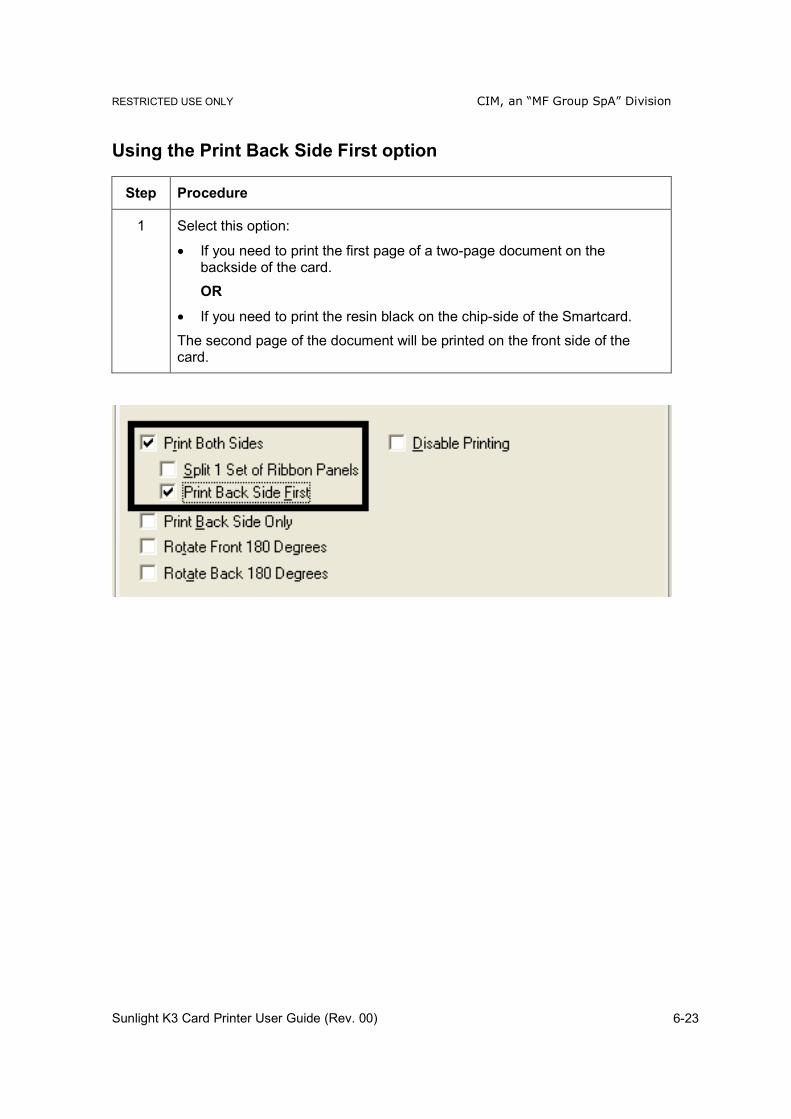
RESTRICTED USE ONLY CIM, an “MF Group SpA” Division
Sunlight K3 Card Printer User Guide (Rev. 00) 6-23
Using the Print Back Side First option
Step Procedure
1 Select this option:
•
If you need to print the first page of a two-page document on the backside of the card.
OR
• If you need to print the resin black on the chip-side of the Smartcard.
The second page of the document will be printed on the front side of the card.
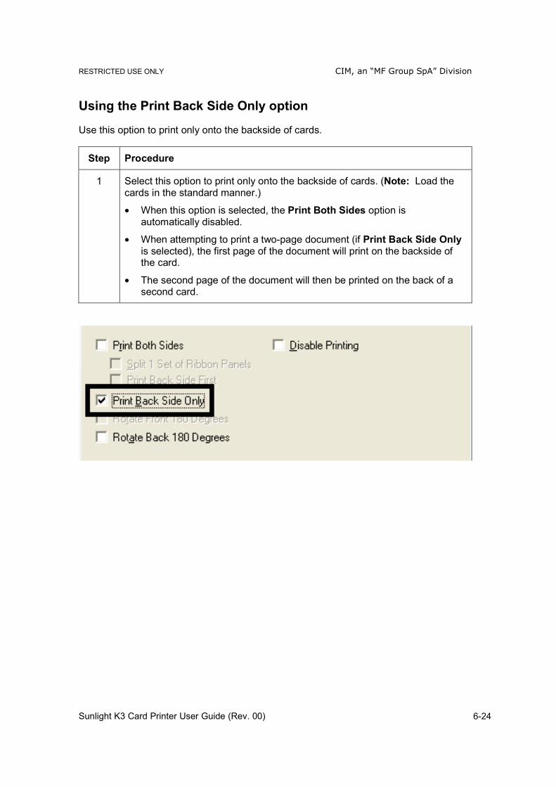
RESTRICTED USE ONLY CIM, an “MF Group SpA” Division
Sunlight K3 Card Printer User Guide (Rev. 00) 6-24
Using the Print Back Side Only option
Use this option to print only onto the backside of cards.
Step Procedure
1 Select this option to print only onto the backside of cards. (Note: Load the cards in the standard manner.)
• When this option is selected, the Print Both Sides option is automatically disabled.
• When attempting to print a two-page document (if Print Back Side Only is selected), the first page of the document will print on the backside of the card.
• The second page of the document will then be printed on the back of a second card.
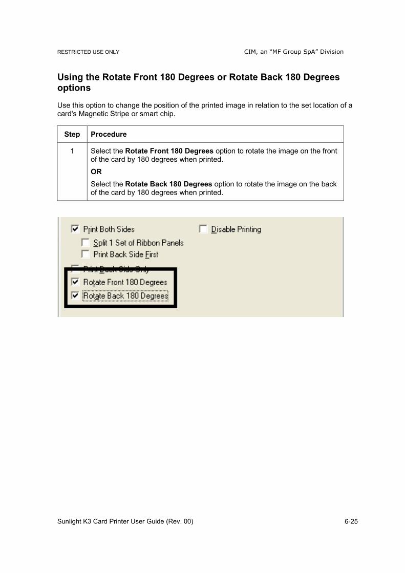
RESTRICTED USE ONLY CIM, an “MF Group SpA” Division
Sunlight K3 Card Printer User Guide (Rev. 00) 6-25
Using the Rotate Front 180 Degrees or Rotate Back 180 Degrees options
Use this option to change the position of the printed image in relation to the set location of a card's Magnetic Stripe or smart chip.
Step Procedure
1 Select the Rotate Front 180 Degrees option to rotate the image on the front of the card by 180 degrees when printed.
OR Select the Rotate Back 180 Degrees option to rotate the image on the back of the card by 180 degrees when printed.
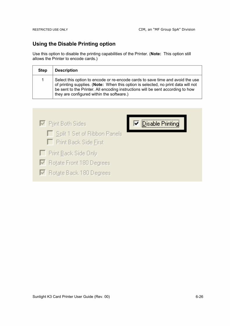
RESTRICTED USE ONLY CIM, an “MF Group SpA” Division
Sunlight K3 Card Printer User Guide (Rev. 00) 6-26
Using the Disable Printing option
Use this option to disable the printing capabilities of the Printer. (Note: This option still allows the Printer to encode cards.)
Step Description
1 Select this option to encode or re-encode cards to save time and avoid the use of printing supplies. (Note: When this option is selected, no print data will not be sent to the Printer. All encoding instructions will be sent according to how they are configured within the software.)

RESTRICTED USE ONLY CIM, an “MF Group SpA” Division
Sunlight K3 Card Printer User Guide (Rev. 00) 6-27
Using the Image Color tab (K3)
Step Procedure
1 Select the Algebraic color matching option and then use this option to control the Contrast and Gamma of the printed image, as well as the individual color balance of Yellow, Magenta and Cyan. (Note: In most cases, the default settings of these options will suffice.)
2 Control the overall darkness and lightness of the printed image by adjusting the Dye-Sub Intensity slide by clicking and dragging the slide.
• Move the slide to the left to cause less heat to be used in the printing process, thus generating a lighter print.
OR
•
Move the slide to the right to cause more heat to be used, thus generating a darker print. (Note: This slide only affects those images printed with dye-sublimation Ribbon panels (YMC).)
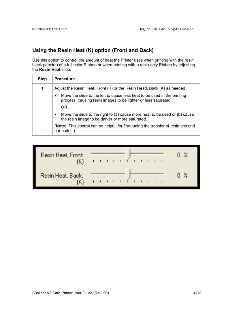
RESTRICTED USE ONLY CIM, an “MF Group SpA” Division
Sunlight K3 Card Printer User Guide (Rev. 00) 6-28
Using the Resin Heat (K) option (Front and Back)
Use this option to control the amount of heat the Printer uses when printing with the resin black panel(s) of a full-color Ribbon or when printing with a resin-only Ribbon by adjusting the Resin Heat slide.
Step Procedure
1 Adjust the Resin Heat, Front (K) or the Resin Head, Back (K) as needed.
•
Move the slide to the left to cause less heat to be used in the printing process, causing resin images to be lighter or less saturated.
OR
• Move the slide to the right to (a) cause more heat to be used or (b) cause the resin image to be darker or more saturated.
(Note: This control can be helpful for fine-tuning the transfer of resin text and bar codes.)
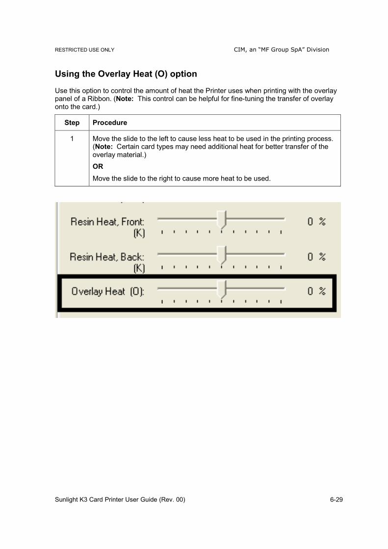
RESTRICTED USE ONLY CIM, an “MF Group SpA” Division
Sunlight K3 Card Printer User Guide (Rev. 00) 6-29
Using the Overlay Heat (O) option
Use this option to control the amount of heat the Printer uses when printing with the overlay panel of a Ribbon. (Note: This control can be helpful for fine-tuning the transfer of overlay onto the card.)
Step Procedure
1 Move the slide to the left to cause less heat to be used in the printing process. (Note: Certain card types may need additional heat for better transfer of the overlay material.)
OR Move the slide to the right to cause more heat to be used.
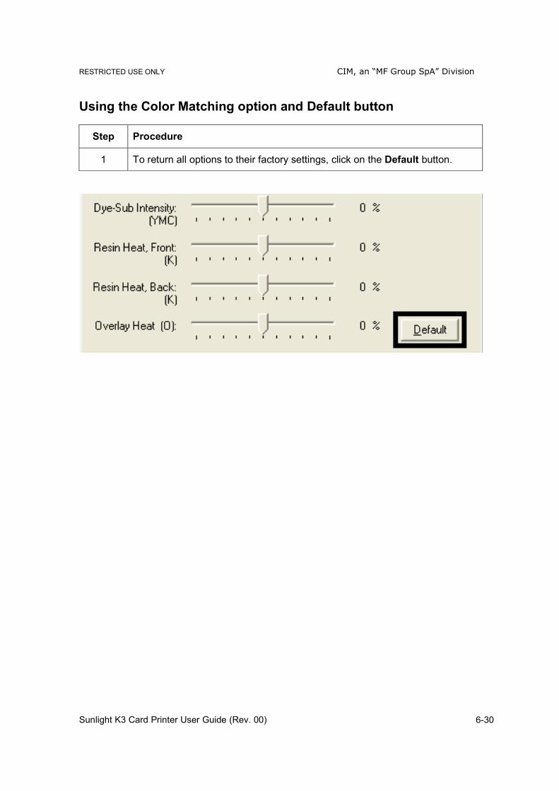
RESTRICTED USE ONLY CIM, an “MF Group SpA” Division
Sunlight K3 Card Printer User Guide (Rev. 00) 6-30
Using the Color Matching option and Default button
Step Procedure
1 To return all options to their factory settings, click on the Default button.
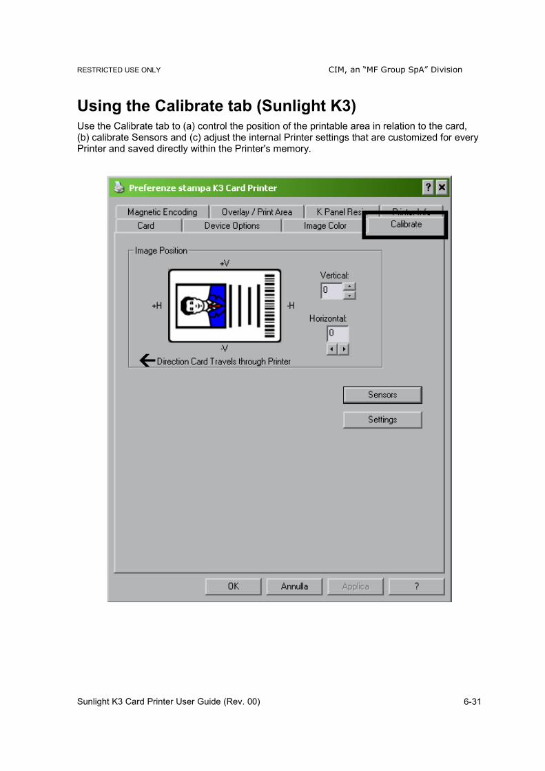
RESTRICTED USE ONLY CIM, an “MF Group SpA” Division
Sunlight K3 Card Printer User Guide (Rev. 00) 6-31
Using the Calibrate tab (Sunlight K3) Use the Calibrate tab to (a) control the position of the printable area in relation to the card, (b) calibrate Sensors and (c) adjust the internal Printer settings that are customized for every Printer and saved directly within the Printer's memory.
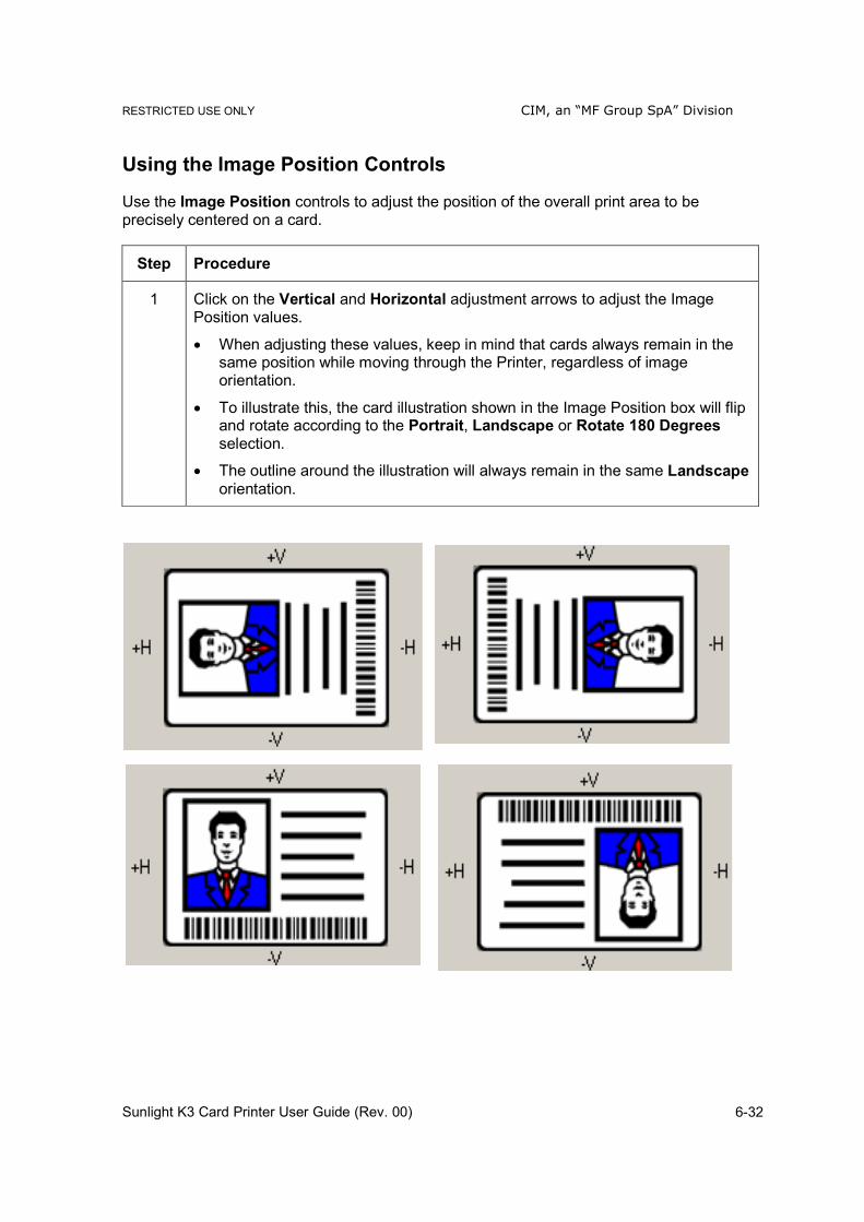
RESTRICTED USE ONLY CIM, an “MF Group SpA” Division
Sunlight K3 Card Printer User Guide (Rev. 00) 6-32
Using the Image Position Controls
Use the Image Position controls to adjust the position of the overall print area to be precisely centered on a card.
Step Procedure
1 Click on the Vertical and Horizontal adjustment arrows to adjust the Image Position values.
•
When adjusting these values, keep in mind that cards always remain in the same position while moving through the Printer, regardless of image orientation.
•
To illustrate this, the card illustration shown in the Image Position box will flip and rotate according to the Portrait, Landscape or Rotate 180 Degrees selection.
•
The outline around the illustration will always remain in the same Landscape orientation.
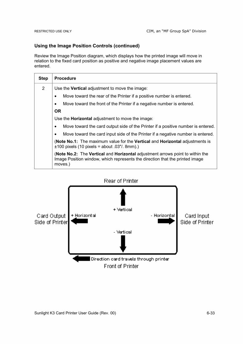
RESTRICTED USE ONLY CIM, an “MF Group SpA” Division
Sunlight K3 Card Printer User Guide (Rev. 00) 6-33
Using the Image Position Controls (continued)
Review the Image Position diagram, which displays how the printed image will move in relation to the fixed card position as positive and negative image placement values are entered.
Step Procedure
2 Use the Vertical adjustment to move the image:
• Move toward the rear of the Printer if a positive number is entered.
•
Move toward the front of the Printer if a negative number is entered.
OR Use the Horizontal adjustment to move the image:
• Move toward the card output side of the Printer if a positive number is entered.
• Move toward the card input side of the Printer if a negative number is entered.
(Note No.1: The maximum value for the Vertical and Horizontal adjustments is ±100 pixels (10 pixels = about .03"/. 8mm).)
(Note No.2: The Vertical and Horizontal adjustment arrows point to within the Image Position window, which represents the direction that the printed image moves.)
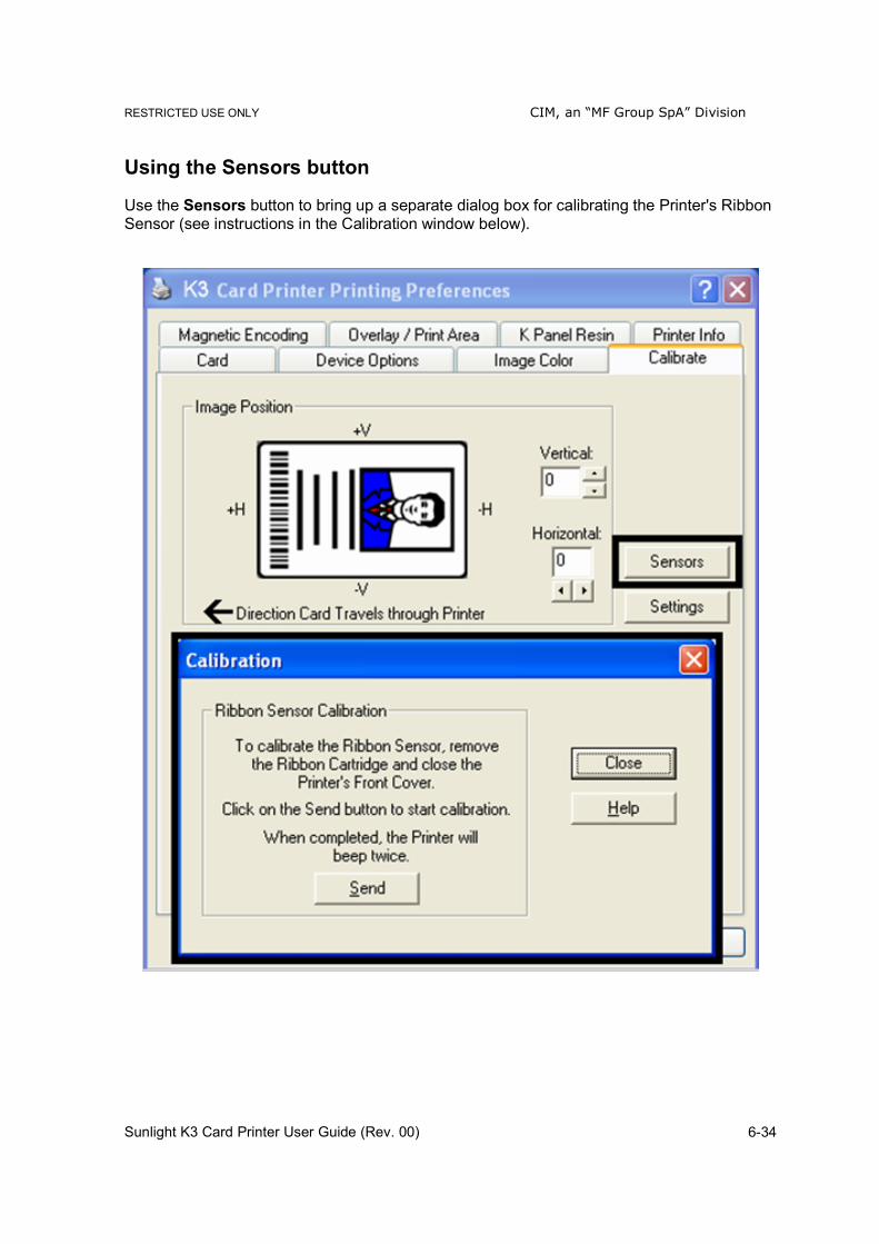
RESTRICTED USE ONLY CIM, an “MF Group SpA” Division
Sunlight K3 Card Printer User Guide (Rev. 00) 6-34
Using the Sensors button
Use the Sensors button to bring up a separate dialog box for calibrating the Printer's Ribbon Sensor (see instructions in the Calibration window below).
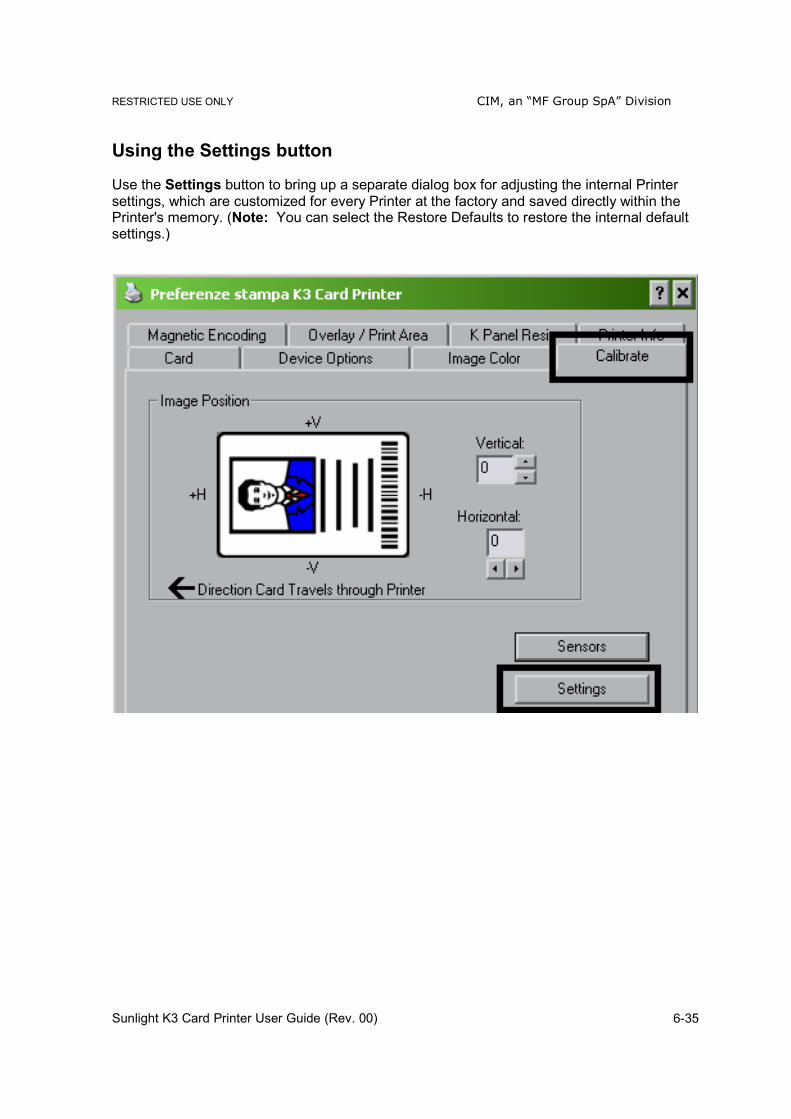
RESTRICTED USE ONLY CIM, an “MF Group SpA” Division
Sunlight K3 Card Printer User Guide (Rev. 00) 6-35
Using the Settings button
Use the Settings button to bring up a separate dialog box for adjusting the internal Printer settings, which are customized for every Printer at the factory and saved directly within the Printer's memory. (Note: You can select the Restore Defaults to restore the internal default settings.)
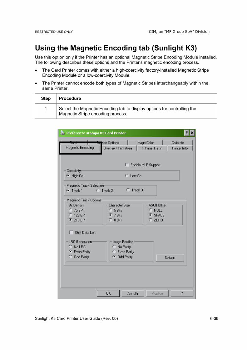
RESTRICTED USE ONLY CIM, an “MF Group SpA” Division
Sunlight K3 Card Printer User Guide (Rev. 00) 6-36
Using the Magnetic Encoding tab (Sunlight K3) Use this option only if the Printer has an optional Magnetic Stripe Encoding Module installed. The following describes these options and the Printer's magnetic encoding process.
• The Card Printer comes with either a high-coercivity factory-installed Magnetic Stripe Encoding Module or a low-coercivity Module.
• The Printer cannot encode both types of Magnetic Stripes interchangeably within the same Printer.
Step Procedure
1 Select the Magnetic Encoding tab to display options for controlling the Magnetic Stripe encoding process.
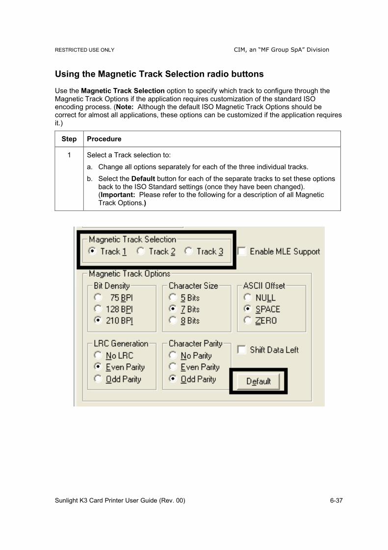
RESTRICTED USE ONLY CIM, an “MF Group SpA” Division
Sunlight K3 Card Printer User Guide (Rev. 00) 6-37
Using the Magnetic Track Selection radio buttons
Use the Magnetic Track Selection option to specify which track to configure through the Magnetic Track Options if the application requires customization of the standard ISO encoding process. (Note: Although the default ISO Magnetic Track Options should be correct for almost all applications, these options can be customized if the application requires it.)
Step Procedure
1 Select a Track selection to:
a. Change all options separately for each of the three individual tracks.
b. Select the Default button for each of the separate tracks to set these options back to the ISO Standard settings (once they have been changed). (Important: Please refer to the following for a description of all Magnetic Track Options.)
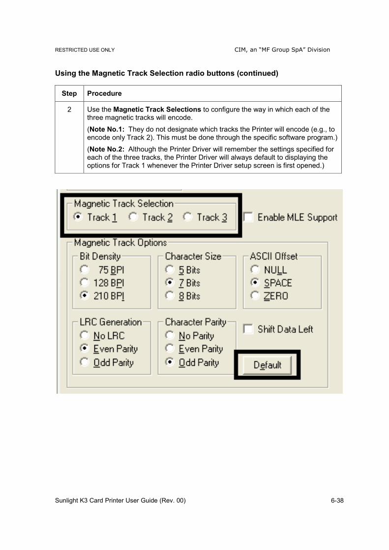
RESTRICTED USE ONLY CIM, an “MF Group SpA” Division
Sunlight K3 Card Printer User Guide (Rev. 00) 6-38
Using the Magnetic Track Selection radio buttons (continued)
Step Procedure
2 Use the Magnetic Track Selections to configure the way in which each of the three magnetic tracks will encode.
(Note No.1: They do not designate which tracks the Printer will encode (e.g., to encode only Track 2). This must be done through the specific software program.)
(Note No.2: Although the Printer Driver will remember the settings specified for each of the three tracks, the Printer Driver will always default to displaying the options for Track 1 whenever the Printer Driver setup screen is first opened.)

RESTRICTED USE ONLY CIM, an “MF Group SpA” Division
Sunlight K3 Card Printer User Guide (Rev. 00) 6-39
Using the Magnetic Track Options radio buttons
Use the Magnetic Track options for these purposes:
•
Customize the Magnetic encoding parameters
• for each of the Magnetic Stripe's three tracks.
• Customize each track independently of the other two.
•
Specify which of the three tracks to customize by selecting one of the three track options.
(Note No.1: After making the required selection, the Magnetic Track Options box displays the current set of customization options for the selected track.)
(Note No.2: For most applications, the default settings for these options do not need to be changed.)
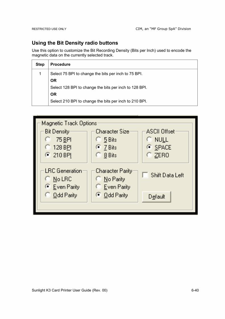
RESTRICTED USE ONLY CIM, an “MF Group SpA” Division
Sunlight K3 Card Printer User Guide (Rev. 00) 6-40
Using the Bit Density radio buttons Use this option to customize the Bit Recording Density (Bits per Inch) used to encode the magnetic data on the currently selected track.
Step Procedure
1 Select 75 BPI to change the bits per inch to 75 BPI.
OR Select 128 BPI to change the bits per inch to 128 BPI.
OR Select 210 BPI to change the bits per inch to 210 BPI.
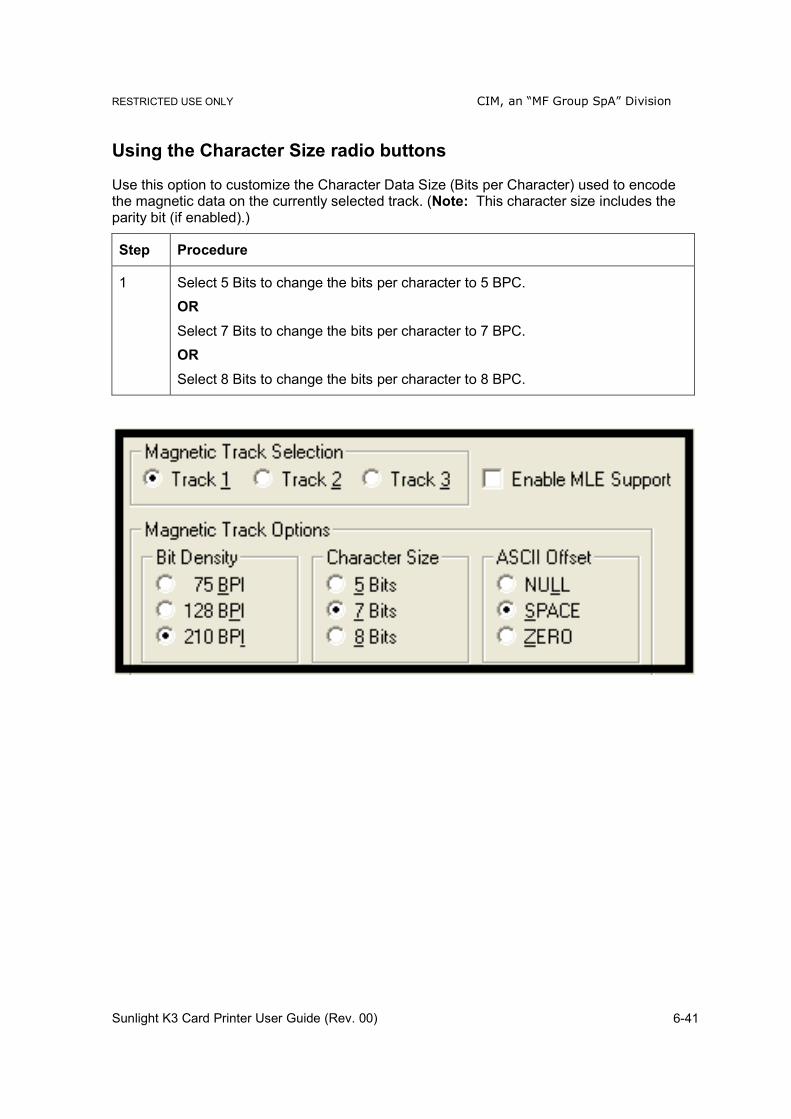
RESTRICTED USE ONLY CIM, an “MF Group SpA” Division
Sunlight K3 Card Printer User Guide (Rev. 00) 6-41
Using the Character Size radio buttons
Use this option to customize the Character Data Size (Bits per Character) used to encode the magnetic data on the currently selected track. (Note: This character size includes the parity bit (if enabled).)
Step Procedure
1 Select 5 Bits to change the bits per character to 5 BPC.
OR Select 7 Bits to change the bits per character to 7 BPC.
OR Select 8 Bits to change the bits per character to 8 BPC.
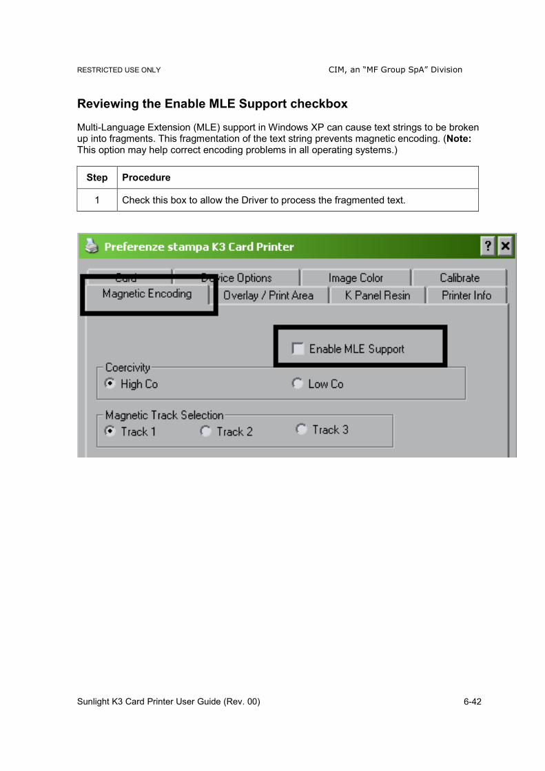
RESTRICTED USE ONLY CIM, an “MF Group SpA” Division
Sunlight K3 Card Printer User Guide (Rev. 00) 6-42
Reviewing the Enable MLE Support checkbox
Multi-Language Extension (MLE) support in Windows XP can cause text strings to be broken up into fragments. This fragmentation of the text string prevents magnetic encoding. (Note: This option may help correct encoding problems in all operating systems.)
Step Procedure
1 Check this box to allow the Driver to process the fragmented text.
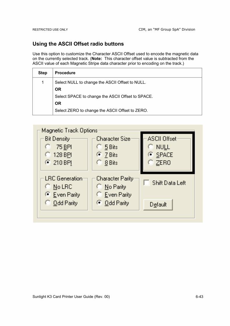
RESTRICTED USE ONLY CIM, an “MF Group SpA” Division
Sunlight K3 Card Printer User Guide (Rev. 00) 6-43
Using the ASCII Offset radio buttons
Use this option to customize the Character ASCII Offset used to encode the magnetic data on the currently selected track. (Note: This character offset value is subtracted from the ASCII value of each Magnetic Stripe data character prior to encoding on the track.)
Step Procedure
1 Select NULL to change the ASCII Offset to NULL.
OR Select SPACE to change the ASCII Offset to SPACE.
OR Select ZERO to change the ASCII Offset to ZERO.
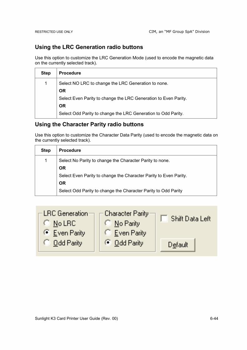
RESTRICTED USE ONLY CIM, an “MF Group SpA” Division
Sunlight K3 Card Printer User Guide (Rev. 00) 6-44
Using the LRC Generation radio buttons
Use this option to customize the LRC Generation Mode (used to encode the magnetic data on the currently selected track).
Step Procedure
1 Select NO LRC to change the LRC Generation to none.
OR Select Even Parity to change the LRC Generation to Even Parity.
OR Select Odd Parity to change the LRC Generation to Odd Parity.
Using the Character Parity radio buttons
Use this option to customize the Character Data Parity (used to encode the magnetic data on the currently selected track).
Step Procedure
1 Select No Parity to change the Character Parity to none.
OR Select Even Parity to change the Character Parity to Even Parity.
OR Select Odd Parity to change the Character Parity to Odd Parity
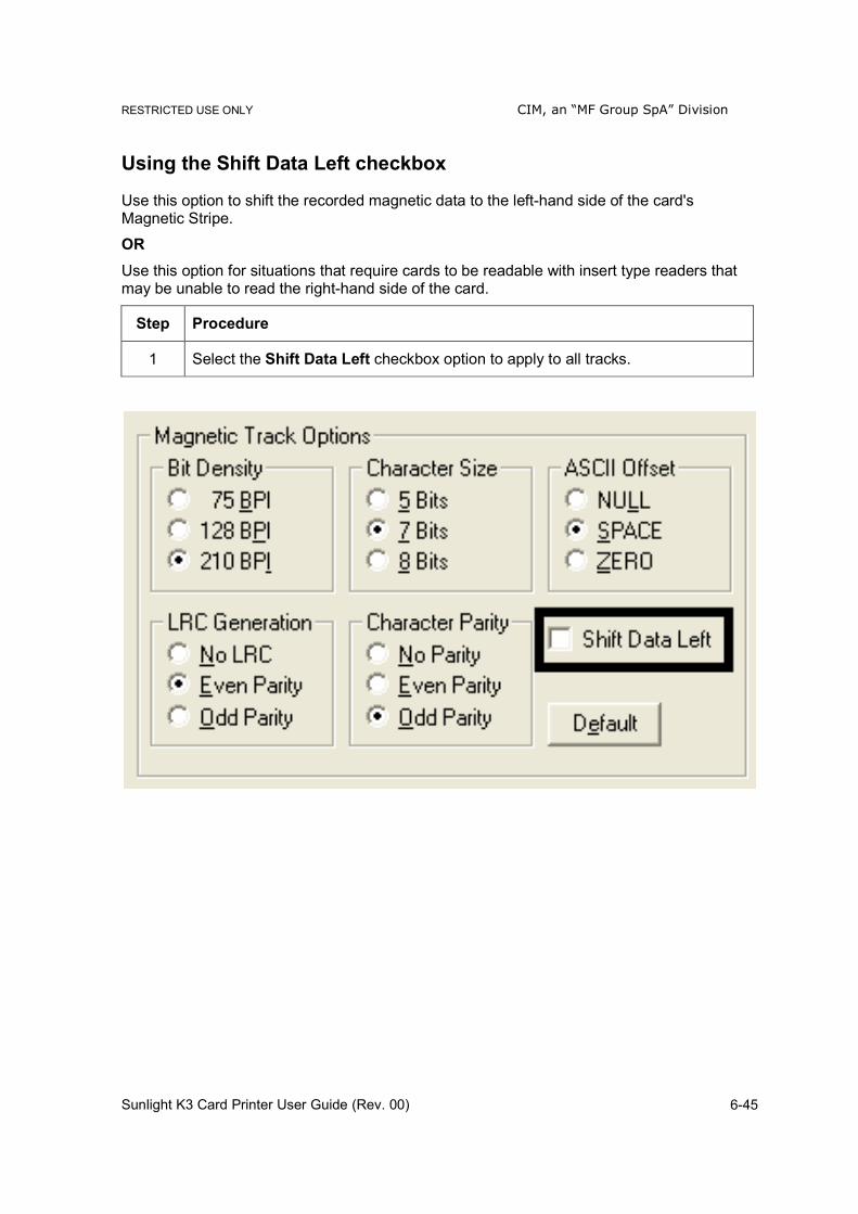
RESTRICTED USE ONLY CIM, an “MF Group SpA” Division
Sunlight K3 Card Printer User Guide (Rev. 00) 6-45
Using the Shift Data Left checkbox
Use this option to shift the recorded magnetic data to the left-hand side of the card's Magnetic Stripe.
OR Use this option for situations that require cards to be readable with insert type readers that may be unable to read the right-hand side of the card.
Step Procedure
1 Select the Shift Data Left checkbox option to apply to all tracks.
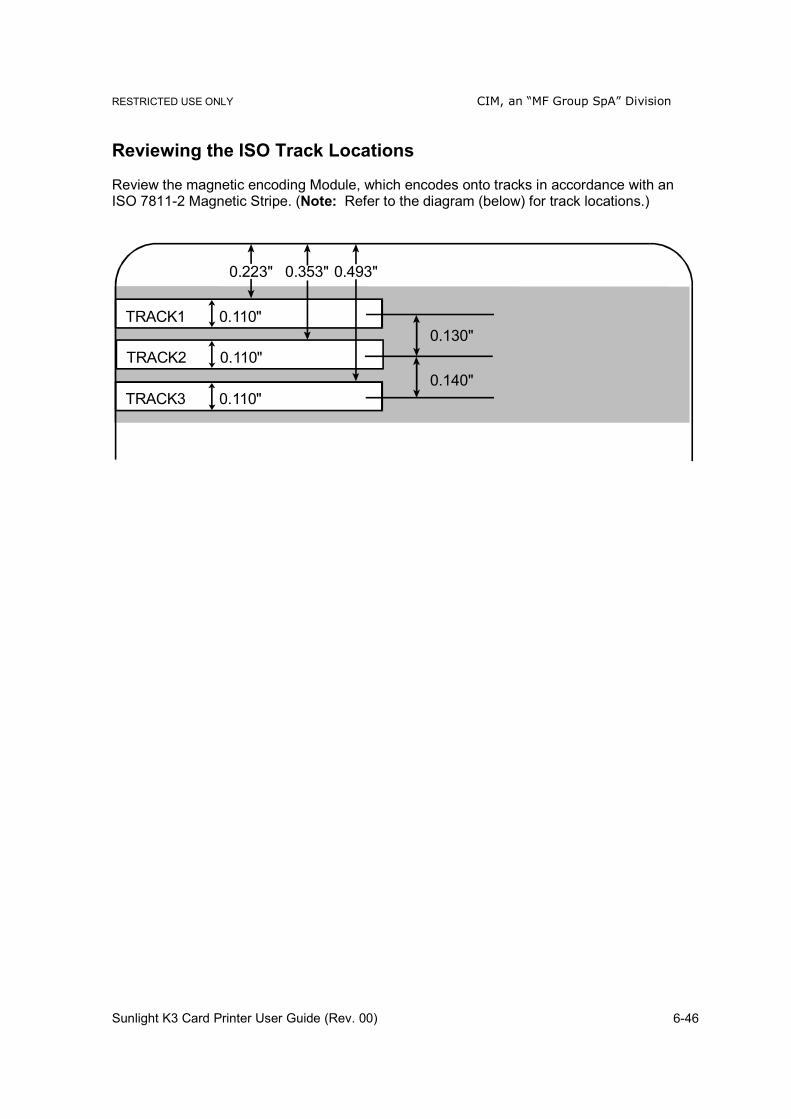
RESTRICTED USE ONLY CIM, an “MF Group SpA” Division
Sunlight K3 Card Printer User Guide (Rev. 00) 6-46
Reviewing the ISO Track Locations
Review the magnetic encoding Module, which encodes onto tracks in accordance with an ISO 7811-2 Magnetic Stripe. (Note: Refer to the diagram (below) for track locations.)
TRACK1 0.110"
TRACK2 0.110"
TRACK3 0.110"
0.130"
0.140"
0.223" 0.353" 0.493"
RESTRICTED USE ONLY CIM, an “MF Group SpA” Division
Sunlight K3 Card Printer User Guide (Rev. 00) 6-47
Sending the Track Information
Magnetic track data is sent in the form of text strings from the application software to the Printer Driver along with all of the other printable objects within the card design.
• Magnetic Track Data added: In order for the Printer Driver to differentiate between magnetic track data and the rest of the printable objects, the magnetic track data strings must be uniquely tagged or added.
• Specific Characters added: In other words, specific characters must be added to the magnetic track data in order for the Printer Driver to know which data is to be encoded, which tracks to encode, when the track data stops and starts and so forth.
• Manually or automatically added: In some cases, these specific characters are automatically added to the string of track data by customized ID software applications. In most cases, however, the User must manually add these characters to the string of magnetic track data.
Entering the Track Information
(Note: If these characters are not added to the track data, the text intended for the magnetic track will most likely appear as printed text on the card.)
Step Procedure
1 To avoid this symptom, track information must be entered as follows.
When entering track data, the "~" character is entered first, followed by the desired track number (1, 2 or 3) used to encode the data.
• The data to be encoded should then follow. (Note: The first character of this data string must be the track's specific Start Sentinel (SS) and the last character must be the specific End Sentinel (ES).)
• The characters or data in between the SS and ES can include all of the valid characters specific to each track. (Note: The number of these characters is limited by each track's maximum character capacity.)
Caution: When segmenting track data, strictly use the appropriate Field Separator (FS).
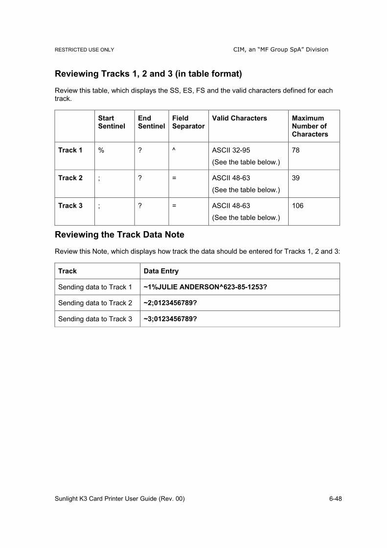
RESTRICTED USE ONLY CIM, an “MF Group SpA” Division
Sunlight K3 Card Printer User Guide (Rev. 00) 6-48
Reviewing Tracks 1, 2 and 3 (in table format)
Review this table, which displays the SS, ES, FS and the valid characters defined for each track.
Start Sentinel
End Sentinel
Field Separator
Valid Characters Maximum Number of Characters
Track 1 % ? ^ ASCII 32-95
(See the table below.)
78
Track 2 ; ? = ASCII 48-63
(See the table below.)
39
Track 3 ; ? = ASCII 48-63
(See the table below.)
106
Reviewing the Track Data Note
Review this Note, which displays how track the data should be entered for Tracks 1, 2 and 3:
Track Data Entry
Sending data to Track 1 ~1%JULIE ANDERSON^623-85-1253?
Sending data to Track 2 ~2;0123456789?
Sending data to Track 3 ~3;0123456789?
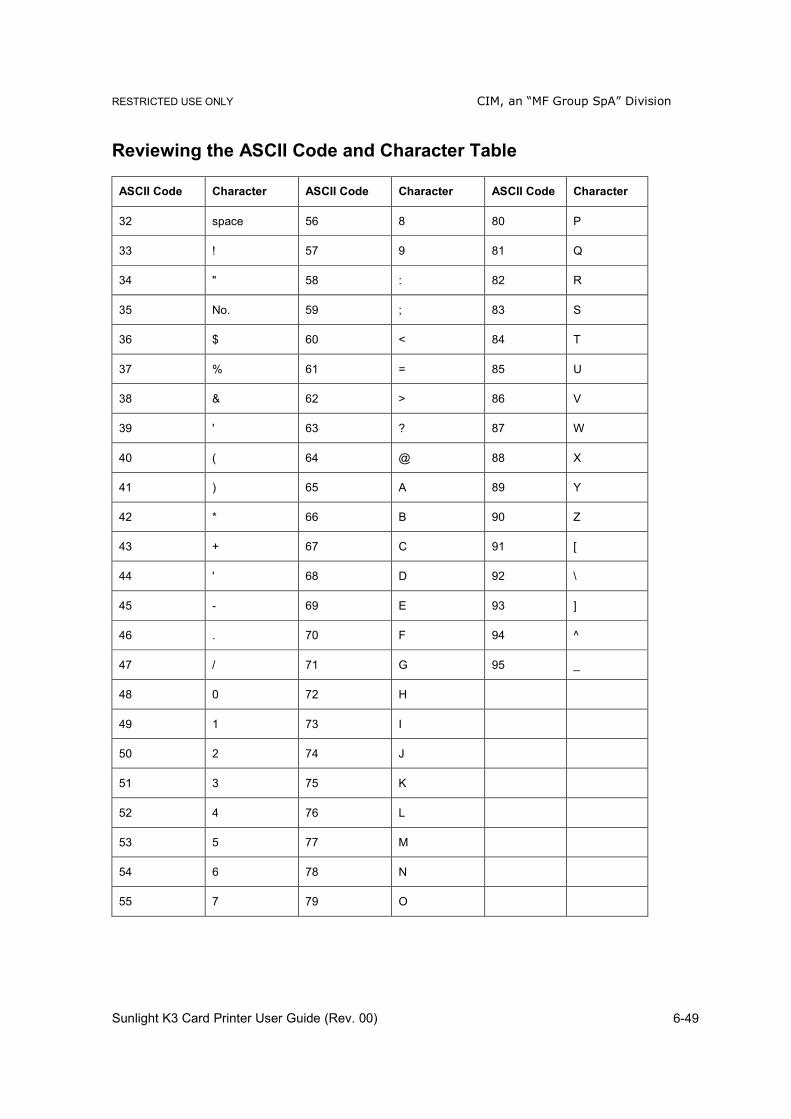
RESTRICTED USE ONLY CIM, an “MF Group SpA” Division
Sunlight K3 Card Printer User Guide (Rev. 00) 6-49
Reviewing the ASCII Code and Character Table
ASCII Code Character ASCII Code Character ASCII Code Character
32 space 56 8 80 P
33 ! 57 9 81 Q
34 " 58 : 82 R
35 No. 59 ; 83 S
36 $ 60 < 84 T
37 % 61 = 85 U
38 & 62 > 86 V
39 ' 63 ? 87 W
40 ( 64 @ 88 X
41 ) 65 A 89 Y
42 * 66 B 90 Z
43 + 67 C 91 [
44 ' 68 D 92 \
45 - 69 E 93 ]
46 . 70 F 94 ^
47 / 71 G 95 _
48 0 72 H
49 1 73 I
50 2 74 J
51 3 75 K
52 4 76 L
53 5 77 M
54 6 78 N
55 7 79 O
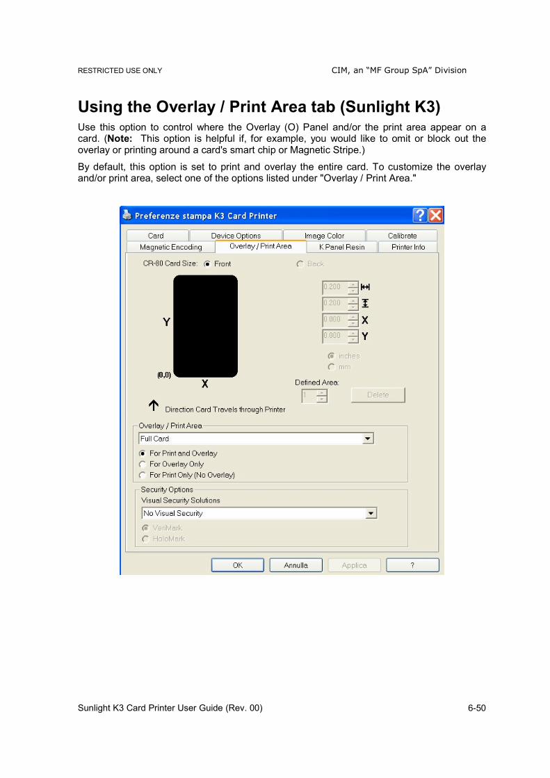
RESTRICTED USE ONLY CIM, an “MF Group SpA” Division
Sunlight K3 Card Printer User Guide (Rev. 00) 6-50
Using the Overlay / Print Area tab (Sunlight K3) Use this option to control where the Overlay (O) Panel and/or the print area appear on a card. (Note: This option is helpful if, for example, you would like to omit or block out the overlay or printing around a card's smart chip or Magnetic Stripe.)
By default, this option is set to print and overlay the entire card. To customize the overlay and/or print area, select one of the options listed under "Overlay / Print Area."
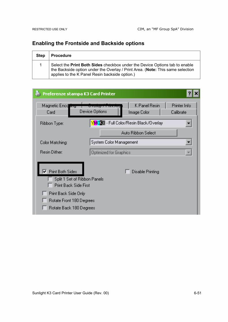
RESTRICTED USE ONLY CIM, an “MF Group SpA” Division
Sunlight K3 Card Printer User Guide (Rev. 00) 6-51
Enabling the Frontside and Backside options
Step Procedure
1 Select the Print Both Sides checkbox under the Device Options tab to enable the Backside option under the Overlay / Print Area. (Note: This same selection applies to the K Panel Resin backside option.)
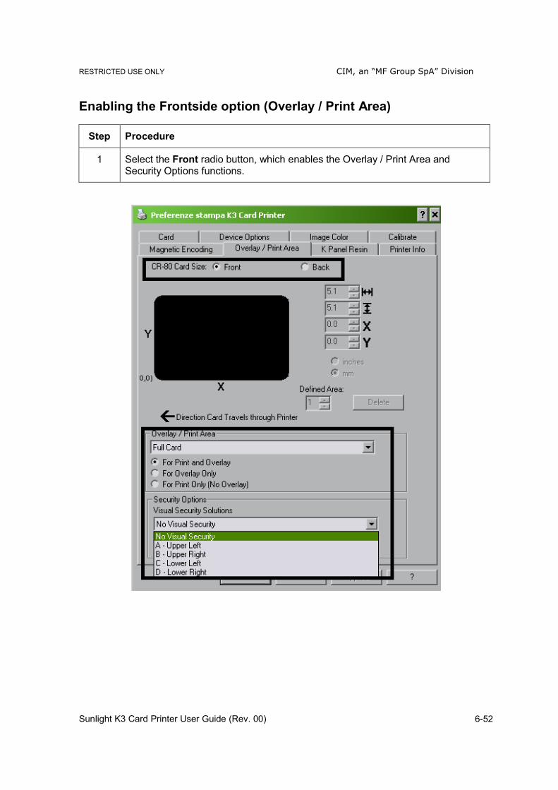
RESTRICTED USE ONLY CIM, an “MF Group SpA” Division
Sunlight K3 Card Printer User Guide (Rev. 00) 6-52
Enabling the Frontside option (Overlay / Print Area)
Step Procedure
1 Select the Front radio button, which enables the Overlay / Print Area and Security Options functions.
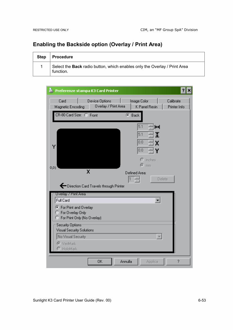
RESTRICTED USE ONLY CIM, an “MF Group SpA” Division
Sunlight K3 Card Printer User Guide (Rev. 00) 6-53
Enabling the Backside option (Overlay / Print Area)
Step Procedure
1 Select the Back radio button, which enables only the Overlay / Print Area function.
RESTRICTED USE ONLY CIM, an “MF Group SpA” Division
Sunlight K3 Card Printer User Guide (Rev. 00) 6-54
Using the Overlay / Print Area dropdown menu
Step Procedure
1 Select the Full Card option for the Printer to overlay and/or print the entire card.
OR Select the Defined Area(s) option for the Printer to overlay and/or print only in the selected and defined area or areas.
OR Select the Undefined Area(s) option for the Printer to overlay and/or print only in the space outside the selected and defined area.
OR Select the Omit Smart Chip Area option for the Printer to overlay and/or print only in the space outside the standard location of a smart chip.
OR Select the Omit Magnetic Stripe Area option for the Printer to overlay and/or print only in the space outside the standard location of an ISO Magnetic Stripe.
OR Select the Omit Signature Area option for the Printer to overlay and/or print only in the space outside the standard location of a signature panel.
(Note: In the card grid, black indicates the area in which the overlay and/or printing will be applied.)
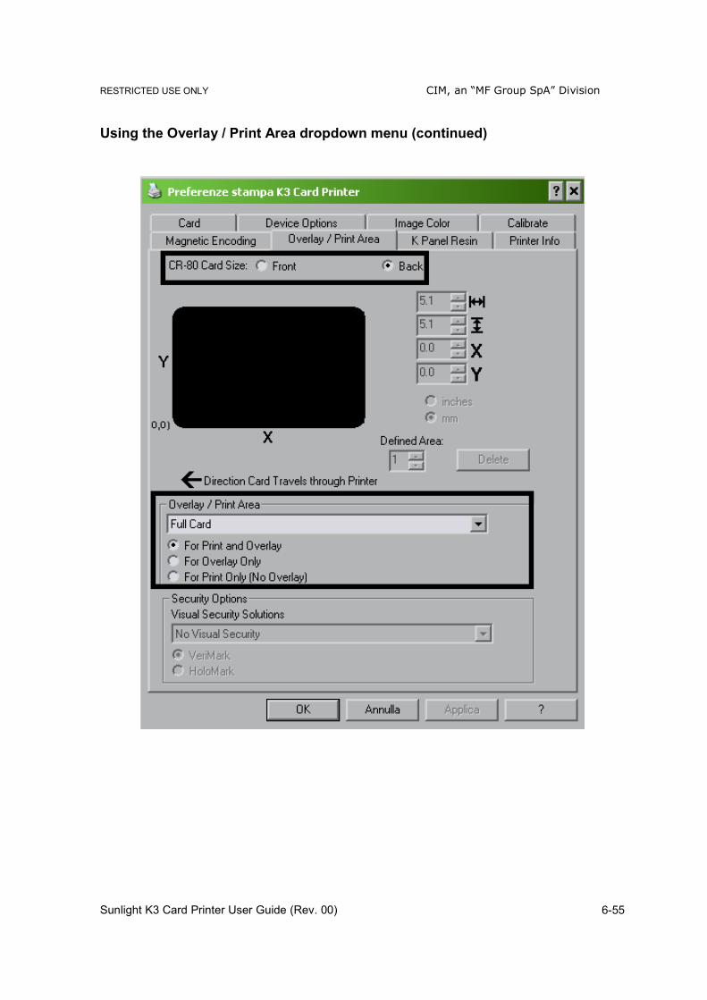
RESTRICTED USE ONLY CIM, an “MF Group SpA” Division
Sunlight K3 Card Printer User Guide (Rev. 00) 6-55
Using the Overlay / Print Area dropdown menu (continued)
RESTRICTED USE ONLY CIM, an “MF Group SpA” Division
Sunlight K3 Card Printer User Guide (Rev. 00) 6-56
Using the Overlay / Print Area
Use these Overlay / Print Area options to control both the print and overlay together or control each individually. (Note: Determine whether to use the Frontside option (via the Front radio button) or the Backside option (via the Back radio button).)
Step Procedure
1 Select For Print and Overlay for the defined area to apply to both the printing and overlay process.
OR Select For Overlay Only for the defined area to apply only to the overlay process. (Note: In this mode, printing will still be allowed over the entire card and only the overlay will be affected.)
OR Select For Print Only (No Overlay) for the defined area to apply only to the print process. (Important: In this mode, the overlay is completely disabled so it will not be applied.)
Caution: An overlay or an overlaminate must protect dye-sublimation printing or it will quickly begin to wear or fade.
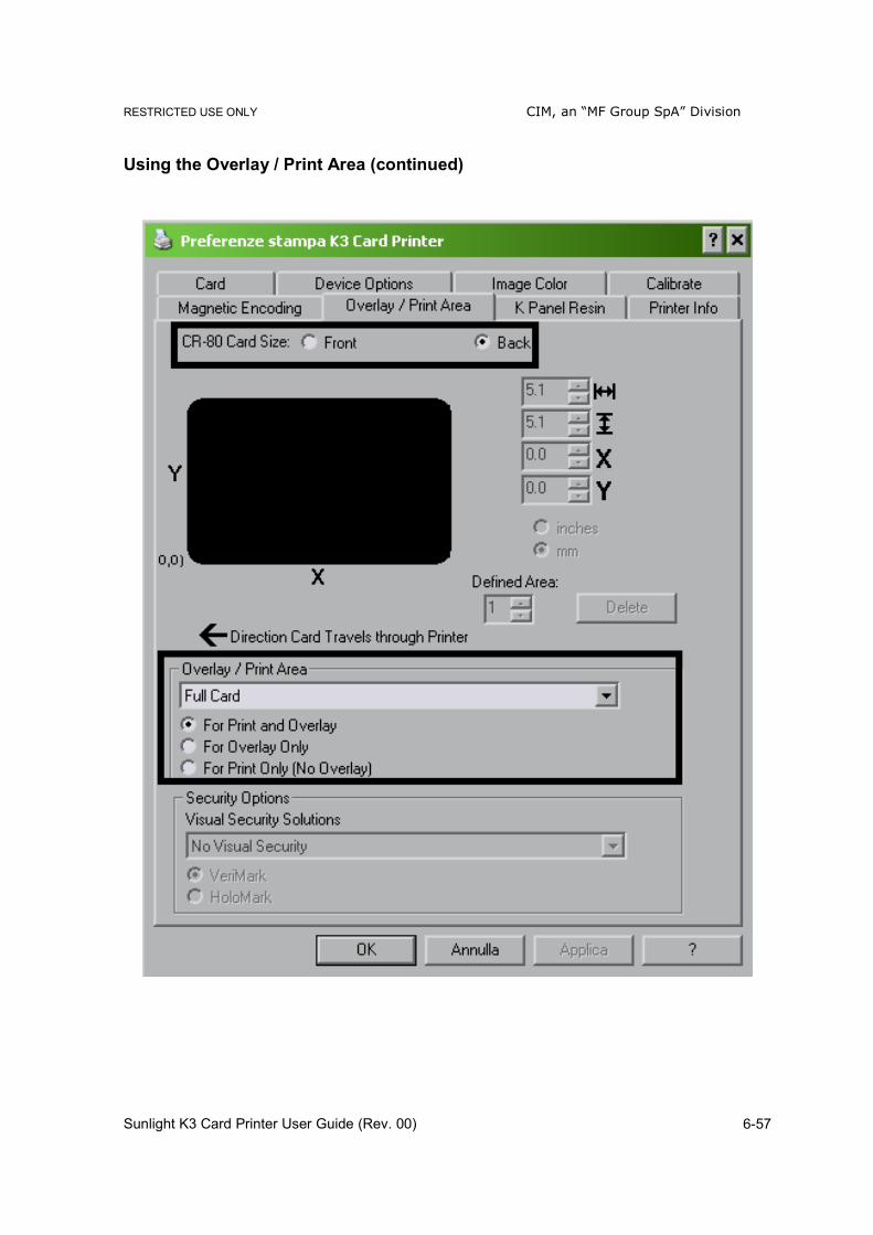
RESTRICTED USE ONLY CIM, an “MF Group SpA” Division
Sunlight K3 Card Printer User Guide (Rev. 00) 6-57
Using the Overlay / Print Area (continued)
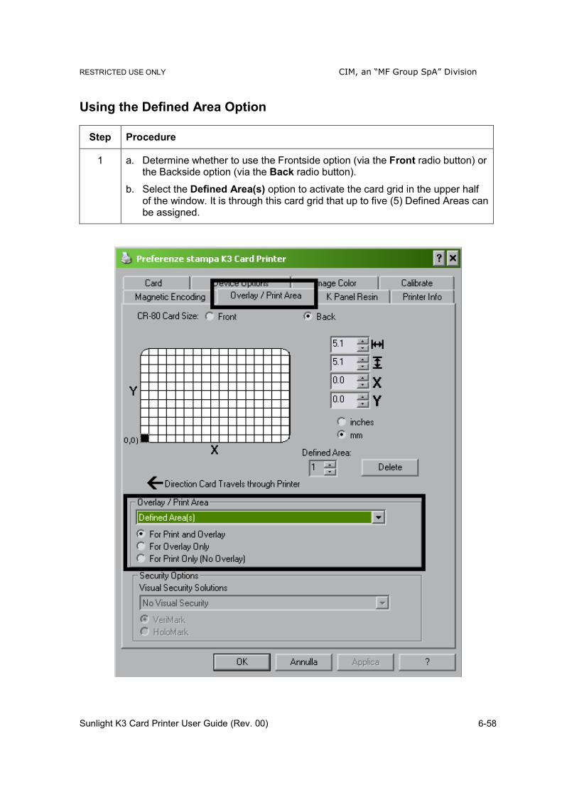
RESTRICTED USE ONLY CIM, an “MF Group SpA” Division
Sunlight K3 Card Printer User Guide (Rev. 00) 6-58
Using the Defined Area Option
Step Procedure
1 a. Determine whether to use the Frontside option (via the Front radio button) or the Backside option (via the Back radio button).
b. Select the Defined Area(s) option to activate the card grid in the upper half of the window. It is through this card grid that up to five (5) Defined Areas can be assigned.
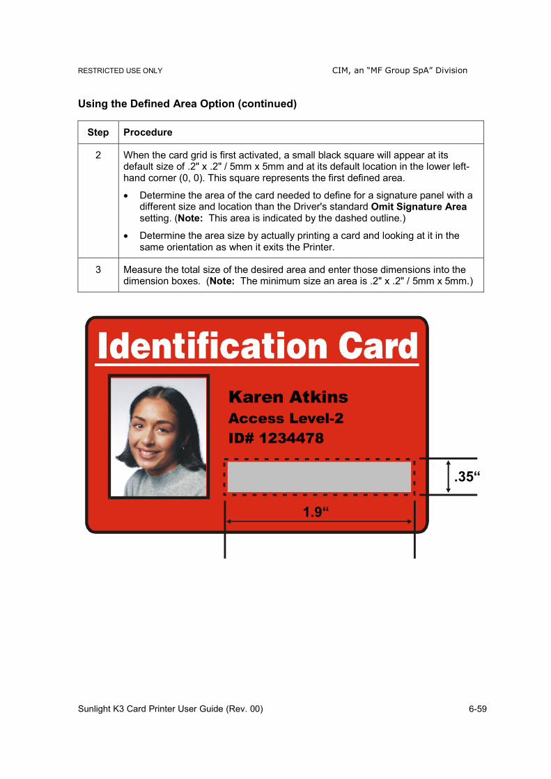
RESTRICTED USE ONLY CIM, an “MF Group SpA” Division
Sunlight K3 Card Printer User Guide (Rev. 00) 6-59
Using the Defined Area Option (continued)
Step Procedure
2 When the card grid is first activated, a small black square will appear at its default size of .2" x .2" / 5mm x 5mm and at its default location in the lower left-hand corner (0, 0). This square represents the first defined area.
•
Determine the area of the card needed to define for a signature panel with a different size and location than the Driver's standard Omit Signature Area setting. (Note: This area is indicated by the dashed outline.)
•
Determine the area size by actually printing a card and looking at it in the same orientation as when it exits the Printer.
3 Measure the total size of the desired area and enter those dimensions into the dimension boxes. (Note: The minimum size an area is .2" x .2" / 5mm x 5mm.)
.35“
1.9“
Karen AtkinsAccess Level-2ID# 1234478
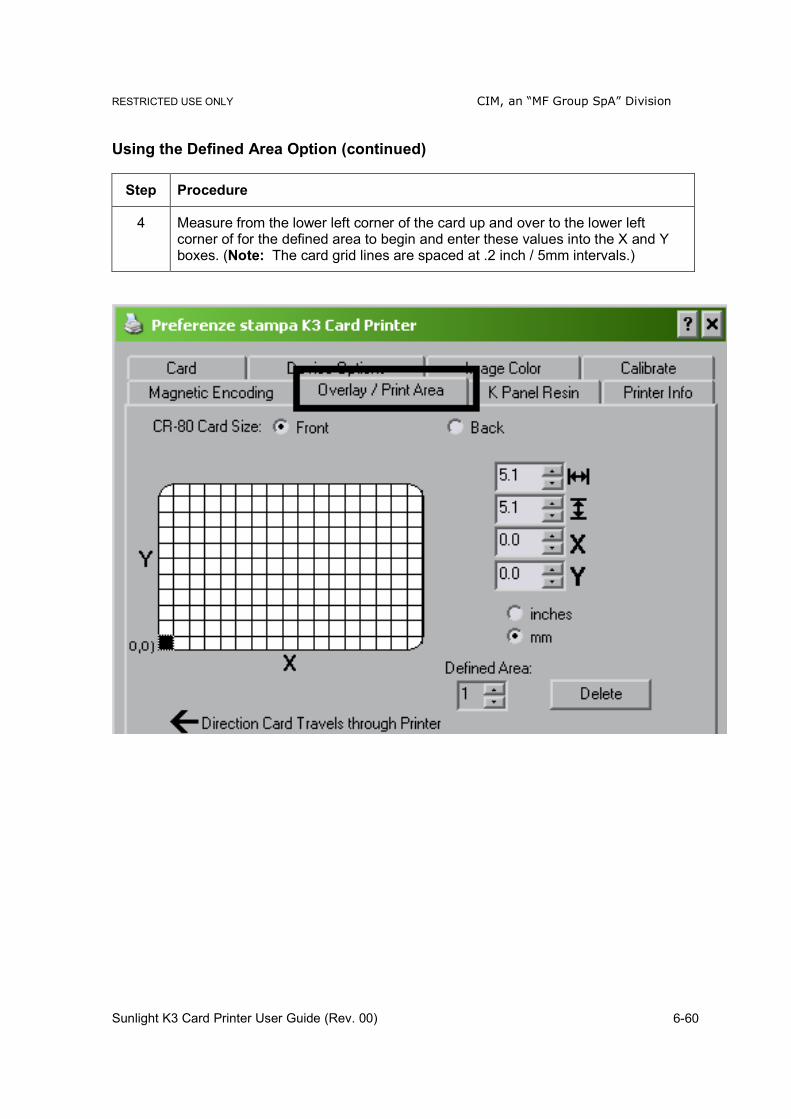
RESTRICTED USE ONLY CIM, an “MF Group SpA” Division
Sunlight K3 Card Printer User Guide (Rev. 00) 6-60
Using the Defined Area Option (continued)
Step Procedure
4 Measure from the lower left corner of the card up and over to the lower left corner of for the defined area to begin and enter these values into the X and Y boxes. (Note: The card grid lines are spaced at .2 inch / 5mm intervals.)
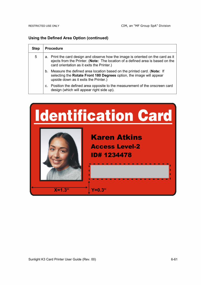
RESTRICTED USE ONLY CIM, an “MF Group SpA” Division
Sunlight K3 Card Printer User Guide (Rev. 00) 6-61
Using the Defined Area Option (continued)
Step Procedure
5 a. Print the card design and observe how the image is oriented on the card as it ejects from the Printer. (Note: The location of a defined area is based on the card orientation as it exits the Printer.)
b. Measure the defined area location based on the printed card. (Note: If selecting the Rotate Front 180 Degrees option, the image will appear upside down as it exits the Printer.)
c. Position the defined area opposite to the measurement of the onscreen card design (which will appear right side up).
Y=0.3“X=1.3“
Karen AtkinsAccess Level-2ID# 1234478
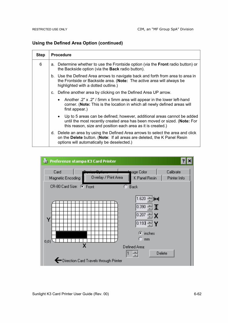
RESTRICTED USE ONLY CIM, an “MF Group SpA” Division
Sunlight K3 Card Printer User Guide (Rev. 00) 6-62
Using the Defined Area Option (continued)
Step Procedure
6 a. Determine whether to use the Frontside option (via the Front radio button) or the Backside option (via the Back radio button).
b. Use the Defined Area arrows to navigate back and forth from area to area in the Frontside or Backside area. (Note: The active area will always be highlighted with a dotted outline.)
c. Define another area by clicking on the Defined Area UP arrow.
• Another .2" x .2" / 5mm x 5mm area will appear in the lower left-hand corner. (Note: This is the location in which all newly defined areas will first appear.)
•
Up to 5 areas can be defined; however, additional areas cannot be added until the most recently created area has been moved or sized. (Note: For this reason, size and position each area as it is created.)
d. Delete an area by using the Defined Area arrows to select the area and click on the Delete button. (Note: If all areas are deleted, the K Panel Resin options will automatically be deselected.)
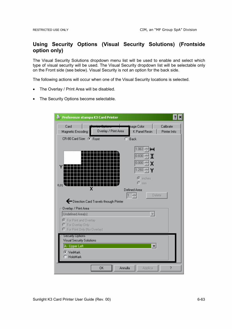
RESTRICTED USE ONLY CIM, an “MF Group SpA” Division
Sunlight K3 Card Printer User Guide (Rev. 00) 6-63
Using Security Options (Visual Security Solutions) (Frontside option only)
The Visual Security Solutions dropdown menu list will be used to enable and select which type of visual security will be used. The Visual Security dropdown list will be selectable only on the Front side (see below). Visual Security is not an option for the back side.
The following actions will occur when one of the Visual Security locations is selected.
•
The Overlay / Print Area will be disabled.
• The Security Options become selectable.
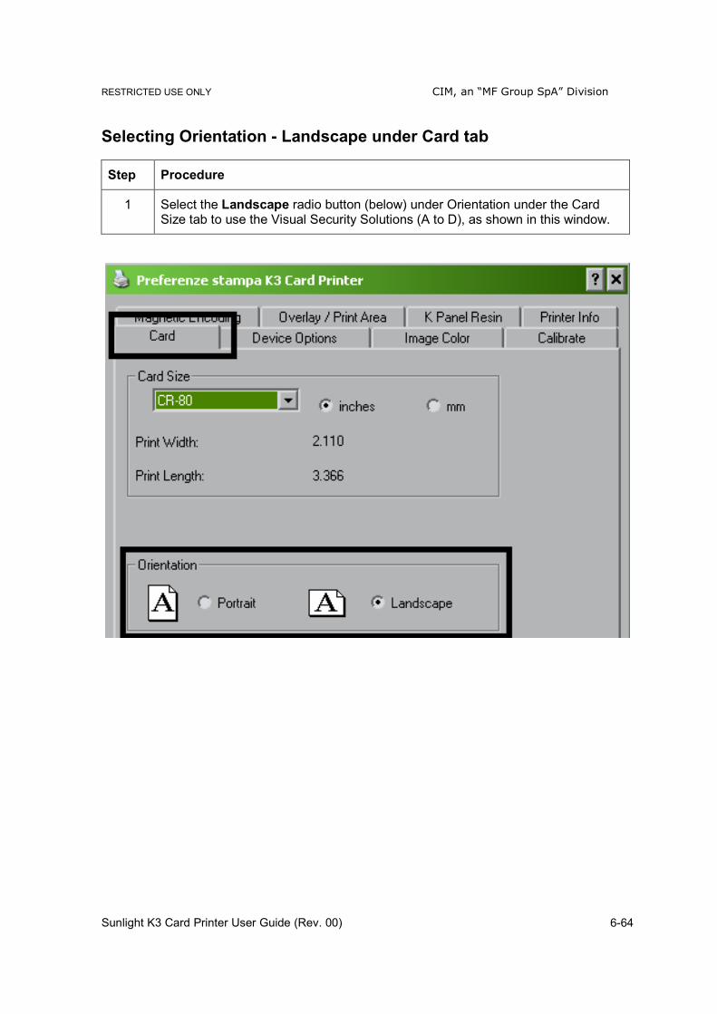
RESTRICTED USE ONLY CIM, an “MF Group SpA” Division
Sunlight K3 Card Printer User Guide (Rev. 00) 6-64
Selecting Orientation - Landscape under Card tab
Step Procedure
1 Select the Landscape radio button (below) under Orientation under the Card Size tab to use the Visual Security Solutions (A to D), as shown in this window.
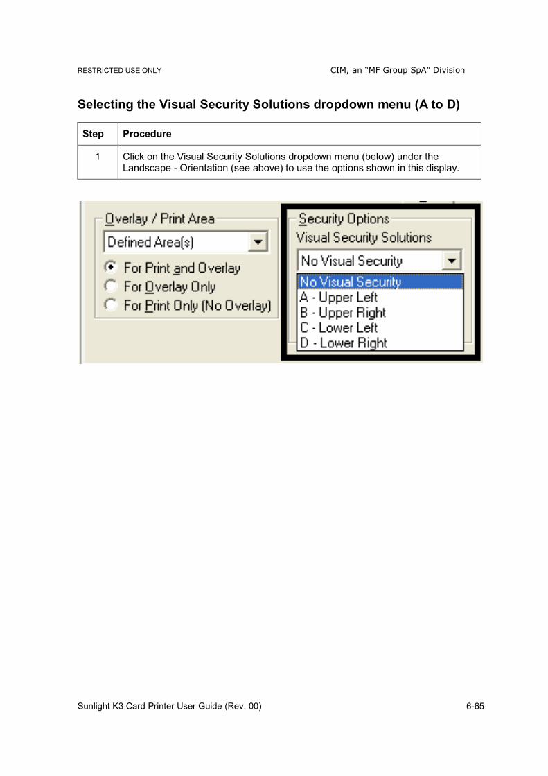
RESTRICTED USE ONLY CIM, an “MF Group SpA” Division
Sunlight K3 Card Printer User Guide (Rev. 00) 6-65
Selecting the Visual Security Solutions dropdown menu (A to D)
Step Procedure
1 Click on the Visual Security Solutions dropdown menu (below) under the Landscape - Orientation (see above) to use the options shown in this display.
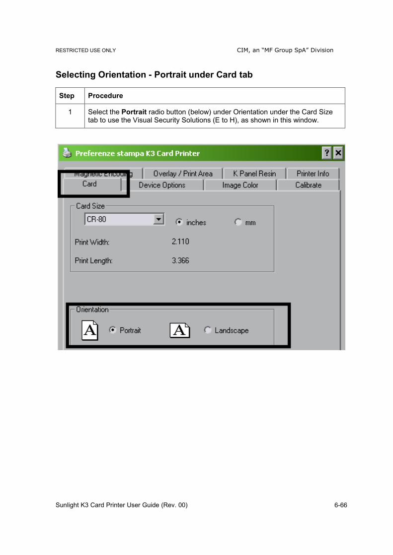
RESTRICTED USE ONLY CIM, an “MF Group SpA” Division
Sunlight K3 Card Printer User Guide (Rev. 00) 6-66
Selecting Orientation - Portrait under Card tab
Step Procedure
1 Select the Portrait radio button (below) under Orientation under the Card Size tab to use the Visual Security Solutions (E to H), as shown in this window.

RESTRICTED USE ONLY CIM, an “MF Group SpA” Division
Sunlight K3 Card Printer User Guide (Rev. 00) 6-67
Selecting the Visual Security Solutions dropdown menu (E to H)
Step Procedure
1 Click on the Visual Security Solutions dropdown menu under the Portrait - Orientation (see above) to use the options shown below.
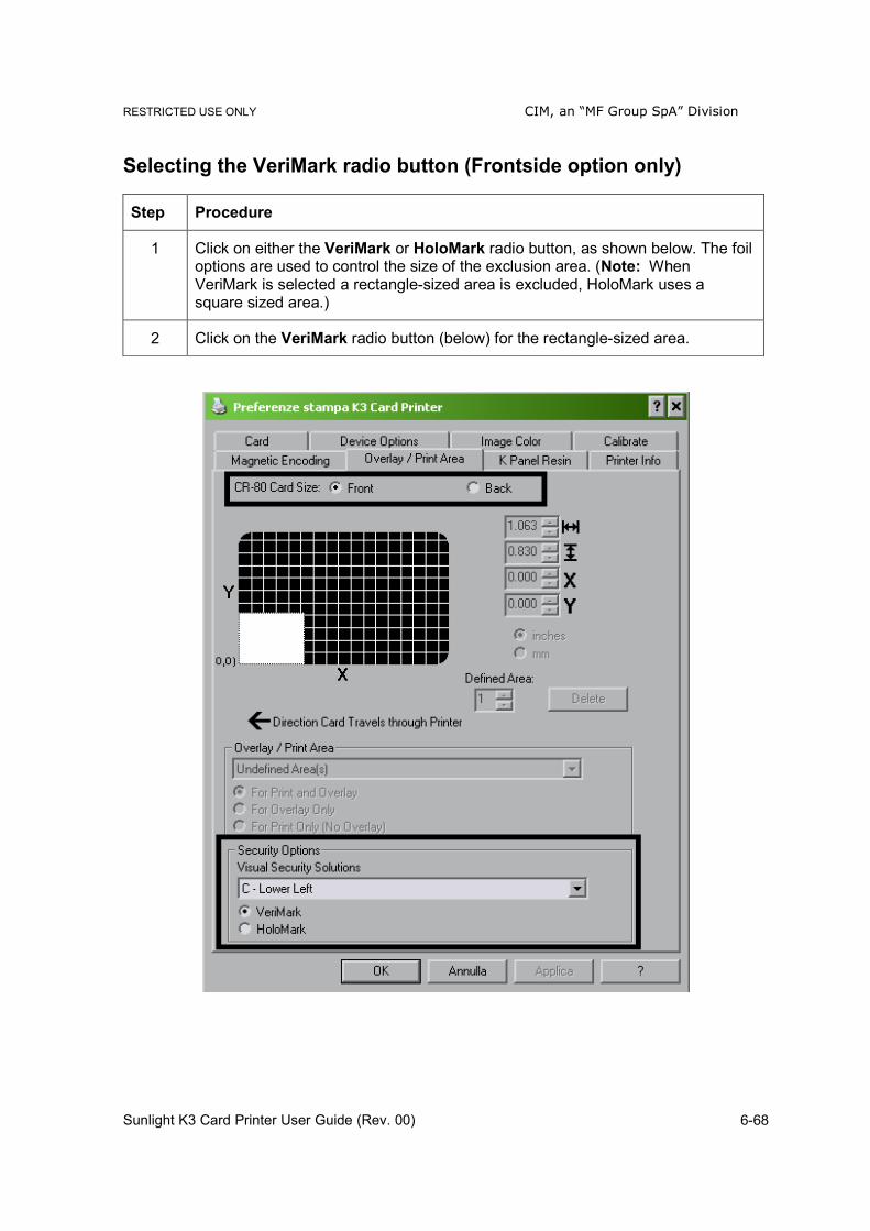
RESTRICTED USE ONLY CIM, an “MF Group SpA” Division
Sunlight K3 Card Printer User Guide (Rev. 00) 6-68
Selecting the VeriMark radio button (Frontside option only)
Step Procedure
1 Click on either the VeriMark or HoloMark radio button, as shown below. The foil options are used to control the size of the exclusion area. (Note: When VeriMark is selected a rectangle-sized area is excluded, HoloMark uses a square sized area.)
2 Click on the VeriMark radio button (below) for the rectangle-sized area.
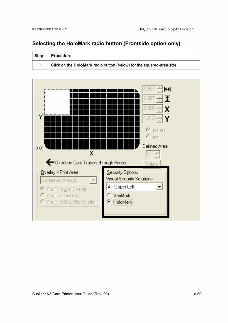
RESTRICTED USE ONLY CIM, an “MF Group SpA” Division
Sunlight K3 Card Printer User Guide (Rev. 00) 6-69
Selecting the HoloMark radio button (Frontside option only)
Step Procedure
1 Click on the HoloMark radio button (below) for the squared-area size.
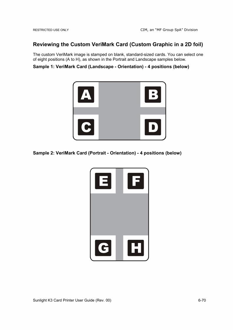
RESTRICTED USE ONLY CIM, an “MF Group SpA” Division
Sunlight K3 Card Printer User Guide (Rev. 00) 6-70
Reviewing the Custom VeriMark Card (Custom Graphic in a 2D foil)
The custom VeriMark image is stamped on blank, standard-sized cards. You can select one of eight positions (A to H), as shown in the Portrait and Landscape samples below.
Sample 1: VeriMark Card (Landscape - Orientation) - 4 positions (below)
A
D
B
C
Sample 2: VeriMark Card (Portrait - Orientation) - 4 positions (below)
FE
G H
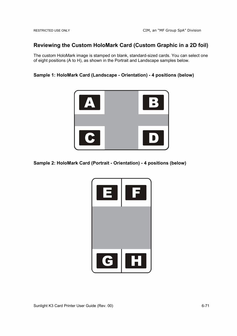
RESTRICTED USE ONLY CIM, an “MF Group SpA” Division
Sunlight K3 Card Printer User Guide (Rev. 00) 6-71
Reviewing the Custom HoloMark Card (Custom Graphic in a 2D foil)
The custom HoloMark image is stamped on blank, standard-sized cards. You can select one of eight positions (A to H), as shown in the Portrait and Landscape samples below.
Sample 1: HoloMark Card (Landscape - Orientation) - 4 positions (below)
DC
BA
Sample 2: HoloMark Card (Portrait - Orientation) - 4 positions (below)
FE
G H
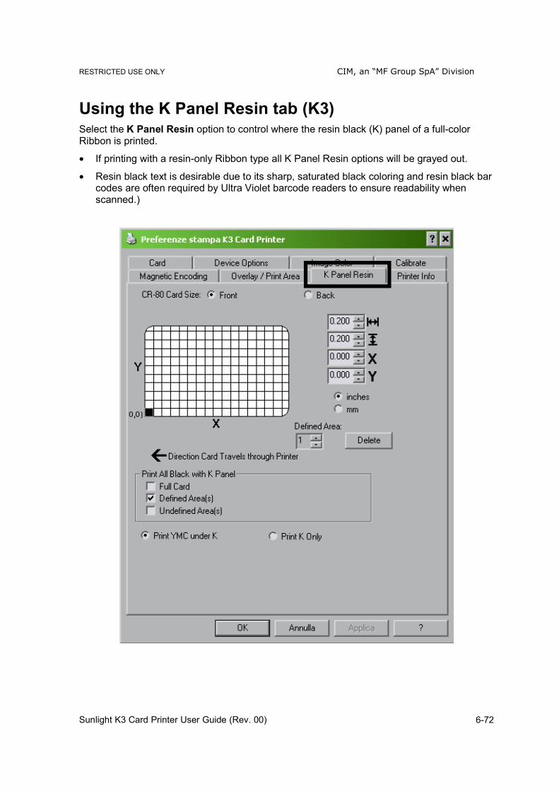
RESTRICTED USE ONLY CIM, an “MF Group SpA” Division
Sunlight K3 Card Printer User Guide (Rev. 00) 6-72
Using the K Panel Resin tab (K3) Select the K Panel Resin option to control where the resin black (K) panel of a full-color Ribbon is printed.
• If printing with a resin-only Ribbon type all K Panel Resin options will be grayed out.
• Resin black text is desirable due to its sharp, saturated black coloring and resin black bar codes are often required by Ultra Violet barcode readers to ensure readability when scanned.)
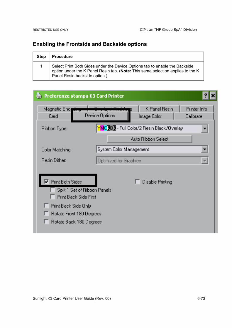
RESTRICTED USE ONLY CIM, an “MF Group SpA” Division
Sunlight K3 Card Printer User Guide (Rev. 00) 6-73
Enabling the Frontside and Backside options
Step Procedure
1 Select Print Both Sides under the Device Options tab to enable the Backside option under the K Panel Resin tab. (Note: This same selection applies to the K Panel Resin backside option.)
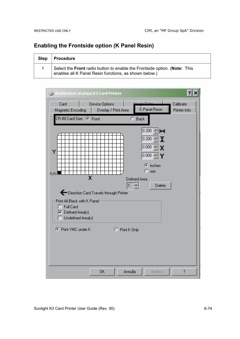
RESTRICTED USE ONLY CIM, an “MF Group SpA” Division
Sunlight K3 Card Printer User Guide (Rev. 00) 6-74
Enabling the Frontside option (K Panel Resin)
Step Procedure
1 Select the Front radio button to enable the Frontside option. (Note: This enables all K Panel Resin functions, as shown below.)
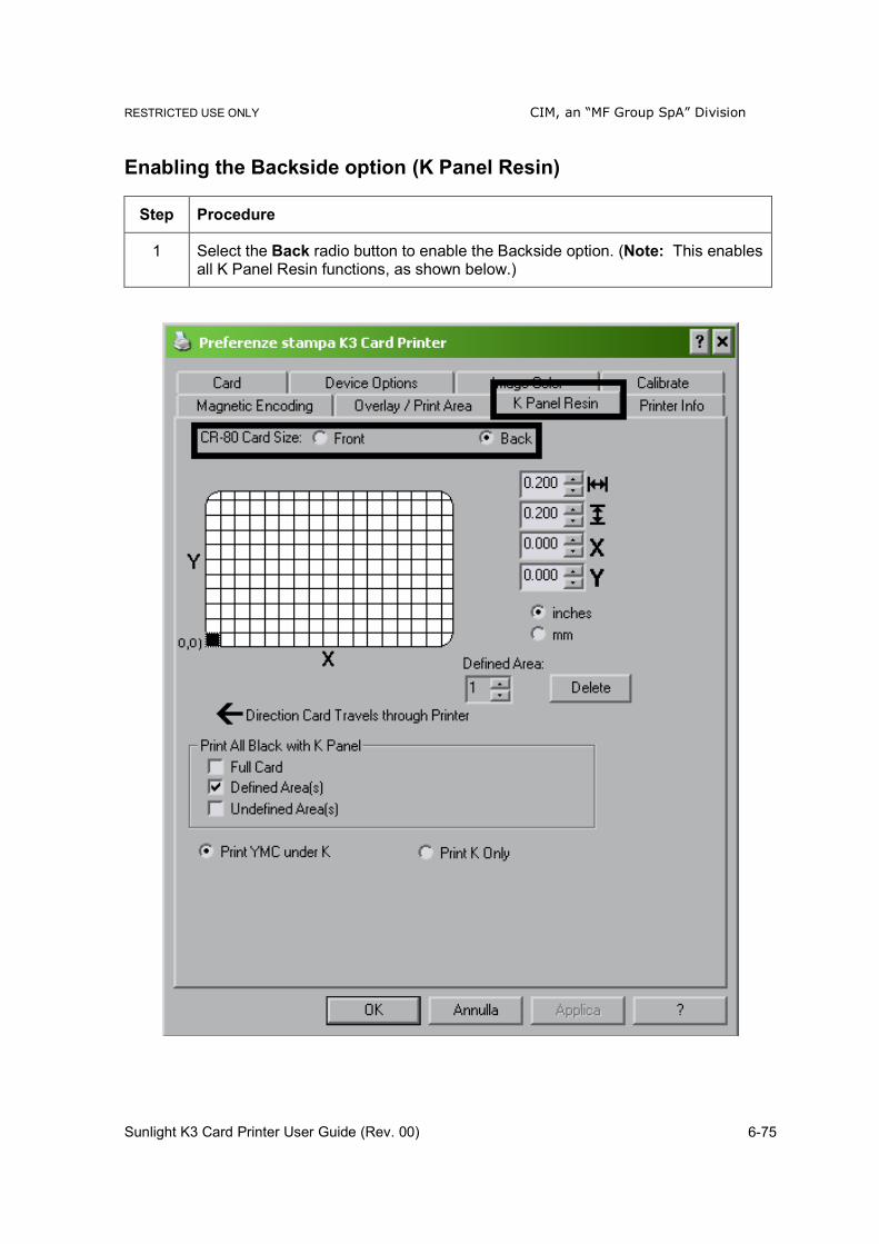
RESTRICTED USE ONLY CIM, an “MF Group SpA” Division
Sunlight K3 Card Printer User Guide (Rev. 00) 6-75
Enabling the Backside option (K Panel Resin)
Step Procedure
1 Select the Back radio button to enable the Backside option. (Note: This enables all K Panel Resin functions, as shown below.)
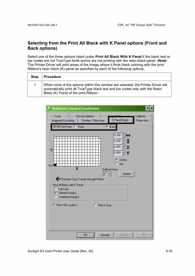
RESTRICTED USE ONLY CIM, an “MF Group SpA” Division
Sunlight K3 Card Printer User Guide (Rev. 00) 6-76
Selecting from the Print All Black with K Panel options (Front and Back options)
Select one of the three options listed under Print All Black With K Panel if the black text or bar codes are not TrueType fonts and/or are not printing with the resin black panel. (Note: The Printer Driver will print areas of the image where it finds black coloring with the print Ribbon's resin black (K) panel as specified by each of the following options.
Step Procedure
1 When none of the options within this window are selected, the Printer Driver will automatically print all TrueType black text and bar codes only with the Resin Black (K) Panel of the print Ribbon.
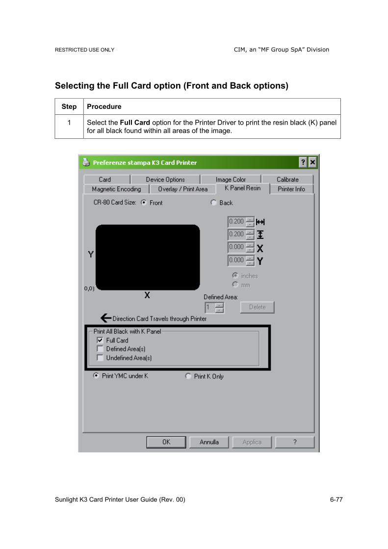
RESTRICTED USE ONLY CIM, an “MF Group SpA” Division
Sunlight K3 Card Printer User Guide (Rev. 00) 6-77
Selecting the Full Card option (Front and Back options)
Step Procedure
1 Select the Full Card option for the Printer Driver to print the resin black (K) panel for all black found within all areas of the image.
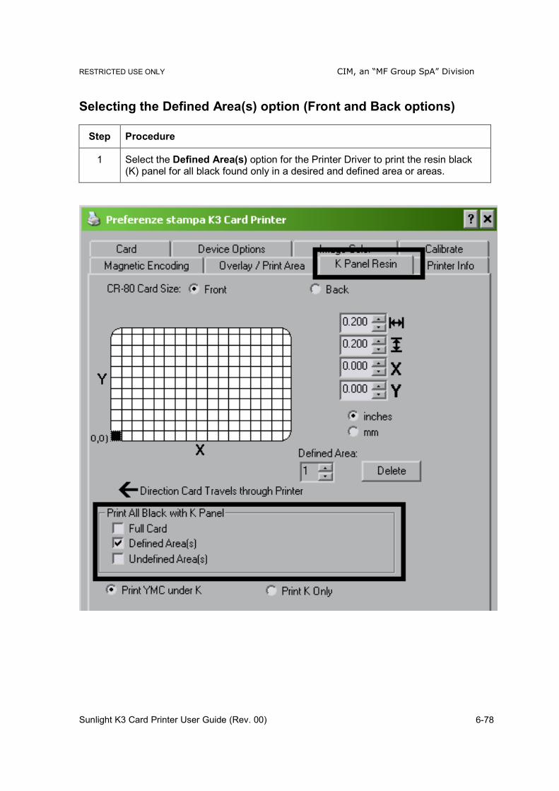
RESTRICTED USE ONLY CIM, an “MF Group SpA” Division
Sunlight K3 Card Printer User Guide (Rev. 00) 6-78
Selecting the Defined Area(s) option (Front and Back options)
Step Procedure
1 Select the Defined Area(s) option for the Printer Driver to print the resin black (K) panel for all black found only in a desired and defined area or areas.
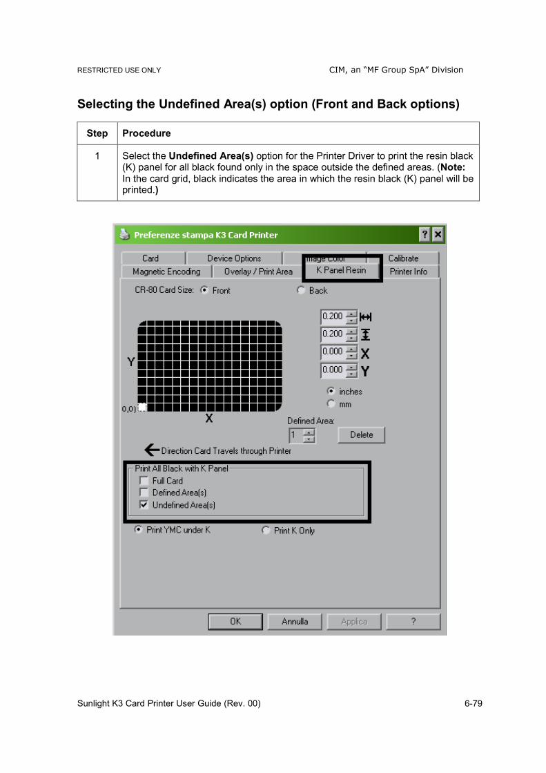
RESTRICTED USE ONLY CIM, an “MF Group SpA” Division
Sunlight K3 Card Printer User Guide (Rev. 00) 6-79
Selecting the Undefined Area(s) option (Front and Back options)
Step Procedure
1 Select the Undefined Area(s) option for the Printer Driver to print the resin black (K) panel for all black found only in the space outside the defined areas. (Note: In the card grid, black indicates the area in which the resin black (K) panel will be printed.)
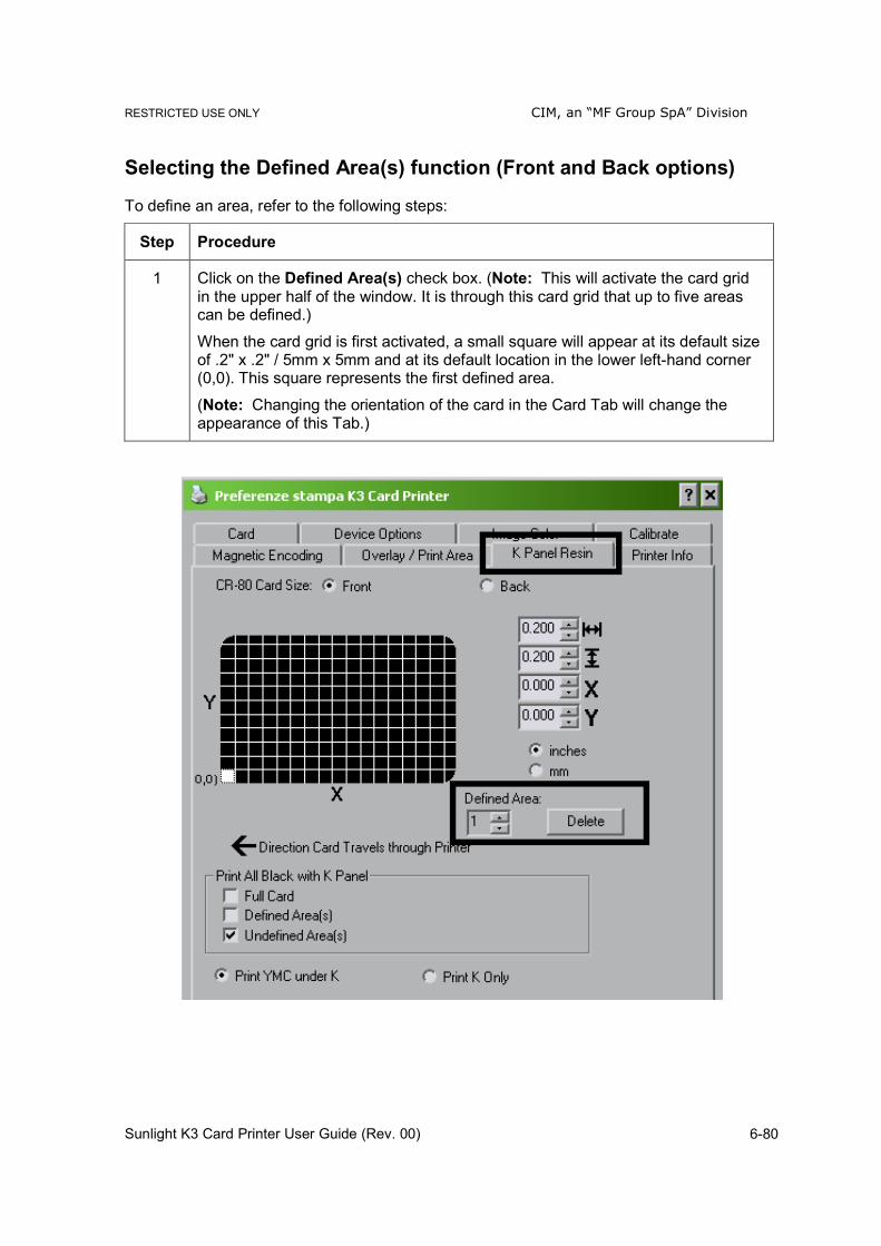
RESTRICTED USE ONLY CIM, an “MF Group SpA” Division
Sunlight K3 Card Printer User Guide (Rev. 00) 6-80
Selecting the Defined Area(s) function (Front and Back options)
To define an area, refer to the following steps:
Step Procedure
1 Click on the Defined Area(s) check box. (Note: This will activate the card grid in the upper half of the window. It is through this card grid that up to five areas can be defined.)
When the card grid is first activated, a small square will appear at its default size of .2" x .2" / 5mm x 5mm and at its default location in the lower left-hand corner (0,0). This square represents the first defined area.
(Note: Changing the orientation of the card in the Card Tab will change the appearance of this Tab.)
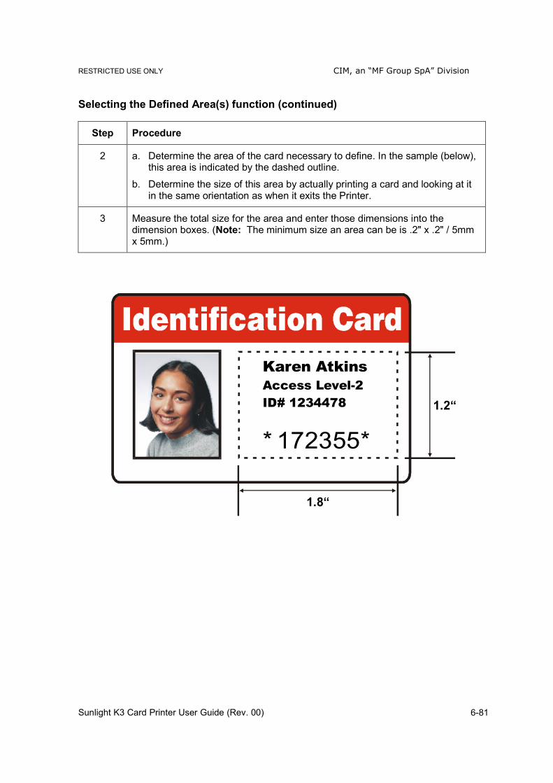
RESTRICTED USE ONLY CIM, an “MF Group SpA” Division
Sunlight K3 Card Printer User Guide (Rev. 00) 6-81
Selecting the Defined Area(s) function (continued)
Step Procedure
2 a. Determine the area of the card necessary to define. In the sample (below), this area is indicated by the dashed outline.
b. Determine the size of this area by actually printing a card and looking at it in the same orientation as when it exits the Printer.
3 Measure the total size for the area and enter those dimensions into the dimension boxes. (Note: The minimum size an area can be is .2" x .2" / 5mm x 5mm.)
* 172355*
Karen AtkinsAccess Level-2ID# 1234478 1.2“
1.8“
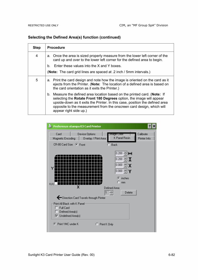
RESTRICTED USE ONLY CIM, an “MF Group SpA” Division
Sunlight K3 Card Printer User Guide (Rev. 00) 6-82
Selecting the Defined Area(s) function (continued)
Step Procedure
4 a. Once the area is sized properly measure from the lower left corner of the card up and over to the lower left corner for the defined area to begin.
b. Enter these values into the X and Y boxes.
(Note: The card grid lines are spaced at .2 inch / 5mm intervals.)
5 a. Print the card design and note how the image is oriented on the card as it ejects from the Printer. (Note: The location of a defined area is based on the card orientation as it exits the Printer.)
b. Measure the defined area location based on the printed card. (Note: If selecting the Rotate Front 180 Degrees option, the image will appear upside-down as it exits the Printer. In this case, position the defined area opposite to the measurement from the onscreen card design, which will appear right side up.)
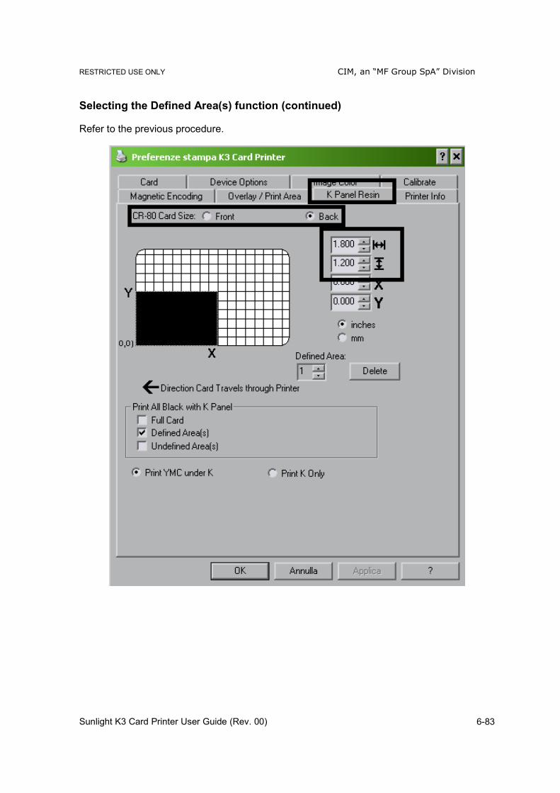
RESTRICTED USE ONLY CIM, an “MF Group SpA” Division
Sunlight K3 Card Printer User Guide (Rev. 00) 6-83
Selecting the Defined Area(s) function (continued)
Refer to the previous procedure.
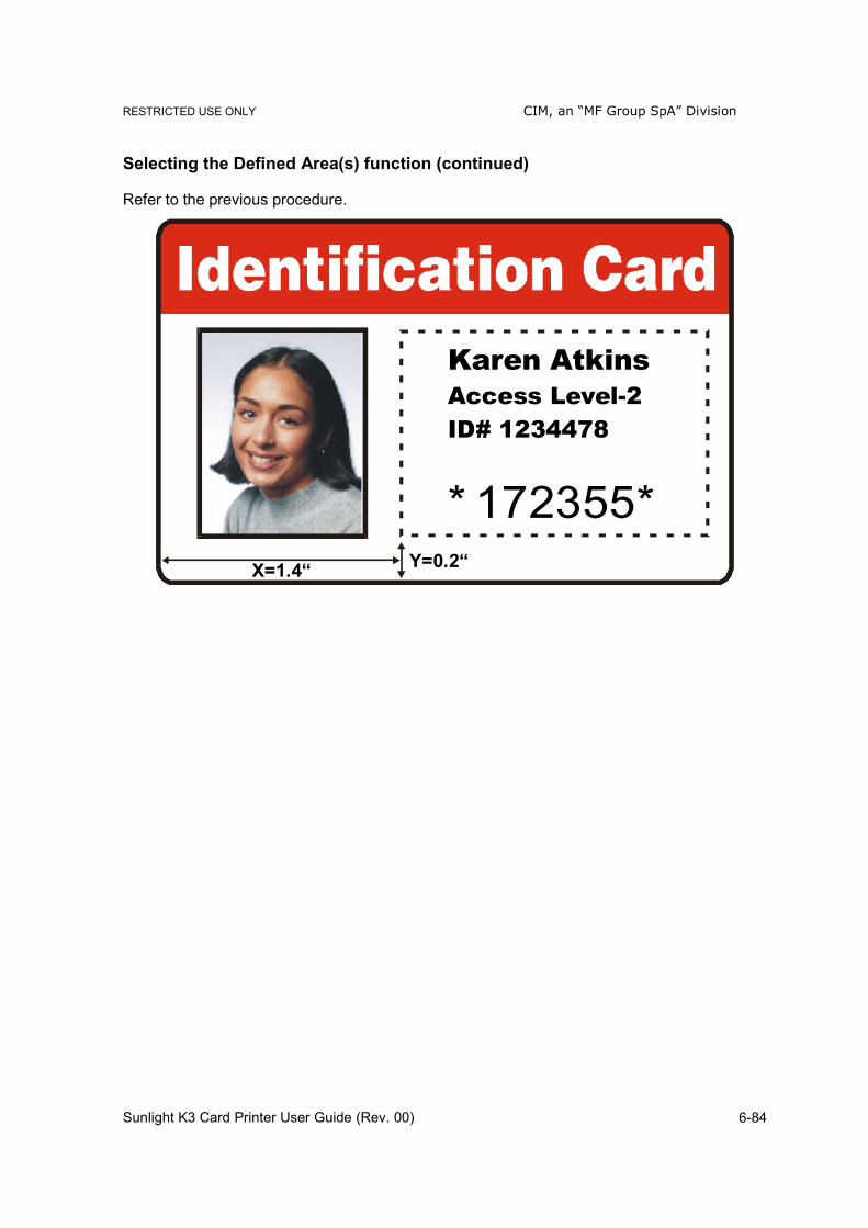
RESTRICTED USE ONLY CIM, an “MF Group SpA” Division
Sunlight K3 Card Printer User Guide (Rev. 00) 6-84
Selecting the Defined Area(s) function (continued)
Refer to the previous procedure.
* 172355*
Karen AtkinsAccess Level-2ID# 1234478
Y=0.2“X=1.4“
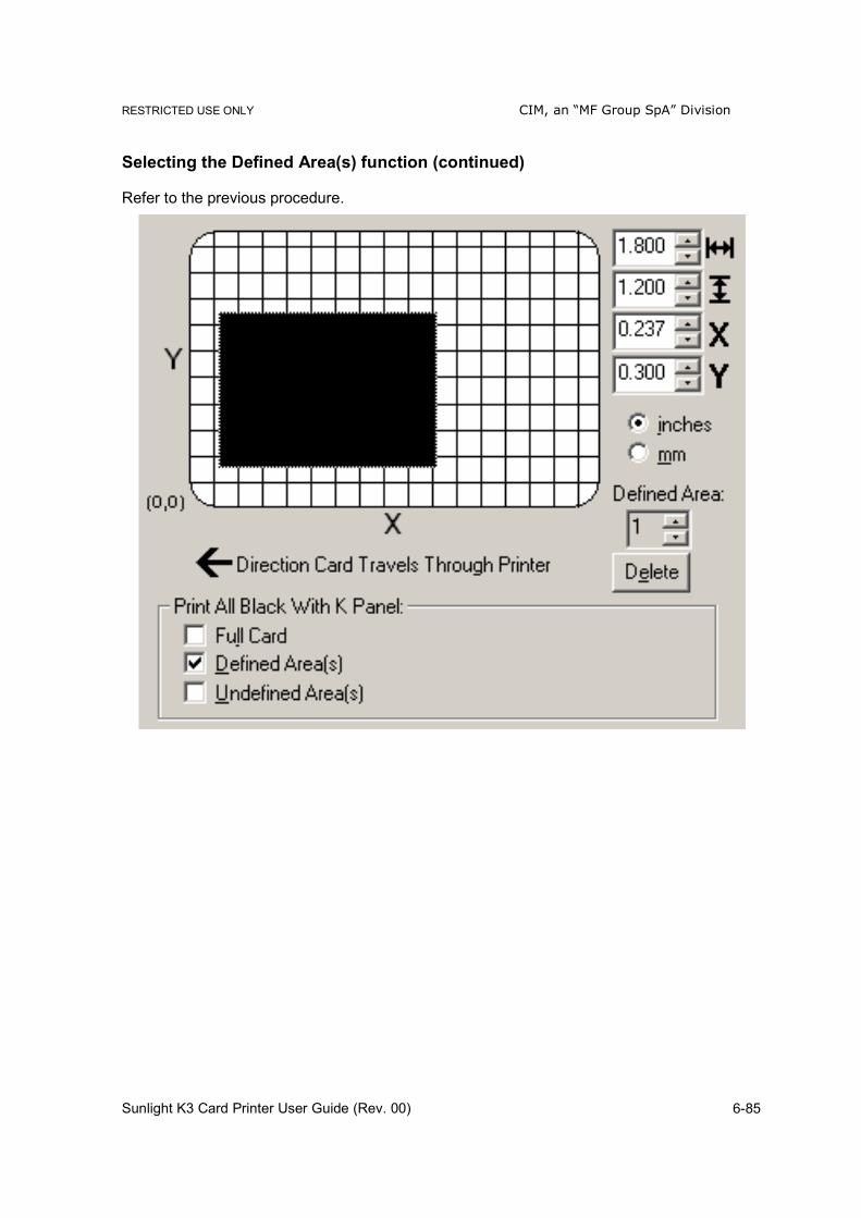
RESTRICTED USE ONLY CIM, an “MF Group SpA” Division
Sunlight K3 Card Printer User Guide (Rev. 00) 6-85
Selecting the Defined Area(s) function (continued)
Refer to the previous procedure.
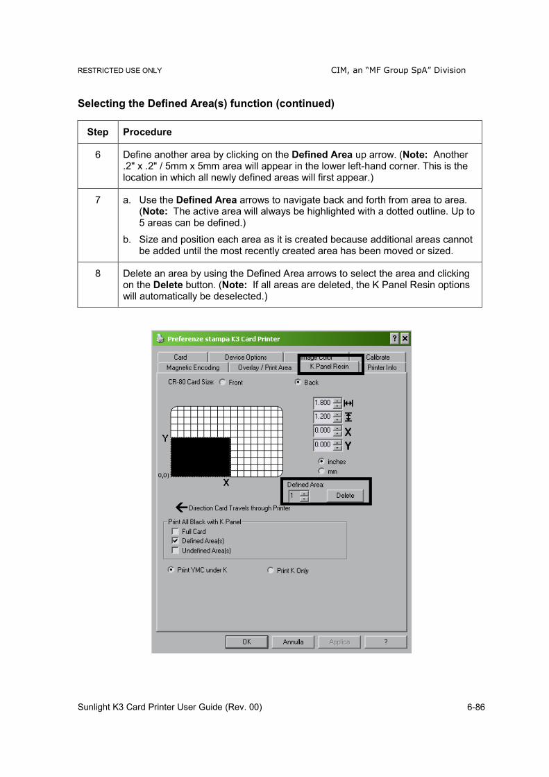
RESTRICTED USE ONLY CIM, an “MF Group SpA” Division
Sunlight K3 Card Printer User Guide (Rev. 00) 6-86
Selecting the Defined Area(s) function (continued)
Step Procedure
6 Define another area by clicking on the Defined Area up arrow. (Note: Another .2" x .2" / 5mm x 5mm area will appear in the lower left-hand corner. This is the location in which all newly defined areas will first appear.)
7 a. Use the Defined Area arrows to navigate back and forth from area to area. (Note: The active area will always be highlighted with a dotted outline. Up to 5 areas can be defined.)
b. Size and position each area as it is created because additional areas cannot be added until the most recently created area has been moved or sized.
8 Delete an area by using the Defined Area arrows to select the area and clicking on the Delete button. (Note: If all areas are deleted, the K Panel Resin options will automatically be deselected.)
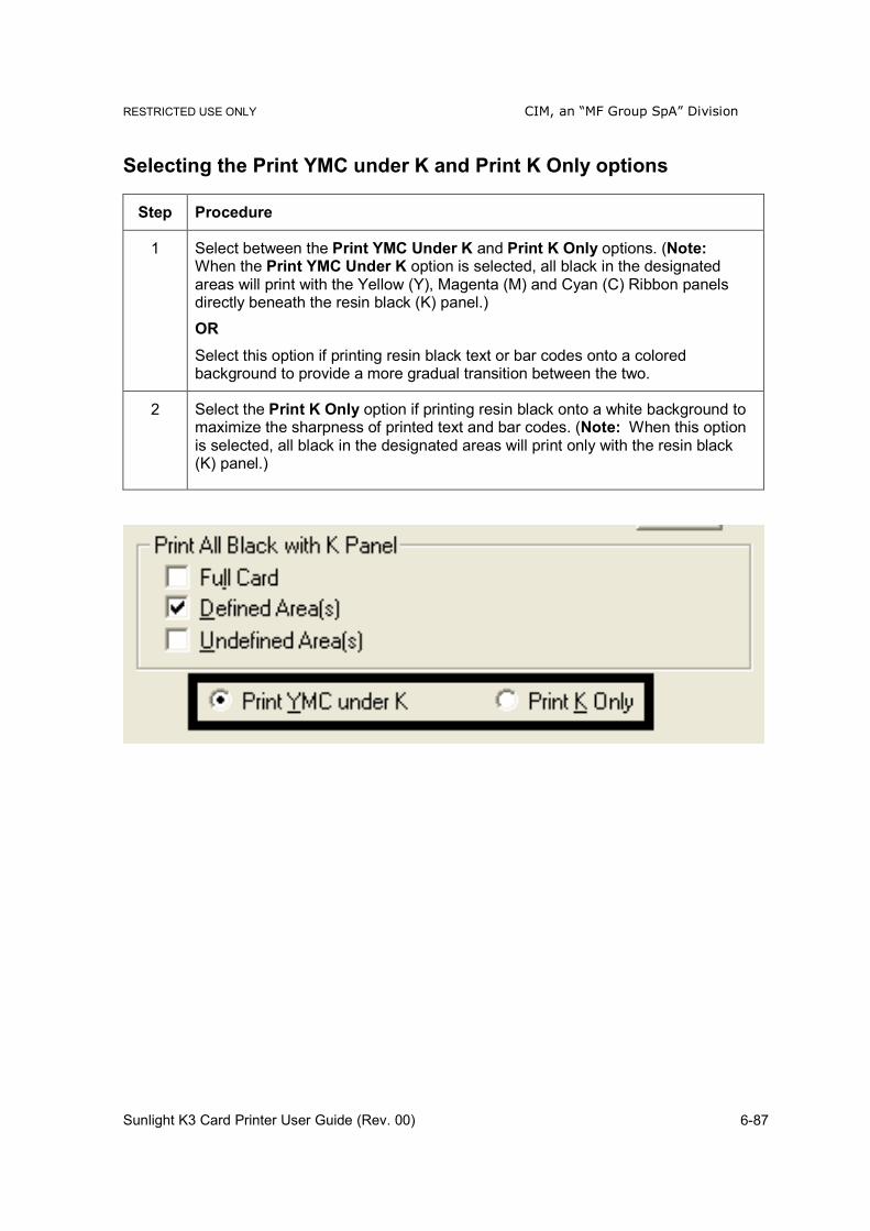
RESTRICTED USE ONLY CIM, an “MF Group SpA” Division
Sunlight K3 Card Printer User Guide (Rev. 00) 6-87
Selecting the Print YMC under K and Print K Only options
Step Procedure
1 Select between the Print YMC Under K and Print K Only options. (Note: When the Print YMC Under K option is selected, all black in the designated areas will print with the Yellow (Y), Magenta (M) and Cyan (C) Ribbon panels directly beneath the resin black (K) panel.)
OR
Select this option if printing resin black text or bar codes onto a colored background to provide a more gradual transition between the two.
2 Select the Print K Only option if printing resin black onto a white background to maximize the sharpness of printed text and bar codes. (Note: When this option is selected, all black in the designated areas will print only with the resin black (K) panel.)
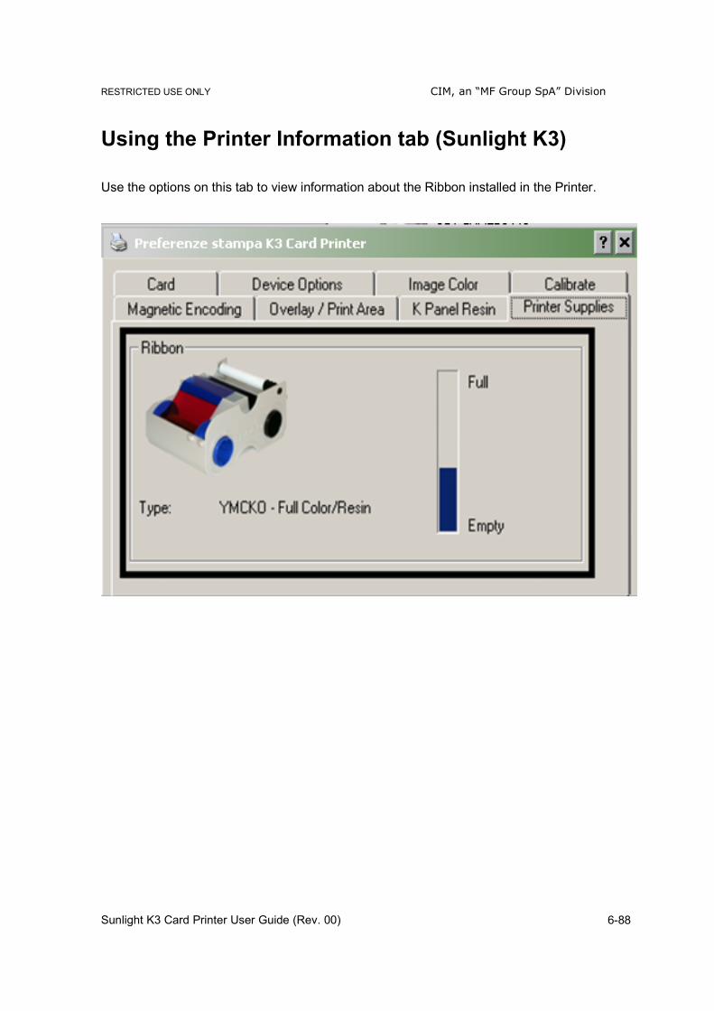
RESTRICTED USE ONLY CIM, an “MF Group SpA” Division
Sunlight K3 Card Printer User Guide (Rev. 00) 6-88
Using the Printer Information tab (Sunlight K3)
Use the options on this tab to view information about the Ribbon installed in the Printer.
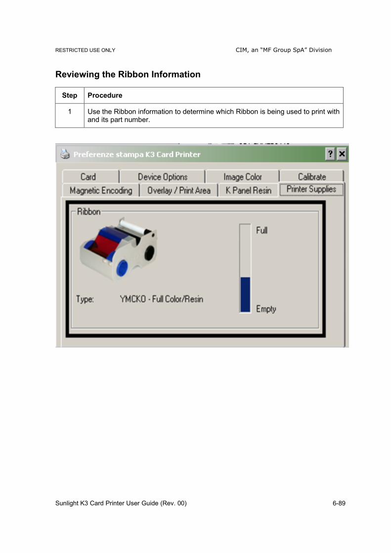
RESTRICTED USE ONLY CIM, an “MF Group SpA” Division
Sunlight K3 Card Printer User Guide (Rev. 00) 6-89
Reviewing the Ribbon Information
Step Procedure
1 Use the Ribbon information to determine which Ribbon is being used to print with and its part number.

RESTRICTED USE ONLY CIM, an “MF Group SpA” Division
Sunlight K3 Card Printer User Guide (Rev. 00) 6-90
Reviewing the Ribbon Level Indicator
Step Procedure
1 Use the Ribbon Level indicator to view approximately how much Ribbon is left.
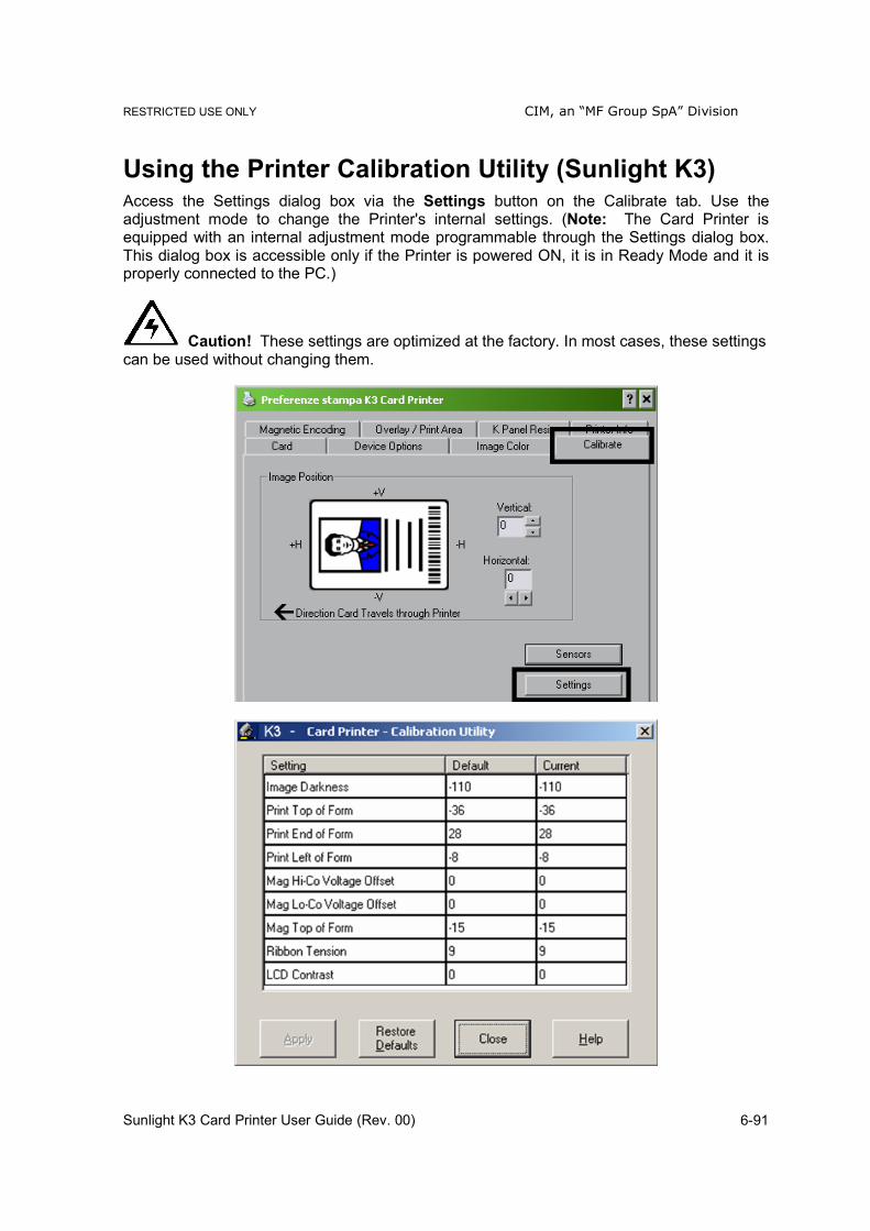
RESTRICTED USE ONLY CIM, an “MF Group SpA” Division
Sunlight K3 Card Printer User Guide (Rev. 00) 6-91
Using the Printer Calibration Utility (Sunlight K3) Access the Settings dialog box via the Settings button on the Calibrate tab. Use the adjustment mode to change the Printer's internal settings. (Note: The Card Printer is equipped with an internal adjustment mode programmable through the Settings dialog box. This dialog box is accessible only if the Printer is powered ON, it is in Ready Mode and it is properly connected to the PC.)
Caution! These settings are optimized at the factory. In most cases, these settings can be used without changing them.
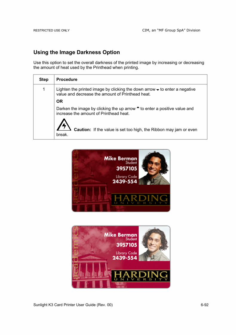
RESTRICTED USE ONLY CIM, an “MF Group SpA” Division
Sunlight K3 Card Printer User Guide (Rev. 00) 6-92
Using the Image Darkness Option
Use this option to set the overall darkness of the printed image by increasing or decreasing the amount of heat used by the Printhead when printing.
Step Procedure
1 Lighten the printed image by clicking the down arrow to enter a negative value and decrease the amount of Printhead heat.
OR Darken the image by clicking the up arrow to enter a positive value and increase the amount of Printhead heat.
Caution: If the value is set too high, the Ribbon may jam or even break.
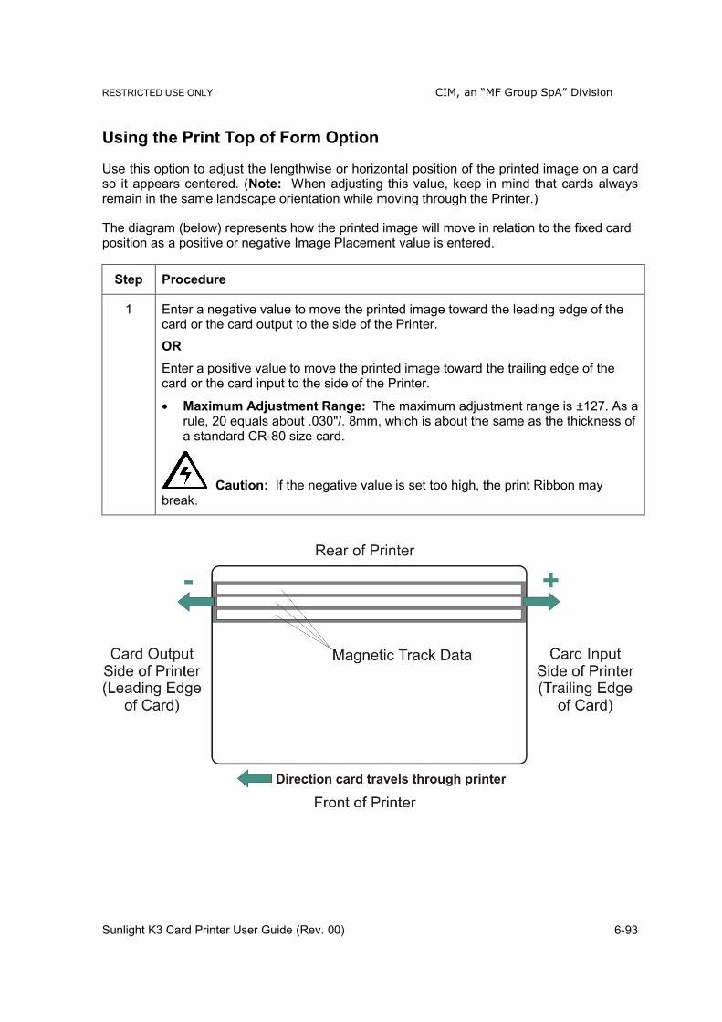
RESTRICTED USE ONLY CIM, an “MF Group SpA” Division
Sunlight K3 Card Printer User Guide (Rev. 00) 6-93
Using the Print Top of Form Option
Use this option to adjust the lengthwise or horizontal position of the printed image on a card so it appears centered. (Note: When adjusting this value, keep in mind that cards always remain in the same landscape orientation while moving through the Printer.)
The diagram (below) represents how the printed image will move in relation to the fixed card position as a positive or negative Image Placement value is entered.
Step Procedure
1 Enter a negative value to move the printed image toward the leading edge of the card or the card output to the side of the Printer.
OR Enter a positive value to move the printed image toward the trailing edge of the card or the card input to the side of the Printer.
• Maximum Adjustment Range: The maximum adjustment range is ±127. As a rule, 20 equals about .030"/. 8mm, which is about the same as the thickness of a standard CR-80 size card.
Caution: If the negative value is set too high, the print Ribbon may break.
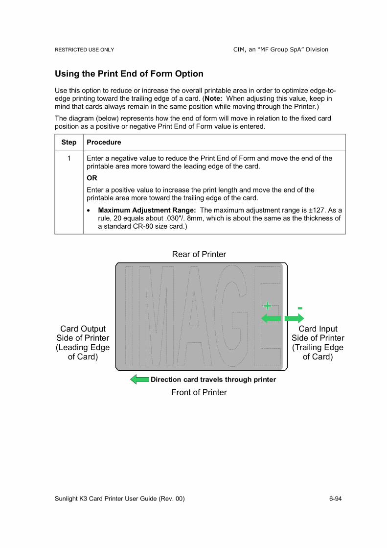
RESTRICTED USE ONLY CIM, an “MF Group SpA” Division
Sunlight K3 Card Printer User Guide (Rev. 00) 6-94
Using the Print End of Form Option
Use this option to reduce or increase the overall printable area in order to optimize edge-to-edge printing toward the trailing edge of a card. (Note: When adjusting this value, keep in mind that cards always remain in the same position while moving through the Printer.)
The diagram (below) represents how the end of form will move in relation to the fixed card position as a positive or negative Print End of Form value is entered.
Step Procedure
1 Enter a negative value to reduce the Print End of Form and move the end of the printable area more toward the leading edge of the card.
OR Enter a positive value to increase the print length and move the end of the printable area more toward the trailing edge of the card.
• Maximum Adjustment Range: The maximum adjustment range is ±127. As a rule, 20 equals about .030"/. 8mm, which is about the same as the thickness of a standard CR-80 size card.)
Direction card travels through printer
Rear of Printer
Card OutputSide of Printer(Leading Edge
of Card)
Card InputSide of Printer(Trailing Edge
of Card)
Front of Printer
-
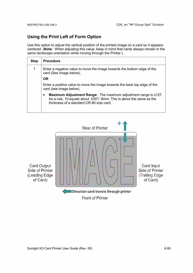
RESTRICTED USE ONLY CIM, an “MF Group SpA” Division
Sunlight K3 Card Printer User Guide (Rev. 00) 6-95
Using the Print Left of Form Option
Use this option to adjust the vertical position of the printed image on a card so it appears centered. (Note: When adjusting this value, keep in mind that cards always remain in the same landscape orientation while moving through the Printer.)
Step Procedure
1 Enter a negative value to move the image towards the bottom edge of the card (See image below),
OR
Enter a positive value to move the image towards the back top edge of the card (see image below).
• Maximum Adjustment Range: The maximum adjustment range is ±127. As a rule, 10 equals about .030"/. 8mm. This is about the same as the thickness of a standard CR-80 size card.

RESTRICTED USE ONLY CIM, an “MF Group SpA” Division
Sunlight K3 Card Printer User Guide (Rev. 00) 6-96
Using the Magnetic Encoder Voltage Offset Option
Use this option to adjust the voltage of the Magnetic Encoder.
• Encoder voltage is set from the factory at a default of 7.24vdc for Hi-Co Magnetic cards and 2.54vdc for Lo-Co Magnetic cards.
• Depending on the cards that are being used, it may be necessary to adjust the encoder voltage out of default.
See the next two procedures for instructions on adjusting the Magnetic Encoder Voltage. (Note: The required encoder voltage for the cards will need to be known in order to properly set the Encoder Voltage Offset value. This information should be available through the card manufacturer or reseller).
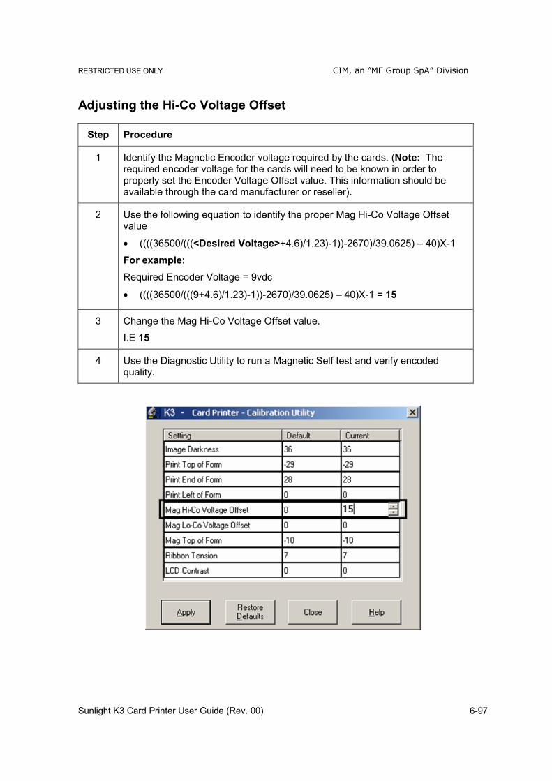
RESTRICTED USE ONLY CIM, an “MF Group SpA” Division
Sunlight K3 Card Printer User Guide (Rev. 00) 6-97
Adjusting the Hi-Co Voltage Offset
Step Procedure
1 Identify the Magnetic Encoder voltage required by the cards. (Note: The required encoder voltage for the cards will need to be known in order to properly set the Encoder Voltage Offset value. This information should be available through the card manufacturer or reseller).
2 Use the following equation to identify the proper Mag Hi-Co Voltage Offset value
• ((((36500/(((<Desired Voltage>+4.6)/1.23)-1))-2670)/39.0625) – 40)X-1
For example: Required Encoder Voltage = 9vdc
• ((((36500/(((9+4.6)/1.23)-1))-2670)/39.0625) – 40)X-1 = 15
3 Change the Mag Hi-Co Voltage Offset value.
I.E 15
4 Use the Diagnostic Utility to run a Magnetic Self test and verify encoded quality.
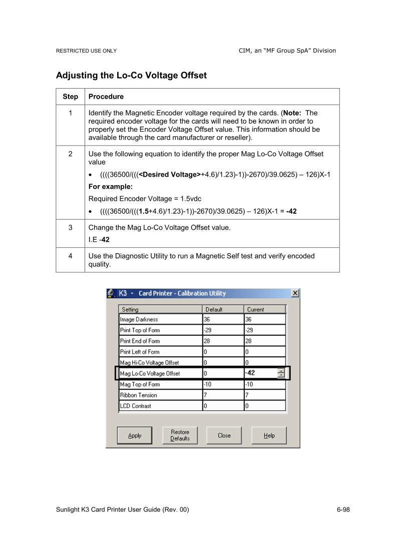
RESTRICTED USE ONLY CIM, an “MF Group SpA” Division
Sunlight K3 Card Printer User Guide (Rev. 00) 6-98
Adjusting the Lo-Co Voltage Offset
Step Procedure
1 Identify the Magnetic Encoder voltage required by the cards. (Note: The required encoder voltage for the cards will need to be known in order to properly set the Encoder Voltage Offset value. This information should be available through the card manufacturer or reseller).
2 Use the following equation to identify the proper Mag Lo-Co Voltage Offset value
• ((((36500/(((<Desired Voltage>+4.6)/1.23)-1))-2670)/39.0625) – 126)X-1
For example: Required Encoder Voltage = 1.5vdc
• ((((36500/(((1.5+4.6)/1.23)-1))-2670)/39.0625) – 126)X-1 = -42
3 Change the Mag Lo-Co Voltage Offset value.
I.E -42
4 Use the Diagnostic Utility to run a Magnetic Self test and verify encoded quality.

RESTRICTED USE ONLY CIM, an “MF Group SpA” Division
Sunlight K3 Card Printer User Guide (Rev. 00) 6-99
Using the Mag Top of Form Option
Use this option only if the Printer has a built-in Magnetic Stripe encoder. (Note: If so, use this option to shift the starting point of where the Printer will begin encoding the magnetic track data on a card's Magnetic Stripe. When adjusting this value, keep in mind that a card and its Magnetic Stripe will always remain in the same relative position as the card travels through the Printer.)
The diagram (below) represents how the magnetic data will move in relation to the fixed position of a card's Magnetic Stripe as a positive or negative Magnetic Offset value is entered. (Note: For this diagram, imagine that the card is transparent and the card's Magnetic stripe can be seen through the top or front side of the card.)
Step Procedure
1 Enter a negative value to move the start of the magnetic data more toward the leading edge of the card or the card output to the side of the Printer.
OR Enter a positive value to move the start of the magnetic data toward the trailing edge of the card or the card input to the side of the Printer.
• Magnetic Data Direction: The arrows on these buttons indicate the direction the magnetic data will move on the card's Magnetic Stripe.
•
Maximum Adjustment Range: The maximum adjustment range is ± 127. As a rule, 20 equals about .030"/. 8mm.) (Note: Keep this in mind when adjusting this option to avoid over-adjusting.)
Caution: If the negative value is set too high, the Printer may start encoding before the card's Magnetic Stripe reaches the encoding head.
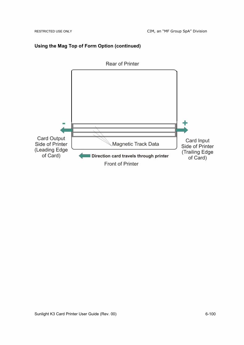
RESTRICTED USE ONLY CIM, an “MF Group SpA” Division
Sunlight K3 Card Printer User Guide (Rev. 00) 6-100
Using the Mag Top of Form Option (continued)
RESTRICTED USE ONLY CIM, an “MF Group SpA” Division
Sunlight K3 Card Printer User Guide (Rev. 00) 6-101
Using the Ribbon Tension Option
Step Procedure
1 Use the Ribbon Tension option to increase the amount of tension (drag) on the Ribbon during printing.
Enter a negative value to decrease the amount of tension that is placed on the Ribbon during printing
OR
Enter a positive value to increases the amount of tension that is placed on the Ribbon during printing.

RESTRICTED USE ONLY CIM, an “MF Group SpA” Division
Sunlight K3 Card Printer User Guide (Rev. 00) 6-102
Using the Flipper Home Offset Option
Use this option to change the Flipper angle relative to home/horizontal position. This is done in order to adjust angle of travel to and from the Printer and Flipper Module.
Step Procedure
1 Enter a negative value to position a card to enter the Printer at an upward angle.
Or Enter a positive value to position a card to enter the Printer at a descending angle.
(Maximum Adjustment Range: The maximum adjustment range is ± 5. 1 is approximately 1 degree.)
Using the Flipper Center Offset Option
Use this option to change the card position on the Flipper Table, relative to the center, for flipping. (Note: This is important to maintain the proper clearance with surrounding objects when flipping a card.)
Step Procedure
1 Enter a negative value to position a card closer to the output of the Printer when the Flipper is in home/horizontal position.
Or Enter a positive value to position a card closer to the output of the Flipper Module when the Flipper is in home/horizontal position.
(Maximum Adjustment Range: The maximum adjustment range is ± 127. As a rule, 20 equals about .030”/.8 mm, which is about the same as the thickness of a standard CR-80 size card.)
Caution: If the offset is set too high or low, the card may jam in the Flipper Module when flipping.
RESTRICTED USE ONLY CIM, an “MF Group SpA” Division
Sunlight K3 Card Printer User Guide (Rev. 00) 6-103
Using the Flipper Smart Angle Offset Option
Use this option to change the Flipper angle relative to the default smart card loading position. This is done in order to adjust travel to and from the Flipper and the Smart Card Docking Module.
Step Procedure
1 Enter a negative value to decrease the amount of Flipper angular movement from the home position to the smart card loading position.
Or Enter a positive value to increase the amount of Flipper angular movement from the home position to the smart card loading position.
(Maximum Adjustment Range: The maximum adjustment range is ± 5. 1 is approximately 1 degree.)
RESTRICTED USE ONLY CIM, an “MF Group SpA” Division
Sunlight K3 Card Printer User Guide (Rev. 00) 7-1
Section 7: Cleaning The Card Printer is built to require a minimum amount of maintenance. Nevertheless, there are a few procedures you can perform on a regular basis or as needed to ensure the best possible performance
Safety Messages (review carefully) Symbol Critical Instructions for Safety purposes
Danger:
Failure to follow these installation guidelines can result in death or serious injury. Information that raises potential safety issues is indicated by a warning symbol (as shown to the left).
• To prevent personal injury, refer to the following safety messages before performing an operation preceded by this symbol.
• To prevent personal injury, always remove the power cord prior to performing repair procedures, unless otherwise specified.
• To prevent personal injury, make sure only qualified personnel perform these procedures.
Caution:
This device is electrostatically sensitive. It may be damaged if exposed to static electricity discharges. Information that raises potential electrostatic safety issues is indicated by a warning symbol (as shown to the left).
• To prevent equipment or media damage, refer to the following safety messages before performing an operation preceded by this symbol.
• To prevent equipment or media damage, observe all established Electrostatic Discharge (ESD) procedures while handling cables in or near the Circuit Board and Printhead Assemblies.
• To prevent equipment or media damage, always wear an appropriate personal grounding device (e.g., a high quality wrist strap grounded to avoid potential damage).
• To prevent equipment or media damage, always remove the Ribbon and Cards from the Printer before making any repairs, unless otherwise specified.
•
To prevent equipment or media damage, take jewelry off of fingers and hands, as well as thoroughly clean hands to remove oil and debris before working on the Printer.

RESTRICTED USE ONLY CIM, an “MF Group SpA” Division
Sunlight K3 Card Printer User Guide (Rev. 00) 7-2
Sunlight K3 Card Printer/Encoders Cleaning Cards
Caution: As with any electronic device, internal components of the Printer, such as the Printhead, may be damaged if exposed to static electrical discharges. To avoid potential damage, always wear an appropriate personal grounding device, such as a wrist strap (with integral resistor) connected to an ESD ground.
Supplies
This Cleaning card provides you with the specialized cleaning supplies and the required cleaning procedures for you to maintain your CIM Sunlight K3 Card Printer/Encoders. The following cleaning procedures will require less than ten minutes. For more thorough cleaning instructions, please refer to the Cleaning Section in the appropriate User Guide.
Cleaning Cards are provided with adhesive backing for cleaning your Printer’s Platen and Card Feed Rollers.
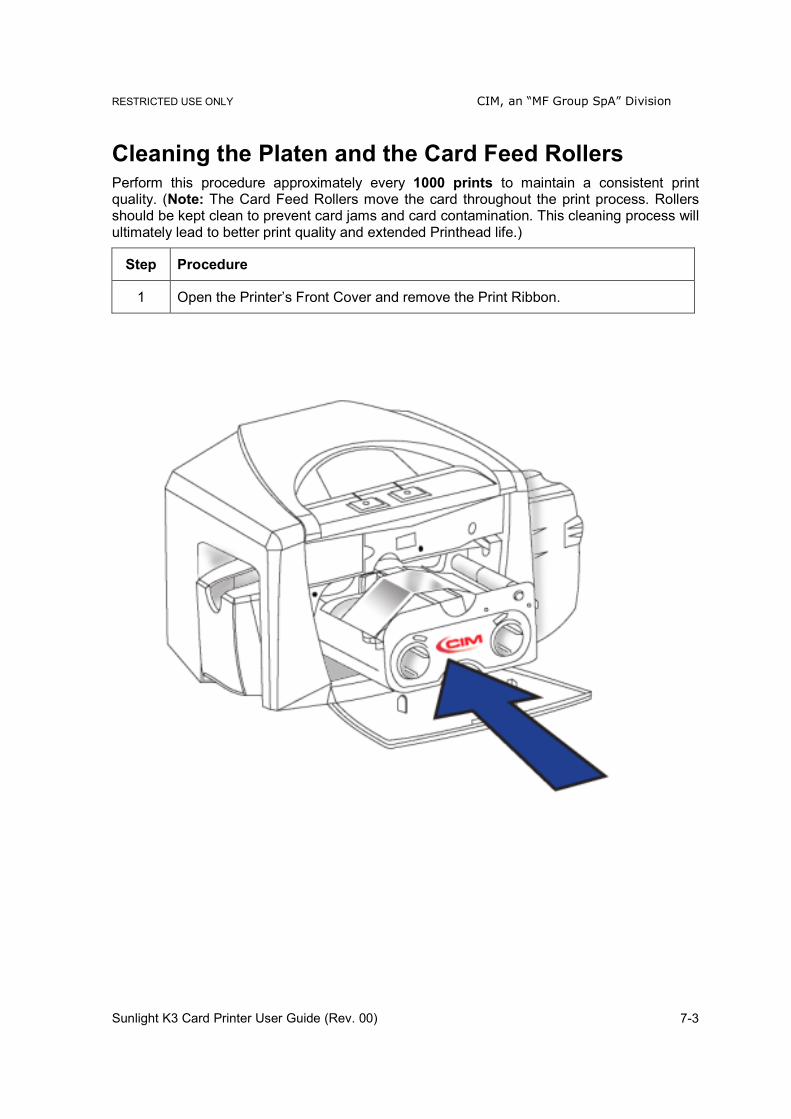
RESTRICTED USE ONLY CIM, an “MF Group SpA” Division
Sunlight K3 Card Printer User Guide (Rev. 00) 7-3
Cleaning the Platen and the Card Feed Rollers Perform this procedure approximately every 1000 prints to maintain a consistent print quality. (Note: The Card Feed Rollers move the card throughout the print process. Rollers should be kept clean to prevent card jams and card contamination. This cleaning process will ultimately lead to better print quality and extended Printhead life.)
Step Procedure
1 Open the Printer’s Front Cover and remove the Print Ribbon.
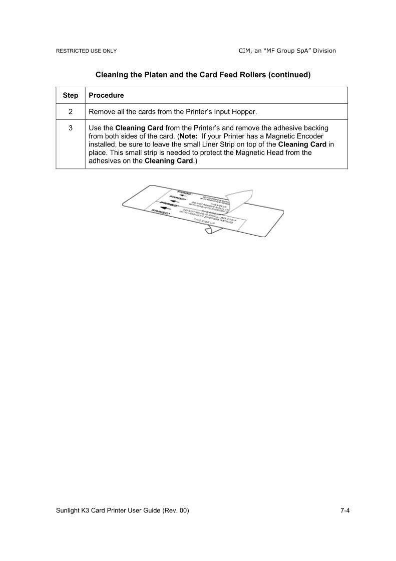
RESTRICTED USE ONLY CIM, an “MF Group SpA” Division
Sunlight K3 Card Printer User Guide (Rev. 00) 7-4
Cleaning the Platen and the Card Feed Rollers (continued)
Step Procedure
2 Remove all the cards from the Printer’s Input Hopper.
3 Use the Cleaning Card from the Printer’s and remove the adhesive backing from both sides of the card. (Note: If your Printer has a Magnetic Encoder installed, be sure to leave the small Liner Strip on top of the Cleaning Card in place. This small strip is needed to protect the Magnetic Head from the adhesives on the Cleaning Card.)
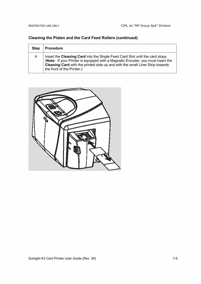
RESTRICTED USE ONLY CIM, an “MF Group SpA” Division
Sunlight K3 Card Printer User Guide (Rev. 00) 7-5
Cleaning the Platen and the Card Feed Rollers (continued)
Step Procedure
4 Insert the Cleaning Card into the Single Feed Card Slot until the card stops. (Note: If your Printer is equipped with a Magnetic Encoder, you must insert the Cleaning Card with the printed side up and with the small Liner Strip towards the front of the Printer.)
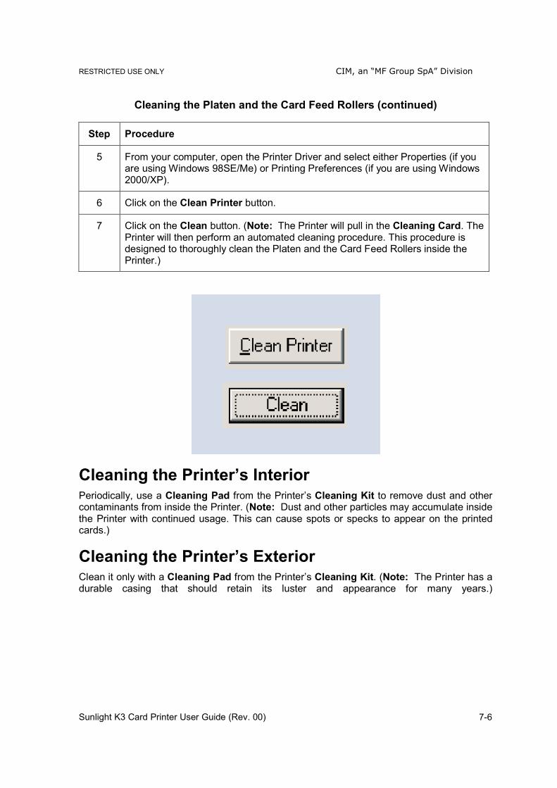
RESTRICTED USE ONLY CIM, an “MF Group SpA” Division
Sunlight K3 Card Printer User Guide (Rev. 00) 7-6
Cleaning the Platen and the Card Feed Rollers (continued)
Step Procedure
5 From your computer, open the Printer Driver and select either Properties (if you are using Windows 98SE/Me) or Printing Preferences (if you are using Windows 2000/XP).
6 Click on the Clean Printer button.
7 Click on the Clean button. (Note: The Printer will pull in the Cleaning Card. The Printer will then perform an automated cleaning procedure. This procedure is designed to thoroughly clean the Platen and the Card Feed Rollers inside the Printer.)
Cleaning the Printer’s Interior Periodically, use a Cleaning Pad from the Printer’s Cleaning Kit to remove dust and other contaminants from inside the Printer. (Note: Dust and other particles may accumulate inside the Printer with continued usage. This can cause spots or specks to appear on the printed cards.)
Cleaning the Printer’s Exterior Clean it only with a Cleaning Pad from the Printer’s Cleaning Kit. (Note: The Printer has a durable casing that should retain its luster and appearance for many years.)
RESTRICTED USE ONLY CIM, an “MF Group SpA” Division
Sunlight K3 Card Printer User Guide (Rev. 00) 8-1
Section 8: Packing the Card Printer The purpose of this section to provide the User with a specific packing procedure for this Card Printer.
Follow this instruction to pack the Card Printer for transport.
Step Procedure
1 Clean the inside of the Printer with compressed air.
2 Wipe it down with a lint-free cloth.
3 Clean the Printhead with a alcohol swab.
4 Pack the Printer in the original carton and packing materials.
5 Ensure to enclose any necessary paperwork, test cards, etc.

RESTRICTED USE ONLY CIM, an “MF Group SpA” Division
Sunlight K3 Card Printer User Guide (Rev. 00) 8-2
PART B. TECHNICAL MANUAL
RESTRICTED USE ONLY CIM, an “MF Group SpA” Division
Sunlight K3 Card Printer User Guide (Rev. 00) 9-1
Section 9: Board Level Diagnostics The purpose of this section to provide the User with specific Board Level Diagnostic procedures for Board Errors and Sensor Testing for this Card Printer.
Safety Messages (review carefully) Symbol Critical Instructions for Safety purposes
Danger:
Failure to follow these installation guidelines can result in death or serious injury. Information that raises potential safety issues is indicated by a warning symbol (as shown to the left).
• To prevent personal injury, refer to the following safety messages before performing an operation preceded by this symbol.
• To prevent personal injury, always remove the power cord prior to performing repair procedures, unless otherwise specified.
• To prevent personal injury, make sure only qualified personnel perform these procedures.
Caution:
This device is electrostatically sensitive. It may be damaged if exposed to static electricity discharges. Information that raises potential electrostatic safety issues is indicated by a warning symbol (as shown to the left).
• To prevent equipment or media damage, refer to the following safety messages before performing an operation preceded by this symbol.
• To prevent equipment or media damage, observe all established Electrostatic Discharge (ESD) procedures while handling cables in or near the Circuit Board and Printhead Assemblies.
• To prevent equipment or media damage, always wear an appropriate personal grounding device (e.g., a high quality wrist strap grounded to avoid potential damage).
• To prevent equipment or media damage, always remove the Ribbon and Cards from the Printer before making any repairs, unless otherwise specified.
• To prevent equipment or media damage, take jewelry off of fingers and hands, as well as thoroughly clean hands to remove oil and debris before working on the Printer.
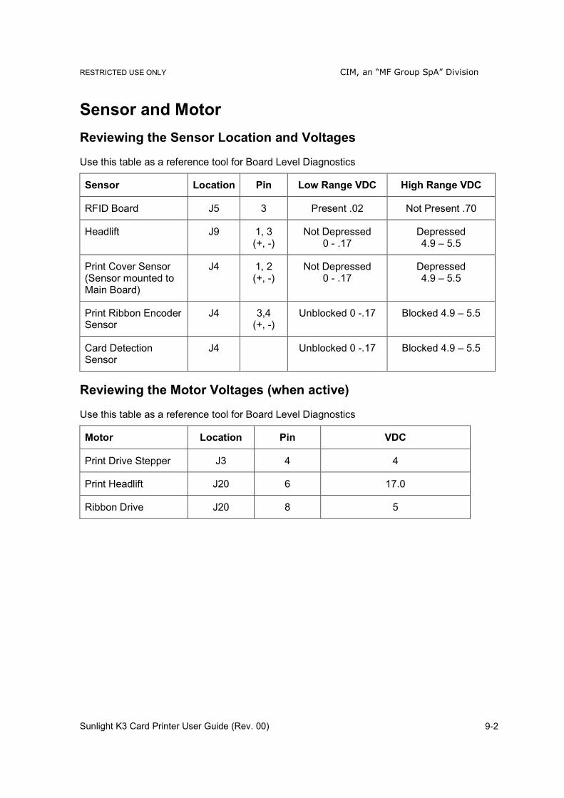
RESTRICTED USE ONLY CIM, an “MF Group SpA” Division
Sunlight K3 Card Printer User Guide (Rev. 00) 9-2
Sensor and Motor Reviewing the Sensor Location and Voltages
Use this table as a reference tool for Board Level Diagnostics
Sensor Location Pin Low Range VDC High Range VDC
RFID Board J5 3 Present .02 Not Present .70
Headlift J9 1, 3 (+, -)
Not Depressed 0 - .17
Depressed 4.9 – 5.5
Print Cover Sensor (Sensor mounted to Main Board)
J4 1, 2 (+, -)
Not Depressed 0 - .17
Depressed 4.9 – 5.5
Print Ribbon Encoder Sensor
J4 3,4 (+, -)
Unblocked 0 -.17 Blocked 4.9 – 5.5
Card Detection Sensor
J4 Unblocked 0 -.17 Blocked 4.9 – 5.5
Reviewing the Motor Voltages (when active)
Use this table as a reference tool for Board Level Diagnostics
Motor Location Pin VDC
Print Drive Stepper J3 4 4
Print Headlift J20 6 17.0
Ribbon Drive J20 8 5

RESTRICTED USE ONLY CIM, an “MF Group SpA” Division
Sunlight K3 Card Printer User Guide (Rev. 00) 10-1
Section 10: Diagnostic Tool Utility The CIM Diagnostics Utility is designed to provide access to the following:
• The diagnostic capabilities of the Printer.
• The internal Self Tests of the Printer.
• The testing options for Magnetic Encoding.
The set of sample images to test the Printer's operation.
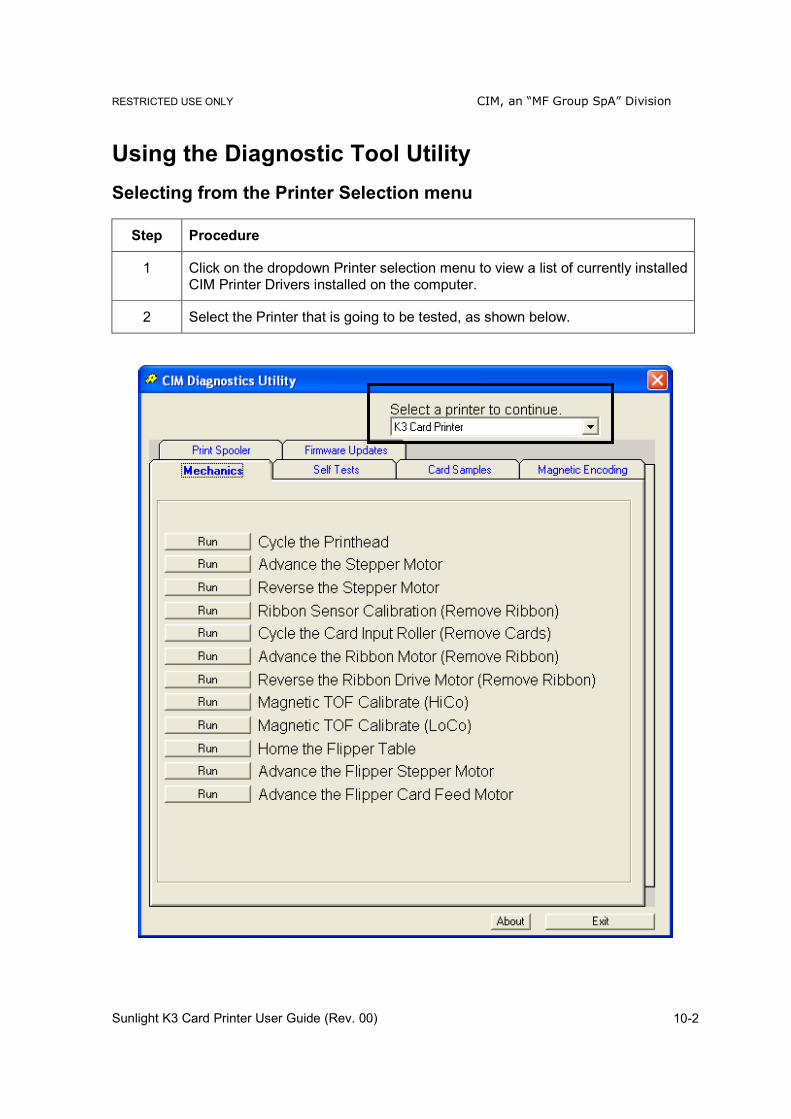
RESTRICTED USE ONLY CIM, an “MF Group SpA” Division
Sunlight K3 Card Printer User Guide (Rev. 00) 10-2
Using the Diagnostic Tool Utility Selecting from the Printer Selection menu
Step Procedure
1 Click on the dropdown Printer selection menu to view a list of currently installed CIM Printer Drivers installed on the computer.
2 Select the Printer that is going to be tested, as shown below.
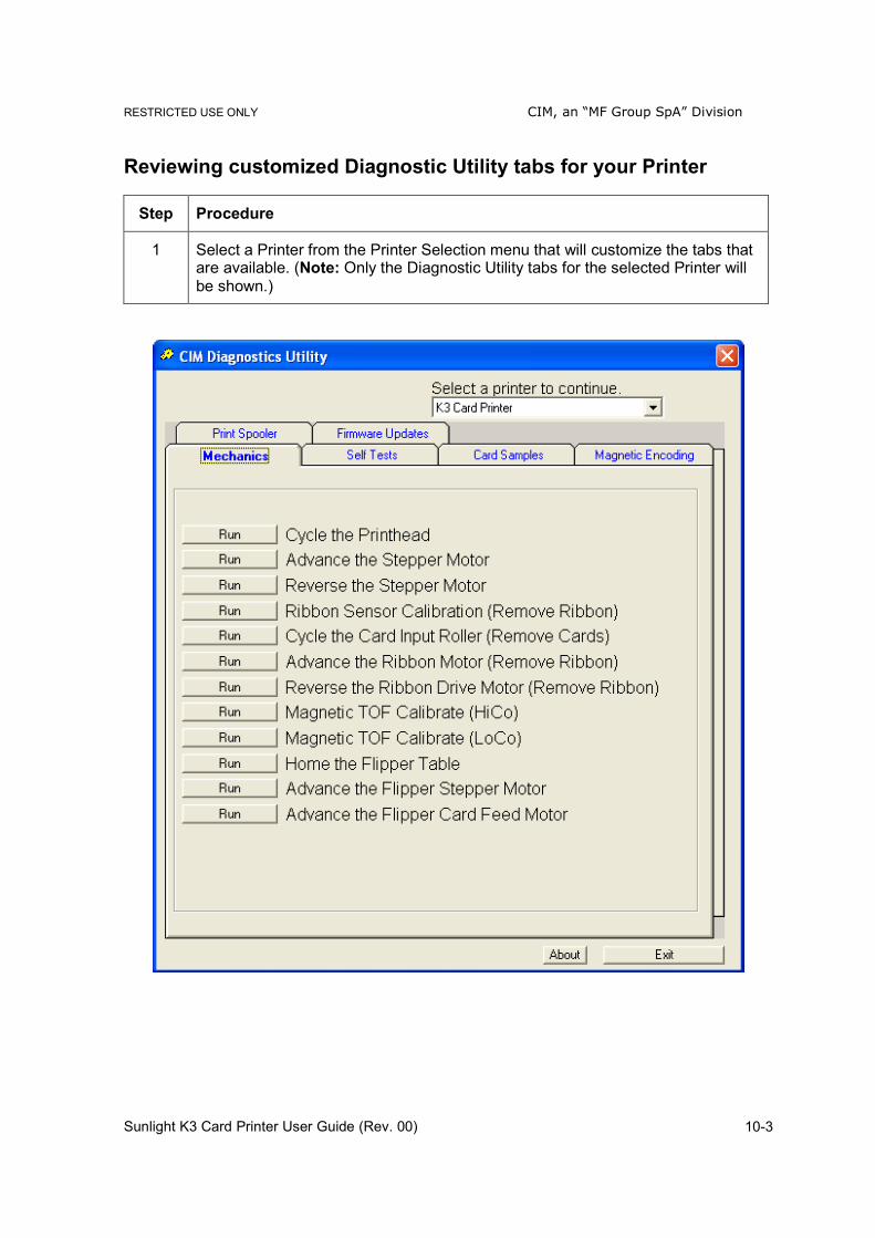
RESTRICTED USE ONLY CIM, an “MF Group SpA” Division
Sunlight K3 Card Printer User Guide (Rev. 00) 10-3
Reviewing customized Diagnostic Utility tabs for your Printer
Step Procedure
1 Select a Printer from the Printer Selection menu that will customize the tabs that are available. (Note: Only the Diagnostic Utility tabs for the selected Printer will be shown.)
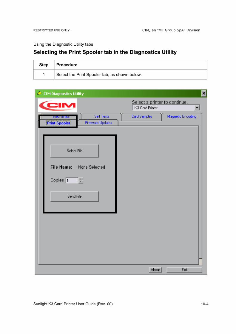
RESTRICTED USE ONLY CIM, an “MF Group SpA” Division
Sunlight K3 Card Printer User Guide (Rev. 00) 10-4
Using the Diagnostic Utility tabs
Selecting the Print Spooler tab in the Diagnostics Utility
Step Procedure
1 Select the Print Spooler tab, as shown below.
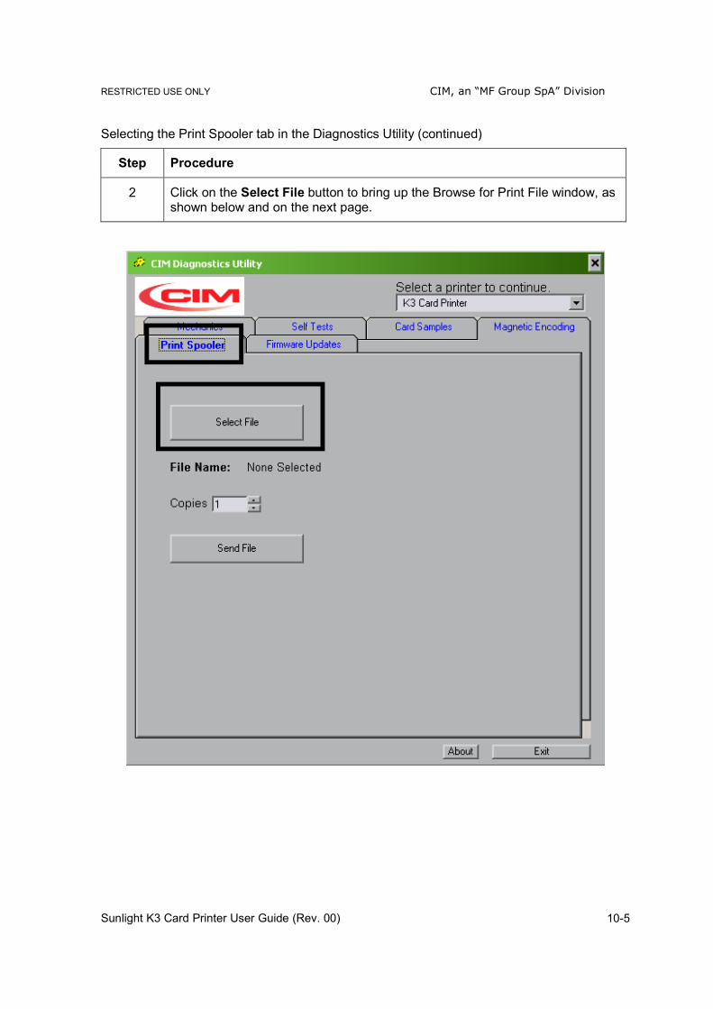
RESTRICTED USE ONLY CIM, an “MF Group SpA” Division
Sunlight K3 Card Printer User Guide (Rev. 00) 10-5
Selecting the Print Spooler tab in the Diagnostics Utility (continued)
Step Procedure
2 Click on the Select File button to bring up the Browse for Print File window, as shown below and on the next page.
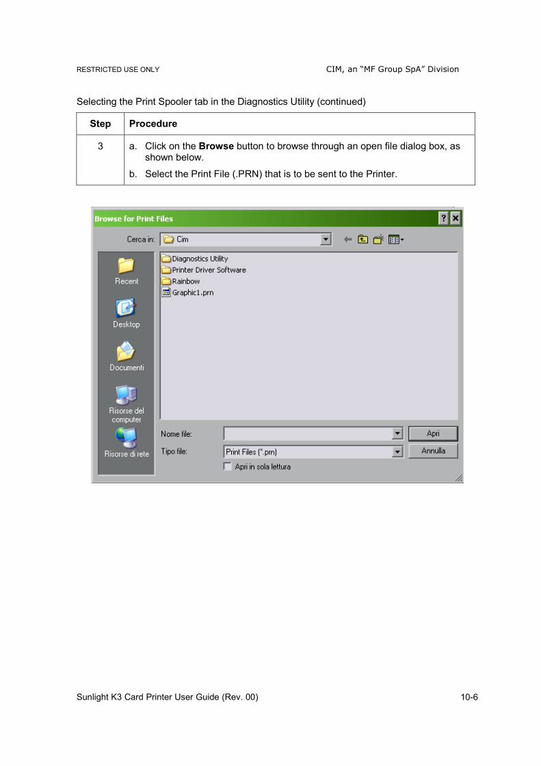
RESTRICTED USE ONLY CIM, an “MF Group SpA” Division
Sunlight K3 Card Printer User Guide (Rev. 00) 10-6
Selecting the Print Spooler tab in the Diagnostics Utility (continued)
Step Procedure
3 a. Click on the Browse button to browse through an open file dialog box, as shown below.
b. Select the Print File (.PRN) that is to be sent to the Printer.
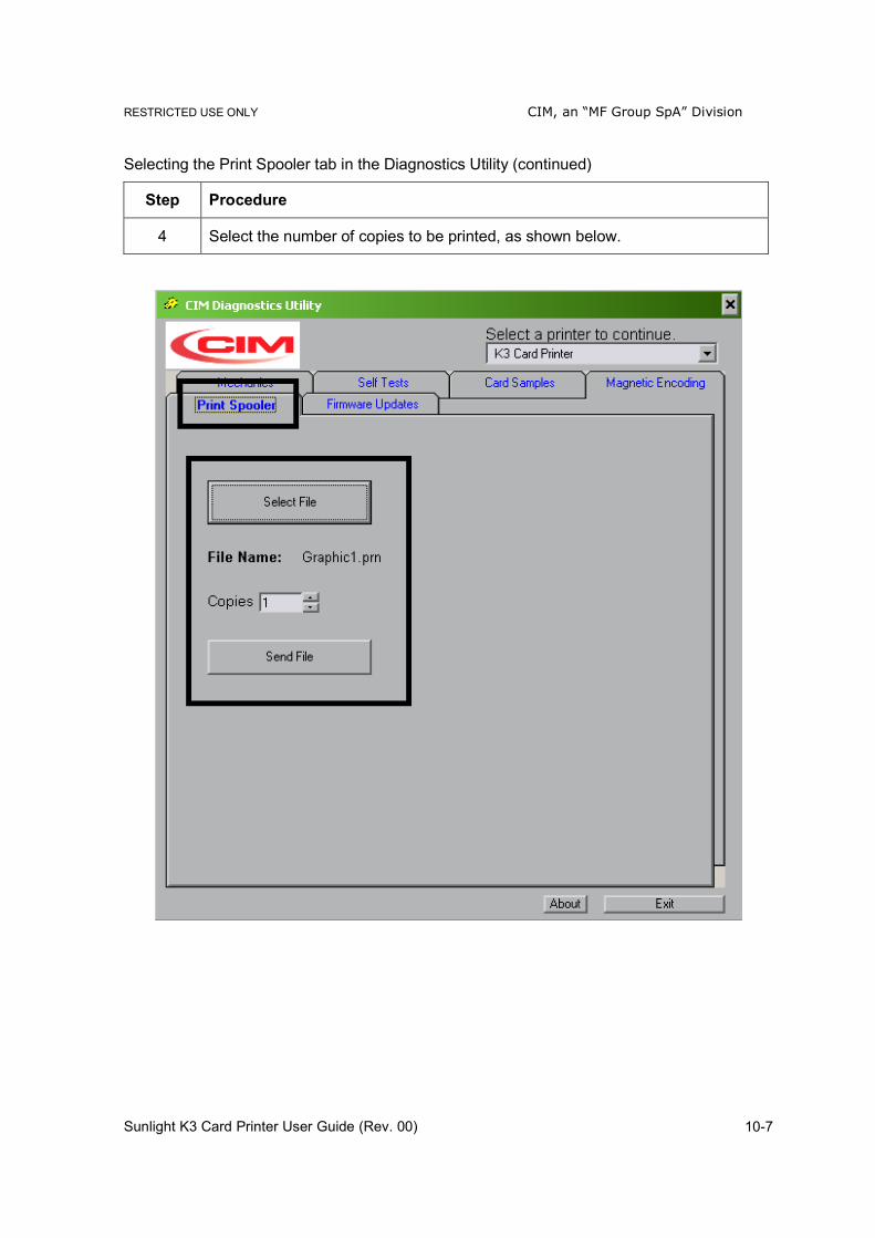
RESTRICTED USE ONLY CIM, an “MF Group SpA” Division
Sunlight K3 Card Printer User Guide (Rev. 00) 10-7
Selecting the Print Spooler tab in the Diagnostics Utility (continued)
Step Procedure
4 Select the number of copies to be printed, as shown below.
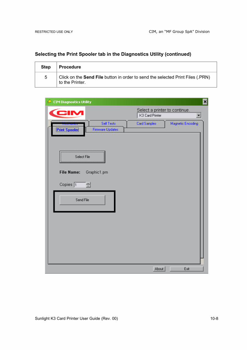
RESTRICTED USE ONLY CIM, an “MF Group SpA” Division
Sunlight K3 Card Printer User Guide (Rev. 00) 10-8
Selecting the Print Spooler tab in the Diagnostics Utility (continued)
Step Procedure
5 Click on the Send File button in order to send the selected Print Files (.PRN) to the Printer.
RESTRICTED USE ONLY CIM, an “MF Group SpA” Division
Sunlight K3 Card Printer User Guide (Rev. 00) 10-9
Selecting the Firmware File
Step Procedure
1 Select the Select Firmware File to open a Browse Dialog Box.
2 Browse to the location where the firmware file is located.
3 Click on the OK button.
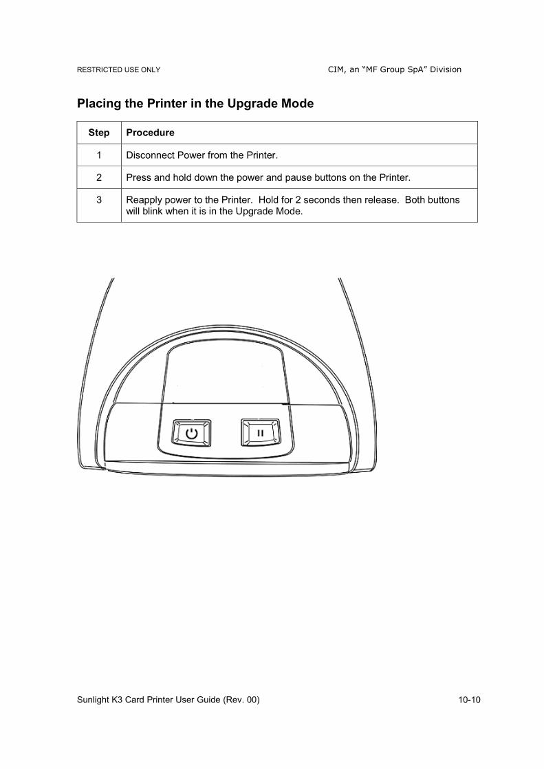
RESTRICTED USE ONLY CIM, an “MF Group SpA” Division
Sunlight K3 Card Printer User Guide (Rev. 00) 10-10
Placing the Printer in the Upgrade Mode
Step Procedure
1 Disconnect Power from the Printer.
2 Press and hold down the power and pause buttons on the Printer.
3 Reapply power to the Printer. Hold for 2 seconds then release. Both buttons will blink when it is in the Upgrade Mode.
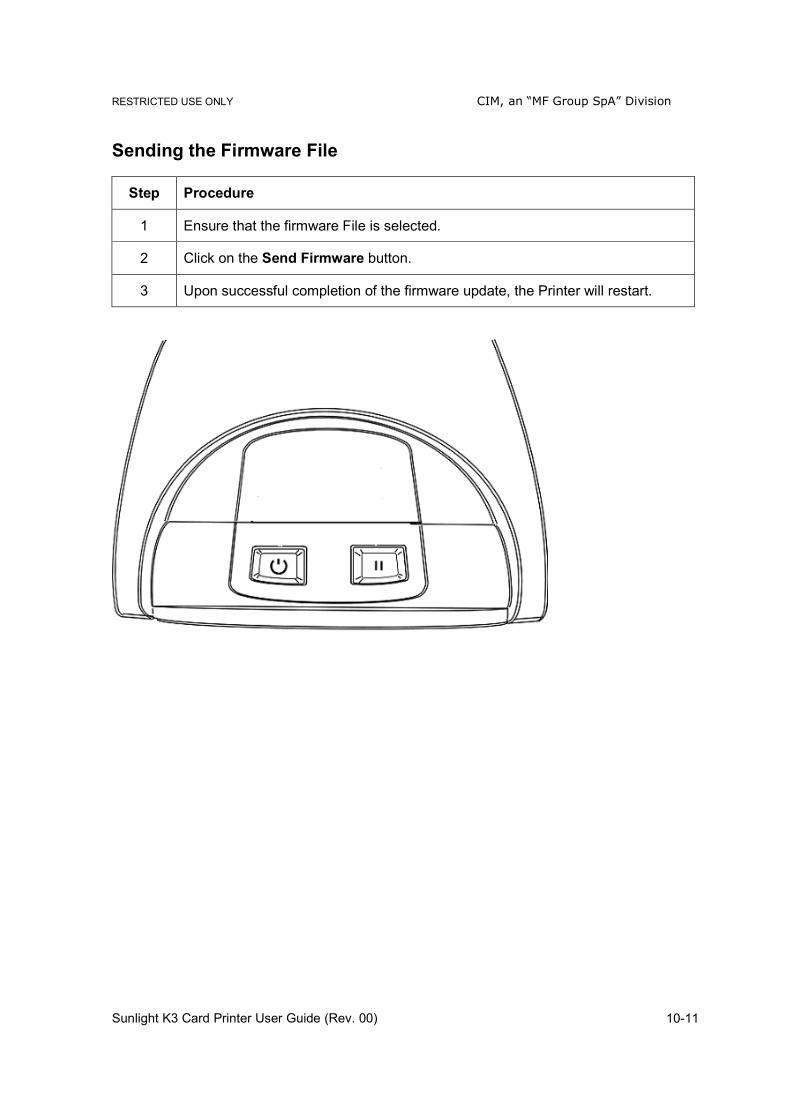
RESTRICTED USE ONLY CIM, an “MF Group SpA” Division
Sunlight K3 Card Printer User Guide (Rev. 00) 10-11
Sending the Firmware File
Step Procedure
1 Ensure that the firmware File is selected.
2 Click on the Send Firmware button.
3 Upon successful completion of the firmware update, the Printer will restart.
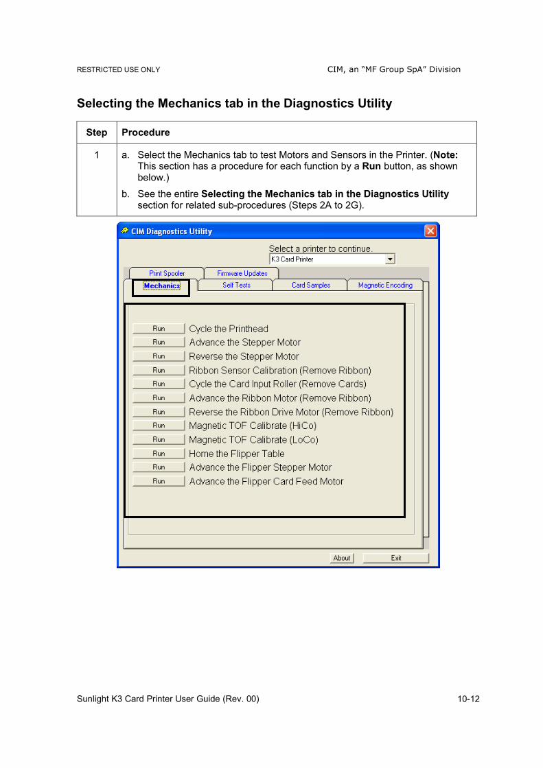
RESTRICTED USE ONLY CIM, an “MF Group SpA” Division
Sunlight K3 Card Printer User Guide (Rev. 00) 10-12
Selecting the Mechanics tab in the Diagnostics Utility
Step Procedure
1 a. Select the Mechanics tab to test Motors and Sensors in the Printer. (Note: This section has a procedure for each function by a Run button, as shown below.)
b. See the entire Selecting the Mechanics tab in the Diagnostics Utility section for related sub-procedures (Steps 2A to 2G).

RESTRICTED USE ONLY CIM, an “MF Group SpA” Division
Sunlight K3 Card Printer User Guide (Rev. 00) 10-13
Selecting the Mechanics tab in the Diagnostics Utility (continued)
Step Procedure
2A Click on the Ribbon Sensor Calibration button to calibrate the Print Ribbon. (Note: This will ensure proper operation of the Ribbon Sensing systems.)
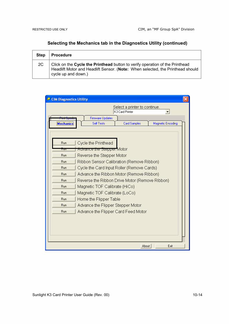
RESTRICTED USE ONLY CIM, an “MF Group SpA” Division
Sunlight K3 Card Printer User Guide (Rev. 00) 10-14
Selecting the Mechanics tab in the Diagnostics Utility (continued)
Step Procedure
2C Click on the Cycle the Printhead button to verify operation of the Printhead Headlift Motor and Headlift Sensor. (Note: When selected, the Printhead should cycle up and down.)
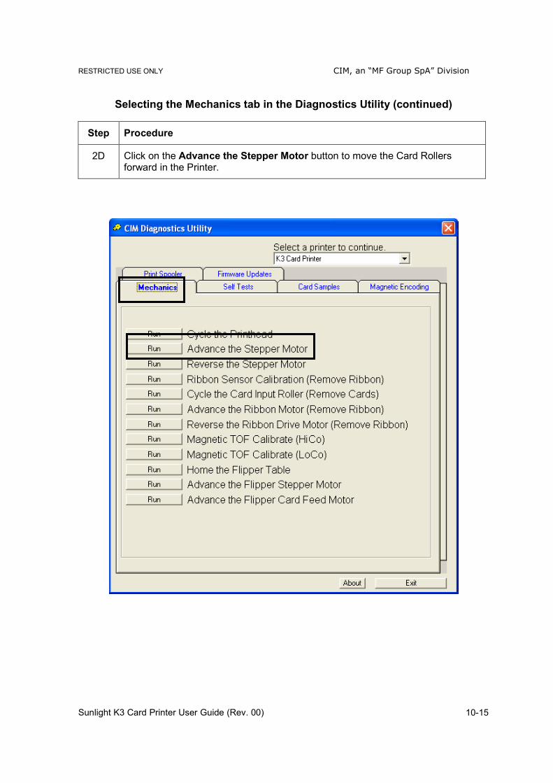
RESTRICTED USE ONLY CIM, an “MF Group SpA” Division
Sunlight K3 Card Printer User Guide (Rev. 00) 10-15
Selecting the Mechanics tab in the Diagnostics Utility (continued)
Step Procedure
2D Click on the Advance the Stepper Motor button to move the Card Rollers forward in the Printer.
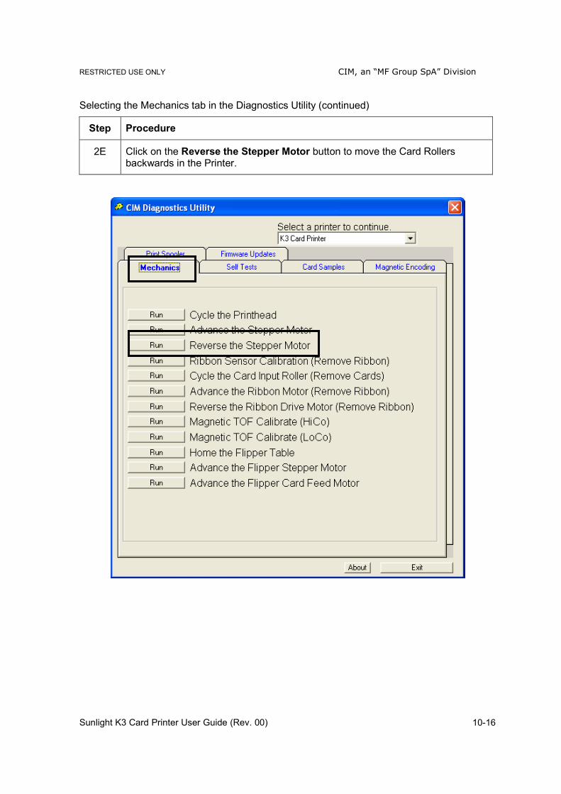
RESTRICTED USE ONLY CIM, an “MF Group SpA” Division
Sunlight K3 Card Printer User Guide (Rev. 00) 10-16
Selecting the Mechanics tab in the Diagnostics Utility (continued)
Step Procedure
2E Click on the Reverse the Stepper Motor button to move the Card Rollers backwards in the Printer.
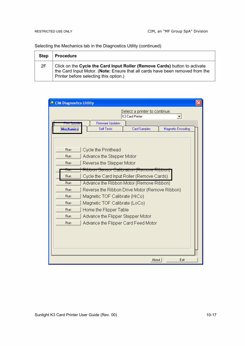
RESTRICTED USE ONLY CIM, an “MF Group SpA” Division
Sunlight K3 Card Printer User Guide (Rev. 00) 10-17
Selecting the Mechanics tab in the Diagnostics Utility (continued)
Step Procedure
2F Click on the Cycle the Card Input Roller (Remove Cards) button to activate the Card Input Motor. (Note: Ensure that all cards have been removed from the Printer before selecting this option.)
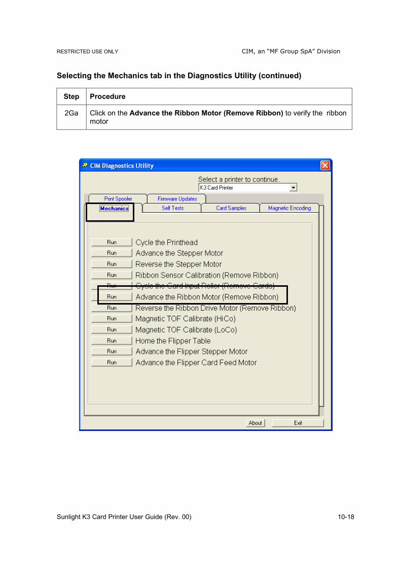
RESTRICTED USE ONLY CIM, an “MF Group SpA” Division
Sunlight K3 Card Printer User Guide (Rev. 00) 10-18
Selecting the Mechanics tab in the Diagnostics Utility (continued)
Step Procedure
2Ga Click on the Advance the Ribbon Motor (Remove Ribbon) to verify the ribbon motor
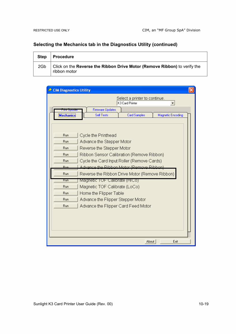
RESTRICTED USE ONLY CIM, an “MF Group SpA” Division
Sunlight K3 Card Printer User Guide (Rev. 00) 10-19
Selecting the Mechanics tab in the Diagnostics Utility (continued)
Step Procedure
2Gb Click on the Reverse the Ribbon Drive Motor (Remove Ribbon) to verify the ribbon motor
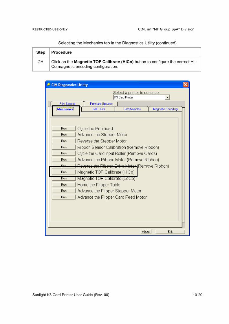
RESTRICTED USE ONLY CIM, an “MF Group SpA” Division
Sunlight K3 Card Printer User Guide (Rev. 00) 10-20
Selecting the Mechanics tab in the Diagnostics Utility (continued)
Step Procedure
2H Click on the Magnetic TOF Calibrate (HiCo) button to configure the correct Hi-Co magnetic encoding configuration.
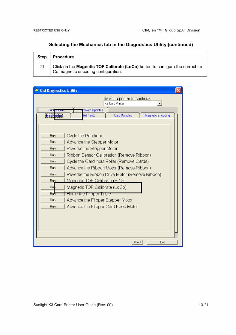
RESTRICTED USE ONLY CIM, an “MF Group SpA” Division
Sunlight K3 Card Printer User Guide (Rev. 00) 10-21
Selecting the Mechanics tab in the Diagnostics Utility (continued)
Step Procedure
2I Click on the Magnetic TOF Calibrate (LoCo) button to configure the correct Lo-Co magnetic encoding configuration.
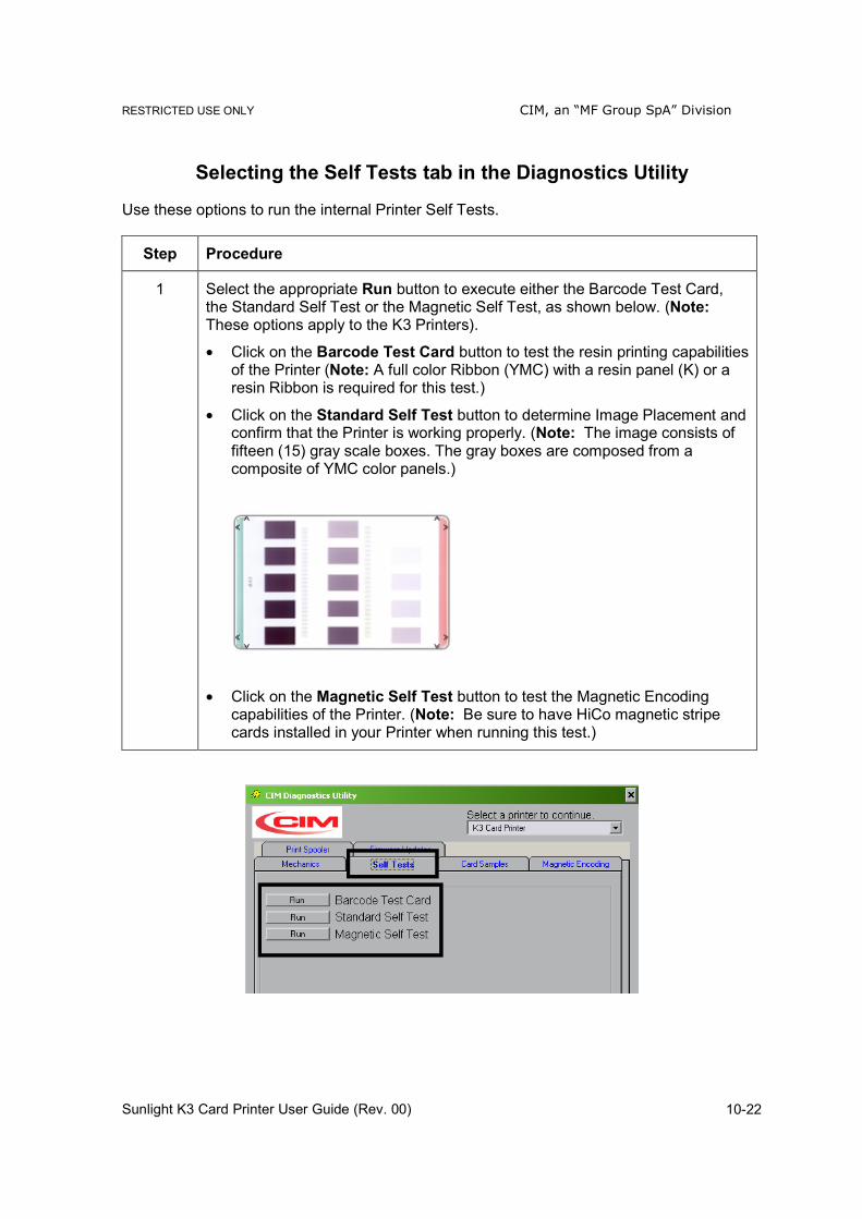
RESTRICTED USE ONLY CIM, an “MF Group SpA” Division
Sunlight K3 Card Printer User Guide (Rev. 00) 10-22
Selecting the Self Tests tab in the Diagnostics Utility
Use these options to run the internal Printer Self Tests.
Step Procedure
1 Select the appropriate Run button to execute either the Barcode Test Card, the Standard Self Test or the Magnetic Self Test, as shown below. (Note: These options apply to the K3 Printers).
• Click on the Barcode Test Card button to test the resin printing capabilities of the Printer (Note: A full color Ribbon (YMC) with a resin panel (K) or a resin Ribbon is required for this test.)
• Click on the Standard Self Test button to determine Image Placement and confirm that the Printer is working properly. (Note: The image consists of fifteen (15) gray scale boxes. The gray boxes are composed from a composite of YMC color panels.)
• Click on the Magnetic Self Test button to test the Magnetic Encoding capabilities of the Printer. (Note: Be sure to have HiCo magnetic stripe cards installed in your Printer when running this test.)
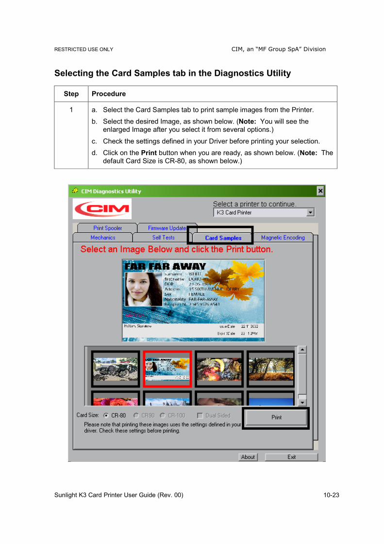
RESTRICTED USE ONLY CIM, an “MF Group SpA” Division
Sunlight K3 Card Printer User Guide (Rev. 00) 10-23
Selecting the Card Samples tab in the Diagnostics Utility
Step Procedure
1 a. Select the Card Samples tab to print sample images from the Printer.
b. Select the desired Image, as shown below. (Note: You will see the enlarged Image after you select it from several options.)
c. Check the settings defined in your Driver before printing your selection.
d. Click on the Print button when you are ready, as shown below. (Note: The default Card Size is CR-80, as shown below.)
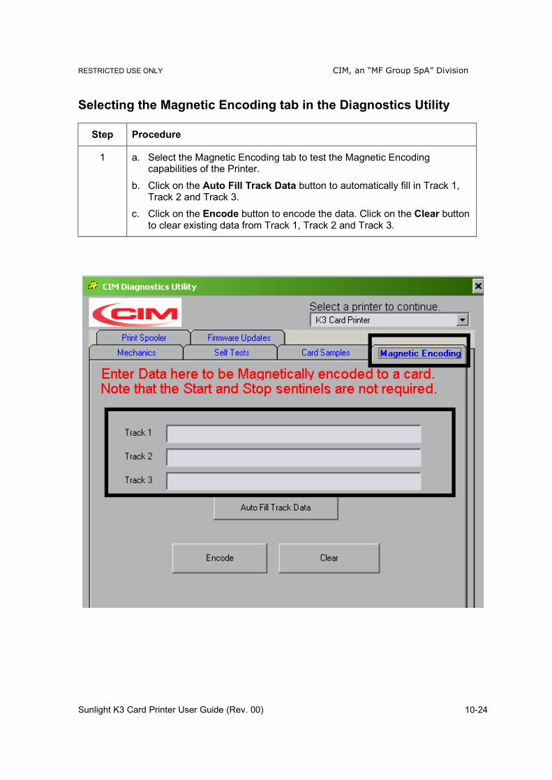
RESTRICTED USE ONLY CIM, an “MF Group SpA” Division
Sunlight K3 Card Printer User Guide (Rev. 00) 10-24
Selecting the Magnetic Encoding tab in the Diagnostics Utility
Step Procedure
1 a. Select the Magnetic Encoding tab to test the Magnetic Encoding capabilities of the Printer.
b. Click on the Auto Fill Track Data button to automatically fill in Track 1, Track 2 and Track 3.
c. Click on the Encode button to encode the data. Click on the Clear button to clear existing data from Track 1, Track 2 and Track 3.
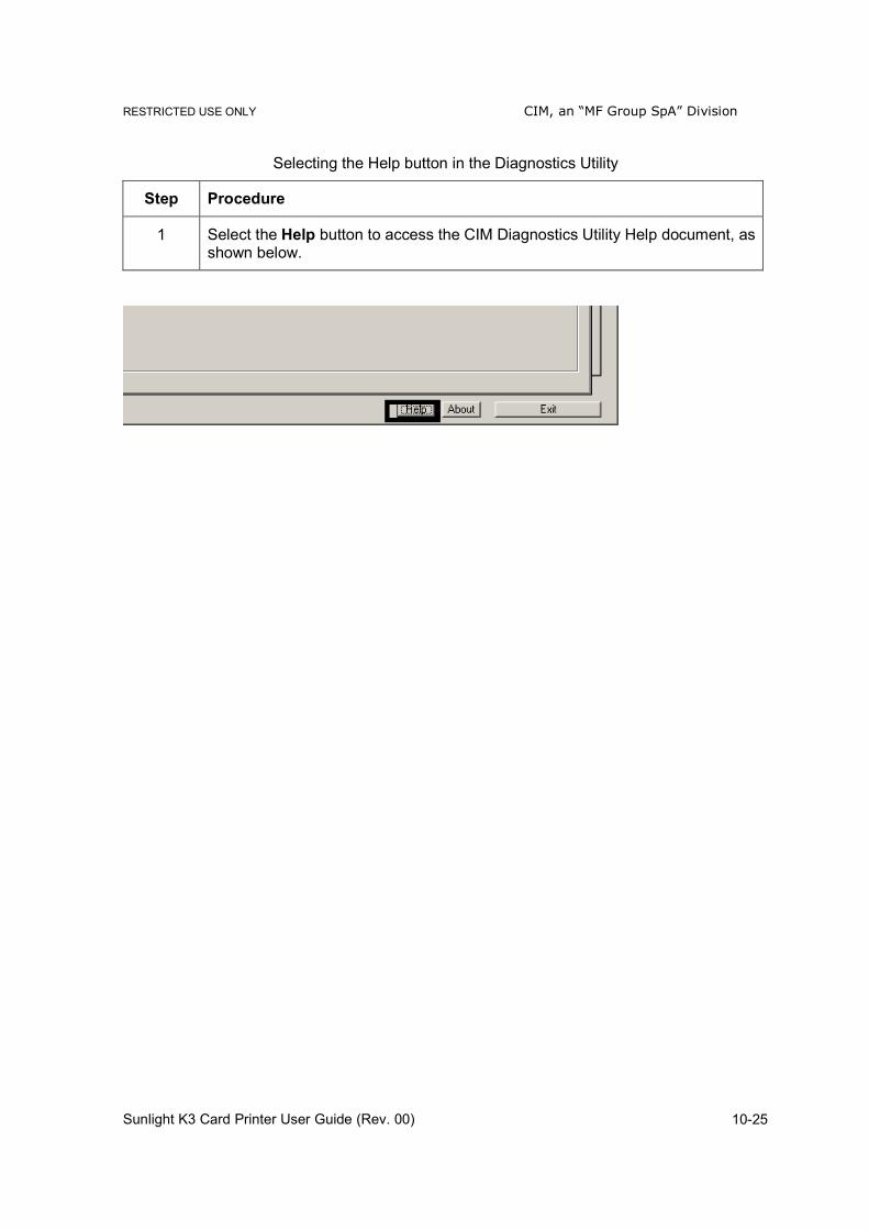
RESTRICTED USE ONLY CIM, an “MF Group SpA” Division
Sunlight K3 Card Printer User Guide (Rev. 00) 10-25
Selecting the Help button in the Diagnostics Utility
Step Procedure
1 Select the Help button to access the CIM Diagnostics Utility Help document, as shown below.
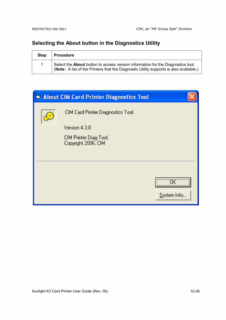
RESTRICTED USE ONLY CIM, an “MF Group SpA” Division
Sunlight K3 Card Printer User Guide (Rev. 00) 10-26
Selecting the About button in the Diagnostics Utility
Step Procedure
1 Select the About button to access version information for the Diagnostics tool. (Note: A list of the Printers that the Diagnostic Utility supports is also available.)

RESTRICTED USE ONLY CIM, an “MF Group SpA” Division
Sunlight K3 Card Printer User Guide (Rev. 00) 10-27
Selecting the Exit button in the Diagnostics Utility
Step Procedure
1 Select the Exit button to close out and exit from the CIM Diagnostics Utility.
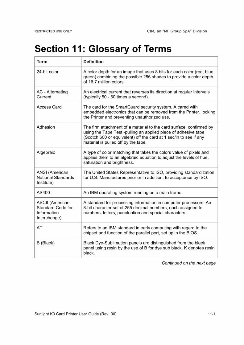
RESTRICTED USE ONLY CIM, an “MF Group SpA” Division
Sunlight K3 Card Printer User Guide (Rev. 00) 11-1
Section 11: Glossary of Terms Term Definition
24-bit color A color depth for an image that uses 8 bits for each color (red, blue, green) combining the possible 256 shades to provide a color depth of 16.7 million colors.
AC - Alternating Current
An electrical current that reverses its direction at regular intervals (typically 50 - 60 times a second).
Access Card The card for the SmartGuard security system. A cared with embedded electronics that can be removed from the Printer, locking the Printer and preventing unauthorized use.
Adhesion The firm attachment of a material to the card surface, confirmed by using the Tape Test -pulling an applied piece of adhesive tape (Scotch 600 or equivelent) off the card at 1 sec/in to see if any material is pulled off by the tape.
Algebraic A type of color matching that takes the colors value of pixels and applies them to an algebraic equation to adjust the levels of hue, saturation and brightness.
ANSI (American National Standards Institute)
The United States Representative to ISO, providing standardization for U.S. Manufactures prior or in addition, to acceptance by ISO.
AS400 An IBM operating system running on a main frame.
ASCII (American Standard Code for Information Interchange)
A standard for processing information in computer processors. An 8-bit character set of 255 decimal numbers, each assigned to numbers, letters, punctuation and special characters.
AT Refers to an IBM standard in early computing with regard to the chipset and function of the parallel port, set up in the BIOS.
B (Black) Black Dye-Sublimation panels are distinguished from the black panel using resin by the use of B for dye sub black. K denotes resin black.
Continued on the next page
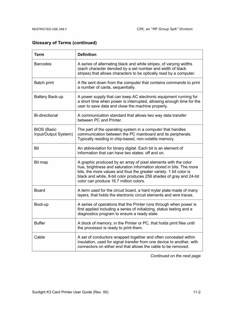
RESTRICTED USE ONLY CIM, an “MF Group SpA” Division
Sunlight K3 Card Printer User Guide (Rev. 00) 11-2
Glossary of Terms (continued)
Term Definition
Barcodes A series of alternating black and white stripes, of varying widths (each character denoted by a set number and width of black stripes) that allows characters to be optically read by a computer.
Batch print A file sent down from the computer that contains commands to print a number of cards, sequentially.
Battery Back-up A power supply that can keep AC electronic equipment running for a short time when power is interrupted, allowing enough time for the user to save data and close the machine properly.
Bi-directional A communication standard that allows two way data transfer between PC and Printer.
BIOS (Basic Input/Output System)
The part of the operating system in a computer that handles communication between the PC mainboard and its peripherals. Typically residing in chip-based, non-volatile memory.
Bit An abbreviation for binary digital. Each bit is an element of information that can have two states: off and on.
Bit map A graphic produced by an array of pixel elements with the color hue, brightness and saturation information stored in bits. The more bits, the more values and thus the greater variety. 1 bit color is black and white, 8-bit color produces 256 shades of gray and 24-bit color can produce 16.7 million colors.
Board A term used for the circuit board, a hard mylar plate made of many layers, that holds the electronic circuit elements and wire traces.
Boot-up A series of operations that the Printer runs through when power is first applied including a series of initializing, status testing and a diagnostics program to ensure a ready state.
Buffer A block of memory, in the Printer or PC, that holds print files until the processor is ready to print them.
Cable A set of conductors wrapped together and often concealed within insulation, used for signal transfer from one device to another, with connectors on either end that allows the cable to be removed.
Continued on the next page
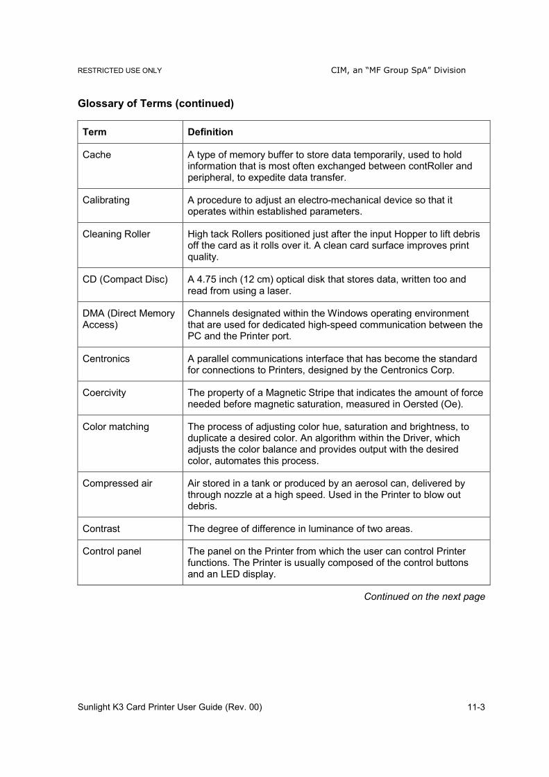
RESTRICTED USE ONLY CIM, an “MF Group SpA” Division
Sunlight K3 Card Printer User Guide (Rev. 00) 11-3
Glossary of Terms (continued)
Term Definition
Cache A type of memory buffer to store data temporarily, used to hold information that is most often exchanged between contRoller and peripheral, to expedite data transfer.
Calibrating A procedure to adjust an electro-mechanical device so that it operates within established parameters.
Cleaning Roller High tack Rollers positioned just after the input Hopper to lift debris off the card as it rolls over it. A clean card surface improves print quality.
CD (Compact Disc) A 4.75 inch (12 cm) optical disk that stores data, written too and read from using a laser.
DMA (Direct Memory Access)
Channels designated within the Windows operating environment that are used for dedicated high-speed communication between the PC and the Printer port.
Centronics A parallel communications interface that has become the standard for connections to Printers, designed by the Centronics Corp.
Coercivity The property of a Magnetic Stripe that indicates the amount of force needed before magnetic saturation, measured in Oersted (Oe).
Color matching The process of adjusting color hue, saturation and brightness, to duplicate a desired color. An algorithm within the Driver, which adjusts the color balance and provides output with the desired color, automates this process.
Compressed air Air stored in a tank or produced by an aerosol can, delivered by through nozzle at a high speed. Used in the Printer to blow out debris.
Contrast The degree of difference in luminance of two areas.
Control panel The panel on the Printer from which the user can control Printer functions. The Printer is usually composed of the control buttons and an LED display.
Continued on the next page
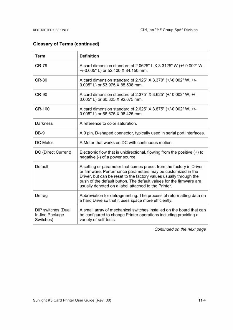
RESTRICTED USE ONLY CIM, an “MF Group SpA” Division
Sunlight K3 Card Printer User Guide (Rev. 00) 11-4
Glossary of Terms (continued)
Term Definition
CR-79 A card dimension standard of 2.0625" L X 3.3125" W (+/-0.002" W, +/-0.005" L) or 52.400 X 84.150 mm.
CR-80 A card dimension standard of 2.125" X 3.370" (+/-0.002" W, +/-0.005" L) or 53.975 X 85.598 mm.
CR-90 A card dimension standard of 2.375" X 3.625" (+/-0.002" W, +/-0.005" L) or 60.325 X 92.075 mm.
CR-100 A card dimension standard of 2.625" X 3.875" (+/-0.002" W, +/-0.005" L) or 66.675 X 98.425 mm.
Darkness A reference to color saturation.
DB-9 A 9 pin, D-shaped connector, typically used in serial port interfaces.
DC Motor A Motor that works on DC with continuous motion.
DC (Direct Current) Electronic flow that is unidirectional, flowing from the positive (+) to negative (-) of a power source.
Default A setting or parameter that comes preset from the factory in Driver or firmware. Performance parameters may be customized in the Driver, but can be reset to the factory values usually through the push of the default button. The default values for the firmware are usually denoted on a label attached to the Printer.
Defrag Abbreviation for defragmenting. The process of reformatting data on a hard Drive so that it uses space more efficiently.
DIP switches (Dual In-line Package Switches)
A small array of mechanical switches installed on the board that can be configured to change Printer operations including providing a variety of self-tests.
Continued on the next page
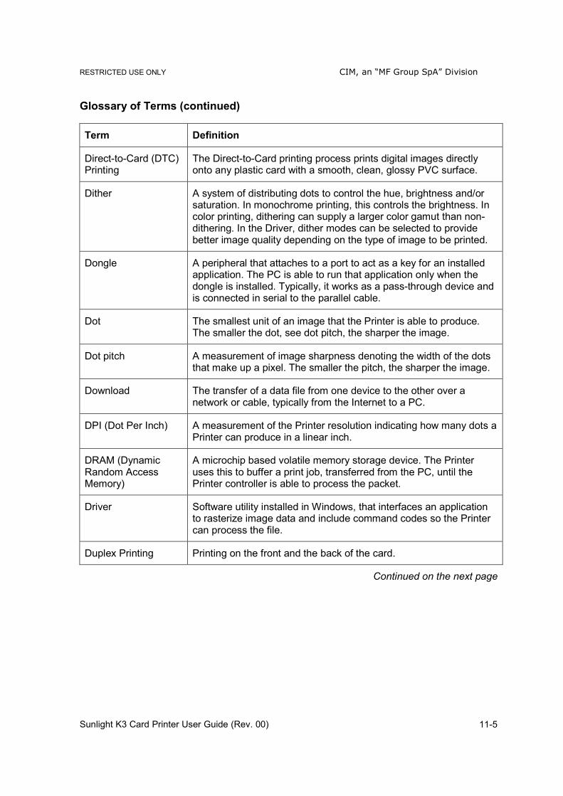
RESTRICTED USE ONLY CIM, an “MF Group SpA” Division
Sunlight K3 Card Printer User Guide (Rev. 00) 11-5
Glossary of Terms (continued)
Term Definition
Direct-to-Card (DTC) Printing
The Direct-to-Card printing process prints digital images directly onto any plastic card with a smooth, clean, glossy PVC surface.
Dither A system of distributing dots to control the hue, brightness and/or saturation. In monochrome printing, this controls the brightness. In color printing, dithering can supply a larger color gamut than non-dithering. In the Driver, dither modes can be selected to provide better image quality depending on the type of image to be printed.
Dongle A peripheral that attaches to a port to act as a key for an installed application. The PC is able to run that application only when the dongle is installed. Typically, it works as a pass-through device and is connected in serial to the parallel cable.
Dot The smallest unit of an image that the Printer is able to produce. The smaller the dot, see dot pitch, the sharper the image.
Dot pitch A measurement of image sharpness denoting the width of the dots that make up a pixel. The smaller the pitch, the sharper the image.
Download The transfer of a data file from one device to the other over a network or cable, typically from the Internet to a PC.
DPI (Dot Per Inch) A measurement of the Printer resolution indicating how many dots a Printer can produce in a linear inch.
DRAM (Dynamic Random Access Memory)
A microchip based volatile memory storage device. The Printer uses this to buffer a print job, transferred from the PC, until the Printer controller is able to process the packet.
Driver Software utility installed in Windows, that interfaces an application to rasterize image data and include command codes so the Printer can process the file.
Duplex Printing Printing on the front and the back of the card.
Continued on the next page
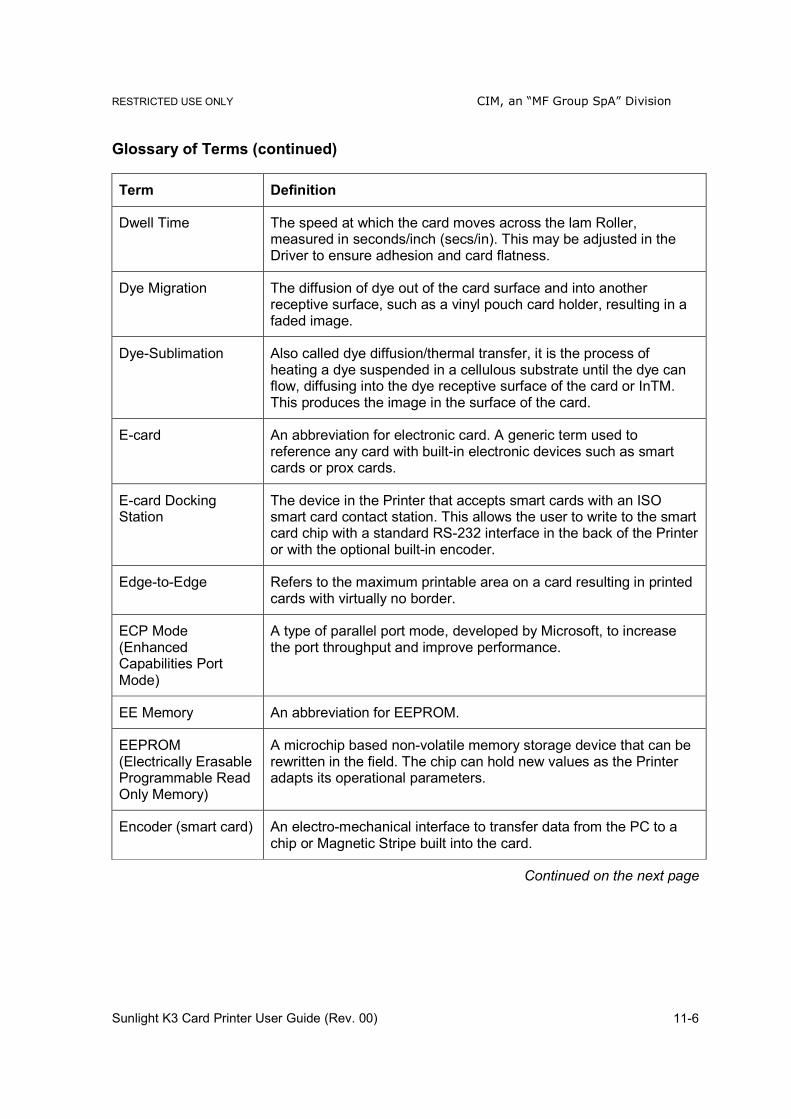
RESTRICTED USE ONLY CIM, an “MF Group SpA” Division
Sunlight K3 Card Printer User Guide (Rev. 00) 11-6
Glossary of Terms (continued)
Term Definition
Dwell Time The speed at which the card moves across the lam Roller, measured in seconds/inch (secs/in). This may be adjusted in the Driver to ensure adhesion and card flatness.
Dye Migration The diffusion of dye out of the card surface and into another receptive surface, such as a vinyl pouch card holder, resulting in a faded image.
Dye-Sublimation Also called dye diffusion/thermal transfer, it is the process of heating a dye suspended in a cellulous substrate until the dye can flow, diffusing into the dye receptive surface of the card or InTM. This produces the image in the surface of the card.
E-card An abbreviation for electronic card. A generic term used to reference any card with built-in electronic devices such as smart cards or prox cards.
E-card Docking Station
The device in the Printer that accepts smart cards with an ISO smart card contact station. This allows the user to write to the smart card chip with a standard RS-232 interface in the back of the Printer or with the optional built-in encoder.
Edge-to-Edge Refers to the maximum printable area on a card resulting in printed cards with virtually no border.
ECP Mode (Enhanced Capabilities Port Mode)
A type of parallel port mode, developed by Microsoft, to increase the port throughput and improve performance.
EE Memory An abbreviation for EEPROM.
EEPROM (Electrically Erasable Programmable Read Only Memory)
A microchip based non-volatile memory storage device that can be rewritten in the field. The chip can hold new values as the Printer adapts its operational parameters.
Encoder (smart card) An electro-mechanical interface to transfer data from the PC to a chip or Magnetic Stripe built into the card.
Continued on the next page
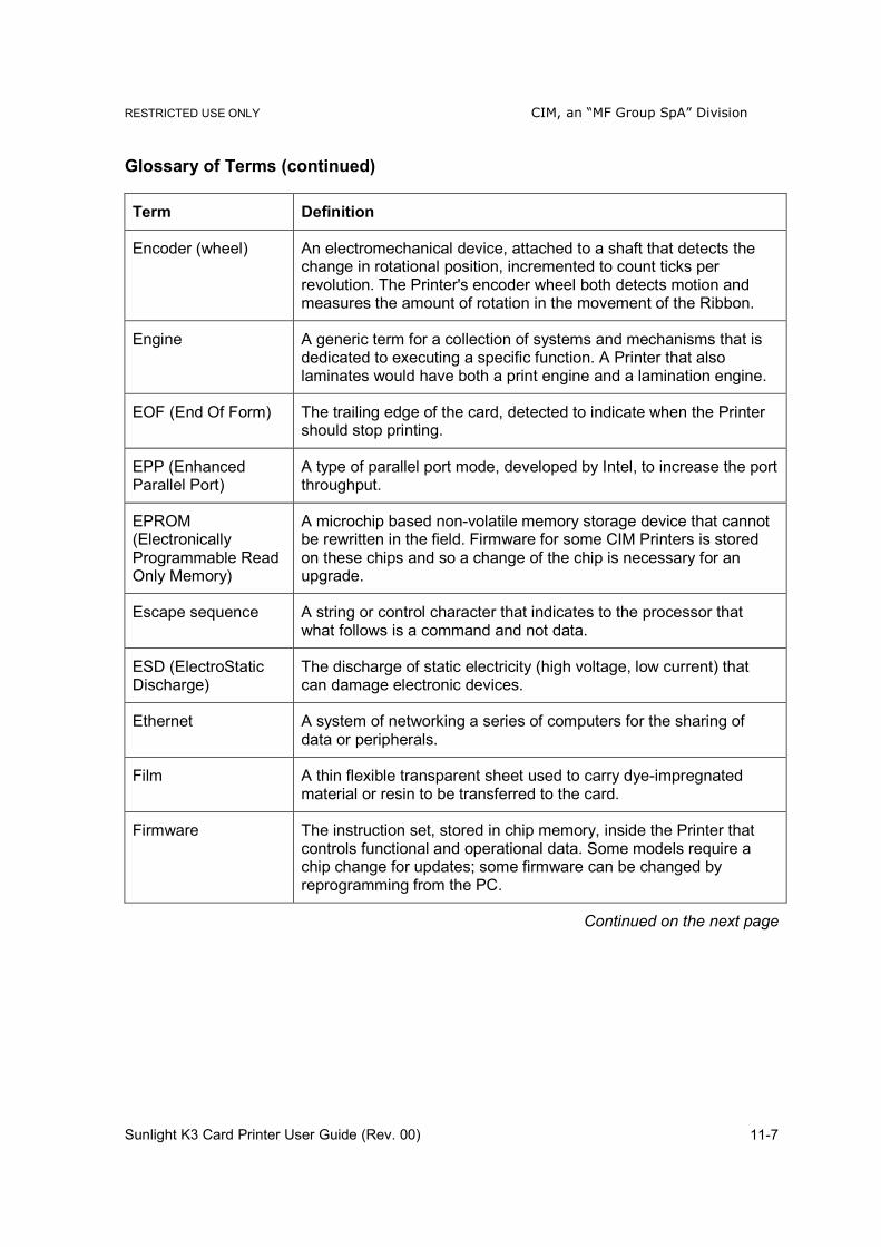
RESTRICTED USE ONLY CIM, an “MF Group SpA” Division
Sunlight K3 Card Printer User Guide (Rev. 00) 11-7
Glossary of Terms (continued)
Term Definition
Encoder (wheel) An electromechanical device, attached to a shaft that detects the change in rotational position, incremented to count ticks per revolution. The Printer's encoder wheel both detects motion and measures the amount of rotation in the movement of the Ribbon.
Engine A generic term for a collection of systems and mechanisms that is dedicated to executing a specific function. A Printer that also laminates would have both a print engine and a lamination engine.
EOF (End Of Form) The trailing edge of the card, detected to indicate when the Printer should stop printing.
EPP (Enhanced Parallel Port)
A type of parallel port mode, developed by Intel, to increase the port throughput.
EPROM (Electronically Programmable Read Only Memory)
A microchip based non-volatile memory storage device that cannot be rewritten in the field. Firmware for some CIM Printers is stored on these chips and so a change of the chip is necessary for an upgrade.
Escape sequence A string or control character that indicates to the processor that what follows is a command and not data.
ESD (ElectroStatic Discharge)
The discharge of static electricity (high voltage, low current) that can damage electronic devices.
Ethernet A system of networking a series of computers for the sharing of data or peripherals.
Film A thin flexible transparent sheet used to carry dye-impregnated material or resin to be transferred to the card.
Firmware The instruction set, stored in chip memory, inside the Printer that controls functional and operational data. Some models require a chip change for updates; some firmware can be changed by reprogramming from the PC.
Continued on the next page
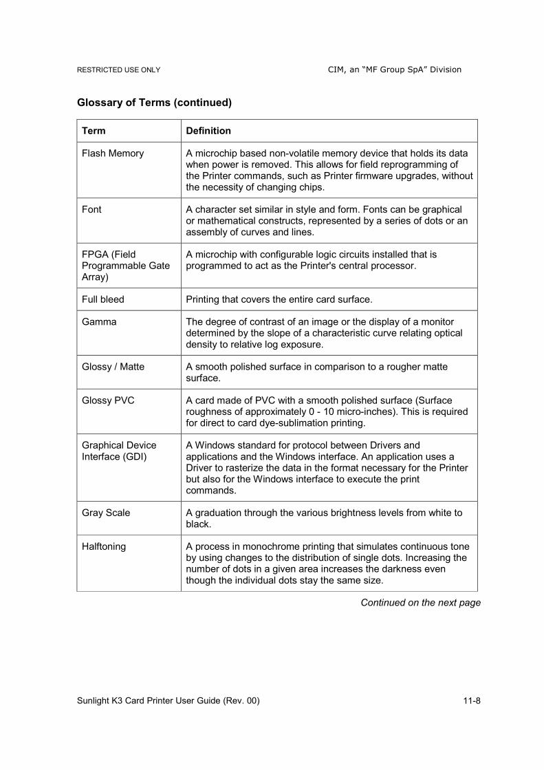
RESTRICTED USE ONLY CIM, an “MF Group SpA” Division
Sunlight K3 Card Printer User Guide (Rev. 00) 11-8
Glossary of Terms (continued)
Term Definition
Flash Memory A microchip based non-volatile memory device that holds its data when power is removed. This allows for field reprogramming of the Printer commands, such as Printer firmware upgrades, without the necessity of changing chips.
Font A character set similar in style and form. Fonts can be graphical or mathematical constructs, represented by a series of dots or an assembly of curves and lines.
FPGA (Field Programmable Gate Array)
A microchip with configurable logic circuits installed that is programmed to act as the Printer's central processor.
Full bleed Printing that covers the entire card surface.
Gamma The degree of contrast of an image or the display of a monitor determined by the slope of a characteristic curve relating optical density to relative log exposure.
Glossy / Matte A smooth polished surface in comparison to a rougher matte surface.
Glossy PVC A card made of PVC with a smooth polished surface (Surface roughness of approximately 0 - 10 micro-inches). This is required for direct to card dye-sublimation printing.
Graphical Device Interface (GDI)
A Windows standard for protocol between Drivers and applications and the Windows interface. An application uses a Driver to rasterize the data in the format necessary for the Printer but also for the Windows interface to execute the print commands.
Gray Scale A graduation through the various brightness levels from white to black.
Halftoning A process in monochrome printing that simulates continuous tone by using changes to the distribution of single dots. Increasing the number of dots in a given area increases the darkness even though the individual dots stay the same size.
Continued on the next page
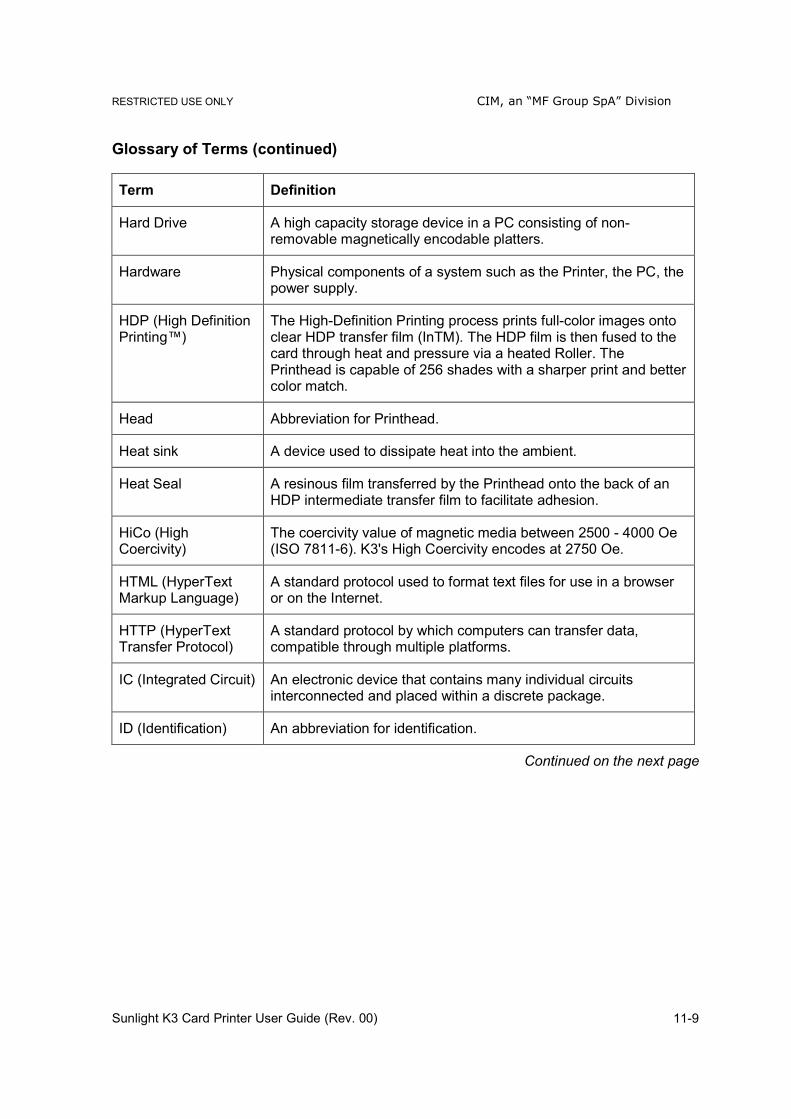
RESTRICTED USE ONLY CIM, an “MF Group SpA” Division
Sunlight K3 Card Printer User Guide (Rev. 00) 11-9
Glossary of Terms (continued)
Term Definition
Hard Drive A high capacity storage device in a PC consisting of non-removable magnetically encodable platters.
Hardware Physical components of a system such as the Printer, the PC, the power supply.
HDP (High Definition Printing™)
The High-Definition Printing process prints full-color images onto clear HDP transfer film (InTM). The HDP film is then fused to the card through heat and pressure via a heated Roller. The Printhead is capable of 256 shades with a sharper print and better color match.
Head Abbreviation for Printhead.
Heat sink A device used to dissipate heat into the ambient.
Heat Seal A resinous film transferred by the Printhead onto the back of an HDP intermediate transfer film to facilitate adhesion.
HiCo (High Coercivity)
The coercivity value of magnetic media between 2500 - 4000 Oe (ISO 7811-6). K3's High Coercivity encodes at 2750 Oe.
HTML (HyperText Markup Language)
A standard protocol used to format text files for use in a browser or on the Internet.
HTTP (HyperText Transfer Protocol)
A standard protocol by which computers can transfer data, compatible through multiple platforms.
IC (Integrated Circuit) An electronic device that contains many individual circuits interconnected and placed within a discrete package.
ID (Identification) An abbreviation for identification.
Continued on the next page
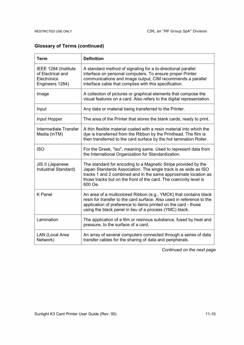
RESTRICTED USE ONLY CIM, an “MF Group SpA” Division
Sunlight K3 Card Printer User Guide (Rev. 00) 11-10
Glossary of Terms (continued)
Term Definition
IEEE 1284 (Institute of Electrical and Electronics Engineers 1284)
A standard method of signaling for a bi-directional parallel interface on personal computers. To ensure proper Printer communications and image output, CIM recommends a parallel interface cable that complies with this specification.
Image A collection of pictures or graphical elements that compose the visual features on a card. Also refers to the digital representation.
Input Any data or material being transferred to the Printer.
Input Hopper The area of the Printer that stores the blank cards, ready to print.
Intermediate Transfer Media (InTM)
A thin flexible material coated with a resin material into which the dye is transferred from the Ribbon by the Printhead. The film is then transferred to the card surface by the hot lamination Roller.
ISO For the Greek, "iso", meaning same. Used to represent data from the International Organization for Standardization.
JIS II (Japanese Industrial Standard)
The standard for encoding to a Magnetic Stripe provided by the Japan Standards Association. The single track is as wide as ISO tracks 1 and 2 combined and in the same approximate location as those tracks but on the front of the card. The coercivity level is 600 Oe.
K Panel An area of a multicolored Ribbon (e.g., YMCK) that contains black resin for transfer to the card surface. Also used in reference to the application of preference to items printed on the card - those using the black panel in lieu of a process (YMC) black.
Lamination The application of a film or resinous substance, fused by heat and pressure, to the surface of a card.
LAN (Local Area Network)
An array of several computers connected through a series of data transfer cables for the sharing of data and peripherals.
Continued on the next page
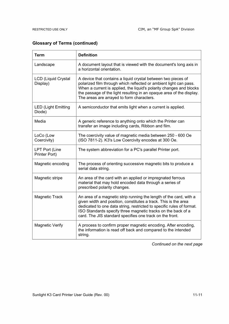
RESTRICTED USE ONLY CIM, an “MF Group SpA” Division
Sunlight K3 Card Printer User Guide (Rev. 00) 11-11
Glossary of Terms (continued)
Term Definition
Landscape A document layout that is viewed with the document's long axis in a horizontal orientation.
LCD (Liquid Crystal Display)
A device that contains a liquid crystal between two pieces of polarized film through which reflected or ambient light can pass. When a current is applied, the liquid's polarity changes and blocks the passage of the light resulting in an opaque area of the display. The areas are arrayed to form characters.
LED (Light Emitting Diode)
A semiconductor that emits light when a current is applied.
Media A generic reference to anything onto which the Printer can transfer an image including cards, Ribbon and film.
LoCo (Low Coercivity)
The coercivity value of magnetic media between 250 - 600 Oe (ISO 7811-2). K3's Low Coercivity encodes at 300 Oe.
LPT Port (Line Printer Port)
The system abbreviation for a PC's parallel Printer port.
Magnetic encoding The process of orienting successive magnetic bits to produce a serial data string.
Magnetic stripe An area of the card with an applied or impregnated ferrous material that may hold encoded data through a series of prescribed polarity changes.
Magnetic Track An area of a magnetic strip running the length of the card, with a given width and position, constitutes a track. This is the area dedicated to one data string, restricted to specific rules of format. ISO Standards specify three magnetic tracks on the back of a card. The JIS standard specifies one track on the front.
Magnetic Verify A process to confirm proper magnetic encoding. After encoding, the information is read off back and compared to the intended string.
Continued on the next page
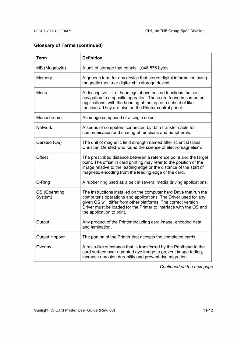
RESTRICTED USE ONLY CIM, an “MF Group SpA” Division
Sunlight K3 Card Printer User Guide (Rev. 00) 11-12
Glossary of Terms (continued)
Term Definition
MB (Megabyte) A unit of storage that equals 1,048,576 bytes.
Memory A generic term for any device that stores digital information using magnetic media or digital chip storage device.
Menu A descriptive list of headings above nested functions that aid navigation to a specific operation. These are found in computer applications, with the heading at the top of a subset of like functions. They are also on the Printer control panel.
Monochrome An image composed of a single color.
Network A series of computers connected by data transfer cable for communication and sharing of functions and peripherals.
Oersted (Oe) The unit of magnetic field strength named after scientist Hans Christian Oersted who found the science of electromagnetism.
Offset The prescribed distance between a reference point and the target point. The offset in card printing may refer to the position of the image relative to the leading edge or the distance of the start of magnetic encoding from the leading edge of the card.
O-Ring A rubber ring used as a belt in several media driving applications.
OS (Operating System)
The instructions installed on the computer hard Drive that run the computer's operations and applications. The Driver used for any given OS will differ from other platforms. The correct version Driver must be loaded for the Printer to interface with the OS and the application to print.
Output Any product of the Printer including card image, encoded data and lamination.
Output Hopper The portion of the Printer that accepts the completed cards.
Overlay A resin-like substance that is transferred by the Printhead to the card surface over a printed dye image to prevent image fading, increase abrasion durability and prevent dye migration.
Continued on the next page
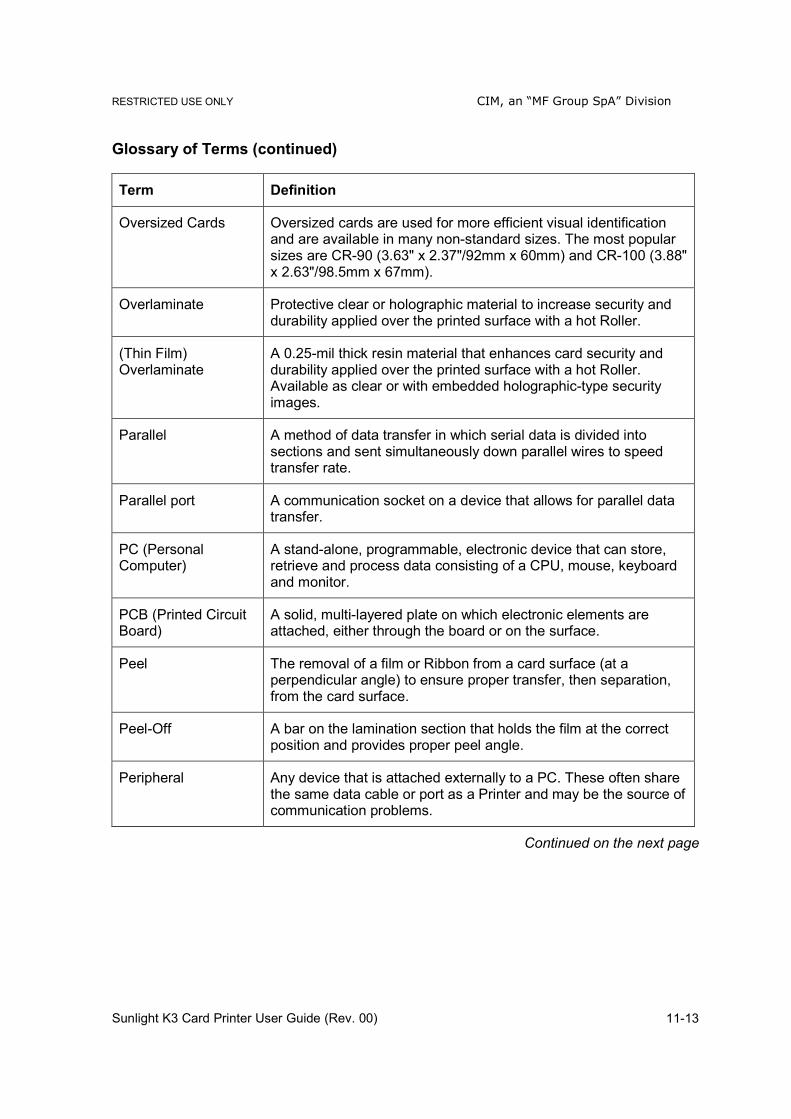
RESTRICTED USE ONLY CIM, an “MF Group SpA” Division
Sunlight K3 Card Printer User Guide (Rev. 00) 11-13
Glossary of Terms (continued)
Term Definition
Oversized Cards Oversized cards are used for more efficient visual identification and are available in many non-standard sizes. The most popular sizes are CR-90 (3.63" x 2.37"/92mm x 60mm) and CR-100 (3.88" x 2.63"/98.5mm x 67mm).
Overlaminate Protective clear or holographic material to increase security and durability applied over the printed surface with a hot Roller.
(Thin Film) Overlaminate
A 0.25-mil thick resin material that enhances card security and durability applied over the printed surface with a hot Roller. Available as clear or with embedded holographic-type security images.
Parallel A method of data transfer in which serial data is divided into sections and sent simultaneously down parallel wires to speed transfer rate.
Parallel port A communication socket on a device that allows for parallel data transfer.
PC (Personal Computer)
A stand-alone, programmable, electronic device that can store, retrieve and process data consisting of a CPU, mouse, keyboard and monitor.
PCB (Printed Circuit Board)
A solid, multi-layered plate on which electronic elements are attached, either through the board or on the surface.
Peel The removal of a film or Ribbon from a card surface (at a perpendicular angle) to ensure proper transfer, then separation, from the card surface.
Peel-Off A bar on the lamination section that holds the film at the correct position and provides proper peel angle.
Peripheral Any device that is attached externally to a PC. These often share the same data cable or port as a Printer and may be the source of communication problems.
Continued on the next page
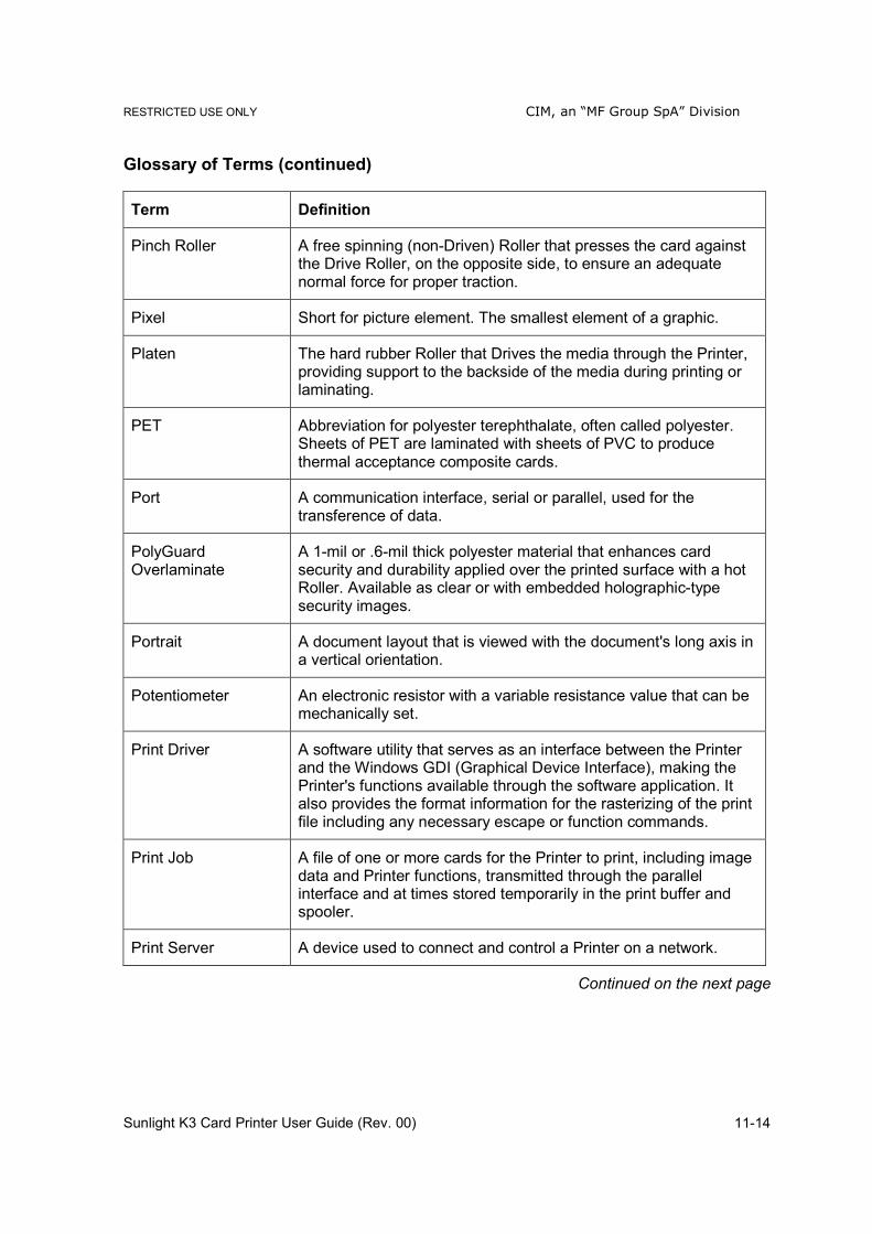
RESTRICTED USE ONLY CIM, an “MF Group SpA” Division
Sunlight K3 Card Printer User Guide (Rev. 00) 11-14
Glossary of Terms (continued)
Term Definition
Pinch Roller A free spinning (non-Driven) Roller that presses the card against the Drive Roller, on the opposite side, to ensure an adequate normal force for proper traction.
Pixel Short for picture element. The smallest element of a graphic.
Platen The hard rubber Roller that Drives the media through the Printer, providing support to the backside of the media during printing or laminating.
PET Abbreviation for polyester terephthalate, often called polyester. Sheets of PET are laminated with sheets of PVC to produce thermal acceptance composite cards.
Port A communication interface, serial or parallel, used for the transference of data.
PolyGuard Overlaminate
A 1-mil or .6-mil thick polyester material that enhances card security and durability applied over the printed surface with a hot Roller. Available as clear or with embedded holographic-type security images.
Portrait A document layout that is viewed with the document's long axis in a vertical orientation.
Potentiometer An electronic resistor with a variable resistance value that can be mechanically set.
Print Driver A software utility that serves as an interface between the Printer and the Windows GDI (Graphical Device Interface), making the Printer's functions available through the software application. It also provides the format information for the rasterizing of the print file including any necessary escape or function commands.
Print Job A file of one or more cards for the Printer to print, including image data and Printer functions, transmitted through the parallel interface and at times stored temporarily in the print buffer and spooler.
Print Server A device used to connect and control a Printer on a network.
Continued on the next page
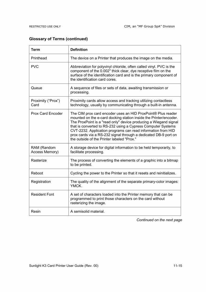
RESTRICTED USE ONLY CIM, an “MF Group SpA” Division
Sunlight K3 Card Printer User Guide (Rev. 00) 11-15
Glossary of Terms (continued)
Term Definition
Printhead The device on a Printer that produces the image on the media.
PVC Abbreviation for polyvinyl chloride, often called vinyl. PVC is the component of the 0.002" thick clear, dye receptive film on the surface of the identification card and is the primary component of the identification card cores.
Queue A sequence of files or sets of data, awaiting transmission or processing.
Proximity (“Prox”) Card
Proximity cards allow access and tracking utilizing contactless technology, usually by communicating through a built-in antenna.
Prox Card Encoder The CIM prox card encoder uses an HID ProxPoint® Plus reader mounted on the e-card docking station inside the Printer/encoder. The ProxPoint is a "read only" device producing a Wiegand signal that is converted to RS-232 using a Cypress Computer Systems CVT-2232. Application programs can read information from HID prox cards via a RS-232 signal through a dedicated DB-9 port on the outside of the Printer labeled "Prox."
RAM (Random Access Memory)
A storage device for digital information to be held temporarily, to facilitate processing.
Rasterize The process of converting the elements of a graphic into a bitmap to be printed.
Reboot Cycling the power to the Printer so that it resets and reinitializes.
Registration The quality of the alignment of the separate primary-color images: YMCK.
Resident Font A set of characters loaded into the Printer memory that can be programmed to print those characters on the card without rasterizing the image.
Resin A semisolid material.
Continued on the next page
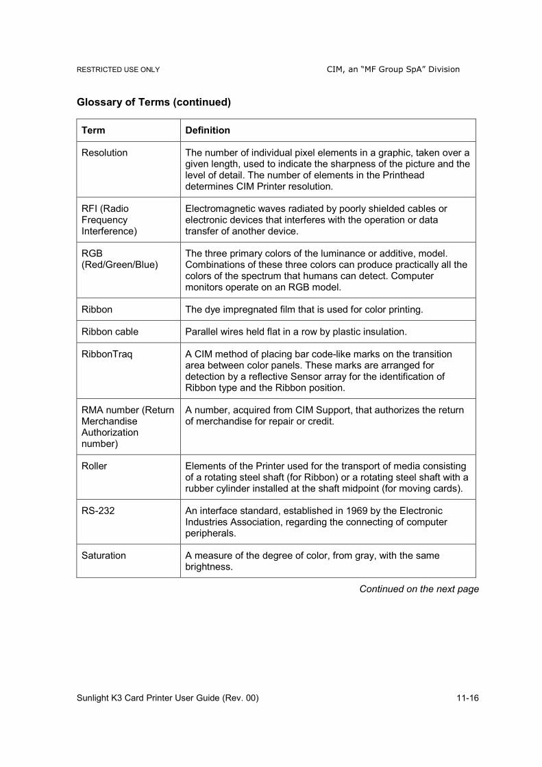
RESTRICTED USE ONLY CIM, an “MF Group SpA” Division
Sunlight K3 Card Printer User Guide (Rev. 00) 11-16
Glossary of Terms (continued)
Term Definition
Resolution The number of individual pixel elements in a graphic, taken over a given length, used to indicate the sharpness of the picture and the level of detail. The number of elements in the Printhead determines CIM Printer resolution.
RFI (Radio Frequency Interference)
Electromagnetic waves radiated by poorly shielded cables or electronic devices that interferes with the operation or data transfer of another device.
RGB (Red/Green/Blue)
The three primary colors of the luminance or additive, model. Combinations of these three colors can produce practically all the colors of the spectrum that humans can detect. Computer monitors operate on an RGB model.
Ribbon The dye impregnated film that is used for color printing.
Ribbon cable Parallel wires held flat in a row by plastic insulation.
RibbonTraq A CIM method of placing bar code-like marks on the transition area between color panels. These marks are arranged for detection by a reflective Sensor array for the identification of Ribbon type and the Ribbon position.
RMA number (Return Merchandise Authorization number)
A number, acquired from CIM Support, that authorizes the return of merchandise for repair or credit.
Roller Elements of the Printer used for the transport of media consisting of a rotating steel shaft (for Ribbon) or a rotating steel shaft with a rubber cylinder installed at the shaft midpoint (for moving cards).
RS-232 An interface standard, established in 1969 by the Electronic Industries Association, regarding the connecting of computer peripherals.
Saturation A measure of the degree of color, from gray, with the same brightness.
Continued on the next page
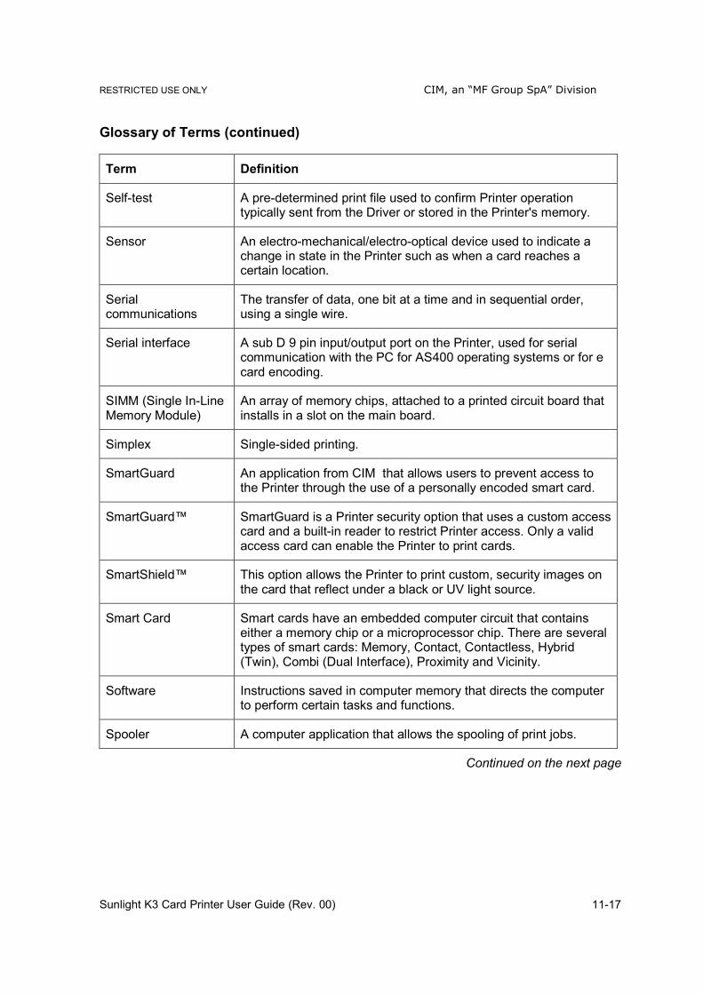
RESTRICTED USE ONLY CIM, an “MF Group SpA” Division
Sunlight K3 Card Printer User Guide (Rev. 00) 11-17
Glossary of Terms (continued)
Term Definition
Self-test A pre-determined print file used to confirm Printer operation typically sent from the Driver or stored in the Printer's memory.
Sensor An electro-mechanical/electro-optical device used to indicate a change in state in the Printer such as when a card reaches a certain location.
Serial communications
The transfer of data, one bit at a time and in sequential order, using a single wire.
Serial interface A sub D 9 pin input/output port on the Printer, used for serial communication with the PC for AS400 operating systems or for e card encoding.
SIMM (Single In-Line Memory Module)
An array of memory chips, attached to a printed circuit board that installs in a slot on the main board.
Simplex Single-sided printing.
SmartGuard An application from CIM that allows users to prevent access to the Printer through the use of a personally encoded smart card.
SmartGuard™ SmartGuard is a Printer security option that uses a custom access card and a built-in reader to restrict Printer access. Only a valid access card can enable the Printer to print cards.
SmartShield™ This option allows the Printer to print custom, security images on the card that reflect under a black or UV light source.
Smart Card Smart cards have an embedded computer circuit that contains either a memory chip or a microprocessor chip. There are several types of smart cards: Memory, Contact, Contactless, Hybrid (Twin), Combi (Dual Interface), Proximity and Vicinity.
Software Instructions saved in computer memory that directs the computer to perform certain tasks and functions.
Spooler A computer application that allows the spooling of print jobs.
Continued on the next page
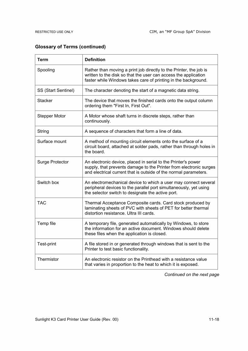
RESTRICTED USE ONLY CIM, an “MF Group SpA” Division
Sunlight K3 Card Printer User Guide (Rev. 00) 11-18
Glossary of Terms (continued)
Term Definition
Spooling Rather than moving a print job directly to the Printer, the job is written to the disk so that the user can access the application faster while Windows takes care of printing in the background.
SS (Start Sentinel) The character denoting the start of a magnetic data string.
Stacker The device that moves the finished cards onto the output column ordering them "First In, First Out".
Stepper Motor A Motor whose shaft turns in discrete steps, rather than continuously.
String A sequence of characters that form a line of data.
Surface mount A method of mounting circuit elements onto the surface of a circuit board, attached at solder pads, rather than through holes in the board.
Surge Protector An electronic device, placed in serial to the Printer's power supply, that prevents damage to the Printer from electronic surges and electrical current that is outside of the normal parameters.
Switch box An electromechanical device to which a user may connect several peripheral devices to the parallel port simultaneously, yet using the selector switch to designate the active port.
TAC Thermal Acceptance Composite cards. Card stock produced by laminating sheets of PVC with sheets of PET for better thermal distortion resistance. Ultra III cards.
Temp file A temporary file, generated automatically by Windows, to store the information for an active document. Windows should delete these files when the application is closed.
Test-print A file stored in or generated through windows that is sent to the Printer to test basic functionality.
Thermistor An electronic resistor on the Printhead with a resistance value that varies in proportion to the heat to which it is exposed.
Continued on the next page
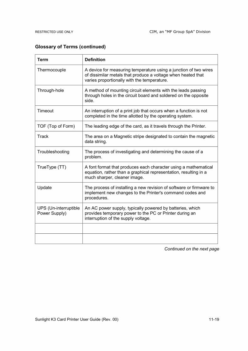
RESTRICTED USE ONLY CIM, an “MF Group SpA” Division
Sunlight K3 Card Printer User Guide (Rev. 00) 11-19
Glossary of Terms (continued)
Term Definition
Thermocouple A device for measuring temperature using a junction of two wires of dissimilar metals that produce a voltage when heated that varies proportionally with the temperature.
Through-hole A method of mounting circuit elements with the leads passing through holes in the circuit board and soldered on the opposite side.
Timeout An interruption of a print job that occurs when a function is not completed in the time allotted by the operating system.
TOF (Top of Form) The leading edge of the card, as it travels through the Printer.
Track The area on a Magnetic stripe designated to contain the magnetic data string.
Troubleshooting The process of investigating and determining the cause of a problem.
TrueType (TT) A font format that produces each character using a mathematical equation, rather than a graphical representation, resulting in a much sharper, cleaner image.
Update The process of installing a new revision of software or firmware to implement new changes to the Printer's command codes and procedures.
UPS (Un-interruptible Power Supply)
An AC power supply, typically powered by batteries, which provides temporary power to the PC or Printer during an interruption of the supply voltage.
Continued on the next page
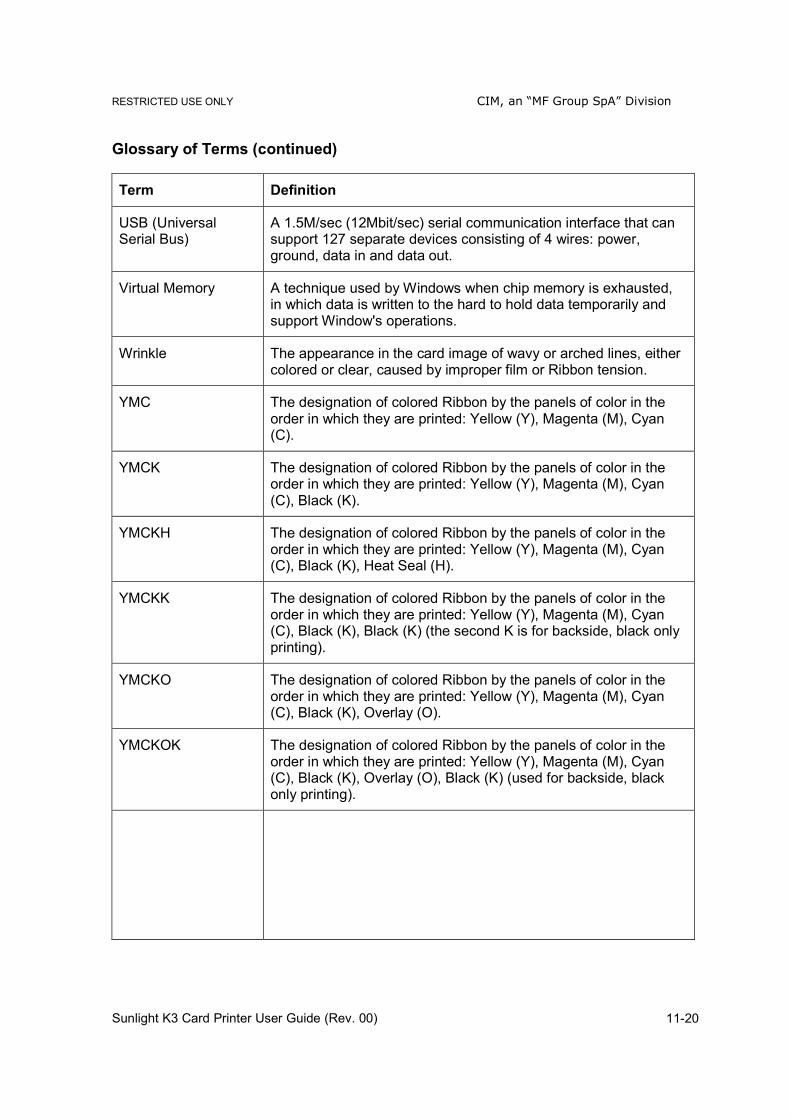
RESTRICTED USE ONLY CIM, an “MF Group SpA” Division
Sunlight K3 Card Printer User Guide (Rev. 00) 11-20
Glossary of Terms (continued)
Term Definition
USB (Universal Serial Bus)
A 1.5M/sec (12Mbit/sec) serial communication interface that can support 127 separate devices consisting of 4 wires: power, ground, data in and data out.
Virtual Memory A technique used by Windows when chip memory is exhausted, in which data is written to the hard to hold data temporarily and support Window's operations.
Wrinkle The appearance in the card image of wavy or arched lines, either colored or clear, caused by improper film or Ribbon tension.
YMC The designation of colored Ribbon by the panels of color in the order in which they are printed: Yellow (Y), Magenta (M), Cyan (C).
YMCK The designation of colored Ribbon by the panels of color in the order in which they are printed: Yellow (Y), Magenta (M), Cyan (C), Black (K).
YMCKH The designation of colored Ribbon by the panels of color in the order in which they are printed: Yellow (Y), Magenta (M), Cyan (C), Black (K), Heat Seal (H).
YMCKK The designation of colored Ribbon by the panels of color in the order in which they are printed: Yellow (Y), Magenta (M), Cyan (C), Black (K), Black (K) (the second K is for backside, black only printing).
YMCKO The designation of colored Ribbon by the panels of color in the order in which they are printed: Yellow (Y), Magenta (M), Cyan (C), Black (K), Overlay (O).
YMCKOK The designation of colored Ribbon by the panels of color in the order in which they are printed: Yellow (Y), Magenta (M), Cyan (C), Black (K), Overlay (O), Black (K) (used for backside, black only printing).
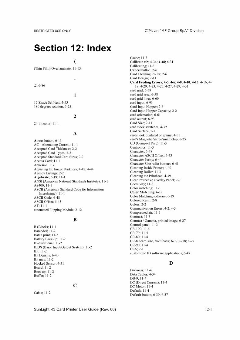
RESTRICTED USE ONLY CIM, an “MF Group SpA” Division
SunLight K3 Card Printer User Guide (Rev. 00) 12-1
Section 12: Index (
(Thin Film) Overlaminate; 11-13
. .2; 6-86
1 15 Shade Self-test; 4-53 180 degrees rotation; 6-25
2 24-bit color; 11-1
A About button; 6-13 AC - Alternating Current; 11-1 Accepted Card Thickness; 2-2 Accepted Card Types; 2-2 Accepted Standard Card Sizes; 2-2 Access Card; 11-1 Adhesion; 11-1 Adjusting the Image Darkness; 4-42; 4-44 Agency Listings; 2-2 Algebraic; 6-19; 11-1 ANSI (American National Standards Institute); 11-1 AS400; 11-1 ASCII (American Standard Code for Information
Interchange); 11-1 ASCII Code; 6-48 ASCII Offset; 6-43 AT; 11-1 automated Flipping Module; 2-12
B B (Black); 11-1 Barcodes; 11-2 Batch print; 11-2 Battery Back-up; 11-2 Bi-directional; 11-2 BIOS (Basic Input/Output System); 11-2 Bit; 11-2 Bit Density; 6-40 Bit map; 11-2 blocked Sensor; 4-31 Board; 11-2 Boot-up; 11-2 Buffer; 11-2
C Cable; 11-2
Cache; 11-3 Calibrate tab; 4-34; 4-48; 6-31 Calibrating; 11-3 Cancel button; 2-6 Card Cleaning Roller; 2-6 Card Design; 2-11 Card Feeding Errors; 4-5; 4-6; 4-8; 4-10; 4-13; 4-16; 4-
18; 4-20; 4-23; 4-25; 4-27; 4-29; 4-31 card grid; 6-59 card grid area; 6-58 card grid lines; 6-60 card input; 6-93 Card Input Hopper; 2-6 Card Input Hopper Capacity; 2-2 card orientation; 6-61 card output; 6-93 Card Size; 2-11 card stock scratches; 4-39 Card Surface; 2-11 cards look pixilated or grainy; 4-51 card's Magnetic Stripe/smart chip; 6-25 CD (Compact Disc); 11-3 Centronics; 11-3 Character; 6-48 Character ASCII Offset; 6-43 Character Parity; 6-44 Character Size radio buttons; 6-41 Cleaning Inside Printer; 4-40 Cleaning Roller; 11-3 Cleaning the Printhead; 4-39 Clear Protective Overlay Panel; 2-7 Coercivity; 11-3 Color matching; 11-3 Color Matching; 6-19 Color Matching software; 6-19 Colored Resin; 2-8 Colors; 2-2 Communication Errors; 4-2; 4-3 Compressed air; 11-3 Contrast; 11-3 Contrast / Gamma, printed image; 6-27 Control panel; 11-3 CR-100; 11-4 CR-79; 11-4 CR-80; 11-4 CR-80 card size, front/back; 6-77; 6-78; 6-79 CR-90; 11-4 CSA; 2-1 customized ID software applications; 6-47
D Darkness; 11-4 Data Cables; 4-34 DB-9; 11-4 DC (Direct Current); 11-4 DC Motor; 11-4 Default; 11-4 Default button; 6-30; 6-37
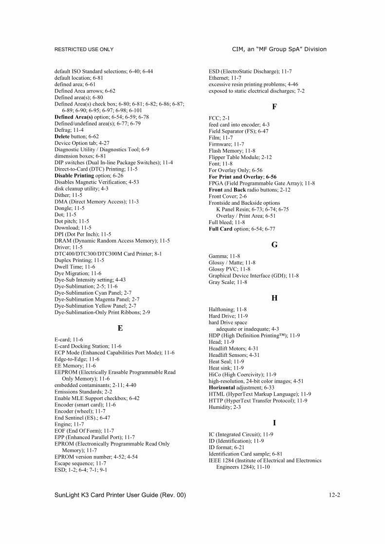
RESTRICTED USE ONLY CIM, an “MF Group SpA” Division
SunLight K3 Card Printer User Guide (Rev. 00) 12-2
default ISO Standard selections; 6-40; 6-44 default location; 6-81 defined area; 6-61 Defined Area arrows; 6-62 Defined area(s); 6-80 Defined Area(s) check box; 6-80; 6-81; 6-82; 6-86; 6-87;
6-89; 6-90; 6-95; 6-97; 6-98; 6-101 Defined Area(s) option; 6-54; 6-59; 6-78 Defined/undefined area(s); 6-77; 6-79 Defrag; 11-4 Delete button; 6-62 Device Option tab; 4-27 Diagnostic Utility / Diagnostics Tool; 6-9 dimension boxes; 6-81 DIP switches (Dual In-line Package Switches); 11-4 Direct-to-Card (DTC) Printing; 11-5 Disable Printing option; 6-26 Disables Magnetic Verification; 4-53 disk cleanup utility; 4-3 Dither; 11-5 DMA (Direct Memory Access); 11-3 Dongle; 11-5 Dot; 11-5 Dot pitch; 11-5 Download; 11-5 DPI (Dot Per Inch); 11-5 DRAM (Dynamic Random Access Memory); 11-5 Driver; 11-5 DTC400/DTC300/DTC300M Card Printer; 8-1 Duplex Printing; 11-5 Dwell Time; 11-6 Dye Migration; 11-6 Dye-Sub Intensity setting; 4-43 Dye-Sublimation; 2-5; 11-6 Dye-Sublimation Cyan Panel; 2-7 Dye-Sublimation Magenta Panel; 2-7 Dye-Sublimation Yellow Panel; 2-7 Dye-Sublimation-Only Print Ribbons; 2-9
E E-card; 11-6 E-card Docking Station; 11-6 ECP Mode (Enhanced Capabilities Port Mode); 11-6 Edge-to-Edge; 11-6 EE Memory; 11-6 EEPROM (Electrically Erasable Programmable Read
Only Memory); 11-6 embedded contaminants; 2-11; 4-40 Emissions Standards; 2-2 Enable MLE Support checkbox; 6-42 Encoder (smart card); 11-6 Encoder (wheel); 11-7 End Sentinel (ES).; 6-47 Engine; 11-7 EOF (End Of Form); 11-7 EPP (Enhanced Parallel Port); 11-7 EPROM (Electronically Programmable Read Only
Memory); 11-7 EPROM version number; 4-52; 4-54 Escape sequence; 11-7 ESD; 1-2; 6-4; 7-1; 9-1
ESD (ElectroStatic Discharge); 11-7 Ethernet; 11-7 excessive resin printing problems; 4-46 exposed to static electrical discharges; 7-2
F FCC; 2-1 feed card into encoder; 4-3 Field Separator (FS); 6-47 Film; 11-7 Firmware; 11-7 Flash Memory; 11-8 Flipper Table Module; 2-12 Font; 11-8 For Overlay Only; 6-56 For Print and Overlay; 6-56 FPGA (Field Programmable Gate Array); 11-8 Front and Back radio buttons; 2-12 Front Cover; 2-6 Frontside and Backside options
K Panel Resin; 6-73; 6-74; 6-75 Overlay / Print Area; 6-51
Full bleed; 11-8 Full Card option; 6-54; 6-77
G Gamma; 11-8 Glossy / Matte; 11-8 Glossy PVC; 11-8 Graphical Device Interface (GDI); 11-8 Gray Scale; 11-8
H Halftoning; 11-8 Hard Drive; 11-9 hard Drive space
adequate or inadequate; 4-3 HDP (High Definition Printing™); 11-9 Head; 11-9 Headlift Motors; 4-31 Headlift Sensors; 4-31 Heat Seal; 11-9 Heat sink; 11-9 HiCo (High Coercivity); 11-9 high-resolution, 24-bit color images; 4-51 Horizontal adjustment; 6-33 HTML (HyperText Markup Language); 11-9 HTTP (HyperText Transfer Protocol); 11-9 Humidity; 2-3
I IC (Integrated Circuit); 11-9 ID (Identification); 11-9 ID format; 6-21 Identification Card sample; 6-81 IEEE 1284 (Institute of Electrical and Electronics
Engineers 1284); 11-10
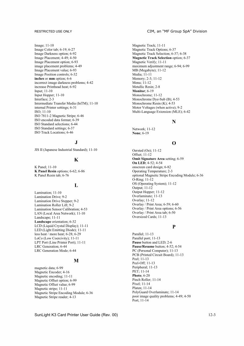
RESTRICTED USE ONLY CIM, an “MF Group SpA” Division
SunLight K3 Card Printer User Guide (Rev. 00) 12-3
Image; 11-10 Image Color tab; 6-19; 6-27 Image Darkness option; 6-92 Image Placement; 4-49; 4-50 Image Placement option; 6-93 image placement problems; 4-49 Image Placement value; 6-93 Image Position controls; 6-32 inches or mm option; 6-6 incorrect image darkness problems; 4-42 increase Printhead heat; 6-92 Input; 11-10 Input Hopper; 11-10 Interface; 2-3 Intermediate Transfer Media (InTM); 11-10 internal Printer settings; 6-31 ISO; 11-10 ISO 7811-2 Magnetic Stripe; 6-46 ISO encoded data format; 6-39 ISO Standard selections; 6-44 ISO Standard settings; 6-37 ISO Track Locations; 6-46
J JIS II (Japanese Industrial Standard); 11-10
K K Panel; 11-10 K Panel Resin options; 6-62; 6-86 K Panel Resin tab; 6-76
L Lamination; 11-10 Lamination Drive; 9-2 Lamination Drive Stepper; 9-2 Lamination Roller Lift; 9-2 Lamination Sensor Calibration; 4-53 LAN (Local Area Network); 11-10 Landscape; 11-11 Landscape orientation; 6-32 LCD (Liquid Crystal Display); 11-11 LED (Light Emitting Diode); 11-11 less heat / more heat; 6-28; 6-29 LoCo (Low Coercivity); 11-11 LPT Port (Line Printer Port); 11-11 LRC Generation; 6-44 LRC Generation Mode; 6-44
M magnetic data; 6-99 Magnetic Encoder; 4-16 Magnetic encoding; 11-11 Magnetic Offset option; 6-99 Magnetic Offset value; 6-99 Magnetic stripe; 11-11 Magnetic Stripe Encoding Module; 6-36 Magnetic Stripe reader; 4-13
Magnetic Track; 11-11 Magnetic Track Options; 6-37 Magnetic Track Selection; 6-37; 6-38 Magnetic Track Selection option; 6-37 Magnetic Verify; 11-11 maximum adjustment range; 6-94; 6-99 MB (Megabyte); 11-12 Media; 11-11 Memory; 2-3; 11-12 Menu; 11-12 Metallic Resin; 2-8 Monitor; 6-19 Monochrome; 11-12 Monochrome Dye-Sub (B); 4-53 Monochrome Resin (K); 4-53 Motor Voltages (when active); 9-2 Multi-Language Extension (MLE); 6-42
N Network; 11-12 None; 6-19
O Oersted (Oe); 11-12 Offset; 11-12 Omit Signature Area setting; 6-59 On LED; 4-52; 4-54 onscreen card design; 6-82 Operating Temperature; 2-3 optional Magnetic Stripe Encoding Module; 6-36 O-Ring; 11-12 OS (Operating System); 11-12 Output; 11-12 Output Hopper; 11-12 Overlaminate; 11-13 Overlay; 11-12 Overlay / Print Area; 6-59; 6-60 Overlay / Print Area options; 6-56 Overlay / Print Area tab; 6-50 Oversized Cards; 11-13
P Parallel; 11-13 Parallel port; 11-13 Pause button and LED; 2-6 Pause/Resume button; 4-52; 4-54 PC (Personal Computer); 11-13 PCB (Printed Circuit Board); 11-13 Peel; 11-13 Peel-Off; 11-13 Peripheral; 11-13 PET; 11-14 Photo; 6-20 Pinch Roller; 11-14 Pixel; 11-14 Platen; 11-14 PolyGuard Overlaminate; 11-14 poor image quality problems; 4-49; 4-50 Port; 11-14
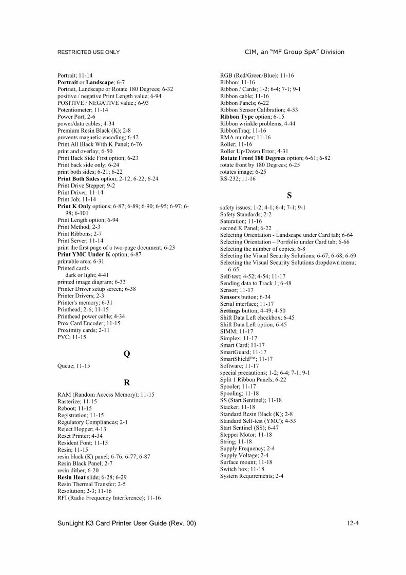
RESTRICTED USE ONLY CIM, an “MF Group SpA” Division
SunLight K3 Card Printer User Guide (Rev. 00) 12-4
Portrait; 11-14 Portrait or Landscape; 6-7 Portrait, Landscape or Rotate 180 Degrees; 6-32 positive / negative Print Length value; 6-94 POSITIVE / NEGATIVE value.; 6-93 Potentiometer; 11-14 Power Port; 2-6 power/data cables; 4-34 Premium Resin Black (K); 2-8 prevents magnetic encoding; 6-42 Print All Black With K Panel; 6-76 print and overlay; 6-50 Print Back Side First option; 6-23 Print back side only; 6-24 print both sides; 6-21; 6-22 Print Both Sides option; 2-12; 6-22; 6-24 Print Drive Stepper; 9-2 Print Driver; 11-14 Print Job; 11-14 Print K Only options; 6-87; 6-89; 6-90; 6-95; 6-97; 6-
98; 6-101 Print Length option; 6-94 Print Method; 2-3 Print Ribbons; 2-7 Print Server; 11-14 print the first page of a two-page document; 6-23 Print YMC Under K option; 6-87 printable area; 6-31 Printed cards
dark or light; 4-41 printed image diagram; 6-33 Printer Driver setup screen; 6-38 Printer Drivers; 2-3 Printer's memory; 6-31 Printhead; 2-6; 11-15 Printhead power cable; 4-34 Prox Card Encoder; 11-15 Proximity cards; 2-11 PVC; 11-15
Q Queue; 11-15
R RAM (Random Access Memory); 11-15 Rasterize; 11-15 Reboot; 11-15 Registration; 11-15 Regulatory Compliances; 2-1 Reject Hopper; 4-13 Reset Printer; 4-34 Resident Font; 11-15 Resin; 11-15 resin black (K) panel; 6-76; 6-77; 6-87 Resin Black Panel; 2-7 resin dither; 6-20 Resin Heat slide; 6-28; 6-29 Resin Thermal Transfer; 2-5 Resolution; 2-3; 11-16 RFI (Radio Frequency Interference); 11-16
RGB (Red/Green/Blue); 11-16 Ribbon; 11-16 Ribbon / Cards; 1-2; 6-4; 7-1; 9-1 Ribbon cable; 11-16 Ribbon Panels; 6-22 Ribbon Sensor Calibration; 4-53 Ribbon Type option; 6-15 Ribbon wrinkle problems; 4-44 RibbonTraq; 11-16 RMA number; 11-16 Roller; 11-16 Roller Up/Down Error; 4-31 Rotate Front 180 Degrees option; 6-61; 6-82 rotate front by 180 Degrees; 6-25 rotates image; 6-25 RS-232; 11-16
S safety issues; 1-2; 4-1; 6-4; 7-1; 9-1 Safety Standards; 2-2 Saturation; 11-16 second K Panel; 6-22 Selecting Orientation - Landscape under Card tab; 6-64 Selecting Orientation – Portfolio under Card tab; 6-66 Selecting the number of copies; 6-8 Selecting the Visual Security Solutions; 6-67; 6-68; 6-69 Selecting the Visual Security Solutions dropdown menu;
6-65 Self-test; 4-52; 4-54; 11-17 Sending data to Track 1; 6-48 Sensor; 11-17 Sensors button; 6-34 Serial interface; 11-17 Settings button; 4-49; 4-50 Shift Data Left checkbox; 6-45 Shift Data Left option; 6-45 SIMM; 11-17 Simplex; 11-17 Smart Card; 11-17 SmartGuard; 11-17 SmartShield™; 11-17 Software; 11-17 special precautions; 1-2; 6-4; 7-1; 9-1 Split 1 Ribbon Panels; 6-22 Spooler; 11-17 Spooling; 11-18 SS (Start Sentinel); 11-18 Stacker; 11-18 Standard Resin Black (K); 2-8 Standard Self-test (YMC); 4-53 Start Sentinel (SS); 6-47 Stepper Motor; 11-18 String; 11-18 Supply Frequency; 2-4 Supply Voltage; 2-4 Surface mount; 11-18 Switch box; 11-18 System Requirements; 2-4
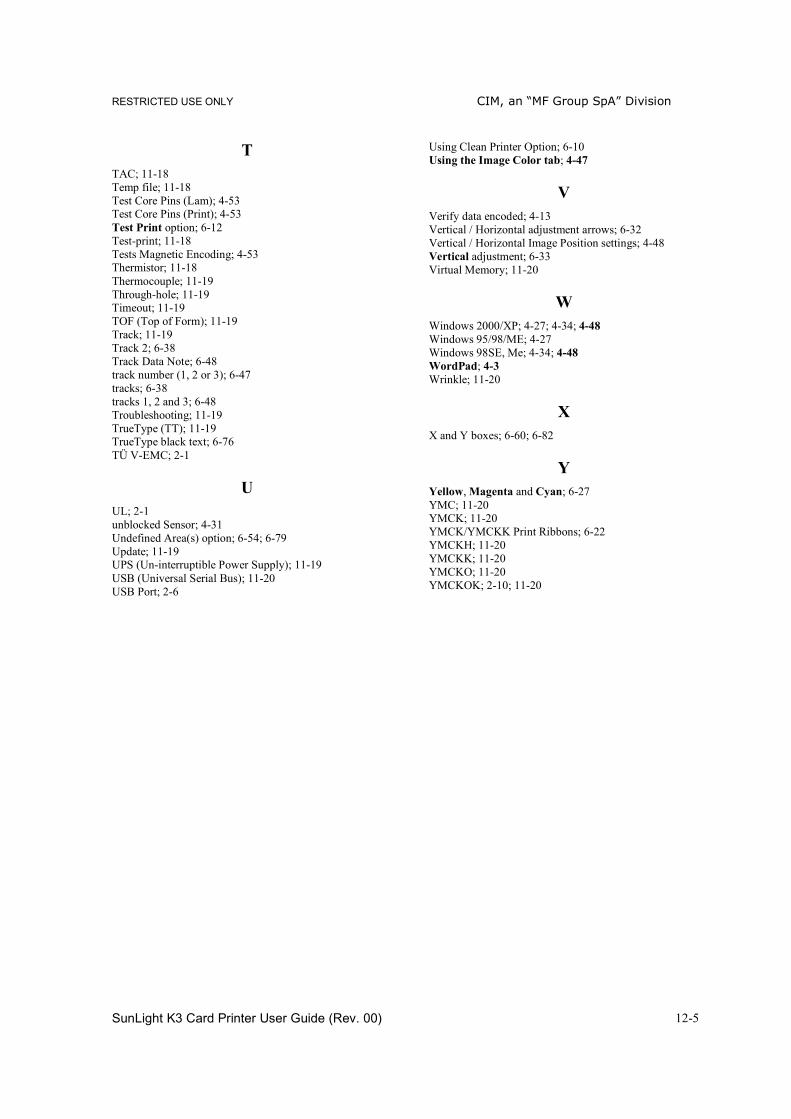
RESTRICTED USE ONLY CIM, an “MF Group SpA” Division
SunLight K3 Card Printer User Guide (Rev. 00) 12-5
T TAC; 11-18 Temp file; 11-18 Test Core Pins (Lam); 4-53 Test Core Pins (Print); 4-53 Test Print option; 6-12 Test-print; 11-18 Tests Magnetic Encoding; 4-53 Thermistor; 11-18 Thermocouple; 11-19 Through-hole; 11-19 Timeout; 11-19 TOF (Top of Form); 11-19 Track; 11-19 Track 2; 6-38 Track Data Note; 6-48 track number (1, 2 or 3); 6-47 tracks; 6-38 tracks 1, 2 and 3; 6-48 Troubleshooting; 11-19 TrueType (TT); 11-19 TrueType black text; 6-76 TÜ V-EMC; 2-1
U UL; 2-1 unblocked Sensor; 4-31 Undefined Area(s) option; 6-54; 6-79 Update; 11-19 UPS (Un-interruptible Power Supply); 11-19 USB (Universal Serial Bus); 11-20 USB Port; 2-6
Using Clean Printer Option; 6-10 Using the Image Color tab; 4-47
V Verify data encoded; 4-13 Vertical / Horizontal adjustment arrows; 6-32 Vertical / Horizontal Image Position settings; 4-48 Vertical adjustment; 6-33 Virtual Memory; 11-20
W Windows 2000/XP; 4-27; 4-34; 4-48 Windows 95/98/ME; 4-27 Windows 98SE, Me; 4-34; 4-48 WordPad; 4-3 Wrinkle; 11-20
X X and Y boxes; 6-60; 6-82
Y Yellow, Magenta and Cyan; 6-27 YMC; 11-20 YMCK; 11-20 YMCK/YMCKK Print Ribbons; 6-22 YMCKH; 11-20 YMCKK; 11-20 YMCKO; 11-20 YMCKOK; 2-10; 11-20
Related Documents