Class 1E connector with quick connect 1/4 turn bayonet coupling and shielding continuity designed to operate during normal & seismic conditions. K2 Qualified / RCC-E 2005 Qualified for use on safety related equipments inside reactor building, under normal and seismic conditions ✓ High shielding performances Reduced shell to shell resistance: ≤ 20 mΩ EMI/RFI protection over a wide frequency range ✓ High sealing level Insulators with grommet seal Back-shell with seal gland ✓ Easy installation and maintenance No need for shrinkable sheath Dismountable insulators ✓ Compliant with EPR wiring specifications CST 74C030.02 New back-shell design with integrated 360° shield termination mechanism ✓ 8N45S Series K2 Qualified Connectors for EPR Reactor K2 Qualified Connectors for EPR Reactor

Welcome message from author
This document is posted to help you gain knowledge. Please leave a comment to let me know what you think about it! Share it to your friends and learn new things together.
Transcript
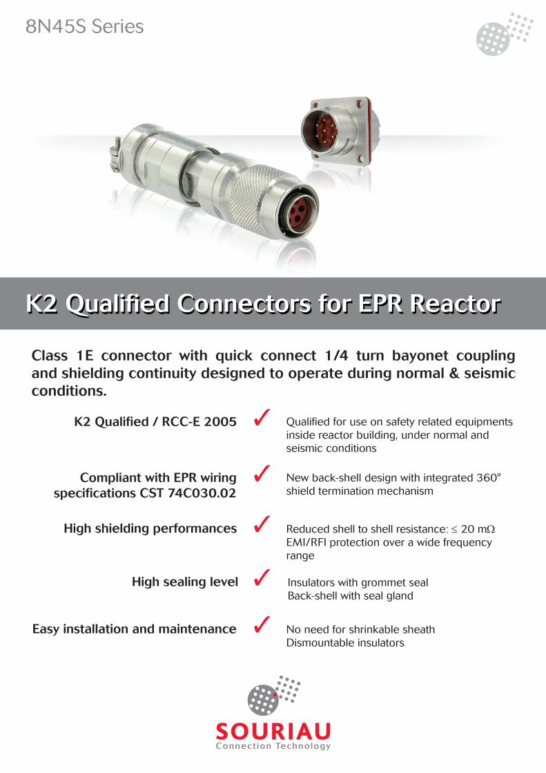
Class 1E connector with quick connect 1/4 turn bayonet coupling and shielding continuity designed to operate during normal & seismic conditions.
K2 Qualified / RCC-E 2005 Qualified for use on safety related equipments inside reactor building, under normal and seismic conditions
✓
High shielding performances Reduced shell to shell resistance: ≤ 20 mΩEMI/RFI protection over a wide frequency range
✓
High sealing level Insulators with grommet sealBack-shell with seal gland
✓
Easy installation and maintenance No need for shrinkable sheathDismountable insulators
✓
Compliant with EPR wiring specifications CST 74C030.02
New back-shell design with integrated 360° shield termination mechanism
✓
8N45S Series
K2 Qualified Connectors for EPR ReactorK2 Qualified Connectors for EPR Reactor

2
8N45S SeriesK2 Qualified Connectors for EPR
2
Description• Class 1E qualified connectors
• Quick connect ¼ turn bayonet coupling
• High shielding performances
• Qualification standards:- H-M2A-2007-01218-FR- RCC-E 2005
Applications• Instrumentation, sensors, probes
• Mandatory for new EPR programs
Technical features
Electrical
• Current rating: 11 A max
• Peak current: 50A/30ms
• Test Voltage rating: 2000 Vrms
• Insulation Resistance: ≥ 5000 MΩ under 500 Vdc
• Contact resistance: 5 mΩ
• Shielding resistance: ≤ 20 mΩ
Environmental
• Ambient temperature : -35 to +60°C (-31 to +140°F)
• Ambient humidity: 75% max.
• Steam test: 100°C (212°F) / 1bar /100% HR / 100h (with Raychem sheath)
• Cumulated radiation: 250 kGy (25 MRads) / 70°C (158°F)
• Dry heat test: 40°C (104°F) / 93% HR / 504h
• Salt spray resistance: 168h
• Protection against water penetration: - IP X6 - IP 68
Mechanical
• Mating / Unmating effort: 0,12 daN.m
• Endurance: 500 mating / unmating
• Cable clamp resistance: Traction 100 N / Torsion 0,5 Nm
Seism / Vibration
• Seism: - Operating Basis Earthquake (OBE): 3g ZPA - Safe Shutdown Earthquake (SSE): 6g ZPA
• Vibration (Sine): 10 to 500Hz
Materials & Plating
Connector Part
Shells Insulator & grommet Seals Contacts
Material Stainless Steel Silicon SiliconCopper alloy(Zinc / Lead)
Plating Nickel (locally) / / Gold over nickel

3
8N45S SeriesK2 Qualified Connectors for EPR
3
Class 1E Safety Connectors
Features & benefits
Applications
Field proven
Designed and manufactured according to RCC-E code8N45S Series connectors meet the design and manufacturing rules of AFCEN’s RCC-E code, which stands as one of the major worldwide references for safety electrical equipments of nuclear islands.
K2 Qualified for 40 years operation8N45S Series connectors are K2 qualified according to RCC-E, which means they are suitable for use on safety related equipments inside reactor building, under normal and seismic conditions. The qualified lifetime of 8N45S Series connectors is 40 years.
SOURIAU 8N45S series connectors are designed to be used for various applications in the reactor containment building • Instrumentation • Control
Used in main power plantsThe 8N45S is designed on the base of the 8N45 which has been extensively used in more than 60 PWR plants (all types including 900, 1300, 1450 MW reactors).
40 years experienceWith 40 years of successful usage without any failure experienced in the field, the 8N45 Series guarantees a safe and reliable connection in the reactor containment building.
Approved quality assurance program
SOURIAU quality assurance program meets International & Nuclear standards: • ISO/EN 9001 :2000 • KTA 3507 • ISO 17025 • NQA-1-1994 & NQA-1a-1995 • SGAQ DIN-DPN 2004-04 • 10 CFR50 Appendix B • Q/N/100, Q/N/200, Q/N/300 • 10 CFR21

4
8N45S SeriesK2 Qualified Connectors for EPR
Compliant with EPR wiring specification CST 74C030.02
Wiring specifications applicable for EPR program (CST 74C030.02) state new requirements for 360° shielding continuity at connector level.
8N45S Series meets these new requirements thanks to:
Bonding cone integrated to the plug’s back-shell, that ensures perfect continuity between cable braid and connector shell
Grounding ring integrated into the plug’s nose, that ensures perfect shell to shell continuity between plug and receptacle over 360°
✓
✓
Cable braid
Cable braidbonding cone
Grounding ring
High performance shielding and ground continuity
Thanks to these new features, high shiel-ding performances are achieved:
EMI / RFI Protection over a large frequency range
Reduced shell to shell resistance to less than 20mΩ
Nickel plating on receptacles ensures that those performances are maintained over time.
Frequency (MHz)
✓
✓
✓
Requirements 8N45S 7Cts 8N45S 3Cts
Features & benefits
5
8N45S SeriesK2 Qualified Connectors for EPR
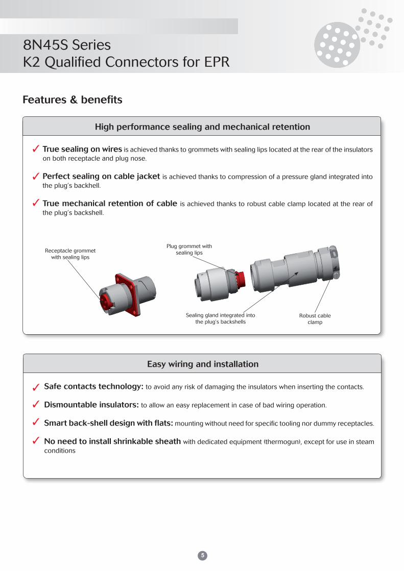
High performance sealing and mechanical retention
True sealing on wires is achieved thanks to grommets with sealing lips located at the rear of the insulators on both receptacle and plug nose.
Perfect sealing on cable jacket is achieved thanks to compression of a pressure gland integrated into the plug’s backhell.
True mechanical retention of cable is achieved thanks to robust cable clamp located at the rear of the plug’s backshell.
✓
✓
✓
Receptacle grommet with sealing lips
Plug grommet with sealing lips
Robust cableclamp
Sealing gland integrated into the plug’s backshells
Easy wiring and installation
Safe contacts technology: to avoid any risk of damaging the insulators when inserting the contacts.
Dismountable insulators: to allow an easy replacement in case of bad wiring operation.
Smart back-shell design with flats: mounting without need for specific tooling nor dummy receptacles.
No need to install shrinkable sheath with dedicated equipment (thermogun), except for use in steam conditions
✓
✓
✓
✓
Features & benefits

6
8N45S SeriesK2 Qualified Connectors for EPR
6
Dimensions and admissible cable diameters
8N45S Series field plugs have been especially designed for use with nuclear qualified shielded cables from Nexans and Prysmian used on EPR program.The plugs comprise two separate elements: the plug nose that contains the insulator and the contacts, and the back-shell that contains the cabling chamber with shielding continuity mechanism.Several back-shell sizes are available to fit all cable sizes, as show in the table below:
Field plug characteristics
A max
ØD
max
Plug nose
ØB
ØC
Backshell
Shell SizeBackshell
Type
Ø C Max. Number of Wired Contacts
A max Ø B Ø D maxmin max
11
30 7.50 9.00
3
95
23.00
23.20
31 9.00 10.40
301*7.50 9.00
9.00 10.40
32 10.50 12.20
21
30 7.50 9.00
4
27.00
31 9.00 10.40
301*7.50 9.00
9.00 10.40
32 10.50 12.20
7
70 8.50 11.00
24.70
71 11.00 12.30
72 12.40 14.00
712*11.00 12.30
12.40 14.00
73** 13.40 15.00N/A
74** 14.80 16.40
* P/N delivered with a set of two sealing glands and compression rings - ** New backshell sizes. Qualification pending.

7
8N45S SeriesK2 Qualified Connectors for EPR
7
Receptacle characteristics
Square flange receptacle
Ø A B C D Ø E Ø F Ø G H
11 16,00 33,50 15,40 24,00 18,60 3,2 19,00 18,00
21 20,00 33,50 15,40 27,00 22,60 3,2 23,00 21,00
F G
H
H
2 types of receptacle backshells are available:• Simple backnut (represented & described hereunder)• Straight with cable clamp and sealing gland (refer to plug description on p. 6)

8
8N45S SeriesK2 Qualified Connectors for EPR
Receptacle characteristics
½”NPT receptacle (shell size 11 only)
M20 receptacle (shell size 11 only)
1/2" NPT Thread
35 mm
19
.05
mm
(3/4
")
Ø 28 mm
26 mm
35 mm
13.4 mm 7.6 mm
M2
0 x1
.5m
m
9
8N45S SeriesK2 Qualified Connectors for EPR
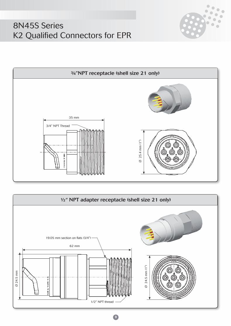
¾”NPT receptacle (shell size 21 only)
½“ NPT adapter receptacle (shell size 21 only)
35 mm
3/4" NPT Thread
62 mm
Ø 2
4.5
mm
19.05 mm section on flats (3/4")
1/2" NPT thread
Ø 2
5.4
mm
(1")
Ø 2
4.5
mm
(1")

10
8N45S SeriesK2 Qualified Connectors for EPR
10
Contact characteristics
Shell sizes and contact layouts
H
1 2
318
0°W
H
1 2
3 4 5
6 716
0°W
Shell size 11
3 contacts Ø 1.5 mm 7 contacts Ø 1.5 mm
Shell size 21
Shell Size Contact typeAdmissible wire section
min/max (mm²)Admissible sleeving
diameters (mm)
11 & 21
Ø1.5 crimp0.38 / 0.93 1.9 / 3.3
Small barrel
Ø1.5 crimp0.93 / 1.91 1.9 / 3.3
Large barrel
Admissible wire sections and sleeving diameters

11
8N45S SeriesK2 Qualified Connectors for EPR
Ordering informations
Product Series 8N45S 11 1 1 25 K2 20
Shell Size / Contact Layout 11 : Shell Size 1, 3 contacts Ø1.5 mm21 : Shell Size 2, 7 contacts Ø1.5 mm
Shell Type 1 : Receptacle 8 : Plug
Contact Type 1 : Male, Large Barrel 2 : Male, Small Barrel 5 : Female, Large Barrel 6 : Female, Small Barrel
Backshell / Interface Type 25 : Simple backnut (receptacles only)30* : Straight backshell (shell sizes 11 and 21) 31* : Straight backshell (shell sizes 11 and 21) 301* : Straight backshell (shell sizes 11 and 21) 32* : Straight backshell (shell size 11 only) 312* : Straight backshell (shell size 11 only) 70* : Straight backshell (shell size 21 only) 71* : Straight backshell (shell size 21 only) 701* : Straight backshell (shell size 21 only) 72* : Straight backshell (shell size 21 only) 712* : Straight backshell (shell size 21 only) 73* : Straight backshell (shell size 21 only) 74* : Straight backshell (shell size 21 only) M2 : M20 Interface (receptacle size 11 only) 05 : 1/2" NPT Interface (receptacle size 11 only) or 1/2" NPT adapter (receptacle size 21 only) 07 : 3/4" NPT Interface (receptacle size 21 only) 15 : Cable clamp Ø12 mm (receptacle size 21 only)
Classification** K2 : K2 qualified connectors according to RCC-E 2005 NC : Non-classified connectors
Packaging blank : standard packaging20 : long duration packaging without chlorine
* See definition table p.6 - ** K2 connectors are manufactured with specific traceability and delivered with End of Manufacturing Report, according
to RCC-E 2005. NC connectors are manufactured with standard traceability and delivered with Certificate of Conformity only

12
8N45S SeriesK2 Qualified Connectors for EPR8N45S SeriesK2 Qualified Connectors for EPR
12
Panel gaskets to seal receptacle on panel
Shell Size Part numbers
11 8400-2222
12 8400-2223
Spare parts
Contacts for re-ordering (sets of 10 contacts)
Shell Size Contact type Set of 10 male contacts P/N Set of 10 female contacts P/N
11 & 21
Ø1.5 crimpSmall barrel
8400-307 AKMEL 8400-9019-900EL
Ø1.5 crimpLarge barrel
8400-144 AKMEL 8400-9018-900EL
Tools
Crimping, insertion & extraction tools
Panel Gaskets
SOURIAU offers a large range of tools to prepare the connectors for use.
The tools listed hereunder perfectly suit the 8N45 Series connectors.
Shell Size Crimping tool LocatorsInsertion tools for pin
& socket contactsExtraction tools- pin contacts
Extraction tools- socket contacts
11 & 12 8365EL 8365-02EL 8400-1475EL 8400-448EL 8400-446EL
Related Documents