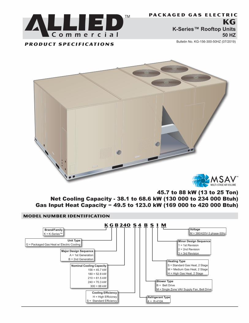
PACKAGED GAS ELECTRIC KG K-Series™ Rooftop Units 50 HZ Bulletin No. KG-156-300-50HZ (07/2019) 45.7 to 88 kW (13 to 25 Ton) Net Cooling Capacity - 38.1 to 68.6 kW (130 000 to 234 000 Btuh) Gas Input Heat Capacity − 49.5 to 123.0 kW (169 000 to 420 000 Btuh) MODEL NUMBER IDENTIFICATION K G b 240 S 4 B S 1 M Brand/Family K = K-Series™ Unit Type G = Packaged Gas Heat w/ Electric Cooling Major Design Sequence A = 1st Generation B = 2nd Generation Nominal Cooling Capacity 156 = 45.7 kW 180 = 52.8 kW 210 = 61.5 kW 240 = 70.3 kW 300 = 88 kW Cooling Efficiency H = High Efficicney S = Standard Efficiency Refrigerant Type 4 = R-410A Blower Type B = Belt Drive M = Single Zone VAV Supply Fan, Belt Drive Heating Type S = Standard Gas Heat, 2 Stage M = Medium Gas Heat, 2 Stage H = High Gas Heat, 2 Stage Minor Design Sequence 1 = 1st Revision 2 = 2nd Revision 3 = 3rd Revision Voltage M = 380/420V-3 phase-50hz PRODUCT SPECIFICATIONS

Welcome message from author
This document is posted to help you gain knowledge. Please leave a comment to let me know what you think about it! Share it to your friends and learn new things together.
Transcript
P A C K A G E D G A S E L E C T R I C
KGK-Series™ Rooftop Units
50 HZBulletin No. KG-156-300-50HZ (07/2019)
45.7 to 88 kW (13 to 25 Ton)Net Cooling Capacity - 38.1 to 68.6 kW (130 000 to 234 000 Btuh)
Gas Input Heat Capacity − 49.5 to 123.0 kW (169 000 to 420 000 Btuh)
MODEL NUMBER IDENTIFICATION
K G b 240 S 4 B S 1 MBrand/Family K = K-Series™
Unit Type G = Packaged Gas Heat w/ Electric Cooling
Major Design Sequence A = 1st Generation
B = 2nd Generation
Nominal Cooling Capacity 156 = 45.7 kW 180 = 52.8 kW 210 = 61.5 kW 240 = 70.3 kW
300 = 88 kW
Cooling Efficiency H = High Efficicney
S = Standard EfficiencyRefrigerant Type 4 = R-410A
Blower Type B = Belt Drive M = Single Zone VAV Supply Fan, Belt Drive
Heating Type S = Standard Gas Heat, 2 Stage M = Medium Gas Heat, 2 Stage H = High Gas Heat, 2 Stage
Minor Design Sequence 1 = 1st Revision 2 = 2nd Revision 3 = 3rd Revision
Voltage M = 380/420V-3 phase-50hz
P R O D U C T S P E C I F I C AT I O N S
KG 45.7 TO 88 KW ROOFTOP UNITS
K-Series™ Packaged Gas / Electric 52.8 to 88 kW 50hz / Page 2
FEATURES AND BENEFITS
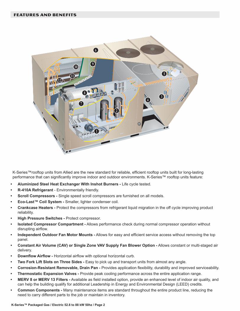
K-Series™rooftop units from Allied are the new standard for reliable, efficient rooftop units built for long-lasting performance that can significantly improve indoor and outdoor environments. K-Series™ rooftop units feature:
• Aluminized Steel Heat Exchanger With Inshot Burners - Life cycle tested.• R-410A Refrigerant - Environmentally friendly.• Scroll Compressors - Single speed scroll compressors are furnished on all models.• Eco-Last™ Coil System - Smaller, lighter condenser coil.• Crankcase Heaters - Protect the compressors from refrigerant liquid migration in the off cycle improving product
reliability. • High Pressure Switches - Protect compressor.• Isolated Compressor Compartment - Allows performance check during normal compressor operation without
disrupting airflow.• Independent Outdoor Fan Motor Mounts - Allows for easy and efficient service access without removing the top
panel.• Constant Air Volume (CAV) or Single Zone VAV Supply Fan Blower Option - Allows constant or multi-staged air
delivery.• Downflow Airflow - Horizontal airflow with optional horizontal curb.• Two Fork Lift Slots on Three Sides - Easy to pick up and transport units from almost any angle.• Corrosion-Resistant Removable, Drain Pan - Provides application flexibility, durability and improved serviceability.• Thermostatic Expansion Valves - Provide peak cooling performance across the entire application range.• MERV 8 or MERV 13 Filters - Available as field installed option, provide an enhanced level of indoor air quality, and
can help the building qualify for additional Leadership in Energy and Environmental Design (LEED) credits.• Common Components - Many maintenance items are standard throughout the entire product line, reducing the
need to carry different parts to the job or maintain in inventory.
B
C
DE
F
G
H
I
JK
LM
K-Series™ Packaged Gas / Electric 52.8 to 88 kW 50hz / Page 3
FEATURES AND BENEFITS
PERFORMANCE/QUALITYComponents bonded for grounding to meet safety standards for servicing required by Underwriters Laboratories (UL) and the International Electrotechnical Commission (IEC).Cooling performance is rated at test conditions included in Air-Conditioning, Heating and Refrigeration (AHRI) Standard 340/360 while operating at rated voltage and air volumes.International Organization for Standardization (ISO) 9001 Registered Manufacturing Quality System.
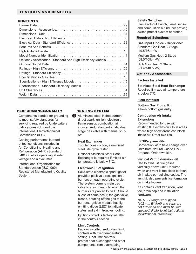
HEATING SYSTEMAluminized steel inshot burners, direct spark ignition, electronic flame sensor, combustion air inducer, redundant automatic dual stage gas valve with manual shut-off.
Heat ExchangerTubular construction, aluminized steel, life cycle tested.Optional Stainless Steel Heat Exchanger is required if mixed air temperature is below 7°C.
Electronic Pilot IgnitionSolid-state electronic spark igniter provides positive direct ignition of burners on each operating cycle. The system permits main gas valve to stay open only when the burners are proven to be lit. Should a loss of flame occur, the gas valve closes, shutting off the gas to the burners. Ignition module has light emitting diode (LED) to indicate status and aid in troubleshooting.Ignition control is factory installed in the controls section.
Limit ControlsFactory installed, redundant limit controls with fixed temperature setting. Heat limit controls protect heat exchanger and other components from overheating.
B
Safety SwitchesFlame roll-out switch, flame sensor and combustion air inducer proving switch protect system operation.
Required SelectionsGas Input Choice - Order one:Standard Gas Heat, 2 Stage (49.5/76.1 kW)Medium Gas Heat, 2 Stage (68.5/105.4 kW)High Gas Heat, 2 Stage (91.4/140.5 kW)
Options / Accessories
Factory InstalledStainless Steel Heat ExchangerRequired if mixed air temperature is below 7°C.
Field InstalledBottom Gas Piping KitAllows bottom gas entry.
Combustion Air Intake ExtensionsRecommended for use with existing flue extension kits in areas where high snow areas can block intake air. Order two kits.
LPG/Propane KitsConversion kit to field change over units from Natural Gas to LPG/Propane. Order two kits.
Vertical Vent Extension KitUse to exhaust flue gases vertically above unit. Required when unit vent is too close to fresh air intakes per building codes. The vent kit also prevents ice formation on intake louvers.Kit contains vent transition, vent tee, drain cap and installation hardware.NOTE - Straight vent pipes (102 mm B-Vent) and caps are not furnished and must be field supplied. Refer to kit instructions for additional information.
CONTENTSBlower Data . . . . . . . . . . . . . . . . . . . . . . . . . . . . . . . . .29Dimensions - Accessories. . . . . . . . . . . . . . . . . . . . . . . . . .40Dimensions - Unit . . . . . . . . . . . . . . . . . . . . . . . . . . . . . .37Electrical Data - High Efficiency . . . . . . . . . . . . . . . . . . . . . .33Electrical Data - Standard Efficiency . . . . . . . . . . . . . . . . . . . .33Features And Benefits . . . . . . . . . . . . . . . . . . . . . . . . . . . 2High Altitude Derate . . . . . . . . . . . . . . . . . . . . . . . . . . . .16Model Number Identification . . . . . . . . . . . . . . . . . . . . . . . . 1Options / Accessories - Standard And High Efficiency Models . . . . . . . 9Outdoor Sound Data . . . . . . . . . . . . . . . . . . . . . . . . . . . .34Ratings - High Efficiency . . . . . . . . . . . . . . . . . . . . . . . . . .25Ratings - Standard Efficiency . . . . . . . . . . . . . . . . . . . . . . . .17Specifications - Gas Heat . . . . . . . . . . . . . . . . . . . . . . . . . .16Specifications - High Efficiency Models . . . . . . . . . . . . . . . . . . .15Specifications - Standard Efficiency Models . . . . . . . . . . . . . . . .13Unit Clearances . . . . . . . . . . . . . . . . . . . . . . . . . . . . . . .34Weight Data . . . . . . . . . . . . . . . . . . . . . . . . . . . . . . . . .36
K-Series™ Packaged Gas / Electric 52.8 to 88 kW 50hz / Page 4
COOLING SYSTEMDesigned to maximize sensible and latent cooling performance at design conditions.System can operate from –1°C to 52°C without any additional controls
R-410A RefrigerantNon-chlorine based, ozone friendly, R-410A.
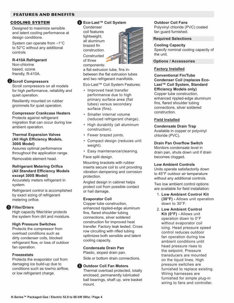
Scroll CompressorsScroll compressors on all models for high performance, reliability and quiet operation.Resiliently mounted on rubber grommets for quiet operation.
Compressor Crankcase HeatersProtects against refrigerant migration that can occur during low ambient operation.
Thermal Expansion Valves (All High Efficiency Models, 300S Model) Assures optimal performance throughout the application range. Removable element head.
Refrigerant Metering Orifice (All Standard Efficiency Models except 300S Model)Accurately meters refrigerant in system. Refrigerant control is accomplished by exact sizing of refrigerant metering orifice.
Filter/DriersHigh capacity filter/drier protects the system from dirt and moisture.
High Pressure SwitchesProtects the compressor from overload conditions such as dirty condenser coils, blocked refrigerant flow, or loss of outdoor fan operation.
FreezestatsProtects the evaporator coil from damaging ice build-up due to conditions such as low/no airflow, or low refrigerant charge.
C
D
Eco-Last™ Coil SystemCondenser coil features lightweight, all aluminum brazed fin construction.Constructed of three components: a flat extrusion tube, fins in-between the flat extrusion tubes and two refrigerant manifolds.Eco-Last™ Coil System Features:• Improved heat transfer
performance due to high primary surface area (flat tubes) versus secondary surface (fins).
• Smaller internal volume (reduced refrigerant charge).
• High durability (all aluminum construction).
• Fewer brazed joints.• Compact design (reduces unit
weight).• Easy maintenance/cleaning.Face split design.Mounting brackets with rubber inserts secure coil to unit providing vibration dampening and corrosion protection.Angled design in cabinet helps protect coil from possible contact or hail damage.
Evaporator Coil Copper tube construction, enhanced rippled-edge aluminum fins, flared shoulder tubing connections, silver soldered construction for improved heat transfer. Factory leak tested. Cross row circuiting with rifled tubing optimizes both sensible and latent cooling capacity.
Condensate Drain PanPlastic, sloped drain pan.Side or bottom drain connections.
Outdoor Coil Fan MotorsThermal overload protected, totally enclosed, permanently lubricated ball bearings, shaft up, wire basket mount.
E
F
Outdoor Coil FansPolyvinyl chloride (PVC) coated fan guard furnished.
Required SelectionsCooling CapacitySpecify nominal cooling capacity of the unit.
Options / Accessories
Factory InstalledConventional Fin/Tube Condenser Coil (replaces Eco-Last™ Coil System, Standard Efficiency Models only)Copper tube construction, enhanced rippled-edge aluminum fins, flared shoulder tubing connections, silver soldered construction.
Field InstalledCondensate Drain TrapAvailable in copper or polyvinyl chloride (PVC).
Drain Pan Overflow SwitchMonitors condensate level in drain pan, shuts down unit if drain becomes clogged.
Low Ambient ControlsUnits operate satisfactorily down to 45°F outdoor air temperature without any additional controls.Two low ambient control options are available for field installation:
1. Low Ambient Control Kit (30°F) - Allows unit operation down to 30°F.
2. Low Ambient Control Kit (0°F) - Allows unit operation down to 0°F without evaporator coil icing. Head pressure speed control reduces outdoor fan operation during low ambient conditions until head pressure rises to the setpoint. Pressure transducers are mounted on the liquid lines. High pressure switches are furnished to replace existing. Wiring harnesses are furnished for simple plug-in wiring to fans and controller.
FEATURES AND BENEFITS
K-Series™ Packaged Gas / Electric 52.8 to 88 kW 50hz / Page 5
CABINETConstructionHeavy-gauge steel panels and full perimeter heavy-gauge galvanized steel base rail provides structural integrity for transportation, handling, and installation.Base rails have rigging holes.Three sides of the base rail have forklift slots.Raised edges around duct and power entry openings in the bottom of the unit provide additional protection against water entering the building.
Airflow ChoiceUnits are available in downflow (vertical) or horizontal return air flow configuration.Horizontal air flow requires Horizontal Roof Curb.Horizontal Return Air Panel Kit is also required if converting a downflow configured unit to horizontal air flow.
Power/Gas EntryElectrical and gas lines can be brought through the unit base or through horizontal access knock-outs
Exterior PanelsConstructed of heavy-gauge, galvanized steel with a two-layer enamel paint finish.
InsulationAll panels adjacent to conditioned air are fully insulated with non-hygroscopic fiberglass insulation.Unit base is fully insulated. The insulation also serves as an air seal to the roof curb, eliminating the need to add a seal during installation.
Access PanelsAccess panels are provided for the economizer/filter section, heating/blower section, and the compressor/controls section.
Options / Accessories
Factory InstalledCorrosion ProtectionA completely flexible immersed coating with an electrodeposited
G
dry film process (AST ElectroFin E-Coat). Meets Mil Spec MIL-P-53084, ASTM B117 Standard Method Salt Spray Testing.Indoor Corrosion Protection:• Coated coil• Painted blower housing• Painted indoor baseOutdoor Corrosion Protection:• Coated coil• Painted outdoor base
Hinged Access PanelsHinged access panels for the filter section, the blower section and compressor/controls section.All hinged panels have seals and quarter-turn latching handles to provide a tight air and water seal.
Field InstalledCombination Coil/Hail GuardsHeavy gauge steel frame painted to match cabinet with expanded metal mesh to protect the outdoor coil from damage.
Horizontal Return Air Panel KitRequired for horizontal applications with Horizontal Roof Curb, contains panel with return air opening for field replacement of existing unit panel and panel to cover bottom return air opening in unit, see dimension drawings.
BLOWERA wide selection of supply air blower options are available to meet a variety of airflow requirements.
MotorOverload protected, equipped with ball bearings. Belt drive motors are offered on all models and are available in several different sizes to maximize air performance.
Supply Air BlowerForward curved blades, double inlet, blower wheel is statically and dynamically balanced. Equipped with ball bearings and adjustable pulley (allows speed change).Blower assembly slides out of unit for servicing.
H
Required SelectionsOrder blower motor output and drive kit number required when base unit is ordered, see Drive Kit Specifications Table.
Select Constant Air Volume (CAV) or Single Zone VAV Supply Fan Blower OptionOn Constant Air volume (CAV) models, the supply air blower will provide a constant volume of air.Single Zone VAV Supply Fan option models utilize a Variable Frequency Drive (VFD) to stage the supply air blower airflow. The VFD alters the frequency and voltage of the power supply to the blower to control blower speed.The supply air blower has two speeds:3. Low speed for part-load
cooling operation. NOTE - Low speed is 66% of high speed.
4. High speed for full load cooling and all heat modes.
Full speed blower operation is set by adjusting the motor pulley to deliver the desired air volume.The ventilation speed is selectable between high and low speed.NOTE - Part load airflow in cooling mode on Single Zone VAV Supply Fan models should not be set below 30 L/s per kW to reduce the risk of evaporator coil freeze-up.The VFD has an operational range of –40 to 52°C outdoor air ambient temperature. Lower operating costs are obtained when the blower is operated on lower speeds.
FEATURES AND BENEFITS
K-Series™ Packaged Gas / Electric 52.8 to 88 kW 50hz / Page 6
FEATURES AND BENEFITS
BLOWER (continued)
Single Zone VAV Supply Fan Sequence of OperationVentilation speed is determined by the VENT SPEED switch setting on VFD control board (LO or HI).Blower operates in low speed for mechanical cooling (Y1).Blower operates in high speed for any other mode (free cooling, mechanical cooling Y1+Y2, and heating).Economizer damper minimum position is fully closed in unoccupied mode.In occupied mode, the economizer damper minimum position is determined by the setting of the two potentiometers on VFD control board.• LO SPD MIN POS
potentiometer sets the minimum position when blower is operating at low speed.
• HI SPD MIN POS potentiometer sets the minimum position when blower is operating at high speed.
Ordering InformationSpecify standard or high efficiency blower motor, motor horsepower and drive kit number when base unit is ordered, see Drive Kit Specifications Table.
CONTROLSUnit ControlAll control voltage is provided via a 24V (secondary) transformer with built-in circuit breaker protection.
Heat/Cool Staging - Capable of up to 2 heat / 2 cool staging with a third party DDC control system or thermostat.
Low Voltage Terminal Block - Provides screw terminal connections for thermostat or controller wiring.
Night Setback Mode - Saves energy by closing outdoor air dampers and operating supply fan on thermostat demand only.
I
Options / Accessories
Field InstalledSmoke DetectorPhotoelectric type, installed in supply air section, return air section or both sections. Available with power board and single sensor (supply or return) or power board and two sensors (supply and return). Power board located in unit control compartment.
ELECTRICALAll units include terminal block and fuse block in power entry junction box for single power entry application.
Marked & Color-Coded WiringAll electrical wiring is color-coded and marked to identify which components it is connecting.
Electrical PlugsPositive connection electrical plugs are used to connect common accessories or maintenance parts for easy removal or installation.
Options/Accessories
Phase MonitorPhase monitor detects the phasing of incoming power. If the incoming power is out of phase or if any of the three phases are lost, an indicator LED on the phase monitor will turn red and the unit will not start. In normal operation with correct incoming power phasing, the LED will be green.NOTE - Phase Monitor is factory Installed in the control compartment on all units equipped with the Single Zone VAV Supply Fan option.
Required Selections
Voltage ChoiceSpecify when ordering base unit.
INDOOR AIR QUALITYAir FiltersDisposable 51 mm filters furnished as standard.
Options / Accessories
Field InstalledHigh Efficiency Air FiltersDisposable MERV 8 or MERV 13 (Minimum Efficiency Reporting Value based on ASHRAE 52.2) efficiency 51 mm pleated filters.
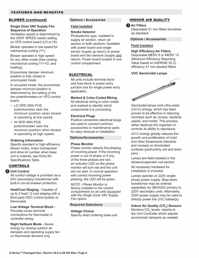
UVC Germicidal Lamps
Germicidal lamps emit ultra-violet (UV-C) energy, which has been proven to be effective in reducing microbes such as viruses, bacteria, yeasts, and molds. This process either destroys the organism or controls its ability to reproduce.UV-C energy greatly reduces the growth and proliferation of mold and other bioaerosols (bacteria and viruses) on illuminated surfaces (particularly coil and drain pan).Lamps are field installed in the blower/evaporator coil section.All necessary hardware for installation is included.Lamps operate on 220V single-phase power supply. Step-down transformer may be ordered separately for 380/420V primary to 220V secondary units. Alternately, 220V power supply may be used to directly power the UVC ballast(s).
Indoor Air Quality (CO2) SensorsMonitors CO2 levels, reports to the Unit Controller which adjusts economizer dampers as needed.
J
K-Series™ Packaged Gas / Electric 52.8 to 88 kW 50hz / Page 7
ECONOMIZER OPTIONS
Factory or Field InstalledEconomizer Features (Standard and High Performance Common Features)Outdoor Air Hood with mist elimination filter is furnished.Mixed Air Sensor is furnished for field installation in the rooftop unit. Sensor is factory installed when Economizers are factory installed.
Standard Economizer Features Gear-driven action, return air and outdoor air dampers, plug-in connections to unit, nylon bearings, neoprene seals, 24-volt, fully-modulating spring return motor.
Standard Economizer Control ModuleThe Standard Economizer Control Module can be adjusted to operate based on outdoor air temperatures.
Economizer Controls:• Damper Minimum Position
- Can be set lower than traditional minimum air requirements resulting in cost savings.
• AQ Sensor - Signals dampers to modulate and maintain 13°C when CO2 is higher than the CO2 setpoint.
• Demand Control Ventilation (DCV) LED - A steady green Demand Control Ventilation LED indicates the IAQ reading is higher than setpoint and requires more fresh air.
• Free Cool LED - A steady green LED indicates outdoor air is suitable for free cooling.
Free Cooling runs when outdoor air temperature is lower than the set temperature on the economizer control. NOTE: The Free Cooling default setting for outdoor air temperature sensor is 13°C.
K High Performance Economizer FeaturesGear-driven action, high torque 24-volt fully-modulating spring return damper motor, return air and outdoor air dampers, plug-in connections to unit, stainless steel bearings, enhanced neoprene blade edge seals and flexible stainless steel jamb seals to minimize air leakage.
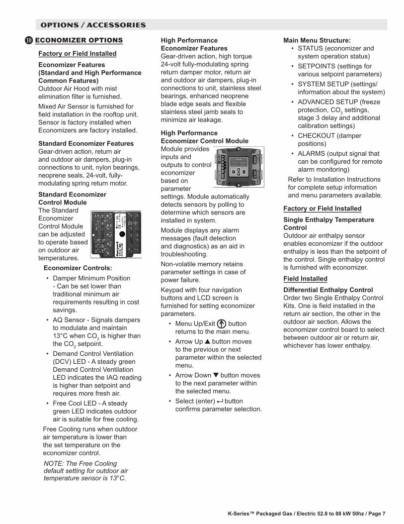
High Performance Economizer Control ModuleModule provides inputs and outputs to control economizer based on parameter settings. Module automatically detects sensors by polling to determine which sensors are installed in system.Module displays any alarm messages (fault detection and diagnostics) as an aid in troubleshooting.Non-volatile memory retains parameter settings in case of power failure.Keypad with four navigation buttons and LCD screen is furnished for setting economizer parameters.
• Menu Up/Exit button returns to the main menu.
• Arrow Up button moves to the previous or next parameter within the selected menu.
• Arrow Down button moves to the next parameter within the selected menu.
• Select (enter) button confirms parameter selection.
Main Menu Structure:• STATUS (economizer and
system operation status)• SETPOINTS (settings for
various setpoint parameters)• SYSTEM SETUP (settings/
information about the system)• ADVANCED SETUP (freeze
protection, CO2 settings, stage 3 delay and additional calibration settings)
• CHECKOUT (damper positions)
• ALARMS (output signal that can be configured for remote alarm monitoring)
Refer to Installation Instructions for complete setup information and menu parameters available.
Factory or Field InstalledSingle Enthalpy Temperature Control Outdoor air enthalpy sensor enables economizer if the outdoor enthalpy is less than the setpoint of the control. Single enthalpy control is furnished with economizer.
Field InstalledDifferential Enthalpy Control Order two Single Enthalpy Control Kits. One is field installed in the return air section, the other in the outdoor air section. Allows the economizer control board to select between outdoor air or return air, whichever has lower enthalpy.
OPTIONS / ACCESSORIES
K-Series™ Packaged Gas / Electric 52.8 to 88 kW 50hz / Page 8
EXHAUST OPTIONS
Downflow Barometric Relief Dampers With Exhaust HoodAllow relief of excess air.Aluminum blade dampers prevent blow back and outdoor air infiltration during off cycle.Exhaust hood with bird screen is furnished.
Field InstalledHorizontal Barometric Relief Dampers With Exhaust HoodFor use when unit is configured for horizontal applications requiring an economizer.Allows relief of excess air.Aluminum blade dampers prevent blow back and outdoor air infiltration during off cycle.Field installed in return air duct.Exhaust hood with bird screen is furnished.
Power Exhaust FanInstalls internal to unit for downflow applications only with economizer option. Provides exhaust air pressure relief. Interlocked to run when supply air blower is operating, fan runs when outdoor air dampers are 50% open (adjustable), motor is overload protected. Requires Economizer with Outdoor Air Hood and Downflow Barometric Relief Dampers. Dual fans are 508 mm diameter with 5 blades with (2) 0.25 kW motors.
L
M
OUTDOOR AIR OPTIONS
Factory or Field InstalledOutdoor Air Damper - Downflow or Horizontal With Air HoodLinked mechanical dampers, 0 to 25% (fixed) outdoor air adjustable, installs in unit. Includes outdoor air hood.Automatic model features fully modulating spring return damper motor with plug-in connection.Manual model features parallel blade, gear-driven dampers with adjustable fixed position.Outdoor Air Hood is included when damper is factory installed and is furnished with damper when ordered for field installation.
ROOF CURBSNailer strip furnished, mates to unit, US National Roofing Contractors Approved, shipped knocked down.
DownflowHybrid Roof CurbsRoof curb can be assembled using interlocking tabs to fasten corners together. No tools required.Curb can also be fastened together with furnished hardware.Available in 203, 356, 457, and 610 mm heights.
Adjustable Pitch CurbFully adjustable pitch curb provides a level platform for rooftop units allowing flexible installations on roofs with uneven or sloped angles.Uses interlocking tabs to fasten corners together. No tools required.Hardware is furnished to connect upper curb with lower curb.Available in 356 mm height.
Adaptor Curbs (not shown)Curbs are regionally sourced. Dimensions will vary based upon the source. Contact your local sales representative for a detailed cut sheet with applicable dimensions.
HorizontalConverts unit from downflow to horizontal (side) air flow, return air is on unit, supply air is on curb, see dimension drawings. Curbs for rooftop applications meet National Roofing Code requirements. Requires Horizontal Return Air Panel Kit. Available in 660, 762, 940 and 1041 mm heights. Optional Insulation Kit is available to help prevent sweating.
CEILING DIFFUSERSCeiling Diffusers (Flush or Step-Down)Aluminum grilles, large center grille, insulated diffuser box with flanges, hanging rings furnished, interior transition (even air flow), internally sealed (prevents recirculation), adapts to T-bar ceiling grids or plaster ceilings.
Transitions (Supply and Return)Used with diffusers, installs in roof curb, galvanized steel construction, flanges furnished for duct connection to diffusers, fully insulated.
OPTIONS / ACCESSORIES
K-Series™ Packaged Gas / Electric 52.8 to 88 kW 50hz / Page 9
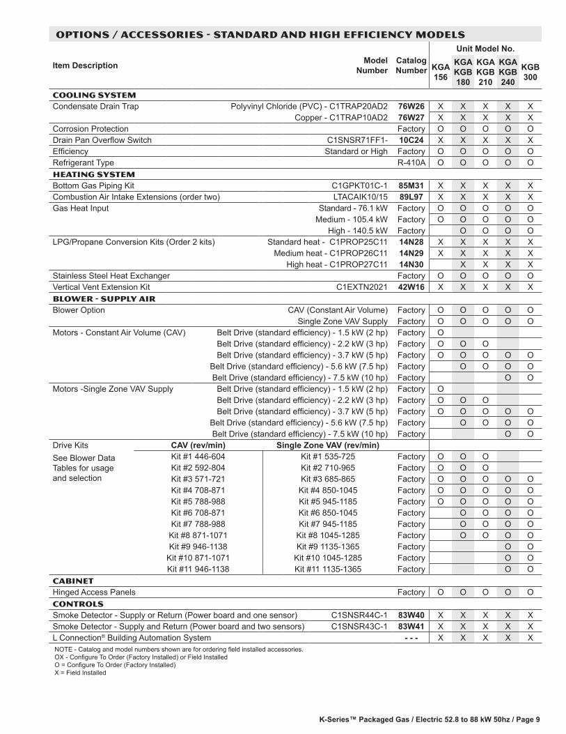
OPTIONS / ACCESSORIES - STANDARD AND HIGH EFFICIENCY MODELS
Item Description Model Number
Catalog Number
Unit Model No.
KGA 156
KGA KGB 180
KGA KGB 210
KGA KGB 240
KGB 300
COOLING SYSTEMCondensate Drain Trap Polyvinyl Chloride (PVC) - C1TRAP20AD2 76W26 X X X X X
Copper - C1TRAP10AD2 76W27 X X X X XCorrosion Protection Factory O O O O ODrain Pan Overflow Switch C1SNSR71FF1- 10C24 X X X X XEfficiency Standard or High Factory O O O O ORefrigerant Type R-410A O O O O OHEATING SYSTEMBottom Gas Piping Kit C1GPKT01C-1 85M31 X X X X XCombustion Air Intake Extensions (order two) LTACAIK10/15 89L97 X X X X XGas Heat Input Standard - 76.1 kW Factory O O O O O
Medium - 105.4 kW Factory O O O O OHigh - 140.5 kW Factory O O O O
LPG/Propane Conversion Kits (Order 2 kits) Standard heat - C1PROP25C11 14N28 X X X X XMedium heat - C1PROP26C11 14N29 X X X X X
High heat - C1PROP27C11 14N30 X X X XStainless Steel Heat Exchanger Factory O O O O OVertical Vent Extension Kit C1EXTN2021 42W16 X X X X XBLOWER - SUPPLY AIRBlower Option CAV (Constant Air Volume) Factory O O O O O
Single Zone VAV Supply Factory O O O O OMotors - Constant Air Volume (CAV) Belt Drive (standard efficiency) - 1.5 kW (2 hp) Factory O
Belt Drive (standard efficiency) - 2.2 kW (3 hp) Factory O O OBelt Drive (standard efficiency) - 3.7 kW (5 hp) Factory O O O O O
Belt Drive (standard efficiency) - 5.6 kW (7.5 hp) Factory O O O OBelt Drive (standard efficiency) - 7.5 kW (10 hp) Factory O O
Motors -Single Zone VAV Supply Belt Drive (standard efficiency) - 1.5 kW (2 hp) Factory OBelt Drive (standard efficiency) - 2.2 kW (3 hp) Factory O O OBelt Drive (standard efficiency) - 3.7 kW (5 hp) Factory O O O O O
Belt Drive (standard efficiency) - 5.6 kW (7.5 hp) Factory O O O OBelt Drive (standard efficiency) - 7.5 kW (10 hp) Factory O O
Drive KitsSee Blower Data Tables for usage and selection
CAV (rev/min) Single Zone VAV (rev/min)Kit #1 446-604 Kit #1 535-725 Factory O O OKit #2 592-804 Kit #2 710-965 Factory O O OKit #3 571-721 Kit #3 685-865 Factory O O O O OKit #4 708-871 Kit #4 850-1045 Factory O O O O OKit #5 788-988 Kit #5 945-1185 Factory O O O O OKit #6 708-871 Kit #6 850-1045 Factory O O O OKit #7 788-988 Kit #7 945-1185 Factory O O O O
Kit #8 871-1071 Kit #8 1045-1285 Factory O O O OKit #9 946-1138 Kit #9 1135-1365 Factory O O
Kit #10 871-1071 Kit #10 1045-1285 Factory O OKit #11 946-1138 Kit #11 1135-1365 Factory O O
CABINETHinged Access Panels Factory O O O O OCONTROLSSmoke Detector - Supply or Return (Power board and one sensor) C1SNSR44C-1 83W40 X X X X XSmoke Detector - Supply and Return (Power board and two sensors) C1SNSR43C-1 83W41 X X X X XL Connection® Building Automation System - - - X X X X XNOTE - Catalog and model numbers shown are for ordering field installed accessories. OX - Configure To Order (Factory Installed) or Field Installed O = Configure To Order (Factory Installed) X = Field Installed
K-Series™ Packaged Gas / Electric 52.8 to 88 kW 50hz / Page 10
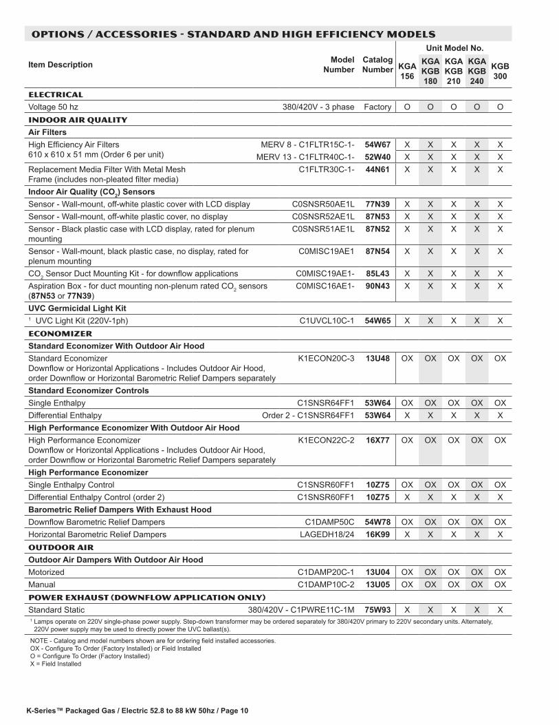
OPTIONS / ACCESSORIES - STANDARD AND HIGH EFFICIENCY MODELS
Item Description Model Number
Catalog Number
Unit Model No.
KGA 156
KGA KGB 180
KGA KGB 210
KGA KGB 240
KGB 300
ELECTRICAL
Voltage 50 hz 380/420V - 3 phase Factory O O O O OINDOOR AIR QUALITY
Air FiltersHigh Efficiency Air Filters 610 x 610 x 51 mm (Order 6 per unit)
MERV 8 - C1FLTR15C-1- 54W67 X X X X XMERV 13 - C1FLTR40C-1- 52W40 X X X X X
Replacement Media Filter With Metal Mesh Frame (includes non-pleated filter media)
C1FLTR30C-1- 44N61 X X X X X
Indoor Air Quality (CO2) SensorsSensor - Wall-mount, off-white plastic cover with LCD display C0SNSR50AE1L 77N39 X X X X XSensor - Wall-mount, off-white plastic cover, no display C0SNSR52AE1L 87N53 X X X X XSensor - Black plastic case with LCD display, rated for plenum mounting
C0SNSR51AE1L 87N52 X X X X X
Sensor - Wall-mount, black plastic case, no display, rated for plenum mounting
C0MISC19AE1 87N54 X X X X X
CO2 Sensor Duct Mounting Kit - for downflow applications C0MISC19AE1- 85L43 X X X X XAspiration Box - for duct mounting non-plenum rated CO2 sensors (87N53 or 77N39)
C0MISC16AE1- 90N43 X X X X X
UVC Germicidal Light Kit1 UVC Light Kit (220V-1ph) C1UVCL10C-1 54W65 X X X X XECONOMIZER
Standard Economizer With Outdoor Air HoodStandard Economizer Downflow or Horizontal Applications - Includes Outdoor Air Hood, order Downflow or Horizontal Barometric Relief Dampers separately
K1ECON20C-3 13U48 OX OX OX OX OX
Standard Economizer ControlsSingle Enthalpy C1SNSR64FF1 53W64 OX OX OX OX OXDifferential Enthalpy Order 2 - C1SNSR64FF1 53W64 X X X X XHigh Performance Economizer With Outdoor Air HoodHigh Performance Economizer Downflow or Horizontal Applications - Includes Outdoor Air Hood, order Downflow or Horizontal Barometric Relief Dampers separately
K1ECON22C-2 16X77 OX OX OX OX OX
High Performance EconomizerSingle Enthalpy Control C1SNSR60FF1 10Z75 OX OX OX OX OXDifferential Enthalpy Control (order 2) C1SNSR60FF1 10Z75 X X X X XBarometric Relief Dampers With Exhaust HoodDownflow Barometric Relief Dampers C1DAMP50C 54W78 OX OX OX OX OXHorizontal Barometric Relief Dampers LAGEDH18/24 16K99 X X X X XOUTDOOR AIR
Outdoor Air Dampers With Outdoor Air HoodMotorized C1DAMP20C-1 13U04 OX OX OX OX OXManual C1DAMP10C-2 13U05 OX OX OX OX OXPOWER EXHAUST (DOWNFLOW APPLICATION ONLY)
Standard Static 380/420V - C1PWRE11C-1M 75W93 X X X X X1 Lamps operate on 220V single-phase power supply. Step-down transformer may be ordered separately for 380/420V primary to 220V secondary units. Alternately,
220V power supply may be used to directly power the UVC ballast(s).
NOTE - Catalog and model numbers shown are for ordering field installed accessories. OX - Configure To Order (Factory Installed) or Field Installed O = Configure To Order (Factory Installed) X = Field Installed
K-Series™ Packaged Gas / Electric 52.8 to 88 kW 50hz / Page 11
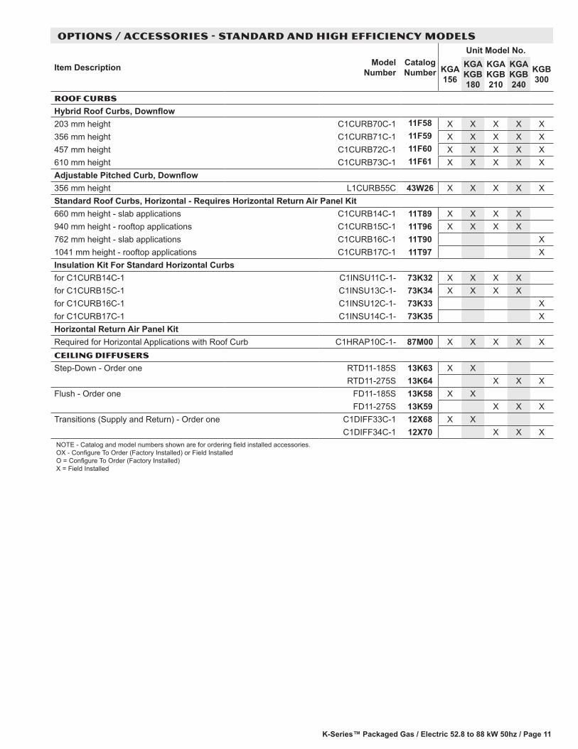
OPTIONS / ACCESSORIES - STANDARD AND HIGH EFFICIENCY MODELS
Item Description Model Number
Catalog Number
Unit Model No.
KGA 156
KGA KGB 180
KGA KGB 210
KGA KGB 240
KGB 300
ROOF CURBS
Hybrid Roof Curbs, Downflow203 mm height C1CURB70C-1 11F58 X X X X X356 mm height C1CURB71C-1 11F59 X X X X X457 mm height C1CURB72C-1 11F60 X X X X X610 mm height C1CURB73C-1 11F61 X X X X XAdjustable Pitched Curb, Downflow356 mm height L1CURB55C 43W26 X X X X XStandard Roof Curbs, Horizontal - Requires Horizontal Return Air Panel Kit 660 mm height - slab applications C1CURB14C-1 11T89 X X X X940 mm height - rooftop applications C1CURB15C-1 11T96 X X X X762 mm height - slab applications C1CURB16C-1 11T90 X1041 mm height - rooftop applications C1CURB17C-1 11T97 XInsulation Kit For Standard Horizontal Curbsfor C1CURB14C-1 C1INSU11C-1- 73K32 X X X Xfor C1CURB15C-1 C1INSU13C-1- 73K34 X X X Xfor C1CURB16C-1 C1INSU12C-1- 73K33 Xfor C1CURB17C-1 C1INSU14C-1- 73K35 XHorizontal Return Air Panel KitRequired for Horizontal Applications with Roof Curb C1HRAP10C-1- 87M00 X X X X XCEILING DIFFUSERS
Step-Down - Order one RTD11-185S 13K63 X XRTD11-275S 13K64 X X X
Flush - Order one FD11-185S 13K58 X XFD11-275S 13K59 X X X
Transitions (Supply and Return) - Order one C1DIFF33C-1 12X68 X XC1DIFF34C-1 12X70 X X X
NOTE - Catalog and model numbers shown are for ordering field installed accessories. OX - Configure To Order (Factory Installed) or Field Installed O = Configure To Order (Factory Installed) X = Field Installed
K-Series™ Packaged Gas / Electric 52.8 to 88 kW 50hz / Page 12
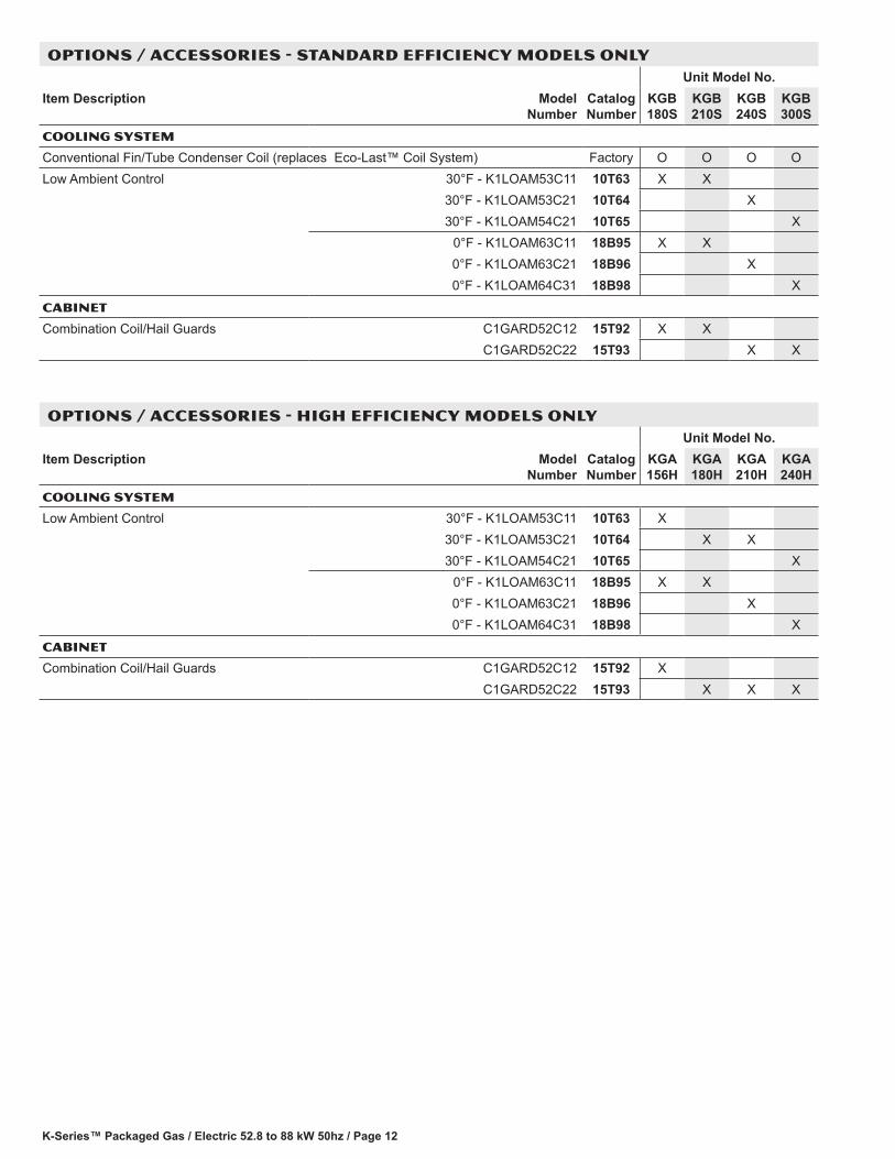
OPTIONS / ACCESSORIES - STANDARD EFFICIENCY MODELS ONLYUnit Model No.
Item Description Model Number
Catalog Number
KGB 180S
KGB 210S
KGB 240S
KGB 300S
COOLING SYSTEM
Conventional Fin/Tube Condenser Coil (replaces Eco-Last™ Coil System) Factory O O O OLow Ambient Control 30°F - K1LOAM53C11 10T63 X X
30°F - K1LOAM53C21 10T64 X30°F - K1LOAM54C21 10T65 X
0°F - K1LOAM63C11 18B95 X X0°F - K1LOAM63C21 18B96 X0°F - K1LOAM64C31 18B98 X
CABINET
Combination Coil/Hail Guards C1GARD52C12 15T92 X XC1GARD52C22 15T93 X X
OPTIONS / ACCESSORIES - HIGH EFFICIENCY MODELS ONLYUnit Model No.
Item Description Model Number
Catalog Number
KGA 156H
KGA 180H
KGA 210H
KGA 240H
COOLING SYSTEM
Low Ambient Control 30°F - K1LOAM53C11 10T63 X30°F - K1LOAM53C21 10T64 X X30°F - K1LOAM54C21 10T65 X
0°F - K1LOAM63C11 18B95 X X0°F - K1LOAM63C21 18B96 X0°F - K1LOAM64C31 18B98 X
CABINET
Combination Coil/Hail Guards C1GARD52C12 15T92 XC1GARD52C22 15T93 X X X
K-Series™ Packaged Gas / Electric 52.8 to 88 kW 50hz / Page 13
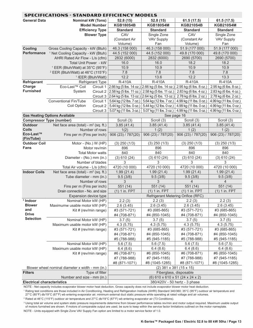
SPECIFICATIONS - STANDARD EFFICIENCY MODELSGeneral Data Nominal kW (Tons) 52.8 (15) 52.8 (15) 61.5 (17.5) 61.5 (17.5)
Model Number KGB180S4B KGB180S4M KGB210S4B KGB210S4MEfficiency Type Standard Standard Standard Standard
Blower Type CAV (Constant Air
Volume)
Single Zone VAV Supply
Fan
CAV (Constant Air
Volume)
Single Zone VAV Supply
FanCooling Performance
Gross Cooling Capacity - kW (Btuh) 46.3 (158 000) 46.3 (158 000) 51.9 (177 000) 51.9 (177 000) 1 Net Cooling Capacity - kW (Btuh) 44.5 (152 000) 44.5 (152 000) 49.8 (170 000) 49.8 (170 000)
AHRI Rated Air Flow - L/s (cfm) 2832 (6000) 2832 (6000) 2690 (5700) 2690 (5700)Total Unit Power - kW 16.0 16.0 18.2 18.2
1 EER (Btuh/Watt) at 35°C (95°F) 10.9 10.9 10.9 10.92 EER (Btuh/Watt) at 46°C (115°F) 7.8 7.8 7.8 7.8
1 IEER (Btuh/Watt) 12.2 13.6 12.2 13.3Refrigerant Charge Furnished
Refrigerant Type R-410A R-410A R-410A R-410A Eco-Last™ Coil
SystemCircuit 1 2.66 kg (5 lbs. 14 oz.) 2.66 kg (5 lbs. 14 oz.) 2.95 kg (6 lbs. 8 oz.) 2.95 kg (6 lbs. 8 oz.)Circuit 2 2.58 kg (5 lbs. 11 oz.) 2.58 kg (5 lbs. 11 oz.) 2.83 kg (6 lbs. 4 oz.) 2.83 kg (6 lbs. 4 oz.)Circuit 3 2.64 kg (5 lbs. 13 oz.) 2.64 kg (5 lbs. 13 oz.) 2.78 kg (6 lbs. 2 oz.) 2.78 kg (6 lbs. 2 oz.)
Conventional Fin/Tube Coil Option
Circuit 1 5.64 kg (12 lbs. 7 oz.) 5.64 kg (12 lbs. 7 oz.) 4.99 kg (11 lbs. 0 oz.) 4.99 kg (11 lbs. 0 oz.)Circuit 2 5.44 kg (12 lbs. 0 oz.) 5.44 kg (12 lbs. 0 oz.) 4.99 kg (11 lbs. 0 oz.) 4.99 kg (11 lbs. 0 oz.)Circuit 3 5.07 kg (11 lbs. 3 oz.) 5.07 kg (11 lbs. 3 oz.) 4.99 kg (11 lbs. 0 oz.) 4.99 kg (11 lbs. 0 oz.)
Gas Heating Options Available See page 16Compressor Type (number) Scroll (3) Scroll (3) Scroll (3) Scroll (3)Outdoor Coils Eco-Last™ (Fin/Tube)
Net face area (total) - m2 (sq. ft.) 3.85 (41.4) 3.85 (41.4) 3.85 (41.4) 3.85 (41.4)Number of rows 1(2) 1 (2) 1 (2) 1 (2)
Fins per m (Fins per inch) 906 (23) / 787(20) 906 (23) / 787(20) 906 (23) / 787(20) 906 (23) / 787(20)
Outdoor Coil Fans
Motor - (No.) W (HP) (3) 250 (1/3) (3) 250 (1/3) (3) 250 (1/3) (3) 250 (1/3)Motor rev/min 896 896 896 896
Total Motor watts 840 840 840 840Diameter - (No.) mm (in.) (3) 610 (24) (3) 610 (24) (3) 610 (24) (3) 610 (24)
Number of blades 3 3 3 3Total Air volume - L/s (cfm) 4720 (10 000) 4720 (10 000) 4720 (10 000) 4720 (10 000)
Indoor Coils Net face area (total) - m2 (sq. ft.) 1.99 (21.4) 1.99 (21.4) 1.99 (21.4) 1.99 (21.4)Tube diameter - mm (in.) 9.5 (3/8) 9.5 (3/8) 9.5 (3/8) 9.5 (3/8)
Number of rows 3 3 4 4Fins per m (Fins per inch) 551 (14) 551 (14) 551 (14) 551 (14)
Drain connection - No. and size (1) 1 in. FPT (1) 1 in. FPT (1) 1 in. FPT (1) 1 in. FPTExpansion device type Refrigerant Metering Orifice (RFC)
3 Indoor Blower and Drive Selection
Nominal Motor kW (HP) 2.2 (3) 2.2 (3) 2.2 (3) 2.2 (3)Maximumw usable motor kW (HP) 2.6 (3.45) 2.6 (3.45) 2.6 (3.45) 2.6 (3.45)
Kit # (rev/min range) #3 (571-721) #3 (685-865) #3 (571-721) #3 (685-865)#4 (708-871) #4 (850-1045) #4 (708-871) #4 (850-1045)
Nominal Motor kW (HP) 3.7 (5) 3.7 (5) 3.7 (5) 3.7 (5)Maximum usable motor kW (HP) 4.3 (5.75) 4.3 (5.75) 4.3 (5.75) 4.3 (5.75)
Kit # (rev/min range) #3 (571-721) #3 (685-865) #3 (571-721) #3 (685-865)#4 (708-871) #4 (850-1045) #4 (708-871) #4 (850-1045)#5 (788-988) #5 (945-1185) #5 (788-988) #5 (945-1185)
Nominal Motor kW (HP) 5.6 (7.5) 5.6 (7.5) 5.6 (7.5) 5.6 (7.5)Maximum usable motor kW (HP) 6.4 (8.6) 6.4 (8.6) 6.4 (8.6) 6.4 (8.6)
Kit # (rev/min range) #6 (708-871) #6 (850-1045) #6 (708-871) #6 (850-1045)#7 (788-988) #7 (945-1185) #7 (788-988) #7 (945-1185)
#8 (871-1071) #8 (1045-1285) #8 (871-1071) #8 (1045-1285)Blower wheel nominal diameter x width - mm (in.) (2) 381 x 381 (15 x 15)
Filters Type of filter Fiberglass, disposableNumber and size - mm (in.) (6) 610 x 610 x 51 (24 x 24 x 2)
Electrical characteristics 380/420V - 50 hertz - 3 phaseNOTE - Net capacity includes evaporator blower motor heat deduction. Gross capacity does not include evaporator blower motor heat deduction.1 Rating test conditions are those included in Air Conditioning, Heating and Refrigeration Institute (AHRI) Standard 340/360; 35°C (95°F) outdoor air temperature and
27°C (80°F) db/19°C (67°F) wb entering evaporator air; minimum external duct static pressure while operating at rated voltage and air volumes.2 Rated at 46°C (115°F) outdoor air temperature and 27°C db/19°C (67°F) wb entering evaporator air (T3 Conditions).3 Using total air volume and system static pressure requirements determine from blower performance tables rev/min and motor output required. Maximum usable output
of motors furnished are shown. If motors of comparable output are used, be sure to keep within the service factor limitations outlined on the motor nameplate.NOTE - Units equipped with Single Zone VAV Supply Fan option are limited to a motor service factor of 1.0.
K-Series™ Packaged Gas / Electric 52.8 to 88 kW 50hz / Page 14
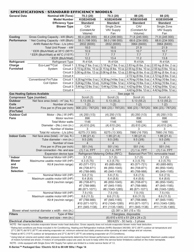
SPECIFICATIONS - STANDARD EFFICIENCY MODELSGeneral Data Nominal kW (Tons) 70.3 (20) 70.3 (20) 88 (25) 88 (25)
Model Number KGB240S4B KGB240S4M KGB300S4B KGB300S4MEfficiency Type Standard Standard Standard Standard
Blower Type CAV (Constant Air
Volume)
Single Zone VAV Supply
Fan
CAV (Constant Air
Volume)
Single Zone VAV Supply
FanCooling Performance
Gross Cooling Capacity - kW (Btuh) 60.4 (206 000) 60.4 (206 000) 71.8 (245 000) 71.8 (245 000)1 Net Cooling Capacity - kW (Btuh) 58.0 (198 000) 58.0 (198 000) 68.6 (234 000) 68.6 (234 000)
AHRI Rated Air Flow - L/s (cfm) 2832 (6000) 2832 (6000) 3964 (8400) 3964 (8400)Total Unit Power - kW 18.0 18.0 21.9 21.9
1 EER (Btuh/Watt) at 35°C (95°F) 10.9 10.9 10.7 10.72 EER (Btuh/Watt) at 46°C (115°F) 7.7 7.7 7.7 7.7
1 IEER (Btuh/Watt) 12.2 13.4 11.2 13.8Refrigerant Charge Furnished
Refrigerant Type R-410A R-410A R-410A R-410A Eco-Last™Coil
SystemCircuit 1 3.18 kg (7 lbs. 0 oz.) 3.18 kg (7 lbs. 0 oz.) 2.83 kg (6 lbs. 2 oz.) 2.83 kg (6 lbs. 2 oz.)Circuit 2 3.15 kg (6 lbs. 15 oz.)3.15 kg (6 lbs. 15 oz.) 2.55 kg (5 lbs. 10 oz.) 2.55 kg (5 lbs. 10 oz.)Circuit 3 3.06 kg (6 lbs. 12 oz.)3.06 kg (6 lbs. 12 oz.) 2.89 kg (6 lbs. 6 oz.) 2.89 kg (6 lbs. 6 oz.)Circuit 4 - - - - - - 2.72 kg (6 lbs. 0 oz.) 2.72 kg (6 lbs. 0 oz.)
Conventional Fin/Tube Coil Option
Circuit 1 6.35 kg(14 lbs. 0 oz.) 6.35 kg (14 lbs. 0 oz.) 4.76 kg (10 lbs. 5 oz.) 4.76 kg (10 lbs. 5 oz.)Circuit 2 6.24 kg (13 lbs. 12 oz). 6.24 kg (13 lbs. 12 oz.) 4.54 kg (10 lbs. 0 oz.) 4.54 kg (10 lbs. 0 oz.)Circuit 3 5.44 kg (12 lbs. 0 oz.) 5.44 kg (12 lbs. 0 oz.) 4.42 kg (9 lbs. 12 oz.) 4.42 kg (9 lbs. 12 oz.)Circuit 4 - - - - - - 4.42 kg (9 lbs. 12 oz.) 4.42 kg (9 lbs. 12 oz.)
Gas Heating Options Available See page 16Compressor Type (number) Scroll (3) Scroll (3) Scroll (4) Scroll (4)Outdoor Coils Eco-Last™ (Fin/Tube)
Net face area (total) - m2 (sq. ft.) 5.13 (55.2) 5.13 (55.2) 5.13 (55.2) 5.13 (55.2)Number of rows 1 (2) 1 (2) 1 (2) 1 (2)
Fins per m (Fins per inch) 906 (23) / 787(20) 906 (23) / 787(20) 906 (23) / 787(20) 906 (23) / 787(20)
Outdoor Coil Fans
Motor - (No.) W (HP) (4) 250 (1/3) (4) 250 (1/3) (6) 250 (1/3) (6) 250 (1/3)Motor rev/min 896 896 896 896
Total Motor watts 1146 1146 1490 1490Diameter - (No.) mm (in.) (4) 610 (24) (4) 610 (24) (6) 610 (24) (4) 610 (24)
Number of blades 3 3 3 3Total Air volume - L/s (cfm) 6275 (13 300) 6275 (13 300) 7880 (16 700) 7880 (16 700)
Indoor Coils Net face area (total) - m2 (sq. ft.) 1.99 (21.4) 1.99 (21.4) 1.99 (21.4) 1.99 (21.4)Tube diameter - mm (in.) 9.5 (3/8) 9.5 (3/8) 9.5 (3/8) 9.5 (3/8)
Number of rows 4 4 4 4Fins per m (Fins per inch) 551 (14) 551 (14) 551 (14) 551 (14)
Drain connection - No. and size (1) 1 in. FPT (1) 1 in. FPT (1) 1 in. FPT (1) 1 in. FPTExpansion device type Refrigerant Metering Orifice (RFC) Balanced Port TXV, removable head
3 Indoor Blower and Drive Selection
Nominal Motor kW (HP) 3.7 (5) 3.7 (5) 3.7 (5) 3.7 (5)Maximumw usable motor kW (HP) 4.3 (5.75) 4.3 (5.75) 4.3 (5.75) 4.3 (5.75)
Kit # (rev/min range) #3 (571-721) #3 (685-865) #3 (571-721) #3 (685-865)#4 (708-871) #4 (850-1045) #4 (708-871) #4 (850-1045)#5 (788-988) #5 (945-1185) #5 (788-988) #5 (945-1185)
Nominal Motor kW (HP) 5.6 (7.5) 5.6 (7.5) 5.6 (7.5) 5.6 (7.5)Maximum usable motor kW (HP) 6.4 (8.6) 6.4 (8.6) 6.4 (8.6) 6.4 (8.6)
Kit # (rev/min range) #6 (708-871) #6 (850-1045) #6 (708-871) #6 (850-1045)#7 (788-988) #7 (945-1185) #7 (788-988) #7 (945-1185)
#8 (871-1071) #8 (1045-1285) #8 (871-1071) #8 (1045-1285)Nominal Motor kW (HP) 7.5 (10) 7.5 (10) 7.5 (10) 7.5 (10)
Maximum usable motor kW (HP) 8.6 (11.5) 8.6 (11.5) 8.6 (11.5) 8.6 (11.5)Kit # (rev/min range) #7 (788-988) #7 (945-1185) #7 (788-988) #7 (945-1185)
#10 (871-1071) #10 (1045-1285) #10 (871-1071) #10 (1045-1285)#11 (945-1138) #11 (1135-1365) #11 (945-1138) #11 (1135-1365)
Blower wheel nominal diameter x width - mm (in.) (2) 381 x 381 (15 x 15)Filters Type of filter Fiberglass, disposable
Number and size - mm (in.) (6) 610 x 610 x 51 (24 x 24 x 2)Electrical characteristics 380/420V - 50 hertz - 3 phaseNOTE - Net capacity includes evaporator blower motor heat deduction. Gross capacity does not include evaporator blower motor heat deduction.1 Rating test conditions are those included in Air Conditioning, Heating and Refrigeration Institute (AHRI) Standard 340/360; 35°C (95°F) outdoor air temperature and
27°C (80°F) db/19°C (67°F) wb entering evaporator air; minimum external duct static pressure while operating at rated voltage and air volumes.2 Rated at 46°C (115°F) outdoor air temperature and 27°C db/19°C (67°F) wb entering evaporator air (T3 Conditions).3 Using total air volume and system static pressure requirements determine from blower performance tables rev/min and motor output required. Maximum usable output
of motors furnished are shown. If motors of comparable output are used, be sure to keep within the service factor limitations outlined on the motor nameplate.NOTE - Units equipped with Single Zone VAV Supply Fan option are limited to a motor service factor of 1.0.
K-Series™ Packaged Gas / Electric 52.8 to 88 kW 50hz / Page 15
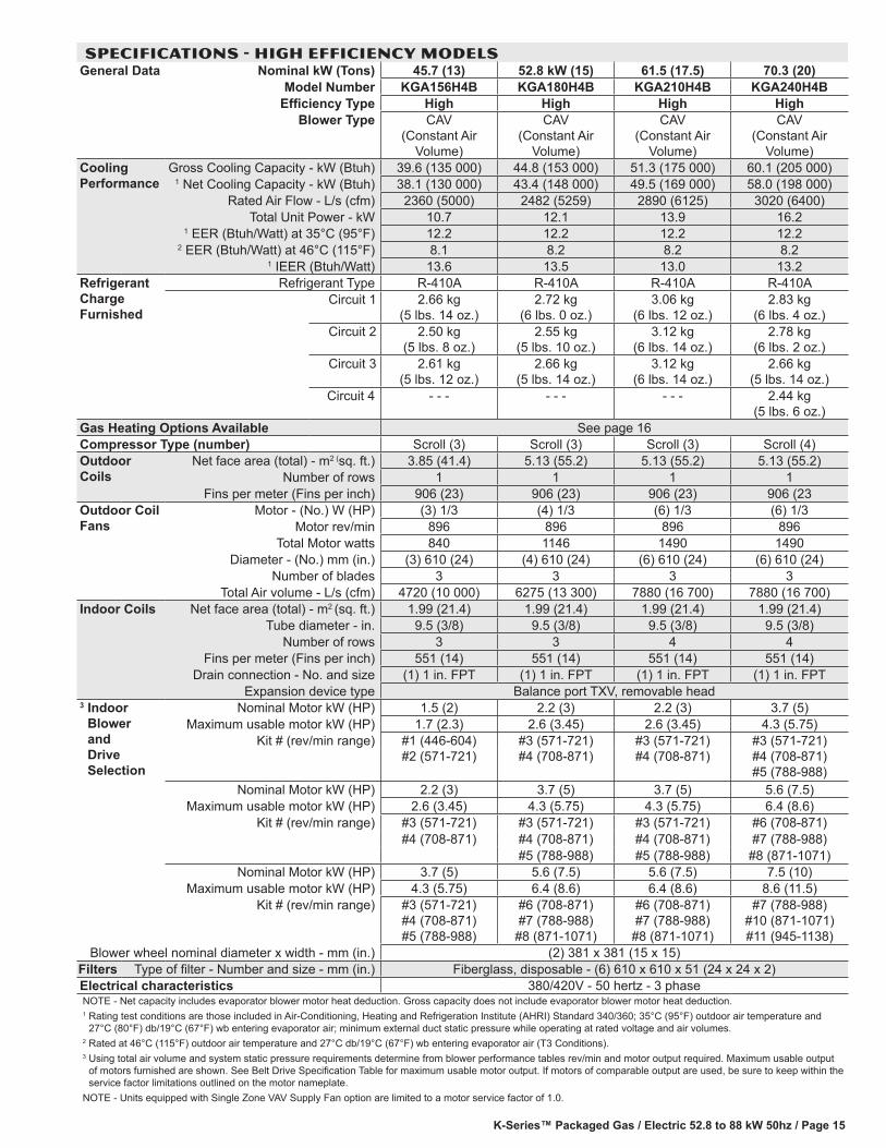
SPECIFICATIONS - HIGH EFFICIENCY MODELSGeneral Data Nominal kW (Tons) 45.7 (13) 52.8 kW (15) 61.5 (17.5) 70.3 (20)
Model Number KGA156H4B KGA180H4B KGA210H4B KGA240H4BEfficiency Type High High High High
Blower Type CAV (Constant Air
Volume)
CAV (Constant Air
Volume)
CAV (Constant Air
Volume)
CAV (Constant Air
Volume)Cooling Performance
Gross Cooling Capacity - kW (Btuh) 39.6 (135 000) 44.8 (153 000) 51.3 (175 000) 60.1 (205 000)1 Net Cooling Capacity - kW (Btuh) 38.1 (130 000) 43.4 (148 000) 49.5 (169 000) 58.0 (198 000)
Rated Air Flow - L/s (cfm) 2360 (5000) 2482 (5259) 2890 (6125) 3020 (6400)Total Unit Power - kW 10.7 12.1 13.9 16.2
1 EER (Btuh/Watt) at 35°C (95°F) 12.2 12.2 12.2 12.22 EER (Btuh/Watt) at 46°C (115°F) 8.1 8.2 8.2 8.2
1 IEER (Btuh/Watt) 13.6 13.5 13.0 13.2Refrigerant Charge Furnished
Refrigerant Type R-410A R-410A R-410A R-410ACircuit 1 2.66 kg
(5 lbs. 14 oz.)2.72 kg
(6 lbs. 0 oz.)3.06 kg
(6 lbs. 12 oz.)2.83 kg
(6 lbs. 4 oz.)Circuit 2 2.50 kg
(5 lbs. 8 oz.)2.55 kg
(5 lbs. 10 oz.)3.12 kg
(6 lbs. 14 oz.)2.78 kg
(6 lbs. 2 oz.)Circuit 3 2.61 kg
(5 lbs. 12 oz.)2.66 kg
(5 lbs. 14 oz.)3.12 kg
(6 lbs. 14 oz.)2.66 kg
(5 lbs. 14 oz.)Circuit 4 - - - - - - - - - 2.44 kg
(5 lbs. 6 oz.)Gas Heating Options Available See page 16Compressor Type (number) Scroll (3) Scroll (3) Scroll (3) Scroll (4)Outdoor Coils
Net face area (total) - m2 (sq. ft.) 3.85 (41.4) 5.13 (55.2) 5.13 (55.2) 5.13 (55.2)Number of rows 1 1 1 1
Fins per meter (Fins per inch) 906 (23) 906 (23) 906 (23) 906 (23Outdoor Coil Fans
Motor - (No.) W (HP) (3) 1/3 (4) 1/3 (6) 1/3 (6) 1/3Motor rev/min 896 896 896 896
Total Motor watts 840 1146 1490 1490Diameter - (No.) mm (in.) (3) 610 (24) (4) 610 (24) (6) 610 (24) (6) 610 (24)
Number of blades 3 3 3 3Total Air volume - L/s (cfm) 4720 (10 000) 6275 (13 300) 7880 (16 700) 7880 (16 700)
Indoor Coils Net face area (total) - m2 (sq. ft.) 1.99 (21.4) 1.99 (21.4) 1.99 (21.4) 1.99 (21.4)Tube diameter - in. 9.5 (3/8) 9.5 (3/8) 9.5 (3/8) 9.5 (3/8)
Number of rows 3 3 4 4Fins per meter (Fins per inch) 551 (14) 551 (14) 551 (14) 551 (14)
Drain connection - No. and size (1) 1 in. FPT (1) 1 in. FPT (1) 1 in. FPT (1) 1 in. FPTExpansion device type Balance port TXV, removable head
3 Indoor Blower and Drive Selection
Nominal Motor kW (HP) 1.5 (2) 2.2 (3) 2.2 (3) 3.7 (5)Maximum usable motor kW (HP) 1.7 (2.3) 2.6 (3.45) 2.6 (3.45) 4.3 (5.75)
Kit # (rev/min range) #1 (446-604) #2 (571-721)
#3 (571-721) #4 (708-871)
#3 (571-721) #4 (708-871)
#3 (571-721) #4 (708-871) #5 (788-988)
Nominal Motor kW (HP) 2.2 (3) 3.7 (5) 3.7 (5) 5.6 (7.5)Maximum usable motor kW (HP) 2.6 (3.45) 4.3 (5.75) 4.3 (5.75) 6.4 (8.6)
Kit # (rev/min range) #3 (571-721) #3 (571-721) #3 (571-721) #6 (708-871)#4 (708-871) #4 (708-871) #4 (708-871) #7 (788-988)
#5 (788-988) #5 (788-988) #8 (871-1071)Nominal Motor kW (HP) 3.7 (5) 5.6 (7.5) 5.6 (7.5) 7.5 (10)
Maximum usable motor kW (HP) 4.3 (5.75) 6.4 (8.6) 6.4 (8.6) 8.6 (11.5)Kit # (rev/min range) #3 (571-721)
#4 (708-871) #5 (788-988)
#6 (708-871) #7 (788-988)
#8 (871-1071)
#6 (708-871) #7 (788-988)
#8 (871-1071)
#7 (788-988) #10 (871-1071) #11 (945-1138)
Blower wheel nominal diameter x width - mm (in.) (2) 381 x 381 (15 x 15)Filters Type of filter - Number and size - mm (in.) Fiberglass, disposable - (6) 610 x 610 x 51 (24 x 24 x 2)Electrical characteristics 380/420V - 50 hertz - 3 phaseNOTE - Net capacity includes evaporator blower motor heat deduction. Gross capacity does not include evaporator blower motor heat deduction.1 Rating test conditions are those included in Air-Conditioning, Heating and Refrigeration Institute (AHRI) Standard 340/360; 35°C (95°F) outdoor air temperature and
27°C (80°F) db/19°C (67°F) wb entering evaporator air; minimum external duct static pressure while operating at rated voltage and air volumes.2 Rated at 46°C (115°F) outdoor air temperature and 27°C db/19°C (67°F) wb entering evaporator air (T3 Conditions).3 Using total air volume and system static pressure requirements determine from blower performance tables rev/min and motor output required. Maximum usable output
of motors furnished are shown. See Belt Drive Specification Table for maximum usable motor output. If motors of comparable output are used, be sure to keep within the service factor limitations outlined on the motor nameplate.
NOTE - Units equipped with Single Zone VAV Supply Fan option are limited to a motor service factor of 1.0.
K-Series™ Packaged Gas / Electric 52.8 to 88 kW 50hz / Page 16
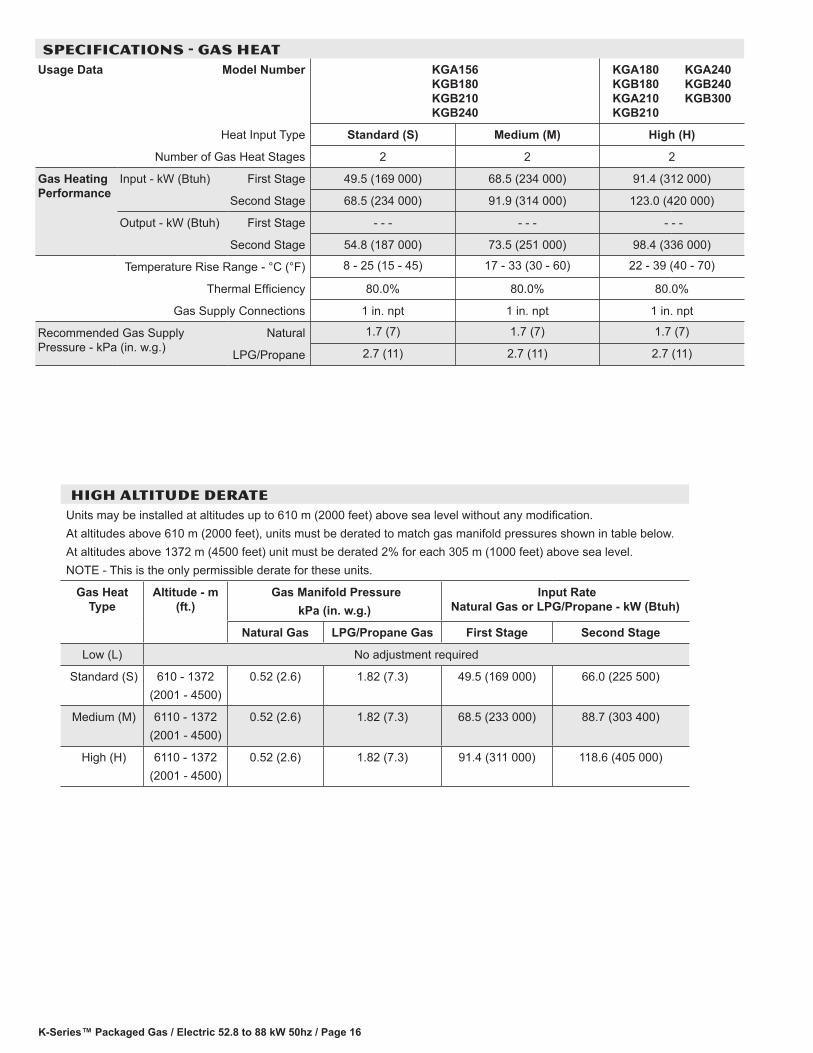
SPECIFICATIONS - GAS HEATUsage Data Model Number KGA156
KGB180 KGB210 KGB240
KGA180 KGB180 KGA210 KGB210
KGA240 KGB240 KGB300
Heat Input Type Standard (S) Medium (M) High (H)
Number of Gas Heat Stages 2 2 2
Gas Heating Performance
Input - kW (Btuh) First Stage 49.5 (169 000) 68.5 (234 000) 91.4 (312 000)
Second Stage 68.5 (234 000) 91.9 (314 000) 123.0 (420 000)
Output - kW (Btuh) First Stage - - - - - - - - -
Second Stage 54.8 (187 000) 73.5 (251 000) 98.4 (336 000)
Temperature Rise Range - °C (°F) 8 - 25 (15 - 45) 17 - 33 (30 - 60) 22 - 39 (40 - 70)
Thermal Efficiency 80.0% 80.0% 80.0%
Gas Supply Connections 1 in. npt 1 in. npt 1 in. npt
Recommended Gas Supply Pressure - kPa (in. w.g.)
Natural 1.7 (7) 1.7 (7) 1.7 (7)
LPG/Propane 2.7 (11) 2.7 (11) 2.7 (11)
HIGH ALTITUDE DERATE Units may be installed at altitudes up to 610 m (2000 feet) above sea level without any modification.At altitudes above 610 m (2000 feet), units must be derated to match gas manifold pressures shown in table below.At altitudes above 1372 m (4500 feet) unit must be derated 2% for each 305 m (1000 feet) above sea level.NOTE - This is the only permissible derate for these units.
Gas Heat Type
Altitude - m (ft.)
Gas Manifold PressurekPa (in. w.g.)
Input Rate Natural Gas or LPG/Propane - kW (Btuh)
Natural Gas LPG/Propane Gas First Stage Second Stage
Low (L) No adjustment required
Standard (S) 610 - 1372(2001 - 4500)
0.52 (2.6) 1.82 (7.3) 49.5 (169 000) 66.0 (225 500)
Medium (M) 6110 - 1372(2001 - 4500)
0.52 (2.6) 1.82 (7.3) 68.5 (233 000) 88.7 (303 400)
High (H) 6110 - 1372(2001 - 4500)
0.52 (2.6) 1.82 (7.3) 91.4 (311 000) 118.6 (405 000)
K-Series™ Packaged Gas / Electric 52.8 to 88 kW 50hz / Page 17
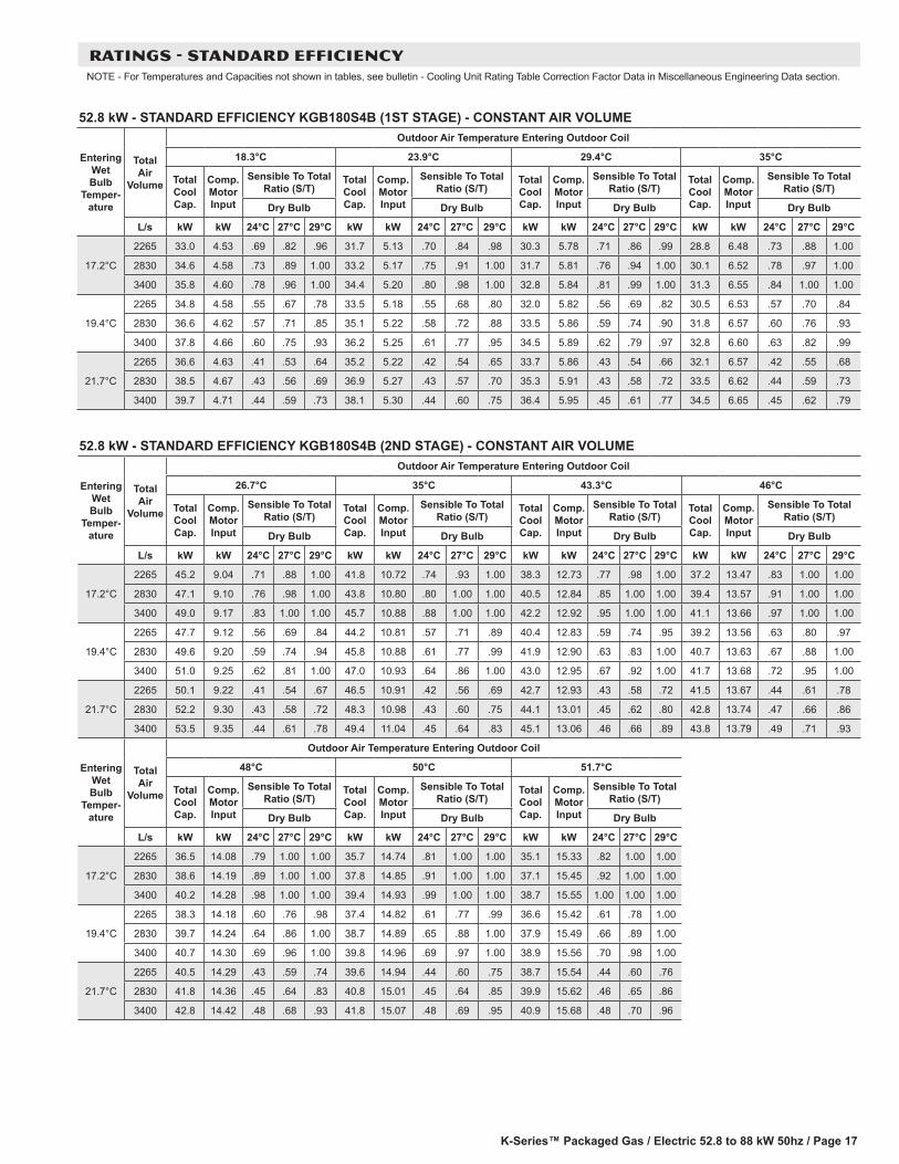
RATINGS - STANDARD EFFICIENCYNOTE - For Temperatures and Capacities not shown in tables, see bulletin - Cooling Unit Rating Table Correction Factor Data in Miscellaneous Engineering Data section.
52.8 kW - STANDARD EFFICIENCY KGB180S4B (1ST STAGE) - CONSTANT AIR VOLUME
Entering Wet Bulb
Temper-ature
Total Air
Volume
Outdoor Air Temperature Entering Outdoor Coil
18.3°C 23.9°C 29.4°C 35°C
Total Cool Cap.
Comp. Motor Input
Sensible To Total Ratio (S/T)
Total Cool Cap.
Comp. Motor Input
Sensible To Total Ratio (S/T)
Total Cool Cap.
Comp. Motor Input
Sensible To Total Ratio (S/T)
Total Cool Cap.
Comp. Motor Input
Sensible To Total Ratio (S/T)
Dry Bulb Dry Bulb Dry Bulb Dry Bulb
L/s kW kW 24°C 27°C 29°C kW kW 24°C 27°C 29°C kW kW 24°C 27°C 29°C kW kW 24°C 27°C 29°C
17.2°C
2265 33.0 4.53 .69 .82 .96 31.7 5.13 .70 .84 .98 30.3 5.78 .71 .86 .99 28.8 6.48 .73 .88 1.00
2830 34.6 4.58 .73 .89 1.00 33.2 5.17 .75 .91 1.00 31.7 5.81 .76 .94 1.00 30.1 6.52 .78 .97 1.00
3400 35.8 4.60 .78 .96 1.00 34.4 5.20 .80 .98 1.00 32.8 5.84 .81 .99 1.00 31.3 6.55 .84 1.00 1.00
19.4°C
2265 34.8 4.58 .55 .67 .78 33.5 5.18 .55 .68 .80 32.0 5.82 .56 .69 .82 30.5 6.53 .57 .70 .84
2830 36.6 4.62 .57 .71 .85 35.1 5.22 .58 .72 .88 33.5 5.86 .59 .74 .90 31.8 6.57 .60 .76 .93
3400 37.8 4.66 .60 .75 .93 36.2 5.25 .61 .77 .95 34.5 5.89 .62 .79 .97 32.8 6.60 .63 .82 .99
21.7°C
2265 36.6 4.63 .41 .53 .64 35.2 5.22 .42 .54 .65 33.7 5.86 .43 .54 .66 32.1 6.57 .42 .55 .68
2830 38.5 4.67 .43 .56 .69 36.9 5.27 .43 .57 .70 35.3 5.91 .43 .58 .72 33.5 6.62 .44 .59 .73
3400 39.7 4.71 .44 .59 .73 38.1 5.30 .44 .60 .75 36.4 5.95 .45 .61 .77 34.5 6.65 .45 .62 .79
52.8 kW - STANDARD EFFICIENCY KGB180S4B (2ND STAGE) - CONSTANT AIR VOLUME
Entering Wet Bulb
Temper-ature
Total Air
Volume
Outdoor Air Temperature Entering Outdoor Coil
26.7°C 35°C 43.3°C 46°C
Total Cool Cap.
Comp. Motor Input
Sensible To Total Ratio (S/T)
Total Cool Cap.
Comp. Motor Input
Sensible To Total Ratio (S/T)
Total Cool Cap.
Comp. Motor Input
Sensible To Total Ratio (S/T)
Total Cool Cap.
Comp. Motor Input
Sensible To Total Ratio (S/T)
Dry Bulb Dry Bulb Dry Bulb Dry Bulb
L/s kW kW 24°C 27°C 29°C kW kW 24°C 27°C 29°C kW kW 24°C 27°C 29°C kW kW 24°C 27°C 29°C
17.2°C
2265 45.2 9.04 .71 .88 1.00 41.8 10.72 .74 .93 1.00 38.3 12.73 .77 .98 1.00 37.2 13.47 .83 1.00 1.00
2830 47.1 9.10 .76 .98 1.00 43.8 10.80 .80 1.00 1.00 40.5 12.84 .85 1.00 1.00 39.4 13.57 .91 1.00 1.00
3400 49.0 9.17 .83 1.00 1.00 45.7 10.88 .88 1.00 1.00 42.2 12.92 .95 1.00 1.00 41.1 13.66 .97 1.00 1.00
19.4°C
2265 47.7 9.12 .56 .69 .84 44.2 10.81 .57 .71 .89 40.4 12.83 .59 .74 .95 39.2 13.56 .63 .80 .97
2830 49.6 9.20 .59 .74 .94 45.8 10.88 .61 .77 .99 41.9 12.90 .63 .83 1.00 40.7 13.63 .67 .88 1.00
3400 51.0 9.25 .62 .81 1.00 47.0 10.93 .64 .86 1.00 43.0 12.95 .67 .92 1.00 41.7 13.68 .72 .95 1.00
21.7°C
2265 50.1 9.22 .41 .54 .67 46.5 10.91 .42 .56 .69 42.7 12.93 .43 .58 .72 41.5 13.67 .44 .61 .78
2830 52.2 9.30 .43 .58 .72 48.3 10.98 .43 .60 .75 44.1 13.01 .45 .62 .80 42.8 13.74 .47 .66 .86
3400 53.5 9.35 .44 .61 .78 49.4 11.04 .45 .64 .83 45.1 13.06 .46 .66 .89 43.8 13.79 .49 .71 .93
Entering Wet Bulb
Temper-ature
Total Air
Volume
Outdoor Air Temperature Entering Outdoor Coil
48°C 50°C 51.7°C
Total Cool Cap.
Comp. Motor Input
Sensible To Total Ratio (S/T)
Total Cool Cap.
Comp. Motor Input
Sensible To Total Ratio (S/T)
Total Cool Cap.
Comp. Motor Input
Sensible To Total Ratio (S/T)
Dry Bulb Dry Bulb Dry Bulb
L/s kW kW 24°C 27°C 29°C kW kW 24°C 27°C 29°C kW kW 24°C 27°C 29°C
17.2°C
2265 36.5 14.08 .79 1.00 1.00 35.7 14.74 .81 1.00 1.00 35.1 15.33 .82 1.00 1.00
2830 38.6 14.19 .89 1.00 1.00 37.8 14.85 .91 1.00 1.00 37.1 15.45 .92 1.00 1.00
3400 40.2 14.28 .98 1.00 1.00 39.4 14.93 .99 1.00 1.00 38.7 15.55 1.00 1.00 1.00
19.4°C
2265 38.3 14.18 .60 .76 .98 37.4 14.82 .61 .77 .99 36.6 15.42 .61 .78 1.00
2830 39.7 14.24 .64 .86 1.00 38.7 14.89 .65 .88 1.00 37.9 15.49 .66 .89 1.00
3400 40.7 14.30 .69 .96 1.00 39.8 14.96 .69 .97 1.00 38.9 15.56 .70 .98 1.00
21.7°C
2265 40.5 14.29 .43 .59 .74 39.6 14.94 .44 .60 .75 38.7 15.54 .44 .60 .76
2830 41.8 14.36 .45 .64 .83 40.8 15.01 .45 .64 .85 39.9 15.62 .46 .65 .86
3400 42.8 14.42 .48 .68 .93 41.8 15.07 .48 .69 .95 40.9 15.68 .48 .70 .96
K-Series™ Packaged Gas / Electric 52.8 to 88 kW 50hz / Page 18
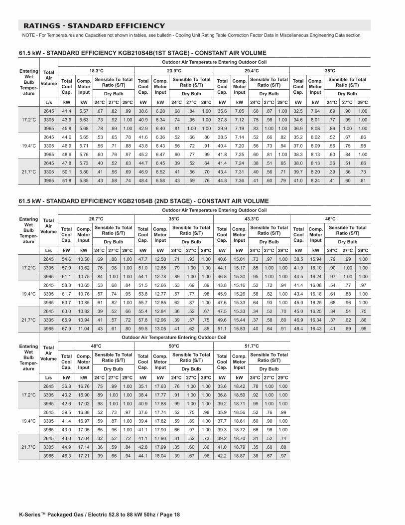
61.5 kW - STANDARD EFFICIENCY KGB210S4B(1ST STAGE) - CONSTANT AIR VOLUME
Entering Wet Bulb
Temper-ature
Total Air
Volume
Outdoor Air Temperature Entering Outdoor Coil
18.3°C 23.9°C 29.4°C 35°C
Total Cool Cap.
Comp. Motor Input
Sensible To Total Ratio (S/T)
Total Cool Cap.
Comp. Motor Input
Sensible To Total Ratio (S/T)
Total Cool Cap.
Comp. Motor Input
Sensible To Total Ratio (S/T)
Total Cool Cap.
Comp. Motor Input
Sensible To Total Ratio (S/T)
Dry Bulb Dry Bulb Dry Bulb Dry Bulb
L/s kW kW 24°C 27°C 29°C kW kW 24°C 27°C 29°C kW kW 24°C 27°C 29°C kW kW 24°C 27°C 29°C
17.2°C
2645 41.4 5.57 .67 .82 .99 38.6 6.28 .68 .84 1.00 35.6 7.05 .68 .87 1.00 32.5 7.94 .69 .90 1.00
3305 43.9 5.63 .73 .92 1.00 40.9 6.34 .74 .95 1.00 37.8 7.12 .75 .98 1.00 34.6 8.01 .77 .99 1.00
3965 45.8 5.68 .78 .99 1.00 42.9 6.40 .81 1.00 1.00 39.9 7.19 .83 1.00 1.00 36.9 8.08 .86 1.00 1.00
19.4°C
2645 44.6 5.65 .53 .65 .78 41.6 6.36 .52 .66 .80 38.5 7.14 .52 .66 .82 35.2 8.02 .52 .67 .86
3305 46.9 5.71 .56 .71 .88 43.8 6.43 .56 .72 .91 40.4 7.20 .56 .73 .94 37.0 8.09 .56 .75 .98
3965 48.6 5.76 .60 .76 .97 45.2 6.47 .60 .77 .99 41.8 7.25 .60 .81 1.00 38.3 8.13 .60 .84 1.00
21.7°C
2645 47.8 5.73 .40 .52 .63 44.7 6.45 .39 .52 .64 41.4 7.24 .38 .51 .65 38.0 8.13 .36 .51 .66
3305 50.1 5.80 .41 .56 .69 46.9 6.52 .41 .56 .70 43.4 7.31 .40 .56 .71 39.7 8.20 .39 .56 .73
3965 51.8 5.85 .43 .58 .74 48.4 6.58 .43 .59 .76 44.8 7.36 .41 .60 .79 41.0 8.24 .41 .60 .81
61.5 kW - STANDARD EFFICIENCY KGB210S4B (2ND STAGE) - CONSTANT AIR VOLUME
Entering Wet Bulb
Temper-ature
Total Air
Volume
Outdoor Air Temperature Entering Outdoor Coil
26.7°C 35°C 43.3°C 46°C
Total Cool Cap.
Comp. Motor Input
Sensible To Total Ratio (S/T)
Total Cool Cap.
Comp. Motor Input
Sensible To Total Ratio (S/T)
Total Cool Cap.
Comp. Motor Input
Sensible To Total Ratio (S/T)
Total Cool Cap.
Comp. Motor Input
Sensible To Total Ratio (S/T)
Dry Bulb Dry Bulb Dry Bulb Dry Bulb
L/s kW kW 24°C 27°C 29°C kW kW 24°C 27°C 29°C kW kW 24°C 27°C 29°C kW kW 24°C 27°C 29°C
17.2°C
2645 54.6 10.50 .69 .88 1.00 47.7 12.50 .71 .93 1.00 40.6 15.01 .73 .97 1.00 38.5 15.94 .79 .99 1.00
3305 57.9 10.62 .76 .98 1.00 51.0 12.65 .79 1.00 1.00 44.1 15.17 .85 1.00 1.00 41.9 16.10 .90 1.00 1.00
3965 61.1 10.75 .84 1.00 1.00 54.1 12.78 .89 1.00 1.00 46.8 15.30 .95 1.00 1.00 44.5 16.24 .97 1.00 1.00
19.4°C
2645 58.8 10.65 .53 .68 .84 51.5 12.66 .53 .69 .89 43.8 15.16 .52 .72 .94 41.4 16.08 .54 .77 .97
3305 61.7 10.76 .57 .74 .95 53.8 12.77 .57 .77 .98 45.9 15.26 .58 .82 1.00 43.4 16.18 .61 .88 1.00
3965 63.7 10.85 .61 .82 1.00 55.7 12.85 .62 .87 1.00 47.6 15.33 .64 .93 1.00 45.0 16.25 .68 .96 1.00
21.7°C
2645 63.0 10.82 .39 .52 .66 55.4 12.84 .36 .52 .67 47.5 15.33 .34 .52 .70 45.0 16.25 .34 .54 .75
3305 65.9 10.94 .41 .57 .72 57.8 12.96 .39 .57 .75 49.6 15.44 .37 .58 .80 46.9 16.34 .37 .62 .86
3965 67.9 11.04 .43 .61 .80 59.5 13.05 .41 .62 .85 51.1 15.53 .40 .64 .91 48.4 16.43 .41 .69 .95
Entering Wet Bulb
Temper-ature
Total Air
Volume
Outdoor Air Temperature Entering Outdoor Coil
48°C 50°C 51.7°C
Total Cool Cap.
Comp. Motor Input
Sensible To Total Ratio (S/T)
Total Cool Cap.
Comp. Motor Input
Sensible To Total Ratio (S/T)
Total Cool Cap.
Comp. Motor Input
Sensible To Total Ratio (S/T)
Dry Bulb Dry Bulb Dry Bulb
L/s kW kW 24°C 27°C 29°C kW kW 24°C 27°C 29°C kW kW 24°C 27°C 29°C
17.2°C
2645 36.8 16.76 .75 .99 1.00 35.1 17.63 .76 1.00 1.00 33.6 18.42 .78 1.00 1.00
3305 40.2 16.90 .89 1.00 1.00 38.4 17.77 .91 1.00 1.00 36.8 18.59 .92 1.00 1.00
3965 42.6 17.02 .98 1.00 1.00 40.9 17.88 .99 1.00 1.00 39.2 18.71 .99 1.00 1.00
19.4°C
2645 39.5 16.88 .52 .73 .97 37.6 17.74 .52 .75 .98 35.9 18.56 .52 .76 .99
3305 41.4 16.97 .59 .87 1.00 39.4 17.82 .59 .89 1.00 37.7 18.61 .60 .90 1.00
3965 43.0 17.05 .65 .96 1.00 41.1 17.90 .66 .97 1.00 39.3 18.72 .66 .98 1.00
21.7°C
2645 43.0 17.04 .32 .52 .72 41.1 17.90 .31 .52 .73 39.2 18.70 .31 .52 .74
3305 44.9 17.14 .36 .59 .84 42.8 17.99 .35 .60 .86 41.0 18.79 .35 .60 .88
3965 46.3 17.21 .39 .66 .94 44.1 18.04 .39 .67 .96 42.2 18.87 .38 .67 .97
RATINGS - STANDARD EFFICIENCYNOTE - For Temperatures and Capacities not shown in tables, see bulletin - Cooling Unit Rating Table Correction Factor Data in Miscellaneous Engineering Data section.

K-Series™ Packaged Gas / Electric 52.8 to 88 kW 50hz / Page 19
RATINGS - STANDARD EFFICIENCYNOTE - For Temperatures and Capacities not shown in tables, see bulletin - Cooling Unit Rating Table Correction Factor Data in Miscellaneous Engineering Data section.
70.3 kW - STANDARD EFFICIENCY KGB240S4B (1ST STAGE) - CONSTANT AIR VOLUME
Entering Wet Bulb
Temper-ature
Total Air
Volume
Outdoor Air Temperature Entering Outdoor Coil
18.3°C 23.9°C 29.4°C 35°C
Total Cool Cap.
Comp. Motor Input
Sensible To Total Ratio (S/T)
Total Cool Cap.
Comp. Motor Input
Sensible To Total Ratio (S/T)
Total Cool Cap.
Comp. Motor Input
Sensible To Total Ratio (S/T)
Total Cool Cap.
Comp. Motor Input
Sensible To Total Ratio (S/T)
Dry Bulb Dry Bulb Dry Bulb Dry Bulb
L/s kW kW 24°C 27°C 29°C kW kW 24°C 27°C 29°C kW kW 24°C 27°C 29°C kW kW 24°C 27°C 29°C
17.2°C
3020 44.2 6.24 .73 .88 1.00 41.9 6.94 .74 .89 1.00 39.4 7.71 .76 .91 1.00 36.8 8.57 .77 .94 1.00
3775 46.4 6.26 .79 .95 1.00 44.0 6.97 .81 .97 1.00 41.4 7.74 .82 .99 1.00 38.7 8.60 .84 1.00 1.00
4530 48.2 6.29 .85 1.00 1.00 45.8 7.00 .86 1.00 1.00 43.5 7.78 .88 1.00 1.00 40.9 8.64 .91 1.00 1.00
19.4°C
3020 47.0 6.27 .58 .71 .84 44.6 6.98 .58 .72 .86 42.0 7.75 .59 .74 .88 39.3 8.61 .60 .75 .91
3775 49.2 6.30 .62 .77 .92 46.6 7.01 .62 .79 .94 43.8 7.79 .63 .80 .97 40.9 8.64 .63 .82 .99
4530 50.8 6.32 .65 .83 .99 48.0 7.03 .65 .84 1.00 45.1 7.81 .66 .86 1.00 42.0 8.67 .67 .89 1.00
21.7°C
3020 49.9 6.30 .43 .56 .69 47.4 7.03 .43 .57 .70 44.7 7.80 .43 .58 .71 41.8 8.67 .42 .59 .73
3775 52.3 6.34 .46 .61 .75 49.5 7.06 .45 .61 .77 46.5 7.84 .45 .62 .78 43.3 8.70 .45 .62 .80
4530 53.7 6.36 .47 .64 .81 50.8 7.08 .47 .64 .82 47.7 7.86 .47 .66 .84 44.5 8.73 .46 .67 .87
70.3 kW - STANDARD EFFICIENCY KGB240S4B (2ND STAGE) - CONSTANT AIR VOLUME
Entering Wet Bulb
Temper-ature
Total Air
Volume
Outdoor Air Temperature Entering Outdoor Coil
26.7°C 35°C 43.3°C 46°C
Total Cool Cap.
Comp. Motor Input
Sensible To Total Ratio (S/T)
Total Cool Cap.
Comp. Motor Input
Sensible To Total Ratio (S/T)
Total Cool Cap.
Comp. Motor Input
Sensible To Total Ratio (S/T)
Total Cool Cap.
Comp. Motor Input
Sensible To Total Ratio (S/T)
Dry Bulb Dry Bulb Dry Bulb Dry Bulb
L/s kW kW 24°C 27°C 29°C kW kW 24°C 27°C 29°C kW kW 24°C 27°C 29°C kW kW 24°C 27°C 29°C
17.2°C
3020 63.0 12.24 .77 .93 1.00 56.6 14.28 .79 .96 1.00 50.3 16.76 .82 .98 1.00 48.5 17.67 .83 .99 1.00
3775 66.2 12.35 .83 .99 1.00 60.0 14.40 .87 1.00 1.00 53.6 16.89 .91 1.00 1.00 51.6 17.80 .92 1.00 1.00
4530 69.3 12.44 .90 1.00 1.00 62.8 14.51 .93 1.00 1.00 56.2 17.00 .97 1.00 1.00 54.2 17.91 .98 1.00 1.00
19.4°C
3020 67.1 12.38 .59 .75 .90 60.3 14.43 .60 .77 .93 53.4 16.89 .61 .80 .97 51.2 17.79 .61 .81 .98
3775 69.8 12.48 .63 .82 .97 62.7 14.52 .65 .85 .99 55.4 16.98 .66 .89 1.00 53.2 17.88 .67 .90 1.00
4530 71.8 12.55 .68 .88 1.00 64.4 14.59 .69 .92 1.00 57.1 17.06 .72 .96 1.00 54.8 17.95 .73 .97 1.00
21.7°C
3020 71.2 12.52 .43 .59 .73 64.2 14.57 .43 .59 .75 56.9 17.05 .42 .60 .78 54.7 17.94 .41 .61 .79
3775 74.0 12.62 .45 .63 .80 66.5 14.68 .45 .64 .83 59.0 17.13 .44 .66 .87 56.7 18.03 .44 .66 .88
4530 76.0 12.69 .47 .67 .86 68.3 14.75 .47 .69 .90 60.4 17.20 .47 .72 .95 58.1 18.10 .46 .73 .96
Entering Wet Bulb
Temper-ature
Total Air
Volume
Outdoor Air Temperature Entering Outdoor Coil
48°C 50°C 51.7°C
Total Cool Cap.
Comp. Motor Input
Sensible To Total Ratio (S/T)
Total Cool Cap.
Comp. Motor Input
Sensible To Total Ratio (S/T)
Total Cool Cap.
Comp. Motor Input
Sensible To Total Ratio (S/T)
Dry Bulb Dry Bulb Dry Bulb
L/s kW kW 24°C 27°C 29°C kW kW 24°C 27°C 29°C kW kW 24°C 27°C 29°C
17.2°C
3020 47.1 18.44 .84 .99 1.00 45.6 19.25 .85 1.00 1.00 44.5 20.01 .86 1.00 1.00
3775 50.1 18.56 .93 1.00 1.00 48.8 19.37 .94 1.00 1.00 47.7 20.14 .95 1.00 1.00
4530 52.7 18.67 .98 1.00 1.00 51.2 19.48 .99 1.00 1.00 49.9 20.24 .99 1.00 1.00
19.4°C
3020 49.6 18.55 .61 .82 .98 48.0 19.36 .61 .83 .98 46.7 20.12 .62 .83 .99
3775 51.6 18.63 .67 .91 1.00 50.1 19.45 .67 .92 1.00 48.7 20.21 .68 .93 1.00
4530 53.0 18.70 .73 .98 1.00 51.5 19.50 .74 .98 1.00 50.1 20.24 .74 .98 1.00
21.7°C
3020 53.0 18.71 .41 .61 .80 51.4 19.50 .41 .61 .81 50.1 20.27 .40 .62 .81
3775 54.9 18.78 .44 .67 .89 53.3 19.58 .44 .67 .91 51.9 20.33 .43 .68 .91
4530 56.3 18.85 .47 .73 .97 54.6 19.64 .47 .74 .97 53.1 20.39 .47 .74 .98

K-Series™ Packaged Gas / Electric 52.8 to 88 kW 50hz / Page 20
88 kW - STANDARD EFFICIENCY KGB300S4B (1ST STAGE) - CONSTANT AIR VOLUME
Entering Wet Bulb
Temper-ature
Total Air
Volume
Outdoor Air Temperature Entering Outdoor Coil
18.3°C 23.9°C 29.4°C 35°C
Total Cool Cap.
Comp. Motor Input
Sensible To Total Ratio (S/T)
Total Cool Cap.
Comp. Motor Input
Sensible To Total Ratio (S/T)
Total Cool Cap.
Comp. Motor Input
Sensible To Total Ratio (S/T)
Total Cool Cap.
Comp. Motor Input
Sensible To Total Ratio (S/T)
Dry Bulb Dry Bulb Dry Bulb Dry Bulb
L/s kW kW 24°C 27°C 29°C kW kW 24°C 27°C 29°C kW kW 24°C 27°C 29°C kW kW 24°C 27°C 29°C
17.2°C
3775 38 5.26 0.72 0.87 0.99 36.3 5.94 0.74 0.9 1 34.7 6.71 0.75 0.92 1 33.3 7.59 0.78 0.95 1
4485 39.4 5.3 0.76 0.93 1 37.6 5.99 0.79 0.96 1 35.9 6.76 0.8 0.98 1 34.4 7.64 0.82 0.99 1
5190 40.5 5.34 0.81 0.98 1 38.6 6.03 0.83 0.99 1 37 6.8 0.85 1 1 35.5 7.68 0.87 1 1
19.4°C
3775 40.1 5.33 0.57 0.7 0.84 38.2 6.02 0.58 0.71 0.86 36.6 6.79 0.59 0.74 0.88 35 7.66 0.6 0.75 0.91
4485 41.4 5.37 0.59 0.74 0.9 39.6 6.07 0.61 0.77 0.93 37.7 6.83 0.62 0.78 0.95 36 7.7 0.63 0.8 0.97
5190 42.5 5.41 0.62 0.79 0.96 40.4 6.1 0.64 0.81 0.98 38.5 6.86 0.64 0.83 0.99 36.7 7.74 0.65 0.85 1
21.7°C
3775 42.5 5.41 0.43 0.56 0.68 40.5 6.1 0.43 0.57 0.69 38.6 6.87 0.45 0.58 0.72 36.9 7.75 0.44 0.59 0.73
4485 43.7 5.46 0.44 0.58 0.72 41.7 6.15 0.44 0.6 0.74 39.8 6.92 0.45 0.61 0.76 37.9 7.8 0.45 0.62 0.78
5190 44.7 5.5 0.44 0.61 0.76 42.6 6.19 0.44 0.63 0.78 40.5 6.95 0.45 0.63 0.8 38.6 7.83 0.47 0.65 0.83
RATINGS - STANDARD EFFICIENCYNOTE - For Temperatures and Capacities not shown in tables, see bulletin - Cooling Unit Rating Table Correction Factor Data in Miscellaneous Engineering Data section.
88 kW - STANDARD EFFICIENCY KGB300S4B (2ND STAGE) - CONSTANT AIR VOLUME
Entering Wet Bulb
Temper-ature
Total Air
Volume
Outdoor Air Temperature Entering Outdoor Coil
26.7°C 35°C 43.3°C 46°C
Total Cool Cap.
Comp. Motor Input
Sensible To Total Ratio (S/T)
Total Cool Cap.
Comp. Motor Input
Sensible To Total Ratio (S/T)
Total Cool Cap.
Comp. Motor Input
Sensible To Total Ratio (S/T)
Total Cool Cap.
Comp. Motor Input
Sensible To Total Ratio (S/T)
Dry Bulb Dry Bulb Dry Bulb Dry Bulb
L/s kW kW 24°C 27°C 29°C kW kW 24°C 27°C 29°C kW kW 24°C 27°C 29°C kW kW 24°C 27°C 29°C
17.2°C
3775 73.2 14 0.76 0.92 1 68.2 16.58 0.78 0.96 1 63.1 19.77 0.81 0.99 1 61.5 20.96 .84 1.00 1.00
4485 75.6 14.13 0.8 0.98 1 70.4 16.71 0.83 1 1 65.6 19.94 0.87 1 1 64.1 21.14 .90 1.00 1.00
5190 77.8 14.25 0.85 1 1 72.9 16.86 0.88 1 1 67.8 20.08 0.93 1 1 66.3 21.29 .95 1.00 1.00
19.4°C
3775 77.2 14.22 0.59 0.73 0.88 71.8 16.8 0.61 0.76 0.92 66.4 19.98 0.62 0.79 0.97 64.6 21.17 .64 .82 .98
4485 79.5 14.35 0.62 0.78 0.95 73.8 16.92 0.64 0.81 0.99 68.1 20.1 0.66 0.85 1 66.3 21.28 .67 .88 1.00
5190 81.2 14.45 0.64 0.82 1 75.3 17.02 0.66 0.86 1 69.4 20.19 0.69 0.91 1 67.6 21.37 .71 .93 1.00
21.7°C
3775 81.5 14.46 0.44 0.58 0.71 75.8 17.05 0.44 0.6 0.74 70 20.23 0.45 0.62 0.77 68.1 21.41 .46 .63 .80
4485 83.8 14.6 0.45 0.61 0.76 77.7 17.16 0.46 0.63 0.79 71.7 20.34 0.47 0.65 0.83 69.8 21.53 .48 .67 .85
5190 85.5 14.69 0.46 0.64 0.8 79.2 17.26 0.47 0.65 0.84 73.1 20.43 0.48 0.68 0.88 71.0 21.61 .49 .71 .91
Entering Wet Bulb
Temper-ature
Total Air
Volume
Outdoor Air Temperature Entering Outdoor Coil
48°C 50°C 51.7°C
Total Cool Cap.
Comp. Motor Input
Sensible To Total Ratio (S/T)
Total Cool Cap.
Comp. Motor Input
Sensible To Total Ratio (S/T)
Total Cool Cap.
Comp. Motor Input
Sensible To Total Ratio (S/T)
Dry Bulb Dry Bulb Dry Bulb
L/s kW kW 24°C 27°C 29°C kW kW 24°C 27°C 29°C kW kW 24°C 27°C 29°C
17.2°C
3775 60.2 21.98 .83 1.00 1.00 59.0 23.07 .84 1.00 1.00 58 24.1 0.85 1 1
4485 62.8 22.16 .90 1.00 1.00 61.6 23.26 .91 1.00 1.00 60.5 24.27 0.92 1 1
5190 64.9 22.29 .96 1.00 1.00 63.5 23.39 .97 1.00 1.00 62.4 24.4 0.98 1 1
19.4°C
3775 63.2 22.18 .63 .81 .99 61.8 23.27 .64 .82 1.00 60.4 24.25 0.65 0.83 1
4485 64.9 22.29 .67 .87 1.00 63.3 23.37 .68 .88 1.00 62 24.38 0.68 0.9 1
5190 66.1 22.37 .70 .94 1.00 64.6 23.46 .71 .95 1.00 63.2 24.45 0.72 0.96 1
21.7°C
3775 66.7 22.43 .46 .63 .79 65.1 23.50 .46 .63 .80 63.8 24.49 0.47 0.64 0.81
4485 68.2 22.52 .48 .66 .85 66.7 23.61 .48 .67 .86 65.4 24.61 0.48 0.68 0.88
5190 69.4 22.62 .49 .70 .92 67.8 23.69 .49 .70 .93 66.4 24.68 0.49 0.71 0.94
K-Series™ Packaged Gas / Electric 52.8 to 88 kW 50hz / Page 21
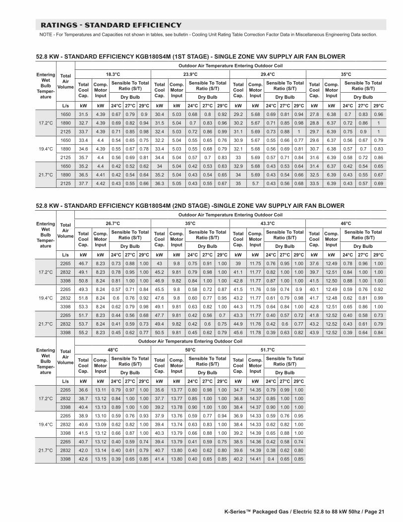
52.8 KW - STANDARD EFFICIENCY KGB180S4M (1ST STAGE) - SINGLE ZONE VAV SUPPLY AIR FAN BLOWER
Entering Wet Bulb
Temper-ature
Total Air
Volume
Outdoor Air Temperature Entering Outdoor Coil
18.3°C 23.9°C 29.4°C 35°C
Total Cool Cap.
Comp. Motor Input
Sensible To Total Ratio (S/T)
Total Cool Cap.
Comp. Motor Input
Sensible To Total Ratio (S/T)
Total Cool Cap.
Comp. Motor Input
Sensible To Total Ratio (S/T)
Total Cool Cap.
Comp. Motor Input
Sensible To Total Ratio (S/T)
Dry Bulb Dry Bulb Dry Bulb Dry Bulb
L/s kW kW 24°C 27°C 29°C kW kW 24°C 27°C 29°C kW kW 24°C 27°C 29°C kW kW 24°C 27°C 29°C
17.2°C
1650 31.5 4.39 0.67 0.79 0.9 30.4 5.03 0.68 0.8 0.92 29.2 5.68 0.69 0.81 0.94 27.8 6.38 0.7 0.83 0.96
1890 32.7 4.39 0.69 0.82 0.94 31.5 5.04 0.7 0.83 0.96 30.2 5.67 0.71 0.85 0.98 28.8 6.37 0.72 0.86 1
2125 33.7 4.39 0.71 0.85 0.98 32.4 5.03 0.72 0.86 0.99 31.1 5.69 0.73 0.88 1 29.7 6.39 0.75 0.9 1
19.4°C
1650 33.4 4.4 0.54 0.65 0.75 32.2 5.04 0.55 0.65 0.76 30.9 5.67 0.55 0.66 0.77 29.6 6.37 0.56 0.67 0.79
1890 34.6 4.39 0.55 0.67 0.78 33.4 5.03 0.55 0.68 0.79 32.1 5.68 0.56 0.69 0.81 30.7 6.38 0.57 0.7 0.83
2125 35.7 4.4 0.56 0.69 0.81 34.4 5.04 0.57 0.7 0.83 33 5.69 0.57 0.71 0.84 31.6 6.39 0.58 0.72 0.86
21.7°C
1650 35.2 4.4 0.42 0.52 0.62 34 5.04 0.42 0.53 0.63 32.9 5.68 0.43 0.53 0.64 31.4 6.37 0.42 0.54 0.65
1890 36.5 4.41 0.42 0.54 0.64 35.2 5.04 0.43 0.54 0.65 34 5.69 0.43 0.54 0.66 32.5 6.39 0.43 0.55 0.67
2125 37.7 4.42 0.43 0.55 0.66 36.3 5.05 0.43 0.55 0.67 35 5.7 0.43 0.56 0.68 33.5 6.39 0.43 0.57 0.69
52.8 KW - STANDARD EFFICIENCY KGB180S4M (2ND STAGE) -SINGLE ZONE VAV SUPPLY AIR FAN BLOWER
Entering Wet Bulb
Temper-ature
Total Air
Volume
Outdoor Air Temperature Entering Outdoor Coil
26.7°C 35°C 43.3°C 46°C
Total Cool Cap.
Comp. Motor Input
Sensible To Total Ratio (S/T)
Total Cool Cap.
Comp. Motor Input
Sensible To Total Ratio (S/T)
Total Cool Cap.
Comp. Motor Input
Sensible To Total Ratio (S/T)
Total Cool Cap.
Comp. Motor Input
Sensible To Total Ratio (S/T)
Dry Bulb Dry Bulb Dry Bulb Dry Bulb
L/s kW kW 24°C 27°C 29°C kW kW 24°C 27°C 29°C kW kW 24°C 27°C 29°C kW kW 24°C 27°C 29°C
17.2°C
2265 46.7 8.23 0.73 0.88 1.00 43 9.8 0.75 0.91 1.00 39 11.75 0.76 0.95 1.00 37.6 12.49 0.78 0.96 1.00
2832 49.1 8.23 0.78 0.95 1.00 45.2 9.81 0.79 0.98 1.00 41.1 11.77 0.82 1.00 1.00 39.7 12.51 0.84 1.00 1.00
3398 50.8 8.24 0.81 1.00 1.00 46.9 9.82 0.84 1.00 1.00 42.8 11.77 0.87 1.00 1.00 41.5 12.50 0.88 1.00 1.00
19.4°C
2265 49.3 8.24 0.57 0.71 0.84 45.5 9.8 0.58 0.72 0.87 41.5 11.76 0.59 0.74 0.9 40.1 12.49 0.59 0.76 0.92
2832 51.8 8.24 0.6 0.76 0.92 47.6 9.8 0.60 0.77 0.95 43.2 11.77 0.61 0.79 0.98 41.7 12.48 0.62 0.81 0.99
3398 53.3 8.24 0.62 0.79 0.98 49.1 9.81 0.63 0.82 1.00 44.3 11.75 0.64 0.84 1.00 42.8 12.51 0.65 0.86 1.00
21.7°C
2265 51.7 8.23 0.44 0.56 0.68 47.7 9.81 0.42 0.56 0.7 43.3 11.77 0.40 0.57 0.72 41.8 12.52 0.40 0.58 0.73
2832 53.7 8.24 0.41 0.59 0.73 49.4 9.82 0.42 0.6 0.75 44.9 11.76 0.42 0.6 0.77 43.2 12.52 0.43 0.61 0.79
3398 55.2 8.23 0.45 0.62 0.77 50.5 9.81 0.45 0.62 0.79 45.6 11.78 0.39 0.63 0.82 43.9 12.52 0.39 0.64 0.84
Entering Wet Bulb
Temper-ature
Total Air
Volume
Outdoor Air Temperature Entering Outdoor Coil
48°C 50°C 51.7°C
Total Cool Cap.
Comp. Motor Input
Sensible To Total Ratio (S/T)
Total Cool Cap.
Comp. Motor Input
Sensible To Total Ratio (S/T)
Total Cool Cap.
Comp. Motor Input
Sensible To Total Ratio (S/T)
Dry Bulb Dry Bulb Dry Bulb
L/s kW kW 24°C 27°C 29°C kW kW 24°C 27°C 29°C kW kW 24°C 27°C 29°C
17.2°C
2265 36.6 13.11 0.79 0.97 1.00 35.6 13.77 0.80 0.98 1.00 34.7 14.35 0.79 0.99 1.00
2832 38.7 13.12 0.84 1.00 1.00 37.7 13.77 0.85 1.00 1.00 36.8 14.37 0.85 1.00 1.00
3398 40.4 13.13 0.89 1.00 1.00 39.2 13.78 0.90 1.00 1.00 38.4 14.37 0.90 1.00 1.00
19.4°C
2265 38.9 13.10 0.59 0.76 0.93 37.9 13.76 0.59 0.77 0.94 36.9 14.33 0.59 0.76 0.95
2832 40.6 13.09 0.62 0.82 1.00 39.4 13.74 0.63 0.83 1.00 38.4 14.33 0.62 0.82 1.00
3398 41.5 13.12 0.66 0.87 1.00 40.3 13.79 0.66 0.88 1.00 39.2 14.39 0.65 0.88 1.00
21.7°C
2265 40.7 13.12 0.40 0.59 0.74 39.4 13.79 0.41 0.59 0.75 38.5 14.36 0.42 0.58 0.74
2832 42.0 13.14 0.40 0.61 0.79 40.7 13.80 0.40 0.62 0.80 39.6 14.39 0.38 0.62 0.80
3398 42.6 13.15 0.39 0.65 0.85 41.4 13.80 0.40 0.65 0.85 40.2 14.41 0.4 0.65 0.85
RATINGS - STANDARD EFFICIENCYNOTE - For Temperatures and Capacities not shown in tables, see bulletin - Cooling Unit Rating Table Correction Factor Data in Miscellaneous Engineering Data section.
K-Series™ Packaged Gas / Electric 52.8 to 88 kW 50hz / Page 22
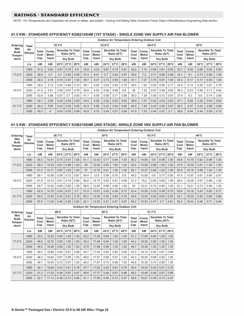
61.5 KW - STANDARD EFFICIENCY KGB210S4M (1ST STAGE) - SINGLE ZONE VAV SUPPLY AIR FAN BLOWER
Entering Wet Bulb
Temper-ature
Total Air
Volume
Outdoor Air Temperature Entering Outdoor Coil
18.3°C 23.9°C 29.4°C 35°C
Total Cool Cap.
Comp. Motor Input
Sensible To Total Ratio (S/T)
Total Cool Cap.
Comp. Motor Input
Sensible To Total Ratio (S/T)
Total Cool Cap.
Comp. Motor Input
Sensible To Total Ratio (S/T)
Total Cool Cap.
Comp. Motor Input
Sensible To Total Ratio (S/T)
Dry Bulb Dry Bulb Dry Bulb Dry Bulb
L/s kW kW 24°C 27°C 29°C kW kW 24°C 27°C 29°C kW kW 24°C 27°C 29°C kW kW 24°C 27°C 29°C
17.2°C
1890 37.2 5.62 0.67 0.78 0.9 35.8 6.33 0.67 0.79 0.91 34.2 7.12 0.68 0.81 0.93 32.7 8.02 0.69 0.83 0.95
2240 38.9 5.7 0.7 0.83 0.95 37.4 6.41 0.7 0.84 0.97 35.8 7.2 0.71 0.86 0.99 34.1 8.1 0.73 0.88 1.00
2595 40.3 5.76 0.73 0.87 1.00 38.7 6.47 0.73 0.89 1.00 37.1 7.27 0.75 0.91 1.00 35.3 8.17 0.77 0.93 1.00
19.4°C
1890 39.6 5.73 0.54 0.64 0.75 38.1 6.45 0.54 0.65 0.76 36.5 7.24 0.55 0.66 0.77 34.8 8.14 0.55 0.67 0.79
2240 41.4 5.81 0.56 0.67 0.79 39.8 6.52 0.56 0.68 0.8 38 7.32 0.57 0.69 0.82 36.3 8.23 0.58 0.71 0.84
2595 42.8 5.88 0.57 0.7 0.83 41.1 6.59 0.58 0.71 0.85 39.3 7.39 0.59 0.72 0.87 37.4 8.3 0.6 0.74 0.89
21.7°C
1890 42.1 5.85 0.42 0.52 0.62 40.5 6.56 0.42 0.52 0.63 38.9 7.37 0.42 0.53 0.63 37.1 8.28 0.42 0.54 0.64
2240 44.2 5.94 0.43 0.54 0.65 42.3 6.66 0.43 0.54 0.66 40.5 7.46 0.43 0.55 0.67 38.7 8.37 0.43 0.56 0.68
2595 45.5 6 0.43 0.55 0.68 43.8 6.73 0.44 0.57 0.69 41.8 7.53 0.44 0.57 0.7 39.9 8.44 0.44 0.59 0.72
61.5 KW - STANDARD EFFICIENCY KGB210S4M (2ND STAGE) -SINGLE ZONE VAV SUPPLY AIR FAN BLOWER
Entering Wet Bulb
Temper-ature
Total Air
Volume
Outdoor Air Temperature Entering Outdoor Coil
26.7°C 35°C 43.3°C 46°C
Total Cool Cap.
Comp. Motor Input
Sensible To Total Ratio (S/T)
Total Cool Cap.
Comp. Motor Input
Sensible To Total Ratio (S/T)
Total Cool Cap.
Comp. Motor Input
Sensible To Total Ratio (S/T)
Total Cool Cap.
Comp. Motor Input
Sensible To Total Ratio (S/T)
Dry Bulb Dry Bulb Dry Bulb Dry Bulb
L/s kW kW 24°C 27°C 29°C kW kW 24°C 27°C 29°C kW kW 24°C 27°C 29°C kW kW 24°C 27°C 29°C
17.2°C
1890 55.5 10.41 0.75 0.91 1.00 51.1 12.42 0.77 0.94 1.00 46.2 14.89 0.8 0.98 1.00 44.6 15.79 0.82 0.99 1.00
2240 58.4 10.55 0.81 0.99 1.00 54 12.58 0.84 1.00 1.00 49.4 15.09 0.88 1.00 1.00 47.9 16.00 0.91 1.00 1.00
2595 61.5 10.71 0.87 1.00 1.00 57 12.75 0.91 1.00 1.00 52.1 15.27 0.96 1.00 1.00 50.5 16.18 0.98 1.00 1.00
19.4°C
1890 59.1 10.58 0.58 0.72 0.87 54.4 12.6 0.59 0.75 0.9 49.2 15.08 0.6 0.77 0.95 47.4 15.97 0.61 0.80 0.97
2240 61.8 10.72 0.61 0.79 0.96 56.8 12.75 0.63 0.81 0.99 51.3 15.2 0.65 0.85 1.00 49.5 16.09 0.67 0.88 1.00
2595 63.7 10.83 0.66 0.85 1.00 58.5 12.85 0.68 0.89 1.00 53 15.31 0.70 0.94 1.00 51.1 16.21 0.73 0.96 1.00
21.7°C
1890 62.9 10.78 0.43 0.57 0.7 57.9 12.81 0.43 0.58 0.72 52.4 15.28 0.43 0.59 0.75 50.6 16.18 0.43 0.60 0.77
2240 65.6 10.93 0.45 0.61 0.76 60.2 12.95 0.45 0.62 0.79 54.6 15.42 0.45 0.64 0.83 52.7 16.30 0.45 0.66 0.86
2595 67.6 11.03 0.46 0.65 0.83 62.1 13.05 0.47 0.67 0.87 56.2 15.53 0.47 0.7 0.91 54.2 16.43 0.48 0.71 0.94
Entering Wet Bulb
Temper-ature
Total Air
Volume
Outdoor Air Temperature Entering Outdoor Coil
48°C 50°C 51.7°C
Total Cool Cap.
Comp. Motor Input
Sensible To Total Ratio (S/T)
Total Cool Cap.
Comp. Motor Input
Sensible To Total Ratio (S/T)
Total Cool Cap.
Comp. Motor Input
Sensible To Total Ratio (S/T)
Dry Bulb Dry Bulb Dry Bulb
L/s kW kW 24°C 27°C 29°C kW kW 24°C 27°C 29°C kW kW 24°C 27°C 29°C
17.2°C
1890 43.4 16.52 0.83 1.00 1.00 42.2 17.29 0.84 1.00 1.00 41.3 17.99 0.84 1.00 1.00
2240 46.6 16.72 0.92 1.00 1.00 45.4 17.48 0.94 1.00 1.00 44.2 18.20 0.95 1.00 1.00
2595 49.2 16.89 0.99 1.00 1.00 47.9 17.68 0.99 1.00 1.00 46.7 18.38 1.00 1.00 1.00
19.4°C
1890 46.0 16.69 0.62 0.81 0.98 44.7 17.44 0.62 0.82 0.99 43.3 18.12 0.62 0.81 0.99
2240 48.0 16.82 0.67 0.89 1.00 46.6 17.57 0.68 0.91 1.00 45.3 18.26 0.68 0.92 1.00
2595 49.7 16.93 0.73 0.97 1.00 48.2 17.67 0.74 0.98 1.00 46.8 18.38 0.74 0.99 1.00
21.7°C
1890 49.1 16.89 0.43 0.61 0.78 47.7 17.63 0.43 0.61 0.79 46.4 18.34 0.43 0.61 0.79
2240 51.2 17.02 0.46 0.67 0.87 49.6 17.77 0.46 0.67 0.88 48.2 18.46 0.46 0.67 0.89
2595 52.7 17.13 0.48 0.73 0.95 51.1 17.90 0.49 0.74 0.97 49.6 18.57 0.49 0.73 0.97
RATINGS - STANDARD EFFICIENCYNOTE - For Temperatures and Capacities not shown in tables, see bulletin - Cooling Unit Rating Table Correction Factor Data in Miscellaneous Engineering Data section.
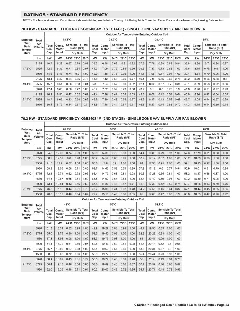
K-Series™ Packaged Gas / Electric 52.8 to 88 kW 50hz / Page 23
70.3 KW - STANDARD EFFICIENCY KGB240S4M (1ST STAGE) - SINGLE ZONE VAV SUPPLY AIR FAN BLOWER
Entering Wet Bulb
Temper-ature
Total Air
Volume
Outdoor Air Temperature Entering Outdoor Coil
18.3°C 23.9°C 29.4°C 35°C
Total Cool Cap.
Comp. Motor Input
Sensible To Total Ratio (S/T)
Total Cool Cap.
Comp. Motor Input
Sensible To Total Ratio (S/T)
Total Cool Cap.
Comp. Motor Input
Sensible To Total Ratio (S/T)
Total Cool Cap.
Comp. Motor Input
Sensible To Total Ratio (S/T)
Dry Bulb Dry Bulb Dry Bulb Dry Bulb
L/s kW kW 24°C 27°C 29°C kW kW 24°C 27°C 29°C kW kW 24°C 27°C 29°C kW kW 24°C 27°C 29°C
17.2°C
2125 40.7 6.28 0.67 0.79 0.91 39.2 6.98 0.68 0.8 0.92 37.6 7.76 0.69 0.82 0.94 35.8 8.64 0.7 0.84 0.97
2595 42.9 6.39 0.71 0.84 0.97 41.3 7.09 0.72 0.86 0.99 39.5 7.87 0.73 0.88 1.00 37.6 8.75 0.75 0.9 1.00
3070 44.6 6.48 0.74 0.9 1.00 42.9 7.18 0.76 0.92 1.00 41.1 7.96 0.77 0.94 1.00 39.1 8.84 0.79 0.96 1.00
19.4°C
2125 43.4 6.42 0.54 0.65 0.75 41.8 7.12 0.55 0.66 0.77 40.1 7.9 0.55 0.66 0.78 38.2 8.79 0.56 0.68 0.8
2595 45.7 6.54 0.56 0.68 0.81 44 7.24 0.57 0.69 0.82 42.1 8.02 0.57 0.7 0.84 40.1 8.89 0.58 0.72 0.86
3070 47.4 6.63 0.58 0.72 0.86 45.7 7.32 0.59 0.73 0.88 43.7 8.1 0.6 0.75 0.9 41.6 8.98 0.61 0.77 0.93
21.7°C
2125 46.1 6.56 0.42 0.52 0.62 44.4 7.26 0.42 0.53 0.63 42.8 8.06 0.42 0.53 0.64 40.9 8.94 0.42 0.54 0.65
2595 48.7 6.69 0.43 0.54 0.66 46.9 7.39 0.43 0.55 0.67 44.9 8.17 0.43 0.56 0.68 42.7 9.05 0.44 0.57 0.69
3070 50.4 6.79 0.44 0.57 0.7 48.5 7.48 0.44 0.57 0.71 46.5 8.27 0.44 0.58 0.72 44.3 9.15 0.44 0.59 0.74
70.3 KW - STANDARD EFFICIENCY KGB240S4M (2ND STAGE) - SINGLE ZONE VAV SUPPLY AIR FAN BLOWER
Entering Wet Bulb
Temper-ature
Total Air
Volume
Outdoor Air Temperature Entering Outdoor Coil
26.7°C 35°C 43.3°C 46°C
Total Cool Cap.
Comp. Motor Input
Sensible To Total Ratio (S/T)
Total Cool Cap.
Comp. Motor Input
Sensible To Total Ratio (S/T)
Total Cool Cap.
Comp. Motor Input
Sensible To Total Ratio (S/T)
Total Cool Cap.
Comp. Motor Input
Sensible To Total Ratio (S/T)
Dry Bulb Dry Bulb Dry Bulb Dry Bulb
L/s kW kW 24°C 27°C 29°C kW kW 24°C 27°C 29°C kW kW 24°C 27°C 29°C kW kW 24°C 27°C 29°C
17.2°C
3020 64.8 12.32 0.74 0.89 1.00 59.8 14.39 0.76 0.93 1.00 54.4 16.89 0.79 0.97 1.00 52.6 17.79 0.81 0.98 1.00
3775 68.2 12.52 0.8 0.98 1.00 63.2 14.59 0.83 0.99 1.00 57.9 17.12 0.87 1.00 1.00 56.2 18.03 0.89 1.00 1.00
4530 71.5 12.7 0.87 1.00 1.00 66.6 14.8 0.9 1.00 1.00 61 17.33 0.95 1.00 1.00 59.1 18.23 0.97 1.00 1.00
19.4°C
3020 68.9 12.56 0.58 0.71 0.86 63.7 14.62 0.59 0.74 0.89 57.9 17.12 0.6 0.77 0.94 55.9 18.01 0.61 0.79 0.95
3775 72.1 12.74 0.62 0.78 0.95 66.4 14.79 0.63 0.81 0.98 60.3 17.28 0.65 0.84 1.00 58.2 18.17 0.66 0.87 1.00
4530 74.3 12.87 0.65 0.84 1.00 68.5 14.92 0.67 0.88 1.00 62.4 17.42 0.69 0.93 1.00 60.2 18.30 0.71 0.95 1.00
21.7°C
3020 73.4 12.81 0.43 0.56 0.69 67.8 14.87 0.43 0.57 0.71 61.8 17.38 0.42 0.59 0.74 59.7 18.26 0.43 0.60 0.76
3775 76.5 13 0.44 0.61 0.76 70.7 15.06 0.44 0.62 0.78 64.2 17.55 0.45 0.64 0.82 62.1 18.44 0.45 0.65 0.85
4530 78.8 13.13 0.46 0.64 0.82 72.7 15.18 0.46 0.66 0.85 66 17.66 0.47 0.68 0.9 63.8 18.55 0.47 0.70 0.92
Entering Wet Bulb
Temper-ature
Total Air
Volume
Outdoor Air Temperature Entering Outdoor Coil
48°C 50°C 51.7°C
Total Cool Cap.
Comp. Motor Input
Sensible To Total Ratio (S/T)
Total Cool Cap.
Comp. Motor Input
Sensible To Total Ratio (S/T)
Total Cool Cap.
Comp. Motor Input
Sensible To Total Ratio (S/T)
Dry Bulb Dry Bulb Dry Bulb
L/s kW kW 24°C 27°C 29°C kW kW 24°C 27°C 29°C kW kW 24°C 27°C 29°C
17.2°C
3020 51.3 18.51 0.82 0.99 1.00 49.9 19.27 0.83 0.99 1.00 48.7 19.96 0.83 1.00 1.00
3775 55.0 18.76 0.90 1.00 1.00 53.5 19.52 0.92 1.00 1.00 52.3 20.23 0.93 1.00 1.00
4530 57.8 18.96 0.98 1.00 1.00 56.3 19.73 0.98 1.00 1.00 55 20.41 0.99 1.00 1.00
19.4°C
3020 54.4 18.72 0.61 0.80 0.97 52.8 19.47 0.62 0.81 0.98 51.4 20.14 0.62 0.8 0.98
3775 56.7 18.89 0.67 0.88 1.00 55.1 19.63 0.67 0.89 1.00 53.6 20.31 0.67 0.9 1.00
4530 58.5 19.02 0.72 0.96 1.00 56.9 19.77 0.73 0.97 1.00 55.4 20.44 0.73 0.98 1.00
21.7°C
3020 58.1 18.99 0.43 0.61 0.77 56.5 19.74 0.43 0.61 0.78 55 20.4 0.43 0.61 0.78
3775 60.4 19.15 0.46 0.66 0.85 58.6 19.89 0.46 0.66 0.87 57.1 20.57 0.46 0.66 0.87
4530 62.0 19.26 0.48 0.71 0.94 60.2 20.00 0.49 0.72 0.95 58.7 20.71 0.48 0.72 0.96
RATINGS - STANDARD EFFICIENCYNOTE - For Temperatures and Capacities not shown in tables, see bulletin - Cooling Unit Rating Table Correction Factor Data in Miscellaneous Engineering Data section.
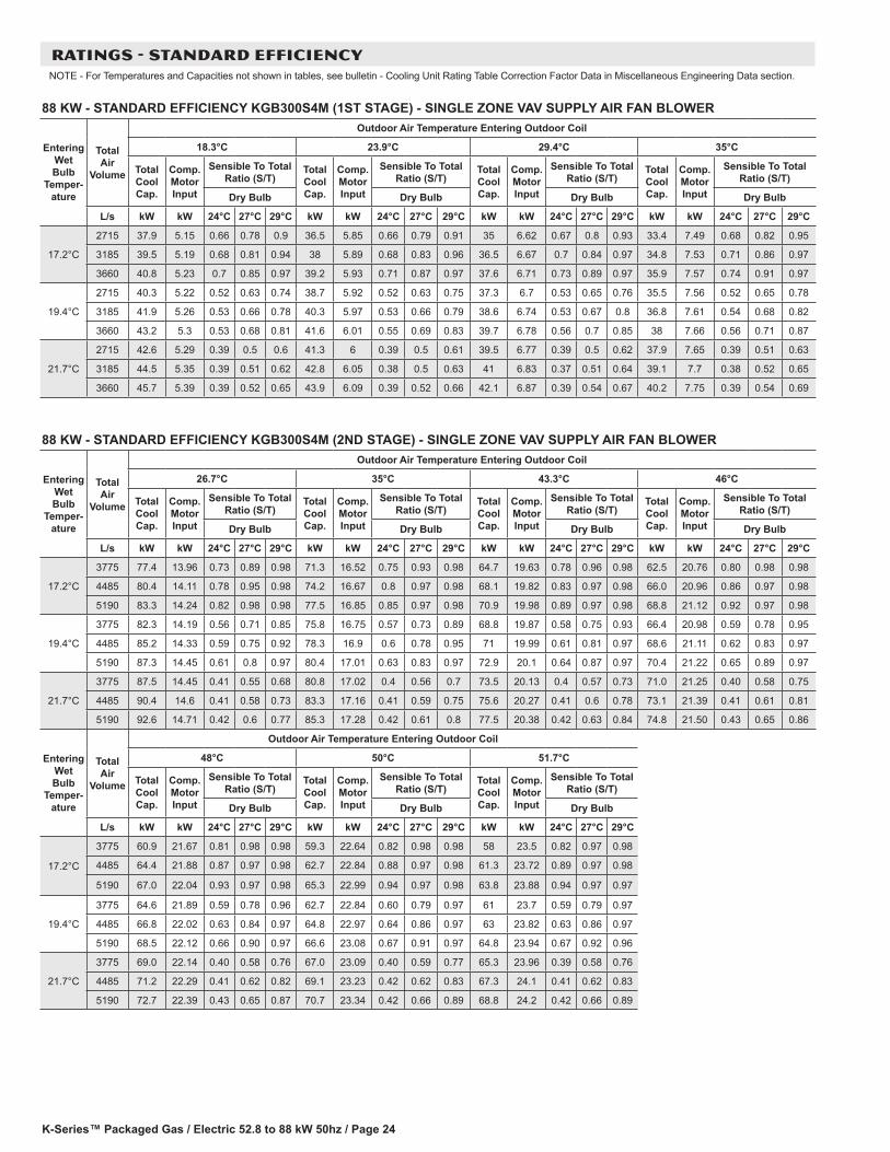
K-Series™ Packaged Gas / Electric 52.8 to 88 kW 50hz / Page 24
RATINGS - STANDARD EFFICIENCYNOTE - For Temperatures and Capacities not shown in tables, see bulletin - Cooling Unit Rating Table Correction Factor Data in Miscellaneous Engineering Data section.
88 KW - STANDARD EFFICIENCY KGB300S4M (1ST STAGE) - SINGLE ZONE VAV SUPPLY AIR FAN BLOWER
Entering Wet Bulb
Temper-ature
Total Air
Volume
Outdoor Air Temperature Entering Outdoor Coil
18.3°C 23.9°C 29.4°C 35°C
Total Cool Cap.
Comp. Motor Input
Sensible To Total Ratio (S/T)
Total Cool Cap.
Comp. Motor Input
Sensible To Total Ratio (S/T)
Total Cool Cap.
Comp. Motor Input
Sensible To Total Ratio (S/T)
Total Cool Cap.
Comp. Motor Input
Sensible To Total Ratio (S/T)
Dry Bulb Dry Bulb Dry Bulb Dry Bulb
L/s kW kW 24°C 27°C 29°C kW kW 24°C 27°C 29°C kW kW 24°C 27°C 29°C kW kW 24°C 27°C 29°C
17.2°C
2715 37.9 5.15 0.66 0.78 0.9 36.5 5.85 0.66 0.79 0.91 35 6.62 0.67 0.8 0.93 33.4 7.49 0.68 0.82 0.95
3185 39.5 5.19 0.68 0.81 0.94 38 5.89 0.68 0.83 0.96 36.5 6.67 0.7 0.84 0.97 34.8 7.53 0.71 0.86 0.97
3660 40.8 5.23 0.7 0.85 0.97 39.2 5.93 0.71 0.87 0.97 37.6 6.71 0.73 0.89 0.97 35.9 7.57 0.74 0.91 0.97
19.4°C
2715 40.3 5.22 0.52 0.63 0.74 38.7 5.92 0.52 0.63 0.75 37.3 6.7 0.53 0.65 0.76 35.5 7.56 0.52 0.65 0.78
3185 41.9 5.26 0.53 0.66 0.78 40.3 5.97 0.53 0.66 0.79 38.6 6.74 0.53 0.67 0.8 36.8 7.61 0.54 0.68 0.82
3660 43.2 5.3 0.53 0.68 0.81 41.6 6.01 0.55 0.69 0.83 39.7 6.78 0.56 0.7 0.85 38 7.66 0.56 0.71 0.87
21.7°C
2715 42.6 5.29 0.39 0.5 0.6 41.3 6 0.39 0.5 0.61 39.5 6.77 0.39 0.5 0.62 37.9 7.65 0.39 0.51 0.63
3185 44.5 5.35 0.39 0.51 0.62 42.8 6.05 0.38 0.5 0.63 41 6.83 0.37 0.51 0.64 39.1 7.7 0.38 0.52 0.65
3660 45.7 5.39 0.39 0.52 0.65 43.9 6.09 0.39 0.52 0.66 42.1 6.87 0.39 0.54 0.67 40.2 7.75 0.39 0.54 0.69
88 KW - STANDARD EFFICIENCY KGB300S4M (2ND STAGE) - SINGLE ZONE VAV SUPPLY AIR FAN BLOWER
Entering Wet Bulb
Temper-ature
Total Air
Volume
Outdoor Air Temperature Entering Outdoor Coil
26.7°C 35°C 43.3°C 46°C
Total Cool Cap.
Comp. Motor Input
Sensible To Total Ratio (S/T)
Total Cool Cap.
Comp. Motor Input
Sensible To Total Ratio (S/T)
Total Cool Cap.
Comp. Motor Input
Sensible To Total Ratio (S/T)
Total Cool Cap.
Comp. Motor Input
Sensible To Total Ratio (S/T)
Dry Bulb Dry Bulb Dry Bulb Dry Bulb
L/s kW kW 24°C 27°C 29°C kW kW 24°C 27°C 29°C kW kW 24°C 27°C 29°C kW kW 24°C 27°C 29°C
17.2°C
3775 77.4 13.96 0.73 0.89 0.98 71.3 16.52 0.75 0.93 0.98 64.7 19.63 0.78 0.96 0.98 62.5 20.76 0.80 0.98 0.98
4485 80.4 14.11 0.78 0.95 0.98 74.2 16.67 0.8 0.97 0.98 68.1 19.82 0.83 0.97 0.98 66.0 20.96 0.86 0.97 0.98
5190 83.3 14.24 0.82 0.98 0.98 77.5 16.85 0.85 0.97 0.98 70.9 19.98 0.89 0.97 0.98 68.8 21.12 0.92 0.97 0.98
19.4°C
3775 82.3 14.19 0.56 0.71 0.85 75.8 16.75 0.57 0.73 0.89 68.8 19.87 0.58 0.75 0.93 66.4 20.98 0.59 0.78 0.95
4485 85.2 14.33 0.59 0.75 0.92 78.3 16.9 0.6 0.78 0.95 71 19.99 0.61 0.81 0.97 68.6 21.11 0.62 0.83 0.97
5190 87.3 14.45 0.61 0.8 0.97 80.4 17.01 0.63 0.83 0.97 72.9 20.1 0.64 0.87 0.97 70.4 21.22 0.65 0.89 0.97
21.7°C
3775 87.5 14.45 0.41 0.55 0.68 80.8 17.02 0.4 0.56 0.7 73.5 20.13 0.4 0.57 0.73 71.0 21.25 0.40 0.58 0.75
4485 90.4 14.6 0.41 0.58 0.73 83.3 17.16 0.41 0.59 0.75 75.6 20.27 0.41 0.6 0.78 73.1 21.39 0.41 0.61 0.81
5190 92.6 14.71 0.42 0.6 0.77 85.3 17.28 0.42 0.61 0.8 77.5 20.38 0.42 0.63 0.84 74.8 21.50 0.43 0.65 0.86
Entering Wet Bulb
Temper-ature
Total Air
Volume
Outdoor Air Temperature Entering Outdoor Coil
48°C 50°C 51.7°C
Total Cool Cap.
Comp. Motor Input
Sensible To Total Ratio (S/T)
Total Cool Cap.
Comp. Motor Input
Sensible To Total Ratio (S/T)
Total Cool Cap.
Comp. Motor Input
Sensible To Total Ratio (S/T)
Dry Bulb Dry Bulb Dry Bulb
L/s kW kW 24°C 27°C 29°C kW kW 24°C 27°C 29°C kW kW 24°C 27°C 29°C
17.2°C
3775 60.9 21.67 0.81 0.98 0.98 59.3 22.64 0.82 0.98 0.98 58 23.5 0.82 0.97 0.98
4485 64.4 21.88 0.87 0.97 0.98 62.7 22.84 0.88 0.97 0.98 61.3 23.72 0.89 0.97 0.98
5190 67.0 22.04 0.93 0.97 0.98 65.3 22.99 0.94 0.97 0.98 63.8 23.88 0.94 0.97 0.97
19.4°C
3775 64.6 21.89 0.59 0.78 0.96 62.7 22.84 0.60 0.79 0.97 61 23.7 0.59 0.79 0.97
4485 66.8 22.02 0.63 0.84 0.97 64.8 22.97 0.64 0.86 0.97 63 23.82 0.63 0.86 0.97
5190 68.5 22.12 0.66 0.90 0.97 66.6 23.08 0.67 0.91 0.97 64.8 23.94 0.67 0.92 0.96
21.7°C
3775 69.0 22.14 0.40 0.58 0.76 67.0 23.09 0.40 0.59 0.77 65.3 23.96 0.39 0.58 0.76
4485 71.2 22.29 0.41 0.62 0.82 69.1 23.23 0.42 0.62 0.83 67.3 24.1 0.41 0.62 0.83
5190 72.7 22.39 0.43 0.65 0.87 70.7 23.34 0.42 0.66 0.89 68.8 24.2 0.42 0.66 0.89
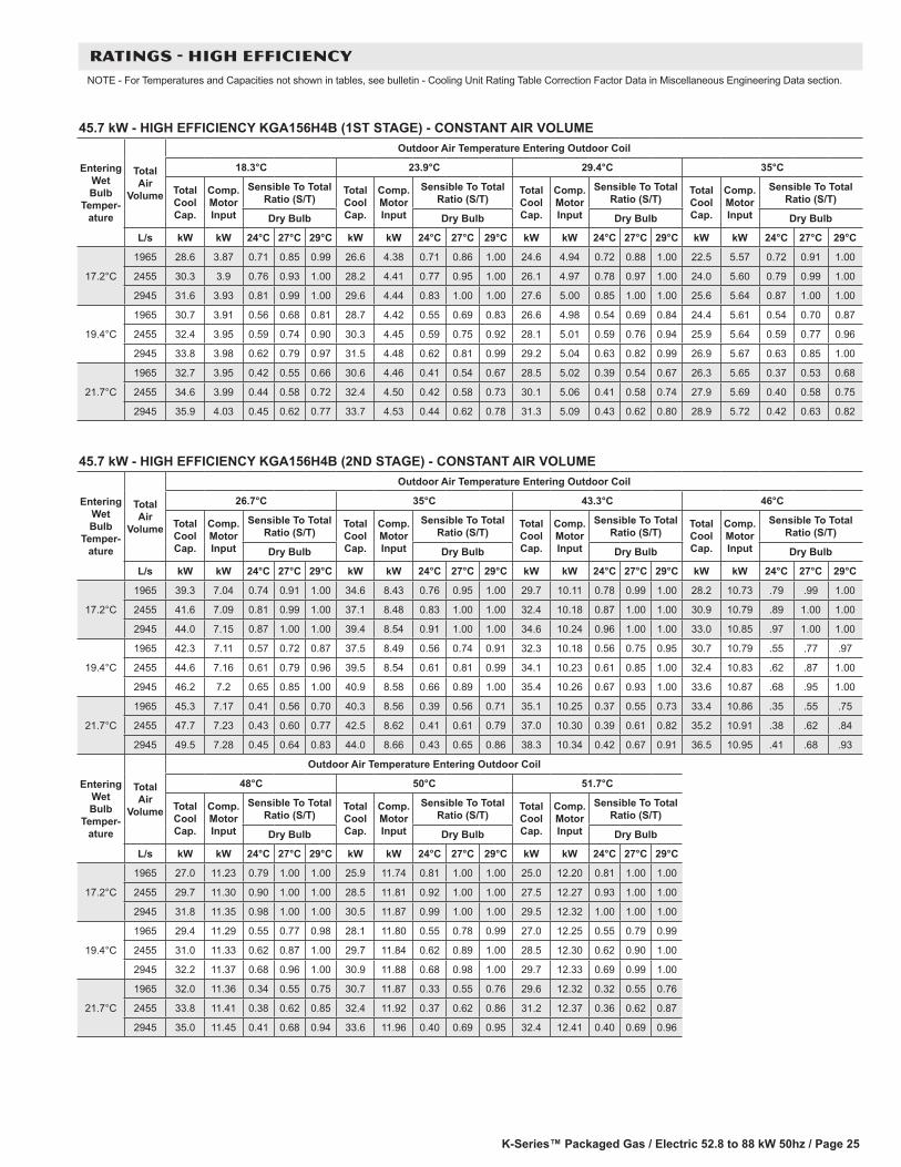
K-Series™ Packaged Gas / Electric 52.8 to 88 kW 50hz / Page 25
45.7 kW - HIGH EFFICIENCY KGA156H4B (1ST STAGE) - CONSTANT AIR VOLUME
Entering Wet Bulb
Temper-ature
Total Air
Volume
Outdoor Air Temperature Entering Outdoor Coil
18.3°C 23.9°C 29.4°C 35°C
Total Cool Cap.
Comp. Motor Input
Sensible To Total Ratio (S/T)
Total Cool Cap.
Comp. Motor Input
Sensible To Total Ratio (S/T)
Total Cool Cap.
Comp. Motor Input
Sensible To Total Ratio (S/T)
Total Cool Cap.
Comp. Motor Input
Sensible To Total Ratio (S/T)
Dry Bulb Dry Bulb Dry Bulb Dry Bulb
L/s kW kW 24°C 27°C 29°C kW kW 24°C 27°C 29°C kW kW 24°C 27°C 29°C kW kW 24°C 27°C 29°C
17.2°C
1965 28.6 3.87 0.71 0.85 0.99 26.6 4.38 0.71 0.86 1.00 24.6 4.94 0.72 0.88 1.00 22.5 5.57 0.72 0.91 1.00
2455 30.3 3.9 0.76 0.93 1.00 28.2 4.41 0.77 0.95 1.00 26.1 4.97 0.78 0.97 1.00 24.0 5.60 0.79 0.99 1.00
2945 31.6 3.93 0.81 0.99 1.00 29.6 4.44 0.83 1.00 1.00 27.6 5.00 0.85 1.00 1.00 25.6 5.64 0.87 1.00 1.00
19.4°C
1965 30.7 3.91 0.56 0.68 0.81 28.7 4.42 0.55 0.69 0.83 26.6 4.98 0.54 0.69 0.84 24.4 5.61 0.54 0.70 0.87
2455 32.4 3.95 0.59 0.74 0.90 30.3 4.45 0.59 0.75 0.92 28.1 5.01 0.59 0.76 0.94 25.9 5.64 0.59 0.77 0.96
2945 33.8 3.98 0.62 0.79 0.97 31.5 4.48 0.62 0.81 0.99 29.2 5.04 0.63 0.82 0.99 26.9 5.67 0.63 0.85 1.00
21.7°C
1965 32.7 3.95 0.42 0.55 0.66 30.6 4.46 0.41 0.54 0.67 28.5 5.02 0.39 0.54 0.67 26.3 5.65 0.37 0.53 0.68
2455 34.6 3.99 0.44 0.58 0.72 32.4 4.50 0.42 0.58 0.73 30.1 5.06 0.41 0.58 0.74 27.9 5.69 0.40 0.58 0.75
2945 35.9 4.03 0.45 0.62 0.77 33.7 4.53 0.44 0.62 0.78 31.3 5.09 0.43 0.62 0.80 28.9 5.72 0.42 0.63 0.82
45.7 kW - HIGH EFFICIENCY KGA156H4B (2ND STAGE) - CONSTANT AIR VOLUME
Entering Wet Bulb
Temper-ature
Total Air
Volume
Outdoor Air Temperature Entering Outdoor Coil
26.7°C 35°C 43.3°C 46°C
Total Cool Cap.
Comp. Motor Input
Sensible To Total Ratio (S/T)
Total Cool Cap.
Comp. Motor Input
Sensible To Total Ratio (S/T)
Total Cool Cap.
Comp. Motor Input
Sensible To Total Ratio (S/T)
Total Cool Cap.
Comp. Motor Input
Sensible To Total Ratio (S/T)
Dry Bulb Dry Bulb Dry Bulb Dry Bulb
L/s kW kW 24°C 27°C 29°C kW kW 24°C 27°C 29°C kW kW 24°C 27°C 29°C kW kW 24°C 27°C 29°C
17.2°C
1965 39.3 7.04 0.74 0.91 1.00 34.6 8.43 0.76 0.95 1.00 29.7 10.11 0.78 0.99 1.00 28.2 10.73 .79 .99 1.00
2455 41.6 7.09 0.81 0.99 1.00 37.1 8.48 0.83 1.00 1.00 32.4 10.18 0.87 1.00 1.00 30.9 10.79 .89 1.00 1.00
2945 44.0 7.15 0.87 1.00 1.00 39.4 8.54 0.91 1.00 1.00 34.6 10.24 0.96 1.00 1.00 33.0 10.85 .97 1.00 1.00
19.4°C
1965 42.3 7.11 0.57 0.72 0.87 37.5 8.49 0.56 0.74 0.91 32.3 10.18 0.56 0.75 0.95 30.7 10.79 .55 .77 .97
2455 44.6 7.16 0.61 0.79 0.96 39.5 8.54 0.61 0.81 0.99 34.1 10.23 0.61 0.85 1.00 32.4 10.83 .62 .87 1.00
2945 46.2 7.2 0.65 0.85 1.00 40.9 8.58 0.66 0.89 1.00 35.4 10.26 0.67 0.93 1.00 33.6 10.87 .68 .95 1.00
21.7°C
1965 45.3 7.17 0.41 0.56 0.70 40.3 8.56 0.39 0.56 0.71 35.1 10.25 0.37 0.55 0.73 33.4 10.86 .35 .55 .75
2455 47.7 7.23 0.43 0.60 0.77 42.5 8.62 0.41 0.61 0.79 37.0 10.30 0.39 0.61 0.82 35.2 10.91 .38 .62 .84
2945 49.5 7.28 0.45 0.64 0.83 44.0 8.66 0.43 0.65 0.86 38.3 10.34 0.42 0.67 0.91 36.5 10.95 .41 .68 .93
Entering Wet Bulb
Temper-ature
Total Air
Volume
Outdoor Air Temperature Entering Outdoor Coil
48°C 50°C 51.7°C
Total Cool Cap.
Comp. Motor Input
Sensible To Total Ratio (S/T)
Total Cool Cap.
Comp. Motor Input
Sensible To Total Ratio (S/T)
Total Cool Cap.
Comp. Motor Input
Sensible To Total Ratio (S/T)
Dry Bulb Dry Bulb Dry Bulb
L/s kW kW 24°C 27°C 29°C kW kW 24°C 27°C 29°C kW kW 24°C 27°C 29°C
17.2°C
1965 27.0 11.23 0.79 1.00 1.00 25.9 11.74 0.81 1.00 1.00 25.0 12.20 0.81 1.00 1.00
2455 29.7 11.30 0.90 1.00 1.00 28.5 11.81 0.92 1.00 1.00 27.5 12.27 0.93 1.00 1.00
2945 31.8 11.35 0.98 1.00 1.00 30.5 11.87 0.99 1.00 1.00 29.5 12.32 1.00 1.00 1.00
19.4°C
1965 29.4 11.29 0.55 0.77 0.98 28.1 11.80 0.55 0.78 0.99 27.0 12.25 0.55 0.79 0.99
2455 31.0 11.33 0.62 0.87 1.00 29.7 11.84 0.62 0.89 1.00 28.5 12.30 0.62 0.90 1.00
2945 32.2 11.37 0.68 0.96 1.00 30.9 11.88 0.68 0.98 1.00 29.7 12.33 0.69 0.99 1.00
21.7°C
1965 32.0 11.36 0.34 0.55 0.75 30.7 11.87 0.33 0.55 0.76 29.6 12.32 0.32 0.55 0.76
2455 33.8 11.41 0.38 0.62 0.85 32.4 11.92 0.37 0.62 0.86 31.2 12.37 0.36 0.62 0.87
2945 35.0 11.45 0.41 0.68 0.94 33.6 11.96 0.40 0.69 0.95 32.4 12.41 0.40 0.69 0.96
RATINGS - HIGH EFFICIENCYNOTE - For Temperatures and Capacities not shown in tables, see bulletin - Cooling Unit Rating Table Correction Factor Data in Miscellaneous Engineering Data section.
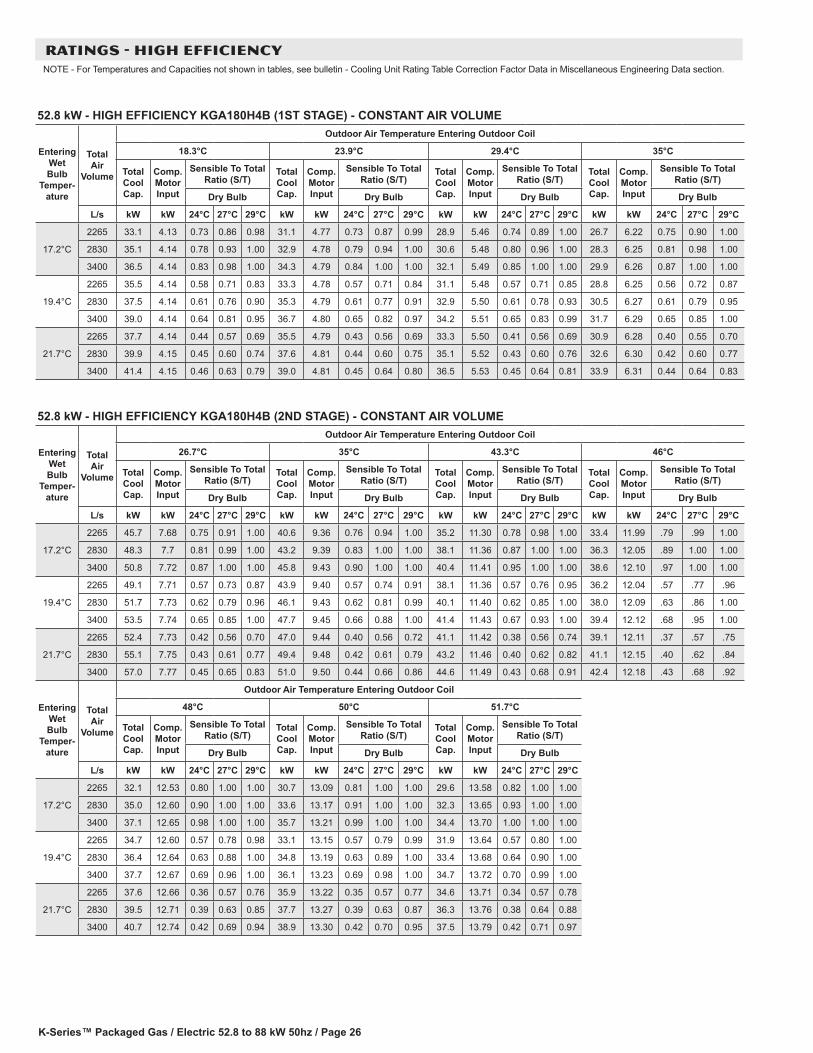
K-Series™ Packaged Gas / Electric 52.8 to 88 kW 50hz / Page 26
52.8 kW - HIGH EFFICIENCY KGA180H4B (1ST STAGE) - CONSTANT AIR VOLUME
Entering Wet Bulb
Temper-ature
Total Air
Volume
Outdoor Air Temperature Entering Outdoor Coil
18.3°C 23.9°C 29.4°C 35°C
Total Cool Cap.
Comp. Motor Input
Sensible To Total Ratio (S/T)
Total Cool Cap.
Comp. Motor Input
Sensible To Total Ratio (S/T)
Total Cool Cap.
Comp. Motor Input
Sensible To Total Ratio (S/T)
Total Cool Cap.
Comp. Motor Input
Sensible To Total Ratio (S/T)
Dry Bulb Dry Bulb Dry Bulb Dry Bulb
L/s kW kW 24°C 27°C 29°C kW kW 24°C 27°C 29°C kW kW 24°C 27°C 29°C kW kW 24°C 27°C 29°C
17.2°C
2265 33.1 4.13 0.73 0.86 0.98 31.1 4.77 0.73 0.87 0.99 28.9 5.46 0.74 0.89 1.00 26.7 6.22 0.75 0.90 1.00
2830 35.1 4.14 0.78 0.93 1.00 32.9 4.78 0.79 0.94 1.00 30.6 5.48 0.80 0.96 1.00 28.3 6.25 0.81 0.98 1.00
3400 36.5 4.14 0.83 0.98 1.00 34.3 4.79 0.84 1.00 1.00 32.1 5.49 0.85 1.00 1.00 29.9 6.26 0.87 1.00 1.00
19.4°C
2265 35.5 4.14 0.58 0.71 0.83 33.3 4.78 0.57 0.71 0.84 31.1 5.48 0.57 0.71 0.85 28.8 6.25 0.56 0.72 0.87
2830 37.5 4.14 0.61 0.76 0.90 35.3 4.79 0.61 0.77 0.91 32.9 5.50 0.61 0.78 0.93 30.5 6.27 0.61 0.79 0.95
3400 39.0 4.14 0.64 0.81 0.95 36.7 4.80 0.65 0.82 0.97 34.2 5.51 0.65 0.83 0.99 31.7 6.29 0.65 0.85 1.00
21.7°C
2265 37.7 4.14 0.44 0.57 0.69 35.5 4.79 0.43 0.56 0.69 33.3 5.50 0.41 0.56 0.69 30.9 6.28 0.40 0.55 0.70
2830 39.9 4.15 0.45 0.60 0.74 37.6 4.81 0.44 0.60 0.75 35.1 5.52 0.43 0.60 0.76 32.6 6.30 0.42 0.60 0.77
3400 41.4 4.15 0.46 0.63 0.79 39.0 4.81 0.45 0.64 0.80 36.5 5.53 0.45 0.64 0.81 33.9 6.31 0.44 0.64 0.83
52.8 kW - HIGH EFFICIENCY KGA180H4B (2ND STAGE) - CONSTANT AIR VOLUME
Entering Wet Bulb
Temper-ature
Total Air
Volume
Outdoor Air Temperature Entering Outdoor Coil
26.7°C 35°C 43.3°C 46°C
Total Cool Cap.
Comp. Motor Input
Sensible To Total Ratio (S/T)
Total Cool Cap.
Comp. Motor Input
Sensible To Total Ratio (S/T)
Total Cool Cap.
Comp. Motor Input
Sensible To Total Ratio (S/T)
Total Cool Cap.
Comp. Motor Input
Sensible To Total Ratio (S/T)
Dry Bulb Dry Bulb Dry Bulb Dry Bulb
L/s kW kW 24°C 27°C 29°C kW kW 24°C 27°C 29°C kW kW 24°C 27°C 29°C kW kW 24°C 27°C 29°C
17.2°C
2265 45.7 7.68 0.75 0.91 1.00 40.6 9.36 0.76 0.94 1.00 35.2 11.30 0.78 0.98 1.00 33.4 11.99 .79 .99 1.00
2830 48.3 7.7 0.81 0.99 1.00 43.2 9.39 0.83 1.00 1.00 38.1 11.36 0.87 1.00 1.00 36.3 12.05 .89 1.00 1.00
3400 50.8 7.72 0.87 1.00 1.00 45.8 9.43 0.90 1.00 1.00 40.4 11.41 0.95 1.00 1.00 38.6 12.10 .97 1.00 1.00
19.4°C
2265 49.1 7.71 0.57 0.73 0.87 43.9 9.40 0.57 0.74 0.91 38.1 11.36 0.57 0.76 0.95 36.2 12.04 .57 .77 .96
2830 51.7 7.73 0.62 0.79 0.96 46.1 9.43 0.62 0.81 0.99 40.1 11.40 0.62 0.85 1.00 38.0 12.09 .63 .86 1.00
3400 53.5 7.74 0.65 0.85 1.00 47.7 9.45 0.66 0.88 1.00 41.4 11.43 0.67 0.93 1.00 39.4 12.12 .68 .95 1.00
21.7°C
2265 52.4 7.73 0.42 0.56 0.70 47.0 9.44 0.40 0.56 0.72 41.1 11.42 0.38 0.56 0.74 39.1 12.11 .37 .57 .75
2830 55.1 7.75 0.43 0.61 0.77 49.4 9.48 0.42 0.61 0.79 43.2 11.46 0.40 0.62 0.82 41.1 12.15 .40 .62 .84
3400 57.0 7.77 0.45 0.65 0.83 51.0 9.50 0.44 0.66 0.86 44.6 11.49 0.43 0.68 0.91 42.4 12.18 .43 .68 .92
Entering Wet Bulb
Temper-ature
Total Air
Volume
Outdoor Air Temperature Entering Outdoor Coil
48°C 50°C 51.7°C
Total Cool Cap.
Comp. Motor Input
Sensible To Total Ratio (S/T)
Total Cool Cap.
Comp. Motor Input
Sensible To Total Ratio (S/T)
Total Cool Cap.
Comp. Motor Input
Sensible To Total Ratio (S/T)
Dry Bulb Dry Bulb Dry Bulb
L/s kW kW 24°C 27°C 29°C kW kW 24°C 27°C 29°C kW kW 24°C 27°C 29°C
17.2°C
2265 32.1 12.53 0.80 1.00 1.00 30.7 13.09 0.81 1.00 1.00 29.6 13.58 0.82 1.00 1.00
2830 35.0 12.60 0.90 1.00 1.00 33.6 13.17 0.91 1.00 1.00 32.3 13.65 0.93 1.00 1.00
3400 37.1 12.65 0.98 1.00 1.00 35.7 13.21 0.99 1.00 1.00 34.4 13.70 1.00 1.00 1.00
19.4°C
2265 34.7 12.60 0.57 0.78 0.98 33.1 13.15 0.57 0.79 0.99 31.9 13.64 0.57 0.80 1.00
2830 36.4 12.64 0.63 0.88 1.00 34.8 13.19 0.63 0.89 1.00 33.4 13.68 0.64 0.90 1.00
3400 37.7 12.67 0.69 0.96 1.00 36.1 13.23 0.69 0.98 1.00 34.7 13.72 0.70 0.99 1.00
21.7°C
2265 37.6 12.66 0.36 0.57 0.76 35.9 13.22 0.35 0.57 0.77 34.6 13.71 0.34 0.57 0.78
2830 39.5 12.71 0.39 0.63 0.85 37.7 13.27 0.39 0.63 0.87 36.3 13.76 0.38 0.64 0.88
3400 40.7 12.74 0.42 0.69 0.94 38.9 13.30 0.42 0.70 0.95 37.5 13.79 0.42 0.71 0.97
RATINGS - HIGH EFFICIENCYNOTE - For Temperatures and Capacities not shown in tables, see bulletin - Cooling Unit Rating Table Correction Factor Data in Miscellaneous Engineering Data section.

K-Series™ Packaged Gas / Electric 52.8 to 88 kW 50hz / Page 27
61.5 kW - HIGH EFFICIENCY KGA210H4B (1ST STAGE) - CONSTANT AIR VOLUME
Entering Wet Bulb
Temper-ature
Total Air
Volume
Outdoor Air Temperature Entering Outdoor Coil
18.3°C 23.9°C 29.4°C 35°C
Total Cool Cap.
Comp. Motor Input
Sensible To Total Ratio (S/T)
Total Cool Cap.
Comp. Motor Input
Sensible To Total Ratio (S/T)
Total Cool Cap.
Comp. Motor Input
Sensible To Total Ratio (S/T)
Total Cool Cap.
Comp. Motor Input
Sensible To Total Ratio (S/T)
Dry Bulb Dry Bulb Dry Bulb Dry Bulb
L/s kW kW 24°C 27°C 29°C kW kW 24°C 27°C 29°C kW kW 24°C 27°C 29°C kW kW 24°C 27°C 29°C
17.2°C
2645 36.8 4.54 0.75 0.90 1.00 34.5 5.17 0.76 0.92 1.00 32.0 5.85 0.77 0.94 1.00 29.5 6.61 0.79 0.97 1.00
3305 38.9 4.58 0.81 0.98 1.00 36.4 5.21 0.83 1.00 1.00 34.1 5.90 0.84 1.00 1.00 31.8 6.66 0.86 1.00 1.00
3965 40.9 4.63 0.87 1.00 1.00 38.6 5.26 0.89 1.00 1.00 36.1 5.95 0.91 1.00 1.00 33.6 6.72 0.94 1.00 1.00
19.4°C
2645 39.4 4.6 0.59 0.73 0.87 37.0 5.23 0.59 0.74 0.89 34.5 5.91 0.59 0.75 0.91 31.9 6.67 0.59 0.76 0.93
3305 41.4 4.64 0.63 0.79 0.95 38.8 5.27 0.63 0.81 0.97 36.1 5.95 0.62 0.82 0.99 33.3 6.71 0.64 0.84 1.00
3965 42.8 4.67 0.66 0.85 1.00 40.1 5.30 0.67 0.87 1.00 37.3 5.98 0.67 0.89 1.00 34.5 6.74 0.68 0.92 1.00
21.7°C
2645 42.3 4.66 0.44 0.58 0.71 39.7 5.29 0.43 0.58 0.72 37.0 5.98 0.42 0.58 0.73 34.3 6.74 0.41 0.58 0.74
3305 44.2 4.71 0.46 0.62 0.77 41.5 5.34 0.45 0.62 0.79 38.7 6.02 0.44 0.62 0.80 35.8 6.78 0.43 0.63 0.82
3965 45.6 4.74 0.47 0.65 0.83 42.8 5.37 0.44 0.66 0.85 39.8 6.06 0.47 0.67 0.87 36.8 6.81 0.45 0.68 0.89
61.5 kW - HIGH EFFICIENCY KGA210H4B (2ND STAGE) - CONSTANT AIR VOLUME
Entering Wet Bulb
Temper-ature
Total Air
Volume
Outdoor Air Temperature Entering Outdoor Coil
26.7°C 35°C 43.3°C 46°C
Total Cool Cap.
Comp. Motor Input
Sensible To Total Ratio (S/T)
Total Cool Cap.
Comp. Motor Input
Sensible To Total Ratio (S/T)
Total Cool Cap.
Comp. Motor Input
Sensible To Total Ratio (S/T)
Total Cool Cap.
Comp. Motor Input
Sensible To Total Ratio (S/T)
Dry Bulb Dry Bulb Dry Bulb Dry Bulb
L/s kW kW 24°C 27°C 29°C kW kW 24°C 27°C 29°C kW kW 24°C 27°C 29°C kW kW 24°C 27°C 29°C
17.2°C
2645 52.3 8.76 0.76 0.92 1.00 46.7 10.53 0.77 0.95 1.00 40.8 12.65 0.80 0.99 1.00 38.9 13.41 0.81 0.99 1.00
3305 55.5 8.83 0.82 0.99 1.00 49.9 10.61 0.85 1.00 1.00 44.2 12.74 0.89 1.00 1.00 42.3 13.50 0.91 1.00 1.00
3965 58.6 8.91 0.88 1.00 1.00 52.9 10.69 0.92 1.00 1.00 46.9 12.81 0.97 1.00 1.00 44.8 13.57 0.98 1.00 1.00
19.4°C
2645 56.3 8.85 0.58 0.73 0.88 50.3 10.62 0.58 0.75 0.92 43.9 12.73 0.58 0.77 0.96 41.9 13.49 0.59 0.79 0.98
3305 59.1 8.92 0.62 0.80 0.97 52.7 10.68 0.63 0.82 0.99 46.1 12.79 0.64 0.86 1.00 44.0 13.54 0.64 0.89 1.00
3965 61.1 8.97 0.65 0.87 1.00 54.5 10.73 0.67 0.90 1.00 47.8 12.84 0.69 0.95 1.00 45.4 13.59 0.70 0.96 1.00
21.7°C
2645 60.4 8.95 0.42 0.57 0.71 54.2 10.72 0.41 0.57 0.73 47.5 12.83 0.39 0.57 0.75 45.3 13.58 0.38 0.58 0.77
3305 63.2 9.02 0.44 0.61 0.78 56.6 10.79 0.43 0.62 0.81 49.6 12.89 0.41 0.63 0.84 47.4 13.64 0.41 0.64 0.86
3965 65.1 9.07 0.46 0.65 0.85 58.4 10.84 0.44 0.67 0.88 51.3 12.94 0.45 0.69 0.93 48.9 13.69 0.44 0.70 0.95
Entering Wet Bulb
Temper-ature
Total Air
Volume
Outdoor Air Temperature Entering Outdoor Coil
48°C 50°C 51.7°C
Total Cool Cap.
Comp. Motor Input
Sensible To Total Ratio (S/T)
Total Cool Cap.
Comp. Motor Input
Sensible To Total Ratio (S/T)
Total Cool Cap.
Comp. Motor Input
Sensible To Total Ratio (S/T)
Dry Bulb Dry Bulb Dry Bulb
L/s kW kW 24°C 27°C 29°C kW kW 24°C 27°C 29°C kW kW 24°C 27°C 29°C
17.2°C
2645 37.5 14.03 0.82 1.00 1.00 36.0 14.66 0.83 1.00 1.00 34.8 15.21 0.84 1.00 1.00
3305 40.7 14.11 0.92 1.00 1.00 39.2 14.73 0.94 1.00 1.00 38.0 15.29 0.95 1.00 1.00
3965 43.2 14.18 0.99 1.00 1.00 41.6 14.80 0.99 1.00 1.00 40.2 15.35 0.99 1.00 1.00
19.4°C
2645 40.2 14.10 0.58 0.79 0.98 38.4 14.72 0.58 0.81 0.99 37.0 15.26 0.58 0.82 0.99
3305 42.1 14.15 0.64 0.90 1.00 40.4 14.77 0.65 0.91 1.00 39.0 15.32 0.65 0.93 1.00
3965 43.7 14.19 0.71 0.98 1.00 42.0 14.81 0.72 0.98 1.00 40.5 15.36 0.73 0.99 1.00
21.7°C
2645 43.6 14.19 0.38 0.58 0.77 41.9 14.81 0.37 0.58 0.78 40.3 15.34 0.37 0.58 0.79
3305 45.5 14.25 0.41 0.64 0.87 43.7 14.86 0.41 0.65 0.89 42.2 15.40 0.40 0.66 0.90
3965 47.0 14.28 0.45 0.71 0.96 45.1 14.90 0.44 0.72 0.97 43.5 15.45 0.44 0.73 0.98
RATINGS - HIGH EFFICIENCYNOTE - For Temperatures and Capacities not shown in tables, see bulletin - Cooling Unit Rating Table Correction Factor Data in Miscellaneous Engineering Data section.
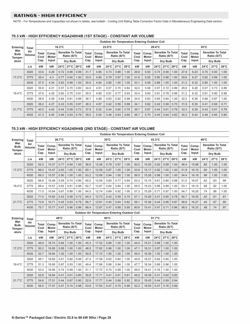
K-Series™ Packaged Gas / Electric 52.8 to 88 kW 50hz / Page 28
70.3 kW - HIGH EFFICIENCY KGA240H4B (1ST STAGE) - CONSTANT AIR VOLUME
Entering Wet Bulb
Temper-ature
Total Air
Volume
Outdoor Air Temperature Entering Outdoor Coil
18.3°C 23.9°C 29.4°C 35°C
Total Cool Cap.
Comp. Motor Input
Sensible To Total Ratio (S/T)
Total Cool Cap.
Comp. Motor Input
Sensible To Total Ratio (S/T)
Total Cool Cap.
Comp. Motor Input
Sensible To Total Ratio (S/T)
Total Cool Cap.
Comp. Motor Input
Sensible To Total Ratio (S/T)
Dry Bulb Dry Bulb Dry Bulb Dry Bulb
L/s kW kW 24°C 27°C 29°C kW kW 24°C 27°C 29°C kW kW 24°C 27°C 29°C kW kW 24°C 27°C 29°C
17.2°C
3020 33.6 4.26 0.72 0.86 0.99 31.7 4.85 0.73 0.88 1.00 29.9 5.50 0.74 0.90 1.00 27.9 6.23 0.75 0.93 1.00
3775 35.4 4.3 0.77 0.94 1.00 33.5 4.90 0.79 0.97 1.00 31.6 5.55 0.80 0.98 1.00 29.6 6.27 0.82 0.99 1.00
4530 37.0 4.34 0.83 0.99 1.00 35.0 4.94 0.85 1.00 1.00 33.1 5.59 0.86 1.00 1.00 31.2 6.32 0.90 1.00 1.00
19.4°C
3020 35.9 4.31 0.57 0.70 0.83 34.0 4.91 0.57 0.70 0.84 32.0 5.56 0.57 0.72 0.86 29.9 6.28 0.57 0.73 0.89
3775 37.6 4.35 0.60 0.75 0.91 35.5 4.95 0.61 0.77 0.93 33.4 5.60 0.61 0.78 0.96 31.2 6.32 0.61 0.80 0.98
4530 38.9 4.39 0.64 0.81 0.98 36.7 4.98 0.63 0.82 0.99 34.5 5.63 0.65 0.84 1.00 32.2 6.36 0.66 0.87 1.00
21.7°C
3020 38.2 4.37 0.43 0.55 0.67 36.3 4.97 0.42 0.56 0.68 34.1 5.62 0.42 0.56 0.70 31.9 6.35 0.41 0.56 0.71
3775 40.0 4.42 0.44 0.59 0.73 37.9 5.02 0.44 0.60 0.75 35.7 5.67 0.44 0.61 0.76 33.3 6.39 0.43 0.61 0.78
4530 41.3 4.45 0.46 0.63 0.79 39.0 5.05 0.46 0.63 0.80 36.7 5.70 0.45 0.64 0.82 34.2 6.42 0.46 0.65 0.85
70.3 kW - HIGH EFFICIENCY KGA240H4B (2ND STAGE) - CONSTANT AIR VOLUME
Entering Wet Bulb
Temper-ature
Total Air
Volume
Outdoor Air Temperature Entering Outdoor Coil
26.7°C 35°C 43.3°C 46°C
Total Cool Cap.
Comp. Motor Input
Sensible To Total Ratio (S/T)
Total Cool Cap.
Comp. Motor Input
Sensible To Total Ratio (S/T)
Total Cool Cap.
Comp. Motor Input
Sensible To Total Ratio (S/T)
Total Cool Cap.
Comp. Motor Input
Sensible To Total Ratio (S/T)
Dry Bulb Dry Bulb Dry Bulb Dry Bulb
L/s kW kW 24°C 27°C 29°C kW kW 24°C 27°C 29°C kW kW 24°C 27°C 29°C kW kW 24°C 27°C 29°C
17.2°C
3020 62.5 10.37 0.77 0.94 1.00 56.6 12.48 0.79 0.97 1.00 50.5 15.05 0.82 0.99 1.00 48.4 15.98 .85 1.00 1.00
3775 66.0 10.47 0.83 1.00 1.00 60.1 12.59 0.87 1.00 1.00 53.9 15.17 0.92 1.00 1.00 51.8 16.10 .94 1.00 1.00
4530 69.3 10.57 0.90 1.00 1.00 63.2 12.69 0.94 1.00 1.00 56.5 15.26 0.98 1.00 1.00 54.4 16.19 .99 1.00 1.00
19.4°C
3020 66.6 10.48 0.59 0.74 0.90 60.2 12.59 0.60 0.77 0.94 53.3 15.15 0.61 0.80 0.98 51.0 16.07 .62 .83 .99
3775 69.4 10.57 0.63 0.81 0.98 62.7 12.67 0.64 0.84 1.00 55.5 15.23 0.66 0.89 1.00 53.1 16.14 .68 .92 1.00
4530 71.5 10.64 0.67 0.88 1.00 64.5 12.74 0.69 0.92 1.00 57.3 15.29 0.71 0.97 1.00 54.7 16.20 .74 .98 1.00
21.7°C
3020 71.0 10.62 0.43 0.58 0.72 64.4 12.73 0.42 0.59 0.75 57.1 15.28 0.41 0.60 0.78 54.7 16.20 .42 .61 .81
3775 73.8 10.71 0.45 0.63 0.79 66.7 12.81 0.45 0.64 0.82 59.1 15.36 0.44 0.66 0.87 56.6 16.27 .44 .67 .90
4530 75.7 10.77 0.47 0.66 0.86 68.4 12.87 0.47 0.69 0.90 60.6 15.41 0.47 0.71 0.96 58.0 16.33 .48 .74 .97
Entering Wet Bulb
Temper-ature
Total Air
Volume
Outdoor Air Temperature Entering Outdoor Coil
48°C 50°C 51.7°C
Total Cool Cap.
Comp. Motor Input
Sensible To Total Ratio (S/T)
Total Cool Cap.
Comp. Motor Input
Sensible To Total Ratio (S/T)
Total Cool Cap.
Comp. Motor Input
Sensible To Total Ratio (S/T)
Dry Bulb Dry Bulb Dry Bulb
L/s kW kW 24°C 27°C 29°C kW kW 24°C 27°C 29°C kW kW 24°C 27°C 29°C
17.2°C
3020 46.9 16.74 0.84 1.00 1.00 45.3 17.52 0.86 1.00 1.00 44.0 18.21 0.88 1.00 1.00
3775 50.2 16.85 0.95 1.00 1.00 48.5 17.62 0.96 1.00 1.00 47.1 18.31 0.97 1.00 1.00
4530 52.7 16.94 1.00 1.00 1.00 50.9 17.72 1.00 1.00 1.00 49.4 18.39 1.00 1.00 1.00
19.4°C
3020 49.1 16.82 0.61 0.82 0.99 47.4 17.59 0.62 0.84 1.00 45.9 18.27 0.62 0.85 1.00
3775 51.3 16.90 0.67 0.93 1.00 49.4 17.66 0.68 0.94 1.00 47.7 18.34 0.69 0.96 1.00
4530 53.0 16.95 0.74 0.99 1.00 51.1 17.72 0.75 0.99 1.00 49.5 18.41 0.76 1.00 1.00
21.7°C
3020 52.8 16.94 0.41 0.61 0.80 50.8 17.71 0.41 0.61 0.81 49.2 18.39 0.41 0.62 0.83
3775 54.6 17.01 0.44 0.67 0.90 52.6 17.77 0.44 0.68 0.92 50.9 18.45 0.44 0.69 0.94
4530 56.0 17.07 0.47 0.74 0.98 53.9 17.83 0.47 0.75 0.99 52.2 18.50 0.47 0.76 0.99
RATINGS - HIGH EFFICIENCYNOTE - For Temperatures and Capacities not shown in tables, see bulletin - Cooling Unit Rating Table Correction Factor Data in Miscellaneous Engineering Data section.
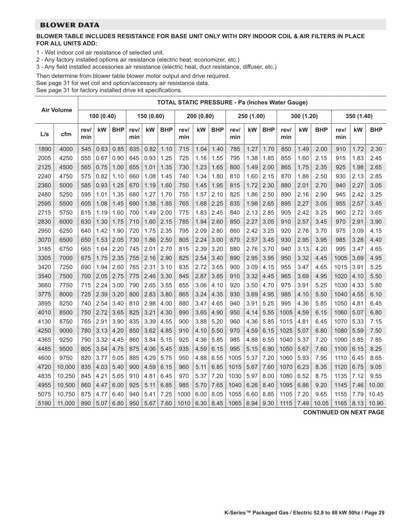
K-Series™ Packaged Gas / Electric 52.8 to 88 kW 50hz / Page 29
BLOWER DATA
BLOWER TABLE INCLUDES RESISTANCE FOR BASE UNIT ONLY WITH DRY INDOOR COIL & AIR FILTERS IN PLACE FOR ALL UNITS ADD:1 - Wet indoor coil air resistance of selected unit. 2 - Any factory installed options air resistance (electric heat, economizer, etc.) 3 - Any field installed accessories air resistance (electric heat, duct resistance, diffuser, etc.)Then determine from blower table blower motor output and drive required. See page 31 for wet coil and option/accessory air resistance data. See page 31 for factory installed drive kit specifications.
Air VolumeTOTAL STATIC PRESSURE - Pa (Inches Water Gauge)
100 (0.40) 150 (0.60) 200 (0.80) 250 (1.00) 300 (1.20) 350 (1.40)
L/s cfmrev/min
kW BHP rev/min
kW BHP rev/min
kW BHP rev/min
kW BHP rev/min
kW BHP rev/min
kW BHP
1890 4000 545 0.63 0.85 635 0.82 1.10 715 1.04 1.40 785 1.27 1.70 850 1.49 2.00 910 1.72 2.302005 4250 555 0.67 0.90 645 0.93 1.25 725 1.16 1.55 795 1.38 1.85 855 1.60 2.15 915 1.83 2.452125 4500 565 0.75 1.00 655 1.01 1.35 730 1.23 1.65 800 1.49 2.00 865 1.75 2.35 925 1.98 2.652240 4750 575 0.82 1.10 660 1.08 1.45 740 1.34 1.80 810 1.60 2.15 870 1.86 2.50 930 2.13 2.852360 5000 585 0.93 1.25 670 1.19 1.60 750 1.45 1.95 815 1.72 2.30 880 2.01 2.70 940 2.27 3.052480 5250 595 1.01 1.35 680 1.27 1.70 755 1.57 2.10 825 1.86 2.50 890 2.16 2.90 945 2.42 3.252595 5500 605 1.08 1.45 690 1.38 1.85 765 1.68 2.25 835 1.98 2.65 895 2.27 3.05 955 2.57 3.452715 5750 615 1.19 1.60 700 1.49 2.00 775 1.83 2.45 840 2.13 2.85 905 2.42 3.25 960 2.72 3.652830 6000 630 1.30 1.75 710 1.60 2.15 785 1.94 2.60 850 2.27 3.05 910 2.57 3.45 970 2.91 3.902950 6250 640 1.42 1.90 720 1.75 2.35 795 2.09 2.80 860 2.42 3.25 920 2.76 3.70 975 3.09 4.153070 6500 650 1.53 2.05 730 1.86 2.50 805 2.24 3.00 870 2.57 3.45 930 2.95 3.95 985 3.28 4.403185 6750 665 1.64 2.20 745 2.01 2.70 815 2.39 3.20 880 2.76 3.70 940 3.13 4.20 995 3.47 4.653305 7000 675 1.75 2.35 755 2.16 2.90 825 2.54 3.40 890 2.95 3.95 950 3.32 4.45 1005 3.69 4.953420 7250 690 1.94 2.60 765 2.31 3.10 835 2.72 3.65 900 3.09 4.15 955 3.47 4.65 1015 3.91 5.253540 7500 700 2.05 2.75 775 2.46 3.30 845 2.87 3.85 910 3.32 4.45 965 3.69 4.95 1020 4.10 5.503660 7750 715 2.24 3.00 790 2.65 3.55 855 3.06 4.10 920 3.50 4.70 975 3.91 5.25 1030 4.33 5.803775 8000 725 2.39 3.20 800 2.83 3.80 865 3.24 4.35 930 3.69 4.95 985 4.10 5.50 1040 4.55 6.103895 8250 740 2.54 3.40 810 2.98 4.00 880 3.47 4.65 940 3.91 5.25 995 4.36 5.85 1050 4.81 6.454010 8500 750 2.72 3.65 825 3.21 4.30 890 3.65 4.90 950 4.14 5.55 1005 4.59 6.15 1060 5.07 6.804130 8750 765 2.91 3.90 835 3.39 4.55 900 3.88 5.20 960 4.36 5.85 1015 4.81 6.45 1070 5.33 7.154250 9000 780 3.13 4.20 850 3.62 4.85 910 4.10 5.50 970 4.59 6.15 1025 5.07 6.80 1080 5.59 7.504365 9250 790 3.32 4.45 860 3.84 5.15 925 4.36 5.85 985 4.88 6.55 1040 5.37 7.20 1090 5.85 7.854485 9500 805 3.54 4.75 875 4.06 5.45 935 4.59 6.15 995 5.15 6.90 1050 5.67 7.60 1100 6.15 8.254600 9750 820 3.77 5.05 885 4.29 5.75 950 4.88 6.55 1005 5.37 7.20 1060 5.93 7.95 1110 6.45 8.654720 10,000 835 4.03 5.40 900 4.59 6.15 960 5.11 6.85 1015 5.67 7.60 1070 6.23 8.35 1120 6.75 9.054835 10,250 845 4.21 5.65 910 4.81 6.45 970 5.37 7.20 1030 5.97 8.00 1080 6.52 8.75 1135 7.12 9.554955 10,500 860 4.47 6.00 925 5.11 6.85 985 5.70 7.65 1040 6.26 8.40 1095 6.86 9.20 1145 7.46 10.005075 10,750 875 4.77 6.40 940 5.41 7.25 1000 6.00 8.05 1055 6.60 8.85 1105 7.20 9.65 1155 7.79 10.455190 11,000 890 5.07 6.80 950 5.67 7.60 1010 6.30 8.45 1065 6.94 9.30 1115 7.49 10.05 1165 8.13 10.90
CONTINUED ON NEXT PAGE
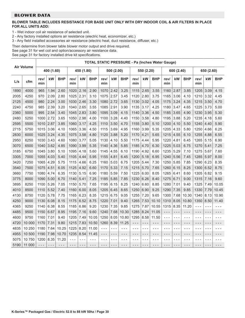
K-Series™ Packaged Gas / Electric 52.8 to 88 kW 50hz / Page 30
BLOWER DATA
BLOWER TABLE INCLUDES RESISTANCE FOR BASE UNIT ONLY WITH DRY INDOOR COIL & AIR FILTERS IN PLACE FOR ALL UNITS ADD:1 - Wet indoor coil air resistance of selected unit. 2 - Any factory installed options air resistance (electric heat, economizer, etc.) 3 - Any field installed accessories air resistance (electric heat, duct resistance, diffuser, etc.)Then determine from blower table blower motor output and drive required. See page 31 for wet coil and option/accessory air resistance data. See page 31 for factory installed drive kit specifications.
Air VolumeTOTAL STATIC PRESSURE - Pa (Inches Water Gauge)
400 (1.60) 450 (1.80) 500 (2.00) 550 (2.20) 600 (2.40) 650 (2.60)
L/s cfmrev/min
kW BHP rev/min
kW BHP rev/min
kW BHP rev/min
kW BHP rev/min
kW BHP rev/min
kW BHP
1890 4000 965 1.94 2.60 1020 2.16 2.90 1070 2.42 3.25 1115 2.65 3.55 1160 2.87 3.85 1205 3.09 4.152005 4250 970 2.09 2.80 1025 2.31 3.10 1075 2.57 3.45 1120 2.80 3.75 1165 3.06 4.10 1210 3.32 4.452125 4500 980 2.24 3.00 1030 2.46 3.30 1080 2.72 3.65 1130 3.02 4.05 1175 3.24 4.35 1215 3.50 4.702240 4750 985 2.39 3.20 1040 2.65 3.55 1085 2.91 3.90 1135 3.17 4.25 1180 3.47 4.65 1225 3.73 5.002360 5000 995 2.54 3.40 1045 2.83 3.80 1095 3.09 4.15 1140 3.36 4.50 1185 3.65 4.90 1230 3.95 5.302480 5250 1000 2.72 3.65 1050 2.98 4.00 1100 3.28 4.40 1150 3.58 4.80 1195 3.88 5.20 1235 4.18 5.602595 5500 1010 2.87 3.85 1060 3.17 4.25 1110 3.50 4.70 1155 3.80 5.10 1200 4.10 5.50 1240 4.40 5.902715 5750 1015 3.06 4.10 1065 3.36 4.50 1115 3.69 4.95 1160 3.99 5.35 1205 4.33 5.80 1250 4.66 6.252830 6000 1025 3.24 4.35 1075 3.58 4.80 1120 3.88 5.20 1170 4.21 5.65 1215 4.55 6.10 1255 4.88 6.552950 6250 1030 3.43 4.60 1080 3.77 5.05 1130 4.10 5.50 1175 4.44 5.95 1220 4.81 6.45 1265 5.15 6.903070 6500 1040 3.62 4.85 1090 3.99 5.35 1140 4.36 5.85 1185 4.70 6.30 1225 5.03 6.75 1270 5.41 7.253185 6750 1045 3.80 5.10 1095 4.18 5.60 1145 4.55 6.10 1190 4.92 6.60 1235 5.29 7.10 1275 5.67 7.603305 7000 1055 4.03 5.40 1105 4.44 5.95 1155 4.81 6.45 1200 5.18 6.95 1240 5.56 7.45 1285 5.97 8.003420 7250 1065 4.29 5.75 1115 4.66 6.25 1160 5.03 6.75 1205 5.44 7.30 1250 5.85 7.85 1290 6.23 8.353540 7500 1075 4.51 6.05 1125 4.92 6.60 1170 5.33 7.15 1215 5.70 7.65 1260 6.15 8.25 1300 6.52 8.753660 7750 1080 4.74 6.35 1130 5.15 6.90 1180 5.59 7.50 1225 6.00 8.05 1265 6.41 8.60 1305 6.82 9.153775 8000 1090 5.00 6.70 1140 5.41 7.25 1185 5.85 7.85 1230 6.26 8.40 1275 6.71 9.00 1315 7.16 9.603895 8250 1100 5.26 7.05 1150 5.70 7.65 1195 6.15 8.25 1240 6.60 8.85 1280 7.01 9.40 1325 7.49 10.054010 8500 1110 5.52 7.40 1160 6.00 8.05 1205 6.45 8.65 1250 6.90 9.25 1290 7.35 9.85 1330 7.79 10.454130 8750 1120 5.78 7.75 1165 6.23 8.35 1215 6.75 9.05 1255 7.20 9.65 1300 7.68 10.30 1340 8.13 10.904250 9000 1130 6.08 8.15 1175 6.52 8.75 1220 7.01 9.40 1265 7.53 10.10 1310 8.05 10.80 1350 8.50 11.404365 9250 1140 6.38 8.55 1185 6.86 9.20 1230 7.35 9.85 1275 7.87 10.55 1315 8.35 11.20 - - - - - - - - -4485 9500 1150 6.67 8.95 1195 7.16 9.60 1240 7.68 10.30 1285 8.24 11.05 - - - - - - - - - - - - - - - - - -4600 9750 1160 7.01 9.40 1205 7.49 10.05 1250 8.05 10.80 1295 8.58 11.50 - - - - - - - - - - - - - - - - - -4720 10 000 1170 7.31 9.80 1215 7.83 10.50 1260 8.39 11.25 - - - - - - - - - - - - - - - - - - - - - - - - - - -4835 10 250 1180 7.64 10.25 1225 8.20 11.00 - - - - - - - - - - - - - - - - - - - - - - - - - - - - - - - - - - - -4955 10 500 1190 7.98 10.70 1235 8.54 11.45 - - - - - - - - - - - - - - - - - - - - - - - - - - - - - - - - - - - -5075 10 750 1200 8.35 11.20 - - - - - - - - - - - - - - - - - - - - - - - - - - - - - - - - - - - - - - - - - - - - -5190 11 000 - - - - - - - - - - - - - - - - - - - - - - - - - - - - - - - - - - - - - - - - - - - - - - - - - - - - - -
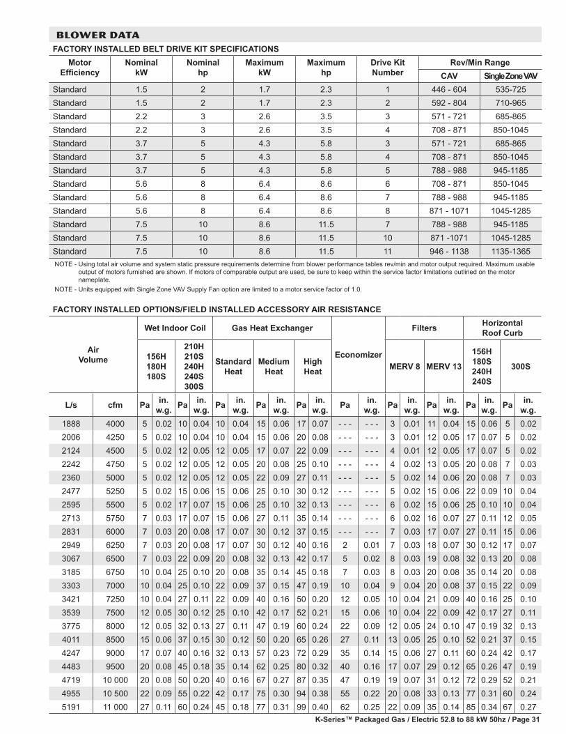
K-Series™ Packaged Gas / Electric 52.8 to 88 kW 50hz / Page 31
FACTORY INSTALLED OPTIONS/FIELD INSTALLED ACCESSORY AIR RESISTANCE
Air Volume
Wet Indoor Coil Gas Heat Exchanger
Economizer
Filters Horizontal Roof Curb
156H 180H 180S
210H 210S 240H 240S 300S
Standard Heat
Medium Heat
High Heat MERV 8 MERV 13
156H 180S 240H 240S
300S
L/s cfm Pa in. w.g. Pa in.
w.g. Pa in. w.g. Pa in.
w.g. Pa in. w.g. Pa in.
w.g. Pa in. w.g. Pa in.
w.g. Pa in. w.g. Pa in.
w.g.1888 4000 5 0.02 10 0.04 10 0.04 15 0.06 17 0.07 - - - - - - 3 0.01 11 0.04 15 0.06 5 0.022006 4250 5 0.02 10 0.04 10 0.04 15 0.06 20 0.08 - - - - - - 3 0.01 12 0.05 17 0.07 5 0.022124 4500 5 0.02 12 0.05 12 0.05 17 0.07 22 0.09 - - - - - - 4 0.01 12 0.05 17 0.07 5 0.022242 4750 5 0.02 12 0.05 12 0.05 20 0.08 25 0.10 - - - - - - 4 0.02 13 0.05 20 0.08 7 0.032360 5000 5 0.02 12 0.05 12 0.05 22 0.09 27 0.11 - - - - - - 5 0.02 14 0.06 20 0.08 7 0.032477 5250 5 0.02 15 0.06 15 0.06 25 0.10 30 0.12 - - - - - - 5 0.02 15 0.06 22 0.09 10 0.042595 5500 5 0.02 17 0.07 15 0.06 25 0.10 32 0.13 - - - - - - 6 0.02 15 0.06 25 0.10 10 0.042713 5750 7 0.03 17 0.07 15 0.06 27 0.11 35 0.14 - - - - - - 6 0.02 16 0.07 27 0.11 12 0.052831 6000 7 0.03 20 0.08 17 0.07 30 0.12 37 0.15 - - - - - - 7 0.03 17 0.07 27 0.11 15 0.062949 6250 7 0.03 20 0.08 17 0.07 30 0.12 40 0.16 2 0.01 7 0.03 18 0.07 30 0.12 17 0.073067 6500 7 0.03 22 0.09 20 0.08 32 0.13 42 0.17 5 0.02 8 0.03 19 0.08 32 0.13 20 0.083185 6750 10 0.04 25 0.10 20 0.08 35 0.14 45 0.18 7 0.03 8 0.03 20 0.08 35 0.14 20 0.083303 7000 10 0.04 25 0.10 22 0.09 37 0.15 47 0.19 10 0.04 9 0.04 20 0.08 37 0.15 22 0.093421 7250 10 0.04 27 0.11 22 0.09 40 0.16 50 0.20 12 0.05 10 0.04 21 0.09 40 0.16 25 0.103539 7500 12 0.05 30 0.12 25 0.10 42 0.17 52 0.21 15 0.06 10 0.04 22 0.09 42 0.17 27 0.113775 8000 12 0.05 32 0.13 27 0.11 47 0.19 60 0.24 22 0.09 12 0.05 24 0.10 47 0.19 32 0.134011 8500 15 0.06 37 0.15 30 0.12 50 0.20 65 0.26 27 0.11 13 0.05 25 0.10 52 0.21 37 0.154247 9000 17 0.07 40 0.16 32 0.13 57 0.23 72 0.29 35 0.14 15 0.06 27 0.11 60 0.24 42 0.174483 9500 20 0.08 45 0.18 35 0.14 62 0.25 80 0.32 40 0.16 17 0.07 29 0.12 65 0.26 47 0.194719 10 000 20 0.08 50 0.20 40 0.16 67 0.27 87 0.35 47 0.19 19 0.07 31 0.12 72 0.29 52 0.214955 10 500 22 0.09 55 0.22 42 0.17 75 0.30 94 0.38 55 0.22 20 0.08 33 0.13 77 0.31 60 0.245191 11 000 27 0.11 60 0.24 45 0.18 77 0.31 99 0.40 62 0.25 22 0.09 35 0.14 85 0.34 67 0.27
BLOWER DATAFACTORY INSTALLED BELT DRIVE KIT SPECIFICATIONS
Motor Efficiency
Nominal kW
Nominal hp
Maximum kW
Maximum hp
Drive Kit Number
Rev/Min RangeCAV Single Zone VAV
Standard 1.5 2 1.7 2.3 1 446 - 604 535-725Standard 1.5 2 1.7 2.3 2 592 - 804 710-965Standard 2.2 3 2.6 3.5 3 571 - 721 685-865Standard 2.2 3 2.6 3.5 4 708 - 871 850-1045Standard 3.7 5 4.3 5.8 3 571 - 721 685-865Standard 3.7 5 4.3 5.8 4 708 - 871 850-1045Standard 3.7 5 4.3 5.8 5 788 - 988 945-1185Standard 5.6 8 6.4 8.6 6 708 - 871 850-1045Standard 5.6 8 6.4 8.6 7 788 - 988 945-1185Standard 5.6 8 6.4 8.6 8 871 - 1071 1045-1285Standard 7.5 10 8.6 11.5 7 788 - 988 945-1185Standard 7.5 10 8.6 11.5 10 871 -1071 1045-1285Standard 7.5 10 8.6 11.5 11 946 - 1138 1135-1365NOTE - Using total air volume and system static pressure requirements determine from blower performance tables rev/min and motor output required. Maximum usable
output of motors furnished are shown. If motors of comparable output are used, be sure to keep within the service factor limitations outlined on the motor nameplate.
NOTE - Units equipped with Single Zone VAV Supply Fan option are limited to a motor service factor of 1.0.
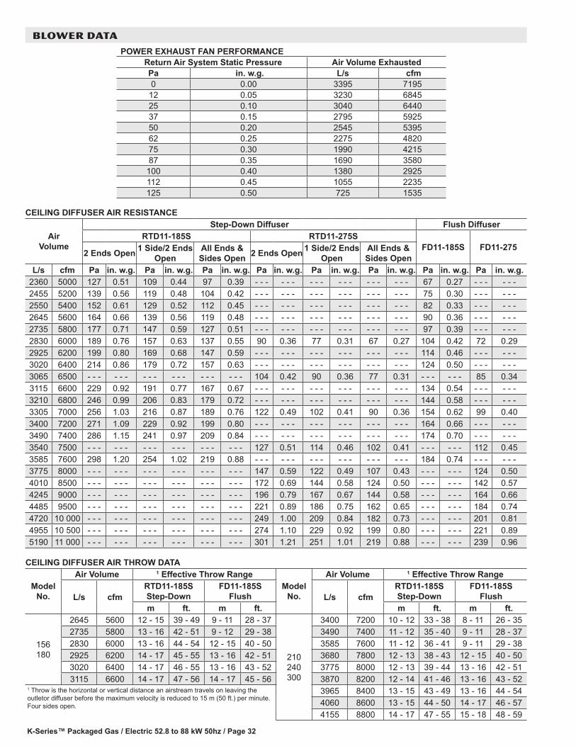
K-Series™ Packaged Gas / Electric 52.8 to 88 kW 50hz / Page 32
POWER EXHAUST FAN PERFORMANCE Return Air System Static Pressure Air Volume Exhausted
Pa in. w.g. L/s cfm 0 0.00 3395 7195
12 0.05 3230 684525 0.10 3040 644037 0.15 2795 592550 0.20 2545 539562 0.25 2275 482075 0.30 1990 421587 0.35 1690 3580
100 0.40 1380 2925112 0.45 1055 2235125 0.50 725 1535
CEILING DIFFUSER AIR RESISTANCE
Air Volume
Step-Down Diffuser Flush DiffuserRTD11-185S RTD11-275S
FD11-185S FD11-2752 Ends Open 1 Side/2 Ends
OpenAll Ends & Sides Open 2 Ends Open 1 Side/2 Ends
OpenAll Ends & Sides Open
L/s cfm Pa in. w.g. Pa in. w.g. Pa in. w.g. Pa in. w.g. Pa in. w.g. Pa in. w.g. Pa in. w.g. Pa in. w.g.2360 5000 127 0.51 109 0.44 97 0.39 - - - - - - - - - - - - - - - - - - 67 0.27 - - - - - -2455 5200 139 0.56 119 0.48 104 0.42 - - - - - - - - - - - - - - - - - - 75 0.30 - - - - - -2550 5400 152 0.61 129 0.52 112 0.45 - - - - - - - - - - - - - - - - - - 82 0.33 - - - - - -2645 5600 164 0.66 139 0.56 119 0.48 - - - - - - - - - - - - - - - - - - 90 0.36 - - - - - -2735 5800 177 0.71 147 0.59 127 0.51 - - - - - - - - - - - - - - - - - - 97 0.39 - - - - - -2830 6000 189 0.76 157 0.63 137 0.55 90 0.36 77 0.31 67 0.27 104 0.42 72 0.292925 6200 199 0.80 169 0.68 147 0.59 - - - - - - - - - - - - - - - - - - 114 0.46 - - - - - -3020 6400 214 0.86 179 0.72 157 0.63 - - - - - - - - - - - - - - - - - - 124 0.50 - - - - - -3065 6500 - - - - - - - - - - - - - - - - - - 104 0.42 90 0.36 77 0.31 - - - - - - 85 0.343115 6600 229 0.92 191 0.77 167 0.67 - - - - - - - - - - - - - - - - - - 134 0.54 - - - - - -3210 6800 246 0.99 206 0.83 179 0.72 - - - - - - - - - - - - - - - - - - 144 0.58 - - - - - -3305 7000 256 1.03 216 0.87 189 0.76 122 0.49 102 0.41 90 0.36 154 0.62 99 0.403400 7200 271 1.09 229 0.92 199 0.80 - - - - - - - - - - - - - - - - - - 164 0.66 - - - - - -3490 7400 286 1.15 241 0.97 209 0.84 - - - - - - - - - - - - - - - - - - 174 0.70 - - - - - -3540 7500 - - - - - - - - - - - - - - - - - - 127 0.51 114 0.46 102 0.41 - - - - - - 112 0.453585 7600 298 1.20 254 1.02 219 0.88 - - - - - - - - - - - - - - - - - - 184 0.74 - - - - - -3775 8000 - - - - - - - - - - - - - - - - - - 147 0.59 122 0.49 107 0.43 - - - - - - 124 0.504010 8500 - - - - - - - - - - - - - - - - - - 172 0.69 144 0.58 124 0.50 - - - - - - 142 0.574245 9000 - - - - - - - - - - - - - - - - - - 196 0.79 167 0.67 144 0.58 - - - - - - 164 0.664485 9500 - - - - - - - - - - - - - - - - - - 221 0.89 186 0.75 162 0.65 - - - - - - 184 0.744720 10 000 - - - - - - - - - - - - - - - - - - 249 1.00 209 0.84 182 0.73 - - - - - - 201 0.814955 10 500 - - - - - - - - - - - - - - - - - - 274 1.10 229 0.92 199 0.80 - - - - - - 221 0.895190 11 000 - - - - - - - - - - - - - - - - - - 301 1.21 251 1.01 219 0.88 - - - - - - 239 0.96
CEILING DIFFUSER AIR THROW DATA
Model No.
Air Volume 1 Effective Throw RangeModel
No.
Air Volume 1 Effective Throw Range
L/s cfmRTD11-185S Step-Down
FD11-185S Flush L/s cfm
RTD11-185S Step-Down
FD11-185S Flush
m ft. m ft. m ft. m ft.
156 180
2645 5600 12 - 15 39 - 49 9 - 11 28 - 37
210 240 300
3400 7200 10 - 12 33 - 38 8 - 11 26 - 352735 5800 13 - 16 42 - 51 9 - 12 29 - 38 3490 7400 11 - 12 35 - 40 9 - 11 28 - 372830 6000 13 - 16 44 - 54 12 - 15 40 - 50 3585 7600 11 - 12 36 - 41 9 - 11 29 - 382925 6200 14 - 17 45 - 55 13 - 16 42 - 51 3680 7800 12 - 13 38 - 43 12 - 15 40 - 503020 6400 14 - 17 46 - 55 13 - 16 43 - 52 3775 8000 12 - 13 39 - 44 13 - 16 42 - 513115 6600 14 - 17 47 - 56 14 - 17 45 - 56 3870 8200 12 - 14 41 - 46 13 - 16 43 - 52
1 Throw is the horizontal or vertical distance an airstream travels on leaving the outletor diffuser before the maximum velocity is reduced to 15 m (50 ft.) per minute. Four sides open.
3965 8400 13 - 15 43 - 49 13 - 16 44 - 544060 8600 13 - 15 44 - 50 14 - 17 46 - 574155 8800 14 - 17 47 - 55 15 - 18 48 - 59
BLOWER DATA
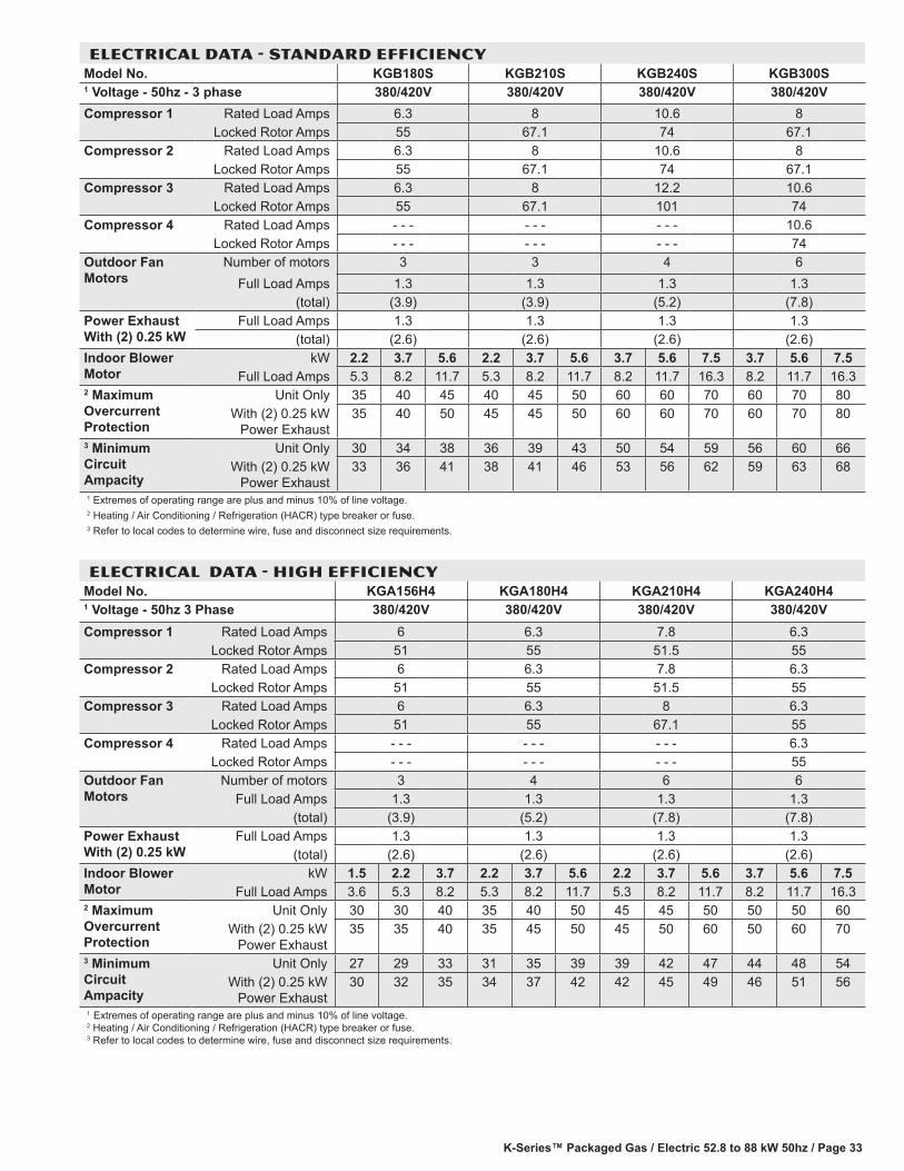
K-Series™ Packaged Gas / Electric 52.8 to 88 kW 50hz / Page 33
ELECTRICAL DATA - STANDARD EFFICIENCYModel No. KGB180S KGB210S KGB240S KGB300S1 Voltage - 50hz - 3 phase 380/420V 380/420V 380/420V 380/420VCompressor 1 Rated Load Amps 6.3 8 10.6 8
Locked Rotor Amps 55 67.1 74 67.1Compressor 2 Rated Load Amps 6.3 8 10.6 8
Locked Rotor Amps 55 67.1 74 67.1Compressor 3 Rated Load Amps 6.3 8 12.2 10.6
Locked Rotor Amps 55 67.1 101 74Compressor 4 Rated Load Amps - - - - - - - - - 10.6
Locked Rotor Amps - - - - - - - - - 74Outdoor Fan Motors
Number of motors 3 3 4 6Full Load Amps 1.3 1.3 1.3 1.3
(total) (3.9) (3.9) (5.2) (7.8)Power Exhaust With (2) 0.25 kW
Full Load Amps 1.3 1.3 1.3 1.3(total) (2.6) (2.6) (2.6) (2.6)
Indoor Blower Motor
kW 2.2 3.7 5.6 2.2 3.7 5.6 3.7 5.6 7.5 3.7 5.6 7.5Full Load Amps 5.3 8.2 11.7 5.3 8.2 11.7 8.2 11.7 16.3 8.2 11.7 16.3
2 Maximum Overcurrent Protection
Unit Only 35 40 45 40 45 50 60 60 70 60 70 80With (2) 0.25 kW
Power Exhaust35 40 50 45 45 50 60 60 70 60 70 80
3 Minimum Circuit Ampacity
Unit Only 30 34 38 36 39 43 50 54 59 56 60 66With (2) 0.25 kW
Power Exhaust33 36 41 38 41 46 53 56 62 59 63 68
1 Extremes of operating range are plus and minus 10% of line voltage.2 Heating / Air Conditioning / Refrigeration (HACR) type breaker or fuse.3 Refer to local codes to determine wire, fuse and disconnect size requirements.
ELECTRICAL DATA - HIGH EFFICIENCYModel No. KGA156H4 KGA180H4 KGA210H4 KGA240H41 Voltage - 50hz 3 Phase 380/420V 380/420V 380/420V 380/420VCompressor 1 Rated Load Amps 6 6.3 7.8 6.3
Locked Rotor Amps 51 55 51.5 55Compressor 2 Rated Load Amps 6 6.3 7.8 6.3
Locked Rotor Amps 51 55 51.5 55Compressor 3 Rated Load Amps 6 6.3 8 6.3
Locked Rotor Amps 51 55 67.1 55Compressor 4 Rated Load Amps - - - - - - - - - 6.3
Locked Rotor Amps - - - - - - - - - 55Outdoor Fan Motors
Number of motors 3 4 6 6Full Load Amps 1.3 1.3 1.3 1.3
(total) (3.9) (5.2) (7.8) (7.8)Power Exhaust With (2) 0.25 kW
Full Load Amps 1.3 1.3 1.3 1.3(total) (2.6) (2.6) (2.6) (2.6)
Indoor Blower Motor
kW 1.5 2.2 3.7 2.2 3.7 5.6 2.2 3.7 5.6 3.7 5.6 7.5Full Load Amps 3.6 5.3 8.2 5.3 8.2 11.7 5.3 8.2 11.7 8.2 11.7 16.3
2 Maximum Overcurrent Protection
Unit Only 30 30 40 35 40 50 45 45 50 50 50 60With (2) 0.25 kW
Power Exhaust35 35 40 35 45 50 45 50 60 50 60 70
3 Minimum Circuit Ampacity
Unit Only 27 29 33 31 35 39 39 42 47 44 48 54With (2) 0.25 kW
Power Exhaust30 32 35 34 37 42 42 45 49 46 51 56
1 Extremes of operating range are plus and minus 10% of line voltage. 2 Heating / Air Conditioning / Refrigeration (HACR) type breaker or fuse. 3 Refer to local codes to determine wire, fuse and disconnect size requirements.
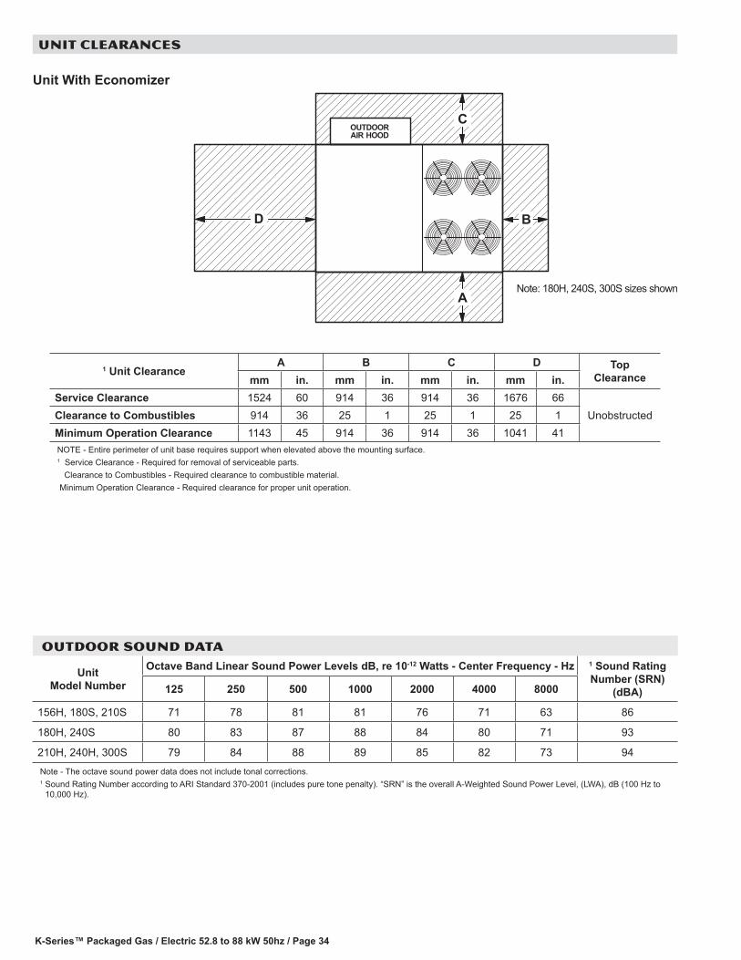
K-Series™ Packaged Gas / Electric 52.8 to 88 kW 50hz / Page 34
UNIT CLEARANCES
1 Unit ClearanceA B C D Top
Clearancemm in. mm in. mm in. mm in.Service Clearance 1524 60 914 36 914 36 1676 66
UnobstructedClearance to Combustibles 914 36 25 1 25 1 25 1Minimum Operation Clearance 1143 45 914 36 914 36 1041 41NOTE - Entire perimeter of unit base requires support when elevated above the mounting surface.1 Service Clearance - Required for removal of serviceable parts. Clearance to Combustibles - Required clearance to combustible material. Minimum Operation Clearance - Required clearance for proper unit operation.
Note: 180H, 240S, 300S sizes shown
Unit With Economizer
D
OUTDOORAIR HOOD
B
C
A
OUTDOOR SOUND DATA
Unit Model Number
Octave Band Linear Sound Power Levels dB, re 10-12 Watts - Center Frequency - Hz 1 Sound Rating Number (SRN)
(dBA)125 250 500 1000 2000 4000 8000
156H, 180S, 210S 71 78 81 81 76 71 63 86
180H, 240S 80 83 87 88 84 80 71 93
210H, 240H, 300S 79 84 88 89 85 82 73 94
Note - The octave sound power data does not include tonal corrections.1 Sound Rating Number according to ARI Standard 370-2001 (includes pure tone penalty). “SRN” is the overall A-Weighted Sound Power Level, (LWA), dB (100 Hz to
10,000 Hz).

K-Series™ Packaged Gas / Electric 52.8 to 88 kW 50hz / Page 35
THIS PAGE INTENTIONALLY LEFT BLANK
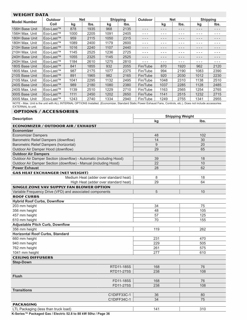
K-Series™ Packaged Gas / Electric 52.8 to 88 kW 50hz / Page 36
OPTIONS / ACCESSORIES
Description Shipping Weightkg lbs.
ECONOMIZER / OUTDOOR AIR / EXHAUSTEconomizerEconomizer Dampers 48 102Barometric Relief Dampers (downflow) 14 30Barometric Relief Dampers (horizontal) 9 20Outdoor Air Damper Hood (downflow) 29 65Outdoor Air DampersOutdoor Air Damper Section (downflow) - Automatic (including Hood) 39 18Outdoor Air Damper Section (downflow) - Manual (including Hood) 22 10Power Exhaust 28 62GAS HEAT EXCHANGER (NET WEIGHT)
Medium Heat (adder over standard heat) 8 18High Heat (adder over standard heat) 29 64
Single zone vav Supply fan BLOWER OPTIONVariable Frequency Drive (VFD) and associated components 5 10ROOF CURBSHybrid Roof Curbs, Downflow203 mm height 34 75356 mm height 48 105457 mm height 57 125610 mm height 70 155Adjustable Pitch Curb, Downflow356 mm height 119 262Horizontal Roof Curbs, Standard660 mm height 231 470940 mm height 229 505762 mm height 261 5751041 mm height 277 610CEILING DIFFUSERSStep-Down
RTD11-185S 168 76RTD11-275S 238 108
FlushFD11-185S 168 76FD11-275S 238 108
Transitions C1DIFF33C-1 36 80C1DIFF34C-1 34 75
PACKAGINGLTL Packaging (less than truck load) 141 310
WEIGHT DATA
Model Number Outdoor Coil
Net Shipping Outdoor Net Shippingkg lbs. kg lbs. kg lbs. kg lbs.
156H Base Unit Eco-Last™ 878 1935 968 2135 - - - - - - - - - - - - - - -156H Max. Unit Eco-Last™ 1000 2205 1091 2405 - - - - - - - - - - - - - - -180H Base Unit Eco-Last™ 959 2115 1050 2315 - - - - - - - - - - - - - - -180H Max. Unit Eco-Last™ 1089 2400 1179 2600 - - - - - - - - - - - - - - -210H Base Unit Eco-Last™ 1016 2240 1107 2440 - - - - - - - - - - - - - - -210H Max. Unit Eco-Last™ 1145 2525 1236 2725 - - - - - - - - - - - - - - -240H Base Unit Eco-Last™ 1055 2325 1145 2525 - - - - - - - - - - - - - - -240H Max. Unit Eco-Last™ 1184 2610 1275 2810 - - - - - - - - - - - - - - -180S Base Unit Eco-Last™ 841 1855 932 2055 Fin/Tube 870 1920 962 2120180S Max. Unit Eco-Last™ 987 2175 1077 2375 Fin/Tube 994 2190 1083 2390210S Base Unit Eco-Last™ 891 1965 982 2165 Fin/Tube 920 2030 1012 2230210S Max. Unit Eco-Last™ 1041 2295 1132 2495 Fin/Tube 1048 2310 1138 2510240S Base Unit Eco-Last™ 989 2180 1080 2380 Fin/Tube 1037 2285 1128 2485240S Max. Unit Eco-Last™ 1139 2510 1229 2710 Fin/Tube 1163 2565 1254 2765300S Base Unit Eco-Last™ 1111 2450 1202 2650 Fin/Tube 1141 2515 1232 2715300S Max. Unit Eco-Last™ 1243 2740 1334 2940 Fin/Tube 1249 2755 1341 2955NOTE - Max. Unit is the unit with ALL INTERNAL OPTIONS Installed. (Economizer, Standard Static Power Exhaust Fans, Controls, etc.). Does not include accessories EXTERNAL to unit.
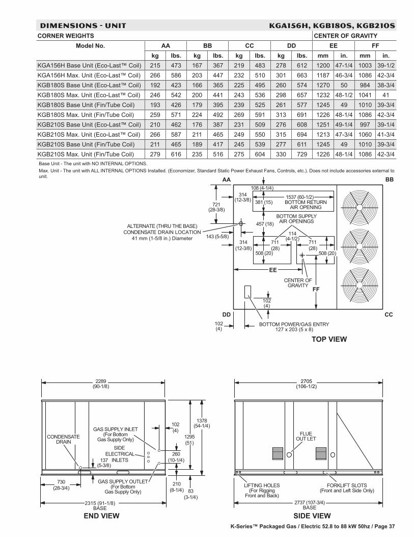
K-Series™ Packaged Gas / Electric 52.8 to 88 kW 50hz / Page 37
BOTTOM SUPPLYAIR OPENINGS
BOTTOM RETURNAIR OPENING
AA BB
CCDD
CENTER OFGRAVITY
EE
FF
TOP VIEW
END VIEW
210(8-1/4)
260(10-1/4)
102(4)
83(3-1/4)
1378(54-1/4)
2289(90-1/8)
730(28-3/4)
137(5-3/8)
1295(51)
2315 (91-1/8)BASE
SIDE ELECTRICAL
INLETS
GAS SUPPLY INLET(For Bottom
Gas Supply Only)CONDENSATE
GAS SUPPLY OUTLET(For Bottom
Gas Supply Only)
DRAIN
SIDE VIEW
FORKLIFT SLOTS(Front and Left Side Only)
LIFTING HOLES(For Rigging
Front and Back)
FLUEOUT LET
BOTTOM POWER/GAS ENTRY102(4)
508 (20)
711(28)
108 (4-1/4)
127 x 203 (5 x 8)
711(28)
102(4)
314(12-3/8)
314(12-3/8)
508 (20)
381 (15)1537 (60-1/2)
114(4-1/2)
2737 (107-3/4)BASE
2705(106-1/2)
ALTERNATE (THRU THE BASE)CONDENSATE DRAIN LOCATION
41 mm (1-5/8 in.) Diameter
457 (18)
(28-3/8)721
143 (5-5/8)
DIMENSIONS - UNIT KGA156H, KGB180S, KGB210SCORNER WEIGHTS CENTER OF GRAVITY
Model No. AA BB CC DD EE FFkg lbs. kg lbs. kg lbs. kg lbs. mm in. mm in.
KGA156H Base Unit (Eco-Last™ Coil) 215 473 167 367 219 483 278 612 1200 47-1/4 1003 39-1/2KGA156H Max. Unit (Eco-Last™ Coil) 266 586 203 447 232 510 301 663 1187 46-3/4 1086 42-3/4KGB180S Base Unit (Eco-Last™ Coil) 192 423 166 365 225 495 260 574 1270 50 984 38-3/4KGB180S Max. Unit (Eco-Last™ Coil) 246 542 200 441 243 536 298 657 1232 48-1/2 1041 41KGB180S Base Unit (Fin/Tube Coil) 193 426 179 395 239 525 261 577 1245 49 1010 39-3/4KGB180S Max. Unit (Fin/Tube Coil) 259 571 224 492 269 591 313 691 1226 48-1/4 1086 42-3/4KGB210S Base Unit (Eco-Last™ Coil) 210 462 176 387 231 509 276 608 1251 49-1/4 997 39-1/4KGB210S Max. Unit (Eco-Last™ Coil) 266 587 211 465 249 550 315 694 1213 47-3/4 1060 41-3/4KGB210S Base Unit (Fin/Tube Coil) 211 465 189 417 245 539 277 611 1245 49 1010 39-3/4KGB210S Max. Unit (Fin/Tube Coil) 279 616 235 516 275 604 330 729 1226 48-1/4 1086 42-3/4Base Unit - The unit with NO INTERNAL OPTIONS.Max. Unit - The unit with ALL INTERNAL OPTIONS Installed. (Economizer, Standard Static Power Exhaust Fans, Controls, etc.). Does not include accessories external to unit.
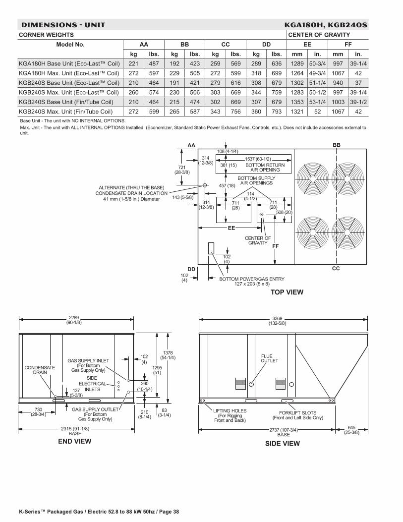
K-Series™ Packaged Gas / Electric 52.8 to 88 kW 50hz / Page 38
BOTTOM SUPPLYAIR OPENINGS
BOTTOM RETURNAIR OPENING
AA BB
CCDD
CENTER OFGRAVITY
EE
FF
TOP VIEW
FLUE
SIDE VIEW
FORKLIFT SLOTS(Front and Left Side Only)
LIFTING HOLES(For Rigging
Front and Back)
OUTLET
3369(132-5/8)
645(25-3/8)2737 (107-3/4)
BASEEND VIEW
210(8-1/4)
260(10-1/4)
102(4)
BOTTOM POWER/GAS ENTRY
314(12-3/8)
711(28)
711(28)
508 (20)
127 x 203 (5 x 8)
381 (15)1537 (60-1/2)
114(4-1/2)
108 (4-1/4)
102(4)
102(4)
314(12-3/8)
1378(54-1/4)
1295(51)
137(5-3/8)
730(28-3/4)
83(3-1/4)
2289(90-1/8)
2315 (91-1/8)BASE
ALTERNATE (THRU THE BASE)CONDENSATE DRAIN LOCATION
41 mm (1-5/8 in.) Diameter
457 (18)
(28-3/8)721
143 (5-5/8)
SIDE ELECTRICAL
INLETS
GAS SUPPLY INLET(For Bottom
Gas Supply Only)CONDENSATE
GAS SUPPLY OUTLET(For Bottom
Gas Supply Only)
DRAIN
DIMENSIONS - UNIT KGA180H, KGB240SCORNER WEIGHTS CENTER OF GRAVITY
Model No. AA BB CC DD EE FFkg lbs. kg lbs. kg lbs. kg lbs. mm in. mm in.
KGA180H Base Unit (Eco-Last™ Coil) 221 487 192 423 259 569 289 636 1289 50-3/4 997 39-1/4KGA180H Max. Unit (Eco-Last™ Coil) 272 597 229 505 272 599 318 699 1264 49-3/4 1067 42KGB240S Base Unit (Eco-Last™ Coil) 210 464 191 421 279 616 308 679 1302 51-1/4 940 37KGB240S Max. Unit (Eco-Last™ Coil) 260 574 230 506 303 669 344 759 1283 50-1/2 997 39-1/4KGB240S Base Unit (Fin/Tube Coil) 210 464 215 474 302 669 307 679 1353 53-1/4 1003 39-1/2KGB240S Max. Unit (Fin/Tube Coil) 272 599 265 587 343 756 360 793 1321 52 1067 42Base Unit - The unit with NO INTERNAL OPTIONS.Max. Unit - The unit with ALL INTERNAL OPTIONS Installed. (Economizer, Standard Static Power Exhaust Fans, Controls, etc.). Does not include accessories external to unit.
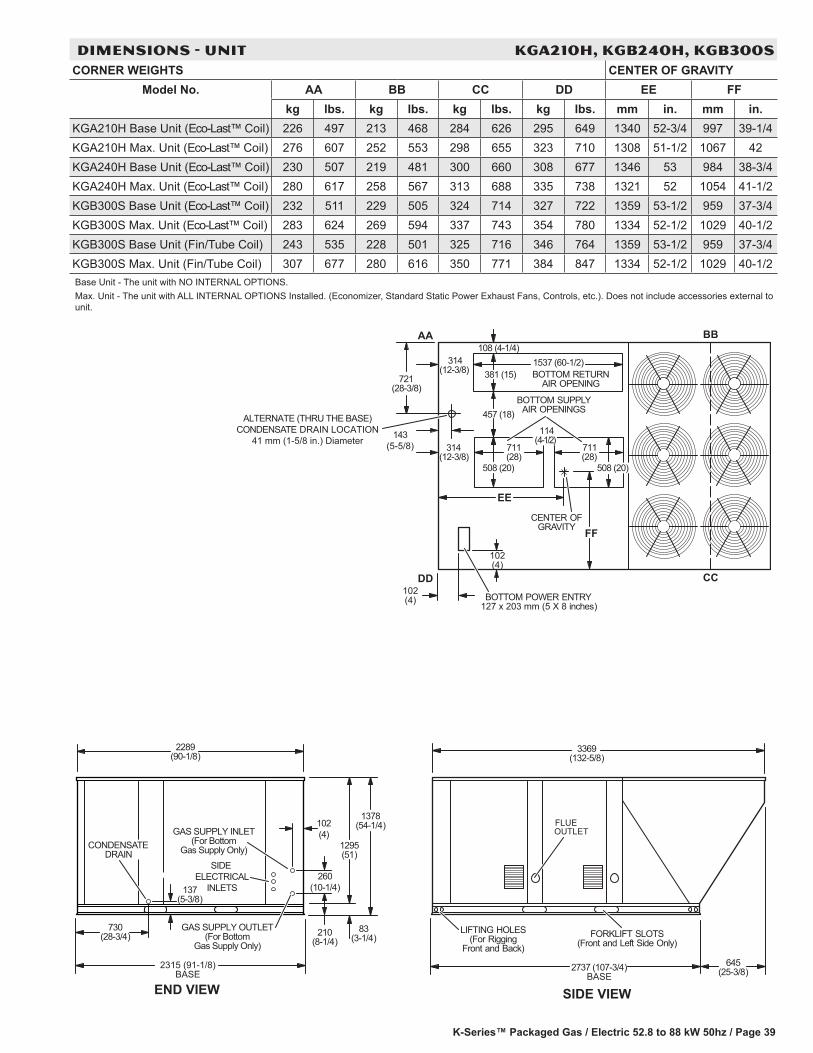
K-Series™ Packaged Gas / Electric 52.8 to 88 kW 50hz / Page 39
FLUE
SIDE VIEW
FORKLIFT SLOTS(Front and Left Side Only)
LIFTING HOLES(For Rigging
Front and Back)
OUTLET
3369(132-5/8)
645(25-3/8)2737 (107-3/4)
BASEEND VIEW
210(8-1/4)
260(10-1/4)
102(4)
1378(54-1/4)
1295(51)
137(5-3/8)
730(28-3/4)
83(3-1/4)
2289(90-1/8)
2315 (91-1/8)BASE
SIDE ELECTRICAL
INLETS
GAS SUPPLY INLET(For Bottom
Gas Supply Only)CONDENSATE
GAS SUPPLY OUTLET(For Bottom
Gas Supply Only)
DRAIN
BOTTOM POWER ENTRY
BOTTOM SUPPLYAIR OPENINGS
BOTTOM RETURNAIR OPENING
AA BB
CCDD
CENTER OFGRAVITY
EE
FF
ALTERNATE (THRU THE BASE)CONDENSATE DRAIN LOCATION
41 mm (1-5/8 in.) Diameter
457 (18)
721(28-3/8)
143 (5-5/8)
127 x 203 mm (5 X 8 inches)
711(28)
711 (28)
508 (20) 508 (20)
381 (15)1537 (60-1/2)
114(4-1/2)
108 (4-1/4)
102(4)
102(4)
314(12-3/8)
314(12-3/8)
DIMENSIONS - UNIT KGA210H, KGB240H, KGB300SCORNER WEIGHTS CENTER OF GRAVITY
Model No. AA BB CC DD EE FFkg lbs. kg lbs. kg lbs. kg lbs. mm in. mm in.
KGA210H Base Unit (Eco-Last™ Coil) 226 497 213 468 284 626 295 649 1340 52-3/4 997 39-1/4KGA210H Max. Unit (Eco-Last™ Coil) 276 607 252 553 298 655 323 710 1308 51-1/2 1067 42KGA240H Base Unit (Eco-Last™ Coil) 230 507 219 481 300 660 308 677 1346 53 984 38-3/4KGA240H Max. Unit (Eco-Last™ Coil) 280 617 258 567 313 688 335 738 1321 52 1054 41-1/2KGB300S Base Unit (Eco-Last™ Coil) 232 511 229 505 324 714 327 722 1359 53-1/2 959 37-3/4KGB300S Max. Unit (Eco-Last™ Coil) 283 624 269 594 337 743 354 780 1334 52-1/2 1029 40-1/2KGB300S Base Unit (Fin/Tube Coil) 243 535 228 501 325 716 346 764 1359 53-1/2 959 37-3/4KGB300S Max. Unit (Fin/Tube Coil) 307 677 280 616 350 771 384 847 1334 52-1/2 1029 40-1/2Base Unit - The unit with NO INTERNAL OPTIONS.Max. Unit - The unit with ALL INTERNAL OPTIONS Installed. (Economizer, Standard Static Power Exhaust Fans, Controls, etc.). Does not include accessories external to unit.
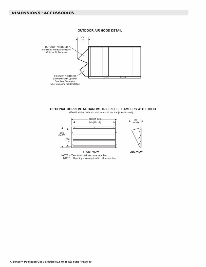
K-Series™ Packaged Gas / Electric 52.8 to 88 kW 50hz / Page 40
DIMENSIONS - ACCESSORIES
OPTIONAL HORIZONTAL BAROMETRIC RELIEF DAMPERS WITH HOOD(Field installed in horizontal return air duct adjacent to unit)
OUTDOOR AIR HOOD DETAIL
OUTDOOR AIR HOOD(Furnished with Economizer or
Outdoor Air Damper)
EXHAUST AIR HOOD(Furnished with Optional
Downflow BarometricRelief Dampers, Field Installed)
406(16)
FRONT VIEW SIDE VIEW
803 (31−5/8)
368(14-1/2)
1 330 (13)
165(6-1/2) 1 749 (29−1/2)
NOTE − Two furnished per order number. 1 NOTE − Opening size required in return air duct.
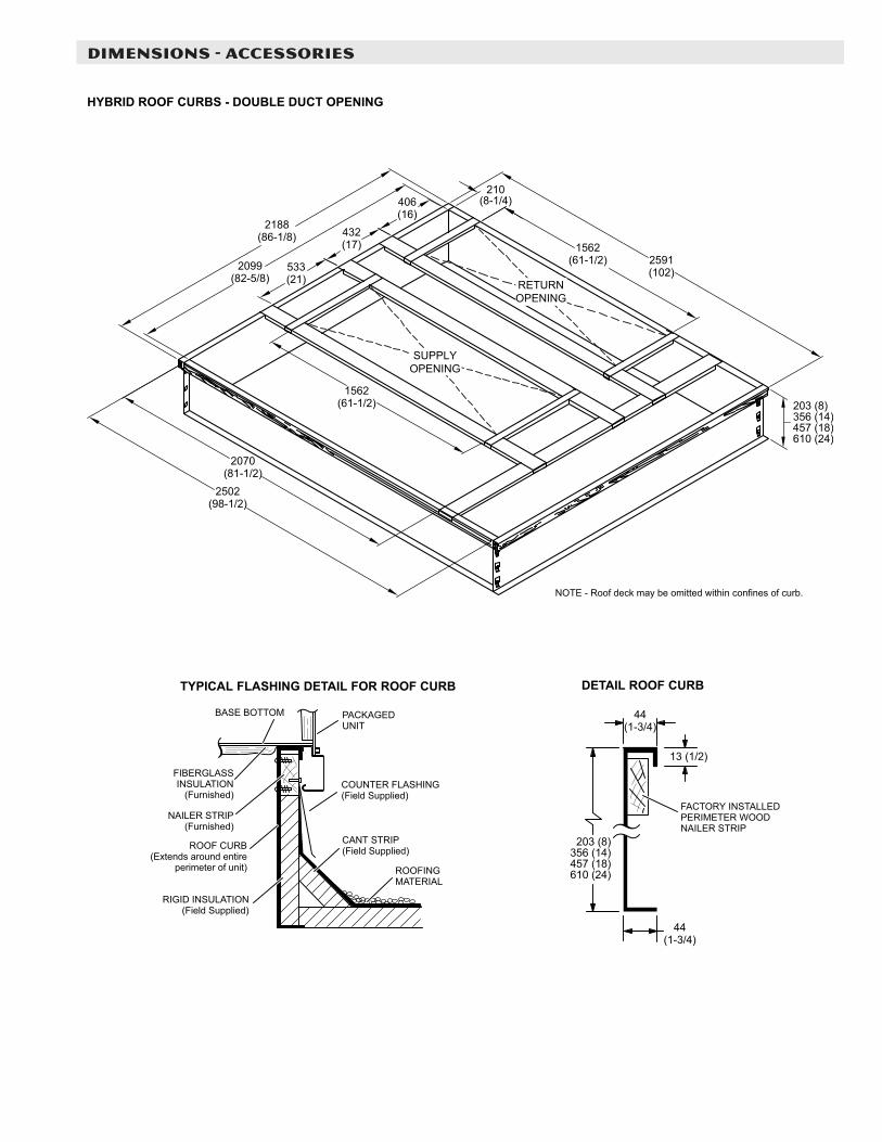
DIMENSIONS - ACCESSORIES
RETURNOPENING
SUPPLYOPENING
NOTE - Roof deck may be omitted within confines of curb.
TYPICAL FLASHING DETAIL FOR ROOF CURB
ROOF CURB(Extends around entire
perimeter of unit)
FIBERGLASSINSULATION
(Furnished)COUNTER FLASHING(Field Supplied)
BASE BOTTOM
RIGID INSULATION(Field Supplied)
ROOFINGMATERIAL
CANT STRIP(Field Supplied)
PACKAGEDUNIT
NAILER STRIP(Furnished)
DETAIL ROOF CURB
FACTORY INSTALLEDPERIMETER WOODNAILER STRIP
HYBRID ROOF CURBS - DOUBLE DUCT OPENING
203 (8)356 (14)457 (18)610 (24)
13 (1/2)
44(1-3/4)
2502(98-1/2)
2070(81-1/2)
1562(61-1/2)
2188(86-1/8)
2099(82-5/8)
533(21)
432(17)
406(16)
210(8-1/4)
1562(61-1/2) 2591
(102)
44(1-3/4)
203 (8)356 (14)457 (18)610 (24)
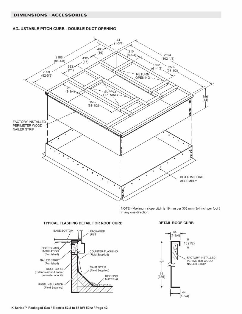
K-Series™ Packaged Gas / Electric 52.8 to 88 kW 50hz / Page 42
DIMENSIONS - ACCESSORIES
TYPICAL FLASHING DETAIL FOR ROOF CURB
ROOF CURB(Extends around entire
perimeter of unit)
FIBERGLASSINSULATION
(Furnished)COUNTER FLASHING(Field Supplied)
BASE BOTTOM
RIGID INSULATION(Field Supplied)
ROOFINGMATERIAL
CANT STRIP(Field Supplied)
PACKAGEDUNIT
NAILER STRIP(Furnished)
DETAIL ROOF CURB
FACTORY INSTALLEDPERIMETER WOODNAILER STRIP
RETURNOPENING
ADJUSTABLE PITCH CURB - DOUBLE DUCT OPENING
SUPPLYOPENING
BOTTOM CURBASSEMBLY
NOTE - Maximum slope pitch is 19 mm per 305 mm (3/4 inch per foot )in any one direction.
FACTORY INSTALLEDPERIMETER WOODNAILER STRIP
2594 (102-1/8)
2502 (98-1/2)
356 (14)
44 (1-3/4)
13 (1/2)
44 (1-3/4)
533 (21)2099
(82-5/8)
14 (356)
2188 (86-1/8)
432 (17)
406 (16)
44 (1-3/4)
210 (8-1/4)
1562 (61-1/2)
210 (8-1/4)
1562 (61-1/2)
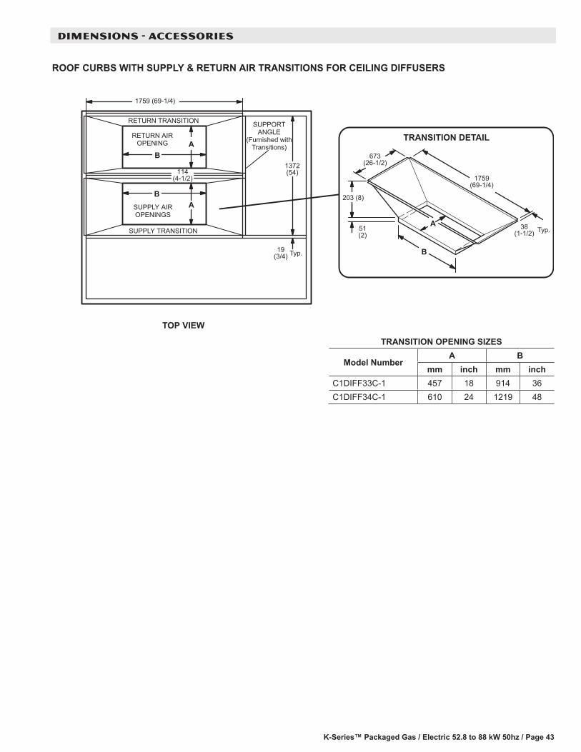
K-Series™ Packaged Gas / Electric 52.8 to 88 kW 50hz / Page 43
DIMENSIONS - ACCESSORIES
ROOF CURBS WITH SUPPLY & RETURN AIR TRANSITIONS FOR CEILING DIFFUSERS
SUPPLY TRANSITION
RETURN TRANSITION
RETURN AIROPENING
SUPPLY AIROPENINGS
TOP VIEW
1372(54)
1759 (69-1/4)
19(3/4) Typ.
114(4-1/2)
SUPPORTANGLE
(Furnished withTransitions)
B
A
B
1759(69-1/4)
51(2)
203 (8)
673(26-1/2)
38(1-1/2) Typ.
TRANSITION DETAIL
A
AB
TRANSITION OPENING SIZES
Model NumberA B
mm inch mm inchC1DIFF33C-1 457 18 914 36C1DIFF34C-1 610 24 1219 48
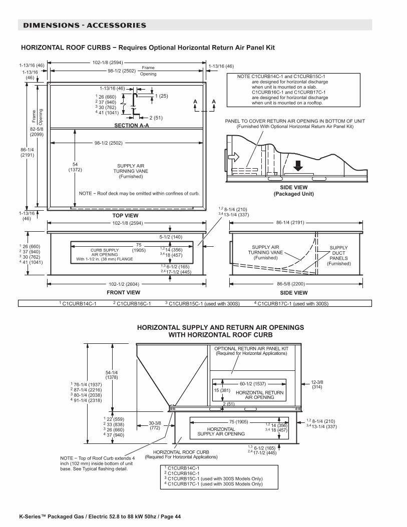
K-Series™ Packaged Gas / Electric 52.8 to 88 kW 50hz / Page 44
DIMENSIONS - ACCESSORIES
HORIZONTAL ROOF CURBS − Requires Optional Horizontal Return Air Panel Kit
PANEL TO COVER RETURN AIR OPENING IN BOTTOM OF UNIT(Furnished With Optional Horizontal Return Air Panel Kit)
SIDE VIEW(Packaged Unit)
SIDE VIEW86-5/8 (2200)
SUPPLYDUCT
PANELS(Furnished)
SUPPLY AIRTURNING VANE
(Furnished)
86-1/4 (2191)
102-1/8 (2594)
TOP VIEW
Fram
eO
peni
ng
FrameOpening
54(1372)
98-1/2 (2502)
82-5/8(2099)
98-1/2 (2502)
NOTE − Roof deck may be omitted within confines of curb.
SUPPLY AIRTURNING VANE
(Furnished)
1-13/16(46)
1-13/16(46)
1-13/16 (46)1-13/16 (46)
86-1/4(2191)
HORIZONTALSUPPLY AIR OPENING
HORIZONTAL ROOF CURB(Required For Horizontal Applications)
75 (1905)
HORIZONTAL RETURNAIR OPENING
12-3/8(314)
15 (381)60-1/2 (1537)
2 (51)
54-1/4(1378)
NOTE − Top of Roof Curb extends 4inch (102 mm) inside bottom of unitbase. See Typical flashing detail.
OPTIONAL RETURN AIR PANEL KIT(Required for Horizontal Applications)
6-1/2 (165) 17-1/2 (445)
1 22 (559)2 33 (838)3 26 (660)4 37 (940)
1 76-1/4 (1937)2 87-1/4 (2216)3 80-1/4 (2038)4 91-1/4 (2318)
14 (356) 18 (457)
30-3/8(772)
HORIZONTAL SUPPLY AND RETURN AIR OPENINGSWITH HORIZONTAL ROOF CURB
1 C1CURB14C-1 2 C1CURB16C-13 C1CURB15C-1 (used with 300S Models Only)4 C1CURB17C-1 (used with 300S Models Only)
1 C1CURB14C-1 2 C1CURB16C-1 3 C1CURB15C-1 (used with 300S) 4 C1CURB17C-1 (used with 300S)
NOTE C1CURB14C-1 and C1CURB15C-1are designed for horizontal dischargewhen unit is mounted on a slab.C1CURB16C-1 and C1CURB17C-1are designed for horizontal dischargewhen unit is mounted on a rooftop.
14 (356) 18 (457)
102-1/2 (2604)
CURB SUPPLYAIR OPENING
With 1-1/2 in. (38 mm) FLANGE
75(1905)
5-1/2 (140)
102-1/8 (2594)
1,2 8-1/4 (210)3,413-1/4 (337)
6-1/2 (165) 17-1/2 (445)
1 26 (660)2 37 (940)3 30 (762)4 41 (1041)
FRONT VIEW
1,23,4
1,32,4
1,2 8-1/4 (210)3,413-1/4 (337)1,2
3,4
1,32,4
1 26 (660)2 37 (940)3 30 (762)4 41 (1041)
1 (25)
2 (51)SECTION A-A
1-13/16 (46)
A A
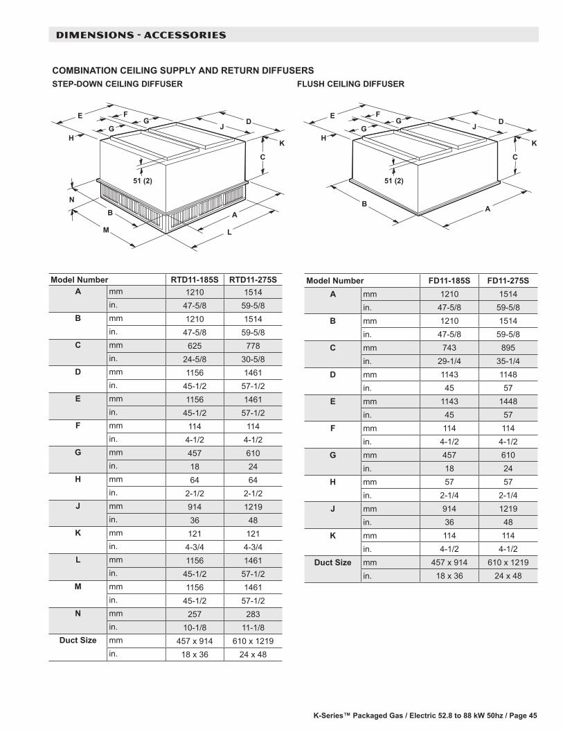
K-Series™ Packaged Gas / Electric 52.8 to 88 kW 50hz / Page 45
DIMENSIONS - ACCESSORIES
COMBINATION CEILING SUPPLY AND RETURN DIFFUSERSRESUFFID GNILIEC HSULFRESUFFID GNILIEC NWOD-PETS
L
A
C
HJG
FE
B
M
N
K
DG
51 (2)
A
C
HJG
FE
B
K
DG
51 (2)
Model Number RTD11-185S RTD11-275SA mm 1210 1514
in. 47-5/8 59-5/8B mm 1210 1514
in. 47-5/8 59-5/8C mm 625 778
in. 24-5/8 30-5/8D mm 1156 1461
in. 45-1/2 57-1/2E mm 1156 1461
in. 45-1/2 57-1/2F mm 114 114
in. 4-1/2 4-1/2G mm 457 610
in. 18 24H mm 64 64
in. 2-1/2 2-1/2J mm 914 1219
in. 36 48K mm 121 121
in. 4-3/4 4-3/4L mm 1156 1461
in. 45-1/2 57-1/2M mm 1156 1461
in. 45-1/2 57-1/2N mm 257 283
in. 10-1/8 11-1/8Duct Size mm 457 x 914 610 x 1219
in. 18 x 36 24 x 48
Model Number FD11-185S FD11-275SA mm 1210 1514
in. 47-5/8 59-5/8B mm 1210 1514
in. 47-5/8 59-5/8C mm 743 895
in. 29-1/4 35-1/4D mm 1143 1148
in. 45 57E mm 1143 1448
in. 45 57F mm 114 114
in. 4-1/2 4-1/2G mm 457 610
in. 18 24H mm 57 57
in. 2-1/4 2-1/4J mm 914 1219
in. 36 48K mm 114 114
in. 4-1/2 4-1/2Duct Size mm 457 x 914 610 x 1219
in. 18 x 36 24 x 48


REVISIONS
REVISIONS
Section Description
Optional Accessories Added Low Ambient Controls.
NOTE - Due to Allied Commercial ongoing commitment to quality, Specifications, Ratings and Dimensions subject to change without notice and without incurring liability. Improper installation, adjustment, alteration, service or maintenance can cause property damage or personal injury. Installation and service must be performed by a qualified installer and servicing agency.
©2019 Allied Air Enterprises LLC, a Lennox International Inc. Company
Visit us at www.allied-commercial.com
For the latest technical information, visit us at www.allied-commercial.com
Contact us at 1-800-448-5872
Related Documents


![Notice of Decision the rooftop addition and rooftop patio ...€¦ · the rooftop addition and rooftop patio, 5.54 metres by 4.04 metres) [2] The subject property is on Condo Common](https://static.cupdf.com/doc/110x72/5fbd4da09cef473df80642ed/notice-of-decision-the-rooftop-addition-and-rooftop-patio-the-rooftop-addition.jpg)


