Collecting Energy from a Planetary Entropic Stirling Engine S. Kazadi, A. Schwartz, J. Huang, R. Goy, C. Koo, S. Choi J. Lim, A. Koh, J. Choi, C. Koh, J. Wang June 13, 2013 Abstract We extend previous work [1, 2] on entrochemical systems, energetically closed systems which spontaneously cre- ate internal thermal gradients. Like electrical batteries, these thermal batteries use differing chemical potentials to generate work, and thermal work is extracted from their environment. This paper introduces a ’spontaneous’ method- ology for recharging the system. We utilize a solar chimney to generate airflow over a draw solution, evaporating water and reconcentrating the solution. The reconcentrated solution is used to restore the original internal concentra- tion gradient which enables the entrochemical system. We examine a device comprising three major parts: a reaction chamber, a distiller, and a solar chimney. We measure the output of our thermal battery at 129.3 ± 11.9 W /m 2 using KCl as an enabling salt and 235.3 ± 15.3 W /m 2 using NaCl as an enabling salt. We measure internal recharge rates of 55.6 ± 6.9 W /m 2 when using a KCl / NaCl salt pair and 116.4 ± 18.0 W /m 2 when using a NaCl / CaCl 2 salt pair. We utilize a 6.096 m tall solar chimney with a 0.74m 2 solar collector. This solar chimney enables airflow of 37.05 m 3 /day. We measure a maximal evaporative performance of 1.213 L/day/m 2 . This corresponds to an effective energy utilization of 75.49 W /m 2 (50.5% of maximum, given the airflow). Extrapolation using the model of [4] to model a 35 ◦ C thermal lift and a 200 m tall chimney indicates an effective energy utilization of 405.49 W /m 2 . We discuss how this energy can enable water distillation. The process naturally stores entropic potential removing daily solar irradiance limitations and enabling on-demand energy. Waste products are humidified air, which may enable precipitation, and salt crystals. 1 Introduction In 2010, Kazadi et. al. [1] coined the term entrochemical system to describe a class of systems in which the development of a thermal gradient through a spontaneous entropy transfer is possible. The devices presented in that work create a thermal gradient spontaneously as a result of the interaction between entropy and energy transfers between two water solution reservoirs of differing chemical potentials. Though the effect is predicted by thermodynamics [2], it has been largely unobserved due to the specific set of conditions required to enable it. The systems also represent an example of what we call thermal batteries, devices that deliver a specific quantity of thermal energy, typically by using an exothermic reaction. Recharging the system was not addressed in previous work. Entrochemical systems function via strictly physical changes as opposed to chemical changes. As a result, an input of heat can reverse the effect. Yet when the heat is directly applied to a closed system, this process is simple distillation of the concentrated solution, and requires more energy than one can extract from the thermal battery. In this paper, we address a recharge method for entrochemical systems. This recharge method uses a solar chimney to enable evaporation of water from an intermediate solution used to “dry” the high concentration reservoir of the entrochemical device when it becomes diluted. This process, which is spontaneous, enables the continual use of the entrochemical system in “harvesting” atmospheric thermal energy. This device’s continual efficacy depends on the ability to continually transfer entropy to the atmosphere through evaporation, making this energizing step spontaneous. In order to explain why this effect does not ever stop, we introduce the concept of a planetary entropic Stirling engine, powered by solar heat. This analogy to a Stirling engine explains how, through the daily heating, the atmosphere is made able to accept entropy after daily rejecting entropy during cooling. In effect, our entrochemical system is “plugged in” to the planetary entropic Stirling engine by the solar chimney. Section 2 describes the entrochemical systems and their energetic, entropic, and systemic properties. Section 3 discusses the planetary entropic Stirling engine. Section 4 describes the apparati and procedures we developed to 1

Welcome message from author
This document is posted to help you gain knowledge. Please leave a comment to let me know what you think about it! Share it to your friends and learn new things together.
Transcript

Collecting Energy from a Planetary Entropic Stirling Engine
S. Kazadi, A. Schwartz, J. Huang, R. Goy, C. Koo, S. ChoiJ. Lim, A. Koh, J. Choi, C. Koh, J. Wang
June 13, 2013
Abstract
We extend previous work [1, 2] on entrochemical systems, energetically closed systems which spontaneously cre-ate internal thermal gradients. Like electrical batteries, thesethermal batteriesuse differing chemical potentials togenerate work, and thermal work is extracted from their environment. This paper introduces a ’spontaneous’ method-ology for recharging the system. We utilize a solar chimney to generate airflow over a draw solution, evaporatingwater and reconcentrating the solution. The reconcentrated solution is used to restore the original internal concentra-tion gradient which enables the entrochemical system. We examine a device comprising three major parts: a reactionchamber, a distiller, and a solar chimney. We measure the output of our thermal battery at 129.3±11.9 W/m2 usingKCl as an enabling salt and 235.3±15.3 W/m2 usingNaCl as an enabling salt. We measure internal recharge ratesof 55.6± 6.9 W/m2 when using aKCl / NaCl salt pair and 116.4± 18.0 W/m2 when using aNaCl / CaCl2 saltpair. We utilize a 6.096m tall solar chimney with a 0.74m2 solar collector. This solar chimney enables airflow of37.05 m3/day. We measure a maximal evaporative performance of 1.213L/day/m2. This corresponds to an effectiveenergy utilization of 75.49W/m2 (50.5% of maximum, given the airflow). Extrapolation using the model of [4] tomodel a 35◦C thermal lift and a 200m tall chimney indicates an effective energy utilization of 405.49W/m2. Wediscuss how this energy can enable water distillation. The process naturally stores entropic potential removing dailysolar irradiance limitations and enabling on-demand energy. Waste products are humidified air, which may enableprecipitation, and salt crystals.
1 Introduction
In 2010, Kazadi et. al. [1] coined the termentrochemical systemto describe a class of systems in which the developmentof a thermal gradient through a spontaneous entropy transfer is possible. The devices presented in that work create athermal gradient spontaneously as a result of the interaction between entropy and energy transfers between two watersolution reservoirs of differing chemical potentials. Though the effect is predicted by thermodynamics [2], it has beenlargely unobserved due to the specific set of conditions required to enable it.
The systems also represent an example of what we callthermal batteries, devices that deliver a specific quantity ofthermal energy, typically by using an exothermic reaction.Recharging the system was not addressed in previous work.Entrochemical systems function via strictly physical changes as opposed to chemical changes. As a result, an input ofheat can reverse the effect. Yet when the heat is directly applied to a closed system, this process is simple distillationof the concentrated solution, and requires more energy thanone can extract from the thermal battery.
In this paper, we address a recharge method for entrochemical systems. This recharge method uses a solar chimneyto enable evaporation of water from an intermediate solution used to “dry” the high concentration reservoir of theentrochemical device when it becomes diluted. This process, which is spontaneous, enables the continual use of theentrochemical system in “harvesting” atmospheric thermalenergy.
This device’s continual efficacy depends on the ability to continually transfer entropy to the atmosphere throughevaporation, making this energizing step spontaneous. In order to explain why this effect does not ever stop, weintroduce the concept of aplanetary entropic Stirling engine, powered by solar heat. This analogy to a Stirling engineexplains how, through the daily heating, the atmosphere is made able to accept entropy after daily rejecting entropyduring cooling. In effect, our entrochemical system is “plugged in” to the planetary entropic Stirling engine by thesolar chimney.
Section 2 describes the entrochemical systems and their energetic, entropic, and systemic properties. Section 3discusses the planetary entropic Stirling engine. Section4 describes the apparati and procedures we developed to
1

investigate this process. Section 5 provides experimentaldata. A discussion is given in Section 6. We conclude inSection 7.
2 Entrochemical Devices
2.1 Basic theory and experiments
The basic entrochemical system is diagrammed in Figure 2.1 below. In the basic system, two reservoirs are at leastpartially filled with water and enclosed in a larger chamber.One of the two reservoirs also contains salt.
������������������������������������������������������������������������������������������������������������������
������������������������������������������������������������������������������������������������������������������
������������������������������������������
������������������������������������������
��������������������������������������������������������������������������������������������������������������������������������������������������������
��������������������������������������������������������������������������������������������������������������������������������������������������������
��������������������������������������������������������������������������������������������������������������������������������������������
��������������������������������������������������������������������������������������������������������������������������������������������
��������������������������������������������������������
��������������������������������������������������������
����������������������������������������������������
����������������������������������������������������
OuterChamber
InnerChamber
DH O2 DH O + NaCl2
VacuumChamber
Figure 2.1: (A) A diagrammatic description of a basic entrochemical system. The reservoirs of water, one containing salt (or more salt than theother) must, in equilibrium, be at the same chemical potential. This is only possible if they are at different temperatures. (B) A nested version ofthe entrochemical system with an external insulating vacuum jacket. [1] reported a thermal gradient of 2.5◦C when used at 19◦C with saturated NaClsolutions on top and distilled water on the bottom.
As a result, the chemical potentials of the two reservoirs,µ , cannot be the same at the same temperature. I.e.,
µH2O(t) 6= µH2O/salt (t) . (1)
In equilibrium the chemical potentials of the two solutionsmust be equal to that of the vapor contained in the chamber.
µH2O (tH2O) = µvapor(tvap) = µH2O/salt (tsalt) . (2)
In order to avoid a contradiction, we must conclude thattH2O 6= tsalt, or that the two water reservoirs equilibrate atdifferent temperatures. This equilibration is mediated bya vapor transfer from the water reservoir to the salt solutionreservoir, increasing entropy and transferring heat (the heat of vaporization).1
The resulting system approaches an equilibrium with a temperature gradient that brings the chemical potentials toapproximate equality. The system never completely reachesequilibrium, however, as some of the thermal energy leaksout of the system from the warmer side or into the system through the colder side. At least a small flow of vapor fromthe water to the salt solution continues until either the concentrations of dissolved solutes in the two reservoirs becomeequal or all the water in the less concentrated side evaporates.
2.2 Temperature gradients, entropy transfers, thermal work limits
We have shown elsewhere [2] that the temperature differencebetween two bodies of water of differing concentrationis given by
T1 = T2
µ1−2∂U1∂N1
µ2−2∂U2∂N2
. (3)
which can be used to yield
∆T = T2
(µ2− µ1)+2(
∂U1∂N1
− ∂U2∂N2
)
µ2−2∂U2∂N2
. (4)
∆T ≃ T2
(
(µ2− µ1)
µ2−2∂U2∂N2
)
. (5)
1A different proof is offered in [2].
2

For solutions, whereµ = −ln(x) with x the mole ratio of water in the solution2 (4) becomes
∆T ≃ T2R(T2ln(x2)−T1ln(x1))
RT2ln(x2)−2∂U2∂N2
(6)
∆T ≃ T
4
RTln(
x2x1
)
∂U2
∂N2−
√
√
√
√
√
4+16
R2T2(
ln(
x2x1
))2
(
∂U2
∂N2
)2
(7)
where∂U2∂N2
is the molar heat of vaporization andT = T2+T12 . When applied to water, this temperature multiplier has the
profile given in Figure 2.2 where the horizontal axes represent the mole fraction of the solutions and the vertical axisrepresents the multiplier.
Figure 2.2: This figure illustrates the entrochemical temperature multiplier given in equation (3). The horizontal axes represent the mole fractions ofthe two solutions and the vertical axis represents the multiplier value.
If x1 is 1 (or pure water), the relation becomes
∆T ≃ RT2
(
ln(x2)
ln(x2)−2
RT2
∂U2∂N2
)
. (8)
This becomes
∆T ≃4T
RTln(x1)
∂U2
∂N2−T
√
√
√
√4+16
R2T2(ln(x1))
2
(
∂U2
∂N2
)2
. (9)
In this case, the curve is given by
2A derivation of this chemical potential may be found in [3].
3
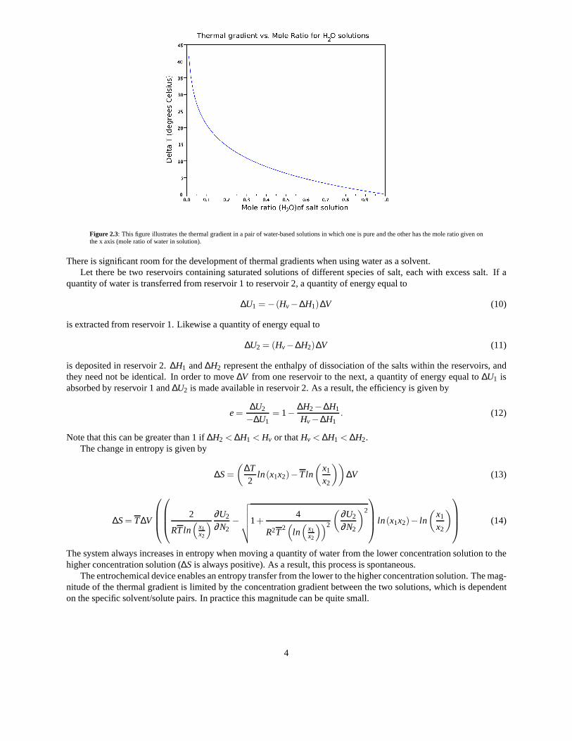
Figure 2.3: This figure illustrates the thermal gradient in a pair of water-based solutions in which one is pure and the other has the mole ratio given onthe x axis (mole ratio of water in solution).
There is significant room for the development of thermal gradients when using water as a solvent.Let there be two reservoirs containing saturated solutionsof different species of salt, each with excess salt. If a
quantity of water is transferred from reservoir 1 to reservoir 2, a quantity of energy equal to
∆U1 = −(Hv−∆H1)∆V (10)
is extracted from reservoir 1. Likewise a quantity of energyequal to
∆U2 = (Hv−∆H2)∆V (11)
is deposited in reservoir 2.∆H1 and∆H2 represent the enthalpy of dissociation of the salts within the reservoirs, andthey need not be identical. In order to move∆V from one reservoir to the next, a quantity of energy equal to∆U1 isabsorbed by reservoir 1 and∆U2 is made available in reservoir 2. As a result, the efficiency is given by
e=∆U2
−∆U1= 1−
∆H2−∆H1
Hv−∆H1. (12)
Note that this can be greater than 1 if∆H2 < ∆H1 < Hv or thatHv < ∆H1 < ∆H2.The change in entropy is given by
∆S=
(
∆T2
ln(x1x2)−Tln
(
x1
x2
))
∆V (13)
∆S= T∆V
2
RTln(
x1x2
)
∂U2
∂N2−
√
√
√
√
√
1+4
R2T2(
ln(
x1x2
))2
(
∂U2
∂N2
)2
ln(x1x2)− ln
(
x1
x2
)
(14)
The system always increases in entropy when moving a quantity of water from the lower concentration solution to thehigher concentration solution (∆S is always positive). As a result, this process is spontaneous.
The entrochemical device enables an entropy transfer from the lower to the higher concentration solution. The mag-nitude of the thermal gradient is limited by the concentration gradient between the two solutions, which is dependenton the specific solvent/solute pairs. In practice this magnitude can be quite small.
4

3 Plugging into the planetary entropic stirling engine
We defineentropic potentialas the maximum entropy a liquid can contribute to a volume of gas at a given temperature.If the water vapor in a volumeV behaves like an ideal gas, then its total entropy is given by aform of the Sackur-Tetrodeequation. This gives us that
σ = nV
[
ln(nQ
n
)
+52
]
(15)
whereP is given by3
P =10
(
8.07131− 1730.3233.426+(T−273.15)
)
760RT(16)
in atmospheres andnQ is given by
nQ =
(
mkBT
2π h̄2
) 32
.
As a result, an amount of water equalling
∆Vw =∆PVg
RTMmρw
can be evaporated into the air, whereVg is the volume of air,Mm is the molecular mass,ρw is the solution density,and∆P is the pressure difference between the vapor pressures at the two temperatures. This will have a concomitantincrease in entropy. Thus heating the air has the potential to draw more vapor out of solution, transferring entropy.This potential change in entropy is the entropic potential of the system and it is this we wish to take advantage of.
The increase in entropy is graphed in Figure 3.1, which illustrates the temperature dependent maximum entropy ofa volume of gas.
0 10020 40 60 8010 30 50 70 900
1
0.2
0.4
0.6
0.8
1.2
1.4
0.1
0.3
0.5
0.7
0.9
1.1
1.3
Temperature (Degrees Celsius)
Ent
ropy
Figure 3.1: These figures give the temperature-dependent maximum entropy of a volume of gas.
The maximum entropy of the day and night environments are different, and this enables evaporative entropy transferduring the day and forces condensation-mediated nighttimeentropy leakage at night.
Analogously to the Stirling engine, the daily process can becharacterized as the creation of a high entropic potentialatmosphere and the subsequent restoration of the previous low entropy state. What is required to “plug in” to thisStirling engine is a method of taking advantage of the daytime expansion of entropic potential and its subsequentnightly reduction.
3This is an approximation based on Antoine’s equation.
5

Figure 3.2: A diagram of the planetary Stirling engine daily cycle.
The capacity of an entrochemical system is reached when either the solute concentrations of the two solutions becomeequal or the solvent in the one of the two solutions (that withlower solute concentration) becomes exhausted. Oncethis capacity is reached the solvent has been transferred tothe high concentration solution. In order to restore itsfunctionality, new solvent must be provided to the bottom reservoir and the solvent must be separated from the solutein the top reservoir. It is the latter of these two steps that requires the input of energy. When coupled to a process thatinduces a positive entropy change, this step is spontaneous.
The overall process, which we call the “Kazadi-cycle” or “k-cycle”, is illustrated below in Figure 3.3 and involvesthree spontaneous steps. First, the entrochemical effect generates the movement of fluid from one reservoir to theother, producing work. Second, the entrochemical effect moves fluid from the top reservoir into the draw solution.Third, evaporation of the solvent from the draw solution utilizes atmospheric thermal energy to transfer entropy intothe atmosphere.
6

Figure 3.3: This process, known as the “Kazadi cycle” or “k-cycle” follows the entropic inputs to the system and its pathway out of the system.
The top reservoir has a T-S diagram illustrated in Figure 3.4.
−0.01 0.00 0.01 0.02 0.03 0.04 0.05 0.06∆Entropy
−1.0
−0.5
0.0
0.5
1.0
1.5
∆Tem
pera
ture
(C
)
Figure3.4: The T-S diagram associated with the top reservoir in the entrochemical device. Initially, the temperature increases,followed by a levelingoff and concomitant increase in entropy. An adiabatic phaseends with the maximal entropy at which point the temperaturedifference decreases to zero.A reversal occurs as the entropy decreases coupled with an decrease in temperature until all the water has been extracted. At that point, entropy hasreturned to the minimum and the system equilibrates to a common temperature (no temperature difference).
This diagram illustrates the thermodynamic cycle the top reservoir goes through. Initially, vapor movement rapidlyincreases the temperature gradient between the high and lowtemperature reservoirs. Next, the reservoir goes throughan isothermal stage during which heat is drawn into the system and radiated out of the system at a constant speed whilethe solvent is transferred between them. The rate at which the solvent is transferred is limited by either the maximalrate of the entrochemical effect or by the rate at which heat is radiated to the environment. Once the solvent transfer hasended the system rapidly comes to thermal equilibrium. Subsequently, during the evaporative stage, the temperatureof the solution drops while the entropy of the solution drops. When the evaporative stage ends, the system reachesthermal equilibrium and returns to the initial point.
This cycle enables the continued extraction of environmental thermal energy for the purpose of doing work as longas the atmosphere is capable of absorbing water vapor. Sincethe world is turning, this ability is restored on a dailybasis (or no water would ever evaporate from the ground when there is a spill, rain, etc.). As a result this process cancontinue virtually indefinitely4.
In order to tie the system’s performance tightly to the environmental entropic potential, a method must be usedto efficiently evaporate the water in the high concentrationsolution. Increasing airflow over a water body serves toincrease the evaporative action. We utilize a solar chimney, which will be described in Section 4.1.2.
4In our experiments, water is used as the solvent. This means that the output of the system as a result of the evaporation is water vapor, whichmay be expected to have a negligible environmental impact. Other solvents one might use, such as ethanol, might have significantly deleteriousenvironmental impacts if released in large quantities, andso are not solvents of choice for this purpose.
7

4 Materials and Methods
We have developed two devices capable of accomplishing together the thermal energy extraction and work production.In addition, we have developed several methods in order to achieve the experimental results of this study.
4.1 Apparati
4.1.1 Basic Entrochemical Reaction Chamber
We have developed an entrochemical reaction chamber which is diagrammatically illustrated in Figure 4.1.
Figure 4.1: The entrochemical reaction chamber contains two reservoirs of salt at different concentrations. The resulting flow offluid from onereservoir to another serves to alternately draw water into the top reservoir or draw it out of the top reservoir, depending on the relative osmolarities ofthe solutions.
The chamber is made from 4” OD cast acrylic tubing approximately 4” long and sealed on each end by 1/4” to 1/2”thick acrylic sheet. Channels in the acrylic approximately1/8” deep and 3/8” wide connect the interior of the chamberto valves which seal off the chamber from its exterior. The chamber contains two reservoirs spatially separated fromone another. The bottom reservoir can be alternately filled and drained by opening valves on the side or bottom ofthe chamber. The top reservoir contains a static salt supplywhich is alternately diluted as a result of the absorption ofwater vapor or concentrated as a result of evaporating waterinto the chamber. The chamber contains a steam injectorthrough which steam can be injected. At the top of the reaction chamber is a valve through which a vacuum is applied.Underneath the reaction chamber is a copper tube and a valve.The valve enables the draining of the chamber while thecopper tube enables the absorption of thermal energy. The top reservoir is made of copper. A copper tube is solderedinto the center of the reservoir, sealing the tube’s interior on the reservoir. The top of the tube is connected to the topof the chamber, and its interior is topologically connectedto the exterior of the chamber through a hole in the top ofthe chamber.
8
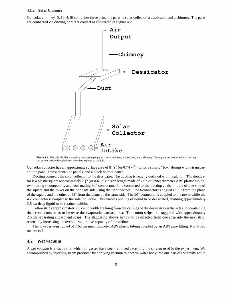
4.1.2 Solar Chimney
Our solar chimney [5, 10, 4, 6] comprises three principle parts: a solar collector, a dessicator, and a chimney. The partsare connected via ducting or direct contact as illustrated in Figure 4.2.
AirOutput
Chimney
Dessicator
Duct
CollectorSolar
AirIntake
Figure 4.2: The solar distiller comprises three principle parts: a solar collector, a dessicator, and a chimney. These parts are connected with ductingand enable airflow through the system when exposed to sunlight.
Our solar collector has an approximate surface area of 8f t2 (or 0.74m2). It has a simple “box” design with a transpar-ent top panel, transparent side panels, and a black bottom panel.
Ducting connects the solar collector to the dessicator. Theducting is heavily outfitted with insulation. The dessica-tor is a plastic square approximately 2f t (or 0.61m) in side length made of 7.62cminner diameter ABS plastic tubing,two mating t-connectors, and four mating 90◦ connectors. It is connected to the ducting at the middle of one side ofthe square and the tower on the opposite side using the t-connectors. One t-connector is angled at 90◦ from the planeof the square and the other at 45◦ from the plane on the same side. The 90◦ connector is coupled to the tower while the45◦ connector is coupled to the solar collector. This enables pooling of liquid to be dessicated, enabling approximately2.5 cmdeep liquid to be retained within.
Cotton strips approximately 2.5 cmin width are hung from the ceilings of the dessicator on the sides not containingthe t-connectors so as to increase the evaporative surface area. The cotton strips are staggered with approximately2.5 cm separating subsequent strips. The staggering allows airflow to be directed from one strip into the next strip,ostensibly increasing the overall evaporative capacity ofthe airflow.
The tower is constructed of 7.62cm inner diameter ABS plastic tubing coupled by an ABS pipe fitting. It is 6.096meters tall.
4.2 Wet vacuum
A wet vacuumis a vacuum in which all gasses have been removed excepting the solvent used in the experiment. Weaccomplished by injecting steam produced by applying vacuum to a warm water body into one part of the cavity while
9
a vacuum is applied to another distal part of the cavity.In our studies, we use 500 mL of water prepared by heating to approximately 76◦C. Steam is injected into our
chambers as outlined above. The vacuum is maintained for a period of at least one minute to ensure that most of theair that was not water vapor was removed from the chamber.
4.3 Salt production
It is necessary to utilize salt crystals that do not have air pockets contained within. Three methods of obtaining thesecrystals are described below.
4.3.1 Salt Drying Method 1
A quantity of water with an excess of salt is heated to boiling. This solution is decanted from the remaining salt intoa pre-heated container. The container is then placed into a vacuum chamber and subjected to a mild vacuum. Boilingof the water in the container generates steam, removing significant amounts of air from the vacuum chamber. Thechamber is then sealed under vacuum and allowed to cool. Crystals form in an air-free environment.
4.3.2 Salt Drying Method 2
Two chambers are connected to one another so that vapor can pass freely between them. A saturated salt solutionis placed into one and both are sealed and a wet vacuum is established within. The saturated salt solution is heated,driving water from the solution into the other, colder chamber; salt crystals without enclosed air are thereby formed.
4.3.3 Salt Drying Method 3
One chamber is prepared with a quantity of a saturated solution prepared with a salt with a high osmolarity within. Athermally conducting container is placed within so that it is in contact with the surface of the water, but water cannotpass into the container. A second saturated salt solution prepared with a salt with a lower osmolarity is placed insidethe container. The container is sealed with a wet vacuum. Salt crystals of the second salt form as the first salt solutionabsorbs the water from the second.
4.4 Forward Direction
The forward direction is that use of the system which enablesthermal work. The forward direction is measured interms of its maximal ability to move energy through the system. This is achieved by maintaining both the energy inputand output surfaces at the same temperature via a water bath.The salts utilized in the forward direction are KCl andNaCl.
Referring to Figure 4.1, we place 20 g of prepared salt and 10 mL of H2O in the top reservoir. We place 150 mLof water in the bottom reservoir, making sure that this wateris not in physical contact with the top reservoir. A wetvacuum is established in the reaction chamber and the entirereaction chamber is placed into a water bath. The wateris circulated around the thermal input of the reaction chamber and into the tube thermally connecting the salt reservoirto the distillation chamber. After a period of between 12 and72 hours (varied so as to eliminate transient effects), theamount of water transferred between the two reservoirs is measured.
4.5 Recharge Procedure
Once the salt in the salt reservoir has been fully dissolved,it is necessary to dry it, regenerating the proper crystals.This procedure consists of two different processes. In one,the salt in the top reservoir is directly dried. In the secondprocess, the higher osmolarity solution used to dry the saltis itself dried. The salts pairs used in the study areKCl/NaClandNaCl/CaCl2.
10
4.5.1 Recharging the salt reservoir
Thirty grams of saturatedKCl or fifty grams of saturatedNaCl salt solution are put in the top reservoir. Approximately450 mL of saturated high osmolarity salt solution is placed in the lower reservoir chamber – enough to bring thesolution’s surface into contact with the top reservoir. A wet vacuum is established in the reaction chamber. After aperiod of time, varying from 12 to 72 hours, the reaction chamber is emptied of the high osmolarity solution havingregenerated the salt crystals. The amount of solution remaining in the top reservoir is measured; the amount of watermoved is the difference between the initial amount and this measurement.
4.5.2 Recharging the high osmolarity solution
This procedure involves utilizing the solar chimney described in Section 4.1.2. A quantity of the high osmolaritysolution, ranging from two to three liters is placed in the dessicator device of the solar chimney. This solution isremoved from the solar chimney between five and twenty-four hours later. The salt solutions used as high osmolaritydraw solutions are NaCl and CaCl2.
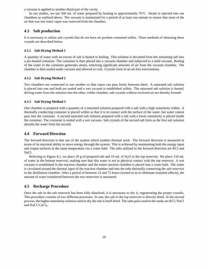
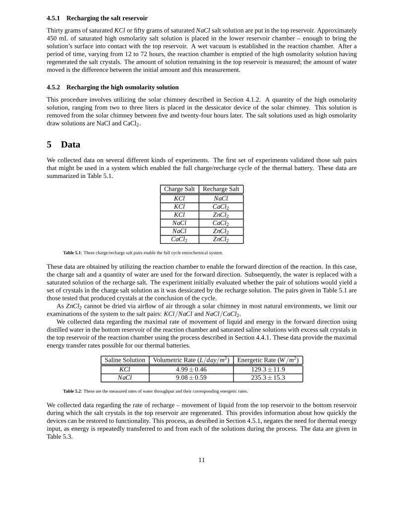
5 Data
We collected data on several different kinds of experiments. The first set of experiments validated those salt pairsthat might be used in a system which enabled the full charge/recharge cycle of the thermal battery. These data aresummarized in Table 5.1.
Charge Salt Recharge Salt
KCl NaClKCl CaCl2KCl ZnCl2NaCl CaCl2NaCl ZnCl2CaCl2 ZnCl2
Table 5.1: These charge/recharge salt pairs enable the full cycle entrochemical system.
These data are obtained by utilizing the reaction chamber toenable the forward direction of the reaction. In this case,the charge salt and a quantity of water are used for the forward direction. Subsequently, the water is replaced with asaturated solution of the recharge salt. The experiment initially evaluated whether the pair of solutions would yield aset of crystals in the charge salt solution as it was dessicated by the recharge solution. The pairs given in Table 5.1 arethose tested that produced crystals at the conclusion of thecycle.
As ZnCl2 cannot be dried via airflow of air through a solar chimney in most natural environments, we limit ourexaminations of the system to the salt pairs:KCl/NaCl andNaCl/CaCl2.
We collected data regarding the maximal rate of movement of liquid and energy in the forward direction usingdistilled water in the bottom reservoir of the reaction chamber and saturated saline solutions with excess salt crystals inthe top reservoir of the reaction chamber using the process described in Section 4.4.1. These data provide the maximalenergy transfer rates possible for our thermal batteries.
Saline Solution Volumetric Rate (L/day/m2) Energetic Rate (W/m2)
KCl 4.99±0.46 129.3±11.9NaCl 9.08±0.59 235.3±15.3
Table 5.2: These are the measured rates of water throughput and their corresponding energetic rates.
We collected data regarding the rate of recharge – movement of liquid from the top reservoir to the bottom reservoirduring which the salt crystals in the top reservoir are regenerated. This provides information about how quickly thedevices can be restored to functionality. This process, as desribed in Section 4.5.1, negates the need for thermal energyinput, as energy is repeatedly transferred to and from each of the solutions during the process. The data are given inTable 5.3.
11
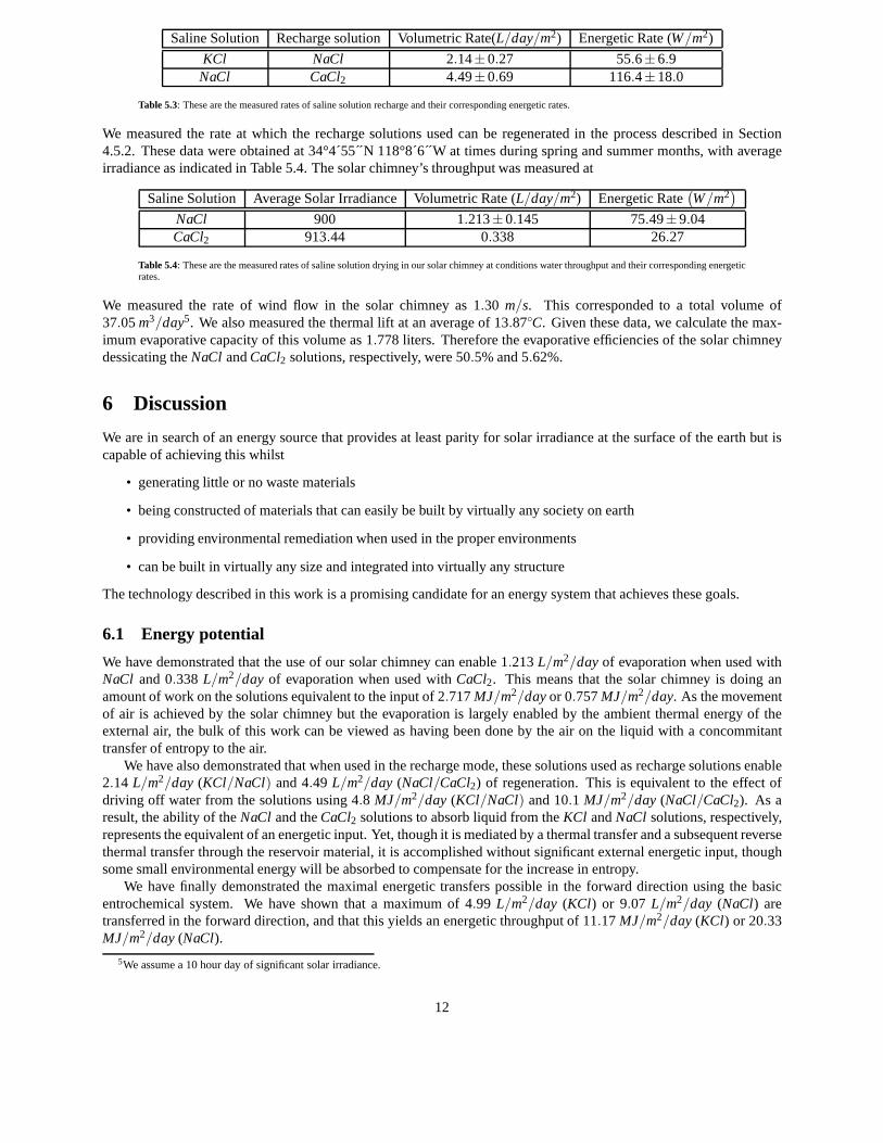
Saline Solution Recharge solution Volumetric Rate(L/day/m2) Energetic Rate (W/m2)
KCl NaCl 2.14±0.27 55.6±6.9NaCl CaCl2 4.49±0.69 116.4±18.0
Table 5.3: These are the measured rates of saline solution recharge and their corresponding energetic rates.
We measured the rate at which the recharge solutions used canbe regenerated in the process described in Section4.5.2. These data were obtained at 34°4´55´́ N 118°8´6´́ W attimes during spring and summer months, with averageirradiance as indicated in Table 5.4. The solar chimney’s throughput was measured at
Saline Solution Average Solar Irradiance Volumetric Rate (L/day/m2) Energetic Rate(
W/m2)
NaCl 900 1.213±0.145 75.49±9.04CaCl2 913.44 0.338 26.27
Table 5.4: These are the measured rates of saline solution drying in our solar chimney at conditions water throughput and their corresponding energeticrates.
We measured the rate of wind flow in the solar chimney as 1.30 m/s. This corresponded to a total volume of37.05m3/day5. We also measured the thermal lift at an average of 13.87◦C. Given these data, we calculate the max-imum evaporative capacity of this volume as 1.778 liters. Therefore the evaporative efficiencies of the solar chimneydessicating theNaCl andCaCl2 solutions, respectively, were 50.5% and 5.62%.
6 Discussion
We are in search of an energy source that provides at least parity for solar irradiance at the surface of the earth but iscapable of achieving this whilst
• generating little or no waste materials
• being constructed of materials that can easily be built by virtually any society on earth
• providing environmental remediation when used in the proper environments
• can be built in virtually any size and integrated into virtually any structure
The technology described in this work is a promising candidate for an energy system that achieves these goals.
6.1 Energy potential
We have demonstrated that the use of our solar chimney can enable 1.213L/m2/dayof evaporation when used withNaCl and 0.338 L/m2/day of evaporation when used withCaCl2. This means that the solar chimney is doing anamount of work on the solutions equivalent to the input of 2.717MJ/m2/dayor 0.757MJ/m2/day. As the movementof air is achieved by the solar chimney but the evaporation islargely enabled by the ambient thermal energy of theexternal air, the bulk of this work can be viewed as having been done by the air on the liquid with a concommitanttransfer of entropy to the air.
We have also demonstrated that when used in the recharge mode, these solutions used as recharge solutions enable2.14 L/m2/day (KCl/NaCl) and 4.49 L/m2/day (NaCl/CaCl2) of regeneration. This is equivalent to the effect ofdriving off water from the solutions using 4.8 MJ/m2/day (KCl/NaCl) and 10.1 MJ/m2/day (NaCl/CaCl2). As aresult, the ability of theNaCl and theCaCl2 solutions to absorb liquid from theKCl andNaCl solutions, respectively,represents the equivalent of an energetic input. Yet, though it is mediated by a thermal transfer and a subsequent reversethermal transfer through the reservoir material, it is accomplished without significant external energetic input, thoughsome small environmental energy will be absorbed to compensate for the increase in entropy.
We have finally demonstrated the maximal energetic transfers possible in the forward direction using the basicentrochemical system. We have shown that a maximum of 4.99 L/m2/day (KCl) or 9.07 L/m2/day (NaCl) aretransferred in the forward direction, and that this yields an energetic throughput of 11.17MJ/m2/day(KCl) or 20.33MJ/m2/day(NaCl).
5We assume a 10 hour day of significant solar irradiance.
12

Together, these indicate that the throughput of the device is limited by the performance of the solar chimney inour model. Extrapolating to much larger solar chimneys in hotter climes transfers the limiting factor to the rechargeperformance. However, as the units can be stacked to improvethe overall performance given a specific footprint, it islikely that a facility employing this technology would still be primarily limited by the performance of the solar chimney.As a result, the power equivalent of the solar chimney is likely to be the limiting factor determining the energy potentialof the technology.
We can evaluate the performance of larger solar chimneys in different climes using the model of Schlaige et. al.[4]If we extrapolate to a larger solar chimney with a height of 200 m and with a thermal lift of 35◦C, the throughput andtherefore energetic potential is 0.405kW/m2 or 6.52L/day/m2.
6.2 Water production
We have already seen that the process generates a significantenergy yield and that this energy is provided in the form ofthermal energy drawn through the thermal battery. It makes sense, then, that this energy could be used for a variety ofthermal processes, though these processes must be enabled.At energetic outputs described in Section 6.1, this processcan enable the production of 1.214 L/m2/day of water when using the solar chimney used in this study. Projectedproduction for a larger chimney is bounded above at 6.52L/day/m2. In order to determine the actual output of thismethod, we propose the entrochemical distiller design given below. These experiments, though under way, will havetheir outcomes reported in an upcoming publication.
The entrochemical distiller comprises of a two parts: a basic entrochemcial reaction chamber and a thermal distiller(Figure 6.1). Heat collected in the top reservoir passes naturally into the distillation water reservoir through the copperpipe connected to the top reservoir. The water in the distillation water reservoir is warmed by the heat, generatingvapor which is warmer than the outside world. This vapor travels to the condenser where it condenses and falls intothe collector. This is a single effect distiller, so the heatpasses naturally back into the environment.
13
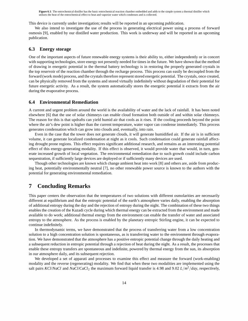
Figure 6.1: The entrochemical distiller has the basic entrochemical reaction chamber embedded and adds to the simple system a thermal distiller whichutilizes the heat of the entrochemical effect to heat and vaporize water which condenses and is collected.
This device is currently under investigation; results willbe reported in an upcoming publication.We also intend to investigate the use of the process in generating electrical power using a process of forward
osmosis [9], enabled by our distilled water production. This work is underway and will be reported in an upcomingpublication.
6.3 Energy storage
One of the important aspects of future renewable energy systems is their ability to, either independently or in concertwith supporting technologies, store energy not presently needed for times in the future. We have shown that the methodof drawing in energetic potential in the thermal battery technology is in restoring the properly generated crystals inthe top reservoir of the reaction chamber through the recharge process. This process can easily be decoupled from theforward (work mode) process, and the crystals therefore represent stored energetic potential. The crystals, once created,can be physically removed from the systems and stored virtually indefinitely without degradation of their potential forfuture energetic activity. As a result, the system automatically stores the energetic potential it extracts from the airduring the evaporative process.
6.4 Environmental Remediation
A current and urgent problem around the world is the availability of water and the lack of rainfall. It has been notedelsewhere [6] that the use of solar chimneys can enable cloudformation both outside of and within solar chimneys.The reason for this is that updrafts can yield humid air that cools as it rises. If the cooling proceeds beyond the pointwhere the air’s dew point is higher than the current temperature, water vapor can condense immediately. This processgenerates condensation which can grow into clouds and, eventually, into rain.
Even in the case that the tower does not generate clouds, it will generate humidified air. If the air is in sufficientvolume, it can generate localized condensation at night as it cools. Such condensation could generate rainfall affect-ing drought prone regions. This effect requires significantadditional research, and remains as an interesting potentialeffect of this energy-generating modality. If this effect is observed, it would provide water that would, in turn, gen-erate increased growth of local vegetation. The environmental remediation due to such growth could include carbonsequestration, if sufficiently large devices are deployed or if sufficiently many devices are used.
Though other technologies are known which change ambient heat into work [8] and others are, aside from produc-ing heat, potentially environmentally neutral [7], no other renewable power source is known to the authors with thepotential for generating environmental remediation.
7 Concluding Remarks
This paper centers the observation that the temperatures oftwo solutions with different osmolarities are necessarilydifferent at equilibrium and that the entropic potential ofthe earth’s atmosphere varies daily, enabling the absorptionof additional entropy during the day and the rejection of entropy during the night. The combination of these two thingsenables the creation of the Kazadi cycle during which thermal energy can be extracted from the environment and madeavailable to do work; additional thermal energy from the environment can enable the transfer of water and associatedentropy to the atmosphere. As the process is enabled by the planetary entropic Stirling engine, it can be expected tocontinue indefinitely.
In thermodynamic terms, we have demonstrated that the process of transferring water from a low concentrationsolution to a high concentration solution is spontaneous, as is transferring water to the environment through evapora-tion. We have demonstrated that the atmosphere has a positive entropic potential change through the daily heating anda subsequent reduction in entropic potential through a rejection of heat during the night. As a result, the processes thatenable these entropy transfers are spontaneous and indefinite, powered by thermal energy from the sun, its absorptionin our atmosphere daily, and its subsequent rejection.
We developed a set of apparati and processes to examine this effect and measure the forward (work-enabling)modality and the reverse (regenerating) modality. We find that when these two modalities are implemented using thesalt pairsKCl/NaCl andNaCl/CaCl2 the maximum forward liquid transfer is 4.98 and 9.02 L/m2/day, respectively,
14

and the maximum recharge rate is 2.19 and 4.49 L/day/m2. These are equivalent to a forward energy production of129.3 W/m2 or 235.3W/m2, respectively. We have also examined the use of a small solarchimney as a means ofrestoring the high osmolarity solution and found that theNaCl andCaCl2 solutions may be restored at a rate of 1.213L/day/m2 and 0.338L/day/m2 respectively. We estimate that solar chimneys similar to that deployed during the early1980’s in Manzanares Spain by the American company Enviromission can extend this capacity beyond the maximumsingle chamber recharge rate, with estimates as high as 6.52L/day/m2.
This process and these apparati provide a significant step toward a fully renewable power source. The energy de-rived from this process may be delivered in the form of heat and subsequently transformed to any number of alternativeforms. We have already outlined a process by which this can beapplied to water distillation – a process that we arecurrently investigating and will report in an upcoming paper. The apparti described and processes developed are suchthat they may be implemented by virtually any society on the planet using indigenous materials and processes. As aresult, it represents a promising potential form of power generation that can be adopted virtually anywhere.
Future work will focus on the development of fully integrated (charge/recharge) systems for the purpose of gener-ating sustained heating/cooling, water distillation, andelectrical power generation.
References
[1] S. Kazadi, R. You, M. Kim, M. Kim, M. Kim.A passive regulated thermal gradient device and application tounpowered refrigeration and heating, Proceedings of the Renewable Energy Conference 2010, Yokohama,Japan, June 27-July 2, 2010.
[2] S. Kazadi, Y. Hong, C. Chau, A. Chaudhary, A. Chaudhary, J. Park, J. Liu, M. Kim, D. Kim, S. Kim.Desalinationpowered by entropy. Proceedings of the Asian Conference on Sustainability, Energy, and the Environment2011, Osaka, Japan, June 2-5, 2011.
[3] Kittel and Kroemer.Thermal Physics. New York: W. H. Freeman and Company, 1980.
[4] .Schlaich, J., Bergermann, R., Schiel, W., and Weinrebe, G., 2005,Design of Commercial Solar Updraft TowerSystems – Utilization of Solar Induced Convective Flows forPower Generation, ASME J. Solar Energy Eng.,127(1), pp. 117-124.
[5] A. Ferreira et. al.Technical Feasibility Assessment of a Solar Chimney for Food Drying. Solar Energy, 82, 198-205, 2008.
[6] VanReken, T.M., Nenes, A.,Cloud Formation in the Plumes of Solar Chimney Power Generation Facilities: AModeling Study, Journal of Solar Energy Engineering, 131, 011009, 2009.
[7] Goldstein, B., G. Hiriart, R. Bertani, C. Bromley, L. Gutiérrez-Negrín, E. Huenges, H. Muraoka, A. Ragnarsson,J. Tester, and V. Zui:Geothermal Energy. In IPCC Special Report on Renewable Energy Sources and ClimateChange Mitigation [O. Edenhofer, R. Pichs-Madruga, Y. Sokona, K. Seyboth, P. Matschoss, S. Kadner, T.Zwickel, P. Eickemeier, G. Hansen, S. Schlömer, C. von Stechow (eds)], Cambridge University Press, Cambridge,United Kingdom and New York, NY, USA, 2011.
[8] P. Santhanam, D. J. Gray Jr., and R. J. Ram. Thermoelectrically Pumped Light-Emitting Diodes Operating aboveUnity Efficiency. Phys. Rev. Lett. 108, 097403 (2012)
[9] T. Cath, A. Childress, and M. Elimelech.Forward osmosis: principles, applications, and recent developments.Journal of Membrane Science, 281, 70-87, 2006.
[10] Y. Jannot and Y. Coulibaly.The “evaporative capacity” as a performance index for a solar-drier air-heater.Solar Energy, 63 (6): pp. 387-391, 1998.
15
Related Documents


