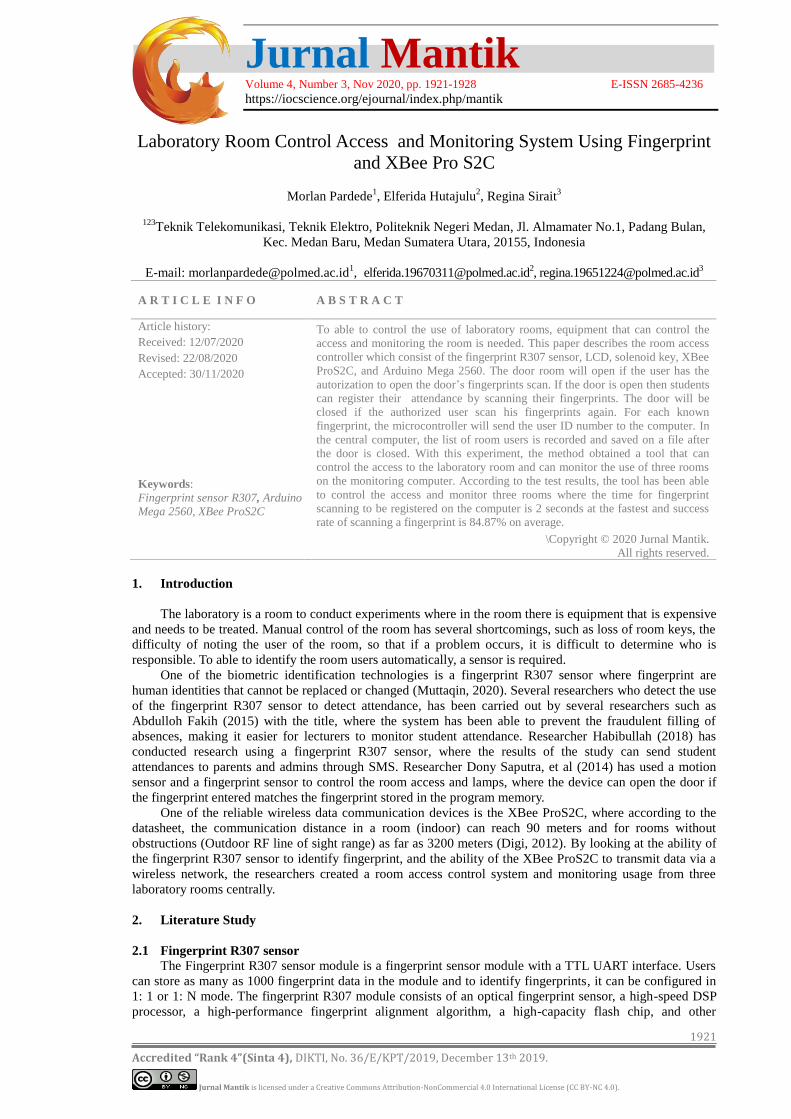
Jurnal Mantik Volume 4, Number 3, Nov 2020, pp. 1921-1928 E-ISSN 2685-4236 https://iocscience.org/ejournal/index.php/mantik 1921 Accredited “Rank 4”(Sinta 4), DIKTI, No. 36/E/KPT/2019, December 13 th 2019. Jurnal Mantik is licensed under a Creative Commons Attribution-NonCommercial 4.0 International License (CC BY-NC 4.0). Laboratory Room Control Access and Monitoring System Using Fingerprint and XBee Pro S2C Morlan Pardede 1 , Elferida Hutajulu 2 , Regina Sirait 3 123 Teknik Telekomunikasi, Teknik Elektro, Politeknik Negeri Medan, Jl. Almamater No.1, Padang Bulan, Kec. Medan Baru, Medan Sumatera Utara, 20155, Indonesia E-mail: [email protected] 1 , [email protected] 2 , [email protected] 3 1. Introduction The laboratory is a room to conduct experiments where in the room there is equipment that is expensive and needs to be treated. Manual control of the room has several shortcomings, such as loss of room keys, the difficulty of noting the user of the room, so that if a problem occurs, it is difficult to determine who is responsible. To able to identify the room users automatically, a sensor is required. One of the biometric identification technologies is a fingerprint R307 sensor where fingerprint are human identities that cannot be replaced or changed (Muttaqin, 2020). Several researchers who detect the use of the fingerprint R307 sensor to detect attendance, has been carried out by several researchers such as Abdulloh Fakih (2015) with the title, where the system has been able to prevent the fraudulent filling of absences, making it easier for lecturers to monitor student attendance. Researcher Habibullah (2018) has conducted research using a fingerprint R307 sensor, where the results of the study can send student attendances to parents and admins through SMS. Researcher Dony Saputra, et al (2014) has used a motion sensor and a fingerprint sensor to control the room access and lamps, where the device can open the door if the fingerprint entered matches the fingerprint stored in the program memory. One of the reliable wireless data communication devices is the XBee ProS2C, where according to the datasheet, the communication distance in a room (indoor) can reach 90 meters and for rooms without obstructions (Outdoor RF line of sight range) as far as 3200 meters (Digi, 2012). By looking at the ability of the fingerprint R307 sensor to identify fingerprint, and the ability of the XBee ProS2C to transmit data via a wireless network, the researchers created a room access control system and monitoring usage from three laboratory rooms centrally. 2. Literature Study 2.1 Fingerprint R307 sensor The Fingerprint R307 sensor module is a fingerprint sensor module with a TTL UART interface. Users can store as many as 1000 fingerprint data in the module and to identify fingerprints, it can be configured in 1: 1 or 1: N mode. The fingerprint R307 module consists of an optical fingerprint sensor, a high-speed DSP processor, a high-performance fingerprint alignment algorithm, a high-capacity flash chip, and other A R T I C L E I N F O A B S T R A C T Article history: Received: 12/07/2020 Revised: 22/08/2020 Accepted: 30/11/2020 Keywords: Fingerprint sensor R307, Arduino Mega 2560, XBee ProS2C To able to control the use of laboratory rooms, equipment that can control the access and monitoring the room is needed. This paper describes the room access controller which consist of the fingerprint R307 sensor, LCD, solenoid key, XBee ProS2C, and Arduino Mega 2560. The door room will open if the user has the autorization to open the door’s fingerprints scan. If the door is open then students can register their attendance by scanning their fingerprints. The door will be closed if the authorized user scan his fingerprints again. For each known fingerprint, the microcontroller will send the user ID number to the computer. In the central computer, the list of room users is recorded and saved on a file after the door is closed. With this experiment, the method obtained a tool that can control the access to the laboratory room and can monitor the use of three rooms on the monitoring computer. According to the test results, the tool has been able to control the access and monitor three rooms where the time for fingerprint scanning to be registered on the computer is 2 seconds at the fastest and success rate of scanning a fingerprint is 84.87% on average. \Copyright © 2020 Jurnal Mantik. All rights reserved.

Welcome message from author
This document is posted to help you gain knowledge. Please leave a comment to let me know what you think about it! Share it to your friends and learn new things together.
Transcript
Jurnal Mantik Volume 4, Number 3, Nov 2020, pp. 1921-1928 E-ISSN 2685-4236 https://iocscience.org/ejournal/index.php/mantik
1921
Accredited “Rank 4”(Sinta 4), DIKTI, No. 36/E/KPT/2019, December 13th 2019.
Jurnal Mantik is licensed under a Creative Commons Attribution-NonCommercial 4.0 International License (CC BY-NC 4.0).
Laboratory Room Control Access and Monitoring System Using Fingerprint
and XBee Pro S2C
Morlan Pardede1, Elferida Hutajulu
2, Regina Sirait
3
123
Teknik Telekomunikasi, Teknik Elektro, Politeknik Negeri Medan, Jl. Almamater No.1, Padang Bulan,
Kec. Medan Baru, Medan Sumatera Utara, 20155, Indonesia
E-mail: [email protected], [email protected]
3
1. Introduction
The laboratory is a room to conduct experiments where in the room there is equipment that is expensive
and needs to be treated. Manual control of the room has several shortcomings, such as loss of room keys, the
difficulty of noting the user of the room, so that if a problem occurs, it is difficult to determine who is
responsible. To able to identify the room users automatically, a sensor is required.
One of the biometric identification technologies is a fingerprint R307 sensor where fingerprint are
human identities that cannot be replaced or changed (Muttaqin, 2020). Several researchers who detect the use
of the fingerprint R307 sensor to detect attendance, has been carried out by several researchers such as
Abdulloh Fakih (2015) with the title, where the system has been able to prevent the fraudulent filling of
absences, making it easier for lecturers to monitor student attendance. Researcher Habibullah (2018) has
conducted research using a fingerprint R307 sensor, where the results of the study can send student
attendances to parents and admins through SMS. Researcher Dony Saputra, et al (2014) has used a motion
sensor and a fingerprint sensor to control the room access and lamps, where the device can open the door if
the fingerprint entered matches the fingerprint stored in the program memory.
One of the reliable wireless data communication devices is the XBee ProS2C, where according to the
datasheet, the communication distance in a room (indoor) can reach 90 meters and for rooms without
obstructions (Outdoor RF line of sight range) as far as 3200 meters (Digi, 2012). By looking at the ability of
the fingerprint R307 sensor to identify fingerprint, and the ability of the XBee ProS2C to transmit data via a
wireless network, the researchers created a room access control system and monitoring usage from three
laboratory rooms centrally.
2. Literature Study
2.1 Fingerprint R307 sensor
The Fingerprint R307 sensor module is a fingerprint sensor module with a TTL UART interface. Users
can store as many as 1000 fingerprint data in the module and to identify fingerprints, it can be configured in
1: 1 or 1: N mode. The fingerprint R307 module consists of an optical fingerprint sensor, a high-speed DSP
processor, a high-performance fingerprint alignment algorithm, a high-capacity flash chip, and other
A R T I C L E I N F O A B S T R A C T
Article history:
Received: 12/07/2020
Revised: 22/08/2020
Accepted: 30/11/2020
Keywords:
Fingerprint sensor R307, Arduino
Mega 2560, XBee ProS2C
To able to control the use of laboratory rooms, equipment that can control the
access and monitoring the room is needed. This paper describes the room access
controller which consist of the fingerprint R307 sensor, LCD, solenoid key, XBee
ProS2C, and Arduino Mega 2560. The door room will open if the user has the
autorization to open the door’s fingerprints scan. If the door is open then students
can register their attendance by scanning their fingerprints. The door will be
closed if the authorized user scan his fingerprints again. For each known
fingerprint, the microcontroller will send the user ID number to the computer. In
the central computer, the list of room users is recorded and saved on a file after
the door is closed. With this experiment, the method obtained a tool that can
control the access to the laboratory room and can monitor the use of three rooms
on the monitoring computer. According to the test results, the tool has been able
to control the access and monitor three rooms where the time for fingerprint
scanning to be registered on the computer is 2 seconds at the fastest and success
rate of scanning a fingerprint is 84.87% on average.
\Copyright © 2020 Jurnal Mantik.
All rights reserved.
Jurnal Mantik, Vol. 4 , No. 3, Nov 2020, pp. 1921-1928 E-ISSN 2685-4236
1922
Accredited “Rank 4”(Sinta 4), DIKTI, No. 36/E/KPT/2019, December 13th 2019.
Jurnal Mantik is licensed under a Creative Commons Attribution-NonCommercial 4.0 International License (CC BY-NC 4.0).
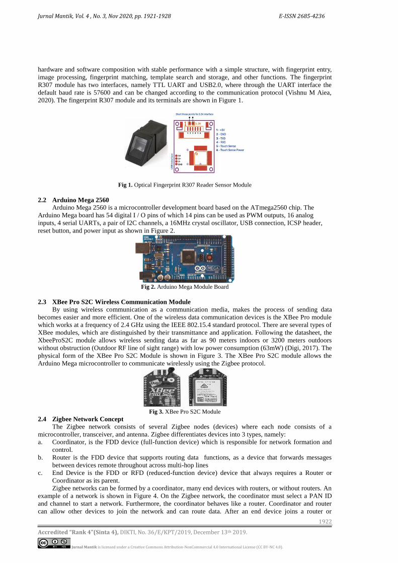
hardware and software composition with stable performance with a simple structure, with fingerprint entry,
image processing, fingerprint matching, template search and storage, and other functions. The fingerprint
R307 module has two interfaces, namely TTL UART and USB2.0, where through the UART interface the
default baud rate is 57600 and can be changed according to the communication protocol (Vishnu M Aiea,
2020). The fingerprint R307 module and its terminals are shown in Figure 1.
Fig 1. Optical Fingerprint R307 Reader Sensor Module
2.2 Arduino Mega 2560 Arduino Mega 2560 is a microcontroller development board based on the ATmega2560 chip. The
Arduino Mega board has 54 digital I / O pins of which 14 pins can be used as PWM outputs, 16 analog
inputs, 4 serial UARTs, a pair of I2C channels, a 16MHz crystal oscillator, USB connection, ICSP header,
reset button, and power input as shown in Figure 2.
Fig 2. Arduino Mega Module Board
2.3 XBee Pro S2C Wireless Communication Module
By using wireless communication as a communication media, makes the process of sending data
becomes easier and more efficient. One of the wireless data communication devices is the XBee Pro module
which works at a frequency of 2.4 GHz using the IEEE 802.15.4 standard protocol. There are several types of
XBee modules, which are distinguished by their transmittance and application. Following the datasheet, the
XbeeProS2C module allows wireless sending data as far as 90 meters indoors or 3200 meters outdoors
without obstruction (Outdoor RF line of sight range) with low power consumption (63mW) (Digi, 2017). The
physical form of the XBee Pro S2C Module is shown in Figure 3. The XBee Pro S2C module allows the
Arduino Mega microcontroller to communicate wirelessly using the Zigbee protocol.
Fig 3. XBee Pro S2C Module
2.4 Zigbee Network Concept
The Zigbee network consists of several Zigbee nodes (devices) where each node consists of a
microcontroller, transceiver, and antenna. Zigbee differentiates devices into 3 types, namely:
a. Coordinator, is the FDD device (full-function device) which is responsible for network formation and
control.
b. Router is the FDD device that supports routing data functions, as a device that forwards messages
between devices remote throughout across multi-hop lines
c. End Device is the FDD or RFD (reduced-function device) device that always requires a Router or
Coordinator as its parent.
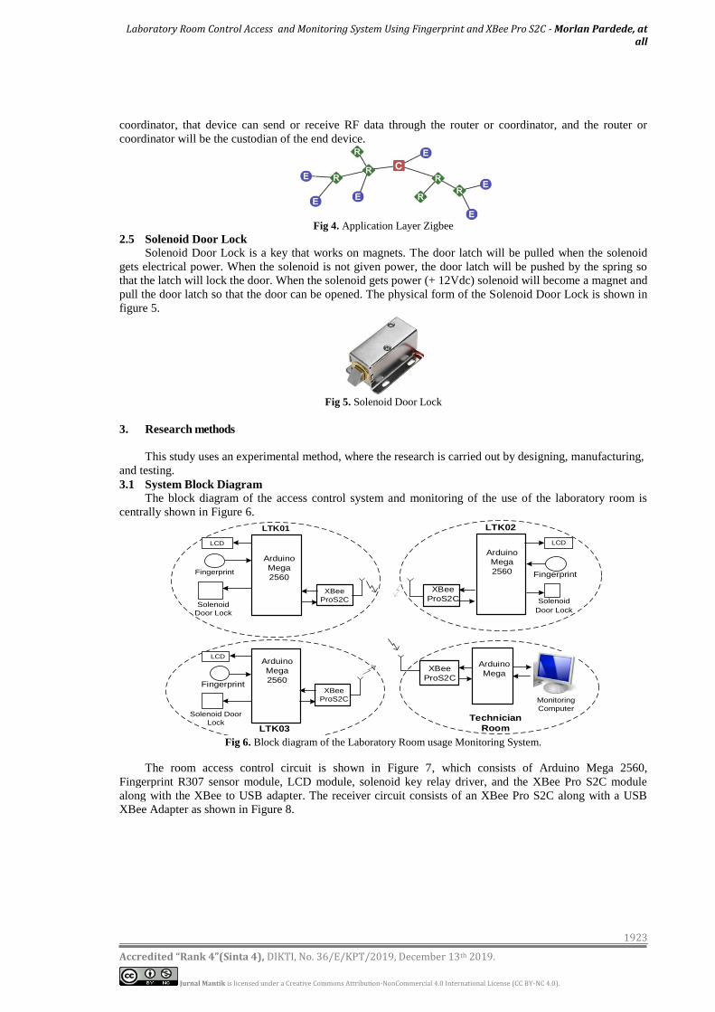
Zigbee networks can be formed by a coordinator, many end devices with routers, or without routers. An
example of a network is shown in Figure 4. On the Zigbee network, the coordinator must select a PAN ID
and channel to start a network. Furthermore, the coordinator behaves like a router. Coordinator and router
can allow other devices to join the network and can route data. After an end device joins a router or
Laboratory Room Control Access and Monitoring System Using Fingerprint and XBee Pro S2C - Morlan Pardede, at all
1923
Accredited “Rank 4”(Sinta 4), DIKTI, No. 36/E/KPT/2019, December 13th 2019.
Jurnal Mantik is licensed under a Creative Commons Attribution-NonCommercial 4.0 International License (CC BY-NC 4.0).
coordinator, that device can send or receive RF data through the router or coordinator, and the router or
coordinator will be the custodian of the end device.
Fig 4. Application Layer Zigbee
2.5 Solenoid Door Lock
Solenoid Door Lock is a key that works on magnets. The door latch will be pulled when the solenoid
gets electrical power. When the solenoid is not given power, the door latch will be pushed by the spring so
that the latch will lock the door. When the solenoid gets power (+ 12Vdc) solenoid will become a magnet and
pull the door latch so that the door can be opened. The physical form of the Solenoid Door Lock is shown in
figure 5.
Fig 5. Solenoid Door Lock
3. Research methods
This study uses an experimental method, where the research is carried out by designing, manufacturing,
and testing.
3.1 System Block Diagram
The block diagram of the access control system and monitoring of the use of the laboratory room is
centrally shown in Figure 6.
Arduino
Mega
2560
LTK01
LCD
Fingerprint
XBee
ProS2CSolenoid
Door Lock
Arduino
Mega
2560
LTK02
LCD
Fingerprint
XBee
ProS2C Solenoid
Door Lock
XBee
ProS2C
Arduino
Mega
Arduino
Mega
2560
LTK03
LCD
FingerprintXBee
ProS2C
Solenoid Door
LockTechnician
Room
Monitoring
Computer
Fig 6. Block diagram of the Laboratory Room usage Monitoring System.
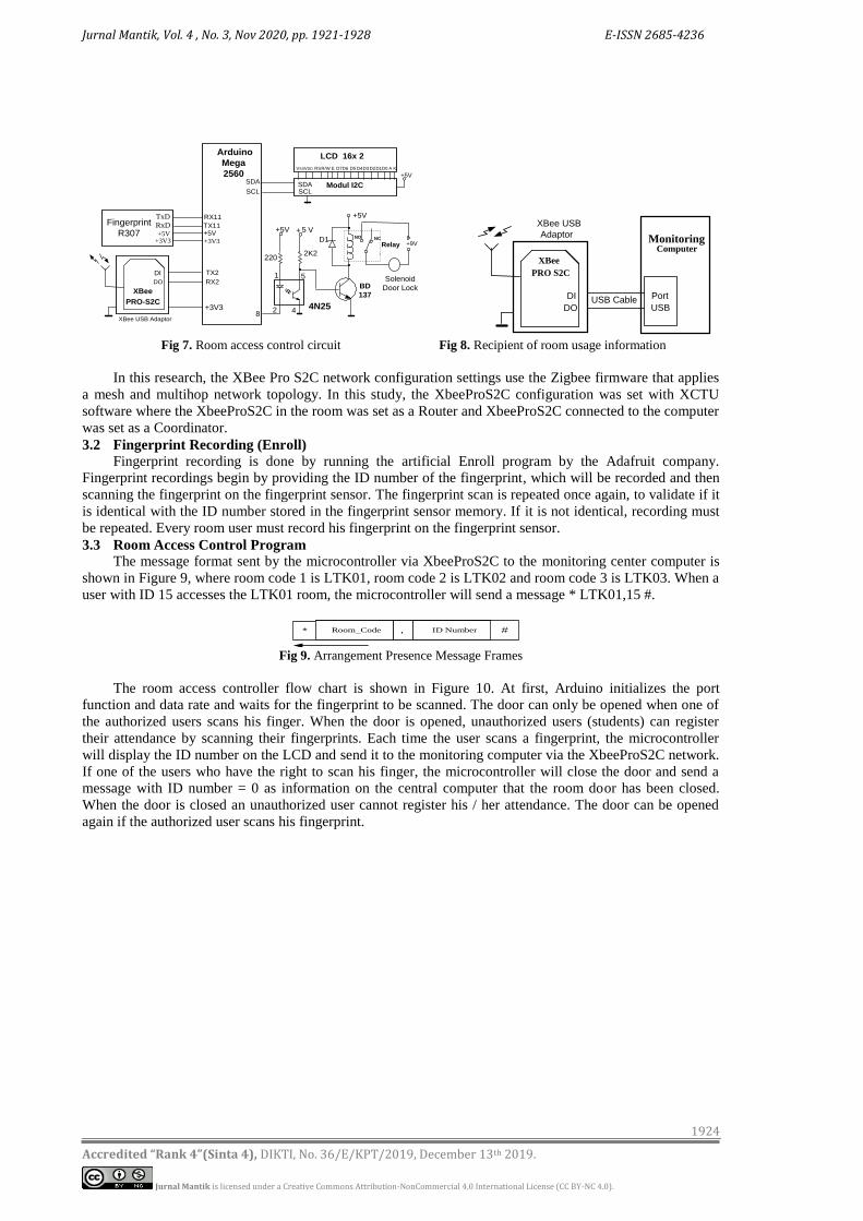
The room access control circuit is shown in Figure 7, which consists of Arduino Mega 2560,
Fingerprint R307 sensor module, LCD module, solenoid key relay driver, and the XBee Pro S2C module
along with the XBee to USB adapter. The receiver circuit consists of an XBee Pro S2C along with a USB
XBee Adapter as shown in Figure 8.
Jurnal Mantik, Vol. 4 , No. 3, Nov 2020, pp. 1921-1928 E-ISSN 2685-4236
1924
Accredited “Rank 4”(Sinta 4), DIKTI, No. 36/E/KPT/2019, December 13th 2019.
Jurnal Mantik is licensed under a Creative Commons Attribution-NonCommercial 4.0 International License (CC BY-NC 4.0).
Arduino
Mega
2560
TX2
RX2
DI
DO
+3V3
XBee
PRO-S2C
LCD 16x 2
D7D6 D4D5RSR/W E A KVDD
+5V
VSS
XBee USB Adaptor
Modul I2C
D3D2D1D0
SDA
SCL SCLSDA
+9V
8
+5V
BD
137
Relay
+ 5 V
2202K2
1 5
2 4N254
NCNO
+5V
D1
TxDRxD+5V
+3V3
Fingerprint
R307
Solenoid
Door Lock
RX11
TX11+5V
+3V3
Monitoring Computer
DI
DO
XBee
PRO S2C
XBee USB
Adaptor
Port
USBUSB Cable
Fig 7. Room access control circuit Fig 8. Recipient of room usage information
In this research, the XBee Pro S2C network configuration settings use the Zigbee firmware that applies
a mesh and multihop network topology. In this study, the XbeeProS2C configuration was set with XCTU
software where the XbeeProS2C in the room was set as a Router and XbeeProS2C connected to the computer
was set as a Coordinator.
3.2 Fingerprint Recording (Enroll)
Fingerprint recording is done by running the artificial Enroll program by the Adafruit company.
Fingerprint recordings begin by providing the ID number of the fingerprint, which will be recorded and then
scanning the fingerprint on the fingerprint sensor. The fingerprint scan is repeated once again, to validate if it
is identical with the ID number stored in the fingerprint sensor memory. If it is not identical, recording must
be repeated. Every room user must record his fingerprint on the fingerprint sensor.
3.3 Room Access Control Program
The message format sent by the microcontroller via XbeeProS2C to the monitoring center computer is
shown in Figure 9, where room code 1 is LTK01, room code 2 is LTK02 and room code 3 is LTK03. When a
user with ID 15 accesses the LTK01 room, the microcontroller will send a message * LTK01,15 #.
Room_Code , ID Number #*
Fig 9. Arrangement Presence Message Frames
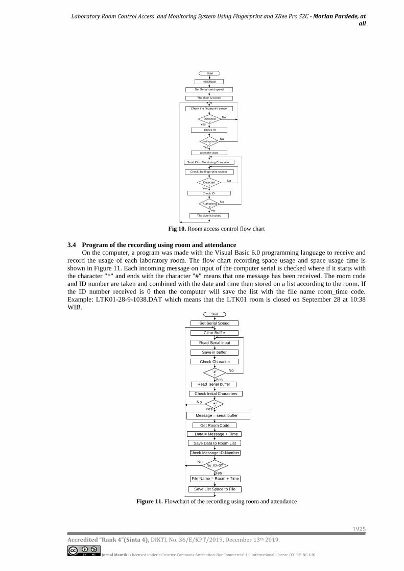
The room access controller flow chart is shown in Figure 10. At first, Arduino initializes the port
function and data rate and waits for the fingerprint to be scanned. The door can only be opened when one of
the authorized users scans his finger. When the door is opened, unauthorized users (students) can register
their attendance by scanning their fingerprints. Each time the user scans a fingerprint, the microcontroller
will display the ID number on the LCD and send it to the monitoring computer via the XbeeProS2C network.
If one of the users who have the right to scan his finger, the microcontroller will close the door and send a
message with ID number = 0 as information on the central computer that the room door has been closed.
When the door is closed an unauthorized user cannot register his / her attendance. The door can be opened
again if the authorized user scans his fingerprint.
Laboratory Room Control Access and Monitoring System Using Fingerprint and XBee Pro S2C - Morlan Pardede, at all
1925
Accredited “Rank 4”(Sinta 4), DIKTI, No. 36/E/KPT/2019, December 13th 2019.
Jurnal Mantik is licensed under a Creative Commons Attribution-NonCommercial 4.0 International License (CC BY-NC 4.0).
Start
Inisialisasi
Set Serial send speed
Check the fingerprint sensor
Check ID
open the door
?authorized
No
Yes
No
Send ID to Monitoring Computer
The door is locked
Yes
Check the fingerprint sensor
?Detected
Check ID
No
No
The door is locked
Yes
Authorized
?
?Detected
Yes
Fig 10. Room access control flow chart
3.4 Program of the recording using room and attendance
On the computer, a program was made with the Visual Basic 6.0 programming language to receive and
record the usage of each laboratory room. The flow chart recording space usage and space usage time is
shown in Figure 11. Each incoming message on input of the computer serial is checked where if it starts with
the character "*" and ends with the character "#" means that one message has been received. The room code
and ID number are taken and combined with the date and time then stored on a list according to the room. If
the ID number received is 0 then the computer will save the list with the file name room_time code.
Example: LTK01-28-9-1038.DAT which means that the LTK01 room is closed on September 28 at 10:38
WIB.
Yes
No
Start
Set Serial Speed
Read Serial Input
Save Data to Room List
Data = Message + Time
Message = serial buffer
Save in buffer
Check Message ID-Number
No_ID=0?
Save List Space to File
Check Initial Characters
?
Yes
No
No
Yes
Read serial buffer
File Name = Room + Time
Check Character
?
Get Room Code
Clear Buffer
Figure 11. Flowchart of the recording using room and attendance
Jurnal Mantik, Vol. 4 , No. 3, Nov 2020, pp. 1921-1928 E-ISSN 2685-4236
1926
Accredited “Rank 4”(Sinta 4), DIKTI, No. 36/E/KPT/2019, December 13th 2019.
Jurnal Mantik is licensed under a Creative Commons Attribution-NonCommercial 4.0 International License (CC BY-NC 4.0).
4. Results and Discussion
4.1 Room Access Testing
Before testing, it is confirmed that the fingerprint of the user who has authorization to open/close the
door and the student who will use the previous room has been recorded on the fingerprint sensor with the
enrollment process. Testing begins by the authorized user to open/close the door scanning the fingerprint to
open the room and is continued by the student (who is not authorized) registering attendance by scanning the
fingerprint. The test ends by scanning the fingerprints of the user who has the right to close the door to the
room.
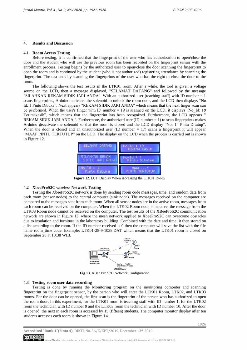
The following shows the test results in the LTK01 room. After a while, the tool is given a voltage
source on the LCD, then a message displayed, "SELAMAT DATANG" and followed by the message
"SILAHKAN REKAM SIDIK JARI ANDA". With an authorized user (teaching staff) with ID number = 1
scans fingerprints, Arduino activates the solenoid to unlock the room door, and the LCD then displays “No
Id: 1 Pintu Dibuka”. Next appears "REKAM SIDIK JARI ANDA" which means that the next finger scan can
be performed. When the user's finger with ID number = 19 is scanned on the LCD, it displays “No_Id: 19
Terimakasih”, which means that the fingerprint has been recognized. Furthermore, the LCD appears "
REKAM SIDIK JARI ANDA ". Furthermore, the authorized user (ID number = 1) to scan fingerprints makes
Arduino deactivate the solenoid so that the room is closed and the LCD display “No: 1” Pintu Ditutup”.
When the door is closed and an unauthorized user (ID number = 17) scans a fingerprint it will appear
“MAAF PINTU TERTUTUP” on the LCD. The display on the LCD when the process is carried out is shown
in Figure 12.
Figure 12. LCD Display When Accessing the LTK01 Room
4.2 XbeeProS2C wireless Network Testing
Testing the XbeeProS2C network is done by sending room code messages, time, and random data from
each room (sensor nodes) to the central computer (sink node). The messages received on the computer are
compared to the messages sent from each room. When all sensor nodes are in the active room, messages from
each room can be received on the computer. When the LTK02 Room node is inactive, the message from the
LTK03 Room node cannot be received on the computer. The test results of the XBeeProS2C communication
network are shown in Figure 13, where the mesh network applied to XbeeProS2C can overcome obstacles
due to insulation and furniture in the laboratory building. Combined with the date and time, it then stored on
a list according to the room. If the ID number received is 0 then the computer will save the list with the file
name room_time code. Example: LTK01-28-9-1038.DAT which means that the LTK01 room is closed on
September 28 at 10:38 WIB.
Computer Monitoring
CoordinatorXBeeProS2C
RouterXBeePro
S2C
RouterXBeeProS2C
RouterXBeeProS2C
LTK01 Room
LTK02 Room
LTK03
Roomx
Fig 13. XBee Pro S2C Network Configuration
4.3 Testing room user data recording
Testing is done by running the Monitoring program on the monitoring computer and scanning
fingerprint on the fingerprint sensor, by the person who will enter the LTK01 Room, LTK02, and LTK03
rooms. For the door can be opened, the first scan is the fingerprint of the person who has authorized to open
the room door. In this experiment, for the LTK01 room is teaching staff with ID number 1, for the LTK02
room the technician with ID number 9 and the LTK03 room the technician with ID number 10. After the door
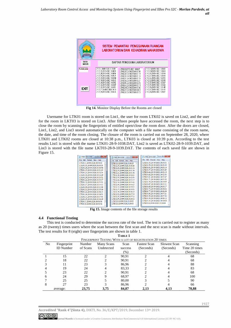
is opened, the next in each room is accessed by 15 (fifteen) students. The computer monitor display after ten
students accesses each room is shown in Figure 14.
Laboratory Room Control Access and Monitoring System Using Fingerprint and XBee Pro S2C - Morlan Pardede, at all
1927
Accredited “Rank 4”(Sinta 4), DIKTI, No. 36/E/KPT/2019, December 13th 2019.
Jurnal Mantik is licensed under a Creative Commons Attribution-NonCommercial 4.0 International License (CC BY-NC 4.0).
Fig 14. Monitor Display Before the Rooms are closed
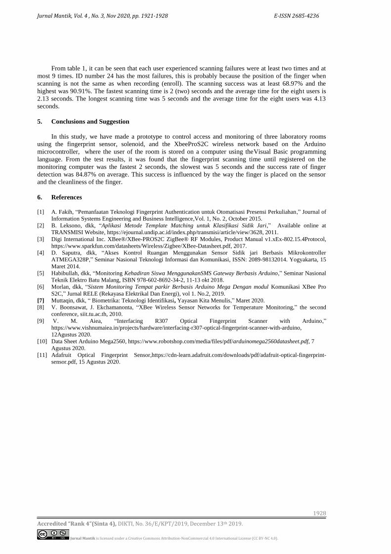
Username for LTK01 room is stored on List1, the user for room LTK02 is saved on List2, and the user
for the room in LKT03 is stored on List3. After fifteen people have accessed the room, the next step is to
close the room by scanning the fingerprints of entitled open/close the room door. After the doors are closed,
List1, List2, and List3 stored automatically on the computer with a file name consisting of the room name,
the date, and time of the room closing. The closure of the room is carried out on September 28, 2020, where
LTK01 and LTK02 rooms are closed at 10:38 p.m., LTK03 is closed at 10:39 p.m. According to the test
results List1 is stored with the name LTK01-28-9-1038.DAT, List2 is saved as LTK02-28-9-1039.DAT, and
List3 is stored with the file name LKT03-28-9-1039.DAT. The contents of each saved file are shown in
Figure 15.
Fig 15. Image contents of the file storage results
4.4 Functional Testing
This test is conducted to determine the success rate of the tool. The test is carried out to register as many
as 20 (twenty) times users where the scan between the first scan and the next scan is made without intervals.
The test results for 8 (eight) user fingerprints are shown in table 1. TABLE 1
FINGERPRINT TESTING WITH A LOT OF REGISTRATION 20 TIMES
No Fingerprint
ID Number
Number
of Scans
Many Scans
Undetected
Scan
success
(%)
Fastest Scan
(Seconds)
Slowest Scan
(Seconds)
Scanning
Time 20 times
(Seconds)
1 15 22 2 90,91 2 4 68
2 18 22 2 90,91 2 4 68
3 11 23 3 86,96 2 4 88
4 19 24 4 83,33 2 4 83
5 23 22 2 90,91 2 4 68
6 24 29 9 68,97 2 4 100
7 25 25 5 80,00 3 5 90
8 27 23 3 86,96 2 4 66
average: 23,75 3,75 84,87 2,13 4,13 78,88
Jurnal Mantik, Vol. 4 , No. 3, Nov 2020, pp. 1921-1928 E-ISSN 2685-4236
1928
Accredited “Rank 4”(Sinta 4), DIKTI, No. 36/E/KPT/2019, December 13th 2019.
Jurnal Mantik is licensed under a Creative Commons Attribution-NonCommercial 4.0 International License (CC BY-NC 4.0).
From table 1, it can be seen that each user experienced scanning failures were at least two times and at
most 9 times. ID number 24 has the most failures, this is probably because the position of the finger when
scanning is not the same as when recording (enroll). The scanning success was at least 68.97% and the
highest was 90.91%. The fastest scanning time is 2 (two) seconds and the average time for the eight users is
2.13 seconds. The longest scanning time was 5 seconds and the average time for the eight users was 4.13
seconds.
5. Conclusions and Suggestion
In this study, we have made a prototype to control access and monitoring of three laboratory rooms
using the fingerprint sensor, solenoid, and the XbeeProS2C wireless network based on the Arduino
microcontroller, where the user of the room is stored on a computer using theVisual Basic programming
language. From the test results, it was found that the fingerprint scanning time until registered on the
monitoring computer was the fastest 2 seconds, the slowest was 5 seconds and the success rate of finger
detection was 84.87% on average. This success is influenced by the way the finger is placed on the sensor
and the cleanliness of the finger.
6. References
[1] A. Fakih, “Pemanfaatan Teknologi Fingerprint Authentication untuk Otomatisasi Presensi Perkuliahan,” Journal of
Information Systems Engineering and Business Intelligence,Vol. 1, No. 2, October 2015.
[2] B. Leksono, dkk, “Aplikasi Metode Template Matching untuk Klasifikasi Sidik Jari,” Available online at
TRANSMISI Website, https://ejournal.undip.ac.id/index.php/transmisi/article/view/3628, 2011.
[3] Digi International Inc. XBee®/XBee-PROS2C ZigBee® RF Modules, Product Manual v1.xEx-802.15.4Protocol,
https://www.sparkfun.com/datasheets/Wireless/Zigbee/XBee-Datasheet.pdf, 2017.
[4] D. Saputra, dkk, “Akses Kontrol Ruangan Menggunakan Sensor Sidik jari Berbasis Mikrokontroller
ATMEGA328P,” Seminar Nasional Teknologi Informasi dan Komunikasi, ISSN: 2089-98132014. Yogyakarta, 15
Maret 2014.
[5] Habibullah, dkk, “Monitoring Kehadiran Siswa MenggunakanSMS Gateway Berbasis Arduino,” Seminar Nasional
Teknik Elektro Batu Malang, ISBN 978-602-8692-34-2, 11-13 okt 2018.
[6] Morlan, dkk, “Sistem Monitoring Tempat parkir Berbasis Arduino Mega Dengan modul Komunikasi XBee Pro
S2C,” Jurnal RELE (Rekayasa Elektrikal Dan Energi), vol 1. No.2, 2019.
[7] Muttaqin, dkk, “ Biometrika: Teknologi Identifikasi, Yayasan Kita Menulis,” Maret 2020.
[8] V. Boonsawat, J. Ekchamanonta, “XBee Wireless Sensor Networks for Temperature Monitoring,” the second
conference, siit.tu.ac.th, 2010.
[9] V. M. Aiea, “Interfacing R307 Optical Fingerprint Scanner with Arduino,”
https://www.vishnumaiea.in/projects/hardware/interfacing-r307-optical-fingerprint-scanner-with-arduino,
12Agustus 2020.
[10] Data Sheet Arduino Mega2560, https://www.robotshop.com/media/files/pdf/arduinomega2560datasheet.pdf, 7
Agustus 2020.
[11] Adafruit Optical Fingerprint Sensor,https://cdn-learn.adafruit.com/downloads/pdf/adafruit-optical-fingerprint-
sensor.pdf, 15 Agustus 2020.
Related Documents