<< 1 JURNAL IAFMI 03 DESEMBER 2015 ISSN 2442 8515

Welcome message from author
This document is posted to help you gain knowledge. Please leave a comment to let me know what you think about it! Share it to your friends and learn new things together.
Transcript
<< 1 jurnal IaFMI 03 Desember 2015
ISSN 2442 8515
jurnal IaFMI 03 Desember 2015 >> 2
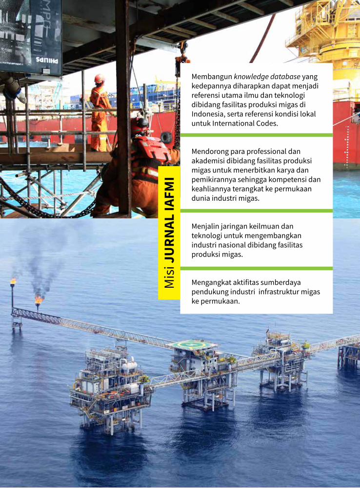
Membangun knowledge database yang kedepannya diharapkan dapat menjadi referensi utama ilmu dan teknologi dibidang fasilitas produksi migas di Indonesia, serta referensi kondisi lokal untuk International Codes.
Mendorong para professional dan akademisi dibidang fasilitas produksi migas untuk menerbitkan karya dan pemikirannya sehingga kompetensi dan keahliannya terangkat ke permukaan dunia industri migas.
Menjalin jaringan keilmuan dan teknologi untuk mengembangkan industri nasional dibidang fasilitas produksi migas.
Mengangkat aktifitas sumberdaya pendukung industri infrastruktur migas ke permukaan.
Mis
i JU
RNAL
IAFM
I
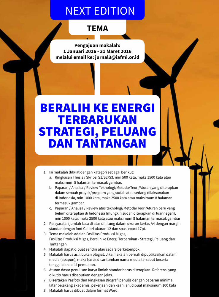
<< 3 jurnal IaFMI 03 Desember 2015NEXT EDITIONTeMA
Pengajuan makalah: 1 Januari 2016 - 31 Maret 2016
melalui email ke: [email protected]
BEralIH KE EnErGI TErBaruKan
STraTEGI, PEluanG dan TanTanGan
1. Isi makalah dibuat dengan kategori sebagai berikut: a. Ringkasan Thesis / Skripsi S1/S2/S3, min 500 kata, maks 1500 kata atau
maksimum 5 halaman termasuk gambar.b. Paparan / Analisa / Review Teknologi/Metoda/Teori/Aturan yang diterapkan
dalam sebuah proyek/program yang sudah atau sedang dilaksanakan di Indonesia, min 1000 kata, maks 2500 kata atau maksimum 8 halaman termasuk gambar
c. Paparan / Analisa / Review atas teknologi/Metoda/Teori/Aturan baru yang belum diterapkan di Indonesia (mungkin sudah diterapkan di luar negeri), min 1000 kata, maks 2500 kata atau maksimum 8 halaman termasuk gambar
2. Persyaratan jumlah kata di atas dihitung dalam ukurun kertas A4 dengan margin standar dengan font Calibri ukuran 12 dan spasi exact 17pt.
3. Tema makalah adalah Fasilitas Produksi Migas, Fasilitas Produksi Migas, Beralih ke Energi Terbarukan - Strategi, Peluang dan
Tantangan. 4. Makalah dapat dibuat sendiri atau secara berkelompok.5. Makalah harus asli, bukan plagiat. Jika makalah pernah dipublikasikan dalam
media (apapun), maka harus dicantumkan nama media tersebut beserta tanggal dan edisi pemuatan.
6. Aturan dasar penulisan karya ilmiah standar harus diterapkan. Referensi yang dikutip harus disebutkan dengan jelas.
7. Disertakan Pasfoto dan Ringkasan Biografi penulis dengan paparan minimal latar belakang akademis, pekerjaan dan keahlian, dibuat maksimum 100 kata
8. Makalah harus dibuat dalam format Word
jurnal IaFMI 03 Desember 2015 >> 4
Jurnal ke-3 IAFMI mengambil tema “Menuju ke Timur Indonesia membangun hingga ke laut dalam”, sejalan dengan tema besar Joint Convention 4 Asosiasi Profesional Industri Migas (HAGI, IAGI, IAFMI dan IAFMI) di Balikpapan 6-8 Oktober 2015.
Kegiatan Eksplorasi dan Eksploitasi sumber daya alam migas di Indonesia dalam bentuk Kontrak Kerja Sama sudah berlangsung sejak tahun 1966, dan saat ini, sumber-sumber minyak dan gas bumi dengan tingkat kesulitan eksplorasi terendah praktis telah habis dieksploitasi. Akan tetapi potensi sumber daya minyak dan gas bumi Indonesia masih cukup besar untuk dikembangkan terutama di daerah-daerah terpencil (remote area), laut dalam, dan kawasan Indonesia Timur yang relative belum dieksplorasi secara intensif.
Tiga Mega Proyek Migas di Indonesia saat ini merupakan pengembangan di wilayah laut dalam dan berlokasi di wilayah Indonesia Timur. Ketiga proyek itu adalah Indonesia Deepwater Development (IDD) dan Lapangan Jangkrik Blok Muara Bakau di Kutai Kalimantan Timur serta Lapangan Abadi Blok Masela di Laut Arafura. Masih banyak potensi gas yang berada di wilayah Indonesia Timur yang saat ini belum tersentuh dan menunggu untuk dieksplorasi lebih lanjut. Penemuan cadangan-cadangan baru di wilayah laut dalam Indonesia Timur memerlukan teknologi tepat guna untuk memproduksi cadangan tersebut dan mengalirkannya kepada ‘user’ atau ‘klien’ yang mayoritas masih terpusat di Indonesia bagian Barat/Tengah.
Makalah-makalah pada edisi ke-3 ini di mengulas konsep-konsep pengembangan proyek migas di Indonesia Timur (FSRU, LNG), dari aspek teknis, project management dan komersial. Selain itu jurnal kali ini mencoba untuk lebih seimbang dalam menerbitkan makalah proyek dan operasi, dengan memuat makalah bertema predictive maintenance melalui penerapan sistem informasi pemeliharaan fasilitas operasi, dan integrity management untuk fasilitas lepas pantai yang sudah mature.
Pada edisi ini Jurnal IAFMI juga memuat informasi seputar proyek-proyek Migas yang bersesuaian dengan tema fasilitas produksi laut dalam, dan liputan acara-acara IAFMI pada kwartal III dan IV tahun 2015. Tahun 2015 adalah tahun yang tidak mudah bagi Industri Migas dunia, oleh karena itu di penghujung tahun ini IAFMI menyelenggarakan CEO Talk dan Golf IAFMI yang akan membahas concerns yang dirasakan KKKS, Kontraktor dan Vendor Migas seputar peraturan perpajakan dan keuangan investasi Migas di Indonesia. Diharapkan hasil dari CEO Talk ini dapat menjadi masukan bagi Pemerintah dan menjadi insentif bagi para pelaku industri Migas untuk dapat terus menggerakan roda perekonomian Indonesia melalui investasi Migas.
Akhir kata, tetap semangat demi kemajuan Industri Migas Indonesia !
Salam Redaksi,
Desi A. MahdiPimpinan Redaksi
Dari Redaksi
<< 5 jurnal IaFMI 03 Desember 2015
Oktober 2015 menjadi momentum yang cukup berharga dan mengesankan bagi IAFMI karena dapat ikut serta menyelenggarakan event nasional JCB 2015 (www.jcb2015). Event ini merupakan joint convention IAFMI bersama tiga asosiasi migas dan tambang yang lebih senior HAGI, IAGI dan IATMI di Balikpapan, dan dihadiri oleh lebih dari 600 peserta. Tema JCB2015 adalah Empowering Marine Earth Resources, sedang IAFMI sendiri mengambil Tema Menuju Timur Membangun Hingga Laut Dalam, selaras dengan Tema sentral JCB2015. IAFMI mengirimkan 19 paper untuk dipresentasikan dalam event ini.
Tema IAFMI dalam JCB2015 ini menjadi Tema Jurnal IAFMI edisi ke 3 ini. Bukan sebuah kebetulan, tapi IAFMI bertekad untuk bersinergi dengan seluruh stakeholder migas untuk membangun laut dalam wilayah Indonesia timur. Selain menjadi tantangan, laut dalam Indonesia timur juga memberi peluang luas dalam semua aspek, ilmu, teknologi, pengembangan wilayah, dan tentu saja bisnis bagi pelaku industri migas. IAFMI sebagai asosiasi keahlian bertekad untuk ambil bagian sesuai bidangnya. IAFMI telah juga menunjukkan kontribusinya di Indonesia timur ini dengan memprakarsai program pelatihan dan sertifikasi welder lokal di Luwuk – Binggai, sebuah lokasi kerja Migas yang sedang dibangun dengan potensi yang cukup besar. IAFMI bekerjasama dengan Pertamina, Rekayasa Industri, Gunanusa dan Titis Sampurna. Tidak saja mengorganisasikan program, tapi juga turut mendanai program ini sebagai hasil dari penggalangan dana melalui IAFMI Golf Charity yang diselenggarakan bulan Juni 2015 yang diikuti 140 peserta.
Kontribusi seluruh pelaku industri migas dalam membangun IAFMI melalui berbagai cara, seperti turut menopang terbitnya Jurnal IAFMI mulai Edisi pertama hingga Edisi ke-3 ini baik melalui tulisan, sponsorship, distribusi maupun persiapan penerbitannya, dan lain-lain akan mempercepat proses peningkatan kontribusi IAFMI bagi kepentingan bersama. Untuk itu, atas nama pengurus kami menyampaikan terimakasih dan penghargaan yang setinggi-tingginya atas partisipasi dan kontribusinya tersebut.
Salam hangat IAFMI
Ir. Rudianto Rimbono, MSc.
Ketua Umum IAFMIKata Pengantar
jurnal IaFMI 03 Desember 2015 >> 6
JAKARTA, 12 NOVEMBER 2015 – Ikatan Ahli Fasilitas Produksi Minyak dan Gas Bumi Indonesia (IAFMI) kembali menggelar acara CEO Talk II dengan topik “Peluang dan Tantangan Bisnis Industri Fasilitas Produksi MIGAS dari Segi Moneter, Fiskal, Perpajakan serta Peningkatan Kapasitas & Kompetensi Nasional”, pada hari Kamis, 12 November 2015 di Hotel Gran Mahakam, Jakarta. Turut hadir sebagai Pembicara Lambok Siahaan (Staf Ahli Dewan Gubernur Bank Indonesia), didampingi Agung Gunawan Raharja (Asisten Direktur Kebijakan dan Pengawasan Sistem Pembayaran Bank Indonesia), serta Ronggo Yudha (Manajer Kebijakan dan Pengawasan Sistem Pembayaran Bank Indonesia).
CEO Talk merupakan salah satu kegiatan IAFMI yang dirancang untuk membangun sinergi pemikiran antara elemen pelaku utama industri fasilitas produksi Migas antara lain SKK Migas dan para profesional yang menjadi pimpinan beragam perusahaan dan institusi migas di KKKS (Kontraktor Kontrak Kerja Sama), Kontraktor EPCI, Vendor, konsultan dan akademisi. IAFMI melihat bahwa semua elemen pelaku industri ini sesungguhnya memiliki tujuan yang sama yaitu kemandirian nasional yang berdiri di atas kompetensi, kapasitas dan kemampuan nasional.
“Kegiatan ini menjadi ajang diskusi bagi para pelaku industri dan regulator di industri Migas untuk membahas peluang dan tantangan di sektor ini guna bersama-sama membangun perekonomian bangsa Indonesia,” ujar Rudianto Rimbono selaku ketua IAFMI.
CEO Talk IAFMI membahas beragam topik, salah satunya issue perpajakan (PPN Impor, PBB, Pajak Impor, tax treaty) di mana 80% masalah di industri Migas berkutat di hal tersebut sebagaimana diungkapkan Deputi Pengendalian Keuangan SKK Migas, Parulian Sihotang, sebagai pembicara pertama pada event ini.
Boyke Pardede, Executive VP dan GM Pertamina Hulu Energi West Madura Offshore (PHE WMO),
mempertanyakan penerapan PBB (Pajak Bumi dan Bangunan) yang nilainya masih dihitung 100% dari nilai produksi meskipun ada production sharing antara pemerintah dan K3S. Tak hanya itu, perhitungan PBB pun berdasarkan nilai produksi tahun sebelumnya meskipun setiap tahun produksi sumur minyak menurun. Hal ini terasa memberatkan terutama untuk lapangan marjinal.
PPN pun dikategorikan sebagai belanja modal (capex), bukan bagian dari biaya yang langsung di-reimburse (expense). Akibatnya, pengembangan lapangan marginal menjadi tidak menarik bagi KKKS akibat tergerusnya nilai keekonomian proyek.
Tak hanya itu, topik terkait aturan PBI (Peraturan Bank Indonesia) No. 17 tahun 2015 yang mengatur penggunaan rupiah di transaksi Migas pun menjadi perhatian dalam CEO Talk IAFMI. “Sebagai gambaran, sebelum PBI ini dikeluarkan, sekitar 52% transaksi antar penduduk menggunakan valas dan kecenderungan peningkatan pengunaan valas untuk transaksi antar penduduk selalu meningkat di Indonesia,” ujar Lambok Siahaan, Staff Ahli Dewan Gubernur Bank Indonesia. Lebih lanjut disampaikan Lambok, meningkatnya peredaran valas di Indonesia menekan nilai tukar mata uang Rupiah dan berdampak kepada stabilitas sistem keuangan. Oleh karena itu, perlu disepakati adanya ‘roadmap’ industri migas untuk mendukung kedaulatan rupiah tanpa menutup mata terhadap tantangan pada pelaksanaannya sehingga dapat tercipta ‘soft landing’ dari penerapan PBI-17 yang dapat diterima oleh para stakeholder di industri migas. “
Terkait penerapan PBI-17 ini, para kontraktor Migas memperhatikan beberapa tantangan pada pelaksanaannya. Joseph Pangalila, Presiden Direktur PT. Tripatra, menyampaikan permasalahan Kontraktor EPC (Engineering, Procurement, Construction) ketika melakukan pembelian barang dari agen di Indonesia yang kesulitan memberikan harga dalam Rupiah dikarenakan fluktuasi nilai tukar yang besar. Lambok Siahaan menyarankan
IAFMI SUKSeS SeLeNGGARAKAN CeO TALK II“PeLUANG DAN TANTANGAN BISNIS
INDUSTRI FASILITAS PRODUKSI MIGAS”
PReSS ReLeASe CeO TALK 2 IAFMI
<< 7 jurnal IaFMI 03 Desember 2015
jalan keluarnya dengan penerapan nilai kontrak dalam rupiah yang dikaitkan kepada suatu formula terhadap kurs Jakarta Interbank Spot Dollar Rate (JISDOR).
Dijelaskan, bahwa untuk sektor energi, sesuai dengan surat dari SKK Migas dan ESDM terkait pelaksanaan PBI-17 akan dibedakan menjadi tiga kategori:
• Kategori 1: Transaksi yang bisa langsung menerapkan ketentuan PBI-17 seperti gaji pegawai Indonesia yang dipekerjakan di Indonesia, sewa rumah, kendaraan di Indonesia, dan sebagainya.
• Kategori 2: Transaksi yang masih memerlukan penilaian apakah termasuk infrastruktur strategis atau bisnis dengan karakteristik tertentu yang memang masih harus menggunakan mata uang asing.
• Kategori 3: Transaksi yang masih mendapatkan pengecualian dalam mata uang asing.Menyikapi kesulitan yang dihadapi industri
migas, Gde Pradnyana, Penasehat Ahli Bidang Peningkatan Kapasitas Kontraktor EPCI Dalam Negeri SKK Migas, menyampaikan usulan solusi lainnya yaitu penerapan multi currency dalam kontrak, yaitu pemisahan pembayaran dalam beberapa mata uang sesuai lingkup kerja, terutama untuk pekerjaan yang bersifat kompleks mencakup Engineering, Procurement and Construction (EPC).
Gde Pradnyana juga meminta pendapat para hadirin apabila persentasi tingkat komponen dalam negeri (TKDN) didasarkan atas seluruh transaksi rupiah yang dalam suatu kontrak pekerjaan. Hal ini mendapat tanggapan dari Mudhito Prakosa, Presdir PT. Mc Dermott Indonesia, bahwa semangat kewajiban pemakaian ‘local content’ adalah untuk menumbuhkembangkan industri nasional. Menjadi tidak berarti, apabila transaksi dalam rupiah tapi tetap untuk pembelian barang-barang yang diimpor dari luar negeri atau untuk pembayaran jasa tenaga kerja asing.
Meskipun beragam masalah dan solusi dipaparkan di CEO Talk IAFMI 2015, semangat untuk berkembang dan maju bersama tetap dirasakan.
“Terkait industri Migas, memang masih banyak pekerjaan rumah yang harus kita selesaikan bersama untuk memajukan industri lokal ini dan perekonomian Indonesia pada umumnya. Karena itu, kami berharap hasil diskusi tidak hanya menjadi sekadar wacana tapi dapat dilaksanakan oleh semua pihak terkait,” ujar Rudianto Rimbono lagi.
Berikut adalah rangkuman serta rekomendasi dari diskusi CEO Talk 2 IAFMI:• IAFMI mendorong dibuatnya roadmap industri
Migas untuk mendukung kedaulatan rupiah yang dapat diterima oleh stakeholder industri migas;
• Dalam kaitannya dengan penerapan PBI-17, IAFMI merekomendasikan agar dibuat Petunjuk Pelaksanaan lebih lanjut yang mengatur:
Formulasi kontrak dalam rupiah yang dikaitkan terhadap kurs JISDOR;
Pelaksanaan Kontrak Multi Currency;Pelaksanaan kontrak bagi vendor dan kontraktor
terkait barang impor dan campuran (packaged equipment).
Kejelasan kriteria proyek yang dapat masuk kategori “Proyek Strategis”dan simplifikasi implementasi pengajuan “exception” oleh KKS/Kontraktor/Vendor.
• IAFMI meminta agar besaran pajak PPh Final khususnya untuk perusahaan jasa konsultan dan konstruksi dapat ditinjau ulang karena besaran saat ini terasa makin berat dengan kondisi ekonomi yang sulit. Penerapan tariff khusus dapat diberlakukan selama periode tertentu;
• IAFMI meminta agar tagihan Ppn konsultan dan kontraktor EPCI ke KKKS dibayarkan langsung ke kontraktor bersamaan dengan pembayaran tagihannya.
• IAFMI mendorong pengenaan pajak bumi dan bangunan (PBB) yang proporsional dan fair sesuai dengan kapasitas produksi tahunan (bukan flat rate sepanjang umur lapangan);
• IAFMI mendorong upaya peningkatan kapabilitas dan kapasitas fabrikan lokal melalui perhitungan TKDN berdasarkan jumlah belanja rupiah pada fabrikan dalam negeri yang pada akhirnya mendorong penggunaan material bahan baku yang diproduksi di dalam negeri;

jurnal IaFMI 03 Desember 2015 >> 8
CeO TALK 2 AND GOLF

<< 9 jurnal IaFMI 03 Desember 2015
jurnal IaFMI 03 Desember 2015 >> 10
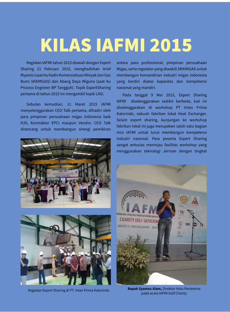
Kegiatan IAFMI tahun 2015 diawali dengan Expert Sharing 21 Februari 2015, menghadirkan Arief Riyanto (saat itu Kadiv Komersialisasi Minyak dan Gas Bumi SKKMIGAS) dan Abang Daya Wiguna (saat itu Process Engineer BP Tangguh). Topik ExpertSharing pertama di tahun 2015 ini mengambil topik LNG.
Sebulan kemudian, 11 Maret 2015 IAFMI menyelenggarakan CEO Talk pertama, dihadiri oleh para pimpinan perusahaan migas Indonesia baik K3S, Kontraktor EPCI maupun Vendor. CEO Talk dirancang untuk membangun sinergi pemikiran
KIlaS IaFMI 2015antara para professional, pimpinan perusahaan Migas, serta regulator yang diwakili SKKMIGAS untuk membangun kemandirian industri migas Indonesia yang berdiri diatas kapasitas dan kompetensi nasional yang mandiri.
Pada tanggal 9 Mei 2015, Expert Sharing IAFMI diselenggarakan sedikit berbeda, kali ini diselenggarakan di workshop PT Intan Prima Kalorindo, sebuah fabrikan lokal Heat Exchanger. Selain expert sharing, kunjungan ke workshop fabrikan lokal ini juga merupakan salah satu bagian misi IAFMI untuk turut membangun kompetensi industri nasional. Para peserta Expert Sharing sangat antusias meninjau fasilitas workshop yang menggunakan teknologi Jerman dengan tingkat
Kegiatan Expert Sharing di PT. Intan Prima Kalorindo Bapak Syamsu Alam, Direktur Hulu Pertamina pada acara IAFMI Golf Charity
<< 11 jurnal IaFMI 03 Desember 2015
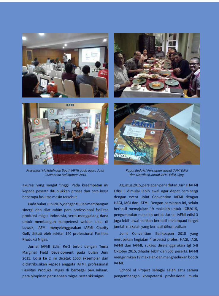
akurasi yang sangat tinggi. Pada kesempatan ini kepada peserta ditunjukkan proses dan cara kerja beberapa fasilitas mesin tersebut
Pada bulan Juni 2015, dengan tujuan membangun sinergi dan silaturahim para professional fasilitas produksi migas Indonesia, serta menggalang dana untuk membangun kompetensi welder lokal di Luwuk, IAFMI menyelenggarakan IAFMI Charity Golf, diikuti oleh sekitar 140 professional Fasilitas Produksi Migas.
Jurnal IAFMI Edisi Ke-2 terbit dengan Tema Marginal Field Development pada bulan Juni 2015. Edisi ke 2 ini dicetak 1500 eksemplar dan didistribusikan kepada anggota IAFMI, professional Fasilitas Produksi Migas di berbagai perusahaan, para pimpinan perusahaan migas, serta skkmigas.
Agustus 2015, persiapan penerbitan Jurnal IAFMI Edisi 3 dimulai lebih awal agar dapat bersinergi dengan event Joint Convention IAFMI dengan HAGI, IAGI dan IATMI. Dengan persiapan ini, selain berhasil memajukan 19 makalah untuk JCB2015, pengumpulan makalah untuk Jurnal IAFMI edisi 3 juga lebih awal bahkan berhasil melampaui target jumlah makalah yang berhasil dikumpulkan
Joint Convention Balikpapan 2015 yang merupakan kegiatan 4 asosiasi profesi HAGI, IAGI, IAFMI dan IAFMI, sukses diselenggarakan tgl 5-8 Oktober 2015, dihadiri lebih dari 600 peserta. IAFMI mengirimkan 19 makalah dan menghadirkan booth IAFMI.
School of Project sebagai salah satu sarana pengembangan kompetensi professional muda
Presentasi Makalah dan Booth IAFMI pada acara Joint Convention Balikpapan 2015
Rapat Redaksi Persiapan Jurnal IAFMI Edisi dan Distribusi Jurnal IAFMI Edisi 2.jpg
jurnal IaFMI 03 Desember 2015 >> 12
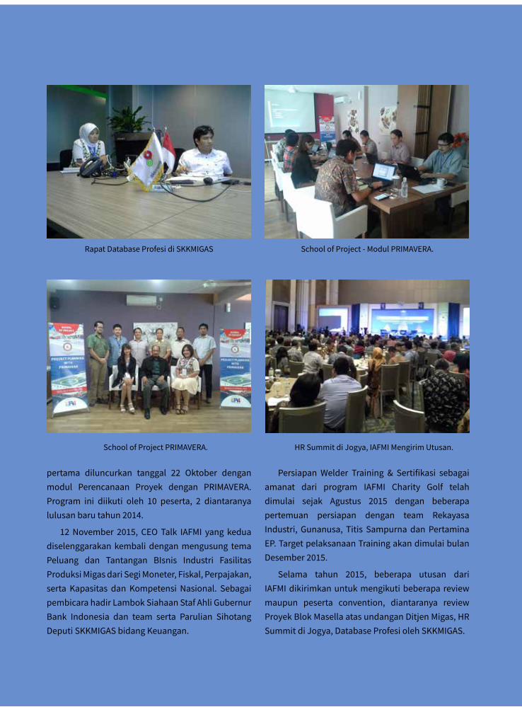
pertama diluncurkan tanggal 22 Oktober dengan modul Perencanaan Proyek dengan PRIMAVERA. Program ini diikuti oleh 10 peserta, 2 diantaranya lulusan baru tahun 2014.
12 November 2015, CEO Talk IAFMI yang kedua diselenggarakan kembali dengan mengusung tema Peluang dan Tantangan BIsnis Industri Fasilitas Produksi Migas dari Segi Moneter, Fiskal, Perpajakan, serta Kapasitas dan Kompetensi Nasional. Sebagai pembicara hadir Lambok Siahaan Staf Ahli Gubernur Bank Indonesia dan team serta Parulian Sihotang Deputi SKKMIGAS bidang Keuangan.
Persiapan Welder Training & Sertifikasi sebagai amanat dari program IAFMI Charity Golf telah dimulai sejak Agustus 2015 dengan beberapa pertemuan persiapan dengan team Rekayasa Industri, Gunanusa, Titis Sampurna dan Pertamina EP. Target pelaksanaan Training akan dimulai bulan Desember 2015.
Selama tahun 2015, beberapa utusan dari IAFMI dikirimkan untuk mengikuti beberapa review maupun peserta convention, diantaranya review Proyek Blok Masella atas undangan Ditjen Migas, HR Summit di Jogya, Database Profesi oleh SKKMIGAS.
Rapat Database Profesi di SKKMIGAS
School of Project PRIMAVERA.
School of Project - Modul PRIMAVERA.
HR Summit di Jogya, IAFMI Mengirim Utusan.
<< 13 jurnal IaFMI 03 Desember 2015
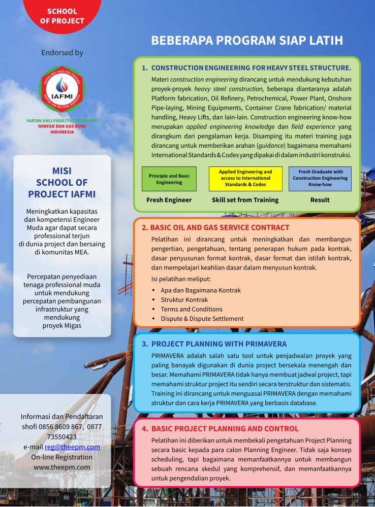
MISI SChOOL OF
PROJeCT IAFMIMeningkatkan kapasitas
dan kompetensi Engineer Muda agar dapat secara
professional terjun di dunia project dan bersaing
di komunitas MEA.
Percepatan penyediaan tenaga professional muda
untuk mendukung percepatan pembangunan
infrastruktur yang mendukung
proyek Migas
Informasi dan Pendaftaran shofi 0856 8609 867, 0877
73550423 e-mail [email protected]
On-line Registration www.theepm.com
+ =
1. CONSTRUCTION eNGINeeRING FOR heAvy STeeL STRUCTURe. Materi construction engineering dirancang untuk mendukung kebutuhan
proyek-proyek heavy steel construction, beberapa diantaranya adalah Platform fabrication, Oil Refinery, Petrochemical, Power Plant, Onshore Pipe-laying, Mining Equipments, Container Crane fabrication/ material handling, Heavy Lifts, dan lain-lain. Construction engineering know-how merupakan applied engineering knowledge dan field experience yang dirangkum dari pengalaman kerja. Disamping itu materi training juga dirancang untuk memberikan arahan (guidance) bagaimana memahami International Standards & Codes yang dipakai di dalam industri konstruksi.
Principle and Basic
Engineering
Applied Engineering and access to International
Standards & Codes
Fresh Graduate with Construction Engineering
Know-how
Fresh Engineer + Skill set from Training = Result Fresh engineer Skill set from Training Result
BeBeRAPA PROGRAM SIAP LATIh
2. BASIC OIL AND GAS SeRvICe CONTRACT Pelatihan ini dirancang untuk meningkatkan dan membangun
pengertian, pengetahuan, tentang penerapan hukum pada kontrak, dasar penyusunan format kontrak, dasar format dan istilah kontrak, dan mempelajari keahlian dasar dalam menyusun kontrak.
Isi pelatihan meliput:
• Apa dan Bagaimana Kontrak• Struktur Kontrak• Terms and Conditions• Dispute & Dispute Settlement
3. PROJeCT PLANNING WITh PRIMAveRA PRIMAVERA adalah salah satu tool untuk penjadwalan proyek yang
paling banayak digunakan di dunia project bersekala menengah dan besar. Memahami PRIMAVERA tidak hanya membuat jadwal project, tapi memahami struktur project itu sendiri secara terstruktur dan sistematis. Training ini dirancang untuk menguasai PRIMAVERA dengan memahami struktur dan cara kerja PRIMAVERA yang berbasis database.
4. BASIC PROJeCT PLANNING AND CONTROL Pelatihan ini diberikan untuk membekali pengetahuan Project Planning
secara basic kepada para calon Planning Engineer. Tidak saja konsep scheduling, tapi bagaimana memanfaatkannya untuk membangun sebuah rencana skedul yang komprehensif, dan memanfaatkannya untuk pengendalian proyek.
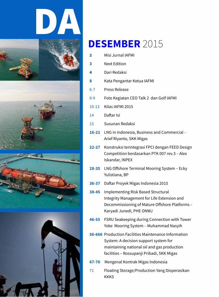
DeSeMBeR 2015daftar isi
2 Misi Jurnal IAFMI
3 Next Edition
4 Dari Redaksi
5 Kata Pengantar Ketua IAFMI
6-7 Press Release
8-9 Foto Kegiatan CEO Talk 2 dan Golf IAFMI
10-13 Kilas IAFMI 2015
14 Daftar Isi
15 Susunan Redaksi
16-21 LNG in Indonesia, Business and Commercial – Arief Riyanto, SKK Migas
22-27 Konstruksi terintegrasi FPCI dengan FEED Design Competition berdasarkan PTK 007 rev.3 – Alex Iskandar, INPEX
28-35 LNG Offshore Terminal Mooring System – Ecky Yulistiana, BP
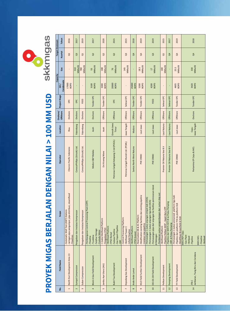
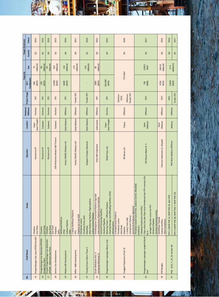
36-37 Daftar Proyek Migas Indonesia 2015
38-45 Implementing Risk Based Structural Integrity Management for Life Extension and Decommissioning of Mature Offshore Platforms – Karyadi Junedi, PHE ONWJ
46-55 FSRU Seakeeping during Connection with Tower Yoke Mooring System – Muhammad Nasyih
56-666 Production Facilities Maintenance Information System: A decision support system for maintaining national oil and gas production facilities – Rossupanji Pribadi, SKK Migas
67-70 Mengenal Kontrak Migas Indonesia
71 Floating Storage/Production Yang Dioperasikan KKKS

s u s u n a n r E d a K S I
Pimpinan Redaksi: Desi A. Mahdi, S.T.,PMP
Project Sponsor: Ir. edwin Badrusomad (Direktur Eksekutif IAFMI)
Team Editor:Risvan Dirza, S.T
Mokhamad Nasyih Aminulloh, S.T
Sponsorship:Ahmad Diponegoro, ST.,MSc
Andre Widhiananto Ariono, ST. MT.
Mokhamad Rifky Soedirdja, S.T., M.T
Dwi Nuraini Siregar, S.T
Chief Editor:Adjie heryanto, S.T
Penanggung Jawab:Ir. Taufik Aditiyawarman, M.M., PMP
(Sekjen IAFMI)
Distribusi:Auliya Fahmi Syafri, S.T
Rosiska Alwin, Se
Anggota Dewan Pakar:Ir. Steve Adrianto, Prof. Ir. Ricky L Tawekal, MSE.,PhD. Ahmad Taufik, M.Eng., PhD., Ir. Iwan Jatmika, Ir. Witoyo, Ir. Sandry Pasambuna, Juanto Sitorus, MT, CPM, PMP, CSEP, Adjie Heryanto, ST.
Ketua Dewan Pakar: Ir. Bob Djanegara
Foto : Koleksi edwinB dan haria hindarwin | Foto Cover oleh Muhasrul ZubirDesain lay out : Dedi The ePM
Sekretariat: Gandaria 8 Office Tower, Lt.5, Jalan Sultan Iskandar Muda, Jakarta 12240, Telp. +62 21 2903 6664
e-mail : [email protected], website: www.iafmi.or.id
daftar isi
jurnal IaFMI 03 Desember 2015 >> 16
aBSTracT
In 2013, Indonesia’s gas reserve is estimated constitute 1.6% of world gas reserves. This reserve is sufficient for 50 years with the current consumption rate. However, domestic gas market is significantly increased within the last decade to satisfy many strategic industry and major gas power plants project. The gas production rate which produced by different fields are expected to be increased to fulfill these demands. There are many forms of how natural gas can be transported and distributed. One of form which is efficient is Liquefied Natural Gas (LNG). However, the readiness of the re-gas infrastructures in time to support distribution of the supply may determine whether domestic market is able to absorb the supply.
conTExT
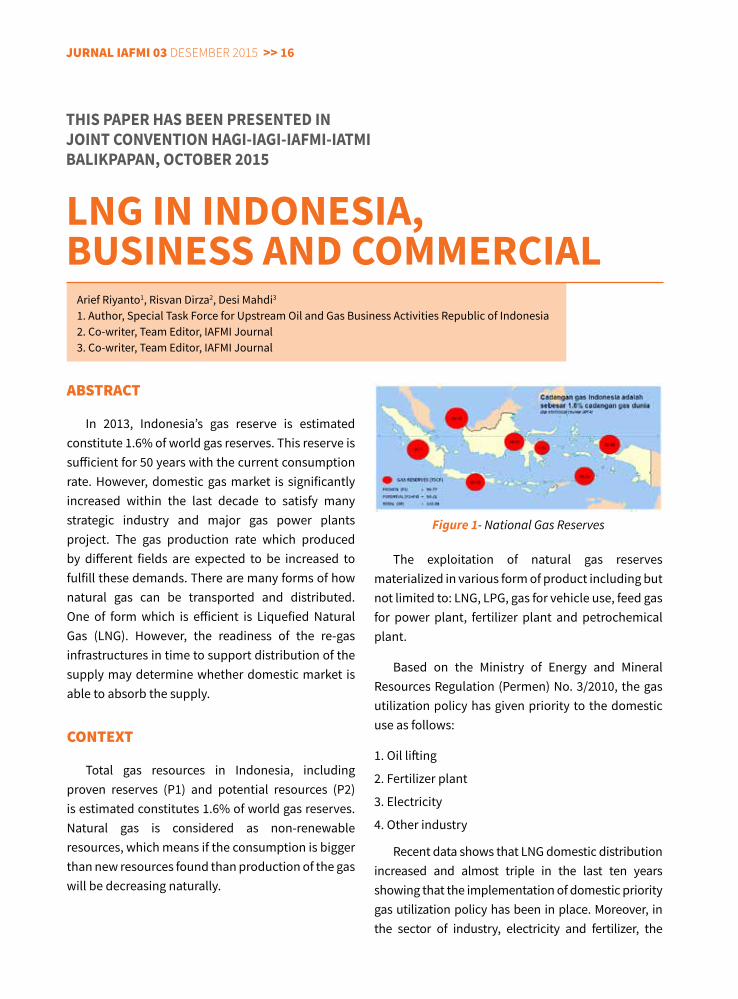
Total gas resources in Indonesia, including proven reserves (P1) and potential resources (P2) is estimated constitutes 1.6% of world gas reserves. Natural gas is considered as non-renewable resources, which means if the consumption is bigger than new resources found than production of the gas will be decreasing naturally.
The exploitation of natural gas reserves materialized in various form of product including but not limited to: LNG, LPG, gas for vehicle use, feed gas for power plant, fertilizer plant and petrochemical plant.
Based on the Ministry of Energy and Mineral Resources Regulation (Permen) No. 3/2010, the gas utilization policy has given priority to the domestic use as follows:
1. Oil lifting
2. Fertilizer plant
3. Electricity
4. Other industry
Recent data shows that LNG domestic distribution increased and almost triple in the last ten years showing that the implementation of domestic priority gas utilization policy has been in place. Moreover, in the sector of industry, electricity and fertilizer, the
ThIS PAPeR hAS BeeN PReSeNTeD INJOINT CONveNTION hAGI-IAGI-IAFMI-IATMIBALIKPAPAN, OCTOBeR 2015
LNG IN INDONeSIA, BUSINeSS AND COMMeRCIAL
Arief Riyanto1, Risvan Dirza2, Desi Mahdi3 1. Author, Special Task Force for Upstream Oil and Gas Business Activities Republic of Indonesia2. Co-writer, Team Editor, IAFMI Journal3. Co-writer, Team Editor, IAFMI Journal
Figure 1- National Gas Reserves
<< 17 jurnal IaFMI 03 Desember 2015
total contract of natural gas utilization in Indonesia has been dramatically increased since 2003 to 2010 and relatively steady in the last five years.
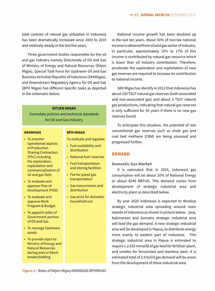
Three government bodies responsible for the oil and gas industry namely Directorate of Oil and Gas of Ministry of Energy and Natural Resources (Ditjen Migas), Special Task Force for Upstream Oil and Gas Business Activities Republic of Indonesia (SKKMigas), and Downstream Regulatory Agency for Oil and Gas (BPH Migas) has different specific tasks as depicted in the schematic below:
National income growth has been doubled up in the last ten years. About 50% of non-tax national income is obtained from oil and gas sector of industry. In particular, approximately 15% to 17% of this income is contributed by natural gas resource which is lower than oil industry contribution. Therefore, accelerate the exploration and exploitation of new gas reserves are required to increase its contribution to national income.
SKK Migas has identify in 2013 that Indonesia has about 150 TSCF natural gas reserves (both associated and non-associated gas) and about 3 TSCF natural gas productions, indicating that natural gas reserves is only sufficient for 50 years if there is no new gas reserves found.
To anticipate this situation, the potential of non conventional gas reserves such as shale gas and coal bed methane (CBM) are being assessed and progressed further.
dEMand
domestic Gas MarketIt is estimated that in 2025, Indonesia gas
consumption will be about 20% of National Energy or about 8249 BBTUD. This demand comes from development of strategic industrial area and electricity plant as described below.
By year 2020 Indonesia is expected to develop strategic industrial area spreading around main islands of Indonesia as shown in picture below. Java, Kalimantan and Sumatra strategic industrial area will lead the gas demand. A new strategic industrial area will be developed in Papua, to distribute energy more evenly to eastern part of Indonesia. This strategic industrial area in Papua is estimated to require c.a 535 mmscfd of gas feed for fertilizer plant, and smelter for ferronickel and stainless steel. It is estimated total of 2.9 bcf/d gas demand will be arose from the development of these industrial area.
DITJeN MIGASFormulate policies and technical standards
for Oil and Gas industry
SKKMIGAS
• Tomonitoroperational aspects of Production Sharing Contractors (PSC) including the exploration, exploitation and commercialisation of oil and gas field
• Toevaluateandapprove Plan of Development (POD)
• Toevaluateandapprove Work Program & Budget
• ToappointsellerofGovernment portion of Oil and Gas
• TomanageUpstreamassets
• ToprovideinputtoMinistry of Energy and Natural Resources during area or block tender/bidding
BPh MIGAS
To evaluate and regulate:
• Fuelavailabilityanddistribution
• Nationalfuelreserves
• Fueltransportationand storing facilities
• Feeforpipedgastransportation
• Gastransmissionanddistribution
• Gaspricefordomestichousehold use
Figure 2 - Roles of Ditjen Migas/SKKMIGAS/BPHMIGAS
jurnal IaFMI 03 Desember 2015 >> 18
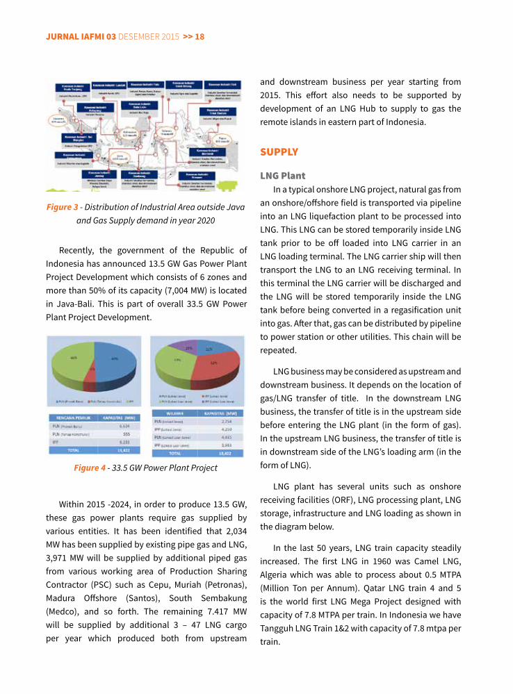
Recently, the government of the Republic of Indonesia has announced 13.5 GW Gas Power Plant Project Development which consists of 6 zones and more than 50% of its capacity (7,004 MW) is located in Java-Bali. This is part of overall 33.5 GW Power Plant Project Development.
and downstream business per year starting from 2015. This effort also needs to be supported by development of an LNG Hub to supply to gas the remote islands in eastern part of Indonesia.
SuPPly
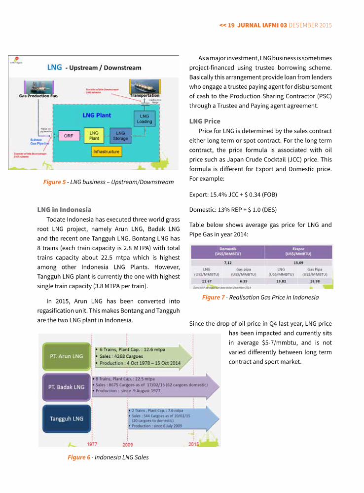
lnG PlantIn a typical onshore LNG project, natural gas from
an onshore/offshore field is transported via pipeline into an LNG liquefaction plant to be processed into LNG. This LNG can be stored temporarily inside LNG tank prior to be off loaded into LNG carrier in an LNG loading terminal. The LNG carrier ship will then transport the LNG to an LNG receiving terminal. In this terminal the LNG carrier will be discharged and the LNG will be stored temporarily inside the LNG tank before being converted in a regasification unit into gas. After that, gas can be distributed by pipeline to power station or other utilities. This chain will be repeated.
LNG business may be considered as upstream and downstream business. It depends on the location of gas/LNG transfer of title. In the downstream LNG business, the transfer of title is in the upstream side before entering the LNG plant (in the form of gas). In the upstream LNG business, the transfer of title is in downstream side of the LNG’s loading arm (in the form of LNG).
LNG plant has several units such as onshore receiving facilities (ORF), LNG processing plant, LNG storage, infrastructure and LNG loading as shown in the diagram below.
In the last 50 years, LNG train capacity steadily increased. The first LNG in 1960 was Camel LNG, Algeria which was able to process about 0.5 MTPA (Million Ton per Annum). Qatar LNG train 4 and 5 is the world first LNG Mega Project designed with capacity of 7.8 MTPA per train. In Indonesia we have Tangguh LNG Train 1&2 with capacity of 7.8 mtpa per train.
Figure 3 - Distribution of Industrial Area outside Java and Gas Supply demand in year 2020
Figure 4 - 33.5 GW Power Plant Project
Within 2015 -2024, in order to produce 13.5 GW, these gas power plants require gas supplied by various entities. It has been identified that 2,034 MW has been supplied by existing pipe gas and LNG, 3,971 MW will be supplied by additional piped gas from various working area of Production Sharing Contractor (PSC) such as Cepu, Muriah (Petronas), Madura Offshore (Santos), South Sembakung (Medco), and so forth. The remaining 7.417 MW will be supplied by additional 3 – 47 LNG cargo per year which produced both from upstream
<< 19 jurnal IaFMI 03 Desember 2015
lnG in IndonesiaTodate Indonesia has executed three world grass
root LNG project, namely Arun LNG, Badak LNG and the recent one Tangguh LNG. Bontang LNG has 8 trains (each train capacity is 2.8 MTPA) with total trains capacity about 22.5 mtpa which is highest among other Indonesia LNG Plants. However, Tangguh LNG plant is currently the one with highest single train capacity (3.8 MTPA per train).
In 2015, Arun LNG has been converted into regasification unit. This makes Bontang and Tangguh are the two LNG plant in Indonesia.
As a major investment, LNG business is sometimes project-financed using trustee borrowing scheme. Basically this arrangement provide loan from lenders who engage a trustee paying agent for disbursement of cash to the Production Sharing Contractor (PSC) through a Trustee and Paying agent agreement.
lnG PricePrice for LNG is determined by the sales contract
either long term or spot contract. For the long term contract, the price formula is associated with oil price such as Japan Crude Cocktail (JCC) price. This formula is different for Export and Domestic price. For example:
Export: 15.4% JCC + $ 0.34 (FOB)
Domestic: 13% REP + $ 1.0 (DES)
Table below shows average gas price for LNG and Pipe Gas in year 2014:
Since the drop of oil price in Q4 last year, LNG price has been impacted and currently sits in average $5-7/mmbtu, and is not varied differently between long term contract and sport market.
Figure 5 - LNG business – Upstream/Downstream
Figure 6 - Indonesia LNG Sales
Figure 7 - Realisation Gas Price in Indonesia
jurnal IaFMI 03 Desember 2015 >> 20
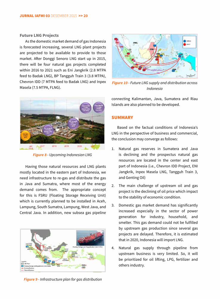
Future lnG ProjectsAs the domestic market demand of gas Indonesia
is forecasted increasing, several LNG plant projects are projected to be available to provide to those market. After Donggi Senoro LNG start up in 2015, there will be four natural gas projects completed within 2016 to 2021 such as Eni Jangkrik (2.8 MTPA feed to Badak LNG), BP Tangguh Train 3 (3.8 MTPA), Chevron IDD (7 MTPA feed to Badak LNG) and Inpex Masela (7.5 MTPA, FLNG).
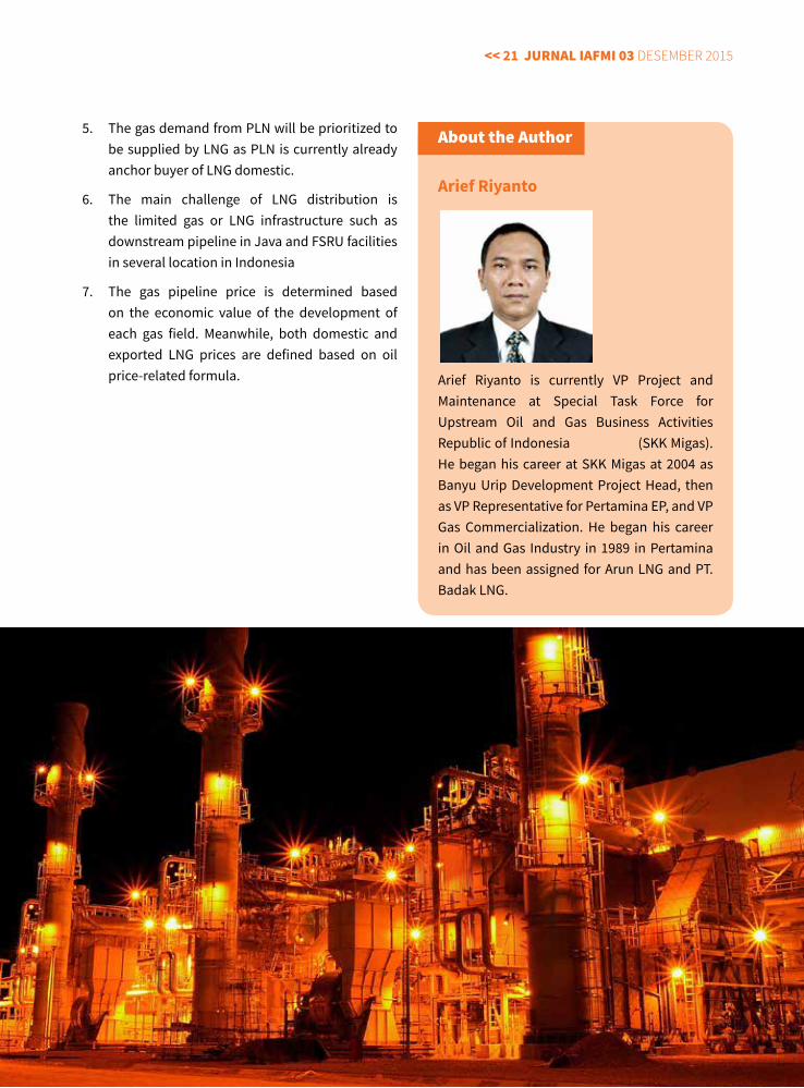
Having those natural resources and LNG plants mostly located in the eastern part of Indonesia, we need infrastructure to re-gas and distribute the gas in Java and Sumatra, where most of the energy demand comes from. The appropriate concept for this is FSRU (Floating Storage Receiving Unit) which is currently planned to be installed in Aceh, Lampung, South Sumatra, Lampung, West Java, and Central Java. In addition, new subsea gas pipeline
connecting Kalimantan, Java, Sumatera and Riau Islands are also planned to be developed.
SuMMary
Based on the factual conditions of Indonesia’s LNG in the perspective of business and commercial, the conclusion may converge as follows:
1. Natural gas reserves in Sumatera and Java is declining and the prospectus natural gas resources are located in the center and east part of Indonesia (i.e., Chevron IDD Project, ENI Jangkrik, Inpex Masela LNG, Tangguh Train 3, and Genting Oil)
2. The main challenge of upstream oil and gas project is the declining of oil price which impact to the stability of economic condition.
3. Domestic gas market demand has significantly increased especially in the sector of power generation for industry, household, and smelter. This gas demand could not be fulfilled by upstream gas production since several gas projects are delayed. Therefore, it is estimated that in 2020, Indonesia will import LNG.
4. Natural gas supply through pipeline from upstream business is very limited. So, it will be prioritized for oil lifting, LPG, fertilizer and others industry.
Figure 9 - Infrastructure plan for gas distribution
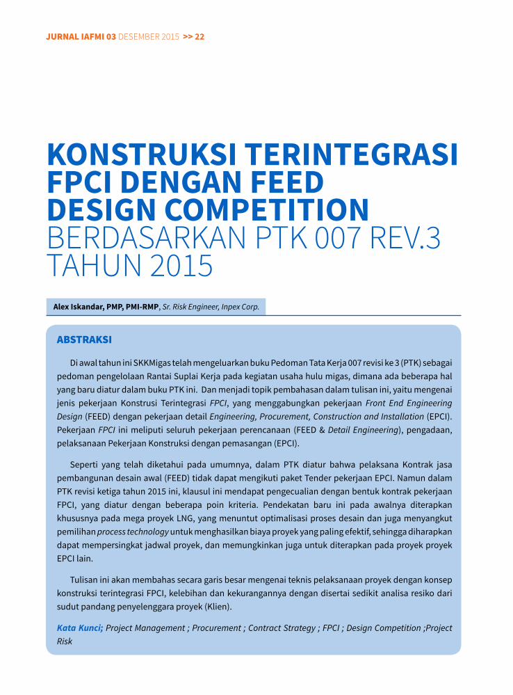
Figure 10 - Future LNG supply and distribution across Indonesia
Figure 8 - Upcoming Indonesian LNG
<< 21 jurnal IaFMI 03 Desember 2015
5. The gas demand from PLN will be prioritized to be supplied by LNG as PLN is currently already anchor buyer of LNG domestic.
6. The main challenge of LNG distribution is the limited gas or LNG infrastructure such as downstream pipeline in Java and FSRU facilities in several location in Indonesia
7. The gas pipeline price is determined based on the economic value of the development of each gas field. Meanwhile, both domestic and exported LNG prices are defined based on oil price-related formula.
about the author
Arief Riyanto
Arief Riyanto is currently VP Project and Maintenance at Special Task Force for Upstream Oil and Gas Business Activities Republic of Indonesia (SKK Migas). He began his career at SKK Migas at 2004 as Banyu Urip Development Project Head, then as VP Representative for Pertamina EP, and VP Gas Commercialization. He began his career in Oil and Gas Industry in 1989 in Pertamina and has been assigned for Arun LNG and PT. Badak LNG.
jurnal IaFMI 03 Desember 2015 >> 22
aBSTraKSI
Di awal tahun ini SKKMigas telah mengeluarkan buku Pedoman Tata Kerja 007 revisi ke 3 (PTK) sebagai pedoman pengelolaan Rantai Suplai Kerja pada kegiatan usaha hulu migas, dimana ada beberapa hal yang baru diatur dalam buku PTK ini. Dan menjadi topik pembahasan dalam tulisan ini, yaitu mengenai jenis pekerjaan Konstrusi Terintegrasi FPCI, yang menggabungkan pekerjaan Front End Engineering Design (FEED) dengan pekerjaan detail Engineering, Procurement, Construction and Installation (EPCI). Pekerjaan FPCI ini meliputi seluruh pekerjaan perencanaan (FEED & Detail Engineering), pengadaan, pelaksanaan Pekerjaan Konstruksi dengan pemasangan (EPCI).
Seperti yang telah diketahui pada umumnya, dalam PTK diatur bahwa pelaksana Kontrak jasa pembangunan desain awal (FEED) tidak dapat mengikuti paket Tender pekerjaan EPCI. Namun dalam PTK revisi ketiga tahun 2015 ini, klausul ini mendapat pengecualian dengan bentuk kontrak pekerjaan FPCI, yang diatur dengan beberapa poin kriteria. Pendekatan baru ini pada awalnya diterapkan khususnya pada mega proyek LNG, yang menuntut optimalisasi proses desain dan juga menyangkut pemilihan process technology untuk menghasilkan biaya proyek yang paling efektif, sehingga diharapkan dapat mempersingkat jadwal proyek, dan memungkinkan juga untuk diterapkan pada proyek proyek EPCI lain.
Tulisan ini akan membahas secara garis besar mengenai teknis pelaksanaan proyek dengan konsep konstruksi terintegrasi FPCI, kelebihan dan kekurangannya dengan disertai sedikit analisa resiko dari sudut pandang penyelenggara proyek (Klien).
Kata Kunci; Project Management ; Procurement ; Contract Strategy ; FPCI ; Design Competition ;Project Risk
KONSTRUKSI TeRINTeGRASI FPCI DeNGAN FeeD DeSIGN COMPeTITION berDasarkan PTk 007 rev.3 Tahun 2015
Alex Iskandar, PMP, PMI-RMP, Sr. Risk Engineer, Inpex Corp.
<< 23 jurnal IaFMI 03 Desember 2015
BaTaSan
Batasan yang digunakan adalah pekerjaan Multiple FEED dengan konsep FPCI menggunakan pengadaan sesuai dengan proses di PTK. Durasi proses pengadaan yang diasumsikan adalah durasi normal dan bukan percepatan berdasarkan diskresi.
Dalam pembahasan ini melingkupi Lingkup kerja Kontraktor SKKMigas sebagai perencana proyek (Klien). Cakupan pembahasan ini terbatas pada strategi kontrak dan pelaksanaan tender proyek FPCI dan pelaksanaan Multiple FEED. Seluruh data dan informasi yang disampaikan adalah bersifat umum berdasarkan asumsi dan penilaian penulis secara pribadi
FPcI ModEl : MulTIPlE FEEd / dESIGn coMPETITIon BEForE EPcI
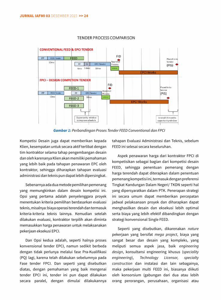
Kompetisi desain (FEED) merupakan hal yang relatif baru dalam dunia industri Migas, dan pada mulanya di laksanakan oleh proyek-proyek LNG, karena biasanya menyangkut investasi yang sangat besar (mega project) yang disertai juga melakukan pemilihan LNG Process Design (Process License) yang
menyangkut permasalahan hak Kekayaan Intelektual (Intellectual Property Right). Desain Kompetisi ini mendorong peserta untuk menerapkan pengalaman dan pengetahuannya untuk mengembangkan solusi-solusi baru yang inovatif. Namun permasalahan utamanya adalah pada penataan kompetisi desain yang kompleks, yang membutuhkan berbagai aturan main yang harus dibuat oleh penyelenggara proyek, untuk dapat mengontrol pekerjaan desain untuk mencapai manfaat yang maksimal dan harus dapat memenuhi kebutuhan semua pihak dalam berkompetisi secara adil dan fair. Namun menurut anggapan penulis, strategi kompetisi Desain ini tidak tepat, bila pemrakarsa proyek telah memiliki licensed process design dan atau telah mempunyai preferred process design yang telah terpilih dari studi yang telah dilakukan sebelumnya.
Fitur kunci dari strategi ini yaitu beberapa kontraktor akan bersaing dengan kontraktor yang lain atas dasar “kompetisi desain” atau “beauty contest”, sehingga setelah menyelesaikan pekerjaan FEED, penyelenggara proyek akan memilih pemenang tunggal untuk fase EPCI dan kontrak lainnya berdasarkan proposal teknis dan komersial perusahaan yang dikembangkan selama fase FEED.
jurnal IaFMI 03 Desember 2015 >> 24
Kompetisi Desain juga dapat memberikan kepada Klien, kesempatan untuk secara aktif terlibat dengan tim kontraktor selama tahap pengembangan desain dan oleh karenanya Klien akan memiliki pemahaman yang lebih baik pada tahapan penawaran EPC oleh kontraktor, sehingga diharapkan tahapan evaluasi administrasi dan teknis pun dapat lebih dipersingkat.
Sebenarnya ada dua metode pemilihan pemenang yang memungkinkan dalam desain kompetisi ini. Opsi yang pertama adalah penyelenggara proyek menentukan kriteria pemilihan berdasarkan evaluasi teknis, misalnya: biaya operasi terendah dan termasuk kriteria-kriteria teknis lainnya. Kemudian setelah dilakukan evaluasi, kontraktor terpilih akan diminta memasukkan harga penawaran untuk melaksanakan pekerjaan eksekusi EPCI.
Dan Opsi kedua adalah, seperti halnya proses konvensional tender EPCI, namun sedikit berbeda dengan tidak perlunya melalui fase Pra-Kualifikasi (PQ) lagi, karena telah dilakukan sebelumnya pada Fase tender FPCI. Dan seperti yang disebutkan diatas, dengan pemahaman yang baik mengenai tender EPCI ini, tender ini pun dapat dilakukan secara paralel, dengan dimulai dilakukannya
tahapan Evaluasi Administrasi dan Teknis, sebelum FEED ini selesai secara keseluruhan.
Aspek penawaran harga dari kontraktor FPCI di kompetisikan sebagai bagian dari kompetisi desain FEED, sehingga penentuan pemenang dengan harga terendah dapat diterapkan dalam penentuan pemenang kompetisi ini, termasuk dengan preferensi Tingkat Kandungan Dalam Negeri/ TKDN seperti hal yang dipersyaratkan dalam PTK. Penerapan strategi ini secara umum dapat memberikan percepatan jadwal pelaksanaan proyek dan diharapkan dapat menghasilkan desain dan eksekusi lebih optimal serta biaya yang lebih efektif dibandingkan dengan strategi konvensional Single FEED.
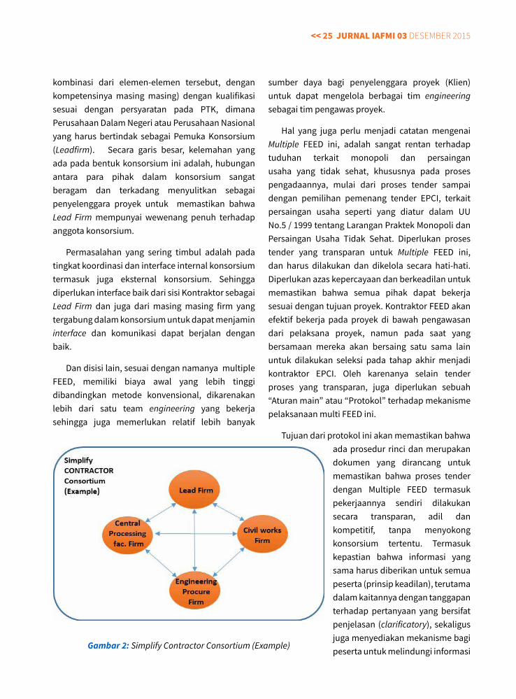
Seperti yang disebutkan, dikarenakan nature pekerjaan yang bersifat mega project, biaya yang sangat besar dan desain yang kompleks, yang meliputi semua aspek jasa, baik engineering design, konsultansi engineering khusus (speciality engineering), Technology Licensor, specialty construction dan instalasi dan lain sebagainya, maka pekerjaan multi FEED ini, biasanya diikuti oleh konsorsium (gabungan dari dua atau lebih orang perorangan, perusahaan, organisasi atau
Gambar 1: Perbandingan Proses Tender FEED Conventional dan FPCI
<< 25 jurnal IaFMI 03 Desember 2015
kombinasi dari elemen-elemen tersebut, dengan kompetensinya masing masing) dengan kualifikasi sesuai dengan persyaratan pada PTK, dimana Perusahaan Dalam Negeri atau Perusahaan Nasional yang harus bertindak sebagai Pemuka Konsorsium (Leadfirm). Secara garis besar, kelemahan yang ada pada bentuk konsorsium ini adalah, hubungan antara para pihak dalam konsorsium sangat beragam dan terkadang menyulitkan sebagai penyelenggara proyek untuk memastikan bahwa Lead Firm mempunyai wewenang penuh terhadap anggota konsorsium.
Permasalahan yang sering timbul adalah pada tingkat koordinasi dan interface internal konsorsium termasuk juga eksternal konsorsium. Sehingga diperlukan interface baik dari sisi Kontraktor sebagai Lead Firm dan juga dari masing masing firm yang tergabung dalam konsorsium untuk dapat menjamin interface dan komunikasi dapat berjalan dengan baik.
Dan disisi lain, sesuai dengan namanya multiple FEED, memiliki biaya awal yang lebih tinggi dibandingkan metode konvensional, dikarenakan lebih dari satu team engineering yang bekerja sehingga juga memerlukan relatif lebih banyak
sumber daya bagi penyelenggara proyek (Klien) untuk dapat mengelola berbagai tim engineering sebagai tim pengawas proyek.
Hal yang juga perlu menjadi catatan mengenai Multiple FEED ini, adalah sangat rentan terhadap tuduhan terkait monopoli dan persaingan usaha yang tidak sehat, khususnya pada proses pengadaannya, mulai dari proses tender sampai dengan pemilihan pemenang tender EPCI, terkait persaingan usaha seperti yang diatur dalam UU No.5 / 1999 tentang Larangan Praktek Monopoli dan Persaingan Usaha Tidak Sehat. Diperlukan proses tender yang transparan untuk Multiple FEED ini, dan harus dilakukan dan dikelola secara hati-hati. Diperlukan azas kepercayaan dan berkeadilan untuk memastikan bahwa semua pihak dapat bekerja sesuai dengan tujuan proyek. Kontraktor FEED akan efektif bekerja pada proyek di bawah pengawasan dari pelaksana proyek, namun pada saat yang bersamaan mereka akan bersaing satu sama lain untuk dilakukan seleksi pada tahap akhir menjadi kontraktor EPCI. Oleh karenanya selain tender proses yang transparan, juga diperlukan sebuah “Aturan main” atau “Protokol” terhadap mekanisme pelaksanaan multi FEED ini.
Tujuan dari protokol ini akan memastikan bahwa ada prosedur rinci dan merupakan dokumen yang dirancang untuk memastikan bahwa proses tender dengan Multiple FEED termasuk pekerjaannya sendiri dilakukan secara transparan, adil dan kompetitif, tanpa menyokong konsorsium tertentu. Termasuk kepastian bahwa informasi yang sama harus diberikan untuk semua peserta (prinsip keadilan), terutama dalam kaitannya dengan tanggapan terhadap pertanyaan yang bersifat penjelasan (clarificatory), sekaligus juga menyediakan mekanisme bagi peserta untuk melindungi informasi Gambar 2: Simplify Contractor Consortium (Example)
jurnal IaFMI 03 Desember 2015 >> 26
rahasia dan kepemilikan, rahasia dagang dan ‘ide’ desain (yang mana tidak dapat dibagi dengan konsorsium lainnya), dan dengan demikian juga mendorong peserta untuk terlibat dalam kompetisi. Salah satu opsi untuk meningkatkan kemandirian administrasi dan azas keadilan adalah menunjuk auditor independen yang disetujui oleh para pihak untuk memantau interaksi selama proses tersebut, termasuk memberikan saran mengenai pelaksanaan protokol selama proses tersebut.
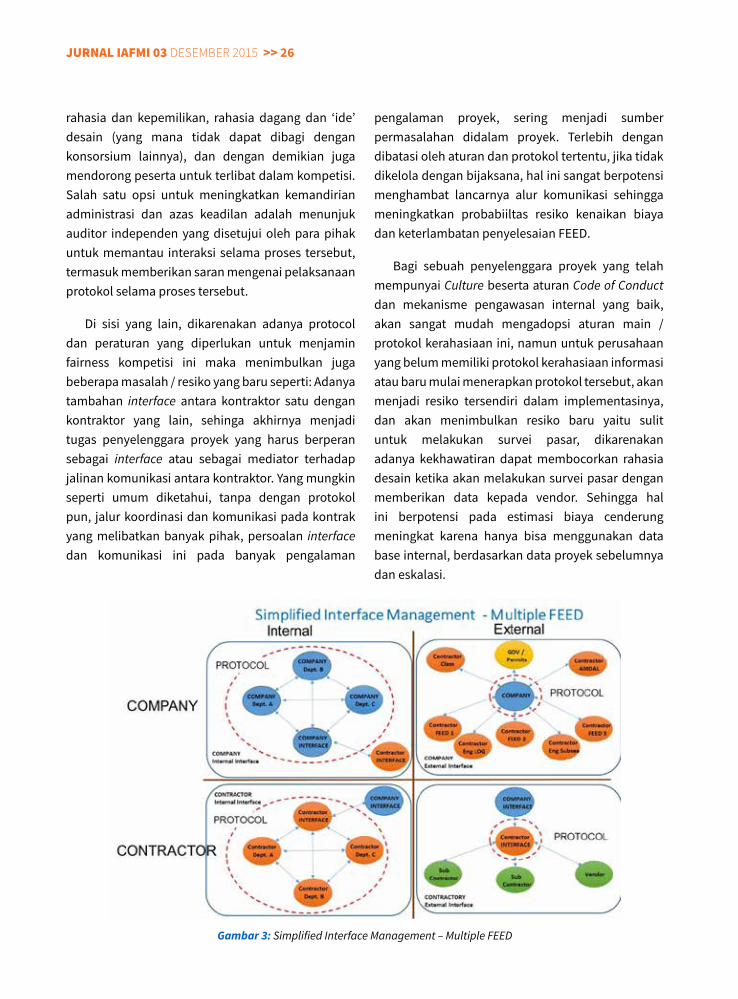
Di sisi yang lain, dikarenakan adanya protocol dan peraturan yang diperlukan untuk menjamin fairness kompetisi ini maka menimbulkan juga beberapa masalah / resiko yang baru seperti: Adanya tambahan interface antara kontraktor satu dengan kontraktor yang lain, sehinga akhirnya menjadi tugas penyelenggara proyek yang harus berperan sebagai interface atau sebagai mediator terhadap jalinan komunikasi antara kontraktor. Yang mungkin seperti umum diketahui, tanpa dengan protokol pun, jalur koordinasi dan komunikasi pada kontrak yang melibatkan banyak pihak, persoalan interface dan komunikasi ini pada banyak pengalaman
pengalaman proyek, sering menjadi sumber permasalahan didalam proyek. Terlebih dengan dibatasi oleh aturan dan protokol tertentu, jika tidak dikelola dengan bijaksana, hal ini sangat berpotensi menghambat lancarnya alur komunikasi sehingga meningkatkan probabiiltas resiko kenaikan biaya dan keterlambatan penyelesaian FEED.
Bagi sebuah penyelenggara proyek yang telah mempunyai Culture beserta aturan Code of Conduct dan mekanisme pengawasan internal yang baik, akan sangat mudah mengadopsi aturan main / protokol kerahasiaan ini, namun untuk perusahaan yang belum memiliki protokol kerahasiaan informasi atau baru mulai menerapkan protokol tersebut, akan menjadi resiko tersendiri dalam implementasinya, dan akan menimbulkan resiko baru yaitu sulit untuk melakukan survei pasar, dikarenakan adanya kekhawatiran dapat membocorkan rahasia desain ketika akan melakukan survei pasar dengan memberikan data kepada vendor. Sehingga hal ini berpotensi pada estimasi biaya cenderung meningkat karena hanya bisa menggunakan data base internal, berdasarkan data proyek sebelumnya dan eskalasi.
Gambar 3: Simplified Interface Management – Multiple FEED
<< 27 jurnal IaFMI 03 Desember 2015
Tentang Penulis
Alex Iskandar, PMP, PMI-RMP Alex Iskandar
memiliki pengalaman selama lebih dari 15 (lima belas) tahun di bidang manajemen proyek pada industri Minyak dan Gas.
Setelah menyelesaikan program sarjana teknik mesin di Institut Teknologi Sepuluh November, Alex memulai karirnya bersama PT Truba Jaya Engineering sebagai Project Control Engineer. Kemudian sempat berkarir di beberapa perusahaan seperti Surveyor Indonesia, Pauwels Trafo Asia, 10 tahun berkarir di ConocoPhillips Indonesia dan sekarang bertugas sebagai Sr. Risk Engineer untuk Inpex Corporation.
Alex adalah anggota aktif dan memiliki sertifikat Project Management Professional (PMP) & Risk Management Professional (RMP) dari Project Management Institute (PMI).
Termasuk juga jadwal dan pekerjaan secara keseluruhan sulit untuk dapat terintegrasi, karena terdapat disparitas estimasi dan juga desain yang berbeda antara kontraktor satu dengan yang lain yang mana termasuk kerahasiaan yang harus dijaga. Strategi komunikasi yang baik diperlukan oleh penyelenggara proyek agar tidak mengakibatkan kehilangan fokus dan arah dari team proyek secara keseluruhan
KESIMPulan
Strategi Multiple FEED / Beauty Contest / Desain Kompetisi adalah suatu pilihan yang baik apabila pemrakarsa proyek (Klien) merasakan perlu adanya pemilihan dari beberapa jenis proses / teknologi yang diinginkan untuk dikompetisikan dalam suatu proyek, dengan jadwal yang relatif lebih cepat dibandingkan dengan metode konvensional, termasuk juga akan mendapatkan biaya Capital Expenditure yang lebih optimal. Namun strategi Desain kompetisi ini, menurut pandangan penulis, dipandang tidak tepat bila pemrakarsa proyek (Klien) telah memiliki licensed process design dan/atau telah mempunyai preferred process design yang telah terpilih dari studi yang telah dilakukan sebelumnya.
Mengingat besarnya biaya investasi di awal proyek, termasuk juga memerlukan banyak resources yang perlu mengawasi jalannya proses FEED, dirasakan perlu menjadi bahan pertimbangan oleh penyelenggara proyek, sehingga tidak mengganggu ke ekonomian proyek. Sehingga ekspektasi penulis, pekerjaan Multiple FEED ini hanya dilakukan untuk pekerjaan Mega Project.
Aturan detail serta protokol kerahasiaan, termasuk perlunya auditor independen merupakan salah satu opsi untuk memastikan pelaksanaan metode ini dilakukan dengan azas berkeadilan. Walaupun disisi yang lain, dengan adanya protokol ini, akan menambah resiko keterlambatan jadwal proyek dan juga resiko naiknya estimasi total biaya proyek.
rEFErEnSI
• Pankaj Shah, Technology Manager LNG - PROJECT DESIGN COMPETITION - A CONTRACTOR’S VIEWPOINT. http://www.ivt.ntnu.no/ept/fag/tep4215/innhold/LNG%20Conferences/2004/Data/Papers-PDF/PS4-7-Durr.pdf
• Diego Braghi - Design Competition Strategy http://diegobraghi.blogspot.co.id/2011/12/diego-braghi-design-competition.html
• Proses Beauty Contest Proyek Donggi -Senoro http://www.kppu.go.id/docs/Putusan/putusan_35_2010_Donggi%20senoro.pdf
jurnal IaFMI 03 Desember 2015 >> 28
InTroducTIonNatural Gas (NG) is used as one of the major sources of energy. However, many cities and industries
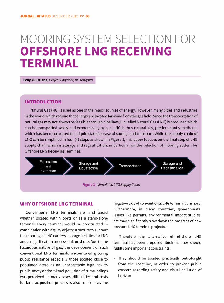
in the world which require that energy are located far away from the gas field. Since the transportation of natural gas may not always be feasible through pipelines, Liquefied Natural Gas (LNG) is produced which can be transported safely and economically by sea. LNG is thus natural gas, predominantly methane, which has been converted to a liquid state for ease of storage and transport. While the supply chain of LNG can be simplified in four (4) steps as shown in Figure 1, this paper focuses on the final step of LNG supply chain which is storage and regasification, in particular on the selection of mooring system for Offshore LNG Receiving Terminal.
Figure 1 – Simplified LNG Supply Chain
mooring sysTem selecTion for OFFShORe LNG ReCeIvING TeRMINAL
ecky yulistiana, Project Engineer, BP Tangguh
WHy oFFSHorE lnG TErMInalConventional LNG terminals are land based
whether located within ports or as a stand-alone terminal. Every terminal would be constructed in combination with a quay or jetty structure to support the mooring of LNG carriers, storage facilities for LNG and a regasification process unit onshore. Due to the hazardous nature of gas, the development of such conventional LNG terminals encountered growing public resistance especially those located close to populated areas as an unacceptable high risk to public safety and/or visual pollution of surroundings was perceived. In many cases, difficulties and costs for land acquisition process is also consider as the
MOORING SYSTEM SELECTION FOR OFFSHORE LNG RECEIVING TERMINAL
ECKY YULISTIANA
PROJECT ENGINEER, BP TANGGUH
I. Introduction Natural Gas (NG) is used as one of the major sources of energy. However, many cities and industries in the world which require that energy are located far away from the gas field. Since the transportation of natural gas may not always be feasible through pipelines, Liquefied Natural Gas (LNG) is produced which can be transported safely and economically by sea. LNG is thus natural gas, predominantly methane, which has been converted to a liquid state for ease of storage and transport. While the supply chain of LNG can be simplified in four (4) steps as shown in Figure 1, this paper focuses on the final step of LNG supply chain which is storage and regasification, in particular on the selection of mooring system for Offshore LNG Receiving Terminal.
Figure 1 – Simplified LNG Supply Chain
II. Why Offshore LNG Terminal
Conventional LNG terminals are land based whether located within ports or as a stand-alone terminal. Every terminal would be constructed in combination with a quay or jetty structure to support the mooring of LNG carriers, storage facilities for LNG and a regasification process unit onshore. Due to the hazardous nature of gas, the development of such conventional LNG terminals encountered growing public resistance especially those located close to populated areas as an unacceptable high risk to public safety and/or visual pollution of surroundings was perceived. In many cases, difficulties and costs for land acquisition process is also consider as the negative side of
conventional LNG terminals onshore. Furthermore, in many countries, governmental issues like permits, environmental impact studies, etc may significantly slow down the progress of new onshore LNG terminal projects. Therefore the alternative of offshore LNG terminal has been proposed. Such facilities should fulfill some important constraints: • They should be located practically
out-of-sight from the coastline, in order to prevent public concern regarding safety and visual pollution of horizon
• They should have a high operability with regard to:
Exploration
and
Extraction
Storage and
Liquefaction Transportation
Storage and
Regasification
negative side of conventional LNG terminals onshore. Furthermore, in many countries, governmental issues like permits, environmental impact studies, etc may significantly slow down the progress of new onshore LNG terminal projects.
Therefore the alternative of offshore LNG terminal has been proposed. Such facilities should fulfill some important constraints:
• They should be located practically out-of-sightfrom the coastline, in order to prevent public concern regarding safety and visual pollution of horizon
<< 29 jurnal IaFMI 03 Desember 2015
mooring system for the first fundamental concept of Offshore LNG Terminals, i.e. FSRU.
oPTIonS For FSru MoorInG SySTEMIn general there are various mooring concepts
developed for ship-shaped offshore vessels (including FPSOs or FSRUs), such as:
- Fixed orientation mooring, i.e. jetty mooring (shallow water) or spread mooring (deeper water)
- Single point mooring, i.e. mooring tower (shallow water) or mooring turret (deeper water)
- Dynamic Positioning (DP), where no mooring lines involved. This type is mainly for temporary mooring only, i.e. for drill ships (will not be covered in this paper)
FSRU terminals operations worldwide are mostly located relatively close to the shoreline at shallow water (typically 18 – 40m water depth) to limit the length of required subsea gas pipeline to supply
• They shouldhave ahighoperabilitywith regardto:
- Berthing and offloading operations of LNG Carriers, which is dependent on environmental conditions
- Processing of stored LNG to NG, (for Offshore LNG Receiving Terminal) which may be impacted by environmental conditions like seawater temperature of wave-induced vessel motions
- Redundancy of systems (enabling maintenance and repair without decreased performance)
There are basically two fundamental concepts for Offshore LNG Receiving Terminals:
• Floating:FloatingStorageandRegasificationUnit(FSRU)
• Onseabed:GravityBasedStructure(GBS)
Focus of this paper is given on the selection of
jurnal IaFMI 03 Desember 2015 >> 30
the NG gas onshore. Therefore the options for FSRU mooring system which will be discussed in this paper are limited to fixed platform/jetty mooring and mooring tower system.
a. Fixed platform/jetty mooring
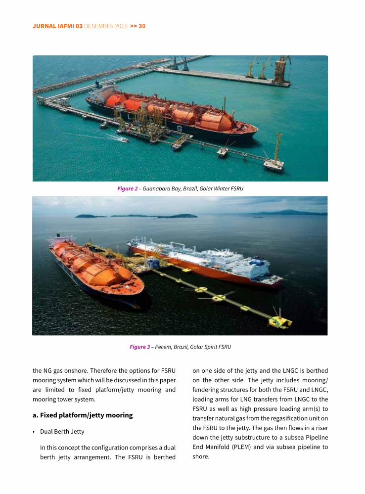
• DualBerthJetty
In this concept the configuration comprises a dual berth jetty arrangement. The FSRU is berthed
on one side of the jetty and the LNGC is berthed on the other side. The jetty includes mooring/fendering structures for both the FSRU and LNGC, loading arms for LNG transfers from LNGC to the FSRU as well as high pressure loading arm(s) to transfer natural gas from the regasification unit on the FSRU to the jetty. The gas then flows in a riser down the jetty substructure to a subsea Pipeline End Manifold (PLEM) and via subsea pipeline to shore.
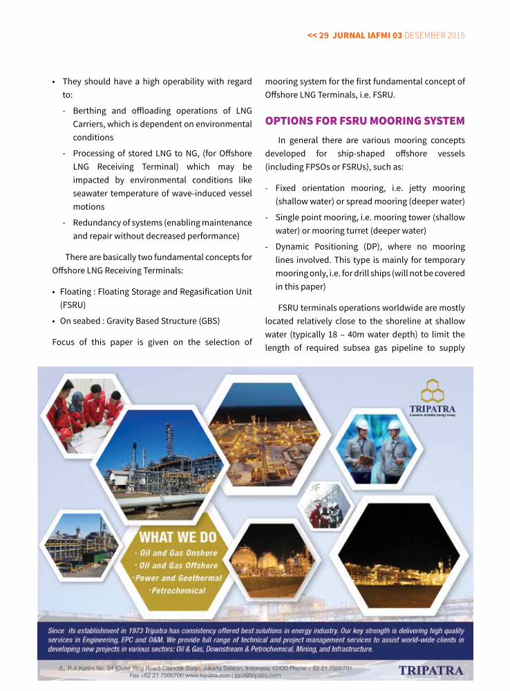
Figure 2 – Guanabara Bay, Brazil, Golar Winter FSRU
Figure 3 – Pecem, Brazil, Golar Spirit FSRU
<< 31 jurnal IaFMI 03 Desember 2015
The dual berth jetty arrangement is currently in operation at the following locations:
- Guanabara Bay, Brazil, Golar Winter FSRU (Figure 2)
- Pecem, Brazil, Golar Spirit FSRU (Figure 3)
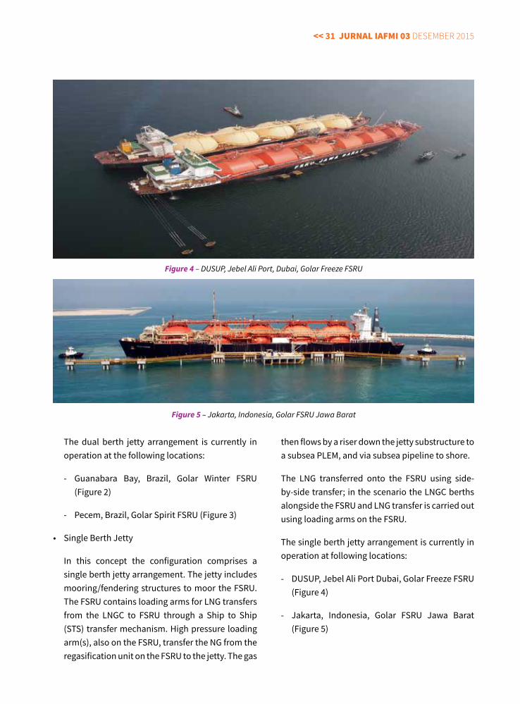
• SingleBerthJetty
In this concept the configuration comprises a single berth jetty arrangement. The jetty includes mooring/fendering structures to moor the FSRU. The FSRU contains loading arms for LNG transfers from the LNGC to FSRU through a Ship to Ship (STS) transfer mechanism. High pressure loading arm(s), also on the FSRU, transfer the NG from the regasification unit on the FSRU to the jetty. The gas
Figure 4 – DUSUP, Jebel Ali Port, Dubai, Golar Freeze FSRU
Figure 5 – Jakarta, Indonesia, Golar FSRU Jawa Barat
then flows by a riser down the jetty substructure to a subsea PLEM, and via subsea pipeline to shore.
The LNG transferred onto the FSRU using side-by-side transfer; in the scenario the LNGC berths alongside the FSRU and LNG transfer is carried out using loading arms on the FSRU.
The single berth jetty arrangement is currently in operation at following locations:
- DUSUP, Jebel Ali Port Dubai, Golar Freeze FSRU (Figure 4)
- Jakarta, Indonesia, Golar FSRU Jawa Barat (Figure 5)
jurnal IaFMI 03 Desember 2015 >> 32
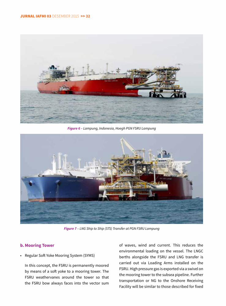
of waves, wind and current. This reduces the environmental loading on the vessel. The LNGC berths alongside the FSRU and LNG transfer is carried out via Loading Arms installed on the FSRU. High pressure gas is exported via a swivel on the mooring tower to the subsea pipeline. Further transportation or NG to the Onshore Receiving Facility will be similar to those described for fixed
Figure 6 – Lampung, Indonesia, Hoegh PGN FSRU Lampung
Figure 7 – LNG Ship to Ship (STS) Transfer at PGN FSRU Lampung
b. Mooring Tower
• RegularSoftYokeMooringSystem(SYMS)
In this concept, the FSRU is permanently moored by means of a soft yoke to a mooring tower. The FSRU weathervanes around the tower so that the FSRU bow always faces into the vector sum
<< 33 jurnal IaFMI 03 Desember 2015
platform/jetty mooring concept.
The tower may be located in approximately 18 to 40m of water depth (typical range used in industry) with benign environmental conditions.
The SYMS arrangement is currently on operation at the following locations:
- Lampung, Indonesia, Hoegh PGN FSRU Lampung (Figure 6 and Figure 7)
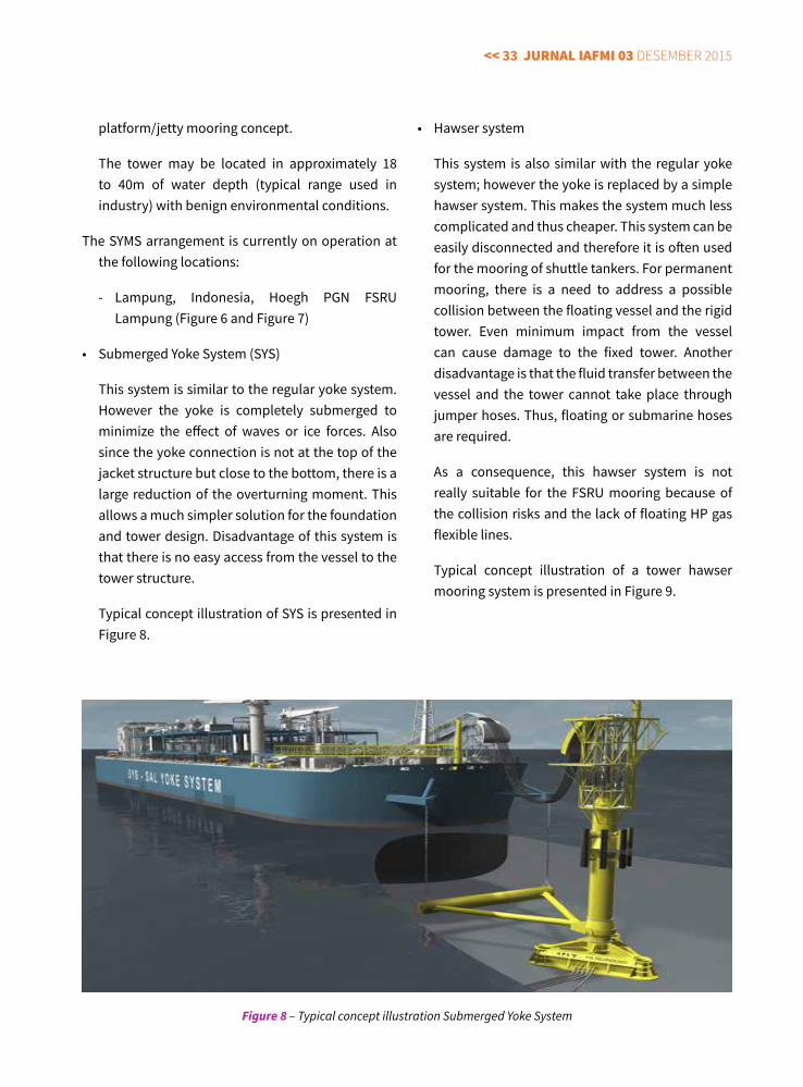
• SubmergedYokeSystem(SYS)
This system is similar to the regular yoke system. However the yoke is completely submerged to minimize the effect of waves or ice forces. Also since the yoke connection is not at the top of the jacket structure but close to the bottom, there is a large reduction of the overturning moment. This allows a much simpler solution for the foundation and tower design. Disadvantage of this system is that there is no easy access from the vessel to the tower structure.
Typical concept illustration of SYS is presented in Figure 8.
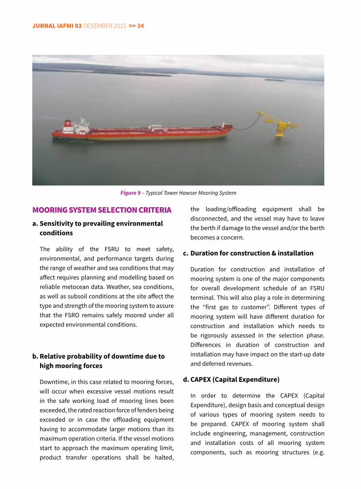
• Hawsersystem
This system is also similar with the regular yoke system; however the yoke is replaced by a simple hawser system. This makes the system much less complicated and thus cheaper. This system can be easily disconnected and therefore it is often used for the mooring of shuttle tankers. For permanent mooring, there is a need to address a possible collision between the floating vessel and the rigid tower. Even minimum impact from the vessel can cause damage to the fixed tower. Another disadvantage is that the fluid transfer between the vessel and the tower cannot take place through jumper hoses. Thus, floating or submarine hoses are required.
As a consequence, this hawser system is not really suitable for the FSRU mooring because of the collision risks and the lack of floating HP gas flexible lines.
Typical concept illustration of a tower hawser mooring system is presented in Figure 9.
Figure 8 – Typical concept illustration Submerged Yoke System
jurnal IaFMI 03 Desember 2015 >> 34
MoorInG SySTEM SElEcTIon crITErIaa. Sensitivity to prevailing environmental
conditions
The ability of the FSRU to meet safety, environmental, and performance targets during the range of weather and sea conditions that may affect requires planning and modelling based on reliable metocean data. Weather, sea conditions, as well as subsoil conditions at the site affect the type and strength of the mooring system to assure that the FSRO remains safely moored under all expected environmental conditions.
b. Relative probability of downtime due to high mooring forces
Downtime, in this case related to mooring forces, will occur when excessive vessel motions result in the safe working load of mooring lines been exceeded, the rated reaction force of fenders being exceeded or in case the offloading equipment having to accommodate larger motions than its maximum operation criteria. If the vessel motions start to approach the maximum operating limit, product transfer operations shall be halted,
the loading/offloading equipment shall be disconnected, and the vessel may have to leave the berth if damage to the vessel and/or the berth becomes a concern.
c. Duration for construction & installation
Duration for construction and installation of mooring system is one of the major components for overall development schedule of an FSRU terminal. This will also play a role in determining the “first gas to customer”. Different types of mooring system will have different duration for construction and installation which needs to be rigorously assessed in the selection phase. Differences in duration of construction and installation may have impact on the start-up date and deferred revenues.
d. CAPeX (Capital expenditure)
In order to determine the CAPEX (Capital Expenditure), design basis and conceptual design of various types of mooring system needs to be prepared. CAPEX of mooring system shall include engineering, management, construction and installation costs of all mooring system components, such as mooring structures (e.g.
Figure 9 – Typical Tower Hawser Mooring System
<< 35 jurnal IaFMI 03 Desember 2015
breasting/mooring dolphins, loading platform, or mooring tower), mooring bollards or quick release hooks, fenders, and also associated loading/offloading equipment and topsides required for different types of mooring system.
e. OPeX (Operational expenditure)
Similar with CAPEX, OPEX (Operational Expenditure) for different types of mooring system also needs to be assessed as another selection criterion. This includes all maintenance and inspection requirements for the mooring system specific components. Periodic replacement of mooring equipment and fenders (depending on their lifetime) shall also be included in the OPEX estimates.
SummaryMooring Type Selection for an Offshore LNG
Terminal shall be addressed earlier in the feasibility study/conceptual engineering phase of the planned facility to ensure all applicable concepts have been evaluated comprehensively and the best applicable concept is selected for the detailed design and construction/installation. Technical criteria (i.e. environmental/met ocean condition, probability of downtime, and schedule for construction/installation) and financial criteria (i.e. CAPEX and OPEX) shall be pre-determined and assessed during feasibility study/conceptual engineering phase to determine the mooring type which is technically and financially feasible and meet the operational requirements of the facility.
Wim van Wijngaarden, Hein Oomen, Jos van der Hoorn, 2004, Offshore LNG Terminals: Sunk or Floated?, Offshore Technology Conference Houston, Texas - 2004
Lloyd’s Register, 2013, Indonesia GAS: FSRU and Small LNG Seminar Presentation Pack, Hotel Borobudur Jakarta
Royal Haskoning Indonesia, 2012, Concept Selection Mooring System and Tower Yoke Mooring System, Labuhan Maringgai LNG Floating Storage and Regasification Facilities Project
For the last two and a half years, Ecky Yulistiana has been working as Project Engineer for BP Indonesia, and has been involved in Tangguh Expansion Project. Prior to join BP Indonesia, Ecky had several professional roles in Engineering
Consultancy Companies, mainly in Project Management, Coastal and Marine Infrastructure Projects in various phases, including Feasibility Studies, Conceptual and Detailed Engineering Design.
He had worked previously for Royal HaskoningDHV, DHV Indonesia, Witteveen+Bos, and Tripatra Engineers & Constructors. Ecky completed his Bachelor Degree in Ocean Engineering, Civil and Planning Faculty, ITB in 2002.
ReFeReNCeS:
ABOUT The AUThOR
jurnal IaFMI 03 Desember 2015 >> 36
Proy
ek B
erja
lan
deng
an n
ilah
diat
as 1
00 M
MU
S$
Oil
/Co
nden
sate
Gas
Kuar
tal
Tahu
n
1N
orth
Dur
i Dev
elop
men
t Are
a 13
- Aut
omat
ic W
ell T
est (
AWT)
Sta
tions
- Jar
inga
n pi
pa p
engu
mpu
l, pi
pa d
istrib
usi,
stea
mflo
od- F
low
lines
Chev
ron
Paci
fic In
done
siaRi
auO
nsho
reEP
C17
000
BOPD
-Q
120
16
2Su
mpa
l Com
pres
sion
Peng
adaa
n da
n In
stal
asi K
ompr
esso
rCo
noco
Phill
ips (
Griss
ik) L
td.
Pale
mba
ngO
nsho
reEP
C-
310
MM
scfd
Q3
2017
3Su
ban
Com
pres
sion
Peng
adaa
n da
n In
stal
asi K
ompr
esso
rCo
noco
Phill
ips (
Griss
ik) L
td.
Pale
mba
ngO
nsho
reFE
ED-
780
MM
scfd
Q1
2019
4Bl
ock
A Ga
s Fie
ld D
evel
opm
ent
- Pem
bang
unan
Cen
tral
Pro
cess
ing
Plan
t (CP
P)- F
low
line
- Tru
nklin
e- S
ulph
ur S
tora
ge- C
usto
dy M
eter
Med
co E
&P
Mal
aka
Aceh
Ons
hore
Tend
er E
PC31
00
BOPD
55
MM
scfd
Q2
2017
5Ja
mbu
Aye
Uta
ra (J
AU)
- 1 (s
atu)
Wel
lhea
d Pl
atfo
rm- P
enga
daan
FPS
OEn
i Kru
eng
Man
eAc
ehO
ffsho
reTe
nder
EPC
3300
BO
PD10
8 M
Msc
fdQ
220
20
6Bu
kit T
ua D
evel
opm
ent
- Wel
lhea
d Pl
atfo
rm- F
PSO
Ren
tal
- Sub
sea
Pipe
line
- Gas
Exp
ort P
ipel
ine
- ORF
Petr
onas
Car
igal
i Ket
apan
g 2
Ltd
(PCK
2L)
Gres
sik-Ja
wa
Tim
urO
ffsho
reEP
C20
000
BOPD
70
MM
scfd
Q2
2015
7Ke
poda
ng G
as D
evel
opm
ent
- Cen
tral
Pro
cess
ing
Plat
form
- W
ellh
ead
Tow
er C
- Inf
ield
Flo
wlin
e Pe
tron
as C
arig
ali M
uria
h Lt
d. (P
CML)
Jaw
a Te
ngah
Offs
hore
Sele
sai E
PC-
145
MM
scfd
Q3
2015
8An
de A
nde
Lum
ut- W
ellh
ead
Plat
form
- FPS
O (L
ease
)Sa
ntos
Nor
th W
est N
atun
aM
adur
aO
ffsho
reTe
nder
EPC
2500
0 BO
PD-
Q4
2018
9KI
LO F
ield
Fur
ther
Dev
elop
men
t- R
eact
ivat
ion
KB &
KC
Plat
form
- Mod
ifica
tion
exist
ing
faci
litie
s dan
exi
stin
g pi
pelin
e - I
nsta
lasi
new
pip
elin
e PH
E O
NW
JLa
ut Ja
wa
Offs
hore
Tend
er E
PC52
00
BOPD
18.5
M
Msc
fdQ
420
19
10O
O-O
C-O
X Fi
eld
Deve
lopm
ent
- Pem
asan
gan
1 (s
atu)
anj
unga
n em
pat k
aki (
OO
A)- P
emas
anga
n 1
(sat
u) a
njun
gan
tiga
kaki
(OCA
)- P
emas
anga
n pi
pa d
ari a
njun
gan
ke fa
silita
s pem
rose
san
dara
t di
Bal
onga
n- P
embo
ran
sum
ur p
enge
mba
ngan
dan
sum
ur st
ep o
ut
PHE
ON
WJ
Laut
Jaw
aO
ffsho
reFE
ED42
00
BOPD
17
MM
scfd
Q3
2019
11Pe
likan
Dev
elop
men
t- W
ellh
ead
Plat
form
- Pip
elin
e Pe
likan
WHP
- Ga
jah
Baru
CPP
Prem
ier O
il N
atun
a Se
a B.
VLa
ut N
atun
aO
ffsho
reSe
lesa
i EPC
-10
0 M
Msc
fdQ
120
15
12Pe
mpi
ng D
evel
opm
ent
- Pip
elin
e da
ri W
NTS
SST
I-B k
e Pu
lau
Pem
ping
- ORF
di P
ulau
Pem
ping
Prem
ier O
il N
atun
a Se
a B.
VLa
ut N
atun
aO
ffsho
reSe
lesa
i EPC
--
Q4
2017
13YY
Fie
ld D
evel
opm
ent
- Pem
asan
gan
1 (s
atu)
unm
anne
d p
latfo
rm ti
ga k
aki
- Pip
elin
e da
ri pl
atfo
rm Y
YA k
e pl
atfo
rm K
LB- M
odifi
kasi
Brow
nfie
ld d
i KLB
PHE
ON
WJ
Laut
Jaw
aO
ffsho
reTe
nder
EPC
4605
BO
PD25
.5
MM
scfd
Q4
2019
14JT
B-C
Jam
bara
n, T
iung
Biru
dan
Cen
dana
KKKS
PEP
Cep
u- G
as P
lant
- Wel
lpad
- Pip
elin
e
KKKS
MCL
- Flo
wlin
e- W
ellp
ad
Pert
amin
a EP
Cep
u &
MCL
Cepu
-Ja
wa
Teng
ahO
nsho
reTe
nder
EPC
3420
BO
PD33
0 M
Msc
fdQ
420
18
Capa
city
Targ
et O
nstr
eam
No.
Fiel
d N
ame
Ope
rato
rLo
catio
nO
nsho
re/
Offs
hore
Proj
ect S
tage
Scop
e
* M
ohon
per
timba
ngan
Bag
ian
Hubu
ngan
Mas
yara
kat S
KK M
igas
terk
ait s
ifat k
erah
asia
an d
ata
ters
ebut
dia
tas s
ebel
um m
engi
nfor
mas
ikan
nya
ke p
ihak
luar
SKK
Mig
as.
PRO
yeK
MIG
AS B
eRJA
LAN
DeN
GAN
NIL
AI >
100
MM
USD
<< 37 jurnal IaFMI 03 Desember 2015
Oil
/Co
nden
sate
Gas
Kuar
tal
Tahu
n
Capa
city
Targ
et O
nstr
eam
No.
Fiel
d N
ame
Ope
rato
rLo
catio
nO
nsho
re/
Offs
hore
Proj
ect S
tage
Scop
e
15Pe
ngem
bang
an G
as Ja
wa
(PPG
J)-Gu
ndih
- Flo
wlin
e - G
as P
lant
Pert
amin
a EP
Cepu
-Ja
wa
Teng
ahO
nsho
reEP
C60
0 BO
PD75
M
Msc
fdQ
220
14
16Pe
ngem
bang
an G
as M
atin
dok
(PPG
M) -
Do
nggi
Gas
Pla
nt- F
low
line
- Gas
Pla
nt
Pert
amin
a EP
Sula
wes
iO
nsho
reEP
C25
0 BO
PD60
M
Msc
fdQ
120
16
17Pr
oyek
Pen
gem
bang
an G
as M
atin
dok
(PPG
M) -
Mat
indo
k Ga
s Pla
nt- F
low
line
- Gas
Pla
ntPe
rtam
ina
EPSu
law
esi
Ons
hore
EPC
-65
M
Msc
fdQ
420
16
18Se
noro
Gas
Dev
elop
men
t- G
as P
lant
- P
ipel
ine
- Jet
ty
JOB
Pert
amin
a M
edco
E&
P To
mor
iSu
law
esi
Ons
hore
EPC
1100
0 BO
PD31
0 M
Msc
fd
Q2
2015
19M
adur
a BD
Dev
elop
men
t
- Wel
lhea
d Pl
atfo
rm- F
PSO
- Sub
sea
Pipe
line
- GM
S
Husk
y CN
OO
C M
adur
a Lt
dSe
lat M
adur
aO
ffsho
reEP
C66
00
BOPD
110
MM
scfd
Q4
2016
20M
DA -
MBH
Dev
elop
men
t- 2
(dua
) Wel
lhea
d Pl
atfo
rm- F
PU- P
ipel
ine
tie in
ke
EJGP
Hu
sky
CNO
OC
Mad
ura
Ltd
Sela
t Mad
ura
Offs
hore
Tend
er E
PC-
175
MM
scfd
Q4
2017
21Te
rang
Sira
sun
Batu
r Pha
se 2
- Pem
bora
n su
mur
- Flo
wlin
es fr
om w
ells
- Man
ifold
- Mai
n Ga
ther
ing
Pipe
line,
Rig
id p
ipel
ine
- Sub
sea
Cont
rol M
odul
e
Kang
ean
Ener
gy In
done
siaSe
lat M
adur
aO
ffsho
reTe
nder
EPC
-21
0 M
Msc
fdQ
120
18
22So
uth
Mah
akam
Dev
. 3
(Jem
pang
Met
ulan
g 1)
- Pem
bang
unan
Unm
anne
d Pl
atfo
rm ti
ga k
aki
- Int
erco
nnec
tions
Pip
elin
e to
Eas
t Man
du
Tota
l E&
P In
done
sieKa
liman
tan
Offs
hore
EPC
1800
BO
PD80
M
Msc
fdQ
320
15
23Pe
ngem
bang
an L
apan
gan
Bany
u U
rip
- Cen
tral
Pro
cess
ing
Faci
litie
s- O
nsho
re P
ipel
ine
- Moo
ring
Tow
er +
Offs
hore
Pip
elin
e- F
loat
ing
Stor
age
and
Offl
oadi
ng F
acili
ties (
FSO
)- I
nfra
stru
ctur
e
Mob
il Ce
pu L
td.
Cepu
-Ja
wa
Teng
ahO
nsho
reEP
C18
5,00
0 BO
PD-
Q4
2015
24Ta
nggu
h Ex
pans
ion
(Tra
in 3
)
- 4 (e
mpa
t) bu
ah P
latfo
rm
- Pem
bora
n su
mur
- W
ell P
ads
- Pip
elin
e- 1
(sat
u) T
rain
LN
G - C
ompr
esso
r (fu
ture
)- S
eism
ik &
Pem
bora
n Ap
prai
sal
BP B
erau
Ltd
Pa
pua
Offs
hore
Ons
hore
: FE
ED
Offs
hore
: Te
nder
EPC
Q4
2020
25Pe
ngem
bang
an L
apan
gan
Jang
krik
Nor
th
East
- Per
alat
an b
awah
laut
(X-tr
ee, S
ubse
a Co
ntro
l, M
anifo
ld,
Umbi
lical
)- F
loat
ing
Prod
uctio
n Un
it (F
PU)
- Pip
a un
tuk
Gas d
an P
ipa
untu
k Ko
nden
sat d
ari F
PU m
enuj
u tit
ik
tie-in
- Jar
inga
n Pi
pa d
ari s
umur
ke
FPU
- Ons
hore
Pip
elin
e- O
nsho
re R
ecei
ving
Fac
ility
ENI M
uara
Bak
au B
. V.
Sela
t M
akas
arO
ffsho
reEP
CI73
8 M
BBL
1330
.5
BSCF
Q3
2017
26ID
D Ba
ngka
- Mod
ifika
si To
psid
e- S
ubse
a Fa
cilit
ies
- Wel
l Com
plet
ion
Chev
ron
Indo
nesia
Co.
(Rap
ak)
Sela
t M
akas
arO
ffsho
reEP
CI37
50
BCPD
109.
25
MM
scfd
Q2
2016
EPCI
1 (W
HP P
HE 1
2, W
HP P
HE 2
4, d
an C
PP)
EPCI
Q3
2016
EPCI
2 (W
HP P
HE 4
8, W
HP P
HE 7
, WHP
PHE
29)
Tend
er E
PCQ
120
17
27.4
MM
SCFD
Mad
ura
3.8
mtp
a
PHE
- 6/1
2, 7
, 24,
29,
44
dan
4827
PHE
Wes
t Mad
ura
Offs
hore
Offs
hore
1265
0 BO
PD
* M
ohon
per
timba
ngan
Bag
ian
Hubu
ngan
Mas
yara
kat S
KK M
igas
terk
ait s
ifat k
erah
asia
an d
ata
ters
ebut
dia
tas s
ebel
um m
engi
nfor
mas
ikan
nya
ke p
ihak
luar
SKK
Mig
as.
jurnal IaFMI 03 Desember 2015 >> 38
aBSTracT
PT Pertamina Hulu Energi Offshore North-West Java (PHE ONWJ) presently has a fleet of 223 offshore platforms, with about 188 platforms are active in the production of oil and gas. The platforms in this fleet have installation dates ranging from 1970 to the present; however the majority of the platforms were installed in the 1970s and 80s. Recognizing the challenge to maintain this mature offshore facilities and the importance of structural integrity to ensure safe and reliable operation, PHE ONWJ has developed Risk-Based Structural Integrity Management (RBSIM) to optimize the underwater inspection, maintenance, and repair (IMR) strategy.
By means of RBSIM approach, the valuable resources will be focused on the platforms “most at risk”. These most-at-risk platforms will have higher priority to be included in the IMR program than platforms with lower risk. Higher risk platforms will be inspected more frequently, using more detailed inspection surveys; whereas those platforms with lower risk ranking will have less frequent and less stringent inspections.
Apart from optimization of underwater IMR strategy, RBSIM also provides means to justify and prioritize structural inspections and studies as part of life extension requirement and initiative for asset decommissioning. RBSIM process captures and review potential threats to the structural integrity which is posed by life extension such as: corrosion, overloading, operational changes, incidents, and fatigue. All of these steps are necessary to lengthen the life of an asset or demonstrate larger structural capacity beyond the original design values. The change management in the RBSIM along with the database system provides a better understanding of the current condition of the offshore platforms and enables PHE ONWJ as the asset owner to properly plan the decommissioning activities.
Implementation of RBSIM provides PHE ONWJ a means to optimize the underwater IMR activities whilst maintaining and not sacrificing structural integrity.
Keywords: Structural Integrity; Risk Based; Life Extension; Decommissioning
IMPLeMeNTING RISK BASeD STRUCTURAL INTeGRITy MANAGeMeNT for life exTension anD Decommissioning of maTure offshore PlaTforms
By: Karyadi Junedi, PT Pertamina Hulu Energi Offshore North-West Java
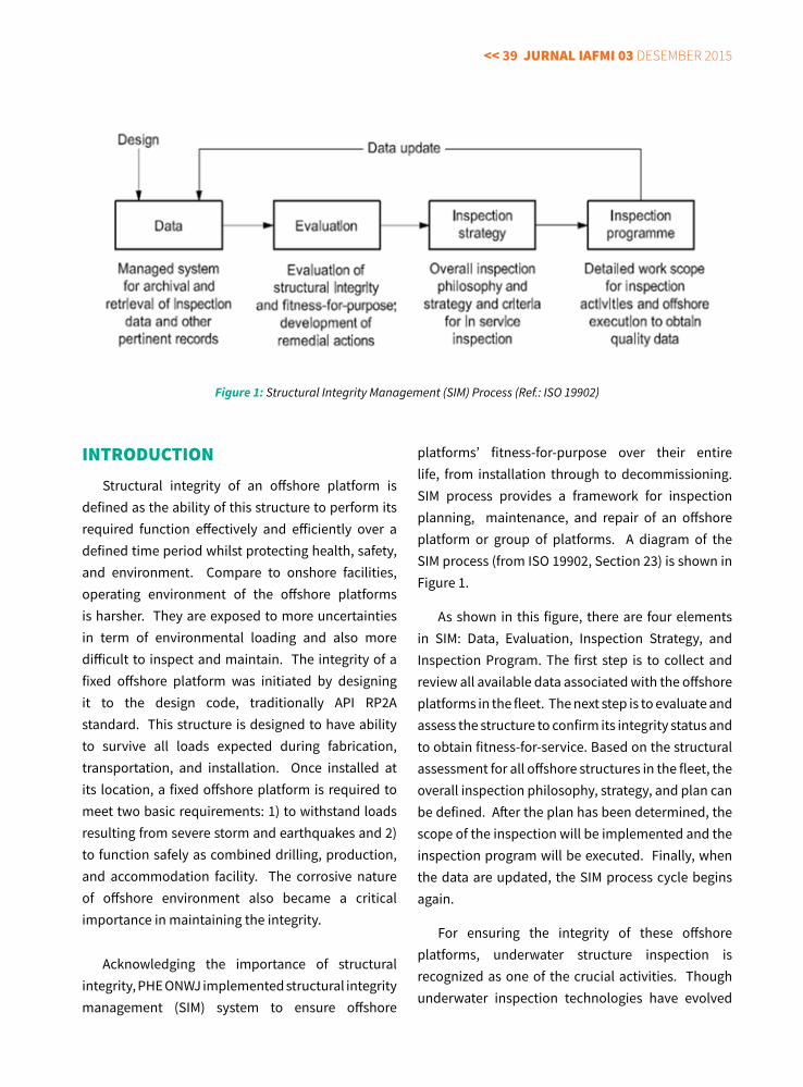
<< 39 jurnal IaFMI 03 Desember 2015
platforms’ fitness-for-purpose over their entire life, from installation through to decommissioning. SIM process provides a framework for inspection planning, maintenance, and repair of an offshore platform or group of platforms. A diagram of the SIM process (from ISO 19902, Section 23) is shown in Figure 1.
As shown in this figure, there are four elements in SIM: Data, Evaluation, Inspection Strategy, and Inspection Program. The first step is to collect and review all available data associated with the offshore platforms in the fleet. The next step is to evaluate and assess the structure to confirm its integrity status and to obtain fitness-for-service. Based on the structural assessment for all offshore structures in the fleet, the overall inspection philosophy, strategy, and plan can be defined. After the plan has been determined, the scope of the inspection will be implemented and the inspection program will be executed. Finally, when the data are updated, the SIM process cycle begins again.
For ensuring the integrity of these offshore platforms, underwater structure inspection is recognized as one of the crucial activities. Though underwater inspection technologies have evolved
InTroducTIonStructural integrity of an offshore platform is
defined as the ability of this structure to perform its required function effectively and efficiently over a defined time period whilst protecting health, safety, and environment. Compare to onshore facilities, operating environment of the offshore platforms is harsher. They are exposed to more uncertainties in term of environmental loading and also more difficult to inspect and maintain. The integrity of a fixed offshore platform was initiated by designing it to the design code, traditionally API RP2A standard. This structure is designed to have ability to survive all loads expected during fabrication, transportation, and installation. Once installed at its location, a fixed offshore platform is required to meet two basic requirements: 1) to withstand loads resulting from severe storm and earthquakes and 2) to function safely as combined drilling, production, and accommodation facility. The corrosive nature of offshore environment also became a critical importance in maintaining the integrity.
Acknowledging the importance of structural integrity, PHE ONWJ implemented structural integrity management (SIM) system to ensure offshore
Figure 1: Structural Integrity Management (SIM) Process (Ref.: ISO 19902)
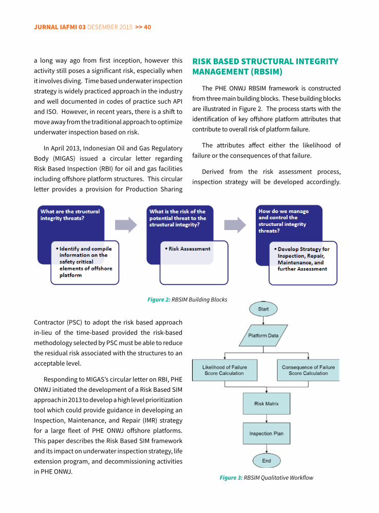
jurnal IaFMI 03 Desember 2015 >> 40
rISK BaSEd STrucTural InTEGrITy ManaGEMEnT (rBSIM)
The PHE ONWJ RBSIM framework is constructed from three main building blocks. These building blocks are illustrated in Figure 2. The process starts with the identification of key offshore platform attributes that contribute to overall risk of platform failure.
The attributes affect either the likelihood of failure or the consequences of that failure.
Derived from the risk assessment process, inspection strategy will be developed accordingly.
a long way ago from first inception, however this activity still poses a significant risk, especially when it involves diving. Time based underwater inspection strategy is widely practiced approach in the industry and well documented in codes of practice such API and ISO. However, in recent years, there is a shift to move away from the traditional approach to optimize underwater inspection based on risk.
In April 2013, Indonesian Oil and Gas Regulatory Body (MIGAS) issued a circular letter regarding Risk Based Inspection (RBI) for oil and gas facilities including offshore platform structures. This circular letter provides a provision for Production Sharing
Contractor (PSC) to adopt the risk based approach in-lieu of the time-based provided the risk-based methodology selected by PSC must be able to reduce the residual risk associated with the structures to an acceptable level.
Responding to MIGAS’s circular letter on RBI, PHE ONWJ initiated the development of a Risk Based SIM approach in 2013 to develop a high level prioritization tool which could provide guidance in developing an Inspection, Maintenance, and Repair (IMR) strategy for a large fleet of PHE ONWJ offshore platforms. This paper describes the Risk Based SIM framework and its impact on underwater inspection strategy, life extension program, and decommissioning activities in PHE ONWJ.
Figure 2: RBSIM Building Blocks
Figure 3: RBSIM Qualitative Workflow
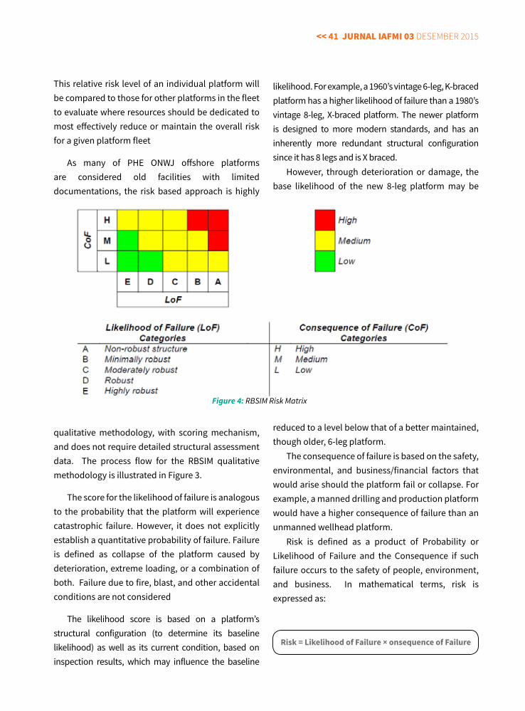
<< 41 jurnal IaFMI 03 Desember 2015
This relative risk level of an individual platform will be compared to those for other platforms in the fleet to evaluate where resources should be dedicated to most effectively reduce or maintain the overall risk for a given platform fleet
As many of PHE ONWJ offshore platforms are considered old facilities with limited documentations, the risk based approach is highly
qualitative methodology, with scoring mechanism, and does not require detailed structural assessment data. The process flow for the RBSIM qualitative methodology is illustrated in Figure 3.
The score for the likelihood of failure is analogous to the probability that the platform will experience catastrophic failure. However, it does not explicitly establish a quantitative probability of failure. Failure is defined as collapse of the platform caused by deterioration, extreme loading, or a combination of both. Failure due to fire, blast, and other accidental conditions are not considered
The likelihood score is based on a platform’s structural configuration (to determine its baseline likelihood) as well as its current condition, based on inspection results, which may influence the baseline
likelihood. For example, a 1960’s vintage 6-leg, K-braced platform has a higher likelihood of failure than a 1980’s vintage 8-leg, X-braced platform. The newer platform is designed to more modern standards, and has an inherently more redundant structural configuration since it has 8 legs and is X braced.
However, through deterioration or damage, the base likelihood of the new 8-leg platform may be
reduced to a level below that of a better maintained, though older, 6-leg platform.
The consequence of failure is based on the safety, environmental, and business/financial factors that would arise should the platform fail or collapse. For example, a manned drilling and production platform would have a higher consequence of failure than an unmanned wellhead platform.
Risk is defined as a product of Probability or Likelihood of Failure and the Consequence if such failure occurs to the safety of people, environment, and business. In mathematical terms, risk is expressed as:
Risk = Likelihood of Failure × onsequence of Failure
Figure 4: RBSIM Risk Matrix
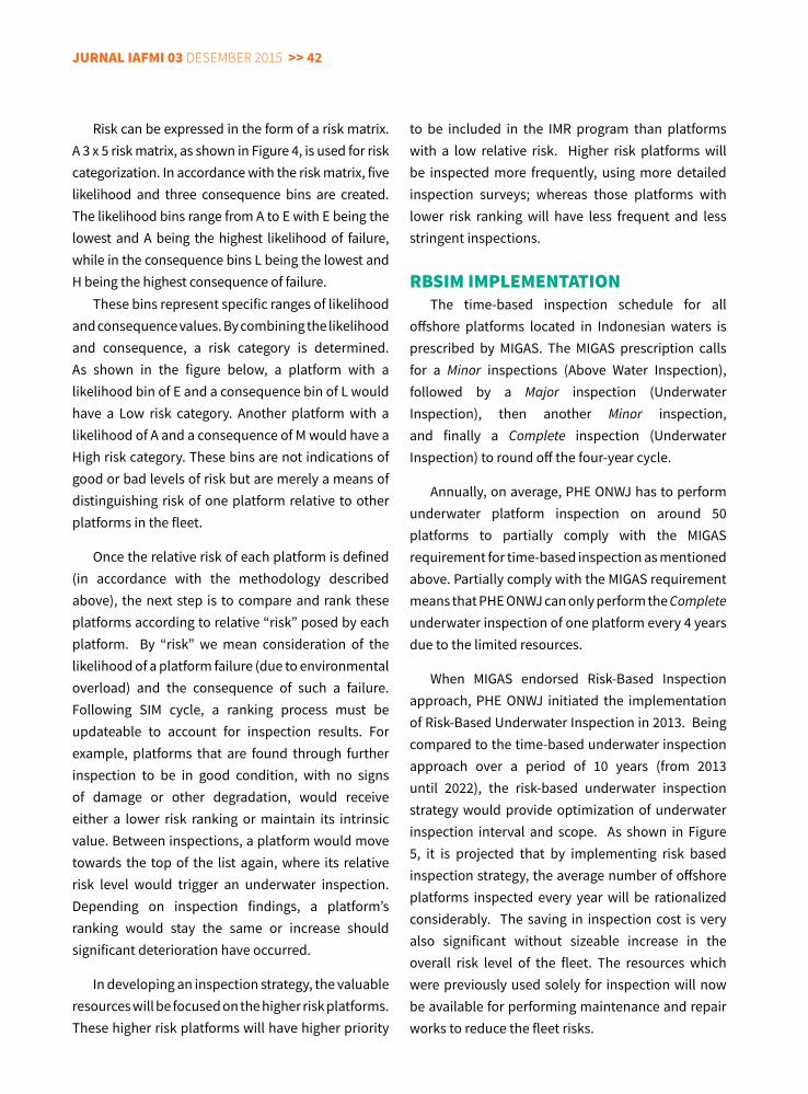
jurnal IaFMI 03 Desember 2015 >> 42
Risk can be expressed in the form of a risk matrix. A 3 x 5 risk matrix, as shown in Figure 4, is used for risk categorization. In accordance with the risk matrix, five likelihood and three consequence bins are created. The likelihood bins range from A to E with E being the lowest and A being the highest likelihood of failure, while in the consequence bins L being the lowest and H being the highest consequence of failure.
These bins represent specific ranges of likelihood and consequence values. By combining the likelihood and consequence, a risk category is determined. As shown in the figure below, a platform with a likelihood bin of E and a consequence bin of L would have a Low risk category. Another platform with a likelihood of A and a consequence of M would have a High risk category. These bins are not indications of good or bad levels of risk but are merely a means of distinguishing risk of one platform relative to other platforms in the fleet.
Once the relative risk of each platform is defined (in accordance with the methodology described above), the next step is to compare and rank these platforms according to relative “risk” posed by each platform. By “risk” we mean consideration of the likelihood of a platform failure (due to environmental overload) and the consequence of such a failure. Following SIM cycle, a ranking process must be updateable to account for inspection results. For example, platforms that are found through further inspection to be in good condition, with no signs of damage or other degradation, would receive either a lower risk ranking or maintain its intrinsic value. Between inspections, a platform would move towards the top of the list again, where its relative risk level would trigger an underwater inspection. Depending on inspection findings, a platform’s ranking would stay the same or increase should significant deterioration have occurred.
In developing an inspection strategy, the valuable resources will be focused on the higher risk platforms. These higher risk platforms will have higher priority
to be included in the IMR program than platforms with a low relative risk. Higher risk platforms will be inspected more frequently, using more detailed inspection surveys; whereas those platforms with lower risk ranking will have less frequent and less stringent inspections.
rBSIM IMPlEMEnTaTIon The time-based inspection schedule for all
offshore platforms located in Indonesian waters is prescribed by MIGAS. The MIGAS prescription calls for a Minor inspections (Above Water Inspection), followed by a Major inspection (Underwater Inspection), then another Minor inspection, and finally a Complete inspection (Underwater Inspection) to round off the four-year cycle.
Annually, on average, PHE ONWJ has to perform underwater platform inspection on around 50 platforms to partially comply with the MIGAS requirement for time-based inspection as mentioned above. Partially comply with the MIGAS requirement means that PHE ONWJ can only perform the Complete underwater inspection of one platform every 4 years due to the limited resources.
When MIGAS endorsed Risk-Based Inspection approach, PHE ONWJ initiated the implementation of Risk-Based Underwater Inspection in 2013. Being compared to the time-based underwater inspection approach over a period of 10 years (from 2013 until 2022), the risk-based underwater inspection strategy would provide optimization of underwater inspection interval and scope. As shown in Figure 5, it is projected that by implementing risk based inspection strategy, the average number of offshore platforms inspected every year will be rationalized considerably. The saving in inspection cost is very also significant without sizeable increase in the overall risk level of the fleet. The resources which were previously used solely for inspection will now be available for performing maintenance and repair works to reduce the fleet risks.
<< 43 jurnal IaFMI 03 Desember 2015
RBSIM implementation also delivers upside
for improving safety performance by reducing diver exposure. RBSIM provides a means to allow application of well-tested Remotely Operated Underwater Vehicles commonly referred to as an ROV. This ROV based underwater inspection technologies would replace the traditional diving exercise, while maintaining the same level of structural integrity assurance.
In short, the risk-based approach provides a means to rationalize the underwater inspection activities whilst maintaining and not sacrificing structural integrity.
rBSIM For lIFE ExTEnSIon and dEcoMMISSIonInG acTIvITIES
There are 223 offshore platforms operated by PHE ONWJ and more than 75% of them have been in operation for more than 20 years. Many of these structures are operating beyond their original design life; however, as the need to sustain oil and
gas production eminent, PHE ONWJ is required to extend the life of its offshore platforms without compromising structural integrity and safety.
Demonstrating the structural integrity of mature assets is of utmost importance when considering life extension. The challenges commonly presented by life extension include: Degradation due to corrosion; Overloading (severe environmental loads, additional topsides loads); Operational changes (platform modifications); Unprecedented incidents (ship collision, explosion); and Structural Fatigue.
Implementation of RBSIM in PHE ONWJ delivers structural integrity assurance for offshore platforms to overcome the above challenges to meet life extension requirements by integrating effective inspection, change management, data/information management, and advanced integrity assessment.
RBSIM covers the development of such inspection strategies, work scopes, inspection results reviews, and the maintenance of inspection record databases. By having access to asset integrity
Figure 5: PHE ONWJ Underwater Inspection Activities Projection
jurnal IaFMI 03 Desember 2015 >> 44
database, the assigned engineer can easily identify structural defect/anomaly, perform assessments, and then develop repair solutions, both for topsides and subsea.
Change management is required when modifications are made to an installation. Brownfield developments (to existing facilities) normally involve changes in the physical and operational parameters of a platform. Meanwhile, greenfield (new) developments often require operational changes as well as updated procedures. The capacity of the existing structure to support modifications is key to this process. RBSIM specifies a weight control procedure that is implemented as part of good change management for any offshore structure. Structural analysis computer model of each offshore platform in the fleet also need to be maintained and updated to quantify the effect of any change on the structure.
This risk based SIM approach is a data intensive exercise and highly dependent upon the quality of the evidence (data) of the structural condition, apart from the competence and skill of the structural engineer. The primary activities include: producing key SIM documentations and annual integrity summary reports; managing the platform inspection philosophy (topsides and subsea); reviewing inspection results; maintaining an anomaly database; engineering of anomaly repairs, emergency response services; and providing structural analysis models and a weight control database.
All of the above activities are essential to ensure the structural critical elements are acceptable and that performance standards are being fulfilled. Furthermore, advanced structural integrity assessment is to be performed to demonstrate enhanced structural capacity beyond the original design values. The outcomes from this assessment provide valuable input for the decision-making process surrounding platform life extension.
Additionally, the Change management in the RBSIM along with the intensive database system provides a better understanding of the current condition of the offshore platforms. Validity of the as-built information (drawings, reports) and all historical records associated with an offshore platform are essential in its decommissioning phase. In preparing the decommissioning of an offshore platform, the assigned engineer is required to secure accurate information on the structural weight of this platform, structural configuration, changes to structure, and current condition. Once this info is available, the removal options screening for both the topside and the jacket (Substructure) can be evaluated. With RBSIM is up and running in PHE ONWJ, the bulk of information required for decommissioning phase has been collected, communicated, and stored in an efficient and accessible manner. This circumstance does enable PHE ONWJ, as the asset owner, to properly plan the decommissioning activities for its offshore platform asset.
SuMMary and concluSIon
The following summary and conclusions are put together with regard to the implementation of the Risk-Based Structural Integrity Management (RBSIM) in PHE ONWJ:• Structural integrity management (SIM) system is
essential to ensure offshore platforms’ fitness-for-purpose over their entire life, from installation through to decommissioning.
• The risk-based approach on SIM helps PHE ONWJ to identify the potential structural threats and evaluate the risk structurally. RBSIM provides an organized process to capture and review the structural integrity risk. A better understanding of the risk of potential structural integrity threats leads to more effective rationalization of work and enables PHE ONWJ to have its radar screen on critical structural integrity issues.
<< 45 jurnal IaFMI 03 Desember 2015
construction, and maintenance works of Fixed Offshore Platforms, Floating Production System (FPSO/FSO), and Marine facilities (Loading/Offloading facilities, Jetty, Mooring system, SBM).
rEFErEncES
1. DeFranco, S., O’Connor, P., Tallin, A., Roy, R., and Puskar, F., 1999, Development of Risk Based Underwater Inspection (RBUI) Process for Prioritizing Inspection of Large Number of Platforms, OTC 10846, Houston, Texas, 3-6 May 1999.
2. Nabavian, M., 2012, Developing a Robust SIM Program, Structural Integrity Management Conference North Sea, 27-28 November 2012.
3. El-Reedy, M.A., 2012, Offshore Structures Design, Construction, and Maintenance, Gulf Professional Publishing, New York.
4. Director General of Oil and Natural Gas Decision No. 21K/38/DJM/1999 dated 16 April 1999 concerning Guidelines and Procedures on Technical Inspections of Platform Constructions Utilized in the Mining of Oil and Natural Gas.
5. ISO 19902-2007, Petroleum and Natural Gas Industry – Fixed Steel Offshore Structures (1st Edition).
6. Structural Integrity Management Framework for Fixed Jacket Structures, Published by Health and Safety Executive UK, RR684, 2009.
7. API RP 2SIM, Structural Integrity Management of Fixed Offshore Structures, November 2014.
• RBSIM provides a structured auditable process to optimize underwater inspection interval and scope based on condition of the platform structure, whilst maintaining and not sacrificing structural integrity.
• RBSIM delivers structural integrity assurance for offshore platforms to meet the requirements from life extension and decommissioning by integrating effective inspection, change management, data/information management, and advanced integrity assessment.
acKnoWlEdGEMEnT
The author would like to thank Management of PT. PHE ONWJ for their permission and support in developing this paper.
aBouT THE auTHor
Karyadi Junedi is Structural Integrity Lead at PERTAMINA Hulu Energi – Offshore North West Java (PHE ONWJ) who is in charge running Structural Integrity Management
System for over 200 fixed platforms in PERTAMINA’s Offshore North West Java Block, Indonesia. Previously, he was a Senior Structural Integrity Engineer with Shell Malaysia E&P and ConocoPhillips Indonesia. He received his MSc. degree in Naval Architecture and Marine Engineering from University of Michigan (1996) and BSc. degree in Marine Engineering from Texas A&M University (1994). His knowledge and skills are molded by over 20 (twenty) years of experience in oil-and-gas-related works, including technical integrity management, project management, engineering design &
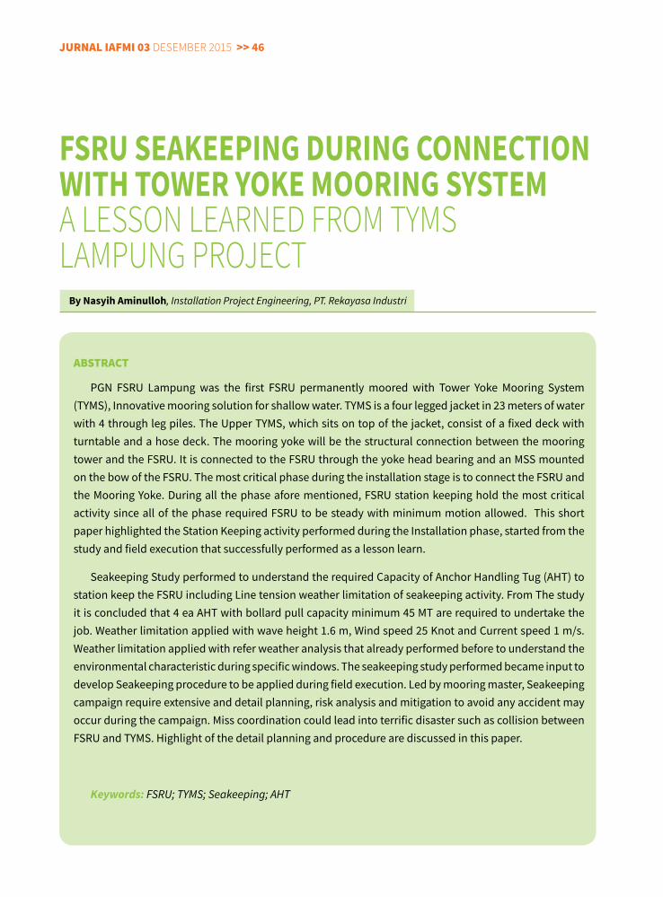
jurnal IaFMI 03 Desember 2015 >> 46
aBSTracT
PGN FSRU Lampung was the first FSRU permanently moored with Tower Yoke Mooring System (TYMS), Innovative mooring solution for shallow water. TYMS is a four legged jacket in 23 meters of water with 4 through leg piles. The Upper TYMS, which sits on top of the jacket, consist of a fixed deck with turntable and a hose deck. The mooring yoke will be the structural connection between the mooring tower and the FSRU. It is connected to the FSRU through the yoke head bearing and an MSS mounted on the bow of the FSRU. The most critical phase during the installation stage is to connect the FSRU and the Mooring Yoke. During all the phase afore mentioned, FSRU station keeping hold the most critical activity since all of the phase required FSRU to be steady with minimum motion allowed. This short paper highlighted the Station Keeping activity performed during the Installation phase, started from the study and field execution that successfully performed as a lesson learn.
Seakeeping Study performed to understand the required Capacity of Anchor Handling Tug (AHT) to station keep the FSRU including Line tension weather limitation of seakeeping activity. From The study it is concluded that 4 ea AHT with bollard pull capacity minimum 45 MT are required to undertake the job. Weather limitation applied with wave height 1.6 m, Wind speed 25 Knot and Current speed 1 m/s. Weather limitation applied with refer weather analysis that already performed before to understand the environmental characteristic during specific windows. The seakeeping study performed became input to develop Seakeeping procedure to be applied during field execution. Led by mooring master, Seakeeping campaign require extensive and detail planning, risk analysis and mitigation to avoid any accident may occur during the campaign. Miss coordination could lead into terrific disaster such as collision between FSRU and TYMS. Highlight of the detail planning and procedure are discussed in this paper.
Keywords: FSRU; TYMS; Seakeeping; AHT
FSRU SeAKeePING DURING CONNeCTIONWITh TOWeR yOKe MOORING SySTeMa lesson learneD from TymslamPung ProJecT
By Nasyih Aminulloh, Installation Project Engineering, PT. Rekayasa Industri
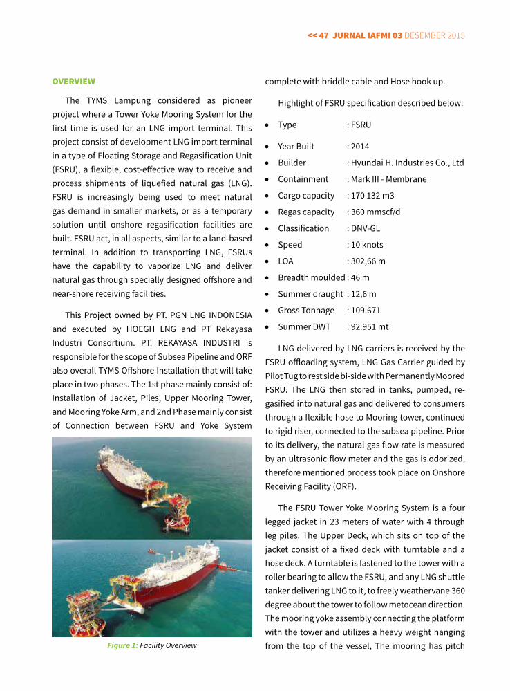
<< 47 jurnal IaFMI 03 Desember 2015
ovErvIEW
The TYMS Lampung considered as pioneer project where a Tower Yoke Mooring System for the first time is used for an LNG import terminal. This project consist of development LNG import terminal in a type of Floating Storage and Regasification Unit (FSRU), a flexible, cost-effective way to receive and process shipments of liquefied natural gas (LNG). FSRU is increasingly being used to meet natural gas demand in smaller markets, or as a temporary solution until onshore regasification facilities are built. FSRU act, in all aspects, similar to a land-based terminal. In addition to transporting LNG, FSRUs have the capability to vaporize LNG and deliver natural gas through specially designed offshore and near-shore receiving facilities.
This Project owned by PT. PGN LNG INDONESIA and executed by HOEGH LNG and PT Rekayasa Industri Consortium. PT. REKAYASA INDUSTRI is responsible for the scope of Subsea Pipeline and ORF also overall TYMS Offshore Installation that will take place in two phases. The 1st phase mainly consist of: Installation of Jacket, Piles, Upper Mooring Tower, and Mooring Yoke Arm, and 2nd Phase mainly consist of Connection between FSRU and Yoke System
complete with briddle cable and Hose hook up.
Highlight of FSRU specification described below:
• Type : FSRU
• Year Built : 2014
• Builder : Hyundai H. Industries Co., Ltd
• Containment : Mark III - Membrane
• Cargo capacity : 170 132 m3
• Regas capacity : 360 mmscf/d
• Classification : DNV-GL
• Speed : 10 knots
• LOA : 302,66 m
• Breadth moulded : 46 m
• Summer draught : 12,6 m
• Gross Tonnage : 109.671
• Summer DWT : 92.951 mt
LNG delivered by LNG carriers is received by the FSRU offloading system, LNG Gas Carrier guided by Pilot Tug to rest side bi-side with Permanently Moored FSRU. The LNG then stored in tanks, pumped, re-gasified into natural gas and delivered to consumers through a flexible hose to Mooring tower, continued to rigid riser, connected to the subsea pipeline. Prior to its delivery, the natural gas flow rate is measured by an ultrasonic flow meter and the gas is odorized, therefore mentioned process took place on Onshore Receiving Facility (ORF).
The FSRU Tower Yoke Mooring System is a four legged jacket in 23 meters of water with 4 through leg piles. The Upper Deck, which sits on top of the jacket consist of a fixed deck with turntable and a hose deck. A turntable is fastened to the tower with a roller bearing to allow the FSRU, and any LNG shuttle tanker delivering LNG to it, to freely weathervane 360 degree about the tower to follow metocean direction. The mooring yoke assembly connecting the platform with the tower and utilizes a heavy weight hanging from the top of the vessel, The mooring has pitch Figure 1: Facility Overview
jurnal IaFMI 03 Desember 2015 >> 48
and roll joints and includes a large ballast tank filled with water to provide the necessary restoring force to minimize vessel motions. Two mooring links suspend the tank from a support structure mounted on the vessel. Power and control systems are all managed from the FSRU.
Detailed the project second phase after TYMS Installation will include the following installation activities after the arrival of FSRU to the anchorage area.
• Breasting of the mooring assist vessels, • Tow- in approach, • Connection to the Mooring Yoke Arm, and • Electrical Cable (Bridle 2 numbers)• Hose Installations (Natural Gas Jumper 12”x3, Air
Hose, Fire Water Hose).
During all the phase afore mentioned, FSRU station keeping hold the most critical activity since all of the phase required FSRU to be steady with minimum motion allowed. The seakeeping study shall be performed to provide input during Seakeeping procedure development to be applied during field execution. This Short paper discussing the FSRU seakeeping work performed in TYMS Lampung Project from the Seakeeping study until general seakeeping execution highlight.
FSru SEaKEEPInG STudy
Seakeeping Study performed to understand the required Capacity of Anchor Handling Tug (AHT) to station keep the FSRU including Line tension weather limitation of seakeeping activity during the installation
of FSRU. FSRU is self-propelled Vessel, after its arrival, the engine shuts down in safe area and firstly 1 kilometer approaching the Mooring Tower the FSRU will be towed by 4 AHT vessels, 2 AHT on bow position and the other two on stern position. Assuming there are 4 load cases before FSRU installation as following;
FSRU Seakeeping study performed in the early stage of project, the purpose covered under this scope is to carry out the dynamic analysis on FSRU installation. The dynamic behavior and soft line tension during installation is stimulated in time domain simulation.
FSRU have very big wind induced area causing FSRU motion very sensitive to Metocean condition. Using of mooring and forward winch not allowed by client thus this required extensive seakeeping study to keep the vessel safe during approaching and connection phase, 4 AHT will functioning as life anchor to station keep the FSRU. In detail the scope of this seakeeping study will be described as follows:
1) Calculate the maximum dynamic behavior
The analysis to calculate maximum dynamic behavior was performed in two phases. Phase one relates to analysis performed with 3D diffraction analysis software MOSES to obtain the motion responses of the vessels. Phase two relates to the coupled time domain analysis performed with marine dynamic software Visual OrcaFlex, with the motion responses obtained from phase one.
The main software used in this seakeeping study is listed below;
CASE DESCRIPTION1 FSRU during towing condition2 FSRU approaching mooring tower, maintain position 30 m from mooring tower3 FSRU softline connected to Yoke, 4 AHT to hold FSRU motion4 FSRU have connected to Yoke, 2 AHTS at stern to hold FSRU motion
Table-1 : Load Case Condition
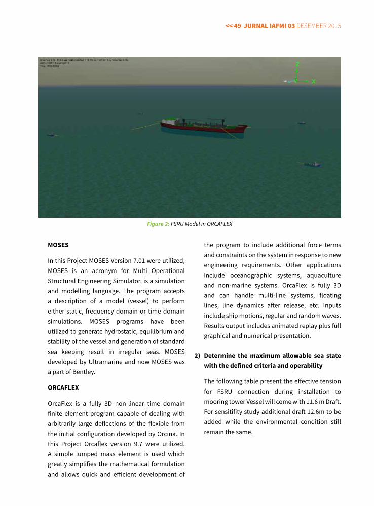
<< 49 jurnal IaFMI 03 Desember 2015
MOSeS
In this Project MOSES Version 7.01 were utilized, MOSES is an acronym for Multi Operational Structural Engineering Simulator, is a simulation and modelling language. The program accepts a description of a model (vessel) to perform either static, frequency domain or time domain simulations. MOSES programs have been utilized to generate hydrostatic, equilibrium and stability of the vessel and generation of standard sea keeping result in irregular seas. MOSES developed by Ultramarine and now MOSES was a part of Bentley.
ORCAFLeX
OrcaFlex is a fully 3D non-linear time domain finite element program capable of dealing with arbitrarily large deflections of the flexible from the initial configuration developed by Orcina. In this Project Orcaflex version 9.7 were utilized. A simple lumped mass element is used which greatly simplifies the mathematical formulation and allows quick and efficient development of
the program to include additional force terms and constraints on the system in response to new engineering requirements. Other applications include oceanographic systems, aquaculture and non-marine systems. OrcaFlex is fully 3D and can handle multi-line systems, floating lines, line dynamics after release, etc. Inputs include ship motions, regular and random waves. Results output includes animated replay plus full graphical and numerical presentation.
2) Determine the maximum allowable sea state with the defined criteria and operability
The following table present the effective tension for FSRU connection during installation to mooring tower Vessel will come with 11.6 m Draft. For sensitifity study additional draft 12.6m to be added while the environmental condition still remain the same.
Figure 2: FSRU Model in ORCAFLEX
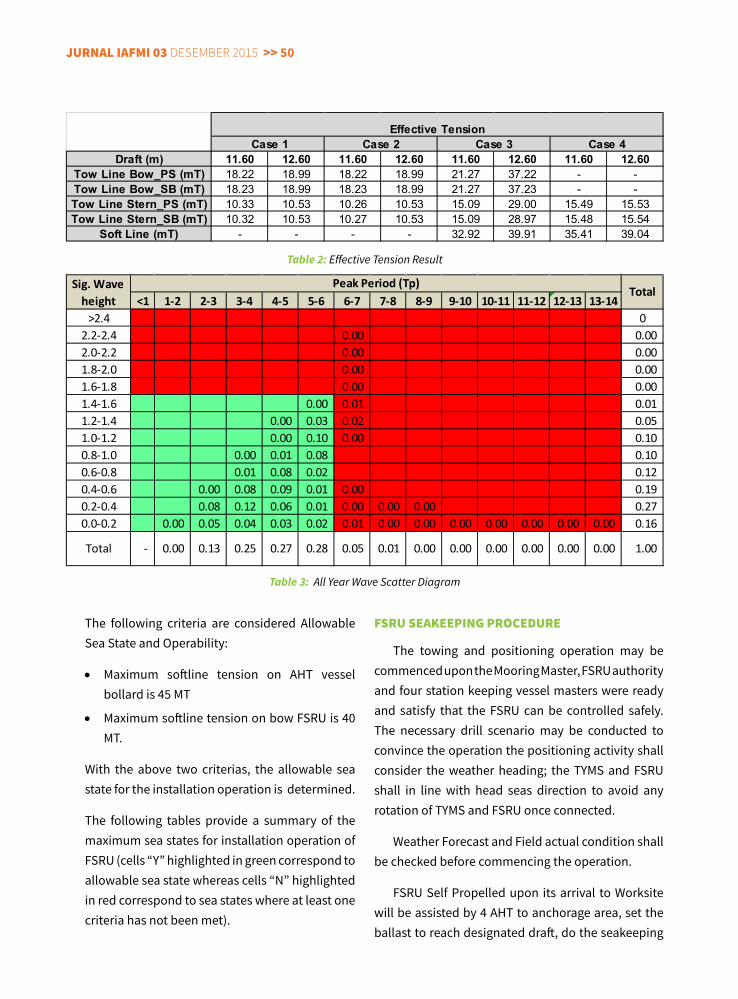
jurnal IaFMI 03 Desember 2015 >> 50
The following criteria are considered Allowable Sea State and Operability:
• Maximum softline tension on AHT vessel bollard is 45 MT
• Maximum softline tension on bow FSRU is 40 MT.
With the above two criterias, the allowable sea state for the installation operation is determined.
The following tables provide a summary of the maximum sea states for installation operation of FSRU (cells “Y” highlighted in green correspond to allowable sea state whereas cells “N” highlighted in red correspond to sea states where at least one criteria has not been met).
FSru SEaKEEPInG ProcEdurE
The towing and positioning operation may be commenced upon the Mooring Master, FSRU authority and four station keeping vessel masters were ready and satisfy that the FSRU can be controlled safely. The necessary drill scenario may be conducted to convince the operation the positioning activity shall consider the weather heading; the TYMS and FSRU shall in line with head seas direction to avoid any rotation of TYMS and FSRU once connected.
Weather Forecast and Field actual condition shall be checked before commencing the operation.
FSRU Self Propelled upon its arrival to Worksite will be assisted by 4 AHT to anchorage area, set the ballast to reach designated draft, do the seakeeping
Draft (m) 11.60 12.60 11.60 12.60 11.60 12.60 11.60 12.60Tow Line Bow_PS (mT) 18.22 18.99 18.22 18.99 21.27 37.22 - -Tow Line Bow_SB (mT) 18.23 18.99 18.23 18.99 21.27 37.23 - -Tow Line Stern_PS (mT) 10.33 10.53 10.26 10.53 15.09 29.00 15.49 15.53Tow Line Stern_SB (mT) 10.32 10.53 10.27 10.53 15.09 28.97 15.48 15.54
Soft Line (mT) - - - - 32.92 39.91 35.41 39.04
Case 1 Case 2 Case 3 Case 4Effective Tension
Table 2: Effective Tension Result
Table 3: All Year Wave Scatter Diagram
<1 1-2 2-3 3-4 4-5 5-6 6-7 7-8 8-9 9-10 10-11 11-12 12-13 13-14>2.4 0
2.2-2.4 0.00 0.00 2.0-2.2 0.00 0.00 1.8-2.0 0.00 0.00 1.6-1.8 0.00 0.00 1.4-1.6 0.00 0.01 0.01 1.2-1.4 0.00 0.03 0.02 0.05 1.0-1.2 0.00 0.10 0.00 0.10 0.8-1.0 0.00 0.01 0.08 0.10 0.6-0.8 0.01 0.08 0.02 0.12 0.4-0.6 0.00 0.08 0.09 0.01 0.00 0.19 0.2-0.4 0.08 0.12 0.06 0.01 0.00 0.00 0.00 0.27 0.0-0.2 0.00 0.05 0.04 0.03 0.02 0.01 0.00 0.00 0.00 0.00 0.00 0.00 0.00 0.16
0.00 0.00 0.00 1.00
Sig. Wave height
Peak Period (Tp)Total
Total - 0.00 0.13 0.25 0.27 0.28 0.05 0.01 0.00 0.00 0.00
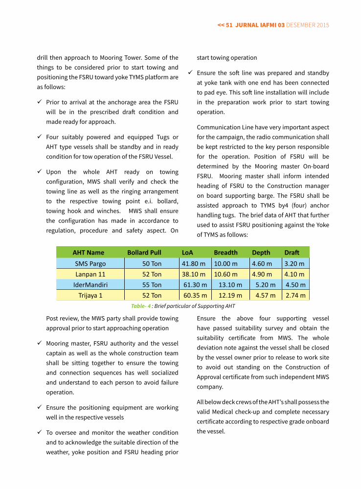
<< 51 jurnal IaFMI 03 Desember 2015
drill then approach to Mooring Tower. Some of the things to be considered prior to start towing and positioning the FSRU toward yoke TYMS platform are as follows:
Prior to arrival at the anchorage area the FSRU will be in the prescribed draft condition and made ready for approach.
Four suitably powered and equipped Tugs or AHT type vessels shall be standby and in ready condition for tow operation of the FSRU Vessel.
Upon the whole AHT ready on towing configuration, MWS shall verify and check the towing line as well as the ringing arrangement to the respective towing point e.i. bollard, towing hook and winches. MWS shall ensure the configuration has made in accordance to regulation, procedure and safety aspect. On
Post review, the MWS party shall provide towing approval prior to start approaching operation
Mooring master, FSRU authority and the vessel captain as well as the whole construction team shall be sitting together to ensure the towing and connection sequences has well socialized and understand to each person to avoid failure operation.
Ensure the positioning equipment are working well in the respective vessels
To oversee and monitor the weather condition and to acknowledge the suitable direction of the weather, yoke position and FSRU heading prior
start towing operation
Ensure the soft line was prepared and standby at yoke tank with one end has been connected to pad eye. This soft line installation will include in the preparation work prior to start towing operation.
Communication Line have very important aspect for the campaign, the radio communication shall be kept restricted to the key person responsible for the operation. Position of FSRU will be determined by the Mooring master On-board FSRU. Mooring master shall inform intended heading of FSRU to the Construction manager on board supporting barge. The FSRU shall be assisted approach to TYMS by4 (four) anchor handling tugs. The brief data of AHT that further used to assist FSRU positioning against the Yoke of TYMS as follows:
Ensure the above four supporting vessel have passed suitability survey and obtain the suitability certificate from MWS. The whole deviation note against the vessel shall be closed by the vessel owner prior to release to work site to avoid out standing on the Construction of Approval certificate from such independent MWS company.
All below deck crews of the AHT’s shall possess the valid Medical check-up and complete necessary certificate according to respective grade onboard the vessel.
AHT Name Bollard Pull LoA Breadth Depth DraftSMS Pargo 50 Ton 41.80 m 10.00 m 4.60 m 3.20 mLanpan 11 52 Ton 38.10 m 10.60 m 4.90 m 4.10 m
IderMandiri 55 Ton 61.30 m 13.10 m 5.20 m 4.50 mTrijaya 1 52 Ton 60.35 m 12.19 m 4.57 m 2.74 m
Table- 4 : Brief particular of Supporting AHT
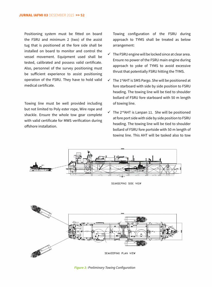
jurnal IaFMI 03 Desember 2015 >> 52
Positioning system must be fitted on board the FSRU and minimum 2 (two) of the assist tug that is positioned at the fore side shall be installed on board to monitor and control the vessel movement. Equipment used shall be tested, calibrated and possess valid certificate. Also, personnel of the survey positioning must be sufficient experience to assist positioning operation of the FSRU. They have to hold valid medical certificate.
Towing line must be well provided including but not limited to Poly ester rope, Wire rope and shackle. Ensure the whole tow gear complete with valid certificate for MWS verification during offshore installation.
Towing configuration of the FSRU during approach to TYMS shall be treated as below arrangement:
The FSRU engine will be locked since at clear area. Ensure no power of the FSRU main engine during approach to yoke of TYMS to avoid excessive thrust that potentially FSRU hitting the TYMS.
The 1stAHT is SMS Pargo. She will be positioned at fore starboard with side by side position to FSRU heading. The towing line will be tied to shoulder bollard of FSRU fore starboard with 50 m length of towing line.
The 2ndAHT is Lanpan 11. She will be positioned at fore port side with side by side position to FSRU heading. The towing line will be tied to shoulder bollard of FSRU fore portside with 50 m length of towing line. This AHT will be tasked also to tow
Figure 3 : Preliminary Towing Configuration
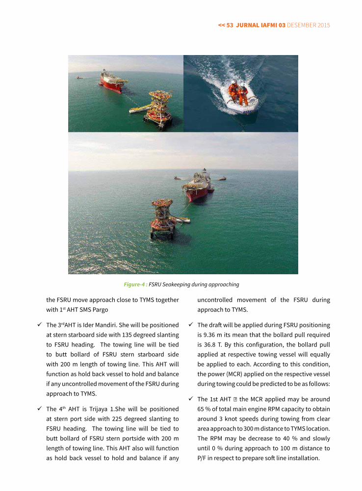
<< 53 jurnal IaFMI 03 Desember 2015
the FSRU move approach close to TYMS together with 1st AHT SMS Pargo
The 3rdAHT is Ider Mandiri. She will be positioned at stern starboard side with 135 degreed slanting to FSRU heading. The towing line will be tied to butt bollard of FSRU stern starboard side with 200 m length of towing line. This AHT will function as hold back vessel to hold and balance if any uncontrolled movement of the FSRU during approach to TYMS.
The 4th AHT is Trijaya 1.She will be positioned at stern port side with 225 degreed slanting to FSRU heading. The towing line will be tied to butt bollard of FSRU stern portside with 200 m length of towing line. This AHT also will function as hold back vessel to hold and balance if any
uncontrolled movement of the FSRU during approach to TYMS.
The draft will be applied during FSRU positioning is 9.36 m its mean that the bollard pull required is 36.8 T. By this configuration, the bollard pull applied at respective towing vessel will equally be applied to each. According to this condition, the power (MCR) applied on the respective vessel during towing could be predicted to be as follows:
The 1st AHT the MCR applied may be around 65 % of total main engine RPM capacity to obtain around 3 knot speeds during towing from clear area approach to 300 m distance to TYMS location. The RPM may be decrease to 40 % and slowly until 0 % during approach to 100 m distance to P/F in respect to prepare soft line installation.
Figure-4 : FSRU Seakeeping during approaching
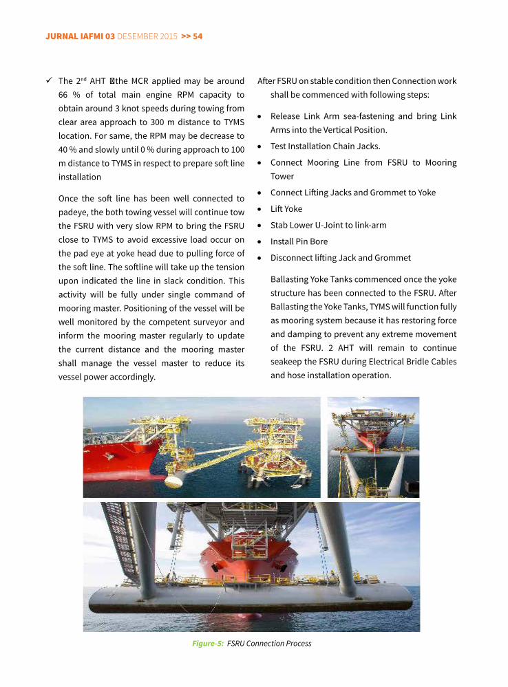
jurnal IaFMI 03 Desember 2015 >> 54
The 2nd AHT the MCR applied may be around 66 % of total main engine RPM capacity to obtain around 3 knot speeds during towing from clear area approach to 300 m distance to TYMS location. For same, the RPM may be decrease to 40 % and slowly until 0 % during approach to 100 m distance to TYMS in respect to prepare soft line installation
Once the soft line has been well connected to padeye, the both towing vessel will continue tow the FSRU with very slow RPM to bring the FSRU close to TYMS to avoid excessive load occur on the pad eye at yoke head due to pulling force of the soft line. The softline will take up the tension upon indicated the line in slack condition. This activity will be fully under single command of mooring master. Positioning of the vessel will be well monitored by the competent surveyor and inform the mooring master regularly to update the current distance and the mooring master shall manage the vessel master to reduce its vessel power accordingly.
After FSRU on stable condition then Connection work shall be commenced with following steps:
• Release Link Arm sea-fastening and bring Link Arms into the Vertical Position.
• Test Installation Chain Jacks.
• Connect Mooring Line from FSRU to Mooring Tower
• Connect Lifting Jacks and Grommet to Yoke
• Lift Yoke
• Stab Lower U-Joint to link-arm
• Install Pin Bore
• Disconnect lifting Jack and Grommet
Ballasting Yoke Tanks commenced once the yoke structure has been connected to the FSRU. After Ballasting the Yoke Tanks, TYMS will function fully as mooring system because it has restoring force and damping to prevent any extreme movement of the FSRU. 2 AHT will remain to continue seakeep the FSRU during Electrical Bridle Cables and hose installation operation.
Figure-5: FSRU Connection Process
<< 55 jurnal IaFMI 03 Desember 2015
concluSIon
This paper Presented FSRU motion characteristic was different with other vessel such as FPSO or FSO, with her big wind area combined with relatively light DWT and Empty condition FSRU motion became very sensitive with motion induced by environmental loading. During connection FSRU shall be kept steady on safe area then approach the TYMS, Secured with mooring line and Connect FSRU’s MSS with TYMS’s Mooring Yoke via mechanical connection.
Seakeeping Study performed to understand the required Capacity of Anchor Handling Tug (AHT) to station keep the FSRU including Line tension weather limitation of seakeeping activity. From The study it is concluded that 4 ea. AHT with bollard pull capacity minimum 45 MT are required to undertake the job. Weather limitation applied with wave height 1.6 m, Wind speed 25 Knot and Current speed 1 m/s. Weather limitation applied with refer weather analysis that already performed before to understand the environmental characteristic during specific windows. The seakeeping study performed became input to develop Seakeeping procedure to be applied during field execution. Led by mooring master, Seakeeping campaign require extensive and detail planning, risk analysis and mitigation to avoid any accident may occur during the campaign.
ReFeReNCe
MWS Noble Denton General Guidelines for Marine Transportation – ND 030 Rev.5.
API RP 2SK RP for Design and Analysis of Station keeping System for Floating Structures
TYMS-V-PRC-004 FSRU Connection Procedure
TYMS-PM-PRC-008 FSRU Bollard Pull Calculation
TYMS-V-CAL-012 FSRU Sea Keeping Study
ABOUT The AUThOR
Mokhamad Nasyih Aminnulloh shortly called “Nasyih” is Installation Project Engineer with more than 7 years’ Experience including overseas experience in PT. Rekayasa Industri
(Rekind). He graduated in 2008 from Sepuluh Nopember Institute of Technology (ITS) Surabaya majoring in Offshore Engineering. Specialized in Offshore Installation Project both Engineering and Field Construction stage.
Nasyih has been working and studying Mooring Tower since in the college because he have an impression that this as challenging subject since it is combining Structural and hydrodynamic Subject. He then during his late career in Rekind assigned to work under SOFEC inc, in Houston to design the First Mooring Tower in Indonesia that is EPC3 Banyu Urip Project. Then continuing to involve on the installation of The First time in the world TYMS System for FSRU on FSRU Lampung project.
jurnal IaFMI 03 Desember 2015 >> 56
ProDucTion faciliTiesmainTenance informaTion sysTem:A DeCISION SUPPORT SySTeM FOR MAINTAINING NATIONAL OIL AND GAS PRODUCTION FACILITIeS
Rossupanji pRibadi1, MohaMad Fauzan aMiR1, ToMy W. poeRWanTo1
1. Author, Special Task Force for Upstream Oil and Gas Business Activities Republic of Indonesia
aBSTracTAs mandated by the government, the Special Task Force for Upstream Oil and Gas Business Activities in
the Republic of Indonesia (known as SKK Migas) has responsibility for maintaining the national oil and gas production facilities as part of its main function in terms of maximizing national oil and gas production. Currently, SKK Migas is managing more than 60 oil and gas production companies (PSC Companies) under Production Sharing Contracts (PSC), operating all over Indonesia. These PSC Companies operate a very large number of production facilities, but ownership remains with the nation, including data related to the facilities. The legacy manual system cannot manage the information and the many issues related to maintenance activities of all these facilities. Therefore, a computer-based information system is needed to become the core in supporting the business or organizational decision-making activities related to the main responsibility of controlling and supervising the operators of the production facilities.
This paper highlights the national-scale maintenance database management system built by the authors to support business and organizational decision-making activities. This system has been built in an efficient and customizable manner, by using common software such as Microsoft Excel and Microsoft Access Database, and empowering the existing human resources. The system has fulfilled expectations, with customable features, and avoided the purchase of commercially available specialized software, which offers limited features and expensive pricing.
Although this software tool offers convenience, a lot of work is still required to improve the prototype.However, by developing this system, at least a short-term powerful solution has been provided that
lays the foundation for the future development of a more established system. In other words, there is no need to wait for the optimum software tools to manage the job. One can start from simple tools and improve continuously.
Keywords; National scale production facilities; maintenance decision support system; simple tools; efficient and customable manner; current software tools
<< 57 jurnal IaFMI 03 Desember 2015
InTroducTIon
Nowadays, database systems play a crucial role in modern industry, enabling large quantities of information to be managed and automatically fed to supporting processes to guide decision-making. In academia and industrial applications, various tools and research have been developed for such purposes, for instance, as reported in [1-4]. Nevertheless, tools developed for managing maintenance data on a national scale are sparse, and may be unavailable for benchmarking of PSC operations.
Given the demands for efficiency and organizational transformation with a limited budget, building a computerized maintenance information system becomes a big challenge. The team was challenged to empower its existing resources, without relying on a third party consultants and software. The solution involved using common software; Microsoft Excel integrated with Microsoft Access Database. The software was selected based on the consideration of user-friendliness and the simplicity to be customized to meet the desired specifications.
The team built a working prototype of a national-scale maintenance database management system, which is useful for supporting decision-making. Although the system has been built from simple tools, its contributions has been significant, as seen from the following functionality:
• Calendar of maintenance and planned shutdowns, which allows proposed shutdowns to be scheduled to avoid big drops in national daily oil and gas national production.
• Maintenance notifications on upcoming planned shutdown activities, so SKK Migas can prepare effective supervising activities, including encouraging the oil and gas companies to optimize shutdown duration, resources, and expenses in safe and effective ways.
• Unplanned shutdown monitoring. Unplanned shutdown are one key performance indicator for how the operators (PSC companies) manage the production facilities. By monitoring these events daily, we can observe the reliability of the operated production facilities and together with oil/gas companies, decide what actions are required to increase the reliability of the plants.
• Maintenance asset monitoring of major production facilities, such as turbo machinery, rotating equipments, pipelines, vessels, and tanks, including their conditions (active, standby, spare or idle engines) gives us a snap-shot of the status of the national equipment. If necessary, we can facilitate equipment loans, transfers and sharing of facilities among the PSC’s.
• Key Performance Indicators. By monitoring maintenance indicators, such as production achievement, plant availability, plant reliability, the maintenance/inspection realization, and maintenance cost, we can measure how the operator companies achieve their performance goals. We regularly announce the company that has shown the best maintenance performance.
• Document database and internal report generation. Important documents, such as Work Program and Budget (WP&B), Authorization For Expenditure (AFE), Place Into Service (PIS), Minutes of Meeting (MOM), are stored in a computerized system and can be recalled anytime. Besides, this system also enables us to generate the data automatically for internal reports or for the other evaluation purposes.
SySTEM dEScrIPTIon
The Production Facilities Maintenance Information System, or so-called SIPFO (in Bahasa abbr. Sistem Informasi Pemeliharaan Fasilitas Operasi) started with the development of a database, which only serves as storage of the simple data, such
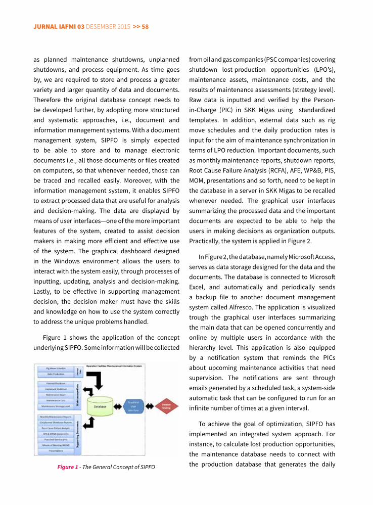
jurnal IaFMI 03 Desember 2015 >> 58
from oil and gas companies (PSC companies) covering shutdown lost-production opportunities (LPO’s), maintenance assets, maintenance costs, and the results of maintenance assessments (strategy level). Raw data is inputted and verified by the Person-in-Charge (PIC) in SKK Migas using standardized templates. In addition, external data such as rig move schedules and the daily production rates is input for the aim of maintenance synchronization in terms of LPO reduction. Important documents, such as monthly maintenance reports, shutdown reports, Root Cause Failure Analysis (RCFA), AFE, WP&B, PIS, MOM, presentations and so forth, need to be kept in the database in a server in SKK Migas to be recalled whenever needed. The graphical user interfaces summarizing the processed data and the important documents are expected to be able to help the users in making decisions as organization outputs. Practically, the system is applied in Figure 2.
In Figure 2, the database, namely Microsoft Access, serves as data storage designed for the data and the documents. The database is connected to Microsoft Excel, and automatically and periodically sends a backup file to another document management system called Alfresco. The application is visualized trough the graphical user interfaces summarizing the main data that can be opened concurrently and online by multiple users in accordance with the hierarchy level. This application is also equipped by a notification system that reminds the PICs about upcoming maintenance activities that need supervision. The notifications are sent through emails generated by a scheduled task, a system-side automatic task that can be configured to run for an infinite number of times at a given interval.
To achieve the goal of optimization, SIPFO has implemented an integrated system approach. For instance, to calculate lost production opportunities, the maintenance database needs to connect with the production database that generates the daily
as planned maintenance shutdowns, unplanned shutdowns, and process equipment. As time goes by, we are required to store and process a greater variety and larger quantity of data and documents. Therefore the original database concept needs to be developed further, by adopting more structured and systematic approaches, i.e., document and information management systems. With a document management system, SIPFO is simply expected to be able to store and to manage electronic documents i.e., all those documents or files created on computers, so that whenever needed, those can be traced and recalled easily. Moreover, with the information management system, it enables SIPFO to extract processed data that are useful for analysis and decision-making. The data are displayed by means of user interfaces—one of the more important features of the system, created to assist decision makers in making more efficient and effective use of the system. The graphical dashboard designed in the Windows environment allows the users to interact with the system easily, through processes of inputting, updating, analysis and decision-making. Lastly, to be effective in supporting management decision, the decision maker must have the skills and knowledge on how to use the system correctly to address the unique problems handled.
Figure 1 shows the application of the concept underlying SIPFO. Some information will be collected
Figure 1 - The General Concept of SIPFO
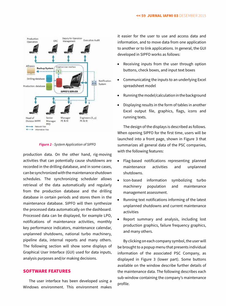
<< 59 jurnal IaFMI 03 Desember 2015
production data. On the other hand, rig-moving activities that can potentially cause shutdowns are recorded in the drilling database, and in some cases, can be synchronized with the maintenance shutdown schedules. The synchronizing scheduler allows retrieval of the data automatically and regularly from the production database and the drilling database in certain periods and stores them in the maintenance database. SIPFO will then synthesize the processed data automatically on the dashboard. Processed data can be displayed, for example LPO, notifications of maintenance activities, monthly key performance indicators, maintenance calendar, unplanned shutdowns, national turbo machinery, pipeline data, internal reports and many others. The following section will show some displays of Graphical User Interface (GUI) used for data inputs, analysis purposes and/or making decisions.
SoFTWarE FEaTurES
The user interface has been developed using a Windows environment. This environment makes
it easier for the user to use and access data and information, and to move data from one application to another or to link applications. In general, the GUI developed in SIPFO works as follows:
• Receiving inputs from the user through option buttons, check boxes, and input text boxes
• Communicating the inputs to an underlying Excel spreadsheet model
• Running the model/calculation in the background
• Displaying results in the form of tables in another Excel output file, graphics, flags, icons and running texts.
The design of the displays is described as follows. When opening SIPFO for the first time, users will be launched into a front page, shown in Figure 3 that summarizes all general data of the PSC companies, with the following features:
• Flag-based notifications representing planned maintenance activities and unplanned shutdowns.
• Icon-based information symbolizing turbo machinery population and maintenance management assessment.
• Running text notifications informing of the latest unplanned shutdowns and current maintenance activities
• Report summary and analysis, including lost production graphics, failure frequency graphics, and many others.
By clicking on each company symbol, the user will be brought to a popup menu that presents individual information of the associated PSC Company, as displayed in Figure 3 (lower part). Some buttons available on the window describe further details of the maintenance data. The following describes each sub-window containing the company’s maintenance profile.
Figure 2 - System Application of SIPFO
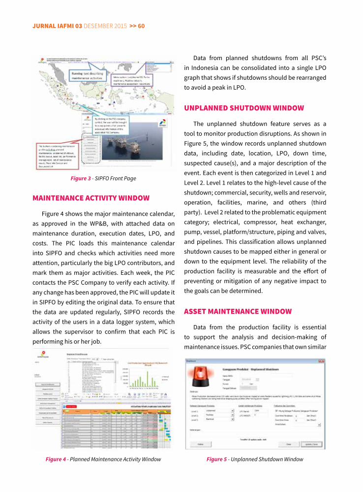
jurnal IaFMI 03 Desember 2015 >> 60
Data from planned shutdowns from all PSC’s in Indonesia can be consolidated into a single LPO graph that shows if shutdowns should be rearranged to avoid a peak in LPO.
unPlannEd SHuTdoWn WIndoW
The unplanned shutdown feature serves as a tool to monitor production disruptions. As shown in Figure 5, the window records unplanned shutdown data, including date, location, LPO, down time, suspected cause(s), and a major description of the event. Each event is then categorized in Level 1 and Level 2. Level 1 relates to the high-level cause of the shutdown; commercial, security, wells and reservoir, operation, facilities, marine, and others (third party). Level 2 related to the problematic equipment category; electrical, compressor, heat exchanger, pump, vessel, platform/structure, piping and valves, and pipelines. This classification allows unplanned shutdown causes to be mapped either in general or down to the equipment level. The reliability of the production facility is measurable and the effort of preventing or mitigation of any negative impact to the goals can be determined.
aSSET MaInTEnancE WIndoW
Data from the production facility is essential to support the analysis and decision-making of maintenance issues. PSC companies that own similar
MaInTEnancE acTIvITy WIndoW
Figure 4 shows the major maintenance calendar, as approved in the WP&B, with attached data on maintenance duration, execution dates, LPO, and costs. The PIC loads this maintenance calendar into SIPFO and checks which activities need more attention, particularly the big LPO contributors, and mark them as major activities. Each week, the PIC contacts the PSC Company to verify each activity. If any change has been approved, the PIC will update it in SIPFO by editing the original data. To ensure that the data are updated regularly, SIPFO records the activity of the users in a data logger system, which allows the supervisor to confirm that each PIC is performing his or her job.
Figure 3 - SIPFO Front Page
Figure 4 - Planned Maintenance Activity Window Figure 5 - Unplanned Shutdown Window
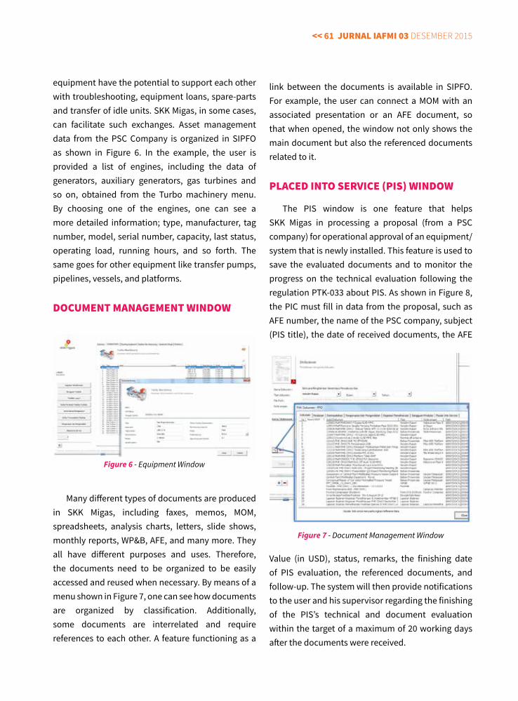
<< 61 jurnal IaFMI 03 Desember 2015
equipment have the potential to support each other with troubleshooting, equipment loans, spare-parts and transfer of idle units. SKK Migas, in some cases, can facilitate such exchanges. Asset management data from the PSC Company is organized in SIPFO as shown in Figure 6. In the example, the user is provided a list of engines, including the data of generators, auxiliary generators, gas turbines and so on, obtained from the Turbo machinery menu. By choosing one of the engines, one can see a more detailed information; type, manufacturer, tag number, model, serial number, capacity, last status, operating load, running hours, and so forth. The same goes for other equipment like transfer pumps, pipelines, vessels, and platforms.
docuMEnT ManaGEMEnT WIndoW
Many different types of documents are produced in SKK Migas, including faxes, memos, MOM, spreadsheets, analysis charts, letters, slide shows, monthly reports, WP&B, AFE, and many more. They all have different purposes and uses. Therefore, the documents need to be organized to be easily accessed and reused when necessary. By means of a menu shown in Figure 7, one can see how documents are organized by classification. Additionally, some documents are interrelated and require references to each other. A feature functioning as a
link between the documents is available in SIPFO. For example, the user can connect a MOM with an associated presentation or an AFE document, so that when opened, the window not only shows the main document but also the referenced documents related to it.
PlacEd InTo SErvIcE (PIS) WIndoW
The PIS window is one feature that helps SKK Migas in processing a proposal (from a PSC company) for operational approval of an equipment/system that is newly installed. This feature is used to save the evaluated documents and to monitor the progress on the technical evaluation following the regulation PTK-033 about PIS. As shown in Figure 8, the PIC must fill in data from the proposal, such as AFE number, the name of the PSC company, subject (PIS title), the date of received documents, the AFE
Value (in USD), status, remarks, the finishing date of PIS evaluation, the referenced documents, and follow-up. The system will then provide notifications to the user and his supervisor regarding the finishing of the PIS’s technical and document evaluation within the target of a maximum of 20 working days after the documents were received.
Figure 6 - Equipment Window
Figure 7 - Document Management Window
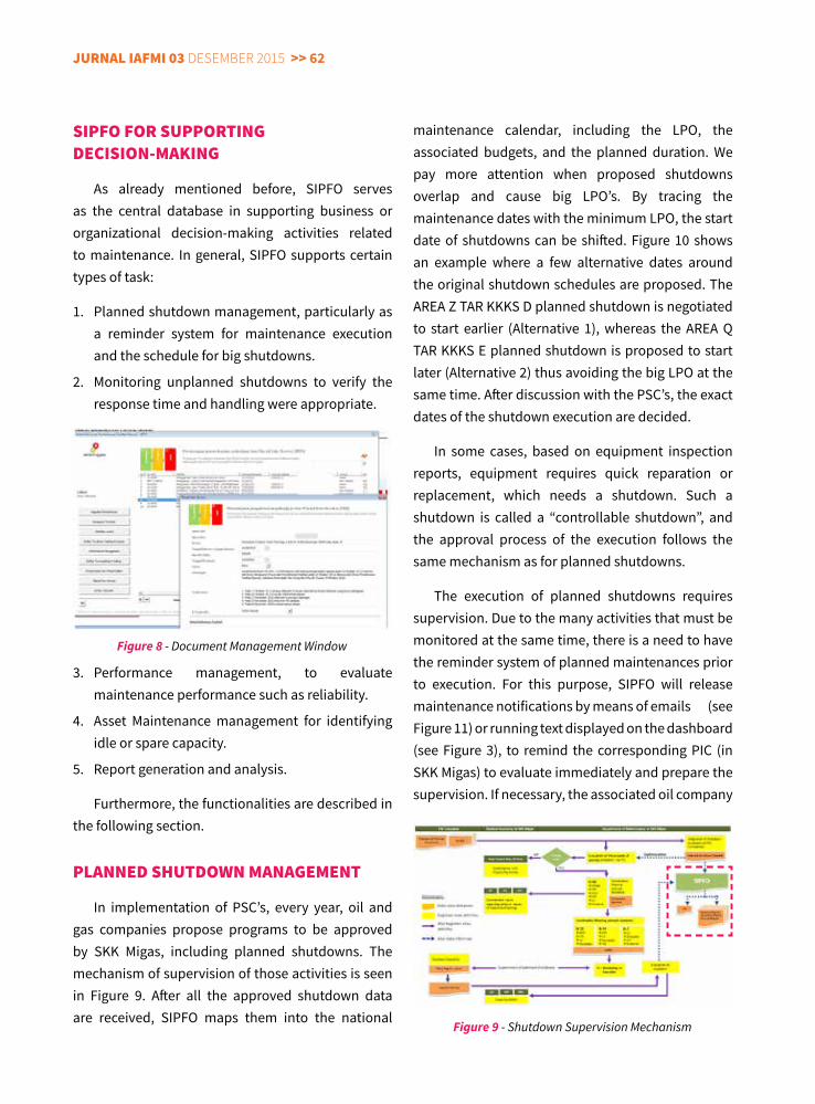
jurnal IaFMI 03 Desember 2015 >> 62
SIPFo For SuPPorTInG dEcISIon-MaKInG
As already mentioned before, SIPFO serves as the central database in supporting business or organizational decision-making activities related to maintenance. In general, SIPFO supports certain types of task:
1. Planned shutdown management, particularly as a reminder system for maintenance execution and the schedule for big shutdowns.
2. Monitoring unplanned shutdowns to verify the response time and handling were appropriate.
3. Performance management, to evaluate maintenance performance such as reliability.
4. Asset Maintenance management for identifying idle or spare capacity.
5. Report generation and analysis.
Furthermore, the functionalities are described in the following section.
PlannEd SHuTdoWn ManaGEMEnT
In implementation of PSC’s, every year, oil and gas companies propose programs to be approved by SKK Migas, including planned shutdowns. The mechanism of supervision of those activities is seen in Figure 9. After all the approved shutdown data are received, SIPFO maps them into the national
maintenance calendar, including the LPO, the associated budgets, and the planned duration. We pay more attention when proposed shutdowns overlap and cause big LPO’s. By tracing the maintenance dates with the minimum LPO, the start date of shutdowns can be shifted. Figure 10 shows an example where a few alternative dates around the original shutdown schedules are proposed. The AREA Z TAR KKKS D planned shutdown is negotiated to start earlier (Alternative 1), whereas the AREA Q TAR KKKS E planned shutdown is proposed to start later (Alternative 2) thus avoiding the big LPO at the same time. After discussion with the PSC’s, the exact dates of the shutdown execution are decided.
In some cases, based on equipment inspection reports, equipment requires quick reparation or replacement, which needs a shutdown. Such a shutdown is called a “controllable shutdown”, and the approval process of the execution follows the same mechanism as for planned shutdowns.
The execution of planned shutdowns requires supervision. Due to the many activities that must be monitored at the same time, there is a need to have the reminder system of planned maintenances prior to execution. For this purpose, SIPFO will release maintenance notifications by means of emails (see Figure 11) or running text displayed on the dashboard (see Figure 3), to remind the corresponding PIC (in SKK Migas) to evaluate immediately and prepare the supervision. If necessary, the associated oil company
Figure 8 - Document Management Window
Figure 9 - Shutdown Supervision Mechanism
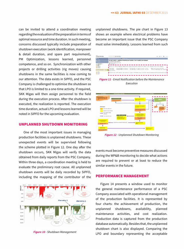
<< 63 jurnal IaFMI 03 Desember 2015
can be invited to attend a coordination meeting regarding the evaluation of the preparation in terms of optimal resource and time duration. In such meeting, concerns discussed typically include preparation of shutdown execution (work identification, manpower & detail duration, and spare part requirement), PM Optimization, lessons learned, personnel competence, and so on. Synchronization with other projects or drilling activities (rig moves) causing shutdowns in the same facilities is now coming to our attention. The data exists in SIPFO, and the PSC Company is challenged to optimise the shutdown so that LPO is limited to a one-time activity. If required, SKK Migas will then assign personnel to the field during the execution process. After the shutdown is executed, the realization is reported. The execution time duration, actual LPO and lessons learned will be noted in SIPFO for the upcoming evaluation.
unPlannEd SHuTdoWn MonITorInG
One of the most important issues in managing production facilities is unplanned shutdowns. These unexpected events will be supervised following the scheme plotted in Figure 12. One day after the shutdown occurs, SKK Migas will verify the data obtained from daily reports from the PSC Company. Within three days, a coordination meeting is held to evaluate the preliminary root cause. All unplanned shutdown events will be daily recorded by SIPFO, including the mapping of the contributor of the
unplanned shutdowns. The pie chart in Figure 13 shows an example where electrical problems have become an important issue that the PSC Company must solve immediately. Lessons learned from such
Figure 10 - Shutdown Management
Figure 11 - Email Notification before the Maintenance Execution
Figure 12 - Unplanned Shutdown Monitoring
events must become preventive measures discussed during the WP&B monitoring to decide what actions are required to prevent or at least to reduce the similar events in the future.
PErForMancE ManaGEMEnT
Figure 14 presents a window used to monitor the general maintenance performance of a PSC Company associated with operational management of the production facilities. It is represented by four charts: the achievement of production, the unplanned shutdowns, availability, planned maintenance activities, and cost realization. Production data is captured from the production database automatically. Besides that, the unplanned shutdown chart is also displayed. Comparing the LPO and boundary representing the acceptable
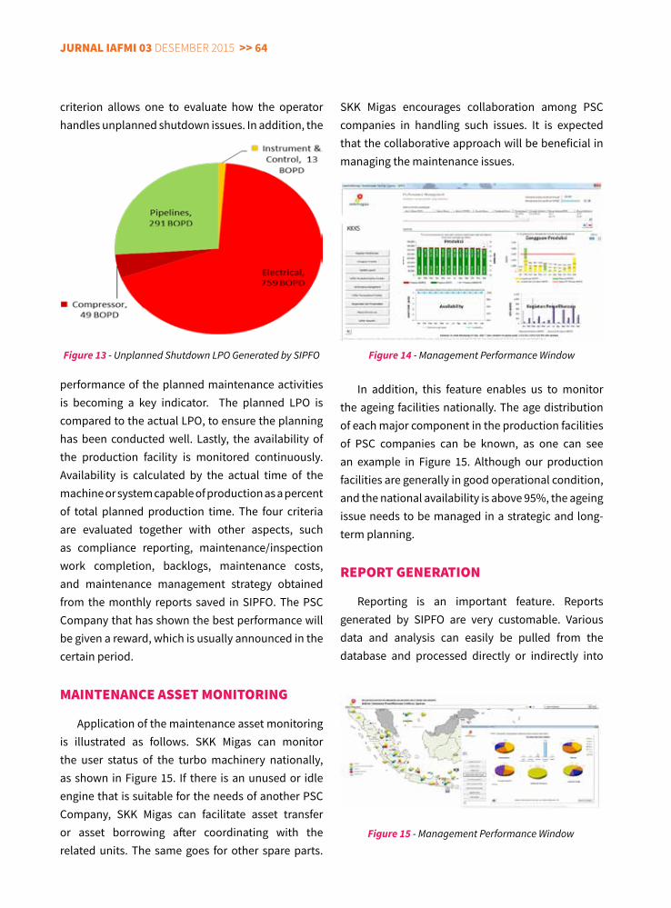
jurnal IaFMI 03 Desember 2015 >> 64
criterion allows one to evaluate how the operator handles unplanned shutdown issues. In addition, the
SKK Migas encourages collaboration among PSC companies in handling such issues. It is expected that the collaborative approach will be beneficial in managing the maintenance issues.
In addition, this feature enables us to monitor the ageing facilities nationally. The age distribution of each major component in the production facilities of PSC companies can be known, as one can see an example in Figure 15. Although our production facilities are generally in good operational condition, and the national availability is above 95%, the ageing issue needs to be managed in a strategic and long-term planning.
rEPorT GEnEraTIon
Reporting is an important feature. Reports generated by SIPFO are very customable. Various data and analysis can easily be pulled from the database and processed directly or indirectly into
performance of the planned maintenance activities is becoming a key indicator. The planned LPO is compared to the actual LPO, to ensure the planning has been conducted well. Lastly, the availability of the production facility is monitored continuously. Availability is calculated by the actual time of the machine or system capable of production as a percent of total planned production time. The four criteria are evaluated together with other aspects, such as compliance reporting, maintenance/inspection work completion, backlogs, maintenance costs, and maintenance management strategy obtained from the monthly reports saved in SIPFO. The PSC Company that has shown the best performance will be given a reward, which is usually announced in the certain period.
MaInTEnancE aSSET MonITorInG
Application of the maintenance asset monitoring is illustrated as follows. SKK Migas can monitor the user status of the turbo machinery nationally, as shown in Figure 15. If there is an unused or idle engine that is suitable for the needs of another PSC Company, SKK Migas can facilitate asset transfer or asset borrowing after coordinating with the related units. The same goes for other spare parts.
Figure 13 - Unplanned Shutdown LPO Generated by SIPFO Figure 14 - Management Performance Window
Figure 15 - Management Performance Window
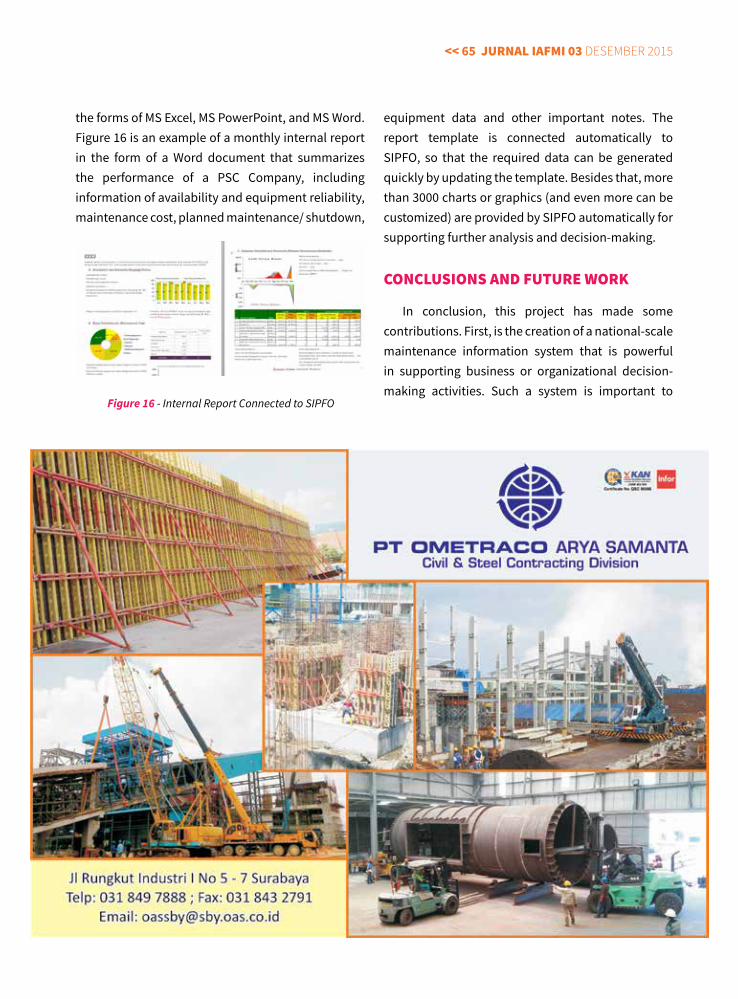
<< 65 jurnal IaFMI 03 Desember 2015
the forms of MS Excel, MS PowerPoint, and MS Word. Figure 16 is an example of a monthly internal report in the form of a Word document that summarizes the performance of a PSC Company, including information of availability and equipment reliability, maintenance cost, planned maintenance/ shutdown,
equipment data and other important notes. The report template is connected automatically to SIPFO, so that the required data can be generated quickly by updating the template. Besides that, more than 3000 charts or graphics (and even more can be customized) are provided by SIPFO automatically for supporting further analysis and decision-making.
concluSIonS and FuTurE WorK
In conclusion, this project has made some contributions. First, is the creation of a national-scale maintenance information system that is powerful in supporting business or organizational decision-making activities. Such a system is important to
Figure 16 - Internal Report Connected to SIPFO
jurnal IaFMI 03 Desember 2015 >> 66
assist SKK Migas to perform its main function, which is to control and supervise all oil and gas production facilities in Indonesia.
Second, the system has been developed successfully in an efficient and customable manner. By using common, current software and by empowering the existing human resources, the proposed system has fulfilled the given expectations. It has more flexibility to customize features compared to commercially available specialist software, and is much cheaper.
Although this software tool offers convenience, a lot of work is still required to improve the prototype. However, by developing this system, at least a short-term powerful solution has been provided, which lays the foundation for future development of a more established system. In the future, SIPFO will become part of an Integrated Operation System that unifies all the data, not only from the surface facilities but also from the subsurface ones, online and in real-time.
acKnoWlEdGEMEnTS
The authors gratefully acknowledge the support of the management of SKK Migas, particularly the Head of Division of Project Management and Facilities Maintenance, the former head of division of maintenance, senior managers of the Maintenance Department, as well as other parties (who could not be unfortunately mentioned one by one) in creation of the system and realisation of this paper.
rEFErEncES
Fernandez, O. A. W., Labib, R. Walmsley, and D. J. Petty. 2003. A decision support maintenance management system: Development and implementation. International Journal of Quality & Reliability Management, 20 8, 965-979.
Jardine, A. K. S., D. Banjevic, and V. Makis. 1997 Optimal replacement policy and the structure of software for condition-based maintenance. Journal of Quality in Maintenance Engineering, 3, 2, 109-119.
Kun-Yung LuChun-Chin Sy. 2009. A real-time decision-making of maintenance using fuzzy agent. International Journal Expert Systems with Applications, 36, 2, 2, 2691-2698.
aBouT THE auTHor
Mohamad Fauzan Amir is currently working in Division of Project Management and Facility Maintenance SKK Migas. He has Ph.D in Process Control from Martin-Luther University,
Germany and has twelve years experiences in international academia, multinational oil/gas, petrochemical industries, especially in process control research and development, control design applications, control and instrumentation system and automation projects, maintenance management, and trainings.
Rossupanji Pribadi is currently working in Division of Project Management and Facility Maintenance SKK Migas. He Joined SKK Migas at 2011 and developed data management and information system for
the national operation facility maintenance management.
He started his career in data management system in Oil and Gas Company since 2003. He has bachelor degree in Computer Science and Master degree in Information Technology from University of Indonesia.
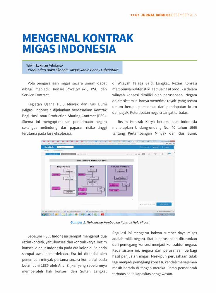
<< 67 jurnal IaFMI 03 Desember 2015
Pola pengusahaan migas secara umum dapat dibagi menjadi: Konsesi(Royalty/Tax), PSC dan Service Contract.
Kegiatan Usaha Hulu Minyak dan Gas Bumi (Migas) Indonesia dijalankan berdasarkan Kontrak Bagi Hasil atau Production Sharing Contract (PSC). Skema ini mengoptimalkan penerimaan negara sekaligus melindungi dari paparan risiko tinggi terutama pada fase eksplorasi.
Sebelum PSC, Indonesia sempat menganut dua rezim kontrak, yaitu konsesi dan kontrak karya. Rezim konsesi dianut Indonesia pada era kolonial Belanda sampai awal kemerdekaan. Era ini ditandai oleh penemuan minyak pertama secara komersial pada bulan Juni 1885 oleh A. J. Ziljker yang sebelumnya memperoleh hak konsesi dari Sultan Langkat
di Wilayah Telaga Said, Langkat. Rezim Konsesi mempunyai kakteristikl, semua hasil produksi dalam wilayah konsesi dimiliki oleh perusahaan. Negara dalam sistem ini hanya menerima royalti yang secara umum berupa persentase dari pendapatan bruto dan pajak. Keterlibatan negara sangat terbatas.
Rezim Kontrak Karya berlaku saat Indonesia menerapkan Undang-undang No. 40 tahun 1960 tentang Pertambangan Minyak dan Gas Bumi.
Regulasi ini mengatur bahwa sumber daya migas adalah milik negara. Status perusahaan diturunkan dari pemegang konsesi menjadi kontraktor negara. Pada sistem ini, negara dan perusahaan berbagi hasil penjualan migas. Meskipun perusahaan tidak lagi menjadi pemegang konsesi, kendali manajemen masih berada di tangan mereka. Peran pemerintah terbatas pada kapasitas pengawasan.
MeNGeNAL KONTRAK MIGAS INDONeSIA
Wiwin Lukman FebriantoDisadur dari Buku Ekonomi Migas karya Benny Lubiantara
Gambar 1. Mekanisme Pembagian Kontrak Hulu Migas
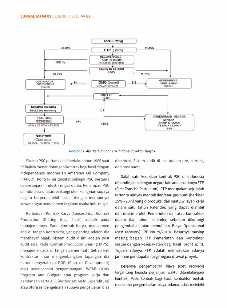
jurnal IaFMI 03 Desember 2015 >> 68
Skema PSC pertama kali berlaku tahun 1966 saat PERMINA menandatangani kontrak bagi hasil dengan Independence Indonesian American Oil Company (IIAPCO). Kontrak ini tercatat sebagai PSC pertama dalam sejarah industri migas dunia. Penerapan PSC di Indonesia dilatarbelakangi oleh keinginan supaya negara berperan lebih besar dengan mempunyai kewenangan manajemen kegiatan usaha hulu migas.
Perbedaan Kontrak Karya (konsesi) dan Kontrak Production Sharing (bagi hasil) adalah pada manajemennya. Pada Kontrak Karya, manajemen ada di tangan kontraktor, yang penting adalah dia membayar pajak. Sistem audit disini adalah post audit saja. Pada Kontrak Production Sharing (KPS), manajemen ada di tangan pemerintah. Setiap kali kontraktor mau mengembangkan lapangan dia harus menyerahkan POD (Plan of Development) atau perencanaan pengembangan, WP&B (Work Program and Budget) atau program kerja dan pendanaan serta AFE (Authorization fo Expenditure) atau otorisasi pengeluaran supaya pengeluaran bisa
dikontrol. Sistem audit di sini adalah pre, current, dan post audit.
Salah satu keunikan kontrak PSC di Indonesia dibandingkan dengan negara lain adalah adanya FTP (First Tranche Petroleum). FTP merupakan sejumlah tertentu minyak mentah dan/atau gas bumi (berkisar 15% - 20%) yang diproduksi dari suatu wilayah kerja dalam satu tahun kalender, yang dapat diambil dan diterima oleh Pemerintah dan atau kontraktor dalam tiap tahun kalender, sebelum dikurangi pengembalian atau pemulihan Biaya Operasional (cost recovery) (PP No.79/2010). Besarnya masing masing bagian FTP Pemerintah dan Kontraktor sesuai dengan kesepakatan bagi hasil (profit split). Tujuan adanya FTP adalah memastikan adanya jaminan pendapatan bagi negara di awal proyek.
Besarnya pengembalian biaya (cost recovery) tergantung kepada perjanjian waktu ditandatangani kontrak. Pada kontrak bagi hasil kontraktor berhak menerima pengembalian biaya selama tidak melebihi
Gambar 2. Alur Perhitungan PSC Indonesia Sektor Minyak
<< 69 jurnal IaFMI 03 Desember 2015
persentase tertentu dari produksi tahunan pada daerah kontrak. Proporsi ini dikenal sebagai cost oil. Kekurangan yang belum diperoleh di carried forward (bawa ke depan) untuk recovery pada tahun. Tahun berikutnya dengan prinsip yang sama cost oil diberi nilai dengan menggunakan harga pasar dari minyak mentah sebelum dibandingkan dengan recoverable cost.
Batas maksimum dari cost oil dikenal sebagai cost stop (cost recovery ceiling), bervariasi tergantung kepada negara dan kontraknya, tapi biasanya berkisar antara 30 dan 60%, walaupun dapat 100%. Harga cost stop mempengaruhi keekonomian, makin besar makin bagus return on investment (pengembalian investasi) nya.
DMO pada dasarnya adalah kewajiban kontraktor untuk memasok kebutuhan domestic sejumlah volume tertentu. Untuk 60 bulan pertama pada saat
produksi dimulai, volume untuk DMO ini dihargai dengan harga pasar minyak mentah tersebut, yang dikenal dengan istilah DMO holiday. Setelah periode DMO holiday, harga minyak DMO akan didiskon sesuai dengan yang tertera pada kontrak, 10%, 15% atau 25% dari harga pasar minyak mentah tersebut.
Kewajiban untuk pemenuhan kebutuhan domestic (DMO) telah ada sejak generasi awal PSC Indonesia. Besarnya DMO fee yang harus dibayar pemerintah juga meningkat, bermula 0,2 US$/barel pada PSC Generasi I dan Generasi II, 10% dari harga minyak pada PSC Generasi III, 15% dari harga minyak (paket Insentif 3/1992) dan 25% dari harga minyak (paket insentif 4/1993).
Penentuan DMO untuk lapangan gas sedikit lebih kompleks dibanding minyak. Perbedaan lainnya adalah bahwa lapangan gas baru akan
Gambar 3. Alur Perhitungan PSC Indonesia Sektor Gas
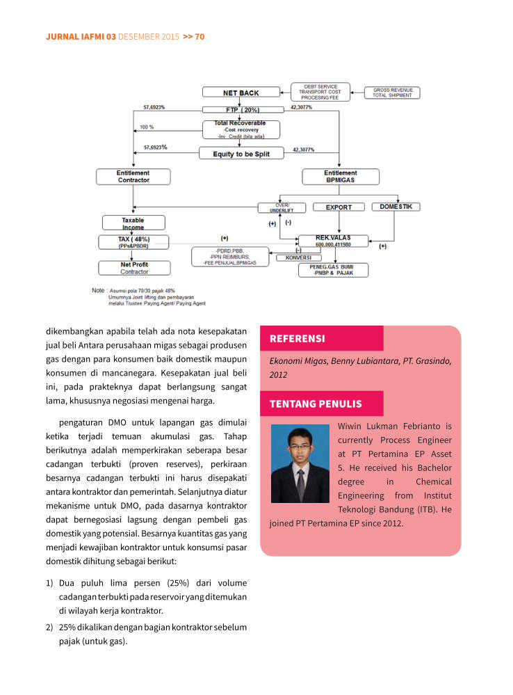
jurnal IaFMI 03 Desember 2015 >> 70
dikembangkan apabila telah ada nota kesepakatan jual beli Antara perusahaan migas sebagai produsen gas dengan para konsumen baik domestik maupun konsumen di mancanegara. Kesepakatan jual beli ini, pada prakteknya dapat berlangsung sangat lama, khususnya negosiasi mengenai harga.
pengaturan DMO untuk lapangan gas dimulai ketika terjadi temuan akumulasi gas. Tahap berikutnya adalah memperkirakan seberapa besar cadangan terbukti (proven reserves), perkiraan besarnya cadangan terbukti ini harus disepakati antara kontraktor dan pemerintah. Selanjutnya diatur mekanisme untuk DMO, pada dasarnya kontraktor dapat bernegosiasi lagsung dengan pembeli gas domestik yang potensial. Besarnya kuantitas gas yang menjadi kewajiban kontraktor untuk konsumsi pasar domestik dihitung sebagai berikut:
1) Dua puluh lima persen (25%) dari volume cadangan terbukti pada reservoir yang ditemukan di wilayah kerja kontraktor.
2) 25% dikalikan dengan bagian kontraktor sebelum pajak (untuk gas).
rEFErEnSI
Ekonomi Migas, Benny Lubiantara, PT. Grasindo, 2012
TEnTanG PEnulIS
Wiwin Lukman Febrianto is currently Process Engineer at PT Pertamina EP Asset 5. He received his Bachelor degree in Chemical Engineering from Institut Teknologi Bandung (ITB). He
joined PT Pertamina EP since 2012.
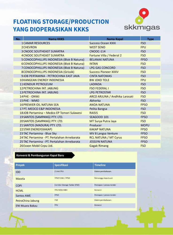
<< 71 jurnal IaFMI 03 Desember 2015
jurnal IaFMI 03 Desember 2015 >> 72
Related Documents