July 29, 201 4 Mr. Rob Wilson Meritage Homes 1671 East Monte Vista Avenue, Su ite 214 Vacaville, California 95688 Geotechnical Engineering Report Addendum BEAVER CREEK Douglas Boulevard Granite Bay, California WKA No . 10191.02 July 29, 2014 CORPORATE 0FFl<:E 3050 Industrial Bou l evard We st Sa cramento , CA 956 91 916.372.1434 phon e 916.372. 2565 fa x STOCKTON OFFICE 3422 We st Hammer Lane, Suite D St oc kto n, CA 95219 209 .234 .7 722 phone 209,234.7727 fa x As authorized , we have completed a geotechnical engineering study for the proposed Beaver Creek residential development located southwesterly of the intersection of Douglas Boulevard and Seeno Avenue in Granite Bay, California . Our office previously prepared a Geotechnical Engineering Report (WKA No. 10110.02, dated June 18, 2014) for the Creekside Oaks residential development, located approximately 700 feet to the east of the subject property, as shown in Figure 1. The purposes of our study have been to explore the existing site, soil, rock and groundwater conditions across the accessible portions of the property, and to evaluate the applicability of the geotechnical engineering report prepared for the Creekside Oaks project to the proposed residential development of the subject property. Our work has been performed in general accordance with the provisions contained in our Geotechnica/ Engineering Services Proposal, dated July 7, 2014, and executed under Cost Code: 00935, referenced in the Master Agreement (Contract No. 4529947) between Meritage Homes of California, Inc. and Wallace- Kuhl & Associates, dated July 11, 2014. Scope of Services Ou r scope of services has included the following tasks: 1. site reconnaissance; 2. review of United States Geological Survey (USGS) topographic maps, geologic maps, ava ilable groundwater information, and previous reports prepared for the subject site and nearby properties;

Welcome message from author
This document is posted to help you gain knowledge. Please leave a comment to let me know what you think about it! Share it to your friends and learn new things together.
Transcript
July 29, 201 4
Mr. Rob Wilson
Meritage Homes
1671 East Monte Vista Avenue, Suite 214
Vacaville , California 95688
Geotechnical Engineering Report Addendum
BEAVER CREEK
Douglas Boulevard
Granite Bay, California
WKA No. 10191.02
July 29, 2014
CORPORATE 0FFl<:E
3050 Indu s tri al Bou levard
We s t S acramento , CA 9569 1
916.372 .1434 phon e
916.372 .2565 fa x
STOCKTON OFFICE
3422 We st Hamm e r Lane, Suite D
St oc kto n, CA 95219
209.234 .7 722 phone
209, 234 .7 727 fa x
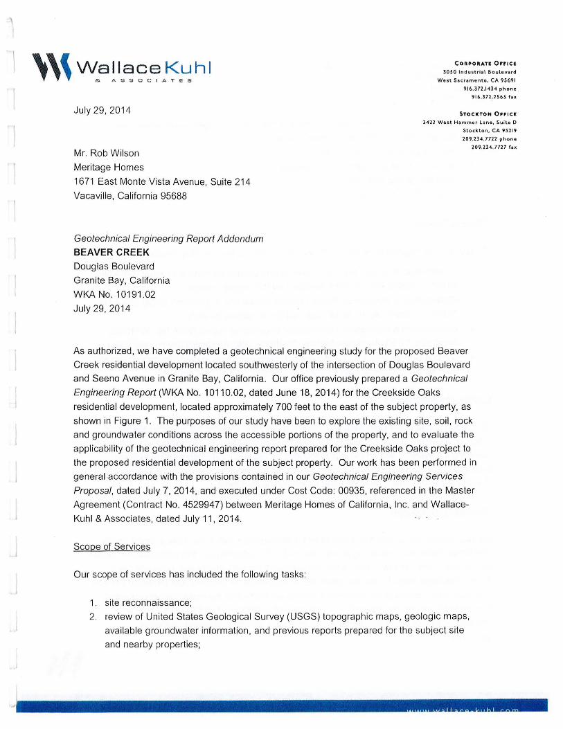
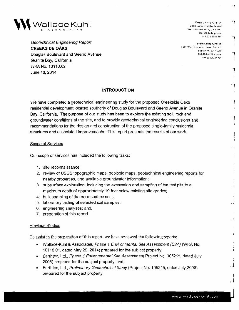
As authorized , we have completed a geotechnical engineering study for the proposed Beaver
Creek residential development located southwesterly of the intersection of Douglas Boulevard
and Seeno Avenue in Granite Bay, California . Our office previously prepared a Geotechnical
Engineering Report (WKA No. 10110.02, dated June 18, 2014) for the Creekside Oaks
residential development, located approximately 700 feet to the east of the subject property, as
shown in Figure 1. The purposes of our study have been to explore the existing site, soil , rock
and groundwater conditions across the accessible portions of the property, and to evaluate the
applicability of the geotechnical engineering report prepared for the Creekside Oaks project to
the proposed residential development of the subject property. Our work has been performed in
general accordance with the provisions contained in our Geotechnica/ Engineering Services
Proposal, dated July 7, 2014, and executed under Cost Code: 00935, referenced in the Master
Agreement (Contract No. 4529947) between Meritage Homes of California, Inc. and Wallace
Kuhl & Associates, dated July 11, 2014.
Scope of Services
Our scope of services has included the following tasks:
1. site reconnaissance;
2. review of United States Geological Survey (USGS) topographic maps, geologic maps,
available groundwater information , and previous reports prepared for the subject site
and nearby properties;

Geotechnical Engineering Report Addendum BEAVER CREEK WKA No. 10191.02 July 29, 2014
Page 2
3. subsurface exploration, including the excavation of six test pits to a maximum depth of
approximately 10 feet below existing site grades;
4. bulk sampling of the near-surface soils;
5. laboratory testing of selected soil samples;
6. engineering analyses; and,
7. preparation of this report.
Previous Studies
To assist in the preparation of this report , we have reviewed the following reports:
• Wallace-Kuhl & Associates, Soil Sampling and Laboratory Analyses Report (WKA No.
10191.03, dated July 24, 2014) prepared for the subject property;
• Wallace-Kuhl & Associates, Phase I Environmental Site Assessment (ESA) (WKA No.
10191.01, dated July 15, 2014) prepared for the subject property;
• Wallace-Kuhl & Associates, Geotechnical Engineering Report (WKA No. 10110.02,
dated July 15, 2014) prepared for the Creekside Oaks residential development; and,
• Geocon Consultants, Inc., Geotechnical Engineering Investigation (Geocon project No.
S9014-06-02, dated August 15, 2005) prepared for the subject property.
Figures and Attachments
This report contains a Vicinity Map as Figure 1; a Site Plan showing the approximate test pit
locations as Figure 2; and Logs of Test Pits as Figures 3 and 4. An explanation of symbols and
classification system used on the logs is included as Figure 5. Laboratory test results are
presented on Figures 6 and 7. Appendix A contains a copy of our Geotechnical Engineering
Report prepared for the Creekside Oaks residential development.
Proposed Development
We understand the subject site is proposed for development with a low-density, single-family
residential subdivision consisting of approximately 16 residential lots. We anticipate the houses
will consist of one- and two-story, wood-framed structures with interior slab-on-grade lower
floors. Structural loads for the structures are anticipated to be relatively light based on this type
of construction. Below grade basements are not anticipated for the residential development.
Associated development will include construction of underground utilities, exterior flatwork,
retaining walls, sound walls, interior paved residential streets, and typical residential
landscaping.
'''
r ,.I
I
l
J
. I
J J .J .J

Geotechnical Engineering Report Addendum BEAVER CREEK WKA No. 10191.02 July 29, 2014
Field Exploration and Testing
Page 3
On July 11, 2014, our field representative observed the excavation and sampling of six test pits
(TP1 through TP6) at the approximate locations shown on Figure 2. The test pits were
excavated to a maximum depth of about 10 feet below existing grades utilizing a Case 580
rubber-tired backhoe equipped with a 24-inch wide bucket. Bulk samples of the near-surface
soils were collected at various depths . The bulk samples were collected using a shovel and
retained in plastic bags. After the completion of the test pits, the excavations were backfilled
with the excavated spoils and compacted using a sheepsfoot compaction wheel. After recovery
of the samples, the field representative visually classified the soil in bags and sealed the bags to
preserve the natural moisture contents . The samples were taken to our laboratory for additional
soil classification and selection of samples for testing.
FINDINGS
Site Description
The project site encompasses a total area of approximately 17 acres and is located
southwesterly of Douglas Boulevard and Seeno Avenue in Granite Bay, California . The site is
bounded to the north by Douglas Boulevard; to the east by vacant land; to the south by rural
residences; and, to the west by vacant land and rural residences.
The topography of the property is gently rolling terrain with ground surface elevations ranging
from approximately +260 to +280 feet relative to mean sea level (msl), according to the USGS
7.5-Minute Topographic Map of the Folsom Quadrangle, dated 1967 (photorevised 1980).
Additionally, the topographic map shows Strap Ravine and dredge tailings within the central
portion of the site.
At the time of our field exploration on July 11, 2014, the site generally supported dense trees,
brush, and vegetation which limited site access. Strap Ravine was observed meandering
southwest to northeast through the central portion of the site. Water was not observed within
the ravine during our site visit. A large soil stockpile, scattered debris and open excavations
were observed in different areas of the northeastern portion of the site. The stockpile was about
1 O feet tall, 150 feet long and 100 feet wide. Observed debris included, but not limited to, tires,
pots, pans, scrap metal and asphalt. The open excavations were somewhat circular-shaped,
with a diameter ranging from three to five feet and a depth of about five feet. The excavations
'''
Geotechnical Engineering Report Addendum BEA VER CREEK WKA No. 10191 .02 July 29, 2014
Page 4
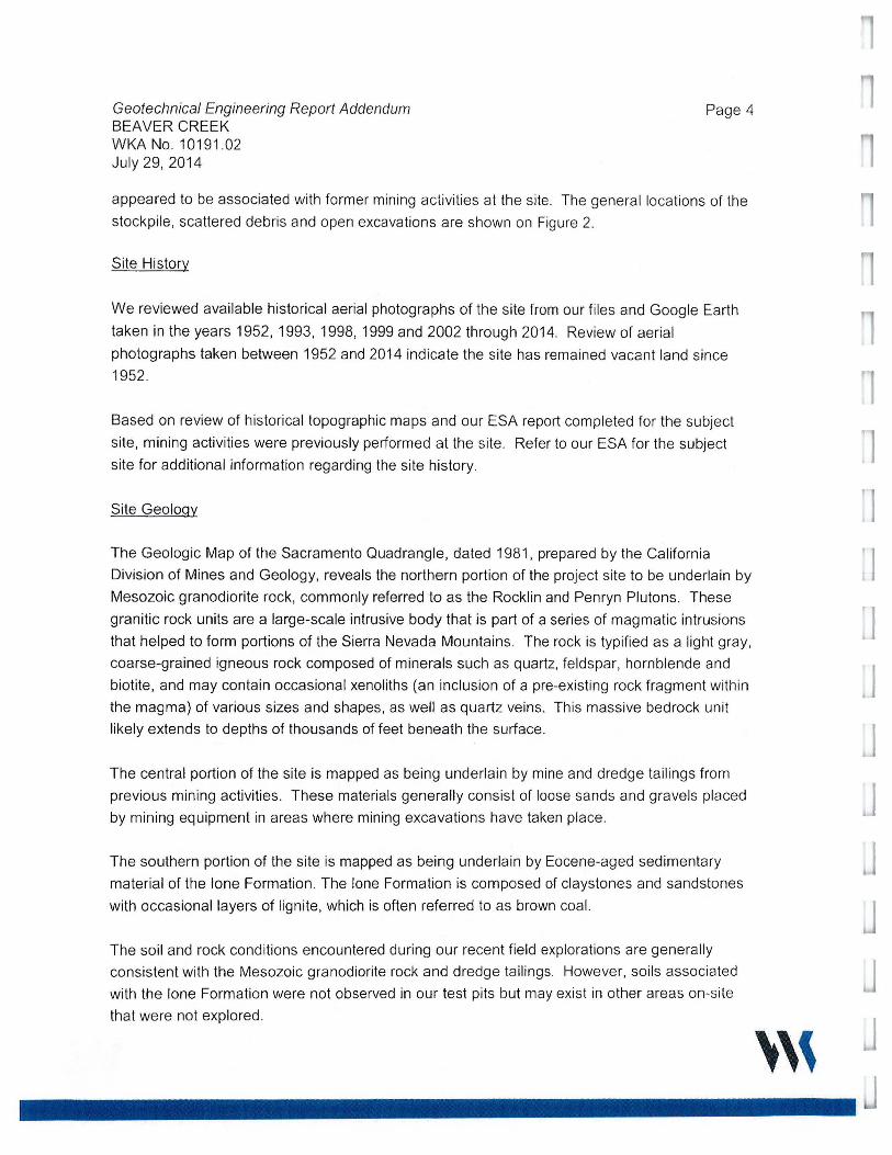
appeared to be associated with former mining activities at the site . The general locations of the
stockpile, scattered debris and open excavations are shown on Figure 2.
Site History
We reviewed available historical aerial photographs of the site from our files and Google Earth
taken in the years 1952, 1993, 1998, 1999 and 2002 through 2014. Review of aerial
photographs taken between 1952 and 2014 indicate the site has remained vacant land since
1952.
Based on review of historical topographic maps and our ESA report completed for the subject
site, mining activities were previously performed at the site. Refer to our ESA for the subject
site for additional information regarding the site history.
Site Geology
The Geologic Map of the Sacramento Quadrangle, dated 1981, prepared by the California
Division of Mines and Geology, reveals the northern portion of the project site to be underlain by
Mesozoic granodiorite rock, commonly referred to as the Rocklin and Penryn Plutons. These
granitic rock units are a large-scale intrusive body that is part of a series of magmatic intrusions
that helped to form portions of the Sierra Nevada Mountains. The rock is typified as a light gray,
coarse-grained igneous rock composed of minerals such as quartz, feldspar, hornblende and
biotite, and may contain occasional xenoliths (an inclusion of a pre-existing rock fragment within
the magma) of various sizes and shapes, as well as quartz veins. This massive bedrock unit
likely extends to depths of thousands of feet beneath the surface .
The central portion of the site is mapped as being underlain by mine and dredge tailings from
previous mining activities. These materials generally consist of loose sands and gravels placed
by mining equipment in areas where mining excavations have taken place.
The southern portion of the site is mapped as being underlain by Eocene-aged sedimentary
material of the lone Formation. The lone Formation is composed of claystones and sandstones
with occasional layers of lignite, which is often referred to as brown coal.
The soil and rock conditions encountered during our recent field explorations are generally
consistent with the Mesozoic granodiorite rock and dredge tailings. However, soils associated
with the lone Formation were not observed in our test pits but may exist in other areas on-site
that were not explored.
'''
1 l
I J
J
Geotechnical Engineering Report Addendum BEAVER CREEK WKANo. 10191 .02 July 29, 2014
Soil and Rock Conditions
Page 5
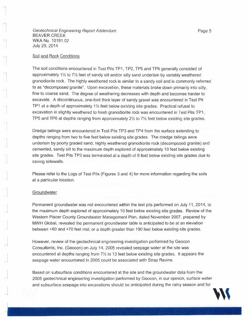
The soil conditions encountered in Test Pits TP1 , TP2, TP5 and TP6 generally consisted of
approximately 1 Yi to 7% feet of sandy silt and/or silty sand underlain by variably weathered
granodiorite rock. The highly weathered rock is similar to a sandy soil and is commonly referred
to as "decomposed granite". Upon excavation, these materials broke down primarily into silty,
fine to coarse sand. The degree of weathering decreases with depth and becomes harder to
excavate. A discontinuous, one-foot thick layer of sandy gravel was encountered in Test Pit
TP1 at a depth of approximately 1 Yi feet below existing site grades. Practical refusal to
excavation in slightly weathered to fresh granodiorite rock was encountered in Test Pits TP1 ,
TP5 and TP6 at depths ranging from approximately 2% to 7% feet below existing site grades.
Dredge tailings were encountered in Test Pits TP3 and TP4 from the surface extending to
depths ranging from two to five feet below existing site grades. The dredge tailings were
underlain by poorly graded sand , highly weathered granodiorite rock (decomposed granite) and
cemented, sandy silt to the maximum depth explored of approximately 10 feet below existing
site grades. Test Pits TP3 was terminated at a depth of 6 feet below existing site grades due to
caving sidewalls .
Please refer to the Logs of Test Pits (Figures 3 and 4) for more information regarding the soils
at a particular location .
Groundwater
Permanent groundwater was not encountered within the test pits performed on July 11, 2014, to
the maximum depth explored of approximately 10 feet below existing site grades. Review of the
Western Placer County Groundwater Management Plan, dated November 2007, prepared by
MWH Global, revealed the permanent groundwater table is anticipated to be at an elevation
between +60 and + 70 feet msl, or a depth greater than 190 feet below existing site grades.
However, review of the geotechnical engineering investigation performed by Geocon
Consultants, Inc . (Geocon) on July 14, 2005 revealed seepage water at the site was
encountered at depths ranging from 7% to 13 feet below existing site grades. It appears the
seepage water encountered in 2005 could be associated with Strap Ravine .
Based on subsurface conditions encountered at the site and the groundwater data from the
2005 geotechnical engineering investigation performed by Geocon, in our opinion, surface water
and subsurface seepage into excavations should be anticipated during the rainy season and for
'''

Geotechnical Engineering Report Addendum BEAVER CREEK WKA No. 10191.02 July 29, 2014
Page 6
several weeks after the last rainfall of the season. Seasonal seeps or springs may be active on
the property. Perched water may also be encountered in excavations during earthwork and
utility construction due to the relatively impermeable geologic materials at the site.
As a result of the impermeable nature of these materials , it is not unusual to observe perched
water above them either at the surface or in shallow excavations. Seepage can also occur
through sloping ground that exposes cemented materials as a consequence of grading and
terracing required for subdivisions constructed on this type of terrain . Although perched water
and seepage can be controlled by appropriate drainage improvements constructed during
landscaping, it is typically not possible to intercept all subsurface water in areas that are
underlain by impermeable geologic materials such as those at the site .
Perched water and seepage are the result of the inability of rain or irrigation water to vertically
migrate through the impermeable geologic materials at the site. Rain and irrigation water
infiltrating the surface through topsoil or permeable engineered fill typically migrates downward
to underlying cemented material and then laterally or down slope on top of the impermeable
cemented material. We emphasize that perched water does not represent the groundwater
table, as the groundwater table is likely 100 feet or more below general surface elevations at the
site .
CONCLUSIONS AND RECOMMENDATIONS
Based on review of the Geotechnica/ Engineering Report (WKA No. 10110.02) prepared for the
Creekside Oaks residential development (located approximately 700 feet to the east of the
subject property), recent site observations, laboratory test results and understanding of the
proposed construction, it is our opinion the conclusions and recommendations contained in the
Creekside Oaks report are generally applicable for design and construction of the planned
residential development and associated improvements, with the following amended conclusions
and recommendations. A copy of the Creekside Oaks report is attached as Appendix A.
2013 CBC/ASCE 7-10 Seismic Design Criteria
Section 1613 of the 2013 edition of the California Building Code (CBC) references ASCE
Standard 7-1 O for seismic design . The following seismic parameters were determined based on
the site latitude and longitude using the public domain computer program developed by the
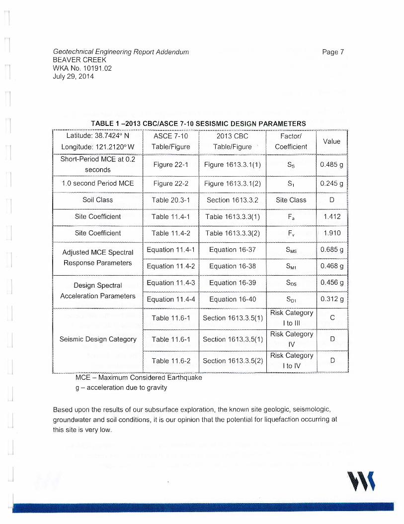
USGS. The following parameters summarized in Table 1 may be used for seismic design of the
proposed residential structures per the 2013 CBC.
'''
1 l
J
Geotechnical Engineering Report Addendum BEAVER CREEK WKA No. 10191 .02 July 29, 2014
TABLE 1 - 2013 CBC/ASCE 7-10 SESISMIC DESIGN PARAMETERS
Latitude: 38. 7 424° N ASCE 7-10 2013 CBC Factor/
Longitude: 121 .2120° W Table/Figure Table/Figure Coefficient
Page 7
Value II i
[-,---' -
Short-Period MCE at 0.2
seconds Figure 22-1 Figure 1613.3.1(1) Ss 0.485 g
1.0 second Period MCE Figure 22-2 Figure 1613.3 .1(2) S1 0.245 g __ .. __ ---- -···~-
I Soil Class Table 20.3-1 Section 1613.3.2 Site Class 0
Site Coefficient Table 11.4-1 Table 1613.3.3(1) Fa 1.412
Site Coefficient Table 11.4-2 Table 1613.3.3(2) Fv 1.910
Adjusted MCE Spectral Equation 11.4-1 Equation 16-37 SMs 0.685 g '
Response Parameters Equation 11.4-2
Design Spectral Equation 11.4-3
Acceleration Parameters Equation 11.4-4
Table 11.6-1
Seismic Design Category Table 11 .6-1
Table 11 .6-2
···················--· u n- •
MCE - Maximum Considered Earthquake
g - acceleration due to gravity
Equation 16-38
Equation 16-39
Equation 16-40
Section 1613.3.5(1)
Section 1613.3.5(1)
Section 1613.3.5(2)
···-·-······-···.,···.,:,:=--~,:·•
SM1 0.468 g
Sos 0.456 g
So, 0.312g
Risk Category C
I to 111
Risk Category D
IV
Risk Category D
I to IV '"
Based upon the results of our subsurface exploration, the known site geologic, seismologic,
groundwater and soil conditions, it is our opinion that the potential for liquefaction occurring at
this site is very low.
'''

Geotechnical Engineering Report Addendum BEAVER CREEK WKA No. 10191.02 July 29, 2014
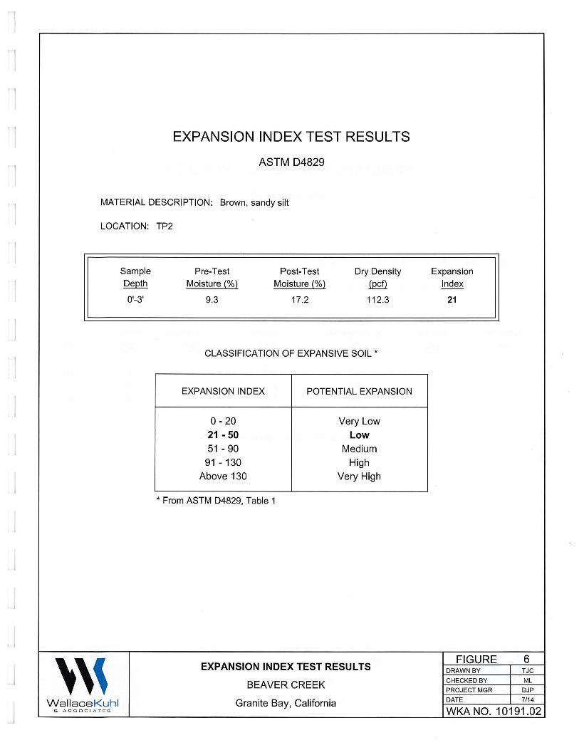
Soil Expansion Potential
Page 8
The surface and near-surface soils at the site generally consisted of silty sand and sandy silt to
depths ranging from about 11h to 71h feet below existing site grades. Laboratory testing
performed on a bulk sample of sandy silt collected from the upper three feet at Test Pit TP2
revealed these soils possess a low expansion potential when tested in accordance with ASTM
04829 (see Figure 6). Therefore, special reinforcement of foundation and floor slabs, or special
moisture conditioning during site grading to resist or control soil expansion pressures, are not
considered necessary for this project.
Dredge tailing often contain clay deposits, commonly referred to as "slickens". Slickens are
highly plastic and typically possess a high expansion potential and can be detrimental to
structures. We did not encounter slickens within our test pits; however, if encountered during
grading, slickens should be removed per the recommendations included in the Creekside Oaks
report (see Appendix A).
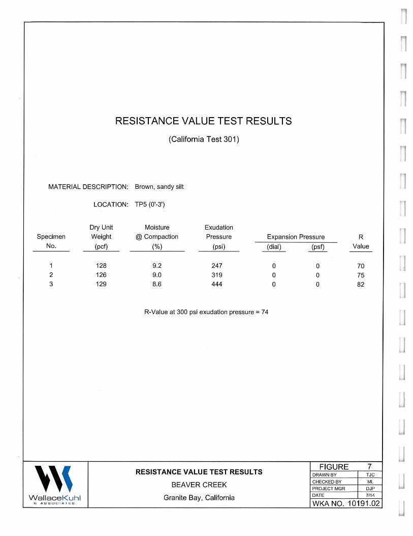
Pavement Subqrade Quality
A representative bulk sample of near-surface soils collected from Test Pit TP5 was subjected to
Resistance ("R") value testing in accordance with California Test 301. Laboratory testing of the
sample revealed the near-surface materials possess an R-value of 74 (see Figure 7). Based on
the laboratory test results, the surface and near-surface soils are considered good subgrade
quality material for support of asphalt concrete pavements. However, based on the variable soil
conditions encountered at the site and our previous experience in the vicinity of this project, it is
likely that near-surface soils that possess lower quality characteristics (lower R-value) for
support of asphalt concrete pavements will be encountered at the site. Therefore, it is our
opinion that an R-value of 30 is appropriate for design of pavements at the site. Asphalt
pavements may be designed in accordance with the pavement design alternatives and
recommendations provided in the Creekside Oaks report (see Appendix A) .
LIMITATIONS
Limitations
This report is considered to be an addendum to our Geotechnica/ Engineering Report (WKA No.
10110.02) prepared for the Creekside Oaks development, and therefore the conclusions and
recommendations contained herein are subject to the limitations stated in that report .
'''
l l I J

Geotechnical Engineering Report Addendum BEAVER CREEK WKA No. 10191.02 July 29, 2014
Page 9
We emphasize that this report is applicable only to the proposed construction and the
investigated site . This report should not be utilized for construction on any other site. This
report is considered valid for the proposed construction for a period of two years following the
date of this report. If construction has not started within two years, we must re-evaluate the
recommendations of this report and update the report, if necessary.
Wallace - Kuhl & Associates
Mauricio Luna
Project Engineer
Attachments :
Figure 1: Vicinity Map
Figure 2: Site Plan
Figures 3 and 4: Logs of Test Pits
Figure 5: Unified Soil Classification System
Figure 6: Expansion Index Test Results
Figure 7: Resistance Value Test Results
Project Engineer
Appendix A: Geotechnical Engineering Report (WKA No. 10110.02, dated June 18, 2014)
'''

1 \
' 0,9
Street data courtesy of Placer County.
"' "' :,, ()
~ m Cl m
i!!
Hydrography courtesy of the U.S. Geological Survey acquired from the GIS Data Depot, December, 2007. Projection: NAD 83, California State Plane , Zone II
''' Wallace Kuh l & ASSOC I ATES
W ILHOFF LN
... U>
" ~ ()
3 ... z 0 g/
sl
,-,,~ ~ :r /. ;rlWKA No. 10110.02 D
. ~- ~--: II I ~, ~ ~ .r rn
er 0 cr
~ z w g 0
" ~ ~ ~ ~ w ~ U EKA R • U> U>
0 ,:
~ "' 3 'ii ,: m 0 er
"' ~ m
" U> ~ ...
!\ 5 ~ ~ >-z .,. "' U> U> 0
~ ~ er
BAYVILLE CT
OAK CREEK~L J_ ~--
\:___,
' ,, N
A 0 1,000 2,000
Feet
VICINITY MAP FIGURE 1
DRAWN BY TJC
BEAVER CREEK CHECKED BY ML PROJECT MGR DJP
Granite Bay, California DATE 7/14
WKA NO. 10191 .02
l ]
]
J
J
J
J
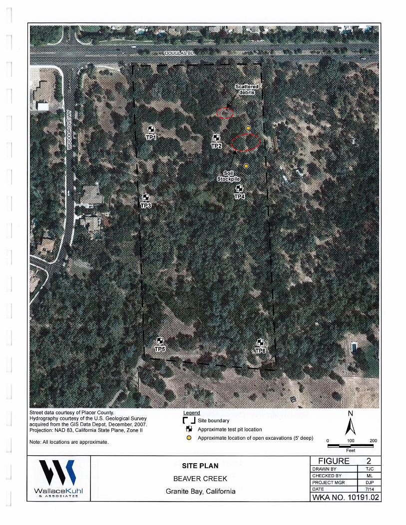
Street data courtesy of Placer County. Hydrography courtesy of the U.S. Geological Survey acquired from the GIS Data Depot, December, 2007. Projection : NAD 83, California State Plane , Zone II
Note : All locations are approximate .
''' WallaceKuhl & ASSOCIA TES
Legend N r J Site boundary
$ Approximate test pit location A 0 Approximate location of open excavations (5' deep)
0 100 200
Feet
SITE PLAN FIGURE 2
DRAWN BY TJC
BEAVER CREEK CHECKED BY ML
PROJECT MGR DJP
Granite Bay, California DATE 7/14
WKA NO. 10191.02
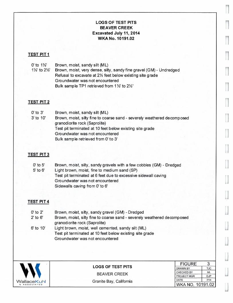
TEST PIT1
O' to 1%' 1%' to2%'
TEST PIT2
O' to 3' 3' to 10'
TEST PIT 3
O' to 5' 5' to 6'
TEST PIT4
O' to 2' 2' to 6'
6' to 10'
''' Wallace Kuhl & A SSOC I AT E S
LOGS OF TEST PITS BEAVER CREEK
Excavated July 11, 2014 WKA No. 10191.02
Brown, moist, sandy silt (ML) Brown, moist, very dense, silty, sandy fine gravel (GM) - Undredged Refusal to excavate at 2% feet below existing site grade Groundwater was not encountered Bulk sample TP1 retrieved from 1 %' to 2%'
Brown, moist, sandy silt (ML) Brown, moist, silty fine to coarse sand - severely weathered decomposed granodiorite rock (Saprolite) Test pit terminated at 10 feet below existing site grade Groundwater was not encountered Bulk sample retrieved from O' to 3'
Brown, moist, silty , sandy gravels with a few cobbles (GM) - Dredged Light brown, moist, fine to medium sand (SP) Test pit terminated at 6 feet due to excessive sidewall caving Groundwater was not encountered Sidewalls caving from O' to 6'
Brown, moist, silty , sandy gravel (GM) - Dredged Brown, moist, silty fine to coarse sand - severely weathered decomposed granodiorite rock (Saprolite) Light brown, moist, well cemented, sandy silt (ML) Test pit terminated at 10 feet below existing site grade Groundwater was not encountered
LOGS OF TEST PITS FIGURE 3
DRAWN BY TJC
BEAVER CREEK CHECKED BY ML
PROJECT MGR DJP
Granite Bay, California DATE 7/1 4
WKA NO. 10191.02
l l
J
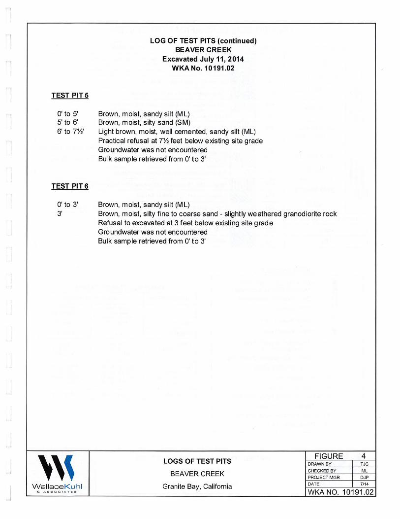
LOG OF TEST PITS (continued) BEAVER CREEK
Excavated July 11, 2014 WKA No. 10191.02
TEST PITS
O' to 5' Brown, moist, sandy silt (ML) 5' to 6' Brown, moist, silty sand (SM) 6' to 7%' Light brown, moist, well cemented, sandy silt (ML)
Practical refusal at 7'Y2 feet below existing site grade Groundwater was not encountered Bulk sample retrieved from O' to 3'
TEST PIT 6
O' to 3' Brown, moist, sandy silt (ML) 3' Brown, moist, silty fine to coarse sand - slightly weathered granodiorite rock
Refusal to excavated at 3 feet below existing site grade Groundwater was not encountered Bulk sample retrieved from O' to 3'
''' FIGURE 4
LOGS OF TEST PITS DRAWN BY TJC
BEAVER CREEK CHECKED BY ML
PROJECT MGR DJP
Wallace Kuhl Granite Bay, California DATE 7/14
& ASS O C I A T E S WKA NO. 10191.02
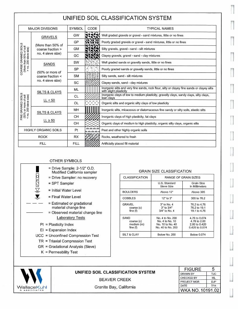
UNIFIED SOIL CLASSIFICATION SYSTEM
MAJOR DIVISIONS SYMBOL CODE TYPICAL NAMES
GW ... , . : •. :t._:t, Well graded gravels or gravel - sand mixtures, little or no fines
GRAVELS ,;, -~---:. ":~.~~-!~ Poorly graded gravels or gravel - sand mixtures, little or no fines ~ GP
6 '5 _ (More than 50% of ~ "' ~ coarse fraction > GM .~ • i . Silty gravels, gravel - sand - silt mixtures
~~ ·; L-~n=o~. 4~s=ie~v=e~s~iz=e~) _ _J__~G~C:____J.~~~~~~C~la::y~e'.:3!~ra~v'.:e~ls~~r::_a~ve:l_=.-_:sa~n~d~-~c:la~~m~i~xt~u~re:s _____________ ~ ~gl ~
~ ~ ~ SANDS SW j\2((/i (/J ~ ci ~ ~ ~ SP o - (50% or more of 0
coarse fraction < SM
no. 4 sieve size) SC
ML SIL TS & CLAYS
~ '5 m CL g ~ -~ LL< 50 o ~ ~ OL
&'//,//h '.Y////j/,:
I
Well graded sands or gravelly sands, little or no fines
Poorly graded sands or gravelly sands, little or no fines
Silty sands, sand - silt mixtures
Clayey sands, sand - clay mixtures
Inorganic silts and very fine sands, rock flour, silty or clayey fine sands or clayey silts with sli!lht plasticity Inorganic clays of low to medium plasticity, gravelly clays, sandy clays, silty clays, lean clays
w ~ <I)
z 0 ·w ~Eot-----------i,-----trw-rrTTl~lrt----------------------------~ Cl'. o ~ MH Inorganic silts, micaceous or diatomaceous fine sandy or silty soils, elastic silts <'.>~ . SILTS&CLAYS
Organic silts and organic silty clays of low plasticity
~~~ CH ~ Inorganic clays of high plasticity, fat clays LL<! 50
OH Organic clays of medium to high plasticity, organic silty clays, organic silts
HIGHLY ORGANIC SOILS Pt
ROCK RX
FILL FILL
OTHER SYMBOLS
..::a!!L~~~
~.;a!!L.;a!!L~.::a: Peat and other highly organic soils
Rocks, weathered to fresh
~x Artificially placed fill material
= Drive Sample: 2-1/2" O.D. Modified California sampler GRAIN SIZE CLASSIFICATION
= Drive Sampler: no recovery
= SPT Sampler
= Initial Water Level
= Final Water Level
= Estimated or gradational material change line
= Observed material change line Laboratory Tests
Pl = Plasticity Index
El = Expansion Index
UCC = Unconfined Compression Test
TR = Triaxial Compression Test
GR = Gradational Analysis (Sieve)
K = Permeability Test
CLASSIFICATION
BOULDERS
COBBLES
GRAVEL coarse (c) fine (f)
SAND coarse (c) medium (m) fine (f)
SILT & CLAY
''' UNIFIED SOIL CLASSIFICATION SYSTEM
BEAVER CREEK
RANGE OF GRAIN SIZES
U.S. Standard Grain Size Sieve Size in Millimeters
Above 12" Above 305
12" to 3" 305 to 76.2
3" to No. 4 76.2 to 4.76 3" to 3/4" 76.2to19.1
3/4" to No. 4 19.1 to4.76
No. 4 to No. 200 4.76 to 0.074 No. 4 to No. 10 4.76 to 2.00
No. 10 to No. 40 2.00 to 0.420 No. 40 to No. 200 0.420 to 0.074
Below No. 200 Below 0.074
FIGURE DRAWN BY CHECKED BY PROJECT MGR DATE
5 TJC ML
DJP 7/14 Wallace Kuhl Granite Bay, California
& A SSOC I ATES WKA NO. 10191.02
l
J
J
J
J
EXPANSION INDEX TEST RESULTS
ASTM D4829
MATERIAL DESCRIPTION: Brown, sandy silt
LOCATION: TP2
''' Wallace Kuhl & ASSOC I ATES
Sample Depth
0'-3'
Pre-Test Moisture (%)
9.3
Post-Test
Moisture(%)
17.2
Dry Density
_(Qf!)_
112.3
CLASSIFICATION OF EXPANSIVE SOIL*
EXPANSION INDEX POTENTIAL EXPANSION
0 - 20 21 - 50 51 - 90
91 - 130 Above 130
* From ASTM D4829, Table 1
Very Low Low
Medium
High Very High
EXPANSION INDEX TEST RESULTS
BEAVER CREEK
Granite Bay, California
Expansion Index
21
FIGURE DRAWN BY
CHECKED BY
PROJECT MGR
DATE
6 TJC
ML
DJP
7/14
WKA NO. 10191.02
RESISTANCE VALUE TEST RESULTS
(California Test 301)
MATERIAL DESCRIPTION: Brown, sandy silt
LOCATION: TPS (0'-3')
Dry Unit Moisture Exudation
Specimen Weight @ Compaction Pressure Expansion Pressure R No. (pcf) (%) (psi) (dial) (psf) Value
--
1 128 9.2 247 0 0 70 2 126 9.0 319 0 0 75 3 129 8.6 444 0 0 82
R-Value at 300 psi exudation pressure= 74
''' RESISTANCE VALUE TEST RESULTS
FIGURE 7 DRAWN BY TJC
BEAVER CREEK CHECKED BY ML
PROJECT MGR DJP
Wallace Kuh l Granite Bay, California DATE 7/14
& A SSOC I ATES WKA NO. 10191.02
l J
J
J
I
Geotechnical Engineering Report
CREEKSIDE OAKS
WKA No. 10110.02
June 18, 2014
Prepared For:
Meritage Homes
1671 East Monte Vista Avenue, Suite 214
Vacaville, California 95688
www. wa Llace-ku h L. com
Geotechnica/ Engineering Report
CREEKSIDE OAKS
WKA No. 10110.02
TABLE OF CONTENTS
INTRODUCTION ........................................................................................................................ 1
Scope of Services ................................................................................................................... 1
Previous Studies ..................................................................................................................... 1
Figures and Attachments ........................................................................................................ 2
Proposed Development .......................................................................................................... 2
FINDINGS .................................................................................................................................. 2
Site Description ...................................................................................................................... 2
Site History ............................................................................................................................. 3
Site Geology ........................................................................................................................... 3
Soil and Rock Conditions ........................................................................................................ 4
Groundwater ........................................................................................................................... 4
CONCLUSIONS ......................................................................................................................... 5
Bearing Capacity .................................................................................................................... 5
2013 CBC/ASCE 7-10 Seismic Design Criteria ....................................................................... 6
Excavation Conditions ............................................................................................................ 6
Soil Expansion Potential ......................................................................................................... 7
Pavement Subgrade Qualities ................................................................................................ 7
On-Site Material Suitability for Engineered Fill Construction ................................................... 8
Soil Corrosion Potential .......................................................................................................... 8
Groundwater ........................................................................................................................... 9
Seasonal Water ...................................................................................................................... 9
RECOMMENDATIONS ............................................................................................................ 1 O
General ................................................................................................................................. 10
Site Clearing and Preparation ............................................................................................... 1 O
Engineered Fill Construction ................................................................................................. 12
Residential Utility Trench Backfill .......................................................................................... 13
Foundations .......................................................................................................................... 14
Interior Floor Slab Support .................................................................................................... 14
Floor Slab Moisture Penetration Resistance ......................................................................... 15
Retaining Wall Design .......................................................................................................... 16
Sound Wall Foundation Systems .......................................................................................... 17
Exterior Flatwork ................................................................................................................... 18
Site Drainage ........................................................................................................................ 18
Pavement Design ................................................................................................................. 19
Geotechnical Engineering Observation and Testing During Earthwork ................................. 20
LIMITATIONS ........................................................................................................................... 21'''
~1
i , I
1
.J I I
. j
'

FIGURES
Geotechnical Engineering Report
CREEKSIDE OAKS
WKA No. 10110.02
TABLE OF CONTENTS (Continued)
Vicinity Map .......................................................................................................... Figure 1
Site Plan ............................................................................................................. Figure 2
Logs of Test Pits ................................................................................ Figures 3 through 5
Unified Soil Classification System ........................................................................ Figure 6
APPENDIX A - General Information, Field and Laboratory Testing
Laboratory Test Summary .................................................................................. Figure A1
Expansion Index Test Results .............................................................. Figures A2 and A3
Resistance Value Test Results ........................................................................... Figure A4
Corrosion Test Results ................................................................... Figures A5 through A?
APPENDIX B -Earthwork Specifications
'''
Geotechnical Engineering Report
CREEKSIDE OAKS
Douglas Boulevard and Seeno Avenue
Granite Bay, California
WKA No. 10110.02
June 18, 2014
INTRODUCTION
CORPORATE OFFICE
3050 Industrial Boulevard
West Sacramento, CA 95691
916.372.1434 phone
916.372.2565 fax
STOCKTON OFFICE
3422 West Hammer Lane, Suite D
Stockton, CA 95219
209.234.7722 phone
209.234.7727 fax
We have completed a geotechnical engineering study for the proposed Creekside Oaks
residential development located southerly of Douglas Boulevard and Seeno Avenue in Granite
Bay, California. The purpose of our study has been to explore the existing soil, rock and
groundwater conditions at the site, and to provide geotechnical engineering conclusions and
recommendations for the design and construction of the proposed single-family residential
structures and associated improvements. This report presents the results of our work.
Scope of Services
Our scope of services has included the following tasks:
1. site reconnaissance;
2. review of USGS topographic maps, geologic maps, geotechnical engineering reports for
nearby properties, and available groundwater information;
3. subsurface exploration, including the excavation and sampling of ten test pits to a
maximum depth of approximately 1 O feet below existing site grades;
4. bulk sampling of the near-surface soils;
5. laboratory testing of selected soil samples;
6. engineering analyses; and, 7. preparation of this report.
Previous Studies
To assist in the preparation of this report, we have reviewed the following reports:
• Wallace-Kuhl & Associates, Phase 1 Environmental Site Assessment (ESA) (WKA No,
10110.01, dated May 29, 2014) prepared for the subject property;
• Earthtec, Ltd., Phase 1 Environmental Site Assessment Project No. 305215, dated July
2006) prepared for the subject property; and,
• Earthtec, Ltd., Preliminary Geotechnical Study (Project No. 105215, dated July 2006) prepared for the subject property.
www.wa Llace-ku h L .com
'l
·1 I
. ,
. J
' 1 I
.J
Geotechnical Engineering Report CREEKSIDE OAKS WKA No.10110.02 June 18, 2014
Page2
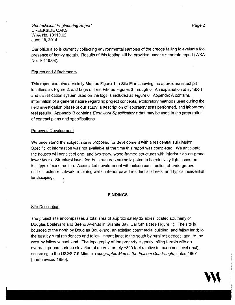
Our office also is currently collecting environmental samples of the dredge tailing to evaluate the
presence of heavy metals. Results of this testing will be provided under a separate report (WKA
No. 10110.03).
Figures and Attachments
This report contains a Vicinity Map as Figure 1; a Site Plan showing the approximate test pit
locations as Figure 2; and Logs of Test Pits as Figures 3 through 5. An explanation of symbols
and classification system used on the logs is included as Figure 6. Appendix A contains
information of a general nature regarding project concepts, exploratory methods used during the
field investigation phase of our study, a description of laboratory tests performed, and laboratory
test results. Appendix B contains Earthwork Specifications that may be used in the preparation
of contract plans and specifications.
Proposed Development
We understand the subject site is proposed for development with a residential subdivision.
Specific lot information was not available at the time this report was completed. We anticipate
the houses will consist of one- and two-story, wood-framed structures with interior slab-on-grade
lower floors. Structural loads for the structures are anticipated to be relatively light based on
this type of construction. Associated development will include construction of underground
utilities, exterior flatwork, retaining walls, interior paved residential streets, and typical residential
landscaping.
FINDINGS
Site Description
The project site encompasses a total area of approximately 32 acres located southerly of
Douglas Boulevard and Seeno Avenue in Granite Bay, California (see Figure 1 ). The site is
bounded to the north by Douglas Boulevard, an existing commercial building, and fallow land; to
the east by rural residences and fallow vacant land; to the south by rural residences; and, to the
west by fallow vacant land. The topography of the property is gently rolling terrain with an
average ground surface elevation of approximately +300 feet relative to mean sea level (msl),
according to the USGS 7.5-Minute Topographic Map of the Folsom Quadrangle, dated 1967
(photorevised 1980).
'''
Geotechnica/ Engineering Report CREEKSIDE OAKS
Page 3
WKA No. 10110.02 June 18, 2014
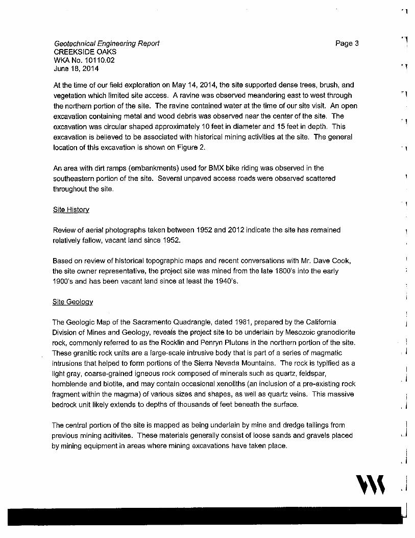
At the time of our field exploration on May 14, 2014, the site supported dense trees, brush, and
vegetation which limited site access. A ravine was observed meandering east to west through
the northern portion of the site. The ravine contained water at the time of our site visit. An open
excavation containing metal and wood debris was observed near the center of the site. The
excavation was circular shaped approximately 1 O feet in diameter and 15 feet in depth. This
excavation is believed to be associated with historical mining activities at the site. The general
location of this excavation is shown on Figure 2.
An area with dirt ramps (embankments) used for BMX bike riding was observed in the
southeastern portion of the site. Several unpaved access roads were observed scattered
throughout the site.
Site History
Review of aerial photographs taken between 1952 and 2012 indicate the site has remained
relatively fallow, vacant land since 1952.
Based on review of historical topographic maps and recent conversations with Mr. Dave Cook,
the site owner representative, the project site was mined from the late 1800's into the early
1900's and has been vacant land since at least the 1940's.
Site Geology
The Geologic Map of the Sacramento Quadrangle, dated 1981, prepared by the California
Division of Mines and Geology, reveals the project site to be underlain by Mesozoic granodiorite
rock, commonly referred to as the Rocklin and Penryn Plutons in the northern portion of the site.
These granitic rock units are a large-scale intrusive body that is part of a series of magmatic
intrusions that helped to form portions of the Sierra Nevada Mountains. The rock is typified as a
light gray, coarse-grained igneous rock composed of minerals such as quartz, feldspar,
hornblende and biotite, and may contain occasional xenoliths (an inclusion of a pre-existing rock
fragment within the magma) of various sizes and shapes, as well as quartz veins. This massive
bedrock unit likely extends to depths of thousands of feet beneath the surface.
The central portion of the site is mapped as being underlain by mine and dredge tailings from
previous mining acitivites. These materials generally consist of loose sands and gravels placed
by mining equipment in areas where mining excavations have taken place.
'''
' 1
' 1 I
1
. l
'j
i ' j
i
'J i I
J
Geotechnica/ Engineering Report CREEKSIDE OAKS WKA No. 10110.02 June 18, 2014
Page4
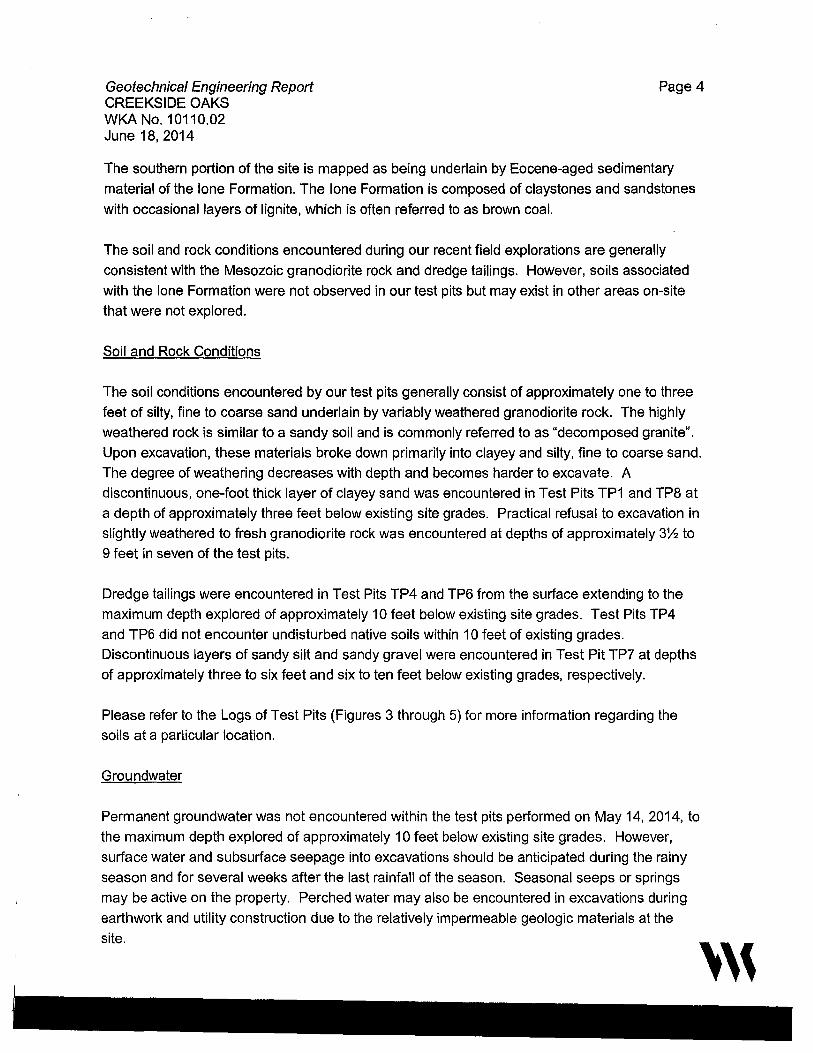
The southern portion of the site is mapped as being underlain by Eocene-aged sedimentary
material of the lone Formation. The lone Formation is composed of claystones and sandstones
with occasional layers of lignite, which is often referred to as brown coal.
The soil and rock conditions encountered during our recent field explorations are generally
consistent with the Mesozoic granodiorite rock and dredge tailings. However, soils associated
with the lone Formation were not observed in our test pits but may exist in other areas on-site
that were not explored.
Soil and Rock Conditions
The soil conditions encountered by our test pits generally consist of approximately one to three
feet of silty, fine to coarse sand underlain by variably weathered granodiorite rock. The highly
weathered rock is similar to a sandy soil and is commonly referred to as "decomposed granite".
Upon excavation, these materials broke down primarily into clayey and silty, fine to coarse sand.
The degree of weathering decreases with depth and becomes harder to excavate. A
discontinuous, one-foot thick layer of clayey sand was encountered in Test Pits TP1 and TP8 at
a depth of approximately three feet below existing site grades. Practical refusal to excavation in
slightly weathered to fresh granodiorite rock was encountered at depths of approximately 3'Y:! to
9 feet in seven of the test pits.
Dredge tailings were encountered in Test Pits TP4 and TP6 from the surface extending to the
maximum depth explored of approximately 10 feet below existing site grades. Test Pits TP4
and TP6 did not encounter undisturbed native soils within 10 feet of existing grades.
Discontinuous layers of sandy silt and sandy gravel were encountered in Test Pit TP7 at depths
of approximately three to six feet and six to ten feet below existing grades, respectively.
Please refer to the Logs of Test Pits (Figures 3 through 5) for more information regarding the
soils at a particular location.
Groundwater
Permanent groundwater was not encountered within the test pits performed on May 14, 2014, to
the maximum depth explored of approximately 10 feet below existing site grades. However,
surface water and subsurface seepage into excavations should be anticipated during the rainy
season and for several weeks after the last rainfall of the season. Seasonal seeps or springs
may be active on the property. Perched water may also be encountered in excavations during
earthwork and utility construction due to the relatively impermeable geologic materials at the
site.
'''
Geotechnica/ Engineering Report CREEKSIDE OAKS
Page 5
WKA No. 10110.02 June 18, 2014
As a result of the impermeable nature of these materials, it is not unusual to observe perched
water above them either at the surface or in shallow excavations. Seepage can also occur
through sloping ground that exposes cemented materials as a consequence of grading and
terracing required for subdivisions constructed on this type of terrain. Although perched water
and seepage can be controlled by appropriate drainage improvements constructed during
landscaping, it is typically not possible to intercept all subsurface water in areas that are
underlain by impermeable geologic materials such as those at the site.
Perched water and seepage are the result of the inability of rain or irrigation water to vertically
migrate through the impermeable geologic materials at the site. Rain and irrigation water
infiltrating the surface through topsoil or permeable engineered fill typically migrates downward
to underlying cemented material and then laterally or down slope on top of the impermeable
cemented material. We emphasize that perched water does not represent the groundwater
table, as the groundwater table is likely 100 feet or more below general surface elevations at the
site.
CONCLUSIONS
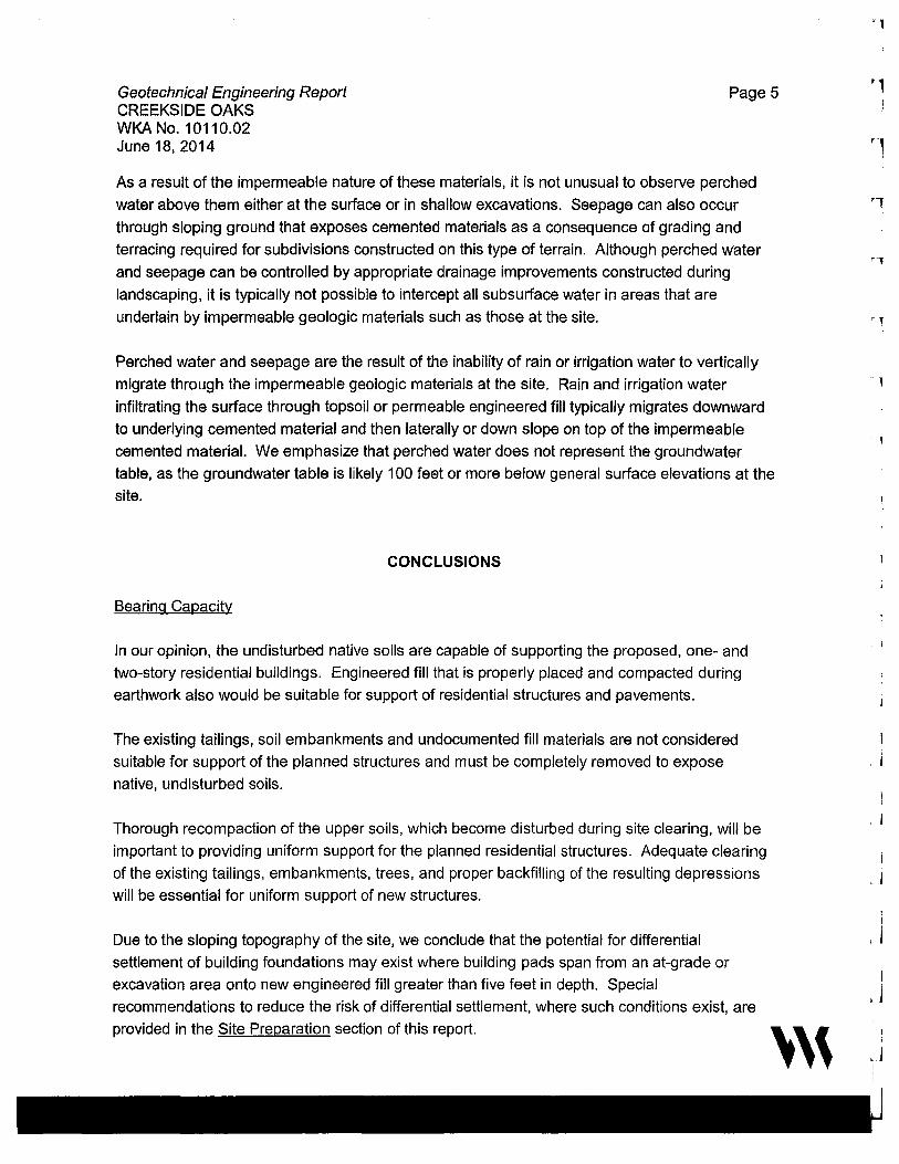
Bearing Capacity
Jn our opinion, the undisturbed native soils are capable of supporting the proposed, one- and
two-story residential buildings. Engineered fill that is properly placed and compacted during
earthwork also would be suitable for support of residential structures and pavements.
The existing tailings, soil embankments and undocumented fill materials are not considered
suitable for support of the planned structures and must be completely removed to expose
native, undisturbed soils.
Thorough recompaction of the upper soils, which become disturbed during site clearing, will be
important to providing uniform support for the planned residential structures. Adequate clearing
of the existing tailings, embankments, trees, and proper backfilling of the resulting depressions
will be essential for uniform support of new structures.
Due to the sloping topography of the site, we conclude that the potential for differential
settlement of building foundations may exist where building pads span from an at-grade or
excavation area onto new engineered fill greater than five feet in depth. Special
recommendations to reduce the risk of differential settlement, where such conditions exist, are
provided in the Site Preparation section of this report.
'''
fl
' l
'l
'l
l L 1
I
'j
' j

Geotechnical Engineering Report CREEKSIDE OAKS WKA No. 10110.02 June 18, 2014
2013 CBC/ASCE 7-10 Seismic Design Criteria
Page 6
Section 1613 of the 2013 edition of the California Building Code (CBC) references ASCE Standard 7-10 for seismic design. The following seismic parameters in Table 1 were determined based on the site latitude and longitude using the public domain computer program developed by the USGS. The following parameters summarized in the table below may be used for seismic design of the proposed residential structures per the 2013 CBC.
Table 1 -2013 CBC/ASCE 7-10 Seismic Design Parameters
Latitude: 38.7424° N ASCE 7-10
Longitude: 121.2120°w Table/Figure
Short-Period MCE at 0.2 Figure 22-1
seconds
1.0 second Period MCE Figure 22-2
Soil Class Table 20.3-1
Site Coefficient Table 11.4-1
Site Coefficient Table 11.4-2
Adjusted MCE Spectral Equation 11.4-1
Response Parameters Equation 11.4-2
Design Spectral Equation 11.4-3
Acceleration Parameters Equation 11.4-4
Table 11.6-1
Seismic Design Category Table 11.6-1
Table 11.6-2
MCE - Maximum Considered Earthquake
g - acceleration due to gravity
2013 CBC Factor/ Table/Figure Coefficient
Figure 1613.3.1(1) Ss
Figure 1613.3.1(2) S1
Section 1613.3.2 Site Class
Table 1613.3.3(1) Fa
Table 1613.3.3(2) Fv
Equation 16-37 SMs
Equation 16-38 SM1
Equation 16-39 Sos
Equation 16-40 S01
Section 1613.3.5(1) Risk Category
I to Ill
Section 1613.3.5(1) Risk Category
IV
Section 1613.3.5(2) Risk Category
I to IV
Value
0.484 g
0.245 g
D
1.413
1.911
0.683 g
0.467 g
0.456 g
0.312 g
C
D
D
Based upon the results of our subsurface exploration, the known site geologic, seismologic,
groundwater and soil conditions, it is our opinion that the potential for liquefaction occurring at
this site is very low.
Excavation Conditions
We anticipate that the majority of the soils and severely to moderately weathered rock should be
excavatable with conventional excavation equipment. However, the weathered granitic rock at ' ''
Geotechnical Engineering Report CREEKSIDE OAKS WKA No. 10110.02 June 18, 2014
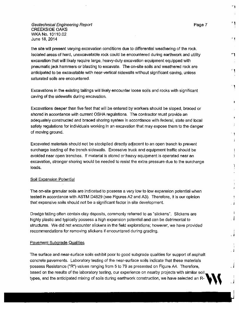
Page 7
the site will present varying excavation conditions due to differential weathering of the rock.
Isolated areas of hard, unexcavatable rock could be encountered during earthwork and utility
excavation that will likely require large, heavy-duty excavation equipment equipped with
pneumatic jack hammers or blasting to excavate. The on-site soils and weathered rock are
anticipated to be excavatable with near-vertical sidewalls without significant caving, unless
saturated soils are encountered.
Excavations in the existing tailings will likely encounter loose soils and rocks with significant
caving of the sidewalls during excavation.
Excavations deeper than five feet that will be entered by workers should be sloped, braced or
shored in accordance with current OSHA regulations. The contractor must provide an
adequately constructed and braced shoring system in accordance with federal, state and local
safety regulations for individuals working in an excavation that may expose them to the danger
of moving ground.
Excavated materials should not be stockpiled directly adjacent to an open trench to prevent
surcharge loading of the trench sidewalls. Excessive truck and equipment traffic should be
avoided near open trenches. If material is stored or heavy equipment is operated near an
excavation, stronger shoring would be needed to resist the extra pressure due to the surcharge
loads.
Soil Expansion Potential
The on-site granular soils are indicated to possess a very low to low expansion potential when tested in accordance with ASTM D4829 (see Figures A2 and A3). Therefore, it is our opinion that expansive soils should not be a significant factor in site development.
Dredge tailing often contain clay deposits, commonly referred to as "slickens". Slickens are highly plastic and typically possess a high expansion potential and can be detrimental to structures. We did not encounter slickens in the field explorations; however, we have provided recommendations for removing slickens if encountered during grading.
Pavement Subgrade Qualities
The surface and near-surface soils exhibit poor to good subgrade qualities for support of asphalt
concrete pavements. Laboratory testing of the near-surface soils indicate that these materials
possess Resistance ("R") values ranging from 5 to 79 as presented on Figure A4. Therefore,
based on the results of the laboratory testing, our experience on nearby projects with similar soil~,
types, and the anticipated mixing of soils during earthwork construction, we have selected an R- l , '
'l
l ' j
Geotechnical Engineering Report CREEKSIDE OAKS
Page 8
WKA No. 10110.02 June 18, 2014
value of 30 for our pavement design with the understanding that clays exposed at pavement
subgrades should be removed and replaced with granular on-site soils.
On-Site Material Suitability for Engineered Fill Construction
The soil and weathered rock at the site, including the tailings and soil stockpiles, are considered
suitable for use as fill materials if free from rubble, rubbish or organic concentrations. The in
place weathered rock will tend to excavate into sands upon removal from trenches.
Unweathered rock, if encountered, may be difficult to break down to a size suitable for use as
engineered fill. Pneumatic jackhammers mounted to large excavators may be able to break
down large pieces of rock.
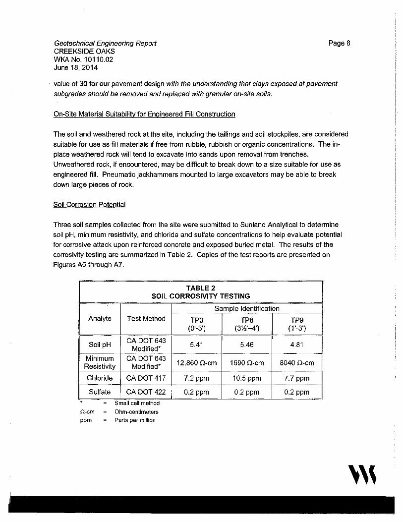
Soil Corrosion Potential
Three soil samples collected from the site were submitted to Sunland Analytical to determine
soil pH, minimum resistivity, and chloride and sulfate concentrations to help evaluate potential
for corrosive attack upon reinforced concrete and exposed buried metal. The results of the
corrosivity testing are summarized in Table 2. Copies of the test reports are presented on
Figures A5 through A7.
TABLE 2 SOIL CORROSIVITY TESTING
Analyte Test Method
Soil pH CA DOT643 Modified*
Minimum CA DOT643 Resistivity Modified*
Chloride CA DOT 417
Sulfate CA DOT 422
* Q-cm
ppm
= Small cell method
= Ohm-centimeters
= Parts per million
Sample Identification
TP3 TP8 (0'-3') (3%'-4')
5.41 5.46
12,860 n-cm 1690 n-cm
7.2 ppm 10.5 ppm
0.2 ppm 0.2 ppm
TP9 (1'-3')
4.81
8040 n-cm
7.7 ppm
0.2 ppm
''\
Geotechnical Engineering Report CREEKSIDE OAKS
Page 9
WKA No. 10110.02 June 18, 2014
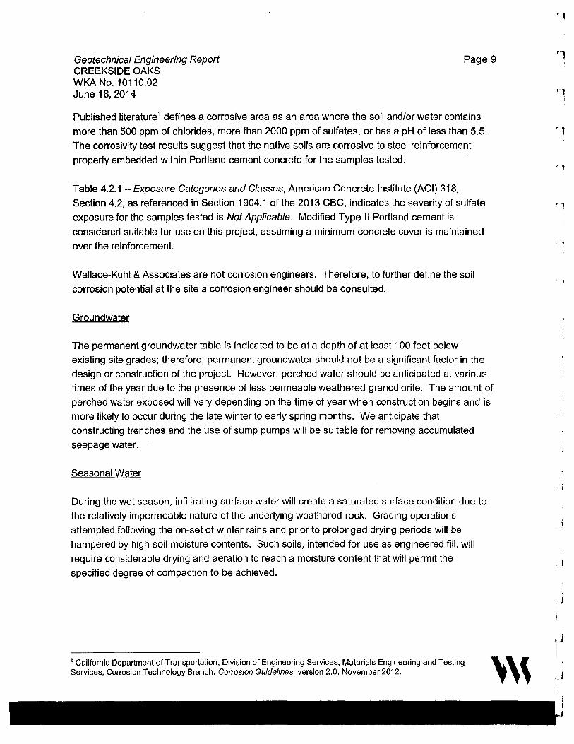
Published literature 1 defines a corrosive area as an area where the soil and/or water contains
more than 500 ppm of chlorides, more than 2000 ppm of sulfates, or has a pH of less than 5.5.
The corrosivity test results suggest that the native soils are corrosive to steel reinforcement
properly embedded within Portland cement concrete for the samples tested.
Table 4.2.1 -Exposure Categories and Classes, American Concrete Institute (ACI) 318,
Section 4.2, as referenced in Section 1904.1 of the 2013 CBC, indicates the severity of sulfate
exposure for the samples tested is Not Applicable. Modified Type II Portland cement is
considered suitable for use on this project, assuming a minimum concrete cover is maintained
over the reinforcement.
Wallace-Kuhl & Associates are not corrosion engineers. Therefore, to further define the soil
corrosion potential at the site a corrosion engineer should be consulted.
Groundwater
The permanent groundwater table is indicated to be at a depth of at least 100 feet below
existing site grades; therefore, permanent groundwater should not be a significant factor in the
design or construction of the project. However, perched water should be anticipated at various
times of the year due to the presence of less permeable weathered granodiorite. The amount of
perched water exposed will vary depending on the time of year when construction begins and is
more likely to occur during the late winter to early spring months. We anticipate that
constructing trenches and the use of sump pumps will be suitable for removing accumulated
seepage water.
Seasonal Water
During the wet season, infiltrating surface water will create a saturated surface condition due to
the relatively impermeable nature of the underlying weathered rock. Grading operations
attempted following the on-set of winter rains and prior to prolonged drying periods will be
hampered by high soil moisture contents. Such soils, intended for use as engineered fill, will
require considerable drying and aeration to reach a moisture content that will permit the
specified degree of compaction to be achieved.
1 California Department of Transportation, Division of Engineering Services, Materials Engineering and Testing Services, Corrosion Technology Branch, Corrosion Guidelines, version 2.0, November 2012. '''
"l
'l
r l
- I
. j
. l
'l
' l
Geotechnica/ Engineering Report CREEKSIDE OAKS
Page 10
WKA No. 10110.02 June 18, 2014
RECOMMENDATIONS
General
We anticipate maximum excavations and fills on the order of two to four feet for development of
the planned residential subdivision. The recommendations contained in this report are based
upon this assumption.
Additionally, the recommendations presented below are appropriate for typical construction in
the late spring through fall months. The on-site soils likely will be saturated by rainfall in the
winter and early spring months, and will not be compactable without drying by aeration or the
addition of lime (or a similar product). Should the construction schedule require work to
continue during the wet months, additional recommendations can be provided, as conditions
dictate.
Grading plans were not available at the time this report was completed. Our office should
review the grading plans as they are developed to confirm that our recommendations remain
applicable, and provide us the opportunity to submute revised recommendations, if needed.
Site Clearing and Preparation
Initially, the site should be cleared of all surface and subsurface structures including berms,
embankments, fencing, or any other deleterious items. Trees and bushes designated to be
removed should include the entire rootball and roots larger than %-inch in diameter. Adequate
removal of debris and tree roots may require laborers and handpicking to clear the subgrade
soils to the satisfaction of our on-site representative. All depressions resulting from the removal
of such items, as well as all loose, disturbed or saturated soils in areas of clearing operations or
tree removal, as identified by our representative in the field, should be cleaned out to firm,
undisturbed soil, as determined by our representative, and restored to grade with engineered fill
compacted in accordance with the recommendations of this report.
Surface vegetation within construction areas should be removed by stripping. Strippings should
not be used in general fill construction in pavement areas or building pads, but may be used in
landscape areas, provided they are kept at least five feet from building pads, moisture
conditioned and compacted. Discing of organics into surface soils may be a suitable alternate
to stripping, depending on the condition and quantity of organics at the time of grading. The
decision to utilize discing in lieu of stripping should be approved by our representative at the
time of earthwork construction. Discing operations, if approved, should be observed by our
representative and must be continuous until the organics are adequately mixed into the soil to
'''

Geotechnical Engineering Report CREEKSIDE OAKS
Page 11
WKA No. 10110.02 June 18, 2014
provide a compactable mixture of soil containing minor amounts of organic matter. Pockets or
significant concentrations of organics will not be allowed.
The existing ravine, low lying areas and drainages should be drained of water and cleaned of
organics, saturated and unstable soils to expose firm, native materials, as determined by our
representative. The exposed surface should be scarified to a depth of at least 12 inches,
moisture conditioned to at least the optimum moisture content and compacted to at least 90
percent of the AS.TM D1557 maximum dry density. It is likely that the excavated soils from the
these areas will be saturated, and will require aeration and a period of drying to allow proper
compaction. Our representative will provide alternative recommendations for stabilizing the
bottom of the excavations, as conditions warrant. Recompaction operations should be
performed in the presence of our representative who will evaluate the performance of the
materials under compactive load. Unstable soil deposits, as determined by our representative,
should be excavated to expose a firm base, and grade restored with engineered fill in
accordance with these recommendations.
Existing tailings located within structural areas should be completely removed to expose firm,
undisturbed native ground, as determined by our representative. Specific recommendations for
lots that contain tailings can be provided once the structural areas have been identified and
grading plans are finalized.
The existing excavations should be excavated, drained of water, and cleaned of debris and
organics. Saturated and unstable soils exposed within the mined areas should be removed to
expose firm, native materials, as determined by our representative. The exposed surface
should be scarified to a depth of 12 inches and compacted to at least 90 percent of the ASTM
D1557 maximum dry density. These soils will likely be saturated and will require aeration and a
period of drying to allow proper compaction. Organically contaminated soils will not be allowed
for use in engineered fill construction. Our representative will provide alternative
recommendations for stabilizing the bottom of the excavations, as conditions warrant.
Areas of removed trees, bushes and structures should be thoroughly ripped and cross-ripped to
expose any remaining structures, debris, or roots, to a depth of at least 12 inches, brought to a
uniform moisture content at least the optimum moisture, and compacted to at least 90 percent of
the maximum dry density per ASTM D1557 specifications. Compaction should be performed
using a Caterpillar 825 (or equivalent-sized sheepsfoot compactor).
Areas to receive fill, remain at-grade, or achieved by excavation, should be scarified to a depth
of 12 inches, brought to at least the optimum moisture content and compacted to at least 90
percent of the maximum dry density per ASTM D1557 specifications. Loose, soft or saturated
'''
'l
' i
j .__j
,J
Geotechnica/ Engineering Report CREEKSIDE OAKS WKA No. 10110.02 June 18, 2014
soils, as identified by our representative during the recompaction operations, should be
removed and replaced with engineered fill.
Page 12
In areas where rocky materials are exposed or encountered, compaction testing of rocky
materials with a nuclear density gauge will not be practical due to the large particle size;
therefore, we recommend a performance specification be followed for the compaction of rocky
materials instead of a minimum percent relative compaction. Rocky materials should be
thoroughly moisture conditioned and uniformly compacted by at least three complete coverages
with a heavy, self-propelled sheepsfoot compactor (Caterpillar 825 compactor or an equivalent),
to the satisfaction of our on-site representative. One complete coverage is defined as the
process necessary to assure that every square foot of subgrade has been traversed and
compacted by the compaction equipment.
Lots achieved by excavation should be observed by our representative to determine whether
soils associated with the lone Formation are present. Recommendations to mitigate the effects
of the lone soils, if encountered, can be provided during construction.
The emergence of unstable soil conditions during site grading operations could indicate the
presence of subsurface structures, rubble, debris or other unsuitable materials. Areas exhibiting
instability, as determined by our field representative, should be excavated to expose dense,
stable soils. It will be crucial that our representative be involved during site grading operations
to observe the equipment in operation.
Engineered Fill Construction
Engineered fill should be placed in horizontal lifts not exceeding six inches in compacted
thickness. Each layer should be uniformly moisture conditioned to at least the optimum
moisture content and compacted to at least 90 percent of the ASTM D1557 maximum dry
density. Compactive effort should be applied uniformly across the full width of the fill.
On-site soils are considered suitable for use in engineered fill construction, if free of rubble,
rubbish, or concentrations of organics. Imported fill materials, if required, should be
compactable, granular soils with a Plasticity Index of 15 or less; an Expansion Index of 20 or
less; be free of particles greater than six inches in maximum dimension; and, have a Resistance
("R") value greater than 30. Imported soils should be approved by our office prior to being
transported to the site. Also, if import fills are required ( other than aggregate base) the
contractor must provide appropriate documentation that the import is free of known
contamination.
'''

Geotechnical Engineering Report CREEKSIDE OAKS
Page 13
WKA No. 10110.02 June 18, 2014
Subgrades for support of the buildings should be protected from disturbance or desiccation until
covered by capillary break material or aggregate base. Disturbed subgrade soils may require
moisture conditioning, scarification and recompaction, depending on the level of disturbance.
The upper twelve inches of final pavement subgrades should be uniformly moisture conditioned
to at least the optimum moisture content and uniformly compacted to at least 95 percent of the
maximum dry density or by at least five complete coverages of a Caterpillar 825 (or equivalent).
Final subgrade preparation should be performed regardless of whether final subgrade
elevations are attained by filling, excavation, or are left at existing grades and should be
performed after all underground utilities have been installed and backfilled. Final pavement
subgrade processing and compaction should be performed just prior to aggregate base
placement and must be stable under construction traffic.
Permanent excavation and fill slopes should be constructed no steeper than two horizontal to
one vertical (2: 1) and should be vegetated as soon as practical following grading to minimize
erosion. As a minimum, erosion control measures should include placement of straw bale
sediment barriers or construction of silt filter fences in areas where surface run-off may be
concentrated. Slopes should be over-built and cutback to design grades and inclinations.
Site preparation should be accomplished in accordance with the recommendations of this
section and the appended Earthwork Specifications. Our representative should be regularly
present throughout grading operations to determine compliance with the job specifications.
Residential Utility Trench Backfill
We recommend only native soils (in lieu of select gravel or sand backfill) be used as backfill for
utility trenches located within the building footprints and extending at least five feet beyond the perimeter foundations to minimize water transmission beneath the structures. Bedding of
utilities and initial backfill should be in accordance with the manufacturer's recommendations for
the pipe materials selected and the Placer County Standards, latest edition. Utility trench
backfill should be uniformly moisture conditioned to at least the optimum moisture content and mechanically compacted in lifts to at least 90 percent of the ASTM D1557 maximum dry density.
We also recommend that underground utility trenches, which are aligned nearly parallel with foundations, be at least three feet from the outer edge of foundations. Trenches should not
encroach into the zone extending outward at a 1 :1 inclination below the bottom of the foundations. Additionally, trenches near foundations should not remain open longer than 72
hours to prevent drying and formation of desiccation and shrinkage cracks. The intent of these recommendations is to prevent loss of both lateral and vertical support of foundations, resulting
in possible settlement.
'''
'l
j
'j
i .J
I
Geotechnical Engineering Report CREEKSIDE OAKS WKA No. 10110.02 June 18, 2014
Page 14
Trench backfill materials and compaction within street right-of-ways should conform to the
applicable portions of the current Placer County Standards, latest edition.
Foundations
The proposed one- and two-story residential structures may be supported upon a continuous
perimeter foundation with continuous and/or isolated interior spread foundations that extend at
least 12 inches into the compacted building pad, as measured from lowest adjacent soil grade.
For this project, the building pad subgrade is defined as the soil surface on which capillary break
gravel is placed. A continuous, reinforced foundation should be utilized for the perimeter of the
structures to act as a "cut-off' to help minimize moisture infiltration and variations beneath the
interior slab-on-grade areas of the structures. Continuous foundations should be at least 12
inches wide; isolated spread foundations should maintain a minimum 18-inch dimension.
Foundations bearing in undisturbed or recompacted native soils, engineered fill, or a
combination of those materials may be sized for maximum allowable "net" soil bearing
pressures of 3000 pounds per square foot (psf) for dead plus live load, and 4000 psf to include
wind or seismic forces. The weight of the foundation concrete extending below lowest adjacent
soil grade may be disregarded in sizing computations.
We recommend that all foundations be adequately reinforced to provide structural continuity,
mitigate cracking, and permit spanning of local soil irregularities. As a minimum, we
recommend that continuous foundations be reinforced with at least two No. 4 steel reinforcing
bars, placed one each near the top and bottom of the foundations. The structural engineer
should determine final foundation reinforcing requirements.
Resistance to lateral displacement of shallow foundations may be computed using an allowable
friction factor of 0.35 multiplied by the effective vertical load on each foundation. Additional
lateral resistance may be achieved using an allowable passive earth pressure against the
vertical projection of the foundation equal to an equivalent fluid pressure of 350 psf per foot of
depth. These two modes of resistance should not be added unless the frictional component is
reduced by 50 percent since mobilization of the passive resistance requires some horizontal
movement, effectively reducing the frictional resistance.
Interior Floor Slab Support
Interior concrete slab-on-grade floors can be supported upon the granular soil subgrade
prepared in accordance with the recommendations in this report and maintained in that
condition (at least the optimum moisture content). Interior concrete slab-on-grade floors should'''
Geotechnical Engineering Report CREEKSIDE OAKS WKA No. 10110.02 June 18, 2014
Page 15
be at least four inches thick and, as a minimum for crack control, contain chaired No. 3
reinforcing bars placed no wider than 24-inch center-to-center each way throughout the slab,
and located at mid-slab depth. This slab reinforcement is suggested as a guide "minimum"
only; final reinforcement and joint spacing should be determined by the structural engineer.
Proper and consistent location of the reinforcement near mid-slab is essential to its
performance. The risk of uncontrolled shrinkage cracking is increased if the reinforcement is
not properly located within the slab.
Floor slabs may be underlain by a layer of free-draining crushed rock, serving as a deterrent to
migration of capillary moisture. The crushed rock layer should be at least four inches thick and
graded such that 100 percent passes a one-inch sieve and less than five percent passes a No.
4 sieve. Additional moisture protection may be provided by placing a vapor retarder membrane
(at least 10-mils thick) directly over the crushed rock. The membrane should meet or exceed
the minimum specifications as outlined in ASTM E1745 and be installed in strict conformance
with the manufacturer's recommendations.
Floor slab construction over the past 25 years or more has included placement of a thin layer of
sand over the vapor retarder membrane. The intent of the sand is to aid in the proper curing of
the slab concrete. However, recent debate over excessive moisture vapor emissions from floor
slabs includes concern for water trapped within the sand. As a consequence, we consider the
use of the sand layer as optional. The concrete curing benefits should be weighed against
efforts to reduce slab moisture vapor transmission.
The recommendations presented above are intended to mitigate significant soils-related
cracking of the slab-on-grade floors. More important to the performance and appearance of a
Portland cement concrete slab is the quality of the concrete, the workmanship of the concrete
contractor, the curing techniques utilized, and the spacing of control joints.
Floor Slab Moisture Penetration Resistance
It is considered likely that interior floor slab subgrade soils will become wet to near-saturated at
some time during the life of the structures. This is a certainty when slabs are constructed during
the wet season or when constantly wet ground or poor drainage conditions exist adjacent to
structures. For this reason, it should be assumed that all slabs in occupied areas, as well as
those intended for moisture-sensitive floor coverings or materials, require protection against
moisture or moisture vapor penetration. Standard practice includes the crushed rock and water
vapor retarder as suggested above. However, the gravel and membrane offer only a limited,
first-line of defense against soil-related moisture. Recommendations contained in this report
concerning foundation and floor slab design are presented as minimum requirements, only from "", ( the geotechnical engineering standpoint. l , ,
1
'l
·1
' ! j
• J
.J
Geotechnica/ Engineering Report CREEKSIDE OAKS
Page 16
WKA No. 10110.02 June 18, 2014
It is emphasized that the use of sub-slab crushed rock and vapor retarder membrane will not
"moisture proof' the slab, nor does it assure that slab moisture transmission levels will be low
enough to prevent damage to floor coverings or other building components. If increased
protection against moisture vapor penetration of slabs is desired, a concrete moisture protection
specialist should be consulted. The design team should consider all available measures for
slab moisture protection. It is commonly accepted that maintaining the lowest practical water
cement ratio in the slab concrete is one of the most effective ways to reduce future moisture
vapor penetration of the completed slabs.
Retaining Wall Design
Retaining walls capable of slight rotation about their base (unrestrained at the top or sides)
should be capable of resisting "active" lateral earth pressure equal to an equivalent fluid
pressure of 40 psf per foot of wall backfill for horizontal backfill conditions. If the walls are fixed
at the top, they should be designed to resist "at-rest" lateral earth pressure equal to an
equivalent fluid pressure of 60 psf per foot for horizontal backfill conditions. For retaining walls
with backfill sloped at a maximum gradient of two horizontal to one vertical (2: 1 ), 20 psf per foot
of depth should be added to the values for horizontal backfill. Retaining wall foundations should
extend at least 12 inches below soil grade and may be designed in accordance with the
appropriate recommendations contained in the Foundations section of this report.
Backfill behind retaining walls should be fully drained to prevent the build-up of hydrostatic
pressure behind the wall. Retaining walls should be provided with a drainage blanket (Class 2
permeable material, Caltrans Specification Section 68-2.02F(3)) at least one-foot wide
extending from the base of wall to within one foot of the top of the wall. The top foot above the
drainage layer should consist of compacted on-site materials, unless covered by concrete
flatwork or pavements. Weep holes or perforated rigid pipe should be provided near the base of
the wall to allow drainage of accumulated water. Drainpipes, if used, should slope to discharge
at no less than a one percent fall to suitable drainage facilities. Open-graded Yz-inch to %-inch
crushed rock may be used in lieu of the Class 2 permeable material, if the rock and drain pipe
are completely enveloped in an approved nonwoven geotextile filter fabric.
Structural backfill materials for retaining walls (other than the drainage layer) should consist of
on-site or imported soils free of significant quantities of rubbish, rubble, organics and rock over
six inches in size; clays should not be used as wall backfill. Structural backfill should be placed
in thin lifts, and should be mechanically compacted to at least 90 percent relative compaction.
Lift thickness will be dependent on the type of compaction equipment utilized by the contractor.
The lateral pressures recommended above assume that clay soils, if exposed during site
excavations, will not be used as backfill behind retaining walls.
''\
Geotechnical Engineering Report CREEKSIDE OAKS
Page 17
WKA No. 10110.02 June 18, 2014
Sound Wall Foundation Systems
Shallow Foundations
The proposed sound walls may be supported upon a shallow spread and/or continuous
foundation embedded at least 18 inches below the lowest adjacent soil grade into firm
undisturbed native soil or properly placed and compacted engineered fill, as confirmed by our
representative. Continuous foundations should maintain a minimum width of 12 inches and
isolated spread foundations should be at least 18 inches in plan dimension. Foundations so
established may be sized for maximum allowable "net" soil bearing pressure of 3000 psf for
dead plus live loads, with a one-third increase for total loads including the short-term effects of
wind or seismic forces. The weight of the foundation concrete extending below lowest adjacent
soil grade may be disregarded in sizing computations. The project structural engineer should
determine the final dimensions and structural reinforcement of the sound wall foundations.
Resistance to lateral foundation displacement for sound wall foundations may be computed
using an allowable friction factor of 0.35, which may be multiplied by the effective vertical load
on the foundation. Additional lateral resistance may be computed using an allowable passive
earth pressure of 350 psf per foot of depth. These two modes of resistance should not be
added unless the frictional value is reduced by 50 percent since full mobilization of these
resistances typically occurs at different degrees of horizontal movement. Where foundations
are located within five feet of slopes steeper than three horizontal to one vertical (3:1 ), six
inches of embedment should be disregarded.
Cast-in-Place Concrete Drilled Piers
Sound walls could also be supported on cast-in-place concrete drilled piers. The piers should
extend at least three feet below the lowest adjacent soil grade and have a minimum shaft
diameter of 18 inches to help facilitate proper cleaning of the bottom of the pier. Drilled piers
founded within undisturbed native soils may be sized utilizing a maximum allowable vertical
bearing capacity of 4000 psf and an allowable skin friction of 250 psf for dead plus live loads,
which may be applied over the surface of the pier deeper than 12 inches below the lowest
adjacent soil grade. Those values may be increased by one-third to include short-term wind or
seismic forces. The weight of foundation concrete below grade may be disregarded in sizing
computations.
'''
'1
'l
. j
1
i
j
. J
I
.)
Geotechnical Engineering Report CREEKSIDE OAKS WKA No. 10110.02 June 18, 2014
Page 18
Uplift resistance of pier foundations may be computed using the following resisting forces,
where applicable: 1) weight of the pier concrete (150 pounds per cubic foot) and, 2) the
allowable skin friction of 250 psf applied over the shaft area of the pier. Increased uplift
resistance can be achieved by increasing the diameter of the pier or increasing the depth.·
The upper 12 inches of skin friction should be neglected unless the pier is completely
surrounded by slab concrete or pavements for a distance of at least three feet from the edge of
the foundation pier.
Sizing of piers to resist lateral loads can be evaluated using Section 1807.3.2 of the 2013 CBC.
A value of 350 pcf as defined in Table 1806.2 of the CBC may be used for the lateral bearing
pressure of the on-site soils. Per Section 1806.1 of the 2013 CBC, an increase of 1/3 is
permitted when using the alternate load combinations in Section 1605.3.2 that include wind or
earthquake loads.
The bottom of the pier excavations should be free of loose or disturbed soils prior to placement
of the concrete. Cleaning of the bearing surface should be verified by the geotechnical engineer
prior to concrete placement. Reinforcement and concrete should be placed in the pier
excavations as soon as possible after excavation is completed to minimize the chances of
sidewall caving into the excavations.
Exterior Flatwork
Soil subgrades supporting exterior concrete flatwork (i.e., driveways, sidewalks, patios, etc.)
should be brought to an over optimum moisture condition and uniformly compacted prior to the
placement of the concrete. Proper moisture conditioning of the subgrade soils is considered
essential to the performance of exterior flatwork. Expansion joints should be provided to allow
for minor vertical movement of the flatwork. Exterior flatwork should be constructed
independent of the perimeter building foundation and isolated column foundations by the
placement of a layer of felt material between the flatwork and the foundation. Irrigated
landscaping adjacent to concrete flatwork will help maintain a more uniform moisture in the soils
and reduce the potential for differential movement. Consideration also should be given to
reinforcing the slabs with rebar for crack control.
Site Drainage
Site drainage should be accomplished to provide positive drainage of surface water away from
the buildings and prevent ponding of water adjacent to foundations. The grades adjacent to the
structures should be sloped away from foundations at a minimum two percent for a distance of ' ''
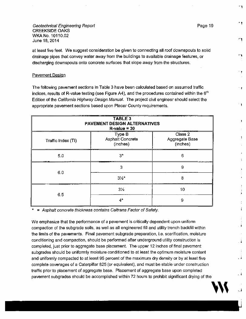
Geotechnical Engineering Report CREEKSIDE OAKS
Page 19
WKA No. 10110.02 June 18, 2014
at least five feet. We suggest consideration be given to connecting all roof downspouts to solid
drainage pipes that convey water away from the buildings to available drainage features, or
discharging downspouts onto concrete surfaces that slope away from the structures.
Pavement Design
The following pavement sections in Table 3 have been calculated based on assumed traffic
indices, results of R-value testing (see Figure A4), and the procedures contained within the 5th
Edition of the California Highway Design Manual. The project civil engineer should select the
appropriate pavement sections based upon Placer County requirements.
TABLE 3 PAVEMENT DESIGN ALTERNATIVES
R-value = 30 Type B Class 2
Traffic Index (Tl) Asphalt Concrete Aggregate Base (inches) (inches)
5.0 3* 6
3 9 6.0
3~* 8
3~ 10 6.5
4* 9
* = Asphalt concrete thickness contains Ca/trans Factor of Safety.
We emphasize that the performance of a pavement is critically dependent upon uniform
compaction of the subgrade soils, as well as all engineered fill and utility trench backfill within
the limits of the pavements. Final pavement subgrade preparation, i.e. scarification, moisture
conditioning and compaction, should be performed after underground utility construction is
completed, just prior to aggregate base placement. The upper 12 inches of final pavement
subgrades should be uniformly moisture conditioned to at least the optimum moisture content
and uniformly compacted to at least 95 percent of the maximum dry density or by at least five
complete coverages of a Caterpillar 825 (or equivalent), and must be stable under construction
traffic prior to placement of aggregate base. Placement of aggregate base upon completed
pavement subgrades should be accomplished within 72 hours to prohibit significant drying of the
'''
C '
. '
' i
• j

Geotechnical Engineering Report CREEKSIDE OAKS
Page 20
WKA No. 10110.02 June 18, 2014
subgrade soils. Class 2 aggregate base should be compacted to at least 95 percent of the
ASTM D1557 maximum dry density.
Materials, quality and construction of the structural section of the pavement should conform to
the applicable provisions of the Caltrans Standard Specifications and applicable Placer County
Standards, latest editions.
Geotechnical Engineering Observation and Testing During Earthwork
Site preparation should be accomplished in accordance with the recommendations of this report
and the Earthwork Specifications provided in Appendix B. Representatives of Wallace-Kuhl &
Associates should be present during site preparation and all grading operations to observe and
test the fill to verify compliance with our recommendations and the job specifications. These
services are beyond the scope of work authorized for this investigation.
Many factors can effect the number of tests that should be performed during the course of
construction, such as soil type, soil moisture, season of the year and contractor
operations/performance. Therefore, it is crucial that the actual number and frequency of testing
be determined by the Geotechnical Engineer during construction based on their observations,
site conditions, and difficulties encountered. As a preliminary guideline we recommend the
following minimum tests:
• mass grading: one test per 500 cubic yards of compacted fill or one per day of
work, whichever is greater
• final subgrade preparation: one test per 10,000 square feet
• aggregate base compaction: one test per 10,000 square feet
• utility backfill: one test per foot of backfill for every 200 linear feet of trench
• wall backfill: one test per foot of backfill for ever 100 linear feet of wall
In the event that Wallace-Kuhl & Associates is not retained to provide geotechnical engineering
observation and testing services during construction, the Geotechnical Engineer retained to
provide these services should indicate in writing that they agree with the recommendations of
this report, or prepare supplemental recommendations as necessary. A final report by the
Geotechnical Engineer should be prepared upon completion of the project.
'''
Geotechnical Engineering Report CREEKSIDE OAKS WKA No. 10110.02 June 18, 2014
Page 21
LIMITATIONS
Our recommendations are based upon the information provided regarding the proposed
construction, combined with our analysis of site conditions revealed by the field exploration and
laboratory testing programs. We have used prudent engineering judgment based upon the
information provided and the data generated from our investigation. This report has been
prepared in substantial compliance with generally accepted geotechnical engineering practices
that exist in the area of the project at the time the report was prepared. No warranty, either
express or implied, is provided.
If the proposed construction is modified or relocated or, if it is found during construction that
subsurface conditions differ from those we encountered at the test pit locations, we should be
afforded the opportunity to review the new information or changed conditions to determine if our
conclusions and recommendations must be modified.
We emphasize that this report is applicable only to the proposed construction and the
investigated site. This report should not be utilized for construction on any other site. This
report is considered valid for the proposed construction for a period of two years following the
date it was issued. If construction has not started within two years, we must reevaluate the
recommendations of this report and update the report, if necessary.
Wallace-Kuhl & Associates
Dominic J. Potestio Project Engineer
'''
r '
r ,
'1
' l
,, i
' j
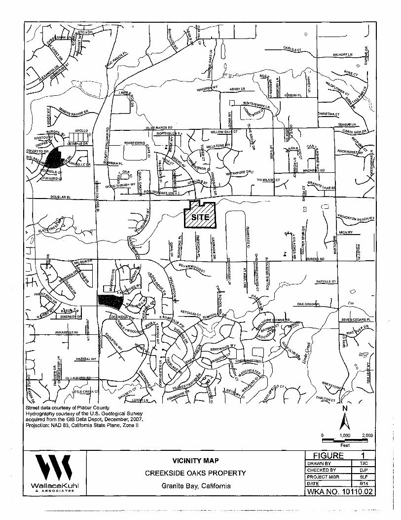
DOUGLAS BL
i
TTLECREtK C
Street data courtesy of Placer County. Hydrography courtesy of the U.S. Geological Survey acquired from the GIS Data Depot, December, 2007. Projection: NAO 83, California State Plane, Zone II
''' WallaceKuhl & ASSOCIATES
i 0
I g "' 0 :c "' 0 F z m .. 0 ... ;o
0
~ 3 0
" ;: Cl) w m > ... z ~
1 "'
VICINITY MAP
CREEKSIDE OAKS PROPERTY
Granite Bay, California
0 I m
"' :,: ;;; m 1/n ~ ;!\ Ill 0 ...
,. 0 z "' 0
" m .t" "'
~ ~ "' z ttl " Cl Cl
3 0
"
WILHOFFLN
cAN (11
~ :,:
~ ~
MACAR ORD
RD
BAYVILLE CT
0
0
N
A 1,000
Feet
FIGURE DRAWN BY
CHECKED BY
PROJECT MGR
DATE
j
" iii In -< ;!l
2,000
1 TJC
DJP
SLF 6/14
WKA NO. 10110.02
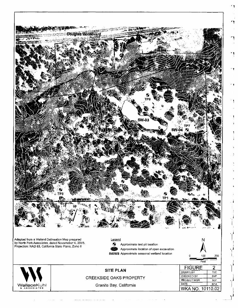
Adapted from a Weiand Delineation Map prepared by North Fork Associates, dated Novemeber 4, 2005. Projection: NAO 83, California State Plane, Zone II
''' WallaceKuhl S. ASSOCIATES
Legend
$ Approximate test pit location
• Approximate location of open excavation
SW/WS Approximate seasonal wetland location
SITE PLAN
CREEKSIDE OAKS PROPERTY
Granite Bay, California
N
A 0 100 200
Feet
FIGURE 2 DRAWN BY TJC
CHECKED BY DJP
PROJECT MGR SLF
DATE 6/14
WKA NO. 10110.02
r 1
'l
.Ii I
) I !
J I I
i !
,) I
····---~
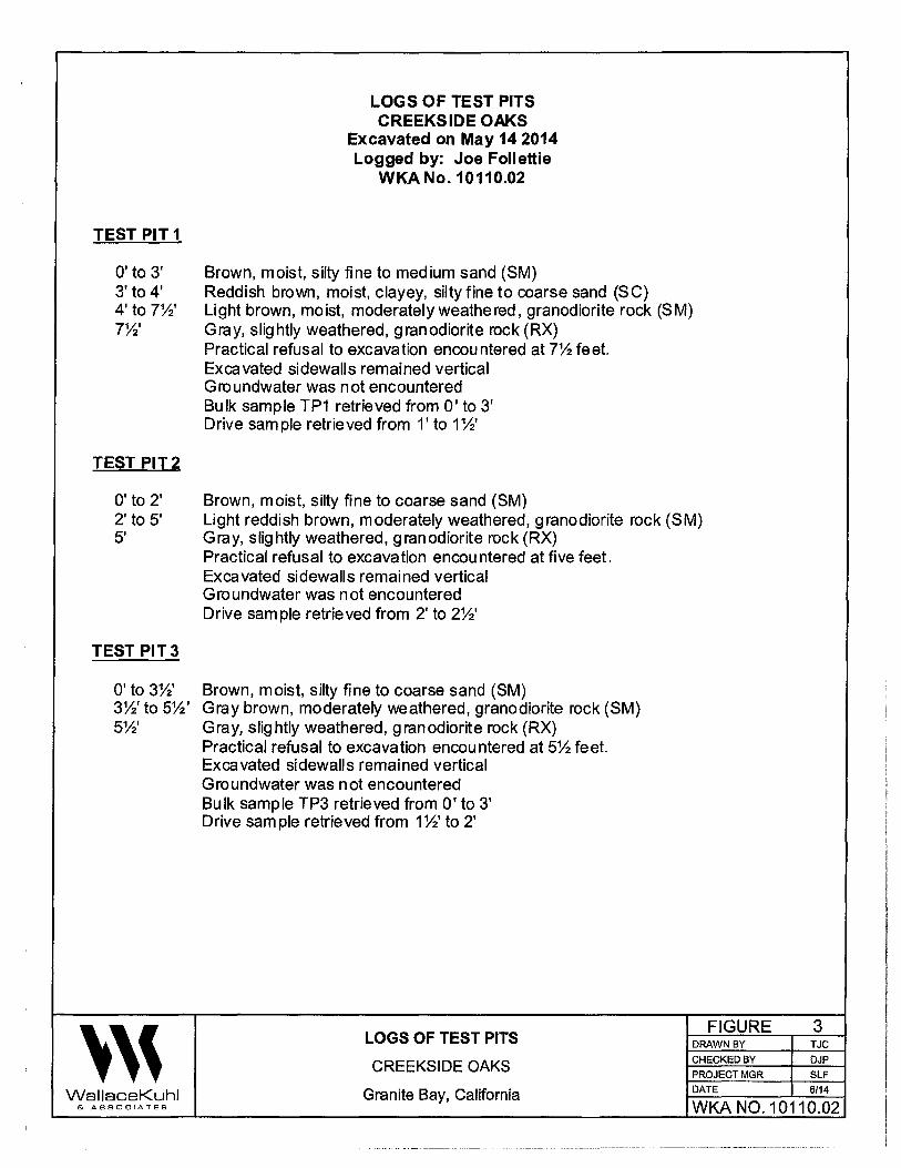
LOGS OF TEST PITS CREEKSIDE OAKS
Excavated on May 14 2014 Logged by: Joe Follettie
WKA No. 10110.02
TEST PIT1
O' to 3' Brown, moist, silty fine to medium sand (SM) 3' to 4' Reddish brown, moist, clayey, silty fine to coarse sand (SC) 4' to T'h' Light brown, moist, moderately weathered, granodiorite rock (SM) 7W Gray, slightly weathered, granodiorite rock (RX)
Practical refusal to excavation encountered at 7Y:! feet. Excavated sidewalls remained vertical Groundwater was not encountered Bulk sample TP1 retrieved from O' to 3' Drive sample retrieved from 1' to 1%'
TESTPIT2
O' to 2' Brown, moist, silty fine to coarse sand (SM) 2' to 5' Light reddish brown, moderately weathered, granodiorite rock (SM) 5' Gray, slightly weathered, granodiorite rock (RX)
Practical refusal to excavation encountered at five feet. Excavated sidewalls remained vertical Groundwater was not encountered Drive sample retrieved from 2' to 2%'
TEST PIT3
O' to 3%' Brown, moist, silty fine to coarse sand (SM) 3W to 5Y:!' Gray brown, moderately weathered, granodiorite rock (SM) 5%' Gray, slightly weathered, granodiorite rock (RX)
Practical refusal to excavation encountered at 5Y:! feet. Excavated sidewalls remained vertical Groundwater was not encountered Bulk sample TP3 retrieved from O' to 3' Drive sample retrieved from 1%' to 2'
''' LOGS OF TEST PITS
FIGURE 3 DRAWN BY TJC
CREEKSIDE OAKS CHECKED BY DJP PROJECT MGR SLF
Wallace Kuhl Granite Bay, California DATE 6/14
& ASSOCIATES WKA N0.10110.02

TEST PIT4
O' to 3' 3' to 10'
TEST PITS
O' to 3' 3' to 3%' 3Wto4%'
TEST PIT6
O' to 9' 3' to 10'
TEST PIT7
O' to 3' 3' to 6' 6' to 10'
''' Wallace Kuhl & ASSOCIATES
LOGS OF TEST PITS (continued) CREEKS IDE OAKS
Excavated on May 14 2014 Logged by: Joe Follettie
WKA No. 10110.02
Brown, moist, silty, sandy, fine to coarse sandy gravel (GM) - Dredged Brown, moist, silty fine to coarse sand (SM) - Dredged Test Pit terminated at 1 O' Sidewalls caving from 3' to 10' Groundwater was not encountered
Brown, moist, silty fine to coarse sand (SM) Gray, moderately weathered, granodiorite rock (SM) Gray brown, slightly weathered, granodiorite rock (RX) Practical refusal to excavation encountered at 4 % feet. Excavated sidewalls remained vertical Groundwater was not encountered Bulk sample TP5 retrieved from O' to 3' Drive sample retrieved from 1' to 1%'
Brown, very moist, silty, sandy gravel and cobbles (GM) - Dredged Brown, very moist, silty fine to coarse sand (SM) - Dredged Test Pit term inated at 1 O' Sidewalls caving from 5' to 10' Groundwater was not encountered Bulk sample TP6 retrieved from O' to 3'
Reddish brown, moist, silty fine to coarse sand (SM) Gray brown, moist, sandy silt (ML) Gray brown, very moist, silty, sandy fine gravel (GM) Test Pit terminated at 1 O' Excavated sidewalls remained vertical Groundwater was not encountered Bulk sample TP7 retrieved from%' to 3'
LOGS OF TEST PITS FIGURE 4
DRAWN BY TJC
CREEKSIDE OAKS CHECKED BY DJP
PROJECT MGR SLF
Granite Bay, California DATE 6/14
WK.A N0.10110.02
• l
i ,j
I ,j
J
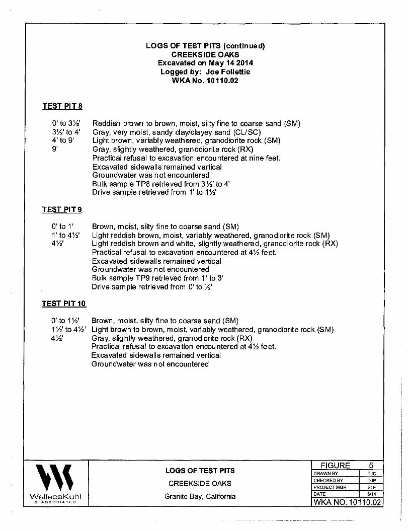
LOGS OF TEST PITS (continued) CREEKS IDE OAKS
Excavated on May 14 2014 Logged by: Joe Follettie
WKA No. 10110.02
TEST PIT 8
O' to 3%' Reddish brown to brown, moist, silty fine to coarse sand (SM) 3%'to 4' Gray, very moist, sandy clay/clayey sand (CL/SC) 4' to 9' Light brown, variably weathered, granodiorite rock (SM) 9' Gray, slightly weathered, granodiorite rock (RX)
Practical refusal to excavation encountered at nine feet. Excavated sidewalls remained vertical Groundwater was not encountered Bulk sample TP8 retrieved from 3%' to 4' Drive sample retrieved from 1' to 1%'
TEST PIT9
O' to 1' Brown, moist, silty fine to coarse sand (SM) 1' to 4%' Llght reddish brown, moist, variably weathered, granodiorite rock (SM) 4%' Light reddish brown and white, slightly weathered, granodiorite rock (RX)
Practical refusal to excavation encountered at 4% feet. Excavated sidewalls remained vertical Groundwater was not encountered Bulk sample TP9 retrieved from 1 ' to 3' Drive sample retrieved from O' to%'
TEST PIT10
O' to 1%' Brown, moist, silty fine to coarse sand (SM) 1%' to 4%' Light brown to brown, moist, variably weathered, granodiorite rock (SM) 4%' Gray, slightly weathered, granodiorite rock (RX)
Practical refusal to excavation encountered at 4% feet. Excavated sidewalls remained vertical Groundwater was n at encountered
''' LOGS OF TEST PITS
FIGURE 5 DRAWN BY TJC
CREEKSIDE OAKS CHECKED BY DJP
PROJECT MGR SLF
WallaceKuhl Granite Bay, California DATE 6/14
& ASSOCIATES WKA N0.10110.02
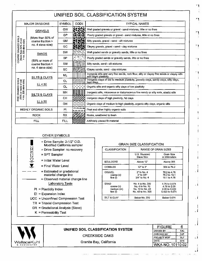
UNIFIED SOIL CLASSIFICATION SYSTEM
MAJOR DIVISIONS SYMBOL CODE TYPICAL NAMES
GRAVELS
(More than 50% of coarse fraction > no. 4 sieve size)
SANDS
(50% or more of coarse fraction < no. 4 sieve size)
GW
GP
GM
GC
SW
SP
SM
SC
ML SILTS & CLAYS
~ =.;- CL i5 Sl.!:l C/)'5: LL< 50 fil i!! ~ OL
... , . ~•.:!•~=' Well graded gravels or gravel - sand mixtures, little or no fines .. -,;;·,., r•Y•·!• Poorly graded gravels or gravel - sand mixtures, little or no fines
:: t, t Silty gravels, gravel - sand - silt mixtures
Clayey gravels, gravel - sand - clay mixtures
11 I
Well graded sands or gravelly sands, little or no fines
Poorly graded sands or gravelly sands, little or no fines
Silty sands, sand - silt mixtures
Clayey sands, sand - clay mixtures
Inorganic silts and very fine sands, rock flour, silty or clayey fine sands or clayey silts with slight plasticity Inorganic clays of low to medium plasticity, gravelly clays, sandy clays, silty clays, lean clays
Organic silts and organic silty clays of low plasticity Z o·i;; ~§oo~--~--~--+--M-H--ir-.1-,-.-.......,11--------.--~-d---------------------t ~ Inorganic silts, m1caceous or iatomaceous fine sandy or silty soils, elastic silts ~ ~ 6 SILTS & CLAYS
~lil; CH ~ Inorganic clays of high plasticity, fat clays LL:?! 50
OH Organic clays of medium to high plasticity, organic silty clays, organic silts
HIGHLY ORGANIC SOILS Pt
ROCK RX
FILL FILL
OTHER SYMBOLS
~Y.!L~~
!z~~.:::&..:a Peat and other highly organic soils
Rocks, weathered to fresh
Artificially placed fill material
= Drive Sample: 2-1/2" 0.0. Modified California sampler GRAIN SIZE CLASSIFICATION
= Drive Sampler: no recovery
= SPT Sampler
= Initial Water Level
= Final Water Level
- - - = Estimated or gradational material change line
= Observed material change line Laboratory Tests
Pl = Plasticity Index
El = Expansion Index
UCC = Unconfined Compression Test
TR = Triaxial Compression Test
GR = Gradational Analysis (Sieve)
K = Permeability Test
CLASSIFICATION
BOULDERS
COBBLES
GRAVEL coarse (c) fine (f)
SAND coarse (c) medium (m) fine (f)
SILT &CLAY
''' UNIFIED SOIL CLASSIFICATION SYSTEM
CREEKSIDE OAKS
RANGE OF GRAIN SIZES
U.S. Standard Grain Size Sieve Size in Millimeters
Above 12" Above 305
12" to 3" 305 to 76.2
3" to No. 4 76.2 to 4.76 3" to 3/4" 76.2 to 19.1
3/4" to No. 4 19.1 to 4.76
No. 4 to No. 200 4.76 to 0.074 No. 4 to No. 10 4.76 to 2.00
No. 10 to No. 40 2.00 to 0.420 No. 40 to No. 200 0.420 to 0.074
Below No. 200 Below 0.074
FIGURE DRAWN BY
CHECKED BY
PROJECT MGR
DATE
6 TJC
DJP
SLF 6/14 Wallace Kuhl Granite Bay, California
& ASSOCIATES WKA NO. 10110.02
____________________________ .... ,., .. ___________ ....
·1
1
'l
J
'j
! J
i ' j
.J

APPENDICES
'''
'l
APPENDIX A General Information, Field and Laboratory Testing
'J
1 ' j
. J
' ' ' I I
.J i i !
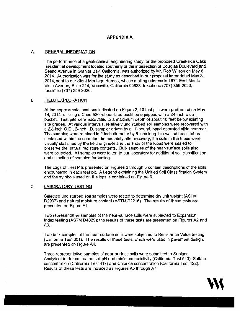
A.
APPENDIX A
GENERAL INFORMATION
The performance of a geotechnical engineering study for the proposed Creekside Oaks residential development located southerly of the intersection of Douglas Boulevard _and
Seeno Avenue in Granite Bay, California, was authorized by Mr. Rob Wilson on May 8, 2014. Authorization was for the study as described in our proposal letter dated May 8, 2014, sent to our client Meritage Homes, whose mailing address is 1671 East Monte Vista Avenue, Suite 214, Vacaville, California 95688; telephone (707) 359-2026; facsimile (707) 359-2026.
B. FIELD EXPLORATION
At the approximate locations indicated on Figure 2, 10 test pits were performed on May 14, 2014, utilizing a Case 580 rubber-tired backhoe equipped with a 24-inch wide bucket. Test pits were excavated to a maximum depth of about 10 feet below existing site grades. At various intervals, relatively undisturbed soil samples were recovered with a 2~-inch O.D., 2-inch I.D. sampler driven by a 10-pound, hand-operated slide hammer. The samples were retained in 2-inch diameter by 6-inch long thin-walled brass tubes contained within the sampler. Immediately after recovery, the soils in the tubes were visually classified by the field engineer and the ends of the tubes were sealed to preserve the natural moisture contents. Bulk samples of the near-surface soils also were collected. All samples were taken to our laboratory for additional soil classification and selection of samples for testing.
The Logs of Test Pits presented on Figures 3 through 5 contain descriptions of the soils encountered in each test pit. A Legend explaining the Unified Soil Classification System and the symbols used on the logs is contained on Figure 6.
C. LABORATORY TESTING
Selected undisturbed soil samples were tested to determine dry unit weight (ASTM D2937) and natural moisture content (ASTM D2216). The results of these tests are presented on Figure A1.
Two representative samples of the near-surface soils were subjected to Expansion Index testing (ASTM D4829); the results of these tests are presented on Figures A2 and A3.
Two bulk samples of the near-surface soils were subjected to Resistance Value testing (California Test 301 ). The results of these tests, which were used in pavement design, are presented on Figure A4.
Three representative samples of near-surface soils were submitted to Sunland Analytical to determine the soil pH and minimum resistivity (California Test 643), Sulfate concentration (California Test 417) and Chloride concentration (California Test 422). Results of these tests are included as Figures A5 through A?.
'''
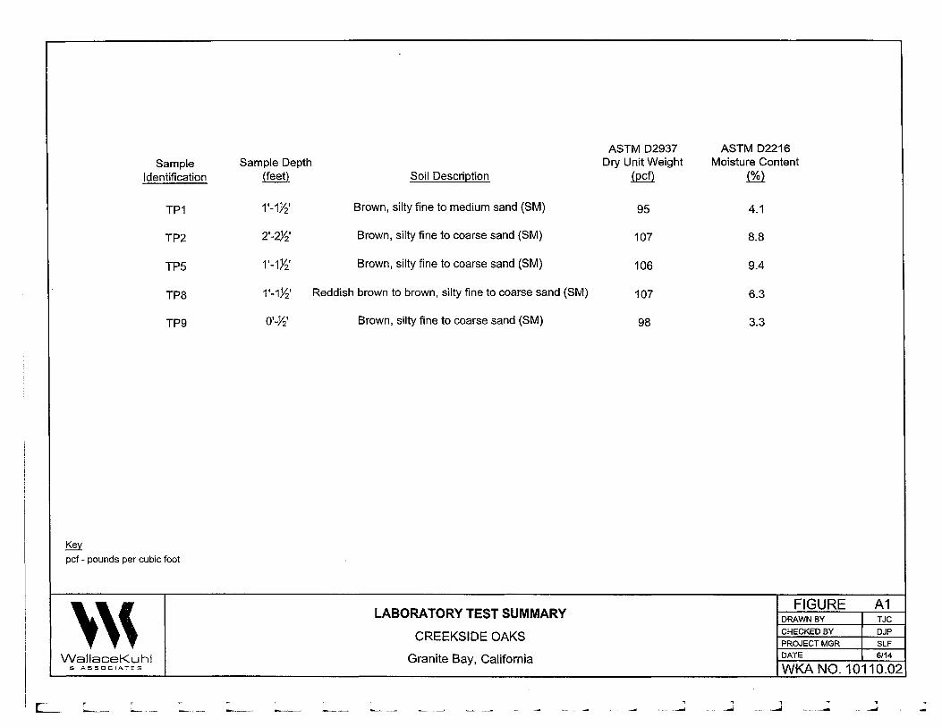
ASTM D2937 ASTM D2216 Sample Sample Depth Dry Unit Weight Moisture Content
Identification (feet) Soil Description iPffl (%)
TP1 1·-1~· Brown, silty fine to medium sand (SM) 95 4.1
TP2 2·-m· Brown, silty fine to coarse sand {SM) 107 8.8
TP5 1·-1~· Brown, silty fine to coarse sand (SM) 106 9.4
TP8 1'-1.Yz' Reddish brown to brown, silty fine to coarse sand (SM) 107 6.3
TP9 o·-~· Brown, silty fine to coarse sand (SM) 98 3.3
~ pcf - pounds per cubic foot
''' LABORATORY TEST SUMMARY
FIGURE A1 DRAWN BY TJC
CREEKSIDE OAKS CHECKED BY DJP
PROJECT MGR SLF
WallaceKuhl Granite Bay, California DATE 6/14
S ASSOCIATES WKA NO. 10110.02
[..__ -----
-, -~
' _... _.] _.
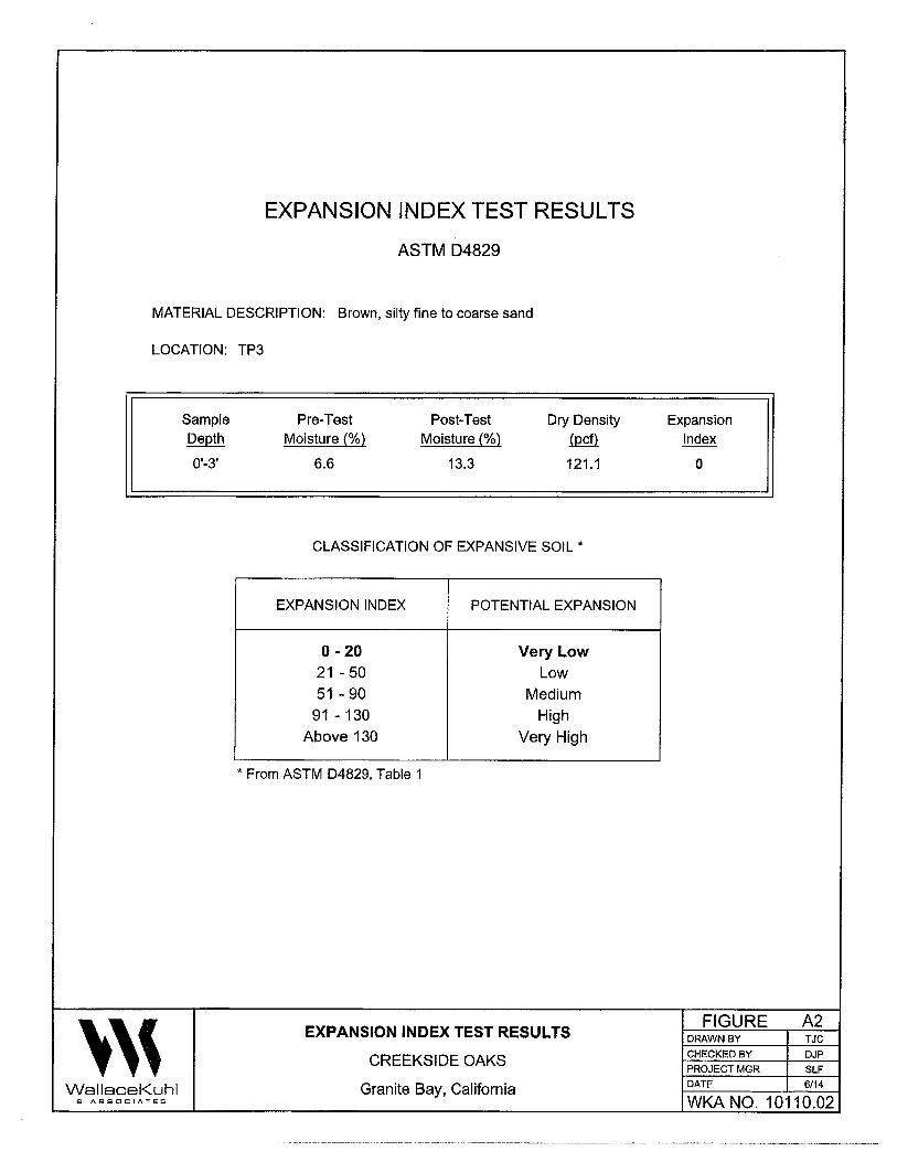
EXPANSION INDEX TEST RESULTS
ASTM D4829
MATERIAL DESCRIPTION: Brown, silty fine to coarse sand
LOCATION: TP3
''' WallaceKuhl & ASSOCIATES
Sample Depth
0'-3'
Pre-Test Moisture(%)
6.6
Post-Test Moisture(%)
13.3
Dry Density
.(Qffl
121.1
CLASSIFICATION OF EXPANSIVE SOIL *
EXPANSION INDEX
0 -20 21 -50 51 - 90
91 - 130 Above 130
* From ASTM D4829, Table 1
POTENTIAL EXPANSION
Very Low Low
Medium High
Very High
EXPANSION INDEX TEST RESULTS
CREEKSIDE OAKS
Granite Bay, California
Expansion Index
0
FIGURE DRAWN BY
CHECKED BY
PROJECT MGR
DATE
A2 TJC
DJP
SLF
6/14
WKANO. 10110.02
··-- --- ---------··-·--··-·····------·--···---------·-----------------------------------------------------

EXPANSION INDEX TEST RESULTS
ASTM 04829
MATERIAL DESCRIPTION: Gray, sandy clay/clayey sand
LOCATION: TP8
''' WallaceKuhl & ASSOCIATES
Sample Depth
3W-4'
Pre-Test Moisture(%)
11.1
Post-Test Moisture(%)
22.7
Dry Density
illffl 105.7
CLASSIFICATION OF EXPANSIVE SOIL*
EXPANSION INDEX
0-20
21 - 50 51 - 90
91 - 130
Above 130
* From ASTM D4829, Table 1
POTENTIAL EXPANSION
Very Low
Low Medium
High
Very High
EXPANSION INDEX TEST RESULTS
CREEKSIDE OAKS
Granite Bay, California
Expansion Index
37
FIGURE DRAWN BY
CHECKED BY
PROJECT MGR
DATE
A3 TJC
DJP
SLF
6/14
WKA NO. 10110.02
"l
'l
. '
' l
·- j
' C l
. j
i
..J

RESISTANCE VALUE TEST RESULTS
(California Test 301)
MATERIAL DESCRIPTION: Brown, silty fine to medium sand
LOCATION: TP1 (0'-3')
Dry Unit Moisture Exudation
Specimen Weight @ Compaction Pressure Expansion Pressure R
No. (pcf) (%) (psi) (dial) (psf) Value --
1 129 9.9 96 0 0 51
2 129 9.5 200 20 87 76
3 128 9.1 683 4 17 84
R-Value at 300 psi exudation pressure = 79
MATERIAL DESCRIPTION: Reddish brown, silty fine to coarse sand
LOCATION: TP7 (W-3')
Dry Unit Moisture Exudation
Specimen Weight @ Compaction Pressure Expansion Pressure R
No. (pcf) (%) (psi) (dial) (psf) Value
1 122 12.5 596 0 0
2 3
Sample extruded, therefore R-Value = 5
''' RESISTANCE VALUE TEST RESULTS
FIGURE A4 DRAWN BY TJC
CREEKSIDE OAKS CHECKED BY DJP PROJECT MGR SLF
WallaceKuhl Granite Bay, California DATE 6/14
& ASSOCIATES WKA NO. 10110.02
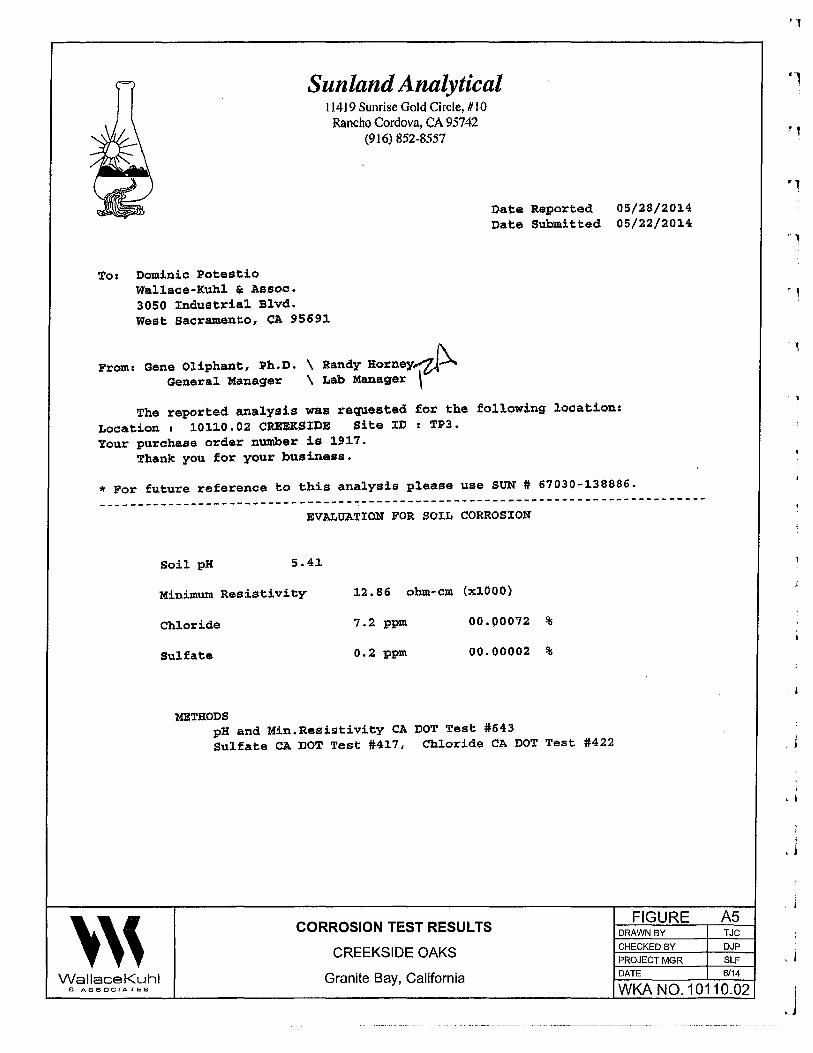
Sunland Analytical 11419 Sunrise Gold Circle, #10
Rancho Cordova, CA 95742 (916) 852-8.557
To: Dominic Potestio Wallace-Kuhl & Assoc. 3050 Industrial Blvd. West Sacramento, CA 95691
From: Gene Oliphant, Ph.D.\ Randy Horney~ General Manage.r \ Lab Manager \
Date Reported Date Submitted
05/28/2014 05/22/201.4
The reported analysis was requested for the following location: Location: 10110.02 CR.EEXSIDE Site ID: TP3. Your purchase order number is 1917.
Thank you for your business.
* For future reference to this analysis please use SUN# 67030-138886.
------------------~--~---------------------------------------------------------
' ' '
EVALUATION FOR SOIL CORROSION
Soil pH 5.41
Minimum Resistivity
Chloride
Sulfate
METHODS
12,86 ohm-cm (xlOOO)
7 .2 ppm
0.2 ppm
00.00072 %
00.00002 %
pH and Min.Resistivity CA DOT Test #643 Sulfate CA DOT Test #417, Chloride CA DOT Test #422
FIGURE DRAWN BY
CHECKED BY
PROJECT MGR
A5 TJC DJP
SLF
Wallace Kuhl
CORROSION TEST RESULTS
CREEKSIDE OAKS
Granite Bay, California DATE 6/14
& ASSOCIATES WKA N0.10110.02
'l
. j
. j
' ' .
!
'j
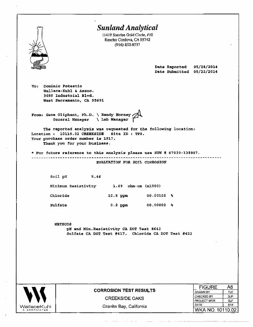
Sunland Analytical 11419 Sunrise Gold Circle, It I 0
Rancho Cordova, CA 95742 (916) 852-8557
To; Dominic Potestio Wallace-Kuhl & Assoc. 3050 Industrial Blvd. West Sacramento, CA 95691
From: Gene Oliphant, Ph.D. \ Randy Horney~ General Manager \ Lab Manager l ·
Date Reported Date Submitted
05/28/2014 05/22/2014
The reported analysis was requested for the following location: Location 1 10110.02 CREEKSIDE Site ID: TPS. Your purchase order number is 1917.
Thank you for your business.
* For future reference to this analysis please use SUN# 67030-138887.
' ' '
EVAJ:.UATION FOR. SOIL CORROSION
Soil pH 5.46
Minimum Resistivity 1.69 ohm-cm (xlOOO)
Chloride
Sulfate
METHODS
10.5 ppm
0.2 ppm
00.00105 %
00.00002 %
pH and Min.Resistivity CA DOT Test #643 Sulfate CA DOT Test #417, Chloride CA DOT Test #422
CORROSION TEST RESULTS
CREEKSIDE OAKS
FIGURE DRAWN BY
CHECKED BY
PROJECT MGR DATE
A6 TJC
DJP
SLF 6/14 Wallace Kuhl Granite Bay, California
& ASSOCIATES WKA N0.10110.02
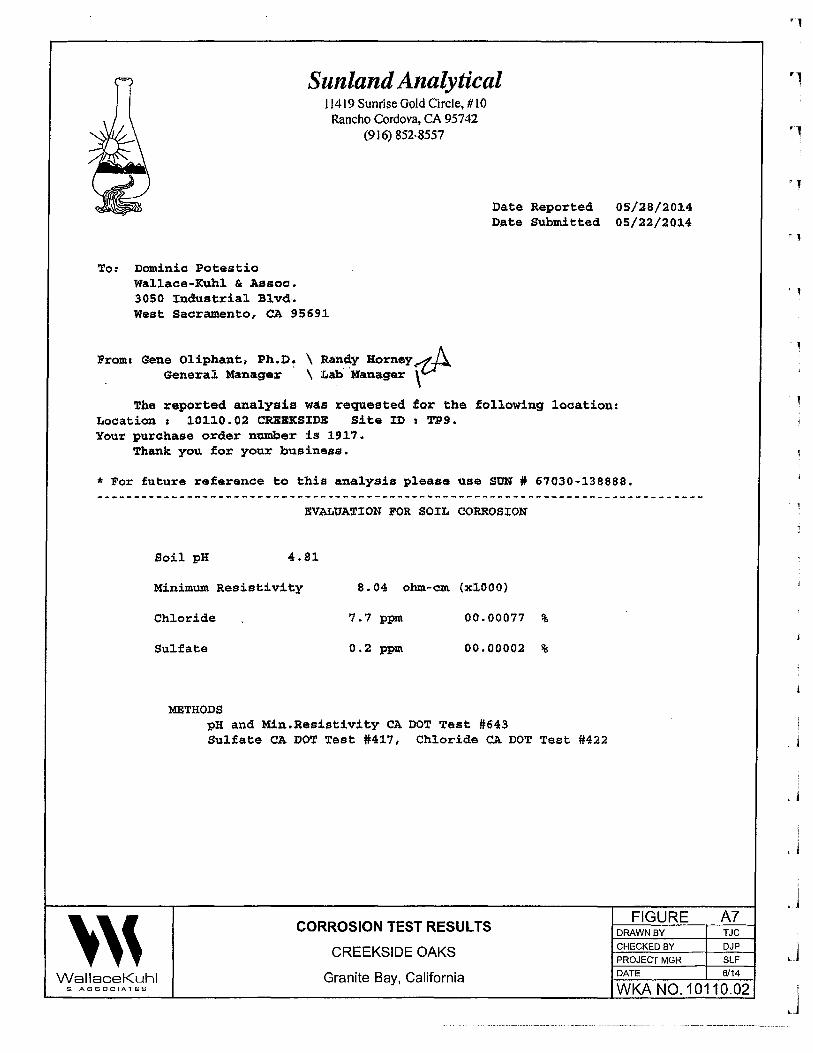
Sunland Analytical I 1419 Sunrise Gold Circle, RIO Rancho Cordova, CA 95742
(916) 852-8557
To: Dominic Potestio Wallace-Kuhl&: Assoc. 3050 Industrial Blvd. West Sacramento, CA 95691
From: Gene Oliphant, Ph.D~ \ Ra~~y Horney~ . General Manager \ Lab Manager\
Date Reported Date Submitted
05/28/2014 05/22/2014
The reported analysis was requested for the following location: Location: 10110.02 CREEKSIDE Site IDs TP9. Your purchase order number is 1917.
Thank you for your business.
* For future reference to this analysis please use SON# 67030-138888.
' ' '
EVALUATION FOR SOIL CORROSION
Soil pH 4.81
Minimum Resistivity
Chloride
Sulfate
METHODS
8.04 ohm-cm (xlOOO}
7.7 ppm
0.2 ppm
00.00077 %
00.00002 %
pH and Min.Resistivity CA DOT Test #643 Sulfate CA DOT Test #417, Chloride CA DOT Test #422
WallaceKuhl
FIGURE DRAWN BY
CHECKED BY
PROJECT MGR DATE
A? TJC DJP
SLF 6/14
& ASSOCIATES
CORROSION TEST RESULTS
CREEKSIDE OAKS
Granite Bay, California WKA NO. 10110.02
·1
'1
J ' j
L i
. j
l ._j
APPENDIXB Earthwork Specifications
'''
APPENDIX B
EARTHWORK SPECIF/CATIONS
CREEKSIDE OAKS
Douglas Boulevard and Seeno Avenue
Granite Bay, California
GEOTECHNICAL ENGINEERING REPORT
A Geotechnical Engineering Report (WKA No. 10110.02; dated June 18, 2014) has been
prepared for this site by Wallace - Kuhl & Associates, Geotechnical Engineers; (916) 372-1434.
A copy is available for review at the office of Wallace - Kuhl & Associates, 3050 Industrial
Boulevard, West Sacramento, California. The information contained in the Geotechnical
Engineering Report was obtained for design purposes only.
GENERAL DESCRIPTION
This item shall include all clearing and grubbing, overexcavation and recompaction operations,
preparation of land to be filled, spreading, compaction, observation and testing of the fill, and all
subsidiary work necessary to complete the grading of the site to conform with the lines, grades
and slopes as shown on the accepted plans.
MATERIALS
Proposed fill material shall be free from organic matter and other unsuitable substances and
shall be approved by the Geotechnical Engineer. On-site materials exceeding six inches (6")
shall be removed from any fill supporting the buildings or pavements. Concentrations of clay
soils shall not be used in the upper twelve inches (12") of the final building pad and pavement
subgrades. Imported fill material shall be granular having a Plasticity Index not exceeding
fifteen (15), an Expansion Index of less than twenty (20), a maximum six-inch (6") particle size,
and a Resistance value of greater than thirty (30). All imported fill sources shall be sampled,
and approved by the Geotechnical Engineer prior to being transported to the site.
CLEARING, GRUBBING AND PREPARING BUILDING AND PAVEMENT AREAS
The site shall be cleared of all surface and subsurface structures, including previous mining
activities, tailings, embankments, fencing and deleterious debris. Trees and shrubs designated
to be removed shall include the entire rootball and roots larger than one-half inch (Yz") in
diameter. Excavations and depressions resulting from the removal of such items shall be
'''
r l
1 !
. j
l ' j
'J
1
L j
' I
'J
.J
WKA No. 10110.02 Page B2
cleaned out to firm, undisturbed soil and backfilled with suitable materials in accordance with
these specifications.
The existing ravine, low lying areas and drainages shall be fully drained of water and cleaned of
organics. Saturated and unstable soils exposed within the ditches shall be removed to expose
firm, native materials, as determined by our representative. The exposed surface shall be
scarified to a depth of twelve inches (12") and compacted to at least ninety percent (90%) of the
ASTM D1557 maximum dry density. These soils will likely be saturated and will require
aeration and a period of drying to allow proper compaction. Organically contaminated soils will
not be allowed for use in engineered fill construction.
Remaining surface organics shall be removed by stripping. Strippings shall not be used in
general fill construction, but may be used in landscape areas, provided they are kept at least
five feet (5') from the building pads, moisture conditioned and compacted. Discing of organics
into the surface soils may be a suitable alternative to stripping, depending upon the quantity
and condition of the surface vegetation at the time of grading. Discing will be allowed only with
our prior approval. Discing operations shall be observed by our representative and must be
continuous until organics are adequately mixed with the soil to provide a compactable mixture.
Pockets or concentrations of organics will not be allowed.
Exposed soil subgrades to receive fill, left at-grade or achieved by excavation, shall then be
scarified to a depth of twelve inches (12"), uniformly moisture conditioned to at least the
optimum moisture content and compacted to at least ninety percent (90%) of the maximum dry
density as determined by the ASTM D1557 Test Method. Recompaction operations shall be
performed in the presence of the Geotechnical Engineer who will evaluate the performance of
the materials under compactive load. Unstable soil deposits, as determined by the
Geotechnical Engineer, shall be excavated to expose a firm base and grades restored with
engineered fill in accordance with these specifications. Compaction shall be achieved using a
heavy, self-propelled, sheepsfoot compactor equivalent to or larger than a Caterpillar 815.
PLACING, SPREADING AND COMPACTING FILL MATERIAL
The selected fill material shall be placed in layers which when compacted shall not exceed six
inches (6") in thickness. Each layer shall be spread evenly and shall be thoroughly mixed
during the spreading to promote uniformity of material in each layer.
'''
WKA No. 10110.02 Page B3
When the moisture content of the fill material is less than the recommended moisture, water
shall be added until the proper moisture content is achieved.
When the moisture content of the fill material is too high to permit the specified compaction to
be attained, the fill material shall be aerated by blading or other methods until the moisture
content is satisfactory.
After each layer has been placed, mixed and spread evenly, it shall be thoroughly compacted to
not less than ninety percent (90%) of the maximum dry density as determined by the ASTM
01557 Test Method. Compaction shall be undertaken with a heavy, self propelled, sheepsfoot
type compactor (Caterpillar 825 or equivalent sized compactor) and shall be accomplished
while the fill material is at the required moisture content. Each layer shall be compacted over its
entire area until the desired density has been obtained.
Rocky materials used as fill shall be thoroughly moisture conditioned to at least the optimum
moisture content and uniformly compacted by at least three (3) complete coverages with a
heavy, self-propelled sheepsfoot compactor (Caterpillar 825 compactor or an equivalent), to the
satisfaction of our on-site representative. One complete coverage is defined as the process
necessary to assure that every square foot of subgrade has been traversed and compacted by
the compaction equipment. Each layer shall be compacted over its entire area until the desired
density has been obtained.
The filling operations shall be continued until the fills have been brought to the finished slopes
and grades as shown on the accepted Drawings.
FIELD DENSITY TESTS
The Geotechnical Engineer or their representative shall make field density tests after
compaction of each layer of fill. Where compaction equipment has disturbed the surface to a
depth of several inches, density tests shall be taken in the compacted material below the
disturbed surface. Additional layers of fill shall not be spread until field density tests indicate the
specified density has been obtained.
''\
r l
·1
.. ~
'l
l 'J
WKA No. 10110.02 Page 84
FINAL SUBGRADE PREPARATION
The upper twelve (12") inches of final building pad subgrades shall be brought to the optimum
moisture content and uniformly compacted to not less than ninety percent (90%) of the ASTM
D1557 maximum dry density or by at least three (3) complete coverages of a Caterpillar 825 ( or
equivalent) regardless of whether final grade is left at the existing grade or is completed by
excavation or filling.
The upper six inches (6") of final subgrades supporting pavements shall be brought to a
uniform moisture content, and shall be uniformly compacted to not less than ninety-five percent
The upper twelve inches (12") of all final pavement subgrades shall be processed, uniformly
moisture conditioned to the optimum moisture content and compacted to at least ninety-five
percent (95%) relative compaction of the ASTM D1557 maximum dry density or by at least five
(5) complete coverages of a Caterpillar 825 (or equivalent) regardless of whether final subgrade
elevations are attained by filling, excavation, or are left at existing grades. Final pavement
processing, moisture conditioning and compaction shall be performed just prior to placement of
pavement aggregate base.
TESTING
Observation and testing by the Geotechnical Engineer or their representative shall be provided
during all filling and compaction operations. The grading contractor shall give at least twenty
four hours (24) notice prior to beginning such operations to allow proper scheduling of the work.
SEASONAL LIMITS
Fill materials shall not be placed, spread or rolled during unfavorable weather conditions. When
heavy rains interrupt the work, fill operations shall not be resumed until field tests indicate that
the moisture content and density of the fill are satisfactory.
I
'''

'l
r 1
. i
j
I ' j
J

Geotechnica/ Engineering Report
CREEKSIDE OAKS
WKA No. 10110.02
June 18, 2014
Prepared For:
Meritage Homes
1671 East Monte Vista Avenue, ~uite 214
Vacaville, California 95688
www. wa lla ce-ku h L. com

Geotechnical Engineering Report
CREEKSIDE OAKS
WKA No. 10110.02
TABLE OF CONTENTS
INTRODUCTION ........................................................................................................................ 1
Scope of Services ................................................................................................................... 1
Previous Studies ..................................................................................................................... 1
Figures and Attachments ........................................................................................................ 2
Proposed Development .......................................................................................................... 2
FINDINGS .................................................................................................................................. 2
Site Description ...................................................................................................................... 2
Site History ............................................................................................................................. 3
Site Geology ........................................................................................................................... 3
Soil and Rock Conditions ........................................................................................................ 4
Groundwater ........................................................................................................................... 4
CONCLUSIONS ......................................................................................................................... 5
Bearing Capacity .................................................................................................................... 5
2013 CBC/ASCE 7-10 Seismic Design Criteria ....................................................................... 6
Excavation Conditions ............................................................................................................ 6
Soil Expansion Potential ......................................................................................................... 7
Pavement Subgrade Qualities ................................................................................................ 7
On-Site Material Suitability for Engineered Fill Construction ................................................... 8
Soil Corrosion Potential .......................................................................................................... 8
Groundwater ... , ....................................................................................................................... 9
Seasonal Water ...................................................................................................................... 9
RECOMMENDATIONS ............................................................................................................ 10
General. ................................................................................................................................ 10
Site Clearing and Preparation ............................................................................................... 1 O
Engineered Fill Construction ................................................................................................. 12
Residential Utility Trench Backfill .......................................................................................... 13
Foundations .......................................................................................................................... 14
Interior Floor Slab Support .................................................................................................... 14
Floor Slab Moisture Penetration Resistance .......................................................................... 15
Retaining Wall Design ........................................................................................................... 16
Sound Wall Foundation Systems ............................. , ............................................................ 17
Exterior Flatwork ................................................................................................................... 18
Site Drainage ........................................................................................................................ 18
Pavement Design ................................................................................................................. 19
Geotechnical Engineering Observation and Testing During Earthwork ................................. 20
LIMITATIONS ........................................................................................................................... 21'''
'
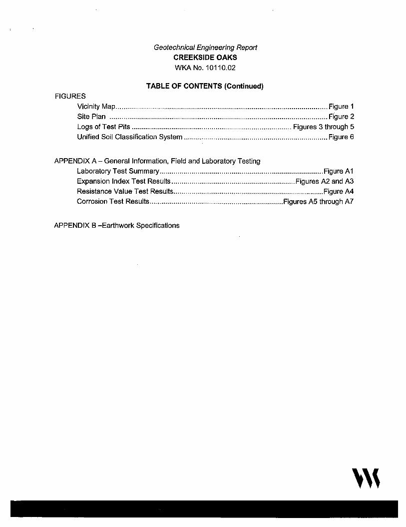
FIGURES
Geotechnica/ Engineering Report
CREEKSIDE OAKS
WKANo.10110.02
TABLE OF CONTENTS (Continued)
Vicinity Map .......................................................................................................... Figure 1
Site Plan ............................................................................................................. Figure 2
Logs of Test Pits ................................................................................ Figures 3 through 5
Unified Soil Classification System ........................................................................ Figure 6
APPENDIX A - General Information, Field and Laboratory Testing
Laboratory Test Summary .................................................................................. Figure A 1
Expansion Index Test Results .............................................................. Figures A2 and A3
Resistance Value Test Results ........................................................................... Figure A4
Corrosion Test Results ................................................................... Figures A5 through A7
APPENDIX B -Earthwork Specifications
'''
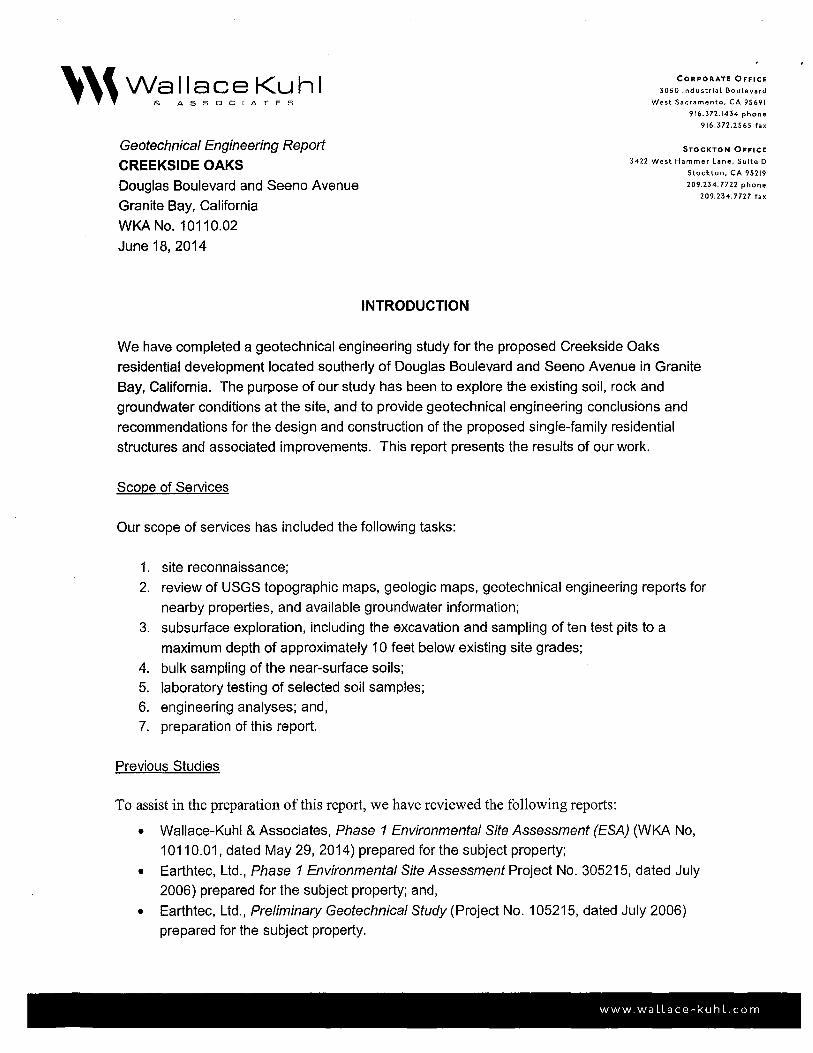
Geotechnical Engineering Report
CREEKSIDE OAKS
Douglas Boulevard and Seeno Avenue
Granite Bay, California
WKA No. 10110.02
June 18, 2014
INTRODUCTION
CORPORATE OFFICE
3050 Industrial Boulevard
West Sacramento, CA 95691
916.372.1434 phone
916.372.2565 fax
STOCKTON OFFICE
3422 West Hammer Lane, Suite D
Stockton, CA 95219
209.234.7722 phone
209.234.7727 fax
We have completed a geotechnical engineering study for the proposed Creekside Oaks
residential development located southerly of Douglas Boulevard and Seeno Avenue in Granite
Bay, California. The purpose of our study has been to explore the existing soil, rock and
groundwater conditions at the site, and to provide geotechnical engineering conclusions and
recommendations for the design and construction of the proposed single-family residential
structures and associated improvements. This report presents the results of our work.
Scope of Services
Our scope of services has included the following tasks:
1. site reconnaissance;
2. review of USGS topographic maps, geologic maps, geotechnical engineering reports for
nearby properties, and available groundwater information;
3. subsurface exploration, including the excavation and sampling of ten test pits to a
maximum depth of approximately 10 feet below existing site grades;
4. bulk sampling of the near-surface soils;
5. laboratory testing of selected soil samples;
6. engineering analyses; and,
7. preparation of this report.
Previous Studies
To assist in the preparation of this report, we have reviewed the following reports:
• Wallace-Kuhl & Associates, Phase 1 Environmental Site Assessment (ESA) (WKA No,
10110.01, dated May 29, 2014) prepared for the subject property;
• Earthtec, Ltd., Phase 1 Environmental Site Assessment Project No. 305215, dated July
2006) prepared for the subject property; and,
• Earthtec, Ltd., Preliminary Geotechnical Study (Project No. 105215, dated July 2006)
prepared for the subject property.
www. wa llace-ku h L. com

Geotechnical Engineering Report CREEKSIDE OAKS
Page2
WKA No. 10110.02 June 18, 2014
Our office also is currently collecting environmental samples of the dredge tailing to evaluate the presence of heavy metals. Results of this testing will be provided under a separate report (WKA No. 10110.03).
Figures and Attachments
This report contains a Vicinity Map as Figure 1; a Site Plan showing the approximate test pit
locations as Figure 2; and Logs of Test Pits as Figures 3 through 5. An explanation of symbols
and classification system used on the logs is included as Figure 6. Appendix A contains
information of a general nature regarding project concepts, exploratory methods used during the
field investigation phase of our study, a description of laboratory tests performed, and laboratory
test results. Appendix B contains Earthwork Specifications that may be used in the preparation
of contract plans and specifications.
Proposed Development
We understand the subject site is proposed for development with a residential subdivision.
Specific lot information was not available at the time this report was completed. We anticipate
the houses will consist of one- and two-story, wood-framed structures with interior slab-on-grade
lower floors. Structural loads for the structures are anticipated to be relatively light based on
this type of construction. Associated development will include construction of underground
utilities, exterior flatwork, retaining walls, interior paved residential streets, and typical residential
landscaping.
FINDINGS
Site Description
The project site encompasses a total area of approximately 32 acres located southerly of
Douglas Boulevard and Seeno Avenue in Granite Bay, California (see Figure 1 ). The site is
bounded to the north by Douglas Boulevard, an existing commercial building, and fallow land; to
the east by rural residences and fallow vacant land; to the south by rural residences; and, to the
west by fallow vacant land. The topography of the property is gently rolling terrain with an
average ground surface elevation of approximately +300 feet relative to mean sea level (msl),
according to the USGS 7.5-Minute Topographic Map of the Folsom Quadrangle, dated 1967
(photorevised 1980).
'''

Geotechnical Engineering Report CREEKSIDE OAKS
Page 3
WKA No. 10110.02 June 18, 2014
At the time of our field exploration on May 14, 2014, the site supported dense trees, brush, and
vegetation which limited site access. A ravine was observed meandering east to west through
the northern portion of the site. The ravine contained water at the time of our site visit. An open
excavation containing metal and wood debris was observed near the center of the site. The
excavation was circular shaped approximately 1 O feet in diameter and 15 feet in depth. This
excavation is believed to be associated with historical mining activities at the site. The general
location of this excavation is shown on Figure 2.
An area with dirt ramps (embankments) used for BMX bike riding was observed in the
southeastern portion of the site. Several unpaved access roads were observed scattered
throughout the site.
Site History
Review of aerial photographs taken between 1952 and 2012 indicate the site has remained
relatively fallow, vacant land since 1952.
Based on review of historical topographic maps and recent conversations with Mr. Dave Cook,
the site owner representative, the project site was mined from the late 1800's into the early
1900's and has been vacant land since at least the 1940's.
Site Geology
The Geologic Map of the Sacramento Quadrangle, dated 1981, prepared by the California
Division of Mines and Geology, reveals the project site to be underlain by Mesozoic granodiorite
rock, commonly referred to as the Rocklin and Penryn Plutons in the northern portion of the site.
These granitic rock units are a large-scale intrusive body that is part of a series of magmatic
intrusions that helped to form portions of the Sierra Nevada Mountains. The rock is typified as a
light gray, coarse-grained igneous rock composed of minerals such as quartz, feldspar,
hornblende and biotite, and may contain occasional xenoliths (an inclusion of a pre-existing rock
fragment within the magma) of various sizes and shapes, as well as quartz veins. This massive
bedrock unit likely extends to depths of thousands of feet beneath the surface.
The central portion of the site is mapped as being underlain by mine and dredge tailings from
previous mining acitivites. These materials generally consist of loose sands and gravels placed
by mining equipment in areas where mining excavations have taken place.
'''

Geotechnical Engineering Report CREEKSIDE OAKS WKA No. 10110.02 June 18, 2014
Page 4
The southern portion of the site is mapped as being underlain by Eocene-aged sedimentary
material of the lone Formation. The lone Formation is composed of claystones and sandstones
with occasional layers of lignite, which is often referred to as brown coal.
The soil and rock conditions encountered during our recent field explorations are generally
consistent with the Mesozoic granodiorite rock and dredge tailings. However, soils associated
with the lone Formation were not observed in our test pits but may exist in other areas on-site
that were not explored.
Soil and Rock Conditions
The soil conditions encountered by our test pits generally consist of approximately one to three
feet of silty, fine to coarse sand underlain by variably weathered granodiorite rock. The highly
weathered rock is similar to a sandy soil and is commonly referred to as "decomposed granite".
Upon excavation, these materials broke down primarily into clayey and silty, fine to coarse sand.
The degree of weathering decreases with depth and becomes harder to excavate. A
discontinuous, one-foot thick layer of clayey sand was encountered in Test Pits TP1 and TP8 at
a depth of approximately three feet below existing site grades. Practical refusal to excavation in
slightly weathered to fresh granodiorite rock was encountered at depths of approximately 3'V2 to
9 feet in seven of the test pits.
Dredge tailings were encountered in Test Pits TP4 and TP6 from the surface extending to the
maximum depth explored of approximately 10 feet below existing site grades. Test Pits TP4
and TP6 did not encounter undisturbed native soils within 10 feet of existing grades.
Discontinuous layers of sandy silt and sandy gravel were encountered in Test Pit TP7 at depths
of approximately three to six feet and six to ten feet below existing grades, respectively.
Please refer to the Logs of Test Pits (Figures 3 through 5) for more information regarding the
soils at a particular location.
Groundwater
Permanent groundwater was not encountered within the test pits performed on May 14, 2014, to
the maximum depth explored of approximately 10 feet below existing site grades. However,
surface water and subsurface seepage into excavations should be anticipated during the rainy
season and for several weeks after the last rainfall of the season. Seasonal seeps or springs
may be active on the property. Perched water may also be encountered in excavations during
earthwork and utility construction due to the relatively impermeable geologic materials at the
site.
'''
Geotechnical Engineering Report CREEKSIDE OAKS
Page 5
WKA No. 10110.02 June 18, 2014
As a result of the impermeable nature of these materials, it is not unusual to observe perched
water above them either at the surface or in shallow excavations. Seepage can also occur
through sloping ground that exposes cemented materials as a consequence of grading and
terracing required for subdivisions constructed on this type of terrain. Although perched water
and seepage can be controlled by appropriate drainage improvements constructed during
landscaping, it is typically not possible to intercept all subsurface water in areas that are
underlain by impermeable geologic materials such as those at the site.
Perched water and seepage are the result of the inability of rain or irrigation water to vertically
migrate through the impermeable geologic materials at the site. Rain and irrigation water
infiltrating the surface through topsoil or permeable engineered fill typically migrates downward
to underlying cemented material and then laterally or down slope on top of the impermeable
cemented material. We emphasize that perched water does not represent the groundwater
table, as the groundwater table is likely 100 feet or more below general surface elevations at the
site.
CONCLUSIONS
Bearing Capacity
In our opinion, the undisturbed native soils are capable of supporting the proposed, one- and
two-story residential buildings. Engineered fill that is properly placed and compacted during
earthwork also would be suitable for support of residential structures and pavements.
The existing tailings, soil embankments and undocumented fill materials are not considered
suitable for support of the planned structures and must be completely removed to expose
native, undisturbed soils.
Thorough recompaction of the upper soils, which become disturbed during site clearing, will be
important to providing uniform support for the planned residential structures. Adequate clearing
of the existing tailings, embankments, trees, and proper backfilling of the resulting depressions
will be essential for uniform support of new structures.
Due to the sloping topography of the site, we conclude that the potential for differential
settlement of building foundations may exist where building pads span from an at-grade or
excavation area onto new engineered fill greater than five feet in depth. Special
recommendations to reduce the risk of differential settlement, where such conditions exist, are
provided in the Site Preparation section of this report.
'''
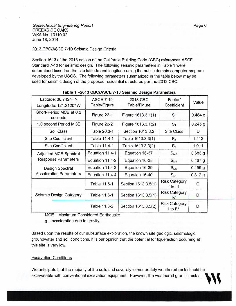
Geotechnical Engineering Report CREEKSIDE OAKS WKA No. 10110.02 June 18, 2014
2013 CBC/ASCE 7-10 Seismic Design Criteria
Page 6
Section 1613 of the 2013 edition of the California Building Code (CBC) references ASCE Standard 7-10 for seismic design. The following seismic parameters in Table 1 were determined based on the site latitude and longitude using the public domain computer program developed by the USGS. The following parameters summarized in the table below may be used for seismic design of the proposed residential structures per the 2013 CBC.
Table 1 -2013 CBC/ASCE 7-10 Seismic Design Parameters
Latitude: 38. 7 424° N ASCE 7-10
Longitude: 121 .2120° w Table/Figure
Short-Period MCE at 0.2 Figure 22-1
seconds
1.0 second Period MCE Figure 22-2
Soil Class Table 20.3-1
Site Coefficient Table11.4-1
Site Coefficient Table 11.4-2
Adjusted MCE Spectral Equation 11.4-1
Response Parameters Equation 11.4-2
Design Spectral Equation 11.4-3
Acceleration Parameters Equation 11.4-4
Table 11.6-1
Seismic Design Category Table 11 .6-1
Table 11.6-2
MCE - Maximum Considered Earthquake
g - acceleration due to gravity
2013 CBC Factor/ Table/Figure Coefficient
Figure 1613.3.1(1) Ss
Figure 1613.3.1(2) S1
Section 1613.3.2 Site Class
Table 1613.3.3(1) Fa
Table 1613.3.3(2) Fv
Equation 16-37 SMs
Equation 16-38 SM1
Equation 16-39 Sos
Equation 16-40 So1
Section 1613.3.5(1) Risk Category
I to Ill
Section 1613.3.5(1) Risk Category
IY'. Risk Category
Section 1613.3.5(2) I to IV
Value
0.484 g
0.245 g
D
1.413
1.911
0.683 g
0.467 g
0.456 g
0.312g
C
D
D
Based upon the results of our subsurface exploration, the known site geologic, seismologic,
groundwater and soil conditions, it is our opinion that the potential for liquefaction occurring at
this site is very low.
Excavation Conditions
We anticipate that the majority of the soils and severely to moderately weathered rock should be
excavatable with conventional excavation equipment. However, the weathered granitic rock at ' ''
i i
I

Geotechnical Engineering Report CREEKSIDE OAKS WKA No. 10110.02 June 18, 2014
Page 7
the site will present varying excavation conditions due to differential weathering of the rock.
Isolated areas of hard, unexcavatable rock could be encountered during earthwork and utility
excavation that will likely require large, heavy-duty excavation equipment equipped with
pneumatic jack hammers or blasting to excavate. The on-site soils and weathered rock are
anticipated to be excavatable with near-vertical sidewalls without significant caving, unless
saturated soils are encountered.
Excavations in the existing tailings will likely encounter loose soils and rocks with significant
caving ofthe sidewalls during excavation.
Excavations deeper than five feet that will be entered by workers should be sloped, braced or
shored in accordance with current OSHA regulations. The contractor must provide an
adequately constructed and braced shoring system in accordance with federal, state and local
safety regulations for individuals working in an excavation that may expose them to the danger
of moving ground.
Excavated materials should not be stockpiled directly adjacent to an open trench to prevent
surcharge loading of the trench sidewalls. Excessive truck and equipment traffic should be
avoided near open trenches. If material is stored or heavy equipment is operated near an
excavation, stronger shoring would be needed to resist the extra pressure due to the surcharge
loads.
Soil Expansion Potential
The on-site granular soils are indicated to possess a very low to low expansion potential when tested in accordance with ASTM D4829 (see Figures A2 and A3). Therefore, it is our opinion that expansive soils should not be a significant factor in site development.
Dredge tailing often contain clay deposits, commonly referred to as "slickens". Slickens are
highly plastic and typically possess a high expansion potential and can be detrimental to structures. We did not encounter slickens in the field explorations; however, we have provided recommendations for removing slickens if encountered during grading.
Pavement Subgrade Qualities
The surface and near-surface soils exhibit poor to good subgrade qualities for support of asphalt
concrete pavements. Laboratory testing of the near-surface soils indicate that these materials
possess Resistance ("R") values ranging from 5 to 79 as presented on Figure A4. Therefore,
based on the results of the laboratory testing, our experience on nearby projects with similar soil~, (
types, and the anticipated mixing of soils during earthwork construction, we have selected an R- , , ,

Geotechnical Engineering Report CREEKSIDE OAKS
Page 8
WK.A No. 10110.02 June 18, 2014
value of 30 for our pavement design with the understanding that clays exposed at pavement
subgrades should be removed and replaced with granular on-site soils.
On-Site Material Suitability for Engineered Fill Construction
The soil and weathered rock at the site, including the tailings and soil stockpiles, are considered
suitable for use as fill materials if free from rubble, rubbish or organic concentrations. The in
place weathered rock will tend to excavate into sands upon removal from trenches.
Unweathered rock, if encountered, may be difficult to break down to a size suitable for use as
engineered fill. Pneumatic jackhammers mounted to large excavators may be able to break
down large pieces of rock.
Soil Corrosion Potential
Three soil samples collected from the site were submitted to Sunland Analytical to determine
soil pH, minimum resistivity, and chloride and sulfate concentrations to help evaluate potential
for corrosive attack upon reinforced concrete and exposed buried metal. The results of the
corrosivity testing are summarized in Table 2. Copies of the test reports are presented on
Figures A5 through A7.
TABLE 2 SOIL CORROSIVITY TESTING
Analyte Test Method
Soil pH CA DOT643
Modified*
Minimum CADOT643 Resistivity Modified*
Chloride CA DOT 417
Sulfate CA DOT 422
* = Small cell method
n-cm ppm
= Ohm-centimeters
= Parts per million
Sample Identification
TP3 TP8 (0'-3') (3W-4')
5.41 5.46
12,860 Q-cm 1690 n-cm
7.2 ppm 10.5 ppm
0.2 ppm 0.2 ppm
TP9 (1'-3')
4.81
8040 Q-cm
7.7 ppm
0.2 ppm
'''
Geotechnical Engineering Report CREEKSIDE OAKS
Page 9
WKA No. 10110.02 June 18, 2014
Published literature 1 defines a corrosive area as an area where the soil and/or water contains
more than 500 ppm of chlorides, more than 2000 ppm of sulfates, or has a pH of less than 5.5.
The corrosivity test results suggest that the native soils are corrosive to steel reinforcement
properly embedded within Portland cement concrete for the samples tested.
Table 4.2.1 -Exposure Categories and Classes, American Concrete Institute (ACI) 318,
Section 4.2, as referenced in Section 1904.1 of the 2013 CBC, indicates the severity of sulfate
exposure for the samples tested is Not Applicable. Modified Type II Portland cement is
considered suitable for use on this project, assuming a minimum concrete cover is maintained
over the reinforcement.
Wallace-Kuhl & Associates are not corrosion engineers. Therefore, to further define the soil
corrosion potential at the site a corrosion engineer should be consulted.
Groundwater
The permanent groundwater table is indicated to be at a depth of at least 100 feet below
existing site grades; therefore, permanent groundwater should not be a significant factor in the
design or construction of the project. However, perched water should be anticipated at various
times of the year due to the presence of less permeable weathered granodiorite. The amount of
perched water exposed will vary depending on the time of year when construction begins and is
more likely to occur during the late winter to early spring months. We anticipate that
constructing trenches and the use of sump pumps will be suitable for removing accumulated
seepage water.
Seasonal Water
During the wet season, infiltrating surface water will create a saturated surface condition due to
the relatively impermeable nature of the underlying weathered rock. Grading operations
attempted following the on-set of winter rains and prior to prolonged drying periods will be
hampered by high soil moisture contents. Such soils, intended for use as engineered fill, will
require considerable drying and aeration to reach a moisture content that will permit the
specified degree of compaction to be achieved.
1 California Department ofTransportation, Division of Engineering Services, Materials Engineering and Testing Services, Corrosion Technology Branch, Corrosion Guidelines, version 2.0, November 2012. '''
Geotechnica/ Engineering Report CREEKSIDE OAKS
Page 10
WKA No. 10110.02 June 18, 2014
RECOMMENDATIONS
General
We anticipate maximum excavations and fills on the order of two to four feet for development of
the planned residential subdivision. The recommendations contained in this report are based
upon this assumption.
Additionally, the recommendations presented below are appropriate for typical construction in
the late spring through fall months. The on-site soils likely will be saturated by rainfall in the
winter and early spring months, and will not be compactable without drying by aeration or the
addition of lime ( or a similar product). Should the construction schedule require work to
continue during the wet months, additional recommendations can be provided, as conditions
dictate.
Grading plans were not available at the time this report was completed. Our office should
review the grading plans as they are developed to confirm that our recommendations remain
applicable, and provide us the opportunity to submute revised recommendations, if needed.
Site Clearing and Preparation
Initially, the site should be cleared of all surface and subsurface structures including berms,
embankments, fencing, or any other deleterious items. Trees and bushes designated to be
removed should include the entire rootball and roots larger than %-inch in diameter. Adequate
removal of debris and tree roots may require laborers and handpicking to clear the subgrade
soils to the satisfaction of our on-site representative. All depressions resulting from the removal
of such items, as well as all loose, disturbed or saturated soils in areas of clearing operations or
tree removal, as identified by our representative in the field, should be cleaned out to firm,
undisturbed soil, as determined by our representative, and restored to grade with engineered fill
compacted in accordance with the recommendations of this report.
Surface vegetation within construction areas should be removed by stripping. Strippings should
not be used in general fill construction in pavement areas or building pads, but may be used in
landscape areas, provided they are kept at least five feet from building pads, moisture
conditioned and compacted. Discing of organics into surface soils may be a suitable alternate
to stripping, depending on the condition and quantity of organics at the time of grading. The
decision to utilize discing in lieu of stripping should be approved by our representative at the
time of earthwork construction. Discing operations, if approved, should be observed by our
representative and must be continuous until the organics are adequately mixed into the soil to
'''

Geotechnical Engineering Report CREEKSIDE OAKS
Page 11
WKA No. 10110.02 June 18, 2014
provide a compactable mixture of soil containing minor amounts of organic matter. Pockets or
significant concentrations of organics will not be allowed.
The existing ravine, low lying areas and drainages should be drained of water and cleaned of
organics, saturated and unstable soils to expose firm, native materials, as determined by our
representative. The exposed surface should be scarified to a depth of at least 12 inches,
moisture conditioned to at least the optimum moisture content and compacted to at least 90
percent of the AS.TM D1557 maximum dry density. It is likely that the excavated soils from the
these areas will be saturated, and will require aeration and a period of drying to allow proper
compaction. Our representative will provide alternative recommendations for stabilizing the
bottom of the excavations, as conditions warrant. Recompaction operations should be
performed in the presence of our representative who will evaluate the performance of the
materials under compactive load. Unstable soil deposits, as determined by our representative,
should be excavated to expose a firm base, and grade restored with engineered fill in
accordance with these recommendations.
Existing tailings located within structural areas should be completely removed to expose firm,
undisturbed native ground, as determined by our representative. Specific recommendations for
lots that contain tailings can be provided once the structural areas have been identified and
grading plans are finalized.
The existing excavations should be excavated, drained of water, and cleaned of debris and
organics. Saturated and unstable soils exposed within the mined areas should be removed to
expose firm, native materials, as determined by our representative. The exposed surface
should be scarified to a depth of 12 inches and compacted to at least 90 percent of the ASTM
D1557 maximum dry density. These soils will likely be saturated and will require aeration and a
period of drying to allow proper compaction. Organically contaminated soils will not be allowed
for use in engineered fill construction. Our representative will provide alternative
recommendations for stabilizing the bottom of the excavations, as conditions warrant.
Areas of removed trees, bushes and structures should be thoroughly ripped and cross-ripped to
expose any remaining structures, debris, or roots, to a depth of at least 12 inches, brought to a
uniform moisture content at least the optimum moisture, and compacted to at least 90 percent of
the maximum dry density per ASTM D1557 specifications. Compaction should be performed
using a Caterpillar 825 (or equivalent-sized sheepsfoot compactor).
Areas to receive fill, remain at-grade, or achieved by excavation, should be scarified to a depth
of 12 inches, brought to at least the optimum moisture content and compacted to at least 90
percent of the maximum dry density per ASTM D1557 specifications. Loose, soft or saturated
'''

Geotechnical Engineering Report CREEKSIDE OAKS WKA No. 10110.02 June 18, 2014
soils, as identified by our representative during the recompaction operations, should be
removed and replaced with engineered fill.
Page 12
In areas where rocky materials are exposed or encountered, compaction testing of rocky
materials with a nuclear density gauge will not be practical due to the large particle size;
therefore, we recommend a performance specification be followed for the compaction of rocky
materials instead of a minimum percent relative compaction. Rocky materials should be
thoroughly moisture conditioned and uniformly compacted by at least three complete coverages
with a heavy, self-propelled sheepsfoot compactor (Caterpillar 825 compactor or an equivalent),
to the satisfaction of our on-site representative. One complete coverage is defined as the
process necessary to assure that every square foot of subgrade has been traversed and
compacted by the compaction equipment.
Lots achieved by excavation should be observed by our representative to determine whether
soils associated with the lone Formation are present. Recommendations to mitigate the effects
of the lone soils, if encountered, can be provided during construction.
The emergence of unstable soil conditions during site grading operations could indicate the
presence of subsurface structures, rubble, debris or other unsuitable materials. Areas exhibiting
instability, as determined by our field representative, should be excavated to expose dense,
stable soils. It will be crucial that our representative be involved during site grading operations
to observe the equipment in operation.
Engineered Fill Construction
Engineered fill should be placed in horizontal lifts not exceeding six inches in compacted
thickness. Each layer should be uniformly moisture conditioned to at least the optimum
moisture content and compacted to at least 90 percent of the ASTM D1557 maximum dry
density. Compactive effort should be applied uniformly across the full width of the fill.
On-site soils are considered suitable for use in engineered fill construction, if free of rubble,
rubbish, or concentrations of organics. Imported fill materials, if required, should be
compactable, granular soils with a Plasticity Index of 15 or less; an Expansion Index of 20 or
less; be free of particles greater than six inches in maximum dimension; and, have a Resistance
("R") value greater than 30. Imported soils should be approved by our office prior to being
transported to the site. Also, if import fills are required (other than aggregate base) the
contractor must provide appropriate documentation that the import is free of known
contamination.
'''
Geotechnical Engineering Report CREEKSIDE OAKS
Page 13
WKA No. 10110.02 June 18, 2014
Subgrades for support of the buildings should be protected from disturbance or desiccation until
covered by capillary break material or aggregate base. Disturbed subgrade soils may require
moisture conditioning, scarification and recompaction, depending on the level of disturbance.
The upper twelve inches of final pavement subgrades should be uniformly moisture conditioned
to at least the optimum moisture content and uniformly compacted to at least 95 percent of the
maximum dry density or by at least five complete coverages of a Caterpillar 825 (or equivalent).
Final subgrade preparation should be performed regardless of whether final subgrade
elevations are attained by filling, excavation, or are left at existing grades and should be
performed after all underground utilities have been installed and backfilled. Final pavement
subgrade processing and compaction should be performed just prior to aggregate base
placement and must be stable under construction traffic.
Permanent excavation and fill slopes should be constructed no steeper than two horizontal to
one vertical (2: 1) and should be vegetated as soon as practical following grading to minimize
erosion. As a minimum, erosion control measures should include placement of straw bale
sediment barriers or construction of silt filter fences in areas where surface run-off may be
concentrated. Slopes should be over-built and cutback to design grades and inclinations.
Site preparation should be accomplished in accordance with the recommendations of this
section and the appended Earthwork Specifications. Our representative should be regularly
present throughout grading operations to determine compliance with the job specifications.
Residential Utility Trench Backfill
We recommend only native soils (in lieu of select gravel or sand backfill) be used as backfill for
utility trenches located within the building footprints and extending at least five feet beyond the perimeter foundations to minimize water transmission beneath the structures. Bedding of
utilities and initial backfill should be in accordance with the manufacturer's recommendations for
the pipe materials selected and the Placer County Standards, latest edition. Utility trench
backfill should be uniformly moisture conditioned to at least the optimum moisture content and
mechanically compacted in lifts to at least 90 percent of the ASTM D1557 maximum dry density.
We also recommend that underground utility trenches, which are aligned nearly parallel with
foundations, be at least three feet from the outer edge of foundations. Trenches should not
encroach into the zone extending outward at a 1 :1 inclination below the bottom of the
foundations. Additionally, trenches near foundations should not remain open longer than 72
hours to prevent drying and formation of desiccation and shrinkage cracks. The intent of these
recommendations is to prevent loss of both lateral and vertical support of foundations, resulting
in possible settlement.
'''
Geotechnical Engineering Report CREEKSIDE OAKS WKA No. 10110.02 June 18, 2014
Page 14
Trench backfill materials and compaction within street right-of-ways should conform to the
applicable portions of the current Placer County Standards, latest edition.
Foundations
The proposed one- and two-story residential structures may be supported upon a continuous
perimeter foundation with continuous and/or isolated interior spread foundations that extend at
least 12 inches into the compacted building pad, as measured from lowest adjacent soil grade.
For this project, the building pad subgrade is defined as the soil surface on which capillary break
gravel is placed. A continuous, reinforced foundation should be utilized for the perimeter of the
structures to act as a "cut-off' to help minimize moisture infiltration and variations beneath the
interior slab-on-grade areas of the structures. Continuous foundations should be at least 12
inches wide; isolated spread foundations should maintain a minimum 18-inch dimension.
Foundations bearing in undisturbed or recompacted native soils, engineered fill, or a
combination of those materials may be sized for maximum allowable "net" soil bearing
pressures of 3000 pounds per square foot (psf) for dead plus live load, and 4000 psf to include
wind or seismic forces. The weight of the foundation concrete extending below lowest adjacent
soil grade may be disregarded in sizing computations.
We recommend that all foundations be adequately reinforced to provide structural continuity,
mitigate cracking, and permit spanning of local soil irregularities. As a minimum, we
recommend that continuous foundations be reinforced with at least two No. 4 steel reinforcing
bars, placed one each near the top and bottom of the foundations. The structural engineer
should determine final foundation reinforcing requirements.
Resistance to lateral displacement of shallow foundations may be computed using an allowable
friction factor of 0.35 multiplied by the effective vertical load on each foundation. Additional
lateral resistance may be achieved using an allowable passive earth pressure against the
vertical projection of the foundation equal to an equivalent fluid pressure of 350 psf per foot of
depth. These two modes of resistance should not be added unless the frictional component is
reduced by 50 percent since mobilization of the passive resistance requires some horizontal
movement, effectively reducing the frictional resistance.
Interior Floor Slab Support
Interior concrete slab-on-grade floors can be supported upon the granular soil subgrade
prepared in accordance with the recommendations in this report and maintained in that
condition (at least the optimum moisture content). Interior concrete slab-on-grade floors should ' ''

Geotechnical Engineering Report CREEKSIDE OAKS WKA No. 10110.02 June 18, 2014
Page 15
be at least four inches thick and, as a minimum for crack control, contain chaired No. 3
reinforcing bars placed no wider than 24-inch center-to-center each way throughout the slab,
and located at mid-slab depth. This slab reinforcement is suggested as a guide "minimum"
only; final reinforcement and joint spacing should be determined by the structural engineer.
Proper and consistent location of the reinforcement near mid-slab is essential to its
performance. The risk of uncontrolled shrinkage cracking is increased if the reinforcement is
not properly located within the slab.
Floor slabs may be underlain by a layer of free-draining crushed rock, serving as a deterrent to
migration of capillary moisture. The crushed rock layer should be at least four inches thick and
graded such that 100 percent passes a one-inch sieve and less than five percent passes a No.
4 sieve. Additional moisture protection may be provided by placing a vapor retarder membrane
(at least 10-mils thick) directly over the crushed rock. The membrane should meet or exceed
the minimum specifications as outlined in ASTM E1745 and be installed in strict conformance
with the manufacturer's recommendations.
Floor slab construction over the past 25 years or more has included placement of a thin layer of
sand over the vapor retarder membrane. The intent of the sand is to aid in the proper curing of
the slab concrete. However, recent debate over excessive moisture vapor emissions from floor
slabs includes concern for water trapped within the sand. As a consequence, we consider the
use of the sand layer as optional. The concrete curing benefits should be weighed against
efforts to reduce slab moisture vapor transmission.
The recommendations presented above are intended to mitigate significant soils-related
cracking of the slab-on-grade floors. More important to the performance and appearance of a
Portland cement concrete slab is the quality of the concrete, the workmanship of the concrete
contractor, the curing techniques utilized, and the spacing of control joints.
Floor Slab Moisture Penetration Resistance
It is considered likely that interior floor slab subgrade soils will become wet to near-saturated at
some time during the life of the structures. This is a certainty when slabs are constructed during
the wet season or when constantly wet ground or poor drainage conditions exist adjacent to
structures. For this reason, it should be assumed that all slabs in occupied areas, as well as
those intended for moisture-sensitive floor coverings or materials, require protection against
moisture or moisture vapor penetration. Standard practice includes the crushed rock and water
vapor retarder as suggested above. However, the gravel and membrane offer only a limited,
first-line of defense against soil-related moisture. Recommendations contained in this report
concerning foundation and floor slab design are presented as minimum requirements, only from'\.., (
the geotechnical engineering standpoint. l , ,
Geotechnica/ Engineering Report CREEKSIDE OAKS
Page 16
WKA No. 10110.02 June 18, 2014
It is emphasized that the use of sub-slab crushed rock and vapor retarder membrane will not
"moisture proof' the slab, nor does it assure that slab moisture transmission levels will be low
enough to prevent damage to floor coverings or other building components. If increased
protection against moisture vapor penetration of slabs is desired, a concrete moisture protection
specialist should be consulted. The design team should consider all available measures for
slab moisture protection. It is commonly accepted that maintaining the lowest practical water
cement ratio in the slab concrete is one of the most effective ways to reduce future moisture
vapor penetration of the completed slabs.
Retaining Wall Design
Retaining walls capable of slight rotation about their base (unrestrained at the top or sides)
should be capable of resisting "active" lateral earth pressure equal to an equivalent fluid
pressure of 40 psf per foot of wall backfill for horizontal backfill conditions. If the walls are fixed
at the top, they should be designed to resist "at-rest" lateral earth pressure equal to an
equivalent fluid pressure of 60 psf per foot for horizontal backfill conditions. For retaining walls
with backfill sloped at a maximum gradient of two horizontal to one vertical (2:1 ), 20 psf per foot
of depth should be added to the values for horizontal backfill. Retaining wall foundations should
extend at least 12 inches below soil grade and may be designed in accordance with the
appropriate recommendations contained in the Foundations section of this report.
Backfill behind retaining walls should be fully drained to prevent the build-up of hydrostatic
pressure behind the wall. Retaining walls should be provided with a drainage blanket (Class 2
permeable material, Caltrans Specification Section 68-2.02F(3)) at least one-foot wide
extending from the base of wall to within one foot of the top of the wall. The top foot above the
drainage layer should consist of compacted on-site materials, unless covered by concrete
flatwork or pavements. Weep holes or perforated rigid pipe should be provided near the base of
the wall to allow drainage of accumulated water. Drainpipes, if used, should slope to discharge
at no less than a one percent fall to suitable drainage facilities. Open-graded %-inch to %-inch
crushed rock may be used in lieu of the Class 2 permeable material, if the rock and drain pipe
are completely enveloped in an approved nonwoven geotextile filter fabric.
Structural backfill materials for retaining walls (other than the drainage layer) should consist of
on-site or imported soils free of significant quantities of rubbish, rubble, organics and rock over
six inches in size; clays should not be used as wall backfill. Structural backfill should be placed
in thin lifts, and should be mechanically compacted to at least 90 percent relative compaction.
Lift thickness will be dependent on the type of compaction equipment utilized by the contractor.
The lateral pressures recommended above assume that clay soils, if exposed during site
excavations, will not be used as backfill behind retaining walls.
'''
Geotechnica/ Engineering Report CREEKSIDE OAKS
Page 17
WKA No. 10110.02 June 18, 2014
Sound Wall Foundation Systems
Shallow Foundations
The proposed sound walls may be supported upon a shallow spread and/or continuous
foundation embedded at least 18 inches below the lowest adjacent soil grade into firm
undisturbed native soil or properly placed and compacted engineered fill, as confirmed by our
representative. Continuous foundations should maintain a minimum width of 12 inches and
isolated spread foundations should be at least 18 inches in plan dimension. Foundations so
established may be sized for maximum allowable "net" soil bearing pressure of 3000 psf for
dead plus live loads, with a one-third increase for total loads including the short-term effects of
wind or seismic forces. The weight of the foundation concrete extending below lowest adjacent
soil grade may be disregarded in sizing computations. The project structural engineer should
determine the final dimensions and structural reinforcement of the sound wall foundations.
Resistance to lateral foundation displacement for sound wall foundations may be computed
using an allowable friction factor of 0.35, which may be multiplied by the effective vertical load
on the foundation. Additional lateral resistance may be computed using an allowable passive
earth pressure of 350 psf per foot of depth. These two modes of resistance should not be
added unless the frictional value is reduced by 50 percent since full mobilization of these
resistances typically occurs at different degrees of horizontal movement. Where foundations
are located within five feet of slopes steeper than three horizontal to one vertical (3:1 ), six
inches of embedment should be disregarded.
Cast-in-Place Concrete Drilled Piers
Sound walls could also be supported on cast-in-place concrete drilled piers. The piers should
extend at least three feet below the lowest adjacent soil grade and have a minimum shaft
diameter of 18 inches to help facilitate proper cleaning of the bottom of the pier. Drilled piers
founded within undisturbed native soils may be sized utilizing a maximum allowable vertical
bearing capacity of 4000 psf and an allowable skin friction of 250 psf for dead plus live loads,
which may be applied over the surface of the pier deeper than 12 inches below the lowest
adjacent soil grade. Those values may be increased by one-third to include short-term wind or
seismic forces. The weight of foundation concrete below grade may be disregarded in sizing
computations.
'''

Geotechnica/ Engineering Report CREEKSIDE OAKS WKA No. 10110.02 June 18, 2014
Page 18
Uplift resistance of pier foundations may be computed using the following resisting forces,
where applicable: 1) weight of the pier concrete (150 pounds per cubic foot) and, 2) the
allowable skin friction of 250 psf applied over the shaft area of the pier. Increased uplift
resistance can be achieved by increasing the diameter of the pier or increasing the depth.·
The upper 12 inches of skin friction should be neglected unless the pier is completely
surrounded by slab concrete or pavements for a distance of at least three feet from the edge of
the foundation pier.
Sizing of piers to resist lateral loads can be evaluated using Section 1807.3.2 of the 2013 CBC.
A value of 350 pct as defined in Table 1806.2 of the CBC may be used for the lateral bearing
pressure of the on-site soils. Per Section 1806.1 of the 2013 CBC, an increase of 1 /3 is
permitted when using the alternate load combinations in Section 1605.3.2 that include wind or
earthquake loads.
The bottom of the pier excavations should be free of loose or disturbed soils prior to placement
of the concrete. Cleaning of the bearing surface should be verified by the geotechnical engineer
prior to concrete placement. Reinforcement and concrete should be placed in the pier
excavations as soon as possible after excavation is completed to minimize the chances of
sidewall caving into the excavations.
Exterior Flatwork
Soil subgrades supporting exterior concrete flatwork (i.e., driveways, sidewalks, patios, etc.)
should be brought to an over optimum moisture condition and uniformly compacted prior to the
placement of the concrete. Proper moisture conditioning of the subgrade soils is considered
essential to the performance of exterior flatwork. Expansion joints should be provided to allow
for minor vertical movement of the flatwork. Exterior flatwork should be constructed
independent of the perimeter building foundation and isolated column foundations by the
placement of a layer of felt material between the flatwork and the foundation. Irrigated
landscaping adjacent to concrete flatwork will help maintain a more uniform moisture in the soils
and reduce the potential for differential movement. Consideration also should be given to
reinforcing the slabs with rebar for crack control.
Site Drainage
Site drainage should be accomplished to provide positive drainage of surface water away from
the buildings and prevent ponding of water adjacent to foundations. The grades adjacent to the
structures should be sloped away from foundations at a minimum two percent for a distance of ' ''

Geotechnical Engineering Report CREEKSIDE OAKS
Page 19
WKA No. 10110.02 June 18, 2014
at least five feet. We suggest consideration be given to connecting all roof downspouts to solid
drainage pipes that convey water away from the buildings to available drainage features, or
discharging downspouts onto concrete surfaces that slope away from the structures.
Pavement Design
The following pavement sections in Table 3 have been calculated based on assumed traffic
indices, results of R-value testing (see Figure A4), and the procedures contained within the 5th
Edition of the California Highway Design Manual. The project civil engineer should select the
appropriate pavement sections based upon Placer County requirements.
TABLE 3 PAVEMENT DESIGN ALTERNATIVES
R-value = 30 Type B Class 2
Traffic Index (Tl) Asphalt Concrete Aggregate Base (inches) (inches)
5.0 3* 6
3 9 6.0
3~* 8
3~ 10 6.5
4* 9
* = Asphalt concrete thickness contains Ca/trans Factor of Safety.
We emphasize that the performance of a pavement is critically dependent upon uniform
compaction of the subgrade soils, as well as all engineered fill and utility trench backfill within
the limits of the pavements. Final pavement subgrade preparation, i.e. scarification, moisture
conditioning and compaction, should be performed after underground utility construction is
completed, just prior to aggregate base placement. The upper 12 inches of final pavement
subgrades should be uniformly moisture conditioned to at least the optimum moisture content
and uniformly compacted to at least 95 percent of the maximum dry density or by at least five
complete coverages of a Caterpillar 825 (or equivalent), and must be stable under construction
traffic prior to placement of aggregate base. Placement of aggregate base upon completed
pavement subgrades should be accomplished within 72 hours to prohibit significant drying of the
'''
Geotechnical Engineering Report CREEKSIDE OAKS
Page 20
WKA No. 10110.02 June 18, 2014
subgrade soils. Class 2 aggregate base should be compacted to at least 95 percent of the
ASTM D1557 maximum dry density.
Materials, quality and construction of the structural section of the pavement should conform to
the applicable provisions of the Caltrans Standard Specifications and applicable Placer County
Standards, latest editions.
Geotechnical Engineering Observation and Testing During Earthwork
Site preparation should be accomplished in accordance with the recommendations of this report
and the Earthwork Specifications provided in Appendix B. Representatives of Wallace-Kuhl &
Associates should be present during site preparation and all grading operations to observe and
test the fill to verify compliance with our recommendations and the job specifications. These
services are beyond the scope of work authorized for this investigation.
Many factors can effect the number of tests that should be performed during the course of
construction, such as soil type, soil moisture, season of the year and contractor
operations/performance. Therefore, it is crucial that the actual number and frequency of testing
be determined by the Geotechnical Engineer during construction based on their observations,
site conditions, and difficulties encountered. As a preliminary guideline we recommend the
following minimum tests:
• mass grading: one test per 500 cubic yards of compacted fill or one per day of
work, whichever is greater
• final subgrade preparation: one test per 10,000 square feet
• aggregate base compaction: one test per 10,000 square feet
• utility backfill: one test per foot of backfill for every 200 linear feet of trench
• wall backfill: one test per foot of backfill for ever 100 linear feet of wall
In the event that Wallace-Kuhl & Associates is not retained to provide geotechnical engineering
observation and testing services during construction, the Geotechnical Engineer retained to
provide these services should indicate in writing that they agree with the recommendations of
this report, or prepare supplemental recommendations as necessary. A final report by the
Geotechnical Engineer should be prepared upon completion of the project.
'''
Geotechnical Engineering Report CREEKSIDE OAKS WKA No. 10110.02 June 18, 2014
Page 21
LIMITATIONS
Our recommendations are based upon the information provided regarding the proposed
construction, combined with our analysis of site conditions revealed by the field exploration and
laboratory testing programs. We have used prudent engineering judgment based upon the
information provided and the data generated from our investigation. This report has been
prepared in substantial compliance with generally accepted geotechnical engineering practices
that exist in the area of the project at the time the report was prepared. No warranty, either
express or implied, is provided.
If the proposed construction is modified or relocated or, if it is found during construction that
subsurface conditions differ from those we encountered at the test pit locations, we should be
afforded the opportunity to review the new information or changed conditions to determine if our
conclusions and recommendations must be modified.
We emphasize that this report is applicable only to the proposed construction and the
investigated site. This report should not be utilized for construction on any other site. This
report is considered valid for the proposed construction for a period of two years following the
date it was issued. If construction has not started within two years, we must reevaluate the
recommendations of this report and update the report, if necessary.
Wallace-Kuhl & Associates
Dominic J. Potestio Project Engineer
'''
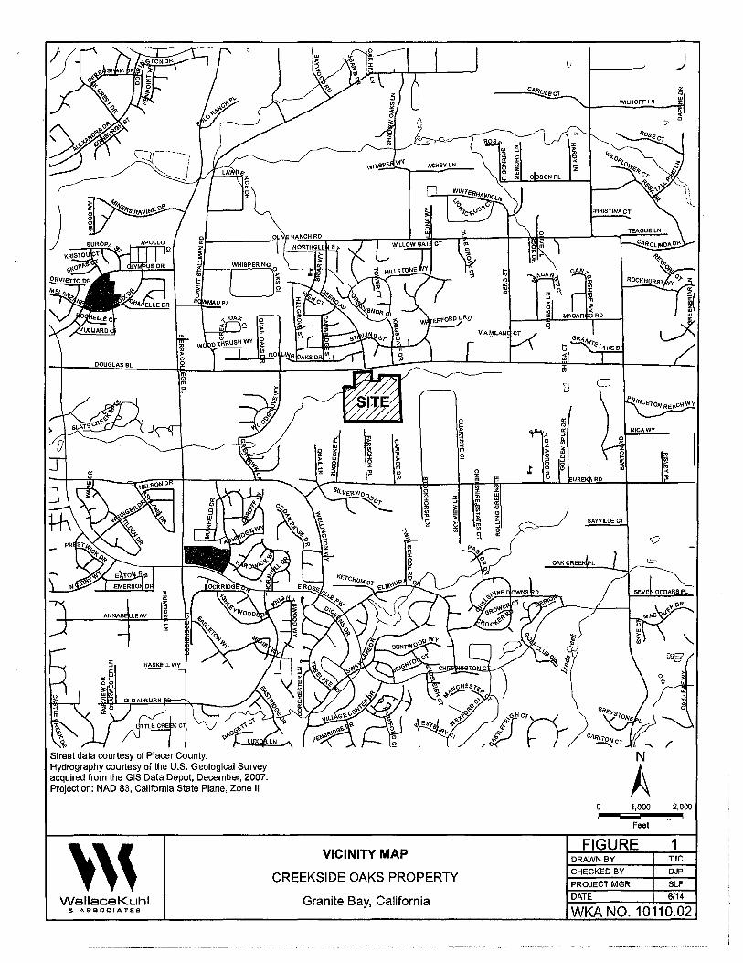
" ' <J,, Street data courtesy of Placer County. Hydrography courtesy of the U.S. Geological Survey acquired from the GIS Data Depot, December, 2007. Projection: NAO 83, California State Plane, Zone II
''' Wallace Kuhl &. ASSOCIATES
g
Ir i 0 w ~ g "' "' 0 0 " )> w :,:
~ F 0 0 Q z m :, ;!! " .,
" 0
~ 3 0
" 1£ "' "' > 'z ~
t "'
VICINITY MAP
CREEKSIDE OAKS PROPERTY
Granite Bay, California
)>
cl N =< m ~
D CJ
,\
0 z )> 0
" m : "' 0 ~ :,:
~ ..
m RO ,.. "' "' :,: " :Ii w m w
"' "' (!)
"' (!)
~ z m :J BAYVILLE CT
"' 6 ~ "' 0
N
A 0 1,000 2,000
Feet
FIGURE 1 DRAWN BY TJC
CHECKED BY DJP
PROJECl MGR SLF
DATE 6/14
WKA NO. 10110.02
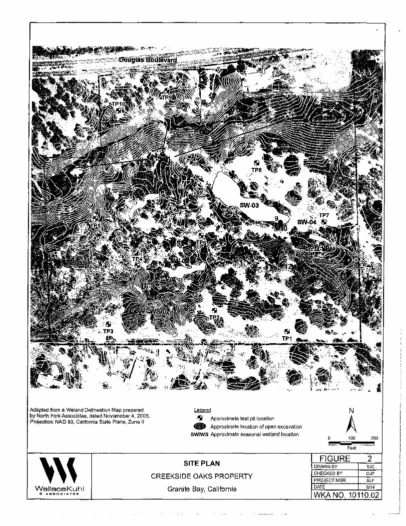
Adapted from a Weiand Delineation Map prepared by North Fork Associates, dated Novemeber 4, 2005. Projection: NAD 83, California State Plane, Zone II
''' WallaceKuhl &. ASSOCIATES
Legend
$ Approximate test pit location
'8 Approximate location of open excavation
SWIWS Approximate seasonal wetland location
SITE PLAN
CREEKSIDE OAKS PROPERTY
Granite Bay, California
i
N
A 0 100 200
Feet
FIGURE 2 DRAWN BY TJC
CHECKED BY DJP
PROJECT MGR SLF
DATE 6/14
WKA NO. 10110.02
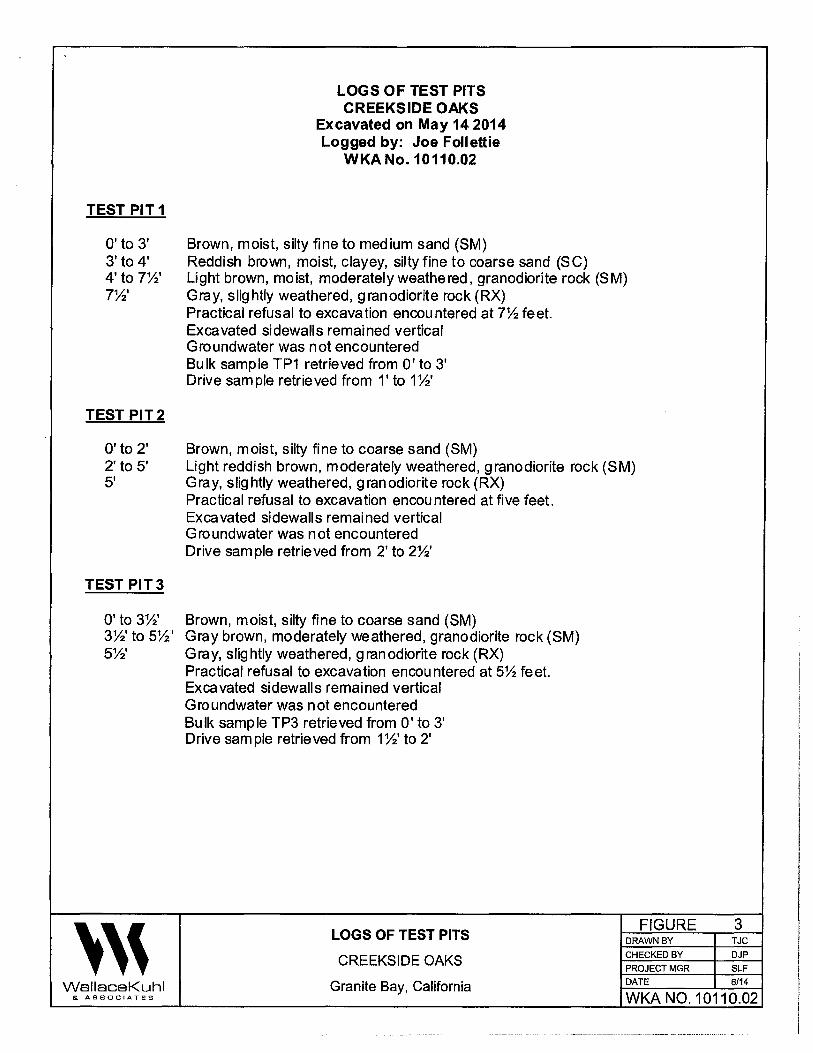
LOGS OF TEST PITS CREEKSIDE OAKS
Excavated on May 14 2014 Logged by: Joe Follettie
WKA No.10110.02
TEST PIT 1
O'to 3' Brown, moist, silty fine to medium sand (SM) 3' to 4' Reddish brown, moist, clayey, silty fine to coarse sand (SC) 4'to T'h' Light brown, moist, moderately weathered, granodiorite rock (SM) T'h' Gray, slightly weathered, granodiorite rock (RX)
Practical refusal to excavation encountered at 7% feet. Excavated sidewalls remained vertical Groundwater was not encountered Bulk sample TP1 retrieved from O' to 3' Drive sample retrieved from 1' to 1%'
TEST PIT2
O'to 2' Brown, moist, silty fine to coarse sand (SM) 2' to 5' Light reddish brown, moderately weathered, granodiorite rock (SM) 5' Gray, slightly weathered, granodiorite rock (RX)
Practical refusal to excavation encountered at five feet. Excavated sidewalls remained vertical Groundwater was not encountered Drive sam pie retrieved from 2' to 2%'
TEST PIT3
O'to 3%' Brown, moist, silty fine to coarse sand (SM) 3%' to 5%' Gray brown, moderately weathered, granodiorite rock (SM) 5%' Gray, slightly weathered, g ran odiorite rock (RX)
Practical refusal to excavation encountered at 5% feet. Excavated sidewalls remained vertical Groundwater was not encountered Bulk sample TP3 retrieved from O' to 3' Drive sample retrieved from 1%' to 2'
''' LOGS OF TEST PITS
FIGURE 3 DRAWN BY TJC
CREEKSIDE OAKS CHECKED BY DJP
PROJECT MGR SLF
WallaceKuhl Granite Bay, California DATE 6/14
& ASSOCIATES WKA N0.10110.02

LOGS OF TEST PITS (continued) CREEKSIDE OAKS
Excavated on May 14 2014 Logged by: Joe Follettie
WKA No. 10110.02
TEST PIT4
O' to 3' Brown, moist, silty, sandy, fine to coarse sandy gravel (GM) - Dredged 3' to 10' Brown, moist, silty fine to coarse sand (SM) - Dredged
Test Pit terminated at 1 O' Sidewalls caving from 3' to 10' Groundwater was not encountered
TEST PITS
O' to 3' Brown, moist, silty fine to coarse sand (SM) 3' to 3%' Gray, moderately weathered, granodiorite rock (SM) 3%' to 4Yz' Gray brown, slightly weathered, granodiorite rock (RX)
Practical refusal to excavation encountered at 4Yz feet. Excavated sidewalls remained vertical Groundwater was not encountered Bulk sample TP5 retrieved from O' to 3' Drive sample retrieved from 1' to 1%'
TEST PIT6
O' to 9' Brown, very moist, silty, sandy gravel and cobbles (GM) - Dredged 3'to 10' Brown, very moist, silty fine to coarse sand (SM) - Dredged
Test Pit terminated at 1 O' Sidewalls caving from 5' to 10' Groundwater was not encountered Bulk sample TP6 retrieved from O' to 3'
TEST PIT7
O' to 3' Reddish brown, moist, silty fine to coarse sand (SM) 3' to 6' Gray brown, moist, sandy silt (ML) 6' to 10' Gray brown, very moist, silty, sandy fine gravel (GM)
Test Pit terminated at 1 O' Excavated sidewalls remained vertical Groundwater was not encountered Bulk sample TP? retrieved from Yz' to 3'
''' LOGS OF TEST PITS
FIGURE 4 DRAWN BY TJC
CREEKSIDE OAKS CHECKED BY DJP PROJECT MGR SLF
Wallace Kuhl Granite Bay, California DATE 6/14
& ASSOCIATES WKA N0.10110.02
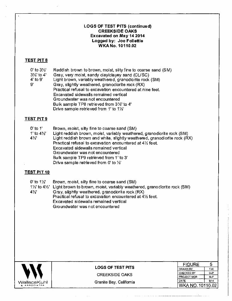
LOGS OF TEST PITS (continued) CREEKSIDE OAKS
Excavated on May 14 2014 Logged by: Joe Follettie
WKA No. 10110.02
TEST PITS
O' to 3W Reddish brown to brown, moist, silty fine to coarse sand (SM) 3W to 4' Gray, very moist, sandy clay/clayey sand (CL/SC) 4' to 9' Light brown, variably weathered, granodiorite rock (SM) 9' Gray, slightly weathered, granodiorite rock (RX)
Practical ref us al to excavation encountered at nine feet. Excavated sidewalls remained vertical Groundwater was not encountered Bulk sample TP8 retrieved from 3W to 4' Drive sample retrieved from 1' to 1W
TEST PIT9
O' to 1' Brown, moist, silty fine to coarse sand (SM) 1' to 4W Light reddish brown, moist, variably weathered, granodiorite rock (SM) 4W Light reddish brown and white, slightly weathered, granodiorite rock (RX)
Practical refusal to excavation encountered at 4% feet. Excavated sidewalls remained vertical Groundwater was not encountered Bulk sample TP9 retrieved from 1' to 3' Drive sample retrieved from O' to W
TEST PIT10
O' to 1W Brown, moist, silty fine to coarse sand (SM) 1%' to 4%' Light brown to brown, moist, variably weathered, granodiorite rock (SM) 4%' Gray, slightly weathered, granodiorite rock (RX)
Practical refusal to excavation encountered at 4% feet. Excavated sidewalls remained vertical Groundwater was not encountered
''' LOGS OF TEST PITS
FIGURE 5 DRAWN BY TJC
CREEKSIDE OAKS CHECKED BY DJP PROJECT MGR SLF
Wallace Kuhl Granite Bay, California DATE 6/14
& ASSOCIATES WKA N0.10110.02
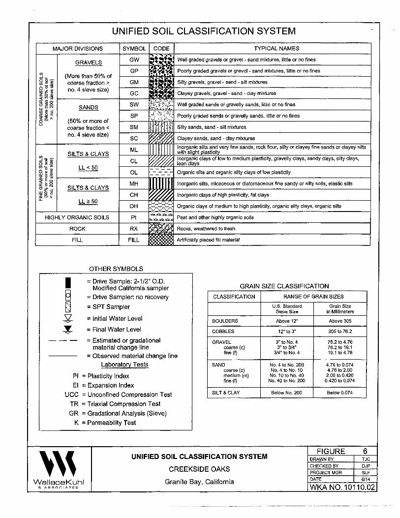
UNIFIED SOIL CLASSIFICATION SYSTEM
MAJOR DIVISIONS SYMBOL CODE TYPICAL NAMES ,~ .. , .
GW :•.~•-:!· Well graded gravels or gravel - sand mixtures, little or no fines GRAVELS -~·1;, -~
Cf) GP ~• ~• Y• Poorly graded gravels or gravel - sand mixtures, little or no fines
6 15 ~ (More than 50% of GM Cf) rn :!l coarse fraction > t Silty gravels, gravel - sand - silt mixtures oO·cn o4' . ) ,, w2 ~~L-~n.:_·=_:s:1e~ve=-=s=,z=e~j_3~_J;~;~c~l~~~~l~~:~~~~~~~'.:_ ____________ J 0 ayey graves, grave - sand - clay mixtures ~LO·~
~ J ~ SANDS SW ~{t(~{· Well graded sands or gravelly sands, little or no fines
0~ ! ~ SP ·f;_.:\:]/:'./ Poorly graded sands or gravelly sands, little or no fines
(50% or more of u coarse fraction < SM j_t 'i. ·: · :: Silty sands, sand - silt mixtures
no. 4 sieve size) ·'~y//x SC ·~5.-"////,· Clayey sands, sand - clay mixtures
ML Inorganic silts and very fine sands, rock flour, silty or clayey fine sands or clayey silts SIL TS & CLAYS with sliaht olasticitv
~"' ai" CL W,1:- ~ Inorganic clays of low to medium plasticity, gravelly clays, sandy clays, silty clays, o Sl .!,! './'///'. Y /, lean clavs Cf) a : LL < 50 ___ _ @ ~ a-; OL _ - _ - _ - _ - Organic silts and organic silty clays of low plasticity z O ·~ t----------+-----11.-.,,......rr1r1-----------------------------1 ~Eo II ~ a~ MH C!l ~ • SILTS & CLAYS
Inorganic silts, micaceous or diatomaceous fine sandy or silty soils, elastic silts
~~~ CH ~ Inorganic clays of high plasticity, fat clays LL LL;;: 50
OH Organic clays of medium to high plasticity, organic silty clays, organic silts
HIGHLY ORGANIC SOILS Pt
ROCK RX
FILL FILL
OTHER SYMBOLS
Y.!L~~~
!kY.!L~~.:i Peat and other highly organic soils
Rocks, weathered to fresh
Artificially placed fill material
= Drive Sample: 2-1/2" O.D. Modified California sampler GRAIN SIZE CLASSIFICATION
= Drive Sampler: no recovery
= SPT Sampler
= Initial Water Level
= Final Water Level
= Estimated or gradational material change line
= Observed material change line Laboratory Tests
Pl = Plasticity Index
El = Expansion Index
UCC = Unconfined Compression Test
TR = Triaxial Compression Test
GR = Gradational Analysis (Sieve)
K = Permeability Test
CLASSIFICATION
BOULDERS
COBBLES
GRAVEL coarse {c) fine (f)
SAND coarse (c) medium (m) fine (f)
SILT &CLAY
''' UNIFIED SOIL CLASSIFICATION SYSTEM
CREEKSIDE OAKS
RANGE OF GRAIN SIZES
U.S. Standard Grain Size Sieve Size in Millimeters
Above 12" Above 305
12" to 3" 305 to 76.2
3" to No. 4 76.2 to4.76 3" to 3/4" 76.2 to 19.1
3/4" to No. 4 19.1 to4.76
No. 4 to No. 200 4.76 to 0.074 No. 4 to No. 10 4.76 to 2.00 No. 1 O to No. 40 2.00 to 0.420 No. 40 to No. 200 0.420 to 0.074
Below No. 200 Below0.074
FIGURE DRAWN BY
CHECKED BY
PROJECT MGR
DATE
6 TJC
DJP
SLF
6/14 Wallace Kuhl & ASSOCIATES
Granite Bay, California WK.A N0.10110.02
·---------·-·-----····~---~-······ .. ·--- ----- -····~--
APPENDICES
'''

APPENDIX A General Information, Field and Laboratory Testing
'''
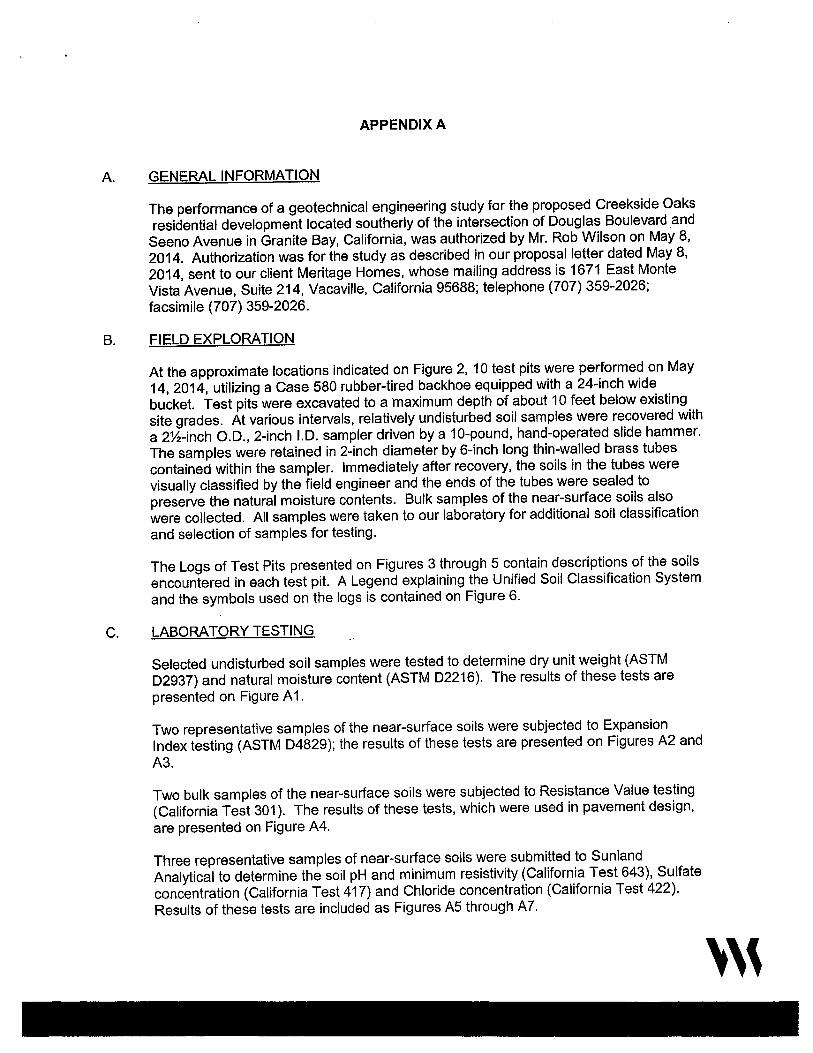
A.
B.
APPENDIX A
GENERAL INFORMATION
The performance of a geotechnical engineering study for the proposed Creekside Oaks residential development located southerly of the intersection of Douglas Boulevard and
Seeno Avenue in Granite Bay, California, was authorized by Mr. Rob Wilson on May 8, 2014. Authorization was for the study as described in our proposal letter dated May 8, 2014, sent to our client Meritage Homes, whose mailing address is 1671 East Monte Vista Avenue, Suite 214, Vacaville, California 95688; telephone (707) 359-2026; facsimile (707) 359-2026.
FIELD EXPLORATION
At the approximate locations indicated on Figure 2, 10 test pits were performed on May 14, 2014, utilizing a Case 580 rubber-tired backhoe equipped with a 24-inch wide bucket. Test pits were excavated to a maximum depth of about 10 feet below existing site grades. At various intervals, relatively undisturbed soil samples were recovered with a 2'V2-inch O.D., 2-inch I.D. sampler driven by a 10-pound, hand-operated slide hammer. The samples were retained in 2-inch diameter by 6-inch long thin-walled brass tubes contained within the sampler. Immediately after recovery, the soils in the tubes were visually classified by the field engineer and the ends of the tubes were sealed to preserve the natural moisture contents. Bulk samples of the near-surface soils also were collected. All samples were taken to our laboratory for additional soil classification and selection of samples for testing.
The Logs of Test Pits presented on Figures 3 through 5 contain descriptions of the soils encountered in each test pit. A Legend explaining the Unified Soil Classification System and the symbols used on the logs is contained on Figure 6.
C. LABORATORY TESTING
Selected undisturbed soil samples were tested to determine dry unit weight (ASTM 02937) and natural moisture content (ASTM D2216). The results of these tests are presented on Figure A 1.
Two representative samples of the near-surface soils were subjected to Expansion Index testing (ASTM D4829); the results of these tests are presented on Figures A2 and
A3.
Two bulk samples of the near-surface soils were subjected to Resistance Value testing (California Test 301 ). The results of these tests, which were used in pavement design, are presented on Figure A4.
Three representative samples of near-surface soils were submitted to Sunland Analytical to determine the soil pH and minimum resistivity (California Test 643), Sulfate concentration (California Test 417) and Chloride concentration (California Test 422). Results of these tests are included as Figures A5 through A7.
'''
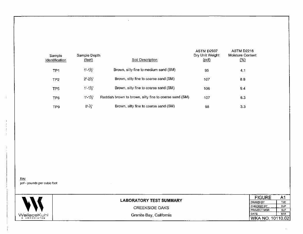
ASTM D2937 ASTM D2216 Sample Sample Depth Dry Unit Weight Moisture Content
Identification (feet) Soil Description ~ (%}
TP1 1'-1Yz' Brown, silty fine to medium sand (SM) 95 4.1
TP2 2·-~· Brown, silty fine to coarse sand (SM) 107 8.8
TP5 1 '-1Yz' Brown, silty fine to coarse sand (SM} 106 9.4
TP8 1 '-1.Yz' Reddish brown to brown, silty fine to coarse sand (SM) 107 6.3
TP9 o·-~· Brown, silty fine to coarse sand (SM) 98 3.3
~ pcf - pounds per cubic foot
''' LABORATORY TEST SUMMARY
FIGURE A1 DRAWN BY TJC
CREEKSIDE OAKS CHECKED BY DJP
PROJECT MGR SLF
WallaceKuhl Granite Bay, California DATE 6/14
6 ASSOCIATES WK.A NO. 10110.02

EXPANSION INDEX TEST RESULTS
ASTM D4829
MATERIAL DESCRIPTION: Brown, silty fine to coarse sand
LOCATION: TP3
Sample Depth
0'-3'
Pre-Test Moisture (%)
6.6
Post-Test Moisture(%)
13.3
Dry Density
~ 121.1
CLASSIFICATION OF EXPANSIVE SOIL*
EXPANSION INDEX
0 -20 21 -50 51 - 90
91 - 130 Above 130
POTENTIAL EXPANSION
Very Low Low
Medium High
Very High
* From ASTM D4829, Table 1
''' EXPANSION INDEX TEST RESULTS
CREEKSIDE OAKS
WallaceKuhl Granite Bay, California & ASSOCIATES
Expansion Index
0
FIGURE DRAWN BY
CHECKED BY
PROJECT MGR
DATE
A2 TJC
DJP
SLF
6/14
WKA NO. 10110.02

EXPANSION INDEX TEST RESULTS
ASTM 04829
MATERIAL DESCRIPTION: Gray, sandy clay/clayey sand
LOCATION: TP8
''' WallaceKuhl & ASSOCIATES
Sample Depth
3,W-4'
Pre-Test Moisture(%)
11.1
Post-Test Moisture(%)
22.7
Dry Density .{QQfl
105.7
CLASSIFICATION OF EXPANSIVE SOIL*
EXPANSION INDEX
0-20
21 - 50 51 - 90
91 - 130
Above 130
* From ASTM 04829, Table 1
POTENTIAL EXPANSION
Very Low
Low Medium
High Very High
EXPANSION INDEX TEST RESULTS
CREEKSIDE OAKS
Granite Bay, California
Expansion Index
37
FIGURE DRAWN BY
CHECKED BY
PROJECT MGR
DATE
A3 TJC
DJP
SLF
6/14
WKA NO. 10110.02
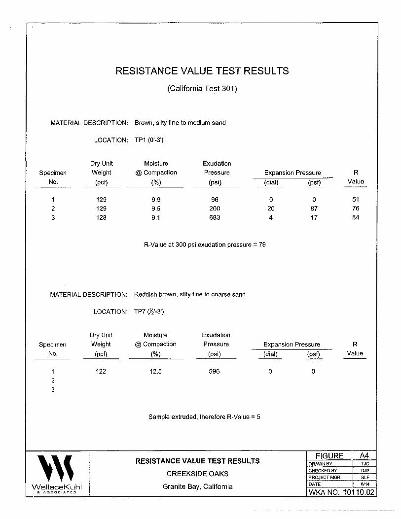
RESISTANCE VALUE TEST RESULTS
(California Te~t 301)
MATERIAL DESCRIPTION: Brown, silty fine to medium sand
LOCATION: TP1 (0'-3')
Dry Unit Moisture Exudation
Specimen Weight @ Compaction Pressure Expansion Pressure R
No. (pcf) (%) (psi) (dial) (psf) Value --
1 129 9.9 96 0 0 51
2 129 9.5 200 20 87 76
3 128 9.1 683 4 17 84
R-Value at 300 psi exudation pressure = 79
MATERIAL DESCRIPTION: Reddish brown, silty fine to coarse sand
LOCATION: TP7 (;~'-3')
Dry Unit Moisture Exudation
Specimen Weight @ Compaction Pressure Expansion Pressure R
No. (pcf) (%) (psi) (dial) (psf) Value
1 122 12.5 596 0 0
2 3
Sample extruded, therefore R-Value = 5
''' RESISTANCE VALUE TEST RESULTS
FIGURE A4 DRAWN BY TJC
CREEKSIDE OAKS CHECKED BY DJP
PROJECT MGR SLF
WallaceKuhl Granite Bay, California DATE 6/14
& ASSOCIATES WKA NO. 10110.02
Sunland Analytical 11419 Sunrise Gold Circle, #10
Rancho Cordova, CA 95742 (916) 852-8557
Date Reported 05/28/2014 Date Submitted 05/22/2014
To: Dominic Potestio Wallace-Kuhl & Assoc. 3050 Industrial Blvd. West Sacramento, CA 95691
From: Gene Oliphant, Ph.D.\ Randy Horney~ General Manager \ Lab Manager \
The reported analysis was requested for the following location: Location: 10110,02 CREEKSIDE Site ID: TPJ, Your purchase order nUlllber is 1917.
Thank you for your business,
* For future reference to this analysis please use SUN# 67030-138886.
--------------------------------------------------------~------------~---------
' ' '
EVALUATION FOR SOIL CORROSION
Soil pH 5.41
Minimum Resistivity
Chloride
Sulfate
METHODS
12.86 ohm-cm (xlOOO)
7.2 ppm
0.2 ppm
00.00072 %
00.00002 %
pH and Min.Resistivity CA DOT Test #643 Sulfate CA DOT Test #417, Chloride CA DOT Test #422
FIGURE DRAWN BY
CHECKED BY
PROJECT MGR
A5 TJC
DJP
SLF
WallaceKuhl
CORROSION TEST RESULTS
CREEKSIDE OAKS
Granite Bay, California DATE 6/14
& ASSOCIATES WKA NO. 10110.02
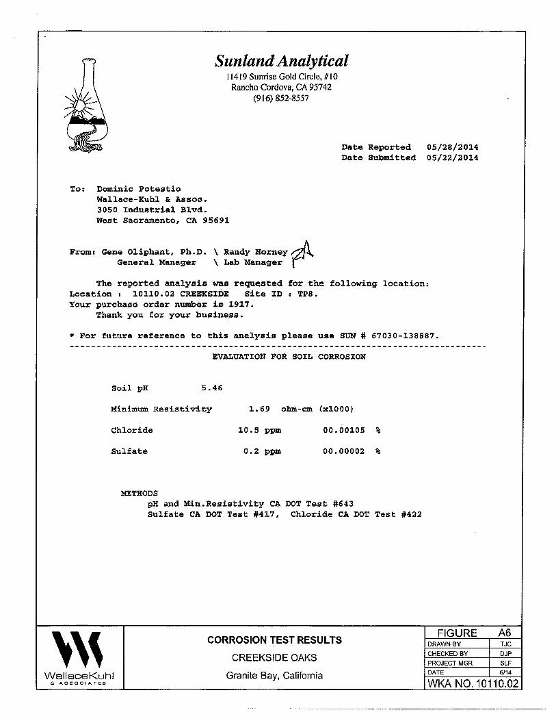
Sunland Analytical 11419 Sunrise Gold Circle, U I 0 Rancho Cordova, CA 95742
(916) 852-8557
Date Reported 05/28/2014 Date Submitted 05/22/2014
To: Dominic Potestio Wallace-Kuhl & Assoc. 3050 Industrial Blvd. West Sacramento, CA 95691
Fromr Gene Oliphant, Ph.D. \ Randy Horney~ General Manager \ Lab Manager \
The reported analysis was requested for the following location: Location r 10110.02 CREEKSIDE Site ID: TPS. Your purchase order number is 1917.
Thank you for your business.
* For future reference to this analysis please use SUN# 67030-138887.
' ' '
EVALUATION FOR SOIL CORROSION
Soil pH 5.46
Minimum Resistivity
Chloride
Sulfate
METHODS
1.69 ohm-cm (xlOOO)
10.5 ppm
0.2 ppm
00.00105 %
00.00002 %
pH and Min.Resistivity CA DOT Test #643 Sulfate CA DOT Test #417, Chloride CA DOT Test #422
CORROSION TEST RESULTS
CREEKSIDE OAKS
Wallace Kuhl
FIGURE DRAWN BY
CHECKED BY
PROJECT MGR
DATE
A6 TJC
DJP
SLF
6/14 Granite Bay, California WKA N0.10110.02 & ASSOCIATES

Sunland Analytical I 1419 Sunrise Gold Circle, #10 Rancho Cordova, CA 95742
(916) 852-8557
Date Reported 05/28/2014 Date Submitted 05/22/2014
To: Dominic Potestio Wallace-Kuhl&: Assoc. 3050 Industrial Blvd. West Sacramento, CA 95691
From: Gene Oliphant, Ph.D~ \ Ra~~y Horney~ . General Manager \ Lab Manager\
The reported analysis was requested for the following location: Location: 10110,02 CREEKSIDE Site ID: TP9, Your purchase order number is 1917.
Thank you for your business.
* For future reference to this analysis please use S'ON # 67030-138888.
' ' '
EVALUATION FOR SOIL CORROSION
Soil pH 4.81
Minimum Resistivity
Chloride
Sulfate
METHODS
8,04 ohm-cm (xlOOO)
7.7 ppm
0.2 ppm
00.00077 %
00.00002 %
pH and Min.Resistivity CA DOT Test #643 Sulfate CA DOT Test #417, Chloride CA DOT Test #422
FIGURE DRAWN BY
CHECKED BY
PROJECT MGR DATE
A? TJC
DJP
SLF 6/14 WallaceKuhl
& ASSOCIATES
CORROSION TEST RESULTS
CREEKSIDE OAKS
Granite Bay, California WKA NO. 10110.02
APPENDIXB Earthwork Specifications
'''
APPENDIX B
EARTHWORK SPECIF/CATIONS
CREEKSIDE OAKS
Douglas Boulevard and Seeno Avenue
Granite Bay, California
GEOTECHNICAL ENGINEERING REPORT
A Geotechnical Engineering Report (WK.A No. 10110.02; dated June 18, 2014) has been
prepared for this site by Wallace - Kuhl & Associates, Geotechnical Engineers; (916) 372-1434.
A copy is available for review at the office of Wallace - Kuhl & Associates, 3050 Industrial
Boulevard, West Sacramento, California. The information contained in the Geotechnical
Engineering Report was obtained for design purposes only.
GENERAL DESCRIPTION
This item shall include all clearing and grubbing, overexcavation and recompaction operations,
preparation of land to be filled, spreading, compaction, observation and testing of the fill, and all
subsidiary work necessary to complete the grading of the site to conform with the lines, grades
and slopes as shown on the accepted plans.
MATERIALS
Proposed fill material shall be free from organic matter and other unsuitable substances and
shall be approved by the Geotechnical Engineer. On-site materials exceeding six inches (6"}
shall be removed from any fill supporting the buildings or pavements. Concentrations of clay
soils shall not be used in the upper twelve inches (12") of the final building pad and pavement
subgrades. Imported fill material shall be granular having a Plasticity Index not exceeding
fifteen (15), an Expansion Index of less than twenty (20), a maximum six-inch (6") particle size,
and a Resistance value of greater than thirty (30). All imported fill sources shall be sampled,
and approved by the Geotechnical Engineer prior to being transported to the site.
CLEARING, GRUBBING AND PREPARING BUILDING AND PAVEMENT AREAS
The site shall be cleared of all surface and subsurface structures, including previous mining
activities, tailings, embankments, fencing and deleterious debris. Trees and shrubs designated
to be removed shall include the entire rootball and roots larger than one-half inch (W') in
diameter. Excavations and depressions resulting from the removal of such items shall be
'''
WKA No. 10110.02 Page B2
cleaned out to firm, undisturbed soil and backfilled with suitable materials in accordance with
these specifications.
The existing ravine, low lying areas and drainages shall be fully drained of water and cleaned of
organics. Saturated and unstable soils exposed within the ditches shall be removed to expose
firm, native materials, as determined by our representative. The exposed surface shall be
scarified to a depth of twelve inches (12") and compacted to at least ninety percent (90%) of the
ASTM D1557 maximum dry density. These soils will likely be saturated and will require
aeration and a period of drying to allow proper compaction. Organically contaminated soils will
not be allowed for use in engineered fill construction.
Remaining surface organics shall be removed by stripping. Strippings shall not be used in
general fill construction, but may be used in landscape areas, provided they are kept at least
five feet (SJ from the building pads, moisture conditioned and compacted. Discing of organics
into the surface soils may be a suitable alternative to stripping, depending upon the quantity
and condition of the surface vegetation at the time of grading. Discing will be allowed only with
our prior approval. Discing operations shall be observed by our representative and must be
continuous until organics are adequately mixed with the soil to provide a compactable mixture.
Pockets or concentrations of organics will not be allowed.
Exposed soil subgrades to receive fill, left at-grade or achieved by excavation, shall then be
scarified to a depth of twelve inches (12"), uniformly moisture conditioned to at least the
optimum moisture content and compacted to at least ninety percent (90%) of the maximum dry
density as determined by the ASTM D1557 Test Method. Recompaction operations shall be
performed in the presence of the Geotechnical Engineer who will evaluate the performance of
the materials under compactive load. Unstable soil deposits, as determined by the
Geotechnical Engineer, shall be excavated to expose a firm base and grades restored with
engineered fill in accordance with these specifications. Compaction shall be achieved using a
heavy, self-propelled, sheepsfoot compactor equivalent to or larger than a Caterpillar 815.
PLACING, SPREADING AND COMPACTING FILL MATERIAL
The selected fill material shall be placed in layers which when compacted shall not exceed six
inches (6") in thickness. Each layer shall be spread evenly and shall be thoroughly mixed
during the spreading to promote uniformity of material in each layer.
'''

WKA No. 10110.02 Page B3
When the moisture content of the fill material is less than the recommended moisture, water
shall be added until the proper moisture content is achieved.
When the moisture content of the fill material is too high to permit the specified compaction to
be attained, the fill material shall be aerated by blading or other methods until the moisture
content is satisfactory.
After each layer has been placed, mixed and spread evenly, it shall be thoroughly compacted to
not less than ninety percent (90%) of the maximum dry density as determined by the ASTM
01557 Test Method. Compaction shall be undertaken with a heavy, self propelled, sheepsfoot
type compactor (Caterpillar 825 or equivalent sized compactor) and shall be accomplished
while the fill material is at the required moisture content. Each layer shall be compacted over its
entire area until the desired density has been obtained.
Rocky materials used as fill shall be thoroughly moisture conditioned to at least the optimum
moisture content and uniformly compacted by at least three (3) complete coverages with a
heavy, self-propelled sheepsfoot compactor (Caterpillar 825 compactor or an equivalent), to the
satisfaction of our on-site representative. One complete coverage is defined as the process
necessary to assure that every square foot of subgrade has been traversed and compacted by
the compaction equipment. Each layer shall be compacted over its entire area until the desired
density has been obtained.
The filling operations shall be continued until the fills have been brought to the finished slopes
and grades as shown on the accepted Drawings.
FIELD DENSITY TESTS
The Geotechnical Engineer or their representative shall make field density tests after
compaction of each layer of fill. Where compaction equipment has disturbed the surface to a
depth of several inches, density tests shall be taken in the compacted material below the
disturbed surface. Additional layers of fill shall not be spread until field density tests indicate the
specified density has been obtained.
'''
WKA No. 10110.02 Page 84
FINAL SUBGRADE PREPARATION
The upper twelve ( 12") inches of final building pad subgrades shall be brought to the optimum
moisture content and uniformly compacted to not less than ninety percent (90%) of the ASTM
D1557 maximum dry density or by at least three (3) complete coverages of a Caterpillar 825 ( or
equivalent) regardless of whether final grade is left at the existing grade or is completed by
excavation or filling.
The upper six inches (6") of final subgrades supporting pavements shall be brought to a
uniform moisture content, and shall be uniformly compacted to not less than ninety-five percent
The upper twelve inches (12") of all final pavement subgrades shall be processed, uniformly
moisture conditioned to the optimum moisture content and compacted to at least ninety-five
percent (95%) relative compaction of the ASTM D1557 maximum dry density or by at least five
(5) complete coverages of a Caterpillar 825 (or equivalent) regardless of whether final subgrade
elevations are attained by filling, excavation, or are left at existing grades. Final pavement
processing, moisture conditioning and compaction shall be performed just prior to placement of
pavement aggregate base.
TESTING
Observation and testing by the Geotechnical Engineer or their representative shall be provided
during all filling and compaction operations. The grading contractor shall give at least twenty
four hours (24) notice prior to beginning such operations to allow proper scheduling of the work.
SEASONAL LIMITS
Fill materials shall not be placed, spread or rolled during unfavorable weather conditions. When
heavy rains interrupt the work, fill operations shall not be resumed until field tests indicate that
the moisture content and density of the fill are satisfactory.
I
'''

Related Documents