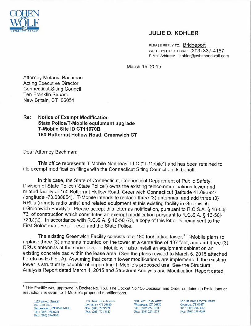
COHFN WOLF ~P.C.~ ATTORNEYS AT LAW JULIE D. KOHLER PLEASE REPLY TO: BfICIgepOff WRITER~s ~iRECT ~ia~: (203) 337-4157 E-Mail Address: [email protected] March 19, 2015 Attorney Melanie Bachman Acting Executive Director Connecticut Siting Council Ten Franklin Square New Britain, CT 06051 Re: Notice of Exempt Modification State Police/T-Mobile equipment upgrade T -Mobile Site ID CT11070B 150 Butternut Hollow Road, Greenwich CT Dear Attorney Bachman: This office represents T -Mobile Northeast LLC ("T -Mobile") and has been retained to file exempt modification filings with the Connecticut Siting Council on its behalf. In this case, the State of Connecticut, Connecticut Department of Public Safety, Division of State Police ("State Police") owns the existing telecommunications tower and related facility at 150 Butternut Hollow Road, Greenwich Connecticut (latitude 41.096927 /longitude -73.638854). T -Mobile intends to replace three (3) antennas, and add three (3) RRUs (remote radio units) and related equipment at this existing facility in Greenwich ("Greenwich Facility"). Please accept this letter as notification, pursuant to R.C.S.A. § 16-50j- 73, of construction which constitutes an exempt modification pursuant to R.C.S.A. § 16 -50j - 72(b)(2). In accordance with R.C.S.A. § 16-50j-73, a copy of this letter is being sent to the First Selectman, Peter Tesei and the State Police. The existing Greenwich Facility consists of a 180 foot lattice tower.' T -Mobile plans to replace three (3) antennas mounted on the tower at a centerline of 137 feet, and add three (3) RRUs antennas at the same level. T -Mobile will also install an equipment cabinet on an existing concrete pad within the lease area. (See the plans revised to March 5, 2015 attached hereto as Exhibit A). Assuming that certain tower modifications are implemented, the existing tower is structurally capable of supporting T -Mobile's proposed use. See the Structural Analysis Report dated March 4, 2015 and Structural Analysis and Modification Report dated This Facility was approved in Docket No. 150. The Docket No.150 Decision and Order contains no limitations or restrictions relevant to T -Mobile's proposed modifications. L I IS BROAD STREET ISH DEER HILL AVENUE 320 Posr RonD WEsz CS7 ORANGE CANTER ROAD P.O. BOX 1H21 DANBURY, CT O6S IO WESTPORT, CT 06880 ORANGE, CC OC~7~ BRIDGEPORT, LT 066 1-1821 'ILL: (203) 7922771 TEL: (2~3) 222.-1 34 TEL: (2~3) ~98~66 TEt: (203) 368-0211 Fax: (203) 791-8149 Fax: (203) 227-1373 Fax: (203) 298-0068 Fax: (203) 3949901

Welcome message from author
This document is posted to help you gain knowledge. Please leave a comment to let me know what you think about it! Share it to your friends and learn new things together.
Transcript
COHFNWOLF~P.C.~ATTORNEYS AT LAW
JULIE D. KOHLER
PLEASE REPLY TO: BfICIgepOff
WRITER~s ~iRECT ~ia~: (203) 337-4157E-Mail Address: [email protected]
March 19, 2015
Attorney Melanie BachmanActing Executive DirectorConnecticut Siting CouncilTen Franklin SquareNew Britain, CT 06051
Re: Notice of Exempt ModificationState Police/T-Mobile equipment upgradeT-Mobile Site ID CT11070B150 Butternut Hollow Road, Greenwich CT
Dear Attorney Bachman:
This office represents T-Mobile Northeast LLC ("T-Mobile") and has been retained tofile exempt modification filings with the Connecticut Siting Council on its behalf.
In this case, the State of Connecticut, Connecticut Department of Public Safety,Division of State Police ("State Police") owns the existing telecommunications tower andrelated facility at 150 Butternut Hollow Road, Greenwich Connecticut (latitude 41.096927/longitude -73.638854). T-Mobile intends to replace three (3) antennas, and add three (3)RRUs (remote radio units) and related equipment at this existing facility in Greenwich("Greenwich Facility"). Please accept this letter as notification, pursuant to R.C.S.A. § 16-50j-73, of construction which constitutes an exempt modification pursuant to R.C.S.A. § 16-50j-72(b)(2). In accordance with R.C.S.A. § 16-50j-73, a copy of this letter is being sent to theFirst Selectman, Peter Tesei and the State Police.
The existing Greenwich Facility consists of a 180 foot lattice tower.' T-Mobile plans toreplace three (3) antennas mounted on the tower at a centerline of 137 feet, and add three (3)RRUs antennas at the same level. T-Mobile will also install an equipment cabinet on anexisting concrete pad within the lease area. (See the plans revised to March 5, 2015 attachedhereto as Exhibit A). Assuming that certain tower modifications are implemented, the existingtower is structurally capable of supporting T-Mobile's proposed use. See the StructuralAnalysis Report dated March 4, 2015 and Structural Analysis and Modification Report dated
This Facility was approved in Docket No. 150. The Docket No.150 Decision and Order contains no limitations orrestrictions relevant to T-Mobile's proposed modifications.
L I IS BROAD STREET ISH DEER HILL AVENUE 320 Posr RonD WEsz CS7 ORANGE CANTER ROAD
P.O. BOX 1H21 DANBURY, CT O6S IO WESTPORT, CT 06880 ORANGE, CC OC~7~
BRIDGEPORT, LT 066 1-1821 'ILL: (203) 7922771 TEL: (2~3) 222.-1 34 TEL: (2~3) ~98~66
TEt: (203) 368-0211 Fax: (203) 791-8149 Fax: (203) 227-1373 Fax: (203) 298-0068Fax: (203) 3949901
COH~NWOLF_~~:_ATT~RN[}'S ,\T LAl4'
March 19, 2015Site ID CT11070BPage 2
January 30, 2015, both attached hereto as Exhibit B.2
The planned modifications to the Greenwich Facility fall squarely within those activitiesexplicitly provided for in R.C.S.A. § 16-50j-72(b)(2).
1 . The proposed modification will not increase the height of the tower. T-Mobile'sreplacement and new antennas will be installed at the 137 foot level. The enclosed towerdrawing confirms that the proposed modification will not increase the height of the tower.
2 . The installation of the T-Mobile equipment in the existing compound, as reflectedon the attached plan (Sheet A-1), will not require an extension of the site boundaries. T-Mobile's proposed equipment will be located entirely within the existing compound area.
3 . The proposed modification to the Facility will not increase the noise levels at theexisting facility by six decibels or more.
4 . The operation of the replacement antennas will not increase the total radiofrequency (RF) power density, measured at the base of the tower, to a level at or above theapplicable standard. According to a Radio Frequency Emissions Analysis Report prepared byEBI dated March 18, 2015 T-Mobile's operations would add 6.79% of the FCC Standard.Therefore, the calculated "worst case" power density for the planned combined operation atthe site including all of the proposed antennas would be 70.20% of the FCC Standard ascalculated for a mixed frequency site as evidenced by the engineering exhibit attached heretoas Exhibit C.
For the foregoing reasons, T-Mobile respectfully submits that the proposed replacementantennas and equipment at the Greenwich Facility constitutes an exempt modification underR.C.S.A. § 16-50j-72(b)(2).
Sincerely,
l.~,w --~ul~ D. Kohler, Esq - -- --
cc: First Selectman Peter Tesei, Town of GreenwichConnecticut Department of Public Safety, Division of State PoliceSheldon Freincle, NSS
z T-Mobile will implement the indicated modifications prior to the installation of its antennas.
~~1~~
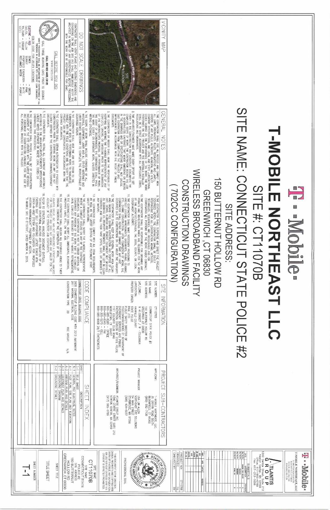
T-MOBILE NORTHEAST LLC
SITE #: CT11070B
SITE ADDRESS:
150 BUTTERNUT HOLLOW RD
GREENWICH ,CT 06830
WIRELESS BROADBAND FACILITY
SITE NAME: CONNECTICUT STATE POLICE #
2
CONSTRUCTION DRAWINGS
( 702CC CONFIGURATION)
VICINITY MAP
DO NOT SCALE
DRAWINGSCONTRACTOR SHALL VERIFY PLANS A
ND EXISTING
DIMENSIONS AND
CONDITIONS ON THE JOB SITE A
ND SHALL IMMEDIATELY
NOTIFY THEARCHITECT IN
WRITING OF ANY DISCREPANCIES
BEFORE PROCEEDINGWITH
THE WORK OR BE RESPONSIBLE FOR
SAME.
CALL BEFORE YOU DIG:
W W W.CBYD.COM
cvl eoo szz aass, oA en
CALL THREE WORKING DAYS PRIOR T
O DIGGING
SAFETY PRECAUTIONS SHALL BE IMPLFAIINIID BY CONiRACTOR(S) AT ALL
TRENCHMG IN
ACCORDANCE WITH
CURRENT OSHA STANDARDS.
COLOR CODE FOR UTILITY
LOCATIONSELECTRIC -
RED
SEWER
-GREEN
GAS/OIL -YELLOW
SURVEY -PINK
TEL/CAN -ORANGE
PROPOSED EXCAVATION
-WHITE
WATER -BLUE
RECLAIMED WATER
-PURPLE
GENERAL NOTES
1. THE CONTRACTOR SHALL GIVE ALL NOTICES AND C
OMPLY WITH
ALL LAWS, ORDINANCES. RULES, REGULATIONS AND LAWFUL
ORDERS OF ANY PUBLIC AUTHORITY, MUNICIPAL A
ND UTILRY
COMPANY SPECIFICATIONS, AND
LOCAL ANA STATE JURISDICTIONALCODES
BEARING ON THE PERFORMANCE O
F THE WORK. THE W
ORK
PERFORMED ON THE PROJECT AND THE MATERIALS INSTALLED
SHALL BE IN STRICT ACCORDANCE WITH
ALL APPLICABLE CODES,REGUTATIONS AND
ORDINANCES.
2. THE ARCHITECT/ENGINEER HAVE
MADE EVERY EFFORT TO SETFORTH
IN THE CONSTRUCTION
AND CONSTRUCT D
OCUMENTS THE
COMPLETE SCOPE OF WORK. THE CONTRACTOR BIDDING THE JOB
IS NEVERTHELESS CAUTIONED THAT
MINOR OMISSIONS O
R ERRORS
IN THE DR4WINGS A
ND OR SPECIFlCATIONS SHALL NOT EXCUSE
SAID CONTR,4CTOR FROM
COMPLETWG THE PROJECT A
ND
IMPROVEMENTS IN ACCORDANCE WITH THE INTENT O
F THESE
DOCUMENTS.
3. THE CONTRACTOR OR BIDDER
SHALL BEAR THE RESPONSIBILITY O
FNOTIFYING (IN
WRITING) THE T—MOBILE REPRESENTATIVE OF ANY
CONFLICTS, ERRORS, OR OMISSIONS PRIOR TO THE SUBMISSION
OF THE CONTRACTOR'S PROPOSAL O
R PERFORMANCE OF WORK. IN
THE EVENT OF DISCREPANCIES, THE CONTRACTOR SHALL PRICE
THE MORE COSTLY O
R EXPENSIVE W
ORK, UNLESS DIRECTED IN
WRITING OTHERWISE.
4. THE SCOPE OF WORK SHALL INCLUDE FURNISHING O
F ALL
MATERIALS, EQUIPMENT, LABOR AND ALL OTHER MATERIALS AND
LABOR DEEMED
NECESSARY TO COMPLETE THE WORK/PROJECT ASDESCRIBED
HEREIN.
5. THE CONTRACTOR SHALL VISIT T
HE JOB SITE PRIOR TO THE
SUBMISSION OF BIDS O
R PERFORMING W
ORK TO
FAMILIARIZEHIMSELF WITH THE FIELD
CONDITIONS AND TO VERIFY THAT THEPROJECT CAN
BE CONSTRUCTED
IN ACCORDANCE WITH THE
CONTRACT DOCUMENTS.
6. THE CONTRACTOR SHALL OBTAIN AUTHORIZATION TO PROCEED WITH
CONSTRUCTION PRIOR TO STARTING W
ORK ON ANY ITEM
NOTCLEARLY DEFINED
BY THE CONSTRUCTION DRAWINGS/CONTRACT
DOCUMENTS.
7. THE CONTRACTOR SHALL INSTALL ALL EQUIPMENT AND MATERIALS
ACCORDING TO THE MANUFACTURER'S/VENDOR'S SPECIFlCATIONS
UNLESS NOTED OTHERWISE O
R WHERE LOCAL CODES O
RORDINANCES TAKE PRECEDENCE.
B. THE CONTRACTOR SHALL PROVIDE A FULL SEf O
F CONSTRUCTION
DOCUMENTS AT T
HE SITE UPDATED
WITH THE L4TEST REVISIONSAND A
DDENDUM OR CLARIFICATIONS AVAIIABLE FOR THE
USE BYALL PERSONNEL INVOLVED
WITH THE PROJECT.
9. THE CONTRACTOR SHALL SUPERVISE AND DIRECT THE PROJECT
DESCRIBED HEREIN. THE CONTRACTOR SHALL B
E SOLELY
RESPONSIBLE FOR ALL CONSTRUCTION
MEANS, METHODS,TECHNIQUES, SEQUENCES, AND
PROCEDURES AND
FORCOORDINATING ALL PORTIONS O
F THE W
ORK UNDER CONTRACT.
10. THE CONTRACTOR
SHALL BE RESPONSIBLE FOR
OBTAINING ANYPERMITS A
ND INSPECTIONS WHICH
ARE REQUIRED FOR THE W
ORK
BY THE ARCHITECT/ENGINEER, THE STATE, COUNTY, O
R LOCAL
GOVERNMENT AUTHORITY.
11.THE CONTRACTOR SHALL M
AKE NECESSARY PROVISIONS TO
PROTECT EXISTING IMPROVEMENTS, EASEMENTS, PAVING, CURBING,
EfC., DURING CONSTRUCTION. UPON COMPLETION
OF WORK, THE
CONTR4CTOR SHALL REPAIR ANY DAMAGE THAT MAY HAVE
OCCURRED DUE TO
CONSTRUCTION ON OR ABOUT T
HE PROPERTY.
i2.THE CONTR4CTOR SHALL KEEP THE GENERAL W
ORK AREA CLEAN
AND HA7ARD
FREE DURING CONSTRUCTION
AND DISPOSE O
F ALL
DIRT, DEBRIS, RUBBISH AND
REMOVE EQUIPMENT NOT SPECIFIED
AS REMAINING ON PROPERTY. PREMISES SHALL BE LEFT IN
CLEANCONDITION
AND FREE FROM
PAINT SPOTS, DUST, OR SMUDGES OF
ANY NATURE.
13. THE CONTRACTOR
SHALL COMPLY WITH ALL O
SHA REQUIREMENTS,
AS WELL AS THE LATEST EDITIONS OF ANY PERTINENT STATE
SAFETY REGULATIONS.
14. THE CONTRACTOR
SHALL NOTIFY THE T—MOBILE REPRESENTATIVEWHERE A
CONFLICT OCCURS ON ANY O
F THE CONTR4CT
DOCUMENTS. THE CONTR4CTOR IS
NOT TO ORDER MATERIAL O
RCONSTRUCT ANY PORTION
OF THE W
ORK THAT IS IN
CONFLICTUNTIL CONFLICT IS RESOLVED
BY THE T—MOBILE REPRESENTATIVE.
15. THE CONTRACTOR SHALL VERIFY ALL DIMENSIONS, ELEVATIONS,
PROPERTY LINES, ETC., ON THE JOB.
16. THE CONTR4CTOR SHALL RETURN
ALL DISTURBED AREAS TO THEIRORIGINAL CONDITION
AT THE COMPLETION OF WORK.
17.ATL4NTIS GROUP, INC. HAS NOT CONDUCTED A STRUCTUR4L ANALYSIS
FOR THIS PROJECT AND DOES NOT ASSUME ANY LIABILITY FOR THEADEQUACY OF THE STRUCTURE AND COMPONENTS.
18. REFER TO STRUCTUR4L ANALYSIS DOCUMENT ENTITLED,
"DETAILED STRUCTURAL ANALYSIS AND EVALUAl10N
OF AN
EXISTING 180' SELF SUPPORTING
LATTICE TOWER WITH
STACK—N—BOLT SYSTEM
AND FOUNDATION
FOR PROPOSED
ANTENNA ARRANGEMENT" PREPARED BY AECOM,
"T—MOBILE SITE ID CT1070B", DATED
MARCH 4, 2015.
SITE INFORMATION
SITE NUMBER:
CT11070B
SITE NAME:
CONNECTICUT STATE POLJCE #2
SITE ADDRESS: 150 BUTTERNUT H
OLLOW RD
GREENWICH ,CT 06830
LAT./LONG.: N
41.096927 / W —73.638854
JURISDICTION: FAIRFIELD
COUNTY
PROPERTY OWNER:
STATE POLICEPAUL ZITO
PUBLIC SAFETY DIRECTOR OF
TELECOMMUNICATIONS CT
DEPARTMENT OF
EMERGENCY SERVICES A
ND PUBLIC
PROTECTION DIVISION
OF STATE POLJCE
1111 COUNTRY CLUB ROAD
MIDDLETOWN, CT 06457
860-685-8280 —OFFICE
860-685-8345 —FAX
860-305-5275 —CELL
860-685-8008 24/7 EMERGENCIES
CODE COMPLIANCE
CONNECTICUT STATE BUILDING
CODE
2005 CONNECTICUT BUILDING
CODE WITH
2013 AMENDMENT
2011 NATIONAL ELECTRICAL C
ODE
CONSTRUCTION TYPE:
2B
USE GROUP:
N/A
PROJECT SUB—CONTRACTORS
APPLICANT: T—MOBILE
NORTHEAST, LLC.35 GRIFFIN
ROAD SOUTH
BLOOMFIELD, CT 06002
(860) 692-7100
PROJECT MANAGER
LISA UN ALLEN
NORTHEAST SITE SOLUTIONS54 MAIN
STREETSTURBRIDGE, M
A 01566
(508) 434-5237
ARCHITECT/ENGINEER: ATLANTIS G
ROUP INC.
1340 CENTRE STREET SUITE 2
12
NEWTON CENTER, M
A 02459
(617) 965-0789
SHEET INDEX
SHEEP DESCRIPTION
T-1
TITLE SHEET
N-1
GENERAL AND ELECTRICAL
NOTES
A-1
PLOT PLAN, SITE
PLAN AND ELEVATION
A-2
ANTENNA PLAN
AND DETAILS
A-3
EQUIPMENT PLAN
AND DETAILS
E-1
GROUNDING DIAGRAM
E-2
GROUNDING DETAILS
~il~•T-MOBILE NORTHEAST, LLC
35 GWFFIN ROAD SOUTH
HLOOMFIELD, CT OF002
OFFICE: (8fi0)fi92-710
FAX:(8607 692-7159
. TLANTIS
G R O U P
1340 Centre
Street, Suite 212
Newton Center, M
A 02459
Office: 617-965-0789
Fax: 617-213-5056
SUBMITTALS
DATE
D6CRIPTION
REVISION
o~te/ts
mum rut r~nnr
n
Vl/19/15
~VppH
D
02/18/15
REV15gN
1
0!/M/15
FlW~L 4V
2
DEPT.
647E
PPP'D
REV190N5
PFE
~~.Z~~~~~~~.PROJECT NO:
CT11070BDRAWN BY:
FG
CHECKED BY:
SM
e~y~Q~YCOAII~F ~~ii
/~@': ~p 5
d~:z
O~GI:
=~'
':*~
'itt''~ ~ARI.11;6~'~C1`~
"~~s;~o AR~'~;.~ ,
PROFESSIONAL SEAL
THIS DOCUMENT IS THE CREATION,
DESIGN, PROPERTY AND COPYRIGHTEDWORK OF T-MOBILE. ANY DUPLICATION
OR USE WITHOUT EXPRESS WRITTEN
CONSENT IS STRICTLY PROHIBITED.
SITE NAME
CT11070B
SITE NAME
CONNECTICUT STATE
POLICE #2
SITE ADDRESS
150 BUTTERNUT
HOLLOW RD
GREENWICH ,CT 06830
SHEET TITLE
TITLE SHEET
SHEET NUMBER
T-1
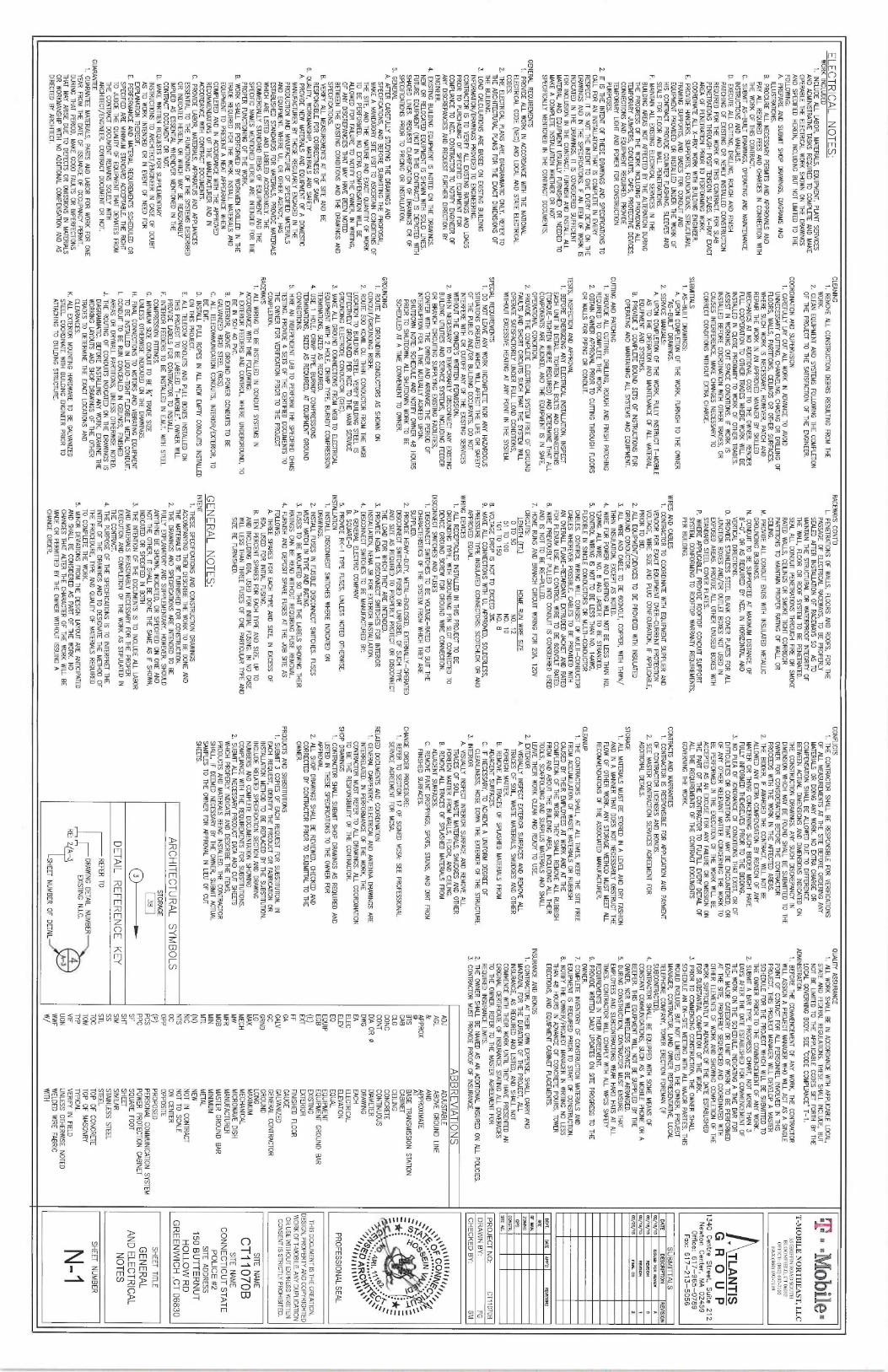
ELECTRICAL NOTES:
WORK INCLUDED
1. INCLUDE ALL L4BOR, MATERIALS, EQUIPMENT, PLANT SERVICESAND ADMINISTRATIVE TASKS REQUIRED TO COMPLETE AND
MAKEOPER4BLE THE ELECTRICAL W
ORK SHOWN ON THE D
R4WMG5
AND SPECIFlE~ HERON, INCLUDING BUT NOT LIMBED TO THE
FOLLOWING:A PREPARE AND SUBMIT S
HOP DRAWINGS, DIAGRAMS AND
ILLUSTRATIONS.B. PROCURE ALL NECESSARY PERMITS AND APPROVALS ANDPAY ALL REQUIRED
FEES AND CHARGES IN CONNECTION WITHTHE W
ORK OF THIS COPITRACT.
C. SUBMR AS-BUILT DR4WING5, OPERATING AND
MAINTENANCEINSTRUCTIONS AND
MANUALS.D. IXECUIE ALT. CUTTING, DRILLING, ROUGH AND FlNISH
PATCHING OF IXISTING OR
NEWLY INSTALLED CONSTRUCTIONREQUIRED FOR THE W
ORK OF THIS CONTRACT. FOR SLAB
PENETRATIONS THROUGH POSE TENSION SLABS, X-RAY EXACTAREA O
F PENETRATION PRIOR TO PERFORMING WORK.
COORDINATE ALL X-R4Y WORK WITH BUILDING ENGINEER.E. PROVIDE HANGERS, SUPPORTS, FOUNDATIONS, SfRUCiUR4L
FRAMING SUPPORTS, AND BASES FOR CONDUR AND
E~UIPMENi PROVIDED OR INSTALLED
UNDER THE WORK OF
HIS CONTRACT. PROVIDE COUNTER FLASHING, SLEEVES ANDSEALS FOR FLOOR AND
WALL PENETTtATI0N5.F. MAINTAIN ALL IXI571NG ELECTRICAL SERVICES IN THE
BUILDING AREAS NOT P,FFECTED BY THE ALTERATION DURINGTHE PROGRESS O
F 1HE WORK INCLUDING PROVIDING ALL
TEMPOR4RY JUMPERS, CONDUITS, CAPS, PROTECTIVE DEVICES,CONNEC110NS AND EQUIPMENT REQUIRED. PROVIDETEMPORARY LIGHT AND POWER FOR CONSTRUCTIONPURP056.
2. IT IS THE INTENT OF THESE DR4WINGS AND SPECIFlCATIONS TO
CALL FOR AN INSTALfATION THAT IS COMPLETE IN EVERYRESPECT. R
IS NOT THE INTENT TO GIVE EVERY DEffJL ON THE
DRAWINGS AND IN THE SPECIFlCATIONS. IF AN ITEM OF WORK IS
INDICATED IN THE DRAWWGS, R IS CONSIDERm SUFFlCIENT
FOR INCLUSION IN THE COMRACT. FURNISH AND INSTALL ALL
MATERIAL AND EQUIPMENT USUALLY FURNISHED OR NEEDED TO
MAKE A COMPLETE INSTALLATION WHETHER O
R NOT
SPECIFlCAIlY MENTIONED IN THE CONTRACT DOCUMENTS.
GENERAL REQUIREMENTSt. PROVIDE ALL W
ORK IN ACCORDANCE WITH THE NATIONAL
ELECTRICAL CODE (NEC) AND LOCAL AND STATE ELECTRICALCODES.
2. THE ELECTRICAL PLANS ARE DIAGRAMMATIC ONLY. REFER TO
THE ARCHffECTURAL PLANS FOR THE EXACT DIMENSIONS OF
THE BUILDING.3. LOAD CALCULATIONS ARE BASED ON IXISTING BUILDING
INFORMATION/DRAWINGS PROVIDES TO ENGINEQtING.
CONTRACTOR IS TO VERIFY ALL EXISTING RATINGS AND LOADS
PRIOR TO PURCHASING OF SPECIFlm
EQUIPMENT FORCOMPLIANCE TO NEG. CONTRACTOR TO NOTIfY ENGINEER O
FANY DISCREPANCIES AND REQUEST FURTHER DIRECTION
BYENGINEER.
4. IXISf1NG BUILDING EQUIPMENT IS NOTED ON THE DRAWINGS.
NEW OR RELOCATED EQUIPMENT IS S
HOWN WI1H SOLID
LINES.FUTURE EQUIPMENT (NOT IN THIS CONTRACT) IS DEPICTED WITHSHADED LJNES. REQUEST CLARIFICATION O
F DR4WING5 O
R OF
SPECIFlCATIONS PRIOR TO PRICING OR INSTALLATION.5. GENERAL
A. AFTER CAREFULLY STUDYING 1HE DRAWINGS ANDSPECIFICATIONS, AND
BEFORE SUBMITI7NG THE PROPOSAL,MAKE A MANDATORY SfTE VISIT TO ASCERTAIN CONDRIONS O
FTHE SITE, AND THE N
ANRE AND EXACT QUANTIN O
F WORK
TO BE PERFORMED. N
O IXfRA COMPENSATION WILL BE
ALLOWED FOR FAILURE TO NOTIFY THE OWNER, IN WRITING,
OF ANY DISCREPANCIES THAT MAY HAVE BEEN
NOTEDBETWEEN THE IXISfWG CONDITIONS AND THE DRAWINGS ANDSPEgFICATI0N5.
B. VERIFY ALT. MEASUREMENTS AT THE SITE AND 8E
RESPONSIBLE FOR CORRECTNESS OF SOME.6. QUNJiY, WORKMANSHIP, MATERIALS AND SAFETY
A. PROVIDE NEW MATERIALS AND EQUIPMENT OF A DOMESTIC
MANUFACTURER BY THOSE REGULARLY ENGAGED IN THEPRODUCTION AND
MANUFACTURE OF SPECIFlED
MATERIALSAND
EQUIPMENT. WHERE UL, OR OTHER AGENCY, HAS
ESTABLJSHED STANDARDS FOR MATERIALS, PROVIDE MATERIALS
WHICH ARE LISTED AND LABELED ACCORDWGLY. THE
COMMERCIALLY STANDARD fTQdS OF EQUIPMENT AND THE
SPECIFlC NAMES MEMIONED HEREIN ARE INTENDm FOR hiEPROPER FUNCTIONING O
F 1HE WORK.
B. WORK SHALL BE PERFORMED BY WORKMEN SKILLED IN hiE
TRADE REgUIRm FOR 1HE WORK. INSTALL MATERIALS AND
EQUIPMENT TO PRESENT A NEAT APPEARANCE WHENCOMPLETED AND IN ACCORDANCE WITH THE APPROVEDRECOMMENDATIONS O
F THE MANUFACTl1RER AND IN
ACCORDANCE WITH CONTRACT DOCUMENTS.C. PROVIDE LABOR, MATERIALS, APPARATUS AND APPLIANCES
ESSENTIAL TO THE FUNCTIONING OF THE SYSTEMS DESCRIBED
OR INDICATED HEREIN, O
R WHICH
MAY BE REASONABLY
IMPLIED AS ESSENTIAL WHENEVER MENTIONm IN THE
COMRACT DOCl1MENT O
R NOT.
D. MAKE WRITTEN REQUESTS FOR SUPPLEMENTARYINSTRUCilONS TO ARCHffECT/ENGINEER IN CASE O
F DOUBT
AS TO WORK INTENDED OR IN EVENT O
F NEED
FORIXPLANAiION THEREOF.
E. PERFORMANCE AND MATERIAL REQUIREMENTS SCHEDULED O
RSPECIFIED ARE MINIMUM STANDARD ACCEPTABLE. THE RIGHTFO JUDGE THE QUNJ7Y OF EQUIPMENT THAT DEVIATES FROMTHE CONTRACT DOCUMENT R
EMNNS SOLELY WITH
ARCHITECT/ENGINEER. CONTRACT DOCUMENT OR NOT.
GUARANTEE1. GUAR4NTEE MATERIALS, PARIS AND LABOR FOR W
ORK FOR O
NE
YEAR FROM THE DATE O
F ISSUANCE OF OCCUPANCY PERMIT.
DURING THAT PERIOD, MAKE GOOD FAULTS OR IMPERFECTIONS
THAT MAY ARISE DUE TO DEFECTS OR OMISSIONS IN MATERIALS
OR WORKMANSHIP WITH
NO ADDRIONAL COMPENSATION
ANA AS
DIRECTED BY ARCHfTECT.
CLEANING1. REMOVE ALI. CONSTRUCTION D
~RIS RESULTING FROM THE
WORK.2. CLEAN
EQUIPMENT AND SYSTEMS FOLLOWING THE COMPLETIONOF THE PROJECT TO THE SATISFAC710N OF THE ENGINEER.
COORDINATION AND SUPERVISION1. CAREFULLY LAY OUT ALL W
ORK IN ADVANCE TO AVOID
UNNECESSARY CUif1NG, CHANNELING, CHASING OR DRIWNG C
FLOORS, WALLS, PARTITIONS, CEILINGS OR OTHER SURFACES.
WHERE SUCH WORK IS NECESS4RY, HOWEVER, PATCH AND
REPAIR THE WORK IN AN APPROVED
MANNER BY SKILLEDMECHANICS AT NO ADDITIONAL COST TO THE OWNER. RENDERFULL COOPERATION TO OTHER TRADES WHERE W
ORK WILL BE
INSTALLED IN CLOSE PROXIMf1Y TO WORK OF OTHER TRADES.
ASSIST IN WORKING OUT SPACE CONDITIONS. IF W
ORK IS
INSTALLED BEFORE COORDINATION WITH OhIER TRADES, O
RCAUSES INTERFERENCE, MAKE CHANGES NECESSARY 7
0CORRECT CONDITIONS WITHOUT IXTRA CHARGE.
SUBMITTALS1. AS-BUILT DRAWINGS:
A. UPON COMPLETION OF THE WORK, FURNISH TO THE O
WNER
"AS -BUILT" DRAWINGS.2. SERVICE MANUALS:b UPON COMPLETION O
F THE WORK, FULLY INSTRUCT T-MOBILE
AS TO THE OPERATION AND
MNNTENANCE OF ALL MATERIAL,
EQUIPMENT AND SYSTEMS.8. PROVIDE 3
COMPLETE BOUND SETS O
F INSTRUC110NS FOR
OPERATING AND MAINTAINING ALL SYSTEMS AND EQUIPMEM.
CUTTING AND PATCHING1. PROVIDE ALL CUTTING, D
RIWNG, ROUGH AND FlNISH PATCHING
REQUIRED TO COMPLETE THE WORK.2. OBTNN OWNER APPROVAL PRIOR TO CUTTING THROUGH FLOORSOR WALLS FOR PIPING OR CONDUR.
TES1S, INSPECTION AND APPROVAL
1. BEFORE ENERGIZING ANY ELECTRICAL INSTALLATION, INSPECTEACH
UNIT IN DETAIL. TIGHTEN ALL BOLTS AND CONNECTIONS
(TORQUE-TIGHTEN WHERE REQUIRED) AND DETERMINE THAT ALLCOMPONENTS ARE AIJGNED, ANA THE EQUIPMENT IS IN
S4FE,OPERATIONAL CONDffION.
2. PROVIDE THE COMPLETE ELECTRICAL SYSTEM FREE OF GROUND
FAULTS AND SHORT CIRCUITS SUCH THAT THE SYSTEM WILL
OPERATE S4TISFACTORILY UNDER FULL LOAD CONDRIONS,WITHOUT EXCESSIVE HEATING AT ANY POINT IN THE SYSTEM.
SPECIAL REQUIREMENTS1. DO
NOT LEAVE ANY WORK INCOMPLETE NOR ANY HAZARDOUS
SfNATIONS CREATED WHICH WILL AFFECT THE LJFE OR SAFETY
OF THE PUBLIC AND/OR BUILDING OCCUPANTS. D
O NOT
INTERFERE WITH OR CUTOFF ANY O
F THE IXISIING SERVICES
WITHOUT THE OWNER'S WRITTEN PERMISSION.
2. WHEN NECESSARY TO TEMPORARILY DISCONNECT ANY EXISTING
BUILDING UTILJTIES AND SERVICE SYSTEMS, INCLUDING FEEDER
OR BRANCH CIRCUITING SUPPLYING IXISTING FpCILfTIES,
CONFER WITH THE OWNER AND ARRANGE THE PERIOD OF
IMERRUP110N FOR p
TIME MUTUALLY AGREED UPON.SHUTDOWN
NOTE: SCHEDULE AND NOTIFY O
WNER 48 HOURS
PRIOR TO SHUTDOWN. ALL SHUTDOWN WORK TO
BESCHEDULED AT A TIME CON4ENIENT TO OWNER.
GROUNDING1. ROUTE ALL GROUNDING CONDUCTORS AS S
HOWN ON
CONDUIT/GROUNDING RISER.2. ROUTE 5
00 KCMIL CV. THHN CONDUCTOR FROM THE M
GB
LOCATION TO BUILDING STEEL VERIFY BUILDING STEEL ISEFFECTIVELY G
ROUNDm PER
NEC TO THE MNN SERVICE
GROUNDING ELECT1i0DE CONDUCTOR (GEC).3. MAKE ALL GROUND CONNECTIONS FROM
MGB TO EIFCTRICAL
EQUIPMENT WITH 2 HOLE, CRIMP 1YPE, BURNDY COMPRESSION
TERMINATIONS, SIZED AS REDUIRED.4. USE 1
HOLE, CRIMP TYPE, BURNDY COMPRESSIONSTERMINATIONS, SIZES AS REQUIRED, AT EQUIPMENT G
ROUND
CONNECTIONS.5. HIRE AN INDEPENDENT LAB TO PERFORM THE SPECIFlED
OHMS
TESTING. PROVIDE 4 SETS O
F THE CER~IFlED
DOCUMENTS TOTHE OWNER FOR VERIFlCAiION PRIOR TO THE PRGIECTCOMPLETION.
RACEWAYS1. ALL WIRING TO B
E INSTALLED IN CONDUIT SYSTEMS IN
ACCORDANCE WITH THE FOLLOWING:A. EXTERIOR FEEDERS AND CON1FtOL, W
HERE UNDERGROUND, TO
BE IN SCH 40 PVC.
B. EXTERIOR, ABOVE GROUND POWER CONDUITS TO BEGALVANIZED
RIGID STEEL (RG5).C. ALL TELECOMMUNICATION CONDUITS, INTERIOR/IXTERIOR, TO
BE EMT.D. INSTALL PULL ROPES IN ALL NEW EMPTY CONDUffS INSTALLEDON THIS PROJECT.
E. ALL TELEWM CONDUITS AND PULL BOXES INSTALLED O
NTHIS PROJECT TO BE LABELED "i-MOBILE". O
WNER WILL
PROVIDE LABELS FOR CONTRACTOR TO INSTAIl.F. INTERIOR FEEDERS TO BE INSTALLED IN
E.M.T. WRH STEEL
COMPR6SION FlITINGS.
G. MINIMUM SIZE CONDUIT TO BE ~" TRADE SIZE
UNIFSS OTHERWISE INDICATES ON hIE DRAWINGS.
H. FlNAL CONNECTIONS TO MOTORS AND VIBRATING EQUIPMENTTO BE INSiALIFU IN LIQUID-TIGHT FLIXIBLE METAL CONDUfT.
I. CONDUIT TO BE RUN CONCEALm IN CEILINGS, FlNISHED
AREAS OR DRYWALL PARTITIONS, UNLESS OTHERWISE NOTED.J. THE ROUTING O
F CONDUITS INDICATED O
N THE DRAWINGS IS
DIAGR4MMAi1C. BEFORE INSTAWNG ANY WORK, EXAMINE THEWORKING LAYOUTS AND S
HOP DRAWINGS O
F THE OTHER
TRADES TO ~EfERMINE THE EJWCT LOCATIONS ANDCLEARANCES.
K. ALL EXTERIOR MOUNTING HARDWARE TO
BE GALVANIZEDSTEEL COORDINATE WITH BUILDING ENGINEER PRIOR TQATTACHING TO BUILDING STRUCTURE.
w,cEwnYs coNYo
L. PENETRATIONS OF WALLS, FLOORS AND ROOFS, FOR 1HE
PASSAGE OF ELECTRICAL RACEWAYS, TO B
E PROPERLY
SEALED AFTER INSTALL4TION OF RACEWAYS S
O AS TO
MAINTAIN THE STRUCTURAL OR WATERPROOF INTEGRITY OF
THE WALL, BOOR OR ROOF SYSTEM TO B
E PENETRATED.
SEAL ALL CONDUIT PENETRATIONS THROUGH FlRE OR SMOKE
R4TED WALLS, GEILINGS OR SMOKE TIGHT CORRIDOR
PARi1TI0NS TO MAfNiAIN PROPER RAi1NG O
F WALL O
RCEILING.
M. PROVIDE ALL CONDUff ENDS WRH INSULATED
MEfAWC
GROUNDING BUSHINGS.N. CONDUIT TO
BE SUPPORTED AT MAXIMUM DISTANCE O
F8'-0", OR AS REQUIRED
BY NEC, IN HORIZONTAL AND
VERTICAL DIRECTIONS.0. PROVIDE STAINLESS STEEL BLANK COVER PLATES FOR ALL
JUNCTION BOXES AND/OR OUTLET BOXES NOT USED INIXPOSED AREAS. PROVIDE ALL OTHER
UNUSED BOXES WITHSTANDARD STEEL COVER PLATES.
P. WHERE APPLICABLE, PROVIDE ROOFTOP CONDUR SUPPORT
SYSTEM, CONFORMING TO ROOFTOP WARRANTY REQUIREMEMS,PER BUILDING.
WIRES AND CABLESi. CONTR,4CTOR TO COORDINATE WITH
EQUIPMENT SUPPLIER ANDVENDOR FOR EXACT EQUIPMENT OVER-
CURRENT PROTECTION
VOLTAGE, WIRE SIZE AND PLUG CONFIGURATION, IF APPLICABLE,PRIOR TO BID.
2. ALL EQUIPMENT/DEVICES TO BE PROVIDED WITH INSULATED
GROUND CONDUCTOR.
3. ALL WIRE AND CABLE TO 8E 600VOLT, COPPER, Wlhl T
HWN/
THHN INSULATION, IXCEPT AS NOTED.4. WIRE FOR POWER AND
LIGHTING WILL NOT BE LESS THAN N0.
12AW6. ALL WIRE N0. 8 AND LARGER TO B
E STRANDED.
5. COMROL WIRING IS NOT TO BE LESS THAN
N0. 14AWG,FLEXIBLE IN SINGLE CONDUCTORS O
R MULTI-
CONDUCTOR
CABLES. CONTROL WIRING WILL CONSIST DF MUL11-CONDUCTOR
CABLES WHEREVER POSSIBLE. CABLES TO BE PROVIDED Wlhl
AN OVERALL Fl.AME-RETARDANT, EXTRUDED JACKET AND R4TEDFOR PLENUM
USE ALL C
OMROL WIRE TO BE 600VOLT RATED.
6. WIRE PREVIOUSLY PULLED INTO CONDUIT IS CONSIDERED USEDAND IS NOT TO
BE RE-PULLED.7. H
OME RUNS AND BRANCH CIRCUIT WIRING FOR ZOA, 120V
CIRCUITS:LENGTH (FT.)
HOME RUN
WIRE SIZE0 TO 5
0
N0. 12
51 TO 100 N0. 1
0101 T
O 150
N0. 88. VOLTAGE DROP IS NOT TO IXCEED 37.9. MAKE ALL CONNECTIONS WfTH
UL APPROVE, SOLDERLESS,
PRESSURE TYPE INSULATED CQNNECTORS: SCOTCHLOK OR AND
APPROVED EQUAL.
WIRING DEVICES1. ALL RECEPTACLES INSTALLED IN THIS PROJECT TO B
EGROUNDING N
PE, WRH GROUNDING PIN
SLOT CONNECTED TODEVICE GROUND SCREW FOR GROUND
WIRE CONNECTION.DISGONNECT SWITCHES AND FUSES
1. DISCONNECT SWITCHES TO BE VOLTAGE-RATED TO SUIT THE
CHARACTERISTICS OF THE SYSiBd FROM
WHICH hIEY ARESUPPLIm.
2. PROVIDE HEAVY-DUTY, METAL-ENCLOSm, EXTERNALLY-OPERATEDDISCONNECT SWITCHES, FUSED O
R UNFUSED, OF S
UCH TYPE
AND SIZE AS REQUIRED TO PROPERLY PROTECT OR DISCONNECT
THE LOAD FOR WHICH THEY ARE INTENDED.3. PROVIDE NEMA 1
DISCONNECT SWITCHES FOR INTERIORINSTALLATION, NEMA 3R FOR EXTERIOR INSTALLATION.
4. DISCONNECT SWRCHES TO
BE MANUFACTURED BY:A GENER4L 0.ECTRIC COMPANY
B. SQUARE-D
5. PROVIDE RK-1 TYPE FUSES, UNLESS NOTED OTHERWISE.INSTALLATION
1. INSTALL DISCONNECT SNITCHES WHERE INDICATED ON
DRAWINGS.2. INSTALL FUSES IN FUSIBLE DISCONNECT SWITCHES. FUSES
MUST MATCH IN TYPE ANA R4TING.
3. FUSES TO BE MOUNTED SO THAT THE LABELS SHOWING h1EIR
RATINGS CAN BE READ WITHOUT REQUIRING FUSE REMOVAL
4. FURNISH ANA DEPOSIT SPARE FUSES AT THE JOB SITE A
SFOLLOWS:A hiREE SPARES FOR EACH T
PE AND SIZE, IN IXCE55 OF
60A, USED FOR INITIAL FUSING.B. TEN PERCENT SPARES FDR EACH TYPE AND SIZE, UP TOAND INCLUDING 60A, USED FOR INITL4L FUSING. IN
NO CASE
WILL LESS THAN THREE F115E5 OF ONE PARTICULAR TYPE AND
SIZE BE FURNISHED.
GENERAL NOTES:
INTENT1. THESE SPECIFICATIONS ANA CONSTRUCTION DRAWINGS
ACCOMPANYING THEM DESCRIBE THE WORK TO BE DONE AND
THE MATERIALS TO BE FURNISHED FOR CONSTRUCTION.
2. THE DR4WINGS AND SPECIFICA710N5 ARE INTENpED TO B
EFULLY IXPLANATORY AND SUPPLEMENTARY. HOWEVER, SHOULDANYTHING
BE SHOWN, INDICATED, O
R SPEGFlED O
N ONE AND
NOT THE OTHER, R SHALL B
E DONE THE SAME AS IF S
HOWN,
INDICATED OR SPECIFlED IN BOTH
3. THE INTENTfON OF 1HE DOCUMENTS IS TO INCLUDE ALL LABOR
AND MAlERWS REASONABLY NECESSARY FOR THE PROPER
IXECUTION AND COMPLETION OF THE W
ORK AS STIPULATED IN
THE COMRACT.
4. THE PURPOSE OF THE SPECIFlCAl10NS IS TO IMERPREf THE
INTENT OF THE DRAWINGS AND TO DESIGNATE THE METHOD O
FTHE PROCEDURE, TYPE AND QUALITY O
F MATERIALS REQUIRED
TO COMPLETE THE WORK.
5. MINOR DEVIATIONS FROM THE DESIGN LAYOUT ARE ANTICIPATED
AND SHALL BE CONSIDFRm AS PART O
F THE WORK. N
OCHANGES THAT ALTER THE CHARACTER O
F THE W
ORK WILL B
EMADE O
R PERMITTED BY THE OWNER WfTFiOUT ISSUING A
CHANGE ORDER.
CONFlJCTS1. THE CONTRACTOR SHALL B
E RESPONSIBLE FOR VERIFlCATIONS
OF ALL MEASUREMENTS AT THE SITE BEFORE ORDERING ANY
MATERIALS OR DOING ANY WORK. NO IXfRA CHARGE O
RCOMPENSATION SHALL BE ALLOWED DUE T
O DIFFERENCE
BEfWEQJ ACTUAL DIMENSIONS AND DfMENSIONS INDICATED ON
THE CONSTRUC110N DR4WINGS. ANY SUCH DISCREPANCY IN
DIMENSION WHICH
MAY BE FOUND SHALL BE SUBMITTED TO THE
OWNER FOR CONSIDERATION
BEFORE THE CONTRACTORPROCEEDS WITH THE W
ORK IN THE AFFECTED AREAS.
2. THE BIDDER, IF AWARDED hiE C
OMR4CT, WILL NOT BE
ALLOWED ANY EXTRA COMPENSATION BY REASON OF ANY
MATTER OR THING CONCERNING S
UCH BIDDER
MIGHT HAVEFULLY INFORMED THEMSELVES PRIOR TO THE BIDDING.
3. NO PLEA O
F IGNORANCE O
F CONDfTI0N5 1HAT EXIST, O
R OF
DIFFICULTIES OR CONDITIONS THAT MAY BE ENCOUNTERED, O
ROF ANY OTHER RELEVANT MATTER CONCERNING THE W
ORK TO
BE PERFORMED IN THE EXECUTION OF THE W
ORK WILL BE
ACCEPTED AS AN IXCUSE FOR ANY FAILURE OR OMISSION ON
THE PART OF THE CONTRACTOR TO FULFILL EVERY DETAIL O
FALL THE REQUIREMENTS O
F THE CONTRACT DOCUMENTS
GOVERNING THE WORK.
CONTRACTS AND WARR4NlIES1. CONTRACTOR IS RESPONSIBLE FOR APPLICATION AND P
AYMEM
OF CONTRACTOR LICENSES ANA BONDS.
2. SEE MASTER CONTR~4CTION SERVICES AGREEMENT FORA~DRIONAL DETAILS.
STOR4GE1. ALL MATERIALS MUST B
E STORM IN A
LEVEL AND DRY FASHIONAND IN
A MANNER THAT DOES NOT NECESSARILY OBSTRUCT THE
FLOW OF OTHER
WORK. ANY STORAGE METHOD MUST MEET ALL
RECOMMENDATIONS OF THE ASSOCIATED MANUFACTURER.
CLEANUP1. THE CONTRACTORS SHALL, AT ALL TIMES, KEEP THE SITE FREEFROM ACCUMULATION
OF WASTE MATERIALS O
R RUBBISH
CAUSED BY THEIR EMPLOYEES AT W
ORK AND AT THE
COMPLETION OF THE WORK. THEY SHALL REMOVE ALL RUBBISH
FROM AND ABOUT THE BUILDING AREA, INCLUDING ALL THEIRTOOLS, SCAFFOLDING AND SURPLUS MATERIALS AND SHALLLEAVE THEIR W
ORK CLE4N ANp READY TO USE.
2. EXTERIOR0. VISUALLY INSPECT EXTERIOR SURFACES AND REMOVE ALL
TRACES OF SOIL, WASTE MATERIALS, S
MUDGES AND OTHER
FOREIGN MATTER.
B. REMOVE All 1RACES OF SPlASHE~ MATERIALS FROM
ADJACENT SURFACES.C. IF NECESSARY, TO ACHIEVE A UNIFORM DEGREE O
FCLEANLINESS, HOSE D
OWN THE IXTERIOR O
F THE S
TRUCNRE.
3. INTERIORA. VISUALLY INSPECT INTII210R SURFACE AND REMOVE ALLTRACES O
F SOIL, WASTE MATERIALS, SMUDGES AND O1HER
FOREIGN MATTER FROM WALLS, B
OOR, AND CEILING.
B. REMOVE ALL TRACES OF SPLASHED
MATERIALS FROMADJACENT SURFACES.
C. REMOVE PAINT DROPPINGS, SPOTS, STAINS, AND DIRT FROMFINISHED SURFACES.
CHANGE ORDER PROCEDURE:1. REFER TO SECTION 1
7 OF SIGNED
MCSA: SEE PROFESSIONALSERVICE AGREEMENT FOR MCSA.
RELATED DOCUMENTS AND COORDINATION1. GENERAL C
ARPEMRY, ELECTRICAL AND ANTENNA DRAWINGS ARE
INTERRELAiE~. IN PERFORMANCE OF THE WORK, 1HE
CONTRACTOR MUST REFER TO ALL DRAWINGS. ALL COORDINATION
TO BE THE RESPONSIBILITY O
F THE CONTRACTOR.
SHOP DRAWINGS
1. CONTRACTOR SHALL SUBMIT SHOP DRAWINGS AS REQUIRED AND
LISTED IN THESE SPECIFlCATIONS TO THE OWNER FORAPPROVAL
2. ALL SHOP DRAWINGS SHALL BE REVIEWED, CHECKED AND
CORRECTED BY CONTRACTOR PRIOR TO SUBMITTAL TO THE
OWNER
PRODUCTS AND SUBSTITUTIONS1. SUBMIT 3
COPI6 OF EACH
REQUEST FOR SUBSTITU110N. INEACH
RE~UESf, IDENTIFY THE PRODUCT OR FABRICATION
OR
INSiAL1AilON METHOD T
O BE REPIACm 8Y hIE SUBSTITUTION.
INCLUDE RELATED SPECIFICAPON SECTION AND DRAWINGNUMBERS AND COMPLETE DOCUMENTATION SHOWINGCOMPLfANCE WITH THE REQUIREMENTS FOR SUBSTITUTIONS.
2. SUBMIT ALL NECESSARY PRODUCT DATA AND CUT SHEETSWHICH PROPERLY INDICATE AND DESCRIBE THE ITEMS,PRODUCTS AND
MATERIALS BEING INSTALLED. THE CONTRP,CTORSHALL., IF DEEMED
NECESSARY BY THE OWNER, SUBMIT ACTUALSAMPLES TO 1
HE OWNER FOR APPROVAL IN
LIEU OF CUT
SHEETS.
QUALITY ASSURANCE1. ALL W
ORK SHALL BE IN ACCORDANCE WITH APPLICABLE LOCAL,
STATE AND FEDERAL REGULAT10N5. THESE SHALL INCLUDE, BUTNOT B
E LIMITED TO THE APPLICABLE CODES SEf FORTH BY THE
LOCAL GOVERNING BODY. SEE "CODE COMPLIANCE" T-1.ADMINISTRATION
1. BEFORE THE COMMENCEMENT OF ANY WORK, THE CONTRACTOR
WILL ASSIGN A PROJECT MANAGER WHO WILL ACT AS A SINGLE
POINT OF CONTACT FOR ALL PERSONNEL INVOLVED IN THIS
PROJECT. THIS PROJECT MANAGER WILL DEVELOP A MASTER
SCHEDULE FOR THE PROJECT WHICH WILL BE SUBMITTED TO
THE OWNER PRIOR TO 11iE COMMENCEMENT OF ANY WORK.
2. SUBMIT A BAR T(PE PROGR6S CHART, NOT MORE THAN 3
DAYS AFTER THE DATE ESTABLISHED FOR COMMENCEMENT OF
THE WORK ON THE SCHEDULE, IN~ICAl1NG A
TIME BAR FOREACH
MNOR CATEGORY OR
UNIT OF WORK TO BE PERFORMED
AT THE SITE, PROPERLY SEQUENCED AND COORDINATED WITHOTHER ELEMENTS OF W
ORK AND SHOWING COMPLETION O
F THE
WORK SUFFlCIENTLY IN ADVANCE O
F THE DATE ESTA6LISHED
FOR SUBSTANTIAL COMPLETION OF h1E WORK.
3. PRIOR TO COMMENCING CONSTRUCTION, THE OWNER SHALL
SCHEDULE AN ON-SITE MEEfiNG WITH ALL MPJOR PARTIES. THIS
WOULD INCLUDE. BUT NOT 11MITED T0, THE QWNER, PROJECTMANAGER, CONTRACTOR, fAND O
WNER REPRESENTATIVE, LOCAL
TELEPHONE COMPANY. TOWER ERECTION FOREMAN (IFSUBCON1RACiED).
4. COMRACTOR SHALL BE EQUIPPED WITH S
OME MEANS O
FCONSTANT COMMUNICATIONS, S
UCH AS A MOBILE P
HONE OR A
BEEPER. THIS EQUIPMENT WILL NOT BE SUPPLIED BY hiE
OWNER, NOR WILL WIRELESS SERVICE B
E ARRANGED.
5. DURING CONSTRUCTION, COMRACTOR MUST ENSURE THAT
EMPLOYEES AND SUBCONTRACTORS WFAR HARD
HATS AT ALL11ME5. CONTRACTOR WILL COMPLY WITH ALL W
PCS SAFETY
REQUIREMENTS IN 1HEIR AGREEMENT.6. P
RONDE WRITTEN
DAILY UPDATES ON SRE PROGRESS TO THE
OWNER.7. COMPLETE INVENTORY O
F CONSTRUC710N
MATERIALS ANDEQUIPMENT IS REgUIRED PRIOR TO START O
F CONSiFiUCiION.
8. NOTIFY THE OWNER/PRWECT MANAGER IN
WRffING NO LE55
THAN 48 HOURS IN ADVANCE OF CONCRETE POURS, TOWER
ERECTIONS, AND EQUIPMENT CABINET PLACEMENTS.
INSURANCE AND BONDS
1. CONTRACTOR, AT THEIR OWN IXPENSE, SHALL CARRY AND
MAINTAIN, FOR THE DURATION OF THE PROJECT, ALL
INSURANCE, AS REQUIRED AND LISTED, AND SHALL NOTCOMMENCE WITH THEIR W
ORK UNi1L THEY HAVE PRESENTED AN
ORIGINAL CERTIFlCAlE OF INSURANCE STATING ALL COVERAGES
TO THE OWNER. REFER TO THE MASTER AGREEMENT FORREQUIRm INSUR4NCE LJMtTS.
2. THE OWNER SHALL B
E NAMED AS AN ADDfTIONAL INSURED O
N ALL POLICIES.
3. CONTRACTOR MUST PROVIDE P
ROOF OF INSURANCE.
ARCHITECTURAL SYMBOLS
STORAGE
38
3
DETAIL REFERENCE KEY
REFER TO
DR4WING DETAIL N
UMBER
EXISTING N.I.C.
RE: 2 A
SHEET NUMBER OF DETAIL
4
ADJ ADJUSTABLE
AGL ABOVE GROUND IJNE
&
AND
~ PROXPROXIMATE
BTS BASE TRANSMISSION
STATIONCAB
CABINETCLG
CEILINGCONC
CONCRETE
CONT
CONTINUOUSDIA O
R 0
DIAMETERDWG
DRAWINGEA
EACHELEC
4ECTRICALELEV
ELEVATIONEQ
EQUAL
EQUIP EQUIPMENT
EGB
EQUIPMENT GROUND BAR
(E)
EXISTINGEXT
IXfERIOR~
FlNISHED FLOOR
GA
GAUGE
GALV GALVANIZED
GC
GENERAL CONTRACTOR
GRND
GROUND
MAX
MAXIMUMMECH
MECHANICALMyy
MICROWAVE DISHMFR
MANUFACTURERMGB
MASTER GROUND BAR
MIN MINIMUM
MTL METAL
(N)
NEW
NIC NOT IN
CONTRACTNTS
NOT TO SCALE
OC
ON CENTER
OPP
OPPOSfiE(P)
PROPOSED
PCS
PERSONAL COMMUNICATION SYSTEM
PPC
POWER PROTECTION
CABINETSF
SQUARE FOOT
SHT
SHEET
SIM SIMIL4R
SS
STAINLESS STEELSTL
STEELTOC
TOP OF CONCRETE
TOM
TOP OF MASONRY
TYP TYPICAL
VIF VERIFY IN
FlELDUON
UNLESS OTHERWISE NOTED
WWF
WELDED WIRE FABRIC
W/
WITH
JL ~ ~Y~/~/ 1~~~ ■
T-MOBILE NORTHEAST, LLC
35 GRIFFIN ROAD SOUTH
BLOOMFfELD, CT 06002
OFFICE: (860)692-7100
FAX:(860) 692-7159
. TLANTIS
G R O U P
1340 Centre
Street, Suite 212
Newton Center,
MA 02459
Office: 617-965-0789
Fax: 617-213-5056
SUBMITTALS
DATE
D6CRIPfION
REVISION02/1 B/15
ISSLm FOR IEVIEII A
oz/ie/is ~visior+
oaz/ia/is
pensroN t
os/os/is nru~ co
z
oevr. any
raP•o ~vrsia+s
wm.wxiNcoas
cor~srtiart r~.
PROJECT NO:
CT11070B
DRAWN 8Y:
FG
CHECKED BY:
SM
``,r~~p~GONNFc ..;~ ~,O 5
g(~IN V ' TG
~~~
':*~
~
~' ~: h
a _
~10ry'~C.7
~~r~''Ji o
~:;;'.:.. ~
s
~~ ~
s~ 540
ARCi~I,,~~
PROFESSIONAL SEAL
THIS DOCUMENT IS T
HE CREATION,
DESIGN, PROPERTY AND COPYRIGHTED
WORK OF T -MOBILE. A
NY ~UPLICATIQN
OR USE WITHOUT EXPRESS WRffTEN
CONSENT IS STRICTLY PROHIBITED.
SITE NAME
CT11070B
SITE NAME
CONNECTICUT STATE
POLICE #2
SITE ADDRESS
1506UTTERNUT
HOLLOW RD
GREENWICH ,CT D6830
SHEET TITLE
GENERAL
AND ELECTRICALNOTES
SHEET NUMBER
N-1
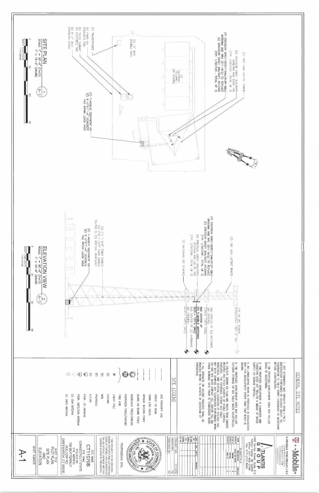
GENERAL SITE
NOTES
t. SITE INFORMATION WAS OBTAINED
FROM A FIELD
INVESTIGATION PERFORMED BY ATLANTIS GROUP, INC.
CONTRACTOR TO FIELD VERIFY DIMENSIONS AS NECESSARY
BEFORE CONSTRUCTION.
2. THE PROPOSED DEVELOPMENT DOES NOT INCLUDE
SIGNS OF ADVERTISING.
(E) 180' HIGH
LATTICE TOWER
(E) ERICSSON (AIR21
B2A/B4P)
ANTENNA AND DDB4 TMA
(NP. 1/SECTOR
TOTAL OF 3)
(P) ERICSSON (KRC118057/1B4A/B12P-88p)
ANTENNA AND RRU (S11-B12) TO REPLACE
(E) ERICSSON (AIR21
64A/62P) ANTENNA
(TYP. 1/SECTOR ,TOTAL OF 3j
I- _
_''-z
. -._--~ ~._:
_._, ._._m___~.
(E~EQUIPMENTBUILDING
~,~~
(BY OTHERS) ~
-~~I
~~
~
_'--
_ ____-'I_._ . -
__~_. -- 1II
_. ~
`T
(E) 12' WIDE
DOUBLE GATE
~ ~ ~~
(E) TRANSFORME
(E) FIBER
ON -
CONCRETE PAD
(E) TELCO CABIN
ON CONCRETE P~
(E) 8'-Q°
HIGHCHAINLINK
FENCE
SITE PLAN
~scams: i "
= 30'-0" (
v xn)
A-1
1" = 15'-0" (
24x36)
'-MOBILE EQUIPMENT ONJ
9'-0"X11'-6" CONCRETE
PAD WITHIN
LFASE AREA
0
30
60
90
SCALE 1"=30'('Itz17)
1"=15' (24x36)
TOP OF (E) TOWER
-~'i~ELEVATION= 180'-0" AGL
(E) 180'
HIGH LATTICE T
OWER
I l
`j
(P) ERICSSON (KRC118057/184A/B12P-B8p)
RAD CENTER OF (E) ANTENNAS
ANTENNA AND RRU (S11-B12) TO REPLACE
(BY OTHERS)
~(E) ERICSSON (AIR21
B4A/B2P) ANTENNA
ELEV.= 148'± (AGL)
(NP. 1/SECTOR ,TOTAL OF 3)
{2,qp CENTER OF
(Ej ERICSSON (AIR21
BZA/B4P)~
P T-MOBILE ANTENNAS
ANTENNA AND dd
B4 TMA
-,-- ELEV.=
137'f AGL
(lYP. 1/SECTOR ,TOTAL OF 3)
RAD CENTER QF (E) ANTENNAS
(BY OTHERS)
(E) ANTENNAS (BY OTHERS)
4- ELEV.=
128'f {AGL)
~"
~~I'-'
~'~ 1~~
~~~,I'
~~I
~~ ~,,r'.
(E) (1) 1-5~8" FIBER
CABLES
'~(E) (12) 1-5/8" COAX CABLES
I"
ROUTED IN (EJ
VERTICAL WAVEGUIDE
~
(P) T-
MOBILE EQUIPMENT ON
'
~,-'
(E) 9'-0"X11'-6" CONCRETE
PAD WITHIN
LEASE AREA
~
~~
~__, -;
—~
<i,
_
ELEVATION VIEW
2SCALE: 1" =
30'-0" (17x17)
A-1
1" = 15'-0" (24x36)
0
30
60
90
SCALE 1"=30' (7
1x17)
1"=15'(24x36)
3. THE PROPOSED DEVELOPMENT IS
UNMANNED ANDTHEREFORE D
OES NOT REQUIRE A
MEANS OF WATER
SUPPLY OR SEWAGE DISPOSAL.
4. NO LANDSCAPING W
ORK IS PROPOSED IN
CONJUNCTIONWITH THIS DEVELOPMENT OTHER THAN THAT WHICH
ISSHOWN.
5. THE PROPOSED
DEVELOPMENT DOES NOT INCLUDEOUTDOOR STORAGE O
R ANY SOLJD
WASTE RECEPTACLES.
6. UTILITIES SHOWN ON PLAN
ARE TAKEN FROM
OWNERS
RECORDS AND FIELD
LOCATION OF VISIBLE SURFACE
FEATURES. THE EXISTENCE, EXTENT AND
EXACTHORIZONTAL AND VERTICAL LOCATIONS O
F UTILffIES HAS
NOT BEEN VERIFlED. ANY CONTRACTOR PERFORMING W
ORK
ON THIS SITE
MUST CONTACT CALL BEFORE YOU D1G
THREE WORKING DAYS PRIOR TO COMMENCING WORK.
7. ALL OBSOLETE OR UNUSED
FACILITIES SHALL BE
REMOVED WITHIN 12 MONTHS OF CESSATION
OF
OPERATIONS.SITE LEGEND
----
SITE PROPERLY LJNE
STREET OR ROAD
-.-=-K-
CHAIN LINK
FENCE
OPAQUE WOODEN FENCE
-
BOARD ON BOARD
FENCE
DECIDUOUS TREES/SHRUBS
EVERGREEN TREES/SHRUBS
~v-r"~
TREE LINE
j8E UTILITY POLE
(E) EXISTING
(N)
NEW
(P) PROPOSED
(F) FUTURE
PROP. LTE ANTENNA
~
PROP, UMTS/GSM AMENNA
EX. GSM ANTENNA
EX. UMTS ANTENNA
T-MOBILE NORTHEAST, LLC
35 GRIFFIN ROAD SOU7H
BLOOMFfELD, CT 06002
OFFICE: (860)642-7100
FAX:(860) 692-7159
. TLANTIS
G R O U P
1340 Centre Street, Suite 2
12
Newton Center, M
A 02459
Office: 617-965-0789
Fax: 617-273-5056
SUBMITTALS
DATE
D6CRIPTION
REVISIONVl/t e/1s
laum FaR ~
W
w
oz/te/te ~swn
o
oa/ta/ts ~srox
t
NIA/13
FlWL Cp 2
~P(.
0.47E PPP'D
REVI90N5
rc ww.zowiNcovs
wwsrti~ ~.
PROJECT NO:
CT11070BDRAWN BY.
FGCHECKED BY:
SM
~,o~oF coNNFc,,~~O SEIN ~ ' ~O ~
_~~
;*~
s
~ A , 1~ti~ry •
V~
~'~i~F~ ARC~~~~~~
PROFESSIONAL SEAL
THIS DOCUMENT IS T
HE CREATION,
DESIGN, PROPERTY AND COPYRIGHTED
WORK OF T-MOBILE. ANY DUPLICATION
OR USE WITHOUT EXPRESS WRITTEN
CONSENT IS STRICTLY PROHIBITED.
SITE NAME
CT11070B
SITE NAME
CONNECTICUT STATE
POLICE #2
SITE ADDRESS
150 BUTTERNUT
HOLLOW RD
GREENWICH ,CT 06830
SHEEP TITLE
PLOT PLAN,
SITE PLAN
AND
ELEVATION
SHEET NUMBER
A-1
RD EfAILED
STRUCTURAL ANA PSIS AOD UEVANUATIOTNT
LO F~ A
N ~ o ~
~~~Iy
■EXISTING
180' SELF SUPPORTING LATTICE T
OWER WITH
L
4~b' ~S
STACK-N-BOLT SYSTEM AND FOUNDATION FOR PROPOSED
ANTENNA ARRANGEMENT" PREPARED BY AECOM,
T-MOBILE NORTII~AST, LLC
'T-MOBILE SITE
ID CT1070B", DATED MARCH 4, 2
015.
3i Gx~~~xoaD sour[a
BLOOMF~ELD, CT 06002
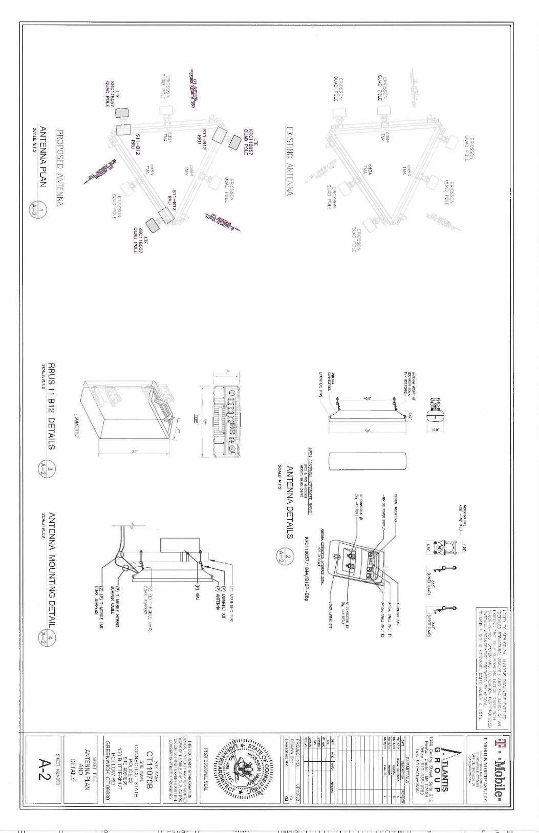
ERICSSON
OFFfCE: (86~) 692-7100
FP Y:(860) 692-7159
QUAD POLE
MOUMING PIPE
4.96'
- (276" -
4~f~ O.D.) ,,....
ERICSSON
QUAD POLE
__ O
TLANTIS
o
`~ GROUP
Z'ce~ 3'as~
1340 Centre
Street, Suite 212
6.85"
(L.OWER CL4AIP)
(l1PPE32 CLAMP)
- —
-- -
--
Newton Center,
MA 02459
Office: 617-965-0789
Fax: 617-213-5056
- -
_ ANTENNA MOUNT KR
ddB4
(KnniaoN scam s.4s'
TMA
P/N esotomoy--- SUBMITTALS
OA7E
D6CRIPiION
REVISION
GROUNDING POINT
o2/te/~s 5sum Foty ~
[w
w-
OPTICAL INDIG4TOR5
oz/~e/~s ~wson
o
ERICSSON
ddB4
- - —~OPIIGL CABLE INPUT j1
o~asi,o Flw~i W
z
QUAD POLE
TMA
-aev oc Powfft suav~r OPIICPL CABLE INPUT ~2
ddB4
mTMA
w
"'
ERICSSON
RF WNNECTOR ~1
QUAD POLE
(ife~ ~5 DEG.)
RF CONNECTOR ~2
ERICSSON
~ (~.fs, +as oEc.)
QUAD POLE
ERICSSON
_..
ANTENNA
DEPL
641E MP'D
REVISIONSQUAD POLE
CONNECTIONS--
LOWQt UFiING EYE
oEr
_.. __... xiE
"- ~-
IlFTING EYE (TYP)- -
AMENNA CONNECTION INTERFACE DETAIL
~ ~~
NOT TD SG4LE
Zor~ir~c
OPS
AIR21 "ANTENNA INTEGRATED
R4DI0" ~+sR+-
(Pcs a~ aws vExsioNs) KRC118057/184A/812P-B8p
s,~,~.WE7Gf{~: B
OLBS (36KG)
PROJECT NO:
CT11070B
EXISTING ANTENNA
ANTENNA DETAILS ~
DRAWN BY:
FG
__..__ _.__
._...... CHECKED BY:
SM
SCALE: N.T.S
~~ A-2
LTE
~ ~@-:'pg
KRC718057
~ pj ~ ~
pQUAD POLE
_7_
_~:
*`
O
ERICSSON
b
_ ~ 0
~~°° ~ ~
(E) MOUNTING
PIPE ~ ••
p
,~6`b: ~j
O
QUAD POLE
~
s Ct'' ~•.~ A
RI.1 1 .: ~ ~
~'
~ o
(P) ANTENNAT K
R
J'~"~`~FO ARC~~~ ~~~
a,tr
S11-B12
~ -_----
1~
--
PROFESSIONAL SEAL
~~
RRU
TOP
(P) RRU
ddB4
THIS DOCUMENT IS T
HE CREATION,
TMA
DESIGN, PROPERTY AND COPYRIGHTED
- ~.,
WORK OF T-MOBILE. A
NY DUPLICATION
S~ ~ -
g~ Z
~R~~.•J
OR USE WITHOUT EXPRESS WRITTEN
ddB4
RRU ~
~ ~
CONSENT IS STRICTLY PROHIBITED.
ERICSSON
TMA
QUAD POLE
''~~~
~ ~'
ddB4
"~
SITE NAME
TMA
~ L~
ice_
(2) (E) T-MOBILE
UMTS
CT11070B
ICI COAX JUMPERS
S11-B12
KRC118057
'~, SITE
NAME
RRU
QUAD POLE
i o
CONNECTICUT STATE
POLICE #2
SITE ADDRESS
LTE a ~"
ERICSSON
~ -
(P) T-
MOBILE HYBRIS
150 BUTTERNUT
KRC718057
q
QUAD POLE
JUMPER CABLE
HOLLOW RD
QUAD POLE
~ ~
%'
~ GREENWICH ,CT 06830
~
~; , ~
z) (P) r—Moei~ u~uCOAX JUMPERS
SHEET TITLE
ANTENNA PLAN
ISOMETRIC
AND
DETAILS
PROPOSED ANTENNA
SHEET NUMBER
RRUS 11 B
12 DETAILS
3
ANTENNA MOUNTING DETAIL 4
—__ _ _
ANTENNA PLAN
~ scare: N.rs
_ _
_ _ _
A-2
scare: N.rs__ _
_ A-2
A-2
SCALE: N.LS
.... A-Z
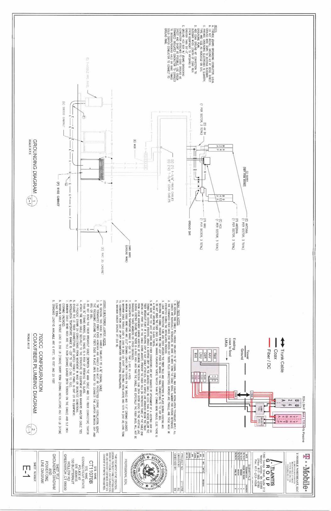
62A ~ 6
4P ~4A ~ 7
00 MHz Passive
L j L
~ T ~ T
i
2i4
ESE
1 B
I B
+~I► Trunk Cable q' p
4''~z
~08X
p i P
Fiber / DC
dd84
RRUS11TA~1A
Bi 2
(E) SECTOR (E) ANTENNA
(VIEW FROM BEHIND) (1
PER SECTOR, 3 TOTAL)
(P) ANTENNA
~~~ (1
PER SECTOR, 3 TOTAL)
B B
B B
2 4
4 12
(E) HCS
NOTES:A
P
A P
(i PER SECTOR, 3 TOTAL)
A. PROVIDE #2AWG GROUNDING CONDUCTOR, U.O.N.B. DO NOT INSTALL GROUND KIT AT BEND. DIRECT
GROUND WIRE DOWN TO ANTENNA BUSSBAR.
(P) RRUC. PROVIDE GROUNDING ELECTRODES IN
QUANTITY, (E) dd
B4
~TYPE AND SIZE AS INDICATED ON SITE
(7 PER SECTOR, 3
TOTAL) (1
PER SECTOR, 3 TOTAL)
GROUNDING PLAN. ~ •
~.: "D. ADD COAX GROUND K
R CONNECTION TO
BUSSBAR WHEN LENGTH OF COAX RUN(FROM EQUIPMENT TO ANTENNA) lS
—
~
— '"` —`
GROUND BARGREATER THAN 20'—~".
_E. GROUND HCS BOX W
/ ~7AWG GROUNDING
CONDUCTOR ATTACHED TO GOOD GROUND ASDIRECT AND SHORT AS POSSIBLE. USE GREENSTRANDED INSULATED CONDUCTOR TO CONNECTTO BUSSBAR/GROUND HALO OR
BARE TINNED (Ej (1) 1-5~8" FIBER
CABLES
SOIJD COPPER CONDUCTOR TO CONNECT TO I
(E) (12) 1-5~8" COAX CABLES
GROUND RING.
(E) MGB __ _ _ __
2AWG BARE(GROUND WIRE)
.____ ~ _~ ~ ; ~ _ ~~ , ~_
_ __ r ~
- -
_ ~ ~_
T__--a
---~
(E) RAC 35 CABINET
---
----------
-------
iI._
~-
~
I w
___ E1;
__ ~ ~
~~~-w
E
E
E
E
E
E
E
EC
E E~
EZ;(E) 58000 CABINET
(P) :6102 CABINET
GROUNDING DIAGRAM
SCALE: N.T.S
E— ~
lower
~
I I' ~
i—ttt—
Ground
III
Existing
coaxfofeed
LMUs —iect
AAV
Batt
TRUNK FIBER
NOTES:1. IN
GENERAL THIS CABLE WILL HANDLE SIMILARLY TO ~' COAXIAL CABLE, A
ND SIMILAR
INSTALLATION TECHNIQUES APPLY. ALLCABLES ARE INDMDUALLY SERIALIZED, B
E SURE TO HRfTE D
OWN THE CABLE SERIAL N
UMBER FOR FUNRE REFERENCE.
2. THE TERMINATED
FlBER ENDS (THE BROKEN OUT FlBERS P
LUS CONNECTORS) HOWEVER ARE FRAGILE, A
ND THESE M
UST BE
PROTECTED DURING T
HE INSTALLATION PROCESS.
3. LEAVE THE PROTECTIVE T
UBE AND SOCK AROUND THE FlBER TAILS AND
CONNECTORS IN
PLACE DURING HOISTING AND
SECURING 1HE CABLE. R
EMOVE THIS ONLY JUST PRIOR T
O MAKING T
HE FlNAL CONNECTIONS T
O THE OVP BOX.
4. DO NOT BEND T
HE FlBER
ENDS (IN l
HE OR4NGE PURGATION
NBES) TIGHTER THAN ~
" (19MM) BEND RADIUS, ELSE T
HERE IS
A RISK O
F BREAKING T
HE GLASS FlBERS.
5. BE SURE THAT THE LACE U
P ENDS AND FlBER C
ONNECTORS ARE N
OT DAMAGED B
Y ATTACHMENT O
F A HOISTING
GRIP OR
DURING hIE HOISTING PROCESS. ATTACH A HOISTING GRIP O
N THE JACKETED
CABLE NO LE55 THAN 6
INCHES B0.0W THE
FlBER BREAKOUT POINT. IF A
HOISTING GRIP IS NOT EASILY ATTACHED, USE A SIMPLE 11NE A
TTACHm BELOW THE FlBER
BREAK-OUT POINT (I.E. AT T
HE CABLE OUTER JACKET). PREVENT T
HE FIBER TAILS (IN
PROTECTNE TUBE) AT T
HE CABLE E
ND
FROM UNDUE MOVEMENT DURING
HOISTING BY SECURING T
HE PROTECTIVE T
UBE (WITH
OUTER SOCK) Tp THE HOISTING
LINE.6. DURING
HOISTING ENSURE THAT T
HERE IS A
FRF£ PATH AND THAT T
HE CABLE, AND
ESPECIALLY THE FlBER
ENDS, WILL NOT BE
SNAGGED ON TOWER MEMBERS OR OTHER OBSTACLES.
7. INSTAIJATION TEMPER4NRE RANGE IS -
22F TO 158F (
-30C TO +70C).
8. MINIMUM CABLE B
END R4DII ARE 2
22" (565MM) LOADm (WITH TENSION
ON THE CABLE) A
ND 11.1" (
280MM) UNLOADED.
9. MAXIMUM CABLE TENSILE LOAD IS 356D
N (800 LB) S
HORT TERM (DURING INSfALLAl10N) A
ND 1070 N (
240 LB) L
ONG TERM.
10. COMMSCOPE NON LACE U
P GRIP
RECOMMENDED FOR
MONOPOLE INSTALLATIONS.
11. MAXIMUM HANGER SPACING 3FT (0.9
M).
HIBRID FIBER/POWER JUMPER
NOTES:1. IN
GENER4L THIS CABLE WILL HANDLE SIMILARLY TO A ~" COAXIAL CABLE.
2. THE TERMINATED FlBER ENDS HOWEVER ARE FRAGILE AND MUST BE PROTECTED DURING INSTALLATION. LEAVE
THE PACKAGING AROUND THE FIBER ENDS IN
PLACE UNTIL READY TO CONNECT THE JUMPER BETWEEN OVP AND
RRU OR BBU.
3. DO NOT BEND THE FIBER
BREAKOUT CABLE (BETWEEN THE MAIN
CABLE ANA THE FlBER
CONNECTOR) TIGHTERTHAN ~'a~ (
19MM) RADIUS, ELSE THERE IS A RISK O
F BREAKING THE GLASS.
4. ATTACH THE MAIN CABLE SECURELY TO THE STRUCTURE OR EQUIPMENT USING HANGERS A
ND/OR CABLE TIES
TO PREVENT STRAIN ON CONNECTIONS FROM
MOVEMENT IN WIND O
R SNOW/ICE CONDITIONS.
5. ENSURE THE LC FlBER CONNECTORS ARE SEATED FlRMLY IN PANEL IN OVP OR IN
EQUIPMENT.6. INSTALLATION TEMPERATURE R4NGE IS
—22F TO 158E (
-30C TO 70C).
7. MINIMUM CABLE BEND
RADII ARE 70.3 INCH (265MM) LOADED (WITH TENSION
ON THE CABLE) AND 5.2 INCH
(130MM) UNLOADED.
8. MAXIMUM CABLE TENSILE LOAD IS 350 LB (1560N) SHORT TERM (DURING INSTALL4TION) AND 105 LB (470N)
LONG TERM.9. STANDARD LENGTHS AVAILABLE ARE 6
FEET, 15 FEET AND 20 FEET
702CC CONFIGURATION
COAX/FIBER PLUMBING DIAGRAM
2SCALE: N.T.S
E—
~
° °~lle'
T-MOBILE NOR'T`HEAST, LLC
35 GRIFFIN ROAD SOUTA
acoot~recn, cr osoaz
OFFICE: (860)692-7100
FAX:(B60) 692-7119 -
. TLANTIS
G R O U P
7340 Centre Street, Suite
272
Newton Center, MA 02459
Office: 6 7 7-965-0789
Fax: 617-213-5056
SUBMITTALS
DATE
DRCRIPTION
REVISION02/76/15
1411m FIXt fEVIEW A
oz/ie/ie xe~son
o0Y/1 Y/15
IEY190X 1
OS/OS/15 FlNV. W
2
nEvc ¢o~
onao ~sroNs
NFE
Fff INN.
zodiNcoPs
coxsrR~ ~.
PROJECT NO:
CT110706DRAWN BY:
FGCHECKED BY:
SM
,a~pFtCONNF ii i
41: ~~
~~.,-1.
~~~ '
~ *~
•~ 0
AIL
A-~`
~~ s~~ ARC~~~~+
PROFESSIONAL SEAL
THIS DOCUMENT IS T
HE CREATION,
DESIGN, PROPERTY AND CQPYRIGHTED
WORK OF T-M081LE. A
NY DUPLICATION
OR USE WITHOUT EXPRESS WRfTTEN
CONSENT I&STRICTLY PROHIBITED.
SITE NAME
CT11070B
SITE NAME
CONNECTICUT STATE
POLICE #2
SITE ADDRESS
150 BUTTERNUT
HOLLOW RD
GREENWICH ,CT 06830
SHEET TITLE
GROUNDING DIAGRAM
AND
POWER ONE
LINE DIAGRAM
SHEEP NUMBER
E-1
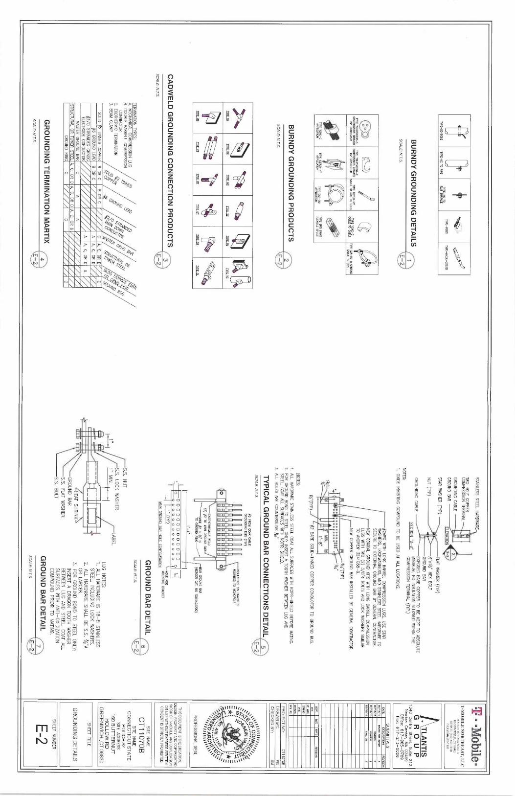
TYPE—YGIBS TYPE—YAC3L-2TC38
TYPE—KC 70
TYPE—BD18G92
TYPE—KC TO PIPE
MT SURFM.E
BURNDY GROUNDING DETAILS
1SCALE: N.T.S.
E-2
O ~ O
0
TYPE YGHR59C2W-3
TYPE YGHP58C2W-2
COMPR6SION GROUND
COMPR6510N GRWN~
77PE GSND—HY
7ypE YGHC—C
TPP CONNECTOR TAP CONNECTOR
IF TO R00 10
~~ ~ ~~
TYPE C#!—BU k CPA5902
CPBLE TO PIPE
•
TYPE YGHC—C
TYPE GSR1~—HY
TYPE BRG BRPID
PPPL1CAl10N PPPIJCATION
~E ~—~
Fl.IXIBLE SPLJCEAPPLICATION
BURNDY GROUNDING PRODUCTS
2SCALE: N.T.S.
E—Z
~.
u•
~r a
~r. u• .
~r .
~r c
~_
~
11' 1:
11' J
11' h
11' H
11~ 11'
CADWELD GROUNDING CONNECTION PRODUCTS
SCALE: N.T.S.
TERMINATION TYPES:
r~~'A. MECHANICAL COMPRESSION
LUG ~
o
~
~e~ ~
<v=B. DOUBLE BARRELL COMPRESSION
~~~ v~
_~ ~
p ~~v
~,~ ~~' QCONNECTOR
~
,~¢4y~, o
~=
Q g-,~<v ~S ~ ~o
C. EXOTHERMIC TERMINATION ~ ~
of
~' a~J~' ~
'~J ~'
~~"? o
D. BEAM CLAMP
o QQ~
c~
\~ = 2
~.~"~ J~' ~~
~ ~'~ J
~~o
~o
~~
~~'~Q-~o ~~
~~~ 0 0~oe- ~
o
SOLID #2 TINNED
COPPER B OR C
B OR C
C
A, C, OR D
C~6 GROUND LEAD
B OR C
A
A, C, OR D
#2/0 STRANDED G
RNDG
A A, C, OR
D A
ELECTRODE CONDUCTORMASTER
GROUND BAR
C
A A
STRUCTURAL OR TOWER
STEEL A, C, OR D
A, C, OR D A. C, OR
DGROUND RING
C
C
C
GROUNDING TERMINATION MARTIX
4SCALE: N.T.S.
E—Z
STAINLESS STEEL HARDWARE
iW0 HOLE COPPER
COMPRESSION TERMINAL
GROUNDING CABLE X
GROUND BAR
ELEVATION x-x
STAR WASHER (TYP)
FLAT WASHER (NP)
NUT (iYP) kz"x1Y~" HEX
BOLTGROUND BAR
GROUNDING CABLE ` EXPOSED
BARE COPPER TO BE KEPT TO ABSOLUTE
SECTION "A-A"
MINIMUM, NO INSULATION ALLOWED WITHIN THE
COMPRESSION TERMINAL (
NP.)
NOTES:
1. OXIDE INHIBITING COMPOUND TO
BE USED AT ALL LOCATIONS.
~2AWG WfTH
LONG BARREL COMPRESSION LUGS, USE STAR
WASHERS, LOCKWASHERS, AND STAINLESS STEEL HARDWARE TOSECURE TO
EXTERNAL GROUND BAR BY GENER4L CONTRACTOR.
NEW COAXIAL G
ROUND KITS
WITH LONG
BARREL COMPRESSIONLUGS WfTH T
WO (2) 3/8"0 BOLTS AND
LOCK WASHERS SIMILAR
TO ANDREW 3241088-9.
NEW COPPER
GROUND BAR INSTALLED
BY GENERAL CONTR4CTOR.
~T o
o~0000 ~Y6~
~y^(~yp~J `#2 BARE SOLID-TINNED COPPER
CONDUCTOR TO GROUND BUS.
NOTES:
1. ALL HARDWARE STAINLESS STEEL COAT ALL SURFACES WITH KOPR-SHIELD
BEFORE MATING.2. FOR
GROUND BOND TO STEEL ONLY:INSERT A TOOTH
WASHER BETWEEN
LUG ANDSTEEL, COAT ALL SURFACES WITH
KOPR-SHIELD.3. ALL HOLES ARE COUNTERSUNK Jy6".
TYPICAL GROUND BAR CONNECTIONS DETAIL 5
SCALE: N.T.S. E—Z
~s FROM COA1( CPBLEGROUNDING KITS (TYP)
MSUfATORS ON BRACKETSMOUNTED TO MONOPOLE
~IXOhiERMIGUlY WELD(2) (~2 TO MAIN GROUND BAR
~~BARE ~2 IN ~
' C
M41N GROUND H4RTO GROUND RING)
(HERGER CAT. NO TGBI14222DG)
~._4.
~ 0 0000000000000
0 0 0 0 0 0 0 0 0 0 0
`"~
~~ ~~~
HOLE FOR
MOUMING BRACKET
MAIN GROUND 9AR HOLE CONFlGURAiION
S.S. NUT
S.S. LOCK WASHER
1"
I 1" MIN. ,_
_,
----~ ~
r
---J L_
L
CHEAT SHRINK
IND BAR
FLAT WASHER
BOLT
GROUND BAR DETAIL
6SCALE: N.T.S.
~ E—Z
LUG NOTES:
1. ALL HARDWARE IS
18-8 STAINLESS
STEEL, INCLUDING LOCK WASHERS.
2. ALL HARDWARE SHALL BE S.S. ~
"d
OR LARGER.
3. FOR GROUND BOND TO STEEL ONLY:
INSERT A DRAGON TOOTH WASHER
BETWEEN LUG AND STEEL. COAT ALL
SURFACES WITH
ANTI-OXIDIZATIONCOMPOUND PRIOR TO MATING.
GROUND BAR DETAIL
~
SCALE: N.T.S. E-2
s s
■ ■
l~
1V
1~
~•
ti
T-MOBILE NORTHEAST, LLC
35 GRIFFM ROAD SOUTH
BLOOMFiELD, CT 06002
OFFICE: (860) 692-7100
FAX:(Sfi0) fi92-7159
. TLANTIS
G R O U P
1340 Centre
Street, Suite 212
Newton Center, M
A 02459
Office: 617-965-0789
Fax: 617-213-5056
SUBMITTALS
DAiE
D6CRIPTION
REVISION02/10/15
ISSUm ipF REVIEW A
oz/ie/is p~tow
o
U~/19/15 REVIgON
1
05/05/15 FlNM. W
2
DEPT. 647E
PPP'D REV190N5
ftFE
Fff 1NN.
ZONING
OPS
wi+srR~ ~.
PROJECT NO:
CT110706DRAWN BY:
FGCHECKED BY:
SM
ay a~OFf C'.ONNF
v iii
~~~
~~~
~,.~CC'' ~ ARI.11~~ry'
~, U~
~~ .
.•,~ ~
°"~ s~o AR~~~~~~
PROFESSIONAL SEAL
THIS DOCUMENT IS THE CREATION,DESIGN, PROPERTY AND COPYRIGHTEDWORK OF T-MOBILE. ANY DUPLICATION
OR USE WITHOUT EXPRESS WRITTENCONSENT IS STRICTLY PROHIBITED.
SITE NAME
CT11070B
SITE NAME
CONNECTICUT STATE
POLICE #2
SITE ADDRESS
150 BUTTERNUT
HOLLOW RD
GREENWICH ,CT 06830
SHEET TITLE
GROUNDING DETAILS
SHEEP NUMBER
E-2
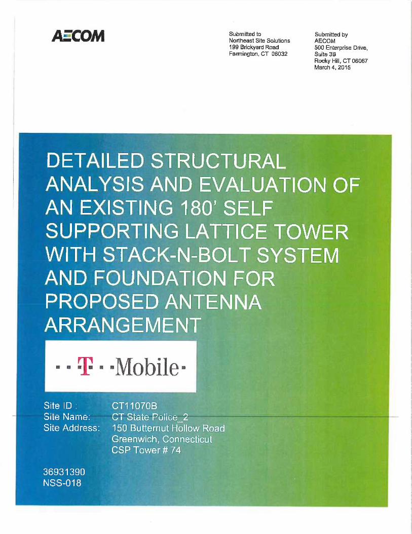
~~~~Submitted toNortheast Site Solutions199 Brickyard RoadFarmington, CT 06032
Submitted byAECOM500 Enterprise Drive,Suite 3BRocky Hill, CT 06067March 4, 2015
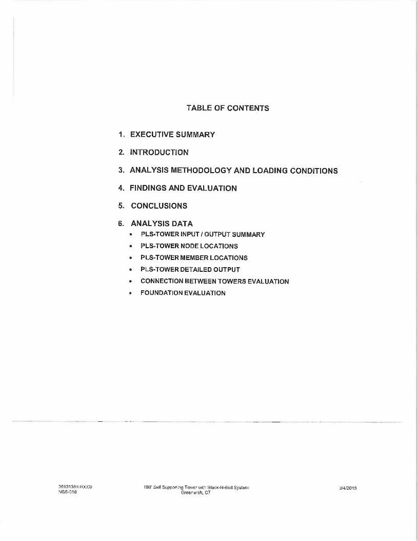
TABLE OF CONTENTS
1. EXECUTIVE SUMMARY
2. INTRODUCTION
3. ANALYSIS METHODOLOGY AND LOADING CONDITIONS
4. FINDINGS AND EVALUATION
5. CONCLUSIONS
6. ANALYSIS DATA• PLS-TOWER INPUT /OUTPUT SUMMARY
• PLS-TOWER NODE LOCATIONS
• PLS-TOWER MEMBER LOCATIONS
• PLS-TOWER DETAILED OUTPUT
• CONNECTION BETWEEN TOWERS EVALUATION
a FOUNDATION EVALUATION
36931399.00000 180' Self Supporting Tower with Stack-N-Bolt System 3/4/2015NSS-018 Greenwich, CT
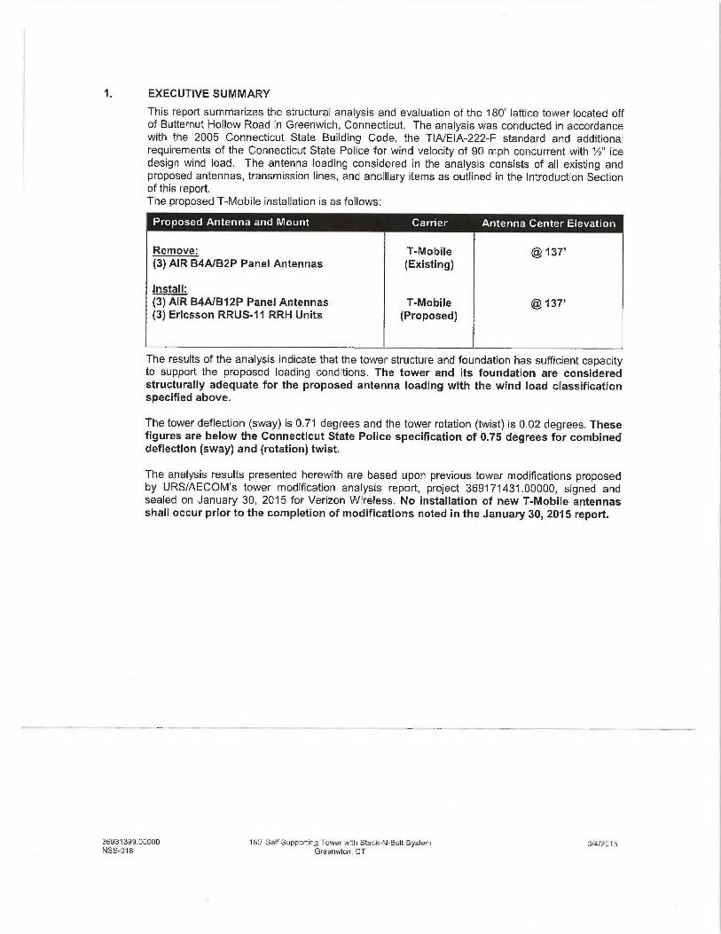
EXECUTIVE SUMMARY
This report summarizes the structural analysis and evaluation of the 180' lattice tower located offof Butternut Hollow Road in Greenwich, Connecticut. The analysis was conducted in accordancewith the 2005 Connecticut State Building Code, the TlA/EIA-222-F standard and additionalrequirements of the Connecticut State Police for wind velocity of 90 mph concurrent with 'h" icedesign wind load. The antenna loading considered in the analysis consists of all existing andproposed antennas, transmission lines, and ancillary items as outlined in the Introduction Sectionof this report.The proposed T-Mobile installation is as follows:
Remove: T-Mobile @ 137'(3) AIR B4AIB2P Panel Antennas (Existing)
Install:(3) AIR B4A/B12P Panel Antennas T-Mobile @ 137'(3) Ericsson RRUS-11 RRH Units (Proposed)
The results of the analysis indicate that the tower structure and foundation has sufficient capacityto support the proposed loading conditions. The tower and its foundation are consideredstructurally adequate for the proposed antenna loading with the wind load classificationspecified above.
The tower deflection (sway) is 0.71 degrees and the tower rotation (twist) is 0.02 degrees. Thesefigures are below the Connecticut State Police specification of 0.75 degrees for combineddeflection (sway) and (rotation) twist.
The analysis results presented herewith are based upon previous tower modifications proposedby URS/AECOM's tower modification analysis report, project 369171431.00000, signed andsealed on January 30, 2015 for Verizon Wireless. No installation of new T-Mobile antennasshall occur prior to the completion of modifications noted in the January 30, 2015 report.
36931399.00000 180' Self Supporting Tower with Stack-N-Bolt System 3/4/2015NSS-D18 Greenwich, CT
EXECUTIVE SUMMARY (continued)
This analysis is based on:
1) The tower structure's theoretical capacity not including any assessment of thecondition of the tower.
2) Member sizes and tower geometry of the outer tower taken from manufacturersdrawings prepared by Rohn Industries, Inc., file number 28325, dated December 28,1992.
3) Member sizes and tower geometry of the inner tower taken from design calculationsand drawings prepared by Towertek Industries Inc., signed and sealed May 9, 2002.
4) Foundation modifications taken from drawings prepared by Walker EngineeringIncorporated, Job number 0206-237R2, signed and sealed November 26, 2002.
5) Tower Site visit performed by URS/AECOM, dated October 31, 2014.6) Previous structural analysis and reinforcement performed by URS/AECOM on behalf
of Verizon Wireless, project number VZ5-782 Rev. 1 / 36917431, signed and sealedJanuary 30, 2015.
7) Antenna inventory provided by the Connecticut State Police via email on February 12015.
8) Proposed antennas via T-Mobile Radio Frequency Data Sheet (REDS) form, datedFebruary 5, 2015.
9) Antenna inventory as specified in section 2 and 6 of this report.
This report is only valid as per the assumptions and data utilized in this report for antennainventory, mounts and associated cables. The contractor shall field verify the antenna and mountconfiguration used, as well as the physical condition of the tower members and connections. Theengineer is to be notified in writing immediately if any of the information in the Structural Analysisis found to be other than specified.
If you should have any questions, please call.
Sincerely,
URS Corporation AES,a subsidiary of AECOM
~,, . -_,:
~~ -y-~ ~~;~'
Richard A. Sambor, P.E. ;~ ~ _ -, -- -.,.Senior Structural Engineer ~ ,, ~ ,;;r ' ~=-
;, Cc: IA, CF/Book-URS/AECOM '~'f~~;;zr',L'~,.,:'',.....s~:~:- .
36931399.00000 1 SD' Self Supporting Tower with Stack-N-Bolt System 3/4/2015NSS-018 Greenwich, CT
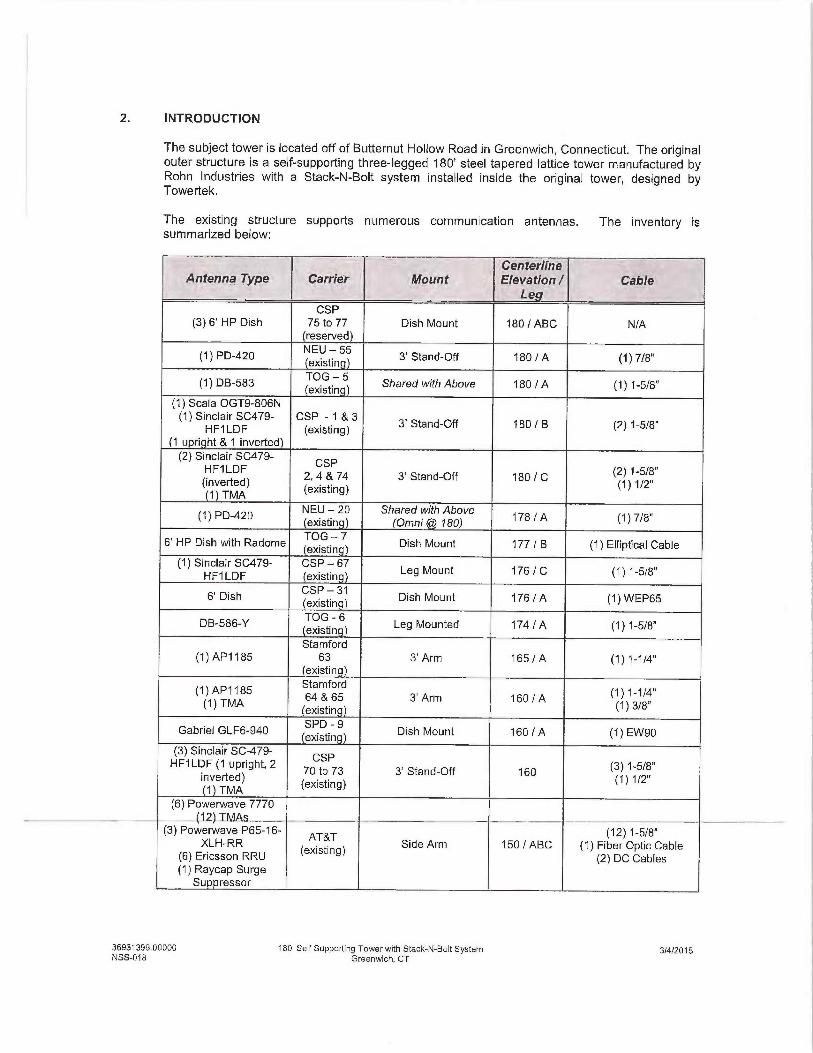
2. INTRODUCTION
The subject tower is located off of Butternut Hallow Road in Greenwich, Connecticut. The originalouter structure is aself-supporting three-legged 180' steel tapered lattice tower manufactured byRohn Industries with aStack-N-Bolt system installed inside the original tower, designed byTowertek.
The existing structure supports numerous communication antennas. The inventory issummarized below:
GenterlfneAntenna Type Carrier Mount Elevation / Cable
LeCSP
(3) 6' HP Dish 75 to 77 Dish Mount 180 /ABC N/A(reserved
(1) PD-420 NEU - 55 3' Stand-Off 180 / A (1) 7/8"(existin
(1) DB-583 TOG — 5 Shared with Above 180 / A (1) 1-5/S"(existin 1
(1) Scala OGT9-806N(1) Sinclair SC479- CSP - 1 & 3
3' Stand-Off 180 / B (2) 1-5/8"HF1LDF (existing)(1 upri ht & 1 inverted(2) Sinclair SC479-
HF1LDF 2, 4 & 74 3' Stand-Off 180 / C ~2~ ~-~~$(inverted) (existing) ~~~ ~~21 TMA
(1) PD-420 NEU — 20 Shared with Above ~ ~$ ~ A (1) 7/8"(existin) (Qmni 180)
6' HP Dish with Radome TOG — 7
Dish Mount 177 / B (1) Elliptical Cableexistin(1) Sinclair SC479- CSP — 67
Leg Mount 176 / C (1) 1-5/8"HF1 LDF (existinal
6' Dish CSP — 31
Dish Mount 176 / A (1) W EP65(existing)
DB-586-Y TOG - 6 Leg Mounted 174 / A (1) 1-5/8"(existing)
Stamford(1)AP1185 63 3'Arm 165/A (1)1-1/4"
(existin
(1)AP1185 Stamford
(1)1-1/4"(1) TMA
64 & 65 3' Arm 160 / A (1) 3/8"(existin 1
Gabriel GLF6-940 SPD - 9
Dish Mount 160 / A (1) EW90(existin )(3) Sinclair SC-479-
CSPHF1 LDF (1 upright, 2 70 to 73 3' Stand-OfF 160
(3) 1-5/8"inverted)
(existing) t~~ ~~2(1) TMA(6) Powerwave 7770
(92~TMAs —_ __.. — _--(3) Powerwave P65-16-
AT&T (12) 1-5/8"XLH-RR
(existing) Side Arm 150 /ABC (1) Fiber Optic Cable(6) Ericsson RRU (2) DC Cables(1) Raycap Surge
Sup ressor
36931399.00000 180' Self Supporting Tower with Stack-N-Bolt System 374!2015NSS-018 Greenwich, CT
CenterlineAntenna Type Carrier Mount Elevation / Gable
to(3) AIR 64A/B12PPanel Antennas T-Mobile
See Below Mount 137 /ABC See Below Cables(3) Ericsson RRUS-11 (Proposed)RRH Units
(3) AIR B2A/B4P Panel T-Mobile (12) 1-518"Antennas (existing) Face Mounted 137 /ABC
~1) Fiber Optic Cable31 AWS) TMA's
(1) DB-586-Y NEU-19
Leg Mounted 135 / B (1) 7/8"(existin
(1) Celwave PD1142 CSP — 21
Shared with Above 135 / B (1) 7/8"(existin
(1) Kreco C041AN NEU — 18
3' Stand-off 13D / A (1 } 7/8"(existing)(3) SLCP 2x6014 Panels(6) Andrew DB844H80-
XY Panels(6) Diplexers
(3) Andrew HBXX-6516DS-A2M PanelAntennas {AWS)
(3) ALU RRH Units (12) 1 5/8"Verizon (3) Boora~ Gates(AWS) (existing) (existing) X30 /ABC (1) 1-518" Fiber Optic
(1) Raycap DB-T1-6Z- Cable8AB-OZ Distribution Box
(AWS)(3) Andrew HBXX-6516DS-A2M (PCS)Panel Antennas
(3) ALU RRH Units(PCS1
(3) APXVSPPI8-C Sprint Boom GatePanel Antennas
(existing) (existing) ~ ~~ ~ ABC (3) Hybriflex Cables6 RRH
(1) PD1142 NEU — 17
3' Stand-off 115 I A (1) 7/8"(existing )
(1) Celwave PD1142 NEU — 16
Shared with Above 110 / A (1) 1-5/8"(existing)
(1) PD1142 CSP — 66
Leg Mounted 80 / A (T} 7/8"(existin 1
(1) 10' Dipole DOT— 56
3' Arm 80 / B (1) 7/8"(existin
(1) PD-1142 CEP — 54
Leg Mounted 80 / C (1) 7/8"(existing
(1) GPS Sprint - 69
Leg Mounted 62 / B (1) 1 /2"(existinVerizon - 68(1) GPS (TMG-26N)
existing Leg Mounted 60 / C (1) 1!2"
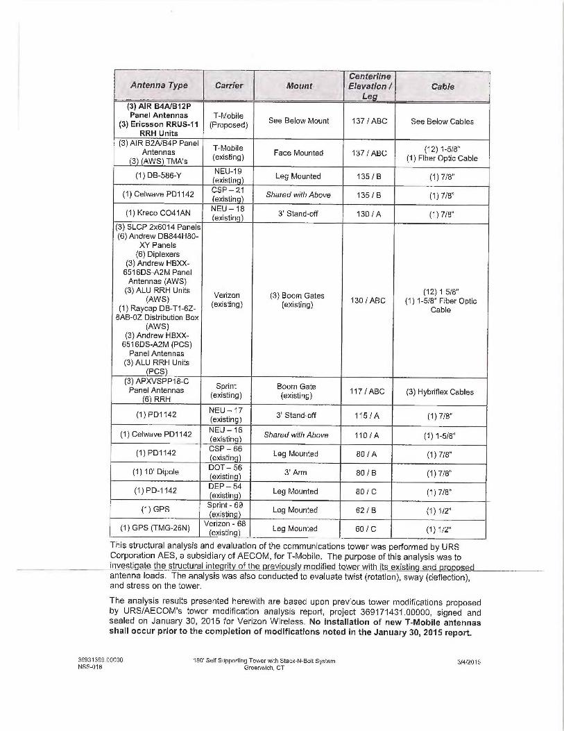
This structural analysis and evaluation of the communications tower was performed by URSCorporation AES, a subsidiary of AECOM, for T-Mobile. The purpose of this analysis was toinvestigate the structural integrity of the previously modified tower with_its existing and nropc~~s d— _ _ -- _— —antenna loads. The analysis was also conducted to evaluate twist (rotation), sway (deflection),and stress on the tower.
The analysis results presented herewith are based upon previous tower modifications proposedby URS/AECOM's tower modification analysis report, project 369171431.00000, signed andsealed on January 30, 2015 for Verizon Wireless. No installation of new T-Mobile antennasshall occur prior to the completion of modifications noted in the January 30, 2015 report.
36931399.000OD 180' Self Supporting Tower with Stack-N-Bolt System 314/2015NSS-018 Greenwich, CT
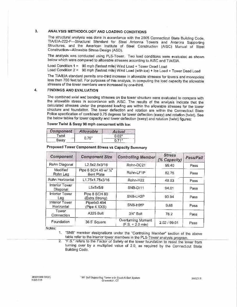
3. ANALYSIS METHODOLOGY AND LOADING CONDITIONS
The structural analysis was done in accordance with the 2005 Connecticut State Building Code,TIA/EIA-222-F—Structural Standard for Steel Antenna Towers and Antenna SupportingStructures, and the American Institute of • Steel Construction (AISC) Manuai of SteelConstruction—Allowable Stress Design (ASD).
The analysis was conducted using PLS-Tower. Two load conditions were evaluated as shownbelow which were compared to allowable stresses according to AISC and TIA/EIA.
Load Condition 1 = 90 mph (fastest mile) Wind Load +Tower Dead LoadLoad Condition 2 = 90 mph {fastest mile) Wind Load (with ice) +Ice Load +Tower Dead LoadThe TIA/EIA standard permits one-third increase in allowable stresses for towers and monopolesless than 700 feet tall. For purposes of this analysis, in computing the load capacity the allowablestresses of the tower members were increased by one-third.
4. FINDINGS AND EVALUATION
The combined axial and bending stresses on the tower structure were evaluated to compare withthe allowable stress in accordance with AISC. The results of the analysis indicate that thecalculated stresses under the proposed loading are within the allowable stresses for the towerstructure and foundation. The tower deflection and rotation are within the Connecticut StatePolice specification of combined 0.75 degrees for tower deflection (sway) and rotation (twist). Seethe below tables for tower capacity and tower deflection (sway) and rotation (twist) figures:Tower Twist &Sway 90 mph concurrent with ice:
Dorn o~ent Allowable ActualTwist
0.75° 0.02°
Swat/ 0.71 °
Proposed Tower Component Stress vs Capacity Summary
Component Component Size Contro!ling Member ,stress Fass/Faill Ca aciRohn Diagonal L2.5x2.5x3/16 Rohn-DC21 99.40 Pass
Modified Pipe 6 SCH 40 w/'/" Rohn-LF1P 82.75 PassRohn Le Bent Plate
Rohn Horizontal L1.75x1.75x3/16 Rohn-H22 48.03 PassInterior Tower
L5x5x5/8 SNB-D111 94.01 PassDiaconalInterior Tower Pipe 8 SCH 80
SNB-LH2P 93.94 PassLe (Extra StronInterior Tower Pipe4x0.494
SNB-H9fP 9.68 PassHorizontal (Pi e 4 XXS
C nn ction A325 Bolt 3/4" Bolt 76.2 Pass
Foundation 36.5' Square Overturning Moment
2 02 / 99.01 Pass(F.S. = 2.0 min)Notes:
1. "SNB" member designations under the "Controlling Member" section of the abovetable refer to the interior tower members in the PLS-Tower analysis program.
2. "~S.' refers to the Factor of Safety of the tower foundation to resist the tower fromturning over by a multiplied value of 2.0, as required by the Connecticut StateBuilding Code.
36931399 OOQ00 1B0' Self Supporting Tower with Stack-N-Bolt System 3/4/2015NSS-018 Greenwich, CT
5. CONCLUSIONS
The results of the analysis indicate that the tower structure and foundation has sufficient capacityto support the proposed loading conditions. The tower and its foundation are consideredstructurally adequate for the proposed antenna loading with the wind load classificationspecified above.
The tower deflection (sway) is 0.71 degrees and the tower rotation (twist) is 0.02 degrees. Thesefigures are below the Connecticut State Police specification of 0.75 degrees for combineddeflection (sway) and (rotation) twist.
The analysis results presented herewith are based upon previous tower modifications proposedby URS/AECOM's tower modification analysis report, project 369171431.00000, signed andsealed on January 30, 2015 for Verizon Wireless. No installation of new T-Mobile antennasshall occur prior to the completion of modifications noted in the January 30, 2015 report.
LimitationslAssumptions:
This report is based on the following:
A. Tower is properly installed and maintained.
B. All members and their geometry are as specified in the original manufacturer drawingsand are in good condition.
C. All required members are in place.
D. All bolts are in place and are properly tightened.
E. Tower is in plumb condition.
F. All member protective coatings are in good condition.
G. All tower members were properly designed, detailed, fabricated, installed, and have beenproperly maintained since erection.
URS is not responsible for any modifications completed prior to or hereafter in which URS is notor was not directly involved. Modifications include but are not limited to:
A. Adding antennasB. Removing/replacing antennasC_ Adding coaxial cables
URS hereby states that this document represents the entire report and that it assumes no liabilityfor any factual changes that may occur after the date of this report. All representations,recommendations, and conclusions are based upon information contained and set forth herein. Ifyou are aware of any information which conflicts with that which is contained herein, or you areaware of any defects arising from original design, material, fabrication, or erection deficiencies,you should disregard this report and immediately contact URS. URS disclaims all liability for anyrepresentation, recommendation, or conclusion not expressly stated herein.
Ongoing and Periodic Inspection and Maintenance:
After the Contractor has successfully completed the installation and the work has been accepted,the owner will be responsible for the ongoing and periodic inspection and maintenance of thetower.
The owner shall refer to TIA/EIA-222-F for recommendations for maintenance and inspection.The frequency of the inspection and maintenance intervals is to be determined by the ownerbased upon actual site and environmental conditions. It is recommended that a complete andthorough inspection of the entire tower structural system be performed at least yearly and morefrequently as conditions warrant. According to TIA/EIA-222-F section 14.1, Note 1: It isrecommended that fhe structure be inspected after severe wind and/or ice storms or otherextreme loading conditions.
36931399 00000 180' Self Supporting Tower with Stack-N-Bolt System 3/412015NSS-018 Greenwich, CT
ANALYSIS DATA
36931399.000OD 18D' Self Supporting Tower with Stack-N-Bolt System 3/412015NSS-018 Greenwich, CT
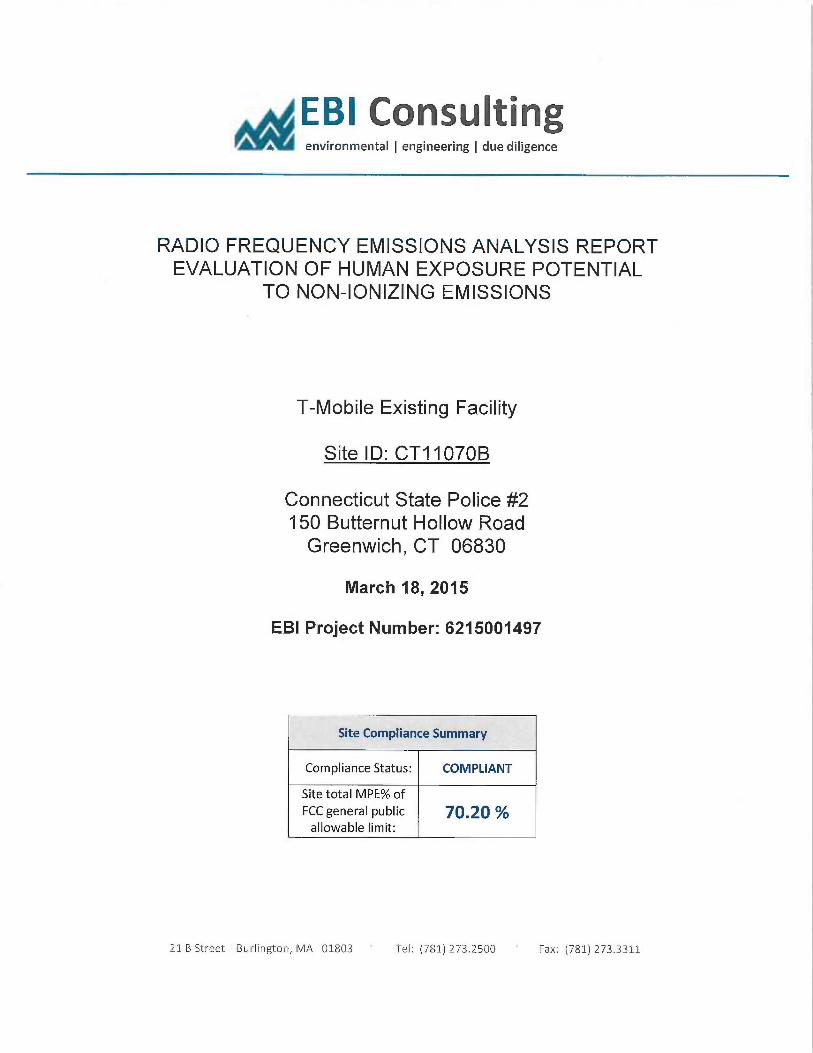
E61 Consultinga environmental ~ engineering ~ due diligence
RADIO FREQUENCY EMISSIONS ANALYSIS REPORTEVALUATION OF HUMAN EXPOSURE POTENTIAL
TO NON-IONIZING EMISSIONS
T-Mobile Existing Facility
Site IDo CT11070B
Connecticut State Police #2150 Butternut Hollow RoadGreenwich, CT 06830
March 18, 2015
EBI Project Number: 6215001497
Site Compliance Summary
Compliance Status: COMPLIANT
Site total MPE% ofFCC general public 70.20allowable limit:
21 B Street Burlington, MA 01803 I el: (781) 273.2500 Fax: (781) 273.3311
EBI Consulting~ environmental ~ engineering ~ due diligence
March 18, 2015
T-Mobile USAAttn: Jason Overbey, RF Manager35 Griffin Road SouthBloomfield, CT 06002
Emissions Analysis for Site: CT11070B —Connecticut State Police #2
EBI Consulting was directed to analyze the proposed T-Mobile facility located at 150 Butternut Hollow
Road, Greenwich, CT, for the purpose of determining whether the emissions from the Proposed T-
Mobile Antenna Installation located on this property are within specified federal limits.
All information itsed in this report was analyzed as a percentage of current Maximum Permissible
Exposure (% MPE) as listed in the FCC OET Bulletin 65 Edition 97-01 and ANSUIEEE Std C95.1. The
FCC regulates Maximum Permissible Exposure in units of microwatts per square centimeter (µW/cm2).
The number of µW/cm2 calculated at each sample point is called the power density. The exposure limit
for power density varies depending upon the frequencies being utilized. Wireless Carriers and Paging
Services use different frequency bands each with different exposure limits, therefore it is necessary to
report results and limits in terms of percent MPE rather than power density.
All results were compared to the FCC (Federal Communications Commission) radio frequency exposure
rules, 47 CFR L 1307(b)(1) — (b)(3), to determine compliance with the Maximum Pernussible Exposure
(MPE) limits for General Fopulaton/iJncontrolled environments as defined below.
General population/uncontrolled exposure limits apply to situations in which the general public maybe
exposed or in which persons who are exposed as a consequence of their employment may not be made
fully aware of the potential for exposure or cannot exercise control over their exposure. Therefore,
members of the general public would always be considered under this category when exposure is not
employment related, for example, in the case of a telecommunications tower that exposes persons in a
nearby residential area.
Public exposure to radio frequencies is regulated and enforced in units of microwatts per square
centimeter (µW/cm2). The general population exposure limit for the 700 MHz Band is 467 µW/cmz, and
the general population exposure limit for the PCS and AWS bands is 1000 µW/cmZ. Because each carrier
will be using different frequency bands, and each frequency band has different exposure limits, it is
necessary to report percent of MPE rather than power density.
21 B Street 'Burlington, MA 01803 Tel: (781) 273.2500 Fax: (781) 273.3311
EBI Consulting~, environmental ~ engineering ~ due diligence
OccupationaUcontrolled eiposure limits apply to situations in which persons are exposed as a
consequence of their employment and in which those persons who are exposed have been made fully
aware of the potential for exposure and can exercise control over their exposure. OccupationaUcontrolled
exposure limits also apply where exposure is of a transient nature as a result of incidental passage through
a location where exposure levels maybe above general population/uncontrolled limits (see below), as
long as the exposed person has been made fully aware of the potential for exposure and can exercise
control over his or her exposure by leaving the area or by some other appropriate means.
Additional details can be found in FCC OET 65.
CALCULATIONS
Calculations were done for the proposed T-Mobile Wireless antenna facility located at 150 Butternut
Hollow Road, Greenwich, CT, using the equipment information listed below. All calculations were
performed per the specifications under FCC OET 65. Since T-Mobile is proposing highly focused
directional panel antennas, which proj ect most of the emitted energy out toward the horizon, all
calculations were performed assuming a lobe representing the maximum gain of the antenna per the
antenna manufactures supplied specifications, minus 10 dB, was focused at the base of the tower. For this
report the sample point is the top of a 6 foot person standing at the base of the tower.
For all calculations,. all equipment was calculated using the following assumptions:
1) 2 GSM channels (PCS Band - 1900 MHz) were considered far each sector of the proposed
installation. These Channels have a transmit power of 30 Watts per Channel
2) 2 LTMTS channels (AWS Band — 2100 N1~Iz) were considered for each sector of the proposed
installation. These Channels have a transmit power of 30 Watts per Channel.
3) 2 LTE channels (AWS Band — 2100 MHz) were considered for each sector of the proposed
installation. These Channels have a transmit power of 60 Watts per Channel.
4) 1 LTE channel (700 MHz Band) was considered for each sector of the proposed installation.
This channel has a transmit power of 30 Watts.
5) All radios at the proposed installation were considered to be running at full power and were
uncombined in their RF transmissions paths per carrier prescribed configuration. Per FCCOET Bulletin No. 65 -Edition 97-01 recommendations to achieve the maximum anticipated
value at each sample point, all power levels emitting from the proposed antenna installation
are increased by a factor of 2.56 to account for possible in-phase reflections from the
surrounding environment. This is rarely the case, and if so, is never continuous.
21 B Street 'Burlington, MA 01803 Tel: (781) 273.2500 ~ Fax: (781) 2733311
EBI Consulting~, environmental ~ engineering ~ due diligence
6) For the following calculations the sample point was the top of a six foot person standing at
the base of the tower. The m~imum gain of the antenna per the antenna manufactures
supplied specifications minus 10 dB was used in this direction. This value is a very
conservative estimate as gain reductions for these particular an#ennas are typically much
higher in this direction.
7) The antennas used in this modeling are the Ericsson AIR21 B2A/B4P for 1900 MHz (PCS)
and 2100 MHz (AWS) channels and the Ericsson AIR21 B4A/B12P for 2100 MHz (AWS)
and 700 MHz channels. This is based on feedback from the carrier with regards to
anticipated antenna selection. The Ericsson AIR21 B2A/B4P has a m~imum gain of 15.9
dBd at its main lobe for both 1900 MHz and 2100 MHz. The Ericsson AIR21 B4A/B12P
has a maximum gain of 15.9 dBd at its main lobe for 2100 MHz and a maximum gain of 13.6
dBd at its main lobe for 700 MI~z. The maxiiuum gain of the antenna per the antenna
manufactures supplied specifications, minus 10 dB, was used for all calculations. This value
is a very conservative estimate as gain reductions for these particular antennas are typically
much higher in this direction.
8) The antenna mounting height centerline of the proposed antennas is 137 feet above ground
level (AGL).
9) Emissions values for additional carriers were taken from the Connecticut Siting Council
active database. Values in this database are provided by the individual carriers themselves.
All calculations were done with respect to uncontrolled /general public threshold limits.
21 B Street Burlington, MA 01803 Tel: (781) 273.2500 Fax: (781j 273.3311
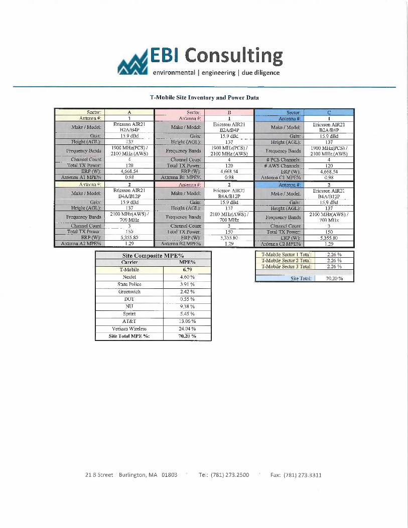
E61 Consulting~, environmental ~ engineering ~ due diligence
T-Mobile Site Inventory and Power Data
Sector: A Sector: B Sector: CAntenna #: 1 Antenna #: 1 Antenna #: 1
Ericsson AIR21 Ericsson AIK21 Ericsson AIR21Make IModel- BZ~4P Make J Model: BZ~4P Make /Model. gZA/B4P
Crain: 15.9 dBd Crain: 15.9 dBd Gain: ~ 15.9 dBdHei t AGL : 137 Hei ht (AGL); 137 Hei t AGL : 137
Frequency Bands 1900 MHz(PCS) /
Frequency Bands 1900 MHz(PCS) /
Frequency Bands 1900 MI~z(PCS) /
2100 MHz (AWS) 2100 MHz (AWS) 2100 MIIz (AWS)Channel Count 4 Channel Count 4 # PCS Channels: 4
Total TX Power: 120 Total TX Power: 120 # AWS Channels: 120ERP (VV): 4,668.54 ERP ); 4,668.54 ERP (VV): 4,668.54
Antenna Al MPE% 0.98 Antenna B] MPE% 0.98 Antenna Cl MPE°lo 0.98
Antenna #: 2 Antenna #: 2 Antenna #: 2Ericsson AIR21 Ericsson AII221 Ericsson AIR21Make /Model: B4A/B12P
Make /Model: B4A/B12P
Make 1 Model: B4A/B12P
Gain: 15.9 dBd Gain: 15.9 dBd Gain: 15.9 dBdHeight (AGL): 137 Height (AGL): 137 Height (AGL). 137
Frequency Bands 2100 MHz(AWS) /
Frequency Bands. 2100 MHz(AW3) /
Frequency Bands 2100 MIIz(AWS) /
700 MHz 700 MHz 700 MN~Channel Count 3 Channel Count 3 Channel Count 3
Total TX Power. 150 Total TX Power. 150 Total TX Pawer: 150ERP (V~: 5,355.80 ERP (W): 5,355.80 ERP (VV): 5,355.80
Antenna A2 IvIPE% 129 Antenna B2 MPE°lo 129 Antenna C2 MPE°/a 129
Site Com osite MPE%Carrier MPE%
T-Mobile 6.79
Nextel 4.60
State Police 3.91
Greenwich 2.42
DOT 0.55
NU 9.38
Sprint 5.45
AT&T 13.06
Verizon Wireless 24.04
Site Total MPE %: 70.20
T-Mobile Sector 1 Total: 2.26T-Mobile Sector 2 Total: 226T-Mobile Sector 3 Total: 2.26
Site Total: 70.20
21 B Street Burlington, MA 01803 Tel: (781) 273.2500 Fax: (781) 273.3311
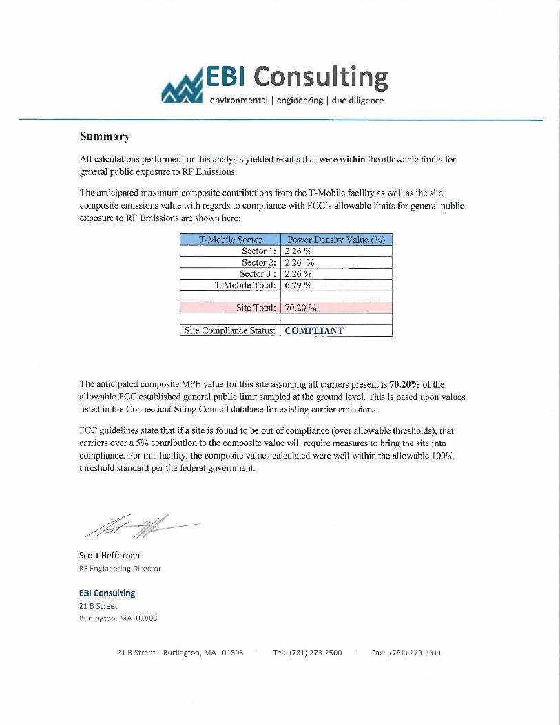
EBI Consulting~r environmental ~ engineering ~ due diligence
Summary
All calculations performed for this analysis yielded results that were within the allowable limits for
general public exposure to RF Emissions.
The anticipated ma~mum composite contributions from the T-Mobile facility as well as the site
composite emissions value with regards to compliance with FCC's allowable limits for general public
exposure to RF Emissions are shown here:
T-Mobile Sector Power Densi Value (%)Sector 1: 2.26Sector 2: 2.26Sector 3 : 2.26
T-Mobile Total: 6.79 %
Site Total: 70.20
Site Com liance Status: COMPLIANT
The anticipated composite MPE value for this site assuming all carriers present is 70.20% of the
allowable FCC established general public limit sampled at the ground level. This is based upon values
listed in the Connecticut Siting Council database for e~sting carrier emissions.
FCC guidelines state that if a site is found to be out of compliance (over allowable thresholds), that
carriers over a 5% contribution to the composite value will require measures to bring the site into
compliance. For this facility, the composite values calculated were well within the allowable 100%
threshold standard per the federal government.
/.~-~
Scott Heffernan
RF Engineering Director
EBI Consulting
21 B Street
Burlington, MA 01803
21 B Street ~ Burlington, MA 01803 Tel: (781) 273.2500 Fax: (781) 273.3311
Related Documents