1 JT-60SA Eurat om Japan Atomic Energy Agency, 1) University of Tokyo, 2) EFDA Close Support Unit, 3) EFDA-CSU-Barcelona, 4) CEA Cadarache, 5) JET-EFDA, 6) EURATOM- ENEA, 7) Max-Planck Institut Title H. Tamai , T. Fujita, M. Kikuchi, K. Kizu, G. Kurita, K. Masaki, M. Matsukawa, Y. Miura, S. Sakurai, A. M. Sukegawa, Y. Takase 1) , K. Tsuchiya, D. Campbell 2) , S. Clement 3) , J. J. Cordier 4) , J. Pamela 5) , F. Romanelli 6) , and C. Sborchia 7) JT-60SA Eurat om JT-60SA Eurat om Prospective performances in JT-60SA towards the ITER and DEMO relevant plasmas O1A-A-360 24th SOFT Conference Sep. 2006, Warsaw, Poland

Welcome message from author
This document is posted to help you gain knowledge. Please leave a comment to let me know what you think about it! Share it to your friends and learn new things together.
Transcript
1
JT-60SA Euratom
Japan Atomic Energy Agency, 1) University of Tokyo, 2) EFDA Close Support Unit, 3) EFDA-CSU-Barcelona, 4) CEA Cadarache, 5) JET-EFDA, 6) EURATOM-ENEA, 7)
Max-Planck Institut
Title
H. Tamai, T. Fujita, M. Kikuchi, K. Kizu, G. Kurita,K. Masaki, M. Matsukawa, Y. Miura, S. Sakurai, A. M. Sukegawa, Y. Takase1), K. Tsuchiya, D. Campbell2), S. Clement3), J. J. Cordier4), J. Pamela5), F. Romanelli6), and C. Sborchia7)
JT-60SA Euratom
JT-60SA Euratom
Prospective performances in JT-60SA towards the ITER and DEMO relevant plasmas
O1A-A-36024th SOFT Conference
Sep. 2006, Warsaw, Poland

2
JT-60SA EuratomOUTLINE
• Mission and Concept
• Plasma Performance
• Engineering Design
• Time Schedule
• Summary

3
JT-60SA Euratom Mission and Concept
• Mission and Concept
• Plasma Performance
• Engineering Design
• Time Schedule
• Summary
4
JT-60SA Euratom
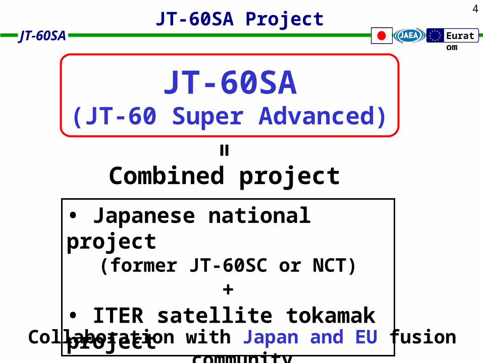
JT-60SA Project
• Japanese national project(former JT-60SC or NCT)
+• ITER satellite tokamak project
Combined project
Collaboration with Japan and EU fusion community
=
JT-60SA(JT-60 Super Advanced)

5
JT-60SA EuratomMission of JT-60SA
Support to ITER - ITER construction phase • optimization of operation scenario, auxiliary system • training of scientists, engineers and technicians - ITER operation phase
• support further development of operating scenarios and understanding of physics issues • Test of possible modifications before their implementation
Support to DEMO - to explore operational regimes and issues complementary to those being addressed in ITER • steady-state operation • advanced plasma regimes (high-beta plasma) • control of power fluxes to wall
Experimental research with ITER relevant plasma configuration - high density operation - increased heating power, plasma current
ITER similar configuration A=3.1, 95=1.7, 95=0.33, q95 =3.0
Support to ITER
divertor structure : TBDhigh-, shape for high-beta operation Time (s)
N
Test of Plasma Facing Component - Compatibility test of reduced activation ferritic steel - Test candidate divertor modules - Sample station for plasma-material research
Support to DEMO
Sustain high beta (N=3.5-5.5) non-inductive CD plasma - Explore high beta regime above no-wall limit - Develop optimized integrated scenario for DEMO for shape, aspect ratio,
SN/DN, current profile, MHD control, fuelling, pumping, divertor shape, …
Exp. in JT-60U
Target for JT-60SA

6
JT-60SA Euratom
Plasma Current Ip(MA) 3.5 / 5.5
Toroidal Field Bt (T) 2.59 / 2.72
Major Radius (m) 3.16 / 3.01
Minor Radius (m) 1.02 / 1.14
Elongation, 95 1.7 / 1. 83
Triangularity, 95 0.33 / 0. 57
Aspect Ratio, A 3.10 / 2.64
Shape Parameter, S 4.0 / 6.7
Safety Factor q95 3.0 / 3.77
Flattop Duration 100 s (8 hours)
Heating & CD power 41 MW x 100 s
N-NBI 34 MW
ECRH 7 MW
PFC wall load 10 MW/m2
Neutron (year) 4 x 10²¹
D2 main plasma + D2 beam injection
Basic Machine Parameters of JT-60SA
ITER similarhigh-S for DEMO
Gravity Support
NBIPort
Shear Panel
Center Solenoid
Stabilizing Plates
Vacuum vessel
Diagnostics Port
In-vessel Coil
Poloidal Field Coil
Spherical Cryostat
Toroidal Field Coil

7
JT-60SA Euratom
Heating & Current Drive Equipement
N-NB (500 keV) co (2u) 10 MW
P-NB (85 keV)
co (2u) 4 MW
ctr (2u) 4 MW
perp (8u) 16 MW
EC110 GHz 3 MW
140 GHz 4 MW
total 41 MW
• Increased injection power of N-NB, and EC
• P-NB : balanced injection for toroidal rotation control
• EC : two-frequency system for flexible control of CD, MHD…
P3-B-336 : Y. Ikeda, et al.
for 100s
Ip
co
Ip
N-NB(co)
EC
Tangential P-NB (ctr)
Perpendicular P-NB
Tangential P-NB (co)
Remote HandlingSystem
Resonance layer of EC with two-frequency system

8
JT-60SA Euratom
Mission and Concept
• Plasma Performance
• Engineering Design
• Time Schedule
• Summary
Plasma Performance

9
JT-60SA Euratom
• Capability to perform operation scenarios- standard operation- hybrid operation- full non-inductive CD operation
• Break-even class plasmas
• High-beta plasma accessibility- shape and aspect ratio- MHD control
• Heat and particle control- divertor plasma performance
Prospective estimation for ITER/DEMO relevant plasmas
10
JT-60SA Euratom
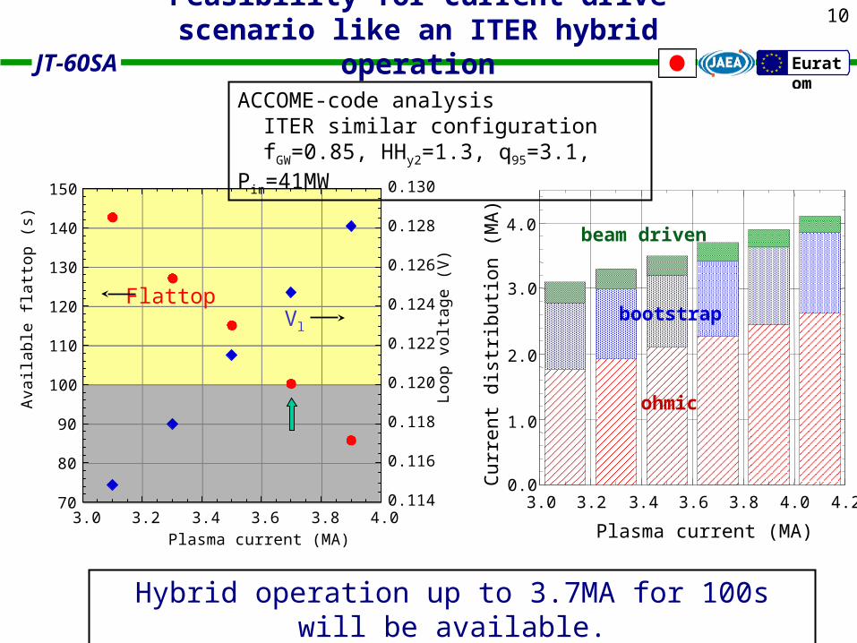
Feasibility for current drive scenario like an ITER hybrid operation
Hybrid operation up to 3.7MA for 100s will be available.
Cur
rent
dis
trib
utio
n (M
A)
Plasma current (MA)
4.0
3.0
2.0
1.0
0.03.23.0 3.4 3.6 3.8 4.0 4.2
beam driven
bootstrap
ohmic
70
80
90
100
110
120
130
140
150
0.114
0.116
0.118
0.120
0.122
0.124
0.126
0.128
0.130
3.0 3.2 3.4 3.6 3.8 4.0
Loop
vol
tage
(V
)
Ava
ilabl
e fla
ttop
(s)
Plasma current (MA)
FlattopVl
ACCOME-code analysis ITER similar configuration fGW=0.85, HHy2=1.3, q95=3.1, Pin=41MW
11
JT-60SA Euratom
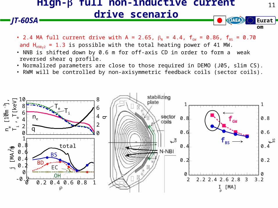
High- full non-inductive current drive scenario
• 2.4 MA full current drive with A = 2.65, N = 4.4, fGW = 0.86, fBS = 0.70 and HH98y2 = 1.3 is possible with the total heating power of 41 MW.
• NNB is shifted down by 0.6 m for off-axis CD in order to form a weak reversed shear q profile.
• Normalized parameters are close to those required in DEMO (J05, slim CS).• RWM will be controlled by non-axisymmetric feedback coils (sector coils).
0
0.2
0.4
0.6
0.8
1
0
0.2
0.4
0.6
0.8
1
2 2.2 2.4 2.6 2.8 3 3.2
f GW
f BS
Ip [MA]
fGW
fBS
-0.20
0.20.40.60.8
1
0 0.2 0.4 0.6 0.8 1
j [M
A/m
2 ]
total
BS
BDEC
OH
02468
10
0
2
4
6
8
n e [10
19 m
-3],
Ti ,
Te [
keV
]
qTe Ti
ne
q

12
JT-60SA Euratom
Access for breakeven and high- plasma with ITER and DEMO relevant parameters
A=2.6, DN, q95~3.5, HH98y2=1.5
2.5
3.0
3.5
4.0
4.5
5.0
5.5
6.0
0.0 0.5 1.0 1.5 2.0
N
QDT
eq
3MA1.5T
3.5MA1.8T
4MA2T
4.5MA2.3T 5MA
2.5T
2.5MA1.25T
25 MWn/nGW=0.8
40 MWn/nGW=0.8
5.5MA2.8T
Accessibility for high QDT and high N is enhanced with increased heating power.
0.00 0.02 0.04 0.06 0.08 0.10 0.12
Normalized collision frequency e*
41MW, HH98y2=1.3
ITER (Steady state)
DEMO (J05)
3MA, fGW=0.56
25MW, HH98y2=1.50.010
0.008
0.006
0.004
0.002
0.000
Nor
mal
ized
Lar
mor
rad
ius
i*
2.4MA, fGW=0.86
Non-dimensional parameters with ITER and DEMO relevant region are expected.
A~2.6, ~1.8, q95~5.5, N~4 (2.4MA, fGW=0.86)
break-even class plasma
TFTR
ITER
JT-60
DIII-D
FTU
LHD
C-Mod JET
Ti(0) (K)
JT-60SA
KSTAR
Self-ignitionCondition
1021
1020
1019EAST
DEMO
Break-evenCondition
108 109107
nD(0
) E
(s
ec/m
3)
collisionless /small normalized Larmor radius

13
JT-60SA Euratom
SIp
aBT
q95 A-11+2(1+22)
4 5 6 7 8
2.5
3.0
3.5
Shape parameter S
Asp
ect
rat
io
A
Divertor pumping(m3/s)≥100 <100
Double nullSingle null
ITER
Flexibility in aspect ratio and plasma shape for high- plasma accessibility
*M. R. Wade, et al., Phys. Plasmas 8 (2001) 2208.
JT-60SA
S=2.0-2.2S=3.1-3.6
JT-60 ASDEX-U JET DIII-D
6
5
4
3
2
Nor
mal
ized
bet
a
N
2 3 4 5 6 7Shape parameter S
DIII-D Experiment *
ITERJT-60
Target of JT-60SAN: 3.5~5.5
S=2-8S=3.0-5.4
S=2.3-7.4
Shape parameter
Flexibility in S and A is extended, which enhances the research capability for high- plasma operation.

14
JT-60SA Euratom
Achievable N depends very much on the location of sector coil
outside stabliser plates : N~3.8 inside stabiliser plates :
N~5.6
・ Sector coils are located on the port entrance in the present design
(Analysis ongoing)
100
101
102
103
104
2 3 4 5 6 7
gro
wth
rat
e [1
/s]
N
RWM stabilisation by feedback control of sector coils (VALEN code analysis*)
100
101
102
103
104
2 3 4 5 6 7
Gp = 0
Gp = 10
7
Gp = 108
Gp = 10
9
ideal wall
gro
wth
ra
te [
1/s
]
N
Ideal limit
Outside
Inside
Controllability for resistive wall mode (RWM)
*G. Kurita, et al., Nucl. Fusion 46 (2006) 383.

15
JT-60SA Euratom
0
25
50
0 50 100 150
j=2,f(i)_II_12,15,18ne
puff
=0.5e22 s-1,Spump
=50 m3/s
puff
=3.0e22 s-1
Spump
=200 m3/s
x (mm)
nedo
(1019
m-3
)
0
25
50
050100150
j=119,f(i)_II_12,15,18ne
puff
=0.5e22 s-1,Spump
=50 m3/s
puff
=3.0e22 s-1
Spump
=200 m3/s
x (mm)
nedi
(1019
m-3
)
0
10
20
30
40
0 50 100 150
j=2,f(i)_II_12,15,18Te
Te
Te
Te
x (mm)
Tedo
(eV)
0
10
20
30
40
050100150
j=119,f(i)_II_12,15,18Te
Te
Te
Te
x (mm)
Tedi
(eV)
- ~1.83, dicertor leg ~ 0.8 m
- Cryopanel under the dome (200 m3/s)- Vertical divertor target (60-80˚)
Qtotal=12 MW, ion= 1 x10²²s-1, puff =0.5 x10²²s-1 ,
Spump = 50 m3/s, e=i=1 m2/s, D=0.3 m2/s , Cimp=1 %
Heat & particle control with semi-closed divertor
Divertor plasma simulation with SOLDOR/NEUT2D code
Detachment control will be available with a strong gas puff.
H. Kawashima, et al., Fus. Eng. Design 81 (2006) 1613.

16
JT-60SA Euratom Engineering Design
Mission and Concept
• Plasma Performance
• Engineering Design
• Time Schedule
• Summary

17
JT-60SA Euratom
Cryostat• Structure design • Structure analysis• Thermal shielding
Engineering Design and Procurement Allocation
First Wall• PFC Ferrite (F82H)• Structure design • Baking/Cooling
Divertor• Target design• Heat removal• Particle pumping• Cooling system
Power Supply
Cryogenic System
Radiation Shielding• R&D of shielding material Boron doped resin etc.• Shielding analysis 2D/3D code
Vacuum Vessel• Structure design • Structure analysis• Baking • Thermal shielding
Superconducting Magnet• Cable-in-conduit conductor• Structure analysis• Support structure
Remote Handling System
TFPF
ECH System

18
JT-60SA Euratom
conductor EF
TF CS
TF CS EF strand NbTi Nb3Sn NbTiconductor cable-in-conduit Bmax (T) 6.4 10 5.0 Top (K) 4.6 5.0 4.8 Iop (kA) 26.5 20 20
Superconducting Coils
P1-E-328 : K. Tsuchiya, et al
P1-E-286 : K. Kizu, et al.

19
JT-60SA Euratom
Vacuum vessel
VV support leg structure
VV is supported with 9 legs.
VV has a double-wall structure.cylindrical: toroidally, polygonal:poloidally140mm 2424
Low cobalt SS316L
(Boronic acid Water)
Bird’s-eye view of vacuum vessel
31
40
mm
9926 mm
one turn resistance: ~15µΩ
baking temp. : ~200˚C (TBD)
Shielding water
VV is covered with a thermal shield.
Helium gas
consists of 18 sections
spring plates (AISI660) for baking
Connection plate to restrain the horizontal swing of VV
SS316
weight: ~300 ton without in-vessel components
3mm

20
JT-60SA Euratom
Plasma facing components
• First wall, divertor modules will be feasible for the maintenance by remote handling system.
• Mono-block target (15MW/m2) will be adopted after the relliability is established bysignficant R&D.
• Exchange with full metal plasma facing components will be decided after experimental and computational analyses.
P2-F-341 : S. Sakurai, et al.
Header(permanent)
Bellows for thermal expansion of heat sink
Pipe connection for laser cutter/welder
Bolted exchangeable armor tiles
Exchangeable heat sink
~0.3m
~1.6m
Total thickness ~ 7cm
Example of FW with exchangeable heat sink
Example of divertor cassette with crank support
Crank support for allowing large thermal expansion
Width 10deg, Weight <500kg
Divertor target
Heat sink for bolted armor
Divertor and dome geometry will be determined.

21
JT-60SA Euratom
SS304 SS304
SS316L SS316L
Radiation Shield
P3-J-302 : A. M. Sukegawa, et al.
DD neutron emission rate
4x10¹⁷ n/sec
5x10²⁰ n/week
3x10²¹ n/3M
4x10²¹ n/year
22
JT-60SA Euratom Time Schedule
Mission and Concept
• Plasma Performance
• Engineering Design
• Time Schedule
• Summary
23
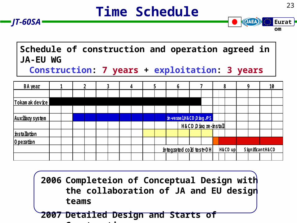
JT-60SA EuratomTime Schedule
2006 Completeion of Conceptual Design with the collaboration of JA and EU design teams
2007 Detailed Design and Starts of Construction
BA year
Tokamak device
Auxiliary system in-vessel,H&CD,Diag./PS
installationOperation
integrated cold test+OH H&CD up
6 7
Significant H&CD
9 108
H&CD,Diag re-install
1 2 3 4 5
Schedule of construction and operation agreed in JA-EU WGConstruction: 7 years + exploitation: 3 years

24
JT-60SA EuratomSummary
• Prospective performance in JT-60SA plasma is estimated on the viewpoint of ITER / DEMO support.
• ITER operation scenario will be investigated with the ITER similar configuration (shape, ne, etc.) by
increased heating power and plasma current.
• Steady-state, high beta plasma controllability will be foreseen (support to DEMO).
• Engineering design will be performed with JA and EU, and the construction is planned to start next year.

25
JT-60SA Euratom
Thank you for your attention.
Dziekuje !!
Acknowledgement
P1-E-286 : K. Kizu, et al. R&D of superconducting coil conductor
P1-E-328 : K. Tsuchiya, et al. Superconducting coil system
P2-F-341 : S. Sakurai, et al. Plasma facing components
P3-J-302 : A. M. Sukegawa, et al.Safety design
P3-B-336 : Y. Ikeda, et al. NBI system
Related Poster PresentationJT-60SA Euratom

26
JT-60SA Euratom
Related Documents