JAPANESE AUTOMOBILE STANDARD JASO M 305-88 7. Scope Weatherstrips for Automobiles This standard specifies fixed glass seal weather- strips, sliding part seal weatherstrips, opening seal weatherstrips, and other equivalent weatherstrips for automobiles (hereinafter referred t o as "weatherstrips"). Remark: In this standard, units and numerical values are based on SI (International System of Units), while units and numerical values given in { 1 are cus- tomary unit system, and are given for reference. 2. Purpose This standard aims to standardize the perfor- mance and test method of weatherstrips used in automobiles and to ensure adequate quality thereof. 3. Classification Weatherstrips shall be classified into the types specified in Table 1 according t o their applica- tions and constructions. 4. Quality 4.1 General Condition of Weatherstrips 11) A good shape preservability. (2) Shall consist of solid rubber or sponge rubber alone or of composite con- struction. (31 Shall consist of rubber of PVC and others, and can be properly used within respec- tive critical performance. (4) Possibility of surface treatment such as hair planting, etc. in compliance with re- quirement for application. 4.2 Appearance of Weatherstrips (1) Shall be free from harmful defects such as flaws, cracks, air bubbles, etc. (2) Shall be free from harmful defects such as blooming, bleeding, etc. (3) Quality of appearance at joint part and in the whole (difference in grade, gloss, hue, etc.) shall be pursuant to agreement between the parties of delivery. 4.3 Shapes and Dimensions of Weatherstrips Shapes and dimensions of weatherstrips shall be pursuant to indication by drawings between the parties of delivery. 4.4 Dimensional Tolerance of Weatherstrips When no dimensional tolerances are particularly specified, the dimensional tolerances pursuant to Table 2 and Table 3 shall apply. 4.5 Assembly Condition of Weatherstrip Weatherstrips manufactured pursuant to this provision are closely related to construction, shape, and dimension of the automobile body to be assembled, and quality of sealing, durability, appearance, etc. in the assembled condition shall be pursuant to agreement between parties of delivery. 4.6 Performance of Weatherstrips Performance of weatherstrips shall be tested pursuant to the test method specified in 5. here- under and shall satisfy provisions tabulated in Table 4. Applicable Standards and Reference Standards: Refer t o Page 19. Former Standard Number: JASO 7004

Welcome message from author
This document is posted to help you gain knowledge. Please leave a comment to let me know what you think about it! Share it to your friends and learn new things together.
Transcript

JAPANESE AUTOMOBILE STANDARD JASO M 305-88
7. Scope
Weatherstrips for Automobiles
This standard specifies fixed glass seal weather- strips, sliding part seal weatherstrips, opening seal weatherstrips, and other equivalent weatherstrips for automobiles (hereinafter referred to as "weatherstrips"). Remark: In this standard, units and numerical values are
based on SI (International System of Units), while units and numerical values given in { 1 are cus-
tomary unit system, and are given for reference.
2. Purpose
This standard aims to standardize the perfor- mance and test method of weatherstrips used in automobiles and to ensure adequate quality thereof.
3. Classification
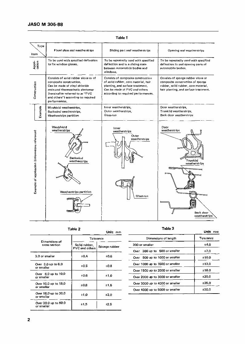
Weatherstrips shall be classified into the types specified in Table 1 according t o their applica- tions and constructions.
4. Quality
4.1 General Condition of Weatherstrips
11) A good shape preservability. (2) Shall consist of solid rubber or sponge
rubber alone or of composite con- struction.
(31 Shall consist of rubber of PVC and others, and can be properly used within respec- tive critical performance.
(4) Possibility of surface treatment such as hair planting, etc. in compliance with re- quirement for application.
4.2 Appearance of Weatherstrips
(1) Shall be free from harmful defects such as flaws, cracks, air bubbles, etc.
(2) Shall be free from harmful defects such as blooming, bleeding, etc.
(3) Quality of appearance at joint part and in the whole (difference in grade, gloss, hue, etc.) shall be pursuant to agreement between the parties of delivery.
4.3 Shapes and Dimensions of Weatherstrips
Shapes and dimensions of weatherstrips shall be pursuant to indication by drawings between the parties of delivery.
4.4 Dimensional Tolerance of Weatherstrips
When no dimensional tolerances are particularly specified, the dimensional tolerances pursuant to Table 2 and Table 3 shall apply.
4.5 Assembly Condition of Weatherstrip
Weatherstrips manufactured pursuant to this provision are closely related to construction, shape, and dimension of the automobile body to be assembled, and quality of sealing, durability, appearance, etc. in the assembled condition shall be pursuant to agreement between parties of delivery.
4.6 Performance of Weatherstrips
Performance of weatherstrips shall be tested pursuant to the test method specified in 5. here- under and shall satisfy provisions tabulated in Table 4.
Applicable Standards and Reference Standards: Refer to Page 19.
Former Standard Number: JASO 7004
JAS0 M 305-88
Over 300 up to 500 or smaller
Over 500 up to 1000 or smaller
Table 1
17.0
110.0 ~ ~~~
Over 1000 up to 1500 or smaller
Over 1500 up to 2000 or smaller
%I 3.0
il 6.0
Sliding part seal weatherstrips Opening seal weatherstrips Fixed glass seal weatherstrips item \
To be used with specified deflection to fix window glasses.
To be repeatedly used with specified def lection to seat opening parts of automobile bodies.
To be repeatedly used with specified deflection and in a sliding state between automobile bodies and windows.
Consists of composite construction of solid rubber, core material, hair planting, and surface treatment. Can be made of PVC and others according to required performances.
Consists of solid rubber alone or of composite constructian. Can be made of vinyl chloride resin and thermoplastic elastomer (hereinafter referred to as "PVC and others") according to required oerformances.
Consists of sponge rubber alone or composite construction of sponge rubber, solid rubber. core material, hair planting, and surface treatment.
Winshield weatherstrips, Backwind weatherstrips, Weatherstrips partition
Inner weatherstrips, Outer weatherstrips, Glass-run
Door weatherstrips, Trunklid weatherstrips, Back door weatherstrips
Winckhield Inner weatherstr ins
Door
weatharstriDs
Ch ter weatherstrios
w
Weatherstrips partition ,
Back door weatherstrips
Table 2 Table 3 Unit: mm
Dimensions of length Tolerance
Unit: mm
Solid rubber. Dimensions of cross section 300 or smaller I +4.0 Sponge rubber PVC and others
3.0 or smaller t0.4
Over 3.0 up to 6.0 or smaller
*0.6
t0.8
I0.6 I Over 6.0 up to 10.0 or smaller Over 2000 up to 3000 or smaller [ 120.0 Il .o
+I .5 Over 3000 up to 4000 or smaller I 125.0 1 k0.8 Over 10.0 up to 18.0 or smaller
Over 4000 up to 5000 or smaller I 130.0 I1 .o I Over 18.0 up to 30.0
or smaller 12.0
i2.5 11 .5 Over 30.0 up to 50.0 or smaller
2

JAS0 M 305-88
Fixed glass seal weatherstrios weatherstri ps
Sl iding pa r t seal Opening seal weatherstrips
6 0 k 5 or 70 I 5
Pursuant t o agreement between the parties o f delivery,
-
-
11 (112) 7 (71) o r more or more o r more o r more
11 (112)
del ivery.
-
With in -20
80 or less
With in -35 With in -20 With in -35 -
50 or less 80 or less 50 or less - Compression set p s t (70 C, after 22 hr.)
Tearing strength tûst
Method A [%I
Method B [%I
%%~&/cm) 200 (20) 1 5 0 (15) 2 0 0 (20) 150 (15) o r more o r more or more o r more -
-
1.5 (15.3)or more
Shall b e f r e e from cracks and splits.
0.2 (2) or more
Wear resistance test
Method A (after 2û,OûO times)
Method B (after 1,000 times)
Shall be free f r o m harmful sp l i t and deformation.
Shall be free
sp l i t and def ormati on.
f r o m harmful - -
Test m e t h o d
?VC and others1 Solid rubber I PVC and others1 %Er 1 zz::rI Sponge rubber I t em No.
5.3.2
5.3.3 [Scale1 Method B ( I R H D M
Compressive load deflect ion tes mN/100 mm ‘(gf/IOO mm}
Pursuant t o agreement between the Darties o f
5.4
5.5 Tension test 1 Tensif streng;? MPa kgf/cm
I Elongation [%I 3 0 0 o r more I 2 0 0 o r m o r e I 3 0 0 o r m o r e I 2 0 0 o r m o r e I -
+ I O or less
5.6 Change rate of ten-
70 hr.) Within -10 1 Wi th in -25 I Wi th in -10 1 Wi th in -25
Change rate of I elongation [%I 5.7.2
Pursuant t o agreement between the parties of delivery.
5.7.3
5.8.2
5.8.3
5.9.2 Impact brittleness
(-25OC o r -35’C) l - Shall be free from cracks and splits.
Bending test (-40 C, after 5 hr.)
Seam ondinqjest MPa figf/cm
5.9.3
5.10
Coatam ination test (80 C, after 24 hr.. after 16 hr. b y weather meter)
Adhesionproof test (7OoC, 95% RH or more a f t r 24 hr.) N/100 rhn rkg f /100 mm]
5.11
5.12
5.13
Shall be free f r o m harmful contamination.
3 (0.3) or more
-
Ozone deterioration test (40DC, 50 pphm, 2W elongation, after 72 hr.)
No spl i t shall b e observed by eye.
Weatherability test (after 200 hr. by weather meter)
5.14 N o spl i t and abnormali tv shall be observed by eye.
Pursuant to agreement between t h e parties of delivery.
- Repeated compression test (100.000 times) [%I 5.1 5
Shall be free f rom harmful wear.
Shall b e free from harmful
Pursuant to agreement between the parties of deliverv.
5.16.2
5.16.3
5.17 Sliding r stance test mN/1 OOTgf / l O0 mm]
Cold/hot repeti t ion test (after 2 cycles) 5.18
3

JAS0 M 305-88
Fixed glass seal weatherstrips
Solid ers rubber
I l
5. Test Method 5.2.2 Standard Condition of Test Specimen
Test method
Test
(Number)
Sliding part seal Opening seal weatherstrips weatherstrips
PVC $Lr specimen 'FE andothers rubber
5.1 Type of Test Method The test specimen shall in principle be the one for which 24 hours or more elapsed after
Table 5 shall indicate type of test methods and manufacture, and shall be kept for one hour or example of applications. more in the room temperature under the stan-
dard condition. 5.2 General Condition of Test
5.2.3 Test Specimen 5.2.1 Standard Condition of Test Room
The test specimen shall in principle be extracted The standard condition of test room shall in prin- from the product and adjusted to the shape and ciple conform to JIS K 6301 (Physical Testing dimension specified in Table 6 by cutting, Methods for Vulcanized Rubber), provided that punching, and grinding. In case the test speci- in case the test room cannot be maintained in men cannot be extracted from the product, it the standard condition, temperature during the shall be prepared from the sheet which has been test shall be noted. formed under the same manufacturing condition
as the product. Table 5
Hardness test Method A O O O O O 3 5.3.2
Method B O O O O O 10 5.3.3
Compressive load deflection test
temperature
O 8 5.4
Repeated compression test
Wear Method A resistance test Method B
Sliding resistance test
O 8 5.15
O O 8 5.16.2
O 8 5.16.3
O O 8 5.1 7
Cold/hot repetition test o O - 5.18

JAS0 M 305-88
Table 6
Shape and dimension (mm) Preparation of test specimen Type Test item
No. 1 test specimen
Weatherability Ozone deterioration
Shall be extracted from the product itself or i t s part.
No. 2 test specimen
Seam bonding force Bonded surface t=M IL = Arbitrary
No. 3 test specimen
Hardness - Method A Tensile Aging
Shall conform to No. 3 type specified in 3.2 of JIS K 6301.
No. 4 test specimen
Tearing strength - Method A Shall conform to B type specified in 9. of JIS K 6301.
No. 5 test specimen
Compression set test - Method A
Shall conform to 10.2 of J E K 6301.
12.7i0.13
No. 6 test specimen
Contamination Shall be extracted from a part of the product. I l i e 2 - 3
No. 7 test specimen
Low temperature impact brittleness
~~
Shall conform to 14.2 of JIS K 6301.
2 - 3 32i 2
No. 8 test specimen
Shall be extracted from the product.
Compressive load deflection Compression set test - Method B Adhesionproof Repeated compression Wear resistance Sliding resistance
No. 9 test specimen
Tensile strength - Method B Low temperature bending
Shall be extracted from a part of the product
100
No. 10 test specimen
Hardness - Method B
P = 4 or more
5

JAS0 M 305-88
5.3 Hardness Test 5.3.3 Method B
5.3.1 Type of Test
The hardness test shall consist of the following two types and either one of them shall be celect- ed by agreement between the parties of delivery.
(1) Method A Hs-A (JIS K 6301) (2) Method B IRHD-M [SRIS 3107 (Inter-
national Testing Method for Hardness of Rubber)]
5.3.2 Method A
Hardness test method A shall conform to 5.2 "Spring Type Hardness Test (A Type)" of JIS K 6301, provided that the test shall be conducted using 4 sheets or more of No.3 in piles.
(1 1 Test Apparatus ( I . 11 Test Machine
The test machine shall consist of the followings, an example of which is in- dicated in Fig. 1.
(a) Test specimen holding table to hold the test specimen.
(b) Pressure adjusting spring to adjust holding pressure of the test specimen.
(c) Push needle to give a hollow on the test specimen.
(d) Test specimen pressing device to have the test specimen closely adhered.
(e) Loading lever to exert a load on the push needle.
(i) IRHD indicator to measure and calcu- late the depth of hollow on the test specimen.
Fig. 1
Preliminary load ___ , original load
6
JAS0 M 305-88
11.2)
Note ( ' 1
(1.31
Note (2)
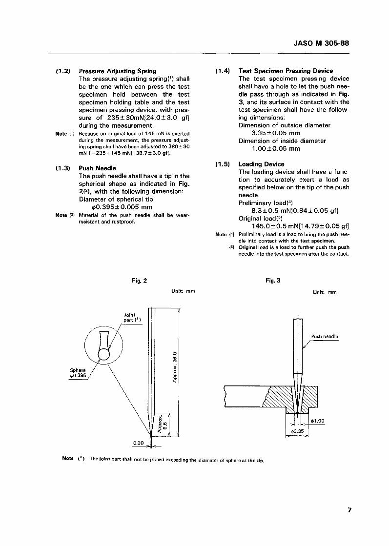
Pressure Adjusting Spring The pressure adjusting spring(') shall be the one which can press the test specimen held between the test specimen holding table and the test specimen pressing device, with pres- sure of 235I30mN[24.0f3.0 gf] during the measurement. Because an original load of 145 mN is exerted during the measurement, the pressure adjust- ing spring shall have been adjusted to 380 f: 30 mN [=235+145 mN1 [38.7+3.0 gfJ.
Push Needle The push needle shall have a tip in the spherical shape as indicated in Fig. 2(2), with the following dimension: Diameter of spherical tip
40.395 k 0.005 mm Material of the push needle shall be wear- resistant and rustproof.
Fig. 2
Unit: mm
0.30
Note (3) The joint part shall not be joined exceeding
( 1.41 Test Specimen Pressing Device The test specimen pressing device shall have a hole to let the push nee- dle pass through as indicated in Fig. 3, and its surface in contact with the test specimen shall have the follow- ing dimensions: Dimension of outside diameter
Dimension of inside diameter 3.3520.05 mm
l.OOITO.05 mm
(1.51 Loading Device The loading device shall have a func- tion to accurately exert a load as specified below on the tip of the push needle. Preliminary load(4)
Original load(5)
Note (4) Preliminary load is a load to bring the push nee- dle into contact with the test specimen.
(5) Original load is a load to further push the push needle into the test specimen after the contact.
8.320.5 rnN{0.8420.05 gf]
145.0IT0.5 mNi14.7920.05 gf]
Fig. 3
U n k rnm
@I .o0 w @3.35
the diameter of sphere at the tip.
7

JAS0 M 305-88
(1.6) Hollow Depth Measuring Device The hollow depth measuring device shall be the one capable to directly read the depth of hollow made by the push needle on the test specimen up to the integral place with IRHDP).
Note (6) Relation between the depth of hollow and IRHD is indicated in Table 7.
Depth of hollow D (mm)
0.00
0.01
0.02
0.03
0.04
O .O5
O .o6
0.07
0.08
0.09
0.10
0.1 1
0.12
0.13
0.14
0.1 5
Table 7
IRHD
100.0
99 .o
95.9
92.0
87.8
83.6
79.5
75.8
72.2
68.7
65.5
62.5
59.7
57.0
54.6
52.3
Depth of hollow D (mm)
0.16
0.17
0.18
0.19
0.20
0.21
o .22
0.23
0.24
0.25
0.26
0.27
O .28
0.29
0.30
IRHD
50.2
48.1
46.2
44.4
42.7
41 .I
39.6
38.2
36.9
35.6
34.4
33.2
32.1
31.1
30.0
(2) Test Specimen (2.1) Shape and
Specimen Dimension of Test
Shape and dimension of the test specimen shall be as follows:
(a) The test specimen to be used shall be No. IO.
(b) Both the upper and lower surfaces of the test specimen shall be smooth and parallel to each other ( 7 ) .
Note ('1 The curved or irregular-shaped test specimens extracted from the products may be tested upon agreement between the parties of deliv- ery. However, measured values shall not be compared with the values of test specimens, surfaces of which are smooth and parallel to each other. In this case, measured values shall be enclosed with ( ) as apparent hardness and the shape of test specimen and the method of test shall be noted.
(cl The test specimen shall have the standard size of 2.020.5 mm in thickness and 4 mm or more in width and length, and shall not protrude from the test specimen holding table (*l.
Note ( 8 ) Hardness test shall be conducted at a place 2 mm or more distant from the edge of the test specimen.
(d) The test specimen with a thickness of 1.0 mm to 4.0 mm may be used(g).
Note (9) When the thickness of test specimen is 1 .O mm or less, the test may be conducted with two test specimens in piles to obtain necessary thickness. However, the pile shall not exceed 3 specimens. When the thickness of test speci- men is 4.0 mm or more, it shall be cut or ground to the specified thickness.
(2.2) Extraction and Preparation of Test Specimen When the test specimen is extracted from the products or thick sheets, the test specimen shall be cut or ground by cutting or grinding machine and shall be adjusted to the specified thickness. The ground surface of the specimen shall be as smooth as possi- ble. Grinding shall be performed in such a manner as generation of heat is controlled to minimum and exces- sive grinding is prevented.
(3) Test Method (3.1) Push Needle Position Adjustment
Adjustment shall be made in such a manner as the tip of push needle comes to the centre of hole in the test specimen pressing device, and it shall be confirmed that the push needle is not in contact with the inside surface of the test specimen pressing device, by protruding 1 /2 or more of spherical surface of the tip from the lower sur- face of the test specimen pressing device.
Measuring method shall be as follows:
(a) The test specimen shall be inserted between the test specimen holding table and the test specimen pressing device, and the pressure adjusting spring shall be adjusted in such a manner as the specified pressure is applied to the test specimen.
(3.2) Measuring Method
8
JAS0 M 305-88
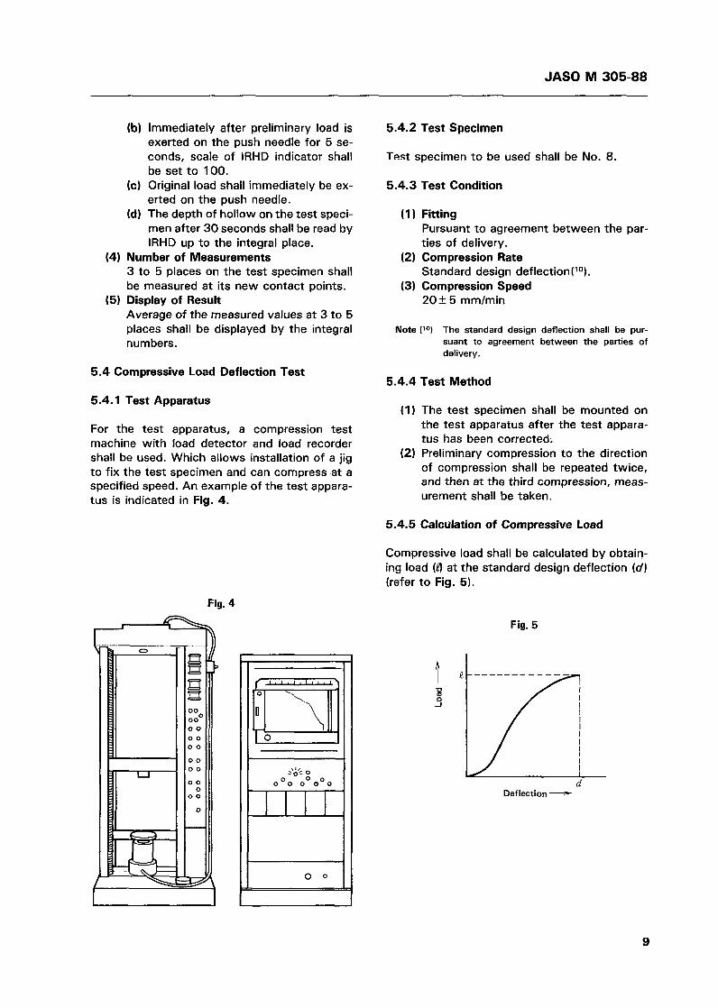
(41
(51
Immediately after preliminary load is exerted on the push needle for 5 se- conds, scale of IRHD indicator shall be set to 100. Original load shall immediately be ex- erted on the push needle. The depth of hollow on the test speci- men after 30 seconds shall be read by IRHD up to the integral place.
Number of Measurements 3 to 5 places on the test specimen shall be measured at its new contact points. Display of Result Average of the measured values at 3 to 5 places shall be displayed by the integral numbers.
5.4 Compressive Load Deflection Test
5.4.1 Test Apparatus
For the test apparatus, a compression test machine with load detector and load recorder shall be used. Which allows installation of a jig to fix the test specimen and can compress at a specified speed. An example of the test appara- tus is indicated in Fig. 4 .
5.4.2 Test Specimen
Test specimen to be used shall be No. 8.
5.4.3 Test Condition
(11 Fitting Pursuant to agreement between the par- ties of delivery.
(21 Compression Rate Standard design deflection(lO).
(31 Compression Speed 20+ 5 mm/min
Note ('O) The standard design deflection shall be pur- suant to agreement between the parties of delivery.
5.4.4 Test Method
(11 The test specimen shall be mounted on the test apparatus after the test appara- tus has been corrected.
(21 Preliminary compression to the direction of compression shall be repeated twice, and then at the third compression, meas- urement shall be taken.
5.4.5 Calculation of Compressive Load
Compressive load shall be calculated by obtain- ing load (4 at the standard design deflection (d) (refer to Fig. 5).
Fig. 4
Fig. 5
I I I
d Deflection -
1 I I I
9

JAS0 M 305-88
5.4.6 Display of Result
In principle, the result shall be displayed by an average value of compressive loads of three test specimens.
e, + e, + e3
3 L =
where: L : Compressive load mN/1 O0 mm(gf/l O0 mm] P,: Load at standard design deflection of No. 1
test specimen mN/1 O0 mm{gf/l O0 mm) f,: Load a t standard design deflection of No. 2
test specimen mN/1 O0 mm[gf/l00 mm) P3: Load at standard design deflection of No. 3
test specimen mN/1 O0 mm{gf/l O0 mm)
5.5 Tension Test
The tension test shall conform to the tension test specified in 3. of JIS K 6301. Test speci- men to be used shall be No. 3.
5.6 Aging Test
Aging test shall conform to the air heating aging test specified in 6.3 of JIS K 6301, provided that test specimen to be used shall be No. 3 and the test shall be conducted at 7O+l0C for 70+$ hours.
5.7 Compression Set Test
5.7.1 Type of Test
The compression set test shall consist of the fol- lowing two types:
(1) Method A
(21 Method B Test of solid rubber, PVC and others
Test of sponge rubber
5.7.2 Method A
Method A of the compression set test shall con- form to the compression set test specified in 10. of JIS K 6301, provided that test specimen to be used shall be No. 5 and the test shall be con- ducted at 704 1 OC for 22k0.25 hours.
5.7.3 Method B
Method B of the compression set test shall be pursuant to the following:
(1 1 Test Apparatus The test apparatus shall conform to Method A specified in 5.7.2, provided that a thickness gauge (minimum scale 0.05 mm) shall be used for measuring the height.
Test specimen to be used shall be No. 8.
The test condition shall be pursuant to the following: (a) Fitting
(21 Test Specimen
(31 Test Condition
Pursuant to agreement between the parties of delivery.
(b) Compression Rate Standard design deflection
(cl Test Temperature (d) Test Time 22 I 0 . 2 5 h
(41 Test Method The test method shall be pursuant to the following: (a) After the measurement of height, the
test specimen shall be compressed under the specified condition and held in an isothermal bath kept at specified temperature for specified time.
(b) After completion of the heat treat- ment, the test specimen shall be quickly taken out of the compression apparatus and left in a room tempera- ture for 30 minutes, and then its height shall be measured.
(c) When measuring the height, the same place shall be measured before and after the test.
70+ 1 OC
(5) Calculation of Permanent Set Rate Changes in the height of the test speci- men before and after the compression set test shall be recorded and calculated from the following equation:
x 100 t o - ti c = - t o - t 2
where: C: Rate of compression set ( % I to: Height of test specimen before the
test (mm) t , : Height of test specimen after the test
ímm) t2: Minimum height of test specimen un-
der the compression (mm) (6) Display of Result
In principle, the result shall be displayed by an average value of permanent set rates of three test specimens.
10
JAS0 M 305-88
Fig. 6
5.8 Tearing Test
5.8.1 Type of Test
The tearing test shall consist of the following two types:
(1) Method A Solid rubber and PVC and others tearing test
Sponge rubber tearing test (2) Method B
5.8.2 Method A
Method A of the tearing test shall conform to the tearing test specified in 9. of JIS K 6301, provided that test specimen to be used shall be No. 4.
5.8.3 Method B
Method B of the tearing test shall be pursuant to the following:
(1) Test Apparatus Tension test machine shall be used for the test with tensile speed of 2002 10 mm/min .
Test specimen to be used shall be No. 9.
A slit of 25 mm length in the longitudinal direction shall be provided on the test specimen as indicated in Fig. 7.
(2) Test Specimen
(3) Slit on Test Specimen
Fig. 7 )> . . :'i
. .. . .:
i SI it
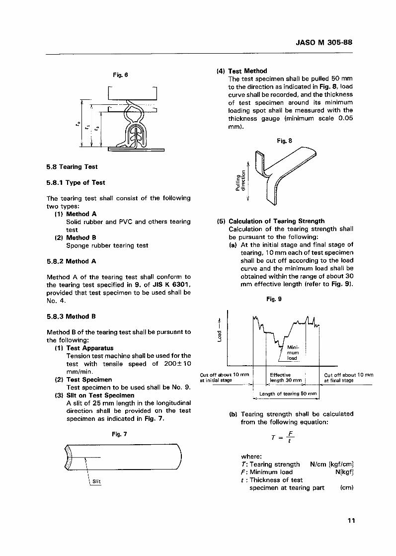
(4) Test Method The test specimen shall be pulled 50 mm to the direction as indicated in Fig. 8, load curve shall be recorded, and the thickness of test specimen around its minimum loading spot shall be measured with the thickness gauge (minimum scale 0.05 mm).
Fig. 8
(51 Calculation of Tearing Strength Calculation of the tearing strength shall be pursuant to the following: (a) At the initial stage and final stage of
tearing, 1 O mm each of test specimen shall be cut off according to the load curve and the minimum load shall be obtained within the range of about 30 mm effective length (refer to Fig. 9).
Fig. 9
Cut off about 1 O mm I I at final stage Effective length 30 mm
Cut off about 10 mm at initial stage
I Length of tearing 50 mm I (b) Tearing strength shall be calculated
from the following equation:
F t T = -
where: T: Tearing strength N/cm (kgf/cm)
t : Thickness of test f : Minimum load N k f )
specimen at tearing part (cm)
11
JAS0 M 305-88
(6) Display of Result In principle, the result shall be displayed by an average value of tearing strength of three test specimens.
5.9 Low Temperature Test
5.9.1 Type of Test
The low temperature test shall consist of the fol- lowing two types:
Method A Impact brittleness test Method B Bending test
Method A
Test Apparatus Test apparatus shall conform to the low temperature impact brittleness test speci- fied in 14. of JIS K 6301. Test Specimen Test specimen to be used shall be No. 7. Temperature of Heat Transfer Medium Temperature of the heat transfer medium shall be pursuant to the following: (a) Solid Rubber -3520.5OC (b) PVC and Others - 2 5 2 0.5OC Test Method Preliminarily, a heat transfer medium shall be uniformly kept in an isothermal bath at specified temperature. As specified in 14.3 (1) of JIS K 6301, the test specimen firmly held by a grip shall be submerged into the cold bath for 310.5 min. and then struck once by a percussion blade. Display of Result In principle, existence or nonexistence of cracks and splits on three test specimens shall be displayed.
Method B
Method B shall be pursuant to the following: (1 1 Test Apparatus
The test apparatus shall conform to the low temperature bending test specified in 5.8 of JIS K 6380 (Industrial Rubber Packing Materials).
Test specimen to be used shall be No. 9.
The test condition shall be pursuant to the following:
(2) Test Specimen
(3) Test Condition
(a) Test temperature -4Ok2OC (b) Test time 5 f0 .25h
(4) Test Method Test method shall be pursuant to 5.8 of JIS K 6380.
(5) Display of Result In principle, existence or nonexistence of cracks and splits on three test specimens shall be displayed.
5.10 Seam Bonding Force Test
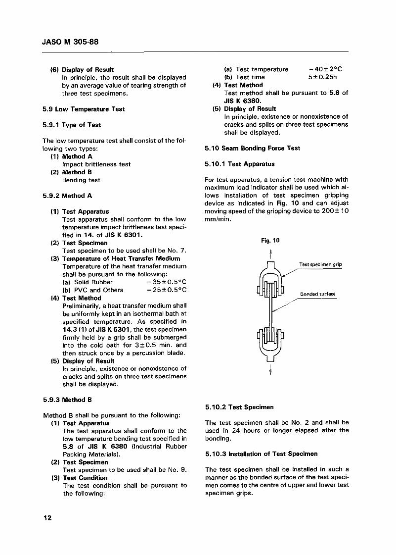
5.1 O. 1 Test Apparatus
For test apparatus, a tension test machine with maximum load indicator shall be used which al- lows installation of test specimen gripping device as indicated in Fig. 10 and can adjust moving speed of the gripping device to 200 +: 1 O mm/min.
Fig. 10
Test specimen grip
Bonded surface
5.10.2 Test Specimen
The test specimen shall be No. 2 and shall be used in 24 hours or longer elapsed after the bonding.
5.10.3 Installation of Test Specimen
The test specimen shall be installed in such a manner as the bonded surface of the test speci- men comes to the centre of upper and lower test specimen grips.
12

JAS0 M 305-88
5.10.4 Test Method 5.1 1.2 Test Specimen
A load shall be exerted on the test specimen and measurement of maximum load shall be taken when flaking or splitting has occurred on the bonded surface of the test specimen.
5.10.5 Calculation of Seam Bonding Force
The seam bonding force shall be calculated from the following equation:
W F = - A
where: F : Seam bonding force W. Maximum load for occurrence
of flaking or splitting on the bonded surface
A : Cross sectional area of bonded surface on the test specimen
M Palkgf /cm2]
N IWI
(cm2)
5.10.6 Display of Result
In principle, the result shall be displayed by an average value of seam bonding forces of three test specimens.
5.1 1 Contamination Test
5.1 1.1 Test Apparatus
The test apparatus shall be pursuant to the fol- lowing:
(1) An isothermal bath which can maintain 802 1 OC shall be used.
(2) A sunshine carbon arc lamp type weatherability test machine conforming to the accelerated weatherability test specified in 5.4 of JIS D 0205 (Test Method of Weatherability for Automobile Parts) shall be used.
The test specimen shall be pursuant to the following:
(1) Test specimen to be used shall be No. 6. (2) White baked coated sheet(")
70 x 150 mm. Note (11) Color and coating material of the baked coated
sheet can be changed by agreement between the parties of delivery.
5.1 1.3 Test Method
The test method shall be pursuant to the fol- lowing:
(1) Two test specimens shall be inserted be- tween two materials to be contaminated (white baked coated sheets) as indicated in Fig. 11, exerted with 4.4N10.45 kgf] load, and put into the isothermal bath which was preliminarily controlled a t 802 1 OC.
(2) After left in the isothermal bath for 2420.25 hours, the materials to be con- taminated shall immediately be taken out of the bath, washed by water on the sur- faces, and examined if they have been contaminated or not.
(3) After the examination, the materials to be contaminated shall be exposed into the sunshine arc lamp type weatherability test machine for 16IO.25 hours.
(4) After the exposure, the surfaces of materials shall be washed by water and examined if they have been contaminated or not.
Fig. 11
Material to be Contaminated Load 4.4N (0.45 kgf}
13

JAS0 M 305-88
5.1 1.4 Judgement of Contamination
Judgement of contamination shall be pursuant to the following:
(1 1 Occurrence or non-occurrence of con- tamination shall be judged by comparison with materials which were contaminated in a blank test.
(2) Details of criteria shall be pursuant to agreement between the parties of delivery.
5.1 1.5 Display of Result
The result shall be displayed pursuant to the fol- lowing:
(1) Occurrence or non-occurrence of con- tamination after the heating shall be dis- played.
(21 Occurrence or non-occurrence of con- tamination after the exposure shall be dis- played on the weathermeter.
5.12 Adhesionproof Test
5.12.1 Test Apparatus
The test apparatus shall be pursuant to the fol- lowing:
(1 1 Compression Device Compression device shall consist of two flat jig plates, a specimen setting jig, and bolts, nuts, and spacers to fix the jig plates. Jig plates shall be made of steel sheets or aluminum sheets which have sufficient thickness not to deform under a load. The specimen setting jig shall be fixed to the jig plate. An example of the compression device is indicated in Fig. 12.
14
Fig. 12 Specimen setting jig
Not to be bonded. Coated sheet or glass
Spacer
(2) Isothermal and Isohumid Bath For the isothermal and isohumid bath, a bath which can maintain specified tem- perature and humidity shall be used.
Push-pull scale shall be the one which has an indicator of maximum load and a mini- mum scale of 0.5N[0.05 kgf].
Glass(13) shall be used for the part which comes in contact with glass in actual au- tomobile, and coated sheet(14) shall be used for the other parts. For reference, an example of dimensions of glass and coat- ed sheet is indicated below. (a) Glass 35 x 120 x 5 mm (b) Coated sheet 35 x 150 x 1 mm
Notes (12) Longitudinal and transverse dimensions and thickness shall be pursuant to agreement be- tween the parties of delivery.
(13) Glass shall be ordinary glass or reinforced glass.
(14) Color and coating material of coated sheet shall be pursuant to agreement between the parties of delivery.
(3) Push-pull Scale
(4) Coated Sheet and Glassí12)
5.12.2 Test Specimen
Test specimen to be used shall be No. 8.
5.12.3 Test Condition
Test condition shall be pursuant to the fol- lowing:
(1 1 Compression rate Standard design deflection
(2) Test temperature 701 2OC (3) Test humidity (4) Test time 24k0.25 h
95% RH or higher
5.12.4 Test Method
(1) Test specimen shall be fixed to the speci- men setting jig and coated sheet or glass shall be placed on the test specimen.
(2) Coated sheet or glass shall be brought to contact with the upper test specimen set- ting jig without bonding and put into the specified compression condition.
(31 Compression jig shall be put into the isothermal and isohumid bath which has been kept at specified temperature and humidity for specified time.
(41 After completion of humidifying, the compression jig shall be taken out and left in the compressed condition in the room temperature for one hour, after that the upper jig plate shall be removed.

JAS0 M 305-88
(5) The coated sheet or glass shall be slowly lifted in the vertical direction by the push- pull scale, and the maximum load (adhe- sive force) a t that time shall be read. An example of the measurement condition shall be indicated in Fig. 13.
Fig. 13
U U
5.12.5 Display of Result
In principle, the result shall be displayed by an average value of adhesive force of three test specimens.
5.13 Ozone Deterioration Test
5.13.1 Test Apparatus
For the test apparatus, a test bath conforming to the accelerated ozone resistance test specified in 5.6 of JIS D 0205 shall be used.
5.13.2 Test Specimen
Test specimen to be used shall be No. 1.
5.13.3 Test Condition
Test condition shall be pursuant to the fol- lowing:
50+ 5 pphm (1) Ozone concentration (2) Test temperature 40+2OC
(41 Test time 70+: h (3) Elongation 20%
5.13.4 Test Specimen Condition Adjustment
Condition of test specimen shall be adjusted pursuant to the following:
(1) Test shall be conducted after the test specimen maintaining 20% elongation has been left in a hermetically sealed box for 2420.25 hours.
(21 Edge part, tightened part, and if neces- sary, reverse side of the test specimen shall have been preliminarily protected by an ozonproof film unharmful to the test.
5.13.5 Display of Result
Existence or nonexistence of visible splits shall be displayed, and only the exposed surface of product shall be subject to judgement.
5.14 Weatherability Test
5.14.1 Test Apparatus
For the test apparatus, a sunshine carbon arc lamp type weatherability test machine conform- ing to the accelerated weatherability test speci- fied in 5.4 of JIS D 0205 shall be used.
5.14.2 Test Specimen
Test specimen to be used shall be No. 1.
5.14.3 Test Time
Test time shall be 200+: h.
5.14.4 Test Method
The test specimen shall be given 20% elonga- tion and placed in the sunshine arc lamp type weatherability test machine for a specified time.
5.14.5 Display of Result
Existence or nonexistence of visible splits and abnormality shall be displayed.
5. I 5 Repeated Compression Test
5.1 5.1 Test Apparatus
The test apparatus shall be the one which con- forms to the repeated compression test speci- fied in 5.6 of JIS K 6382 (Latex Form Rubber for Cushion), provided that a thickness gauge (mini- mum scale 0.05 mm) shall be used for measure- ment of height.
5.15.2 Test Specimen
Test specimen to be used shall be No. 8.
15
JAS0 M 305-88
5.15.3 Test Condition 5.15.6 Display of Result
The test condition shall be pursuant to the fol- lowing:
(1) Fitting Pursuant to agreement between the par- ties of delivery.
(2) Compression rate Standard design deflection
(3) Compression speed 60 times/min (4) Number of compression 100,000 times
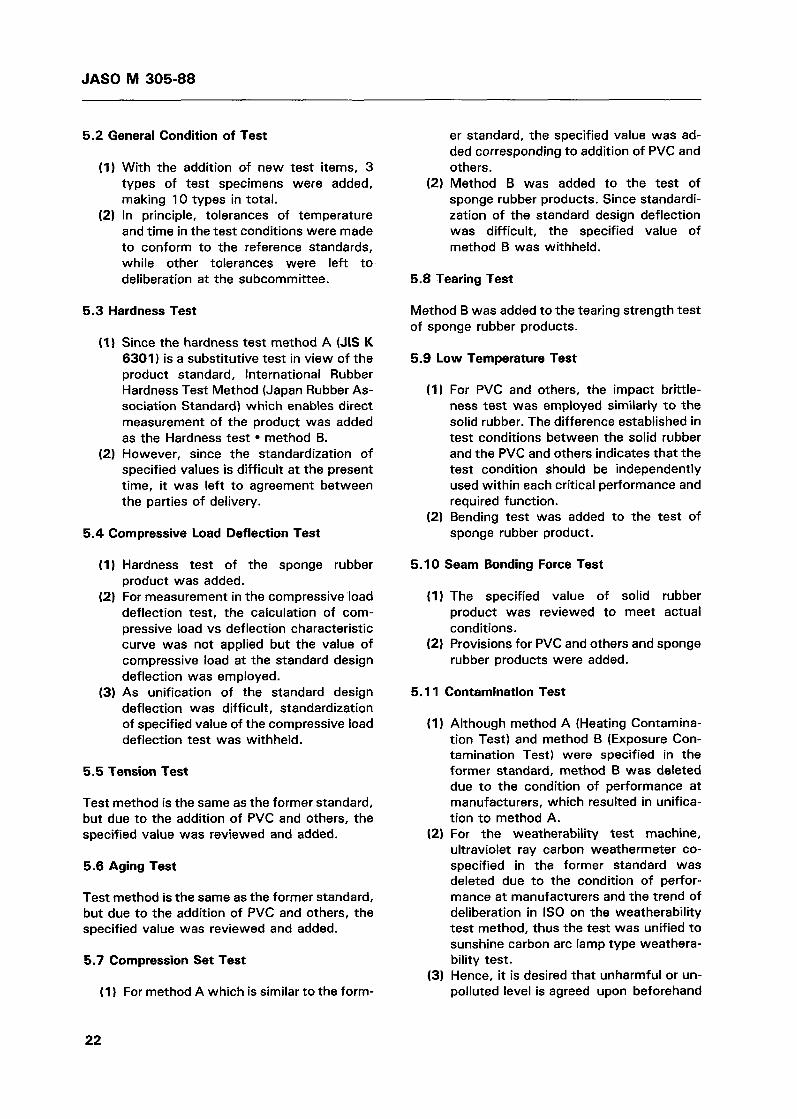
5.1 5.4 Test Method
(1) After the height of test specimen has been measured, the test specimen shall be set on the test apparatus under the specified condition and shall be continu- ously and repeatedly compressed at specified speed in the room temperature.
(2) After the test specimen has been com- pressed a t specified number of times, it shall be taken out of the test apparatus and left in the room temperature for 30 minutes, after that its height shall be measured. The measuring spots before and after the test shall be the same.
5.15.5 Calculation of Variation Rate of Height
The variation rate of height shall be calculated pursuant to Method B (5) of the above 5.7.3.
In principle, the result shall display an average value of the variation rates of height of three test specimens and existence or nonexistence of splits, flaking, and wears.
5.16 Wear Resistance Test
5.16.1 Type of Test
Wear resistance test shall consist of the follow- ing two types:
(1) Method A Solid rubber and PVC and others wear resistance test.
Sponge rubber wear resistance test (2) Method B
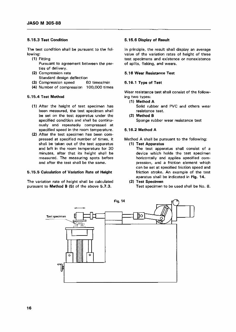
5.16.2 Method A
Method A shall be pursuant to the following: Test Apparatus The test apparatus shall consist of a device which holds the test specimen horizontally and applies specified com- pression, and a friction element which can be set at specified friction speed and friction stroke. An example of the test aparatus shall be indicated in Fig. 14. Test Specimen Test specimen to be used shall be No. 8.
Fig. 14 -
16
JAS0 M 305-88
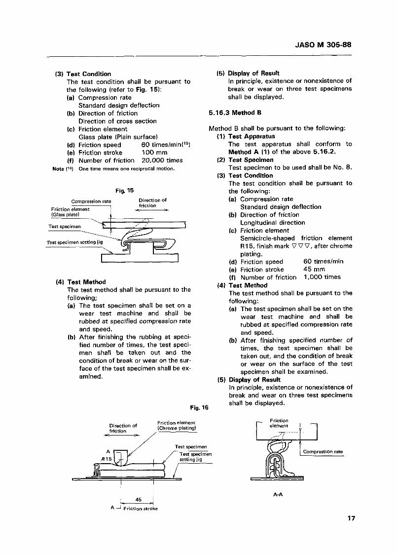
(3) Test Condition (5 ) Display of Result The test condition shall be pursuant to In principle, existence or nonexistence of
following (refer to Fig. 15): Compression rate Standard design deflection Direction of friction Direction of cross section Friction element Glass plate (Plain surface) Friction speed 60 times/minP" Friction stroke 100 mm Number of friction 20,000 times One time means one reciprocal motion.
Fig. 15 Compression rate Direction of
friction Friction element P (Glass plate)
Test specimen I
I
(4) Test Method The test method shall be pursuant to the following; (a) The test specimen shall be set on a
wear test machine and shall be rubbed at specified compression rate and speed.
(b) After finishing the rubbing at speci- fied number of times, the test speci- men shall be taken out and the condition of break or wear on the sur- face of the test specimen shall be ex- amined.
Fig. 16
break or wear on three test specimens shall be displayed.
5.16.3 Method B
Method B shall be pursuant to the following: (1 ) Test Apparatus
The test apparatus shall conform to Method A (I) of the above 5.16.2.
Test specimen to be used shall be No. 8.
The test condition shall be pursuant to the following:
(2) Test Specimen
(3) Test Condition
Friction element (Chrome plating) Direction of
friction
(a) Compression rate
(b) Direction of friction
(c) Friction element
Standard design deflection
Longitudinal direction
Semicircle-shaped friction element R I 5, finish mark V V V , after chrome plating.
(d) Friction speed 60 times/min (e) Friction stroke 45 mm (f) Number of friction 1,000 times
(4) Test Method The test method shall be pursuant to the following: (a) The test specimen shall be set on the
wear test machine and shall be rubbed at specified compression rate and speed.
(b) After finishing specified number of times, the test specimen shall be taken out, and the condition of break or wear on the surface of the test specimen shall be examined.
(5) Display of Result In principle, existence or nonexistence of break and wear on three test specimens shall be displayed.
A-A
17

JAS0 M 305-88
5.17 Sliding Resistance Test
5.17.1 Test Apparatus
For the test apparatus, a tension test machine with a load recorder which allows installation of the test specimen setting jig as indicated in Fig. 17 and can pull the glass plate at specified speed, shall be used.
5.17.2 Test Specimen
Test specimen.to be used shall be No. 8.
5.17.3 Test Condition
Fitting Pursuant to agreement between the par- ties of delivery. Compression rate Standard design deflection Glass pulling speed 200 2 1 O mm/min Dimension of glass('6) Pursuant to the example as indicated in Fig. 18. (16) Longitudinal and transverse dimensions and
thickness shall be pursuant to agreement be- tween the parties of delivery.
Fig. 17
5.17.4 Test Method
The test method shall be pursuant to the fol- lowing:
(1 1 After the test specimen has been fixed to the holding jig as indicated in Fig. 18, the glass plate shall be inserted into the bot- tom of the jig.
(2) Glass shall be pulled in the vertical direc- tion at specified speed, and the first resistance (17 occurring when the glass is moved 1 O mm or more shall be measured. However, í shall not include the load of glass.
5.17.5 Calculation of Sliding Resistance
The sliding resistance shall be calculated from the following equation:
F w = - 2
where: W: Sliding resistance mN/100 mm(gf/l00 mm] F : Resistance per two test specimens
mN/100 mm{gf/l O0 mm]
5.17.6 Display of Result
In principle, the result shall be displayed by an average value of sliding resistance of three test specimens.
Fig. 18
Pulling direction
Thickness of glass plate 5 rnrn
\ R2.5 (Polished and chamfered)
18

JASO M 305-88
5.18 Cold/hot Repetition Test
5.18.1 Test Apparatus
For the test apparatus, a test bath which con- forms to the cold/hot repetition test specified in 5.1.4 (4) of JASO M 312 (Testing Method of Plastics Parts for Automobiles) shall be used.
5.18.2 Test Specimen
Test specimen to be used shall be the product it- self or a part of the product.
5.18.4 Temperatures
Two-cycle test shall be conducted, one cycle being 80 f 2 OC/3h + Room temperature/O. 5h -+ - 3OoC 2 2OC/2h + Room temperature/0.5h -t 4 9 2 1 OC, 95% RH or more/3h + Room tem- perature/0.5h + - 3OoC * 2OC/14h + Room temperature/O. 5h.
5.18.5 Display of Result
Existence or nonexistence of split and deforma- tion shall be displayed.
5.18.3 Fitting Condition
Fitting shall be conducted in an actual automo- bile or its equivalent.
Applicable Standards: JIS D 0205 JIS K 6301 JIS K 6380 JIS K 6382 JASO M 312
SRIS 3107 International Rubber Hardness Testing Methods - Japan
Test Method of Weatherability for Automobile Parts Physical Testing Methods for Vulcanized Rubber Industrial Rubber Packing Materials Latex Form Rubber for Cushion Testing Method of Plastics Parts for Automobiles
Reference Standards: JASO M 304 Cellular Substances for Automobiles
Rubber Association Standards
19

JASO M 305-88
Introduction
Explanatory Note on
JASO M 305-88 Weatherstrips for Automobiles
Inasmuch as 17 years have elapsed without any correction or revision since the former standard was established in October 1970, the standard was taken up to be revised in the 1987 fiscal year. In the process of revision, recent trend was emphatically studied and deliberated to in- corporate it in the revised standard. Keynotes of the revision are as follows:
Since the former standard specified only the fixed glass seal weatherstrips for au- tomobiles, which is rather narrow appli- cation of weatherstrips, the product was classified this time according to the con- dition of application, and the sliding part seal weatherstrips and opening seal weatherstrips were added to form three types in the product classification. As materials of weatherstrips, resultful vinyl chloride resin and promising ther- moplastic elastomer were added to the provision, in addition to the rubber materi- als. Further, provision of sponge rubber was added to the solid rubber specified in the former standard. Accompanied by the addition of the slid- ing part seal weatherstrips and opening seal weatherstrips, a total of 11 types of product tests, Le., hardness test method B, compressive load deflection test, compression set test method B, splitting strength test method B, low temperature bending test, adhesionproof test, repeated compression test, wear resistance test methods A and B, sliding resistance test, and cold/hot repetition test, were added. The International System of Units (SI) is now in the second stage, and the unit system in this standard was reviewed in line with SI. In the following, explanations will be given to the items for which supplemental descriptions are specially thought to be necessary. (The item numbers are the same as in the Text.)
1. Scope
Weatherstrips can roughly be classified accord- ing to their applications to the fixed glass seal weatherstrips which are used to fix window glasses with specified deflection, the sliding part seal weatherstrips which are used with specified deflection and slide between the au- tomobile body and glasses, and the opening seal weatherstrips which are repeatedly used to seal gaps at opening parts with specified deflection, and accordingly, these types were included in the scope. According to the provision of terms in JASO 2 210-75, the glass-run is independent of weatherstrips, but since the term of weather- strips is now changing from the name of part to the name of function and the glass-run was deliberated to be a part with that function, it was decided to include the glass-run in the present revision.
3. Classification
(1 1
(21
(31
(41
Although only one type of the fixed glass seal weatherstrips was specified in the former standard, three types are now specified based on their applications and constructions, as indicated in the Scope. As materials to be used for sealing, which is the most important function required for construction, the sponge rubber, the vinyl chloride resin which is partially used now, and the promising thermoplastic elastomer were actively employed, not to mention the solid rubber. As construction of the product, compo- site construction (many types and classes such as core material, hair planting, sur- face treatment, etc.) was added, in addi- tion to the single material construction. Since the parts indicated in the example of application have different product names in each manufacturer, typical plain names were selected and outline draw- ings of their panel assembly were added.
20

JASO M 305-88
Reference standards
SRIS 3107 (international Rubber Hardness Test Method)
4. Quality
Addition Revision
O
(31 Accompanied by the addition of the test of 11 types of products and a partial revi- sion of the test method, addition and revi- sion of the specified values were incorporated. Specified values for the items for which standardization is presently difficult were left to agreement between the parties of delivery. These specified values are the subjects to be decided in the future.
Partial revision of former standard
JIS K 6382 (Latex Form Rubber for Cushion)
Subcommittee (Draft)
Subcommittee (Draft)
(11 In this revision, quality was classified to the performance of weatherstrips which is the main subject and to the items for which standardization is difficult. Quality of appearance of weatherstrips, indica- tion of shapes and dimensions on draw- ings, quality of fitted weatherstrips, etc. belong to the latter items, and these items were specified to be pursuant to agreement between the parties of delivery.
(21 Dimensional tolerance of only the cross section of weatherstrips was classified to solid rubber application and sponge rub- ber application to meet actual conditions, and the dimensional tolerance of length was made common to both rubbers based on their fitting conditions.
O
O
O
O
5. Test Method
5.1 Type of Test Method
(11 A table indicating the test item, applica- tion, type of weatherstrips, test speci- men, and test method, was added.
(21 The added and revised test methods as well as reference standards will be indi- cated in the Explanatory Table.
Explanatory Table
Test method Reason
Hardness of products such as solid runner and PVC and others
Hardness test - Method B
Compressive load deflection test Hardness of sponge rubber products JASO M304 (Cellular Substances for Automobiles)
Compression set test - Method B Compression set of sponge rubber products
JIS K 6382 ( Latex Form Rubber for Cushion)
~ ________~ ~
Subcommittee ( Draf t)
O I
Tearing strength test - Method B Tearing strength of sponge rubber products
Cold-resistance of sponge rubber products
Low temperature bending test 1 ° 1 JIS K 6380 (Industrial Rubber Packing Materials)
Contamination test Partial revision of former standard
Simplification
Adhesionproof t e s t l o / Subcommittee (Draft) Adhesion-resistance of sponge rubber oroducts
Weatherability tes t Fitness to actual condition
Permanent strain after repeated compression of sponge products
Repeated compression test
Method A t Method B Wear resistance test
Wear resistance of solid rubber and PVC and others porducts
Wear resistance of sponge rubber products
Sliding resistance test Subcommittee (Draft) 1 0 1 Sliding resistance of products
Cold/hot repetition test 1 ° 1 JASO M 312 (Testing Method of Plastics Parts for Automobiles)
Cold temperature resistance of PVC and others products
21
JAS0 M 305-88
5.2 General Condition of Test
(1) With the addition of new test items, 3 types of test specimens were added, making 10 types in total.
(2) In principle, tolerances of temperature and time in the test conditions were made to conform to the reference standards, while other tolerances were left to deliberation a t the subcommittee.
5.3 Hardness Test
(1) Since the hardness test method A (JIS K 6301 1 is a substitutive test in view of the product standard, International Rubber Hardness Test Method (Japan Rubber As- sociation Standard) which enables direct measurement of the product was added as the Hardness test method B.
(2) However, since the standardization of specified values is difficult at the present time, it was left to agreement between the parties of delivery.
5.4 Compressive Load Deflection Test
(1) Hardness test of the sponge rubber product was added.
(2) For measurement in the compressive load deflection test, the calculation of com- pressive load vs deflection characteristic curve was not applied but the value of compressive load a t the standard design deflection was employed.
(3) As unification of the standard design deflection was difficult, standardization of specified value of the compressive load deflection test was withheld.
5.5 Tension Test
Test method is the same as the former standard, but due to the addition of PVC and others, the specified value was reviewed and added.
5.6 Aging Test
Test method is the same as the former standard, but due to the addition of PVC and others, the specified value was reviewed and added.
5.7 Compression Set Test
( I l For method A which is similar to the form-
er standard, the specified value was ad- ded corresponding to addition of PVC and others.
(2) Method B was added to the test of sponge rubber products. Since standardi- zation of the standard design deflection was difficult, the specified value of method B was withheld.
5.8 Tearing Test
Method B was added to the tearing strength test of sponge rubber products.
5.9 Low Temperature Test
(1) For PVC and others, the impact brittle- ness test was employed similarly to the solid rubber. The difference established in test conditions between the solid rubber and the PVC and others indicates that the test condition should be independently used within each critical performance and required function.
(2) Bending test was added to the test of sponge rubber product.
5.10 Seam Bonding Force Test
(1) The specified value of solid rubber product was reviewed to meet actual conditions.
(2) Provisions for PVC and others and sponge rubber products were added.
5.1 1
(1
Contamination Test
Although method A (Heating Contamina- tion Test) and method B (Exposure Con- tamination Test) were specified in the former standard, method B was deleted due to the condition of performance a t manufacturers, which resulted in unifica- tion to method A.
(2) For the weatherability test machine, ultraviolet ray carbon weathermeter CO-
specified in the former standard was deleted due to the condition of perfor- mance at manufacturers and the trend of deliberation in I S 0 on the weatherability test method, thus the test was unified to sunshine carbon arc lamp type weathera- bility test.
(3) Hence, it is desired that unharmful or un- polluted level is agreed upon beforehand
22
JAS0 M 305-88
between the parties of delivery for the purpose of evaluation.
5.12 Adhesionproof Test
This test was added for evaluation of adherence phenomenon between weatherstrips and glass- es or panels when they were left outdoors for a long time. The specified values were established in reference to actual measurement values and calculation values for automobiles.
5.13 Ozone Deterioration Test
Same as the former standard.
5.14 Weatherability Test
(1) For weatherability test, ultraviolet ray carbon weather meter was deleted simi- larly to the contamination test, and the test was unified to sunshine carbon arc lamp type weatherability test.
(2) For evaluation, it is desired that a level which does not cause splitting and abnor- mality is agreed upon beforehand be- tween the parties of delivery.
5.17 Sliding Resistance Test
(1) This test was added as a sliding resistance test of the sliding part seal weatherstrips.
(2) Since unification of the fitting and stan- dard design deflection is difficult, stan- dardization of the specified value of sliding resistance test was withheld.
5.18 Coldlhot Repetition Test
(1) Cold/hot repetition test using an actual automobile or its equivalent jig was added for the cold/hot durability test of PVC and other products.
(2) The result of this test is not only for the test of the PVC and other materials but also the result of overall tests including effects of the designed shape of product and construction of panel. Therefore, at- tention must be paid to the evaluation and analysis of the test result.
(3) For evaluation, it is desired that a level which does not cause harmful splitting and deformation is agreed upon between the parties of delivery.
5.15 Repeated Compression Test Postscript
(1) This test was added as compression en- durance test of the sponge rubber product.
(2) Since the unification of standard design deflection is difficult, standardization of the specified value of repeated compres- sion test was withheld.
5.16 Wear Resistance Test
(1) Method A was added for application of the sliding part seal weatherstrips to solid rubber and PVC and other products. The compression rate was specified to be the standard design deflection, with 20,000 times of friction.
(2) Method B was added for surface wear test of the sponge rubber product. It was specified to use the specified friction ele- ment, with 1,000 times of friction.
(3) For evaluation, it is desired that a level which does not cause harmful wear is agreed upon between the parties of del ivery .
Matters that were specifically mentioned in the course of deliberation are as follows:
(1) Although an attempt was made to stan- dardize the shapes and dimensions as well, they were deleted from the provi- sion because the shapes and dimensions are closely related to design and panel construction of automobiles, and it is difficult to standardize them at the present time.
(2) Although there was an opinion to incor- porate a provision for wax removing liquid which is used to clean-up the wax preliminarily coated to prevent rust during transportation, this was excluded from the provision this time because EPDM which is widely used in weatherstrips a t the present time is not the oil resistance rubber and belongs to a different field from the condition of application.
(3) It is desired for the glass-run to be speci- fied in a separate standard since there still remains insufficiency to specify perfor- mance and function of glass-run itself.
23
JAS0 M 305-88
(4) For the rubber used in bus windows, it is desired to follow JIS D 4601 (Window Weatherstrips for Automobiles) in which the shapes and dimensions have been standard ked.
(5 ) There were many opinion on employment of combustion test of weatherstrips, but the employment was withheld because it was deliberated to be still premature at the present time due to unclearness whether the weatherstrips should be sub- jected to legal control under FMVSS 302 (Combustion Test of Interior Materials) or not and because no consideration was given to the combustionproof property of the most products both overseas and domestically.
24

JAS0 M 305-88
In the event of any doubt, the original standards in Japanese should be referred.
: SECOND PHASED STANDARD
(The standard where customary units and converted values are given in
brackets after specified values of SI units.)
Established by the Standard Council of JSAE
Date of Establishment: 1970-1 0-9
Date of Revision: 1988-3-30
Sub Committee in which the draft was made: SC of Weatherstrips
Technical Committee under which the draft was discussed: TC of Materials
Investigating Committee: Standard Committee under the Standard Council
Published by
The Society of Automotive Engineers of Japan, Inc. 10-2, Goban-Cho, Chiyoda-ku, Tokyo 102, Japan
This printed matter has been prepared with financial support from the Japan Auto-Race Organization.
Related Documents


