Journal of the European Ceramic Society 37 (2017) 4833–4842 Contents lists available at www.sciencedirect.com Journal of the European Ceramic Society jo ur nal home p ag e: www. elsevier.com/locate/jeurceramsoc 3D printing of open-porous cellular ceramics with high specific strength Johannes Maurath ∗ , Norbert Willenbacher Karlsruhe Institute of Technology, Institute for Mechanical Process Engineering Mechanics ,76131, Karlsruhe, Germany a r t i c l e i n f o Article history: Received 4 May 2017 Received in revised form 30 May 2017 Accepted 1 June 2017 Available online 9 June 2017 Keywords: 3D printing Direct ink writing Capillary suspensions Open-porous ceramics Mechanical strength a b s t r a c t We present a novel processing route for manufacturing highly open porous, hierarchically structured ceramics via direct ink writing. We manufactured cellular samples with overall porosities up to 88% that exhibit fully open-porous struts with porosities between 45 and 60% and pore sizes x 50,3 < 6 m using capillary suspension based inks. An innovative processing strategy enabled manufacturing crack-free, undeformed cellular ceramic samples. We printed hexagonal honeycomb structures that showed exceptionally high specific strength under compression load and significantly enlarged the strength-density range that was covered by sintered cap- illary suspensions, so far. Without loss of mechanical strength the density of ceramic parts was decreased by about a factor of 2–3. Strength of in-plane and out-of-plane loaded hexagonal honeycomb structures varies according to common scaling laws for cellular structures. The honeycombs are mechanically more efficient than bulk specimens from capillary suspensions, since they show a distinctly lower sensitivity of strength on density. © 2017 Elsevier Ltd. All rights reserved. 1. Introduction Highly porous ceramic materials with low density are exten- sively used in various technical applications, including filtration membranes for processes with hot or chemical reactive media, catalyst supports, energy storage systems, tissue-engineering scaf- folds or lightweight construction materials [1–4]. The structure of a porous material strongly determines its properties and this also defines the field of application. Generally, we can distinguish between open and closed porous structures, while open porous ceramics exhibit a high permeability with a high accessible surface area, and closed-porous structures show good thermal insulation properties [5,6]. Engineering materials with a tailored mechanical strength at low densities are often inspired by natural materials, like wood, weed or cancellous bone, that are hierarchically struc- tured [7–9]. These materials consist of lattice-like architectures that define cells in the mm-range, while the struts may be porous as well with pores in the m-range, or they are complex composite materials [7,10–12]. 3D printing is a common way for manufac- turing ceramic structures with well-defined cell geometry in the mm-range, but controlling also the porosity in the struts is a great ∗ Corresponding author: E-mail address: [email protected] (J. Maurath). challenge up to now. This is especially valid for fully open-porous structures that are not only a high-strength structural ceramic, but also a functional material. 3D printing methods enable the fast and versatile manufactur- ing of prototypes, products at low number of units and tailor-made products. Next to ceramic parts [13,14], also polymers [15] and metals [13] and even food-products [16], are manufactured with 3D printing processes. However, 3D printing of ceramics is challeng- ing due to complex process requirements. Typically, fabrication of dense ceramic components is addressed, but also porous ceramic materials are fabricated, especially for medical products like tailor- made implants or bone scaffolds [13,14,17,18], since these products cannot be manufactured economically via common processes like injection molding. A common 3D printing technique for porous ceramics is the so-called direct ink writing (DIW) where the desired body is assembled by specifically depositing small amounts of an ink or a paste [19]. This can be realized by a filamentary-based approach, like robocasting [13,20] and fused deposition modeling [14,20], or by a droplet-based approach, such as ink-jet printing [21,22]. Various processes are established for processing porous ceramic materials, including direct foaming, sacrificial templating, par- tial sintering, and using sacrificial fugitives [5,6]. Most of these techniques were originally developed for manufacturing macro- porous bulk ceramics, but are partially combined with 3D printing http://dx.doi.org/10.1016/j.jeurceramsoc.2017.06.001 0955-2219/© 2017 Elsevier Ltd. All rights reserved.

Welcome message from author
This document is posted to help you gain knowledge. Please leave a comment to let me know what you think about it! Share it to your friends and learn new things together.
Transcript
3s
JK
a
ARRAA
K3DCOM
1
smcfoabcapsltdwmtm
h0
Journal of the European Ceramic Society 37 (2017) 4833–4842
Contents lists available at www.sciencedirect.com
Journal of the European Ceramic Society
jo ur nal home p ag e: www. elsev ier .com/ locate / jeurceramsoc
D printing of open-porous cellular ceramics with high specifictrength
ohannes Maurath ∗, Norbert Willenbacherarlsruhe Institute of Technology, Institute for Mechanical Process Engineering Mechanics ,76131, Karlsruhe, Germany
r t i c l e i n f o
rticle history:eceived 4 May 2017eceived in revised form 30 May 2017ccepted 1 June 2017vailable online 9 June 2017
eywords:D printing
a b s t r a c t
We present a novel processing route for manufacturing highly open porous, hierarchically structuredceramics via direct ink writing. We manufactured cellular samples with overall porosities up to 88% thatexhibit fully open-porous struts with porosities between 45 and 60% and pore sizes x50,3 < 6 �m usingcapillary suspension based inks. An innovative processing strategy enabled manufacturing crack-free,undeformed cellular ceramic samples.
We printed hexagonal honeycomb structures that showed exceptionally high specific strength undercompression load and significantly enlarged the strength-density range that was covered by sintered cap-
irect ink writingapillary suspensionspen-porous ceramicsechanical strength
illary suspensions, so far. Without loss of mechanical strength the density of ceramic parts was decreasedby about a factor of 2–3. Strength of in-plane and out-of-plane loaded hexagonal honeycomb structuresvaries according to common scaling laws for cellular structures. The honeycombs are mechanically moreefficient than bulk specimens from capillary suspensions, since they show a distinctly lower sensitivityof strength on density.
© 2017 Elsevier Ltd. All rights reserved.
. Introduction
Highly porous ceramic materials with low density are exten-ively used in various technical applications, including filtrationembranes for processes with hot or chemical reactive media,
atalyst supports, energy storage systems, tissue-engineering scaf-olds or lightweight construction materials [1–4]. The structuref a porous material strongly determines its properties and thislso defines the field of application. Generally, we can distinguishetween open and closed porous structures, while open porouseramics exhibit a high permeability with a high accessible surfacerea, and closed-porous structures show good thermal insulationroperties [5,6]. Engineering materials with a tailored mechanicaltrength at low densities are often inspired by natural materials,ike wood, weed or cancellous bone, that are hierarchically struc-ured [7–9]. These materials consist of lattice-like architectures thatefine cells in the mm-range, while the struts may be porous asell with pores in the �m-range, or they are complex composite
aterials [7,10–12]. 3D printing is a common way for manufac-uring ceramic structures with well-defined cell geometry in them-range, but controlling also the porosity in the struts is a great
∗ Corresponding author:E-mail address: [email protected] (J. Maurath).
ttp://dx.doi.org/10.1016/j.jeurceramsoc.2017.06.001955-2219/© 2017 Elsevier Ltd. All rights reserved.
challenge up to now. This is especially valid for fully open-porousstructures that are not only a high-strength structural ceramic, butalso a functional material.
3D printing methods enable the fast and versatile manufactur-ing of prototypes, products at low number of units and tailor-madeproducts. Next to ceramic parts [13,14], also polymers [15] andmetals [13] and even food-products [16], are manufactured with 3Dprinting processes. However, 3D printing of ceramics is challeng-ing due to complex process requirements. Typically, fabrication ofdense ceramic components is addressed, but also porous ceramicmaterials are fabricated, especially for medical products like tailor-made implants or bone scaffolds [13,14,17,18], since these productscannot be manufactured economically via common processes likeinjection molding. A common 3D printing technique for porousceramics is the so-called direct ink writing (DIW) where the desiredbody is assembled by specifically depositing small amounts of anink or a paste [19]. This can be realized by a filamentary-basedapproach, like robocasting [13,20] and fused deposition modeling[14,20], or by a droplet-based approach, such as ink-jet printing[21,22].
Various processes are established for processing porous ceramicmaterials, including direct foaming, sacrificial templating, par-
tial sintering, and using sacrificial fugitives [5,6]. Most of thesetechniques were originally developed for manufacturing macro-porous bulk ceramics, but are partially combined with 3D printing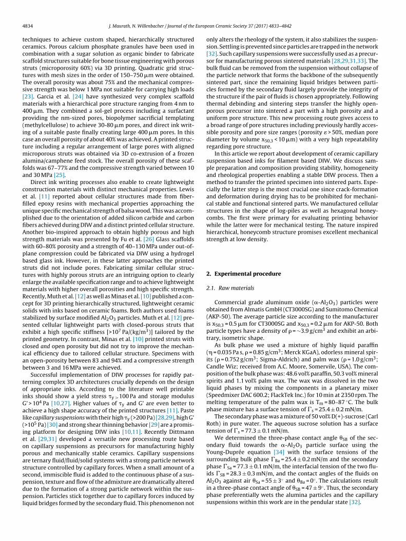
4 Europ
tccsstTs[m4p(ictmafa
cefiupfiAswpbstemRcsssepciab
toiGal(ieopasspdpl
834 J. Maurath, N. Willenbacher / Journal of the
echniques to achieve custom shaped, hierarchically structurederamics. Porous calcium phosphate granules have been used inombination with a sugar solution as organic binder to fabricatecaffold structures suitable for bone tissue engineering with poroustruts (microporosity 60%) via 3D printing. Quadratic grid struc-ures with mesh sizes in the order of 150–750 �m were obtained.he overall porosity was about 75% and the mechanical compres-ive strength was below 1 MPa not suitable for carrying high loads23]. Garcia et al. [24] have synthesized very complex scaffold
aterials with a hierarchical pore structure ranging from 4 nm to00 �m. They combined a sol-gel process including a surfactantroviding the nm-sized pores, biopolymer sacrificial templatingmethylcellulose) to achieve 30-80 �m pores, and direct ink writ-ng of a suitable paste finally creating large 400 �m pores. In thisase an overall porosity of about 40% was achieved. A printed struc-ure including a regular arrangement of large pores with aligned
icroporous struts was obtained via 3D co-extrusion of a frozenlumina/camphene feed stock. The overall porosity of these scaf-olds was 67–77% and the compressive strength varied between 10nd 30 MPa [25].
Direct ink writing processes also enable to create lightweightonstruction materials with distinct mechanical properties. Lewist al. [11] reported about cellular structures made from fiber-lled epoxy resins with mechanical properties approaching thenique specific mechanical strength of balsa wood. This was accom-lished due to the orientation of added silicon carbide and carbonbers achieved during DIW and a distinct printed cellular structure.nother bio-inspired approach to obtain highly porous and hightrength materials was presented by Fu et al. [26] Glass scaffoldsith 60–80% porosity and a strength of 40–130 MPa under out-of-lane compression could be fabricated via DIW using a hydrogelased glass ink. However, in these latter approaches the printedtruts did not include pores. Fabricating similar cellular struc-ures with highly porous struts are an intriguing option to clearlynlarge the available specification range and to achieve lightweightaterials with higher overall porosities and high specific strength.
ecently, Muth et al. [12] as well as Minas et al. [10] published a con-ept for 3D printing hierarchically structured, lightweight ceramicolids with inks based on ceramic foams. Both authors used foamstabilized by surface modified Al2O3 particles. Muth et al. [12] pre-ented cellular lightweight parts with closed-porous struts thatxhibit a high specific stiffness [>107 Pa/(kg/m3)] tailored by therinted geometry. In contrast, Minas et al. [10] printed struts withlosed and open porosity but did not try to improve the mechan-cal efficiency due to tailored cellular structure. Specimens withn open-porosity between 83 and 94% and a compressive strengthetween 3 and 16 MPa were achieved.
Successful implementation of DIW processes for rapidly pat-erning complex 3D architectures crucially depends on the designf appropriate inks. According to the literature well printablenks should show a yield stress �y >100 Pa and storage modulus’ > 104 Pa [10,27]. Higher values of �y and G’ are even better tochieve a high shape accuracy of the printed structures [11]. Pasteike capillary suspensions with their high �y (>200 Pa) [28,29], high G’>105 Pa) [30] and strong shear thinning behavior [29] are a promis-ng platform for designing DIW inks [10,11]. Recently Dittmannt al. [29,31] developed a versatile new processing route basedn capillary suspensions as precursors for manufacturing highlyorous and mechanically stable ceramics. Capillary suspensionsre ternary fluid/fluid/solid systems with a strong particle networktructure controlled by capillary forces. When a small amount of aecond, immiscible fluid is added to the continuous phase of a sus-
ension, texture and flow of the admixture are dramatically alteredue to the formation of a strong particle network within the sus-ension. Particles stick together due to capillary forces induced byiquid bridges formed by the secondary fluid. This phenomenon not
ean Ceramic Society 37 (2017) 4833–4842
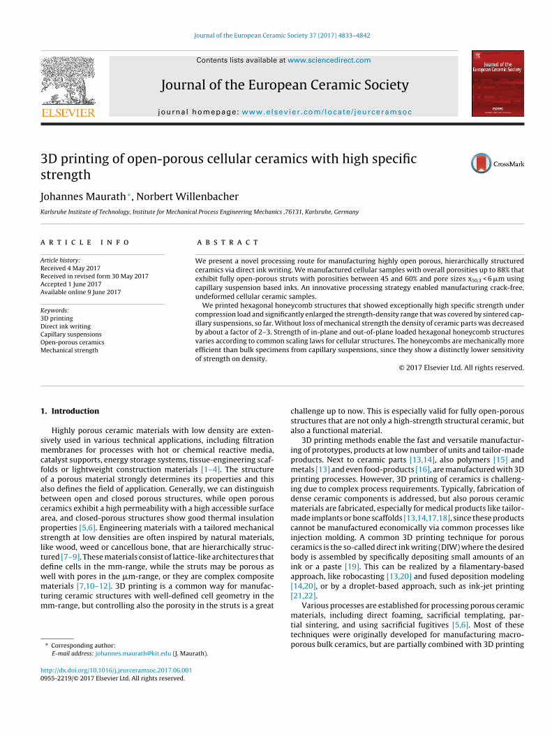
only alters the rheology of the system, it also stabilizes the suspen-sion. Settling is prevented since particles are trapped in the network[32]. Such capillary suspensions were successfully used as a precur-sor for manufacturing porous sintered materials [28,29,31,33]. Thebulk fluid can be removed from the suspension without collapse ofthe particle network that forms the backbone of the subsequentlysintered part, since the remaining liquid bridges between parti-cles formed by the secondary fluid largely provide the integrity ofthe structure if the pair of fluids is chosen appropriately. Followingthermal debinding and sintering steps transfer the highly open-porous precursor into sintered a part with a high porosity and auniform pore structure. This new processing route gives access toa broad range of pore structures including previously hardly acces-sible porosity and pore size ranges (porosity � > 50%, median porediameter by volume x50,3 < 10 �m) with a very high repeatabilityregarding pore structure.
In this article we report about development of ceramic capillarysuspension based inks for filament based DIW. We discuss sam-ple preparation and composition providing stability, homogeneityand rheological properties enabling a stable DIW process. Then amethod to transfer the printed specimen into sintered parts. Espe-cially the latter step is the most crucial one since crack-formationand deformation during drying has to be prohibited for mechani-cal stable and functional sintered parts. We manufactured cellularstructures in the shape of log-piles as well as hexagonal honey-combs. The first were primary for evaluating printing behaviorwhile the latter were for mechanical testing. The nature inspiredhierarchical, honeycomb structure promises excellent mechanicalstrength at low density.
2. Experimental procedure
2.1. Raw materials
Commercial grade aluminum oxide (�-Al2O3) particles wereobtained from Almatis GmbH (CT3000SG) and Sumitomo Chemical(AKP-50). The average particle size according to the manufactureris x50,3 = 0.5 �m for CT3000SG and x50,3 = 0.2 �m for AKP-50. Bothparticle types have a density of � = ∼3.9 g/cm3 and exhibit an arbi-trary, isometric shape.
As bulk phase we used a mixture of highly liquid paraffin(� = 0.035 Pa s, � = 0.85 g/cm3; Merck KGaA), odorless mineral spir-its (� = 0.752 g/cm3; Sigma-Aldrich) and palm wax (� = 1.0 g/cm3;Candle Wiz; received from A.C. Moore, Somervile, USA). The com-position of the bulk phase was: 48.6 vol% paraffin, 50.3 vol% mineralspirits and 1.1 vol% palm wax. The wax was dissolved in the twoliquid phases by mixing the components in a planetary mixer(Speedmixer DAC 600.2; FlackTek Inc.) for 10 min at 2350 rpm. Themelting temperature of the palm wax is Tm = 80–87 ◦C. The bulkphase mixture has a surface tension of �s = 25.4 ± 0.2 mN/m.
The secondary phase was a mixture of 50 vol% D(+)-sucrose (CarlRoth) in pure water. The aqueous sucrose solution has a surfacetension of �s = 77.3 ± 0.1 mN/m.
We determined the three-phase contact angle �SB of the sec-ondary fluid towards the �-Al2O3 particle surface using theYoung-Duprée equation [34] with the surface tensions of thesurrounding bulk phase �Ba = 25.4 ± 0.2 mN/m and the secondaryphase �Sa = 77.3 ± 0.1 mN/m, the interfacial tension of the two flu-ids �SB = 28.3 ± 0.3 mN/m, and the contact angles of the fluids on
Al2O3 against air �Sa = 55 ± 3◦ and �Ba = 0◦. The calculations resultin a three-phase contact angle of �SB = 47 ± 9◦. Thus, the secondaryphase preferentially wets the alumina particles and the capillarysuspensions within this work are in the pendular state [32].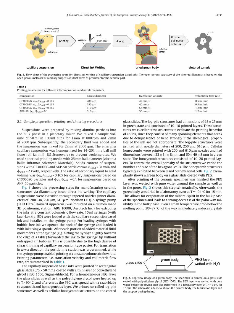
J. Maurath, N. Willenbacher / Journal of the European Ceramic Society 37 (2017) 4833–4842 4835
Fig. 1. Flow sheet of the processing route for direct ink writing of capillary suspension based inks. The open-porous structure of the sintered filaments is based on theopen-porous network of capillary suspensions that serve as precursor for the ceramic part.
Table 1Printing parameters for different ink compositions and nozzle diameters.
composition nozzle diameter translation velocity volumetric flow rate
CT3000SG, sec/solid = 0.165 200 �m 42 mm/s 0.5 ml/min
2
tuatc(ubsvCA
sse(3tLibwmtesitPr
ggttts
of the specimen and leads to a strong decrease of the palm wax sol-ubility in the bulk phase. Even a small temperature drop below themelting point (80–87 ◦C) of the wax immediately induces crystal-
CT3000SG, sec/solid = 0.165 250 �mCT3000SG, sec/solid = 0.165 610 �m
AKP-50, sec/solid = 0.1 610 �m
.2. Sample preparation, printing, and sintering procedures
Suspensions were prepared by mixing alumina particles intohe bulk phase in a planetary mixer. We mixed a sample vol-me of 50 ml in 100 ml cups for 1 min at 800 rpm and 2 mint 2000 rpm. Subsequently, the secondary fluid was added andhe suspension was mixed for 2 min at 2000 rpm. The emergingapillary suspension was homogenized for 14–20 h in a ball milllong roll jar mill; US Stoneware) to prevent agglomerates. Wesed spherical grinding media with 25 mm ball diameter (zirconiaalls; Inframat Advanced Materials). Solids content of suspen-ions with CT3000SG and AKP-50 particles was solid = 31 vol% andsolid = 23 vol%, respectively. The ratio of secondary liquid to solidolume was sec/solid = 0.165 for capillary suspensions based onT3000SG particles and sec/solid = 0.1 for suspensions based onKP-50 particles.
Fig. 1 shows the processing steps for manufacturing ceramictructures via filamentary based direct ink writing. The capillaryuspensions were extruded through tapered nozzles (inner diam-ters of: 200 �m, 250 �m, 610 �m; Nordson EFD). A syringe pumpPHD Ultra; Harvard Apparatus) was mounted on a custom madeD positioning station (ABG 10000; Aerotech Inc.) for extrudinghe inks at a constant volumetric flow rate. 10 ml syringes (withuer-Lok tip; BD) were loaded with the capillary suspension basednk and installed on the syringe pump. For loading syringes withubble-free ink we opened the back of the syringe and loaded itith ink using a spatula. After each portion of added material fitfulovements of the syringe (e.g. hitting the syringe slightly towards
he edge of a table) forwarded the ink to the syringe tip withoutntrapped air bubbles. This is possible due to the high degree ofhear thinning of capillary suspension type pastes. For translationn x-y-z direction the positioning station was programmed, whilehe syringe pump enabled printing at constant volumetric flow rate.rinting parameters, i.e. translation velocity and volumetric flowate, are summarized in Table 1.
The capillary suspension based inks were printed on rectangularlass slides (75 × 50 mm), coated with a thin layer of polyethylenelycol (PEG 1500, Sigma-Aldrich). For a homogeneous PEG layer
he glass slides as well as the polyethylene glycol were heated upo T = 90 ◦C, and afterwards the PEG was spread with a razorbladeo a smooth and homogeneous layer. We printed so-called log-piletructures as well as cellular honeycomb structures on the coated40 mm/s 0.5 ml/min55 mm/s 1.2 ml/min55 mm/s 1.2 ml/min
glass slides. The log-pile structures had dimensions of 25 × 25 mmin green state and consisted of 10–16 printed layers. These struc-tures are excellent test structures to evaluate the printing behaviorof an ink, since they consist of many spanning elements that breakdue to deliquescence or bend strongly if the rheological proper-ties of the ink are not appropriate. The log-pile structures wereprinted with nozzle diameters of 200, 250 and 610 �m. Cellularhoneycombs were printed with 200 and 610 �m nozzles and haddimensions between 23 × 34 × 8 mm and 60 × 40 × 8 mm in greenstate. The honeycomb structures consisted of 10–20 printed lay-ers. To control the overall porosity of the structures we varied thenumber and size of the hexagonal cells. The honeycomb structurestypically exhibited between 8 and 50 hexagonal cells. Fig. 2 exem-plarily shows a green body on a glass slide coated with PEG.
After printing of the ceramic specimen was finished the PEGlayer was wetted with pure water around the sample as well asin the pores. Fig. 2 shows this step schematically. Afterwards, thegreen body was dried in a laboratory oven at T = ∼94 ◦C for 15 min.This allows for evaporation of the mineral spirit in the bulk phase
Fig. 2. Top view image of a green body. The specimen is printed on a glass slidecoated with polyethylene glycol (PEG 1500). The PEG layer was wetted with purewater before the drying step was performed in a laboratory oven at T = ∼94 ◦C for15 min. The schematic side view shows the printed body, the lubrication layer andthe support during drying.
4 European Ceramic Society 37 (2017) 4833–4842
liifugP
otttf1op
nfTf
2
cKlBTT
d9s
tl
HctIpsca
gvnticm(
3
3
icw
Fig. 3. Image of (a) a freely flowing pure suspension (solid = 31 vol%, sec/solid = 0)
836 J. Maurath, N. Willenbacher / Journal of the
ization. The slippery PEG/water layer enables the sample to shrinkn the xy-plane and prohibits adhesion on the substrate during dry-ng. After drying the green body was exposed to room temperatureor 30–60 s allowing for crystallization of the palm wax in the resid-al bulk phase. The specimen were stable enough to move themently onto a porous ceramic sintering plate, while the slipperyEG/water layer was still liquid and served as lubricating film.
Organic binder components in the green bodies were burnedut in a debinding furnace. The samples were heated from roomemperature to 200 ◦C at a rate of 2 ◦C/min. Subsequently, theemperature was held constant for 1 h at 200 ◦C. Afterwards, theemperature was increased to 700 ◦C with 1 ◦C/min and was heldor 1 h at 700 ◦C. Finally, the oven was cooled down to 400 ◦C with.5 ◦C/min. After 15 min at a constant temperature of 400 ◦C, theven was further cooled down to room temperature without tem-erature regulation.
For sintering we used a custom made high temperature fur-ace. Sintering temperatures were between 1200 and 1400 ◦C. The
urnace was heated up to the sintering temperature at 3 ◦C/min.he final temperature was held constant for 2 h. Subsequently, theurnace cooled down to 50 ◦C at 2 ◦C/min.
.3. Measurements
Rheological measurements were performed with a stress-ontrolled rheometer (Haake Mars II, Thermo Fisher Scientific,arlsruhe, Germany). Plate-plate geometry (upper plate: titanium,
ower plate: stainless steel) with a diameter of 35 mm was used.oth plates were rough (sandblasted surface) to prevent wall slip.he experiments were conducted at a gap height of 1 mm at
= 20 ◦C.Porosity of the struts �s of the sintered cellular specimen was
etermined using the Archimedes’ principle according to DIN EN93-1. True porosity of the cellular ceramics �* was calculated fromample dimensions and sample weight.
Dimensions of printed struts and pores in green bodies and sin-ered parts were determined via manual image analysis using aight microscope.
Scanning-electron-microscope (SEM) micrographs (S-4500;itachi High-Technologies Europe GmbH) of the surface and of therosscut of sintered parts were used to analyze their microstruc-ure. Pore size was calculated via image analysis using the Linentercept Count Method [35]. Therefore, SEM micrographs of sam-le cross sections were examined. To prepare appropriate crossections of sintered parts we infiltrated them with epoxy resin,ured the resin at elevated temperature (70 ◦C for 20 h), and grindednd polished the specimens afterwards.
For compressive strength tests the honeycomb structures wererinded to a fully flat surface. Preliminary tests confirmed thatertical boundaries do not affect mechanical strength, so we didot remove these parts from all specimens. Compressive strengthests of cellular honeycombs were performed with material test-ng machines (Zwick Roell). The samples were loaded displacementontrolled at a rate of 0.05 mm/s for the 10 kN load cell (machineodel: ProLine Z010) and 0.05 mm/min for the 300 kN load cell
machine model: Zwick 300) until they failed.
. Results and discussion
.1. Rheology
We observed gel-like, pasteous behavior and a high yield stressn capillary suspensions based on CT3000SG and AKP-50 parti-les. Texture and gel-strength of the suspensions change stronglyith addition of the secondary liquid. Fig. 3 shows the texture of a
and (b) a capillary suspension (CT3000SG, solid = 31 vol%, sec/solid = 0.165) basedon CT3000SG particles. Paste (b) shows excellent printing behavior.
pure suspension and an appropriate capillary suspension. The lat-ter keeps the shape without any deliquescence and it consequentlyshows excellent printing behavior.
Rheological measurements proofed the gel-like behavior of bothsuspensions. We performed oscillatory shear experiments for puresuspensions as well as capillary suspensions based on the aluminapowders CT3000SG and AKP-50. Paste composition was adjustedsuch that suspensions from both material systems show similarrheological and hence similar printing behavior. Due to the smallersize of AKP-50 particles a lower particle volume fraction was suf-ficient compared to the CT3000SG system to get suspensions aswell as capillary suspensions with similar properties [36]. A solidscontent of solid = 31 vol% for CT3000SG and solid = 23 vol% forAKP-50 based suspensions was chosen. Furthermore, the ratio ofsecondary liquid to solid volume was set to sec/solid = 0.165 andsec/solid = 0.1 for capillary suspensions based on CT3000SG andAKP-50 particles, respectively.
Fig. 3a exemplarily shows the storage and loss moduli, G’ and G”,for the CT3000SG based suspension with and without added sec-ondary fluid. In both cases the moduli are independent of frequencyin the whole investigated range ( = 0.1–100 rad/s) and G’ is aboutone order of magnitude larger than G”. Adding the secondary fluid,however, results in a transition from a weak to a strong gel with analmost three orders of magnitude increase in modulus (from 103 Pato 106 Pa). Similar results were fund for the AKP-50 based system(G’ increased from 103 Pa to 106 Pa).
The yield stress �y is an important indicator for evaluating theprinting behavior of a paste since pastes with high yield stressare less prone to deliquescence of printed filaments [10,11]. Wedetermined the yield stress �y of the suspensions via oscillatoryshear amplitude sweep measurements at a constant frequency of = 1 rad/s. Fig. 4 exemplarily shows the data for the CT3000SG par-ticle based system. At a certain stress amplitude G’ and G” dropdrastically from the plateau in the linear viscoelastic regime (LVE).This drop indicates the transition of the suspension from solidto fluid-like behavior [30]. We define a drop of G’ for more thanone decade compared to the plateau in the LVE regime as the cri-terion to determine the onset of yielding and the correspondingstress amplitude value is treated as the apparent yield stress �y.For CT3000SG particles the yield stress of the pure suspension is�y = 8.8 ± 2.5 Pa and of the capillary suspension �y = 2287 ± 157 Pa.For AKP-50 suspensions the yield stresses are �y = 5.1 ± 1.6 Pa and�y = 2131 ± 148 Pa, respectively. The yield stress of the capillarysuspension is for both material systems more than two orders ofmagnitude larger than that of the corresponding pure suspension.
These results are in agreement with prior works on capillarysuspensions [36,37]. The high yield stress and storage modulus
values for the capillary suspensions result from the strong perco-lating particle network consisting of capillary bridges that is muchstronger than the van der Waals network that is predominant in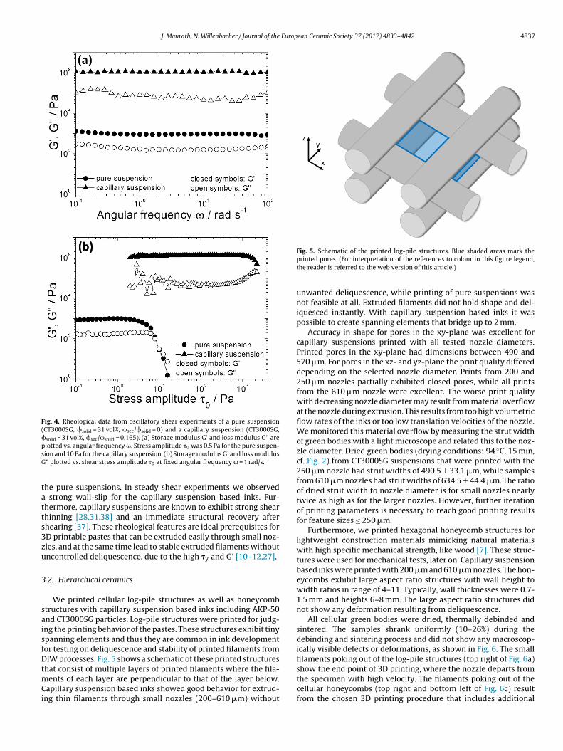
J. Maurath, N. Willenbacher / Journal of the European Ceramic Society 37 (2017) 4833–4842 4837
Fig. 4. Rheological data from oscillatory shear experiments of a pure suspension(CT3000SG, solid = 31 vol%, sec/solid = 0) and a capillary suspension (CT3000SG,solid = 31 vol%, sec/solid = 0.165). (a) Storage modulus G’ and loss modulus G” arepsG
tatts3zu
3
saisfDtmCi
lotted vs. angular frequency . Stress amplitude �0 was 0.5 Pa for the pure suspen-ion and 10 Pa for the capillary suspension. (b) Storage modulus G’ and loss modulus” plotted vs. shear stress amplitude �0 at fixed angular frequency = 1 rad/s.
he pure suspensions. In steady shear experiments we observed strong wall-slip for the capillary suspension based inks. Fur-hermore, capillary suspensions are known to exhibit strong shearhinning [28,31,38] and an immediate structural recovery afterhearing [37]. These rheological features are ideal prerequisites forD printable pastes that can be extruded easily through small noz-les, and at the same time lead to stable extruded filaments withoutncontrolled deliquescence, due to the high �y and G’ [10–12,27].
.2. Hierarchical ceramics
We printed cellular log-pile structures as well as honeycombtructures with capillary suspension based inks including AKP-50nd CT3000SG particles. Log-pile structures were printed for judg-ng the printing behavior of the pastes. These structures exhibit tinypanning elements and thus they are common in ink developmentor testing on deliquescence and stability of printed filaments fromIW processes. Fig. 5 shows a schematic of these printed structures
hat consist of multiple layers of printed filaments where the fila-ents of each layer are perpendicular to that of the layer below.
apillary suspension based inks showed good behavior for extrud-ng thin filaments through small nozzles (200–610 �m) without
Fig. 5. Schematic of the printed log-pile structures. Blue shaded areas mark theprinted pores. (For interpretation of the references to colour in this figure legend,the reader is referred to the web version of this article.)
unwanted deliquescence, while printing of pure suspensions wasnot feasible at all. Extruded filaments did not hold shape and del-iquesced instantly. With capillary suspension based inks it waspossible to create spanning elements that bridge up to 2 mm.
Accuracy in shape for pores in the xy-plane was excellent forcapillary suspensions printed with all tested nozzle diameters.Printed pores in the xy-plane had dimensions between 490 and570 �m. For pores in the xz- and yz-plane the print quality differeddepending on the selected nozzle diameter. Prints from 200 and250 �m nozzles partially exhibited closed pores, while all printsfrom the 610 �m nozzle were excellent. The worse print qualitywith decreasing nozzle diameter may result from material overflowat the nozzle during extrusion. This results from too high volumetricflow rates of the inks or too low translation velocities of the nozzle.We monitored this material overflow by measuring the strut widthof green bodies with a light microscope and related this to the noz-zle diameter. Dried green bodies (drying conditions: 94 ◦C, 15 min,cf. Fig. 2) from CT3000SG suspensions that were printed with the250 �m nozzle had strut widths of 490.5 ± 33.1 �m, while samplesfrom 610 �m nozzles had strut widths of 634.5 ± 44.4 �m. The ratioof dried strut width to nozzle diameter is for small nozzles nearlytwice as high as for the larger nozzles. However, further iterationof printing parameters is necessary to reach good printing resultsfor feature sizes ≤ 250 �m.
Furthermore, we printed hexagonal honeycomb structures forlightweight construction materials mimicking natural materialswith high specific mechanical strength, like wood [7]. These struc-tures were used for mechanical tests, later on. Capillary suspensionbased inks were printed with 200 �m and 610 �m nozzles. The hon-eycombs exhibit large aspect ratio structures with wall height towidth ratios in range of 4–11. Typically, wall thicknesses were 0.7-1.5 mm and heights 6–8 mm. The large aspect ratio structures didnot show any deformation resulting from deliquescence.
All cellular green bodies were dried, thermally debinded andsintered. The samples shrank uniformly (10–26%) during thedebinding and sintering process and did not show any macroscop-ically visible defects or deformations, as shown in Fig. 6. The smallfilaments poking out of the log-pile structures (top right of Fig. 6a)
show the end point of 3D printing, where the nozzle departs fromthe specimen with high velocity. The filaments poking out of thecellular honeycombs (top right and bottom left of Fig. 6c) resultfrom the chosen 3D printing procedure that includes additional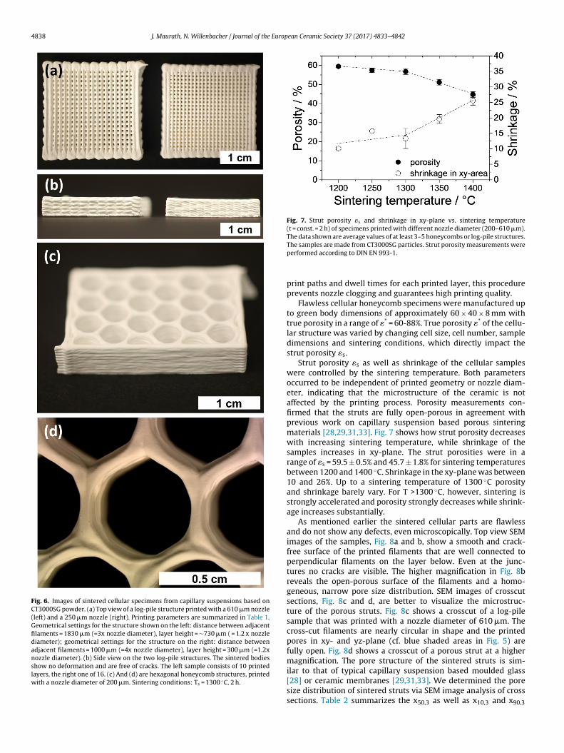
4838 J. Maurath, N. Willenbacher / Journal of the European Ceramic Society 37 (2017) 4833–4842
Fig. 6. Images of sintered cellular specimens from capillary suspensions based onCT3000SG powder. (a) Top view of a log-pile structure printed with a 610 �m nozzle(left) and a 250 �m nozzle (right). Printing parameters are summarized in Table 1.Geometrical settings for the structure shown on the left: distance between adjacentfilaments = 1830 �m (=3x nozzle diameter), layer height = ∼730 �m ( = 1.2 x nozzlediameter); geometrical settings for the structure on the right: distance betweenadjacent filaments = 1000 �m (=4x nozzle diameter), layer height = 300 �m (=1.2xnozzle diameter). (b) Side view on the two log-pile structures. The sintered bodiesshow no deformation and are free of cracks. The left sample consists of 10 printedlayers, the right one of 16. (c) And (d) are hexagonal honeycomb structures, printedwith a nozzle diameter of 200 �m. Sintering conditions: Ts = 1300 ◦C, 2 h.
Fig. 7. Strut porosity �s and shrinkage in xy-plane vs. sintering temperature(t = const. = 2 h) of specimens printed with different nozzle diameter (200–610 �m).The data shown are average values of at least 3–5 honeycombs or log-pile structures.
The samples are made from CT3000SG particles. Strut porosity measurements wereperformed according to DIN EN 993-1.print paths and dwell times for each printed layer, this procedureprevents nozzle clogging and guarantees high printing quality.
Flawless cellular honeycomb specimens were manufactured upto green body dimensions of approximately 60 × 40 × 8 mm withtrue porosity in a range of �* = 60-88%. True porosity �* of the cellu-lar structure was varied by changing cell size, cell number, sampledimensions and sintering conditions, which directly impact thestrut porosity �s.
Strut porosity �s as well as shrinkage of the cellular sampleswere controlled by the sintering temperature. Both parametersoccurred to be independent of printed geometry or nozzle diam-eter, indicating that the microstructure of the ceramic is notaffected by the printing process. Porosity measurements con-firmed that the struts are fully open-porous in agreement withprevious work on capillary suspension based porous sinteringmaterials [28,29,31,33]. Fig. 7 shows how strut porosity decreaseswith increasing sintering temperature, while shrinkage of thesamples increases in xy-plane. The strut porosities were in arange of �s = 59.5 ± 0.5% and 45.7 ± 1.8% for sintering temperaturesbetween 1200 and 1400 ◦C. Shrinkage in the xy-plane was between10 and 26%. Up to a sintering temperature of 1300 ◦C porosityand shrinkage barely vary. For T >1300 ◦C, however, sintering isstrongly accelerated and porosity strongly decreases while shrink-age increases substantially.
As mentioned earlier the sintered cellular parts are flawlessand do not show any defects, even microscopically. Top view SEMimages of the samples, Fig. 8a and b, show a smooth and crack-free surface of the printed filaments that are well connected toperpendicular filaments on the layer below. Even at the junc-tures no cracks are visible. The higher magnification in Fig. 8breveals the open-porous surface of the filaments and a homo-geneous, narrow pore size distribution. SEM images of crosscutsections, Fig. 8c and d, are better to visualize the microstruc-ture of the porous struts. Fig. 8c shows a crosscut of a log-pilesample that was printed with a nozzle diameter of 610 �m. Thecross-cut filaments are nearly circular in shape and the printedpores in xy- and yz-plane (cf. blue shaded areas in Fig. 5) arefully open. Fig. 8d shows a crosscut of a porous strut at a highermagnification. The pore structure of the sintered struts is sim-ilar to that of typical capillary suspension based moulded glass
[28] or ceramic membranes [29,31,33]. We determined the poresize distribution of sintered struts via SEM image analysis of crosssections. Table 2 summarizes the x50,3 as well as x10,3 and x90,3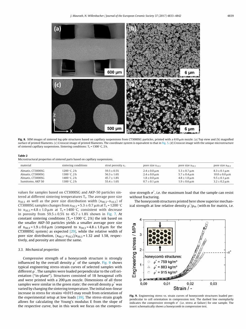
J. Maurath, N. Willenbacher / Journal of the European Ceramic Society 37 (2017) 4833–4842 4839
Fig. 8. SEM images of sintered log-pile structures based on capillary suspensions from CT3000SG particles, printed with a 610 �m nozzle. (a) Top view and (b) magnifiedsurface of printed filaments. (c) Crosscut image of printed filaments. The coordinate system is equivalent to that in Fig. 5. (d) Crosscut image with the unique microstructureof sintered capillary suspensions. Sintering conditions: Ts = 1300 ◦C, 2 h.
Table 2Microstructural properties of sintered parts based on capillary suspensions.
material sintering conditions strut porosity �s pore size x10.3 pore size x50.3 pore size x90.3
Almatis, CT3000SG 1200 ◦C, 2 h 59.5 ± 0.5% 2.4 ± 0.0 �m 5.3 ± 0.7 �m 8.3 ± 0.1 �m◦
vtxCtictoCpt
3
itdeasvitat
without fracturing.The honeycomb structures printed here show superior mechan-
ical strength at low relative density �*/�m (with m for matrix, i.e.
Almatis, CT3000SG 1300 C, 2 h 56.3 ± 1.6%
Almatis, CT3000SG 1400 ◦C, 2 h 45.7 ± 1.8%
Sumitomo, AKP 50 1300 ◦C, 2 h 55.4 ± 1.6%
alues for samples based on CT3000SG and AKP-50 particles sin-ered at different sintering temperatures Ts. The average pore size50,3 as well as the pore size distribution width (x90,3–x10,3) ofT3000SG samples changes from x50,3 = 5.3 ± 0.7 �m at Ts = 1200 ◦Co x50,3 = 4.8 ± 1.0 �m at Ts = 1400 ◦C, consistent with decreasen porosity from 59.5 ± 0.5% to 45.7 ± 1.8% shown in Fig. 7. Atonstant sintering conditions (Ts = 1300 ◦C, 2 h) the ink based onhe smaller AKP-50 particles yields a smaller average pore sizef x50,3 = 1.9 ± 0.6 �m (compared to x50,3 = 4.8 ± 1.0 �m for theT3000SG system) as expected [29], while the relative width ofore size distribution, (x90,3–x10,3)/x50,3 = 1.32 and 1.58, respec-ively, and porosity are almost the same.
.3. Mechanical properties
Compressive strength of a honeycomb structure is stronglynfluenced by the overall density �* of the sample. Fig. 9 showsypical engineering stress-strain curves of selected samples withifferent �*. The samples were loaded perpendicular to the cell ori-ntation (“in-plane”). Structures consisted of 18 hexagonal cellsnd were printed with a 200 �m nozzle. Dimensions of all threeamples were similar in the green state; the overall density �* wasaried by changing the sintering temperature. The initial non-linear
ncrease in stress for strains <0.015 may result from orientation ofhe experimental setup at low loads [39]. The stress-strain graphllows for calculating the Young’s modulus E from the slope ofhe respective curve, but in this work we focus on the compres-2.4 ± 0.0 �m 5.7 ± 0.4 �m 10.0 ± 0.0 �m1.8 ± 0.0 �m 4.8 ± 1.0 �m 9.5 ± 0.1 �m0.7 ± 0.1 �m 1.9 ± 0.6 �m 3.2 ± 0.2 �m
sive strength �*, i.e. the maximum load that the sample can resist
Fig. 9. Engineering stress vs. strain curves of honeycomb structures loaded per-pendicular to cell orientation in compression test. The dashed line exemplarilyindicates the compressive strength �* (i.e. stress at failure) for one sample. Theinsert schematically shows a honeycomb in compression test.
4840 J. Maurath, N. Willenbacher / Journal of the Europ
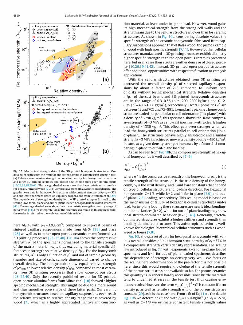
Fig. 10. Mechanical strength data of the 3D printed honeycomb structures. Onedata point represents the result of one tested sample in compression strength test.(a) Relative compressive strength vs. relative density for honeycomb structuresand other 3D printed ceramics and glasses that exhibit fully open-porous struts[10,23,25,28,29,40]. The orange shaded areas show the characteristic rel. strength –rel. density range of wood [7]. (b) Compressive strength as a function of density. Thegraph shows data for honeycomb structures with constant strut porosity �s = ∼57%and slip-cast specimens based on capillary suspensions from Dittmann et al. [29].The dependence of strength on density for the 3D printed samples fits well to thescaling laws for in-plane and out-of-plane loaded hexagonal honeycomb structures[43]. The orange shaded areas show the characteristic strength – density range ofBt
hs[3sofs(o�i[osahtw
alsa wood [11]. (For interpretation of the references to colour in this figure legend,he reader is referred to the web version of this article.)
ere Al2O3 with �m = 3.9 g/cm3) compared to slip-cast beams ofintered capillary suspensions made from Al2O3 [29] and glass28] as well as to other open-porous ceramics manufactured viaD printing processes [23–25,40]. Fig. 10a shows the compressivetrength �* of the specimens normalized to the tensile strengthf the matrix material �ts,m, thus excluding material specific dif-erences in strength vs. relative density �*/�m. For the honeycombtructures, �* is only a function of �*, and not of sample geometrynumber and size of cells, sample dimensions) varied to changeverall density. The honeycombs show equal relative strength*/�ts,m at lower relative density �*/�m compared to most ceram-
cs from 3D printing processes that show open-porous struts23–25,40]. Only the recently published results for 3D printed,pen-porous alumina foams from Minas et al. [10] showed a higherpecific mechanical strength. This might be due to a more round
nd thus smoother pore shape of these latter parts. Our ceramiconeycomb structures based on capillary suspensions even reachhe relative strength to relative density range that is covered byood [7], which is a highly appreciated lightweight construc-ean Ceramic Society 37 (2017) 4833–4842
tion material, at least under in-plane load. However, wood gainsits high mechanical strength from the strong cell walls and thestrength gain due to the cellular structure is lower than for ceramicstructures. As shown in Fig. 10b, considering absolute values thespecific strength of the ceramic honeycombs fabricated from cap-illary suspensions approach that of Balsa wood, the prime exampleof wood with high specific strength [7,11]. However, other cellularstructures manufactured in 3D printing processes exhibit distinctlyhigher specific strength than the open porous ceramics presentedhere, but in all cases their struts are either dense or of closed poros-ity [10,26,39,41,42]. Instead, 3D printed open porous structuresoffer additional opportunities with respect to filtration or catalysisapplications.
With the cellular structures obtained from 3D printing wedecreased the overall density �* of sintered capillary suspen-sions by about a factor of 2–3 compared to uniform barsor disks without losing mechanical strength. Relative densities�*/�m of the cast beams and 3D printed honeycomb structuresare in the range of 0.3–0.56 (�* = 1200–2200 kg/m3) and 0.12-0.25 (�* = 490–1000 kg/m3), respectively. Overall porosities �* arebetween 43 and 70% and 75–88%. Exemplarily picking a honeycombstructure loaded perpendicular to cell orientation (“in-plane”) witha density of ∼790 kg/m3, this specimen shows the same compres-sive strength of ∼3 MPa as a slip-cast specimen with a clearly higherdensity of ∼1330 kg/m3. This effect gets even stronger when weload the honeycomb structures parallel to cell orientation (“out-of-plane”). The structures behave highly anisotropic and a similarstrength (∼3 MPa) is achieved now at a density of only ∼490 kg/m3.In turn, at a given density strength increases by a factor 2–3 com-paring in-plane to out-of-plane loading.
As can be seen from Fig. 10b, the compressive strength of hexag-onal honeycombs is well described by [7–9]
�∗
�ts,s= C
(�∗
�s
)k
(1)
where �* is the compressive strength of the honeycomb, �ts,s is thetensile strength of the struts, �* is the true density of the honey-comb, �s is the strut density, and C and k are constants that dependon type of cellular structure and loading direction. For hexagonalhoneycombs C = 1/3 while k = 2 and 1 for in-plane [7,9] and out-of-plane [7,8] loading, respectively. This scaling model is based onthe mechanisms of failure of hexagonal cellular structures underload. For in-plane loading these structures are nearly ideal bending-dominated lattices (k = 2), while for out-of-plane loading they showideal stretch-dominated behavior (k = 1) [43]. Generally, stretch-dominated structures exhibit a higher stiffness and strength thanbending-dominated structures. This anisotropic behavior is well-known for biological hierarchical cellular structures such as wood,weed or bones [7,8].
Fig. 10b shows a set of data for hexagonal honeycombs with var-ious overall densities �*, but constant strut porosity of �s = 57%, ina compressive strength versus density representation. The scalinglaw introduced in Eq. (1) with exponents k = 2 for in-plane loadedspecimens and k = 1 for out-of-plane loaded specimens describesthe dependence of strength on density very well. We focus onthe scaling here, determination of the pre-factor C is not possiblehere, since this would require knowledge of the tensile strengthof the porous struts �ts,s not available so far. For porous ceramicsthis quantity is in general hardly accessible, since brittle materialstend to undefined stresses in the tensile test thus causing erro-
neous results. However, the term �ts,sC(
1�s
)k= C* is constant if strut
density �s as well as tensile strength �ts,s of the porous struts areconstant [29], as it is the case here. From a fit of Eq. (1) to the data inFig. 10b we determine C* and with �s = 1694 kg/m3 (i.e. �s = ∼57%)as well as C = 1/3 we estimate consistent tensile strength values
Europ
�ot5i
mwpsdiecicwm
4
csscaafaawzums6(
esccumeocssd
rtcicficps
tsa
[
[
[
[
[
[
[
[[
[
[
[
[
[
[
[
J. Maurath, N. Willenbacher / Journal of the
ts,s = 31 ± 3 MPa and �ts,s = 42 ± 3 MPa from the in-plane and out-f-plane data sets, respectively. This seems to overestimate therue tensile strength of the struts expected to be about a factor of–10 lower than the compressive strength [44] which in our case
s ∼20 ± 5 MPa [29].However, the scaling laws describe the density dependence of
echanical strength of the hexagonal honeycomb structures veryell. In both cases of loading, in-plane and out-of-plane, the 3Drinted structures are mechanically more efficient than cast beams,trength of slip-cast samples is significantly more sensitive to aecrease of density than the lattice structures. This high mechan-
cal efficiency of lattice structures was also reported by Minast al. [10] and Muth et al. [12] who successfully used different inkompositions, emulsions and foams including ceramic particles,nstead of capillary suspensions for direct ink writing of hierar-hically structured cellular solids as well as by Compton et al. [11],ho manufactured triangular honeycombs from organic compositeaterials.
. Conclusions
We introduced a processing route for manufacturing hierarchi-ally structured, highly open-porous cellular structures with highpecific strength. We developed inks based on ceramic capillaryuspensions that show excellent printing behavior for 3D printingellular structures with high aspect ratios (height/width = 4–11)s well as small spanning elements. The ink concept is versatilend can be applied to a wide range of ceramic particles with dif-erent particle size, while rheological behavior of the ink can bedjusted easily according to printing and processing demands in
wide range. We successfully used a filamentary based direct inkriting technique for printing cellular ceramic structures with noz-
le diameters ≥200 �m. An innovative processing strategy enableds to debind and sinter these filigree structures without crack for-ation or undesired deformation of the specimens. Hierarchically
tructured, cellular samples with overall porosities in the range of0–88% were produced. The printed struts are fully open porous�s = 45–60%) and show average pore sizes x50,3 < 6 �m.
We printed ceramic hexagonal honeycomb structures that showxceptionally high specific strength compared to common capillaryuspension based ceramics and to most 3D printed open porouseramics from other processes. The overall density of the honey-omb structures is significantly decreased compared to slip-castniform samples, but the cellular structure still guaranteed a highechanical strength in compression. Specific strength of the hon-
ycomb structures is about a factor of 2–3 larger than the strengthf cast specimens. Honeycomb structures behave anisotropic underompression load, and the compressive strength of in-plane loadedamples is about 2–3 times larger than that of out-of-plane loadedpecimens. The obtained compression strength data are very wellescribed by commonly accepted scaling laws.
The concept introduced here offers further opportunities for fab-ication of cellular solids with even higher mechanical strength inhe range of e.g. Balsa wood, one of the prime examples for naturalellular materials with unique specific strength [11]. Two promis-ng strategies are to use the so-called smart capillary suspensiononcept [33] to reinforce the sintering necks in the porous strutsnally resulting in a higher overall mechanical strength or to useapillary suspensions based on glass particles yielding smootherore structure beneficial for high mechanical strength at low den-ity [28].
Beyond that the open porous hierarchical structures spanninghe length scales from 10−3 m to 10−7 m enabled by DIW of capillaryuspension type ceramic inks may find application in separationnd filtration processes, e.g. as microfluidic crossflow filters for hot
[
[
ean Ceramic Society 37 (2017) 4833–4842 4841
gas filtration or as catalyst supports with smart flow channels forfast chemical reactions requiring high internal surface.
Acknowledgement
We would like to thank Jennifer A. Lewis and Joseph T. Muthfrom Harvard University for providing experimental assistance andfruitful discussion of the work. We would also like to thank theKarlsruhe House of Young Scientists for the financial support thatincluded travel expenses and allowed for the collaboration betweenKarlsruhe Institute and Technology and Harvard University. Wethank the Almatis GmbH for the donation of alumina particlesas well as the smooth collaboration. Further thanks are given toThomas Lebe for the support at the SEM-microscope.
References
[1] P. Colombo, Conventional and novel processing methods for cellular ceramics,Philos. Trans. R. Soc. A 364 (2006) 109–124.
[2] F. Akhtar, L. Andersson, S. Ogunwumi, N. Hedin, L. Bergström, Structuringadsorbents and catalysts by processing of porous powders, J. Eur. Ceram. Soc.34 (2014) 1643–1666.
[3] E.C. Hammel, O.-R. Ighodaro, O.I. Okoli, Processing and properties of advancedporous ceramics: an application based review, Ceram. Int. 40 (2014)15351–15370.
[4] W.-Y. Yeong, W.Y. Yeong, C.-K. Chua, C.K. Chua, K.-F. Leong, K.F. Leong, et al.,Rapid prototyping in tissue engineering: challenges and potential, TrendsBiotechnol. 22 (2004) 643–652.
[5] T. Ohji, M. Fukushima, Macro-porous ceramics: processing and properties, Int.Mater. Rev. 57 (2012) 115–131.
[6] A.R. Studart, U. Gonzenbach, E. Tervoort, L. Gauckler, Processing routes tomacroporous ceramics: a review, J. Am. Ceram. Soc. 89 (2006) 1771–1789.
[7] L.J. Gibson, The hierarchical structure and mechanics of plant materials, J. R.Soc. Interface 9 (2012) 2749–2766.
[8] L. Gibson, M. Ashby, Cellular Solids: Structure and Properties, CambridgeUniversity Press, Cambridge, UK, 1997.
[9] N.A. Fleck, V.S. Deshpande, M.F. Ashby, Micro-architectured materials: past,present and future, Proc. R. Soc. A Math. Phys. Eng. Sci. 466 (2010) 2495–2516.
10] C. Minas, D. Carnelli, E. Tervoort, A.R. Studart, 3D printing of emulsions andfoams into hierarchical porous ceramics, Adv. Mater. (2016).
11] B.G. Compton, J.A. Lewis, 3D-printing of lightweight cellular composites, Adv.Mater. 26 (2014) 5930–5935.
12] J.T. Muth, P.G. Dixon, L. Woish, L.J. Gibson, J.A. Lewis, Architected cellularceramics with tailored stiffness via direct foam writing, Proc. Natl. Acad. Sci.(2017) (201616769).
13] A. Zocca, P. Colombo, C.M. Gomes, J. Günster, Additive manufacturing ofceramics: issues, potentialities, and opportunities, J. Am. Ceram. Soc. 98(2015) 1983–2001.
14] N. Guo, M.C. Leu, Additive manufacturing: technology, applications andresearch needs, Front. Mech. Eng. 8 (2013) 215–243.
15] B. Wendel, D. Rietzel, F. Kühnlein, R. Feulner, G. Hülder, E. Schmachtenberg,Additive processing of polymers, Macromol. Mater. Eng. 293 (2008) 799–809.
16] J.I. Lipton, M. Cutler, F. Nigl, D. Cohen, H. Lipson, Additive manufacturing forthe food industry – a review, Trends Food Sci. Technol. 43 (2015) 114–123.
17] VDI, Statusreport – Additive Fertigungsverfahren, 2014.18] K.F. Leong, C.M. Cheah, C.K. Chua, Solid freeform fabrication of
three-dimensional scaffolds for engineering replacement tissues and organs,Biomaterials 24 (2003) 2363–2378.
19] J.A. Lewis, Direct ink writing of 3D functional materials, Adv. Funct. Mater. 16(2006) 2193–2204.
20] J. Deckers, J. Vleugels, J.-P. Kruth, Additive manufacturing of ceramics: areview, J. Ceram. Sci. Technol. 5 (2014) 245–260.
21] E.M. Sachs, M.J. Cima, P.A. Williams, D. Brancazio, J. Cornie, Three dimensionalprinting: rapid tooling and prototypes directly from a CAD model, J. Manuf.Sci. Eng. 114 (1992) 481–488.
22] J. Song, M. Edirisinghe, J. Evans, Formulation and multilayer jet printing ofceramic inks, J. Am. Ceram. Soc. 82 (1999) 3374–3380.
23] H. Seitz, U. Deisinger, B. Leukers, R. Detsch, G. Ziegler, Different calciumphosphate granules for 3-D printing of bone tissue engineering scaffolds, Adv.Eng. Mater. 11 (2009) 41–46.
24] A. Garcia, I. Izquierdo-Barba, M. Colilla, C.L. De Laorden, M. Vallet-Regi,Preparation of 3-D scaffolds in the SiO2-P2O5 system with tailoredhierarchical meso-macroporosity, Acta Biomater. 7 (2011) 1265–1273.
25] Y.W. Moon, I.J. Choi, Y.H. Koh, H.E. Kim, Porous alumina ceramic scaffolds withbiomimetic macro/micro-porous structure using three-dimensional (3-D)
ceramic/camphene-based extrusion, Ceram. Int. 41 (2015) 12371–12377.26] Q. Fu, E. Saiz, A.P. Tomsia, Bioinspired strong and highly porous glassscaffolds, Adv. Funct. Mater. 21 (2011) 1058–1063.
27] J.E. Smay, J. Cesarano III, J.A. Lewis, Colloidal inks for directed assembly of 3-Dperiodic structures, Langmuir 18 (2002) 5429–5437.
4 Europ
[
[
[
[
[
[
[
[
[
[
[
[
[
[
[
842 J. Maurath, N. Willenbacher / Journal of the
28] J. Maurath, J. Dittmann, N. Schultz, N. Willenbacher, Fabrication of highlyporous glass filters using capillary suspension processing, Sep. Purif. Technol.149 (2015) 470–478.
29] J. Dittmann, N. Willenbacher, Micro structural investigations and mechanicalproperties of macro porous ceramic materials from capillary suspensions, J.Am. Ceram. Soc. 97 (2014) 3787–3792.
30] J. Maurath, B. Bitsch, Y. Schwegler, N. Willenbacher, Influence of particleshape on the rheological behavior of three-phase non-Brownian suspensions,colloids surfaces a physicochem, Eng. Asp. 497 (2016) 316–326.
31] J. Dittmann, E. Koos, N. Willenbacher, Ceramic capillary suspensions: novelprocessing route for macroporous ceramic materials, J. Am. Ceram. Soc. 96(2013) 391–397.
32] E. Koos, N. Willenbacher, Capillary forces in suspension rheology, Science 331(2011) 897–900.
33] J. Dittmann, J. Maurath, B. Bitsch, N. Willenbacher, Highly porous materialswith unique mechanical properties from smart capillary suspensions, Adv.
Mater. 28 (2016) 1689–1696.34] E. Koos, J. Johannsmeier, L. Schwebler, N. Willenbacher, Tuning suspensionrheology using capillary forces, Soft Matter. 8 (2012) 6620.
35] J. Russ, R. Dehoff, Practical Stereology, Kluwer Academic/Plenum Publishers,2000.
[
[
ean Ceramic Society 37 (2017) 4833–4842
36] E. Koos, Capillary suspensions: particle networks formed through thecapillary force, Curr. Opin. Colloid Interface Sci. 19 (2014) 575–584.
37] E. Koos, W. Kannowade, N. Willenbacher, Restructuring and aging in acapillary suspension, Rheol. Acta 53 (2014) 947–957.
38] B. Bitsch, J. Dittmann, M. Schmitt, P. Scharfer, W. Schabel, N. Willenbacher, Anovel slurry concept for the fabrication of lithium-ion battery electrodes withbeneficial properties, J. Power Sources 265 (2014) 81–90.
39] J. Bauer, S. Hengsbach, I. Tesari, R. Schwaiger, O. Kraft, High-strength cellularceramic composites with 3D microarchitecture, Proc. Natl. Acad. Sci. 111(2014) 2453–2458.
40] C. Polzin, D. Gunther, H. Seitz, 3D printing of porous Al2O3 and SiC ceramics, J.Ceram. Sci. Technol. 6 (2015) 141–145.
41] X. Zheng, H. Lee, T.H. Weisgraber, M. Shusteff, J. DeOtte, E.B. Duoss, et al.,Ultralight, ultrastiff mechanical metamaterials, Science 344 (2014)1373–1377.
42] L.R. Meza, S. Das, J.R. Greer, Lightweight and recoverable three – dimensional
ceramic nanolattices, Science 345 (2014) 1322–1326.43] M.F. Ashby, The properties of foams and lattices, Philos. Trans. A. Math. Phys.Eng. Sci. 364 (2006) 15–30.
44] Informationszentrum Technische Keramik, Brevier Technische Keramik,Fahner Verlag, Lauf, Germany, 2003.
Related Documents


![Journal of the Ceramic Society of Japan 127 [10] 722-727 ...](https://static.cupdf.com/doc/110x72/62564c0748bff36af2683deb/journal-of-the-ceramic-society-of-japan-127-10-722-727-.jpg)

![Boron Glass Composites - Australian Ceramic Society of The Australian Ceramic Society Volume 52 [2], 2016, 103 – 110 103 Tissue Engineering Scaffolds from La 2O 3 – Hydroxyapatite\Boron](https://static.cupdf.com/doc/110x72/5ad2d1697f8b9a86158d9069/boron-glass-composites-australian-ceramic-society-of-the-australian-ceramic-society.jpg)


![Journal of the Ceramic Society of Japan 128 [7] 340-348 ...](https://static.cupdf.com/doc/110x72/61689832d394e9041f70f230/journal-of-the-ceramic-society-of-japan-128-7-340-348-.jpg)

