Shock isolation performance of a geometric anti-spring isolator Lixun Yan a , Shouhu Xuan b , Xinglong Gong b, * a Department of Precision Machinery and Precision Instrumentation, University of Science and Technology of China, Hefei, China b CAS Key Laboratory of Mechanical Behavior and Design of Materials, Department of Modern Mechanics, University of Science and Technology of China, Hefei, China article info Article history: Received 15 April 2017 Received in revised form 19 September 2017 Accepted 15 October 2017 Keywords: Shock isolation Geometric anti-spring isolator Nonlinear dynamic stiffness abstract In this paper, shock isolation performance of a geometric anti-spring (GAS) isolator is investigated. The static and dynamic stiffness property of GAS isolator is discussed. The mathematical simulation is used to explore the effect of several parameters on shock isolation performance of GAS isolator under a modified half-sine pulse acceleration exci- tation. Shock isolation experiments of GAS isolator under base acceleration excitation with different excitation amplitudes and payloads are carried out. The results show that the dynamic stiffness characteristic of GAS isolator determines its shock isolation performance. When shock acceleration amplitude is not too large, GAS isolator shows better shock ac- celeration and absolute displacement isolation performance than the equivalent linear system. The effects of shock acceleration amplitude, payload, and damping on the shock isolation performance of GAS isolator are discussed, which provide guidelines for its further practical application. © 2017 Elsevier Ltd. All rights reserved. 1. Introduction Shock is a common problem existing in many cases, such as rough road excitation in transportation, takeoff and landing of aircraft, earthquake and so on. Usually, it involves a very large force and displacement, which will lead to the damage of sensitive equipment, human discomfort, and other effects. The shock isolation performance of an isolation system is of great importance. Commonly, shock isolation is achieved through energy storage by elastic deformation while shock occurs and energy dissipation to minimize the residual vibration when the shock has finished [1]. The fundamental theory of shock analysis and isolation has been studied in Refs. [2,3], which mostly deals with linear systems. Nowadays, nonlinear passive isolation systems which can counteract the contradiction between adequate load capacity and low natural frequency of linear systems in low-frequency vibration isolation, have drawn increasing attention [4]. Connecting the negative stiffness mechanism in parallel to the positive stiffness spring is a major method to achieve nonlinear passive isolation systems. Nonlinear isolation system with negative stiffness mechanism, such as horizontally compressed bars [5e7], inclined linear springs [8e11], sliding beams [12], Euler buckled beams [13], cam-roller-spring mechanisms [14] * Corresponding author. CAS Key Laboratory of Mechanical Behavior and Design of Materials, Department of Modern Mechanics, University of Science and Technology of China, No. 443, Huangshan Road, Shushan District, Hefei 230027, Anhui, China. E-mail address: [email protected] (X. Gong). Contents lists available at ScienceDirect Journal of Sound and Vibration journal homepage: www.elsevier.com/locate/jsvi https://doi.org/10.1016/j.jsv.2017.10.024 0022-460X/© 2017 Elsevier Ltd. All rights reserved. Journal of Sound and Vibration 413 (2018) 120e143

Welcome message from author
This document is posted to help you gain knowledge. Please leave a comment to let me know what you think about it! Share it to your friends and learn new things together.
Transcript

Journal of Sound and Vibration 413 (2018) 120e143
Contents lists available at ScienceDirect
Journal of Sound and Vibration
journal homepage: www.elsevier .com/locate/ jsvi
Shock isolation performance of a geometric anti-springisolator
Lixun Yan a, Shouhu Xuan b, Xinglong Gong b, *
a Department of Precision Machinery and Precision Instrumentation, University of Science and Technology of China, Hefei, Chinab CAS Key Laboratory of Mechanical Behavior and Design of Materials, Department of Modern Mechanics, University of Science andTechnology of China, Hefei, China
a r t i c l e i n f o
Article history:Received 15 April 2017Received in revised form 19 September 2017Accepted 15 October 2017
Keywords:Shock isolationGeometric anti-spring isolatorNonlinear dynamic stiffness
* Corresponding author. CAS Key Laboratory of Mand Technology of China, No. 443, Huangshan Road
E-mail address: [email protected] (X. Gong).
https://doi.org/10.1016/j.jsv.2017.10.0240022-460X/© 2017 Elsevier Ltd. All rights reserved.
a b s t r a c t
In this paper, shock isolation performance of a geometric anti-spring (GAS) isolator isinvestigated. The static and dynamic stiffness property of GAS isolator is discussed. Themathematical simulation is used to explore the effect of several parameters on shockisolation performance of GAS isolator under a modified half-sine pulse acceleration exci-tation. Shock isolation experiments of GAS isolator under base acceleration excitation withdifferent excitation amplitudes and payloads are carried out. The results show that thedynamic stiffness characteristic of GAS isolator determines its shock isolation performance.When shock acceleration amplitude is not too large, GAS isolator shows better shock ac-celeration and absolute displacement isolation performance than the equivalent linearsystem. The effects of shock acceleration amplitude, payload, and damping on the shockisolation performance of GAS isolator are discussed, which provide guidelines for itsfurther practical application.
© 2017 Elsevier Ltd. All rights reserved.
1. Introduction
Shock is a common problem existing in many cases, such as rough road excitation in transportation, takeoff and landing ofaircraft, earthquake and so on. Usually, it involves a very large force and displacement, which will lead to the damage ofsensitive equipment, human discomfort, and other effects. The shock isolation performance of an isolation system is of greatimportance. Commonly, shock isolation is achieved through energy storage by elastic deformation while shock occurs andenergy dissipation to minimize the residual vibration when the shock has finished [1]. The fundamental theory of shockanalysis and isolation has been studied in Refs. [2,3], which mostly deals with linear systems.
Nowadays, nonlinear passive isolation systems which can counteract the contradiction between adequate load capacityand low natural frequency of linear systems in low-frequency vibration isolation, have drawn increasing attention [4].Connecting the negative stiffness mechanism in parallel to the positive stiffness spring is amajor method to achieve nonlinearpassive isolation systems. Nonlinear isolation system with negative stiffness mechanism, such as horizontally compressedbars [5e7], inclined linear springs [8e11], sliding beams [12], Euler buckled beams [13], cam-roller-spring mechanisms [14]
echanical Behavior and Design of Materials, Department of Modern Mechanics, University of Science, Shushan District, Hefei 230027, Anhui, China.

Nomenclatures
XL;YL Horizontal and vertical coordinate of spring's vertex~XL;
~XL Dimensionless horizontal and vertical coordinate of spring's vertexGX ;GY Horizontal and vertical load of spring's vertex~GX ;
~GY Dimensionless horizontal and vertical load of spring's vertexl; x Actual and dimensionless curve coordinate of differential segment dlqðlÞ Angle between X-axis positive direction and tangent direction of the segment dlQðlÞ;PðlÞ;MðlÞ Horizontal and vertical internal force, flexural moment of differential segment dlwðlÞ;h; L Width, thickness, and length of the blade springFy; y Dimensionless vertical restoring force and vertical displacement of the isolatorm; dst Load mass and static deflection of GAS isolatorun Natural angular frequency of GAS isolatorust Natural frequency calculated by static stiffness of GAS isolatoruel Natural frequency of the static stiffness equivalent linear isolatorc; z Viscous damping and damping ratio of the isolatorB;pðtÞ Acceleration amplitude and pulse shape function of shock excitation
L. Yan et al. / Journal of Sound and Vibration 413 (2018) 120e143 121
and so on, can realize low or zero net vertical dynamic stiffness without a loss of bearing capacity. At relatively small levels ofvibration, the dynamic characteristics of these nonlinear isolation systems [11,15e19] can be captured by the Duffing equationallowing physical insight into the effects of the nonlinearity [20]. Magnetic anti-spring was another method to producenegative stiffness characteristics [21e25]. These negative stiffness structures originated from the permanent magnets andelectromagnets were highly effective. However, they were very thermally sensitive and it might induce unwanted couplingsto external electromagnetic fields. In addition, using the inherent nonlinear mechanical property or geometric nonlinearity ofstructures is another exploration to obtain the low dynamic stiffness property. These structures, such as bistable compositeplates [26], extreme geometric nonlinear spring [27,28], scissor-like structures [29], shape memory alloy [30] and so on, havegreat prospects in the practical application of nonlinear low-frequency isolation. However, complex physical mechanisms andnonlinear transcendental equations become a major challenge. Nonetheless, much deep-in research work still needs to bedone for their further industrial application.
The aforementioned works mainly were concentrated on the vibration isolation performance of nonlinear isolationsystems under harmonic excitation. However, in terms of nonlinear isolation structures, only a little research work has beenperformed on their shock isolation performance. Snowdon firstly incorporated the nonlinear elements into the theory ofshock isolation [31] and found that softening elastic elements could lead to an improved shock isolation. Alexander [32] andGeorgiadis et al. [33] considered shock isolation design based on the use of nonlinear energy sinks, which were very easilyimplementable by means of linear stiffness element.
Ledezma-Ramirez et al. [34] investigated a switchable stiffness isolator for shock isolation, pointed out that the stiffnessnonlinearity could be advantageous in improving shock isolation in absolute displacement and acceleration responsecompared to the linear elastic element. As a negative stiffness element, the buckled beam has also been studied for shockisolation and it exhibited superior performance in linear isolators [35,36]. Tang et al. [37]and Liu et al. [38] investigated theshock isolation response of nonlinear low dynamic stiffness isolator under different types of shock inputs and found that anonlinear isolator could outperform the linear one if shock excitation amplitude is small.
The geometrical anti-spring (GAS) structure was proposed by Cella [39] for the purpose of seismic attenuation and it wassuccessfully applied in optical table prototype designed for advanced LIGO (Laser Interferometer Gravitational-wave Ob-servatory) [40] and external injection bench of the advanced Virgo gravitational wave detector [41]. In contrast to thenonlinear isolator, the advantages of GAS isolator include structurally simple and compactness, space saving and insensitiveto temperatures or external electromagnetic fields, and so on. However, except for the seismic attenuation in gravitationalwave observatory, GAS isolator has not been applied in any other vibration reduction application. And the thorough shockisolation performance of this nonlinear isolation structure, which is of great importance for its further practical application,has not been discussed.
In this paper, a geometric anti-spring isolator is developed and its shock isolation performance is theoretically andexperimentally studied. The nonlinear stiffness and natural frequency characteristics of the GAS isolator are theoreticallyinvestigated using a micro-element method in Section 2. In Section 3, shock isolation performance of this nonlinear isolatorunder the excitation of the modified half-sine pulse is explored through mathematical simulation. The effects of the geo-metric parameter, excitation amplitude, payload, and damping on shock isolation performance of GAS isolator are considered.In Section 4, shock isolation experiments of GAS isolator under base acceleration excitation with different excitation am-plitudes and payloads are performed by an electromagnetic vibration table, which validates the simulation results. Someconclusions are given in Section 5.

L. Yan et al. / Journal of Sound and Vibration 413 (2018) 120e143122
2. Geometric anti-spring isolator
GAS isolator (Fig. 1(a) and (b)) consists of several quasi-trapezoidal blade springs (Fig. 1(c)). The blade springs are built flatand bent under the load. Their bottoms are radially clamped to a base structure and vertices are connected together. Theexternal forces including vertical load and horizontal constraint force are applied to the vertex. The width of blade spring isrepresented by wðlÞ, with l 2 ½0; L�. The shape function of blade spring is
gðxÞ ¼ wðlÞwð0Þ ¼ ½c1 þ c2cos ðbxÞ þ c3sin ðbxÞ��1 (1)
Where x ¼ l=L, c1 ¼ �0:377, c2 ¼ 1:377, c3 ¼ 0:195 and b ¼ 1:361. The width wðlÞ and length L of blade spring are much
larger than constant thickness h.2.1. Theoretical analysis
Due to the radial symmetricity, the mechanical property of GAS isolator can be characterized with a single blade spring(Fig. 1(d) and (e)). The effects of shear deformation and extensibility in the longitudinal direction are all neglected. XL and YLrepresent the horizontal and vertical coordinate of blade springs' vertex. GX and GY denote the horizontal constraint load andvertical load. PðlÞ; QðlÞ and MðlÞ are the horizontal internal force, vertical internal force and bending moment of differentialsegment dl, respectively. qðlÞ is the angle between the positive X-axis direction and tangent direction of dl. The relationshipbetween variables X, Y and q can be written as
dXdl
¼ cos q;dYdl
¼ sin q (2)
The relationship between the curvature and bending moment can be written as
1r¼ �dq
dl¼ M
EI(3)
where EI denotes the flexural rigidity of blade spring and IðlÞ ¼ d3wðlÞ=12.According to static force equilibrium, two following equations can be obtained
dPdl
¼ 0;dQdl
¼ 0 (4)
Here, the gravity of dl is neglected because the whole mass of blade springs is very small compared with base structures andpayload mass. Therefore, internal forces of dl keep constant and P ¼ GX ;Q ¼ GY .
Fig. 1. The model of the GAS isolator. (a) Schematic diagram of the GAS isolator. (b) Photograph of the GAS isolator. (c) The shape of blade spring. (d) A simplifiedmodel of the GAS isolator. (e) A differential segment of the simplified model.
L. Yan et al. / Journal of Sound and Vibration 413 (2018) 120e143 123
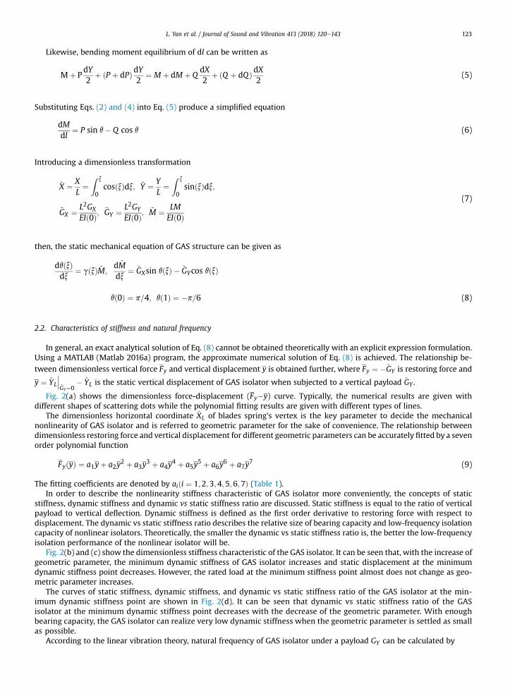
Likewise, bending moment equilibrium of dl can be written as
Mþ PdY2
þ ðP þ dPÞdY2
¼ M þ dM þ QdX2
þ ðQ þ dQÞdX2
(5)
Substituting Eqs. (2) and (4) into Eq. (5) produce a simplified equation
dMdl
¼ P sin q� Q cos q (6)
Introducing a dimensionless transformation
~X ¼ XL¼Z x
0cosðxÞdx; ~Y ¼ Y
L¼Z x
0sinðxÞdx;
~GX ¼ L2GX
EIð0Þ;~GY ¼ L2GY
EIð0Þ;~M ¼ LM
EIð0Þ
(7)
then, the static mechanical equation of GAS structure can be given as
dqðxÞdx
¼ gðxÞ ~M;d ~Mdx
¼ ~GXsin qðxÞ � ~GYcos qðxÞ
qð0Þ ¼ p=4; qð1Þ ¼ �p=6 (8)
2.2. Characteristics of stiffness and natural frequency
In general, an exact analytical solution of Eq. (8) cannot be obtained theoretically with an explicit expression formulation.Using a MATLAB (Matlab 2016a) program, the approximate numerical solution of Eq. (8) is achieved. The relationship be-tween dimensionless vertical force Fy and vertical displacement y is obtained further, where Fy ¼ �~GY is restoring force and
y ¼ ~YL
���~GY¼0
� ~YL is the static vertical displacement of GAS isolator when subjected to a vertical payload ~GY .
Fig. 2(a) shows the dimensionless force-displacement (Fy�y) curve. Typically, the numerical results are given withdifferent shapes of scattering dots while the polynomial fitting results are given with different types of lines.
The dimensionless horizontal coordinate ~XL of blades spring's vertex is the key parameter to decide the mechanicalnonlinearity of GAS isolator and is referred to geometric parameter for the sake of convenience. The relationship betweendimensionless restoring force and vertical displacement for different geometric parameters can be accurately fitted by a sevenorder polynomial function
FyðyÞ ¼ a1yþ a2y2 þ a3y
3 þ a4y4 þ a5y
5 þ a6y6 þ a7y
7 (9)
The fitting coefficients are denoted by aiði ¼ 1;2;3;4;5;6;7Þ (Table 1).In order to describe the nonlinearity stiffness characteristic of GAS isolator more conveniently, the concepts of static
stiffness, dynamic stiffness and dynamic vs static stiffness ratio are discussed. Static stiffness is equal to the ratio of verticalpayload to vertical deflection. Dynamic stiffness is defined as the first order derivative to restoring force with respect todisplacement. The dynamic vs static stiffness ratio describes the relative size of bearing capacity and low-frequency isolationcapacity of nonlinear isolators. Theoretically, the smaller the dynamic vs static stiffness ratio is, the better the low-frequencyisolation performance of the nonlinear isolator will be.
Fig. 2(b) and (c) show the dimensionless stiffness characteristic of the GAS isolator. It can be seen that, with the increase ofgeometric parameter, the minimum dynamic stiffness of GAS isolator increases and static displacement at the minimumdynamic stiffness point decreases. However, the rated load at the minimum stiffness point almost does not change as geo-metric parameter increases.
The curves of static stiffness, dynamic stiffness, and dynamic vs static stiffness ratio of the GAS isolator at the min-imum dynamic stiffness point are shown in Fig. 2(d). It can be seen that dynamic vs static stiffness ratio of the GASisolator at the minimum dynamic stiffness point decreases with the decrease of the geometric parameter. With enoughbearing capacity, the GAS isolator can realize very low dynamic stiffness when the geometric parameter is settled as smallas possible.
According to the linear vibration theory, natural frequency of GAS isolator under a payload GY can be calculated by

Fig. 2. (a) Curve of dimensionless force vs dimensionless displacement of the GAS isolator. (b) Dimensionless dynamic stiffness vs dimensionless displacement.(c) Curve of dimensionless dynamic stiffness vs dimensionless payload. (d) Static stiffness, dynamic stiffness and dynamic vs static stiffness ratio of the GASisolator at the minimal dynamic stiffness working point. (e) Curve of dimensionless natural frequency vs dimensionless displacement. (f) Curve of dimensionlessnatural frequency vs dimensionless payload.
L. Yan et al. / Journal of Sound and Vibration 413 (2018) 120e143124
u2n ¼ g
GY
vFyvy
¼ gL
1~GY
vFyvy
L2Fy
Here, Fy ¼ EIð0Þ. The dimensionless natural frequency of GAS isolator can be written as follow~u2n ¼ L
gu2n ¼ 1
~GY
vFyvy
!
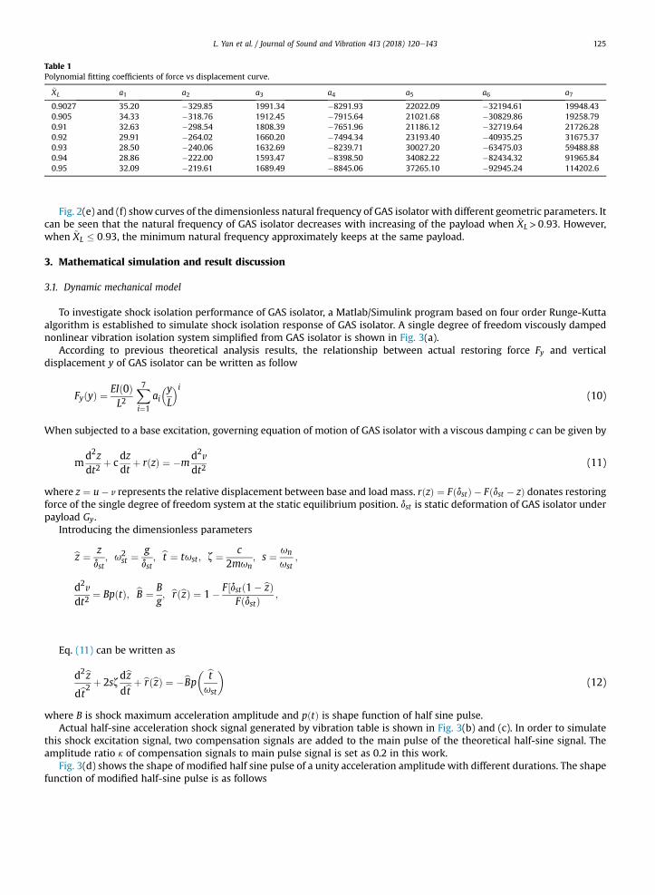
Table 1Polynomial fitting coefficients of force vs displacement curve.
~XL a1 a2 a3 a4 a5 a6 a7
0.9027 35.20 �329.85 1991.34 �8291.93 22022.09 �32194.61 19948.430.905 34.33 �318.76 1912.45 �7915.64 21021.68 �30829.86 19258.790.91 32.63 �298.54 1808.39 �7651.96 21186.12 �32719.64 21726.280.92 29.91 �264.02 1660.20 �7494.34 23193.40 �40935.25 31675.370.93 28.50 �240.06 1632.69 �8239.71 30027.20 �63475.03 59488.880.94 28.86 �222.00 1593.47 �8398.50 34082.22 �82434.32 91965.840.95 32.09 �219.61 1689.49 �8845.06 37265.10 �92945.24 114202.6
L. Yan et al. / Journal of Sound and Vibration 413 (2018) 120e143 125
Fig. 2(e) and (f) show curves of the dimensionless natural frequency of GAS isolator with different geometric parameters. Itcan be seen that the natural frequency of GAS isolator decreases with increasing of the payload when ~XL >0:93. However,when ~XL � 0:93, the minimum natural frequency approximately keeps at the same payload.
3. Mathematical simulation and result discussion
3.1. Dynamic mechanical model
To investigate shock isolation performance of GAS isolator, a Matlab/Simulink program based on four order Runge-Kuttaalgorithm is established to simulate shock isolation response of GAS isolator. A single degree of freedom viscously dampednonlinear vibration isolation system simplified from GAS isolator is shown in Fig. 3(a).
According to previous theoretical analysis results, the relationship between actual restoring force Fy and verticaldisplacement y of GAS isolator can be written as follow
FyðyÞ ¼ EIð0ÞL2
X7i¼1
ai�yL
�i(10)
When subjected to a base excitation, governing equation of motion of GAS isolator with a viscous damping c can be given by
md2zdt2
þ cdzdt
þ rðzÞ ¼ �md2v
dt2(11)
where z ¼ u� v represents the relative displacement between base and load mass. rðzÞ ¼ FðdstÞ � Fðdst � zÞ donates restoringforce of the single degree of freedom system at the static equilibrium position. dst is static deformation of GAS isolator underpayload Gy.
Introducing the dimensionless parameters
bz ¼ zdst
; u2st ¼
gdst
; bt ¼ tust ; z ¼ c2mun
; s ¼ un
ust;
d2v B F½dstð1� bzÞ
dt2¼ BpðtÞ; bB ¼g; brðbzÞ ¼ 1�
FðdstÞ ;
Eq. (11) can be written as
d2bzdbt2 þ 2sz
dbzdbt þ brðbzÞ ¼ �bBp� bt
ust
�(12)
where B is shock maximum acceleration amplitude and pðtÞ is shape function of half sine pulse.Actual half-sine acceleration shock signal generated by vibration table is shown in Fig. 3(b) and (c). In order to simulate
this shock excitation signal, two compensation signals are added to the main pulse of the theoretical half-sine signal. Theamplitude ratio k of compensation signals to main pulse signal is set as 0.2 in this work.
Fig. 3(d) shows the shape of modified half sine pulse of a unity acceleration amplitude with different durations. The shapefunction of modified half-sine pulse is as follows

Fig. 3. Dynamic mechanical model of GAS isolator under base shock excitation. (a) Single degree of freedom viscously damped nonlinear vibration isolationsystem under base excitation. (b) Half-sine acceleration shock signal generated by vibration table and theoretical simulation signal. (c) Excitation displacementsignals of vibration table and theoretical simulation signal. (d) Shape of the modified half-sine pulse with different durations.
L. Yan et al. / Journal of Sound and Vibration 413 (2018) 120e143126

L. Yan et al. / Journal of Sound and Vibration 413 (2018) 120e143 127
p� btust
�¼
8>>>>>>>>><>>>>>>>>>:
�k sinp
t1
btust
; 0 �btust
� t1
�sinp
t
� btust
� t1
�; t1 �
btust
� t1 þ t
�k sinp
t
� btust
� t1 � t
�; t1 þ t �
btust
� 2t1 þ t
(13)
where t is the duration of main pulse and t1 ¼ t=2k.
3.2. Method of evaluating shock isolation performance
To evaluate shock isolation performance of nonlinear vibration isolation system, shock acceleration ratio (SAR), shockdisplacement ratio (SDR) and relative displacement ratio (RDR), which are related to the forces transmitted through theisolator and available deformation space or clearance, are used [34,37].
SAR ¼ j€ujmaxj€vjmax
(14)
jujmax
SDR ¼ jvjmax(15)ju� vjmax
RDR ¼ jvjmax(16)The force transmitted through elastic and damping elements from base excitation is equal to the product of mass andacceleration. If SAR is large, forces transmitted through the elastic and damping elements are considerable. SDR gives themaximumdisplacement transmissibility. A large SDRmeans vibration isolation performance of nonlinear isolator is poor. RDRshows the size of relative deformation of the nonlinear isolator, and a large RDR means a large deflection.
These three indexes are normally presented graphically as a function of severity parameter b. For a linear system, severityparameter is defined as
b ¼ T2t
(17)
where T is the natural period of the linear system and t is the duration of shock main pulse. According to the size of b, shocktransmissibility can be divided into three regions.When b[1, shock duration is small compared to natural period of isolationsystem and shock signal is isolated, which is called shock isolation region. When b ≪ 1, shock duration is too long comparedto natural period of isolation system and shock excitation is similar to a slow static loading, which is equivalent static region.When b is close to 1, response amplitude of isolators is larger than excitation amplitude, which is shock amplification region.
Because the natural period of nonlinear isolator varies with vibration levels, which depend on both excitation amplitudeand duration of the pulse, severity parameter b is redefined as the ratio of the natural period of the equivalent linear system ofGAS isolator to duration of shock main pulse. Therefore, severity parameter is given as follows
b ¼ p
tuel
uel ¼ffiffiffiffiffiffiffiffiffiffiffiffiffiffi
g
Lbdkmin
s (18)
Here, bdkmin is dimensionless static deformation of GAS isolator working at the minimal dynamic stiffness point.
3.3. Simulation results and discussion
In this section, the effects of the geometric parameter, excitation amplitude, static payload and viscous damping ratio onthe shock isolation performance of GAS isolator are discussed. Three shock isolation performance indexes are plottedwith theseverity parameter ranging from 0.1 to 100.
3.3.1. Effect of the geometric parameterFig. 4 shows shock time domain response of GAS isolator with a shock main pulse duration of 11 ms. GAS isolator works at
the minimum dynamic stiffness point with the same damping ratio of 0.1 and shock excitation acceleration amplitude is 30 g.
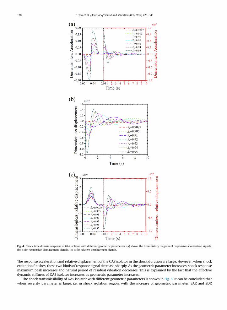
Fig. 4. Shock time domain response of GAS isolator with different geometric parameters. (a) shows the time-history diagram of responsive acceleration signals.(b) is for responsive displacement signals. (c) is for relative displacement signals.
L. Yan et al. / Journal of Sound and Vibration 413 (2018) 120e143128
The response acceleration and relative displacement of the GAS isolator in the shock duration are large. However, when shockexcitation finishes, these two kinds of response signal decrease sharply. As the geometric parameter increases, shock responsemaximum peak increases and natural period of residual vibration decreases. This is explained by the fact that the effectivedynamic stiffness of GAS isolator increases as geometric parameter increases.
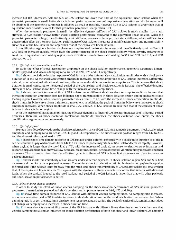
The shock transmissibility of GAS isolator with different geometric parameters is shown in Fig. 5. It can be concluded thatwhen severity parameter is large, i.e. in shock isolation region, with the increase of geometric parameter, SAR and SDR
L. Yan et al. / Journal of Sound and Vibration 413 (2018) 120e143 129
increase but RDR decreases. SAR and SDR of GAS isolator are lower than that of the equivalent linear isolator when thegeometric parameter is small. Better shock isolation performance in terms of responsive acceleration and displacement willbe obtained if the geometric parameter is adjusted as small as possible. However, RDR of GAS isolator is larger than that ofequivalent linear isolator except for that geometric parameter is larger than 0.93.
When the geometric parameter is small, the effective dynamic stiffness of GAS isolator is much smaller than staticstiffness. So GAS isolator shows better shock isolation performance compared to the equivalent linear isolator. When thegeometric parameter is large, the effective dynamic stiffness increases to be larger than static stiffness, which will lead to adeterioration effect on the shock isolation performance of GAS isolator. The range of amplification region and transmissibilitycurve peak of the GAS isolator are larger than that of the equivalent linear isolator.
In amplification region, vibration displacement amplitude of the isolator increases and the effective dynamic stiffness ofGAS isolator increases quickly, which leads the abrupt increase of the shock transmissibility. When severity parameter issmall, i.e. in equivalent static loading region, shock excitation is similar to a static loading. So SAR and SDR tend to 1, and RDRapproaches to 0.
3.3.2. Effect of shock acceleration amplitudeTo study the effect of shock acceleration amplitude on the shock isolation performance, geometric parameter, dimen-
sionless payload, and viscous damping ratio are set as 0.92, 1.75 and 0.1, respectively.Fig. 6 shows shock time domain response of GAS isolator under different shock excitation amplitudes with a shock pulse
duration of 11 ms. As the shock acceleration amplitude increases, response amplitude of GAS isolator increases. Differently,natural period of residual vibration almost keeps the same under different excitation amplitudes. This is because that shockduration is small compared to the natural period of the GAS isolator and shock excitation is isolated. The effective dynamicstiffness of GAS isolator shows little change with the increase of shock amplitudes.
Fig. 7 shows the shock transmissibility of GAS isolator under different shock acceleration amplitudes. It can be seen thatincreasing excitation amplitude does not influence shock transmissibility in shock isolation region and in equivalent staticloading region. However, when severity parameter varies from 1 to 20, with the increase of shock acceleration amplitude,shock transmissibility curve shows a rightward movement. In addition, the peak of transmissibility curve increases as shockamplitude increases. When shock amplitude is small, SAR and SDR of GAS isolator are less than that of the equivalent linearisolator in shock isolation region.
With the increase of vibration amplitude, the effective dynamic stiffness of GAS isolator increases and its natural perioddecreases. Therefore, as shock excitation acceleration amplitude increases, the shock excitation level enters the shockamplification region more and more early.
3.3.3. Effect of payloadTo study the effect of payloads on the shock isolation performance of GAS isolator, geometric parameter, shock acceleration
amplitude and damping ratio are set as 0.92, 30 g and 0.1, respectively. The dimensionless payload ranges from 1.47 to 2.10,and the dimensionless rated load is 1.75.
Fig. 8 shows shock time domain response of GAS isolator under different payloads with a shock pulse duration of 11 ms. Itcan be seen that as payload increases from 1.47 to 1.75, shock response magnitude of GAS isolator decreases rapidly. However,when payload is larger than the rated load (1.75), with the increase of payload, response acceleration peak increases andresponse displacement peak shows a slow decrease. Meantime, natural period of residual vibration firstly increases and thendecreases. This is resulted from that the effective dynamic stiffness of GAS isolator first decreases and then increases aspayload increases.
Fig. 9 shows shock transmissibility of GAS isolator under different payloads. In shock isolation region, SAR and SDR firstdecrease and then increase as payload increases. The minimal shock acceleration ratio is obtained when payload is equal tothe rated load. If the payload is not far away from the rated load, shock transmissibility of GAS isolator will be still smaller thanthat of the equivalent linear isolator. This agrees with the dynamic stiffness characteristic of the GAS isolator with differentloads. When the payload is equal to the rated load, natural period of the GAS isolator is larger than that with other payloadsand shock isolation performance is better.
3.3.4. Effect of linear viscous dampingIn order to study the effect of linear viscous damping on the shock isolation performance of GAS isolator, geometric
parameter, dimensionless payload and shock acceleration amplitude are set as 0.92, 1.75 and 30 g.Fig. 10 shows time domain response of GAS isolator with different viscous damping ratios. As damping ratio increases,
response acceleration peak of GAS isolator increases in shock duration time but the residual vibration is attenuated fast.Whendamping ratio is larger, the maximum displacement response appears earlier. The peak of relative displacement almost doesnot change as damping ratio increases in shock duration time.
Fig. 11 shows shock transmissibility curve of the GAS isolator with different linear damping ratios. It can be seen thatviscous damping has a similar influence on shock isolation performance of both nonlinear and linear isolators. As damping
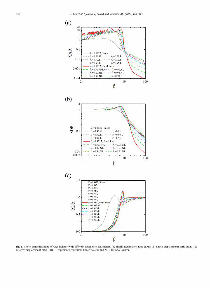
Fig. 5. Shock transmissibility of GAS isolator with different geometric parameters. (a) Shock acceleration ratio (SAR). (b) Shock displacement ratio (SDR). (c)Relative displacement ratio (RDR). L represents equivalent linear isolator and NL is for GAS isolator.
L. Yan et al. / Journal of Sound and Vibration 413 (2018) 120e143130
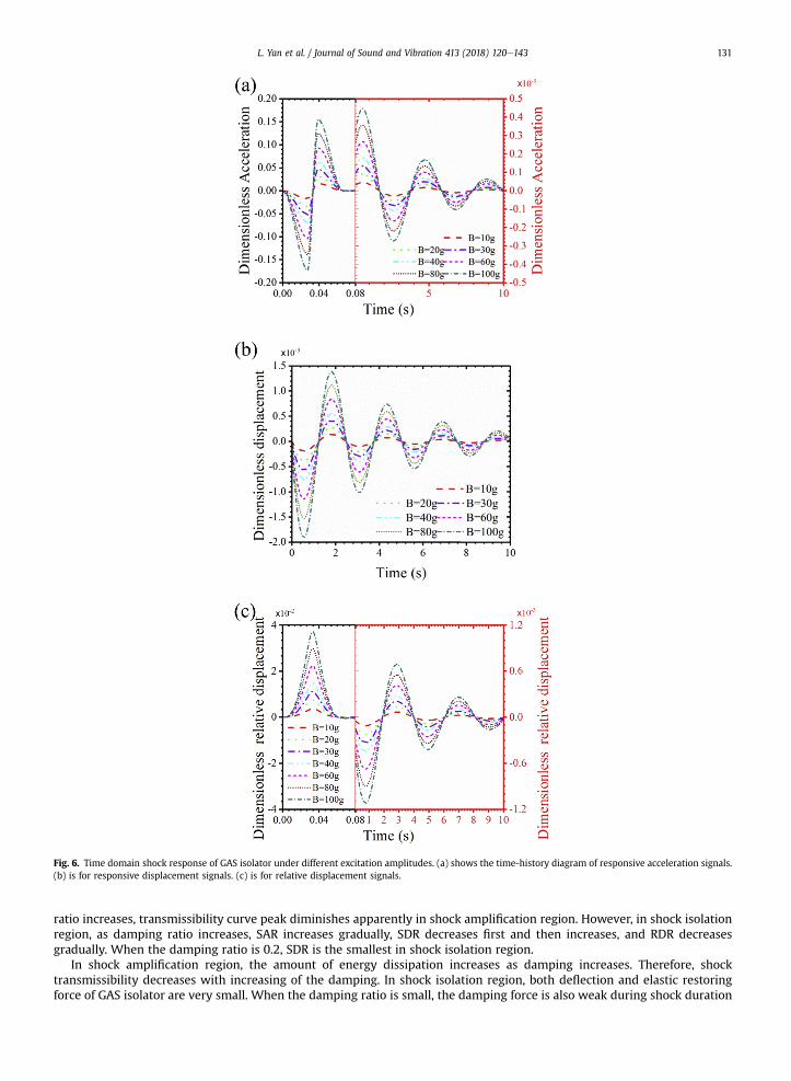
Fig. 6. Time domain shock response of GAS isolator under different excitation amplitudes. (a) shows the time-history diagram of responsive acceleration signals.(b) is for responsive displacement signals. (c) is for relative displacement signals.
L. Yan et al. / Journal of Sound and Vibration 413 (2018) 120e143 131
ratio increases, transmissibility curve peak diminishes apparently in shock amplification region. However, in shock isolationregion, as damping ratio increases, SAR increases gradually, SDR decreases first and then increases, and RDR decreasesgradually. When the damping ratio is 0.2, SDR is the smallest in shock isolation region.
In shock amplification region, the amount of energy dissipation increases as damping increases. Therefore, shocktransmissibility decreases with increasing of the damping. In shock isolation region, both deflection and elastic restoringforce of GAS isolator are very small. When the damping ratio is small, the damping force is also weak during shock duration
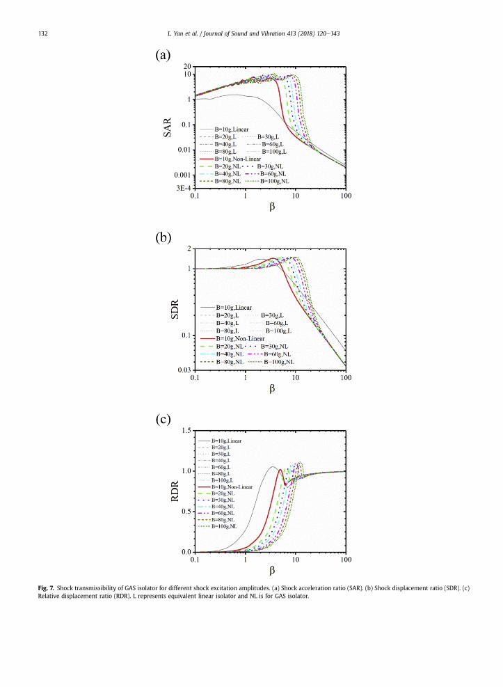
Fig. 7. Shock transmissibility of GAS isolator for different shock excitation amplitudes. (a) Shock acceleration ratio (SAR). (b) Shock displacement ratio (SDR). (c)Relative displacement ratio (RDR). L represents equivalent linear isolator and NL is for GAS isolator.
L. Yan et al. / Journal of Sound and Vibration 413 (2018) 120e143132
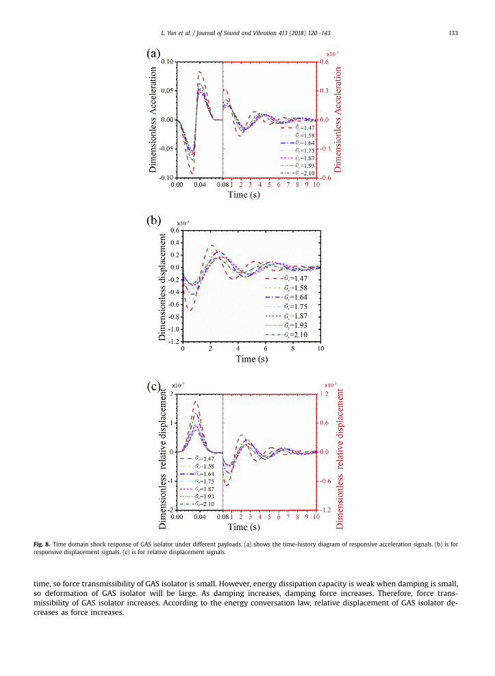
Fig. 8. Time domain shock response of GAS isolator under different payloads. (a) shows the time-history diagram of responsive acceleration signals. (b) is forresponsive displacement signals. (c) is for relative displacement signals.
L. Yan et al. / Journal of Sound and Vibration 413 (2018) 120e143 133
time, so force transmissibility of GAS isolator is small. However, energy dissipation capacity is weak when damping is small,so deformation of GAS isolator will be large. As damping increases, damping force increases. Therefore, force trans-missibility of GAS isolator increases. According to the energy conversation law, relative displacement of GAS isolator de-creases as force increases.
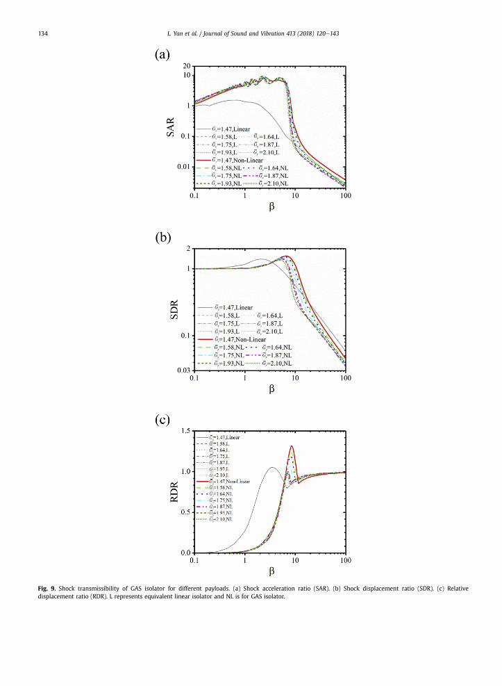
Fig. 9. Shock transmissibility of GAS isolator for different payloads. (a) Shock acceleration ratio (SAR). (b) Shock displacement ratio (SDR). (c) Relativedisplacement ratio (RDR). L represents equivalent linear isolator and NL is for GAS isolator.
L. Yan et al. / Journal of Sound and Vibration 413 (2018) 120e143134
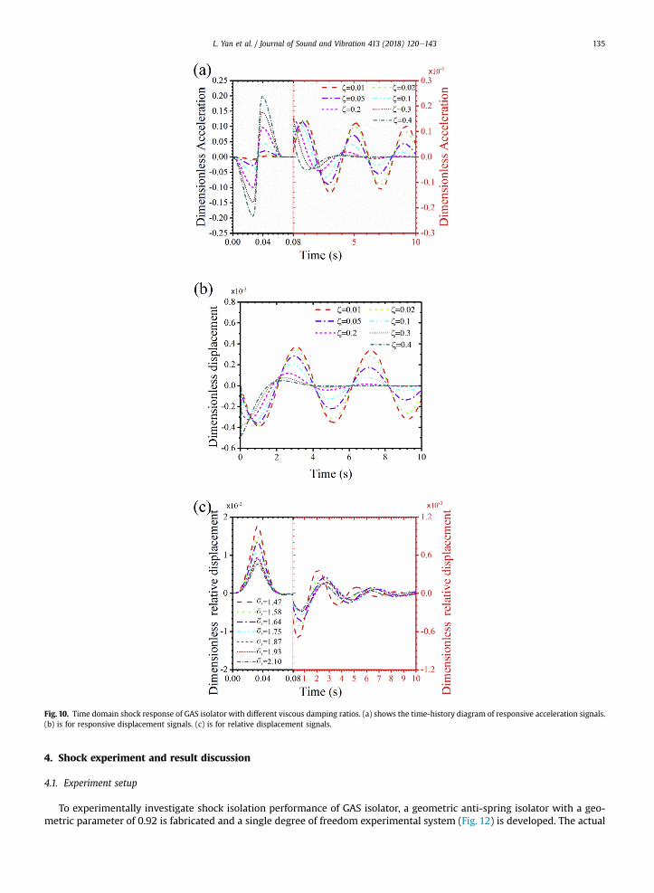
Fig. 10. Time domain shock response of GAS isolator with different viscous damping ratios. (a) shows the time-history diagram of responsive acceleration signals.(b) is for responsive displacement signals. (c) is for relative displacement signals.
L. Yan et al. / Journal of Sound and Vibration 413 (2018) 120e143 135
4. Shock experiment and result discussion
4.1. Experiment setup
To experimentally investigate shock isolation performance of GAS isolator, a geometric anti-spring isolator with a geo-metric parameter of 0.92 is fabricated and a single degree of freedom experimental system (Fig. 12) is developed. The actual
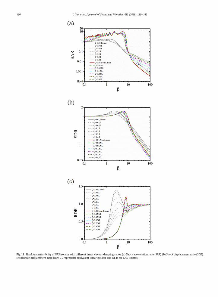
Fig. 11. Shock transmissibility of GAS isolator with different linear viscous damping ratios. (a) Shock acceleration ratio (SAR). (b) Shock displacement ratio (SDR).(c) Relative displacement ratio (RDR). L represents equivalent linear isolator and NL is for GAS isolator.
L. Yan et al. / Journal of Sound and Vibration 413 (2018) 120e143136
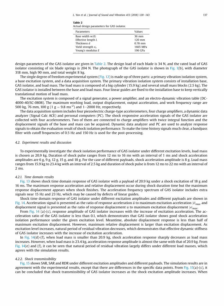
Table 2Actual design parameters for GAS isolator.
Parameters Values
Base width wð0Þ 36 mmEffective length L 120 mmThickness d 0.78 mmYield strength ss 1665 MPaYoung's modulus E 196 GPa
L. Yan et al. / Journal of Sound and Vibration 413 (2018) 120e143 137
design parameters of the GAS isolator are given in Table 2. The design load of each blade is 34 N, and the rated load of GASisolator consisting of six blade springs is 204 N. The photograph of the GAS isolator is shown in Fig. 1(b), with diameter318 mm, high 90 mm, and total weight 8 kg.
The single degree of freedom experimental system (Fig.12) is made up of three parts: a primary vibration isolation system,a base excitation system, and a data acquisition system. The primary vibration isolation system consists of installation base,GAS isolator, and load mass. The load mass is composed of a big cylinder (15.9 kg) and several small mass blocks (2.5 kg). TheGAS isolator is installed between the base and loadmass. Four linear guides are fixed to the installation base to keep verticallytranslational motion of load mass.
The excitation system is composed of a signal generator, a power amplifier, and an electro-dynamic vibration table (DC-4000-40/SC-0808). The maximum working load, output displacement, output acceleration, and work frequency range are500 kg, 76 mm, 100 g (1 g ¼ 9.8 ms-2) and 1e2000 Hz, respectively.
The data acquisition system includes four piezoelectric charge-type accelerometers, four charge amplifiers, a dynamic dataanalyzer (Signal Calc ACE) and personal computers (PC). The shock responsive acceleration signals of the GAS isolator arecollected with four accelerometers. Two of them are connected to charge amplifiers with twice integral function and thedisplacement signals of the base and mass can be acquired. Dynamic data analyzer and PC are used to analyze responsesignals to obtain the evaluation result of shock isolation performance. Tomake the time history signals much clear, a bandpassfilter with cutoff frequencies of 0.5 Hz and 150 Hz is used for the post-processing.
4.2. Experiment results and discussion
To experimentally investigate the shock isolation performance of GAS isolator under different excitation levels, load massis chosen as 20.9 kg. Duration of shock pulse ranges from 12 ms to 16 ms with an interval of 1 ms and shock accelerationamplitudes are 6 g, 9 g, 12 g, 15 g, and 18 g. For the case of different payloads, shock acceleration amplitude is 8 g. Load massranges from 15.9 kg to 23.4 kg with an interval of 2.5 kg and duration of shock pulse is from 12ms to 22ms with an interval of2 ms.
4.2.1. Time domain resultsFig. 13 shows shock time domain response of GAS isolator with a payload of 20.9 kg under a shock excitation of 18 g and
16 ms. The maximum response acceleration and relative displacement occur during shock duration time but the maximumresponse displacement appears when shock finishes. The acceleration frequency spectrum of GAS isolator includes extrasignals near 15 Hz and 23 Hz, which may be caused by defects of linear guides.
Shock time domain response of GAS isolator under different excitation amplitudes and different payloads are shown inFig. 14. Acceleration signal is presented as the ratio of response acceleration €u to maximum excitation acceleration j€vjmax anddisplacement signal is presented as the ratio of response displacement u to maximum excitation displacement jvjmax.
From Fig. 14 (a)-(c), response amplitude of GAS isolator increases with the increase of excitation acceleration. The ac-celeration ratio of the GAS isolator is less than 0.1, which demonstrates that GAS isolator shows good shock accelerationisolation performance under the given excitation level. Meantime, absolute displacement response is less than half ofmaximum excitation displacement. However, maximum relative displacement is larger than excitation displacement. Asexcitation level increases, natural period of residual vibration decreases, which demonstrates that effective dynamic stiffnessof GAS isolator increases with the increase of excitation acceleration.
In Fig. 14(d)-(f), when load mass is smaller than 20.9 kg, shock acceleration response sharply decreases as load massincreases. However, when loadmass is 23.4 kg, acceleration response amplitude is almost the samewith that of 20.9 kg. FromFig. 14(e) and (f), it can be seen that natural period of residual vibration largely differs under different load masses, whichagrees with the simulation results.
4.2.2. Shock transmissibilityFig. 15 shows SAR, SAR and RDR under different excitation amplitudes and different payloads. The simulation results are in
agreement with the experimental results, except that there are differences in the specific data points. From Fig. 15(a)-(c), itcan be concluded that shock transmissibility of GAS isolator increases as the shock excitation amplitude increases. When
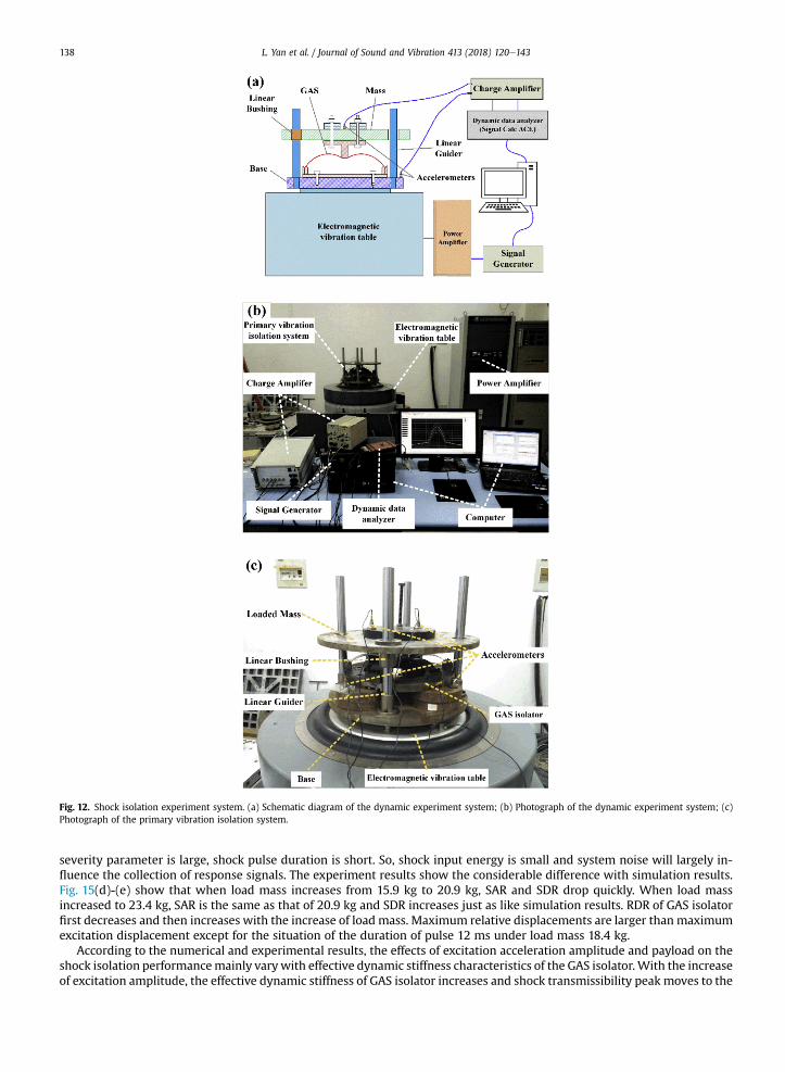
Fig. 12. Shock isolation experiment system. (a) Schematic diagram of the dynamic experiment system; (b) Photograph of the dynamic experiment system; (c)Photograph of the primary vibration isolation system.
L. Yan et al. / Journal of Sound and Vibration 413 (2018) 120e143138
severity parameter is large, shock pulse duration is short. So, shock input energy is small and system noise will largely in-fluence the collection of response signals. The experiment results show the considerable difference with simulation results.Fig. 15(d)-(e) show that when load mass increases from 15.9 kg to 20.9 kg, SAR and SDR drop quickly. When load massincreased to 23.4 kg, SAR is the same as that of 20.9 kg and SDR increases just as like simulation results. RDR of GAS isolatorfirst decreases and then increases with the increase of load mass. Maximum relative displacements are larger than maximumexcitation displacement except for the situation of the duration of pulse 12 ms under load mass 18.4 kg.
According to the numerical and experimental results, the effects of excitation acceleration amplitude and payload on theshock isolation performancemainly vary with effective dynamic stiffness characteristics of the GAS isolator. With the increaseof excitation amplitude, the effective dynamic stiffness of GAS isolator increases and shock transmissibility peak moves to the
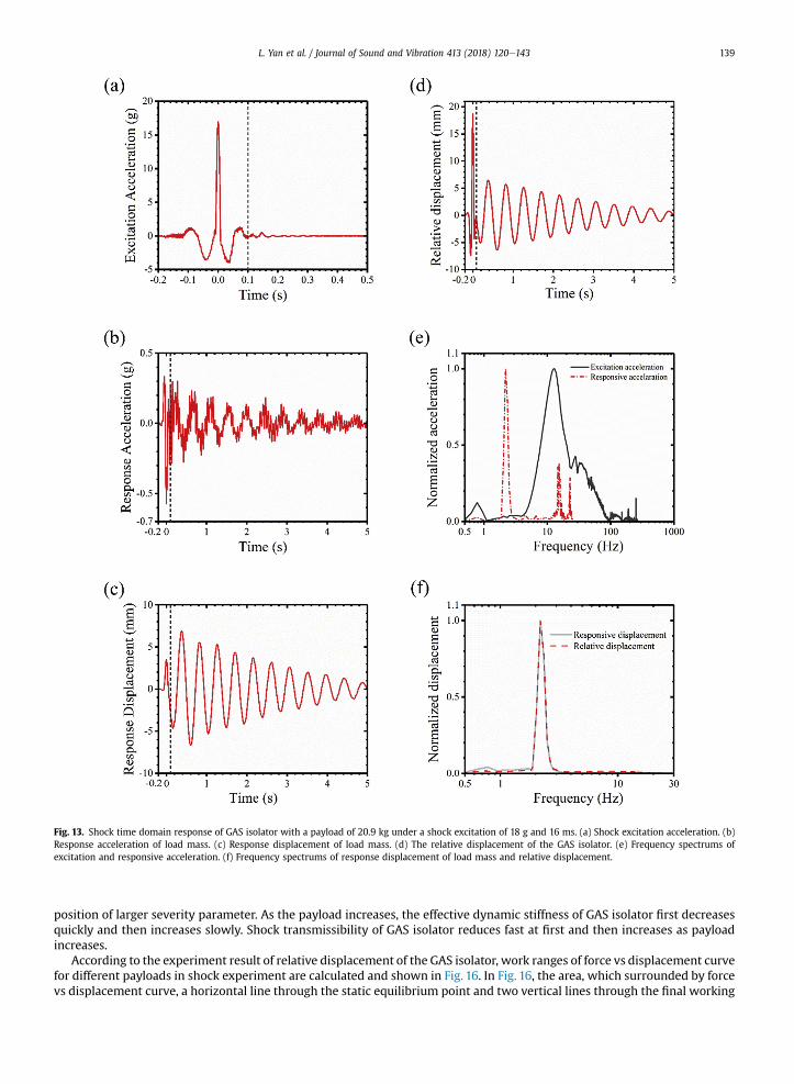
Fig. 13. Shock time domain response of GAS isolator with a payload of 20.9 kg under a shock excitation of 18 g and 16 ms. (a) Shock excitation acceleration. (b)Response acceleration of load mass. (c) Response displacement of load mass. (d) The relative displacement of the GAS isolator. (e) Frequency spectrums ofexcitation and responsive acceleration. (f) Frequency spectrums of response displacement of load mass and relative displacement.
L. Yan et al. / Journal of Sound and Vibration 413 (2018) 120e143 139
position of larger severity parameter. As the payload increases, the effective dynamic stiffness of GAS isolator first decreasesquickly and then increases slowly. Shock transmissibility of GAS isolator reduces fast at first and then increases as payloadincreases.
According to the experiment result of relative displacement of the GAS isolator, work ranges of force vs displacement curvefor different payloads in shock experiment are calculated and shown in Fig. 16. In Fig. 16, the area, which surrounded by forcevs displacement curve, a horizontal line through the static equilibrium point and two vertical lines through the final working

Fig. 14. Time domain response of GAS isolator. (a)e(c) are response acceleration, response displacement and relative displacement under different excitationlevels with a shock pulse duration of 16 ms. (d)e(f) are response acceleration, response displacement and relative displacement under different payloads with thepulse duration of 22 ms and the excitation amplitude of 8 g.
L. Yan et al. / Journal of Sound and Vibration 413 (2018) 120e143140
point, denotes shock input energy approximately. When load mass is 20.9 kg, the maximum shock energy is represented bythe area surrounded bydOD, OC and CD. For the equivalent linear isolator, according to the energy conservation law, the shockenergy can be approximately represented by the area of DOAB. It is clear that relative displacement of equivalent linearisolator is smaller than that of GAS isolator. This can explain why RDR of GAS isolator is larger than that of equivalent linearisolator in shock isolation region. In amplification region, when relative displacement is large enough that nonlinear restoringforce is larger than linear restoring force at maximum relative displacement point, the relative displacement of GAS isolatorwill be equal to or smaller than that of equivalent linear isolator.
5. Conclusion
In this paper, shock isolation performance of a GAS isolator subjected to double-sided compensation half-sine shock inputis studied with numerical simulation. The shock isolation performance of GAS isolator under different excitation amplitudesand different payloads is experimentally investigated. Base on numerical and experimental results, some conclusion can begiven as follows,
(1) The effective dynamic stiffness dominants shock isolation performance of GAS isolator. GAS isolator has an advantageon shock acceleration and displacement isolation in shock isolation region compared to the equivalent linear isolator.The smaller the geometric parameter is, the better the shock isolation performance will be. However, relativedisplacement ratio of the GAS isolator is larger than that of the equivalent linear isolator.
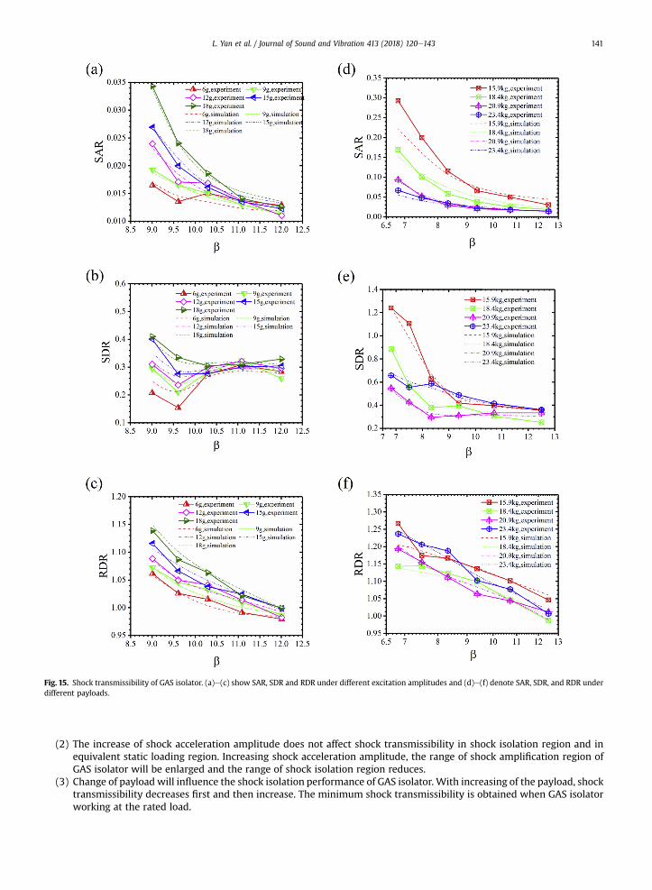
Fig. 15. Shock transmissibility of GAS isolator. (a)e(c) show SAR, SDR and RDR under different excitation amplitudes and (d)e(f) denote SAR, SDR, and RDR underdifferent payloads.
L. Yan et al. / Journal of Sound and Vibration 413 (2018) 120e143 141
(2) The increase of shock acceleration amplitude does not affect shock transmissibility in shock isolation region and inequivalent static loading region. Increasing shock acceleration amplitude, the range of shock amplification region ofGAS isolator will be enlarged and the range of shock isolation region reduces.
(3) Change of payload will influence the shock isolation performance of GAS isolator. With increasing of the payload, shocktransmissibility decreases first and then increase. The minimum shock transmissibility is obtained when GAS isolatorworking at the rated load.
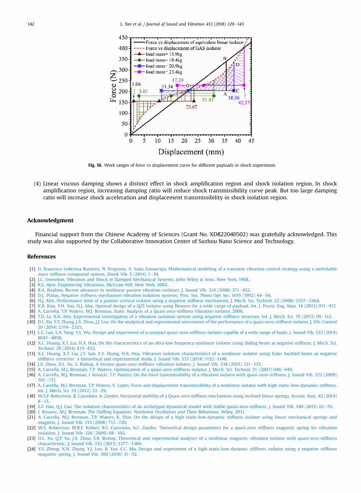
Fig. 16. Work ranges of force vs displacement curve for different payloads in shock experiment.
L. Yan et al. / Journal of Sound and Vibration 413 (2018) 120e143142
(4) Linear viscous damping shows a distinct effect in shock amplification region and shock isolation region. In shockamplification region, increasing damping ratio will reduce shock transmissibility curve peak. But too large dampingratio will increase shock acceleration and displacement transmissibility in shock isolation region.
Acknowledgment
Financial support from the Chinese Academy of Sciences (Grant No. XDB22040502) was gratefully acknowledged. Thisstudy was also supported by the Collaborative Innovation Center of Suzhou Nano Science and Technology.
References
[1] D. Francisco Ledezma-Ramirez, N. Ferguson, A. Salas Zamarripa, Mathematical modeling of a transient vibration control strategy using a switchablemass stiffness compound system, Shock Vib. 5 (2014) 1e10.
[2] J.C. Snowdon, Vibration and Shock in Damped Mechanical Systems, John Wiley & Sons, New York, 1968.[3] R.S. Ayre, Engineering Vibrations, McGraw-Hill, New York, 2002.[4] R.A. Ibrahim, Recent advances in nonlinear passive vibration isolators, J. Sound Vib. 314 (2008) 371e452.[5] D.L. Platus, Negative stiffness-mechanism vibration isolation systems, Proc. Soc. Photo Opt. Ins. 1619 (1992) 44e54.[6] H.J. Ahn, Performance limit of a passive vertical isolator using a negative stiffness mechanism, J. Mech. Sci. Technol. 22 (2008) 2357e2364.[7] K.R. Kim, Y.H. You, H.J. Ahn, Optimal design of a QZS isolator using flexures for a wide range of payload, Int. J. Precis. Eng. Man. 14 (2013) 911e917.[8] A. Carrella, T.P. Waters, M.J. Brennan, Static Analysis of a Quasi-zero-stiffness Vibration Isolator, 2006.[9] T.D. Le, K.K. Ahn, Experimental investigation of a vibration isolation system using negative stiffness structure, Int. J. Mech. Sci. 70 (2013) 99e112.
[10] D.L. Xu, Y.Y. Zhang, J.X. Zhou, J.J. Lou, On the analytical and experimental assessment of the performance of a quasi-zero-stiffness isolator, J. Vib. Control20 (2014) 2314e2325.
[11] C.C. Lan, S.A. Yang, Y.S. Wu, Design and experiment of a compact quasi-zero-stiffness isolator capable of a wide range of loads, J. Sound Vib. 333 (2014)4843e4858.
[12] X.C. Huang, X.T. Liu, H.X. Hua, On the characteristics of an ultra-low frequency nonlinear isolator using sliding beam as negative stiffness, J. Mech. Sci.Technol. 28 (2014) 813e822.
[13] X.C. Huang, X.T. Liu, J.Y. Sun, Z.Y. Zhang, H.X. Hua, Vibration isolation characteristics of a nonlinear isolator using Euler buckled beam as negativestiffness corrector: a theoretical and experimental study, J. Sound Vib. 333 (2014) 1132e1148.
[14] J.X. Zhou, D.L. Xu, S. Bishop, A torsion quasi-zero stiffness vibration isolator, J. Sound Vib. 338 (2015) 121e133.[15] A. Carrella, M.J. Brennan, T.P. Waters, Optimization of a quasi-zero-stiffness isolator, J. Mech. Sci. Technol. 21 (2007) 946e949.[16] A. Carrella, M.J. Brennan, I. Kovacic, T.P. Waters, On the force transmissibility of a vibration isolator with quasi-zero-stiffness, J. Sound Vib. 322 (2009)
707e717.[17] A. Carrella, M.J. Brennan, T.P. Waters, V. Lopes, Force and displacement transmissibility of a nonlinear isolator with high-static-low-dynamic-stiffness,
Int. J. Mech. Sci. 55 (2012) 22e29.[18] W.S.P. Robertson, B. Cazzolato, A. Zander, Horizontal stability of a Quasi-zero stiffness mechanism using inclined linear springs, Acoust. Aust. 42 (2014)
8e13.[19] Z.F. Hao, Q.J. Cao, The isolation characteristics of an archetypal dynamical model with stable-quasi-zero-stiffness, J. Sound Vib. 340 (2015) 61e79.[20] I. Kovacic, M.J. Brennan, The Duffing Equation: Nonlinear Oscillators and Their Behaviour, Wiley, 2011.[21] A. Carrella, M.J. Brennan, T.P. Waters, K. Shin, On the design of a high-static-low-dynamic stiffness isolator using linear mechanical springs and
magnets, J. Sound Vib. 315 (2008) 712e720.[22] W.S. Robertson, M.R.F. Kidner, B.S. Cazzolato, A.C. Zander, Theoretical design parameters for a quasi-zero stiffness magnetic spring for vibration
isolation, J. Sound Vib. 326 (2009) 88e103.[23] D.L. Xu, Q.P. Yu, J.X. Zhou, S.R. Bishop, Theoretical and experimental analyses of a nonlinear magnetic vibration isolator with quasi-zero-stiffness
characteristic, J. Sound Vib. 332 (2013) 3377e3389.[24] Y.S. Zheng, X.N. Zhang, Y.J. Luo, B. Yan, C.C. Ma, Design and experiment of a high-static-low-dynamic stiffness isolator using a negative stiffness
magnetic spring, J. Sound Vib. 360 (2016) 31e52.

L. Yan et al. / Journal of Sound and Vibration 413 (2018) 120e143 143
[25] G.X. Dong, X.N. Zhang, S.L. Xie, B. Yan, Y.J. Luo, Simulated and experimental studies on a high-static-low-dynamic stiffness isolator using magneticnegative stiffness spring, Mech. Syst. Signal Process. 86 (2017) 188e203.
[26] A.D. Shaw, S.A. Neild, D.J. Wagg, P.M. Weaver, A. Carrella, A nonlinear spring mechanism incorporating a bistable composite plate for vibrationisolation, J. Sound Vib. 332 (2013) 6265e6275.
[27] Z. Hu, G.T. Zheng, A combined dynamic analysis method for geometrically nonlinear vibration isolators with elastic rings, Mech. Syst. Signal Process76e77 (2016) 634e648.
[28] L.N. Virgin, S.T. Santillan, R.H. Plaut, Vibration isolation using extreme geometric nonlinearity, J. Sound Vib. 315 (2008) 721e731.[29] X.T. Sun, X.J. Jing, Analysis and design of a nonlinear stiffness and damping system with a scissor-like structure, Mech. Syst. Signal Process. 66e67
(2016) 723e742.[30] Y. Araki, K. Kimura, T. Asai, T. Masui, T. Omori, R. Kainuma, Integrated mechanical and material design of quasi-zero-stiffness vibration isolator with
superelastic CueAleMn shape memory alloy bars, J. Sound Vib. 358 (2015) 74e83.[31] J.C. Snowdon, Transient response of nonlinear isolation mountings to pulselike displacements, J. Acoust. Soc. Am. 35 (1963) 389e396.[32] A.E. Vakakis, Shock isolation through the use of nonlinear energy sinks, J. Vib. Control 9 (2003) 79e93.[33] F. Georgiadis, A.F. Vakakis, D.M. McFarland, L. Bergman, Shock isolation through passive energy pumping caused by nonsmooth nonlinearities, Int. J.
Bifurcat. Chaos 15 (2005) 1989e2001.[34] D.F. Ledezma-Ramirez, N.S. Ferguson, M.J. Brennan, B. Tang, An experimental nonlinear low dynamic stiffness device for shock isolation, J. Sound Vib.
347 (2015) 1e13.[35] B.A. Fulcher, D.W. Shahan, M.R. Haberman, C.C. Seepersad, P.S. Wilson, Analytical and experimental investigation of buckled beams as negative
stiffness elements for passive vibration and shock isolation systems, J. Vib. Acoust. 136 (2014).[36] X.C. Huang, Y. Chen, H.X. Hua, X.T. Liu, Z.Y. Zhang, Shock isolation performance of a nonlinear isolator using Euler buckled beam as negative stiffness
corrector: theoretical and experimental study, J. Sound Vib. 345 (2015) 178e196.[37] B. Tang, M.J. Brennan, On the shock performance of a nonlinear vibration isolator with high-static-low-dynamic-stiffness, Int. J. Mech. Sci. 81 (2014)
207e214.[38] X.T. Liu, X.C. Huang, H.X. Hua, Performance of a zero stiffness isolator under shock excitations, J. Vib. Control 20 (2014) 2090e2099.[39] G. Cella, V. Sannibale, R. DeSalvo, S. Marka, A. Takamori, Monolithic geometric anti-spring blades, Nucl. Instrum. Method A 540 (2005) 502e519.[40] V. Sannibale, B. Abbott, Y. Aso, V. Boschi, D. Coyne, R. DeSalvo, S. M�arka, D. Ottaway, A. Stochino, Recent results of a seismically isolated optical table
prototype designed for advanced LIGO, J. Phys. Conf. Ser. 122 (2008) 012010.[41] M.R. Blom, M.G. Beker, A. Bertolini, J.F.J. van den Brand, H.J. Bulten, E. Hennes, F.A. Mul, D.S. Rabeling, A. Schimmel, Seismic attenuation system for the
external injection bench of the Advanced Virgo gravitational wave detector, Nucl. Instrum. Method A 718 (2013) 466e470.
Related Documents