Original Article Load sharing ability of the liner in type III composite pressure vessels under internal pressure Jose ´ Humberto S Almeida Jr 1,3 , Hugo Faria 2 , Anto ´ nio T Marques 3 and Sandro C Amico 1 Abstract In this work, the load sharing ability of metallic liners in type III composite overwrapped pressure vessel was investigated by means of accurate numerical models based on finite element method in order to realistically represent the hybrid metal-composite structure. The varying thickness of the composite layers throughout the dome, as well as their angles, were accounted for in the model. The study focused on the influence of material properties and liner-to-composite thick- ness ratio on the stress and strain distribution between liner and composite at the cylindrical, dome, and polar boss regions. Two novel concepts for the evaluation of the structural response of a composite overwrapped pressure vessel were introduced, namely: (i) the liner stress and strain fractions, and (ii) the correlation with liner-to-composite thick- ness ratio. The results show complex overall behavior close to the onset of plasticity of the liner, which is critically investigated. A decrease in liner stress fraction was found for higher internal pressure loads since the stress field is increasingly dominated by the composite overwrap. Also, the von Mises equivalent stress along the longitudinal profile of the structure showed a peak at the dome of the liner, whereas for the composite, the peak was at the shoulder region. This was justified considering that, at low pressure, the liner operates elastically in compression-tension mode and the composite in tension-tension mode. Keywords Composite overwrapped pressure vessel, finite element analysis, liner load share, thickness ratio, filament winding Introduction Composite overwrapped pressure vessels (COPVs) are amongst the most efficient structural concepts for high- pressure storage of fluids. The main applications are portable or industrial gas storage tanks and onboard fuel tanks for vehicles, where their weight savings when compared with classical metallic solutions may reach 75%. 1 Due to the very high pressures involved and the safety risks associated with the use of COPV, their greater acceptance in several markets still depend on accurate and reliable knowledge of their behavior. Pressure vessels have been classified into: fully metal- lic tank (Type I), metallic liner hoop-wrapped with composite (Type II), metallic liner fully overwrapped with composite (Type III), polymer-lined composite vessel (Type IV), and linerless composite pressure vessel (Type V). Their suitability to a particular application depends upon associated structural respon- sibility, critical weight, load level, stored fluid, and cost (manufacturing, transport, installation, and maintenance). 2 The liner of a type III COPV, unlike types IV and V, can effectively share part of the load to which the 1 PPGE3M, UFRGS – Federal University of Rio Grande do Sul, Brazil 2 INEGI – Institute of Mechanical Engineering and Industrial Management, Portugal 3 FEUP – Faculty of Engineering of the University of Porto, Portugal Corresponding author: Jose ´ Humberto S Almeida Jr, PPGE3M, UFRGS – Federal University of Rio Grande do Sul, Av. Bento Gonc ¸alves, 9500, 91501-970, Porto Alegre/RS, Brazil. Email: [email protected] Journal of Reinforced Plastics and Composites 2014, Vol. 33(24) 2274–2286 ! The Author(s) 2014 Reprints and permissions: sagepub.co.uk/journalsPermissions.nav DOI: 10.1177/0731684414560221 jrp.sagepub.com at UNIV FED DO RIO GRANDE DO SUL on November 29, 2014 jrp.sagepub.com Downloaded from

Welcome message from author
This document is posted to help you gain knowledge. Please leave a comment to let me know what you think about it! Share it to your friends and learn new things together.
Transcript
Original Article
Load sharing ability of the liner intype III composite pressure vesselsunder internal pressure
Jose Humberto S Almeida Jr1,3, Hugo Faria2,Antonio T Marques3 and Sandro C Amico1
Abstract
In this work, the load sharing ability of metallic liners in type III composite overwrapped pressure vessel was investigated
by means of accurate numerical models based on finite element method in order to realistically represent the hybrid
metal-composite structure. The varying thickness of the composite layers throughout the dome, as well as their angles,
were accounted for in the model. The study focused on the influence of material properties and liner-to-composite thick-
ness ratio on the stress and strain distribution between liner and composite at the cylindrical, dome, and polar boss
regions. Two novel concepts for the evaluation of the structural response of a composite overwrapped pressure vessel
were introduced, namely: (i) the liner stress and strain fractions, and (ii) the correlation with liner-to-composite thick-
ness ratio. The results show complex overall behavior close to the onset of plasticity of the liner, which is critically
investigated. A decrease in liner stress fraction was found for higher internal pressure loads since the stress field is
increasingly dominated by the composite overwrap. Also, the von Mises equivalent stress along the longitudinal profile of
the structure showed a peak at the dome of the liner, whereas for the composite, the peak was at the shoulder region.
This was justified considering that, at low pressure, the liner operates elastically in compression-tension mode and the
composite in tension-tension mode.
Keywords
Composite overwrapped pressure vessel, finite element analysis, liner load share, thickness ratio, filament winding
Introduction
Composite overwrapped pressure vessels (COPVs) areamongst the most efficient structural concepts for high-pressure storage of fluids. The main applications areportable or industrial gas storage tanks and onboardfuel tanks for vehicles, where their weight savings whencompared with classical metallic solutions may reach75%.1 Due to the very high pressures involved andthe safety risks associated with the use of COPV,their greater acceptance in several markets stilldepend on accurate and reliable knowledge of theirbehavior.
Pressure vessels have been classified into: fully metal-lic tank (Type I), metallic liner hoop-wrapped withcomposite (Type II), metallic liner fully overwrappedwith composite (Type III), polymer-lined compositevessel (Type IV), and linerless composite pressure
vessel (Type V). Their suitability to a particularapplication depends upon associated structural respon-sibility, critical weight, load level, stored fluid, andcost (manufacturing, transport, installation, andmaintenance).2
The liner of a type III COPV, unlike types IV and V,can effectively share part of the load to which the
1PPGE3M, UFRGS – Federal University of Rio Grande do Sul, Brazil2INEGI – Institute of Mechanical Engineering and Industrial Management,
Portugal3FEUP – Faculty of Engineering of the University of Porto, Portugal
Corresponding author:
Jose Humberto S Almeida Jr, PPGE3M, UFRGS – Federal University of Rio
Grande do Sul, Av. Bento Goncalves, 9500, 91501-970, Porto Alegre/RS,
Brazil.
Email: [email protected]
Journal of Reinforced Plastics
and Composites
2014, Vol. 33(24) 2274–2286
! The Author(s) 2014
Reprints and permissions:
sagepub.co.uk/journalsPermissions.nav
DOI: 10.1177/0731684414560221
jrp.sagepub.com
at UNIV FED DO RIO GRANDE DO SUL on November 29, 2014jrp.sagepub.comDownloaded from
COPV is subjected, having a non-negligible structuralcontribution to the overall response. Type III COPVsare typically produced in two separate steps, the man-ufacturing of the liner and of the composite overwrap-ping by filament winding. The composite outer shell canbe wound following different patterns and layups,allowing tailored designs for each application and/orrequired performance. This is of great importance forthe optimum distribution of load between the metallicliner and the composite layers. It is common under-standing that, under regular operating conditions, theliner of the COPV should work in the fully elasticregime, but COPV mass efficiency points to the use ofits plasticity. If a thin liner is used, the composite mustbear most of the load and constrain the liner enough toprevent its plastic deformation. However, technologicaland economic aspects may drive the choice of linerthickness and composite configuration so that an opti-mized combination is reached.3
There are usually three main regions in a COPVliner.2 The polar boss is the interface region withexternal devices. The dome is a critical section andits geometry strongly influences the overall COPV’sperformance. The main reasons for this are: (1) theliner typically presents thickness variations in thisregion due to its own manufacture (e.g. deep draw-ing), (2) the composite layup over this region ischaracterized by continuously changing angles ineach ply, and (3) the turnaround end zones of eachlayer may vary considerably, yielding very differentstiffening profiles. Therefore, the dome region mayundergo quite different stress levels depending on theimplemented design.4 And although spherical domesmaximize overall strength under static internal pres-sure,5 the need to combine the structural contributionsof the liner and the composite, as well as themanufacturing feasibility, results in other profiles. Inparticular, the path of the winding band around thedome is quite complex due to changes of relativeangles, from the nominal winding angle to 90� at theturnaround zone.
Son and Chang2 presented three modelling optionsfor a Type III pressure vessel for hydrogen storagebased on aluminum liner overwrapped by carbon/epoxy composite. (1) A laminate-based modellingapproach which deals with averaged anisotropicproperties (easier and faster modelling) but underes-timates generated stresses, especially at the domeregions (2) A ply-based model based on orthotropicply property to finite shell element, considering theactual fiber direction in each layer to predict accuratestress distribution. (3) An approach based on thecombination of both. The full ply-based model pre-sented more accurate stress distribution at the domeregions, which was experimentally validated. Park
et al.6 modelled the winding patterns of COPVs forarbitrary surfaces and used these patterns in the finiteelement analysis (FEA). The developed algorithmsaimed at finding the optimum winding angle andcomposite thickness. They reported that the differencein winding angle between the first and last pliesreached 18� near the polar openings. Thus, a com-plete knowledge of the actual through-the-thicknesschange of winding angle is required for precise mod-eling of stress distributions.
Metallic liners share the load with the compositeshell and this share is essentially dependent on linermaterial and thickness, and geometry of the COPV.Several studies in the literature7,8 focus on non-loadsharing liners overwrapped by composite layers.However, depending on the specific case, the load inthe liner should be taken into account when assessingthe COPV in-service behavior for an optimizeddesign.
In this context, this work investigates the influenceof liner thickness on the load sharing ability ofaluminum and stainless steel liners for similar COPVgeometries. Stress and strain were numerically analyzedin all regions of the liner and the composite structure.The geometries and specific winding features weremodelled in accordance with realistic windingpossibilities as reported in a previous work of thegroup.9
Finite element structural modelling
Pressure vessels were modelled using aluminum orstainless steel liners fully overwrapped by a T700carbon/epoxy towpreg. The used elastic properties ofthe metallic liners and the composite layers are pre-sented in Table 1.10
Structural modelling was carried out based on finiteelement method (FEM) with Abaqus� 6.13 software.Nonlinear geometry was considered in all cases sincelarge and unbalanced deformations are expected. The20-layer composite lay-up used for the COPV com-prised: (i) Layers 1–10: hoop winding (90�), frictionless,
Table 1. Elastic properties of the liners and the composite.
Property Aluminum Stainless steel T700
E11 (GPa) 73.77 193.71 148.24
E22, E33 (GPa) 73.77 193.71 1.56
�12, �13 0.33 0.26 0.28
�23 0.33 0.26 0.31
G12, G13 (GPa) 27.73 77.21 1.46
G23 (GPa) – – 0.56
Almeida Jr et al. 2275
at UNIV FED DO RIO GRANDE DO SUL on November 29, 2014jrp.sagepub.comDownloaded from
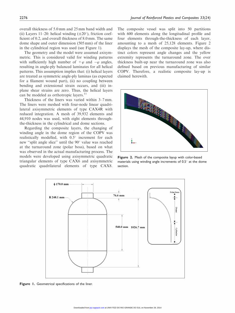
overall thickness of 5.0mm and 25mm band width and(ii) Layers 11–20: helical winding (�20�), friction coef-ficient of 0.2, and overall thickness of 8.0mm. The samedome shape and outer dimension (505mm) of the linerin the cylindrical region was used (see Figure 1).
The geometry and the model were assumed axisym-metric. This is considered valid for winding patternswith sufficiently high number of +’ and �’ angles,resulting in angle-ply balanced laminates for all helicalpatterns. This assumption implies that: (i) helical layersare treated as symmetric angle-ply laminas (as expectedfor a filament wound part), (ii) no coupling betweenbending and extensional strain occurs, and (iii) in-plane shear strains are zero. Thus, the helical layerscan be modeled as orthotropic layers.11
Thickness of the liners was varied within 3–7mm.The liners were meshed with four-node linear quadri-lateral axisymmetric elements of type CAX4R withreduced integration. A mesh of 39,932 elements and44,910 nodes was used, with eight elements through-the-thickness in the cylindrical and dome sections.
Regarding the composite layers, the changing ofwinding angle in the dome region of the COPV wasrealistically modelled, with 0.5� increment for eachnew ‘‘split angle slice’’ until the 90� value was reachedat the turnaround zone (polar boss), based on whatwas observed in the actual manufacturing process. Themodels were developed using axisymmetric quadratictriangular elements of type CAX6 and axisymmetricquadratic quadrilateral elements of type CAX8.
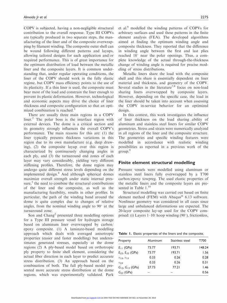
The composite vessel was split into 50 partitionswith 600 elements along the longitudinal profile andfour elements through-the-thickness of each layer,amounting to a mesh of 25,128 elements. Figure 2displays the mesh of the composite lay-up, where dis-tinct colors represent angle changes and the yellowextremity represents the turnaround zone. The overthickness built-up near the turnaround zone was alsodefined based on previous manufacturing of similarCOPV. Therefore, a realistic composite lay-up isclaimed herewith.
Figure 1. Geometrical specifications of the liner.
Figure 2. Mesh of the composite layup with color-based
materials using winding angle increments of 0.5� at the dome
section.
2276 Journal of Reinforced Plastics and Composites 33(24)
at UNIV FED DO RIO GRANDE DO SUL on November 29, 2014jrp.sagepub.comDownloaded from
A convergence study over the structure wasperformed for detecting mathematical or geometricsingularities, especially at the connection betweencylindrical region and dome, and at the polar bossarea. This was done by varying element size and meshdensity.
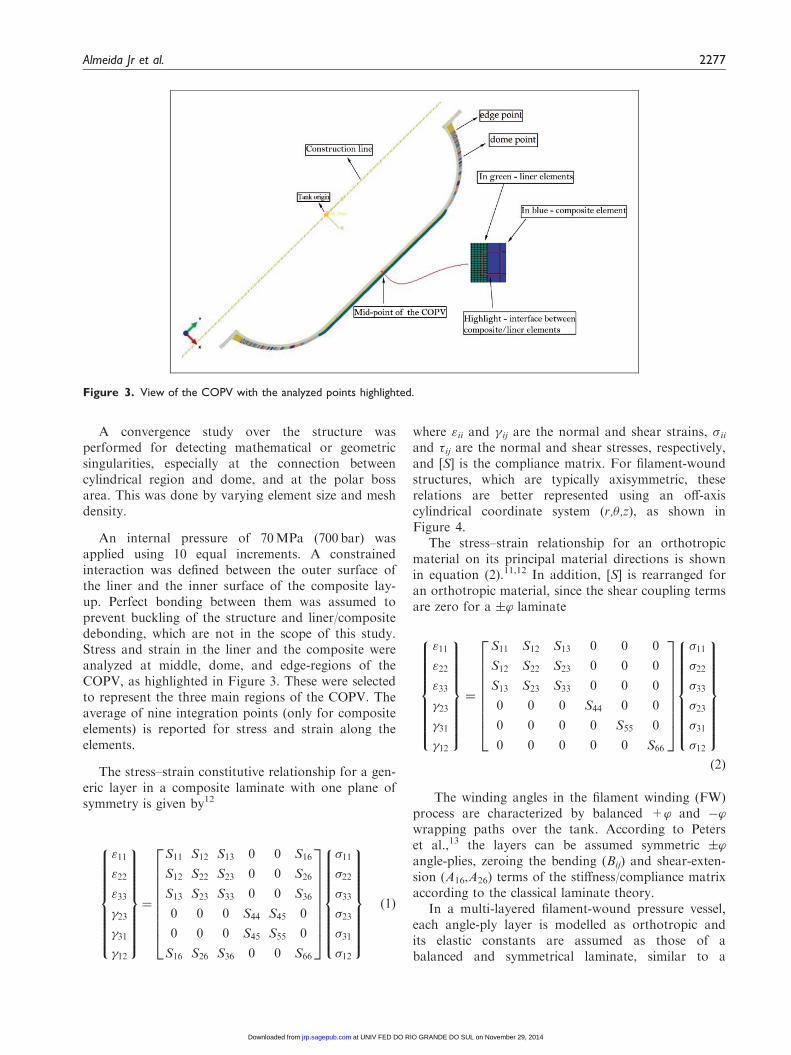
An internal pressure of 70MPa (700 bar) wasapplied using 10 equal increments. A constrainedinteraction was defined between the outer surface ofthe liner and the inner surface of the composite lay-up. Perfect bonding between them was assumed toprevent buckling of the structure and liner/compositedebonding, which are not in the scope of this study.Stress and strain in the liner and the composite wereanalyzed at middle, dome, and edge-regions of theCOPV, as highlighted in Figure 3. These were selectedto represent the three main regions of the COPV. Theaverage of nine integration points (only for compositeelements) is reported for stress and strain along theelements.
The stress–strain constitutive relationship for a gen-eric layer in a composite laminate with one plane ofsymmetry is given by12
"11
"22
"33
�23
�31
�12
8>>>>>>>><>>>>>>>>:
9>>>>>>>>=>>>>>>>>;
¼
S11 S12 S13 0 0 S16
S12 S22 S23 0 0 S26
S13 S23 S33 0 0 S36
0 0 0 S44 S45 0
0 0 0 S45 S55 0
S16 S26 S36 0 0 S66
2666666664
3777777775
�11
�22
�33
�23
�31
�12
8>>>>>>>><>>>>>>>>:
9>>>>>>>>=>>>>>>>>;
ð1Þ
where "ii and � ij are the normal and shear strains, �iiand �ij are the normal and shear stresses, respectively,and [S] is the compliance matrix. For filament-woundstructures, which are typically axisymmetric, theserelations are better represented using an off-axiscylindrical coordinate system (r,�,z), as shown inFigure 4.
The stress–strain relationship for an orthotropicmaterial on its principal material directions is shownin equation (2).11,12 In addition, [S] is rearranged foran orthotropic material, since the shear coupling termsare zero for a �’ laminate
"11
"22
"33
�23
�31
�12
8>>>>>>>><>>>>>>>>:
9>>>>>>>>=>>>>>>>>;
¼
S11 S12 S13 0 0 0
S12 S22 S23 0 0 0
S13 S23 S33 0 0 0
0 0 0 S44 0 0
0 0 0 0 S55 0
0 0 0 0 0 S66
2666666664
3777777775
�11
�22
�33
�23
�31
�12
8>>>>>>>><>>>>>>>>:
9>>>>>>>>=>>>>>>>>;ð2Þ
The winding angles in the filament winding (FW)process are characterized by balanced +’ and �’wrapping paths over the tank. According to Peterset al.,13 the layers can be assumed symmetric �’angle-plies, zeroing the bending (Bij) and shear-exten-sion (A16,A26) terms of the stiffness/compliance matrixaccording to the classical laminate theory.
In a multi-layered filament-wound pressure vessel,each angle-ply layer is modelled as orthotropic andits elastic constants are assumed as those of abalanced and symmetrical laminate, similar to a
Figure 3. View of the COPV with the analyzed points highlighted.
Almeida Jr et al. 2277
at UNIV FED DO RIO GRANDE DO SUL on November 29, 2014jrp.sagepub.comDownloaded from
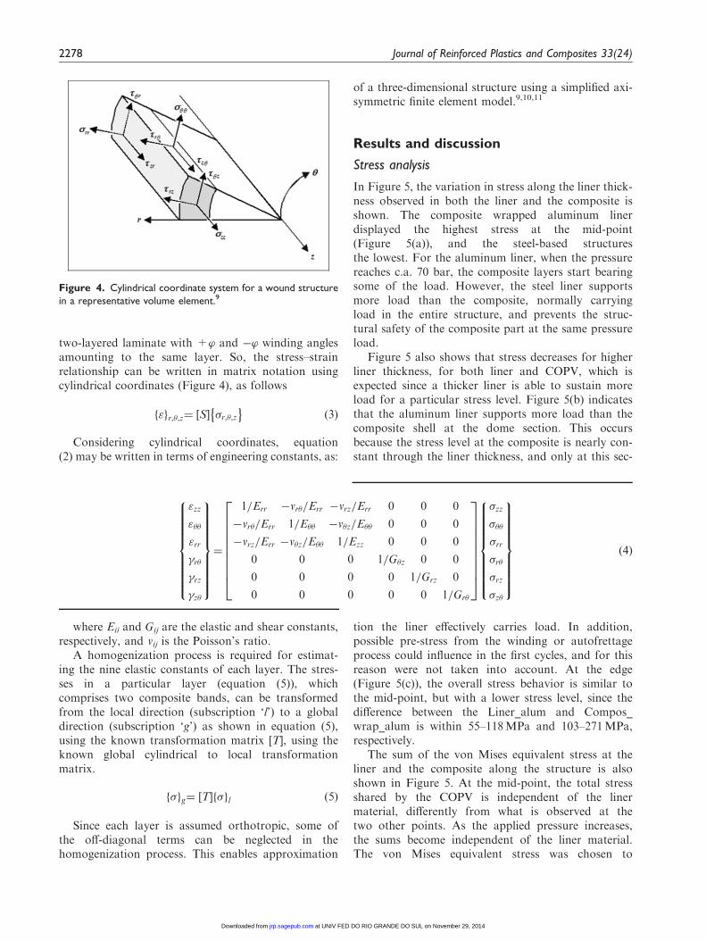
two-layered laminate with +’ and �’ winding anglesamounting to the same layer. So, the stress–strainrelationship can be written in matrix notation usingcylindrical coordinates (Figure 4), as follows
"f gr,�,z¼ S½ � �r,�,z� �
ð3Þ
Considering cylindrical coordinates, equation(2) may be written in terms of engineering constants, as:
where Eii and Gij are the elastic and shear constants,respectively, and vij is the Poisson’s ratio.
A homogenization process is required for estimat-ing the nine elastic constants of each layer. The stres-ses in a particular layer (equation (5)), whichcomprises two composite bands, can be transformedfrom the local direction (subscription ‘l’) to a globaldirection (subscription ‘g’) as shown in equation (5),using the known transformation matrix [T], using theknown global cylindrical to local transformationmatrix.
�f gg¼ T½ � �f gl ð5Þ
Since each layer is assumed orthotropic, some ofthe off-diagonal terms can be neglected in thehomogenization process. This enables approximation
of a three-dimensional structure using a simplified axi-symmetric finite element model.9,10,11
Results and discussion
Stress analysis
In Figure 5, the variation in stress along the liner thick-ness observed in both the liner and the composite isshown. The composite wrapped aluminum linerdisplayed the highest stress at the mid-point(Figure 5(a)), and the steel-based structuresthe lowest. For the aluminum liner, when the pressurereaches c.a. 70 bar, the composite layers start bearingsome of the load. However, the steel liner supportsmore load than the composite, normally carryingload in the entire structure, and prevents the struc-tural safety of the composite part at the same pressureload.
Figure 5 also shows that stress decreases for higherliner thickness, for both liner and COPV, which isexpected since a thicker liner is able to sustain moreload for a particular stress level. Figure 5(b) indicatesthat the aluminum liner supports more load than thecomposite shell at the dome section. This occursbecause the stress level at the composite is nearly con-stant through the liner thickness, and only at this sec-
tion the liner effectively carries load. In addition,possible pre-stress from the winding or autofrettageprocess could influence in the first cycles, and for thisreason were not taken into account. At the edge(Figure 5(c)), the overall stress behavior is similar tothe mid-point, but with a lower stress level, since thedifference between the Liner_alum and Compos_wrap_alum is within 55–118MPa and 103–271MPa,respectively.
The sum of the von Mises equivalent stress at theliner and the composite along the structure is alsoshown in Figure 5. At the mid-point, the total stressshared by the COPV is independent of the linermaterial, differently from what is observed at thetwo other points. As the applied pressure increases,the sums become independent of the liner material.The von Mises equivalent stress was chosen to
"zz
"��
"rr
�r�
�rz
�z�
8>>>>>>>><>>>>>>>>:
9>>>>>>>>=>>>>>>>>;
¼
1=Err �vr�=Err �vrz=Err 0 0 0
�vr�=Err 1=E�� �v�z=E�� 0 0 0
�vrz=Err �v�z=E�� 1=Ezz 0 0 0
0 0 0 1=G�z 0 0
0 0 0 0 1=Grz 0
0 0 0 0 0 1=Gr�
2666666664
3777777775
�zz
���
�rr
�r�
�rz
�z�
8>>>>>>>><>>>>>>>>:
9>>>>>>>>=>>>>>>>>;
ð4Þ
Figure 4. Cylindrical coordinate system for a wound structure
in a representative volume element.9
2278 Journal of Reinforced Plastics and Composites 33(24)
at UNIV FED DO RIO GRANDE DO SUL on November 29, 2014jrp.sagepub.comDownloaded from
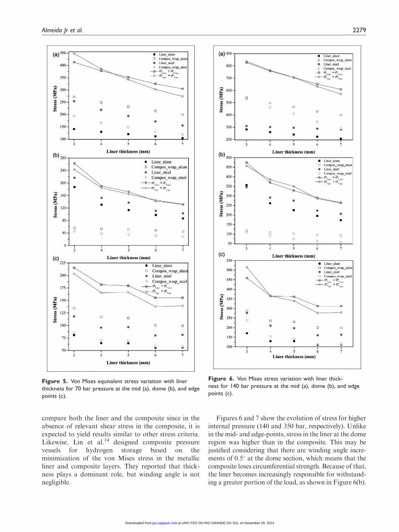
compare both the liner and the composite since in theabsence of relevant shear stress in the composite, it isexpected to yield results similar to other stress criteria.Likewise, Lin et al.14 designed composite pressurevessels for hydrogen storage based on theminimization of the von Mises stress in the metallicliner and composite layers. They reported that thick-ness plays a dominant role, but winding angle is notnegligible.
Figures 6 and 7 show the evolution of stress for higherinternal pressure (140 and 350 bar, respectively). Unlikein the mid- and edge-points, stress in the liner at the domeregion was higher than in the composite. This may bejustified considering that there are winding angle incre-ments of 0.5� at the dome section, which means that thecomposite loses circumferential strength. Because of that,the liner becomes increasingly responsible for withstand-ing a greater portion of the load, as shown in Figure 6(b).
Figure 5. Von Mises equivalent stress variation with liner
thickness for 70 bar pressure at the mid (a), dome (b), and edge
points (c).
Figure 6. Von Mises stress variation with liner thick-
ness for 140 bar pressure at the mid (a), dome (b), and edge
points (c).
Almeida Jr et al. 2279
at UNIV FED DO RIO GRANDE DO SUL on November 29, 2014jrp.sagepub.comDownloaded from

The stress distribution at the edge is complex, because thisis a turbulent zone due to the return of the winding cycle,achieving high angles, c.a. 90�, and back at the start ofanother cycle. Also, the polar boss is an intrinsic stressconcentration region due to local geometrical and phys-ical discontinuities, yielding higher stress gradients.Discontinuities also occur in the dome section, but, inthis case, the winding angle is closer to the desired one,providing better mechanical stability.
Figure 7 presents the von Mises equivalent stress fora pressure of 350 bar. Stress in the composite overwrap
is higher than in the liners at the mid- and edge-sections, and lower at the dome section. This evidencesa decrease in load sharing of the liner along the struc-ture. The liner material did not exert significant influ-ence in load sharing and the difference betweenaluminum and steel was below 4%, except at the cylin-drical section. It is also interesting to notice that, at 350bar, all sums of stresses are nearly overlapping.
To enable comparison between different COPV con-figurations, three simple and novel concepts are pro-posed in this work: the liner stress fraction (�lf),liner strain fraction ("lf), and the thickness ratio (tr)defined as:
�lf ¼�l
�l þ �c"lf ¼
"l"l þ "c
tr ¼tltc
ð6Þ
where �l and �c are stress at a particular position of theliner and the composite, respectively, "l and "c arestrain at a particular position of the liner and the com-posite, respectively, and tl and tc are thickness of theliner and the composite, respectively.
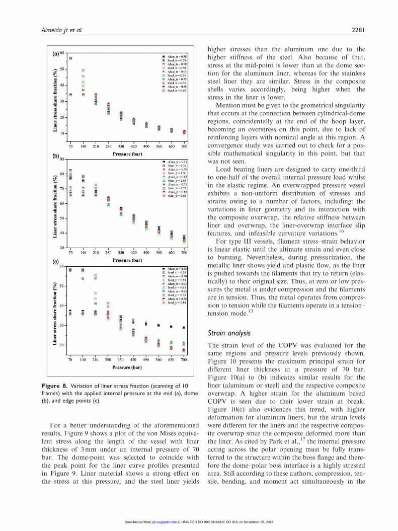
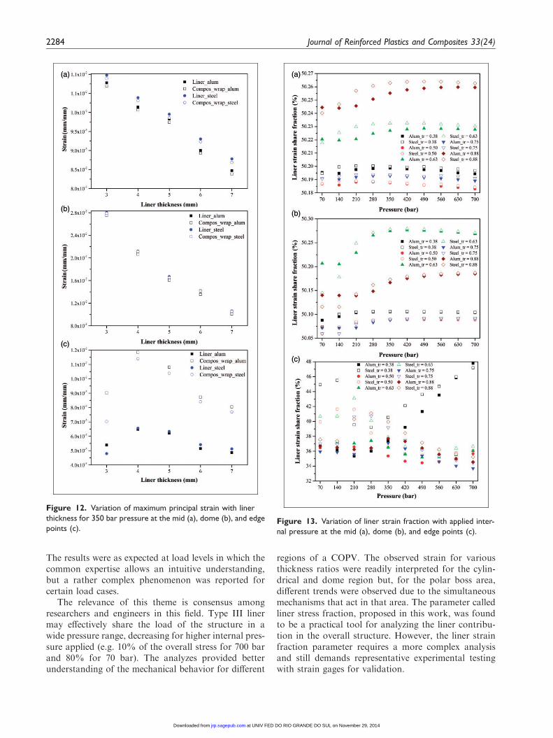
The variation in liner stress fraction with internalpressure (up to 700 bar) at the selected regions isshown in Figure 8. It can be seen that the liner stressfraction decreases with pressure for the whole range ofthickness ratio studied. It can also be concluded that:(i) in the mid-point (Figure 8(a)), the liner stress frac-tion varies coherently and tends asymptotically to afraction of around 10% for all thickness ratios; (ii)the liner material influences load fraction up to a pres-sure of around 210 bar. For higher pressures, yieldstress of the liner is reached, and its contribution tothe structure gradually reduces; (iii) for the mid- anddome-point (Figure 8(a) to (b)), the liner share stressdisplays a decreasing trend; (iv) the stainless steel linershared a greater portion of the load in the structurethan the aluminum one; and (v) the behavior at theedge-point (Figure 8(c)) was more complex, and aclear trend for the variation in liner stress fractioncould not be identified. In this case (edge-point),stress concentrations and, in particular, plasticity ofthe liners seem to govern the overall contribution.
The stress fraction at the dome-point was the highestamong the evaluated regions, reaching 80% for theSteel_tr¼ 0.38 and Steel_tr¼ 0.50 specimens at 70 bar(Figure 8). Here again the elasto-plasticity of the iso-tropic liner and the increase in winding angles of thecomposite contributed to that. These results are inagreement with those of Kabir,15 who found thatincorporation of a liner decreased maximum stress(from 460 to 330MPa) in a compositeoverwrapped metallic liner structure. For a stiff liner,the load sharing is remarkable, reducing observed max-imum stress.
Figure 7. Von Mises stress variation with liner thickness for
350 bar at the mid (a), dome (b), and edge points (c).
2280 Journal of Reinforced Plastics and Composites 33(24)
at UNIV FED DO RIO GRANDE DO SUL on November 29, 2014jrp.sagepub.comDownloaded from
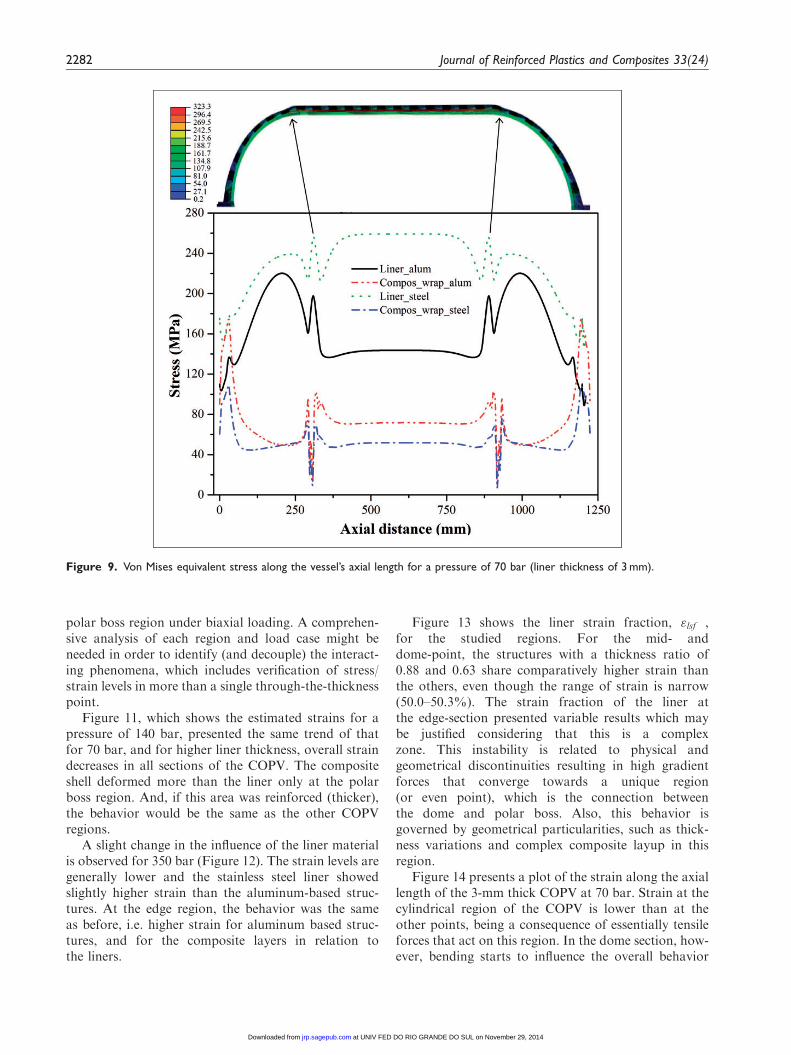
For a better understanding of the aforementionedresults, Figure 9 shows a plot of the von Mises equiva-lent stress along the length of the vessel with linerthickness of 3mm under an internal pressure of 70bar. The dome-point was selected to coincide withthe peak point for the liner curve profiles presentedin Figure 9. Liner material shows a strong effect onthe stress at this pressure, and the steel liner yields
higher stresses than the aluminum one due to thehigher stiffness of the steel. Also because of that,stress at the mid-point is lower than at the dome sec-tion for the aluminum liner, whereas for the stainlesssteel liner they are similar. Stress in the compositeshells varies accordingly, being higher when thestress in the liner is lower.
Mention must be given to the geometrical singularitythat occurs at the connection between cylindrical-domeregions, coincidentally at the end of the hoop layer,becoming an overstress on this point, due to lack ofreinforcing layers with nominal angle at this region. Aconvergence study was carried out to check for a pos-sible mathematical singularity in this point, but thatwas not seen.
Load bearing liners are designed to carry one-thirdto one-half of the overall internal pressure load whilstin the elastic regime. An overwrapped pressure vesselexhibits a non-uniform distribution of stresses andstrains owing to a number of factors, including: thevariations in liner geometry and its interaction withthe composite overwrap, the relative stiffness betweenliner and overwrap, the liner-overwrap interface slipfeatures, and infeasible curvature variations.16
For type III vessels, Elament stress–strain behavioris linear elastic until the ultimate strain and even closeto bursting. Nevertheless, during pressurization, themetallic liner shows yield and plastic Fow, as the lineris pushed towards the Elaments that try to return (elas-tically) to their original size. Thus, at zero or low pres-sures the metal is under compression and the Elamentsare in tension. Thus, the metal operates from compres-sion to tension while the Elaments operate in a tension–tension mode.13
Strain analysis
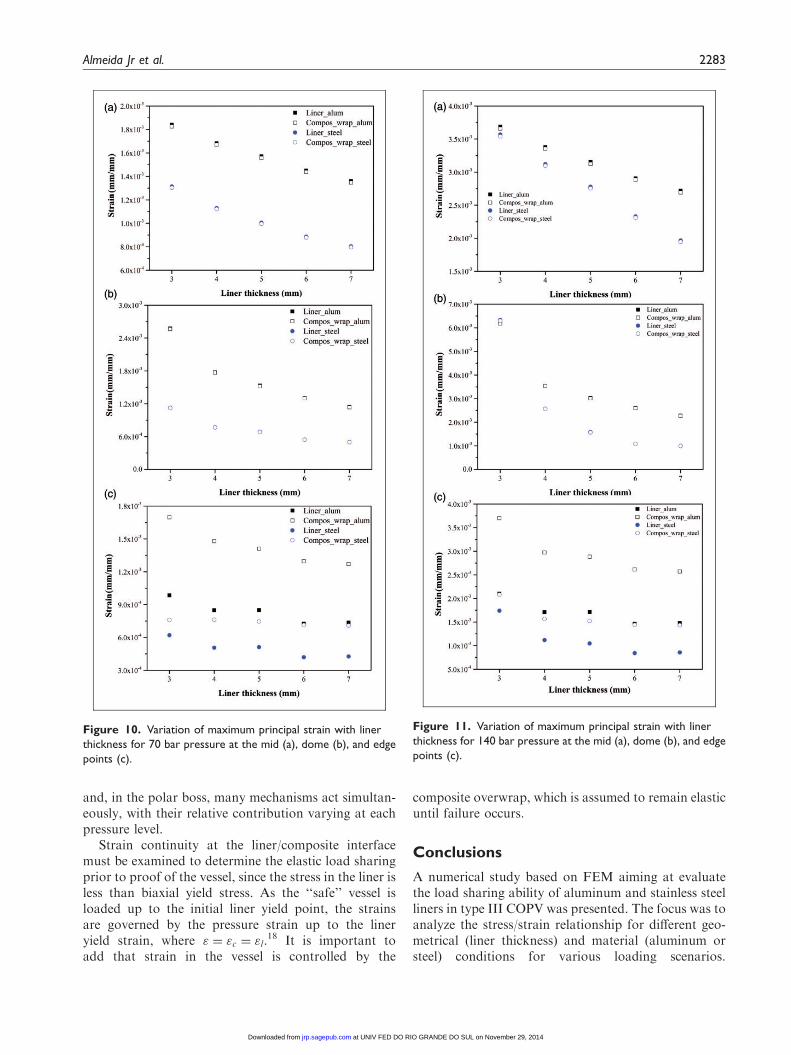
The strain level of the COPV was evaluated for thesame regions and pressure levels previously shown.Figure 10 presents the maximum principal strain fordifferent liner thickness at a pressure of 70 bar.Figure 10(a) to (b) indicates similar results for theliner (aluminum or steel) and the respective compositeoverwrap. A higher strain for the aluminum basedCOPV is seen due to their lower strain at break.Figure 10(c) also evidences this trend, with higherdeformation for aluminum liners, but the strain levelswere different for the liners and the respective compos-ite overwrap since the composite deformed more thanthe liner. As cited by Park et al.,17 the internal pressureacting across the polar opening must be fully trans-ferred to the structure within the boss flange and there-fore the dome–polar boss interface is a highly stressedarea. Still according to these authors, compression, ten-sile, bending, and moment act simultaneously in the
Figure 8. Variation of liner stress fraction (scanning of 10
frames) with the applied internal pressure at the mid (a), dome
(b), and edge points (c).
Almeida Jr et al. 2281
at UNIV FED DO RIO GRANDE DO SUL on November 29, 2014jrp.sagepub.comDownloaded from
polar boss region under biaxial loading. A comprehen-sive analysis of each region and load case might beneeded in order to identify (and decouple) the interact-ing phenomena, which includes verification of stress/strain levels in more than a single through-the-thicknesspoint.
Figure 11, which shows the estimated strains for apressure of 140 bar, presented the same trend of thatfor 70 bar, and for higher liner thickness, overall straindecreases in all sections of the COPV. The compositeshell deformed more than the liner only at the polarboss region. And, if this area was reinforced (thicker),the behavior would be the same as the other COPVregions.
A slight change in the influence of the liner materialis observed for 350 bar (Figure 12). The strain levels aregenerally lower and the stainless steel liner showedslightly higher strain than the aluminum-based struc-tures. At the edge region, the behavior was the sameas before, i.e. higher strain for aluminum based struc-tures, and for the composite layers in relation tothe liners.
Figure 13 shows the liner strain fraction, "lsf ,for the studied regions. For the mid- anddome-point, the structures with a thickness ratio of0.88 and 0.63 share comparatively higher strain thanthe others, even though the range of strain is narrow(50.0–50.3%). The strain fraction of the liner atthe edge-section presented variable results which maybe justified considering that this is a complexzone. This instability is related to physical andgeometrical discontinuities resulting in high gradientforces that converge towards a unique region(or even point), which is the connection betweenthe dome and polar boss. Also, this behavior isgoverned by geometrical particularities, such as thick-ness variations and complex composite layup in thisregion.
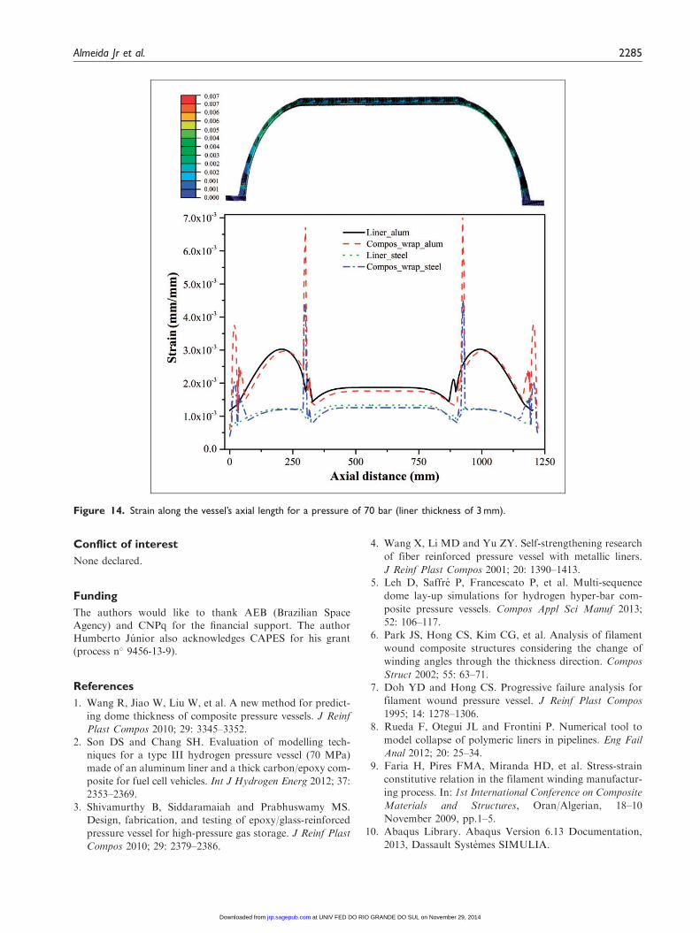
Figure 14 presents a plot of the strain along the axiallength of the 3-mm thick COPV at 70 bar. Strain at thecylindrical region of the COPV is lower than at theother points, being a consequence of essentially tensileforces that act on this region. In the dome section, how-ever, bending starts to influence the overall behavior
Figure 9. Von Mises equivalent stress along the vessel’s axial length for a pressure of 70 bar (liner thickness of 3 mm).
2282 Journal of Reinforced Plastics and Composites 33(24)
at UNIV FED DO RIO GRANDE DO SUL on November 29, 2014jrp.sagepub.comDownloaded from
and, in the polar boss, many mechanisms act simultan-eously, with their relative contribution varying at eachpressure level.
Strain continuity at the liner/composite interfacemust be examined to determine the elastic load sharingprior to proof of the vessel, since the stress in the liner isless than biaxial yield stress. As the ‘‘safe’’ vessel isloaded up to the initial liner yield point, the strainsare governed by the pressure strain up to the lineryield strain, where " ¼ "c ¼ "l.
18 It is important toadd that strain in the vessel is controlled by the
composite overwrap, which is assumed to remain elasticuntil failure occurs.
Conclusions
A numerical study based on FEM aiming at evaluatethe load sharing ability of aluminum and stainless steelliners in type III COPV was presented. The focus was toanalyze the stress/strain relationship for different geo-metrical (liner thickness) and material (aluminum orsteel) conditions for various loading scenarios.
Figure 10. Variation of maximum principal strain with liner
thickness for 70 bar pressure at the mid (a), dome (b), and edge
points (c).
Figure 11. Variation of maximum principal strain with liner
thickness for 140 bar pressure at the mid (a), dome (b), and edge
points (c).
Almeida Jr et al. 2283
at UNIV FED DO RIO GRANDE DO SUL on November 29, 2014jrp.sagepub.comDownloaded from
The results were as expected at load levels in which thecommon expertise allows an intuitive understanding,but a rather complex phenomenon was reported forcertain load cases.
The relevance of this theme is consensus amongresearchers and engineers in this field. Type III linermay effectively share the load of the structure in awide pressure range, decreasing for higher internal pres-sure applied (e.g. 10% of the overall stress for 700 barand 80% for 70 bar). The analyzes provided betterunderstanding of the mechanical behavior for different
regions of a COPV. The observed strain for variousthickness ratios were readily interpreted for the cylin-drical and dome region but, for the polar boss area,different trends were observed due to the simultaneousmechanisms that act in that area. The parameter calledliner stress fraction, proposed in this work, was foundto be a practical tool for analyzing the liner contribu-tion in the overall structure. However, the liner strainfraction parameter requires a more complex analysisand still demands representative experimental testingwith strain gages for validation.
Figure 13. Variation of liner strain fraction with applied inter-
nal pressure at the mid (a), dome (b), and edge points (c).
Figure 12. Variation of maximum principal strain with liner
thickness for 350 bar pressure at the mid (a), dome (b), and edge
points (c).
2284 Journal of Reinforced Plastics and Composites 33(24)
at UNIV FED DO RIO GRANDE DO SUL on November 29, 2014jrp.sagepub.comDownloaded from
Conflict of interest
None declared.
Funding
The authors would like to thank AEB (Brazilian SpaceAgency) and CNPq for the financial support. The authorHumberto Junior also acknowledges CAPES for his grant
(process n� 9456-13-9).
References
1. Wang R, Jiao W, Liu W, et al. A new method for predict-
ing dome thickness of composite pressure vessels. J Reinf
Plast Compos 2010; 29: 3345–3352.2. Son DS and Chang SH. Evaluation of modelling tech-
niques for a type III hydrogen pressure vessel (70 MPa)
made of an aluminum liner and a thick carbon/epoxy com-
posite for fuel cell vehicles. Int J Hydrogen Energ 2012; 37:
2353–2369.
3. Shivamurthy B, Siddaramaiah and Prabhuswamy MS.
Design, fabrication, and testing of epoxy/glass-reinforced
pressure vessel for high-pressure gas storage. J Reinf Plast
Compos 2010; 29: 2379–2386.
4. Wang X, Li MD and Yu ZY. Self-strengthening research
of fiber reinforced pressure vessel with metallic liners.
J Reinf Plast Compos 2001; 20: 1390–1413.5. Leh D, Saffre P, Francescato P, et al. Multi-sequence
dome lay-up simulations for hydrogen hyper-bar com-
posite pressure vessels. Compos Appl Sci Manuf 2013;
52: 106–117.
6. Park JS, Hong CS, Kim CG, et al. Analysis of filament
wound composite structures considering the change of
winding angles through the thickness direction. Compos
Struct 2002; 55: 63–71.7. Doh YD and Hong CS. Progressive failure analysis for
filament wound pressure vessel. J Reinf Plast Compos
1995; 14: 1278–1306.8. Rueda F, Otegui JL and Frontini P. Numerical tool to
model collapse of polymeric liners in pipelines. Eng Fail
Anal 2012; 20: 25–34.
9. Faria H, Pires FMA, Miranda HD, et al. Stress-strain
constitutive relation in the filament winding manufactur-
ing process. In: 1st International Conference on Composite
Materials and Structures, Oran/Algerian, 18–10
November 2009, pp.1–5.
10. Abaqus Library. Abaqus Version 6.13 Documentation,
2013, Dassault Systemes SIMULIA.
Figure 14. Strain along the vessel’s axial length for a pressure of 70 bar (liner thickness of 3 mm).
Almeida Jr et al. 2285
at UNIV FED DO RIO GRANDE DO SUL on November 29, 2014jrp.sagepub.comDownloaded from
11. Akula VMK and Shubert MK. Nonlinear FEA of com-posite overwrapped pressure vessels. In: American Societyof Composites-28th Technical Conference, State College/
Pennsylvania, 9–13 September 2013, pp.1–14.12. Kaw AK. Mechanics of composite materials. Boca Raton/
Florida, USA: CRC Press, 2006.13. Peters ST, Humphrey WD and Foral RF. Filament wind-
ing: Composite structure fabrication. Covina, CA:SAMPE Publishers, 2000.
14. Lin D, Hsieh J-C, Chindakham N, et al. Optimal design
of the composite laminate hydrogen storage vessel. Int JEnerg Res 2013; 37: 761–768.
15. Kabir MZ. Finite element analysis of composite pressure
vessels with a load sharing metallic liner. Compos Struct2000; 49: 247–255.
16. Kim C and White SR. Continuous curing
and induced thermal stresses of a thick filament wound
composite cylinder. J Reinf Plast Comp 2001; 20:
166–180.17. Park J-S, Kim C-U, Kang H-K, et al. Structural analysis
and strain monitoring of the filament wound motor case.
J Compos Mater 2002; 36: 2373–2388.
18. Thesken JC, et al. A theoretical investigation of composite
overwrapped pressure vessel (COPV) mechanics applied to
NASA full scale tests. National Aeronautics and Space
Administration. Technical report no. NASA/
TM—2009-215684.
2286 Journal of Reinforced Plastics and Composites 33(24)
at UNIV FED DO RIO GRANDE DO SUL on November 29, 2014jrp.sagepub.comDownloaded from
Related Documents


