July 10, 2019 Volume 1, Issue 1 Pages 1-37 JOURNAL OF MECHANICAL ENGINEERING & ALLIED SCIENCES About the Cover: Pedicle screw rod systems are commonly used for treating spinal instability and low back pain mainly caused due to degeneration disc disease (DDD) or fracture. Computed Tomography (CT) scan of thresholding & 3D model created in MIMICS. In this issue: Spotlights Articles

Welcome message from author
This document is posted to help you gain knowledge. Please leave a comment to let me know what you think about it! Share it to your friends and learn new things together.
Transcript
July 10, 2019 Volume 1, Issue 1 Pages 1-37
JOURNAL OF MECHANICAL ENGINEERING & ALLIED
SCIENCES
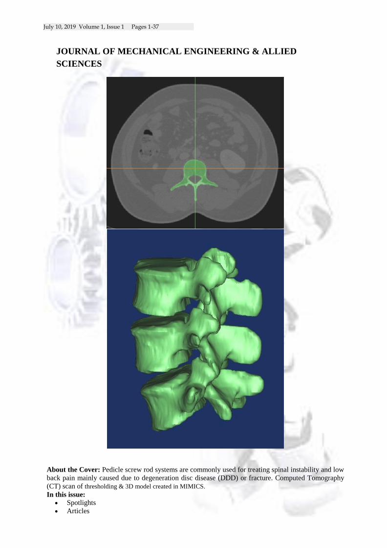
About the Cover: Pedicle screw rod systems are commonly used for treating spinal instability and low
back pain mainly caused due to degeneration disc disease (DDD) or fracture. Computed Tomography
(CT) scan of thresholding & 3D model created in MIMICS.
In this issue:
Spotlights
Articles
July 10, 2019 Volume 1, Issue 1 Pages 1-37
JOURNAL OF MECHANICAL ENGINEERING & ALLIED
SCIENCES
Journal is Peer Reviewed (Refereed) and seeks to publish a balanced mix of high quality theoretical or empirical research articles, case studies, book reviews, editorials as well as pedagogical and curricular issues surrounding science and engineering fields.
Call for Paper(s)
We will continue to strengthen our Journals as a helpful research source for scholars, researchers and students. We courteously invite you to submit your research papers(s) using online submission process. If you feel any difficulty please feel free to mail at [email protected] with journal name in subject line
Call for Editors
We courteously invite you as an editor for our journal(s). Submit your short bio, background, and some information to [email protected]
JOURNAL OF MECHANICAL ENGINEERING & ALLIED
SCIENCES
Journal of MECHANICAL ENGINEERING & ALLIED SCIENCES is an open access journal that
publishes articles which contribute to new results. The main aim of JMEAS is to publish refereed, original
research articles, and studies that describe the latest research and developments in the area of computer
engineering & science.
.
Editorial Office:
Department of Mechancial Engineering
JIS College of Engineering
Block A, Phase-III
Kalani, Nadia, West Bengal, India
Print ISSN :
VIEW JOURNAL | CURRENT ISSUE | CONTACT US

July 10, 2019 Volume 1, Issue 1 Pages 1-37
JOURNAL OF MECHANICAL ENGINEERING & ALLIED
SCIENCES
Editorial Board
Sr. No.
Member Name Affiliation/Address Email Editorial/Advisory /Reviewer Board
1 Dr. Dipankar Sanyal Prof., Dep. of Mechanical Engineering, Jadavpur University
Editorial
2 Dr. Sanchyan Mukherjee
Asso. Prof. , Dep. of Mechanical Engineering, Kalayni Govt. Engg. College
Editorial
3 Dr. Santanu Das Prof. Dep. of Mechanical Engineering, Kalayni Govt. Engg. College
Editorial
4 Dr. Sandip Ghosh Asso. Prof. Dep. of Mechanical Engineering, JIS College of Engineering
Editorial
5 Dr. B. Oraon Prof., Dep. of Mechanical Engineering, Jadavpur University
Editorial
6 Dr. Jayanta Biswas Asst. Prof. Dep. of Mechanical Engineering, JIS College of Engineering
Reviewer
7 Dr. Anal Ranjan Sengupta
Asst. Prof. Dep. of Mechanical Engineering, JIS College of Engineering
Reviewer

July 10, 2019 Volume 1, Issue 1 Pages 1-37
4
JOURNAL OF MECHANICAL ENGINEERING & ALLIED
SCIENCES
Index:
1 Spotlights of the Journal by the Editor
5
2 Ligamentous Lumbar Spine Model for Studying the Response of Natural and Pedicle Screw Implanted Vertebrae: A Finite Element Study Jayanta Kr Biswas, Masud Rana, Anal Ranjan Sengupta, Shishir Kr Biswas, Subhasish Halder, Anirban Sarkar, Palash Biswas
6-13
3 DRY GRINDING WITH SILICON CARBIDE WHEEL: A RVIEW Manish Mukhopadhyay, Ayan Banerjee2, Arnab Kundu, Sirsendu Mahata, Bijoy Mandal and Santanu Das
14-18
4 OPTIMIZING TITANIUM GRINDING WITH CONVENTIONAL WHEELS Ayan Banerjee, Manish Mukhopadhyay, Arnab Kundu, Sirsendu Mahata, Bijoy Mandal and Santanu Das
19-22
5 ASSESSING GRINDABILITY OF INCONEL USING ALUMINA WHEEL
Arnab Kundu1, Ayan Banerjee2, Manish
Mukhopadhyay3, Sirsendu Mahata4, Bijoy Mandal5
and Santanu Das6
23-27
6 Optimization of Process Parameters of Miniature Spur Gear in Wire-cut EDM of Inconel-718 T. Paul, S. Chakraborty, and D. Bose
28-33
7 Investigation of the performances H-rotors at low wind velocities A.R. Sengupta, J.K. Biswas, S. Biswas
34-37

July 10, 2019 Volume 1, Issue 1 Pages 1-37
5
Spotlights of the Journal
by the Editor Major focus of this journal has been nurturing ideas and little innovations taking place in
smaller laboratories across the states in this country. In this first the thrust areas identified are
biomechanical systems, their applicability, solutions as well suitable characterizations of
various mechanical systems. Main objective is to promote research that provides solutions to
societal problems and make livelihood of human being improved and sustainable

6
Ligamentous Lumbar Spine Model for Studying the Response of Natural
and Pedicle Screw Implanted Vertebrae: A Finite Element Study
Jayanta Kr Biswas*1, Masud Rana
2, Anal Ranjan Sengupta
1, Shishir Kr Biswas
1, Subhasish Halder
1,
Anirban Sarkar1, Palash Biswas
1
Department of Mechanical Engineering, JIS College of Engineering, Kalyani, West Bengal,Nadia –741235,
India
Department of Aerospace Engineering & Applied Mechanics, Indian Institute of Engineering Science and
Technology, Shibpur, Howrah-711103, India
*Email- [email protected]
ABSTRACT
Pedicle screw rod systems are commonly used for treating spinal instability and low back pain mainly
caused due to degeneration disc disease (DDD) or fracture. Finite element (FE) method is a useful
tool to analyze the problems related to spinal degeneration disease.Different FE studies of spinal
instability have been performed with different degrees of precision. Our objective of this study is to
find out the effect of ligaments on FE analysis of natural spine model and spine model with pedicle
screw fixation from the viewpoint of Range of Motion (ROM). Computed Tomography (CT) scan
data is used to develop finite element model of spine. Finite element models with and without
ligaments of a natural L3-L5 lumbar vertebrae and L3-L5 lumbar vertebrae with pedicle screw
fixation are developed. ROM for flexion and extension are calculated under bending moments of 2, 4,
6, 7.5, 10 Nm only and under a compressive force of 500N coupled with same bending moments. The
finite element analyses show that the ROM of natural spine is about 50% higher than that of natural
spine with ligaments. But in case of spine model with pedicle screw fixation, only 2% difference of
ROM is observed.
Keywords: Lumbar Spine, Finite Element Analysis, Pedicle Screw, Ligament
INTRODUCTION
The functions of the spine are to provide flexibility, support of the upper body weight, and protect the spinal
cord and nerve roots. Spine contains a series of 24 vertebral bones connected by nearly 75 joints that control
motion in three planes, flexion- extension, axial rotation and lateral bending. Degenerative disc disease (DDD)
and severe external loads may cause compression on nerves and make the spine become unstable, which cause
lower back pain and affect the ROM of spinal column. Most humans, aged 30 years and more, show
degenerative changes in the inter-vertebral discs [1]. One of the major medical remedy for this kind of problem
is arthrodesis (fusion), which is an effective tool in the management of a wide variety of spinal instabilities and
painful conditions [2,3,4]. Pedicle screw fixation (fusion) is one of the major and widely used surgical remedy
for treating these conditions [5]. Pedicle screws are the strongest component compared to other spinal implants
and are becoming more popular [6,7]. Ligaments attached to the vertebrae reduce excessive motion of spine and
provide stability [8]. But it is very complex process to include ligaments in the model.
Finite element analysis (FEA) is an effective tool to analyze the processes which are difficult to beclarified by
experimental methods. It allows new design to be tested before a prototype is manufactured. FEA technique has
the potential to reduce costs and to save time during the development of new effective spinal treatment methods
or implants [9,10,11]. There is a need to obtain realistic and perfect models for the human spine. The FEA of the
spine under various loading conditions is helpful in predicting the success of an implant and future risk of
fracture.

7
OBJECTIVE The aim of the study was to develop finite element models of lumbar vertebrae (L3-L5), with and without
ligaments and the same with pedicle screw fixation using Computed Tomography (CT) scan data and to study
the ROM in that region. The objective of this study was: i) to understand the importance of considering
ligaments in finite element modeling of lumbar spine. ii) to calculate the ROM for flexion and extension under
various loading conditions.
METHODS
The geometry of the L3-L4-L5 lumbar spine model is constructed through use of computed tomography (CT)
images in the DICOM format of total 175 slices, with a slice space of 1mm. CT slices are usedwith MIMICS
14.0 (Technologielaan 15, B-3001 Leuven, Belgium) software to create the lumbar spine. These CT slices are
threshold within the gray value of the lumber vertebra bone. The area file, created with MIMICS,is exported to
finite element package ANSYS,Inc14.0 (Southpointe, 275 Technology Drive Canonsburg, PA 15317) to create
3D volume.
Fig.1: CT scan image thresholding.
Fig.2: 3D model created in MIMICS.
The inter-vertebral discsare modeled manually between L3-L4 vertebrae and L4-L5 vertebrae.Tetrahedral solid
element was selected for discretization process. MIMICS is used formaterial propertiesassignment. Material
properties of different parts of the bone are given in the following table.

8
Table1: Material properties of different parts of the bone.
Components Material properties
Cortical shell E= 12000 MPa, = 0.3 [12]
Posterior Bone E= 3500 MPa, = 0.25 [12]
Cancellous bone This material properties is
taken from MIMICS
Bone Graft E= 12000 MPa, = 0.3 [12]
Fig. 3: Stress-strain curve used for intervertebral disc [13].
Rod and the screws are also modeled and mesh all volume using element SOLID 92. The material properties
and dimensions of the rod and screw are given in the table.
Material Young’s
modulus
(MPa)
Poisson’s
ratio
Dia
(mm)
Length
(mm)
Stainless
Steel
180000 0.3 6 35
Table 2: Material properties and dimensions of the screw [14].
Material Young’s
modulus
(MPa)
Poisson’s
ratio
Dia
(mm)
Length
(mm)
Stainless
Steel
180000 0.3 4 58
Table 3: Material properties and dimensions of the rod [14].
Ligaments Young'sModulus (MPa) Poisson'sratio Area(mm2
Anterior longitudinal ligament (ALL) 20 0.3 63.7
Posterior longitudinal ligament (PLL) 20 0.3 20
Ligamentum flavum (LF) 19.5 0.3 40
Interspinous ligament (ISL) 12 0.3 40
Supraspinous ligament (SSL) 15 0.3 30
Intertransverse ligament (ITL) 59 0.3 1.8
Facet capsulary ligament (FCL) 33 0.3 30
Table 4: Material properties of ligaments [15,16].
All the four models (natural lumbar with and without ligaments & pedicle screw fixation with and without
ligaments) are subjected to bending moment of 2,4,6,7.5 and 10Nm applied on L3 and a compressive load of
500N applied on the superior surface of L3 coupled with the same bending moments for flexion and extension.
The inferior surface of the L5 vertebral body is completely fixed in all directions.The ROMbetween L3-L5are
examined andcompared.
0
2
4
6
0 0.2 0.4 0.6
Str
ess
(MP
a)
Strain

9
Fig.7: Boundary conditions applied.
Calculation of Range of Motion:-
To find out the Range of motion between the vertebrae, three nodes nearest to the center of gravity selected
which lie in the X-Z plane and these three nodes create a plane. Another new plane is generated after
deformation taking same none.The angle between two planes is equal to the angle between their normal vectors.
A1x + B1y + C1z + D1 = 0 for plane before deformation
and A2x + B2y + C2z + D2 = 0 for plane after deformation
then the angle between two planes found by using the following formula
cos α = |A1·A2 + B1·B2 + C1·C2|
√A12 + B1
2 + C1
2 √A2
2 + B2
2 + C2
2
The angle between these two planes is calculated using a C program with the software Turbo C++.
RESULTS
To find out the angle between L3-L5, the node nearest to the center of gravity is selected first. Another two
nodes are selected which lie in the X-Z plane containing that node. These three nodes create a plane and another
new plane is generated after deformation. The angle between these two planes is calculated using a C program
with the software Turbo C++. The ROM of all the models under different loading conditions are shown below.
Fig.8: ROM of natural spine under bending moments only.
-40
-20
0
20
40
-10 -6 -2 4 7.5
Ran
ge o
f M
oti
on
(D
eg)
Bending Moment (Nm)
Without Ligament
With Ligament

10
Fig.9: ROM of natural spine under compressive load coupled with bending moments.
Fig.10: Comparison of ROMs for natural lumbar spine.
Fig.11: ROM of spine with pedicle screw under bending moments only.
-20
-10
0
10
20
30
40
-10 -6 -2 4 7.5
Ran
ge o
f M
oti
on
(D
eg)
Bending Moment (Nm)
Without Ligament
With Ligament
-30
-20
-10
0
10
20
30
40
-20 -10 0 10 20
Ran
ge o
f M
oti
on
(D
eg)
Bending Moment (Nm)
Coupled Load with Ligament
Only Bending Moment without LIgament
Coupled Load without Ligament
Only Bending Moment with Ligament
-1
-0.5
0
0.5
1
-10 -7.5 -6 -4 -2 2 4 6 7.5 10
Ra
ng
e o
f M
oti
on
(D
eg)
Bending Moment (Nm)
With Ligament
Without Ligament

11
Fig.12: ROM of spine with pedicle screw under compressive load coupled with bending moments.
Fig.13: Comparison of ROMs for implanted lumbar spine.
The results of the compressive load coupled with bending moments applied on natural lumbar spinewith
ligaments are compared with the experimental data of Panjabi et al. (1994). From this comparison it is clear that
the results are almost same except the results of extension for 2 and 4Nm.
Fig.14: Deformed shape with undeformed model for extension and flexion.
00.5
11.5
22.5
33.5
1 2 3 4 5 6 7 8 9 10
Ran
ge o
f M
oti
on
(D
eg)
Bending Moment (Nm)
Without Ligament
With Ligament
-1.5
-1
-0.5
0
0.5
1
1.5
2
2.5
3
3.5
-20 -10 0 10 20
Ra
ng
e o
f M
oti
on
(D
eg)
Bending Moment (Nm)
Only bending moment with ligament
Only bending moment without ligament
Coupled load with ligament
Coupled load without ligament

12
Fig. 15: ROM of natural spine under compressive load coupled with bending moments.
CONCLUSIONS
From the results of the numerical solutions, the following conclusions may be drawn:
Ligaments play an important role in finite element analysis of natural lumbar spine. About 50% more ROM is
observed in every case.
Ligaments have no significant effect on ROM of a lumbar spine model with pedicle screw implant. Only 2%
difference is found in every case.
Under compressive load on the implanted model no backward motion is found even under 10Nm backward
bending moment.
REFERENCES
1. Antonius Rohlmann, Thomas Zander, Hendrik Schmidt,Hans-Joachim Wilke, Georg Bergmann, 2006,
―Analysis of the influence of disc degeneration on the mechanical behaviour of a lumbar motion segment
using the finite elementmethod‖, Journal of Biomechanics, 39 2484–2490.
2. K. K Lee, E. C. Teo, F. K. Fuss, V. Vanneuville, T. X. Qiu, H. W. Ng, K. Yang, and R. J. Sabitzer 2004,
―Finite-Element Analysis for Lumbar Interbody Fusion Under Axial Loading‖, IEEE Transactions on
Biomedical Engineering, Vol. 51, No. 3.
3. GuilhemDenoziere, David N. Ku, 2006 ―Biomechanical comparison between fusion of two vertebrae and
implantation of an artificial intervertebral disc‖, Journal of Biomechanics 39 766–775.
4. Jeremy J. Reid, Jared S. Johnson, Jeffrey C. Wang, 2011, ―Challenges to bone formation in spinal fusion‖,
Journal of Biomechanics 44 213–220.
5. Kuo-Hua Chao et al., 2013, ―Biomechanical analysis of different types of pedicle screw augmentation: A
cadaveric and synthetic bone sample study of instrumented vertebral specimens‖, Medical Engineering &
Physics 35 1506– 1512.
6. Antonius Rohlmann, Hadi Nabil Boustani, Georg Bergmann, Thomas Zander, 2010, ―Effect of a pedicle-
screw-based motion preservation system on lumbar spine biomechanics: A probabilistic finite element study
with subsequent sensitivity analysis‖, Journal of Biomechanics 43 2963–2969.
7. Ahn, Y.H., Chen, W.M., Lee, K.Y., Park, K.W., Lee, S.J., 2008, ―Comparison of the loadsharing
characteristics between pedicle-based dynamic and rigid rod devices‖ Biomedical Materials 3, 44101.
-10
-5
0
5
10
15
20
25
-10 -7.5 -6 -4 -2 2 4 6 7.5 10
Ran
ge o
f M
oti
on
(D
eg)
Bending Moment (Nm)
Panjabi et al. (1994)
Numerical Results

13
8. Frank Heuer, Hendrik Schmidt, ZdenekKlezl, Lutz Claes, Hans-Joachim Wilke, 2007, ―Stepwise reduction
of functional spinal structures increase range of motion and change lordosis angle‖, Journal of
Biomechanics 40 271–280.
9. Goel, V. K., & Gilbertson, L. G., 1995, ―Applications of the finite element method to thoracolumbar spinal
research-past, present, and future”, Spine, 20, 1719–1727.
10. Goel, V. K., Monroe, B. T., Gilbertson, L. G., &Brinkmann, P. 1995, ―Interlaminar shear stress and
laminae separation in a disc. Finite elementanalysis of the L3–L4 motion segment to axial compressive
loads‖, Spine, 20, 689–698.
11. Rohlmann, A., Bergmann, G., Graichen, F., &Klockner, C. 1999, ―Influence of internal spinal fixators
stiffness on stresses in the adjacent intervertebral discs‖, European Spine Journal, 8(Suppl), 7.
12. Goel, V.K., Ramirez, S.A., Kong, W., Gilbertson, L.G.,1995, ―Cancellous bone young’s modulus variation
within the vertebral body of a ligamentous lumber spine- application of bone adaptive remodeling
concepts‖, Journal of Biomechanical Engineering; 117, 266-271.
13. WANG Yi, CHEN Hai-bin, ZHANG Ling, ZHANG Li-ying, LIU Jing-cheng and WANG Zheng-guo,
2012, ―Influence of degenerative changes of intervertebral disc on its material properties and pathology‖,
Chinese Journal of Traumatology 2012;15(2):67-76.
14. Jayanta Biswas, SantanuKarmakar,SantanuMajumder,ParthaSarathi Banerjee,SubrataSaha,& Amit
Roychowdhury, 2014, ―Optimization of Spinal Implant Screw for Lower Vertebra through Finite Element
Studies‖, Journal of Long-Term Effects of Medical Implants, 24(2–3): 99–108.
15. Dong Suk Shin, Kunwoo Lee, Daniel Kim, 2007, ―Biomechanical study of lumbar spine with dynamic
stabilization device using finite element method‖, Computer-Aided Design 39 559–567.
16. Yang-HweiTsuang, Yueh-Feng Chiang, Chih-Yi Hung, Hung-Wen Wei, Chang-Hung Huang, Cheng-Kung
Cheng, 2009, ―Comparison of cage application modality in posterior lumbar interbody fusion with
posterior instrumentation—A finite element study‖, Medical Engineering & Physics 31 565–570.
17. Panjabi, M.M., Oxland, T.R., Yamamoto, I., Crisco, J.J., 1994, ―Mechanical behavior of the human lumbar
and lumbosacral spine as shown by three dimensional load–displacement curves”, American Journal of
Bone and Joint Surgery 76, 413–424.

14
DRY GRINDING WITH SILICON CARBIDE WHEEL: A REVIEW Manish Mukhopadhyay
1, Ayan Banerjee
2, Arnab Kundu
3, Sirsendu Mahata
4, Bijoy Mandal
5 and Santanu Das
6
Department of Mechanical Engineering,
Kalyani Government Engineering College,Kalyani, Nadia-741235
Email: 1 [email protected],
Abstract: Titanium alloys find their application in a variety of engineering fields, namely in aerospace, automotive, petrochemical and biomedical industry, due to their properties like high corrosive
resistance, low specific gravity, high specific strength, non magnetic property and bio compatibility.
However, this material is hard to grind owing to its low thermal conductivity, high hardness at elevated
temperature and high chemical reactivity resulting in high force requirement, severe wheel loading, high
grinding ratio, etc. For these reasons, proper selection of cutting parameters like wheel speed, table feed
and infeed (depth of cut) plays a significant role. The present experimental investigation is aimed at finding
better grinding parameters, comparing two different infeed values. Grinding forces, surface roughness,
grinding chip forms and ground surface morphology are observed in case of surface grinding of
Titanium Grade 1 using silicon carbide wheel, under dry condition. The results suggest that grinding
forces as well as surface roughness values increase with increase in infeed value.
Keyword:Grinding, Titanium Grade 1, Silicon Carbide Wheel, Grinding Ratio, Surface Roughness.
I. Introduction
Grinding is a material removal process, generally used to shape and finish components made of metals and other materials. Grinding is a widely used machining process in industry for surface smoothing and finishing. The precision and surface finish obtained through grinding can be up to ten times better than that with either turning or milling. Grinding employs an abrasive tool, usually in the form of a rotating wheel brought into controlled contact with a work surface [1], [2]. Grinding is one of the most complex manufacturing processes with respect to material removal. Although classified as a conventional machining process, it differs significantly from the more traditional processes like milling, drilling and turning, as the material is removed by undefined cutting edges. With high negative rake angle, the material removal in grinding occurs with a very large number of these undefined cutting edges, whose shape, orientation and distribution are random due to the manufacturing process of the grinding wheel. The cutting edges are the protruding geometry of hard abrasive grains which are immersed in a bond structure forming a grinding wheel. It is the random nature of these grains and their interactions with the work material that make the process so complex [3]. Progress of the science and technology has called for a great variety of materials with diversified properties, and various new materials such as hardened steel, titanium alloy, nickel based alloy, etc. have been developed and applied continuously. These materials are generally difficult to machine with low machinability rating, and machining of these materials is always a big challenge [4]. Among these materials Titanium and its alloys are a big hit in manufacturing industry. Titanium alloy is a high strength-to-weight ratio material with superior fatigue strength. It is non-magnetic, non-poisonous, corrosion-resistant and heat-resistant. These favourable properties have brought about its wide application in daily life and industry. However, from the machining view point, titanium alloy is chemically active, and the chips tend to adhere easily onto the wheel surface in grinding due to very high local temperature and pressure at the grinding zone. Machining and grinding of titanium and its alloys are difficult due to their chemical reactivity beyond 350o C, low thermal conductivity and high hot strength [5], [6]. Unlike grinding of conventional steels where heat generated spreads quickly from high temperature grinding zone, grinding heat gets accumulated during grinding of titanium alloys due to their low thermal conductivity. Grinding temperature rises sharply during initial wheel-work contact, attains a quasi-steady state with a long workpiece, and increases further when wheel-work is disengaged [7], [8]. Titanium grade 1 is a super alloy that is widely used in aeronautical industry for making airframe components, components of chemical desalination plants, cryogenic vessels, heat exchanger tubes, biomedical industry, petroleum industry, etc. [9], [10]. During grinding of titanium grade 1 alloy common problems such as surface damage, surface burn, intense wheel loading, etc are commonly reported [11], [12], [13]. Apart from that, problems like chip re-deposition might also occur on the job surface. This re-deposition creates progressively

15
Manish Mukhopadhyay, Ayan Banerjee, Arnab Kundu, Sirsendu Mahata, Bijoy Mandal and Santanu Das et al, experimental
investigation on grindability of titanium grade 1 using silicon carbide wheel under dry condition, Global Journal on Advancement in Engineering and Science, 2(1), March 2016, pp. 129-133
increasing surface damage with the increase in hardness of wheel [15]. Proper selection of grinding parameters plays a very significant role in this process. Selection of grinding wheel is also an important consideration. Dense wheels are suitable for harder material while less dense structure is better for softer materials. Bonding strength of grinding wheel is also important to withstand centrifugal forces, to resist shock loading of wheel and to hold abrasive grains rigidly [16]. According to Malkin [17] and Rowe [18], Silicon Carbide wheels are better suited for non ferrous materials like titanium. The present research work is aimed at finding the suitable infeed value for which better grinding results are observed when comparing two different infeed values. The experimental observations are made in case of plunge surface grinding of titanium grade 1 alloy using a silicon carbide wheel in dry condition. Analysis was done considering certain parameters such as force requirement, surface roughness, chip forms and ground surface morphology.
II. Experimental Procedures
Workpiece Material: The workpiece material used is titanium grade 1 alloy having hardness of 22 HRC and size 120 mm × 55 mm × 6 mm, whose composition is given in Table 1. It is a widely used alloy of titanium in aerospace and biomedical industry. The material has high impact toughness and is readily weldable. The material is capable of deep drawing, and used for plate, frame, and tube heat exchangers [19].
Table 1: Composition of titanium grade 1alloy.
Titanium Iron Oxygen Nitrogen
99.85 0.12 0.02 0.01
Experimental setup and measurement: Experiments are carried out on plunge surface grinding machine of HMT Praga division. Force readings are taken for 20 upgrinding passes at 10 and 20 micron infeed on Sushma made strain gauge type dynamometer. Grinding chip and ground surface morphology are observed under toolmakers microscope. Surface roughness values are measured on a portable surface roughness tester (Mitutoyo make). Details of experimental condition and equipment used are provided in Table 2.
Table 2: Experimental conditions and equipment used
Surface Grinding Machine Make : HMT Praga Division Model : 452 P Infeed Resolution : 1 µm Main Motor Power : 1.5 kW Maximum Spindle Speed : 2800 rpm
Grinding Wheel Make : Carborundum Universal Limited Type : Disc Type Size : 200 × 31.75 × 20 Specification : CGC 60 K 5 V
Workpiece Material : Titanium Grade 1 Dimension : 120 mm × 55 mm × 6 mm Hardness : 22 HRC
Environment Dry
Force Dynamometer Make : Sushma Grinding Dynamometer, Bengaluru Model : SA 116 Range : 0.1 – 100 kg Resolution : 0.1 kg
Wheel Dresser Make : Solar, India Specification : 0.5 carat Single Point Diamond Tip Dressing Infeed : 20 µm
Surface Roughness Tester Make : Mitutoyo, Japan Model : Surftest 301 Range : 0.05 – 40 µm Resolution : 0.05 µm
Tool Makers Microscope Make : Mitutoyo, Japan Model : TM 510

16
Manish Mukhopadhyay, Ayan Banerjee, Arnab Kundu, Sirsendu Mahata, Bijoy Mandal and Santanu Das et al, experimental investigation on grindability of titanium grade 1 using silicon carbide wheel under dry condition, Global Journal on Advancement in Engineering and Science,
2(1), March 2016, pp. 129-133
III. Experimental results and discussion
The following section deals with the results obtained for different experiments and their possible explanations.
Grinding Forces: Grinding force is one of the most important factors in evaluating the performance of grinding process. The force in surface grinding has two components: tangential grinding force and normal grinding force. Grinding forces were observed for 20 passes in upgrinding operation at 10 micron and 20 micron.
Fig. 1: Variation of grinding forces with number of grinding passes under dry condition at 10 micron and 20 micron infeed
The plot in fig. 1 depicts number of passes on abscissa and grinding forces on ordinate. Both tangential and normal forces are shown in the same plot for 10 micron and 20 micron. From the trend it can be easily seen that value of normal force is always greater than tangential force component value for both infeeds. A general increasing trend is observed up to 8 passes. This may be because of the fact that during first few passes grinding wheel is unable to take the given infeed due to stiffness of the system. After 8
th pass a general decrease in force value is observed. This may
be due to the autosharpening operation which becomes inevitable due to wheel loading during previous passes.
Both tangential and normal force component values are higher in case of 20 micron infeed. The 19th
and 20th
pass value differs from this general trend. This may be due to the effect of high wheel material removal in previous passes which results in lower penetration of grinding wheel in last two passes. Overall the force values are higher in case of 20 micron infeed which is normally expected.
Surface Roughness: Surface roughness often simply termed as roughness is a component of surface texture. It is quantified by the deviations in the direction of the normal to a real surface from its ideal form. If these deviations are large, the surface is rough; if they are small, the surface is smooth [20].
Fig. 2: Comparison of surface roughness (micron) in transverse direction after 20 grinding passes

17
Manish Mukhopadhyay, Ayan Banerjee, Arnab Kundu, Sirsendu Mahata, Bijoy Mandal and Santanu Das et al, experimental investigation on grindability of titanium grade 1 using silicon carbide wheel under dry condition, Global Journal on Advancement in Engineering and
Science, 2(1), March 2016, pp. 129-133
Surface roughness values are observed on a portable surface roughness tester. Average surface roughness values (Ra) are taken as the average of five different roughness values observed at different locations in transverse direction
on the ground surface after 20 passes. From the above histogram (fig. 2), it can be clearly seen that average surface roughness value at 10 micron infeed is much smaller compared to that at 20 micron infeed. This is due to the fact that at higher value of infeed, force requirement is more and more heat is generated, resulting in poor surface finish.
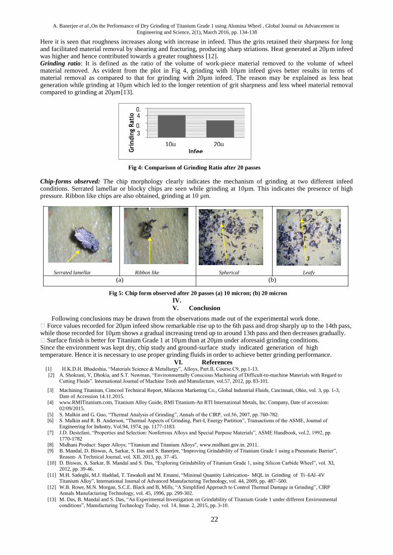
Grinding Ratio: An important parameter in assessing the grinding performance is the Grinding Ratio (G ratio). It is defined as the ratio between volume of work material removed to the volume of wheel material removed. From the definition of G-ratio, it is obvious that, higher amount of G ratio is desirable. So, from the calculated values as presented in fig. 3, it can be inferred that grinding with 10 micron is preferable than with 20 micron infeed.
Fig. 3: Comparison of Grinding Ratio after 20 passes
Chip study and surface morphology: Chip form and ground surface study play is important in predicting and analysing a grinding operation. Fig. 4 and fig. 5 shows the observed chip form and ground surface respectively.
(a) (b) Fig. 4: Chip form observed after 18 passes (a) 10 micron; (b) 20 micron
(a) (b)
Fig. 5: Surface topography observed after 20 passes (a) 10 micron; (b) 20 micron

18
Manish Mukhopadhyay, Ayan Banerjee, Arnab Kundu, Sirsendu Mahata, Bijoy Mandal and Santanu Das et al, experimental investigation on grindability of titanium grade 1 using silicon carbide wheel under dry condition, Global Journal on Advancement in Engineering and
Science, 2(1), March 2016, pp. 129-133
Chips are collected after 18 passes. Large number of blocky and fragmented chips is observed suggesting higher wheel loading. Very few chips are leafy. Surface form was observed after 20 passes under toolmakers microscope. Long and deep lay marks are observed on the surface. Chip re-deposition is also seen at places which suggest favourable grinding has not taken place. It is expected that use of suitable grinding fluid may improve chip form and ground surface morphology. Future experimental works would be done in this respect.
IV. Conclusion
Analysing the different parameters obtained during grinding of titanium grade alloy using silicon carbide wheel at 10 and 20 micron infeed, the following conclusions are drawn:
Tangential force values are lower than normal force values in all the cases as usual.
Force requirement in case of 20 micron is greater than that at 10 micron for all the passes except 19th
and 20
th pass.
Surface finish and grinding ratio are found to be better at 10 micron infeed than that at 20 micron infeed. Further experiments may be done using an appropriate grinding fluid to improve grinding performance while
surface grinding titanium grade 1.
V. References
1. http://manufacturing.stanford.edu/processes/Grinding.pdf , accessed on 08-08-2015. 2. R. B. Kinalkar and M. S. Harne, “A Review on Various Cooling System Employed in Grinding”, International Journal of Innovative
Technology and Exploring Engineering; Vol. 4 (2014), pp. 29-35. 3. P. Govindan, “Investigations on the Influence of Processing Conditions on Grinding Process,” International Journal of Engineering
Science and Research Technology, Vol. 2 (2013), pp. 648–654. 4. Y. S. Liao, Y. P. Yu and C. H. Chan, “Effects of Cutting Fluids with nano-particles in Grinding of Titanium Alloys”, Advanced
Materials Research, Vol. 126-128 (2010), pp 353-358. 5. A. B. Chattopadhyay, Machining and Machine Tools, Wiley India Pvt. Ltd., India. 2011. 6. R. D. Palhade, V. B. Tungikar and G. M. Dhole, “Application of Different Environments in Grinding of Titanium Alloys (Ti-6Al-4V):
Investigations on Precision Brazed Type Monolayered Cubic Boron Nitride (CBN) Grinding Wheel”, Institution of Engineers (India) Journal–Production Engineering Division, Vol. 90 (2009), pp.9-13.
7. S. Malkin and G. Guo, “Thermal Analysis of Grinding”, Annals of the CIRP, Vol.56 (2007), pp.760-782. 8. S. Malkin and R. B. Anderson, “Thermal Aspects of Grinding, Part-I, Energy Partition”, Transactions of the ASME, Journal of
Engineering for Industry, Vol.94 (1974), pp.1177-1183. 9. Midhani Product: Super Alloys; Titanium and Titanium Alloys, www.midhani.gov.in, 2011. 10. B. Mandal, D. Biswas, A. Sarkar, S. Das and S. Banerjee, “Improving Grindability of Titanium Grade 1 using Pneumatic Barrier”
Reason- A Technical Journal; Vol. 12 (2011), pp. 37-45. 11. M. C. Shaw and A. Vyas, “Heat-Affected Zones in Grinding Steel”, Annals of the CIRP, Vo1.43 (1994), pp. 279-282. 12. B. Mandal, S. Majumdar, S. Banerjee and S. Das, “Predictive model and Investigation of the Formation of Stiff Air Layer around the
Grinding Wheel”, Advanced Material Research, Vol. 83 (2010), pp. 654-660. 13. A. Bhattacharya, Metal Cutting Theory and Practice, New Central Book Agency (P) Ltd., Calcutta, 1984. 14. D. M. Turley, “Factors Affecting Surface Finish when Grinding Titanium and Titanium Alloy (Ti-6Al-4V)”, Materials Research
Laboratories, Defence Science and Technology Organization, Australia, Vol. 104(1982) pp. 223-235. 15. Y. Li, W. B. Rowe and B. Mills, “Grinding Conditions and Selection Strategy”, Journal of Engineering Manufacture, Vol.213 (1999),
pp.119-129. 16. K. V. Kumar and M. C. Shaw, “Metal Transfer and Wear in Fine Grinding”, Wear; Vol. 82 (1982), pp. 257-270. 17. S. Malkin, Grinding Technology. Industrial Press; New York, 2008. 18. W. B. Rowe, Principles of Modern Grinding Technology, William Andrew, Ney York, 2013. 19. Titanium Grade -1: Titanium Alloy; Arcam AB; www.arcam.com; Molndal, Sweden; (Accessed on 2nd Sep 2015). 20. www.wikipedia.org/wiki/Surface_roughness, Accessed on 15-01-2016.

19
OPTIMIZING TITANIUM GRINDING WITH CONVENTIONAL
WHEELS
Ayan Banerjee1, Manish Mukhopadhyay2, Arnab Kundu3, Sirsendu Mahata4, Bijoy Mandal5 and Santanu Das6
Department of Mechanical Engineering,
JIS College of Engineering, Nadia -741235, INDIA Email:
Abstract: Titanium and its alloys are considered to be difficult-to-machine material due to their poor heat
conductivity and high chemical reactivity at elevated temperature. But owing to their excellent properties
such as high strength-to-weight ratio, low density, resistance to corrosion, etc., titanium and its alloys find
wide applications in automotive, aerospace, shipping industries and others. Hence, grinding process is adopted
to remove material from such exotic metals and their alloys to achieve the desired surface finish of the product.
However, wheel-loading, wheel material removal, grit wear are some of the major problems encountered
during grinding. Selection of proper wheel with appropriate combination of process parameters is thus
extremely important prior to grinding. In the present work, grinding has been performed on Titanium Grade 1
using alumina wheel under dry environment. Observations with respect to grinding force, surface
roughness, ground chip-forms and workpiece surfaces are taken for two infeed. Grinding ratio is also
calculated. Results show that a relatively better grindability can be achieved while working at an infeed of 10
µm under dry condition.
Keywords: Grinding, Titanium Grade 1; Alumina wheel; Grinding force; Ground surface; Grinding ratio;
Ground chips.
I. Introduction
The advancement of material science and technology has facilitated the discovery of new elements, metals and alloys having high hardness, strength, ductility, toughness and low thermal conductivity, thereby making them difficult to machine. These metals/alloys not only possess the ability to sustain high temperature but also retain their integrity with minimum environmental impact [1]. Thus, material like titanium, molybdenum, rhenium, tungsten, cobalt, tantalum, niobium, chromium, hastelloy, nimonic, waspaloy, udimet etc have found profound use in the aerospace, vehicles, engines and gas turbines, nuclear and biomedical industrial sectors [2]. But these materials also require proper machining and/or grinding before being readied for use in the industry. In the present paper, one such material namely Titanium has been chosen to work on. Following the past research works, Titanium and its alloys are experienced to be difficult-to-machine material. Titanium is 30% stronger and nearly 50% lighter than steel, while it is 60% heavier than aluminum but twice as strong [3]. With its low density, high strength, and excellent resistance to corrosion, titanium is believed to solve many engineering challenges. But, Titanium is a poor conductor of heat [4]. When it comes to machining titanium, heat generated by the cutting action does not dissipate quickly, rather it gets concentrated on the cutting edge and the tool face. It also has a strong alloying tendency or chemical reactivity at high temperature which may cause galling, welding and smearing along with rapid wear of the cutting tool. These two factors together with its work-hardening characteristics and low modulus of elasticity makes titanium a difficult-to-machine material [3]. Grinding of titanium is also challenging as evident from its previous works. Grinding at high speed requires large force and generates high heat which may cause surface burns and re-deposition of chips on the ground surface. Apart from that, intense wheel loading and wheel material removal are the possible adverse phenomena while grinding [5], [6]. But due to its huge demand, grinding of titanium is essential inspite of the difficulties already stated. Hence it should be done by selecting the proper combination of environment, abrasive wheel, and grinding process parameters.

A. Banerjee et al.,On the Performance of Dry Grinding of Titanium Grade 1 using Alumina Wheel , Global Journal on Advancement in
Engineering and Science, 2(1), March 2016, pp. 134-138
20
II. Experimental Procedure
Workpiece and Wheel Material: Commercially pure Titanium Grade 1 is best known for its corrosion applications than titanium alloys, especially when high strength is not a requirement [7]. Apart from this, its applications can distinctively be found in surgical implants and prosthetic devices due to its inertness in thehuman body, that is, resistance to corrosion by body fluids [7], [8]. The present set of experiments includes Titanium Grade 1 plate of dimension 120 mm × 64 mm × 6 mm as workpiece, the composition of which is given below in Table 1.
Table 1: Composition of titanium grade 1alloy.
Titanium Iron Oxygen Nitrogen
99.85 0.12 0.02 0.01
The selection of grinding wheel is a very important factor in case of grinding of titanium. At high temperature, titanium has strong affinity for nitrogen, oxygen and carbon. Reports pertaining to the fact that nitrogen, oxygen and carbon react with titanium at high temperature and tend to make the material harder, stronger and less ductile, can be found in the works of Mandal et al.[9]. Hence the wheel chosen here to work with is an alumina wheel of specification AA 60 K 5 V. Also alumina wheel is cheap and widely used.
Experimental set-up and procedure: Grinding experiments have been performed on a Surface Grinder of HMT Praga division make. Two infeed 10µm and 20 µm were selected for the experiments. Each experiment comprised of 20 passes in up-grinding mode and under dry environment. Wheel dressing is performed with a dressing depth of 20 µm, at a speed of 2.3 m/min, using a single point 0.5 carat diamond dresser. Tangential (Ft) and normal (Fn) force values were obtained using a Sushma make strain gauge type dynamometer.
Table 2: Experimental set-up details
Surface Grinding Machine Make : HMT Praga Division, Model : 452 P Infeed Resolution : 1 μm, Main Motor Power : 1.5 kW Maximum Spindle Speed : 2800 rpm
Grinding Wheel Make : Carborundum Universal limited Type : Disc Type, Size : 200 × 31.75 × 20 Specification : AA 60 K 5 V
Workpiece Material : Titanium Grade 1 Dimension : 120 mm × 55 mm × 6 mm Hardness : 22 HRC
Working Environment Dry
Force Dynamometer Make : Sushma Grinding Dynamometer, Bengaluru, Model : SA 116 Range : 0.1 – 100 kg, Resolution : 0.1 kg
Wheel Dresser Make : Solar, India Specification : 0.5 carat Single Point Diamond Tip Dressing Infeed : 20 μm, Dressing speed: 2.3m/min
Surface Roughness Tester Make : Mitutoyo, Japan, Model : Surftest 301 Range : 0.05 – 40 μm, Resolution : 0.05 μm
Tool Makers Microscope Make : Mitutoyo, Japan, Model : TM 510
III. Experimental results and discussion
Grinding Force: The plot in Fig 1 shows the variation of grinding force with the number of passes for both the infeed of 10µm and 20µm.
Grinding at 10µm infeed showed force values rising high at the 4th pass and thereafter rising gradually and falling
again. But grinding at 20µm infeed, showed force values having a steep rise at the 6th pass and then falling deep
down at 14th pass. The reason may be explained as dulling of grits which have resulted in more friction rather than material removal. Grain pull-out also may have occurred in this case, resulting in an inability for the grinding wheel to cut at desired infeed value. Hence force required was high. Gradually as fresh grits came out, force requirement decreased and normal cutting action resumed.

A. Banerjee et al.,On the Performance of Dry Grinding of Titanium Grade 1 using Alumina Wheel , Global Journal on Advancement in
Engineering and Science, 2(1), March 2016, pp. 134-138
21
Fig 1: Variation of grinding forces with number of grinding passes under dry condition at 10 µm and 20 µm
infeed
Ground Surface Observed: Images show a better surface finish at 10 µm than at 20 µm. Fig 2(b) of ground surface for 20µm infeed show deeper grinding marks and traces of temperature induced deformation. Vibrations are also noticed while grinding at 20µm infeed. This is a clear indication of high wheel-loading and glazing, resulting in generation of high grinding zone temperature [10].
Lay marks
Deeper grinding lay marks
Crater (a) (b)
Fig 2: Ground surface observed after 20 passes (a) 10µm; (b) 20µm
Surface roughness values clearly indicates a better surface in case of grinding at 10µm infeed value. The normal grinding force (Fn) has an influence upon the surface roughness of the workspiece[11]. The variation of average surface roughness (Ra) values obtained from the ground surfaces with respect to infeeds have been shown in Fig 3.
Fig 3: Variation of surface roughness in transverse direction w.r.t. infeed after 20 grinding passes
Infeed
20µm 10 µm
3
2
1
0
Ra v
alu
e (µm
)
A. Banerjee et al.,On the Performance of Dry Grinding of Titanium Grade 1 using Alumina Wheel , Global Journal on Advancement in
Engineering and Science, 2(1), March 2016, pp. 134-138
22
(b) (a)
Leafy Spherical Ribbon like Serrated lamellar
Here it is seen that roughness increases along with increase in infeed. Thus the grits retained their sharpness for long and facilitated material removal by shearing and fracturing, producing sharp striations. Heat generated at 20µm infeed was higher and hence contributed towards a greater roughness [12]. Grinding ratio: It is defined as the ratio of the volume of work-piece material removed to the volume of wheel material removed. As evident from the plot in Fig 4, grinding with 10µm infeed gives better results in terms of material removal as compared to that for grinding with 20µm infeed. The reason may be explained as less heat generation while grinding at 10µm which led to the longer retention of grit sharpness and less wheel material removal compared to grinding at 20µm [13].
Fig 4: Comparison of Grinding Ratio after 20 passes
Chip-forms observed: The chip morphology clearly indicates the mechanism of grinding at two different infeed conditions. Serrated lamellar or blocky chips are seen while grinding at 10µm. This indicates the presence of high pressure. Ribbon like chips are also obtained, grinding at 10 µm.
Fig 5: Chip form observed after 20 passes (a) 10 micron; (b) 20 micron
IV.
V. Conclusion
Following conclusions may be drawn from the observations made out of the experimental work done. Force values recorded for 20µm infeed show remarkable rise up to the 6th pass and drop sharply up to the 14th pass, while those recorded for 10µm shows a gradual increasing trend up to around 13th pass and then decreases gradually. Surface finish is better for Titanium Grade 1 at 10µm than at 20µm under aforesaid grinding conditions. Since the environment was kept dry, chip study and ground-surface study indicated generation of high temperature. Hence it is necessary to use proper grinding fluids in order to achieve better grinding performance.
VI. References [1] H.K.D.H. Bhadeshia, “Materials Science & Metallurgy”, Alloys, Part.II, Course.C9, pp.1-13.
[2] A. Shokrani, V, Dhokia, and S.T. Newman, “Environmentally Conscious Machining of Difficult-to-machine Materials with Regard to Cutting Fluids”. International Journal of Machine Tools and Manufacture, vol.57, 2012, pp. 83-101.
[3] Machining Titanium, Cimcool Technical Report, Milacron Marketing Co., Global Industrial Fluids, Cincinnati, Ohio, vol. 3, pp. 1-3,
Date of Accession 14.11.2015. [4] www.RMITitanium.com, Titanium Alloy Guide, RMI Titanium-An RTI International Metals, Inc. Company, Date of accession:
02/09/2015.
[5] S. Malkin and G. Guo, “Thermal Analysis of Grinding”, Annals of the CIRP, vol.56, 2007, pp. 760-782. [6] S. Malkin and R. B. Anderson, “Thermal Aspects of Grinding, Part-I, Energy Partition”, Transactions of the ASME, Journal of
Engineering for Industry, Vol.94, 1974, pp. 1177-1183.
[7] J.D. Destefani, “Properties and Selection: Nonferrous Alloys and Special Purpose Materials”, ASME Handbook, vol.2, 1992, pp.
1770-1782 [8] Midhani Product: Super Alloys; “Titanium and Titanium Alloys", www.midhani.gov.in. 2011. [9] B. Mandal, D. Biswas, A, Sarkar, S. Das and S. Banerjee, “Improving Grindability of Titanium Grade 1 using a Pneumatic Barrier”,
Reason- A Technical Journal, vol. XII, 2013, pp. 37–45. [10] D. Biswas, A. Sarkar, B. Mandal and S. Das, “Exploring Grindability of Titanium Grade 1, using Silicon Carbide Wheel”, vol. XI,
2012, pp. 39-46.
[11] M.H. Sadeghi, M.J. Haddad, T. Tawakoli and M. Emami, “Minimal Quantity Lubrication- MQL in Grinding of Ti–6Al–4V Titanium Alloy”, International Journal of Advanced Manufacturing Technology, vol. 44, 2009, pp. 487–500.
[12] W.B. Rowe, M.N. Morgan, S.C.E. Black and B, Mills, “A Simplified Approach to Control Thermal Damage in Grinding”, CIRP Annals Manufacturing Technology, vol. 45, 1996, pp. 299-302.
[13] M. Das, B. Mandal and S. Das, “An Experimental Investigation on Grindability of Titanium Grade 1 under different Environmental conditions”, Manufacturing Technology Today, vol. 14, Issue. 2, 2015, pp. 3-10.
Infeed
20µm
10µm
0.4
0.3
0.2
0.1
0
Gri
ndin
g R
ati
o

23
ASSESSING GRINDABILITY OF INCONEL USING ALUMINA
WHEEL Arnab Kundu
1, Ayan Banerjee
2, Manish Mukhopadhyay
3, Sirsendu Mahata
4, Bijoy Mandal
5 and Santanu Das
6
Department of Mechanical Engineering, Kalyani Government Engineering College
Kalyani, Nadia, West Bengal 741235, INDIA
Email: [email protected],
Abstract: In this ever changing world of manufacturing industries, constant research and development has led to extensive use of Inconel alloys which are Nickel base superalloys. These alloys are widely used in gas turbine blades, seals and combustors, as well as turbocharger rotors and seals, high temperature fasteners, chemical processing and pressure vessels, heat exchanger tubing, steam generators, etc. Certain properties of these Inconel alloys viz. high strength and high resistance to temperature and corrosion make them commercially attractive and make Inconel a difficult-to-grind material, mainly due to high intense wheel loading, workpiece surface deterioration, and high heat generation. A proper wheel has to be selected to minimize cutting forces, and to reduce wheel wear as well as cutting temperature, particularly during dry grinding. In the present investigation, experiments have been performed to make a comparative study on grindability of Inconel 600 alloy under two different infeed values. It has been observed that grindability of Inconel 600 at 10 μm infeed is better than a 20 μm infeed in case of dry grinding, with respect to grinding forces, surface roughness, grinding ratio and the observed chip forms.
Keywords: Grinding, Inconel, wheel loading, grinding forces, surface roughness.
I. Introduction
Grinding is a well-known abrasive machining process that employs a grinding wheel as the cutting tool. Excess
workpiece material is removed in the form of microscopic chips by the grinding wheel which is composed of a
large number of cutting edges constituted by the hard and sharp abrasive grits held strongly in the wheel by a
suitable bond material. Average surface roughness (Ra) as low as 0.1 μm is obtainable through grinding, which
is up to ten times better than with either turning or milling [1]. Advanced grinding processes find major
applications in aerospace, energy and transport industries where the surface and subsurface quality of the
components manufactured are of prime importance as the components fail mainly by fatigue, creep, stress. A
major aerospace alloy is Inconel, which is a Nickel-Chromium superalloy. During the last 20 years, use of these
super-alloys has significantly increased in various industries, due to their excellent properties. These alloys are
widely used in gas turbine blades, seals, and combustors, as well as turbocharger rotors and seals, high
temperature fasteners, chemical processing and pressure vessels, heat exchanger tubing, steam generators etc.
Inconel 600 is a Nickel-Chromium alloy having high creep-rupture strength at high temperatures to about 700°C
(1290°F). The versatility of Inconel 600 has led to its use in a variety of applications involving temperatures
from cryogenic to above 2000°F [2]. High hardness, high hot strength and low thermal conductivity make it a
difficult-to-machine material. High cutting forces and heat generated during grinding of Inconel lead to poor
surface quality, thus shortening wheel life. Hence, proper selection of grinding parameters has to be made.
Sinha et al. [6] conducted several experiments on Inconel 718 to identify the optimum dressing parameters. In
case of Inconel 718, for minimum specific grinding forces the optimum dressing depth range is 30 to 40 μm.
Specific grinding forces vary inversely with dressing lead. Wear surfaces of cutting tools are analysed to study
the wear mechanism of cemented carbide tools in turning Inconel 718 superalloys [7]. SEM analysis indicated
that the wear of carbide was caused by diffusion of elements (Ni or Fe) in workpiece into tool's binder (Co) by a

A. Kundu et al. , An Experimental Investigation On The Grindability Of Inconel Using Alumina Wheel Under Dry
Condition, Global Journal on Advancement in Engineering and Science, 2(1), March 2016, pp. 149-153
24
grain boundary diffusion mechanism, so diffusion wear is dominant. Also, a longer tool life was obtained with
low content of cBN (45-60%), small grain size and ceramic binder. Anderson et al. [8] used a 1.5 kW CO2 laser
to preheat the surface of Inconel 718 superalloy. It was seen that specific cutting energy decreased significantly
during Laser Assisted Machining (LAM) from conventional machining. Surface finish improved two-fold as
temperature increases from room temperature to 540oC. This process is economically beneficial as large savings
in cost are achieved. Mandal et al. [9], [10] and Singh et al. [11] compared grindability of Inconel 600 under dry
conditions, flood cooling and wet with pneumatic barrier setup. It was reported that force requirements, wheel
wear, surface roughness were reduced by using the pneumatic barrier setup as compared to the other systems.
In the present experimental work, grindability of Inconel 600 with two different infeed of 10 μm and 20 μm has
been compared in terms of grinding forces, surface roughness, G-ratio and type of chips observed. Surface
grinding has been performed in a horizontal axis grinding machine using an alumina wheel in dry environment.
II. EXPERIMENTAL DETAILS
The workpiece material used is a rectangular plate of Inconel 600 alloy having dimensions of 120mm x 60mm x
6 mm and a hardness of 90 HRB. The chemical composition of Inconel 600 alloy used in this experiment is
given in Table 1. Before grinding, Rockwell hardness test has been conducted to measure the hardness of the
workpiece.
Table 1: Chemical composition of Inconel 600
Units Nickel Chromium Iron Manganese Carbon
% 73 14.2 8.4 0.86 0.15
Grinding has been performed on a horizontal axis surface grinding machine. The complete specifications and
other equipment used are detailed in Table 2. Up grinding has been performed for 20 passes at 10 and 20 μm
infeed. A constant wheel speed of 30 m/s and a table feed of 14 m/min are maintained throughout the whole
experimental investigation. Force values have been measured by a Sushma make strain gauge type
dynamometer. During each pass, both the tangential (Ft) and normal (Fn) components of forces have been
measured and recorded. Surface roughness has been measured by a portable surface roughness tester of
Mitutoyo make.
Table 2: Experimental and equipment details
Surface Grinding Machine Make: HMT Praga Division
Model: 452 P
Infeed Resolution: 1 μm
Main Motor Power: 1.5 kW
Maximum Spindle Speed: 2800 rpm
Grinding Wheel Make: Carborundum Universal limited
Type: Disc
Dimensions: 200 × 31.75 × 20
Specification: AA60K5V
Workpiece Material: Inconel 600
Dimensions: 120 mm × 60 mm × 6 mm
Hardness: 90 HRB
Force Dynamometer Make: Sushma Grinding Dynamometer, Bengaluru
Model: SA 116
Range: 0.1 – 100 kg
Resolution: 0.1 kg
Wheel Dresser Make: Solar, India
Specification: 0.5 carat single point diamond tip
Dressing Infeed: 20 μm
Surface Roughness Tester Make: Mitutoyo, Japan
Model: Surftest 301
Range: 0.05 – 40 μm
Resolution: 0.05 μm
Tool Makers Microscope Make: Mitutoyo, Japan
Model: TM 510
.

A. Kundu et al. , An Experimental Investigation On The Grindability Of Inconel Using Alumina Wheel Under Dry
Condition, Global Journal on Advancement in Engineering and Science, 2(1), March 2016, pp. 149-153
25
III. RESULTS AND DISCUSSION
Fig. 2 represents variation of tangential and normal forces with the number of passes at 10 μm infeed, while Fig. 3 represents variation of the same forces with a 20 μm infeed.
Fig 2: Variation of grinding forces with numberof passes at 10 μm infeed
Fig 3: Variation of grinding forces with number of passes at 20 μm infeed
Figure 4: Comparison of surface roughness (Ra) for 10 μm and 20 μm infeed
The plots above make it quite clear that normal force (Fn) is higher than the tangential force (Ft) in both the cases. Fig. 1 shows a gradually increasing trend of forces. This is due to the fact that forces increase with the increase in infeed and rapid dulling of wheel grits and wheel loading. Fig. 3 depicts a rising trend of forces up to the 13
th pass. After that, the forces gradually decrease. This may be due to autosharpening of the wheel, where
dull grits get dislodged bringing fresh grits to the wheel surface, thus improving cutting action and decreasing the force values.

A. Kundu et al. , An Experimental Investigation On The Grindability Of Inconel Using Alumina Wheel Under Dry
Condition, Global Journal on Advancement in Engineering and Science, 2(1), March 2016, pp. 149-153
26
From Fig. 4, it can be clearly seen that the surface roughness (Ra) at 10 μm infeed is lower than that at 20 μm infeed. This can be attributed to the low thermal conductivity of the workpiece which generates more heat at 20 μm infeed. Also, strong adhesion between the wheel and workpiece can be responsible for higher roughness values.
Grinding ratio is the ratio of material removal rate to the wheel material removal rate. It is an important parameter in judging grindability. Higher G-ratio indicates good grindability, but not always. For instance, the wheel may be too hard for the workpiece material which can cause an increase in forces and lead to a poor surface texture.
Fig.5: Comparison of G-ratio for both 10 and 20 μm infeeds.
From Fig. 5, it is clearly seen that G-ratio is higher in case of 10 μm infeed than 20 μm infeed indicating better grindability achieved at 10 μm infeed.
The chips obtained and the ground surface have been observed under a tool maker’s microscope after 20 passes. Fig. 6 shows the chip morphology after 20 passes in case of 10 and 20 μm infeeds.
(a) (b)
Fig.6: Chip morphology in case of (a) 10 μm, and (b) 20 μm
(a) (b) Fig.7: Ground morphology in case of (a) 10 μm, and (b) 20 μm
Chips are collected from the 17th
pass onwards. Fig. 6(a) shows mainly blocky and fragmented chips along
with pulled out grains indicating high wheel wear and high wheel loading. Fig. 6(b) shows curled chips, both continuous and discontinuous, indicating favourable grinding. The surface topography shows chip redeposition as evident from Fig. 7(a). Chip redeposition occurs on account of the chips adhering to the extremely heated surface of the workpiece.

A. Kundu et al. , An Experimental Investigation On The Grindability Of Inconel Using Alumina Wheel Under Dry
Condition, Global Journal on Advancement in Engineering and Science, 2(1), March 2016, pp. 149-153
27
IV. Conclusion
In the present work, the effect of infeed on Inconel 600 using an alumina wheel has been studied experimentally. The main results obtained are summarized as follows:
The normal force component (Fn) is higher than the tangential (Ft) force in all the cases.
Both tangential and normal forces in case of 20 μm infeed are higher than that of 10 μm infeed.
Surface roughness values are lower in case of 10 μm infeed, indicating a higher surface finish.
Grinding ratio or G-ratio is higher in case of 10 μm infeed.
The observed chip images reveal more shear type chip formation at 10 μm infeed. Chip redeposition is found on the surface of the workpiece, indicating very high heat generation.
On the whole, the grindability of Inconel 600 under dry conditions with an infeed of 10 μm is found to be better than that at 20 μm infeed.
References
[1] manufacturing.stanford.edu/processes/Grinding.pdf, accessed on 14/08/2015. [2] http://www.specialmetals.com/assets/docμments/alloys/inconel/inconel-alloy-600.pdf, accessed on 14/08/2015.
[3] T.A. Vijey and V. Surianarayanan, “Studies on oxidation behavior of Inconel based superalloy (Inconel 600)”, International Journal of Engineering Sciences & Research Technology, Vol. 2 (2013), pp. 1566-1577.
[4] P. L. Tso, “Study on the grinding of Inconel 718”, Journal of Materials Processing Technology, Vol. 55 (1995), pp. 421-426.
[5] D.V. Patil, S. Ghosh, A. Ghosh and A.B. Chattopadhyay, On grindability of Inconel 718 under high efficiency deep grinding by monolayer cBN wheel, International Journal of Abrasive Technology, Vol. 1(2007), pp. 173-186.
[6] M. K. Sinha, D. Setti, Ghosh, S. Ghosh and P. V. Rao, “An investigation into selection of optimum dressing parameters based on grinding wheel grit size”, Proceedings of the 5th International & 26th All India Manufacturing Technology, Design and Research Conference, Guhawati, 2014.
[7] Y. S. Liao and R. H. Shiue, “Carbide tool wear mechanism in turning of Inconel 718”, Wear, Vol. 193 (1996), pp. 16-24.
[8] M. Anderson, R. Patwa and Y. C. Shin, “Laser-assisted machining of Inconel 718 with an economic analysis”, International Journal of Machine Tools & Manufacture, Vol. 46 (2006), pp. 1879–189.
[9] B. Mandal, A. Sarkar, D. Biswas, S. Das and S. Banerjee, “An effective grinding fluid delivery technique to improve grindability of Inconel-600”, Proceedings of the 5th International & 26th All India Manufacturing Technology, Design and Research Conference,
Guwahati, 2014. [10] B. Mandal, D. Biswas, A. Sarkar, S. Das and S. Banerjee, “Improving grindability of inconel 600 using alumina wheel through
pneumatic barrier assisted fluid application”, Advanced Materials Research, Vol. 622-623 (2013), pp. 394-398.
[11] S.K. Singh, S.R. Dutta and R. Ranjan,” Grindability of inconel-600 under different environmental conditions”, International Journal of Advanced Technology in Engineering and Science, Vol. 2(2014), pp. 104-109.

28
Optimization of Process Parameters of Miniature Spur Gear in Wire-cut EDM of
Inconel-718
T. Paul*a,b
, S. Chakraborty, and D. Bose
Department of Mechanical Engineering, JIS College of Engineering
Manufacturing Technology, Department of Mechanical Engineering
National Institute of Technical Teachers’ Training and Research, Kolkata- 700106, INDIA
Abstract
This paper has dealt with the development in the material science that leads to the development of advanced engineering material like super
alloy i.e. Inconel-718. An alternative competitive process is WEDM to manufacture complex Inconel part geometries. Therefore, it is
observed that manufacture of micro spur gear with high dimensional accuracy is a very challenging task by WEDM process. To
manufacture components with intricate shapes and profiles, Wire electrical discharge machining (WEDM) is widely accepted as non-
traditional machining process. Five process parameters like Pulse-on-time, Pulse-off-time, Wire feed, Gap voltage and Peak current upto 5
levels are chosen as an input parameter. This paper is focused on the aspects related to the material removal rate and dimensional accuracy
which are the most important parameters from economical aspects as well as from the point of view of selecting the optimum condition of
processes. In addition, the present work also proposes the development of mathematical model to predict the Addendum error, Tooth
thickness error ,Pitch error, and Dedendum error by using RSM. Thus, optimum input parameters are obtained by using Multi objective
optimization to achieve minimum errors in the gear profile. ANOVA is used to identify the significant process parameters. It is seen that
the material removal rate is high when the peak current and Ton is at extreme. It has also been concluded that at high discharge energy the
rate of errors increases along with the formation of dominant coral reef (SEM analysis). Random micro voids also occur at low discharge
energy.
Keywords: WEDM, Miniature Spur Gear, Material Removal Rate (MRR), various errors, Optimization, Regression Models, ANOVA.
1. INTRODUCTION
In industrial, scientific and domestic applications miniature gears are extensively used. Typical applications include robotic drives, smart
toys, timer mechanisms, precision scientific instruments, robotics drive, miniature pumps and motors. For the transmission of motion a
fine pitch gears are generated by implementing brass wire during machining. The conventional process of generating meso gears consist
of gear stamping, gear hobbing, powder metallurgy, gear extrusion, and die casting. But there are certain limitations i.e. post finishing
operations is necessary in gear stamping for avoiding poor edge definition, in gear extrusion there is a problem of die wear, in gear
hobbing process tool marks occurs on the flanks of the gear, accuracy of gears are poor for die casting, and to arrange various fine powder
of gear materials is one of the challenging task in the powder metallurgy process [1-3]. Through the international standers the quality of
micro geometry parameters of a gear is determined by AGMA (American gear manufacturing association) and DIN (Deutsche normen).
Better quality gear is indicated by Higher AGMA number or lower DIN number and vice versa [4]. In [5] it has been proved that low
discharge energy is the most significant factor for better quality gear. To achieve best quality gears the experimental research decided to
identify the most important parameters (Peak current, Pulse on time, Pulse off time, Gap voltage, and Wire feed rate) within the feasible
ranges. The effect of the five parameters on accumulated pitch deviation and total profile deviation has been described in [6]. In [7] the
effect of wire feed rate, cutting speed and pulse off time on outside diameter and chordal tooth thickness of the best quality miniature gear
has been determined. The difficulty in adopting the traditional manufacturing processes for producing micro gears can be attributed
mainly due to the development of new materials with a low machinability, dimensional and accuracy requirement for precision
application and a higher production rate and economy.
For the present study Inconel-718 alloy has been chosen as work piece material for manufacturing gear.Inconel-718 alloy is a very high-
strength, corrosion-resistant nickel chromium material .Inconel-718 is widely used in turbo machinery industry due to their outstanding
mechanical properties [8]. It is very difficult task to machine an advanced material like Inconel alloys by using conventional mechanical
processes such as broaching, milling or grinding [9]. WEDM process is an alternative competitive process to manufacture complex Inconel
part geometries. Inconel-718 typically finds application in gas turbines, rocket motors, space craft and nuclear reactors and pumps. This
paper particularly dealt with the generation of the best quality miniature gear by the best feasible combination of the input parameters.

29
2. DETAILS OF EXPERIMENTATION
2.1 Selection of Process Parameters
The selection are based on certain consideration to input parameters and output parameters the following parameters are chosen in
machining INCONEL-718 (Table 1).
Table 1 Input and Output Parameters
Input Parameters
Output Parameters
1. Pulse-on-time (µs)
2. Pulse-off-time (µs)
3. Wire feed (mm/min)
4. Gap voltage (volt)
5. Peak current (A)
1. Material removal rate (mm3/min)
2. Surface roughness
3. Various errors ( Pitch error,
Addendum error, Dedendum error,
Tooth thickness error)
2.2 Controllable Parameters and Their Limits
The identification of process parameters and to define the level of each factor has been formed to be equally crucial to the successes of any
optimization problem. The controllable parameters their actual and decided ranges along with the different levels are shown in Table 2. Table 2 Controllable Parameters and Their Limits
Notations
(Coded
names)
Controllable
parameters
Units
Actual
range
Decided
range
Levels/Limits
-2 -1 0 1 2
A Wire feed rate m/min 1-100 25-85 25 40 55 70 85
B Peak current A 1-5 1-5 1 2 3 4 5
C Pulse-on-time µsec 1-100 30-70 30 40 50 60 70
D Pulse-off-time µsec 1-15 3-11 3 5 7 9 11
E Gap voltage Volts 1-100 30-70 30 40 50 60 70
2.3 Design of Miniature Gear
Design Calculation is represented in Table 3.
i. Module=0.7mm
ii. Numbers of teeth (N) =10
iii. Pressure Angle (Ɵ) = 20 ̊
Table 3 Design Calculation of Miniature Gear
Sl No.
Terms Formula Dimensions (mm)
01 Module P.C.D/N 0.7
02 Circular Pitch π ×m 2.19
03 Addendum 0.318× C.P 0.69
04 Addendum circle diameter P.C.D +(2× Addendum) 8.4
05 Clearance C.P/20 0.11
06 Dedendum Addendum+ Clearence 0.81
07 Dedendum Circle Diameter P.C.D - (2× Dedendum) 5.4
08 Tooth Thickness C.P/2 1.1
3. RESULTS AND DISCUSSION
The details physical and geometrical aspects of the miniature gears are given in the following paragraphs.

30
3.1 Optimal Levels of Process Parameters for Single Responses By using Response Surface Methodology the optimum level of process parameters has been achieved to obtain the best quality miniature
gears. Table 4 Optimal Levels of Process Parameters for Single Responses
Response Optimal Values
A B C D E
MRR 25 5 70 3 70
SR 55 3 30 6 60
Pitch error 25 3 50 7 40
Addendum error 70 3 30 5 80
Dedendum error 25 1 70 6 40
Tooth thickness error 55 3 40 5 80
3.2 Analysis of Variance (ANOVA)
The effect of parameters on responses is carried out by ANOVA. Different parameters are having a relative significance value and it is
determined by the calculated F-values for various responses. The Analysis of Variance (ANOVA) and F-ratio test have been
performed to check the adequacy of the model as well as the significance of the individual model co-efficient. It can be appreciated
the P value is less than 0.05 (Table 5-8) which means the model is significant at 95% confidence level. Table 5 ANOVA for Pitch Error
Factors DOF SS2 MS F P
W.F 1 0.00018 0.00018 1.00 0.325
Ip 1 0.001530 0.001530 8.50 0.000
Ton 1 0.042197 0.042197 234.38 0.000
Toff 1 0.112954 0.112954 627.41 0.000
GV 1 0.000072 0.000072 0.40 0.002
Error 31 0.005581 0.000180
Total 51 0.346489
S= 0.0134176 R-sq= 97.39% R-sq(adj)= 96.35%
Table 6 ANOVA for Dedendum Error
Factors DOF SS2 MS F P
W.F 1 0.000000 0.000000 0.00 0.569
Ip 1 0.000040 0.000040 0.27 0.000
Ton 1 0.085110 0.085110 585.79 0.000
Toff 1 0.057570 0.057570 396.24 0.000
GV 1 0.000241 0.000241 1.66 0.000
Error 31 0.004504 0.000145
Total 51 0.300798
S= 0.0120537 R-sq= 97.50% R-sq(adj)= 96.54%
Table 7 ANOVA for Addendum Error
Factors DOF SS2 MS F P
W.F 1 0.000910 0.000910 3.70 0.064
Ip 1 0.003660 0.003660 14.87 0.000
Ton 1 0.093354 0.093354 379.34 0.000
Toff 1 0.195776 0.195776 795.53 0.000
GV 1 0.014273 0.014273 58.00 0.000
Error 31 0.007629 0.000246
Total 51 0.589016
S= 0.0156874 R-sq= 97.70% R-sq(adj)= 96.87%

31
Table 8 ANOVA for Tooth thickness Error
Factors DOF SS2 MS F P
W.F 1 0.05103 0.05103 25.25 0.000
Ip 1 0.23069 0.23069 114.15 0.000
Ton 1 0.00115 0.00115 0.57 0.000
Toff 1 0.98819 0.98819 488.98 0.000
GV 1 0.07038 0.07038 34.83 0.000
Error 31 0.06260 0.002021
Total 51 3.68793
S= 0.0449544 R-sq= 97.30% R-sq(adj)= 96.21%
3.3 MATHEMATICAL MODEL
The empirical models are developed for Addendum error, Dedendum error, pitch error and tooth thickness error based on the
experimental value using MINITAB 16 and the models are represented in Equation 1, 2,3 and 4.
The models have maintained a noble relationship between parameters and their respective responses. The models are having the value
of R2 above 0.95.
PITCH ERROR = 1.917 + 0.00583 W.F - 0.1787 Ip - 0.02969 Ton - 0.2622 Toff
- 0.00048 G.V + 0.000057 W.F*W.F + 0.01653 Ip*Ip
+ 0.000112 Ton*Ton + 0.012351 Toff*Toff + 0.000087 G.V*G.V
+ 0.000458 W.F*Ip - 0.000003 W.F*Ton + 0.000057 W.F*Toff
- 0.000241 W.F*G.V + 0.001194 Ip*Ton - 0.00139 Ip*Toff
+ 0.000131 Ip*G.V + 0.001342 Ton*Toff + 0.000079 Ton*G.V
+ 0.000163 Toff*G.V …..... (1)
ADD ERROR = 9.629 - 0.00745 W.F - 0.2492 Ip - 0.01775 Ton - 0.1733 Toff
- 0.00896 G.V + 0.000065 W.F*W.F + 0.03472 Ip*Ip - 0.000018 Ton*Ton
+ 0.008854 Toff*Toff - 0.000138 G.V*G.V + 0.000863 W.F*Ip
- 0.000010 W.F*Ton + 0.000215 W.F*Toff - 0.000073 W.F*G.V
+ 0.001728 Ip*Ton - 0.00290 Ip*Toff - 0.000837 Ip*G.V
- 0.001757 Ton*Toff + 0.000529 Ton*G.V + 0.001342 Toff*G.V …..... (2)
DED ERROR = 6.520 + 0.00178 W.F + 0.0541 Ip - 0.04123 Ton - 0.2977 Toff
- 0.00999 G.V + 0.000004 W.F*W.F - 0.00253 Ip*Ip + 0.000197 Ton*Ton
+ 0.010552 Toff*Toff + 0.000034 G.V*G.V - 0.000456 W.F*Ip
+ 0.000021 W.F*Ton + 0.000032 W.F*Toff - 0.000032 W.F*G.V
- 0.000120 Ip*Ton - 0.00203 Ip*Toff + 0.000107 Ip*G.V
+ 0.002287 Ton*Toff + 0.000066 Ton*G.V + 0.000728 Toff*G.V …..... (3)
TOOTH THICKNESS ERROR = 9.195 - 0.04687 W.F - 1.4280 Ip - 0.08128 Ton
- 0.5617 Toff - 0.0553 G.V + 0.000437 W.F*W.F
+ 0.07017 Ip*Ip - 0.000012 Ton*Ton + 0.02861 Toff*Toff
- 0.000021 G.V*G.V + 0.005160 W.F*Ip - 0.000128 W.F*Ton
+ 0.001156 W.F*Toff - 0.000361 W.F*G.V
+ 0.010530 Ip*Ton - 0.01592 Ip*Toff + 0.007726 Ip*G.V
- 0.000620 Ton*Toff + 0.001054 Ton*G.V
+ 0.001430 Toff*G.V …..... (4)
3.4 VALIDATION OF OPTIMUM RESULTS OF RESPONSES
With respect to experimental values for MRR, Surface roughness, addendum error, dedendum error, pitch error, and tooth thickness
errors, the optimum levels of influence parameter are determined by implementing Response Surface Methodology and are shown in
Table 4. The actual responses as well as the predicted values for various output response are also shown in Table 9.

32
Table 9 Confirmation Testing
Response Predicted
Value Expt. Value
% Error
MRR 4.4152 4.55 2.96
SR 2.1771 2.224 2.10
Pitch value 0.0310 0.0319 2.82
Addendum 7.2809 7.4061 1.67
Dedendum 4.2445 4.2962 1.203
Tooth thickness 0.0841 0.0869 3.22
3.5 PHYSICAL ASPECT OF MINIATURE GEAR
3.5.1. Various Error Measurement
Appropriate selection of parameters is essential to reduce the various types of error. It has been observed that at Wire feed rate
75m/min, Peak current 2A, Pulse on time 50µs, Pulse off time 5µs and gap voltage 70 V the best miniature gear has been
manufactured. The output parameters experimental values was 2.0385 mm3/min for MRR, 0.19100 µm for Pitch error, 7.8950 µm for
Addendum error, 4.3310 µm for Dedendum error, and 0.1820 µm for tooth thickness error. Few microscopic views during the
measurement time of the miniature gears have been added below.
Figure 1 Measurement of the tooth thickness Figure 2 Measurement of the Addendum and Dedendum Circle Diameter
3.5.2. Microstructure Characterization
The best quality gear that has been manufacture by WEDM on the combination of Wire feed rate 75m/min, Peak current 2A, Pulse on
time 50µs, Pulse off time 5µs and gap voltage 70 V and the Figure 3 depicts the SEM image of the gear. Similarly it has also been
observed that at maximum peak current (5A), wire feed is 60m/min, pulse on time is 40µs, gap voltage is 60V and pulse off time is
7µs the maximum error has been achieved. Minimum thermal impact takes place on the material surface at the lowest discharge
energy.
Fig.3. SEM image of the best quality miniature gear tooth Fig.3. SEM image of the worst quality miniature gear tooth

33
4. CONCLUSION
In the present work, the various errors related as well as surface related parameters of the miniature gear that has been produced in WEDM
were quantitatively and qualitatively interpreted and examined. The generation of the regular shaped craters is preferred to achieve for
better surface integrity and geometric accuracy of the WEDM products. The following conclusion that has been drawn out is as follows-
The main factors that affect the gear profile (geometrical profile) are Peak current, Pulse on Time and Gap Voltage. The outcome
works also suggest that to achieve the best quality gear there should be a strongly implementation of low discharge energy
parameters.
The best quality miniature gears had the following experimental value 2.0385 mm3/min for MRR, 0.19100 µm for Pitch error,
7.8950 µm for Addendum error, 4.3310 µm for Dedendum error, and 0.1820 µm for tooth thickness error.
SEM analysis also states that the best quality gear has achieved crack free surface structure as well as the surface of the gear
tooth overlapped by flat, shallow, and regular shaped craters.
High quality miniature gears with the best tribological properties and also with a better functional performance characteristics can
be achieved by WEDM or in other words WEDM is an ideal choice for the generation of high quality miniature gears.
References
[1] Bralla J., Designfor manufacturability handbook, Tata McGraw-Hill, New York, 1998.
[2] Davis J.R., Gear materials, properties and manufacture, ASM International, Ohio, 2005.
[3] Townsend D.P., Dudley’s gear handbook, Tata McGraw-Hill, New Delhi, 2011.
[4] Grzesik W., Advanced machining processes of metallic materials, Elsevier, Oxford, 2008.
[5] Ali M.Y., Karim A.N.M., Adesta E.Y.T., Ismail A.F., Abdullah A.A., Idris M.N., Comparative study of conventional and micro
WEDM based on machining of meso/micro sized spur gear, International Journal Precision Engineering Manufacturing, 11(5), pp.
779-784, 2010.
[6] Gupta K., Lain N.K., On micro geometry of miniature gears manufactured by WEDM, Material Manufacturing Process, 28(10), pp.
1153-1159, 2013.
[7] Gupta K., Lain N.K., Deviations in geometry of miniature gears fabricated by WEDM, IMECE 66560, Proceedings of the ASME
International Mechanical Engineering Congress and Exposition, San Diego, USA, 2013.
[8] Guo Y.B., Li W., Jawahir I.S., Surface integrity characterization and prediction in machining of hardened and difficult-to-machine
alloy: a state-of-art research review and analysis, Machining Sci. Tech., 13/4, pp. 437-470, 2009.
[9] Sharman A.R.C., Hughes J.L., Ridgway K., Workpiece surface integrity and tool life issues when turning Inconel 718 nickel based
superalloy, Machining Sci. Tech., 8/3, pp. 399-414, 2004.
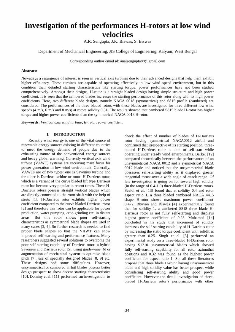
34
Investigation of the performances H-rotors at low wind
velocities A.R. Sengupta, J.K. Biswas, S. Biswas
Department of Mechanical Engineering, JIS College of Engineering, Kalyani, West Bengal
Corresponding author email id: [email protected]
Abstract:
Nowadays a resurgence of interest is seen in vertical axis turbines due to their advanced designs that help them exhibit
higher efficiency. These turbines are capable of operating effectively in low wind speed environment, but in this
condition their detailed starting characteristics like starting torque, power performances have not been studied
comprehensively. Amongst their designs, H-rotor is a straight bladed design having simple structure and high power
coefficient. It is seen that the cambered blades increases the starting performance of this rotor along with its high power
coefficients. Here, two different blade designs, namely NACA 0018 (symmetrical) and S815 profile (cambered) are
considered. The performances of the three bladed rotors with these blades are investigated for three different low wind
speeds (4 m/s, 6 m/s and 8 m/s) at rotors solidity 0.51. The results showed that cambered S815 blade H-rotor has higher
torque and higher power coefficients than the symmetrical NACA 0018 H-rotor.
Keywords: Vertical axis wind turbine, H- rotor; power coefficient.
1. INTRODUCTION
Recently wind energy is one of the vital source of
renewable energy sources existing in different countries
to meet the energy demand of people due to the
exhausting nature of the conventional energy sources
and heavy global warming. Currently vertical axis wind
turbine (VAWT) systems are receiving main focus for
power generation in low wind environment. Generally,
VAWTs are of two types: one is Savonius turbine and
the other is Darrieus turbine or rotor. H-Darrieus rotor,
which is a variant of the curve bladed lift type Darrieus
rotor has become very popular in recent times. These H-
Darrieus rotors possess straight vertical blades which
are directly connected to the rotor shaft with the help of
struts [1]. H-Darrieus rotor exhibits higher power
coefficient compared to the curve bladed Darrieus rotor
[2] and therefore this rotor can be applicable for power
production, water pumping, crop grinding etc. in distant
areas. But this rotor shows poor self-starting
characteristics as symmetrical blade shapes are used in
many cases [3, 4]. So further research is needed to find
proper blade shapes so that the VAWT can show
improved self-starting and performance features. Many
researchers suggested several solutions to overcome the
poor self-starting capability of Darrieus rotor: a hybrid
Savonius and Darrieus rotor [5], using guide-vane [6] or
augmentation of mechanical system to optimize blade
pitch [7], use of specially designed blades [8, 9] etc.
These designs had some difficulties. However,
unsymmetrical or cambered airfoil blades possess better
design prospect to show decent starting characteristics
[10]. Dominy et al. [11] performed an investigation to
check the effect of number of blades of H-Darrieus
rotor having symmetrical NACA0012 airfoil and
confirmed that irrespective of its starting position, three-
bladed H-Darrieus rotor is able to self-start while
operating under steady wind environments. Barker [12]
compared theoretically between the performances of an
unsymmetrical NACA 0012 and a symmetrical NACA
0012 blade and noticed that the unsymmetrical blade
possesses self-starting ability as it displayed greater
tangential thrust over a wide angle of attack range. Of
late investigation is going on for several high solidity
(in the range of 0.4-1.0) three-bladed H-Darrieus rotors.
Saeidi et al. [13] found that at solidity 0.4 and rotor
aspect ratio 1, a three bladed cambered NACA 4415
shape H-rotor shows maximum power coefficient
0.472. Bhuyan and Biswas [4] experimentally found
that for solidity 1, a cambered S818 three blade H-
Darrieus rotor is not fully self-starting and displays
highest power coefficient of 0.28. Mohamed [14]
concluded in his study that increment of solidity
increases the self-starting capability of H-Darrieus rotor
by increasing the static torque coefficient with solidities
greater than 0.25. Singh et al. [3] performed an
experimental study on a three-bladed H-Darrieus rotor
having S1210 unsymmetrical blades which showed
fully self-starting capability for all rotor azimuthal
positions and 0.32 was found as the highest power
coefficient for aspect ratio 1. So, all these literatures
propose that three blade H-rotor having unsymmetrical
blade and high solidity value has better prospect while
considering self-starting ability and good power
coefficient. However the detail investigation of three-
bladed H-Darrieus rotor’s performance with other

35
cambered blade profiles having high solidity with
proper investigation to starting time at low tip speed
ratios is very less. So more researches are needed in this
field to show that these H-Darrieus rotors can work in
low wind velocity environments successfully.
2. OBJECTIVE OF THIS STUDY
From the previous section, it can be realized that
three bladed H-Darrieus rotor with unsymmetrical
blades and high solidity has the potentiality to solve the
poor self-starting feature and performance of such wind
σ = 𝑁𝑐
𝐷
(a) (b)
(1)
turbines. In this paper, along with rotor solidity like the
past studies, starting time is taken as an important
parameter to improve the performances of cambered
blade H-Darrieus rotor, which could help to rise the
energy yield in case of low wind speed conditions.
Furthermore, there is still not much work on the self-
starting ability, torque coefficient measurement etc. of
cambered blade H-Darrieus rotor having high solidity,
to attain some clear perception for this type of VAWT
rotor in low wind environment. Again, it has been
noticed that higher tangential thrust offered by
unsymmetrical airfoils help them to show better self-
start than symmetrical ones, and such blades with
higher thickness are better for good self-starting of a
rotor [3, 4, 15, 16]. Therefore, due to higher thickness
of unsymmetrical S815 airfoil profile than other popular
NREL S-series airfoils like S809, S818, S1210 etc., it
has been chosen here [17], as the performance of H-
Darrieus rotor having S815 blades has not been studied
broadly earlier. So, in this paper experimental analysis
has been performed on symmetrical NACA 0018 and
unsymmetrical S815 three-bladed H-Darrieus rotor at
high rotor solidity 0.51 for three different low wind
speed conditions (4 m/s, 6 m/s and 8 m/s). NACA 0018
airfoil profile is chosen to compare its performance with
S815, as it is very commonly used in case of H-
Darrieus rotors [18]. Main aim of this paper is to find
the better H-Darrieus rotor configuration which possess
better self-starting features, lower starting time and
higher performances at low tip speed ratios.
Fig 1. (a) Fabricated S815 rotor blade (b) fabricated NACA
0018 rotor blade
4. EXPERIMENTAL METHODS
The H-rotors mounted on the structure were placed
in open air at a distance from the outlet of a centrifugal
blower test rig. Wind speed was measured using a
digital vane type anemometer ranging 0-30 m/s having
accuracy level of ±1%. A digital non-contact
tachometer was used to measure the rpm of the rotors
having accuracy level of ±1%. By using a digital stop
watch, the starting time of the rotors at different
azimuthal positions was measured having least count of
0.01 second. Every set of experiments is repeated up to
around 4 to 5 times to get correct and precise results.
For calculating rotors torques, a rope brake
dynamometer arrangement was used. There was a nylon
string twined around a pulley which is joined to the
main shaft through which a brake load was hung and
the other end of the string was tied to the spring balance
dynamometer to measure its reading. The mechanical
torque (T) generated by the main rotor shaft was found
by recording the weights and the spring balance
readings.
The performance of the H-Darrieus rotors is determined
by finding the torque values and power coefficients that
can be attained from the following eqns. 5 and 6 [3, 4]:
𝐶 = 4𝑇 (2)
3. CONSTRUCTION OF H-ROTORS
To fabricate a three bladed H-Darrieus rotor, at first
the outlines of S815 and NACA 0018 airfoils were
generated. Then, as per the procedure mentioned by
Singh et al. [3], three numbers of blades for both
profiles were fabricated and sample images of those
blades have been shown in Figs. 1(a) and 1(b). Balsa
wood was selected as the material for its various
structural advantages [3, 19]. Every single blade has
height (H) 29 cm and chord (c) 5 cm which were
connected to a MS shaft of 0.6 cm radius and 70 cm
length with the help of fully threaded circular struts.
These three struts were 120° apart from each other, 19
cm long and 4 mm in diameter. Two ball bearings were
used at both end of the supporting structure to place the
rotor centre i.e. the shaft. Petrol and lubricating oil was
used to wash and clean the bearings periodically. The
solidity (σ) value of the three bladed rotors has been
calculated using eqn. 1 [3]. .
𝑡 𝜌𝑈2𝐷2𝐻
𝐶𝑝 = λ × 𝐶𝑡 (3)
where ρ is the air density, 𝐶𝑡 is the torque coefficient
and 𝐶𝑝 is the power coefficient
5. RESULTS AND DISCUSSIONS
To assess the self-starting ability of the two rotors,
an experimental study was made to find the static
torque coefficients at different azimuthal positions over
a complete rotational cycle for rotor solidity 0.51 and
three selected wind velocities from 4-8 m/s. The graphs
have been plotted in Fig. 2 for both the rotors at
selected operating conditions. It has been observed that
for both rotors the static torque values are cyclic in
nature with a periodicity of around 120°. It can also be
observed that both the rotors are able to self-start for
selected wind velocities and solidity value as they do
not show negative static torque coefficients and both
S815 NACA 0018

36
rotors show highest static torque values at 4 m/s wind
speed.
(a)
(b)
Fig. 2. Static torque coefficient vs. azimuthal angle
positions of both the rotors
Fig. 3. Dynamic torque coefficient vs. tip speed ratio for both
rotors
Fig. 3 is showing the variation of dynamic torque
coefficient with tip speed ratio (TSR) for both the
rotors. It is seen that S815 blade rotor has higher
dynamic torque than NACA 0018 blade rotor for the
given TSR range. The highest dynamic torque can be
seen in case of S815 at TSR = 1.48 and for both the
rotors as the TSR values increase the dynamic torque
values firstly increase and then decrease. Also it is
observed that the average dynamic torque coefficient
values have been increased for unsymmetrical S815
rotor.
Fig. 4. Power coefficient vs. tip speed ratio both rotors
In Fig. 4 graph has been plotted to find out the
power coefficient (Cp) value with respect to tip speed
ratio for two different rotors for three selected wind
speed values. It can be seen that, Cp values for both the
rotors firstly increase as TSR value increases up to
certain limit, but after that trip with further increase of
TSR. So, it can be said that an optimum TSR value can
be found for which Cp attains its maximum value. Here,
both the rotors have almost equal operating range but
the power coefficient (Cp) of unsymmetrical S815 rotor
is higher than symmetrical NACA 0018 rotor. In case of
S815 rotor the maximum Cp of 0.19 has been achieved
at TSR value 1.48 whereas for NACA 0018 rotor the
same has been found at TSR 1.43 and the value of Cp is 0.16. The uncertainty in power coefficient as calculated
using eqn. 7 lies in 2.2% - 5.5% range and the same
using eqn. 8 for torque ranges in 0.3% - 0.6%.
Therefore from the above analysis it can be said
that this unsymmetrical H-Darrieus rotor possesses high
potentiality to be used for various small-scale
applications in low wind regime to produce power.
More research using scaled-up models having this
unsymmetrical S815 blade with high solidity can be
made to improve its operating range and thus its
performance so that it can be widely used in distant
parts where grid-connected electricity is inadequate.
6. CONCLUSIONS
In this present study a three-bladed H-rotor having
cambered S815 blades was compared with another
three-bladed H-rotor having symmetrical NACA 0018
blades in similar operating conditions to check their
self-starting abilities and overall performances. At first,
to examine their self-starting ability, static torque
coefficients at all rotor azimuthal positions for solidity
were measured. After that their power coefficients
(Cp) were calculated for this same solidity at various TSR values corresponding to three different wind speed
conditions. Detail analysis was made from the results,
so that a clear comparison can be done on the basis of
self-starting features and overall performance between
the symmetrical and unsymmetrical blades of three-
bladed H-rotors. From this present investigation the
following conclusions can be drawn:
Azimuthal angle (degree)
360
240
120
0
0.03
0.0
1
4m/s
6m/
s
8m/
s
0.05
S815 0.0
7
Azimuthal angle (degree)
360
240
120
0
0.03
0.0
1
4m/s
6m/
s
8m/
s
0.05
NACA 0018
0.07
0.18
S815
NACA
0018 0.12
0.0
6
0
0.4
1 1.6
TS
R
2.2
2.8
2.8 2.2 1.6 TSR
1 0.4
0.18
0.12
0.06
0
S815
NACA 0018 0.24
Dy
nam
ic t
orq
ue
coef
f S
tati
c to
rqu
e co
eff
Sta
tic
torq
ue
coef
f
Cp

37
Both the rotors exhibit positive
static torque coefficients for all
rotor azimuthal positions for
solidity 0.51. These positive
values suggest that both the rotors
are having self-starting
characteristics for this current operating
conditions considered.
These rotors show good dynamic torque in this
TSR range (0.4-2.5) and low wind speed
conditions, but unsymmetrical S815 rotor
shows greater dynamic torque than
symmetrical NACA 0018 rotor for this current
operating conditions considered.
For 0.51 solidity, maximum Cp values are 0.19 for S815 rotor and 0.16 for NACA 0018 rotor
at TSR values 1.48 and 1.43 respectively. So
in this current operating conditions and the
TSR range, S815 rotor possess better
performance than NACA 0018 rotor.
From this present study, it has been seen that high
solidity unsymmetrical S815 blade H-Darrieus rotor has
higher static and dynamic torque coefficient and higher
power coefficient than the symmetrical NACA 0018
blade H-Darrieus rotor. By scaling up this design
model, its performance may be studied to make a
comparison with the current findings. Furthermore, this
work may be helpful for future researchers towards
more study on high solidity unsymmetrical H-Darrieus
rotors to improve their performances.
References
[1] M. H. Mohamed, “Performance investigation of H-rotor
Darrieus turbine with new airfoil shapes,” International
Journal of Energy, 2012; Vol. 47, pp. 522–530, 2012.
[2] S. Errikson, H. Bernhoff and M. Leijon, “Evaluation of
different turbine concepts for wind power,” International
Journal of Renewable and Sustainable Energy Reviews, Vol.
12(5), pp. 1419-1434, 2008.
[3] M. A. Singh, A. Biswas and R.D. Misra, “Investigation of
self-starting and high rotor solidity on the performance of a
three S1210 blade H-type Darrieus rotor,” International
Journal of Renewable energy, Vol. 76, pp. 381-387, 2015.
[4] S. Bhuyan, A. Biswas, “Investigations on self-starting and
performance characteristics of simple H and hybrid H-
Savonius vertical axis wind rotors,” International Journal of
Energy Conversion and Management, Vol. 87, pp. 859-867,
2014.
[5] R. Gupta, A. Biswas and K. K. Sharma, “Comparative
study of a three-bucket Savonius rotor with a combined three-
bucket Savonius-three-bladed Darrieus rotor,” International
Journal of Renewable energy, Vol. 33(9), pp. 1974–1981,
2008.
[6] M. Takao, H. Kuma, T. Maeda, Y. Kamada, M. Oki, and
A. Minoda, “A straight-bladed vertical axis wind turbine with
a directed guide vane row-effect of guide vane geometry on
the performance,” Journal of Thermal Science, Vol. 18 (1),
pp. 54–57, 2009.
[7] I. Paraschivoiu, O. Trifu and F. Saeed, “H-Darrieus wind
turbine with blade pitch control,” International Journal of
Rotating Machinery, Vol. 2009, pp. 1–7, 2009.
[8] J. DeCoste, A. Smith, D. White, D. Berkvens and J.
Crawford, “Self-starting Darrieus wind turbine,” Design
Project Mech. 4020. Dalhousie University, Hallifax, Canada, 2004.
[9] P. Bhatta, M. A. Paluszek and J. B. Mueller
, “Individual blade pitch and camber control for
vertical axis wind turbines,” WWEC2008, Kingston, Canada, 2008.
[10] V. G. Dereng,
“Fixed geometry self-starting transverse axis wind
turbine,” United States Patent 4264279.
Available at: http://www.freepatentsonline.com/4264279.html [accessed on 27.06.15].
[11] R. Dominy, P. Lunt, A. Bickerdyke and J. Dominy,
“Self-starting capability of a Darrieus turbine,” Proc. Of the I
Mech E part A: Journal of Power and Energy, Vol. 221 (1),
pp. 111-120, 2007.
[12] J. R. Baker, “Features to aid or enable self-starting of
fixed pitch low solidity vertical axis wind turbines,” Journal
of Wind Engineering and Industrial Aerodynamics, Vol. 15,
pp. 369-380, 1983.
[13] D. Saeidi, A. Sedaghat, P. Alamdari and A. A.
Alemrajabi, “Aerodynamic design and economical evaluation
of site specific small vertical axis wind turbines,”
International Journal of Applied Energy, Vol. 101, pp. 765–
775, 2013.
[14] M. H. Mohamed, “Impacts of solidity and hybrid system
in small wind turbines performance,” International Journal of
Energy, Vol. 57, pp. 495-504, 2013.
[15] B. Kirke, “Evaluation of self-starting vertical axis wind
turbines for stand-alone applications,” Ph.D. thesis. School of
Engineering, Griffith University; 1998.
[16] L. A. Danao, N. Qin and R. Howell, “A numerical study
of blade thickness and camber effects on vertical axis wind
turbines,” Journal of Power and Energy, Vol. 226 (7), pp. 867-
881, 2012.
[17] D. A. Griffin, “NREL advanced research turbine (ART)
aerodynamic design of ART-2B rotor blades,” NREL/SR-
500-28473, 2000.
[18] N. C. Batista, R. Melicio, J. C. O. Matias and J. P. S.
Catalao, New blade profile for Darrieus wind turbines capable
to self-start, IET Conference on Renewable Power
Generation, pp. 1-5, 2011.
[19] J. P. Tillman, “Improvements to vertical axis wind
turbine blades to aid in self-starting,” Masters Theses. Paper
697, 2011. http://thekeep.eiu.edu/theses/697 (Accessed on
02/09/2015).
Related Documents