Metal chalcogenides as counter electrode materials in quantum dot sensitized solar cells: a perspective Ke Meng, a Gang Chen * a and K. Ravindranathan Thampi * bc The quantum dot sensitized solar cell (QDSSC), which has an analogous structure and working principle to the dye sensitized solar cell, has drawn much attention due to its characteristic advantages like ease of fabrication, robustness and the potential for multiple electron generation. Much effort to optimize various components of QDSSCs has been taken to boost the overall device performance. It is well known that the counter electrode (CE) plays a vital role in sensitized solar cells and could profoundly impact the device performance. Recently, metal chalcogenides have been explored as superb counter electrode materials for QDSSCs. This review gives a panorama of both conventional noble metals and carbon CEs and newly emerged metal chalcogenide CE materials for QDSSCs, while the influence of CE materials on the overall device performance is stressed in detail. The Conclusions and prospects emphasizes the importance of studies on metal chalcogenide CE materials and puts forward the remaining challenges that need to be addressed. 1. Introduction Renewable energy sources are increasingly preferred over fossil fuels for attaining sustainability in our consumption patterns. 1 Among the renewable energy sources, solar energy is the most abundant energy source, which provides our planet with about 10 000 times more energy than today's global energy consumption per day. 2 Solar energy can be collected and converted into heat or electricity. Photovoltaic (PV) cells provide a direct way to convert solar energy into electricity with attractive conversion efficiencies. 3–6 The third generation PV cells comprising of advanced thin lms and newer PV concepts promise potentially higher energy conversion efficiencies at lower costs, among which dye Dr. Ke Meng obtained his B.E. degree from Central South University. Aer that, he pursued his Ph.D. degree in Chemical Engineering from University College Dublin, Ire- land, in 2014, under the super- vision of Prof. K. Ravindranathan Thampi. His doctoral thesis focused on the investigation of novel materials for DSSC and QDSSC. He is currently a postdoctoral fellow in the School of Physical Science and Technology at ShanghaiTech University, China, supervised by Prof. Gang Chen, where he investigated novel materials and architectures for solar energy conversion and storage devices. Prof. Chen received his B.S. degree from University of Science and Technology of China (USTC) in 2000 and his Ph.D. degree from Purdue University in 2007. He worked as a post-doctoral fellow at University of California, San Diego (UCSD) before he moved to the Materials Science Division of Lawrence Berkeley National Laboratory in 2011. In late 2012, he joined Shanghai Insti- tute of Applied Physics (SINAP) as a full professor on the CAS “100- Talents” project. Since January of 2015, he joined the School of Physical Science and Technology at ShanghaiTech University. Currently, his group applies a broad range of X-ray and optical techniques, including X-ray diffraction, scattering and absorption, FTIR, and Raman spectroscopy, to study nanoscale and energy- related materials. a School of Physical Science and Technology, Shanghaitech University, Shanghai, China. E-mail: [email protected] b School of Chemical and Bioprocess Engineering, University College Dublin, Beleld, Dublin 4, Ireland. E-mail: [email protected] c UCD Earth Institute, University College Dublin, Beleld, Dublin 4, Ireland Cite this: DOI: 10.1039/c5ta05071e Received 7th July 2015 Accepted 30th September 2015 DOI: 10.1039/c5ta05071e www.rsc.org/MaterialsA This journal is © The Royal Society of Chemistry 2015 J. Mater. Chem. A Journal of Materials Chemistry A REVIEW Published on 30 September 2015. Downloaded by Shanghai Tech University on 17/11/2015 01:54:14. View Article Online View Journal

Welcome message from author
This document is posted to help you gain knowledge. Please leave a comment to let me know what you think about it! Share it to your friends and learn new things together.
Transcript

Journal ofMaterials Chemistry A
REVIEW
Publ
ishe
d on
30
Sept
embe
r 20
15. D
ownl
oade
d by
Sha
ngha
i Tec
h U
nive
rsity
on
17/1
1/20
15 0
1:54
:14.
View Article OnlineView Journal
Metal chalcogen
DdUpCUlvRdifc
in the School of Physical Science anUniversity, China, supervised byinvestigated novel materials andconversion and storage devices.
aSchool of Physical Science and Technolo
China. E-mail: [email protected] of Chemical and Bioprocess Enginee
Dublin 4, Ireland. E-mail: ravindranathan.tcUCD Earth Institute, University College Du
Cite this: DOI: 10.1039/c5ta05071e
Received 7th July 2015Accepted 30th September 2015
DOI: 10.1039/c5ta05071e
www.rsc.org/MaterialsA
This journal is © The Royal Society of
ides as counter electrodematerialsin quantum dot sensitized solar cells: a perspective
Ke Meng,a Gang Chen*a and K. Ravindranathan Thampi*bc
The quantum dot sensitized solar cell (QDSSC), which has an analogous structure and working principle to the
dye sensitized solar cell, has drawnmuch attention due to its characteristic advantages like ease of fabrication,
robustness and the potential for multiple electron generation. Much effort to optimize various components of
QDSSCs has been taken to boost the overall device performance. It is well known that the counter electrode
(CE) plays a vital role in sensitized solar cells and could profoundly impact the device performance. Recently,
metal chalcogenides have been explored as superb counter electrodematerials for QDSSCs. This review gives
a panorama of both conventional noble metals and carbon CEs and newly emerged metal chalcogenide CE
materials for QDSSCs, while the influence of CE materials on the overall device performance is stressed in
detail. The Conclusions and prospects emphasizes the importance of studies on metal chalcogenide CE
materials and puts forward the remaining challenges that need to be addressed.
1. Introduction
Renewable energy sources are increasingly preferred overfossil fuels for attaining sustainability in our consumption
r. Ke Meng obtained his B.E.egree from Central Southniversity. Aer that, heursued his Ph.D. degree inhemical Engineering fromniversity College Dublin, Ire-and, in 2014, under the super-ision of Prof. K.avindranathan Thampi. Hisoctoral thesis focused on thenvestigation of novel materialsor DSSC and QDSSC. He isurrently a postdoctoral fellowd Technology at ShanghaiTechProf. Gang Chen, where hearchitectures for solar energy
gy, Shanghaitech University, Shanghai,
ring, University College Dublin, Beleld,
blin, Beleld, Dublin 4, Ireland
Chemistry 2015
patterns.1 Among the renewable energy sources, solar energyis the most abundant energy source, which provides ourplanet with about 10 000 times more energy than today'sglobal energy consumption per day.2 Solar energy can becollected and converted into heat or electricity. Photovoltaic(PV) cells provide a direct way to convert solar energy intoelectricity with attractive conversion efficiencies.3–6 The thirdgeneration PV cells comprising of advanced thin lms andnewer PV concepts promise potentially higher energyconversion efficiencies at lower costs, among which dye
Prof. Chen received his B.S.degree from University ofScience and Technology ofChina (USTC) in 2000 and hisPh.D. degree from PurdueUniversity in 2007. He workedas a post-doctoral fellow atUniversity of California, SanDiego (UCSD) before he movedto the Materials Science Divisionof Lawrence Berkeley NationalLaboratory in 2011. In late2012, he joined Shanghai Insti-
tute of Applied Physics (SINAP) as a full professor on the CAS “100-Talents” project. Since January of 2015, he joined the School ofPhysical Science and Technology at ShanghaiTech University.Currently, his group applies a broad range of X-ray and opticaltechniques, including X-ray diffraction, scattering and absorption,FTIR, and Raman spectroscopy, to study nanoscale and energy-related materials.
J. Mater. Chem. A

Journal of Materials Chemistry A Review
Publ
ishe
d on
30
Sept
embe
r 20
15. D
ownl
oade
d by
Sha
ngha
i Tec
h U
nive
rsity
on
17/1
1/20
15 0
1:54
:14.
View Article Online
sensitized solar cells7–10 (DSSC) and quantum dot sensitizedsolar cells11–14 (QDSSC) are particularly promising due toa variety of reasons. DSSCs were rst introduced as a thirdgeneration solar cell concept in the late 1980s and early 90s.7
By the application of natural or synthetic organic dyes assensitizers and mesoporous layers of semiconductors, suchas TiO2, as charge collectors and carriers, DSSCs haveattained conversion efficiencies of 13%.15 QDSSCs, similar inprinciple but replacing dyes with quantum dots (QDs) as lightharvesting sensitizers, are considered superior because ofthe interesting optoelectronic properties of QDs.14 Aquantum dot (QD) is a nanometre-scale semiconductorcrystallite.16 It connes the electron–hole pair in all threedimensions.16–18 The size attributes a quantum conne-ment to the particles giving rise to tuneable band gaps,high molar extinction coefficients and large intrinsic dipolemoments.17 Taking advantages of these properties, QDSSCshave attained an efficiency of more than 8%,19 despite theirrelatively shorter history and much lower industrialinvestment.
Over the years, much effort has been made to improve theoverall performance of QDSSCs.20–29 Different quantum dotsynthesis and sensitization methods,30–40 including chemicalbath deposition (CBD), successive ionic absorption and reaction(SILAR), direct absorption (DA), linker assisted absorption,electro deposition, atom layer deposition (ALD), etc., weredeveloped, aiming to obtain QDs with superior opto- and elec-tro-chemical properties, while various choices of wide band gapstructures (WBGS) for QDSSC, such as materials41–49 includingTiO2, ZnO, SnO2, BaTiO3, Nb3O7, Nb3O7F or Zn2SnO4 andstructures50–59 including mesoporous semiconductor lms,nanowires, nanorods or nanosheets, were investigated to obtainenhanced charge transfer and transportation abilities.
Prof. K. R. Thampi received hisM.Sc., from University of Kerala,India, in 1978, and Ph.D. fromIIT-Madras, Chennai, India, in1984. He then joined IPCLResearch Centre, India, asa Research Scientist and gainedindustrial experience beforemoving to EPFL at Lausanne,Switzerland, in 1986, where heworked on a variety of renewableenergy topics and projectmanagement. In 2009, he took up
the SFI-Stokes Solar Energy Engineering Professorship at UniversityCollege Dublin, Ireland. His main research topics include solarcells, renewable hydrogen production, solid-oxide and directmethanol fuel cells, nano materials, heterogeneous catalysis, energystorage, low-carbon chemistry and biomass conversion technology.He teaches chemical processes related to renewable energyconversion and storage methods, industrial hydrocarbon process-ing, and chemistry of nano-materials and molecular engineering.He has authored many publications and patents.
J. Mater. Chem. A
Researchers have also focused on the development of compat-ible electrolytes and counter electrodes to attain higherconversion efficiencies and cell stability. Classic I�/I3
� electro-lytes are not suitable for QDSSCs mainly because of the photo-corrosion problem.60 A variety of alternative electrolytes wereinvestigated,61–67 among which, an aqueous polysulde elec-trolyte had proved itself as the most competitive. The counterelectrode, where electrons ow back into the electrolyte fromthe external circuit, requires materials with favorable catalyticproperties and charge transfer ability to better functionalizeQDSSCs.68 This drives the intensive investigation on appro-priate counter electrode materials; noble metals, carbon mate-rials, metal suldes, metal selenides and other alternativecounter electrode materials have been successfully introducedin QDSSCs. Among these, metal chalcogenides (metal suldesand selenides) exhibit the most promising performance. Thisreview gives a thorough overview of this class of promisingcounter electrode materials and their inuence on the QDSSCperformance.
2. Working principles of QDSSC
The QDSSC has a very similar structure to that of the DSSC,where the sensitizer is a QD, instead of a dye.11–14 Speci-cally, it comprises a working electrode (WE) and a counterelectrode (CE) sandwiched together with an electrolyte ora hole-transporting mediator, as shown in Fig. 1. The WEconsists of a transparent uorine-doped tin oxide (FTO)conducting substrate, a layer of wide band gap semi-conductor material lm (usually a layer of mesoporousTiO2) sensitized by QD sensitizers. The counter electrode isbuilt on an FTO conducting substrate with a layer ofa catalytic material. With a similar structure, the workingmechanism of the QDSSC is analogous to that of the DSSC,as shown in Fig. 2. The electrons are passed through anexternal circuit from the WE to the CE. The electrolyte, mostcommonly a solution of redox couples or a hole-conductor,works as the charge carrier mediator. The working princi-ples of the QDSSC could also be found in many reviewarticles on various processes central to the development ofQDSSCs published in recent years.69–75
Fig. 1 Structure of a typical QDSSC.
This journal is © The Royal Society of Chemistry 2015

Fig. 2 Scheme of the working mechanism of QDSSCs.
Review Journal of Materials Chemistry A
Publ
ishe
d on
30
Sept
embe
r 20
15. D
ownl
oade
d by
Sha
ngha
i Tec
h U
nive
rsity
on
17/1
1/20
15 0
1:54
:14.
View Article Online
3. Electrolytes for QDSSCs
The most common electrolyte used in DSSCs is the I�/I3�
electrolyte prepared by mixing I� and I2 with other additives insuitable organic solvents.7,10,76 However, experimental resultsshowed that I�/I3
� electrolytes are not suitable for QDSSCsmainly because of the photo-corrosion problem observed onQDs when using this electrolyte.60,77 Though a study was con-ducted to protect the QDs from bleaching by coating them withprotective layers,78 the overall PCE of the cell remained quite lowindicating that suitable alternative electrolytes should be foundand used to improve the QDSSC performance and its long-termstability.
The photo-degradation of light absorbing semiconductorswhen in contact with the I�/I3
� electrolyte has been observed inphoto-electrochemical cells (PECs) early in the 1970s.79,80 Thisundesired effect was explained by the fact that the reaction(when CdS is used as the light absorbing semiconductor, forexample)
CdS + 2h+ / Cd2+ + S (1)
competes with the desired hole injection reaction
3I� þ 2hþ����!
CdSI3
� (2)
leading to rapid surface degradation. Such corrosion problemsare inherent in most semiconductors with the exception ofsome wide band gap semiconductors like TiO2.81 A S2�/Sn
2�
redox electrolyte was introduced to lower the anodic potentialaiding in solving the stability problem though at the expense oflowering the driving potential and thus the conversion effi-ciency.82–84 The experimental results showed that the S2�/Sn
2�
redox electrolyte indeed stabilized the photo-electrode andpromising power conversion efficiencies were obtained for thePEC devices.
This S2�/Sn2� redox electrolyte was adopted in the QDSSC
and identied as an efficient and compatible electrolyte.60,85 Theworking mechanism of this redox couple in the QDSSC can beexplained by the following processes.
The oxidizers in the redox couple collect holes at the photo-electrode (TiO2/QDs) and more precisely at the electrode–elec-trolyte interface.
This journal is © The Royal Society of Chemistry 2015
S2� + 2h+ / S (3)
S + Sn�12� / Sn
2� (n ¼ 2–5) (4)
Aer the ion diffusion process in the electrolyte, the oxidizedspecies (the Sn
2� ions) are converted back to S2� by collectingelectrons at the electrolyte/counter electrode interface.
Sn2� + 2e� / Sn�1
2� + S2� (5)
The S2�/Sn2� redox couple is able to mediate the carrier for
Cd chalcogenide QDSSCs efficiently. Most of the high efficiencyQDSSCs reported used the polysulde electrolyte.19,30,31,86
However, it was evidenced that the polysulde electrolyte wasnot suitable for PbS QDs because of the photo-corrosionproblem, again.87 By doping the PbS QDs with Hg2+ 87 or pro-tecting the PbS QDs with a CdS coating layer,88 considerablyhigh efficiency PbS sensitized solar cells using the polysuldeelectrolyte were also fabricated.
Based on the S2�/Sn2� redox couple, much effort has also
been made to enhance the polysulde electrolyte's perfor-mance, such as the inclusion of additives or structural modi-cation of the redox couple.60,67,89,90 KCl60 and GuSCN89 have beenproved to be effective additives for the electrolyte to help thesolar cell's Jsc. An organic cation was introduced in the redoxcouple to replace the common counterion Na+, which signi-cantly improved the FF of solar cells.67 A sulde/polysuldebased ionic liquid electrolyte was once prepared for the QDSSCas well.90
Several solid state electrolytes were used in QDSSCs to realizesolid state devices, which avoids the engineering and vapourtoxicity problems arising from leakages and seal degradationdue to the volatility of low-boiling solvents.35,37,64,91–93 Holetransporting materials like Spiro-MeOTAD,35,37 P3HT91 andCuSCN,94 and solid-state ionic conductors involving polysulderedox species64,93 are usually coupled with noble metal CEs tofunctionalize QDSSCs. However, the efficiency of the solid statedevices remains lower than that of the liquid-junction cells.Future studies are expected to investigate in this interesting andexciting eld.
Other electrolyte systems, such as Co2+/Co3+, Mn complexes,thiolate/disulde, Fe3+/Fe2+ and Fe(CN)6
3+/Fe(CN)64+ 61–67 elec-
trolytes have also been tested in QDSSCs. However, the resultsindicate that unless there is a major breakthrough in devel-oping an efficient electrolyte system, researchers have to rely onthe polysulde electrolytes to move the eld of QDSSCsforward.12
4. Counter electrode in QDSSCs
The counter electrode (CE) is where the electrons ow back intothe electrolyte from the external circuit. It is evidenced that theCE has a vital inuence on the solar cell's overall performance.95
The impact of the counter electrode on the performance of theQDSSC is mainly derived from the material's conductivity sinceit provides electron pathways to complete the circuit as well as
J. Mater. Chem. A

Fig. 3 Cyclic voltammograms for S-modified Au(111) and Pt(111)electrodes recorded at 50 mV s�1 in 0.1 M HClO4 solution.100
Journal of Materials Chemistry A Review
Publ
ishe
d on
30
Sept
embe
r 20
15. D
ownl
oade
d by
Sha
ngha
i Tec
h U
nive
rsity
on
17/1
1/20
15 0
1:54
:14.
View Article Online
the catalytic ability to regenerate the reduced species (S2�) inthe electrolyte.96,97
The conductivity of the CE is affected by the sheet resistanceof the FTO substrate, resistance of the counter electrode mate-rial and the corresponding contact resistance.96 It is part of solarcell's series resistance (Rs) which determines one of the solarcell's most important parameters, the ll factor (FF). A superi-orly conductive CE reduces Rs, thereby improving the FF,resulting in a higher efficient QDSSC device.97
The catalytic ability of the CE can be rationalized using theterm of current density (J), which can be calculated from thecharge transfer resistance (Rct), using the equation21
Rct ¼ RT
nFJ(6)
where R is the gas constant, T is the absolute temperature, n isthe number of electrons transferred in the elementary electrodereaction and F is the Faraday's constant. The reactions at the CEvary depending on the choice of redox species applied as thecharge mediator. When the S2�/Sn
2� redox couple is used in theQDSSC, the reaction shown in (5) occurs. More detailed infor-mation on the analytic methods for CEs could be found inanother quite recent review98 on the QDSSC CE, which alsoprovides great insights into the common CE material used inthis eld.
Efficient CEs for QDSSCs require favorable charge transferability and catalytic properties. To achieve this, a variety of CEshave been studied based on the combination of differentmaterials and structures. In the following sections, CEmaterialsincluding both the conventional (noble metal and carbon) andthe newly emerged metal chalcogenides (copper suldes, othermetal suldes and metal selenides) will be introducedseparately.
5. Noble metal and carbon5.1 Pt as the counter electrode
Pt is a highly catalytic, precious, lustrous, grey-white metal. Itsremarkable stability and favorable thermal/electrical propertiesmake it attractive in various applications.99 Pt is the mostcommon CE material for the DSSC, since it possesses appre-ciable electrocatalytic ability towards I3
� reduction and superiorconductivity.7–10 In the early stage of the QDSSC research, theDSSC benchmark Pt material was introduced to catalyze theS2�/Sn
2� redox couple.60,77,100 However, these devices exhibitedunfavorable power conversion efficiencies, mainly limited bythe poor ll factor and short circuit current density. Theincompatibility between the polysulde electrolyte and the Ptcounter electrode was pointed out, which was explained by thefact that sulfur-containing compounds adsorb preferably andstrongly to the Pt surface and thus reduce its catalytic abilityand conductivity.100,101
5.2 Au-based materials
In order to better functionalize the polysulde electrolyte, Auhas been studied as an alternative CE material for QDSSCs.Several studies evaluated the inuence of replacing Pt with Au
J. Mater. Chem. A
as the CE material on the QDSSC performance.95,100,102 Resultshave been unanimous that higher PCEs were obtained for Au-containing QDSSC devices indicating that Au worked as a bettercatalytic material. Lee et al. designed an experiment to explainthis phenomenon where Pt and Au electrodes were introducedto study the adsorption behaviour of S2� on the electrodes andits effect on the surface activity, in the assist of cyclic voltam-metry measurements.100 It was certied that though S2� ionsadsorbed on both Pt and Au surfaces, the ions adsorbed moreweakly on the Au material (Fig. 3 presents the cyclic voltam-mograms). The Au material in the nanoparticle (NP) form hasalso been applied as the CE in QDSSCs due to its characteristicproperties including high surface area, transmittance andelectrical conductivity. Kiyonaga et al. examined the catalyticproperties of Au NPs (Fig. 4a) to reduce Sn
2� ions in a photo-electrochemical solar cell using quantum dot-sensitized TiO2
photoelectrodes;103 they revealed that the size and crystalorientation control of Au nanoparticles greatly affect theircatalytic properties. Zhu et al. further embedded Au NPs ina graphene network structure to build a reduced graphene(RG)–Au NP composite lm as the CE for QDSSCs (Fig. 4b),aiming at the combination of the high catalytic properties of AuNPs and the conductivity of graphene.104 From a recent study, itwas evidenced that an Au/Pt composite also had enhancedelectrocatalytic activity compared to the sole Au or Pt material.Yoon et al. coated Au on Pt NPs by electro-deposition to forma composite material (Fig. 4c and d); QDSSCs using this mate-rial as the CE showed the maximized PCE.105
5.3 Carbon
To fabricate efficient and low-cost QDSSCs, alternative CEmaterials with lower prices and higher catalytic abilities otherthan noble metal materials should be investigated. The carbonmaterial, a class of material featured as cost-effective, environ-mentally friendly, earth-abundant, corrosion-resistive andhighly catalytic, is quite promising in these regards.99,106–108
Various carbon materials, such as carbon black, mesoporous
This journal is © The Royal Society of Chemistry 2015

Fig. 4 SEM images of (a) Au NPs,103 (b) Au NPs embedded in the RGnetwork, inset corresponds to the EDS spectrum,104 (c) Au clusters,105
and (d) Pt coated Au, inset shows cross-sectional SEM images.105
Review Journal of Materials Chemistry A
Publ
ishe
d on
30
Sept
embe
r 20
15. D
ownl
oade
d by
Sha
ngha
i Tec
h U
nive
rsity
on
17/1
1/20
15 0
1:54
:14.
View Article Online
carbon, carbon nanotubes (CNTs), graphene and fullerenes,have been successfully employed as CEmaterials in the realm ofDSSC research.107,109–113 The superior conductivity and favorablecatalytic ability towards the I�/I3
� redox couple, plus the lowcost of these carbon materials make this class of materiala competitive rival. Carbon materials also show catalytic abilitytowards the S2�/Sn
2� redox couple.114,115 This drives intensivestudies on the employment of carbon materials as CEs inQDSSCs.
Fan et al. rstly tested activated carbon and hierarchicalnanostructured spherical carbon with a hollow core/meso-porous shell (HCMS) as the CE material in QDSSCs.116 Solar celldevices consisting either of the two carbon based CEs out-performed devices that employ the Pt CE, indicating the bettercatalytic ability of the carbon material over Pt. Results alsoshowed that the HCMS material better functionalize the poly-sulde electrolyte compared to active carbon. Considering thesimilar roughness of the two structures, it was argued that theunique structure of the HCMS enhanced mass transportationand thus led to more efficient diffusion of the reactants andproducts in the electrolyte's redox reactions. A PCE of 3.9% wasobtained for solar cells using the HCMS CE while the Rct
between this CE and the polysulde electrolyte was measured tobe 12 U cm2. The authors further developed an ordered multi-modal porous carbon (OMPC) CE structure.117 QDSSCs usingthis CE exhibited even better PCE of 4.36% and Rct of 3.5 U cm2,mainly due to the improvement in mass transportation resultedfrom the interconnected multimodal pore framework. Othercarbon materials, including ordered mesocellular carbonfoam,118,119 hollow core–mesoporous shell carbon,120 nitrogen-doped hollow carbon nanoparticles121 and vertically alignedsingle-walled carbon nanotubes,122 were also designed andprepared as efficient CE materials for QDSSCs.
This journal is © The Royal Society of Chemistry 2015
Despite intensive research, the PCE of QDSSCs employingcarbon based CEs remains lower than 5% for the best. Thelowest Rct reported between the carbon CE and the polysuldeelectrolyte is 3.5 U cm2, which is still one order of magnitudehigher than that of Pt towards triiodides in DSSCs.117,123 Thesevalues suggest that the carbon CE might not be a perfect choicefor polysulde reduction; however, its superior conductivitymakes it a proper conductive substrate to prepare hybridmaterials as efficient CEs for QDSSCs. It remains to be seenwhether judicious alteration of material architectures, espe-cially at the interfacial levels, inuences favourably the Rct andbrings it down to values comparable to that of I�/I3
� measuredwith Pt. The wide spread interest in carbon materials, especiallygraphene based, is expected to dwell on such possibilities in thenear future.
6. Metal chalcogenides as CEs inQDSSCs6.1 Copper sulde materials
Since the discovery of CdS/Cu2S heterojunction solar cells in1954,124 copper suldes have drawn much attention as a highlyuseful component in photovoltaic cells. A suitable band gap of1.1–1.4 eV and a high absorption coefficient of 104 cm�1 makecopper suldes a possibly ideal class of material with low costand low toxicity.125 It is well known that copper suldes can beobtained with different phases, from the Cu2S in the ‘sulfur richregion’ to CuS in the ‘copper rich region’. The complex struc-tures and valence states of CuxS endow themselves with inter-esting physical and electrochemical properties. Studies haveshown that CuxS possesses superior catalytic ability towards thereduction of Sn
2�.84,95,115 This makes it promising as an efficientCE material in QDSSCs.
6.1.1 Cu2S. Cu2S is a p-type semiconductor with a reportedbandgap of 1.1–1.4 eV and has a wide application in solarcells.126 In the 1980s, Hodes et al. found that the Cu2S-based CEpossesses superior advantages when working with polysuldeelectrolytes in a photo-electrochemical cell (PEC).115 The Cu2SCE was fabricated by exposing etched brass gauze in a poly-sulde solution. This CE was adopted in the QDSSC, whichresulted in an enhancement of device performance.43,95 Specif-ically, the FF and Jsc were dramatically enhanced due to the CE'simproved catalytic properties. Despite the outperformance ofthe Cu2S material, the Cu2S CE prepared in this manner suffersfrom stability problems over a long period of time, which ismainly due to the fact that the residual Cu in the brass substrateconstantly reacts with the electrolyte leading to ultimate disin-tegration of the CE lm itself.101,115,130 Also, the poor mechanicalstability and relatively low surface area of the Cu2S lm alsoaffect its performance as a CE. In these regards, novel Cu2S CEpreparation methods were developed, aiming at the obtainmentof CEs with better stability, conductivity and catalytic ability.
To avoid the aforementioned problems, FTO conductingglasses are introduced to replace brass as the substrate todeposit Cu2S lms. The electroplating approach was rstintroduced by our group to deposit porous Cu2S lms on FTO
J. Mater. Chem. A

Fig. 6 (a) Nyquist plots of symmetric cells based on different counterelectrodes, inset is the equivalent circuit to simulate the EIS curves and(b) J–V curves of cells applying different kinds of counter electrodes.51
Journal of Materials Chemistry A Review
Publ
ishe
d on
30
Sept
embe
r 20
15. D
ownl
oade
d by
Sha
ngha
i Tec
h U
nive
rsity
on
17/1
1/20
15 0
1:54
:14.
View Article Online
substrates.51 The CE was fabricated using a two-step method byrst electrodepositing a thin layer of Cu on FTO, followed bya polysulde treatment. The preparation process is depictedusing SEM images shown in Fig. 5. The nal Cu2S lmcomposing of 20–50 nm thick nanosheets possesses a porous,ower-like structure and has a thickness between 100 and 200nm. The favorable structure gives the lm superior catalyticability. The charge transfer resistance between the Cu2S lmand the polysulde electrolyte was calculated to be a relativelylow value of 5.7 U cm�2, while a promising PCE of 2.6% wasobtained for the CdS QDSSC using this novel CE (Fig. 6). TheCu2S CE prepared using a similar method was introduced inCdSSe and CdSeTe QDSSCs, resulting in the PCEs as high as5.41% (ref. 131) and 6.36%,30 respectively. Other methods,including chemical bath deposition,127,132,133 spray deposi-tion,128,134 screen-printing135 and vapor deposition,129 were alsointroduced to deposit Cu2S lms on the FTO substrate, leadingto various lm morphologies and properties (Fig. 7). Theseefforts signicantly improved the catalytic properties andstability of CEs.
The catalytic properties and electrical conductivity are twomain factors determining the performance of a CE.136 Cu2Slms coated on FTO substrates provide CEs with good catalyticability but undesirable electrical conductivity due to theintrinsically poor conductivity of Cu2S. Thus, composite mate-rials prepared by hybridizing Cu2S with conductive species aredeposited on FTO substrates to form CE structures with bothsuperior catalytic activity and conductivity. Among these CEstructures, a rationally designed core–shell structure developedby Jiang et al. was particularly interesting and performedpromisingly.137 In this structure, a tin-doped indium oxidenanowire (ITO) core works as a three-dimensional conductivenetwork and a degenerate p-type Cu2S nanocrystal shell func-tions as a catalyst (Fig. 8a–c presents the SEM and TEM images
Fig. 5 (a) SEM images of bare FTO glass, (b) SEM images of Cu platedFTO glass, (c) SEM images of Cu2S coated FTO glass and (d) cross-sectional SEM image of Cu2S coated FTO glass (Cu2S layer highlightedmanually).51
J. Mater. Chem. A
of the composite material). Also, this core–shell structurecongured the tunnel junction arrays which could facilitatecharge transfer and transportation processes. Thus, the newdesign signicantly decreased the charge transfer resistanceand sheet resistance of the CE, resulting in a 35% enhancementin the QDSSC PCE compared to its Cu2S-lm rival. This CEstructure was further optimized by engineering the ITO/Cu2Sinterfaces achieved by various synthetic methods.138 The Kamatgroup developed another highly efficient CE structure byincorporating Cu2S nanocrystals into reduced graphene oxide(RGO) (microscopy pictures shown in Fig. 8d–f).101 Takingadvantage of RGO's ability to stabilize metal nanoparticles, Cuparticles were rstly spread onto the RGO mat and then con-verted into Cu2S by immersing in polysulde solution. The CEwas nally obtained using an ex situ method by doctor-bladingthe resultant Cu2S/RGO composite on a FTO substrate. The highsurface area of the 2D RGO mat promotes a large number ofCu2S reactive sites, while the conductivity of the compositematerial enables efficient electron shuttling. These positivefactors guaranteed the outperformance of this CE over the Pt
Fig. 7 SEM and TEM images of Cu2S nanostructures prepared using (a)and (b) CBD (nanorod),127 (c) spray deposition128 and (d) vapor depo-sition method,129 inset of (a) is the XRD pattern of the Cu2S nanorod.
This journal is © The Royal Society of Chemistry 2015

Fig. 8 (a) Low-magnification and (b) high-magnification SEM imagesof ITO@Cu2S, (c) HRTEM image showing the interface of Cu2S nano-crystal shell and ITO nanowire core,137 (d) SEM image of the RGO–Cu2S composite, (e) TEM image of the Cu2S nanoparticles embeddedinto the RGO matrix along with some residual Cu0 and (f) TEM imagedefocused to show the RGO sheet within the composite,101 adaptedwith permission from ref. 101 and 137, Copyright 2013 AmericanChemical Society.
Fig. 9 Photocurrent stability of Mn-doped-CdS/CdSe QDSSCs undercontinuous illumination (100 mW cm�2); inset shows the schematicdesign of the sandwich-solar cell (Cu2S/RGO counter electrode andaqueous 1 M S2�/1 M S as electrolytes).41 Reprint with permission fromref. 41, Copyright 2012 American Chemical Society.
Fig. 10 (a) Digital photograph and (b) J–V curve and power density(under AM1.5 illumination) of the 12.97 cm2 CdS/CdSe QDSSCmodule.141
Review Journal of Materials Chemistry A
Publ
ishe
d on
30
Sept
embe
r 20
15. D
ownl
oade
d by
Sha
ngha
i Tec
h U
nive
rsity
on
17/1
1/20
15 0
1:54
:14.
View Article Online
electrode, indicated by a dramatic improvement of �75% in theQDSSC ll factor. The same CE also showed encouragingperformance and stability when incorporated in a Mn-dopedCdS/CdSe QDSSC; a PCE of 5.4% was obtained while a steadyphotocurrent was delivered over 2 h of illumination, as shownin Fig. 9.41 Following this, a one-step method was developed byYe et al. to prepare a similar Cu2S/RGO composite, resulting inenhanced performance.139 There are also a few studiescompositing Cu2S with carbon black to fabricate QDSSCCEs.140,141 Though the lab-size QDSSCs employing this CEshowed an inferior PCE (mostly lower than 4%), the preferablestability and ease of fabrication made this CE a promisingcandidate for large-scale QDSSC production. CdS/CdSe QDSSCmodules with the aperture area of over 12 cm2 have beenfabricated, exhibiting a promising 2.31% PCE without cellperformance degradation in 30 days (Fig. 10 presents the digitalphotograph and performance of the module).141
6.1.2 CuxS. Despite the intensive studies employing Cu2Sas the CE in the QDSSC, it was reported that Cu2S is a relativelyunstable phase in its stoichiometric members, mainly due tothe formation of Cu vacancies even in thermodynamic
This journal is © The Royal Society of Chemistry 2015
equilibrium with the bulk copper metal.145 It was even debatedthat the structural information on Cu2S has been misled, sinceXRD analysis of the so-called Cu2S CE made by reacting brasswith polysulde solution revealed not Cu2S, but Cu1.75S.146
Indeed, Cu2S had already been found intrinsically unstable inprevious experimental and theoretical investigations,125,147
which could be attributed to its crystal structure behaving like
J. Mater. Chem. A

Journal of Materials Chemistry A Review
Publ
ishe
d on
30
Sept
embe
r 20
15. D
ownl
oade
d by
Sha
ngha
i Tec
h U
nive
rsity
on
17/1
1/20
15 0
1:54
:14.
View Article Online
a solid backbone of sulfur anions surrounded by a liquid ofmobile Cu+ cations.148 It was also reported that Cu2S easilydegraded into Cu-decient phases.146 The misassignment ofthese Cu-decient phases as Cu2S due to their highly similarXRD patterns has also been stated in other copper suldesapplication areas.126 Thus, researchers turned their attention tothe entire CuxS family, from Cu2S (chalcocite) to CuS (covellite),Cu1.96S (djurleite), Cu1.8S (digenite), Cu1.75S (anilite) and Cu1.12S(yarrowite).
CuS, even though as a p-type semiconductor, exhibits mixedelectronic and ionic conductivity due to the presence of Cuvacancies which give rise to free holes acting as electronacceptors.149 The good stability and conductivity of CuS driveresearchers to apply it as a CE material in QDSSCs. Wang et al.developed a hierarchical CuS structure on a conductivesubstrate by employing a one-step electrochemical depositionmethod (Fig. 11a and b).142 They monitored the overall perfor-mance of QDSSCs employing their CuS CE, brass-based Cu2S CEand Pt CE under 120 min continuous illumination, respectively,among which the CuS CE showed the best cell performance andstability.142 Savariraj et al. prepared a knit coir mat structuredCuS lm directly on a FTO substrate applying the in situ CBDmethod (Fig. 11c).152 They found that by varying the depositiontime, the density of Cu vacancies increased, leading toenhanced CE performance.152 Other structures of CuS includingnano-akes, nano-platelets and nano-peas143,153 were alsoprepared while novel materials like Mn-doped CuS,154 CuS/electrospun carbon nanober,144 CuS/reduced graphene oxidenanocomposite155 and CuS/porous conductive substrate156
(Fig. 11d) were introduced to further optimize the performanceof CuS based CEs.
Other CuxS materials also showed promising performancewhen employed in QDSSCs. Chen et al. designed and developeda skeletal Cu1.75S nano-cage structure (Fig. 12a and b).157 The 3Dopening hollow structure provided a large surface area and
Fig. 11 SEM images of (a) hierarchical CuS prepared by electrode-position,142 (b) electrodeposited CuS CE's cross-section,142 (c) knit coirmat structured CuS film143 and (d) CuS/electrospun carbon nanofibercomposite,144 adapted with permission from ref. 142–144, Copyright2014 American Chemical Society.
J. Mater. Chem. A
facilitated electrolyte inltration/diffusion, leading to enhancedQDSSC performance. A cyclic voltammetry measurement wasfurther carried out to probe the redox processes and stability ofthe CEs. The higher current density and the superior cyclabilityindicate that the novel Cu1.7S structure possesses preferablecatalytic activity and stability compared to the brass-based Cu2SCE, as shown in Fig. 13. Ye et al. employed an in situ method toprepare Cu1.8S nanosheet arrays as CEs for QDSSCs (Fig. 12cand d show the SEM pictures). A facial hydrothermal methodwas employed to prepare the porous structure utilizing CuCland thiourea as precursors.158
Li et al. applied an ex situ method to deposit a CuS/Cu1.8Scomposite material on FTO. CuS and Cu1.8S NPs were rstprepared hydrothermally; followed by screen-printing on theconductive substrate.131 They manipulated the Cu/S ratio andrevealed that CuS shows a slightly superior performancecompared to Cu1.8S. The sintering temperature of CuxS coatedFTO was also varied to optimize the CE performance. A highlyreproducible efficiency of 6.28% was obtained for cells applyingtheir CE.
Despite the intensive studies on CuxS materials, most of thereports focus on the development of electrocatalysts' novelnanostructuring or facile synthesis routes. Less attention is paidto the intrinsic electrochemical properties of CuxS. Consideringthe various compositions available for copper suldes,a systemic investigation on their optical and electrochemicalproperties is necessary. Kim et al. developed a novel CBDmethod to deposit CuxS lms on FTO substrates.146
By varying the concentration ratio of the precursors, CuxSwith various stoichiometries were obtained, allowing a systemicstudy of the composition-dependent electrocatalytic activity ofCuxS (Fig. 14 presents the digital photographs and XRD patternsof copper suldes). The results indicated that when applyingdifferent kinds of CuxS materials as CEs in QDSSCs, CuSpossesses superior performance compared to other CuxS. Tafel
Fig. 12 (a and b) SEM images of skeletal Cu1.75S architecture, inset of(a) is a simulated structure;150 (c and d) SEM images of Cu1.8S nano-sheet arrays, inset of (d) is the SAED pattern,151 adapted from ref. 151with permission from The Royal Society of Chemistry.
This journal is © The Royal Society of Chemistry 2015

Fig. 13 Cyclic voltammograms of SKE-Cu1.75S and brass/Cu2S in 1 M/1M polysulfide solution (a) first 50 cycles and (b) 600 cycles.150
Review Journal of Materials Chemistry A
Publ
ishe
d on
30
Sept
embe
r 20
15. D
ownl
oade
d by
Sha
ngha
i Tec
h U
nive
rsity
on
17/1
1/20
15 0
1:54
:14.
View Article Online
polarization and Nyquist plots obtained using symmetricdummy cells ascertained that the catalytic ability of CuxS lmsshows a decreasing trend as the amount of Cu in the CuxS lmsbecame progressively richer, as presented in Fig. 15. Moreinterestingly, the stability of CuxS lms was also relevant totheir composition. Generally, the Cu-decient lms (CuS and
Fig. 14 (a) Photographs and (b) XRD patterns (peaks from the FTOsubstrate are marked with asterisks) of copper sulfides: CuS, Cu1.12S,Cu1.75S, and Cu1.8S.146 Reprint with permission from ref. 146, Copyright2012 American Chemical Society.
This journal is © The Royal Society of Chemistry 2015
Cu1.12S) were more stable than the Cu-rich counterparts (Cu1.75Sand Cu1.8S), due to their greater resistance against surfaceoxidation.
6.2 Other metal suldes
Other metal suldes, including cobalt sulde, lead sulde,nickel sulde and iron sulde are also tested as CE materials inQDSSCs.163–168 Among them, CoS and PbS showed promisingcatalytic ability.
Yang et al. prepared a low cost CoS CE for the CdS/CdSeQDSSC employing a CBD method.164 According to their results,the electrocatalytic activities of the sulde electrodes followedthe order of CuS > CoS > NiS > Pt, however, CuS showed inferior
Fig. 15 (a) Tafel polarization curves and (b) Nyquist plots of CuxS (insetshows an equivalent circuit) and (c) J–V curves of QDSSCs with variousCuxS CEs under 1 sun illumination.146 Reprint with permission from ref.146, Copyright 2012 American Chemical Society.
J. Mater. Chem. A

Fig. 17 (a) Mechanical robust testing of the QDSSCs employing CoSnanorod array/graphite paper as CEs, where Dh/h0 is the function ofmechanical bending cycles161 and (b) variations in the resistance of anCoS–Au network electrode and an ITO electrode on PET films asa function of the number of bending cycles,162 insets of (a) and (b) showthe bending setups; (a) is adapted from ref. 161 with permission fromThe Royal Society of Chemistry.
Journal of Materials Chemistry A Review
Publ
ishe
d on
30
Sept
embe
r 20
15. D
ownl
oade
d by
Sha
ngha
i Tec
h U
nive
rsity
on
17/1
1/20
15 0
1:54
:14.
View Article Online
stability. It was also argued that the greater reectance of theCoS electrode enabled efficient reection of the incident lighton the TiO2 layer leading to more efficient sun light absorption.The same group further designed and investigated the cobaltsulde core–shell nanosheet structure (Fig. 16a)159 and CuS/CoShybridmaterial169 to obtain amore catalytic and stable CE. Yuanet al. developed an electrodeposition method to deposit CoSlms on conductive substrates;170 they showed that the elec-trodeposited CoS/ITO CE offered remarkable electrocatalyticactivity compared to CBD CoS/ITO or CoS/FTO CEs. FlexibleCoS-containing CEs were also fabricated to functionalize ex-ible QDSSCs. Carbon ber/CoS nanotube array hybrid struc-tures (Fig. 16b),160 CoS nanorod array/graphite paper composite(Fig. 16c)161 and CoS nanowires/Au hybridized networks(Fig. 16d)162 were subtly designed and prepared as efficientexible CE architectures. These CEs exhibited dramatic catalyticactivity and superior mechanical strength. No obvious changesin morphology and catalytic ability were observed aer bendingtests, as indicated in Fig. 17.
Tachan et al. introduced a PbS CE for the QDSSC.163 The PbSCE was fabricated by immersing Pb foil in H2SO4 rst, followedby polysulde treatment. In their study, the charge transferresistance of the PbS electrode in the aqueous polysuldeelectrolyte was calculated and when compared to alternative CEmaterials for polysulde electrolytes, PbS showed the minimumRct value of all. Stability tests of the PbS counter electrodeshowed no degradation under illumination when in contactwith the polysulde electrolyte for over 100 h. The PbS materialwas further composited with carbon black171 or graphene,172
aiming at obtaining a more efficient and stable CE. The Rct of
Fig. 16 SEM images of (a) cobalt sulfide core–shell nanosheet struc-ture,159 (b) carbon fiber/CoS nanotube array hybrid structure,160 (c) CoSnanorod array/graphite paper composite161 and (d) CoS nanowire/Auhybridized network.162 (b) and (c) are adapted from ref. 160 and 161with permission from The Royal Society of Chemistry.
J. Mater. Chem. A
the composite CE was calculated to be less than 10U cm2, whichis an order of magnitude lower than the value obtained in thestudy on pure PbS CEs. Other composite materials, includingPbS/CuS173 and PbS/ZnO nanorod core–shell materials,174 werefurther designed and investigated as promising PbS-containingCEs for QDSSCs.
Earth-abundant metal pyrite (FeS2, CoS2, NiS2, and theiralloys) thin lms were also systemically investigated as alter-native electrocatalysts for the polysulde reduction.175 CV andEIS results demonstrated the high catalytic activity of the tran-sition metal pyrites toward polysulde reduction and high-lighted the particularly high intrinsic activity of NiS2, whichcould realize improved QDSSC performance, as shown inFig. 18. Furthermore, alloying different transition metal pyritescould introduce structural disorders, which increase their arealdensity of active sites for catalysis, leading to enhancedperformance.
Ternary and quaternary chalcogenides, normally regarded asattractive light absorbing materials in PV cells, were alsointroduced as CE materials in QDSSCs, due to their goodstability and catalytic ability towards the aqueous polysuldeelectrolyte. Non-toxic and low-cost materials like CuInS2 orCu2ZnSnS4 (CZTS) CE were successfully incorporated inQDSSCs and exhibited promising performance.176–181
This journal is © The Royal Society of Chemistry 2015

Fig. 18 (a) CV and (b) EIS characterization of the symmetrical cells ofthe metal pyrite thin films prepared on CoS2/glass electrodes towardpolysulfide reduction, inset of (b) shows the equivalent circuit, theresults of these fittings shown as solid line traces.175 Reprint withpermission from ref. 175, Copyright 2014 American Chemical Society.
Fig. 19 J–V curves of QDSSCswith variousmetal selenide CEs under 1sun illumination.186 Reprint with permission from ref. 186, Copyright2014 American Chemical Society.
Fig. 20 XPS spectra of (a) Cu 2p (peak 1, Cu+ from Cu1.8Se; peak 2,Cu2+ from Cu1.8Se; peak 3, shake-up satellites due to Cu+), (b) Se 3dfrom the Cu1.8Se film, (c) Pb 4f (peak 1, Pb2+ from PbSe; peak 2, Pb2+
from PbO) and (d) Se 3d (peak 1, Se2� from PbSe; peak 2, intermediateoxidation state (roughly corresponding to Se0); peak 3, Se4+ fromSeO2) from the PbSe film.186 Reprint with permission from ref. 186,Copyright 2014 American Chemical Society.
Review Journal of Materials Chemistry A
Publ
ishe
d on
30
Sept
embe
r 20
15. D
ownl
oade
d by
Sha
ngha
i Tec
h U
nive
rsity
on
17/1
1/20
15 0
1:54
:14.
View Article Online
6.3 Metal selenides
As an important class of chalcogenides, semiconducting sele-nides have drawn enormous attention due to their distinctiveelectronic properties and interesting chemical behaviors. It hasbeen investigated in a wide variety of potential applications,such as optical recording materials, sensors, laser materials andPV elds.182–185 Quite recently, metal selenides have emerged asa new class of CE electrocatalysts for QDSSCs, despite theirconventional and successful utilization as sensitizers for photo-electrodes. Choi et al. conducted a thorough study on binarymetal selenide materials and assessed their feasibility as CEmaterials for QDSSCs.186 Eight different types of binary sele-nides (MnSe, CoSe2, NiSe2, Cu1.8Se, MoSe2, WSe2, PbSe, andBi2Se3) were randomly selected as electro-catalyst candidatesand employed to prepare CEs for QDSSCs. The performance ofsolar cells featuring these metal selenides was compared withthat of QDSSCs employing conventional Pt CEs. The recorded J–V curves (Fig. 19) reveal that solar cell devices involving Cu1.8Seor PbSe CEs showed better overall performance than that withPt, while inferior performances were obtained when applyingother CEs. An in-depth study on Cu1.8Se and PbSe CEs wasfurther conducted to investigate their physical and electro-chemical properties. XRD, Raman and XPS results ascertainedtheir chemical compositions and revealed their air stability
This journal is © The Royal Society of Chemistry 2015
(Fig. 20 highlighted XPS spectra of Cu1.8Se and PbSe lms,respectively). Specically, Cu1.8S has a favorable stability whilePbSe was partly oxidized to PbO and SeO2 due to its instabilityunder air. EIS results revealed that Cu1.8Se, compared to PbSe,had better catalytic ability and electrochemical stability whenfunctioning in the polysulde electrolyte. A maximized PCE of5.01% was obtained for QDSSCs using the Cu1.8Se CE. However,the CEs were prepared using a SILAR method in this study,making it difficult to control the metal selenides lms' crystal-linity, grain size or composition. These parameters subtlydictate the resulting lms' physicochemical properties. Thus,there is still much room for the improvement of metal selenidesCE's performance.
Bo et al. developed a facial approach to fabricate copperselenide CEs.187 A red layer of Se was rst deposited on theconductive substrate, followed by a simple Cu2+ treatment. This
J. Mater. Chem. A
Journal of Materials Chemistry A Review
Publ
ishe
d on
30
Sept
embe
r 20
15. D
ownl
oade
d by
Sha
ngha
i Tec
h U
nive
rsity
on
17/1
1/20
15 0
1:54
:14.
View Article Online
method was reported as easy-processing and time-saving, whileit eliminated the rigorous preparing conditions. This methodalso allowed the preparation of other metal selenide functionalCEs, such as PbSe, Ag2Se, etc. However, the resulting copperselenide lm consisted of the stoichiometries of Cu3Se2 andCu1.8Se while traces of selenium oxide were observed. Thismight degrade the electrochemical properties of the copperselenide lm, as indicated by the lower PCE of the QDSSC ob-tained (lower than 4%). Liu et al. reported a low-temperature,solution-based method to deposit metal selenide lms as effi-cient CEs for QDSSCs.188 The metal selenide lms were formedby drop casting their dissolved inks onto a conductive substrate,followed by a mild thermal treatment. FeSe2, Cu1.8S, and CuSelms have been prepared using this method, all of whichshowed promising performance. This facial preparationmethod offers great potential for low-cost and large-scaleproduction of metal selenide materials for solar cellapplication.
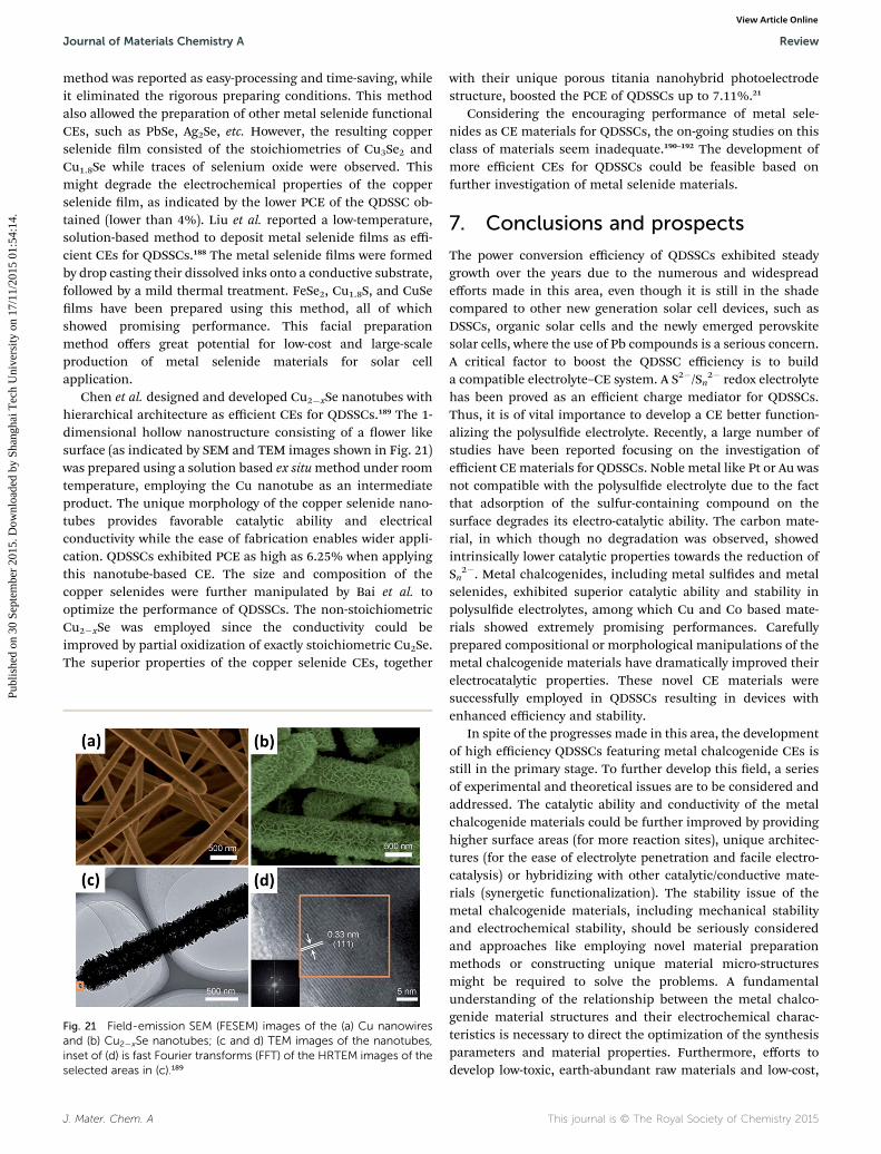
Chen et al. designed and developed Cu2�xSe nanotubes withhierarchical architecture as efficient CEs for QDSSCs.189 The 1-dimensional hollow nanostructure consisting of a ower likesurface (as indicated by SEM and TEM images shown in Fig. 21)was prepared using a solution based ex situmethod under roomtemperature, employing the Cu nanotube as an intermediateproduct. The unique morphology of the copper selenide nano-tubes provides favorable catalytic ability and electricalconductivity while the ease of fabrication enables wider appli-cation. QDSSCs exhibited PCE as high as 6.25% when applyingthis nanotube-based CE. The size and composition of thecopper selenides were further manipulated by Bai et al. tooptimize the performance of QDSSCs. The non-stoichiometricCu2�xSe was employed since the conductivity could beimproved by partial oxidization of exactly stoichiometric Cu2Se.The superior properties of the copper selenide CEs, together
Fig. 21 Field-emission SEM (FESEM) images of the (a) Cu nanowiresand (b) Cu2�xSe nanotubes; (c and d) TEM images of the nanotubes,inset of (d) is fast Fourier transforms (FFT) of the HRTEM images of theselected areas in (c).189
J. Mater. Chem. A
with their unique porous titania nanohybrid photoelectrodestructure, boosted the PCE of QDSSCs up to 7.11%.21
Considering the encouraging performance of metal sele-nides as CE materials for QDSSCs, the on-going studies on thisclass of materials seem inadequate.190–192 The development ofmore efficient CEs for QDSSCs could be feasible based onfurther investigation of metal selenide materials.
7. Conclusions and prospects
The power conversion efficiency of QDSSCs exhibited steadygrowth over the years due to the numerous and widespreadefforts made in this area, even though it is still in the shadecompared to other new generation solar cell devices, such asDSSCs, organic solar cells and the newly emerged perovskitesolar cells, where the use of Pb compounds is a serious concern.A critical factor to boost the QDSSC efficiency is to builda compatible electrolyte–CE system. A S2�/Sn
2� redox electrolytehas been proved as an efficient charge mediator for QDSSCs.Thus, it is of vital importance to develop a CE better function-alizing the polysulde electrolyte. Recently, a large number ofstudies have been reported focusing on the investigation ofefficient CE materials for QDSSCs. Noble metal like Pt or Au wasnot compatible with the polysulde electrolyte due to the factthat adsorption of the sulfur-containing compound on thesurface degrades its electro-catalytic ability. The carbon mate-rial, in which though no degradation was observed, showedintrinsically lower catalytic properties towards the reduction ofSn
2�. Metal chalcogenides, including metal suldes and metalselenides, exhibited superior catalytic ability and stability inpolysulde electrolytes, among which Cu and Co based mate-rials showed extremely promising performances. Carefullyprepared compositional or morphological manipulations of themetal chalcogenide materials have dramatically improved theirelectrocatalytic properties. These novel CE materials weresuccessfully employed in QDSSCs resulting in devices withenhanced efficiency and stability.
In spite of the progresses made in this area, the developmentof high efficiency QDSSCs featuring metal chalcogenide CEs isstill in the primary stage. To further develop this eld, a seriesof experimental and theoretical issues are to be considered andaddressed. The catalytic ability and conductivity of the metalchalcogenide materials could be further improved by providinghigher surface areas (for more reaction sites), unique architec-tures (for the ease of electrolyte penetration and facile electro-catalysis) or hybridizing with other catalytic/conductive mate-rials (synergetic functionalization). The stability issue of themetal chalcogenide materials, including mechanical stabilityand electrochemical stability, should be seriously consideredand approaches like employing novel material preparationmethods or constructing unique material micro-structuresmight be required to solve the problems. A fundamentalunderstanding of the relationship between the metal chalco-genide material structures and their electrochemical charac-teristics is necessary to direct the optimization of the synthesisparameters and material properties. Furthermore, efforts todevelop low-toxic, earth-abundant raw materials and low-cost,
This journal is © The Royal Society of Chemistry 2015

Review Journal of Materials Chemistry A
Publ
ishe
d on
30
Sept
embe
r 20
15. D
ownl
oade
d by
Sha
ngha
i Tec
h U
nive
rsity
on
17/1
1/20
15 0
1:54
:14.
View Article Online
large-area, green manufacturing processes for metal chalco-genides should be taken as well to guarantee that the develop-ment in this area fulls the basic commercial andenvironmental requirements. Thus, the investigation andapplication of novel metal chalcogenide QDSSC CE materials isa quite challenging yet promising research topic, whichprovides an opportunity for the further improvement of theQDSSC performance and for its potential commercialization.
Acknowledgements
G. Chen acknowledges the support from the National NaturalScience Foundation of China (11375256) and Science andTechnology Commission of Shanghai Municipality(14JC1493300). K. R. Thampi acknowledges the SFI-AirtricityStokes professorship grant [S07/EN/E013].
References
1 J. P. Holdren, Science, 2008, 319, 424–434.2 N. S. Lewis, Science, 2007, 315, 798–801.3 M. Graetzel, R. A. J. Janssen, D. B. Mitzi and E. H. Sargent,Nature, 2012, 488, 304–312.
4 H. Savin, P. Repo, G. von Gastrow, P. Ortega, E. Calle,M. Garın and R. Alcubilla, Nat. Nanotech., 2015, 10, 624–628.
5 J. Kim, Z. Hong, G. Li, T.-B. Song, J. Chey, Y. S. Lee, J. You,C.-C. Chen, D. K. Sadana and Y. Yang, Nat. Commun., 2015,6, 6391.
6 Y. Yang, W. Chen, L. Dou, W.-H. Chang, H.-S. Duan, B. Bob,G. Li and Y. Yang, Nat. Photonics, 2015, 9, 190–198.
7 B. O'regan and M. Gratzel, Nature, 1991, 353, 737–740.8 M. Gratzel, Inorg. Chem., 2005, 44, 6841–6851.9 M. Gratzel, J. Photochem. Photobiol., A, 2004, 164, 3–14.10 M. Gratzel, J. Photochem. Photobiol., C, 2003, 4, 145–153.11 S. Ruhle, M. Shalom and A. Zaban, ChemPhysChem, 2010,
11, 2290–2304.12 I. Mora-Sero, S. Gimenez, F. Fabregat-Santiago, R. Gomez,
Q. Shen, T. Toyoda and J. Bisquert, Acc. Chem. Res., 2009,42, 1848–1857.
13 A. Nozik, Phys. E, 2002, 14, 115–120.14 P. V. Kamat, J. Phys. Chem. C, 2008, 112, 18737–18753.15 S. Mathew, A. Yella, P. Gao, R. Humphry-Baker,
B. F. Curchod, N. Ashari-Astani, I. Tavernelli,U. Rothlisberger, M. K. Nazeeruddin and M. Gratzel, Nat.Chem., 2014, 6, 242–247.
16 M. Reed, J. Randall, R. Aggarwal, R. Matyi, T. Moore andA. Wetsel, Phys. Rev. Lett., 1988, 60, 535.
17 W. K. Leutwyler, S. L. Burgi and H. Burgl, Science, 1996, 271,933–937.
18 O. E. Semonin, J. M. Luther, S. Choi, H.-Y. Chen, J. Gao,A. J. Nozik and M. C. Beard, Science, 2011, 334, 1530–1533.
19 K. Zhao, Z. Pan, I. Mora-Sero, E. Canovas, H. Wang, Y. Song,X. Gong, J. Wang, M. Bonn and J. Bisquert, J. Am. Chem.Soc., 2015, 137, 5602–5609.
This journal is © The Royal Society of Chemistry 2015
20 S. Jiao, Q. Shen, I. Mora-Sero, J. Wang, Z. Pan, K. Zhao,Y. Kuga, X. Zhong and J. Bisquert, ACS Nano, 2015, 9,908–915.
21 Y. Bai, C. Han, X. Chen, H. Yu, X. Zong, Z. Li and L. Wang,Nano Energy, 2015, 13, 609–619.
22 Z. Pan, I. N. Mora-Sero, Q. Shen, H. Zhang, Y. Li, K. Zhao,J. Wang, X. Zhong and J. Bisquert, J. Am. Chem. Soc., 2014,136, 9203–9210.
23 J. Tian, L. Lv, C. Fei, Y. Wang, X. Liu and G. Cao, J. Mater.Chem. A, 2014, 2, 19653–19659.
24 H. McDaniel, N. Fuke, N. S. Makarov, J. M. Pietryga andV. I. Klimov, Nat. Commun., 2013, 4, 2887.
25 E. M. Barea, M. Shalom, S. Gimenez, I. Hod, I. Mora-Sero,A. Zaban and J. Bisquert, J. Am. Chem. Soc., 2010, 132,6834–6839.
26 M. Shalom, S. Ruhle, I. Hod, S. Yahav and A. Zaban, J. Am.Chem. Soc., 2009, 131, 9876–9877.
27 T.-L. Li, Y.-L. Lee and H. Teng, Energy Environ. Sci., 2012, 5,5315–5324.
28 P. V. Kamat, Acc. Chem. Res., 2012, 45, 1906–1915.29 N. Fuke, L. B. Hoch, A. Y. Koposov, V. W. Manner,
D. J. Werder, A. Fukui, N. Koide, H. Katayama andM. Sykora, ACS Nano, 2010, 4, 6377–6386.
30 Z. Pan, K. Zhao, J. Wang, H. Zhang, Y. Feng and X. Zhong,ACS Nano, 2013, 7, 5215–5222.
31 J. Wang, I. Mora-Sero, Z. Pan, K. Zhao, H. Zhang, Y. Feng,G. Yang, X. Zhong and J. Bisquert, J. Am. Chem. Soc., 2013,135, 15913–15922.
32 O. Niitsoo, S. K. Sarkar, C. Pejoux, S. Ruhle, D. Cahen andG. Hodes, J. Photochem. Photobiol., A, 2006, 181, 306–313.
33 H. Zhang, K. Cheng, Y. Hou, Z. Fang, Z. Pan, W. Wu, J. Huaand X. Zhong, Chem. Commun., 2012, 48, 11235–11237.
34 A. Salant, M. Shalom, I. Hod, A. Faust, A. Zaban andU. Banin, ACS Nano, 2010, 4, 5962–5968.
35 T. P. Brennan, P. Ardalan, H. B. R. Lee, J. R. Bakke, I. Ding,M. D. McGehee and S. F. Bent, Adv. Energy Mater., 2011, 1,1169–1175.
36 H. Lee, M. Wang, P. Chen, D. R. Gamelin,S. M. Zakeeruddin, M. Gratzel and M. K. Nazeeruddin,Nano Lett., 2009, 9, 4221–4227.
37 H. Lee, H. C. Leventis, S. J. Moon, P. Chen, S. Ito,S. A. Haque, T. Torres, F. Nuesch, T. Geiger andS. M. Zakeeruddin, Adv. Funct. Mater., 2009, 19, 2735–2742.
38 I. Robel, V. Subramanian, M. Kuno and P. V. Kamat, J. Am.Chem. Soc., 2006, 128, 2385–2393.
39 P. Brown and P. V. Kamat, J. Am. Chem. Soc., 2008, 130,8890–8891.
40 X.-Y. Yu, J.-Y. Liao, K.-Q. Qiu, D.-B. Kuang and C.-Y. Su, ACSNano, 2011, 5, 9494–9500.
41 P. K. Santra and P. V. Kamat, J. Am. Chem. Soc., 2012, 134,2508–2511.
42 C. Li, L. Yang, J. Xiao, Y.-C. Wu, M. Søndergaard, Y. Luo,D. Li, Q. Meng and B. B. Iversen, Phys. Chem. Chem. Phys.,2013, 15, 8710–8715.
43 X. Huang, S. Huang, Q. Zhang, X. Guo, D. Li, Y. Luo,Q. Shen, T. Toyoda and Q. Meng, Chem. Commun., 2011,47, 2664–2666.
J. Mater. Chem. A
Journal of Materials Chemistry A Review
Publ
ishe
d on
30
Sept
embe
r 20
15. D
ownl
oade
d by
Sha
ngha
i Tec
h U
nive
rsity
on
17/1
1/20
15 0
1:54
:14.
View Article Online
44 H. Zhang, Y. Wang, D. Yang, Y. Li, H. Liu, P. Liu, B. J. Woodand H. Zhao, Adv. Mater., 2012, 24, 1598–1603.
45 H. Zhang, Y. Li, Y. Wang, P. Liu, H. Yang, X. Yao, T. An,B. J. Wood and H. Zhao, J. Mater. Chem. A, 2013, 1, 6563–6571.
46 L.-B. Li, Y.-F. Wang, H.-S. Rao, W.-Q. Wu, K.-N. Li, C.-Y. Suand D.-B. Kuang, ACS Appl. Mater. Interfaces, 2013, 5,11865–11871.
47 K. Meng, P. K. Surolia and K. R. Thampi, J. Mater. Chem. A,2014, 2, 10231–10238.
48 P. Sudhagar, T. Song, D. H. Lee, I. Mora-Sero, J. Bisquert,M. Laudenslager, W. M. Sigmund, W. I. Park, U. Paik andY. S. Kang, J. Phys. Chem. Lett., 2011, 2, 1984–1990.
49 J. Hensel, G. Wang, Y. Li and J. Z. Zhang, Nano Lett., 2010,10, 478–483.
50 K. S. Leschkies, R. Divakar, J. Basu, E. Enache-Pommer,J. E. Boercker, C. B. Carter, U. R. Kortshagen, D. J. Norrisand E. S. Aydil, Nano Lett., 2007, 7, 1793–1798.
51 K. Meng, P. K. Surolia, O. Byrne and K. R. Thampi, J. PowerSources, 2014, 248, 218–223.
52 J. Jean, S. Chang, P. R. Brown, J. J. Cheng, P. H. Rekemeyer,M. G. Bawendi, S. Gradecak and V. Bulovic, Adv. Mater.,2013, 25, 2790–2796.
53 J. Tian, Q. Zhang, E. Uchaker, Z. Liang, R. Gao, X. Qu,S. Zhang and G. Cao, J. Mater. Chem. A, 2013, 1, 6770–6775.
54 T. You, L. Jiang, K.-L. Han and W.-Q. Deng, Nanotechnology,2013, 24, 245401.
55 M. Seol, H. Kim, Y. Tak and K. Yong, Chem. Commun., 2010,46, 5521–5523.
56 S. Huang, Q. Zhang, X. Huang, X. Guo, M. Deng, D. Li,Y. Luo, Q. Shen, T. Toyoda and Q. Meng, Nanotechnology,2010, 21, 375201.
57 H. Wang, M. Miyauchi, Y. Ishikawa, A. Pyatenko,N. Koshizaki, Y. Li, L. Li, X. Li, Y. Bando and D. Golberg,J. Am. Chem. Soc., 2011, 133, 19102–19109.
58 T. Toyoda and Q. Shen, J. Phys. Chem. Lett., 2012, 3, 1885–1893.
59 J. Chen, C. Li, G. Eda, Y. Zhang, W. Lei, M. Chhowalla,W. I. Milne and W.-Q. Deng, Chem. Commun., 2011, 47,6084–6086.
60 Y.-L. Lee and C.-H. Chang, J. Power Sources, 2008, 185, 584–588.
61 A. J. Haring, M. E. Pomatto, M. R. Thornton and A. J. Morris,ACS Appl. Mater. Interfaces, 2014, 6, 15061–15067.
62 H. J. Lee, P. Chen, S.-J. Moon, F. Sauvage, K. Sivula,T. Bessho, D. R. Gamelin, P. Comte, S. M. Zakeeruddinand S. I. Seok, Langmuir, 2009, 25, 7602–7608.
63 Y. Tachibana, H. Y. Akiyama, Y. Ohtsuka, T. Torimoto andS. Kuwabata, Chem. Lett., 2007, 36, 88–89.
64 K. Meng and K. R. Thampi, ACS Appl. Mater. Interfaces,2014, 6, 20768–20775.
65 K. Meng, P. K. Surolia, O. Byrne and K. R. Thampi, J. PowerSources, 2015, 275, 681–687.
66 H. J. Lee, J.-H. Yum, H. C. Leventis, S. M. Zakeeruddin,S. A. Haque, P. Chen, S. I. Seok, M. Gratzel andM. K. Nazeeruddin, J. Phys. Chem. C, 2008, 112, 11600–11608.
J. Mater. Chem. A
67 L. Li, X. Yang, J. Gao, H. Tian, J. Zhao, A. Hagfeldt andL. Sun, J. Am. Chem. Soc., 2011, 133, 8458–8460.
68 I. Hod and A. Zaban, Langmuir, 2013, 30, 7264–7273.69 J. Duan, H. Zhang, Q. Tang, B. He and L. Yu, J. Mater. Chem.
A, 2015, 3, 17497–17510.70 I. Hwang and K. Yong, ChemElectroChem, 2015, 2, 634–653.71 H. Jun, M. Careem and A. Arof, Renewable Sustainable
Energy Rev., 2013, 22, 148–167.72 M. Kouhnavard, S. Ikeda, N. Ludin, N. A. Khairudin,
B. Ghaffari, M. Mat-Teridi, M. Ibrahim, S. Sepeai andK. Sopian, Renewable Sustainable Energy Rev., 2014, 37,397–407.
73 P. V. Kamat, J. Phys. Chem. Lett., 2013, 4, 908–918.74 M. Wu, X. Lin, Y. Wang and T. Ma, J. Mater. Chem. A, 2015,
3, 19638–19656.75 Z. Yang, C.-Y. Chen, P. Roy and H.-T. Chang, Chem.
Commun., 2011, 47, 9561–9571.76 A. Yella, H.-W. Lee, H. N. Tsao, C. Yi, A. K. Chandiran,
M. K. Nazeeruddin, E. W.-G. Diau, C.-Y. Yeh,S. M. Zakeeruddin and M. Gratzel, Science, 2011, 334,629–634.
77 C. H. Chang and Y. L. Lee, Appl. Phys. Lett., 2007, 91,053503.
78 M. Shalom, S. Dor, S. Ruhle, L. Grinis and A. Zaban, J. Phys.Chem. C, 2009, 113, 3895–3898.
79 A. Fujishima, E. Sugiyama and K. Honda, Bull. Chem. Soc.Jpn., 1971, 44, 304–304.
80 H. Gerischer, J. Electroanal. Chem. Interfacial Electrochem.,1975, 58, 263–274.
81 K. Rajeshwar, P. Singh and J. DuBow, Electrochim. Acta,1978, 23, 1117–1144.
82 B. Miller and A. Heller, Nature, 1976, 262, 680.83 A. B. Ellis, S. W. Kaiser and M. S. Wrighton, J. Am. Chem.
Soc., 1976, 98, 1635–1637.84 G. Hodes, J. Manassen and D. Cahen, Nature, 1976, 261,
403.85 V. Chakrapani, D. Baker and P. V. Kamat, J. Am. Chem. Soc.,
2011, 133, 9607–9615.86 M. A. Hossain, J. R. Jennings, C. Shen, J. H. Pan, Z. Y. Koh,
N. Mathews and Q. Wang, J. Mater. Chem., 2012, 22, 16235–16242.
87 J.-W. Lee, D.-Y. Son, T. K. Ahn, H.-W. Shin, I. Y. Kim,S.-J. Hwang, M. J. Ko, S. Sul, H. Han and N.-G. Park, Sci.Rep., 2013, 3, 1050.
88 S. Do Sung, I. Lim, P. Kang, C. Lee and W. I. Lee, Chem.Commun., 2013, 49, 6054–6056.
89 C.-Y. Chou, C.-P. Lee, R. Vittal and K.-C. Ho, J. PowerSources, 2011, 196, 6595–6602.
90 V. Jovanovski, V. Gonzalez-Pedro, S. Gimenez, E. Azaceta,G. N. Cabanero, H. Grande, R. Tena-Zaera, I. N. Mora-Seroand J. Bisquert, J. Am. Chem. Soc., 2011, 133, 20156–20159.
91 J. Qian, Q.-S. Liu, G. Li, K.-J. Jiang, L.-M. Yang and Y. Song,Chem. Commun., 2011, 47, 6461–6463.
92 Z. Yu, Q. Zhang, D. Qin, Y. Luo, D. Li, Q. Shen, T. Toyodaand Q. Meng, Electrochem. Commun., 2010, 12, 1776–1779.
This journal is © The Royal Society of Chemistry 2015

Review Journal of Materials Chemistry A
Publ
ishe
d on
30
Sept
embe
r 20
15. D
ownl
oade
d by
Sha
ngha
i Tec
h U
nive
rsity
on
17/1
1/20
15 0
1:54
:14.
View Article Online
93 C.-F. Chi, P. Chen, Y.-L. Lee, I.-P. Liu, S.-C. Chou,X.-L. Zhang and U. Bach, J. Mater. Chem., 2011, 21, 17534–17540.
94 G. Larramona, C. Chone, A. Jacob, D. Sakakura,B. Delatouche, D. Pere, X. Cieren, M. Nagino andR. Bayon, Chem. Mater., 2006, 18, 1688–1696.
95 S. Gimenez, I. Mora-Sero, L. Macor, N. Guijarro, T. Lana-Villarreal, R. Gomez, L. J. Diguna, Q. Shen, T. Toyoda andJ. Bisquert, Nanotechnology, 2009, 20, 295204.
96 L. T. L. Lee, J. He, B. Wang, Y. Ma, K. Y. Wong, Q. Li, X. Xiaoand T. Chen, Sci. Rep., 2014, 4, 4063.
97 G. R. Li, F. Wang, Q. W. Jiang, X. P. Gao and P. W. Shen,Angew. Chem., Int. Ed., 2010, 49, 3653–3656.
98 I. Hwang and K. Yong, ChemElectroChem, 2015, 2, 634–653.99 S. Thomas, T. Deepak, G. Anjusree, T. Arun, S. V. Nair and
A. S. Nair, J. Mater. Chem. A, 2014, 2, 4474–4490.100 Y. L. Lee and Y. S. Lo, Adv. Funct. Mater., 2009, 19, 604–609.101 J. G. Radich, R. Dwyer and P. V. Kamat, J. Phys. Chem. Lett.,
2011, 2, 2453–2460.102 X.-Y. Yu, B.-X. Lei, D.-B. Kuang and C.-Y. Su, Chem. Sci.,
2011, 2, 1396–1400.103 T. Kiyonaga, T. Akita and H. Tada, Chem. Commun., 2009,
2011–2013.104 G. Zhu, L. Pan, H. Sun, X. Liu, T. Lv, T. Lu, J. Yang and
Z. Sun, ChemPhysChem, 2012, 13, 769–773.105 Y.-P. Yoon, J.-H. Kim, S.-H. Kang, H. Kim, C.-J. Choi,
K.-K. Kim and K.-S. Ahn, Appl. Phys. Lett., 2014, 105, 083116.106 H. Zhu, J. Wei, K. Wang and D. Wu, Sol. Energy Mater. Sol.
Cells, 2009, 93, 1461–1470.107 J. D. Roy-Mayhew, D. J. Bozym, C. Punckt and I. A. Aksay,
ACS Nano, 2010, 4, 6203–6211.108 D. Chen, H. Zhang, Y. Liu and J. Li, Energy Environ. Sci.,
2013, 6, 1362–1387.109 M. Wu, X. Lin, T. Wang, J. Qiu and T. Ma, Energy Environ.
Sci., 2011, 4, 2308–2315.110 J. Chen, K. Li, Y. Luo, X. Guo, D. Li, M. Deng, S. Huang and
Q. Meng, Carbon, 2009, 47, 2704–2708.111 W. J. Lee, E. Ramasamy, D. Y. Lee and J. S. Song, ACS Appl.
Mater. Interfaces, 2009, 1, 1145–1149.112 P. Joshi, Y. Xie, M. Ropp, D. Galipeau, S. Bailey and Q. Qiao,
Energy Environ. Sci., 2009, 2, 426–429.113 H. Sun, Y. Luo, Y. Zhang, D. Li, Z. Yu, K. Li and Q. Meng, J.
Phys. Chem. C, 2010, 114, 11673–11679.114 Q. Zhang, Y. Zhang, S. Huang, X. Huang, Y. Luo, Q. Meng
and D. Li, Electrochem. Commun., 2010, 12, 327–330.115 G. Hodes, J. Manassen and D. Cahen, J. Electrochem. Soc.,
1980, 127, 544–549.116 S.-Q. Fan, B. Fang, J. H. Kim, J.-J. Kim, J.-S. Yu and J. Ko,
Appl. Phys. Lett., 2010, 96, 063501.117 S.-Q. Fan, B. Fang, J. H. Kim, B. Jeong, C. Kim, J.-S. Yu and
J. Ko, Langmuir, 2010, 26, 13644–13649.118 M. Seol, E. Ramasamy, J. Lee and K. Yong, J. Phys. Chem. C,
2011, 115, 22018–22024.119 P. Sudhagar, E. Ramasamy, W.-H. Cho, J. Lee and
Y. S. Kang, Electrochem. Commun., 2011, 13, 34–37.120 G. S. Paul, J. H. Kim, M.-S. Kim, K. Do, J. Ko and J.-S. Yu,
ACS Appl. Mater. Interfaces, 2012, 4, 375–381.
This journal is © The Royal Society of Chemistry 2015
121 J. Dong, S. Jia, J. Chen, B. Li, J. Zheng, J. Zhao, Z. Wang andZ. Zhu, J. Mater. Chem., 2012, 22, 9745–9750.
122 F. Hao, P. Dong, J. Zhang, Y. Zhang, P. E. Loya, R. H. Hauge,J. Li, J. Lou and H. Lin, Sci. Rep., 2012, 2, 368.
123 X. Fang, T. Ma, G. Guan, M. Akiyama, T. Kida and E. Abe, J.Electroanal. Chem., 2004, 570, 257–263.
124 D. Reynolds, G. Leies, L. Antes and R. Marburger, Phys. Rev.,1954, 96, 533.
125 Y. Zhao and C. Burda, Energy Environ. Sci., 2012, 5, 5564–5576.
126 Y. Zhao, H. Pan, Y. Lou, X. Qiu, J. Zhu and C. Burda, J. Am.Chem. Soc., 2009, 131, 4253–4261.
127 Z. Peng, Y. Liu, Y. Zhao, K. Chen, Y. Cheng and W. Chen,Electrochim. Acta, 2014, 135, 276–283.
128 G. S. Selopal, I. Concina, R. Milan, M. M. Natile,G. Sberveglieri and A. Vomiero, Nano Energy, 2014, 6,200–210.
129 S. Wang, W. Dong, X. Fang, S. Zhou, J. Shao, Z. Deng,R. Tao, Q. Zhang, L. Hu and J. Zhu, Electrochim. Acta,2015, 154, 47–53.
130 L. Quan, W. Li, L. Zhu, X. Chang and H. Liu, RSC Adv., 2014,4, 32214–32220.
131 K. Zhao, H. Yu, H. Zhang and X. Zhong, J. Phys. Chem. C,2014, 118, 5683–5690.
132 Y.-F. Xu, W.-Q. Wu, H.-S. Rao, H.-Y. Chen, D.-B. Kuang andC.-Y. Su, Nano Energy, 2015, 11, 621–630.
133 C. Shen, L. Sun, Z. Y. Koh and Q. Wang, J. Mater. Chem. A,2014, 2, 2807–2813.
134 H. Salaramoli, E. Maleki, Z. Shariatinia and M. Ranjbar, J.Photochem. Photobiol., A, 2013, 271, 56–64.
135 M. Deng, S. Huang, Q. Zhang, D. Li, Y. Luo, Q. Shen,T. Toyoda and Q. Meng, Chem. Lett., 2010, 39, 1168–1170.
136 I. Mora-Sero, S. Gimenez, T. Moehl, F. Fabregat-Santiago,T. Lana-Villareal, R. Gomez and J. Bisquert,Nanotechnology, 2008, 19, 424007.
137 Y. Jiang, X. Zhang, Q.-Q. Ge, B.-B. Yu, Y.-G. Zou, W.-J. Jiang,W.-G. Song, L.-J. Wan and J.-S. Hu, Nano Lett., 2013, 14,365–372.
138 Y. Jiang, X. Zhang, Q.-Q. Ge, B.-B. Yu, Y.-G. Zou, W.-J. Jiang,J.-S. Hu, W.-G. Song and L.-J. Wan, ACS Appl. Mater.Interfaces, 2014, 6, 15448–15455.
139 M. Ye, C. Chen, N. Zhang, X. Wen, W. Guo and C. Lin, Adv.Energy Mater., 2014, 4, 1301564.
140 M. Deng, Q. Zhang, S. Huang, D. Li, Y. Luo, Q. Shen,T. Toyoda and Q. Meng, Nanoscale Res. Lett., 2010, 5, 986–990.
141 D.-M. Li, L.-Y. Cheng, Y.-D. Zhang, Q.-X. Zhang,X.-M. Huang, Y.-H. Luo and Q.-B. Meng, Sol. EnergyMater. Sol. Cells, 2014, 120, 454–461.
142 F. Wang, H. Dong, J. Pan, J. Li, Q. Li and D. Xu, J. Phys.Chem. C, 2014, 118, 19589–19598.
143 A. D. Savariraj, K. Viswanathan and K. Prabakar,Electrochim. Acta, 2014, 149, 364–369.
144 L. Li, P. Zhu, S. Peng, M. Srinivasan, Q. Yan, A. S. Nair,B. Liu and S. Samakrishna, J. Phys. Chem. C, 2014, 118,16526–16535.
J. Mater. Chem. A
Journal of Materials Chemistry A Review
Publ
ishe
d on
30
Sept
embe
r 20
15. D
ownl
oade
d by
Sha
ngha
i Tec
h U
nive
rsity
on
17/1
1/20
15 0
1:54
:14.
View Article Online
145 P. Lukashev, W. R. Lambrecht, T. Kotani andM. V. Schilfgaarde, Phys. Rev. B: Condens. Matter Mater.Phys., 2007, 76, 195202.
146 C. S. Kim, S. H. Choi and J. H. Bang, ACS Appl. Mater.Interfaces, 2014, 6, 22078–22087.
147 J. L. Da Silva, S.-H. Wei, J. Zhou and X. Wu, Appl. Phys. Lett.,2007, 91, 091902.
148 M. Buerger and B. J. Wuensch, Science, 1963, 141, 276–277.149 M. Kundu, T. Hasegawa, K. Terabe and M. Aono, J. Appl.
Phys., 2008, 103, 073523.150 W. Chen, M. Wang, T. Qian, H. Cao, S. Huang, Q. He,
N. Liang, C. Wang and J. Zai, Nano Energy, 2015, 12, 186–196.
151 M. Ye, X. Wen, N. Zhang, W. Guo, X. Liu and C. Lin, J.Mater. Chem. A, 2015, 3, 9595–9600.
152 A. D. Savariraj, K. K. Viswanathan and K. Prabakar, ACSAppl. Mater. Interfaces, 2014, 6, 19702–19709.
153 H.-J. Kim, J.-H. Kim, C. S. P. Kumar, D. Punnoose,S.-K. Kim, C. V. Gopi and S. S. Rao, J. Electroanal. Chem.,2015, 739, 20–27.
154 C. V. Gopi, M. Venkata-Haritha, S.-K. Kim, S. S. Rao,D. Punnoose and H.-J. Kim, RSC Adv., 2015, 5, 2963–2967.
155 Y. Zhang, J. Tian, H. Li, L. Wang, X. Qin, A. M. Asiri, A. O. Al-Youbi and X. Sun, Langmuir, 2012, 28, 12893–12900.
156 H. Chen, L. Zhu, H. Liu and W. Li, J. Phys. Chem. C, 2013,117, 3739–3746.
157 W. L. Chen, M. Wang, T. Y. Qian, H. L. Cao, S. S. Huang,Q. Q. He, N. Liang, C. Wang and J. T. Zai, Nano Energy,2015, 12, 186–196.
158 M. Ye, X. Wen, N. Zhang, W. Guo, X. Liu and C. Lin, J.Mater. Chem. A, 2015, 3, 9595–9600.
159 Z. Yang, C.-Y. Chen and H.-T. Chang, Sol. Energy Mater. Sol.Cells, 2011, 95, 2867–2873.
160 W. Guo, C. Chen, M. Ye, M. Lv and C. Lin, Nanoscale, 2014,6, 3656–3663.
161 M. Que, W. Guo, X. Zhang, X. Li, Q. Hua, L. Dong andC. Pan, J. Mater. Chem. A, 2014, 2, 13661–13666.
162 W. Guo, X. Zhang, R. Yu, M. Que, Z. Zhang, Z. Wang,Q. Hua, C. Wang, Z. L. Wang and C. Pan, Adv. EnergyMater., 2015, 5, 1500141.
163 Z. Tachan, M. Shalom, I. Hod, S. Ruhle, S. Tirosh andA. Zaban, J. Phys. Chem. C, 2011, 115, 6162–6166.
164 Z. Yang, C.-Y. Chen, C.-W. Liu and H.-T. Chang, Chem.Commun., 2010, 46, 5485–5487.
165 H. Geng, L. Zhu, W. Li, H. Liu, L. Quan, F. Xi and X. Su, J.Power Sources, 2015, 281, 204–210.
166 H. J. Kim, T. B. Yeo, S. K. Kim, S. S. Rao, A. D. Savariraj,K. Prabakar and C. V. Gopi, Eur. J. Inorg. Chem., 2014,2014, 4281–4286.
167 A. D. Mani, M. Deepa, P. Ghosal and C. Subrahmanyam,Electrochim. Acta, 2014, 139, 365–373.
168 H.-J. Kim, D.-J. Kim, S. S. Rao, A. D. Savariraj, K. Soo-Kyoung, M.-K. Son, C. V. Gopi and K. Prabakar,Electrochim. Acta, 2014, 127, 427–432.
J. Mater. Chem. A
169 Z. Yang, C. Y. Chen, C. W. Liu, C. L. Li and H. T. Chang, Adv.Energy Mater., 2011, 1, 259–264.
170 H. Yuan, J. Lu, X. Xu, D. Huang, W. Chen, Y. Shen andM. Wang, J. Electrochem. Soc., 2013, 160, H624–H629.
171 Y. Yang, L. Zhu, H. Sun, X. Huang, Y. Luo, D. Li andQ. Meng, ACS Appl. Mater. Interfaces, 2012, 4, 6162–6168.
172 P. Parand, M. Samadpour, A. Esfandiar and A. Iraji Zad,ACS Photonics, 2014, 1, 323–330.
173 M. Eskandari, V. Ahmadi and R. Ghahary, Electrochim. Acta,2015, 151, 393–398.
174 X. Song, M. Wang, J. Deng, Y. Ju, T. Xing, J. Ding, Z. Yangand J. Shao, J. Power Sources, 2014, 269, 661–670.
175 M. S. Faber, M. A. Lukowski, Q. Ding, N. S. Kaiser and S. Jin,J. Phys. Chem. C, 2014, 118, 21347–21356.
176 X. Zhang, X. Huang, Y. Yang, S. Wang, Y. Gong, Y. Luo, D. Liand Q. Meng, ACS Appl. Mater. Interfaces, 2013, 5, 5954–5960.
177 J. Xu, X. Yang, Q.-D. Yang, T.-L. Wong and C.-S. Lee, J. Phys.Chem. C, 2012, 116, 19718–19723.
178 Y. Cao, Y. Xiao, J.-Y. Jung, H.-D. Um, S.-W. Jee, H. M. Choi,J. H. Bang and J.-H. Lee, ACS Appl. Mater. Interfaces, 2013, 5,479–484.
179 Y. Zhang, C. Shi, X. Dai, F. Liu, X. Fang and J. Zhu,Electrochim. Acta, 2014, 118, 41–44.
180 X. Zeng, W. Zhang, Y. Xie, D. Xiong, W. Chen, X. Xu,M. Wang and Y.-B. Cheng, J. Power Sources, 2013, 226,359–362.
181 J. Xiao, X. Zeng, W. Chen, F. Xiao and S. Wang, Chem.Commun., 2013, 49, 11734–11736.
182 H. Ahari, C. L. Bowes, T. Jiang, A. Lough, G. A. Ozin,R. L. Bedard, S. Petrov and D. Young, Adv. Mater., 1995, 7,375–378.
183 W. Wang, Y. Geng, P. Yan, F. Liu, Y. Xie and Y. Qian, J. Am.Chem. Soc., 1999, 121, 4062–4063.
184 V. Colvin, M. Schlamp and A. Alivisatos, Nature, 1994, 370,354–357.
185 F. Gong, H. Wang, X. Xu, G. Zhou and Z.-S. Wang, J. Am.Chem. Soc., 2012, 134, 10953–10958.
186 H. M. Choi, I. A. Ji and J. H. Bang, ACS Appl. Mater.Interfaces, 2014, 6, 2335–2343.
187 F. Bo, C. Zhang, C. Wang, S. Xu, Z. Wang and Y. Cui, J.Mater. Chem. A, 2014, 2, 14585–14592.
188 F. Liu, J. Zhu, L. Hu, B. Zhang, J. Yao, M. K. Nazeeruddin,M. Gratzel and S. Dai, J. Mater. Chem. A, 2015, 3, 6315–6323.
189 X. Q. Chen, Z. Li, Y. Bai, Q. Sun, L. Z. Wang and S. X. Dou,Chem.–Eur. J., 2015, 21, 1055–1063.
190 C. Ma, Q. Tang, D. Liu, Z. Zhao, B. He, H. Chen and L. Yu, J.Power Sources, 2015, 276, 215–221.
191 C. Ma, Q. Tang, Z. Zhao, M. Hou, Y. Chen, B. He and L. Yu,J. Power Sources, 2015, 278, 183–189.
192 J. Xu, X. Yang, Q. Yang, W. Zhang and C.-S. Lee, ACS Appl.Mater. Interfaces, 2014, 6, 16352–16359.
This journal is © The Royal Society of Chemistry 2015
Related Documents