http://jcm.sagepub.com/ Materials Journal of Composite http://jcm.sagepub.com/content/2/1/18 The online version of this article can be found at: DOI: 10.1177/002199836800200102 1968 2: 18 Journal of Composite Materials N.J. Pagano and J.C. Halpin Influence of End Constraint in the Testing of Anisotropic Bodies Published by: http://www.sagepublications.com On behalf of: American Society for Composites can be found at: Journal of Composite Materials Additional services and information for http://jcm.sagepub.com/cgi/alerts Email Alerts: http://jcm.sagepub.com/subscriptions Subscriptions: http://www.sagepub.com/journalsReprints.nav Reprints: http://www.sagepub.com/journalsPermissions.nav Permissions: http://jcm.sagepub.com/content/2/1/18.refs.html Citations: at MICHIGAN STATE UNIV LIBRARIES on October 31, 2010 jcm.sagepub.com Downloaded from

Welcome message from author
This document is posted to help you gain knowledge. Please leave a comment to let me know what you think about it! Share it to your friends and learn new things together.
Transcript

http://jcm.sagepub.com/
MaterialsJournal of Composite
http://jcm.sagepub.com/content/2/1/18The online version of this article can be found at:
DOI: 10.1177/002199836800200102
1968 2: 18Journal of Composite MaterialsN.J. Pagano and J.C. Halpin
Influence of End Constraint in the Testing of Anisotropic Bodies
Published by:
http://www.sagepublications.com
On behalf of:
American Society for Composites
can be found at:Journal of Composite MaterialsAdditional services and information for
http://jcm.sagepub.com/cgi/alertsEmail Alerts:
http://jcm.sagepub.com/subscriptionsSubscriptions:
http://www.sagepub.com/journalsReprints.navReprints:
http://www.sagepub.com/journalsPermissions.navPermissions:
http://jcm.sagepub.com/content/2/1/18.refs.htmlCitations:
at MICHIGAN STATE UNIV LIBRARIES on October 31, 2010jcm.sagepub.comDownloaded from
18
Influence of End Constraint in the
Testing of Anisotropic Bodies
N. J. PAGANOAND
J. C. HALPIN
Nonmetallic Materials DivisionAir Force Materials LaboratoryWright-Patterson AFB, Ohio
One of the most elementary concepts in elasticity theory is thatof a uniform state of stress. Producing such a state of stress in thelaboratory, however, is not a trivial task. A common experiment incomposite mechanics—the tension test of off-angle composites-isdiscussed in this paper and the influence of end constraint on theuniform stress field is investigated. Analytical and experimentalevidence is presented to show the serious effects caused by con-ventional clamping devices.
INTRODUCTION
ONE of the more common experiments currently being utilized tocharacterize composite materials is the tension test of off-anglespecimens, i.e., specimens in which the unidirectional filaments areneither parallel nor perpendicular to the direction of the appliedtensile force. In order to interpret the data from such experiments, itis assumed that uniform states of stress and strain exist within the
gage section. In this paper, we shall present analytical and experi-mental evidence which indicates that conventional modes of endconstraint induce severe perturbations in the stress and strain fields.Owing to the restraint caused by clamping devices, significant shearand bending effects are present.
Consider the off-angle composite specimen (or simply, a homo-geneous anisotropic material) under uniform normal stress (To as
shown in Figure 1. The deformed configuration is indicated by solidlines. Of particular concern is the shear strain
where S16 is the shear coupling compliance, which causes the bar to
at MICHIGAN STATE UNIV LIBRARIES on October 31, 2010jcm.sagepub.comDownloaded from

19
Figure 1. Uniform state of stress. Figure 2. Effect of clamped ends.
distort into a parallelogram. Suppose, however, that the ends of thebar are constrained to remain horizontal, a condition which approxi-mates the effect of clamped ends. As shown in Figure 2, the applica-tion of constant end displacements induces shearing forces andbending couples at the ends of the bar, which result in the non-uniform deformation shown in the figure.
at MICHIGAN STATE UNIV LIBRARIES on October 31, 2010jcm.sagepub.comDownloaded from

20
ANALYTICAL SOLUTION
In order to gain insight as to the influence of the constraint pro-duced by gripping the ends of a tensile specimen, we shall simulatethese displacement boundary conditions and solve the appropriateboundary value problem in the linear theory of elasticity (see Figure3). Since composite specimens are thin members, we assume that thebar is in a state of plane stress in the xy plane. We also consider amacroscopically homogeneous material, which is consistent with thenature of the response to be studied. In Figure 3 the axes of materialsymmetry are at an angle a with the x and y coordinate axes, and xy isa plane of material symmetry. Hence, the governing equations whichmust be satisfied in the orthotropic medium [1] are the equationsof equilibrium,
the strain-displacement relations,
Figure 3. Specimen geometry.=zi»
at MICHIGAN STATE UNIV LIBRARIES on October 31, 2010jcm.sagepub.comDownloaded from
21
and the constitutive relations,
where Sij are the compliance coefficients with respect to the xycoordinate system, four of these being independent. Eliminating thestrain and displacement components from eqs. (3) and (4) and using(2), we obtain the following stress compatibility equation:
Therefore, in the stress formulation, the governing equations are (2)and (5).
If an end surface of the bar in Figure 3, say x = 0, is supported by arigid clamp, the boundary conditions on this end can be expressed by
while on the surfaces y = -h, the prescribed boundary conditions aregiven by
since these edges are free surfaces.The boundary value problem described by the solution of eqs. (2)
and (5) which satisfies (7) and the end conditions corresponding to (6)is a very complicated one, and can probably only be solved by numer-ical methods. Furthermore, photographs shown later illustrate thatthe displacements at a clamped end do not satisfy eqs. (6) in an actualexperiment. Rather, the specimen tends to be pulled out of the clampdue to the Poisson contraction in the thickness direction. In view of
this, we shall seek a solution that satisfies eqs. (2), (5), and (7), andreplace eqs. (6) by boundary conditions on the center line, i.e.,
and
where Eo (center-line strain) is a constant which is directly propor-tional to the magnitude of the applied axial force.
at MICHIGAN STATE UNIV LIBRARIES on October 31, 2010jcm.sagepub.comDownloaded from

22
Since the shearing force in the bar is independent of x, we assumea solution for Txy of the form
where f ( y ) is an arbitrary function of y alone. Substituting eq. (10)into (2) and integrating, we find that
where h (x) and g ( y ) are arbitrary functions of the respective vari-ables. Putting eqs. (11) into the compatibility equation (5) and using(7) yields
where Co, C1, C2 are constants. Thus the stress and strain componentsare given by
and
Integrating the strain-displacement relations (3) after inserting eqs.(14) gives the following displacement functions:
-
at MICHIGAN STATE UNIV LIBRARIES on October 31, 2010jcm.sagepub.comDownloaded from

23
By use of boundary conditions (8) and (9), the various constants aredetermined as
which completes the solution. We observe that the stress and straincomponents on the center line y = 0 assume constant values. In
particular, we see that
Suppose that the tension test of an off-angle composite is used asthe basis for determining Ell, the composite modulus of elasticity inthe x direction. If the effects noted here are not taken into account,this modulus will be erroneously recorded as E1~, where
However, eqs. (17) and (18) show that
.
where
and
In other words, 71 is a measure of the error in the observed modulus.The value of T can be quite large for certain values of a (see Figure 3)in highly anisotropic composites like boron-epoxy and graphite-epoxy, but for materials like glass-epoxy, it is quite small. Using data
at MICHIGAN STATE UNIV LIBRARIES on October 31, 2010jcm.sagepub.comDownloaded from
24
and transformation curves presented by Tsai [2] on boron-epoxycomposites for a fiber volume fraction of .65, a = 30°, and t/w = 2,the value of T is found to be .33, whereas for t/w = 6, ~ = .07; theserepresent errors in the observed value of E11 of 50% and 7%, respec-tively, according to eq. (19). For large values of t/w, the value of Tapproaches zero.
The numerical values presented in the previous paragraph aregiven as an estimate of the error produced by end constraint. Wemust recall that eq. (19) is based upon an approximate version of thedisplacement boundary conditions at the clamped ends, i.e., we haveassumed restraint at one point (on the center line) at each end. Al-though subsequent photographs indicate that this assumption is
reasonable, it appears that bending effects would be more pro-nounced if a finite width of the specimen is restrained. It might seemthat errors can be reduced by allowing an end clamp to rotate, whichis a common practice in conventional testing machines. The majorfactor, however, is the clamping or gripping per se, rather than theorientation of the end fixture, so that rotation of an end has little effecton the strain field. We shall return to these points in the discussionof our experimental results.We may also express our results in terms of the applied axial force
P as shown in Figure 2, rather than using the parameter Eo, since... , ......... ~ -
where t is the thickness of the bar and Co and C2 are given by eqs. (16).It is interesting to determine the solution of the present problem
as ~ becomes very large. Consideration of eqs. (13)-(16) as Z ~ 00yields
Theoretically then, the strain components correspond to the uniformstate of stress in Figure 1, although the displacement field does not.This paradox is due to the disappearance of certain displacementgradients as .t ~ 00. Hence, the stress field approaches uniformitywith increasing len gth..... =. , ..=t:.~ n:: ,-_,~ ;;_.. ; , >&dquo;7
at MICHIGAN STATE UNIV LIBRARIES on October 31, 2010jcm.sagepub.comDownloaded from

25
Figure 4. Deformed bar, analytical solution.
Another interesting case arises when 516 = 0. In this case, we seefrom eqs. (16) that
and from eqs. (13) and (14), we find that the stress and strain fields areuniform.
The deformed shape of a &dquo;tensile&dquo; specimen, as predicted byeqs. (15), is drawn to scale in Figure 4. The compliance coefficientsused in the calculations were (in.2/#):
which corresponds to the material discussed in the next section for anangle a = 30°. In order to clearly illustrate the response character-istics, the longitudinal strain Eo is taken as .20 in the figure.
EXPERIMENTAL RESULTS
In order to demonstrate the response discussed in the previous
at MICHIGAN STATE UNIV LIBRARIES on October 31, 2010jcm.sagepub.comDownloaded from
26
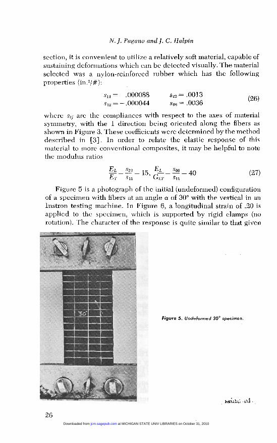
section, it is convenient to utilize a relatively soft material, capable ofsustaining deformations which can be detected visually. The materialselected was a nylon-reinforced rubber which has the followingproperties (in.2/#):
where sij are the compliances with respect to the axes of materialsymmetry, with the 1 direction being oriented along the fibers asshown in Figure 3. These coefficients were determined by the methoddescribed in [3]. In order to relate the elastic response of thismaterial to more conventional composites, it may be helpful to notethe modulus ratios
Figure 5 is a photograph of the initial (undeformed) configurationof a specimen with fibers at an angle a of 30° with the vertical in anInstron testing machine. In Figure 6, a longitudinal strain of .20 isapplied to the specimen, which is supported by rigid clamps (norotation). The character of the response is quite similar to that given
Figure 5. Undeformed 300 specimen.
at MICHIGAN STATE UNIV LIBRARIES on October 31, 2010jcm.sagepub.comDownloaded from
27
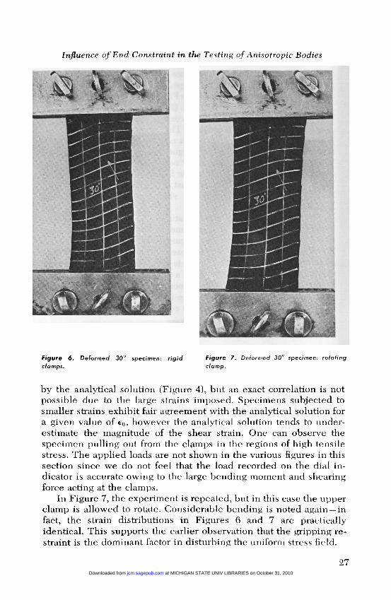
Figure 6. Deformed 30° specimen: rigidclamps.
Figure 7. Deformed 30° specimen: rotatingclamp.
by the analytical solution (Figure 4), but an exact correlation is notpossible due to the large strains imposed. Specimens subjected tosmaller strains exhibit fair agreement with the analytical solution fora given value of Eo, however the analytical solution tends to under-estimate the magnitude of the shear strain. One can observe the
specimen pulling out from the clamps in the regions of high tensilestress. The applied loads are not shown in the various figures in thissection since we do not feel that the load recorded on the dial in-dicator is accurate owing to the large bending moment and shearingforce acting at the clamps.
In Figure 7, the experiment is repeated, but in this case the upperclamp is allowed to rotate. Considerable bending is noted again-infact, the strain distributions in Figures 6 and 7 are practicallyidentical. This supports the earlier observation that the gripping re-straint is the dominant factor in disturbing the uniform stress field.
at MICHIGAN STATE UNIV LIBRARIES on October 31, 2010jcm.sagepub.comDownloaded from

28
As shown in [3], the compliance S16 vanishes when a is approxi-mately 60° for this material. A specimen of this configuration wasdeformed with Eo = .20 as shown in Figure 8(b). The resulting uniformstate of strain, as predicted in eqs. (24) and (14), is quite evident. Ofcourse, the constraint of lateral contraction in the grips gives thespecimen a dogbone appearance. This constraint is accompanied byself-equilibrating lateral forces, in contrast to the type of constraintunder discussion in this paper. Figure 8(c) shows the reversal of thedirection of bending as the shear coupling compliance S16 changessign, as predicted by eqs. (15). The fibers in Figure 8(c) are at 75° tothe applied axial force. For contrast, Figure 6 is repeated as Figure8(a). The corresponding uniform states of strain are depicted in[3], Figure 9.
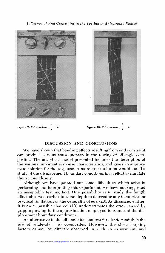
The effect of length to width ratio is illustrated in Figures 9, 10,and 11. The deformations of specimens having length to width ratiosof 2, 4, and 6 are shown in these figures. The strain field in the centralregion of the bar in Figure 11 is closely approaching the uniform stateof strain given by eqs. (23). This is verified further by comparisonof Figures 11 and 12. In Figure 12, a uniform state of stress is inducedby the method discussed in reference [3]. In Figures 11 and 12, thelongitudinal strain Eo has the value 0.20. We can see that the strainfields are nearly equivalent in the central region of the bar.
Figure 8 (a). 30° specimen. (b). 60° specimen. (c). 7S° specimen.
at MICHIGAN STATE UNIV LIBRARIES on October 31, 2010jcm.sagepub.comDownloaded from
29
Figure 9. 30° specimens = 2.w
Figure 10. 30° speCImen, - = 4.w
DISCUSSION AND CONCLUSIONS
We have shown that bending effects resulting from end constraintcan produce serious consequences in the testing of off-angle com-posites. The analytical model presented includes the description ofthe various important response characteristics, and gives an approxi-mate solution for the response. A more exact solution would entail a
study of the displacement boundary conditions in an effort to simulatethem more closely.
Although we have pointed out some difficulties which arise inperforming and interpreting this experiment, we have not suggestedan acceptable test method. One possibility is to study the lengtheffect observed earlier in some depth to determine any theoretical orpractical limitations on the generality of eqs. (23). As discussed earlier,it is quite possible that eq. (19) underestimates the error caused bygripping owing to the approximation employed to represent the dis-placement boundary conditions.
An alternative to the off-angle tension test for elastic moduli is theuse of angle-ply (Ia) composites. However, the shear-couplingfactors cannot be directly observed in such an experiment, and
at MICHIGAN STATE UNIV LIBRARIES on October 31, 2010jcm.sagepub.comDownloaded from

30
tFigure 1 1. 30° specimen, -; = 6.
wFigure 12. 30° specimen, uniform state of
stress.
boundary layer effects near the free edges preclude an exact analyticaldescription of the experiment.
An apparatus similar to that discussed by Halpin and Pagano [3]can be utilized to introduce a uniform state of stress in an off-anglecomposite. Although the design of this apparatus may need modifica-tion in the testing of hard materials such as structural composites, itappears to be the most promising method to induce uniform stress.This approach is obviously limited to the determination of elasticmoduli, i.e., it cannot be expected to yield reliable strength data. The
at MICHIGAN STATE UNIV LIBRARIES on October 31, 2010jcm.sagepub.comDownloaded from
31
latter problem can conceivably be solved by suitable modification ofthe ends of the test specimen. Considerable caution must be ex-ercised in this regard since building up the ends of a test piece willinduce similar effects to those observed in this paper, but probablyon a smaller scale. It must be emphasized, however, that carefulexperimental verification of any such scheme must be undertaken inorder to ensure the existence of a uniform state of strain, at least in aregion away from the ends of the bar.
Although we have restricted our attention to a specific materialand a particular experiment, the nature of the influence of end con-straint is considerably more general. For example, any material whichis macroscopically anisotropic, such as metals or polymers which areanisotropic because of their fabrication processes, are subject to theseeffects. In compression testing of anisotropic bodies, the conse-quences of end constraint tend to be more serious since these speci-mens are relatively short. Similar arguments can be advanced toillustrate the influence of gripping in torsion experiments as well asin the testing of plates and shells.
NOMENCLATURE
x, y = Cartesian coordinates.(TX, U&dquo;y, ’Txy = Stress components.Ex, Ey = Normal strain components.yxy = Engineering shear strain.u, v = Displacement components in x and y directions.ss = Compliance coefficients with respect to x, y axes.811 --- 866 = Compliance coefficients with respect to material sym-
metry axes.Eo = Applied longitudinal strain.f ( y ) , g ( y ) , h ( x ) = Arbitrary functions.Co --- Cs = Constants.w = 2h, ~9 t = Dimensions of specimen.Ei? = Observed modulus of elasticity.T = Factor reflecting error in observed modulus of elasticity.EL, Er = Longitudinal and transverse moduli of elasticity.GLT = Longitudinal-transverse shear modulus.a = Angle of rotation.
REFERENCES
1. S. G. Lekhnitskii, Theory of Elasticity of an Anisotropic Elastic Body, Holden-Day(1963).
2. S. W. Tsai, "Mechanics of Composite Materials," Air Force Materials LaboratoryTechnical Report AFML-TR-66-149, Part I (1966).
3. J. C. Halpin and N. J. Pagano, "Observations on Linear Anisotropic Viscoelasticity,"J. Composite Materials, Vol. 2 (1968), p. 68.
(Received December 9, 1967)
at MICHIGAN STATE UNIV LIBRARIES on October 31, 2010jcm.sagepub.comDownloaded from
Related Documents


