Electrodeposition and electrocatalytic properties of Pt/Ni–Co nanowires for non-enzymatic glucose detection Sahar Sadat Mahshid a,b , Sara Mahshid c , Abolghasem Dolati a,⇑ , Mohammad Ghorbani a , Lixia Yang d , Shenglian Luo b , Qingyun Cai b,⇑ a Materials Science and Engineering Department, Sharif University of Technology, Tehran 11155-9466, Iran b State Key Laboratory of Chemo/Biosensing and Chemometrics, Department of Chemistry, Hunan University, Changsha 410082, China c School of Engineering, Monash University Sunway Campus, Bandar Sunway 46150, Malaysia d School of Environment and Chemical Engineering, Nanchang Hangkong University, Nanchang 330063, China article info Article history: Received 20 June 2012 Received in revised form 26 October 2012 Accepted 29 October 2012 Available online 16 November 2012 Keywords: Nanowires Electrodeposition Non-enzymatic Glucose oxidation abstract A nanowire arrays system consisting of an ordered configuration of Pt, Ni and Co was constructed in single-bath solution through pulse electrodeposition. This structure was evaluated as a potential amper- ometric non-enzymatic sensor to detect glucose in alkaline solution. We observed a strong and fast amperometric response at low applied potential of 0.4 V vs. SCE over linear ranges of 0–0.2 mM and 0.2–8 mM glucose with sensitivities of 1125 and 333 lA mM 1 cm 2 , respectively. We also observed a low detection limit for glucose of 1 lM. Correlation of the electronic and geometric modifications with the electrochemical performance characteristics enhanced catalytic activity of the electrode by applying the Ni and Co components to Pt nanowires structure. The electrode showed good analytical performance and high selectivity with no interference from other oxidable species, demonstrating its promise for developing an effective glucose sensor. Ó 2012 Elsevier B.V. All rights reserved. 1. Introduction Among one-dimensional structured materials, nanowires have been extensively used as the backbones of nanoelectronic devices, nanosensors, catalysts and information storage systems, not only because of high surface to volume ratio but also their unique phys- ical and electronic properties [1–5]. The properties of nanowire de- vices depend strongly on the distribution, nanostructure and orientation of individual wires within the sensor. In order to con- trol the transfer of electrons through nanowires and thereby en- hance their functionality, great efforts have been made to create dense and aligned nanowire arrays [6]. Different metals such as platinum, gold, and alloys containing Pt, Pb, Au, Pd and Rh have been explored as electrode materials in the fields of catalysts, fuel cells and biosensors including glucose sensors [7–11]. Glucose sensing is extremely important for the treatment of diabetic pa- tients, which accounts for 85% market share of all the biosensor products. Since the risk for renal, retinal and neural complications is directly related to the magnitude of chronic elevations of blood glucose, the demand for a fast and reliable glucose sensor with high sensitivity, good response, high stability and low cost have drawn much attention [4,11–13]. Enzymatic glucose sensors, based on the immobilization of glucose oxidase (GO x ) on different types of electrodes, are the focus of most previous studies on this subject, due to their high sensitivity and selectivity [14–23]. However, an important challenge in improving enzymatic glucose sensors is the loss of enzyme activity that occurs during the immobilization; and also the activity of enzyme is easily affected by temperature, oxygen, pH, humidity, detergents, organic reagents and toxic chemicals which accordingly affects their stability, sensitivity and reproducibility [3,12]. Another limitation is interference from oxidizable species in blood, such as ascorbic and uric acid, since the electrode must be poised at at least 0.7 V vs. Ag/AgCl for the electrochemical detection of hydrogen peroxide generated by enzyme-catalyzed oxidation of glucose [11,12]. Therefore, the development of non-enzymatic glucose biosensors has received much attention because of their potential for higher sensitivity and selectivity as well as their reduced susceptibility to fouling by enzyme-aging and adsorbed intermediates. In this regard, metallic platinum is one of the mostly researched noble metals in the biosensor field because of its stability in electrochemical reactions and its prominent catalytic activities. It has been re- ported that sensitivity, selectivity and anti-fouling property may be improved by increasing the ratio of nanoscopic surface area to the geometric surface area (roughness factor) [24,19,25,26]. Simi- larly, the electrochemical property of metallic nickel electrode, nickel nanoparticles and nickel nanowire arrays have been well investigated; and nickel electrodes (Ni, NiO or Ni(OH) 2 based 0925-8388/$ - see front matter Ó 2012 Elsevier B.V. All rights reserved. http://dx.doi.org/10.1016/j.jallcom.2012.10.186 ⇑ Corresponding authors. Tel.: +98 21 66165259; fax: +98 21 66165717 (A. Dolati), tel./fax: +86 731 88821848 (Q. Cai). E-mail addresses: [email protected] (A. Dolati), [email protected] (Q. Cai). Journal of Alloys and Compounds 554 (2013) 169–176 Contents lists available at SciVerse ScienceDirect Journal of Alloys and Compounds journal homepage: www.elsevier.com/locate/jalcom

Welcome message from author
This document is posted to help you gain knowledge. Please leave a comment to let me know what you think about it! Share it to your friends and learn new things together.
Transcript
Journal of Alloys and Compounds 554 (2013) 169–176
Contents lists available at SciVerse ScienceDirect
Journal of Alloys and Compounds
journal homepage: www.elsevier .com/locate / ja lcom
Electrodeposition and electrocatalytic properties of Pt/Ni–Co nanowiresfor non-enzymatic glucose detection
Sahar Sadat Mahshid a,b, Sara Mahshid c, Abolghasem Dolati a,⇑, Mohammad Ghorbani a, Lixia Yang d,Shenglian Luo b, Qingyun Cai b,⇑a Materials Science and Engineering Department, Sharif University of Technology, Tehran 11155-9466, Iranb State Key Laboratory of Chemo/Biosensing and Chemometrics, Department of Chemistry, Hunan University, Changsha 410082, Chinac School of Engineering, Monash University Sunway Campus, Bandar Sunway 46150, Malaysiad School of Environment and Chemical Engineering, Nanchang Hangkong University, Nanchang 330063, China
a r t i c l e i n f o a b s t r a c t
Article history:Received 20 June 2012Received in revised form 26 October 2012Accepted 29 October 2012Available online 16 November 2012
Keywords:NanowiresElectrodepositionNon-enzymaticGlucose oxidation
0925-8388/$ - see front matter � 2012 Elsevier B.V. Ahttp://dx.doi.org/10.1016/j.jallcom.2012.10.186
⇑ Corresponding authors. Tel.: +98 21 6616525(A. Dolati), tel./fax: +86 731 88821848 (Q. Cai).
E-mail addresses: [email protected] (A. Dolati), qyc
A nanowire arrays system consisting of an ordered configuration of Pt, Ni and Co was constructed insingle-bath solution through pulse electrodeposition. This structure was evaluated as a potential amper-ometric non-enzymatic sensor to detect glucose in alkaline solution. We observed a strong and fastamperometric response at low applied potential of 0.4 V vs. SCE over linear ranges of 0–0.2 mM and0.2–8 mM glucose with sensitivities of 1125 and 333 lA mM�1 cm�2, respectively. We also observed alow detection limit for glucose of 1 lM. Correlation of the electronic and geometric modifications withthe electrochemical performance characteristics enhanced catalytic activity of the electrode by applyingthe Ni and Co components to Pt nanowires structure. The electrode showed good analytical performanceand high selectivity with no interference from other oxidable species, demonstrating its promise fordeveloping an effective glucose sensor.
� 2012 Elsevier B.V. All rights reserved.
1. Introduction
Among one-dimensional structured materials, nanowires havebeen extensively used as the backbones of nanoelectronic devices,nanosensors, catalysts and information storage systems, not onlybecause of high surface to volume ratio but also their unique phys-ical and electronic properties [1–5]. The properties of nanowire de-vices depend strongly on the distribution, nanostructure andorientation of individual wires within the sensor. In order to con-trol the transfer of electrons through nanowires and thereby en-hance their functionality, great efforts have been made to createdense and aligned nanowire arrays [6]. Different metals such asplatinum, gold, and alloys containing Pt, Pb, Au, Pd and Rh havebeen explored as electrode materials in the fields of catalysts, fuelcells and biosensors including glucose sensors [7–11]. Glucosesensing is extremely important for the treatment of diabetic pa-tients, which accounts for 85% market share of all the biosensorproducts. Since the risk for renal, retinal and neural complicationsis directly related to the magnitude of chronic elevations of bloodglucose, the demand for a fast and reliable glucose sensor withhigh sensitivity, good response, high stability and low cost havedrawn much attention [4,11–13]. Enzymatic glucose sensors, based
ll rights reserved.
9; fax: +98 21 66165717
[email protected] (Q. Cai).
on the immobilization of glucose oxidase (GOx) on different typesof electrodes, are the focus of most previous studies on this subject,due to their high sensitivity and selectivity [14–23]. However, animportant challenge in improving enzymatic glucose sensors isthe loss of enzyme activity that occurs during the immobilization;and also the activity of enzyme is easily affected by temperature,oxygen, pH, humidity, detergents, organic reagents and toxicchemicals which accordingly affects their stability, sensitivityand reproducibility [3,12]. Another limitation is interference fromoxidizable species in blood, such as ascorbic and uric acid, sincethe electrode must be poised at at least 0.7 V vs. Ag/AgCl for theelectrochemical detection of hydrogen peroxide generated byenzyme-catalyzed oxidation of glucose [11,12]. Therefore, thedevelopment of non-enzymatic glucose biosensors has receivedmuch attention because of their potential for higher sensitivityand selectivity as well as their reduced susceptibility to foulingby enzyme-aging and adsorbed intermediates. In this regard,metallic platinum is one of the mostly researched noble metalsin the biosensor field because of its stability in electrochemicalreactions and its prominent catalytic activities. It has been re-ported that sensitivity, selectivity and anti-fouling property maybe improved by increasing the ratio of nanoscopic surface area tothe geometric surface area (roughness factor) [24,19,25,26]. Simi-larly, the electrochemical property of metallic nickel electrode,nickel nanoparticles and nickel nanowire arrays have been wellinvestigated; and nickel electrodes (Ni, NiO or Ni(OH)2 based
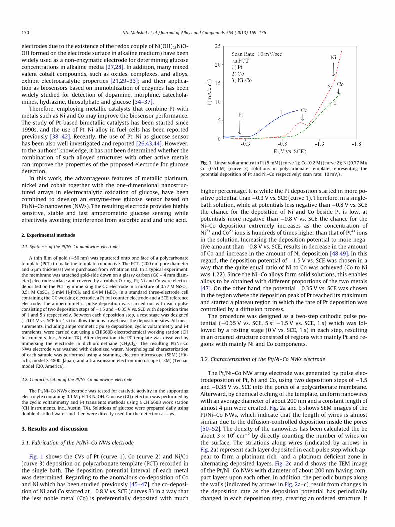
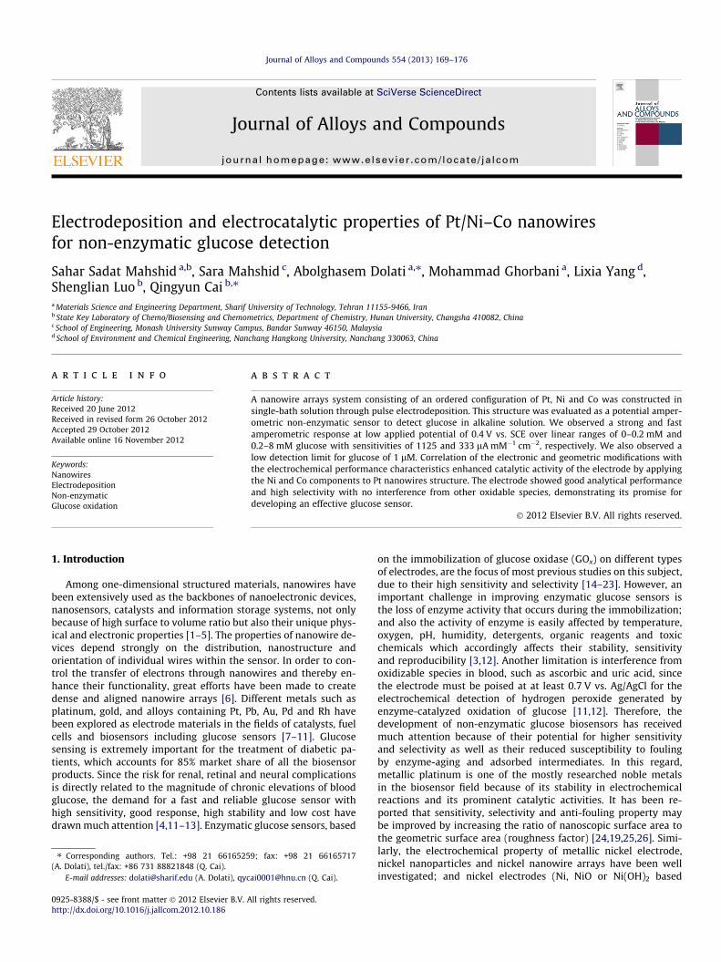
Fig. 1. Linear voltammetry in Pt (5 mM) (curve 1); Co (0.2 M) (curve 2); Ni (0.77 M)/Co (0.51 M) (curve 3) solutions in polycarbonate template representing thepotential deposition of Pt and Ni–Co respectively; scan rate: 10 mV/s.
170 S.S. Mahshid et al. / Journal of Alloys and Compounds 554 (2013) 169–176
electrodes due to the existence of the redox couple of Ni(OH)2/NiO-OH formed on the electrode surface in alkaline medium) have beenwidely used as a non-enzymatic electrode for determining glucoseconcentrations in alkaline media [27,28]. In addition, many mixedvalent cobalt compounds, such as oxides, complexes, and alloys,exhibit electrocatalytic properties [21,29–33]; and their applica-tion as biosensors based on immobilization of enzymes has beenwidely studied for detection of dopamine, morphine, catechola-mines, hydrazine, thiosulphate and glucose [34–37].
Therefore, employing metallic catalysts that combine Pt withmetals such as Ni and Co may improve the biosensor performance.The study of Pt-based bimetallic catalysts has been started since1990s, and the use of Pt–Ni alloy in fuel cells has been reportedpreviously [38–42]. Recently, the use of Pt–Ni as glucose sensorhas been also well investigated and reported [26,43,44]. However,to the authors’ knowledge, it has not been determined whether thecombination of such alloyed structures with other active metalscan improve the properties of the proposed electrode for glucosedetection.
In this work, the advantageous features of metallic platinum,nickel and cobalt together with the one-dimensional nanostruc-tured arrays in electrocatalytic oxidation of glucose, have beencombined to develop an enzyme-free glucose sensor based onPt/Ni–Co nanowires (NWs). The resulting electrode provides highlysensitive, stable and fast amperometric glucose sensing whileeffectively avoiding interference from ascorbic acid and uric acid.
2. Experimental methods
2.1. Synthesis of the Pt/Ni–Co nanowires electrode
A thin film of gold (�50 nm) was sputtered onto one face of a polycarbonatetemplate (PCT) to make the template conductive. The PCTs (200 nm pore diameterand 6 lm thickness) were purchased from Whatman Ltd. In a typical experiment,the membrane was attached gold-side down on a glassy carbon (GC – 4 mm diam-eter) electrode surface and covered by a rubber O-ring. Pt, Ni and Co were electro-deposited on the PCT by immersing the GC electrode in a mixture of 0.77 M NiSO4,0.51 M CoSO4, 5 mM H2PtCl6 and 0.4 M H3BO3 in a standard three-electrode cellcontaining the GC working electrode, a Pt foil counter electrode and a SCE referenceelectrode. The amperommetric pulse deposition was carried out with each pulseconsisting of two deposition steps of �1.5 and �0.35 V vs. SCE with deposition timeof 1 and 5 s respectively. Between each deposition step, a rest stage was designed(�0.01 V vs. SCE for 1 s) to allow the ions travel near the deposition sites. All mea-surements, including amperommetric pulse deposition, cyclic voltammetry and i-ttransients, were carried out using a CHI660B electrochemical working station (CHInstruments. Inc., Austin, TX). After deposition, the PC template was dissolved byimmersing the electrode in dichloromethane (CH2Cl2). The resulting Pt/Ni–CoNWs electrode was washed with deionized water. Morphological characterizationof each sample was performed using a scanning electron microscope (SEM) (Hit-achi, model S-4800, Japan) and a transmission electron microscope (TEM) (Tecnai,model F20, America).
2.2. Characterization of the Pt/Ni–Co nanowires electrode
The Pt/Ni–Co NWs electrode was tested for catalytic activity in the supportingelectrolyte containing 0.1 M pH 13 NaOH. Glucose (Gl) detection was performed bythe cyclic voltammetry and i-t transients methods using a CHI660B work station(CH Instruments. Inc., Austin, TX). Solutions of glucose were prepared daily usingdouble distilled water and then were directly used for the detection assays.
3. Results and discussion
3.1. Fabrication of the Pt/Ni–Co NWs electrode
Fig. 1 shows the CVs of Pt (curve 1), Co (curve 2) and Ni/Co(curve 3) deposition on polycarbonate template (PCT) recorded inthe single bath. The deposition potential interval of each metalwas determined. Regarding to the anomalous co-deposition of Coand Ni which has been studied previously [45–47], the co-deposi-tion of Ni and Co started at �0.8 V vs. SCE (curves 3) in a way thatthe less noble metal (Co) is preferentially deposited with much
higher percentage. It is while the Pt deposition started in more po-sitive potential than �0.3 V vs. SCE (curve 1). Therefore, in a single-bath solution, while at potentials less negative than �0.8 V vs. SCEthe chance for the deposition of Ni and Co beside Pt is low, atpotentials more negative than �0.8 V vs. SCE the chance for theNi–Co deposition extremely increases as the concentration ofNi2+ and Co2+ ions is hundreds of times higher than that of Pt4+ ionsin the solution. Increasing the deposition potential to more nega-tive amount than �0.8 V vs. SCE, results in decrease in the amountof Co and increase in the amount of Ni deposition [48,49]. In thisregard, the deposition potential of �1.5 V vs. SCE was chosen in away that the quite equal ratio of Ni to Co was achieved (Co to Niwas 1.22). Since the Ni–Co alloys form solid solutions, this enablesalloys to be obtained with different proportions of the two metals[47]. On the other hand, the potential �0.35 V vs. SCE was chosenin the region where the deposition peak of Pt reached its maximumand started a plateau region in which the rate of Pt deposition wascontrolled by a diffusion process.
The procedure was designed as a two-step cathodic pulse po-tential (�0.35 V vs. SCE, 5 s; �1.5 V vs. SCE, 1 s) which was fol-lowed by a resting stage (0 V vs. SCE, 1 s) in each step, resultingin an ordered structure consisted of regions with mainly Pt and re-gions with mainly Ni and Co components.
3.2. Characterization of the Pt/Ni–Co NWs electrode
The Pt/Ni–Co NW array electrode was generated by pulse elec-trodeposition of Pt, Ni and Co, using two deposition steps of �1.5and �0.35 V vs. SCE into the pores of a polycarbonate membrane.Afterward, by chemical etching of the template, uniform nanowireswith an average diameter of about 200 nm and a constant length ofalmost 4 lm were created. Fig. 2a and b shows SEM images of thePt/Ni–Co NWs, which indicate that the length of wires is almostsimilar due to the diffusion-controlled deposition inside the pores[50–52]. The density of the nanowires has been calculated the beabout 3 � 108 cm�2 by directly counting the number of wires onthe surface. The striations along wires (indicated by arrows inFig. 2a) represent each layer deposited in each pulse step which ap-pear to form a platinum-rich- and a platinum-deficient zone inalternating deposited layers. Fig. 2c and d shows the TEM imageof the Pt/Ni–Co NWs with diameter of about 200 nm having com-pact layers upon each other. In addition, the periodic bumps alongthe walls (indicated by arrows in Fig. 2a–c), result from changes inthe deposition rate as the deposition potential has periodicallychanged in each deposition step, creating an ordered structure. It
Element Weight% Atomic%
C K 6.12 37.73
O K 4.30 19.90
Co K 12.94 19.48
Ni K 10.61 15.96
Pt M 58.91 4.25
Au M 7.12 2.68
Totals 100.00
a
c
b
d
e
Fig. 2. (a and b) SEM images of Pt/Ni–Co nanowires electrodeposited by pulse method, and (c) TEM image of the Pt/Ni–Co NWs. (d) Elemental analysis of Pt/Ni–Co NWs byEDX spectrum. Arrows show the periodic bumps along nanowires.
S.S. Mahshid et al. / Journal of Alloys and Compounds 554 (2013) 169–176 171
is these alternating lighter and darker regions (shown by wide ar-rows in Fig. 2d) that are indicative of the differences in composi-tion of the layers. The darker region is probably platinum richwhile the ligher region is platinum deficient zone. The EDX analysisof the Pt/Ni–Co NWs (Fig. 2d) indicates the presence of Ni, Co andPt in the proportions 10.61 wt.%, 12.94 wt.% and 58.91 wt.%,respectively.
3.3. Electrochemical Properties of the Pt/Ni–Co NWs electrode
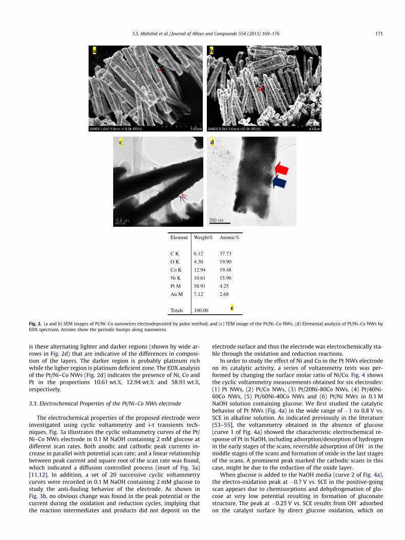
The electrochemical properties of the proposed electrode wereinvestigated using cyclic voltammetry and i-t transients tech-niques. Fig. 3a illustrates the cyclic voltammetry curves of the Pt/Ni–Co NWs electrode in 0.1 M NaOH containing 2 mM glucose atdifferent scan rates. Both anodic and cathodic peak currents in-crease in parallel with potential scan rate; and a linear relationshipbetween peak current and square root of the scan rate was found,which indicated a diffusion controlled process (inset of Fig. 3a)[11,12]. In addition, a set of 20 successive cyclic voltammetrycurves were recorded in 0.1 M NaOH containing 2 mM glucose tostudy the anti-fouling behavior of the electrode. As shown inFig. 3b, no obvious change was found in the peak potential or thecurrent during the oxidation and reduction cycles, implying thatthe reaction intermediates and products did not deposit on the
electrode surface and thus the electrode was electrochemically sta-ble through the oxidation and reduction reactions.
In order to study the effect of Ni and Co in the Pt NWs electrodeon its catalytic activity, a series of voltammetry tests was per-formed by changing the surface molar ratio of Ni/Co. Fig. 4 showsthe cyclic voltammetry measurements obtained for six electrodes:(1) Pt NWs, (2) Pt/Co NWs, (3) Pt/20Ni-80Co NWs, (4) Pt/40Ni-60Co NWs, (5) Pt/60Ni-40Co NWs and (6) Pt/Ni NWs in 0.1 MNaOH solution containing glucose. We first studied the catalyticbehavior of Pt NWs (Fig. 4a) in the wide range of �1 to 0.8 V vs.SCE in alkaline solution. As indicated previously in the literature[53–55], the voltammetry obtained in the absence of glucose(curve 1 of Fig. 4a) showed the characteristic electrochemical re-sponse of Pt in NaOH, including adsorption/desorption of hydrogenin the early stages of the scans, reversible adsorption of OH� in themiddle stages of the scans and formation of oxide in the last stagesof the scans. A prominent peak marked the cathodic scans in thiscase, might be due to the reduction of the oxide layer.
When glucose is added to the NaOH media (curve 2 of Fig. 4a),the electro-oxidation peak at �0.7 V vs. SCE in the positive-goingscan appears due to chemisorptions and dehydrogenation of glu-cose at very low potential resulting in formation of gluconatestructure. The peak at �0.25 V vs. SCE results from OH- adsorbedon the catalyst surface by direct glucose oxidation, which on
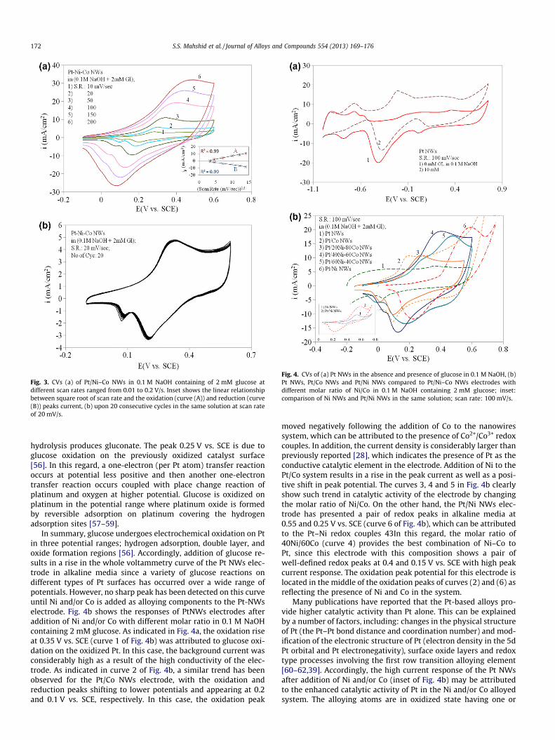
Fig. 3. CVs (a) of Pt/Ni–Co NWs in 0.1 M NaOH containing of 2 mM glucose atdifferent scan rates ranged from 0.01 to 0.2 V/s. Inset shows the linear relationshipbetween square root of scan rate and the oxidation (curve (A)) and reduction (curve(B)) peaks current, (b) upon 20 consecutive cycles in the same solution at scan rateof 20 mV/s.
Fig. 4. CVs of (a) Pt NWs in the absence and presence of glucose in 0.1 M NaOH, (b)Pt NWs, Pt/Co NWs and Pt/Ni NWs compared to Pt/Ni–Co NWs electrodes withdifferent molar ratio of Ni/Co in 0.1 M NaOH containing 2 mM glucose; inset:comparison of Ni NWs and Pt/Ni NWs in the same solution; scan rate: 100 mV/s.
172 S.S. Mahshid et al. / Journal of Alloys and Compounds 554 (2013) 169–176
hydrolysis produces gluconate. The peak 0.25 V vs. SCE is due toglucose oxidation on the previously oxidized catalyst surface[56]. In this regard, a one-electron (per Pt atom) transfer reactionoccurs at potential less positive and then another one-electrontransfer reaction occurs coupled with place change reaction ofplatinum and oxygen at higher potential. Glucose is oxidized onplatinum in the potential range where platinum oxide is formedby reversible adsorption on platinum covering the hydrogenadsorption sites [57–59].
In summary, glucose undergoes electrochemical oxidation on Ptin three potential ranges; hydrogen adsorption, double layer, andoxide formation regions [56]. Accordingly, addition of glucose re-sults in a rise in the whole voltammetry curve of the Pt NWs elec-trode in alkaline media since a variety of glucose reactions ondifferent types of Pt surfaces has occurred over a wide range ofpotentials. However, no sharp peak has been detected on this curveuntil Ni and/or Co is added as alloying components to the Pt-NWselectrode. Fig. 4b shows the responses of PtNWs electrodes afteraddition of Ni and/or Co with different molar ratio in 0.1 M NaOHcontaining 2 mM glucose. As indicated in Fig. 4a, the oxidation riseat 0.35 V vs. SCE (curve 1 of Fig. 4b) was attributed to glucose oxi-dation on the oxidized Pt. In this case, the background current wasconsiderably high as a result of the high conductivity of the elec-trode. As indicated in curve 2 of Fig. 4b, a similar trend has beenobserved for the Pt/Co NWs electrode, with the oxidation andreduction peaks shifting to lower potentials and appearing at 0.2and 0.1 V vs. SCE, respectively. In this case, the oxidation peak
moved negatively following the addition of Co to the nanowiressystem, which can be attributed to the presence of Co2+/Co3+ redoxcouples. In addition, the current density is considerably larger thanpreviously reported [28], which indicates the presence of Pt as theconductive catalytic element in the electrode. Addition of Ni to thePt/Co system results in a rise in the peak current as well as a posi-tive shift in peak potential. The curves 3, 4 and 5 in Fig. 4b clearlyshow such trend in catalytic activity of the electrode by changingthe molar ratio of Ni/Co. On the other hand, the Pt/Ni NWs elec-trode has presented a pair of redox peaks in alkaline media at0.55 and 0.25 V vs. SCE (curve 6 of Fig. 4b), which can be attributedto the Pt–Ni redox couples 43In this regard, the molar ratio of40Ni/60Co (curve 4) provides the best combination of Ni–Co toPt, since this electrode with this composition shows a pair ofwell-defined redox peaks at 0.4 and 0.15 V vs. SCE with high peakcurrent response. The oxidation peak potential for this electrode islocated in the middle of the oxidation peaks of curves (2) and (6) asreflecting the presence of Ni and Co in the system.
Many publications have reported that the Pt-based alloys pro-vide higher catalytic activity than Pt alone. This can be explainedby a number of factors, including: changes in the physical structureof Pt (the Pt–Pt bond distance and coordination number) and mod-ification of the electronic structure of Pt (electron density in the 5dPt orbital and Pt electronegativity), surface oxide layers and redoxtype processes involving the first row transition alloying element[60–62,39]. Accordingly, the high current response of the Pt NWsafter addition of Ni and/or Co (inset of Fig. 4b) may be attributedto the enhanced catalytic activity of Pt in the Ni and/or Co alloyedsystem. The alloying atoms are in oxidized state having one or
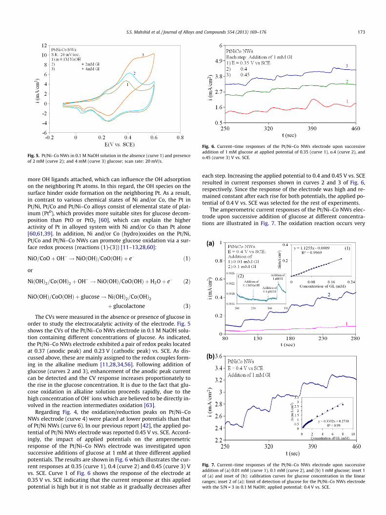
Fig. 5. Pt/Ni–Co NWs in 0.1 M NaOH solution in the absence (curve 1) and presenceof 2 mM (curve 2); and 4 mM (curve 3) glucose; scan rate: 20 mV/s.
Fig. 6. Current–time responses of the Pt/Ni–Co NWs electrode upon successiveaddition of 1 mM glucose at applied potential of 0.35 (curve 1), o.4 (curve 2), ando.45 (curve 3) V vs. SCE.
Fig. 7. Current–time responses of the Pt/Ni–Co NWs electrode upon successiveaddition of (a) 0.01 mM (curve 1), 0.1 mM (curve 2), and (b) 1 mM glucose; inset 1of (a) and inset of (b): calibration curves for glucose concentration in the linearranges; inset 2 of (a): limit of detection of glucose for the Pt/Ni–Co NWs electrodewith the S/N = 3 in 0.1 M NaOH; applied potential: 0.4 V vs. SCE.
S.S. Mahshid et al. / Journal of Alloys and Compounds 554 (2013) 169–176 173
more OH ligands attached, which can influence the OH adsorptionon the neighboring Pt atoms. In this regard, the OH species on thesurface hinder oxide formation on the neighboring Pt. As a result,in contrast to various chemical states of Ni and/or Co, the Pt inPt/Ni, Pt/Co and Pt/Ni–Co alloys consist of elemental state of plat-inum (Pt0), which provides more suitable sites for glucose decom-position than PtO or PtO2 [60], which can explain the higheractivity of Pt in alloyed system with Ni and/or Co than Pt alone[60,61,39]. In addition, Ni and/or Co (hydro)oxides on the Pt/Ni,Pt/Co and Pt/Ni–Co NWs can promote glucose oxidation via a sur-face redox process (reactions (1)-(3)) [11–13,28,60]:
NiO=CoOþ OH� ! NiOðOHÞ=CoOðOHÞ þ e� ð1Þ
or
NiðOHÞ2=CoðOHÞ2 þ OH� ! NiOðOHÞ=CoOðOHÞ þH2Oþ e� ð2Þ
NiOðOHÞ=CoOðOHÞ þ glucose! NiðOHÞ2=CoðOHÞ2þ glucolactone ð3Þ
The CVs were measured in the absence or presence of glucose inorder to study the electrocatalytic activity of the electrode. Fig. 5shows the CVs of the Pt/Ni–Co NWs electrode in 0.1 M NaOH solu-tion containing different concentrations of glucose. As indicated,the Pt/Ni–Co NWs electrode exhibited a pair of redox peaks locatedat 0.37 (anodic peak) and 0.23 V (cathodic peak) vs. SCE. As dis-cussed above, these are mainly assigned to the redox couples form-ing in the alkaline medium [11,28,34,56]. Following addition ofglucose (curves 2 and 3), enhancement of the anodic peak currentcan be detected and the CV response increases proportionately tothe rise in the glucose concentration. It is due to the fact that glu-cose oxidation in alkaline solution proceeds rapidly, due to thehigh concentration of OH- ions which are believed to be directly in-volved in the reaction intermediates oxidation [63].
Regarding Fig. 4, the oxidation/reduction peaks on Pt/Ni–CoNWs electrode (curve 4) were placed at lower potentials than thatof Pt/Ni NWs (curve 6). In our previous report [42], the applied po-tential of Pt/Ni NWs electrode was reported 0.45 V vs. SCE. Accord-ingly, the impact of applied potentials on the amperometricresponse of the Pt/Ni–Co NWs electrode was investigated uponsuccessive additions of glucose at 1 mM at three different appliedpotentials. The results are shown in Fig. 6 which illustrates the cur-rent responses at 0.35 (curve 1), 0.4 (curve 2) and 0.45 (curve 3) Vvs. SCE. Curve 1 of Fig. 6 shows the response of the electrode at0.35 V vs. SCE indicating that the current response at this appliedpotential is high but it is not stable as it gradually decreases after
each step. Increasing the applied potential to 0.4 and 0.45 V vs. SCEresulted in current responses shown in curves 2 and 3 of Fig. 6,respectively. Since the response of the electrode was high and re-mained constant after each rise for both potentials, the applied po-tential of 0.4 V vs. SCE was selected for the rest of experiments.
The amperometric current responses of the Pt/Ni–Co NWs elec-trode upon successive addition of glucose at different concentra-tions are illustrated in Fig. 7. The oxidation reaction occurs very
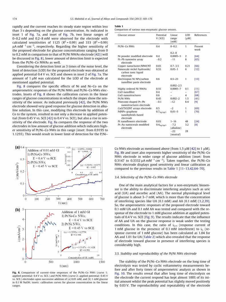
Table 1Comparison of various non-enzymatic glucose sensors.
Glucose sensor PotentialV (SCE)
Linearrange(mM)
LOD(lM)
References
Pt/Ni–Co NWs 0.4 0–0.2 1 Presentwork
0.2–8Ni powder modified electrode 0.4 0.0005–5 2 [64]Pt–Pb nanowire array
electrode�0.2 �11 8 [65]
Copper nanocluster/MWCNT 0.65 0.7–3.5 0.21 [66]Nanoscale nickel hydroxide/
carbon ionic liquidelectrode
0.55 0.05–1 6 [12]
Electrospun Ni NPs/carbonnanofiber paste electrode
0.6 0.5–23 1 [13]
0.002–2.5Highly ordered Ni NWAs 0.55 0.0005–7 0.1 [11]CuO nanofibre 0.4 – – [67]CuO nanostructures 0.6 – 4 [68]Pt/Ni NWs 0.45 0.002–2 1.5 [41]Pinecone-shaped Pt–Pb
nanostructures electrode�0.1 –12 8.4 [9]
CuO/TiO2NT arrays electrode 0.5 –2 1 [69]PdNPs–graphene
nanohybrids-basedelectrode
0.7Ag/AgCl 0.01–5 1 [70]
Pt nanoflowers electrode 0.03 1–16 48 [24]Pt–Au nanocorals modified
electrode0.4Ag/AgCl �7.2
(alkaline)3.2 [8]
�22(neutral)
28
174 S.S. Mahshid et al. / Journal of Alloys and Compounds 554 (2013) 169–176
rapidly and the current reaches its steady state region within lessthan 3 s depending on the glucose concentration. As indicated ininset 1 of Fig. 7a, and inset of Fig. 7b, two linear ranges of0–0.2 mM and 0.2–8 mM were observed for the electrode withcalculated sensitivities of 1125 (R2 = 0.99) and 333 (R2 = 0.99)lA mM�1 cm�2, respectively. Regarding the higher sensitivity ofthe proposed electrode for glucose concentrations ranging from 0to 0.2 mM in comparison to that of Pt/Ni NWAs electrode [42] (willbe discussed in Fig. 8), lower amount of detection limit is expectedfrom the Pt/Ni–Co NWAs as well.
Considering the detection limit as 3 times of the noise level, thelimit of detection (LOD) for the proposed electrode was obtained atapplied potential 0.4 V vs. SCE and shown in inset 2 of Fig. 7a. Theamount of 1 lM was calculated for the LOD of the electrode atmentioned applied potential.
Fig. 8 compares the specific effects of Ni and Ni–Co on theamperometric responses of the Pt/Ni NWs and Pt/Ni–Co NWs elec-trodes. Insets of Fig. 8 shows the calibration curves in the linearranges of glucose concentrations in which the slopes show the sen-sitivity of the sensor. As indicated previously [42], the Pt/Ni NWselectrode showed very good response for glucose detection in alka-line solution. In this case, modifying this electrode by addition ofCo to the system, resulted in not only a decrease in applied poten-tial (from 0.45 V vs. SCE [42] to 0.4 V vs. SCE), but also a rise in sen-sitivity of the electrode. Fig. 8a compares the response of the twoelectrodes in low amount of glucose addition which indicates high-er sensitivity of Pt/Ni–Co NWs in this range (inset: from 0.9195 to1.1255). This would result in lower limit of detection for the P/Ni–
Fig. 8. Comparison of current–time responses of the Pt/Ni–Co NWs (curve 1;applied potential: 0.4 V vs. SCE.) and Pt/Ni NWs (curve 2; applied potential: 0.45 Vvs. SCE.) electrodes upon successive addition of (a) 0.01 mM, and (b) 1 mM glucosein 0.1 M NaOH; insets: calibration curves for glucose concentration in the linearranges.
Co NWs electrode as mentioned above (from 1.5 lM [42] to 1 lM).Fig. 8b and inset also represents higher sensitivity of the Pt/Ni–CoNWs electrode in wider range of glucose addition (inset: from0.3147 to 0.3332 lA mM�1 cm�2). Taken together, the Pt/Ni–CoNWs electrode displays good sensitivity and linear calibration ascompared to the previous results in Table 1 [11–13,42,64–70].
3.4. Selectivity of the Pt/Ni–Co NWs electrode
One of the main analytical factors for a non-enzymatic biosen-sor is the ability to discriminate interfering analytes such as uricacid (UA) and ascorbic acid (AA). The normal physiological levelof glucose is about 3–7 mM, which is more than the concentrationof interfering species like UA (0.1 mM) and AA (0.1 mM) [1,2,39].So, the amperometric responses of the proposed electrode toward0.1 mM UA and 0.1 mM AA was tested and compared with the re-sponse of the electrode to 1 mM glucose addition at applied poten-tials of 0.4 V vs. SCE (Fig. 9). The results indicate that the influenceof AA and UA on the glucose response is weak under the testingconditions. In this case, the ratio of iG+I (response current of1 mM glucose in the presence of 0.1 mM interferent) to iG (re-sponse current of 1 mM glucose) has been calculated as 1.04 forAA and 1.01 for UA (Table 2) which also revealed that the responseof electrode toward glucose in presence of interfering species isconsiderably high.
3.5. Stability and reproducibility of the Pt/Ni NWs electrode
The stability of the Pt/Ni–Co NWs electrode on the long time ofelectrolysis was tested by cyclic voltammetry measurements be-fore and after forty times of amperometric analysis as shown inFig. 10. The results reveal that after long time of electrolysis onthe electrode the current respond has kept almost 100% of its ini-tial amount whilst the peak potential has slightly moved positivelyby 0.03 V. The reproducibility and repeatability of the electrode
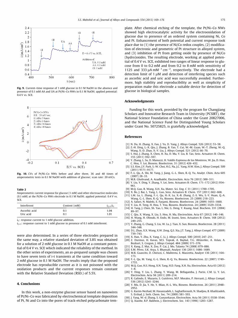
Fig. 9. Current–time response of 1 mM glucose in 0.1 M NaOH in the absence andpresence of 0.1 mM AA and UA at Pt/Ni–Co NWs in 0.1 M NaOH; applied potential:0.4 V vs. SCE.
Table 2Amperometric current response for glucose (1 mM) and other electroactive molecules(0.1 mM) at the Pt/Ni–Co NWs electrode in 0.1 M NaOH; applied potential: 0.4 V vs.SCE.
Interferent Content (mM) iG+1/iG
Ascorbic acid 0.1 1.04Uric acid 0.1 1.01
iG: response current to 1 mM glucose addition.iG+1: response current to 1 mM glucose in presence of 0.1 mM interferent.
Fig. 10. CVs of Pt/Ni–Co NWs before and after three, 36 and 40 times ofamperometric tests in 0.1 M NaOH with addition of glucose; scan rate: 20 mV/s.
S.S. Mahshid et al. / Journal of Alloys and Compounds 554 (2013) 169–176 175
were also determined. In a series of three electrodes prepared inthe same way, a relative standard deviation of 3.8% was obtainedfor a solution of 2 mM glucose in 0.1 M NaOH at a constant poten-tial of 0.4 V vs. SCE which indicated the reliability of the method. Inthe other series of experiments, an as-prepared sample was chosento have seven tests of i-t transients at the same condition toward2 mM glucose in 0.1 M NaOH. The results imply that the proposedelectrode has reproducible current as it is not poisoned with theoxidation products and the current responses remain constantwith the Relative Standard Deviation (RSD.) of 5.5%.
4. Conclusions
In this work, a non-enzyme glucose sensor based on nanowiresof Pt/Ni–Co was fabricated by electrochemical template depositionof Pt, Ni and Co into the pores of track-etched polycarbonate tem-
plate. After chemical etching of the template, the Pt/Ni–Co NWsshowed high electrocatalytic activity for the electrooxidation ofglucose due to presence of an ordered system containing Ni, Coand Pt. Enhancement of both potential and current response tookplace due to (1) the presence of Ni/Co redox couples, (2) modifica-tion of electronic and geometric of Pt structure in alloyed system,and (3) inhibition of Pt from getting oxide by presence of Ni/Co(hydro)oxides. The resulting electrode, working at applied poten-tial of 0.4 V vs. SCE, exhibited two ranges of linear response to glu-cose from 0 to 0.2 mM and from 0.2 to 8 mM with sensitivity of1125 and 333 lA mM�1 cm�2, respectively. The electrode had adetection limit of 1 lM and detection of interfering species suchas ascorbic acid and uric acid was successfully avoided. Further-more, high stability and reproducibility as well as simplicity ofpreparation make this electrode a suitable device for detection ofglucose in biological samples.
Acknowledgments
Funding for this work, provided by the program for ChangjiangScholars and Innovative Research Team in University (PCSIRT), theNational Science Foundation of China under the Grant 20827006,and the National Science Fund for Distinguished Young Scholarsunder Grant No. 50725825, is gratefully acknowledged.
References
[1] N. Du, H. Zhang, X. Fan, J. Yu, D. Yang, J. Alloys Compd. 526 (2012) 53–58.[2] Z.-H. Ding, L.-X. Qiu, J. Zhang, B. Yao, T. Cui, W.-M. Guan, W.-T. Zheng, W.-Q.
Wang, X.-D. Zhao, X.-Y. Liu, J. Alloys Compd. 521 (2012) 66–70.[3] S. Hui, J. Zhang, X. Chen, H. Xu, D. Ma, Y. Liu, B. Tao, Sens. Actuators B: Chem.
155 (2011) 592–597.[4] Y. Zhang, L. Su, D. Manuzzi, H. Valdés Espinosa de los Monteros, W. Jia, D. Huo,
C. Hou, Y. Lei, Biosens. Bioelectron. 31 (2012) 426–432.[5] S.S. Kim, J.Y. Park, S.-W. Choi, H.G. Na, J.C. Yang, H.W. Kim, J. Alloys Compd. 509
(2011) 9171–9177.[6] F.-L. Qu, A. Shi, M. Yang, J. Jiang, G.-L. Shen, R.-Q. Yu, Analyt. Chim. Acta 605
(2007) 28–33.[7] M.B. Gholivand, A. Azadbakht, Electrochim. Acta 76 (2012) 300–311.[8] Y. Liu, Y. Ding, Y. Zhang, Y. Lei, Sens. Actuators B: Chem. 171–172 (2012) 954–
961.[9] M.Q. Guo, R. Wang, X.H. Xu, Mater. Sci. Eng. C 31 (2011) 1700–1705.
[10] X. Bo, J. Bai, L. Yang, L. Guo, Sens. Actuators B: Chem. 157 (2011) 662–668.[11] L.M. Lu, L. Zhang, F.-L. Qu, H.-X. Lu, X.-B. Zhang, Z.-S. Wu, S.-Y. Huan, Q.-A.
Wang, G.-L. Shen, R.-Q. Yu, Biosens. Bioelectron. 25 (2009) 218–223.[12] A. Safavi, N. Maleki, E. Farjami, Biosens. Bioelectron. 24 (2009) 1655–1660.[13] Y. Liu, H. Teng, H. Hou, T. You, Biosens. Bioelectron. 24 (2009) 3329–3334.[14] H. Tang, J. Chen, Sh. Yao, L. Nie, G. Deng, Y. Kuang, Anal. Biochem. 331 (2004)
89–97.[15] C. Qiu, X. Wang, X. Liu, S. Hou, H. Ma, Electrochim. Acta 67 (2012) 140–146.[16] H. Wang, H. Ohnuki, H. Endo, M. Izumi, Sens. Actuators B: Chem. 168 (2012)
249–255.[17] Y. Zhang, G. Chang, S. Liu, W. Lu, J. Tian, X. Sun, Biosens. Bioelectron. 28 (2011)
344–348.[18] D.L. Zhao, X.X. Wang, X.W. Zeng, Q.S. Xia, J.T. Tang, J. Alloys Compd. 477 (2009)
739–743.[19] X. Han, Y. Zhu, X. Yang, C. Li, J. Alloys Compd. 500 (2010) 247–251.[20] Z. Durmus, H. Kavas, M.S. Toprak, A. Baykal, T.G. Altincekic, A. Aslan, A.
Bozkurt, S. Cosgun, J. Alloys Compd. 484 (2009) 371–376.[21] X. Kang, Z. Mai, X. Zou, P. Cai, J. Mo, Talanta 74 (2008) 879–886.[22] E.M. Pérez, S.K. Arya, S. Bhansali, Analyst 136 (2011) 1686–1689.[23] M.R. Guascito, D. Chirizzi, C. Malitesta, E. Mazzotta, Analyst 136 (2011) 164–
173.[24] F.-L. Qu, M. Yang, G.-L. Shen, R.-Q. Yu, Biosens. Bioelectron. 22 (2007) 1749–
1755.[25] M.Q. Guo, H.S. Hong, X.N. Tang, H.D. Fang, X.H. Xu, Electrochim. Acta 63 (2012)
1–8.[26] Y. Ding, Y. Liu, L. Zhang, Y. Wang, M. Bellagamba, J. Parisi, C.M. Li, Y. Lei,
Electrochim. Acta 58 (2011) 209–214.[27] R. Galindo, E. Mazario, S. Gutiérrez, M.P. Morales, P. Herrasti, J. Alloys Compd.
536 (2012) S241–S244.[28] Y. Mu, D. Jia, Y. He, Y. Miao, H.-L. Wu, Biosens. Bioelectron. 26 (2011) 2948–
2952.[29] G. Karim-Nezhad, M. Hasanzadeh, L. Saghatforoush, N. Shadjou, B. Khalilzadeh,
S. Ershad, J. Serb. Chem. Soc. 74 (2009) 581–593.[30] J. Yang, W.-d. Zhang, S. Gunasekaran, Electrochim. Acta 56 (2011) 5538–5544.[31] Q. Xiaohe, R.P. Baldwin, J. Electrochem. Soc. 143 (1996) 1283–1287.

176 S.S. Mahshid et al. / Journal of Alloys and Compounds 554 (2013) 169–176
[32] J. Wang, P.V.A. Pamidi, C. Parrade, D.S. Park, J. Pingerron, Electroanalysis 9(1997) 908–911.
[33] S.A. Wring, J.P. Hard, B.J. Birch, Anal. Chim. Acta 229 (1990) 63–70.[34] M. Florescu, Ch.M.A. Brett, Revue Roumaine de Chimie 52 (2007) 969–974.[35] M. Yang, J. Jiang, Y. Yang, X. Chen, G. Shen, R. Yu, Biosens. Bioelectron. 21
(2006) 1791–1797.[36] S. Wang, L. Lu, M. Yang, Y. Lei, G. Shen, R. Yu, Anal. Chim. Acta 651 (2009) 220–
226.[37] K. Wang, J.-J. Xu, H.-Y. Chen, Biosens. Bioelectron. 20 (2005) 1388–1396.[38] Y. Zhao, L.Z. Fan, Y.F. Qiu, Sh. Yang, Electrochim. Acta 52 (2007) 5873–5878.[39] S. Mukerjee, S. Srinivasan, M.P. Soriaga, J. McBreen, J. Electrochem. Soc. 142
(1995) 1409–1422.[40] M.K. Min, J. Cho, K. Cho, H. Kim, Electrochim. Acta 45 (2000) 4211–4217.[41] K.T. Kim, Y.G. Kim, J.S. Chung, J. Electrochem. Soc. 142 (1995) 1531–1534.[42] T. Toda, H. Igarashi, H. Uchida, M. Watanabe, J. Electrochem. Soc. 146 (1999)
3750–3756.[43] S.S. Mahshid, S. Mahshid, A. Dolati, M. Ghorbani, L. Yang, S. Luo, Q. Cai,
Electrochim. Acta 58 (2011) 551–555.[44] S.S. Mahshid, S. Luo, L. Yang, S. Mahshid, A. Dolati, M. Ghorbani, Q. Cai, Sensor
Lett. 9 (2011) 1598–1605.[45] L. Wang, Y. Gao, Q. Xue, H. Liu, T. Xu, Appl. Surf. Sci. 242 (2005) 326–332.[46] A.M. Abd El-Halim, Surf. Technol. 23 (1984) 207–213.[47] D. Golodnitsky, Yu Rosenberg, A. Ulus, Electrochim. Acta 47 (2002) 2707–2714.[48] S.S. Mahshid, A. Dolati, Inter. J. Mod. Phys. B 22 (2008) 3046–3059.[49] A. Dolati, S.S. Mahshid, Mater. Chem. Phys. 108 (2008) 391–396.[50] B.R. Scharifiker, J. Mostany, J. Electroanal. Chem. 177 (1984) 13–23.[51] E. Gomez, Z.G. Kipervaser, E. Valles, Thin Solid Films 440 (2003) 45–53.[52] S.S. Mahshid, A. Dolati, S. Hashemi Daryan, M. Ghorbani, A.
Ghahramaninezhad, ECS Trans. 28 (2010) 25–35.
View publication statsView publication stats
[53] E.H. Yu, K. Scott, R.W. Reeve, J. Electroanal. Chem. 547 (2003) 17–24.[54] A.V. Tripkovic, K.Dj. Popovic, J.D. Lovic, V.M. Jovanovic, A. Kowal, J. Electroanal.
Chem. 572 (2004) 119–128.[55] K.L. Nagashree, M.F. Ahmed, Syn. Met. 158 (2008) 610–616.[56] D. Basu, S. Basu, Electrochim. Acta 56 (2011) 6106–6113.[57] H.-W. Lei, B. Wu, C.-S. Cha, H. Kita, J. Electroanal. Chem. 382 (1995) 103–110.[58] K.D. Popovic, N.M. Markovic, A.V. Tripkovic, R.R. Adtic, J. Electroanal. Chem.
313 (1991) 181–199.[59] S. Park, H. Boo, J. Korean Electrochem. Soc. 11 (2008) 147–153.[60] K.-W. Park, J.-H. Choi, B.-K. Kwon, S.-A. Lee, Y.-E. Sung, H.-Y. Ha, S.-A.h. Hong,
H. Kim, A. Wieckowski, J. Phys. Chem. B 106 (2002) 1869–1877.[61] U.A. Paulus, A. Wokaun, G.G. Scherer, T.J. Schmidt, V. Stamenkovic, N.M.
Markovic, P.N. Ross, Electrochim. Acta 47 (2002) 3787–3798.[62] M.-K. Min, J. Cho, K. Cho, H. Kim, Electrochim. Acta 45 (2000) 4211–4217.[63] X. Yan, X. Ge, S. Cui, Nanoscale Res. Lett. 6 (2011) 313–318.[64] T. You, O. Niwa, Z. Chen, K. Hayashi, M. Tomita, S. Hirono, Anal. Chem. 75
(2003) 5191–5196.[65] Y. Bai, Y.Y. Sun, C.Q. Sun, Biosens. Bioelectron. 24 (2008) 579–585.[66] X. Kang, Z. Mai, X. Zou, P. Cai, J. Mo, Anal. Biochem. 363 (2007) 143–150.[67] W. Wang, L. Zhang, S. Tong, X. Li, W. Song, Biosens. Bioelectron. 25 (2009) 708–
714.[68] X. Wang, C. Hu, H. Liu, G. Du, X. He, Y. Xi, Sens. Actuators B: Chem. 144 (2010)
220–225.[69] S. Luo, F. Su, C. Liu, J. Li, R. Liu, Y. Xiao, Y. Li, X. Liu, Q. Cai, Talanta 86 (2011)
157–163.[70] L.-M. Lu, H.-B. Li, F. Qu, X.-B. Zhang, G.-L. Shen, R.-Q. Yu, Biosens. Bioelectron.
26 (2011) 3500–3504.
Related Documents


