Residual-Stress Predictions in Polycrystalline Alumina Venkata R. Vedula* ,† and S. Jill Glass* Ceramic Materials Department, Sandia National Laboratories, Albuquerque, New Mexico 87185 David M. Saylor* and Gregory S. Rohrer* Department of Materials Science and Engineering, Carnegie Mellon University, Pittsburgh, Pennsylvania 15213 W. Craig Carter* Department of Materials Science and Engineering, Massachusetts Institute of Technology, Cambridge, Massachusetts 02139 Stephen A. Langer and Edwin R. Fuller Jr.* National Institute of Standards and Technology, Gaithersburg, Maryland 20899 Microstructure-level residual stresses occur in polycrystalline ceramics during processing, as a result of thermal expansion anisotropy and crystallographic misorientation across the grain boundaries. Depending on the grain size, the magnitude of these stresses can be sufficiently high to cause spontaneous microcracking when cooled from the processing temperature. They are also likely to affect where cracks initiate and propagate under macroscopic loading. The magnitudes of residual stresses in untextured and textured alumina samples have been predicted using experimentally determined grain orientations and object-oriented finite-element analysis. The crystallographic orientations have been obtained using electron-backscattered diffraction. The residual stresses are lower and the stress distributions are narrower in the textured samples, in comparison with those in the untextured samples. Crack initiation and propagation also have been simulated, using a Griffith-like fracture criterion. The grain-boundary- energy:surface-energy ratios required for computations are estimated using atomic-force-microscopy thermal-groove measurements. I. Introduction R ESIDUAL stresses form in polycrystalline ceramics during pro- cessing, as a result of thermal expansion anisotropy and crystallographic misorientation across the grain boundaries. Dur- ing formation of the microstructure, boundaries with higher mobilities and energies are likely to be eliminated, thereby changing the distribution of lattice orientations and misorienta- tions. This process is expected to change the distribution of grain orientations (and misorientations) with increasing grain size to a distribution that is less random. Therefore, the magnitude and distribution of stresses are likely to be dependent on the grain size and degree of texture in the samples. When a polycrystalline material with noncubic crystal symme- try is subjected to a temperature change, each grain will attempt to strain differently than its neighbors, resulting in residual stresses and strains in the material. In brittle materials, the thermal strains that result during cooling from the sintering temperature can be comparable to the fracture strain of the material, leading to internal cracking (also known as spontaneous microcracking). The onset of microcracking is dependent on the grain (crystal) size; below a critical value, no spontaneous microcracking occurs. Although the stresses generated in a material are not dependent on the grain size, the ability of the material to convert the total strain energy to fracture energy is grain-size-dependent. Assuming that enough stress and potential microcrack formation sites are available, the formation of microcracks in ceramics has been shown to be governed by the stored elastic strain energy. 1 Highly textured microstructures have been shown to reduce the residual stresses and cracking associated with thermal contraction anisotropy in alumina drastically. 2 More recently, it has also been shown that, under multiple Hertzian indentation loadings, the damage evolution rate is much lower for textured samples. 3 In addition to grain size and texture in samples, grain-shape distribution and the extent to which stress relax- ation mechanisms are active will also influence the variation of residual stresses. However, for the purpose of this paper, no stress relaxation mechanisms are assumed to be active. Residual stresses are critical to the R-curve behavior that occurs in some ceramics. In ceramic-containing components, macroscopic residual stresses also result, because of thermal- expansion mismatch between different materials. 4 The interac- tion between macroscopic and microscopic residual stresses can significantly influence the crack initiation and propagation in the ceramic and affect the component reliability. This paper presents a methodology to predict residual stresses in ceramics, using experimentally determined grain orientations in conjunction with object-oriented finite-element analysis (OOF). The critical temperature for microcrack forma- tion in alumina is also predicted, as a function of grain size. Crystallographic orientations and relative grain boundary ener- gies required for predictions are obtained using electron- backscattered diffraction (EBSD) and atomic force microscopy (AFM), respectively. The stresses and stress distributions in untextured and textured alumina are compared. A recent study applied a similar approach to predict residual stresses in J. Ro ¨del—contributing editor Manuscript No. 188662. Received March 27, 2000; approved August 1, 2001. Sandia is a multiprogram laboratory operated by Sandia Corp., a Lockheed Martin Co., for the United States Department of Energy, under Contract No. DE-ACO4-94AL85000. The work performed at CMU was supported in part by the MRSEC Program of the NSF, under Award Number DMR-9632556. *Member, American Ceramic Society. † Present address: United Technologies Research Center, East Hartford, CT 06108. J. Am. Ceram. Soc., 84 [12] 2947–54 (2001) 2947 journal

Welcome message from author
This document is posted to help you gain knowledge. Please leave a comment to let me know what you think about it! Share it to your friends and learn new things together.
Transcript
Residual-Stress Predictions in Polycrystalline Alumina
Venkata R. Vedula*,† and S. Jill Glass*Ceramic Materials Department, Sandia National Laboratories, Albuquerque, New Mexico 87185
David M. Saylor* and Gregory S. Rohrer*Department of Materials Science and Engineering, Carnegie Mellon University, Pittsburgh, Pennsylvania 15213
W. Craig Carter*Department of Materials Science and Engineering, Massachusetts Institute of Technology,
Cambridge, Massachusetts 02139
Stephen A. Langer and Edwin R. Fuller Jr.*National Institute of Standards and Technology, Gaithersburg, Maryland 20899
Microstructure-level residual stresses occur in polycrystallineceramics during processing, as a result of thermal expansionanisotropy and crystallographic misorientation across thegrain boundaries. Depending on the grain size, the magnitudeof these stresses can be sufficiently high to cause spontaneousmicrocracking when cooled from the processing temperature.They are also likely to affect where cracks initiate andpropagate under macroscopic loading. The magnitudes ofresidual stresses in untextured and textured alumina sampleshave been predicted using experimentally determined grainorientations and object-oriented finite-element analysis. Thecrystallographic orientations have been obtained usingelectron-backscattered diffraction. The residual stresses arelower and the stress distributions are narrower in the texturedsamples, in comparison with those in the untextured samples.Crack initiation and propagation also have been simulated,using a Griffith-like fracture criterion. The grain-boundary-energy:surface-energy ratios required for computations areestimated using atomic-force-microscopy thermal-groovemeasurements.
I. Introduction
RESIDUAL stresses form in polycrystalline ceramics during pro-cessing, as a result of thermal expansion anisotropy and
crystallographic misorientation across the grain boundaries. Dur-ing formation of the microstructure, boundaries with highermobilities and energies are likely to be eliminated, therebychanging the distribution of lattice orientations and misorienta-tions. This process is expected to change the distribution of grainorientations (and misorientations) with increasing grain size to adistribution that is less random. Therefore, the magnitude and
distribution of stresses are likely to be dependent on the grain sizeand degree of texture in the samples.
When a polycrystalline material with noncubic crystal symme-try is subjected to a temperature change, each grain will attempt tostrain differently than its neighbors, resulting in residual stressesand strains in the material. In brittle materials, the thermal strainsthat result during cooling from the sintering temperature can becomparable to the fracture strain of the material, leading to internalcracking (also known as spontaneous microcracking). The onset ofmicrocracking is dependent on the grain (crystal) size; below acritical value, no spontaneous microcracking occurs. Although thestresses generated in a material are not dependent on the grain size,the ability of the material to convert the total strain energy tofracture energy is grain-size-dependent. Assuming that enoughstress and potential microcrack formation sites are available, theformation of microcracks in ceramics has been shown to begoverned by the stored elastic strain energy.1
Highly textured microstructures have been shown to reducethe residual stresses and cracking associated with thermalcontraction anisotropy in alumina drastically.2 More recently, ithas also been shown that, under multiple Hertzian indentationloadings, the damage evolution rate is much lower for texturedsamples.3 In addition to grain size and texture in samples,grain-shape distribution and the extent to which stress relax-ation mechanisms are active will also influence the variation ofresidual stresses. However, for the purpose of this paper, nostress relaxation mechanisms are assumed to be active.
Residual stresses are critical to the R-curve behavior thatoccurs in some ceramics. In ceramic-containing components,macroscopic residual stresses also result, because of thermal-expansion mismatch between different materials.4 The interac-tion between macroscopic and microscopic residual stresses cansignificantly influence the crack initiation and propagation inthe ceramic and affect the component reliability.
This paper presents a methodology to predict residualstresses in ceramics, using experimentally determined grainorientations in conjunction with object-oriented finite-elementanalysis (OOF). The critical temperature for microcrack forma-tion in alumina is also predicted, as a function of grain size.Crystallographic orientations and relative grain boundary ener-gies required for predictions are obtained using electron-backscattered diffraction (EBSD) and atomic force microscopy(AFM), respectively. The stresses and stress distributions inuntextured and textured alumina are compared. A recent studyapplied a similar approach to predict residual stresses in
J. Rodel—contributing editor
Manuscript No. 188662. Received March 27, 2000; approved August 1, 2001.Sandia is a multiprogram laboratory operated by Sandia Corp., a Lockheed
Martin Co., for the United States Department of Energy, under Contract No.DE-ACO4-94AL85000. The work performed at CMU was supported in part bythe MRSEC Program of the NSF, under Award Number DMR-9632556.
*Member, American Ceramic Society.†Present address: United Technologies Research Center, East Hartford,
CT 06108.
J. Am. Ceram. Soc., 84 [12] 2947–54 (2001)
2947
journal
alumina, using computationally generated microstructures andrandomly assigned grain orientations.5
II. Experimental Details
(1) Materials StudiedThe untextured samples used in this study were obtained from
D. Kovar at the University of Texas at Austin (Austin, TX). Thesamples were prepared from 99.99%-pure alumina powder (AKP-50, Sumitomo Chemical America, New York).‡ The powder wascompacted in a uniaxial press at 28 MPa and then isostaticallypressed at 280 MPa. The pressed pellets were packed in a cruciblewith the parent powder and fired at 1600°C. Two sets of samples,with average sizes of 10 and 27 �m, were produced. Details of theprocessing can be found elsewhere.6 Surfaces of the samples wereprepared using an automatic polisher (Model PM5, Logitech, Ltd.,Westlake, OH). The samples were initially lapped with 9-�malumina slurry, followed by a final polish with 0.05-�m colloidalsilica (pH 10).
The textured alumina samples were obtained from D. Bran-don (Technion–Israel Institute of Technology, Haifa, Israel).They were prepared by gelcasting lay-up tapes that containedaligned alumina platelets. The final microstructure had non-equiaxed, platelike grains and a very strong preferred orienta-tion with the c-axis perpendicular to the plane of the tapes.7
Typical grain dimensions were 28.5 �m � 4.7 �m.
(2) Electron-Backscattered-Diffraction MeasurementsThe orientations of individual grains on the surface of samples
were obtained using electron-backscattered diffraction (EBSD).The technique involves use of an electron beam incident on asample tilted at 70° to the electron-beam normal. The interaction ofthe electron beam with the sample generates a diffraction cone thatcan be recorded on a phosphor screen. The patterns (known asKikuchi diffraction patterns) can be indexed to determine theorientation of each grain, with reference to a reference axis. Thepatterns were collected using scanning electron microscopy (SEM)(Model XL40FEG, Philips Research Laboratories, Eindhoven, TheNetherlands). Scans were performed in a hexagonal grid with aspacing of 3 and 1.5 �m in untextured and textured samples,respectively. The grid of measured orientations defines the posi-tion and size of each grain. A commercially available system,Orientation Imaging Microscopy® (OIM) (TexSEM Laboratories,Inc., Draper, UT) was used to collect and index the patternsautomatically. This system allows a large population of grains tobe identified.
(3) Atomic-Force-Microscopy Groove MeasurementsThe width and depth of the thermal grooves formed at the grain
boundaries were measured using atomic force microscopy (AFM),to determine the ratio of the grain-boundary free energy (�gb) tothe surface free energy (�s).
8 Dihedral angles were measured usinga stand-alone AFM apparatus (Model SAA-125, Digital Instru-ments, Tonawanda, NY) that was positioned above the samplemounted on an X–Y translation stage (Model TSE-150, BurleighInstruments, Fishers, NY) with a reproducible position resolutionof 50 nm. (Readers are referred to the work of Saylor and Rohrer8
for a detailed description of the method.) The samples werethermal-grooved at 1600°C for 100 h. The ratio �gb/�s wasobtained using the simplified Herring equation: �gb/�s � 2 cos(�/2), where � is the surface dihedral angle.8 This equationassumes that the surface energies are isotropic, the grain-boundaryplane is perpendicular to the macroscopic sample surface, and the
grain-boundary energy is a function of misorientation alone andnot a function of the boundary-plane inclination.
III. Finite-Element Analysis
(1) Object-Oriented Finite-Element AnalysisObject-oriented finite-element analysis (OOF) was developed at
NIST.9,10 It is designed to investigate the response of microstruc-tures to mechanical and thermal loads. The program performsthermoelastic calculations in two dimensions (plane strain or planestress) using three-node triangular elements. Several “smart”meshing schemes, based on energy minimization, are available tomesh curved features, such as grain boundaries. A digital image ofa microstructure, obtained either via optical/electron microscopyor as a result of a computer simulation, can be used for analysis.The crystallographic orientations obtained via EBSD were inputmanually as a set of Euler angles (�, �, �). The elastic stiffnessconstants used for �-alumina (trigonal crystal symmetry) in theanalysis were as follows: C11 � 497 GPa, C12 � 163 GPa, C13 �111 GPa, C14 � �23.5 GPa, C33 � 498 GPa, and C44 � 147 GPa.The coefficients of thermal expansion (CTEs) used for �-aluminain the analysis were as follows: �11 � 8.6 � 10�6/°C and �33 �9.3 � 10�6/°C.11 Based on this data, a finite-element grid withassociated properties is generated on which mechanical and/orthermal loading can be applied. Then, a solution is obtained for thespecified boundary conditions, distortion, and temperature change.The calculations were performed assuming that the plane stress(33 � 0) and free boundary conditions mimicked unconstrainedcooling of a thin plate from its sintering temperature.
(2) OIM-2-OOF CodeThe methodology of manually assigning properties to various
grains in a microstructure works well when working with smallermicrostructures (�100 grains). The objective of this work was toanalyze stresses and stress distributions in large microstructures, togather statistically reliable data. Therefore, an analysis code(OIM-2-OOF) was developed that allows crystallographic orien-tations from OIM to be directly imported into OOF. An OIM scanis typically conducted in a hexagonal grid, where the user specifiesthe step size and the x- and y-axis ranges for the scan. TheOIM-2-OOF code converts the data from the hexagonal grid to asquare grid, generates an image, and writes an intermediate filethat contains information regarding the grains and their respectivecrystallographic orientations. This code allows the user to analyzeresidual-stress distributions in large microstructures (600 grains)with relative ease. The code also detects grain boundaries andassigns respective relative grain-boundary energies (obtained bygroove measurements) automatically.
(3) Crack Propagation in CeramicsThe elements in the OOF code are designed to fail under a
Griffith-like strain-energy-based criterion. The elements crackwhen the required surface energy can be supplied by the storedstrain energy per crack extension (�L), i.e.,
1
2ij
elem�ijelem
Aelem
�L� 2� (1)
where Aelem is the element area and � is the surface energy of thecracked interface; �ij
elem and �ijelem are the respective stresses and
strains in the elements.The analysis involves the following steps:(1) Thermal and mechanical loads are applied and the
microstructure is equilibrated to determine stress/strain distri-bution.
(2) The energy balance is computed and, if an elementsatisfies the energy criterion for cracking, the stiffness of theelement is set to zero.
(3) The microstructure is re-equilibrated and the stressdistribution is recalculated.
‡Certain trade names and company products are mentioned in the text to specify theexperimental procedure and equipment used adequately. In no case does suchidentification imply recommendation or endorsement by the National Institute ofStandards and Technology, nor does it imply that the products are necessarily the bestavailable for that purpose.
2948 Journal of the American Ceramic Society—Vedula et al. Vol. 84, No. 12
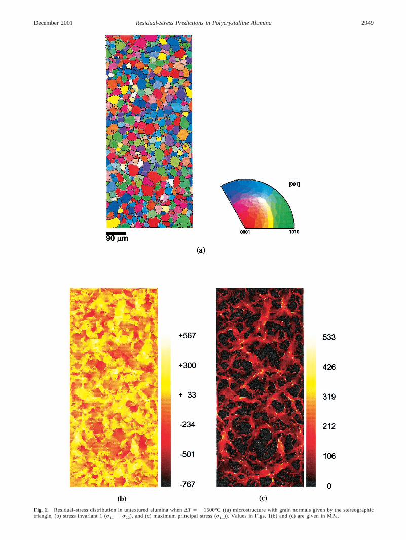
Fig. 1. Residual-stress distribution in untextured alumina when �T � �1500°C ((a) microstructure with grain normals given by the stereographictriangle, (b) stress invariant 1 (11 22), and (c) maximum principal stress (11)). Values in Figs. 1(b) and (c) are given in MPa.
December 2001 Residual-Stress Predictions in Polycrystalline Alumina 2949
(4) Steps (1)–(3) are repeated until no more elementsmutate or one or more cracks become unstable, causing fractureinto two or more fragments.
IV. Results and Discussion
(1) Residual-Stress Distributions in Untextured andTextured Alumina
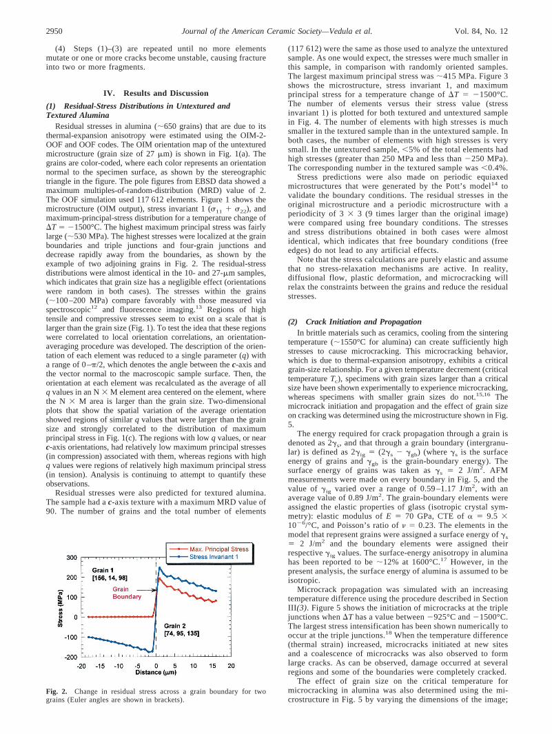
Residual stresses in alumina (�650 grains) that are due to itsthermal-expansion anisotropy were estimated using the OIM-2-OOF and OOF codes. The OIM orientation map of the untexturedmicrostructure (grain size of 27 �m) is shown in Fig. 1(a). Thegrains are color-coded, where each color represents an orientationnormal to the specimen surface, as shown by the stereographictriangle in the figure. The pole figures from EBSD data showed amaximum multiples-of-random-distribution (MRD) value of 2.The OOF simulation used 117 612 elements. Figure 1 shows themicrostructure (OIM output), stress invariant 1 (11 22), andmaximum-principal-stress distribution for a temperature change of�T � �1500°C. The highest maximum principal stress was fairlylarge (�530 MPa). The highest stresses were localized at the grainboundaries and triple junctions and four-grain junctions anddecrease rapidly away from the boundaries, as shown by theexample of two adjoining grains in Fig. 2. The residual-stressdistributions were almost identical in the 10- and 27-�m samples,which indicates that grain size has a negligible effect (orientationswere random in both cases). The stresses within the grains(�100–200 MPa) compare favorably with those measured viaspectroscopic12 and fluorescence imaging.13 Regions of hightensile and compressive stresses seem to exist on a scale that islarger than the grain size (Fig. 1). To test the idea that these regionswere correlated to local orientation correlations, an orientation-averaging procedure was developed. The description of the orien-tation of each element was reduced to a single parameter (q) witha range of 0–�/2, which denotes the angle between the c-axis andthe vector normal to the macroscopic sample surface. Then, theorientation at each element was recalculated as the average of allq values in an N � M element area centered on the element, wherethe N � M area is larger than the grain size. Two-dimensionalplots that show the spatial variation of the average orientationshowed regions of similar q values that were larger than the grainsize and strongly correlated to the distribution of maximumprincipal stress in Fig. 1(c). The regions with low q values, or nearc-axis orientations, had relatively low maximum principal stresses(in compression) associated with them, whereas regions with highq values were regions of relatively high maximum principal stress(in tension). Analysis is continuing to attempt to quantify theseobservations.
Residual stresses were also predicted for textured alumina.The sample had a c-axis texture with a maximum MRD value of90. The number of grains and the total number of elements
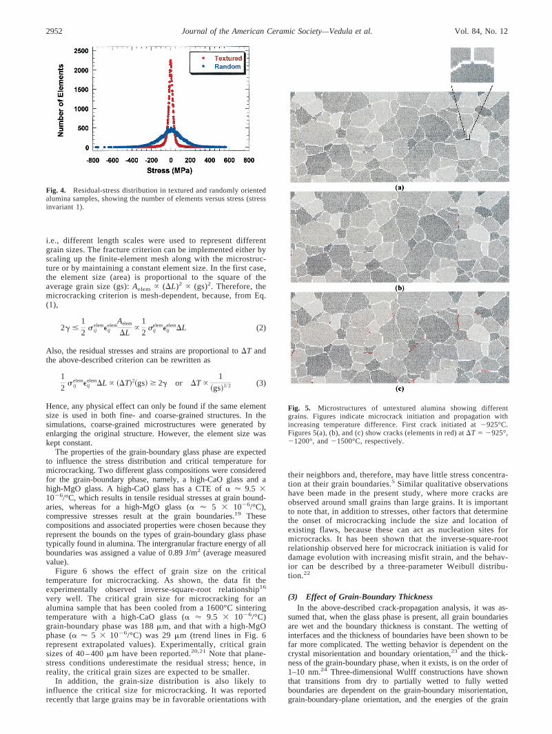
(117 612) were the same as those used to analyze the untexturedsample. As one would expect, the stresses were much smaller inthis sample, in comparison with randomly oriented samples.The largest maximum principal stress was �415 MPa. Figure 3shows the microstructure, stress invariant 1, and maximumprincipal stress for a temperature change of �T � �1500°C.The number of elements versus their stress value (stressinvariant 1) is plotted for both textured and untextured samplein Fig. 4. The number of elements with high stresses is muchsmaller in the textured sample than in the untextured sample. Inboth cases, the number of elements with high stresses is verysmall. In the untextured sample, �5% of the total elements hadhigh stresses (greater than 250 MPa and less than �250 MPa).The corresponding number in the textured sample was �0.4%.
Stress predictions were also made on periodic equiaxedmicrostructures that were generated by the Pott’s model14 tovalidate the boundary conditions. The residual stresses in theoriginal microstructure and a periodic microstructure with aperiodicity of 3 � 3 (9 times larger than the original image)were compared using free boundary conditions. The stressesand stress distributions obtained in both cases were almostidentical, which indicates that free boundary conditions (freeedges) do not lead to any artificial effects.
Note that the stress calculations are purely elastic and assumethat no stress-relaxation mechanisms are active. In reality,diffusional flow, plastic deformation, and microcracking willrelax the constraints between the grains and reduce the residualstresses.
(2) Crack Initiation and PropagationIn brittle materials such as ceramics, cooling from the sintering
temperature (�1550°C for alumina) can create sufficiently highstresses to cause microcracking. This microcracking behavior,which is due to thermal-expansion anisotropy, exhibits a criticalgrain-size relationship. For a given temperature decrement (criticaltemperature Tc), specimens with grain sizes larger than a criticalsize have been shown experimentally to experience microcracking,whereas specimens with smaller grain sizes do not.15,16 Themicrocrack initiation and propagation and the effect of grain sizeon cracking was determined using the microstructure shown in Fig.5.
The energy required for crack propagation through a grain isdenoted as 2�s, and that through a grain boundary (intergranu-lar) is defined as 2�ig � (2�s � �gb) (where �s is the surfaceenergy of grains and �gb is the grain-boundary energy). Thesurface energy of grains was taken as �s � 2 J/m2. AFMmeasurements were made on every boundary in Fig. 5, and thevalue of �ig varied over a range of 0.59 –1.17 J/m2, with anaverage value of 0.89 J/m2. The grain-boundary elements wereassigned the elastic properties of glass (isotropic crystal sym-metry): elastic modulus of E � 70 GPa, CTE of � � 9.5 �10�6/°C, and Poisson’s ratio of � � 0.23. The elements in themodel that represent grains were assigned a surface energy of �s
� 2 J/m2 and the boundary elements were assigned theirrespective �ig values. The surface-energy anisotropy in aluminahas been reported to be �12% at 1600°C.17 However, in thepresent analysis, the surface energy of alumina is assumed to beisotropic.
Microcrack propagation was simulated with an increasingtemperature difference using the procedure described in SectionIII(3). Figure 5 shows the initiation of microcracks at the triplejunctions when �T has a value between �925°C and �1500°C.The largest stress intensification has been shown numerically tooccur at the triple junctions.18 When the temperature difference(thermal strain) increased, microcracks initiated at new sitesand a coalescence of microcracks was also observed to formlarge cracks. As can be observed, damage occurred at severalregions and some of the boundaries were completely cracked.
The effect of grain size on the critical temperature formicrocracking in alumina was also determined using the mi-crostructure in Fig. 5 by varying the dimensions of the image;
Fig. 2. Change in residual stress across a grain boundary for twograins (Euler angles are shown in brackets).
2950 Journal of the American Ceramic Society—Vedula et al. Vol. 84, No. 12

Fig. 3. Residual-stress distribution in textured alumina when �T � �1500°C ((a) microstructure with grain normals given by the stereographictriangle, (b) stress invariant 1 (11 22), and (c) maximum principal stress (11)). Values in Figs. 3(b) and (c) are given in MPa.
December 2001 Residual-Stress Predictions in Polycrystalline Alumina 2951
i.e., different length scales were used to represent differentgrain sizes. The fracture criterion can be implemented either byscaling up the finite-element mesh along with the microstruc-ture or by maintaining a constant element size. In the first case,the element size (area) is proportional to the square of theaverage grain size (gs): Aelem � (�L)2 � (gs)2. Therefore, themicrocracking criterion is mesh-dependent, because, from Eq.(1),
2� �1
2ij
elem�ijelem
Aelem
�L�
1
2�ij
elem�ijelem�L (2)
Also, the residual stresses and strains are proportional to �T andthe above-described criterion can be rewritten as
1
2ij
elem�ijelem�L � ��T�2�gs� � 2� or �T �
1
�gs�1/ 2 (3)
Hence, any physical effect can only be found if the same elementsize is used in both fine- and coarse-grained structures. In thesimulations, coarse-grained microstructures were generated byenlarging the original structure. However, the element size waskept constant.
The properties of the grain-boundary glass phase are expectedto influence the stress distribution and critical temperature formicrocracking. Two different glass compositions were consideredfor the grain-boundary phase, namely, a high-CaO glass and ahigh-MgO glass. A high-CaO glass has a CTE of � � 9.5 �10�6/°C, which results in tensile residual stresses at grain bound-aries, whereas for a high-MgO glass (� � 5 � 10�6/°C),compressive stresses result at the grain boundaries.19 Thesecompositions and associated properties were chosen because theyrepresent the bounds on the types of grain-boundary glass phasetypically found in alumina. The intergranular fracture energy of allboundaries was assigned a value of 0.89 J/m2 (average measuredvalue).
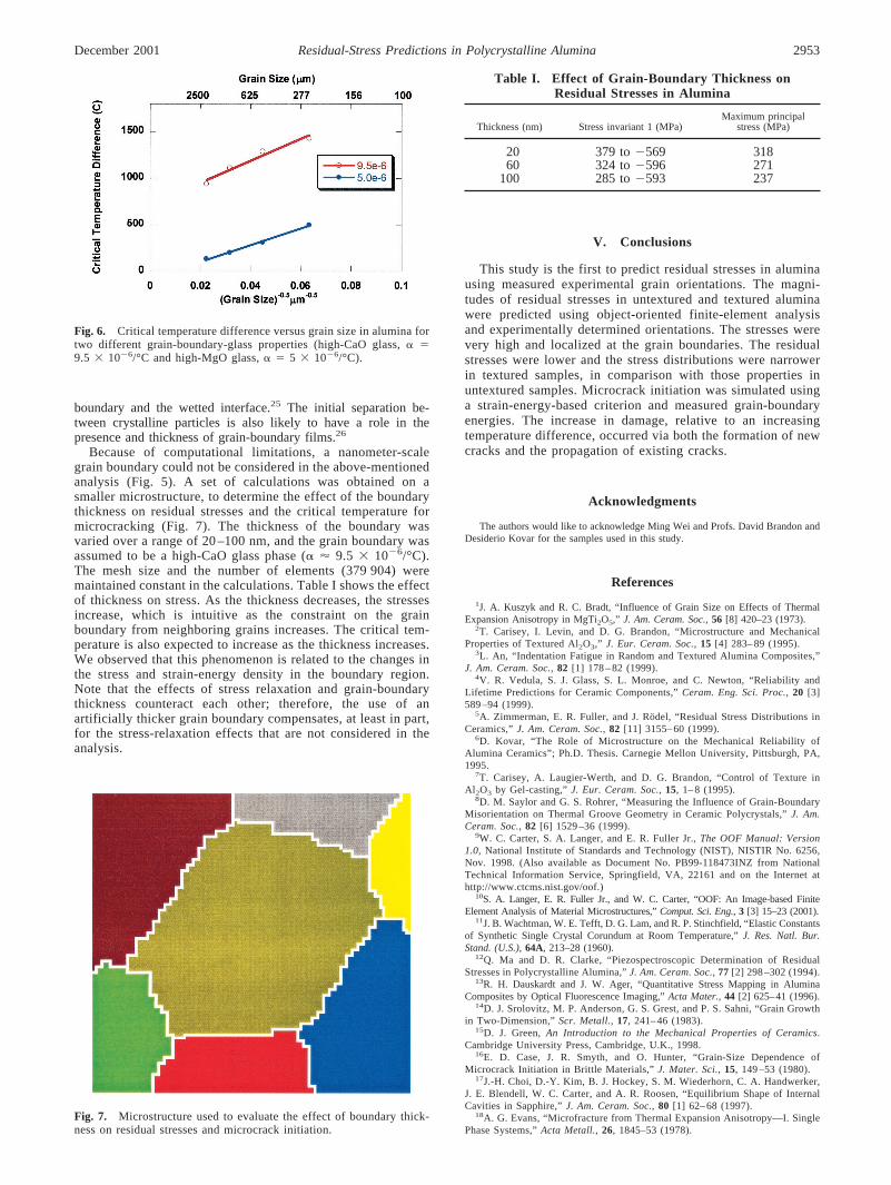
Figure 6 shows the effect of grain size on the criticaltemperature for microcracking. As shown, the data fit theexperimentally observed inverse-square-root relationship16
very well. The critical grain size for microcracking for analumina sample that has been cooled from a 1600°C sinteringtemperature with a high-CaO glass (� � 9.5 � 10�6/°C)grain-boundary phase was 188 �m, and that with a high-MgOphase (� � 5 � 10�6/°C) was 29 �m (trend lines in Fig. 6represent extrapolated values). Experimentally, critical grainsizes of 40 – 400 �m have been reported.20,21 Note that plane-stress conditions underestimate the residual stress; hence, inreality, the critical grain sizes are expected to be smaller.
In addition, the grain-size distribution is also likely toinfluence the critical size for microcracking. It was reportedrecently that large grains may be in favorable orientations with
their neighbors and, therefore, may have little stress concentra-tion at their grain boundaries.5 Similar qualitative observationshave been made in the present study, where more cracks areobserved around small grains than large grains. It is importantto note that, in addition to stresses, other factors that determinethe onset of microcracking include the size and location ofexisting flaws, because these can act as nucleation sites formicrocracks. It has been shown that the inverse-square-rootrelationship observed here for microcrack initiation is valid fordamage evolution with increasing misfit strain, and the behav-ior can be described by a three-parameter Weibull distribu-tion.22
(3) Effect of Grain-Boundary ThicknessIn the above-described crack-propagation analysis, it was as-
sumed that, when the glass phase is present, all grain boundariesare wet and the boundary thickness is constant. The wetting ofinterfaces and the thickness of boundaries have been shown to befar more complicated. The wetting behavior is dependent on thecrystal misorientation and boundary orientation,23 and the thick-ness of the grain-boundary phase, when it exists, is on the order of1–10 nm.24 Three-dimensional Wulff constructions have shownthat transitions from dry to partially wetted to fully wettedboundaries are dependent on the grain-boundary misorientation,grain-boundary-plane orientation, and the energies of the grain
Fig. 4. Residual-stress distribution in textured and randomly orientedalumina samples, showing the number of elements versus stress (stressinvariant 1).
Fig. 5. Microstructures of untextured alumina showing differentgrains. Figures indicate microcrack initiation and propagation withincreasing temperature difference. First crack initiated at �925°C.Figures 5(a), (b), and (c) show cracks (elements in red) at �T � �925°,�1200°, and �1500°C, respectively.
2952 Journal of the American Ceramic Society—Vedula et al. Vol. 84, No. 12
boundary and the wetted interface.25 The initial separation be-tween crystalline particles is also likely to have a role in thepresence and thickness of grain-boundary films.26
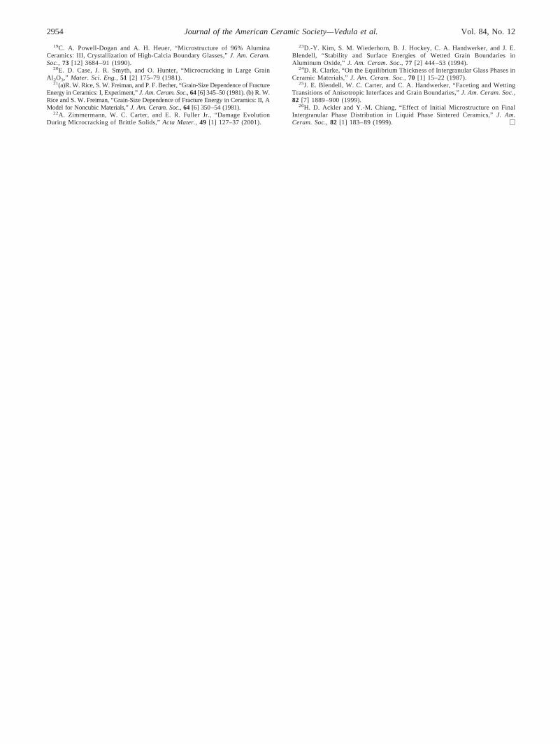
Because of computational limitations, a nanometer-scalegrain boundary could not be considered in the above-mentionedanalysis (Fig. 5). A set of calculations was obtained on asmaller microstructure, to determine the effect of the boundarythickness on residual stresses and the critical temperature formicrocracking (Fig. 7). The thickness of the boundary wasvaried over a range of 20 –100 nm, and the grain boundary wasassumed to be a high-CaO glass phase (� � 9.5 � 10�6/°C).The mesh size and the number of elements (379 904) weremaintained constant in the calculations. Table I shows the effectof thickness on stress. As the thickness decreases, the stressesincrease, which is intuitive as the constraint on the grainboundary from neighboring grains increases. The critical tem-perature is also expected to increase as the thickness increases.We observed that this phenomenon is related to the changes inthe stress and strain-energy density in the boundary region.Note that the effects of stress relaxation and grain-boundarythickness counteract each other; therefore, the use of anartificially thicker grain boundary compensates, at least in part,for the stress-relaxation effects that are not considered in theanalysis.
V. Conclusions
This study is the first to predict residual stresses in aluminausing measured experimental grain orientations. The magni-tudes of residual stresses in untextured and textured aluminawere predicted using object-oriented finite-element analysisand experimentally determined orientations. The stresses werevery high and localized at the grain boundaries. The residualstresses were lower and the stress distributions were narrowerin textured samples, in comparison with those properties inuntextured samples. Microcrack initiation was simulated usinga strain-energy-based criterion and measured grain-boundaryenergies. The increase in damage, relative to an increasingtemperature difference, occurred via both the formation of newcracks and the propagation of existing cracks.
Acknowledgments
The authors would like to acknowledge Ming Wei and Profs. David Brandon andDesiderio Kovar for the samples used in this study.
References
1J. A. Kuszyk and R. C. Bradt, “Influence of Grain Size on Effects of ThermalExpansion Anisotropy in MgTi2O5,” J. Am. Ceram. Soc., 56 [8] 420–23 (1973).
2T. Carisey, I. Levin, and D. G. Brandon, “Microstructure and MechanicalProperties of Textured Al2O3,” J. Eur. Ceram. Soc., 15 [4] 283– 89 (1995).
3L. An, “Indentation Fatigue in Random and Textured Alumina Composites,”J. Am. Ceram. Soc., 82 [1] 178 – 82 (1999).
4V. R. Vedula, S. J. Glass, S. L. Monroe, and C. Newton, “Reliability andLifetime Predictions for Ceramic Components,” Ceram. Eng. Sci. Proc., 20 [3]589 –94 (1999).
5A. Zimmerman, E. R. Fuller, and J. Rodel, “Residual Stress Distributions inCeramics,” J. Am. Ceram. Soc., 82 [11] 3155– 60 (1999).
6D. Kovar, “The Role of Microstructure on the Mechanical Reliability ofAlumina Ceramics”; Ph.D. Thesis. Carnegie Mellon University, Pittsburgh, PA,1995.
7T. Carisey, A. Laugier-Werth, and D. G. Brandon, “Control of Texture inAl2O3 by Gel-casting,” J. Eur. Ceram. Soc., 15, 1– 8 (1995).
8D. M. Saylor and G. S. Rohrer, “Measuring the Influence of Grain-BoundaryMisorientation on Thermal Groove Geometry in Ceramic Polycrystals,” J. Am.Ceram. Soc., 82 [6] 1529 –36 (1999).
9W. C. Carter, S. A. Langer, and E. R. Fuller Jr., The OOF Manual: Version1.0, National Institute of Standards and Technology (NIST), NISTIR No. 6256,Nov. 1998. (Also available as Document No. PB99-118473INZ from NationalTechnical Information Service, Springfield, VA, 22161 and on the Internet athttp://www.ctcms.nist.gov/oof.)
10S. A. Langer, E. R. Fuller Jr., and W. C. Carter, “OOF: An Image-based FiniteElement Analysis of Material Microstructures,” Comput. Sci. Eng., 3 [3] 15–23 (2001).
11J. B. Wachtman, W. E. Tefft, D. G. Lam, and R. P. Stinchfield, “Elastic Constantsof Synthetic Single Crystal Corundum at Room Temperature,” J. Res. Natl. Bur.Stand. (U.S.), 64A, 213–28 (1960).
12Q. Ma and D. R. Clarke, “Piezospectroscopic Determination of ResidualStresses in Polycrystalline Alumina,” J. Am. Ceram. Soc., 77 [2] 298 –302 (1994).
13R. H. Dauskardt and J. W. Ager, “Quantitative Stress Mapping in AluminaComposites by Optical Fluorescence Imaging,” Acta Mater., 44 [2] 625–41 (1996).
14D. J. Srolovitz, M. P. Anderson, G. S. Grest, and P. S. Sahni, “Grain Growthin Two-Dimension,” Scr. Metall., 17, 241– 46 (1983).
15D. J. Green, An Introduction to the Mechanical Properties of Ceramics.Cambridge University Press, Cambridge, U.K., 1998.
16E. D. Case, J. R. Smyth, and O. Hunter, “Grain-Size Dependence ofMicrocrack Initiation in Brittle Materials,” J. Mater. Sci., 15, 149 –53 (1980).
17J.-H. Choi, D.-Y. Kim, B. J. Hockey, S. M. Wiederhorn, C. A. Handwerker,J. E. Blendell, W. C. Carter, and A. R. Roosen, “Equilibrium Shape of InternalCavities in Sapphire,” J. Am. Ceram. Soc., 80 [1] 62– 68 (1997).
18A. G. Evans, “Microfracture from Thermal Expansion Anisotropy—I. SinglePhase Systems,” Acta Metall., 26, 1845–53 (1978).
Fig. 6. Critical temperature difference versus grain size in alumina fortwo different grain-boundary-glass properties (high-CaO glass, � �9.5 � 10�6/°C and high-MgO glass, � � 5 � 10�6/°C).
Fig. 7. Microstructure used to evaluate the effect of boundary thick-ness on residual stresses and microcrack initiation.
Table I. Effect of Grain-Boundary Thickness onResidual Stresses in Alumina
Thickness (nm) Stress invariant 1 (MPa)Maximum principal
stress (MPa)
20 379 to �569 31860 324 to �596 271
100 285 to �593 237
December 2001 Residual-Stress Predictions in Polycrystalline Alumina 2953
19C. A. Powell-Dogan and A. H. Heuer, “Microstructure of 96% AluminaCeramics: III, Crystallization of High-Calcia Boundary Glasses,” J. Am. Ceram.Soc., 73 [12] 3684 –91 (1990).
20E. D. Case, J. R. Smyth, and O. Hunter, “Microcracking in Large GrainAl2O3,” Mater. Sci. Eng., 51 [2] 175–79 (1981).
21(a)R. W. Rice, S. W. Freiman, and P. F. Becher, “Grain-Size Dependence of FractureEnergy in Ceramics: I, Experiment,” J. Am. Ceram. Soc., 64 [6] 345–50 (1981). (b) R. W.Rice and S. W. Freiman, “Grain-Size Dependence of Fracture Energy in Ceramics: II, AModel for Noncubic Materials,” J. Am. Ceram. Soc., 64 [6] 350–54 (1981).
22A. Zimmermann, W. C. Carter, and E. R. Fuller Jr., “Damage EvolutionDuring Microcracking of Brittle Solids,” Acta Mater., 49 [1] 127–37 (2001).
23D.-Y. Kim, S. M. Wiederhorn, B. J. Hockey, C. A. Handwerker, and J. E.Blendell, “Stability and Surface Energies of Wetted Grain Boundaries inAluminum Oxide,” J. Am. Ceram. Soc., 77 [2] 444 –53 (1994).
24D. R. Clarke, “On the Equilibrium Thickness of Intergranular Glass Phases inCeramic Materials,” J. Am. Ceram. Soc., 70 [1] 15–22 (1987).
25J. E. Blendell, W. C. Carter, and C. A. Handwerker, “Faceting and WettingTransitions of Anisotropic Interfaces and Grain Boundaries,” J. Am. Ceram. Soc.,82 [7] 1889 –900 (1999).
26H. D. Ackler and Y.-M. Chiang, “Effect of Initial Microstructure on FinalIntergranular Phase Distribution in Liquid Phase Sintered Ceramics,” J. Am.Ceram. Soc., 82 [1] 183– 89 (1999). �
2954 Journal of the American Ceramic Society—Vedula et al. Vol. 84, No. 12
Related Documents