Principal Investigator: Jorge Crichigno Award 1829698 “CyberTraining CIP: Cyberinfrastructure Expertise on High-throughput Networks for Big Science Data Transfers” Book Version: 10-24-2021 OPEN SHORTEST PATH FIRST LAB SERIES

Welcome message from author
This document is posted to help you gain knowledge. Please leave a comment to let me know what you think about it! Share it to your friends and learn new things together.
Transcript

Principal Investigator: Jorge Crichigno
Award 1829698 “CyberTraining CIP: Cyberinfrastructure Expertise on High-throughput
Networks for Big Science Data Transfers”
Book Version: 10-24-2021
OPEN SHORTEST PATH FIRST LAB SERIES

Open Shortest Path First Lab Series
Contents
gomezgaj
Typewriter
Lab 1: Introduction to Mininet Lab 2: Introduction to FRR Lab 3: Configuring Single-Area OSPFv2 Lab 4: Configuring Multi-Area OSPFv2 Exercise 1: Configuring Multi-Area OSPFv2 Lab 5: Configuring OSPFv2 with Default Route Lab 6: OSPFv2 Virtual Link Exercise 2: Configuring OSPFv2 Virtual Link Lab 7: OSPFv2 Authentication Lab 8: Setting OSPFv2 Route Cost Lab 9: Configuring Multi-Area OSPFv3 Exercise 3: Configuring Multi-Area OSPFv3 Lab 10: Configuring Dual Stack OSPF Routing
OPEN SHORTEST PATH FIRST
Lab 1: Introduction to Mininet
Document Version: 10-11-2021
Award 1829698 “CyberTraining CIP: Cyberinfrastructure Expertise on High-throughput
Networks for Big Science Data Transfers”

Lab 1: Introduction to Mininet
Page 2
Contents Overview ............................................................................................................................. 3
Objectives............................................................................................................................ 3
Lab settings ......................................................................................................................... 3
Lab roadmap ....................................................................................................................... 3
1 Introduction to Mininet .............................................................................................. 3
2 Invoke Mininet using the CLI ...................................................................................... 5
2.1 Invoke Mininet using the default topology .......................................................... 5
2.2 Test connectivity .................................................................................................. 9
3 Build and emulate a network in Mininet using the GUI ........................................... 10
3.1 Build the network topology ............................................................................... 10
3.2 Test connectivity ................................................................................................ 12
3.3 Automatic assignment of IP addresses .............................................................. 15
3.4 Save and load a Mininet topology ..................................................................... 18
4 Configure router r1 ................................................................................................... 19
4.1 Verify end-hosts configuration........................................................................... 20
4.2 Configure router’s interface ............................................................................... 21
4.3 Verify router r1 configuration ............................................................................ 25
4.4 Test connectivity between end-hosts ................................................................ 26
References ........................................................................................................................ 26
Lab 1: Introduction to Mininet
Page 3
Overview This lab provides an introduction to Mininet, a virtual testbed used for testing network tools and protocols. It demonstrates how to invoke Mininet from the command-line interface (CLI) utility and how to build and emulate topologies using a graphical user interface (GUI) application. Objectives By the end of this lab, you should be able to:
1. Understand what Mininet is and why it is useful for testing network topologies. 2. Invoke Mininet from the CLI. 3. Construct network topologies using the GUI. 4. Save/load Mininet topologies using the GUI. 5. Configure the interfaces of a router using the CLI.
Lab settings The information in Table 1 provides the credentials of the Client machine.
Table 1. Credentials to access the Client machine.
Device
Account
Password
Client admin password
Lab roadmap This lab is organized as follows:
1. Section 1: Introduction to Mininet. 2. Section 2: Invoke Mininet using the CLI. 3. Section 3: Build and emulate a network in Mininet using the GUI. 4. Section 4: Configure router r1.
1 Introduction to Mininet Mininet is a virtual testbed enabling the development and testing of network tools and protocols. With a single command, Mininet can create a realistic virtual network on any type of machine (Virtual Machine (VM), cloud-hosted, or native). Therefore, it provides an inexpensive solution and streamlined development running in line with production networks1. Mininet offers the following features:

Lab 1: Introduction to Mininet
Page 4
• Fast prototyping for new networking protocols.
• Simplified testing for complex topologies without the need of buying expensive hardware.
• Realistic execution as it runs real code on the Unix and Linux kernels.
• Open-source environment backed by a large community contributing extensive documentation.
Figure 1. Hardware network vs. Mininet emulated network.
Mininet is useful for development, teaching, and research as it is easy to customize and interact with it through the CLI or the GUI. Mininet was originally designed to experiment with OpenFlow2 and Software-Defined Networking (SDN)3. This lab, however, only focuses on emulating a simple network environment without SDN-based devices. Mininet’s logical nodes can be connected into networks. These nodes are sometimes called containers, or more accurately, network namespaces. Containers consume sufficiently fewer resources that networks of over a thousand nodes have created, running on a single laptop. A Mininet container is a process (or group of processes) that no longer has access to all the host system’s native network interfaces. Containers are then assigned virtual Ethernet interfaces, which are connected to other containers through a virtual switch4. Mininet connects a host and a switch using a virtual Ethernet (veth) link. The veth link is analogous to a wire connecting two virtual interfaces, as illustrated below.
Figure 2. Network namespaces and virtual Ethernet links.
h1 s1 h2s2
s3
Hardware NetworkMininet Emulated Network

Lab 1: Introduction to Mininet
Page 5
Each container is an independent network namespace, a lightweight virtualization feature that provides individual processes with separate network interfaces, routing tables, and Address Resolution Protocol (ARP) tables. Mininet provides network emulation opposed to simulation, allowing all network software at any layer to be simply run as is; i.e. nodes run the native network software of the physical machine. On the other hand, in a simulated environment applications and protocol implementations need to be ported to run within the simulator before they can be used. 2 Invoke Mininet using the CLI The first step to start Mininet using the CLI is to start a Linux terminal. 2.1 Invoke Mininet using the default topology
Step 1. Launch a Linux terminal by holding the Ctrl+Alt+T keys or by clicking on the Linux terminal icon.
Figure 3. Linux terminal icon.
The Linux terminal is a program that opens a window and permits you to interact with a command-line interface (CLI). A CLI is a program that takes commands from the keyboard and sends them to the operating system for execution. Step 2. To start a minimal topology, enter the command shown below. When prompted for a password, type password and hit enter. Note that the password will not be visible as you type it. sudo mn

Lab 1: Introduction to Mininet
Page 6
Figure 4. Starting Mininet using the CLI.
The above command starts Mininet with a minimal topology, which consists of a switch connected to two hosts as shown below.
Figure 5. Mininet’s default minimal topology.
When issuing the sudo mn command, Mininet initializes the topology and launches its command line interface which looks like this: mininet>
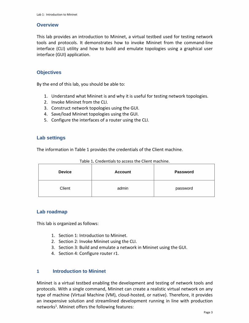
Step 3. To display the list of Mininet CLI commands and examples on their usage, type the following command: help
Lab 1: Introduction to Mininet
Page 7
Figure 6. Mininet’s help command.
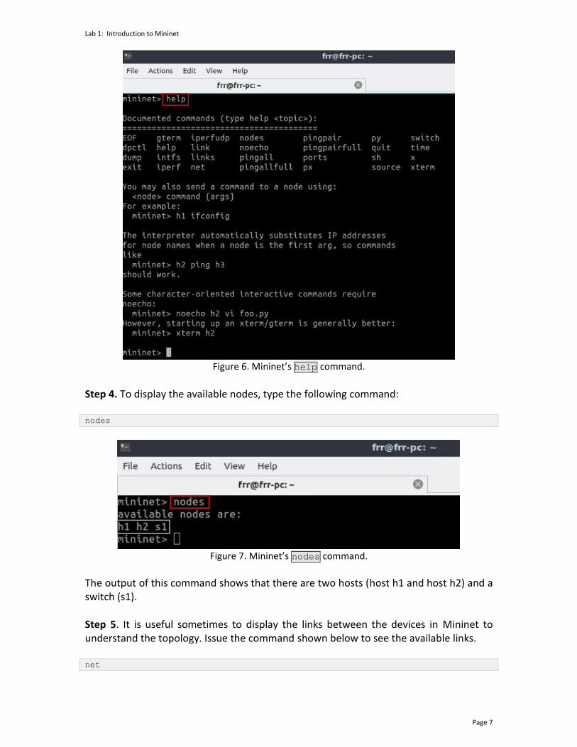
Step 4. To display the available nodes, type the following command: nodes
Figure 7. Mininet’s nodes command.
The output of this command shows that there are two hosts (host h1 and host h2) and a switch (s1). Step 5. It is useful sometimes to display the links between the devices in Mininet to understand the topology. Issue the command shown below to see the available links. net

Lab 1: Introduction to Mininet
Page 8
Figure 8. Mininet’s net command.
The output of this command shows that:
1. Host h1 is connected using its network interface h1-eth0 to the switch on interface s1-eth1.
2. Host h2 is connected using its network interface h2-eth0 to the switch on interface s1-eth2.
3. Switch s1: a. has a loopback interface lo. b. connects to h1-eth0 through interface s1-eth1. c. connects to h2-eth0 through interface s1-eth2.
Mininet allows you to execute commands on a specific device. To issue a command for a specific node, you must specify the device first, followed by the command. Step 6. To proceed, issue the command: h1 ifconfig
Figure 9. Output of h1 ifconfig command.

Lab 1: Introduction to Mininet
Page 9
This command executes the ifconfig Linux command on host h1. The command shows host h1’s interfaces. The display indicates that host h1 has an interface h1-eth0 configured with IP address 10.0.0.1, and another interface lo configured with IP address 127.0.0.1 (loopback interface). 2.2 Test connectivity
Mininet’s default topology assigns the IP addresses 10.0.0.1/8 and 10.0.0.2/8 to host h1 and host h2 respectively. To test connectivity between them, you can use the command ping. The ping command operates by sending Internet Control Message Protocol (ICMP) Echo Request messages to the remote computer and waiting for a response or reply. Information available includes how many responses are returned and how long it takes for them to return. Step 1. On the CLI, type the command shown below. This command tests the connectivity between host h1 and host h2. To stop the test, press Ctrl+c. The figure below shows a successful connectivity test. Host h1 (10.0.0.1) sent four packets to host h2 (10.0.0.2) and successfully received the expected responses. h1 ping 10.0.0.2
Figure 10. Connectivity test between host h1 and host h2.
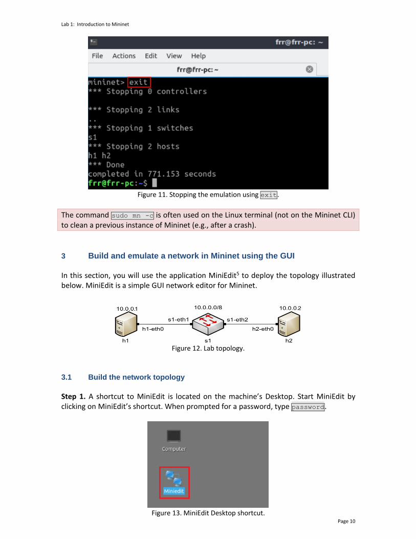
Step 2. Stop the emulation by typing the following command: exit
Lab 1: Introduction to Mininet
Page 10
Figure 11. Stopping the emulation using exit.
The command sudo mn -c is often used on the Linux terminal (not on the Mininet CLI) to clean a previous instance of Mininet (e.g., after a crash).
3 Build and emulate a network in Mininet using the GUI In this section, you will use the application MiniEdit5 to deploy the topology illustrated below. MiniEdit is a simple GUI network editor for Mininet.
Figure 12. Lab topology.
3.1 Build the network topology
Step 1. A shortcut to MiniEdit is located on the machine’s Desktop. Start MiniEdit by clicking on MiniEdit’s shortcut. When prompted for a password, type password.
Figure 13. MiniEdit Desktop shortcut.
Lab 1: Introduction to Mininet
Page 11
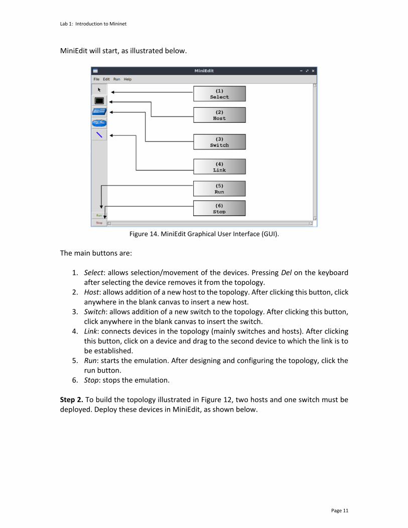
MiniEdit will start, as illustrated below.
Figure 14. MiniEdit Graphical User Interface (GUI).
The main buttons are:
1. Select: allows selection/movement of the devices. Pressing Del on the keyboard after selecting the device removes it from the topology.
2. Host: allows addition of a new host to the topology. After clicking this button, click anywhere in the blank canvas to insert a new host.
3. Switch: allows addition of a new switch to the topology. After clicking this button, click anywhere in the blank canvas to insert the switch.
4. Link: connects devices in the topology (mainly switches and hosts). After clicking this button, click on a device and drag to the second device to which the link is to be established.
5. Run: starts the emulation. After designing and configuring the topology, click the run button.
6. Stop: stops the emulation. Step 2. To build the topology illustrated in Figure 12, two hosts and one switch must be deployed. Deploy these devices in MiniEdit, as shown below.

Lab 1: Introduction to Mininet
Page 12
Figure 15. MiniEdit’s topology.
Use the buttons described in the previous step to add and connect devices. The configuration of IP addresses is described in Step 3. Step 3. Configure the IP addresses of host h1 and host h2. Host h1’s IP address is 10.0.0.1/8 and host h2’s IP address is 10.0.0.2/8. A host can be configured by holding the right click and selecting properties on the device. For example, host h2 is assigned the IP address 10.0.0.2/8 in the figure below. Click OK for the settings to be applied.
Figure 16. Configuration of a host’s properties.
3.2 Test connectivity
Before testing the connection between host h1 and host h2, the emulation must be started. Step 1. Click the Run button to start the emulation. The emulation will start and the buttons of the MiniEdit panel will gray out, indicating that they are currently disabled.
Lab 1: Introduction to Mininet
Page 13
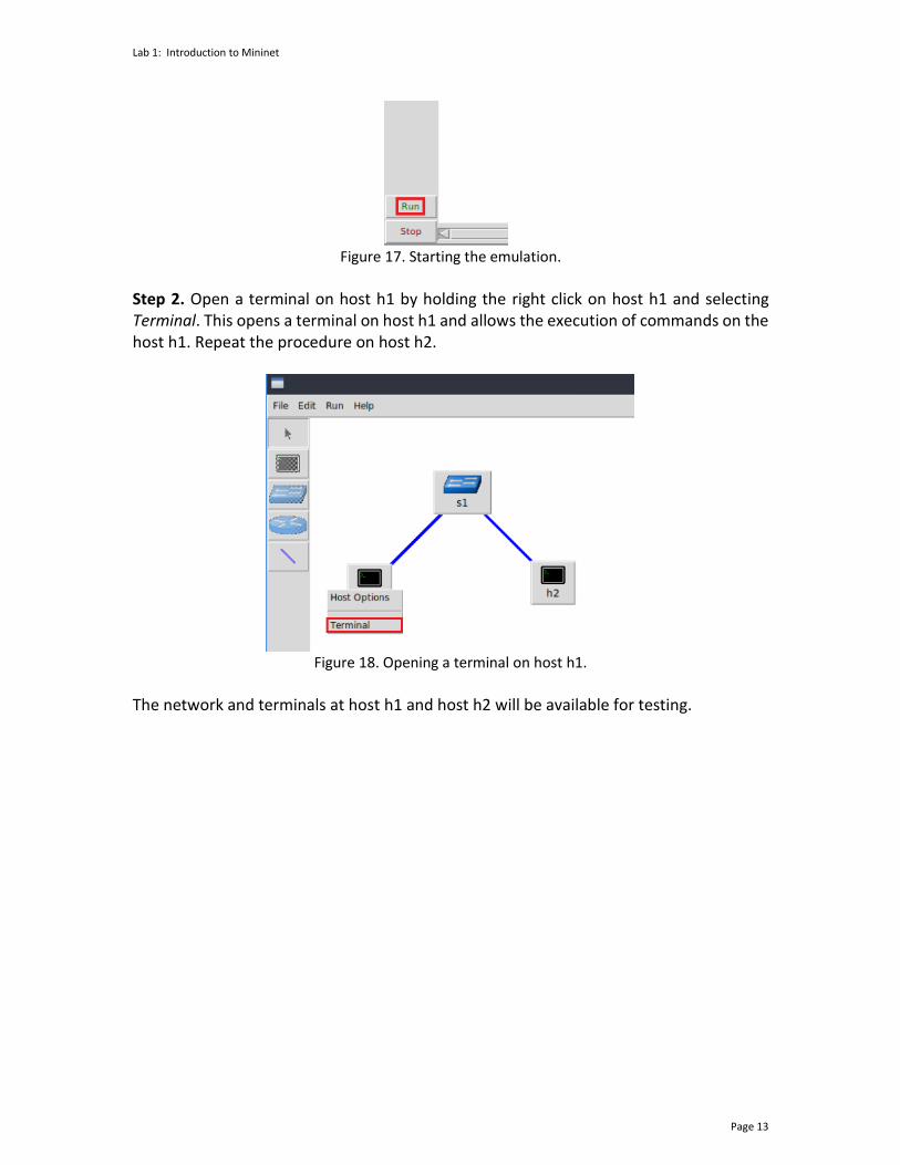
Figure 17. Starting the emulation.
Step 2. Open a terminal on host h1 by holding the right click on host h1 and selecting Terminal. This opens a terminal on host h1 and allows the execution of commands on the host h1. Repeat the procedure on host h2.
Figure 18. Opening a terminal on host h1.
The network and terminals at host h1 and host h2 will be available for testing.

Lab 1: Introduction to Mininet
Page 14
Figure 19. Terminals at host h1 and host h2.
Step 3. On host h1’s terminal, type the command shown below to display its assigned IP addresses. The interface h1-eth0 at host h1 should be configured with the IP address 10.0.0.1 and subnet mask 255.0.0.0. ifconfig
Figure 20. Output of ifconfig command on host h1.
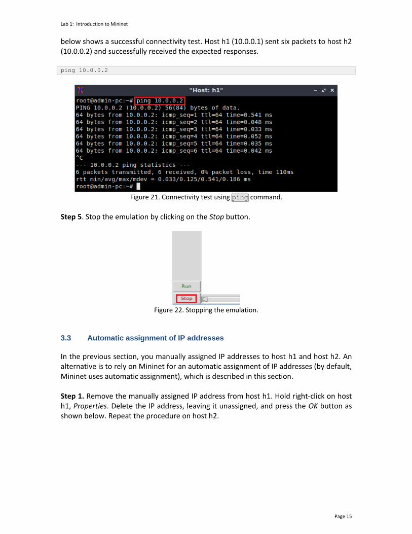
Repeat Step 3 on host h2. Its interface h2-eth0 should be configured with IP address 10.0.0.2 and subnet mask 255.0.0.0. Step 4. On host h1’s terminal, type the command shown below. This command tests the connectivity between host h1 and host h2. To stop the test, press Ctrl+c. The figure
Lab 1: Introduction to Mininet
Page 15
below shows a successful connectivity test. Host h1 (10.0.0.1) sent six packets to host h2 (10.0.0.2) and successfully received the expected responses. ping 10.0.0.2
Figure 21. Connectivity test using ping command.
Step 5. Stop the emulation by clicking on the Stop button.
Figure 22. Stopping the emulation.
3.3 Automatic assignment of IP addresses
In the previous section, you manually assigned IP addresses to host h1 and host h2. An alternative is to rely on Mininet for an automatic assignment of IP addresses (by default, Mininet uses automatic assignment), which is described in this section. Step 1. Remove the manually assigned IP address from host h1. Hold right-click on host h1, Properties. Delete the IP address, leaving it unassigned, and press the OK button as shown below. Repeat the procedure on host h2.

Lab 1: Introduction to Mininet
Page 16
Figure 23. Host h1 properties.
Step 2. Click on Edit, Preferences button. The default IP base is 10.0.0.0/8. Modify this value to 15.0.0.0/8, and then press the OK button.
Figure 24. Modification of the IP Base (network address and prefix length).
Step 3. Run the emulation again by clicking on the Run button. The emulation will start and the buttons of the MiniEdit panel will be disabled. Step 4. Open a terminal on host h1 by holding the right click on host h1 and selecting Terminal.
Lab 1: Introduction to Mininet
Page 17
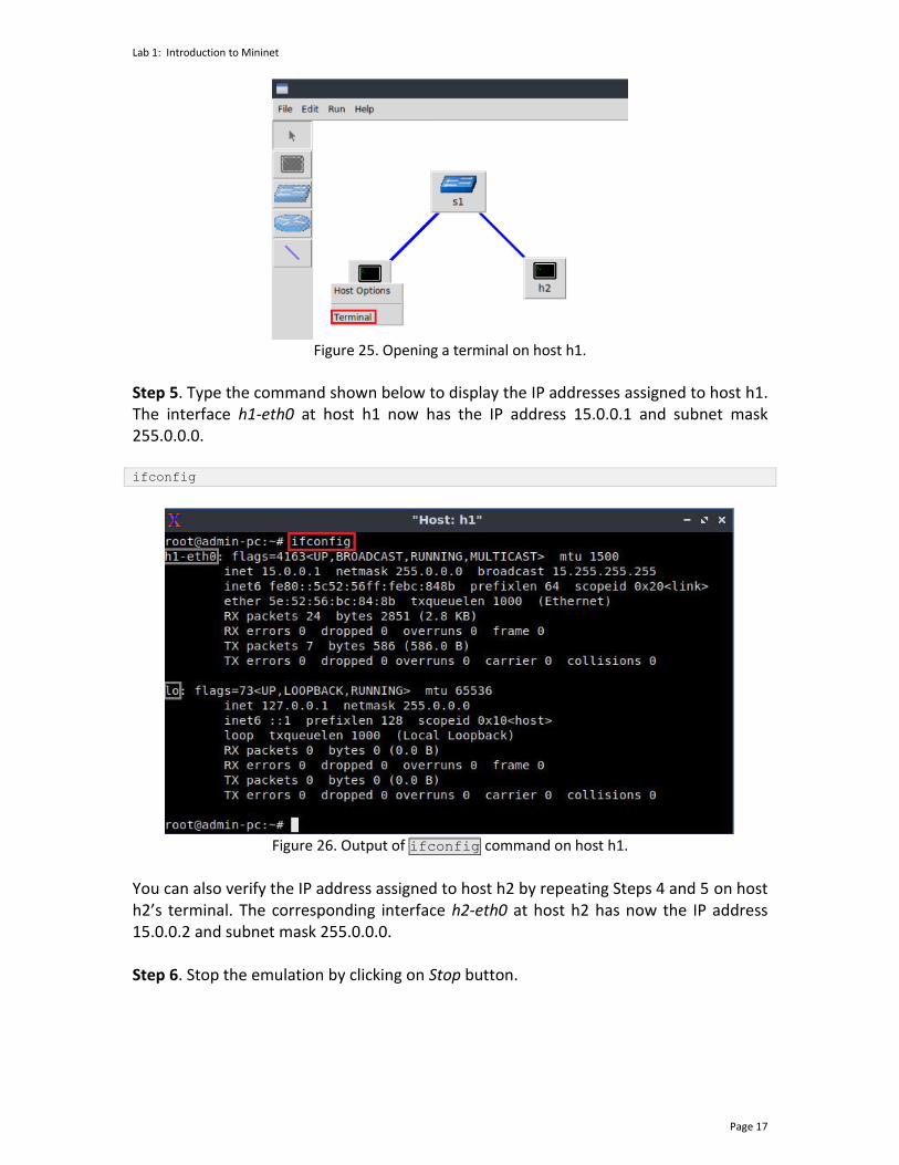
Figure 25. Opening a terminal on host h1.
Step 5. Type the command shown below to display the IP addresses assigned to host h1. The interface h1-eth0 at host h1 now has the IP address 15.0.0.1 and subnet mask 255.0.0.0. ifconfig
Figure 26. Output of ifconfig command on host h1.
You can also verify the IP address assigned to host h2 by repeating Steps 4 and 5 on host h2’s terminal. The corresponding interface h2-eth0 at host h2 has now the IP address 15.0.0.2 and subnet mask 255.0.0.0. Step 6. Stop the emulation by clicking on Stop button.
Lab 1: Introduction to Mininet
Page 18
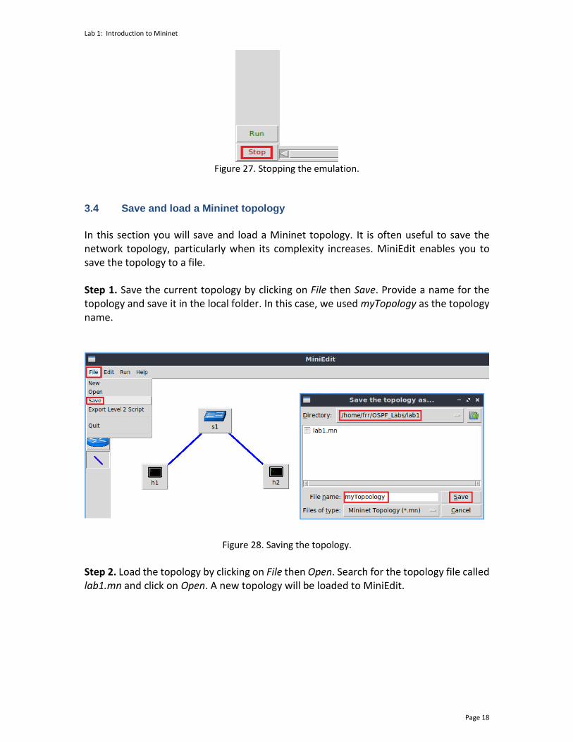
Figure 27. Stopping the emulation.
3.4 Save and load a Mininet topology
In this section you will save and load a Mininet topology. It is often useful to save the network topology, particularly when its complexity increases. MiniEdit enables you to save the topology to a file. Step 1. Save the current topology by clicking on File then Save. Provide a name for the topology and save it in the local folder. In this case, we used myTopology as the topology name.
Figure 28. Saving the topology.
Step 2. Load the topology by clicking on File then Open. Search for the topology file called lab1.mn and click on Open. A new topology will be loaded to MiniEdit.
Lab 1: Introduction to Mininet
Page 19
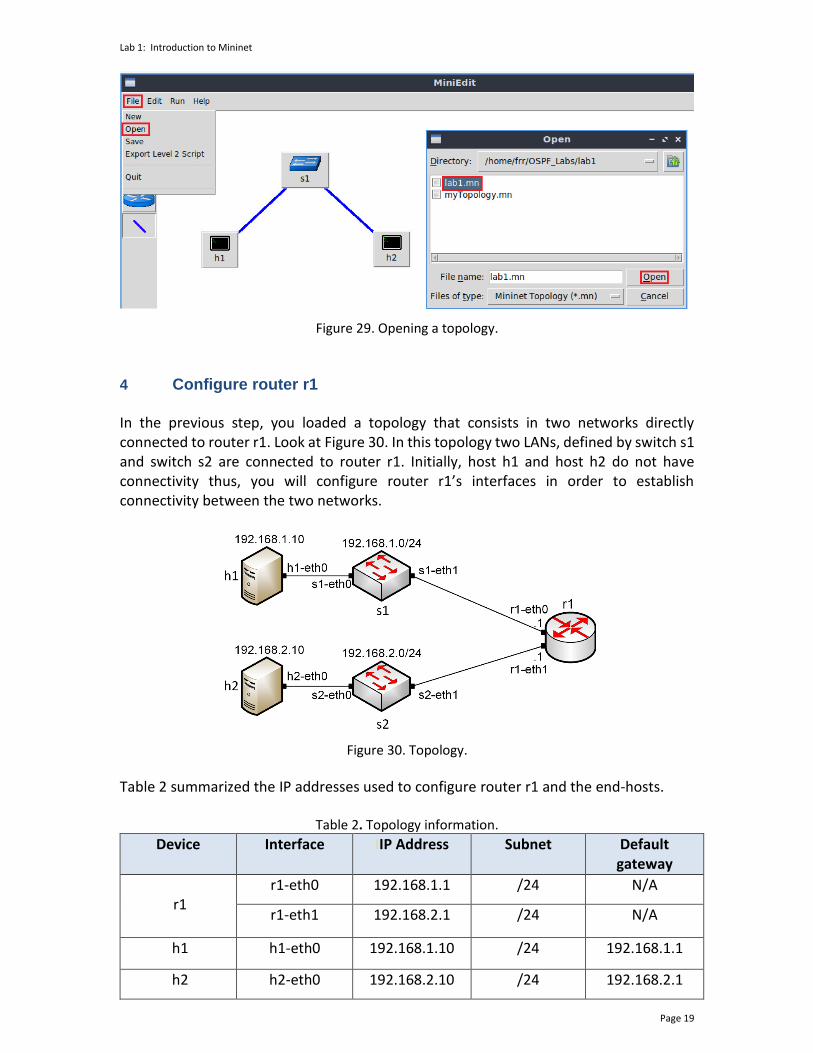
Figure 29. Opening a topology.
4 Configure router r1 In the previous step, you loaded a topology that consists in two networks directly connected to router r1. Look at Figure 30. In this topology two LANs, defined by switch s1 and switch s2 are connected to router r1. Initially, host h1 and host h2 do not have connectivity thus, you will configure router r1’s interfaces in order to establish connectivity between the two networks.
Figure 30. Topology.
Table 2 summarized the IP addresses used to configure router r1 and the end-hosts.
Table 2. Topology information. Device Interface IIP Address Subnet Default
gateway
r1
r1-eth0 192.168.1.1 /24 N/A
r1-eth1 192.168.2.1 /24 N/A
h1 h1-eth0 192.168.1.10 /24 192.168.1.1
h2 h2-eth0 192.168.2.10 /24 192.168.2.1

Lab 1: Introduction to Mininet
Page 20
Step 1. Click on the Run button to start the emulation. The emulation will start and the buttons of the MiniEdit panel will gray out, indicating that they are currently disabled.
Figure 31. Starting the emulation.
4.1 Verify end-hosts configuration
In this section, you will verify that the IP addresses are assigned according to Table 2. Additionally, you will check routing information. Step 1. Hold right-click on host h1 and select Terminal. This opens the terminal of host h1 and allows the execution of commands on that host.
Figure 32. Opening a terminal on host h1.
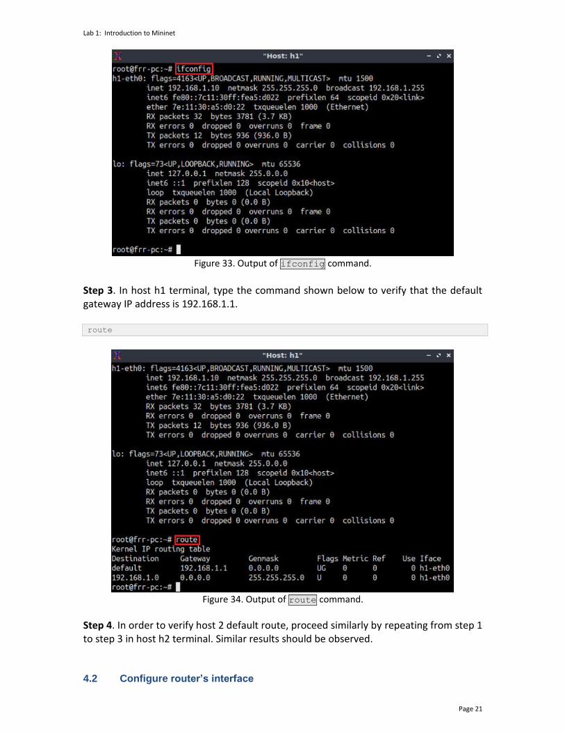
Step 2. In host h1 terminal, type the command shown below to verify that the IP address was assigned successfully. You will verify that host h1 has two interfaces, h1-eth0 configured with the IP address 192.168.1.10 and the subnet mask 255.255.255.0 and, the loopback interface lo configured with the IP address 127.0.0.1. ifconfig
Lab 1: Introduction to Mininet
Page 21
Figure 33. Output of ifconfig command.
Step 3. In host h1 terminal, type the command shown below to verify that the default gateway IP address is 192.168.1.1. route
Figure 34. Output of route command.
Step 4. In order to verify host 2 default route, proceed similarly by repeating from step 1 to step 3 in host h2 terminal. Similar results should be observed. 4.2 Configure router’s interface

Lab 1: Introduction to Mininet
Page 22
Step 1. In order to configure router r1, hold right-click on router r1 and select Terminal.
Figure 35. Opening a terminal on router r1.
Step 2. In this step, you will start the zebra daemon, a multi-server routing software that provides TCP/IP based routing protocols. The configuration will not be working if you do not enable zebra daemon initially. To activate the zebra daemon, type the following command: zebra
Figure 36. Starting zebra daemon.
Step 3. After initializing zebra, vtysh should be started in order to provide all the CLI commands defined by the daemons. To proceed, issue the following command: vtysh
Figure 37. Starting vtysh on router r1.
Step 4. Type the following command in the router r1 terminal to enter in configuration mode. configure terminal

Lab 1: Introduction to Mininet
Page 23
Figure 38. Entering in configuration mode.
Step 5. Type the following command in the router r1 terminal to configure interface r1-eth0. interface r1-eth0
Figure 39. Configuring interface r1-eth0.
Step 6. Type the following command on router r1 terminal to configure the IP address of the interface r1-eth0. ip address 192.168.1.1/24
Figure 40. Configuring an IP address to interface r1-eth0.
Step 7. Type the following command exit from interface r1-eth0 configuration. exit

Lab 1: Introduction to Mininet
Page 24
Figure 41. Exiting from configuring interface r1-eth0.
Step 8. Type the following command on router r1 terminal to configure the interface r1-eth1. interface r1-eth1
Figure 42. Configuring interface r1-eth1.
Step 9. Type the following command on router r1 terminal to configure the IP address of the interface r1-eth1. ip address 192.168.2.1/24
Figure 43. Configuring an IP address to interface r1-eth1.
Lab 1: Introduction to Mininet
Page 25
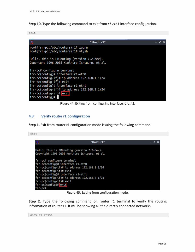
Step 10. Type the following command to exit from r1-eth1 interface configuration. exit
Figure 44. Exiting from configuring interface r1-eth1.
4.3 Verify router r1 configuration
Step 1. Exit from router r1 configuration mode issuing the following command: exit
Figure 45. Exiting from configuration mode.
Step 2. Type the following command on router r1 terminal to verify the routing information of router r1. It will be showing all the directly connected networks. show ip route

Lab 1: Introduction to Mininet
Page 26
Figure 46. Displaying routing information of router r1.
4.4 Test connectivity between end-hosts
In this section you will run a connectivity test between host h1 and host h2. Step 1. In host h1 terminal type the command shown below. Notice that according to Table 2, the IP address 192.168.2.10 is assigned to host h2. To stop the test press ctrl+c
ping 192.168.2.10
Figure 47. Connectivity test between host h1 and host h2.
This concludes lab 1. Stop the emulation and then exit out of MiniEdit and the Linux terminal. References
Lab 1: Introduction to Mininet
Page 27
1. Mininet walkthrough. [Online]. Available: http://Mininet.org. 2. Mckeown N., Anderson T., Balakrishnan H., Parulkar G., Peterson L., Rexford J.,
Shenker S., Turner J., “OpenFlow,” ACM SIGCOMM Computer Communication Review, vol. 38, no. 2, p. 69, 2008.
3. Esch J., “Prolog to, software-defined networking: a comprehensive survey,” Proceedings of the IEEE, vol. 103, no. 1, pp. 10–13, 2015.
4. Dordal P., “An Introduction to computer networks,”. [Online]. Available: https://intronetworks.cs.luc.edu/.
5. Lantz B., Gee G. “MiniEdit: a simple network editor for Mininet.” 2013. [Online]. Available: https://github.com/Mininet/Mininet/blob/master/examples.
OPEN SHORTEST PATH FIRST
Lab 2: Introduction to Free Range Routing (FRR)
Document Version: 05-25-2021
Award 1829698 “CyberTraining CIP: Cyberinfrastructure Expertise on High-throughput
Networks for Big Science Data Transfers”
Lab 2: Introduction to Free Range Routing (FRR)
Page 2
Contents Overview ............................................................................................................................. 3
Objectives............................................................................................................................ 3
Lab settings ......................................................................................................................... 3
Lab roadmap ....................................................................................................................... 3
1 Introduction to FRR ..................................................................................................... 3
1.1 FRR architecture ................................................................................................... 4
1.2 FRR and Mininet integration ................................................................................ 5
2 Lab topology................................................................................................................ 6
2.1 Lab settings........................................................................................................... 6
2.2 Open the topology ............................................................................................... 7
2.3 Load the configuration file ................................................................................... 8
2.4 Run the emulation ................................................................................................ 9
2.5 Verify the configuration ..................................................................................... 10
2.6 Test connectivity between end-hosts ................................................................ 14
3 Configure a routing protocol .................................................................................... 14
3.1 Enable a routing daemon ................................................................................... 15
3.2 Configure static route ........................................................................................ 16
3.3 Verify the configuration ..................................................................................... 18
4 Test connectivity and verify routes between end-hosts .......................................... 19
References ........................................................................................................................ 20

Lab 2: Introduction to Free Range Routing (FRR)
Page 3
Overview This lab is an introduction to Free Range Routing (FRR), which is a routing software suite that provides TCP/IP based routing services with routing protocols support. FRR also coordinates tasks such as exchanging routing information with other routers, making routing and policy decisions and, managing packet forwarding. In this lab, you will explore FRR architecture, load basic configuration and conduct connectivity tests within a simple topology. Objectives By the end of this lab, you should be able to:
1. Understand the architecture of FRR. 2. Run FRR daemons in an emulated environment. 3. Enable routing features using the router’s command line. 4. Navigate into FRR terminal using administrative commands. 5. Load a configuration file into the router. 6. Perform a connectivity test between end hosts.
Lab settings The information in Table 1 provides the credentials of the Client.
Table 1. Credentials to access the Client machine.
Device
Account
Password
Client admin password
Lab roadmap This lab is organized as follows:
1. Section 1: Introduction to FRR. 2. Section 2: Lab topology. 3. Section 3: Configure a routing protocol. 4. Section 4: Test connectivity and verify routes between end-hosts.
1 Introduction to FRR Implementing IP routing usually involves buying expensive and vertically integrated equipment from specific companies. This approach has limitations such as the hardware's
Lab 2: Introduction to Free Range Routing (FRR)
Page 4
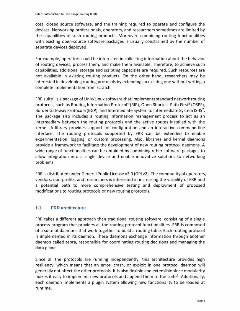
cost, closed source software, and the training required to operate and configure the devices. Networking professionals, operators, and researchers sometimes are limited by the capabilities of such routing products. Moreover, combining routing functionalities with existing open-source software packages is usually constrained by the number of separate devices deployed. For example, operators could be interested in collecting information about the behavior of routing devices, process them, and make them available. Therefore, to achieve such capabilities, additional storage and scripting capacities are required. Such resources are not available in existing routing products. On the other hand, researchers may be interested in developing routing protocols by extending an existing one without writing a complete implementation from scratch. FRR suite1 is a package of Unix/Linux software that implements standard network routing protocols, such as Routing Information Protocol4 (RIP), Open Shortest Path First5 (OSPF), Border Gateway Protocol6 (BGP), and Intermediate System to Intermediate System IS-IS7. The package also includes a routing information management process to act as an intermediary between the routing protocols and the active routes installed with the kernel. A library provides support for configuration and an interactive command-line interface. The routing protocols supported by FRR can be extended to enable experimentation, logging, or custom processing. Also, libraries and kernel daemons provide a framework to facilitate the development of new routing protocol daemons. A wide range of functionalities can be obtained by combining other software packages to allow integration into a single device and enable innovative solutions to networking problems. FRR is distributed under General Public License v2.0 (GPLv2). The community of operators, vendors, non-profits, and researchers is interested in increasing the visibility of FRR and a potential path to more comprehensive testing and deployment of proposed modifications to routing protocols or new routing protocols. 1.1 FRR architecture
FRR takes a different approach than traditional routing software, consisting of a single process program that provides all the routing protocol functionalities. FRR is composed of a suite of daemons that work together to build a routing table. Each routing protocol is implemented in its daemon. These daemons exchange information through another daemon called zebra, responsible for coordinating routing decisions and managing the data plane. Since all the protocols are running independently, this architecture provides high resiliency, which means that an error, crash, or exploit in one protocol daemon will generally not affect the other protocols. It is also flexible and extensible since modularity makes it easy to implement new protocols and append them to the suite1. Additionally, each daemon implements a plugin system allowing new functionality to be loaded at runtime.

Lab 2: Introduction to Free Range Routing (FRR)
Page 5
Figure 1 illustrates FRR architecture. It consists of a set of processes communicating via Inter-process Communication (IPC) protocol. This protocol refers to the mechanism provided by an operating system (OS) to manage shared data between different processes. Network routing protocols such as BGP, OSPF, and IS-IS are implemented in processes such as bgpd, ripd, ospfd, ldpd, etc. These processes are daemons that implement routing protocols. For example, the bgpd process implements the BGP daemon, the ripd process implements the RIP daemon, etc. Another daemon, called zebra, acts as an intermediary between the kernel’s forwarding plane and the routing protocol processes. Additionally, an interactive command-line tool called vtysh allows these processes to be monitored and configured. The vtysh command-line tool communicates with other processes via a simple string passing protocol, where the strings are essentially identical to the commands entered. The zebra process is a fundamental part of FRR architecture. Its purpose is to maintain a backup of packet forwarding state, such as the network interfaces and the table of currently active routes. The currently active routes are also referred to as the Forwarding Information Base (FIB) 2. Usually, the kernel manages packet forwarding therefore, the kernel maintains these. The zebra process also collects routing information from the routing protocol processes and stores these, together with its shadow copy of the FIB, in its own Routing Information Base (RIB)2 whereas, static routes are also configured. The zebra process then is responsible for selecting the best route from all those available for a destination and updating the FIB3. Additionally, information about the current best routes may be distributed to the protocol daemons. The zebra process maintains the routing daemons updated if any change occurs in the network interface state.
Vtysh
Kernel (FIB)
bgpd
Zebra (RIB)
ospfd ripd ldpd ...
Packets
Data plane
Control plane
Interactive command line
Protocols daemons
Service daemon
User space
Kernel space
Figure 1. FRR architecture.
1.2 FRR and Mininet integration
Mininet is a network emulator which runs a collection of end-hosts, switches, routers, and links on a single Linux kernel5. Mininet provides network emulation, allowing all network software at any layer to be run as-is, i.e., nodes run the native network software of the physical machine. Hence, the set of commands provided by FRR are inherited and
Lab 2: Introduction to Free Range Routing (FRR)
Page 6
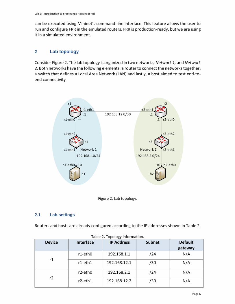
can be executed using Mininet’s command-line interface. This feature allows the user to run and configure FRR in the emulated routers. FRR is production-ready, but we are using it in a simulated environment. 2 Lab topology Consider Figure 2. The lab topology is organized in two networks, Network 1, and Network 2. Both networks have the following elements: a router to connect the networks together, a switch that defines a Local Area Network (LAN) and lastly, a host aimed to test end-to-end connectivity
r1-eth1
r1-eth0
r2-eth1
r2-eth0
s1-eth2 s2-eth2
s1-eth1 s2-eth1
h1-eth0 h2-eth0
h1 h2
s1 s2
r1 r2
192.168.12.0/30
.1
.10
.1.1
.2
.10
Network 1 Network 2
192.168.1.0/24 192.168.2.0/24
Figure 2. Lab topology.
2.1 Lab settings
Routers and hosts are already configured according to the IP addresses shown in Table 2.
Table 2. Topology information.
Device Interface IIP Address Subnet Default gateway
r1
r1-eth0 192.168.1.1 /24 N/A
r1-eth1 192.168.12.1 /30 N/A
r2
r2-eth0 192.168.2.1 /24 N/A
r2-eth1 192.168.12.2 /30 N/A
Lab 2: Introduction to Free Range Routing (FRR)
Page 7
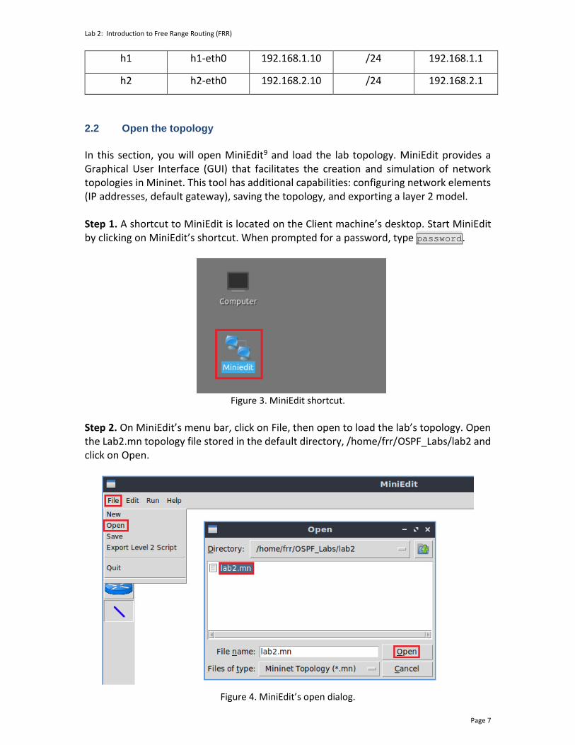
h1 h1-eth0 192.168.1.10 /24 192.168.1.1
h2 h2-eth0 192.168.2.10 /24 192.168.2.1
2.2 Open the topology
In this section, you will open MiniEdit9 and load the lab topology. MiniEdit provides a Graphical User Interface (GUI) that facilitates the creation and simulation of network topologies in Mininet. This tool has additional capabilities: configuring network elements (IP addresses, default gateway), saving the topology, and exporting a layer 2 model. Step 1. A shortcut to MiniEdit is located on the Client machine’s desktop. Start MiniEdit by clicking on MiniEdit’s shortcut. When prompted for a password, type password.
Figure 3. MiniEdit shortcut.
Step 2. On MiniEdit’s menu bar, click on File, then open to load the lab’s topology. Open the Lab2.mn topology file stored in the default directory, /home/frr/OSPF_Labs/lab2 and click on Open.
Figure 4. MiniEdit’s open dialog.

Lab 2: Introduction to Free Range Routing (FRR)
Page 8
Figure 5 shows the topology used in this lab. To configure the interfaces, you will execute a script that will load the configuration on the routers.
Figure 5. Mininet’s topology.
2.3 Load the configuration file
At this point, the topology is loaded. However, the interfaces are not configured. To assign IP addresses to the devices’ interfaces, you will execute a script that loads the configuration to the routers and end devices.
Step 1. Click on the icon below to open the Linux terminal.
Figure 6. Opening Linux terminal.
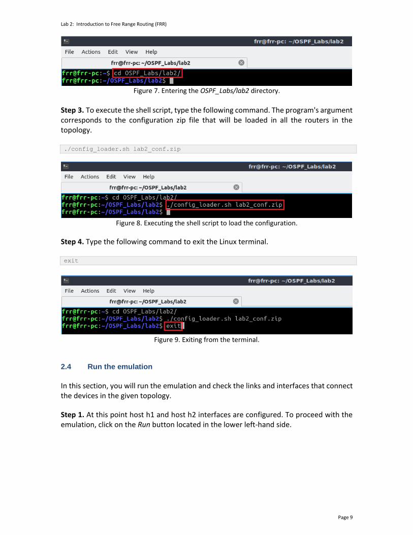
Step 2. Click on the Linux terminal and navigate into OSPF_Labs/lab2 directory by issuing the following command. This folder contains a configuration file and the script responsible for loading the configuration. The configuration file will assign the IP addresses to the routers’ interfaces. The cd command is short for change directory, followed by an argument that specifies the destination directory. cd OSPF_Labs/lab2
Lab 2: Introduction to Free Range Routing (FRR)
Page 9
Figure 7. Entering the OSPF_Labs/lab2 directory.
Step 3. To execute the shell script, type the following command. The program's argument corresponds to the configuration zip file that will be loaded in all the routers in the topology. ./config_loader.sh lab2_conf.zip
Figure 8. Executing the shell script to load the configuration.
Step 4. Type the following command to exit the Linux terminal. exit
Figure 9. Exiting from the terminal.
2.4 Run the emulation
In this section, you will run the emulation and check the links and interfaces that connect the devices in the given topology.
Step 1. At this point host h1 and host h2 interfaces are configured. To proceed with the emulation, click on the Run button located in the lower left-hand side.

Lab 2: Introduction to Free Range Routing (FRR)
Page 10
Figure 10. Starting the emulation.
Step 2. Issue the following command to display the interface names and connections. links
Figure 11. Displaying network interfaces.
In Figure 11, the link displayed within the gray box indicates that interface eth2 of switch s1 connects to interface eth0 of host h1 (i.e., s1-eth2<->h1-eth0). 2.5 Verify the configuration
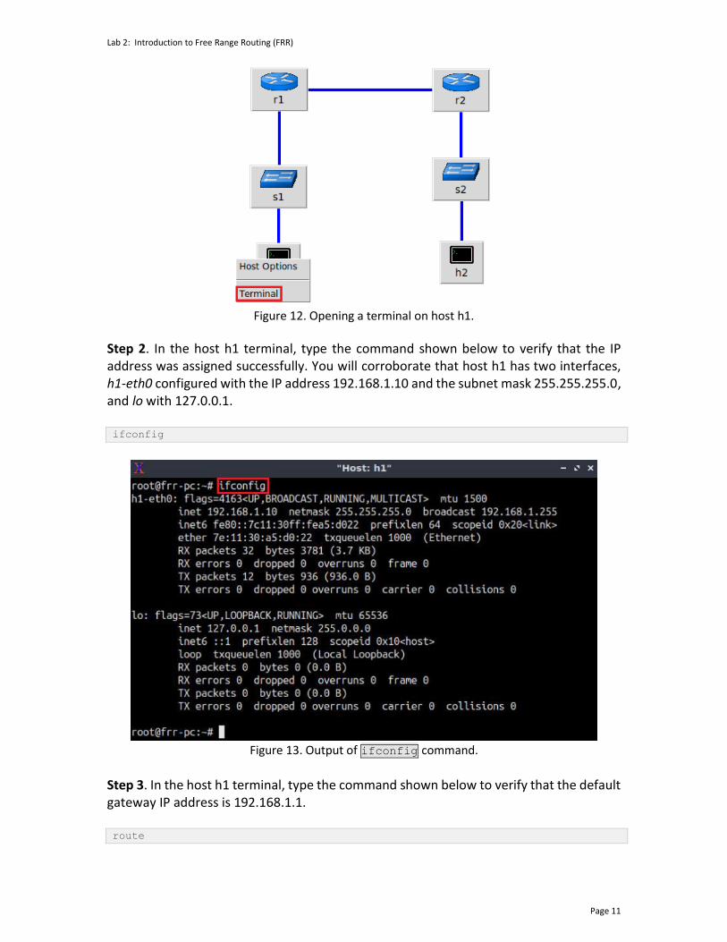
In the following steps, you will verify the IP address to the hosts following Table 2 as the IP addresses are already configured for you. You can verify each host's IP addresses and the routing table of each router to see if the configuration is correct according to the table. Step 1. Hold right-click on host h1 and select Terminal. This opens the terminal of host h1 and allows the execution of commands on that host.
Lab 2: Introduction to Free Range Routing (FRR)
Page 11
Figure 12. Opening a terminal on host h1.
Step 2. In the host h1 terminal, type the command shown below to verify that the IP address was assigned successfully. You will corroborate that host h1 has two interfaces, h1-eth0 configured with the IP address 192.168.1.10 and the subnet mask 255.255.255.0, and lo with 127.0.0.1. ifconfig
Figure 13. Output of ifconfig command.
Step 3. In the host h1 terminal, type the command shown below to verify that the default gateway IP address is 192.168.1.1. route

Lab 2: Introduction to Free Range Routing (FRR)
Page 12
Figure 14. Output of route command.
Step 4. To verify host 2 default route, proceed similarly by repeating from step 1 to step 3 in the host h2 terminal. Similar results should be observed. Step 5. To verify router r1, hold right-click on router r1 and select Terminal.
Figure 15. Opening a terminal on router r1.
Step 6. In this step, you will start the zebra daemon, a multi-server routing software that provides TCP/IP-based routing protocols. Further details about the zebra daemon are provided in Section 1. To start zebra, type the following command: zebra
Lab 2: Introduction to Free Range Routing (FRR)
Page 13
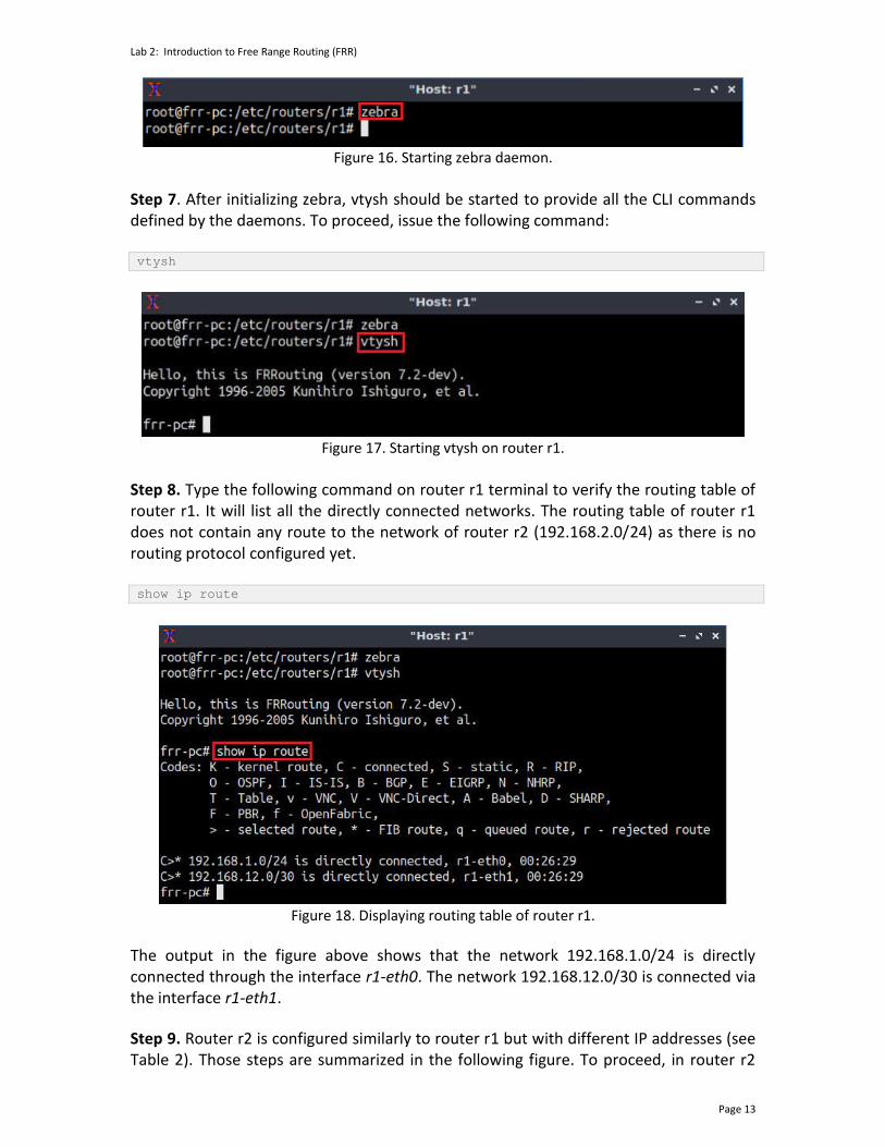
Figure 16. Starting zebra daemon.
Step 7. After initializing zebra, vtysh should be started to provide all the CLI commands defined by the daemons. To proceed, issue the following command: vtysh
Figure 17. Starting vtysh on router r1.
Step 8. Type the following command on router r1 terminal to verify the routing table of router r1. It will list all the directly connected networks. The routing table of router r1 does not contain any route to the network of router r2 (192.168.2.0/24) as there is no routing protocol configured yet. show ip route
Figure 18. Displaying routing table of router r1.
The output in the figure above shows that the network 192.168.1.0/24 is directly connected through the interface r1-eth0. The network 192.168.12.0/30 is connected via the interface r1-eth1.
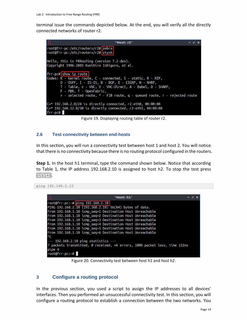
Step 9. Router r2 is configured similarly to router r1 but with different IP addresses (see Table 2). Those steps are summarized in the following figure. To proceed, in router r2
Lab 2: Introduction to Free Range Routing (FRR)
Page 14
terminal issue the commands depicted below. At the end, you will verify all the directly connected networks of router r2.
Figure 19. Displaying routing table of router r2.
2.6 Test connectivity between end-hosts
In this section, you will run a connectivity test between host 1 and host 2. You will notice that there is no connectivity because there is no routing protocol configured in the routers. Step 1. In the host h1 terminal, type the command shown below. Notice that according to Table 1, the IP address 192.168.2.10 is assigned to host h2. To stop the test press ctrl+c. ping 192.168.2.10
Figure 20. Connectivity test between host h1 and host h2.
3 Configure a routing protocol In the previous section, you used a script to assign the IP addresses to all devices' interfaces. Then you performed an unsuccessful connectivity test. In this section, you will configure a routing protocol to establish a connection between the two networks. You

Lab 2: Introduction to Free Range Routing (FRR)
Page 15
will configure static routing in router r1 and router r2 such that host h1 can reach host h2 and vice versa. First, you will initialize the daemon that enables static route configuration. Then you will configure static routes in router r1 and router r2. Specifically, static routes are configured by setting the destination network and the next hop's IP address. Finally, you will verify the configuration. The syntax to configure static routes in the FRR router is as follows: ip route <NETWORK> <GATEWAY>
• ip route: is used to create or modify routing tables.
• NETWORK: specifies the destination network.
• GATEWAY: determines the next hop IP address. 3.1 Enable a routing daemon
In this section you will run the daemon that enables static routing configuration. Step 1. In router r1 terminal, type the following command to exit from FRR terminal. exit
Figure 21. Exiting the vtysh session.
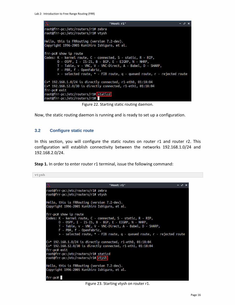
Step 2. Now issue the following command on router r1 terminal to enable the static routing daemon. staticd
Lab 2: Introduction to Free Range Routing (FRR)
Page 16
Figure 22. Starting static routing daemon.
Now, the static routing daemon is running and is ready to set up a configuration.
3.2 Configure static route
In this section, you will configure the static routes on router r1 and router r2. This configuration will establish connectivity between the networks 192.168.1.0/24 and 192.168.2.0/24. Step 1. In order to enter router r1 terminal, issue the following command: vtysh
Figure 23. Starting vtysh on router r1.

Lab 2: Introduction to Free Range Routing (FRR)
Page 17
Step 2. To enable router r1 configuration mode, issue the following command: configure terminal
Figure 24. Enabling configuration mode on router r1.
Step 3. In order to configure a static route to reach out the network 192.168.2.0/24 thru the IP address 192.168.12.2, type the following command: ip route 192.168.2.0/24 192.168.12.2
Figure 25. Configuring a static route on router r1.
Step 4. To exit from configuration mode, issue the following command: exit
Figure 26. Exiting from configuration mode.
Step 5. The figure below summarizes the steps that must be followed in router r2 terminal in order to configure static route. From the perspective of router r2 the network 192.168.1.0 is reachable via the IP address 192.168.12.1.

Lab 2: Introduction to Free Range Routing (FRR)
Page 18
Figure 27. Configuring static routing on router r2.
3.3 Verify the configuration
In this section, you will verify the configuration on router r1 and router r2. Step 1. In router r1 terminal, type the following command to show the routing table entries. Notice that the network 192.168.2.0/24 shown with the S>* is reachable via the IP address 192.168.12.2. ‘S’ indicates a static route. The egress interface is r1-eth1: show ip route
Figure 28. Verifying the routing table of router r1.
Step 2. Similarly, in router r2 terminal, type the following command to show the routing table entries. Notice that the network 192.168.1.0/24 (static route) is reachable via the IP address 192.168.12.1. The egress interface is r2-eth1:

Lab 2: Introduction to Free Range Routing (FRR)
Page 19
show ip route
Figure 29. Verifying the routing table of router r2.
4 Test connectivity and verify routes between end-hosts In this section you will perform a connectivity test from host h1 to host h2. Additionally, you will check the details about the path that a packet takes from host h1, the source, to host h2, the destination. Step 1. On host h1 terminal type the following command. The IP address 192.168.2.10 corresponds to host h2: ping 192.168.2.10
Figure 30. Output of ping command on host h1.
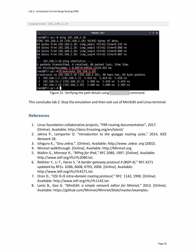
Step 2. On host h1 terminal type the following command. Notice that it takes three hops to reach out the destination which, in this case is host h2.
Lab 2: Introduction to Free Range Routing (FRR)
Page 20
traceroute 192.168.2.10
Figure 31. Verifying the path details using traceroute command.
This concludes lab 2. Stop the emulation and then exit out of MiniEdit and Linux terminal. References
1. Linux foundation collaborative projects, “FRR routing documentation”, 2017. [Online]. Available: http://docs.frrouting.org/en/latest/
2. Jakma P., Lamparter D. “Introduction to the quagga routing suite,” 2014, IEEE Network 28.
3. Ishiguro K., “Gnu zebra,”. [Online]. Available: http://www. zebra. org (2002). 4. Mininet walkthrough. [Online]. Available: http://Mininet.org. 5. Malkin G., Minnear R., “RIPng for IPv6,” RFC 2080, 1997. [Online]. Available:
http://www.ietf.org/rfc/rfc2080.txt. 6. Rekhter Y., Li T., Hares S. “A border gateway protocol 4 (BGP-4),” RFC 4271
updated by RFCs 6286, 6608, 6793, 2006. [Online]. Available: http://www.ietf.org/rfc/rfc4271.txt.
7. Oran D., “OSI IS-IS intra-domain routing protocol,” RFC 1142, 1990. [Online]. Available: http://www.ietf.org/rfc/rfc1142.txt.
8. Lantz B., Gee G. “MiniEdit: a simple network editor for Mininet,” 2013. [Online]. Available: https://github.com/Mininet/Mininet/blob/master/examples.

OPEN SHORTEST PATH FIRST
Lab 3: Configuring Single-Area OSPFv2
Document Version: 10-22-2021
Award 1829698 “CyberTraining CIP: Cyberinfrastructure Expertise on High-throughput
Networks for Big Science Data Transfers”

Lab 3: Configuring Single-Area OSPFv2
Page 2
Contents Overview ............................................................................................................................. 3
Objectives............................................................................................................................ 3
Lab settings ......................................................................................................................... 3
Lab roadmap ....................................................................................................................... 3
1 Introduction ................................................................................................................ 3
1.1 Routing protocols ................................................................................................. 3
1.2 The OSPF routing protocol ................................................................................... 5
1.3 OSPF packets ........................................................................................................ 5
1.4 OSPF states, LSDB exchange, and synchronization .............................................. 6
1.5 OSPF passive interfaces ........................................................................................ 7
2 Lab topology................................................................................................................ 8
2.1 Lab settings........................................................................................................... 9
2.2 Loading the topology.......................................................................................... 10
2.3 Load the zebra daemon and verify the configuration ....................................... 13
3 Configuring single-area OSPF .................................................................................... 17
3.1 Configuring OSPF in routers r1, r2, and r3 ......................................................... 17
3.2 Verifying OSPF neighbors, routing information, and connectivity .................... 22
4 Configuring OSPF passive interfaces ......................................................................... 25
References ........................................................................................................................ 27

Lab 3: Configuring Single-Area OSPFv2
Page 3
Overview This lab describes the routing protocol Open Shortest Path First (OSPF) which falls into the category of Interior Gateway Protocols (IGPs). In this lab, the user will configure single-area OSPF and verify connectivity between devices in different networks. Additionally, the user will configure and verify OSPF neighbors, routing information, and passive interfaces on routers. Objectives By the end of this lab, you should be able to:
1. Explain the concept of OSPF. 2. Configure single-area OSPF. 3. Verify OSPF neighbors and routing information. 4. Understand and configure OSPF passive interfaces.
Lab settings The information in Table 1 provides the credentials to access the Client machine.
Table 1. Credentials to access the Client machine.
Device
Account
Password
Client admin password
Lab roadmap This lab is organized as follows:
1. Section 1: Introduction. 2. Section 2: Lab topology. 3. Section 3: Configuring single-area OSPF. 4. Section 4: Configuring OSPF passive interfaces.
1 Introduction 1.1 Routing protocols
Lab 3: Configuring Single-Area OSPFv2
Page 4
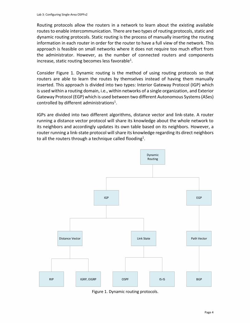
Routing protocols allow the routers in a network to learn about the existing available routes to enable intercommunication. There are two types of routing protocols, static and dynamic routing protocols. Static routing is the process of manually inserting the routing information in each router in order for the router to have a full view of the network. This approach is feasible on small networks where it does not require too much effort from the administrator. However, as the number of connected routers and components increase, static routing becomes less favorable1. Consider Figure 1. Dynamic routing is the method of using routing protocols so that routers are able to learn the routes by themselves instead of having them manually inserted. This approach is divided into two types: Interior Gateway Protocol (IGP) which is used within a routing domain, i.e., within networks of a single organization, and Exterior Gateway Protocol (EGP) which is used between two different Autonomous Systems (ASes) controlled by different administrations1. IGPs are divided into two different algorithms, distance vector and link-state. A router running a distance vector protocol will share its knowledge about the whole network to its neighbors and accordingly updates its own table based on its neighbors. However, a router running a link-state protocol will share its knowledge regarding its direct neighbors to all the routers through a technique called flooding1.
RIP IGRP, EIGRP OSPF IS-IS BGP
Distance Vector Link State Path Vector
IGP EGP
DynamicRouting
Figure 1. Dynamic routing protocols.

Lab 3: Configuring Single-Area OSPFv2
Page 5
1.2 The OSPF routing protocol
OSPF is a widely supported IGP in the family of routing protocols, meaning that it is designed to be used within a single AS. It is a link-state protocol which sends information about directly connected links to all routers in the network, instead of sending the entire routing table as in the case of distance vector protocol2. An OSPF area is a logical collection of OSPF networks, routers, and links that has the same area-ID. A router within an area must maintain a topological database for the area to which it belongs2. The OSPF routing protocol uses Link-State Advertisements (LSAs) to communicate the router’s local routing topology with all other local routers in the same OSPF area2. LSA is the standard way of communication in the OSPF routing protocol. OSPF is designed to be scalable, thus there are multiple types of LSA packets that accommodate OSPF features. For example, type 1 LSA packets are exchanged between the same area of origin and do not leave the area2. Consider Figure 2. Routers share LSA packets on OSPF-enabled interfaces to form a view of the current topology. Thus, when routers converge, they will have full visibility of all the network’s components, i.e., the routers and the links.
r1
r2
r3
LSA LSA
Network view from r2
Network view from r3Network view from r1
Figure 2. A network running OSPF.
1.3 OSPF packets

Lab 3: Configuring Single-Area OSPFv2
Page 6
The OSPF version 21,2 (OSPFv2) is the one used to handle IPv4 traffic. The protocol number is 89. OSPF packets are classified into the following types:
• Hello packets: They are used to discover, build, and keep OSPF neighbor adjacencies.
• Database Description Packets (DBD): It is used to describe the Link-State Data Base (LSDB) of a router. The LSDB is used by routers participating in the OSPF process to verify that their databases are synchronized.
• Link-State Request (LSR): A router uses it to request the latest Link State Advertisement (LSA).
• Link-State Update (LSU): They are used to flood LSAs and sending LSA responses to LSR packets.
• Link-State Acknowledgement (LSAck): It is used to acknowledge LSA packets. 1.4 OSPF states, LSDB exchange, and synchronization
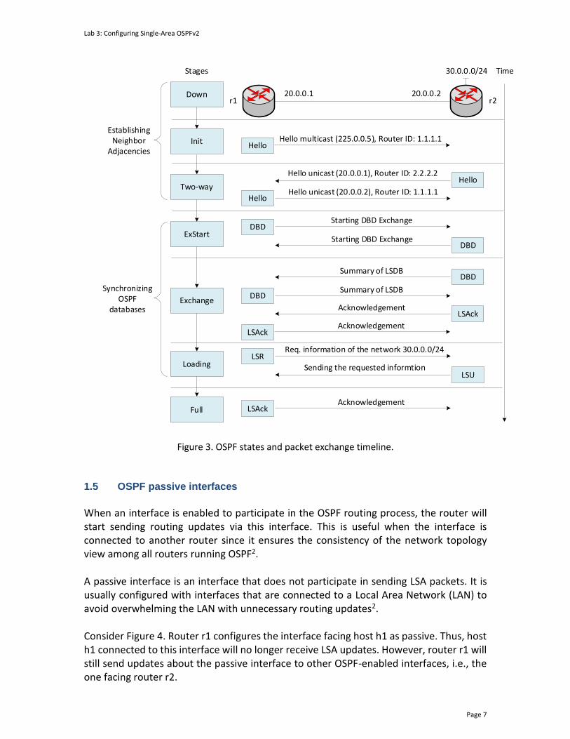
The routers participating in the OSPF process pass through multiple states before forming full adjacency, as shown in Figure 3. Routers r1 and r2 will start exchanging OSPF packets following the states summarized below.
• Down: No information is sent or received by routers r1 and r2.
• Init: Router r2 interface has detected a Hello packet broadcasted by router r1. The broadcast IP address used by OSPFv2 is 225.0.0.5. The hello packet also contains the Router ID. However, bidirectional communication has not been established.
• Two-way: Router r2 responded by sending a hello packet to the unicast address of router r1 (i.e., 20.0.0.1). At the end of this state, the Designated Router (DR) and the Backup Designated Router (BDR) are chosen. The DR and the BDR are used to reduce the amount of packet exchanged in the OSPF process, meaning that non-DR and non-BDR will only exchange routes with the former and the latter. The router with the highest router ID will be selected as the DR (i.e., router r2). The router with the second router ID will become the BDR (i.e., router r1).
• ExStart: In this state, routers r1 and r2 establish the initial sequence number used to ensure that routers get the latest update when they exchange OSPF packets.
• Exchange: During this state, routers exchange LSDB by sending DBD packets. DBD packet contain information about the LSA entry header included in the router’s LSDB. Additionally, the router uses a sequence number to determine the freshness of the OSPF packet. Each DBD packet is acknowledged with LSAck packet.
• Loading: In this state, router information exchange finalizes. Routers build two lists that comprise the link-state request and link-state retransmission. The link-state request list includes any information that might be incomplete or outdated, whereas any update that is sent will be registered in the retransmission list until it gets acknowledged.
• Full: At this point, neighbor adjacencies are fully established, meaning that adjacent routers will have the same LSDB.
Lab 3: Configuring Single-Area OSPFv2
Page 7
Init
r1 r220.0.0.1 20.0.0.2
Hello multicast (225.0.0.5), Router ID: 1.1.1.1
Hello unicast (20.0.0.1), Router ID: 2.2.2.2
Down
Two-wayHello unicast (20.0.0.2), Router ID: 1.1.1.1
ExStart
Starting DBD Exchange
Starting DBD Exchange
TimeStages
Hello
Hello
Summary of LSDB
Summary of LSDBExchange
Loading
Full
Hello
30.0.0.0/24
DBD
DBD
Acknowledgement
DBD
Acknowledgement
DBD
Req. information of the network 30.0.0.0/24LSR
LSUSending the requested informtion
LSAck
LSAck
AcknowledgementLSAck
Establishing Neighbor
Adjacencies
Synchronizing OSPF
databases
Figure 3. OSPF states and packet exchange timeline.
1.5 OSPF passive interfaces
When an interface is enabled to participate in the OSPF routing process, the router will start sending routing updates via this interface. This is useful when the interface is connected to another router since it ensures the consistency of the network topology view among all routers running OSPF2. A passive interface is an interface that does not participate in sending LSA packets. It is usually configured with interfaces that are connected to a Local Area Network (LAN) to avoid overwhelming the LAN with unnecessary routing updates2. Consider Figure 4. Router r1 configures the interface facing host h1 as passive. Thus, host h1 connected to this interface will no longer receive LSA updates. However, router r1 will still send updates about the passive interface to other OSPF-enabled interfaces, i.e., the one facing router r2.

Lab 3: Configuring Single-Area OSPFv2
Page 8
r1 r2LSA LSA
r1h1
LSA
Passive-interface
Network view from r1 Network view from r2
Figure 4. Passive interface in OSPF.
2 Lab topology Consider Figure 5. The topology consists of three networks connected to their respective routers. The communication between networks is established via single-area OSPF configured in all routers. The routers participating in the OSPF process are in the backbone area (i.e., area 0).

Lab 3: Configuring Single-Area OSPFv2
Page 9
s3
h1 h3
r1 r3
h1-eth0
r1-eth2
r2-eth2
r3-eth0
h3-eth0.10
.1
.1
.2 .1
.2
.1
.10
.1
192.168.2.0/24
r2
.1 .2
r1-eth1 r3-eth2
192.168.13.0/30
s1
s1-eth1
s1-eth2 s3-eth1
s3-eth2
192.168.1.0/24 192.168.3.0/24
h2
h2-eth0.10
s2-eth1
s2-eth2
s2
Figure 5. Lab topology.
2.1 Lab settings
Table 2 contains information about the devices and their corresponding interfaces, IPv4 addresses, subnet, and default gateway.
Table 2. Topology Information.
Device Interface IIPv4 Address Subnet Default Gateway
Router 1 (r1)
r1-eth0 192.168.12.1 /30 N/A
r1-eth1 192.168.13.1 /30 N/A
r1-eth2 192.168.1.1 /24 N/A
Lab 3: Configuring Single-Area OSPFv2
Page 10
Router 2 (r2)
r2-eth0 192.168.12.2 /30 N/A
r2-eth1 192.168.23.1 /30 N/A
r2-eth2 192.168.2.1 /24 N/A
Router 3 (r3)
r3-eth0 192.168.3.1 /24 N/A
r3-eth1 192.168.23.2 /30 N/A
r3-eth2 192.168.13.2 /30 N/A
Host 1 (h1) h1-eth0 192.168.1.10 /24 192.168.1.1
Host 2 (h2) h2-eth0 192.168.2.10 /24 192.168.2.1
Host 3 (h3) h3-eth0 192.168.3.10 /24 192.168.3.1
2.2 Loading the topology
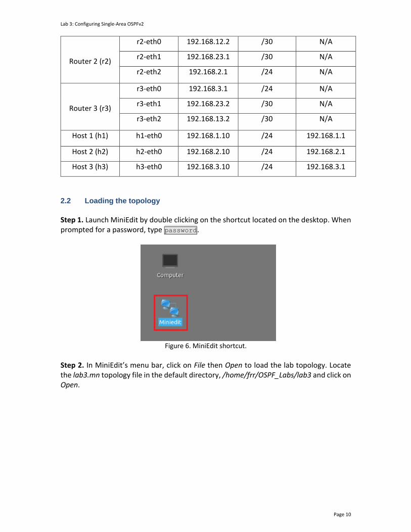
Step 1. Launch MiniEdit by double clicking on the shortcut located on the desktop. When prompted for a password, type password.
Figure 6. MiniEdit shortcut.
Step 2. In MiniEdit’s menu bar, click on File then Open to load the lab topology. Locate the lab3.mn topology file in the default directory, /home/frr/OSPF_Labs/lab3 and click on Open.

Lab 3: Configuring Single-Area OSPFv2
Page 11
Figure 7. MiniEdit’s open dialog.
Step 3. Click on the Run button located on the lower left-hand side to run the emulation.
Figure 8. Starting the emulation.
At this point, the topology is loaded with all the required network components. Next, you will execute a script that will configure the interfaces of the routers.
Automating the configuration of interfaces with the script is intended to facilitate the lab experience and to focus on the OSPF experiment.
Step 4. Open the Linux terminal by clicking on the icon located in the taskbar.
Figure 9. Opening Linux terminal.
Step 5. Issue the command shown below to set the lab environment. This command configures the IP addresses of the routers’ interface according to Table 2. If a password is required, type password.
Lab 3: Configuring Single-Area OSPFv2
Page 12
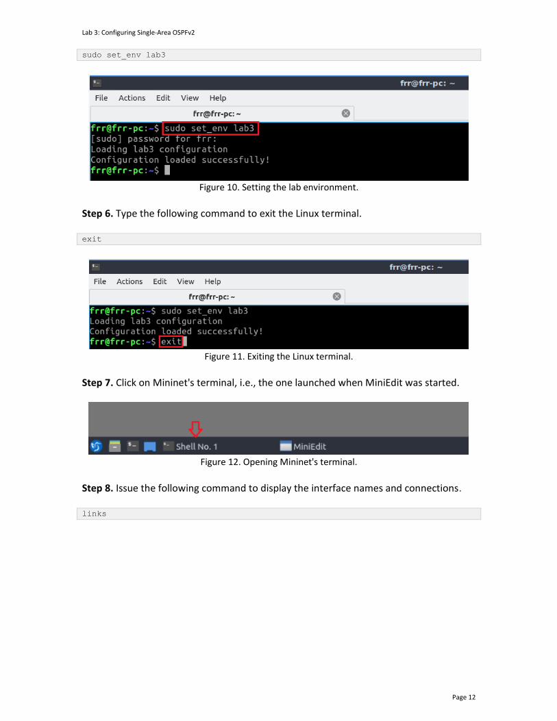
sudo set_env lab3
Figure 10. Setting the lab environment.
Step 6. Type the following command to exit the Linux terminal. exit
Figure 11. Exiting the Linux terminal.
Step 7. Click on Mininet's terminal, i.e., the one launched when MiniEdit was started.
Figure 12. Opening Mininet's terminal.
Step 8. Issue the following command to display the interface names and connections. links

Lab 3: Configuring Single-Area OSPFv2
Page 13
Figure 13. Displaying network interfaces.
In the figure above, the link displayed within the gray box indicates that interface eth2 of host h2 connects to interface eth1 of switch s2 (i.e., h2-eth0<->s2-eth1). 2.3 Load the zebra daemon and verify the configuration
In this section, you will verify that the IP addresses listed in Table 2 and inspect the routing table of the routers. Step 1. Hold right-click on host h1 and select Terminal. This opens the terminal of host h1 and allows the execution of commands on that host.
Figure 14. Opening a terminal on host h1.

Lab 3: Configuring Single-Area OSPFv2
Page 14
Step 2. In the host h1 terminal, type the command shown below to verify that the IP address was assigned successfully. You will verify that host h1 has two interfaces. Interface h1-eth0 is configured with the IP address 192.168.1.10 and the subnet mask 255.255.255.0 and a loopback lo interface. ifconfig
Figure 15. Displaying host h1 interfaces.
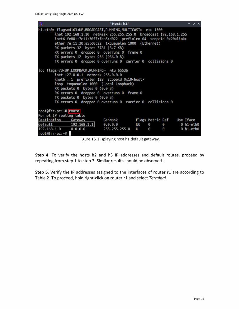
Step 3. In the host h1 terminal, type the command shown below to verify that the default gateway IP address is 192.168.1.1. route
Lab 3: Configuring Single-Area OSPFv2
Page 15
Figure 16. Displaying host h1 default gateway.
Step 4. To verify the hosts h2 and h3 IP addresses and default routes, proceed by repeating from step 1 to step 3. Similar results should be observed. Step 5. Verify the IP addresses assigned to the interfaces of router r1 are according to Table 2. To proceed, hold right-click on router r1 and select Terminal.

Lab 3: Configuring Single-Area OSPFv2
Page 16
Figure 17. Opening a terminal on router r1.
Step 6. In this step, you will start the zebra daemon, a multi-server routing software that provides TCP/IP-based routing protocols. The configuration will not be working if you do not enable zebra daemon initially. To start the zebra, type the following command: zebra
Figure 18. Starting zebra daemon.
Step 7. After initializing zebra, vtysh should be started to provide all the CLI commands defined by the daemons. To proceed, issue the following command: vtysh
Figure 19. Starting vtysh on router r1.
Step 8. Type the following command on router r1 terminal to verify the routing table. It will list all the directly connected networks. Notice that the routing table of router r1 does

Lab 3: Configuring Single-Area OSPFv2
Page 17
not contain any route to the network of router r2 (192.168.2.0/24) as there is no routing protocol configured yet. show ip route
Figure 20. Displaying routing table of router r1.
Step 9. To verify the routing table of the other routers, proceed similarly by repeating from step 5 to step 8 on the router terminal.
3 Configuring single-area OSPF In this section, you will configure the OSPF routing protocol in routers r1, r2, and r3. OSPF will be handling the internal routing in this configuration. To configure OSPF, you will be using single area which is area 0 (also known as backbone area). 3.1 Configuring OSPF in routers r1, r2, and r3
Step 1. Navigate to router r1’s terminal by selecting the router’s r1 terminal from the taskbar.
Figure 21. Opening router r1’s terminal.
Step 2. In router r1’s terminal, type the command below to exit the vtysh session.

Lab 3: Configuring Single-Area OSPFv2
Page 18
exit
Figure 22. Exiting the vtysh session.
Step 3. Enable and start the OSPF routing protocol by typing the following command: ospfd
Figure 23. Starting the OSPF daemon.
Step 4. In order to enter router r1’s shell for FRR daemons, issue the following command: vtysh
Figure 24. Starting vtysh in router r1.
Step 5. At this point, you have entered router r1’s shell for FRR daemons, to enter configuration mode in router r1, issue the following command: configure terminal
Figure 25. Enabling configuration mode in router r1.

Lab 3: Configuring Single-Area OSPFv2
Page 19
Step 6. In order to configure OSPF type the command shown below. This command will enable OSPF configuration mode where you can assign the networks directly connected to router r1. router ospf
Figure 26. Configuring OSPF in router r1.
Step 7. Assign a router ID to router r1 by issuing the following command. ospf router-id 1.1.1.1
Figure 27. Assigning a router ID in router r1.
Step 8. Type the following command to enable the interface r1-eth2 to participate in the OSPF process in area 0. network 192.168.1.0/24 area 0

Lab 3: Configuring Single-Area OSPFv2
Page 20
Figure 28. Enabling interface r1-eth2 to participate in the OSPF process of area 0.
Step 9. Type the following command to enable the interface r1-eth0 to participate in the OSPF process in area 0. network 192.168.12.0/30 area 0
Figure 29. Enabling interface r1-eth0 to participate in the OSPF process of area 0.
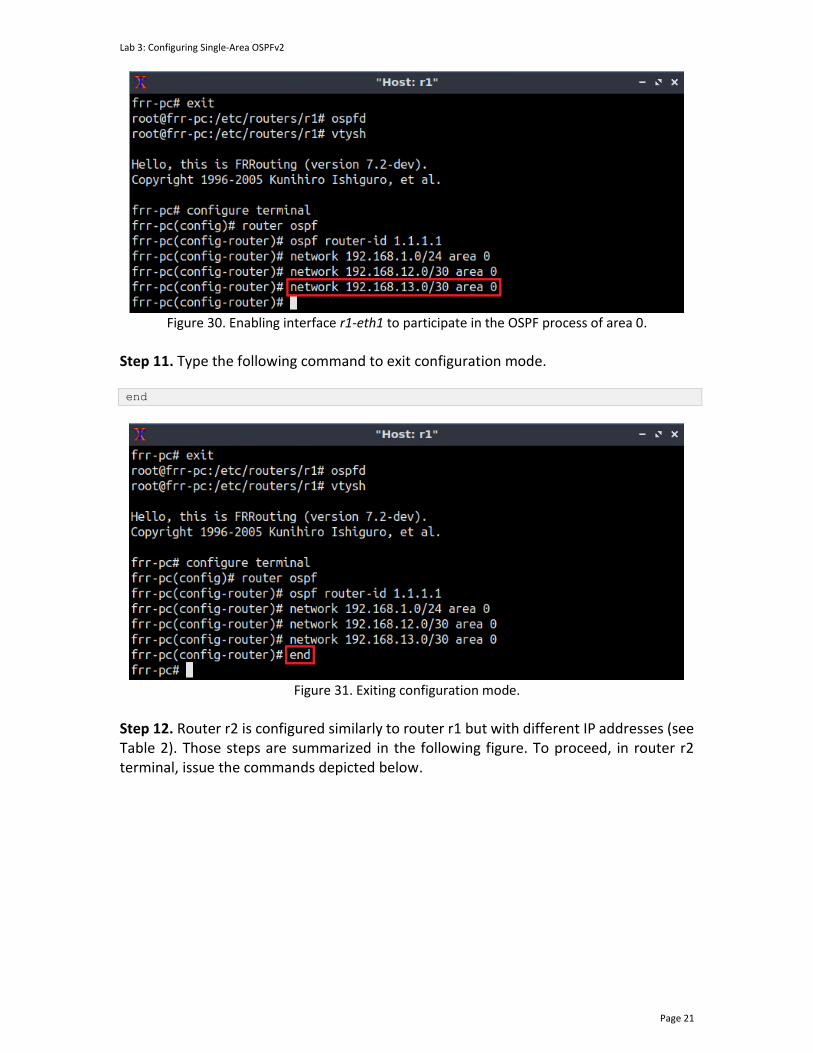
Step 10. Type the following command to enable the interface r1-eth1 to participate in the OSPF process in area 0. network 192.168.13.0/30 area 0
Lab 3: Configuring Single-Area OSPFv2
Page 21
Figure 30. Enabling interface r1-eth1 to participate in the OSPF process of area 0.
Step 11. Type the following command to exit configuration mode. end
Figure 31. Exiting configuration mode.
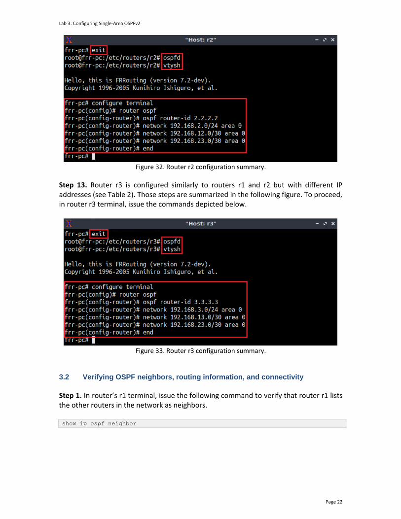
Step 12. Router r2 is configured similarly to router r1 but with different IP addresses (see Table 2). Those steps are summarized in the following figure. To proceed, in router r2 terminal, issue the commands depicted below.
Lab 3: Configuring Single-Area OSPFv2
Page 22
Figure 32. Router r2 configuration summary.
Step 13. Router r3 is configured similarly to routers r1 and r2 but with different IP addresses (see Table 2). Those steps are summarized in the following figure. To proceed, in router r3 terminal, issue the commands depicted below.
Figure 33. Router r3 configuration summary.
3.2 Verifying OSPF neighbors, routing information, and connectivity
Step 1. In router’s r1 terminal, issue the following command to verify that router r1 lists the other routers in the network as neighbors. show ip ospf neighbor

Lab 3: Configuring Single-Area OSPFv2
Page 23
Figure 34. Displaying router r1’s OSPF neighbors.
The output of the figure above shows that the neighbor ID is a unique ID for the router which, if not explicitly specified, will be the IP address of the highest interface of the router. The address field is the IP address of the corresponding neighbor. The interface field refers to the interface of the router through which the network is connected, with its corresponding IP address.
Step 2. To display all the routing information in the routing table of router r1, issue the following command:
show ip route
Figure 35. Displaying router r1’s routing table.
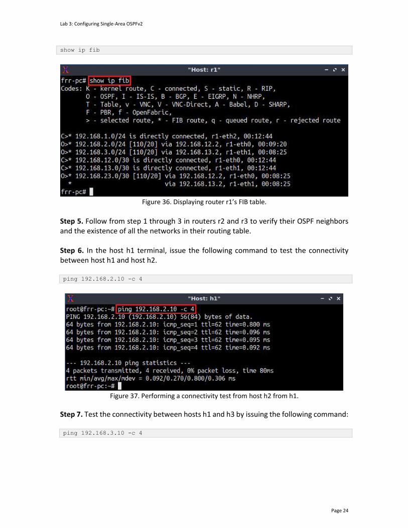
Consider the above figure. The output displays the networks learned along with additional attributes, such as the routing protocol that discovered the network. For example, networks with the symbol O on the left are learned from OSPF, whereas those with symbol C are directly connected to the device. Furthermore, the symbol > on the left of the displayed network indicates that this entry is selected to reach the network. The symbol * indicates that the route is inserted in Forwarding Information Base (FIB) of the router. In this network, the routes 192.168.2.0/24, 192.168.3.0/24, and 192.168.23.0/30 are discovered and reached by the OSPF routing protocol (O>*). Step 3. Issue the following command to show the FIB table.
Lab 3: Configuring Single-Area OSPFv2
Page 24
show ip fib
Figure 36. Displaying router r1’s FIB table.
Step 5. Follow from step 1 through 3 in routers r2 and r3 to verify their OSPF neighbors and the existence of all the networks in their routing table. Step 6. In the host h1 terminal, issue the following command to test the connectivity between host h1 and host h2. ping 192.168.2.10 -c 4
Figure 37. Performing a connectivity test from host h2 from h1.
Step 7. Test the connectivity between hosts h1 and h3 by issuing the following command: ping 192.168.3.10 -c 4

Lab 3: Configuring Single-Area OSPFv2
Page 25
Figure 38. Performing a connectivity test from host h3 from h1.
Step 6. Similarly, repeat steps 5 and 6 to test the connectivity between any two components in the network. 4 Configuring OSPF passive interfaces In this section, you will configure the passive interface OSPF feature on the interfaces of the routers connecting them to their hosts, i.e., the interfaces r1-eth1, r3-eth0 and r2-eth2 on each router. Thus, reducing the traffic on the LANs as they do not need to receive dynamic routing protocol communication. Step 1. Re-enter router r1’s terminal. Interface r1-eth2 is activated to send and receive OSPF routing updates. To verify the OSPF status of this interface, type the following command. show ip ospf interface r1-eth2
Figure 39. OSPF information on interface r1-eth2.
Consider the figure above. The interface r1-eth2 exchanges hello packets. These messages indicate that this interface is alive and participating in the OSPF routing updates. The counter indicates how long it will take to send the next hello packet, in this case 7.489 seconds.
Lab 3: Configuring Single-Area OSPFv2
Page 26
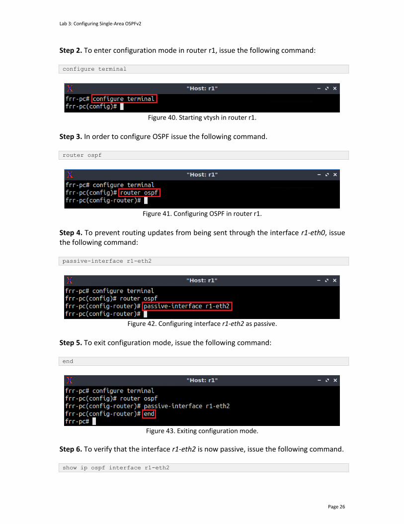
Step 2. To enter configuration mode in router r1, issue the following command: configure terminal
Figure 40. Starting vtysh in router r1.
Step 3. In order to configure OSPF issue the following command. router ospf
Figure 41. Configuring OSPF in router r1.
Step 4. To prevent routing updates from being sent through the interface r1-eth0, issue the following command: passive-interface r1-eth2
Figure 42. Configuring interface r1-eth2 as passive. Step 5. To exit configuration mode, issue the following command: end
Figure 43. Exiting configuration mode.
Step 6. To verify that the interface r1-eth2 is now passive, issue the following command. show ip ospf interface r1-eth2

Lab 3: Configuring Single-Area OSPFv2
Page 27
Figure 44. OSPF information in interface r1-eth2.
Consider the figure above. Notice that the interface r1-eth2 no longer exchanges hello packets and is configured as passive, which means it is not receiving the OSPF routing updates. Step 7. Similarly, in router r2 configure r2-eth2 as a passive interface by repeating steps 2 through 6 with the appropriate addresses. The commands are summarized below.
Figure 45. Configuring r2-eth2 as a passive interface.
Step 8. Similarly, in router r3 configure r3-eth0 as a passive interface by repeating steps 2 through 6 with the appropriate addresses. The necessary commands are summarized below.
Figure 46. Configuring r3-eth0 as a passive interface.
This concludes lab 3. Stop the emulation and then exit out of MiniEdit.
References
1. Moy, J. “RFC 1247: OSPF version 2.” 1991. 2. Moy, J. “RFC 2328: OSPF version 2.” 1998.

Lab 3: Configuring Single-Area OSPFv2
Page 28
3. Coltun, R., Ferguson, D., Moy, J., Lindem, A. “RFC 5340, OSPF for IPv6.” 2008. 4. Peterson, L. “Computer networks: a systems approach.” 6th Edition, 2021. 5. Tanenbaum, D. Wetherall. “Computer networks.” 5th Edition. 2012. 6. J. Kurose, K. Ross. “Computer networking, a top-down approach.” 7th Edition.
2017. 7. Teare, D., Vachon, B., Graziani, R. “Implementing Cisco IP routing (ROUTE)
foundation learning guide: (CCNP ROUTE 300-101).” 2014. 8. Linux foundation collaborative projects. “FRR routing documentation.” 2017
[Online] Available: http://docs.frrouting.org/en/latest/.
OPEN SHORTEST PATH FIRST
Lab 4: Configuring Multi-Area OSPFv2
Document Version: 10-22-2021
Award 1829698 “CyberTraining CIP: Cyberinfrastructure Expertise on High-throughput
Networks for Big Science Data Transfers”
Lab 4: Configuring Multi-Area OSPFv2
Page 2
Contents Overview ............................................................................................................................. 3
Objectives............................................................................................................................ 3
Lab settings ......................................................................................................................... 3
Lab roadmap ....................................................................................................................... 3
1 Introduction ................................................................................................................ 3
1.1 Single-area OSPF .................................................................................................. 3
1.2 Multi-area OSPF ................................................................................................... 4
1.3 OSPF router ID ...................................................................................................... 5
2 Lab topology................................................................................................................ 6
2.1 Lab settings........................................................................................................... 7
2.2 Loading the topology............................................................................................ 7
2.3 Load the zebra daemon and verify the configuration ....................................... 10
3 Configuring multi-area OSPF ..................................................................................... 14
3.1 Configuring multi-area OSPF in routers r1, r2, and r3 ....................................... 14
3.2 Verifying OSPF neighbors, routing information, and connectivity .................... 19
4 Configuring OSPF passive interfaces ......................................................................... 21
4.1 Configuring passive interfaces in routers r1, r2, and r3..................................... 21
References ........................................................................................................................ 23
Lab 4: Configuring Multi-Area OSPFv2
Page 3
Overview This lab explains the concept of multi-area Open Shortest Path First (OSPF) and provides a scenario to show its usage and effectiveness. Moreover, the user will configure multi-area OSPF on a simple topology, assign each router a unique ID, configure passive interfaces, and test the connectivity between hosts in different networks. Objectives By the end of this lab, you should be able to:
1. Explain the concept of multi-area OSPF. 2. Understand when and why to use multi-area OSPF. 3. Configure multi-area OSPF. 4. Understand and configure OSPF router IDs. 5. Understand and configure OSPF passive interfaces.
Lab settings The information in Table 1 provides the credentials to access the Client machine.
Table 1. Credentials to access the Client machine.
Device
Account
Password
Client admin password
Lab roadmap This lab is organized as follows:
1. Section 1: Introduction. 2. Section 2: Lab topology. 3. Section 3: Configuring multi-area OSPF. 4. Section 4: Configuring OSPF passive interfaces.
1 Introduction 1.1 Single-area OSPF

Lab 4: Configuring Multi-Area OSPFv2
Page 4
OSPF is a widely supported Interior Gateway Protocol (IGP) in the family of routing protocols, meaning that it is designed to be used within a single Autonomous System (AS). It is a link-state protocol which sends information about directly connected links to all routers in the network, instead of sending the entire routing table as in the case of distance vector protocol1.
An OSPF area is a logical collection of OSPF networks, routers, and links that has the same Area-ID. A router within an OSPF area maintains a topological database for the area to which it belongs2. Configuring only one OSPF area (single-area OSPF) within networks, becomes infeasible in large networks due to several reasons listed below1:
• The link state database of every router can become overwhelmingly large since it will be filled with information about each router and link within the entire network.
• The routing table of every router will be large as well, which can delay routing decisions and slow down the network.
• The entire network will be flooded by updates, causing congestion, and requiring the OSPF algorithm to be run in each router after every update.
Consider Figure 1. The figure displays single-area OSPF within a network of 5 routers. Each router has a full view of the whole topology in the network. Additionally, the Link-State Advertisements (LSAs) used by OSPF are flooded over the entire network.
LSA LSA
LSA LSA
LSA
LSA
LSA LSA
LSA
LSA
Figure 1. Single-area OSPF within a large network.
1.2 Multi-area OSPF

Lab 4: Configuring Multi-Area OSPFv2
Page 5
To make OSPF more efficient and scalable, OSPF supports hierarchical routing using the concept of area. An OSPF area is a group of routers that share the same link-state information in their link-state databases. When a large OSPF area is divided into smaller areas, it is called multi-area OSPF. Multi-area OSPF is useful in larger network deployments since it reduces the size of the routing table, minimizes the link-state update overhead, and shrinks the frequency of OSPF algorithm calculations. When multi-area OPSF is running, routers only need to know about the links in their own area2. Consider Figure 2. The routers run OSPF, and the topology is divided into three areas, area 0, area 1 and area 2. Area 0 is also called the backbone area since all other areas are connected to it directly, and it is the zone where the communication between the areas occurs3. Essentially, routers within an area receive OSPF advertisements from routers within their area only. For instance, a link failure in area 1 won’t be propagated to area 2. Routers that connect to multiple areas are referred to as Area Border Routers (ABR), i.e., routers r4 and r5 are ABRs in Figure 2. ABRs establish a connection between the backbone area and their area.
Area 1 Area 2
r4
r8
r2
r3
r5
r6
r7
r1
Topology Topology
Area 0
r9
Figure 2. Multi-area OSPF topology.
1.3 OSPF router ID
Each OSPF router chooses a router ID that is unique in the network. This ID identifies each router in the topology. If there are duplicate router IDs, then the network will have reachability issues. To assign a router ID, OSPF uses the following criteria:
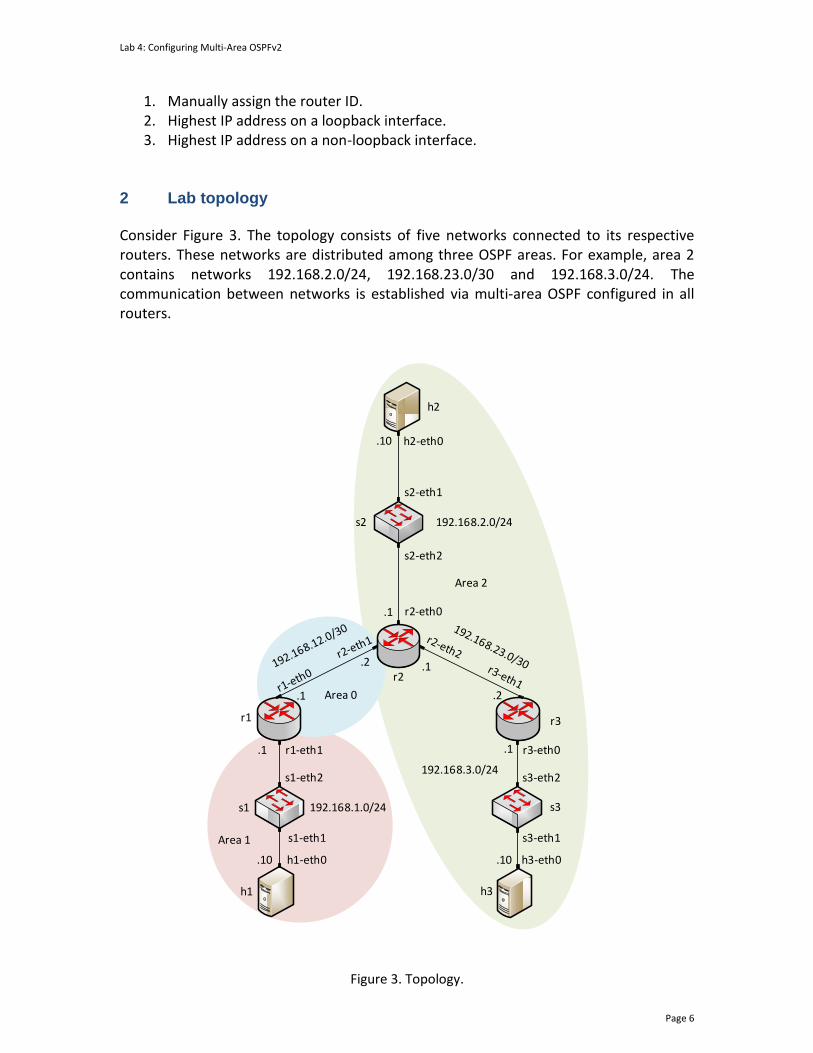
Lab 4: Configuring Multi-Area OSPFv2
Page 6
1. Manually assign the router ID. 2. Highest IP address on a loopback interface. 3. Highest IP address on a non-loopback interface.
2 Lab topology Consider Figure 3. The topology consists of five networks connected to its respective routers. These networks are distributed among three OSPF areas. For example, area 2 contains networks 192.168.2.0/24, 192.168.23.0/30 and 192.168.3.0/24. The communication between networks is established via multi-area OSPF configured in all routers.
192.168.2.0/24
h2
h2-eth0.10
s2-eth1
s2-eth2
s2
s3
h1 h3
r1 r3
h1-eth0
r1-eth1
r2-eth0
r3-eth0
h3-eth0.10
.1
.1
.2 .1
.2
.1
.10
.1
r2
s1
s1-eth1
s1-eth2 s3-eth2
s3-eth1
192.168.1.0/24
192.168.3.0/24
Area 0
Area 1
Area 2
Figure 3. Topology.

Lab 4: Configuring Multi-Area OSPFv2
Page 7
2.1 Lab settings
Table 2 contains information about the devices and their corresponding interfaces, IPv4 addresses, subnet, and default gateway.
Table 2. Topology Information. Device Interface IIPv4 Address Subnet Default
Gateway
Router 1 (r1)
r1-eth0 192.168.12.1 /30 N/A
r1-eth1 192.168.1.1 /24 N/A
Router 2 (r2)
r2-eth0 192.168.2.1 /24 N/A
r2-eth1 192.168.12.2 /30 N/A
r2-eth2 192.168.23.1 /30 N/A
Router 3 (r3)
r3-eth0 192.168.3.1 /24 N/A
r3-eth1 192.168.23.2 /30 N/A
Host 1 (h1) h1-eth0 192.168.1.10 /24 192.168.1.1
Host 2 (h2) h2-eth0 192.168.2.10 /24 192.168.2.1
Host 3 (h3) h3-eth0 192.168.3.10 /24 192.168.3.1
2.2 Loading the topology
Step 1. Launch MiniEdit by double clicking on the shortcut located on the desktop. When prompted for a password, type password.
Figure 4. MiniEdit shortcut.
Step 2. In Miniedit’s menu bar, click on File then open to load the lab topology. Locate the lab4.mn topology file in the default directory, /home/frr/OSPF_Labs/lab4 and click on Open.

Lab 4: Configuring Multi-Area OSPFv2
Page 8
Figure 5. MiniEdit’s open dialog.
Step 3. Click on the Run button located on the lower left-hand side to run the emulation.
Figure 6. Starting the emulation.
At this point, the topology is loaded with all the required network components. Next, you will execute a script that will load the configure the interfaces of the routers.
Automating the configuration of interfaces with the script is intended to facilitate the lab experience and to focus on the OSPF experiment.
Step 4. Open the Linux terminal by clicking on the icon located in the taskbar.
Figure 7. Opening Linux terminal.
Step 5. Issue the command shown below to set the lab environment. This command configures the IP addresses of the routers’ interface according to Table 2. If a password is required, type password.

Lab 4: Configuring Multi-Area OSPFv2
Page 9
sudo set_env lab4
Figure 8. Setting the lab environment.
Step 6. Type the following command to exit the Linux terminal. exit
Figure 9. Exiting the Linux terminal.
Step 7. Click on Mininet's terminal, i.e., the one launched when MiniEdit was started.
Figure 10. Opening Mininet's terminal.
Step 8. Issue the following command to display the interface names and connections. links
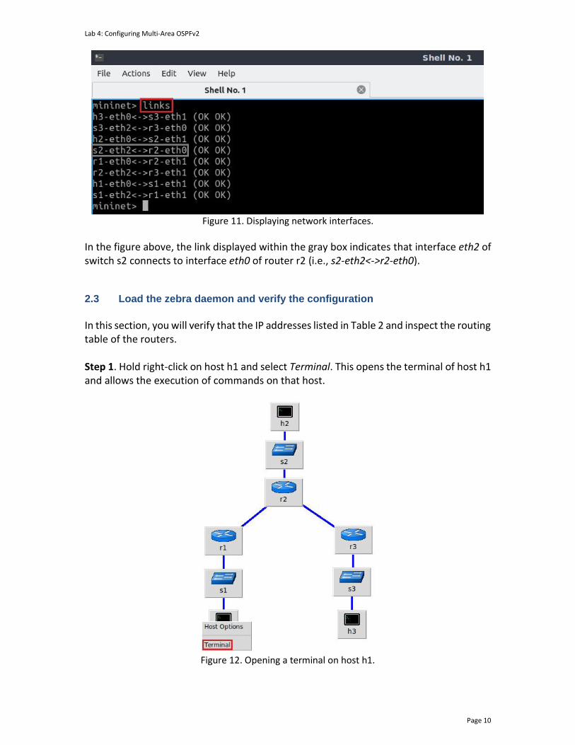
Lab 4: Configuring Multi-Area OSPFv2
Page 10
Figure 11. Displaying network interfaces.
In the figure above, the link displayed within the gray box indicates that interface eth2 of switch s2 connects to interface eth0 of router r2 (i.e., s2-eth2<->r2-eth0). 2.3 Load the zebra daemon and verify the configuration
In this section, you will verify that the IP addresses listed in Table 2 and inspect the routing table of the routers. Step 1. Hold right-click on host h1 and select Terminal. This opens the terminal of host h1 and allows the execution of commands on that host.
Figure 12. Opening a terminal on host h1.
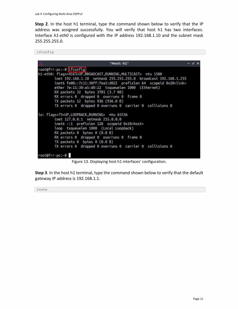
Lab 4: Configuring Multi-Area OSPFv2
Page 11
Step 2. In the host h1 terminal, type the command shown below to verify that the IP address was assigned successfully. You will verify that host h1 has two interfaces. Interface h1-eth0 is configured with the IP address 192.168.1.10 and the subnet mask 255.255.255.0. ifconfig
Figure 13. Displaying host h1 interfaces’ configuration.
Step 3. In the host h1 terminal, type the command shown below to verify that the default gateway IP address is 192.168.1.1. route
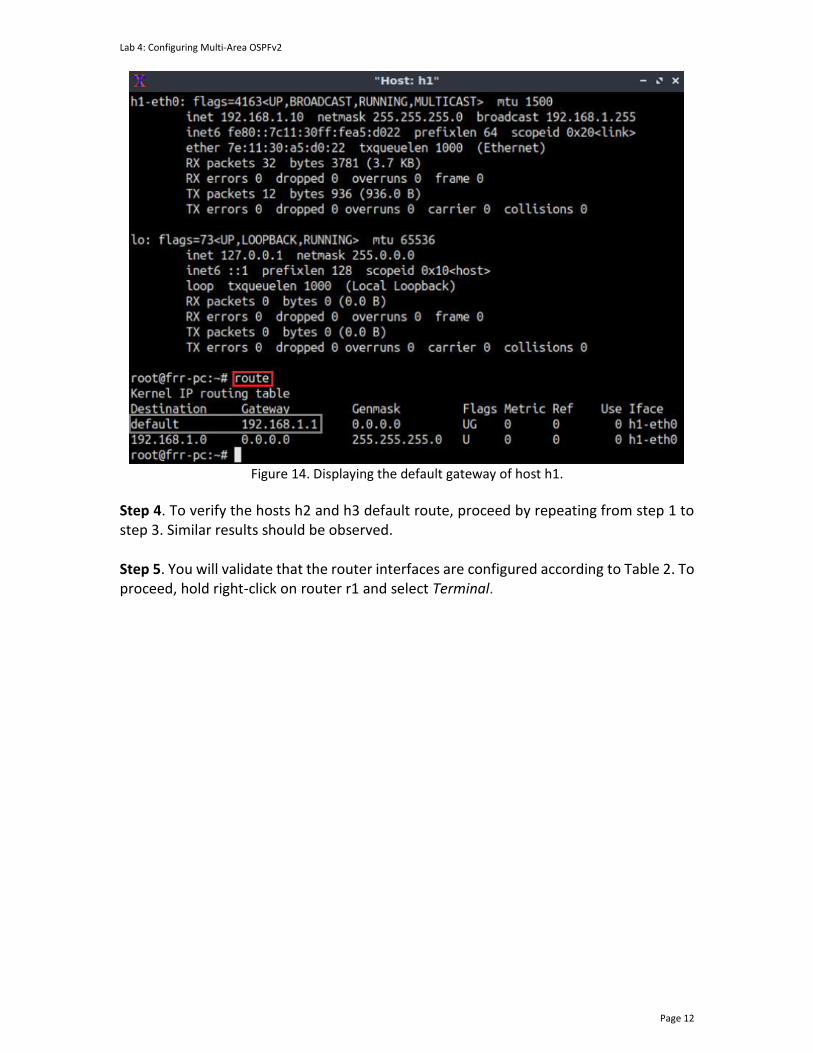
Lab 4: Configuring Multi-Area OSPFv2
Page 12
Figure 14. Displaying the default gateway of host h1.
Step 4. To verify the hosts h2 and h3 default route, proceed by repeating from step 1 to step 3. Similar results should be observed. Step 5. You will validate that the router interfaces are configured according to Table 2. To proceed, hold right-click on router r1 and select Terminal.

Lab 4: Configuring Multi-Area OSPFv2
Page 13
Figure 15. Opening a terminal on router r1.
Step 6. In this step, you will start the zebra daemon, a multi-server routing software that provides TCP/IP-based routing protocols. The configuration will not be working if you do not enable zebra daemon initially. To start the zebra, type the following command: zebra
Figure 16. Starting zebra daemon.
Step 7. After initializing zebra, vtysh should be started to provide all the CLI commands defined by the daemons. To proceed, issue the following command: vtysh
Figure 17. Starting vtysh on router r1.
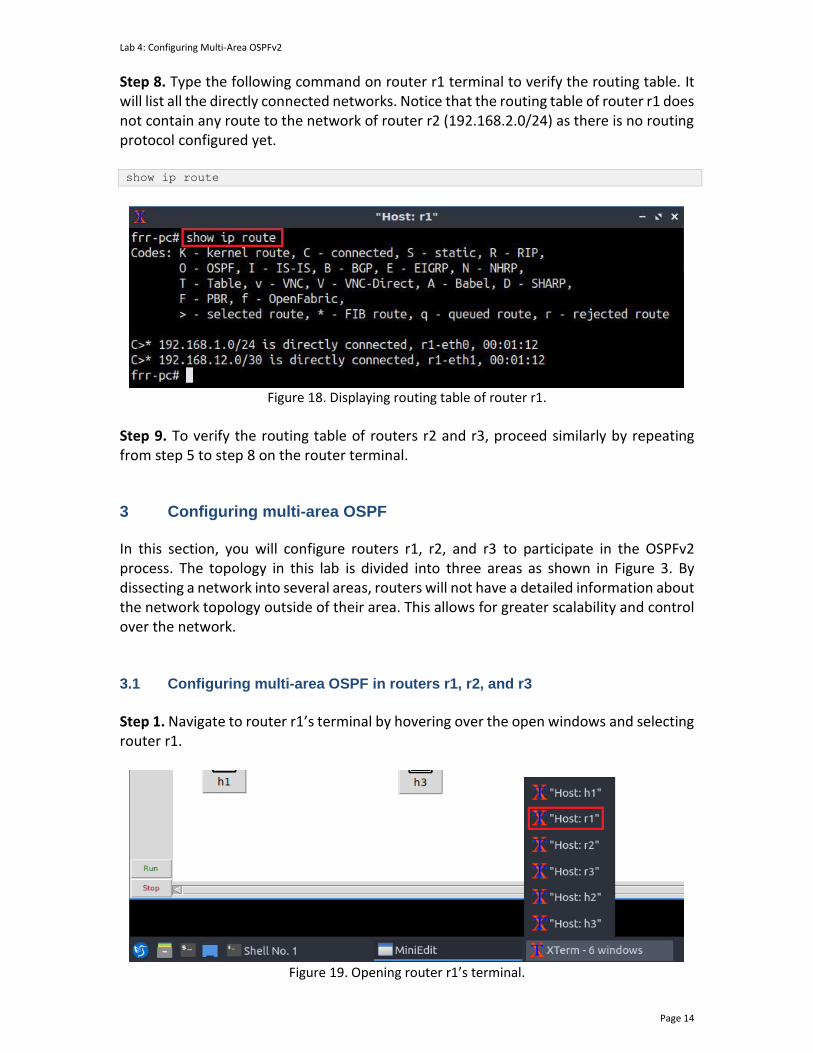
Lab 4: Configuring Multi-Area OSPFv2
Page 14
Step 8. Type the following command on router r1 terminal to verify the routing table. It will list all the directly connected networks. Notice that the routing table of router r1 does not contain any route to the network of router r2 (192.168.2.0/24) as there is no routing protocol configured yet. show ip route
Figure 18. Displaying routing table of router r1.
Step 9. To verify the routing table of routers r2 and r3, proceed similarly by repeating from step 5 to step 8 on the router terminal.
3 Configuring multi-area OSPF In this section, you will configure routers r1, r2, and r3 to participate in the OSPFv2 process. The topology in this lab is divided into three areas as shown in Figure 3. By dissecting a network into several areas, routers will not have a detailed information about the network topology outside of their area. This allows for greater scalability and control over the network. 3.1 Configuring multi-area OSPF in routers r1, r2, and r3
Step 1. Navigate to router r1’s terminal by hovering over the open windows and selecting router r1.
Figure 19. Opening router r1’s terminal.

Lab 4: Configuring Multi-Area OSPFv2
Page 15
Step 2. In router r1’s terminal, type the command below to exit the vtysh session. exit
Figure 20. Exiting the vtysh session.
Step 3. Enable and start the OSPF routing protocol by typing the following command: ospfd
Figure 21. Starting the OSPF daemon.
Step 4. In order to enter router r1’s shell for FRR daemons, issue the following command: vtysh
Figure 22. Starting vtysh in router r1.
Step 5. At this point, you have entered router r1’s shell for FRR daemons, to enter configuration mode in router r1, issue the following command: configure terminal
Figure 23. Enabling configuration mode in router r1.
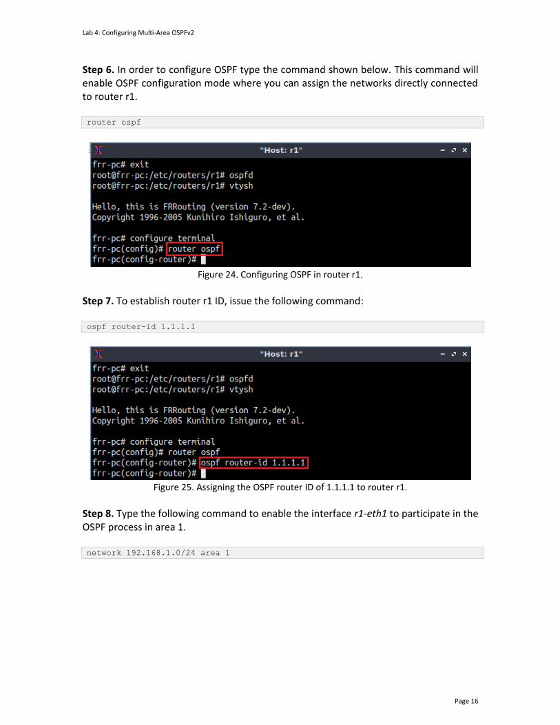
Lab 4: Configuring Multi-Area OSPFv2
Page 16
Step 6. In order to configure OSPF type the command shown below. This command will enable OSPF configuration mode where you can assign the networks directly connected to router r1. router ospf
Figure 24. Configuring OSPF in router r1.
Step 7. To establish router r1 ID, issue the following command: ospf router-id 1.1.1.1
Figure 25. Assigning the OSPF router ID of 1.1.1.1 to router r1.
Step 8. Type the following command to enable the interface r1-eth1 to participate in the OSPF process in area 1. network 192.168.1.0/24 area 1

Lab 4: Configuring Multi-Area OSPFv2
Page 17
Figure 26. Enabling interface r1-eth1 to participate in the OSPF process of area 1.
Consider the above figure. The command enables the interface r1-eth0 to participate in the OSPF routing process of area 1 since this interface matches 192.168.1.0/24. Step 9. Similarly, issue the following command, so that the interface r1-eth0 can participate in the routing process of area 0. network 192.168.12.0/30 area 0
Figure 27. Enabling interface r1-eth0 to participate in the OSPF process of area 0.
Step 10. Type the following command to exit from configuration mode. end
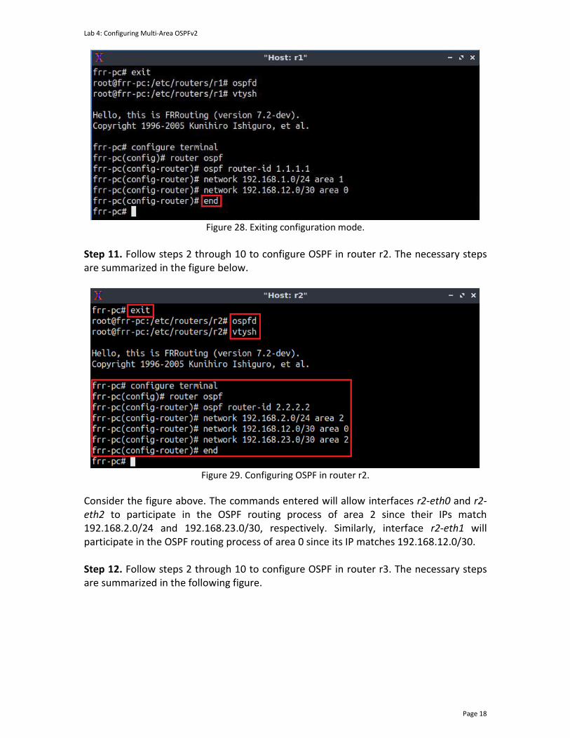
Lab 4: Configuring Multi-Area OSPFv2
Page 18
Figure 28. Exiting configuration mode.
Step 11. Follow steps 2 through 10 to configure OSPF in router r2. The necessary steps are summarized in the figure below.
Figure 29. Configuring OSPF in router r2.
Consider the figure above. The commands entered will allow interfaces r2-eth0 and r2-eth2 to participate in the OSPF routing process of area 2 since their IPs match 192.168.2.0/24 and 192.168.23.0/30, respectively. Similarly, interface r2-eth1 will participate in the OSPF routing process of area 0 since its IP matches 192.168.12.0/30. Step 12. Follow steps 2 through 10 to configure OSPF in router r3. The necessary steps are summarized in the following figure.
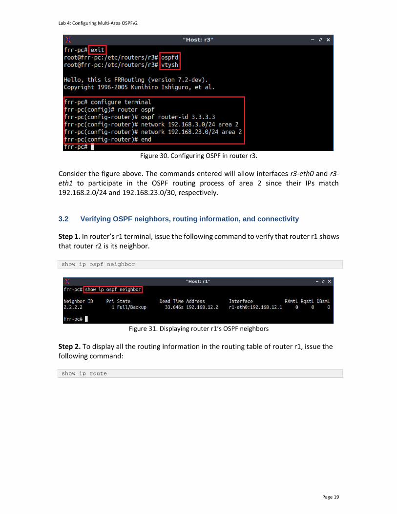
Lab 4: Configuring Multi-Area OSPFv2
Page 19
Figure 30. Configuring OSPF in router r3.
Consider the figure above. The commands entered will allow interfaces r3-eth0 and r3-eth1 to participate in the OSPF routing process of area 2 since their IPs match 192.168.2.0/24 and 192.168.23.0/30, respectively. 3.2 Verifying OSPF neighbors, routing information, and connectivity
Step 1. In router’s r1 terminal, issue the following command to verify that router r1 shows that router r2 is its neighbor. show ip ospf neighbor
Figure 31. Displaying router r1’s OSPF neighbors
Step 2. To display all the routing information in the routing table of router r1, issue the following command:
show ip route

Lab 4: Configuring Multi-Area OSPFv2
Page 20
Figure 32. Displaying router r1’s routing table.
Consider the above figure. The output displays the networks learned along with additional attributes, such as the routing protocol that discovered the network. For example, networks with the symbol O on the left are learned from OSPF, whereas those with symbol C are directly connected to the device. Furthermore, the symbol > on the left of the displayed network indicates that this entry is selected to reach the network. The symbol *, this indicates that the route is inserted in Forwarding Information Base (FIB) of the router. In this network, the routes 192.168.2.0/24, 192.168.3.0/24, and 192.168.23.0/30 are discovered and reached by the OSPF routing protocol (O>*). Step 3. Test the connectivity between host h1 and host h2 by typing the command below. ping 192.168.2.10 -c 4
Figure 33. Performing a connectivity test between host h1 and host h2.
Step 4. Test the connectivity between host h1 and host h3 by issuing the command below. ping 192.168.3.10 -c 4

Lab 4: Configuring Multi-Area OSPFv2
Page 21
Figure 34. Performing a connectivity test between host h1 and host h3.
Step 5. Similarly, you can test the connectivity on hosts h2 and h3 by following steps 1 and 2. 4 Configuring OSPF passive interfaces In this section, you will configure OSPF passive interfaces in routers r1, r2, and r3. These configurations will disable the forwarding of OSPF packets out of the interfaces. The use of passive interfaces increases security and reduces the network traffic within the network it is implemented on. The passive interfaces belong to the link connecting the routers to their hosts, i.e., the interface eth0 of each router. 4.1 Configuring passive interfaces in routers r1, r2, and r3
Step 1. Issue the following command to enter configuration mode. configure terminal
Figure 35. Entering configuration mode in router r1.
Step 2. To configure OSPF in the router type the command shown below. This command will enable OSPF configuration mode. router ospf
Figure 36. Configuring OSPF in router r1.
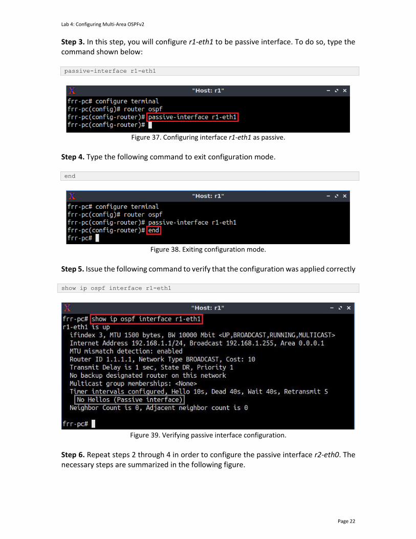
Lab 4: Configuring Multi-Area OSPFv2
Page 22
Step 3. In this step, you will configure r1-eth1 to be passive interface. To do so, type the command shown below: passive-interface r1-eth1
Figure 37. Configuring interface r1-eth1 as passive.
Step 4. Type the following command to exit configuration mode. end
Figure 38. Exiting configuration mode.
Step 5. Issue the following command to verify that the configuration was applied correctly show ip ospf interface r1-eth1
Figure 39. Verifying passive interface configuration.
Step 6. Repeat steps 2 through 4 in order to configure the passive interface r2-eth0. The necessary steps are summarized in the following figure.

Lab 4: Configuring Multi-Area OSPFv2
Page 23
Figure 40. Configuring OSPF passive interface in router r2.
Step 7. Repeat steps 2 through 5 in order to configure the passive interface r3-eth0. The necessary steps are summarized in the following figure.
Figure 41. Configuring OSPF passive interfaces in router r3.
This concludes lab 4. Stop the emulation and then exit out of MiniEdit.
References
1. Moy, J. “RFC 1247: OSPF version 2.” 1991. 2. Moy, J. “RFC 2328: OSPF version 2.” 1998. 3. Coltun, R., Ferguson, D., Moy, J., Lindem, A. “RFC 5340, OSPF for IPv6.” 2008. 4. Peterson, L. “Computer networks: a systems approach.” 6th Edition, 2021. 5. Tanenbaum, D. Wetherall. “Computer networks.” 5th Edition. 2012. 6. J. Kurose, K. Ross. “Computer networking, a top-down approach.” 7th Edition.
2017. 7. Teare, D., Vachon, B., Graziani, R. “Implementing Cisco IP routing (ROUTE)
foundation learning guide: (CCNP ROUTE 300-101).” 2014. 8. Linux foundation collaborative projects. “FRR routing documentation.” 2017
[Online] Available: http://docs.frrouting.org/en/latest/.

OPEN SHORTEST PATH FIRST
Exercise 1: Configuring Multi-Area OSPFv2
Document Version: 10-22-2021
Award 1829698 “CyberTraining CIP: Cyberinfrastructure Expertise on High-throughput
Networks for Big Science Data Transfers”

Exercise 1: Configuring Multi-Area OSPFv2
Page 2
Contents 1 Exercise description .................................................................................................... 3
1.1 Credentials .............................................................................................................. 3
2 Setting the environment ............................................................................................. 3
3 Deliverables ................................................................................................................. 6
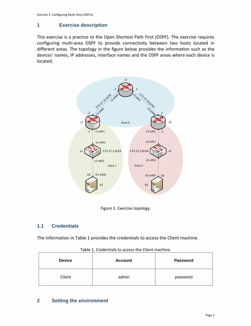
Exercise 1: Configuring Multi-Area OSPFv2
Page 3
1 Exercise description This exercise is a practice to the Open Shortest Path First (OSPF). The exercise requires configuring multi-area OSPF to provide connectivity between two hosts located in different areas. The topology in the figure below provides the information such as the devices’ names, IP addresses, interface names and the OSPF areas where each device is located.
h1 h2
h1-eth0 h2-eth0.10 .10
s1
s1-eth2 s2-eth2
173.17.1.0/24 173.17.2.0/24 s2
.1
s1-eth1 s2-eth1
r2
r1 r3
r1-eth1 r3-eth1
.1
.2 .2
.1
.1
Area 1 Area 2
Area 0
Figure 1. Exercise topology.
1.1 Credentials The information in Table 1 provides the credentials to access the Client machine.
Table 1. Credentials to access the Client machine.
Device
Account
Password
Client admin password
2 Setting the environment
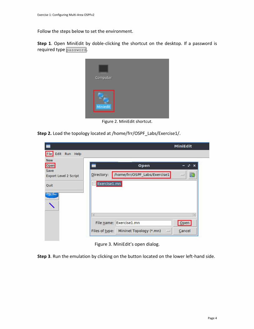
Exercise 1: Configuring Multi-Area OSPFv2
Page 4
Follow the steps below to set the environment. Step 1. Open MiniEdit by doble-clicking the shortcut on the desktop. If a password is required type password.
Figure 2. MiniEdit shortcut.
Step 2. Load the topology located at /home/frr/OSPF_Labs/Exercise1/.
Figure 3. MiniEdit’s open dialog.
Step 3. Run the emulation by clicking on the button located on the lower left-hand side.

Exercise 1: Configuring Multi-Area OSPFv2
Page 5
Figure 4. Starting the emulation.
Step 4. Open the Linux terminal by clicking on the icon located in the taskbar.
Figure 5. Opening Linux terminal.
Step 5. Issue the command shown below to set the lab environment. This command configures the IP addresses in all routers. If a password is required, type password. sudo set_env exercise1
Figure 6. Setting the lab environment.
Step 6. Type the following command to exit the Linux terminal. exit
Figure 7. Exiting the Linux terminal.
Exercise 1: Configuring Multi-Area OSPFv2
Page 6
3 Deliverables Follow the steps below to complete the exercise.
a) Open a terminal in each router, then, start zebra and the OSPF daemons. b) Access each router CLI using the vtysh command.
c) Verify the directly connected routes in each router.
d) Assign an OSPF router ID to each router.
e) Configure router r1 to participate in the OSPF process of areas 0 and 1.
f) Configure router r2 to participate in the OSPF process of area 0.
g) Configure router r3 to participate in the OSPF process of areas 0 and 2.
h) Set the passive interfaces in routers r1 and r3.
i) Verify the routing and OSPF neighbor tables of each router.
j) Perform a connectivity test from host h1 to host h2.
OPEN SHORTEST PATH FIRST
Lab 5: Configuring OSPFv2 with Default Route
Document Version: 10-22-2021
Award 1829698 “CyberTraining CIP: Cyberinfrastructure Expertise on High-throughput
Networks for Big Science Data Transfers”
Lab 5: Configuring OSPFv2 with Default Route
Page 2
Contents
Overview ......................................................................................................................... 3
Objectives............................................................................................................................ 3
Lab settings ......................................................................................................................... 3
Lab roadmap ....................................................................................................................... 3
1 Introduction to advanced OSPF features .................................................................... 3
1.1 Default route ........................................................................................................ 4
1.2 Propagating the default route in OSPF ................................................................ 4
2 Lab topology................................................................................................................ 5
2.1 Lab settings........................................................................................................... 6
2.2 Loading the topology............................................................................................ 7
2.3 Load the zebra daemon and verify the configuration ....................................... 10
3 Configuring OSPF ...................................................................................................... 14
3.1 Configuring single-area OSPF in routers r1, r2, and r3 ...................................... 14
3.2 Verifying Connectivity ........................................................................................ 18
4 Configuring a static route ......................................................................................... 19
5 Propagating default routes in OSPF .......................................................................... 21
5.1 Configuring a static route in router r2 ............................................................... 21
5.2 Propagating the default route to routers r1 and r3 in OSPF.............................. 23
5.3 Verifying Connectivity ........................................................................................ 25
References ........................................................................................................................ 26

Lab 5: Configuring OSPFv2 with Default Route
Page 3
Overview
This lab shows how to propagate a default route between routers running Open Shortest Path First (OSPF). A default route establishes an exit point from a router when the packet destination is not available in the routing table. In this lab, you will configure OSPF to advertise the default route to the other routers. Objectives By the end of this lab, you should be able to:
1. Configure single-area OSPF. 2. Establish a default static route. 3. Propagate the default route throughout the entire OSPF autonomous system.
Lab settings The information in Table 1 provides the credentials to access the Client machine.
Table 1. Credentials to access Client machine.
Device
Account
Password
Client admin password
Lab roadmap This lab is organized as follows:
1. Section 1: Introduction to advanced OSPF features. 2. Section 2: Lab topology. 3. Section 3: Configuring OSPF. 4. Section 4: Configuring a static route. 5. Section 5: Propagating the default route in OSPF.
1 Introduction to advanced OSPF features
OSPF is a widely used Interior Gateway Protocol (IGP) in large enterprise networks. In deployment, there are several scenarios where network administrators have to change the default configuration inside the routing protocol and configure some advanced features. By default, OSPF does not share default routes, and the timer to share OSPF
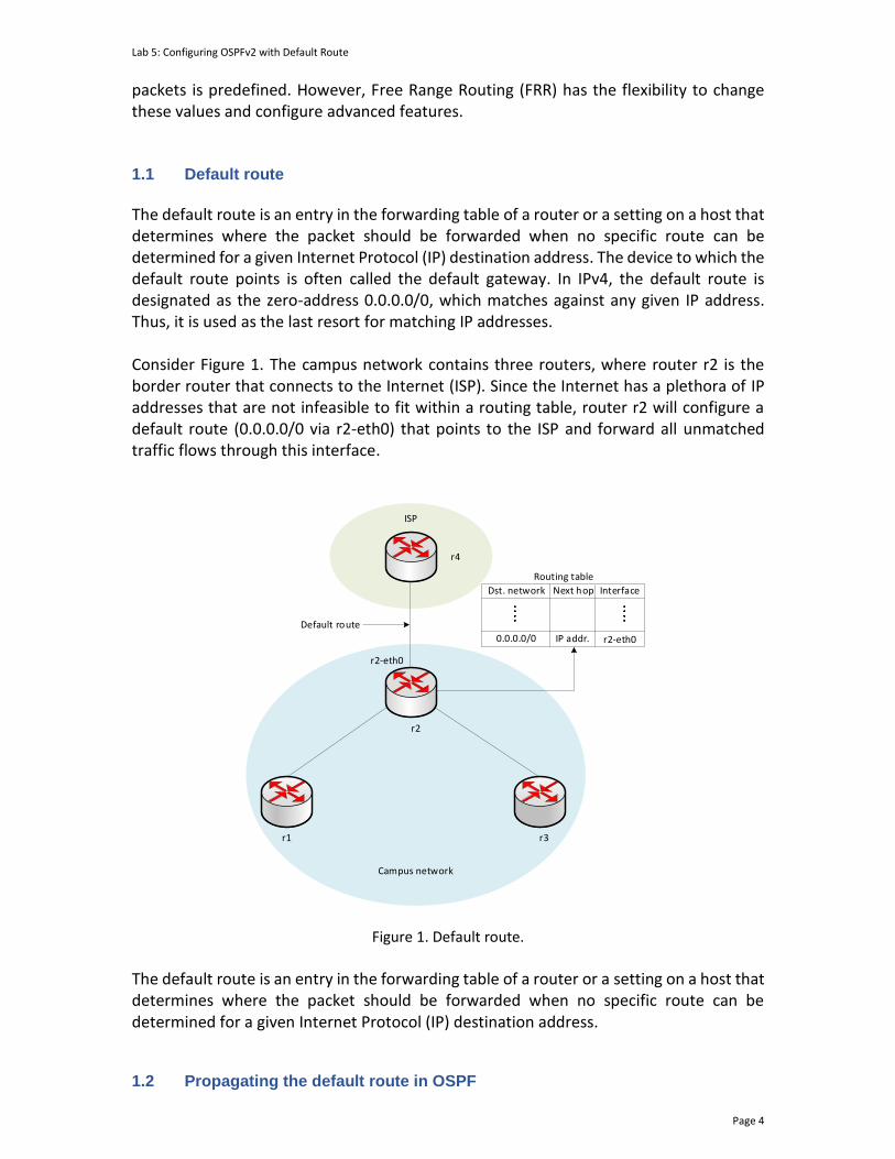
Lab 5: Configuring OSPFv2 with Default Route
Page 4
packets is predefined. However, Free Range Routing (FRR) has the flexibility to change these values and configure advanced features. 1.1 Default route
The default route is an entry in the forwarding table of a router or a setting on a host that determines where the packet should be forwarded when no specific route can be determined for a given Internet Protocol (IP) destination address. The device to which the default route points is often called the default gateway. In IPv4, the default route is designated as the zero-address 0.0.0.0/0, which matches against any given IP address. Thus, it is used as the last resort for matching IP addresses. Consider Figure 1. The campus network contains three routers, where router r2 is the border router that connects to the Internet (ISP). Since the Internet has a plethora of IP addresses that are not infeasible to fit within a routing table, router r2 will configure a default route (0.0.0.0/0 via r2-eth0) that points to the ISP and forward all unmatched traffic flows through this interface.
Routing table
Campus network
r2-eth0
Default route
ISP
r2
r1 r3
r4
r2-eth0
Dst. network InterfaceNext hop
0.0.0.0/0 IP addr.
Figure 1. Default route.
The default route is an entry in the forwarding table of a router or a setting on a host that determines where the packet should be forwarded when no specific route can be determined for a given Internet Protocol (IP) destination address.
1.2 Propagating the default route in OSPF

Lab 5: Configuring OSPFv2 with Default Route
Page 5
OSPF shares dynamic routes between routers in the same area. However, when a router is configured with a default route, this route is not propagated to other routers. This is the default behavior of OSPF, but it can be adjusted so that also the default route is shared with other routers. Consider Figure 2. The campus network runs OSPF as an IGP, and router r2 configures a default route to the ISP. Moreover, router r2 is configured to propagate the default route to its OSPF neighbors. Therefore, routers r1 and r3 will receive and store the default route in their forwarding table, where it will point to the interface facing router r2.
r1-eth0
Campus network
ISP
r2
r1 r3
Default route propagation
r2-eth0
r3-eth0
r4
Routing table
r2-eth0
Dest. network InterfaceNext hop
0.0.0.0/0 IP addr.
Routing table
r3-eth0
Dest. network InterfaceNext hop
0.0.0.0/0 IP addr.
Routing table
r1-eth0
Dest. network InterfaceNext hop
0.0.0.0/0 IP addr.
Default route
Figure 2. Propagating the default route in OSPF.
2 Lab topology Consider Figure 3. The topology comprises two Autonomous Systems (ASes), an internal network, and an external network. The communication within the internal network is performed via single-area OSPF. The internal network communicates to the external network using a static route.
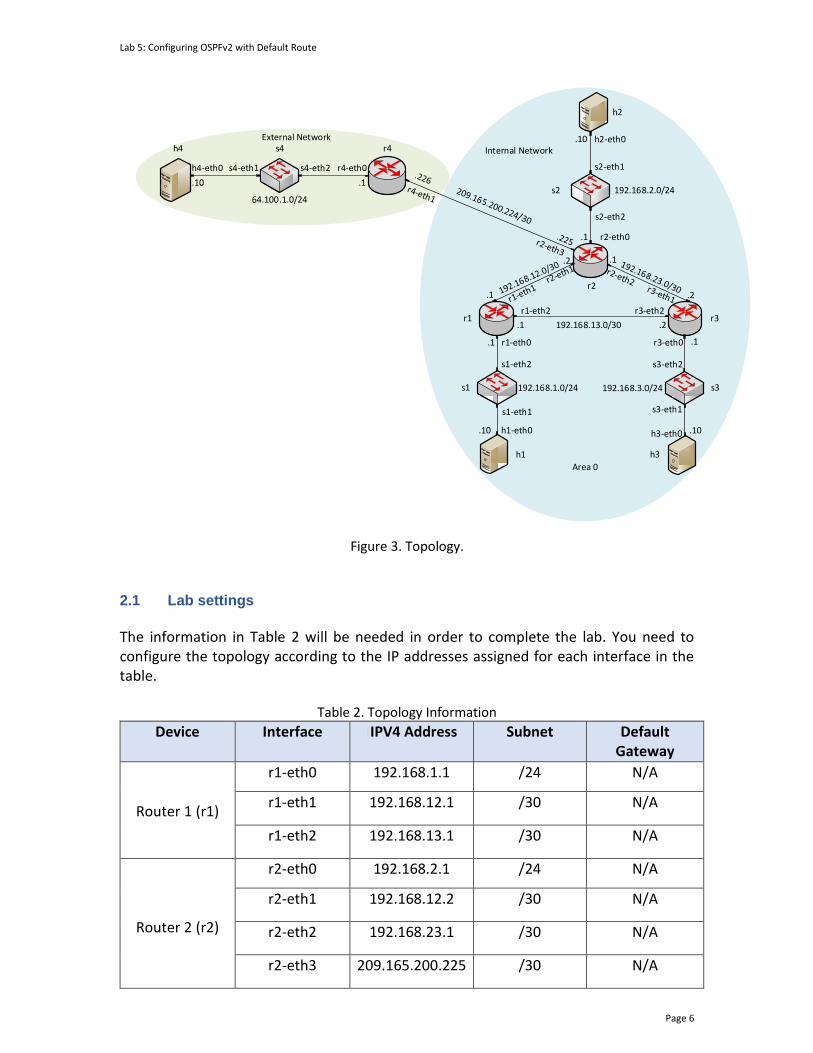
Lab 5: Configuring OSPFv2 with Default Route
Page 6
192.168.2.0/24
h2
h2-eth0.10
s2-eth1
s2-eth2
s264.100.1.0/24
r4-eth0
r4
.1
s4
h4-eth0
h4
.10 .1
s4-eth1 s4-eth2
External Network
Area 0
s3
h1 h3
r1 r3
h1-eth0
r1-eth0
r2-eth0
r3-eth0
h3-eth0.10
.1
.1
.2 .1
.2
.1
.10
.1
r2
.1 .2
r1-eth2 r3-eth2
192.168.13.0/30
s1
s1-eth1
s1-eth2 s3-eth2
s3-eth1
192.168.1.0/24 192.168.3.0/24
Internal Network
Figure 3. Topology.
2.1 Lab settings
The information in Table 2 will be needed in order to complete the lab. You need to configure the topology according to the IP addresses assigned for each interface in the table.
Table 2. Topology Information
Device Interface IIPV4 Address Subnet Default Gateway
Router 1 (r1)
r1-eth0 192.168.1.1 /24 N/A
r1-eth1 192.168.12.1 /30 N/A
r1-eth2 192.168.13.1 /30 N/A
Router 2 (r2)
r2-eth0 192.168.2.1 /24 N/A
r2-eth1 192.168.12.2 /30 N/A
r2-eth2 192.168.23.1 /30 N/A
r2-eth3 209.165.200.225 /30 N/A

Lab 5: Configuring OSPFv2 with Default Route
Page 7
Router 3 (r3)
r3-eth0 192.168.3.1 /24 N/A
r3-eth1 192.168.23.2 /30 N/A
r3-eth2 192.168.13.2 /30 N/A
Router 4 (r4)
r4-eth0 64.100.1.1 /24 N/A
r4-eth1 209.165.200.226 /30 N/A
Host 1 (h1) h1-eth0 192.168.1.10 /24 192.168.1.1
Host 2 (h2) h2-eth0 192.168.2.10 /24 192.168.2.1
Host 3 (h3) h3-eth0 192.168.3.10 /24 192.168.3.1
Host 4 (h4) h4-eth0 64.100.1.10 /24 64.100.1.1
2.2 Loading the topology
Step 1. Launch MiniEdit by double clicking on the shortcut located on the desktop. When prompted for a password, type password.
Figure 4. MiniEdit shortcut.
Step 2. In Miniedit’s menu bar, click on File then open to load the lab topology. Locate the lab5.mn topology file in the default directory, /home/frr/OSPF_Labs/lab5 and click on Open.

Lab 5: Configuring OSPFv2 with Default Route
Page 8
Figure 5. MiniEdit’s open dialog.
Step 3. Click on the Run button located on the lower left-hand side to run the emulation.
Figure 6. Starting the emulation.
At this point, the topology is loaded with all the required network components. Next, you will execute a script that will configure the interfaces of the routers.
Automating the configuration of interfaces with the script is intended to facilitate the lab experience and to focus on the OSPF experiment.
Step 4. Open the Linux terminal by clicking on the icon located in the taskbar.
Figure 7. Opening Linux terminal.
Step 5. Issue the command shown below to set the lab environment. This command configures the IP addresses of the routers’ interface according to Table 2. If a password is required, type password.
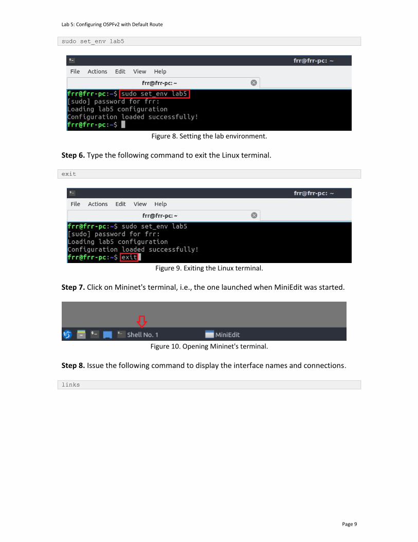
Lab 5: Configuring OSPFv2 with Default Route
Page 9
sudo set_env lab5
Figure 8. Setting the lab environment.
Step 6. Type the following command to exit the Linux terminal. exit
Figure 9. Exiting the Linux terminal.
Step 7. Click on Mininet's terminal, i.e., the one launched when MiniEdit was started.
Figure 10. Opening Mininet's terminal.
Step 8. Issue the following command to display the interface names and connections. links
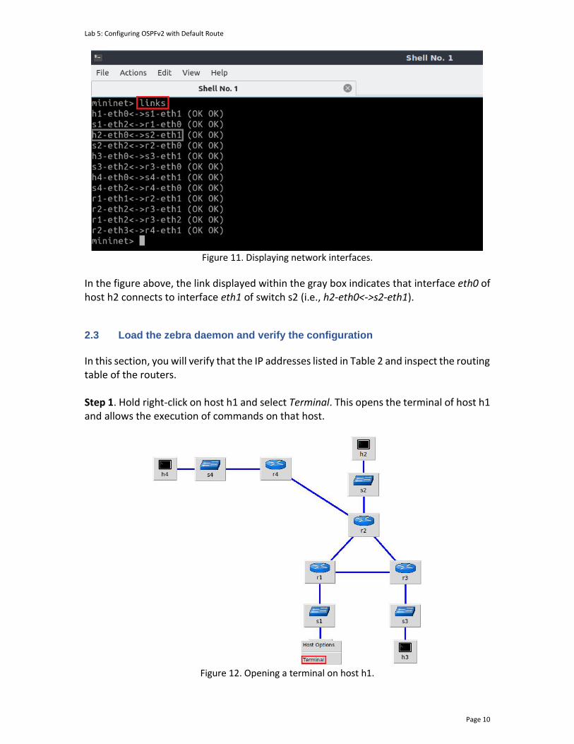
Lab 5: Configuring OSPFv2 with Default Route
Page 10
Figure 11. Displaying network interfaces.
In the figure above, the link displayed within the gray box indicates that interface eth0 of host h2 connects to interface eth1 of switch s2 (i.e., h2-eth0<->s2-eth1). 2.3 Load the zebra daemon and verify the configuration
In this section, you will verify that the IP addresses listed in Table 2 and inspect the routing table of the routers. Step 1. Hold right-click on host h1 and select Terminal. This opens the terminal of host h1 and allows the execution of commands on that host.
Figure 12. Opening a terminal on host h1.

Lab 5: Configuring OSPFv2 with Default Route
Page 11
Step 2. In the host h1 terminal, type the command shown below to verify that the IP address was assigned successfully. You will verify that host h1 has two interfaces. Interface h1-eth0 is configured with the IP address 192.168.1.10 and the subnet mask 255.255.255.0. ifconfig
Figure 13. The output of ifconfig command.
Step 3. In the host h1 terminal, type the command shown below to verify that the default gateway IP address is 192.168.1.1. route
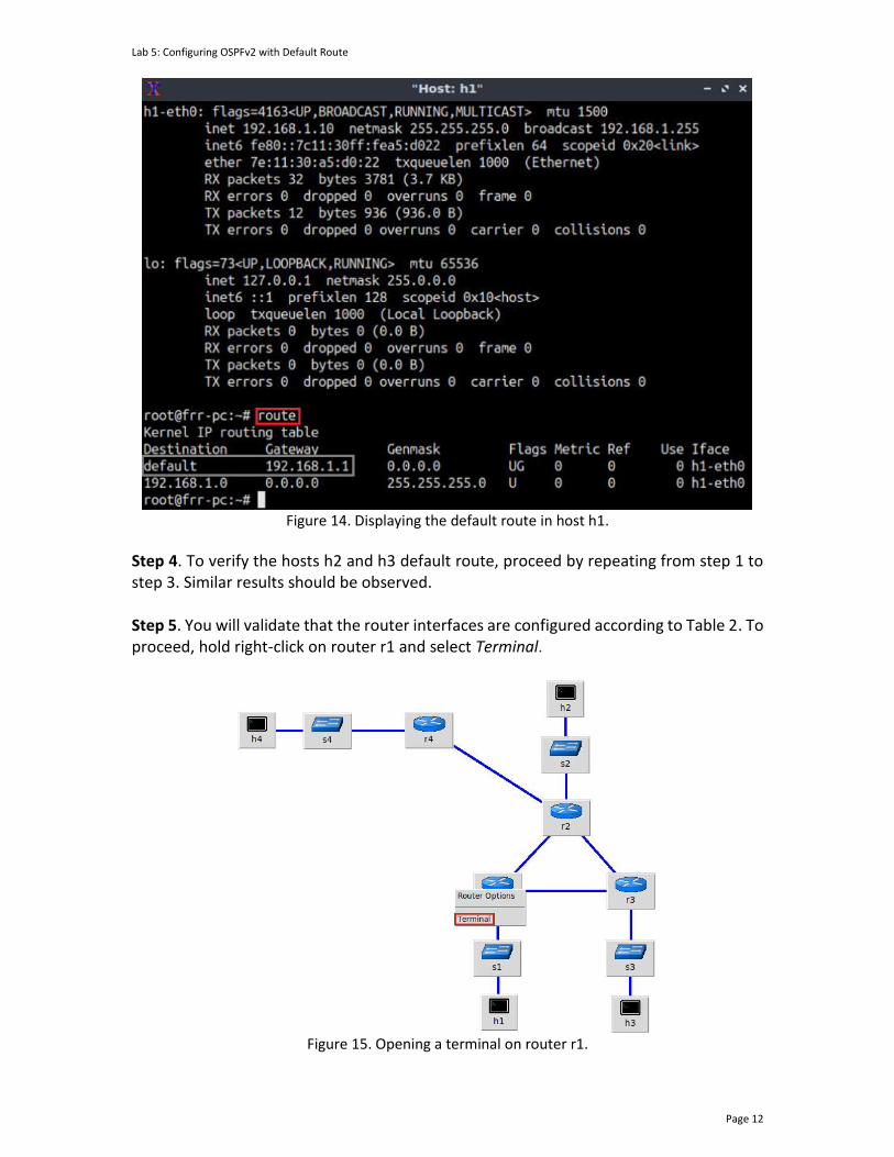
Lab 5: Configuring OSPFv2 with Default Route
Page 12
Figure 14. Displaying the default route in host h1.
Step 4. To verify the hosts h2 and h3 default route, proceed by repeating from step 1 to step 3. Similar results should be observed. Step 5. You will validate that the router interfaces are configured according to Table 2. To proceed, hold right-click on router r1 and select Terminal.
Figure 15. Opening a terminal on router r1.
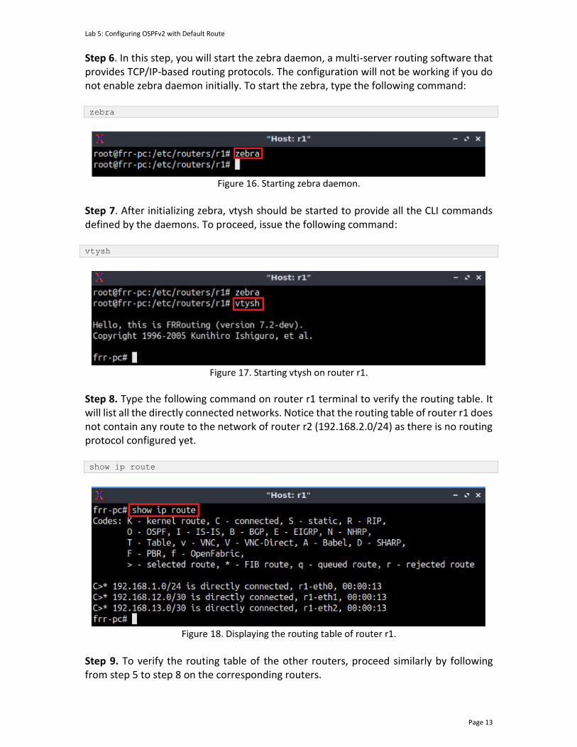
Lab 5: Configuring OSPFv2 with Default Route
Page 13
Step 6. In this step, you will start the zebra daemon, a multi-server routing software that provides TCP/IP-based routing protocols. The configuration will not be working if you do not enable zebra daemon initially. To start the zebra, type the following command: zebra
Figure 16. Starting zebra daemon.
Step 7. After initializing zebra, vtysh should be started to provide all the CLI commands defined by the daemons. To proceed, issue the following command: vtysh
Figure 17. Starting vtysh on router r1.
Step 8. Type the following command on router r1 terminal to verify the routing table. It will list all the directly connected networks. Notice that the routing table of router r1 does not contain any route to the network of router r2 (192.168.2.0/24) as there is no routing protocol configured yet. show ip route
Figure 18. Displaying the routing table of router r1.
Step 9. To verify the routing table of the other routers, proceed similarly by following from step 5 to step 8 on the corresponding routers.
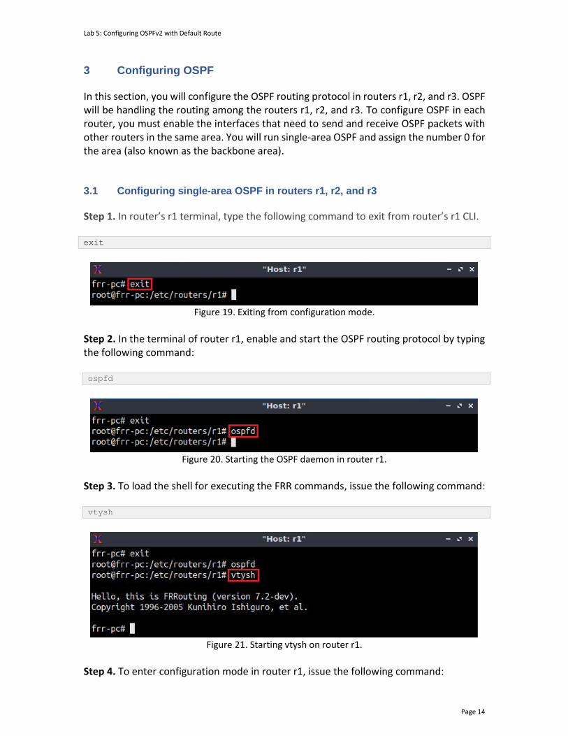
Lab 5: Configuring OSPFv2 with Default Route
Page 14
3 Configuring OSPF In this section, you will configure the OSPF routing protocol in routers r1, r2, and r3. OSPF will be handling the routing among the routers r1, r2, and r3. To configure OSPF in each router, you must enable the interfaces that need to send and receive OSPF packets with other routers in the same area. You will run single-area OSPF and assign the number 0 for the area (also known as the backbone area). 3.1 Configuring single-area OSPF in routers r1, r2, and r3
Step 1. In router’s r1 terminal, type the following command to exit from router’s r1 CLI. exit
Figure 19. Exiting from configuration mode.
Step 2. In the terminal of router r1, enable and start the OSPF routing protocol by typing the following command: ospfd
Figure 20. Starting the OSPF daemon in router r1.
Step 3. To load the shell for executing the FRR commands, issue the following command: vtysh
Figure 21. Starting vtysh on router r1.
Step 4. To enter configuration mode in router r1, issue the following command:
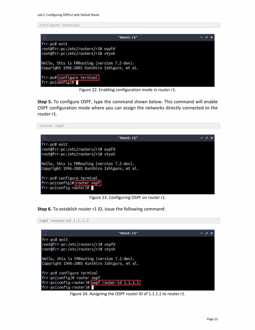
Lab 5: Configuring OSPFv2 with Default Route
Page 15
configure terminal
Figure 22. Enabling configuration mode in router r1.
Step 5. To configure OSPF, type the command shown below. This command will enable OSPF configuration mode where you can assign the networks directly connected to the router r1. router ospf
Figure 23. Configuring OSPF on router r1.
Step 6. To establish router r1 ID, issue the following command: ospf router-id 1.1.1.1
Figure 24. Assigning the OSPF router ID of 1.1.1.1 to router r1.
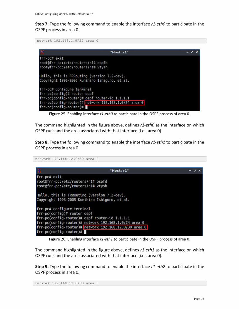
Lab 5: Configuring OSPFv2 with Default Route
Page 16
Step 7. Type the following command to enable the interface r1-eth0 to participate in the OSPF process in area 0. network 192.168.1.0/24 area 0
Figure 25. Enabling interface r1-eth0 to participate in the OSPF process of area 0.
The command highlighted in the figure above, defines r1-eth0 as the interface on which OSPF runs and the area associated with that interface (i.e., area 0). Step 8. Type the following command to enable the interface r1-eth1 to participate in the OSPF process in area 0. network 192.168.12.0/30 area 0
Figure 26. Enabling interface r1-eth1 to participate in the OSPF process of area 0.
The command highlighted in the figure above, defines r1-eth1 as the interface on which OSPF runs and the area associated with that interface (i.e., area 0).
Step 9. Type the following command to enable the interface r1-eth2 to participate in the OSPF process in area 0. network 192.168.13.0/30 area 0

Lab 5: Configuring OSPFv2 with Default Route
Page 17
Figure 27. Enabling interface r1-eth2 to participate in the OSPF process of area 0.
The command highlighted in the figure above, defines r1-eth2 as the interface on which OSPF runs and the area associated with that interface (i.e., area 0). Step 10. To exit OSPF configuration mode, type the following command: end
Figure 28. Exiting OSPF configuration mode.
Step 11. Router r2 is configured similarly to router r1 but with different IP addresses (see Table 2). Those steps are summarized in the following figure. To proceed, in router r2 terminal, issue the commands depicted below.
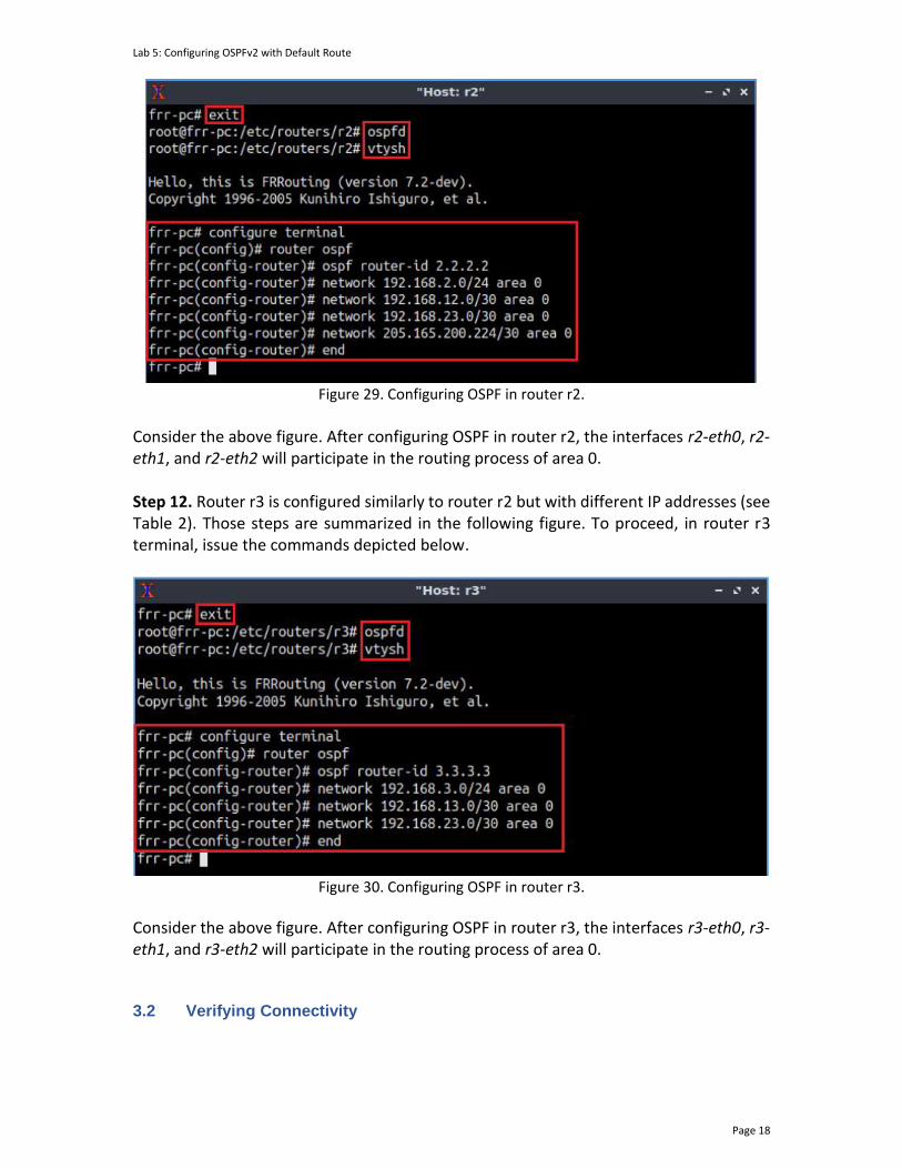
Lab 5: Configuring OSPFv2 with Default Route
Page 18
Figure 29. Configuring OSPF in router r2.
Consider the above figure. After configuring OSPF in router r2, the interfaces r2-eth0, r2-eth1, and r2-eth2 will participate in the routing process of area 0. Step 12. Router r3 is configured similarly to router r2 but with different IP addresses (see Table 2). Those steps are summarized in the following figure. To proceed, in router r3 terminal, issue the commands depicted below.
Figure 30. Configuring OSPF in router r3.
Consider the above figure. After configuring OSPF in router r3, the interfaces r3-eth0, r3-eth1, and r3-eth2 will participate in the routing process of area 0.
3.2 Verifying Connectivity
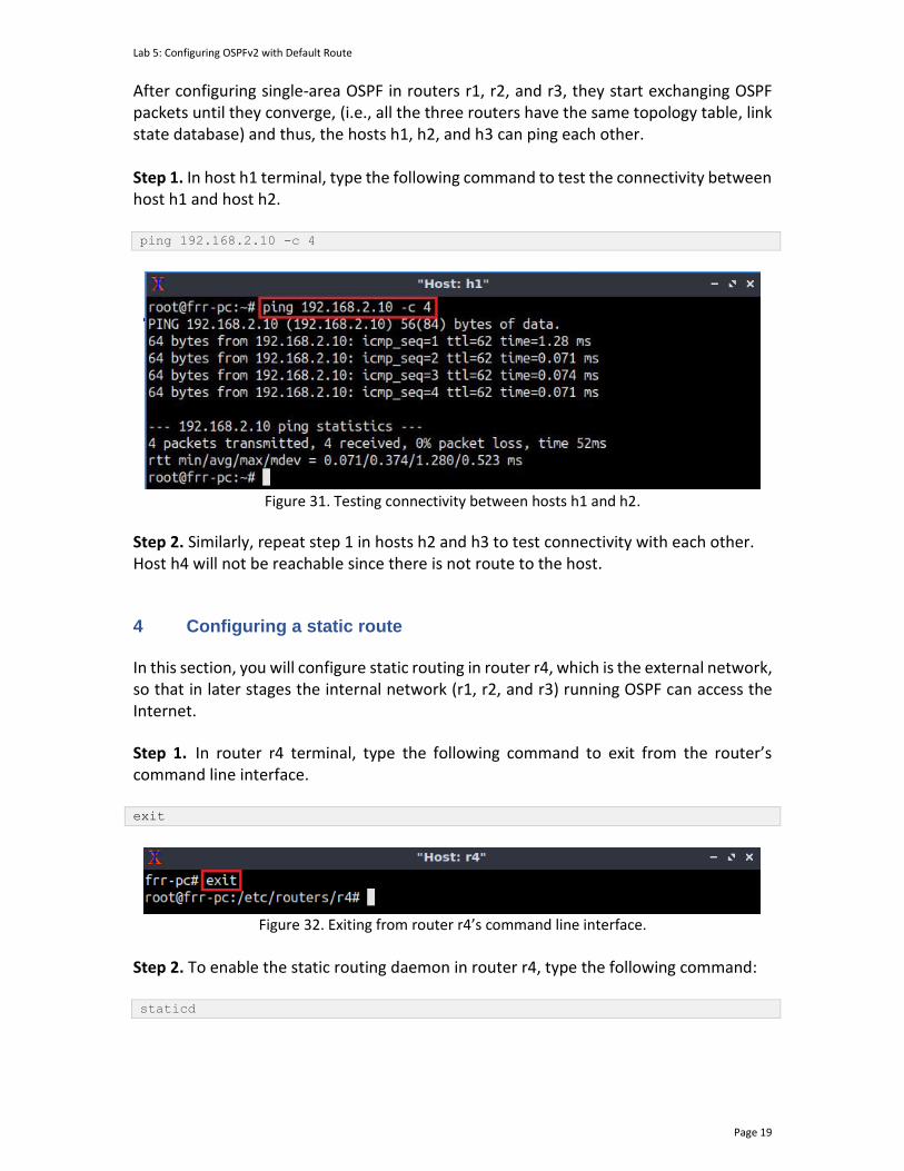
Lab 5: Configuring OSPFv2 with Default Route
Page 19
After configuring single-area OSPF in routers r1, r2, and r3, they start exchanging OSPF packets until they converge, (i.e., all the three routers have the same topology table, link state database) and thus, the hosts h1, h2, and h3 can ping each other. Step 1. In host h1 terminal, type the following command to test the connectivity between host h1 and host h2. ping 192.168.2.10 -c 4
Figure 31. Testing connectivity between hosts h1 and h2.
Step 2. Similarly, repeat step 1 in hosts h2 and h3 to test connectivity with each other. Host h4 will not be reachable since there is not route to the host.
4 Configuring a static route
In this section, you will configure static routing in router r4, which is the external network, so that in later stages the internal network (r1, r2, and r3) running OSPF can access the Internet. Step 1. In router r4 terminal, type the following command to exit from the router’s command line interface. exit
Figure 32. Exiting from router r4’s command line interface.
Step 2. To enable the static routing daemon in router r4, type the following command: staticd
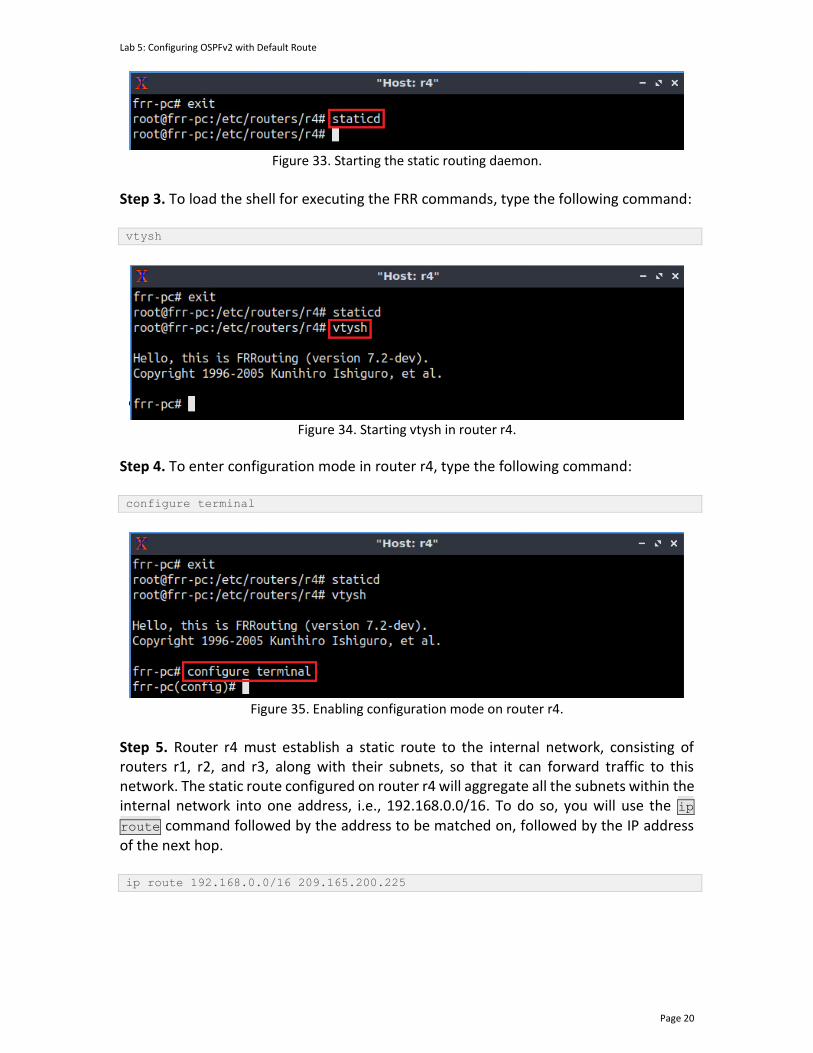
Lab 5: Configuring OSPFv2 with Default Route
Page 20
Figure 33. Starting the static routing daemon.
Step 3. To load the shell for executing the FRR commands, type the following command: vtysh
Figure 34. Starting vtysh in router r4.
Step 4. To enter configuration mode in router r4, type the following command: configure terminal
Figure 35. Enabling configuration mode on router r4.
Step 5. Router r4 must establish a static route to the internal network, consisting of routers r1, r2, and r3, along with their subnets, so that it can forward traffic to this network. The static route configured on router r4 will aggregate all the subnets within the internal network into one address, i.e., 192.168.0.0/16. To do so, you will use the ip route command followed by the address to be matched on, followed by the IP address of the next hop. ip route 192.168.0.0/16 209.165.200.225
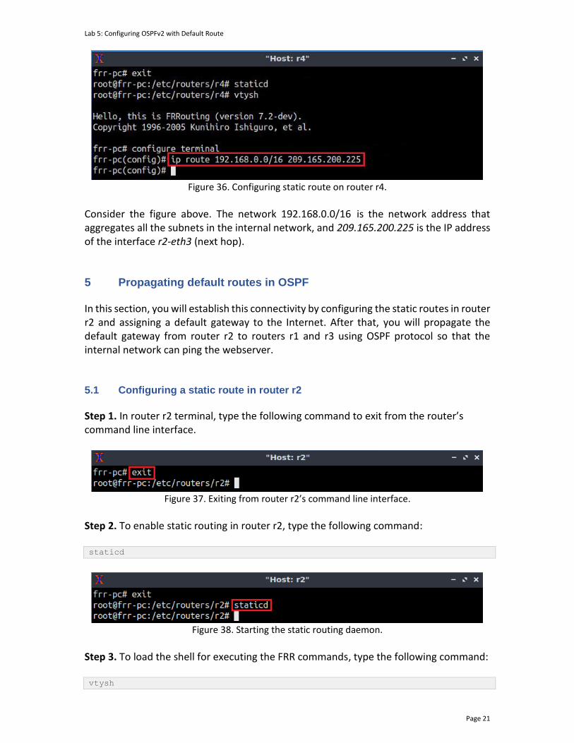
Lab 5: Configuring OSPFv2 with Default Route
Page 21
Figure 36. Configuring static route on router r4.
Consider the figure above. The network 192.168.0.0/16 is the network address that aggregates all the subnets in the internal network, and 209.165.200.225 is the IP address of the interface r2-eth3 (next hop). 5 Propagating default routes in OSPF
In this section, you will establish this connectivity by configuring the static routes in router r2 and assigning a default gateway to the Internet. After that, you will propagate the default gateway from router r2 to routers r1 and r3 using OSPF protocol so that the internal network can ping the webserver. 5.1 Configuring a static route in router r2
Step 1. In router r2 terminal, type the following command to exit from the router’s command line interface.
Figure 37. Exiting from router r2’s command line interface.
Step 2. To enable static routing in router r2, type the following command: staticd
Figure 38. Starting the static routing daemon.
Step 3. To load the shell for executing the FRR commands, type the following command: vtysh
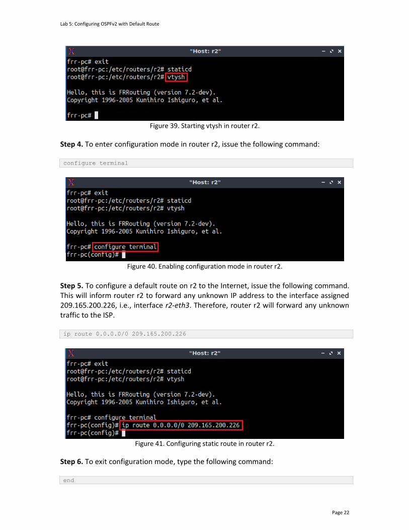
Lab 5: Configuring OSPFv2 with Default Route
Page 22
Figure 39. Starting vtysh in router r2.
Step 4. To enter configuration mode in router r2, issue the following command: configure terminal
Figure 40. Enabling configuration mode in router r2.
Step 5. To configure a default route on r2 to the Internet, issue the following command. This will inform router r2 to forward any unknown IP address to the interface assigned 209.165.200.226, i.e., interface r2-eth3. Therefore, router r2 will forward any unknown traffic to the ISP. ip route 0.0.0.0/0 209.165.200.226
Figure 41. Configuring static route in router r2.
Step 6. To exit configuration mode, type the following command: end
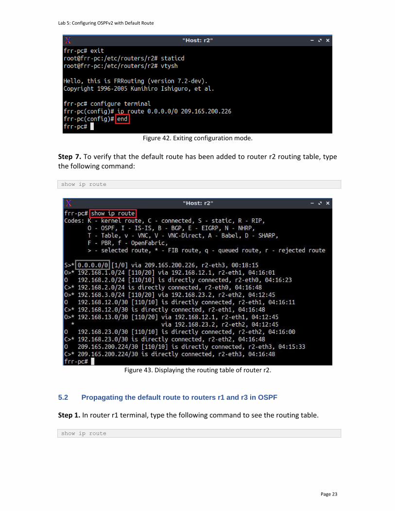
Lab 5: Configuring OSPFv2 with Default Route
Page 23
Figure 42. Exiting configuration mode.
Step 7. To verify that the default route has been added to router r2 routing table, type the following command: show ip route
Figure 43. Displaying the routing table of router r2.
5.2 Propagating the default route to routers r1 and r3 in OSPF
Step 1. In router r1 terminal, type the following command to see the routing table. show ip route

Lab 5: Configuring OSPFv2 with Default Route
Page 24
Figure 44. Displaying the routing table of router r1.
Consider the figure above. The routing table of router r1 does not contain the default route as configured in router r2. When the default route is configured in one router, the route has to be propagated to the other routers in the OSPF area so that the default route may be added to the routing table. Step 2. In the previous subsection, you configured a default route in router r2. However, this route was not propagated in OSPF. To advertise this route in OSPF protocol to other routers running OSPF in the same area first start by executing the following command in router r2’s terminal. configure terminal
Figure 45. Enabling configuration mode on router r2.
Step 3. To enable OSPF configuration mode, write the below command. router ospf
Figure 46. Enabling OSPF configuration mode in router r2.
Step 4. To propagate the default route, write the below command.

Lab 5: Configuring OSPFv2 with Default Route
Page 25
default-information originate
Figure 47. Propagating the default route in OSPF.
Step 5. To exit OSPF configuration mode type the following command: end
Figure 48. Exiting OSPF configuration mode in router r2.
Step 6. In router r1 terminal, issue the following command to view the routing table of router r1. show ip route
Figure 49. Displaying the routing table of router r1.
5.3 Verifying Connectivity
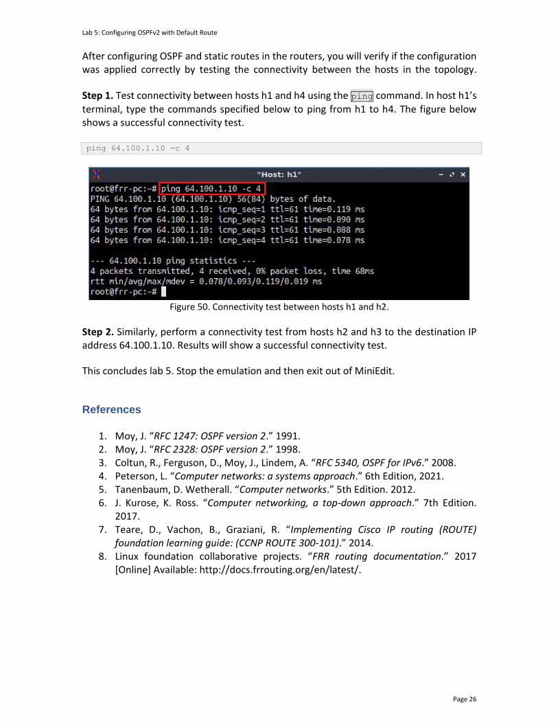
Lab 5: Configuring OSPFv2 with Default Route
Page 26
After configuring OSPF and static routes in the routers, you will verify if the configuration was applied correctly by testing the connectivity between the hosts in the topology. Step 1. Test connectivity between hosts h1 and h4 using the ping command. In host h1’s terminal, type the commands specified below to ping from h1 to h4. The figure below shows a successful connectivity test. ping 64.100.1.10 -c 4
Figure 50. Connectivity test between hosts h1 and h2.
Step 2. Similarly, perform a connectivity test from hosts h2 and h3 to the destination IP address 64.100.1.10. Results will show a successful connectivity test.
This concludes lab 5. Stop the emulation and then exit out of MiniEdit.
References
1. Moy, J. “RFC 1247: OSPF version 2.” 1991. 2. Moy, J. “RFC 2328: OSPF version 2.” 1998. 3. Coltun, R., Ferguson, D., Moy, J., Lindem, A. “RFC 5340, OSPF for IPv6.” 2008. 4. Peterson, L. “Computer networks: a systems approach.” 6th Edition, 2021. 5. Tanenbaum, D. Wetherall. “Computer networks.” 5th Edition. 2012. 6. J. Kurose, K. Ross. “Computer networking, a top-down approach.” 7th Edition.
2017. 7. Teare, D., Vachon, B., Graziani, R. “Implementing Cisco IP routing (ROUTE)
foundation learning guide: (CCNP ROUTE 300-101).” 2014. 8. Linux foundation collaborative projects. “FRR routing documentation.” 2017
[Online] Available: http://docs.frrouting.org/en/latest/.

OPEN SHORTEST PATH FIRST
Lab 6: OSPFv2 Virtual Link
Document Version: 10-22-2021
Award 1829698 “CyberTraining CIP: Cyberinfrastructure Expertise on High-throughput
Networks for Big Science Data Transfers”
Lab 6: OSPFv2 Virtual Link
Page 2
Contents Overview ............................................................................................................................. 3
Objectives............................................................................................................................ 3
Lab settings ......................................................................................................................... 3
Lab roadmap ....................................................................................................................... 3
1 Introduction ................................................................................................................ 3
1.1 OSPF virtual link ................................................................................................... 4
1.2 OSPF virtual link use cases ................................................................................... 4
1.3 Design considerations and limitations of OSPF virtual links ................................ 5
2 Lab topology................................................................................................................ 5
2.1 Lab settings........................................................................................................... 6
2.2 Loading the topology............................................................................................ 7
2.3 Load the zebra daemon and verify the configuration ....................................... 10
3 Configuring multi-area OSPF ..................................................................................... 14
3.1 Configuring OSPF in routers r1, r2, and r3 ......................................................... 14
3.2 Verifying OSPF neighbors, routing information, and connectivity. ................... 19
4 Configuring OSPF virtual link .................................................................................... 21
4.1 Verifying OSPF neighbors, routing information, and connectivity. .................. 22
References ........................................................................................................................ 24

Lab 6: OSPFv2 Virtual Link
Page 3
Overview This lab introduces the concept of a virtual link, a feature of the Open Shortest Path First (OSPF) protocol employed to link an area that is not contiguous to the backbone area (i.e., area 0). The OSPF protocol requires a direct connection of the nonbackbone areas to the backbone area. In this way, the OSPF protocol redistributes the routes received from the nonbackbone areas. This lab explains how to configure a virtual link on routers participating in the OSPF process. Objectives By the end of this lab, you should be able to:
1. Understand the concept of OSPF virtual link. 2. Configure multi-area OSPF. 3. Identify the scenarios where a virtual link can be employed. 4. Configure OSPF virtual link to connect a non-contiguous area to the backbone
area. 5. Understand the limitations of using a virtual link.
Lab settings The information in Table 1 provides the credentials to access the Client machine.
Table 1. Credentials to access the Client machine.
Device
Account
Password
Client admin password
Lab roadmap This lab is organized as follows:
1. Section 1: Introduction. 2. Section 2: Lab topology. 3. Section 3: Configuring multi-area OSPF. 4. Section 4: Configuring OSPF virtual link.
1 Introduction

Lab 6: OSPFv2 Virtual Link
Page 4
1.1 OSPF virtual link
The OSPF protocol requires a backbone area (i.e., area 0) when more than one area is configured. All the nonbackbone areas must be directly connected to the backbone area. In this way, the nonbackbone areas inject their routes into the backbone area, and the backbone area can redistribute these routes to the other areas. However, there are scenarios where nonbackbone areas are not contiguous to the backbone area, meaning that the OSPF protocol will not exchange routing information with the non-contiguous areas. Nevertheless, the OSPF protocol provides the virtual link feature, allowing non-contiguous areas to connect to the backbone area across a transit area. 1.2 OSPF virtual link use cases
Virtual links are used in two cases:
1. Linking a nonbackbone area that cannot be physically connected to the backbone area.
2. Connecting partitioned parts of the backbone area. Consider Figure 1. In this scenario, the backbone area (i.e., area 0) is divided in two parts. A virtual link can be configured in routers r2 and r4, to create a logical connection between the two parts of the backbone across a transit area (i.e., area 1). Therefore, the routers can participate in the OSPF process.
Area 1
Transit AreaBackbone
Area
Virtual Link
Area 0Area 0
BackboneArea
r1
r2 r4
r5
r3
r6 r8r7 r9
Figure 1. OSPF virtual link use case. A virtual link can be used in a scenario where the backbone area is separated by a transit area.
Consider Figure 2. In this scenario, area 2 is not contiguous to the backbone area. Thus, configuring a virtual link between routers r1 and r3 will provide a logical path to area 0. In this topology, area 1 is used as a transit area allowing area 2 to participate in the OSPF process. A transit network can carry data traffic that is neither locally originated nor locally destined12.
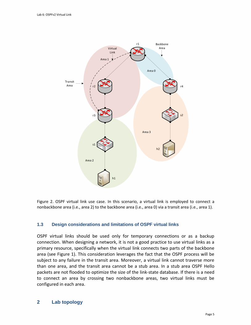
Lab 6: OSPFv2 Virtual Link
Page 5
s1
s2
r1
r2
r3
r4
Area 1
Area 2
Area 3
Area 0
h1
h2
Transit Area
BackboneAreaVirtual
Link
Figure 2. OSPF virtual link use case. In this scenario, a virtual link is employed to connect a nonbackbone area (i.e., area 2) to the backbone area (i.e., area 0) via a transit area (i.e., area 1). 1.3 Design considerations and limitations of OSPF virtual links
OSPF virtual links should be used only for temporary connections or as a backup connection. When designing a network, it is not a good practice to use virtual links as a primary resource, specifically when the virtual link connects two parts of the backbone area (see Figure 1). This consideration leverages the fact that the OSPF process will be subject to any failure in the transit area. Moreover, a virtual link cannot traverse more than one area, and the transit area cannot be a stub area. In a stub area OSPF Hello packets are not flooded to optimize the size of the link-state database. If there is a need to connect an area by crossing two nonbackbone areas, two virtual links must be configured in each area.
2 Lab topology

Lab 6: OSPFv2 Virtual Link
Page 6
Consider Figure 3. The topology comprises four OSPF areas, where areas 1 and 3 are physically connected to the backbone area (i.e., area 0). Notice that there is no direct connection from area 2 to the backbone area. The following sections show the steps to configure routers r3 and r1 to establish a virtual link that will connect area 2 to the backbone using area 1 as a transit area.
h1
h2
h1-eth0
h2-eth0
.10
.10
s1
s1-eth2
s2-eth2
192.168.1.0/24
192.168.2.0/24 s2
.1
.1
s1-eth1
s2-eth1
r1
r2
r3
r4
r2-eth1
r3-eth0
r3-eth1
r4-eth1
.1
.2 .2
.1
192.168.23.0/30
.2
.1
Area 0
Area 1
Area 2
Area 3
Figure 3. Lab topology.
2.1 Lab settings
Table 2 contains information about the devices and their corresponding interfaces, IPv4 addresses, subnet, and default gateway.
Table 2. Topology Information. Device Interface IIPv4 Address Subnet Default
Gateway
r1-eth0 192.168.14.1 /30 N/A

Lab 6: OSPFv2 Virtual Link
Page 7
Router 1 (r1) r1-eth1 192.168.12.1 /30 N/A
Router 2 (r2)
r2-eth0 192.168.12.2 /30 N/A
r2-eth1 192.168.23.1 /30 N/A
Router 3 (r1)
r3-eth0 192.168.23.2 /30 N/A
r3-eth1 192.168.1.1 /24 N/A
Router 4 (r3)
r4-eth0 192.168.14.2 /30 N/A
r4-eth1 192.168.2.1 /24 N/A
Host 1 (h1) h1-eth0 192.168.1.10 /24 192.168.1.1
Host 2 (h2) h2-eth0 192.168.2.10 /24 192.168.2.1
2.2 Loading the topology
Step 1. Launch MiniEdit by double clicking on the shortcut located on the desktop. When prompted for a password, type password.
Figure 4. MiniEdit shortcut.
Step 2. In Miniedit’s menu bar, click on File then open to load the lab topology. Locate the lab6.mn topology file in the default directory, /home/frr/OSPF_Labs/lab6 and click on Open.
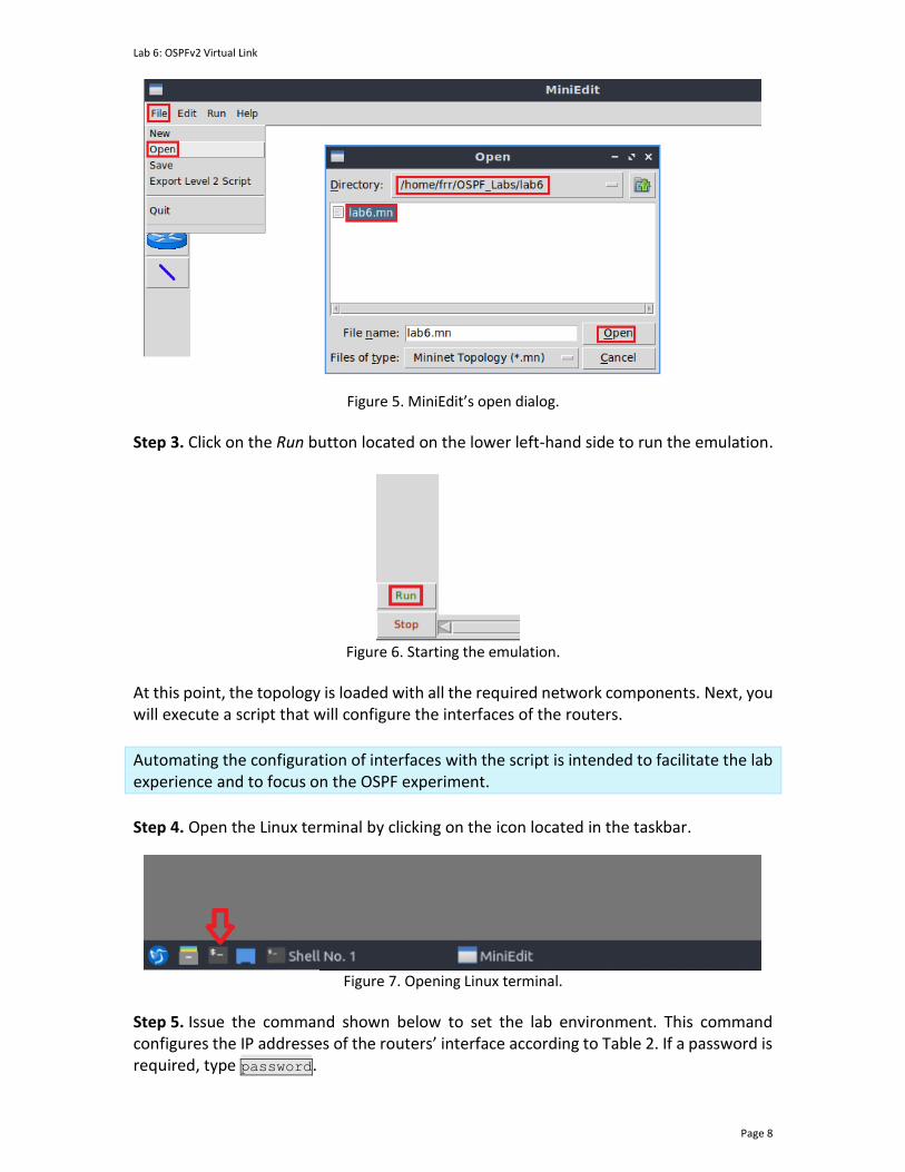
Lab 6: OSPFv2 Virtual Link
Page 8
Figure 5. MiniEdit’s open dialog.
Step 3. Click on the Run button located on the lower left-hand side to run the emulation.
Figure 6. Starting the emulation.
At this point, the topology is loaded with all the required network components. Next, you will execute a script that will configure the interfaces of the routers.
Automating the configuration of interfaces with the script is intended to facilitate the lab experience and to focus on the OSPF experiment.
Step 4. Open the Linux terminal by clicking on the icon located in the taskbar.
Figure 7. Opening Linux terminal.
Step 5. Issue the command shown below to set the lab environment. This command configures the IP addresses of the routers’ interface according to Table 2. If a password is required, type password.
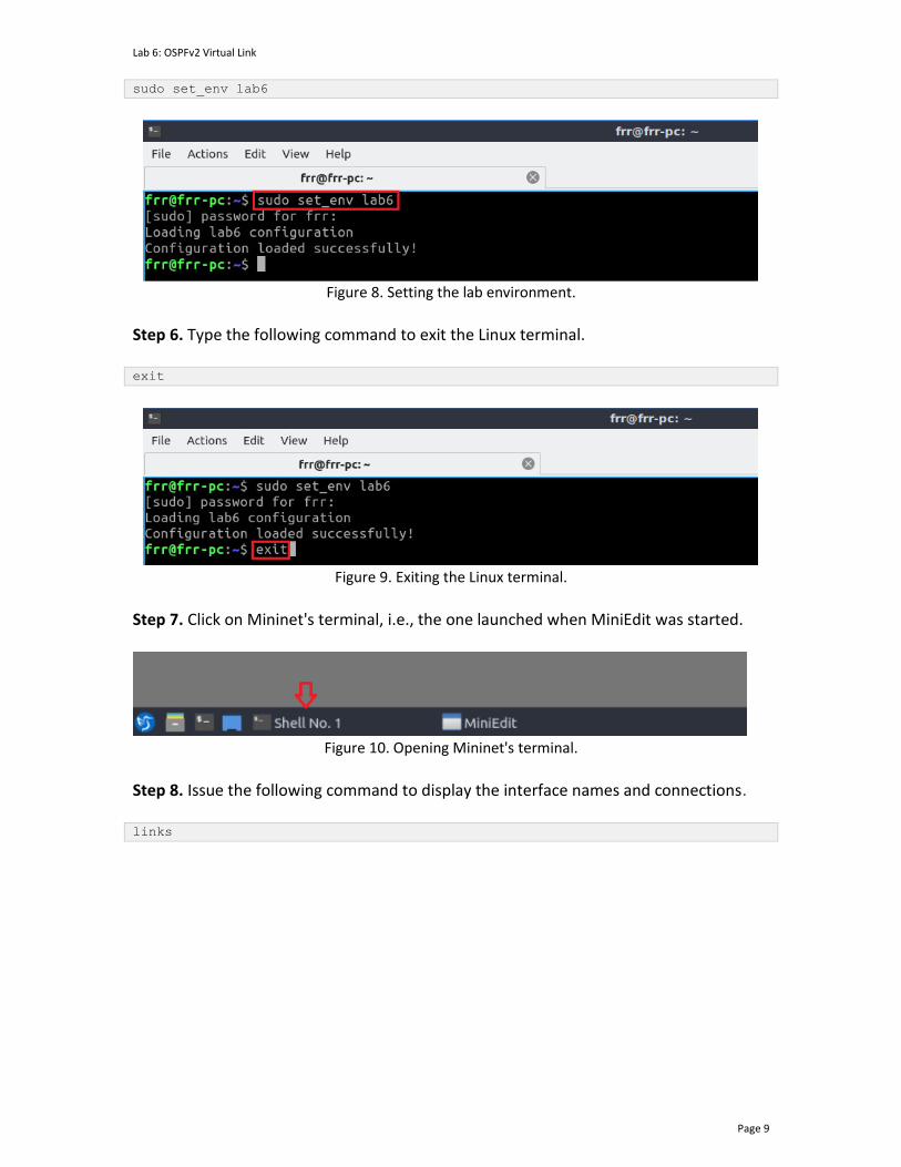
Lab 6: OSPFv2 Virtual Link
Page 9
sudo set_env lab6
Figure 8. Setting the lab environment.
Step 6. Type the following command to exit the Linux terminal. exit
Figure 9. Exiting the Linux terminal.
Step 7. Click on Mininet's terminal, i.e., the one launched when MiniEdit was started.
Figure 10. Opening Mininet's terminal.
Step 8. Issue the following command to display the interface names and connections. links

Lab 6: OSPFv2 Virtual Link
Page 10
Figure 11. Displaying network interfaces.
In the figure above, the link displayed within the gray box indicates that interface eth1 of switch s1 connects to interface eth0 of host h1 (i.e., s1-eth1<->h1-eth0). 2.3 Load the zebra daemon and verify the configuration
In this section, you will verify that the IP addresses listed in Table 2 and inspect the routing table of the routers. Step 1. Hold right-click on host h1 and select Terminal. This opens the terminal of host h1 and allows the execution of commands on that host.
Figure 12. Opening a terminal on host h1.
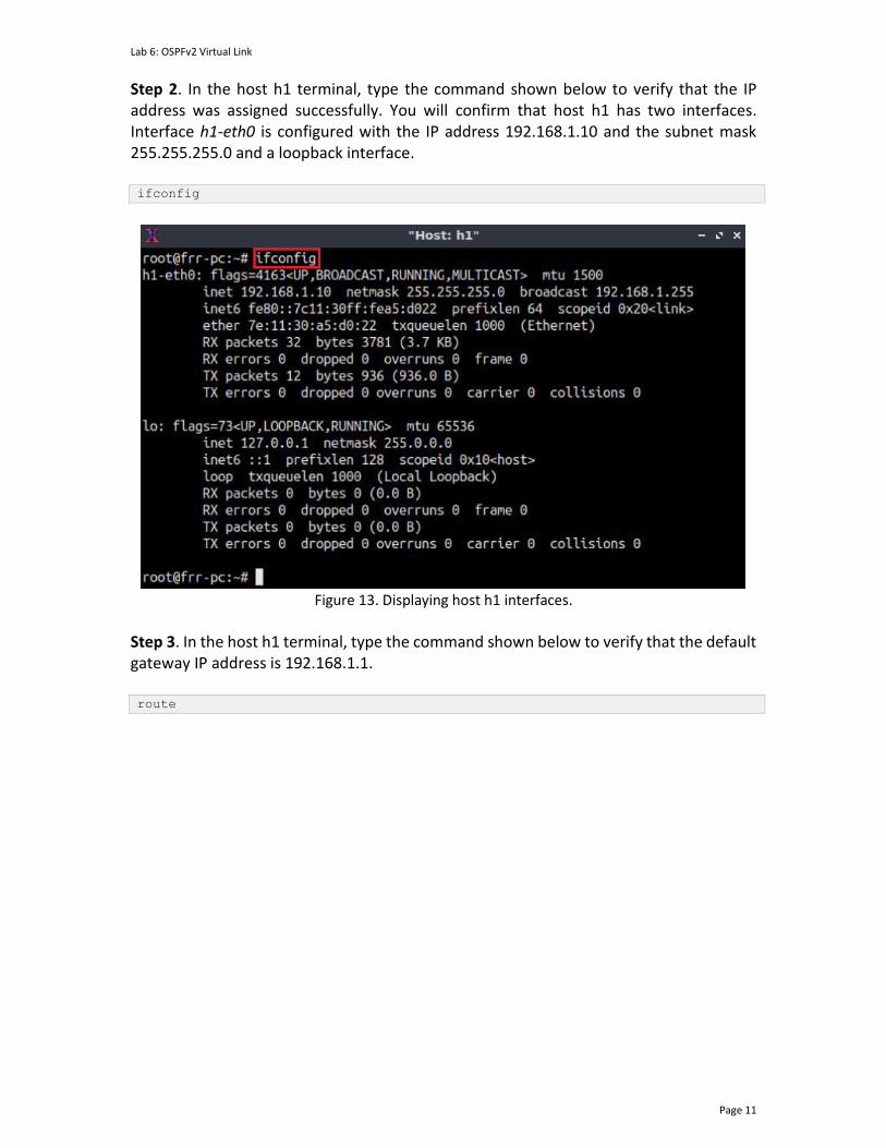
Lab 6: OSPFv2 Virtual Link
Page 11
Step 2. In the host h1 terminal, type the command shown below to verify that the IP address was assigned successfully. You will confirm that host h1 has two interfaces. Interface h1-eth0 is configured with the IP address 192.168.1.10 and the subnet mask 255.255.255.0 and a loopback interface. ifconfig
Figure 13. Displaying host h1 interfaces.
Step 3. In the host h1 terminal, type the command shown below to verify that the default gateway IP address is 192.168.1.1. route

Lab 6: OSPFv2 Virtual Link
Page 12
Figure 14. Displaying host h1 default gateway.
Step 4. To verify the hosts h2 and h3 default route, proceed by repeating from step 1 to step 3. Similar results should be observed. Step 5. You will validate that the router interfaces are configured according to Table 2. To proceed, hold right-click on router r1 and select Terminal.
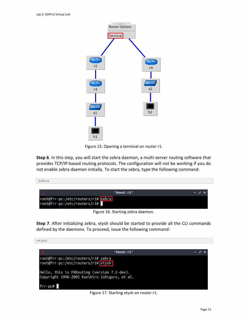
Lab 6: OSPFv2 Virtual Link
Page 13
Figure 15. Opening a terminal on router r1.
Step 6. In this step, you will start the zebra daemon, a multi-server routing software that provides TCP/IP-based routing protocols. The configuration will not be working if you do not enable zebra daemon initially. To start the zebra, type the following command: zebra
Figure 16. Starting zebra daemon.
Step 7. After initializing zebra, vtysh should be started to provide all the CLI commands defined by the daemons. To proceed, issue the following command: vtysh
Figure 17. Starting vtysh on router r1.
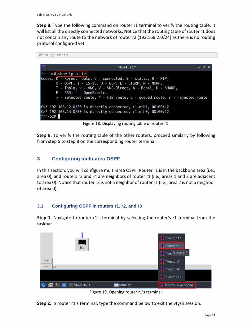
Lab 6: OSPFv2 Virtual Link
Page 14
Step 8. Type the following command on router r1 terminal to verify the routing table. It will list all the directly connected networks. Notice that the routing table of router r1 does not contain any route to the network of router r2 (192.168.2.0/24) as there is no routing protocol configured yet. show ip route
Figure 18. Displaying routing table of router r1.
Step 9. To verify the routing table of the other routers, proceed similarly by following from step 5 to step 8 on the corresponding router terminal.
3 Configuring multi-area OSPF In this section, you will configure multi-area OSPF. Router r1 is in the backbone area (i.e., area 0), and routers r2 and r4 are neighbors of router r1 (i.e., areas 1 and 3 are adjacent to area 0). Notice that router r3 is not a neighbor of router r1 (i.e., area 2 is not a neighbor of area 0). 3.1 Configuring OSPF in routers r1, r2, and r3
Step 1. Navigate to router r1’s terminal by selecting the router’s r1 terminal from the taskbar.
Figure 19. Opening router r1’s terminal.
Step 2. In router r1’s terminal, type the command below to exit the vtysh session.
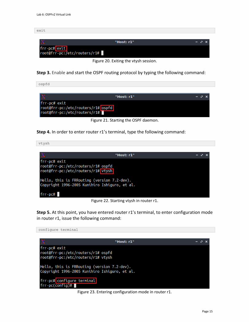
Lab 6: OSPFv2 Virtual Link
Page 15
exit
Figure 20. Exiting the vtysh session.
Step 3. Enable and start the OSPF routing protocol by typing the following command: ospfd
Figure 21. Starting the OSPF daemon.
Step 4. In order to enter router r1’s terminal, type the following command: vtysh
Figure 22. Starting vtysh in router r1.
Step 5. At this point, you have entered router r1’s terminal, to enter configuration mode in router r1, issue the following command: configure terminal
Figure 23. Entering configuration mode in router r1.
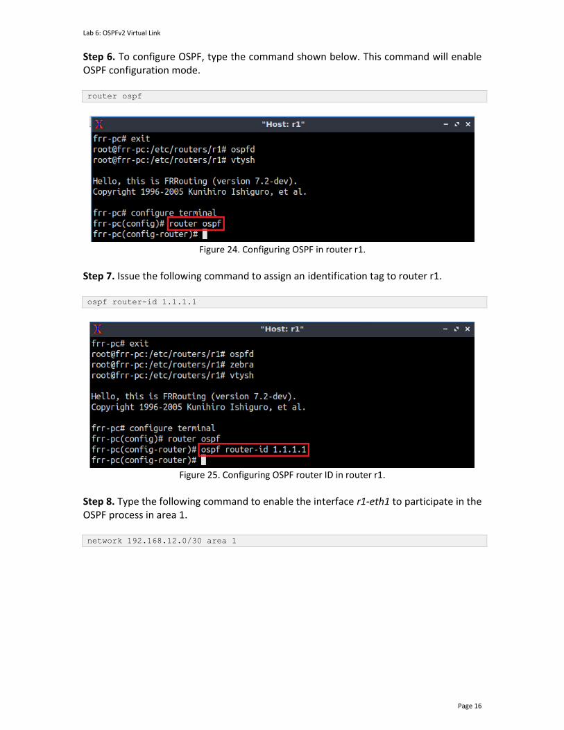
Lab 6: OSPFv2 Virtual Link
Page 16
Step 6. To configure OSPF, type the command shown below. This command will enable OSPF configuration mode. router ospf
Figure 24. Configuring OSPF in router r1.
Step 7. Issue the following command to assign an identification tag to router r1. ospf router-id 1.1.1.1
Figure 25. Configuring OSPF router ID in router r1.
Step 8. Type the following command to enable the interface r1-eth1 to participate in the OSPF process in area 1. network 192.168.12.0/30 area 1
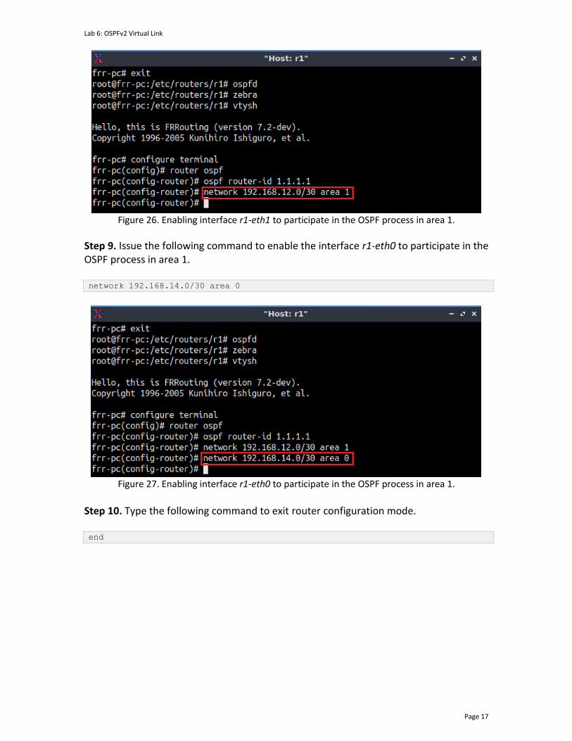
Lab 6: OSPFv2 Virtual Link
Page 17
Figure 26. Enabling interface r1-eth1 to participate in the OSPF process in area 1.
Step 9. Issue the following command to enable the interface r1-eth0 to participate in the OSPF process in area 1. network 192.168.14.0/30 area 0
Figure 27. Enabling interface r1-eth0 to participate in the OSPF process in area 1.
Step 10. Type the following command to exit router configuration mode. end

Lab 6: OSPFv2 Virtual Link
Page 18
Figure 28. Exiting router configuration mode.
Consider the figure above. After configuring OSPF in router r1, the interfaces r1-eth1, and r1-eth0 will participate in the routing process of area 1 and area 0 respectively.
Step 11. Router r2 is configured similarly to router r1 but with different IP addresses (see Table 2). Those steps are summarized in the following figure. To proceed, in router r2 terminal, issue the commands depicted below.
Figure 29. Router r2 configuration summary.
Consider the figure above. After configuring OSPF in router r2, the interfaces r2-eth0, and r2-eth1 will participate in the routing process of area 1. Step 12. Router r3 is configured similarly to router r2 but with different IP addresses (see Table 2). Those steps are summarized in the following figure. To proceed, in router r3 terminal, issue the commands depicted below.
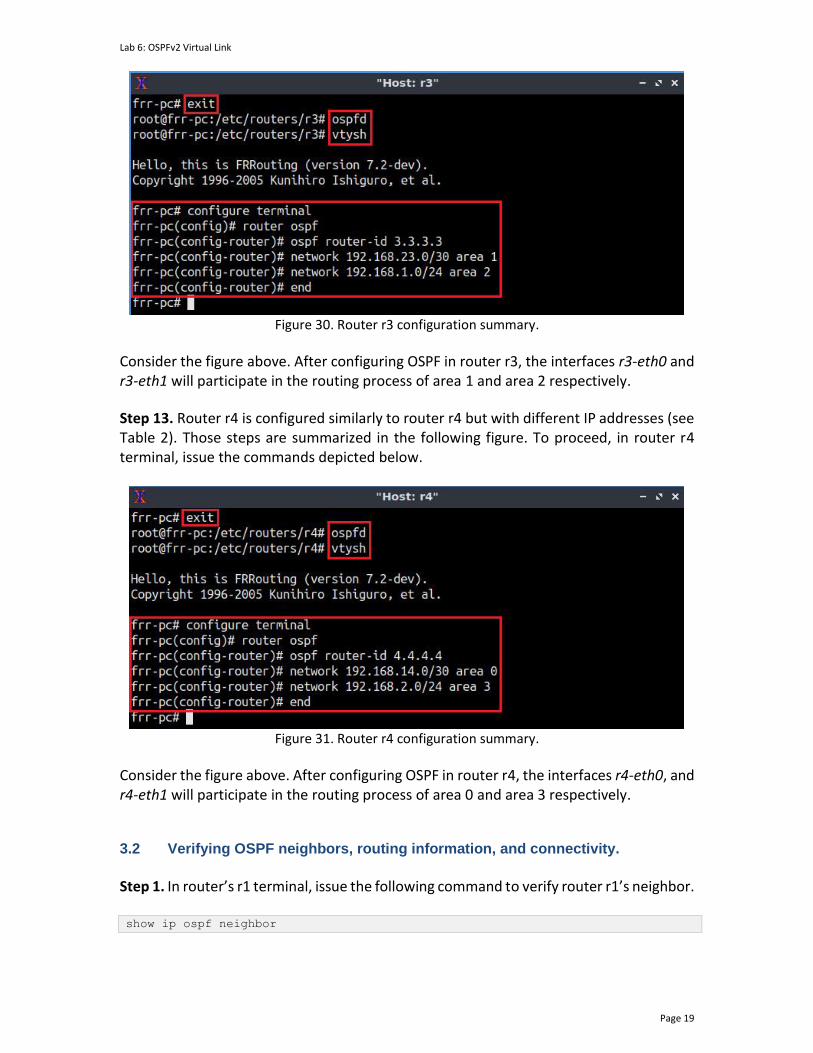
Lab 6: OSPFv2 Virtual Link
Page 19
Figure 30. Router r3 configuration summary.
Consider the figure above. After configuring OSPF in router r3, the interfaces r3-eth0 and r3-eth1 will participate in the routing process of area 1 and area 2 respectively.
Step 13. Router r4 is configured similarly to router r4 but with different IP addresses (see Table 2). Those steps are summarized in the following figure. To proceed, in router r4 terminal, issue the commands depicted below.
Figure 31. Router r4 configuration summary.
Consider the figure above. After configuring OSPF in router r4, the interfaces r4-eth0, and r4-eth1 will participate in the routing process of area 0 and area 3 respectively. 3.2 Verifying OSPF neighbors, routing information, and connectivity.
Step 1. In router’s r1 terminal, issue the following command to verify router r1’s neighbor. show ip ospf neighbor
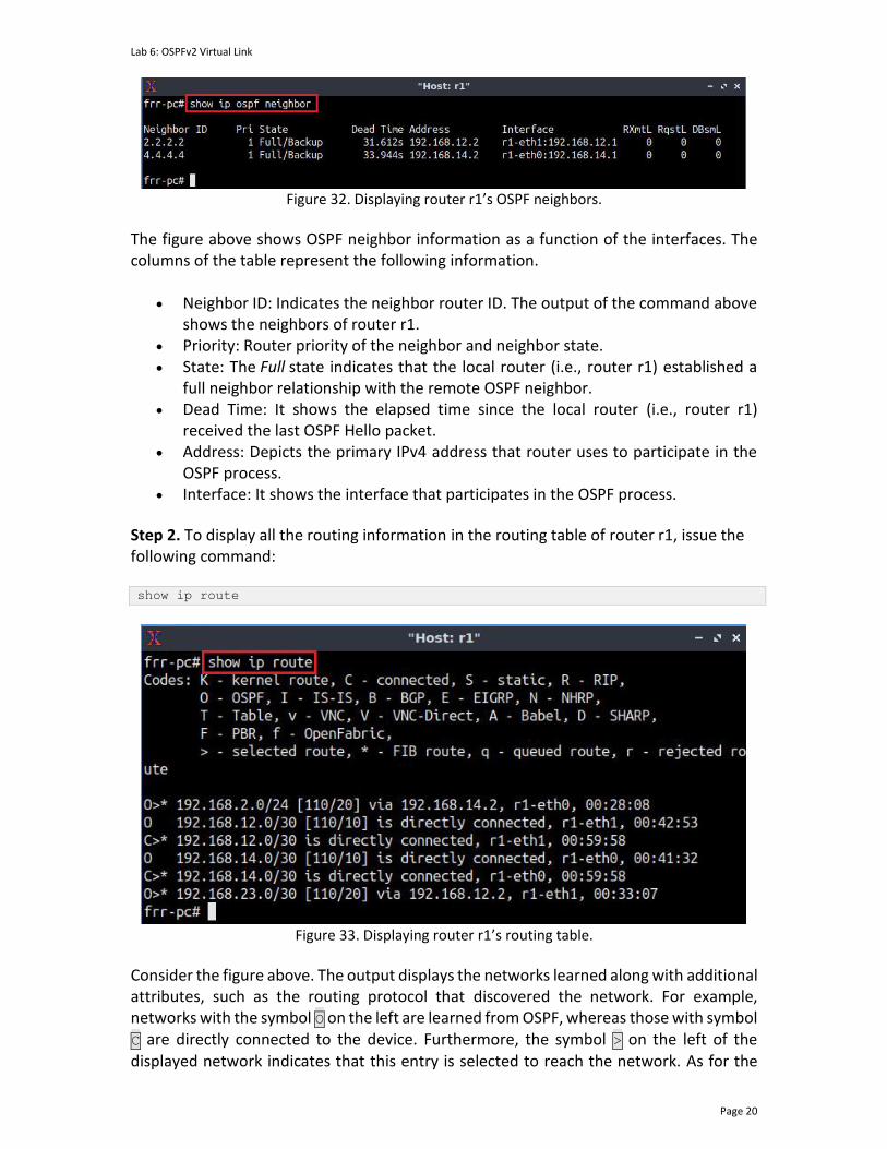
Lab 6: OSPFv2 Virtual Link
Page 20
Figure 32. Displaying router r1’s OSPF neighbors.
The figure above shows OSPF neighbor information as a function of the interfaces. The columns of the table represent the following information.
• Neighbor ID: Indicates the neighbor router ID. The output of the command above shows the neighbors of router r1.
• Priority: Router priority of the neighbor and neighbor state. • State: The Full state indicates that the local router (i.e., router r1) established a
full neighbor relationship with the remote OSPF neighbor. • Dead Time: It shows the elapsed time since the local router (i.e., router r1)
received the last OSPF Hello packet. • Address: Depicts the primary IPv4 address that router uses to participate in the
OSPF process. • Interface: It shows the interface that participates in the OSPF process.
Step 2. To display all the routing information in the routing table of router r1, issue the following command:
show ip route
Figure 33. Displaying router r1’s routing table.
Consider the figure above. The output displays the networks learned along with additional attributes, such as the routing protocol that discovered the network. For example, networks with the symbol O on the left are learned from OSPF, whereas those with symbol C are directly connected to the device. Furthermore, the symbol > on the left of the displayed network indicates that this entry is selected to reach the network. As for the
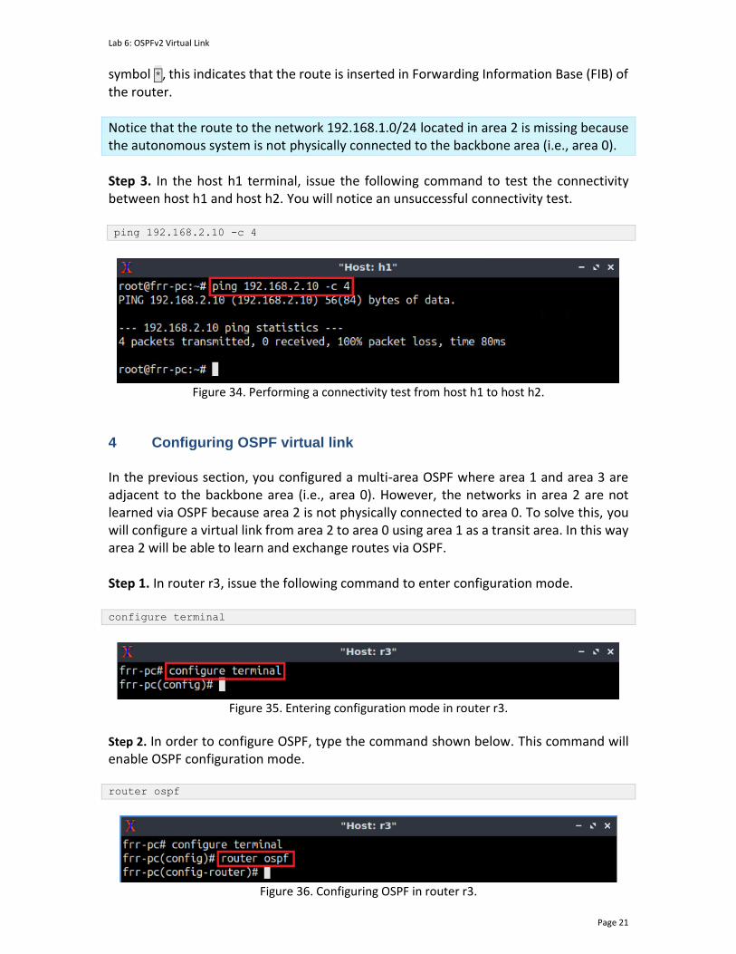
Lab 6: OSPFv2 Virtual Link
Page 21
symbol *, this indicates that the route is inserted in Forwarding Information Base (FIB) of the router.
Notice that the route to the network 192.168.1.0/24 located in area 2 is missing because the autonomous system is not physically connected to the backbone area (i.e., area 0).
Step 3. In the host h1 terminal, issue the following command to test the connectivity between host h1 and host h2. You will notice an unsuccessful connectivity test. ping 192.168.2.10 -c 4
Figure 34. Performing a connectivity test from host h1 to host h2.
4 Configuring OSPF virtual link In the previous section, you configured a multi-area OSPF where area 1 and area 3 are adjacent to the backbone area (i.e., area 0). However, the networks in area 2 are not learned via OSPF because area 2 is not physically connected to area 0. To solve this, you will configure a virtual link from area 2 to area 0 using area 1 as a transit area. In this way area 2 will be able to learn and exchange routes via OSPF. Step 1. In router r3, issue the following command to enter configuration mode. configure terminal
Figure 35. Entering configuration mode in router r3.
Step 2. In order to configure OSPF, type the command shown below. This command will enable OSPF configuration mode. router ospf
Figure 36. Configuring OSPF in router r3.
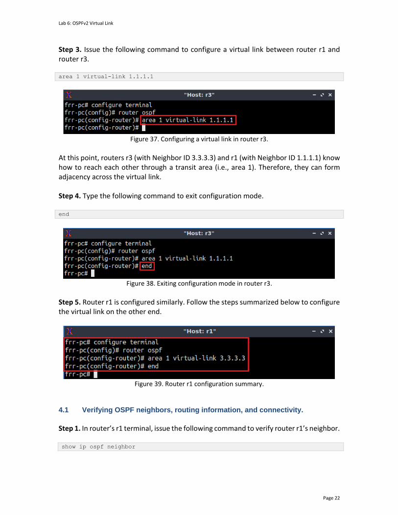
Lab 6: OSPFv2 Virtual Link
Page 22
Step 3. Issue the following command to configure a virtual link between router r1 and router r3. area 1 virtual-link 1.1.1.1
Figure 37. Configuring a virtual link in router r3.
At this point, routers r3 (with Neighbor ID 3.3.3.3) and r1 (with Neighbor ID 1.1.1.1) know how to reach each other through a transit area (i.e., area 1). Therefore, they can form adjacency across the virtual link. Step 4. Type the following command to exit configuration mode. end
Figure 38. Exiting configuration mode in router r3.
Step 5. Router r1 is configured similarly. Follow the steps summarized below to configure the virtual link on the other end.
Figure 39. Router r1 configuration summary.
4.1 Verifying OSPF neighbors, routing information, and connectivity.
Step 1. In router’s r1 terminal, issue the following command to verify router r1’s neighbor. show ip ospf neighbor
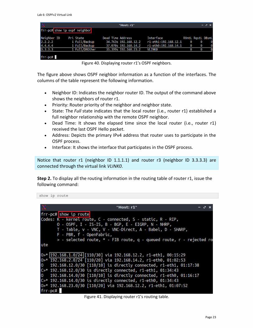
Lab 6: OSPFv2 Virtual Link
Page 23
Figure 40. Displaying router r1’s OSPF neighbors.
The figure above shows OSPF neighbor information as a function of the interfaces. The columns of the table represent the following information.
• Neighbor ID: Indicates the neighbor router ID. The output of the command above shows the neighbors of router r1.
• Priority: Router priority of the neighbor and neighbor state. • State: The Full state indicates that the local router (i.e., router r1) established a
full neighbor relationship with the remote OSPF neighbor. • Dead Time: It shows the elapsed time since the local router (i.e., router r1)
received the last OSPF Hello packet. • Address: Depicts the primary IPv4 address that router uses to participate in the
OSPF process. • Interface: It shows the interface that participates in the OSPF process.
Notice that router r1 (neighbor ID 1.1.1.1) and router r3 (neighbor ID 3.3.3.3) are connected through the virtual link VLINK0.
Step 2. To display all the routing information in the routing table of router r1, issue the following command:
show ip route
Figure 41. Displaying router r1’s routing table.

Lab 6: OSPFv2 Virtual Link
Page 24
Consider the figure above. The output displays the networks learned along with additional attributes, such as the routing protocol that discovered the network. For example, networks with the symbol O on the left are learned from OSPF, whereas those with symbol C are directly connected to the device. Furthermore, the symbol > on the left of the
displayed network indicates that this entry is selected to reach the network. As for the symbol *, this indicates that the route is inserted in Forwarding Information Base (FIB) of
the router.
Notice that the route to the network 192.168.1.0/24 has a next-hop IP 192.168.12.2 which corresponds to router r2.
Step 3. In the host h1 terminal, issue the following command to test the connectivity between host h1 and host h2. ping 192.168.2.10 -c 4
Figure 42. Performing a connectivity test from host h1 to host h2.
The figure above shows a successful connectivity test. This concludes lab 6. Stop the emulation and then exit out of MiniEdit.
References
1. Moy, J. “RFC 1247: OSPF version 2.” 1991. 2. Moy, J. “RFC 2328: OSPF version 2.” 1998. 3. Coltun, R., Ferguson, D., Moy, J., Lindem, A. “RFC 5340, OSPF for IPv6.” 2008. 4. Peterson, L. “Computer networks: a systems approach.” 6th Edition, 2021. 5. Tanenbaum, D. Wetherall. “Computer networks.” 5th Edition. 2012. 6. J. Kurose, K. Ross. “Computer networking, a top-down approach.” 7th Edition.
2017. 7. Teare, D., Vachon, B., Graziani, R. “Implementing Cisco IP routing (ROUTE)
foundation learning guide: (CCNP ROUTE 300-101).” 2014. 8. Linux foundation collaborative projects. “FRR routing documentation.” 2017
[Online] Available: http://docs.frrouting.org/en/latest/.

OPEN SHORTEST PATH FIRST
Exercise 2: Configuring OSPF Virtual Link
Document Version: 10-22-2021
Award 1829698 “CyberTraining CIP: Cyberinfrastructure Expertise on High-throughput
Networks for Big Science Data Transfers”
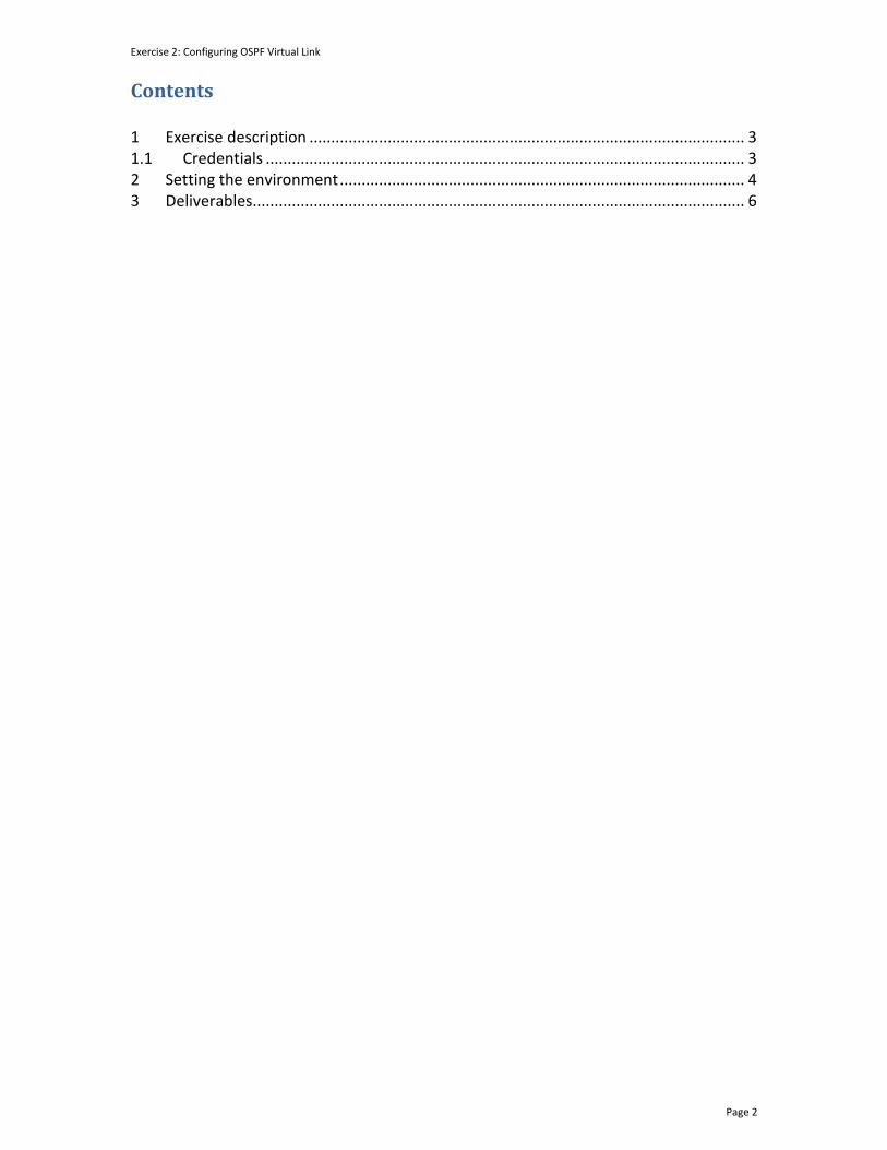
Exercise 2: Configuring OSPF Virtual Link
Page 2
Contents 1 Exercise description .................................................................................................... 3
1.1 Credentials .............................................................................................................. 3
2 Setting the environment ............................................................................................. 4
3 Deliverables ................................................................................................................. 6

Exercise 2: Configuring OSPF Virtual Link
Page 3
1 Exercise description This exercise is a practice to the Open Shortest Path First (OSPF) virtual link. The OSPF protocol requires all the nonbackbone areas to be directly connected to the backbone area (i.e., area 0). In cases, where a direct connection is not possible, a virtual link can be configured. Consider the figure below. Area 2 is not directly connected to the backbone area. In this exercise, you will configure a virtual link between routers r1 and r3 to connect area 2 to the backbone area. Therefore, host h1 can communicate with host h2.
h1
h2
h1-eth0
h2-eth0
.10
.10
s1
s1-eth1
s2-eth1
173.17.1.0/24
173.17.2.0/24 s2
.1
.1
s1-eth2
s2-eth2
r1
r2
r3
r4
r2-eth1
r3-eth0
r3-eth1
r4-eth1
.1
.2 .2
.1
173.17.23.0/30
.2
.1
Area 0
Area 1
Area 2
Area 3
Virtual Link
Figure 1. Exercise topology.
1.1 Credentials The information in Table 1 provides the credentials to access the Client machine.
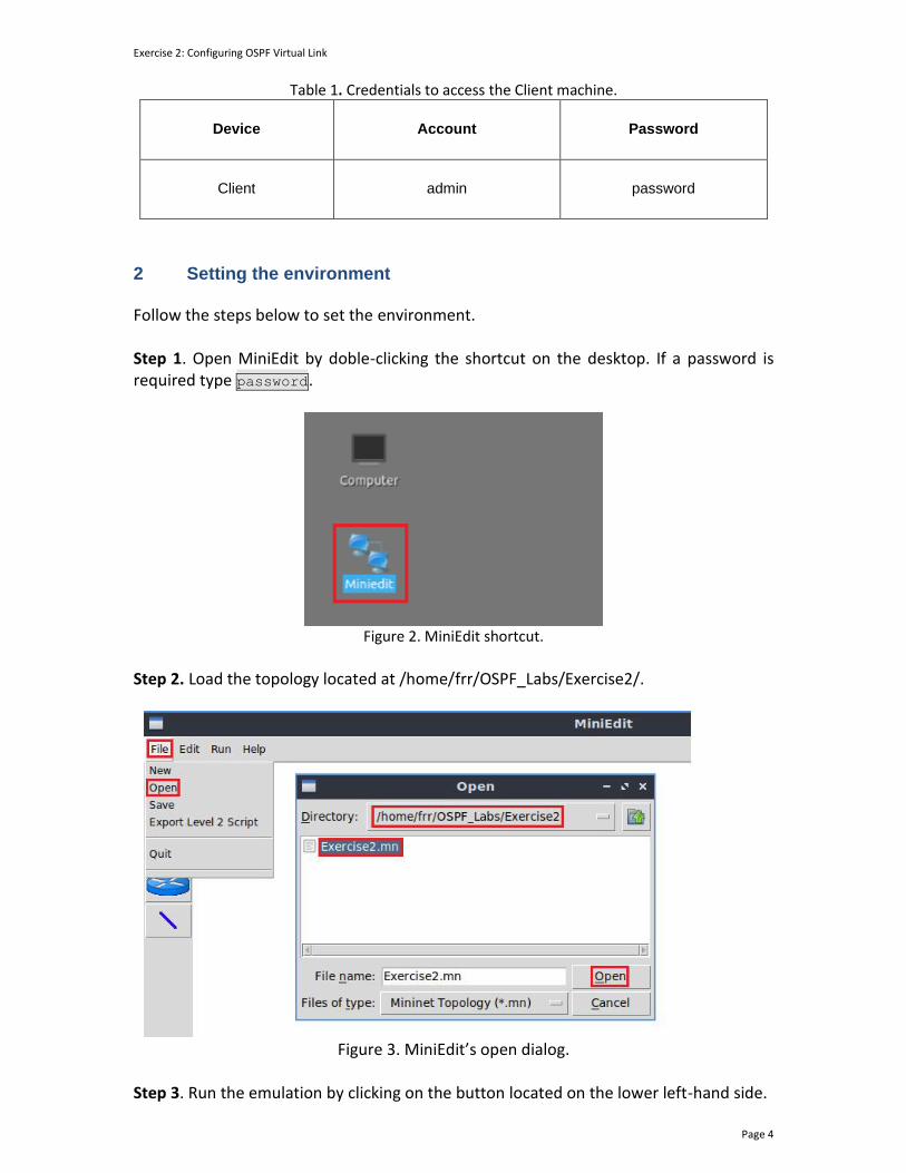
Exercise 2: Configuring OSPF Virtual Link
Page 4
Table 1. Credentials to access the Client machine.
Device
Account
Password
Client admin password
2 Setting the environment Follow the steps below to set the environment. Step 1. Open MiniEdit by doble-clicking the shortcut on the desktop. If a password is required type password.
Figure 2. MiniEdit shortcut.
Step 2. Load the topology located at /home/frr/OSPF_Labs/Exercise2/.
Figure 3. MiniEdit’s open dialog.
Step 3. Run the emulation by clicking on the button located on the lower left-hand side.

Exercise 2: Configuring OSPF Virtual Link
Page 5
Figure 4. Starting the emulation.
Step 4. Open the Linux terminal by clicking on the icon located in the taskbar.
Figure 5. Opening Linux terminal.
Step 5. Issue the command shown below to set the lab environment. This command configures the IP addresses in all routers. If a password is required, type password. sudo set_env exercise2
Figure 6. Setting the lab environment.
Step 6. Type the following command to exit the Linux terminal. exit
Figure 7. Exiting the Linux terminal.
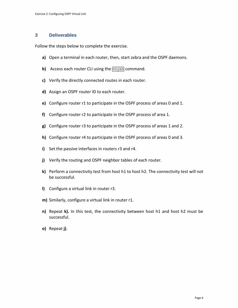
Exercise 2: Configuring OSPF Virtual Link
Page 6
3 Deliverables Follow the steps below to complete the exercise.
a) Open a terminal in each router, then, start zebra and the OSPF daemons. b) Access each router CLI using the vtysh command.
c) Verify the directly connected routes in each router.
d) Assign an OSPF router ID to each router.
e) Configure router r1 to participate in the OSPF process of areas 0 and 1.
f) Configure router r2 to participate in the OSPF process of area 1.
g) Configure router r3 to participate in the OSPF process of areas 1 and 2.
h) Configure router r4 to participate in the OSPF process of areas 0 and 3.
i) Set the passive interfaces in routers r3 and r4.
j) Verify the routing and OSPF neighbor tables of each router.
k) Perform a connectivity test from host h1 to host h2. The connectivity test will not
be successful.
l) Configure a virtual link in router r3.
m) Similarly, configure a virtual link in router r1.
n) Repeat k). In this test, the connectivity between host h1 and host h2 must be successful.
o) Repeat j).

OPEN SHORTEST PATH FIRST
Lab 7: OSPFv2 Authentication
Document Version: 10-22-2021
Award 1829698 “CyberTraining CIP: Cyberinfrastructure Expertise on High-throughput
Networks for Big Science Data Transfers”

Lab 7: OSPFv2 Authentication
Page 2
Contents Overview ............................................................................................................................. 3
Objectives............................................................................................................................ 3
Lab settings ......................................................................................................................... 3
Lab roadmap ....................................................................................................................... 3
1 Introduction ................................................................................................................ 3
1.1 OSPF authentication modes ................................................................................. 4
1.2 OSPF authentication types ................................................................................... 5
2 Lab topology................................................................................................................ 6
2.1 Lab settings........................................................................................................... 7
2.2 Loading the topology............................................................................................ 8
2.3 Load the zebra daemon and verify the configuration ....................................... 10
3 Configuring multi-area OSPF ..................................................................................... 14
3.1 Configuring OSPF in routers r1, r2, and r3 ......................................................... 14
3.2 Verifying OSPF neighbors, routing information, and connectivity .................... 18
4 Configuring OSPF interface-based authentication using simple password .............. 20
4.1 Verifying the configuration ................................................................................ 21
5 Configuring OSPF area-based authentication using MD5 ........................................ 24
5.1 Verifying the configuration ................................................................................ 26
References ........................................................................................................................ 28
Lab 7: OSPFv2 Authentication
Page 3
Overview This lab introduces Open Shortest Path First (OSPF) authentication, which is used to secure the exchange of routing information between neighbor routers. This lab shows how to authenticate OSPF routing information using two modes of authentications: a simple password and a cryptographic algorithm. Moreover, the lab shows and discusses the limitations of the simple password mode and how the cryptographic algorithm mitigates the shortcomings of the former. Objectives By the end of this lab, you should be able to:
1. Understand the importance of routing authentication. 2. Configure multi-area OSPF. 3. Authenticate the exchange of routing information between OSPF participants. 4. Identify the limitations of the OSPF authentication modes.
Lab settings The information in Table 1 provides the credentials to access the Client machine.
Table 1. Credentials to access the Client machine.
Device
Account
Password
Client admin password
Lab roadmap This lab is organized as follows:
1. Section 1: Introduction. 2. Section 2: Lab topology. 3. Section 3: Configuring multi-area OSPF. 4. Section 4: Configuring OSPF interface-based authentication using simple
password. 5. Section 5: Configuring OSPF area-based authentication using MD5.
1 Introduction
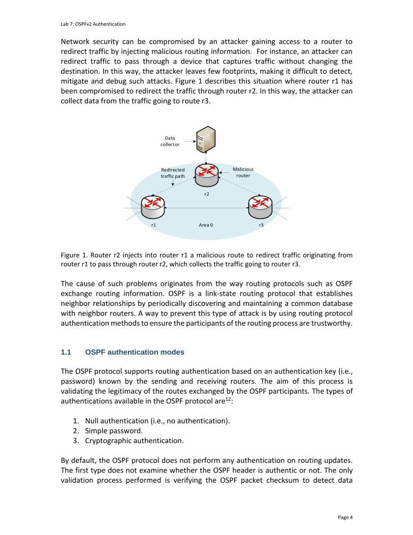
Lab 7: OSPFv2 Authentication
Page 4
Network security can be compromised by an attacker gaining access to a router to redirect traffic by injecting malicious routing information. For instance, an attacker can redirect traffic to pass through a device that captures traffic without changing the destination. In this way, the attacker leaves few footprints, making it difficult to detect, mitigate and debug such attacks. Figure 1 describes this situation where router r1 has been compromised to redirect the traffic through router r2. In this way, the attacker can collect data from the traffic going to route r3.
r1 r3Area 0
r2
Data collector
Malicious router
Redirected traffic path
Figure 1. Router r2 injects into router r1 a malicious route to redirect traffic originating from router r1 to pass through router r2, which collects the traffic going to router r3.
The cause of such problems originates from the way routing protocols such as OSPF exchange routing information. OSPF is a link-state routing protocol that establishes neighbor relationships by periodically discovering and maintaining a common database with neighbor routers. A way to prevent this type of attack is by using routing protocol authentication methods to ensure the participants of the routing process are trustworthy. 1.1 OSPF authentication modes
The OSPF protocol supports routing authentication based on an authentication key (i.e., password) known by the sending and receiving routers. The aim of this process is validating the legitimacy of the routes exchanged by the OSPF participants. The types of authentications available in the OSPF protocol are12:
1. Null authentication (i.e., no authentication). 2. Simple password. 3. Cryptographic authentication.
By default, the OSPF protocol does not perform any authentication on routing updates. The first type does not examine whether the OSPF header is authentic or not. The only validation process performed is verifying the OSPF packet checksum to detect data

Lab 7: OSPFv2 Authentication
Page 5
corruption. The second method consists of setting a password that is exchanged with the neighbors. Using the simple password authentication method prevents malicious routers from inadvertently joining the network. However, this type of encryption is vulnerable to passive attacks, which can be performed by anyone with physical access to the network collecting OSPF packets (e.g., hello packets). The attacker can inspect OSPF packet headers and obtain the secret key which is sent over the network and is the same in each pair of routers. Therefore, the attack described in Figure 1 can be delivered. The OSPF protocol supports the Message Digest 5 (MD5) cryptographic hash algorithm to authenticate and verify the integrity of OSPF packets. The algorithm takes as input a message of arbitrary length to produce a 128-bit output known as message digest of the input. The strength of the algorithm leverage on the computational difficulty of creating two outputs with the same message digest. Additionally, the OSPF protocol includes in the packet header a nondecreasing sequence number to protect against replay attacks. Therefore, using the MD5 cryptographic hash algorithm protects the OSPF participants against reply attacks. 1.2 OSPF authentication types
OSPF supports area-based and interface-based authentication. The area-based authentication applies to packets received by the interfaces pertaining to an OSPF area. On the other hand, interface-based is restricted only to packets received by a specific interface. Moreover, a router participating in the OSPF process can use both simple password and MD5 authentication in different interfaces. Consider Figure 2. Router r2 authenticates router r1 based on the interface using the simple password mode. On the other hand, the authentication between router r2 and router r3 is performed using an area-based authentication using the cryptographic mode (i.e., MD5). Notice that if there is a conflict between the interface-based and area-based mode, the interface-based authentication type takes precedence.

Lab 7: OSPFv2 Authentication
Page 6
h1 h2
s1 s2
r2
r1 r3
Area 1 Area 2
Area 0
Interface-based authentication
Area-based authentication
Figure 2. Router r2 authenticates router r1 based on the interface using the simple password mode. The authentication between router r2 and router r3 is performed using an area-based authentication using the cryptographic mode (i.e., MD5).
2 Lab topology Consider Figure 3. The topology comprises three OSPF areas, where area 0 is the backbone area and areas 1 and 2 are physically connected. You will configure a multi-area OSPF. Then, you will configure OSPF authentication using a simple password between router r1 and router r2 based on their interfaces. On the other hand, the authentication between router r2 and router r3 will be performed using the cryptographic authentication method based on the OSPF participants' area.
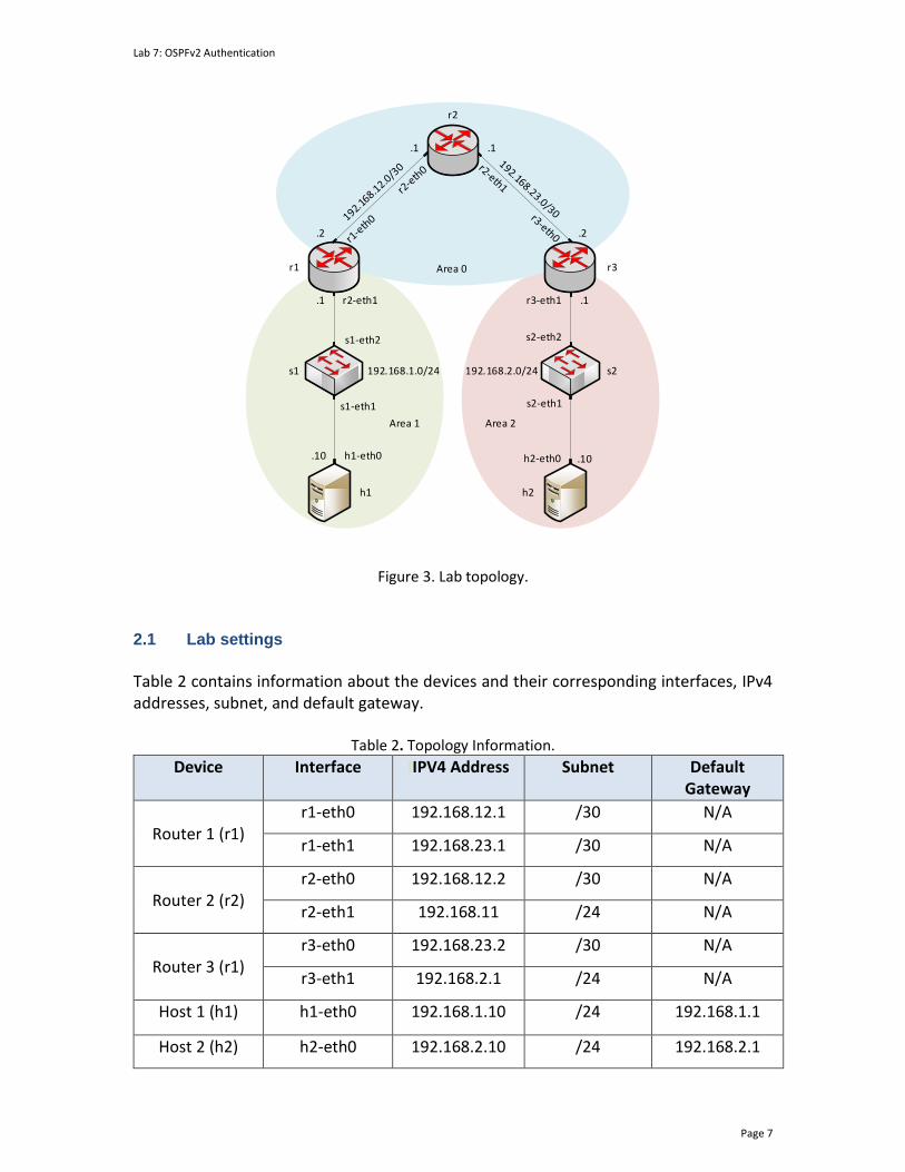
Lab 7: OSPFv2 Authentication
Page 7
h1 h2
h1-eth0 h2-eth0.10 .10
s1
s1-eth1 s2-eth1
192.168.1.0/24 192.168.2.0/24 s2
.1
s1-eth2 s2-eth2
r2
r1 r3
r2-eth1 r3-eth1
.1
.2 .2
.1
.1
Area 1 Area 2
Area 0
Figure 3. Lab topology.
2.1 Lab settings
Table 2 contains information about the devices and their corresponding interfaces, IPv4 addresses, subnet, and default gateway.
Table 2. Topology Information.
Device Interface IIPV4 Address Subnet Default Gateway
Router 1 (r1)
r1-eth0 192.168.12.1 /30 N/A
r1-eth1 192.168.23.1 /30 N/A
Router 2 (r2)
r2-eth0 192.168.12.2 /30 N/A
r2-eth1 192.168.11 /24 N/A
Router 3 (r1)
r3-eth0 192.168.23.2 /30 N/A
r3-eth1 192.168.2.1 /24 N/A
Host 1 (h1) h1-eth0 192.168.1.10 /24 192.168.1.1
Host 2 (h2) h2-eth0 192.168.2.10 /24 192.168.2.1
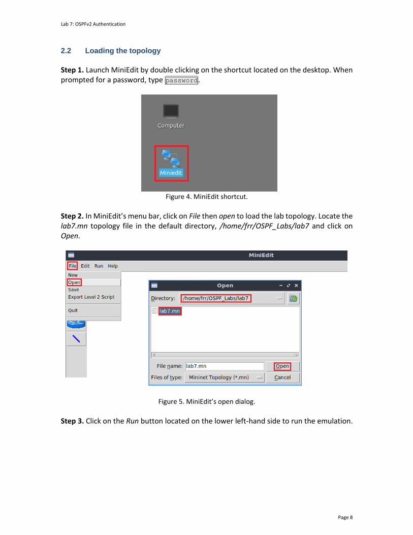
Lab 7: OSPFv2 Authentication
Page 8
2.2 Loading the topology
Step 1. Launch MiniEdit by double clicking on the shortcut located on the desktop. When prompted for a password, type password.
Figure 4. MiniEdit shortcut.
Step 2. In MiniEdit’s menu bar, click on File then open to load the lab topology. Locate the lab7.mn topology file in the default directory, /home/frr/OSPF_Labs/lab7 and click on Open.
Figure 5. MiniEdit’s open dialog.
Step 3. Click on the Run button located on the lower left-hand side to run the emulation.

Lab 7: OSPFv2 Authentication
Page 9
Figure 6. Starting the emulation.
At this point, the topology is loaded with all the required network components. Next, you will execute a script that will configure the interfaces of the routers.
Automating the configuration of interfaces with the script is intended to facilitate the lab experience and to focus on the OSPF experiment.
Step 4. Open the Linux terminal by clicking on the icon located in the taskbar.
Figure 7. Opening Linux terminal.
Step 5. Issue the command shown below to set the lab environment. This command configures the IP addresses of the routers’ interface according to Table 2. If a password is required, type password. sudo set_env exercise1
Figure 8. Setting the lab environment.
Step 6. Type the following command to exit the Linux terminal. exit

Lab 7: OSPFv2 Authentication
Page 10
Figure 9. Exiting the Linux terminal.
Step 7. Click on Mininet's terminal, i.e., the one launched when MiniEdit was started.
Figure 10. Opening Mininet's terminal.
Step 8. Issue the following command to display the interface names and connections. links
Figure 11. Displaying network interfaces.
In the figure above, the link displayed within the gray box indicates that interface eth2 of switch s2 connects to interface eth0 of host h1 (i.e., s2-eth2<->h1-eth0). 2.3 Load the zebra daemon and verify the configuration
In this section, you will verify that the IP addresses listed in Table 2 and inspect the routing table of the routers. Step 1. Hold right-click on host h1 and select Terminal. This opens the terminal of host h1 and allows the execution of commands on that host.
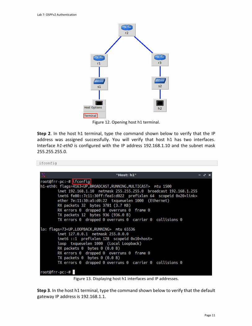
Lab 7: OSPFv2 Authentication
Page 11
Figure 12. Opening host h1 terminal.
Step 2. In the host h1 terminal, type the command shown below to verify that the IP address was assigned successfully. You will verify that host h1 has two interfaces. Interface h1-eth0 is configured with the IP address 192.168.1.10 and the subnet mask 255.255.255.0. ifconfig
Figure 13. Displaying host h1 interfaces and IP addresses.
Step 3. In the host h1 terminal, type the command shown below to verify that the default gateway IP address is 192.168.1.1.

Lab 7: OSPFv2 Authentication
Page 12
route
Figure 14. Displaying host h1 default route.
Step 4. To verify the hosts h2 and h3 default route, proceed by following from step 1 to step 3. Similar results should be observed. Step 5. You will validate that the router interfaces are configured according to Table 2. To proceed, hold right-click on router r1 and select Terminal.
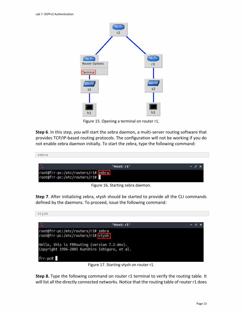
Lab 7: OSPFv2 Authentication
Page 13
Figure 15. Opening a terminal on router r1.
Step 6. In this step, you will start the zebra daemon, a multi-server routing software that provides TCP/IP-based routing protocols. The configuration will not be working if you do not enable zebra daemon initially. To start the zebra, type the following command: zebra
Figure 16. Starting zebra daemon.
Step 7. After initializing zebra, vtysh should be started to provide all the CLI commands defined by the daemons. To proceed, issue the following command: vtysh
Figure 17. Starting vtysh on router r1.
Step 8. Type the following command on router r1 terminal to verify the routing table. It will list all the directly connected networks. Notice that the routing table of router r1 does
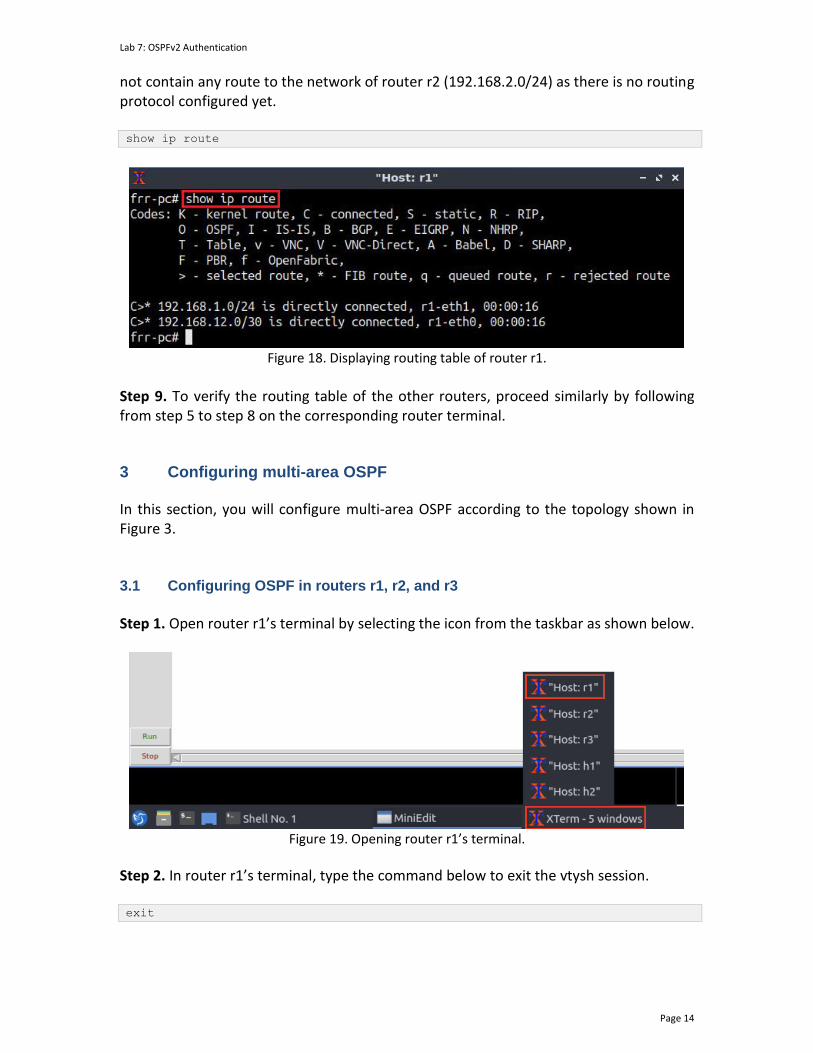
Lab 7: OSPFv2 Authentication
Page 14
not contain any route to the network of router r2 (192.168.2.0/24) as there is no routing protocol configured yet. show ip route
Figure 18. Displaying routing table of router r1.
Step 9. To verify the routing table of the other routers, proceed similarly by following from step 5 to step 8 on the corresponding router terminal.
3 Configuring multi-area OSPF In this section, you will configure multi-area OSPF according to the topology shown in Figure 3. 3.1 Configuring OSPF in routers r1, r2, and r3
Step 1. Open router r1’s terminal by selecting the icon from the taskbar as shown below.
Figure 19. Opening router r1’s terminal.
Step 2. In router r1’s terminal, type the command below to exit the vtysh session. exit

Lab 7: OSPFv2 Authentication
Page 15
Figure 20. Exiting the vtysh session.
Step 3. Enable and start the OSPF routing protocol by typing the following command: ospfd
Figure 21. Starting the OSPF daemon.
Step 4. To enter router r1’s terminal, type the following command: vtysh
Figure 22. Starting vtysh in router r1.
Step 5. At this point, you have entered router r1’s terminal, to enter configuration mode in router r1, issue the following command: configure terminal
Figure 23. Entering configuration mode in router r1.
Step 6. To configure OSPF type the command shown below. This command will enable OSPF configuration mode.
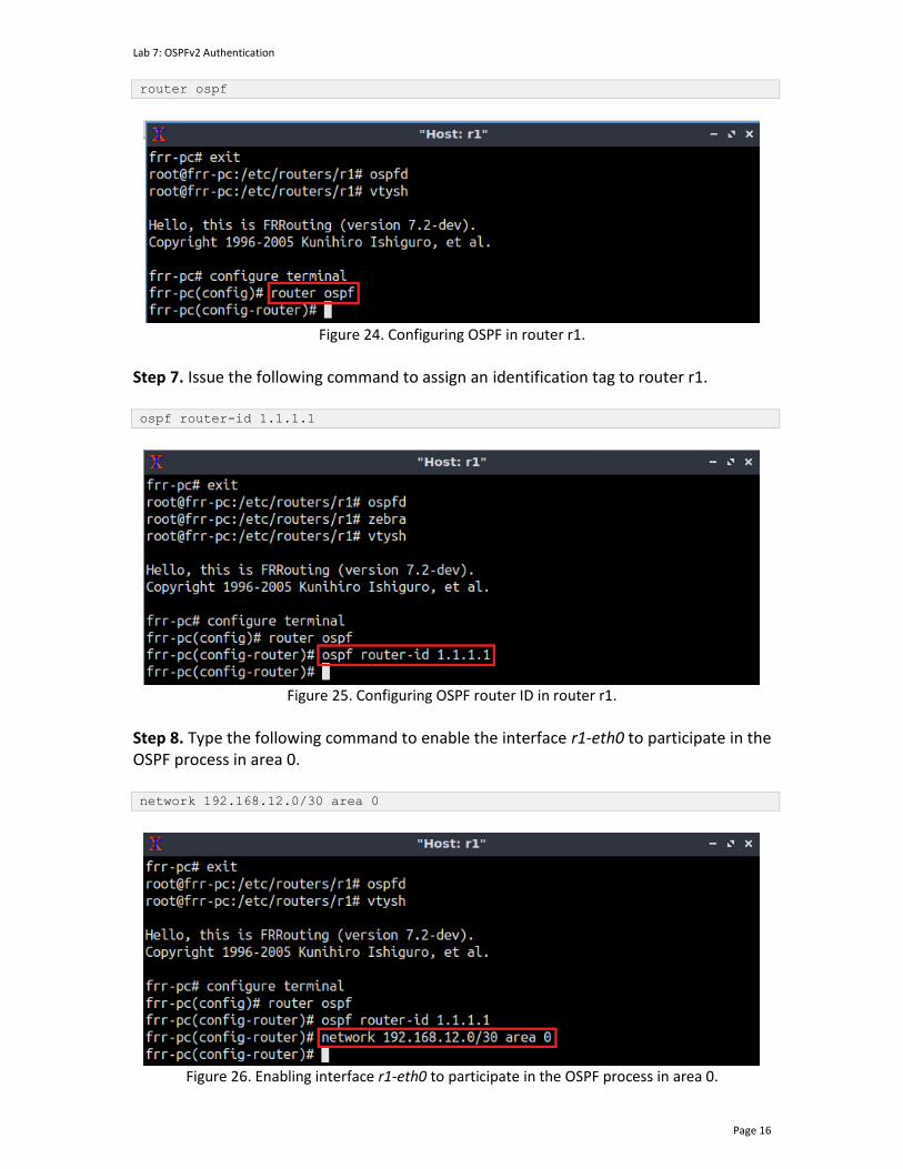
Lab 7: OSPFv2 Authentication
Page 16
router ospf
Figure 24. Configuring OSPF in router r1.
Step 7. Issue the following command to assign an identification tag to router r1. ospf router-id 1.1.1.1
Figure 25. Configuring OSPF router ID in router r1.
Step 8. Type the following command to enable the interface r1-eth0 to participate in the OSPF process in area 0. network 192.168.12.0/30 area 0
Figure 26. Enabling interface r1-eth0 to participate in the OSPF process in area 0.
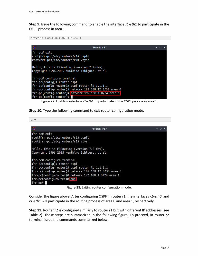
Lab 7: OSPFv2 Authentication
Page 17
Step 9. Issue the following command to enable the interface r1-eth1 to participate in the OSPF process in area 1. network 192.168.1.0/24 area 1
Figure 27. Enabling interface r1-eth1 to participate in the OSPF process in area 1.
Step 10. Type the following command to exit router configuration mode. end
Figure 28. Exiting router configuration mode.
Consider the figure above. After configuring OSPF in router r1, the interfaces r1-eth0, and r1-eth1 will participate in the routing process of area 0 and area 1, respectively.
Step 11. Router r2 is configured similarly to router r1 but with different IP addresses (see Table 2). Those steps are summarized in the following figure. To proceed, in router r2 terminal, issue the commands summarized below.

Lab 7: OSPFv2 Authentication
Page 18
Figure 29. Router r2 configuration summary.
Consider the figure above. After configuring OSPF in router r2, the interfaces r2-eth0, and r2-eth1 will participate in the routing process of area 0. Step 12. Router r3 is configured similarly to router r2 but with different IP addresses (see Table 2). Those steps are summarized in the following figure. To proceed, in router r3 terminal, issue the commands depicted below.
Figure 30. Router r3 configuration summary.
Consider the figure above. After configuring OSPF in router r3, the interfaces r3-eth0 and r3-eth1 will participate in the routing process of area 0 and area 2, respectively. 3.2 Verifying OSPF neighbors, routing information, and connectivity
Step 1. In router’s r2 terminal, issue the following command to verify its neighbors. show ip ospf neighbor

Lab 7: OSPFv2 Authentication
Page 19
Figure 31. Displaying router r2’s OSPF neighbors.
The figure above shows OSPF neighbor information as a function of the interfaces. The columns of the table represent the following information.
• Neighbor ID: Indicates the neighbor router ID. The output of the command above shows the neighbors of router r2.
• Priority: Router priority of the neighbor and neighbor state. • State: The Full state indicates that the local router (i.e., router r2) established a
full neighbor relationship with the remote OSPF neighbor. • Dead Time: It shows the elapsed time since the local router (i.e., router r2)
received the last OSPF hello packet. • Address: Depicts the primary IPv4 address that router uses to participate in the
OSPF process. • Interface: It shows the interface that participates in the OSPF process.
Step 2. To display the routing table of router r2, issue the following command:
show ip route
Figure 32. Displaying router r2’s routing table.
Consider the above figure. The output displays the networks learned along with additional attributes, such as the routing protocol that discovered the network. For example, networks with the symbol O on the left are learned from OSPF, whereas those with symbol C are directly connected to the device. Furthermore, the symbol > on the left of the displayed network indicates that this entry is selected to reach the network. As for the
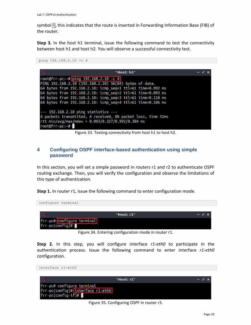
Lab 7: OSPFv2 Authentication
Page 20
symbol *, this indicates that the route is inserted in Forwarding Information Base (FIB) of the router.
Step 3. In the host h1 terminal, issue the following command to test the connectivity between host h1 and host h2. You will observe a successful connectivity test. ping 192.168.2.10 -c 4
Figure 33. Testing connectivity from host h1 to host h2.
4 Configuring OSPF interface-based authentication using simple
password In this section, you will set a simple password in routers r1 and r2 to authenticate OSPF routing exchange. Then, you will verify the configuration and observe the limitations of this type of authentication. Step 1. In router r1, issue the following command to enter configuration mode. configure terminal
Figure 34. Entering configuration mode in router r1.
Step 2. In this step, you will configure interface r1-eth0 to participate in the authentication process. Issue the following command to enter interface r1-eth0 configuration. interface r1-eth0
Figure 35. Configuring OSPF in router r3.
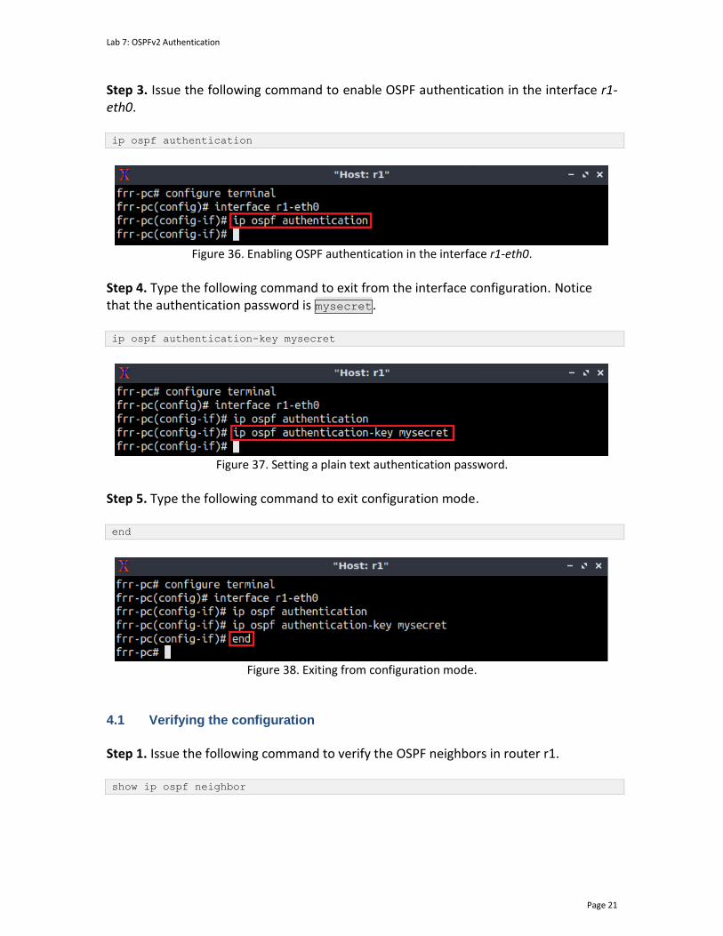
Lab 7: OSPFv2 Authentication
Page 21
Step 3. Issue the following command to enable OSPF authentication in the interface r1-eth0. ip ospf authentication
Figure 36. Enabling OSPF authentication in the interface r1-eth0.
Step 4. Type the following command to exit from the interface configuration. Notice that the authentication password is mysecret. ip ospf authentication-key mysecret
Figure 37. Setting a plain text authentication password.
Step 5. Type the following command to exit configuration mode. end
Figure 38. Exiting from configuration mode.
4.1 Verifying the configuration
Step 1. Issue the following command to verify the OSPF neighbors in router r1. show ip ospf neighbor

Lab 7: OSPFv2 Authentication
Page 22
Figure 39. Displaying OSPF neighbors.
The figure above shows an empty OSPF neighbor table in router r1. This result shows that router r1 cannot accept routing information from a peer (i.e., router r2 with neighbor ID 2.2.2.2) that is not authenticated. Similar result is observed in the OSPF neighbor table of router r2, where the routing information of router r1 (with a neighbor ID 1.1.1.1) is also missing.
Notice that it takes around 40 seconds to refresh the OSPF neighbor table.
Step 2. To allow routers r1 and r2 exchanging routing information, proceed by issuing the commands summarized in the figure below.
Figure 40. Router r2 configuration summary.
Notice that the passwords must be the same in router r1 and router r2 so that they can exchange routing information.
Step 3. Go back to router r1 terminal and issue the command below. show ip ospf neighbor
Figure 41. Displaying OSPF neighbors.
In the figure above you will observe that router r2 appears now as a neighbor of router r1. This result indicates that routers r1 and r2 can now exchange authenticated routing information. Step 4. Perform a connectivity test by issuing the following command. The result will show a successful connectivity test. ping 192.168.2.10 -c 4
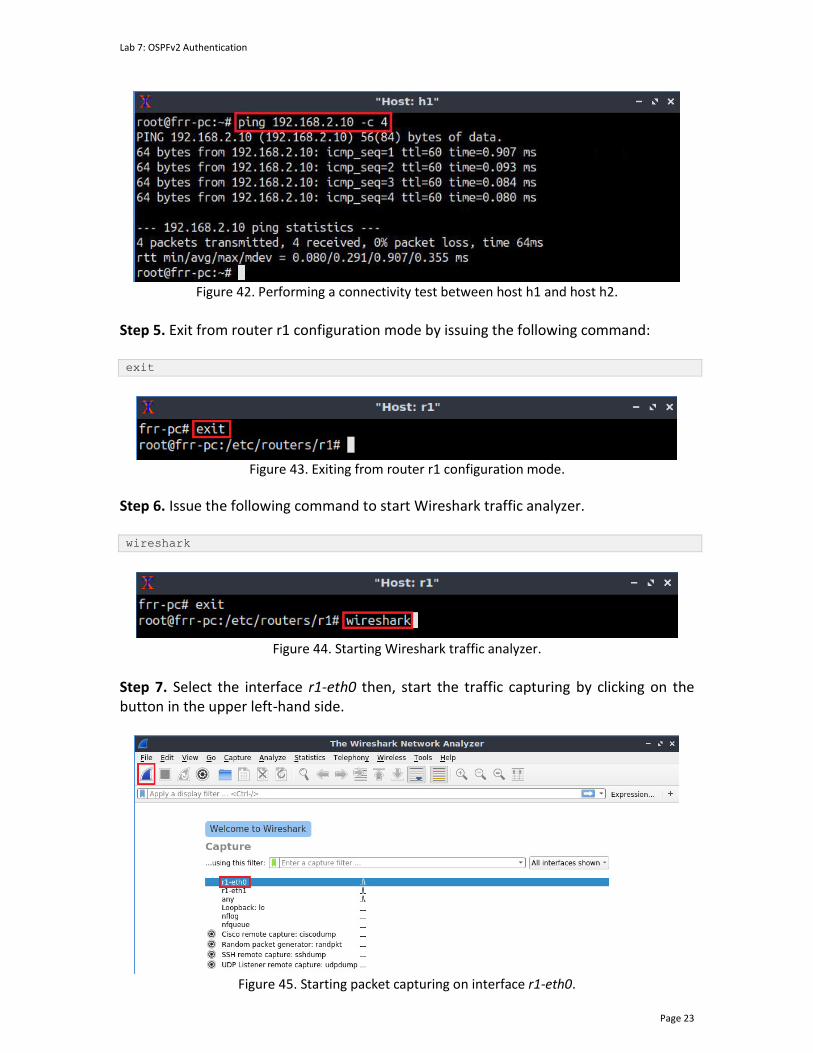
Lab 7: OSPFv2 Authentication
Page 23
Figure 42. Performing a connectivity test between host h1 and host h2.
Step 5. Exit from router r1 configuration mode by issuing the following command: exit
Figure 43. Exiting from router r1 configuration mode.
Step 6. Issue the following command to start Wireshark traffic analyzer. wireshark
Figure 44. Starting Wireshark traffic analyzer.
Step 7. Select the interface r1-eth0 then, start the traffic capturing by clicking on the button in the upper left-hand side.
Figure 45. Starting packet capturing on interface r1-eth0.
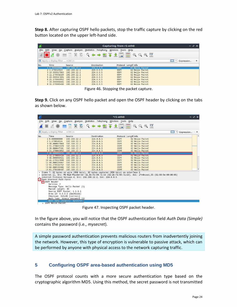
Lab 7: OSPFv2 Authentication
Page 24
Step 8. After capturing OSPF hello packets, stop the traffic capture by clicking on the red button located on the upper left-hand side.
Figure 46. Stopping the packet capture.
Step 9. Click on any OSPF hello packet and open the OSPF header by clicking on the tabs as shown below.
Figure 47. Inspecting OSPF packet header.
In the figure above, you will notice that the OSPF authentication field Auth Data (Simple) contains the password (i.e., mysecret).
A simple password authentication prevents malicious routers from inadvertently joining the network. However, this type of encryption is vulnerable to passive attack, which can be performed by anyone with physical access to the network capturing traffic.
5 Configuring OSPF area-based authentication using MD5 The OSPF protocol counts with a more secure authentication type based on the cryptographic algorithm MD5. Using this method, the secret password is not transmitted
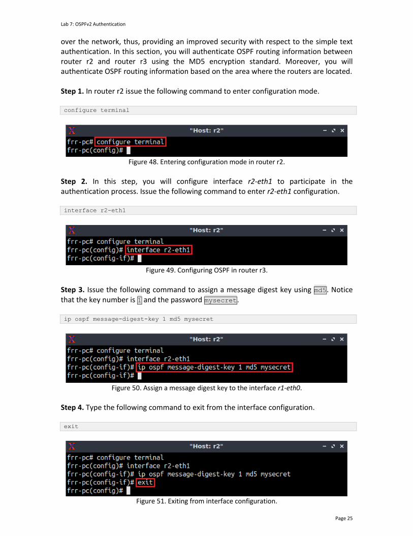
Lab 7: OSPFv2 Authentication
Page 25
over the network, thus, providing an improved security with respect to the simple text authentication. In this section, you will authenticate OSPF routing information between router r2 and router r3 using the MD5 encryption standard. Moreover, you will authenticate OSPF routing information based on the area where the routers are located. Step 1. In router r2 issue the following command to enter configuration mode. configure terminal
Figure 48. Entering configuration mode in router r2.
Step 2. In this step, you will configure interface r2-eth1 to participate in the authentication process. Issue the following command to enter r2-eth1 configuration. interface r2-eth1
Figure 49. Configuring OSPF in router r3.
Step 3. Issue the following command to assign a message digest key using md5. Notice that the key number is 1 and the password mysecret.
ip ospf message-digest-key 1 md5 mysecret
Figure 50. Assign a message digest key to the interface r1-eth0.
Step 4. Type the following command to exit from the interface configuration. exit
Figure 51. Exiting from interface configuration.
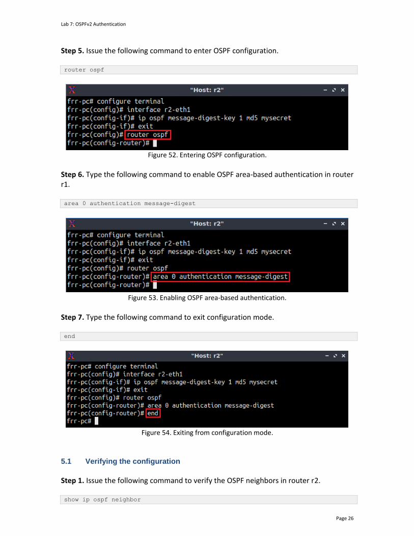
Lab 7: OSPFv2 Authentication
Page 26
Step 5. Issue the following command to enter OSPF configuration. router ospf
Figure 52. Entering OSPF configuration.
Step 6. Type the following command to enable OSPF area-based authentication in router r1. area 0 authentication message-digest
Figure 53. Enabling OSPF area-based authentication.
Step 7. Type the following command to exit configuration mode. end
Figure 54. Exiting from configuration mode.
5.1 Verifying the configuration
Step 1. Issue the following command to verify the OSPF neighbors in router r2. show ip ospf neighbor

Lab 7: OSPFv2 Authentication
Page 27
Figure 55. Displaying OSPF neighbors.
The figure above shows that router r2 cannot accept routing information from a peer (i.e., router r3 with neighbor ID 3.3.3.3) that is not authenticated. A similar result is observed in the OSPF neighbor table of router r3, where the routing information of router r2 (with a neighbor ID 2.2.2.2) is also missing.
Notice that it takes around 40 seconds to refresh the OSPF neighbor table.
Step 2. In router r3, proceed by issuing the commands summarized in the table below to allow routers r2 and r3 exchanging routing information.
Figure 56. Router r3 configuration summary.
Step 3. In router r3 terminal, issue the command below. show ip ospf neighbor
Figure 57. Displaying OSPF neighbors.
In the figure above you will observe that router r2 appears now as a neighbor of router r3. This result means routers r2 and r3 can now exchange routing information. Step 4. Perform a connectivity test by issuing the following command. The result will show a successful connectivity test. ping 192.168.2.10 -c 4
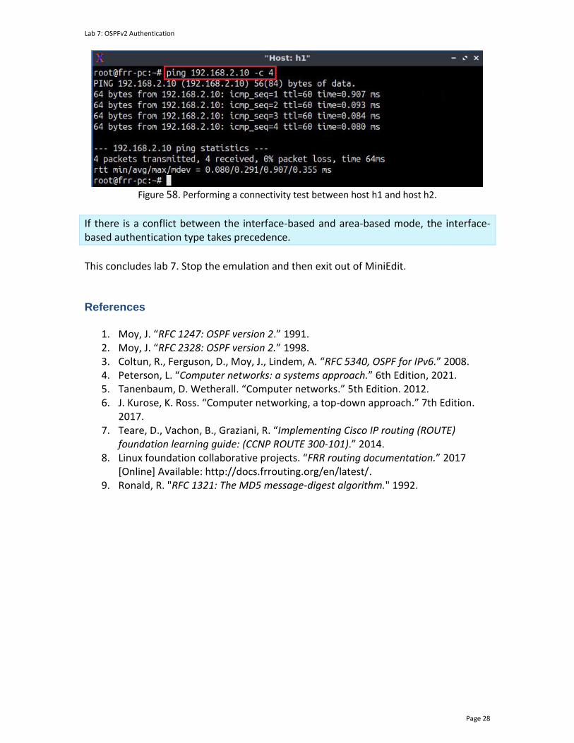
Lab 7: OSPFv2 Authentication
Page 28
Figure 58. Performing a connectivity test between host h1 and host h2.
If there is a conflict between the interface-based and area-based mode, the interface-based authentication type takes precedence.
This concludes lab 7. Stop the emulation and then exit out of MiniEdit. References
1. Moy, J. “RFC 1247: OSPF version 2.” 1991. 2. Moy, J. “RFC 2328: OSPF version 2.” 1998. 3. Coltun, R., Ferguson, D., Moy, J., Lindem, A. “RFC 5340, OSPF for IPv6.” 2008. 4. Peterson, L. “Computer networks: a systems approach.” 6th Edition, 2021. 5. Tanenbaum, D. Wetherall. “Computer networks.” 5th Edition. 2012. 6. J. Kurose, K. Ross. “Computer networking, a top-down approach.” 7th Edition.
2017. 7. Teare, D., Vachon, B., Graziani, R. “Implementing Cisco IP routing (ROUTE)
foundation learning guide: (CCNP ROUTE 300-101).” 2014. 8. Linux foundation collaborative projects. “FRR routing documentation.” 2017
[Online] Available: http://docs.frrouting.org/en/latest/. 9. Ronald, R. "RFC 1321: The MD5 message-digest algorithm." 1992.
OPEN SHORTEST PATH FIRST
Lab 8: Setting OSPFv2 Bandwidth and Costs
Document Version: 10-22-2021
Award 1829698 “CyberTraining CIP: Cyberinfrastructure Expertise on High-throughput
Networks for Big Science Data Transfers”
Lab 8: Setting OSPFv2 Bandwidth and Costs
Page 2
Contents Overview ............................................................................................................................. 3
Objectives............................................................................................................................ 3
Lab settings ......................................................................................................................... 3
Lab roadmap ....................................................................................................................... 3
1 Introduction ................................................................................................................ 3
1.1 OSPF path calculation ........................................................................................... 4
1.2 OSPF automatic cost calculation, reference bandwith update and cost overriding ........................................................................................................................ 5
2 Lab topology................................................................................................................ 5
2.1 Lab settings........................................................................................................... 6
2.2 Loading the topology............................................................................................ 6
2.3 Load the zebra daemon and verify the configuration ......................................... 9
3 Configuring single-area OSPF .................................................................................... 12
3.1 Configuring OSPF in routers r1, r2, and r3 ......................................................... 12
3.2 Verifying routing information and connectivity ................................................. 17
4 Setting interface and reference bandwidth.............................................................. 19
4.1 Setting OSPF reference bandwidth .................................................................... 19
4.2 Setting bandwidth information to the interfaces of router r1 .......................... 20
4.3 Verifying interfaces costs and bandwidth .......................................................... 22
5 Overriding OSPF costs ............................................................................................... 24
5.1 Setting the path cost to router r1 interfaces ..................................................... 24
5.2 Verifying interfaces costs and bandwidth .......................................................... 25
5.3 Changing route cost in an intermediate router ................................................. 28
References ........................................................................................................................ 29
Lab 8: Setting OSPFv2 Bandwidth and Costs
Page 3
Overview This lab introduces Open Shortest Path First (OSPF) bandwidth and costs, which are metrics used to determine the best path to a destination network. The lab conducts the reader through the steps to configure the interface bandwidth and override the cost resulting from the bandwidth calculation. The user will verify the routing tables and perform throughput tests to validate the results. Objectives By the end of this lab, you should be able to:
1. Understand the concept of OSPF bandwidth and costs. 2. Configure single-area OSPF. 3. Establish the interfaces’ bandwidth of a router. 4. Understand how OSPF calculates an interface’s cost. 5. Override the costs resulting from the bandwidth. 6. Perform a throughput test to validate the configuration.
Lab settings The information in Table 1 provides the credentials to access the Client machine.
Table 1. Credentials to access the Client machine.
Device
Account
Password
Client admin password
Lab roadmap This lab is organized as follows:
1. Section 1: Introduction. 2. Section 2: Lab topology. 3. Section 3: Configuring single-area OSPF. 4. Section 4: Setting interface and reference bandwidth. 5. Section 5: Overriding OSPF costs.
1 Introduction

Lab 8: Setting OSPFv2 Bandwidth and Costs
Page 4
1.1 OSPF path calculation
The OSPF protocol calculates the shortest path from a source to a destination network by running the Shortest Path First (SPF) algorithm, also known as the Dijkstra algorithm. Each router participating in the OSPF process have the topology table (i.e., Link-State Database (LSDB), which contains all the information about the topology in an OSPF area. The information in the topology table contains the costs to reach the directly attached network. The SPF algorithm computes these costs and the OSPF protocol then chooses the route with the lowest cost. Notice that the SPF algorithm will be executed if there is any change in the network topology within an OSPF area (i.e., intra-area changes). The SPF algorithm does not rerun if there are changes in the topology corresponding to another area (i.e., inter-area changes). Consider Figure 1. The topology comprises routers participating in the OSPF process including the networks and the costs associated with each path. For example, to reach the network 192.168.2.0/24 from the network 192.168.1.0/24, there are two paths. The first path is r1-> r2 -> r3 and the other one is r1 -> r4 -> r3. The OSPF protocol runs the SPF algorithm to select the best path by creating an SPF tree with the information extracted from the topology table. The best path will be present in the routing table which in this case is r1 -> r4 -> r3 and has a cost of 28.
r2
r1 r3
r4
192.168.2.0/24192.168.1.0/24
Cost=4Cost=5
Figure 1. Path’s cost calculation.
To reach the network 192.168.2.0/24 from the network 192.168.1.0/24. The OSPF protocol runs the SPF algorithm to select the best path by creating an SPF tree with the information extracted from the topology table. Then, route with the lowest cost will be selected.
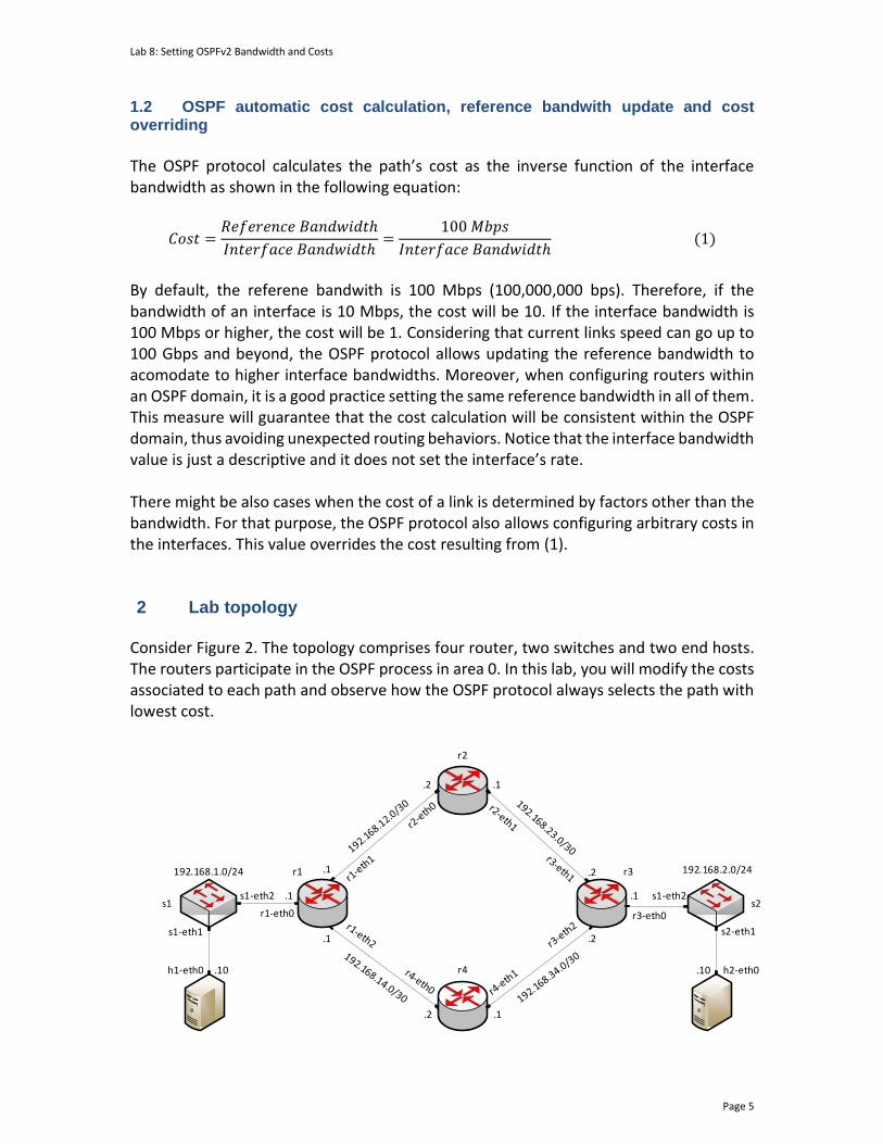
Lab 8: Setting OSPFv2 Bandwidth and Costs
Page 5
1.2 OSPF automatic cost calculation, reference bandwith update and cost overriding
The OSPF protocol calculates the path’s cost as the inverse function of the interface bandwidth as shown in the following equation:
𝐶𝑜𝑠𝑡 =𝑅𝑒𝑓𝑒𝑟𝑒𝑛𝑐𝑒 𝐵𝑎𝑛𝑑𝑤𝑖𝑑𝑡ℎ
𝐼𝑛𝑡𝑒𝑟𝑓𝑎𝑐𝑒 𝐵𝑎𝑛𝑑𝑤𝑖𝑑𝑡ℎ=
100 𝑀𝑏𝑝𝑠
𝐼𝑛𝑡𝑒𝑟𝑓𝑎𝑐𝑒 𝐵𝑎𝑛𝑑𝑤𝑖𝑑𝑡ℎ (1)
By default, the referene bandwith is 100 Mbps (100,000,000 bps). Therefore, if the bandwidth of an interface is 10 Mbps, the cost will be 10. If the interface bandwidth is 100 Mbps or higher, the cost will be 1. Considering that current links speed can go up to 100 Gbps and beyond, the OSPF protocol allows updating the reference bandwidth to acomodate to higher interface bandwidths. Moreover, when configuring routers within an OSPF domain, it is a good practice setting the same reference bandwidth in all of them. This measure will guarantee that the cost calculation will be consistent within the OSPF domain, thus avoiding unexpected routing behaviors. Notice that the interface bandwidth value is just a descriptive and it does not set the interface’s rate. There might be also cases when the cost of a link is determined by factors other than the bandwidth. For that purpose, the OSPF protocol also allows configuring arbitrary costs in the interfaces. This value overrides the cost resulting from (1). 2 Lab topology
Consider Figure 2. The topology comprises four router, two switches and two end hosts. The routers participate in the OSPF process in area 0. In this lab, you will modify the costs associated to each path and observe how the OSPF protocol always selects the path with lowest cost.
h1-eth0
s1
s1-eth1
192.168.1.0/24 192.168.2.0/24
s1-eth2
r2
r1 r3
.2
.1 .2
.1
r4
r1-eth0
h2-eth0
s2-eth1
s2
.1
.2 .1
.2
s1-eth2
r3-eth0
.10.10
.1 .1
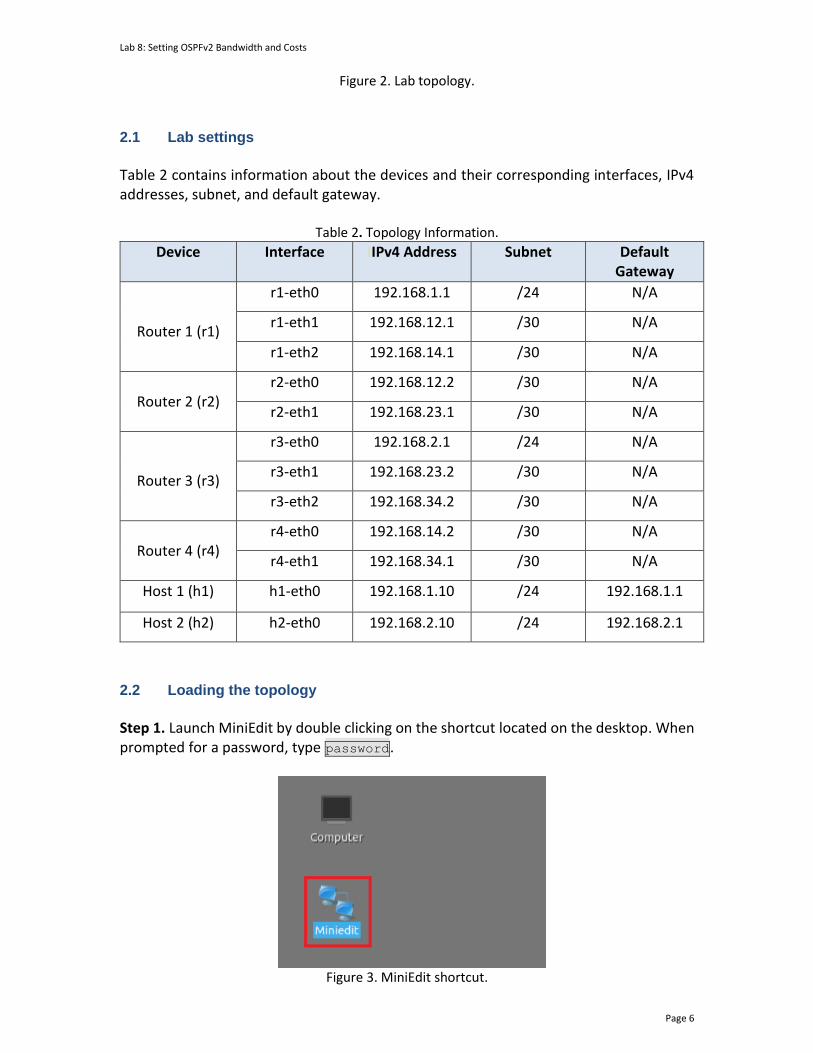
Lab 8: Setting OSPFv2 Bandwidth and Costs
Page 6
Figure 2. Lab topology.
2.1 Lab settings
Table 2 contains information about the devices and their corresponding interfaces, IPv4 addresses, subnet, and default gateway.
Table 2. Topology Information.
Device Interface IIPv4 Address Subnet Default Gateway
Router 1 (r1)
r1-eth0 192.168.1.1 /24 N/A
r1-eth1 192.168.12.1 /30 N/A
r1-eth2 192.168.14.1 /30 N/A
Router 2 (r2)
r2-eth0 192.168.12.2 /30 N/A
r2-eth1 192.168.23.1 /30 N/A
Router 3 (r3)
r3-eth0 192.168.2.1 /24 N/A
r3-eth1 192.168.23.2 /30 N/A
r3-eth2 192.168.34.2 /30 N/A
Router 4 (r4)
r4-eth0 192.168.14.2 /30 N/A
r4-eth1 192.168.34.1 /30 N/A
Host 1 (h1) h1-eth0 192.168.1.10 /24 192.168.1.1
Host 2 (h2) h2-eth0 192.168.2.10 /24 192.168.2.1
2.2 Loading the topology
Step 1. Launch MiniEdit by double clicking on the shortcut located on the desktop. When prompted for a password, type password.
Figure 3. MiniEdit shortcut.
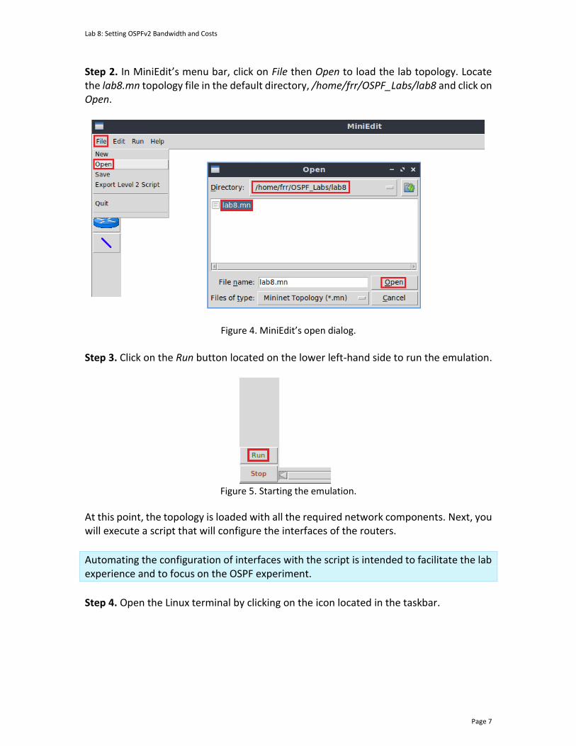
Lab 8: Setting OSPFv2 Bandwidth and Costs
Page 7
Step 2. In MiniEdit’s menu bar, click on File then Open to load the lab topology. Locate the lab8.mn topology file in the default directory, /home/frr/OSPF_Labs/lab8 and click on Open.
Figure 4. MiniEdit’s open dialog.
Step 3. Click on the Run button located on the lower left-hand side to run the emulation.
Figure 5. Starting the emulation.
At this point, the topology is loaded with all the required network components. Next, you will execute a script that will configure the interfaces of the routers.
Automating the configuration of interfaces with the script is intended to facilitate the lab experience and to focus on the OSPF experiment.
Step 4. Open the Linux terminal by clicking on the icon located in the taskbar.

Lab 8: Setting OSPFv2 Bandwidth and Costs
Page 8
Figure 6. Opening Linux terminal.
Step 5. Issue the command shown below to set the lab environment. This command configures the IP addresses of the routers’ interface according to Table 2. If a password is required, type password. sudo set_env lab8
Figure 7. Setting the lab environment.
Step 6. Type the following command to exit the Linux terminal. exit
Figure 8. Exiting the Linux terminal.
Step 7. Click on Mininet's terminal, i.e., the one launched when MiniEdit was started.
Figure 9. Opening Mininet's terminal.
Step 8. Issue the following command to display the interface names and connections. links

Lab 8: Setting OSPFv2 Bandwidth and Costs
Page 9
Figure 10. Displaying network interfaces.
In the figure above, the link displayed within the gray box indicates that interface eth2 of switch s1 connects to interface eth0 of router r1 (i.e., s1-eth2<->r1-eth0). 2.3 Load the zebra daemon and verify the configuration
In this section, you will verify that the IP addresses listed in Table 2 and inspect the routing table of the routers. Step 1. Hold right-click on host h1 and select Terminal. This opens the terminal of host h1 and allows the execution of commands on that host.
Figure 11. Opening host h1 terminal.
Step 2. In the host h1 terminal, type the command shown below to verify that the IP address was assigned successfully. You will verify that interface h1-eth0 is configured with the IP address 192.168.1.10 and the subnet mask 255.255.255.0. ifconfig

Lab 8: Setting OSPFv2 Bandwidth and Costs
Page 10
Figure 12. Displaying host h1 interfaces and IP addresses.
Step 3. In the host h1 terminal, type the command shown below to verify that the default gateway IP address is 192.168.1.1. route
Figure 13. Displaying host h1 default route.
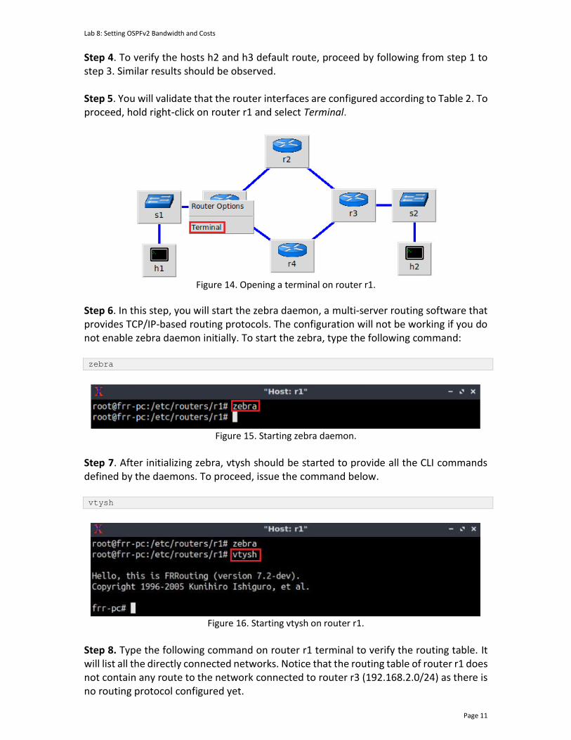
Lab 8: Setting OSPFv2 Bandwidth and Costs
Page 11
Step 4. To verify the hosts h2 and h3 default route, proceed by following from step 1 to step 3. Similar results should be observed. Step 5. You will validate that the router interfaces are configured according to Table 2. To proceed, hold right-click on router r1 and select Terminal.
Figure 14. Opening a terminal on router r1.
Step 6. In this step, you will start the zebra daemon, a multi-server routing software that provides TCP/IP-based routing protocols. The configuration will not be working if you do not enable zebra daemon initially. To start the zebra, type the following command: zebra
Figure 15. Starting zebra daemon.
Step 7. After initializing zebra, vtysh should be started to provide all the CLI commands defined by the daemons. To proceed, issue the command below. vtysh
Figure 16. Starting vtysh on router r1.
Step 8. Type the following command on router r1 terminal to verify the routing table. It will list all the directly connected networks. Notice that the routing table of router r1 does not contain any route to the network connected to router r3 (192.168.2.0/24) as there is no routing protocol configured yet.

Lab 8: Setting OSPFv2 Bandwidth and Costs
Page 12
show ip route
Figure 17. Displaying routing table of router r1.
Step 9. To verify the routing table of the other routers, proceed similarly by following from step 5 to step 8 on the corresponding router terminal.
3 Configuring single-area OSPF This section shows the steps to configure single-area OSPF, meaning that all the OSPF participants will form part of the backbone area (i.e., area 0). 3.1 Configuring OSPF in routers r1, r2, and r3
Step 1. Open router r1’s terminal by selecting the icon from the taskbar as shown below.
Figure 18. Opening router r1’s terminal.
Step 2. In router r1’s terminal, type the command below to exit the vtysh session. exit
Figure 19. Exiting the vtysh session.
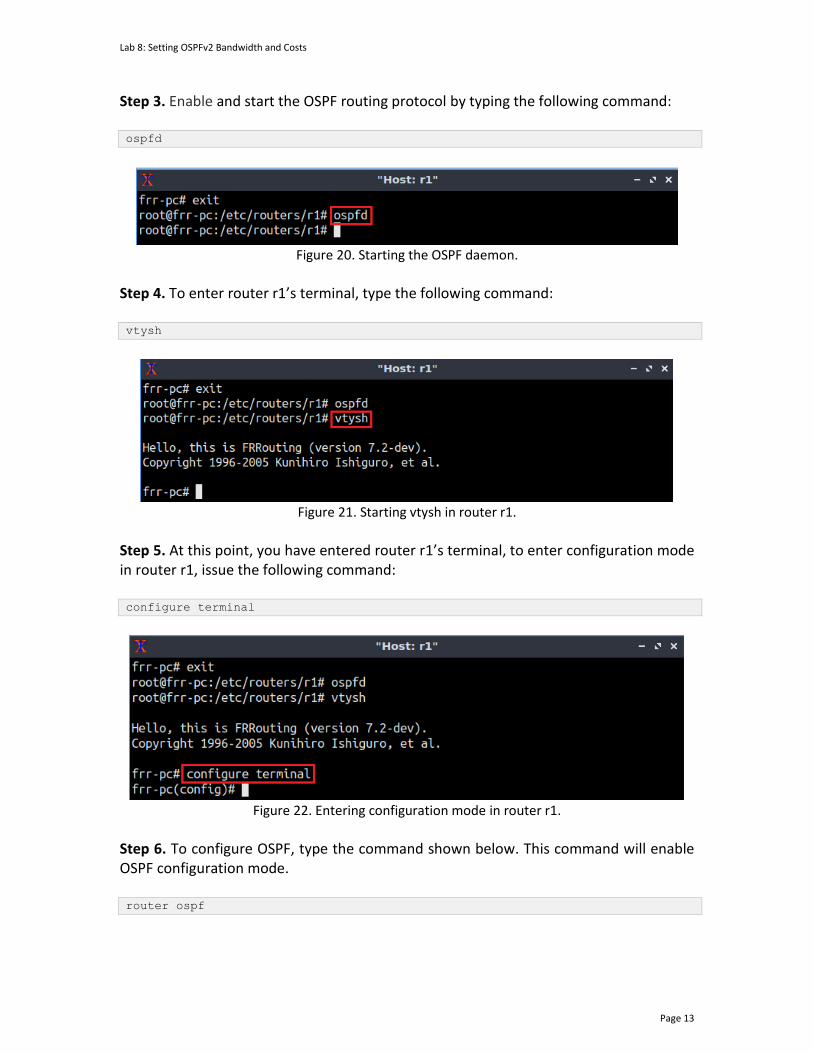
Lab 8: Setting OSPFv2 Bandwidth and Costs
Page 13
Step 3. Enable and start the OSPF routing protocol by typing the following command: ospfd
Figure 20. Starting the OSPF daemon.
Step 4. To enter router r1’s terminal, type the following command: vtysh
Figure 21. Starting vtysh in router r1.
Step 5. At this point, you have entered router r1’s terminal, to enter configuration mode in router r1, issue the following command: configure terminal
Figure 22. Entering configuration mode in router r1.
Step 6. To configure OSPF, type the command shown below. This command will enable OSPF configuration mode. router ospf

Lab 8: Setting OSPFv2 Bandwidth and Costs
Page 14
Figure 23. Configuring OSPF in router r1.
Step 7. To establish router r1 ID, issue the following command: ospf router-id 1.1.1.1
Figure 24. Assigning the OSPF router ID of 1.1.1.1 to router r1.
Step 8. Type the following command to enable interface r1-eth1 to participate in the OSPF process of area 0. network 192.168.12.0/30 area 0
Figure 25. Enabling interface r1-eth1 to participate in the OSPF process in area 0.
Step 9. Type the following command to enable interface r1-eth0 to participate in the OSPF process of area 0.
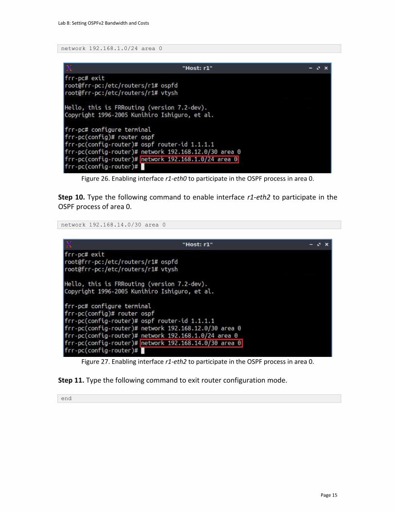
Lab 8: Setting OSPFv2 Bandwidth and Costs
Page 15
network 192.168.1.0/24 area 0
Figure 26. Enabling interface r1-eth0 to participate in the OSPF process in area 0.
Step 10. Type the following command to enable interface r1-eth2 to participate in the OSPF process of area 0. network 192.168.14.0/30 area 0
Figure 27. Enabling interface r1-eth2 to participate in the OSPF process in area 0.
Step 11. Type the following command to exit router configuration mode. end

Lab 8: Setting OSPFv2 Bandwidth and Costs
Page 16
Figure 28. Exiting router configuration mode.
Consider the figure above. After configuring OSPF in router r1, the interfaces r1-eth0, r1-eth1, and r1-eth2 will participate in the routing process in area 0.
Step 12. Router r2 is configured similarly to router r1 but with different IP addresses (see Table 2). Those steps are summarized in the following figure. To proceed, in router r2 terminal, issue the commands summarized below.
Figure 29. Router r2 configuration summary.
Consider the above figure. After configuring OSPF in router r2, the interfaces r2-eth0, and r2-eth1 will participate in the routing process of area 0. Step 13. Router r3 is configured similarly to router r2 but with different IP addresses (see Table 2). Those steps are summarized in the following figure. To proceed, in router r3 terminal, issue the commands depicted below.
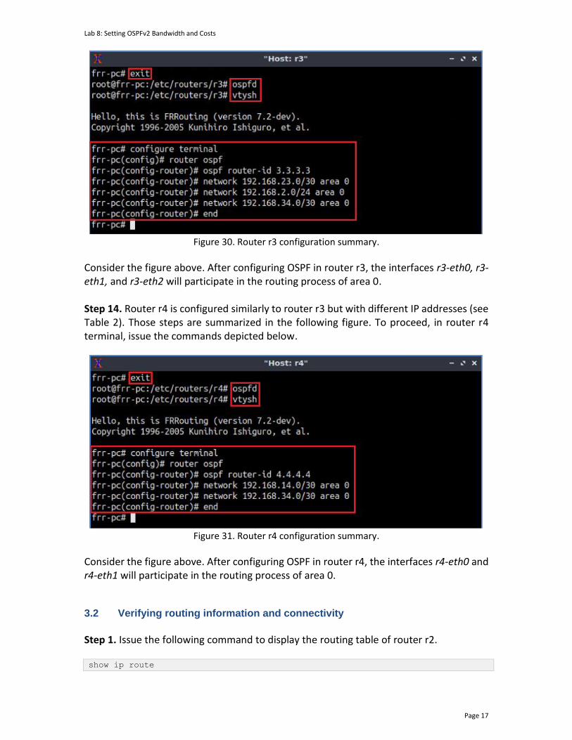
Lab 8: Setting OSPFv2 Bandwidth and Costs
Page 17
Figure 30. Router r3 configuration summary.
Consider the figure above. After configuring OSPF in router r3, the interfaces r3-eth0, r3-eth1, and r3-eth2 will participate in the routing process of area 0. Step 14. Router r4 is configured similarly to router r3 but with different IP addresses (see Table 2). Those steps are summarized in the following figure. To proceed, in router r4 terminal, issue the commands depicted below.
Figure 31. Router r4 configuration summary.
Consider the figure above. After configuring OSPF in router r4, the interfaces r4-eth0 and r4-eth1 will participate in the routing process of area 0. 3.2 Verifying routing information and connectivity
Step 1. Issue the following command to display the routing table of router r2.
show ip route

Lab 8: Setting OSPFv2 Bandwidth and Costs
Page 18
Figure 32. Displaying router r1’s routing table.
Consider the figure above. The output displays the networks learned along with additional attributes, such as the routing protocol that discovered the network. For example, networks with the symbol O on the left are learned from OSPF, whereas those with symbol C are directly connected to the device. Furthermore, the symbol > on the left of the displayed network indicates that this entry is selected to reach the network. As for the symbol *, this indicates that the route is inserted in Forwarding Information Base (FIB) of the router.
Notice that there are two routes to reach the network 192.168.2.0/24. The selected route (i.e., denoted by the > symbol) is the one via 192.168.12.2.
Step 2. In the host h1 terminal, issue the following command to test the connectivity between host h1 and host h2. You will observe a successful connectivity test. ping 192.168.2.10 -c 4
Figure 33. Testing connectivity from host h1 to host h2.

Lab 8: Setting OSPFv2 Bandwidth and Costs
Page 19
4 Setting interface and reference bandwidth
The OSPF protocol derives the cost of a path from the interface bandwidth. The higher the bandwidth the lower the cost. Additionally, OSPF allows the user updating the reference bandwidth which is a good practice considering that networks operate at higher speeds than default reference bandwidth (i.e., 100 Mbps). 4.1 Setting OSPF reference bandwidth
Step 1. In router r1, issue the following command to enter configuration mode. configure terminal
Figure 34. Entering configuration mode in router r1.
Step 2. To configure OSPF, type the command shown below. This command will enable OSPF configuration mode. router ospf
Figure 35. Entering OSPF configuration.
Step 3. Issue the following command to establish the reference bandwidth. In this example, the reference bandwidth is set to 100,000 which corresponds to 100 Gbps. auto-cost reference-bandwidth 100000
Figure 36. Establishing the reference bandwidth.
By default, the reference bandwidth is 100 Mbps, which means the protocol will not correctly compute costs over this value. Nowadays, links operating at 1 Gbps, 10 Gbps, and even 100 Gbps are more common. Therefore, updating the default reference bandwidth is a good practice to ensure that the protocol is computing the costs correctly.
Step 4. Type the following command to exit configuration mode.
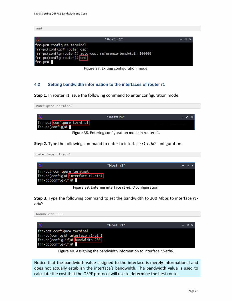
Lab 8: Setting OSPFv2 Bandwidth and Costs
Page 20
end
Figure 37. Exiting configuration mode.
4.2 Setting bandwidth information to the interfaces of router r1
Step 1. In router r1 issue the following command to enter configuration mode. configure terminal
Figure 38. Entering configuration mode in router r1.
Step 2. Type the following command to enter to interface r1-eth0 configuration. interface r1-eth1
Figure 39. Entering interface r1-eth0 configuration.
Step 3. Type the following command to set the bandwidth to 200 Mbps to interface r1-eth0. bandwidth 200
Figure 40. Assigning the bandwidth information to interface r1-eth0.
Notice that the bandwidth value assigned to the interface is merely informational and does not actually establish the interface’s bandwidth. The bandwidth value is used to calculate the cost that the OSPF protocol will use to determine the best route.
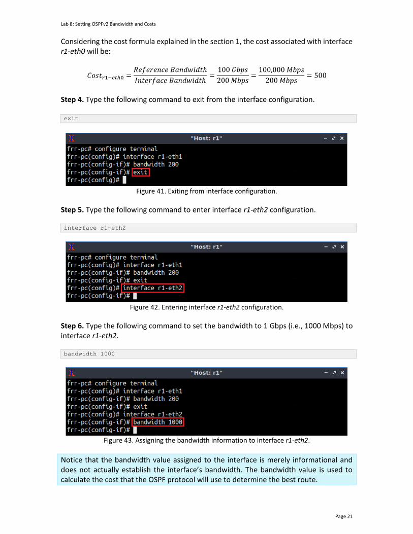
Lab 8: Setting OSPFv2 Bandwidth and Costs
Page 21
Considering the cost formula explained in the section 1, the cost associated with interface r1-eth0 will be:
𝐶𝑜𝑠𝑡𝑟1−𝑒𝑡ℎ0 =𝑅𝑒𝑓𝑒𝑟𝑒𝑛𝑐𝑒 𝐵𝑎𝑛𝑑𝑤𝑖𝑑𝑡ℎ
𝐼𝑛𝑡𝑒𝑟𝑓𝑎𝑐𝑒 𝐵𝑎𝑛𝑑𝑤𝑖𝑑𝑡ℎ=
100 𝐺𝑏𝑝𝑠
200 𝑀𝑏𝑝𝑠=
100,000 𝑀𝑏𝑝𝑠
200 𝑀𝑏𝑝𝑠= 500
Step 4. Type the following command to exit from the interface configuration. exit
Figure 41. Exiting from interface configuration.
Step 5. Type the following command to enter interface r1-eth2 configuration. interface r1-eth2
Figure 42. Entering interface r1-eth2 configuration.
Step 6. Type the following command to set the bandwidth to 1 Gbps (i.e., 1000 Mbps) to interface r1-eth2. bandwidth 1000
Figure 43. Assigning the bandwidth information to interface r1-eth2.
Notice that the bandwidth value assigned to the interface is merely informational and does not actually establish the interface’s bandwidth. The bandwidth value is used to calculate the cost that the OSPF protocol will use to determine the best route.

Lab 8: Setting OSPFv2 Bandwidth and Costs
Page 22
Considering the cost formula explained in the section 1, the cost associated with interface r1-eth0 will be:
𝐶𝑜𝑠𝑡𝑟1−𝑒𝑡ℎ2 =𝑅𝑒𝑓𝑒𝑟𝑒𝑛𝑐𝑒 𝐵𝑎𝑛𝑑𝑤𝑖𝑑𝑡ℎ
𝐼𝑛𝑡𝑒𝑟𝑓𝑎𝑐𝑒 𝐵𝑎𝑛𝑑𝑤𝑖𝑑𝑡ℎ=
100 𝐺𝑏𝑝𝑠
1 𝐺𝑏𝑝𝑠= 100
Step 7. Type the following command to exit interface configuration. end
Figure 44. Exiting interface configuration mode.
4.3 Verifying interfaces costs and bandwidth
Step 1. In router r1, issue the following command to see interface r1-eth1 configuration. Notice that the bandwidth is 200 Mbps and the related cost 500. show ip ospf interface r1-eth1
Figure 45. Verifying OSPF path cost.
Step 2. In router r1, issue the following command to see interface r1-eth2 configuration. Notice that the bandwidth is 1000 Mbps (i.e., 1 Gpbs) and the cost 100. show ip ospf interface r1-eth2

Lab 8: Setting OSPFv2 Bandwidth and Costs
Page 23
Figure 46. Verifying OSPF path cost.
Step 3. Type the following command to see the routing table of router r1. show ip route
Figure 47. Verifying the routing table of router r1.
Notice that the route selected to reach the network 192.168.2.0/24 is via the interface r1-eth2, which has the lower cost.
Step 4. In host h2 terminal, type the following command to start an iperf3 server. Iperf3 is a tool to measure the maximum achievable bandwidth on IP networks. The argument -s specifies that host h2 will run in server mode. iperf3 -s
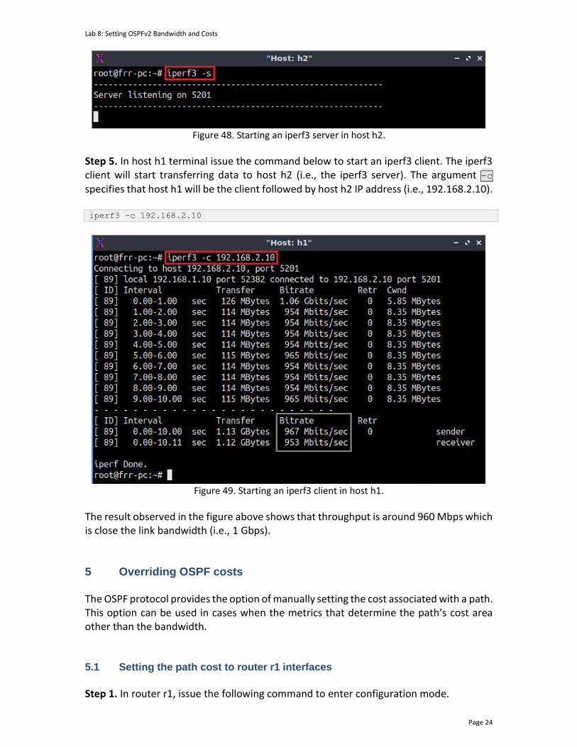
Lab 8: Setting OSPFv2 Bandwidth and Costs
Page 24
Figure 48. Starting an iperf3 server in host h2.
Step 5. In host h1 terminal issue the command below to start an iperf3 client. The iperf3 client will start transferring data to host h2 (i.e., the iperf3 server). The argument -c specifies that host h1 will be the client followed by host h2 IP address (i.e., 192.168.2.10). iperf3 -c 192.168.2.10
Figure 49. Starting an iperf3 client in host h1.
The result observed in the figure above shows that throughput is around 960 Mbps which is close the link bandwidth (i.e., 1 Gbps). 5 Overriding OSPF costs The OSPF protocol provides the option of manually setting the cost associated with a path. This option can be used in cases when the metrics that determine the path’s cost area other than the bandwidth. 5.1 Setting the path cost to router r1 interfaces
Step 1. In router r1, issue the following command to enter configuration mode.

Lab 8: Setting OSPFv2 Bandwidth and Costs
Page 25
configure terminal
Figure 50. Entering configuration mode in router r1.
Step 2. Type the following command to enter to interface r1-eth1 configuration. interface r1-eth1
Figure 51. Entering interface r1-eth1 configuration.
Step 3. Override the current OSPF calculated cost on the interface r1-eth1 by issuing the following command. ip ospf cost 10
Figure 52. Overriding interface r1-eth0 calculated cost.
Step 4. Type the following command to exit from the interface configuration. end
Figure 53. Exiting configuration mode.
5.2 Verifying interfaces costs and bandwidth
Step 1. In router r1, issue the following command to see interface r1-eth1 configuration. show ip ospf interface r1-eth1
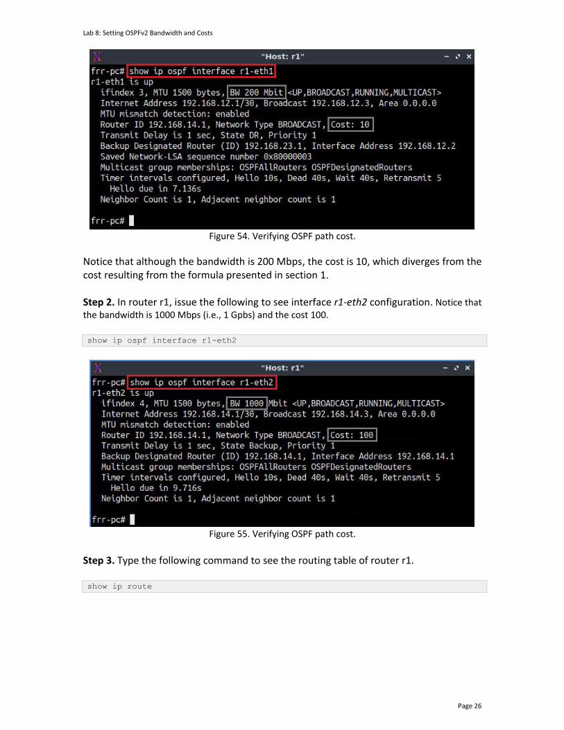
Lab 8: Setting OSPFv2 Bandwidth and Costs
Page 26
Figure 54. Verifying OSPF path cost.
Notice that although the bandwidth is 200 Mbps, the cost is 10, which diverges from the cost resulting from the formula presented in section 1. Step 2. In router r1, issue the following to see interface r1-eth2 configuration. Notice that the bandwidth is 1000 Mbps (i.e., 1 Gpbs) and the cost 100.
show ip ospf interface r1-eth2
Figure 55. Verifying OSPF path cost.
Step 3. Type the following command to see the routing table of router r1. show ip route
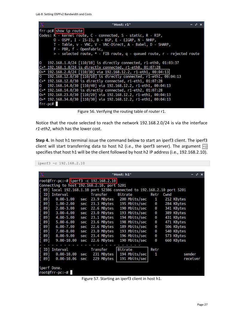
Lab 8: Setting OSPFv2 Bandwidth and Costs
Page 27
Figure 56. Verifying the routing table of router r1.
Notice that the route selected to reach the network 192.168.2.0/24 is via the interface r1-eth2, which has the lower cost.
Step 4. In host h1 terminal issue the command below to start an iperf3 client. The iperf3 client will start transferring data to host h2 (i.e., the iperf3 server). The argument -c specifies that host h1 will be the client followed by host h2 IP address (i.e., 192.168.2.10). iperf3 -c 192.168.2.10
Figure 57. Starting an iperf3 client in host h1.

Lab 8: Setting OSPFv2 Bandwidth and Costs
Page 28
The result observed in the figure above shows that throughput is around 192 Mbps which is close the link bandwidth (i.e., 200 Mbps). 5.3 Changing route cost in an intermediate router
In this subsection, you will change the cost of the interface r2-eth1, aiming at impacting the aggregate path’s cost and modifying the route to reach the network 192.168.2.0/24. Step 1. Enter router r2 configuration mode issuing the following command. configure terminal
Figure 58. Entering configuration mode in router r2.
Step 2. Enter interface r2-eth1 configuration by typing the command below. interface r2-eth1
Figure 59. Entering interface r2-eth1 configuration.
Step 3. Modify the OSPF cost in the interface r2-eth1 issuing the following command. ip ospf cost 200
Figure 60. Modifying OSPF cost in the interface r2-eth1.
Step 4. Type the following command to exit configuration mode. end

Lab 8: Setting OSPFv2 Bandwidth and Costs
Page 29
Figure 61. Exiting from configuration mode.
Step 5. To verify the route selected to reach the network 192.168.2.0/24, type the following command in router r1 terminal. show ip route
Figure 62. Showing the routing table of router r1.
Notice that the route selected to reach the network 192.168.2.0/24 is via the interface r1-eth2, which has the lower cost. This concludes lab 8. Stop the emulation and then exit out of MiniEdit. References
1. Moy, J. “RFC 1247: OSPF version 2.” 1991. 2. Moy, J. “RFC 2328: OSPF version 2.” 1998. 3. Coltun, R., Ferguson, D., Moy, J., Lindem, A. “RFC 5340: OSPF for IPv6.” 2008. 4. Peterson, L. “Computer networks: a systems approach.” 6th Edition, 2021. 5. Tanenbaum, D. Wetherall. “Computer networks.” 5th Edition. 2012. 6. J. Kurose, K. Ross. “Computer networking, a top-down approach.” 7th Edition.
2017. 7. Teare, D., Vachon, B., Graziani, R. “Implementing Cisco IP routing (ROUTE)
foundation learning guide: (CCNP ROUTE 300-101).” 2014.

Lab 8: Setting OSPFv2 Bandwidth and Costs
Page 30
8. Linux foundation collaborative projects. “FRR routing documentation.” 2017 [Online] Available: http://docs.frrouting.org/en/latest/.
OPEN SHORTEST PATH FIRST
Lab 9: Configuring Multi-Area OSPFv3
Document Version: 10-03-2021
Award 1829698 “CyberTraining CIP: Cyberinfrastructure Expertise on High-throughput
Networks for Big Science Data Transfers”
Lab 9: Configuring Multi-Area OSPFv3
Page 2
Contents Overview ............................................................................................................................. 3
Objectives............................................................................................................................ 3
Lab settings ......................................................................................................................... 3
Lab roadmap ....................................................................................................................... 3
1 Introduction ................................................................................................................ 3
1.1 Differences between OSPv2 and OPSFv3 ............................................................. 3
1.2 OSPFv3 packets .................................................................................................... 4
1.3 OSPFv3 LSDB exchange and synchronization ....................................................... 4
1.4 OSPFv3 passive interface ..................................................................................... 6
2 Lab topology................................................................................................................ 6
2.1 Lab settings........................................................................................................... 6
2.2 Loading the topology............................................................................................ 7
2.3 Load the zebra daemon and verify the configuration ....................................... 10
3 Configuring multi-area OSPFv3 ................................................................................. 13
1.1 Configuring OSPFv3 in routers r1, r2, and r3 ..................................................... 13
3.2 Configuring passive interfaces ........................................................................... 18
4 Verifying routing information and connectivity ....................................................... 19
References ........................................................................................................................ 21
Lab 9: Configuring Multi-Area OSPFv3
Page 3
Overview This lab introduces Open Shortest Path First version 3 (OSPFv3), which supports IPv6 routing. The lab explains the behavior and main features of OSPFv3 highlighting the differences with its previous version. Additionally, it guides the user on how to configure and verify multi-area OSPFv3. Objectives By the end of this lab, you should be able to:
1. Understand the features of OSPFv3. 2. Identify the difference between OSPFv2 and OSPFv3. 3. Configure multi-area OSPFv3. 4. Verify the configuration.
Lab settings The information in Table 1 provides the credentials to access the Client machine.
Table 1. Credentials to access the Client machine.
Device
Account
Password
Client admin password
Lab roadmap This lab is organized as follows:
1. Section 1: Introduction. 2. Section 2: Lab topology. 3. Section 3: Configuring multi-area OSPFv3. 4. Section 4: Verifying routing information and connectivity.
1 Introduction 1.1 Differences between OSPv2 and OPSFv3
The OSPFv3 protocol supports IPv6 routes and uses the same principles of OSPFv2. Understanding the differences between OSPFv2 and OSPFv3 is essential to operate and

Lab 9: Configuring Multi-Area OSPFv3
Page 4
configure IPv6 networks that uses OSPF as their routing protocol. The changes introduced in OSPFv3 were necessary to support new addressing semantics and the size of IPv6 addresses. The OSPFv3 header is simpler than the previous version having the authentication fields removed from the OSPFv3 header. Instead, OSPFv3 relies on IPv6 Authentication Header (AH) and Encapsulating Security Packets (ESP). Additionally, OSPFv3 supports IPv6 address families, which supports both IPv4 and IPv6 unicast traffic.
Notice that the OSPF version implemented in Free Range Routing (FRR), is based in the RFC 27403, which only supports IPv6 routing.
1.2 OSPFv3 packets
The OSPFv3 packets are classified into the following types:
• Hello packets: They are used to discover, build, and keep OSPF neighbor adjacencies. In OSPFv3, hello packets do not contain address information. Instead, it includes the interface ID that the originating router has included to identify its interface to the link uniquely.
• Database Description Packets (DBD): It is used to describe the Link-State Data Base (LSDB) of a router. The LSDB is used by routers participating in the OSPF process to verify that their databases are synchronized.
• Link-State Request (LSR): A router uses it to request the latest Link State Advertisement (LSA).
• Link-State Update (LSU): They are used to flood LSAs and sending LSA responses to LSR packets.
• Link-State Acknowledgement (LSAck): It is used to acknowledge LSA packets. OSPFv3 packets are encapsulated into IPv6 packets, and the protocol number is 89. 1.3 OSPFv3 LSDB exchange and synchronization
The routers participating in the OSPF process pass through multiple states before forming full adjacency, as shown in Figure 1. Router r1 and r2 will start exchanging OSPF packets following the states summarized below.
• Down: No information is sent or received by routers r1 and r2.
• Init: Router r2 interface has detected a Hello packet broadcasted by router r1. The IPv6 broadcast address used by OSPFv3 is FF02::5. The hello packet also contains the Router ID. However, bidirectional communication has not been established.
• Two-way: Router r2 responded by sending a hello packet to the unicast address of router r1 (i.e., 2001:10::1). At the end of this state, the Designated Router (DR) and the Backup Designated Router (BDR) are chosen. The DR and the BDR are used to reduce the amount of packet exchanged in the OSPF process, meaning that non-DR and non-BDR will only exchange routes with the former and the latter. The router with the highest router ID will be elected as the selected as the DR (i.e.,
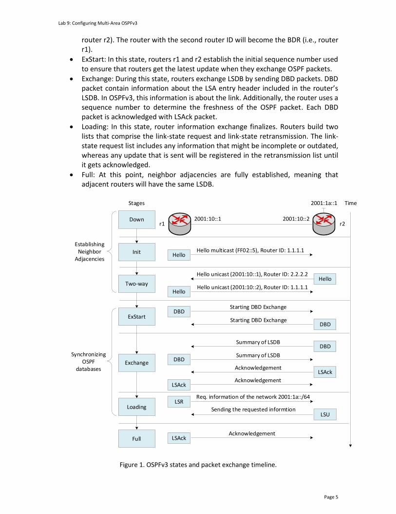
Lab 9: Configuring Multi-Area OSPFv3
Page 5
router r2). The router with the second router ID will become the BDR (i.e., router r1).
• ExStart: In this state, routers r1 and r2 establish the initial sequence number used to ensure that routers get the latest update when they exchange OSPF packets.
• Exchange: During this state, routers exchange LSDB by sending DBD packets. DBD packet contain information about the LSA entry header included in the router’s LSDB. In OSPFv3, this information is about the link. Additionally, the router uses a sequence number to determine the freshness of the OSPF packet. Each DBD packet is acknowledged with LSAck packet.
• Loading: In this state, router information exchange finalizes. Routers build two lists that comprise the link-state request and link-state retransmission. The link-state request list includes any information that might be incomplete or outdated, whereas any update that is sent will be registered in the retransmission list until it gets acknowledged.
• Full: At this point, neighbor adjacencies are fully established, meaning that adjacent routers will have the same LSDB.
Init
r1 r22001:10::1 2001:10::2
Hello multicast (FF02::5), Router ID: 1.1.1.1
Hello unicast (2001:10::1), Router ID: 2.2.2.2
Down
Two-wayHello unicast (2001:10::2), Router ID: 1.1.1.1
ExStart
Starting DBD Exchange
Starting DBD Exchange
TimeStages
Hello
Hello
Summary of LSDB
Summary of LSDBExchange
Loading
Full
Hello
2001:1a::1
DBD
DBD
Acknowledgement
DBD
Acknowledgement
DBD
Req. information of the network 2001:1a::/64LSR
LSUSending the requested informtion
LSAck
LSAck
AcknowledgementLSAck
Establishing Neighbor
Adjacencies
Synchronizing OSPF
databases
Figure 1. OSPFv3 states and packet exchange timeline.

Lab 9: Configuring Multi-Area OSPFv3
Page 6
1.4 OSPFv3 passive interface
Configuring a passive interface in a router participating in the OSPFv3 process is a common method for reducing the use of resources. When a passive interface is configured, the router stops sending and receiving OSPF hello packets on the selected interface. Therefore, the passive interface must be configured only on interfaces where the router will not establish any OSPF neighbor adjacency. 2 Lab topology Consider Figure 4. The topology consists of four networks connected to its respective routers. The communication between networks is established via multi-area OSPFv3 configured in all routers.
h1 h2
h1-eth0 h2-eth0.10 .10
s1
s1-eth2 s2-eth2
2001:192:168:1::0/64
s2
.1
s1-eth1 s2-eth1
r2
r1 r3
r1-eth1 r3-eth1
.2
.1 .2
.1
.1
Area 1.1.1.1
Area 2.2.2.2
Area 0.0.0.0
2001:192:168:2::0/64
Figure 2. Lab topology.
2.1 Lab settings
Table 2 contains information about the devices and their corresponding interfaces, IPv4 addresses, subnet, and default gateway.
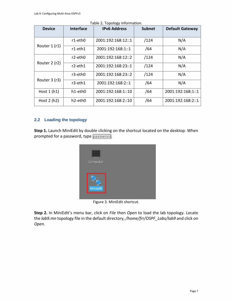
Lab 9: Configuring Multi-Area OSPFv3
Page 7
Table 2. Topology information.
Device Interface IIPv6 Address Subnet Default Gateway
Router 1 (r1)
r1-eth0 2001:192:168:12::1 /124 N/A
r1-eth1 2001:192:168:1::1 /64 N/A
Router 2 (r2)
r2-eth0 2001:192:168:12::2 /124 N/A
r2-eth1 2001:192:168:23::1 /124 N/A
Router 3 (r3)
r3-eth0 2001:192:168:23::2 /124 N/A
r3-eth1 2001:192:168:2::1 /64 N/A
Host 1 (h1) h1-eth0 2001:192:168:1::10 /64 2001:192:168:1::1
Host 2 (h2) h2-eth0 2001:192:168:2::10 /64 2001:192:168:2::1
2.2 Loading the topology
Step 1. Launch MiniEdit by double clicking on the shortcut located on the desktop. When prompted for a password, type password.
Figure 3. MiniEdit shortcut.
Step 2. In MiniEdit’s menu bar, click on File then Open to load the lab topology. Locate the lab9.mn topology file in the default directory, /home/frr/OSPF_Labs/lab9 and click on Open.

Lab 9: Configuring Multi-Area OSPFv3
Page 8
Figure 4. MiniEdit’s open dialog.
Step 3. Click on the Run button located on the lower left-hand side to run the emulation.
Figure 5. Starting the emulation.
At this point, the topology is loaded with all the required network components. Next, you will execute a script that will configure the interfaces of the routers.
Automating the configuration of interfaces with the script is intended to facilitate the lab experience and to focus on the OSPF experiment.
Step 4. Open the Linux terminal by clicking on the icon located in the taskbar.
Figure 6. Opening Linux terminal.
Step 5. Issue the command shown below to set the lab environment. This command configures the IP addresses of the routers’ interface according to Table 2. If a password is required, type password.

Lab 9: Configuring Multi-Area OSPFv3
Page 9
sudo set_env lab9
Figure 7. Setting the lab environment.
Step 6. Type the following command to exit the Linux terminal. exit
Figure 8. Exiting the Linux terminal.
Step 7. Click on Mininet's terminal, i.e., the one launched when MiniEdit was started.
Figure 9. Opening Mininet's terminal.
Step 8. Issue the following command to display the interface names and connections. links
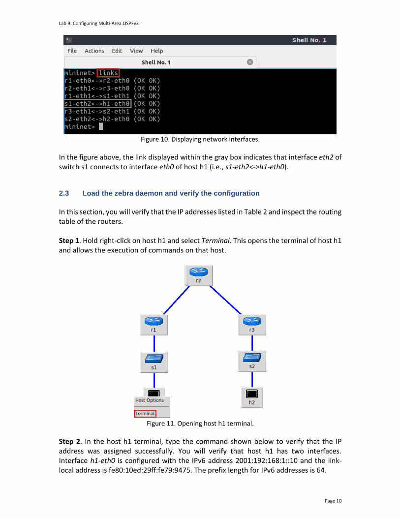
Lab 9: Configuring Multi-Area OSPFv3
Page 10
Figure 10. Displaying network interfaces.
In the figure above, the link displayed within the gray box indicates that interface eth2 of switch s1 connects to interface eth0 of host h1 (i.e., s1-eth2<->h1-eth0). 2.3 Load the zebra daemon and verify the configuration
In this section, you will verify that the IP addresses listed in Table 2 and inspect the routing table of the routers. Step 1. Hold right-click on host h1 and select Terminal. This opens the terminal of host h1 and allows the execution of commands on that host.
Figure 11. Opening host h1 terminal.
Step 2. In the host h1 terminal, type the command shown below to verify that the IP address was assigned successfully. You will verify that host h1 has two interfaces. Interface h1-eth0 is configured with the IPv6 address 2001:192:168:1::10 and the link-local address is fe80:10ed:29ff:fe79:9475. The prefix length for IPv6 addresses is 64.
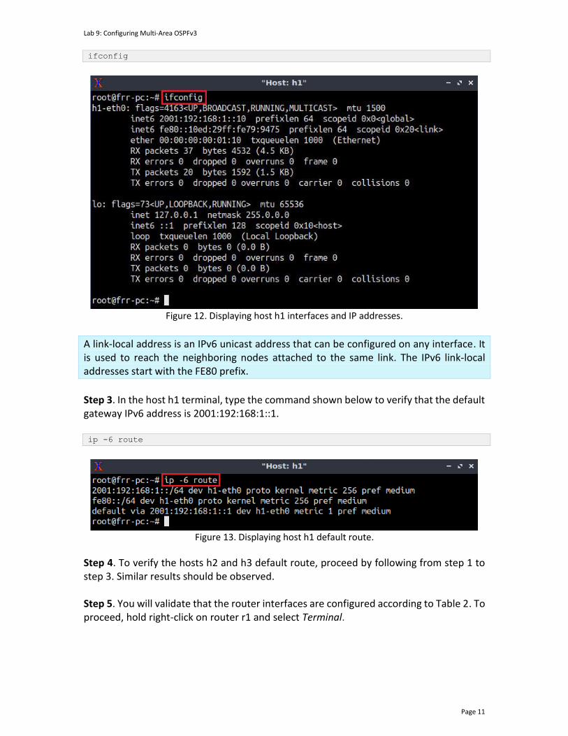
Lab 9: Configuring Multi-Area OSPFv3
Page 11
ifconfig
Figure 12. Displaying host h1 interfaces and IP addresses.
A link-local address is an IPv6 unicast address that can be configured on any interface. It is used to reach the neighboring nodes attached to the same link. The IPv6 link-local addresses start with the FE80 prefix.
Step 3. In the host h1 terminal, type the command shown below to verify that the default gateway IPv6 address is 2001:192:168:1::1. ip -6 route
Figure 13. Displaying host h1 default route.
Step 4. To verify the hosts h2 and h3 default route, proceed by following from step 1 to step 3. Similar results should be observed. Step 5. You will validate that the router interfaces are configured according to Table 2. To proceed, hold right-click on router r1 and select Terminal.

Lab 9: Configuring Multi-Area OSPFv3
Page 12
Figure 14. Opening a terminal on router r1.
Step 6. In this step, you will start the zebra daemon, a multi-server routing software that provides TCP/IP-based routing protocols. The configuration will not be working if you do not enable zebra daemon initially. To start the zebra, type the following command: zebra
Figure 15. Starting zebra daemon.
Step 7. After initializing zebra, vtysh should be started to provide all the CLI commands defined by the daemons. To proceed, issue the following command: vtysh
Figure 16. Starting vtysh on router r1.
Step 8. Type the following command on router r1 terminal to verify the routing table. It will list all the directly connected networks. Notice that the routing table of router r1 does not contain any route to the network connected to router r3 (2001:192:168:2::0/64) as there is no routing protocol configured yet. The first two entries correspond to the directly
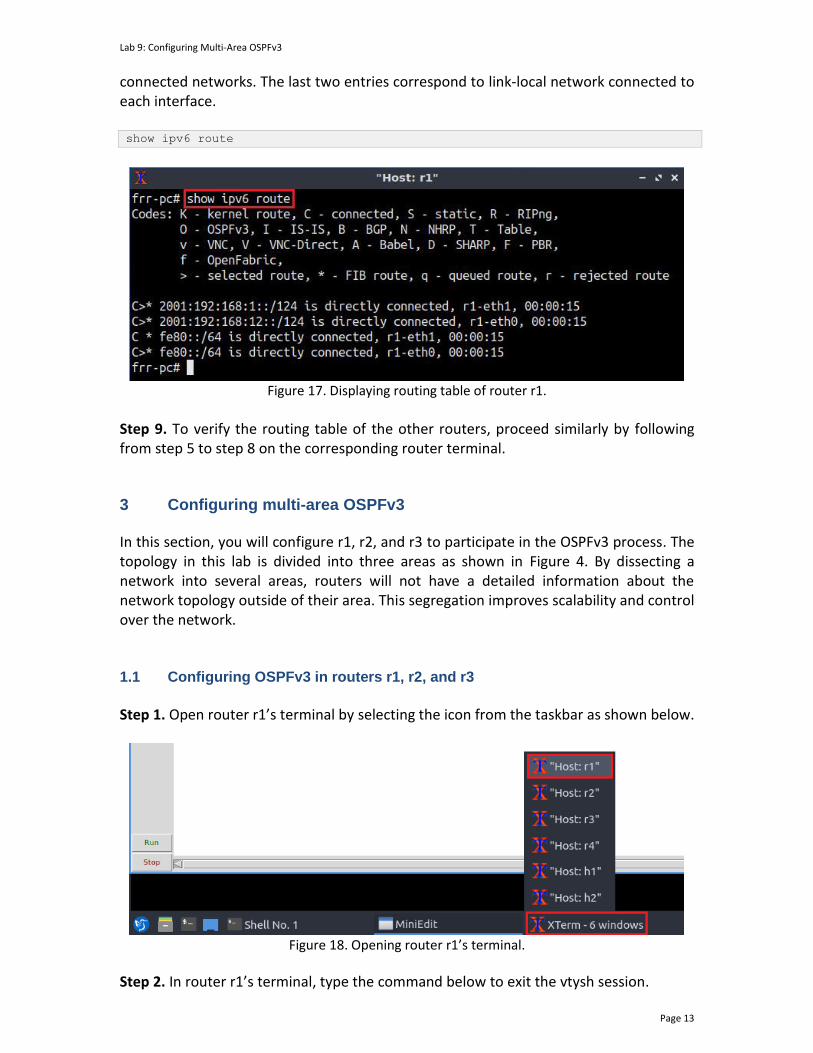
Lab 9: Configuring Multi-Area OSPFv3
Page 13
connected networks. The last two entries correspond to link-local network connected to each interface. show ipv6 route
Figure 17. Displaying routing table of router r1.
Step 9. To verify the routing table of the other routers, proceed similarly by following from step 5 to step 8 on the corresponding router terminal.
3 Configuring multi-area OSPFv3 In this section, you will configure r1, r2, and r3 to participate in the OSPFv3 process. The topology in this lab is divided into three areas as shown in Figure 4. By dissecting a network into several areas, routers will not have a detailed information about the network topology outside of their area. This segregation improves scalability and control over the network. 1.1 Configuring OSPFv3 in routers r1, r2, and r3
Step 1. Open router r1’s terminal by selecting the icon from the taskbar as shown below.
Figure 18. Opening router r1’s terminal.
Step 2. In router r1’s terminal, type the command below to exit the vtysh session.
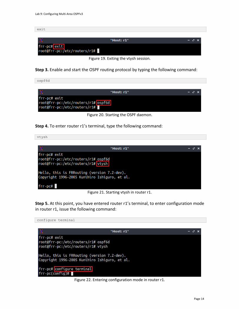
Lab 9: Configuring Multi-Area OSPFv3
Page 14
exit
Figure 19. Exiting the vtysh session.
Step 3. Enable and start the OSPF routing protocol by typing the following command: ospf6d
Figure 20. Starting the OSPF daemon.
Step 4. To enter router r1’s terminal, type the following command: vtysh
Figure 21. Starting vtysh in router r1.
Step 5. At this point, you have entered router r1’s terminal, to enter configuration mode in router r1, issue the following command: configure terminal
Figure 22. Entering configuration mode in router r1.
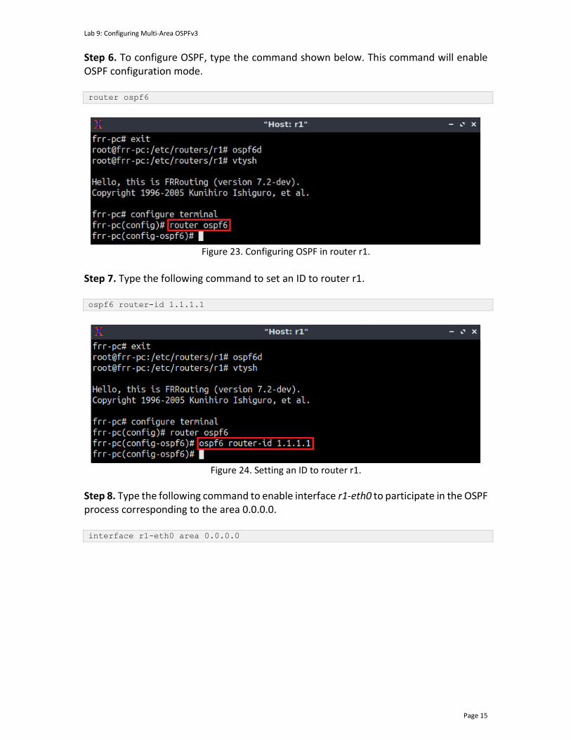
Lab 9: Configuring Multi-Area OSPFv3
Page 15
Step 6. To configure OSPF, type the command shown below. This command will enable OSPF configuration mode. router ospf6
Figure 23. Configuring OSPF in router r1.
Step 7. Type the following command to set an ID to router r1. ospf6 router-id 1.1.1.1
Figure 24. Setting an ID to router r1.
Step 8. Type the following command to enable interface r1-eth0 to participate in the OSPF process corresponding to the area 0.0.0.0. interface r1-eth0 area 0.0.0.0
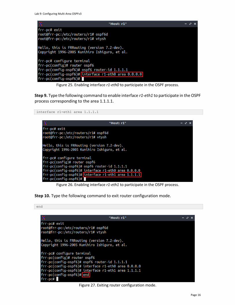
Lab 9: Configuring Multi-Area OSPFv3
Page 16
Figure 25. Enabling interface r1-eth0 to participate in the OSPF process.
Step 9. Type the following command to enable interface r1-eth1 to participate in the OSPF process corresponding to the area 1.1.1.1. interface r1-eth1 area 1.1.1.1
Figure 26. Enabling interface r1-eth1 to participate in the OSPF process.
Step 10. Type the following command to exit router configuration mode. end
Figure 27. Exiting router configuration mode.
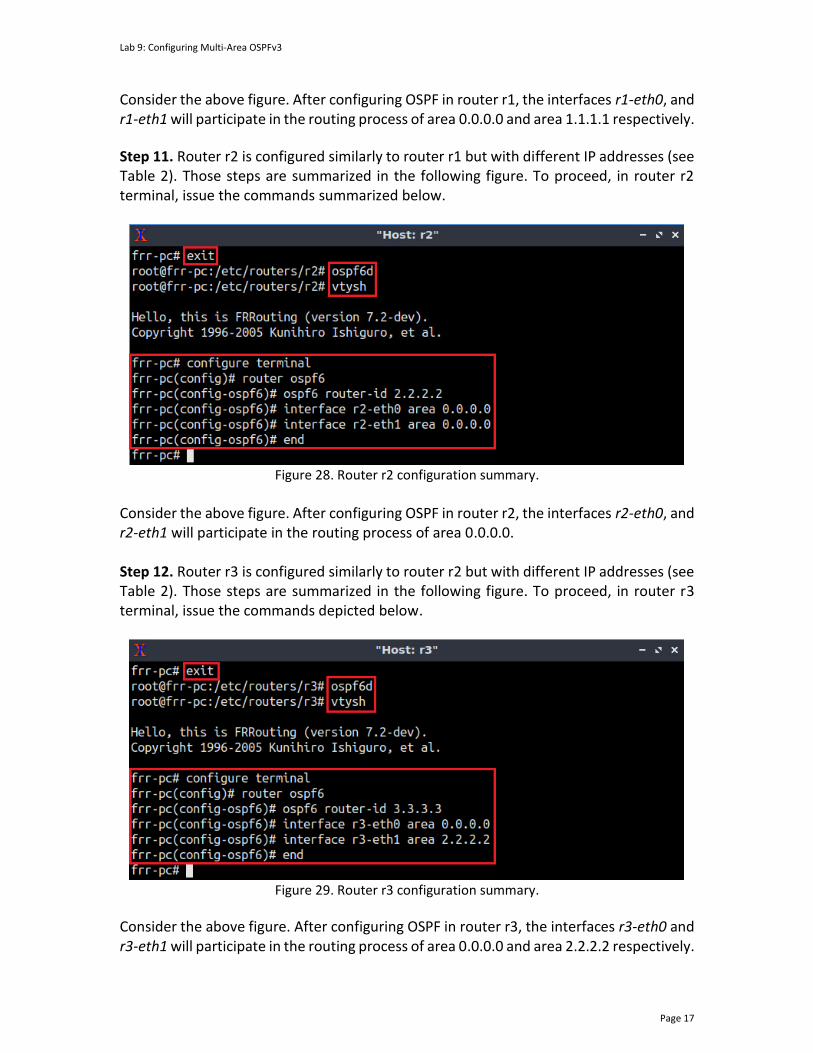
Lab 9: Configuring Multi-Area OSPFv3
Page 17
Consider the above figure. After configuring OSPF in router r1, the interfaces r1-eth0, and r1-eth1 will participate in the routing process of area 0.0.0.0 and area 1.1.1.1 respectively.
Step 11. Router r2 is configured similarly to router r1 but with different IP addresses (see Table 2). Those steps are summarized in the following figure. To proceed, in router r2 terminal, issue the commands summarized below.
Figure 28. Router r2 configuration summary.
Consider the above figure. After configuring OSPF in router r2, the interfaces r2-eth0, and r2-eth1 will participate in the routing process of area 0.0.0.0. Step 12. Router r3 is configured similarly to router r2 but with different IP addresses (see Table 2). Those steps are summarized in the following figure. To proceed, in router r3 terminal, issue the commands depicted below.
Figure 29. Router r3 configuration summary.
Consider the above figure. After configuring OSPF in router r3, the interfaces r3-eth0 and r3-eth1 will participate in the routing process of area 0.0.0.0 and area 2.2.2.2 respectively.
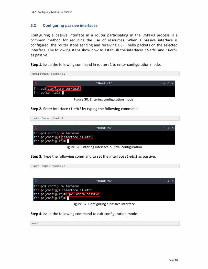
Lab 9: Configuring Multi-Area OSPFv3
Page 18
3.2 Configuring passive interfaces
Configuring a passive interface in a router participating in the OSPFv3 process is a common method for reducing the use of resources. When a passive interface is configured, the router stops sending and receiving OSPF hello packets on the selected interface. The following steps show how to establish the interfaces r1-eth1 and r3-eth1 as passive.
Step 1. Issue the following command in router r1 to enter configuration mode. configure terminal
Figure 30. Entering configuration mode.
Step 2. Enter interface r1-eth1 by typing the following command. interface r1-eth1
Figure 31. Entering interface r1-eth1 configuration.
Step 3. Type the following command to set the interface r1-eth1 as passive. ipv6 ospf6 passive
Figure 32. Configuring a passive interface.
Step 4. Issue the following command to exit configuration mode. end
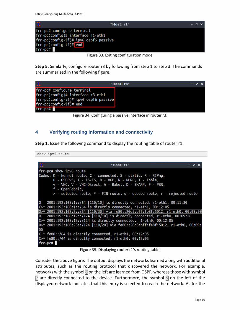
Lab 9: Configuring Multi-Area OSPFv3
Page 19
Figure 33. Exiting configuration mode.
Step 5. Similarly, configure router r3 by following from step 1 to step 3. The commands are summarized in the following figure.
Figure 34. Configuring a passive interface in router r3.
4 Verifying routing information and connectivity Step 1. Issue the following command to display the routing table of router r1.
show ipv6 route
Figure 35. Displaying router r1’s routing table.
Consider the above figure. The output displays the networks learned along with additional attributes, such as the routing protocol that discovered the network. For example, networks with the symbol O on the left are learned from OSPF, whereas those with symbol C are directly connected to the device. Furthermore, the symbol > on the left of the displayed network indicates that this entry is selected to reach the network. As for the
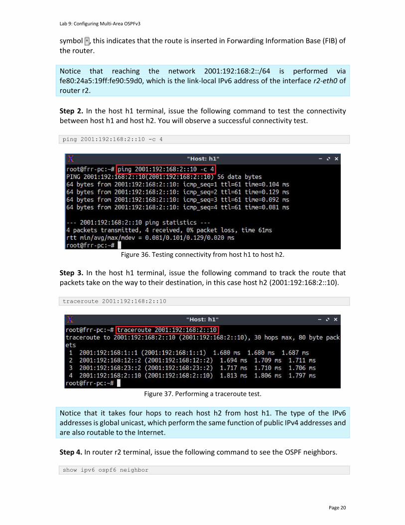
Lab 9: Configuring Multi-Area OSPFv3
Page 20
symbol *, this indicates that the route is inserted in Forwarding Information Base (FIB) of the router.
Notice that reaching the network 2001:192:168:2::/64 is performed via fe80:24a5:19ff:fe90:59d0, which is the link-local IPv6 address of the interface r2-eth0 of router r2.
Step 2. In the host h1 terminal, issue the following command to test the connectivity between host h1 and host h2. You will observe a successful connectivity test. ping 2001:192:168:2::10 -c 4
Figure 36. Testing connectivity from host h1 to host h2.
Step 3. In the host h1 terminal, issue the following command to track the route that packets take on the way to their destination, in this case host h2 (2001:192:168:2::10). traceroute 2001:192:168:2::10
Figure 37. Performing a traceroute test.
Notice that it takes four hops to reach host h2 from host h1. The type of the IPv6 addresses is global unicast, which perform the same function of public IPv4 addresses and are also routable to the Internet.
Step 4. In router r2 terminal, issue the following command to see the OSPF neighbors. show ipv6 ospf6 neighbor
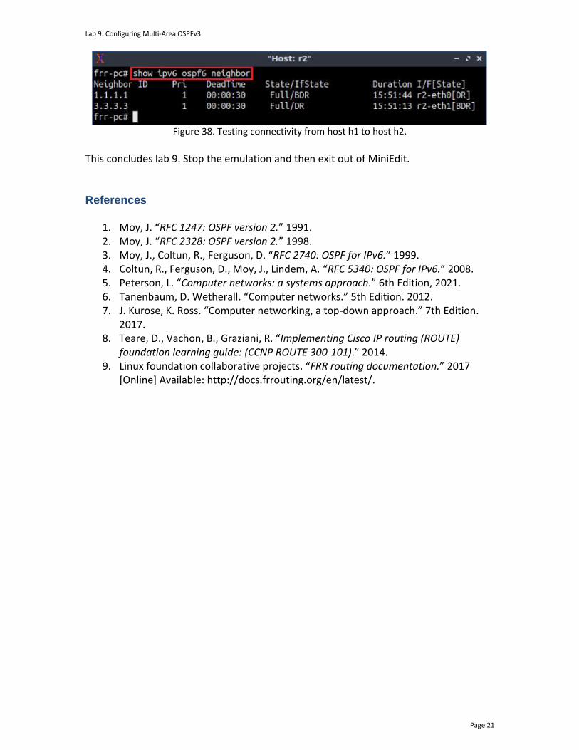
Lab 9: Configuring Multi-Area OSPFv3
Page 21
Figure 38. Testing connectivity from host h1 to host h2.
This concludes lab 9. Stop the emulation and then exit out of MiniEdit. References
1. Moy, J. “RFC 1247: OSPF version 2.” 1991. 2. Moy, J. “RFC 2328: OSPF version 2.” 1998. 3. Moy, J., Coltun, R., Ferguson, D. “RFC 2740: OSPF for IPv6.” 1999. 4. Coltun, R., Ferguson, D., Moy, J., Lindem, A. “RFC 5340: OSPF for IPv6.” 2008. 5. Peterson, L. “Computer networks: a systems approach.” 6th Edition, 2021. 6. Tanenbaum, D. Wetherall. “Computer networks.” 5th Edition. 2012. 7. J. Kurose, K. Ross. “Computer networking, a top-down approach.” 7th Edition.
2017. 8. Teare, D., Vachon, B., Graziani, R. “Implementing Cisco IP routing (ROUTE)
foundation learning guide: (CCNP ROUTE 300-101).” 2014. 9. Linux foundation collaborative projects. “FRR routing documentation.” 2017
[Online] Available: http://docs.frrouting.org/en/latest/.
OPEN SHORTEST PATH FIRST
Exercise 3: Configuring Multi-Area OSPFv3
Document Version: 10-24-2021
Award 1829698 “CyberTraining CIP: Cyberinfrastructure Expertise on High-throughput
Networks for Big Science Data Transfers”
Exercise 3: Configuring Multi-Area OSPFv3
Page 2
Contents 1 Exercise description .................................................................................................... 3
1.1 Credentials .............................................................................................................. 3
2 Setting the environment ............................................................................................. 3
3 Deliverables ................................................................................................................. 6

Exercise 3: Configuring Multi-Area OSPFv3
Page 3
1 Exercise description This exercise is a practice to the Open Shortest Path First version 3 (OSPFv3). The exercise requires configuring multi-area OSPFv3 to provide connectivity between two hosts located in different areas. The topology in the figure below provides the information such as the devices’ names, IPv6 addresses, interface names and the OSPF areas where each device is located.
h1 h2
h1-eth0 h2-eth0:10 :10
s1
s1-eth2 s2-eth2
2001:173:17:1::0/64 2001:173:17:2::0/64
s2
:1
s1-eth1 s2-eth1
r2
r1 r3
r1-eth1 r3-eth1
:2
:1 :2
:1
:1
Area 1 Area 2
Area 0
Figure 1. Exercise topology.
1.1 Credentials The information in Table 1 provides the credentials to access the Client machine.
Table 1. Credentials to access the Client machine.
Device
Account
Password
Client admin password
2 Setting the environment
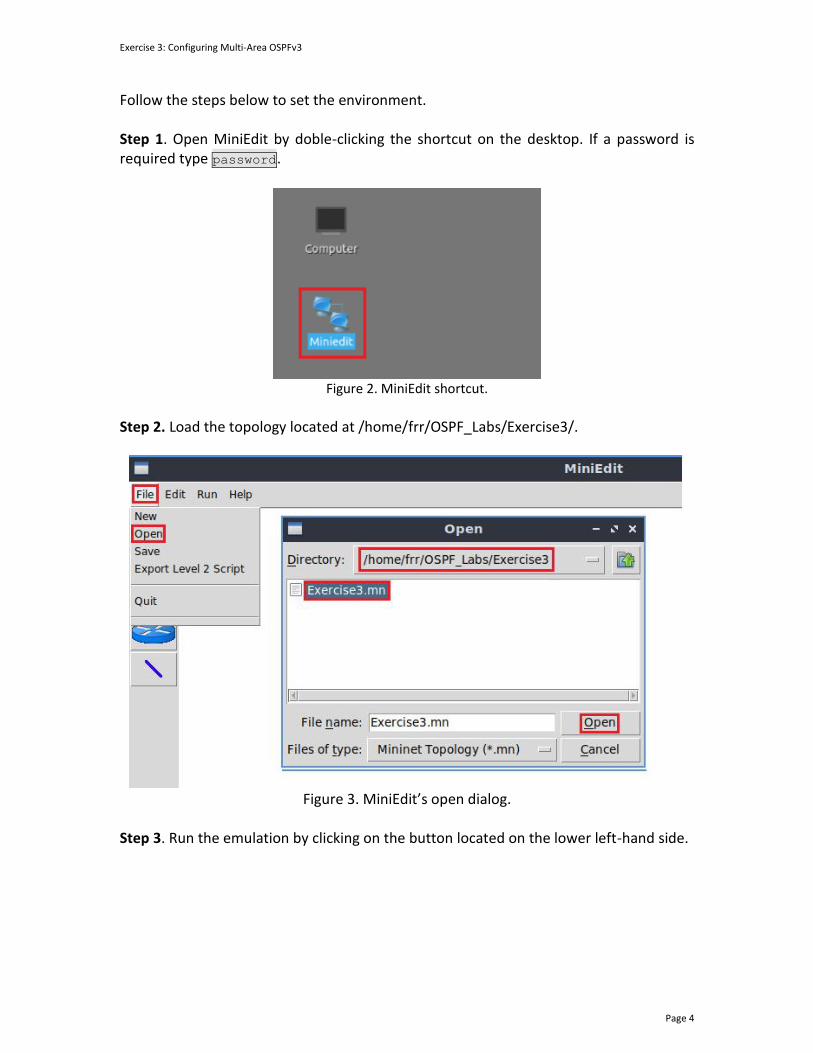
Exercise 3: Configuring Multi-Area OSPFv3
Page 4
Follow the steps below to set the environment. Step 1. Open MiniEdit by doble-clicking the shortcut on the desktop. If a password is required type password.
Figure 2. MiniEdit shortcut.
Step 2. Load the topology located at /home/frr/OSPF_Labs/Exercise3/.
Figure 3. MiniEdit’s open dialog.
Step 3. Run the emulation by clicking on the button located on the lower left-hand side.
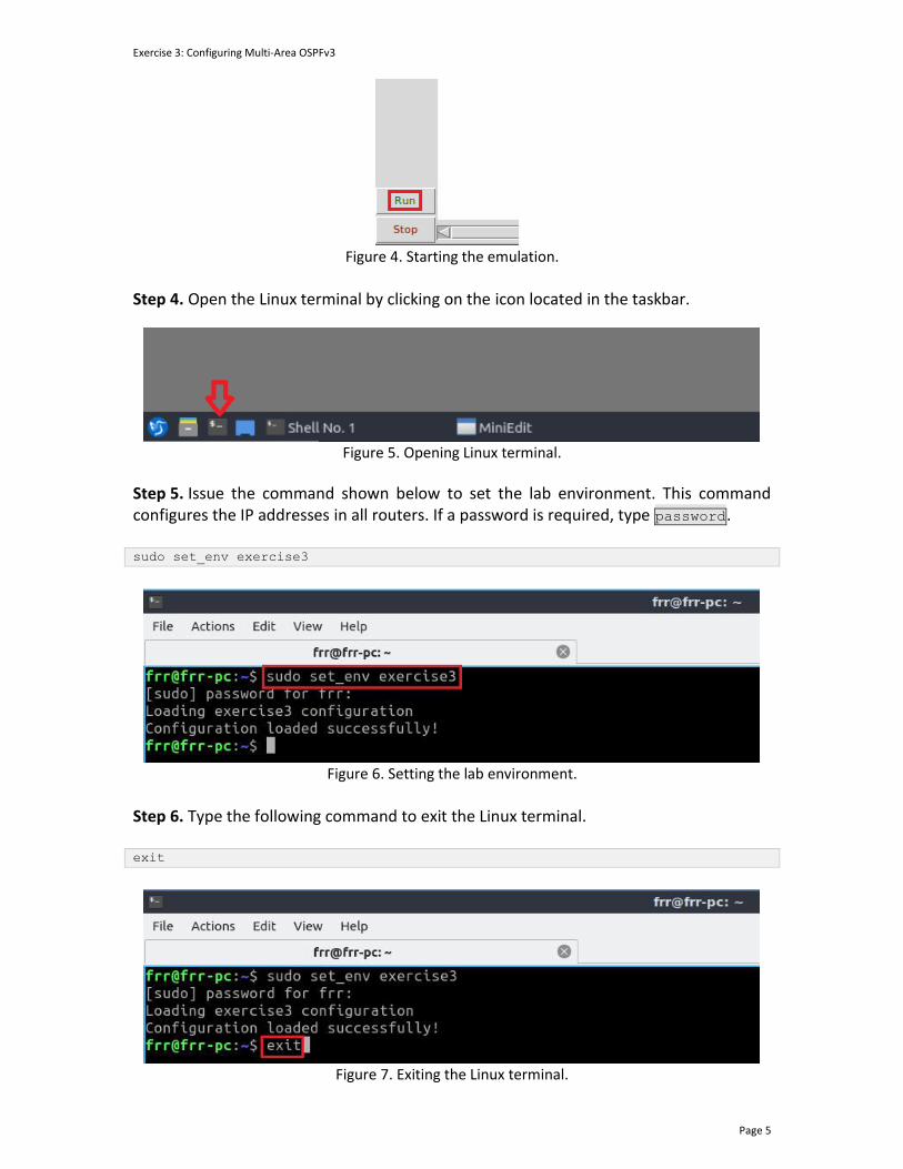
Exercise 3: Configuring Multi-Area OSPFv3
Page 5
Figure 4. Starting the emulation.
Step 4. Open the Linux terminal by clicking on the icon located in the taskbar.
Figure 5. Opening Linux terminal.
Step 5. Issue the command shown below to set the lab environment. This command configures the IP addresses in all routers. If a password is required, type password. sudo set_env exercise3
Figure 6. Setting the lab environment.
Step 6. Type the following command to exit the Linux terminal. exit
Figure 7. Exiting the Linux terminal.
Exercise 3: Configuring Multi-Area OSPFv3
Page 6
3 Deliverables Follow the steps below to complete the exercise.
a) Open a terminal in each router, then, start zebra and the OSPFv3 daemons. b) Access each router CLI using the vtysh command.
c) Verify the directly connected routes in each router.
d) Assign an OSPF router ID to each router.
e) Configure router r1 to participate in the OSPF process of areas 0 and 1.
f) Configure router r2 to participate in the OSPF process of area 0.
g) Configure router r3 to participate in the OSPF process of areas 0 and 2.
h) Set the passive interfaces in routers r1 and r3.
i) Verify the routing and OSPF neighbor tables of each router.
j) Perform a connectivity test from host h1 to host h2.

OPEN SHORTEST PATH FIRST
Lab 10: Configuring Dual Stack OSPF Routing
Document Version: 10-11-2021
Award 1829698 “CyberTraining CIP: Cyberinfrastructure Expertise on High-throughput
Networks for Big Science Data Transfers”
Lab 10: Configuring Dual Stack OSPF Routing
Page 2
Contents Overview ............................................................................................................................. 3
Objectives............................................................................................................................ 3
Lab settings ......................................................................................................................... 3
Lab roadmap ....................................................................................................................... 3
1 Introduction ................................................................................................................ 3
1.1 Advantages of dual stack routing ......................................................................... 4
1.2 Free range routing (FRR) and OSPFv3 .................................................................. 4
2 Lab topology................................................................................................................ 4
2.1 Lab settings........................................................................................................... 5
2.2 Loading the topology............................................................................................ 6
2.3 Load the zebra daemon and verify the configuration ......................................... 9
3 Configuring single-area OSPFv2 ................................................................................ 13
3.1 Configuring OSPFv2 in routers r1, r2, and r3 ..................................................... 13
3.2 Verifying IPv4 routing information and connectivity ......................................... 17
4 Configuring single-area OSPFv3 ................................................................................ 19
4.1 Configuring OSPFv3 in routers r1, r2, and r3 ..................................................... 19
4.2 Verifying IPv6 routing information and connectivity ......................................... 23
References ........................................................................................................................ 25

Lab 10: Configuring Dual Stack OSPF Routing
Page 3
Overview This lab introduces dual stack routing using OSPF, where the routers involved in the OSPF process forward IPv4 and IPv6 traffic. Dual stack routing is a method that can facilitate the transition from IPv4 to IPv6. The user will configure the routers participating in the OSPF process to handle IPv4 and IPv6 packets in this lab. Objectives By the end of this lab, you should be able to:
1. Understand the concept of dual stack routing. 2. Configure two OSPF process per instance to handle IPv4 and IPv6 traffic. 3. Understand the scope and limitations of dual stack routing. 4. Verify both OSPv2 and OSPv3 configurations.
Lab settings The information in Table 1 provides the credentials to access the Client machine.
Table 1. Credentials to access the Client machine.
Device
Account
Password
Client admin password
Lab roadmap This lab is organized as follows:
1. Section 1: Introduction. 2. Section 2: Lab topology. 3. Section 3: Configuring single-area OSPFv2. 4. Section 4: Configuring single-area OSPFv3.
1 Introduction The Internet Protocol version 6 (IPv6) has been developed to solve the architectural limitations of IPv4. One of the main characteristics of IPv6 is the provision of a more significant number of addresses compared to IPv4. Although the IPv6 adoption over the Internet remains small, major network operators and content providers are increasingly using IPv6 in their deployments10.

Lab 10: Configuring Dual Stack OSPF Routing
Page 4
IPv4 is the protocol that the Internet has used since its very early years. Therefore, it is the most important and most widely deployed networking protocol in existence. Although it has been said that IPv4 addresses are scarce and already exhausted, the Network Address Translation (NAT) technology has extended IPv4’s life11. Using the dual stack approach is a method to achieve the coexistence between IPv4 and IPv6. Utilizing dual stack implies that the network hardware can handle IPv4 and IPv6 traffic simultaneously. Therefore, this approach can facilitate the transition from IPv4 to IPv611,12,13. 1.1 Advantages of dual stack routing
The dual stack approach can be a cost-effective and straightforward method for migrating to IPv6. It enables high processing efficiency and reduces information loss by eliminating the need for translation between two protocol stacks. The translation refers to a mechanism that introduces operational complexity and lower performance. Moreover, implementing services over IPv6 can increasingly reduce the usage of IPv4, paving the way to fully migrate to IPv6. Nevertheless, the dual stack approach must not be considered a long-term solution as it requires the implementation of routing protocol for IPv4 and IPv6. This limitation increases the time that it takes to implement and configure devices that handle both protocols. 1.2 Free range routing (FRR) and OSPFv3
The OSPF version 3 implementation available in FRR is based on the RFC 27403, which only supports IPv6 routing. However, FRR supports running and configuring multiple routing daemons in one instance (i.e., a router). This characteristic allows implementing dual stack routing. 2 Lab topology Consider Figure 1. The topology consists of four networks connected to their respective routers. The communication between networks is established via single-area OSPFv2, and OSPFv3 configured in all routers. Note that end hosts interfaces have both IPv4 and IPv6 addresses.

Lab 10: Configuring Dual Stack OSPF Routing
Page 5
h1 h2
h1-eth0 h2-eth0.10:10
.10:10
s1
s1-eth2 s2-eth2
2001:192:168:1::0/64
s2
.1:1
s1-eth1 s2-eth1
r2
r1 r3
r2-eth1 r3-eth1
.2:2
.1:1
.2:2
.1:1
.1:1
Area 1 Area 2
Area 0
2001:192:168:2::0/64
192.168.1.0/24 192.168.2.0/24
Figure 1. Lab topology.
2.1 Lab settings
Table 2 and Table 3 contain information related to the interfaces of all devices in the topology. Additionally, the tables have the IPv4, IPv6 addresses, subnet, and default gateways.
Table 2. Topology information.
Device Interface IIPv4 Address Subnet Default Gateway
Router 1 (r1)
r1-eth0 192.168.12.1 /30 N/A
r1-eth1 192.168.1.0 /24 N/A
Router 2 (r2)
r2-eth0 192.168.12.2 /30 N/A
r2-eth1 192.168.23.1 /30 N/A
Router 3 (r3)
r3-eth0 192.168.23.2 /30 N/A
r3-eth1 192.168.2.1 /24 N/A
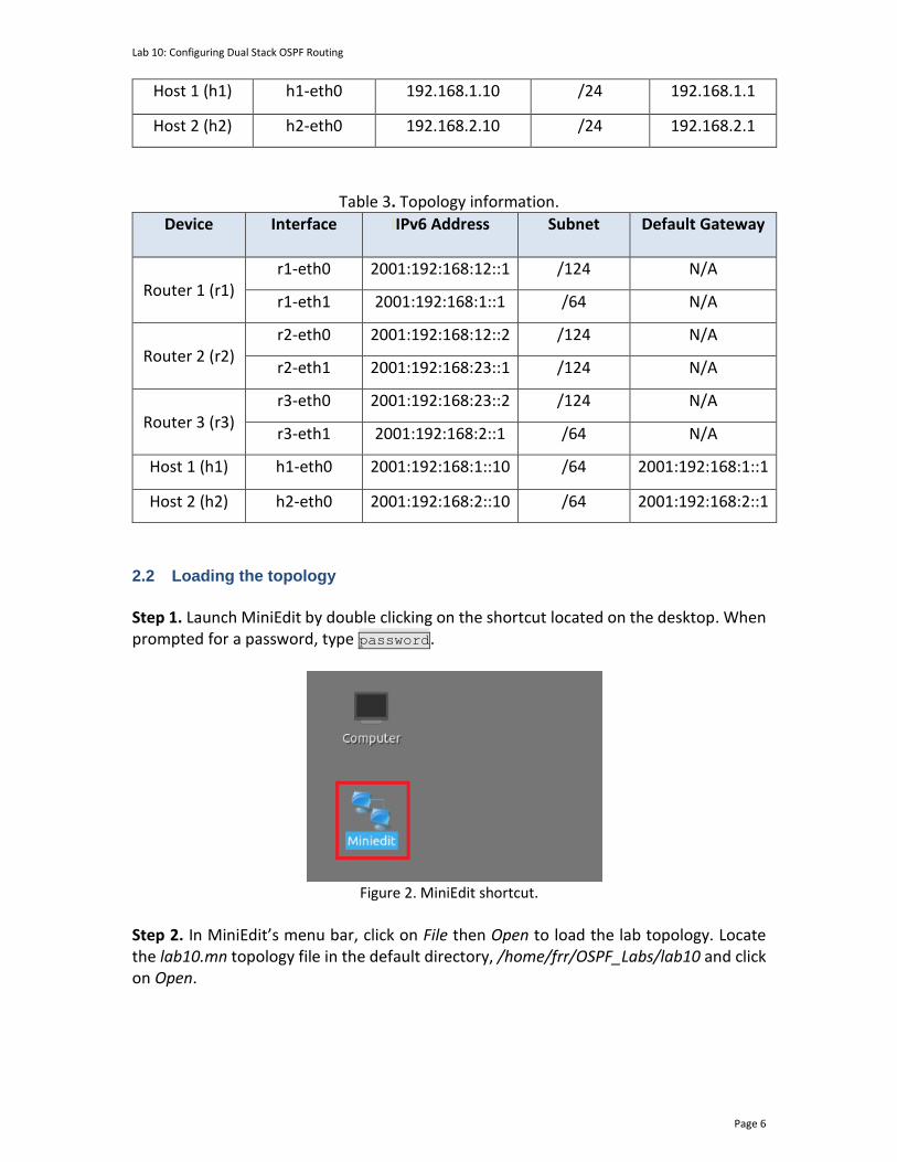
Lab 10: Configuring Dual Stack OSPF Routing
Page 6
Host 1 (h1) h1-eth0 192.168.1.10 /24 192.168.1.1
Host 2 (h2) h2-eth0 192.168.2.10 /24 192.168.2.1
Table 3. Topology information.
Device Interface IIPv6 Address Subnet Default Gateway
Router 1 (r1)
r1-eth0 2001:192:168:12::1 /124 N/A
r1-eth1 2001:192:168:1::1 /64 N/A
Router 2 (r2)
r2-eth0 2001:192:168:12::2 /124 N/A
r2-eth1 2001:192:168:23::1 /124 N/A
Router 3 (r3)
r3-eth0 2001:192:168:23::2 /124 N/A
r3-eth1 2001:192:168:2::1 /64 N/A
Host 1 (h1) h1-eth0 2001:192:168:1::10 /64 2001:192:168:1::1
Host 2 (h2) h2-eth0 2001:192:168:2::10 /64 2001:192:168:2::1
2.2 Loading the topology
Step 1. Launch MiniEdit by double clicking on the shortcut located on the desktop. When prompted for a password, type password.
Figure 2. MiniEdit shortcut.
Step 2. In MiniEdit’s menu bar, click on File then Open to load the lab topology. Locate the lab10.mn topology file in the default directory, /home/frr/OSPF_Labs/lab10 and click on Open.

Lab 10: Configuring Dual Stack OSPF Routing
Page 7
Figure 3. MiniEdit’s open dialog.
At this point, the topology is loaded with all the required network components. Next, you will execute a script that will load the configuration of the routers. Step 3. Click on the Run button located on the lower left-hand side to run the emulation.
Figure 4. Starting the emulation.
At this point, the topology is loaded with all the required network components. Next, you will execute a script that will configure the interfaces of the routers.
Automating the configuration of interfaces with the script is intended to facilitate the lab experience and to focus on the OSPF experiment.
Step 4. Open the Linux terminal by clicking on the icon located in the taskbar.
Figure 5. Opening Linux terminal.
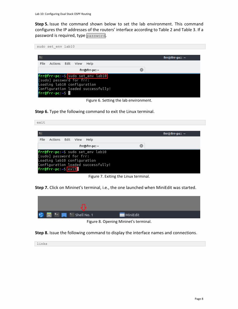
Lab 10: Configuring Dual Stack OSPF Routing
Page 8
Step 5. Issue the command shown below to set the lab environment. This command configures the IP addresses of the routers’ interface according to Table 2 and Table 3. If a password is required, type password. sudo set_env lab10
Figure 6. Setting the lab environment.
Step 6. Type the following command to exit the Linux terminal. exit
Figure 7. Exiting the Linux terminal.
Step 7. Click on Mininet's terminal, i.e., the one launched when MiniEdit was started.
Figure 8. Opening Mininet's terminal.
Step 8. Issue the following command to display the interface names and connections. links

Lab 10: Configuring Dual Stack OSPF Routing
Page 9
Figure 9. Displaying network interfaces.
In the figure above, the link displayed within the gray box indicates that interface eth2 of switch s1 connects to interface eth0 of host h1 (i.e., s1-eth2<->h1-eth0). 2.3 Load the zebra daemon and verify the configuration
In this section, you will verify that the IP addresses listed in Table 2 and inspect the routing table of the routers. Step 1. Hold right-click on host h1 and select Terminal. This opens the terminal of host h1 and allows the execution of commands on that host.
Figure 10. Opening host h1 terminal.
Step 2. In the host h1 terminal, type the command shown below to verify that the IP address was assigned successfully. ifconfig

Lab 10: Configuring Dual Stack OSPF Routing
Page 10
Figure 11. Displaying host h1 interfaces and IP addresses.
You will verify that host h1 has two interfaces. Interface h1-eth0 is configured with the IPv4 address 192.168.1.10, the link-local IPv6 address fe80::d858:83ff:fe72:7576, and the IPv6 global unicast address 2001:192:168:1::10. The prefix length for IPv6 addresses is 64. The other interface is the loopback lo.
A link-local address is an IPv6 unicast address that can be configured on any interface. It is used to reach the neighboring nodes attached to the same link. The IPv6 link-local addresses start with the FE80 prefix.
Step 3. In the host h1 terminal, type the following command to verify that the default IPv4 gateway address is 192.168.1.1.
Figure 12. Displaying host h1 default IPv4 route.
Step 4. In the host h1 terminal, type the command shown below to verify that the default IPv6 gateway address is 2001:192:168:1::1. ip -6 route
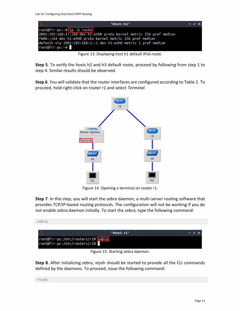
Lab 10: Configuring Dual Stack OSPF Routing
Page 11
Figure 13. Displaying host h1 default IPv6 route.
Step 5. To verify the hosts h2 and h3 default route, proceed by following from step 1 to step 4. Similar results should be observed. Step 6. You will validate that the router interfaces are configured according to Table 2. To proceed, hold right-click on router r1 and select Terminal.
Figure 14. Opening a terminal on router r1.
Step 7. In this step, you will start the zebra daemon, a multi-server routing software that provides TCP/IP-based routing protocols. The configuration will not be working if you do not enable zebra daemon initially. To start the zebra, type the following command: zebra
Figure 15. Starting zebra daemon.
Step 8. After initializing zebra, vtysh should be started to provide all the CLI commands defined by the daemons. To proceed, issue the following command: vtysh

Lab 10: Configuring Dual Stack OSPF Routing
Page 12
Figure 16. Starting vtysh on router r1.
Step 9. Type the following command on router r1 terminal to verify the IPv4 routing table. It will list all the directly connected networks. Notice that the routing table of router r1 does not contain any route to the network connected to router r3 (192.168.2.0/24) as there is no routing protocol configured yet. show ip route
Figure 17. Displaying the IPv4 routing table of router r1.
Step 10. Type the following command on router r1 terminal to verify the IPv6 routing table. It will list all the directly connected networks. Notice that the routing table of router r1 does not contain any route to the network connected to router r3 (2001:192:168:2::0/64) as there is no routing protocol configured yet. The first two entries correspond to the directly connected networks. The last two entries correspond to link-local network connected to each interface. show ipv6 route

Lab 10: Configuring Dual Stack OSPF Routing
Page 13
Figure 18. Displaying the IPv6 routing table of router r1.
Step 11. To verify the routing table of the other routers, proceed similarly by following from step 6 to step 10 on the corresponding router terminal.
3 Configuring single-area OSPFv2 In this section, you will configure r1, r2, and r3 to participate in the OSPFv2 process of area 0. 3.1 Configuring OSPFv2 in routers r1, r2, and r3
Step 1. Open router r1’s terminal by selecting the icon from the taskbar as shown below.
Figure 19. Opening router r1’s terminal.
Step 2. In router r1’s terminal, type the command below to exit the vtysh session. exit
Figure 20. Exiting the vtysh session.

Lab 10: Configuring Dual Stack OSPF Routing
Page 14
Step 3. Enable and start the OSPF routing protocol by typing the following command: ospfd
Figure 21. Starting the OSPF daemon.
Step 4. To enter router r1’s terminal, type the following command: vtysh
Figure 22. Starting vtysh in router r1.
Step 5. At this point, you have entered router r1’s terminal, to enter configuration mode in router r1, issue the following command: configure terminal
Figure 23. Entering configuration mode in router r1.
Step 6. To configure OSPF, type the command shown below. This command will enable OSPF configuration mode. router ospf

Lab 10: Configuring Dual Stack OSPF Routing
Page 15
Figure 24. Configuring OSPF in router r1.
Step 7. Type the following command to set an ID to router r1. ospf router-id 1.1.1.1
Figure 25. Setting an ID to router r1.
Step 8. Type the following command to enable interface r1-eth0 to participate in the OSPF process corresponding to area 0. network 192.168.12.0/30 area 0
Figure 26. Enabling interface r1-eth0 to participate in the OSPF process.
Step 9. Type the following command to enable interface r1-eth1 to participate in the OSPF process corresponding to area 0.

Lab 10: Configuring Dual Stack OSPF Routing
Page 16
network 192.168.2.0/24 area 0
Figure 27. Enabling interface r1-eth1 to participate in the OSPF process.
Step 10. Type the following command to exit router configuration mode. end
Figure 28. Exiting router configuration mode.
Consider the figure above. After configuring OSPF in router r1, the interfaces r1-eth0, and r1-eth1 will participate in the routing process of area 0 and area 1 respectively.
Step 11. Router r2 is configured similarly to router r1 but with different IP addresses (see Table 2). Those steps are summarized in the following figure. To proceed, in router r2 terminal, issue the commands summarized below.

Lab 10: Configuring Dual Stack OSPF Routing
Page 17
Figure 29. Router r2 configuration summary.
Consider the figure above. After configuring OSPF in router r2, the interfaces r2-eth0, and r2-eth1 will participate in the routing process of area 0. Step 12. Router r3 is configured similarly to router r2 but with different IP addresses (see Table 2). Those steps are summarized in the following figure. To proceed, in router r3 terminal, issue the commands depicted below.
Figure 30. Router r3 configuration summary.
Consider the figure above. After configuring OSPF in router r3, the interfaces r3-eth0 and r3-eth1 will participate in the routing process of area. 3.2 Verifying IPv4 routing information and connectivity
Step 1. Issue the following command to display the IPv4 routing table of router r1.
show ip route
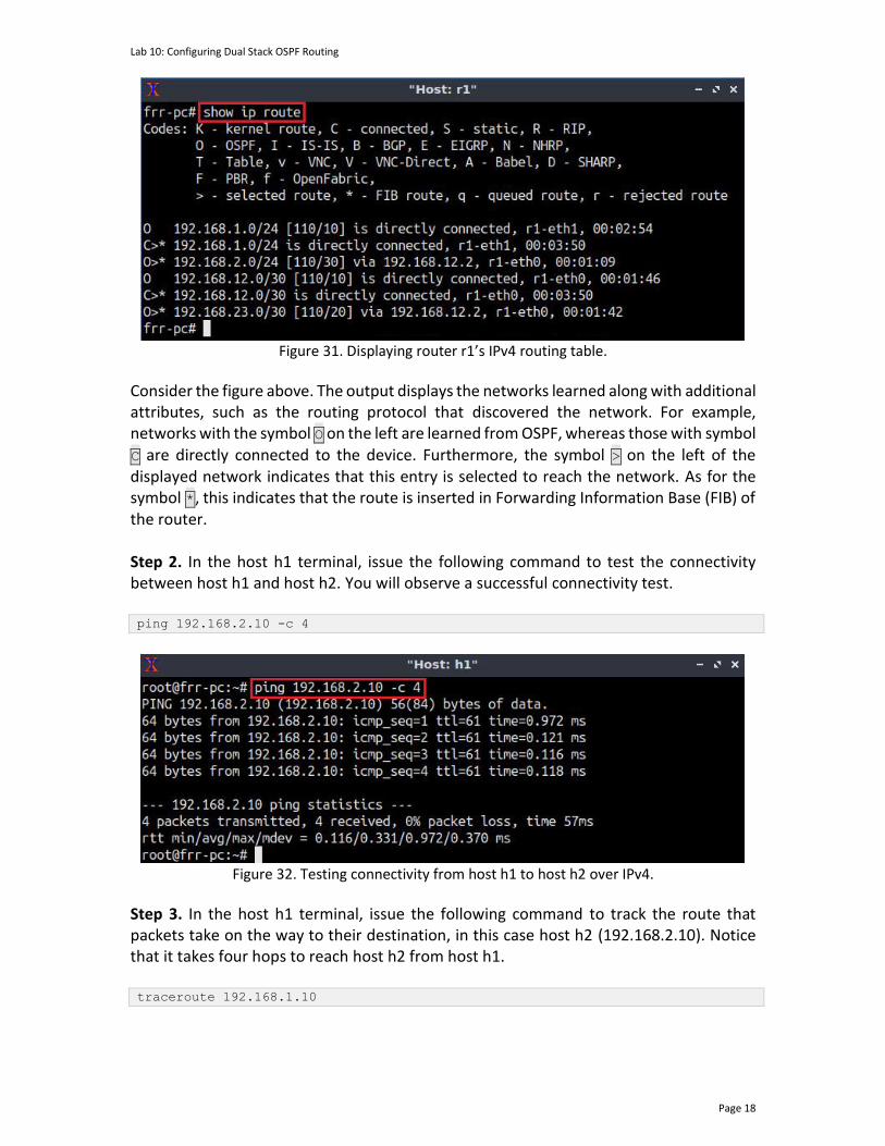
Lab 10: Configuring Dual Stack OSPF Routing
Page 18
Figure 31. Displaying router r1’s IPv4 routing table.
Consider the figure above. The output displays the networks learned along with additional attributes, such as the routing protocol that discovered the network. For example, networks with the symbol O on the left are learned from OSPF, whereas those with symbol C are directly connected to the device. Furthermore, the symbol > on the left of the displayed network indicates that this entry is selected to reach the network. As for the symbol *, this indicates that the route is inserted in Forwarding Information Base (FIB) of the router. Step 2. In the host h1 terminal, issue the following command to test the connectivity between host h1 and host h2. You will observe a successful connectivity test. ping 192.168.2.10 -c 4
Figure 32. Testing connectivity from host h1 to host h2 over IPv4.
Step 3. In the host h1 terminal, issue the following command to track the route that packets take on the way to their destination, in this case host h2 (192.168.2.10). Notice that it takes four hops to reach host h2 from host h1. traceroute 192.168.1.10
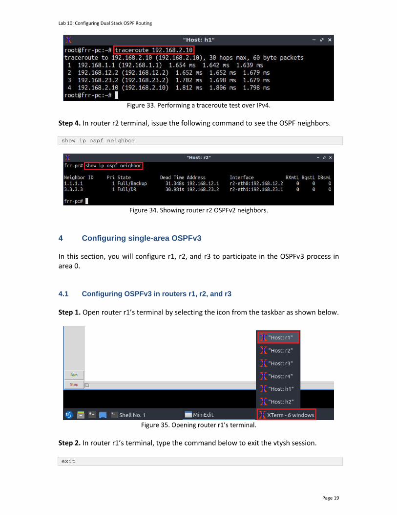
Lab 10: Configuring Dual Stack OSPF Routing
Page 19
Figure 33. Performing a traceroute test over IPv4.
Step 4. In router r2 terminal, issue the following command to see the OSPF neighbors. show ip ospf neighbor
Figure 34. Showing router r2 OSPFv2 neighbors.
4 Configuring single-area OSPFv3 In this section, you will configure r1, r2, and r3 to participate in the OSPFv3 process in area 0. 4.1 Configuring OSPFv3 in routers r1, r2, and r3
Step 1. Open router r1’s terminal by selecting the icon from the taskbar as shown below.
Figure 35. Opening router r1’s terminal.
Step 2. In router r1’s terminal, type the command below to exit the vtysh session. exit

Lab 10: Configuring Dual Stack OSPF Routing
Page 20
Figure 36. Exiting the vtysh session.
Step 3. Enable and start the OSPF routing protocol by typing the following command: ospf6d
Figure 37. Starting the OSPF daemon.
Step 4. To enter router r1’s terminal, type the following command: vtysh
Figure 38. Starting vtysh in router r1.
Step 5. At this point, you have entered router r1’s terminal, to enter configuration mode in router r1, issue the following command: configure terminal
Figure 39. Entering configuration mode in router r1.
Step 6. To configure OSPF, type the command shown below. This command will enable OSPF configuration mode.

Lab 10: Configuring Dual Stack OSPF Routing
Page 21
router ospf6
Figure 40. Configuring OSPF in router r1.
Step 7. Type the following command to set an ID to router r1. ospf6 router-id 0.0.0.1
Figure 41. Setting an ID to router r1.
Step 8. Type the following command to enable interface r1-eth0 to participate in the OSPF process corresponding to the area 0.0.0.0. interface r1-eth0 area 0.0.0.0
Figure 42. Enabling interface r1-eth0 to participate in the OSPF process.

Lab 10: Configuring Dual Stack OSPF Routing
Page 22
Step 9. Type the following command to enable interface r1-eth1 to participate in the OSPF process corresponding to the area 0.0.0.0. interface r1-eth1 area 0.0.0.0
Figure 43. Enabling interface r1-eth1 to participate in the OSPF process.
Step 10. Type the following command to exit router configuration mode. end
Figure 44. Exiting router configuration mode.
Consider the figure above. After configuring OSPF in router r1, the interfaces r1-eth0, and r1-eth1 will participate in the routing process of area 0.0.0.0.
Step 11. Router r2 is configured similarly to router r1 but with different IP addresses (see Table 2). Those steps are summarized in the following figure. To proceed, in router r2 terminal, issue the commands summarized below.
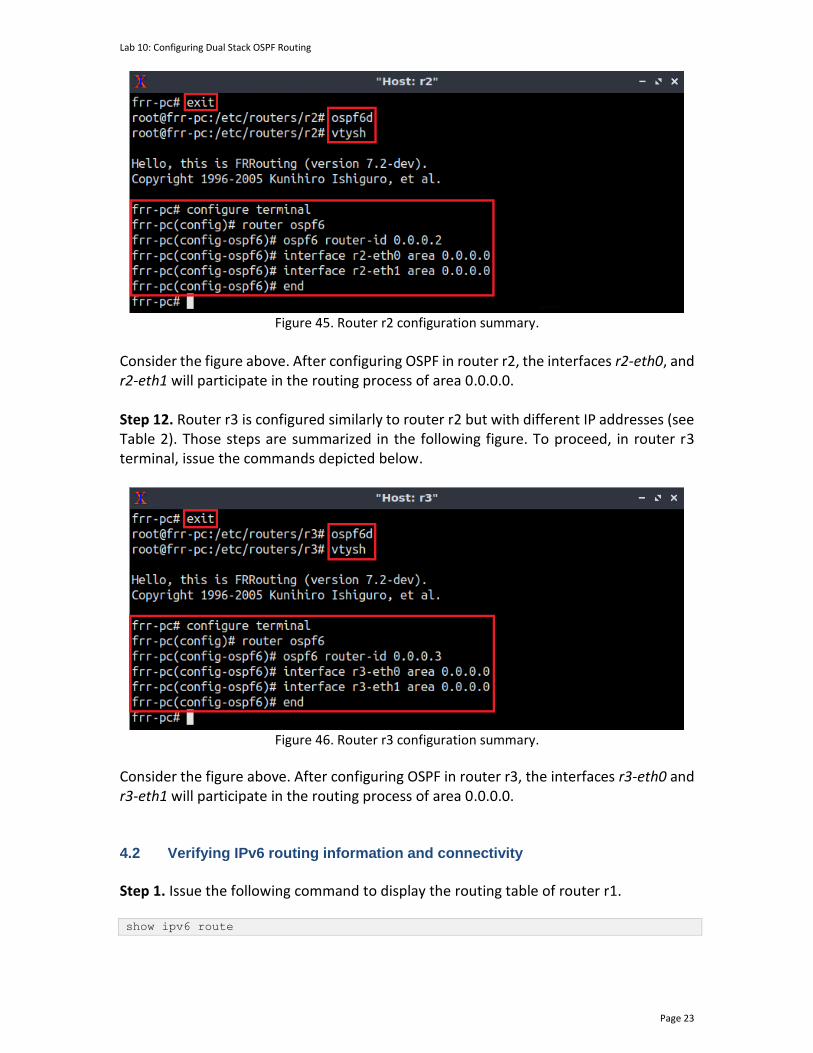
Lab 10: Configuring Dual Stack OSPF Routing
Page 23
Figure 45. Router r2 configuration summary.
Consider the figure above. After configuring OSPF in router r2, the interfaces r2-eth0, and r2-eth1 will participate in the routing process of area 0.0.0.0. Step 12. Router r3 is configured similarly to router r2 but with different IP addresses (see Table 2). Those steps are summarized in the following figure. To proceed, in router r3 terminal, issue the commands depicted below.
Figure 46. Router r3 configuration summary.
Consider the figure above. After configuring OSPF in router r3, the interfaces r3-eth0 and r3-eth1 will participate in the routing process of area 0.0.0.0. 4.2 Verifying IPv6 routing information and connectivity
Step 1. Issue the following command to display the routing table of router r1.
show ipv6 route

Lab 10: Configuring Dual Stack OSPF Routing
Page 24
Figure 47. Displaying router r1’s routing table.
Notice that reaching the network 2001:192:168:2::/64 is performed via fe80::2c32:81ff:fe80:7aba, which is the link-local IPv6 address of the interface r2-eth0 of router r2.
Step 2. In the host h1 terminal, issue the following command to test the connectivity between host h1 and host h2. You will observe a successful connectivity test. ping 2001:192:168:2::10 -c 4
Figure 48. Testing connectivity from host h1 to host h2 over IPv6.
Step 3. In the host h1 terminal, issue the following command to track the route that packets take on the way to their destination, in this case host h2 (2001:192:168:2::10). traceroute 2001:192:168:2::10

Lab 10: Configuring Dual Stack OSPF Routing
Page 25
Figure 49. Performing a traceroute test over IPv6.
Notice that it takes four hops to reach host h2 from host h1. The type of the IPv6 addresses is global unicast, which perform the same function of public IPv4 addresses and are also routable to the Internet.
Step 4. In router r2 terminal, issue the following command to see the OSPF neighbors. show ipv6 ospf6 neighbor
Figure 50. Testing connectivity from host h1 to host h2.
The figure above shows that router r1 and router r3 (Router IDs 0.0.0.1 and 0.0.0.3 respectively) are neighbors of router r2. This concludes lab 10. Stop the emulation and then exit out of MiniEdit. References
1. Moy, J. “RFC 1247: OSPF version 2.” 1991. 2. Moy, J. “RFC 2328: OSPF version 2.” 1998. 3. Coltun, R., Ferguson, D., Moy, J., Lindem, A. “RFC 2740: OSPF for IPv6.” 1999. 4. Coltun, R., Ferguson, D., Moy, J., Lindem, A. “RFC 5340: OSPF for IPv6.” 2008. 5. Peterson, L. “Computer networks: a systems approach.” 6th Edition, 2021. 6. Tanenbaum, D. Wetherall. “Computer networks.” 5th Edition. 2012. 7. J. Kurose, K. Ross. “Computer networking, a top-down approach.” 7th Edition.
2017. 8. Teare, D., Vachon, B., Graziani, R. “Implementing Cisco IP routing (ROUTE)
foundation learning guide: (CCNP ROUTE 300-101).” 2014. 9. Linux foundation collaborative projects. “FRR routing documentation.” 2017.
[Online], Available: http://docs.frrouting.org/en/latest/. 10. Google, “Google ipv6 implementors conference,” 2010. [Online]. Available:
https://sites.google.com/site/ ipv6implementors/2010/agenda.

Lab 10: Configuring Dual Stack OSPF Routing
Page 26
11. Karpilovsky, E., Gerber A., Pei D., Rexford J., Shaikh, A. “Quantifying the extent of IPv6 deployment.” In International Conference on Passive and Active Network Measurement. 2009.
12. Ram, M., “Will U.S. government directives spur IPv6 adoption?”2010. [Online]. Available: http://www.circleid.com/posts/20100929_will_ us_government_directives_spur_ipv6_adoption/.
13. Jakub C., Allman M., Zhang J., Lekel-Johnson S., Osterweil E., Bailey, M. "Measuring IPv6 adoption." In Proceedings of the 2014 ACM Conference on SIGCOMM, 2014.
Related Documents