Thermal, mechanical and self-destruction properties of aluminum reinforced carbon foam Shameel Farhan 1 • Ru-Min Wang 1 Published online: 22 April 2015 Ó Springer Science+Business Media New York 2015 Abstract Carbon foam has been developed by templating method with phenolic resin and coal tar pitch as matrix pre- cursor and polyurethane foam as a sacrificial template. For improving thermal and mechanical properties, aluminum (Al) powder with 2–8 wt% was added into the impregnation mixture. Carbonization at 1273 K in inert environment under the cover of coke breeze produced Al 4 C 3 in situ and AlN by substitution reaction. Various thermal and mechanical tests showed a density of 0.50–0.58 g/cm 3 , open porosity of 64–68 %, thermal conductivity of 0.043–0.385 W/mK and a compressive strength of 17–32 MPa for the samples con- taining 0–6 wt% Al. Scanning electron microscope was used to evaluate the pore morphology, distribution of Al in the porous network and an approximate pore size distribution which came out to be in the range of 2–200 lm. X-ray mapping showed a homogeneous dispersion of Al with some agglomerates into the ball shape. Carbon foam with 8 wt% Al showed self-destruction in 14 days after 15 days of manufacturing. The destruction started from core and pro- ceeded towards outer surface resulting in a core–shell effect. X-ray diffraction analysis confirmed the destruction due to the formation of Al 4 C 3 and reaction with atmospheric mois- ture forming Al(OH) 3 . This property can be further explored to be applied in the field of composite tooling for advanced carbon fiber reinforced composites. The tool will lose strength after certain time, facilitating in easy removal from the complex shape composites. Keywords Carbon foam In situ Self-destruction Compressive strength Thermal conductivity Environmental effects 1 Introduction Carbon/aluminum composites have been receiving consid- erable attention due to their high thermal properties, high specific strength and modulus for application in commercial and automobile industries [1, 2]. They offer the possibility of thermal management applications with tailorable properties. Graphite foams, on the other hand, are also showing a great potential for improving the thermal management applica- tions due to their low density, and high porosity along with large surface area [3–5]. Googin [6] reported the first process dedicated to controlling the structure and properties of car- bon foams by varying the precursor material. Until now several researchers explored a variety of applications for carbon foam materials [7–10]. These studies pioneered me- sophase derived graphitic foams for honeycomb materials to develop a highly structural material. Recently, Klett devel- oped a new manufacturing technique to enhance the thermal properties of carbon foams [11]. Typically, carbon foams are prepared from organic precursors like phenolic resin, coal or mesophase pitches [12–14]. The template carbonization process has been regarded as the simplest and effective method to produce carbon foam with controlled properties. Impregnations of a precursor into the template, stabilization/ curing and template removal/conversion into carbon at high temperature are the key controls. The most commonly used organic precursor is a phenolic resin. Carbon foam derived from phenolic resin can be used for the high-strength thermal insulations in aerospace, nuclear, cryogenics and building industry [15–17]. Coal derived and pitch based carbon foams & Shameel Farhan [email protected] Ru-Min Wang [email protected] 1 Department of Applied Chemistry, School of Science, Northwestern Polytechnical University, Xi’an 710072, China 123 J Porous Mater (2015) 22:897–906 DOI 10.1007/s10934-015-9963-3

Welcome message from author
This document is posted to help you gain knowledge. Please leave a comment to let me know what you think about it! Share it to your friends and learn new things together.
Transcript

Thermal, mechanical and self-destruction properties of aluminumreinforced carbon foam
Shameel Farhan1 • Ru-Min Wang1
Published online: 22 April 2015
� Springer Science+Business Media New York 2015
Abstract Carbon foam has been developed by templating
method with phenolic resin and coal tar pitch as matrix pre-
cursor and polyurethane foam as a sacrificial template. For
improving thermal and mechanical properties, aluminum
(Al) powder with 2–8 wt% was added into the impregnation
mixture. Carbonization at 1273 K in inert environment under
the cover of coke breeze produced Al4C3 in situ and AlN by
substitution reaction. Various thermal and mechanical tests
showed a density of 0.50–0.58 g/cm3, open porosity of
64–68 %, thermal conductivity of 0.043–0.385 W/mK and a
compressive strength of 17–32 MPa for the samples con-
taining 0–6 wt%Al. Scanning electron microscope was used
to evaluate the pore morphology, distribution of Al in the
porous network and an approximate pore size distribution
which came out to be in the range of 2–200 lm. X-ray
mapping showed a homogeneous dispersion of Al with some
agglomerates into the ball shape.Carbon foamwith 8 wt%Al
showed self-destruction in 14 days after 15 days of
manufacturing. The destruction started from core and pro-
ceeded towards outer surface resulting in a core–shell effect.
X-ray diffraction analysis confirmed the destruction due to
the formation of Al4C3 and reaction with atmospheric mois-
ture forming Al(OH)3. This property can be further explored
to be applied in the field of composite tooling for advanced
carbon fiber reinforced composites. The tool will lose
strength after certain time, facilitating in easy removal from
the complex shape composites.
Keywords Carbon foam � In situ � Self-destruction �Compressive strength � Thermal conductivity �Environmental effects
1 Introduction
Carbon/aluminum composites have been receiving consid-
erable attention due to their high thermal properties, high
specific strength and modulus for application in commercial
and automobile industries [1, 2]. They offer the possibility of
thermal management applications with tailorable properties.
Graphite foams, on the other hand, are also showing a great
potential for improving the thermal management applica-
tions due to their low density, and high porosity along with
large surface area [3–5]. Googin [6] reported the first process
dedicated to controlling the structure and properties of car-
bon foams by varying the precursor material. Until now
several researchers explored a variety of applications for
carbon foam materials [7–10]. These studies pioneered me-
sophase derived graphitic foams for honeycombmaterials to
develop a highly structural material. Recently, Klett devel-
oped a new manufacturing technique to enhance the thermal
properties of carbon foams [11]. Typically, carbon foams are
prepared from organic precursors like phenolic resin, coal or
mesophase pitches [12–14]. The template carbonization
process has been regarded as the simplest and effective
method to produce carbon foam with controlled properties.
Impregnations of a precursor into the template, stabilization/
curing and template removal/conversion into carbon at high
temperature are the key controls. The most commonly used
organic precursor is a phenolic resin. Carbon foam derived
from phenolic resin can be used for the high-strength thermal
insulations in aerospace, nuclear, cryogenics and building
industry [15–17]. Coal derived and pitch based carbon foams
& Shameel Farhan
Ru-Min Wang
1 Department of Applied Chemistry, School of Science,
Northwestern Polytechnical University, Xi’an 710072, China
123
J Porous Mater (2015) 22:897–906
DOI 10.1007/s10934-015-9963-3
usually have high thermal conductivities and lower structural
strengths [18]. Recently, a hybrid carbon foam has been
prepared where both phenolic resin and pitch are used si-
multaneously using PU as a soft template [19]. Moreover
about 2 wt% Aluminum (Al) powder was added to enhance
the strength of the carbon foam. Due to hybrid nature, the
thermal properties of this foam can be modified using dif-
ferent heat treatment temperatures. Pitches are graphitizable,
which offer higher thermal conductivity when treated at
temperature[2273 K.
The aim of the present investigation is to further explore
the effect of Al powder on the thermal and mechanical
properties of hybrid resin/pitch based carbon foam. Al with
lower melting temperature (*933 K) is expected to react
in situ with the newly forming carbon matrix at the car-
bonization temperature of 1273 K. At lower amount of Al,
there was a significant increase in the thermal and me-
chanical properties. When the amount of Al in the carbon
foam increased to 8 wt%, it showed an abnormal behavior
called ‘‘self-destruction’’ in the ambient environment. The
phenomenon was pictured and probable causes were in-
vestigated in this paper. In recent years, the attempt to
manufacture larger components as a one-piece is increasing
especially in aerospace and aircraft industry. Induced
stresses due to autoclave curing of carbon fiber reinforced
composites play a key role in the performance of com-
posites. The novel carbon foam containing Al has a great
potential for using as a collapsible tooling material since it
can be tailored to be a low cost, durable and lightweight
material [20–23].
2 Experimental procedure
2.1 Raw materials
Semi-rigid PU foam (yellow color, 0.06 g/cm3 density,
0.40 mm average pore size, 8–12 % carbon contents as
determined by TGA) was purchase commercially and
washed with distilled water and dried in air. The phenolic
resin was prepared by the polymerization of industrial-
grade phenol and 37 % analytical grade formaldehyde
(mole ratio 1:1.6) at 369–373 K using a basic catalyst.
Processing details can be found in [24–27]. Pure Al (200
mesh, 99.8 wt% purity) and coal tar pitch (Wuhan China,
1.25 g/cm3 density, 358 K softening point, 398 K melting
point, 57–62 wt% volatiles, C90 wt% carbon contents)
was purchased from Beijing Jinwen Chemical Reagents
Company. Analytical grade isopropanol (purchased from
Sinopharm Chemical Reagent Beijing Co., Ltd) was used
to lower the viscosity of the phenolic resin/powdered pitch/
Al impregnating mixture.
2.2 Carbon foam preparation
Initially, coal tar pitch was crushed, ground and mixed with
Al powder in four different batches. Al to pitch weight ratio
was 10.5–32 corresponding to 2–8 wt% Al in the final cured
PU foam containing all precursors. The four batches were
ball milled in a tungsten carbide jar for about 5 h using a
QM-1SP2 planetary-type ball mill with a planetary rotation
speed of 450 rpm. The objective was to reduce the particle
size and make a close contact of Al powder with the pitch.
This fine powder mixture was added into diluted phenolic
resin and homogenized using a slow speed mixer for 1 h.
Further details of the process can be found in the Ref. [19].
Briefly the main controlling parameters were the ball mil-
ling of Al and pitch powder (-150 mesh), impregnation and
stabilization of PU foam, post curing stabilization at 523 K,
slow pyrolysis up to 1273 K in inert gas under the cover of
coke breeze and finally a slow cooling rate. In a coking
furnace, the samples were placed in a steel container and
coke breeze was poured over them. Excessive amount of
coke breeze, about ten times the volume of the samples, was
used to cover all the samples. At the first stage of the car-
bonization process, a slow heating rate of 10�/h was se-
lected until 773 K. The slow rate minimized the risk of
cracks produced due to evolution of volatiles from the
sample. Moreover, it also promoted the reaction of Al
powder with the nascent carbon and the gaseous products of
pitch/resin pyrolysis like CH4, H2, CO, CO2, and H2O etc.
forming in situ Al compounds. After 773 K, the rate was
increased to 40�/h up to 1273 K and held for 2 h. The coke
breeze, being reusable, served multiple functions other than
producing a reduced environment. It controlled the flow of
volatiles and gases, homogenized temperature distribution,
exerted a slight pressurization on the sample and preserved
heat during the cooling cycle. A slow cooling rate of 30/h
was used until 673 K. After that the furnace was shut shown
to cool naturally. Table 1 shows the various key features of
the novel carbon foam during processing and after final heat
treatment.
2.3 Characterization
The changes in geometric density were measured by the
ratio of mass of sample to the total apparent volume. The
true density was measured using a helium gas displacement
Qunatachrome Pentapycnometer. The true density is the
mass per unit volume of the material, which excludes all
the voids or pores. The porosity and the total pore volume
were calculated using the following expression:
%P ¼ qt � qaqt
� �� 100 ð1Þ
898 J Porous Mater (2015) 22:897–906
123

VT ¼ qt � qaqtqa
� �ð2Þ
Where %P is the bulk porosity, VT is the total pore volume,
qt and qa are the true and apparent densities of the samples
respectively. Thermal conductivity was measured using a
comparative cut bar instrument based on ASTM E1225
Test Method. The compressive strength was measured us-
ing the SANS CMT 5105 (100 KN) mechanical testing
machine. The vertical moving speed of the loading head
was 0.5 mm/min (corresponding to a very low strain rate of
5.5 9 10-4 s-1). The specimens were machined to
ø = 33 mm 9 50 mm size giving a length to diameter
ratio of about 1.5. In order to avoid the dust spread on the
machine, the specimens were placed in a steel pipe fitted
with a plunger. The plunger was attached to the moving
head of the machine. The specimens are shown in Fig. 1.
The morphology of the foam was examined by using a
JEOL (model JSM-6610LV) scanning electron microscope
equipped by an energy dispersive X-ray analyzer. The
phase and composition of samples were identified by X-ray
diffraction (XRD, D8 Advance, Cu-ka radiation, 0.01�wide scanning steps, and 1 s/step acquisition time). The
samples were machined with ø = 25 mm 9 1.0 mm in
size.
2.4 Comparative cut bar (ASTM E1225 test
method)
This is a simple and most widely used comparative method
for testing thermal conductivity in axial direction. The
principle of the measurement is to compare the respective
thermal gradients when steady-state heat flux is passed
through known and unknown samples. This thermal gra-
dient is inversely proportional to their thermal conduc-
tivities. A tailor made apparatus is shown in Fig. 2. The
carbon foam sample with ø = 25 mm 9 20 mm was
sandwiched between two known reference samples.
Stainless steel STS 304 samples with same size as that of
carbon foam sample and thermal conductivity of 19 W/mK
were used as reference. To eliminate heat losses in the
radial direction, rigid polyurethane sleeves with outer and
inner diameters of 150 and 25 mm respectively, were used
to cover all the samples as shown in the inset of Fig. 2. The
heat source was also insulated around the radial direction
using glass fiber reinforced housing. The room temperature
was lowered to 283 K and maintained for 24 h. The tem-
perature at the hot face was raised slowly with two holding
steps of 10 h at 300 and 310 K respectively. A cooling fan
was used on the cold face to dissipate away the heat. At
steady-state condition, the thermal conductivity of the
target sample was calculated using the following Eq. (4)
derived from Fourier’s law of heat conduction.
Q
A¼ KS
DTSL
¼ Kr
DT1 þ DT22L
� �ð3Þ
Where Q/A is the heat flux, L is the distance between two
end, Ks is the thermal conductivity and DTs is the tem-
perature gradient.
KS ¼ Kr
DT1 þ DT22DTS
� �C ð4Þ
Table 1 Key processing parameters and properties of carbon foam
Parameter Values
Weight ratio of carbon precursors
Phenolic resin: Pitch 3:1
Volumetric compression of PU foam (%) 10–15
Weight loss after curing (wt%) 6–8
Volume shrinkage after carbonization (%) 18–22
Total Weight loss after carbonization (wt%) 50–60
Fig. 1 Various carbon foam samples, a for thermal conductivity; b for compression testing and c compression test fixture
J Porous Mater (2015) 22:897–906 899
123

Where Kr is the thermal conductivity of reference sample,
DT1 and DT2 are the thermal gradients across the reference
sample 1 and reference sample 2 respectively. The sizes of
all the three samples were same. C is the correction factor
which depends on the efficiency of the apparatus and
usually within 1.0–1.02.
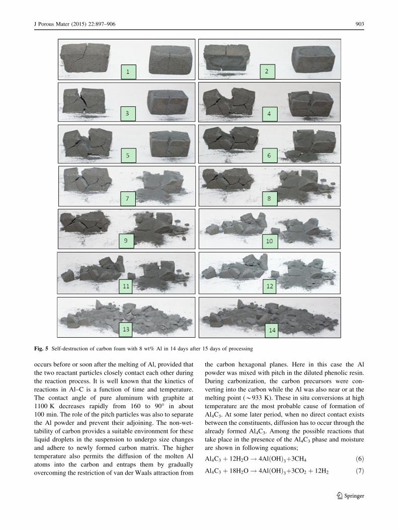
2.5 Self-destruction at room temperature
Two parts of carbon foam with 8 wt% Al content were
placed on the shelf at room temperature (300 K) for
30 days and pictured the degradation behavior. Cracks
appeared after 15 days and continued for another 14 days.
3 Results and discussion
3.1 General properties
Table 2 shows the general properties of the carbon foam.
Density increased with the rise in Al wt% while the open
porosity and pore volume decreased accordingly. The car-
bon foam without Al showed a very low value of thermal
conductivity. Almost 800 % increase in the thermal con-
ductivity was observed in the sample containing 6 wt% Al.
With further increase in Al contents, a sharp decreasing
trend was noticed and gain at 6 wt% reduced to half.
Powdered Al with particle size distribution (particle di-
ameter of 60–130 lm) was dispersed in the phenolic resin
along with the ground coal tar pitch. The carbon precursors
were pyrolyzed to carbon during high temperature treat-
ment. During this treatment, part of Al was converted into
in situ compounds and well mixed in the body of ligaments.
Higher thermal conductivity of Al and the most probable
conductive channel created inside the ligaments were re-
sponsible for higher values of thermal conductivity. There
was a slight drop in thermal conductivity when the amount
of Al increased to 8 wt%. The key factor of carbon/Al in-
terface affecting phonon coupling between and propagation
across the interfacial phases is aluminum carbide (Al4C3) at
the junction between the aluminum and the carbonaceous
matrix. The formation of Al4C3 lowers the phonon coupling
and propagation between the constituent materials, lower-
ing the thermal conductivity. The Al4C3 phase is brittle,
hydroscopic, and generally known to have a low thermal
conductivity. The formation of significant amount of Al4C3
decreased the thermal conductivity and stability of carbon
foam. The resulting material became very hygroscopic and
unstable which will be further explained in the following
sections. SEM pictures of the carbon foam are shown in
Fig. 3. The open cell structure is seen in all the pictures and
also evident by the porosity calculations shown in Table 2.
In this particular case, the pores are not exactly spherical or
elliptical but are of irregular, uneven and rough shape. Due
to the complexity and randomness in the pore shape, it is
difficult to obtain accurate dimensions and distribution of
pore sizes. It falls between a broad range of 2–200 lm,
although some pores in the image are seen bigger which
were broken during cutting, grinding and sample prepara-
tion. Some bigger voids of 500 lm size are also visible in
all pictures. As the Al contents increased from 2 to 8 wt%,
the pore sizes and void spaces decreased remarkably. The
specimen with 8 wt% Al seems to be more uniform and
dense.
The EDX technique was used to find the composition of
individual particle. Instead of rastering over a relatively large
inspection field, single points were also defined and ana-
lyzed. In Fig. 4d, the resulting spectra shows that, Al metal
along with carbon, nitrogen and oxygen was detected in the
inspection field. X-ray mapping of elements is also shown in
Fig. 4b. Here the position of Al element emitting charac-
teristic X-rays within an inspection field was indicated by
grey color. Al is visible in the whole inspection field with
some areas showing agglomerates into the form of balls. Al
does not wet the carbon, some particles agglomerated in the
Fig. 2 Comparative guarded
axial heat flow system;
a pictorial view with an inset
showing sample fitted in
insulated cavity and b schematic
view
900 J Porous Mater (2015) 22:897–906
123

form of spheres with outer surface either smooth or covered
with some nanoparticles and most probably some oxy car-
bides and nitrides (EDX results). Overall, the pore wall
surface in the carbon foam is rough and uneven and there are
some agglomerates of Al with sizes in the range of 1–25 lm.
The pore wall thickness is also not the same and varies be-
tween 10 and 100 lm. This was due to the multiple im-
pregnation cycles and a slight pressurization during curing of
the resin. The multiple coatings of the resin/pitch mixture
and the carbonization shrinkage transformed the open
reticulated structure of the PU foam into the coarse, rough
and uneven morphology.
3.2 Self-destruction at room temperature
Figure 5 shows the sequential destruction of carbon foam
in 14 days. The destruction was due to non-wetting con-
ditions between the monolithic phases for short contact
Table 2 Effect of Al contents on density, porosity and thermal conductivity
Al powder (wt%) Bulk density
(g/cm3)
True density
(g/cm3)
Porosity (%) Open pore volume
(cm3/g)
Thermal conductivity
(W/mK)
0 0.50 1.50 66.67 1.33 0.043
2 0.55 1.53 64.05 1.16 0.092
4 0.56 1.58 64.56 1.15 0.142
6 0.58 1.61 63.97 1.10 0.385
8 0.60 1.62 62.96 1.05 0.221
Fig. 3 SEM micrographs of carbon foam with Al; a 2 %, b 4 %, c 6 % and d 8 %
J Porous Mater (2015) 22:897–906 901
123

times, and the reactivity of carbon with liquid aluminum
[28, 29]. At 1023 K, the free energy of formation of Al4C3
is -168 kJ/mol [30]. The formation of Al4C3 at the carbon/
Al interface is often observed in carbon fiber reinforced
aluminum matrix composites infiltrated at high tem-
peratures and low cooling rates [31] In this case, the for-
mation of Al4C3 was accompanied by self-destruction of
porous structure and ultimately converting to fine to coarse
powder.
Moreover the destruction started from the inner core of
the foam and proceeded outward resulting in a core–shell
effect. To further investigate this behavior, samples were
taken from the outer and inner part of the carbon foam
before the destruction started. XRD analysis clarified this
effect by showing a vast difference in carbide content from
inner core to outer surface. Figure 6 showed a greater in-
tensity of Al4C3 peaks in the inner core sample than that in
the outer surface. Some new peaks of nitride were also
visible in the sample taken from the outer surface of the
carbon foam. It is also well known that liquid aluminum
does not wet carbon. The peaks of Al4C3 and AlN are also
visible in the sample with 6 wt% Al but with a lower in-
tensity. The surface of aluminum is covered by a thin
protective layer of aluminum oxide. The carbonization
temperature was 1273 K, which was far less than required
for the formation of AlN in the carbon foam. As shown in
the Al–C phase diagram, Al4C3 melts following the peri-
tectic reaction [32];
Al4C3 ! liquid Al - richð Þ þ graphite at 2433K: ð5Þ
Therefore, the peritectic reaction was not the deter-
mining reaction in the carbonization reaction because it
was much lower than the peritectic temperature. Instead, it
can be proposed that the AlN formation reaction was car-
ried out by the substitution reaction, where carbon atoms
were directly substituted by nitrogen atoms to form the
AlN. However the amount substitute by nitrogen atom was
very little. It has been reported that the Al4C3 substantially
worsens mechanical properties in carbon/Al composites but
a small quantity of it can enhance the interface [33, 34].
Therefore, when a lower amount of Al was used in the
manufacturing of carbon foam, the mechanical and thermal
properties improved. According to thermodynamic pre-
diction [33], carbon can react with aluminum to form
Al4C3 at any temperature under 1773 K. Since the Al is
liquid at high temperature, the diffusion of carbon cannot
be ruled out. When the liquid Al is completely surrounded
by carbon, it become saturated by the carbon. The large
carbide crystals precipitates out during slow cooling as
prevailed during this experiment. In the study of reaction in
Al–Ti–C system, the Al–C reaction occurs at 978 K pro-
vided the carbon contents are not limited. This reaction
Fig. 4 Dispersion of Al into
carbon foam; a, c SEM image
showing agglomerated particles,
b X-ray mapping of Al and
d EDX results showing oxy
carbides and nitrides
902 J Porous Mater (2015) 22:897–906
123
occurs before or soon after the melting of Al, provided that
the two reactant particles closely contact each other during
the reaction process. It is well known that the kinetics of
reactions in Al–C is a function of time and temperature.
The contact angle of pure aluminum with graphite at
1100 K decreases rapidly from 160 to 90� in about
100 min. The role of the pitch particles was also to separate
the Al powder and prevent their adjoining. The non-wet-
tability of carbon provides a suitable environment for these
liquid droplets in the suspension to undergo size changes
and adhere to newly formed carbon matrix. The higher
temperature also permits the diffusion of the molten Al
atoms into the carbon and entraps them by gradually
overcoming the restriction of van der Waals attraction from
the carbon hexagonal planes. Here in this case the Al
powder was mixed with pitch in the diluted phenolic resin.
During carbonization, the carbon precursors were con-
verting into the carbon while the Al was also near or at the
melting point (*933 K). These in situ conversions at high
temperature are the most probable cause of formation of
Al4C3. At some later period, when no direct contact exists
between the constituents, diffusion has to occur through the
already formed Al4C3. Among the possible reactions that
take place in the presence of the Al4C3 phase and moisture
are shown in following equations;
Al4C3 þ 12H2O ! 4Al OHð Þ3þ3CH4 ð6Þ
Al4C3 þ 18H2O ! 4Al OHð Þ3þ3CO2 þ 12H2 ð7Þ
Fig. 5 Self-destruction of carbon foam with 8 wt% Al in 14 days after 15 days of processing
J Porous Mater (2015) 22:897–906 903
123

Since the carbon foam was not immersed in water, but
exposed to ambient air, it is expected that the formation of
Al(OH)3 is closely related to the interaction of Al4C3 with
the surrounding moisture. As shown in Eq. (6), the reaction
of Al4C3 with water is very slow forming methane gas at
room temperature [35]. Alternatively, carbon dioxide is
formed in excessive water according to Eq. (7). This in
agreement with observations of bubbles emerging from
polished surfaces in a SiC/6061-MMC [36]. The XRD scan
of the destroyed sample taken from the inner core is shown
in Fig. 7. The peaks of Al(OH)3 are also visible confirming
the reaction shown in Eq. (6). In the current case, reaction
shown in Eq. (6) is most probable cause of destruction
because it was very slow. The net result was a decrease in
the mechanical strength of the carbon foam, manifested as
a gradual degradation of the material by the slow interac-
tion with the atmospheric moisture. It is expected that
carbon, having a smaller atomic mass than Al, is the dif-
fusing species through the Al4C3 layer, and this occurs at a
relatively slow rate. Thus, further growth of Al4C3 occurs
at an even slower rate when the amount of Al is small. This
is the most probable cause of showing no self-destruction
in carbon foam with Al B 6 wt%.
3.3 Compressive strength
Table 3 shows the data and the stress–strain curves
recorded during compression of samples with different
amounts of Al in Fig. 8. It exhibits multi-stage deformation
responses including the initial elastic region with a high
slope, a linear hardening regime, a stress-plateau region
and a graceful failure. The initial high slope corresponds to
the elastic deformation, and the beginning of the non-lin-
earity is the time when crack propagation in the pore walls
happens [37]. It can be observed that the initial high slope
and the collapse stress of the carbon foam increased with
increasing Al wt%. In addition, as clearly observed from
the deformation responses, the Al wt% has a significant
effect on the deformation behavior of the carbon foam. The
carbon foams, prepared at lower Al wt%, displayed a long
Fig. 6 XRD patterns of carbon foam sample with 6 and 8 wt% Al
(sample taken from outer surface and inner core)Fig. 7 XRD patterns of self-destructed carbon foam powder con-
taining 8 wt% Al
Table 3 Average compressive strength and modulus of the carbon
foam with 0–8 wt% Al
Sample ID Ultimate compressive
strength (MPa)
Compressive
modulus (GPa)
0 % Al 16.87 0.48
2 % Al 23.42 0.74
4 % Al 24.77 0.93
6 % Al 32.58 1.19
8 % Al 34.81 1.02
Fig. 8 Compressive stress–strain curves of carbon foams with
0–8 wt% Al
904 J Porous Mater (2015) 22:897–906
123

plateau region around their yield points, suggesting a more
flexible deformation manner. Moreover the first fracture
stress is in the range of 9–12 MPa for the carbon foam with
Al\ 4 wt%.When the carbon foam was prepared at a
higher Al wt%, it exhibited the conventional brittle fracture
with a short plateau region. The fracture stress also in-
creased to 22–23 MPa. The reason for the variation in
deformation behavior is probably attributed to the differ-
ence in the pore structures of the resulting carbon foam.
The carbon foam with 8 wt% Al presented stress–strain
curve characterized by an elastic behavior, a narrow strain
hardening region and a sudden rupture as generally
recorded for dense ceramics. The vertical downward slope
at a strain of about 0.0045, indicate the fast propagation of
micro-cracks. This could be attributed to the aggregation of
Al at high wt%.
After elastic region, the first drop in strength corresponds
to fracture stress. The maximum stress somewhat lies in
between the stress-plateau region and used to calculate the
ultimate compressive strength. Cracks initiate at the peak
stress value and the material tends to generate fragments as a
result of these cracks. The long serrated plateau region along
with strain hardening originates from the coexistence of
collapsed and uncollapsed zones, typical of brittle foam
undergoing successive pore wall fractures. It can be seen
that the compressive strength of the composites was im-
proved with an increase in additive amount of Al from 2 to
8 wt%. The porosity also decreased with increasing Al wt%
resulting in a higher values of strength. When the additive
amount of Al was 8 wt%, the compressive strength after
passing the plateau region decreased more than that of
6 wt% Al carbon foam but after started increasing to a max
value of 34.8 MPa. A possible reason for this could be due
to the densification and stabilization of carbon foam. The
fact indicates that the carbon foam was toughened after the
addition of Al. The reason for this increase is very com-
plicated. One of the explanations could be that the Al was
converted into Al4C3 and to some extent AlN that toughened
the pore walls of carbon foams. Inter diffusion between
aluminum and carbon matrix leads to the formation of an
interlayer that contributes in strengthening the ligaments.
Although excess Al4C3 is known to often lead to the dete-
rioration of mechanical properties, its potential to contribute
to matrix hardening has also been suggested.
It can also be seen in Fig. 8 that the compressive strain
of the carbon foam without Al was 1.19 %, while the
compressive strains of carbon foams with 2, 4, 6, and
8 wt% of Al were 1.01, 0.92, 0.81, and 0.69 %, respec-
tively. Carbon foam with no Al showed a lower compres-
sive strength and a higher strain. With increasing the
additive content, the compressive strength increased and
the strain decreases. Summarily, in order to improve the
compressive strength of carbon foams, the optimum
amount of Al should be around 5 wt%. Higher amount of
Al will un-stabilized the carbon foam after ageing at room
temperature.
4 Conclusions
Carbon foam was prepared from the carbonization of pitch/
phenolic resin slurry supported on a polyurethane foam tem-
plate. 2–8 wt% Al was used to improve the thermal and me-
chanical properties. The properties and structural examination
showed a density of 0.50–0.60 g/cm3, open porosity of
63–68 %, thermal conductivity of 0.043–0.385 WmK, com-
pressive strength of 17–35 MPa, pore size distribution of
2–200 lm and pore wall thickness of 10–100 lm. Carbon
foam with 8 wt% Al showed self-destruction in 14 days after
15 days of manufacturing. The destruction started from core
and proceeded towards outer surface resulting in a core–shell
effect. XRD analysis confirmed the destruction due to the
formation of Al4C3 and reaction with atmospheric moisture
formingAl(OH)3. On the outer surface, a little amount of AlN
was detected due to substitution reaction of nitrogen with
carbon. One potential application of this self-destruction is in
the field of composite tooling. The novel carbon foam con-
taining controlled amount of Al, carbonization temperature
and cooling rate can beused to fabricate a collapsiblemandrel,
which will lose strength after certain time interval facilitating
in easy and self-removal.
Conflict of interest The authors declare that they have no conflict
of interest.
References
1. T. Suzuki, H. Umehara, Pitch-based carbon fiber microstructure
and texture and compatibility with aluminum coated using che-
mical vapor deposition. Carbon 37, 47–59 (1999)
2. J.F. Silvain, C. Vincent, J.M. Heintz, N. Chandra, Novel pro-
cessing and characterization of Cu/CNF nanocomposite for high
thermal conductivity applications. Compos. Sci. Technol. 69,2474–2484 (2009)
3. Y. Chen, B. Chen, X. Shi, H. Xu, Y. Hu, Y. Yuan, Preparation of
pitch-based carbon foam using polyurethane foam template.
Carbon 45, 2132–2134 (2007)
4. N.C. Gallego, J.W. Klett, Carbon foams for thermal management.
Carbon 41, 1461–1466 (2003)
5. R. Mehta, D.P. Anderson, J.W. Hager, Graphitic open-celled
carbon foams: processing and characterization. Carbon 41,2174–2176 (2003)
6. J. Googin, J. Napier, M. Scrivner, Method for manufacturing
foam carbon products, US Patent 3,345,440 (1967)
7. F.C. Cowlard, J.C. Lewis, Vitreous carbon: as new form of car-
bon. J. Mater. Sci. 2, 507–512 (1967)
8. R. D. Klett, High temperature insulating carbonaceous material,
US Patent 3,914,392 (1975)
9. R.W. Pekala, R.W. Hopper, Low-density microcellular carbon
foams. J. Mater. Sci. 22, 1840–1844 (1987)
J Porous Mater (2015) 22:897–906 905
123

10. J. Lee, K. Sohn, T. Hyeon, Fabrication of novel mesocellular
carbon foams with uniform ultralarge mesopores. J. Am. Chem.
Soc. 123, 5146–5147 (2001)
11. J. Klett, High thermal conductivity mesophase pitched-derived
carbon foam, in Proceedings of the 1998 43rd International
SAMPE Symposium and Exhibition, Part 1 (of 2) (Anaheim, CA
31 May–4 June, 1998)
12. C. Chen, E.B. Kennel, A.H. Stiller, P.G. Stansberry, J.W. Zondlo,
Carbon foam derived from various precursors. Carbon 44,1535–1543 (2006)
13. X.W. Wu, Y.G. Liu, M.H. Fang, L.F. Mei, B.C. Luo, Preparation
and characterization of carbon foams derived from alumi-
nosilicate and phenolic resin. Carbon 49, 1782–1786 (2011)
14. H.F. Xu, H.J. Zhang, Y.D. Huang, Y. Wang, Porous carbon/silica
composite monoliths derived from resorcinol–formaldehyde/
TEOS. J. Non-Cryst. Solids 356, 971–976 (2010)
15. Y.R. Liu, B.P. Lin, D. Li, X.Q. Zhang, Y. Sun, H. Yang, Mag-
netically-separable hierarchically porous carbon monoliths with
partially graphitized structures as excellent adsorbents for dyes.
J. Porous Mat. 21, 933–938 (2014)
16. S.W. Lei, Q.G. Guo, J.L. Shi, L. Liu, Preparation of phenolic-
based carbon foam with controllable pore structure and high
compressive strength. Carbon 48, 2644–2646 (2010)
17. Y.H. Yan, X.M. Shi, J.G. Liu, T. Zhao, Y.Z. Yu, Thermosetting
resin system based on novolak and bismaleimide for resin-
transfer molding. J. Appl. Polym. Sci. 83, 1651–1657 (2002)
18. M. Calvo, R. Garcıa, A. Arenillas, I. Suarez, S.R. Moinelo,
Carbon foams from coals: a preliminary study. Fuel 84,2184–2189 (2005)
19. S. Farhan, R.M. Wang, H. Jiang, N. Ul-Haq, Preparation and
characterization of carbon foam derived from pitch and phenolic
resin using a soft templating method. J. Anal. Appl. Pyrolysis
110, 229–234 (2014)
20. A.M. Druma, M.K. Alam, C. Druma, Analysis of thermal con-
duction in carbon foams. Int. J. Therm. Sci. 43, 689–695 (2004)
21. S.R. White, Y.K. Kim, Process-induced residual stress analysis of
AS4/3501-6 composite material. Mech. Compos. Mater. Struct. 5,153–186 (1998)
22. F.C. Campbell, Manufacturing processes for advanced compos-
ites (Elsevier Advanced Technology, Amsterdam, 2004)
23. A.M. Druma, M.K. Alam, M.S. Anghelescu, C. Druma, Three
dimensional modeling of carbon foams, in ASME international
mechanical engineering congress and exposition 2005 (Orlando,
FL, 5–11 November, 2005)
24. A. Gardziella, L.A. Pilato, A. Knop, Phenolic resins: chemistry,
application, standardization, safety and ecology, 2nd edn.
(Springer, Berlin, 2000)
25. P. Byung-Dae, R. Bernard, Y.S. Kim, W.T. So, Effect of syn-
thesis parameters on thermal behavior of phenol-formaldehyde
resol resin. J. Appl. Polym. Sci. 83, 1415–1424 (2002)
26. J. Wang, H. Jiang, N. Jiang, Study on the pyrolysis of phenol-
formaldehyde (PF) resin and modified PF resin. Thermochim.
Acta 496, 136–142 (2009)
27. L.B. Manfredi, O. De La Osa, N. Galego Fernandez, A. Vazquez,
Structure-properties relationship for resols with different
formaldehyde/phenol molar ratio. Polymer 40, 3867–3875 (1999)
28. J.T. Blucher, J. Dobranszky, U. Narusawa, Aluminium double
composite structures reinforced with composite wires. Mater. Sci.
Eng., A 387–389, 867–872 (2004)
29. E. Pippel, J. Woltersdorf, M. Doktor, J. Blucher, H.P. Degischer,
Interlayer structure of carbon fibre reinforced aluminium wires.
J. Mater. Sci. 35, 2279–2289 (2000)
30. R.Y. Lin, Interface evolution in aluminum matrix composites
during fabrication. Key Eng. Mater. 104–107, 507–522 (1995)
31. M.H. Vidal-Setif, M. Lancin, C. Marhic, R. Valle, J.L. Raviart,
J.C. Daux, M. Rabinovitch, On the role of brittle interfacial
phases on the mechanical properties of carbon fibre reinforced
Al-based matrix composites. Mater. Sci. Eng., A 272, 321–333(1999)
32. C. Qiu, R. Metselaar, Solubility of carbon in liquid Al and sta-
bility of Al4C3. J. Alloys Compd. 216, 55–60 (1994)
33. S.H. Li, C.G. Chao, Effects of carbon fiber/Al interface on me-
chanical properties of carbon-fiber-reinforced aluminum-matrix
composites. Metall. Mater. Trans. A 35, 2153–2160 (2004)
34. H. Kwon, H. Kurita, M. Leparoux, A. Kawasaki, Carbon nano-
fiber reinforced aluminum matrix composite fabricated by com-
bined process of spark plasma sintering and hot extrusion.
J. Nanosci. Nanotechnol. 11, 4119–4126 (2011)
35. T.Y. Kosolapova, Carbides properties production and applica-
tions, 1st edn. (Plenum Press, New York, 1971)
36. J.K. Park, J.P. Lucas, Moisture effect on SiCP/6061 Al MMC:
dissolution of interfacial Al4C3. Scr. Mater. 37, 511–516 (1997)
37. S. Meille, M. Lombardi, J. Chevalier, L. Montanaro, Mechanical
properties of porous ceramics in compression: on the transition
between elastic, brittle, and cellular behavior. J. Europ. Ceram.
Soc. 32, 3959–3967 (2012)
906 J Porous Mater (2015) 22:897–906
123
Related Documents