JOM Corrosion and Corrosion Control in Light Water Reactors --Manuscript Draft-- Manuscript Number: JOMJ-D-13-00077R1 Full Title: Corrosion and Corrosion Control in Light Water Reactors Article Type: Overview Corresponding Author: Barry Gordon, Bs, MS Structural Integrity Associates, Inc. San Jose, California UNITED STATES Corresponding Author Secondary Information: Corresponding Author's Institution: Structural Integrity Associates, Inc. Corresponding Author's Secondary Institution: First Author: Barry Gordon, Bs, MS First Author Secondary Information: Order of Authors: Barry Gordon, Bs, MS Order of Authors Secondary Information: Abstract: Since serious corrosion problems that have plagued the light water reactor (LWR) industry for decades. The complex corrosion mechanisms involved and the development of practical engineering solutions for their mitigation will discussed. After a brief discussion of the basic designs of the boiling water reactor (BWR) and pressurized water reactor (PWR), emphasis will be placed on the general corrosion of LWR containments, flow-accelerated corrosion of carbon steel components, intergranular stress corrosion cracking (IGSCC) in BWRs, primary water stress corrosion cracking (PWSCC) in PWRs and irradiation assisted stress corrosion cracking (IASCC) in both systems. Finally, the corrosion future of both plants will be discussed as plants extend their period of operation for an additional 20 to 40 years. Response to Reviewers: Raul did an excellent job in reviewing my paper. I appreciate his constructive comments. Powered by Editorial Manager® and Preprint Manager® from Aries Systems Corporation

Welcome message from author
This document is posted to help you gain knowledge. Please leave a comment to let me know what you think about it! Share it to your friends and learn new things together.
Transcript
JOM
Corrosion and Corrosion Control in Light Water Reactors--Manuscript Draft--
Manuscript Number: JOMJ-D-13-00077R1
Full Title: Corrosion and Corrosion Control in Light Water Reactors
Article Type: Overview
Corresponding Author: Barry Gordon, Bs, MSStructural Integrity Associates, Inc.San Jose, California UNITED STATES
Corresponding Author SecondaryInformation:
Corresponding Author's Institution: Structural Integrity Associates, Inc.
Corresponding Author's SecondaryInstitution:
First Author: Barry Gordon, Bs, MS
First Author Secondary Information:
Order of Authors: Barry Gordon, Bs, MS
Order of Authors Secondary Information:
Abstract: Since serious corrosion problems that have plagued the light water reactor (LWR)industry for decades. The complex corrosion mechanisms involved and thedevelopment of practical engineering solutions for their mitigation will discussed. Aftera brief discussion of the basic designs of the boiling water reactor (BWR) andpressurized water reactor (PWR), emphasis will be placed on the general corrosion ofLWR containments, flow-accelerated corrosion of carbon steel components,intergranular stress corrosion cracking (IGSCC) in BWRs, primary water stresscorrosion cracking (PWSCC) in PWRs and irradiation assisted stress corrosioncracking (IASCC) in both systems. Finally, the corrosion future of both plants will bediscussed as plants extend their period of operation for an additional 20 to 40 years.
Response to Reviewers: Raul did an excellent job in reviewing my paper. I appreciate his constructivecomments.
Powered by Editorial Manager® and Preprint Manager® from Aries Systems Corporation
Barry Gordon, PE Corrosion Engineering, NACE Fellow and Corrosion Specialist, has
consulted on various light water reactor (LWR) corrosion and material issues for over
four decades with special emphasis on stress corrosion cracking (SCC). As an
Associate with Structural Integrity Associates, Inc., he has addressed numerous
materials and corrosion problems in the LWR industry over a wide range of subjects
including reactor internals, piping, fuel hardware, water chemistry transients, weld
overlays and repairs, alloy selection, failure analysis, license renewal, NRC inspection
relief, dry fuel storage, corrosion of steel in concrete, decontamination, etc. Mr. Gordon
has his BS and MS degrees in Material Science Engineering from Carnegie Mellon
University.
*BiographyClick here to download Biography: JOM Barry Gordon Bio.doc
Corrosion in Light Water Reactors
Barry M. Gordon
Structural Integrity Associates, Inc.
San Jose, CA 95138
1.0 Introduction
Nuclear energy is a significant source of power worldwide. In the USA, commercial nuclear
power plants provide approximately 20% of the consumed energy. This article will briefly
review the series of serious corrosion problems that have plagued the light water reactors (LWR)
industry for decades, the complex corrosion mechanisms involved and the development of
practical engineering solutions for their mitigation. However, to understand the nature of LWR
corrosion problems, a quick historical perspective of the corrosion design basis of commercial
LWRs, i.e., boiling water reactors (BWRs) and pressurized water reactors (PWRs) is necessary.
2.0 Light Water Reactor Designs and Corrosion
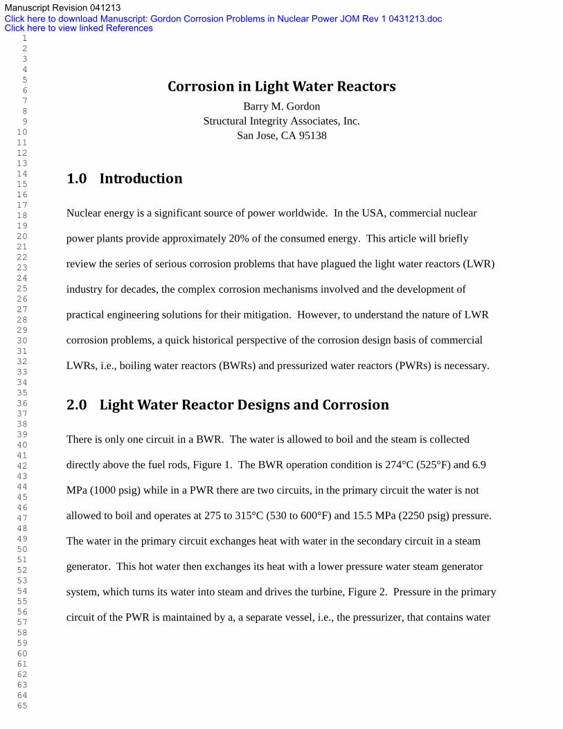
There is only one circuit in a BWR. The water is allowed to boil and the steam is collected
directly above the fuel rods, Figure 1. The BWR operation condition is 274°C (525°F) and 6.9
MPa (1000 psig) while in a PWR there are two circuits, in the primary circuit the water is not
allowed to boil and operates at 275 to 315°C (530 to 600°F) and 15.5 MPa (2250 psig) pressure.
The water in the primary circuit exchanges heat with water in the secondary circuit in a steam
generator. This hot water then exchanges its heat with a lower pressure water steam generator
system, which turns its water into steam and drives the turbine, Figure 2. Pressure in the primary
circuit of the PWR is maintained by a, a separate vessel, i.e., the pressurizer, that contains water
Manuscript Revision 041213Click here to download Manuscript: Gordon Corrosion Problems in Nuclear Power JOM Rev 1 0431213.doc Click here to view linked References
1 2 3 4 5 6 7 8 9 10 11 12 13 14 15 16 17 18 19 20 21 22 23 24 25 26 27 28 29 30 31 32 33 34 35 36 37 38 39 40 41 42 43 44 45 46 47 48 49 50 51 52 53 54 55 56 57 58 59 60 61 62 63 64 65

that is heated to the saturation temperature (boiling point) for the desired pressure by submerged
electrical heaters.
1 2 3 4 5 6 7 8 9 10 11 12 13 14 15 16 17 18 19 20 21 22 23 24 25 26 27 28 29 30 31 32 33 34 35 36 37 38 39 40 41 42 43 44 45 46 47 48 49 50 51 52 53 54 55 56 57 58 59 60 61 62 63 64 65
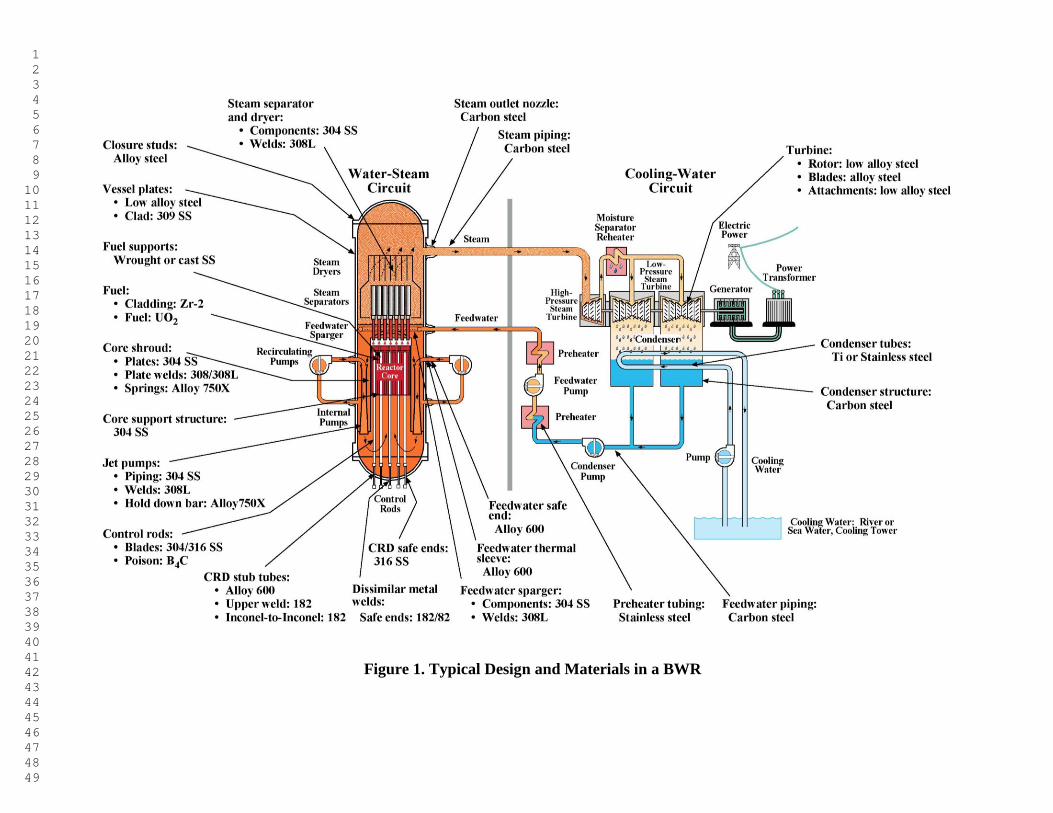
Figure 1. Typical Design and Materials in a BWR
1 2 3 4 5 6 7 8 9 10 11 12 13 14 15 16 17 18 19 20 21 22 23 24 25 26 27 28 29 30 31 32 33 34 35 36 37 38 39 40 41 42 43 44 45 46 47 48 49
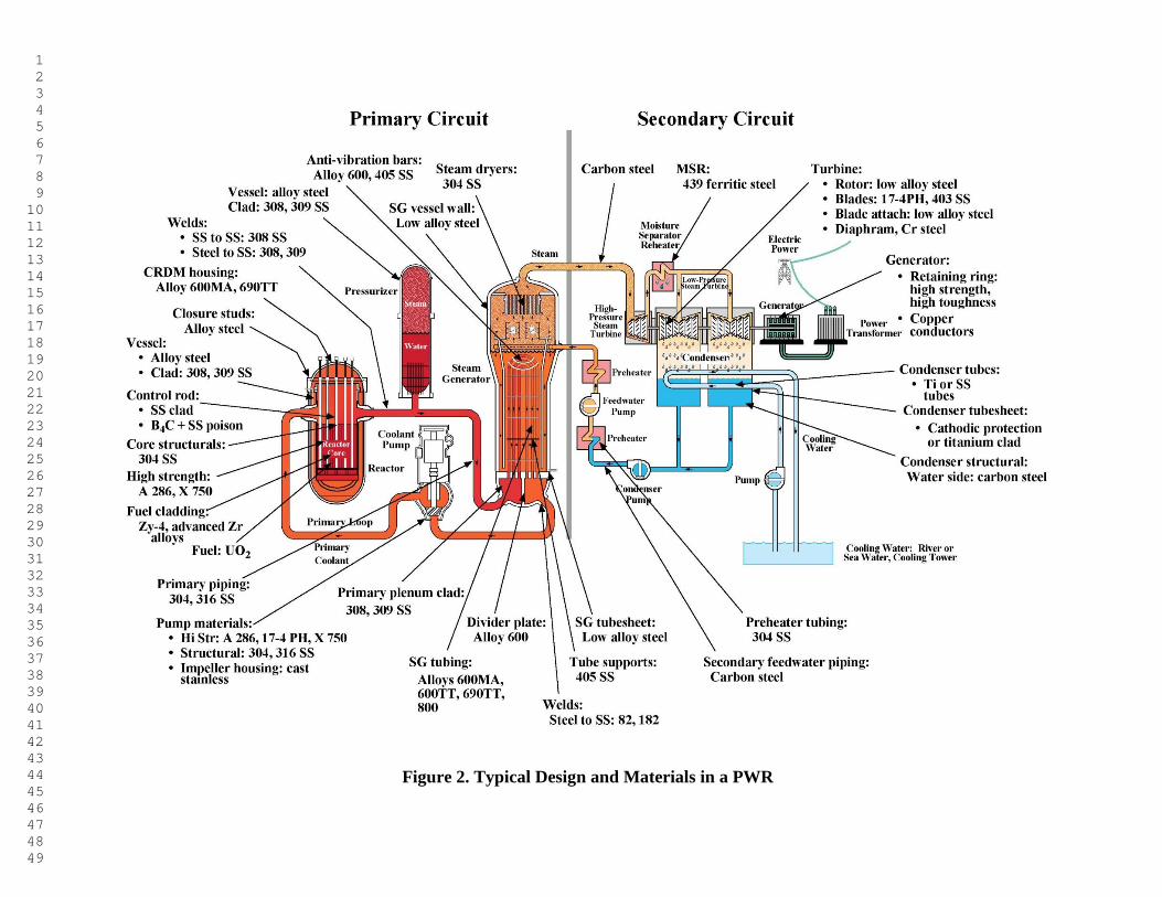
Figure 2. Typical Design and Materials in a PWR
1 2 3 4 5 6 7 8 9 10 11 12 13 14 15 16 17 18 19 20 21 22 23 24 25 26 27 28 29 30 31 32 33 34 35 36 37 38 39 40 41 42 43 44 45 46 47 48 49
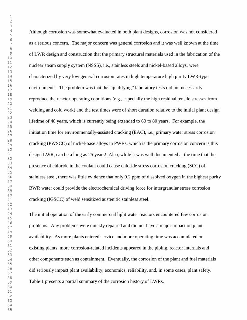
Although corrosion was somewhat evaluated in both plant designs, corrosion was not considered
as a serious concern. The major concern was general corrosion and it was well known at the time
of LWR design and construction that the primary structural materials used in the fabrication of the
nuclear steam supply system (NSSS), i.e., stainless steels and nickel-based alloys, were
characterized by very low general corrosion rates in high temperature high purity LWR-type
environments. The problem was that the “qualifying” laboratory tests did not necessarily
reproduce the reactor operating conditions (e.g., especially the high residual tensile stresses from
welding and cold work) and the test times were of short duration relative to the initial plant design
lifetime of 40 years, which is currently being extended to 60 to 80 years. For example, the
initiation time for environmentally-assisted cracking (EAC), i.e., primary water stress corrosion
cracking (PWSCC) of nickel-base alloys in PWRs, which is the primary corrosion concern is this
design LWR, can be a long as 25 years! Also, while it was well documented at the time that the
presence of chloride in the coolant could cause chloride stress corrosion cracking (SCC) of
stainless steel, there was little evidence that only 0.2 ppm of dissolved oxygen in the highest purity
BWR water could provide the electrochemical driving force for intergranular stress corrosion
cracking (IGSCC) of weld sensitized austenitic stainless steel.
The initial operation of the early commercial light water reactors encountered few corrosion
problems. Any problems were quickly repaired and did not have a major impact on plant
availability. As more plants entered service and more operating time was accumulated on
existing plants, more corrosion-related incidents appeared in the piping, reactor internals and
other components such as containment. Eventually, the corrosion of the plant and fuel materials
did seriously impact plant availability, economics, reliability, and, in some cases, plant safety.
Table 1 presents a partial summary of the corrosion history of LWRs.
1 2 3 4 5 6 7 8 9 10 11 12 13 14 15 16 17 18 19 20 21 22 23 24 25 26 27 28 29 30 31 32 33 34 35 36 37 38 39 40 41 42 43 44 45 46 47 48 49 50 51 52 53 54 55 56 57 58 59 60 61 62 63 64 65
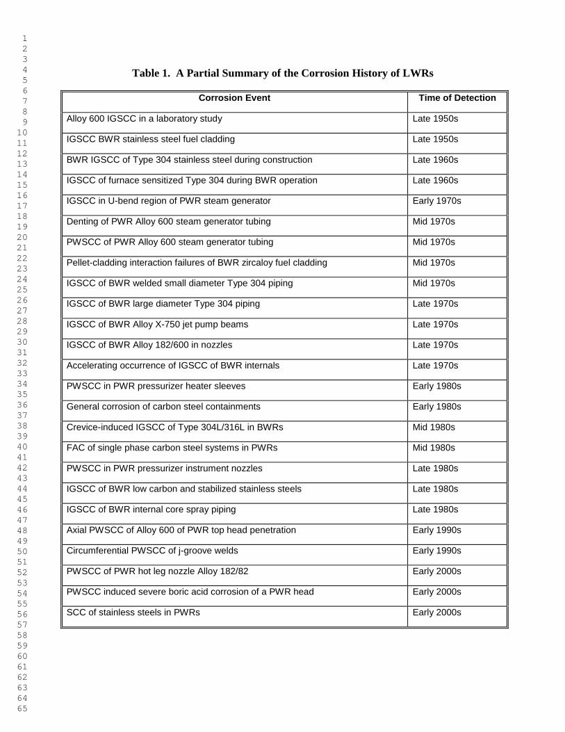
Table 1. A Partial Summary of the Corrosion History of LWRs
Corrosion Event Time of Detection
Alloy 600 IGSCC in a laboratory study Late 1950s
IGSCC BWR stainless steel fuel cladding Late 1950s
BWR IGSCC of Type 304 stainless steel during construction Late 1960s
IGSCC of furnace sensitized Type 304 during BWR operation Late 1960s
IGSCC in U-bend region of PWR steam generator Early 1970s
Denting of PWR Alloy 600 steam generator tubing Mid 1970s
PWSCC of PWR Alloy 600 steam generator tubing Mid 1970s
Pellet-cladding interaction failures of BWR zircaloy fuel cladding Mid 1970s
IGSCC of BWR welded small diameter Type 304 piping Mid 1970s
IGSCC of BWR large diameter Type 304 piping Late 1970s
IGSCC of BWR Alloy X-750 jet pump beams Late 1970s
IGSCC of BWR Alloy 182/600 in nozzles Late 1970s
Accelerating occurrence of IGSCC of BWR internals Late 1970s
PWSCC in PWR pressurizer heater sleeves Early 1980s
General corrosion of carbon steel containments Early 1980s
Crevice-induced IGSCC of Type 304L/316L in BWRs Mid 1980s
FAC of single phase carbon steel systems in PWRs Mid 1980s
PWSCC in PWR pressurizer instrument nozzles Late 1980s
IGSCC of BWR low carbon and stabilized stainless steels Late 1980s
IGSCC of BWR internal core spray piping Late 1980s
Axial PWSCC of Alloy 600 of PWR top head penetration Early 1990s
Circumferential PWSCC of j-groove welds Early 1990s
PWSCC of PWR hot leg nozzle Alloy 182/82 Early 2000s
PWSCC induced severe boric acid corrosion of a PWR head Early 2000s
SCC of stainless steels in PWRs Early 2000s
1 2 3 4 5 6 7 8 9 10 11 12 13 14 15 16 17 18 19 20 21 22 23 24 25 26 27 28 29 30 31 32 33 34 35 36 37 38 39 40 41 42 43 44 45 46 47 48 49 50 51 52 53 54 55 56 57 58 59 60 61 62 63 64 65
3.0 Containment General Corrosion
Nuclear reactor containment is an airtight steel structure enclosing the reactor normally sealed
off from the outside atmosphere. The steel is either free-standing or attached to concrete. It is
designed, in any emergency, to contain the escape of radiation. The containment is the fourth
and final barrier to radioactive release (part of a nuclear reactor's defense in depth strategy), the
first being the fuel ceramic itself, the second being the zirconium alloy fuel cladding tubes, the
third being the reactor pressure vessel and coolant system.
3.1 Oyster Creek BWR Containment Corrosion
The Oyster Creek BWR, which entered service in 1969, utilizes a Mark I carbon steel
containment as shown in Figure 3. During the 1980 refueling outage water was noted around
various containment penetrations and floors [1]. The presence of water indicated that an
intrusion of water into the annular space between the carbon steel drywell shell and concrete
shield wall had occurred. Radiological analysis of the water samples indicated an activity level
similar to primary water. This suggested that the source of the water was the reactor cavity
located immediately above the drywell as indicated by the heavy arrow in Figure 3.
While initial analyses suggested that the water was due to leaks at the bellows drain line gasket,
it was eventually determined that the leaks were due to numerous through-wall corrosion fatigue
cracks located approximately 2 meters (~6 feet) above the cavity seal floor. This cavity seal
leakage plus any condensation in the gap between the insulation and the drywell shell, the initial
installation of moist sand in the sand cushion and the seepage of water from the initial sprayed-
on insulation slurry could provide an electrolyte for the corrosion of the drywell shell.
1 2 3 4 5 6 7 8 9 10 11 12 13 14 15 16 17 18 19 20 21 22 23 24 25 26 27 28 29 30 31 32 33 34 35 36 37 38 39 40 41 42 43 44 45 46 47 48 49 50 51 52 53 54 55 56 57 58 59 60 61 62 63 64 65
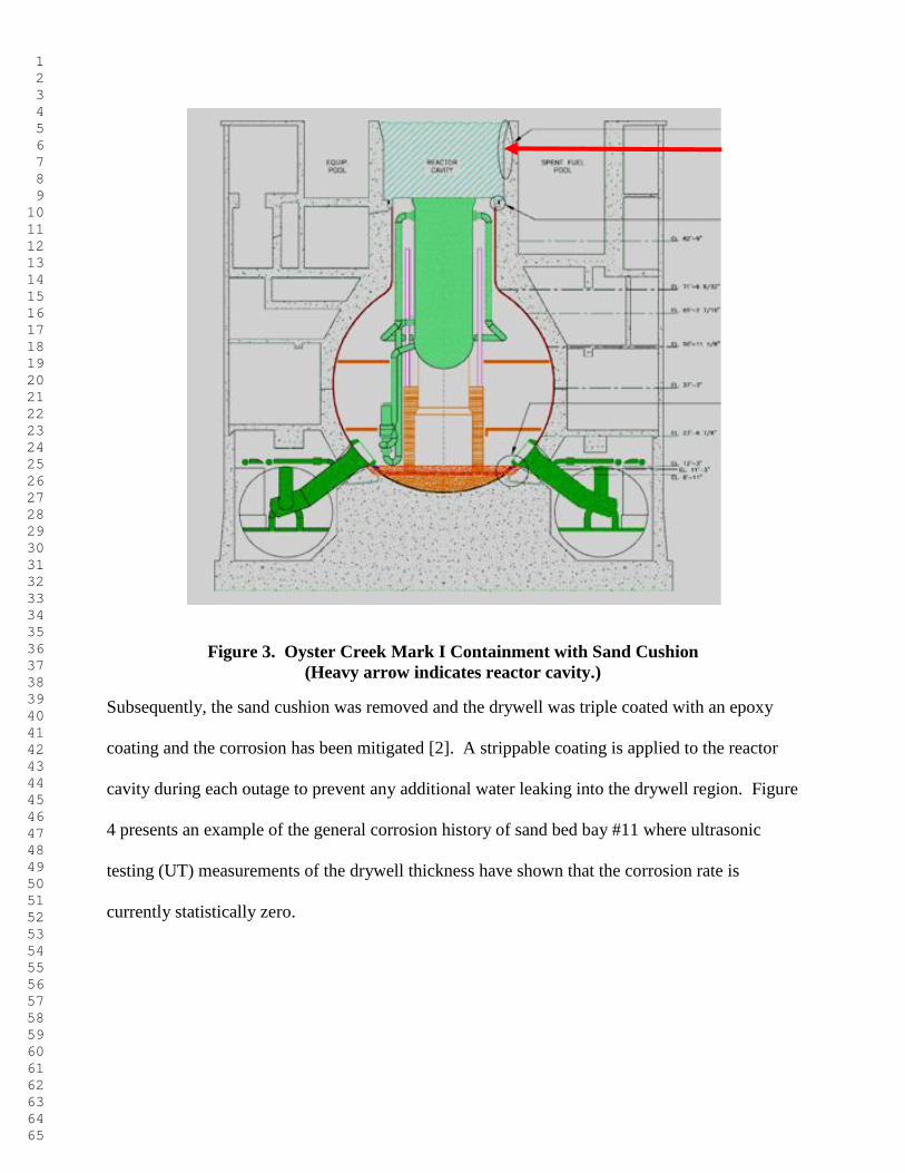
Figure 3. Oyster Creek Mark I Containment with Sand Cushion
(Heavy arrow indicates reactor cavity.)
Subsequently, the sand cushion was removed and the drywell was triple coated with an epoxy
coating and the corrosion has been mitigated [2]. A strippable coating is applied to the reactor
cavity during each outage to prevent any additional water leaking into the drywell region. Figure
4 presents an example of the general corrosion history of sand bed bay #11 where ultrasonic
testing (UT) measurements of the drywell thickness have shown that the corrosion rate is
currently statistically zero.
1 2 3 4 5 6 7 8 9 10 11 12 13 14 15 16 17 18 19 20 21 22 23 24 25 26 27 28 29 30 31 32 33 34 35 36 37 38 39 40 41 42 43 44 45 46 47 48 49 50 51 52 53 54 55 56 57 58 59 60 61 62 63 64 65
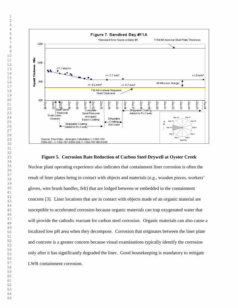
Figure 5. Corrosion Rate Reduction of Carbon Steel Drywell at Oyster Creek
Nuclear plant operating experience also indicates that containment liner corrosion is often the
result of liner plates being in contact with objects and materials (e.g., wooden pieces, workers’
gloves, wire brush handles, felt) that are lodged between or embedded in the containment
concrete [3]. Liner locations that are in contact with objects made of an organic material are
susceptible to accelerated corrosion because organic materials can trap oxygenated water that
will provide the cathodic reactant for carbon steel corrosion. Organic materials can also cause a
localized low pH area when they decompose. Corrosion that originates between the liner plate
and concrete is a greater concern because visual examinations typically identify the corrosion
only after it has significantly degraded the liner. Good housekeeping is mandatory to mitigate
LWR containment corrosion.
1 2 3 4 5 6 7 8 9 10 11 12 13 14 15 16 17 18 19 20 21 22 23 24 25 26 27 28 29 30 31 32 33 34 35 36 37 38 39 40 41 42 43 44 45 46 47 48 49 50 51 52 53 54 55 56 57 58 59 60 61 62 63 64 65
4.0 FLOW-ACCELERATED CORROSION
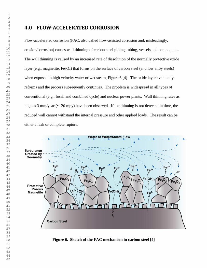
Flow-accelerated corrosion (FAC, also called flow-assisted corrosion and, misleadingly,
erosion/corrosion) causes wall thinning of carbon steel piping, tubing, vessels and components.
The wall thinning is caused by an increased rate of dissolution of the normally protective oxide
layer (e.g., magnetite, Fe3O4) that forms on the surface of carbon steel (and low alloy steels)
when exposed to high velocity water or wet steam, Figure 6 [4]. The oxide layer eventually
reforms and the process subsequently continues. The problem is widespread in all types of
conventional (e.g., fossil and combined cycle) and nuclear power plants. Wall thinning rates as
high as 3 mm/year (~120 mpy) have been observed. If the thinning is not detected in time, the
reduced wall cannot withstand the internal pressure and other applied loads. The result can be
either a leak or complete rupture.
Figure 6. Sketch of the FAC mechanism in carbon steel [4]
1 2 3 4 5 6 7 8 9 10 11 12 13 14 15 16 17 18 19 20 21 22 23 24 25 26 27 28 29 30 31 32 33 34 35 36 37 38 39 40 41 42 43 44 45 46 47 48 49 50 51 52 53 54 55 56 57 58 59 60 61 62 63 64 65
The rate of wall loss (unfortunately aka “wear rate”) of a given component is affected by
temperature, local flow velocity, component geometry on local hydrodynamics (e.g., turbulence),
the pH at temperature, the liquid phase dissolved oxygen concentration and the alloy
composition (e.g., especially Cr, Mo and Cu).
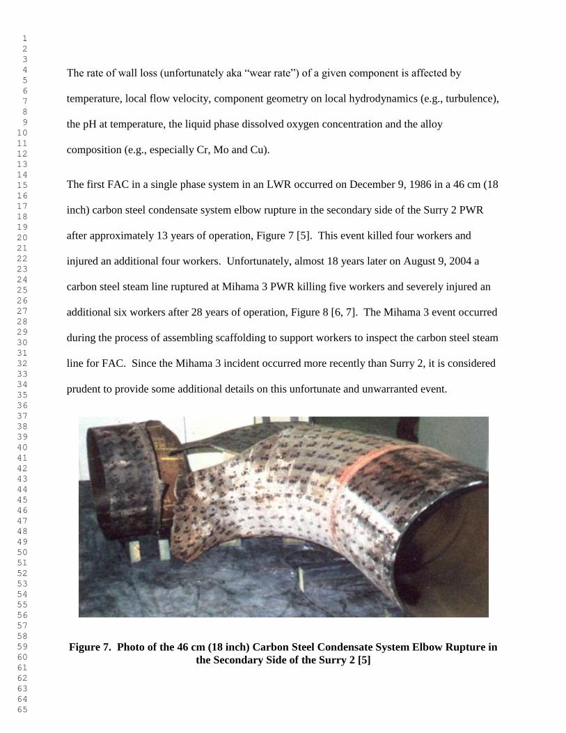
The first FAC in a single phase system in an LWR occurred on December 9, 1986 in a 46 cm (18
inch) carbon steel condensate system elbow rupture in the secondary side of the Surry 2 PWR
after approximately 13 years of operation, Figure 7 [5]. This event killed four workers and
injured an additional four workers. Unfortunately, almost 18 years later on August 9, 2004 a
carbon steel steam line ruptured at Mihama 3 PWR killing five workers and severely injured an
additional six workers after 28 years of operation, Figure 8 [6, 7]. The Mihama 3 event occurred
during the process of assembling scaffolding to support workers to inspect the carbon steel steam
line for FAC. Since the Mihama 3 incident occurred more recently than Surry 2, it is considered
prudent to provide some additional details on this unfortunate and unwarranted event.
Figure 7. Photo of the 46 cm (18 inch) Carbon Steel Condensate System Elbow Rupture in
the Secondary Side of the Surry 2 [5]
1 2 3 4 5 6 7 8 9 10 11 12 13 14 15 16 17 18 19 20 21 22 23 24 25 26 27 28 29 30 31 32 33 34 35 36 37 38 39 40 41 42 43 44 45 46 47 48 49 50 51 52 53 54 55 56 57 58 59 60 61 62 63 64 65
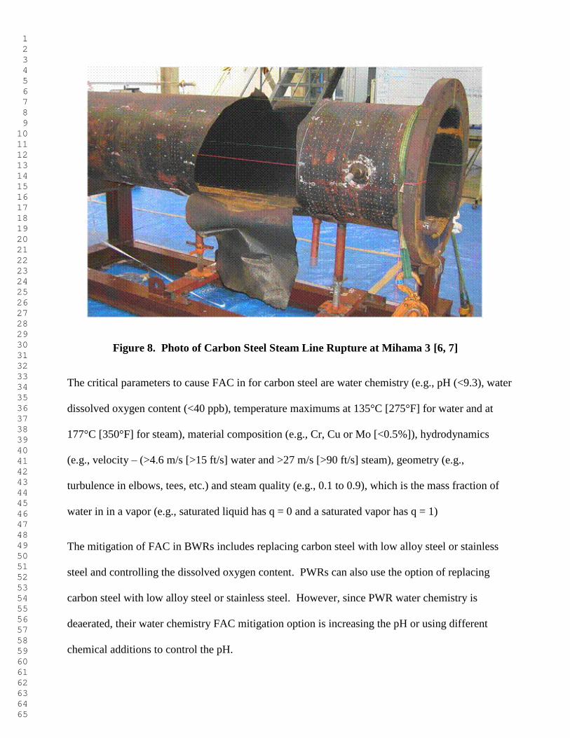
Figure 8. Photo of Carbon Steel Steam Line Rupture at Mihama 3 [6, 7]
The critical parameters to cause FAC in for carbon steel are water chemistry (e.g., pH (<9.3), water
dissolved oxygen content (<40 ppb), temperature maximums at 135°C [275°F] for water and at
177°C [350°F] for steam), material composition (e.g., Cr, Cu or Mo [<0.5%]), hydrodynamics
(e.g., velocity – (>4.6 m/s [>15 ft/s] water and >27 m/s [>90 ft/s] steam), geometry (e.g.,
turbulence in elbows, tees, etc.) and steam quality (e.g., 0.1 to 0.9), which is the mass fraction of
water in in a vapor (e.g., saturated liquid has q = 0 and a saturated vapor has q = 1)
The mitigation of FAC in BWRs includes replacing carbon steel with low alloy steel or stainless
steel and controlling the dissolved oxygen content. PWRs can also use the option of replacing
carbon steel with low alloy steel or stainless steel. However, since PWR water chemistry is
deaerated, their water chemistry FAC mitigation option is increasing the pH or using different
chemical additions to control the pH.
1 2 3 4 5 6 7 8 9 10 11 12 13 14 15 16 17 18 19 20 21 22 23 24 25 26 27 28 29 30 31 32 33 34 35 36 37 38 39 40 41 42 43 44 45 46 47 48 49 50 51 52 53 54 55 56 57 58 59 60 61 62 63 64 65
5.0 IGSCC in BWRs
5.1 Introduction
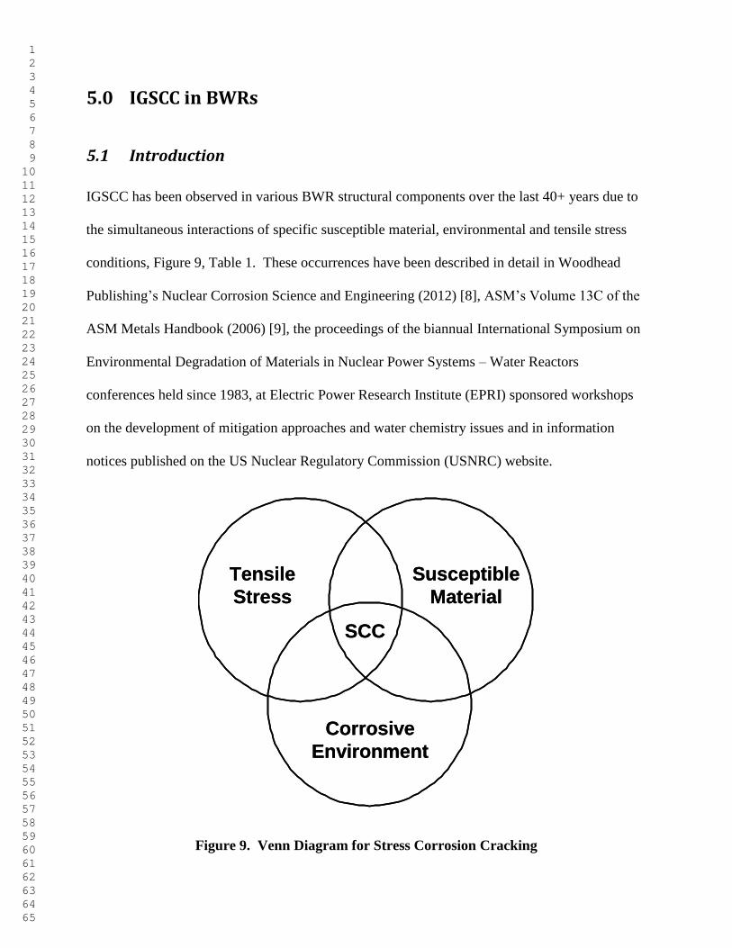
IGSCC has been observed in various BWR structural components over the last 40+ years due to
the simultaneous interactions of specific susceptible material, environmental and tensile stress
conditions, Figure 9, Table 1. These occurrences have been described in detail in Woodhead
Publishing’s Nuclear Corrosion Science and Engineering (2012) [8], ASM’s Volume 13C of the
ASM Metals Handbook (2006) [9], the proceedings of the biannual International Symposium on
Environmental Degradation of Materials in Nuclear Power Systems – Water Reactors
conferences held since 1983, at Electric Power Research Institute (EPRI) sponsored workshops
on the development of mitigation approaches and water chemistry issues and in information
notices published on the US Nuclear Regulatory Commission (USNRC) website.
Tensile
Stress
Susceptible
Material
Corrosive
Environment
SCC
Tensile
Stress
Susceptible
Material
Corrosive
Environment
SCC
Figure 9. Venn Diagram for Stress Corrosion Cracking
1 2 3 4 5 6 7 8 9 10 11 12 13 14 15 16 17 18 19 20 21 22 23 24 25 26 27 28 29 30 31 32 33 34 35 36 37 38 39 40 41 42 43 44 45 46 47 48 49 50 51 52 53 54 55 56 57 58 59 60 61 62 63 64 65
5.2 Parameters for IGSCC in BWR Piping
For the BWR, the initiation of IGSCC of austenitic stainless steel and nickel-base alloys occurs
when the following necessary fundamental conditions are simultaneously present [10]:
1. Chromium depleted zone at the grain boundary in weld heat affected zones (HAZs) due to
chromium carbide (Cr23C6) precipitation, i.e. “sensitization” [11].
2. Tensile stress greater than the at temperature yield stress (e.g., ~140 MPa at 288°C [550°F]
for Type 304 stainless steel).
3. High temperature (>93°C [200°F]) water where the corrosion potential or as referred to in the
nuclear industry the “electrochemical corrosion potential” [ECP] of the stainless steel in the
coolant is >-230 mV(SHE).
5.2.1 BWR Piping Materials
Susceptibility to IGSCC varies from alloy to alloy and with the metallurgical condition and
microstructure of the material under consideration. Given “normal” conditions of stress and
environment, several BWR structural materials have shown susceptibility to IGSCC as a result of
the material itself or because of its fabrication history. These materials include weld sensitized,
furnace sensitized or cold worked Type 304 and 316 stainless steel, mill annealed nickel-base
Alloy 600 and as-welded Alloy 182 weld metal.
When non-stabilized austenitic stainless steels containing greater than 0.030 w/o carbon are furnace
heated treated or welded in a temperature range of approximately 550 to 850°C (for a sufficient
period of time, a precipitation reaction occurs due to the insolubility of carbon in the alloy.
Austenite containing greater than 0.030 w/o carbon precipitates Cr23C6 at the grain boundaries.
1 2 3 4 5 6 7 8 9 10 11 12 13 14 15 16 17 18 19 20 21 22 23 24 25 26 27 28 29 30 31 32 33 34 35 36 37 38 39 40 41 42 43 44 45 46 47 48 49 50 51 52 53 54 55 56 57 58 59 60 61 62 63 64 65
Since chromium provides the corrosion resistance for austenitic stainless steels, the chromium
carbide precipitation at the grain boundary creates an envelope of chromium depleted alloy that is
not resistant to aqueous corrosion. The chromium depleted zone is no longer a stainless steel, but
rather a very small area low alloy steel anode galvanically coupled to a large area stainless steel
cathode. If a sufficient tensile stress is placed on an austenitic stainless steel that has become
thermally “sensitized” by this phase transformation, then IGSCC can occur if, and only if, the
environment can support the corrosion reaction. A similar chromium depletion sensitization
mechanism occurs in austenitic nickel-base alloys such as Alloys 600 and 182 in the BWR.
5.2.2 Tensile Stress
There are primarily three sources of tensile stress in the BWR: fabricational stresses, primary
stresses and secondary stresses. Fabricational stresses consist of stresses introduced during fit-up
and assembly in the shop or field, those introduced by machining or forming operations (surface
grinding, cold straightening, bending, etc.) and, perhaps most importantly, welding. As is the
case for weld residual stresses, abusive grinding can produce surface residual stresses near or
above the yield point of the material. Primary stresses from the operational forces including
mechanical and pressure load stress may also be significant, especially at constraints in an
assembly. Corrosion product stress may also play an important role in crack propagation.
Secondary stresses such as thermal stresses can also be high.
Increasing the applied tensile stress level decreases the time to crack initiation, Figure 10. The
material may exhibit a “threshold” stress [11]. The threshold level is related to the environment
and may vary if environmental conditions change. For example, a reactor component may be
subjected to a stress below its “threshold” stress for normal operating conditions. However, if a
1 2 3 4 5 6 7 8 9 10 11 12 13 14 15 16 17 18 19 20 21 22 23 24 25 26 27 28 29 30 31 32 33 34 35 36 37 38 39 40 41 42 43 44 45 46 47 48 49 50 51 52 53 54 55 56 57 58 59 60 61 62 63 64 65
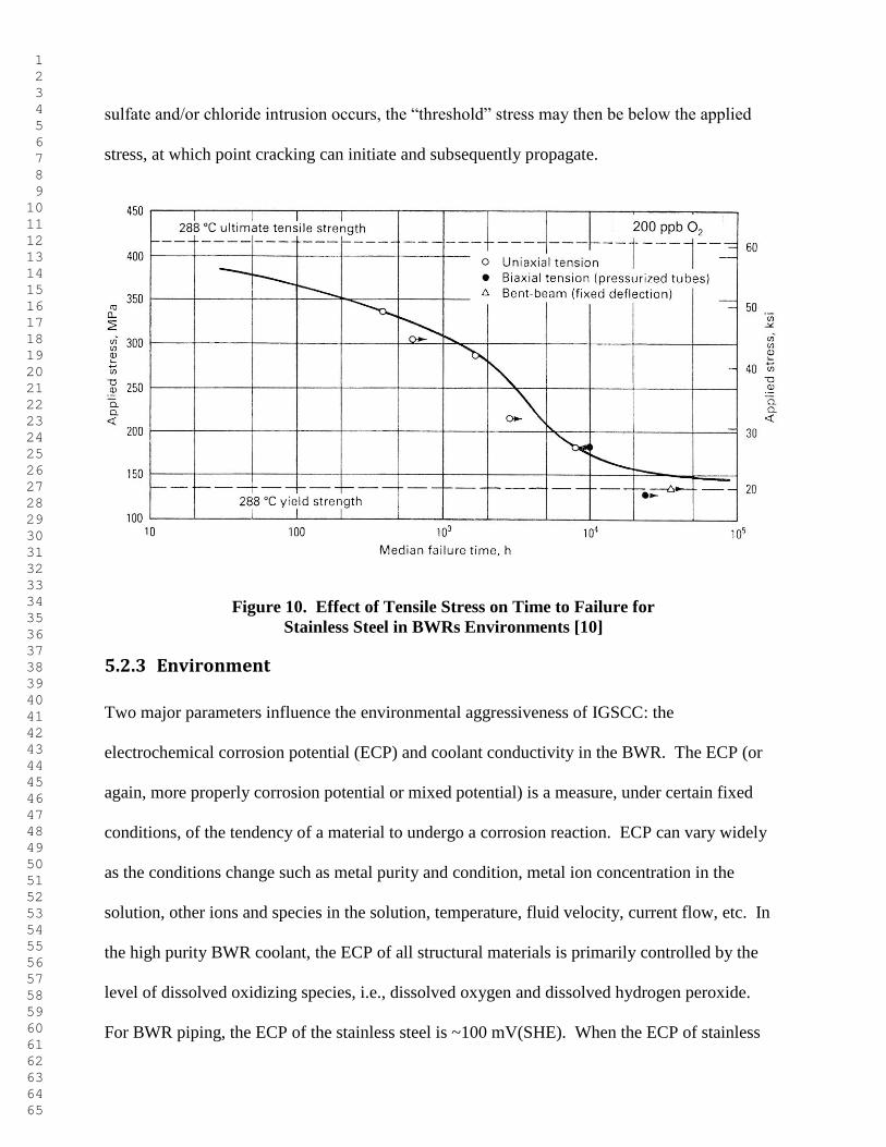
sulfate and/or chloride intrusion occurs, the “threshold” stress may then be below the applied
stress, at which point cracking can initiate and subsequently propagate.
Figure 10. Effect of Tensile Stress on Time to Failure for
Stainless Steel in BWRs Environments [10]
5.2.3 Environment
Two major parameters influence the environmental aggressiveness of IGSCC: the
electrochemical corrosion potential (ECP) and coolant conductivity in the BWR. The ECP (or
again, more properly corrosion potential or mixed potential) is a measure, under certain fixed
conditions, of the tendency of a material to undergo a corrosion reaction. ECP can vary widely
as the conditions change such as metal purity and condition, metal ion concentration in the
solution, other ions and species in the solution, temperature, fluid velocity, current flow, etc. In
the high purity BWR coolant, the ECP of all structural materials is primarily controlled by the
level of dissolved oxidizing species, i.e., dissolved oxygen and dissolved hydrogen peroxide.
For BWR piping, the ECP of the stainless steel is ~100 mV(SHE). When the ECP of stainless
1 2 3 4 5 6 7 8 9 10 11 12 13 14 15 16 17 18 19 20 21 22 23 24 25 26 27 28 29 30 31 32 33 34 35 36 37 38 39 40 41 42 43 44 45 46 47 48 49 50 51 52 53 54 55 56 57 58 59 60 61 62 63 64 65
steel is >-230 mV(SHE), IGSCC initiation of thermally sensitized stainless steel is possible even
in the highest purity environment.
The BWR is characterized by very pure water electrolyte and, hence, low conductivity. In fact,
today many BWRs have conductivities that approach the theoretical limit of 0.055 µS/cm at
25°C (77°F). However, an increase in conductivity not only adversely affects the SCC behavior
of BWR structural materials, but will also can detrimentally affect the rate of radiation field
buildup and fuel performance. Therefore, reactor water conductivity levels should be maintained
at the lowest levels practically achievable.
5.3 Mitigation of IGSCC in BWR Piping
The following discussion presents the most common IGSCC mitigation techniques for BWR
piping, where some of which have been successfully applied to PWR piping systems. The
mitigation methods are presented under general categories of material solutions, tensile stress
solutions and environmental solutions. A few of the remedies address two of the three necessary
conjoint factors illustrated in Figure 9.
5.3.1 Materials Solutions
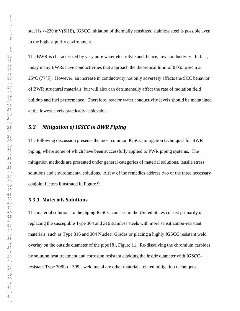
The material solutions to the piping IGSCC concern in the United States consist primarily of
replacing the susceptible Type 304 and 316 stainless steels with more sensitization-resistant
materials, such as Type 316 and 304 Nuclear Grades or placing a highly IGSCC resistant weld
overlay on the outside diameter of the pipe [8], Figure 11. Re-dissolving the chromium carbides
by solution heat treatment and corrosion resistant cladding the inside diameter with IGSCC-
resistant Type 308L or 309L weld metal are other materials related mitigation techniques.
1 2 3 4 5 6 7 8 9 10 11 12 13 14 15 16 17 18 19 20 21 22 23 24 25 26 27 28 29 30 31 32 33 34 35 36 37 38 39 40 41 42 43 44 45 46 47 48 49 50 51 52 53 54 55 56 57 58 59 60 61 62 63 64 65
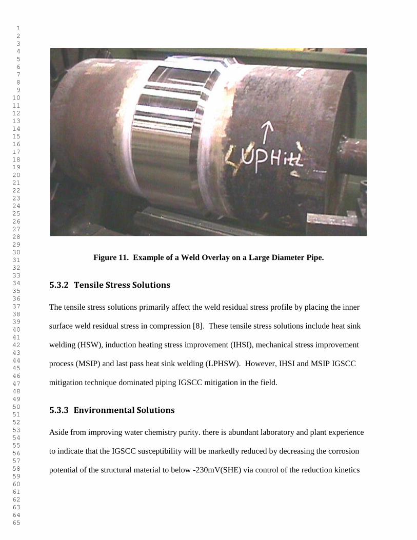
Figure 11. Example of a Weld Overlay on a Large Diameter Pipe.
5.3.2 Tensile Stress Solutions
The tensile stress solutions primarily affect the weld residual stress profile by placing the inner
surface weld residual stress in compression [8]. These tensile stress solutions include heat sink
welding (HSW), induction heating stress improvement (IHSI), mechanical stress improvement
process (MSIP) and last pass heat sink welding (LPHSW). However, IHSI and MSIP IGSCC
mitigation technique dominated piping IGSCC mitigation in the field.
5.3.3 Environmental Solutions
Aside from improving water chemistry purity. there is abundant laboratory and plant experience
to indicate that the IGSCC susceptibility will be markedly reduced by decreasing the corrosion
potential of the structural material to below -230mV(SHE) via control of the reduction kinetics
1 2 3 4 5 6 7 8 9 10 11 12 13 14 15 16 17 18 19 20 21 22 23 24 25 26 27 28 29 30 31 32 33 34 35 36 37 38 39 40 41 42 43 44 45 46 47 48 49 50 51 52 53 54 55 56 57 58 59 60 61 62 63 64 65
associated with the dissolved oxygen and hydrogen peroxide in the reactor coolant [12]. The
current strategy for achieving a protection potential condition for all wetted reactor components
(including the core internals) is to introduce a noble metal (e.g., platinum) onto the material
surface [13]. This action effectively increases the exchange current densities for the H2/H2O and
O2/H2O redox reactions and allows recombination of the oxygen and hydrogen at much lower
hydrogen addition levels. Figure 12 presents the effect of corrosion potential on IGSCC in
BWRs [14].
0 0.1 0.2 0.3 0.4 0.5 0.6
-600
-500
-400
-300
-200
-100
0
100
200
Conductivity (µS/cm)
Ele
ctr
oc
he
mic
al
Pote
nti
al
(V,
SHE)
No IGSCC
IGSCC
BWR Data Sources Dresden 2 FitzPatrick Ringhals 1 Nuclenor Hatch 1 Hope Creek NMP 1
IGSCC
NO IGSCC
Figure 12. Effect of Corrosion Potential on IGSCC in BWRs [14]
1 2 3 4 5 6 7 8 9 10 11 12 13 14 15 16 17 18 19 20 21 22 23 24 25 26 27 28 29 30 31 32 33 34 35 36 37 38 39 40 41 42 43 44 45 46 47 48 49 50 51 52 53 54 55 56 57 58 59 60 61 62 63 64 65
6.0 PWSCC in PWRs
6.1 Introduction to PWSCC in PWRs
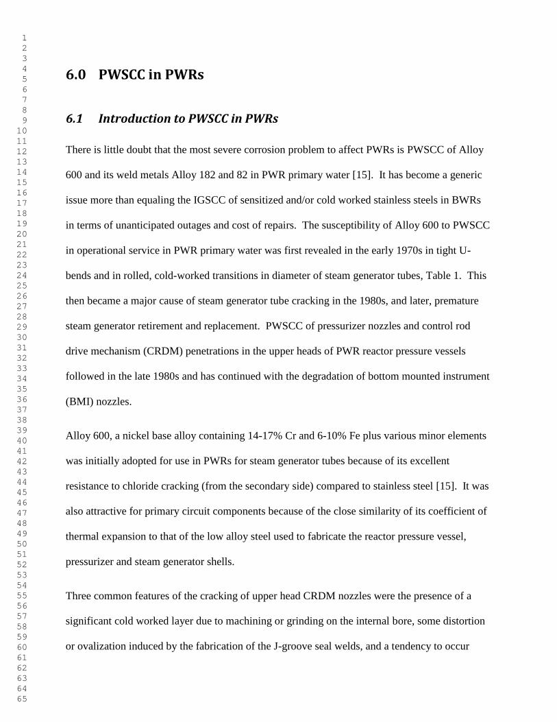
There is little doubt that the most severe corrosion problem to affect PWRs is PWSCC of Alloy
600 and its weld metals Alloy 182 and 82 in PWR primary water [15]. It has become a generic
issue more than equaling the IGSCC of sensitized and/or cold worked stainless steels in BWRs
in terms of unanticipated outages and cost of repairs. The susceptibility of Alloy 600 to PWSCC
in operational service in PWR primary water was first revealed in the early 1970s in tight U-
bends and in rolled, cold-worked transitions in diameter of steam generator tubes, Table 1. This
then became a major cause of steam generator tube cracking in the 1980s, and later, premature
steam generator retirement and replacement. PWSCC of pressurizer nozzles and control rod
drive mechanism (CRDM) penetrations in the upper heads of PWR reactor pressure vessels
followed in the late 1980s and has continued with the degradation of bottom mounted instrument
(BMI) nozzles.
Alloy 600, a nickel base alloy containing 14-17% Cr and 6-10% Fe plus various minor elements
was initially adopted for use in PWRs for steam generator tubes because of its excellent
resistance to chloride cracking (from the secondary side) compared to stainless steel [15]. It was
also attractive for primary circuit components because of the close similarity of its coefficient of
thermal expansion to that of the low alloy steel used to fabricate the reactor pressure vessel,
pressurizer and steam generator shells.
Three common features of the cracking of upper head CRDM nozzles were the presence of a
significant cold worked layer due to machining or grinding on the internal bore, some distortion
or ovalization induced by the fabrication of the J-groove seal welds, and a tendency to occur
1 2 3 4 5 6 7 8 9 10 11 12 13 14 15 16 17 18 19 20 21 22 23 24 25 26 27 28 29 30 31 32 33 34 35 36 37 38 39 40 41 42 43 44 45 46 47 48 49 50 51 52 53 54 55 56 57 58 59 60 61 62 63 64 65
much more frequently in the outer set-up circles where the angles between the vertical CRDM
nozzle and the domed upper head were greatest [15]. The combination of these three features
plus the fact that the upper head is stress relieved before the CRDM nozzles are welded in place
pointed to high residual stresses being responsible for these premature failures.
6.2 Mitigation of PWSCC
While SCC mitigation techniques such as weld overlays used in BWR piping IGSCC mitigation are
directly applicable to PWSCC and there appears to be promising environmental PWSCC mitigation
through the use on zinc injection [16] and an increase dissolved hydrogen content [17, 18], the
primary approach to PWSCC is through materials with the higher chromium content Alloy 690 and
its weld metals, i.e., the only well-established compositional correlation between PWSCC initiation
and nickel-based alloys and weld metal is the chromium content of the alloy [19].
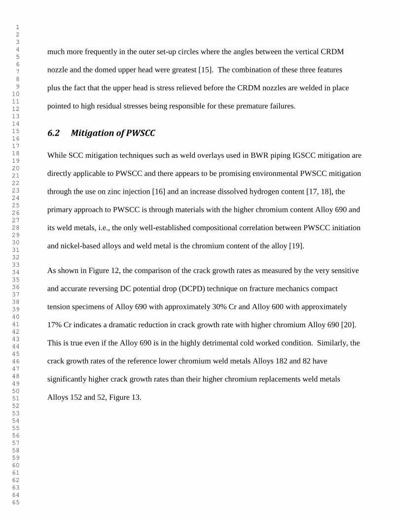
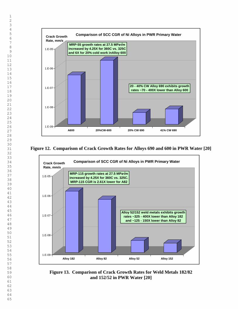
As shown in Figure 12, the comparison of the crack growth rates as measured by the very sensitive
and accurate reversing DC potential drop (DCPD) technique on fracture mechanics compact
tension specimens of Alloy 690 with approximately 30% Cr and Alloy 600 with approximately
17% Cr indicates a dramatic reduction in crack growth rate with higher chromium Alloy 690 [20].
This is true even if the Alloy 690 is in the highly detrimental cold worked condition. Similarly, the
crack growth rates of the reference lower chromium weld metals Alloys 182 and 82 have
significantly higher crack growth rates than their higher chromium replacements weld metals
Alloys 152 and 52, Figure 13.
1 2 3 4 5 6 7 8 9 10 11 12 13 14 15 16 17 18 19 20 21 22 23 24 25 26 27 28 29 30 31 32 33 34 35 36 37 38 39 40 41 42 43 44 45 46 47 48 49 50 51 52 53 54 55 56 57 58 59 60 61 62 63 64 65
1.E-09
1.E-08
1.E-07
1.E-06
1.E-05
A600 20%CW-600 20% CW 690 41% CW 690
Comparison of SCC CGR of Ni Alloys in PWR Primary WaterCrack Growth
Rate, mm/s
20 - 40% CW Alloy 690 exhibits growth
rates ~70 - 400X lower than Alloy 600
MRP-55 growth rates at 27.5 MPam
increased by 4.25X for 360C vs. 325C
and 6X for 20% cold work inAlloy 600
Figure 12. Comparison of Crack Growth Rates for Alloys 690 and 600 in PWR Water [20]
1.E-09
1.E-08
1.E-07
1.E-06
1.E-05
Alloy 182 Alloy 82 Alloy 52 Alloy 152
Comparison of SCC CGR of Ni Alloys in PWR Primary WaterCrack Growth
Rate, mm/s
Alloy 52/152 weld metals exhibits growth
rates ~325 - 400X lower than Alloy 182
and ~125 - 150X lower than Alloy 82
MRP-115 growth rates at 27.5 MPam
increased by 4.25X for 360C vs. 325C.
MRP-115 CGR is 2.61X lower for A82
Figure 13. Comparison of Crack Growth Rates for Weld Metals 182/82
and 152/52 in PWR Water [20]
1 2 3 4 5 6 7 8 9 10 11 12 13 14 15 16 17 18 19 20 21 22 23 24 25 26 27 28 29 30 31 32 33 34 35 36 37 38 39 40 41 42 43 44 45 46 47 48 49 50 51 52 53 54 55 56 57 58 59 60 61 62 63 64 65
7.0 Irradiation Assisted Stress Corrosion Cracking in LWRs
7.1 Introduction to IASCC
A growing concern for electric power utilities worldwide has been degradation in core component
[21]. Service failures have occurred in BWR core components and, to a somewhat lesser extent, in
PWR core components consisting of iron- and nickel-base stainless alloys that have achieved a
significant neutron fluence in environments that span oxygenated to hydrogenated water at 270-
340°C (518-644°F). Because cracking susceptibility is a function of radiation, stress and
environment, the failure mechanism has been termed irradiation-assisted stress corrosion cracking
(IASCC). Initially, the components affected have been either relatively small (bolts, springs, etc.)
or designed for replacement (fuel rods, control blades, or instrumentation tubes). In the past two
decades, much more structural components (e.g., PWR baffle bolts and BWR core shrouds). A
recent review describe the current knowledge related to IASCC service experience and laboratory
investigations and highlight the limited amount of well-controlled experimentation that exists on
well-characterized materials [21]. This lack of critical experimentation and the large number of
interdependent parameters make it imperative that underpinning science be used to guide
mechanistic understanding and quantification of IASCC.
The importance of neutron fluence on IASCC has been well established. IG SCC is promoted in austenitic
stainless steels as a critical “threshold” fluence is exceeded, Figure 14 [21]. Cracking is observed in BWR
oxygenated water at fluences above 2 to 5 x 10²⁰
n/cm2 (E>1 MeV), which corresponds to about 0.3 to 0.7
displacements per atom (dpa). Comparable “threshold” fluence for IASCC susceptibility has been reported
for high-stress, in-service BWR component cracking and during ex-situ, slow-strain-rate SCC testing of
irradiated stainless steels. This indicates “persistent” radiation effects (material changes) are primarily
1 2 3 4 5 6 7 8 9 10 11 12 13 14 15 16 17 18 19 20 21 22 23 24 25 26 27 28 29 30 31 32 33 34 35 36 37 38 39 40 41 42 43 44 45 46 47 48 49 50 51 52 53 54 55 56 57 58 59 60 61 62 63 64 65
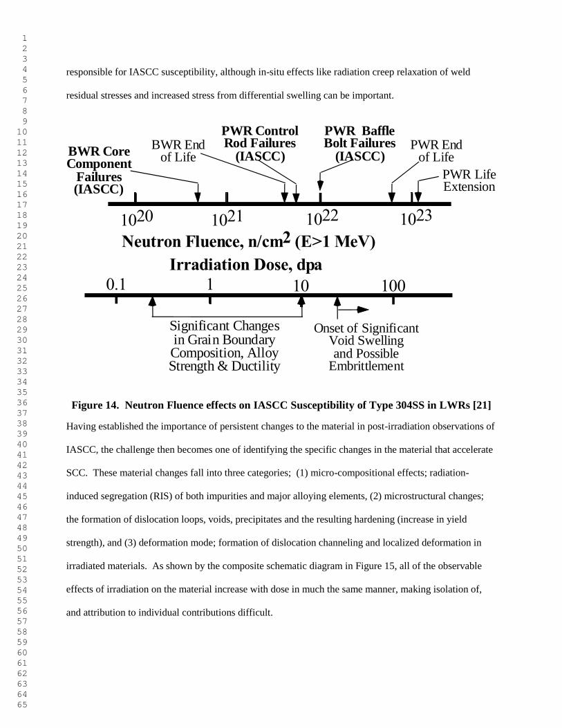
responsible for IASCC susceptibility, although in-situ effects like radiation creep relaxation of weld
residual stresses and increased stress from differential swelling can be important.
1020 1021 1022 1023
0.1 1 10 100
Neutron Fluence, n/cm2 (E>1 MeV)
Irradiation Dose, dpa
BWR CoreComponent
Failures(IASCC)
BWR Endof Life
PWR ControlRod Failures
(IASCC)PWR End
of Life
PWR BaffleBolt Failures
(IASCC)
Significant Changesin Grain BoundaryComposition, AlloyStrength & Ductility
Onset of SignificantVoid Swellingand Possible
Embrittlement
PWR LifeExtension
Figure 14. Neutron Fluence effects on IASCC Susceptibility of Type 304SS in LWRs [21]
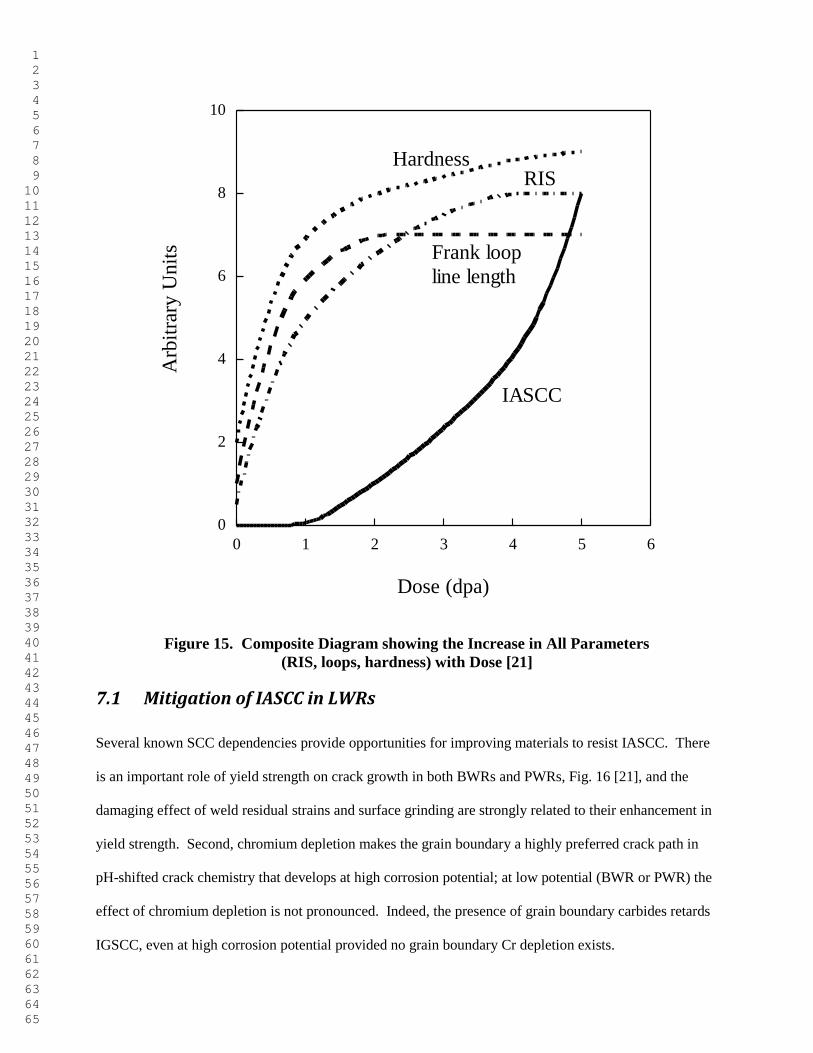
Having established the importance of persistent changes to the material in post-irradiation observations of
IASCC, the challenge then becomes one of identifying the specific changes in the material that accelerate
SCC. These material changes fall into three categories; (1) micro-compositional effects; radiation-
induced segregation (RIS) of both impurities and major alloying elements, (2) microstructural changes;
the formation of dislocation loops, voids, precipitates and the resulting hardening (increase in yield
strength), and (3) deformation mode; formation of dislocation channeling and localized deformation in
irradiated materials. As shown by the composite schematic diagram in Figure 15, all of the observable
effects of irradiation on the material increase with dose in much the same manner, making isolation of,
and attribution to individual contributions difficult.
1 2 3 4 5 6 7 8 9 10 11 12 13 14 15 16 17 18 19 20 21 22 23 24 25 26 27 28 29 30 31 32 33 34 35 36 37 38 39 40 41 42 43 44 45 46 47 48 49 50 51 52 53 54 55 56 57 58 59 60 61 62 63 64 65
0
2
4
6
8
10
0 1 2 3 4 5 6
Arb
itra
ry U
nit
s
Dose (dpa)
HardnessRIS
Frank loop
line length
IASCC
Figure 15. Composite Diagram showing the Increase in All Parameters
(RIS, loops, hardness) with Dose [21]
7.1 Mitigation of IASCC in LWRs
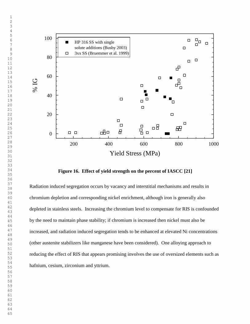
Several known SCC dependencies provide opportunities for improving materials to resist IASCC. There
is an important role of yield strength on crack growth in both BWRs and PWRs, Fig. 16 [21], and the
damaging effect of weld residual strains and surface grinding are strongly related to their enhancement in
yield strength. Second, chromium depletion makes the grain boundary a highly preferred crack path in
pH-shifted crack chemistry that develops at high corrosion potential; at low potential (BWR or PWR) the
effect of chromium depletion is not pronounced. Indeed, the presence of grain boundary carbides retards
IGSCC, even at high corrosion potential provided no grain boundary Cr depletion exists.
1 2 3 4 5 6 7 8 9 10 11 12 13 14 15 16 17 18 19 20 21 22 23 24 25 26 27 28 29 30 31 32 33 34 35 36 37 38 39 40 41 42 43 44 45 46 47 48 49 50 51 52 53 54 55 56 57 58 59 60 61 62 63 64 65
0
20
40
60
80
100
200 400 600 800 1000
HP 316 SS with single
solute additions (Busby 2003)
3xx SS (Bruemmer et al. 1999)
% I
G
Yield Stress (MPa)
Figure 16. Effect of yield strength on the percent of IASCC [21]
Radiation induced segregation occurs by vacancy and interstitial mechanisms and results in
chromium depletion and corresponding nickel enrichment, although iron is generally also
depleted in stainless steels. Increasing the chromium level to compensate for RIS is confounded
by the need to maintain phase stability; if chromium is increased then nickel must also be
increased, and radiation induced segregation tends to be enhanced at elevated Ni concentrations
(other austenite stabilizers like manganese have been considered). One alloying approach to
reducing the effect of RIS that appears promising involves the use of oversized elements such as
hafnium, cesium, zirconium and yttrium.
1 2 3 4 5 6 7 8 9 10 11 12 13 14 15 16 17 18 19 20 21 22 23 24 25 26 27 28 29 30 31 32 33 34 35 36 37 38 39 40 41 42 43 44 45 46 47 48 49 50 51 52 53 54 55 56 57 58 59 60 61 62 63 64 65
However since most LWRs are planning on life extension of an additional 20 and 40 years and
the overall replacement of irradiated components is extremely difficult, the current emphasis on
IASCC mitigation involves addressing the tensile stress parameter of SCC. Fiber laser peening
(FLP) and water jet peening (WJP) are the two tensile stress reducing techniques that have been
used in Japan for both mitigation in operating plants, but also for new construction.
7.1.1 Fiber Laser Peening (FLP)
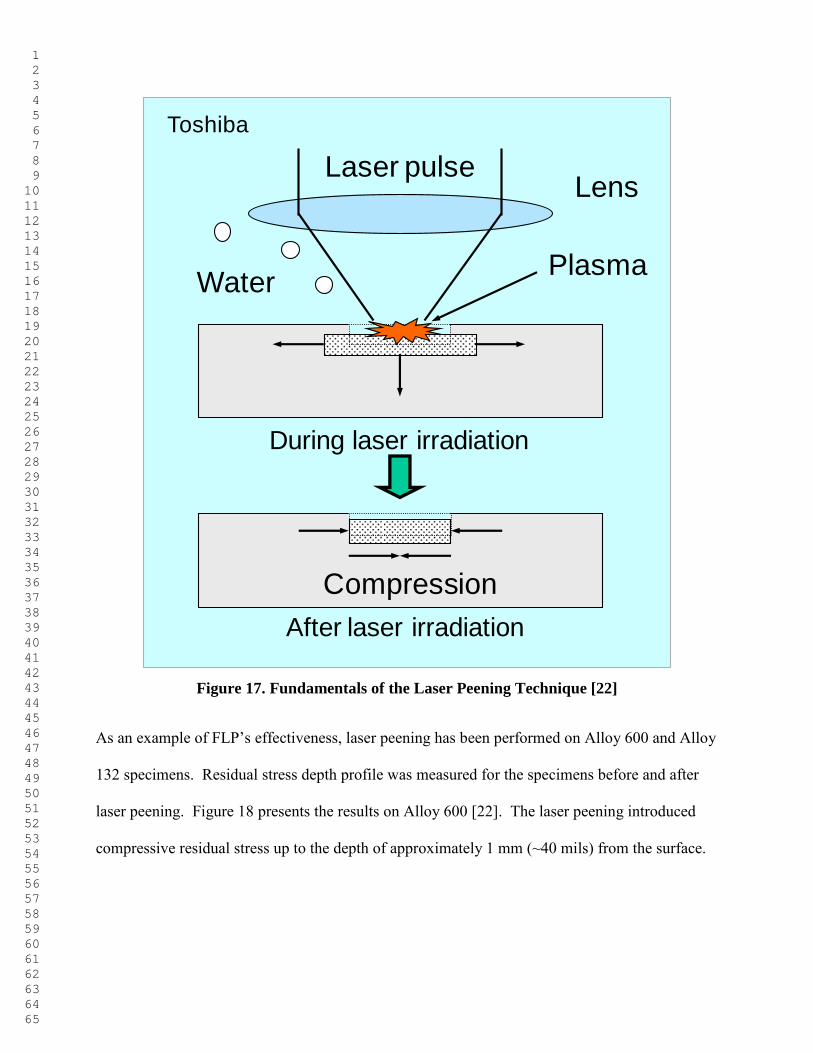
Laser peening is an energy conversion process involving a change from laser energy to shock
wave energy that results in plastic deformation of the metal substrate. When a nanosecond-order
laser pulse delivered via an optical fiber (e.g., FLP) focuses on a water-immersed metal surface,
the top surface absorbs the laser energy and instantaneously evaporates through ablative
interaction as illustrated in Figure 17 [22].
The evaporating metal is confined due to the inertia of the surrounding water that inhibits the
expansion of the metal vapor. The resulting high-density metal vapor is immediately ionized to
form plasma. Subsequent energy absorption in the plasma generates a heat-sustained shock
wave that impinges on the metal surface with an intensity of several GPa, (several 100s ksi) far
exceeding the yield strength of the metal. The shock wave propagates into the metal interior and
loses energy as it creates a permanent strain in the metal. After the passage of the shock wave,
the permanent strain remains and the surrounding metal constrains the strained region as a
reaction to elastic strain, thus creating a compressive residual stress on the metal surface.
1 2 3 4 5 6 7 8 9 10 11 12 13 14 15 16 17 18 19 20 21 22 23 24 25 26 27 28 29 30 31 32 33 34 35 36 37 38 39 40 41 42 43 44 45 46 47 48 49 50 51 52 53 54 55 56 57 58 59 60 61 62 63 64 65
LensLaser pulse
Plasma
Compression
Water
After laser irradiation
Toshiba
During laser irradiation
Figure 17. Fundamentals of the Laser Peening Technique [22]
As an example of FLP’s effectiveness, laser peening has been performed on Alloy 600 and Alloy
132 specimens. Residual stress depth profile was measured for the specimens before and after
laser peening. Figure 18 presents the results on Alloy 600 [22]. The laser peening introduced
compressive residual stress up to the depth of approximately 1 mm (~40 mils) from the surface.
1 2 3 4 5 6 7 8 9 10 11 12 13 14 15 16 17 18 19 20 21 22 23 24 25 26 27 28 29 30 31 32 33 34 35 36 37 38 39 40 41 42 43 44 45 46 47 48 49 50 51 52 53 54 55 56 57 58 59 60 61 62 63 64 65
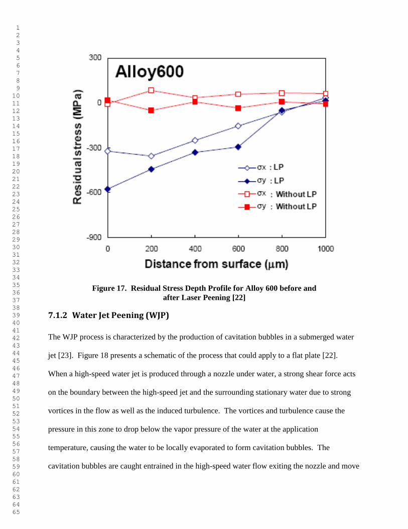
Figure 17. Residual Stress Depth Profile for Alloy 600 before and
after Laser Peening [22]
7.1.2 Water Jet Peening (WJP)
The WJP process is characterized by the production of cavitation bubbles in a submerged water
jet [23]. Figure 18 presents a schematic of the process that could apply to a flat plate [22].
When a high-speed water jet is produced through a nozzle under water, a strong shear force acts
on the boundary between the high-speed jet and the surrounding stationary water due to strong
vortices in the flow as well as the induced turbulence. The vortices and turbulence cause the
pressure in this zone to drop below the vapor pressure of the water at the application
temperature, causing the water to be locally evaporated to form cavitation bubbles. The
cavitation bubbles are caught entrained in the high-speed water flow exiting the nozzle and move
1 2 3 4 5 6 7 8 9 10 11 12 13 14 15 16 17 18 19 20 21 22 23 24 25 26 27 28 29 30 31 32 33 34 35 36 37 38 39 40 41 42 43 44 45 46 47 48 49 50 51 52 53 54 55 56 57 58 59 60 61 62 63 64 65
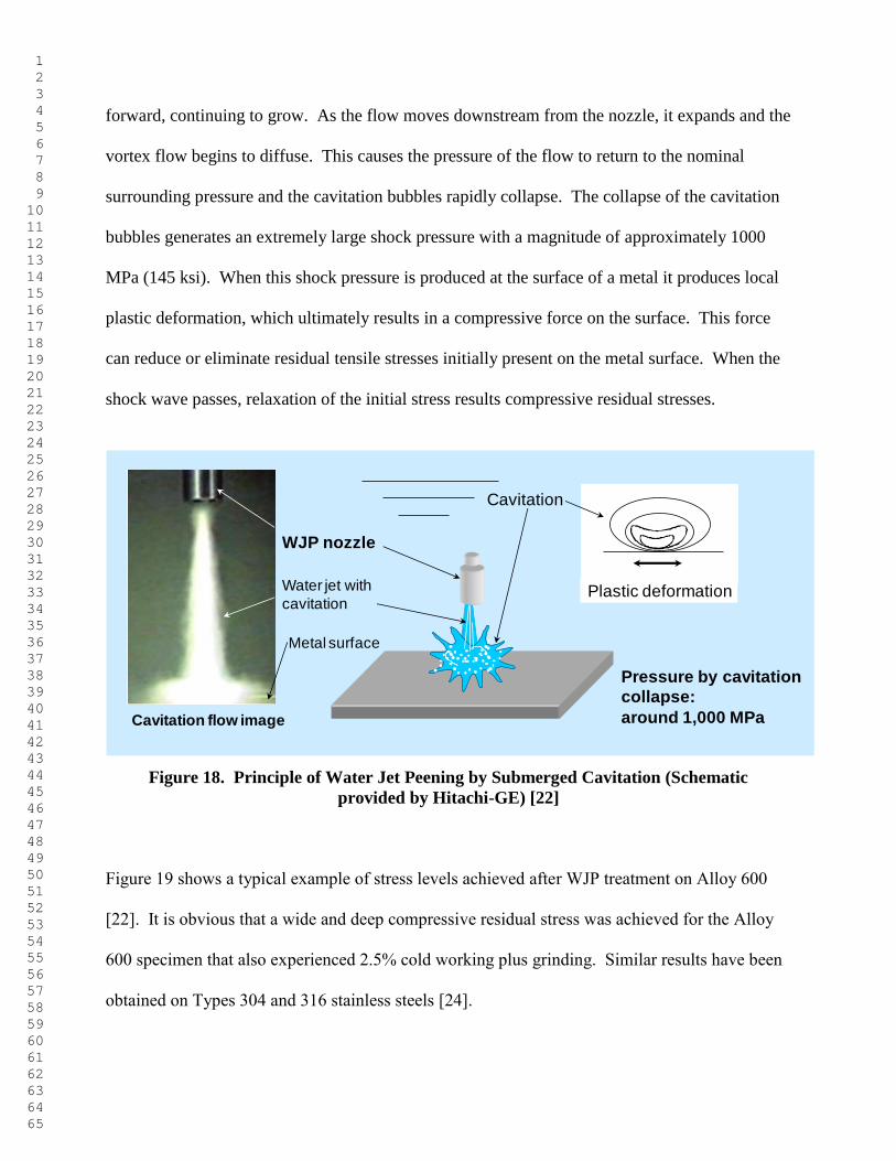
forward, continuing to grow. As the flow moves downstream from the nozzle, it expands and the
vortex flow begins to diffuse. This causes the pressure of the flow to return to the nominal
surrounding pressure and the cavitation bubbles rapidly collapse. The collapse of the cavitation
bubbles generates an extremely large shock pressure with a magnitude of approximately 1000
MPa (145 ksi). When this shock pressure is produced at the surface of a metal it produces local
plastic deformation, which ultimately results in a compressive force on the surface. This force
can reduce or eliminate residual tensile stresses initially present on the metal surface. When the
shock wave passes, relaxation of the initial stress results compressive residual stresses.
Pressure by cavitation
collapse:
around 1,000 MPa
WJP nozzle
Plastic deformation
Cavitation
Cavitation flow image
Water jet with
cavitation
Metal surface
Figure 18. Principle of Water Jet Peening by Submerged Cavitation (Schematic
provided by Hitachi-GE) [22]
Figure 19 shows a typical example of stress levels achieved after WJP treatment on Alloy 600
[22]. It is obvious that a wide and deep compressive residual stress was achieved for the Alloy
600 specimen that also experienced 2.5% cold working plus grinding. Similar results have been
obtained on Types 304 and 316 stainless steels [24].
1 2 3 4 5 6 7 8 9 10 11 12 13 14 15 16 17 18 19 20 21 22 23 24 25 26 27 28 29 30 31 32 33 34 35 36 37 38 39 40 41 42 43 44 45 46 47 48 49 50 51 52 53 54 55 56 57 58 59 60 61 62 63 64 65
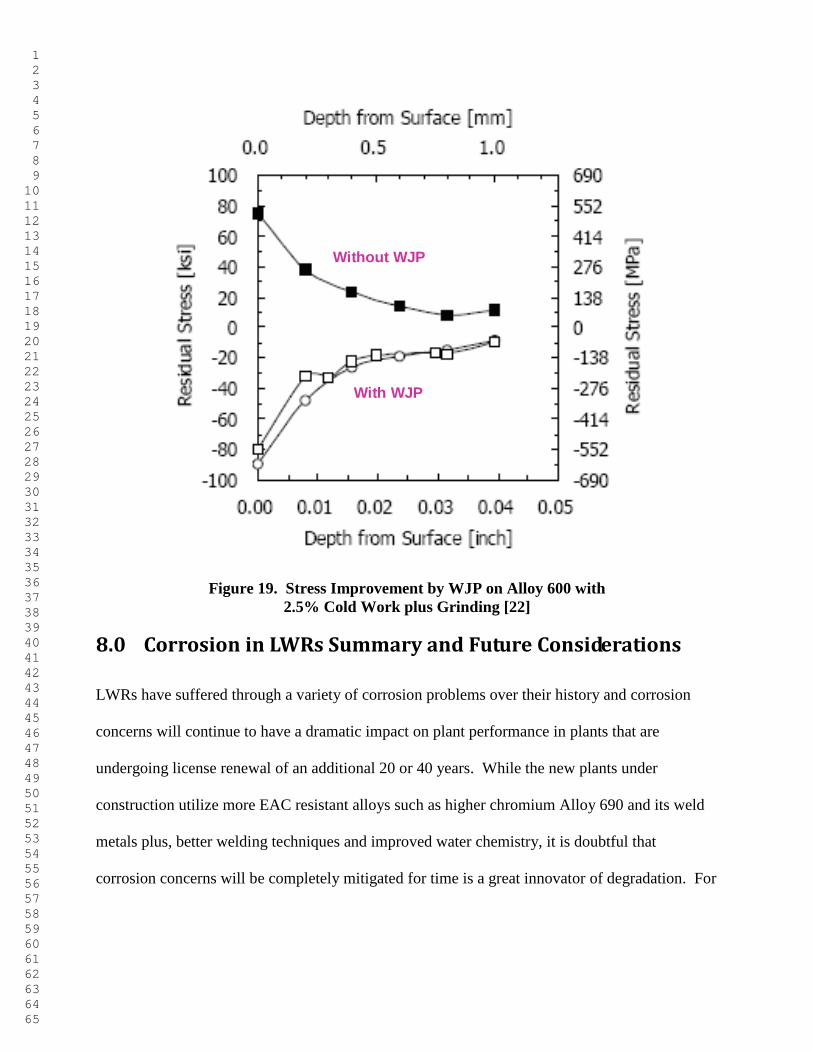
Without WJP
With WJP
Figure 19. Stress Improvement by WJP on Alloy 600 with
2.5% Cold Work plus Grinding [22]
8.0 Corrosion in LWRs Summary and Future Considerations
LWRs have suffered through a variety of corrosion problems over their history and corrosion
concerns will continue to have a dramatic impact on plant performance in plants that are
undergoing license renewal of an additional 20 or 40 years. While the new plants under
construction utilize more EAC resistant alloys such as higher chromium Alloy 690 and its weld
metals plus, better welding techniques and improved water chemistry, it is doubtful that
corrosion concerns will be completely mitigated for time is a great innovator of degradation. For
1 2 3 4 5 6 7 8 9 10 11 12 13 14 15 16 17 18 19 20 21 22 23 24 25 26 27 28 29 30 31 32 33 34 35 36 37 38 39 40 41 42 43 44 45 46 47 48 49 50 51 52 53 54 55 56 57 58 59 60 61 62 63 64 65
example, only recently has the SCC of austenitic stainless steel in PWR environments been
observed.
Finally, it has been argued that because of defense-in depth design and operating features,
materials degradation issues such as SCC of piping and core internals in current BWR (and
PWR) designs do not increase significantly a plants’ baseline core-damage frequency (CDF) or
large energy release frequency (LERF) [25, 26]. However, there is no question that such failures
have a marked negative impact on both the economy of plant operation and the public perception
of nuclear reactor safety. Thus, the resolution of such problems is essential, especially with
changes in the plants’ licensing basis associated with, for example, life extension/license renewal
and power up-rates that may affect EAC susceptibility.
The corrosion challenges for the future will be governed by changes in operating and regulatory
conditions [25]. For instance, in the US there is a steady movement towards regulations that are
not only performance-based, but also risk-informed. This development emphasizes decision-
making that takes into account the relative importance of various maintenance, in-service
inspection, procurement, etc. activities in terms of their impact on plant safety (e.g., CDF, LERF)
(US NRC Reg. Guides 1.174, 1.175, 1.176, 1.177 and 1.178). To date, time-dependent materials
degradation phenomena have not been included in the probabilistic risk assessments and the
associated event- and fault-trees that address, for instance, either the accident initiation frequency
or the reliability of components that play a role in subsequent accident mitigation. Thus the
near-term challenge in materials-degradation technology is to extend the current deterministic
and mechanisms-informed understanding of the cracking phenomena to cover the uncertainties
associated with the random crack initiation processes, and the uncertainties associated with the
propagation rate data and models.
1 2 3 4 5 6 7 8 9 10 11 12 13 14 15 16 17 18 19 20 21 22 23 24 25 26 27 28 29 30 31 32 33 34 35 36 37 38 39 40 41 42 43 44 45 46 47 48 49 50 51 52 53 54 55 56 57 58 59 60 61 62 63 64 65
A further operational driver that presents challenges is the constant desire for longer fuel cycles
and the resultant increase in time between component inspections and over 60 years of plant
operation [25]. This puts a premium on defining the kinetics of damage accumulation and the
development of inspection techniques that have adequate resolution and probability of detection
capabilities for the particular system at risk.
9.0 References
1. B. M. Gordon, “Corrosion Issues in the BWR and Their Mitigation for Plant Life
Extension,” paper presented at the ANS Topical Meeting on Nuclear Plant Life
Extension, Snowbird, UT, July 1988.
2. B. L. Lipford and J. C. Flynn, “Drywell Corrosion Stopped at Oyster Creek,” Power
Engineering, November 1993, p. 47.
3. NRC information notice 2010-12: Containment Liner Corrosion, June 18, 2010.
4. R. B. Dooley, “Flow-Accelerated Corrosion in Fossil and Combined Cycle/HRSG
Plants,” PowerPlant Chemistry 2008, 10(2), p. 68.
5. U. S. Nuclear Regulatory Commission, “Feedwater Line Break,” Information Notice 86-
106, Supplement 1, U.S. Nuclear Regulatory Commission, Washington, D.C., February
13, 1987.
6. NISA, “Secondary Piping Rupture Accident at Mihama Power Station, Unit 3, of the
Kansai Electric Power Co., Inc. (Final Report),” (Translated by JNES, Rev 1 as of May
14, 2005), The Nuclear and Industrial Safety Agency, March 30, 2005.
7. Y. S. Garud, “Issues and Advances in the Assessment of Flow Accelerated Corrosion,”
paper presented at the 14th International Conference on Environmental Degradation in
Nuclear Power Systems – Water Reactors. Virginia Beach, VA. August 23-27, 2009.
Published in proceedings of same. Eds. T. R. Allen, J. T. Busby and G. Ilevbare.
American Nuclear Society, La Grange Park, IL, 2010.
8. F. P. Ford, B. M. Gordon and R. M. Horn, “Intergranular Stress Corrosion Cracking
(IGSCC) in Boiling Water Reactor (BWRs),” Nuclear Corrosion Science and
Engineering, Ed. Damien Féron, Woodhead Publishing, Abington Hall, Abington,
Cambridge, 2012, p 548.
9. F. P. Ford, B. M. Gordon and R. M. Horn, “Corrosion in Boiling Water Reactors,” ASM
Handbook Volume 13C, Corrosion: Environments and Industries, A. D. Cramer and B. S.
Covino, Jr. Eds, ASM, Metals Park, OH, 2006, p 341.
1 2 3 4 5 6 7 8 9 10 11 12 13 14 15 16 17 18 19 20 21 22 23 24 25 26 27 28 29 30 31 32 33 34 35 36 37 38 39 40 41 42 43 44 45 46 47 48 49 50 51 52 53 54 55 56 57 58 59 60 61 62 63 64 65
10. H. H. Klepfer, et al, “Investigation of Cause of Cracking in Austenitic Stainless Steel
Piping” NEDO-21000, General Electric July 1975.
11. B. M. Gordon and G. M. Gordon.” Corrosion in Boiling Water Reactors”. ASM
Handbook Corrosion Volume 13. 1987, p. 929.
12. B. M. Gordon, “BWR Material Life Extension through Hydrogen Water Chemistry,”
paper presented at the Operability of Nuclear Power Systems in Normal and Adverse
Environments, Albuquerque, NM, American Nuclear Society, La Grange Park, IL,
October 1986.
13. P. L. Andresen, Y. J. Kim, T. P. Diaz and S. Hettiarachchi, “Mitigation of SCC by On-
line NobleChem,” paper presented at the 13th
International Symposium on Environmental
Degradation of Materials in Nuclear Power Systems - Water Reactors, Whistler, British
Columbia ,August 19 - 23, 2007. Eds. P. J. King, T. R. Allen and J. T. Busby. Published
by Canadian Nuclear Society, Toronto, ON, 2007.
14. R. L. Cowan, “Optimizing Water Chemistry in US Boiling Water Reactors” paper
presented at the VGB Conference Plant Chemistry Essen, Germany, October 1994.
15. P. M. Scott and P. Combrade, “Corrosion in Pressurized Water Reactors,” ASM
Handbook Volume 13C, Corrosion: Environments and Industries, A. D. Cramer and B. S.
Covino, Jr. Eds, ASM, Metals Park, OH, 2006, p 362.
16. J. N. Esposito, et al., “The Addition of Zinc to Primary Reactor Coolant for Enhanced
PWSCC Resistance,” Proceedings of the 5th International Symposium on Environmental
Degradation of Materials in Nuclear Power Systems - Water Reactors, ANS, LaGrange,
IL, p. 495, 1992.
17. T. Cassagne, B. Fleury, F. Vaillant, O. Bouvier and P. Combrade, “An Update on the
Influence of Hydrogen on the PWSCC of Nickel Base Alloys in High Temperature
Water,” paper presented at the 8th
International Symposium on Environmental
Degradation of Materials in Nuclear Power Systems – Water Reactors, August 10 – 14,
1997, Amelia Island, published in proceedings of same, ANS, La Grange Park, IL, 1997,
p. 307.
18. P. L. Andresen, J. Hickling, K. Ahluwalia and J. Wilson, “Effect of Dissolved H2 on SCC
of Ni Alloys and Weld Metals,” paper 09414 presented at Corrosion 2009, Atlanta, GA,
March 22-26, 2009, NACE, Houston, TX.
19. “Materials Reliability Program: Crack Growth Rates for Evaluating Primary Water Stress
Corrosion Cracking of Alloy 82, 182, and 132 Welds (MRP-115),” EPRI, Palo Alto, CA:
2004. 1006696.
20. P. L. Andresen, M. Morra, J. Hickling, K. Ahluwalia and J. Wilson, “Effect of
Deformation and Orientation on SCC of Alloy 690,” paper 09412 presented at Corrosion
2009, Atlanta, GA, March 22-26, 2009, NACE, Houston, TX.
1 2 3 4 5 6 7 8 9 10 11 12 13 14 15 16 17 18 19 20 21 22 23 24 25 26 27 28 29 30 31 32 33 34 35 36 37 38 39 40 41 42 43 44 45 46 47 48 49 50 51 52 53 54 55 56 57 58 59 60 61 62 63 64 65
21. G. S. Was, J. T. Busby and P. L. Andresen, “Effect of Irradiation on Stress Corrosion
Cracking and Corrosion in Light Water Reactors,” ASM Handbook Volume 13C,
Corrosion: Environments and Industries, A. D. Cramer and B. S. Covino, Jr. Eds, ASM,
Metals Park, OH, 2006, p 386.
22. T. Lian, R. Couch and P. Crooker, “Surface Stress Improvement by Peening for PWSCC
Mitigation,” Briefing to NRC on PWSCC Mitigation, Rockville, Maryland, August 6, 2009.
23. “Materials Reliability Program: Technical Basis Document for Primary Water Stress
Corrosion Cracking Mitigation by Surface Treatments (MRP-267),” EPRI, Palo Alto, CA:
Final Report, January 2010. 1020481.
24. K. Osumi, “Water Jet Peening (WJP) Technology,” paper presented at the Mitigation
Working Group MRP Alloy 600 82/182 ITG Meeting, Austin, TX, September 14, 2005.
25. F. P. Ford, B. M. Gordon and R. M. Horn, “Intergranular Stress Corrosion Cracking (IGSCC)
in Boiling Water Reactor (BWRs),” Nuclear Corrosion Science and Engineering, Ed. Damien
Féron, Woodhead Publishing, Abington Hall, Abington, Cambridge, 2012, p 548.
26. G. Ware, D. Morton, M. Nitzel and S. Eide, “Evaluation of Risk Associated with Intergranular
Stress Corrosion Cracking in Boiling Water Reactor Internals,” NUREG/CR-6677,
INEEL/EXT-2000-00888, July, Rockville, MD, 2000.
1 2 3 4 5 6 7 8 9 10 11 12 13 14 15 16 17 18 19 20 21 22 23 24 25 26 27 28 29 30 31 32 33 34 35 36 37 38 39 40 41 42 43 44 45 46 47 48 49 50 51 52 53 54 55 56 57 58 59 60 61 62 63 64 65
Related Documents