Technical Report #2 John Jay College Expansion Project Michael Hopper Structural Option AE Consultant: Dr. Lepage October 24 th , 2008 New York, NY

Welcome message from author
This document is posted to help you gain knowledge. Please leave a comment to let me know what you think about it! Share it to your friends and learn new things together.
Transcript

Technical Report #2
Mike
[Type the company name]
Technical Report #2
John Jay College Expansion Project
Michael Hopper
Structural Option
AE Consultant: Dr. Lepage
October 24th, 2008
New York, NY
Michael Hopper John Jay College Expansion Project Structural Option New York, NY A E Consultant: Dr. Lepage 10/24/2008
Technical Assignment #2
2 | 5 1
Table of Contents Executive Summary…………………………………………………………………………………….3 Introduction……………………………………………………………………………………………….4
Gravity Loads…………………………………………………………………………………...6 Design Codes and Reference Manuals….…………………………………………..7 Deflection Criteria…………………………………………………………………………….7 Fire Protection and Fire Ratings………………………………………………………..7 Existing Floor Framing System…………………………………………………………………….9 Alternative Floor Framing Systems...………………………………………………………..11 Two‐Way Flat Slab…………………..……………………………………………………..12 Two‐Way Post‐Tensioned Slab……………………………………………………….14 Pre‐Cast Hollow Core Plank on Steel Beams…..…………………………….…16 Conclusions… …………………………………………………………………………………………..18 Appendix A……………………………………………………………………………………………….20 Appendix B……………………………………………………………………………………………….22 Appendix C……………………………………………………………………………………………….28 Appendix D……………………………………………………………………………………………….43 Appendix E…………………………………………………………………………………………….…46

Michael Hopper John Jay College Expansion Project Structural Option New York, NY A E Consultant: Dr. Lepage 10/24/2008
Technical Assignment #2
3 | 5 1
Executive Summary In the second technical report of the John Jay College Expansion Project alternative floor systems are investigated. A typical interior bay of 30’‐0” x 25’‐10” was analyzed and designed for four floor systems, including the existing, and were compared based on: self weight, total structural depth, constructability, impact on the existing architecture and steel structure, fire ratings, and cost. The existing floor system is composite steel and was chosen because of its light self weight and ability to span long distances. The three other systems that are studied in this report include:
‐ Two‐Way Flat Slab with Drop Panels, ‐ Two‐Way Post‐Tensioned Slab, and ‐ Pre‐Cast Hollow Core Planks on Steel Beams.
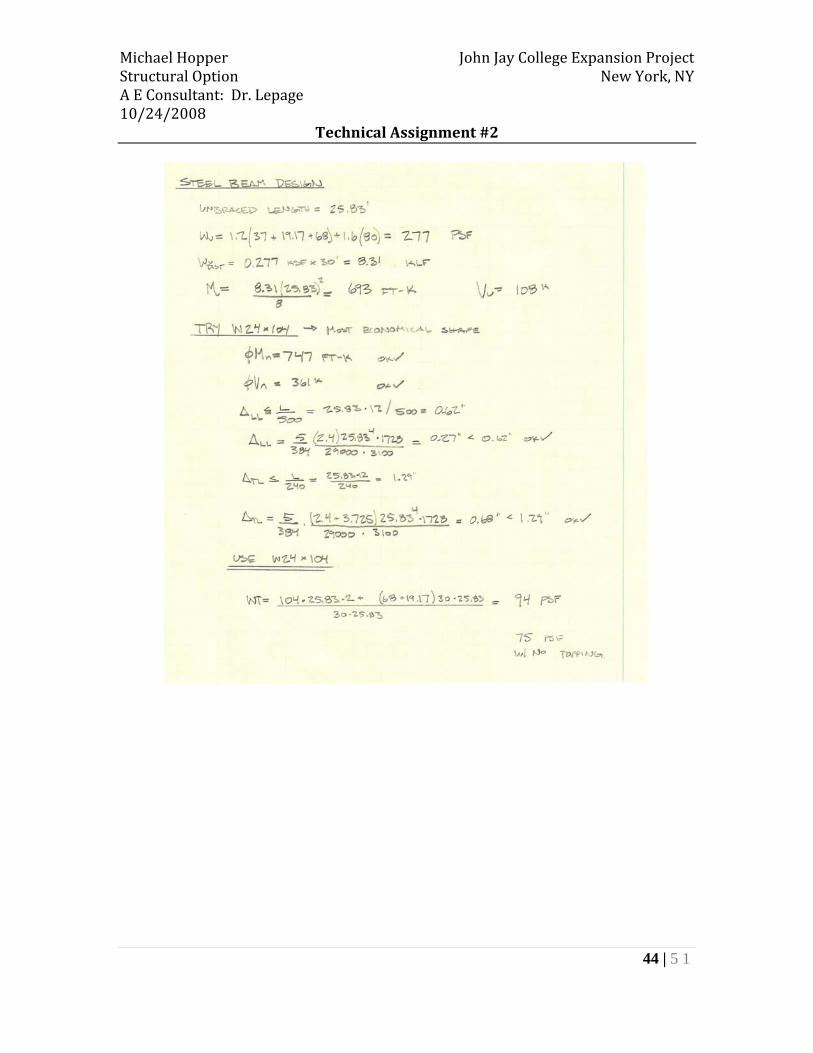
The design of a two‐way flat slab floor system resulted in a 10” thick slab with 13” thick drop panels. This system is efficient for the typical bay analyzed in this report, but would not be economical for longer spans. Transferring gravity loads over Amtrak tracks beneath the building would be very complicated and expensive due to the self weight of this concrete floor system, and therefore it will not be studied beyond this report. The goal of analyzing a post‐tensioned two‐way slab was to minimize the self weight of the floor system to reduce the gravity loads that must be transferred over the Amtrak tracks by maintaining a thin slab profile. After designing the post‐tensioned concrete slab floor system, it was determined that a 7” slab was adequate to span 30’‐0”, but drop panels had to be incorporated to resist punching shear. This thin slab required a substantial amount of steel reinforcement at interior supports for ultimate strength requirements. Despite the uncertainty of transferring the heavy self weight of a concrete structure over the tracks, the post‐tensioned system will be investigated further because it fits into the layout of the existing building. 30’‐0” long pre‐cast hollow core planks were sized according to Nitterhouse Concrete Products Hollow Core Plank Design Tables and were determined to be 10” thick. 2” of lightweight topping was added to the hollow core planks to ensure a level floor surface and to provide a rigid diaphragm for distributing lateral forces to the centralized braced frames. These planks are supported by W24x104 non‐composite steel beams. Less structural steel is used in this floor system because there are no infill beams and less concrete is used as well, resulting in a lighter self weight of the structure. Efficient manufacturing and construction methods, as well as long span capabilities, make pre‐cast hollow core planks on steel beams a viable option worth studying further.
Michael Hopper John Jay College Expansion Project Structural Option New York, NY A E Consultant: Dr. Lepage 10/24/2008
Technical Assignment #2
4 | 5 1
Introduction
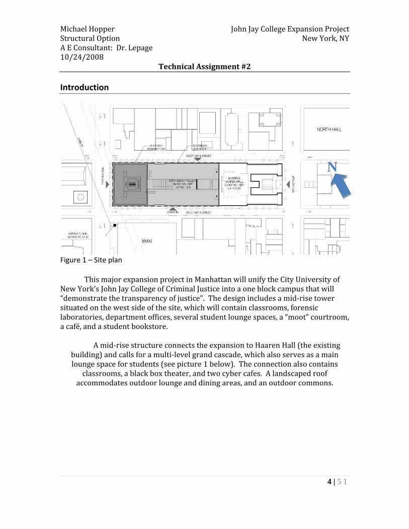
Figure 1 – Site plan
This major expansion project in Manhattan will unify the City University of New York’s John Jay College of Criminal Justice into a one block campus that will “demonstrate the transparency of justice”. The design includes a mid‐rise tower situated on the west side of the site, which will contain classrooms, forensic laboratories, department offices, several student lounge spaces, a “moot” courtroom, a café, and a student bookstore.
A mid‐rise structure connects the expansion to Haaren Hall (the existing building) and calls for a multi‐level grand cascade, which also serves as a main lounge space for students (see picture 1 below). The connection also contains
classrooms, a black box theater, and two cyber cafes. A landscaped roof accommodates outdoor lounge and dining areas, and an outdoor commons.
N

Michael Hopper John Jay College Expansion Project Structural Option New York, NY A E Consultant: Dr. Lepage 10/24/2008
Technical Assignment #2
5 | 5 1
Picture 1 – Rendering of the Grand Cascade.
Amtrak tracks cross the south‐west corner of the site, which is beneath the
mid‐rise tower. This restriction led to a unique structural solution to transfer over the tracks. Floors 1 through 5 are transferred over the tracks using built‐up steel transfer girders and floors 6 through 14 are hanging from perimeter plate hangers supported at the penthouse level by transfer trusses that are one‐story tall. These trusses then transfer the loads to a braced frame core.
The existing floor system of the John Jay College Expansion Project is a composite steel system with the most typical bay size being 30’‐0”x37’‐10”. This system was chosen to reduce the self weight of the structure to permit transferring gravity loads over the Amtrak tracks. Braced Frames wrap around a centralized service core in the 14 story tower and cascade.
The remainder of this report investigates the existing floor framing system, as
well as three alternative solutions. All designs are considered schematic as the objective of this report is to study the various floor systems that can be applied to the expansion project. Several variables are taken into account when comparing floor systems such as: fire protection, weight, cost, overall structural depths, and constructability. All

Michael Hopper John Jay College Expansion Project Structural Option New York, NY A E Consultant: Dr. Lepage 10/24/2008
Technical Assignment #2
6 | 5 1
alternative floor systems will be designed and compared using a typical interior bay, as seen in figure 2.
Figure 2 – Typical interior bay used to design the floor systems in this report. Gravity Loads:
Dead loads used to design the floor systems in this report included the self
weight of the floor system and the superimposed dead load of 37 psf determined in technical report one. This is a typical superimposed dead load for the building.
Typical live loads for the John Jay College Expansion Project are:
Assembly Areas: 60 psf Office Spaces: 50 psf Public Spaces: 100 psf
Live loads used to design the floor systems in this report were taken as 80 psf. This is an average of assembly areas and public areas. There are also several areas such as laboratories, cafeterias, and large corridors where live loads are not permitted to be reduced. Therefore, live loads will not be reduced in this report.
Michael Hopper John Jay College Expansion Project Structural Option New York, NY A E Consultant: Dr. Lepage 10/24/2008
Technical Assignment #2
7 | 5 1
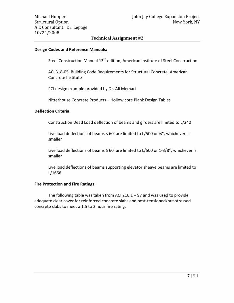
Design Codes and Reference Manuals:
Steel Construction Manual 13th edition, American Institute of Steel Construction
ACI 318‐05, Building Code Requirements for Structural Concrete, American Concrete Institute
PCI design example provided by Dr. Ali Memari Nitterhouse Concrete Products – Hollow core Plank Design Tables
Deflection Criteria:
Construction Dead Load deflection of beams and girders are limited to L/240
Live load deflections of beams < 60’ are limited to L/500 or ¾”, whichever is smaller
Live load deflections of beams ≥ 60’ are limited to L/500 or 1‐3/8”, whichever is smaller Live load deflections of beams supporting elevator sheave beams are limited to L/1666
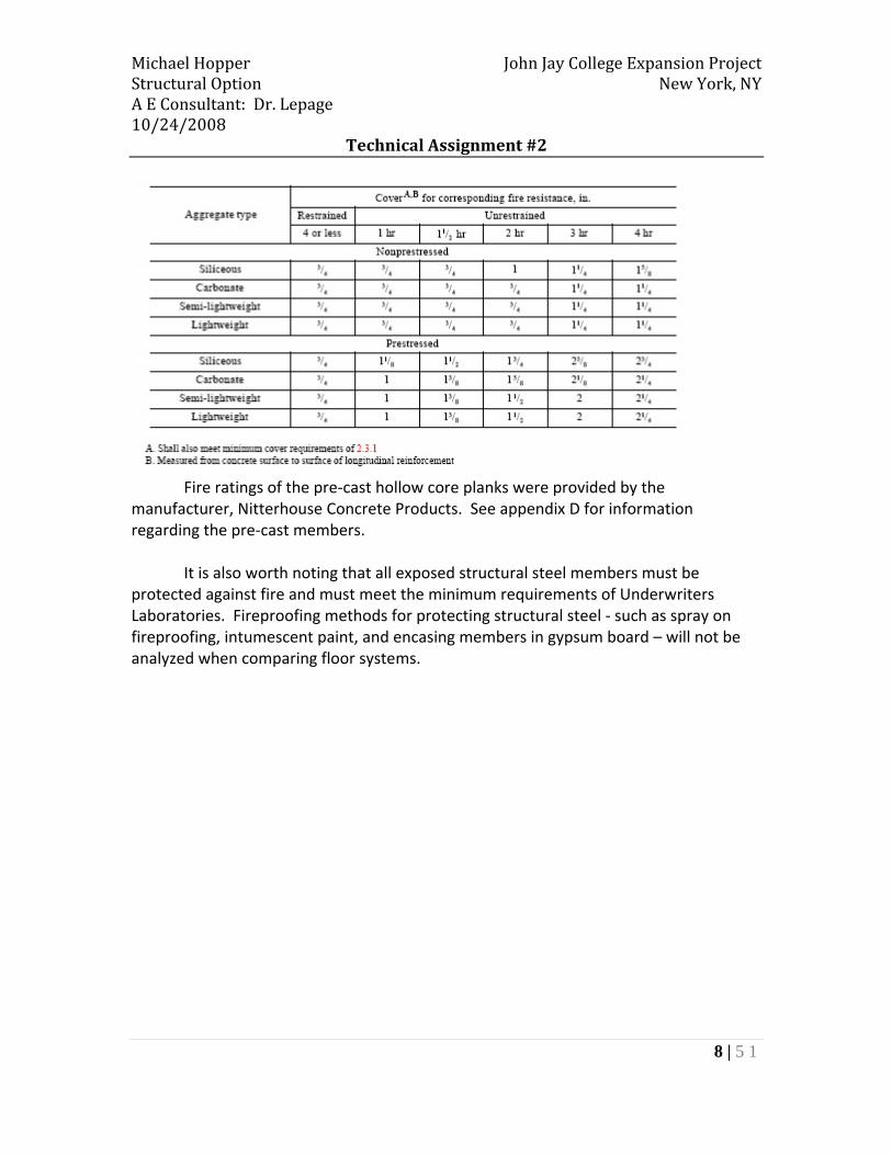
Fire Protection and Fire Ratings: The following table was taken from ACI 216.1 – 97 and was used to provide adequate clear cover for reinforced concrete slabs and post‐tensioned/pre‐stressed concrete slabs to meet a 1.5 to 2 hour fire rating.
Michael Hopper John Jay College Expansion Project Structural Option New York, NY A E Consultant: Dr. Lepage 10/24/2008
Technical Assignment #2
8 | 5 1
Fire ratings of the pre‐cast hollow core planks were provided by the manufacturer, Nitterhouse Concrete Products. See appendix D for information regarding the pre‐cast members.
It is also worth noting that all exposed structural steel members must be
protected against fire and must meet the minimum requirements of Underwriters Laboratories. Fireproofing methods for protecting structural steel ‐ such as spray on fireproofing, intumescent paint, and encasing members in gypsum board – will not be analyzed when comparing floor systems.
Michael Hopper John Jay College Expansion Project Structural Option New York, NY A E Consultant: Dr. Lepage 10/24/2008
Technical Assignment #2
9 | 5 1
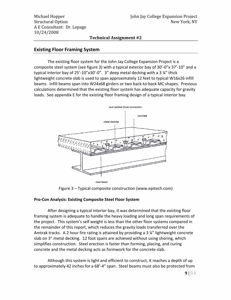
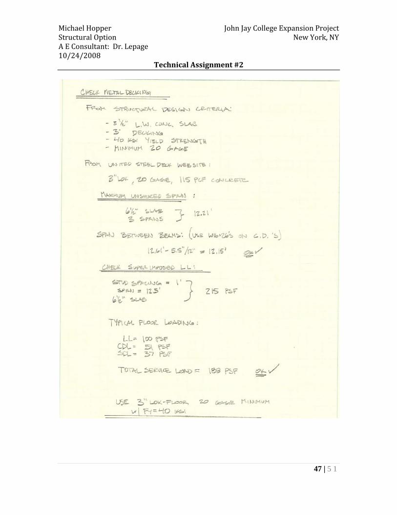
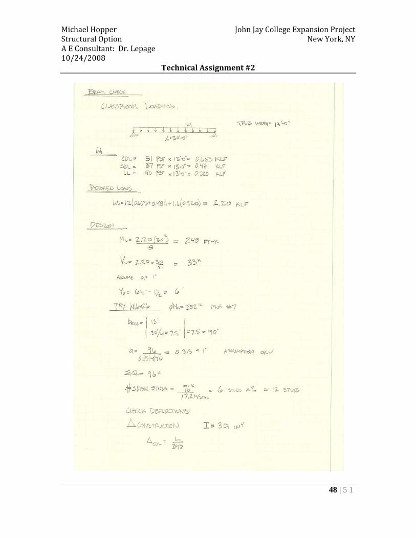
Existing Floor Framing System The existing floor system for the John Jay College Expansion Project is a composite steel system (see figure 3) with a typical exterior bay of 30’‐0”x 37’‐10” and a typical interior bay of 25’‐10”x30’‐0”. 3” deep metal decking with a 3 ¼” thick lightweight concrete slab is used to span approximately 12 feet to typical W16x26 infill beams. Infill beams span into W24x68 girders or two back‐to‐back MC shapes. Previous calculations determined that the existing floor system has adequate capacity for gravity loads. See appendix E for the existing floor framing design of a typical interior bay.
Figure 3 – Typical composite construction (www.epitech.com)
Pro‐Con Analysis: Existing Composite Steel Floor System After designing a typical interior bay, it was determined that the existing floor framing system is adequate to handle the heavy loading and long span requirements of the project. This system’s self weight is less than the other floor systems compared in the remainder of this report, which reduces the gravity loads transferred over the Amtrak tracks. A 2 hour fire rating is attained by providing a 3 ¼” lightweight concrete slab on 3” metal decking. 12 foot spans are achieved without using shoring, which simplifies construction. Steel erection is faster than forming, placing, and curing concrete and the metal decking acts as formwork for the concrete slab.
Although this system is light and efficient to construct, it reaches a depth of up to approximately 42 inches for a 68’‐4” span. Steel beams must also be protected from
Michael Hopper John Jay College Expansion Project Structural Option New York, NY A E Consultant: Dr. Lepage 10/24/2008
Technical Assignment #2
10 | 5 1
fire with spray‐on fireproofing or intumescent paint. This system is the most expensive floor system in this report due to the high material costs, but it is also lighter which reduces the costs of columns and foundations.
Overall, this is an excellent floor system for the John Jay College Expansion
Project. It has enough capacity to resist heavy laboratory loads, the ability to span great distances, and it keeps the self weight of the structure relatively light to allow loads to be transferred over the train tracks under the building.
Michael Hopper John Jay College Expansion Project Structural Option New York, NY A E Consultant: Dr. Lepage 10/24/2008
Technical Assignment #2
11 | 5 1
Alternative Floor Framing Systems
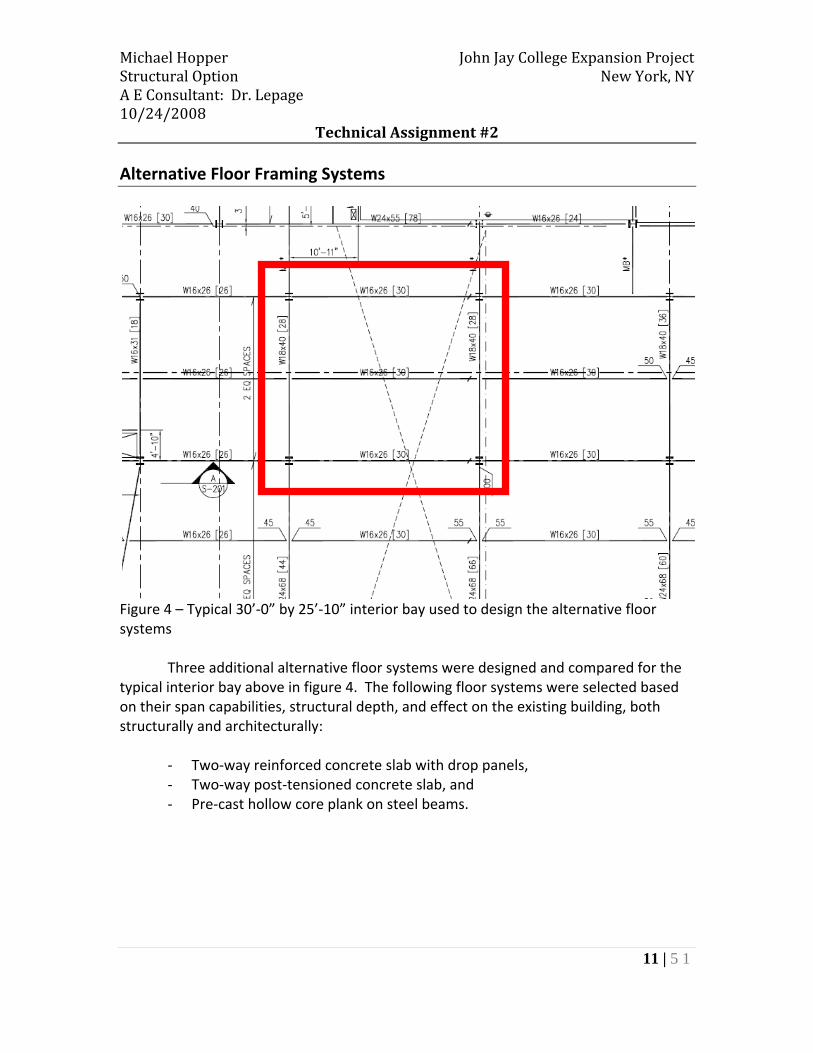
Figure 4 – Typical 30’‐0” by 25’‐10” interior bay used to design the alternative floor systems
Three additional alternative floor systems were designed and compared for the typical interior bay above in figure 4. The following floor systems were selected based on their span capabilities, structural depth, and effect on the existing building, both structurally and architecturally:
‐ Two‐way reinforced concrete slab with drop panels, ‐ Two‐way post‐tensioned concrete slab, and ‐ Pre‐cast hollow core plank on steel beams.
Michael Hopper John Jay College Expansion Project Structural Option New York, NY A E Consultant: Dr. Lepage 10/24/2008
Technical Assignment #2
12 | 5 1
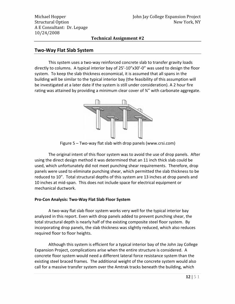
Two‐Way Flat Slab System This system uses a two‐way reinforced concrete slab to transfer gravity loads
directly to columns. A typical interior bay of 25’‐10”x30’‐0” was used to design the floor system. To keep the slab thickness economical, it is assumed that all spans in the building will be similar to the typical interior bay (the feasibility of this assumption will be investigated at a later date if the system is still under consideration). A 2 hour fire rating was attained by providing a minimum clear cover of ¾” with carbonate aggregate.
Figure 5 – Two‐way flat slab with drop panels (www.crsi.com)
The original intent of this floor system was to avoid the use of drop panels. After using the direct design method it was determined that an 11 inch thick slab could be used, which unfortunately did not meet punching shear requirements. Therefore, drop panels were used to eliminate punching shear, which permitted the slab thickness to be reduced to 10”. Total structural depths of this system are 13 inches at drop panels and 10 inches at mid‐span. This does not include space for electrical equipment or mechanical ductwork. Pro‐Con Analysis: Two‐Way Flat Slab Floor System A two‐way flat slab floor system works very well for the typical interior bay analyzed in this report. Even with drop panels added to prevent punching shear, the total structural depth is nearly half of the existing composite steel floor system. By incorporating drop panels, the slab thickness was slightly reduced, which also reduces required floor to floor heights. Although this system is efficient for a typical interior bay of the John Jay College Expansion Project, complications arise when the entire structure is considered. A concrete floor system would need a different lateral force resistance system than the existing steel braced frames. The additional weight of the concrete system would also call for a massive transfer system over the Amtrak tracks beneath the building, which

Michael Hopper John Jay College Expansion Project Structural Option New York, NY A E Consultant: Dr. Lepage 10/24/2008
Technical Assignment #2
13 | 5 1
could be very expensive and difficult to incorporate into the architecture of the building. Labor costs are also high compared to the other systems analyzed in this report due to the heavy use of formwork and placing large quantities of concrete. Another area of concern is the bay spacing: a span of approximately 68 feet is required in the grand cascade and a flat slab could not efficiently be used. To incorporate this floor system, the architecture would have to be altered to incorporate more columns in long span areas creating similar bays to the one analyzed in this report. Due to the increased self weight of the structure and the long span requirements for the John Jay College Expansion Project, a two‐way flat slab floor system is not a very efficient solution.
Michael Hopper John Jay College Expansion Project Structural Option New York, NY A E Consultant: Dr. Lepage 10/24/2008
Technical Assignment #2
14 | 5 1
Two‐Way Post‐Tensioned Floor System
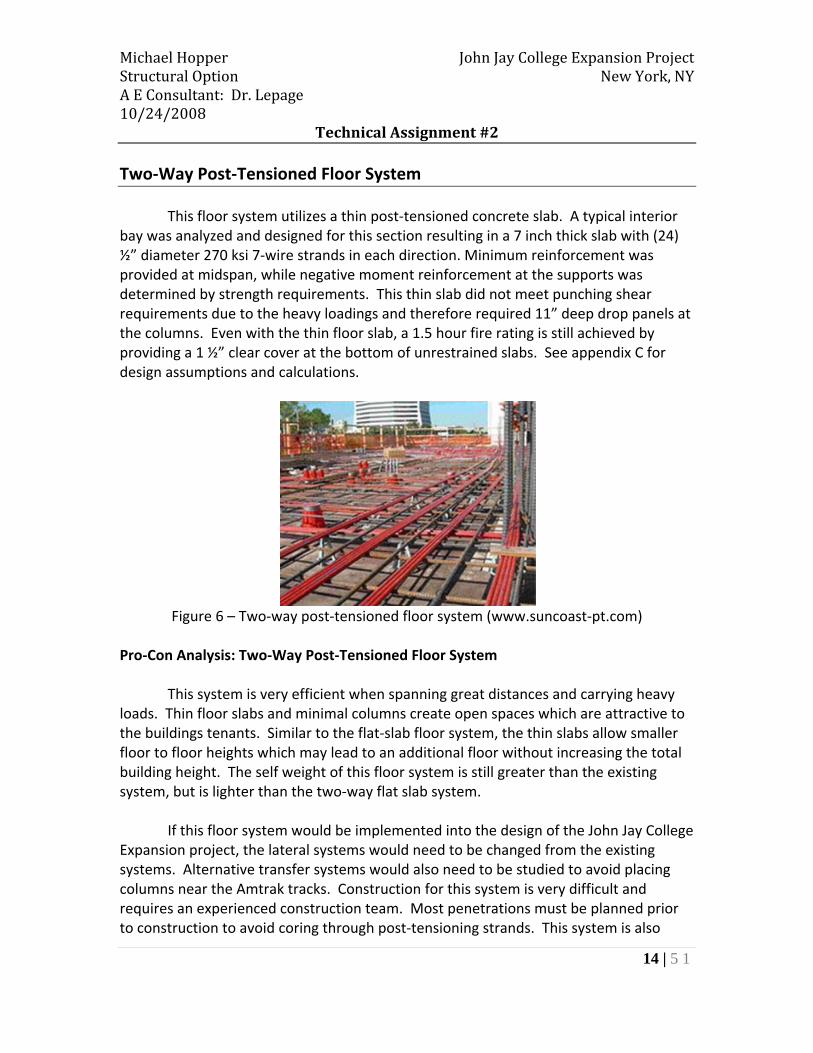
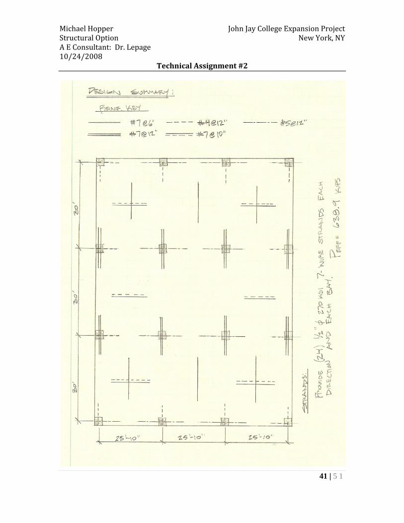
This floor system utilizes a thin post‐tensioned concrete slab. A typical interior bay was analyzed and designed for this section resulting in a 7 inch thick slab with (24) ½” diameter 270 ksi 7‐wire strands in each direction. Minimum reinforcement was provided at midspan, while negative moment reinforcement at the supports was determined by strength requirements. This thin slab did not meet punching shear requirements due to the heavy loadings and therefore required 11” deep drop panels at the columns. Even with the thin floor slab, a 1.5 hour fire rating is still achieved by providing a 1 ½” clear cover at the bottom of unrestrained slabs. See appendix C for design assumptions and calculations.
Figure 6 – Two‐way post‐tensioned floor system (www.suncoast‐pt.com)
Pro‐Con Analysis: Two‐Way Post‐Tensioned Floor System This system is very efficient when spanning great distances and carrying heavy loads. Thin floor slabs and minimal columns create open spaces which are attractive to the buildings tenants. Similar to the flat‐slab floor system, the thin slabs allow smaller floor to floor heights which may lead to an additional floor without increasing the total building height. The self weight of this floor system is still greater than the existing system, but is lighter than the two‐way flat slab system. If this floor system would be implemented into the design of the John Jay College Expansion project, the lateral systems would need to be changed from the existing systems. Alternative transfer systems would also need to be studied to avoid placing columns near the Amtrak tracks. Construction for this system is very difficult and requires an experienced construction team. Most penetrations must be planned prior to construction to avoid coring through post‐tensioning strands. This system is also
Michael Hopper John Jay College Expansion Project Structural Option New York, NY A E Consultant: Dr. Lepage 10/24/2008
Technical Assignment #2
15 | 5 1
expensive compared to other concrete floor systems and takes more time to construct, but with increased spans it has the ability to be more economical and efficient. Overall, this system is a viable option due to the long span requirements of the John Jay College Expansion Project. A more comprehensive study of transfer systems over the Amtrak tracks must be performed to see if an efficient and economical transfer method can be achieved with the increased self weight of a concrete structure.

Michael Hopper John Jay College Expansion Project Structural Option New York, NY A E Consultant: Dr. Lepage 10/24/2008
Technical Assignment #2
16 | 5 1
Pre‐Cast Hollow Core Planks on Steel Beams
Pre‐cast hollow core planks were studied for their ability to span long distances, while maintaining a light self weight. Hollow core planks were sized according to Nitterhouse Concrete Products (see appendix D for calculations). A 10” thick x 4’ wide hollow core plank spanning 30’‐0” was determined to be adequate for the heavy loading requirements of the public spaces and laboratories. 2” of lightweight concrete topping was assumed to be added to level floors from hollow core plank cambers, and also to create a rigid diaphragm for lateral loading. These planks also achieve a 2 hour fire rating without the need of additional fire proofing. Steel beams were chosen because they are lighter than pre‐cast concrete inverted tee or rectangular beams. They also allow the existing steel braced frame to still be utilized, as well as the hanging structure and transfer trusses. After designing the non‐composite steel beams, it was found that a W24x104 was required for strength.
Figure 7 – Pre‐cast hollow core planks on steel beams (www.spancrete.com)
Pro‐Con Analysis: Pre‐Cast Hollow Core Plank on Steel Beam Floor System The main advantage of using the pre‐cast hollow core plank system is that it is very efficient. Members are easily prefabricated in a pre‐cast plant, which results in higher quality members and reduce on site construction time. Therefore, construction is simple any time of the year and under any weather conditions. Pre‐cast planks already meet the required fire ratings for the job, and there is no need for additional fireproofing materials. Hollow core planks contain less material than traditional concrete slab floor systems, which is not only cheaper, but also environmentally friendly. By using steel beams to support the planks, the existing braced frames can still
Michael Hopper John Jay College Expansion Project Structural Option New York, NY A E Consultant: Dr. Lepage 10/24/2008
Technical Assignment #2
17 | 5 1
be used to resist lateral forces. Less steel is also needed, as there is no need for infill beams. With a W24 beam, a 10” thick hollow core plank, and 2” of light weight concrete topping, the total floor depth is approximately 36” for spans of 30’. Not only is depth an issue with this system, but pre‐cast planks must be ordered long in advance for a large project. Design consultants must also have excellent communication throughout the project to account for penetrations in the floor system. Steel beams need to be protected from fire with spray on fireproofing or intumescent paint, which can be expensive. In conclusion, this floor system is a practical option due to its self weight, constructability, sustainability, and long span capabilities. Erection time is minimal, which is attractive for a project which is behind schedule, such as the John Jay College Expansion Project. It is also the cheapest floor system because it uses less material and construction is simple.

Michael Hopper John Jay College Expansion Project Structural Option New York, NY A E Consultant: Dr. Lepage 10/24/2008
Technical Assignment #2
18 | 5 1
Conclusion
Table 1 – Comparison of floor systems analyzed.
Note: Costs are not a direct indication of what each floor system would cost to construct in New York City, but are used to make general cost comparisons between floor systems.
Existing Two‐Way Two‐Way Post Pre‐cast Hollow CoreComposite Steel Flat Slab Tensioned Slab Planks on Steel Beams
Floor System Comparison ‐ Typical Interior BayCriterion
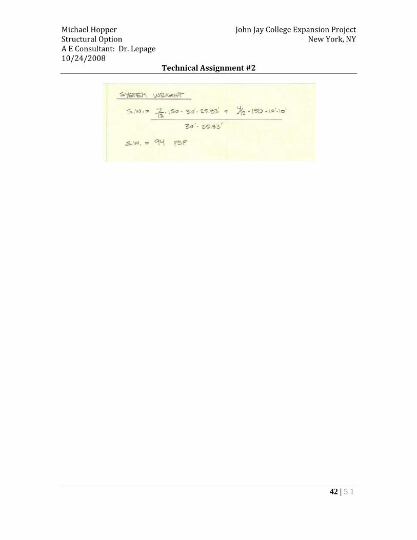
Self Weight (psf) 55 130 94 94
Slab Depth (in) 6.25 10 7 12
Total Depth (in) 24.15 13 11 36.1
Constructibility Medium Medium Hard Easy
Foundation Impact ‐‐ Major Yes Yes
Architectural Impact ‐‐ Major No No
Transfer System Impact ‐‐ Major Major Yes
21.522Fire Rating (hr)
Total Cost per ft2 ($) 19.00 16.50 18.53 13.08
Possible Alternative ‐‐ No Yes Yes
Additional Study ‐‐ No Yes Yes
Vibration Average Best Above Average Average
Lateral System Impact ‐‐ Yes Yes No

Michael Hopper John Jay College Expansion Project Structural Option New York, NY A E Consultant: Dr. Lepage 10/24/2008
Technical Assignment #2
19 | 5 1
In the second technical report of the John Jay College Expansion Project, alternative floor systems were studied through schematic design of a typical interior bay. Self weight and long span capabilities were major factors when determining if a floor system was a viable option. The expansion project has a large middle bay of approximately 68 feet, which creates an open plan for the cascade. Not only must the floor system span great distances, but it also must have a light self weight to permit loads to transfer over the Amtrak tracks underneath the first level. Due to these two main requirements, a two‐way flat slab floor system cannot be used effectively. At 130 psf, it is by far the heaviest system analyzed and would need a massive transfer system that would not fit into the architecture of the building. Decreased bay sizes would need more interior columns, which affects the foundation and neglects the need for open space in the grand cascade. Despite the thin slab profile of this system, a two‐way flat slab could not be implemented into the existing building. Although a post‐tensioned two‐way slab would require a different lateral force resistance system and is complicated to construct, it is still worth investigating because of its long span capabilities. By incorporating longer spans, this system has the capability to become more efficient and economical. An alternative transfer system would also need to be investigated, but it would be less massive than a system required for a non‐post‐tensioned concrete system due to a floor system self weight of 94 psf. The most economical and constructible system in this study is the pre‐cast hollow core planks on steel beams. This system is the cheapest because of the low labor costs associated with erecting the hollow core planks and steel beams. All structural members are fabricated off site, which allows for less material used and minimal construction time. A self weight of 94 psf would lead to increasing member sizes for the transfer systems, but this may still be economically feasible due to less steel members being used (no infill beams ). This floor system also has the ability to utilize a braced frame to resist lateral forces and can span great distances. Therefore, hollow core planks on steel beams are worth future consideration.

Michael Hopper John Jay College Expansion Project Structural Option New York, NY A E Consultant: Dr. Lepage 10/24/2008
Technical Assignment #2
20 | 5 1
Appendix A – Typical Framing Plans
Typical Tower Framing Plan

Michael Hopper John Jay College Expansion Project Structural Option New York, NY A E Consultant: Dr. Lepage 10/24/2008
Technical Assignment #2
21 | 5 1
Typical Cascade Area Framing Plan

Michael Hopper John Jay College Expansion Project Structural Option New York, NY A E Consultant: Dr. Lepage 10/24/2008
Technical Assignment #2
22 | 5 1
Appendix B – Two‐Way Flat Slab with Drop Panels

Michael Hopper John Jay College Expansion Project Structural Option New York, NY A E Consultant: Dr. Lepage 10/24/2008
Technical Assignment #2
23 | 5 1

Michael Hopper John Jay College Expansion Project Structural Option New York, NY A E Consultant: Dr. Lepage 10/24/2008
Technical Assignment #2
24 | 5 1

Michael Hopper John Jay College Expansion Project Structural Option New York, NY A E Consultant: Dr. Lepage 10/24/2008
Technical Assignment #2
25 | 5 1

Michael Hopper John Jay College Expansion Project Structural Option New York, NY A E Consultant: Dr. Lepage 10/24/2008
Technical Assignment #2
26 | 5 1

Michael Hopper John Jay College Expansion Project Structural Option New York, NY A E Consultant: Dr. Lepage 10/24/2008
Technical Assignment #2
27 | 5 1
Michael Hopper John Jay College Expansion Project Structural Option New York, NY A E Consultant: Dr. Lepage 10/24/2008
Technical Assignment #2
28 | 5 1
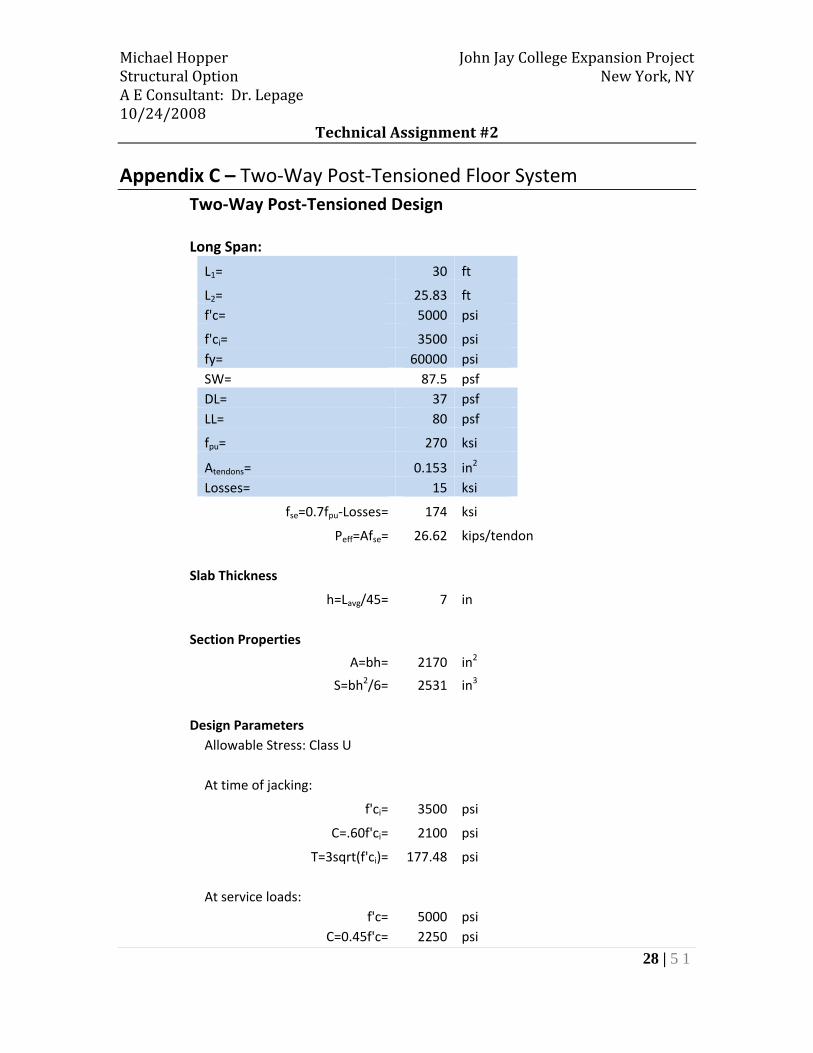
Appendix C – Two‐Way Post‐Tensioned Floor System Two‐Way Post‐Tensioned Design
Long Span:
L1= 30 ft
L2= 25.83 ft f'c= 5000 psi
f'ci= 3500 psi fy= 60000 psi SW= 87.5 psf DL= 37 psf LL= 80 psf
fpu= 270 ksi
Atendons= 0.153 in2 Losses= 15 ksi
fse=0.7fpu‐Losses= 174 ksi
Peff=Afse= 26.62 kips/tendon
Slab Thickness
h=Lavg/45= 7 in
Section Properties
A=bh= 2170 in2
S=bh2/6= 2531 in3
Design Parameters Allowable Stress: Class U
At time of jacking:
f'ci= 3500 psi
C=.60f'ci= 2100 psi
T=3sqrt(f'ci)= 177.48 psi
At service loads: f'c= 5000 psi
C=0.45f'c= 2250 psi
Michael Hopper John Jay College Expansion Project Structural Option New York, NY A E Consultant: Dr. Lepage 10/24/2008
Technical Assignment #2
29 | 5 1
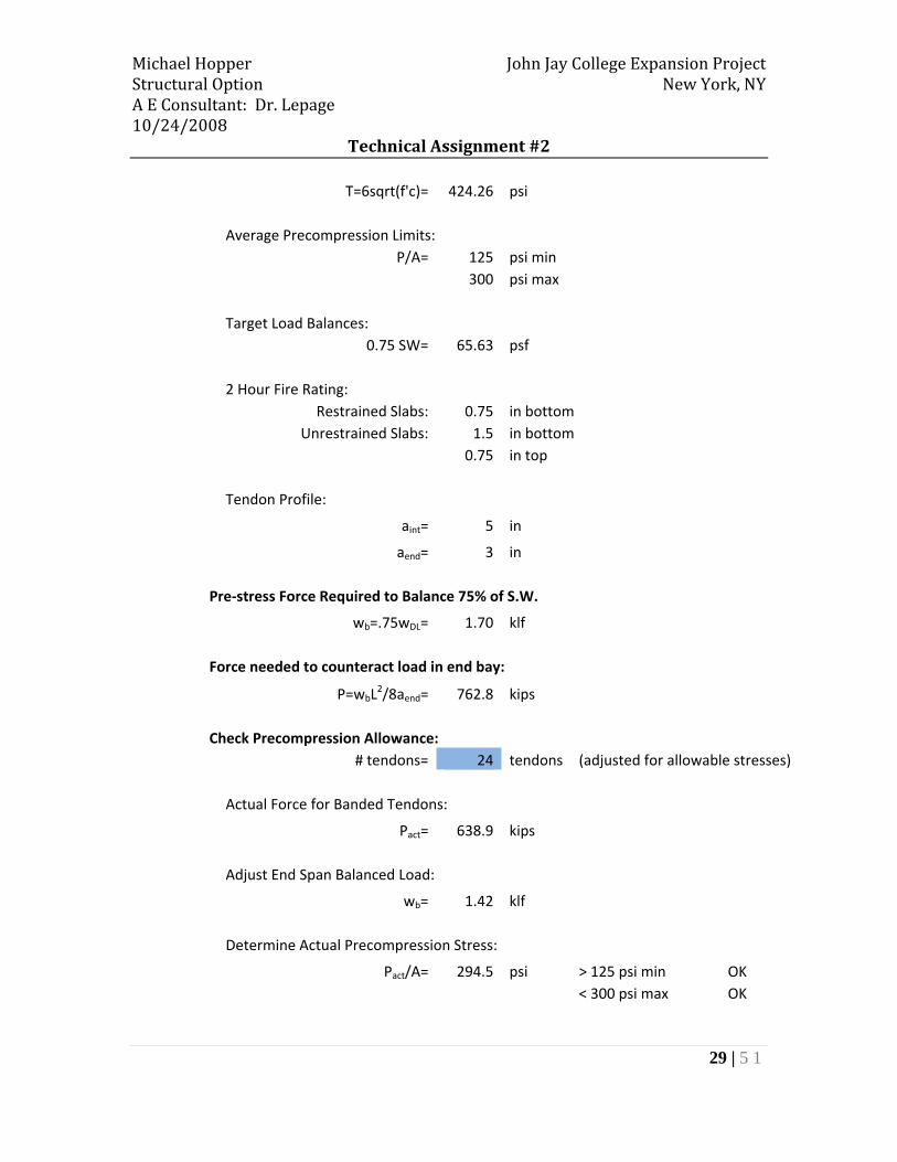
T=6sqrt(f'c)= 424.26 psi
Average Precompression Limits: P/A= 125 psi min
300 psi max
Target Load Balances: 0.75 SW= 65.63 psf
2 Hour Fire Rating: Restrained Slabs: 0.75 in bottom
Unrestrained Slabs: 1.5 in bottom 0.75 in top
Tendon Profile:
aint= 5 in
aend= 3 in
Pre‐stress Force Required to Balance 75% of S.W.
wb=.75wDL= 1.70 klf
Force needed to counteract load in end bay:
P=wbL2/8aend= 762.8 kips
Check Precompression Allowance: # tendons= 24 tendons (adjusted for allowable stresses)
Actual Force for Banded Tendons:
Pact= 638.9 kips
Adjust End Span Balanced Load:
wb= 1.42 klf
Determine Actual Precompression Stress:
Pact/A= 294.5 psi > 125 psi min OK < 300 psi max OK
Michael Hopper John Jay College Expansion Project Structural Option New York, NY A E Consultant: Dr. Lepage 10/24/2008
Technical Assignment #2
30 | 5 1
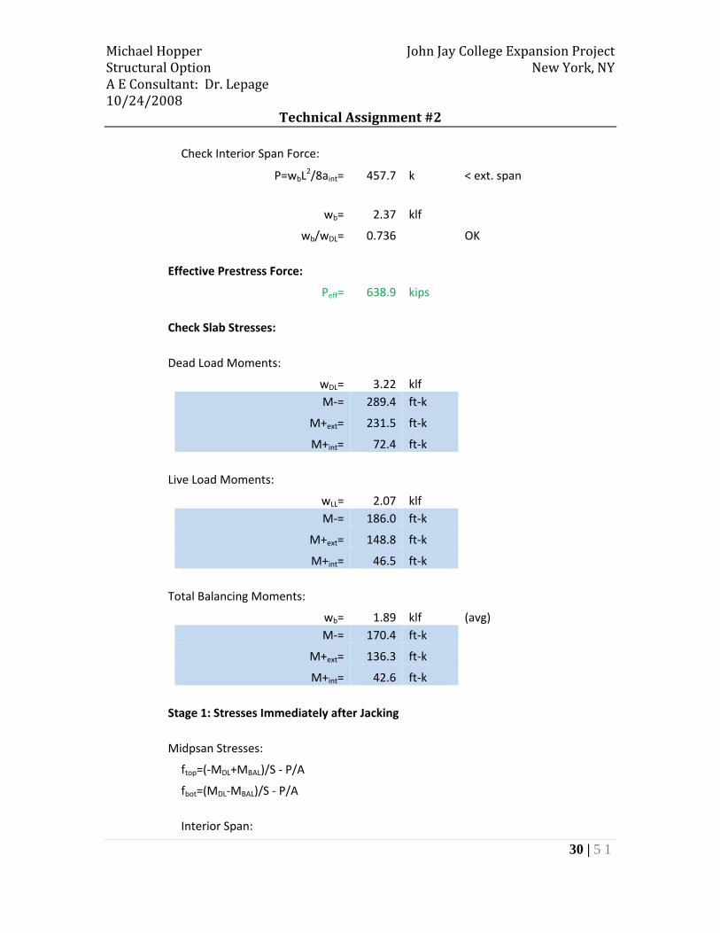
Check Interior Span Force:
P=wbL2/8aint= 457.7 k < ext. span
wb= 2.37 klf
wb/wDL= 0.736 OK
Effective Prestress Force:
Peff= 638.9 kips
Check Slab Stresses:
Dead Load Moments:
wDL= 3.22 klf M‐= 289.4 ft‐k
M+ext= 231.5 ft‐k
M+int= 72.4 ft‐k
Live Load Moments:
wLL= 2.07 klf M‐= 186.0 ft‐k
M+ext= 148.8 ft‐k
M+int= 46.5 ft‐k
Total Balancing Moments:
wb= 1.89 klf (avg) M‐= 170.4 ft‐k
M+ext= 136.3 ft‐k
M+int= 42.6 ft‐k
Stage 1: Stresses Immediately after Jacking
Midpsan Stresses:
ftop=(‐MDL+MBAL)/S ‐ P/A
fbot=(MDL‐MBAL)/S ‐ P/A
Interior Span:
Michael Hopper John Jay College Expansion Project Structural Option New York, NY A E Consultant: Dr. Lepage 10/24/2008
Technical Assignment #2
31 | 5 1
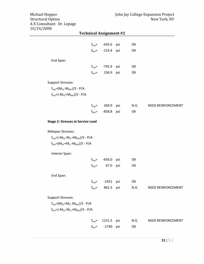
ftop= ‐435.6 psi OK
fbot= ‐153.4 psi OK
End Span:
ftop= ‐745.9 psi OK
fbot= 156.9 psi OK
Support Stresses:
ftop=(MDL‐MBAL)/S ‐ P/A
fbot=(‐MDL+MBAL)/S ‐ P/A
ftop= 269.9 psi N.G. NEED REINFORCEMENT
fbot= ‐858.8 psi OK
Stage 2: Stresses at Service Load
Midspan Stresses:
ftop=(‐MDL‐MLL+MBAL)/S ‐ P/A
fbot=(MDL+MLL‐MBAL)/S ‐ P/A
Interior Span:
ftop= ‐656.0 psi OK
fbot= 67.0 psi OK
End Span:
ftop= ‐1451 psi OK
fbot= 862.3 psi N.G. NEED REINFORCEMENT
Support Stresses:
ftop=(MDL+MLL‐MBAL)/S ‐ P/A
fbot=(‐MDL‐MLL+MBAL)/S ‐ P/A
ftop= 1151.5 psi N.G. NEED REINFORCEMENT
fbot= ‐1740 psi OK

Michael Hopper John Jay College Expansion Project Structural Option New York, NY A E Consultant: Dr. Lepage 10/24/2008
Technical Assignment #2
32 | 5 1
Ultimate Strength:
M1=Pe= 133.11 ft‐k
Msec=MBAL‐M1= 37.3 ft‐k at interior supports
Mu=1.2MDL+1.6MLL+1.0MSEC
Mu= 534.5 ft‐k midspan
Mu= ‐607.6 ft‐k support
Minimum Bonded Reinforcement:
Positive Moment: Exterior Span: Minimum positive moment reinforcement required
y=ft/(ft+fc)h= 2.61 in
Nc=MDL+LL/S*.5*y*L2= 729 kips
Asmin=Nc/.5fy= 24.30 in2 Distribute reinforcement evenly across the width of the slab
Asmin= 0.94 in2/ft
Use #7 @ 6" O.C. Bottom = 1.2 in2/ft OK Minimum length 1/3 clear span
Negative Moment: Interior Supports
Acf= 2520 in2
Asmin=0.00075Acf= 1.89 in2
Use 10 #4 Top 2 in2
Exterior Supports
Acf= 2170 in2
Asmin=0.00075Acf= 1.63 in2
Use 9 #4 Top 1.8 in2
Bars span minimum of 1/6 clear span each side of support

Michael Hopper John Jay College Expansion Project Structural Option New York, NY A E Consultant: Dr. Lepage 10/24/2008
Technical Assignment #2
33 | 5 1
At least 4 bars in each direction
Max Bar Spacing= 10.5 in
Check if minimum reinforcement is sufficient for ultimate strength:
Mn=(Asfy+Apsfps)(d‐a/2) dsupport= 6 in dmidspan= 5.25 in
Aps= 3.672 in2 L/h= 51.4
At Supports:
fps=fse+10000+(f'cbd)/(300Aps)= 192441 psi
a=(Asfy+Apsfps)/(0.85f'cb)= 0.628 in φMn= 352.5 ft‐k N.G.
Asreq= 13.1 in2
Provide #7 @ 12" OC As= 15.498 in2
At Midspan:
fps=fse+10000+(f'cbd)/(300Aps)= 191386 psi
a=(Asfy+Apsfps)/(0.85f'cb)= 1.640 in φMn= 851.4 ft‐k OK
Use Minimum Reinforcement

Michael Hopper John Jay College Expansion Project Structural Option New York, NY A E Consultant: Dr. Lepage 10/24/2008
Technical Assignment #2
34 | 5 1
Short Span:
L1= 25.83 ft
L2= 30 ft f'c= 5000 psi
f'ci= 3500 psi fy= 60000 psi SW= 87.5 psf DL= 37 psf LL= 80 psf
fpu= 270 ksi
Atendons= 0.153 in2 Losses= 15 ksi
fse=0.7fpu‐Losses= 174 ksi
Peff=Afse= 26.62 kips/tendon
Slab Thickness
h=Lavg/45= 7 in
Section Properties
A=bh= 2520 in2
S=bh2/6= 2940 in3
Design Parameters Allowable Stress: Class U
At time of jacking:
f'ci= 3500 psi
C=.60f'ci= 2100 psi
T=3sqrt(f'ci)= 177.48 psi
At service loads: f'c= 5000 psi
C=0.45f'c= 2250 psi T=6sqrt(f'c)= 424.26 psi
Average Precompression Limits:
Michael Hopper John Jay College Expansion Project Structural Option New York, NY A E Consultant: Dr. Lepage 10/24/2008
Technical Assignment #2
35 | 5 1
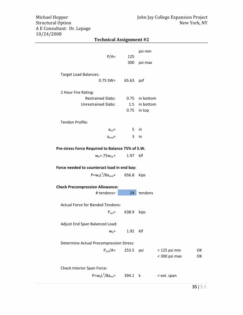
P/A= 125 psi min
300 psi max
Target Load Balances: 0.75 SW= 65.63 psf
2 Hour Fire Rating: Restrained Slabs: 0.75 in bottom
Unrestrained Slabs: 1.5 in bottom 0.75 in top
Tendon Profile:
aint= 5 in
aend= 3 in
Pre‐stress Force Required to Balance 75% of S.W.
wb=.75wDL= 1.97 klf
Force needed to counteract load in end bay:
P=wbL2/8aend= 656.8 kips
Check Precompression Allowance: # tendons= 24 tendons
Actual Force for Banded Tendons:
Pact= 638.9 kips
Adjust End Span Balanced Load:
wb= 1.92 klf
Determine Actual Precompression Stress:
Pact/A= 253.5 psi > 125 psi min OK < 300 psi max OK
Check Interior Span Force:
P=wbL2/8aint= 394.1 k < ext. span

Michael Hopper John Jay College Expansion Project Structural Option New York, NY A E Consultant: Dr. Lepage 10/24/2008
Technical Assignment #2
36 | 5 1
wb= 3.19 klf
wb/wDL= 0.855 OK
Effective Prestress Force:
Peff= 638.9 kips
Check Slab Stresses:
Dead Load Moments:
wDL= 3.74 klf M‐= 249.2 ft‐k
M+ext= 199.4 ft‐k
M+int= 62.3 ft‐k
Live Load Moments:
wLL= 2.40 klf M‐= 160.1 ft‐k
M+ext= 128.1 ft‐k
M+int= 40.0 ft‐k
Total Balancing Moments:
wb= 2.55 klf (avg) M‐= 170.4 ft‐k
M+ext= 136.3 ft‐k
M+int= 42.6 ft‐k
Stage 1: Stresses Immediately after Jacking
Midpsan Stresses:
ftop=(‐MDL+MBAL)/S ‐ P/A
fbot=(MDL‐MBAL)/S ‐ P/A
Interior Span:
ftop= ‐334.0 psi OK
fbot= ‐173.1 psi OK

Michael Hopper John Jay College Expansion Project Structural Option New York, NY A E Consultant: Dr. Lepage 10/24/2008
Technical Assignment #2
37 | 5 1
End Span:
ftop= ‐510.89 psi OK
fbot= 3.81 psi OK
Support Stresses:
ftop=(MDL‐MBAL)/S ‐ P/A
fbot=(‐MDL+MBAL)/S ‐ P/A
ftop= 68.1 psi OK
fbot= ‐575.2 psi OK
Stage 2: Stresses at Service Load
Midspan Stresses:
ftop=(‐MDL‐MLL+MBAL)/S ‐ P/A
fbot=(MDL+MLL‐MBAL)/S ‐ P/A
Interior Span:
ftop= ‐497.4 psi OK
fbot= ‐9.7 psi OK
End Span:
ftop= ‐1033.8 psi OK
fbot= 526.7 psi N.G. NEED REINFORCEMENT
Support Stresses:
ftop=(MDL+MLL‐MBAL)/S ‐ P/A
fbot=(‐MDL‐MLL+MBAL)/S ‐ P/A
ftop= 721.7 psi N.G. NEED REINFORCEMENT
fbot= ‐1228.8 psi OK
Ultimate Strength:
Michael Hopper John Jay College Expansion Project Structural Option New York, NY A E Consultant: Dr. Lepage 10/24/2008
Technical Assignment #2
38 | 5 1
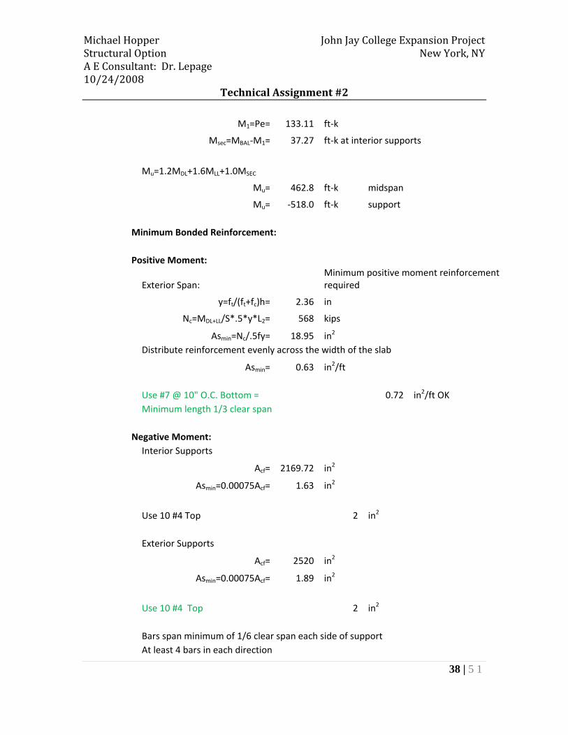
M1=Pe= 133.11 ft‐k
Msec=MBAL‐M1= 37.27 ft‐k at interior supports
Mu=1.2MDL+1.6MLL+1.0MSEC
Mu= 462.8 ft‐k midspan
Mu= ‐518.0 ft‐k support
Minimum Bonded Reinforcement:
Positive Moment:
Exterior Span: Minimum positive moment reinforcement required
y=ft/(ft+fc)h= 2.36 in
Nc=MDL+LL/S*.5*y*L2= 568 kips
Asmin=Nc/.5fy= 18.95 in2 Distribute reinforcement evenly across the width of the slab
Asmin= 0.63 in2/ft
Use #7 @ 10" O.C. Bottom = 0.72 in2/ft OK Minimum length 1/3 clear span
Negative Moment: Interior Supports
Acf= 2169.72 in2
Asmin=0.00075Acf= 1.63 in2
Use 10 #4 Top 2 in2
Exterior Supports
Acf= 2520 in2
Asmin=0.00075Acf= 1.89 in2
Use 10 #4 Top 2 in2
Bars span minimum of 1/6 clear span each side of support At least 4 bars in each direction
Michael Hopper John Jay College Expansion Project Structural Option New York, NY A E Consultant: Dr. Lepage 10/24/2008
Technical Assignment #2
39 | 5 1
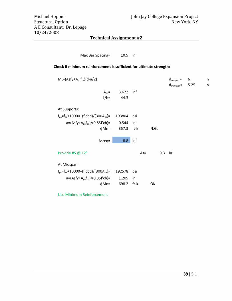
Max Bar Spacing= 10.5 in
Check if minimum reinforcement is sufficient for ultimate strength:
Mn=(Asfy+Apsfps)(d‐a/2) dsupport= 6 in dmidspan= 5.25 in
Aps= 3.672 in2 L/h= 44.3
At Supports:
fps=fse+10000+(f'cbd)/(300Aps)= 193804 psi
a=(Asfy+Apsfps)/(0.85f'cb)= 0.544 in φMn= 357.3 ft‐k N.G.
Asreq= 8.8 in2
Provide #5 @ 12” As= 9.3 in2
At Midspan:
fps=fse+10000+(f'cbd)/(300Aps)= 192578 psi
a=(Asfy+Apsfps)/(0.85f'cb)= 1.205 in φMn= 698.2 ft‐k OK
Use Minimum Reinforcement

Michael Hopper John Jay College Expansion Project Structural Option New York, NY A E Consultant: Dr. Lepage 10/24/2008
Technical Assignment #2
40 | 5 1
Michael Hopper John Jay College Expansion Project Structural Option New York, NY A E Consultant: Dr. Lepage 10/24/2008
Technical Assignment #2
41 | 5 1
Michael Hopper John Jay College Expansion Project Structural Option New York, NY A E Consultant: Dr. Lepage 10/24/2008
Technical Assignment #2
42 | 5 1

Michael Hopper John Jay College Expansion Project Structural Option New York, NY A E Consultant: Dr. Lepage 10/24/2008
Technical Assignment #2
43 | 5 1
Appendix D – Pre‐Cast Hollow Core Planks on Steel Beam
Michael Hopper John Jay College Expansion Project Structural Option New York, NY A E Consultant: Dr. Lepage 10/24/2008
Technical Assignment #2
44 | 5 1

Michael Hopper John Jay College Expansion Project Structural Option New York, NY A E Consultant: Dr. Lepage 10/24/2008
Technical Assignment #2
45 | 5 1
Michael Hopper John Jay College Expansion Project Structural Option New York, NY A E Consultant: Dr. Lepage 10/24/2008
Technical Assignment #2
46 | 5 1
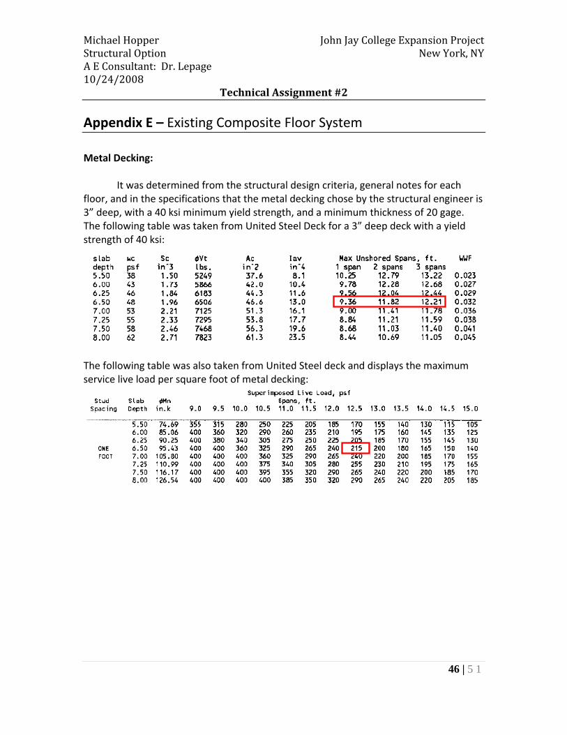
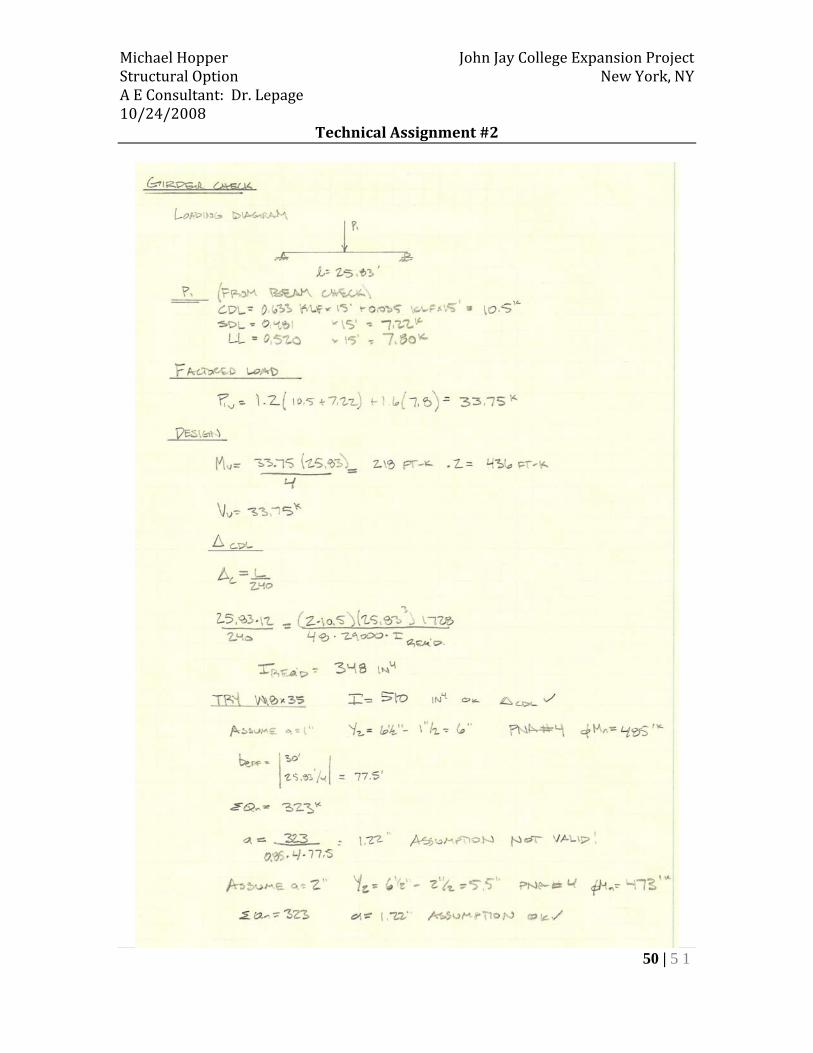
Appendix E – Existing Composite Floor System Metal Decking:
It was determined from the structural design criteria, general notes for each floor, and in the specifications that the metal decking chose by the structural engineer is 3” deep, with a 40 ksi minimum yield strength, and a minimum thickness of 20 gage. The following table was taken from United Steel Deck for a 3” deep deck with a yield strength of 40 ksi:
The following table was also taken from United Steel deck and displays the maximum service live load per square foot of metal decking:
Michael Hopper John Jay College Expansion Project Structural Option New York, NY A E Consultant: Dr. Lepage 10/24/2008
Technical Assignment #2
47 | 5 1
Michael Hopper John Jay College Expansion Project Structural Option New York, NY A E Consultant: Dr. Lepage 10/24/2008
Technical Assignment #2
48 | 5 1

Michael Hopper John Jay College Expansion Project Structural Option New York, NY A E Consultant: Dr. Lepage 10/24/2008
Technical Assignment #2
49 | 5 1
Michael Hopper John Jay College Expansion Project Structural Option New York, NY A E Consultant: Dr. Lepage 10/24/2008
Technical Assignment #2
50 | 5 1

Michael Hopper John Jay College Expansion Project Structural Option New York, NY A E Consultant: Dr. Lepage 10/24/2008
Technical Assignment #2
51 | 5 1
Related Documents


