1 Voltage stability and reactive power sharing in inverter-based microgrids with consensus-based distributed voltage control Johannes Schiffer, Thomas Seel, J¨ org Raisch, Tevfik Sezi Abstract—We propose a consensus-based distributed voltage control (DVC), which solves the problem of reactive power shar- ing in autonomous inverter-based microgrids with dominantly inductive power lines and arbitrary electrical topology. Opposed to other control strategies available thus far, the control presented here does guarantee a desired reactive power distribution in steady-state while only requiring distributed communication among inverters, i.e., no central computing nor communication unit is needed. For inductive impedance loads and under the assumption of small phase angle differences between the output voltages of the inverters, we prove that the choice of the control parameters uniquely determines the corresponding equilibrium point of the closed-loop voltage and reactive power dynamics. In addition, for the case of uniform time constants of the power measurement filters, a necessary and sufficient condition for local exponential stability of that equilibrium point is given. The compatibility of the DVC with the usual frequency droop control for inverters is shown and the performance of the proposed DVC is compared to the usual voltage droop control [1] via simulation of a microgrid based on the CIGRE (Conseil International des Grands R´ eseaux Electriques) benchmark medium voltage distribution network. Index Terms—Microgrid control, microgrid stability, voltage stability, smart grid applications, inverters, droop control, power sharing, secondary control, consensus algorithms, multi-agent systems, distributed cooperative control. I. I NTRODUCTION Microgrids represent a promising concept to facilitate the integration of distributed renewable sources into the electrical grid [2]–[4]. Two main motivating facts for the need of such concepts are: (i) the increasing installation of renewable energy sources world-wide – a process motivated by political, environmental and economic factors; (ii) a large portion of these renewable sources consists of small-scale distributed generation units connected at the low (LV) and medium voltage (MV) levels via AC inverters. Since the physical char- acteristics of inverters largely differ from the characteristics of conventional electrical generators, i.e., synchronous generators (SGs), different control approaches are required [5]. A microgrid addresses these issues by gathering a combi- nation of generation units, loads and energy storage elements at distribution level into a locally controllable system, which can be operated either in grid-connected mode or in islanded mode, i.e., in a completely isolated manner from the main transmission system. J. Schiffer and T. Seel are with the Technische Universit¨ at Berlin, Germany {schiffer, seel}@control.tu-berlin.de J. Raisch is with the Technische Universit¨ at Berlin & Max- Planck-Institut f¨ ur Dynamik komplexer technischer Systeme, Germany [email protected] T. Sezi is with Siemens AG, Smart Grid Division, Nuremberg, Germany [email protected] Essential components in power systems are so-called grid- forming units. In AC networks, these units have the task to provide a synchronous frequency and a certain voltage level at all buses in the network, i.e., to provide a stable operating point. Analyzing under which conditions such an operating point can be provided and maintained, naturally leads to the problems of frequency and voltage stability. In conventional power systems, grid-forming units are SGs. In inverter-based microgrids, however, grid-forming capabilities have to be provided by inverter-interfaced sources [6], [7]. Inverters operated in grid-forming mode can be represented as ideal AC voltage sources [5]–[9]. Besides frequency and voltage stability, power sharing is an important performance criterion in the operation of microgrids [5]–[8]. Here, power sharing is understood as the ability of the local controls of the individual generation sources to achieve a desired steady-state distribution of the power outputs of all generation sources relative to each other, while satisfying the load demand in the network. The relevance of this control objective lies within the fact that it allows to prespecify the utilization of the generation units in operation, e.g., to prevent overloading [7]. In conventional power systems, where generation sources are connected to the network via SGs, droop control is often used to achieve the objective of active power sharing [10]. Under this approach, the current value of the rotational speed of each SG in the network is monitored locally to derive how much power each SG needs to provide. Inspired hereby, researchers have proposed to apply a sim- ilar control to AC inverters [1], [11]. It has been shown – in [12], [13] for lossless microgrids and in [14] for lossy networks – that this heuristic proportional decentralized con- trol law indeed locally stabilizes the network frequency and that the control gains and setpoints can be chosen such that a desired active power distribution is achieved in steady- state without any explicit communication among the differ- ent sources. The nonnecessity of an explicit communication system is explained by the fact that the network frequency serves as a common implicit communication signal. Since the actuator signal of this control is the local frequency, it is called frequency droop control throughout the present paper. Furthermore, in large transmission systems droop control is usually only applied to obtain a desired active power distribution, while the voltage amplitude at a generator bus is regulated to a nominal voltage setpoint via an automatic voltage regulator (AVR) acting on the excitation system of the SG. In microgrids the power lines are typically relatively short. Then, the AVR employed at the transmission level is in general not appropiate since even slight differences in voltage amplitudes (caused, e.g., by sensor inaccuracies) can provoke

Welcome message from author
This document is posted to help you gain knowledge. Please leave a comment to let me know what you think about it! Share it to your friends and learn new things together.
Transcript

1
Voltage stability and reactive power sharing in inverter-basedmicrogrids with consensus-based distributed voltage control
Johannes Schiffer, Thomas Seel, Jorg Raisch, Tevfik Sezi
Abstract—We propose a consensus-based distributed voltagecontrol (DVC), which solves the problem of reactive power shar-ing in autonomous inverter-based microgrids with dominantlyinductive power lines and arbitrary electrical topology. Opposedto other control strategies available thus far, the control presentedhere does guarantee a desired reactive power distribution insteady-state while only requiring distributed communicationamong inverters, i.e., no central computing nor communicationunit is needed. For inductive impedance loads and under theassumption of small phase angle differences between the outputvoltages of the inverters, we prove that the choice of the controlparameters uniquely determines the corresponding equilibriumpoint of the closed-loop voltage and reactive power dynamics. Inaddition, for the case of uniform time constants of the powermeasurement filters, a necessary and sufficient condition forlocal exponential stability of that equilibrium point is given. Thecompatibility of the DVC with the usual frequency droop controlfor inverters is shown and the performance of the proposed DVCis compared to the usual voltage droop control [1] via simulationof a microgrid based on the CIGRE (Conseil Internationaldes Grands Reseaux Electriques) benchmark medium voltagedistribution network.
Index Terms—Microgrid control, microgrid stability, voltagestability, smart grid applications, inverters, droop control, powersharing, secondary control, consensus algorithms, multi-agentsystems, distributed cooperative control.
I. INTRODUCTION
Microgrids represent a promising concept to facilitate theintegration of distributed renewable sources into the electricalgrid [2]–[4]. Two main motivating facts for the need ofsuch concepts are: (i) the increasing installation of renewableenergy sources world-wide – a process motivated by political,environmental and economic factors; (ii) a large portion ofthese renewable sources consists of small-scale distributedgeneration units connected at the low (LV) and mediumvoltage (MV) levels via AC inverters. Since the physical char-acteristics of inverters largely differ from the characteristics ofconventional electrical generators, i.e., synchronous generators(SGs), different control approaches are required [5].
A microgrid addresses these issues by gathering a combi-nation of generation units, loads and energy storage elementsat distribution level into a locally controllable system, whichcan be operated either in grid-connected mode or in islandedmode, i.e., in a completely isolated manner from the maintransmission system.
J. Schiffer and T. Seel are with the Technische Universitat Berlin, Germany{schiffer, seel}@control.tu-berlin.de
J. Raisch is with the Technische Universitat Berlin & Max-Planck-Institut fur Dynamik komplexer technischer Systeme, [email protected]
T. Sezi is with Siemens AG, Smart Grid Division, Nuremberg, [email protected]
Essential components in power systems are so-called grid-forming units. In AC networks, these units have the taskto provide a synchronous frequency and a certain voltagelevel at all buses in the network, i.e., to provide a stableoperating point. Analyzing under which conditions such anoperating point can be provided and maintained, naturallyleads to the problems of frequency and voltage stability. Inconventional power systems, grid-forming units are SGs. Ininverter-based microgrids, however, grid-forming capabilitieshave to be provided by inverter-interfaced sources [6], [7].Inverters operated in grid-forming mode can be representedas ideal AC voltage sources [5]–[9].
Besides frequency and voltage stability, power sharing is animportant performance criterion in the operation of microgrids[5]–[8]. Here, power sharing is understood as the ability of thelocal controls of the individual generation sources to achievea desired steady-state distribution of the power outputs of allgeneration sources relative to each other, while satisfying theload demand in the network. The relevance of this controlobjective lies within the fact that it allows to prespecify theutilization of the generation units in operation, e.g., to preventoverloading [7].
In conventional power systems, where generation sourcesare connected to the network via SGs, droop control is oftenused to achieve the objective of active power sharing [10].Under this approach, the current value of the rotational speedof each SG in the network is monitored locally to derive howmuch power each SG needs to provide.
Inspired hereby, researchers have proposed to apply a sim-ilar control to AC inverters [1], [11]. It has been shown –in [12], [13] for lossless microgrids and in [14] for lossynetworks – that this heuristic proportional decentralized con-trol law indeed locally stabilizes the network frequency andthat the control gains and setpoints can be chosen such thata desired active power distribution is achieved in steady-state without any explicit communication among the differ-ent sources. The nonnecessity of an explicit communicationsystem is explained by the fact that the network frequencyserves as a common implicit communication signal. Since theactuator signal of this control is the local frequency, it is calledfrequency droop control throughout the present paper.
Furthermore, in large transmission systems droop controlis usually only applied to obtain a desired active powerdistribution, while the voltage amplitude at a generator busis regulated to a nominal voltage setpoint via an automaticvoltage regulator (AVR) acting on the excitation system ofthe SG. In microgrids the power lines are typically relativelyshort. Then, the AVR employed at the transmission level is ingeneral not appropiate since even slight differences in voltageamplitudes (caused, e.g., by sensor inaccuracies) can provoke
2
high reactive power flows [15]. Therefore, droop control istypically also applied to the voltage with the objective toachieve a desired reactive power distribution in microgrids.The most common (heuristic) approach is to set the voltageamplitude via a proportional control, the feedback signal ofwhich is the reactive power generation relative to a referencesetpoint [1], [9]. Hence, we call this control voltage droopcontrol throughout the paper.
The droop control strategies discussed previously are de-rived under the assumption of a dominantly inductive network,i.e., for power lines with small R/X ratios, and they are(by far) the most commonly used ones in this scenario [9].However, even in networks with dominantly inductive powerlines, the voltage droop control [1] exhibits a significantdrawback: it does in general not guarantee a desired reactivepower sharing, i.e., it does, in general, not achieve the desiredcontrol goal, as discussed e.g., in [13], [16]–[18]. Moreover,to the best of the authors’ knowledge, no theoretically orexperimentally well-founded selection criteria are known forthe parameters of the voltage droop control that would ensureat least a guaranteed minimum (quantified) performance interms of reactive power sharing.
As a consequence, several other or modified (heuristic)decentralized voltage control strategies have been proposed inthe literature, e.g., [16]–[22]. Most of this work is restrictedto networks of inverters connected in parallel. Moreover,typically only networks composed of two DG units are con-sidered. Conditions on voltage stability for a parallel inductivemicrogrid with constant power loads have been presented in[18]. With most approaches the control performance in termsof reactive power sharing with respect to the original control[1] is improved. However, no general conditions or formalguarantees for reactive power sharing are given. A quantitativeanalysis of the error in power sharing is provided in [16] forthe control proposed therein.
Other related work is [23], in which several local andcentralized control schemes for reactive power control ofphotovoltaic units are compared via simulation with respectto voltage regulation and loss minimization. In [24], [25],distributed control schemes for the problem of optimal reactivepower compensation are presented. Therein, the distributedgeneration (DG) units are modeled as constant power or P -Qbuses and, hence, assumed to be operated as grid-feeding andnot as grid-forming units [6], [8]. In [24], loads are modeledby the exponential model, while in [23], [25], constant powerloads are considered.
The main contributions of the present paper are two-fold:First, as a consequence of the preceding discussion, wepropose a consensus-based distributed voltage control (DVC),which guarantees reactive power sharing in meshed inverter-based microgrids with dominantly inductive power lines andarbitrary electrical topology. Opposed to most other relatedcommunication-based control concepts, e.g., [26], [27], thepresent approach does only require distributed communicationamong inverters, i.e., it does neither require a central com-munication or computing unit nor all-to-all communicationamong the inverters.
The consensus protocol used to design the DVC is based on
the weighted average consensus protocol [28]. This protocolhas been applied previously in inverter-based microgrids tothe problems of secondary frequency control [12], [29]–[31],as well as secondary voltage control [30]–[33]. In contrastto the approach of the present paper, the secondary voltagecontrol scheme proposed in [30], [31] is designed to regulateall voltage amplitudes to a common reference value. Asa consequence, this approach does, in general, not achievereactive power sharing.
Second, unlike other work on distributed voltage controlconsidering reactive power sharing, e.g., [32]–[34], we providea rigorous mathematical analysis of the closed-loop voltageand reactive power dynamics of a microgrid with inductiveimpedance loads under the proposed DVC. More precisely, weprove that the choice of the control parameters uniquely de-termines the corresponding equilibrium point. In addition, forthe case of uniform time constants of the power measurementfilters, we give a necessary and sufficient condition for localexponential stability of that equilibrium point. The two latterresults are derived under the standard assumption of smallphase angle differences between the output voltages of theDG units [10], [18].
Furthermore, and as discussed previously, the performanceof the voltage droop control [1] in terms of reactive powersharing is, in general, unsatisfactory. Therefore, the controlpresented here is meant to replace the voltage droop control[1] rather than complementing it in a secondary control-likemanner, as e.g., in [27], [32]–[34].
We also provide a selection criterion for the control pa-rameters, which not only ensures reactive power sharing, butalso that the average of all voltage amplitudes in the networkis equivalent to the nominal voltage amplitude for all times.Finally, we evaluate the performance of the DVC comparedto the voltage droop control [1] and its compatibility with thestandard frequency droop control [1] via extensive simulations.Hence, the present work extends our previous results in [35]in several regards.
We would like to emphasize that reactive power sharingby manipulation of the voltage amplitudes is of particularpractical interest in networks or clusters of networks, wherethe generation units are in close electrical proximity. Thisis often the case in microgrids and we only consider suchnetworks in this paper. Then, the line impedances are relativelylow, which from the standard power flow equations [10],implies that small variations in the voltage suffice to achievea desired reactive power sharing. Also, close electrical prox-imity usually implies close geographical distance between thedifferent units, which facilitates the practical implementationof a distributed communication network.
The remainder of this paper is outlined as follows: at first,we introduce the basic models of the electrical microgrid,including that of an AC inverter, and the communicationnetwork in Section II. In Section III we formalize the conceptof power sharing and present the suggested DVC. The resultson existence and uniqueness properties of equilibria of theclosed-loop dynamics under the DVC are given in Section IV.The stability result is presented in Section V. The controlperformance is illustrated by simulations in Section VI. Fi-

3
nally, conclusions and directions for future work are given inSection VII.
II. PRELIMINARIES AND NOTATION
We define the sets N := {1, . . . , n}, R≥0 := {x ∈ R|x ≥0}, R>0 := {x ∈ R|x > 0}, R<0 := {x ∈ R|x < 0} andT := [0, 2π). For a set V, let |V| denote its cardinality. LetV be a finite set of distinct natural numbers vi ∈ N, i =1, . . . , |V|. Then i ∼ V denotes “i = v1, . . . , v|V|“. Let x :=col(xi) ∈ Rn denote a vector with entries xi, i ∼ N ; 0n ∈ Rnthe vector of all zeros; 1n ∈ Rn the vector with all ones; Inthe n× n identity matrix; 0n×n the n× n matrix of all zerosand diag(ai), i ∼ N , an n×n diagonal matrix with entries ai.Furthermore, ‖ · ‖1 denotes the vector 1-norm and ‖ · ‖∞ thevector ∞-norm. For z ∈ C, <(z) denotes the real part of zand =(z) its imaginary part. Let j denote the imaginary unit.The conjugate transpose of a vector v is denoted by v∗. For amatrix A ∈ Rn×n, let σ(A) := {λ ∈ C : det(λIn −A) = 0}denote its spectrum. The numerical range or field of valuesof A is defined as W (A) := {x∗Ax : x ∈ Cn, x∗x = 1}.It holds that σ(A) ⊆ W (A) [36]. If A is symmetric thenW (A) ⊆ R and min(σ(A)) ≤ W (A) ≤ max(σ(A)) [36].Let Asy = 1
2 (A + AT ), respectively Ask = 12 (A − AT ) be
the symmetric, respectively skew-symmetric part of A. Then<(W (A)) = W (Asy) and =(W (A)) = W (Ask) [36].
The following result is used in the paper.
Lemma II.1. [36] Let A and B be matrices of appropriatedimensions and let B be positive semidefinite. Then,
σ(AB)⊆W (A)W (B) :={λ=αβ|α∈W (A), β∈W (B)}.
We briefly recall some graph theoretic notions used in thepaper. For further information on graph theory, the reader isreferred to, e.g., [37] and references therein.
An undirected graph of order n is a tuple G := (V, E), whereV := {1, . . . , n} is the set of nodes and E ⊆ V × V, E :={e1, . . . , em} is the set of undirected edges. The l-th edgeconnecting nodes i and k is denoted as el = {i, k} = {k, i}.The set of neighbors of a node i is denoted by Ci and containsall k for which el = {i, k} ∈ E .
The |V|×|V| adjacency matrix A has entries aik = aki = 1if an edge between i and k exists and aik = 0 otherwise.The degree of a node i is given by di =
∑nk=1 aik. With
D := diag(di) ∈ Rn×n, the Laplacian matrix of an undirectedgraph is given by L := D − A and is symmetric positivesemidefinite [37].
A path in a graph is an ordered sequence of nodes such thatany pair of consecutive nodes in the sequence is connected byan edge. G is called connected if for all pairs (i, k) ∈ V × V,i 6= k, there exists a path from i to k. Given an undirectedgraph, zero is a simple eigenvalue of its Laplacian matrix L ifand only if the graph is connected. Moreover, a correspondingright eigenvector to this simple zero eigenvalue is then 1n, i.e.,L1n = 0n [37].
A. Network model
This work is mainly concerned with reactive power. Ac-cording to [10], [38], in lack of detailed knowledge of the
load composition in the network, the most commonly acceptedstatic load representation is to model the reactive powerdemand by a constant impedance. Therefore, we consider ageneric meshed microgrid and assume that loads are modeledby constant impedances1. This leads to a set of nonlineardifferential-algebraic equations (DAE). Then, a network re-duction (called Kron-reduction [10]) is carried out to eliminateall algebraic equations corresponding to loads and to obtain aset of differential equations. We assume this process has beencarried out and work with the Kron-reduced network.
In the reduced network, each node represents a DG unitinterfaced via an AC inverter. The set of nodes of thisnetwork is denoted by N := {1, . . . , n}. We associate atime-dependent phase angle δi : R≥0 → T and a voltageamplitude Vi : R≥0 → R>0 to each node i ∈ N in themicrogrid. Two nodes i and k of the microgrid are connectedvia a complex admittanceYik = Yki ∈ C. For convenience, wedefine Yik := 0 whenever i and k are not directly connectedvia an admittance. We denote the set of neighbors of a nodei ∈ N by Ni := {k
∣∣ k ∈ N , k 6= i , Yik 6= 0}. For ease ofnotation, we write angle differences as δik(t) := δi(t)− δk(t).
We assume that the microgrid is connected, i.e., that for allpairs {i, k} ∈ N ×N , i 6= k, there exists an ordered sequenceof nodes from i to k such that any pair of consecutive nodesin the sequence is connected by a power line represented byan admittance. This assumption is reasonable for a microgrid,unless severe line outages separating the system into severaldisconnected parts occur.
Furthermore, we assume that the power lines of the micro-grid are lossless, i.e., all lines can be represented by purelyinductive admittances. This may be justified as follows [12],[13]. In medium (MV) and low voltage (LV) networks theline impedance is usually not purely inductive, but has a non-negligible resistive part. On the other hand, the inverter outputimpedance is typically inductive (due to the output inductorand/or the possible presence of an output transformer). Underthese circumstances, the inductive parts dominate the resistiveparts in the admittances for some particular microgrids, espe-cially on the MV level. We only consider such microgrids andabsorb the inverter output admittance (together with a possibletransformer admittance) into the line admittances Yik, whileneglecting all resistive effects.
Then, an admittance connecting two nodes i and k can berepresented by Yik := jBik with Bik = Bki ∈ R<0. Therepresentation of loads as constant impedances in the originalnetwork leads to shunt-admittances at at least some of thenodes in the Kron-reduced network, i.e., Yii = Gii+jBii 6= 0for some i ∈ N , where Gii ∈ R>0 is the shunt conductanceand Bii ∈ R<0 denotes the inductive shunt susceptance. Forconvenience, we define Yii := 0 whenever there is no shuntadmittance present at a node i ∈ N . Finally, we assume thatthe loading in the original network is such that no power or
1To the best of our knowledge, there does not exist one standard load model.The main reason for this is that there are typically many different kinds ofloads connected within one power system or microgrid, see, e.g., [10], [38],[39]. Therefore, we are aware that not all loads can be accurately representedby constant impedance loads and our results may be inaccurate for other typeof load models, such as dynamic loads [39].

4
voltage constraints are violated at any time.The overall active and reactive power flows Pi : Tn ×
Rn>0 → R and Qi : Tn × Rn>0 → R at a node i ∈ N areobtained as2
Pi(δ1, . . . , δn, V1, . . . , Vn) =
GiiV2i +
∑
k∼Ni
|Bik|ViVk sin(δik),
Qi(δ1, . . . , δn, V1, . . . , Vn) =
|Bii|V 2i −
∑
k∼Ni
|Bik|ViVk cos(δik),
(1)
with Bii := Bii +∑k∼Ni
Bik. Hence,
|Bii| ≥∑
k∼Ni
|Bik|. (2)
To motivate the voltage control proposed in Section III andto establish the results in Sections IV and V, we make use ofthe standard decoupling assumption3, see [10], [18].
Assumption II.2. δik(t) ≈ 0 ∀t ≥ 0, i ∼ N , k ∼ Ni.Under Assumption II.2, cos(δik(t)) ≈ 1, for all t ≥ 0 and
i ∼ N , k ∼ Ni. Consequently, the reactive power flow at anode i ∈ N reduces to Qi : Rn>0 → R
Qi(V1, . . . , Vn) = |Bii|V 2i −
∑
k∼Ni
|Bik|ViVk. (3)
Clearly, the reactive power Qi can then be controlled bycontrolling the voltage amplitudes Vi and Vk, k ∈ Ni. Thisfact is used when designing a distributed voltage control forreactive power sharing in Section III.
The apparent power flow is given by Si = Pi + jQi.Since we are mainly concerned with dynamics of generationunits, we express all power flows in generator convention [40].That is, delivered active power is positive, while absorbedactive power is negative; capacitive reactive power is countedpositively and inductive reactive power is counted negatively.
Remark II.3. The restriction to inductive shunt admittances isjustified as follows. The admittance loads in the Kron-reducednetwork are a conglomeration of the individual loads in theoriginal network, see, e.g., [10], [41]. Therefore, assumingpurely inductive loads in the Kron-reduced network can beinterpreted as assuming that the original network is notovercompensated, i.e., that the overall load possesses in-ductive character. Furthermore, capacitive shunt admittancesin distribution systems mainly stem from capacitor banksused to compensate possibly strong inductive behaviors ofloads. In conventional distribution systems, these devices areadditionally inserted in the system to improve its performancewith respect to reactive power consumption [10], [23]. Thisis needed because there is no generation located close tothe loads. However, in a microgrid, the generation units arelocated close to the loads. Hence, the availability of generation
2To simplify notation the time argument of all signals is omitted from nowon.
3Our results in Sections IV and V also hold for arbitrary, but constant angledifferences, i.e., δik(t) := δik, δik ∈ T, but at the cost of a more complexnotation.
units at distribution level is likely to replace the need forcapacitor banks, see also [23].
B. Inverter model
We model the inverters as AC voltage sources the amplitudeand frequency of which can be defined by the designer [5],[6], [8].4 Then, an inverter at node i ∈ N can be representedas [6], [13]
δi = uδi ,
τPi Pmi = −Pmi + Pi,
Vi = uVi ,
τPiQmi = −Qmi +Qi,
(4)
where uδi : R≥0 → R and uVi : R≥0 → R are controls. Fur-thermore, it is assumed that the active and reactive poweroutputs Pi and Qi given in (1) are measured and processedthrough a filter with time constant τPi
∈ R>0 [11], [42].We furthermore associate to each inverter its power ratingSNi ∈ R>0, i ∼ N .
C. Communication network
The proposed voltage control is distributed and requirescommunication among generation units in the network. To de-scribe the high-level properties of the communication network,a graph theoretic notation is used in the paper.
We assume that the communication network is representedby an undirected and connected graph G = (V, E). Further-more, we assume that the graph contains no self-loops, i.e.,there is no edge el = {i, i}. A node represents an individualagent. In the present case, this is a power generation source.If there is an edge between two nodes i and k, then i and kcan exchange their local measurements with each other. Thenodes in the communication and in the electrical network areidentical, i.e., N ≡ V. Note that the communication topologymay, but does not necessarily have to, coincide with thetopology of the electrical network, i.e., we may allow Ci 6= Nifor any i ∈ V.
III. POWER SHARING AND INVERTER CONTROL
In this section the frequency and voltage controls uδi anduVi for the inverters represented by (4) are introduced. Recallthat power sharing is an important performance criterion inmicrogrids. The concept of proportional power sharing isformalized via the following definition.
Definition III.1. Let γi ∈ R>0 and χi ∈ R>0 denote constantweighting factors and P si , respectively Qsi , the steady-stateactive, respectively reactive, power flow, i ∼ N . Then, twoinverters at nodes i and k are said to share their active,
4An underlying assumption to this model is that whenever the inverterconnects an intermittent renewable generation source, e.g., a photovoltaic plantor a wind plant, to the network, it is equipped with some sort of storage (e.g.,flywheel, battery). Thus, it can increase and decrease its power output withina certain range.

5
respectively reactive, powers proportionally according to γiand γk, respectively χi and χk, if
P siγi
=P skγk, respectively
Qsiχi
=Qskχk
.
Remark III.2. From (4) it follows that in steady-state Pmi = 0and Qmi = 0. Hence, Pm,si = P si and Qm,si = Qsi , where thesuperscript s denotes signals in steady-state.
Remark III.3. A practical choice for γi and χi would, forexample, be γi = χi = SNi , where SNi ∈ R>0 is the nominalpower rating of the inverter at node i ∈ N . However, anoperator may also wish to consider other technical, economicor environmental criteria, such as fuel consumption, genera-tion costs or emission costs, when determining the weightingcoefficients γi and χi, i ∼ N , see, e.g., [43], [44].
A. Frequency droop control and active power sharing
For the problem of active power sharing, the followingdecentralized proportional control law, commonly referred toas frequency droop control [9], is often employed
uδi = ωd − kPi(Pmi − P di ), (5)
where ωd ∈ R>0 is the desired (nominal) frequency, kPi∈
R>0 the frequency droop gain, Pmi the measured active powerand P di ∈ R its desired setpoint.
It is shown in [12]–[14] that the following selection ofcontrol gains and setpoints for the control law (5) guaranteesa proportional active power distribution in steady-state in thesense of Definition III.1
kPiγi = kPk
γk, kPiP di = kPk
P dk . (6)
A detailed physical motivation for the control law (5) is givenin [13].
B. Distributed voltage control (DVC)
Following the heuristics of the frequency droop control (5),droop control is typically also applied with the goal to achievea desired reactive power distribution in microgrids. The mostcommon (heuristic) voltage droop control is given by [1], [9]
uVi = V di − kQi(Qmi −Qdi ), (7)
where V d ∈ R>0 is the desired (nominal) voltage, kQi∈ R>0
the voltage droop gain, Qmi the measured reactive power andQdi ∈ R its desired setpoint. The control law (7) is decentral-ized, i.e., the feedback signal is the locally measured reactivepower Qmi , and it does therefore not require communication.However, to the best of the authors’ knowledge, there areno known selection criteria for the parameters of the voltagedroop control (7) that would ensure a desired reactive powersharing, see also [13], [17], [18].
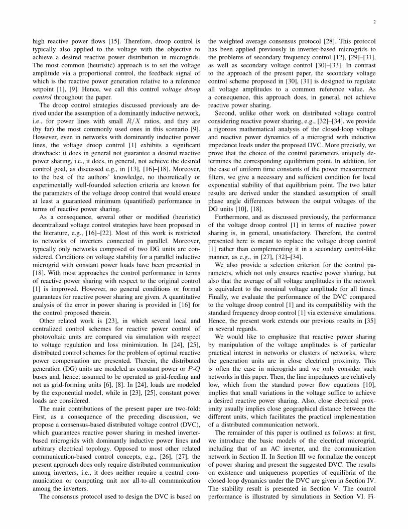
Inspired by consensus-algorithms, see e.g., [28], we there-fore propose the following distributed voltage control (DVC)
-
++-
PWM andinner control
loops
Grid
Low passfilter
Powercalculation
Qmi
Qi
1χi
Vi
Vdi
|Ci|ki
∑
Weighted reactivepower measurementsof inverter outputsat neighbor nodes
Ci = {l, . . . , k} provided bycommunication system
Ql
.
..Qk
∫
Fig. 1: Block diagram of the proposed DVC for an inverter at node i ∈ N . Viis the voltage amplitude, V d
i its desired (nominal) value, Qmi is the measured
reactive power and Qi the weighted reactive power, where χi is the weightingcoefficient to ensure proportional reactive power sharing and ki is a feedbackgain.
uVi for an inverter at node i ∈ N
uVi (t) := V di − ki∫ t
0
ei(τ)dτ,
ei(t) :=∑
k∼Ci
(Qmi (t)
χi− Qmk (t)
χk
)=∑
k∼Ci(Qi(t)− Qk(t)),
(8)
where V di ∈ R>0 is the desired (nominal) voltage amplitudeand ki ∈ R>0 is a feedback gain. For convenience, we havedefined the weighted reactive power flows Qi := Qmi /χi, i ∼N . Recall that Ci defined in II-C is the set of neighbor nodes ofnode i in the graph induced by the communication network,i.e., the set of nodes that node i can exchange informationwith. The control scheme is illustrated for an inverter at nodei ∈ N in Fig. 1. We prove in Section V that the control (8)does guarantee proportional reactive power sharing in steady-state.
Remark III.4. Consider a scenario in which there exists ahigh-level control that can generate setpoints Qdi , i ∼ N , forthe reactive power injections. A possible high-level control is,for example, the one proposed in [25]. The control (8) caneasily be combined with such high-level control by setting eigiven in (8) to
ei =∑
k∼Ci
((Qmi −Qdi )
χi− (Qmk −Qdk)
χk
). (9)
Then the inverters share their absolute reactive power injec-tions with respect to individual setpoints in steady-state.
Remark III.5. In addition to reactive power sharing, itusually is desired that the voltage amplitudes Vi, i ∼ N ,remain within certain bounds. With the control law (8), wherethe voltage amplitudes are actuator signals, this can, e.g., beensured by saturating the control signal uVi . In that case, theperformance in reactive power sharing could be degradadedwhen the control signal is saturated. For mathematical sim-plicity, this is not considered in the present analysis.
C. Closed-loop voltage and reactive power dynamics
To establish the results in Sections IV and V, we make useof the standard decoupling Assumption II.2. It follows from (3)that the influence of the dynamics of the phase angles on the

6
reactive power flows can then be neglected. Since, moreover,the DVC given in (8) only uses reactive power measurements,the model (4) can be reduced to
Vi = uvi ,
τ Qmi = −Qmi +Qi.(10)
Differentiating Vi = uVi with respect to time and combining(8) and (10), the closed-loop dynamics of the i-th node aregiven by
Vi = −kiei = −ki∑
k∼Ci
(Qmiχi− Qmk
χk
),
τPiQmi = −Qmi +Qi,
(11)
and the interaction between nodes is modeled by (3). Notethat Vi(0) = V di is determined by the control law (8).
Recalling from II-C that L ∈ Rn×n is the Laplacian matrixof the communication network and defining the n×n matrices
T :=diag(τPi), D := diag(1/χi), K := diag(ki),
as well as the column vectors V ∈Rn, Q∈Rn and Qm∈Rn
V := col(Vi), Q := col(Qi), Qm := col(Qmi ),
the closed-loop system dynamics can be written compactly inmatrix form as
V = −KLDQm,T Qm = −Qm +Q,
(12)
where Qi = Qi(V ) is given by (3) and the initial conditionsfor each element of V are determined by the control law (8),i.e., V (0) = V d := col(V di ), i ∼ N .Remark III.6. Recall that an inverter represented by (4)is operated in grid-forming mode, which implies that theamplitude and frequency of the voltage provided at the inverterterminals can be specified by the operator, respectively, by asuitable control [8]. This also applies to the initial conditionsof the voltages V (0) = V d in (12).
D. Reactive power sharing and a voltage conservation law
The next result proves that the proposed DVC does indeedguarantee proportional reactive power sharing in steady-state.
Claim III.7. The control law (8) achieves proportional re-active power sharing in steady-state in the sense of Defini-tion III.1.
Proof. Set V = 0 in (12). Note that, since L is the Laplacianmatrix of an undirected connected graph, it has a simple zeroeigenvalue with a corresponding right eigenvector β1n, β ∈R \ {0}. All its other eigenvalues are positive real. Moreover,K is a diagonal matrix with positive diagonal entries and from(12) in steady-state Qs = Qm,s. Hence, for β ∈ R \ {0} andi ∼ N , k ∼ N
0n = −KLDQs ⇔ DQs = β1n ⇔Qsiχi
=Qskχk
. (13)
���
Remark III.8. Because of (13), all entries of Qm,s = Qs(V s)must have the same sign. Since we consider inductive networksand loads, only Qm,s = Qs(V s) ∈ Rn>0 is practicallyrelevant.
The following fact reveals an important property of thesystem (12), (3).
Fact III.9. The flow of the system (12), (3) satisfies for allt ≥ 0 the conservation law
‖K−1V (t)‖1 =
n∑
i=1
Vi(t)
ki= ξ(V (0)), (14)
where the positive real parameter ξ(V (0)) is given by
ξ(V (0)) = ‖K−1V (0)‖1 =
n∑
i=1
V diki. (15)
Proof. Recall that L is the Laplacian matrix of an undi-rected connected graph. Consequently, L is symmetric positivesemidefinite and possesses a simple zero eigenvalue with cor-responding right eigenvector 1n, i.e., L = LT and L1n = 0n.Hence, 1TnL = 0Tn . Multiplying the first equation in (12) fromthe left with 1TnK
−1 yields
1TnK−1V = 0TnDQ
m ⇒n∑
i=1
Viki
= 0. (16)
Integrating (16) with respect to time and using (15) yields(14). ���
Fact III.9 has the following important practical implication:by interpreting the control gains ki as weighting coefficients,expression (14) is equivalent to the weighted average voltageamplitude V (t) in the network, i.e.,
V (t) :=1
n
n∑
i=1
Vi(t)
ki.
By Fact III.9, we then have that for all t ≥ 0
V (t) := V (0) =ξ(V (0))
n=
1
n
n∑
i=1
V diki. (17)
Hence, the parameters V di and ki, i ∼ N , offer usefuldegrees of freedom for a practical implementation of the DVC(8). For example, a typical choice for V di would be V di = VN ,i ∼ N , where VN denotes the nominal voltage amplitude. Bysetting ki = 1, i ∼ N , (17) becomes
V (t) :=1
n
n∑
i=1
Vi(t) = VN , (18)
i.e., the average voltage amplitude V (t) of all generator busesin the network is for all t ≥ 0 equivalent to the nominal voltageamplitude VN .
Remark III.10. Note that achieving (18) for t→∞ is exactlythe control goal of the distributed voltage control proposedin [34], Section IV-B. As we have just shown, for V di = VN ,ki = 1, i ∼ N , the DVC (8) not only guarantees compliance of(18) for t→∞, but for all t ≥ 0. In addition, by Claim III.7,

7
the DVC (8) guarantees a desired reactive power sharing insteady-state.
Remark III.11. Let xs = col(V s, Qs) be an equilibriumpoint of the system (12), (3). It follows from Fact III.9 thatonly solutions of the system (12), (3) with initial conditionssatisfying
‖K−1V (0)‖1 = ‖K−1V s‖1can converge to xs.
IV. EXISTENCE AND UNIQUENESS OF EQUILIBRIA
To streamline the presentation of the main result within thissection, it is convenient to introduce the matrix T ∈ Rn×nwith entries
Tii := |Bii|, Tik := −|Bik|, i 6= k. (19)
Lemma IV.1. The matrix T is positive definite.
Proof. Recall that Bii = Bii +∑k∼Ni
Bik and (2). It is theneasily verified that the matrix
T − diag(|Bii|),
is a symmetric weighted Laplacian matrix. Recall that themicrogrid is connected by assumption. Consequently, T −diag(|Bii|) possesses a simple zero eigenvalue with a corre-sponding right eigenvector 1n and all its other eigenvalues arepositive real, i.e., for any v ∈ Rn \ {β1n}, β ∈ R \ {0}(T − diag(|Bii|)
)1n = 0n, v
T(T − diag(|Bii|)
)v ∈ R>0.
Furthermore, recall that Bii 6= 0 for at least some i ∈ N .Hence, T is positive definite. ���
The proposition below proves existence of equilibria ofthe system (12), (3). In addition, it shows that the controlparameters uniquely determine the corresponding equilibriumpoint of the system (12), (3). We demonstrate in the simulationstudy in Section VI that the tuning parameter κ (introducedin the proposition) allows to easily shape the performance ofthe closed-loop dynamics.
Proposition IV.2. Consider the system (12), (3). Fix D anda positive real constant α. Set K = κK, where κ is apositive real parameter and K ∈ Rn×n a diagonal matrixwith positive real diagonal entries. To all initial conditionscol(V (0), Qm(0)) with the property
‖K−1V (0)‖1 = α, (20)
there exists a unique positive equilibrium pointcol(V s, Qm,s) ∈ R2n
>0. Moreover, to any α there existsa unique positive constant β such that
‖K−1V s‖1 = α, Qs = Qm,s = βD−11n. (21)
Proof. To establish the claim, we first prove that to each Qs ∈Rn>0 satisfying (21) there exists a unique V s ∈ Rn>0. To thisend, consider (13). Clearly, any Qs = βD−11n, β ∈ R>0
satisfies (13) and is hence a possible vector of positive steady-state reactive power flows. Fix a β ∈ R>0. Because of
Qsi = |Bii|V s2
i −∑
k∼Ni
|Bik|V si V sk , i ∼ N , (22)
no element V si can then be zero. Hence, (22) can be rewrittenas
−Qsi
V si+ |Bii|V si −
∑
k∼Ni
|Bik|V sk = 0, i ∼ N ,
or, more compactly,
F (V s) + T V s = 0n, (23)
where F (V s) := col(−Qsi/V si ) ∈ Rn and T is defined in(19). Recall that according to Lemma IV.1, T is positivedefinite. Consider the function f : Rn>0 → R,
f(V ) :=1
2V TT V −
n∑
i=1
Qsi ln(Vi),
which has the property that(∂f(V )
∂V
)T= F (V ) + T V.
Hence, any critical point of f satisfies (23), respectively (22).Moreover,
∂2f(V )
∂V 2= diag
(QsiV 2i
)+ T > 0,
which means that the Hessian of f is positive definite for allV ∈ Rn>0. Therefore, f is a strictly convex continuous functionon the convex set Rn>0. Note that f tends to infinity on theboundary of Rn>0, i.e.,
f(V )→∞ as ‖V ‖∞ →∞,f(V )→∞ as min
i∈N(Vi)→ 0.
Hence, there exist positive real constants m0 � 1, r1 � 1and r2 � 1, such that
W := {V ∈ Rn>0 | mini∈N
(Vi) ≥ r1 ∧ ‖V ‖∞ ≤ r2},
V ∈ Rn>0 \W ⇒ f(V ) > m0,
∃V ∈ W such that f(V ) < m0.
Clearly, W is a compact set. Hence, by the Weierstrassextreme value theorem [45], f attains a minimum on W. Byconstruction, this minimum is attained at the interior of W,which by differentiability of f implies that it is a critical pointof f . Consequently, the vector V s := arg minV ∈W(f(V ))is the unique solution of (23) and thus the unique positivevector of steady-state voltage amplitudes corresponding to agiven positive vector of steady-state reactive power flows Qs.This proves existence of equilibria of the system (12), (3).Moreover, it shows that to a given Qs ∈ Rn>0, there exists aunique corresponding V s ∈ Rn>0.
We next prove by contradiction that the constant α uniquelydetermines the positive equilibrium point col(V s, Qs) ∈ R2n
>0
corresponding to all initial conditions col(V (0), Qm(0)) with

8
the property (20). Assume that there exist two different posi-tive equilibrium points col(V s1 , Q
s1) ∈ R2n
>0 and col(V s2 , Qs2) ∈
R2n>0 with the following property
‖K−1V s1 ‖1 =‖K−1V s2 ‖1 = α. (24)
It follows from (13) that the vectors Qs1 and Qs2 are identicalup to multiplication by a positive real constant ϑ, i.e.,
Qs2 = ϑQs1.
The uniqueness result above implies ϑ 6= 1, i.e., Qs1 6= Qs2.Otherwise V s1 and V s2 would coincide and the two equilibriumpoints would be the same. Clearly, if col(V s1 , Q
s1) satisfies
(22), then col(V s2 , Qs2) = col(
√ϑV s1 , ϑQ
s1), ϑ > 0, also satis-
fies (22) and, because of the uniqueness result, V s2 =√ϑV s1
is the unique steady-state voltage vector corresponding to Qs2.As ϑ 6= 1, it follows immediately that (24) is violated. Theproof is completed by recalling that Fact III.9 implies that
‖K−1V (t)‖1 = ‖K−1V (0)‖1for all t ≥ 0. ���
Remark IV.3. The following useful property is an immediateconsequence of Proposition IV.2. Suppose col(V s, Qm,s) ∈R2n>0 is a known equilibrium point of the system (12), (3) with
the properties Qs = βD−11n and ‖K−1V s‖1 = α. Then forany ϑ ∈ R>0 and for all initial conditions col(V (0), Qm(0))with the property ‖K−1V (0)‖1 =
√ϑα, the corresponding
unique equilibrium point is given by col(√ϑV s, ϑQm,s).
Remark IV.4. Fix a real constant α. Consider a linear first-order consensus system with state vector x ∈ Rn and dynamicsx = −Lx, x(0) = x0, where L ∈ Rn×n is the Laplacianmatrix of the communication network. It is well-known, seee.g., [28], that if the graph model of the communicationnetwork is undirected and connected, then
xs =1
n1Tnx01n =
1
n
(n∑
i=1
xi(0)
)1n.
Hence, to all x0 with the property∑ni=1 xi(0) = α, there
exists a unique xs with∑ni=1 x
si = α. Proposition IV.2 shows
that the nonlinear system (12), (3) exhibits an equivalentproperty.
V. STABILITY
In this section we establish necessary and sufficient con-ditions for local exponential stability of equilibria of thesystem (12), (3). To this end, we make the following importantobservation. It follows from Fact III.9 that the motion of anarbitrary voltage Vi, i ∈ N , can be expressed in terms of allother voltages Vk, k ∼ N \{i} for all t ≥ 0. This implies thatstudying the stability properties of equilibra of the system (12),(3) with dimension 2n, is equivalent to studying the stabilityproperties of corresponding equilibria of a reduced system ofdimension 2n− 1.
For ease of notation and without loss of generality, wechoose to express Vn as
Vn = knξ(V (0))−n−1∑
i=1
knkiVi, (25)
with ξ(V (0)) given by (15). Furthermore, we define thereduced voltage vector VR ∈ Rn−1>0 as
VR := col(V1, . . . Vn−1), (26)
and denote the reactive power flows in the new coordinates by
QRi(V1, . . . , Vn−1) = |Bii|V 2i −
∑
k∼Ni
|Bik|ViVk,
QRn(V1, . . . , Vn−1) = |Bnn|V 2n −
∑
k∼Nn
|Bnk|VkVn,(27)
where Vn = Vn(V1, . . . , Vn−1) and i ∼ N \ {n}. By definingthe matrix LR ∈ R(n−1)×n
LR :=[In−1 0n−1
]KL, (28)
the system (12), (3) can be written in the reduced coordinatescol(VR, Qm) ∈ Rn−1>0 × Rn as
VR = −LRDQm,T Qm = −Qm +QR,
(29)
with QR := col(QRi) ∈ Rn and QRi , i ∼ N , given in (27).
A. Error states and linearization
Recall Proposition IV.2. Clearly, the existence and unique-ness properties of the system (12), (3) hold equivalently forthe reduced system (29), (27) with Vn given in (25). Letcol(V s, Qm,s) ∈ R2n
>0 be a positive equilibrium point ofthe system (12), (3) and col(V sR, Q
m,s) ∈ R2n−1>0 be the
corresponding equilibrium point of the system (29), (27). Itfollows from (25) that
∂Vn(V1, . . . , Vn−1)
∂Vi= −kn
ki, i ∼ N \ {n}.
Consequently, the partial derivative of the reactive power flowQRk
, k ∼ N , given in (29), (27) with respect to the voltageVi, i ∼ N \ {n}, can be written as
∂QRk
∂Vi=∂Qk∂Vi
− knki
∂Qk∂Vn
, i ∼ N \ {n}. (30)
Hence, by introducing the matrix
N :=∂Q
∂V
∣∣∣V s∈ Rn×n
with entries (use (3))
nii :=2|Bii|V si −∑
k∼Ni
|Bik|V sk , nik :=−|Bik|V si , i 6= k,
(31)as well as the matrix R ∈ Rn×(n−1)
R :=
[I(n−1)−bT
], b := col
(knk1, . . . ,
knkn−1
), (32)
and by making use of (30), it follows that
∂QR∂VR
∣∣∣V sR
= NR. (33)
To derive an analytic stability condition it is convenient toassume identical low pass filter time constants.
Assumption V.1. The time constants of the low pass filters in(12) are chosen such that τ = τP1
= . . . = τPn.

9
Remark V.2. In practice, the low-pass filters are typicallyimplemented in order to filter the fundamental component ofthe power injections [11]. Hence, Assumption V.1 is not overlyconservative in practice.
Furthermore, we define the deviations of the systemvariables with respect to the given equilibrium pointcol(V sR, Q
m,s) ∈ R2n−1>0 as
VR := VR − V sR ∈ Rn−1,Qm := Qm −Qm,s ∈ Rn.
Linearizing the microgrid (29), (27) at this equilibrium pointand making use of (33) together with Assumption V.1 yields
[˙VR˙Qm
]=
[0(n−1)×(n−1) −LRD
1τNR − 1
τ In
]
︸ ︷︷ ︸:=A
[VRQm
]. (34)
Note that
RLR = R[In−1 0n−1
]KL =
[In−1 0n−1−bT 0
]KL
= K
[In−1 0n−1−1Tn−1 0
]L = KL,
(35)
and thatRTK−11n = 0n−1. (36)
B. Condition for local exponential stability
The main contribution of this section is to give a necessaryand sufficient condition for local exponential stability of anequilibrium point of the system (29), (27).
Lemma V.3. For Qs, V s ∈ Rn>0, all eigenvalues of N havepositive real part.
Proof. Dividing (22) by V si > 0 yields
QsiV si
= |Bii|V si −∑
k∼Ni
|Bik|V sk > 0. (37)
Furthermore, from (2) it follows that
|Bii|V si ≥∑
k∼Ni
|Bik|V si . (38)
Hence, with nii and nik defined in (31) we have that
nii = 2|Bii|V si −∑
k∼Ni
|Bik|V sk > |Bii|V si ≥∑
k∼N\{i}|nik|.
Therefore, N is a diagonally dominant matrix with positivediagonal elements and the claim follows from Gershgorin’sdisc theorem [46]. ���
Lemma V.4. For Qs, V s ∈ Rn>0, the matrix product NDLDhas a zero eigenvalue with geometric multiplicity one and acorresponding right eigenvector βD−11n, β ∈ R \ {0}; allother eigenvalues have positive real part.
Proof. The matrix D is diagonal with positive diagonal entriesand hence positive definite. Furthermore, L is the Laplacianmatrix of an undirected connected graph and therefore positivesemidefinite. We also know that L has a simple zero eigenvalue
with a corresponding right eigenvector β1n, β ∈ R \ {0}.Moreover, Lemma V.3 implies that N is nonsingular. Conse-quently,
NDLDv = 0n ⇔ LDv = 0n ⇔ v = βD−11n, β ∈ R\{0}.
Hence, NDLD has a zero eigenvalue with geometric mul-tiplicity one and a corresponding right eigenvector βD−11n,β ∈ R \ {0}. In addition, DLD is positive semidefinite andby Lemma II.1 it follows that
σ(NDLD) ⊆W (N)W (DLD).
By the aforementioned properties of D and L, we have thatW (DLD) ⊆ R≥0. To prove that all eigenvalues apart fromthe zero eigenvalue have positive real part, we show that<(W (N)) ⊆ R>0. This also implies that the only element ofthe imaginary axis in W (N)W (DLD) is the origin. To seethis, we recall that the real part of the numerical range of Nis given by the range of its symmetric part, i.e.,
<(W (N)) = W
(1
2
(N +NT
)).
The symmetric part of N has entries
nii := nii, nik := −1
2|Bik|(V si + V sk ),
where nii is defined in (31). From (37) it follows that
|Bii|V si >∑
k∼Ni
|Bik|V sk .
Hence, together with (38) it follows that
|Bii|V si >1
2
∑
k∼Ni
|Bik|(V si + V sk ) =∑
k∼N\{i}|nik|
and
nii = 2|Bii|V si −∑
k∼Ni
|Bik|V sk > |Bii|V si >∑
k∼N\{i}|nik|.
Consequently, the symmetric part of N is diagonally domi-nant with positive diagonal entries and by Gershgorin’s disctheorem its eigenvalues are all positive real. ���
We are now ready to state our main result within thissection.
Proposition V.5. Consider the system (12), (3). Fix D andpositive real constants α and τ. Set τPi = τ, i ∼ Nand K = κD, where κ is a positive real parameter. Letcol(V s, Qm,s) ∈ R2n
>0 be the unique equilibrium point of thesystem (12), (3) corresponding to all V (0) with the property‖D−1V (0)‖1 = α. Denote by xs = col(V sR, Q
m,s) ∈ R2n−1>0
the unique corresponding equilibrium point of the reducedsystem (29), (27).
Let µi = ai + jbi be the i-th nonzero eigenvalue of thematrix product NDLD with ai ∈ R and bi ∈ R. Then, xs isa locally exponentially stable equilibrium point of the system(29), (27) if and only if the positive real parameter κ is chosensuch that
τκb2i < ai (39)
10
for all µi. Moreover, the equilibrium point xs is locallyexponentially stable for any positive real κ if and only ifNDLD has only real eigenvalues.
Proof. We have just shown that with τPi= τ, i ∼ N , the
linear system (34) locally represents the microgrid dynamics(29), (27). The proof is thus given by deriving the spectrum ofA, with A defined in (34). Let λ be an eigenvalue of A with acorresponding right eigenvector v = col(v1, v2), v1 ∈ Cn−1,v2 ∈ Cn. Then,
−LRDv2 = λv1,
1
τ(NRv1 − v2) = λv2.
(40)
We first prove by contradiction that zero is not an eigenvalueof A. Therefore, assume λ = 0. Then,
LRDv2 = 0n−1. (41)
From the definition of LR given in (28) it follows that (41)can only be satisfied if
KLDv2 =
[0n−1a
], a ∈ C.
The fact that L = LT together with L1n = 0n implies that1TnK
−1KLDv = 0 for any v ∈ Cn. Therefore,
1TnK−1KLDv2 = 1TnK
−1[0n−1a
]=
a
kn= 0.
Hence, a must be zero. Consequently, v2 = βD−11n, β ∈ R.Inserting λ = 0 and v2 = βD−11n in the second line of (40)and recalling K = κD yields
NRv1 = βD−11n = βκK−11n. (42)
Premultiplying with v∗1RT gives, because of (36),v∗1RTNRv1 = 0. As, according to the proof of Lemma V.4,<(W (N)) ⊆ R>0, this implies
Rv1 = 0n. (43)
Hence, because of (42), β = 0 and v2 = 0n. Finally, becauseof (32) , (43) implies v1 = 0n−1. Hence, (40) can only holdfor λ = 0 if v1 = 0n−1 and v2 = 0n. Therefore, zero is notan eigenvalue of A.
We proceed by establishing conditions under which alleigenvalues of A have negative real part. Since λ 6= 0, (40)can be rewritten as
λ2v2 +1
τλv2 +
1
τNRLRDv2 = 0n. (44)
Recall from (35) that RLR = KL. Moreover, K = κD.Hence, (44) is equivalent to
τλ2v2 + λv2 + κNDLDv2 = 0n. (45)
This implies that v2 must be an eigenvector of NDLD. Recallthat Lemma V.4 implies that NDLD has a zero eigenvaluewith geometric multiplicity one and all its other eigenvalueshave positive real part. For NDLDv2 = 0n, (45) has solutionsλ = 0 and λ = −1/τ. Recall that zero is not an eigenvalueof A. Hence, we have λ1 = −1/τ as first eigenvalue (withunknown algebraic multiplicity) of the matrix A.
We now investigate the remaining 0 ≤ m ≤ 2n−2 eigenval-ues of the matrix A ∈ R(2n−1)×(2n−1). Denote the remaining5
eigenvalues of NDLD by µi ∈ C. Let a corresponding righteigenvector be given by wi ∈ Cn, i.e., NDLDwi = µiwi.Without loss of generality, choose wi such that w∗iwi = 1.By multiplying (45) from the left with w∗i , the remaining meigenvalues of A are the solutions λi1,2 of
τλ2i1,2 + λi1,2 + κµi = 0. (46)
First, consider real nonzero eigenvalues, i.e., µi = ai withai > 0. Then, clearly, both solutions of (46) have nega-tive real parts, e.g., by the Hurwitz condition. Next, con-sider complex eigenvalues of NDLD, i.e., µi = ai + jbi,ai > 0, bi ∈ R \ {0}. Then, from (46) we have
λi1,2 =1
2τ
(−1±
√1− 4τκ(ai + jbi)
). (47)
We define αi := 1− 4aiτκ, βi := −4biτκ and recall that theroots of a complex number
√αi + jβi, βi 6= 0, are given by
±(ψi + jνi), ψi ∈ R, νi ∈ R, [47] with
ψi =
√1
2
(αi +
√α2i + β2
i
).
Thus, both solutions λi1,2 in (47) have negative real parts ifand only if
√1
2
(αi +
√α2i + β2
i
)< 1⇔
√α2i + β2
i < 2− αi.
Inserting αi and βi gives√
(1− 4aiτκ)2 + 16b2i τ2κ2 < 1 + 4aiτκ,
where the right hand side is positive. The condition is thereforeequivalent to condition (39) for bi 6= 0. Hence, A is Hurwitzif and only if (39) holds for all µi. Finally, xs is locallyexponentially stable if and only if A is Hurwitz [48]. ���
Remark V.6. Note that equilibria of (29), (27) are inde-pendent of the parameters τ and κ. Hence, selecting κaccording to the stability condition (39) does not modify agiven equilibrium point col(V sR, Q
sm).
Remark V.7. The selection K = κD is suggested inProposition V.5 based on Lemma V.4, which states that< (σ(NKLD)) ⊆ R≥0 if K = D. This condition is sufficient,not necessary. Hence, there may very well exist other choicesof K for which xs, i.e., an equilibrium of the system (12), (3),is stable.
VI. SIMULATION STUDY
The performance of the proposed DVC (8) is demonstratedvia simulations based on the three-phase islanded Subnetwork1 of the CIGRE benchmark medium voltage distributionnetwork [49]. The network is a meshed network and consists
5Neither the algebraic multiplicities of the eigenvalues of the matrix productNDLD nor the geometric multiplicities of its nonzero eigenvalues are knownin the present case. However, this information is not required, since, toestablish the claim, it suffices to know that <(σ(NDLD)) ⊆ R≥0. Thisfact has been proven in Lemma V.4.

11
of 11 main buses, see Fig. 2. To obtain a practically relevantsetup, we assume that the phase angles of the inverters arecontrolled by the typical frequency droop control given in (5).
The main purpose of the simulation analysis is four-fold: (i)to evaluate the performance of the DVC (8) compared to thevoltage droop control (7); (ii) to investigate the ability of theDVC to quickly achieve a desired reactive power distributionafter changes in the load; (iii) to test the compatibility of theDVC (8) with the frequency droop control (5); (iv) to analyzethe influence of control design parameters on convergenceproperties of the closed-loop system. These are main criteriafor a practical implementation of the DVC (8). To this end, wehave performed a large number of simulations with a varietyof initial conditions, control parameters and load changes.
The network modeling follows [14]. Compared to the orig-inal system [49], the combined heat and power (CHP) dieselgenerator at bus 9b is replaced by an inverter-interfaced CHPfuel cell (FC). and the power ratings of the DG units arescaled by a factor 4, such that the controllable units (CHPs,batteries, FC) can satisfy the load demand in autonomousoperation mode. We assume that the PV units connected atbuses 3, 4, 6, 8 and 11 are not equipped with any storagedevice and, therefore, not operated in grid-forming, but in grid-feeding mode. This is standard practice and means that thePV units are controlled in such a way that they deliver a fixedamount of power to an energized grid [8]. Since then the PVunits can not be represented by (4), we denote them as non-controllable units. Hence, the network in Fig. 2 possesses atotal of six controllable DG sources. We assume that all theseunits are equipped with the frequency droop control givenin (5). The voltage is controlled either by the DVC (8) orthe voltage droop control (7), depending on the simulationscenario. We associate to each inverter its power rating SNi ,i ∼ N and assume for simplicity that the transformer powerrating is equivalent to that of the corresponding generationsource. The transformer impedances of the inverter-interfacedunits are modeled based on the IEEE standard 399–1997 [50].The corresponding shunt-admittance representing a load at anode is computed at nominal frequency and voltage and bysumming the load demand and the PV generation at eachnode. Then, in the corresponding Kron-reduced network, allnodes represent controllable DGs. The line parameters andlengths are as given in [49]. As outlined in II-A, we mergethe transformer and filter impedances of the inverters with theline impedances. The largest R/X ratio of an admittance in thenetwork is then 0.3. For HV transmission lines it is typically0.31 [8], [15]. Hence, the assumption of dominantly inductiveadmittances is satisfied. To satisfy Assumption V.1, the lowpass filter time constants are set to τPi = 0.2 s, i ∼ N . Fora European grid with nominal frequency fd = 50 Hz, this isequivalent to τPi
= 10/fd.All simulations are carried out in Plecs [51]. In contrast to
the model given by (1), (4) used for the analysis, the induc-tances are represented by first-order ODEs in the model usedfor the simulations rather than constants as in (1). The graphmodel of the distributed communication network required forthe implementation of the DVC (8) is also depicted in Fig. 2.Nodes that are connected with each other exchange their local
reactive power measurements. Note that the communication isnot all-to-all and that there is no central unit.
We consider the following representative scenario to illus-trate our results: at first, the system is operated under nominalloading conditions; then, at t = 0.5 s there is a load increaseat bus 9; at t = 2.5 s, the load at bus 4 is disconnected. Themagnitude of each change in load corresponds to approxi-mately 0.1Sbase. From a practical point of view, this representsa significant change in load. Furthermore, the total length ofthe power lines connecting bus 5 and 9, i.e., the two mostremote nodes with grid-forming units, is 2.15 km with a totalimpedance of 0.014 + j0.005 pu (without considering thetransformers), where pu denotes per unit values with respectto the common system base power Sbase given in Table I.Hence, the electrical distance between the buses is smalland the requirement of reactive power sharing is practicallymeaningful in the considered scenario.
The gains and setpoints of the frequency droop controllersare selected according to the conditions given in (6), i.e.,such that the inverters share the active power proportionallyin steady-state. We select the nominal power rate of eachsource as weighting coefficient, i.e., γi = SNi , i ∼ N andset P di = 0.6SNi pu, as well as kPi = 0.2/SNi Hz/pu, i ∼ N .
Due to the lack of precise selection criteria for the reactivepower setpoints and droop gains of the voltage droop control(7), we employ the criteria for frequency droop control givenin (6), see also [12], [14]. To the best of our knowledge,this is standard practice. Hence, the droop gains of thevoltage droop control (7) are set to Qdi = 0.25SNi puand kQi
= 0.1/SNi pu/pu. For the DVC (8), we select thenominal power rate of each source as weighting coefficient,i.e., χi = SNi , i ∼ N (see also Remark III.3) and, followingProposition V.5, we select K = κD with κ = 0.04. For bothvoltage controls, we set V di = 1 pu, i ∼ N .
The simulation results are shown for the system (4), (1)operated with the voltage droop control (7) in Fig. 3a andwith the DVC (8) in Fig. 3b. The system quickly reaches asteady-state under both controls, also after the changes in loadat t = 0.5 s and t = 2.5 s. Local stability of the reduced-dimension closed-loop voltage and reactive power dynamicsunder the control (8) is confirmed for all three operating pointsvia Proposition V.5.
Under the voltage droop control (7), the reactive poweris not shared by all inverters in the desired manner. Nu-merous further simulation scenarios confirm that the voltagedroop control (7) does not achieve a desired reactive powersharing. From our experience, the relative deviations of theweighted reactive powers Qi, i ∼ N , in a steady-state, i.e.,maxi∼N Qsi/mini∼N Qsi , can be as low as a few percent, butalso go beyond 30% for control parameters chosen within apractically reasonable range. Moreover, an increase in reactivepower demand (see, e.g., the load step at t = 0.5 s), leads toan undesirable decrease of the voltage amplitudes. Therefore,[27], [32], [34] propose the use of a secondary control loopwith an integrator to restore the voltage amplitudes to accept-able values.
On the contrary and as predicted, the DVC (8) does achievea desired reactive power distribution in steady-state. Moreover,

12
PCC
110/20 kV
Main electrical network
1
23
4
5
6
7
8
910
11
∼= PV
∼= PV
∼= PV
∼= PV
∼= Wind
∼= PV
∼= PV
∼= Bat
∼= FC
∼= PV
∼= Bat
∼= FC
∼= PV
∼= FC CHP
∼= FC CHP
5a
5b
5c
9a
9b
9c
10a
10b
10c
Electrical microgrid
5b
5c
9c 9b
10c
10b
Graph model ofdistributed communication network
Fig. 2: 20 kV MV benchmark model adapted from [49] with 11 main buses and inverter-interfaced units of type: PV–photovoltaic, FC–fuel cell, Bat–battery,CHP fuel cell. The controllable units are located at buses 5b, 5c, 9b, 9c, 10b and 10c. PCC denotes the point of common coupling to the main grid. The sign↓ denotes loads. The numbering of the main buses is according to [49].
when the system is operated with the DVC (8), the voltagelevels remain close to the nominal value V d = 1 pu. Also, asstated in Fact III.9, the average weighted voltage level remainsconstant for all t ≥ 0 under the DVC (8), see Fig. 4. Inaddition, our simulation results show a good compatibility ofthe DVC (8) and the frequency droop control (5). As outlinedin Section III-C, there exist other meaningful choices for K,for example, K = κI. Overall, we have obtained the bestperformance with K = κD and 0.05 < κ < 0.15.
Furthermore, κ is a very intuitive tuning parameter. Inanalogy to linear SISO control systems, low values of κ leadto relatively long settling times, but little overshoot. On thecontrary, the larger κ is chosen, the shorter is the settling timeat the cost of a higher overshoot and a broader error band.This effect is illustrated for different values of κ in Fig. 5. Inaddition, the convergence speed depends on the connectivityproperties of the communication network, as well as on thephysical characteristics of the electrical network. A detailedevaluation of the influence of these two points is subject offuture research.
VII. CONCLUSION
We have proposed a distributed consensus-based voltagecontrol, which solves the problem of reactive power sharingin inverter-based microgrids with dominantly inductive powerlines. This problem is relevant in networks or network-clusterswhere the electrical distance between the generation units issmall. Opposed to the widely used voltage droop control, seee.g., [9], the control presented here does guarantee a desiredreactive power distribution in steady-state.
Moreover, under the assumption of small phase angle dif-ferences between the output voltages of the DG units, we haveproven the following two statements: (i) the choice of thecontrol parameters uniquely determines an equilibrium pointof the voltage and reactive power dynamics; (ii) the controlparameters and the time constants of the low-pass filters can bechosen such that this equilibrium point is locally exponentiallystable.
TABLE I: Main test system parameters
Base values Sbase = 4.75 MVA, Vbase = 20 kVMax. sys. load 0.91+j0.30 puTotal PV gen. 0.15 puSNi [0.505, 0.028, 0.261, 0.179, 0.168, 0.012] pu
0 1 2 3 4
1.14
1.15
1.16
t [s]
‖D−1V‖ 1
[pu]
Fig. 4: Weighted average voltage ‖D−1V ‖ under the DVC (8) ’–’ and thevoltage droop control (7) ’- -’ in pu.
The gain in performance in terms of power sharing com-pared to the usual voltage droop control has been demonstratedin a simulation example based on the CIGRE benchmarkdistribution network. In addition, the simulations show goodcompatibility of the proposed voltage control with the typicalfrequency droop control for inverters. We also have providedsome intuition for the choice of the control parameters ofthe proposed DVC. Overall, the evaluation of the simulationresults together with our experiences from numerous furthersimulation scenarios lead to the conclusion that the DVC isa well-suited control scheme for voltage control and reactivepower sharing in inverter-based microgrids.
Future research will address relaxation of some of theassumptions and extend the analysis to microgrids with dis-tributed rotational and electronic generation, i.e., with somesources interfaced to the network via SGs and others viainverters. In addition, the present analysis will be extended tonetwork models with further, possibly dynamic, load models.

13
0 1 2 3 40.2
0.25
0.3
0.35
Q/S
N[-]
0 1 2 3 4−40
−30
−20
∆f[m
Hz]
0 1 2 3 4
0.70.750.8
t [s]
P/S
N[-]
0 1 2 3 4
0.99
1
1.01
V[pu]
(a) Trajectories of the system (4), (1) under the frequency droop control (5)and the voltage droop control (7)
0 1 2 3 40.2
0.25
0.3
0.35
Q/S
N[-]
0 1 2 3 4−40
−30
−20
∆f[m
Hz]
0 1 2 3 4
0.70.750.8
t [s]
P/S
N[-]
0 1 2 3 4
0.99
1
1.01
V[pu]
(b) Trajectories of the system (4), (1) under the frequency droop control (5)and the DVC (8)
Fig. 3: Comparison of voltage droop control and DVC. Trajectories of the power outputs relative to source rating Pi/SNi and Qi/S
Ni , the voltage amplitudes
Vi in pu and the internal relative frequencies ∆fi = (ωi − ωd)/(2π) in Hz of the controllable sources in the microgrid given in Fig. 2, i = 1, . . . , 6. Thelines correspond to the following sources: battery 5b, i = 1 ’–’; FC 5c, i = 2 ’- -’; FC CHP 9b, i = 3 ’+-’; FC CHP 9c, i = 4 ’* -’; battery 10b, i = 5 ’M-’ and FC 10c, i = 6 ’o-’. The initial conditions have been chosen arbitrarily, but equal in both scenarios.
0 0.5 1 1.5 2 2.5 3
0.26
0.3
0.34
Q/S
N[-]
0 0.5 1 1.5 2 2.5 3
0.995
0.996
t [s]
V[pu]
Fig. 5: Responses of the voltage amplitude V5 and the weighted reactivepower Q5/SN
5 of inverter 5 at bus 10b to a load step at bus 9 for differentvalues of κ : κ = 0.005 ’- -’, κ = 0.02 ’-+’, κ = 0.07 ’-*’, κ = 0.15 ’–’.
REFERENCES
[1] M. Chandorkar, D. Divan, and R. Adapa, “Control of parallel connectedinverters in standalone AC supply systems,” IEEE Transactions onIndustry Applications, vol. 29, no. 1, pp. 136 –143, jan/feb 1993.
[2] R. Lasseter, “Microgrids,” in IEEE Power Engineering Society WinterMeeting, 2002, vol. 1, 2002, pp. 305 – 308 vol.1.
[3] N. Hatziargyriou, H. Asano, R. Iravani, and C. Marnay, “Microgrids,”IEEE Power and Energy Magazine, vol. 5, no. 4, pp. 78 –94, july-aug.2007.
[4] H. Farhangi, “The path of the smart grid,” IEEE Power and EnergyMagazine, vol. 8, no. 1, pp. 18 –28, january-february 2010.
[5] T. Green and M. Prodanovic, “Control of inverter-based micro-grids,”
Electric Power Systems Research, vol. Vol. 77, no. 9, pp. 1204–1213,july 2007.
[6] J. Lopes, C. Moreira, and A. Madureira, “Defining control strategies formicrogrids islanded operation,” IEEE Transactions on Power Systems,vol. 21, no. 2, pp. 916 – 924, may 2006.
[7] F. Katiraei, R. Iravani, N. Hatziargyriou, and A. Dimeas, “Microgridsmanagement,” IEEE Power and Energy Magazine, vol. 6, no. 3, pp.54–65, 2008.
[8] J. Rocabert, A. Luna, F. Blaabjerg, and P. Rodriguez, “Control of powerconverters in AC microgrids,” IEEE Transactions on Power Electronics,vol. 27, no. 11, pp. 4734–4749, Nov 2012.
[9] J. Guerrero, P. Loh, M. Chandorkar, and T. Lee, “Advanced controlarchitectures for intelligent microgrids – part I: Decentralized and hier-archical control,” IEEE Transactions on Industrial Electronics, vol. 60,no. 4, pp. 1254–1262, 2013.
[10] P. Kundur, Power system stability and control. McGraw-Hill, 1994.[11] N. Pogaku, M. Prodanovic, and T. Green, “Modeling, analysis and
testing of autonomous operation of an inverter-based microgrid,” IEEETransactions on Power Electronics, vol. 22, no. 2, pp. 613 –625, march2007.
[12] J. W. Simpson-Porco, F. Dorfler, and F. Bullo, “Synchronization andpower sharing for droop-controlled inverters in islanded microgrids,”Automatica, vol. 49, no. 9, pp. 2603 – 2611, 2013.
[13] J. Schiffer, R. Ortega, A. Astolfi, J. Raisch, and T. Sezi, “Conditionsfor stability of droop-controlled inverter-based microgrids,” Automatica,vol. 50, no. 10, pp. 2457–2469, 2014.
[14] J. Schiffer, D. Goldin, J. Raisch, and T. Sezi, “Synchronization ofdroop-controlled microgrids with distributed rotational and electronicgeneration,” in 52nd Conference on Decision and Control, Florence,Italy, 2013, pp. 2334–2339.
[15] A. Engler, “Applicability of droops in low voltage grids,” InternationalJournal of Distributed Energy Resources, vol. 1, no. 1, pp. 1–6, 2005.
[16] Q.-C. Zhong, “Robust droop controller for accurate proportional loadsharing among inverters operated in parallel,” IEEE Transactions onIndustrial Electronics, vol. 60, no. 4, pp. 1281–1290, 2013.
[17] Y. W. Li and C.-N. Kao, “An accurate power control strategy for power-electronics-interfaced distributed generation units operating in a low-voltage multibus microgrid,” IEEE Transactions on Power Electronics,vol. 24, no. 12, pp. 2977 –2988, dec. 2009.

14
[18] J. W. Simpson-Porco, F. Dorfler, and F. Bullo, “Voltage stabilizationin microgrids using quadratic droop control,” in 52nd Conference onDecision and Control, Florence, Italy, 2013, pp. 7582–7589.
[19] C. K. Sao and P. W. Lehn, “Autonomous load sharing of voltage sourceconverters,” IEEE Transactions on Power Delivery, vol. 20, no. 2, pp.1009–1016, 2005.
[20] Y. Mohamed and E. El-Saadany, “Adaptive decentralized droop con-troller to preserve power sharing stability of paralleled inverters indistributed generation microgrids,” IEEE Transactions on Power Elec-tronics, vol. 23, no. 6, pp. 2806 –2816, nov. 2008.
[21] W. Yao, M. Chen, J. Matas, J. Guerrero, and Z.-M. Qian, “Design andanalysis of the droop control method for parallel inverters consideringthe impact of the complex impedance on the power sharing,” IEEETransactions on Industrial Electronics, vol. 58, no. 2, pp. 576 –588,feb. 2011.
[22] C.-T. Lee, C.-C. Chu, and P.-T. Cheng, “A new droop control method forthe autonomous operation of distributed energy resource interface con-verters,” in IEEE Energy Conversion Congress and Exposition (ECCE),2010, pp. 702–709.
[23] K. Turitsyn, P. Sulc, S. Backhaus, and M. Chertkov, “Options for controlof reactive power by distributed photovoltaic generators,” Proceedingsof the IEEE, vol. 99, no. 6, pp. 1063–1073, 2011.
[24] S. Bolognani and S. Zampieri, “A distributed control strategy forreactive power compensation in smart microgrids,” IEEE Transactionson Automatic Control, vol. 58, no. 11, pp. 2818–2833, Nov 2013.
[25] S. Bolognani, G. Cavraro, R. Carli, and S. Zampieri, “A distributedfeedback control strategy for optimal reactive power flow with voltageconstraints,” arXiv preprint arXiv:1303.7173, 2013.
[26] M. Marwali, J.-W. Jung, and A. Keyhani, “Control of distributedgeneration systems - part ii: Load sharing control,” IEEE Transactionson Power Electronics, vol. 19, no. 6, pp. 1551 – 1561, nov. 2004.
[27] A. Micallef, M. Apap, C. Spiteri-Staines, and J. M. Guerrero, “Sec-ondary control for reactive power sharing in droop-controlled islandedmicrogrids,” in IEEE International Symposium on Industrial Electronics(ISIE), 2012, pp. 1627–1633.
[28] R. Olfati-Saber, J. A. Fax, and R. M. Murray, “Consensus and coop-eration in networked multi-agent systems,” Proceedings of the IEEE,vol. 95, no. 1, pp. 215–233, 2007.
[29] H. Bouattour, J. W. Simpson-Porco, F. Dorfler, and F. Bullo, “Furtherresults on distributed secondary control in microgrids,” in 52nd Confer-ence on Decision and Control, Dec 2013, pp. 1514–1519.
[30] A. Bidram, A. Davoudi, F. L. Lewis, and Z. Qu, “Secondary controlof microgrids based on distributed cooperative control of multi-agentsystems,” IET Generation, Transmission & Distribution, vol. 7, no. 8,pp. 822–831, 2013.
[31] A. Bidram, A. Davoudi, F. Lewis, and J. Guerrero, “Distributed coop-erative secondary control of microgrids using feedback linearization,”IEEE Transactions on Power Systems, vol. 28, no. 3, pp. 3462–3470,2013.
[32] L.-Y. Lu, “Consensus-based P-f and Q-V droop control for multipleparallel-connected inverters in lossy networks,” in IEEE InternationalSymposium on Industrial Electronics (ISIE), 2013, pp. 1–6.
[33] L.-Y. Lu and C.-C. Chu, “Autonomous power management and loadsharing in isolated micro-grids by consensus-based droop control ofpower converters,” in 1st International Future Energy Electronics Con-ference (IFEEC), Nov 2013, pp. 365–370.
[34] Q. Shafiee, J. Guerrero, and J. Vasquez, “Distributed secondary controlfor islanded microgrids – a novel approach,” IEEE Transactions onPower Electronics, vol. 29, no. 2, pp. 1018–1031, 2014.
[35] J. Schiffer, T. Seel, J. Raisch, and T. Sezi, “A consensus-based distributedvoltage control for reactive power sharing in microgrids,” in 13thEuropean Control Conference, Strasbourg, France, 2014, pp. 1299–1305.
[36] H. Roger and R. J. Charles, Topics in matrix analysis. CambridgeUniversity Press, 1991.
[37] C. Godsil and G. Royle, Algebraic Graph Theory. Springer, 2001.[38] J. Machowski, J. Bialek, and J. Bumby, Power system dynamics: stability
and control. J.Wiley & Sons, 2008.[39] T. Van Cutsem and C. Vournas, Voltage stability of electric power
systems. Springer, 1998, vol. 441.[40] J. D. Glover, M. S. Sarma, and T. J. Overbye, Power system analysis
and design. Cengage Learning, 2011.[41] F. Dorfler and F. Bullo, “Kron reduction of graphs with applications
to electrical networks,” IEEE Transactions on Circuits and Systems I:Regular Papers, vol. 60, no. 1, pp. 150–163, 2013.
[42] E. Coelho, P. Cortizo, and P. Garcia, “Small-signal stability for parallel-connected inverters in stand-alone AC supply systems,” IEEE Transac-tions on Industry Applications, vol. 38, no. 2, pp. 533–542, 2002.
[43] G. Diaz, C. Gonzalez-Moran, J. Gomez-Aleixandre, and A. Diez,“Scheduling of droop coefficients for frequency and voltage regulationin isolated microgrids,” IEEE Transactions on Power Systems, vol. 25,no. 1, pp. 489 –496, feb. 2010.
[44] C. Hernandez-Aramburo, T. Green, and N. Mugniot, “Fuel consumptionminimization of a microgrid,” IEEE Transactions on Industry Applica-tions, vol. 41, no. 3, pp. 673 – 681, may-june 2005.
[45] D. P. Bertsekas, A. Nedic, and A. E. Ozdaglar, Convex analysis andoptimization. Athena Scientific Belmont, 2003.
[46] R. A. Horn and C. R. Johnson, Matrix analysis. Cambridge universitypress, 2012.
[47] S. Rabinowitz, “How to find the square root of a complex number,”Mathematics and Informatics Quarterly, vol. 3, pp. 54–56, 1993.
[48] H. K. Khalil, Nonlinear systems. Prentice Hall, 2002, vol. 3.[49] K. Rudion, A. Orths, Z. Styczynski, and K. Strunz, “Design of bench-
mark of medium voltage distribution network for investigation of DGintegration,” in IEEE PESGM, 2006.
[50] IEEE, “IEEE recommended practice for industrial and commercialpower systems analysis (brown book),” IEEE Standard 399-1997, pp.1–488, Aug 1998.
[51] Plexim GmbH, “Plecs software, www.plexim.com,” 2013.
Related Documents