9NIZI11112111 SI:10151M II St101131M113 30010 S30010 SHOISISNYILL 1 SIMON 113W11SNO3 Jo; si3I M3N S11001 010113 }13MOd IJIONS ONV 10311S 01 MOH SUNNI HU 9 3110H 3H1 OINI MHO 0111NOVI1 311 SHOHOORI 11111 0301A Pa3pd-moi `Jeindod ism io A.10108.1!

Welcome message from author
This document is posted to help you gain knowledge. Please leave a comment to let me know what you think about it! Share it to your friends and learn new things together.
Transcript
9NIZI11112111
SI:10151M II St101131M113 30010
S30010
SHOISISNYILL 1
SIMON 113W11SNO3
Jo; si3I M3N
S11001 010113 }13MOd IJIONS ONV 10311S 01 MOH
SUNNI HU 9 3110H 3H1 OINI MHO 0111NOVI1 311
SHOHOORI 11111 0301A Pa3pd-moi `Jeindod ism io A.10108.1!
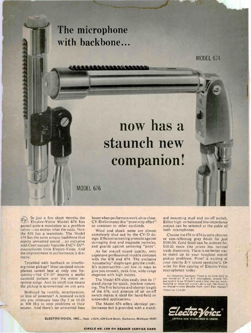
The microphonewith backbone...
(12In just a few short months the4. Electro-Voice Model 676 has
gained quite a reputation as a problemsolver -no matter what the odds. Nowthe 676 has a teammate. The Model674 has the same unique backbone thatrejects unwanted sound ... an exclusivewith Continuously Variable-D(CV-D)T mmicrophones from Electro-Voice. Andthe improvement in performance is dra-matic.
Troubled with feedback or interfer-ing noise pickup? Most cardioid micro-phones cancel best at only one fre-quency-but CV -D* insures a usefulcardioid pattern over the entire re-sponse range. And its small size meansthe pickup is symmetrical on any axis.
Bothered by rumble, reverberation,or loss of presence? A recessed switchlets you attenuate bass (by 5 or 10 dbat 100 Hz) to stop problems at theirsource. And there's no unwanted bass
boost when performers work ultra -close.CV -D eliminates this "proximity effect"so common to other cardioids.
Wind and shock noise are almostcompletely shut out by the CV -D de-sign. Efficient screening protects againstdamaging dust and magnetic particles,and guards against annoying "pops".
As for overall sound quality, onlyexpensive professional models comparewith the 676 and 674. The exclusiveAcoustalloy® diaphragm gets the credit.It's indestructible-yet low in mass togive you smooth, peak -free, wide -rangeresponse with high output.
The Model 676 slips easily into its 1"stand clamp for quick, positive mount-ing. The fine balance and shorter lengthof the 676, and absence of an on -offswitch makes it ideal for hand-held orsuspended applications.
The Model 674 offers identical per-formance but is provided with a stand-
ard mounting stud and on -off switch.Either high- or balanced low -impedanceoutput can be selected at the cable ofboth microphones.
Choose the 676 or 674 in satin chromeor non-reflecting gray finish for just$100.00. Gold finish can be ordered for$10.00 more (list prices less normaltrade discounts). There is no better wayto stand up to your toughest soundpickup problems. Proof is waiting atyour nearby E -V sound specialist's. Orwrite for free catalog of Electro-Voicemicrophones today.
An important footnote: There is no time limit toour warranty! If an E -V microphone should fail,just send it to us. If there's even a hint that our work-manship or materials weren't up to par, the repair isno charge - even decades from now! Fair enough?*Patent No. 3.115,207
SMettr" CC,®ELECTRO-VOICE, INC., Dept. 1162N, 629 Cecil Street, Buchanan, Michigan 49107.
CIRCLE NO. 108 ON READER SERVICE CARD
SETTING NEW STANDARDS IN SOUND
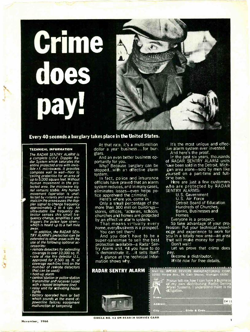
Crimedoespay!
Every 40 seconds a burglary takes place in the United States.
TECHNICAL INFORMATION
The RADAR SENTRY ALARM isa complete U.H.F. Doppler Ra-dar System which saturates theentire protected area with invis-ible r.f. microwaves. It providescomplete wall to wall-floor toceiling protectio3 for an area ofup to 5;000 square feet. Withouthuman movement in the pro-tected area, the microwave sig-nal remains stable. Any humanmovement (ope-ation is unaf-fected by rodents and small ani-mals)in the area causes the dop-pler signal to change frequencyapproximately 2 to 4 cps. Anultra -stable low frequency de-tector senses :his small fre-quency change, amplifies it andtriggers the police type siren-which is heard Lp to a half mileaway.
In addition, the RADAR SEN-TRY ALARM's protection can beextended to other areas with theuse of the following optional ac-cessories: remote detectors for extendingcoverage to over 10,000 sq. ft.
rate of rise fire detector U.L.approved for 2,500 sq. ft. ofcoverage each (no limit on thenumber of remote detectorsthat can be used)
hold-up alarm central station 7 police station
transmitter ane receiver (usedwith a leased telephone line)
relay unit for activating houselights
battery operated horn or bellwhich sounds an the event of:powerline Mare; equipmentmalfunction or tampering
At that ra-_e a multi -milliondollar a yea- business...for bur-glars.
And an ever better business op-portunity for you.
Why? Because ourglary can bestopped...with ai effective alarmsystem.
In fact, po' ice and insuranceofficials have proved that an alarmsystem reduces, and in many cases,eliminates losses-even helps po-lice apprehend the criminal.
Here's where yon come inOnly a small per entage cf the
more than 100 mill on buildiigs-stores, offices, 'actories, schoolschurches and hcmes are protectedby an effect ve alarm system.
That meals vi-tually everyhome, everybusiness is a prospect.
You can sell them!And you don't have to be a
super -salesman to sell the bestprotection avai la ble-a Rada- Sen-try Alarm uoit. .5,11 you have to dois demonstrate it. . it sells itself.
A glance at tie -echnical infor-mation shows wily.
RADAR SENTRY ALARM
It s the most unique and effec-=i4e alarm system ever invented.
Aid here's the proof.Ir the past six years, thousands
of RADAR SENTRY ALARM unitslave been sold in the Detroit, Mich-gan area alone-solc by men likejoJrself on a part-time and full--sine basis.
Here are just a few customers.A.ho are protected by RADARSENTRY ALARMS:
U.S. GovernmentU.S. Air ForceDetroit Board of EducationHundreds of Churches,Banks, Businesses andHomes
Everyone is a prospect.So take advantage of your pro-
fession! Put your technical knowl-ecge and experience to work fory -cu in a totally new area-an areatiat will make money for you!
Don't wai-!Let us prove that crime does
pay.Become a distributor.Write now for free details.
- -Mail to: REAR` DEVICES MANUFACTURING CORP.22003 Ha -pa- Ave., St. Clair Shores, Michiga- 48080
FlIase tell me how I can have a businessof my own distributing Rada- SentryAlarm Systems. I understand there is noobligation.
Name
Address
City State & Code
EW-11
November, 1966CIRCLE NO. 92 ON READIER SERVICE CARD
1
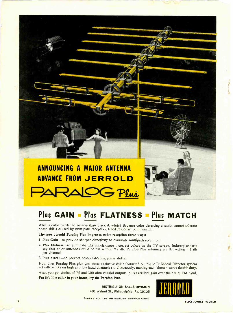
ANNOUNCING A MAJOR ANTENNA
ADVANCE FROM JERROLD
PAFRol_cDG INAL42,
Plus GAIN Plus FLATNESS Plus MATCHWhy is color harder to receive than black & white? Because color detecting circuits cannot toleratephase shifts caused by multipath reception, tilted response, or mismatch.
The new Jerrold Paralog-Plus improves color reception three ways:1. Plus Gain-to provide sharper directivity to eliminate multipath reception.2. Plus Flatness-to eliminate tilts which cause incorrect colors on the TV screen. Industry experts
say that color antennas must be flat within ± 2 db. Paralog-Plus antennas are flat within ± 1 dbper channel.
3. Plus Match-to prevent color -distorting phase shifts.
How does Paralog-Plus give you these exclusive color features? A unique Bi Modal Director systemactually works on high and low band channels simultaneously, making each element serve double duty.Also, you get choice of 75 and 300 ohm coaxial outputs, plus excellent gain over the entire FM band.For life -like color in your home, try the Paralog-Plus.
DISTRIBUTOR SALES DIVISION401 Walnut St., Philadelphia, Pa. 19105 JE114011)
CIRCLE NO. 109 ON READER SERVICE CARD2 ELECTRONICS WORLD
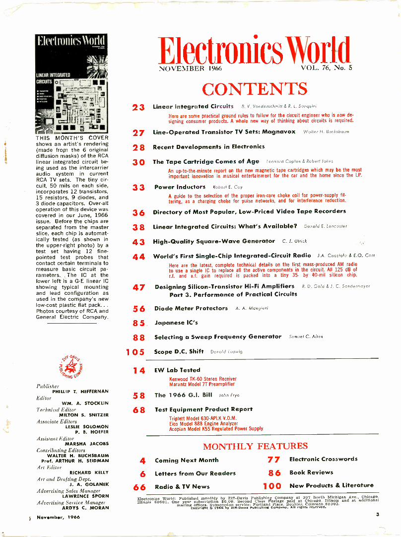
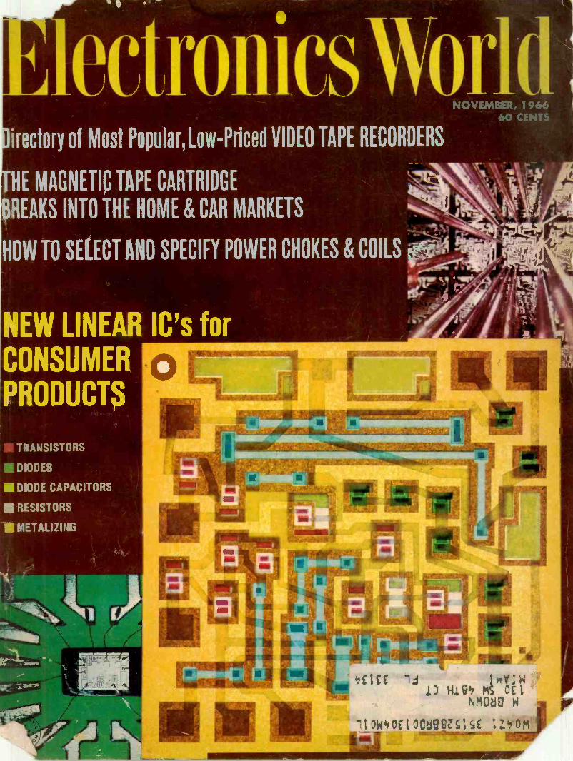
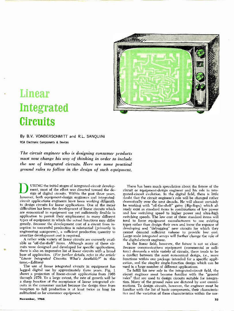
THIS MONTH'S COVERshows an artist's rendering(made froin the 6 originaldiffusion masks) of the RCAlinear integrated circuit be-ing used as the intercarrieraudio system in currentRCA TV sets. The tiny cir-cuit, 50 mils on each side,incorporates 12 transistors,15 resistors, 9 diodes, and3 diode capacitors. Over-alloperation of this device wascovered in our June, 1966issue. Before the chips areseparated from the masterslice, each chip is automat-ically tested (as shown inthe upper -right photo) by atest set having 12 fine -pointed test probes thatcontact certain terminals tomeasure basic circuit pa-rameters. The IC at thelower left is a G -E linear ICshowing typical mountingand lead configuration asused in the company's newlow-cost plastic flat pack...Photos courtesy of RCA andGeneral Electric Company.
D
2
/ NG c -
PublisherPHILLIP T. HEFFERNAN
EditorWM. A. STOCKLIN
Technical EditorMILTON S. SNITZER
Associate EditorsLESLIE SOLOMON
P. B. HOEFER
Assistant EditorMARSHA JACOBS
Contributing EditorsWALTER H. BUCHSBAUM
Prof. ARTHUR H. SEIDMANArt Editor
RICHARD KELLYArt and Drafting Dept.
J. A. GOLANEKAdvertising Sales Manager
LAWRENCE SPORNAdvertising Service Manager
ARDYS C. MORAN
33
3638
4344
ElectronwsWorldNOVEMBER 1966 VOL. 76, No. 5
CONTENTS23 Linear Integrated Circuits B. V. Vonderschmitt & R. L. Sanquini
Here are some practical ground rules to follow for the circuit engineer who is now de-signing consumer products. A whole new way of thinking about circuits is required.
27 Line -Operated Transistor TV Sets: Magnavox Walter H. Buchsbaum
28 Recent Developments in Electronics
3 0 The Tape Cartridge Comes of Age Leonard Coplen & Robert Johns
An up-to-the-minute report on the new magnetic tape cartridges which may be the mostimportant innovation in musical entertainment for the car and the home since the LP.
Power Inductors Robert E. Coy
A guide to the selection of the proper iron -core choke coil for power -supply fil-tering, as a charging choke for pulse networks, and for interference reduction.
Directory of Most Popular, Low -Priced Video Tape Recorders
Linear Integrated Circuits: What's Available? Donald E. Lancaster
High -Quality Square -Wave Generator C. J. Ulrick
World's First Single -Chip Integrated -Circuit Radio J.A. Cacciola & E.Q. Corr
Here are the latest, complete technical details on the first mass-produced AM radioto use a single IC to replace all the active components in the circuit. All 125 dB ofr.f. and a.f. gain required is packed into a tiny 35- by 40 -mil silicon chip.
47 Designing Silicon -Transistor Hi-Fi Amplifiers R. D. Gold & J. C. Sondermeyer
Part 3. Performance of Practical Circuits
56 Diode Meter Protectors A. A. Mangieri
85 Japanese IC's
8 8 Selecting a Sweep Frequency Generator Samuel C. Allen
105 Scope D.C. Shift Donald Ludwig
14 EW Lab TestedKenwood TK-60 Stereo ReceiverMarantz Model 7T Preamplifier
58 The 1966 G.I. Bill John Frye
68 Test Equipment Product ReportTriplett Model 630-APLK V.O.M.Eico Model 888 Engine AnalyzerAcopian Model K55 Regulated Power Supply
MONTHLY FEATURES4 Coming Next Month
6 Letters from Our Readers
66 Radio & TV News 100
77 Electronic Crosswords
86 Book Reviews
New Products & Literature
Electronics World: Published monthly by Ziff -Davis Publishing Company at 307 North Michigan Ave., Chicago,Illinois 60601. One year subscription $6.00. Second Class Postage paid at Chicago, Illinois and at additional
mailing offices. Subscripton service: Portland Place, Boulder. Colorado 80302.Copyright C 1966 hy Ziff -Davis Publishing Company. All rights reserved.
November, 1966 3
NEW
DLCT 7.5 WATTS
N EW
DLC 7.5 WATTS
8M2CT 15 WATTS
N EW
CORBREFLEX 30/30T30 WATTS
8M2C 15 WATTS
NEW
SH-30/30T30 WATTS
NEW FROM
UNIVERSITY
SOUND
additionsto the world's
greatest
selection ofpaging-talkback
speakers!
What's your pleasure? Communica-tions to fit the whisper of a medium-sized office . . . or the roar of GrandCentral Station? University has 'em!Some with full frequency response forbackground music. All with the crisp,natural voice quality so unique toUniversity. Write for our new '66/'67PA Catalog today.
LISTEN-UNIVERSITY SOUNDS BETTER
UNIVERSITY SOUNDAl DIVISION OF LI V LING All r C INC
Dept. L 65. P.O. Box 1056, Oklahoma City, Okla.CIRCLE NO. 80 ON READER SERVICE CARD
4
COMINGNEXT
MONTHSPECIAL FEATURE ARTICLES ON:
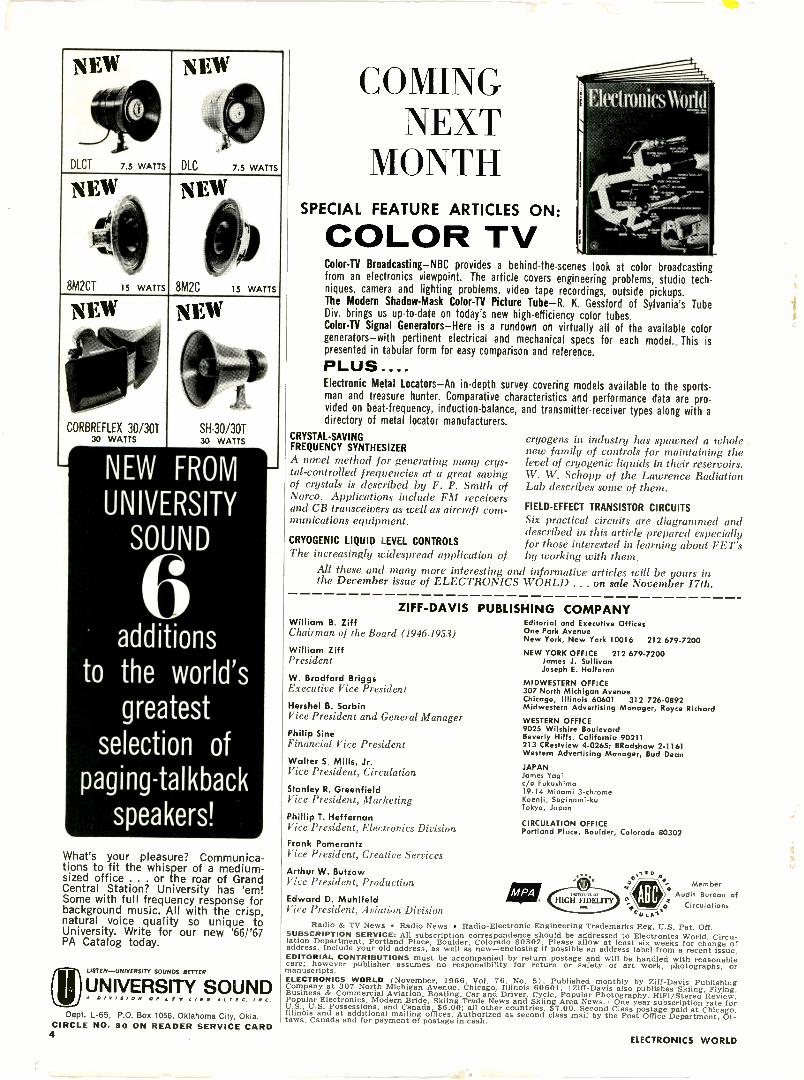
COLOR TVColor -TV Broadcasting-NBC provides a behind -the -scenes look at color broadcastingfrom an electronics viewpoint. The article covers engineering problems, studio tech-niques, camera and lighting problems, video tape recordings, outside pickups.The Modern Shadow -Mask Color -TV Picture Tube-R. K. Gessford of Sylvania's TubeDiv. brings us up-to-date on today's new high -efficiency color tubes.Color -TV Signal Generators-Here is a rundown on virtually all of the available colorgenerators-with pertinent electrical and mechanical specs for each model. This ispresented in tabular form for easy comparison and reference.
PLUS....Electronic Metal Locators-An in-depth survey covering models available to the sports-man and treasure hunter. Comparative characteristics and performance data are pro-vided on beat -frequency, induction -balance, and transmitter -receiver types along with a
directory of metal locator manufacturers.
CRYSTAL -SAVINGFREQUENCY SYNTHESIZER
A novel method for generating many crys-tal -controlled frequencies at a great savingof crystals is described by F. P. Smith ofNarco. Applications include FM receiversand CB transceivers as well as aircraft com-munications equipment.
CRYOGENIC LIQUID LEVEL CONTROLS
The increasingly widespread application ofAll these and many more interesting anthe December issue of ELECTRONICS
cryogen in industry has spawned a wholenew family of controls for maintaining thelevel of cryogenic liquids in their reservoirs.W. W. Schopp of the Lawrence RadiationLab describes some of them.
FIELD-EFFECT TRANSISTOR CIRCUITS
Six practical circuits are diagrammed anddescribed in this article prepared especiallyfor those interested in learning about FET'sby working with them.
d informative articles will be yours inWORLD . . . on sale November 17th.
ZIFF-DAVIS PUBLISWilliam B. ZiffChairman of the Board (1946-1953)
William ZiffPresident
W. Bradford BriggsExecutive Vire President
Hershel B. SarbinVice President and General Manager
Philip SineFinancial Vice President
Walter S. Mills, Jr.Vice President, Circulation
Stanley R. GreenfieldVice President, Marketing
Phillip T. HeffernanVice President, Electronics DivisionFrank PomerantzVice President, Creative Services
Arthur W. ButzowVice President, Production
Edward D. MuhlfeldVice President, Aviation Division
HING COMPANYEditorial and Executive OfficesOne Park AvenueNew York, New York 10016 212 679-7200
NEW YORK OFFICE 212 679-7200James J. SullivanJoseph E. Halloran
MIDWESTERN OFFICE307 North Michigan AvenueChicago, Illinois 60601 312 726-0892Midwestern Advertising Manager, Royce Richard
WESTERN OFFICE9025 Wilshire BoulevardBeverly Hills, California 90211213 CRestview 4-0265; BRadshaw 2-1161Western Advertising Manager, Bud Dean
JAPANJames Yagic/o Fukushima19-14 Minami 3 -chromeKoenli, Suginami-kuTokyo, Japan
CIRCULATION OFFICEPortland Place, Boulder, Colorado 80302
MemberAudit Bureau of
Circulations
Radio & TV News Radio News Radio -Electronic Engineering Trademarks Reg. U.S. Pat. Off.SUBSCRIPTION SERVICE: All subscription correspondence should be addressed to Electronics World, Circu-lation Department, Portland Place, Boulder, Colorado 80302. Please allow at least six weeks for change ofaddress. Include your old address, as well as new-enclosing if possible an address label from a recent issue.EDITORIAL CONTRIBUTIONS must be accompanied by return postage and will be handled with reasonablecare; however publisher assumes no responsibility for return or safety of art work, photographs, ormanuscripts.ELECTRONICS WORLD (November, 1966, Vol. 76, No. 51. Published monthly by Ziff -Davis PublishingCompany at 307 North Michigan Avenue, Chicago, Illinois 60601. (Ziff -Davis also publishes Skiing, Flying.Business & Commercial Aviation, Boating, Car and Driver, Cycle, Popular Photography, HiFi/Stereo Review,Popular Electronics, Modern Bride, Skiing Trade News and Skiing Area News. I One year subscription rate forU.S., U.S. Possessions, and Canada, $6.00; all other countries, $7.00. Second Class postage paid at Chicago.Illinois and at additional mailing offices. Authorized as second class mail by the Post Office Department, Ot-tawa. Canada and for payment of postage in cash.
ELECTRONICS WORLD
MALLORY Tips for Technicians ffJuly-
Tips on replacingelectrolytic capacitors
V1/4 tkkAAViS,NNPC%ADE IN USA
MFp VOC80 450 if::
20 459 -1,y)
I i'.3t.6 313__
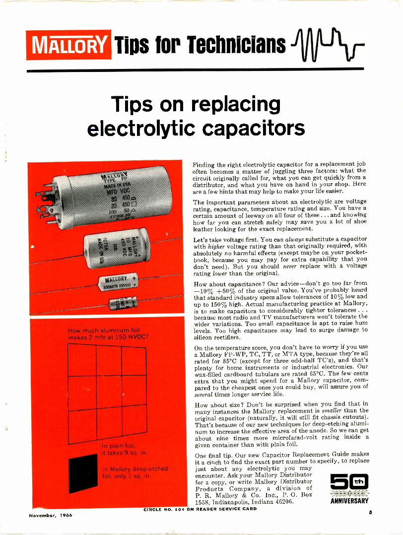
How much aluminum foilmakes 2 mfd at 150 WVDC?
In plain foil,it takes 9 sq. in.
In Mallory deep -etfoil, only 1 sq. in.
ok,
Finding the right electrolytic capacitor for a replacement joboften becomes a matter of juggling three factors: what thecircuit originally called for, what you can get quickly from adistributor, and what you have on hand in your shop. Hereare a few hints that may help to make your life easier.
The important parameters about an electrolytic are voltagerating, capacitance, temperature rating and size. You have acertain amount of leeway on all four of these ... and knowinghow far you can stretch safely may save you a lot of shoeleather looking for the exact replacement.
Let's take voltage first. You can always substitute a capacitorwith higher voltage rating than that originally required, withabsolutely no harmful effects (except maybe on your pocket-book, because you may pay for extra capability that youdon't need). But you should never replace with a voltagerating lower than the original.
How about capacitance? Our advice-don't go too far from-10% +50% of the original value. You've probably heardthat standard industry specs allow tolerances of 10% low andup to 150% high. Actual manufacturing practice at Mallory,is to make capacitors to considerably tighter tolerances . . .
because most radio and TV manufacturers won't tolerate thewider variations. Too small capacitance is apt to raise humlevels. Too high capacitance may lead to surge damage tosilicon rectifiers.
On the temperature score, you don't have to worry if you usea Mallory FP -WP, TC, TT, or MTA type, because they're allrated for 85°C (except for three odd -ball TC's), and that'splenty for home instruments or industrial electronics. Ourwax -filled cardboard tubulars are rated 65°C. The few centsextra that you might spend for a Mallory capacitor, com-pared to the cheapest ones you could buy, will assure you ofseveral times longer service life.
How about size ? Don't be surprised when you find that inmany instances the Mallory replacement is smaller than theoriginal capacitor (naturally, it will still fit chassis cutouts).That's because of our new techniques for deep -etching alumi-num to increase the effective area of the anode. So we can getabout nine times more microfarad-volt rating inside agiven container than with plain foil.
One final tip. Our new Capacitor Replacement Guide makesit a cinch to find the exact part number to specify, to replacejust about any electrolytic you mayencounter. Ask your Mallory Distributorfor a copy, or write Mallory DistributorProducts Company, a division ofP. R. Mallory & Co. Inc., P. O. Box1558, Indianapolis, Indiana 46206.
CIRCLE NO. 104 ON READER SERVICE CARDANNIVERSARY
November, 1966
Buy the BEST!/T form!
CAPACITIVE DISCHARGEIGNITION SYSTEM
ONLY $ 299.5 PPD.!
Why settle for less in motor vehicle ignitionsystems when you can buy the very BEST fromDelta, the originators, the leaders in capacitivedischarge (SCR) systems. Delta pioneered thiselectronic marvel. Thousands have installed thisremarkable electronic system. Now YOU can pur-chase at low, LOW cost, and in easy -to -build kitform, the king of them all, the DELTAKIT. Lowprice due simply to high production levels at nosacrifice in peerless Delta quality.
Operate Any MotorVehicle More Efficiently
Compare these proven benefits:
Up to 20% Increase in GasolineMileage
A Installs in Only 10 Minutes onany Car or Boat
A Spark Plugs Last 3 to 10 TimesLonger
Instant Starts in all Weather Dramatic Increase in Acceleration
and General PerformanceA Promotes More Complete
Combustion
Literature and complete technical infor-mation sent by return mail.
BETTER YET-ORDER TODAY!
DELTA DELTAPRODUCTS, INC
P.O. Box 1147EW, Grand Junction, Colo. 81501
Enclosed is $ Ship prepaid.1:1 Ship C.O.D.
Please send:EI Mark Tens (Assembled) @ $44.95El Mark Tens (Delta Kit) @ $29.95SPECIFY - Positive Ground Negative
Ground 0 6 or ID 12VoltCar Year Make
Name
I Address
I City/State Zip
DP 6-2CIRCLE NO. 1216
J
LETTERSFROM OUR
READERS
INSULATED -GATE TRANSISTORTo the Editors:
As the author of some articles andpapers on insulated -gate field-effecttransistors, I was quite interested toread Donald Lancaster's piece in yourJuly, 1966 issue on the same subject.In general, I felt the topic was wellhandled. However, there are two itemswhich Don and his readers might findinteresting.
The first item is that the IEEESymbols Coordinating Committee nowhas an IGFET symbol which givespositive identification of the source ter-minal by putting the gate connectionat the source end of the gate. In addi-tion, this new symbol shows whetheran IGFET has a p -channel or ann -channel and also differentiates be-tween enhancement -type and deple-tion -type IGFET's.
Incidentally, Don's article may haveleft his readers with the impressionthat all IGFET's are the enhancementtype. As you probably know, there areseveral depletion -type IGFET's avail-able also. (Depletion types are charac-terized as "normally on" in contrastwith the enhancement types which are"off" in the absence of gate voltage.)
Another point is that I think Don hasconfused "bipolar" with "bilateral." AllFET's, whether insulated -gate ( IGFET )or junction -gate ( JUGFET ), are uni-polar devices because all source -to -drainconduction is carried out by chargecarriers of one polarity. On the otherhand, all FET's are bilateral becausetheir source and drain can be inter-changed. (It should be noted that dif-ferences in the size or relative positionof source and drain in some deviceslead to the designation of a "preferred"source which gives best performance incertain applications. )
IGFET's should open a whole newrange of applications, so I'm lookingforward to reading future articles.
DAVID M. GRISWOLDNew Providence, N. J.
* * *
AUTO BURGLAR ALARMTo the Editors:
After reading the article by Edwin R.DeLoach an an SCR auto burglar alarm( August issue ), I thought some readersmight be interested in the alarm I de-
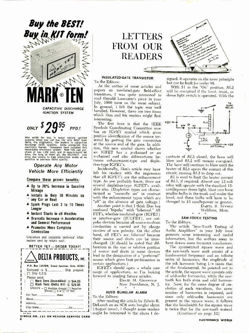
signed. It operates on the same principlebut can be built for under $6.
With Si in the "On" position, RL2will be energized if the hood, trunk, ordome light switch is operated. With the
TONORM
PELAY
4I2V
contacts of RL2 closed, the horn willblow and RL2 will remain energized.The horn will continue to blow until theheater of RL1 opens the contact of thiscircuit, causing RL2 to drop out.
RI is used to limit the heater currentof RL1, if required. Almost any 12 -voltrelay will operate with the standard 15-candlepower dome light. Most cars havesmaller bulbs in the trunk and under thehood, and these bulbs will have to bechanged to 15 candlepower or greater.
DARYL R. STYBLOWaltham, Mass.
* * *
SAW -TOOTH TESTINGTo the Editors:
The article "Saw -Tooth Testing ofAudio Amplifiers" in your July issuepresents some interesting and usefulinformation, but the authors seem tohave drawn some incorrect conclusions.
The symmetrical square wave andthe saw -tooth wave each consist of afundamental frequency and an infiniteseries of harmonics, the amplitude ofthe nth harmonic being 1/n times thatof the fundamental. As pointed out inthe article, the square wave consists onlyof odd -order harmonics, while the saw -tooth has both even and odd harmon-ics. Now, for the same degree of res-olution of each waveform, the samenumber of harmonics is required, andsince only odd -order harmonics arepresent in the square wave, it followsthat the bandwidth for the square waveis twice that for the saw -tooth instead
(Continued on page 12)ON READER SERVICE CARD
ELECTRONICS WORLD
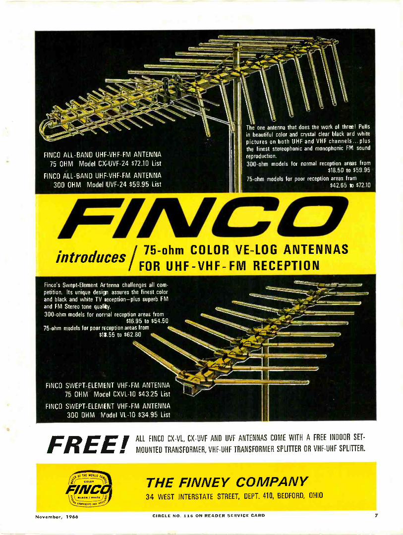
FINCO ALL -BAND UHF -VHF -FM ANTENNA
75 OHM Model CX-UVF-24 $72.10 List
FINCO ALL -BAND UHF -VHF -FM ANTENNA
300 OHM Model UVF-24 $59.95 List
The one antenna that does the work of three! Pullsin beautiful color and crystal clear black and whitepictures on both UHF and VHF channels . plusthe finest stereophonic and monophonic FM soundreproduction.
300 -ohm models for normal reception areas from$18.50 to $59.95
75 -ohm models for poor reception areas from$42.65 to $72.10
introduces 75 -ohm COLOR VE-LOG ANTENNASFOR UHF -VHF -FM RECEPTION
Finco's Swept -Element Artenna challenges all com-petition. Its unique design assures the finest colorand black and white TV reception-plus superb FMand FM Stereo tone quality.
300 -ohm models for normal reception areas from$16.95 to $54.50
75 -ohm models for poor reception areas from$15.55 to $62.80
FINCO SWEPT -ELEMENT VHF -FM ANTENNA
75 OHM Mocel CXVL-10 $43.25 List
FINCO SWEPT -ELEMENT VHF -FM ANTENNA
300 OHM Nadel VL-10 $34.35 List
FREES
ALL FINCO CX-VL, CX-UVF AND UVF ANTENNAS COME WITH A FREE INDOOR SET-
. MOUNTED TRANSFORMER, VHF -UHF TRANSFORMER SPLITTER OR VHF -UHF SPLITTER.
to Of THE WORLD t46
co-.
FINCOk0 7'';)
THE FINNEY COMPANY34 WEST INTERSTATE STREET, DEPT. 410, BEDFORD, OHIO
November, 1966 CIRCLE NO. 116 ON READER SERVICE CARD 7
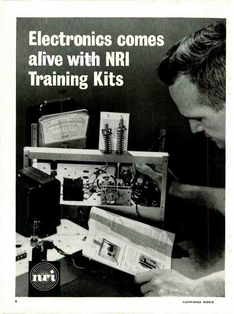
Electronics comesalive with NRITraining Kits
a ELECTRONICS WORLD
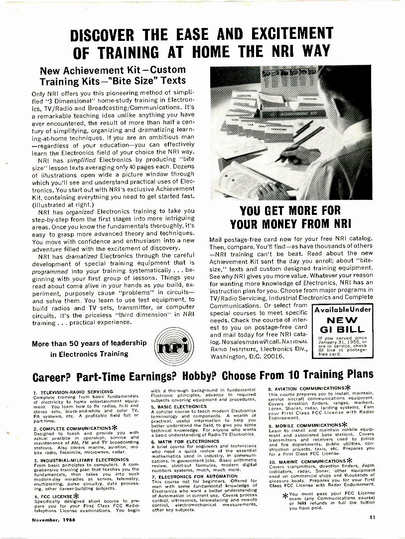
DISCOVER THE EASE AND EXCITEMENT
OF TRAINING AT HOME THE NRI WAYNew Achievement Kit-CustomTraining Kits-"Bite Size" Texts
Only NRI offers you this pioneering method of simpli-fied "3 Dimensional" home -study training in Electron-ics, TV/Radio and Broadcasting/Communications. It'sa remarkable teaching idea unlike anything you haveever encountered, the result of more than half a cen-tury of simplifying, organizing and dramatizing learn-ing -at-home techniques. If you are an ambitious man-regardless of your education-you can effectivelylearn the Electronics field of your choice the NRI way.
NRI has simplified Electronics by producing "bitesize" lesson texts averaging only 40 pages each. Dozensof illustrations open wide a picture window throughwhich you'll see and understand practical uses of Elec-tronics. You start out with NRI's exclusive AchievementKit, containing everything you need to get started fast.(Illustrated at right.)
NRI has organized Electronics training to take youstep-by-step from the first stages into more intriguingareas. Once you know the fundamentals thoroughly, it'seasy to grasp more advanced theory and techniques.You move with confidence and enthusiasm into a newadventure filled with the excitement of discovery.
NRI has dramatized Electronics through the carefuldevelopment of special training equipment that is
programmed into your training systematically ... be-ginning with your first group of lessons. Things youread about come alive in your hands as you build, ex-periment, purposely cause "problems" in circuits-and solve them. You learn to use test equipment, tobuild radios and TV sets, transmitter, or computercircuits. It's the priceless "third dimension" in NRItraining ... practical experience.
More than 50 years of leadershipin Electronics Training
Career?
YOU GET MORE FORYOUR MONEY FROM NRI
Mail postage -free card now for your free NRI catalog.Then, compare. You'll find-as have thousands of others-NRI training can't be beat. Read about the newAchievement Kit sent the day you enroll; about "bite -size," texts and custom designed training equipment.See why NRI gives you more value. Whatever your reasonfor wanting more knowledge of Electronics, NRI has aninstruction plan for you. Choose from major programs inTV/Radio Servicing, Industrial Electronics and CompleteCommunications. Or select fromspecial courses to meet specificneeds. Check the course of inter-est to you on postage -free cardand mail today for free NRI cata-log. No salesma n will call. NATIONALRADIO INSTITUTE, Electronics Div.,Washington, D.C. 20016.
AvailableUnderNEW
GI BILLIf you served sinceJanuary 31, 1955, orare in service, checkGI line in postage -free card.
Part -Time Earnings? Hobby? Choose From 10 Training Plans1. TELEVISION -RADIO SERVICINGComplete training from basic fundamentalsof electricity to home entertainment equip-ment. You learn how to fix radios, hi-fi andstereo sets, black -and -white and color TV,
PA systems, etc. A profitable field full orpart-time.
2. COMPLETE COMMUNICATIONS*Designed to teach and provide you withactual practice in operation, service andmaintenance of AM, FM and TV broadcastingstations. Also covers marine, aviation, mo-bile radio, facsimile, microwave, radar.
3. INDUSTRIAL -MILITARY ELECTRONICSFrom basic principles to computers. A com-prehensive training plan that teaches you thefundamentals, then takes you into suchmodern-day miracles as servos, telemetry,multiplexing, pulse circuitry, data process.ing, other career -building subjects.
4. FCC LICENSE*Specifically designed short course to pre-pare you for your First Class FCC Radio-telephone License examinations. You begin
with a' thorough background in fundamentalElectronic principles, advance to requiredsubjects covering equipment and procedures.5. BASIC ELECTRONICSA concise course to teach modern Electronicsterminology and components. A wealth ofpractical, useful information to help youbetter understand the field, to give you sometechnical knowledge. For anyone who wantsa basic understanding of Radio -TV Electronics.
6. MATH FOR ELECTRONICSA brief course for engineers and technicianswho need a quick review of the essentialmathematics used in industry, in communi-cations, in government jobs. Basic arithmeticreview, short-cut formulas, modern digitalnumbers systems, much, much more.7. ELECTRONICS FOR AUTOMATIONThis course not for beginners. Offered formen with some fundamental knowledge ofElectronics who want a better understandingof Automation in current use. Covers processcontrol, ultrasonics, telemetering and remotecontrol, electromechanical measurements.other key subjects.
8. AVIATION COMMUNICATIONS*This course prepares you to install, maintain,service aircraft communications equipment.Covers direction finders, ranges, markers,Loran, Shoran, radar, landing systems. Earnyour First Class FCC License with RadarEndorsement.
9. MOBILE COMMUNICATIONS*Learn to install and maintain mobile equip-ment and associated base stations. Coverstransmitters and receivers used by policeand fire departments, public utilities, con-struction projects, taxis, etc. Prepares youfor a First Class FCC License.
10. MARINE COMMUNICATIONS*Covers transmitters, direction finders, depthindicators, radar, Sonar, other equipmentused on commercial ships and thousands ofpleasure boats. Prepares you for your FirstClass FCC License with Radar Endorsement.
ge You must pass your FCC License"-exam (any Communications course)
or NRI refunds in full the tuitionyou have paid.
November, 1966 11
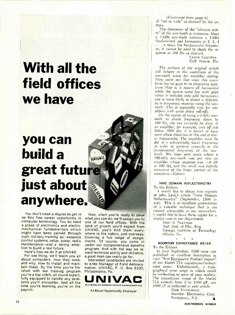
With all thefield officeswe have
you canbuild agreat futurjust aboutanywhere
You don't need a degree to get inon this fine career opportunity incomputer technology. You do needa grasp of electronics and electro-mechanical fundamentals whichmight have been gained throughsuch military training as: weaponscontrol systems, radar, sonar, radiomaintenance-and a strong ambi-tion to build a real future.
Here's how we do it at UNIVAC.For one thing, we'll teach you all
about computers. How they work,and why. How to install and main-tain them. By the time you're fin-ished with our training programyou're a top notch, all round expert,fully equipped to handle any prob-lems you'll encounter. And all thetime you're learning you're on thepayroll.
Now, when you're ready to showwhat you can do, we'll assign you toone of our field offices. With thekind of growth you'd expect fromUNIVAC, you'll find them every-where in the nation, and overseas.Covering a full range of assign-ments. Of course, you come inunder our comprehensive benefitsprogram. And with the way we re-ward technical ability and initiative,a good man can really go far.
Interested candidates are invitedto write Manager of Field Adminis-tration, UNIVAC, P. 0. Box 8100,Philadelphia, Pa.
UNIVACDIVISION OF SPERRY RANO CORPORATION
An Equal Opportunity Employer
(Continued from page 6)of "not as wide" as claimed by the au-thors.
The discussion of the "obvious utili-ty" of the saw -tooth is erroneous. Sincea 1 -kHz saw -tooth contains a 1 -kHzfundamental and harmonics at 2, 3, 4. . . n times the fundamental frequen-cy, it cannot be used to check the re-sponse at 100 Hz as claimed.
LLOYD CLAYTONGulf Breeze, Fla.
The authors of the original articlestill believe in the usefulness of thesaw -tooth wave for amplifier testing.They point out that since this wave-form has no gaps in its frequency spec-trum (that is, it covers all harmonics)while the square wave has such gaps(since it includes only odd harmonics),one is more likely to detect a deficien-cy in frequency response using the satv-tooth. This is especially true for am-plifiers with quite sharp roll -offs.
On the matter of using a 1 -kHz saw-tooth to check frequency down to100 Hz, this can certainly be done. Ifan amplifier, for example, cuts off justbelow 1000 Hz, it is found to havesome phase distortion at this and at low-er frequencies. The amplifier must befiat to a substantially lower frequencyin order to perform properly at thefundamental frequency of the saw -tooth. We have seen cases where a100 -kHz saw -tooth was put into anamplifier whose response was -6 dBat 100 Hz, and the result was definitecurvature of the linear portion of thewaveform.-Editors
* * *
TIME DOMAIN REFLECTOMETRYTo the Editors:
I would like to obtain two reprintsof John Lenk's article "Time DomainReflectometry" (September, 1966 is-sue). This is an excellent presentationof a valuable technique that is nottreated adequately in our curriculum.I would like to have these copies for adisplay case in our department.
JOHN B. PEATMANAsst. Prof. of Elec. Eng.Georgia Institute of TechnologyAtlanta, Ga.
* * *
BOONTON CAPACITANCE METERTo the Editors:
In your September, 1966 issue youpublished an excellent description inyour "Test Equipment Product Report"of our Model 71A capacitance/induct-ance meter. Unfortunately, a typo-graphical error crept in which couldbe misleading to some of your readers.The capacitance range of the Model71A extends from 0 to 1000 pF, not1000 p.F as indicated in your article.
NEIL UPTEGROVEBoonton Electronics Corp.Parsippany, N.J.
12ELECTRONICS WORLD
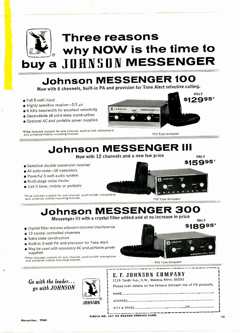
Three reasons, why NOW is the time to
buy a JOHNSON MESSENGERJohnson MESSENGER 100
Now with 6 channels, built-in PA and provision for Tone Alert selective calling.
Full 5 -watt input Highly sensitive receiver-0.5 µV 6 KHz bandwidth for excellent selectivity
Dependable all solid-state construction
Optional AC and portable power supplies
Price includes crystals for one channel, push -to -talk microphoneand universal mobile mounting bracket. FCC Type Accepted
Johnson MESSENGER IIINow with 12 channels and a new low price
Sensitive double conversion receiver
All solid -state -18 transistors Powerful 3 -watt audio system Multi -stage noise limiter Use it base, mobile or portable
Price includes crystals for one channel, push -to -talk microphoneand universal mobile mounting bracket. FCC Type Accepted
ONLY
$15 9 95*
Johnson MESSENGER 300Messenger Ill with a crystal filter added and at no increase in price
Crystal filter reduces adjacent channel interference
12 crystal controlled channels
Solid state construction Built-in 3 -watt PA and provision for Tone Alert
May be used with accessory AC and portable powersupplies
'Price includes crystals for one channel, push -to -talk microphoneand universal mobile mounting bracket.
FCC Type Accepted
ONLY
Go with the leader...go with JOHNSON
JOHNSON
E. F. JOHNSON COMPANY1179 Tenth Ave., S.W., Waseca, Minn. 56093
Please rush details on the famous Johnson line of CB products.
NAME
ADDRESS
CITY & STATE ZIP
CIRCLE NO. 107 ON READER SERVICE CARDNovember, 1966
13
EW
LAB TESTED
HI-FI PRODUCTREPORTTESTED BY HIRSCH-HOUCK LABS
Kenwood TK-60 Stereo ReceiverMarantz Model 7T Preamplifier
Kenwood TK-60 Stereo ReceiverFor copy of manufacturer's brochure, circle No. 27 on Reader Service Card.
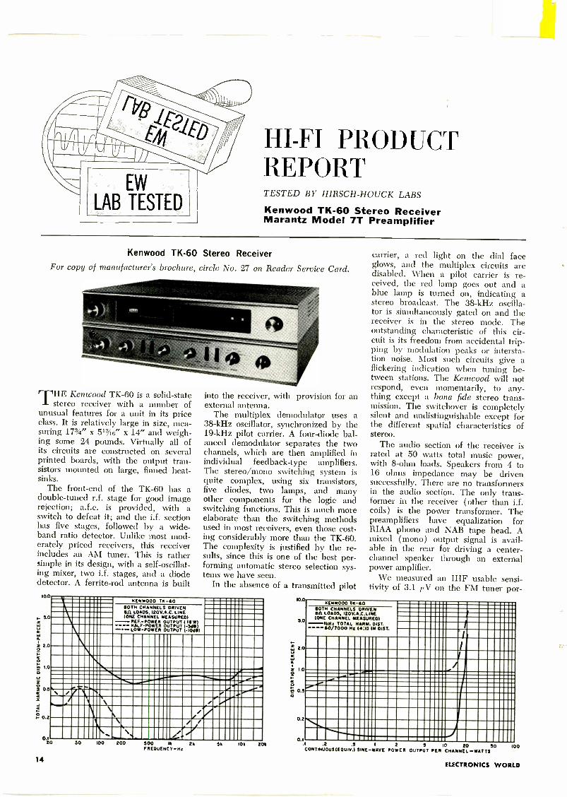
THE Kenwood TK-60 is a solid-statestereo receiver with a number of
unusual features for a unit in its priceclass. It is relatively large in size, mea-suring 173/4" x 51%6" x 14" and weigh-ing some 24 pounds. Virtually all ofits circuits are constructed on severalprinted boards, with the output tran-sistors mounted on large, finned heat-sinks.
The front-end of the TK-60 has adouble -tuned r.f. stage for good imagerejection; a.f.c. is provided, with aswitch to defeat it; and the i.f. sectionhas five stages, followed by a wide-band ratio detector. Unlike most mod-erately priced receivers, this receiverincludes an AM tuner. This is rathersimple in its design, with a self -oscillat-ing mixer, two i.f. stages, and a diodedetector. A ferrite -rod antenna is built
100
, 5.0
z 2.00
0.5
.C-; 0.2
0.120
into the receiver, with provision for anexternal antenna.
The multiplex demodulator uses a38 -kHz oscillator, synchronized by the19 -kHz pilot carrier. A four -diode bal-anced demodulator separates the twochannels, which are then amplified inindividual feedback -type amplifiers.The stereo/mono switching system isquite complex, using six transistors,five diodes, two lamps, and manyother components for the logic andswitching functions. This is much moreelaborate than the switching methodsused in most receivers, even those cost-ing considerably more than the TK-60.The complexity is justified by the re-sults, since this is one of the best per-forming automatic stereo selection sys-tems we have seen.
In the absence of a transmitted pilot
AENw000 TA -60BOTH CHANNELS DRIVERBA LOADS, 120v..C. LINE(ONE CHARNEL INESUREDI
REF. POWER OUTPUT I 115W)HALF -POWER OUTPUT (-3,18)
---LOW POWER OUTPUT 1-106151
_..........1.... ..."1......., ..." ......0.IR\ y \ - " ....---'
...'
h.
-.\ / ./".^,......., \ \ / 4/ 1\ \A,
/ i/\ I __,..,,,,.
50 100 200 500 Ik 2kFREQUENCY -H
5k 10k 20k
10.0
SO
0H 0.5
0.2
0.I.2 .5 2 5 i0 20 50
CONTiNuOUSIECIUIV.1 SINE -WAVE POWER OUTPUT PER CHANNEL -WATTS
carrier, a red light on the dial faceglows, and the multiplex circuits aredisabled. When a pilot carrier is re-ceived, the red lamp goes out and ablue lamp is turned on, indicating astereo broadcast. The 38 -kHz oscilla-tor is simultaneously gated on and thereceiver is in the stereo mode. Theoutstanding characteristic of this cir-cuit is its freedom from accidental trip-ping by modulation peaks or intersta-tion noise. Most such circuits give aflickering indication when tuning be-tween stations. The Kenwood will notrespond, even momentarily, to any-thing except a bona fide stereo trans-mission. The switchover is completelysilent and undistinguishable except forthe different spatial characteristics ofstereo.
The audio section of the receiver israted at 50 watts total music power,with 8 -ohm loads. Speakers from 4 to16 ohms impedance may be drivensuccessfully. There are no transformersin the audio section. The only trans-former in the receiver (other than i.f.coils) is the power transformer. Thepreamplifiers have equalization forRIAA phono and NAB tape head. Amixed (mono) output signal is avail-able in the rear for driving a center -channel speaker through an externalpower amplifier.
We measured an IHF usable sensi-tivity of 3 1 f1.V on the FM tuner por-
AENwOOD TA -60 2
BOTH CHANNELS DRIVENBA LOADS, 120V.A.C.L1NE(ONE CHANNEL MEASURED)
-1 HA TOTAL HAIRY. D ST.----60/7000 Hz (:1) IM 01ST.
F
s
I
I6....-- Am.I -0. ..-
ro-
'......,...._
*.'...............
100
14ELECTRONICS WORLD
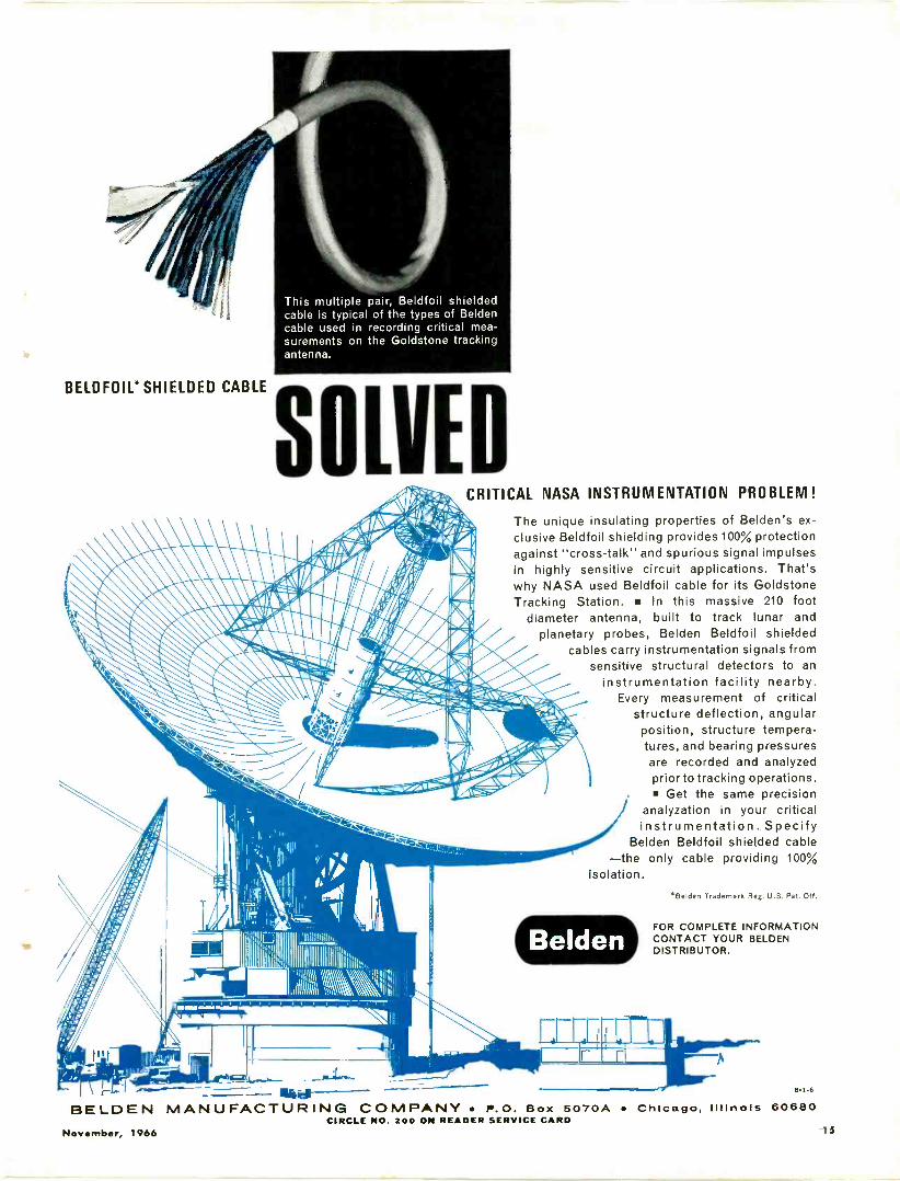
This multiple pair, Beldfoil shieldedcable is typical of the types of Beldencable used in recording critical mea-surements on the Goldstone trackingantenna.
sBELDFOIL*SHIELDED CABLE
-- Uiiief
CRITICAL NASA INSTRUMENTATION PROBLEM!
The unique insulating properties of Belden's ex-clusive Beldfoil shielding provides 100% protectionagainst "cross -talk" and spurious signal impulsesin highly sensitive circuit applications. That'swhy NASA used Beldfoil cable for its GoldstoneTracking Station. In this massive 210 foot
diameter antenna, built to track lunar andplanetary probes, Belden Beldfoil shielded
cables carry instrumentation signals fromsensitive structural detectors to an
instrumentation facility nearby.Every measurement of critical
structure deflection, angularposition, structure tempera-tures, and bearing pressuresare recorded and analyzedprior to tracking operations. Get the same precision
analyzation in your criticalinstrumentation. Specify
Belden Beldfoil shielded cable-the only cable providing 100%
isolation.Belden Trademark Reg. U.S. Pat. Off.
FOR COMPLETE INFORMATIONCONTACT YOUR BELDENDISTRIBUTOR.
14
8-1.6
BELDEN MANUFACTURING COMPANY P.O. Box 5070A CIRCLE NO. 200 ON READER SERVICE CARD
November, 1966
Chicago, Illinois 6068015
Thinking of collegeand a
space age career inelectronics?
Send for this booklet onENGINEERING TECHNOLOGY
AND ENGINEERING
Learn how you can prepare for adynamic career as an electrical ormechanical engineering technician orengineer in such exciting, growingfields as avionics, missiles, reliabili-ty control, fluid mechanics, dataprocessing, metallurgy, microelec-tronics, and advanced aerospaceresearch.
MSOE offers residence study pro-grams leading to these degrees inengineering technology and engi-neering:
2 years-Associate in Applied Science4 years-Bachelor of Science
Alto get facts about scholarships andfinancial aids, job placement andother student services, plus photographs of MSOE technical labora-tories and student activities.For your copy, just mailthe coupon -no obligation.
Programs approved for veteran training.
MSOEMilwaukee School of EngineeringDept. EW-1166, 1025 N. Milwaukee St.,Milwaukee, Wisconsin 53201Please send the "Your Career" booklet.I'm interested in0 Electrical fields 0 Mechanical fields
Name Age
Address
City State ZIPMS -289
CIRCLE NO. 102 ON READER SERVICE CARD16
+5
0
-5
-10
-15
a -20U
-25
- 30
-35
-40
:::::::::: ..............
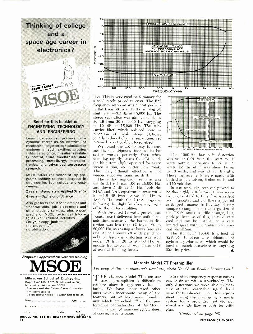
FM PERFORMANCEAVERAGE BOTH CHANNELS
i
::
:::::::: : :::::::::::::::
;;;;;
:::: ". 111
50 100 200 500 1k 2hFREQUENCY -Hz
lion. This is very good performance fora moderately priced receiver. The FMfrequency response was almost perfect-ly flat from 30 to 7000 Hz, sloping offslightly to -3.5 dB at 15,000 Hz. Thestereo separation was also good, about:30 dB from 30 to 4000 Hz, droppingto 10 dB at 15,000 Hz. The sub -carrier filter, which reduced noise inreception of weak stereo stations,greatly reduced channel separation, yetretained a noticeable stereo effect.
We found the TK-60 easy to tune,and the unambiguous stereo indicationsystem worked perfectly. Even whenscanning rapidly across the FM band,the blue stereo light operated for everystereo station, no matter how weak.The a.f.c., although effective, is notneeded since we found no drift.
The audio frequency response waswithin ±1 dB from 100 to 18,000 Hz,and down 5 dB at 20 Hz. Both theRIAA and NAB equalization were with-in ±1.5 dB from below 100 Hz to15,000 Hz, with the RIAA responsefollowing the slight low -frequency roll -
off in the audio amplifiers.With the rated 18 watts per channel
(continuous) delivered from both chan-nels simultaneously, the harmonic dis-tortion was less than 1% from 120 to20,000 Hz, increasing at lower frequen-cies. At half power (9 watts per chan-nel) or less, the distortion was wellunder 1% from 20 to 20,000 Hz. Atmiddle frequencies it was under 0.1%at normal listening levels.
5k 10k
20 SO .0 SI. 20, SO.R.F INS6., SIGNAL IN 6.11CIROVOLTSWV./
20k
The 1000 -Hz harmonic distortionwas under 0.2% from 0.1 watt to 15watts output, increasing to 2% at 19watts. IM distortion was about 1% upto 10 watts, and was 2% at 16 watts.These measurements were made withboth channels driven, 8 -ohm loads, anda 120 -volt line.
In use tests, the receiver proved tobe thoroughly satisfactory. It was sensi-tive, non -critical to tune, had excellentaudio quality, and no flaws appearedin its performance. In this day of verycompact components, the large size ofthe TK-60 seems a trifle strange, but,perhaps because of this, it runs verycool and can be installed in a verylimited space without provision for spe-cial ventilation.
The Kentvood TK-60 is priced at$239.95. It offers a combination ofstyle and performance which would behard to match elsewhere at anythinglike its price.
Marantz Model 7T PreamplifierFor copy of the manufacturer's brochure, circle No. 28 on Reader Service Card.
THE Marantz Model 7T transistorstereo preamplifien is difficult to
criticize since it apparently has nofaults. We have encountered otherunits which incorporate many of thefeatures, but we have never found aunit which embodied all of the per-formance characteristics of the Model7T. This sort of near -perfection does,of course, have its price.
Most of its frequency response curvescan be drawn with a straightedge. Theonly distortions we were able to mea-sure at any reasonable signal levelwere those inherent in our test equip-ment. Using the preamp in a musicsystem for a prolonged test did notreveal a single flaw or basis for criti-cism.
(Continued on page 95)
ELECTRONICS WORLD
A New Electronics Slide Rulewith Self -Training Course
Why didn't someone think of this before?Here's a great new way to solve electronic problems accurately
. easily. The Cleveland Institute Electronics Slide Rule*is the only rule designed specifically for the exacting require-ments of electronics computation. It comes complete withan illustrated Instruction Course consisting of four AUTO -PROGRAM MED* lessons . . . each with a short quiz you cansend in for grading and consultation by CIE's expert instructors.With this personal guidance, you'll soon be solving complexelectronics problems in seconds while others still struggle alongwith pad and pencil.
Here's what Mr. Joseph J. DeFrance, Head of the ElectricalTechnology Dept., New York City Community College, hasto say about it:
GET BOTH FREE!
Send coupontoday
"I was very intrigued by the 'quickie' electronics problemsolutions. It is an ingenious technique. The special scalesshould be of decided value to any technician, engineer,or student. The CIE slide rule is a natural."
See for yourself. Learn how to whip through all kinds of react-ance, resonance, inductance, AC and DC circuitry problems inseconds . . . become a whiz at conventional computations too!
This all -metal 10" rule is made to our tough specs by Pickett,Inc. . . . comes complete with top grain leather carrying caseand Instruction Course. A $50 value for less than $25. Sendcoupon for FREE illustrated booklet and FREE Pocket Elec-tronics Data Guide. Cleveland Institute of Electronics, 1776E. 17th St., Dept.EW-130,Cleveland, Ohio 44114.
*TRADEMARK
Cleveland Instituteof Electronics
1776 E. 17th St., Dept. EW-130 Cleveland, Ohio 44114Please send FREE Electronics Slide Rule Booklet.SPECIAL BONUS: Mail coupon promptly . . . get FREE Pocket Electronics Data Guide too!
Name
Address
City
I -
(Please Print)
County
State _Zip
A leader in Electronics Training ... since 1934
November, 1966CIRCLE NO. 123 ON READER SERVICE CARD
17

"Get moreeducation
orget out ofelectronics
. that's my advice"
NOW! 2 NE PROGRAWMS ! Computer
SystemsT
IndustrialElectronics
forAutomationeconology
Ask any man who really knows the electronics industry.Opportunities are few for men without advanced technicaleducation. If you stay on that level, you'll never make muchmoney. And you'll be among the first to go in a layoff.
But, if you supplement your experience with more educationin electronics, you can become a specialist. You'll enjoy goodincome and excellent security. You won't have to worry aboutautomation or advances in technology putting you out of a job.
How can you get the additional education you must have toprotect your future-and the future of those who depend onyou? Going back to school isn't easy for a man with a joband family obligations.
CREI Home Study Programs offer you a practical way to getmore education without going back to school. You study athome, at your own pace, on your own schedule. And you studywith the assurance that what you learn can be applied on the jobimmediately to make you worth more money to your employer.
You're eligible for a CREI Program if you work in electronicsand have a high school education. OurFREE book gives complete information.Airmail postpaid card for your copy. If cardis detached, use coupon below or write:CREI, Dept. 1121-D, 3224 Sixteenth Street,N.W., Washington, D.C. 20010.
Found,d 19'27
CREIAccredited Member
of the National Home Study Council
,.rem on,' MUM, S MS
The Capitol Radio Engineering InstituteDept. 1121-D, 3224 Sixteenth Street, N.W., Washington, D.C. 20010
Please send me FREE book describing CREI Programs. I amemployed in electronics and have a high school education.
NAME AGE
ADDRESS
CITY STATE ZIP CODE
EMPLOYED BY
TYPE OF PRESENT WORK 0 GI BILL
I am interested in ID Electronic Engineering Technology, Space Electronics El Nuclear Engineering Technology
NEW! Industrial Electronics for Automation0 NEW! Computer Systems Technology
L
21
Get this $ 65RCA color TV course
whenyou buythis
COLOR TELEVISIONw a
11111111Ie or this
WR-64B RCA ColorBar/Dot/Crosshatch Generator
WR-69A RCA TV -FMSweep Generator
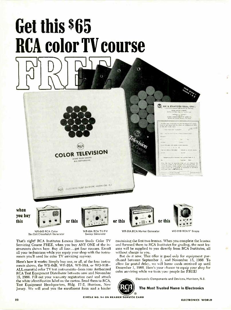
That's right! RCA Institutes famous Home Study Color TVServicing Course FREE, when you buy ANY ONE of the in-struments shown here. Buy all four... get four courses. Enrollall your technicians while you equip your shop with the instru-ments you'll need for color TV servicing anyway.Here's how it works: Simply buy one, or all, of the four instru-ments shown, the WR-64B, WR-69A, WR-99A, or WO-91B-ALL essential color TV test instruments-from your AuthorizedRCA Test Equipment Distributor between now and November15, 1966. Fill out your warranty registration card and attachthe white identification label on the carton. Send them to RCA,Test Equipment Headquarters, Bldg. 17-2, Harrison, NewJersey. We will send you the enrollment form and a binder
or this
1,1,0 aftf,of:
i,giArsr. DV,
- -4vii&..) )
1.
or this3,
WR-99A RCA Marker Generator WO -91B RCA 5" Scope
containing the first two lessons. When you complete the lessonsand forward them to RCA Institutes for grading, the next les-sons will be supplied to you directly from RCA Institutes, allwithout charge to you.
But do it now. This offer is good only for equipment pur-chased between September 1, and November 15, 1966. Toallow for postal delay, we will honor cards received up untilDecember 1, 1966. Here's your chance to equip your shop forcolor servicing while we train your people for FREE!
Electronic Components and Devices, Harrison, N.J.
The Most Trusted Name in Electronics
22CIRCLE NO. 94 ON READER SERVICE CARD
ELECTRONICS WORLD
integratedCircuitsBy B.V. VONDERSCHMITT and R.L. SANQUINIRCA Electronic Components & Devices
The circuit engineer who is designing consumer productsmust now change his way of thinking in order to includethe use of integrated circuits. Here are some practicalground rules to follow in the design of such equipment.
URING the initial stages of integrated -circuit develop-ment, most of the effort was directed toward the de-sign of digital circuits. Within the past three years,
however, both equipment -design engineers and integrated -
circuit applications engineers have been working diligentlyto design circuits for linear applications. One of the majordifficulties has been the development of linear circuits whichare economical in equipment use yet sufficiently flexible inapplication to permit their employment in many differenttypes of equipment in which the actual functions may differgreatly. Because the development cost of a circuit from in-ception to successful production is substantial (primarily inengineering manpower), a sufficient production quantity toamortize development cost is required.
A rather wide variety of linear circuits are currently avail-able as "off -the -shelf' items. Although many of these cir-cuits were designed and developed for specific applications,there is also an impressive list of linear circuits with a broadbase of application. (For further details, refer to the article"Linear Integrated Circuits: What's Available?" in thisissue.-Editors)
The use of linear integrated circuits in equipment haslagged digital use by approximately three years. Fig. 1
shows a projection of linear -circuit applications from 1965through 1970. To a large extent, the rate of growth will bea sharp function of the acceptance of linear integrated cir-cuits in the consumer market because the design time frominception to full production is at least twice as long formilitarized as for consumer equipment.
There has been much speculation about the future of thecircuit or equipment -design engineer and his role in inte-grated -circuit evolution. In the digital field, there is littledoubt that the circuit engineer's role will be changed ratherdramatically over the next decade. He will almost certainlybe working with "off -the -shelf" gates (flip-flops) which al-ready exist as standard items in combinations of low powerand low switching speed to higher power and ultra -highswitching speeds. The low cost of these standard items willtend to force equipment manufacturers to use existingtypes rather than design their own and incur the expense ofdeveloping and "debugging" new circuits for which theycannot demand sufficient volume to provide low cost.Large-scale integrated arrays will further change the role ofthe digital -circuit engineer.
In the linear field, however, the future is not so clear.Because communications equipment (commercial or mili-tary) demands a wide variety of circuits, there tends to bea conflict between the most economical design, i.e., morefunctions within one package intended for a specific appli-cation, and the simpler single -function design which can beused in a large number of different applications.
To fulfill his new role in the integrated -circuit field, thecircuit engineer must become familiar with the "groundrules" that are used to design circuits suitable for integra-tion. Many of the ground rules are dictated by cost consid-erations. To design circuits, however, the engineer must befamiliar with the list of basic components, their characteris-tics and the variation of these characteristics within the nor -
November, 1966 23
mal production processes, and the trade-offs of closer toler-ances on characteristics and the reduction in yield thatthese tolerances will cause.
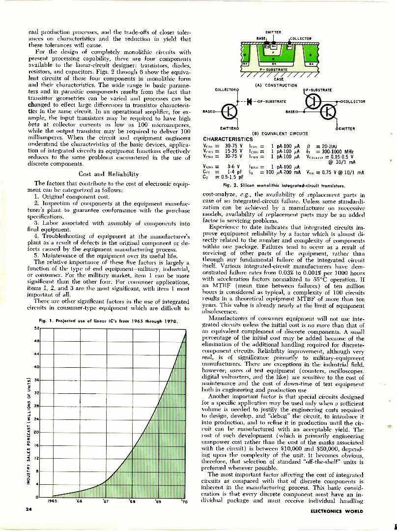
For the design of completely monolithic circuits withpresent processing capability, there are four componentsavailable to the linear -circuit designer: transistors, diodes,resistors, and capacitors. Figs. 2 through 6 show the equiva-lent circuits of these four components in monolithic formand their characteristics. The wide range in basic parame-ters and in parasitic components results from the fact thattransistor geometries can be varied and processes can bechanged to effect large differences in transistor characteris-tics in the same circuit. In an operational amplifier, for ex-ample, the input transistors may be required to have highbeta at collector currents as low as 100 microamperes,while the output transistor may be required to deliver 100milliamperes. When the circuit and equipment engineersunderstand the characteristics of the basic devices, applica-tion of integrated circuits in equipment functions effectivelyreduces to the same problems encountered in the use ofdiscrete components.
Cost and ReliabilityThe factors that contribute to the cost of electronic equip-
ment can be categorized as follows:1. Original component cost.2. Inspection of components at the equipment manufac-
turer's plant to guarantee conformance with the purchasespecifications.
3. Labor associated with assembly of components intofinal equipment.
4. Troubleshooting of equipment at the manufacturer'splant as a result of defects in the original component or de-fects caused by the equipment manufacturing process.
5. Maintenance of the equipment over its useful life.The relative importance of these five factors is largely a
function of the type of end equipment-military, industrial,or consumer. For the military market, item 1 can be moresignificant than the other four. For consumer applications,items 1, 2, and 3 are the most significant, with item 1 mostimportant of all.
There are other significant factors in the use of integratedcircuits in consumer -type equipment which are difficult to
Fig. 1. Projected use of linear IC's from 1965 through 1970.52
48
44
40
36
32
28
24
20
16
12
8
1965 67 68 69 70
COLLECTOR
EMITTER
BASE COLLECTOR
CASE
(A) CONSTRUCTION
--OP-SUBSTRATE
BASED I E I BASE
P -SUBSTRATE
COLLECTOR
EMITTER EMITTER
(B) EQUIVALENT CIRCUITSCHARACTERISTICSVcio = 30-75 V Icro = 1 pA-100 µA = 20-2UUVelio = 15-35 V icE0 = 1 pA-100 AA IT = 300-1000 MHzVero = 30-75 V lcBo = 1 pA-100 µA VCE( ea t = 0.15-0.5 V
@ 10/1 mAV.80 = 3-6 V IEB0 = 1 pA-100 ILACc, = 1-4 pF IQ = 100 PA -200 mA YBE = 0.75 V @ 10/1 mACc = 0.5-1.5 pF
Fig. 2. Silicon monolithic integrated -circuit transistors.
cost -analyze, e.g., the availability of replacement parts incase of an integrated -circuit failure. Unless some standardi-zation can be achieved by a manufacturer on successivemodels, availability of replacement parts may be an addedfactor in servicing problems.
Experience to date indicates that integrated circuits im-prove equipment reliability by a factor which is almost di-rectly related to the number and complexity of componentswithin one package. Failures tend to occur as a result ofservicing of other parts of the equipment, rather thanthrough any fundamental failure of the integrated circuititself. Various integrated -circuit manufacturers have dem-onstrated failure rates from 0.03% to 0.001% per 1000 hourswith acceleration factors normalized to 55°C operation. Ifan MTBF (mean time between failures) of ten millionhours is considered as typical, a complexity of 100 circuitsresults in a theoretical equipment MTBF of more than tenyears. This value is already nearly at the limit of equipmentobsolescence.
Manufacturers of consumer equipment will not use inte-grated circuits unless the initial cost is no more than that ofan equivalent complement of discrete components. A smallpercentage of the initial cost may be added because of theelimination of the additional handling required for discrete -
component circuits. Reliability improvement, although veryreal, is of significance primarily to military -equipmentmanufacturers. There are exceptions in the industrial field,however; users of test equipment (counters, oscilloscopes,digital voltmeters, and the like) are sensitive to the cost ofmaintenance and the cost of down -time of test equipmentboth in engineering and production use.
Another important factor is that special circuits designedfor a specific application may be used only when a sufficientvolume is needed to justify the engineering costs requiredto design, develop, and "debug" the circuit, to introduce itinto production, and to refine it in production until the cir-cuit can be manufactured with an acceptable yield. Thecost of such development (which is primarily engineeringmanpower cost rather than the cost of the masks associatedwith the circuit) is between $10,000 and $50,000, depend-ing upon the complexity of the unit. It becomes obvious,therefore, that selection of standard "off -the -shelf" units ispreferred wherever possible.
The most important factor affecting the cost of integratedcircuits as compared with that of discrete components isinherent in the manufacturing process. This basic consid-eration is that every discrete component must have an in-dividual package and must receive individual handling
24 ELECTRONICS WORLD
6
A C 8
CASE
B
P - SUBSTRATE*
CASE
(A) CONSTRUCTION
P-SUBSTRATEo6P-SUBSTRATE(B) EQUIVALENT CIRCUITS
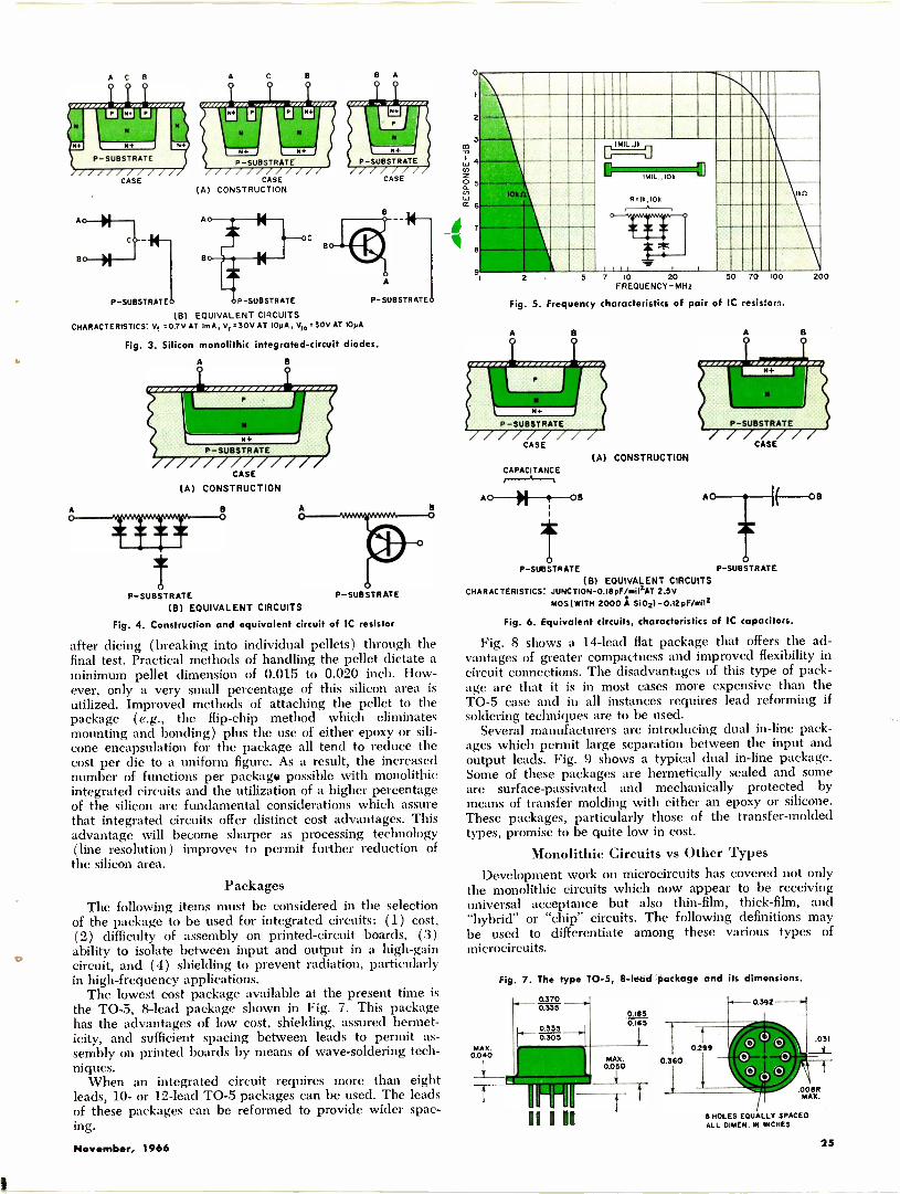
CHARACTERISTICS: Vf =0.7V AT ImA, Vr =30V AT IOWA, V10 -30V AT 10pA
Fig. 3. Silicon monolithic integrated -circuit diodes.
A
CASE
(A) CONSTRUCTION
B
A
CASE
A
P -SUBSTRATE
B
P -SUBSTRATE P -SUBSTRATE
(B) EQUIVALENT CIRCUITS
Fig. 4. Construction and equivalent circuit of IC resistor
after dicing (breaking into individual pellets) through thefinal test. Practical methods of handling the pellet dictate aminimum pellet dimension of 0.015 to 0.020 inch. How-ever, only a very small percentage of this silicon area isutilized. Improved methods of attaching the pellet to thepackage (e.g., the flip -chip method which eliminatesmounting and bonding) plus the use of either epoxy or sili-cone encapsulation for the package all tend to reduce thecost per die to a uniform figure. As a result, the increasednumber of functions per package possible with monolithicintegrated circuits and the utilization of a higher percentageof the silicon are fundamental considerations which assurethat integrated circuits offer distinct cost advantages. Thisadvantage will become sharper as processing technology(line resolution) improves to permit further reduction ofthe silicon area.
PackagesThe following items must be considered in the selection
of the package to be used for integrated circuits: (1) cost,(2) difficulty of assembly on printed -circuit boards, (3)
o ability to isolate between input and output in a high -gaincircuit, and (4) shielding to prevent radiation, particularlyin high -frequency applications.
The lowest cost package available at the present time isthe TO -5, 8 -lead package shown in Fig. 7. This packagehas the advantages of low cost, shielding, assured hermet-icity, and sufficient spacing between leads to permit as-sembly on printed boards by means of wave -soldering tech-niques.
When an integrated circuit requires more than eightleads, 10- or 12 -lead TO -5 packages can be used. The leadsof these packages can be reformed to provide wider spac-ing.
2
3co
4
Oz
0.
9
Ik
E
C M11 .10k 2Hun R 9k, i0k
!kit
I Ill i !
AO
2 5 7 10 20FREQUENCY -MHz
Fig. 5. Frequency characteristics of pair of IC resistor:.
CASE
CAPACITANCE
OB
(A) CONSTRUCTION
50 70 100
CASE
200
OS
P -SUBSTRATE P -SUBSTRATE
(B) EQUIVALENT CIRCUITSCHARACTERISTICS: JUNCTION-0.18pF/mi1iAT 2.5V
MOS(WITH 2000 A S105)-0.12pF/mil2
Fig. 6. Equivalent circuits, characteristics of IC capacitors.
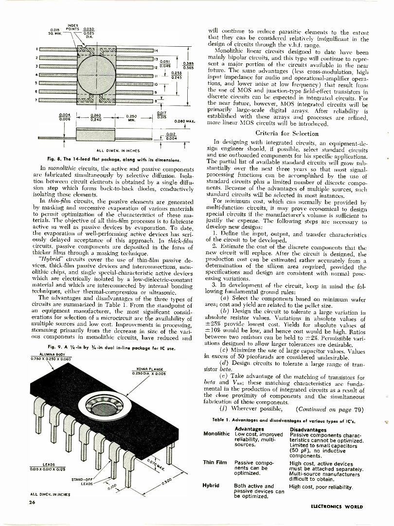
Fig. 8 shows a 14 -lead flat package that offers the ad-vantages of greater compactness and improved flexibility incircuit connections. The disadvantages of this type of pack-age are that it is in most cases more expensive than theTO -5 case and in all instances requires lead reforming ifsoldering techniques are to be used.
Several manufacturers are introducing dual in -line pack-ages which permit large separation between the input andoutput leads. Fig. 9 shows a typical dual in -line package.Some of these packages are hermetically sealed and someare surface-passivated and mechanically protected bymeans of transfer molding with either an epoxy or silicone.These packages, particularly those of the transfer -moldedtypes, promise to be quite low in cost.
Monolithic Circuits vs Other TypesDevelopment work on microcircuits has covered not only
the monolithic circuits which now appear to be receivinguniversal acceptance but also thin-film, thick -film, and"hybrid" or "chip" circuits. The following definitions maybe used to differentiate among these various types ofmicrocircuits.
MAX.0.040
Fig. 7. The type TO -5, 8 -lead package and its dimensions.
0.3700.335
0.335 H0.305
MAX0.050
I- 0i! 11 1111
a o n DO
0.1850.165
(-8 HOLES EQUALLY SPACEDAl L DIMEN. IN INCHES
November, 1966 25
INDEX
0.015 POINTS 0.030SQ. MIN
2f
31
4 1-5 1
61
71
0 0040.006
1
0.025DIA.
14
113 o.051 0.36512 0.049 0.365
0.2550.245n
9
_L-J
0.2600.240
0.250MIN.
0.0170.015
0.090iMAX.
ALL DIMEN. IN INCHES
0.012r 0.004
t
Fig. 8. The 14 -lead flat package, along with its dimensions.
In monolithic circuits, the active and passive componentsare fabricated simultaneously by selective diffusion. Isola-tion between circuit elements is obtained by a single diffu-sion step which forms back-to-back diodes, conductivelyisolating these elements.
In thin-film circuits, the passive elements are generatedby masking and successive evaporation of various materialsto permit optimization of the characteristics of these ma-terials. The objective of all thin-film processes is to fabricateactive as well as passive devices by evaporation. To date,the evaporation of well -performing active devices has seri-ously delayed acceptance of this approach. In thick -filmcircuits, passive components are deposited in the form ofthicker films through a masking technique.
"Hybrid" circuits cover the use of thin-film passive de-vices, thick -film passive devices and interconnections, mon-olithic chips, and single special -characteristic active deviceswhich are electrically isolated by a low -dielectric -constantmaterial and which are interconnected by internal bondingtechniques, either thermal -compression or ultrasonic.
The advantages and disadvantages of the three types ofcircuits are summarized in Table 1. From the standpoint ofan equipment manufacturer, the most significant consid-erations for selection of a microcircuit are the availability ofmultiple sources and low cost. Improvements in processing,stemming primarily from the decrease in size of the vari-ous components in monolithic circuits, have reduced and
Fig. 9. A 1/4 -in by 3/4 -in dual in -line package for IC use.ALUMINA BODY
0.750 X 0.250 X 0.060
'yeLEADS
0.015 X 0.010 X 0.125
STAND-OFF/LEADS 00
ALL DIMEN. IN INCHES
26
KOVAR FLANGE0.250 DIA. X 0.009
will continue to reduce parasitic elements to the extentthat they can be considered relatively insignificant in thedesign of circuits through the v.h.f. range.
Monolithic linear circuits designed to date have beenmainly bipolar circuits, and this type will continue to repre-sent a major portion of the circuits available in the nearfuture. The same advantages (less cross -modulation, highinput impedance for audio and operational -amplifier opera-tions, and lower noise at low frequency) that result fromthe use of MOS and junction -type field-effect transistors indiscrete circuits can be expected in integrated circuits. Forthe near future, however, MOS integrated circuits will beprimarily large-scale digital arrays. After reliability isestablished with these arrays and processes are refined,more linear MOS circuits will be introduced.
Criteria for SelectionIn designing with integrated circuits, an equipment -de-
sign engineer should, if possible, select standard circuitsand use outboarded components for his specific applications.The partial list of available standard circuits will grow sub-stantially over the next three years so that most signal -processing functions can be accomplished by the use ofstandard circuits plus a limited number of discrete compo-nents. Because of the advantages of multiple sources, suchstandard circuits will be selected in most instances.
For minimum cost, which can normally be provided bymulti -function circuits, it may prove economical to designspecial circuits if the manufacturer's volume is sufficient tojustify the expense. The following steps are necessary todevelop new designs:
1. Define the input, output, and transfer characteristicsof the circuit to be developed.
2. Estimate the cost of the discrete components that thenew circuit will replace. After the circuit is designed, theproduction cost can be estimated rather accurately from adetermination of the silicon area required, provided thespecifications and design are consistent with normal proc-essing variations.
3. In development of the circuit, keep in mind the fol-lowing fundamental ground rules:
(a) Select the components based on minimum waferarea; cost and yield are related to the pellet size.
(b) Design the circuit to tolerate a large variation inabsolute resistor values. Variations in absolute values of±25% provide lowest cost. Yields for absolute values of-.10% would be low, and hence cost would be high. Ratiosbetween two resistors can be held to ±2%. Permissible vari-ations designed to allow larger tolerances are desirable.
(c) Minimize the use of large capacitor values. Valuesin excess of 50 picofarads are considered undesirable.
(d) Design circuits to tolerate a large range of tran-sistor beta.
(e) Take advantage of the matching of transistors forbeta and V96; these matching characteristics are funda-mental in the production of integrated circuits as a result ofthe close proximity of components and the simultaneousfabrication of these components.
(f) Wherever possible, (Continued on page 79)
Table I. Advantages and disadvantages of various types of IC's.
AdvantagesMonolithic Low cost, improved
reliability, multi -sources.
Thin Film Passive compo-nents can beoptimized.
Hybrid Both active andpassive devices canbe optimized.
DisadvantagesPassive components charac-teristics cannot be optimized.Limited to small capacitors(50 pF), no inductivecomponents.High cost, active devicesmust be attached separately.Multi -source manufacturersdifficult to obtain.High cost, poor reliability.
ELECTRONICS WORLD
Line -OperatedTransistorTV Sets: MagnavoxBy WALTER H. BUCHSBAUM
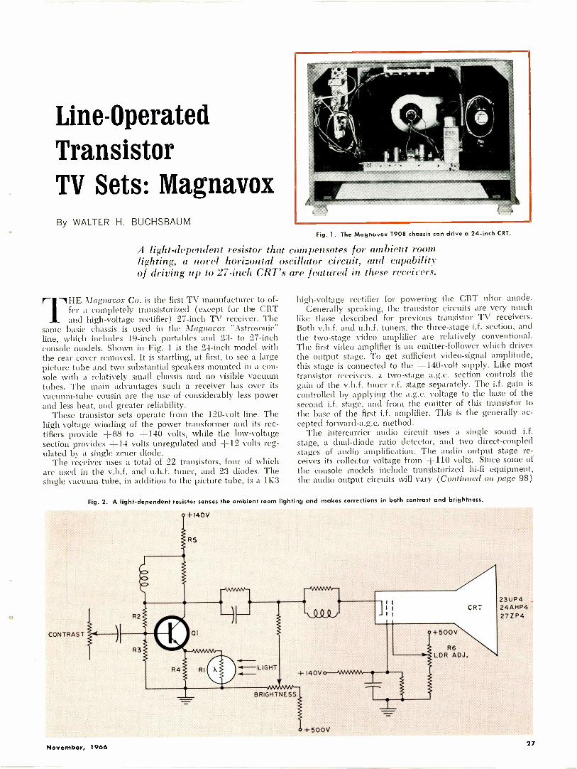
Fig. 1. The Magnavox 1908 chassis can drive a 24 -inch CRT.
A light -dependent resistor that compensates for ambient roomlighting, a novel horizontal oscillator circuit, and capabilityof driving up to 27 -inch CRT's are featured in these receivers.
TIIE Magnavox Co. is the first TV manufacturer to of-fer a completely transistorized (except for the CRTand high -voltage rectifier) 27 -inch TV receiver. The
same basic chassis is used in the Magnavox "Astrosonic"line, which includes 19 -inch portables and 23- to 27 -inchconsole models. Shown in Fig. 1 is the 24 -inch model withthe rear cover removed. It is startling, at first, to see a largepicture tube and two substantial speakers mounted in a con-sole with a relatively small chassis and no visible vacuumtubes. The main advantages such a receiver has over itsvacuum -tube cousin are the use of considerably less powerand less heat, and greater reliability.
These transistor sets operate from the 120 -volt line. Thehigh -voltage winding of the power transformer and its rec-tifiers provide +68 to +140 volts, while the low -voltagesection provides +14 volts unregulated and +12 volts reg-ulated by a single zener diode.
The receiver uses a total of 22 transistors, four of whichare used in the v.h.f. and u.h.f. tuner, and 23 diodes. Thesingle vacuum tube, in addition to the picture tube, is a 1K3
high -voltage rectifier for powering the CRT ultor anode.Generally speaking, the transistor circuits are very much
like those described for previous transistor TV receivers.Both v.h.f. and u.h.f. tuners, the three -stage i.f. section, andthe two -stage video amplifier are relatively conventional.The first video amplifier is an emitter -follower which drivesthe output stage. To get sufficient video -signal amplitude,this stage is connected to the +140 -volt supply. Like mosttransistor receivers, a two -stage a.g.c. section controls thegain of the v.h.f. tuner r.f. stage separately. The i.f. gain iscontrolled by applying the a.g.c. voltage to the base of thesecond i.f. stage, and from the emitter of this transistor tothe base of the first i.f. amplifier. This is the generally ac-cepted forward-a.g.c. method.
The intercarrier audio circuit uses a single sound i.f.stage, a dual -diode ratio detector, and two direct -coupledstages of audio amplification. The audio output stage re-ceives its collector voltage from +110 volts. Since some ofthe console models include transistorized hi-fi equipment,the audio output circuits will vary (Continued on page 98)
Fig. 2. A light -dependent resistor senses the ambient room lighting and makes corrections in both contrast and brightness.
CONTRAST
\c>
R2
R3
-NWVOA.-
vYsIsts#v`
\00(ii.
÷140V
BRIGHTNESS
+500V
+500V
R6LDR ADJ.
CRT23UP424AHP42721)4
November, 1966 27
RECENT
DEVELOPMENTS
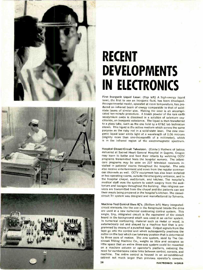
IN ELECTRONICSFirst Inorganic Liquid Laser. (Top left) A high-energy liquidlaser, the first to use an inorganic fluid, has been developed.An experimental model, operated at room temperature, has pro-duced an infrared beam of energy comparable to that of solid-state lasers of similar size. Making the laser is an uncompli-cated ten-minute procedure. A bluish powder of the rare earthneodymium oxide is dissolved in a solution of selenium oxy-chloride, an inorganic substance. The liquid is then transferredto a glass tube, such as the one held by a GT&E lab technicianshown. This liquid is the active medium which serves the samepurpose as the ruby rod in a solid-state laser. The new inor-ganic liquid laser emits light at a wavelength of 1.06 microns(slightly more than one -thousandth of a millimeter), whichis in the infrared region of the electromagnetic spectrum.
Hospital Closed -Circuit Television. (Center) Mothers of babiesdelivered at Sacred Heart General Hospital in Eugene, Oregonmay learn to bathe and feed their infants by watching CCTVprograms transmitted from the hospital nursery. The infant -care programs may be seen on 227 television receivers in-stalled in patients' rooms throughout the hospital. The setsalso receive entertainment and news from the regular commer-cial channels as well. CCTV equipment has also been installedin two operating rooms, outside the emergency entrance, and inthe hospital chapel, auditorium, and kitchen. The hospital'smedical staff uses the system to watch surgery from the audi-torium and lounges throughout the building. Also religious ser-vices are transmitted from the chapel and the patients can seetheir meals being prepared in the hospital's kitchen. The closed-circuit TV system was designed and manufactured by Sylvania.
Machine -Tool Control Uses IC's. (Bottom left) Many integrated -
circuit elements like the one in the foreground beside the dimeare used in a new numerical contouring control system. Thissingle, tiny, integrated circuit is the equivalent of the circuitboard in the background which was used in an earlier system.In numerical contouring, material such as metal or wood, isautomatically cut and shaped by a machine tool that is pro-grammed by means of a punched tape. Output signals from thetape go into the control unit which subsequently positions thecutter on the tool which can take any positicn that is determinedby three axes of motion. The new system, used by The Cin-cinnati Milling Machine Co., weighs so little and occupies solittle space that an entire three -axis system could be mountedon a machine column or operator's platform, reducing theneed for cumbersome cable links between control, console, andmachine. The entire control is housed in an air-conditionedcabinet not much larger than previous operator's console.28 ELECTRONICS WORLD
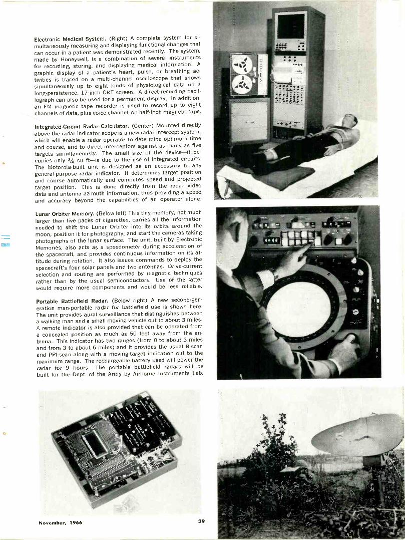
Electronic Medical System. (Right) A complete system for si-multaneously measuring and displaying functional changes thatcan occur in a patient was demonstrated recently. The system,made by Honeywell, is a combination of several instrumentsfor recording, storing, and displaying medical information. A
graphic display of a patient's heart, pulse, or breathing ac-tivities is traced on a multi -channel oscilloscope that showssimultaneously up to eight kinds of physiological data on along -persistence, 17 -inch CRT screen. A direct -recording oscil-
lograph can also be used for a permanent display. In addition,an FM magnetic tape recorder is used to record up to eightchannels of data, plus voice channel, on half -inch magnetic tape.
Integrated -Circuit Radar Calculator. (Center) Mounted directlyabove the radar indicator scope is a new radar intercept system,which will enable a radar operator to determine optimum timeand course, and to direct interceptors against as many as fivetargets simultaneously. The small size of the device-it oc-cupies only 3/4 cu ft-is due to the use of integrated circuits.The Motorola -built unit is designed as an accessory to anygeneral-purpose radar indicator. It determines target positionand course automatically and computes speed and projectedtarget position. This is done directly from the radar videodata and antenna azimuth information, thus providing a speed
and accuracy beyond the capabilities of an operator alone.
Lunar Orbiter Memory. (Below left) This tiny memory, not muchlarger than five packs of cigarettes, carries all the informationneeded to shift the Lunar Orbiter into its orbits around the
moon, position it for photography, and start the cameras takingphotographs of the lunar surface. The unit, built by ElectronicMemories, also acts as a speedometer during acceleration ofthe spacecraft, and provides continuous information on its at-titude during rotation. It also issues commands to deploy thespacecraft's four solar panels and two antennas. Drive -currentselection and routing are performed by magnetic techniquesrather than by the usual semiconductors. Use of the latterwould require more components and would be less reliable.
Portable Battlefield Radar. (Below right) A new second -gen-eration man -portable radar for battlefield use is shown here.The unit provides aural surveillance that distinguishes betweena walking man and a small moving vehicle out to about 3 miles.A remote indicator is also provided that can be operated froma concealed position as much as 50 feet away from the an-tenna. This indicator has two ranges (from 0 to about 3 milesand from 3 to about 6 miles) and it provides the usual B -scanand PPI-scan along with a moving -target indication out to themaximum range. The rechargeable battery used will power theradar for 9 hours. The portable battlefield radars will be
built for the Dept. of the Army by Airborne Instruments Lab.
November, 1966 29
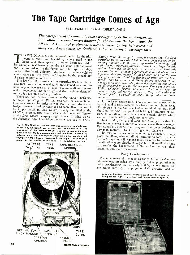
The Tape Cartridge Comes of AgeBy LEONARD COPLEN & ROBERT JOHNS
The emergence of the magnetic tape cartridge may be the most importantinnovation in musical entertainment for the car and the home since theLP record. Dozens of equipment makers are now offering their wares, andmany record companies are duplicating their libraries in cartridge form.
TRADITIONALLY, entertainment media like the pho-nograph, radio, and television, have started in thehome and then spread to other locations. Radio,
for example, first became popular as home entertainmentand then moved out to the family car. The tape cartridge,on the other hand, although introduced in home machinesa few years ago, was given real impetus by the availabilityof cartridge players for the car.
The heart of the system is the cartridge itself, a plasticcase that holds a single reel of ;4" tape joined in a contin-uous loop or two reels of le" tape in a conventional reel-to-reel arrangement. The cartridge and the machine designedto play it make up a cartridge system.
There are two leading systems on the market. Both use34" tape, operating at 3i ips, recorded in conventionaltwo -track stereo. In order to put more music into a car-tridge, however, both systems record more than one set oftracks per cartridge. One system, usually identified as theFidelipac system, uses four tracks while the other (knownas the Lear system) employs eight tracks. In other words,the Fidelipac 4 -track cartridge contains two sets of tracks,
Fig. 1. The Fidelipac ITeleProl cartridge consists of a single reelof specially lubricated tape arranged as a continuous loop. Thetape comes off the center of the reel and moves around the tapeguide and past the two pressure pads and tape head. It then goesbetween pinch roller and capstan which are on the tape deck andengage the tape through openings in cartridge. The tape thenreturns to the outside of the tape reel, completing the loop.
1/4" TAPE3-3/4 IPS
TAPE TAPE RETAINERREEL SPRING
OPENING FOR TAPE HEAD TAPEPINCH ROLLER OPENING GUIDE
CAPSTAN PRESSUREOPENING PADS
30 ELECTRONICS WORLD
Editor's Note: As we go to press, it appears that the Learcartridge system described below has a good chance of be-coming number 1 in the auto tape -cartridge market. Andwith the fast -increasing library of 8 -track cartridges for thissystem, home use would seem to be assured. At least thiswas the feeling of many observers at a recent all -industrytape -cartridge conference held in Chicago. Some of the rea-sons given are that Ford has decided to stick with the Learsystem, and Chevrolet and Plymouth are expected to an-nounce it for next year. Also, the major recording companiesare all expected to join the 8 -track fold. Don't count out thePhilips (Norelco) system, however, which is expected tomake a strong bid for this market. If they can't make it inthe auto field, they should do well in the portable and homemarkets.
while the Lear carries four. The average music content inboth 4- and 8 -track systems has been running about 40 to50 minutes, or the equivalent of a record album (althoughthe Lear cartridge is capable of holding 80 minutes of mu-sic). In addition, there is a mono 4 -track library whichcontains four bands of music per cartridge.
(Incidentally, the use of Lear and Fidelipac as descrip-tive terms is more a matter of convenience than accuracy.
that owns Fidelipac,also manufactures 8 -track cartridges and players.)
The question arises as to whether one system will sup-plant the others, whether all will continue to coexist, wheth-er another system will replace them. In order to understandthe situation more clearly, it might be well worth the timeto describe the background of the various systems, theirstrengths, and their weaknesses.
Early DevelopmentsThe emergence of the tape cartridge for musical enter-
tainment was preceded by a long period of preparation inradio broadcasting. In the early 1960's, radio stations be-gan using cartridges to program their growing load of
A pair of Fidelipac 300 -ft cartridges are shown here prior tobeing loaded with 4 -track tape and before label is applied.
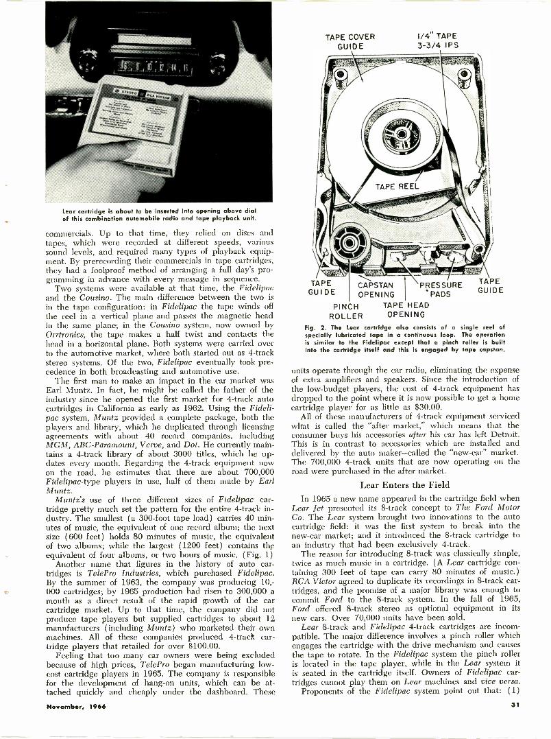
Lear cartridge is about to be inserted into opening above dialof this combination automobile radio and tape playback unit.
commercials. Up to that time, they relied on discs andtapes, which were recorded at different speeds, varioussound levels, and required many types of playback equip-ment. By prerecording their commercials in tape cartridges,they had a foolproof method of arranging a full day's pro-gramming in advance with every message in sequence.
Two systems were available at that time, the Fidelipacand the Cousin. The main difference between the two isin the tape configuration: in Fidelipac the tape winds offthe reel in a vertical plane and passes the magnetic headin the same plane; in the Cousin system, now owned byOrrtronics, the tape makes a half twist and contacts thehead in a horizontal plane. Both systems were carried overto the automotive market, where both started out as 4 -trackstereo systems. Of the two, Fidelipac eventually took pre-cedence in both broadcasting and automotive use.
The first man to make an impact in the car market wasEarl Muntz. In fact, he might be called the father of theindustry since he opened the first market for 4 -track autocartridges in California as early as 1962. Using the Fideli-pac system, Muntz provided a complete package, both theplayers and library, which he duplicated through licensingagreements with about 40 record companies, includingMGM, ABC -Paramount, Verve, and Dot. He currently main-tains a 4 -track library of about 3000 titles, which he up-dates every month. Regarding the 4 -track equipment nowon the road, he estimates that there are about 700,000Fidelipac-type players in use, half of them made by EarlMuntz.
Muntz's use of three different sizes of Fidelipac car-tridge pretty much set the pattern for the entire 4 -track in-dustry. The smallest (a 300 -foot tape load) carries 40 min-utes of music, the equivalent of one record album; the nextsize (600 feet) holds 80 minutes of music, the equivalentof two albums; while the largest (1200 feet) contains theequivalent of four albums, or two hours of music. (Fig. 1)
Another name that figures in the history of auto car-tridges is TelePro Industries, which purchased Fidelipac.By the summer of 1963, the company was producing 10,-
e 000 cartridges; by 1965 production had risen to 300,000 amonth as a direct result of the rapid growth of the carcartridge market. Up to that time, the company did notproduce tape players but supplied cartridges to about 12manufacturers (including Muntz) who marketed their ownmachines. All of these companies produced 4 -track car-tridge players that retailed for over $100.00.
Feeling that too many car owners were being excludedbecause of high prices, TelePro began manufacturing low-cost cartridge players in 1965. The company is responsiblefor the development of hang -on units, which can be at-tached quickly and cheaply under the dashboard. These
TAPE COVERGUIDE
AKATAPE CAPSTAN PRESSURE
GUIDE OPENING PADS
PINCH TAPE HEAD
ROLLER OPENING
Fig. 2. The Lear cartridge also consists of a single reel ofspecially lubricated tape in a continuous loop. The operationis similar to the Fidelipac except that a pinch roller is builtinto the cartridge itself and this is engaged by tape capstan.
1/4" TAPE3-3/4 IPS
units operate through the car radio, eliminating the expenseof extra amplifiers and speakers. Since the introduction ofthe low -budget players, the cost of 4 -track equipment hasdropped to the point where it is now possible to get a homecartridge player for as little as $30.00.
All of these manufacturers of 4 -track equipment servicedwhat is called the "after market," which means that theconsumer buys his accessories after his car has left Detroit.This is in contrast to accessories which are installed anddelivered by the auto maker-called the "new -car" market.The 700,000 4 -track units that are now operating on theroad were purchased in the after market.
Lear Enters the FieldIn 1965 a new name appeared in the cartridge field when
Lear Jet presented its 8 -track concept to The Ford MotorCo. The Lear system brought two innovations to the autocartridge field: it was the first system to break into thenew -car market; and it introduced the 8 -track cartridge toan industry that had been exclusively 4 -track.
The reason for introducing 8 -track was classically simple,twice as much music in a cartridge. (A Lear cartridge con-taining 300 feet of tape can carry 80 minutes of music.)RCA Victor agreed to duplicate its recordings in 8 -track car-tridges, and the promise of a major library was enough tocommit Ford to the 8 -track system. In the fall of 1965,Ford offered 8 -track stereo as optional equipment in itsnew cars. Over 70,000 units have been sold.
Lear 8 -track and Fidelipac 4 -track cartridges are incom-patible. The major difference involves a pinch roller whichengages the cartridge with the drive mechanism and causesthe tape to rotate. In the Fidelipac system the pinch rolleris located in the tape player, while in the Lear system itis seated in the cartridge itself. Owners of Fidelipac car-tridges cannot play them on Lear machines and vice versa.
Proponents of the Fidelipac system point out that: (1)
November, 1966 31
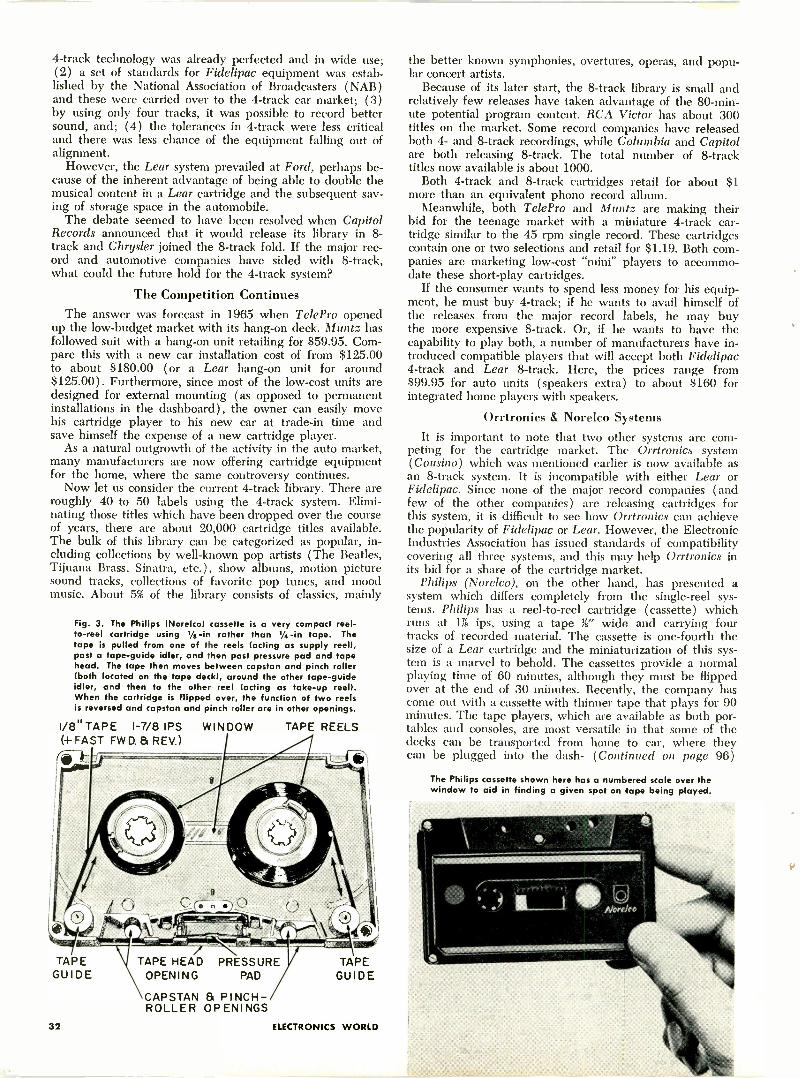
4 -track technology was already perfected and in wide use;(2) a set of standards for Fidelipac equipment was estab-lished by the National Association of Broadcasters (NAB)and these were carried over to the 4 -track car market; (3)by using only four tracks, it was possible to record bettersound, and; (4) the tolerances in 4 -track were less criticaland there was less chance of the equipment falling out ofalignment.
However, the Lear system prevailed at Ford, perhaps be-cause of the inherent advantage of being able to double themusical content in a Lear cartridge and the subsequent sav-ing of storage space in the automobile.
The debate seemed to have been resolved when CapitolRecords announced that it would release its library in 8 -track and Chrysler joined the 8 -track fold. If the major rec-ord and automotive companies have sided with 8 -track,what could the future hold for the 4 -track system?
The Competition ContinuesThe answer was forecast in 1965 when TelePro opened
up the low -budget market with its hang -on deck. Muntz hasfollowed suit with a hang -on unit retailing for $59.95. Com-pare this with a new car installation cost of from $125.00to about $180.00 (or a Lear hang -on unit for around$125.00). Furthermore, since most of the low-cost units aredesigned for external mounting (as opposed to permanentinstallations in the dashboard), the owner can easily movehis cartridge player to his new car at trade-in time andsave himself the expense of a new cartridge player.
As a natural outgrowth of the activity in the auto market,many manufacturers are now offering cartridge equipmentfor the home, where the same controversy continues.
Now let us consider the current 4 -track library. There areroughly 40 to 50 labels using the 4 -track system. Elimi-nating those titles which have been dropped over the courseof years, there are about 20,000 cartridge titles available.The bulk of this library can be categorized as popular, in-cluding collections by well-known pop artists (The Beatles,Tijuana Brass, Sinatra, etc.), show albums, motion picturesound tracks, collections of favorite pop tunes, and moodmusic. About 5% of the library consists of classics, mainly
Fig. 3. The Philips (Norelco) cassette is a very compact reel-to-reel cartridge using 1/8 -in rather than 1/4 -in tape. Thetape is pulled from one of the reels (acting as supply reel),past a tape -guide idler, and then past pressure pad and tapehead. The tape then moves between capstan and pinch roller(both located on the tape deck), around the other tape -guideidler, and then to the other reel (acting as take-up reel).When the cartridge is flipped over, the function of two reelsis reversed and capstan and pinch roller are in other openings.
1/8" TAPE 1-7/8 IPS(+ FAST FWD. a REV.)
I
TAPEGUIDE
32
WINDOW TAPE REELS
TtldTAPE HEAD PRESSURE TAPE
OPENING PAD GUIDE
CAPSTAN 3 PINCH -ROLLER OPENINGS
ELECTRONICS WORLD
the better known symphonies, overtures, operas, and popu-lar concert artists.
Because of its later start, the 8 -track library is small andrelatively few releases have taken advantage of the 80 -min-ute potential program content. RCA Victor has about 300titles on the market. Some record companies have releasedboth 4- and 8 -track recordings, while Columbia and Capitolare both releasing 8 -track. The total number of 8 -tracktitles now available is about 1000.
Both 4 -track and 8 -track cartridges retail for about $1more than an equivalent phono record album.
Meanwhile, both TelePro and Muntz are making theirbid for the teenage market with a miniature 4 -track car-tridge similar to the 45 rpm single record. These cartridgescontain one or two selections and retail for $1.19. Both com-panies are marketing low-cost "mini" players to accommo-date these short -play cartridges.
If the consumer wants to spend less money for his equip-ment, he must buy 4 -track; if he wants to avail himself ofthe releases from the major record labels, he may buythe more expensive 8 -track. Or, if he wants to have thecapability to play both, a number of manufacturers have in-troduced compatible players that will accept both Fidelipac4 -track and Lear 8 -track. Here, the prices range from$99.95 for auto units (speakers extra) to about $160 forintegrated home players with speakers.
Orrtronics & Norelco SystemsIt is important to note that two other systems are com-
peting for the cartridge market. The Orrtronics system(Cousino) which was mentioned earlier is now available asan 8 -track system. It is incompatible with either Lear orFidelipac. Since none of the major record companies (andfew of the other companies) are releasing cartridges forthis system, it is difficult to see how Orrtronics can achievethe popularity of Fidelipac or Lear. However, the ElectronicIndustries Association has issued standards of compatibilitycovering all three systems, and this may help Orrtronics inits bid for a share of the cartridge market.
Philips (Norelco), on the other hand, has presented asystem which differs completely from the single -reel sys-tems. Philips has a reel-to-reel cartridge (cassette) whichruns at 176 ips, using a tape 34" wide and carrying fourtracks of recorded material. The cassette is one-fourth thesize of a Lear cartridge and the miniaturization of this sys-tem is a marvel to behold. The cassettes provide a normalplaying time of 60 minutes, although they must be flippedover at the end of 30 minutes. Recently, the company hascome out with a cassette with thinner tape that plays for 90minutes. The tape players, which are available as both por-tables and consoles, are most versatile in that some of thedecks can be transported from home to car, where theycan be plugged into the dash- (Continued on page 96)
The Philips cassette shown here has a numbered scale over thewindow to aid in finding a given spot on tape being played.
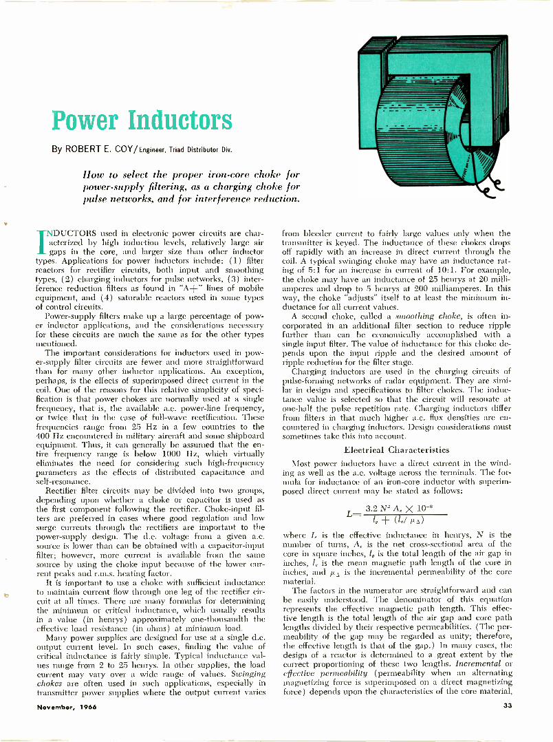
Power InductorsBy ROBERT E. COY/ Engineer, Triad Distributor Div.
How to select the proper iron -core choke forpower -supply filtering, as a charging choke forpulse networks, and for interference reduction.
raDUCTORS used in electronic power circuits are char-cterized by high induction levels, relatively large air
gaps in the core, and larger size than other inductortypes. Applications for power inductors include: (1) filterreactors for rectifier circuits, both input and smoothingtypes, (2) charging inductors for pulse networks, (3) inter-ference reduction filters as found in "A+" lines of mobileequipment, and (4) saturable reactors used in some typesof control circuits.
Power -supply filters make up a large percentage of pow-er inductor applications, and the considerations necessaryfor these circuits are much the same as for the other typesmentioned.
The important considerations for inductors used in pow-er -supply filter circuits are fewer and more straightforwardthan for many other inductor applications. An exception,perhaps, is the effects of superimposed direct current in thecoil. One of the reasons for this relative simplicity of speci-fication is that power chokes are normally used at a singlefrequency, that is, the available a.c. power -line frequency,or twice that in the case of full -wave rectification. Thesefrequencies range from 25 Hz in a few countries to the400 Hz encountered in military aircraft and some shipboardequipment. Thus, it can generally be assumed that the en-tire frequency range is below 1000 Hz, which virtuallyeliminates the need for considering such high -frequencyparameters as the effects of distributed capacitance andself -resonance.
Rectifier filter circuits may be divided into two groups,depending upon whether a choke or capacitor is used asthe first component following the rectifier. Choke -input fil-ters are preferred in cases where good regulation and lowsurge currents through the rectifiers are important to thepower -supply design. The d.c. voltage from a given a.c.source is lower than can be obtained with a capacitor -inputfilter; however, more current is available from the samesource by using the choke input because of the lower cur-rent peaks and r.m.s. heating factor.
It is important to use a choke with sufficient inductanceb to maintain current flow through one leg of the rectifier cir-
cuit at all times. There are many formulas for determiningthe minimum or critical inductance, which usually resultsin a value (in henrys) approximately one -thousandth theeffective load resistance (in ohms) at minimum load.
Many power supplies are designed for use at a single d.c.output current level. In such cases, finding the value ofcritical inductance is fairly simple. Typical inductance val-ues range from 2 to 25 henrys. In other supplies, the loadcurrent may vary over a wide range of values. Swingingchokes are often used in such applications, especially intransmitter power supplies where the output current varies
from bleeder current to fairly large values only when thetransmitter is keyed. The inductance of these chokes dropsoff rapidly with an increase in direct current through thecoil. A typical swinging choke may have an inductance rat-ing of 5:1 for an increase in current of 10:1. For example,the choke may have an inductance of 25 henrys at 20 milli-amperes and drop to 5 henrys at 200 milliamperes. In thisway, the choke "adjusts" itself to at least the minimum in-ductance for all current values.
A second choke, called a smoothing choke, is often in-corporated in an additional filter section to reduce ripplefurther than can be economically accomplished with asingle input filter. The value of inductance for this choke de-pends upon the input ripple and the desired amount ofripple reduction for the filter stage.
Charging inductors are used in the charging circuits ofpulse -forming networks of radar equipment. They are simi-lar in design and specifications to filter chokes. The induc-tance value is selected so that the circuit will resonate atone-half the pulse repetition rate. Charging inductors differfrom filters in that much higher a.c. flux densities are en-countered in charging inductors. Design considerations mustsometimes take this into account.
Electrical CharacteristicsMost power inductors have a direct current in the wind-
ing as well as the a.c. voltage across the terminals. The for-mula for inductance of an iron -core inductor with superim-posed direct current may be stated as follows:
L3.2 N2 A X 10-8
(l./where L is the effective inductance in henrys, N is thenumber of turns, A, is the net cross-sectional area of thecore in square inches, 1, is the total length of the air gap ininches, 1, is the mean magnetic path length of the core ininches, and p...% is the incremental permeability of the corematerial.
The factors in the numerator are straightforward and canbe easily understood. The denominator of this equationrepresents the effective magnetic path length. This effec-tive length is the total length of the air gap and core pathlengths divided by their respective permeabilities. (The per-meability of the gap may be regarded as unity; therefore,the effective length is that of the gap.) In many cases, thedesign of a reactor is determined to a great extent by thecorrect proportioning of these two lengths. Incremental oreffective permeability (permeability when an alternatingmagnetizing force is superimposed on a direct magnetizingforce) depends upon the characteristics of the core material,
November, 1966 33
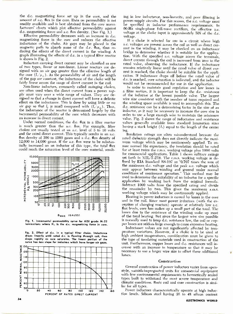
the d.c. magnetizing force set up in the core, and theamount of a.c. flux in the core. Data on permeability is notreadily available and is best obtained from the core manu-facturers' charts which plot effective permeability againstd.c. magnetizing force and a.c. flux density. (See Fig. 1.)
Effective permeability decreases with an increase in d.c.magnetizing force in the core and reduces the effectiveinductance of the choke. Air gaps may be placed in themagnetic path to absorb some of the d.c. flux, thus re-ducing the effects of the direct current in the winding. Agraph illustrating the effects of d.c. in a typical filter reactoris shown in Fig. 2.
Inductors carrying direct current may be classified as oneof two types, linear or non-linear. Linear reactors are de-signed with an air gap greater than the effective length ofthe core (l,/µ,6). As the permeability of air and the lengthof the gap are constant, the inductance of the choke will befairly linear across the range of direct current in the coil.
Non-linear inductors, commonly called swinging chokes,are often used when the direct current from a power sup-ply must vary over a wide range of values. They are de-signed so that a change in direct current will have a definiteeffect on the inductance. This is done by using little or noair gap so that 1, is small compared with (id/Ad . Thus,the inductance of the reactor is determined largely by theincremental permeability of the core which decreases withan increase in direct current.
Under normal conditions, the d.c. flux in a filter reactoris much greater than the a.c. flux. For example, filterchokes are usually tested at an a.c. level of 5 to 10 voltsand the rated direct current. This typically results in an a.c.flux density of 300 to 1000 gauss and a d.c. flux density of12,000 to 14,000 gauss. If the a.c. flux were to be substan-tially increased on an inductor of this type, the total fluxcould reach the saturation level of the core material, result-
10,000
500030002000
1000
500
300200
100
50O
immosmaionmilommamEMMUMIII=Elm.IIMMEMBIIIMM=MO
=1111111 I=MP 05
Ho - 0
,Immomeminnow-..gom vmmo
Amirapsoniau.0.7dP;11IMEN
111111111E11146111011111f,t7dialMON....021f.;;ii=1=1714;;11==
_-..sluilMIIMION11.1 IMINIIIMOMI..MM1111
0 0nrl
0O 00 00 00 0 0ri M h o
BmAx (GAUSS)
0 000
,r)
000 O
00O
OOOO
Fig. 1. Incremental permeability curve for AISI grade M-22laminations where H., is the d.c. magnetizing force in core.
Fig. 2. Effect of d.c. in a typical filter choke. Inductancedrops linearly until rated d.c. is flowing through coil, thendrops rapidly as core saturates. The linear portion of thecurve has less slope for inductors which have larger air gaps.
130
120
110
100
90
80
70
60
50020 40 60 80 100 120 140
PERCENT OF RATED DIRECT CURRENT160
ing in low inductance, non -linearity, and poor filtering inpower -supply circuits. For this reason, the a.c. voltage mustbe specified in inductor performance requirements. In60 -Hz single-phase full -wave rectifiers, the effective a.c.voltage at the choke input is approximately 50% of the d.c.voltage.
If a choke is selected for use in a circuit where higha.c. voltages are present across the coil as well as direct cur-rent in the winding, it may be checked on an inductancebridge to determine whether it is suitable for the applica-tion. With the specified a.c. voltage across the terminals,direct current through the coil is increased from zero to therated value, observing the inductance. If the inductanceremains relatively linear until the rated value of direct cur-rent is reached, the choke should be suitable for the appli-cation. If inductance drops off before the rated value ofd.c. is reached, core saturation is indicated, and the inductorwould not be recommended for use in the application.
In order to maintain good regulation and low losses ina filter section, it is important to keep the d.c. resistanceof the inductor at the lowest possible value. The largestwire size consistent with the number of turns required andthe winding space available is used to accomplish this. Thed.c. resistance can be a determining factor in the size of aninductor, as it may be necessary to increase the core size inorder to use a large enough wire to maintain the minimumvalue. Fig. 3 shows the range of inductance and resistancevalues generally available from standard lamination sizeshaving a stack height (L) equal to the length of the centerleg.
Insulation ratings are often misunderstood because therated dielectric strength does not directly indicate the maxi-mum voltage which may be continuously applied. To en-sure normal life expectancy, the insulation should be ratedfor at least twice the r.m.s. working voltage plus 1000 voltsfor commercial applications. Table 1 shows military ratingsset forth in MIL -T -27B. The r.m.s. working voltage is de-fined by EIA Standard RS -197 as "0.707 times the sum ofthe maximum d.c. voltage and the peak a.c. voltage whichmay appear between winding and ground under normalconditions of continuous operation." This method may beused to determine the suitability of an inductor for a specificapplication by working back from the original formula.Subtract 1000 volts from the specified rating and dividethe remainder by two. This gives the maximum r.m.s.working voltage which may be continuously applied.
Heating in power inductors is caused by losses in the coreand in the coil. Since most power inductors (with the ex-ception of charging reactors) operate at relatively Iow a.c.flux levels, core loss makes up a small part of the total. Thelosses due to the resistance of the winding make up mostof the total heating. But since the largest wire size possibleis normally used to keep d.c. resistance low, the coil or cop-per losses are seldom large enough to cause excessive heating.
Inductance values are not significantly affected by tem-perature variations. However, if a choke is to be used athigh ambient temperatures, consideration must be given tothe type of insulating materials used in construction of theunit. Furthermore, copper losses and d.c. resistances will in-crease with an increase in temperature so that it may benecessary to use a larger wire size to offset these additionallosses.
ConstructionGeneral construction of power inductors varies from open -
style, varnish -impregnated units for commercial equipmentwith few environmental requirements to hermetically sealedtypes built to withstand the most severe temperature andclimatic conditions. Basic coil and core construction is simi-lar for all types.
Power inductors characteristically operate at high induc-tion levels. Silicon steel having 3% to 4% silicon content
34 ELECTRONICS WORLD
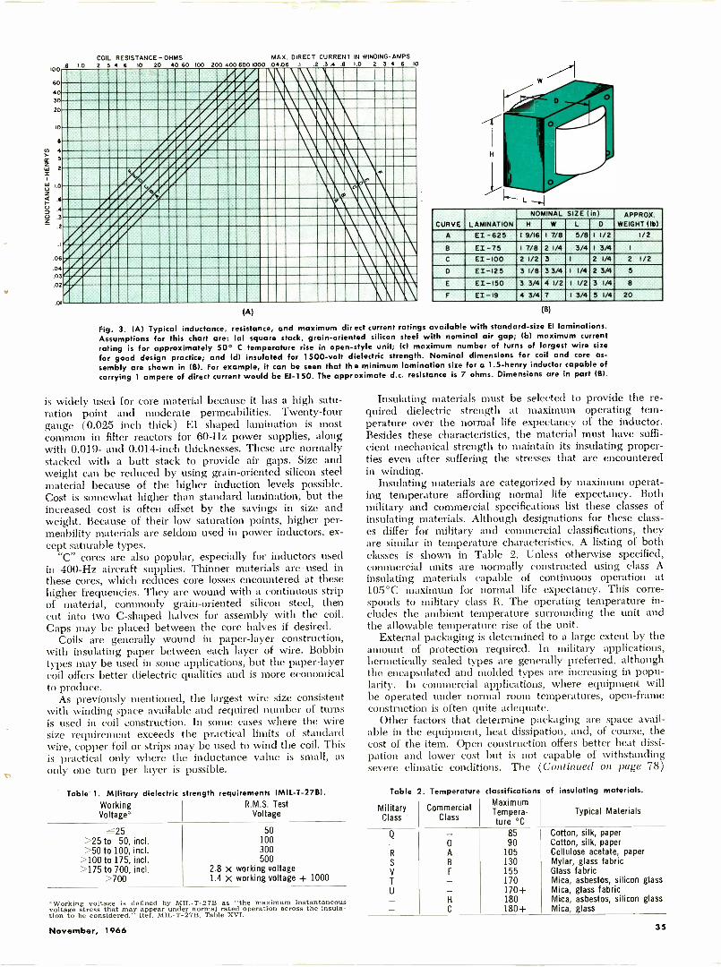
100 '6 1.0
60
4030
20
10
L/1 4>-cc 3zta 2
1.0
z
7 4,3
z
.06
04.03
.02
.01
COIL RESISTANCE -OHMS2 3 4 6 10 20 40 60 100 200 400 600 1000
MAX. DIRECT CURRENT IN WINDING -AMPS.04.06 1 .2 .3 .4 .6 I 0 2 3 4 6 10
N
CURVE LAMINATION
NOMINAL SIZE ( in) APPROX.WEIGHT (Ib)H W L D
A EI -625 1 9/16 1 7/8 5/8 1 1/2 1/2
8 EI -75 17/8 2 1/4 3/4 I 3/4 I
C EI -100 2 1/2 3 I 2 1/4 2 1/2
D EI-125 3 1/8 33/4 I 1/4 2 3/4 5
E EI-150 3 3/4 4 1/2 I 1/2 3 1/4 8
F EI-I9 4 3/4 7 1 3/4 5 1/4 20
(A) (B)
Fig. 3. (A) Typical inductance, resistance, and maximum direct current ratings available with standard -size El laminations.Assumptions for this chart are: la) square stack, grain -oriented silicon steel with nominal air gap; (b) maximum currentrating is for approximately 50° C temperature rise in open -style unit; Ic) maximum number of turns of largest wire sizefor good design practice; and (dl insulated for 1500 -volt dielectric strength. Nominal dimensions for coil and core as-sembly are shown in (B). For example, it can be seen that the minimum lamination size for a 1.5 -henry inductor capable ofcarrying 1 ampere of direct current would be El -150. The approximate d.c. resistance is 7 ohms. Dimensions are in part (B).
is widely used for core material because it has a high satu-ration point and moderate permeabilities. Twenty-fourgauge (0.025 inch thick) EI shaped lamination is mostcommon in filter reactors for 60 -Hz power supplies, alongwith 0.019- and 0.014 -inch thicknesses. These are normallystacked with a butt stack to provide air gaps. Size andweight can be reduced by using grain -oriented silicon steelmaterial because of the higher induction levels possible.Cost is somewhat higher than standard lamination, but theincreased cost is often offset by the savings in size andweight. Because of their low saturation points, higher per-meability materials are seldom used in power inductors, ex-cept saturable types.
"C" cores are also popular, especially for inductors usedin 400 -Hz aircraft supplies. Thinner materials are - used inthese cores, which reduces core losses encountered at thesehigher frequencies. They are wound with a continuous stripof material, commonly grain -oriented silicon steel, thencut into two C -shaped halves for assembly with the coil.Gaps may be placed between the core halves if desired.
Coils are generally wound in paper -layer construction,with insulating paper between each layer of wire. Bobbintypes may be used in some applications, but the paper -layercoil offers better dielectric qualities and is more economicalto produce.
As previously mentioned, the largest wire size consistentwith winding space available and required number of turnsis used in coil construction. In some cases where the wiresize requirement exceeds the practical limits of standardwire, copper foil or strips may be used to wind the coil. Thisis practical only where the inductance value is small, asonly one turn per layer is possible.
Table 1. Military dielectric strength requirements (MIL -T-2781.Working R.M.S. TestVoltage' Voltage
r 25>25 to 50, incl.>50 to 100, incl.
>100 to 175, incl.>175 to 700, incl.
>700
50100300500
2.8 x working voltage1.4 x working voltage + 1000
'Working voltage is defined by MIL -T -27B as "the maximum instantaneousvoltage stress that may appear under normal rated operation across the insula-tion to be considered." Ref. MIL -T-2713. Table XVI.
Insulating materials must be selected to provide the re-quired dielectric strength at maximum operating tem-perature over the normal life expectancy of the inductor.Besides these characteristics, the material must have suffi-cient mechanical strength to maintain its insulating proper-ties even after suffering the stresses that are encounteredin winding.
Insulating materials are categorized by maximum operat-ing temperature affording normal life expectancy. Bothmilitary and commercial specifications list these classes ofinsulating materials. Although designations for these class-es differ for military and commercial classifications, theyare similar in temperature characteristics. A listing of bothclasses is shown in Table 2. Unless otherwise specified,commercial units are normally constructed using class Ainsulating materials capable of continuous operation at105°C maximum for normal life expectancy. This corre-sponds to military class R. The operating temperature in-cludes the ambient temperature surrounding the unit andthe allowable temperature rise of the unit.
External packaging is determined to a large extent by theamount of protection required. In military applications,hermetically sealed types are generally preferred, althoughthe encapsulated and molded types are increasing in popu-larity. In commercial applications, where equipment willbe operated under normal room temperatures, open -frameconstruction is often quite adequate.
Other factors that determine packaging are space avail-able in the equipment, heat dissipation, and, of course, thecost of the item. Open construction offers better heat dissi-pation and lower cost but is not capable of withstandingsevere climatic conditions. The (Continued on page 78)
Table 2. Temperature classifications of insulating materials.
MilitaryClass
CommercialClass
Maximumpera-
ture °CTypical Materials
Q - 85 Cotton, silk, paper- 0 90 Cotton, silk, paperR A 105 Cellulose acetate, paperS B 130 Mylar, glass fabricV F 155 Glass fabricT - 170 Mica, asbestos, silicon glassU - 170+ Mica, glass fabric- H 180 Mica, asbestos, silicon glass- C 180+ Mica, glass
November, 1966 35
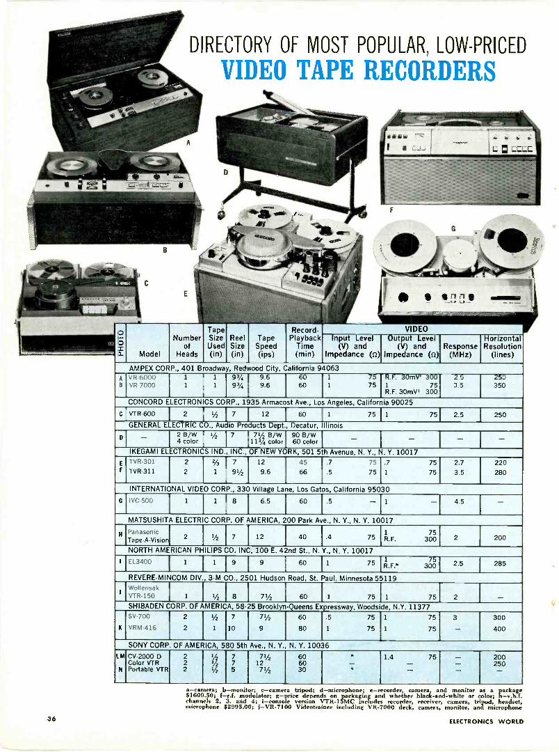
Model
DIRECTORY OF MOST POPULAR, LOW-PRICED
VIDEO TAPE RECORDERS
Numberof
Heads
TapeSizeUsed(in)
Record -Reel Tape Playback Input LevelSize Speed Time (V) and(in) (ips) (min) Impedance (Q)
AMPEX CORP., 401 Broadway, Redwood City, California 94063A VR-6000 1
B VR-7000 1
1 93/4 9.6 601 93/4 9.6 60
1
1
7575
VIDEOOutput Level Horizontal
(V) and Response ResolutionImpedance (c2) (MHz) (lines)
R.F. 30mV' 2.51 75 3.5R.F. 30mVI 300
250350
CONCORD ELECTRONICS CORP., 1935 Armacost Ave., Los Angeles, California 90025
C VTR -600 2
J1/2 7 12 60 11 75 11 75
GENERAL ELECTRIC O., Audio Products Dept. Decatur, llinois
D - 4 !OlOir I'/2
7 171V)B/W
9600
B/W
IKEGAMI ELECTRONICS IND. INC., OF NEW YORK, 501 5th Avenue, N. Y., N. Y. 10017
2.5 250
INTERNATIONAL VIDEO CORP., 330 Village Lane, Los Gatos, California 95030
G I IVC-500 I 1 1 1 1 8 I 6.5 I 60 .5 1
MATSUSHITA ELECTRIC CORP. OF AMERICA, 200 Park Ave., N. Y., N. Y. 10017
Panasonic2
Tape -A -Vision '/2 7 12 40 .4 75
NORTH AMERICAN PHILIPS CO. INC, 100 E. 42nd St., N. Y., N. Y. 10017
1 75R.F. 300
4.5
2 200
EL3400 1 1 9 9 60 1 75 R.F."75
300 2.5 285
REVEREMINCOM DIV , 3M CO., 2501 Hudson Road, St. Paul, Minnesota 55119WollensakVTR -150 1 1/2I 8 I 71/2 60
SHIBADEN CORP. OF AMERICA, 58.25 Brookl n ueens ExSV-700
VRM-416
7'/2
9
SONY CORP OF AMERICA, 580 5th Ave., N. Y.
CV -2000 DColor VTRPortable VTR
60
80
resswa , Woodside, N.Y. 11377.5
1
75
75
N. Y. 10036
1
1
75
75
3 300
400
a-camera; b-monitor; c-camera tripod; d-microphone; e-recorder, camera, and monitor as a package$1609.50; f-r.f. modulator; g-price depends on packaging and whether black -and -white or color; h-v.h.f.channels 2, 3, and 4; i-console version VTR -151'4C includes recorder, receiver, camera, tripod, headset,microphone $2995.00; j-VR-7100 Videotrainer including VR-7000 deck, camera, monitor, and microphone
36 ELECTRONICS WORLD
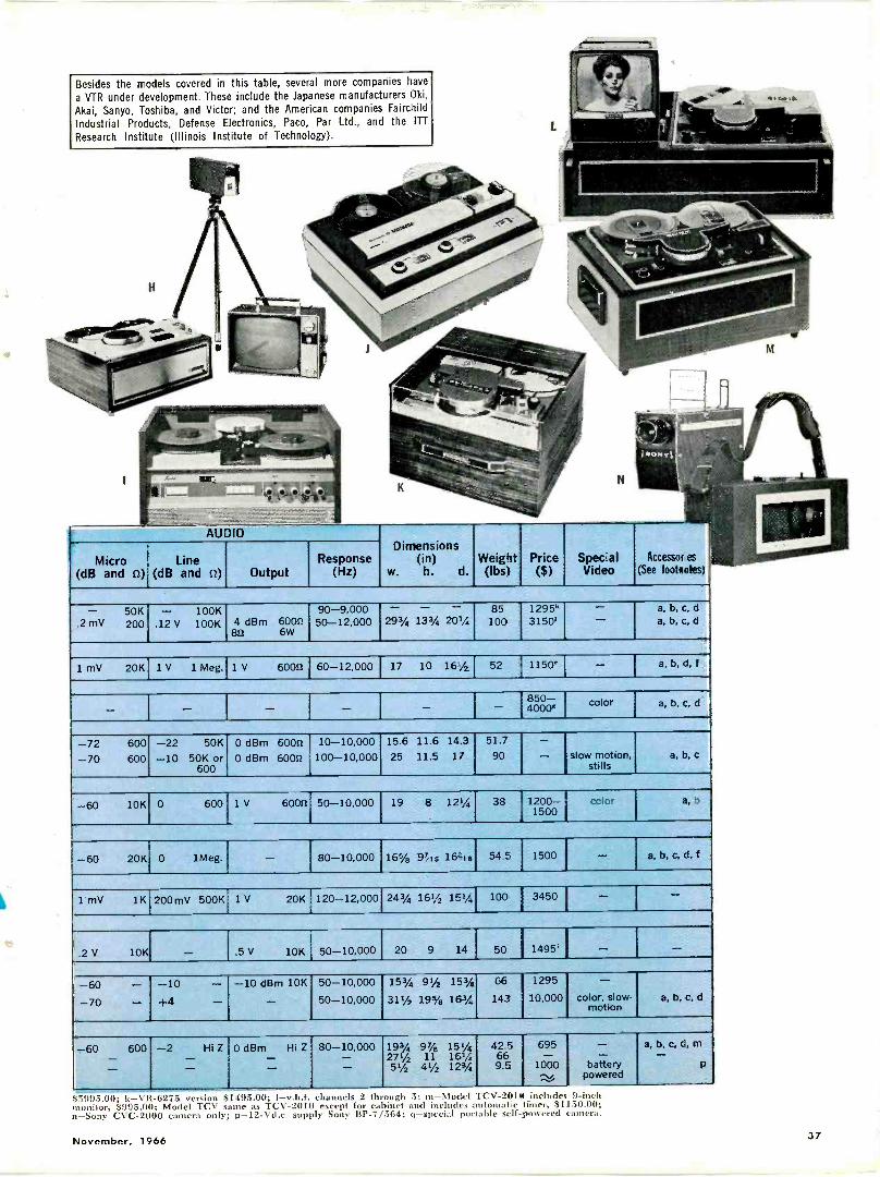
Besides the models covered in this table, several more companies havea VTR under development. These include the Japanese manufacturers Oki,
Akai, Sanyo, Toshiba, and Victor; and the American companies FairchildIndustrial Products, Defense Electronics, Paco, Par Ltd., and the ITTResearch Institute (Illinois Institute of Technology).
H
AUDIODimensions
(in)w. h. d.
WeiritOhs,
Price($)
Spec alVideo
Accessor es
(See footnotes)Micro
(dB and o)Line
(dB and o) OutputResponse
(Hz)
-.2 mV
50K200
-.12 V
100K100K 4 dBm 6000
80 6W
90-9,00050-12,000
-293/4
- -131/4 201/4
85100
1295"3150' - a, b, c, d
a, b, c, d
1 mV 20K 1 V 1 Meg. 1 V 6000 60-12,000 17 10 161/2 52 1150' - a, b, d, f
- - - - - - 850-40004
color a, b, c, d
-72-70
600
600
-22-10
50K
50K or600
0 dBm 6000 1 10-10,0000 dBm 6000 1 100-10,000
1
15.6
25
11.6 14.311.5 17
51.7
90
-- slow motion,
stillsa, b, c
-60 10K 0 600 1 V 60001 50-10,000 19 8 121/4 38 1200-1500
CCIOr a, b
-60 20K 0 1Meg ,
i -I
80-10,000 16% 97/is 16i1ir, 54.E 1500 - a, b, c, d, f
1 mV 1K 200mV 500K i 1 V 20K 1 120-12,000i
243% 161/2 1514 100 1 3450 - -
.2 V 10K - .5 V 10K 50-10,000 20 9 14 50 1495' - --60-70
--
-10+4
--
-10 dBm 10K-
50-10,00050-10,000
1531/4
311/2
91/2 151/4
19% 1631/4
66
143
1295
10,000
-color, slow-
motiona, la, c, d
-60 --600 -2 --
Hi Z 0 dBm Hi Z--80-10,000--
191/4271/251/2
97/e 151/411 161/4
411/2 121/4
42.5669.5
695-1000-..,
--battery
powered
a, b, c, d, m-p
599.5.00; k-VR-6275 version $1495.00; 1-v.h.f. channels 2 th ough 5; m-Model TCV-2014. includes 9 -inchmonitor, $995.00; Model TCV same as TCV-2010 except for cabinet and includes automatic timer, $1150.00:n-Sony CVC-2000 camera only; p-12-Vd.c. supply Sony BP -7/564; q-special portable self -powered camera.
November, 1966 37
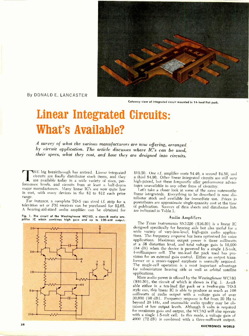
By DONALD E. LANCASTER
Cutaway view of integrated circuit mounted in 14 -lead flat pack.
Linear Integrated Circuits:What's Available?A survey of what the various manufacturers are now offering, arranged,by circuit application. The article discusses where IC's can be used,their specs, what they cost, and how they are designed into circuits.
THE big breakthrough has arrived. Linear integratedcircuits are finally distributor stock items, and theyare available today in a wide variety of sizes, per-
formance levels, and circuits from at least a half -dozenmajor manufacturers. Many linear IC's are now quite lowin cost, with many devices in the $2 to $12 each pricerange.
For instance, a complete TO -5 can sized i.f. strip for atelevision set or FM receiver can be purchased for $2.65.
A hearing -aid -sized audio amplifier can be obtained forFig. 1. The circuit of the Westinghouse WC1 83, a class -B audio am-plifier IC which combines high gain and up to 100-mW output.
$10.50. One r.f. amplifier costs $4.40, a second $4.50, anda third $4.80. Other linear integrated circuits are still veryhigh-priced, but these frequently offer performance advan-tages unavailable in any other form of circuitry.
Let's take a closer look at some of the more noteworthylinear integrateds. Everything to be described is now dis-tributor stock and available for immediate use. Prices inparentheses are approximate single -quantity cost at the timeof publication. Sources of data sheets and distributor listsare indicated in Table 1.
Audio AmplifiersThe Texas Instruments SN1220 ($16.20) is a linear IC
designed specifically for hearing aids but also useful for awide variety of very -low-level, high -gain audio applica-tions. The frequency response has been optimized for voiceapplications. Maximum output power is three milliwattsat a 5% distortion level, and total voltage gain is 16,000(84 dB) when the device is powered by a single 1.5 -volt,4 -milliampere cell. The ten -lead flat pack used has pro-vision for an external gain control. Either an output trans-former or a center -tapped earphone is normally required.The single -cell operation is a most important advantagefor subminiature hearing aids as well as orbital satelliteapplications.
More audio power is offered by the Westinghouse WC183( $10.50), the circuit of which is shown in Fig. 1. Avail-able either in a ten -lead flat pack or a twelve -pin TO -5style can, this linear IC is able to produce as much as 100milliwatts of audio output with a voltage gain of over30,000 (90 dB). Frequency response is flat from 50 Hz tobeyond 20 kHz, and reasonable audio quality may be ob-tained at low output levels. Although 6 volts is requiredfor maximum gain and output, the WC183 will also operatewith a single 1.5 -volt cell. In this mode, a voltage gain of4000 (72 dB) is combined with a three-milliwatt output.
38ELECTRONICS WORLD
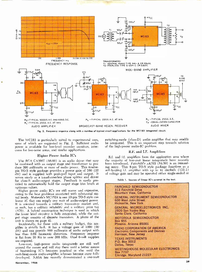
11011111.1111111111
11111111111111111111111111111111111111111111
%°, 76
z 74
1111111111111111111111111111111111iiimmiIIIIiiiiiiimmIll11111111111111M1101
OSCko 72
11111111111vc, r .55V
11111111111111=111111M1 1111111111111111111111111111111111111111111111111111111111111=1"1111111111111111111111111111111101MF
100
T7.5 y F
RS -TYPICAL 500011 A.C. AND 60011 D.C.RL-TYPICAL 25011. A.C. AT IkHz
AUDIO AMPLIFIER
1.000 10,000 20 000 50,000FREQUENCY-Hz
FREQUENCY RESPONSETRANSFORMERS!TI -GENERAL RADIO TYPE 941-A OR EOUIV.T2 -PEERLESS TYPE E -204-D OR EOUIV.
WIDE -BAND AMPLIFIER
RL -TYPICAL 25011 A.C. AT 'kHz
BROADCAST -BAND REGEN. RECEIVER
2
YOAUDIOINPUT
RL -TYPICAL 2501L A.C.Ce -EOUALIZATION CAPACITOR
AUDIO MIXER
Fig. 2. Frequency response along with a number of typical circuit applications for the WC1 83 integrated circuit.
The WC183 is particularly suited to experimental uses,some of which are suggested in Fig. 2. Sufficient audiopower is available for low-level recorder monitors, inter-coms for low -noise areas, and similar applications.
Higher Power Audio IC'sThe RCA CA3007 ($6.00) is an audio driver that may
be combined with an output stage and transformer to pro-duce 300 milliwatts or more of audio power. This twelve -pin TO -5 style package provides a power gain of 160 (22
dB) and is supplied with push-pull input and output. Itserves nicely as a transformerless phase splitter and driverfor class -B audio -output stages. Feedback is easily pro-vided to automatically hold the output stage bias levels atoptimum values.
Higher power audio IC's are still scarce and expensive,owing to the heat problems associated with substantial sig-nal levels. Motorola's MC1524 is one 10 -pin TO -5 style canlinear IC that can supply one watt of audio -output power.It is oriented towards a military transceiver market and,as such, has a military reliability and a military price tag($70). A hybrid construction technique is used in whichthe lower level circuitry is fully integrated, while the out -
o put stage consists of discrete transistors. A photo of theunit is shown on page 41.
Incidentally, for those with a military budget, this am-plifier is strictly hi-fi. It has a voltage gain of 1000 (60dB) and can provide 900 milliwatts of audio output withless than 0.6% harmonic distortion. Frequency responseis flat from 20 Hz to over 300 kHz. Dual 6 -volt suppliesare required.
Low-cost, high -power audio integrateds are still wellaround the corner and will stay there until a better meansof heatsinking IC's becomes practical or else until theswitching -mode audio -amplifier schemes become more fulldeveloped. NASA has recently demonstrated a one -watt
switching -mode (class -D) audio amplifier that may readilybe integrated. This is an important step towards solutionof the high -power audio -IC problem.
R.F. and I.F. AmplifiersR.f. and i.f. amplifiers form the application area where
the majority of low-cost linear integrateds have recentlybeen introduced. Fairchild's ktA703 ($4.50) is an interest-ing entry. This 8 -pin TO -5 style package functions as aself-limiting i.f. amplifier with up to 41 decibels (112:1)
of voltage gain and may be operated either single -ended or
Table 1. Sources of linear IC's covered in the text.
FAIRCHILD SEMICONDUCTOR313 Fairchild DriveMountain View, CaliforniaGENERAL INSTRUMENT SEMICONDUCTOR600 West John StreetHicksville, New YorkGENERAL MICROELECTRONICS INC.2920 San Ysidro WaySanta Clara, CaliforniaMOTOROLA SEMICONDUCTORBox 955Phoenix, Arizona 85001RADIO CORPORATION OF AMERICAElectronic Components and DevicesHarrison, New JerseyTEXAS INSTRUMENTSP.O. Box 5012Dallas, TexasWESTINGHOUSE MOLECULAR ELECTRONICSBox 7737Elkridge, Maryland 21227
November, 1966 39
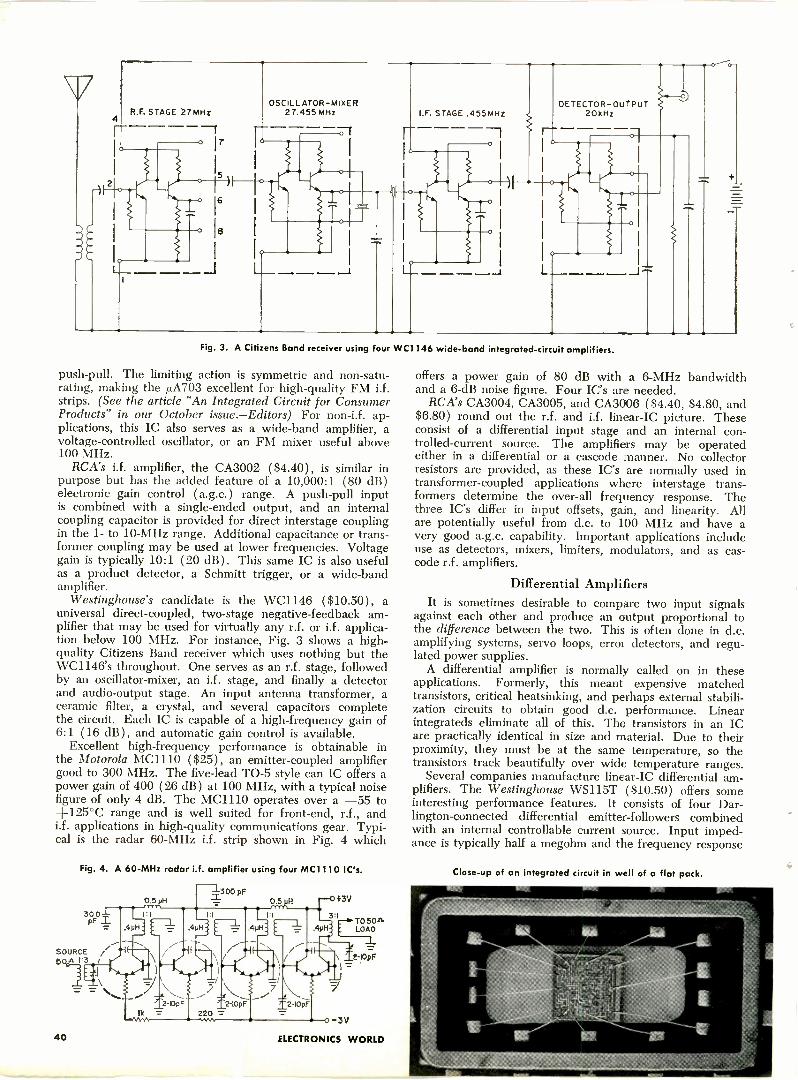
R.E. STAGE 27MHz
E
rOSCILLATOR-MIXER
27.45527.455 MHz I.F. STAGE .455MHZ- DETECTOR -OUTPUT20kHz
Fig. 3. 3. A Citizens Band receiver using four WC1146 wide -band integrated -circuit amplifiers.
push-pull. The limiting action is symmetric and non -satu-rating, making the /J.A703 excellent for high -quality FM i.f.strips. (See the article "An Integrated Circuit for ConsumerProducts" in our October issue.-Editors) For non-i.f. ap-plications, this IC also serves as a wide -band amplifier, avoltage -controlled oscillator, or an FM mixer useful above100 MHz.
RCA's i.f. amplifier, the CA3002 ($4.40), is similar inpurpose but has the added feature of a 10,000:1 (80 dB)electronic gain control (a.g.c.) range. A push-pull inputis combined with a single -ended output, and an internalcoupling capacitor is provided for direct interstage coupling
former coupling may be used at lower frequencies. Voltagegain is typically 10:1 (20 dB). This same IC is also usefulas a product detector, a Schmitt trigger, or a wide -bandamplifier.
Westinghouse's candidate is the WC1146 ($10.50), auniversal direct -coupled, two -stage negative -feedback am-plifier that may be used for virtually any r.f. or i.f. applica-tion below 100 MHz. For instance, Fig. 3 shows a high -quality Citizens Band receiver which uses nothing but theWC1146's throughout. One serves as an r.f. stage, followedby an oscillator -mixer, an i.f. stage, and finally a detectorand audio -output stage. An input antenna transformer, aceramic filter, a crystal, and several capacitors completethe circuit. Each IC is capable of a high -frequency gain of6:1 (16 dB), and automatic gain control is available.
Excellent high -frequency performance is obtainable inthe Motorola MC1110 ($25), an emitter -coupled amplifiergood to 300 MHz. The five -lead TO -5 style can IC offers apower gain of 400 (26 dB) at 100 MHz, with a typical noisefigure of only 4 dB. The MC1110 operates over a -55 to+125°C range and is well suited for front-end, r.f., andi.f. applications in high -quality communications gear. Typi-cal is the radar 60 -MHz i.f. strip shown in Fig. 4 which
40
Fig. 4. A 60 -MHz radar i f. amplifier using four MC1110 IC's.
TO 50+sLOAD
_L
t-lOpF=
ELECTRONICS WORLD
offers a power gain of 80 dB with a 6 -MHz bandwidthand a 6 -dB noise figure. Four IC's are needed.
RCA's CA3004, CA3005, and CA3006 ($4.40, $4.80, and$6.80) round out the r.f. and i.f. linear -IC picture. Theseconsist of a differential input stage and an internal con-trolled -current source. The amplifiers may be operatedeither in a differential or a cascode manner. No collectorresistors are provided, as these IC's are normally used intransformer -coupled applications where interstage trans-formers determine the over-all frequency response. Thethree IC's differ in input offsets, gain, and linearity. Allare potentially useful from d.c. to 100 MHz and have avery good a.g.c. capability. Important applications includeuse as detectors, mixers, limiters, modulators, and as cas-code r.f. amplifiers.
Differential AmplifiersIt is sometimes desirable to compare two input signals
against each other and produce an output proportional tothe difference between the two. This is often done in d.c.amplifying systems, servo loops, error detectors, and regu-lated power supplies.
A differential amplifier is normally called on in theseapplications. Formerly, this meant expensive matchedtransistors, critical heatsinking, and perhaps external stabili-zation circuits to obtain good d.c. performance. Linearintegrateds eliminate all of this. The transistors in an ICare practically identical in size and material. Due to theirproximity, they must be at the same temperature, so thetransistors track beautifully over wide temperature ranges.
Several companies manufacture linear -IC differential am-plifiers. The Westinghouse WS115T ($10.50) offers someinteresting performance features. It consists of four Dar-lington -connected differential emitter -followers combinedwith an internal controllable current source. Input imped-ance is typically half a megohm and the frequency response
Close-up of an integrated circuit in well of a flat pack.
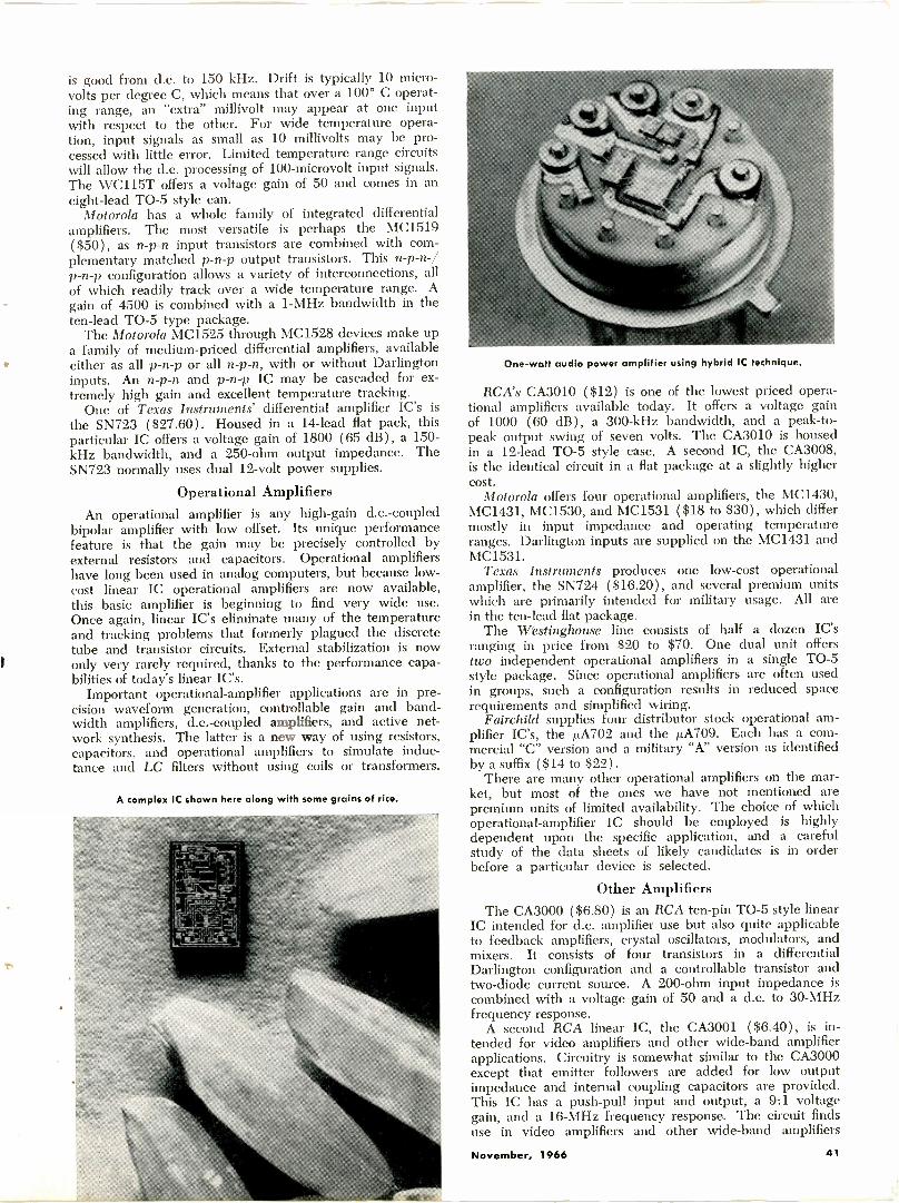
is good from d.c. to 150 kHz. Drift is typically 10 microvolts per degree C, which means that over a 100° C operat-ing range, an "extra" millivolt may appear at one inputwith respect to the other. For wide temperature opera-tion, input signals as small as 10 millivolts may be pro-cessed with little error. Limited temperature range circuitswill allow the d.c. processing of 100 -microvolt input signals.The WC115T offers a voltage gain of 50 and comes in aneight -lead TO -5 style can.
Motorola has a whole family of integrated differentialamplifiers. The most versatile is perhaps the MC1519( $50), as n -p -n input transistors are combined with com-plementary matched p -n -p output transistors. This n -p -n-/p -n -p configuration allows a variety of interconnections, allof which readily track over a wide temperature range. Again of 4500 is combined with a 1 -MHz bandwidth in theten -lead TO -5 type package.
The Motorola MC1525 through MC1528 devices make upa family of medium-priced differential amplifiers, availableeither as all p -n -p or all n -p -n, with or without Darlingtoninputs. An n -p -n and p -n -p IC may be cascaded for ex-tremely high gain and excellent temperature tracking.
One of Texas Instruments' differential amplifier IC's isthe SN723 ($27.60). Housed in a 14 -lead flat pack, thisparticular IC offers a voltage gain of 1800 (65 dB), a 150 -kHz bandwidth, and a 250 -ohm output impedance. TheSN723 normally uses dual 12 -volt power supplies.
Operational AmplifiersAn operational amplifier is any high -gain d.c.-coupled
bipolar amplifier with low offset. Its unique performancefeature is that the gain may be precisely controlled byexternal resistors and capacitors. Operational amplifiershave long been used in analog computers, but because low-cost linear IC operational amplifiers are now available,this basic amplifier is beginning to find very wide use.Once again, linear IC's eliminate many of the temperatureand tracking problems that formerly plagued the discretetube and transistor circuits. External stabilization is nowonly very rarely required, thanks to the performance capa-bilities of today's linear IC's.
Important operational -amplifier applications are in pre-cision waveform generation, controllable gain and band-width amplifiers, d.c.-coupled amplifiers, and active net-work synthesis. The latter is a new way of using resistors,capacitors, and operational amplifiers to simulate induc-tance and LC filters without using coils or transformers.
A complex IC shown here along with some grains of rice.
One -watt audio power amplifier using hybrid IC technique.
RCA's CA3010 ( $12) is one of the lowest priced opera-tional amplifiers available today. It offers a voltage gainof 1000 (60 dB), a 300 -kHz bandwidth, and a peak -to -peak output swing of seven volts. The CA3010 is housedin a 12 -lead TO -5 style case. A second IC, the CA3008,is the identical circuit in a flat package at a slightly highercost.
Motorola offers four operational amplifiers, the MC1430,MC1431, MC1530, and MC1531 ($18 to $30), which differmostly in input impedance and operating temperatureranges. Darlington inputs are supplied on the MC1431 andMC1531.
Texas Instruments produces one low-cost operationalamplifier, the SN724 ($16.20), and several premium unitswhich are primarily intended for military usage. All arein the ten -lead flat package.
The Westinghouse line consists of half a dozen IC'sranging in price from $20 to $70. One dual unit offerstwo independent operational amplifiers in a single TO -5style package. Since operational amplifiers are often usedin groups, such a configuration results in reduced spacerequirements and simplified wiring.
Fairchild supplies four distributor stock operational am-plifier IC's, the ,uA702 and the p.A709. Each has a com-mercial "C" version and a military "A" version as identifiedby a suffix ($14 to $22).
There are many other operational amplifiers on the mar-ket, but most of the ones we have not mentioned arepremium units of limited availability. The choice of whichoperational -amplifier IC should be employed is highlydependent upon the specific application, and a carefulstudy of the data sheets of likely candidates is in orderbefore a particular device is selected.
Other AmplifiersThe CA3000 ( $6.80) is an RCA ten -pin TO -5 style linear
IC intended for d.c. amplifier use but also quite applicableto feedback amplifiers, crystal oscillators, modulators, andmixers. It consists of four transistors in a differentialDarlington configuration and a controllable transistor andtwo -diode current source. A 200 -ohm input impedance iscombined with a voltage gain of 50 and a d.c. to 30 -MHzfrequency response.
A second RCA linear IC, the CA3001 ($6.40), is in-tended for video amplifiers and other wide -band amplifierapplications. Circuitry is somewhat similar to the CA3000except that emitter followers are added for low outputimpedance and internal coupling capacitors are provided.This IC has a push-pull input and output, a 9:1 voltagegain, and a 16 -MHz frequency response. The circuit findsuse in video amplifiers and other wide -band amplifiers
November, 1966 41
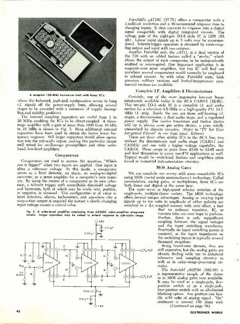
A complete 120 -MHz transceiver built with linear IC's.
where the balanced, push-pull configuration serves to keepr.f. signals off the power -supply lines, allowing severalstages to be cascaded with a minimum of supply decoup-ling and stability problems.
The internal coupling capacitors are useful from 1 to20 MHz, enabling the IC's to be direct -coupled. A three-stage amplifier with a gain of more than 1000 from 10 kHzto 10 MHz is shown in Fig. 5. Here additional externalcapacitors have been used to obtain the better lower fre-quency response. Still larger capacitors would allow opera-tion into the sub -audio region, making this particular circuitwell suited for oscilloscope preamplifiers and other wide -
band, low-level amplifiers.
ComparatorsComparators are used to answer the question, "Which
one is bigger?" when two inputs are applied. One input isoften a reference voltage. In this mode, a comparatorserves as a limit detector, an alarm, an analog -to -digitalconverter, or a sense amplifier for a computer's core mem-ory. By using the output of a comparator as its own refer-ence, a Schmitt trigger with controllable threshold voltageand hysteresis, both of which may be made zero, positive,or negative, is obtained. This configuration is of value inlevel detectors, alarms, tachometers, and anywhere else asnap -action output is required the instant a slowly changinginput voltage crosses a critical value.
Fig. 5. A wide -band amplifier employingcircuits. Larger capacitors may be added
C Ik
VIN
50OHMS
lk
lk
three CA3001 video -amplifier integratedto extend response to sub -audio range.
0.001 F
1k
lk
0.001 µF
Ff= 0-6V
Fairchild's iLA710C ($7.75) offers a comparator with a1 -millivolt resolution and a 40 -nanosecond response time tochanging inputs. It then converts its response into a digitalsignal compatible with digital integrated circuits. Thevoltage gain of the eight -pin TO -5 style IC is 1200 (62dB). Linear input signals up to 5 volts may be accommo-dated. Schmitt -trigger operation is obtained by cross -coup-ling output and input with two resistors.
Another Fairchild unit, the p.A711, is a dual version ofthe 710 with an added feature called a "strobe," whichallows the output of each comparator to be independentlyenabled or interrogated. One important application is inmagnetic -core sense amplifiers, but this IC will find useanywhere several comparators would normally be employedin related circuits. As with other Fairchild units, bothpremium military versions and limited -temperature com-mercial versions are available.
Complete I.F. Amplifiers & DiscriminatorsCertainly, one of the most impressive low-cost linear
integrateds available today is the RCA CA3013 ($2.65).This ten -pin TO -5 style IC is a complete i.f. and audiosection for a television 4.5 -MHz or a high -quality FM 10.7-MHz i.f. strip. Inside the can are three self-limiting i.f.stages, a discriminator, a dual audio stage, and a regulatedpower supply. The twelve transistors and twelve diodesadd up to eleven cents per active device, a price totallyunmatched by discrete circuitry. (Refer to "TV Set UsesIntegrated Circuit" in our June issue.-Editors)
There are three other similar IC's in the RCA line, twowithout the discriminator and audio stage (CA3011 andCA3012) and one with a higher voltage capability, theCA3014. These range in price from $2.00 to $3.65 eachand lend themselves to many non -FM applications as well.Typical would be wide -band limiters and amplifiers oftenfound in industrial instrumentation circuitry.
MOS Analog GatesWe can conclude our survey with some remarkable IC's
using MOS (metal oxide semiconductor) technology. Calledcommutators, analog gates, or multiplexers, these IC's areboth linear and digital at the same time.
The units serve as high-speed selector switches of thesingle -pole, multiple -throw variety. The MOS technologyoffers several unique advantages. Analog or varying inputsignals up to ten volts in amplitude of either polarity areswitched in a d.c.-coupled manner with zero offset, a feat
that no ordinary transistor, IC, orvacuum tube can ever hope to perform.Further, there is only insignificantcoupling between the signal voltagesand the input switching waveforms.Practically no input switching power isrequired, as the input impedance onthe switching inputs is typically severalthousand megohms.
Being brand-new devices, they arestill expensive, but the analog gates arealready finding wide use in industrialtelemetry and sampling circuitry aswell as in radar -image -processing cir-cuitry.
The Fairchild iuM3700 ($62.50) isa representative sample of the dozenor so MOS analog gates now available.It may be used as a single -pole, five -position switch or as a single -pole,four -position switch with an all -channelblanking option. Any position can han-dle ±10 volts of analog signal. "On"resistance is around 150 ohms with
(Continued on page 76)42 ELECTRONICS WORLD
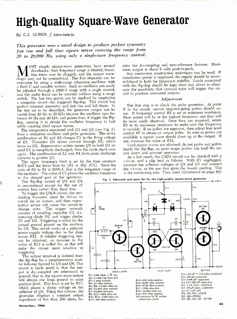
High -Quality Square -Wave GeneratorBy C.J. ULRICK / Collins Radio Co.
This generator uses a novel design to produce perfect symmetryfast rise and fall time square waves covering the range from20 to 20,000 Hz, using only a single -turn frequency control.
OST simple square -wave generators have severaldrawbacks: their frequency range is limited, transi-tion times may be sluggish, and the output wave-
s rape may not be symmetrical. The first objection can beovercome by using a wide -range relaxation oscillator witha fixed C and variable resistor. Such an oscillator can easilybe adjusted through a 1000:1 range with a single control,and the audio band can be covered without using a rangeswitch. The last two points can be resolved by employinga computer circuit-the triggered flip-flop. This circuit hasperfect inherent symmetry and fast rise and fall times. Inthe test set to be described, the generator output can bevaried from 20 Hz to 20 kHz because the oscillator runs be-tween 40 Hz and 40 kHz and pulses from it trigger the flip-flop, causing it to divide the oscillator frequency in halfwhile creating ideal square waves.
The components associated with Q1 and Q2 (see Fig. 1)form a relaxation oscillator and pulse generator. The seriescombination of R1 and R2 charges Cl to the firing voltageof Q1. Transistor Q1 draws current through R5, whichturns on Q2. Regenerative action causes Q2 to hold Q1 onuntil Cl is completely discharged; then the cycle starts overagain. The combination of Ll and R4 limits peak dischargecurrents to protect Ql.
The upper frequency limit is set by the time constantR1C1 and the lower limit by (R1 + R2) (Cl). Since theratio of R2 to R1 is 1000:1, that is the frequency range ofthe oscillator. The value of Cl places the oscillator frequencyin the desired part of the spectrum.
The flip-flop circuit of Q3 and Q4is conventional except for the use ofemitter bias rather than fixed bias.
To trigger the Q3Q4 circuit, the con-ducting transistor must be driven tocut-off for an instant, and then regen-erative action will cause the circuit tochange state. The trigger networkconsists of coupling capacitor C3, d.c.restoring diode D2, and trigger diodesDI and D3. Triggering is aided by thevirtual ground placed on the emittersby C6. The circuit works at a reducedpower -supply voltage due to the dropacross R12. If reliable triggering can-not be obtained, an increase in thevalue of R12 is called for, as this willmake the circuit more sensitive totriggering.
The output terminal is isolated fromthe flip-flop by a complementary emit-ter follower formed by Q5 and Q6. Thiscircuit is fairly novel in that the out-put is d.c.-coupled yet referenced toground, that is, the square -wave outputwill always rise from ground to somepositive level. This level is set by R17,
which places a clamp voltage on thecollector of Q5. Using this scheme, thegenerator displays a constant outputimpedance of less than 200 ohms, be -
sides the d.c-coupling and zero -reference features. Maxi-mum output is about 5 volts peak -to -peak.
Any convenient construction techniques can be used. Iftransformer power is employed, the supply should be zener-stabilized to hold the frequency stability. Leads associatedwith the flip-flop should be kept short and direct to elimi-nate the possibility that external noise will trigger this cir-cuit to produce unwanted outputs.
AdjustmentThe first step is to check the pulse generator. At point
B in the circuit, narrow negative -going pulses should oc-cur. If frequency control R2 is set at minimum resistance,these pulses will be at the highest frequency and thus willbe more easily observed. Once they are acquired, rotateR2 to its maximum resistance to make sure the frequencyis variable. If no pulses are apparent, then adjust bias levelcontrol R7 to obtain an output pulse. As soon as pulses areavailable, a square wave should show up at the output. Ifnot, increase the value of R12.
Until square waves are obtained, do not probe any pointsinside the flip-flop, as some scope probes can load the cir-cuit down and prevent operation.
As a last resort, the Q3Q4 circuit can be checked with av.t.v.m. and a clip lead as follows. With Q1 unplugged,measure the collector voltages of Q3 and Q4 and connectthe v.t.v.m. to the one that gives the lowest reading. Thisis the conducting side. Then short (Continued on page 82)
Fig. 1. Schematic and parts list for the high -quality square -wave generator.
RI
82FREO
CI
R4
R7
02 I 8112N706
OSCILLATOR
R1-1000 ohm, 1 W res.R2-1 meg log taper potR3-1 meg resistorR4-22 ohm resistorR5, R8-10,000 ohm res.R6-33,000 ohm resistorR7-50,000 ohm potR9, R13-1800 ohm res.RIO, R14-3300 ohm res.R11-100 ohm resistor
FLIP/ FLOP
R12-560 ohm resistorR15-8200 ohm resistorR16-4700 ohm resistorR17-2500 ohm potR18-39,000 ohm res.R19-470 ohm resistorAll resistors 11/2 W unless
otherwise noted
o +25v
'1OUT
0
819
OGNDBUFFER
C1-.04 NF ± 5% mica capacitorC2-220 pF capacitorC3-1000 pF capacitorC4, C5-500 pF capacitorC6-1 µF elect. capacitorC7-10 AF elect. capacitorL1-4.7 g1-1 coilDl, D2, D3 -1N270Q1, Q6 -2N964Q2, Q3, Q4, Q5 -2N706
November, 1966 43
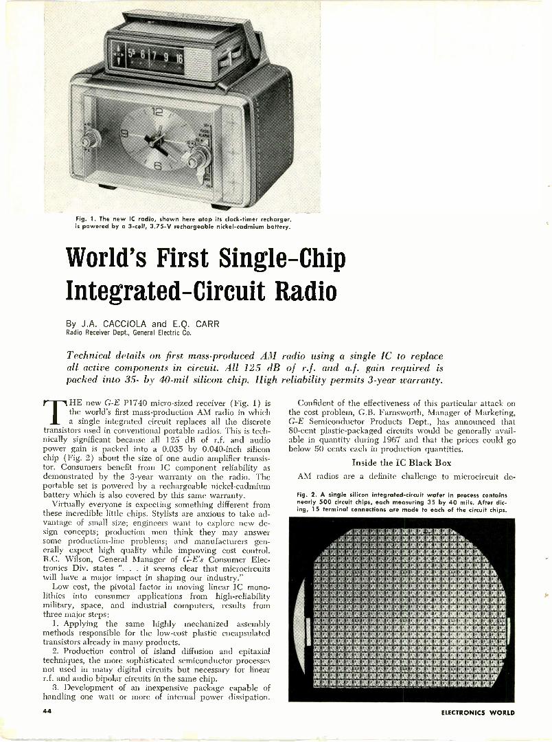
Fig. 1. The new IC radio, shown here atop its clock -timer recharger,is powered by a 3 -cell, 3.75-V rechargeable nickel -cadmium battery.
World's First Single -ChipIntegrated -Circuit RadioBy J.A. CACCIOLA and E.Q. CARRRadio Receiver Dept., General Electric Co.
Technical details on first mass-produced AM radio using a single IC to replaceall active components in circuit. All 125 dB of r.f. and a.f. gain required ispacked into 35- by 40 -mil silicon chip. High reliability permits 3 -year warranty.
THE new G -E P1740 micro -sized receiver (Fig. 1) isthe world's first mass -production AM radio in whicha single integrated circuit replaces all the discrete
transistors used in conventional portable radios. This is tech-nically significant because all 125 dB of r.f. and audiopower gain is packed into a 0.035 by 0.040 -inch siliconchip (Fig. 2) about the size of one audio amplifier transis-tor. Consumers benefit from IC component reliability asdemonstrated by the 3 -year warranty on the radio. Theportable set is powered by a rechargeable nickel -cadmiumbattery which is also covered by this same warranty.
Virtually everyone is expecting something different fromthese incredible little chips. Stylists are anxious to take ad-vantage of small size; engineers want to explore new de-sign concepts; production men think they may answersome production -line problems; and manufacturers gen-erally expect high quality while improving cost control.R.C. Wilson, General Manager of G -E's Consumer Elec-tronics Div. states ". . . it seems clear that microcircuitswill have a major impact in shaping our industry."
Low cost, the pivotal factor in moving linear IC mono-lithics into consumer applications from high -reliabilitymilitary, space, and industrial computers, results fromthree major steps:
1. Applying the same highly mechanized assemblymethods responsible for the low-cost plastic encapsulatedtransistors already in many products.
2. Production control of island diffusion and epitaxialtechniques, the more sophisticated semiconductor processesnot used in many digital circuits but necessary for linearr.f. and audio bipolar circuits in the same chip.
3. Development of an inexpensive package capable ofhandling one watt or more of internal power dissipation.
Confident of the effectiveness of this particular attack onthe cost problem, G.B. Farnsworth, Manager of Marketing,G -E Semiconductor Products Dept., has announced that80 -cent plastic -packaged circuits would be generally avail-able in quantity during 1967 and that the prices could gobelow 50 cents each in production quantities.
Inside the IC Black Box
AM radios are a definite challenge to microcircuit de -
Fig. 2. A single silicon integrated -circuit wafer in process containsnearly 500 circuit chips, each measuring 35 by 40 mils. After dic-ing, 15 terminal connections are made to each of the circuit chips.
atLIaalfc;:xxxxxxx,
WANAKIARK2GC.9tailg201101121;20ti
26719(21,9019/21A2Ck:AvEliZZiiignx2t9C 2t;;'itiMMIUM2C2C.2tMAN
24261121KRUMWAiri,REXITAMICICAr
lti4E2M9C2EW..XXXXZWIt.917
44 ELECTRONICS WORLD
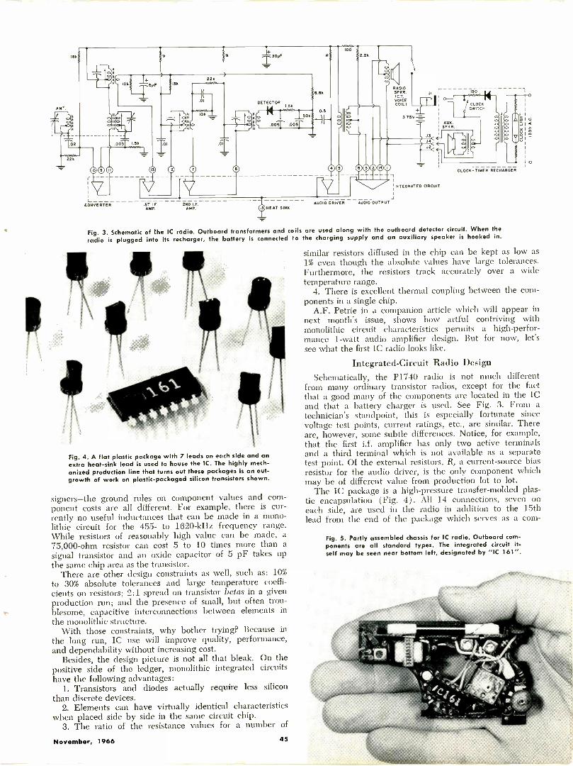
ANT
O
lek
2
22k
58P
.0051 1.5k
m0r
V1
CONVERTER
WA,
15k22
01
ok.
.01
DETECTOR.),.5M
-E-t""' 15011
.00T .00T
6.5k
RU
o
RADIOSPKR.
COIL)
0:INTEGRATED CIRCUIT
1ST I.F 2ND I.F.AMP. AMP. HEAT SINK
AUDIO DRIVER AUDIO OUTPUT
CLOCK -TIMER RECHARGER
Fig. 3. Schematic of the IC radio. Outboard transformers and coils are used along with the outboard detector circuit. When theradio is plugged into its recharger, the battery is connected to the charging supply and an auxiliary speaker is hooked in.
Fig. 4. A flat plastic package with 7 leads on each side and anextra heat -sink lead is used to house the IC. The highly mech-anized production line that turns out these packages is an out-growth of work on plastic -packaged silicon transistors shown.
signers-the ground rules on component values and com-ponent costs are all different. For example, there is cur-rently no useful inductances that can be made in a mono-lithic circuit for the 455- to 1620 -kHz frequency range.While resistors of reasonably high value can be made, a75,000 -ohm resistor can cost 5 to 10 times more than asignal transistor and an oxide capacitor of 5 pF takes upthe same chip area as the transistor.
There are other design constraints as well, such as: 10%to 30% absolute tolerances and large temperature coeffi-cients on resistors; 2:1 spread on transistor betas in a givenproduction run; and the presence of small, but often trou-
e- blesome, capacitive interconnections between elements inthe monolithic structure.
With those constraints, why bother trying? Because inthe long run, IC use will improve quality, performance,and dependability without increasing cost.
Besides, the design picture is not all that bleak. On thepositive side of the ledger, monolithic integrated circuitshave the following advantages:
1. Transistors and diodes actually require less siliconthan discrete devices.
2. Elements can have virtually identical characteristicswhen placed side by side in the same circuit chip.
3. The ratio of the resistance values for a number of
November, 1966 45
similar resistors diffused in the chip can be kept as low as1% even though the absolute values have large tolerances.Furthermore, the resistors track accurately over a widetemperature range.
4. There is excellent thermal coupling between the com-ponents in a single chip.
A.F. Petrie in a companion article which will appear innext month's issue, shows how artful contriving withmonolithic circuit characteristics permits a high-perfor-mance 1 -watt audio amplifier design. But for now, let'ssee what the first IC radio looks like.
Integrated -Circuit Radio DesignSchematically, the P1740 radio is not much different
from many ordinary transistor radios, except for the factthat a good many of the components are located in the ICand that a battery charger is used. See Fig. 3. From atechnician's standpoint, this is especially fortunate sincevoltage test points, current ratings, etc., are similar. Thereare, however, some subtle differences. Notice, for example,that the first i.f. amplifier has only two active terminalsand a third terminal which is not available as a separatetest point. Of the external resistors, R, a current -source biasresistor for the audio driver, is the only component whichmay be of different value from production lot to lot.
The IC package is a high-pressure transfer -molded plas-tic encapsulation (Fig. 4). All 14 connections, seven oneach side, are used in the radio in addition to the 15thlead from the end of the package which serves as a com-
Fig. 5. Partly assembled chassis for IC radio. Outboard com-ponents are all standard types. The integrated circuit it-self may be seen near bottom left, designated by "IC 161".
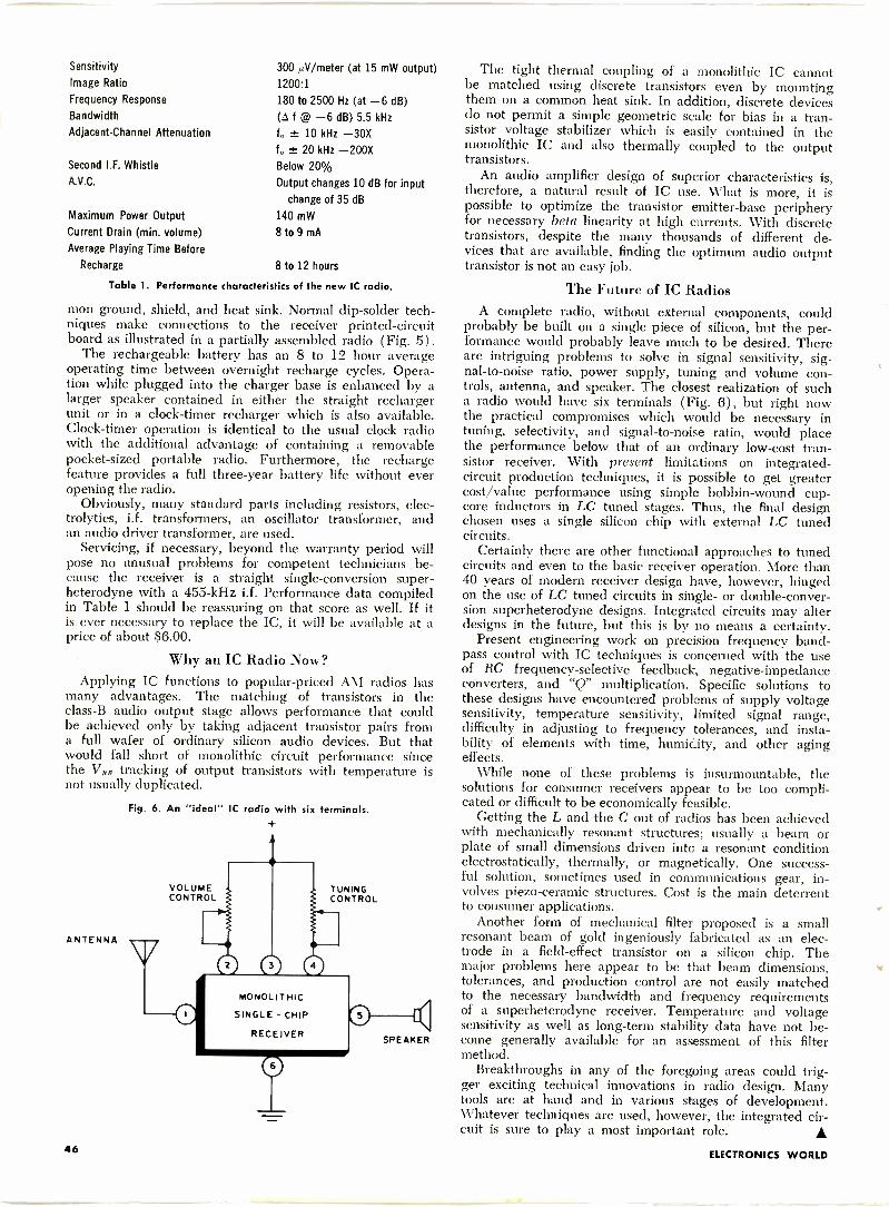
Sensitivity
Image Ratio
Frequency Response
Bandwidth
Adjacent -Channel Attenuation
Second I.F. Whistle
A.V.C.
Maximum Power Output
Current Drain (min. volume)
Average Playing Time Before
Recharge 8 to 12 hours
Table 1. Performance characteristics of the new IC radio.
300 µV/meter (at 15 mW output)1200:1
180 to 2500 Hz (at -6 dB)(A f @ -6 dB) 5.5 kHzf. ± 10 kHz -30Xf. ± 20 kHz -200XBelow 20%
Output changes 10 dB for input
change of 35 dB
140 mW
8 to 9 mA
mon ground, shield, and heat sink. Normal dip -solder tech-niques make connections to the receiver printed -circuitboard as illustrated in a partially assembled radio (Fig. 5).
The rechargeable battery has an 8 to 12 hour averageoperating time between overnight recharge cycles. Opera-tion while plugged into the charger base is enhanced by alarger speaker contained in either the straight rechargerunit or in a clock -timer recharger which is also available.Clock -timer operation is identical to the usual clock radiowith the additional advantage of containing a removablepocket -sized portable radio. Furthermore, the rechargefeature provides a full three-year battery life without everopening the radio.
Obviously, many standard parts including resistors, elec-trolytics, i.f. transformers, an oscillator transformer, andan audio driver transformer, are used.
Servicing, if necessary, beyond the warranty period willpose no unusual problems for competent technicians be-cause the receiver is a straight single -conversion super-heterodyne with a 455 -kHz i.f. Performance data compiledin Table 1 should be reassuring on that score as well. If itis ever necessary to replace the IC, it will be available at aprice of about $6.00.
Why an IC Radio Now?Applying IC functions to popular -priced AM radios has
many advantages. The matching of transistors in theclass -B audio output stage allows performance that couldbe achieved only by taking adjacent transistor pairs froma full wafer of ordinary silicon audio devices. But thatwould fall short of monolithic circuit performance sincethe VftE tracking of output transistors with temperature isnot usually duplicated.
ANTENNA
Fig. 6. An "ideal" IC radio with six terminals.
VOLUMECONTROL
0
TUNINGCONTROL
MONOLITHIC
SINGLE - CHIP
RECEIVER
0
0 '4SPEAKER
The tight thermal coupling of a monolithic IC cannotbe matched using discrete transistors even by mountingthem on a common heat sink. In addition, discrete devicesdo not permit a simple geometric scale for bias in a tran-sistor voltage stabilizer which is easily contained in themonolithic IC and also thermally coupled to the outputtransistors.
An audio amplifier design of superior characteristics is,therefore, a natural result of IC use. What is more, it ispossible to optimize the transistor emitter -base peripheryfor necessary beta linearity at high currents. With discretetransistors, despite the many thousands of different de-vices that are available, finding the optimum audio outputtransistor is not an easy job.
The Future of IC RadiosA complete radio, without external components, could
probably be built on a single piece of silicon, but the per-formance would probably leave much to be desired. Thereare intriguing problems to solve in signal sensitivity, sig-nal-to-noise ratio, power supply, tuning and volume con-trols, antenna, and speaker. The closest realization of sucha radio would have six terminals (Fig. 6), but right nowthe practical compromises which would be necessary intuning, selectivity, and signal-to-noise ratio, would placethe performance below that of an ordinary low-cost tran-sistor receiver. With present limitations on integrated -circuit production techniques, it is possible to get greatercost/value performance using simple bobbin -wound cup-core inductors in LC tuned stages. Thus, the final designchosen uses a single silicon chip with external LC tunedcircuits.
Certainly there are other functional approaches to tunedcircuits and even to the basic receiver operation. More than40 years of modern receiver design have, however, hingedon the use of LC tuned circuits in single- or double -conver-sion superheterodyne designs. Integrated circuits may alterdesigns in the future, but this is by no means a certainty.
Present engineering work on precision frequency band-pass control with IC techniques is concerned with the useof RC frequency -selective feedback, negative -impedanceconverters, and "Q" multiplication. Specific solutions tothese designs have encountered problems of supply voltagesensitivity, temperature sensitivity, limited signal range,difficulty in adjusting to frequency tolerances, and insta-bility of elements with time, humidity, and other agingeffects.
While none of these problems is insurmountable, thesolutions for consumer receivers appear to be too compli-cated or difficult to be economically feasible.
Getting the L and the C out of radios has been achievedwith mechanically resonant structures; usually a beam orplate of small dimensions driven into a resonant conditionelectrostatically, thermally, or magnetically. One success-ful solution, sometimes used in communications gear, in-volves piezo-ceramic structures. Cost is the main deterrentto consumer applications.
Another form of mechanical filter proposed is a smallresonant beam of gold ingeniously fabricated as an elec-trode in a field-effect transistor on a silicon chip. Themajor problems here appear to be that beam dimensions,tolerances, and production control are not easily matchedto the necessary bandwidth and frequency requirementsof a superheterodyne receiver. Temperature and voltagesensitivity as well as long-term stability data have not be-come generally available for an assessment of this filtermethod.
Breakthroughs in any of the foregoing areas could trig-ger exciting technical innovations in radio design. Manytools are at hand and in various stages of development.Whatever techniques are used, however, the integrated cir-cuit is sure to play a most important role.
46 ELECTRONICS WORLD
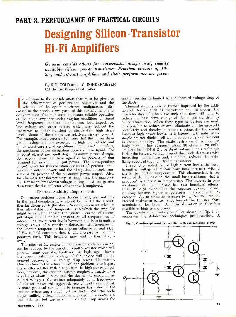
PART 3. PERFORMANCE OF PRACTICAL CIRCUITS
Designing Silicon -TransistorHi-Fi AmplifiersGeneral considerations for conservative design using readilyavailable silicon power transistors. Practical circuits of 10-,25-, and 70 -watt amplifiers and their performance are given.
By R.D. GOLD and J.C. SONDERMEYERRCA Electronic Components & Devices
IN addition to the consideration that must be given tothe achievement of performance objectives and theselection of the optimum circuit configuration (dis-
cussed in the previous two parts of this series), the circuitdesigner must also take steps to insure reliable operationof the audio amplifier under varying conditions of signallevel, frequency, ambient temperature, load impedance,line voltage, and other factors which may subject thetransistors to either transient or steady-state high stresslevels. Some of these steps are relatively straightforward.For example, it is necessary to insure that the power dissi-pation ratings are not exceeded at high line voltage andunder worst -case signal conditions. For class -A amplifiers,the maximum power dissipation occurs at zero signal. Foran ideal class -B push-pull stage, maximum power dissipa-tion occurs when the drive signal is 64 percent of thatrequired for maximum output power. The correspondingoutput power for this condition occurs at 42 percent of themaximum output power, and the dissipation in each tran-sistor is 20 percent of the maximum power output. Also,for class -AB transformer -coupled amplifiers, the appropri-ate transistor breakdown -voltage rating must be greaterthan twice the d.c. collector voltage that is employed.
Thermal Stability RequirementsOne serious problem facing the design engineer, not only
in the quasi -complementary circuit but in all the circuitsthus far discussed, is the ability to design a circuit which isthermally stable at all temperatures to which the amplifiermight be exposed. Ideally, the quiescent current of an out-put stage should remain constant at all temperatures ofinterest. At low current levels however, the base -to -emittervoltage (VBE) of a transistor decreases with increases inthe junction temperature for a given collector current (It).If VBE is held constant, then /, will increase as the tem-perature rises. This behavior may lead to thermal run-away.
The effect of increasing temperature on collector currentcan be reduced by the use of an emitter resistor which will
t provide some local d.c. feedback. At high signal levels,the over-all saturation voltage of the device will be in-creased because of the voltage drop across this resistor.One solution to the saturation -voltage problem is to bypassthe emitter resistor with a capacitor. In high -power ampli-fiers, however, the emitter resistors employed usually havea value of about 1 ohm, and the size of the capacitor re-quired to bypass the emitter adequately at all frequenciesof interest makes this approach economically impractical.A more practical solution is to increase the value of theemitter resistor and shunt it with a diode. With this tech-nique, sufficient degeneration is provided to improve cir-cuit stability, but the maximum voltage drop across the
emitter resistor is limited to the forward voltage drop ofthe diode.
Thermal stability can be further improved by the addi-tion of devices such as thermistors or bias diodes, thecharacteristics of which are such that they will tend toreduce the base drive voltage of the output transistor astemperatures rise. When these types of devices are used,it is possible to reduce or even eliminate emitter networkscompletely and thereby to reduce substantially the circuitlosses at high power levels. It is interesting to note that asimple emitter diode itself will provide some improvementin circuit stability. The static resistance of a diode isfairly high at low currents (about 30 ohms at 20 milli-amperes for a 1N1612). A disadvantage of this techniqueis that the forward voltage drop of this diode decreases withincreasing temperature and, therefore, reduces the stabi-lizing effects of the high dynamic resistance.
It should be noted that at high current levels, the base -to -emitter voltage of silicon transistors increases with arise in the junction temperature. This characteristic is theresult of the increase in the small base resistance that isproduced by the rise in temperature. The increase in baseresistance with temperature has two beneficial effects:First, it helps to stabilize the transistor against thermalrunaway because higher temperatures now require an in-crease in Vim to cause an increase in Ic. Second, the in-creased resistance causes a portion of the transfer char-acteristic to be linear. A lower distortion is thereforepossible at high temperatures.
The quasi -complementary amplifier shown in Fig. 1 in-corporates the stabilization techniques just described. A
Fig. 1. Quasi -complementary amplifier with compensating diodes.+vcc
Di
November, 1966 47
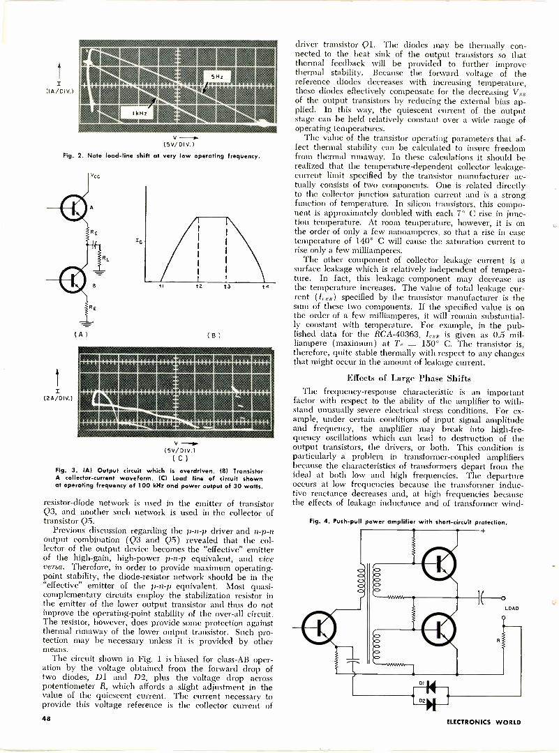
Filig1111111111111111111111111
mormittiamIIINCJIMESIONEMI
V
(5v/Div.)Fig. 2. Note load -line shift at very low operating frequency.
(24/01v.)
vcc.
( A )
2
(B)
13
SIEEMICEMZEIM111111111111111111111111111111111111
mniumatememmmumegm.
v(5v/DIV.)(C)
Fig. 3. (A) Output circuit which is overdriven. (8) TransistorA collector -current waveform. (C) Load line of circuit shownat operating frequency of 100 kHz and power output of 30 watts.
resistor -diode network is used in the emitter of transistorQ3, and another such network is used in the collector oftransistor Q5.
Previous discussion regarding the p -n -p driver and n -p -noutput combination (Q3 and Q5) revealed that the col-lector of the output device becomes the "effective" emitterof the high -gain, high -power p -n -p equivalent, and viceversa. Therefore, in order to provide maximum operating-
point stability, the diode -resistor network should be in the"effective" emitter of the p -n -p equivalent. Most quasi -complementary circuits employ the stabilization resistor inthe emitter of the lower output transistor and thus do notimprove the operating -point stability of the over-all circuit.The resistor, however, does provide some protection againstthermal runaway of the lower output transistor. Such pro-tection may be necessary unless it is provided by othermeans.
The circuit shown in Fig. 1 is biased for class -AB oper-ation by the voltage obtained from the forward drop oftwo diodes, Dl and D2, plus the voltage drop acrosspotentiometer R, which affords a slight adjustment in thevalue of the quiescent current. The current necessary toprovide this voltage reference is the collector current of
driver transistor Ql. The diodes may be thermally con-nected to the heat sink of the output transistors so thatthermal feedback will be provided to further improvethermal stability. Because the forward voltage of thereference diodes decreases with increasing temperature,these diodes effectively compensate for the decreasing VRRof the output transistors by reducing the external bias ap-plied. In this way, the quiescent current of the outputstage can be held relatively constant over a wide range ofoperating temperatures.
The value of the transistor operating parameters that af-fect thermal stability can be calculated to insure freedomfrom thermal runaway. In these calculations it should berealized that the temperature -dependent collector leakage-
current limit specified by the transistor manufacturer ac-tually consists of two components. One is related directlyto the collector junction saturation current and is a strongfunction of temperature. In silicon transistors, this compo-nent is approximately doubled with each 7° C rise in junc-tion temperature. At room temperature, however, it is onthe order of only a few nanoamperes, so that a rise in casetemperature of 140° C will cause the saturation current torise only a few milliamperes.
The other component of collector leakage current is asurface leakage which is relatively independent of tempera-ture. In fact, this leakage component may decrease asthe temperature increases. The value of total leakage cur-rent (I( En) specified by the transistor manufacturer is thesum of these two components. If the specified value is onthe order of a few milliamperes, it will remain substantial-ly constant with temperature. For example, in the pub-lished data for the RCA -40363, IcE, is given as 0.5 mil-liampere (maximum) at TO = 150° C. The transistor is,therefore, quite stable thermally with respect to any changesthat might occur in the amount of leakage current.
Effects of Large Phase ShiftsThe frequency -response characteristic is an important
factor with respect to the ability of the amplifier to with-stand unusually severe electrical stress conditions. For ex-ample, under certain conditions of input signal amplitudeand frequency, the amplifier may break into high -fre-quency oscillations which can lead to destruction of theoutput transistors, the drivers, or both. This condition isparticularly a problem in transformer -coupled amplifiersbecause the characteristics of transformers depart from theideal at both low and high frequencies. The departureoccurs at low frequencies because the transformer induc-tive reactance decreases and, at high frequencies becausethe effects of leakage inductance and of transformer wind -
Fig. 4. Push-pull power amplifier with ,hort-circuit protection.
D2
LOAD
48 ELECTRONICS WORLD
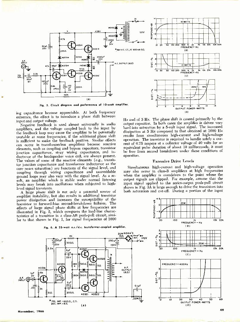
IA +1
50pF25V
A.F.INPUT
(8) 47k
10kVOL.
3..4 3.35
-it+50pF6V 180 pF
IN3193
+38V
1143193
2000pF50V
=1740310
2000pF25V
A.F. OUTPUT (ell)
co 0
%i
120V S0. 2
wcc 3
*56V A.C. C.T.,AT 600mA D.C.
140310
100k
(A)
Fig 5. Circuit diagram and performance of 10 -watt amplifier.
ing capacitance become appreciable. At both frequencyextremes, the effect is to introduce a phase shift betweeninput and output voltage.
Negative feedback is used almost universally in audioamplifiers, and the voltage coupled back to the input bythe feedback loop may cause the amplifier to be potentiallyunstable at some frequencies, if the additional phase shiftis sufficient to make the feedback positive. Similar effectscan occur in transformerless amplifiers because reactiveelements, such as coupling and bypass capacitors, transistorjunction capacitance, stray wiring capacitance, and in-ductance of the loudspeaker voice coil, are always present.The values of some of the reactive elements (e.g., transis-tor junction capacitance and transformer inductance as thecore nears saturation) are functions of the signal level, andcoupling through wiring capacitance and unavoidableground loops may also vary with the signal level. As a re-sult, an amplifier which is stable under normal listeninglevels may break into oscillations when subjected to high-level signal transients.
A large phase shift is not only a potential source ofamplifier instability, but also results in additional transistorpower dissipation and increases the susceptibility of thetransistor to forward -bias second -breakdown failures. Theeffects of large signal phase shifts at low frequencies areillustrated in Fig. 2, which compares the load -line charac-teristics of a transistor in a class -AB push-pull circuit, simi-lar to that shown in Fig. 1, for signal frequencies of 1000
10 WATTS
10 20 50 100 200 500 lk 2k 55 10k 20k 50k 100kFREQUENCY -Hz
(B)
1.0
At
06
10 WATTS
.410 20 50 100 200 500 1k 2k 5kFREQUENCY -Hz
(C)
1.5
e 1.0
E
10k 20k 50k 100k
1.
2011z/I
MHz/
2 4 6 8 10 12
OUTPUT POWER -WATTS14
Hz and of 5 Hz. The phase shift is caused primarily by theoutput capacitor. In both cases the amplifier is driven veryhard into saturation by a 5 -volt input signal. The increaseddissipation at 5 Hz compared to that obtained at 1000 Hzresults from simultaneous high -current and high -voltageoperation. The transistor is required to handle safely a cur-rent of 0.75 ampere at a collector voltage of 40 volts for anequivalent pulse duration of about 10 milliseconds; it mustbe free from second breakdown under these conditions ofoperation.
Excessive Drive LevelsSimultaneous high -current and high -voltage operation
may also occur in class -B amplifiers at high frequencieswhen the amplifier is overdriven to the point where theoutput signals are clipped. For example, assume that theinput signal applied to the series -output push-pull circuitshown in Fig. 3A is large enough to drive the transistors intoboth saturation and cut-off. During a portion of the input
Fig. 6. A 25 -watt a.c./d.c. transformer -coupled amplifier.
40231
1pF 15k
3VA.F. /a:4INPUT is,
.02
2.2k
250pF
25V
4k
30011
40320
DO2 pF
3k
51n.
2pF
25V
180
40321
1N37
180k 51011 511
250 pF
150
4032
511
29F25V
3001140321 40322
20W IN3194.51011
I.5A: 120V
A.F.OUTPUT
(8111
a/or-
*PRI. IMP..60011, C.T.SEC. IMP..8.0.
CAI
.22M11
025W
20 100 ikFREQUENCY - Hz
(B)
5
4
8!-' 3
2
1
020
10k 20k
25W
4
3
2co
0
100 1k
FREQUENCY- Hz( C )
10k 20k
FREQUENCY- 400Hz
J0o
10 20 30 40 50OUTPUT POWER -WATTS
(01
60
November, 1966 49
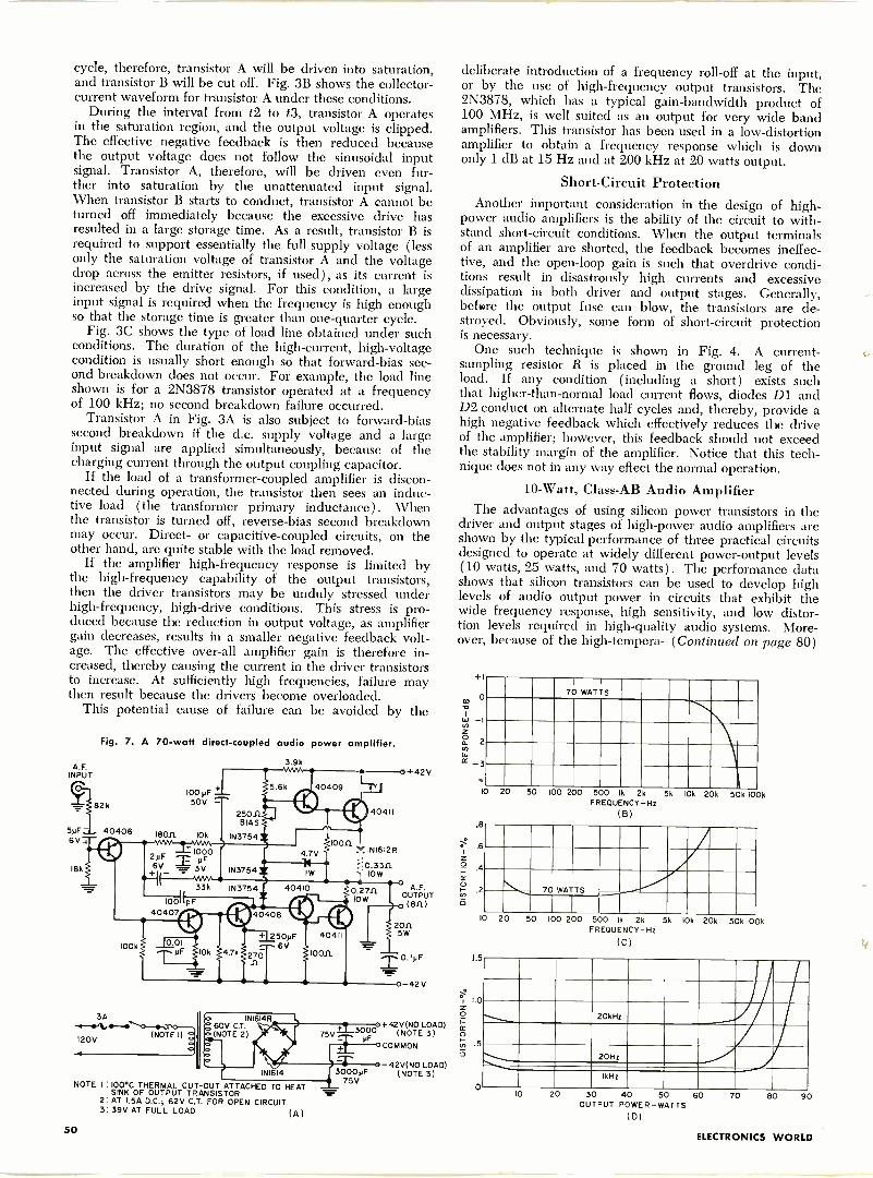
cycle, therefore, transistor A will be driven into saturation,and transistor B will be cut off. Fig. 3B shows the collector-current waveform for transistor A under these conditions.
During the interval from t2 to t3, transistor A operatesin the saturation region, and the output voltage is clipped.The effective negative feedback is then reduced becausethe output voltage does not follow the sinusoidal inputsignal. Transistor A, therefore, will be driven even fur-ther into saturation by the unattenuated input signal.When transistor B starts to conduct, transistor A cannot beturned off immediately because the excessive drive hasresulted in a large storage time. As a result, transistor B isrequired to support essentially the full supply voltage (lessonly the saturation voltage of transistor A and the voltagedrop across the emitter resistors, if used), as its current isincreased by the drive signal. For this condition, a largeinput signal is required when the frequency is high enoughso that the storage time is greater than one -quarter cycle.
Fig. 3C shows the type of load line obtained under suchconditions. The duration of the high -current, high -voltagecondition is usually short enough so that forward -bias sec-ond breakdown does not occur. For example, the load lineshown is for a 2N3878 transistor operated at a frequencyof 100 kHz; no second breakdown failure occurred.
Transistor A in Fig. 3A is also subject to forward -biassecond breakdown if the d.c. supply voltage and a largeinput signal are applied simultaneously, because of thecharging current through the output coupling capacitor.
If the load of a transformer -coupled amplifier is discon-nected during operation, the transistor then sees an induc-tive load ( the transformer primary inductance). Whenthe transistor is turned off, reverse -bias second breakdownmay occur. Direct- or capacitive -coupled circuits, on theother hand, are quite stable with the load removed.
If the amplifier high -frequency response is limited bythe high -frequency capability of the output transistors,then the driver transistors may be unduly stressed underhigh -frequency, high -drive conditions. This stress is pro-duced because the reduction in output voltage, as amplifiergain decreases, results in a smaller negative feedback volt-age. The effective over-all amplifier gain is therefore in-creased, thereby causing the current in the driver transistorsto increase. At sufficiently high frequencies, failure maythen result because the drivers become overloaded.
This potential cause of failure can be avoided by the
Fig. 7. A 70 -watt direct -coupled audio power amplifier.
A.F.INPUT
82k
5pF- 404066V4
I8k
3A
(NOTE I)120V
3.9k
NOTE I:100*C THERMAL CUT-OUT ATTACHED TO HEATSINK OF OUTPUT TRANSISTOR
2: AT I.5A D.C.; 62V C.T. FOR OPEN CIRCUIT3:39V AT FULL LOAD (A)
loonINI612R
0.33nIOW
+42V
+42V(NO LOAD)3000 (NOTE 3)COMMON
42V(NO LOAD)(NOTE 3)
deliberate introduction of a frequency roll -off at the input,or by the use of high -frequency output transistors. The2N3878, which has a typical gain -bandwidth product of100 MHz, is well suited as an output for very wide bandamplifiers. This transistor has been used in a low -distortionamplifier to obtain a frequency response which is downonly 1 dB at 15 Hz and at 200 kHz at 20 watts output.
Short -Circuit ProtectionAnother important consideration in the design of high -
power audio amplifiers is the ability of the circuit to with-stand short-circuit conditions. When the output terminalsof an amplifier are shorted, the feedback becomes ineffec-tive, and the open -loop gain is such that overdrive condi-tions result in disastrously high currents and excessivedissipation in both driver and output stages. Generally,before the output fuse can blow, the transistors are de-stroyed. Obviously, some form of short-circuit protectionis necessary.
One such technique is shown in Fig. 4. A current -sampling resistor R is placed in the ground leg of theload. If any condition (including a short) exists suchthat higher -than -normal load current flows, diodes Dl andD2 conduct on alternate half cycles and, thereby, provide ahigh negative feedback which effectively reduces the driveof the amplifier; however, this feedback should not exceedthe stability margin of the amplifier. Notice that this tech-nique does not in any way effect the normal operation.
10 -Watt, Class -AB Audio AmplifierThe advantages of using silicon power transistors in the
driver and output stages of high -power audio amplifiers areshown by the typical performance of three practical circuitsdesigned to operate at widely different power -output levels(10 watts, 25 watts, and 70 watts). The performance datashows that silicon transistors can be used to develop highlevels of audio output power in circuits that exhibit thewide frequency response, high sensitivity, and low distor-tion levels required in high -quality audio systems. More-over, because of the high -tempera- (Continued on page 80)
+1
CD
0a_ 2to
3
10 20 50
70 WATTS
100 200 500 k 2kFREQUENCY -Hz
(B)
5k 10k 20k 50k 100k
.8
.6
i= 4
cr
.2 70 WATTS
10 20 50 100 200 500 k 2k 5k 10k 20k 50k 100kFREOUENCY-Hz
(C)
1.5
1.0
.5
0
20k Hz
20Hz
!kHz
10 20 30 40 50 60OUTPUT POWER -WATTS
(D)
70 80 90
50ELECTRONICS WORLD
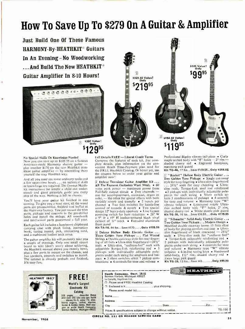
How To Save Up To $279 On A Guitar & AmplifierJust Build One Of These Famous
HARMONY-By-HEATHKIT Guitars
In An Evening - No Woodworking
... And Build The New HEATHKIT'
Guitar Amplifier In 8-10 Hours!
L.T.d $300 Value!Only
'1299'No Special Skills Or Knowledge NeededNow you can save up to $109.55 on a famousAmerican -made Harmony electric guitar -plus another $170 on the new Heathkit tran-sistor guitar amplifier - by assembling themyourself the easy Heathkit way.
And all you need are some ordinary tools anda few spare -time hours ... no technical skillsor knowledge are required. The famous Heath -kit instructions (so simple a child can under-stand) and giant pictorials guide you everystep of the way. Nothing is left to chance.
You'll have your guitar kit finished in oneevening. To give you a head start, all the woodparts are preassembled, finished and buffed atthe Harmony factory. You just mount the trimparts, pickups and controls in the pre -drilledholes and install the strings. All woodworkand mechanical parts guaranteed a full year.
Each guitar kit includes a handsome chipboardcarrying case with plush lining, instructionbook, tuning record, pick, connecting cord,and a cushioned leather neck strap.
The guitar amplifier kit will probably take youa couple of evenings. Only one small circuitboard to wire (don't worry about soldering,the Heathkit manual shows you exactly how),plus a few parts to mount on the chassis, andtwo speakers, controls and switches to install.The cabinet is already prebuilt and finished.It's easy fun.
HEATHKIT 1967
-tesstr-,
FREE!
5329.50 Value!Only
Full Details FREE - Liberal Credit TermsCompare the features of each kit. For com-plete details, plus information on the con-venient Heath Time -Payment plan send forthe FREE Heathkit Catalog. Or better yet, usethe coupon below to order your guitar andamplifier now!
N Deluxe Transistor Guitar Amplifier Kit ...All The Features Guitarists Want Most. 60watts peak power - maximum power fromFail -Safe output circuit Two channels -one for accompaniment, accordian, organ ormike, - the other for special effects with bothvariable reverb and tremolo 2 inputs perchannel Two foot switches for hands -freecontrol of tremolo & reverb Two specialdesign 12" heavy-duty speakers Line bypassreversing switch for hum reduction 28" Wx 9" D x 19" H leather -textured black vinylcabinet of 3/4" stock Extruded aluminumfront panelKit TA -16, 44 lbs...Save $170.... Only $129.95
0 Deluxe Hollow Body Electric Guitar ...Three Golden Tone Pickups ... Flat WoundStrings Double -cutaway style for easy finger-ing of all frets Ultra -slim fingerboard -24'/2"scale Ultra -slim, "uniform -feel" neck withadjustable Torque-Lok reinforcing rod 3pickups with individually adjustable pole -pieces under each string for emphasis and bal-ance 3 silent switches select 7 pickup com-binations 6 controls for tone and volume
World's LargestElectronic Kit
Catalog108 pages ... describe theseand over 250 kits you can build
. stereo/hi-fi, color TV, elec-tronic organs, radios, marine.home & hobby items. Mail cou-pon or write Heath Company,Benton Harbor, Michigan 49022.
$145 Value!Only
'99"
11 $158.50 Value!Only
'1199'
11111
11111
11:11
11111
Professional Bigsby vibrato tail -piece Curlymaple arched body with "F" holes - 2' rim -shaded cherry red Engraved headpiece,matching pick guardKit TG -46, 17 lbs... Save S109.55 .. Only $219.95
11 "Rocket" Hollow Body Electric Guitar ...Two Golden Tone Pickups Single cut -awaystyle for easy fingering Ultra -slim fingerboard
. 241/2" scale for easy chording Ultra -slim neck, Torque-Lok steel rod reinforced 2 pickups with individually adjustable pole -pieces for each string Silent switch se-lects 3 combinations of pickups 4 controlsfor tone and volume Harmony type "W"vibrato tailpiece Laminated maple Ultra -thin arched body with "F" holes, 2" rim,shaded cherry red White plastic pick guardKit TG -36, 16 lbs... Save $38.55... Only 5119.95
0 "Silhouette" Solid -Body Electric Guitar ...Two Golden Tone Pickups ... Modern Design Modified double cutaway leaves 15 frets clearof body for playing comfort and ease Ultra -slim fingerboard of black rosewood - 241/2'scale Ultra -slim neck for "uniform feel" Torque-Lok adjustable reinforcing rod
2 pickups with individually adjustable pole -pieces under each string 4 controls for toneand volume Harmony type "W" vibratotailpiece 6 -in -line tuning keys Hardwoodsolid -body, 1'/2" rim,. shaded cherry redExtra large pick guardKit TG -26, 13 lbs...Save $45 Only 699.95
Heath Company, Dept. 15-11Benton Harbor, Michigan 49022In Canada, Daystrom Ltd.0 Please send FREE Heathkit CatalogO Enclosed is S plus shipping.
Please send model (s)
Name
LEI:gram
Address
City State Zip
Prices & specifications subject to change without notice. TG -100
November, 1966CIRCLE NO. 111 ON READER SERVICE CARD
51
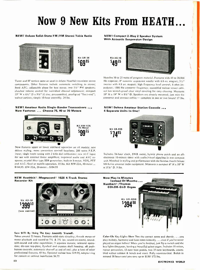
Now 9 New Kits From HEATH...NEW! Deluxe Solid -State FM /FM Stereo Table Radio
Kit GR-36
$6995
Tuner and IF section same as used in deluxe Hcathkit transistor stereocomponents. Other features include automatic switching to stereo;fixed AFC; adjustable phase for best stereo; two 51/2" PM speakers;clutched volume control for individual channel adjustment; compact19" W x 61/2" D x 91/2" H size; preassembled, prealigned "front-end";walnut cabinet; simple 10 -hour assembly. 24 lbs.
NEW! Amateur Radio Single -Bander Transceivers ...New Features ... Choose 75, 40 or 20 Meters
Kit HW-12A75 -Meter
$9995
Now features upper or lower sideband operation on all models; newdeluxe styling; more convenient control locations; 200 watts P.E.P.input; single knob tuning with 2 kHz dial calibration; new ALC inputfor use with external linear amplifiers; improved audio and AVC re-sponse; crystal filter type SSB generation; built-in S -meter, VOX, PTTand ALC; fixed or mobile operation. 15 lbs. Kit HW-22A, 40 -meter..$104.95. HW-32A, 20 -meter.. $104.95
NEW! Compact 2 -Way 2 Speaker SystemWith Acoustic Suspension Design
Kit AS -16
$4995
Handles 10 to 25 watts of program material. Features wide 45 to 20,000Hz response; 8" acoustic suspension woofer with 6.8 oz. magnet; 31/2"tweeter with 4.8 oz. magnet; high frequency level control; 8 ohm im-pedance; 1500 Hz crossover frequency; assembled walnut veneer cabi-net has scratch -proof clear vinyl covering for easy cleaning. Measures10" H x 19" W x 81/2" D. Speakers are already mounted; just wire thecrossover and connect cables - complete in one or two hours! 17 lbs.
NEW! Deluxe Amateur Station Console ...4 Separate Units In One!
Kit SB-630
$ 1495
Includes 24 -hour clock, SWR meter, hybrid phone patch and an all -electronic 10 -minute timer with audio/visual signaling in one compactunit. Matched in styling and performance with the famous Heath DeluxeSB-Series amateur radio equipment. Measures a compact 6" H x 10" Wx 11 '/H" D. 9 lbs.
NEW Heathkit' /Magnecord' 1020 4 -Track StereoRecorder Kit
Kit AD -16
$39950(less cabinet)
Save $170 By Doing The Easy Assembly Yourself.Takes around 25 hours. Features solid-state circuitry; 4 -track stereo ormono playback and record at 71/2 & 33/4 ips; sound -on -sound, sound -with -sound and echo capabilities; 3 separate motors; solenoid opera-tion; die-cast top -plate, flywheel and capstan shaft housing; all push-button controls; automatic shut-off at end of reel; plus a host of otherprofessional features. 45 lbs. Optional walnut base $19.95, adapter ringfor custom or cabinet installation $4.75
Now Play In MinutesInstead Of Months...
Heathkit /ThomasCOLOR-GLO Organ
Kit GD-325B
$39490
Color-Glo Key Lights Show You the correct notes and chords ... youplay melody, harmony and bass notes instantly ... even if you've neverplayed an organ before! When you're finished, just flip a switch and thekey lights disappear, leaving a beautiful spinet organ. Includes 10 voices,repeat percussion, 13 -note bass pedals, two 37 -note keyboards, assem-bled walnut cabinet & bench and more. Fully transistorized. Builds inaround 50 hours and you save up to $150! 172 lbs.
52 ELECTRONICS WORLD
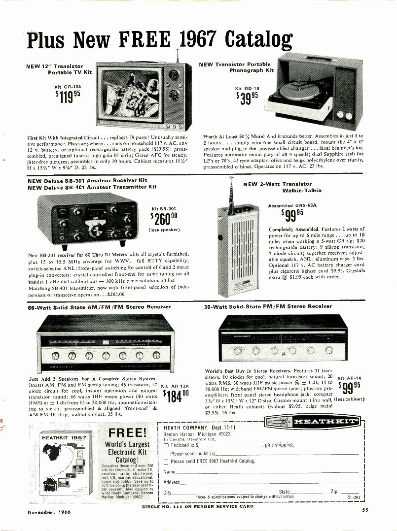
Plus New FREE 1967 CatalogNEW 12" Transistor
Portable TV Kit
Kit GR-104
$11995
First Kit With Integrated Circuit ... replaces 39 parts! Unusually sensi-tive performance. Plays anywhere ... runs on household 117 v. AC, any12 v. battery, or optional rechargeable battery pack ($39.95); preas-sembled, prealigned tuners; high gain IF strip; Gated AFC for steady,jitter -free pictures; assembles in only 10 hours. Cabinet measures 111/2"H x 15Y4" W x 9%" D. 23 lbs.
NEW Transistor PortablePhonograph Kit
Kit GD-16
$3995
Worth At Least 50 % More! And it sounds better. Assembles in just 1 to2 hours . . . simply wire one small circuit board, mount the 4" x 6"speaker and plug in the preassembled changer ... ideal beginner's kit.Features automatic mono play of all 4 speeds; dual Sapphire styli forLP's or 78's; 45 rpm adapter; olive and beige polyethylene over sturdy.preassembled cabinet. Operates on 117 v. AC. 23 lbs.
NEW Deluxe SB-301 Amateur Receiver KitNEW Deluxe SB-401 Amateur Transmitter Kit
Kit SB-301
$260"(less speaker)
New SB-301 receiver for 80 Thru 10 Meters with all crystals furnished,plus 15 to 15.5 MHz coverage for WWV; full RTTY capability;switch -selected ANL; front -panel switching for control of 6 and 2 meterplug-in converters; crystal -controlled front-end for same tuning on allbands; 1 kHz dial calibrations - 100 kHz per revolution. 23 lbs.Matching SB-401 transmitter, now with front -panel selection of inde-pendent or transceive operation... $285.00
NEW 2 -Watt TransistorWalkie-Talkie
Assembled GRS-65A
$9995
Completely Assembled. Features 2 watts ofpower for up to 6 mile range . .. up to 10miles when working a 5 -watt CB rig; $20rechargeable battery; 9 silicon transistor,2 diode circuit; superhet receiver; adjust-able squelch, ANL; aluminum case. 3 lbs.Optional 117 v. AC battery charger cordplus cigarette lighter cord $9.95. Crystalsextra ® $1.99 each with order.
66 -Watt Solid -State AM /FM /FM Stereo Receiver
Just Add 2 Speakers For A Complete Stereo System.Boasts AM, FM and FM stereo tuning; 46 transistor, 17diode circuit for cool, instant operation and naturaltransistor sound; 66 watts IHF music power (40 wattsRMS) at ± 1 db from 15 to 30,000 Hz; automatic switch-ing to stereo; preassembled & aligned "front-end" &AM -FM IF strip; walnut cabinet. 35 lbs.
rHEATHKIT" 1967 FREE!World's Largest
Electronic KitCatalog!
Describes these and over 250kits for stereo/hi-fi, color TV.amateur radio, shortwave.test, CB, marine, educational,home and hobby. Save up to50% by doing the easy assem-bly yourself. Mail coupon orwrite Heath Company, BentonHarbor, Michigan '49022
Kit AR -13A
$184"
30 -Watt Solid -State FM /FM Stereo Receiver
World's Best Buy In Stereo Receivers. Features 31 tran-sistors, 10 diodes for cool, natural transistor sound; 20watts RMS, 30 watts IHF music power ® ± 1 db, 15 to50,000 Hz; wideband FM/FM stereo tuner; plus two pre-amplifiers; front panel stereo headphone jack; compact3 ye H x 15,/4" W x 12"D size. Custom mount it in a wall, (less cabinet)
or either Heath cabinets (walnut $9.95, beige metal$3.95). 16 lbs.
HEATH COMPANY, Dept.15-11Benton Harbor, Michigan 49022In Canada, Daystrom Ltd.0 Enclosed is $ plus shipping.
Please send model (s)
El Please send FREE 1967 Heathkit Catalog.
Kit AR -14
$9995
Name
Address
CityPrices & specifications subject to change without notice.
State ZipCL -261
November, 1966CIRCLE NO. 111 ON READER SERVICE CARD
55
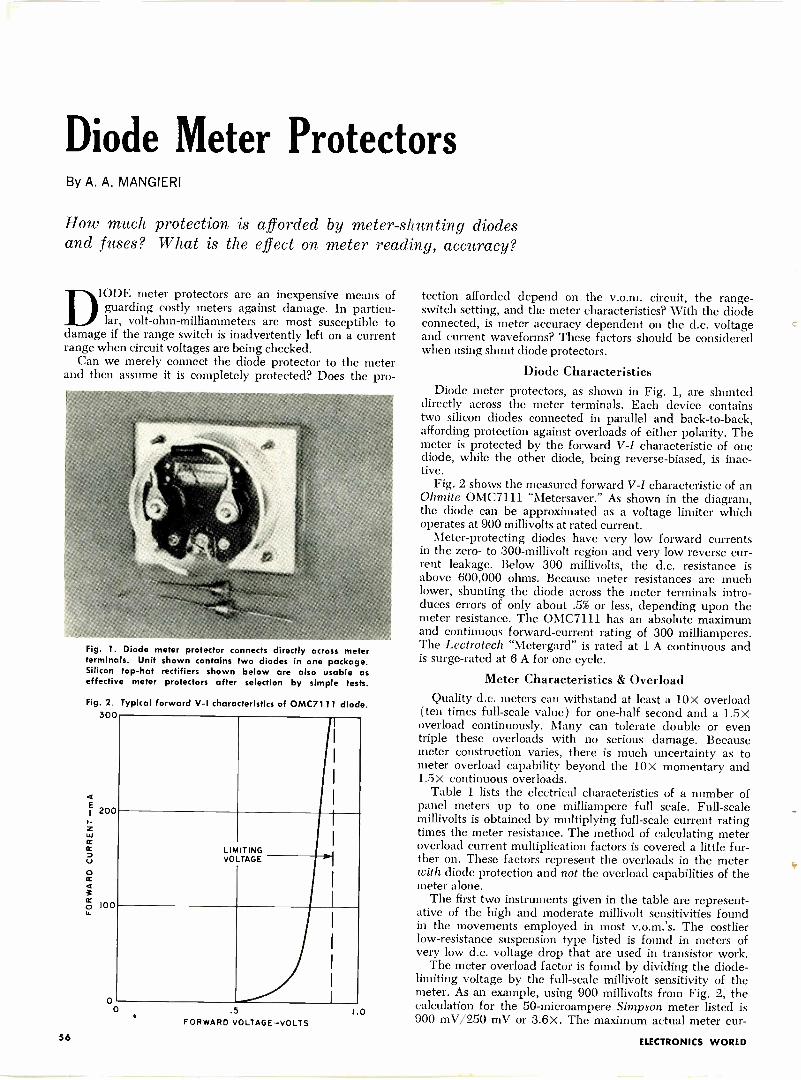
Diode Meter ProtectorsBy A. A. MANGIERI
How much protection is afforded by meter -shunting diodesand fuses? What is the effect on meter reading, accuracy?
DIODE meter protectors are an inexpensive means ofguarding costly meters against damage. In particu-lar, volt-ohm-milliammeters are most susceptible to
damage if the range switch is inadvertently left on a currentrange when circuit voltages are being checked.
Can we merely connect the diode protector to the meterand then assume it is completely protected? Does the pro -
Fig. 1. Diode meter protector connects directly across meterterminals. Unit shown contains two diodes in one package.Silicon top -hat rectifiers shown below are also usable aseffective meter protectors after selection by simple tests.
Fig. 2. Typical forward V -I characteristics of OMC7111 diode.300
200
100
00
LIMITINGVOLTAGE
.5
FORWARD VOLTAGE-VOLTSt0
tection afforded depend on the v.o.m. circuit, the range-switch setting, and the meter characteristics? With the diodeconnected, is meter accuracy dependent on the d.c. voltageand current waveforms? These factors should be consideredwhen using shunt diode protectors.
Diode CharacteristicsDiode meter protectors, as shown in Fig. 1, are shunted
directly across the meter terminals. Each device containstwo silicon diodes connected in parallel and back-to-back,affording protection against overloads of either polarity. Themeter is protected by the forward V -I characteristic of onediode, while the other diode, being reverse -biased, is inac-tive.
Fig. 2 shows the measured forward V -I characteristic of anOhmite OMC7111 "Metersaver." As shown in the diagram,the diode can be approximated as a voltage limiter whichoperates at 900 millivolts at rated current.
Meter -protecting diodes have very low forward currentsin the zero- to 300 -millivolt region and very low reverse cur-rent leakage. Below 300 millivolts, the d.c. resistance isabove 600,000 ohms. Because meter resistances are muchlower, shunting the diode across the meter terminals intro-duces errors of only about .5% or less, depending upon themeter resistance. The OMC7111 has an absolute maximumand continuous forward -current rating of 300 milliamperes.The Lectrotech "Metergard" is rated at 1 A continuous andis surge -rated at 6 A for one cycle.
Meter Characteristics & OverloadQuality d.c. meters can withstand at least a 10x overload
(ten times full-scale value) for one-half second and a 1.5xoverload continuously. Many can tolerate double or eventriple these overloads with no serious damage. Becausemeter construction varies, there is much uncertainty as tometer overload capability beyond the 10x momentary and1.5 x continuous overloads.
Table 1 lists the electrical characteristics of a number ofpanel meters up to one milliampere full scale. Full-scalemillivolts is obtained by multiplying full-scale current ratingtimes the meter resistance. The method of calculating meteroverload current multiplication factors is covered a little fur-ther on. These factors represent the overloads in the meterwith diode protection and not the overload capabilities of themeter alone.
The first two instruments given in the table are represent-ative of the high and moderate millivolt sensitivities foundin the movements employed in most v.o.m.'s. The costlierlow -resistance suspension type listed is found in meters ofvery low d.c. voltage drop that are used in transistor work.
The meter overload factor is found by dividing the diode -
limiting voltage by the full-scale millivolt sensitivity of themeter. As an example, using 900 millivolts from Fig. 2, thecalculation for the 50 -microampere Simpson meter listed is900 mV/250 mV or 3.6x. The maximum actual meter cur -
56 ELECTRONICS WORLD
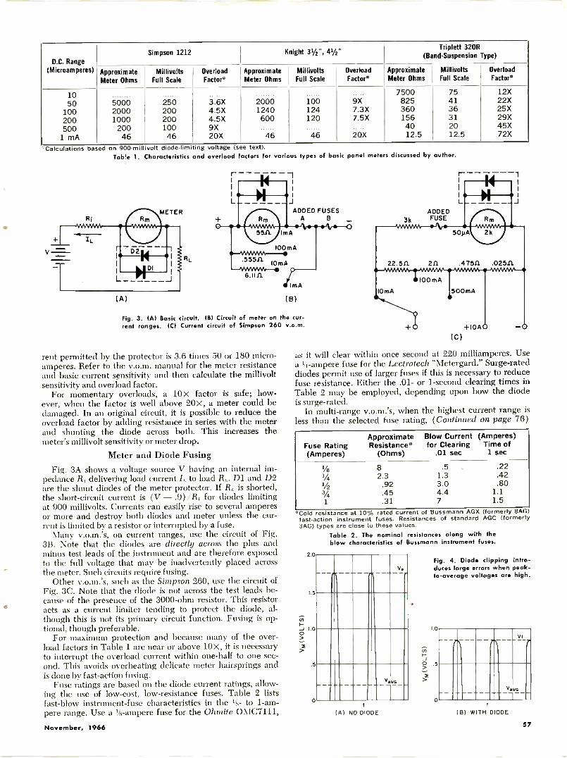
D.C. Range(Microamperes)
Simpson 1212 Knight VA", 41/2"Triplett 320R
(Band -Suspension Type)
Approximate MillivoltsMeter Ohms Full Scale
OverloadFactor°
Approximate MillivoltsMeter Ohms Full Scale
OverloadFactor°
Approximate MillivoltsMeter Ohms Full Scale
OverloadFactor*
10 7500 75 12X
50 5000 250 3.6X 2000 100 9X 825 41 22X
100 2000 200 4.5X 1240 124 7.3X 360 36 25X
200 1000 200 4.5X 600 120 7.5X 156 31 29X
500 200 100 9X 40 20 45X
1 mA 46 46 20X 46 46 20X 12.5 12.5 72X
'Calculations based on 900 -millivolt diode -limiting voltage (see text).Table 1. Characteristics and overload factors for various types of basic panel meters discussed by author.
6.1111
(A)
ADDED FUSESA
(B)
Fig. 3. (A) Basic circuit. (B) Circuit of meter on the cur-rent ranges. (C) Current circuit of Simpson 260 v.o.m.
rent permitted by the protector is 3.6 times 50 or 180 micro-amperes. Refer to the v.o.m. manual for the meter resistanceand basic current sensitivity and then calculate the millivoltsensitivity and overload factor.
For momentary overloads, a 10x factor is safe; how-ever, when the factor is well above 20X, a meter could bedamaged. In an original circuit, it is possible to reduce theoverload factor by adding resistance in series with the meterand shunting the diode across both. This increases themeter's millivolt sensitivity or meter drop.
Meter and Diode FusingFig. 3A shows a voltage source V having an internal im-
pedance R, delivering load current /,, to load R,. D1 and D2are the shunt diodes of the meter protector. If R,, is shorted,the short-circuit current is (V - .9)/R, for diodes limitingat 900 millivolts. Currents can easily rise to several amperesor more and destroy both diodes and meter unless the cur-rent is limited by a resistor or interrupted by a fuse.
Many v.o.m.'s, on current ranges, use the circuit of Fig.3B. Note that the diodes are directly across the plus andminus test leads of the instrument and are therefore exposedto the full voltage that may be inadvertently placed acrossthe meter. Such circuits require fusing.
Other v.o.m.'s, such as the Simpson 260, use the circuit ofFig. 3C. Note that the diode is not across the test leads be-cause of the presence of the 3000 -ohm resistor. This resistoracts as a current limiter tending to protect the diode, al-though this is not its primary circuit function. Fusing is op-tional, though preferable.
For maximum protection and because many of the over-load factors in Table 1 are near or above 10x, it is necessaryto interrupt the overload current within one-half to one sec-ond. This avoids overheating delicate meter hairsprings andis done by fast -action fusing.
Fuse ratings are based on the diode current ratings, allow-ing the use of low-cost, low -resistance fuses. Table 2 listsfast -blow instrument -fuse characteristics in the 4c- to 1 -am-pere range. Use a Vs -ampere fuse for the Ohmite OMC7111,
3k
r -
LADDEDFUSE
100 m A
10mA 500mA
as it will clear within once second at 220 milliamperes. Usea 11 -ampere fuse for the Lectrotech "Metergard." Surge -rateddiodes permit use of larger fuses if this is necessary to reducefuse resistance. Either the .01- or 1 -second clearing times inTable 2 may be employed, depending upon how the diodeis surge -rated.
In multi -range v.o.m.'s, when the highest current range isless than the selected fuse rating, (Continued on page 76)
Fuse Rating(Amperes)
ApproximateResistance"'
(Ohms)
Blow Currentfor Clearing
.01 sec
(Amperes)Time of
1 sec
1/8 8 .5 .221/4 2.3 1.3 .42
1/2 .92 3.0 .803/4 .45 4.4 1.11 .31 7 1.5
*Cold resistance at 10%fast -action instrument3AG) types are close to
Table 2. Theblow characte
2.0
1.5
r3
_1 1.0O
.5
0
rated current of Bussmann AGX (formerly 8AGfuses. Resistances of standard AGC (formerlythese values.nominal resistances along with theristics of Bussmann instrument fuses.
--1(A) NO DIODE
Viva
Fig. 4. Diode clipping intro-duces large errors when peak -to -average voltages are high.
1.0
(7)
'0 5>X
0
- -11 r1VI
-7
V
±16
B) WITH DIODE
November, 1966 57
JOHNFRYE
Under the terms of a recently passed benefits act, veteransare entitled to receive broad -based educational assistance.
THE 1966 G.I. BILLAN, am I tuckered!" Barney said, smothering ayawn. "What kept you up late, hamming ordating?" Mac, his boss, asked. "Nothing so fun -
type," Barney replied. "A cousin of mine, fresh out of theArmy and just home from Vietnam, and I were tryingto figure out what help he could expect in continuing hisinterrupted education under the new Veterans' Readjust-ment Benefits Act of 1966. Believe me," Barney said, tap-ping a pamphlet on the bench in front of him, "wadingthrough Public Law 98-358 here is worse than trying totrace one of those postage -stamp -size circuits pasted inthe back of a Japanese transistor radio."
"Okay," Mac said, lighting his pipe and leaning backagainst the bench, "tell me about it. You know you'rebusting to."
"Thought you'd never ask," Barney said with a grin."Anyway, the purpose of the bill is to make service in theArmed Forces more attractive, to help young people getan education they could not otherwise afford, and to com-pensate in part for educational and career sacrifices madeby young men serving their country."
"Who's eligible for this help?""You make a wonderful straight man; you ask precisely
the right questions-the ones I can answer," Barney mar-veled. "Any veteran is eligible for benefits who served onactive duty for more than 180 days, any part of whichoccurred after January 31, 1955, and who was releasedunder conditions 'other than dishonorable.' If he was re-leased from active duty after January 31, 1955 for a ser-vice -connected disability, the 180 -days -plus requirement iswaived. And if he has served on active duty for at leasttwo years and continues to serve on active duty, he iseligible for benefits while still in the service.
"But he doesn't get active -duty credit for training. Hecan't count a period when assigned by his service full-timeto a civilian institution for a course substantially the sameas one offered civilians, or periods of service as a cadetor midshipman in a service academy, or active trainingin the National Guard or Reserves."
"Where can he go to school? What kind of courses canhe take?"
"He can attend any institution approved for training,including public or private secondary, vocational, corre-spondence, or business school; junior or teachers' college,normal school, college or university, professional, scien-tific, or technical institution, or any other institution whichfurnishes education at the secondary level or above."
"I notice you say 'approved' institution. I don't supposethe benefit would be granted for a course in surfboardriding."
"You suppose right. The Veterans' Administrator will notapprove any course which is avocational or recreational incharacter unless the veteran can prove the course will beof practical use in his present or contemplated business oroccupation. The Administrator ordinarily will not approveflight training, apprentice or other on-the-job training or
institutional on -farm training. Neither will benefits begranted for open -circuit TV courses unless they are partof an in -residence program leading to a college degree."
"Let's get to the grubby, but interesting, details: howmuch money will the veteran receive?"
"That depends on several factors. If he engages in full-time institutional training, consisting of a minimum of 14semester hours or the equivalent, he will be eligible for$100 per month. Having one dependent raises this to $125.Two dependents or more brings it to $150. On the otherhand, if he takes only three-quarter time training, consist-ing of 10 to 13 semester hours or equivalent, the monthlypayments are reduced to roughly three -fourths those fig-ures. If he takes half-time training, consisting of 7 to 9hours, payments are reduced to approximately one-halfthe full-time figures. Payments for a person taking lessthan half-time training or for one taking training while onactive duty are computed at the rate of the establishedcharges for tuition and fees required of non -veterans takingthe course or at $100 per month for a full-time course,whichever is the lesser. Payments for veterans taking co-operative training is $80 a month for no dependents, $100for one dependent, and $120 for two or more dependents."
"How about veterans taking courses by correspondence?""The educational assistance allowance will be computed
on the basis of the established charge paid by non -veteransfor the same courses. The actual -cost allowance is paidquarterly on a pro rata basis for the lessons completed bythe veteran and serviced and certified by the school."
"How long do these payments go on?""Each eligible person is entitled to educational assis-
tance for a period of one month, or the equivalent in part-time training, for each month or fraction thereof of hisactive -duty service after January 31, 1955, but not to ex-ceed 36 months. Thus entitlement resulting from threeyears of active service would see the veteran through fouryears of college if he attended full-time nine months peryear. If he took half-time training, he would use up halfa month of his entitlement and receive half the full-timerate for each month he took the training. As you can see,this works out so all veterans eligible for the same amountof entitlement can eventually receive substantially thesame amount of assistance whether they elect to takefull, three-quarter, or half-time training. In the case ofa veteran taking a program of education exclusively bycorrespondence, 34 the elapsed time in following this pro-gram would be charged against his period of entitlement."
"Isn't there any limit on the time this offer is good?""In a way, yes. The veteran's education must be com-
pleted within eight years from the date of his dischargeor from June 1, 1966, whichever is later."
"Can the assistance be lost for any reason?""You bet. The Administrator must discontinue the allow-
ance if, at any time, he finds the veteran's conduct orprogress unsatisfactory according to regularly prescribedstandards and practices of the school in which he is en -
58 ELECTRONICS WORLD
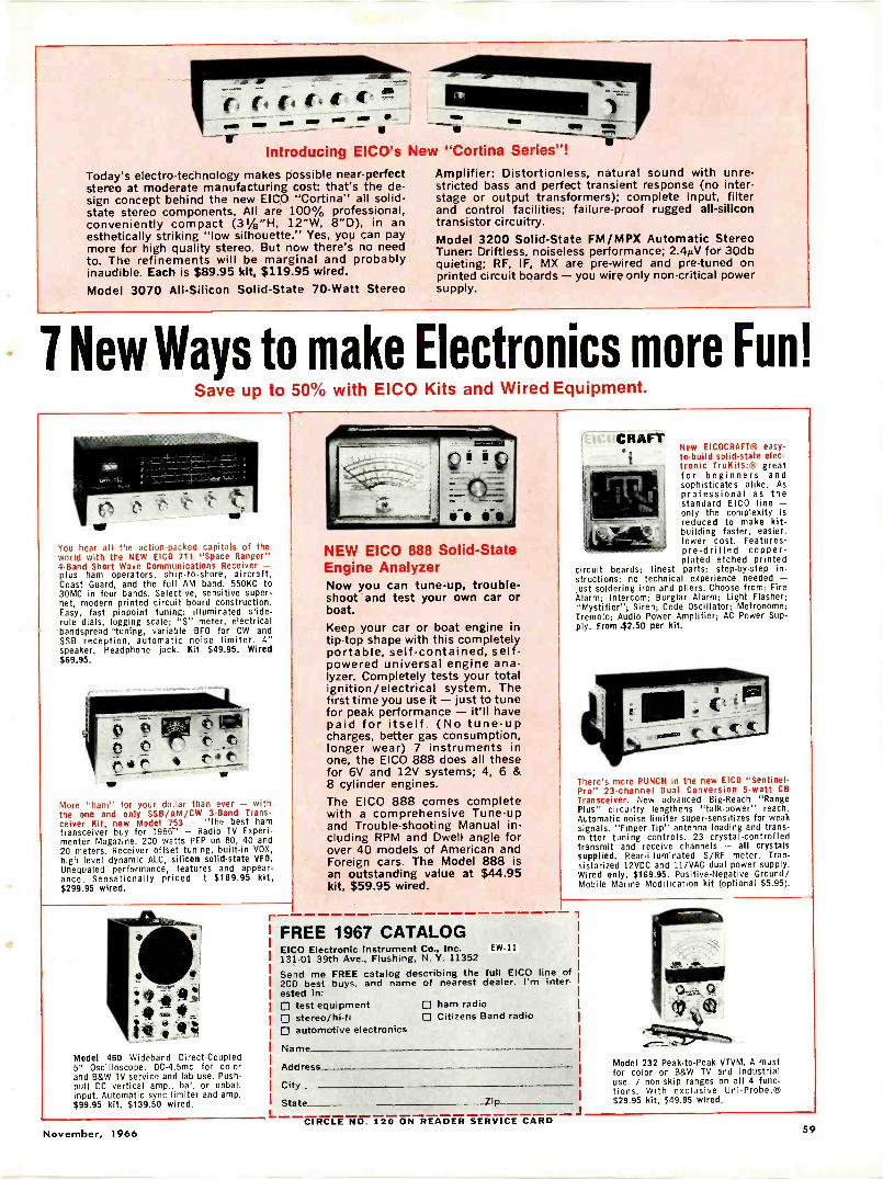
UMW....
V lay ma-*-Introducing EICO's New "Cortina Series"!
Today's electro-technology makes possible near -perfectstereo at moderate manufacturing cost: that's the de-sign concept behind the new EICO "Cortina" all solid-state stereo components. All are 100% professional,conveniently compact (31/4"H, 12"W, 8"D), in anesthetically striking "low silhouette." Yes, you can paymore for high quality stereo. But now there's no needto. The refinements will be marginal and probablyinaudible. Each is $89.95 kit, $119.95 wired.Model 3070 All -Silicon Solid -State 70 -Watt Stereo
Amplifier: Distortionless, natural sound with unre-stricted bass and perfect transient response (no inter -stage or output transformers); complete input, filterand control facilities; failure -proof rugged all -silicontransistor circuitry.Model 3200 Solid -State FM /MPX Automatic StereoTuner: Driftless, noiseless performance; 2.4AV for 30dbquieting; RF, IF, MX are pre -wired and pre -tuned onprinted circuit boards - you wire only non -critical powersupply.
7 New Ways to make Electronics more Fun!Save up to 50% with EICO Kits and Wired Equipment.
You hear all the action -packed capitals of theworld with the NEW EICO 711 "Space Ranger"4 -Band Short Wave Communications Receiver -plus ham operators, ship -to -shore, aircraft,Coast Guard, and the full AM band. 550KC to30MC in four bands. Selective, sensitive super -het, modern printed circuit board construction.Easy, fast pinpoint tuning: illuminated slide -rule dials, logging scale; "S" meter, electricalbandspread tuning, variable BFO for CW andSSB reception, automatic noise limiter. 4"speaker. Headphone jack. Kit $49.95. Wired$69.95.
More "ham" for your dollar than ever - withthe one and only SSB/AM/CW 3 -Band Trans-ceiver Kit, new Model 753 - "the best hamtransceiver buy for 1966" - Radio TV Experi-menter Magazine. 200 watts PEP on 80, 40 and20 meters. Receiver offset tuning, built-in VOX,high level dynamic ALC, silicon solid-state VFO.Unequaled performance, features and appear-ance. Sensationally priced t $189.95 kit,$299.95 wired.
r
Model 460 Wideband Direct -Coupled5" Oscilloscope. DC-4.5mc for colorand B&W TV service and lab use. Push-pull DC vertical amp., bal. or unbal.input. Automatic sync limiter and amp.$99.95 kit, $139.50 wired.
NEW EICO 888 Solid -StateEngine AnalyzerNow you can tune-up, trouble-shoot and test your own car orboat.Keep your car or boat engine intip-top shape with this completelyportable, self-contained, self -powered universal engine ana-lyzer. Completely tests your totalignition/electrical system. Thefirst time you use it - just to tunefor peak performance - it'll havepaid for itself. (No tune-upcharges, better gas consumption,longer wear) 7 instruments inone, the EICO 888 does all thesefor 6V and 12V systems; 4, 6 &8 cylinder engines.The EICO 888 comes completewith a comprehensive Tune-upand Trouble -shooting Manual in-cluding RPM and Dwell angle forover 40 models of American andForeign cars. The Model 888 isan outstanding value at $44.95kit, $59.95 wired.
New EICOCRAFT1+, easy -to -build solid-state elec-tronic TruKits:® greatfor beginners andsophisticates alike. Asprofessional as thestandard EICO line -only the complexity Isreduced to make kit -building faster, easier,lower cost. Features:pre -drilled copper -plated etched printed
circuit boards; finest parts; step-by-step in-structions; no technical experience needed -just soldering iron and pliers. Choose from: FireAlarm; Intercom; Burglar Alarm; Light Flasher;"Mystifier"; Siren; Code Oscillator; Metronome;Tremolo; Audio Power Amplifier; AC Power Sup-ply. From $2.50 per kit.
There's more PUNCH in the new EICO "Sentinel -Pro" 23 -channel Dual Conversion 5 -watt CBTransceiver. New advanced Big -Reach "RangePlus" circuitry lengthens "talk -power" reach.Automatic noise limiter super -sensitizes for weaksignals. "Finger Tip" antenna loading and trans-mitter tuning controls. 23 crystal -controlledtransmit and receive channels - all crystalssupplied. Rear -illuminated S/RF meter. Tran-sistorized 12VDC and 117VAC dual power supply.Wired only, $169.95. Positive -Negative Ground/Mobile Marine Modification kit (optional $5.95).
FREE 1967 CATALOGEICO Electronic Instrument Co., Inc. EW-11131.01 39th Ave., Flushing, N. Y. 11352Send me FREE catalog describing the full EICO line of200 best buys, and name of nearest dealer. I'm inter-ested in:El test equipment 0 ham radio stereo/hi-fi El Citizens Band radio0 automotive electronics
Name
Address
City
State Zip
Model 232 Peak -to -Peak VTVM. A mustfor color or B&W TV and industrialuse. 7 non -skip ranges on all 4 func-tions. With exclusive Uni-Probe.®$29.95 kit, $49.95 wired.
November, 1966CIRCLE NO. 120 ON READER SERVICE CARD
59
Electronics WorldSUBSCRIBER SERVICE
Please include an address label when writing aboutyour subscription to help us serve you promptly.Write to: Portland Place, Boulder, Colo. 80302
Change of Address:Please let us knowyou are moving atleast 4 weeks in ad-vance. Affix magazineaddress label in spaceto the right and printnew address below. Ifyou have a questionabout your subscrip-tion, attach addresslabel to your letter.
To Subscribe:Check boxes below.
0 New 0 Renewal0 5 years $210 3 years $150 1 year $6
Specify0 Payment enclosed- You get 1 extraissue per year FREE!
;2.
f;'
0 Bill me later. L.
'77
a
-nome pleose print
0147
address
city
slate zip -code
Enjoy the "music -only" programsnow available on the FM broadcast
band from coast to coast.
NO COMMERCIALS NO INTERRUPTIONS
It's easy! Just plug Music Associated's SubCarrier Detector into multiplex jack of youiFM tuner or easily wire into discriminator.Tune through your FM dial and hear programsof continuous, commercial -free music you arenow missing. The Detector, self -powered andwith electronic mute for quieting betweenselections, permits reception of popular back-ground music programs no longer sent by wirebut transmitted as hidden programs on theFM broadcast band from cod%t to coast. Usewith any FM tuner. Size: 51/2" x 6". Shippingweight approx. 7 lbs.
KIT $4950(with pre -tuned coils, no alignment necessary)
WIRED $7500COVER $4.95 EXTRA
Current List of FM Broadcast Stations with SCAauthorization $1.00
MUSIC ASSOCIATED55 Glenwood Road, Upper Montclair, New Terse,
Phone: (201)-744-3387
I5'
5'
I444
5'
441,
5'
Sir
5'
4f
,
rolled. However, the Administrator canrenew the allowance if the cause of theunsatisfactory conduct or progress isremoved and the program the veterannow proposes to pursue-whether oldor new-is suited to his aptitudes, in-terests, and abilities."
"Then he can change his course?""Each veteran can make one change
of program of education if his originalprogram has not been interrupted ordiscontinued through his own fault.However, the Administrator may ap-prove one additional change (or an ini-tial change otherwise not permittedbecause of the student's failure) if itseems the veteran has a better likeli-hood of success by undertaking a newprogram."
"You spoke of a veteran's obtainingthis educational assistance while still inservice. Does that mean he could bepaid for training in a foreign school?"
"In some approved institutions ofhigher learning, yes. Keep in mind thatany institution in which the veterantakes training, domestic or foreign,must have VA approval before the ed-ucational assistance will be allowed.Furthermore, the Administrator at hisdiscretion may deny or discontinue ed-ucational assistance to a vet in a foreigneducational institution if he finds suchenrollment is not for the best interestof the veteran or the Government."
"Let's suppose our veteran is alreadyengaged in a program of education athis own expense when payments start-ed on June 1, 1966. Can he obtain edu-cational assistance to help him continuethis program? Can he obtain retroac-tive payments back to the time hestarted the course?"
"By obtaining approval of his course,he could receive payments to help himcontinue that course, but he could notobtain any retroactive payments goingback beyond June 1, 1966. Benefits arepaid starting with June, 1966 but onlyto veterans beginning a course in thatmonth or those enrolled in a coursewhich will continue beyond that month."
Mac reached over and picked up thepamphlet to which Barney had beenreferring and leafed through it. "Didyou winnow all this information out ofthe fine print in this booklet?" he de-manded.
"I had other help," Barney admitted."The Veterans' Administration, Wash-ington, D.C. 20420, put out a sum-mary of the Act entitled 'VA Pamphlet23-66-1' that helps explain the legalwording. And the National Home StudyCouncil, 1601 18th Street, N.W., Wash-ington, D.C. 20009, has issued a coupleof clarifying bulletins, #14 and #26,that are most helpful in understandingthe law, especially as it pertains to cor-respondence schools. My cousin hadthese with him."
"Just what does your cousin, or any
other eligible person, have to do to ob-tain this educational assistance underthe new G.I. Bill?"
"First, he obtains an application format any VA office, active -duty station, orAmerican Embassy. He fills this outand submits it to the nearest VA Re-gional Office if he is in the UnitedStates. If he is living outside the coun-try, he submits his application and allsubsequent communications to thenearest American Embassy for trans-mittal to the VA Benefits Office, 2033M Street, N. W., Washington, D.C.20421. If he is a veteran, he encloses acopy of his separation document, DDForm 214, with the application. Ac-tive -duty personnel must submit aStatement of Service from their Com-manding Officer or designate. To re-ceive additional allowance for a depen-dent ( wife, child, or dependent par-ent), a certified copy of the publicrecord of the marriage, birth, etc.,should also accompany the application."
"I hope every veteran now eligible,and every one who later becomes eligi-ble, will apply for this educational as-sistance," Mac said. "It's a wonderfulopportunity, honestly earned, for thesefellows to equip themselves to taketheir rightful place in the world theyhave helped preserve. And I'll bet a lotof them will take their training in ourfield-not necessarily in service work,but in some of the many other branchesof electronics offering an attractive fu-ture, such as computers, space elec-tronics, medical electronics, communi-cations, color -TV broadcasting, and in-dustrial electronics.
"After all, most of those men havehad to postpone their own plans forcollege or advanced training and it isonly fair for Uncle Sam to give them ahand when they've finished the job.Such financial help is a very small re-turn for what they've done for us."
"I'm with you, and the thing I likeabout the Act is its broad base. It offerssomething to practically every veteran.If he already has the necessary credits,he can use his benefits to become anelectrical engineer or an electronics en-gineer. If he lacks the credits to getinto a university or if he wants to workwhile he is training, he can take part-time vocational training or can securehis education at his own pace throughcorrespondence. Fellows who learnmore easily by doing rather than study-ing can take advantage of the coopera-tive schools. Finally, through the ac-tive -service allowance, a person in theArmed Forces can, if he wishes, starthis training while he is still on activeduty."
"Yep," Mac concluded the conversa-tion, "the opportunity is there for thetaking, and if I were eligible I'd cer-tainly take advantage of it at the veryfirst chance."
CIRCLE NO. 99 ON READER SERVICE CARD60 CIRCLE NO. 86 ON READER SERVICE CARD -48r
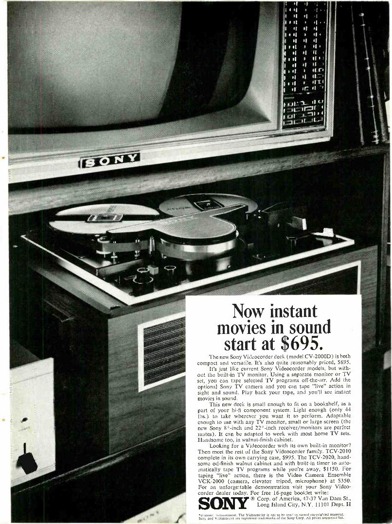
I If
if 01
I of I lisif s lis.
s
ill s siltif If li '
s of s 111'if if 11 '
s i if4 11 li '
":.11:--11.1
'
7,=1:,..' -11 --
Now instantmovies in soundstart at $695.
The new Sony Videocorder deck (model CV -2000D) is bothcompact and versatile. It's also quite reasonably priced, $695,
It's just like current Sony Videocorder models, but with-out the built-in TV monitor. Using a separate monitor or TVset, you can tape selected TV programs off -the -air. Add theoptional Sony TV camera and you can tape "live" action insight and sound. Play back your tape, and you'll see instantmovies in sound.
This new deck is small enough to fit on a bookshelf, as apart of your hi-fi component system. Light enough (only 44lbs.) to take wherever you want it to perform. Adaptableenough to use with any TV monitor, small or large screen (thenew Sony 8'^ -inch and 22" -inch receiver/monitors are perfectmates). It can be adapted to work with most home TV sets.Handsome too, in walnut -finish cabinet.
Looking for a Videocorder with its own built-in monitor?Then meet the rest of the Sony Videocorder family. TCV-2010complete in its own carrying case, $995. The TCV-2020, hand-some oil -finish walnut cabinet and with built-in timer to auto-matically tape TV programs while you're away, $1150. Fortaping "live" action, there is the Video Camera EnsembleVCK-2000 (camera, elevator tripod, microphone) at $350.For an unforgettable demonstration visit your Sony Video -corder dealer today. For free 16 -page booklet write:
SONY®
Corp.Long
IsflandaAndniCe riitcya, N47Y-371 VI la0n1
Dpaemp StH. ,
*diagonal measurement. The Videocorder is not to be used to record copyrighted material.Sony and Videocorder are registered trademarks of the Sony Corp. All prices suggested list.
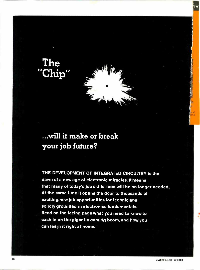
The"Chip"
e
41
...will it make or breakyour job future?
THE DEVELOPMENT OF INTEGRATED CIRCUITRY is the
dawn of a new age of electronic miracles. It meansthat many of today's job skills soon will be no longer needed.At the same time it opens the door to thousands ofexciting new job opportunities for technicianssolidly grounded in electronics fundamentals.Read on the facing page what you need to know tocash in on the gigantic coming boom, and how youcan learn it right at home.
of4
62 ELECTRONICS WORLD
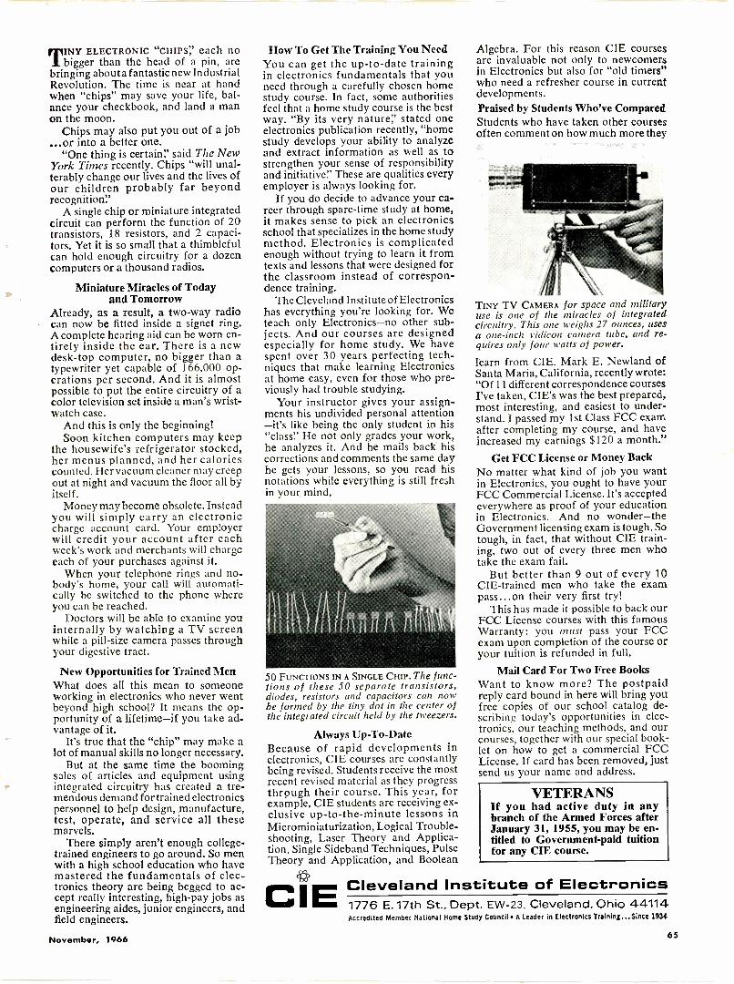
INY ELECTRONIC "CHIPS:' each no1 bigger than the head of a pin, arebringing about a fantastic new IndustrialRevolution. The time is near at handwhen "chips" may save your life, bal-ance your checkbook, and land a manon the moon.
Chips may also put you out of a job...or into a better one.
"One thing is certain!' said The NewYork Thnes recently. Chips "will unal-terably change our lives and the lives ofour children probably far beyondrecognition!'
A single chip or miniature integratedcircuit can perform the function of 20transistors, 18 resistors, and 2 capaci-tors. Yet it is so small that a thimblefulcan hold enough circuitry for a dozencomputers or a thousand radios.
Miniature Miracles of Todayand Tomorrow
Already, as a result, a two-way radiocan now be fitted inside a signet ring.A complete hearing aid can be worn en-tirely inside the ear. There is a newdesk -top computer, no bigger than atypewriter yet capable of 166,000 op-erations per second. And it is almostpossible to put the entire circuitry of acolor television set inside a man's wrist-watch case.
And this is only the beginning!Soon kitchen computers may keep
the housewife's refrigerator stocked,her menus planned, and her caloriescounted. Her vacuum cleaner may creepout at night and vacuum the floor all byitself.
Money may become obsolete. Insteadyou will simply carry an electroniccharge account card. Your employerwill credit your account after eachweek's work and merchants will chargeeach of your purchases against it.
When your telephone rings and no-body's home, your call will automati-cally be switched to the phone whereyou can be reached.
Doctors will be able to examine youinternally by watching a TV screenwhile a pill -size camera passes throughyour digestive tract.
New Opportunities for Trained MenWhat does all this mean to someoneworking in electronics who never wentbeyond high school? It means the op-portunity of a lifetime-if you take ad-vantage of it.
It's true that the "chip" may make alot of manual skills no longer necessary.
But at the same time the boomingsales of articles and equipment usingintegrated circuitry has created a tre-mendous demand fortrained electronicspersonnel to help design, manufacture,test, operate, and service all thesemarvels.
There simply aren't enough college -trained engineers to go around. So menwith a high school education who havemastered the fundamentals of elec-tronics theory are being begged to ac-cept really interesting, high -pay jobs asengineering aides, junior engineers, andfield engineers.
How To Get The Training You NeedYou can get the up-to-date trainingin electronics fundamentals that youneed through a carefully chosen homestudy course. In fact, some authoritiesfeel that a home study course is the bestway. "By its very nature!' stated oneelectronics publication recently, "homestudy develops your ability to analyzeand extract information as well as tostrengthen your sense of responsibilityand initiative:' These are qualities everyemployer is always looking for.
If you do decide to advance your ca-reer through spare -time study at home,it makes sense to pick an electronicsschool that specializes in the home studymethod. Electronics is complicatedenough without trying to learn it fromtexts and lessons that were designed forthe classroom instead of correspon-dence training.
The Cleveland Institute of Electronicshas everything you're looking for. Weteach only Electronics-no other sub-jects. And our courses are designedespecially for home study. We havespent over 30 years perfecting tech-niques that make learning Electronicsat home easy, even for those who pre-viously had trouble studying.
Your instructor gives your assign-ments his undivided personal attention-it's like being the only student in his"class:' He not only grades your work,he analyzes it. And he mails back hiscorrections and comments the same dayhe gets your lessons, so you read hisnotations while everything is still freshin your mind.
50 FUNCTIONS IN A SINGLE CHIP. The func-tions of these 50 separate transistors,diodes, resistors and capacitors can nowbe formed by the tiny dot in the center ofthe integrated circuit held by the tweezers.
Always Up -To -DateBecause of rapid developments inelectronics, CIE courses arc constantlybeing revised. Students receive the mostrecent revised material as they progressthrough their course. This year, forexample, CIE students are receiving ex-clusive up-to-the-minute lessons inMicrominiaturization, Logical Trouble-shooting, Laser Theory and Applica-tion, Single Sideband Techniques, PulseTheory and Application, and Boolean
CI
Algebra. For this reason CIE coursesare invaluable not only to newcomersin Electronics but also for "old timers"who need a refresher course in currentdevelopments.Praised by Students Who've ComparedStudents who have taken other coursesoften comment on how much more they
TINY TV CAMERA for space and militaryuse is one of the miracles of integratedcircuitry. This one weighs 27 ounces, usesa one -inch vidicon camera tube, and re-quires only four watts of power.
learn from CIE. Mark E. Newland ofSanta Maria, California, recently wrote:"Of 11 different correspondence coursesI've taken, CIE's was the best prepared,most interesting, and easiest to under-stand. I passed my 1st Class FCC examafter completing my course, and haveincreased my earnings $120 a month."
Get FCC License or Money BackNo matter what kind of job you wantin Electronics, you ought to have yourFCC Commercial License. It's acceptedeverywhere as proof of your educationin Electronics. And no wonder-theGovernment licensing exam is tough. Sotough, in fact, that without CIE train-ing, two out of every three men whotake the exam fail.
But better than 9 out of every 10CIE -trained men who take the exampass...on their very first try!
This has made it possible to back ourFCC License courses with this famousWarranty: you must pass your FCCexam upon completion of the course oryour tuition is refunded in full.
Mail Card For Two Free BooksWant to know more? The postpaidreply card bound in here will bring youfree copies of our school catalog de-scribing today's opportunities in elec-tronics, our teaching methods, and ourcourses, together with our special book-let on how to get a commercial FCCLicense. If card has been removed, justsend us your name and address.
VETERANSIf you had active duty in anybranch of the Armed Forces afterJanuary 31, 1955, you may be en-titled to Government -paid tuitionfor any CIE course.
ECleveland Institute of Electronics1776 E. 17th St., Dept. EW-23. Cleveland, Ohio 44114Accredited Member National Home Study Council A Leader in Electronics Training...Since 1934
November, 1966 65
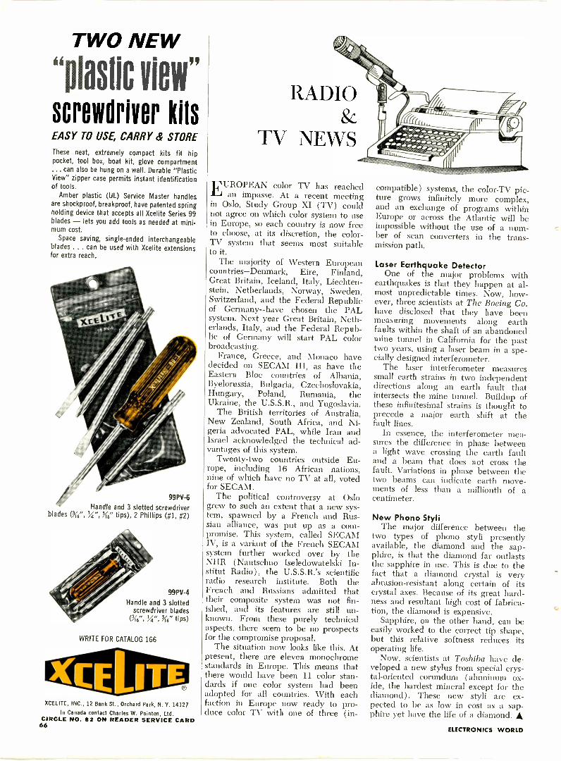
TWO NEW
"plastic view"screworiver kitsEASY TO USE, CARRY & STORE
These neat, extremely compact kits fit hippocket, tool box, boat kit, glove compartment... can also be hung on a wall. Durable "PlasticView" zipper case permits instant identificationof tools.
Amber plastic (UL) Service Master handlesare shockproof, breakproof, have patented springholding device that accepts all Xcelite Series 99blades - lets you add tools as needed at minimum cost.
Space saving, single -ended interchangeableblades . .. can be used with Xcelite extensionsfor extra reach.
99PV-6
Handle and 3 slotted screwdriverblades (3i' ", Kg." tips), 2 Phillips (#1, #2)
99PV-4
Handle and 3 slottedscrewdriver blades
Of6", 14", Na" tips)
WRITE FOR CATALOG 166
XCELITE, INC., 12 Bank St., Orchard Park, N. Y. 14127
In Canada contact Charles W. Pointon, Ltd.CIRCLE NO. 82 ON READER SERVICE CARD66
RADIO
TV NEWS
EUROPEAN color TV has reachedan impasse. At a recent meeting
in Oslo, Study Group XI (TV) couldnot agree on which color system to usein Europe, so each country is now freeto choose, at its discretion, the color-TV system that seems most suitableto it.
The majority of Western Europeancountries-Denmark, Eire, Finland,Great Britain, Iceland, Italy, Liechten-stein, Netherlands, Norway, Sweden,Switzerland, and the Federal Republicof Germany-have chosen the PALsystem. Next year Great Britain, Neth-erlands, Italy, and the Federal Repub-lic of Germany will start PAL colorbroadcasting.
France, Greece, and Monaco havedecided on SECAM III, as have theEastern Bloc countries of Albania,Byelorussia, Bulgaria, Czechoslovakia,Hungary, Poland, Rumania, theUkraine, the U.S.S.R., and Yugoslavia.
The British territories of Australia,New Zealand, South Africa, and Ni-geria advocated PAL, while Iran andIsrael acknowledged the technical ad-vantages of this system.
Twenty-two countries outside Eu-rope, including 16 African nations,nine of which have no TV at all, votedfor SECAM.
The political controversy at Oslogrew to such an extent that a new sys-tem, spawned by a French and Rus-sian alliance, was put up as a com-promise. This system, called SECAMIV, is a variant of the French SECAMsystem further worked over by theNIIR (Nautschno Iseledowatelski In-stitut Radio), the U.S.S.R.'s scientificradio research institute. Both theFrench and Russians admitted thattheir composite system was not fin-ished, and its features are still un-known. From these purely technicalaspects, there seem to be no prospectsfor the compromise proposal.
The situation now looks like this. Atpresent, there are eleven monochromestandards in Europe. This means thatthere would have been 11 color stan-dards if one color system had beenadopted for all countries. With eachfaction in Europe now ready to pro-duce color TV with one of three (in-
compatible) systems, the color -TV pic-ture grows infinitely more complex,and an exchange of programs withinEurope or across the Atlantic will beimpossible without the use of a num-ber of scan converters in the trans-mission path.
Laser Earthquake DetectorOne of the major problems with
earthquakes is that they happen at al-most unpredictable times. Now, how-ever, three scientists at The Boeing Co.have disclosed that they have beenmeasuring movements along earthfaults within the shaft of an abandonedmine tunnel in California for the pasttwo years, using a laser beam in a spe-cially designed interferometer.
The laser interferometer measuressmall earth strains in two independentdirections along an earth fault thatintersects the mine tunnel. Buildup ofthese infinitesimal strains is thought toprecede a major earth shift at thefault lines.
In essence, the interferometer mea-sures the difference in phase betweena light wave crossing the earth faultand a beam that does not cross thefault. Variations in phase between thetwo beams can indicate earth move-ments of less than a millionth of acentimeter.
New Phono StyliThe major difference between the
two types of phono styli presentlyavailable, the diamond and the sap-phire, is that the diamond far outlaststhe sapphire in use. This is due to thefact that a diamond crystal is veryabrasion -resistant along certain of itscrystal axes. Because of its great hard-ness and resultant high cost of fabrica-tion, the diamond is expensive.
Sapphire, on the other hand, can beeasily worked to the correct tip shape,but this relative softness reduces itsoperating life.
Now, scientists at Toshiba have de-veloped a new stylus from special crys-tal -oriented corundum (aluminum ox-ide, the hardest mineral except for thediamond). These new styli are ex-pected to be as low in cost as a sap-phire yet have the life of a diamond.
ELECTRONICS WORLD
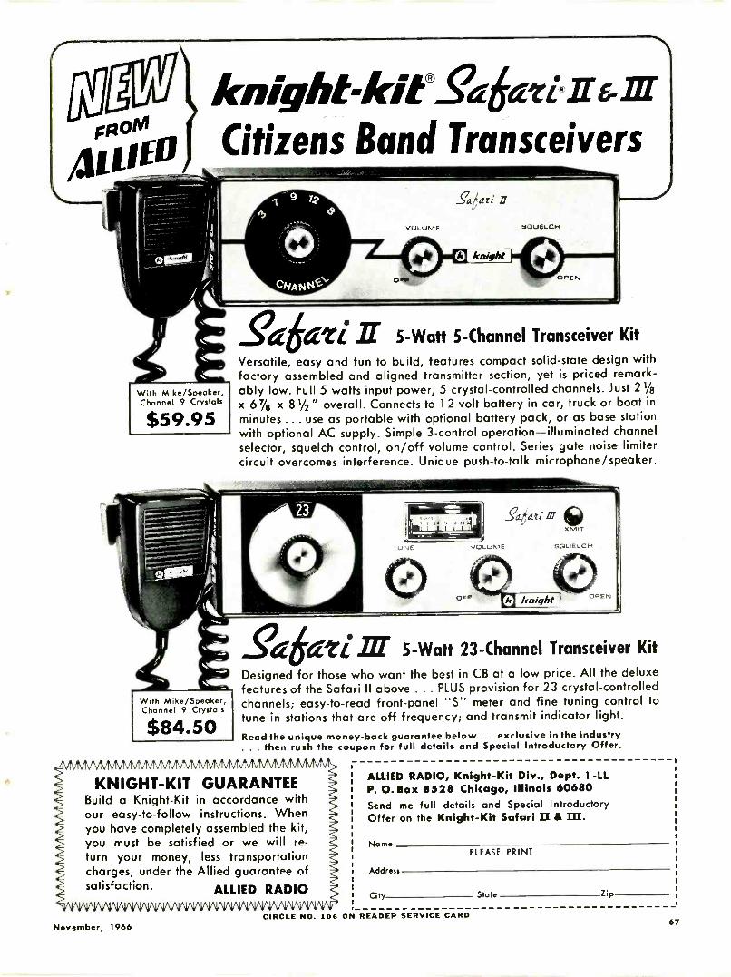
FROM
411
knight-kitS4ati il-6-ffr
Citizens Band Transceivers
With Mike/Speaker,Channel 9 Crystals
$59.95
With Mike/Speaker,Channel 9 Crystals
$84.50
....caati
VOLUME SQUELCH
k knight
OPEN
rC dzi It 5 -Watt 5 -Channel Transceiver Kit
Versatile, easy and fun to build, features compact solid-state design withfactory assembled and aligned transmitter section, yet is priced remark-ably low. Full 5 watts input power, 5 crystal -controlled channels. Just 21/8x 67/8 x 8 1/2" overall. Connects to 12 -volt battery in car, truck or boat inminutes ... use as portable with optional battery pack, or as base stationwith optional AC supply. Simple 3 -control operation-illuminated channelselector, squelch control, on/off volume control. Series gate noise limitercircuit overcomes interference. Unique push -to -talk microphone/speaker.
gaaati 5 -Watt 23 -Channel Transceiver KitDesigned for those who want the best in CB at a low price. All the deluxefeatures of the Safari II above . . . PLUS provision for 23 crystal -controlledchannels; easy -to -read front -panel "S" meter and fine tuning control totune in stations that are off frequency; and transmit indicator light.Read the unique money -back guarantee below ... exclusive in the industry. . . then rush the coupon for full details and Special Introductory Offer.
KNIGHT -KIT GUARANTEEBuild a Knight -Kit in accordance withour easy -to -follow instructions. Whenyou have completely assembled the kit,you must be satisfied or we will re-turn your money, less transportationcharges, under the Allied guarantee ofsatisfaction. ALLIED RADIO
ALLIED RADIO, Knight -Kit Div., Dept. 1 -LLP. 0. Box 8528 Chicago, Illinois 60680Send me full details and Special IntroductoryOffer on the Knight -Kit Safari II &
NamePLEASE PRINT
Address
City State Zip
November, 1966CIRCLE NO. 106 ON READER SERVICE CARD
67
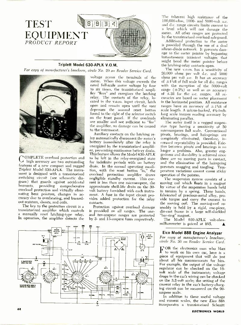
TESTEQUIPMENTPRODUCT REPORT
(E1(8))(314
Triplett Model 63 O-APLK V.O.M.For copy of manufacturer's brochure, circle No. 29 on Reader Service Card.
CONIPLETE overload protection andhigh accuracy are two outstanding
features of a new compact and ruggedTriplett Model 630-APLK. The instru-ment is designed with a transistorizedswitching circuit (see schematic dia-gram) that guards against accidentalburnouts, providing comprehensiveoverload protection and virtually elimi-nating bent pointers, changes in ac-curacy due to overheating, and burned -out resistors, shunts, and coils.
The key to the protection circuit is atransistorized amplifier which controlsa manually reset latching -type relay.In operation, the amplifier detects the
NMI luITO,,r_.
rr"
SI SUM 9101NM Id 11I1
I lawn. WO "RD MIS I new
NON.03(1,
MAW1.11Cnal
NOM
weeWIWI KV
KW
voltage across the terminals of themeter. When this voltage exceeds therated full-scale meter voltage by fourto six times, the transistorized ampli-fier "fires" and energizes the latchingrelay. The contacts of the relay, lo-cated in the v.o.m. input circuit, latchopen and remain open until the userdepresses the manual reset buttonfound to the right of the selector switchon the front panel. If the overloadsare smaller and not sufficient to "fire"the amplifier, no damage can be causedto the instrument.
Auxiliary contacts on the latching re-lay automatically disconnect the meter'sbattery immediately after the relay isenergized by the transistorized amplifi-er, preventing continuous battery drain.This feature allows the Model 630-APLKto be left in the relay -energized statefor indefinite periods with no batterydrain. In the normal operating condi-tion, with the reset button "in," theoverload protection amplifier drawsnegligible standby current. This cur-rent is less than one microampere, theapproximate shelf -life drain on the 30-volt battery furnished with each instru-ment. A fuse in the input circuit pro-vides added protection for the relaycontacts.
Protection against overload damageis provided on all ranges. The one -and ten -ampere ranges are protectedby 3- and 15 -ampere fuses respectively.
1,1
MP. SO...
/I IS We Sao
Sc,,"431r
SIN;1011
tr
SKIS
. elk
%W.
The inherent high resistance of the100,000 -ohm, 1000- and 5000 -volt a.c.and d.c. range circuits limits current toa level which will not damage themeter. All other ranges are protectedby the transistorized overload safeguard.
Additional protection to the meteris provided through the use of a dualsilicon -diode network. It prevents dam-age to the meter pointer by bypassinginstantaneous transient voltages thatmight bend the meter pointer beforethe latching -relay contacts open.
The new v.o.m. has a sensitivity of20,000 ohms per volt d.c. and 5000ohms per volt a.c. It has an accuracyof -±-11/2% of full scale for all d.c. rangeswith the exception of the 5000 -voltrange (±31/2) as well as an accuracyof ±3% for the a.c. ranges. All ac-curacies are based on meter placementin the horizontal position. All resistanceranges have an accuracy of -±-11/2% ofscale length. A mirror -backed, 41/2 -inch -
long scale insures reading accuracy byeliminating parallax.
The meter itself is a rugged suspen-sion type having a sensitivity of 50microamperes full scale. Conventionalpivots, bearings, and hairsprings arecompletely eliminated; therefore, in-creased repeatability is provided. Fric-tion between pivots and bearings is nolonger a problem. Also, greater rug-gedness and durability is achieved sincethere are no moving parts in contact,and the elimination of the hairspringprevents snagging and tangling. Tem-perature variations cannot cause stickyoperation of the pointer.
The suspension system consists of amoving coil which floats in a magnetby virtue of the suspension bands heldin tension by a spring. These bands,fabricated of precious -metal alloy, pro-vide torque and carry the current tothe moving coil. The moving -coil as-sembly is held by a rigid, one-piece,die-cast frame in a large self -shielded"bar -ring" magnet.
The Model 630-APLK volt-ohm-milliammeter is priced at $95.
Eico Model 888 Engine AnalyzerFor copy of manufacturer's brochure,circle No. 30 on Reader Service Card.
FOR the electronics man who likesto work on his own car, here is a
piece of equipment that will do justabout all his measurements for him.For example, the output of the voltageregulator can be checked on the 16 -
volt scale of the instrument; voltagedrops in the car's wiring can be checkedon the 3.2 -volt scale; the setting of thecurrent relay in the car's battery -charg-ing circuit can be measured on the 90 -
ampere scale.In addition to these useful voltage
and current scales, the new Eico 888incorporates a transistorized Schmitt
68ELECTRONICS WORLD
1967
Photofact Annual Index
4, PUBLIC ATIONQ
MASTER INDEX 10 1HE AUTHORITATIVESERVICE BAIA FORM
ELECTRONICS INDUSTRY
COMPLETE
PHOTOFACT COVERAGE
COEitRS PHOTOFACTSETS 1
THROUGH 8. ;Ali PH010-
FACI FOLDERreleases from
Apr.l 1.1946 to January.1967
All Pii(110FAC1 Specia1.-
led Senes volumes released
through Ian 1%7I.
IMPORTANT: Use his Master
Annual Index with the latest
current Supplementtor cont.
plete up-to-date model coy
ciao Supplements ate Is-
sued in February May and
September of each year
See CoereSete Testa of
Contents an Page I
FreePhotofact
AnnualIndexfor your use
throughout 1967
send today for your instant handy guideto the world's finest electronic service data!covers over 70,000 listings of:
TV Receivers Home & Auto Radios Phonos & Hi-FiCB Radios Tape Recorders Record Changers
NOW INCLUDES- Special Index to Color TV Receivers Complete Listing of Sams Technical Books Complete List of Sams Distributors
Send today for this valuable 136 -page guide covering virtuallyevery model of home -entertainment electronic equipmentproduced since 1946! Helps you locate the proper PHOTO -FACT Folder to quickly solve any service problem in anymodel. PHOTOFACT provides everything you need in com-plete, uniform style for quick, effective repairs: FamousStandard Notation Schematics packed with the service de-tails you need; Full Photo Coverage of all chassis views; Com-plete Replacement Parts Lists; Tube Placement Diagrams;Alignment Instructions; CircuiTrace® for printed boards;Disassembly Instructions; Dial Cord Diagrams; Changer andRecorder "Exploded Views"-plus dozens of other great fea-tures. Send coupon for your FREE copy of the latest PHOTO -FACT Index to the service data you need!
JOIN THE PHOTOFACT-OF-THE-MONTH CLUB:ONLY $10 PER MONTH NOW BRINGS
YOU 20% MORE PHOTOFACT COVERAGETO KEEP YOU AHEAD-SAVES YOU
OVER $60 PER YEAR!For details, see your Sams Distributor, or send coupon
CIRCLE NO. 91 ON READER SERVICE CARD
THE "PHOTOFACT ANNUAL INDEX" AND3 SUPPLEMENTS NOW PROVIDE COMPLETEREFERENCE TO PHOTOFACT COVERAGE:
Send for the Photofact AnnualIndex-your "master" referencethroughout 1967. Once you areon our mailing list, you will auto-matically receive three additionalIndex Supplements (in February,May, and September, 1967) tokeep you up-to-the-minute onPhotofact coverage of the latestequipment released.
SEND FOR
FREEANNUAL
INDEX
HOWARD W. SAMS & CO., Dept. EWF-114300 W. 62nd St., Indianapolis, Indiana 46206
Send FREE 1967 Photofact Annual Index andplace my name on your mailing list to receive the Supplements
0 Send Photofact-of-the-Month Club details
My Distributor is
Shop Name
Attn -
Address
City State Zip
November, 1966 69
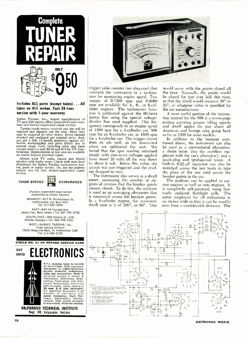
Complete
TUNERREPAIR
ONLY
9 50
Includes ALL parts (except tubes) ... Alllabor on ALL makes. Fast 24 -hourservice with 1 -year warranty
Sarkes Tarzian, Inc., largest manufacturer ofTV and FM tuners, offers unexcelled tuner over-haul and factory -supervised repair service.
Tarzian-made tuners received one day will berepaired and shipped out the next. More timemay be required on other makes. Every channelchecked and realigned per original specs. And,you get a full, 12 -month guarantee against de-fective workmanship and parts failure due tonormal usage. Cost, including labor and parts(except tubes) is only $9.50 and $15 for UV com-binations. Replacements at low cost are availableon tuners beyond practical repair.
Always send TV make, chassis and Modelnumber with faulty tuner. Check with your localdistributor for Sarkes Tarzian replacement tun-ers, parts or repair service. Or, use the addressnearest you for fast, factory -supervised repairservice.
TUNER SERVICE CORPORATION
(Factory -supervised tuner serviceauthorized by Sarkes Tarzian)
MIDWEST -817 N. Pennsylvania St.Indianapolis, Ind. Box 1642
Tel: 317-632-3493
EAST -547-49 Tonnele Ave.Jersey City, New Jersey Tel: 201-792-3730
SOUTH -EAST --938 Gordon St., S.W.Atlanta, Georgia Tel: 404-758-2232
WEST-SARKES TARZIAN, Inc.Tuner Service Division
10654 Magnolia Blvd., N. Hollywood, Calif.Tel : 213-769-2720
CIRCLE NO. 83 ON READER SERVICE CARD
v. ELECTRONICSV.T.I. training leads to successas technicians, field engineers.specialists in communications,guided missiles. computers.radar and automation. Basic &advanced courses in theory &laboratory. Electronic Engi-neering Technology and Elec-tronic Technology curriculaboth available. Assoc. degree in29 mos. B. S. also obtainable.G.I. approved. Graduates in allbranches of electronics withmajor companies. Start Feb-ruary, September. Dorms,campus. High school graduateor equivalent. Write for catalog.
VALPARAISO TECHNICAL INSTITUTEDept. RD, Valparaiso, Indiana
trigger pulse counter (see diagram) thatconverts the instrument to a tachom-eter for measuring engine speed. Tworanges of 0-1200 rpm and 0-6000rpm are available for 4-, 6-, or 8 -cyl-inder engines. The tachometer func-tion is calibrated against the 60 -hertzpower line using the special voltage -divider line cord supplied. This fre-quency corresponds to an engine speedof 1200 rpm for a 6 -cylinder car, 900rpm for an 8 -cylinder car, or 1800 rpmfor a 4 -cylinder car. The trigger circuitdoes its job well, as we discoveredwhen we calibrated the unit. Wefound that the rpm reading remainedsteady with sine -wave voltages appliedfrom about 20 volts all the way downto about R volt. Below this value, thecircuit was not triggered and the read-ing dropped to zero.
The instrument also serves as a dwellmeter, measuring the number of de-grees of rotation that the breaker pointsremain closed. To do this, the analyzeris used as an averaging ohmmeter thatis connected across the breaker points.In a 6 -cylinder engine, the maximumdwell time is % of 360°, or 60°. This
a
0
SI-or11.12 0
100
RE
J30
z
would occur with the points closed allthe time. Normally, the points wouldbe closed for just over half this time,so that the dwell would measure 30° to35°, or wtiatexer value is specified bythe car manufacturer.
A most useful portion of the instruc-tion manual for the 888 is a seven -pagesection covering proper idling speedsand dwell angles for just about allAmerican and foreign cars, going backas far as 1950 for some models.
In addition to the features men-tioned above, the instrument can alsobe used as a conventional ohmmeter,a diode tester (for the rectifiers em-ployed with the car's alternator), and aspark -plug and ignition -coil tester. Abuilt-in 0.22-µF capacitor can also beswitched across the test leads to takethe place of the one used across thebreaker points in the car.
The analyzer can be applied to ma-rine engines as well as auto engines. Itis completely self -powered, using foureasily replaced flashlight cells. Themeter employed for all indications issix inches wide so that it can be readilyseen from a considerable distance. The
ROOv
C600
eV
-*0--El
MY
3, -or
o0.?
100
T R.3KBL
e A °/0 I
ICA/
SI-CR
02
es
NOTES:
!/0,. CAPAC,TOR3 ARE UF.
tb k
10
.0 0,
Si-Cf
2. ri-7,ZMI2Nr,2111,Earre-t"Er'.7""005,0,1.
7.
4. 0 FRONT PANEL CONTROL.0 SCREWDRivER ADJUST.
S. C) uoD.CATES CONNECTION POINTS ON PC BOARD. 1/141
02
03
4
CL
1
'
' °
,
2
70
,^
70 ELECTRONICS WORLD
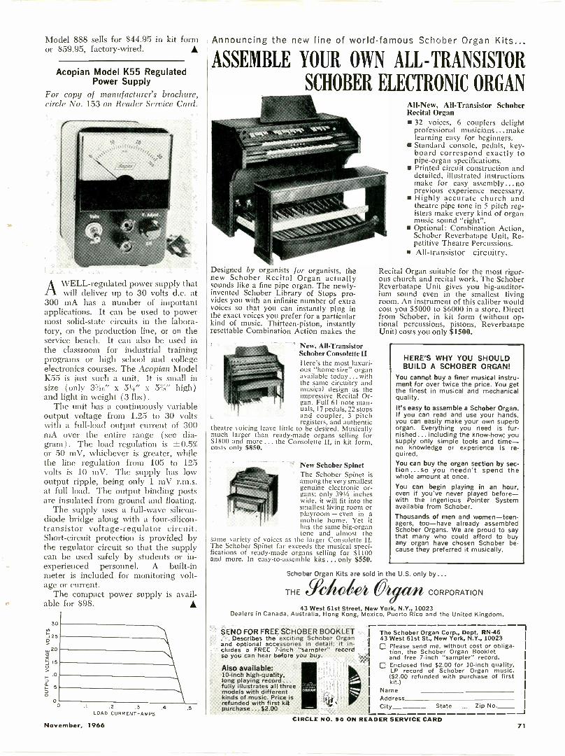
Model 888 sells for $44.95 in kit formor $59.95, factory -wired.
Acopian Model K55 RegulatedPower Supply
For copy of manufacturer's brochure,circle No. 153 on Reader Service Card.
AWELL -regulated power supply thatwill deliver up to 30 volts d.c. at
300 mA has a number of importantapplications. It can be used to powermost solid-state circuits in the labora-tory, on the production line, or on theservice bench. It can also be used inthe classroom for industrial trainingprograms or high school and collegeelectronics courses. The Acopian ModelK55 is just such a unit. It is small insize (only 34e x 514" x 5%" high)and light in weight (3 lbs) .
The unit has a continuously variableoutput voltage from 1.25 to 30 voltswith a full -load output current of 300mA over the entire range (see dia-gram). The load regulation is ±0.5%or 50 mV, whichever is greater, whilethe line regulation from 105 to 125volts is 10 mV. The supply has lowoutput ripple, being only 1 mV r.m.s.at full load. The output binding postsare insulated from ground and floating.
The supply uses a full -wave silicon -diode bridge along with a four -silicon -transistor voltage -regulator circuit.Short-circuit protection is provided bythe regulator circuit so that the supplycan be used safely by students or in-experienced personnel. A built-inmeter is included for monitoring volt-age or current.
The compact power supply is avail-able for $98.
30
-J 25
,' 200
150
100
0
00 .1 .2 .3 .4
LOAD CURRENT -AMPS
Announcing the new line of world-famous Schober Organ Kits
ASSEMBLE YOUR OWN ALL -TRANSISTOR
SCHOBER ELECTRONIC ORGAN
Designed by organists for organists, thenew Schober Recital Organ actuallysounds like a fine pipe organ. The newly -invented Schober Library of Stops pro-vides you with an infinite number of extravoices so that you can instantly plug inthe exact voices you prefer for a particularkind of music. Thirteen -piston, instantlyresettable Combination Action makes the
New, All -TransistorSchober Consolette IIHere's the most luxuri-ous "home -size" organavailable today ... withthe same circuitry andmusical design as theimpressive Recital Or-gan. Full 61 -note man-uals, 17 pedals, 22 stopsand coupler, 3 pitchregisters, and authentic
theatre voicing leave little to be desired. Musicallymuch larger than ready-made organs selling for$1800 and more ... the Consolette II, in kit form,costs only $850.
New Schober SpinetThe Schober Spinet isamong the very smallestgenuine electronic or-gans; only 39'/4 incheswide, it will fit into thesmallest living room orplayroom - even in amobile home. Yet ithas the same big -organtone and almost the
same variety of voices as the larger Consolette II.The Schober Spinet far exceeds the musical speci-fications of ready-made organs selling for $1100and more. In easy -to -assemble kits... only $550.
All-New,All-Transistor SchoberRecital Organ 32 voices, 6 couplers delight
professional musicians ...makelearning easy for beginners.
Standard console, pedals, key-board correspond exactly topipe -organ specifications.
Printed circuit construction anddetailed, illustrated instructionsmake for easy assembly ... noprevious experience necessary.
Highly accurate church andtheatre pipe tone in 5 pitch reg-isters make every kind of organmusic sound "right".
Optional: Combination Action,Schober Reverbatape Unit, Re-petitive Theatre Percussions.
All -transistor circuitry.
Recital Organ suitable for the most rigor-ous church and recital work. The SchoberReverbatape Unit gives you big -auditor-ium sound even in the smallest livingroom. An instrument of this caliber wouldcost you $5000 to $6000 in a store. Directfrom Schober, in kit form (without op-tional percussions, pistons, ReverbatapeUnit) costs you only $1500.
HERE'S WHY YOU SHOULDBUILD A SCHOBER ORGAN!
You cannot buy a finer musical instru-ment for over twice the price. You getthe finest in musical and mechanicalquality.
It's easy to assemble a Schober Organ.If you can read and use your hands,you can easily make your own superborgan. Everything you need is fur-nished ... including the know-how; yousupply only simple tools and time-no knowledge or experience is re-quired.You can buy the organ section by sec-tion... so you needn't spend thewhole amount at once.You can begin playing in an hour,even if you've never played before-with the ingenious Pointer Systemavailable from Schober.Thousands of men and women-teen-agers, too-have already assembledSchober Organs. We are proud to saythat many who could afford to buyany organ have chosen Schober be-cause they preferred it musically.
Schober Organ Kits are sold in the U.S. only by...
THE Ydic (*A r m CORPORATION
43 West 61st Street, New York, N.Y., 10023Dealers in Canada, Australia, Hong Kong, Mexico, Puerto Rico and the United Kingdom.
SEND FOR FREE SCHOBER BOOKLET. Describes the exciting Schober Organ
and optional accessories in detail; it in-cludes a FREE 7 -inch "sampler" recordso you can hear before you buy.
Also available:10 -inch high -quality,long playing record ...fully illustrates all threemodels with differentkinds of music. Price isrefunded with first kitpurchase... $2.00
The Schober Organ Corp., Dept. RN -4643 West 61st St., New York, N.Y., 10023111 Please send me, without cost or obliga-
tion, the Schober Organ Bookletand free 7 -inch "sampler" record.
Enclosed find $2.00 for 10 -inch quality,LP record of Schober Organ music.($2.00 refunded with purchase of firstkit.)
NameAddressCity State Zip No.
CIRCLE NO. 90 ON READER SERVICE CARD
1
November, 1966 71
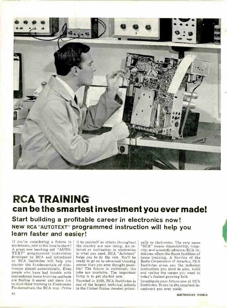
RCA TRAININGcan be the smartest investment you ever made!Start building a profitable career in electronics now!New RCA "AUTOTEXT" programmed instruction will help youlearn faster and easier!If you're considering a future inelectronics, now is the time to start !A great new teaching aid-"AUTO-TEXT" programmed instructiondeveloped by RCA and introducedby RCA Institutes will help youmaster the fundamentals of elec-tronics almost automatically. Evenpeople who have had trouble withconventional home training methodsare finding it easier and more funto start their training in ElectronicsFundamentals the RCA way. Prove
it to yourself as others throughoutthe country are now doing. An in-terest or inclination in electronicsis what you need. RCA "Autotext"helps you to do the rest. You'll beready to go on to advanced trainingsooner than you ever thought possi-ble ! The future is unlimited ; thejobs are available. The importantthing is to get started now.Founded in 1909, RCA Institutes isone of the largest technical schoolsin the United States devoted princi-
pally to electronics. The very name"RCA" means dependability, integ-rity, and scientific advance. RCA In-stitutes offers the finest facilities ofhome training. A Service of theRadio Corporation of America, RCAInstitutes gives you the technicalinstruction you need to plan, buildand realize the career you want intoday's fastest growing field.Investigate your future now at RCAInstitutes. It can be the smartest in-vestment you ever made.
72 ELECTRONICS WORLD
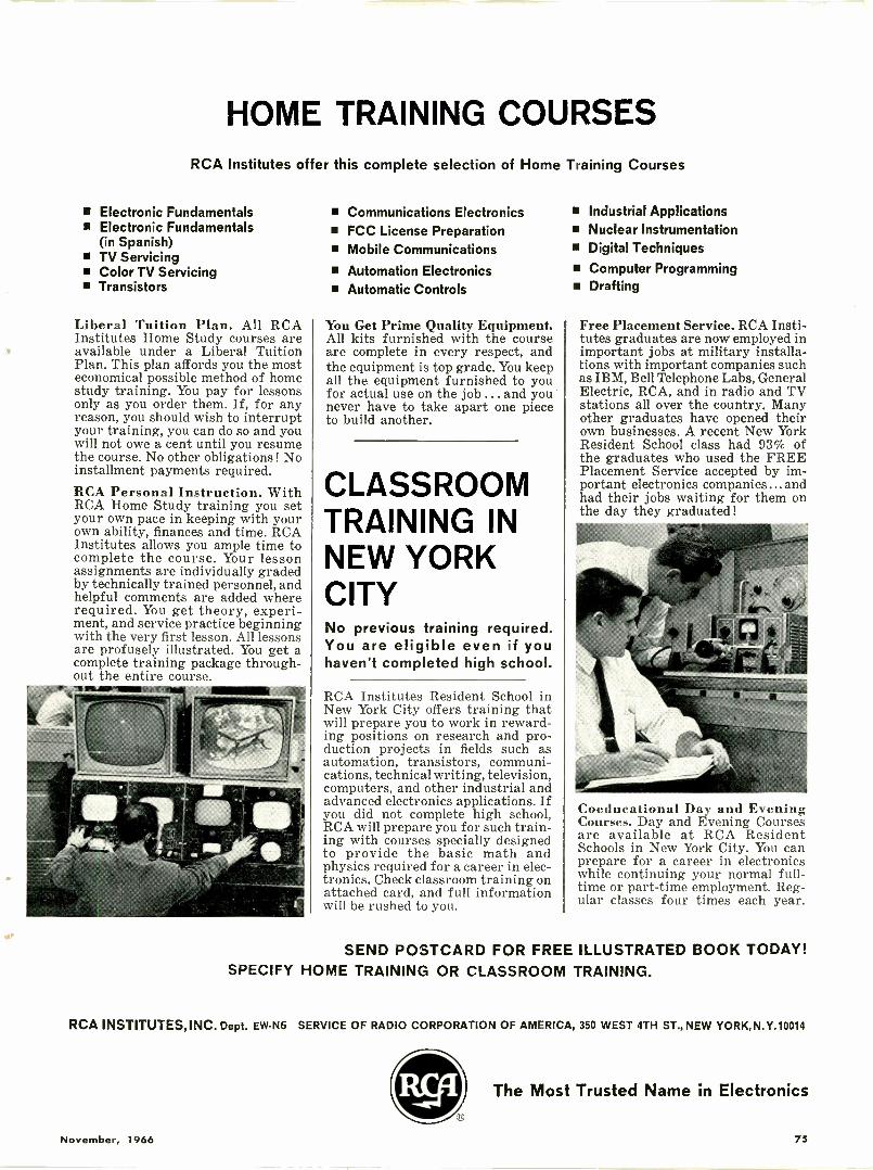
HOME TRAINING COURSESRCA Institutes offer this complete selection of Home Training Courses
Electronic Fundamentals Electronic Fundamentals
(in Spanish) TV Servicing Color TV Servicing Transistors
Liberal Tuition Plan. All RCAInstitutes Home Study courses areavailable under a Liberal TuitionPlan. This plan affords you the mosteconomical possible method of homestudy training. You pay for lessonsonly as you order them. If, for anyreason, you should wish to interruptyour training, you can do so and youwill not owe a cent until you resumethe course. No other obligations ! Noinstallment payments required.RCA Personal Instruction. WithRCA Home Study training you setyour own pace in keeping with yourown ability, finances and time. RCAInstitutes allows you ample time tocomplete the course. Your lessonassignments are individually gradedby technically trained personnel, andhelpful comments are added whererequired. You get theory, experi-ment, and service practice beginningwith the very first lesson. All lessonsare profusely illustrated. You get acomplete training package through-out the entire course.
Communications Electronics FCC License Preparation Mobile Communications Automation Electronics Automatic Controls
You Get Prime Quality Equipment.All kits furnished with the courseare complete in every respect, andthe equipment is top grade. You keepall the equipment furnished to youfor actual use on the job ... and younever have to take apart one pieceto build another.
CLASSROOMTRAINING INNEW YORKCITYNo previous training required.You are eligible even if youhaven't completed high school.
RCA Institutes Resident School inNew York City offers training thatwill prepare you to work in reward-ing positions on research and pro-duction projects in fields such asautomation, transistors, communi-cations, technical writing, television,computers, and other industrial andadvanced electronics applications. Ifyou did not complete high school,RCA will prepare you for such train-ing with courses specially designedto provide the basic math andphysics required for a career in elec-tronics. Check classroom training onattached card, and full informationwill be rushed to you.
Industrial Applications Nuclear Instrumentation Digital Techniques Computer Programming Drafting
Free Placement Service. RCA Insti-tutes graduates are now employed inimportant jobs at military installa-tions with important companies suchas IBM, Bell Telephone Labs, GeneralElectric, RCA, and in radio and TVstations all over the country. Manyother graduates have opened theirown businesses. A recent New YorkResident School class had 93% ofthe graduates who used the FREEPlacement Service accepted by im-portant electronics companies...andhad their jobs waiting for them onthe day they graduated!
Coeducational Day and EveningCourses. Day and Evening Coursesare available at RCA ResidentSchools in New York City. You canprepare for a career in electronicswhile continuing your normal full-time or part-time employment. Reg-ular classes four times each year.
SEND POSTCARD FOR FREE ILLUSTRATED BOOK TODAY!SPECIFY HOME TRAINING OR CLASSROOM TRAINING.
RCA INSTITUTES, INC. Dept. EW-N6 SERVICE OF RADIO CORPORATION OF AMERICA, 350 WEST 4TH ST., NEW YORK, N.Y.10014
The Most Trusted Name in Electronics
November, 1966 75
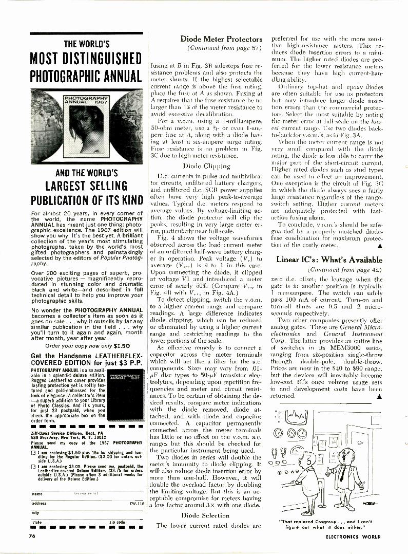
THE WORLD'S
MOST DISTINGUISHED
PHOTOGRAPHIC ANNUAL
PHOTOGRAPHYANNUAL 1967
AND THE WORLD'S
LARGEST SELLING
PUBLICATION OF ITS KINDFor almost 20 years, in every corner ofthe world, the name PHOTOGRAPHYANNUAL has meant just one thing: photo-graphic excellence. The 1967 edition willshow you why. It's the best yet. A brilliantcollection of the year's most stimulatingphotographs, taken by the world's mostgifted photographers and painstakinglyselected by the editors of Popular Photog-raphy.
Over 200 exciting pages of superb, pro-vocative pictures - magnificently repro-duced in stunning color and dramaticblack and white-and described in fulltechnical detail to help you improve yourphotographic skills.
No wonder the PHOTOGRAPHY ANNUALbecomes a collector's item as soon as itgoes on sale ... why it outsells by far anysimilar publication in the field . . . whyyou'll turn to it again and again, monthafter month, year after year.
Order your copy now only $1.50
Get the Handsome LEATHERFLEX-COVERED EDITION for just $3 P.P.PHOTOGRAPHY ANNUAL is also avail-able in a splendid deluxe edition.Rugged Leatherflex cover provideslasting protection yet is softly tex-tured and gold -embossed for thelook of elegance. A collector's item-a superb addition to your Libraryof Photo Classics. And it's yours,for just $3 postpaid, when youcheck the appropriate box on theorder form.mmmm INN I= I= NM IN MN MI NIZiff -Davis Service Division, Dept. PA589 Broadway, New York, N. Y. 10012Please send my copy of the 1967 PHOTOGRAPHYANNUAL. I am enclosing $1.50 plus 15c for shipping and han-
dling for the Regular Edition. ($2.00 for orders out-side U.S.A.)
I am enclosing $3.00. Please send me, postpaid, theLeathertlex-covered Deluxe Edition. ($3.75 for ordersoutside U.S.A.) (Please allow 3 additional weeks fordelivery of the Deluxe Edition.)
PHOTOGRAPHYANNUAL '67
name (PLEASE PRINT)
address EW-116
city
state zip codeNM In IN NI NI MIR MR
Diode Meter Protectors(Continued from page 57)
fusing at B in Fig. 3B sidesteps fuse re-sistance problems and also protects themeter shunts. If the highest selectablecurrent range is above the fuse rating,place the fuse at A as shown. Fusing atA requires that the fuse resistance be nolarger than 1% of the meter resistance toavoid excessive decalibration.
For a v.o.m. using a 1 -milliampere,50 -ohm meter, use a %- or even 1 -am-pere fuse at A, along with a diode hav-ing at least a six -ampere surge rating.Fuse resistance is no problem in Fig.3C due to high meter resistance.
Diode ClippingD.c. currents in pulse and multivibra-
tor circuits, unfiltered battery chargers,and unfiltered d.c. SCR power suppliesoften have very high peak -to -averagevalues. Typical d.c. meters respond toaverage values. By voltage -limiting ac-tion, the diode protector will clip thepeaks, resulting in very large meter er-ror, particularly near full scale.
Fig. 4 shows the voltage waveformsobserved across the load current meterof an unfiltered half -wave battery charg-er in operation. Peak voltage (V0) toaverage (V,.0) is 9 to 1 in this case.Upon connecting the diode, it clippedat voltage VI and introduced a metererror of nearly 50%. (Compare V,,, inFig. 4B with V,., in Fig. 4A.)
To detect clipping, switch the v.o.m.to a higher current range and comparereadings. A large difference indicatesdiode clipping, which can be reducedor eliminated by using a higher currentrange and restricting readings to thelower portions of the scale.
An effective remedy is to connect acapacitor across the meter terminalswhich will act like a filter for the a.c.components. Sizes may vary from .01-itE' disc types to 50-pF transistor elec-trolytics, depending upon repetition fre-quencies and meter and circuit resist-ances. To be certain of obtaining the de-sired results, compare meter indicationswith the diode removed, diode at-tached, and with diode and capacitorconnected. A capacitor permanentlyconnected across the meter terminalshas little or no effect on the v.o.m. a.c.ranges but this should be checked forthe particular instrument being used.
Two diodes in series will double themeter's immunity to diode clipping. Itwill also reduce diode insertion error bymore than one-half. However, it willdouble the overload factor by doublingthe limiting voltage. But this is an ac-ceptable compromise for meters havinga low factor around 3x with one diode.
Diode SelectionThe lower current rated diodes are
preferred for use with the more sensi-tive high -resistance meters. This re-duces diode insertion errors to a mini-mum. The higher rated diodes are pre-feffed for the lower resistance metersbecause they have high current -han-dling ability.
Ordinary top -hat and epoxy diodesare often suitable for use as protectorsbut may introduce larger diode inser-tion errors than the commercial protec-tors. Select the most suitable by notingthe meter error at full scale on the low-est current range. Use two diodes back-to-back for v.o.m.'s, as in Fig. 3A.
When the meter current range is notvery small compared with the dioderating, the diode is less able to carry themajor part of the short-circuit current.Higher rated diodes such as stud typescan be used to effect an improvement.One exception is the circuit of Fig. 3Cin which the diode always sees a fairlylarge resistance regardless of the range -switch setting. Higher current metersare adequately protected with fast -action fusing alone.
To conclude, v.o.m.'s should be safe-guarded by a properly matched diode-
fuse combination for maximum protec-tion of the costly meter.
Linear IC's: What's Available(Continued from page 42)
zero d.c. offset; the leakage when thegate is in another position is typically1 nanoampere. The switch can safelypass 100 mA of current. Turn -on andturn-off times are 0.5 and 2 micro-seconds respectively.
Two other companies presently offeranalog gates. These are General Micro-electronics and General InstrumentCorp. The latter provides an entire lineof switches in its MEM5000 series,ranging from six -position single -throwthrough double -pole, double -throw.Prices are now in the $40 to $90 range,but the devices will inevitably becomelow-cost IC's once volume usage setsin and development costs have beenreturned.
o
"That replaced Cosgrove ... and I can'tfigure out what it does either."
76 ELECTRONICS WORLD
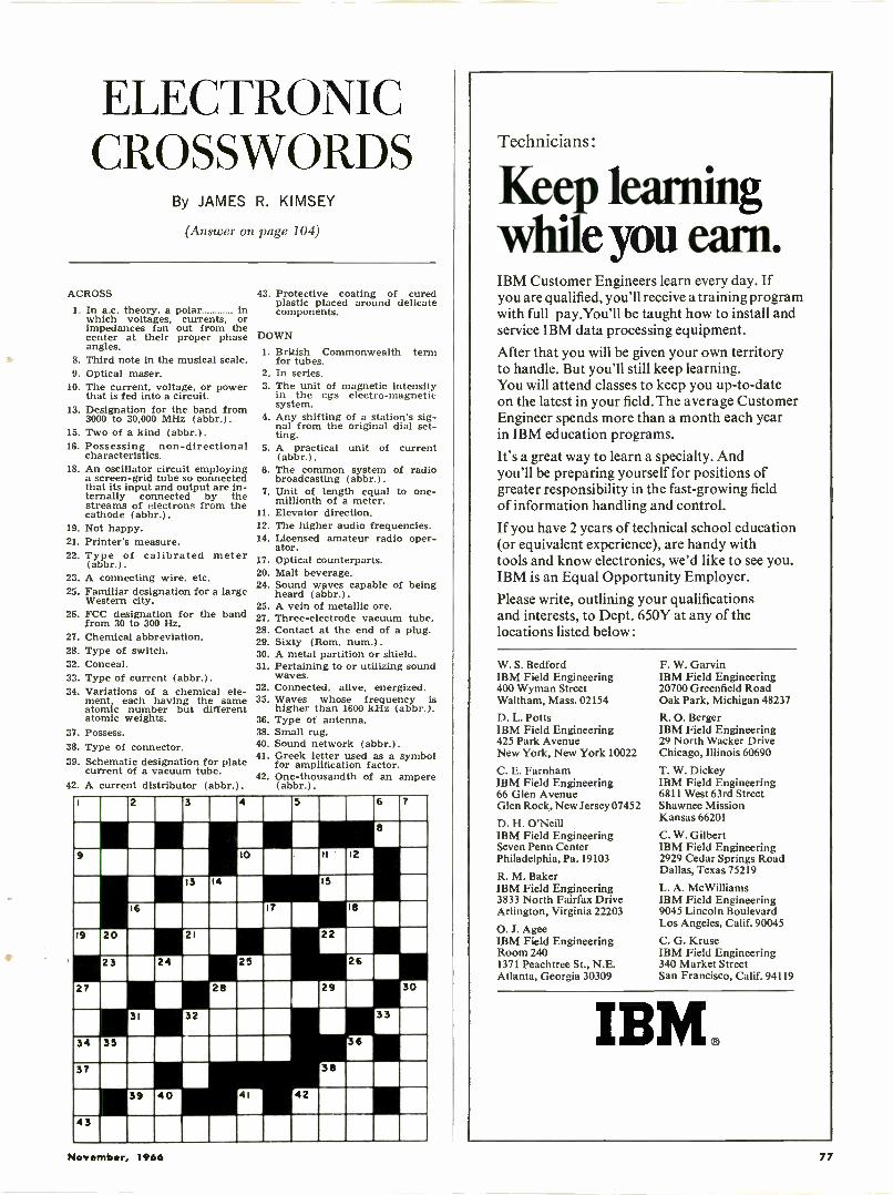
ELECTRONICCROSSWORDS
By JAMES R. KIMSEY
(Answer on page 104)
ACROSS
1. In a.c. theory, a polar inwhich voltages, currents, orimpedances fan out from thecenter at their proper phaseangles.
8. Third note in the musical scale.9. Optical maser.
10. The current, voltage, or powerthat is fed into a circuit.
13. Designation for the band from3000 to 30,000 MHz (abbr.).
15. Two of a kind (abbr.).16. Possessing non -directional
characteristics.18. An oscillator circuit employing
a screen -grid tube so connectedthat its input and output are in-ternally connected by thestreams of electrons from thecathode (abbr.).
19. Not happy.21. Printer's measure.22. Type of calibrated meter
(abbr.).23. A connecting wire, etc.25. Familiar designation for a large
Western city.26. FCC designation for the band
from 30 to 300 Hz.27. Chemical abbreviation.28. Type of switch.32. Conceal.33. Type of current (abbr.).34. Variations of a chemical ele-
ment, each having the sameatomic number but differentatomic weights.
37. Possess.38. Type of connector.39. Schematic designation for plate
current of a vacuum tube.42. A current distributor (abbr.).
43. Protective coating of curedplastic placed around delicatecomponents.
DOWN
1. British Commonwealthfor tubes.
2. In series.3. The unit of magnetic intensity
in the cgs electro-magneticsystem.
4. Any shifting of a station's sig-nal from the original dial set-ting.
5. A practical(abbr.).
6. The common systembroadcasting (abbr.).
7. Unit of length equalmillionth of a meter.
11. Elevator direction.12. The higher audio frequencies.14. Licensed amateur radio oper-
ator.17. Optical counterparts.20. Malt beverage.24. Sound waves capable of being
heard (abbr.).25. A vein of metallic ore.27. Three -electrode vacuum tube.28. Contact at the end of a plug.29. Sixty (Rom. num.).30. A metal partition or shield.31. Pertaining to or utilizing sound
waves.32. Connected, alive, energized.35. Waves whose frequency is
higher than 1600 kHz (abbr.).36. Type of antenna.38. Small rug.40. Sound network (abbr.).41. Greek letter used as a symbol
for amplification factor.42. One -thousandth of an ampere
(abbr.).
term
unit of current
of radio
to one -
1 2 3 4 5 .6 7
9 10 11 12
13 14 15
16 .IT 18
19 20 21 22
23 24 2S 26
27 28 29 30
31 33
34 3S II 111137 38
39 40 41 42
4 3
Technicians :
Keep learningwhile you earn.IBM Customer Engineers learn every day. Ifyou are qualified, you'll receive a training programwith full pay.You'll be taught how to install andservice IBM data processing equipment.
After that you will be given your own territoryto handle. But you'll still keep learning.You will attend classes to keep you up-to-dateon the latest in your field. The average CustomerEngineer spends more than a month each yearin IBM education programs.
It's a great way to learn a specialty. Andyou'll be preparing yourself for positions ofgreater responsibility in the fast-growing fieldof information handling and control.
If you have 2 years of technical school education(or equivalent experience), are handy withtools and know electronics, we'd like to see you.IBM is an Equal Opportunity Employer.Please write, outlining your qualificationsand interests, to Dept. 650Y at any of thelocations listed below :
W. S. BedfordIBM Field Engineering400 Wyman StreetWaltham, Mass. 02154
D. L. PottsIBM Field Engineering425 Park AvenueNew York, New York 10022
C. E. FarnhamIBM Field Engineering66 Glen AvenueGlen Rock, New Jersey 07452
D. H. O'NeillIBM Field EngineeringSeven Penn CenterPhiladelphia, Pa. 19103
R. M. BakerIBM Field Engineering3833 North Fairfax DriveArlington, Virginia 22203
O. J. AgeeIBM Field EngineeringRoom 2401371 Peachtree St., N.E.Atlanta, Georgia 30309
F. W. GarvinIBM Field Engineering20700 Greenfield RoadOak Park, Michigan 48237
R. 0. BergerIBM Field Engineering29 North Wacker DriveChicago, Illinois 60690
T. W. DickeyIBM Field Engineering6811 West 63rd StreetShawnee MissionKansas 66201
C. W. GilbertIBM Field Engineering2929 Cedar Springs RoadDallas, Texas 75219
L. A. McWilliamsIBM Field Engineering9045 Lincoln BoulevardLos Angeles, Calif. 90045
C. G. KruseIBM Field Engineering340 Market StreetSan Francisco, Calif. 94119
IBM.
November, 1966 77
send just and
I will send you this special
COLOR TV issue ofPF REP RTER
There's no better way to acquaint you withthe invaluable, practical help PF REPORTERoffers you month-af4er-month in your elec-tronics work, than to start your subscriptionwith a copy of the special November ColorTV issue for just one cent!
We'll enter your subscription with Novem-ber and send you the next 11 issues for only$2.49-regular subscription rate is $5.00 peryear-so you save ONE-HALF!
To see what we mean about the practicalvalue of PF REPORTER, here are just someof the features in the Color TV issue:Know Your 1967 Color Circuits-a valuable pre-view of significant new developments and fea-tures Color Countermeasures-symptomsand solutions for recurring color TV troubles Servicing Bandpass Amplifiers-fundamentalsof this basic color stage Color Chaos-whathappens when a chassis gets redesigned Noteson Test Equipment-uses in color servicing The Troubleshooter-answers to perplexingcolor service problems Color TV Training-AND MUCH MORE!A single issue of PF REPORTER can bringyou information and help worth many timesour special low introductory subscriptionprice. And here's your solid guarantee: Sub-scribe to PF REPORTER today. If you aren'tcompletely satisfied it's the best magazine inthe electronics servicing field, just let us knowand we'll refund the unexpired portion of yoursubscription immediately.
SPECIAL HALF-PRICE PF REPORTERINTRODUCTORY SUBSCRIPTION OFFER!
PF REPORTER, Dept. EWR-11Box 68003, Indianapolis, Ind. 462680 Okay - here's my penny-start my
subscription with your Special Nov.Color TV issue, and bill me for $2.49for a full one-year term (regular rateis $5 per year). $2.50 enclosed Bill me
Name
Firm
Address
City State Zip
Power Inductors(Continued from page 35)
hermetically sealed types offer thegreatest amount of protection and bestappearance, while having the poorestheat dissipation and higher cost. Manytypes of construction between thesetwo extremes are available which com-bine the desired qualities of each. Forexample, many fully enclosed types ofinductors are available which are nothermetically sealed but which havemore protection and better appearancethan the open -frame types.
The hermetically sealed inductor iscompletely enclosed in a metal casewhich has been filled with a suitablecompound and sealed by soldering allthe seams and openings. Filling ma-terial may be wax, pitch, epoxy, orpolyester, depending upon the tem-perature requirements of the item.This type offers maximum protectionagainst mechanical and environmentalstresses but is generally larger andheavier than equivalent units of otherconstruction. Molded and encapsulatedtypes offer reasonable protection andare increasing in usage where size andweight are significant in equipmentdesign. Epoxies are prominent as en-capsulants, and silicon rubber is oftenused for high -temperature applications.Encapsulated or molded inductors of-fer good moisture resistance, mechani-cal strength, and heat dissipation butare not as impervious to thermal con-ditions as hermetically sealed types.
Open -frame, varnish -impregnatedunits are quite common in commer-cial applications where environmentalconditions are not severe. Varnish im-pregnation offers moderate protectionagainst moisture and climate. Varia-tions of this open construction offerseveral levels of protection by use ofend covers, partial enclosures, etc.
Commercial & Military SpecsMIL -T -27B, "Transformers and In-
ductors ( Audio, Power and High Pow-er Pulse), General Specification for,"sets forth minimum standards for in-ductors used in military equipment.Areas covered by this specification in-clude: materials, design, inspection re-quirements, case sizes, marking, en-vironmental requirements and testing,and packaging levels. Transformers andinductors supplied to this specificationare normally hermetically sealed(grades 1 or 4) or encapsulated ormolded (grades 2 or 5). Open -frametypes may be purchased to this speci-fication (grades 3 and 6) but are nor-mally used only where further protec-tion will be provided in the equip-ment, such as encapsulation of sub-assemblies.
Transformers and inductors supplied
to MIL -T -27B are marked with a MILtype number, such as TF4RX01EA.This number indicates the grade, tem-perature class, life expectancy, family,and case size of the unit. An addi-tional three digits following this typenumber indicate that the unit is de-signed to a particular government MSdrawing.
Compliance with this specification ismandatory for items supplied for mostmilitary equipment, and completequalification testing must be performedfor many contracts.
Commercial standards, although notas strictly followed by individual con-tractors as the military equivalents, setforth specifications which are general-ly adhered to by the electronics indus-try. For power inductors, RS -197 (re-vision of TR-110-B) covers power filterinductors and RS -181 (revision of TR-127) covers iron -core charging induc-tors. These particular standards areavailable through the engineering de-partment of the Electronic IndustriesAssociation (EIA).
Specifying Power InductorsThe following ten points should be
considered when selecting or specifyinginductors for electronic power circuits.Some of these points will be dictatedby the electrical requirements of thecircuit in which the inductor is to beused, while others will depend largelyupon the construction of the equipmentand its intended usage.
1. Application and circuit used. Forcharging inductors, a schematic of thecircuit should be made available, whilefor filter inductors, specifying the typeof rectifier circuit (i.e., full -wave bridge,etc.) should be adequate.
2. Inductance and tolerance. Due tothe complexity of design and numberof variables on inductors carrying di-rect current, at least 10% toleranceshould be allowed. Standard toleranceon off -the -shelf inductors of this typeis -20% to +50%.
3. A.c. operating voltage and fre-quency.
4. Direct current or range of direct -
current values that are present in thecoil.
5. D.c. resistance and tolerance whennecessary to circuit operation.
6. Dielectric strength and/or maxi-mum working voltage.
7. Case type (open frame, encap-sulated, etc.).
8. Terminals (wire leads, turret type,lugs, etc.).
9. Environmental requirements, in-cluding maximum temperature riseand operating temperature, moistureresistance, thermal shock, vibration andshock, life expectancy, and other ap-plicable factors.
10. Applicable military or commer-cial specifications.
CIRCLE NO. VA ON READER SERVICE CARD78 ELECTRONICS WORLD
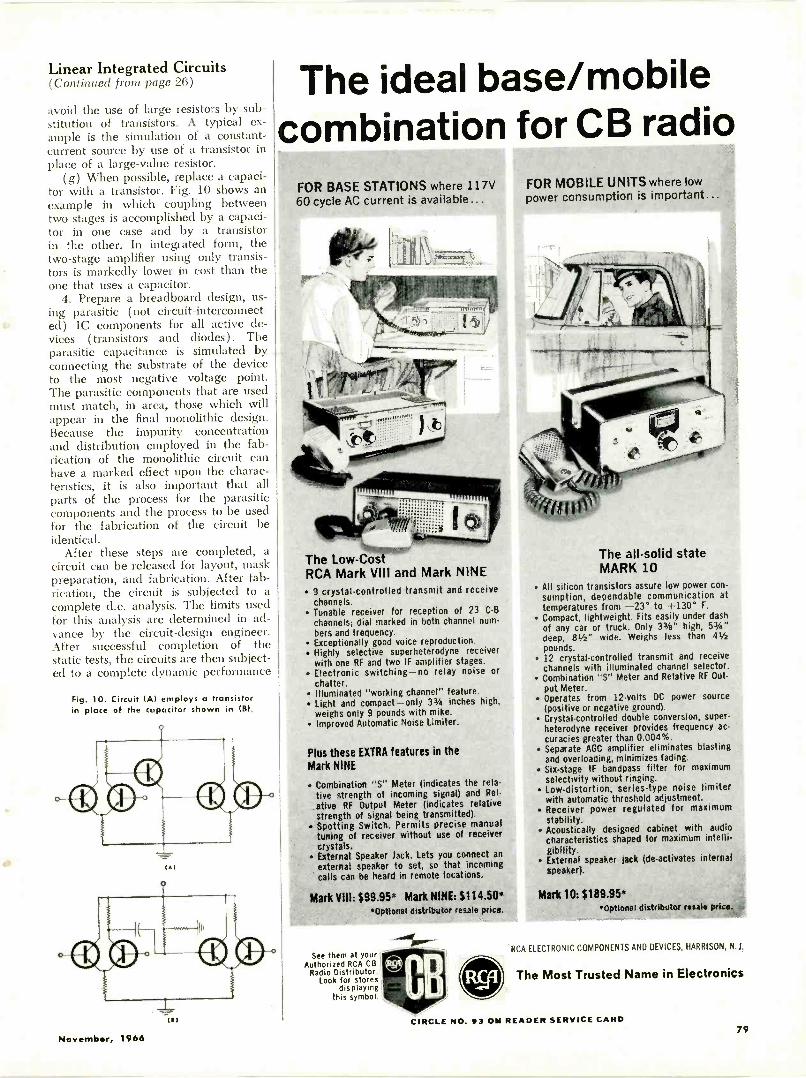
Linear Integrated Circuits(Continued front page 26)
avoid the use of large resistors by sub-stitution of transistors. A typical ex-ample is the simulation of a constant -current source by use of a transistor inplace of a large -value resistor.
(g) When possible, replace a capaci-tor with a transistor. Fig. 10 shows anexample in which coupling betweentwo stages is accomplished by a capaci-tor in one case and by a transistor»in the other. In integrated form, thetwo -stage amplifier using only transis-tors is markedly lower in cost than theone that uses a capacitor.
4. Prepare a breadboard design, us-ing parasitic (not circuit -interconnect-ed) IC components for all active de-vices (transistors and diodes). Theparasitic capacitance is simulated byconnecting the substrate of the deviceto the most negative voltage point.The parasitic components that are usedmust match, in area, those which willappear in the final monolithic design.Because the impurity concentrationand distribution employed in the fab-rication of the monolithic circuit canhave a marked effect upon the charac-teristics, it is also important that allparts of the process for the parasiticcomponents and the process to be usedfor the fabrication of the circuit beidentical.
After these steps are completed, acircuit can be released for layout, maskpreparation, and fabrication. After fab-rication, the circuit is subjected to acomplete d.c. analysis. The limits usedfor this analysis are determined in ad-vance by the circuit -design engineer.After successful completion of thestatic tests, the circuits are then subject-ed to a complete dynamic performance
Fig. 10. Circuit lAsl employs a transistorin place of the capacitor shown in
9
(Al
The ideal base/mobilecombination for CB radio
FOR BASE STATIONS where 117V60 cycle AC current is available...
The Low -CostRCA Mark VIII and Mark NINE 9 crystal -controlled transmit and receive
channels. Tunable receiver for reception of 23 C8
channels; dial marked in both channel num-bers and frequency.
Exceptionally good voice reproduction. Highly selective superheterodyne receiver
with one RF and two IF amplifier stages. Electronic switching-no relay noise or
chatter. Illuminated "working channel" feature. Light and compact -only 33/4 inches high,
weighs only 9 pounds with mike. Improved Automatic Noise Limiter.
Plus these EXTRA features in theMark NINE
Combination "S" Meter (indicates the rela-tive strength of incoming signal) and Rel.ative RF Output Meter (indicates relativestrength of signal being transmitted).
Spotting Switch. Permits precise manualtuning of receiver without use of receivercrystals.
External Speaker Jack. Lets you connect anexternal speaker to set, so that incomingcalls can be heard in remote locations.
Mark VIII: $99.95* Mark NINE: $114.50*Optional distributor resale price.
See them at yourAuthorized RCA CB
Radio Distributor.Look for stores
displayingthis symbol.
FOR MOBILE UNITS where lowpower consumption is important...
The all -solid stateMARK 10
All silicon transistors assure low power con-sumption, dependable communication attemperatures from -23° to 1-130° F.
Compact, lightweight. Fits easily under dashof any car or truck. Only 33/a" high, 53/4"deep, 8I/z" wide. Weighs less than 41/2pounds.
12 crystal -controlled transmit and receivechannels with illuminated channel selector.
Combination "S" Meter and Relative RF Out-put Meter.
Operates from 12 -volts DC power source(positive or negative ground).
Crystal -controlled double conversion, super-heterodyne receiver provides frequency ac-curacies greater than 0.004%.
Separate AGC amplifier eliminates blastingand overloading, minimizes fading.
Six -stage IF bandpass filter for maximumselectivity without ringing.
Low -distortion, series -type noise limiterwith automatic threshold adjustment.
Receiver power regulated for maximumstability.
Acoustically designed cabinet with audiocharacteristics shaped for maximum intelli-gibility.
External speaker jack (de -activates internalspeaker).
Mark 10: $189.95**Optional distributor reSala price,
RCA ELECTRONIC COMPONENTS AND DEVICES, HARRISON, N.J.
The Most Trusted Name in Electronics
November, 1966
CIRCLE NO. $3 ON READER SERVICE CARD79
THE FALL 1966 EDITION OF THE EXCITING
ELECTRONIC EXPERIMENTER'S HANDBOOK
IS ALL -NEW, PACKED WITH THE MOST
FASCINATING CONSTRUCTION PROJECTS
EVER AND READY FOR YOU RIGHT NOW!
You'll build a smoke alarm for your home ... a TVpicture tester and rejuvenator . . . a $10 solid-state 6 -watt amplifier . . a headlights -on alarm
. a watchdog mobile monitor ... a failsafe tran-sistor power supply...a 99c speaker enclosure...and over 20 other challenging do-it-yourself con-struction projects!
Each project is described from start to finish inclear, concise, easy -to -follow language. Add fullydetailed schematics, illustrations and parts lists-plus dozens of professional how-to tips and tech.niques-and you've got all the ingredients forsome of the most unique electronics items you'veever seen .. . or put together with your own twohands!Including units for: your home audio/stereo/hi-fi
your car SWL-C13-Ham test equipment
Whether you keep the valuable units you'll build,or sell them for a profit (they'll cost you next tonothing to construct), the Fall 1966 Electronic Ex-perimenter's Handbook is guaranteed to increaseyour over-all electronics proficiency and provideyou with hour after hour of sheer fun!And note this special bonus feature: "ProjectChoose"-an exclusive report on electronics correspondence and resident schools!
Over 148 pages of fascinating electronics in all.Don't miss it! Use the coupon below and order yourcopy today!
only Got the message?GET THE HANDSOME".LEATHERFLEX-
$1 25 Get the scissors!MM. =Mb 11 IMO NMBOUND EDITION (
for just ZIFFDAVIS SERVICE DIVISIONI DEPT. EEH-F
$3 POSTPAID! I 589 Broadway N.Y., N.Y. 10012The Fall 1966 1 OK! Send me the all -new Fall 1966Electronic Ever- Electronic Experimenter's Hand-imenter's Hand- I book.book is also avail $1.25 enclosed, plus 15c forable in a Wen - shipping and handling. Senddid deluxe edi- me the regular edition. ($1.75lion. RuggedLeatherflex coverprovides lastingprotection yet issoftly texturedand gold -emboss-ed for the look ofelegance_ A col-lector's item-asuperb additionto your electron-ics bookshelf.And it's yours,for just $3 post-paid, when youcheck the appro-priate box on theorder form
for orders outside the U.S.A.)ri $3.00 enclosed. Send me the
Deluxe Leatherflex-bound edi-tion, postpaid. ($3.75 for ordersoutside the U.S.A.) Allow threeadditional weeks for delivery.
name
address
city
PLEASE PAINT LW I I
state zip codePAYMENT MUST BE ENCLOSED
WITH ORDER
11404ate Yes,Yes, I did miss the big Spring
IA 1966 edition. So please rush it tome right now! I want the El
( ular edition EI Deluxe Leatherflexabboouvned) edition. (Prices same as
I
analysis to ensure that the unit com-plies with the original "black -box"specifications.
Production TestingBecause an integrated unit performs
a circuit or multiple -circuit function,testing can be a significant portion ofthe cost. However, a large part of thetesting cost can be avoided by use ofa.c. or dynamic specifications whichpermit performance deviations withinthe normal process variables. Undersuch conditions, an integrated circuitcan generally be evaluated completelyby means of static or d.c. testing.These static tests are fast (typical au-tomatic -equipment static test rates areon the order of 30 to 60 tests per sec-ond) and provide a high probabilitythat the circuit will perform properlyunder dynamic conditions because thecomponents of the integrated circuitare frequently more sensitive to d.c.than a.c. evaluation.
There are obvious exceptions forwhich d.c. tests cannot assure compli-ance with an a.c. specification, partic-ularly When capacitor coupling is used.In such cases the pellet is d.c.-probedbefore dicing at internal points andthen may be a.c.-tested after the mount-ing and bonding have been completed.
The FutureThe most important single develop-
ment in linear integrated circuits overthe next few years should be the de-sign of standard types and the accep-tance of these types by equipmentmanufacturers. Large volume require-ments with extreme emphasis on lowcost will encourage the developmentof special circuits with multi -functionuses, particularly in consumer andsome limited industrial applications.Technological developments will ex-tend the frequency range through u.h.f.,and large improvements will be forth-coming in low -noise applications atboth high and low frequencies. Exten-sion into greater power -handling capa-bility will, to a large extent, be deter-mined by economic considerations.Combinations of MOS and bipolartransistors offer some unique technicaladvantages and will become a part ofthe standard types offered by moremanufacturers.
The most significant contributionthat integrated circuits will make toequipment of the future is that morecomplex instruments will be generatedbecause one or more orders of magni-tude of electronic functions will bepurchased for the same cost. In addi-tion, the improvement in reliabilitywill permit such designs. As a result,equipment manufacturers will be stim-ulated to design products which todayare neither practical nor economicallyfeasible.
Designing Hi-Fi Amplifiers(Continued front page 50)
Lure capabilities of the silicon transis-tors, the performance of the amplifiersremains essentially the same over awide variation in ambient temperature.
Fig. 5A shows a schematic of a prac-tical 10 -watt quasi -complementary au-dio amplifier. This circuit employs thesame stability techniques as those usedin the circuit of Fig. 1. Two 1N3754diodes are used in the input of thedriver stage to compensate for theeffect of high -temperature variations ofthe output transistors. Two 1 -ohm re-sistors are placed in the output stage toprovide the degeneration required forcircuit stability. These resistors areshunted by 1N3193 diodes to reducelosses when the amplifier is operated atfull rated output power.
The use of direct -coupled stages andlocal d.c. feedback results in very stablequiescent operation at ambient tem-peratures up to 71°C. With an over-allnegative feedback of 5 dB, the ampli-fier has a response that is flat within1 dB from 15 to 20,000 Hz. Perfor-mance curves for the 10 -watt ampli-fier are shown in Figs. 5B, 5C, and 5D.
25 -Watt, Class -AB Audio Amplifier
Fig. 6A shows the schematic of a25 -watt a.c./d.c. transformer -coupledaudio amplifier intended primarily forpublic-address systems and other ap-plications for which economy and flex-ibility with respect to load impedanceare important considerations. The highbreakdown voltage of the silicon powertransistors used in the output and driverstages permit the amplifier to be op-erated directly from a 120 -volt a.c. ord.c. line. The negative -voltage termi-nals of the amplifier (i.e., circuitground) is isolated from chassis groundby a 0.22-megohm resistor to reducethe risks of electrical shock. The signalinput should be transformer -coupled tothe power amplifier to avoid shockhazard from the signal -source ground.A 0.1-µF capacitor provides a low im-pedance connection between circuitground and chassis ground at r.f. fre-quencies to prevent high -frequency os-cillations.
Each driver transistor is connectedto the associated output transistor in aDarlington arrangement; the output istransformer -coupled to the speaker.Drive -signal phase inversion is pro-vided by a transistor phase-splitter cir-cuit. The small amount of forward biasrequired for class -AB operation is pro-vided by the 180,000 and 510 -ohmresistors and the 1N3754 diode. Thediode also provides the temperaturecompensation required so that thequiescent current will remain relative-ly constant for wide variations in tem-perature. With the 10 dB of over-all
80ELECTRONICS WORLD
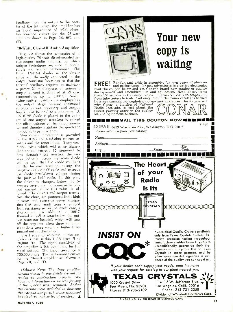
feedback from the output to the emit-ter of the first stage, the amplifier hasan input impedance of 2500 ohms.Performance curves for the 25 -wattunit are shown in Figs. 6B, 6C, and6D.
70 -Watt, Class -AB Audio AmplifierFig. 7A shows the schematic of a
high -quality 70 -watt direct -coupled se-ries -output audio amplifier in whichunique techniques are used to obtainstable and reliable performance. Thethree 1N3754 diodes in the driverstage are thermally connected to theoutput transistor heatsinks so that thethermal feedback required to maintaina preset 20 milliamperes of quiescentoutput current is obtained at all casetemperatures up to 100°C. Small -value emitter resistors are employed inthe output stage because additionalstability is not necessary and outputlosses must be held to a minimum. A1N1612R diode is placed in the emit-ter of one output transistor to cancelthe offset voltage of the input transis-tor and thereby maintain the quiescentoutput voltage near zero.
Short-circuit protection is providedby the 0.27- and 0.33 -ohm emitter re-sistors and the zener diode. If any con-dition exists which will cause higher -than -normal current (5 amperes) toflow through these resistors, the vol-tage potential across the zener diodewill be such that the diode conductsin the forward direction during thenegative output half cycle and exceedsthe diode breakdown voltage duringthe positive half cycle. In this way,the driver is clamped below the 5 -ampere level, and no increase in out-put current above this value is al-lowed. The drivers and output transis-tors, therefore, are protected from highcurrents and excessive power dissipa-tion that may result from a reducedload resistance or, in the worst case, ashort-circuit. In addition, a 100°Cthermal cut-off is attached to the out-put transistor heatsink which will turnoff the amplifier when these abnormalconditions cause sustained higher -than -normal output dissipation.
The frequency response of the am-plifier is flat within 1 dB from 5 to25,000 Hz. The input sensitivity ofthe amplifier is 0.8 volt r.m.s. for fullrated output. The input resistance is100,000 ohms. The performance curvesfor the 70 -watt amplifier are shown inFigs. 7B, and 7D.
(Editor's Note: The three amplifiercircuits shown in this article are not in-tended as construction projects. Wehave no information on sources for anyof the special parts required. Ratherthe circuits were included to illustratethe various design principles discussedin this three-part series of articles.) A
)000000000a
Your newcopy iswaiting
FREE 1For fun and pride in assembly, for long years of pleasureand performance, for new adventures in creative electronics
mail the coupon below and get Conar's brand new catalog of qualitydo-it-yourself and assembled kits and equipment. Read about itemsfrom TV set kits to transistor radios . . . from VTVM's to scopes . . .
from tube testers to tools. And every item in the Conar catalog is backedby a no-nonsense, no -loopholes, money -back guarantee! See for yourselfwhy Conar, a division of National
fastest growing entry in the quality RRadio Institute, is just about thekit and equipment business.
1111111111111111IMINIVIAIL THIS COUPON NOWINIIIIMIIIIMIIIIINIII 4,, ,,. 11/41)11.4%Ift 3939 Wisconsin Ave., Washington, D.C. 20016
;111
Please send me your new catalog.111
II Name IsIII Address III
StateZip I
111 City M
iniMMUMEMMEMMOMMEMEMEMEMEM
The Heartof yourRadiois Its
11-
EXASYSTALS
INSIST ON'Controlled Quality Crystals availableonly from Texas Crystals dealers. Ex-tensive precision testing throughoutmanufacture enables Texas Crystals tounconditionally guarantee their fre-quency control crystals. Use of TexasCrystals in space program and byother governmental agencies is evi-dence of the quality you can count on.
If your dealer can't supply your needs, send his namewith your request for catalog to our plant nearest you.
TEXAS CRYSTALS Vee-1000 Crystal Drive 4117 W. Jefferson Blvd.Fort Myers, Fla. 33901 Los Angeles, Calif. 90016Phone: 813-936-2109 Phone: 213-731-2258
Division of Whitehall Electronics Corp.
November, 1966CIRCLE NO. 84 ON READER SERVICE CARD
81
SC Scot TT
SCOTT'S NEWONE -AFTERNOON
TUNER KITDELIVERS
AMAZING FETPERFORMANCE
Now you can get factory -wired per-formance from a kit that takes only oneafternoon to build! Scott's new LT -112Bis the only kit with Field Effect Transistorcircuitry", enabling you to enjoy morestations more clearly. lnterstation MutingControl effects complete quiet betweenFM stations . . . oscilloscope output al-lows laboratory -precise correction formultipath distortion.
"Scott's LT -112 ... is one of the finestFM stereo tuners we have tested and it iseasily the best kit -built tuner we havechecked . . . Because of its simple con-struction and trouble -free nature, it is alogical choice for anyone who wants thefinest in FM reception at a most remark-able price." Hi Fi/Stereo Review.LT -112B specifications: Usable sensitivity, 1.8 µV; Crossmodulation, 90 dB; Stereo separation, 40 dB; Captureratio, 2.5 dB; Price, $189.95. Winds pending
For complete information on the Scott LT -1128, send foryour free copy of Scott's 16 -page full -color illustratedGuide to Custom Stereo.
FREE! 1961 SCOTT
GUIDE TO CUSTOM STEREOHere are 16 colorful, information -packedpages on Scott stereo components . . .
receivers, tuners, amplifiers, speakers ...for 1967. Fact -filled, fully -illustrated articlesshow you what to look for when buyingsolid-state corn ponents, how stereo works,how to create your own home music system.
NAME
ADDRESS
CITY
STATE
Scott . . where innovation is a tradition
SCOTT°H. H. Scott, Inc.,
111 Powdermill Road, Maynard, Mass.Export: H. H. Scott, Inc., Maynard, Mass.
Prices slightly higher west of Rockies. Subject to change without notice
Square -Wave Generator
(Continued from page 43)
the base of this transistor to the emittermomentarily and note that the collectorvoltage should rise as the other side be-comes conducting. Do this severaltimes, and if results are consistent, theflip-flop is operating. If pulses had beenobserved at point A, the trouble wouldhave been in the trigger network con-sisting of C3, Dl, D2, and D3. Diodepolarities and bad capacitors are theusual causes of trigger trouble.
Once square waves are being pro-duced, audio equipment can be testedby any of the well-known methods. Ifthe scope used with the generator doesnot have d.c.-coupling or a low -endresponse to below 5 Hz, it will affectthe waveshape, and this should betaken into account before some possiblyinnocent amplifier is accused of havingpoor low -end response.
At the other extreme of the spec-trum, rise time and overshoot measure-ments will allow equipment to bejudged to beyond 100 kHz.
For great accuracy, either a fre-quency counter or an accurate audiosignal generator used in the well-knownLissajous pattern system can be em-ployed to calibrate R2. In lieu of these,a procedure having intermediate ac-curacy can be performed as follows:
1. Adjust the scope sweep so that asingle low -voltage 60 -Hz sine wave(line frequency) applied to the verticalinput occupies the bulk of the cali-brated scope graticule. Adjust the
scope controls so that the sine wave isstationary and its zero points crossnoted graticule marks.
2. Remove the 60 -Hz signal fromthe scope and substitute the square-
wave generator output. Adjust R2 sothat one complete square wave nowoccupies exactly the same space as the60 -Hz sine wave. This is the 60 -Hzsetting of R2 and this point should beso marked.
3. Reset the scope sweep speed sothat three cycles of 60 -Hz square wavenow occupy the same space as thesingle one did previously. Adjust R2so that one square wave now occupiesthis space. This is the 20 -Hz settingof R2. If R2 will not reach 20 Hz,reduce the value of R3 in 100,000 -ohmsteps until it does.
To calibrate the higher frequencies,"walk up" the audio spectrum asfollows:
1. Fill the graticule space with a20 -Hz square wave. Adjust R2 for twosquare waves in this space. This is the40 -Hz setting.
2. Change the scope sweep speedfor one 40 -Hz square wave on thegraticule. Adjust R2 for two squarewaves. This represents the 80 -Hzsetting.
3. Continue the above procedure toproduce settings at 20, 40, 80, 160,320, 640, 1280, 2560, and 5120 Hz,and at 10.240 and 20.480 kHz at theend of the R2 rotation. Unfortunately,in spite of the use of logarithmic poten-tiometer for R2, the frequencies willtend to bunch up at the maximum re-sistance end of the pot.
SPEAKER EFFICIENCY AND AMPLIFIER POWERBy R.S. OAKLEY, Jr.
T N the table below, the second column-a. refers to the percent of amplifierpower converted to acoustic power bythe loudspeaker. Direct radiators insmall cabinets will normally be about0.5% to 2.0% efficient; direct radiatorsin large cabinets will be about 2.0% to10% efficient. Horn -loaded systems willbe about 10% to 50% efficient.
The columns marked "AmplifierPower" refer to continuous power rat-ings (per channel) of amplifiers. It isassumed that 0.25 acoustic watt per chan-nel will result in natural sound levels.For instance, an amplifier rated at 25clean continuous watts per channel
ould normally be sufficient to drivespeakers of 1.0% efficiency. In a room
that is much larger than normal or ina room with very "dead" acoustics, 100watts might be needed.
The column marked "Music" takes in-to account the fact that peak power inmusic signals will be from ten to onehundred times greater than the normalaverage power. In a larger -than -normal"dead" listening room, a speaker of10% efficiency might have to handle asmuch as 10 watts on very loud orchestralpeaks. But assuming a peak -to -averageratio of only 10 dB, the average power ofa music signal fed to the speaker wouldnot normally exceed about .25 watt.
(Note: This material was derived frominformation supplied by Acoustic Re-search, Inc.)
SPEAKER EFFICIENCY AMPLIFIER POWER MUSICVery low 0.5% 50 200 5.0Low 1.0% 25 100 2.5Medium low 2.0% 12.5 50 1.25Medium 5.0% 5.0* 20 0.5Medium high 10% 2.5* 10* 0.25High 20% 1.25* 5.0* 0.125Very high 50% 0.5* 2.0* 0.05.Commercially available amplifiers rated at leis than 10 watts per channel may have excessive distortionfor wide -range music applications. On the other hand, some amplifiers rated at more than 10 watts perchannel may have too much hum or noise for high -efficiency speakers.CIRCLE NO. 89 ON READER SERVICE CARD
82 CIRCLE NO. 125 ON READER SERVICE CARD
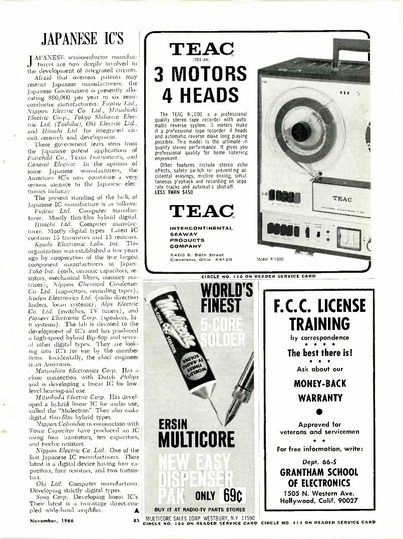
JAPANESE IC'SAPANESE semiconductor manufac-
J tuners are now deeply involved inthe development of integrated circuits.
Afraid that overseas patents mayrestrict Japanese manufacturers, theJapanese Government is presently allo-cating $80,000 per year to six semi-conductor manufacturers: Fujitsu Ltd.,Nippon Electric Co. Ltd., MitsubishiElectric Corp., Tokyo Shibaura Elec-tric Ltd. (Toshiba), Oki Electric Ltd.,and Hitachi Ltd. for integrated cir-cuit research and development.
These government fears stem fromthe Japanese patent applications ofFairchild Co., Texas Instruments, andGeneral Electric. In the opinion ofsome Japanese manufacturers, theAmerican IC's now constitute a veryserious menace to the Japanese elec-tronics industry.
The present standing of the bulk ofJapanese IC manufacture is as follows:
Fujitsu Ltd. Computer manufac-turer. Mostly thin-film hybrid digital.
Hitachi Ltd. Computer manufac-turer. Mostly digital types. Latest ICcontains 15 transistors and 13 resistors.
Kyodo Electronic Labs. Inc. Thisorganization was established a few yearsago by cooperation of the five largestcomponent manufacturers in Japan:Toko Inc. (coils, ceramic capacitors, re-sistors, mechanical filters, memory ma-trices); Nippon Chemical CondenserCo. Ltd. (capacitors, recording tapes);Koden Electronics Ltd. (radio directionfinders, loran systems); Alps ElectricCo. Ltd. (switches, TV tuners);Pioneer Electronic Corp. (speakers, hi-fi systems). The lab is devoted to thedevelopment of IC's and has produceda high-speed hybrid flip-flop and sever-al other digital types. They are look-ing into IC's for use by the memberfirms. Incidentally, the chief engineeris an American.
Matsushita Electronics Corp. Has aclose connection with Dutch Philipsand is developing a linear IC for low-level hearing -aid use.
Mitsubishi Electric Corp. Has devel-oped a hybrid linear IC for audio use,called the "Molectron". They also makedigital thin-film hybrid types.
Nippon Columbia in conjunction withTowa Capacitor have produced an ICusing four transistors, ten capacitors,and twelve resistors.
Nippon Electric Co. Ltd. One of thefirst Japanese IC manufacturers. Theirlatest is a digital device having four ca-pacitors, four resistors, and two transis-tors.
Oki Ltd. Computer manufacturer.Developing strictly digital types.
Sony Corp. Developing linear IC's.Their latest is a two -stage direct -cou-pled wide -band amplifier.
1/4
TiE7A.0
3 MOTORS4 HEADS
The TEAC R-1000 is a professionalquality stereo tape recorder with auto-matic reverse system. 3 motors makeit a professional type recorder. 4 headsand automatic reverse make long playingpossible. This model is the ultimate inquality stereo performance. It gives youprofessional quality for home listeningenjoyment.
Other features include stereo echoeffects, safety switch for preventing ac-cidental erasings, micline mixing, simul-taneous playback and recording on sepa-rate tracks and automatic shut-off.LESS THAN $450
TEACINTERCONTINENTALSEAWAYPRODUCTSCOMPANY5400 E. 96th StreetCleveland, Ohio 44125 Morel R-1000
CIRCLE NO. 110 ON READER SERVICE CARD
WORLD'SFINEST
ERSIN
MULTICORE
ONLY 69cBUY IT AT RADIO -TV PARTS STORES
F.C.C. LICENSE
TRAININGby correspondence
The best there is!
Ask about our
MONEY -BACK
WARRANTY
Approved forveterans and servicemen
For free information, write:
Dept. 66-S
GRANTHAM SCHOOL
OF ELECTRONICS1505 N. Western Ave.
Hollywood, Calif. 90027
November, 1966 85 MULTICORE SALES CORP. WESTBURY, N.Y. 11590CIRCLE NO. 100 ON READER SERVICE CARD CIRCLE NO. 113 ON READER SERVICE CARD
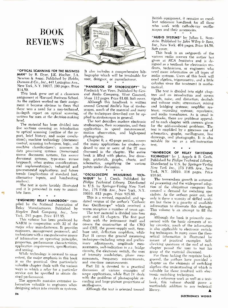
BOOKREVIEWS
"OPTICAL SCANNING FOR THE BUSINESSMAN" by R. Dyer, J.E. Hoelter, J.A.Newton & Assoc. Published by Hobbs,Dorman & Co., Inc., 441 Lexington Ave.,New York, N.Y. 10017. 190 pages. Price$14.50.
This book grew out of a classroomassignment at Harvard Business School.As the authors worked on their assign-ment it became obvious to them thatthere was a need for a non -technical,in-depth report on optical scanning,written for men at the decision -makinglevel.
The material has been divided intofive sections covering an introductionto optical scanning (outline of the re-port, brief history, and major conclu-sions); machine technology (documentcontrol, scanning techniques, logic, andmachine classifications); scanners indata processing systems (turnaroundsource document systems, fan sourcedocument systems, type -scan versuskeypunch, other system considerations,and implementation); industrial andgovernmental applications; and futuretrends (implications of standard font,alternative inputs, and handwritingreaders ).
The text is quite lavishly illustratedand it is presented in easy to assimi-late form.
a *
"ENGINEERS' RELAY HANDBOOK" com-piled by the National Association ofRelay Manufacturers. Published byHayden Book Company, Inc., NewYork. 293 pages. Price $11.95.
This volume has been produced byNARM in cooperation with 32 of themajor relay manufacturers. It providesengineers, management personnel, andtechnicians with a comprehensive sourceof information on operating principles,properties, performance characteristics,application requirements, specifications,and testing.
While technology is covered to someextent, the major emphasis in this bookis on the practical. One particularlyvaluable chapter deals with the variousways in which a relay for a particularservice can be specified to obtain de-sired performance.
The appendix contains extensive in-formation valuable to engineers whendesigning relays into circuits or systems.
BASIC ElliCiutffix ClHhU0.11Yl1q$'
It also includes a comprehensive bib-liography which will be invaluable foruser, designer, or manufacturer.
* * *
"HANDBOOK OF STROBOSCOPY" byFrederick Van Veen. Published by Gen-eral Radio Company, West Concord,Mass. 112 pages. Price $1.00. Soft cover.
Although this handbook is writtenaround General Radio's line of strobo-scopes, much of the material and manyof the techniques described can be ap-plied to stroboscopes in general.
The text describes modern electronicstroboscopes, their accessories, and theirapplication in speed measurement,motion observation, and high-speedphotography.
Chapter 6, a 42 -page section, coversthe many applications for strobes-in-dexed to one or more of the 37 usesdiscussed in the chapter. The entirebook is filled with photos, line draw-ings, pictorials, graphs, charts, andschematics, amplifying the variouspoints under discussion.
O
"OSCILLOSCOPE MEASURING TECH-NIQUE" by J. Czech. Published byPhilips Technical Library. Distributedin U.S. by Springer-Verlag New YorkInc., 175 Fifth Ave., New York, N.Y.10010. 613 pages. Price $15.80.
This is a revised, expanded, and up-dated version of the author's "CathodeRay Oscilloscope" which received awarm reception a number of years ago.
The text material is divided into fourparts and 33 chapters. The first partdeals with the instrument itself andcovers the construction of the CROand CRT, the power -supply unit, time-
base unit, deflection amplifiers, whilePart II covers the general measuringtechnique-including setup and prelim-inary adjustments, amplitude mea-surements, null -indication in a.c. bridgecircuits, the electronic switch, the usesof intensity modulation, phase mea-surements, frequency measurements,and rise -time measurements.
Part III is devoted to a practicaldiscussion of various examples ofscope applications, while Part IV dealswith the problems of photographic re-cording and large -picture projections ofoscillograms.
Although the text is oriented toward
British equipment, it remains an excel-lent reference handbook for all thosewho work with cathode-ray oscillo-scopes and their accessories.
* * *
"AUDIO SYSTEMS" by Julian L. Bern-stein. Published by John Wiley & Sons,Inc., New York. 404 pages. Price $4.50.Soft cover.
This book is an outgrowth of thevarious audio courses the author hasgiven at RCA Institutes and is de-signed as a textbook for electronics stu-dents, technicians, or engineers whoneed more information on all types ofaudio systems. Users of this book willneed algebra, trigonometry, and a littlecalculus since the treatment is mathe-matical.
The text is divided into eight chap-ters and an introduction and coverssignals, noise, and distortion; decibelsand volume units; attenuators; mixingand bridging systems; amplifier sys-tems; recording systems; equalizers;and audio transducers. As is usual intextbooks, there are problems append-ed to each chapter with answers givenfor the odd -numbered problems. Thetext is amplified by a generous use ofschematics, graphs, oscillograms, linedrawings, and photographs. It is alsosuitable for use as a self -instructiontext.
* * *"HANDBOOK OF RELAY SWITCHINGTECHNIQUE" by J. Appels & B. Geels.Published by Philips Technical Library.Distributed in U.S. by Springer-VerlagNew York Inc., 175 Fifth Ave., NewYork, N.Y. 10010. 316 pages. Price$10.80.
The tremendous growth in automat-ed processing and the widespread adop-tion of the ubiquitous computer hascreated a demand for switching spe-cialists. As the authors point out, notonly is there a scarcity of skilled work-ers but there is a paucity of availableinformation to eliminate this shortage.This volume is an attempt to fill thegap.
Although the book is primarily con-cerned with the basic elements of re-lay circuitry, much of the informationis also applicable to electronic switch-ing techniques. In many cases the theo-retical information is illustrated bymeans of practical examples. Self -checking questions at the end of eachchapter permit the user to test hisgrasp of the material discussed.
For those lacking the requisite back-ground, the authors have provided achapter on the elements of switchingalgebra-the understanding of which isvaluable for those involved with elec-tronic switching techniques.
As a reference work as well as a text-book, this volume should prove aworthwhile addition to any technicallibrary. A
86ELECTRONICS WORLD
al
eenymeenyminey mo
00
1111 i
TAPE RECORDER sigtI/11\1, Itit f 111) \ MIMI t'.!'1.01f DING
How to Choose a Tape Recorder * The New Tape CartridgeMachines for Home and Car *Roundup of Video RecordersTape Editing *Taping Off the Air * Prerecorded TapesPortable Recorders * Operating Principles of RecordersDirectory of Stereo Tape Recorders. Accessories. Mikes
NR-o'nintioseArt.,,
(
Well, that's one way to buy a tape recorder . . .
. . . But we've got a better idea. It's called the
1967 TAPE RECORDER ANNUAL-your guide to the tape recorder brands and models on the market rightthis minute. The only buyer's guide of its kind available in the field!Oh, it may not be as exciting as the "blind -man's -bluff" method, but it sure is a lot lesscostly ... and less disappointing. This ency-clopedic volume will arm you with all theessential data you need to go out and pickthe very best recording equipment in yourprice range. Without a qualm. Without an"after -you -get -it -home" let -down. Without ablindfold!
You'll find more than 132 pages of fullinformation on over 250 models from virtu-ally every major manufacturer. Stereo andmono. Portables and full home installations.Even video tape recorders and the new carcartridge machines! All the model numbers,
specifications, dimensions and prices. Al-most 200 photos. Every vital statistic youneed to compare the newest recorders andselect the one that will bring you the greatestvalue for your dollar!And that's only half the story. After you buyyour recorder, turn to the articles on micro-phone selection, basic tape recorder theory,taping off the air, creative editing or thespecial accessories section. You'll get experttips by the dozens. Ten complete featurescovering every aspect of tape recording. Alldesigned to give you better performance,greater versatility and a lot more fun fromyour tape recorder!
How much for this indispensable treasury of sound advice? Just $1.25. A small price for a big eye-opener.
CET THE HANDSOME LEATHERFLEX-COVEREDEDITION FOR $3 POSTPAID!
THE 1967 TAPE RECORDER ANNUALis also available in a splendiddeluxe edition. Rugged Leatherflexcover provides lasting protectionyet is softly textured and gold -embossed for the look of elegance.A collector's item-a superb addi-tion to your permanent referencelibrary. And it's yours, for just$3 postpaid, when you check theappropriate box on the order form.
Ziff -Davis Service Division, Dept. TRA589 Broadway, New York, N.Y. 10012Please send my copy of the 1967 TAPE RECORDER ANNUAL as checked below:El I am enclosing $L25 plus 15c for shipping and handling for the Regular
Edition. ($L75 for orders outside U.S.A.)ID I am enclosing $3.00. Please send me, postpaid, the Leatherflex-covered
Deluxe Edition. ($3.75 for orders outside U.S.A.) (Please allow 3 additionalweeks for delivery of the Deluxe Edition.)
name(please print) EW-116
address
city state zip code
November, 1966 87
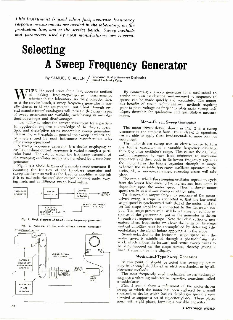
This instrument is used when fast, accurate frequencyresponse measurements are needed in the laboratory, on theproduction line, and at the service bench. Sweep methodsand parameters used by most manufacturers are covered.
SelectingA Sweep Frequency GeneratorBy SAMUEL C. ALLEN Supervisor, Quality Assurance Engineering
Jerrold Electronics Corp.
WHEN the need arises for a fast, accurate methodof making frequency -response measurements,whether in the laboratory, on the production line,
or at the service bench, a sweep frequency generator is usu-ally chosen to fill the assignment. But a look through sev-eral manufacturers' catalogues will indicate that many typesof sweep generators are available, each having its own dis-tinct advantages and disadvantages.
The ability to select the correct instrument for a particu-lar application requires a knowledge of the theory, opera-tion, and descriptive terms concerning sweep generators.This article will explain in general the sweep methods andparameters used by most instrument manufacturers whooffer sweep equipment.
A sweep frequency generator is a device employing anoscillator whose output frequency is varied through a parti-cular band. The rate at which the frequency excursion ofthe sweeping oscillator occurs is determined by a time -basegenerator.
Fig. 1 is a block diagram of a simple sweep generator il-lustrating the function of the time -base generator andsweep oscillator as well as the leveling amplifier whose job't is to maintain the oscillator output constant under vary-ing loads and at different sweep bandwidths.
TIME -BASE
GENERATORSWEEP
OSCILLATOR
LEVELINGAMPLIFIER
(AUTOMATIC LEVELCONTROL)
OUTPUTMATCHINGNETWORK
SWEEPOUTPUT
SAMPLE OF SWEEPOUTPUT VOLTAGE
Fig. 1. Block diagram of basic sweep frequency generator.
Fig. 2. Principle of the motor -driven sweep generator.SYNCHRONOUS MOTOR
SCOPE
VARIABLE-FREO.OSCILLATOR
VERT. HOMEOVARIABLE
FREQUENCYMOTOR SPEED
CONTROL SWEEPVARIABLE OUTPUT
TUNINGCAPACITOR
UNITUNDERTEST
VARIABLE -
PHASE
NETWORK
By connecting a sweep generator to a mechanical re-corder or to an oscilloscope, measurement of frequency re-sponse can be made quickly and accurately. The numer-ous benefits of sweep techniques over methods requiringpoint-to-point voltage vs frequency plots make sweep tech-niques desirable for qualitative and quantitative measure-ments.
Motor -Driven Sweep GeneratorThe motor -driven device shown in Fig. 2 is a sweep
generator in the simplest form. By studying its operation,we are able to apply these fundamentals to more complexequipment.
The motor -driven sweep uses an electric motor to turnthe tuning capacitor of a variable frequency oscillatorthroughout the oscillator's range. This causes the oscillatoroutput frequency to vary from minimum to maximumfrequency and then back to its lowest frequency again asthe motor turns the tuning capacitor through its range.Whether the variable frequency oscillator operates in theaudio, r.f., or microwave range, sweeping action will take_place.
The rate at which the sweeping oscillator repeats its cyclefrom the lowest frequency to the highest and back again isdependent upon the motor speed. Thus, a slower motorspeed results in a slower sweep repetition rate.
To observe the output frequency response of the motor -driven sweep, a scope is connected so that the horizontalscope speed is synchronized with that of the motor, and thevertical scope amplifier is connected to the generator out-put. The scope presentation will be a frequency vs time re-sponse of the generator output as the generator is driventhrough its frequency range. Note that observation of gen-erators whose frequencies are above the range of the scopevertical amplifier must be accomplished by detecting (de-modulating) the signal before applying it to the scope.
Synchronization of the horizontal scope speed with themotor speed is established through a phase -shifting net-work which allows the forward and return sweep traces tobe superimposed on the scope screen, thereby giving alinear frequency vs time display.
Mechanical -Type Sweep GeneratorAt this point, it should be noted that sweeping action
may be accomplished by either electromechanical or by all-electronic methods.
The most frequently used mechanical sweep techniqueemploys a vibrating inductor or capacitor, sometimes calleda wobbulator.
Figs. 3 and 4 show a refinement of the motor -drivensweep in which the motor has been replaced by a smallspeaker -like device which has its diaphragm specially con-structed to support a set of capacitor plates. These platesmesh with rigid plates, forming a variable capacitor.
88ELECTRONICS WORLD
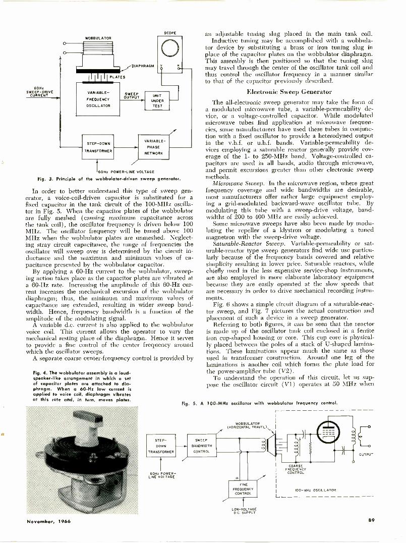
60HzSWEEP -DRIVE
CURRENT
WOBBULATOR
VARIABLE -
FREQUENCY
OSCILLATOR
DIAPHRAGM
SWEEPOUTPUT
SCOPE
V
STEP-DOWN
TRANSFORMER
UNIT
UNDER
TEST
VARIABLE -
PHASE
NETWORK
60Hz POWER -LINE VOLTAGE
Fig. 3. Principle of the wobbulator-driven sweep generator.
In order to better understand this type of sweep gen-erator, a voice -coil -driven capacitor is substituted for afixed capacitor in the tank circuit of the 100 -MHz oscilla-tor in Fig. 5. When the capacitor plates of the wobbulatorare fully meshed (causing maximum capacitance acrossthe tank coil), the oscillator frequency is driven below 100MHz. The oscillator frequency will be tuned above 100MHz when the wobbulator plates are unmeshed. Neglect-ing stray circuit capacitance, the range of frequencies theoscillator will sweep over is determined by the circuit in-ductance and the maximum and minimum values of ca-pacitance presented by the wobbulator capacitor.
By applying a 60 -Hz current to the wobbulator, sweep-ing action takes place as the capacitor plates are vibrated ata 60 -Hz rate. Increasing the amplitude of this 60 -Hz cur-rent increases the mechanical excursion of the wobbulatordiaphragm; thus, the minimum and maximum values ofcapacitance are extended, resulting in wider sweep band-width. Hence, frequency bandwidth is a function of theamplitude of the modulating signal.
A variable d.c. current is also applied to the wobbulatorvoice coil. This current allows the operator to vary themechanical resting place of the diaphragm. Hence it servesto provide a fine control of the center frequency aroundwhich the oscillator sweeps.
A separate coarse center -frequency control is provided by
Fig. 4. The wobbulator assembly is a loud-speaker -like arrangement in which a setof capacitor plates are attached to dia-phragm. When a 60 -Hz low current isapplied to voice coil, diaphragm vibratesat this rate and, in turn, moves plates.
STEP-
DOWN
TRANSFORMER
Fig
60Hz POWER -LINE VOLTAGE
an adjustable tuning slug placed in the main tank coil.Inductive tuning may be accomplished with a wobbula-
tor device by substituting a brass or iron tuning slug inplace of the capacitor plates on the wobbulator diaphragm.This assembly is then positioned so that the tuning slugmay travel through the center of the oscillator tank coil andthus control the oscillator frequency in a manner similarto that of the capacitor previously described.
Electronic Sweep GeneratorThe all -electronic sweep generator may take the form of
a modulated microwave tube, a variable -permeability de-vice, or a voltage -controlled capacitor. While modulatedmicrowave tubes find application at microwave frequen-cies, some manufacturers have used these tubes in conjunc-tion with a fixed oscillator to provide a heterodyned outputin the v.h.f. or u.h.f. bands. Variable -permeability de-vices employing a saturable reactor generally provide cov-erage of the 1- to 250 -MHz band. Voltage -controlled ca-pacitors are used in all bands, audio through microwave,and permit excursions greater than other electronic sweepmethods.
Microwave Sweep. In the microwave region, where greatfrequency coverage and wide bandwidths are desirable,most manufacturers offer rather large equipment employ-ing a grid -modulated backward -wave oscillator tube. Bymodulating this tube with a sweep -drive voltage, band-widths of 200 to 400 MHz are easily achieved.
Some microwave sweeps have also been made by modu-lating the repeller of a klystron or modulating a tunedmagnetron with the sweep -drive voltage.
Saturable -Reactor Sweep. Variable -permeability or sat-urable -reactor type sweep generators find wide use particu-larly because of the frequency bands covered and relativesimplicity resulting in lower price. Saturable reactors, whilechiefly used in the less expensive service -shop instruments,are also employed in more elaborate laboratory equipmentbecause they are easily operated at the slow speeds thatare necessary in order to drive mechanical recording instru-ments.
Fig. 6 shows a simple circuit diagram of a saturable -reac-tor sweep, and Fig. 7 pictures the actual construction andplacement of such a device in a sweep generator.
Referring to both figures, it can be seen that the reactoris made up of the oscillator tank coil enclosed in a ferriteiron cup -shaped housing or core. This cup core is physical-ly placed between the poles of a stack of U-shaped lamina-tions. These laminations appear much the same as thoseused in transformer construction. Around one leg of thelaminations is another coil which forms the plate load forthe power -amplifier tube (V2).
To understand the operation of this circuit, let us sup-pose the oscillator circuit (V1) operates at 50 MHz when
5. A 100 -MHz oscillator with wobbulator frequency control.
SWEEP
BANDWIDTH
CONTROL
WOBBULATOR(HORIZONTAL TRAVEL)
FINE
FREQUENCYCONTROL
LOW -VOLTAGED.C. SUPPLY
-----) EOUTPUT
COARSEFREQUENCY
CONTROL
100 -MHz OSCILLATOR
L
November, 1966 89
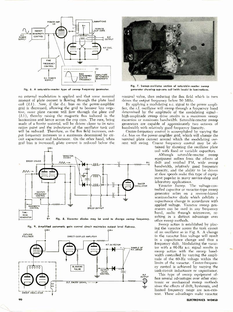
A.G.POWERSUPPLY
POWER AMP.V2
SWEEP -BANDWIDTHCONTROL
FINE
FREOUENCYCONTROL
D.C. POWERSUPPLY
B+
LAMINATIONS
FERRITECUP CORE
OV
BIAS AMPLITUDEDETERMINES DETERMINESCENTER BANDWIDTHFREQUENCY
Fig. 6. A saturable -reactor ype of sweep frequency generator.
no external modulation is applied and that some nominalamount of plate current is flowing through the plate loadcoil (L1 ). Now, if the d.c. bias on the power -amplifiergrid is decreased, allowing the grid to become less nega-tive, more plate current will flow through the plate coil(L1), thereby raising the magnetic flux induced in thelaminations and hence across the cup core. The core, beingmade of a ferrite material, will be driven closer to its satu-ration point and the inductance of the oscillator tank coilwill be reduced. Therefore, as the flux field increases, out-put frequency increases to a maximum determined by cir-cuit capacitance and inductance. On the other hand, whengrid bias is increased, plate current is reduced below the
SWEEP DRIVER
BANDWIDTHCONTROL
TIME -BASE
GENERATOR
VARACTORDIODES
Q.0 0
SWEEP OUTPUT
Fig. 8. Varactor diodes may be used to change
Fig. 7. Sweep -oscillator section of saturable -reactor sweepgenerator showing cup -core coil (with leads) in laminations.
nominal value, thus reducing the flux field which in turndrives the output frequency below 50 MHz.
By applying a modulating a.c. signal to the power ampli-fier, the r.f. oscillator will sweep through a frequency banddetermined by the amplitude of the modulating signal-high-amplitude sweep drive results in a maximum sweepexcursion or maximum bandwidth. Saturable -reactor sweepgenerators are capable of approximately two octaves ofbandwidth with relatively good frequency linearity.
Center -frequency control is accomplished by varying thed.c. bias on the power -amplifier grid, which will change thenominal plate current around which the modulating cur-rent will swing. Coarse frequency control may be ob-
tained by shunting the oscillator platecoil with fixed or variable capacitors.
Although saturable -reactor sweepequipment suffers from the effects ofdrift and residual FM, wide sweepbandwidth, relatively good frequencylinearity, and the ability to be drivenat slow speeds make this type of equip-ment popular in many service -shop andlaboratory applications.
Varactor Sweep. The voltage -con-trolled capacitor or varactor-type sweepgenerator relies on a reverse -biasedsemiconductor diode which exhibits acapacitance change in accordance withapplied voltage. Varactor sweep gen-erators can be used in any frequencyband, audio through microwave, re-sulting in a distinct advantage overother sweep methods.
Sweep action is established by plac-ing the varactor across the tank circuitof an oscillator as in Fig. 8. A changein the varactor bias voltage will resultin a capacitance change and thus afrequency shift. Modulating the varac-
SAMPL E OF tor with a 60 -Hz a.c. signal results inR.F.SWEEP sweep action with the sweep band-
width controlled by varying the ampli-tude of the 60 -Hz voltage within thelimits of the varactor. Center -frequen-cy control is achieved by varying thetank -circuit inductance or capacitance.
This type of sweep equipment of-fers several advantages over other elec-tronic or mechanical sweep methodssince the effects of drift, hysteresis, andlimited frequency range are non-exis-tent. These advaritages make varactor
sweep
8+
SWEEPOSCILLATOR
Fig. 9. Amplified automatic gain control circuit maintains output level flatness.08+ Q8+
CATHODEFOLLOWER
LSWEEP OSCILLATOR
DIRECT -COUPLED AMPLIFIER
BLANKINGPULSE
R.F. SWEEP SIGNAL
R.F. DETECTOR
OUTPUT IILEVEL
CONTROL
frequency.
90 ELECTRONICS WORLD
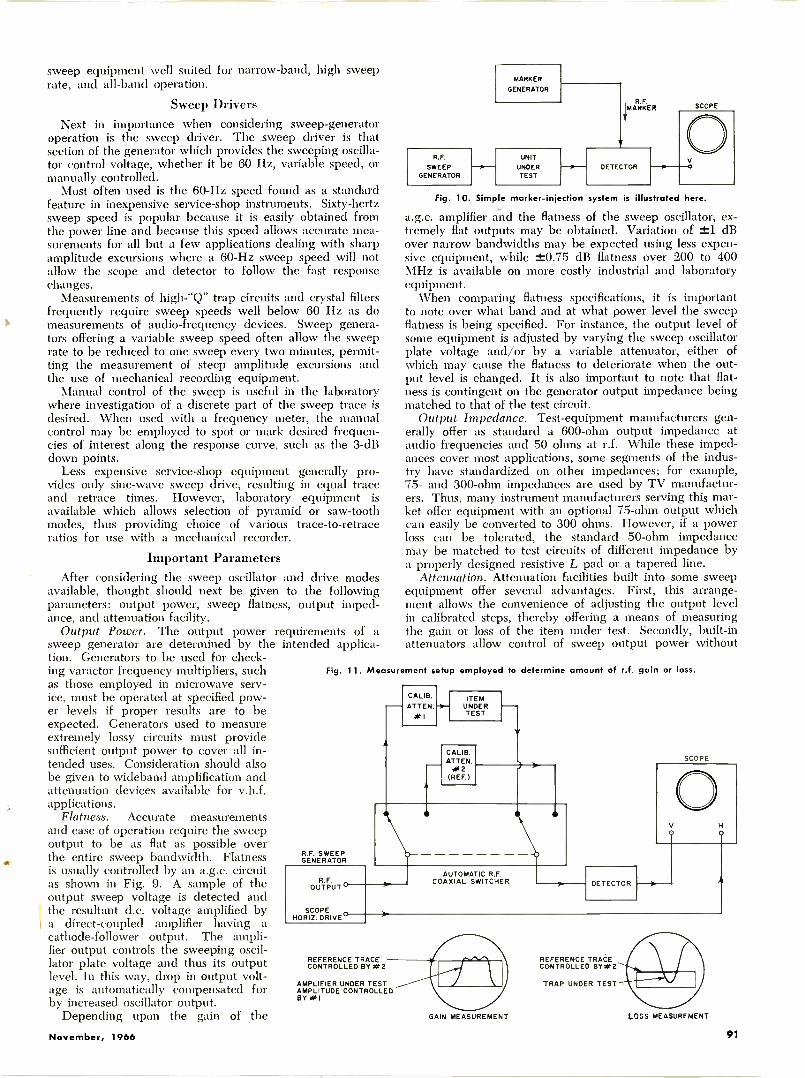
sweep equipment well suited for narrow -band, high sweeprate, and all -band operation.
Sweep DriversNext in importance when considering sweep -generator
operation is the sweep driver. The .sweep driver is thatsection of the generator which provides the sweeping oscilla-tor control voltage, whether it be 60 Hz, variable speed, ormanually controlled.
Most often used is the 60 -Hz speed found as a standardfeature in inexpensive service -shop instruments. Sixty -hertzsweep speed is popular because it is easily obtained fromthe power line and because this speed allows accurate mea-surements for all but a few applications dealing with sharpamplitude excursions where a 60 -Hz sweep speed will notallow the scope and detector to follow the fast responsechanges.
Measurements of high -"Q" trap circuits and crystal filtersfrequently require sweep speeds well below 60 Hz as domeasurements of audio -frequency devices. Sweep genera-tors offering a variable sweep speed often allow the sweeprate to be reduced to one sweep every two minutes, permit-ting the measurement of steep amplitude excursions andthe use of mechanical recording equipment.
Manual control of the sweep is useful in the laboratorywhere investigation of a discrete part of the sweep trace isdesired. When used with a frequency meter, the manualcontrol may be employed to spot or mark desired frequen-cies of interest along the response curve, such as the 3 -dBdown points.
Less expensive service -shop equipment generally pro-vides only sine -wave sweep drive, resulting in equal traceand retrace times. However, laboratory equipment isavailable which allows selection of pyramid or saw -toothmodes, thus providing choice of various trace -to -retraceratios for use with a mechanical recorder.
Important ParametersAfter considering the sweep oscillator and drive modes
available, thought should next be given to the followingparameters: output power, sweep flatness, output imped-ance, and attenuation facility.
Output Power. The output power requirements of asweep generator are determined by the intended applica-tion. Generators to be used for check-ing varactor frequency multipliers, suchas those employed in microwave serv-ice, must be operated at specified pow-er levels if proper results are to beexpected. Generators used to measureextremely lossy circuits must providesufficient output power to cover all in-tended uses. Consideration should alsobe given to wideband amplification andattenuation devices available for v.h.f.applications.
Flatness. Accurate measurementsand ease of operation require the sweepoutput to be as flat as possible overthe entire sweep bandwidth. Flatnessis usually controlled by an a.g.c. circuitas shown in Fig. 9. A sample of theoutput sweep voltage is detected andthe resultant d.c. voltage amplified bya direct -coupled amplifier having acathode -follower output. The ampli-fier output controls the sweeping oscil-lator plate voltage and thus its outputlevel. In this way, drop in output volt-age is automatically compensated forby increased oscillator output.
Depending upon the gain of the
R.F.
SWEEPGENERATOR
MARKER
GENERATOR
UNIT
UNDERTEST
MR.F.ARKER
DETECTOR
SCOPE
V
Fig. 10. Simple marker -injection system is illustrated here.
a.g.c. amplifier and the flatness of the sweep oscillator, ex-tremely flat outputs may be obtained. Variation of ±1 dBover narrow bandwidths may be expected using less expen-sive equipment, while ±0.75 dB flatness over 200 to 400MHz is available on more costly industrial and laboratoryequipment.
When comparing flatness specifications, it is importantto note over what band and at what power level the sweepflatness is being specified. For instance, the output level ofsome equipment is adjusted by varying the sweep oscillatorplate voltage and/or by a variable attenuator, either ofwhich may cause the flatness to deteriorate when the out-put level is changed. It is also important to note that flat-ness is contingent on the generator output impedance beingmatched to that of the test circuit.
Output Impedance. Test -equipment manufacturers gen-erally offer as standard a 600 -ohm output impedance ataudio frequencies and 50 ohms at r.f. While these imped-ances cover most applications, some segments of the indus-try have standardized on other impedances; for example,75- and 300 -ohm impedances are used by TV manufactur-ers. Thus, many instrument manufacturers serving this mar-ket offer equipment with an optional 75 -ohm output whichcan easily be converted to 300 ohms. However, if a powerloss can be tolerated, the standard 50 -ohm impedancemay be matched to test circuits of different impedance bya properly designed resistive L pad or a tapered line.
Attenuation. Attenuation facilities built into some sweepequipment offer several advantages. First, this arrange-ment allows the convenience of adjusting the output levelin calibrated steps, thereby offering a means of measuringthe gain or loss of the item under test. Secondly, built-inattenuators allow control of sweep output power without
Fig. 11. Measurement setup employed to determine amount of r.f. gain or loss.
R.F. SWEEPGENERATOR
R.F.OUTPUT s'
SCOPE ,HORIZ. DRIVE-
CALIB.ATTEN.
#1
ITEMUNDERTEST
CALIB.ATTER.#2
(REF.)
AUTOMATIC R.F.COAXIAL SWITCHER DETECTOR
SCOPE
REFERENCE TRACECONTROLLED BY W2
AMPLIFIER UNDER TESTAMPLITUDE CONTROLLEDBY WI
REFERENCE TRACECONTROLLED BY*2
TRAP UNDER TEST
GAIN MEASUREMENT LOSS MEASUREMENT
November, 1966 91
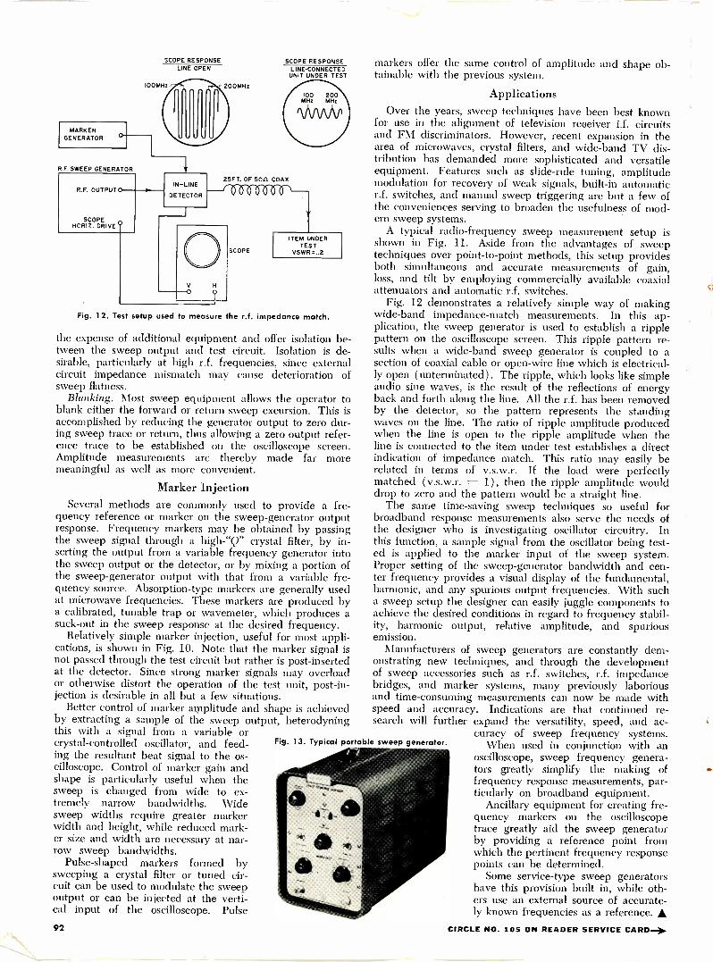
MARKERGENERATOR
R.F.SWEEP GENERATOR
SCOPE RESPONSELINE OPEN
200MHz
R.F. OUTPUT 0 -1. -
SCOPEHCRIZ. DRIVE
IN -LINE
DETECTOR
SCOPE RESPONSELINE -CONNECTEDUNIT UNDER TEST
25FT. OF 5011 COAX
SCOPE
ITEMITEM UNDER
TESTVSWR=I.2
Fig. 12. Test setup used to measure he r.f. impedance match.
the expense of additional equipment and offer isolation be-tween the sweep output and test circuit. Isolation is de-sirable, particularly at high r.f. frequencies, since externalcircuit impedance mismatch may cause deterioration ofsweep flatness.
Blanking. Most sweep equipment allows the operator toblank either the forward or return sweep excursion. This isaccomplished by reducing the generator output to zero dur-ing sweep trace or return, thus allowing a zero output refer-ence trace to be established on the oscilloscope screen.Amplitude measurements are thereby made far moremeaningful as well as more convenient.
Marker InjectionSeveral methods are commonly used to provide a fre-
quency reference or marker on the sweep -generator outputresponse. Frequency markers may be obtained by passingthe sweep signal through a high -"Q" crystal filter, by in-serting the output from a variable frequency generator intothe sweep output or the detector, or by mixing a portion ofthe sweep -generator output with that from a variable fre-quency source. Absorption -type markers are generally usedat microwave frequencies. These markers are produced bya calibrated, tunable trap or wavemeter, which produces asuck -out in the sweep response at the desired frequency.
Relatively simple marker injection, useful for most appli-cations, is shown in Fig. 10. Note that the marker signal isnot passed through the test circuit but rather is post -insertedat the detector. Since strong marker signals may overloador otherwise distort the operation of the test unit, post -in-jection is desirable in all but a few situations.
Better control of marker amplitude and shape is achievedby extracting a sample of the sweep output, heterodyningthis with a signal from a variable orcrystal -controlled oscillator, and feed-ing the resultant beat signal to the os-cilloscope. Control of marker gain andshape is particularly useful when thesweep is changed from wide to ex-tremely narrow bandwidths. Widesweep widths require greater markerwidth and height, while reduced mark-er size and width are necessary at nar-row sweep bandwidths.
Pulse -shaped markers formed bysweeping a crystal filter or tuned cir-cuit can be used to modulate the sweepoutput or can be injected at the verti-cal input of the oscilloscope. Pulse
Fig. 13. Typical portable sweep generator.
markers offer the same control of amplitude and shape ob-tainable with the previous system.
ApplicationsOver the years, sweep techniques have been best known
for use in the alignment of television reoeiver i.f. circuitsand FM discriminators. However, recent expansion in thearea of microwaves, crystal filters, and wide -band TV dis-tribution has demanded more sophisticated and versatileequipment. Features such as slide -rule tuning, amplitudemodulation for recovery of weak signals, built-in automaticr.f. switches, and manual sweep triggering are but a few ofthe conveniences serving to broaden the usefulness of mod-ern sweep systems.
A typical radio -frequency sweep measurement setup isshown in Fig. 11. Aside from the advantages of sweeptechniques over point-to-point methods, this setup providesboth simultaneous and accurate measurements of gain,loss, and tilt by employing commercially available coaxialattenuators and automatic r.f. switches.
Fig. 12 demonstrates a relatively simple way of makingwide -band impedance -match measurements. In this ap-plication, the sweep generator is used to establish a ripplepattern on the oscilloscope screen. This ripple pattern re-sults when a wide -band sweep generator is coupled to asection of coaxial cable or open -wire line which is electrical-ly open (unterminated). The ripple, which looks like simpleaudio sine waves, is the result of the reflections of energyback and forth along the line. All the r.f. has been removedby the detector, so the pattern represents the standingwaves on the line. The ratio of ripple amplitude producedwhen the line is open to the ripple amplitude when theline is connected to the item under test establishes a directindication of impedance match. This ratio may easily berelated in terms of v.s.w.r. If the load were perfectlymatched ( v.s.w.r. = 1), then the ripple amplitude woulddrop to zero and the pattern would be a straight line.
The same time -saving sweep techniques so useful forbroadband response measurements also serve the needs ofthe designer who is investigating oscillator circuitry. Inthis function, a sample signal from the oscillator being test-ed is applied to the marker input of the sweep system.Proper setting of the sweep -generator bandwidth and cen-ter frequency provides a visual display of the fundamental,harmonic, and any spurious output frequencies. With sucha sweep setup the designer can easily juggle components toachieve the desired conditions in regard to frequency stabil-ity, harmonic output, relative amplitude, and spuriousemission.
Manufacturers of sweep generators are constantly dem-onstrating new techniques, and through the developmentof sweep accessories such as r.f. switches, r.f. impedancebridges, and marker systems, many previously laboriousand time-consuming measurements can now be made withspeed and accuracy. Indications are that continued re-search will further expand the versatility, speed, and ac-
curacy of sweep frequency systems.When used in conjunction with an
oscilloscope, sweep frequency genera-tors greatly simplify the making offrequency response measurements, par-ticularly on broadband equipment.
Ancillary equipment for creating fre-quency markers on the oscilloscopetrace greatly aid the sweep generatorby providing a reference point fromwhich the pertinent frequency responsepoints can be determined.
Some service -type sweep generatorshave this provision built in, while oth-ers use an external source of accurate-ly known frequencies as a reference. A
92 CIRCLE NO. 105 ON READER SERVICE CARD -3.
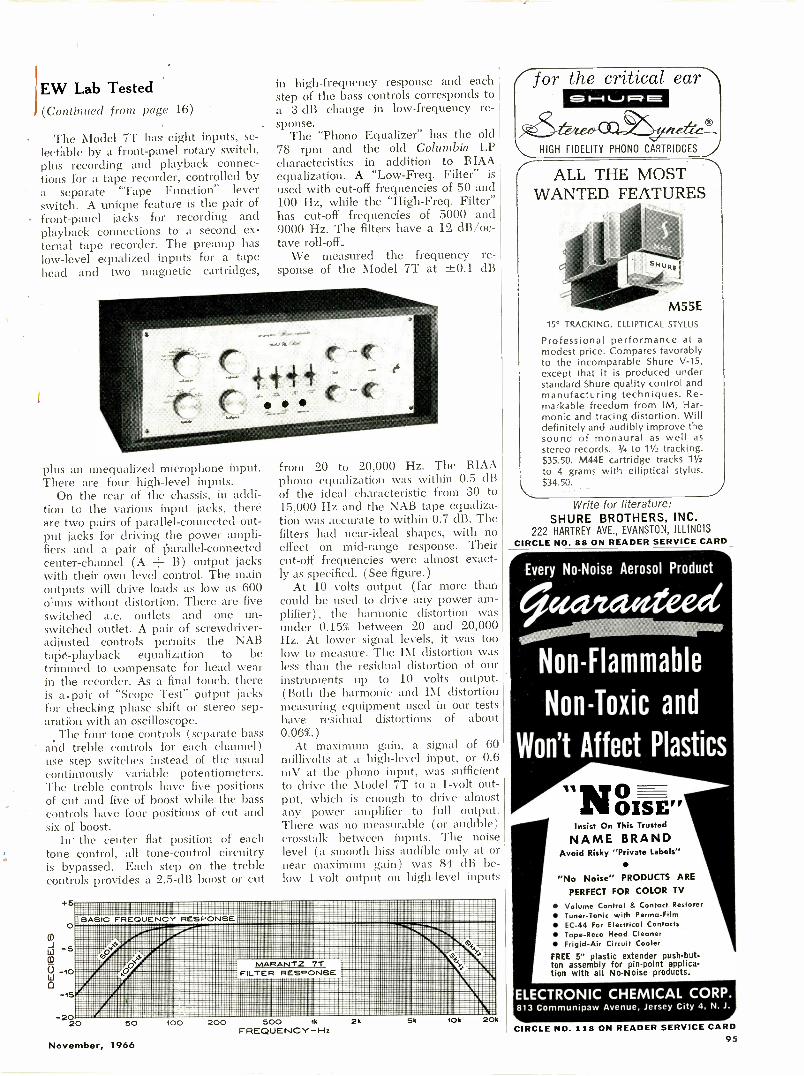
EW Lab TestedI (Continued front page 16)
The Model 7T has eight inputs, se-lectable by a front -panel rotary switch,plus recording and playback connec-tions for a tape recorder, controlled bya separate "Tape Function" leverswitch. A unique feature is the pair offront -panel jacks for recording andplayback connections to a second ex-ternal tape recorder. The preamp haslow-level equalized inputs for a tapehead and two magnetic cartridges,
plus an unequalized microphone input.There are four high-level inputs.
On the rear of the chassis, in addi-tion to the various input jacks, thereare two pairs of parallel -connected out-put jacks for driving thefiers and a pair of parallel -connectedcenter -channel (A B) output jackswith their own level control. The mainoutputs will drive loads as low as 600ohms without distortion. There are fiveswitched a.c. outlets and one un-switched outlet. A pair of screwdriver -adjusted controls permits the NABtape -playback equalization to betrimmed to compensate for head wearin the recorder. As a final touch, thereis a.pair of "Scope Test" output jacksfor checking phase shift or stereo sep-aration with an oscilloscope.
The four tone controls (separate bassand treble controls for each channel)use step switches instead of the usualcontinuously variable potentiometers.The treble controls have five positionsof cut and five of boost while the basscontrols have four positions of cut andsix of boost.
In. the center flat position of eachtone control, all tone -control circuitryis bypassed. Each step on the treblecontrols provides a 2.5 -dB boost or cut
2020 50 100 200 500 1k
FREQUENCY-Hz
in high -frequency response and eachstep of the bass controls corresponds toa 3 -dB change in low-frequency re-sponse.
The "Phono Equalizer" has the old78 rpm and the old Columbia LPcharacteristics in addition to RIAAequalization. A "Low-Freq. Filter" is
used with cut-off frequencies of 50 and100 Hz, while the "High-Freq. Filter"has cut-off frequencies of 5000 and9000 Hz. The filters have a 12 dB/oc-tave roll -off.
We measured the frequency re-sponse of the Model 7T at ±0.1 dB
from 20 to 20,000 Hz. The RIAAphono equalization was within 0.5 dBof the ideal characteristic from 30 to15,000 Hz and the NAB tape equaliza-tion was accurate to within 0.7 dB. The
effect on mid -range response. Theircut-off frequencies were almost exact-ly as specified. (See figure.)
At 10 volts output (far more thancould be used to drive any power am-plifier), the harmonic distortion wasunder 0.15% between 20 and 20,000Hz. At lower signal levels, it was toolow to measure. The IM distortion wasless than the residual distortion of ourinstruments up to 10 volts output.(Both the harmonic and IM distortionmeasuring equipment used in our testshave residual distortions of about0.06%.)
At maximum gain, a signal of 60millivolts at a high-level input, or 0.6mV at the phono input, was sufficientto drive the Model 7T to a 1 -volt out-put, which is enough to drive almostany power amplifier to full output.There was no measurable (or audible)crosstalk between inputs. The noiselevel (a smooth hiss audible only at ornear maximum gain ) was 84 dB be-low 1 -volt output on high-level inputs
/for the critical ear10-1 V 1=0 E
HIGH FIDELITY PHONO CARTRIDGES
ALL THE MOSTWANTED FEATURES
M55E15° TRACKING, ELLIPTICAL STYLUS
Professional performance at amodest price. Compares favorablyto the incomparable Shure V-15,except that it is produced understandard Shure quality control andmanufacturing techniques. Re-markable freedom from IM, Har-monic and tracing distortion. Willdefinitely and audibly improve thesound of monaural as well asstereo records. 1/4 to 11/2 tracking.$35.50. M44E cartridge tracks 11/2to 4 grams with elliptical stylus.$34.50.
Write for literature:SHURE BROTHERS, INC.
AVE., EVANSTON, ILLINOISCIRCLE NO. 88 ON READER SERVICE CARD
Every No -Noise Aerosol Product
Non -Flammable
Non -Toxic and
Won't Affect Plastics
"N0OISE"
Insist On This Trusted
NAME BRANDAvoid Risky "Private Labels"
"No Noise" PRODUCTS AREPERFECT FOR COLOR TV
Volume Control & Contact Restorer Tuner -Tonic with Parma -Film EC -44 For Electrical Contacts Tape-Reco Head Cleaner Frigid -Air Circuit CoolerFREE 5" plastic extender push-but-ton assembly for pin -point applica-tion with all No -Noise products.
ELECTRONIC CHEMICAL CORP.813 Communipaw Avenue, Jersey City 4, N. J.
November, 1966
2k 5k Ok 20CIRCLE NO. 118 ON READER SERVICE CARD
95
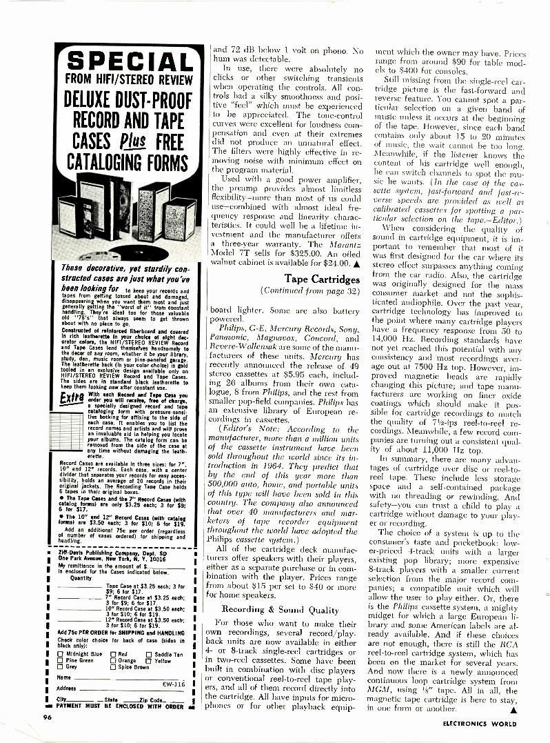
SPECIALFROM HIFI/STEREO REVIEW
DELUXE DUST -PROOF
RECORD AND TAPE
CASES FREE
CATALOGING FORMS
These decorative, yet sturdily con-structed cases are just what you'vebeen looking for to keep your records andtapes from getting tossed about and damaged,disappearing when you want them most and justgenerally getting the "worst of it" from constanthandling. They're ideal too for those valuableold "78's" that always seem to get thrownabout with no place to go.Constructed of reinforced fiberboard and coveredIn rich leatherette in your choice of eight dec-orator colon, the HIFI/STEREO REVIEW Recordand Tape Cases lend therriseives handsomely tothe decor of any room, whether it be your library,study, den, music room or pine -paneled garage.The leatherette back (in your color choice) is goldtooled in an exclusive design available only onHIFI/STEREO REVIEW Record and Tape Cases.The sides are in standard black leatherette tokeep them looking new after constant use.
EXtr Withersay::
Recordreceandive, fro
Tar ofcsctea you,
a specially designed record and tapecataloging form with pressure -sensi-tive backing for affixing to the side ofeach case. It enables you to list therecord names and artists and will provean invaluable aid in helping you locateyour albums. The catalog form can beremoved from the side of the case atany time without damaging the leatherette.
Record Cases are available in three sizes: for 7",10" and 12" records. Each case, with a centerdivider that separates your records for easy acces-sibility, holds an average of 20 records in theiroriginal jackets. The Recording Tape Case holds6 tapes in their original boxes. The Tape Cases and the 7" Record Cases (withcatalog forms) are only $3.25 each; 3 for $9;6 for $17. The 10" and 12" Record Cases (with catalogforms) are $3.50 each; 3 for $10; 6 for $19.
Add an additional 75c per order (regardlessof number of cases ordered) for shipping andhandling.
Ziff -Davis Publishing Company, Dept. SDOne Park Avenue, New York, N. Y. 10016My remittance in the amount of $I is enclosed for the Cases indicated below.
Quantity
II
I
II
III
I
Tape Case at $3.25 each; 3 for$9; 6 for $17.7' Record Case at $3.25 each;3 for $9; 6 for $17.10" Record Case at $3.50 each;3 for $10; 6 for $19.12^ Record Case at $3.50 each;3 for $10; 6 for $19.
Add 75c PER ORDER for SHIPPING and HANDLINGCheck color choice for back of case (sides inblack only):0 Midnight Blue 0 Red 0 Saddle Tan0 Pine Green 0 Orange 0 Yellow0 Grey 0 Spice Brown
Name
AddressEW-116
I City State lip CodePAYMENT MUST BE ENCLOSED WITH ORDER MI
and 72 dB below 1 volt on phono. Nohum was detectable.
In use, there were absolutely noclicks or other switching transientswhen operating the controls. All con-trols had a silky smoothness and posi-tive "feel" which must be experiencedto be appreciated. The tone -controlcurves were excellent for loudness com-pensation and even at their extremesdid not produce an unnatural effect.The filters were highly effective in re-moving noise with minimum effect onthe program material.
Used with a good power amplifier,the preamp provides almost limitlessflexibility-more than most of us coulduse-combined with almost ideal fre-quency response and linearity charac-teristics. It could well be a lifetime in-vestment and the manufacturer offersa three-year warranty. The MarantzModel 7T sells for $325.00. An oiledwalnut cabinet is available for $24.00. A
Tape Cartridges(Continued from page 32)
board lighter. Some are also batterypowered.
Philips, G -E, Mercury Records, Sony,Panasonic, Magnavox, Concord, andRevere-Wollensak are some of the manu-facturers of these units. Mercury hasrecently announced the release of 49stereo cassettes at $5.95 each, includ-ing 26 albums from their own cata-logue, 8 from Philips, and the rest fromsmaller pop -field companies. Philips hasan extensive library of European re-cordings in cassettes.
(Editor's Note: According to themanufacturer, more than a million unitsof the cassette instrument have beensold throughout the world since its in-troduction in 1964. They predict thatby the end of this year more than500,000 auto, home, and portable unitsof this type will have been sold in thiscountry. The company also announcedthat over 40 manufacturers and mar-keters of tape recorder equipmentthroughout the world have adopted thePhilips cassette system.)
All of the cartridge deck manufac-turers offer speakers with their players,either as a separate purchase or in com-bination with the player. Prices rangefrom about $15 per set to $40 or morefor home speakers.
Recording & Sound QualityFor those who want to make their
own recordings, several record/play-back units are now available in either4- or 8 -track single -reel cartridges orin two -reel cassettes. Some have beenbuilt in combination with disc playersor conventional reel-to-reel tape play-ers, and all of them record directly intothe cartridge. All have inputs for micro-phones or for other playback equip-
ment which the owner may have. Pricesrange from around $90 for table mod-els to $400 for consoles.
Still missing from the single -reel car-tridge picture is the fast -forward andreverse feature. You cannot spot a par-ticular selection on a given band ofmusic unless it occurs at the beginningof the tape. However, since each bandcontains only about 15 to 20 minutesof music, the wait cannot be too long.Meanwhile, if the listener knows thecontent of his cartridge well enough,he can switch channels to spot the mu-sic he wants. (In the case of the cas-sette system, fast -forward and fast-re-verse speeds are provided as well ascalibrated cassettes for spotting a par-ticular selection on the tape.-Editor.)
When considering the quality ofsound in cartridge equipment, it is im-portant to remember that most of itwas first designed for the car where itsstereo effect surpasses anything comingfrom the car radio. Also, the cartridgewas originally designed for the massconsumer market and not the sophis-ticated audiophile. Over the past year,cartridge technology has improved tothe point where many cartridge playershave a frequency response from 50 to14,000 Hz. Recording standards havenot yet reached this potential with anyconsistency and most recordings aver-age out at 7500 Hz top. However, im-proved magnetic heads are rapidlychanging this picture; and tape manu-facturers are working on finer oxidecoatings which should make it pos-sible for cartridge recordings to matchthe quality of 7'/z-ips reel-to-reel re-cordings. Meanwhile, a few record com-panies are turning out a consistent qual-ity of about 11,000 Hz top.
In summary, there are many advan-tages of cartridge over disc or reel-to-reel tape. These include less storagespace and a self-contained packagewith no threading or rewinding. Andsafety-you can trust a child to play acartridge without damage to your play-er or recording.
The choice of a system is up to theconsumer's taste and pocketbook: low-er -priced 4 -track units with a largerexisting pop library; more expensive8 -track players with a smaller currentselection from the major record com-panies; a compatible unit which willallow the user to play either. Or, thereis the Philips cassette system, a mightymidget for which a large European li-brary and some American labels are al-ready available. And if these choicesare not enough, there is still the RCAreel-to-reel cartridge system, which hasbeen on the market for several years.And now there is a newly announcedcontinuous loop cartridge system fromMGM, using ',i3" tape. All in all, themagnetic tape cartridge is here to stay,in one form or another.
96ELECTRONICS WORLD
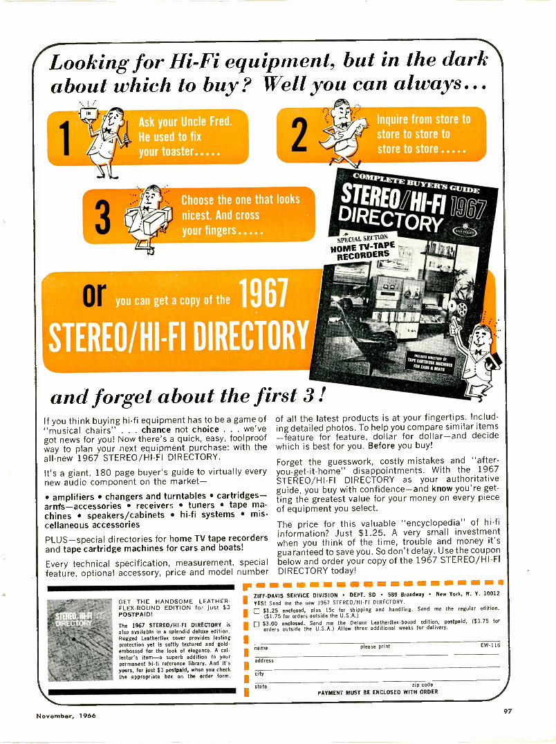
Looking for Hi-Fi equipment, but in the darkabout which to buy? Well you can always...
1
3
sk your Uncle Fred.
e used to fixtoaster
Choose the one that looks,01 nicest. And cross
your fingers
you can get a copy of the 1967
and forget about the first 3 !If you think buying hi-fi equipment has to be a game of"musical chairs" . . . chance not choice . . . we'vegot news for you! Now there's a quick, easy, foolproofway to plan your next equipment purchase: with theall -new 1967 STEREO/HI-FI DIRECTORY.
It's a giant, 180 page buyer's guide to virtually everynew audio component on the market-
amplifiers changers and turntables cartridges-arnis-accessories receivers tuners tape ma-chines speakers/cabinets hi-fi systems mis-cellaneous accessories
PLUS-special directories for home TV tape recordersand tape cartridge machines for cars and boats!
Every technical specification, measurement, specialfeature, optional accessory, price and model number
GET THE HANDSOME LEATHER -FLEX -BOUND EDITION for just $3POSTPAID!
The 1967 STEREO/HI-Fl DIRECTORY is
also available in a splendid deluxe edition.Rugged Leatherflex cover provides lastingprotection yet is softly textured and gold -embossed for the look of elegance. A col-lector's item-a superb addition to yourpermanent hi-fi reference library. And it'syours, for just $3 postpaid, when you checkthe appropriate box on the order form.
Inquire from store to
1.:01! store to store to
store to. store
JR'S GILME
STERNA!!FI
DIRllmyEcioRty
SPECIAL SITIMN
HowiETD-TD:E-RECORDER-
of all the latest products is at your fingertips. Includ-ing detailed photos. To help you compare similar items-feature for feature, dollar for dollar-and decidewhich is best for you. Before you buy!
Forget the guesswork, costly mistakes and "after -you -get -it -home" disappointments. With the 1967STEREO/HI-FI DIRECTORY as your authoritativeguide, you buy with confidence-and know you're get-ting the greatest value for your money on every pieceof equipment you select.
The price for this valuable "encyclopedia" of hi-fiinformation? Just $1.25. A very small investmentwhen you think of the time, trouble and money it'sguaranteed to save you. So don't delay. Use the couponbelow and order your copy of the 1967 STEREO/HI-FIDIRECTORY today!
re as se sin es . ss 11111 ION ZIFF-DAVIS SERVICE DIVISION DEPT. SD 589 Broadway New York, N. Y. 10012
YES! Send me the new 1967 STEREO/HTFI DIRECTORY.I $1.25 enclosed, plus 15c for shipping and handling. Send me the regular edition.
($1.75 for orders outside the U.S.A.)$3.00 enclosed. Send me the Deluxe Leatherflex-bound edition, postpaid. ($3.75 fororders outside the U.S.A.) Allow three additional weeks for delivery.
name please print EW116
address
city
state zip code
PAYMENT MUST BE ENCLOSED WITH ORDER
November, 196697
ARE YOU CASHING -IN
ON THE PROFITABLE II
2 -WAY RADIO SERVICE BUSINESS ?
* Motorola will train you for this rewarding, elite profession
* Send for our FREE EVALUATION EXAM. Prove to yourself thatyou are ready to learn FM 2 -way radio servicing.
Opportunities in 2 -way radio servicing are virtually unlimited. Just one of the hundreds of successful Motorola ServiceStations writes, "we would be pleased to interview any graduateof your school that has received some training in 2 -way radiomaintenance. We are an established firm, 10 years old, witha promise of expansion governed by our ability to obtain com-petent technicians." Get all the facts today. There is noobligation and no salesman will call.
CI MOTOROLA TRAINING INSTITUTE4545 West Augusta Blvd. Chicago 51, Illinois Dept. AEF646
0 Send me FREE entrance exam.0 Send full details on Home Study Course on FM 2 -way Radio
ServicingEl Send me details on how you can help me prepare for an FCC
License.
Name Occupation
Address
City Iona State
CIRCLE NO. 101 ON READER SERVICE CARD
Sonalert®New high -reliabilitysolid-state tone signalProduces distinctive 2800 or4500 cps tone, draws only 3 to14 milliamps.
No RF noise-no arcing con-tacts. Explosion -proof.
High reliability - solid-stateoscillator drives piezoelectricsound transducer.High output - 68 to 80 dbsound level.
Standard models available for operation on 6 to 28volts DC, 6 to 28 volts AC, 110 volts AC. Can besupplied with pulsed output, 3 to 5 pulses per second.For data, typical circuitry for over -voltage, under-voltage, overheat, security, and many other signallingapplications, write Mallory Distributor Products Com-pany, a division of P. R. Mallory & Co. Inc., P.O.Box 1558, Indianapolis, Indiana 46206.
5ANNIVERSARY
CIRCLE NO. 103 ON READER SERVICE CARD98
ELECTRONICS WORLD
MALLORY
Line -Operated TV Sets(Continued from page 27)
with the model. In the 19 -inch portable, a single -ended out-put stage is used. This transistor, a 71N1, is a low -current,high -voltage type with a collector load impedance of ap-proximately 3000 ohms. This is quite similar to a typicalaudio output tube.
One of the novel features of this receiver is the light -de-pendent resistor (LDR) circuit that provides automaticbrightness adjustment for varying room lighting conditions.The light -dependent resistor, R1 in Fig. 2, is mounted nearthe front of the TV set but is electrically connected acrossthe emitter resistor of video output amplifier Ql. This tran-sistor receives the video signal on its base and receives afixed forward bias through R2 and R3. Emitter resistor R4is shunted by the LDR. Note that the collector of Q1 isd.c.-connected to the cathode of the picture tube as well asto the brightness control, which is a d.c. adjustment. Whenroom lighting increases, LDR resistance becomes smaller,which means that there is less total emitter resistance in Ql.With less emitter resistance, Q1 has more gain and therebyproduces a larger amplitude video signal. At the same time,the average d.c. collector voltage is reduced because a larg-er current is being drawn through R5. Because of the d.c.connection of the Q1 collector, this increased voltage droplowers the positive voltage on the cathode of the picturetube, increasing brightness as well as contrast.
If ambient room lighting decreases, LDR resistance in-creases. This reduces the gain in Q1 as well as the currentdrawn by R5 and thereby provides less contrast and lessbrightness on the picture -tube screen. A 33 -ohm resistor isconnected in series with the LDR to limit the variation ofits resistance to avoid over -correction. As shown in Fig. 2,the screen grid of the picture tube controlsrent for a given level of ambient light, contrast, and bright-ness. In combination with the front -panel contrast andbrightness adjustments, the secondary control (LDR adjust-ment R6) is used to set the operating range of the auto-matic brightness circuit.
The sync separator and the vertical oscillator output cir-cuits are very much like those found in other transistor re-ceivers. The vertical deflection coils are connected in paral-lel across an iron -core choke.
This TV receiver is the first model to use a conventionalblocking oscillator transformer and circuit to generate hori-zontal sweep voltage. This circuit, shown in Fig. 3, uses asingle transistor and two diodes to provide the a.f.c. as wellas the saw -tooth generation function. The output of the syncseparator is applied to a set of dual diodes for phase com-parison with a feedback signal from the horizontal outputtransformer, just as in all TV receivers. The d.c. correction
Fig. 3. Horizontal oscillator frequency is controlled by var-iations in d.c. across DI produced by either horizontal holdcontrol or correction voltage from horizontal phase comparator.
± DCCORRECTION
+I2V
voltage developed there, however, isthen applied directly across diode DI,which acts as a capacitor that is vari-able by the d.c. applied across it. Tran-sistor Q1 oscillates easily because ofcoupling between the collector and basethrough the two respective windings ofT1 and forward -biasing resistor R1.
The frequency of oscillation is con-trolled by a resonant network consistingof Ll, Cl, and diode DI. The horizon-tal -hold control sets the positive voltagewhich is placed on the cathode of D1and thereby controls the action of thed.c. correction voltage from the phasecomparator. The resonant frequency ofLI, Cl, and DI is varied by changingthe d.c. voltage across D1, either througha change in correction voltage from thephase comparator, or through a changein the positive voltage from the hori-zontal hold control. Across the collectorwinding of the blocking oscillator trans-former, diode D2 and a series resistorlimit the high positive voltage spikewhich occurs when the transistor is cutoff.
The third winding on transformer T1provides output pulses to Q2 (the hori-zontal driver stage). Resistor R2 is atemperature -sensitive resistor which ismounted near QI and which compen-sates for temperature variation. As thetemperature of Q1 increases, R2 will de-crease in resistance, producing a heavy
T1 and causing a change inthe inductance reflected back into Ql.With proper polarity connections, theinductance change is such as to correctfor any frequency drift of the oscillator,and this stabilizes the collector currentas well.
The horizontal output circuit of theMagnavox unit is very similar, at leastin its principle of operation, to that de-scribed for previous transistor receivers.The output transistor drives the twohorizontal deflection coils in parallel, aswell as the primary of the flybacktransformer. An autotransformer sec-ondary is used to step up the voltagefor the vacuum -tube rectifier whichproduces +18 kV. The damper diodeis connected directly across the outputtransistor, and a separate diode is usedto rectify the boost voltage to provide+500 volts, which is then used for thefocus element and the screen grid ofthe picture tube.
NEW WWV STARTING DATE
TIRENational Bureau of Standards
(U.S. Department of Co llll terve), re-cently announced that effective 0000UT, December 1, 1966, all of the ser-vices presently provided on 2.5, 5, 10,15, 20, and 25 MHz by the Bureau'sbroadcast station WWV located at Green-belt, Maryland, will be continued byWVi'V now installed in its new locationat Fort Collins, Colorado.
Did you ever ... lift a wire -lead component
from a printed wiring board
for testing ?
... test or replace a
capacitor or resistor on
a crowded tube socket
CUT YOUR TIME IN HALF with
XVIREM* Soldering -Aids...the revolutionary connectorsthat practically let you do"in -circuit" component testing!
WIRE FLUX SOLDER
VC V
The KWI KETTE SOL-
DERING AID is not
just another wirespring connector! It
has a Copperweldwire inner core, anintermediate layer of
flux, and an outer jacket of solder...all you need is heat!
KWIKETTES are now being packedwith Sprague AtomeCapacitors at noextra cost to you! Whenever youneed tubular electrolytics, insist onpre-packaged Sprague Atoms fromyour parts distributor and you'll auto-matically get your KWIKETTE com-ponent connectors . . . the biggestboon to the service technician sincethe soldering gun!
*tradema rk
FREE TRIALPACKAGE!
10 free KWIKETTE Soldering Aids areyours for the asking! Simply sendyour postcard request to KWIKETTECenter, Sprague Products Co., 51
Marshall Street, North Adams, Mass.01247. Don't forget to include thename of your Sprague Distributor.
WORLD'S LARGEST MANUFACTURER OF CAPACITORS6,6109
APPLY
HEAT!
SPRAGUETHE MARK OF RELIABILITY
November, 1966CIRCLE NO. 85 ON READER SERVICE CARD
99
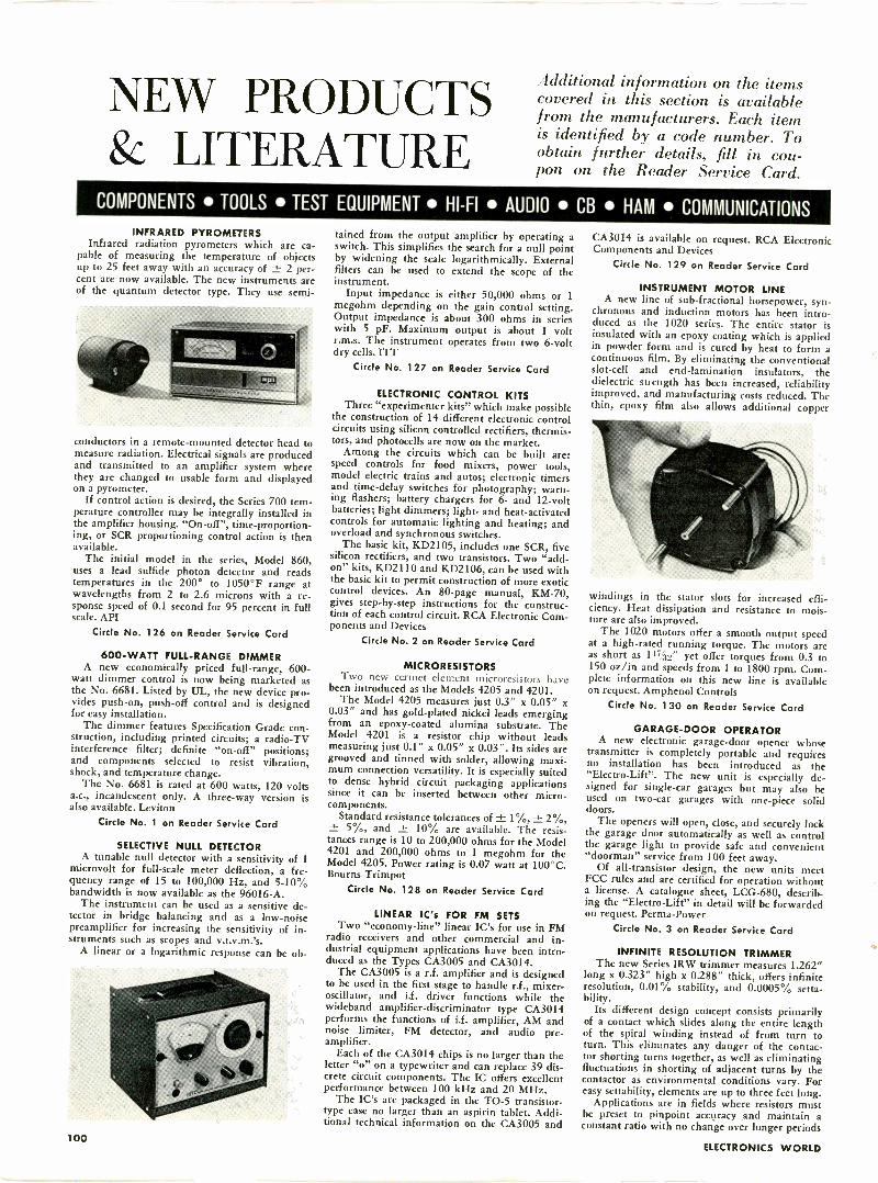
NEW PRODUCTS& LITERATURE
additional information on the itemscovered in this section is availablefrom the manufacturers. Each itemis identified by a code number. Toobtain further details, fill in cou-pon on the Reader Service Card.
COMPONENTS TOOLS TEST EQUIPMENT HI-FI AUDIO CB HAM COMMUNICATIONSINFRARED PYROMETERS
Infrared radiation pyrometers which are ca-pable of measuring the temperature of objectsup to 25 feet away with an accuracy of ± 2 per-cent are now available. The new instruments areof the quantum detector type. They use semi-
conductors in a remote -mounted detector head tomeasure radiation. Electrical signals are producedand transmitted to an amplifier system wherethey are changed to usable form and displayedon a pyrometer.
If control action is desired, the Series 700 tem-perature controller may be integrally installed inthe amplifier housing. "On -off", time -proportion-ing, or SCR proportioning control action is thenavailable.
The initial model in the series, Model 860,uses a lead sulfide photon detector and readstemperatures in the 200° to 1050°F range atwavelengths from 2 to 2.6 microns with a re-sponse speed of 0.1 second for 95 percent in fullscale. API
Circle No. 126 on Reader Service Card
600 -WATT FULL -RANGE DIMMERA new economically priced full -range, 600-
watt dimmer control is now being marketed asthe No. 6681. Listed by UL, the new device pro-vides push -on, push -off control and is designedfor easy installation.
The dimmer features Specification Grade con-struction, including printed circuits; a radio -TVinterference filter; definite "on -off" positions;and components selected to resist vibration,shock, and temperature change.
The No. 6681 is rated at 600 watts, 120 voltsa.c., incandescent only. A three-way version isalso available. Leviton
Circle No. 1 on Reader Service Card
SELECTIVE NULL DETECTORA tunable null detector with a sensitivity of 1
microvolt for full-scale meter deflection, a fre-quency range of 15 to 100,000 Hz, and 5-10%bandwidth is now available as the 96016-A.
The instrument can be used as a sensitive de-tector in bridge balancing and as a low -noisepreamplifier for increasing the sensitivity of in-struments such as scopes and v.t.v.m.'s.
A linear or a logarithmic response can be ob-
tained from the output amplifier by operating aswitch. This simplifies the search for a null pointby widening the scale logarithmically. Externalfilters can be used to extend the scope of theinstrument.
Input impedance is either 50,000 ohms or 1megohm depending on the gain control setting.Output impedance is about 300 ohms in serieswith 5 pF. Maximum output is about 1 voltr.m.s. The instrument operates from two 6 -voltdry cells. ITT
Circle No. 127 on Reader Service Card
ELECTRONIC CONTROL KITSThree "experimenter kits" which make possible
the construction of 14 different electronic controlcircuits using silicon controlled rectifiers, thermis-tors, and photocells are now on the market.
Among the circuits which can be built are:speed controls for food mixers, power tools,model electric trains and autos; electronic timersand time -delay switches for photography; warn-ing flashers; battery chargers for 6- and 12 -voltbatteries; light dimmers; light- and heat -activatedcontrols for automatic lighting and heating; andoverload and synchronous switches.
The basic kit, KD2105, includes one SCR, fivesilicon rectifiers, and two transistors. Two "add-on" kits, KD2110 and KD2106, can be used withthe basic kit to permit construction of more exoticcontrol devices. An 80 -page manual, KM -70,gives step-by-step instructions for the construc-tion of each control circuit. RCA Electronic Com-ponents and Devices
Circle No. 2 on Reader Service Card
MICRORESISTORSTwo new cermet clement microresistors have
been introduced as the Models 4205 and 4201.The Model 4205 measures just 03" x 0.05" x
0.03" and has gold-plated nickel leads emergingfrom an epoxy -coated alumina substrate. TheModel 4201 is a resistor chip without leadsmeasuring just 0.1" x 0.05" x 0.03". Its sides aregrooved and tinned with solder, allowing maxi-mum connection versatility. It is especially suitedto dense hybrid circuit packaging applicationssince it can be inserted between other micro-components.
Standard resistance tolerances of ± 1%, ± 2%,± 5%, and ± 10% are available. The resis-tances range is 10 to 200,000 ohms for the Model4201 and 200,000 ohms to 1 megohm for theModel 4205. Power rating is 0.07 watt at 100°C.Bourns Trimpot
Circle No. 128 on Reader Service Card
LINEAR IC's FOR FM SETSTwo "economy -line" linear IC's for use in FM
radio receivers and other commercial and in-dustrial equipment applications have been intro-duced as the Types CA3005 and CA3014.
The CA3005 is a r.f. amplifier and is designedto be used in the first stage to handle r.f., mixer-oscillator, and i.f. driver functions while thewideband amplifier -discriminator type CA3014performs the functions of i.f. amplifier, AM andnoise limiter, FM detector, and audio pre-amplifier.
Each of the CA3014 chips is no larger than theletter "o" on a typewriter and can replace 39 dis-crete circuit components. The IC offers excellentperformance between 100 kHz and 20 MHz.
The IC's are packaged in the TO -5 transistor-type case no larger than an aspirin tablet. Addi-tional technical information on the CA3005 and
CA3014 is available on request. RCA ElectronicComponents and Devices
Circle No. 129 on Reader Service Card
INSTRUMENT MOTOR LINEA new line of sub -fractional horsepower, syn-
chronous and induction motors has been intro-duced as the 1020 series. The entire stator isinsulated with an epoxy coating which is appliedin powder form and is cured by heat to form acontinuous film. By eliminating the conventionalslot -cell and end -lamination insulators, thedielectric strength has been increased, reliabilityimproved, and manufacturing costs reduced. Thethin, epoxy film also allows additional copper
windings in the stator slots for increased effi-ciency. Heat dissipation and resistance to mois-ture are also improved.
The 1020 motors offer a smooth output speedat a high -rated running torque. The motors areas short as 11-7,(30" yet offer torques from 0.3 to150 oz/in and speeds from 1 to 1800 rpm. Com-plete information on this new line is availableon request. Amphenol Controls
Circle No. 130 on Reader Service Card
GARAGE -DOOR OPERATORA new electronic garage -door opener whose
transmitter is completely portable and requiresno installation has been introduced as the"Electro-Lift". The new unit is especially de-signed for single -car garages but may also beused on two -car garages with one-piece soliddoors.
The openers will open, close, and securely lockthe garage door automatically as well as controlthe garage light to provide safe and convenient"doorman" service from 100 feet away.
Of all -transistor design, the new units meetFCC rules and are certified for operation withouta license. A catalogue sheet, LCG-680, describ-ing the "Electro-Lift" in detail will be forwardedon request. Perma-Power
Circle No. 3 on Reader Service Card
INFINITE RESOLUTION TRIMMERThe new Series IRW trimmer measures 1.262"
long x 0323" high x 0.288" thick, offers infiniteresolution, 0.01% stability, and 0.0005% setta-bility.
Its different design concept consists primarilyof a contact which slides along the entire lengthof the spiral winding instead of from turn toturn. This eliminates any danger of the contac-tor shorting turns together, as well as eliminatingfluctuations in shorting of adjacent turns by thecontactor as environmental conditions vary. Foreasy settability, elements are up to three feet long.
Applications are in fields where resistors mustbe preset to pinpoint accuracy and maintain aconstant ratio with no change over longer periods
100ELECTRONICS WORLD
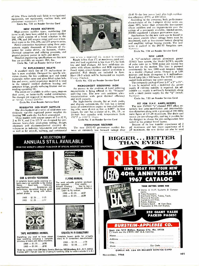
of time. These include such fields as navigationalequipment, test equipment, machine tools, andproduction equipment. CTS
Circle No. 131 on Reader Service Card
NEW POWER RECTIFIERSHigh -current rectifier types, numbering 238
items in all, have been added to a power rectifierline which consists of a broad selection in the100, 150, and 160 ampere range and over a hun-dred types in the 240, 250, and 275 ampere series.
Power conversion equipment using these com-ponents supply thousands of kilowatts of d.c.power for motor drives, arc furnaces, electro-chemical extraction and refining processes, andgeneral-purpose power in mills and mines.
Detailed engineering specifications on this newline are available on request. IRC, Inc.
Circle No. 132 on Reader Service Card
TV REPLACEMENT RELAYSA standard stock line of TV replacement re-
lays is now available. Designed for specific tele-vision chassis, the line combines new and testedmaterials: nylon cams and glass -filled nylon bob-bin and cover; acetal copolymer material is usedin the integral molded platform bearing andarmature hinge, greatly reducing friction and ex-tending operating life.
The relays are available in either open, snap -ondust cover, or hermetically sealed construction.No changes are required in mounting, terminals,or ratings. Cornell-Dubilicr
Circle No. 4 on Reader Service Card
REGULATED 500 -WATT SUPPLIESThe development of a series of solid-state con-
tinuously variable regulated power supplies de-livering 500 watts d.c. has been announced.
Three models with output ranges of 2 to 32 V,2 to 55 V, and 2 to 125 V are designed for con-tinuous heavy-duty production testing; design;electronic and electromechanical circuitry de-velopment in industry; laboratories and schools;as well as for aircraft, military, and commercial
uses where a regulated d.c. output is required.Ripple is less than 1% at maximum rated cur-
rent and load regulation is less than 1% for bothline and load changes. All have solid-state cir-cuitry with silicon rectifiers and SCR regulation.Fused input, circuit -breaker output protection isprovided. Full details are included in Spec.Sheet PS -3 which will be forwarded on request.Electro Products
Circle No. 133 on Reader Service Card
MICROCIRCUIT SOLDERING IRONAn answer to the problem of hand soldering
microcircuits is being offered in the "Princess"soldering iron. The new unit combines ultra -miniaturization with great thermal efficiencyand work capacity.
For high -density circuits, flat or stack packs,and discrete components, the iron has a specialseries of subminiature copper or iron -clad solder-ing nibs, some drawn as fine as 0.005". In heatranges, the user has a choice of 6-, 10-, 15-, or18 -watt heat capsules with temperatures from450°F to 1000°F. Ungar
Circle No. 5 on Reader Service Card
GERMANIUM RECTIFIERThe new 1N91-93 germanium rectifier fea-
tures an extremely low forward voltage drop
A SELECTION OF
ANNUALS STILL AVAILABLEFROM THE WORLD'S LARGEST PUBLISHER OF SPECIAL INTEREST MAGAZINES
CAR & DRIVER YEARBOOKA complete buyers guide covering virtually every car available in the UnitedStates . . . Road tests . . . Technicalspecifications . . Accessories andperformance equipment buying guide. . . Guide to racing with action -packed photos.
1966 - $1.25 #151965 - $1.25 #17
TAPE RECORDER ANNUAL
Everything you need to know abouttape recording including a completedirectory of mono and stereo recorders.
1966 - $1.25 #301965 - $1.00 #31
FLYING --.-
FLYING ANNUAL
The most valuable aviation yearbookever compiled . . . Pilot reports . .
Aircraft directory . . . How to buy aused airplane . . . Hamm. directory. . . Learn to fly section.
1966 - $1.25............#271965 - $1.25............#28
STERECHFRIZDIRECTORY
STEREO/Hi Fl DIRECTORY
Complete buyers guide for virtuallyevery Hi Fi component manufactured.
1966 - $1.25 #291965 - $1.00 #37
(0.45 V-for low power loss) plus high rectifica-tion efficiency (75% at 100 kHz).
According to the company, both performancecharacteristics of the 1 -ampere device series areabout 50% better than comparable low -currentsilicon rectifiers and are improvements over theratings of a previously available, limited -source,JEDEC-registered 1 -ampere germanium type.
Applications for the new units can be found inlow -power circuits where voltage losses must beminimized, such as low -current battery chargingand amplifier voltage biasing circuits. The newseries is packed in the DO -13 flangeless case.Motorola
Circle No. 134 on Reader Service Card
NEW LASERA "Q" -switched yttrium aluminum garnet
(YAG) laser system, the Model LCW3, capableof pulse rates up to 5000 pulses per second hasbeen put on the market. The laser is pumpedcontinuously by two 1000 -watt tungsten lampsin a double elliptical cavity. Output is at 1.06microns and beam divergence is 4 milliradians.Rated lamp life is 500 hours. The LCW3 is water-cooled from ordinary tap water sources.
The compactly packaged laser is 8" x 5" x 21".It can be supplied with a stabilized d.c. powersupply if extreme stability is required. An ad-justable a.c. supply is ordinarily furnished, alongwith a small power supply for the "Q" switch.Raytheon
Circle No. 135 on Reader Service Card
FET FOR V.H.F. AMPS/MIXERSThe new 2N3823 "n" -channel FET offers ex-
tremely low cross -modulation and intermodula-tion distortion along with a guaranteed 100 MHznoise figure of 2.5 dB maximum. The drain andsource are interchangeable, making it possible forthe designer to choose the pin configuration bestsuited to his printed board layout.
Because of its low transfer capacitance of 2pF maximum and low input capacitance of 6pF maximum, the new device can also be used
BIGGER . BETTERTHAN EVER!
FREE!9I
SEND TODAY FOR YOUR NEW
40th ANNIVERSARY1967 CATALOG
YOUR BUYING GUIDE FOR
Stereo & Hi-Fi Systems & Compo-nents.
Tope Recorders.Electronic Ports, Tubes, Tools.
Phonos & Records. Cameros and Film. Public Address. Citizens Band. Ham Gear. Transistor Cr FM -AM Radios.
BURSTEIN-APPLEBEE CO.Dept. EW, 1012 McGee, K City, Mo. 64106El Rush me the FREE 1967 B -A Catalog.
Name
Address
City
State Zip Code
Order by number from Ziff -Davis Service Division, 589 Broadway, N.Y., N.Y.10012.Enclose add'I 150 per copy for shipping & handling (500 for orders outside U.S.A.)
CIRCLE NO.
November, 1966
124 ON READER SERVICE CARD
101
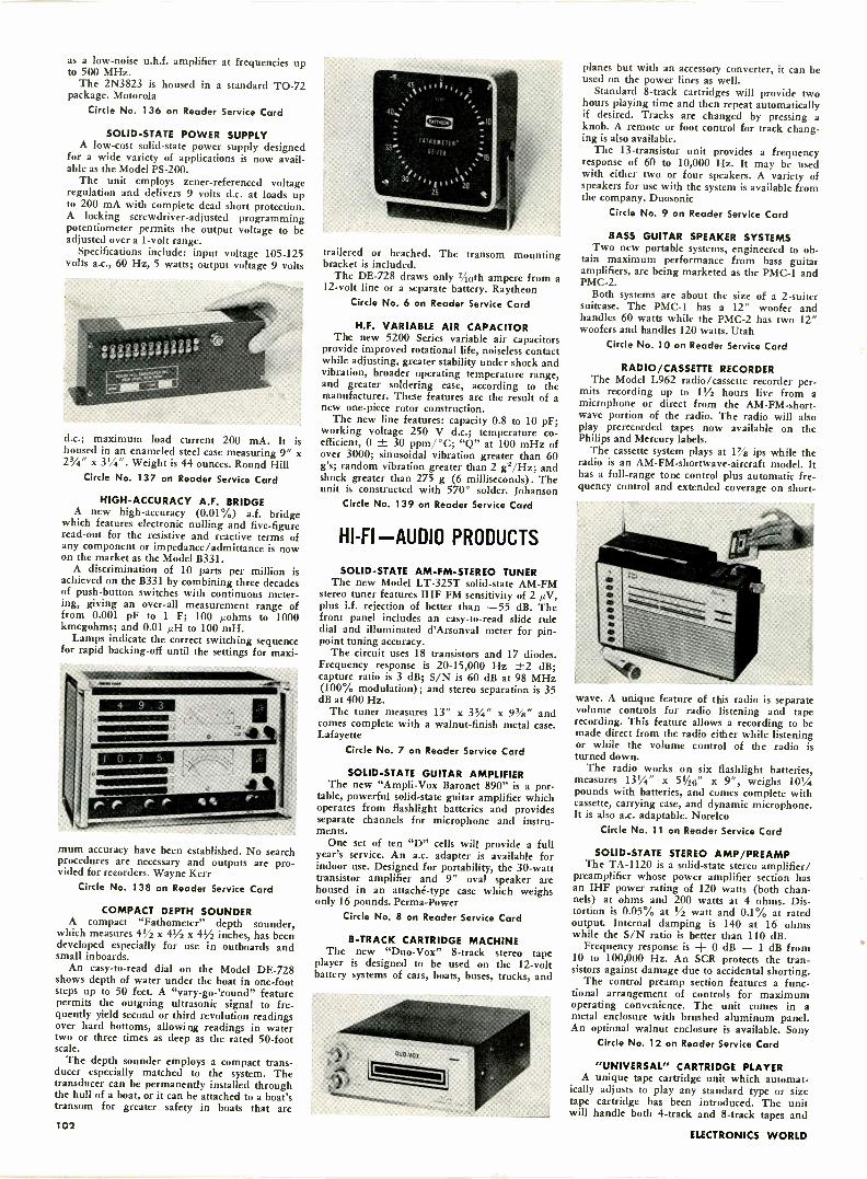
as a low -noise u.h.f. amplifier at frequencies upto 500 MHz.
The 2N3823 is housed in a standard TO -72package. Motorola
Circle No. 136 on Reader Service Card
SOLID-STATE POWER SUPPLYA low-cost solid-state power supply designed
for a wide variety of applications is now avail-able as the Model PS -200.
The unit employs zener-referenced voltageregulation and delivers 9 volts d.c. at loads upto 200 mA with complete dead short protection.A locking screwdriver -adjusted programmingpotentiometer permits the output voltage to beadjusted over a 1 -volt range.
Specifications include: input voltage 105-125volts a.c., 60 Hz, 5 watts; output voltage 9 volts
d.c.; maximum load current 200 mA. It ishoused in an enameled steel case measuring 9" x23/4" x 31/4". Weight is 44 ounces. Round Hill
Circle No. 137 on Reader Service Card
HIGH -ACCURACY A.F. BRIDGEA new high -accuracy (0.01%) a.f. bridge
which features electronic nulling and five -figureread-out for the resistive and reactive terms ofany component or impedance/admittance is nowon the market as the Model B331.
A discrimination of 10 parts per million isachieved on the B331 by combining three decadesof push-button switches with continuous meter-ing, giving an over-all measurement range offrom 0.001 pF to 1 F; 100 µohms to 1000kmegohms; and 0.01 /LH to 100 mH.
Lamps indicate the correct switching sequencefor rapid backing -off until the settings for maxi-
\tllrlaill.IIMMIMIMIMNMIII.11.15' -:
II4 9 )
1111.11111
mum accuracy have been established. No searchprocedures are necessary and outputs are pro-vided for recorders. Wayne Kerr
Circle No. 138 on Reader Service Card
COMPACT DEPTH SOUNDERA compact "Fathometer" depth sounder,
which measures 41/2 x 41/2 x 41/2 inches, has beendeveloped especially for use in outboards andsmall inboards.
An easy -to -read dial on the Model DE -728shows depth of water under the boat in one -footsteps up to 50 feet. A "vary -go -'round" featurepermits the outgoing ultrasonic signal to fre-quently yield second or third revolution readingsover hard bottoms, allowing readings in watertwo or three times as deep as the rated 50 -footscale.
The depth sounder employs a compact trans-ducer especially matched to the system. Thetransducer can be permanently installed throughthe hull of a boat, or it can be attached to a boat'stransom for greater safety in boats that are
trailered or beached. The transom mountingbracket is included.
The DE -728 draws only 3/40th ampere from a12 -volt line or a separate battery. Raytheon
Circle No. 6 on Reader Service Card
H.F. VARIABLE AIR CAPACITORThe new 5200 Series variable air capacitors
provide improved rotational life, noiseless contactwhile adjusting, greater stability under shock andvibration, broader operating temperature range,and greater soldering ease, according to themanufacturer. These features are the result of anew one-piece rotor construction.
The new line features: capacity 0.8 to 10 pF;working voltage 250 V d.c.; temperature co-efficient, 0 ± 30 ppm/ °C; "Q" at 100 mHz ofover 3000; sinusoidal vibration greater than 60g's; random vibration greater than 2 g2/Hz; andshock greater than 275 g (6 milliseconds). Theunit is constructed with 570° solder. Johanson
Circle No. 139 on Reader Service Card
HI-FI -AUDIO PRODUCTS
SOLID-STATE AM -FM -STEREO TUNERThe new Model LT -325T solid-state AM -FM
stereo tuner features IHF FM sensitivity of 2 µV,plus i.f. rejection of better than -55 dB. Thefront panel includes an easy -to -read slide ruledial and illuminated d'Arsonval meter for pin-point tuning accuracy.
The circuit uses 18 transistors and 17 diodes.Frequency response is 20-15,000 Hz ±2 dB;capture ratio is 3 dB; S/N is 60 dB at 98 MHz(100% modulation); and stereo separation is 35dB at 400 Hz.
The tuner measures 13" x 3%" x 9%" andcomes complete with a walnut -finish metal case.Lafayette
Circle No. 7 on Reader Service Card
SOLID-STATE GUITAR AMPLIFIERThe new "Ampli-Vox Baronet 890" is a por-
table, powerful solid-state guitar amplifier whichoperates from flashlight batteries and providesseparate channels for microphone and instru-ments.
One set of ten "D" cells will provide a fullyear's service. An a.c. adapter is available forindoor use. Designed for portability, the 30 -watttransistor amplifier and 9" oval speaker arehoused in an attache -type case which weighsonly 16 pounds. Perma-Power
Circle No. 8 on Reader Service Card
8 -TRACK CARTRIDGE MACHINEThe new "Duo -Vox" 8 -track stereo tape
player is designed to be used on the 12 -voltbattery systems of cars, boats, buses, trucks, and
planes but with an accessory converter, it can beused on the power lines as well.
Standard 8 -track cartridges will provide twohours playing time and then repeat automaticallyif desired. Tracks are changed by pressing aknob. A remote or foot control for track chang-ing is also available.
The 13 -transistor unit provides a frequencyresponse of 60 to 10,000 Hz. It may be usedwith either two or four speakers. A variety ofspeakers for use with the system is available fromthe company. Duosonic
Circle No. 9 on Reader Service Card
BASS GUITAR SPEAKER SYSTEMSTwo new portable systems, engineered to ob-
tain maximum performance from bass guitaramplifiers, are being marketed as the PMC-1 andPMC-2.
Both systems are about the size of a 2-suitersuitcase. The PMC-1 has a 12" woofer andhandles 60 watts while the PMC-2 has two 12"woofers and handles 120 watts. Utah
Circle No. 10 on Reader Service Card
RADIO/CASSETTE RECORDERThe Model L962 radio/cassette recorder per-
mits recording up to 11/2 hours live from amicrophone or direct from the AM -FM -short-wave portion of the radio. The radio will alsoplay prerecorded tapes now available on thePhilips and Mercury labels.
The cassette system plays at 1% ips while theradio is an AM -FM -shortwave -aircraft model. Ithas a full -range tone control plus automatic fre-quency control and extended coverage on short-
wave. A unique feature of this radio is separatevolume controls for radio listening and taperecording. This feature allows a recording to bemade direct from the radio either while listeningor while the volume control of the radio isturned down.
The radio works on six flashlight batteries,measures 131/4" x 5%6" x 9", weighs 10%pounds with batteries, and comes complete withcassette, carrying case, and dynamic microphone.It is also a.c. adaptable. Norelco
Circle No. 11 on Reader Service Card
SOLID-STATE STEREO AMP/PREAMPThe TA -1120 is a solid-state stereo amplifier/
preamplifier whose power amplifier section hasan IHF power rating of 120 watts (both chan-nels) at ohms and 200 watts at 4 ohms. Dis-tortion is 0.05% at 1/2 watt and 0.1% at ratedoutput. Internal damping is 140 at 16 ohmswhile the S/N ratio is better than 110 dB.
Frequency response is + 0 dB - 1 dB from10 to 100,000 Hz. An SCR protects the tran-sistors against damage due to accidental shorting.
The control preamp section features a func-tional arrangement of controls for maximumoperating convenience. The unit comes in ametal enclosure with brushed aluminum panel.An optional walnut enclosure is available. Sony
Circle No. 12 on Reader Service Card
"UNIVERSAL" CARTRIDGE PLAYERA unique tape cartridge unit which automat-
ically adjusts to play any standard type or sizetape cartridge has been introduced. The unitwill handle both 4 -track and 8 -track tapes and
102ELECTRONICS WORLD
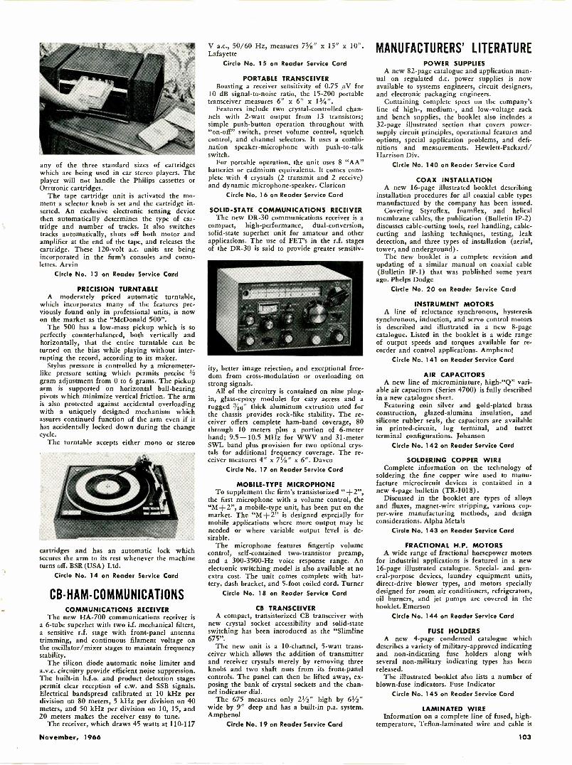
any of the three standard sizes of cartridgeswhich are being used in car stereo players. Theplayer will not handle the Philips cassettes orOrrtronic cartridges.
The tape cartridge unit is activated the mo-ment a selector knob is set and the cartridge in-serted. An exclusive electronic sensing devicethen automatically determines the type of car-tridge and number of tracks. It also switchestracks automatically, shuts off both motor andamplifier at the end of the tape, and releases thecartridge. These 120 -volt a.c. units are beingincorporated in the firm's consoles and conso-lettes. Arvin
Circle No. 13 on Reader Service Card
PRECISION TURNTABLEA moderately priced automatic turntable,
which incorporates many of the features pre-viously found only in professional units, is nowon the market as the "McDonald 500".
The 500 has a low -mass pickup which is soperfectly counterbalanced, both vertically andhorizontally, that the entire turntable can beturned on the bias while playing without inter-rupting the record, according to its maker.
Stylus pressure is controlled by a micrometer -like pressure setting which permits precise tfs
gram adjustment from 0 to 6 grams. The pickuparm is supported on horizontal ball -bearingpivots which minimize vertical friction. The armis also protected against accidental overloadingwith a uniquely designed mechanism whichassures continued function of the arm even if ithas accidentally locked down during the changecycle.
The turntable accepts either mono or stereo
cartridges and has an automatic lock whichsecures the arm to its rest whenever the machineturns off. BSR (USA) Ltd.
Circle No. 14 on Reader Service Card
CB -HAM -COMMUNICATIONSCOMMUNICATIONS RECEIVER
The new HA -700 communications receiver isa 6 -tube superhet with two i.f. mechanical filters,a sensitive r.f. stage with front -panel antennatrimming, and continuous filament voltage onthe oscillator/mixer stages to maintain frequencystability.
The silicon diode automatic noise limiter anda.v.c. circuitry provide efficient noise suppression.The built-in b.f.o. and product detection stagespermit clear reception of c.w. and SSB signals.Electrical bandspread calibrated at 10 kHz perdivision on 80 meters, 5 kHz per division on 40meters, and 50 kHz per division on 10, 15, and20 meters makes the receiver easy to tune.
The receiver, which draws 45 watts at 110-117
V a.c., 50/60 Hz, measures 75/8" x 15" x 10".Lafayette
Circle No. 15 on Reader Service Card
PORTABLE TRANSCEIVERBoasting a receiver sensitivity of 0.75 AV for
10 dB signal-to-noise ratio, the 15-200 portabletransceiver measures 6" x 6" x
Features include two crystal -controlled chan-nels with 2 -watt output from 13 transistors;simple push-button operation throughout with"on -off" switch, preset volume control, squelchcontrol, and channel selectors. It uses a combi-nation speaker -microphone with push -to -talkswitch.
For portable operation, the unit uses 8 "AA"batteries or cadmium equivalents. It comes com-plete with 4 crystals (2 transmit and 2 receive)and dynamic microphone -speaker. Claricon
Circle No. 16 on Reader Service Card
SOLID-STATE COMMUNICATIONS RECEIVERThe new DR -30 communications receiver is a
compact, high-performance, dual -conversion,solid-state superhet unit for amateur and otherapplications. The use of FET's in the r.f. stagesof the DR -30 is said to provide greater sensitiv-
ity, better image rejection, and exceptional free-dom from cross -modulation or overloading onstrong signals.
All of the circuitry is contained on nine plug-in, glass -epoxy modules for easy access and arugged 3/t6" thick aluminum extrusion used forthe chassis provides rock -like stability. The re-ceiver offers complete ham -band coverage, 80through 10 meters plus a portion of 6 -meterband; 9.5-10.5 MHz for WWV and 31 -meterSWL band plus provision for two optional crys-tals for additional frequency coverage. The re-ceiver measures 4" x 7'/8" x 6". Davco
Circle No. 17 on Reader Service Card
MOBILE -TYPE MICROPHONETo supplement the firm's transistorized "d-2",
the first microphone with a volume control, the"M+2", a mobile -type unit, has been put on themarket. The "M+2" is designed especially formobile applications where more output may beneeded or where variable output level is de-sirable.
The microphone features fingertip volumecontrol, self-contained two -transistor preamp,and a 300 -3500 -Hz voice response range. Anelectronic switching model is also available at noextra cost. The unit comes complete with bat-tery, dash bracket, and 5 -foot coiled cord. Turner
Circle No. 18 on Reader Service Card
CB TRANSCEIVERA compact, transistorized CB transceiver with
new crystal socket accessibility and solid-stateswitching has been introduced as the "Slimline675".
The new unit is a 10 -channel, 5 -watt trans-ceiver which allows the addition of transmitterand receiver crystals merely by removing threeknobs and two shaft nuts from its front -panelcontrols. The panel can then be lifted away, ex-posing the bank of crystal sockets and the chan-nel indicator dial.
The 675 measures only 21/2" high by 61/2"wide by 9" deep and has a built-in p.a. system.Amphenol
Circle No. 19 on Reader Service Card
MANUFACTURERS' LITERATUREPOWER SUPPLIES
A new 82 -page catalogue and application man-ual on regulated d.c. power supplies is nowavailable to systems engineers, circuit designers,and electronic packaging engineers.
Containing complete specs on the company'sline of high-, medium-, and low -voltage rackand bench supplies, the booklet also includes a32 -page illustrated section that covers power -supply circuit principles, operational features andoptions, special application problems, and defi-nitions and measurements. Hewlett-Packard/Harrison Div.
Circle No. 140 on Reader Service Card
COAX INSTALLATIONA new 16 -page illustrated booklet describing
installation procedures for all coaxial cable typesmanufactured by the company has been issued.
Covering Styroflex, foamflex, and helicalmembrane cables, the publication (Bulletin IP-2)discusses cable -cutting tools, reel handling, cable -cutting and lashing techniques, testing, leakdetection, and three types of installation (aerial,tower, and underground).
The new booklet is a complete revision andupdating of a similar manual on coaxial cable(Bulletin IP-1) that was published some yearsago. Phelps Dodge
Circle No. 20 on Reader Service Card
INSTRUMENT MOTORSA line of reluctance synchronous, hysteresis
synchronous, induction, and servo control motorsis described and illustrated in a new 8 -pagecatalogue. Listed in the booklet is a wide rangeof output speeds and torques available for re-corder and control applications. Amphenol
Circle No. 141 on Reader Service Card
AIR CAPACITORSA new line of microminiature, high -"Q" vari-
able air capacitors (Series 4700) is fully describedin a new catalogue sheet.
Featuring coin silver and gold-plated brassconstruction, glazed -alumina insulation, andsilicone rubber seals, the capacitors are availablein printed -circuit, lug terminal, and turretterminal configurations. Johanson
Circle No. 142 on Reader Service Card
SOLDERING COPPER WIREComplete information on the technology of
soldering the fine copper wire used to manu-facture microcircuit devices is contained in anew 4 -page bulletin (TR-1018).
Discussed in the booklet are types of alloysand fluxes, magnet -wire stripping, various cop-per -wire manufacturing methods, and designconsiderations. Alpha Metals
Cirole No. 143 on Reader Service Card
FRACTIONAL H.P. MOTORSA wide range of fractional horsepower motors
for industrial applications is featured in a new16 -page illustrated catalogue. Special- and gen-eral-purpose devices, laundry equipment units,direct -drive blower types, and motors speciallydesigned for room air conditioners, refrigerators,oil burners, and jet pumps are covered in thebooklet. Emerson
Circle No. 144 on Reader Service Card
FUSE HOLDERSA new 4 -page condensed catalogue which
describes a variety of military -approved indicatingand non -indicating fuse holders along withseveral non-military indicating types has beenreleased.
The illustrated booklet also lists a number ofblown -fuse indicators. Fuse Indicator
Circle No. 145 on Reader Service Card
LAMINATED WIREInformation on a complete line of fused, high -
temperature, Teflon -laminated wire and cable is
November, 1966 103
PERMANENT PROTECTION !
ElectronicsWorldDeluxe Magazine Files
that hold a fullyear's copies!
Designed to keep yourperiodicals orderly and easy to refer to. Thesedurable files guard against soiling, tearing, wearor misplacement of issues. They look, feel likeleather and are washable! 23kt. gold lettering andexquisite 2 -color binding make them highly -deco-rative additions to your bookshelves.
Shipped POSTPAID! FULLY GUARANTEED!
Only $3.50 each -3 for $10, 6for $19Order several today-for ELECTRONICS WORLD
and all your other favorite magazines.r
Jesse Jones Box Corp., Box 5120, Dept. EWPhiladelphia 41, Pa.
Enclosed is $ . Please send meElectronics World Magazine Files in the colors checkedbelow:
[7] Black backing/maroon sides
n Maroon backing/black sides
NAME
ADDRESS
CITY STATE _ ZIP CODE _
Orders outside U.S.A. please add $1 additional foreach file ordered.
(Payment must accompany order) -
1
4
COMPLETE TUNER
OVERHAUL
ALL MAKESALL LABORAND PARTSFEXCEPT TUBES6 TIRBRISISTORSI
995
Send complete t r now...or write for full infor-mation and mailing labels. Exchanges on tonersunfit for °verb:nil from 812.05
CASTLE TV TUNER SERVICEMAIN PLANT: 5717 N. Western Ave., Chicago 45. Illinois
EAST: 41-54 Vernon Blvd.. Long Island City I, New YorkCastle TV Services. Ltd.... Nationwide service.
For service in Canada write to Chicago for details, Canadian address. and mailing lit.
*Major pads ore charged extra in Canada
CANADA
"HOW TO MAKE MONEYIN
Mobile Radio Maintenance" AugAUTHORITATIVE GUIDEBOOK
ABOUT ?RE 0001 166wet 1401111.E6s000
WRITE TODAYI FREE .....441at IGIFTS FACTS FIGURES. PAT RATES
LAMPK I N LABORATORI ES, INC. MFM Div, BRADENTON, FLA.
LEARN Engineering AT HOMEFix 1 dr,higir auto/gallon dy,letris. lei. II irati,,toicomplete electronics. College level Home Studycourses taught so you can understand them. Earnmore in the highly paid electronics industry. Com-puters. All-siles. theory and practical. Kits furnished.Over 30.000 graduates now employed. ResidentMasses at our Chiengo campus it desired. Founded1934. Catalog. "Vets -write for Information aboutG I Hill Training."American Institute of Engineering & Technology
1141 West Fullerton Parkway Chicago, III. 60614
EAR6Mist FREE! GIANTNuOn't
SENSATIONALtt#ELECTRONICS CATALOG
HENSHAW TV SUPPLY_ 3617 TROOST, KANSAS CITY, MO.
contained in a new 20 -page illustrated booklet.Products covered include miniature instrumentwire, hookup wire, low -bulk power conductors,and shielded and Teflon -jacketed cables.
Featured in the publication is a series of tablescomparing the company's light wall insulationwith conventional insulations in terms of sizeand weight. In addition, there are sections onuseful wire formulas and American Wire Gaugesas well as a wire stranding chart. Inso
Circle No. 146 on Reader Service Card
TOOL SETSA new illustrated catalogue sheet describing
three color -coded "Tray Bien" nutdriver sets inmolded plastic trays has been issued. Each setcontains seven tools, either solid -shaft or hollow -shaft, in a variety of hex openings. Xcelite
Circle No. 21 on Reader Service Card
PLASTIC FASTENERSAn expanded 20 -page illustrated catalogue
(No. 110) covering a wide variety of plasticfasteners is now available. Listed in the bookletare screws, bolts, nuts, and washers made ofnylon, Teflon, polyethylene, polystyrene, andother plastics. Product Components
Circle No. 147 on Reader Service Card
FET APPLICATIONSTwenty-one different circuits, all employing
FET's, are presented in a new 4 -page pamphletentitled "FET Circuit Ideas."
Included are a number of amplifiers, pream-plifiers, and oscillators, as well as a voltmeter,timer, hi-fi tone control, phase shifter, and micro -power flip-flop. Siliconix
Circle No. 148 on Reader Service Card
SHOWROOM ALL -CHANNEL TVThe benefits to the TV and appliance dealer
of single -cable distribution systems that carryv.h.f., u.h.f., and FM programs over the samechannel are outlined in a new 4 -page illustratedbrochure (DS -C-017).
Included in the booklet are typical schematiclayouts for all -channel TV showroom systems aswell as several special applications. Jerrold
Circle No. 22 on Reader Service Card
CAPACITOR RELIABILITYTantalum -foil capacitor reliability is the subject
of a new 26 -page illustrated report (No. GET -2998). The publication defines reliability, dis-cusses methods of determining failure rates, andlists various product features and capabilitiesthat contribute to reliability.
Featured in the brochure is a 4 -page statementon the company's quality -control policy. GeneralElectric
Circle No. 149 on Reader Service Card
COUNTER PLUG-INInformation on the Type DP -140 event counter
and slave plug-in is offered in a new illustratedcatalogue sheet. Fully transistorized and pro-viding three -digit all -electronic display, the unitis designed for use with the company's DMS-3200 digital measuring system to permit exten-sion of the system's frequency -measurement andevent -counting capability. Hickok
Circle No. 23 on Reader Service Card
INTEGRATED CIRCUITSDesign data and applications for seventeen
DTL circuits are contained in a new 24 -pagebooklet on SE100J-Series IC's. A 9 -page sectionis devoted to characteristic curves, includingdesign limit curves, for all elements of the series.
In addition, the brochure contains block dia-grams of typical subsystem applications, includinga switch -bounce eliminator, several shift registers,and a synchronous decade counter. Signetics
Circle No. 150 on Reader Service Card
TEST INSTRUMENTSA line of panel and portable electrical and
electronic test instruments is described and illus-trated in a new 12 -page catalogue (No. 49-T).Covered in the booklet are a wide range of volt-ohm-milliammeters, tube and transistor analyzers,and various accessories. Triplett
Circle No. 24 on Reader Service Card
WIRING BOOKLETA new pocket -sized 26 -page booklet entitled
"Helping Hand for Electrical Wiring" is nowavailable. The brochure discusses electricity, typesof circuits, resistance, splices, and a variety ofterminals. Typical installations are illustrated,and a handy 7 -page glossary of terms is pro-vided. Vaco
Circle No. 151 on Reader Service Card
AUDIO PRODUCTSA line of audio accessories, including audio
mixers, speaker controls, couplers, adapters,selector switches, molded cable assemblies, and awide range of connectors, is described and illus-trated in a new 14 -page catalogue (No. A -401b).Switchcraft
Circle No. 25 on Reader Service Card
TEST EQUIPMENTInformation on the "Commander" line of
color -TV test equipment is offered in three newillustrated catalogue sheets. Features, accessories,and applications of a cathode -ray -tube checker/rejuvenator, a field -strength meter, and a colorgenerator are covered. Amphenol
Circle No. 26 on Reader Service Card
MILITARY SWITCHESComprehensive selection charts covering one -
hole mounted switches that conform to variousmilitary specifications have been issued.
Reference data on positive -action and miniaturepositive -action switches in single-, double-, andfour -pole configurations is supplied, as well asinformation on rotary types, special service de-vices, and switch guards. Cutler -Hammer
Circle No. 152 on Reader Service Card
PHOTO CREDITSPage
14
27
Credit
Kenwood Electronics, Inc.Magnavox
30 TelePro Industries, Inc.31 Lear Jet Corp.32 Norelco38, 40, 41 (bottom) Texas Instruments41 (top), 42 Motorola, Inc.44, 45 General Electric Co.68 Triplett70 Eico Electronic Instrument Co., Inc.72 Acopian89, 90, 92 Jerrold Electronics Corp.95 Marantz Co., Inc.
Answer to Crossword Puzzleappearing on page 77
V ECTORD I AGR AMA A ER M M I
L ASER I NPUT CV C S H F P R RE ASTATIC ECOSAD EM M DB NLEAD L A L F
TE F TOGGL E SR S HIDE X A CI SOTOPES Y R0M N T MALED I P M MAG EENCAPSUL AT I ON
104 ELECTRONICS WORLD
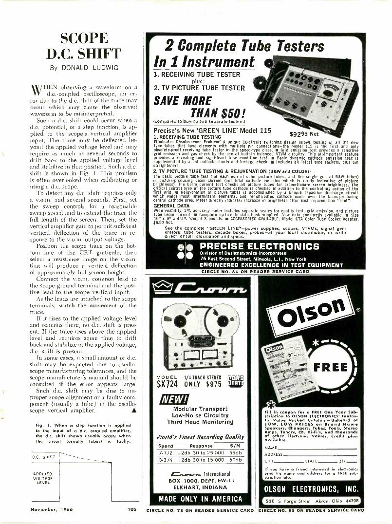
SCOPED.C. SHIFT
By DONALD LUDWIG
WHEN observing a waveform on ad.c.-coupled oscilloscope, an er-
ror due to the d.c. shift of the trace mayoccur which may cause the observedwaveform to be misinterpreted.
Such a d.c. shift could occur when ad.c. potential, or a step function, is ap-plied to the scope's vertical amplifierinput. The trace may be deflected be-yond the applied voltage level and mayrequire as much as several seconds todrift back to the applied voltage leveland stabilize in that position. Such a d.c.shift is shown in Fig. 1. This problemis often overlooked when calibrating orusing a d.c. scope.
To detect any d.c. shift requires onlya v.o.m. and several seconds. First, setthe sweep controls for a reasonablesweep speed and to extend the trace thefull length of the screen. Then, set thevertical amplifier gain to permit sufficientvertical deflection of the trace in re-sponse to the v.o.m. output voltage.
Position the scope trace on the bot-tom line of the CRT graticule, thenselect a resistance range on the v.o.m.that will produce a vertical deflectionof approximately full screen height.
Connect the v.o.m. common lead tothe scope ground terminal and the posi-tive lead to the scope vertical input.
As the leads are attached to the scopeterminals, watch the movement of thetrace.
If it rises to the applied voltage leveland remains there, no d.c. shift is pres-ent. If the trace rises above the appliedlevel and requires some time to driftback and stabilize at the applied voltage,d.c. shift is present.
In some cases, a small amount of d.c.shift may be expected due to oscillo-scope manufacturing tolerances, and thescope manufacturer's manual should beconsulted if the error appears large.
Such d.c. shift may be due to im-proper scope alignment or a faulty com-ponent (usually a tube) in the oscillo-scope vertical amplifier. A
Fig. 1. When a step function is appliedto the input of a d.c. coupled amplifier,the d.c. shift shown usually occurs whenthe circuit (usually tubes) is faulty.
D.C. SHIFT
APPLIEDVOLTAGE
LEVEL
2 Complete Tube TestersIn 1 Instrument1. RECEIVING TUBE TESTER
plus:2. TV PICTURE TUBE TESTER
SAVE MORETHAN $50!
(compared to buying two separate testers)
1. RECEIVING TUBE TESTINGEliminates Obsolescence Problem! A unique 10 -circuit switching design allows testing of all the newtype tubes that have elements with multiple pin connections-the Model 115 is the first and onlyobsolete -proof receiving tube tester in the speed -type class. Grid emission test provides a sensitivegrid emission and gas check by the use of built-in balanced VTVM circuitry. This all-important featureprovides a revealing and significant tube condition test. Basic dynamic cathode emission tett issupplemented by a hot cathode shorts and leakage check. Is Includes all latest type sockets, plus pinstraighteners.2. TV PICTURE TUBE TESTING & REJUVENATION (B&W and COLOR) The basic picture tube test (for each gun of color picture tubes, and the single gun of B&W tubes)is picture -producing beam current (not total cathode emission which is rarely indicative of picturebrightness). The beam current test checks all picture tubes for proportionate screen brightness. Thecritical central area of the picture tube cathode is checked in addition to the controlling action of thefirst grid. Rejuvenation of picture tubes is accomplished by a unique capacitor discharge circuitwhich welds most intermittent elements, and redistributes cathode oxide over the beam -producingcentral cathode area. Meter directly indicates increase in brightness after each rejuvenation "shot".GENERAL DATAWide visibility, 2% accuracy meter includes separate scales for quality test, grid emission, and picturetube beam current. Complete up-to-date data book supplied. New data constantly available. Size16" x 9rt x 43/4". Weight 8 pounds. ACCESSORIES AVAILABLE: Model CTA Color Tube Socket Adapter,$6.50 Net.
See the complete "GREEN LINE"-power supplies, scopes, VTVMs, signal gen.orators, tube testers, decade boxes, probes-at your local distributor, or writedirect for full information and specs.
Precise's New 'GREEN LINE' Model 115 $9295 Net
00 PRECISE ELECTRONICS di Division of Designatronics IncorporatedW 76 East Second Street, Mineola, L.I., New York
ENGINEERED EXCELLENCE IN TEST EQUIPMENTCIRCLE NO. 81 ON READER SERVICE CARD
lif=m1F1:11"11/1Flo
MODEL 1/4 TRACK STEREO
SX]24 ONLY $975
Modular TransportLow -Noise Circuitry
Third Head Monitoring
World's Finest Recording QualitySpeed Response S/N7-1/2 ±2db 30 to 25,000 55db3-3/4 ±2db 30 to 15,000 50db
Cet.crwers.. InternationalBOX 1000, DEPT. EW-11
ELKHART, INDIANA
Fill in coupon for a FREE One Year Sub-scription to OLSON ELECTRONICS' Fantas-tic Value Packed Catalog - Unheard ofLOW, LOW PRICES on Brand NameSpeakers, Changers, Tubes, Tools, StereoAmps, Tuners, CB, Hi-Fi's, and thousandsof other Electronic Values. Credit planavailable.
NAME
ADDRESS
CITY STATE ZIP-If you have a friend interested in electronicssend his name and address for a FREE sub-
6_scription also.
OLSON ELECTRONICS, INC.
November, 1966 105
MADE ONLY IN AMERICA 528 S. Forge Street Akron, Ohio 44308
CIRCLE NO. 78 ON READER SERVICE CARD CIRCLE NO. 98 ON READER SERVICE CARD
ELECTRONICSMARKET PLACE
COMMERCIAL RATE: For firms or individuals offering commercial productss or services. 700 per word (including name and address). Minimum order$7.00. Payment must accompany copy except when ads are placed by accredited advertising agencies. Frequency discount: 5% for 6 months; 10%for 12 months paid in advance.READER RATE: For individuals with a personal item to buy or sell. 400 per word (including name and address). No Minimum! Payment must accom-pany copy.GENERAL INFORMATION: First word in all ads set in bold caps at no ext ra charge. Additional words may be set in bold caps at10rt extra per word.All copy subject to publisher's approval. Closing Date: 1st of the 2nd preceding month (for example, March issue closes January 1st). Send orderand remittance to: Hal Cymes, ELECTRONICS WORLD, One Park Avenue, New York, New York 10016
FOR SALE
JUST starting in TV service? Write for free 32page catalog of service order books, invoices,job tickets, phone message books, statementsand file systems. Oelrich Publications, 6556 W.Higgins Rd. Chicago, III. 60656.GOVERNMENT Surplus Receivers, Transmitters,Snooperscopes, Radios, Parts, Picture Catalog25jt. Meshna, Nahant, Mass. 09108.INVESTIGATORS, FREE BROCHURE, LATESTSUBMINIATURE ELECTRONC SURVEILLANCEEQUIPMENT. ACE ELECTRONICS, 11500-J NW7TH AVE., MIAMI, FLA. 33168.CANADIANS -Giant Surplus Bargain PackedCatalogs. Electronics, Hi-Fi, Shortwave, Ama-teur, Citizens Radio. Rush $1.00 (Refunded).ETCO. Dept. Z, Box 741, Montreal, Canada.JAPAN & Hong Kong Electronics Directory.Products, components, supplies. 50 firms -just$1.00. Ippano Kaisha Ltd., Box 6266, Spokane,Washington 99207.TRANSISTORS -Miniature Electronic Parts.Send for Free Catalog. Electronic Control De-sign Company, P.O. Box 1432M, Plainfield, N.J.
RECTIFIERS & TRANSISTORSSilicon Diodes
Amps 100 PIV 200 PIV 400 PIV 600 PIV.75. .07 .10 .14 .21
3 .14 .22 .28 .4015 - .75 1.20 1.5535 - 1.30 2.00 2.70
AmpS 700 PIV 800 PIV 900 PIV 1000 PIV.75 .25 .32 .40 .553 .49 .58 .67 .78
15 1.70 1.85 2.2535 3.15 3.60 4.50 4.801100 PIV 70c. 1200 PIV 850, .75 amp
TopHat. or FlangeleSS10 Watt Sil. Zener Stud 20%, 12-200V 95C ea.1 Watt Zener, axial 20%, 8-200V 50; ea.$11. diode Stud, 1500 piv, 300 ma 500 ea.Hoffman Sil. Epoxy diodes, 200 ma.
3000 PIV 980 6000 PIV $2.49Thermistor bead, 900 or 1200 ohm, 600°F-2/$1.00
Silicon Power Transistors4W, 2n498. 70.5 50015W. 2n2990. 70.5
30W, 2n2151. T0.60 $18.1140W, 291047, 70-S7 51.4050W, 291722, 70-53 51.5050W. 2n1724. 70-61 51.502n1300 series, NPN or PNP 6/51.00Sil. Junction diodes, 1N200 series 15/$1.0070 amp. stud, 50 P1V-$2.50, 100 PIV $3.50Amplifier, 6 Tubes, new, 3 lbs. $1.49Nickel Cadmium Battery, 91/2 oz. 8 amp hr $2.5010 Lbs. Power Resistors, 5-60W $1.9810 Lbs. Paper Capacitors, assorted $1.98IN34A 12/51.002 Watt Pots, assorted 15/$1.00Mercury Batteries, 5.4V, 6/8"xl" 4/$1.00100-1/4 w resistors, assorted $1.9850 W. Zeners 12, 14, 16, 18 $2.00 ea.50 disc cap, assorted 980Computer Boards, parts free-Transistors..80 ea.
Varicap-Voltage Variable Capacitor27, 47, or 100 pf at 4v., 4:1 $1.25
150 W Germanium Power (Diamond Case)2n1021...$1.00 2n1022...51.25 2n511 $1.50
20 W Germanium Power (internal heat sink)2n1038 4/$1.00 2n1039 3/$1.00 2n1040 2/$1.002n1041 600 Add 100 ea. for external heat sink
SILICON CONTRO LED RECTIFIERSPRV .75A* 7A 16A. PRV .75A 7A 168.25 -- -- .4850 - .45 .70
300 1.20 1.80 2.20
100 - .70 1.20 400 1.70 2.20 2.70200 .80 1.15 1.70 500 1.95 3.00 3.30
*Too Hat, others Stud 600 2.30 3.20 3.90money back guarantee. $2.00 min. order. includepostage. Write For Free Catalog. C.O.D. 25%
Electronic Components Co.Box 2902, Baton Rouge, La. 70821
CANADIANS, transistors, all semiconductorsand components. Free catalogue contains ref-erence data on 300 transistor types. J.&J. Electronics (Dept. EW), P.O. Box 1437 Winnipeg,Manitoba, Canada.METERS -Surplus, new, used, panel and port-able. Send for list. Hanchett, Box 5577, River-side, Calif. 92507.MESHNA'S TRANSISTORIZED CONVERTER KIT$5.00. Two models -converts car radio to re-ceive 30-50 mc or 100-200 mc (one mc tuning).Meshna, North Reading, Mass. 01864.R.F. CONVERTERS World's largest selection.Also CCTV cameras, transmitters, etc. Lowestfactory prices. Catalog 10it. Vanguard, 196-23Jamaica Ave., Hollis, N.Y. 11423.CONVERT any television to sensitive big -screenoscilloscope. Only minor changes required. Noelectronic experience necessary. Illustratedplans, $2.00. Relco-A22, Box 10563, Houston18, Texas.ELECTRONIC Ignition Kits, Components FreeDiagrams. Anderson Engineering, Epsom, NewHampshire 03239.FREE ELECTRONICS (new and surplus) partscatalog. We repair multimeters. Bigelow Elec-tronics, Bluffton, Ohio 45817.SURVEILLANCE EQUIPMENT -NEW HIGH PER-FORMANCE SUBMINIATURE MODELS. ELEC-TRONIC COUNTERMEASURE DEVICES TO PRO-TECT PRIVACY. FREE DATA: SECURITY ELEC-TRONICS-EW, 15 EAST 43RD STREET, NEWYORK, N.Y. 10017.DETECTIVES! Free brochures! Electronic Sur-veillance devices. SILMAR ELECTRONICS, 3476N.W. 7th Street, Miami, Florida 33125.CRYSTALS . . . largest selection in UnitedStates at lowest prices. 48 Hr. delivery. Thou-sands of frequencies in stock. Types includeHC6/U, HC18/U, FT -241, FT -243, FT -171, etc.Send 100 for catalog with oscillator circuits.Refunded on first order. Jan Crystals, 2400ECrystal Dr., Fort Myers, Fla. 33901.DIAGRAMS, service information, Radio $1.00,Television $2. BEITMAN, 1760 Balsam, High-land Park, Illinois 60035.WHOLESALE: Microphones 89e, Speakers 490,Amplifiers $4.39. Hundreds of items. Catalog250. Royal, 8632 La Mesa Blvd., La Mesa, Calif.NEW supersensitive transistor locators detectburied gold, silver, coins. Kits, assembled mod-els. $19.95 up. Free catalog. Relco-A22, Box10563, Houston 18, Texas.McGEE RADIO COMPANY. Big 1966.1967 cat-alog sent free. America's best values. HiFi am-plifiers -speakers -electronic parts. Send name,address and zip code number to McGee RadioCompany, 1901 McGee Street, Dept. EG, KansasCity, Missouri 64108.USED TEST EQUIPMENT. VTVM'S, OSCILLO-SCOPES, SIGNAL GENERATORS. LOW PRICES.COME SEE. REX, 759 10th Ave., NEW YORK,NEW YORK 10019.R.C.A. Transconductance type tube tester ModelWT100A. Good condition $100. Rozman, 18Maple Avenue, Ellenville, New York 12428.STEREO for sale. 3 Components Harmon KardonCitation III and tuner. Harmon Kardon CitationIV Pre -Amp, Dynakit 35 stereo amp. Originalvalue $578. Will accept $255.00. Write 10310Malcolm Circle, Cockeysville, Md.WARNING Burglar Alarm Decals two for $1.00.Protect your home or business. Used RadarAlarms, phone dialers. Information. Reid's Elec-tronics, 1221A East Van Buren, Phoenix, Arizona85008.
TRANSISTORIZED Products Importers catalog.$1.00. Intercontinental. CPO 1717, Tokyo, Japan.
GREGORY ELECTRON ICS
Reconditioned & Used FM2 -WAY RADIO SAVINGS
Partial list -Send for Fall '66 catalog
Voice Commander132 to 172 MC, 1W 9.5"x 5.3" x 1.7" Reducedprice including brandNew Rechargeable NickelCadmium Battery Pack
Lowest Price Ever!
148If crystal & tuning is de,
.-. sired add $45.00Battery charger for theseunits $16.00
WRITE FOR QUANTITY PRICES
VOICE COMMANDER
Tuned & CrystalledMonitor Receiver only- $78with dry Batteries
MOTOROLA 30-50mcT-51 GGV
Vibrator Power Supply46 6/12v 50.60 watts
Complete with all accessories, lessSame unit tuned 4.r:etapanadnd antenna.
to desired fre-twenty, Including TX Narrow, RX Wide $188new antenna. add545.
Transmitter & ReceiverFully Narrow Banded $208(Less accessories, deduct $30.00)
GE TX 4ET56 v 30 watt 40-50mc $10
GE TX 4ET512 v 30 watt 40-50mc $15
We Buy Late Model Equipment for Cash-Write; Wire or Phone!
`OR~~ GREGORYGE.,...--- ELECTRONICS
CORPORATION249 RT. 46, Saddle Brook, N.1., 07662
Phone: (201) 489-9000
CIRCLE NO. 117 ON READER SERVICE CARD106
CIRCLE NO. 112 ON READER SERVICE CARDELECTRONICS WORLD
U.S. GOV'T ELECTRONIC SURPLUS
Nationally Known -World Famous SURPLUS CENTER offersfinest, most expensive, Government Surplus electronic units andcomponents at a fraction et their original acquisition cast.
ORDER DIRECT FROM AD or WRITE FOR CATALOGS
LABORATORY EXPERIMENTAL KIT
PERFORM 100'S OFFASCINATINGELECTRICAL
EXPERIMENTS
Gov't Aguish,.Cost Of Ports jOver J50.00 ,,,
$14.85 ,,gal;=ti 10F.O.B. 41 C. M41111121611
1 ITEM $A222 I - - Amazing Value! I aluable gilt for son orhusband. Dundreds of fascinating ...penmen.. Teaches modem elec-tronic theory and practice. Easy, interesting wan to team.
brat...intent with clectro-plating. elerlro-magnetir ploinomena, re -burglar alarm relay circuits, rectification, lest circuits,
eavesdropping, motor experiments, transformer phenomena, etc.
Kit Cronin': in' motor. AC motor, elected -magnetic coils, aeand dc relays. set fa b capacitors, compass, test bulbs, platingchemicals, silicon diode, germanium diode. burglar alarm actuator.carbon marranhone ea.esdmirning element, ac test socket, permanentoagnets, telephone handset, cords. test clips, wire and other items.ver 35 pieces. Includes fine Experimental Manual with drawing, pro-
cedures, etc., written in Pmfekstonal engineer,
Also furnished with each kit out popular book Rome LaboratoryBench and Experimental Procridores. t Reg. 01.001. Shows how to buildwonderful home laboratory test bench, and how to get the most out ofyour experimental work. 112 lbs.i Parts cost griv't over 550.00.
AC PROGRAM TIMING CLOCK
(ITEM t11511 ) - 'Zenith 115VAC program
.'
tinier. Use for periodic signalling. work breaks,school classes turn on tadio for newscasts. etc.Adjustable clips permit switching On or Off any-time during 24 -hour period. Sufficient clips formultiple programing. Also has "skip-a-daY.''emote. Contacts can handle up to 11 -amps.NY' it 6Ii.' x .I. Wt. 8 lbs. Gov't Cost Oyer530.00.
Instructions Furnished. F.0.11. $9.49
AUTO -PILOT GYROSCOPE( ITEM 4115 1 - - DC motor driven.
gimbal mounted gyroscope. Ultra -expensiveprecision unit used to nsteer. large, multi -engine planes. Deviation from establishedplane sends potentiometer controlled sig-nals to bring about chano in other motors.Ind can he used as auto -pilot for boats.
li...Si
F.O.B. $12.47Wonderful class action.it to demonstrateand study evro Missiles, plane,
,17.-.At.b.-,..-ovrasvv:,,10:70,;....
STANDARD DIAL TELEPHONE( ITEM 41111 ) - - Standard, commercial
telephone same . used throughout U.S.A. Attrative polished black, like new condition. Use asextension phone to private systems or connectseveral phones together of local intercom sys-tem. Full instructions are amished. WI. 9 lbs.Original Cost 024.50. F.O.I. $5.95STEP-BY-STEP AUTOMATIC SWITCH
( ITEM Old ). Amazing 'inn -and -around.%elecoo-mannetir telephone switch. Dial .. bank ..1.:';pair from I to 100. Make your own telephone system.C. also be used to remotely control up to 100 cit.cults over a single pair of wires.
',._Ont. of our FOUR STAR bargains. Comes corn- ,,....plete with data. one dial and one line bank. Size. IV. Ii:3. x 7.' x IV% WE 16 lbs. l'ust Gov't Over $75.00. xx..-,.,
:1:1'.PIILITIZI!,kihnSXCZircins F.O.B. $9.95 ,
too- STEP UP/DOWN TRANSFORMER,..-,11 ( ITEM 41543) - - Stenvollageupor down.
1 w Ilas many uses. Will step 115 -volts UP to 230-volts or step 230-volts down to ill -roils. Pill
'gibs also transform 115 -volts to 55-volts.Rated 1.73
.0. $4.99 .,r.v.tr.: zw."4,!Pg.to7r."ir-41%:-
TYPICAL BUYS FROM OUR 1967 CATALOGSS 150.10 Geared 2 -hp Battery Golf Car Motor $24.95S 15.00 - Westinghouse DC Ammeter, 0 te 301 $ 7.11S 40.00- Vacuum/Pressure Pump, 12-VDC $11.95
- - - 00 -MW Wilkie -Talkies, Per Pair $19.60- - - - Deluxe, Multi- ***** , AC/DC Tester $ 8.98
54000.00 - Carrier Telephone Amplifier System $13.91
Correspondence \SPECIAL SALE
Course In .ffill!, .if
ELECTRICALENGINEERING lt,i,,I;;u'rts..7:1? $8.79 Postpaid
( ITEM 8A181 ) - - Wonderful chance to obtain technical train-ing at Aroa/ing Low i'osti Lincoln Engineering School h. suspendedits Correspondence Courses because of increased operating costs. Weoffer a limited number of the school's complete Electrical EngineeringCourse but without the examination Paper grading service. The courseinonatata of 14 lesson unit books. Each boob has the regular crams, andn 'a separate section. "Standard Answers'. to each exam question.
Course is well written, easy to understand, profusely Illustrated.Reader's Digest Mae, easy to carry and study in spare time. Many Lin-coln Engineering School students holding excellent jobs as a result of1..E.S. training. Course contains latest infonnation on transistors, sil-icon diodes, etc. additional book on bow to build and operate a "HomeLaboratory and Experimental Bench" furnished with each course.
SEND 25c COIN OR STAMPS FOR 3 MAIN CATALOGS'.0q:22b All Items FOB Lincoln Money Back Guarantee
SURPLUS CENTERDEPT. FW-III LINCOLN, NEBR. 68501
DON'T WONDER who you talked to, write itdown. Record book for CB'ers. Rush stamp forsample page or $2.00 postpaid. Alameda Pub-lishing, 9128 N. 4th, Albuquerque, N.M. 87114.TUBE TESTER $9.00. Shell model 102 testerpanel, 7"0-Ima meter. 102 sockets, vibrator test-er, 18" wide x 16" high. EVEREADY battery test-er, $4.00. Money back guarantee. Kirby, 3606Delmar Road, Indianapolis, Indiana 46220.
ELECTRONICS ENGINEERINGAND INSTRUCTION
FCC LICENSE in six weeks. First class radiotelephone. Results guaranteed. Elkins RadioSchool, 2603C, Inwood, Dallas, Texas.ELECTRONICS! Associate degree -29 months.Technicians, field engineers, specialists in com-munications, missiles, computers, radar, automation. Start September, February. ValparaisoTechnical Institute, Dept. N, Valparaiso, Indiana.F.C.C. LICENSE (first class) in seven weeks.Resident classes or correspondence. Grantham,1505 N. Western, Hollywood, California 90027.REI First Class Radio Telephone License in (5)weeks Guaranteed. Tuition $295.00. Job place-ment free. Radio Engineering Institute, 1336Main Street, Sarasota, Fla.LEARN ELECTRONIC ORGAN SERVICING athome. All Makes including transistors. Experi-mental kit -troubleshooting. Accredited NHSC.Free Booklet. NILES BRYANT SCHOOL, 3631Stockton, Dept. A, Sacramento 20, Calif.HIGHLY -effective home study review for FCCcommercial phone exams. Free literature!COOK'S SCHOOL OF ELECTRONICS, P.O. Box10634, Jackson, Miss. 39209.PROFESSIONAL Engineering, Electronics. FreeProspectus. CIST, Suite 674, 263 AdelaideStreet, West, Toronto, Canada.FCC LICENSE THROUGH TAPE RECORDED IN-STRUCTION. Bob Johnson Audio -Visual Training,1060D Duncan, Manhattan Beach, California90266.
TUBES
BEFORE you buy receiving tubes, Transistors,Diodes, Electronic Components and Accessories. . . send for Giant Free Zalytron Current Cata-log, featuring Standard Brand Tubes: RCA, GE,etc. -all Brand new premium quality individ-ually boxed. One year guarantee -all at biggestdiscounts in America! We serve professionalservicemen, hobbyists, experimenters, engi-neers, technicians. Why pay more? ZalytronTube Corp., 469-W Jericho Turnpike, Mineola,N.Y. 11502.FREE Catalog. Electronic parts, tubes. Whole-sale. Thousands of items. Unbeatable prices.Arcturus Electronics ZD, 502-22 St., Union City,N.J. 07087.TUBES, SEMICONDUCTORS, ELECTRONICEQUIPMENT & COMPONENTS. Quality mer-chandise only! Serving engineers, purchasingagents, TV/HiFi servicemen and hams for 16years. Write for catalog or call WA 5-7000.BARRY ELECTRONICS, 512 Broadway, NewYork, N.Y. 10012.TUBES -33e each. Year guarantee. Tuner Clean-er $1.09. Free catalog. Cornell, 4213-W Uni-versity, San Diego, Calif. 92105.
WANTED
QUICKSILVER. Platinum, Silver, Gold. Ores An-alyzed. Free Circular. Mercury Terminal. Nor-wood, Mass.CASH Paid! Sell your surplus electronic TUBES.(Want UNUSED, CLEAN Radio/TV Receiving,Transmitting, Special Purpose, Magnetrons,Klystrons, Broadcast Types.) Want military andcommercial Lab/Test Equipment. Want com-mercial Ham Receivers and Transmitters. For aFair Deal Write: BARRY ELECTRONICS, 512Broadway, New York, N.Y. 10012 (WA 5-7000)
$7.95
Dept. EW116
Dial telephone Special.Factory re -conditioned,Complete, guaranteed.Add $1.00 if plug re-quired. Shipments F.O.B.Waymart. Write for com-plete telephone list.
SURPLUS SAVING CENTERWaymart, Pa. 18472
FAMOUS BC -645 TRANSCEIVER15 Tubes 435 to 500 MCcan be modified for 2 -waycommunication. voice or ..;,..Q8 --r_ . ,code, on ham band 420.450 V SW1. it --amc. citisens radio 460-470mc. fixed and mobile 450- )1`101.,,,,LISr....IP480 mc. television expo t -li ',ZOOmental 470-300 mc. 15 -II, .o(tubes alone worth
-% '',1.- Jrmore than sale price!): 4-
"7F7, 4-7117. 2-7E6. 2- BRAND -..6E6, 2-955 and 1 -WE- NEW316A. Now covers 460 to490 mc. Brand new BC -645 with tubes, less powersupply in factory carton.Shipping weight 25 lbs. SPECIALI.1 $1 6.95 IPE -101C Dynamotor, 12/24W Input $6.95UHF Antenna Assembly 2.45Complete Set of 10 Plugs 5.50Control Box 2.25
SPECIAL "PACKAGE" OFFER:BC -645 Transceiver, Dynamotor and all accessoriesabove, COMPLETE, BRAND NEW,While Stocks Last $26.95
AN/APR-4Y FM & AM RECEIVER"FB" FOR SATELLITE TRACKING!
Nigh precision lab instru.... --.-- - ment, suitable for moni-
...... haring and measuring fre-..A.5 :e< twenty and relative signalstrength of signals from- g 38 to 4000 Mc in 5 tun-,''' Mg ranges. For 110 volt
.s. ..,-..l5 60 cycle AC operation.v rip 3,;,,'...,),.,"1- built-in power supply.Original circuit diagram
'';r C) , 0 included. Checked out.Perfect, LIKENEW $88.50
TN -19 TUNING UNIT for above, continuous tuning975 to 22011 Mc.. .004 right for 1296 Mc, SatelliteFrequency and other current Ham activity. Checkedout, perfect $59.50Other tuning units for above, TN.16, nu -17, TN -18,TN -34 in stock P U RBC -929 3 -Inch Scope, with all tubes,
$16.95LIKE NEW ..... ...... ... .. . . .. . ..Conversion instructions, with diagram for 110 VAC operation $ .05
SCR -522 2 METER TRANSMITTER -RECEIVERVHF Transmitter -Receiver, 100-158 Me. 4 -channels.Xtal-controlled. Amplitude modulated voice, Completewith all 18 tubes, top rack and metal case. Exc.Cond. $39.50
BC -22I FREQUENCY METEREquipped with original calibration charts. I25KC. to20,000 Kt with crystal check points in all ranges.and' CrystaUsedl. CHECKEDall tubes
OUT., original calibration BookUnmodulated $79.50
BC -221 1000 Kc Crystal Brand New . . ... ... $5.50BC221 FREQ. METER CASE. aluminum with. %nit.reg. supply. Shock mounted. BRAND NEW....53.95LM Freq. Meter. Modulated. 125 Kc to 20.0, 0 Ko.With Calibration Book, Like New $79.50As above, less Calib. Book, exc. used $34.50ARR.15 Collins Receiver, Tunable.with Collins PTO and calibrator (written up in "73"mag) Complete with tubes.Like New $88.50
BC1206-C BEACON RECEIVER 195 to 420 Kc, madeby Setchel-Carlson. 0orks on 24-28 volts DC. 135Ku. IF. Complete with 5 tubes. glee 4' 5 4" x 6.Wt. 4 lbs. NEW $12.95USED leas tubes $5.9524 V DC POWER SUPPLY (ABC) Setchell-CarlsonModel 24. INPUT: 24 VDC at .8 Amp. OUTPUT:1.5 V at .3 A., 63 V at .010 A., and -6 V.7"x42x4". Wt. 4 lbs. Like New,Checked out $6.95
EE -8 FIELD PHONESChecked out, perfect working order. Complete withall charts.
parts. Excellent Condition. LIKE NEW!$16.95
SCR -274 COMMAND EQUIPMENTALL COMPLETE WITH TUBES Like BRANDType Description Used New NEWBC -453 Receiver
190-550 Kc. $14.95 $18.95 P.U.R.BC -454 Receiver 3-6 Mc. $16.50 $21.50BC -455 Receiver 6-9 Mc. $14.98 $19.50 $24.50BC946 Receiver, 550-1500 Kc. Complete with alltubes. Brand New, In original packing $48.501.5 to 3 MC. Receiver Brand New $24.50
110 Volt AC Power Supply fOr all 274 N andARC -5 Receivers. Complete with metal case, instructions. Factory wired, tested, ready to oper-ate $12.50SPLINED TUNING KNOB for 274-N and ARC -5RECEIVERS. Fits BC -453, BC -454 andothers. Only 49C
2.1 to 3 Me. Transmitter. Brand New $12.95BC -458 TRANSMITTER -5.3 to 7 Mc. Complete withall tubes and crystal $12.95BRAND NEWLike New $8.95BC -459 TRANSMITTER -7 to 9 Mc. Complete withtubes & crystal $19.50Like NewBC -696 TRANSMITTER 3.4 Mc Complete with si6.95All Tubes & Czystal. Brand NewLike New $12.95BC -456 Modulator USED $2.75 NEW $4.95
ALL ACCESSORIES AVAILABLE FOR ABOVESCR -625 fil:NE DETECTOR
Complete portable outfit in original packing, with allaccessories. Excellent, Used $32.50AN/ARR-2 Receiver, 234.258 Mc, Complete with 11tubes. Brand New $11.95Exc. Used $ 7.952 -Volt Willard Storage Ratter,, 20 Amp. Hr Model20.2, 3"x4"x51/2" high. Brand New $2.796-Volt Willard Midget Storage Battery, 3 Amp. Hr.3 -5/8.x1 -13/16"x2-3/8''. Brand New $2.95
Please include 25% Deposit with ordcr-BalanceC.O.D., or Remittance in Full. 500 Handling Chargeson all orders under $5.00. All shipments F.O.B. OurWarehouse, N.Y.C. All Merchandise subject to PriorSale and Price Change. For NEW COMPLETE CATA-LOG, send 250, refunded with first order!
G & G RADIO SUPPLY CO.Telephone: (212) CO 7-4605
77 Leonard St. New York, N.Y. 10013CIRCLE NO. 79 ON READER SERVICE CARDNovember, 1966 107
r -
A
L A L
I T E
D E SP.O. BOX 74SOMERVILLE, MASS. 02143
SILICONPOWER
RECTIFIERS
SPECIAL INTRODUCTORYOFFER
15 EPDXY RECTIFIERS WITH EVERY$5.00 PURCHASE. MANY OVER 600 PIV.
NO SHORTS OR OPENSFET'S "N" CHANNEL TYPE SIMILAR
TO C-610 USED AS AMP, SWITCH, CHOPPER -VERY HIGH INPUT Z $1.25 EACH
5A INSULBASE
PRV 3A 20A PRV50 .05 .20 50 .10100 .10 .40 100 .20200 .20 .60 200 .40400 .25 .80 400 .60600 .35 1.20 600 1.00800 .45 1.50 800 1.251000 .65
TOP HAT &EPDXY
750 MAPRV50 .05100 .07200 .09400 .12600 .20800 .251000 .501200 .65
6"x9" speakers 20 ohms 1.5 oz. magnet 1400 .85$2.50 ea
4' speakers 3.2 ohms 1 oz. magnet $1.25 ea2.5 speakers 10 ohms 2/$1.00Dual i megohm potentiometers with 6 & 12 volt off -on
switches 4/$1.0024 volt 60 cycle 6 pole 13 open, 3 closed) 2 throw 15
amp contactors $4.00 ea455 KC IF Transformers 3/$1.00262 KC IF Transformers.............. 3/$1.00Dual 20MFD at 350 volts electrolytic condensers 3/$1.0028-101 MMF ceramic trimmer condensers 6/$1.00GaAs Varactors, sim to AP -1, AP -6 etc. 70KMC min. at
150 mw $4.00Terms: FOB Cambridge, Mass.Send check or Money OrderInclude Postage, Average Wt.per package 1/2 lb. Allow for C.O.D.Minimum Order $2.00
A) Sim to 2N1640 bidirectional transis-tors, a TO -5 silicon unit in which thecollector and emitter are interchange-able. $.40 ea.
B) Sim to 2N728. A high frequency TO -18NPN unit extending to the UHF range.
5/$1.00C) Sim to 2N2885 (NPN) and TMT 8035
(PNP) microtransistors. 75 mw powerat high freq.
Both units $1.00
D) Sim to 2N1648 NPN high voltage 20Watt silicon unit, used in power out-put stages & power transistor drivers.
2/$1.00E) Glass diodes color coded.
SI 20/$1.006E 30/$1.00
F) Similar to 2N2875PNP silicon 20 wattpower transistors with a cut off fre-quency to 30 Mc. 2/$1.00
G) Sim to 2N255 20 watt PNP germaniumpower transistor in a TO -3 case 4/$1.00
H) 10 Watt Zeners 2 -70 -volts, state de-sired voltages 500 ea.
I) Silicon bilateral switch, replaces twoSCR's by firing in either directionwhen the breakdown voltage is (3A-
ceeded. Used in light dimmers etc.2/$1.00
SEND FOR FREE CATALOG (To Be Available Soon)CIRCLE NO. 87 ON READER SERVICE CARD
UNUSUAL BARGAINS... MANY U. S. GOV'T SURPLUS
"Balls of Fun" for Kids ...Traffic Stoppers for Stores ...
Terrific for Amateur Meteorologists ...
SURPLUS GIANT WEATHER BALLOONSAt last . . . available again in big8 -ft. diameter. Create a neighbor-hood sensation. Great backyardfun. Exciting beach attraction.Blow up with vacuum cleaners orauto air hose. Sturdy enough forplay: all oilier uses with reason-able care (can be punctured bysharp objects.) Filled with he-lium (available locally) use bal-loons high in the sky to attractcrowds. advertise store sales. an-nounce fair onenings. etc. Ama-
tneteoolo,L.ts use balloons to measure cloudheights, wind speeds. temperature, pressure. humidityat various heights. l'hotog.x.thers can utilize for low-costaerial photos. Recent Gov't. surplus of heavy, hlack,neoprene rubber.Stock No. 60,568 -AK $2.00 Ppd.
BATTERIES GUARANTEEDRECHARGEABLE FOR 5 YRS.
Use these remarkable space-age Nickel -Cadmium batteries in flashlight, port-able radios, toy or Hash guns. Obsoleteall others! Low-cost hit include com-pact, highly efficient battery chargerand 2 "D" size Ni-('d batteries guar-anteed rechargeable to full power for5 yrs, Power output remains constant --
doesn't fade away as with lead -acid cells. Durable, blackplastid charger 59's" x 5" a IV dli. plugs into standardwall outlet. Conildetely charges 1 or 2 "D" or "C" slaebatteries in 16 hrs. Light shows when unit is charging-will not overcharge.Stock No. 60,59I -AK $9.95 Ppd.
Stock No. 60,592 -AK (Charger only) $5.99 Pod.Stock No. 60,593 -AK (Two "0" Cells only $5.90 Ppd.
Order by Stock No. -Check or Money Order -Money -Back guarantee
EDMUND SCIENTIFIC CO., Barrington, N.J. 08007
SEND FOR FREE CATALOG "AK"Completely new 1967 edition, NewItems, categories, illustrations. 148 easy'[...read pages packed with nearly 4000',usual items. Enormous selection ofAstronomical Telescopes, Microscopes.Binoculars, Magnifiers, Magnets, Lenses,Prisms. Many war surplus Items: forhobbyists. experimenters. workshop.factory. Write for catalog l'AK."Please include your Zip Code.
Please inriude your Cod,kumoi, ccr 10.MM/. w..Arrx. 41.1./1/0110,
EDMUND SCIENTIFIC CO., BARRINGTON, NEW JERSEY 011001
BIGCATALOGWorld's "BEST BUYS"Mitin GOV'T. SURPLUS
Electronic Equipment
COMMUNICATIONRECEIVER -6 BANDS
BC -348 Receiver AM -Six bands 200 to 500 KC. and1.5 to 18 MC. With crystal phasing, antenna align.,CW oscillator, beat. freq. AVC/MVC, audio gain, anddimmer pilot light controls. Also slow and fast tuningwith large fan dial. Phone and speaker lacks. Withtubes: 1/617, 3/61(7, 1/6C5, 1/6K6, 1/668, & 1/6F7.Voltage required: 24 volts for filament & pilot light and220 VDC Qt 70 MA. for high voltage. Size: 18 x 101/2 x91/2". Wt.: 40 lbs.
PRICES:Used, less Dynamotor $69.50Used, less Dynamotor -Checked for Operation 79.50DM -28 Dynamotor -28 VDC Used: 4.95FT -154 Shock Mounting Base 2.75P10-103 Plug for rear of Receiver 2.50AC POWER SUPPLY, With Speaker, for BC -348: 115Volt 60 cycle supply with speaker housed in black
DO-IT-YOURSELF
PROFESSIONAL ELECTRONIC PROJECTS -$1.00up. Catalog 250. PARKS, Box 25565, Seattle,Wash. 98125.
TAPE & RECORDERS
RENT Stereo Tapes -over 2,500 Different -allmajor labels -free brochure. Stereo-Parti, 1616-E. W. Terrace Way, Santa Rosa, California.BEFORE renting Stereo Tapes, try us. Postpaidboth ways -no deposit -immediate delivery.Quality- Dependability -Service -Satisfaction -prevail here. If you've been dissatisfied in thepast, your initial order will prove this is no idleboast. Free Catalog. Gold Coast Tape Library,Box 2262, Palm Village Station, Hialeah, Fla.33012.TAPE RECORDER SALE. Brand new, latest mod-els, $10.00 above cost. Arkay Sales. 1028-BCommonwealth Ave., Boston, Mass 02215.TAPE -MATES now offers ALL TAPES -ALL LA-BELS at TREMENDOUS SAVINGS plus FREETape -Mates membership. For FREE brochurewrite TAPE -MATES, 5727-EW W. Jefferson Blvd.,Los Angeles 90016.STEREO TAPES. Save up to 60% (no member-ship fees, postpaid anywhere USA). Free 60 -page catalog. We discount batteries, recorders,tape accessories. Beware of slogans "not un-dersold," as the discount information you sup-ply our competitor is usually reported to thefactory. SAXITONE, 1776 Columbia Rd., Wash-ington, D. C. 20009.HI-FI components, tape recorders, sleep learnequipment, tapes. Unusual Values. Free cat-alog. Dressner, 1523 Jericho Turnpike, NewHyde Park 10, N.Y.TAPES, TAPE RECORDERS -sold, exchanged.Free catalog. Tower, Lafayette Hill, Pa. 19444.EXCHANGE STEREO TAPES. Catalog. Art's,4431 Avocado Street, Hollywood, Calif. 90027.
HIGH FIDELITY
LOW, LOW quotes: all components and re-corders. Hi-Fi, Roslyn 9, Penna.FREE! Send for money saving stereo catalog#E11W and lowest quotations on your indi-vidual component, tape recorder or system re-quirements. Electronic Values Inc., 200 West20th Street, N.Y., N.Y. 10011.HI-FI Components, Tape Recorders at guaran-teed "We Will Not Be Undersold" prices. 15 -day money -back guarante. Two-year warranty.No Catalog. Quotations Free. Hi -Fidelity Cen-ter, 239 (L) East 149th Street, New York 10451.FREE -$1.00 Value "Miracle" Record cleaningcloth with every quotation on HIFI EQUIPMENT.Our "ROCK BOTTOM" prices on NAME BRANDamplifiers -tuners -tape -recorders - speakers -FRANCHISED -59 YEARS IN BUSINESS. Writefor this month's specials -NOW! Rabson's 57thSt., Inc., Dept. 569, 119 W. 57th St., New York,New York 10019.HIFI speaker system. Small, walnut. Magnifi-cent. $29.95. TANG, Box 162A, FraminghamCtr., Mass. 01701.
REPAIRS AND SERVICES
crackel case with connectingoperate. Size: 10PS -348
TG
cable and plug, ready tox 10 x 6", Wt.: 15 lbs. No.
$18.95
-34A KEYERAutomatic unit for re-producing audible codepractice signals pre-viously recorded in inkon paper tapes. Com-plete with speaker andphone jack for plugginginto head -set. Variablespeed motor control to
TV Tuners Rebuilt and Aligned per manufac-turers' specification. Only $9.50. Any makeUHF or VHF. We ship COD Ninety Day writtenguarantee. Ship complete with tubes or writefor free mailing kit and dealer brochure. JWElectronics. Box 51B, Bloomington, Indiana.RECONING-COMPLETE SPEAKER RECONINGSERVICE ANY MAKE. ANY SIZE. MIDWESTSPEAKER SERVICE, 715 N. SHERMAN, INDI-ANAPOLIS, IND, 46201.
lator for use with hand key.25 WPM. Keying osci-
Complete portable unit GOVERNMENT SURPLUSwith Tubes and operating Manual:
New: $24.95 -Used: $19.95
FOR BIG CATALOG -SEND 25¢ (stamps or coin)and receive 500 CREDIT on your order!
ADDRESS DEPT. EW
FAIR RADIO SALES1016 E. EUREKA Box 1105 LIMA, OHIO 45802
JEEPS Typically From $53.90. . . Trucks From$78.40. . . Boats, Typewriters, Airplanes, Elec-tronics Equipment, Photographic Equipment,used. 100,000 Bargains Direct From Govern-ment. Complete Sales Directory and SurplusCatalog $1.00 (Deductible First $10.00 Order).Surplus Service, Box 820-K, Holland, Michigan49423.
CIRCLE NO. 119 ON READER SERVICE CARD108 ELECTRCNICS WORLD
RECORDS
REPLACE worn LP Jackets-White 200, Colors250. Min Shipment 20, Samples 500, Records,Hillburn P.O., New York.DORIC COMBO ORGAN RECORD. Hear theswinging sounds for 250, Doric Organs, Box 1,Convent, N.J. 07961.
MUSIC
POEMS wanted for songs. Send poems. CrownMusic, 49 -EL West 32, New York 1.
PRINTING
BUSINESS CARDS $3.95 thousand postpaid.Letterheads, envelopes, all raised printing.Samples. Hill & Hill Co., 1254-ZD Gardenia,Houston, Texas 77018.EMBOSSED business cards $2.99-1000. Freesamples. Gables, 405N Clifton, Glenshaw, Pa.15116.
STAMPS
STAMPS FREE! New issues-New countries-Triangles-ROCKETS-OLYMPICS - SCOUTS-BIRDS-FLOWERS-ANIMALS-ALSO Old Cana-dian and U. S. Stamps. Plus complete illus-trated Canadian Stamp Catalog. Send 100 formailing. GRAY STAMP COMPANY, Dept. Z2,Toronto, Canada.
BOOKS
CANADIANS-Fabulous Electronic Book Cata-log-Listing over 500 Titles-Free-Books, Box796A, Montreal.
REPARACIoN De Motores Electricos (Dos Vold-menes) $16.00. INSTALACIONES ELECTRICAS$9.00, catalog 250. Books in Spanish. Burke As-sociates, Manchester, Mass.
AUTHORS' SERVICES
AUTHORS! Learn how to have your book pub-lished, promoted, distributed. FREE booklet"ZD," Vantage, 120 West 31 St., New York 1.SONGWRITERS WANTED. Send songs for re-cordings-royalty contract. Tin Pan Alley, 1650-H Broadway, New York 10019.WANTED WRITERS! Short stories, articles,books, plays, poetry. Will help place, sell yourwork. Write today, free particulars! LiteraryAgent Mead, Dept. C-45, 915 Broadway, NewYork 10, N.Y.
PHOTOGRAPHY-FILM,EQUIPMENT, SERVICES
MEDICAL FILM-Adults only-"Childbirth" onereel, 8mm $7.50; 16mm $14.95. InternationalW, Greenvale, Long Island, New York.SCIENCE Bargains-Request Free Giant Catalog"CJ" -148 pages-Astronomical Telescops, Microscopes, Lenses, Binoculars, Kits, Parts, WarSurplus bargains. Edmund Scientific Co., Bar-rington, New Jersey.
EDUCATIONALOPPORTUNITIES
LEARN While Asleep, hypnotize with your re-corder, phonograph. Astonishing details, sensa-tional catalog free! Sleep -Learning Association,Box 24-ZD, Olympia, Washington.LEARN while asleep. Remarkable, scientific,92% effective. Details free. ASR Foundation,Box 721, Dept. e.g., Lexington, Kentucky.USED Correspondence Courses and Books soldand rented. Money back guarantee. Catalogfree. (Courses Bought). Lee Mountain, Pisgah,Alabama.
INVENTIONS WANTED
INVENTIONS-IDEAS developed: Cash/RoyaltySales. Member: United States Chamber Com-merce. Raymond Lee, 130-G West 42nd, NewYork City 10036.
FREE0 FREEWORTH or
TransWoreRectifiersCondensersDiodesKnobsCoils, Rte.
Radio, TV Parts, Add 25e for handlin
PLUSCHOOSE $1 ITEMHere ANY FREE
BOTH "GIFTS" FREEWITH $10.00 ORDERS
similar- to
2N30852N30872N3089
FIELD-EFFECTTRANSISTOR
Vacuums''''' DICKSON "r'e0 LOW NOISE FEU
,,q,eunitva-
N-channelT018
VosFci°11OStOrs. WORTH $24
amplifier
infrared,$195
with spec sheet. In
WORLD SMOST POPULAR $1 PARTS PAKSD 3 INFRA -RED DETECTORS, with leads $1E $25 SURPRISE PAK: transistors, rect, diodes, etc $1E 40 PRECISION RESISTORS, 1/., 1, 2W; 1% values $1 30 CORNING "LOW NOISE" resistors, 5% too! $10 60 TUBULAR CONDENSERS, to .Smf, to 1Kv, asst $1E 40 DISC CONDENSERS, 27 mmf to .05 nil to 1KV $1E 60 TUBE SOCKETS, receptacles, plugs, audio, etc. $1O 30 POWER RESISTORS, 5 to SOW, to .291( ohms 50 MICA CONDENSERS, to .1mf, silvers too! $1O 10 VOLUME CONTROLS, to 1 meg, switch too! $1 10 ELECTROLYTICS, to 500mf, asst &tubulars $1fij 50 RADIO & TV KNOBS, asstd. colors & styles $1O 10 TRANSISTOR ELECTROLYTICS: 10 mf to 500 mf $1El 50 COILS & CHOKES, if, rf, ant, osc, & more $1ri 35 TWO WATTERS, asst Intl: A.B., 5% too! $10 75 HALF WATTERS, asst inel: A.B., 5% too!CI 60 HI -Q RESISTORS, Y., 1, 2W, 1% & 5% values $1I] 10 PHONO PLUG & JACK SETS, tuners, amps $1E 10 TUBULAR ELECTROLYTICS, to 100 nif $1
INFRA -RED PHOTO DETECTOR TRANSDUCER $1O INFRA -RED PARABOLIC REFLECTOR & FILTER $1 40 WORLD'S SMALLEST COND., to .05mf $1 4 TRANSISTOR TRANSFORMERS, asst. worth $21 $1
2 CLAIREX PHOTO ELECTRIC CELL, CL607 $1 60 CERAMIC CONDENSERS, discs, npo's, to .01 $10 40 "TINY" RESISTORS, 1/10W, 5% too! $1 10 TRANSISTOR SOCKETS for pnp-npn transistors $1El 30 MOLDED COND'S, mylar, pore, black beauty $1
FACTORY SEMI-KON-DUCTORSO 3 2N706 500MW, 300MC NPN PLANAR, TO -18 $1E 4 2N35 TRANSISTORS, npn, by Sylvania, T022 $1E 4 2N255 POWER TRANSISTOR EQUALS, TO3 case $1 2-500 MC, 2N708 NPN Silicon planar T046 $1n 15 NPN TRANSISTORS, 2N31, 170, 440, no test - Si 85 WATT 2N424 PLANAR, silicon, TO -53 non,.. $1
0 10 NPN SWITCHING TRANSISTORS, 2N338, 940 ., $1 25 ZENERS GLASS SILICON DIODES, no test $1E 2 "TINY" 2N1613 2W. 100:14C. TO46 case, non $10 15 PNP TRANSISTORS, CK722. 2N35, 107, no test $10 4 BIDIRECTIONAL TRANSISTORS, 2N16411Yes ' $1El 3 2N711 300MW, 300 MC, PNP MESA, 1018 $1
Aft IGNITIONovr'\
M`tr......ro""----, TRANSISTOR2N1100 95
,,o_Am,,%:32 100
rwoHil. AMP 800 PRV
M,,, /,(4 SUBMINIATURE 4 f orRECTIFIERS $1
1 Oc FOR OUR '1,11.06 ' BARGAIN CATALOG ON:Li Sonmonductors 0 Poly Paks .7] Parts
TERMS: send check, moneyper mac 1 lb. Rated, net 30 days.
25%
AK S
miler, include postage-ask. wt.
P.O. BOX 942 RP0 LY
SO. LYNNFIELD, MASS.PRK-KING.. OF THE WORLD
FIRST TIME IN U.S.A.!"ONE PRICE" SCRS!
check the proper amp and PRV blocks.0 7 -amp 1716 -amp 25 -amp
140 .4.0A,,
PRV Sale50 35C
100 75t200 H 1.35400 D 2.25
PRV Sale600 3.35800 0 4.50
1000 El 5,591200 E 5.95
SILICON POWER STUD RECTIFIERSAMPS 25 PIV 50 PIV 100 PIV 200 PIV
3 fl 51 11 7t 12t 19115 n 151 221 aot 65135 C] 39t 50t D 754 E 1.19
AMPS 400 PIV 600 PIV 800 PIV 1000 PIV3 El 25t 0 35t 0 451 69t
15 E 901 FA 1.35 r] 1.59 E 1.7935 n 1.90 17 2.50 0 2.75 0 2.95
750 MIL TOP HAT AND EPDXIESPIV Sole PIV Sale PIV Sale.50 E 51 600 E 191 1400 95e100 7t 800 n 291 1600 E 1.10200 0 91 1000 Ej 511 1800 Ej 1.35
400 0 13t 1200 0 691 2000 Li 1.50 30 TRANSISTORS, 'f. If, audio °se -if s, T05 no test $iD 3 2 -WATT PLANAR TRANS'TRS, 2N697, 100mcnpn$1E 4 2N33 6 NPN SILICON transistors, Transistron $1O 10 ZENERS REFERENCES stud, asst types $10 25 GERMANIUM & SILICON DIODES, no test $1E 25 TOP HAT RECTIFIERS, silicon, 710ma. no test $1El 10 FAMOUS CK722 TRANSISTORS, pnp no test
10 30 -MC TRANSISTORS, silicon, TO18, no test $1 3 -2N705 MESA, 300 me, 300 mw. pnp, T018 $1E 10 2-6Amp RECT's, studs, silicon, 10 to 400 V0 10 PNP SWITCHING TRANSISTORS. INI01.no test .$1
CIRCLE NO. 9S ON READER SERVICE CARD
INVENTORS. We will develop, help sell youridea or invention, patented or unpatented. Ournational manufacturer clients are urgentlyseeking new items for outright cash sale orroyalties. Financial assistance available. 10years proven performance. For free informa-tion, write Dept. 42, Wall Street Invention Bro-kerage, 79 Wall Street, New York 5, N.Y.INVENTORS! Promotion, protection, search ser-vice. Free forms, information; New York InventionService, Dept. 13, 160 Broadway, New York 10038.INVENTIONS WANTED. Financial Assistance.Free protection forms, information: Contact: In-ternational Invention Institute, Dept. 31; 160Broadway, New York, N.Y. 10038.
BUSINESS OPPORTUNITIESI MADE $40,000.00 YEAR by mailorder! Helpedothers make money! Start with $10.00-Freeproof. Torrey, Box 63566-N, Oklahoma City,Oklahoma 73106.FREE BOOK "990 Successful, Little -Known Busi-nesses." Work home! Plymouth -945K, Brooklyn,New York 11218.
INVESTIGATE Accidents-Earn $750 to $1,400monthly. Men urgently needed. Car furnished.Business expenses paid. No selling. No collegeeducation necessary. Pick own job location. In-vestigate full time. Or earn $6.44 hour sparetime. Write for Free Literature. No obligation.Universal, CZ -11, 6801 Hillcrest, Dallas, Texas75205.CITIZENS BAND Radio Dealerships Available.Sell Full or Part Time. Knox Electronic, Dept.274, Galesburg, Ill. 61401.FREE CATALOGS. Repair air conditioning, re-frigeration. Tools, supplies, full instructions.Doolco, 2016 Canton, Dallas, Texas 75201.YOUR OPINIONS $10 HOUR. No Skill. Detailsfrom Research, ZD2, Box 669, Mineola, N.Y.11501.
EMPLOYMENT INFORMATIONFOREIGN and USA job opportunities availablenow. Construction, all trades. Earnings to $2,-000.00 monthly. Paid overtime, travel, bonuses.Write: Universal Employment, Woodbridge, Con-necticut 06525.
November, 1966 109
GET IT from GOODHEART!EVERYTHING UNCONDITIONALLY GUARANTEED!
ALL -BAND SSB RCVR BARGAIN: liallIcrafters R-431AltIt-7. 53o ke to 43 me continuous. Voice. LW,MCW, aligned, grid, w/ hook: 2-IIF, 2-IF's.S -meter: noise lintrt 3 xtl, 3 non-xtl 1A9.50selectivity choices. Less pwr sitlY.. . '-'iii, 0. wi. ..ply': S311. SSB product detector: $20
TIME PAY PLAN: Any purchase totaling 1 0%$ itto.00 or Inore. down payment only...
DZ-I Suiterliet rotr 15-70 & 100-1500 1:c. 89.50R-23/ARC-5 Command rex'. 190 550 he. 14.95A.R.C. 12 ;7.-22 Command roil. 540-1600 he. ...... 17.95A R R-5 revr, 60 ey. am/u0, 27-140 loc. 149.50APR -4Y AM/F'51 Mar 111011. to 115 V 50/110 ey, withinvr plug, book, tuners 35-11100 me. 250.00CV-253/ALR Tuner brand new 3S-1000 MC. 250.00P.U.R. for tuners U75-2200 anti 2175-40IW In,URR-I3 Rect- 222.75-401 Inc ANI, tv/book 249.50
illitildbiiiiii for AN. 111111 heir 10.00Handbooks for AN/ARC-3 or for ART -I3 10.00Other Handbooks, or Schematics, ask for them!HA -62-B is AV pm' slily for SCR -522. only 17.95-(D13. xiotr 45 \V Po .92, .V1. 115-150 inc. 295.00TDZ Anitr 30 W Ito .92. At:. 225-400 me. 495.00LM -14 fres. meter. .01',', 125 he -20 me 57.507S-323/UR freq. Pieter 20-450 MC., .001% 169.50Gertsch FM -3 iv/AC liar, 1-1000 nat. 0.0111',; 395.00
Hewl-Pack #150A 5" scope, DC to 10 Mc certifiedto/#153A differential :cool. 01110-iti 535.00With #15113 111-oani 1111,111 o niv/eni 545.00With #152A dual -trot, plug in 565.00
DuMont ,...,., dual bearn soopo. DC 150 he. 199.50Tekt. 511AD, 5 ey to 10 Ille. :NI Inv/ellt 225.00Tekt. ,t--512, DC to 2 me, 5 my, eta 195.00Tekt. 41314AD, In to 10 ino..111 nit/cot 350.00Tekt. #531; ta/5313 & 2 -trace 53C, wkertit 795.00
STANDARD SIGNAL GENERATORSLP: 95,4, ke to 50 me. VV, owe slily 199.50TS -413/U: 75 he to 40 Inc, sal 0111111 279.50Gen. Radio 805-C: 16 he to 50 me 750.00TS -606:.085-40 nig, up to 111W out 995.00Meas. Corp Model 80: 2 to 400 me 375.00URM-26: Compaot MIL generator 1-1(10 Me 295.00Hewl-Pack 608B: 10 to 400 me 395.00Howl -Pack 608C: 10 to 4s0 Inc ..... . . ......... 750.00Borg-Warner G201: State ,pees as ao8D 750.00IS -510A: Exact. inlitoriml 11.1.. 111511 950.00TS -608: 42.400 Inc, up to lOW out 1295.00AN/USM-I6: AM, h'51., oil oalib 10-440 me 995.00
SEND FOR more into on ..ything above. SEND FORHot ,,t 1,2111ated Bowel. BIPIPlini: at ridiculously lowprices. ASK IF WE HAVE what you tiers that youdon't find above: thi, :id list. only 5,; or our stock.WE ALSO BUY! SO TELL US WHAT YOU HAVE.
R. E. GOODHEART CO. INC.Box 1220-A, Beverly Hills, Calif. 90213
Phones: Area 213. office 272-5707. messages 275-5342
CIRCLE NO. 114 ON READER SERVICE CARD
HYPNOTISM
FREE Hypnotism, Self -Hypnosis, Sleep Learning.Catalog! Drawer H400, Ruidoso, N.M. 88345.FREE TRIAL!! Sensational self-hypnosis recordkit. Forum, 333-AA11 Michigan, Chicago 60601.HYPNOTIZE FEMALES!-Unnoticed! Instantly!Nerves! Send $2.25. Research Enterprises,29-SN21 Samoset, Woburn, Mass.
REAL ESTATE
FREE Fall -Holidays CATALOG! Big 180 pages!Selected Best thruout the U.S. Thousands ofproperties described, pictured-Land, Farms,Homes, Businesses-Waterfront, Recreation, Re-tirement. 66 Years' service, 490 Offices, 36states Coast to Coast. Mailed FREE from theWorld's Largest! STROUT REALTY, 50-ZD, East42nd St., N.Y. ,N.Y. 10017.
RUBBER STAMPS
RUBBER ADDRESS STAMP $1.00. Signature$2.88. Free catalog. Jackson Products, 1433Winnemac, Chicago, Ill. 60640.
MISCELLANEOUS
WINEMAKERS: Free illustrated catalog ofyeasts, equipment. Semplex, Box 7208, Minne-apolis, Minn. 55412.LEMURIAN VIEWPOINT-Thought-provoking dis-cussions of Universal Truth, man's purpose onearth, reincarnation, and subjects from Lemur-ian Philosophy. Send for FREE copy. LemurianFellowship, Dept. 624, Ramona, Calif. 92065.LEBANON Holy Land Koweit-REMAILING-$1.00 airmail. Box 5569, Beirut.BEERS, PEACH BRANDY, WINES-Strongest For-mulas, $2.25. (complete brew supplies hydrom-eters catalog 100)-Research Enterprises, 29-DSamoset, Woburn, Mass.
ELECTRONICS WORLD NOVEMBER 1966
ADVERTISERS INDEX
READER
SERVICE NO. ADVERTISER PAGE NO.
READER
SERVICE NO. ADVERTISER PAGE NO.
125 Allied Radio 83, 84 103 Mallory & Co., Inc., P.R. 98
American Institute of Engineering 102 Milwaukee School of Engineering 16
& Technology 104 101 Motorola Training Institute 98
200 Belden Manufacturing Company 15 99 Music Associated 60
124 Burstein-Applebee Co. 101 100 Multicore Sales Corp. 85
Capitol Radio Engineering National Radio Institute 8, 9, 10, 11
Institute, The 18, 19, 20, 21 98 Olson Electronics, Inc. 105
Castle TV Tuner Service 104 96 PF Reporter 78
123 Cleveland Institute of Electronics .... 17 95 Poly Paks 109
Cleveland Institute of 81 Precise Electronics 105
Electronics 62, 63, 64, 65 RCA Electronic Components
Conar 81 and Devices FOURTH COVER
78 Crown International 105 94 RCA Electronic Components
121 Delta Products, Inc. 6 and Devices 22
120 EICO Electronic Instrument Co., Inc... 59 93 RCA Electronic Components
119 Edmund Scientific Co. 108 and Devices 79
108 Electro-Voice, Inc. SECOND COVER RCA Institutes, Inc. 72, 73, 74, 75
118 Electronic Chemical Corp. 95 92 Radar Devices Manufacturing
117 Electronic Components Co. 106 Corp. 1
Fair Radio Sales 108 91 Sams & Co., Howard W 69
116 Finney Company, The 7 90 Schober Organ Corporation, The . 71
G & G Radio Supply Co. 107 89 Scott, Inc., H.H. 82
114 Goodheart Co. Inc., R.E. 110 88 Shure Brothers, Inc. 95
113 Grantham School of Electronics 85 87 Solid State Sales 108
112 Gregory Electronics Corporation 106 86 Sony Corp. of America 61
111 Heath Company 51, 52, 53, 54, 55 85 Sprague Products Co. 99
Henshaw TV Supply 104 79 Surplus Center 107
IBM 77 Surplus Saving Center 107
110 Intercontinental Seaway 84 Texas Crystals 81
Products Company 85 97 Triplett Electric Instrumentt
109 Jerrold Electronics Corporation 2 Company THIRD C1OVER
107 Johnson Company, E.F. 13 83 Tuner Service Corporation 70
106 Knight -Kit Div., Allied Radio 67 UNIVAC 12
105 Lafayette Radio Electronics 93, 94 80 University Sound 4
Lampkin Laboratories, Inc. 104 Valparaiso Technical Institute 70
104 Mallory & Co. Inc., P.R. 5 82 Xcelite, Inc. 66
CLASSIFIED ADVERTISING 106, 107, 108, 109, 110
110in U.S-. A.
ELECTRONICS WORLD
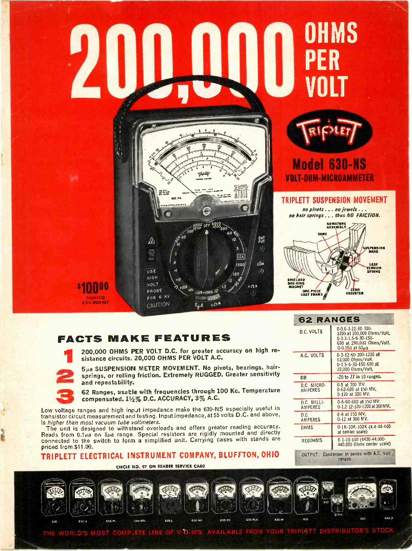
$10000SUGGESTED
U.S.A. USER NET
USEHIGH
VOLT
PROBEFOR 6 KV
CAUTION
6000 off40 -0,20003.0c--N
606. 60
I22
111
120
\\.I0 2 to./1,11100 ? VflA
sIOW.100K .12
Cit. I
to 0,3
FACTS MAKE FEATURES
2
OUTPUT
200,000 OHMS PER VOLT D.C. for greater accuracy on high re-sistance circuits. 20,000 OHMS PER VOLT A.C.
5Aa SUSPENSION METER MOVEMENT. No pivots, bearings, hair-springs, or rolling friction. Extremely RUGGED. Greater sensitivityand repeatability.62 Ranges, usable with frequencies through 100 Kc. Temperaturecompensated. 13212% D.C. ACCURACY, 3% A.C.
Low voltage ranges and high input impedance make the 630 -NS especially useful intransistor circuit measurement and testing. Input impedance, at 55 volts D.C. and above,is higher than most vacuum rube voltmeters.
The unit is designed to withstand overloads and offers greater reading accuracy.Reads from 0.1bia on 5,Lia range Special resistors are rigidly mounted and directlyconnected to the switch to form a simplified unit. Carrying cases with stands arepriced from $11.00.
TRIPLETT ELECTRICAL I NI STRUMENT COMPANY, BLUFFTON, OHIOCIRCLE ND. 97 ON READER SERVICE CARD
OHMS
PER
VOLT
Model 630 -NSVOLT-OHM-MICROAMMETER
TRIPLETT SUSPENSION MOVEMENTno pivots . .. no jewels . .
no hair springs . . thus NO FRICTION.
SUSPENSIONBAND
LEAFTENSIONSPRING
SHIELDEDBAR -RINGMAGNET
ONE-PIECECAST FRAME
62 RANGESD.C. VOLTS
0-0.6-3-12-60-300-1200 at 100,000 Ohms/Volt.0-0.3-1.5-6-30-150-600 at 200,000 Ohms/Volt.0-0.150 at 60ya
A.C. VOLTS 0-3-12-60-300-1200 at10,000 Ohms/Volt.0-1.5-6-30-150-600 at20,000 Ohms/Volt
DB -20 to 77 in 10 ranges.
D.C. MICRO-AMPERES
0-5 at 300 MV.0-60-600 at 150 MV.0-120 at 300 MV.
D.C. MILLI-AMPERES
0-6-60-600 at 150 MV.0-1.2-12-120-1200 at 300 MV.
D.C.AMPERES
0-6 at 150 MV.0-12 at 300 MV.
OHMS 0 -1K -10K -100K (4.4-44-440at center scale)
MEGOHMS 0-1-10-100 (4400-44,000-440.000 Ohms center scale)
OUTPUT: Condenser in series with A.C. Voltranges.
630 630-A 630 -PL 630 -APL 630.L 630 -NA 630M6 63041.8 630-31 631 ' 800 666-11
THE WORLD'S MOST COMP_ETE LINE OF V -b -M'S AVAILABLE FROM YOUR TRIPLET- -"/
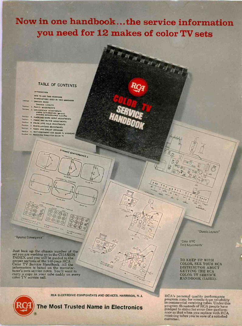
ow in one han book...the service informationyou need for 12 makes of color TV sets
Section
Section
Section
TABLE OF CONTENTS
INTRODUCTION
NOW TO USE THIS HANDBOOK
ABBREVIATIONS USED IN THIS HANDBOOK1. CHASSIS INDEX
CHASSIS LAYOUTS2. PURITY ADJUSTMENTS
J. CONVERGENCE ADJUSTMENTSSTATIC CONVERGENCE (Wm()DYNAMIC CONVERGENCE (specific)
Section 4. BLACK.AND.WHITE SETUP ADJUSTMENTSSection 5. PHASE AND MATRIX ADJUSTMENTSSection
S. COLOR AFPC FIELD ADJUSTMENTSSection 7, MISCELLANEOUS ADJUSTMENTSSection B. FUSES AND CIRCUIT BREAKERSSection 9. TEST EQUIPMENT FOR COLOR TV SERVICINGSection 10. RECEIVING TUBES FOR COLOR TV
'Dynamic Convergence',
Just look up the chassis number of theset you are working on in the CHASSIS /INDEX and you will be guided to theproper sections of the I40 -page RCAColor TV Service Handbook. All theinformation is based on the manufac-turer's own service notes. You'll want tocarry a copy in your tube caddy on everycolor TV service call.
';'2.(°'
RCA ELECTRONIC COMPONENTS PIND 'DEVICES, HARRISON, N.J.
The Most Trusted Name in Electronics
"Chassis Layouts"
"Color AFPCFie d Adjustments"
TO KEEP UP WITHCOLOR, SEE YOUR RCADISTRIBUTOR A BOUTGETTING THE RCACOLOR TV SERVICEHANDBOOK (1A1553).
RCA's personal quality performanceprogram aims for missile -type reliabilityin commercial receiving tubes. Under thisprogram thousands of RCA people havepledged to strive for error -free -perform-ance so that when you replace with RCAreceiving tubes you're sure of a satisfiedcustomer.
Related Documents


![MHO TESTING TECHNIQUES AND MATH [Read-Only] GUIDE Why have a MHO unit testing techniques and math lecture? Simplified explanation of a MHO unit Ohms law & phase to phase (ph-ph) MHO](https://static.cupdf.com/doc/110x72/5ac257cd7f8b9ad73f8df4fe/mho-testing-techniques-and-math-read-only-guide-why-have-a-mho-unit-testing-techniques.jpg)


