JMC – Joint Motion JMC – Joint Motion Controller Controller Complete guide to Complete guide to building and testing each building and testing each JMC JMC

JMC – Joint Motion Controller Complete guide to building and testing each JMC.
Jan 12, 2016
Welcome message from author
This document is posted to help you gain knowledge. Please leave a comment to let me know what you think about it! Share it to your friends and learn new things together.
Transcript

JMC – Joint Motion JMC – Joint Motion ControllerController
Complete guide to building and Complete guide to building and testing each JMCtesting each JMC

2 channel 24v Motor Controller2 channel 24v Motor ControllerThe motor controller is a flash programmable, compact servo driver that can be used for all of the power axes on the hubo. The amplifier stage contains the power electronics like the MOSFETs, filter capacitors, and current sensors.
On the controller board, The Controller Area Network interface connects to the main computer, converting drive commands into servo output. The controller board reads the motor encoder and uses a PD loop for position control.
Soldering the PCBSoldering the PCB
The density of parts and complexity of these circuits means that soldering and assembly has to be correct the first time. A good order to solder part is:
1. Large, dense chips such as quad-flat pack
2. Components with pads underneath the part that require a lot of room to reach
3. Chip resistors, capacitors, and diodes by size: By only soldering one kind of part at a time, the chance of choosing the wrong one accidentally is reduced.
4. Bulky components such as radial capacitors, MOSFETS, DC-DC converters, inductors, etc.
5. Headers and connectors
4
1
13
3
3
5
5
4
5
51
14
3

Check Solder JointsCheck Solder Joints
Bad Joints– Look tarnished or dirty– Lack solder– Have a bubble-like
appearance– parts crooked or tilted– have solder whiskers
or bridges between pins
• Pictures for each point (coming soon)

Check Solder JointsCheck Solder Joints
Good Joints– Have even distribution
of new solder– Look shiny and clean– Are aligned with the
pads– Have distinct edges
• Pictures for each point (coming soon)
ConnectorsConnectors
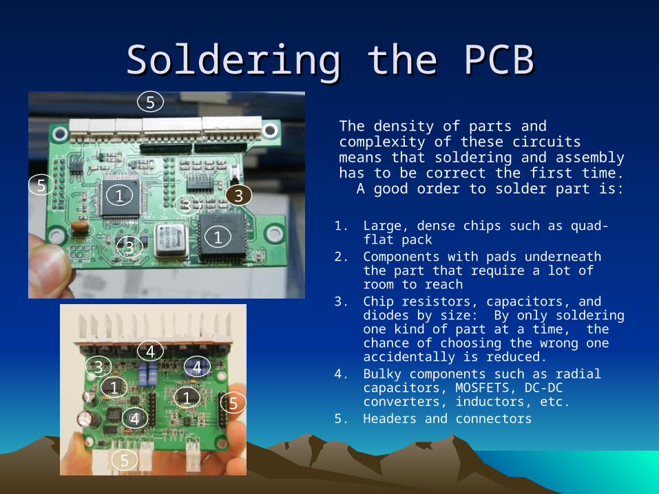
Connector layout
1. Encoder for Motor 1 (8 pins)
2. Encoder for Motor 2 (8 pins)
3. Pot 1 (ignore)
4. Pot 2 (ignore)
5. CAN Bus (2 pins)
6. 24V
7. 12V (do NOT plug 24V here)
8. Motor 1
9. Motor 2
MotorsMotors
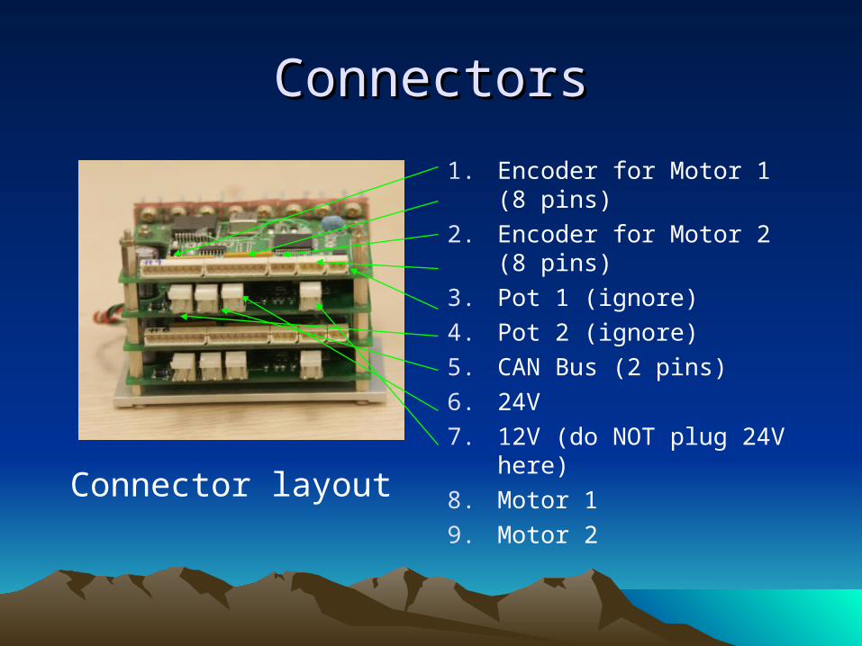
The leg joints use 90W and 400W motors to drive each of the 6 axes. Brush DC motors were chosen for their efficiency, as well as the simplicity of the controller.
For testing, the rack of motors is connected to the motor driver outputs. An embedded computer identical to that in the HUBO sends test commands to each axis, verifying that the joint motion is accurate.

CAN Bus OperationCAN Bus Operation
• 2 wire differential signal
• Address built into the signal to allow multiple devices on a common bus
• NRZ data transmission (similar to RS232)
• (need to research further, w/ diagrams)

Testing ProcedureTesting Procedure
In this section is the complete In this section is the complete procedure for testing a boardprocedure for testing a board

Flash ProgrammingFlash Programming
1. Open Codewarrior IDE for Motorola processors
2. Open file C:\Metrowerks_work\KHR_3_ALPHA\JMCxx\motor.mcp
3. Connect BDM (6 pins) to controller board, tilting it in the socket to contact all 6 pins (fiddle with this if necessary to get a good connection)
4. Run ‘Debugger’ (4th button) while BDM is connected (i.e. hold the connector in place with your finger)

Flash ProgrammingFlash Programming
5. Under the ‘ICD’ Menu, choose ‘Flash…’ to bring up the flash programming window.
6. Select the FLASHC000 (and ONLY that one) and press ‘Erase’ to clear the memory of old programs.
7. Load the new flash program in folder \bin\motor.abs
8. Hit ’Reset Target’, ignore the warning, and disconnect the BDM cable

Operating the Power supplyOperating the Power supply
The power distribution board connects to either the hubo's batteries or an external power supply. It delivers +/- 12V, 24V and 5V to the motor controllers and sensors.
• Switches 1 and 3 are computer power; Don’t touch during Operation
• Switch 2 toggles power to the controller (12V)
• Switch 7 controls power to the sensors (encoder, F/T)
• Switches 4,5, and 6 are not used in this test
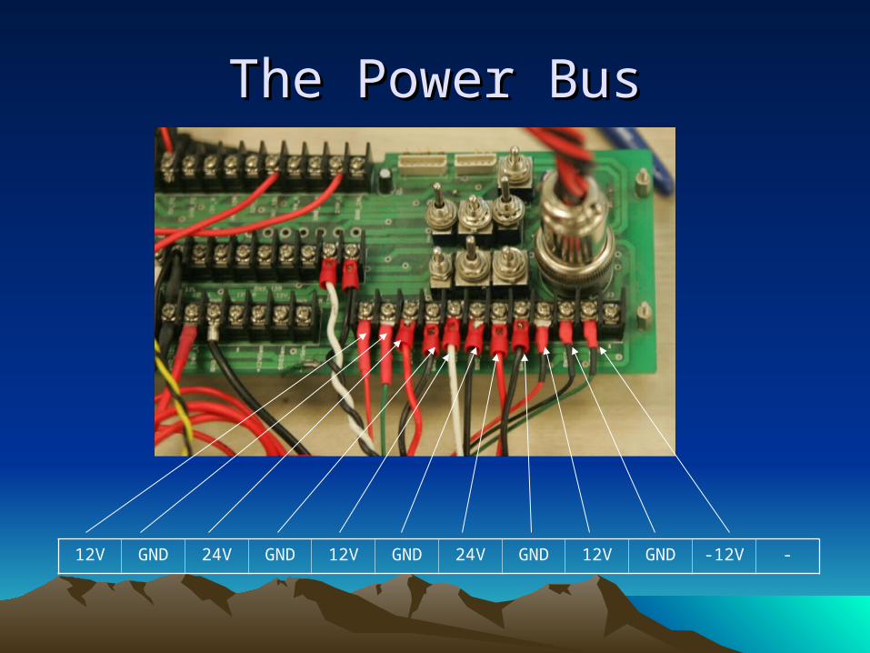
The Power BusThe Power Bus
12V GND 24V GND 12V GND 24V GND 12V GND -12V -

Joint Axis TestingJoint Axis Testing
1. Turn Power Supply OFF
2. Connect 24V, 12V, Motor 1, Motor 2, Encoder 1, Encoder 2, CAN Bus as shown
3. Load Startrack Test program
4. After verifying connections, turn on Power supply
5. Press START to connect to CAN and begin issuing commands

EncodersEncoders
1. Press CONTROL OFF to shut off power to the motors (for safety)
2. Press Encoder Zero to reset encoder values
3. Press Read Encoder to bring up the encoder data screen.
4. While manually turning the servomotor, you should see the connected encoders readout change

Power TestsPower Tests
1. Press ‘Open Loop Test’
2. Enter a value in the speed textbox
3. Press ‘RUN’ and verify motor is turning.
4. Press ‘Motor Position Control’
5. Enter a position for motor to seek and press Run

Future AdditionsFuture Additions
• Troubleshooting a non-functional board
• Schematics and functional diagrams
• F/T sensor assembly (strain), F/T signal conditioner (there are no spares currently, so I need to wait for this part)
• Connecting and operating the booster amplifier for the hip joint
Related Documents