Basic Operation 1 How to use the menu 2 How to use the menu2 3 Maintenance and Inspection 4 Installation 5 Appendix 6 JFC-800/JFC-810 Color Echo Sounder Instruction Manual

Welcome message from author
This document is posted to help you gain knowledge. Please leave a comment to let me know what you think about it! Share it to your friends and learn new things together.
Transcript
Basic Operation 1 How to use the menu 2 How to use the menu2 3 Maintenance and Inspection 4
Installation 5 Appendix 6
JFC-800/JFC-810
Color Echo Sounder
Instruction Manual


7ZPNA4625A i
Cautions for High Voltage
High voltages, ranging from several hundreds to tens of thousands of volts, are used in electronic apparatus, such as radio and radar instruments. These voltages are totally harmless in most operations. However, touching a component inside the unit is very dangerous. (Any person other than authorized service engineers should not maintain, inspect, or adjust the unit.)
High voltages on the order of tens of thousand volts are most likely to cause instant deaths from electrical shocks. At times, even voltages on the order of several hundred volts could lead to electrocution. To defend against electrical shock hazards, don't put your hand into the inside of apparatus. When you put in a hand unavoidably in case of urgent, it is strongly suggested to turn off the power switch and allow the capacitors, etc. to discharge with a wire having its one end positively grounded to remove residual charges. Before you put your hand into the inside of apparatus, make sure that internal parts are no longer charged. Extra protection is ensured by wearing dry cotton gloves at this time. Another important precaution to observe is to keep one hand in your pocket at a time, instead of using both hands at the same time.
It is also important to select a secure footing to work on, as the secondary effects of electrical shock hazards can be more serious. In the event of electrical shocks, disinfect the burnt site completely and obtain medical care immediately.

ii 7ZPNA4625A
Precautions for Rescue of Victim of Electric Shock
When a victim of electric shock is found, turn off the power source and ground the circuit immediately. If this is impossible, move the victim away from the unit as quick as possible without touching him or her with bare hands. He or she can safely be moved if an insulating material such as dry wood plate or cloth is used.
Breathing may stop if current flows through the respiration center of brain due to electric shock. If the electric shock is not large, breathing can be restored by artificial respiration. A victim of electric shock looks pale and his or her pulse may become very weak or stop, resulting in unconsciousness and rigidity at worst. It is necessary to perform first aid immediately.
7ZPNA4625A iii
Method of First-Aid Treatment
Precautions for First-Aid Treatments
Whenever a person is struck by an electrical shock, give the patient artificial respiration immediately on the spot, unless it is absolutely necessary to move the patient for safety's sake. Once started, artificial respiration should be continued rhythmically.
(1) Refrain from touching the patient carelessly as a result of the accident; the first-aider could suffer from electrical shocks by himself or herself.
(2) Turn off the power calmly and certainly, and move the patient apart from the cable gently.
(3) Call or send for a physician or ambulance immediately, or ask someone to call doctor.
(4) Lay the patient on the back, loosening the necktie, clothes, belts and so on.
(5) (a) Feel the patient's pulse.
(b) Check the heartbeat by bringing your ear close to the patient's heart.
(c) Check for respiration by bringing your face or the back of your hand to the patient's face.
(d) Check the size of patient's pupils.
(6) Opening the patient's mouth, remove artificial teeth, cigarettes, chewing gum, etc. if any. With the patient's mouth open, stretch the tongue and insert a towel or the like into the mouth to prevent the tongue from being withdrawn into the throat. (If the patient clenches the teeth so tight that the mouth won't open, use a screwdriver or the like to force the mouth open and then insert a towel or the like into the mouth.)
(7) Wipe off the mouth to prevent foaming mucus and saliva from accumulating.
iv 7ZPNA4625A
Treatment to Give When the Patient Has a Pulse Beating but Has Ceased to Breathe
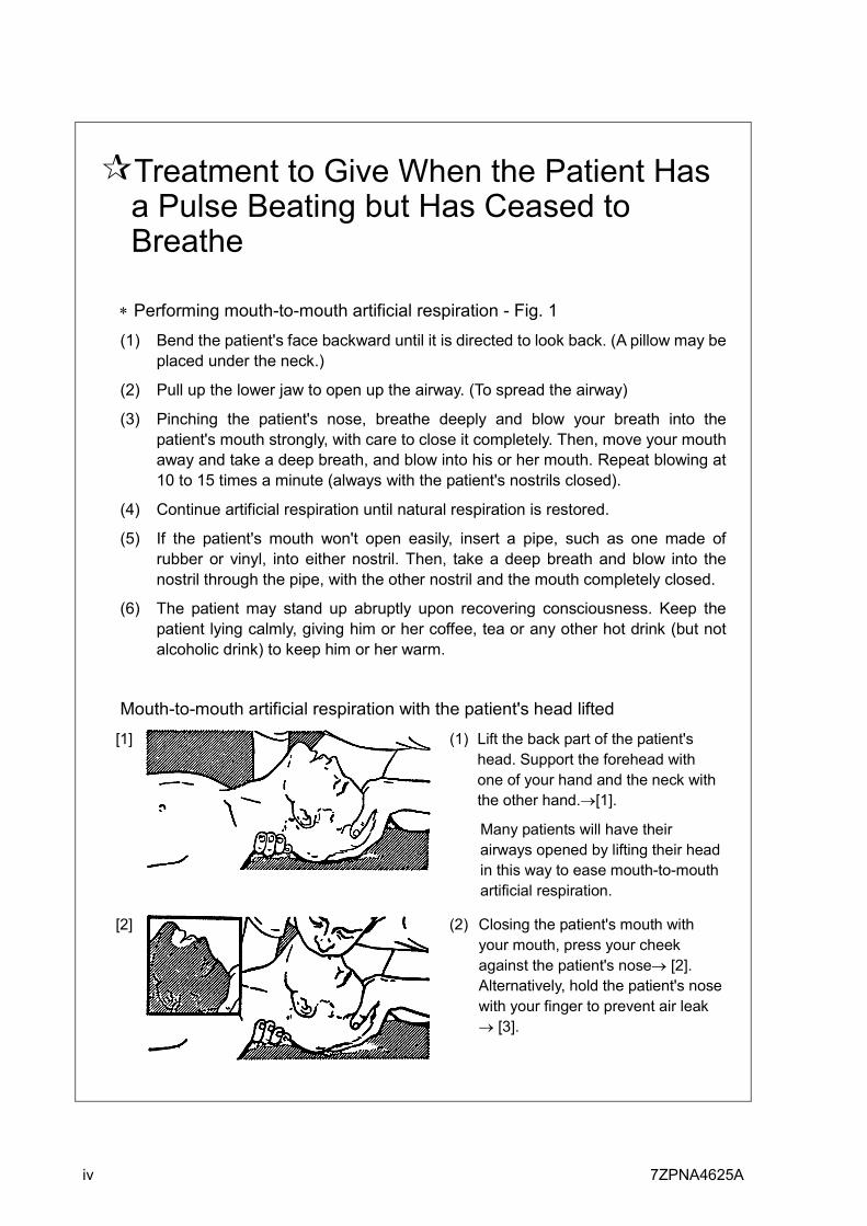
∗ Performing mouth-to-mouth artificial respiration - Fig. 1
(1) Bend the patient's face backward until it is directed to look back. (A pillow may be placed under the neck.)
(2) Pull up the lower jaw to open up the airway. (To spread the airway)
(3) Pinching the patient's nose, breathe deeply and blow your breath into the patient's mouth strongly, with care to close it completely. Then, move your mouth away and take a deep breath, and blow into his or her mouth. Repeat blowing at 10 to 15 times a minute (always with the patient's nostrils closed).
(4) Continue artificial respiration until natural respiration is restored.
(5) If the patient's mouth won't open easily, insert a pipe, such as one made of rubber or vinyl, into either nostril. Then, take a deep breath and blow into the nostril through the pipe, with the other nostril and the mouth completely closed.
(6) The patient may stand up abruptly upon recovering consciousness. Keep the patient lying calmly, giving him or her coffee, tea or any other hot drink (but not alcoholic drink) to keep him or her warm.
Mouth-to-mouth artificial respiration with the patient's head lifted
[1]
(1) Lift the back part of the patient's head. Support the forehead with one of your hand and the neck with the other hand.→[1].
Many patients will have their airways opened by lifting their head in this way to ease mouth-to-mouth artificial respiration.
[2]
(2) Closing the patient's mouth with your mouth, press your cheek against the patient's nose→ [2]. Alternatively, hold the patient's nose with your finger to prevent air leak → [3].

7ZPNA4625A v
[3]
(3) Blowing air into the patient's lungs. Blow air into the patient's lungs until chest is seen to rise. The first 10 breaths must be blown as fast as possible.
Fig. 1 Mouth-to-mouth artificial respiration
Treatment to Give When the Patient Has No Pulse Beating and Has Ceased to Breathe
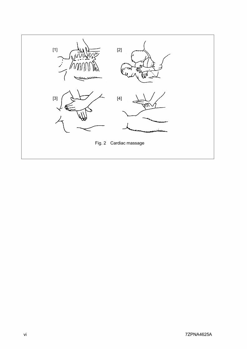
∗ Performing cardiac massage - Fig. 2
If the patient has no pulse beating, with the pupils open and no heartbeat being heard, the patient has a cardiac arrest and requires immediate artificial respiration. Continue this until a medical specialist arrives, and follow his or her directions after that.
(1) Putting one hand on about the lower one third of the patient's ribs and the other hand over the back of the first, with your elbow fully stretched (with bended elbow, you can’t press to the extent the patient’s ribs are depressed), apply your body weight to the hands to press the patient's body until it is depressed about 2 cm (Repeat this about 50 times a minute). (Cardiac massage)
(2) If only one first-aider is available, perform a cardiac massage about 15 times and then give mouth-to-mouth artificial respiration 2 times. Repeat this sequence.
If two first-aiders are available, while one person performs a cardiac massage 15 times, the other should give mouth-to-mouth artificial respiration 2 times. Repeat this sequence. (Combined cardiac massage and mouth-to-mouth artificial respiration method)
(3) Check the patient's pupils and feel the pulse from time to time. When the pupils are restored to normal and the pulse begins to beat regularly, stop treating and keep the patient calm while giving him or her coffee, tea or any other hot drink to keep him or her warm while watching him or her carefully.
vi 7ZPNA4625A
Fig. 2 Cardiac massage
[1]
[3]
[2]
[4]
7ZPNA4625A vii
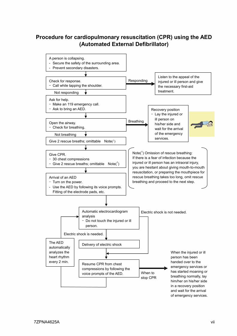
Procedure for cardiopulmonary resuscitation (CPR) using the AED (Automated External Defibrillator)
A person is collapsing. - Secure the safety of the surrounding area. - Prevent secondary disasters.
Check for response. - Call while tapping the shoulder.
Breathing
Recovery position - Lay the injured or
ill person on his/her side and wait for the arrival of the emergency services.
Not responding
Ask for help. - Make an 119 emergency call. - Ask to bring an AED.
Listen to the appeal of the injured or ill person and give the necessary first-aid treatment.
Responding
Not breathing
Give 2 rescue breaths; omittable Note(1)
Give CPR. - 30 chest compressions - Give 2 rescue breaths; omittable Note(1)
Note(1) Omission of rescue breathing: If there is a fear of infection because the injured or ill person has an intraoral injury, you are hesitant about giving mouth-to-mouth resuscitation, or preparing the mouthpiece for rescue breathing takes too long, omit rescue breathing and proceed to the next step.
Open the airway. - Check for breathing.
Arrival of an AED
- Turn on the power. - Use the AED by following its voice prompts. Fitting of the electrode pads, etc.
Automatic electrocardiogram analysis - Do not touch the injured or ill
person.
Electric shock is needed.
Electric shock is not needed.
Delivery of electric shock
Resume CPR from chest compressions by following the voice prompts of the AED.
When the injured or ill person has been handed over to the emergency services or has started moaning or breathing normally, lay him/her on his/her side in a recovery position and wait for the arrival of emergency services.
When to stop CPR
A person is collapsing. - Secure the safety of the surrounding area. - Prevent secondary disasters.
The AED automatically analyzes the heart rhythm every 2 min.
viii 7ZPNA4625A
Procedure for Cardiopulmonary Resuscitation (CPR) Using the AED (Automated External Defibrillator)
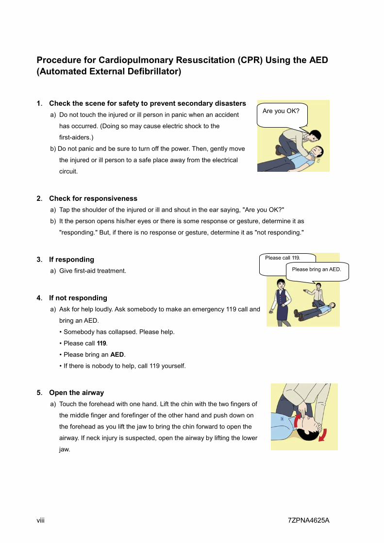
1. Check the scene for safety to prevent secondary disasters a) Do not touch the injured or ill person in panic when an accident
has occurred. (Doing so may cause electric shock to the
first-aiders.)
b) Do not panic and be sure to turn off the power. Then, gently move
the injured or ill person to a safe place away from the electrical
circuit.
2. Check for responsiveness a) Tap the shoulder of the injured or ill and shout in the ear saying, "Are you OK?"
b) It the person opens his/her eyes or there is some response or gesture, determine it as
"responding." But, if there is no response or gesture, determine it as "not responding."
3. If responding a) Give first-aid treatment.
4. If not responding a) Ask for help loudly. Ask somebody to make an emergency 119 call and
bring an AED.
• Somebody has collapsed. Please help.
• Please call 119.
• Please bring an AED.
• If there is nobody to help, call 119 yourself.
5. Open the airway a) Touch the forehead with one hand. Lift the chin with the two fingers of
the middle finger and forefinger of the other hand and push down on
the forehead as you lift the jaw to bring the chin forward to open the
airway. If neck injury is suspected, open the airway by lifting the lower
jaw.
Are you OK?
Please call 119.
Please bring an AED.
7ZPNA4625A ix
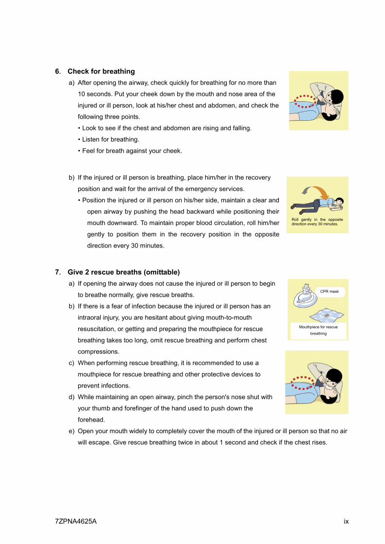
6. Check for breathing
a) After opening the airway, check quickly for breathing for no more than
10 seconds. Put your cheek down by the mouth and nose area of the
injured or ill person, look at his/her chest and abdomen, and check the
following three points.
• Look to see if the chest and abdomen are rising and falling.
• Listen for breathing.
• Feel for breath against your cheek.
b) If the injured or ill person is breathing, place him/her in the recovery
position and wait for the arrival of the emergency services.
• Position the injured or ill person on his/her side, maintain a clear and
open airway by pushing the head backward while positioning their
mouth downward. To maintain proper blood circulation, roll him/her
gently to position them in the recovery position in the opposite
direction every 30 minutes.
7. Give 2 rescue breaths (omittable) a) If opening the airway does not cause the injured or ill person to begin
to breathe normally, give rescue breaths.
b) If there is a fear of infection because the injured or ill person has an
intraoral injury, you are hesitant about giving mouth-to-mouth
resuscitation, or getting and preparing the mouthpiece for rescue
breathing takes too long, omit rescue breathing and perform chest
compressions.
c) When performing rescue breathing, it is recommended to use a
mouthpiece for rescue breathing and other protective devices to
prevent infections.
d) While maintaining an open airway, pinch the person's nose shut with
your thumb and forefinger of the hand used to push down the
forehead.
e) Open your mouth widely to completely cover the mouth of the injured or ill person so that no air
will escape. Give rescue breathing twice in about 1 second and check if the chest rises.
Roll gently in the opposite direction every 30 minutes.
CPR mask
Mouthpiece for rescue
breathing

x 7ZPNA4625A
8. Cardiopulmonary resuscitation (CPR) (combination of chest compressions and
rescue breaths) a) Chest compressions
1) Position of chest compressions
• Position the heel of one hand in the center of the chest, approximately between the
nipples, and place your other hand on top of the one that is in position.
2) Perform chest compressions
• Perform uninterrupted chest compressions
of 30 at the rate of about 100 times per
minute
• While locking your elbows positioning
yourself vertically above your hands.
• With each compression, depress the chest wall to a depth of approximately 4 to 5 cm.
b) Combination of 30 chest compressions and 2 rescue breaths
1) After performing 30 chest compressions, give 2 rescue
breaths. If rescue breathing is omitted, perform only chest
compressions.
2) Continuously perform the combination of 30 chest
compressions and 2 rescue breaths without interruption.
3) If there are two or more first-aiders, alternate with each other approximately every two
minutes (five cycles of compressions and ventilations at a ratio of 30:2) without interruption.
30 times
Compress with these parts (the heels of both hands).
2 times
7ZPNA4625A xi
9. When to stop cardiopulmonary resuscitation (CPR)
a) When the injured or ill person has been handed over to the emergency services
b) When the injured or ill person has started moaning or breathing normally, lay him/her on his/her
side in a recovery position and wait for the arrival of emergency services.
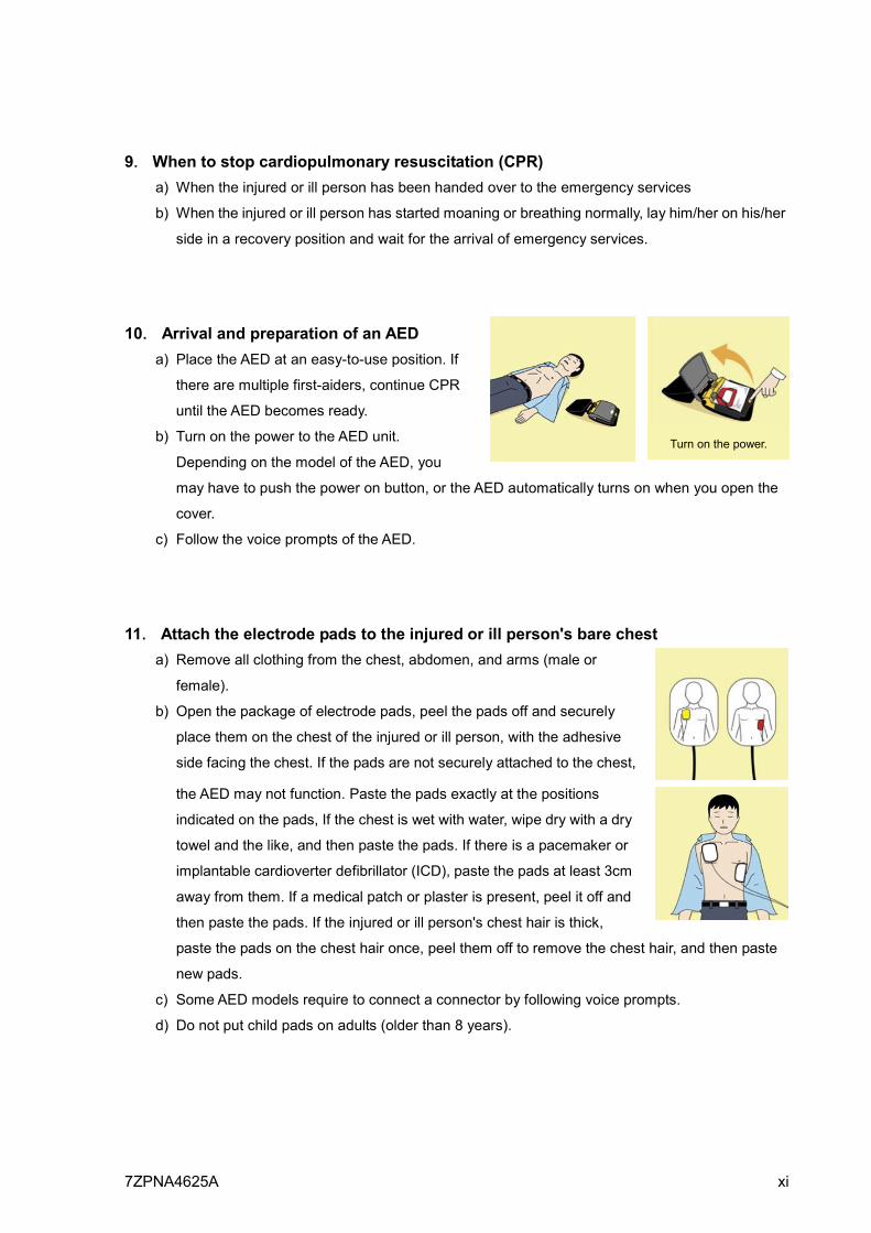
10. Arrival and preparation of an AED a) Place the AED at an easy-to-use position. If
there are multiple first-aiders, continue CPR
until the AED becomes ready.
b) Turn on the power to the AED unit.
Depending on the model of the AED, you
may have to push the power on button, or the AED automatically turns on when you open the
cover.
c) Follow the voice prompts of the AED.
11. Attach the electrode pads to the injured or ill person's bare chest a) Remove all clothing from the chest, abdomen, and arms (male or
female).
b) Open the package of electrode pads, peel the pads off and securely
place them on the chest of the injured or ill person, with the adhesive
side facing the chest. If the pads are not securely attached to the chest,
the AED may not function. Paste the pads exactly at the positions
indicated on the pads, If the chest is wet with water, wipe dry with a dry
towel and the like, and then paste the pads. If there is a pacemaker or
implantable cardioverter defibrillator (ICD), paste the pads at least 3cm
away from them. If a medical patch or plaster is present, peel it off and
then paste the pads. If the injured or ill person's chest hair is thick,
paste the pads on the chest hair once, peel them off to remove the chest hair, and then paste
new pads.
c) Some AED models require to connect a connector by following voice prompts.
d) Do not put child pads on adults (older than 8 years).
Turn on the power.
xii 7ZPNA4625A
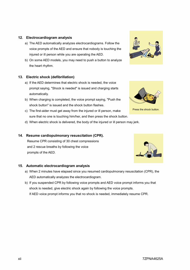
12. Electrocardiogram analysis a) The AED automatically analyzes electrocardiograms. Follow the
voice prompts of the AED and ensure that nobody is touching the
injured or ill person while you are operating the AED.
b) On some AED models, you may need to push a button to analyze
the heart rhythm.
13. Electric shock (defibrillation)
a) If the AED determines that electric shock is needed, the voice
prompt saying, "Shock is needed" is issued and charging starts
automatically.
b) When charging is completed, the voice prompt saying, "Push the
shock button" is issued and the shock button flashes.
c) The first-aider must get away from the injured or ill person, make
sure that no one is touching him/her, and then press the shock button.
d) When electric shock is delivered, the body of the injured or ill person may jerk.
14. Resume cardiopulmonary resuscitation (CPR).
Resume CPR consisting of 30 chest compressions
and 2 rescue breaths by following the voice
prompts of the AED.
15. Automatic electrocardiogram analysis a) When 2 minutes have elapsed since you resumed cardiopulmonary resuscitation (CPR), the
AED automatically analyzes the electrocardiogram.
b) If you suspended CPR by following voice prompts and AED voice prompt informs you that
shock is needed, give electric shock again by following the voice prompts.
If AED voice prompt informs you that no shock is needed, immediately resume CPR.
Press the shock button.
7ZPNA4625A xiii
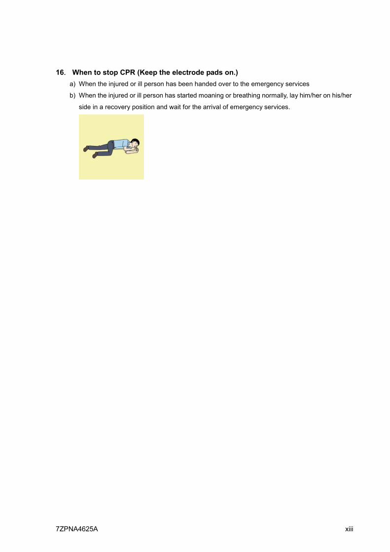
16. When to stop CPR (Keep the electrode pads on.) a) When the injured or ill person has been handed over to the emergency services
b) When the injured or ill person has started moaning or breathing normally, lay him/her on his/her
side in a recovery position and wait for the arrival of emergency services.
PREFACE JFC-800/JFC-810
xiv 7ZPNA4625A
PREFACE
• For copy and transcription of this Instruction Manual (hereinafter referred to as this manual),
permission from JRC is needed. JRC prohibits the un-authorized copy and transcription of this
manual.
• If this manual is lost or damaged, consult a dealer of JRC or JRC.
• The specification of the products and the contents in this manual are subject to change without
notice.
• The contents displayed on the menu of product may be different from the expression of this
manual. The fonts and shapes of the keys and menus in the illustration may differ from the actual
ones, and some parts may be omitted.
• JRC is not liable for damages and troubles arisen from misunderstanding of the contents in this
manual.
• JRC is not liable for any damages caused by earthquake, lightning, wind and flood damage and
fire for which JRC is not responsible, and actions by third parties, other accidents, customer’s
unintended error/abuse and the use under other abnormal conditions.
• JRC is not liable for damages of accompaniment (change/loss of memorized content, loss of
business profit, stop of business) arisen from use or failure of our products.
• If the stored data are changed or lost, irrespective of causes of troubles and damages, JRC is not
liable for them.
• JRC is not liable for any damages arisen from malfunction caused by combination of software and
connected equipment in which JRC is not engaged.
If there was an offer from the other ships for interference mitigation, in the order of the wideband echo
sounder, the echo sounder using multiple frequency and the echo sounder using a single frequency,
please take measures of change of use frequency and the reduction of the transmitting sound
pressure level.
JFC-800/JFC-810 Before Operation
7ZPNA4625A xv
Before Operation
Pictorial Indication
Various pictorial indications are included in this Instruction manual and are shown on this equipment so that you can operate them safely and correctly and prevent any danger to you and / or to other persons and any damage to your property during operation. Such indications and their meanings are as follows.
Please understand them before you read this manual:
DANGER
This indication is shown where incorrect equipment operation due to negligence may cause death or serious injuries.
WARNING
This indication is shown where any person is supposed to be in danger of being killed or seriously injured if this indication is neglected and these equipment are not operated correctly.
CAUTION This indication is shown where any person is
supposed to be injured or any property damage is supposed to occur if this indication is neglected and these equipment are not operated correctly.
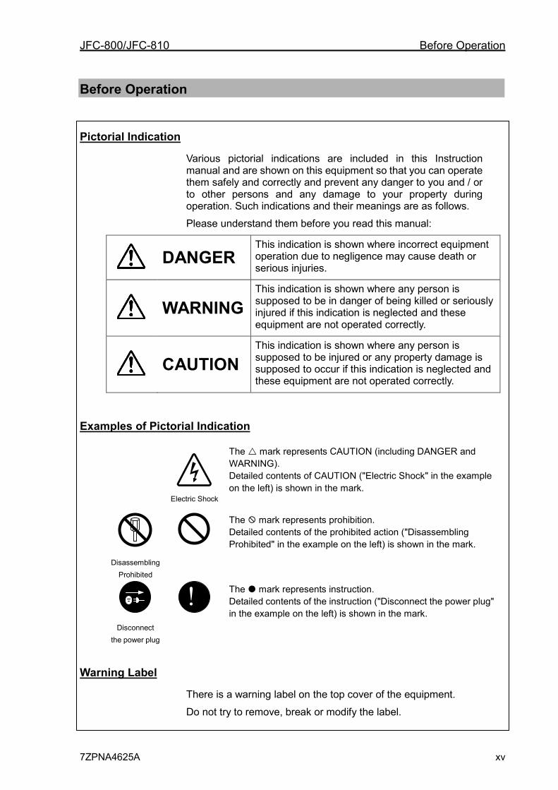
Examples of Pictorial Indication
Electric Shock
The mark represents CAUTION (including DANGER and WARNING). Detailed contents of CAUTION ("Electric Shock" in the example on the left) is shown in the mark.
Disassembling
Prohibited
The mark represents prohibition. Detailed contents of the prohibited action ("Disassembling Prohibited" in the example on the left) is shown in the mark.
Disconnect
the power plug
!
The mark represents instruction. Detailed contents of the instruction ("Disconnect the power plug" in the example on the left) is shown in the mark.
Warning Label
There is a warning label on the top cover of the equipment.
Do not try to remove, break or modify the label.
Before Operation JFC-800/JFC-810
xvi 7ZPNA4625A
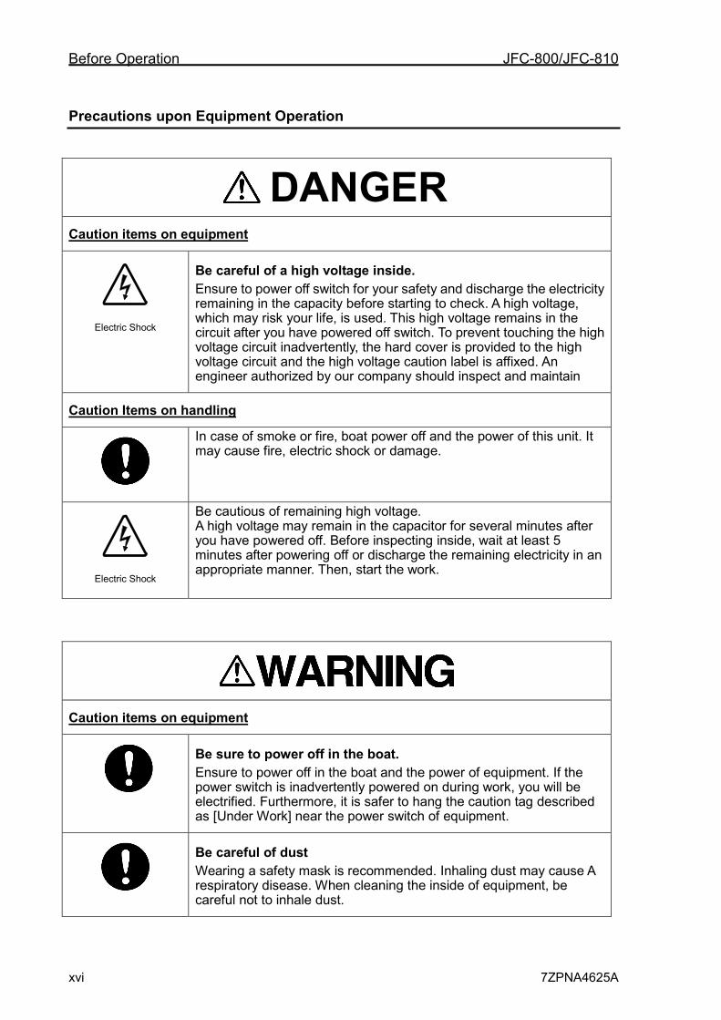
Precautions upon Equipment Operation
DANGER
Caution items on equipment
Electric Shock
Be careful of a high voltage inside. Ensure to power off switch for your safety and discharge the electricity remaining in the capacity before starting to check. A high voltage, which may risk your life, is used. This high voltage remains in the circuit after you have powered off switch. To prevent touching the high voltage circuit inadvertently, the hard cover is provided to the high voltage circuit and the high voltage caution label is affixed. An engineer authorized by our company should inspect and maintain
Caution Items on handling
In case of smoke or fire, boat power off and the power of this unit. It may cause fire, electric shock or damage.
Electric Shock
Be cautious of remaining high voltage. A high voltage may remain in the capacitor for several minutes after you have powered off. Before inspecting inside, wait at least 5 minutes after powering off or discharge the remaining electricity in an appropriate manner. Then, start the work.
Caution items on equipment
Be sure to power off in the boat. Ensure to power off in the boat and the power of equipment. If the power switch is inadvertently powered on during work, you will be electrified. Furthermore, it is safer to hang the caution tag described as [Under Work] near the power switch of equipment.
Be careful of dust Wearing a safety mask is recommended. Inhaling dust may cause A respiratory disease. When cleaning the inside of equipment, be careful not to inhale dust.
JFC-800/JFC-810 Before Operation
7ZPNA4625A xvii
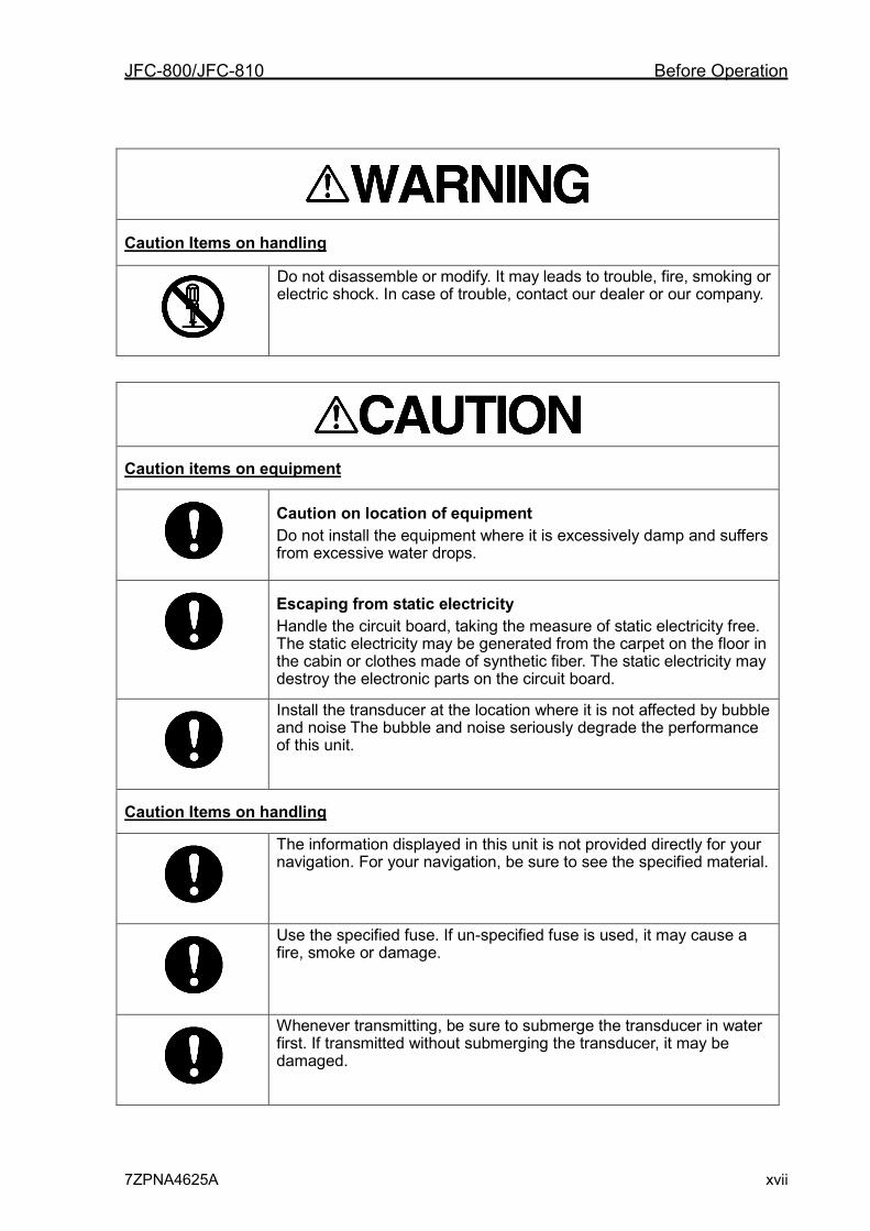
Caution Items on handling
Do not disassemble or modify. It may leads to trouble, fire, smoking or electric shock. In case of trouble, contact our dealer or our company.
Caution items on equipment
Caution on location of equipment Do not install the equipment where it is excessively damp and suffers from excessive water drops.
Escaping from static electricity Handle the circuit board, taking the measure of static electricity free. The static electricity may be generated from the carpet on the floor in the cabin or clothes made of synthetic fiber. The static electricity may destroy the electronic parts on the circuit board.
Install the transducer at the location where it is not affected by bubble and noise The bubble and noise seriously degrade the performance of this unit.
Caution Items on handling
The information displayed in this unit is not provided directly for your navigation. For your navigation, be sure to see the specified material.
Use the specified fuse. If un-specified fuse is used, it may cause a fire, smoke or damage.
Whenever transmitting, be sure to submerge the transducer in water first. If transmitted without submerging the transducer, it may be damaged.
Contents JFC-800/JFC-810
xviii 7ZPNA4625A
Contents Caution ................................................. i PREFACE ............................................. xiv Before Operation ..................................... xv
Pictorial Indication .................. xv Examples of Pictorial Indication ............................... xv Warning Label ........................ xv Precautions upon Equipment Operation .............................. xvi
Contents ............................................. xviii
Chapter 1 Basic Operation ...................... 1-1 1.1 Functions .................................... 1-1
1.2 Features ..................................... 1-1
1.3 Configuration of Equipment ........ 1-2
1.4 System Configuration ................. 1-5
1.5 Frequency .................................. 1-6
Setting of Output Frequency ...... 1-6
Setting of Power Frequency ....... 1-6
Adjustment of bottom detection.. 1-7
1.6 How to use the key ..................... 1-8
1.7 Power On/Off .............................. 1-9
Power on .................................... 1-9
Power off .................................... 1-9
Alarm of Power Voltage .............. 1-9
1.8 LCD Brilliance Adjustment ........ 1-10
Adjustment of LCD Brilliance ... 1-10
Brightness Adjustment of Panel
Brilliance ................................... 1-10
1.9 Switch-over of Display mode .... 1-10
Normal Image (Low frequency,
High frequency) ........................ 1-10
Dual frequency ......................... 1-11
Zoom (Low frequency, High
frequency) ................................ 1-11
Navigation Menu
(NAV1, NAV2) ........................... 1-13
1.10 Selection of NAV Display ......... 1-14
Type of NAV Display ................ 1-14
Selection of NAV Menu ............ 1-14
1.11 Switch-over of Range ............... 1-15
Setting the range switching to auto
range ........................................ 1-15
Setting the range switching to
Manual range ........................... 1-15
1.12 Setting of Shift .......................... 1-15
Setting of Manual Shift ............. 1-15
Release of manual Shift ........... 1-16
Setting of Auto Shift .................. 1-16
1.13 Gain Adjustment ....................... 1-17
TVG .......................................... 1-17
1.14 Use of [EVENT] key ................. 1-17
Selecting the event key
function ..................................... 1-18
Presetting the waypoint ............ 1-18
Store the image ........................ 1-19
Fishing hot spot ........................ 1-19
1.15 Use of [F1] / [F2] key ................ 1-20
Selecting the
[F1] / [F2] key ........................... 1-20
Preset of [F1] / [F2] key ............ 1-20
1.16 Operation of VRM .................... 1-20
1.17 Display of fish information ........ 1-21
Display the fish symbol / Stop the
display of fish symbol ............... 1-21
Selecting the symbol info ......... 1-21
Fish symbol detection
adjustment ................................ 1-22
Size adjustment ........................ 1-22
Big fish / Big fish color .............. 1-22
Points to note in use of fish
symbol ...................................... 1-23
Chapter 2 How to use the menu ............. 2-1
JFC-800/JFC-810 Contents
7ZPNA4625A xix
2.1 How to operate the menu .......... 2-1
Display the menu / Stop the
display of menu .......................... 2-1
Menu Operation ......................... 2-1
2.2 Changing of Image Speed ......... 2-2
2.3 Rejection of Interference ............ 2-2
Interference Rejection ................ 2-2
2.4 Color Rejection of Weak Echo ... 2-3
Color Rejection .......................... 2-3
2.5 Rejection of Noise ...................... 2-3
Noise Rejection .......................... 2-3
2.6 Setting of Shift step .................... 2-3
2.7 Selection of Zoom ...................... 2-3
2.8 Setting of Zoom Range .............. 2-4
2.9 Setting of Zoom Start ................. 2-4
2.10 Preset of Range ......................... 2-4
Easy registration method of the
range .......................................... 2-5
2.11 Setting of Background Color ...... 2-5
2.12 Setting of White Line .................. 2-5
2.13 Setting of Alarm .......................... 2-6
Stopping the alarm sound .......... 2-6
Setting the alarm ........................ 2-7
Release the alarm ...................... 2-7
Confirm the alarm state .............. 2-7
2.14 Preset/ WPT edit/ WPT delete of
Waypoint ................................... 2-8
NAV Start .................................... 2-8
Cancel the NAV .......................... 2-8
Edit the destination .................... 2-8
Delete the waypoint ................... 2-9
Recall the stored image and
preset it as a destination ............ 2-9
2.15 Store/Recall/Deletion of Image 2-10
Store the image ........................ 2-10
Recall the stored image ........... 2-10
Delete the stored image ........... 2-11
Add the comment to the stored
image ....................................... 2-11
2.16 Explanation of Sona-ToneTM .... 2-12
Switch-over of Sona-ToneTM .... 2-12
Connection of External
Speaker .................................... 2-12
2.17 Explanation of Menu Item ........ 2-12
Inner-hull .................................. 2-12
Change the TX power .............. 2-13
Change the Pulse width ........... 2-13
Change the Bandwidth ............. 2-13
D.Range ................................... 2-14
Display Width ........................... 2-14
Display the A scope / Stop the
display of A scope .................... 2-14
Change the display color of echo
sounder image ......................... 2-14
Change the depth value ........... 2-14
Display the depth unit / Stop the
display of depth unit ................. 2-14
Display the water temp graph /
Stop the display of water temp
graph ........................................ 2-15
Setting of the background color of
NAV display .............................. 2-15
Setting of the echo sounder
display at NAV display ............. 2-15
Image Swap ............................. 2-15
Display the Operation guide /
Stop the display of Operation
guide ........................................ 2-15
Display the detection area /
Stop the display of detection
area .......................................... 2-15
Setting of Scale display............ 2-16
Change the scale value ........... 2-16
Change the image direction ..... 2-16
Setting of Depth measurement 2-16
Change the display color ......... 2-16
Setting of Key lock ................... 2-16
Sub Depth Value ...................... 2-17
Contents JFC-800/JFC-810
xx 7ZPNA4625A
Change the User setting .......... 2-17
Change the scale type ............. 2-17
Change the bottom color .......... 2-17
Change the image partition ...... 2-17
Display the Frequency /Stop the
display of Frequency ................ 2-17
Selecting a display area of fish
symbol indication ...................... 2-18
Chapter 3 How to use the menu2 ............ 3-1 3.1 Display of Menu ......................... 3-1
Display the menu ....................... 3-1
Return to the normal menu ........ 3-1
3.2 Setting of External Input/Output . 3-1
Buzzer Setting ............................ 3-1
Temp Source .............................. 3-1
Speed Source ............................. 3-1
Baud Rate .................................. 3-1
NMEA Monitor ............................ 3-2
NMEA Output Data ..................... 3-2
External synchronous input ........ 3-2
Unreceived synchronization ....... 3-2
3.3 Setting of Correction Item .......... 3-3
Draft Set ..................................... 3-3
Sonic Speed ............................... 3-3
Water Temp ................................ 3-3
Boat Speed ................................. 3-3
Directivity angle (Low/High) ....... 3-3
Bubble ........................................ 3-3
Bubble time set........................... 3-3
3.4 Setting of Basic Set Item ............ 3-3
Language ................................... 3-3
Range & Speed Unit ................... 3-3
Depth Unit .................................. 3-3
Temperature Unit ........................ 3-4
Local time Offset ........................ 3-4
GPS select ................................. 3-4
GPS initialize .............................. 3-4
3.5 Maintenance Menu ..................... 3-4
Simulation................................... 3-4
Slide show .................................. 3-4
Initialize ...................................... 3-4
System Check ............................ 3-4
All WPTs deletes ........................ 3-4
All stored image deletes ............. 3-4
Bottom start ................................ 3-4
Past image ................................. 3-4
Inner-hull .................................... 3-5
3.6 Setting of Adjust2 Item ............... 3-5
STC strength adjust Low / High . 3-5
STC depth adjust Low / High ..... 3-5
Color adjust ................................ 3-5
Image speed adjust .................... 3-5
Bottom limit................................. 3-5
Sounding .................................... 3-6
3.7 Frequency Select ....................... 3-6
Frequency select ........................ 3-6
Power frequency adjustment ..... 3-6
Chapter 4 Maintenance and Inspection ... 4-1 4.1 Inspection ................................... 4-1
4.2 Cleaning ..................................... 4-1
Display unit ................................. 4-1
Transducer ................................. 4-1
4.3 Fuse Replacement ..................... 4-2
4.4 If you suspect a trouble .............. 4-2
4.5 Diagnostic Test ........................... 4-3
Diagnose .................................... 4-3
Confirm the version .................... 4-3
Return to the menu .................... 4-3
Chapter 5 Installation .............................. 5-1 5.1 Items of Caution on Installation .. 5-1
Unpacking the components ........ 5-1
Inspection of components and
accessories ................................ 5-1
Decision of Installing Location.... 5-1
Laying and Connection of
Cable .......................................... 5-2
JFC-800/JFC-810 Contents
7ZPNA4625A xxi
Confirmation after Installation .... 5-2
5.2 Installation of Display unit .......... 5-3
Desk-top Installation .................. 5-3
Flush-mount Installation ............. 5-5
5.3 Installation of Transducer ........... 5-6
In case of Inner-hull
for TD-501C ............................... 5-6
5.4 Wiring ......................................... 5-7
Connection of Cable to Display
unit ............................................. 5-7
Pin Assignment of Rear
Connector .................................. 5-8
Connection of Power Cable ....... 5-9
Connection of Transducer .......... 5-9
Connection with external echo
sounder .................................... 5-10
Connection with external
navigation equipment ............... 5-10
Connection with Speed Sensor or
Water Temperature Sensor
(Option) .................................... 5-11
Connection of External Speaker
for Sona- ToneTM (J2)
(Prepared by a customer) ........ 5-12
Connection of External Monitor
(J5) (Prepared by a customer) . 5-12
5.5 Serial Data ............................... 5-13
Input Data................................. 5-13
Output Data .............................. 5-13
Chapter 6 Appendix ................................ 6-1 6.1 Menu List ................................... 6-1
6.2 Specification ............................... 6-5
6.3 Dimensions ................................ 6-6

Contents JFC-800/JFC-810
xxii 7ZPNA4625A
JFC-800/JFC-810 Chapter 1 Basic Operation
7ZPNA4625A 1-1
1 2 3 4 5 6 7 8 9 10 11 12 13 14 15 16 17 18 19 20 21 22 23 24 25 26 付録
Chapter 1 Basic Operation
1.1 Functions
The JFC-800/JFC-810 is a Dual frequency Color LCD display echo sounder.
This unit equipped with digital process displays the circumstance in the water under all conditions, matching with the high luminance 10.4 inch LCD.
1.2 Features
The main features of this unit are as follows:
● With the digital reception process, the compatibility of the high resolution in a shallow depth and the noise rejection capability in a deep depth are established. The auto mode function provides the best image.
● The high-performance LCD maintains high visibility under any conditions.
● The unit can be installed in an open bridge and is highly waterproof.
● Sona-Tone (Sonar sound) function is equipped with for catching situations schools of fish and others by sound.
● Up to 10 images can be stored. If you connect the optional GPS, the fishing hot spot function, that directs your boat to navigate easily to the location desired, is available by marking the event mark when recalling the stored image.
● With the adoption of a specific filter (AR coat), an image can be seen clearly, refusing sunshine. The countermeasures against the reflection on the LCD screen and dew are provided. This display has a high level of visibility under all operation conditions.
● The various alarm functions are available. (Bottom, school of fish, water temperature*, board speed*, arrival*, XTE*, power) (Note: The mark * denotes that the connection of option is mandatory)
● When flush-mounting, the unit can be easily installed from front side.
● The RGB output for an external monitor is provided as standard equipment. The use of the external monitor enables you to observe easily the echo sounder screen at a location which is remote from a main unit. (External monitor: Prepared by a customer)
Chapter 1 Basic Operation JFC-800/JFC-810
1-2 7ZPNA4625A
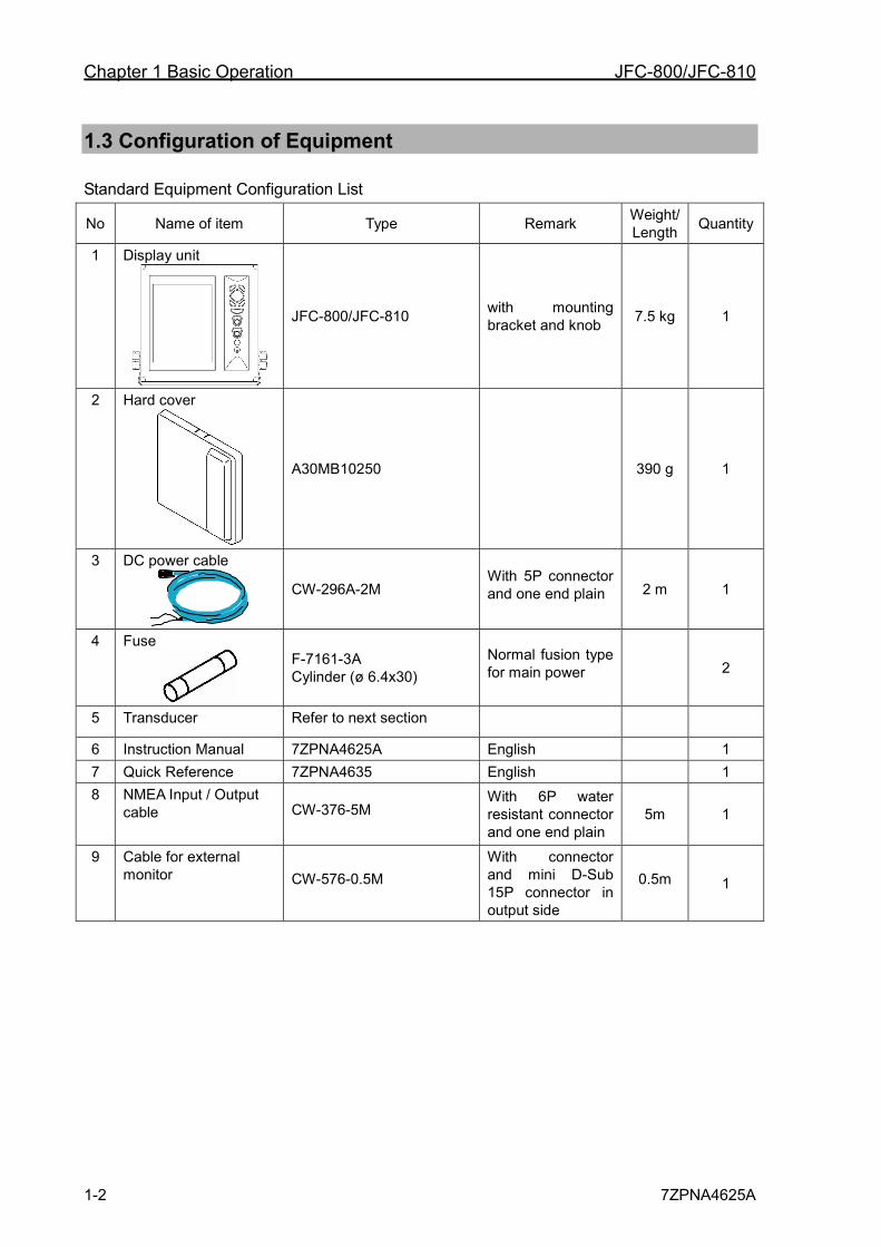
1.3 Configuration of Equipment
Standard Equipment Configuration List
No Name of item Type Remark Weight/ Length Quantity
1 Display unit
JFC-800/JFC-810 with mounting bracket and knob 7.5 kg 1
2 Hard cover
A30MB10250 390 g 1
3 DC power cable
CW-296A-2M With 5P connector and one end plain 2 m 1
4 Fuse
F-7161-3A Cylinder (ø 6.4x30)
Normal fusion type for main power 2
5 Transducer Refer to next section
6 Instruction Manual 7ZPNA4625A English 1 7 Quick Reference 7ZPNA4635 English 1 8 NMEA Input / Output
cable CW-376-5M With 6P water resistant connector and one end plain
5m 1
9 Cable for external monitor CW-576-0.5M
With connector and mini D-Sub 15P connector in output side
0.5m 1
JFC-800/JFC-810 Chapter 1 Basic Operation
7ZPNA4625A 1-3
1 2 3 4 5 6 7 8 9 10 11 12 13 14 15 16 17 18 19 20 21 22 23 24 25 26 付録
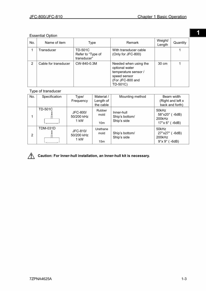
Essential Option
No. Name of item Type Remark Weight/ Length Quantity
1 Transducer TD-501C Refer to “Type of transducer”
With transducer cable (Only for JFC-800)
1
2 Cable for transducer CW-840-0.3M Needed when using the optional water temperature sensor / speed sensor (For JFC-800 and TD-501C)
30 cm 1
Type of transducer No. Specification Type/
Frequency Material / Length of the cable
Mounting method Beam width (Right and left x back and forth)
1
TD-501C
JFC-800/ 50/200 kHz
1 kW
Rubber mold
10m
Inner-hull Ship’s bottom/ Ship’s side
50kHz 58°x20° ( -6dB)
200kHz 17°x 6° ( -6dB)
2
TDM-031D
JFC-810/ 50/200 kHz
1 kW
Urethane mold
15m
Ship’s bottom/ Ship’s side
50kHz 27°x27° ( -6dB)
200kHz 9°x 9° ( -6dB)
Caution: For Inner-hull installation, an Inner-hull kit is necessary.
Chapter 1 Basic Operation JFC-800/JFC-810
1-4 7ZPNA4625A
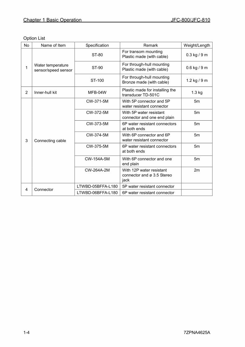
Option List No Name of Item Specification Remark Weight/Length
1 Water temperature sensor/speed sensor
ST-80 For transom mounting Plastic made (with cable) 0.3 kg / 9 m
ST-90 For through-hull mounting Plastic made (with cable) 0.6 kg / 9 m
ST-100 For through-hull mounting Bronze made (with cable) 1.2 kg / 9 m
2 Inner-hull kit MFB-04W Plastic made for installing the transducer TD-501C 1.3 kg
3 Connecting cable
CW-371-5M With 5P connector and 5P water resistant connector
5m
CW-372-5M With 5P water resistant connector and one end plain
5m
CW-373-5M 6P water resistant connectors at both ends
5m
CW-374-5M With 6P connector and 6P water resistant connector
5m
CW-375-5M 6P water resistant connectors at both ends
5m
CW-154A-5M With 6P connector and one end plain
5m
CW-264A-2M With 12P water resistant connector and ø 3.5 Stereo jack
2m
4 Connector LTWBD-05BFFA-L180 5P water resistant connector LTWBD-06BFFA-L180 6P water resistant connector
JFC-800/JFC-810 Chapter 1 Basic Operation
7ZPNA4625A 1-5
1 2 3 4 5 6 7 8 9 10 11 12 13 14 15 16 17 18 19 20 21 22 23 24 25 26 付録
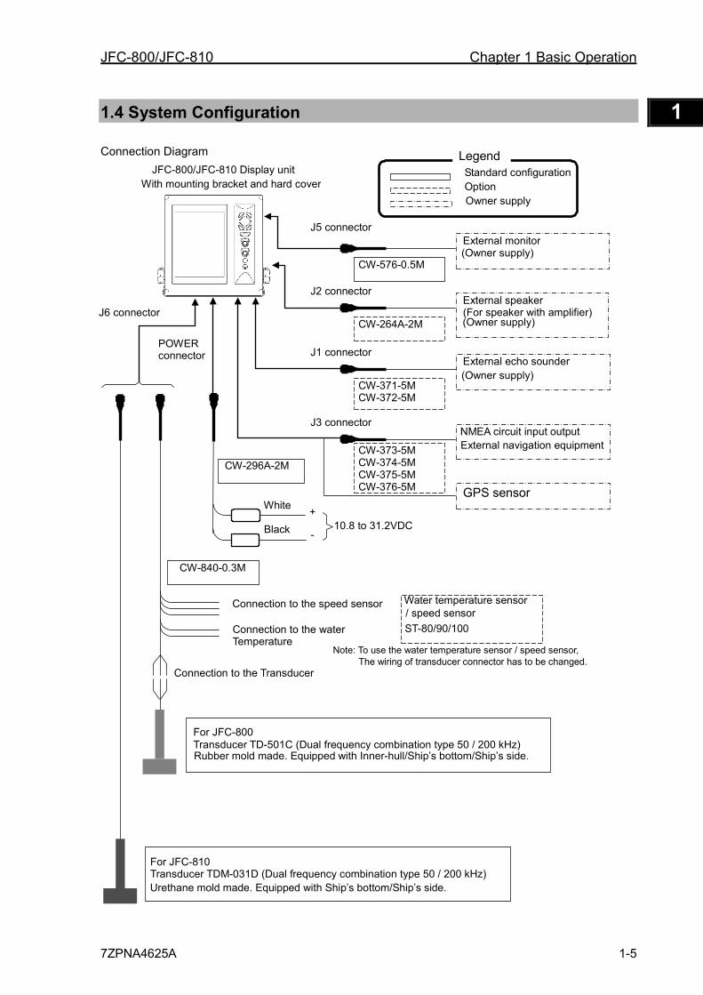
1.4 System Configuration
Connection Diagram
White
Black +
-
Connection to the Transducer
Connection to the speed sensor
Connection to the water Temperature
POWER connector
J6 connector
J5 connector External monitor
CW-576-0.5M (Owner supply)
CW-296A-2M
10.8 to 31.2VDC
CW-840-0.3M
External speaker (For speaker with amplifier)
CW-264A-2M (Owner supply)
J2 connector
External echo sounder
CW-371-5M CW-372-5M
(Owner supply)
J1 connector
NMEA circuit input output CW-373-5M
CW-374-5M CW-375-5M CW-376-5M
External navigation equipment
J3 connector
GPS sensor
JFC-800/JFC-810 Display unit With mounting bracket and hard cover
Standard configuration Option Owner supply
Legend
Note: To use the water temperature sensor / speed sensor, The wiring of transducer connector has to be changed.
Rubber mold made. Equipped with Inner-hull/Ship’s bottom/Ship’s side.
For JFC-800 Transducer TD-501C (Dual frequency combination type 50 / 200 kHz)
For JFC-810 Transducer TDM-031D (Dual frequency combination type 50 / 200 kHz) Urethane mold made. Equipped with Ship’s bottom/Ship’s side.
Water temperature sensor
ST-80/90/100
/ speed sensor
Chapter 1 Basic Operation JFC-800/JFC-810
1-6 7ZPNA4625A
1.5 Frequency JFC-800 / JFC-810 is used with the other transducer, please make sure to set the below items manually in line with the transducer installed.
Caution: When you do the wrong setting, there is a risk of breakage to the transducer. Caution: By the transmission frequency, noise increased,may not be able to connect. Caution: Fish symbol function in except High frequency 200kHz and Low frequency
50kHz cannot be guaranteed. Setting of Output Frequency
1 Press the [MENU] key.
2 Select [Freq] → [Freq select ]. (See [2.1 How to operate the menu])
3 Press the [ ] key.
4 Set the output frequency. (Press the [ ] key or [ ] key)
5 Press the [MENU] key. Then, the edit is finished.
Caution: If you want to use in the two-frequency it is only setting of (50 / 200kHz).
Setting of Power Frequency 1 Press the [MENU] key.
2 Select [Freq] → [Power freq adj]. (See [2.1 How to operate the menu])
3 Press the [ ] key.
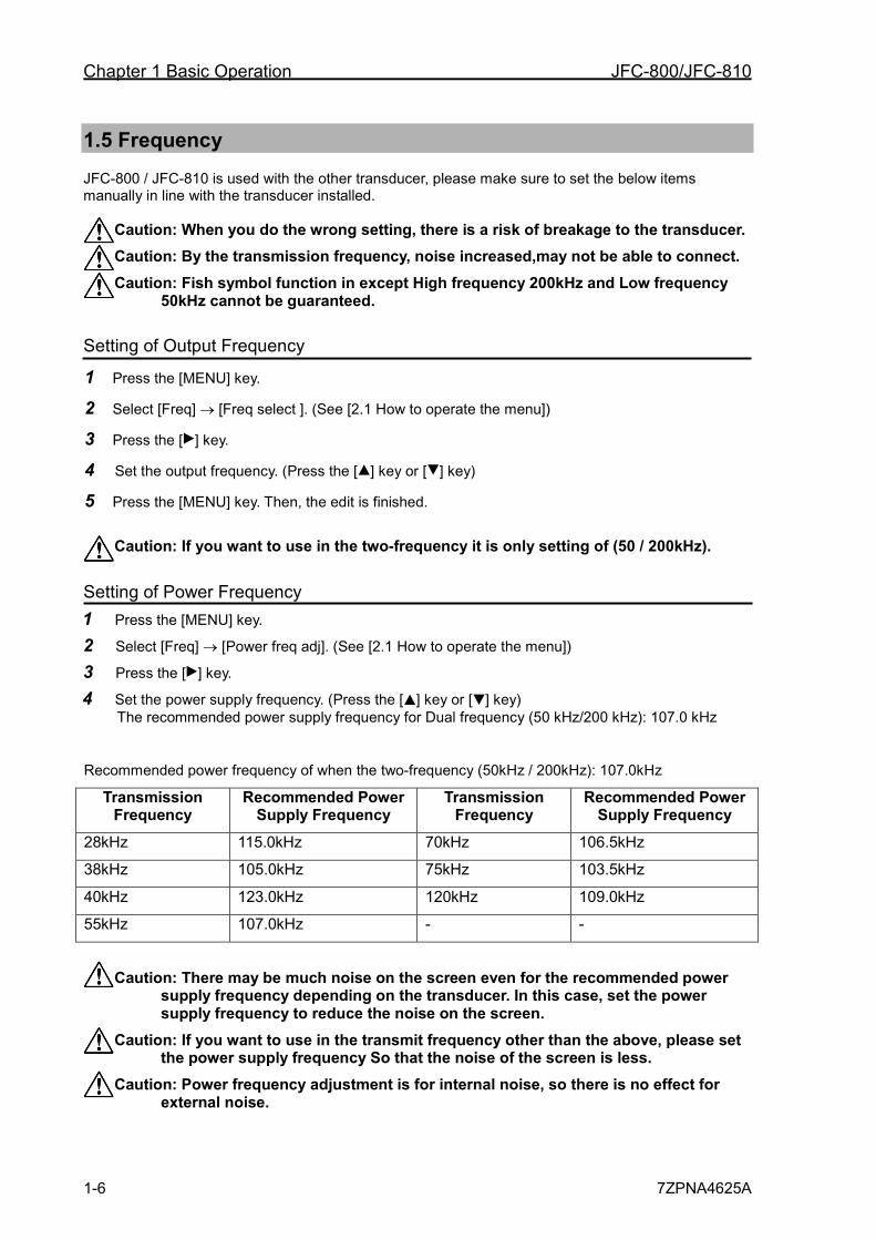
4 Set the power supply frequency. (Press the [ ] key or [ ] key) The recommended power supply frequency for Dual frequency (50 kHz/200 kHz): 107.0 kHz
Recommended power frequency of when the two-frequency (50kHz / 200kHz): 107.0kHz
Transmission Frequency
Recommended Power Supply Frequency
Transmission Frequency
Recommended Power Supply Frequency
28kHz 115.0kHz 70kHz 106.5kHz
38kHz 105.0kHz 75kHz 103.5kHz
40kHz 123.0kHz 120kHz 109.0kHz
55kHz 107.0kHz - -
Caution: There may be much noise on the screen even for the recommended power supply frequency depending on the transducer. In this case, set the power supply frequency to reduce the noise on the screen.
Caution: If you want to use in the transmit frequency other than the above, please set the power supply frequency So that the noise of the screen is less.
Caution: Power frequency adjustment is for internal noise, so there is no effect for external noise.
JFC-800/JFC-810 Chapter 1 Basic Operation
7ZPNA4625A 1-7
1 2 3 4 5 6 7 8 9 10 11 12 13 14 15 16 17 18 19 20 21 22 23 24 25 26 付録
5 Press the [MENU] key. Then, the edit is finished.
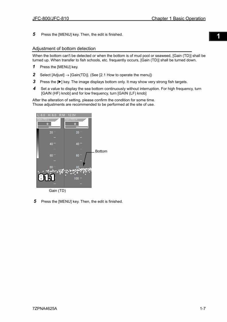
Adjustment of bottom detection When the bottom can't be detected or when the bottom is of mud pool or seaweed, [Gain (TD)] shall be turned up. When transfer to fish schools, etc. frequently occurs, [Gain (TD)] shall be turned down.
1 Press the [MENU] key.
2 Select [Adjust] → [Gain(TD)]. (See [2.1 How to operate the menu])
3 Press the [ ] key. The image displays bottom only. It may show very strong fish targets.
4 Set a value to display the sea bottom continuously without interruption. For high frequency, turn [GAIN (HF) knob] and for low frequency, turn [GAIN (LF) knob]
After the alteration of setting, please confirm the condition for some time. Those adjustments are recommended to be performed at the site of use.
5 Press the [MENU] key. Then, the edit is finished.
Gain (TD)
Bottom
Gain (TD) L Gain (TD) H
L: 6.0 H: 6.0 R:M 12.0V
Chapter 1 Basic Operation JFC-800/JFC-810
1-8 7ZPNA4625A
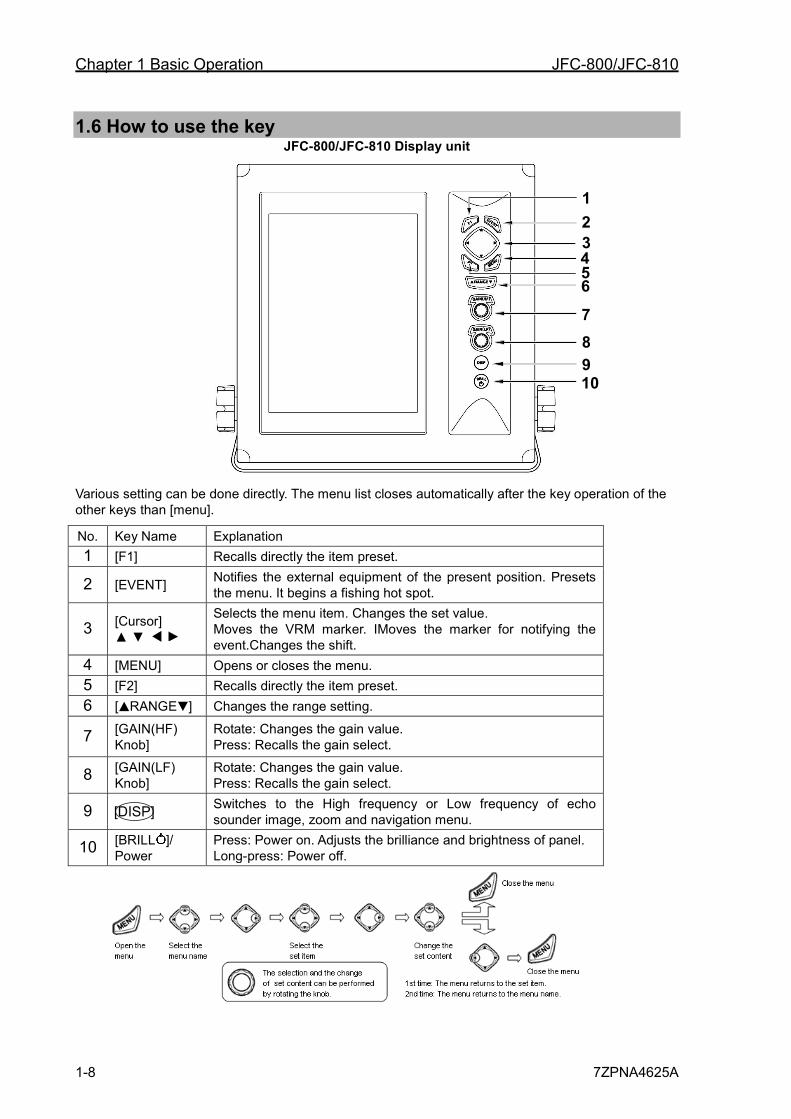
1.6 How to use the key JFC-800/JFC-810 Display unit
Various setting can be done directly. The menu list closes automatically after the key operation of the other keys than [menu].
No. Key Name Explanation 1 [F1] Recalls directly the item preset.
2 [EVENT] Notifies the external equipment of the present position. Presets the menu. It begins a fishing hot spot.
3 [Cursor] ▲ ▼
Selects the menu item. Changes the set value. Moves the VRM marker. IMoves the marker for notifying the event.Changes the shift.
4 [MENU] Opens or closes the menu. 5 [F2] Recalls directly the item preset. 6 [ RANGE ] Changes the range setting.
7 [GAIN(HF) Knob]
Rotate: Changes the gain value. Press: Recalls the gain select.
8 [GAIN(LF) Knob]
Rotate: Changes the gain value. Press: Recalls the gain select.
9 Switches to the High frequency or Low frequency of echo sounder image, zoom and navigation menu.
10 [BRILL ]/ Power
Press: Power on. Adjusts the brilliance and brightness of panel. Long-press: Power off.
1 2
4 5 6 7
8 9 10
3
[DISP]
JFC-800/JFC-810 Chapter 1 Basic Operation
7ZPNA4625A 1-9
1 2 3 4 5 6 7 8 9 10 11 12 13 14 15 16 17 18 19 20 21 22 23 24 25 26 付録
1.7 Power On/Off
Power on 1 Press the [BRILL ] key to power on.
The startup menu is displayed. When started up, the internal memories (ROM, RAM) are automatically checked. When checking is normally finished, the menu below is displayed.
Caution: If an error occurs in the memory
check, the LED on the operation panel blinks. The unit may be not function normally. If you suspect trouble, contact the dealer of your purchase or our company.
2 Language Selection at Initial Startup.
When powering on first, the [Language] menu is displayed.
Select the language with [ ] key or [ ] key. (The language can be selected by rotating the [GAIN (HF) Knob] or [GAIN (LF) Knob].)
3 When the installation of a transducer is [Inner-hull], select the [Yes].
Press [ ] and [ ] keys in sequence, and select the [Yes]. 4 Press the [MENU] key to decide the
language and the inner-hull.
5 After a few seconds, the menu sets the screen as selected in [DISP].
Caution: In addition to English, Japanese, there are several compatible languages.
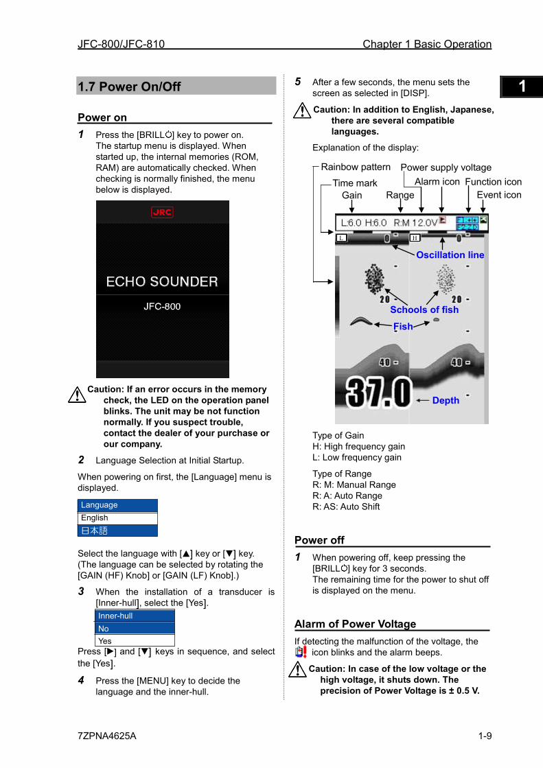
Explanation of the display:
Type of Gain H: High frequency gain L: Low frequency gain
Type of Range R: M: Manual Range R: A: Auto Range R: AS: Auto Shift
Power off 1 When powering off, keep pressing the
[BRILL ] key for 3 seconds. The remaining time for the power to shut off is displayed on the menu.
Alarm of Power Voltage If detecting the malfunction of the voltage, the
icon blinks and the alarm beeps.
Caution: In case of the low voltage or the high voltage, it shuts down. The precision of Power Voltage is ± 0.5 V.
Language English 日本語
Inner-hull No Yes
Rainbow pattern
Time mark Gain Range
Alarm icon
Fish Schools of fish
Oscillation line
Depth
L H
Power supply voltage Function icon
Event icon
Chapter 1 Basic Operation JFC-800/JFC-810
1-10 7ZPNA4625A
1.8 LCD Brilliance Adjustment
Adjustment of LCD Brilliance The brilliance of the display can be adjusted to facilitate visualization.
The [Lcd brill] and [Panel brill] can be switched every time when pressing the [BRILL ] key.
1 Press the [BRILL ] key for a short period of time to display the menu ([Lcd brill]).
2 Rotate the [GAIN (HF) Knob] or [GAIN (LF) Knob]. When “1” is selected, it is darkest. When “10” is selected, it is brightest.
Lcd brill
10
3 Press the [MENU] key to close the menu.
Brightness Adjustment of Panel Brilliance The brightness of panel can be adjusted.
The [Lcd brill] and [Panel brill] can be switched every time when pressing the [BRILL ] key.
1 Press the [BRILL ] key for a short period of time to display the menu ([Panel brill]).
2 Rotate the [GAIN (HF) Knob] or [GAIN (LF) Knob]. When “1” is selected, it is darkest. When “10” is selected, it is brightest.
Panel brill
10
3 Press the [MENU] key to close the menu.
1.9 Switch-over of Display mode
7 kinds of displays are provided in all. Select the display suitable for your purpose.
1 Press the [DISP] key.
2 Select the display you desire to display. (Press the [ ] key or [ ] key.) (The set item can be selected by rotating the [GAIN (HF) Knob] or [GAIN (LF) Knob].)
(H): High frequency
(L): Low frequency
NAV1: Navigation display1
NAV2: Navigation display2
3 Press the [MENU] key to close the menu.
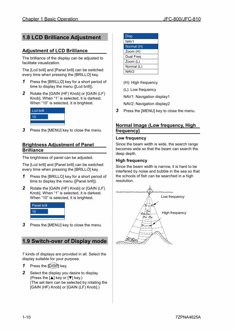
Normal Image (Low frequency, High frequency) Low frequency Since the beam width is wide, the search range becomes wide so that the beam can search the deep depth.
High frequency Since the beam width is narrow, it is hard to be interfered by noise and bubble in the sea so that the schools of fish can be searched in a high resolution.
(50 kHz)
(200 kHz)
Low frequency
High frequency
Disp NAV1 Normal (H) Zoom (H) Dual Freq Zoom (L) Normal (L) NAV2
JFC-800/JFC-810 Chapter 1 Basic Operation
7ZPNA4625A 1-11
1 2 3 4 5 6 7 8 9 10 11 12 13 14 15 16 17 18 19 20 21 22 23 24 25 26 付録
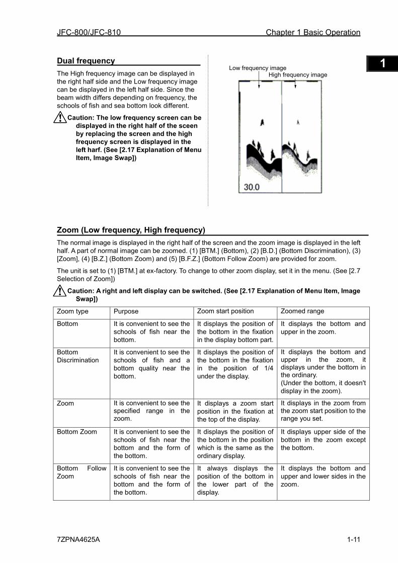
Dual frequency The High frequency image can be displayed in the right half side and the Low frequency image can be displayed in the left half side. Since the beam width differs depending on frequency, the schools of fish and sea bottom look different.
Caution: The low frequency screen can be displayed in the right half of the sceen by replacing the screen and the high frequency screen is displayed in the left harf. (See [2.17 Explanation of Menu Item, Image Swap])
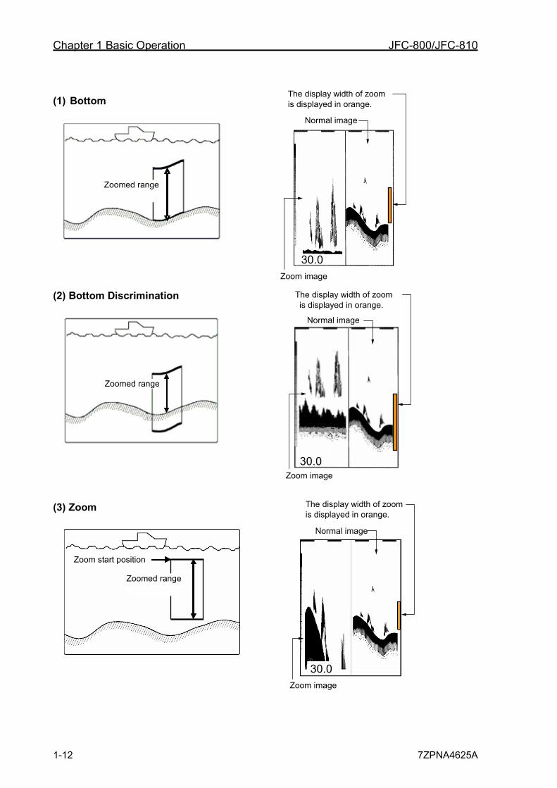
Zoom (Low frequency, High frequency) The normal image is displayed in the right half of the screen and the zoom image is displayed in the left half. A part of normal image can be zoomed. (1) [BTM.] (Bottom), (2) [B.D.] (Bottom Discrimination), (3) [Zoom], (4) [B.Z.] (Bottom Zoom) and (5) [B.F.Z.] (Bottom Follow Zoom) are provided for zoom.
The unit is set to (1) [BTM.] at ex-factory. To change to other zoom display, set it in the menu. (See [2.7 Selection of Zoom])
Caution: A right and left display can be switched. (See [2.17 Explanation of Menu Item, Image Swap])
Zoom type Purpose Zoom start position Zoomed range
Bottom It is convenient to see the schools of fish near the bottom.
It displays the position of the bottom in the fixation in the display bottom part.
It displays the bottom and upper in the zoom.
Bottom Discrimination
It is convenient to see the schools of fish and a bottom quality near the bottom.
It displays the position of the bottom in the fixation in the position of 1/4 under the display.
It displays the bottom and upper in the zoom, it displays under the bottom in the ordinary. (Under the bottom, it doesn't display in the zoom).
Zoom It is convenient to see the specified range in the zoom.
It displays a zoom start position in the fixation at the top of the display.
It displays in the zoom from the zoom start position to the range you set.
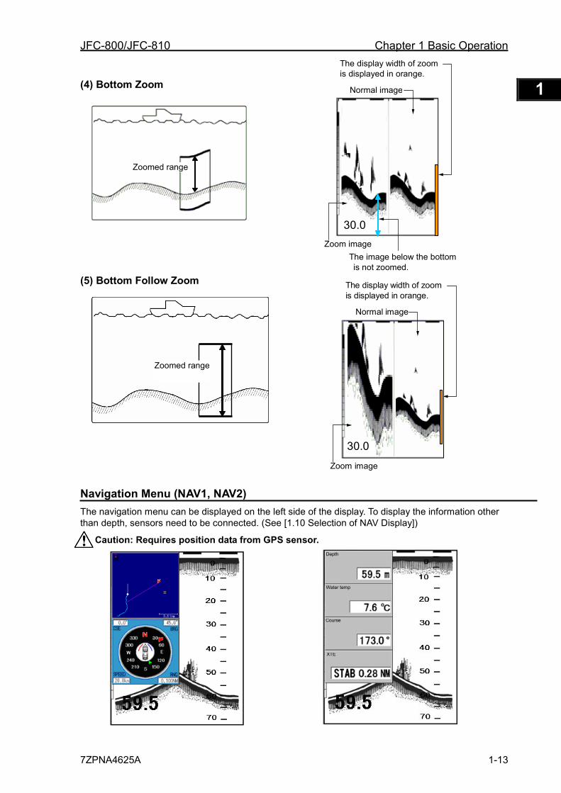
Bottom Zoom It is convenient to see the schools of fish near the bottom and the form of the bottom.
It displays the position of the bottom in the position which is the same as the ordinary display.
It displays upper side of the bottom in the zoom except the bottom.
Bottom Follow Zoom
It is convenient to see the schools of fish near the bottom and the form of the bottom.
It always displays the position of the bottom in the lower part of the display.
It displays the bottom and upper and lower sides in the zoom.
Low frequency image High frequency image
Chapter 1 Basic Operation JFC-800/JFC-810
1-12 7ZPNA4625A
(1) Bottom
(2) Bottom Discrimination
(3) Zoom
Zoom start position
Zoomed range
Zoomed range
Zoomed range
30.0
The display width of zoom is displayed in orange.
Normal image
Zoom image
The display width of zoom is displayed in orange.
Normal image
Zoom image 30.0
The display width of zoom is displayed in orange.
Normal image
Zoom image 30.0
JFC-800/JFC-810 Chapter 1 Basic Operation
7ZPNA4625A 1-13
1 2 3 4 5 6 7 8 9 10 11 12 13 14 15 16 17 18 19 20 21 22 23 24 25 26 付録
(4) Bottom Zoom
(5) Bottom Follow Zoom
Navigation Menu (NAV1, NAV2) The navigation menu can be displayed on the left side of the display. To display the information other than depth, sensors need to be connected. (See [1.10 Selection of NAV Display])
Caution: Requires position data from GPS sensor.
Depth
Water temp
Course
XTE
30.0
The display width of zoomis displayed in orange.
Normal image
Zoom image
Zoomed range
Zoomed range
The image below the bottom is not zoomed.
30.0
The display width of zoom is displayed in orange.
Normal image
Zoom image
Chapter 1 Basic Operation JFC-800/JFC-810
1-14 7ZPNA4625A
1.10 Selection of NAV Display
Selection of NAV Display
The information can be displayed on the NAV display (NAV 1, NAV2).
Caution:Requires position data from GPS sensor.
Type of NAV Display The following images can be displayed on the NAV Display (NAV1, NAV2).
Simple potter Compass
Speed meter
Wpt dist dir., Time required, Wind dir., Wind speed, depth, Lat/Lon, Boat speed, course, water temp, Heading and XTE
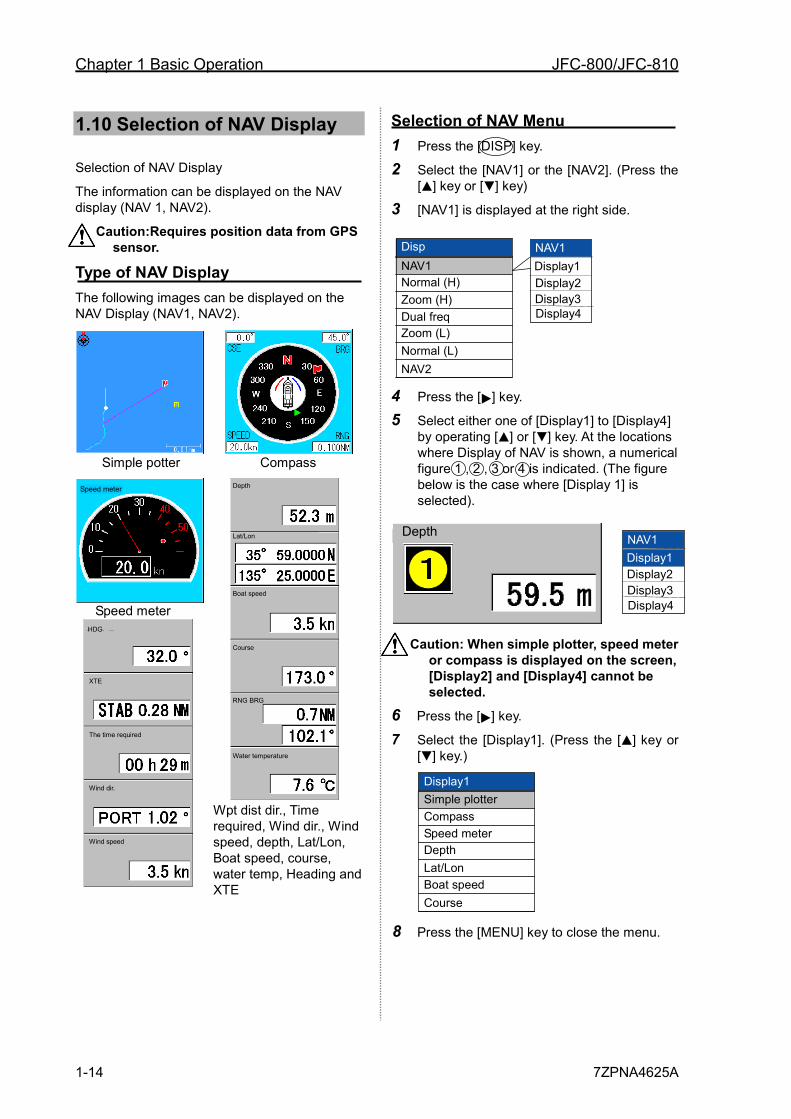
Selection of NAV Menu 1 Press the [DISP] key.
2 Select the [NAV1] or the [NAV2]. (Press the [ ] key or [ ] key)
3 [NAV1] is displayed at the right side.
4 Press the [ ] key.
5 Select either one of [Display1] to [Display4] by operating [ ] or [ ] key. At the locations where Display of NAV is shown, a numerical figure 1 , 2 , 3 or 4 is indicated. (The figure below is the case where [Display 1] is selected).
Caution: When simple plotter, speed meter or compass is displayed on the screen, [Display2] and [Display4] cannot be selected.
6 Press the [ ] key.
7 Select the [Display1]. (Press the [ ] key or [ ] key.)
8 Press the [MENU] key to close the menu.
Display1 Simple plotter Compass Speed meter Depth Lat/Lon Boat speed Course
Disp NAV1 Normal (H) Zoom (H) Dual freq Zoom (L) Normal (L) NAV2
NAV1 Display1 Display2 Display3 Display4
NAV1
Display2 Display3 Display4
Display1 Depth
RNG BRG
Course
Lat/Lon
Water temperature
Depth
Boat speed
XTE
The time required
Wind dir.
Wind speed
HDG
Speed meter
JFC-800/JFC-810 Chapter 1 Basic Operation
7ZPNA4625A 1-15
1 2 3 4 5 6 7 8 9 10 11 12 13 14 15 16 17 18 19 20 21 22 23 24 25 26 付録
1.11 Switch-over of Range
The range of measured depth displayed on the display can be changed.
To meet your purpose, select the range of measured depth.
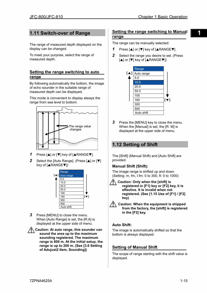
Setting the range switching to auto range By following automatically the bottom, the image of echo sounder in the suitable range of measured depth can be displayed.
This mode is convenient to display always the range from sea level to bottom.
The range value changes
1 Press [ ] or [ ] key of [ RANGE ].
2 Select the [Auto Range]. (Press [ ] or [ ] key of [ RANGE ])
3 Press [MENU] to close the menu. When [Auto Range] is set, the [R:A] is displayed at the upper side of menu.
Caution: At auto range, this sounder can sound the area up to the maximum sounding registered. The maximum range is 800 m. At the initial setup, the range is up to 200 m. (See [3.6 Setting of Adujust2 Item, Sounding])
Setting the range switching to Manual range The range can be manually selected:
1 Press [ ] or [ ] key of [ RANGE ].
2 Select the range you desire to set. (Press [ ] or [ ] key of [ RANGE ])
3 Press the [MENU] key to close the menu. When the [Manual] is set, the [R: M] is displayed at the upper side of menu.
1.12 Setting of Shift
The [Shift] (Manual Shift) and [Auto Shift] are provided.
Manual Shift (Shift): The image range is shifted up and down. (Setting: m, fm, I.fm: 0 to 300, ft: 0 to 1000)
Caution: Only when the [shift] is registered in [F1] key or [F2] key, it is effective. It is invalid when not registered. (See [1.15 Use of [F1] / [F2] key)
Caution: When the equipment is shipped from the factory, the [shift] is registered in the [F2] key.
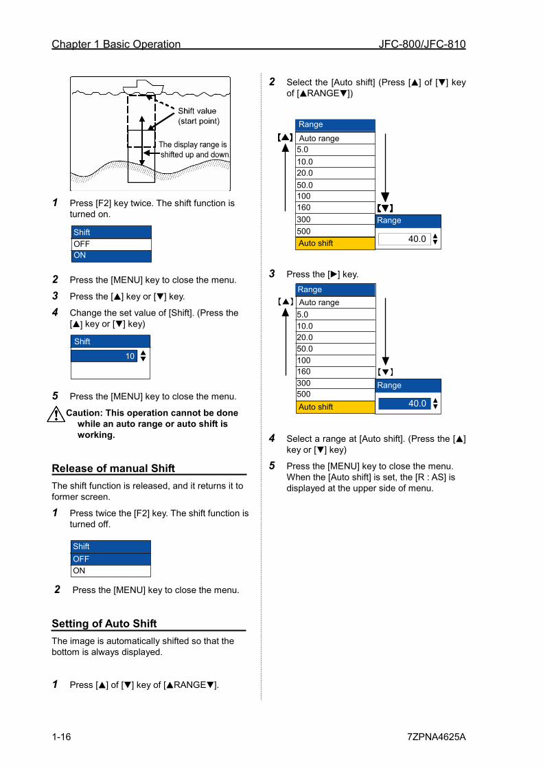
Auto Shift: The image is automatically shifted so that the bottom is always displayed.
Setting of Manual Shift The scope of range starting with the shift value is displayed.
Range
5.0 10.0 20.0 50.0 100 160 300 500 Auto shift
Auto range
Range
5.0 10.0 20.0 50.0 100 160 300 500 Auto shift
Auto range
Chapter 1 Basic Operation JFC-800/JFC-810
1-16 7ZPNA4625A
1 Press [F2] key twice. The shift function is
turned on.
2 Press the [MENU] key to close the menu.
3 Press the [ ] key or [ ] key.
4 Change the set value of [Shift]. (Press the [ ] key or [ ] key)
Shift
10
0~300 m
5 Press the [MENU] key to close the menu.
Caution: This operation cannot be done while an auto range or auto shift is working.
Release of manual Shift The shift function is released, and it returns it to former screen.
1 Press twice the [F2] key. The shift function is turned off.
2 Press the [MENU] key to close the menu.
Setting of Auto Shift The image is automatically shifted so that the bottom is always displayed.
1 Press [ ] of [ ] key of [ RANGE ].
2 Select the [Auto shift] (Press [ ] of [ ] key of [ RANGE ])
3 Press the [ ] key.
4 Select a range at [Auto shift]. (Press the [ ] key or [ ] key)
5 Press the [MENU] key to close the menu. When the [Auto shift] is set, the [R : AS] is displayed at the upper side of menu.
10.0 20.0 50.0 100 160 300 500
Auto range
Auto shift
5.0
Range
10.0 20.0 50.0 100 160 300 500
Auto range
Auto shift
5.0
Range
40.0
Range
40.0
Range
Shift OFF ON
Shift OFF ON
JFC-800/JFC-810 Chapter 1 Basic Operation
7ZPNA4625A 1-17
1 2 3 4 5 6 7 8 9 10 11 12 13 14 15 16 17 18 19 20 21 22 23 24 25 26 付録
1.13 Gain Adjustment
When only the image of High frequency is displayed, the High frequency gain can be adjusted. (Setting: 0 to 10)
When only the image of Low frequency is displayed, the Low frequency gain can be adjusted.
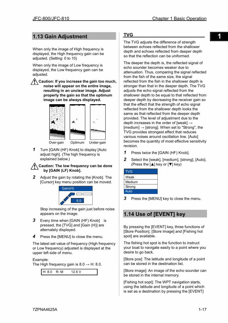
Caution: If you increase the gain too much, noise will appear on the entire image, resulting in an unclear image. Adjust properly the gain so that the optimum image can be always displayed.
Over-gain Under-gainOptimum 1 Turn [GAIN (HF) Knob] to display [Auto
adjust high]. (The high frequency is explained below.)
Caution: The low frequency can be done by [GAIN (LF) Knob].
2 Adjust the gain by rotating the [Knob]. The [Cursor] key menu position can be moved.
Stop increasing of the gain just before noise appears on the image.
3 Every time when [GAIN (HF) Knob] is pressed, the [TVG] and [Gain (H)] are alternately displayed.
4 Press the [MENU] to close the menu.
The latest set value of frequency (High frequency or Low frequency) adjusted is displayed at the upper left side of menu.
Example: The High frequency gain is 8.0 → H: 8.0.
TVG The TVG adjusts the difference of strength between echoes reflected from the shallower depth and echoes reflected from deeper depth so that the reflection can be uniformed.
The deeper the depth is, the reflected signal of echo sounder becomes weaker due to attenuation. Thus, comparing the signal reflected from the fish of the same size, the signal reflected from the fish in the shallower depth is stronger than that in the deeper depth. The TVG adjusts the echo signal reflected from the shallower depth to be equal to that reflected from deeper depth by decreasing the receiver gain so that the effect that the strength of echo signal reflected from the shallower depth looks the same as that reflected from the deeper depth provided. The level of adjustment due to the depth increases in the order of [weak] → [medium] → [strong]. When set to "Strong", the TVG provides strongest effect that reduces various noises around oscillation line. [Auto] becomes the quantity of most effective sensitivity revision.
1 Press twice the [GAIN (HF) Knob].
2 Select the [weak], [medium], [strong], [Auto]. (Press the [ ] key or [ ] key)
3 Press the [MENU] key to close the menu.
1.14 Use of [EVENT] key
By pressing the [EVENT] key, three functions of [Store Position]. [Store Image] and [Fishing hot spot] are available.
The fishing hot spot is the function to instruct your boat to navigate easily to a point where you desire to go back.
[Store pos]: The latitude and longitude of a point can be stored in the destination list.
[Store image]: An image of the echo sounder can be stored in the internal memory.
[Fishing hot sopt]: The WPT navigation starts, using the latitude and longitude of a point which is set as a destination by pressing the [EVENT]
R: M 12.6 V H: 8.0
TVG Weak Medium Strong Auto
6.0
Gain(H)
Chapter 1 Basic Operation JFC-800/JFC-810
1-18 7ZPNA4625A
key. Simultaneously, the latitude and longitude of the point can be stored in the destination list.
Caution: Requires position data from GPS sensor.
Selecting the event key function Select the functions when pressing the [EVENT] key.
1 Press the [MENU] key.
2 Select [System] → [EVENT Key set]. (Press the [ ] key or [ ] key or [ ] key) (See [2.1 How to operate the menu])
3 Press the [ ] key.
4 Change the setting of [EVENT key set]. (Press the [ ] key or [ ] key)
5 Press the [MENU] to close the menu.
Presetting the waypoint When you find the school of fish or tide, its location can be preset as a waypoint. (10 locations at maximum)
When presetting the waypoint, switch [System] → [EVENT Key set] → [Store pos]. (See [1.14 Use of [EVENT] key Selecting the event key function])
1 In the state that no other key is pressed, press the [ ] key or [ ] key.
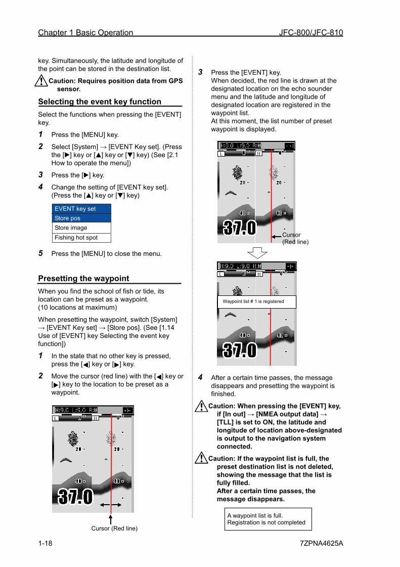
2 Move the cursor (red line) with the [ ] key or [ ] key to the location to be preset as a waypoint.
3 Press the [EVENT] key. When decided, the red line is drawn at the designated location on the echo sounder menu and the latitude and longitude of designated location are registered in the waypoint list. At this moment, the list number of preset waypoint is displayed.
4 After a certain time passes, the message
disappears and presetting the waypoint is finished.
Caution: When pressing the [EVENT] key, if [In out] → [NMEA output data] → [TLL] is set to ON, the latitude and longitude of location above-designated is output to the navigation system connected.
Caution: If the waypoint list is full, the preset destination list is not deleted, showing the message that the list is fully filled. After a certain time passes, the message disappears.
Waypoint list # 1 is registered
Cursor (Red line)
L H
L H
EVENT key set Store pos Store image Fishing hot spot
Cursor (Red line)
L H
A waypoint list is full. Registration is not completed
JFC-800/JFC-810 Chapter 1 Basic Operation
7ZPNA4625A 1-19
1 2 3 4 5 6 7 8 9 10 11 12 13 14 15 16 17 18 19 20 21 22 23 24 25 26 付録
Caution: If the waypoint list is full, delete an unnecessary waypoint from the waypoint list.
Store the image When you find the schools of fish, its location can be stored as a waypoint. (10 locations at maximum)
When storing the image, switch [NAV] → [EVENT Key set] → [Store pos]. (See [1.14 Use of [EVENT] key Selecting the event key function].)
1 Press the [EVENT] key.
2 After a certain time passes, the image of echo sounder presently displayed is stored and the list number of stored image is displayed.
3 After a certain time passes, the message
disappears and storing the image is finished.
Caution: If the waypoint list is fully filled, the preset destination list is not deleted, showing the message that the image is fully filled. After a certain time passes, the message disappears.
As for deletion and recall of images, see [2.15 Store/Recall/Deletion of image].
Fishing hot spot Leads you back to your favorite fishing hot spots or other previously stored positions in memory with input from optional GPS sensor. (See [2.14 Preset/ WPT edit/ WPT delete of Waypoint])
To perform the fishing hot spot, it is necessary to select [System] → [EVENT key set] → [Fishing hot spot]. (See [1.14 Use of [EVENT] key Selecting the event key function].)
1 In the state that no other key is pressed, press the [ ] key or the [ ] key.
2 Move the cursor (red line) to a point you desire to go back with the [ ] key or [ ] key.
3 Press the [EVENT] key.
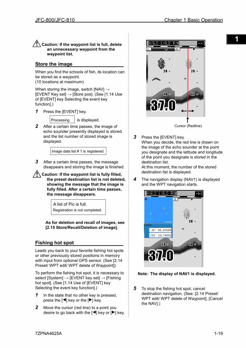
When you decide, the red line is drawn on the image of the echo sounder at the point you designate and the latitude and longitude of the point you designate is stored in the destination list. At this moment, the number of the stored destination list is displayed.
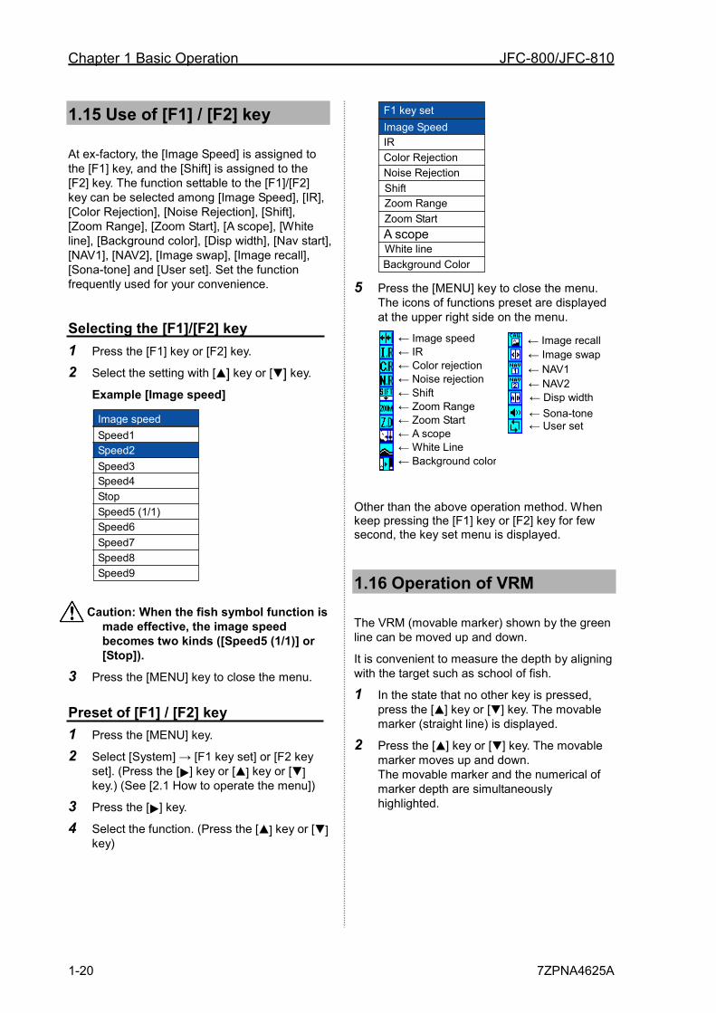
4 The navigation display (NAV1) is displayed and the WPT navigation starts.
Note: The display of NAV1 is displayed.
5 To stop the fishing hot spot, cancel destination navigation. (See: [2.14 Preset/ WPT edit/ WPT delete of Waypoint], [Cancel the NAV].)
A list of Pic is full. Registration is not completed.
Image data list # 1 is registered
Processing is displayed. Cursor (Redline)
L H
L H
Chapter 1 Basic Operation JFC-800/JFC-810
1-20 7ZPNA4625A
1.15 Use of [F1] / [F2] key
At ex-factory, the [Image Speed] is assigned to the [F1] key, and the [Shift] is assigned to the [F2] key. The function settable to the [F1]/[F2] key can be selected among [Image Speed], [IR], [Color Rejection], [Noise Rejection], [Shift], [Zoom Range], [Zoom Start], [A scope], [White line], [Background color], [Disp width], [Nav start], [NAV1], [NAV2], [Image swap], [Image recall], [Sona-tone] and [User set]. Set the function frequently used for your convenience.
Selecting the [F1]/[F2] key 1 Press the [F1] key or [F2] key.
2 Select the setting with [ ] key or [ ] key.
Example [Image speed]
Caution: When the fish symbol function is
made effective, the image speed becomes two kinds ([Speed5 (1/1)] or [Stop]).
3 Press the [MENU] key to close the menu.
Preset of [F1] / [F2] key 1 Press the [MENU] key.
2 Select [System] → [F1 key set] or [F2 key set]. (Press the [ ] key or [ ] key or [ ] key.) (See [2.1 How to operate the menu])
3 Press the [ ] key.
4 Select the function. (Press the [ ] key or [ ] key)
5 Press the [MENU] key to close the menu.
The icons of functions preset are displayed at the upper right side on the menu.
Other than the above operation method. When keep pressing the [F1] key or [F2] key for few second, the key set menu is displayed.
1.16 Operation of VRM
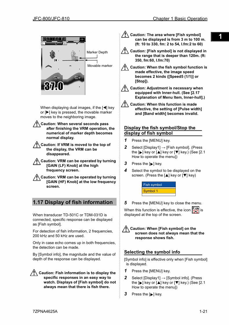
The VRM (movable marker) shown by the green line can be moved up and down.
It is convenient to measure the depth by aligning with the target such as school of fish.
1 In the state that no other key is pressed, press the [ ] key or [ ] key. The movable marker (straight line) is displayed.
2 Press the [ ] key or [ ] key. The movable marker moves up and down. The movable marker and the numerical of marker depth are simultaneously highlighted.
F1 key set Image Speed IR Color Rejection Noise Rejection
A scope
Shift Zoom Range Zoom Start
Background Color White line
Image speed Speed1 Speed2 Speed3 Speed4 Stop Speed5 (1/1) Speed6 Speed7 Speed8 Speed9
← Image speed ←
IR ←
Color rejection ←
Noise rejection ←
Shift ←
Zoom Range ←
Zoom Start ←
A scope ←
White Line ←
Background color
←
Image recall ←
Image swap ←
NAV1 ←
NAV2 ←
Disp width ←
Sona-tone ←
User set
JFC-800/JFC-810 Chapter 1 Basic Operation
7ZPNA4625A 1-21
1 2 3 4 5 6 7 8 9 10 11 12 13 14 15 16 17 18 19 20 21 22 23 24 25 26 付録
When displaying dual images, if the [ ] key or [ ] key is pressed, the movable marker moves to the neighboring image.
Caution: When several seconds pass after finishing the VRM operation, the numerical of marker depth becomes normal display.
Caution: If VRM is moved to the top of the display, the VRM can be disappeared.
Caution: VRM can be operated by turning [GAIN (LF) Knob] at the high frequency screen.
Caution: VRM can be operated by turning [GAIN (HF) Knob] at the low frequency screen.
1.17 Display of fish information
When transducer TD-501C or TDM-031D is connected, specific response can be displayed as [Fish symbol].
For detection of fish information, 2 frequencies, 200 kHz and 50 kHz are used.
Only in case echo comes up in both frequencies, the detection can be made.
By [Symbol info], the magnitude and the value of depth of the response can be displayed.
Caution: Fish information is to display the specific responses in an easy way to watch. Displays of [Fish symbol] do not always mean that there is fish there.
Caution: The area where [Fish symbol] can be displayed is from 3 m to 100 m. (ft: 10 to 330, fm: 2 to 54, I.fm:2 to 60)
Caution: [Fish symbol] is not displayed in the range that is deeper than 120m. (ft: 350, fm:60, I.fm:70)
Caution: When the fish symbol function is made effective, the image speed becomes 2 kinds ([Speed5 (1/1)] or [Stop]).
Caution: Adjustment is necessary when equipped with Inner-hull. (See [2.17 Explanation of Menu Item, Inner-hull].)
Caution: When this function is made effective, the setting of [Pulse width] and [Band width] becomes invalid.
Display the fish symbol/Stop the display of fish symbol 1 Press the [MENU] key.
2 Select [Display1] → [Fish symbol]. (Press the [ ] key or [ ] key or [ ] key.) (See [2.1 How to operate the menu])
3 Press the [ ] key.
4 Select the symbol to be displayed on the screen. (Press the [ ] key or [ ] key)
5 Press the [MENU] key to close the menu.
When this function is effective, the icon is displayed at the top of the screen.
Caution: When [Fish symbol] on the screen does not always mean that the response shows fish.
Selecting the symbol info [Symbol info] is effective only when [Fish symbol] is displayed.
1 Press the [MENU] key.
2 Select [Display1] → [Symbol info]. (Press the [ ] key or [ ] key or [ ] key.) (See [2.1 How to operate the menu])
3 Press the [ ] key.
Movable marker
Marker Depth 20.0
L H
Fish symbol
Symbol 1
Chapter 1 Basic Operation JFC-800/JFC-810
1-22 7ZPNA4625A
4 Select the information associated with [Fish symbol] (Press the [ ] key or [ ] key.)
Caution: The display of [Size] is expressed in cm.
5 Press the [MENU] key to close the menu.
Caution: The magnitude by [Symbol info] would not be always the response from fish. And it may be incorrect due to various environmental conditions. Please take these as reference.
Caution: The value of depth by [Symbol info] would not be always the response from fish. That shows the point that there was specific response.
Caution: Please correct the size when the indicated value is different from the fish that actually fished. (See [3.3 Setting of correct item, Size adjust])
Fish symbol detection adjustment Detection of fish marks can be adjusted.
Select [Correct] → [Detect adjust f].
Caution: If the larger the set values become, the more fish marks can be displayed with more false detections.
Caution: For Through-hull installation, adjust between 1 and 4. For Inner-hull installations, adjust between 3 and 6.
Size adjustment The indicated size of fish marks can be adjusted.
Please correct the size when the indicated value is different from the fish that actually caught.
Select [Correct] → [Size adjust].
The indicated size will change by approximately 10 to 20 percent of the value, per one setting value.
Caution: When the value of [Detect adjust f] is set at 5 or 6, the size of fish can not be specified and there may be cases where no numerical figures are displayed or only "----" is displayed. When there is no display of numerical figures, it is judged that fish are too small. When "---" is displayed, it is judged that fish is too big.
Big fish / Big fish color The fish bigger than the set value [cm] is specified as big fish.
Select keys of [Display2] → [Big fish].
Colors for values of big fish can be assigned.
Select keys of [Display2] → [Color table 2] → [Big fish color].
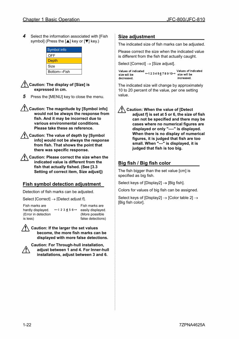
Symbol info OFF Depth Size Bottom↔Fish
JFC-800/JFC-810 Chapter 1 Basic Operation
7ZPNA4625A 1-23
1 2 3 4 5 6 7 8 9 10 11 12 13 14 15 16 17 18 19 20 21 22 23 24 25 26 付録
The values displayed by this function may be incorrect depending on various environmental conditions. In use of these values, please understand the following factors of error, and use them as reference: [Factors of error] 1 When there are overlapping responses,
all of them may be displayed to show the magnitude of a point.
2 The strength of reflection may depend on the output of transducer unit and may result in a factor of error.
3 The strength of reflection may depend on the kind of fish and may result in a factor of error. As for the fish such as the squid which don't have an air bladder, the error is big.
4 Fish banks, fishing net, fishing equipment, air bubbles and floating objects, etc. may be detected and displayed.
5 When the transducer unit is mounted in inner-hull, there may be cases where response cannot be detected depending on attenuation, and large error may be generated.
6 The strength of reflection may depend on the difference of ship handling such as stoppage and cruising, and may result in a factor of error.
7 Each transducer unit may have difference in transmission/receiving performance to cause error.
8 When there is dirt in the sea and the plankton layers have been generated, it becomes the factor of the error margin.
Points to note in use of fish symbol

Chapter 1 Basic Operation JFC-800/JFC-810
1-24 7ZPNA4625A
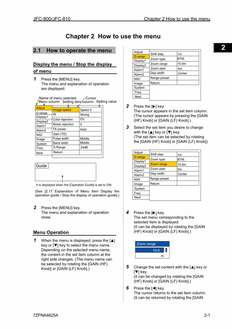
JFC-800/JFC-810 Chapter 2 How to use the menu
7ZPNA4625A 2-1
1 2 3 4 5 6 7 8 9 10 11 12 13 14 15 16 17 18 19 20 21 22 23 24 25 26 付録
Chapter 2 How to use the menu
2.1 How to operate the menu
Display the menu / Stop the display of menu 1 Press the [MENU] key.
The menu and explanation of operation are displayed.
2 Press the [MENU] key. The menu and explanation of operation close.
Menu Operation 1 When the menu is displayed, press the [ ]
key or [ ] key to select the menu name. Depending on the selected menu name, the content in the set item column at the right side changes. (The menu name can be selected by rotating the [GAIN (HF) Knob] or [GAIN (LF) Knob].)
2 Press the [ ] key. The cursor appears in the set item column. (The cursor appears by pressing the [GAIN (HF) Knob] or [GAIN (LF) Knob].)
3 Select the set item you desire to change with the [ ] key or [ ] key. (The set item can be selected by rotating the [GAIN (HF) Knob] or [GAIN (LF) Knob])
4 Press the [ ] key. The set menu corresponding to the selected item is displayed. (It can be displayed by rotating the [GAIN (HF) Knob] or [GAIN (LF) Knob].)
5 Change the set content with the [ ] key or [ ] key. (It can be changed by rotating the [GAIN (HF) Knob] or [GAIN (LF) Knob].)
6 Press the [ ] key. The cursor returns to the set item column. (It can be returned by rotating the [GAIN
Menu column
Adjust
Display1 D.range
Display2
Alarm1 Alarm2
NAV Image
Freq
Image speed IR Color rejection Noise rejection TX power Gain (TD)
D.Range
Speed 5 Strong 0%
0 Auto
Guide
Name of menu selected Setting item column
It is displayed when the [Operation Guide] is set to ON.
(See [2.17 Explanation of Menu Item Display the operation guide / Stop the display of operation guide].)
Setting value Cursor
Pulse width
System Band width Middle Middle
Next Return 24dB
Disp width
Shift step Zoom type Zoom range Zoom start
Range preset Return
1m
0m 10.0m BTM.
Adjust
Display1 D.range
Display2
Alarm1 Alarm2
NAV Image
Next
System
Center
Freq
Disp width
Shift step Zoom type Zoom range Zoom start
Range preset Return
1m
10.0m 0m
BTM.
Adjust
Display1 D.range
Display2
Alarm1 Alarm2
NAV Image
Freq System
Center
Next
Zoom range
10.0 m
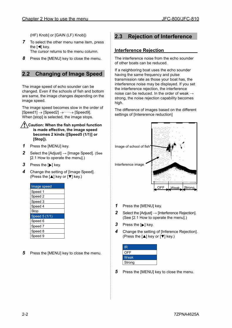
Chapter 2 How to use the menu JFC-800/JFC-810
2-2 7ZPNA4625A
(HF) Knob] or [GAIN (LF) Knob])
7 To select the other menu name item, press the [ ] key. The cursor returns to the menu column.
8 Press the [MENU] key to close the menu.
2.2 Changing of Image Speed
The image speed of echo sounder can be changed. Even if the schools of fish and bottom are same, the image changes depending on the image speed.
The image speed becomes slow in the order of [Speed1] → [Speed2] →···∙∙→ [Speed9]. When [stop] is selected, the image stops.
Caution: When the fish symbol function is made effective, the image speed becomes 2 kinds ([Speed5 (1/1)] or [Stop]).
1 Press the [MENU] key.
2 Select the [Adjust] → [Image Speed]. (See [2.1 How to operate the menu].)
3 Press the [ ] key.
4 Change the setting of [Image Speed]. (Press the [ ] key or [ ] key.)
5 Press the [MENU] key to close the menu.
2.3 Rejection of Interference
Interference Rejection The interference noise from the echo sounder of other boats can be reduced.
If a neighboring boat uses the echo sounder having the same frequency and pulse transmission rate as those your boat has, the interference noise may be displayed. If you set the interference rejection, the interference noise can be reduced. In the order of weak → strong, the noise rejection capability becomes high.
The difference of images based on the different settings of [Intererence reduction]
1 Press the [MENU] key.
2 Select the [Adjust] → [Interference Rejection]. (See [2.1 How to operate the menu].)
3 Press the [ ] key.
4 Change the setting of [Inference Rejection]. (Press the [ ] key or [ ] key.)
IROFFWeakStrong
5 Press the [MENU] key to close the menu.
Image speed Speed 1 Speed 2 Speed 3 Speed 4 Stop Speed 5 (1/1) Speed 6 Speed 7 Speed 8 Speed 9
O F F Weak Strong
Image of school of fish
Interference image
JFC-800/JFC-810 Chapter 2 How to use the menu
7ZPNA4625A 2-3
1 2 3 4 5 6 7 8 9 10 11 12 13 14 15 16 17 18 19 20 21 22 23 24 25 26 付録
2.4 Color Rejection of Weak Echo
Color Rejection The color of weak echo can be rejected.
Rejecting noise on the entire image and weak echo around the school of fish makes it easier to see the school of fish. It is the convenient function when displaying the echo stronger than the specific signal. (Setting: 0 ~ 50 %)
1 Press the [MENU] key.
2 Select the [Adjust] → [Color Rejection]. (See [2.1 How to operate the menu])
3 Press the [ ] key.
4 Change the setting of [Color Rejection]. (Press the [ ] key or [ ] key.)
5 Press the [MENU] key to close the menu.
2.5 Rejection of Noise
Noise Rejection The influence of noise can be reduced.
Due to echo reflected from plankton and trash, the speck-like noise may appear on the entire image. Setting the [Noise rejection] reduces the speck-like noise and makes it easier to see the image of school of fish. (Setting: 0 ~ 10)
The greater the set value becomes, the stronger the effect of noise rejection becomes.
1 Press the [MENU] key.
2 Select [Adjust] → [Noise rejection]. (See [2.1 How to operate the menu])
3 Press the [ ] key.
4 Change the setting of [Noise rejection]. (Press the [ ] key or [ ] key)
5 Press the [MENU] key to close the menu.
2.6 Setting of Shift step
The shifting range is set by pressing the [ ] key or [ ] key one time. (Setting range: 1m, 10m, 1/8, 1/4)
1 Press the [MENU] key.
2 Select the [D.range] → [Shift step]. (See [2.1 How to operate the menu])
3 Press the [ ] key.
4 Change the setting of [Shift step]. (Press the [ ] key or [ ] key.)
5 Press the [MENU] key to close the menu.
Caution: When the shift is set to 1/4 with 100m range, it shifts by 25m.
2.7 Selection of Zoom
Set the zoom display with the display mode ([zoom (H)] or [zoom (L)].
The [Bottom], [Bottom Discrimination], [Zoom], [[Bottom Zoom] and [Bottom Follow Zoom] are provided. (See [1.9 Switch-over of Display mode])
1 Press the [MENU] key.
2 Select [D.range] → [Zoom type]. (See [2.1 How to operate the menu])
3 Press the [ ] key.
4 Select the zoom type. (Press the [ ] key or [ ] key)
Color Rejection
0 %
5
Shift step 1m 10m 1/8 1/4
Noise Rejection
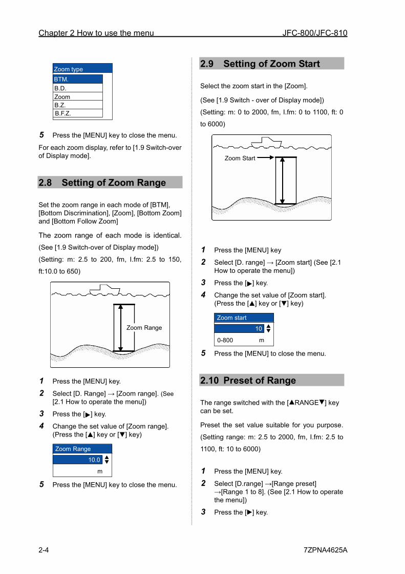
Chapter 2 How to use the menu JFC-800/JFC-810
2-4 7ZPNA4625A
5 Press the [MENU] key to close the menu.
For each zoom display, refer to [1.9 Switch-over of Display mode].
2.8 Setting of Zoom Range
Set the zoom range in each mode of [BTM], [Bottom Discrimination], [Zoom], [Bottom Zoom] and [Bottom Follow Zoom]
The zoom range of each mode is identical. (See [1.9 Switch-over of Display mode])
(Setting: m: 2.5 to 200, fm, I.fm: 2.5 to 150,
ft:10.0 to 650)
Zoom Range
1 Press the [MENU] key.
2 Select [D. Range] → [Zoom range]. (See [2.1 How to operate the menu])
3 Press the [ ] key.
4 Change the set value of [Zoom range]. (Press the [ ] key or [ ] key)
Zoom Range
10.0
m 5 Press the [MENU] key to close the menu.
2.9 Setting of Zoom Start
Select the zoom start in the [Zoom].
(See [1.9 Switch - over of Display mode])
(Setting: m: 0 to 2000, fm, I.fm: 0 to 1100, ft: 0
to 6000)
Zoom Start
1 Press the [MENU] key
2 Select [D. range] → [Zoom start] (See [2.1 How to operate the menu])
3 Press the [ ] key.
4 Change the set value of [Zoom start]. (Press the [ ] key or [ ] key)
Zoom start
10
0~800 m 5 Press the [MENU] to close the menu.
2.10 Preset of Range
The range switched with the [ RANGE ] key can be set.
Preset the set value suitable for you purpose.
(Setting range: m: 2.5 to 2000, fm, I.fm: 2.5 to
1100, ft: 10 to 6000)
1 Press the [MENU] key.
2 Select [D.range] →[Range preset] →[Range 1 to 8]. (See [2.1 How to operate the menu])
3 Press the [ ] key.
Zoom type BTM.
Zoom B.Z.
B.D.
B.F.Z.
0-800
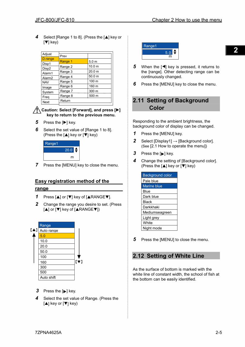
JFC-800/JFC-810 Chapter 2 How to use the menu
7ZPNA4625A 2-5
1 2 3 4 5 6 7 8 9 10 11 12 13 14 15 16 17 18 19 20 21 22 23 24 25 26 付録
4 Select [Range 1 to 8]. (Press the [ ] key or [ ] key)
Caution: Select [Forward], and press [ ] key to return to the previous menu.
5 Press the [ ] key.
6 Select the set value of [Range 1 to 8]. (Press the [ ] key or [ ] key)
Range1
20.0
m 7 Press the [MENU] key to close the menu.
Easy registration method of the range 1 Press [ ] or [ ] key of [ RANGE ].
2 Change the range you desire to set. (Press [ ] or [ ] key of [ RANGE ])
3 Press the [ ] key.
4 Select the set value of Range. (Press the [ ] key or [ ] key)
5 When the [ ] key is pressed, it returns to the [range]. Other detecting range can be continuously changed.
6 Press the [MENU] key to close the menu.
2.11 Setting of Background Color
Responding to the ambient brightness, the background color of display can be changed.
1 Press the [MENU] key.
2 Select [Display1] → [Background color]. (See [2.1 How to operate the menu])
3 Press the [ ] key.
4 Change the setting of [Background color]. (Press the [ ] key or [ ] key)
5 Press the [MENU] to close the menu.
2.12 Setting of White Line
As the surface of bottom is marked with the white line of constant width, the school of fish at the bottom can be easily identified.
Background color Pale blue Marine blue Blue Dark blue Black Darkkhaki Mediumseagreen Light grey White Night mode
Disp1 D.range
Disp2
Alarm1
Alarm2
NAV
Image
System
Prev 5.0 m
Next
Range 1 Range 2
Range 3
Range 4
Range 5
Range 6
Range 7
Range 8
Return
10.0 m 20.0 m 50.0 m 100 m 160 m 300 m 500 m Freq
Adjust
Range
5.0 10.0 20.0 50.0 100 160 300
500
Auto range
Auto shift
Range1 5 . 0
m
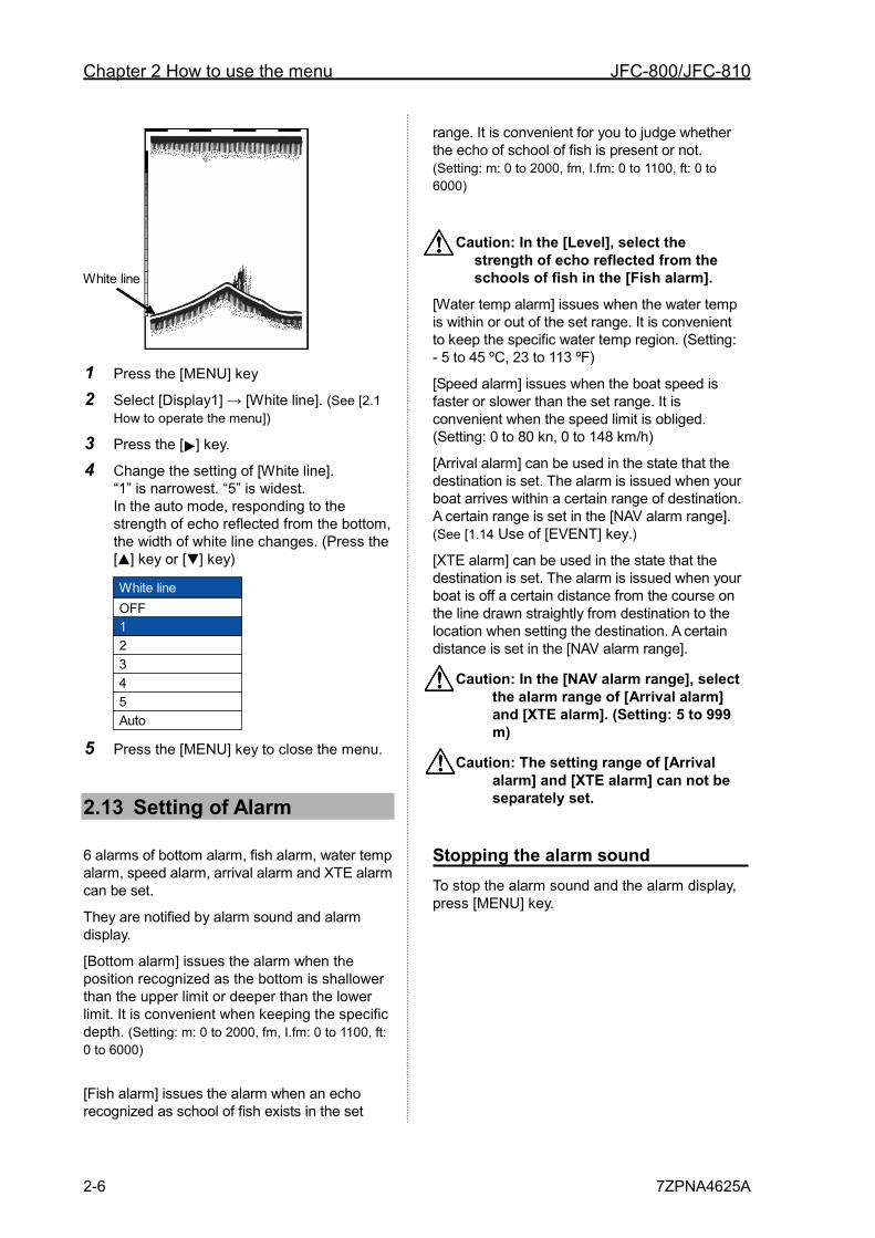
Chapter 2 How to use the menu JFC-800/JFC-810
2-6 7ZPNA4625A
White line
1 Press the [MENU] key
2 Select [Display1] → [White line]. (See [2.1 How to operate the menu])
3 Press the [ ] key.
4 Change the setting of [White line]. “1” is narrowest. “5” is widest. In the auto mode, responding to the strength of echo reflected from the bottom, the width of white line changes. (Press the [ ] key or [ ] key)
White lineOFF12345Auto
5 Press the [MENU] key to close the menu.
2.13 Setting of Alarm
6 alarms of bottom alarm, fish alarm, water temp alarm, speed alarm, arrival alarm and XTE alarm can be set.
They are notified by alarm sound and alarm display.
[Bottom alarm] issues the alarm when the position recognized as the bottom is shallower than the upper limit or deeper than the lower limit. It is convenient when keeping the specific depth. (Setting: m: 0 to 2000, fm, I.fm: 0 to 1100, ft: 0 to 6000)
[Fish alarm] issues the alarm when an echo recognized as school of fish exists in the set
range. It is convenient for you to judge whether the echo of school of fish is present or not. (Setting: m: 0 to 2000, fm, I.fm: 0 to 1100, ft: 0 to 6000)
Caution: In the [Level], select the strength of echo reflected from the schools of fish in the [Fish alarm].
[Water temp alarm] issues when the water temp is within or out of the set range. It is convenient to keep the specific water temp region. (Setting: - 5 to 45 ºC, 23 to 113 ºF)
[Speed alarm] issues when the boat speed is faster or slower than the set range. It is convenient when the speed limit is obliged. (Setting: 0 to 80 kn, 0 to 148 km/h)
[Arrival alarm] can be used in the state that the destination is set. The alarm is issued when your boat arrives within a certain range of destination. A certain range is set in the [NAV alarm range]. (See [1.14 Use of [EVENT] key.)
[XTE alarm] can be used in the state that the destination is set. The alarm is issued when your boat is off a certain distance from the course on the line drawn straightly from destination to the location when setting the destination. A certain distance is set in the [NAV alarm range].
Caution: In the [NAV alarm range], select the alarm range of [Arrival alarm] and [XTE alarm]. (Setting: 5 to 999 m)
Caution: The setting range of [Arrival alarm] and [XTE alarm] can not be separately set.
Stopping the alarm sound To stop the alarm sound and the alarm display, press [MENU] key.
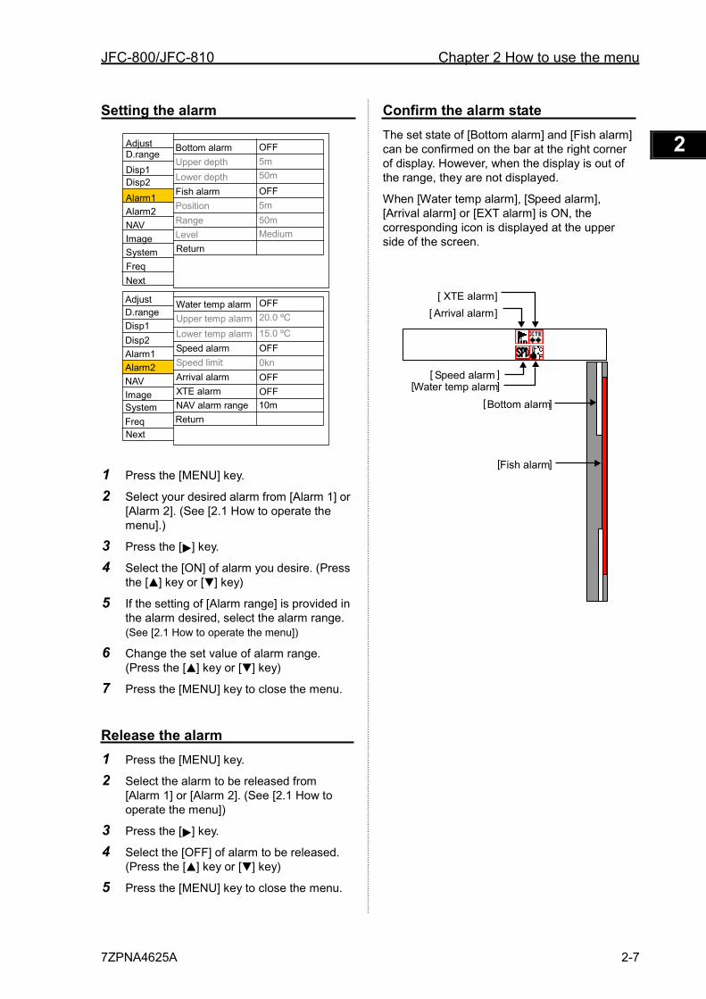
JFC-800/JFC-810 Chapter 2 How to use the menu
7ZPNA4625A 2-7
1 2 3 4 5 6 7 8 9 10 11 12 13 14 15 16 17 18 19 20 21 22 23 24 25 26 付録
Setting the alarm
1 Press the [MENU] key.
2 Select your desired alarm from [Alarm 1] or [Alarm 2]. (See [2.1 How to operate the menu].)
3 Press the [ ] key.
4 Select the [ON] of alarm you desire. (Press the [ ] key or [ ] key)
5 If the setting of [Alarm range] is provided in the alarm desired, select the alarm range. (See [2.1 How to operate the menu])
6 Change the set value of alarm range. (Press the [ ] key or [ ] key)
7 Press the [MENU] key to close the menu.
Release the alarm 1 Press the [MENU] key.
2 Select the alarm to be released from [Alarm 1] or [Alarm 2]. (See [2.1 How to operate the menu])
3 Press the [ ] key.
4 Select the [OFF] of alarm to be released. (Press the [ ] key or [ ] key)
5 Press the [MENU] key to close the menu.
Confirm the alarm state The set state of [Bottom alarm] and [Fish alarm] can be confirmed on the bar at the right corner of display. However, when the display is out of the range, they are not displayed.
When [Water temp alarm], [Speed alarm], [Arrival alarm] or [EXT alarm] is ON, the corresponding icon is displayed at the upper side of the screen.
[ Bottom alarm ]
[ Fish alarm ]
[ Speed alarm ]
[ Arrival alarm ] [ XTE alarm ]
[ Water temp alarm ]
Adjust
Disp1 D.range
Alarm1
Alarm2
NAV
Image
System
Bottom alarm Upper depth Lower depth Fish alarm Position Range Level Return
OFF 5m 50m OFF 5m 50m Medium
Adjust
Disp1 D.range
Disp2
Alarm1
Alarm2
NAV
Image
System
Water temp alarm Upper temp alarm Lower temp alarm Speed alarm Speed limit Arrival alarm XTE alarm NAV alarm range Return
OFF 20.0 ºC 15.0 ºC OFF 0kn OFF OFF 10m
Next
Next
Disp2
Freq
Freq
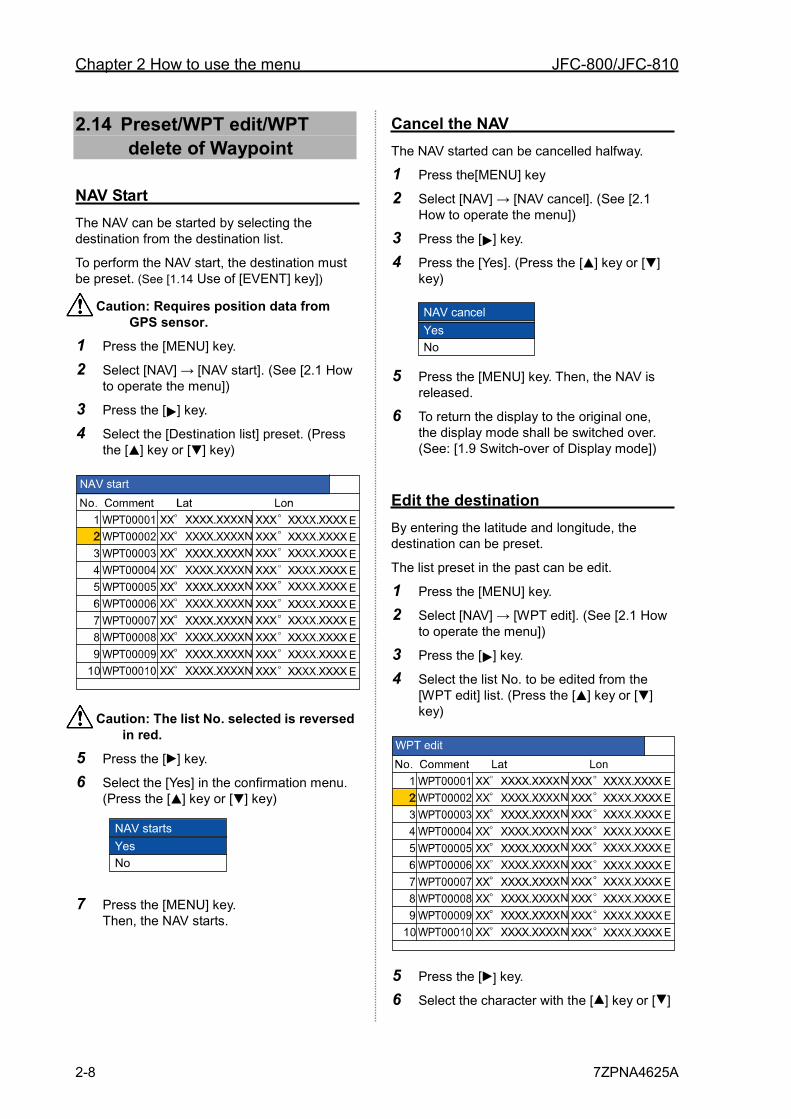
Chapter 2 How to use the menu JFC-800/JFC-810
2-8 7ZPNA4625A
2.14 Preset/WPT edit/WPT delete of Waypoint
NAV Start The NAV can be started by selecting the destination from the destination list.
To perform the NAV start, the destination must be preset. (See [1.14 Use of [EVENT] key])
Caution: Requires position data from GPS sensor.
1 Press the [MENU] key.
2 Select [NAV] → [NAV start]. (See [2.1 How to operate the menu])
3 Press the [ ] key.
4 Select the [Destination list] preset. (Press the [ ] key or [ ] key)
Caution: The list No. selected is reversed in red.
5 Press the [ ] key.
6 Select the [Yes] in the confirmation menu. (Press the [ ] key or [ ] key)
7 Press the [MENU] key. Then, the NAV starts.
Cancel the NAV The NAV started can be cancelled halfway.
1 Press the[MENU] key
2 Select [NAV] → [NAV cancel]. (See [2.1 How to operate the menu])
3 Press the [ ] key.
4 Press the [Yes]. (Press the [ ] key or [ ] key)
NAV cancelYesNo
5 Press the [MENU] key. Then, the NAV is released.
6 To return the display to the original one, the display mode shall be switched over. (See: [1.9 Switch-over of Display mode])
Edit the destination By entering the latitude and longitude, the destination can be preset.
The list preset in the past can be edit.
1 Press the [MENU] key.
2 Select [NAV] → [WPT edit]. (See [2.1 How to operate the menu])
3 Press the [ ] key.
4 Select the list No. to be edited from the [WPT edit] list. (Press the [ ] key or [ ] key)
5 Press the [ ] key.
6 Select the character with the [ ] key or [ ]
NAV startsYesNo
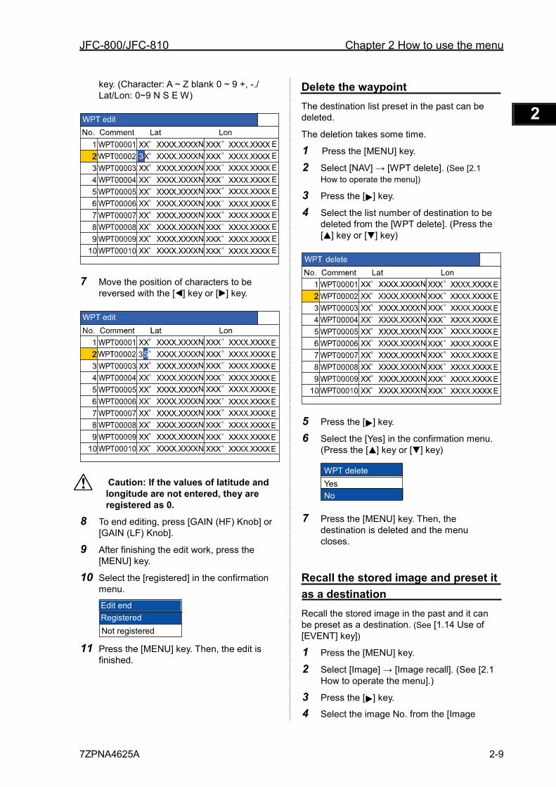
JFC-800/JFC-810 Chapter 2 How to use the menu
7ZPNA4625A 2-9
1 2 3 4 5 6 7 8 9 10 11 12 13 14 15 16 17 18 19 20 21 22 23 24 25 26 付録
key. (Character: A ~ Z blank 0 ~ 9 +, -./ Lat/Lon: 0~9 N S E W)
7 Move the position of characters to be reversed with the [ ] key or [ ] key.
Caution: If the values of latitude and longitude are not entered, they are registered as 0.
8 To end editing, press [GAIN (HF) Knob] or [GAIN (LF) Knob].
9 After finishing the edit work, press the [MENU] key.
10 Select the [registered] in the confirmation menu.
11 Press the [MENU] key. Then, the edit is
finished.
Delete the waypoint The destination list preset in the past can be deleted.
The deletion takes some time.
1 Press the [MENU] key.
2 Select [NAV] → [WPT delete]. (See [2.1 How to operate the menu])
3 Press the [ ] key.
4 Select the list number of destination to be deleted from the [WPT delete]. (Press the [ ] key or [ ] key)
5 Press the [ ] key.
6 Select the [Yes] in the confirmation menu. (Press the [ ] key or [ ] key)
7 Press the [MENU] key. Then, the
destination is deleted and the menu closes.
Recall the stored image and preset it as a destination Recall the stored image in the past and it can be preset as a destination. (See [1.14 Use of [EVENT] key])
1 Press the [MENU] key.
2 Select [Image] → [Image recall]. (See [2.1 How to operate the menu].)
3 Press the [ ] key.
4 Select the image No. from the [Image
WPT delete Yes No
Registered Edit end
Not registered
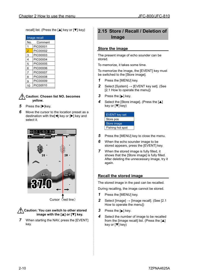
Chapter 2 How to use the menu JFC-800/JFC-810
2-10 7ZPNA4625A
recall] list. (Press the [ ] key or [ ] key)
Caution: Chosen list NO. becomes yellow.
5 Press the [ ]key.
6 Move the cursor to the location preset as a destination with the[ ] key or [ ] key and select it.
Caution: You can switch to other stored image with the [ ] or [ ] key.
7 When starting the NAV, press the [EVENT] key.
2.15 Store / Recall / Deletion of Image
Store the image The present image of echo sounder can be stored.
To memorize, it takes some time.
To memorize the image, the [EVENT] key must be switched to the [Store image].
1 Press the [MENU] key.
2 Select [System] → [EVENT key set]. (See [2.1 How to operate the menu])
3 Press the [ ] key.
4 Select the [Store image]. (Press the [ ] key or [ ] key)
5 Press the [MENU] key to close the menu.
6 When the echo sounder image to be stored appears, press the [EVENT] key.
7 When the stored image is fully filled, it shows that the [Store image] is fully filled. After deleting the unnecessary image, try it again.
Recall the stored image The stored image in the past can be recalled.
During recalling, the image cannot be stored.
1 Press the [MENU] key.
2 Select [Image] → [Image recall]. (See [2.1 How to operate the menu])
3 Press the [ ] key.
4 Select the number of image to be recalled from the [Image recall] list. (Press the [ ] key or [ ] key)
Cursor(red line)
H L
EVENT key set Store pos Store image Fishing hot spot
Image recall No. Comment 1 2 3 4
5
6 7 8
9 10
P I C 0 0 0 0 1 P I C 0 0 0 02 P I C 0 0 0 03 P I C 0 0 0 04 P I C 0 0 0 05 P I C 0 0 0 06 P I C 0 0 0 07 P I C 0 0 0 08 P I C 0 0 0 09 P I C 0 0 010
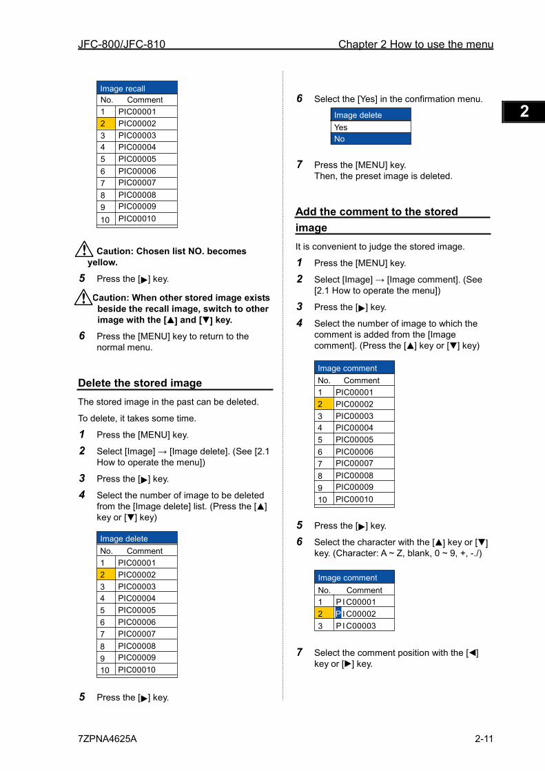
JFC-800/JFC-810 Chapter 2 How to use the menu
7ZPNA4625A 2-11
1 2 3 4 5 6 7 8 9 10 11 12 13 14 15 16 17 18 19 20 21 22 23 24 25 26 付録
Caution: Chosen list NO. becomes yellow.
5 Press the [ ] key.
Caution: When other stored image exists beside the recall image, switch to other image with the [ ] and [ ] key.
6 Press the [MENU] key to return to the normal menu.
Delete the stored image The stored image in the past can be deleted.
To delete, it takes some time.
1 Press the [MENU] key.
2 Select [Image] → [Image delete]. (See [2.1 How to operate the menu])
3 Press the [ ] key.
4 Select the number of image to be deleted from the [Image delete] list. (Press the [ ] key or [ ] key)
5 Press the [ ] key.
6 Select the [Yes] in the confirmation menu.
7 Press the [MENU] key. Then, the preset image is deleted.
Add the comment to the stored image It is convenient to judge the stored image.
1 Press the [MENU] key.
2 Select [Image] → [Image comment]. (See [2.1 How to operate the menu])
3 Press the [ ] key.
4 Select the number of image to which the comment is added from the [Image comment]. (Press the [ ] key or [ ] key)
5 Press the [ ] key.
6 Select the character with the [ ] key or [ ] key. (Character: A ~ Z, blank, 0 ~ 9, +, -./)
7 Select the comment position with the [ ] key or [ ] key.
Image delete Yes No
Image recall No. Comment 1 2
3 4
5
6 7
8 9
10
P I C 0 0 0 0 1 P I C 0 0 0 02 P I C 0 0 0 03 P I C 0 0 0 04 P I C 0 0 0 05 P I C 0 0 0 06 P I C 0 0 0 07 P I C 0 0 0 08 P I C 0 0 0 09 P I C 0 0 010
Image delete No. Comment 1 2
3 4
5 6 7
8
9 10
P I C 0 0 0 0 1 P I C 0 0 0 02 P I C 0 0 0 03 P I C 0 0 0 04 P I C 0 0 0 05 P I C 0 0 0 06 P I C 0 0 0 07 P I C 0 0 0 08 P I C 0 0 0 09 P I C 0 0 010
Image comment No. Comment 1 2
3 4
5
6 7
8 9 10
P I C 0 0 0 0 1 P I C 0 0 0 02 P I C 0 0 0 03 P I C 0 0 0 04 P I C 0 0 0 05 P I C 0 0 0 06 P I C 0 0 0 07 P I C 0 0 0 08 P I C 0 0 0 09 P I C 0 0 010
Image comment No. Comment 1 2
3
P I C 0 0 0 0 1 P I C 0 0 0 02 P I C 0 0 0 03
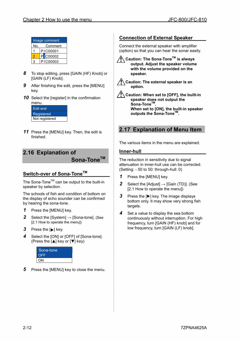
Chapter 2 How to use the menu JFC-800/JFC-810
2-12 7ZPNA4625A
8 To stop editing, press [GAIN (HF) Knob] or [GAIN (LF) Knob].
9 After finishing the edit, press the [MENU] key.
10 Select the [register] in the confirmation menu.
11 Press the [MENU] key. Then, the edit is finished.
2.16 Explanation of Sona-ToneTM
Switch-over of Sona-ToneTM The Sona-ToneTM can be output to the built-in speaker by selection.
The schools of fish and condition of bottom on the display of echo sounder can be confirmed by hearing the sona-tone.
1 Press the [MENU] key.
2 Select the [System] → [Sona-tone]. (See [2.1 How to operate the menu])
3 Press the [ ] key.
4 Select the [ON] or [OFF] of [Sona-tone]. (Press the [ ] key or [ ] key)
5 Press the [MENU] key to close the menu.
Connection of External Speaker Connect the external speaker with amplifier (option) so that you can hear the sonar easily.
Caution: The Sona-ToneTM is always output. Adjust the speaker volume with the volume provided on the speaker.
Caution: The external speaker is an option.
Caution: When set to [OFF], the built-in speaker does not output the Sona-ToneTM. When set to [ON], the built-in speaker outputs the Sona-ToneTM.
2.17 Explanation of Menu Item
The various items in the menu are explained.
Inner-hull The reduction in sensitivity due to signal attenuation in inner-hull use can be corrected. (Setting: - 50 to 50: through-hull: 0)
1 Press the [MENU] key.
2 Select the [Adjust] → [Gain (TD)]. (See [2.1 How to operate the menu])
3 Press the [ ] key. The image displays bottom only. It may show very strong fish targets.
4 Set a value to display the sea bottom continuously without interruption. For high frequency, turn [GAIN (HF) knob] and for low frequency, turn [GAIN (LF) knob].
Edit end Registered Not registered
1 2
3
P I C 0 0 0 0 1 P I C 0 0 0 02 P I C 0 0 0 03
Image comment No. Comment
Sonar toneOFFON
Sona-tone
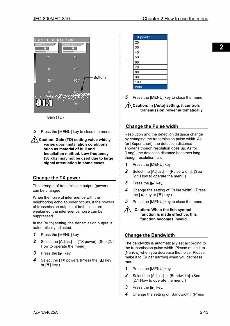
JFC-800/JFC-810 Chapter 2 How to use the menu
7ZPNA4625A 2-13
1 2 3 4 5 6 7 8 9 10 11 12 13 14 15 16 17 18 19 20 21 22 23 24 25 26 付録
5 Press the [MENU] key to close the menu.
Caution: Gain (TD) setting value widely varies upon installation conditions such as material of hull and installation method. Low frequency (50 kHz) may not be used due to large signal attenuation in some cases.
Change the TX power The strength of transmission output (power) can be changed.
When the noise of interference with the neighboring echo sounder occurs, if the powers of transmission outputs at both sides are weakened, the interference noise can be suppressed.
In the [Auto] setting, the transmission output is automatically adjusted.
1 Press the [MENU] key.
2 Select the [Adjust] → [TX power]. (See [2.1 How to operate the menu])
3 Press the [ ] key.
4 Select the [TX power]. (Press the [ ] key or [ ] key.)
5 Press the [MENU] key to close the menu.
Caution: In [Auto] setting, it controls transmission power automatically.
Change the Pulse width Resolution and the detection distance change by changing the transmission pulse width. As for [Super short], the detection distance shortens though resolution goes up. As for [Long], the detection distance becomes long though resolution falls.
1 Press the [MENU] key.
2 Select the [Adjust] → [Pulse width]. (See [2.1 How to operate the menu])
3 Press the [ ] key.
4 Change the setting of [Pulse width]. (Press the [ ] key or [ ] key.)
5 Press the [MENU] key to close the menu.
Caution: When the fish symbol function is made effective, this function becomes invalid.
Change the Bandwidth The bandwidth is automatically set according to the transmission pulse width. Please make it to [Narrow] when you decrease the noise. Please make it to [Super narrow] when you decrease more.
1 Press the [MENU] key.
2 Select the [Adjust] → [Bandwidth]. (See [2.1 How to operate the menu])
3 Press the [ ] key.
4 Change the setting of [Bandwidth]. (Press
Bottom
Gain (TD)
Gain (TD) L Gain (TD) H
L: 6.0 H: 6.0 R:M 12.0V TX power
1
Auto
2030405060708090100
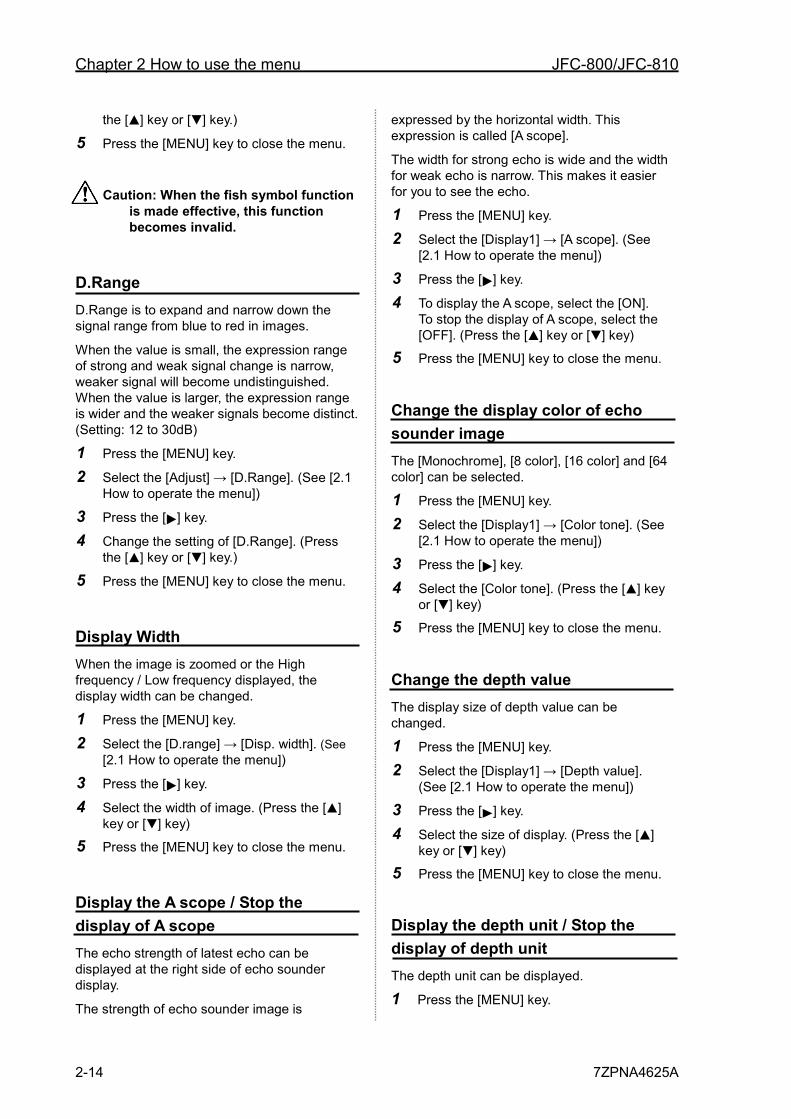
Chapter 2 How to use the menu JFC-800/JFC-810
2-14 7ZPNA4625A
the [ ] key or [ ] key.)
5 Press the [MENU] key to close the menu.
Caution: When the fish symbol function is made effective, this function becomes invalid.
D.Range D.Range is to expand and narrow down the signal range from blue to red in images.
When the value is small, the expression range of strong and weak signal change is narrow, weaker signal will become undistinguished. When the value is larger, the expression range is wider and the weaker signals become distinct. (Setting: 12 to 30dB)
1 Press the [MENU] key.
2 Select the [Adjust] → [D.Range]. (See [2.1 How to operate the menu])
3 Press the [ ] key.
4 Change the setting of [D.Range]. (Press the [ ] key or [ ] key.)
5 Press the [MENU] key to close the menu.
Display Width When the image is zoomed or the High frequency / Low frequency displayed, the display width can be changed.
1 Press the [MENU] key.
2 Select the [D.range] → [Disp. width]. (See [2.1 How to operate the menu])
3 Press the [ ] key.
4 Select the width of image. (Press the [ ] key or [ ] key)
5 Press the [MENU] key to close the menu.
Display the A scope / Stop the display of A scope The echo strength of latest echo can be displayed at the right side of echo sounder display.
The strength of echo sounder image is
expressed by the horizontal width. This expression is called [A scope].
The width for strong echo is wide and the width for weak echo is narrow. This makes it easier for you to see the echo.
1 Press the [MENU] key.
2 Select the [Display1] → [A scope]. (See [2.1 How to operate the menu])
3 Press the [ ] key.
4 To display the A scope, select the [ON]. To stop the display of A scope, select the [OFF]. (Press the [ ] key or [ ] key)
5 Press the [MENU] key to close the menu.
Change the display color of echo sounder image The [Monochrome], [8 color], [16 color] and [64 color] can be selected.
1 Press the [MENU] key.
2 Select the [Display1] → [Color tone]. (See [2.1 How to operate the menu])
3 Press the [ ] key.
4 Select the [Color tone]. (Press the [ ] key or [ ] key)
5 Press the [MENU] key to close the menu.
Change the depth value The display size of depth value can be changed.
1 Press the [MENU] key.
2 Select the [Display1] → [Depth value]. (See [2.1 How to operate the menu])
3 Press the [ ] key.
4 Select the size of display. (Press the [ ] key or [ ] key)
5 Press the [MENU] key to close the menu.
Display the depth unit / Stop the display of depth unit The depth unit can be displayed.
1 Press the [MENU] key.
JFC-800/JFC-810 Chapter 2 How to use the menu
7ZPNA4625A 2-15
1 2 3 4 5 6 7 8 9 10 11 12 13 14 15 16 17 18 19 20 21 22 23 24 25 26 付録
2 Select the [Display1] → [Unit display]. (See [2.1 How to operate the menu])
3 Press the [ ] key.
4 To display the depth unit, select the [ON]. To stop the display of depth unit, select the [OFF]. (Press the [ ] key or [ ] key)
5 Press the [MENU] key to close the menu.
Display the water temp graph / Stop the display of water temp graph The latest water temp value and the graph of past water temp data can be displayed.
1 Press the [MENU] key.
2 Select the [Display1] → [Water temp graph]. (See [2.1 How to operate the menu])
3 Press the [ ] key.
4 To display the water temp graph, select the [ON]. To stop the display of water temp graph, select the [OFF]. (Press the [ ] key or [ ] key)
5 Press the [MENU] key to close the menu.
Setting of the background color of NAV display The color of background of navigation display (NAV1, NAV2) can be changed.
1 Press the [MENU] key.
2 Select the [NAV] → [Background color]. (See [2.1 How to operate the menu].)
3 Press the [ ] key.
4 Select the [Background color]. (Press the [ ] key or [ ] key)
5 Press the [MENU] key to close the menu.
Setting of the echo sounder display at NAV display The sounder display can be selected at NAV (NAV 1, NAV 2) to be displayed.
1 Press the [MENU] key.
2 Select the [NAV] → [NAV1 (2)]. (See [2.1 How to operate the menu])
3 Press the [ ] key.
4 Select the echo sounder display at [NAV 1] or [NAV 2] to be displayed. (Press the [ ] key or [ ] key)
5 Press the [MENU] key to close the menu.
Image Swap The images of echo sounder at the right and left sides can be swapped.
1 Press the [MENU] key.
2 Select the [Image] → [Image swap]. (See [2.1 How to operate the menu])
3 Press the [ ] key.
4 Select the swap state[A|B],[B|A]. (Press the [ ] key or [ ] key)
5 Press the [MENU] key to close the menu.
Display the Operation guide/Stop the display of Operation guide When displaying the menu, it sets whether or not the operation guide is displayed at the lower part on the display.
When setting to “No display of operation guide”, the echo sounder image can be easily seen at the menu operation.
1 Press the [MENU] key.
2 Select the [System] → [Operation guide]. (See [2.1 How to operate the menu])
3 Press the [ ] key.
4 To display the Operation guide, select the [ON]. To stop the display of Operation guide, select the [OFF]. (Press the [ ] key or [ ] key)
5 Press the [MENU] key to close the menu.
Display the detection area / Stop the display of detection area The range of the search that can be detected in the angle of beam spread of the transducer used can be displayed.
Chapter 2 How to use the menu JFC-800/JFC-810
2-16 7ZPNA4625A
1 Press the [MENU] key.
2 Select the [Display2] → [Detection area]. (See [2.1 How to operate the menu])
3 Press the [ ] key.
4 To display the Detection area, select the [ON]. To stop the display of Detection area, select the [OFF]. (Press the [ ] key or [ ] key)
5 Press the [MENU] key to close the menu.
Caution: The beam angle of transducer is different depending on the transducer. (See [3.3 Setting of Correct Item, Directirity angle (Low/High)].)
Setting of Scale display The set of the scale display
1 Press the [MENU] key.
2 Select the [Display2] → [Scale display]. (See [2.1 How to operate the menu])
3 Press the [ ] key.
4 Select the [Scale display]. (Press the [ ] key or [ ] key)
5 Press the [MENU] key to close the menu.
Change the scale value The display size of the scale value can be changed.
1 Press the [MENU] key.
2 Select the [Display2] → [Scale]. (See [2.1 How to operate the menu])
3 Press the [ ] key.
4 Select the [Scale]. (Press the [ ] key or [ ] key)
5 Press the [MENU] key to close the menu.
Change the image direction Selects the direction of display image.
1 Press the [MENU] key.
2 Select the [Display2] → [Image direction]. (See [2.1 How to operate the menu])
3 Press the [ ] key.
4 Select the [Image direction]. (Press the [ ] key or [ ] key)
5 Press the [MENU] key to close the menu.
Setting of Depth measurement Selects the method for depth measurement, which is shown on the display.
1 Press the [MENU] key.
2 Select the [Display2] → [Bottom detection]. (See [2.1 How to operate the menu])
3 Press the [ ] key.
4 Select the [Bottom detection]. (Press the [ ] key or [ ] key)
5 Press the [MENU] key to close the menu.
Change the display color The display color can be changed.
1 Press the [MENU] key.
2 Select the [Display2] → [Color table 1] or [Color table 2]. (See [2.1 How to operate the menu])
3 Press the [ ] key.
4 Select the [Color table]. (Press the [ ] key or [ ] key)
5 Press the [ ] key.
6 Select the color. (Press the [ ] key or [ ] key)
7 Press the [MENU] key to close the menu.
Setting of Key lock Disables the functions of controls and keys to avoid deviation of these settings by unintentionally touching them during operation.
1 Press the [MENU] key.
2 Select the [System] → [Key lock]. (See [2.1 How to operate the menu])
3 Press the [ ] key.
4 Select the [Key lock]. (Press the [ ] key or [ ] key)
5 Press the [ ] key.
JFC-800/JFC-810 Chapter 2 How to use the menu
7ZPNA4625A 2-17
1 2 3 4 5 6 7 8 9 10 11 12 13 14 15 16 17 18 19 20 21 22 23 24 25 26 付録
6 Select the [ON] or [OFF]. (Press the [ ] key or [ ] key)
7 Press the [MENU] key to close the menu.
Sub Depth Value Depth value can be displayed with the selected depth unit independently in addition to the Main depth value.
1 Press the [MENU] key.
2 Select the [System] → [Sub Depth Value]. (See [2.1 How to operate the menu])
3 Press the [ ] key.
4 Select the Sub Depth unit from [m], [fm], [I.fm] or [ft].
To stop the display of Sub Depth Value, select [OFF]. (Press the [ ] key or [ ] key)
5 Press the [MENU] key to close the menu.
Change the User setting A set value of the menu entry can be memorized by four patterns. It is convenient to switch the pattern according to the purpose of the fishery.
Caution: The unit set to [1] at the factory.
1 Press the [MENU] key.
2 Select the [System] → [User set]. (See [2.1 How to operate the menu])
3 Press the [ ] key.
4 Select the [2]. (Press the [ ] key or [ ] key)
5 Press the [MENU] key to close the menu.
6 When a set value of the menu entry is changed, it is automatically memorized in [2].
7 [3] and [4] also memorize a set value of the menu entry by a similar operation, and it is possible to switch.
Change the scale type The interval of indications of scale can be
changed.
1 Press the [MENU] key.
2 Select the [Display2] → [Scale type]. (See [2.1 How to operate the menu])
3 Press the [ ] key.
4 Select the [Scale type]. (Press the [ ] key or [ ] key)
5 Press the [MENU] key to close the menu.
Change the bottom color The dark red color of sea bottom can be changed.
1 Press the [MENU] key.
2 Select the [Display2] → [Color table 2] → [Bottom color]. (See [2.1 How to operate the menu])
3 Press the [ ] key.
4 Select the [Bottom color]. (Press the [ ] key or [ ] key)
Black ← 0, , , 176, , , 255 → Red
5 Press the [MENU] key to close the menu.
Change the image partition The image partition of echo sounder can be change to "Horizontal split" or “Vertical split”.
1 Press the [MENU] key.
2 Select the [Image] → [Image partition]. (See [2.1 How to operate the menu])
3 Press the [ ] key.
4 Select the [Image partition]. (Press the [ ] key or [ ] key)
5 Press the [MENU] key to close the menu.
Display the frequency / Stop the display of frequency The frequeny of the transducer currently in use can be displayed.
1 Press the [MENU] key.
2 Select the [Display2] → [Freq display]. (See [2.1 How to operate the menu])
3 Press the [ ] key.
Chapter 2 How to use the menu JFC-800/JFC-810
2-18 7ZPNA4625A
4 To display the Freq display, select the [ON]. To stop the display of Freq display, select the [OFF]. (Press the [ ] key or [ ] key)
5 Press the [MENU] key to close the menu.
Selecting a display area of fish symbol indication The fish symbol can be displayed either on side A or on side B, or on both sides, by the following operation.
1 Press the [MENU] key.
2 Select the [Image] → [Fish image]. (See [2.1 How to operate the menu])
3 Press the [ ] key.
4 Select the [A|B], [A| ], [ |B]. (Press the [ ] key or [ ] key)
5 Press the [MENU] key to close the menu.
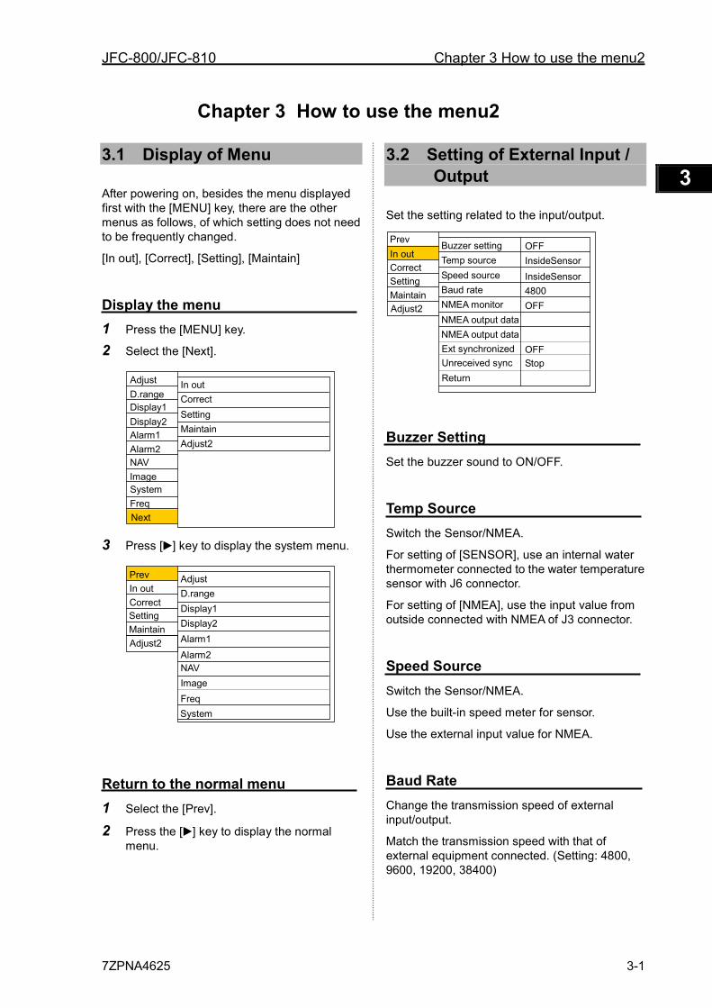
JFC-800/JFC-810 Chapter 3 How to use the menu2
7ZPNA4625 3-1
1 2 3 4 5 6 7 8 9 10 11 12 13 14 15 16 17 18 19 20 21 22 23 24 25 26 付録
Chapter 3 How to use the menu2
3.1 Display of Menu
After powering on, besides the menu displayed first with the [MENU] key, there are the other menus as follows, of which setting does not need to be frequently changed.
[In out], [Correct], [Setting], [Maintain]
Display the menu 1 Press the [MENU] key.
2 Select the [Next].
3 Press [ ] key to display the system menu.
Return to the normal menu 1 Select the [Prev].
2 Press the [ ] key to display the normal menu.
3.2 Setting of External Input / Output
Set the setting related to the input/output.
Buzzer Setting Set the buzzer sound to ON/OFF.
Temp Source Switch the Sensor/NMEA.
For setting of [SENSOR], use an internal water thermometer connected to the water temperature sensor with J6 connector.
For setting of [NMEA], use the input value from outside connected with NMEA of J3 connector.
Speed Source Switch the Sensor/NMEA.
Use the built-in speed meter for sensor.
Use the external input value for NMEA.
Baud Rate Change the transmission speed of external input/output.
Match the transmission speed with that of external equipment connected. (Setting: 4800, 9600, 19200, 38400)
Correct In out
Setting Maintain
Buzzer setting Temp source Speed source Baud rate NMEA monitor
OFF InsideSensor InsideSensor 4800 OFF
NMEA output data
Ext synchronized NMEA output data
Return
OFF
Adjust2
Unreceived sync Stop
Display1 D.range
Display2
Alarm1 Alarm2
NAV Image
System
In out Correct Setting Maintain
Freq
Adjust2
Next
Adjust2
Correct In out
Setting Maintain
Adjust
D.range Display1 Display2
Alarm1 Alarm2
NAV Image
System
Freq
Adjust
Prev
Prev
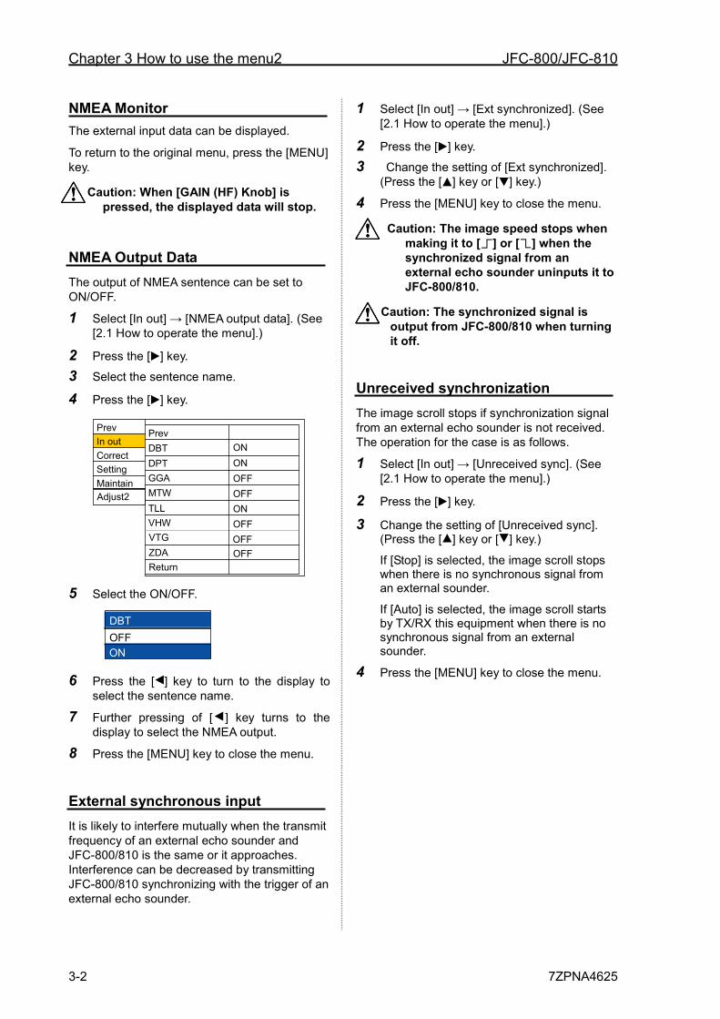
Chapter 3 How to use the menu2 JFC-800/JFC-810
3-2 7ZPNA4625
NMEA Monitor The external input data can be displayed.
To return to the original menu, press the [MENU] key.
Caution: When [GAIN (HF) Knob] is pressed, the displayed data will stop.
NMEA Output Data The output of NMEA sentence can be set to ON/OFF.
1 Select [In out] → [NMEA output data]. (See [2.1 How to operate the menu].)
2 Press the [ ] key.
3 Select the sentence name.
4 Press the [ ] key.
5 Select the ON/OFF.
6 Press the [ ] key to turn to the display to select the sentence name.
7 Further pressing of [ ] key turns to the display to select the NMEA output.
8 Press the [MENU] key to close the menu.
External synchronous input It is likely to interfere mutually when the transmit frequency of an external echo sounder and JFC-800/810 is the same or it approaches. Interference can be decreased by transmitting JFC-800/810 synchronizing with the trigger of an external echo sounder.
1 Select [In out] → [Ext synchronized]. (See [2.1 How to operate the menu].)
2 Press the [ ] key.
3 Change the setting of [Ext synchronized]. (Press the [ ] key or [ ] key.)
4 Press the [MENU] key to close the menu.
Caution: The image speed stops when making it to [ ] or [ ] when the synchronized signal from an external echo sounder uninputs it to JFC-800/810.
Caution: The synchronized signal is output from JFC-800/810 when turning it off.
Unreceived synchronization The image scroll stops if synchronization signal from an external echo sounder is not received. The operation for the case is as follows.
1 Select [In out] → [Unreceived sync]. (See [2.1 How to operate the menu].)
2 Press the [ ] key.
3 Change the setting of [Unreceived sync]. (Press the [ ] key or [ ] key.)
If [Stop] is selected, the image scroll stops when there is no synchronous signal from an external sounder.
If [Auto] is selected, the image scroll starts by TX/RX this equipment when there is no synchronous signal from an external sounder.
4 Press the [MENU] key to close the menu.
Correct In out
Setting Maintain
Prev DBT DPT GGA MTW OFF TLL
VTG VHW
Return ZDA OFF
OFF OFF
OFF
ON ON
ON Adjust2
Prev
DBT
OFF ON
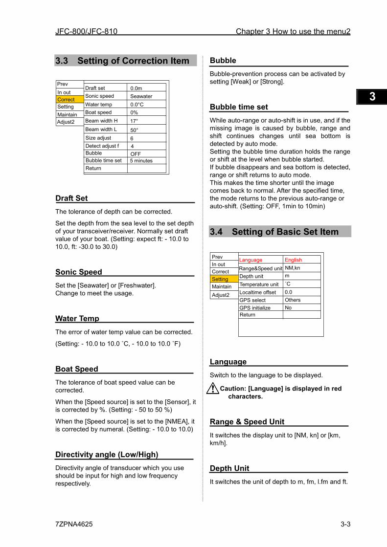
JFC-800/JFC-810 Chapter 3 How to use the menu2
7ZPNA4625 3-3
1 2 3 4 5 6 7 8 9 10 11 12 13 14 15 16 17 18 19 20 21 22 23 24 25 26 付録
3.3 Setting of Correction Item
Draft Set The tolerance of depth can be corrected.
Set the depth from the sea level to the set depth of your transceiver/receiver. Normally set draft value of your boat. (Setting: expect ft: - 10.0 to 10.0, ft: -30.0 to 30.0)
Sonic Speed Set the [Seawater] or [Freshwater]. Change to meet the usage.
Water Temp The error of water temp value can be corrected.
(Setting: - 10.0 to 10.0 ˚C, - 10.0 to 10.0 ˚F)
Boat Speed The tolerance of boat speed value can be corrected.
When the [Speed source] is set to the [Sensor], it is corrected by %. (Setting: - 50 to 50 %)
When the [Speed source] is set to the [NMEA], it is corrected by numeral. (Setting: - 10.0 to 10.0)
Directivity angle (Low/High) Directivity angle of transducer which you use should be input for high and low frequency respectively.
Bubble Bubble-prevention process can be activated by setting [Weak] or [Strong].
Bubble time set While auto-range or auto-shift is in use, and if the missing image is caused by bubble, range and shift continues changes until sea bottom is detected by auto mode. Setting the bubble time duration holds the range or shift at the level when bubble started. If bubble disappears and sea bottom is detected, range or shift returns to auto mode. This makes the time shorter until the image comes back to normal. After the specified time, the mode returns to the previous auto-range or auto-shift. (Setting: OFF, 1min to 10min)
3.4 Setting of Basic Set Item
Language Switch to the language to be displayed.
Caution: [Language] is displayed in red characters.
Range & Speed Unit It switches the display unit to [NM, kn] or [km, km/h].
Depth Unit It switches the unit of depth to m, fm, l.fm and ft.
Correct In out
Setting Maintain
Draft set Sonic speed Water temp Boat speed
Size adjust
Seawater 0.0m
0.0°C 0%
Beam width H Beam width L
17° 50°
Detect adjust f 6
Bubble
Return
4 OFF
Adjust2
Bubble time set 5 minutes
Prev
Correct In out
Setting Maintain
Range&Speed unit Depth unit Temperature unit Localtime offset GPS select GPS initialize Return
m NM,kn
˚C
Others No
English Language
Adjust2 0.0
Prev
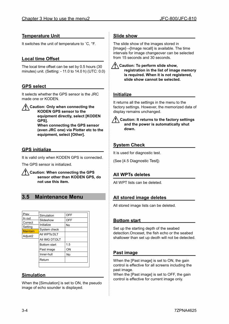
Chapter 3 How to use the menu2 JFC-800/JFC-810
3-4 7ZPNA4625
Temperature Unit It switches the unit of temperature to ˚C, °F.
Local time Offset The local time offset can be set by 0.5 hours (30 minutes) unit. (Setting: - 11.0 to 14.0 h) (UTC: 0.0)
GPS select It selects whether the GPS sensor is the JRC made one or KODEN.
Caution: Only when connecting the KODEN GPS sensor to the equipment directly, select [KODEN GPS]. When connecting the GPS sensor (even JRC one) via Plotter etc to the equipment, select [Other].
GPS initialize It is valid only when KODEN GPS is connected.
The GPS sensor is initialized.
Caution: When connecting the GPS sensor other than KODEN GPS, do not use this item.
3.5 Maintenance Menu
Simulation When the [Simulation] is set to ON, the pseudo image of echo sounder is displayed.
Slide show The slide show of the images stored in [Image]→[Image recall] is available. The time intervals for image changeover can be selected from 15 seconds and 30 seconds.
Caution: To perform slide show, registration in the list of image memory is required. When it is not registered, slide show cannot be selected.
Initialize It returns all the settings in the menu to the factory settings. However, the memorized data of display remains unchanged.
Caution: It returns to the factory settings and the power is automatically shut down.
System Check It is used for diagnostic test.
(See [4.5 Diagnostic Test])
All WPTs deletes All WPT lists can be deleted.
All stored image deletes All stored image lists can be deleted.
Bottom start Set up the starting depth of the seabed detection.Onceset, the fish echo or the seabed shallower than set up deoth will not be detected.
Past image When the [Past image] is set to ON, the gain control is effective for all screens including the past image. When the [Past image] is set to OFF, the gain control is effective for current image only.
Prev
Correct In out
Setting Maintain
Simulation
Initialize System check
Inner-hull
No OFF
All WPTs:DLT All IMG DT:DLT
Slideshow OFF
Bottom start 1.5 Past image ON
Adjust2
Return No
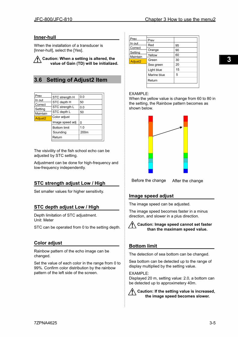
JFC-800/JFC-810 Chapter 3 How to use the menu2
7ZPNA4625 3-5
1 2 3 4 5 6 7 8 9 10 11 12 13 14 15 16 17 18 19 20 21 22 23 24 25 26 付録
Inner-hull When the installation of a transducer is [Inner-hull], select the [Yes].
Caution: When a setting is altered, the value of Gain (TD) will be initialized.
3.6 Setting of Adjust2 Item
The visivility of the fish school echo can be adjusted by STC setting.
Adjustment can be done for high-frequency and low-frequency independently.
STC strength adjust Low / High Set smaller values for higher sensitivity.
STC depth adjust Low / High Depth limitation of STC adjustment. Unit: Meter
STC can be operated from 0 to the setting depth.
Color adjust Rainbow pattern of the echo image can be changed.
Set the value of each color in the range from 0 to 99%. Confirm color distribution by the rainbow pattern of the left side of the screen.
EXAMPLE: When the yellow value is change from 60 to 80 in the setting, the Rainbow pattern becomes as shown below.
Image speed adjust The image speed can be adjusted.
The image speed becomes faster in a minus direction, and slower in a plus direction.
Caution: Image speed cannot set faster than the maximam speed value.
Bottom limit The detection of sea bottom can be changed.
Sea bottom can be detected up to the range of display multiplied by the setting value.
EXAMPLE: Displayed 20 m, setting value: 2.0, a bottom can be detected up to approximetery 40m.
Caution: If the setting value is increased, the image speed becomes slower.
Prev
Correct In out
Setting Maintain
STC strength H
STC strength L STC depth L
Return
0.0 50
Color adjust Image speed adj
STC depth H 0.0
Bottom limit 1.0
Adjust2 50
0
Sounding 200m
Prev
Correct In out
Setting Maintain
Orange
Return
Green
Red
Adjust2
Prev
Yellow
95 90 60 30
Sea green Light blue Marine blue
20 15 5
Before the change After the change
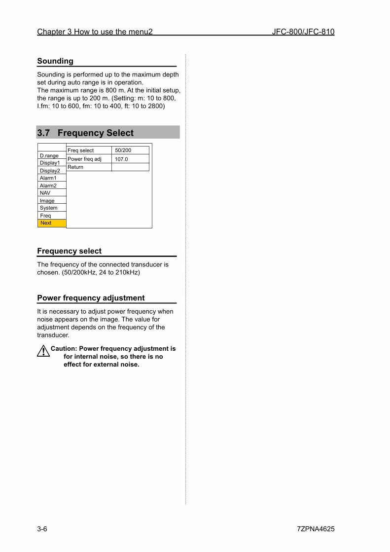
Chapter 3 How to use the menu2 JFC-800/JFC-810
3-6 7ZPNA4625
Sounding Sounding is performed up to the maximum depth set during auto range is in operation. The maximum range is 800 m. At the initial setup, the range is up to 200 m. (Setting: m: 10 to 800, I.fm: 10 to 600, fm: 10 to 400, ft: 10 to 2800)
3.7 Frequency Select
Frequency select The frequency of the connected transducer is chosen. (50/200kHz, 24 to 210kHz)
Power frequency adjustment It is necessary to adjust power frequency when noise appears on the image. The value for adjustment depends on the frequency of the transducer.
Caution: Power frequency adjustment is for internal noise, so there is no effect for external noise.
Display1 D.range
Display2
Alarm1 Alarm2
NAV Image
System
Freq select Power freq adj Return
Next Freq
50/200 107.0
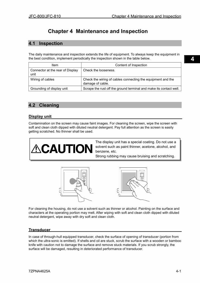
JFC-800/JFC-810 Chapter 4 Maintenance and Inspection
7ZPNA4625A 4-1
1 2 3 4 5 6 7 8 9 10 11 12 13 14 15 16 17 18 19 20 21 22 23 24 25 26 付録
Chapter 4 Maintenance and Inspection
4.1 Inspection
The daily maintenance and inspection extends the life of equipment. To always keep the equipment in the best condition, implement periodically the inspection shown in the table below.
Item Content of Inspection Connector at the rear of Display unit
Check the looseness.
Wiring of cables Check the wiring of cables connecting the equipment and the damage of cable.
Grounding of display unit Scrape the rust off the ground terminal and make its contact well.
4.2 Cleaning
Display unit Contamination on the screen may cause faint images. For cleaning the screen, wipe the screen with soft and clean cloth dipped with diluted neutral detergent. Pay full attention as the screen is easily getting scratched. No thinner shall be used.
For cleaning the housing, do not use a solvent such as thinner or alcohol. Painting on the surface and characters at the operating portion may melt. After wiping with soft and clean cloth dipped with diluted neutral detergent, wipe away with dry soft and clean cloth.
Transducer In case of through-hull equipped transducer, check the surface of opening of transducer (portion from which the ultra-sonic is emitted). If shells and oil are stuck, scrub the surface with a wooden or bamboo knife with caution not to damage the surface and remove stuck materials. If you scrub strongly, the surface will be damaged, resulting in deteriorated performance of transducer.
The display unit has a special coating. Do not use a solvent such as paint thinner, acetone, alcohol, and benzene, etc. Strong rubbing may cause bruising and scratching.
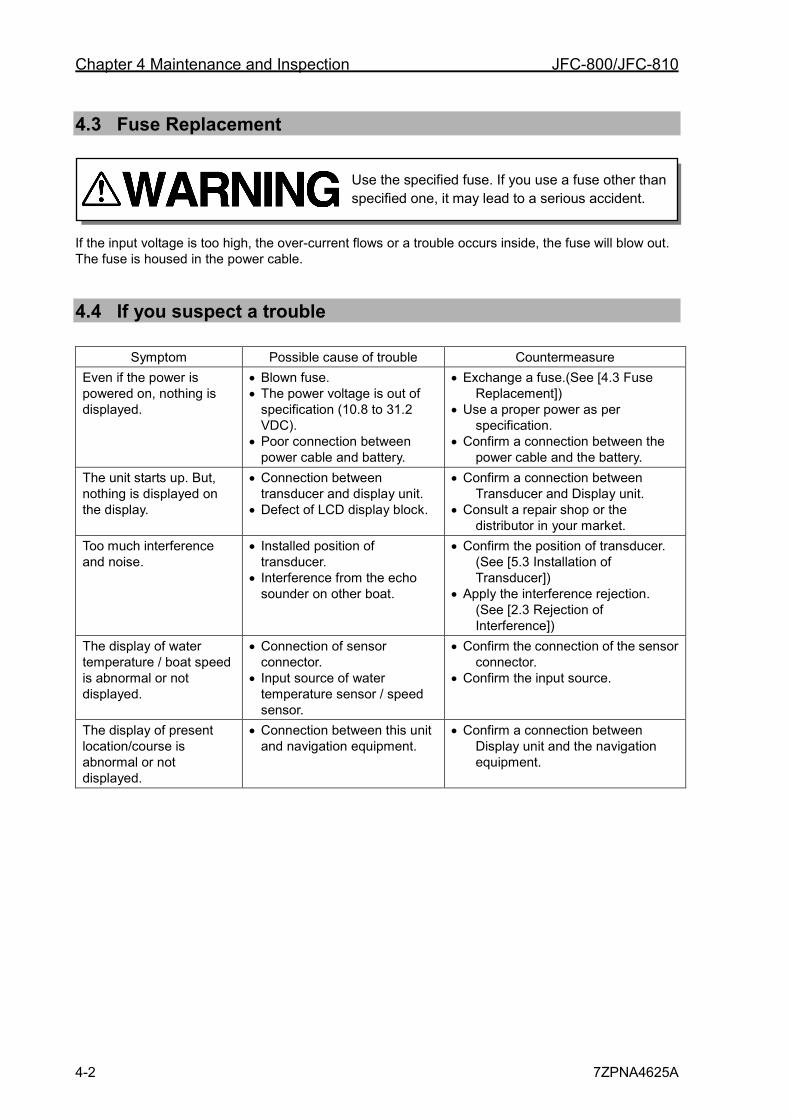
Chapter 4 Maintenance and Inspection JFC-800/JFC-810
4-2 7ZPNA4625A
4.3 Fuse Replacement
If the input voltage is too high, the over-current flows or a trouble occurs inside, the fuse will blow out. The fuse is housed in the power cable.
4.4 If you suspect a trouble
Symptom Possible cause of trouble Countermeasure Even if the power is powered on, nothing is displayed.
• Blown fuse. • The power voltage is out of
specification (10.8 to 31.2 VDC).
• Poor connection between power cable and battery.
• Exchange a fuse.(See [4.3 Fuse Replacement])
• Use a proper power as per specification.
• Confirm a connection between the power cable and the battery.
The unit starts up. But, nothing is displayed on the display.
• Connection between transducer and display unit.
• Defect of LCD display block.
• Confirm a connection between Transducer and Display unit.
• Consult a repair shop or the distributor in your market.
Too much interference and noise.
• Installed position of transducer.
• Interference from the echo sounder on other boat.
• Confirm the position of transducer. (See [5.3 Installation of Transducer])
• Apply the interference rejection. (See [2.3 Rejection of Interference])
The display of water temperature / boat speed is abnormal or not displayed.
• Connection of sensor connector.
• Input source of water temperature sensor / speed sensor.
• Confirm the connection of the sensor connector.
• Confirm the input source.
The display of present location/course is abnormal or not displayed.
• Connection between this unit and navigation equipment.
• Confirm a connection between Display unit and the navigation equipment.
Use the specified fuse. If you use a fuse other than specified one, it may lead to a serious accident.
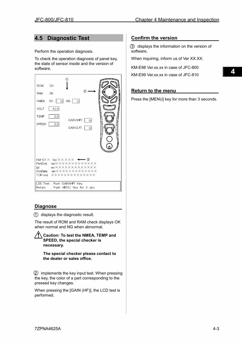
JFC-800/JFC-810 Chapter 4 Maintenance and Inspection
7ZPNA4625A 4-3
1 2 3 4 5 6 7 8 9 10 11 12 13 14 15 16 17 18 19 20 21 22 23 24 25 26 付録
4.5 Diagnostic Test
Perform the operation diagnosis.
To check the operation diagnosis of panel key, the state of sensor inside and the version of software.
Diagnose 1 displays the diagnostic result.
The result of ROM and RAM check displays OK when normal and NG when abnormal.
Caution: To test the NMEA, TEMP and SPEED, the special checker is necessary.
The special checker please contact to the dealer or sales office.
2 implements the key input test. When pressing the key, the color of a part corresponding to the pressed key changes.
When pressing the [GAIN (HF)], the LCD test is performed.
Confirm the version 3 displays the information on the version of software.
When inquiring, inform us of Ver XX.XX.
KM-E98 Ver.xx.xx in case of JFC-800
KM-E99 Ver.xx.xx in case of JFC-810
Return to the menu Press the [MENU] key for more than 3 seconds.

Chapter 4 Maintenance and Inspection JFC-800/JFC-810
4-4 7ZPNA4625A
JFC-800/JFC-810 Chapter 5 Installation
7ZPNA4625A 5-1
1 2 3 4 5 6 7 8 9 10 11 12 13 14 15 16 17 18 19 20 21 22 23 24 25 26 付録
Chapter 5 Installation
5.1 Items of Caution on Installation
To realize the full performance of echo sounder, the installation of JFC-800/JFC-810 must be performed by an engineer who is officially authorized by our company. The installation work includes the following content.
(1) Unpacking the components
(2) Inspection of configuration unit, spare, accessories and material for installation
(3) Check of power voltage and capacity of current
(4) Decision of installing location
(5) Installation of Display unit and transducer
(6) Installation of accessories
(7) Plan and execution of cable laying and connection
(8) Adjustment after completion of installation
Unpacking the components Unpack the components and confirm that all of the items match with the contents on the equipment configuration list. If not matched, Contact the dealer you purchased or our sales company.
Inspection of components and accessories Inspect the appearance of each components and accessories and check that no dents or damage exist.
If any dents or damage exist and they are believed to be caused by accident during transportation, contact the transportation and insurance company and consult our sales company or our dealer nearest to you.
Decision of Installing Location To realize the full performance of equipment, install the equipment, considering the points mentioned below.
(1) Install the equipment at the location in the bridge so that its display can be easily seen.
(2) Select a safe location where the equipment is not exposed to humidity, water splash, rain and direct sunshine.
(3) Keep enough space for maintenance. Especially, secure enough space at the rear panel where many cables are concentrated.
(4) Keep the equipment as far away from the wireless transmitter/receiver as possible.
The equipment is not waterproof. Avoid excessively damp place. Do not install the equipment in the place suffering from excessive water-drops. Otherwise, the corrosion may occur inside.
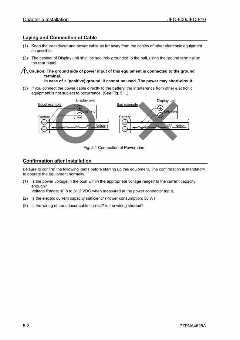
Chapter 5 Installation JFC-800/JFC-810
5-2 7ZPNA4625A
Laying and Connection of Cable (1) Keep the transducer and power cable as far away from the cables of other electronic equipment
as possible.
(2) The cabinet of Display unit shall be securely grounded to the hull, using the ground terminal on the rear panel.
Caution: The ground side of power input of this equipment is connected to the ground terminal. In case of + (positive) ground, it cannot be used. The power may short-circuit.
(3) If you connect the power cable directly to the battery, the interference from other electronic equipment is not subject to occurrence. (See Fig. 5.1.)
Fig. 5.1 Connection of Power Line
Confirmation after Installation Be sure to confirm the following items before starting up this equipment. The confirmation is mandatory to operate the equipment normally.
(1) Is the power voltage in the boat within the appropriate voltage range? Is the current capacity enough? Voltage Range: 10.8 to 31.2 VDC when measured at the power connector input.
(2) Is the electric current capacity sufficient? (Power consumption: 30 W)
(3) Is the wiring of transducer cable correct? Is the wiring shorted?
Good example Bad example Display unit Display unit
Battery Battery
Noise Noise
CVS-1410 CVS-1410
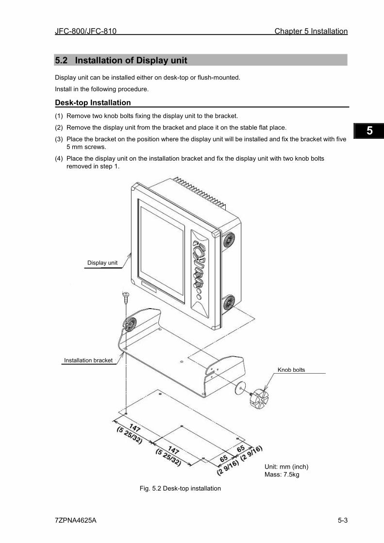
JFC-800/JFC-810 Chapter 5 Installation
7ZPNA4625A 5-3
1 2 3 4 5 6 7 8 9 10 11 12 13 14 15 16 17 18 19 20 21 22 23 24 25 26 付録
5.2 Installation of Display unit Display unit can be installed either on desk-top or flush-mounted.
Install in the following procedure.
Desk-top Installation(1) Remove two knob bolts fixing the display unit to the bracket.
(2) Remove the display unit from the bracket and place it on the stable flat place.
(3) Place the bracket on the position where the display unit will be installed and fix the bracket with five 5 mm screws.
(4) Place the display unit on the installation bracket and fix the display unit with two knob bolts removed in step 1.
Fig. 5.2 Desk-top installation
Unit: mm (inch) Mass: 7.5kg
Knob bolts Installation bracket
Display unit
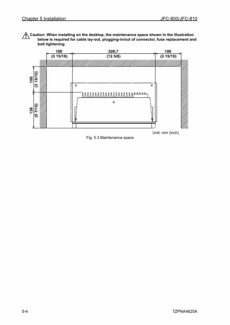
Chapter 5 Installation JFC-800/JFC-810
5-4 7ZPNA4625A
Caution: When installing on the desktop, the maintenance space shown in the illustration below is required for cable lay-out, plugging-in/out of connector, fuse replacement and bolt tightening.
Fig. 5.3 Maintenance space
Unit: mm (inch)
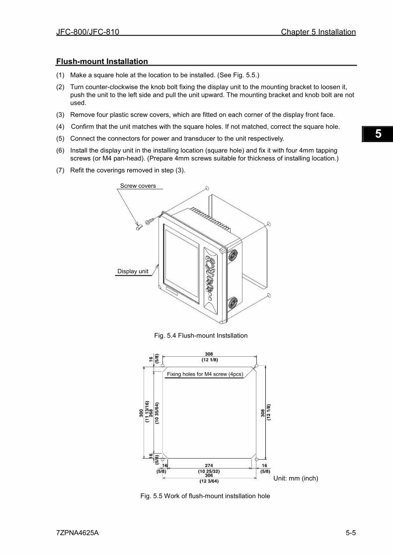
JFC-800/JFC-810 Chapter 5 Installation
7ZPNA4625A 5-5
1 2 3 4 5 6 7 8 9 10 11 12 13 14 15 16 17 18 19 20 21 22 23 24 25 26 付録
Flush-mount Installation (1) Make a square hole at the location to be installed. (See Fig. 5.5.)
(2) Turn counter-clockwise the knob bolt fixing the display unit to the mounting bracket to loosen it, push the unit to the left side and pull the unit upward. The mounting bracket and knob bolt are not used.
(3) Remove four plastic screw covers, which are fitted on each corner of the display front face.
(4) Confirm that the unit matches with the square holes. If not matched, correct the square hole.
(5) Connect the connectors for power and transducer to the unit respectively.
(6) Install the display unit in the installing location (square hole) and fix it with four 4mm tapping screws (or M4 pan-head). (Prepare 4mm screws suitable for thickness of installing location.)
(7) Refit the coverings removed in step (3).
Fig. 5.4 Flush-mount Instsllation
Fig. 5.5 Work of flush-mount instsllation hole
Display unit
Screw covers
Fixing holes for M4 screw (4pcs)
Unit: mm (inch)
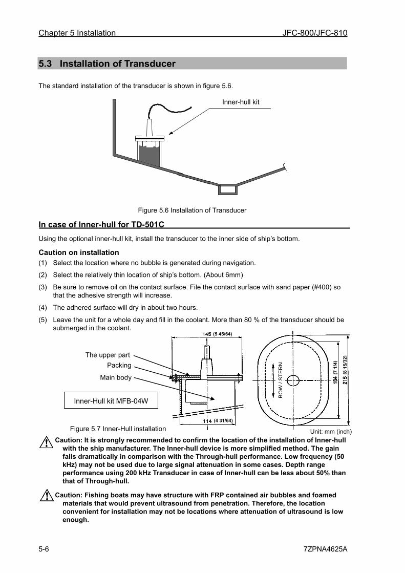
Chapter 5 Installation JFC-800/JFC-810
5-6 7ZPNA4625A
5.3 Installation of Transducer
The standard installation of the transducer is shown in figure 5.6.
Figure 5.6 Installation of Transducer
In case of Inner-hull for TD-501C Using the optional inner-hull kit, install the transducer to the inner side of ship’s bottom.
Caution on installation (1) Select the location where no bubble is generated during navigation.
(2) Select the relatively thin location of ship’s bottom. (About 6mm)
(3) Be sure to remove oil on the contact surface. File the contact surface with sand paper (#400) so that the adhesive strength will increase.
(4) The adhered surface will dry in about two hours.
(5) Leave the unit for a whole day and fill in the coolant. More than 80 % of the transducer should be submerged in the coolant.
Caution: It is strongly recommended to confirm the location of the installation of Inner-hull with the ship manufacturer. The Inner-hull device is more simplified method. The gain falls dramatically in comparison with the Through-hull performance. Low frequency (50 kHz) may not be used due to large signal attenuation in some cases. Depth range performance using 200 kHz Transducer in case of Inner-hull can be less about 50% than that of Through-hull.
Caution: Fishing boats may have structure with FRP contained air bubbles and foamed materials that would prevent ultrasound from penetration. Therefore, the location convenient for installation may not be locations where attenuation of ultrasound is low enough.
Inner-hull kit
Figure 5.7 Inner-Hull installation
The upper part Packing
Main body
Inner-Hull kit MFB-04W
BO
W /
STE
RN
(5 45/64)
(4 31/64)
(7 1
/4)
(8 1
5/32
)
Unit: mm (inch)
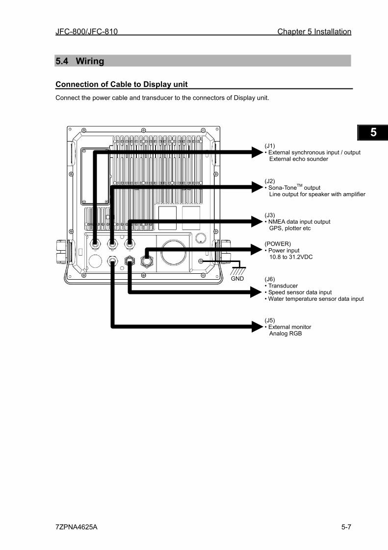
JFC-800/JFC-810 Chapter 5 Installation
7ZPNA4625A 5-7
1 2 3 4 5 6 7 8 9 10 11 12 13 14 15 16 17 18 19 20 21 22 23 24 25 26 付録
5.4 Wiring
Connection of Cable to Display unit Connect the power cable and transducer to the connectors of Display unit.
(J1) • External synchronous input / output
External echo sounder (J2) • Sona-ToneTM output
Line output for speaker with amplifier (J3) • NMEA data input output
GPS, plotter etc (POWER) • Power input
10.8 to 31.2VDC (J6) • Transducer • Speed sensor data input • Water temperature sensor data input (J5) • External monitor
Analog RGB
GND
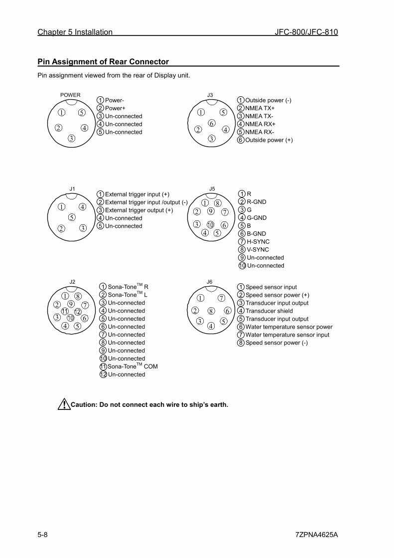
Chapter 5 Installation JFC-800/JFC-810
5-8 7ZPNA4625A
Pin Assignment of Rear Connector Pin assignment viewed from the rear of Display unit.
1
2 3
4
5 6
1 Power- 2 Power+ 3 Un-connected 4 Un-connected 5 Un-connected
POWER J3
1 2
3 4 5
6
7 8
9
1 Sona-ToneTM R 2 Sona-ToneTM L 3 Un-connected 4 Un-connected 5 Un-connected 6 Un-connected 7 Un-connected 8 Un-connected 9 Un-connected 10 Un-connected 11 Sona-ToneTM COM 12 Un-connected
J2
1
3 4
5
2
1 External trigger input (+) 2 External trigger input /output (-) 3 External trigger output (+) 4 Un-connected 5 Un-connected
J1
1
3
4 5
2
1 2
3 4 5
6
7 8
9
1 R 2 R-GND 3 G 4 G-GND 5 B 6 B-GND 7 H-SYNC 8 V-SYNC 9 Un-connected 10 Un-connected
J5
1 Outside power (-) 2 NMEA TX+ 3 NMEA TX- 4 NMEA RX+ 5 NMEA RX- 6 Outside power (+)
1
2 3
4 5 6
7
8
J6 1 Speed sensor input 2 Speed sensor power (+) 3 Transducer input output 4 Transducer shield 5 Transducer input output 6 Water temperature sensor power 7 Water temperature sensor input 8 Speed sensor power (-)
Caution: Do not connect each wire to ship’s earth.
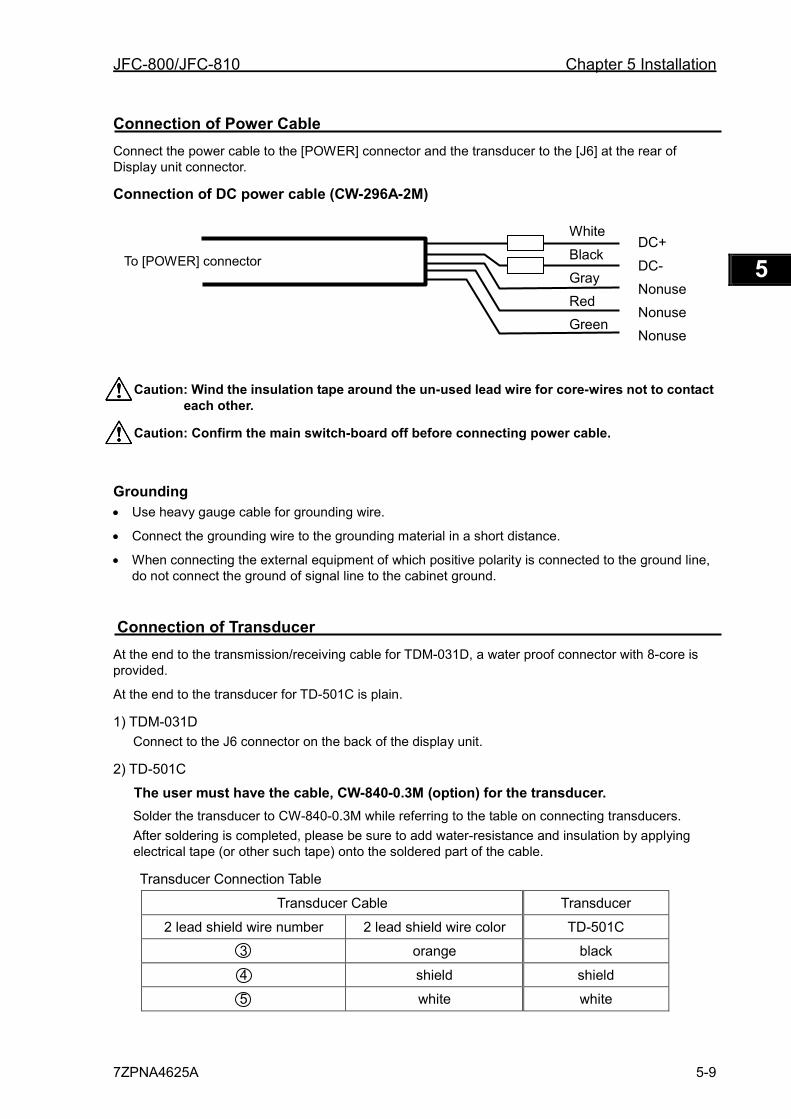
JFC-800/JFC-810 Chapter 5 Installation
7ZPNA4625A 5-9
1 2 3 4 5 6 7 8 9 10 11 12 13 14 15 16 17 18 19 20 21 22 23 24 25 26 付録
Connection of Power Cable Connect the power cable to the [POWER] connector and the transducer to the [J6] at the rear of Display unit connector.
Connection of DC power cable (CW-296A-2M)
Caution: Wind the insulation tape around the un-used lead wire for core-wires not to contact each other.
Caution: Confirm the main switch-board off before connecting power cable.
Grounding • Use heavy gauge cable for grounding wire.
• Connect the grounding wire to the grounding material in a short distance.
• When connecting the external equipment of which positive polarity is connected to the ground line, do not connect the ground of signal line to the cabinet ground.
Connection of Transducer At the end to the transmission/receiving cable for TDM-031D, a water proof connector with 8-core is provided.
At the end to the transducer for TD-501C is plain.
1) TDM-031D Connect to the J6 connector on the back of the display unit.
2) TD-501C
The user must have the cable, CW-840-0.3M (option) for the transducer. Solder the transducer to CW-840-0.3M while referring to the table on connecting transducers. After soldering is completed, please be sure to add water-resistance and insulation by applying electrical tape (or other such tape) onto the soldered part of the cable.
Transducer Connection Table
Transducer Cable Transducer
2 lead shield wire number 2 lead shield wire color TD-501C
3 orange black
4 shield shield
5 white white
To [POWER] connector DC+
DC- Nonuse Nonuse Nonuse
White
Black Gray Red Green
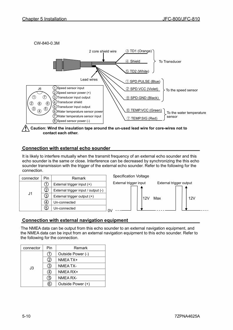
Chapter 5 Installation JFC-800/JFC-810
5-10 7ZPNA4625A
CW-840-0.3M
Caution: Wind the insulation tape around the un-used lead wire for core-wires not to contact each other.
Connection with external echo sounder It is likely to interfere mutually when the transmit frequency of an external echo sounder and this echo sounder is the same or close. Interference can be decreased by synchronizing the this echo sounder transmission with the trigger of the external echo sounder. Refer to the following for the connection.
Connection with external navigation equipment The NMEA data can be output from this echo sounder to an external navigation equipment, and the NMEA data can be input from an external navigation equipment to this echo sounder. Refer to the following for the connection.
connector Pin Remark
J3
1 Outside Power (-) 2 NMEA TX+ 3 NMEA TX- 4 NMEA RX+ 5 NMEA RX- 6 Outside Power (+)
connector Pin Remark
J1
1 External trigger input (+) 2 External trigger input / output (-) 3 External trigger output (+) 4 Un-connected 5 Un-connected 0V
Specification Voltage
External trigger input External trigger output
12V Max 12V
2 core shield wire TD1 (Orange)
TD2 (White)
Shield
SPD.PULSE (Blue)
SPD.VCC (Violet)
SPD.GND (Black)
TEMP.VCC (Green)
TEMP.SIG (Red)
Lead wires
To the speed sensor
To the water temperature sensor
To Transducer
1
2
3 4
5
6
7
8
J6 1 Speed sensor input 2 Speed sensor power (+) 3 Transducer input output 4 Transducer shield 5 Transducer input output 6 Water temperature sensor power 7 Water temperature sensor input 8 Speed sensor power (-)
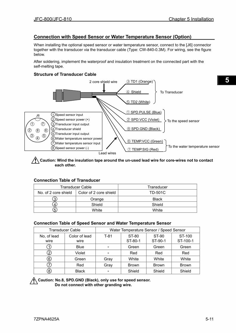
JFC-800/JFC-810 Chapter 5 Installation
7ZPNA4625A 5-11
1 2 3 4 5 6 7 8 9 10 11 12 13 14 15 16 17 18 19 20 21 22 23 24 25 26 付録
Connection with Speed Sensor or Water Temperature Sensor (Option) When installing the optional speed sensor or water temperature sensor, connect to the [J6] connector together with the transducer via the transducer cable (Type: CW-840-0.3M). For wiring, see the figure below.
After soldering, implement the waterproof and insulation treatment on the connected part with the self-melting tape.
Structure of Transducer Cable
Caution: Wind the insulation tape around the un-used lead wire for core-wires not to contact each other.
Connection Table of Transducer Transducer Cable Transducer
No. of 2 core shield Color of 2 core shield TD-501C 3 Orange Black 4 Shield Shield 5 White White
Connection Table of Speed Sensor and Water Temperature Sensor Transducer Cable Water Temperature Sensor / Speed Sensor
No, of lead wire
Color of lead wire
T-81 ST-80 ST-80-1
ST-90 ST-90-1
ST-100 ST-100-1
1 Blue - Green Green Green 2 Violet - Red Red Red 6 Green Gray White White White 7 Red Gray Brown Brown Brown 8 Black - Shield Shield Shield
Caution: No.8, SPD.GND (Black), only use for speed sensor. Do not connect with other granding wire.
2 core shield wire TD1 (Orange)
TD2 (White)
Shield
SPD.PULSE (Blue)
SPD.VCC (Violet)
SPD.GND (Black)
TEMP.VCC (Green)
TEMP.SIG (Red) Lead wires
To the speed sensor
To the water temperature sensor
To Transducer
1 Speed sensor input 2 Speed sensor power (+) 3 Transducer input output 4 Transducer shield 5 Transducer input output 6 Water temperature sensor power 7 Water temperature sensor input 8 Speed sensor power (-)
1
2
3 4
5
6
7
8
J6
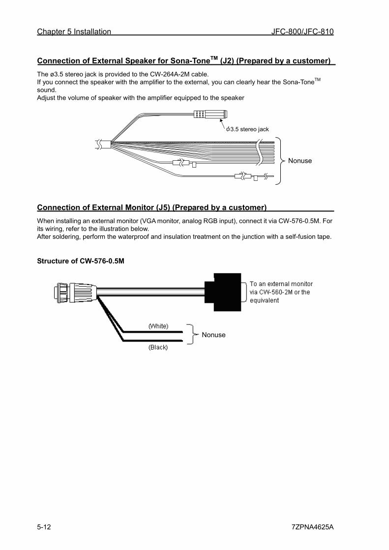
Chapter 5 Installation JFC-800/JFC-810
5-12 7ZPNA4625A
Connection of External Speaker for Sona-ToneTM (J2) (Prepared by a customer) The ø3.5 stereo jack is provided to the CW-264A-2M cable. If you connect the speaker with the amplifier to the external, you can clearly hear the Sona-ToneTM sound. Adjust the volume of speaker with the amplifier equipped to the speaker
3.5 stereo jack
Connection of External Monitor (J5) (Prepared by a customer) When installing an external monitor (VGA monitor, analog RGB input), connect it via CW-576-0.5M. For its wiring, refer to the illustration below. After soldering, perform the waterproof and insulation treatment on the junction with a self-fusion tape.
Structure of CW-576-0.5M
Nonuse
Nonuse
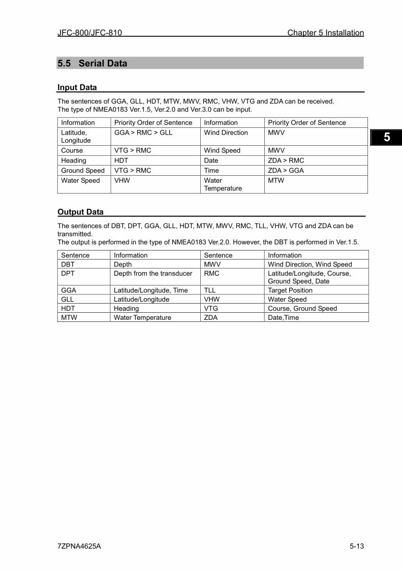
JFC-800/JFC-810 Chapter 5 Installation
7ZPNA4625A 5-13
1 2 3 4 5 6 7 8 9 10 11 12 13 14 15 16 17 18 19 20 21 22 23 24 25 26 付録
5.5 Serial Data
Input Data The sentences of GGA, GLL, HDT, MTW, MWV, RMC, VHW, VTG and ZDA can be received. The type of NMEA0183 Ver.1.5, Ver.2.0 and Ver.3.0 can be input.
Information Priority Order of Sentence Information Priority Order of Sentence Latitude, Longitude
GGA > RMC > GLL Wind Direction MWV
Course VTG > RMC Wind Speed MWV Heading HDT Date ZDA > RMC Ground Speed VTG > RMC Time ZDA > GGA Water Speed VHW Water
Temperature MTW
Output Data The sentences of DBT, DPT, GGA, GLL, HDT, MTW, MWV, RMC, TLL, VHW, VTG and ZDA can be transmitted. The output is performed in the type of NMEA0183 Ver.2.0. However, the DBT is performed in Ver.1.5.
Sentence Information Sentence Information DBT Depth MWV Wind Direction, Wind Speed DPT Depth from the transducer RMC Latitude/Longitude, Course,
Ground Speed, Date GGA Latitude/Longitude, Time TLL Target Position GLL Latitude/Longitude VHW Water Speed HDT Heading VTG Course, Ground Speed MTW Water Temperature ZDA Date,Time

Chapter 5 Installation JFC-800/JFC-810
5-14 7ZPNA4625A
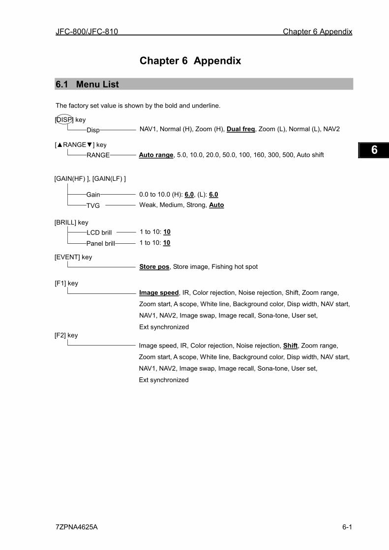
JFC-800/JFC-810 Chapter 6 Appendix
7ZPNA4625A 6-1
1 2 3 4 5 6 7 8 9 10 11 12 13 14 15 16 17 18 19 20 21 22 23 24 25 26 付録
Chapter 6 Appendix
6.1 Menu List
The factory set value is shown by the bold and underline.
[DISP] key
Disp NAV1, Normal (H), Zoom (H), Dual freq, Zoom (L), Normal (L), NAV2
[▲RANGE▼] key RANGE Auto range, 5.0, 10.0, 20.0, 50.0, 100, 160, 300, 500, Auto shift
[GAIN(HF) ], [GAIN(LF) ]
Weak, Medium, Strong, Auto Gain 0.0 to 10.0 (H): 6.0, (L): 6.0
LCD brill 1 to 10: 10
Panel brill
1 to 10: 10
[EVENT] key Store pos, Store image, Fishing hot spot
[F1] key Image speed, IR, Color rejection, Noise rejection, Shift, Zoom range,
Zoom start, A scope, White line, Background color, Disp width, NAV start,
NAV1, NAV2, Image swap, Image recall, Sona-tone, User set,
Ext synchronized [F2] key
Image speed, IR, Color rejection, Noise rejection, Shift, Zoom range,
Zoom start, A scope, White line, Background color, Disp width, NAV start,
NAV1, NAV2, Image swap, Image recall, Sona-tone, User set,
Ext synchronized
TVG
[BRILL] key
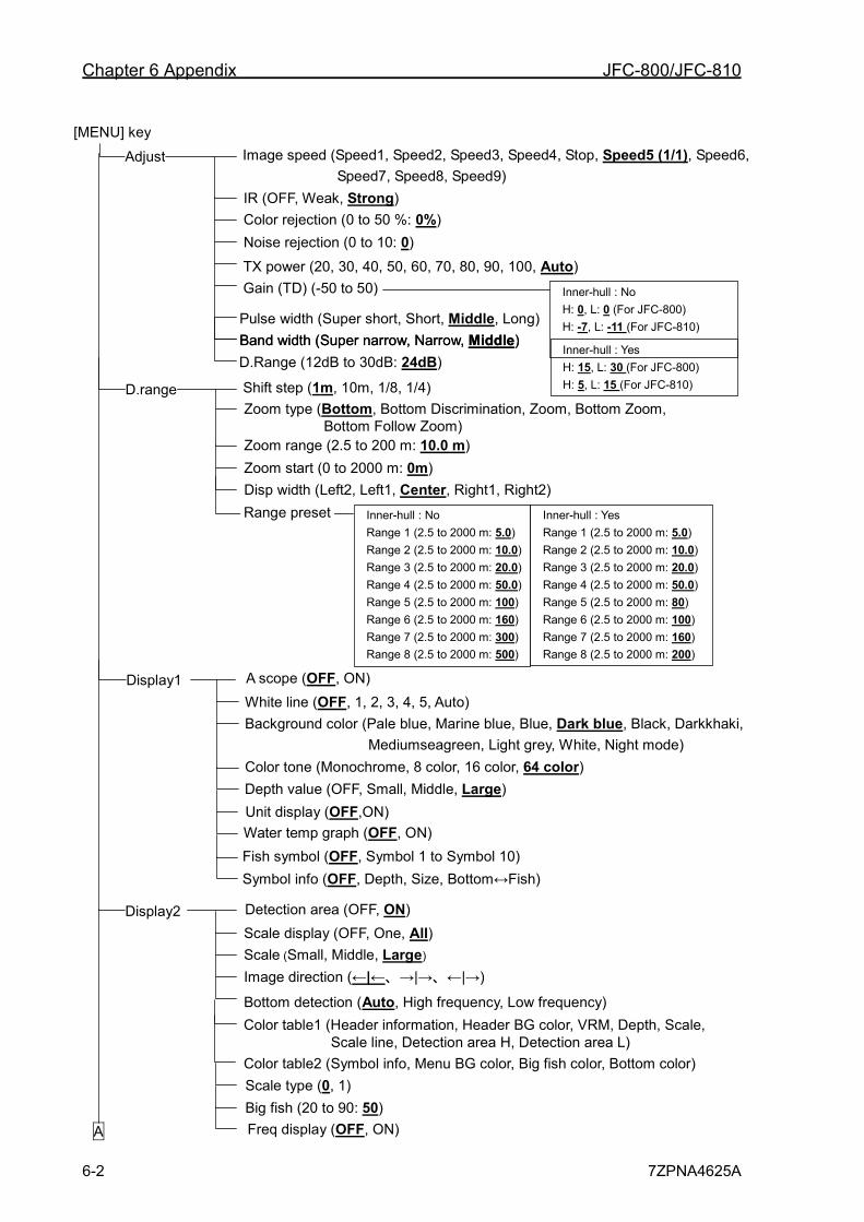
Chapter 6 Appendix JFC-800/JFC-810
6-2 7ZPNA4625A
[MENU] key
Adjust Image speed (Speed1, Speed2, Speed3, Speed4, Stop, Speed5 (1/1), Speed6, Speed7, Speed8, Speed9)
IR (OFF, Weak, Strong) Color rejection (0 to 50 %: 0%) Noise rejection (0 to 10: 0)
TX power (20, 30, 40, 50, 60, 70, 80, 90, 100, Auto) Gain (TD) (-50 to 50)
Shift step (1m, 10m, 1/8, 1/4) Zoom type (Bottom, Bottom Discrimination, Zoom, Bottom Zoom, Bottom Follow Zoom) Zoom range (2.5 to 200 m: 10.0 m) Zoom start (0 to 2000 m: 0m) Disp width (Left2, Left1, Center, Right1, Right2)
D.range
Range preset
A scope (OFF, ON) White line (OFF, 1, 2, 3, 4, 5, Auto) Background color (Pale blue, Marine blue, Blue, Dark blue, Black, Darkkhaki,
Mediumseagreen, Light grey, White, Night mode) Color tone (Monochrome, 8 color, 16 color, 64 color) Depth value (OFF, Small, Middle, Large)
Display1
Water temp graph (OFF, ON) Fish symbol (OFF, Symbol 1 to Symbol 10) Symbol info (OFF, Depth, Size, Bottom↔Fish)
A
Detection area (OFF, ON) Scale display (OFF, One, All) Scale (Small, Middle, Large) Image direction (←|←、→|→、←|→)
Color table1 (Header information, Header BG color, VRM, Depth, Scale, Scale line, Detection area H, Detection area L)
Display2
Color table2 (Symbol info, Menu BG color, Big fish color, Bottom color)
Pulse width (Super short, Short, Middle, Long) Band width (Super narrow, Narrow, Middle)
Bottom detection (Auto, High frequency, Low frequency)
Scale type (0, 1) Big fish (20 to 90: 50) Freq display (OFF, ON)
Unit display (OFF,ON)
Inner-hull : No H: 0, L: 0 (For JFC-800) H: -7, L: -11 (For JFC-810) Inner-hull : Yes H: 15, L: 30 (For JFC-800) H: 5, L: 15 (For JFC-810)
Inner-hull : No Range 1 (2.5 to 2000 m: 5.0) Range 2 (2.5 to 2000 m: 10.0) Range 3 (2.5 to 2000 m: 20.0) Range 4 (2.5 to 2000 m: 50.0) Range 5 (2.5 to 2000 m: 100) Range 6 (2.5 to 2000 m: 160) Range 7 (2.5 to 2000 m: 300) Range 8 (2.5 to 2000 m: 500)
Inner-hull : Yes Range 1 (2.5 to 2000 m: 5.0) Range 2 (2.5 to 2000 m: 10.0) Range 3 (2.5 to 2000 m: 20.0) Range 4 (2.5 to 2000 m: 50.0) Range 5 (2.5 to 2000 m: 80) Range 6 (2.5 to 2000 m: 100) Range 7 (2.5 to 2000 m: 160) Range 8 (2.5 to 2000 m: 200)
Band width (Super narrow, Narrow, Middle) D.Range (12dB to 30dB: 24dB)
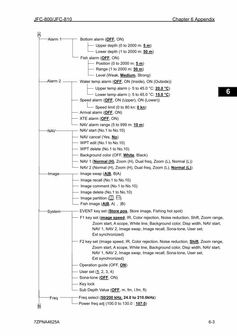
JFC-800/JFC-810 Chapter 6 Appendix
7ZPNA4625A 6-3
1 2 3 4 5 6 7 8 9 10 11 12 13 14 15 16 17 18 19 20 21 22 23 24 25 26 付録
Bottom alarm (OFF, ON) Upper depth (0 to 2000 m: 5 m) Lower depth (1 to 2000 m: 50 m)
Fish alarm (OFF, ON) Position (0 to 2000 m: 5 m)
Alarm 1
Range (1 to 2000 m: 50 m) Level (Weak, Medium, Strong)
Water temp alarm (OFF, ON (Inside), ON (Outside))
Upper temp alarm (- 5 to 45.0 °C: 20.0 °C) Lower temp alarm (- 5 to 45.0 °C: 15.0 °C)
Speed alarm (OFF, ON (Upper), ON (Lower))
Speed limit (0 to 80 kn: 0 kn)
Alarm 2
Arrival alarm (OFF, ON) XTE alarm (OFF, ON) NAV alarm range (5 to 999 m: 10 m) NAV start (No.1 to No.10) NAV cancel (Yes, No) WPT edit (No.1 to No.10) WPT delete (No.1 to No.10) Background color (OFF, White, Black)
NAV
NAV 1 (Normal (H), Zoom (H), Dual freq, Zoom (L), Normal (L)) NAV 2 (Normal (H), Zoom (H), Dual freq, Zoom (L), Normal (L))
A
Image swap (A|B, B|A) Image recall (No.1 to No.10) Image comment (No.1 to No.10) Image delete (No.1 to No.10)
Image
EVENT key set (Store pos, Store image, Fishing hot spot) F1 key set (Image speed, IR, Color rejection, Noise reduction, Shift, Zoom range,
Zoom start, A scope, White line, Background color, Disp width, NAV start, NAV 1, NAV 2, Image swap, Image recall, Sona-tone, User set, Ext synchronized)
System
F2 key set (Image speed, IR, Color rejection, Noise reduction, Shift, Zoom range, Zoom start, A scope, White line, Background color, Disp width, NAV start, NAV 1, NAV 2, Image swap, Image recall, Sona-tone, User set, Ext synchronized)
B
Image partition ( , ) Fish image (A|B, A| , |B)
Freq Freq select (50/200 kHz, 24.0 to 210.0kHz) Power freq adj (100.0 to 130.0 : 107.0)
Sub Depth Value (OFF, m, fm, I.fm, ft)
User set (1, 2, 3, 4) Sona-tone (OFF, ON) Key lock
Operation guide (OFF, ON)
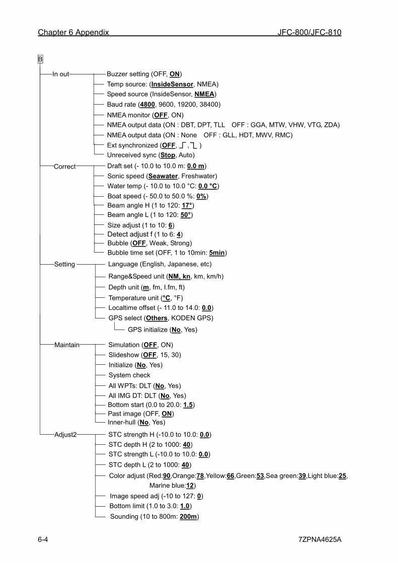
Chapter 6 Appendix JFC-800/JFC-810
6-4 7ZPNA4625A
Draft set (- 10.0 to 10.0 m: 0.0 m) Sonic speed (Seawater, Freshwater) Water temp (- 10.0 to 10.0 °C: 0.0 °C) Boat speed (- 50.0 to 50.0 %: 0%)
Correct
Language (English, Japanese, etc)
Range&Speed unit (NM, kn, km, km/h) Depth unit (m, fm, I.fm, ft) Temperature unit (°C, °F) Localtime offset (- 11.0 to 14.0: 0.0) GPS select (Others, KODEN GPS)
Setting
GPS initialize (No, Yes)
B
Simulation (OFF, ON)
Initialize (No, Yes) System check All WPTs: DLT (No, Yes) All IMG DT: DLT (No, Yes)
Maintain Slideshow (OFF, 15, 30)
Beam angle H (1 to 120: 17°) Beam angle L (1 to 120: 50°)
Buzzer setting (OFF, ON) Temp source: (InsideSensor, NMEA) Speed source (InsideSensor, NMEA) Baud rate (4800, 9600, 19200, 38400)
In out
NMEA monitor (OFF, ON) NMEA output data (ON : DBT, DPT, TLL OFF : GGA, MTW, VHW, VTG, ZDA) NMEA output data (ON : None OFF : GLL, HDT, MWV, RMC)
Size adjust (1 to 10: 6)
Bottom start (0.0 to 20.0: 1.5)
Ext synchronized (OFF, , )
Detect adjust f (1 to 6: 4)
STC strength H (-10.0 to 10.0: 0.0)
STC strength L (-10.0 to 10.0: 0.0) STC depth L (2 to 1000: 40)
Adjust2 STC depth H (2 to 1000: 40)
Image speed adj (-10 to 127: 0) Bottom limit (1.0 to 3.0: 1.0)
Color adjust (Red:90,Orange:78,Yellow:66,Green:53,Sea green:39,Light blue:25, Marine blue:12)
Bubble (OFF, Weak, Strong)
Inner-hull (No, Yes)
Bubble time set (OFF, 1 to 10min: 5min)
Sounding (10 to 800m: 200m)
Past image (OFF, ON)
Unreceived sync (Stop, Auto)
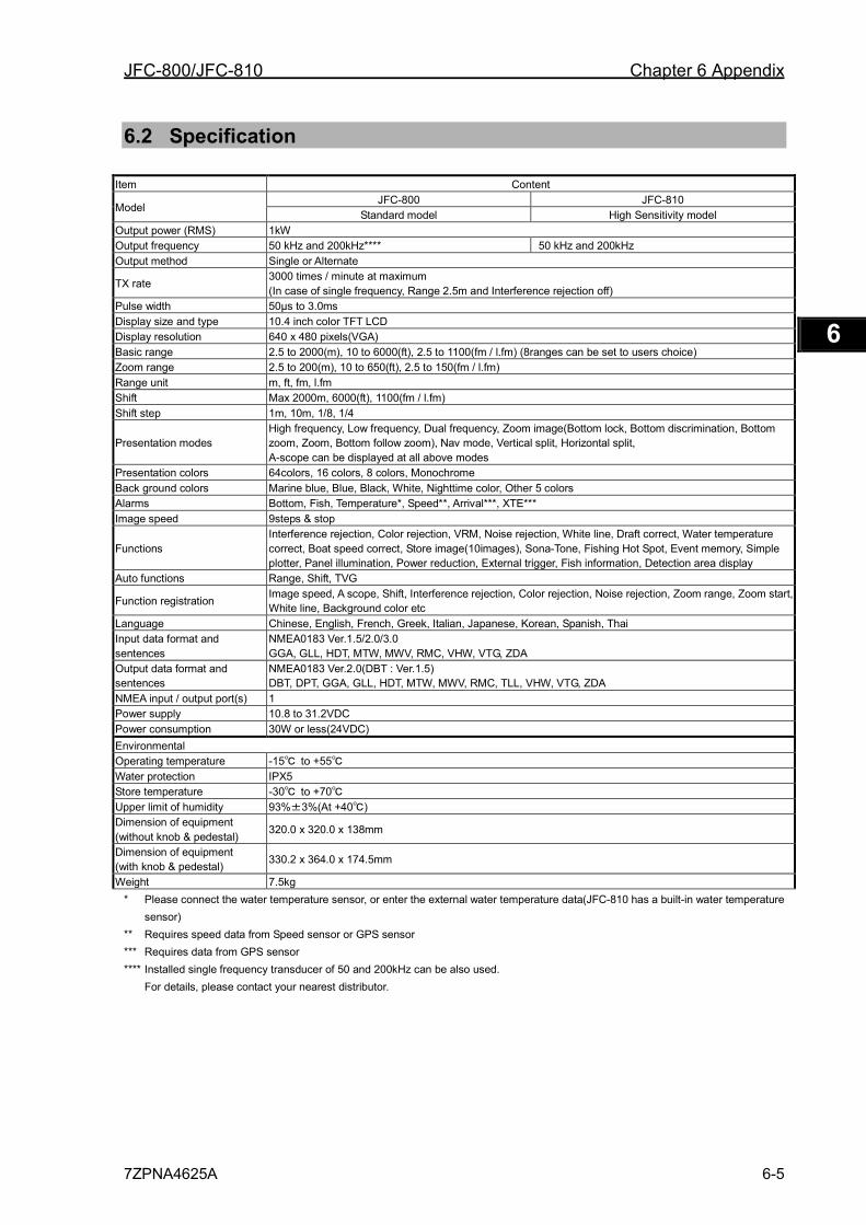
JFC-800/JFC-810 Chapter 6 Appendix
7ZPNA4625A 6-5
1 2 3 4 5 6 7 8 9 10 11 12 13 14 15 16 17 18 19 20 21 22 23 24 25 26 付録
6.2 Specification
Item Content
Model JFC-800 JFC-810
Standard model High Sensitivity model Output power (RMS) 1kW Output frequency 50 kHz and 200kHz**** 50 kHz and 200kHz Output method Single or Alternate
TX rate 3000 times / minute at maximum (In case of single frequency, Range 2.5m and Interference rejection off)
Pulse width 50µs to 3.0ms Display size and type 10.4 inch color TFT LCD Display resolution 640 x 480 pixels(VGA) Basic range 2.5 to 2000(m), 10 to 6000(ft), 2.5 to 1100(fm / l.fm) (8ranges can be set to users choice) Zoom range 2.5 to 200(m), 10 to 650(ft), 2.5 to 150(fm / l.fm) Range unit m, ft, fm, l.fm Shift Max 2000m, 6000(ft), 1100(fm / l.fm) Shift step 1m, 10m, 1/8, 1/4
Presentation modes High frequency, Low frequency, Dual frequency, Zoom image(Bottom lock, Bottom discrimination, Bottom zoom, Zoom, Bottom follow zoom), Nav mode, Vertical split, Horizontal split, A-scope can be displayed at all above modes
Presentation colors 64colors, 16 colors, 8 colors, Monochrome Back ground colors Marine blue, Blue, Black, White, Nighttime color, Other 5 colors Alarms Bottom, Fish, Temperature*, Speed**, Arrival***, XTE*** Image speed 9steps & stop
Functions Interference rejection, Color rejection, VRM, Noise rejection, White line, Draft correct, Water temperature correct, Boat speed correct, Store image(10images), Sona-Tone, Fishing Hot Spot, Event memory, Simple plotter, Panel illumination, Power reduction, External trigger, Fish information, Detection area display
Auto functions Range, Shift, TVG
Function registration Image speed, A scope, Shift, Interference rejection, Color rejection, Noise rejection, Zoom range, Zoom start, White line, Background color etc
Language Chinese, English, French, Greek, Italian, Japanese, Korean, Spanish, Thai Input data format and sentences
NMEA0183 Ver.1.5/2.0/3.0 GGA, GLL, HDT, MTW, MWV, RMC, VHW, VTG, ZDA
Output data format and sentences
NMEA0183 Ver.2.0(DBT : Ver.1.5) DBT, DPT, GGA, GLL, HDT, MTW, MWV, RMC, TLL, VHW, VTG, ZDA
NMEA input / output port(s) 1 Power supply 10.8 to 31.2VDC Power consumption 30W or less(24VDC) Environmental Operating temperature -15℃ to +55℃ Water protection IPX5 Store temperature -30℃ to +70℃ Upper limit of humidity 93%±3%(At +40℃) Dimension of equipment (without knob & pedestal)
320.0 x 320.0 x 138mm
Dimension of equipment (with knob & pedestal) 330.2 x 364.0 x 174.5mm
Weight 7.5kg * Please connect the water temperature sensor, or enter the external water temperature data(JFC-810 has a built-in water temperature
sensor) ** Requires speed data from Speed sensor or GPS sensor *** Requires data from GPS sensor **** Installed single frequency transducer of 50 and 200kHz can be also used.
For details, please contact your nearest distributor.
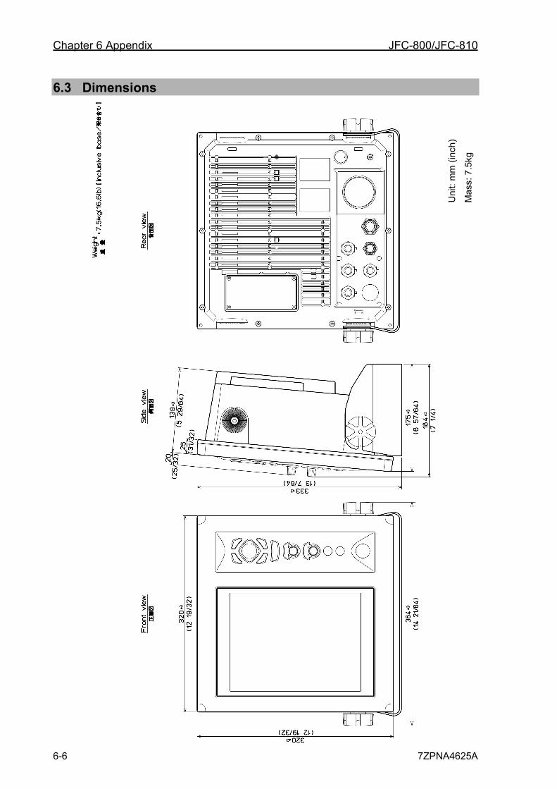
Chapter 6 Appendix JFC-800/JFC-810
6-6 7ZPNA4625A
6.3 Dimensions
Uni
t: m
m (i
nch)
Mas
s: 7
.5kg
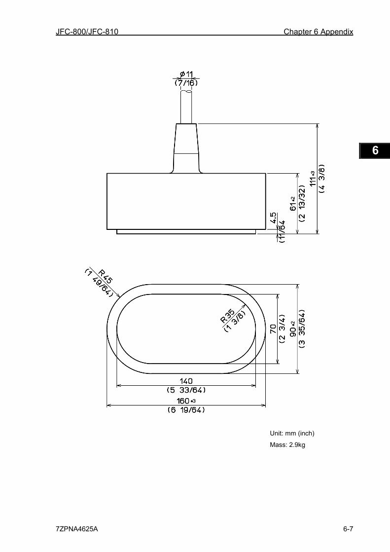
JFC-800/JFC-810 Chapter 6 Appendix
7ZPNA4625A 6-7
1 2 3 4 5 6 7 8 9 10 11 12 13 14 15 16 17 18 19 20 21 22 23 24 25 26 付録
Unit: mm (inch)
Mass: 2.9kg
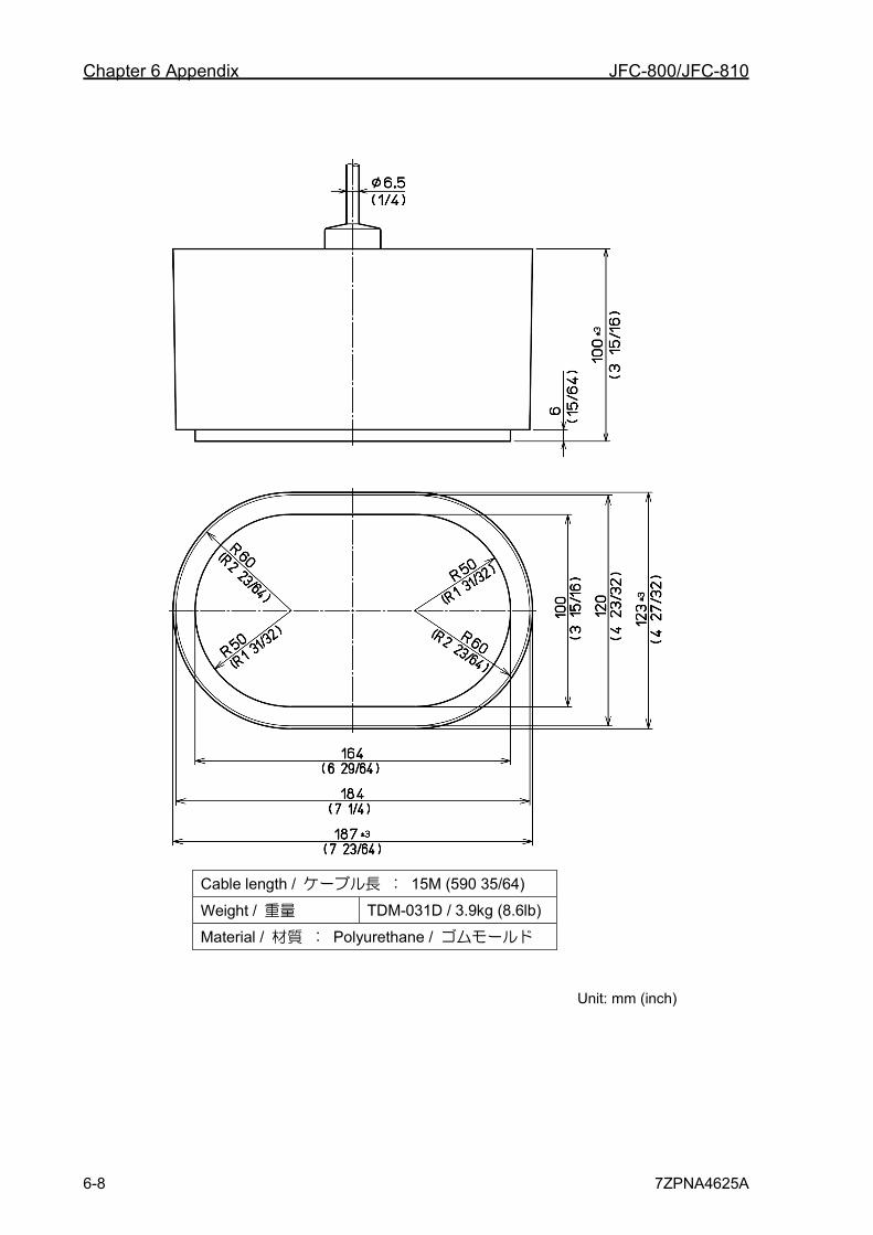
Chapter 6 Appendix JFC-800/JFC-810
6-8 7ZPNA4625A
Cable length / ケーブル長 : 15M (590 35/64)
Weight / 重量 TDM-031D / 3.9kg (8.6lb)
Material / 材質 : Polyurethane / ゴムモールド
Unit: mm (inch)


ISO 9001, ISO 14001 Certified
DEC. 2018 Edition 2CODE No.7ZPNA4625A
1 2 3 4 5 6
Not use the asbestos
For further information,contact:
URL Head office : http://www.jrc.co.jp/eng/
Marine Service Department
1-7-32 Tatsumi, Koto-ku, Tokyo 135-0053, Japan
: +81-50-3786-9201e-mailOne-call
Basic Operation 1 How to use the menu 2 How to use the menu2 3 Maintenance and Inspection 4
Installation 5 Appendix 6
JFC-800/JFC-810
Color Echo Sounder
Instruction Manual
Related Documents