© 2020 JETIR November 2020, Volume 7, Issue 11 www.jetir.org (ISSN-2349-5162) JETIR2011318 Journal of Emerging Technologies and Innovative Research (JETIR) www.jetir.org 141 An Experimental Study to Address the Issues of Low Durability and Low Compressive Strength of Mud Plaster PROF. RIYAZ AHMAD QASAB * , MOHD RAFIQ MIR * , AIMA ASHRAF * , AATIF MOHAMMAD DAR * , UBHAT ALI * , BISMA MANZOOR WANI * , FIRDOUS AHMAD PARRAY * . 1 Assistant Professor Dept Of Civil Engineering Islamic University, 2 Student, 3 Student, 4 Student, 4 Student, 5 Student, 6 Student. *Department of Civil Engineering. Islamic University Of Science And Technology, Awantipora 192122, J&K, India. Abstract : Mud based plasters are completely compatible with traditional materials and building techniques. Today with low- cost mass housing as a priority, the need for plastering materials which are efficient and economical has awakened a new interest in green materials like mud. The only drawback is the limited durability of the material against the aggressive action exerted by external agents as a result of which the use of mud plasters has declined over the years. To improve the durability and strength characteristics of mud plaster, our team has proposed the use of certain additives like shellac, jute and white clay to be used in various percentages. Samples with and without a coating of shellac were prepared and subjected to jet impingement, sample disintegration and unconfined compressive strength tests. The addition of 5% jute and 5% shellac to modified mud plaster together yielded remarkable results and has thereby been proposed as an alternative to the conventional mud plaster reinforced with straw. A keen observation of results indicated that the rate of erosion of conventional straw plaster was much higher as compared to that of the improved plaster. Also, the compressive strength for the modified plaster was 13.08% higher than the conventional plaster. The straw plaster disintegrated at a much faster rate in comparison to the improved plaster. The coated samples reflected a marked improvement in comparison to their uncoated counterparts. So, we as a team also suggest that an application of a coating of shellac over existing mud plastered surfaces could serve as an effective measure in enhancing the durability characteristics. I. INTRODUCTION Buildings are large consumers of energy in all countries. In regions with harsh climatic conditions, a substantial share of energy goes to heating and cooling the buildings. This heating and air conditioning load can be reduced through many means; notable among them is the proper design and selection of building envelope and its building components. Mud construction is economically beneficial. The use of excavated soil means greatly reduced costs in comparison with other building materials. Even if this soil is transported from other construction sites, it is usually much cheaper than industrial building materials. It saves energy. The preparation, transport and handling of soil on site require only about 1% of the energy needed for the production, transport and handling of reinforced concrete and other construction materials. Mud, then produces virtually no environmental pollution. Mud-based plasters often use mud in combination with other natural materials such as wheat straw or cow dung, or with mineral additives, to improve the basic qualities of the mud by acting as stabilizers, hardeners, and waterproofing agents. Even without additives, however, mud plasters and renders can give excellent results provided that they are made and applied with skill and care and maintained regularly. Ever since the emergence of lime and cement-based plasters, the use of mud plasters has been shelved. Taking note of the usual scenario with due regard to the prevalence of cement plaster, this project was set up with the aim of showing that soil-based plasters can still be relevant in today’s construction industry. The primary aim of the project was to improve the durability, impermeability and strength of the mud plaster. Extensive analysis and scrutiny of the previously published research papers was done. Also, the traditionally trained and well experienced workmen were consulted to obtain a more detailed knowhow about the various additives that were traditionally incorporated in mud plasters, their method of applications and the problems encountered following application. 1.1 Literature Survey It is known that plasterwork, and the decoration upon it, was applied more than 4,000 years ago. Mud architecture began in Egypt and developed to its full extent alongside the Nile 1 (Capaldi, 2011). The Pharaohs of Egypt used plaster surfaces in their palaces and pyramids, which still exists in a hard and durable state today. One of the earliest archaeological examples of both civilization and plaster is Çatalhöyük (7500 BC), located in present day Turkey. A densely populated town, Çatalhöyük’s dwell ings had mud brick walls and floors coated with a locally available clay marl that made a suitable plaster In the Earliest European settle rs’ plasterwork, a mud plaster was used or more usually a mud- lime mixture, Old Economy Village is one such German settlement. The early Nineteenth- Century utopian village in present-day Ambridge, Pennsylvania, used clay plaster substrate exclusively in the brick and wood frame high architecture of the Feast Hall, Great House and other large and commercial structures as well as in the brick, frame and log dwellings of the society members. At present, about 15% of UNESCO Heritage Sites is represented by earthen architectures 2 (UNESCO(Accessed: 28 July2014). In the Marcheregion (Italy), a total of 245 earthen buildings are still present according to a recent official cataloguing. 3 (Recanati, Tecnostampa, 2005, pp. 45–284). Numerous researches have been carried out on earth-based plasters. Studies have been conducted on the effects of various fibres like straw, sisal, banana and coconut fibres to increase properties of the mud plaster. (César Cardoso, Rute Eires and Guimarães )(A common traditional practice is the addition of cow dung as an additive to earthen plasters, which improves the cohesion and plasticity of soils of low clay content. (3) Another practice is the addition of horse urine, which acts as a hardener and improves impermeability and impact resistance. 4 (Appropriate Technology Magazine, Volume 26/Number 1th June of 1999).

Welcome message from author
This document is posted to help you gain knowledge. Please leave a comment to let me know what you think about it! Share it to your friends and learn new things together.
Transcript
© 2020 JETIR November 2020, Volume 7, Issue 11 www.jetir.org (ISSN-2349-5162)
JETIR2011318 Journal of Emerging Technologies and Innovative Research (JETIR) www.jetir.org 141
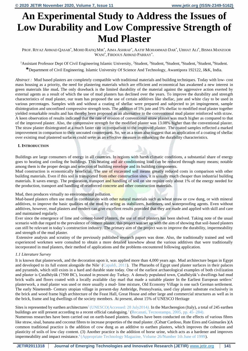
An Experimental Study to Address the Issues of
Low Durability and Low Compressive Strength of
Mud Plaster PROF. RIYAZ AHMAD QASAB*, MOHD RAFIQ MIR*, AIMA ASHRAF*, AATIF MOHAMMAD DAR*, UBHAT ALI*, BISMA MANZOOR
WANI*, FIRDOUS AHMAD PARRAY*.
1Assistant Professor Dept Of Civil Engineering Islamic University, 2Student, 3Student, 4Student, 4Student, 5Student, 6Student.
*Department of Civil Engineering. Islamic University Of Science And Technology, Awantipora 192122, J&K, India.
Abstract : Mud based plasters are completely compatible with traditional materials and building techniques. Today with low- cost
mass housing as a priority, the need for plastering materials which are efficient and economical has awakened a new interest in
green materials like mud. The only drawback is the limited durability of the material against the aggressive action exerted by
external agents as a result of which the use of mud plasters has declined over the years. To improve the durability and strength
characteristics of mud plaster, our team has proposed the use of certain additives like shellac, jute and white clay to be used in
various percentages. Samples with and without a coating of shellac were prepared and subjected to jet impingement, sample
disintegration and unconfined compressive strength tests. The addition of 5% jute and 5% shellac to modified mud plaster together
yielded remarkable results and has thereby been proposed as an alternative to the conventional mud plaster reinforced with straw.
A keen observation of results indicated that the rate of erosion of conventional straw plaster was much higher as compared to that
of the improved plaster. Also, the compressive strength for the modified plaster was 13.08% higher than the conventional plaster.
The straw plaster disintegrated at a much faster rate in comparison to the improved plaster. The coated samples reflected a marked
improvement in comparison to their uncoated counterparts. So, we as a team also suggest that an application of a coating of shellac
over existing mud plastered surfaces could serve as an effective measure in enhancing the durability characteristics.
I. INTRODUCTION
Buildings are large consumers of energy in all countries. In regions with harsh climatic conditions, a substantial share of energy
goes to heating and cooling the buildings. This heating and air conditioning load can be reduced through many means; notable
among them is the proper design and selection of building envelope and its building components.
Mud construction is economically beneficial. The use of excavated soil means greatly reduced costs in comparison with other
building materials. Even if this soil is transported from other construction sites, it is usually much cheaper than industrial building
materials. It saves energy. The preparation, transport and handling of soil on site require only about 1% of the energy needed for
the production, transport and handling of reinforced concrete and other construction materials.
Mud, then produces virtually no environmental pollution.
Mud-based plasters often use mud in combination with other natural materials such as wheat straw or cow dung, or with mineral
additives, to improve the basic qualities of the mud by acting as stabilizers, hardeners, and waterproofing agents. Even without
additives, however, mud plasters and renders can give excellent results provided that they are made and applied with skill and care
and maintained regularly.
Ever since the emergence of lime and cement-based plasters, the use of mud plasters has been shelved. Taking note of the usual
scenario with due regard to the prevalence of cement plaster, this project was set up with the aim of showing that soil-based plasters
can still be relevant in today’s construction industry. The primary aim of the project was to improve the durability, impermeability
and strength of the mud plaster.
Extensive analysis and scrutiny of the previously published research papers was done. Also, the traditionally trained and well
experienced workmen were consulted to obtain a more detailed knowhow about the various additives that were traditionally
incorporated in mud plasters, their method of applications and the problems encountered following application.
1.1 Literature Survey
It is known that plasterwork, and the decoration upon it, was applied more than 4,000 years ago. Mud architecture began in Egypt
and developed to its full extent alongside the Nile1 (Capaldi, 2011). The Pharaohs of Egypt used plaster surfaces in their palaces
and pyramids, which still exists in a hard and durable state today. One of the earliest archaeological examples of both civilization
and plaster is Çatalhöyük (7500 BC), located in present day Turkey. A densely populated town, Çatalhöyük’s dwellings had mud
brick walls and floors coated with a locally available clay marl that made a suitable plaster In the Earliest European settlers’
plasterwork, a mud plaster was used or more usually a mud- lime mixture, Old Economy Village is one such German settlement.
The early Nineteenth- Century utopian village in present-day Ambridge, Pennsylvania, used clay plaster substrate exclusively in
the brick and wood frame high architecture of the Feast Hall, Great House and other large and commercial structures as well as in
the brick, frame and log dwellings of the society members. At present, about 15% of UNESCO Heritage
Sites is represented by earthen architectures2 (UNESCO(Accessed: 28 July2014). In the Marcheregion (Italy), a total of 245 earthen
buildings are still present according to a recent official cataloguing.3 (Recanati, Tecnostampa, 2005, pp. 45–284).
Numerous researches have been carried out on earth-based plasters. Studies have been conducted on the effects of various fibres
like straw, sisal, banana and coconut fibres to increase properties of the mud plaster. (César Cardoso, Rute Eires and Guimarães )(A
common traditional practice is the addition of cow dung as an additive to earthen plasters, which improves the cohesion and
plasticity of soils of low clay content. (3) Another practice is the addition of horse urine, which acts as a hardener and improves
impermeability and impact resistance.4 (Appropriate Technology Magazine, Volume 26/Number 1th June of 1999).
© 2020 JETIR November 2020, Volume 7, Issue 11 www.jetir.org (ISSN-2349-5162)
JETIR2011318 Journal of Emerging Technologies and Innovative Research (JETIR) www.jetir.org 142
Chandra et al. (1998) made a study on the use of cactus in mortars and concrete. The liquid from prickly pear cactus used
to be one of the most common additives in America. The juice from the prickly pear cactus leaf pads will serve many functions.
According to some sources, it helps the plaster set and increases its stickiness or adhesion. Cactus juice also serves as a stabilizer
in that it helps make earthen plasters more water-resistant and more durable. It also prevents dusting. Research has been published on the use of bitumen as an additive in earthen plasters. Investigation have been carried out in Central
Building Research Institute Roorkee and elsewhere during last 3 decades to develop a "Non-erodible mud plaster" based on bitumen
cut back and have been successfully adopted on several houses to prove it effectiveness.5(Central Building Research Institute, Non
erodable Mud Plaster, Roorkee [online]http://cbri.res.in/CSIR800/.../WebTech/RBEA3-NonErodableMudPlaster.pdf (accessed 23
July 2015).
Typha-reinforced clay mortars improve on common mineral mortars because they are 100 % recyclable and their production costs
(financial and in terms of energy) are low.”
As per the tests conducted on the use of cattail, it was found that the natural fibres reinforce the clay and increase its tensile (bending)
strength as well as its compressive strength. . Other positive qualities of Typha for this application are its near-invisibility when
mixed into clay mortars, its high content of polyphenols (natural tanning agents in the cattail plant) which assure long-term natural
microbiological protection of the plant and make the plaster resistant to mildew, and the pleasing interior design effects that can be
achieved. 6 ( G. Georgiev, W. Theuerkorn, M. Krus, R. Kilian and T. Grosskinsky)
Research has been performed on the use of wheat straw, barley straw and wood shavings in mud plasters. Previous investigations
show that earth plaster with high straw content performs much better than earth plaster without straw in terms of duration of erosion
failure. Straw cushions the impact of water drops and prevents earth plaster from the formation of large erosion channels.7
(Macmillan Publishers Ltd. 1742–8262 Journal of Building Appraisal Vol. 5, 4, 329–340).
Experiments have also been carried out on the use of oat straw in mud plasters. From the results established, the addition of oat
straw remarkably decreased both flexural and compressive strength of plasters. The increase of added volume of oat fibre, from
10% to 20%, promotes improvement in both flexural and compressive strength. Mechanical and physical characteristics were tested,
showing that addition of these fibres contribute to decrease linear drying shrinkage and thermal conductivity, as well as promoting
the adhesion strength of plaster to the substrate.8 (Springer, RILEM Book Series vol. 12, p. 315-327 ).
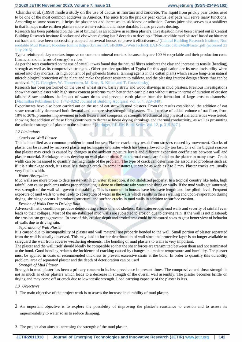
1.2 Limitations
Cracks on Wall Plaster
This is identified as a common problem in mud houses. Plaster cracks may result from stresses caused by movement. Cracks of
plaster can be caused by incorrect plastering techniques or plaster which has been allowed to dry too fast. One of the biggest reasons
that plaster may crack is caused by changes in the ambient moisture levels and different expansion coefficients between wall and
plaster material. Shrinkage cracks develop on wall plaster often. Fine thermal cracks are found on the plaster in many cases. Crack
width can be measured to quantify the magnitude of the problem. The type of crack can determine the associated problems such as;
if it is a shrinkage crack, it is usually a through crack. In some instances, it can be as wide as 2 to 3 mm. Plaster cracks are usually
very fine in width.
Water Absorption
Mud walls are more prone to deteriorate with high water absorption, if not stabilized properly. In a tropical country like India, high
rainfall can cause problems unless proper detailing is done to eliminate rain water splashing on walls. If the mud walls get saturated;
wet strength of the wall will govern the stability. This is common in houses have less eave length and low plinth level. Frequent
exposure of mud walls to water leads to absorption of water in the walls which results in their swelling and upon evaporation during
drying, shrinkage occurs. It produces structural and surface cracks in mud walls in addition to surface erosion.
Erosion of Walls Due to Driving Rain
Adverse climatic conditions produce deteriorating effects on mud shelters. Rainwater erodes mud walls and severity of rainfall even
leads to their collapse. Most of the un-stabilized mud walls are subjected to erosion due to driving rain. If the wall is not plastered;
the erosion can get aggravated. In case of this, erosion depth and eroded area could be measured so as to get a better view of behavior
of walls due to driving rain.
Separation of Wall Plaster
It is caused due to incompatibility of plaster and wall material not properly bonded to the wall. Small portion of plaster separated
from the wall is usually observed. This may lead to further deterioration of wall since the protective layer is no longer available to
safeguard the wall from adverse weathering elements. The bonding of mud plasters to walls is very important.
The plaster and the wall itself should ideally be compatible so that the shear forces are transmitted between them and not terminated
at the bond. Good bonding reduces the incidence of cracking caused by changes in ambient temperature and humidity. The plaster
must be applied in coats of recommended thickness to prevent excessive strain at the bond. In order to quantify this durability
problem, area of separated plaster and the depth of deterioration can be used
Strength of Mud Plaster
Strength in mud plaster has been a primary concern in its less prevalence in present times. The compressive and shear strength is
not as much as other plasters which leads to a decrease in strength of the overall wall assembly. The plaster becomes brittle on
drying and may come off or crack due to low tensile strength. Load carrying capacity of the plaster is less.
1.3 Objectives
1. The main objective of the project work is to assess the increase in durability of mud plaster.
2. An important objective is to explore the possibility of improving the plaster’s resistance to erosion and to assess its
impermeability to water so as to reduce damping.
3. The project also aims at increasing the strength of the mud plaster.
© 2020 JETIR November 2020, Volume 7, Issue 11 www.jetir.org (ISSN-2349-5162)
JETIR2011318 Journal of Emerging Technologies and Innovative Research (JETIR) www.jetir.org 143
4. The main aim of the project work is to provide a sustainable way to address rural housing problem due to construction material
constraint.
2. RESEARCH METHODOLOGY
2.1 MATERIALS AND THEIR PROPERTIES
Materials form the substances which are used and incorporated in a scheme to obtain and forecast results which can be beneficial
to the society in terms of economy, comfort and ease of availability. The chief material used in our project was mud keeping in
view its accessibility along with several additives to enhance its properties as a sustainable material. The properties of these materials
are explained below:
2.1.1 SOIL
The composition of traditional mud plasters varies from place to place and is an important factor in determining durability. The
clay content is particularly significant, because if it is too low the plaster will lack strength and cohesion, and if it is too high there
will be a risk of cracking due to shrinkage, which will weaken the bond to the wall. A suitable clay content is usually around 10
to 15 per cent, but values outside this range could also be suitable depending on the type of clay. The sand- to-silt ratio is also
very important in determining the quality of a plaster. Hence the choice of soil is an important factor that affects the quality of
plaster formed.
In order to determine the most suitable soil for mud plasters in Kashmir, a survey was conducted in different regions of Kashmir.
From the survey it was concluded that Karewa soils, locally known as Wuddar, have been traditionally used. Karewas are fresh-
water (fluviatile and lacustrine) deposits found as low flat mounds or elevated plateaus in the Valley of Kashmir and the Kishtwar
and Bhadarwah tracts of the Jammu Division. The important Karewas are found in Kulgam, Shopian, Badgam, Qazigund,
Tangmarg, Gulmarg, Baramulla, Lethpora, Chandhara, Pampore, Bijbehara, Awantipora, Islamabad (Anantnag), Mattan, Tral and
Ganderbal. The Pampore Karewa is famous all over the world for saffron cultivation.
Karewa deposits were collected from Galinder, Pampore. The top layer of soil was removed as it contained organic matter and
various tests were then carried out to establish the soil properties. 2.1.2 SHELLAC
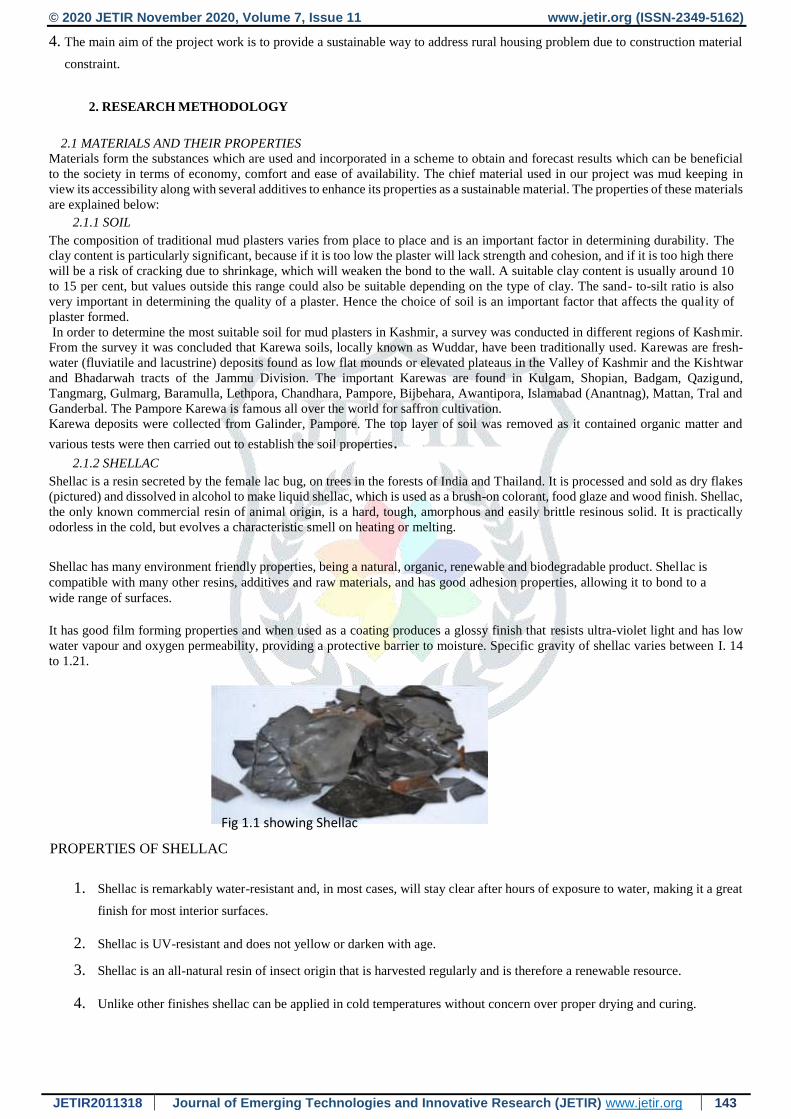
Shellac is a resin secreted by the female lac bug, on trees in the forests of India and Thailand. It is processed and sold as dry flakes
(pictured) and dissolved in alcohol to make liquid shellac, which is used as a brush-on colorant, food glaze and wood finish. Shellac,
the only known commercial resin of animal origin, is a hard, tough, amorphous and easily brittle resinous solid. It is practically
odorless in the cold, but evolves a characteristic smell on heating or melting.
Shellac has many environment friendly properties, being a natural, organic, renewable and biodegradable product. Shellac is
compatible with many other resins, additives and raw materials, and has good adhesion properties, allowing it to bond to a
wide range of surfaces.
It has good film forming properties and when used as a coating produces a glossy finish that resists ultra-violet light and has low
water vapour and oxygen permeability, providing a protective barrier to moisture. Specific gravity of shellac varies between I. 14
to 1.21.
PROPERTIES OF SHELLAC
1. Shellac is remarkably water-resistant and, in most cases, will stay clear after hours of exposure to water, making it a great
finish for most interior surfaces.
2. Shellac is UV-resistant and does not yellow or darken with age.
3. Shellac is an all-natural resin of insect origin that is harvested regularly and is therefore a renewable resource.
4. Unlike other finishes shellac can be applied in cold temperatures without concern over proper drying and curing.
Fig 1.1 showing Shellac
© 2020 JETIR November 2020, Volume 7, Issue 11 www.jetir.org (ISSN-2349-5162)
JETIR2011318 Journal of Emerging Technologies and Innovative Research (JETIR) www.jetir.org 144
2.1.3 JUTE/SACK FIBER
Jute is a long, soft, shiny vegetable fiber that can be spun into coarse, strong threads. It is a long, soft, shiny fiber that can be spun
into coarse, strong threads. Jute fibers are composed primarily of the plant materials cellulose, lignin, and pectin. The shrinkage
ratio of clay can be reduced by the addition of fibers such as jute.
Table 1.1 showing mechanical properties of fiber
Mechanical Properties Value
Density (g/cm3) 1.3
Elongation (%) 3.5-4.5
Tensile Strength (MPa) 393-723
Young’s Modulus (GPa) 2605
2.1.4 WHITE CLAY AND HEATED WHITE CLAY
White clay is a clay mineral, part of the group of industrial minerals. Clay is a product of the erosion of feldspar and other minerals
Endothermic dehydration of white clay begins at 550–600°C that modifies the properties of white clay resulting in a reddish brown
powder. White clay has a low shrink– swell capacity and a low cation-exchange capacity. It is a soft, muddy, usually white, produced
by the chemical weathering of aluminium-silicate minerals like feldspar.
The tensile resistance of clay in a plastic state is termed its “binding force.” A simple method for enhancing the binding force of
very lean mud mixes is to add soil with a high clay content or even pure clay. So white clay was chosen as additive to increase the
binding force of the mud plaster. Also, as heated-white clay decreases the permeability in cement, it was added as an additive to
study if it exhibits the same property in mud.
2.2 EXPERIMENTAL WORK
2.2.1 SAMPLE PREPRATION At first, the oversized gravels and organic matter was removed from the soil and the soil was pulverized. The
conventional samples were initially prepared and were proceeded by the preparation of improved soil samples whose
properties were then studied relative to the former.
For preparation of straw samples, straw was bowdlerized finely with the help of workshop equipment. To a
calculated volume of soil, 25% of straw was added. The straw samples were thoroughly mixed with well
pulverized soil and a water content enough to make the mix workable.
Jute is used as a tensile reinforcement replacement. Jute sacks were finely cut to yield fine fibers which were
mixed in percentages of 5, 10 and 15 by volume of the soil with pulverized soil along with water to form a
homogenous mixture.
Shellac, available in the form of large flakes were broken down to smaller pieces and then added to water which
was then boiled and stirred continuously till it attained a desired viscosity. The shellac to water ratio was 1:10.
The solution of Shellac was then added in percentages of 0.5, 1, 3, 5, 7 and 10 by weight of soil along with adequate
quantity of water to make the mix workable.
White clay, obtained from the mountain ranges in Awantipora, Jammu and Kashmir, India was pulverized
and passed through 2mm sieve. This was added to soil in percentages of 10, 20, 30 and 40 by weight of
soil and the samples were prepared.
The sieved white clay was heated in a muffle furnace at a temperature of 600oC and for a duration of 24 hours. A
reddish brown powder was obtained which was added to the pulverized soil in percentages of 10, 20, 30 and 40
by weight and after adding adequate amount of water, samples were prepared.
© 2020 JETIR November 2020, Volume 7, Issue 11 www.jetir.org (ISSN-2349-5162)
JETIR2011318 Journal of Emerging Technologies and Innovative Research (JETIR) www.jetir.org 145
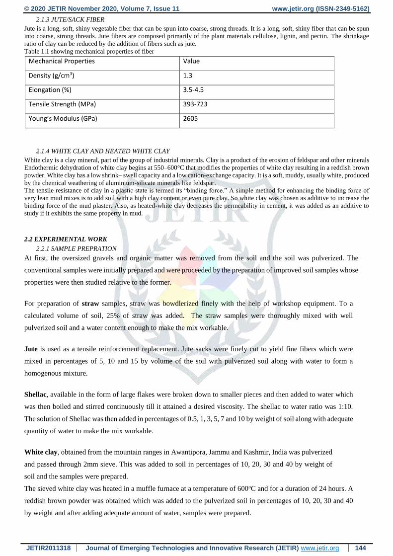
All the above samples were casted into circular moulds of 4-inch diameter and 25 mm thickness and cubical moulds of
dimension 70x70 mm. The materials yielding the best results were selected on the basis of various tests conducted. The
optimum percentages selected were Jute 5% with Shellac 3%, Jute 5% with Shellac 5% and Jute 5% with Shellac 7%.
These combinations were then casted in the form of samples with above given dimensions. These were then
tested.
Fig 1.2 showing circular and cubical Moulds to obtain the best
combination percentage among these.
2.2.2 TESTS ON SOIL
2.2.2.1 LIQUID LIMIT TEST
Liquid limit is the water content at which a soil is practically in a liquid state, but has infinitesimal
resistance against flow which can be measured by any standardized procedure. Liquid limit test is carried out
by simple casagrandis apparatus. The liquid limit of the selected soil specimen is 34.5875%.
2.2.2.2 PLASTIC LIMIT TEST
Plastic limit is the water content below which the soil stops behaving as a plastic material. Plastic limit test was
performed by rolling a soil sample in 3mm threads until it cracks. The plastic limit of the soil sample is 17.45 %.
2.2.2.3 SPECIFIC GRAVITY
Specific gravity, G, is the ratio of mass density of solids to that of water. A soil’s specific gravity largely depends
on the density of minerals making up the individual particles. Specific Gravity test was carried out by density bottle
method which yielded an average specific gravity value of 2.49
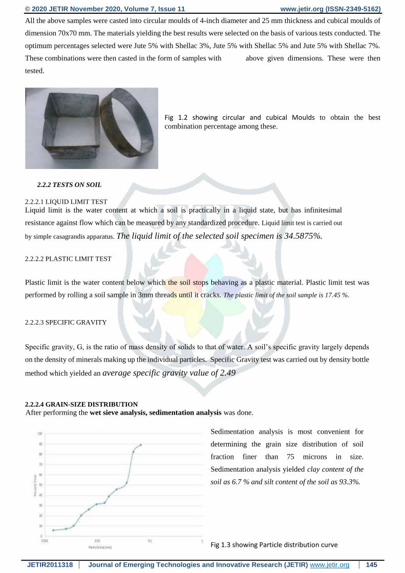
2.2.2.4 GRAIN-SIZE DISTRIBUTION
After performing the wet sieve analysis, sedimentation analysis was done.
Sedimentation analysis is most convenient for
determining the grain size distribution of soil
fraction finer than 75 microns in size.
Sedimentation analysis yielded clay content of the
soil as 6.7 % and silt content of the soil as 93.3%.
Fig 1.3 showing Particle distribution curve
© 2020 JETIR November 2020, Volume 7, Issue 11 www.jetir.org (ISSN-2349-5162)
JETIR2011318 Journal of Emerging Technologies and Innovative Research (JETIR) www.jetir.org 146
2.2.3 CASTING AND MIX DESIGN
Various individual samples of jute, shellac, white clay and heated white clay were casted at different percentages and the materials
yielding the best results were selected on the basis of various tests conducted. The optimum percentages were selected and combined
in the form of samples which were then tested to obtain the best results. Samples of straw were also made for comparison and its
percentage was taken as 25% by volume of soil.
Table 1.2 showing various percentages of different additives used in individual samples
Jute percentage (by volume of soil) 5 10 15 - - -
Shellac paste percentage (by
weight of soil)
0.5 1 3 5 7 10
White clay percentage (by
weight of soil)
10 20 30 40 - -
Heated white clay percentage
(by weight of soil)
10 20 30 40 - -
Table 1.3 showing various percentages of additives used in combination samples
Jute percentage (by volume of soil) 5 5 5
Shellac paste percentage (by
weight of soil)
3 5 7
2.2.4 TESTING OF SAMPLES
Various samples of straw, jute, shellac, white clay and sintered white clay were first tested individually for all the
below given tests. These samples were then casted again and then coated with shellac and were again tested
individually to study the effect of shellac coating,
From the results few combination percentages was chosen and those samples were then tested individually for all
the below given tests which yielded a single combination that was used to plaster the wall to simulate actual field
conditions.
2.2.4.1 SAMPLE DISINTEGRATION TEST
In this test, the time taken by the submerged part to disintegrate in static water was measured. At the end of a
specified period of time, the water absorption is calculated.
For this test a sample was weighed after air drying (W1) and then again weighed (W2) after placing the sample
in water for 24 hours.
© 2020 JETIR November 2020, Volume 7, Issue 11 www.jetir.org (ISSN-2349-5162)
JETIR2011318 Journal of Emerging Technologies and Innovative Research (JETIR) www.jetir.org 147
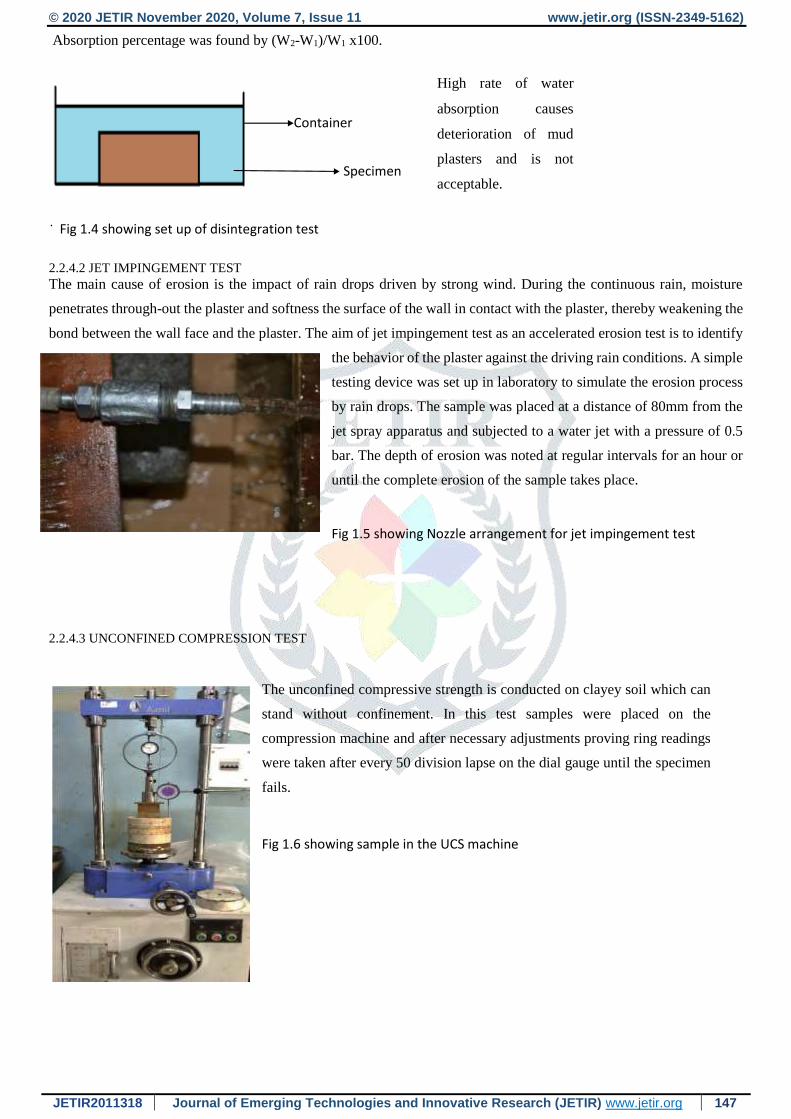
Absorption percentage was found by (W2-W1)/W1 x100.
2.2.4.2 JET IMPINGEMENT TEST The main cause of erosion is the impact of rain drops driven by strong wind. During the continuous rain, moisture
penetrates through-out the plaster and softness the surface of the wall in contact with the plaster, thereby weakening the
bond between the wall face and the plaster. The aim of jet impingement test as an accelerated erosion test is to identify
the behavior of the plaster against the driving rain conditions. A simple
testing device was set up in laboratory to simulate the erosion process
by rain drops. The sample was placed at a distance of 80mm from the
jet spray apparatus and subjected to a water jet with a pressure of 0.5
bar. The depth of erosion was noted at regular intervals for an hour or
until the complete erosion of the sample takes place.
Fig 1.5 showing Nozzle arrangement for jet impingement test
2.2.4.3 UNCONFINED COMPRESSION TEST
The unconfined compressive strength is conducted on clayey soil which can
stand without confinement. In this test samples were placed on the
compression machine and after necessary adjustments proving ring readings
were taken after every 50 division lapse on the dial gauge until the specimen
fails.
Fig 1.6 showing sample in the UCS machine
.
Container
Specimen
High rate of water
absorption causes
deterioration of mud
plasters and is not
acceptable.
Fig 1.4 showing set up of disintegration test
© 2020 JETIR November 2020, Volume 7, Issue 11 www.jetir.org (ISSN-2349-5162)
JETIR2011318 Journal of Emerging Technologies and Innovative Research (JETIR) www.jetir.org 148
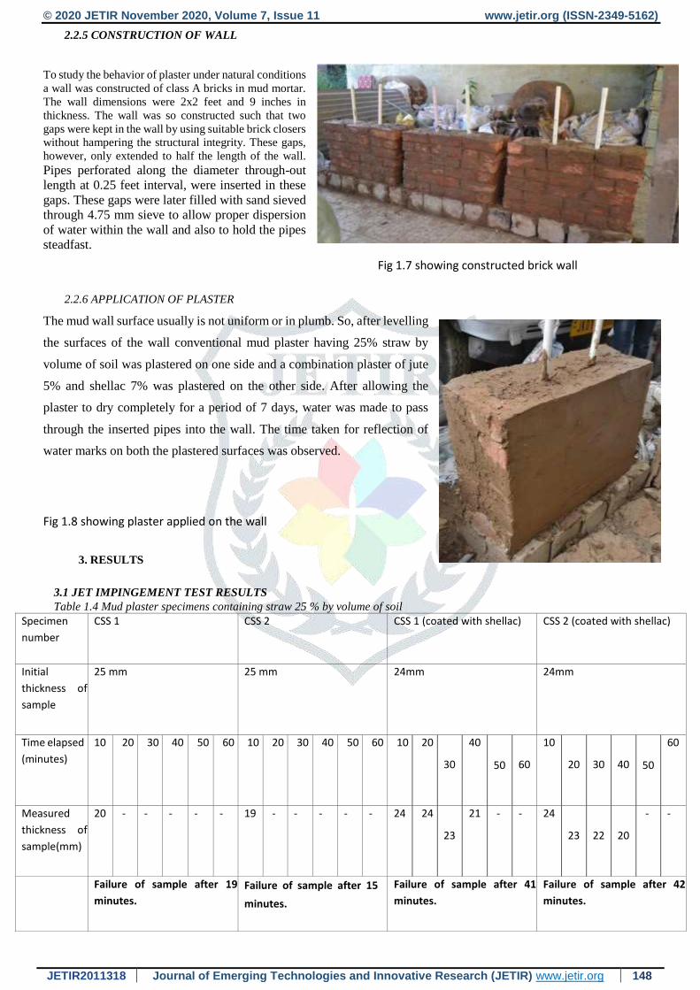
2.2.5 CONSTRUCTION OF WALL
To study the behavior of plaster under natural conditions
a wall was constructed of class A bricks in mud mortar.
The wall dimensions were 2x2 feet and 9 inches in
thickness. The wall was so constructed such that two
gaps were kept in the wall by using suitable brick closers
without hampering the structural integrity. These gaps,
however, only extended to half the length of the wall.
Pipes perforated along the diameter through-out
length at 0.25 feet interval, were inserted in these
gaps. These gaps were later filled with sand sieved
through 4.75 mm sieve to allow proper dispersion
of water within the wall and also to hold the pipes
steadfast.
Fig 1.7 showing constructed brick wall
2.2.6 APPLICATION OF PLASTER
The mud wall surface usually is not uniform or in plumb. So, after levelling
the surfaces of the wall conventional mud plaster having 25% straw by
volume of soil was plastered on one side and a combination plaster of jute
5% and shellac 7% was plastered on the other side. After allowing the
plaster to dry completely for a period of 7 days, water was made to pass
through the inserted pipes into the wall. The time taken for reflection of
water marks on both the plastered surfaces was observed.
Fig 1.8 showing plaster applied on the wall
3. RESULTS
3.1 JET IMPINGEMENT TEST RESULTS
Table 1.4 Mud plaster specimens containing straw 25 % by volume of soil Specimen
number
CSS 1 CSS 2 CSS 1 (coated with shellac) CSS 2 (coated with shellac)
Initial
thickness of
sample
25 mm 25 mm 24mm 24mm
Time elapsed
(minutes)
10 20 30 40 50 60 10 20 30 40 50 60 10 20
30
40
50
60
10
20
30
40
50
60
Measured
thickness of
sample(mm)
20
- - - - - 19 - - - - - 24 24
23
21
- - 24
23
22
20
- -
Failure of sample after 19
minutes. Failure of sample after 15
minutes.
Failure of sample after 41
minutes.
Failure of sample after 42
minutes.
© 2020 JETIR November 2020, Volume 7, Issue 11 www.jetir.org (ISSN-2349-5162)
JETIR2011318 Journal of Emerging Technologies and Innovative Research (JETIR) www.jetir.org 149
Table 1.5 Mud plaster specimens containing jute by 5% as an additive subjected to jet impingement test. Specimen
number
J5A J5B J5 (coated with a single layer
of shellac)
Initial thickness
of sample
24 mm 23 mm 22 mm
Time elapsed
(minutes)
10
20
30
40
50
60
10 20 30 40 50 60 10 20 30 40 50 60
Measured
Thickness
of
sample(mm)
18
11
- - - - 19 16 - - - - 20 18 15 5 - -
Failure of sample after 23
minutes.
Failure of sample after 27
minutes.
Failure of sample after 42
minutes.
Specimen
number
J10A J10 B J10 (coated with a single
layer of shellac)
Initial thickness of
sample
24 mm 25 mm 22mm
Time elapsed
(minutes)
10 20 30 40 50 60 10 20 30 40 50 60 10 20 30 40 50 60
Measured
thickness
of
sample(mm)
17 14 - - - - 16 10 - - - - 21 19 16 7 - -
Failure of sample after 22
minutes.
Failure of sample after 21
minutes.
Failure of sample after 45
minutes.
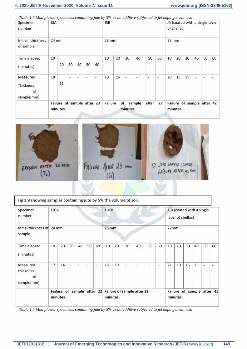
Table 1.5 Mud plaster specimens containing jute by 5% as an additive subjected to jet impingement test.
Fig 1.9 showing samples containing jute by 5% the volume of soil.
© 2020 JETIR November 2020, Volume 7, Issue 11 www.jetir.org (ISSN-2349-5162)
JETIR2011318 Journal of Emerging Technologies and Innovative Research (JETIR) www.jetir.org 150
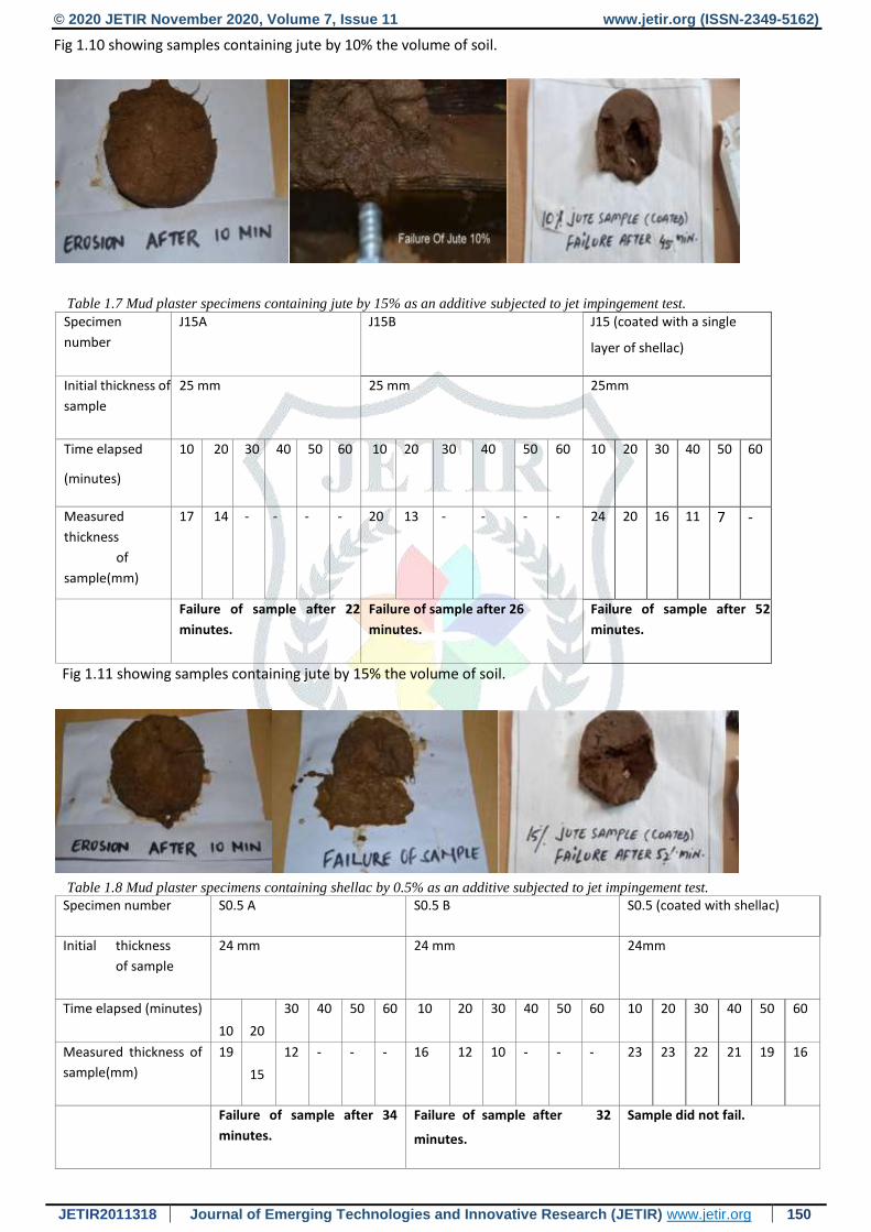
Fig 1.10 showing samples containing jute by 10% the volume of soil.
Table 1.7 Mud plaster specimens containing jute by 15% as an additive subjected to jet impingement test. Specimen
number
J15A J15B J15 (coated with a single
layer of shellac)
Initial thickness of
sample
25 mm 25 mm 25mm
Time elapsed
(minutes)
10 20 30 40 50 60 10 20 30 40 50 60 10 20 30 40 50 60
Measured
thickness
of
sample(mm)
17 14 - - - - 20 13 - - - - 24 20 16 11 7 -
Failure of sample after 22
minutes.
Failure of sample after 26
minutes.
Failure of sample after 52
minutes.
Fig 1.11 showing samples containing jute by 15% the volume of soil.
Table 1.8 Mud plaster specimens containing shellac by 0.5% as an additive subjected to jet impingement test.
Specimen number S0.5 A S0.5 B S0.5 (coated with shellac)
Initial thickness
of sample
24 mm 24 mm 24mm
Time elapsed (minutes)
10
20
30 40 50 60 10 20 30 40 50 60 10 20 30 40 50 60
Measured thickness of
sample(mm)
19
15
12 - - - 16 12 10 - - - 23 23 22 21 19 16
Failure of sample after 34
minutes.
Failure of sample after 32
minutes.
Sample did not fail.
© 2020 JETIR November 2020, Volume 7, Issue 11 www.jetir.org (ISSN-2349-5162)
JETIR2011318 Journal of Emerging Technologies and Innovative Research (JETIR) www.jetir.org 151
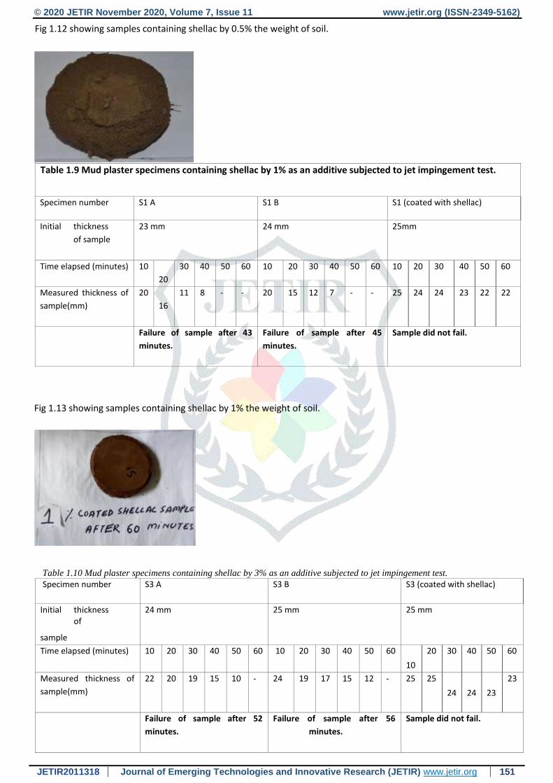
Fig 1.12 showing samples containing shellac by 0.5% the weight of soil.
Table 1.9 Mud plaster specimens containing shellac by 1% as an additive subjected to jet impingement test.
Specimen number S1 A S1 B S1 (coated with shellac)
Initial thickness
of sample
23 mm 24 mm 25mm
Time elapsed (minutes) 10
20
30 40 50 60 10 20 30 40 50 60 10 20 30 40 50 60
Measured thickness of
sample(mm)
20
16
11 8 - - 20 15 12 7 - - 25 24 24 23 22 22
Failure of sample after 43
minutes.
Failure of sample after 45
minutes.
Sample did not fail.
Fig 1.13 showing samples containing shellac by 1% the weight of soil.
Table 1.10 Mud plaster specimens containing shellac by 3% as an additive subjected to jet impingement test.
Specimen number S3 A S3 B S3 (coated with shellac)
Initial thickness of
sample
24 mm 25 mm 25 mm
Time elapsed (minutes) 10 20 30 40 50 60 10 20 30 40 50 60
10
20 30 40 50 60
Measured thickness of
sample(mm)
22 20 19 15 10 - 24 19 17 15 12 - 25 25
24
24
23
23
Failure of sample after 52
minutes.
Failure of sample after 56
minutes.
Sample did not fail.
© 2020 JETIR November 2020, Volume 7, Issue 11 www.jetir.org (ISSN-2349-5162)
JETIR2011318 Journal of Emerging Technologies and Innovative Research (JETIR) www.jetir.org 152
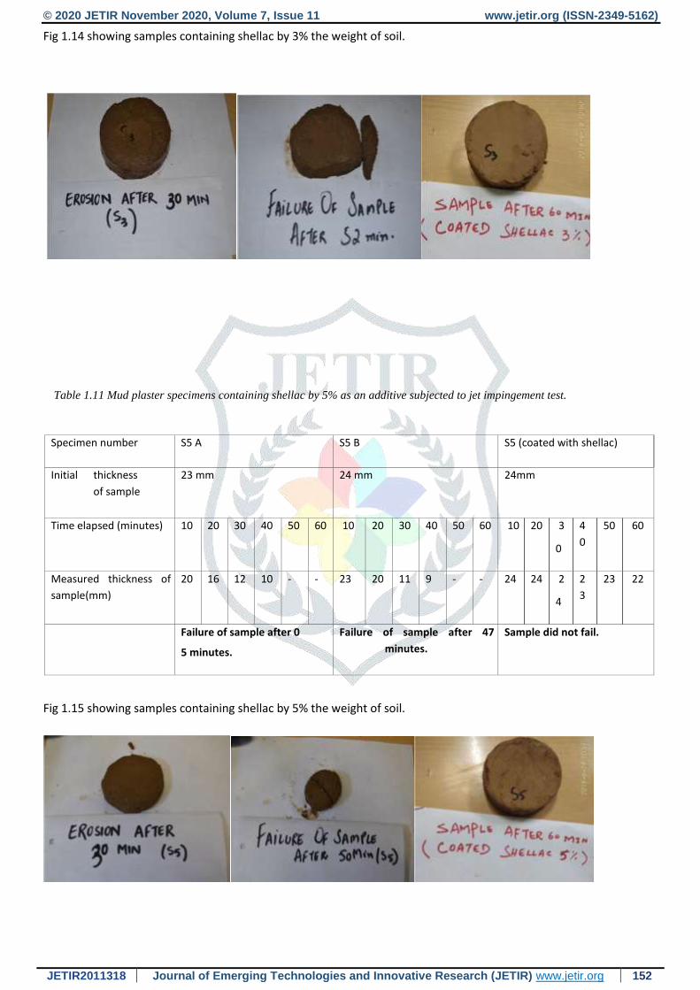
Fig 1.14 showing samples containing shellac by 3% the weight of soil.
Table 1.11 Mud plaster specimens containing shellac by 5% as an additive subjected to jet impingement test.
Specimen number S5 A S5 B S5 (coated with shellac)
Initial thickness
of sample
23 mm 24 mm 24mm
Time elapsed (minutes) 10 20 30 40 50 60 10 20 30 40 50 60 10 20 3
0
4
0
50 60
Measured thickness of
sample(mm)
20 16 12 10 - - 23 20 11 9 - - 24 24 2
4
2
3
23 22
Failure of sample after 0
5 minutes.
Failure of sample after 47
minutes.
Sample did not fail.
Fig 1.15 showing samples containing shellac by 5% the weight of soil.
© 2020 JETIR November 2020, Volume 7, Issue 11 www.jetir.org (ISSN-2349-5162)
JETIR2011318 Journal of Emerging Technologies and Innovative Research (JETIR) www.jetir.org 153
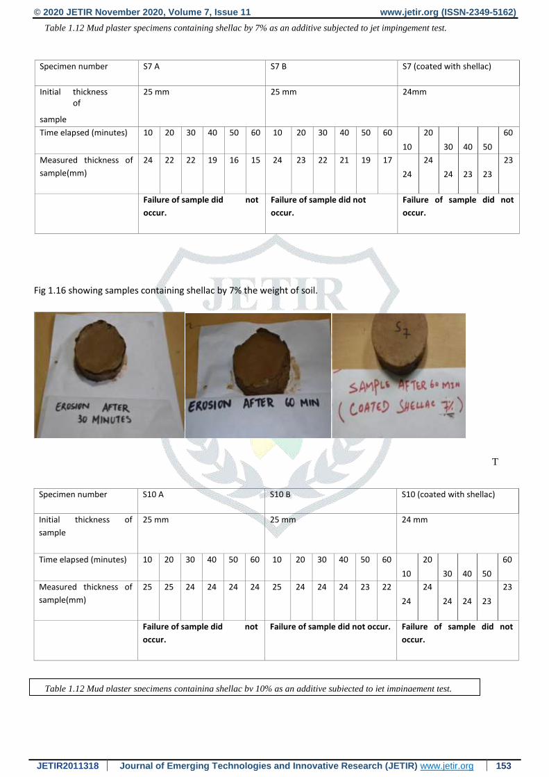
Table 1.12 Mud plaster specimens containing shellac by 7% as an additive subjected to jet impingement test.
Specimen number S7 A S7 B S7 (coated with shellac)
Initial thickness of
sample
25 mm 25 mm 24mm
Time elapsed (minutes) 10 20 30 40 50 60 10 20 30 40 50 60
10
20
30
40
50
60
Measured thickness of
sample(mm)
24 22 22 19 16 15 24 23 22 21 19 17
24
24
24
23
23
23
Failure of sample did not
occur.
Failure of sample did not
occur.
Failure of sample did not
occur.
Fig 1.16 showing samples containing shellac by 7% the weight of soil.
T
Specimen number S10 A S10 B S10 (coated with shellac)
Initial thickness of
sample
25 mm 25 mm 24 mm
Time elapsed (minutes) 10 20 30 40 50 60 10 20 30 40 50 60
10
20
30
40
50
60
Measured thickness of
sample(mm)
25 25 24 24 24 24 25 24 24 24 23 22
24
24
24
24
23
23
Failure of sample did not
occur.
Failure of sample did not occur. Failure of sample did not
occur.
Table 1.12 Mud plaster specimens containing shellac by 10% as an additive subjected to jet impingement test.
© 2020 JETIR November 2020, Volume 7, Issue 11 www.jetir.org (ISSN-2349-5162)
JETIR2011318 Journal of Emerging Technologies and Innovative Research (JETIR) www.jetir.org 154
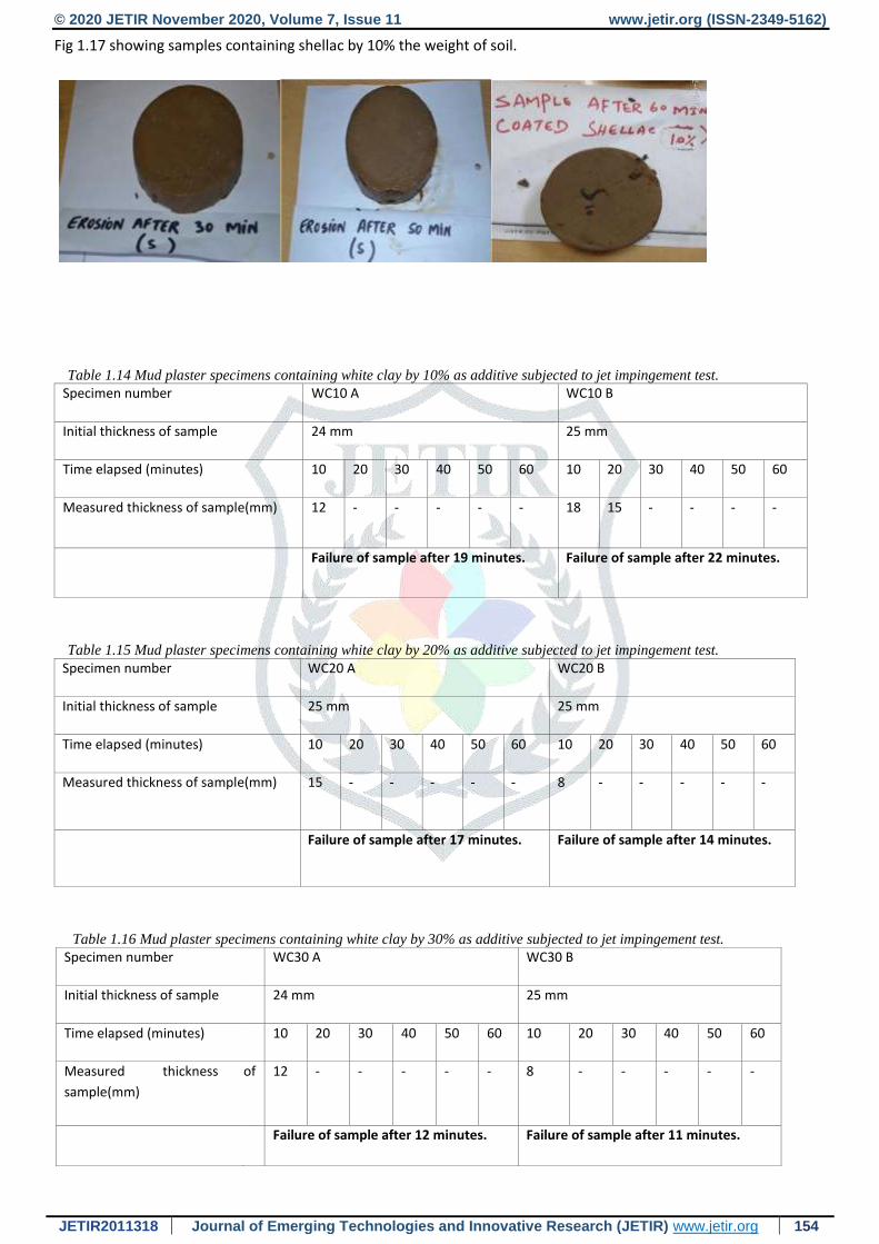
Fig 1.17 showing samples containing shellac by 10% the weight of soil.
Table 1.14 Mud plaster specimens containing white clay by 10% as additive subjected to jet impingement test.
Specimen number WC10 A WC10 B
Initial thickness of sample 24 mm 25 mm
Time elapsed (minutes) 10 20 30 40 50 60 10 20 30 40 50 60
Measured thickness of sample(mm) 12 - - - - - 18 15 - - - -
Failure of sample after 19 minutes. Failure of sample after 22 minutes.
Table 1.15 Mud plaster specimens containing white clay by 20% as additive subjected to jet impingement test.
Specimen number WC20 A WC20 B
Initial thickness of sample 25 mm 25 mm
Time elapsed (minutes) 10 20 30 40 50 60 10 20 30 40 50 60
Measured thickness of sample(mm) 15 - - - - - 8 - - - - -
Failure of sample after 17 minutes. Failure of sample after 14 minutes.
Table 1.16 Mud plaster specimens containing white clay by 30% as additive subjected to jet impingement test.
Specimen number WC30 A WC30 B
Initial thickness of sample 24 mm 25 mm
Time elapsed (minutes) 10 20 30 40 50 60 10 20 30 40 50 60
Measured thickness
sample(mm)
of 12 - - - - - 8 - - - - -
Failure of sample after 12 minutes. Failure of sample after 11 minutes.
© 2020 JETIR November 2020, Volume 7, Issue 11 www.jetir.org (ISSN-2349-5162)
JETIR2011318 Journal of Emerging Technologies and Innovative Research (JETIR) www.jetir.org 155
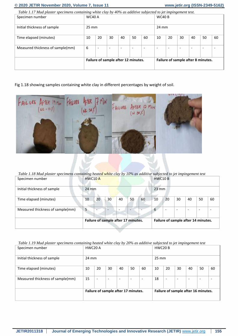
Table 1.17 Mud plaster specimens containing white clay by 40% as additive subjected to jet impingement test.
Specimen number WC40 A WC40 B
Initial thickness of sample 25 mm 24 mm
Time elapsed (minutes) 10 20 30 40 50 60 10 20 30 40 50 60
Measured thickness of sample(mm) 6 - - - - - - - - - - -
Failure of sample after 12 minutes. Failure of sample after 8 minutes.
Fig 1.18 showing samples containing white clay in different percentages by weight of soil.
Table 1.18 Mud plaster specimens containing heated white clay by 10% as additive subjected to jet impingement test
Specimen number HWC10 A HWC10 B
Initial thickness of sample 24 mm 23 mm
Time elapsed (minutes) 10 20 30 40 50 60 10 20 30 40 50 60
Measured thickness of sample(mm) 5 - - - - - 6 - - - - -
Failure of sample after 17 minutes. Failure of sample after 14 minutes.
Table 1.19 Mud plaster specimens containing heated white clay by 20% as additive subjected to jet impingement test
Specimen number HWC20 A HWC20 B
Initial thickness of sample 24 mm 25 mm
Time elapsed (minutes) 10 20 30 40 50 60 10 20 30 40 50 60
Measured thickness of sample(mm) 15 - - - - - 18 - - - - -
Failure of sample after 17 minutes. Failure of sample after 16 minutes.
© 2020 JETIR November 2020, Volume 7, Issue 11 www.jetir.org (ISSN-2349-5162)
JETIR2011318 Journal of Emerging Technologies and Innovative Research (JETIR) www.jetir.org 156
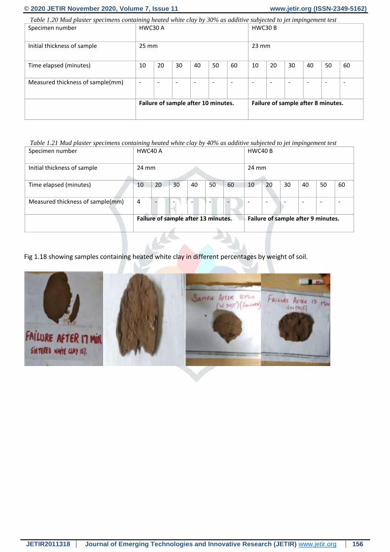
Table 1.20 Mud plaster specimens containing heated white clay by 30% as additive subjected to jet impingement test
Specimen number HWC30 A HWC30 B
Initial thickness of sample 25 mm 23 mm
Time elapsed (minutes) 10 20 30 40 50 60 10 20 30 40 50 60
Measured thickness of sample(mm) - - - - - - - - - - - -
Failure of sample after 10 minutes. Failure of sample after 8 minutes.
Table 1.21 Mud plaster specimens containing heated white clay by 40% as additive subjected to jet impingement test
Specimen number HWC40 A HWC40 B
Initial thickness of sample 24 mm 24 mm
Time elapsed (minutes) 10 20 30 40 50 60 10 20 30 40 50 60
Measured thickness of sample(mm) 4 - - - - - - - - - - -
Failure of sample after 13 minutes. Failure of sample after 9 minutes.
Fig 1.18 showing samples containing heated white clay in different percentages by weight of soil.
© 2020 JETIR November 2020, Volume 7, Issue 11 www.jetir.org (ISSN-2349-5162)
JETIR2011318 Journal of Emerging Technologies and Innovative Research (JETIR) www.jetir.org 157
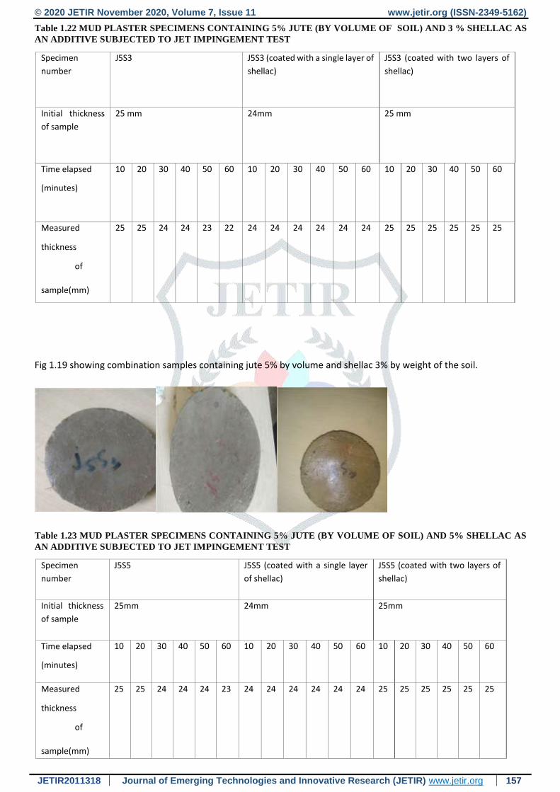
Table 1.22 MUD PLASTER SPECIMENS CONTAINING 5% JUTE (BY VOLUME OF SOIL) AND 3 % SHELLAC AS
AN ADDITIVE SUBJECTED TO JET IMPINGEMENT TEST
Specimen
number
J5S3
J5S3 (coated with a single layer of
shellac)
J5S3 (coated with two layers of
shellac)
Initial thickness
of sample
25 mm
24mm 25 mm
Time elapsed
(minutes)
10 20 30 40 50 60 10 20 30 40 50 60 10 20 30 40 50 60
Measured
thickness
of
sample(mm)
25 25 24 24 23 22 24 24 24 24 24 24 25 25 25 25 25 25
Fig 1.19 showing combination samples containing jute 5% by volume and shellac 3% by weight of the soil.
Table 1.23 MUD PLASTER SPECIMENS CONTAINING 5% JUTE (BY VOLUME OF SOIL) AND 5% SHELLAC AS
AN ADDITIVE SUBJECTED TO JET IMPINGEMENT TEST
Specimen
number
J5S5
J5S5 (coated with a single layer
of shellac)
J5S5 (coated with two layers of
shellac)
Initial thickness
of sample
25mm
24mm 25mm
Time elapsed
(minutes)
10 20 30 40 50 60 10 20 30 40 50 60 10 20 30 40 50 60
Measured
thickness
of
sample(mm)
25 25 24 24 24 23 24 24 24 24 24 24 25 25 25 25 25 25
© 2020 JETIR November 2020, Volume 7, Issue 11 www.jetir.org (ISSN-2349-5162)
JETIR2011318 Journal of Emerging Technologies and Innovative Research (JETIR) www.jetir.org 158
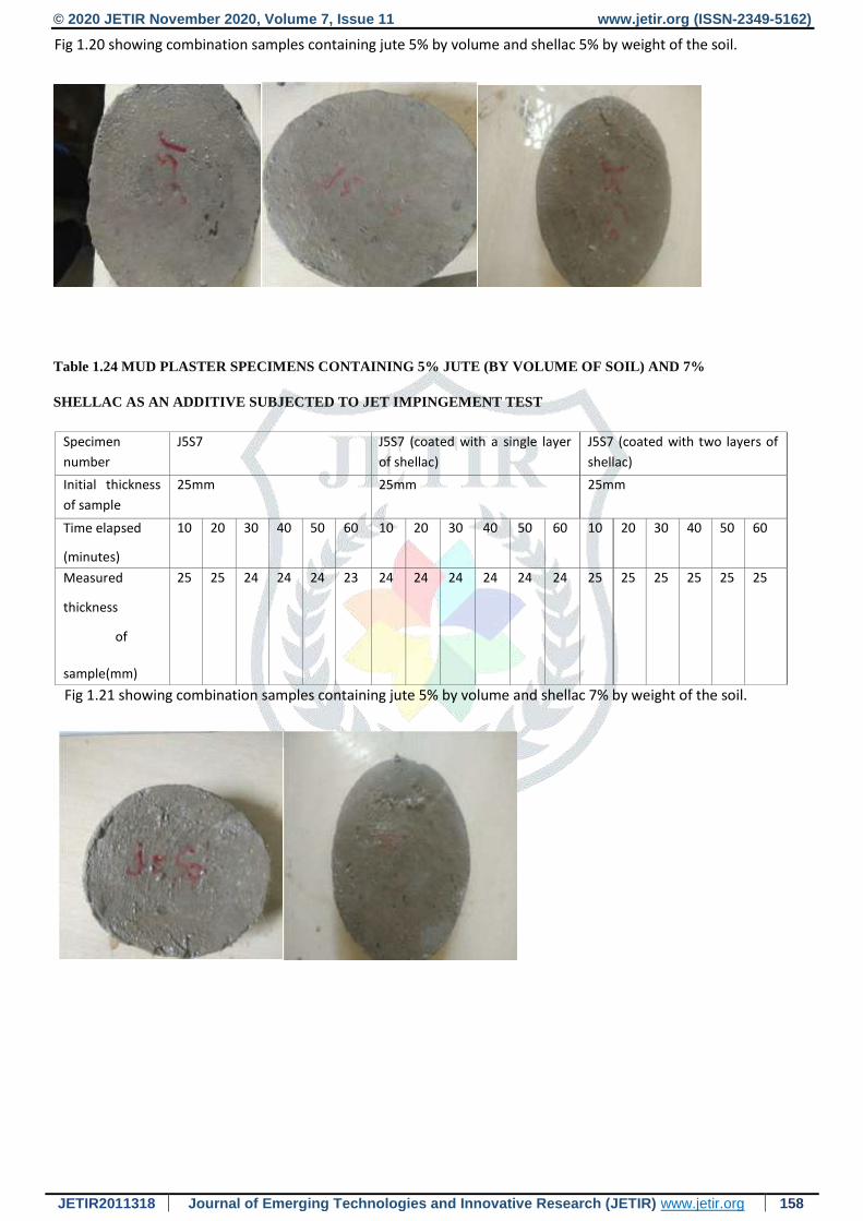
Fig 1.20 showing combination samples containing jute 5% by volume and shellac 5% by weight of the soil.
Table 1.24 MUD PLASTER SPECIMENS CONTAINING 5% JUTE (BY VOLUME OF SOIL) AND 7%
SHELLAC AS AN ADDITIVE SUBJECTED TO JET IMPINGEMENT TEST
Specimen
number
J5S7
J5S7 (coated with a single layer
of shellac)
J5S7 (coated with two layers of
shellac)
Initial thickness
of sample
25mm
25mm 25mm
Time elapsed
(minutes)
10 20 30 40 50 60 10 20 30 40 50 60 10 20 30 40 50 60
Measured
thickness
of
sample(mm)
25 25 24 24 24 23 24 24 24 24 24 24 25 25 25 25 25 25
Fig 1.21 showing combination samples containing jute 5% by volume and shellac 7% by weight of the soil.
© 2020 JETIR November 2020, Volume 7, Issue 11 www.jetir.org (ISSN-2349-5162)
JETIR2011318 Journal of Emerging Technologies and Innovative Research (JETIR) www.jetir.org 159
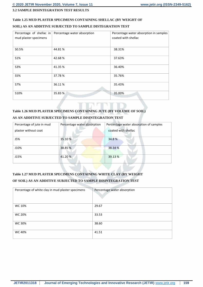
3.2 SAMPLE DISINTEGRATION TEST RESULTS
Table 1.25 MUD PLASTER SPECIMENS CONTAINING SHELLAC (BY WEIGHT OF
SOIL) AS AN ADDITIVE SUBJECTED TO SAMPLE DISTEGRATION TEST
Percentage of shellac in
mud plaster specimens
Percentage water absorption
Percentage water absorption in samples
coated with shellac
S0.5% 44.81 % 38.31%
S1% 42.68 % 37.63%
S3% 41.35 % 36.40%
S5% 37.78 % 35.76%
S7% 36.11 % 35.43%
S10% 35.83 % 35.00%
Table 1.26 MUD PLASTER SPECIMENS CONTAINING JUTE (BY VOLUME OF SOIL)
AS AN ADDITIVE SUBJECTED TO SAMPLE DISINTEGRATION TEST
Percentage of jute in mud
plaster without coat
Percentage water absorption Percentage water absorption of samples
coated with shellac
J5% 35.10 % 34.8 %
J10% 38.85 % 38.34 %
J15% 41.20 % 39.13 %
Table 1.27 MUD PLASTER SPECIMENS CONTAINING WHITE CLAY (BY WEIGHT
OF SOIL) AS AN ADDITIVE SUBJECTED TO SAMPLE DISINTEGRATION TEST
Percentage of white clay in mud plaster specimens Percentage water absorption
WC 10% 29.67
WC 20% 33.53
WC 30% 38.60
WC 40% 41.51
© 2020 JETIR November 2020, Volume 7, Issue 11 www.jetir.org (ISSN-2349-5162)
JETIR2011318 Journal of Emerging Technologies and Innovative Research (JETIR) www.jetir.org 160
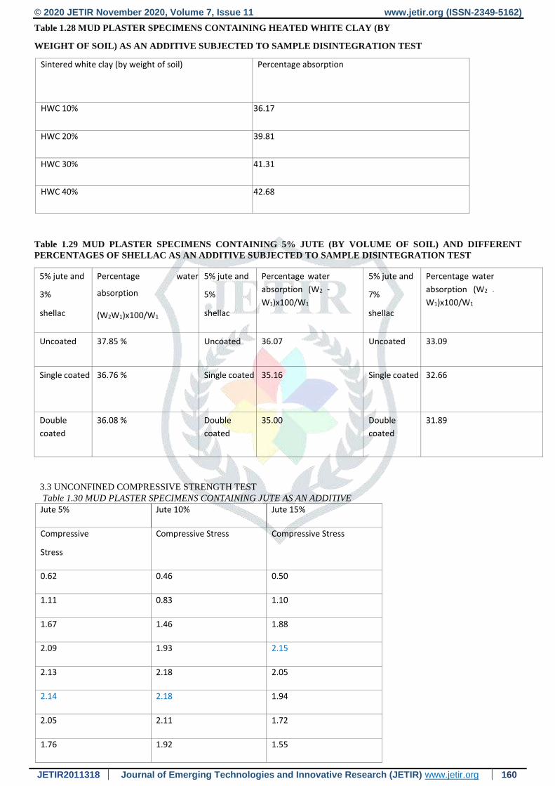
Table 1.28 MUD PLASTER SPECIMENS CONTAINING HEATED WHITE CLAY (BY
WEIGHT OF SOIL) AS AN ADDITIVE SUBJECTED TO SAMPLE DISINTEGRATION TEST
Sintered white clay (by weight of soil) Percentage absorption
HWC 10% 36.17
HWC 20% 39.81
HWC 30% 41.31
HWC 40% 42.68
Table 1.29 MUD PLASTER SPECIMENS CONTAINING 5% JUTE (BY VOLUME OF SOIL) AND DIFFERENT
PERCENTAGES OF SHELLAC AS AN ADDITIVE SUBJECTED TO SAMPLE DISINTEGRATION TEST
5% jute and
3%
shellac
Percentage water
absorption
(W2W1)x100/W1
5% jute and
5%
shellac
Percentage water
absorption (W2 -
W1)x100/W1
5% jute and
7%
shellac
Percentage water
absorption (W2 -
W1)x100/W1
Uncoated 37.85 % Uncoated 36.07 Uncoated 33.09
Single coated 36.76 % Single coated 35.16 Single coated 32.66
Double
coated
36.08 % Double
coated
35.00 Double
coated
31.89
3.3 UNCONFINED COMPRESSIVE STRENGTH TEST Table 1.30 MUD PLASTER SPECIMENS CONTAINING JUTE AS AN ADDITIVE
Jute 5% Jute 10% Jute 15%
Compressive
Stress
Compressive Stress Compressive Stress
0.62 0.46 0.50
1.11 0.83 1.10
1.67 1.46 1.88
2.09 1.93 2.15
2.13 2.18 2.05
2.14 2.18 1.94
2.05 2.11 1.72
1.76 1.92 1.55
© 2020 JETIR November 2020, Volume 7, Issue 11 www.jetir.org (ISSN-2349-5162)
JETIR2011318 Journal of Emerging Technologies and Innovative Research (JETIR) www.jetir.org 161
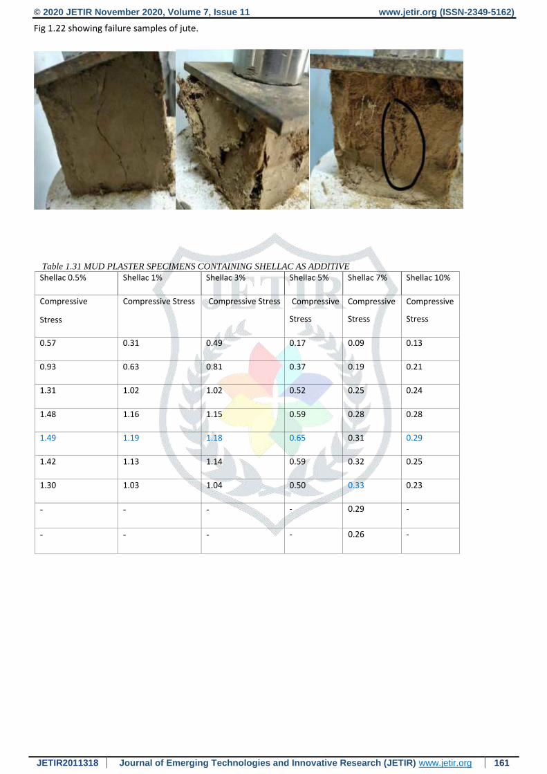
Fig 1.22 showing failure samples of jute.
Table 1.31 MUD PLASTER SPECIMENS CONTAINING SHELLAC AS ADDITIVE Shellac 0.5% Shellac 1% Shellac 3% Shellac 5% Shellac 7% Shellac 10%
Compressive
Stress
Compressive Stress Compressive Stress Compressive
Stress
Compressive
Stress
Compressive
Stress
0.57 0.31 0.49 0.17 0.09 0.13
0.93 0.63 0.81 0.37 0.19 0.21
1.31 1.02 1.02 0.52 0.25 0.24
1.48 1.16 1.15 0.59 0.28 0.28
1.49 1.19 1.18 0.65 0.31 0.29
1.42 1.13 1.14 0.59 0.32 0.25
1.30 1.03 1.04 0.50 0.33 0.23
- - - - 0.29 -
- - - - 0.26 -
© 2020 JETIR November 2020, Volume 7, Issue 11 www.jetir.org (ISSN-2349-5162)
JETIR2011318 Journal of Emerging Technologies and Innovative Research (JETIR) www.jetir.org 162
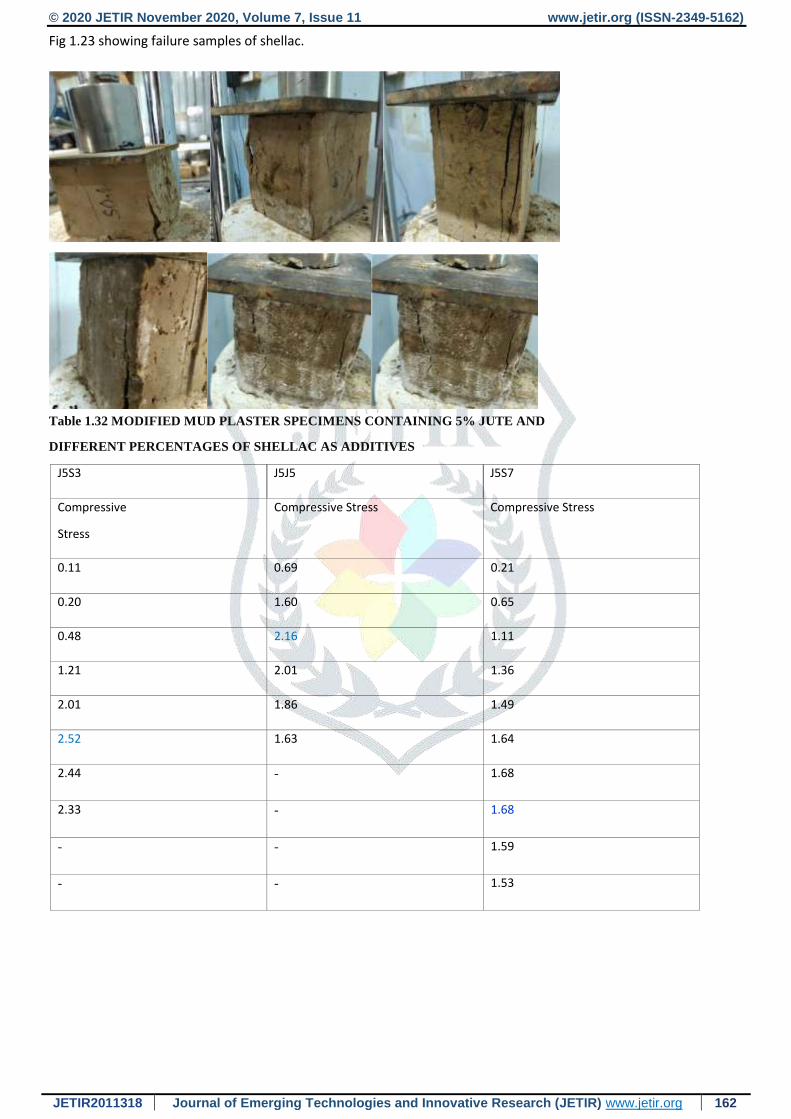
Fig 1.23 showing failure samples of shellac.
Table 1.32 MODIFIED MUD PLASTER SPECIMENS CONTAINING 5% JUTE AND
DIFFERENT PERCENTAGES OF SHELLAC AS ADDITIVES
J5S3 J5J5 J5S7
Compressive
Stress
Compressive Stress Compressive Stress
0.11 0.69 0.21
0.20 1.60 0.65
0.48 2.16 1.11
1.21 2.01 1.36
2.01 1.86 1.49
2.52 1.63 1.64
2.44 - 1.68
2.33 - 1.68
- - 1.59
- - 1.53
© 2020 JETIR November 2020, Volume 7, Issue 11 www.jetir.org (ISSN-2349-5162)
JETIR2011318 Journal of Emerging Technologies and Innovative Research (JETIR) www.jetir.org 163
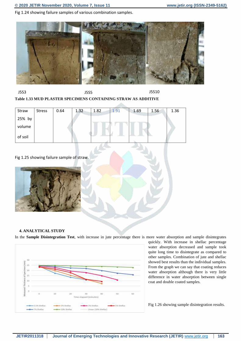
Fig 1.24 showing failure samples of various combination samples.
Table 1.33 MUD PLASTER SPECIMENS CONTAINING STRAW AS ADDITIVE
Straw
25% by
volume
of soil
Stress 0.64 1.32 1.82 1.91 1.69 1.56 1.36
Fig 1.25 showing failure sample of straw.
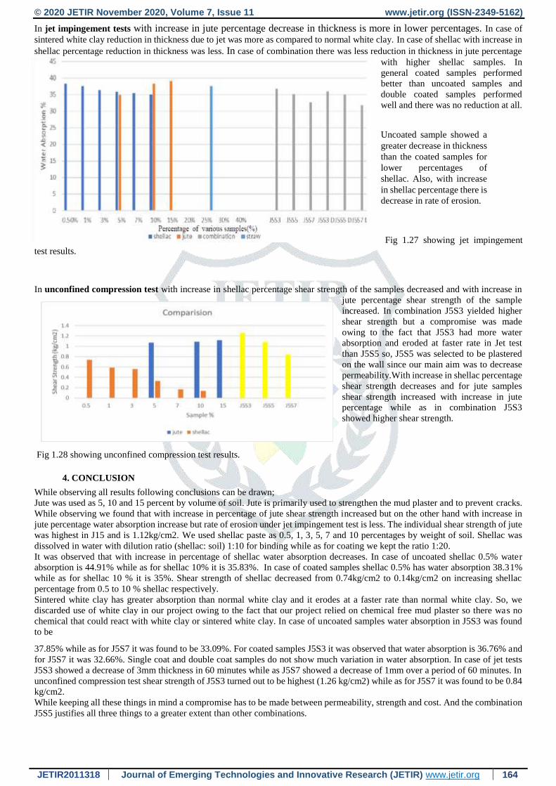
4. ANALYTICAL STUDY
In the Sample Disintegration Test, with increase in jute percentage there is more water absorption and sample disintegrates
quickly. With increase in shellac percentage
water absorption decreased and sample took
quite long time to disintegrate as compared to
other samples. Combination of jute and shellac
showed best results than the individual samples.
From the graph we can say that coating reduces
water absorption although there is very little
difference in water absorption between single
coat and double coated samples.
Fig 1.26 showing sample disintegration results.
J5S3 J5S5 J5S10
© 2020 JETIR November 2020, Volume 7, Issue 11 www.jetir.org (ISSN-2349-5162)
JETIR2011318 Journal of Emerging Technologies and Innovative Research (JETIR) www.jetir.org 164
In jet impingement tests with increase in jute percentage decrease in thickness is more in lower percentages. In case of
sintered white clay reduction in thickness due to jet was more as compared to normal white clay. In case of shellac with increase in
shellac percentage reduction in thickness was less. In case of combination there was less reduction in thickness in jute percentage
with higher shellac samples. In
general coated samples performed
better than uncoated samples and
double coated samples performed
well and there was no reduction at all.
Uncoated sample showed a
greater decrease in thickness
than the coated samples for
lower percentages of
shellac. Also, with increase
in shellac percentage there is
decrease in rate of erosion.
Fig 1.27 showing jet impingement
test results.
In unconfined compression test with increase in shellac percentage shear strength of the samples decreased and with increase in
jute percentage shear strength of the sample
increased. In combination J5S3 yielded higher
shear strength but a compromise was made
owing to the fact that J5S3 had more water
absorption and eroded at faster rate in Jet test
than J5S5 so, J5S5 was selected to be plastered
on the wall since our main aim was to decrease
permeability.With increase in shellac percentage
shear strength decreases and for jute samples
shear strength increased with increase in jute
percentage while as in combination J5S3
showed higher shear strength.
Fig 1.28 showing unconfined compression test results.
4. CONCLUSION
While observing all results following conclusions can be drawn;
Jute was used as 5, 10 and 15 percent by volume of soil. Jute is primarily used to strengthen the mud plaster and to prevent cracks.
While observing we found that with increase in percentage of jute shear strength increased but on the other hand with increase in
jute percentage water absorption increase but rate of erosion under jet impingement test is less. The individual shear strength of jute
was highest in J15 and is 1.12kg/cm2. We used shellac paste as 0.5, 1, 3, 5, 7 and 10 percentages by weight of soil. Shellac was
dissolved in water with dilution ratio (shellac: soil) 1:10 for binding while as for coating we kept the ratio 1:20.
It was observed that with increase in percentage of shellac water absorption decreases. In case of uncoated shellac 0.5% water
absorption is 44.91% while as for shellac 10% it is 35.83%. In case of coated samples shellac 0.5% has water absorption 38.31%
while as for shellac 10 % it is 35%. Shear strength of shellac decreased from 0.74kg/cm2 to 0.14kg/cm2 on increasing shellac
percentage from 0.5 to 10 % shellac respectively.
Sintered white clay has greater absorption than normal white clay and it erodes at a faster rate than normal white clay. So, we
discarded use of white clay in our project owing to the fact that our project relied on chemical free mud plaster so there was no
chemical that could react with white clay or sintered white clay. In case of uncoated samples water absorption in J5S3 was found
to be
37.85% while as for J5S7 it was found to be 33.09%. For coated samples J5S3 it was observed that water absorption is 36.76% and
for J5S7 it was 32.66%. Single coat and double coat samples do not show much variation in water absorption. In case of jet tests
J5S3 showed a decrease of 3mm thickness in 60 minutes while as J5S7 showed a decrease of 1mm over a period of 60 minutes. In
unconfined compression test shear strength of J5S3 turned out to be highest (1.26 kg/cm2) while as for J5S7 it was found to be 0.84
kg/cm2.
While keeping all these things in mind a compromise has to be made between permeability, strength and cost. And the combination
J5S5 justifies all three things to a greater extent than other combinations.

© 2020 JETIR November 2020, Volume 7, Issue 11 www.jetir.org (ISSN-2349-5162)
JETIR2011318 Journal of Emerging Technologies and Innovative Research (JETIR) www.jetir.org 165
REFERENCES
[1] Capaldi, X. (2011) Ancient Egyptian Mud Brick Construction: Materials, Technology, and Implications for Modern Man,
Egypt Unit Research Paper – Draft 2, 1 April [online] https://dataplasmid.wordpress.Com/2011 (accessed 23 July 2015).
[2] UNESCO. Available from: http://whc.unesco.org/en/list/. (Accessed: 28 July2014).
[3] [F. Bravi, P. Cantillo, Censimento e Catalogazione, in: Direzione Regionale per iBeni Culturali e Paesaggistici delle
Marche. Architetture di terra nelle Marche,Recanati, Tecnostampa, 2005, pp. 45–284.3]
[4] BASIN & Pratical Action. Mud plasters and renders. BASIN - Building Advisory Service and Information Network.
Original text - Appropriate Technology Magazine, Volume 26/Number 1th June of 1999, AT Brief N.28, Edited by Practical
Action Publishing, The Schumacher Centre for Technology & Development 2002.
[5] Central Building Research Institute, non erodable Mud Plaster, Roorkee [online] http://cbri.res.in/CSIR-
800/.../WebTech/RBEA3-NonErodableMudPlaster.pdf (accessed 23 July 2015).
[6] G. Georgiev, W. Theuerkorn, M. Krus, R. Kilian and T. Grosskinsky, “The potential role of cattail-reinforced clay plaster
in sustainable building”,Fraunhofer-Institute for Building Physics IBP Holzkirchen, Germany.
[7] Taha Ashour, Wei Wu “The influence of natural reinforcement fibres on erosion properties of earth plaster materials for
straw bale buildings” 2010 Macmillan Publishers Ltd. 1742–8262 Journal of Building Appraisal Vol. 5, 4, 329–340.
[8] José Lima, Pailina Faria “Eco-efficient earthen plasters-The influence of the addition of natural fibers” Springer, RILEM
Book Series vol. 12, p. 315-327. Hardcover ISBN: 978-94-017-7513-7; eBook ISBN 978-94-017-7515-1; ISSN: 2211-
0844. Doi:10.1007/978-94-017-7515-1_24.
Related Documents