INSTRUCTION INSTRUCTION MANUAL MANUAL JAX-91 JAX-91 WEATHER FACSIMILE WEATHER FACSIMILE RECEIVER RECEIVER

Welcome message from author
This document is posted to help you gain knowledge. Please leave a comment to let me know what you think about it! Share it to your friends and learn new things together.
Transcript

INSTRUCTION INSTRUCTION MANUAL MANUAL
JAX-91JAX-91WEATHER FACSIMILE WEATHER FACSIMILE
RECEIVER RECEIVER
01ETM ISO 9001, ISO 14001 Certified
Printed in Japan
Marine Service Department
+81-3-3492-1305 +81-3-3779-1420 [email protected]
Telephone : Facsimile : e-mail :
AMSTERDAM Branch Telephone : Facsimile : e-mail :
+31-20-658-0750 +31-20-658-0755 [email protected]
SEATTLE Branch Telephone : Facsimile : e-mail :
+1-206-654-5644 +1-206-654-7030 [email protected]
CODE No.7ZPNA4002CODE No.7ZPNA4002
SEP. 2006 Edition 1 JRCSEP. 2006 Edition 1 JRC
Not use the asbestos
For further information,contact:
URL http://www.jrc.co.jp

i
INTRODUCTION Thank you very much for your buying the JRC JAX-91 Weather Facsimile Receiver. The JAX-91 is designed to receive FAX broadcasts such as weather charts and marine charts transmitted in a low frequency band (80 to 160kHz) and in a high frequency band (2 to 25MHz) and record those on recording paper.
Please read this Instruction Manual carefully before operating this equipment for the proper use of it.
Please take good charge of this Instruction Manual so that you can refer to it as
needed. It will serve for your use if you have any unclear points about or any trouble in this equipment.
ii
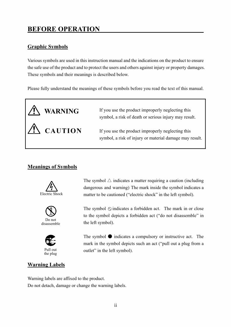
BEFORE OPERATION Graphic Symbols Various symbols are used in this instruction manual and the indications on the product to ensure the safe use of the product and to protect the users and others against injury or property damages. These symbols and their meanings is described below. Please fully understand the meanings of these symbols before you read the text of this manual.
If you use the product improperly neglecting this symbol, a risk of death or serious injury may result. If you use the product improperly neglecting this symbol, a risk of injury or material damage may result.
Meanings of Symbols
The symbol indicates a matter requiring a caution (including dangerous and warning) The mark inside the symbol indicates a matter to be cautioned (“electric shock” in the left symbol). The symbol indicates a forbidden act. The mark in or close to the symbol depicts a forbidden act (“do not disassemble” in the left symbol). The symbol indicates a compulsory or instructive act. The mark in the symbol depicts such an act (“pull out a plug from a outlet” in the left symbol).
Warning Labels Warning labels are affixed to the product. Do not detach, damage or change the warning labels.
CAUTION
WARNING
Electric Shock
Do not disassemble
Pull out the plug

iii
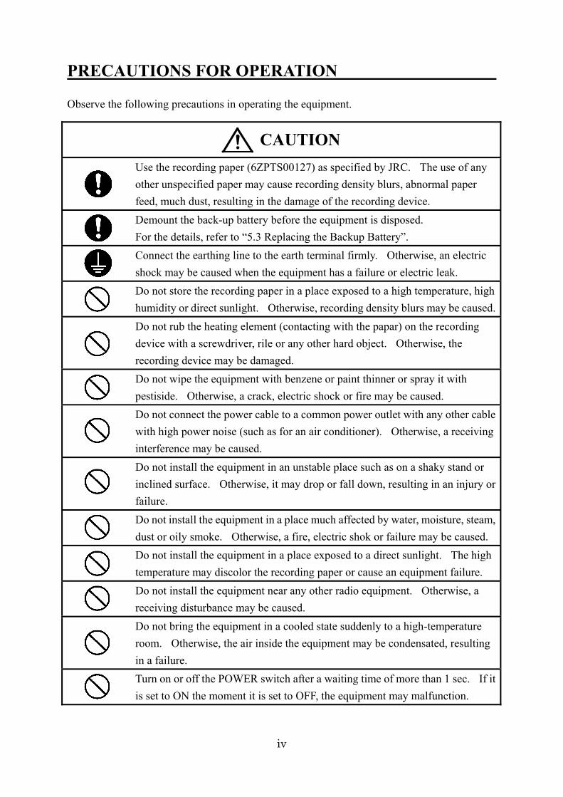
PRECAUTIONS FOR OPERATION Observe the following precautions in operating the equipment.
Do not use any power voltage other than the indicated voltage. Otherwise, a fire or electric shock may be caused.
Do not insert or drop any foreign object such as a metallic piece into an air vent or opening. Otherwise, a fire, electric shock or failure may be caused.
Do not disassemble or modify this equipment. Otherwise, a fire, electric shock or failure may be caused.
Do not put a container filled with water or a small metallic piece close to the equipment. If water is spilled into the equipment, a fire, electric shock or failure may be caused.
Do not install the equipment in a place where it may be splashed with water, oil or chemical. Otherwise, a fire, electric shock or failure may be caused.
Do not insert or pull out a power plug with wet hands. Otherwise, an electric shock may be caused.
If any foreign object such as water or metallic piece is inserted in the equipment, set OFF the POWER switch of the equipment and pull the power plug from the power outlet. Then, contact a nearby JRC office, branch, sales office or agent. The continued use of the equipment may cause a fire or electric shock.
If anything abnormal such as smoke, strange smell or unusual heat is emitted, set OFF the POWER switch of the equipment immediately and pull the power plug from power outlet. Then, contact a nearby JRC office, branch, sales office or agent. The continued use of the equipment may cause a fire or electric shock.
The user may not use inspect or repair the inside of the equipment. The inspection or repair made by a person other than a maintenance specialist may cause a fire or electric shock. For the inspection or repair of the equipment, please contact a nearby JRC office, branch, sales office or agent.
If the equipment has a failure, set the POWER switch to OFF and pull the power plug out of the power outlet. Then, contact a nearby JRC office, branch, saled office or agent. The continured use of the equipment may cause a fire or electric shock.
In returning the run-out lithium battery to JRC, take the isulating treatment such as attaching a tape to the +/– terminals (or the lead wires). If the battery is short-circuited with no insulating treatment, a heat, explosion or fire may be caused.
WARNING
iv
PRECAUTIONS FOR OPERATION Observe the following precautions in operating the equipment.
Use the recording paper (6ZPTS00127) as specified by JRC. The use of any other unspecified paper may cause recording density blurs, abnormal paper feed, much dust, resulting in the damage of the recording device. Demount the back-up battery before the equipment is disposed. For the details, refer to “5.3 Replacing the Backup Battery”. Connect the earthing line to the earth terminal firmly. Otherwise, an electric shock may be caused when the equipment has a failure or electric leak. Do not store the recording paper in a place exposed to a high temperature, high humidity or direct sunlight. Otherwise, recording density blurs may be caused.Do not rub the heating element (contacting with the papar) on the recording device with a screwdriver, rile or any other hard object. Otherwise, the recording device may be damaged. Do not wipe the equipment with benzene or paint thinner or spray it with pestiside. Otherwise, a crack, electric shock or fire may be caused. Do not connect the power cable to a common power outlet with any other cable with high power noise (such as for an air conditioner). Otherwise, a receiving interference may be caused. Do not install the equipment in an unstable place such as on a shaky stand or inclined surface. Otherwise, it may drop or fall down, resulting in an injury or failure. Do not install the equipment in a place much affected by water, moisture, steam, dust or oily smoke. Otherwise, a fire, electric shok or failure may be caused. Do not install the equipment in a place exposed to a direct sunlight. The high temperature may discolor the recording paper or cause an equipment failure. Do not install the equipment near any other radio equipment. Otherwise, a receiving disturbance may be caused. Do not bring the equipment in a cooled state suddenly to a high-temperature room. Otherwise, the air inside the equipment may be condensated, resulting in a failure. Turn on or off the POWER switch after a waiting time of more than 1 sec. If it is set to ON the moment it is set to OFF, the equipment may malfunction.
CAUTION
v
PRECAUTIONS FOR OPERATION
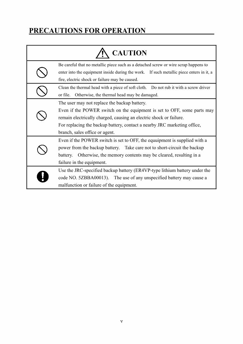
Be careful that no metallic piece such as a detached screw or wire scrap happens to enter into the equipment inside during the work. If such metallic piece enters in it, a fire, electric shock or failure may be caused.
Clean the thermal head with a piece of soft cloth. Do not rub it with a screw driver or file. Otherwise, the thermal head may be damaged.
The user may not replace the backup battery. Even if the POWER switch on the equipment is set to OFF, some parts may remain electrically charged, causing an electric shock or failure. For replacing the backup battery, contact a nearby JRC marketing office, branch, sales office or agent. Even if the POWER switch is set to OFF, the equuipment is supplied with a power from the backup battery. Take care not to short-circuit the backup battery. Otherwise, the memory contents may be cleared, resulting in a failure in the equipment. Use the JRC-specified backup battery (ER4VP-type lithium battery under the code NO. 5ZBBA00013). The use of any unspecified battery may cause a malfunction or failure of the equipment.
CAUTION
vi
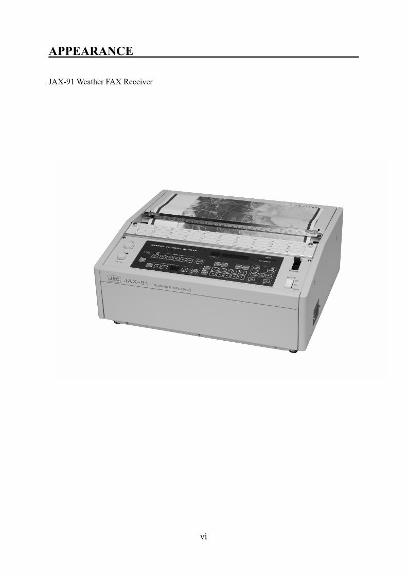
APPEARANCE JAX-91 Weather FAX Receiver

Table of Contents INTRODUCTION ........................................................................................................ i BEFORE OPERATION .............................................................................................. ii PRECAUTIONS FOR OPERATION.......................................................................... iii PRECAUTIONS FOR OPERATION.......................................................................... iv PRECAUTIONS FOR OPERATION............................................................................v APPEARANCE .......................................................................................................... vi Glossary ...................................................................................................................... 1 CHAPTER 1 GENERAL........................................................................................... 3
1.1 Function ......................................................................................................... 3 1.2 Composition ................................................................................................... 5 1.3 Outline Drawings ............................................................................................ 7 1.4 Overall Connection Diagram........................................................................... 8
CHAPTER 2 NAMES & FUNCTIONS OF PARTS.................................................... 9 2.1 FAX Control Panel.......................................................................................... 9 2.2 Receiver Control Panel.................................................................................. 10 2.3 Indicators ......................................................................................................11 2.4 Other Controls and Switches ......................................................................... 12
CHAPTER 3 INSTALLATION ............................................................................... 13 3.1 Installation Procedure ................................................................................... 13 3.2 Precautions for Installation ........................................................................... 14 3.3 Installation Diagrams.................................................................................... 16 3.4 Installation Procedure ................................................................................... 17 3.5 Connections to External Terminals ................................................................ 18 3.6 Antenna Connector’s Connection .................................................................. 19
CHAPTER 4 OPERATION ..................................................................................... 20 4.1 Setting of Receiving Frequency ..................................................................... 20
4.1.1 Automatic Frequency Selection Function (for High Frequency Band) ...... 20 4.1.2 Use of Tuning Meter and RCV Monitor................................................... 23 4.1.3 Setting of Receiving Frequencies ............................................................. 24 4.1.4 Storing of Receiving Frequencies............................................................. 25 4.1.5 Recalling of Stored Frequency................................................................. 26 4.1.6 Use of UP/DOWN Switches ..................................................................... 27 4.1.7 Use of CLR Switch.................................................................................. 27
4.2 Setting FAX Receive Mode ............................................................................ 28
4.2.1 AUTO Mode (Automatic Receiving)........................................................ 29 4.2.2 SEMI AUTO Mode (Semi-automatic Receiving) ...................................... 30 4.2.3 MANU Mode (Manual Receiving) ........................................................... 31 4.2.4 Program Mode ....................................................................................... 34
4.3 Checking and Changing Programs ................................................................ 40 4.3.1 Checking Programs ................................................................................ 40 4.3.2 Changing Programs ................................................................................ 41 4.3.3 Clearing Programs ................................................................................. 42 4.3.4 Printing Lists.......................................................................................... 43
4.4 Other Operations .......................................................................................... 46 4.4.1 Adjusting of Brightness for Operating Panel ........................................... 46 4.4.2 Switchover to External Receiver ............................................................. 46 4.4.3 Recording Paper Feed............................................................................. 47 4.4.4 Black/White Reversal ............................................................................... 47 4.4.5 Adjusting Image Inclination.................................................................... 47
CHAPTER 5 MAINETENANCE & INSPECTION ................................................. 48 5.1 Replacing Recording Paper ........................................................................... 48 5.2 Cleaning ....................................................................................................... 51 5.3 Replacing Backup Battery............................................................................. 52 5.4 Troubleshooting ............................................................................................ 55
CHAPTER 6 OPERATING ENVIRONMENT......................................................... 57 CHAPTER 7 CUSTOMER SUPPORT .................................................................... 58 CHAPTER 8 DISPOSAL OF THE EQUIPMENT.................................................... 59
8.1 Disposal of the Equipment............................................................................. 59 8.2 Disposal of Used Batteries ............................................................................. 59
CHAPTER 9 SPECIFICATIONS ............................................................................ 60 Lists of Related Products ........................................................................................... 63 Drawing No. 1 ........................................................................................................... 64 Drawing No. 2 ........................................................................................................... 65
1
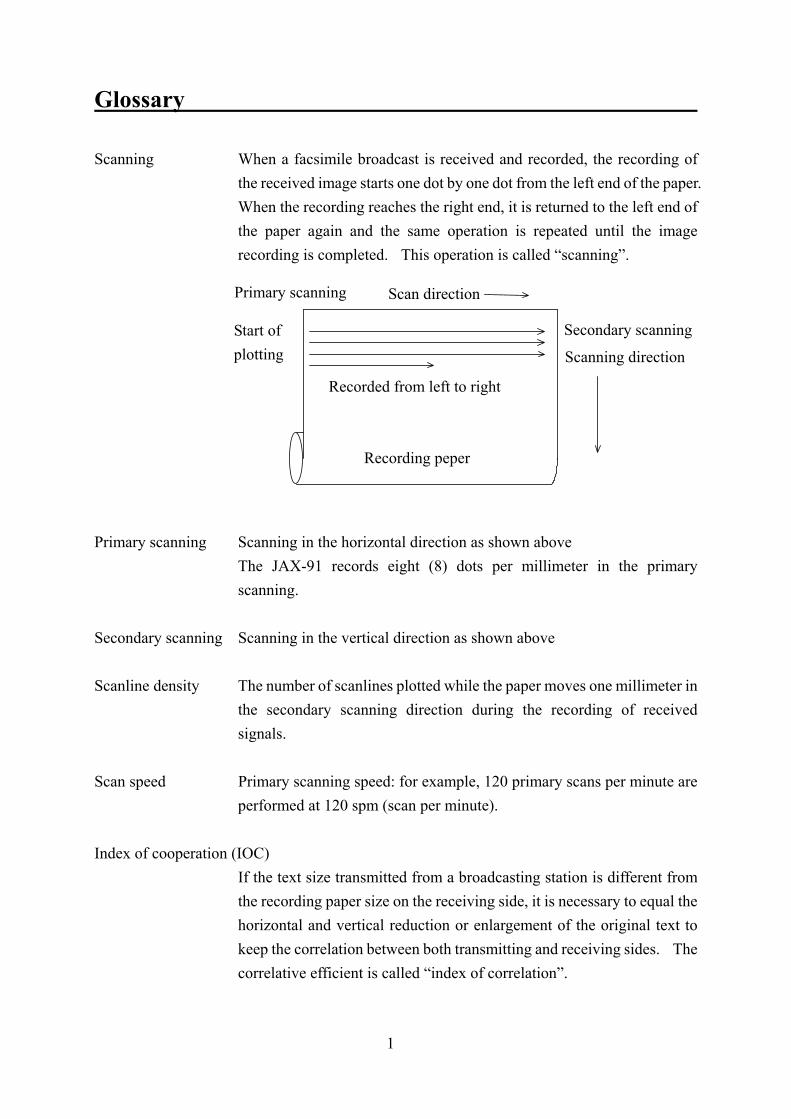
Glossary Scanning When a facsimile broadcast is received and recorded, the recording of
the received image starts one dot by one dot from the left end of the paper. When the recording reaches the right end, it is returned to the left end of the paper again and the same operation is repeated until the image recording is completed. This operation is called “scanning”.
Primary scanning Scanning in the horizontal direction as shown above The JAX-91 records eight (8) dots per millimeter in the primary
scanning. Secondary scanning Scanning in the vertical direction as shown above Scanline density The number of scanlines plotted while the paper moves one millimeter in
the secondary scanning direction during the recording of received signals.
Scan speed Primary scanning speed: for example, 120 primary scans per minute are
performed at 120 spm (scan per minute). Index of cooperation (IOC) If the text size transmitted from a broadcasting station is different from
the recording paper size on the receiving side, it is necessary to equal the horizontal and vertical reduction or enlargement of the original text to keep the correlation between both transmitting and receiving sides. The correlative efficient is called “index of correlation”.
Recorded from left to right
Primary scanning Scan direction
Recording peper
Start of plotting
Secondary scanning
Scanning direction
2
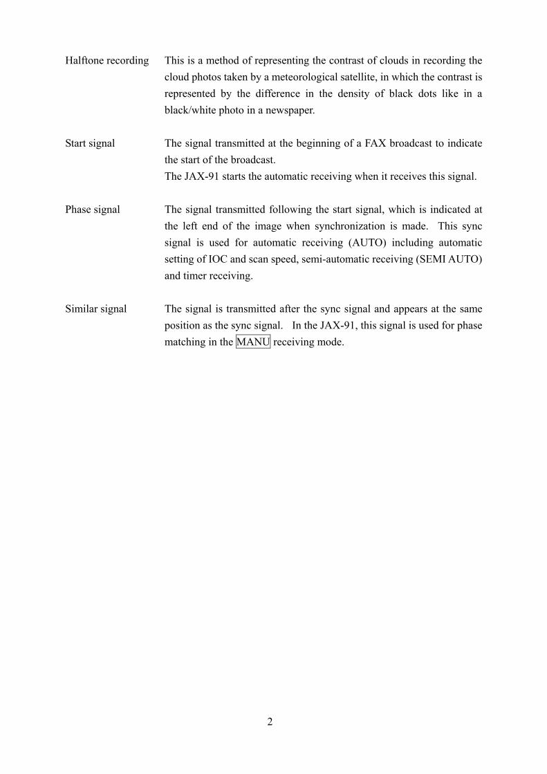
Halftone recording This is a method of representing the contrast of clouds in recording the cloud photos taken by a meteorological satellite, in which the contrast is represented by the difference in the density of black dots like in a black/white photo in a newspaper.
Start signal The signal transmitted at the beginning of a FAX broadcast to indicate
the start of the broadcast. The JAX-91 starts the automatic receiving when it receives this signal. Phase signal The signal transmitted following the start signal, which is indicated at
the left end of the image when synchronization is made. This sync signal is used for automatic receiving (AUTO) including automatic setting of IOC and scan speed, semi-automatic receiving (SEMI AUTO) and timer receiving.
Similar signal The signal is transmitted after the sync signal and appears at the same
position as the sync signal. In the JAX-91, this signal is used for phase matching in the MANU receiving mode.
3
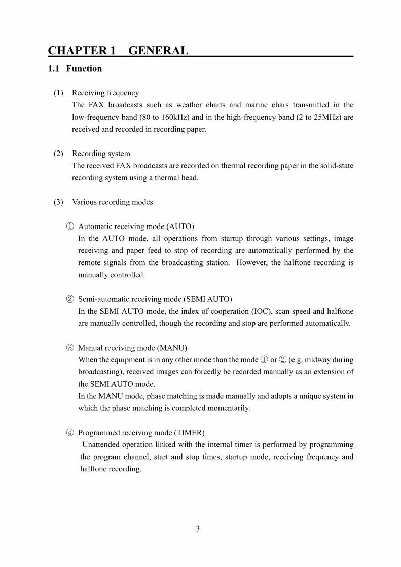
CHAPTER 1 GENERAL 1.1 Function
(1) Receiving frequency The FAX broadcasts such as weather charts and marine chars transmitted in the low-frequency band (80 to 160kHz) and in the high-frequency band (2 to 25MHz) are received and recorded in recording paper.
(2) Recording system
The received FAX broadcasts are recorded on thermal recording paper in the solid-state recording system using a thermal head.
(3) Various recording modes
① Automatic receiving mode (AUTO) In the AUTO mode, all operations from startup through various settings, image
receiving and paper feed to stop of recording are automatically performed by the remote signals from the broadcasting station. However, the halftone recording is manually controlled.
② Semi-automatic receiving mode (SEMI AUTO)
In the SEMI AUTO mode, the index of cooperation (IOC), scan speed and halftone are manually controlled, though the recording and stop are performed automatically.
③ Manual receiving mode (MANU)
When the equipment is in any other mode than the mode ① or ② (e.g. midway during broadcasting), received images can forcedly be recorded manually as an extension of the SEMI AUTO mode. In the MANU mode, phase matching is made manually and adopts a unique system in which the phase matching is completed momentarily.
④ Programmed receiving mode (TIMER)
Unattended operation linked with the internal timer is performed by programming the program channel, start and stop times, startup mode, receiving frequency and halftone recording.
4
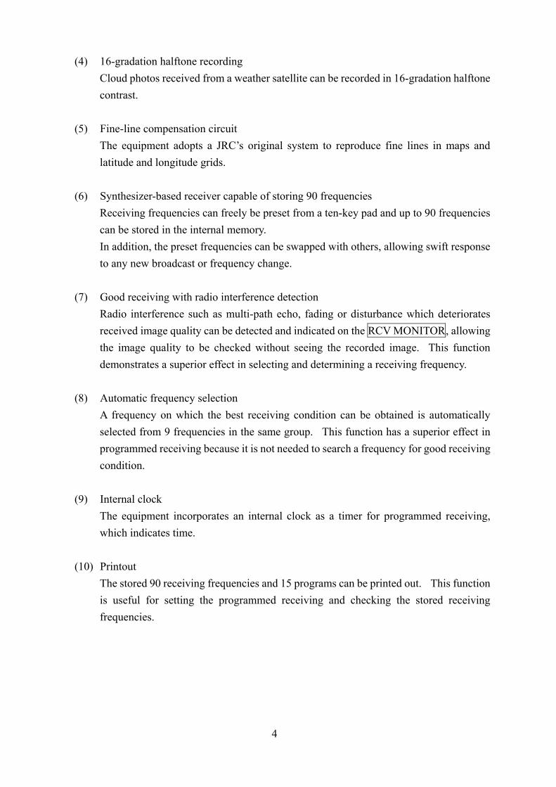
(4) 16-gradation halftone recording Cloud photos received from a weather satellite can be recorded in 16-gradation halftone contrast.
(5) Fine-line compensation circuit The equipment adopts a JRC’s original system to reproduce fine lines in maps and latitude and longitude grids.
(6) Synthesizer-based receiver capable of storing 90 frequencies Receiving frequencies can freely be preset from a ten-key pad and up to 90 frequencies can be stored in the internal memory. In addition, the preset frequencies can be swapped with others, allowing swift response to any new broadcast or frequency change.
(7) Good receiving with radio interference detection Radio interference such as multi-path echo, fading or disturbance which deteriorates received image quality can be detected and indicated on the RCV MONITOR, allowing the image quality to be checked without seeing the recorded image. This function demonstrates a superior effect in selecting and determining a receiving frequency.
(8) Automatic frequency selection A frequency on which the best receiving condition can be obtained is automatically selected from 9 frequencies in the same group. This function has a superior effect in programmed receiving because it is not needed to search a frequency for good receiving condition.
(9) Internal clock The equipment incorporates an internal clock as a timer for programmed receiving, which indicates time.
(10) Printout The stored 90 receiving frequencies and 15 programs can be printed out. This function is useful for setting the programmed receiving and checking the stored receiving frequencies.

5
1.2 Composition
Standard Components No. Component Code Q’ty Remarks 1 Weather FAX Receiver JAX-91 1 set 2 Protective Cover MTT311954 1 unit 3 Standard Spare Parts 7ZXJD0088 1 set Refer to the next page. 4 Antenna Connector N-P-7 5JAAQ00005 1 pc Fitted in the receiver 5 Test Recording Paper 6ZPTS00127 1 roll 6 Instruction Manual 7ZPNA4002 1 copy 7 Meteorological Facsimile
Broadcast Schedule and Explanatory Notes
5ZPEZ00001 1 copy
The JAX-91 is shipped with the test recording paper and the antenna
connector fitted in it.
CAUTION
6
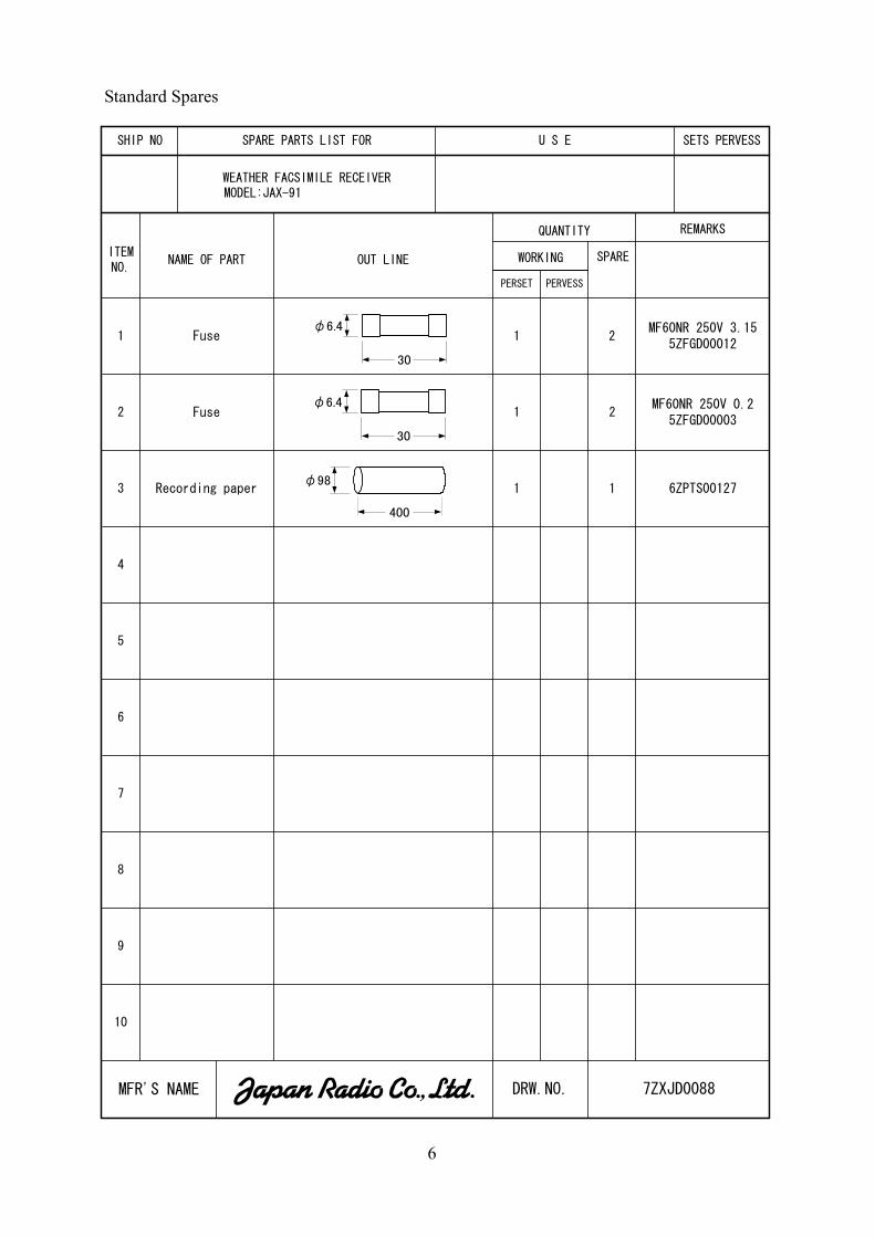
Standard Spares
7ZXJD0088
SHIP NO
WEATHER FACSIMILE RECEIVERMODEL:JAX-91
ITEMNO.
NAME OF PART SPARE
PERSET
1
2
3
4
5
6
9
10
SPARE PARTS LIST FOR U S E SETS PERVESS
PERVESS
QUANTITY REMARKS
OUT LINE WORKING
7
8
MFR'S NAME DRW.NO.
1 2
Fuse
Fuse
Recording paper
1
1 1
2
MF60NR 250V 3.155ZFGD00012
MF60NR 250V 0.25ZFGD00003
6ZPTS00127
400
φ98
φ6.4
30
φ6.4
30
7
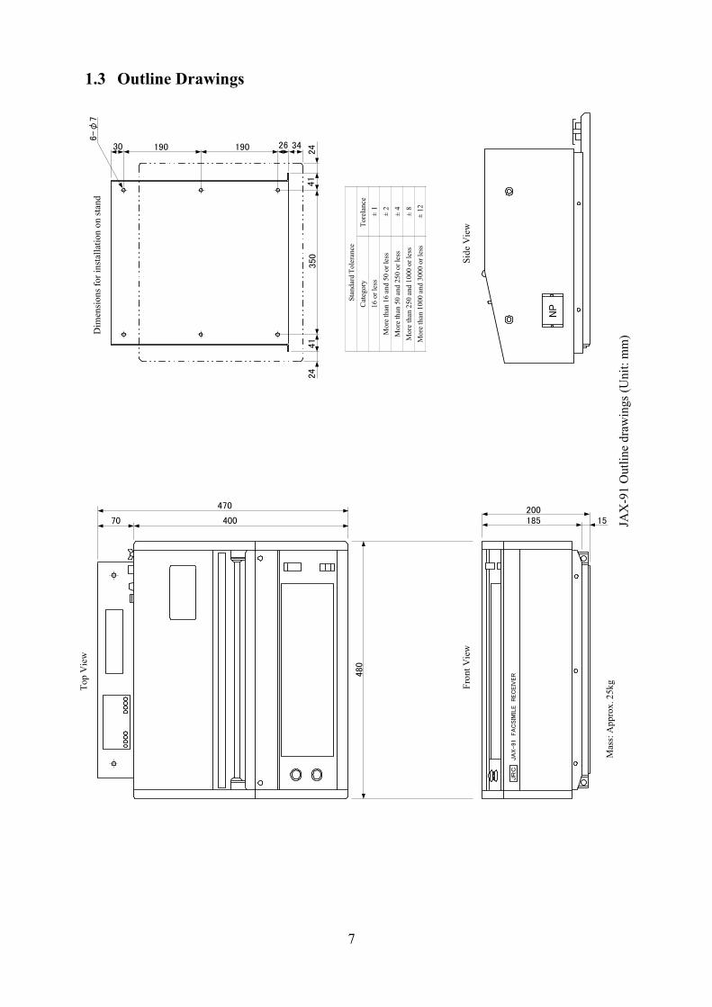
1.3 Outline Drawings
NP
Mas
s: A
ppro
x. 2
5kg
JR
CJA
X-91 FA
CSIM
ILE R
EC
EIV
ER
185200
15
480
70
470
400
350
41
24342619019030
6-φ
7
41
24
Dim
ensi
ons f
or in
stal
latio
n on
stan
d
Side
Vie
w
Top
Vie
w
Fron
t Vie
w
JAX
-91
Out
line
draw
ings
(Uni
t: m
m)
Stan
dard
Tol
eran
ceC
ateg
ory
Tore
lanc
e16
or l
ess
± 1
Mor
e th
an 1
6 an
d 50
or l
ess
± 2
Mor
e th
an 5
0 an
d 25
0 or
less
± 4
Mor
e th
an 2
50 a
nd 1
000
or le
ss±
8M
ore
than
100
0 an
d 30
00 o
r les
s±
12
8
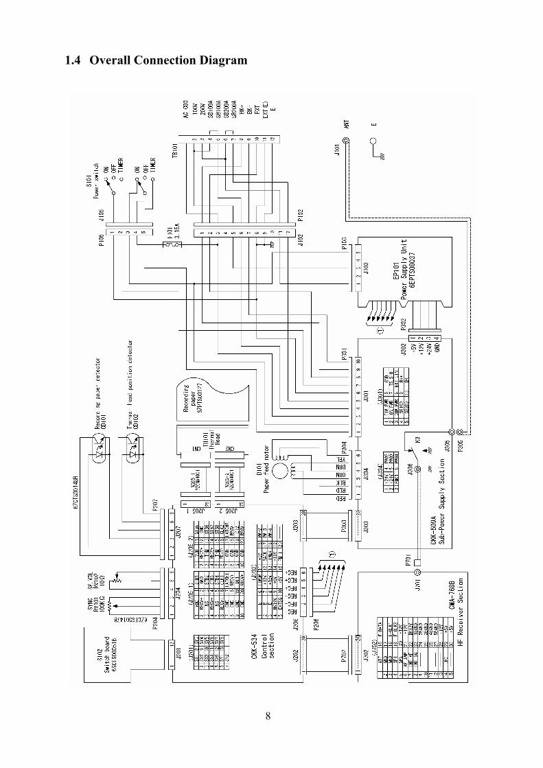
1.4 Overall Connection Diagram
9
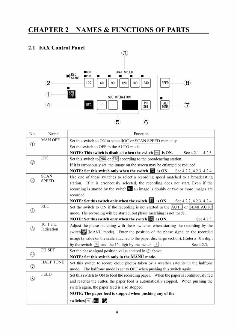
CHAPTER 2 NAMES & FUNCTIONS OF PARTS 2.1 FAX Control Panel No. Name Function
① MAN OPE Set this switch to ON to select IOC or SCAN SPEED manually.
Set the switch to OFF in the AUTO mode. NOTE: This switch is disabled when the switch is ON. See 4.2.1 – 4.2.3.
②
IOC Set this switch to 288 or 576 according to the broadcasting station. If it is erroneously set, the image on the screen may be enlarged or reduced. NOTE: Set this switch only when the switch is ON. See 4.2.2, 4.2.3, 4.2.4.
③
SCAN SPEED
Use one of these switches to select a recording speed matched to a broadcasting station. If it is erroneously selected, the recording does not start. Even if the recording is started by the switch , an image is doubly or two or more images are recorded. NOTE: Set this switch only when the switch is ON. See 4.2.2, 4.2.3, 4.2.4.
④
REC Set the switch to ON if the recording is not started in the AUTO or SEMI AUTO mode. The recording will be started, but phase matching is not made. NOTE: Set this switch only when the switch is ON. See 4.2.3.
⑤
10, 1 and Indication
Adjust the phase matching with these switches when starting the recording by the switch (MANU mode). Enter the position of the phase signal in the recorded image (a value on the scale attached to the paper discharge section). (Enter a 10’s digit by the switch and the 1’s digit by the switch . See 4.2.3.
⑥
PH SET Set the phase signal position value entered in ⑤ above. NOTE: Set this switch only in the MANU mode.
⑦
HALF TONE Set this switch to record cloud photos taken by a weather satellite in the halftone mode. The halftone mode is set to OFF when pushing this switch again.
⑧
FEED Set this switch to ON to feed the recording paper. When the paper is continuously fed and reaches the cutter, the paper feed is automatically stopped. When pushing the switch again, the paper feed is also stopped. NOTE: The paper feed is stopped when pushing any of the
switches , , .
SCAN SPEED
3
RECSTART
288
576
IOC 82 60 90 120 180 240 FEED
MANOPE1
PHSET110RECRECREC
SUB OPERATION
HALFTONE 74
5 6
PRG
MANOPE
REC
MANOPE
MANOPE
MANOPE
10 1
PRG REC

10
2.2 Receiver Control Panel No. Name Function
① CLR This switch is used to clear the frequency indication or memory contents. When the switch is ON, the program indicated on the CH (2-digit LED) indicator is cleared. See 4.1.7 and 4.3.3.
② MI This switch is used to store the indicated frequency in the indicated frequency channel. See 4.1.4.
③ MO This switch is used to read a stored frequency. When setting the switch to ON, the ten keys are set for the frequency channel. See 4.1.5.
④ CH This switch is used to indicate a frequency channel to store a frequency. The switch is not used when frequencies are stored a sequential series of channels. See 4.1.4.
⑤ UP/DOWN This switch is used to change an indicated frequency in 100Hz steps. When pushing the switch once, the frequency is changed by 100Hz. See 4.1.5.
⑥ 0 – 9
(10-key)
The ten keys can be used to set a frequency or a channel. When the switch is set to ON, the ten keys can be used to set various programs.When the switch is set to ON, the ten keys can be used to set the time.
543
1 2 3 4 5
09876CLR
MI
MO CH UP DOWN
2
1
6
PRG
PRG

11
2.3 Indicators No. Name Function
① Channel Indicator The indicator indicates a frequency channel or programmed channel.
② Frequency/time
indicator
The indicator indicates a receiving frequency, present time, receiving start time, receiving stop time or backup battery run-out.
③ TUNING meter The meter indicates the tuning state of a receiving frequency. The center LED lamp is lighting, the receiving state is the best. NOTE: This meter is used for HF receiving only. See 4.1.2.
④ RCV MONITOR The lamp indicates a receiving state. When the LED lamp is lighting, the receiving state is the best. See 4.1.2.
⑤ Unit indicator The unit of receiving frequency is lighting in red. The LED indicator goes off when setting a program.
⑥ Time type indicator The START indicator is blinking in orange when the step of entering a receiving start time comes in the program setting operation. The STOP indicator is blinking in orange when the step of entering a receiving stop time comes in the program setting operation. See 4.2.4 (3).
⑦ Channel type indicator The PROF indicator is blinking in orange when the step of entering a program channel comes in the program setting operation. The FREQ indicator is blinking in orange when the step of entering a frequency channel comes in the program setting operation. See 4.2.4 (3) to 4.3.2.
CHPROG FREQ START STOP
RCV MONITOR
TUNING
kHz
1 2
3
4567
12
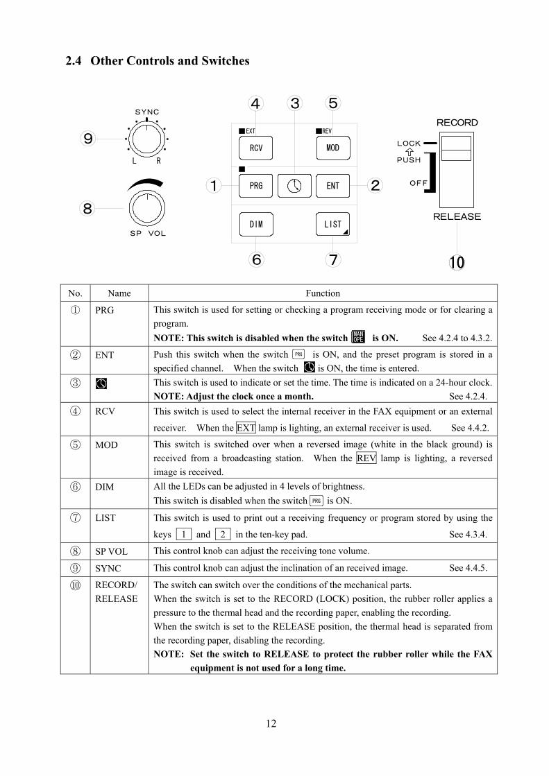
2.4 Other Controls and Switches No. Name Function
① PRG This switch is used for setting or checking a program receiving mode or for clearing a program. NOTE: This switch is disabled when the switch is ON. See 4.2.4 to 4.3.2.
② ENT Push this switch when the switch is ON, and the preset program is stored in a specified channel. When the switch is ON, the time is entered.
③ This switch is used to indicate or set the time. The time is indicated on a 24-hour clock.NOTE: Adjust the clock once a month. See 4.2.4.
④ RCV This switch is used to select the internal receiver in the FAX equipment or an external
receiver. When the EXT lamp is lighting, an external receiver is used. See 4.4.2.
⑤ MOD This switch is switched over when a reversed image (white in the black ground) is received from a broadcasting station. When the REV lamp is lighting, a reversed image is received.
⑥ DIM All the LEDs can be adjusted in 4 levels of brightness. This switch is disabled when the switch is ON.
⑦ LIST This switch is used to print out a receiving frequency or program stored by using the
keys 1 and 2 in the ten-key pad. See 4.3.4.
⑧ SP VOL This control knob can adjust the receiving tone volume.
⑨ SYNC This control knob can adjust the inclination of an received image. See 4.4.5.
⑩ RECORD/ RELEASE
The switch can switch over the conditions of the mechanical parts. When the switch is set to the RECORD (LOCK) position, the rubber roller applies a pressure to the thermal head and the recording paper, enabling the recording. When the switch is set to the RELEASE position, the thermal head is separated from the recording paper, disabling the recording. NOTE: Set the switch to RELEASE to protect the rubber roller while the FAX
equipment is not used for a long time.
DIM LIST
RCV
PRG
MOD
ENT
4 3 5
2
76
1
EXT REV
9
8
RL
SYNC
SP VOL
1010
RECORD
LOCK
PUSH
OFF
RELEASE
MANOPE
PRG
PRG

13
CHAPTER 3 INSTALLATION Please request JRC service personnel for the installation and cabling work for the JAX-91 Weather Facsimile Receiver. If you change the place of installation for the equipment, please follow the procedure as described below.
WARNING Do not use any other power voltage than the specified in the manual. Otherwise, a fire or electric shock may be caused. Do not handle the equipment with wet hands. Otherwise, an electric shock or failure may be caused. Connect the earth cable to the earth terminal. Otherwise,an electric shock may be caused if a failure or an electric leak occurs in the equipment.
CAUTION Do not use the power cable in common with any other power cable with high power noise (e.g. for air conditioner). Otherwise, a receiving interference may be caused. Do not install the equipment on a shaky stand or in an unstable place. Otherwise, it may drop or fall down, resulting in an injury or failure. Be careful that no metallic piece such as a detached screw or wire scrap happens to enter into the equipment inside during the work. If such metallic piece enters in it, a fire, electric shock or failure may be caused.
3.1 Installation Procedure
① Set the POWER switch to OFF and stop the power supply to the equipment. ② Disconnect the antenna cable, power cable, BK cable, external receiver’s AF signal
cable and earth cable. NOTE: • Disconnect the BK cable and an external receiver’s AF signal cable after
checking their polarity. • Connect the BK cable to the equipment if it makes the common use of a
transmitter and an antenna with other equipment. MEMO: BK is an abbreviation of BREAK-IN, which separates the equipment from
the antenna.
14
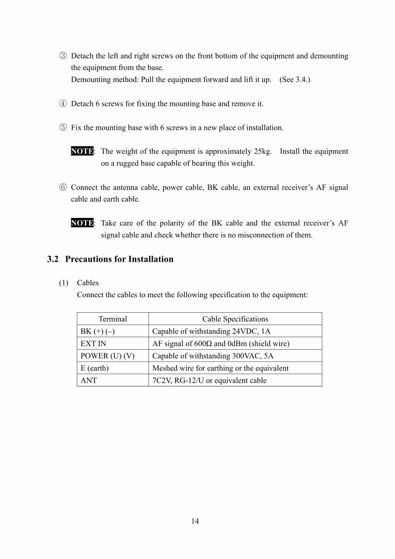
③ Detach the left and right screws on the front bottom of the equipment and demounting
the equipment from the base. Demounting method: Pull the equipment forward and lift it up. (See 3.4.)
④ Detach 6 screws for fixing the mounting base and remove it. ⑤ Fix the mounting base with 6 screws in a new place of installation.
NOTE: The weight of the equipment is approximately 25kg. Install the equipment
on a rugged base capable of bearing this weight.
⑥ Connect the antenna cable, power cable, BK cable, an external receiver’s AF signal cable and earth cable.
NOTE: Take care of the polarity of the BK cable and the external receiver’s AF
signal cable and check whether there is no misconnection of them.
3.2 Precautions for Installation
(1) Cables Connect the cables to meet the following specification to the equipment:
Terminal Cable Specifications BK (+) (–) Capable of withstanding 24VDC, 1A EXT IN AF signal of 600Ω and 0dBm (shield wire) POWER (U) (V) Capable of withstanding 300VAC, 5A E (earth) Meshed wire for earthing or the equivalent ANT 7C2V, RG-12/U or equivalent cable

15
(2) Power voltage The JAX-91 equipment operates on both 100VAC and 220VAC. Operate the equipment within the following operating voltage range: 100VAC line 80V to 132VAC, single-phase, 50/60Hz 220VAC line 160V to 264VAC, single-phase, 50/60Hz
NOTE: Strictly observe the power voltage range as specified above.
(3) Connection of power cable and short bar The connecting positions of the short bar to connect to the terminal board on the rear side of the equipment and the power cable are different by the power voltage used. The connection points are shown in the diagram below.
100VAC line 220VAC line
UV
3 6 71 2 4 5
100VAC
UV
3 6 71 2 4 5
220VACShort bar Short bar
16
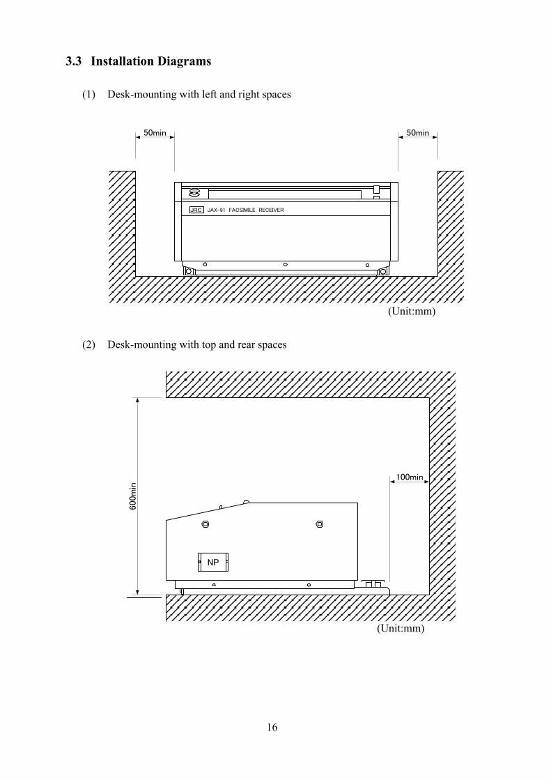
3.3 Installation Diagrams
(1) Desk-mounting with left and right spaces (Unit:mm)
(2) Desk-mounting with top and rear spaces (Unit:mm)
JRC JAX-91 FACSIMILE RECEIVER
50min50min
NP
100min
600m
in
17
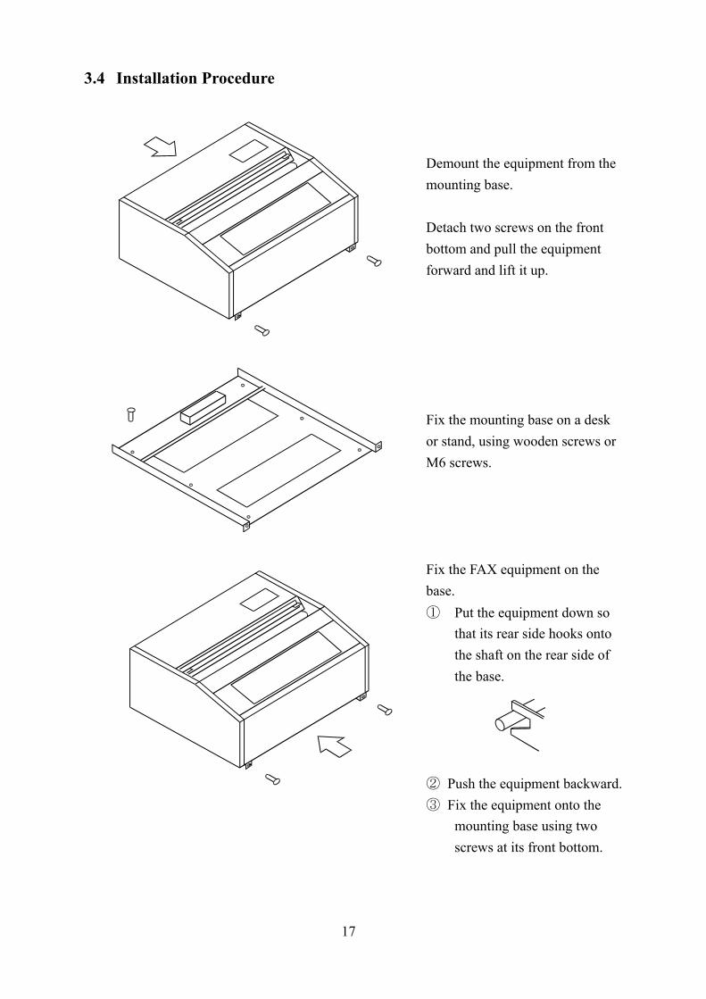
3.4 Installation Procedure
Demount the equipment from the mounting base. Detach two screws on the front bottom and pull the equipment forward and lift it up. Fix the mounting base on a desk or stand, using wooden screws or M6 screws. Fix the FAX equipment on the base. ① Put the equipment down so
that its rear side hooks onto the shaft on the rear side of the base.
② Push the equipment backward. ③ Fix the equipment onto the
mounting base using two screws at its front bottom.
18
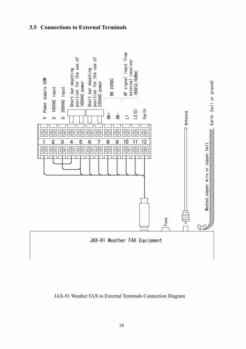
3.5 Connections to External Terminals
JAX-91 Weather FAX to External Terminals Connection Diagram
Earth (hull or ground)
Earth
Antenna
1 2 3 4 5 6 7 8 9 10 11 12
Meshed copper wire or copper belt
Fuse
JAX-91 Weather FAX Equipment
V Power supply COM
U 100VAC input
U 200VAC input
Short bar mounting
position for the use of
100VAC power
Short bar mounting
position for the use of
220VAC power
BK 24VDC
AF signal input from
external receiver
(600Ω/0dBm)
BK+
BK-
L1
L2(E)
19
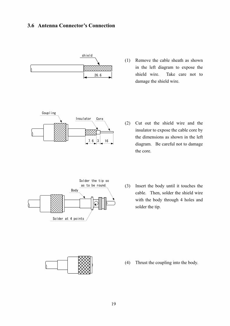
3.6 Antenna Connector’s Connection
(1) Remove the cable sheath as shown in the left diagram to expose the shield wire. Take care not to damage the shield wire.
(2) Cut out the shield wire and the
insulator to expose the cable core by the dimensions as shown in the left diagram. Be careful not to damage the core.
(3) Insert the body until it touches the
cable. Then, solder the shield wire with the body through 4 holes and solder the tip.
(4) Thrust the coupling into the body.
26.6
shield
163
Insulator Core
7.6
Coupling
Body
Solder at 4 points
Solder the tip so
as to be round.
20
CHAPTER 4 OPERATION 4.1 Setting of Receiving Frequency
The JAX-91 Receiver is designed to receive facsimile broadcasts transmitted in the low frequency band (80 to 160kHz) and in the high frequency band (2 to 25MHz). Various broadcasting stations broadcast their different facsimile broadcasts simultaneously on several different frequencies. The received image quality depends upon the radio propagation conditions and the receiving conditions are not constant by season, daytime or nighttime and receiving location. Therefore, the equipment must be operated in keeping in mind that the best receiving frequency is not the same, but that it should be changed according to the receiving conditions. The JAX-91 is provided with an automatic frequency selection function to ensure that a proper frequency for the best receiving conditions is selected to receive a good FAX image.
4.1.1 Automatic Frequency Selection Function (for High Frequency Band)
The equipment is capable of automatically selecting a proper frequency for the best receiving conditions by storing all the frequencies on which the same FAX broadcast from a broadcasting station can be received, in the same channel group. If the receiving conditions on a selected frequency become worse gradually, the equipment performs the automatic selection of another frequency on which the good receiving conditions are obtained. To use this automatic frequency selection function, the frequencies on which the same FAX image is broadcast simultaneously should be stored in the frequency channels in the same group.
(1) Frequency Channel A channel to store a frequency on which a FAX broadcast is transmitted is called a frequency channel. A maximum of 9 frequencies can be stored in one channel group, and a total of 90 frequencies can be stored in this equipment.
(2) Channel Group
There are 9 frequency channels in each channel group, in which a representative frequency channel is called a group channel. The group channel can not store any frequency.

21
The equipment is provided with the following combinations of group channels and the frequency channels:
Group Channel Frequency Channels 00 01 ~ 09 10 11 ~ 19 20 21 ~ 29 30 31 ~ 39 40 41 ~ 49 50 51 ~ 59 60 61 ~ 69 70 71 ~ 79 80 81 ~ 89 90 91 ~ 99
(3) Setting Procedure
Store all the frequencies transmitted from a broadcasting station to broadcast FAX images in the frequency channels in the same group. For example, if the automatic frequency selection is performed for the FAX broadcasts from JMH (to store the frequencies in group channel 00), execute the following steps:
① Store 3622.5 kHz in the frequency channel 01. ② Store 7305.0 kHz in the frequency channel 02. ③ Store 13,597.0 kHz in the frequency channel 03. ④ Do not store any frequencies in the remaining frequency channels 04 to 09. Push only the switch not to input other frequencies.
MEMO • For the receiving frequency storing procedure, refer to “4.1.4 Storing
of Receiving Frequencies” in page 25. JMH is a call sign for FAX broadcasts in Japan. NOTE If any frequencies from a different broadcasting station are stored in the
preset group for another station, no expected FAX broadcasts can be received. Do not store such frequencies from a different station.
The automatic frequency selection function is not available for the low frequency band (80 to 160 kHz).
The broadcasting frequencies may be subject to change. Confirm by the latest broadcasting schedule.
MI

22
(4) Operating Procedure First, call the representative group channel for the frequency channels in which the frequencies for the FAX broadcasts from a specific broadcasting station are stored. For example, if FAX broadcasts are received from JMH in the same case as in “(3) Setting Procedure” above, the operating procedure is as follows:
① Push the switch and push the numeric keys 0 0 in this turn. This operation set the equipment to the automatic frequency selection mode, in
which a frequency for the good receiving conditions is selected automatically. ② If the automatic frequency selection is made again after the above operation, repeat
step ① again. NOTE This function is operated when the internal receiver in the equipment is used.
In operating this function, the frequency selection takes more or less time to compare the receiving conditions on all the frequencies stored in the same group. Thus, execute the operation about one minute earlier than the start time of broadcasting.
The receiving conditions on the automatically selected frequency are not absolutely good because of the following circumstances: (a) The radio propagation condition on the selected frequencies is
generally bad. (b) The radio propagation condition is good only when the frequencies are
compared. (c) The radio propagation condition on the automatically selected
frequencies becomes worse gradually. MEMO This function can be used in all the four receiving modes (AUTO, SEMI
AUTO, MANU and Program) adopted in this equipment. This function can be used in the following cases:
(a) When the group channel is called by the switch and a numeric key. (b) When the POWER switch is set to OFF in the automatic frequency
selection mode and then to ON. (c) When the radio propagation condition on the receiving frequencies
becomes worse gradually.
MI
MO

23
4.1.2 Use of Tuning Meter and RCV Monitor
(1) Tuning Meter (for HF Band) The Tuning Meter indicates the tuning condition of a receiving frequency on its seven-segment LEDs. You need not use this tuning meter when the receiving frequency is known because the receiver is of synthesizer type. This tuning meter is useful when the receiving frequency is unknown (in SSB or other receiving) or searched using an external receiver.
① Tuned state The central LED is lighting or the both ends are blinking.
② Tuning range The tuning range is from all lighting LEDs to the central LED indicating the tuning point.
③ Detuned state All the LEDs are extinguished.
(2) RCV Monitor
The lighting LED indicates the best receiving condition. The LED may be blinking or extinguished for a receiving frequency. In this case, the receiving frequency should be changed over to select a frequency on which the LED is lighting, or blinking at less blinking times. MEMO The same FAX broadcast is transmitted mainly on several different frequencies in the HF band. There are frequencies that are easy and difficult (or unable) to receive the HF-band FAX broadcasts depending upon the season, a time span and a receiving location. The frequencies vary at all times. Even if a FAX broadcast can be received well in the daytime, it may be unable to be received in the nighttime. In such case, the receiving frequency should be changed to receive the FAX broadcast well.
Allowable tuning range
The shaded area indicates the lighting LED.
TUNING
RCV
24
4.1.3 Setting of Receiving Frequencies
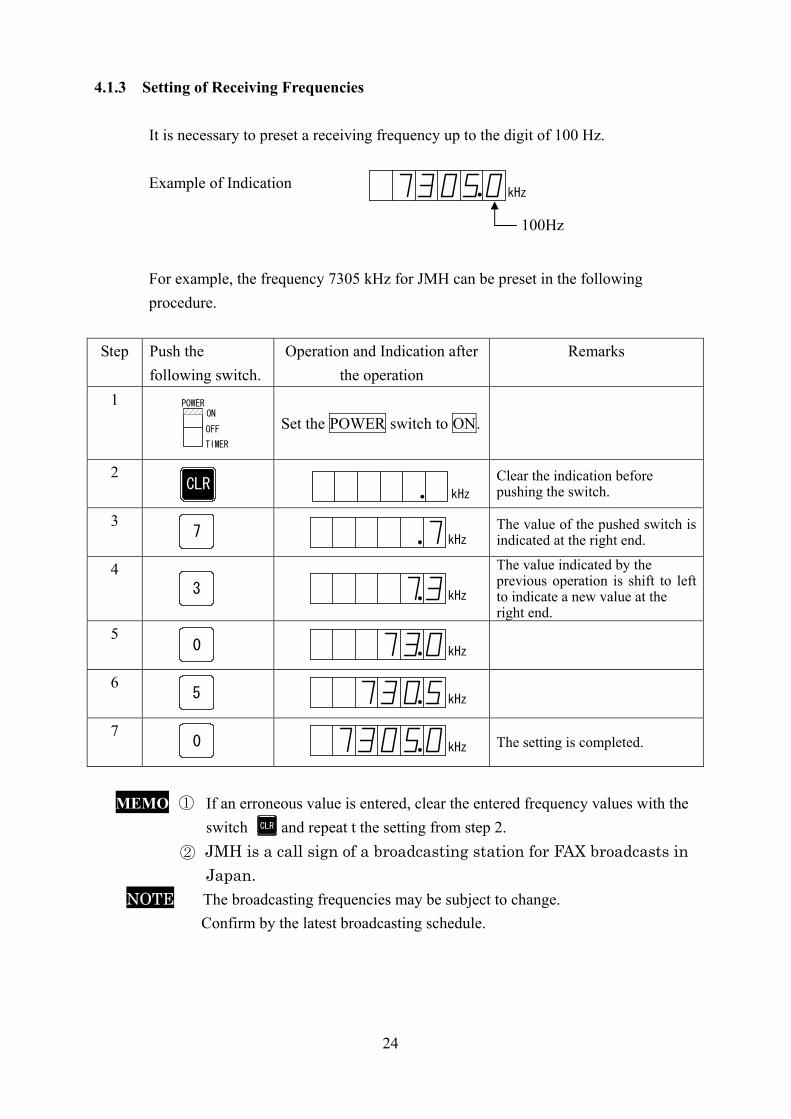
It is necessary to preset a receiving frequency up to the digit of 100 Hz. Example of Indication For example, the frequency 7305 kHz for JMH can be preset in the following procedure.
Step Push the following switch.
Operation and Indication after the operation
Remarks
1
Set the POWER switch to ON.
2
Clear the indication before pushing the switch.
3
The value of the pushed switch is indicated at the right end.
4
The value indicated by the previous operation is shift to left to indicate a new value at the right end.
5
6
7
The setting is completed.
MEMO ① If an erroneous value is entered, clear the entered frequency values with the
switch and repeat t the setting from step 2. JMH is a call sign of a broadcasting station for FAX broadcasts in
Japan. NOTEt The broadcasting frequencies may be subject to change.
Confirm by the latest broadcasting schedule.
kHz
100Hz
POWERON
OFF
TIMER
CLR
7
3
0
5
0
kHz
kHz
kHz
kHz
kHz
kHz
CLR
②

25
4.1.4 Storing of Receiving Frequencies
This equipment can store up to 90 receiving frequencies in memory (90 channels). The switches to be used are 3 types: ~ , and . ~ : Used to preset a receiving frequency or channel number. : Used to store an indicated receiving frequency in an indicated channel
number and indicate the next channel number. : Used to store a receiving frequency in any other channel number than
that shifted up by the switch . For example, if 3622.5 kHz, 7305.0 kHz and 13597.0 kHz for JMH are stored in the channels 01, 02 and 03 respectively, the following procedure shall be executed:
Step Push the following switch.
Operation and Indication after the Operation
Remarks
1
Set the POWER switch to ON.
2
Clear the indication before pushing the switch.
3
Enter the receiving frequency value of 36225.
4
Push the switch . The indication does not change.
5
Enter the channel number 01.
6
Push the switch . 3622.5kHz is stored in the channel 01 and the channel number is shifted up by 1.
7
Enter the receiving frequency value 73050.
8
Push the switch . 7305.0 kHz is store in the channel 02 and the channel number is shifted up by 1.
9
Enter the receiving frequency value 135970.
10
Push the switch . 13597.0 kHz is stored in the channel 03 and the channel number is shifted up by 1.
NOTEt The broadcasting frequencies may be subject to change.
Confirm by the latest broadcasting schedule.
0 9 MI CH
0 9
MI
CH
MI
POWERON
OFF
TIMER
CLR
0 9~
0 9~
0 9~
MI
CH
kHz
kHz
kHz
kHz
kHz
CH
kHz
MI
MI
kHz
0 9~kHz
MIkHz
MI
MI
26
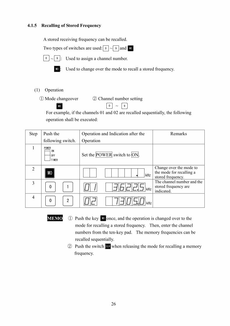
4.1.5 Recalling of Stored Frequency
A stored receiving frequency can be recalled.
Two types of switches are used: ~ and
~ : Used to assign a channel number.
: Used to change over the mode to recall a stored frequency.
(1) Operation
① Mode changeover ② Channel number setting ~
For example, if the channels 01 and 02 are recalled sequentially, the following operation shall be executed:
Step Push the
following switch. Operation and Indication after the Operation
Remarks
1
Set the POWER switch to ON.
2
Change over the mode to the mode for recalling a stored frequency.
3
The channel number and the stored frequency are indicated.
4
MEMO ① Push the key once, and the operation is changed over to the
mode for recalling a stored frequency. Then, enter the channel numbers from the ten-key pad. The memory frequencies can be recalled sequentially.
② Push the switch when releasing the mode for recalling a memory frequency.
0 9 MO
0 9
MO
MO 0 9
POWERON
OFF
TIMER
MOkHz
kHz
kHz
1
2
0
0
MO
CLR

27
4.1.6 Use of UP/DOWN Switches The UP/DOWN switches are used to increase or decrease a receiving frequency (as indicated in the indicator) in 100-Hz steps. switch: A receiving frequency is higher by an increment of 100Hz when pushing
the switch once. switch: A receiving frequency is lower by an decrement of 100Hz when pushing
the switch once. MEMO These switches can be used with the TUNING meter when searching for a
SSB or ISB frequency. CAUTION When pushing the switch after the above operation, an indicated
frequency and channel may be stored and the stored frequency and channel may be rewritten.
4.1.7 Use of CLR Switch
The switch is used for the following operations: ① Clear the frequencies that are currently indicated. ② Release the reading from the memory. ③ Clear the frequencies and programs that are stored in the memory.
UP
DOWN
MI
CLR
28
4.2 Setting FAX Receive Mode
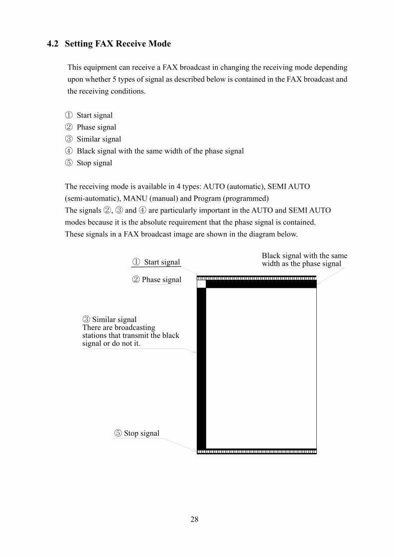
This equipment can receive a FAX broadcast in changing the receiving mode depending upon whether 5 types of signal as described below is contained in the FAX broadcast and the receiving conditions. ① Start signal ② Phase signal ③ Similar signal ④ Black signal with the same width of the phase signal ⑤ Stop signal The receiving mode is available in 4 types: AUTO (automatic), SEMI AUTO (semi-automatic), MANU (manual) and Program (programmed) The signals ②, ③ and ④ are particularly important in the AUTO and SEMI AUTO modes because it is the absolute requirement that the phase signal is contained. These signals in a FAX broadcast image are shown in the diagram below.
① Start signal
② Phase signal
③ Similar signal There are broadcasting stations that transmit the black signal or do not it.
⑤ Stop signal
Black signal with the same width as the phase signal

29
4.2.1 AUTO Mode (Automatic Receiving) In the AUTO mode, the equipment detects the start signal, automatically presets the parameters IOC and SCAN SPEED , and starts the recording until it detects the stop signal and automatically stops the operation.
(1) Operating Procedure The equipment is set to the AUTO mode, in which the start signal is detected to start the recording automatically in the procedure as shown below.
Step Operation Switch Operating Procedure 1
RECORD/RELEASE Lever
Set the RECORD/RELEASE lever to the RECORD (LOCK) position.
CAUTION The recording is possible only in the LOCK position. 2
Set the POWER switch to ON.
3
When the LED of the switch is lighting, push this switch and extinguish the LED
4
Set a receiving frequency or recall a memory frequency and indicate the receiving frequency in the indicator. For the detail, refer to 4.1.3 – 4.1.4. NOTE Select a frequency for good receiving conditions using RCV MONITOR.
5
The LED is lighting in the halftone recording and the LED is extinguished in non-halftone recording.
(2) Outline of Operation
Operation Description
Set the equipment to the AUTO mode.
① Start signal detection IOC is selected. ② Phase signal detection SCAN SPEED is selected and phase matching
is made. The LED REC START lights up.
③ FAX image receiving The recording starts. ④ Stop signal detection The selected IOC and SCAN SPEED LEDs extinguish and the recording stops.
⑤ Paper feed The recording paper is fed up to the cutter position and stops.
MANOPE
MO
0 9~
HALFTONE
POWERON
OFF
TIMER
MANOPE
MANOPE
LED
HALFTONE
LED
30
NOTE ① The above operation is disabled when the switch is set to ON. Set the switch to OFF.
② The above operation is disabled when the clock is indicated. However, the receiving continues when the clock is indicated after the recording is started.
③ When the power is set to ON, the equipment is operated in the conditions that were preset when the power is set to OFF previously. Then, recheck the receiving mode and the receiving frequencies.
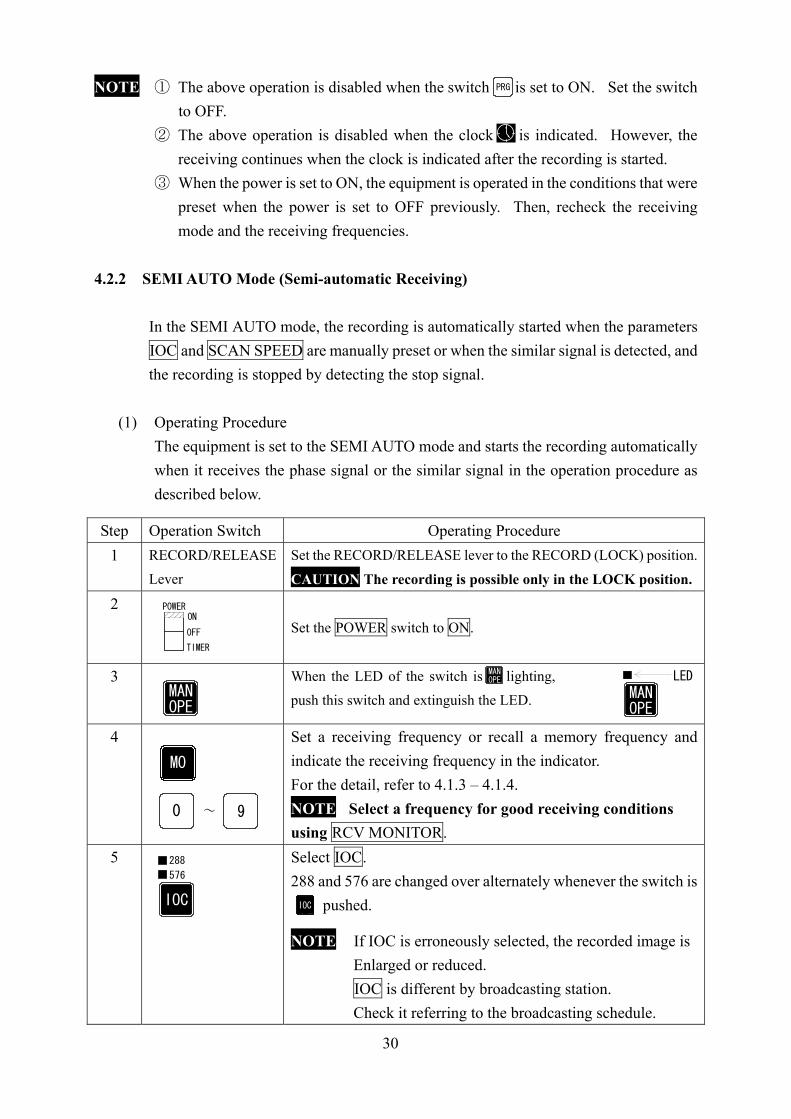
4.2.2 SEMI AUTO Mode (Semi-automatic Receiving)
In the SEMI AUTO mode, the recording is automatically started when the parameters IOC and SCAN SPEED are manually preset or when the similar signal is detected, and the recording is stopped by detecting the stop signal.
(1) Operating Procedure
The equipment is set to the SEMI AUTO mode and starts the recording automatically when it receives the phase signal or the similar signal in the operation procedure as described below.
Step Operation Switch Operating Procedure 1
RECORD/RELEASE Lever
Set the RECORD/RELEASE lever to the RECORD (LOCK) position.
CAUTION The recording is possible only in the LOCK position. 2
Set the POWER switch to ON.
3
When the LED of the switch is lighting, push this switch and extinguish the LED.
4
Set a receiving frequency or recall a memory frequency and indicate the receiving frequency in the indicator. For the detail, refer to 4.1.3 – 4.1.4. NOTE Select a frequency for good receiving conditions using RCV MONITOR.
5
Select IOC. 288 and 576 are changed over alternately whenever the switch is
pushed.
NOTE If IOC is erroneously selected, the recorded image is Enlarged or reduced. IOC is different by broadcasting station. Check it referring to the broadcasting schedule.
PRG
MANOPE
MO
0 9~
POWERON
OFF
TIMER
MANOPE
MANOPE
LED
288
576
IOCIOCIOC

31
6
Select SCAN SPEED. The LED of the switch pushed lights up. NOTE If the scan speed is erroneously selected, the recording
does not start. SCAN SPEED is different by broadcasting station. Check it referring to the broadcasting schedule.
7
The LED is lighting in the halftone recording and the LED is extinguished in non-halftone recording.
(2) Outline of Operation
Operation Description Set the equipment to the SEMI AUTO mode.
① Phase signal or similar signal detection
② Stop signal detection
The recording starts. The recording stops.
NOTE ① The above operation is disabled when the switch is set to ON. Set the switch
to OFF. ② The above operation is disabled when the clock is indicated. However, the
receiving continues when the clock is indicated after the recording is started. ③ When the power is set to ON, the equipment is operated in the conditions that were
preset when the power is set to OFF previously. Then, recheck the receiving mode and the receiving frequencies.
4.2.3 MANU Mode (Manual Receiving)
In the MANU mode, all the operations should be executed manually. This mode can be used to forcedly start the recording which is not started or in the midst of broadcasting in the SEMI AUTO mode. The recording is not started in the SEMI AUTO mode in the following cases that: ① the recording conditions are bad (due to weak radio intensity and radio
disturbances); ② the phase signal or the similar signal is not broadcast.
HALFTONE
LEDHALFTONE
2401801209060
SCAN SPEED
PRG

32
(1) Operating Procedure The MANU mode is preset to forcedly start the recording in the following procedure:
Step Operation Switch Operating Procedure 1
RECORD/RELEASE Lever
Set the RECORD/RELEASE lever to the RECORD (LOCK) position.
CAUTION The recording is possible only in the LOCK position. 2
Set the POWER switch to ON.
3
When the LED of the switch is lighting, push this switch and extinguish the LED.
4
Set a receiving frequency or recall a memory frequency and indicate the receiving frequency in the indicator. For the detail, refer to 4.1.3 – 4.1.4. NOTE Select a frequency for good receiving conditions
using RCV MONITOR. 5
Select IOC. 288 and 576 are changed over alternately whenever the switch is
pushed. NOTE If IOC is erroneously selected, the recorded image is
enlarged or reduced. IOC is different by broadcasting station. Check it referring to the broadcasting schedule.
6
Select SCAN SPEED. The LED of the switch pushed lights up. NOTE If the scan speed is erroneously selected, the
recording does not start. SCAN SPEED is different by broadcasting station. Check it referring to the broadcasting schedule.
7
The LED is lighting in the halftone recording and the LED is extinguished in non-halftone recording.
8
Push the switch . The LED lights up and the recording starts. (Phase matching is not performed.)
9
Phase matching is performed. For the detailed operation, refer to the description “(2) Details of Phase Matching” next.
POWERON
OFF
TIMER
MANOPEMAN
OPE MANOPE
LED
MO
0 9~
288
576
IOC
IOCIOC
HALFTONE
LED
2401801209060
SCAN SPEED
HALFTONE
RECRECRECREC
RECSTART
10 1 PHSET
SUB OPERATION

33
(2) Details of Phase Matching Condition in which the recording has started, but the phase matching is not performed:
• Check the position of the similar signal (which is depicted at 23 on the scale in the above diagram).
• Make the phase matching manually. ① Push the Sub Operation switch twice to indicate 2 at the 10’s digit on the
indicator. ② Then, push the switch three times to indicate 3 at the 1’s digit on the
indicator. ③ Check that 23 is indicated on the indicator. ④ Push the [PH SET] switch.
Condition in which the phase matching is completed
• When the phase matching is completed, the similar signal is divided into two at the
left and at the right end or indicated at either of both end. NOTE There are some broadcasting stations that do not transmit the similar
signal. In such case, make the phase matching at the break between the images regarding it as the similar signal.
Simir signal
Recording paper
Scale
10
1
10 1
SUB OPERATION
① ② ③ ④
PHSET
Similar signal Similar signal
Scale
23 1 31
31 123
Recording paper
34
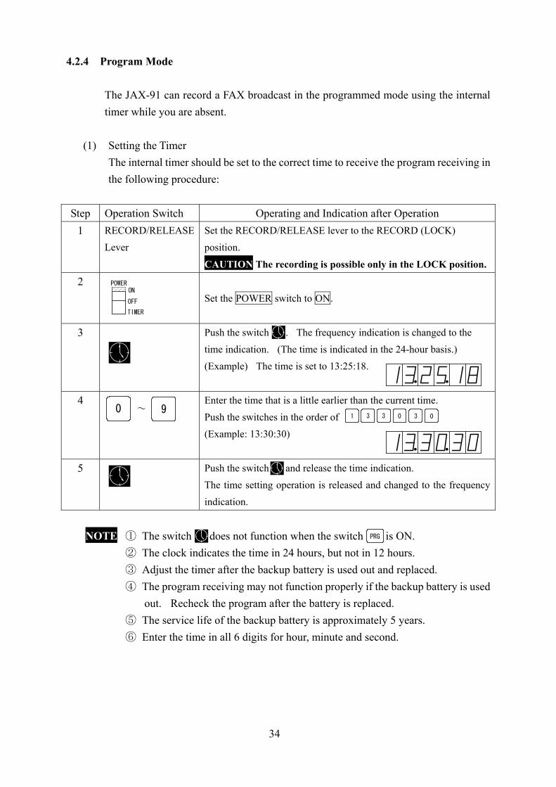
4.2.4 Program Mode
The JAX-91 can record a FAX broadcast in the programmed mode using the internal timer while you are absent.
(1) Setting the Timer The internal timer should be set to the correct time to receive the program receiving in the following procedure:
Step Operation Switch Operating and Indication after Operation 1
RECORD/RELEASE Lever
Set the RECORD/RELEASE lever to the RECORD (LOCK) position.
CAUTION The recording is possible only in the LOCK position. 2
Set the POWER switch to ON.
3
Push the switch . The frequency indication is changed to the time indication. (The time is indicated in the 24-hour basis.) (Example) The time is set to 13:25:18.
4
Enter the time that is a little earlier than the current time. Push the switches in the order of (Example: 13:30:30)
5
Push the switch and release the time indication. The time setting operation is released and changed to the frequency indication.
NOTE ① The switch does not function when the switch is ON. ② The clock indicates the time in 24 hours, but not in 12 hours. ③ Adjust the timer after the backup battery is used out and replaced. ④ The program receiving may not function properly if the backup battery is used
out. Recheck the program after the battery is replaced. ⑤ The service life of the backup battery is approximately 5 years. ⑥ Enter the time in all 6 digits for hour, minute and second.
1 3 3 0 3 0
POWERON
OFF
TIMER
0 9~
PRG

35
(2) Program Parameters Unattended receiving and recording of up to 15 FAX broadcasts can be performed during 24 hours in the program mode. The parameters to be programmed are the following 8 items:
Program Item Description Program channel Set a program channel. (NOTE ①) Start time Set the receiving start time. (NOTE ④) Stop time Set the receiving stop time. (NOTE ④) Receiving frequency Set a receiving frequency. AUTO or SEMI AUTO Decide whether to set the AUTO or SEMI AUTO mode. IOC Set IOC. (NOTE ②) SCAN SPEED Set a scan speed. HALF TONE Set whether or not to record halftone images.
NOTE ① The channel can be selected out of 15 channels from channel 00 to channel 14. ② It is unnecessary to set IOC in the AUTO mode. ③ Any other broadcast cannot be programmed overlapped during the time period
from the start time to the stop time. ④ The interval between a program and another program shall be one minute or
more. Definition of Channel The term “channel” has two meanings for purpose of the JAX-91 equipment. Take care not to confuse these meanings. ① Frequency channel
A frequency channel means a memory location (channel No.) to store a receiving frequency. This equipment has a capacity of storing a total of 90 channels (90 frequencies) from channel 01 to channel 99. • The channel number with the least significant digit 0 means a group channel (e.g.
channel 00). • No receiving frequency can be stored in a group channel.
② Program channel
A program channel means a memory location (program No.) to store a receiving program. This equipment has a capacity of storing a total of 15 channels (15 programs) from channel 00 to channel 14.

36
(3) Program Entry Procedure
Step Operation Switch Operating and Indication after Operation 1
Set the POWER switch to ON. NOTE Check before programming whether the current time on the clock is correct.
2
Push the switch . The characters of PRG are blinking.
3
Set a program channel. (Example: channel 00.) Push the switches .
4
Push the switch . The characters of STRT are blinking.
5
Set the receiving start time. (Example: 11:40) Push the switches and .
6
Push the switch . The characters of STOP are blinking.
7
Set the receiving stop time. (Example: 12:20) Push the switches and .
8
Push the switch . The characters of FREQ are blinking.
9
Set the frequency channel. (Example: channel 01) Push the switches .
10 Push the switch . The LED of the switch is blinking.
POWERON
OFF
TIMER
PRG
PRG
CH
PROG FREQ START STOP
0 9~0 0
CH
PROG FREQ START STOP
CH
ENTCH
PROG FREQ START STOP
ENT
0 9~1 1
04
CH
PROG FREQ STOPSTART
ENT
ENT
CH
PROG FREQ START STOP
0 9~1 2
02
CH
PROG FREQ START STOP
ENT
ENT
CH
PROG FREQ START STOP
0 9~
0 1
CH
PROG FREQ START STOP
ENT
ENT
MANOPE MAN
OPE
LED

37
11 When selecting the AUTO mode, continously press the switch until its LED goes out. When selecting the SEMI AUTO mode, continuously press the switch until its LED lights up.
In programming in the AUTO mode, proceed with the following procedure after the above procedure:
Step Operation Switch Operating and Indication after Operation 12
Push the switch . The LED HALF TONE is blinking.
13
In making the halftone recording (of cloud photos from a weather satellite), set the LED lighting to OFF and in making no halftone recording, set the LED lighting to ON.
14
Push the switch . The characters of PROG are blinking. The program on channel 00 is completed. The next program can be set.
15
Push the switch and release the program setting mode.
NOTE The program receiving is not available if the program setting mode is released. Be sure to do this operation.
NOTE Print out the program list and confirm that the list has no TIME ERR.
MANOPE
LED MANOPE
MANOPE
ENT
ENT
LED
HALFTONE
HALFTONE
LED
HALFTONE
ENT
ENT
CH
PROG FREQ START STOP
PRG
PRG
38
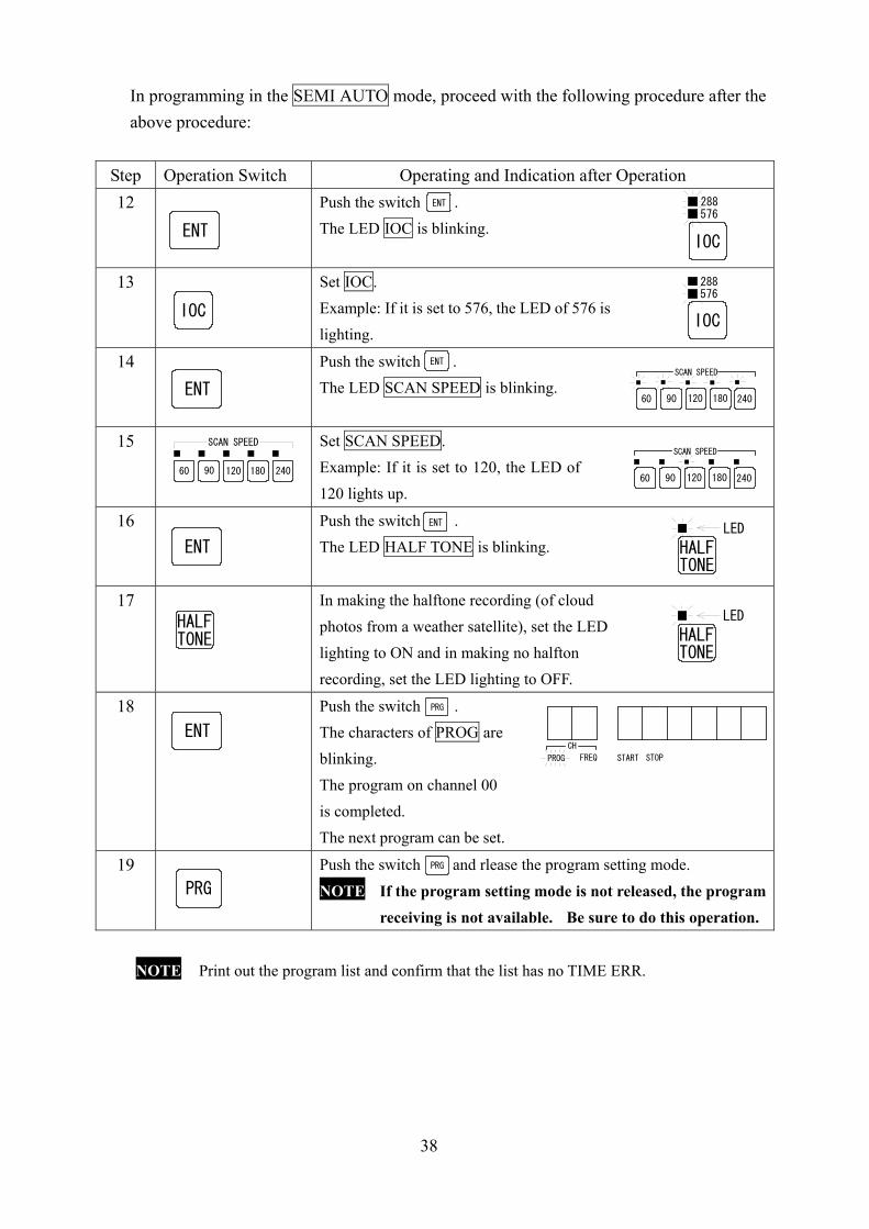
In programming in the SEMI AUTO mode, proceed with the following procedure after the above procedure:
Step Operation Switch Operating and Indication after Operation 12
Push the switch . The LED IOC is blinking.
13
Set IOC. Example: If it is set to 576, the LED of 576 is lighting.
14
Push the switch . The LED SCAN SPEED is blinking.
15
Set SCAN SPEED. Example: If it is set to 120, the LED of 120 lights up.
16
Push the switch . The LED HALF TONE is blinking.
17
In making the halftone recording (of cloud photos from a weather satellite), set the LED lighting to ON and in making no halfton recording, set the LED lighting to OFF.
18
Push the switch . The characters of PROG are blinking. The program on channel 00 is completed. The next program can be set.
19
Push the switch and rlease the program setting mode.
NOTE If the program setting mode is not released, the program receiving is not available. Be sure to do this operation.
NOTE Print out the program list and confirm that the list has no TIME ERR.
ENT
ENTIOC
288576
IOCIOC
288576
ENT
ENTSCAN SPEED
60 90 120 180 240
2401801209060
SCAN SPEEDSCAN SPEED
60 90 120 180 240
ENTLED
HALFTONE
HALFTONE
LED
HALFTONE
ENTCH
PROG FREQ START STOP
PRG
PRG
PRG
ENT
39
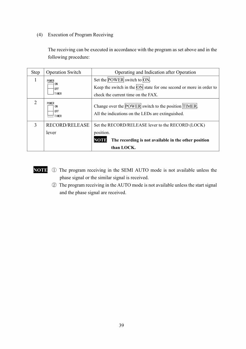
(4) Execution of Program Receiving
The receiving can be executed in accordance with the program as set above and in the following procedure:
Step Operation Switch Operating and Indication after Operation 1
Set the POWER switch to ON. Keep the switch in the ON state for one second or more in order to check the current time on the FAX.
2
Change over the POWER switch to the position TIMER. All the indications on the LEDs are extinguished.
3
RECORD/RELEASE lever
Set the RECORD/RELEASE lever to the RECORD (LOCK) position.
NOTE The recording is not available in the other position than LOCK.
NOTE ① The program receiving in the SEMI AUTO mode is not available unless the phase signal or the similar signal is received.
② The program receiving in the AUTO mode is not available unless the start signal and the phase signal are received.
POWERON
OFF
TIMER
TIMER
POWERON
OFF
40
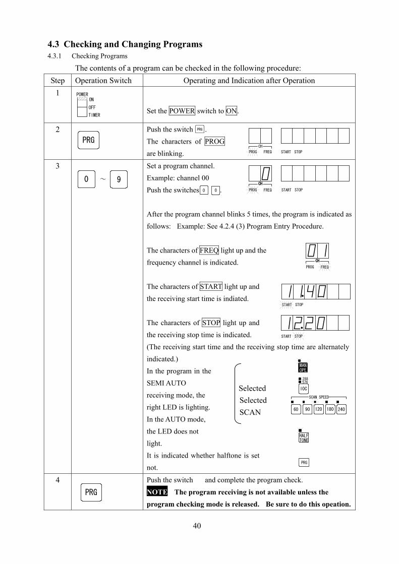
4.3 Checking and Changing Programs 4.3.1 Checking Programs
The contents of a program can be checked in the following procedure: Step Operation Switch Operating and Indication after Operation
1
Set the POWER switch to ON.
2
Push the switch . The characters of PROG are blinking.
3
Set a program channel. Example: channel 00 Push the switches . After the program channel blinks 5 times, the program is indicated as follows: Example: See 4.2.4 (3) Program Entry Procedure. The characters of FREQ light up and the frequency channel is indicated. The characters of START light up and the receiving start time is indiated. The characters of STOP light up and the receiving stop time is indicated. (The receiving start time and the receiving stop time are alternately indicated.) In the program in the SEMI AUTO receiving mode, the right LED is lighting. In the AUTO mode, the LED does not light. It is indicated whether halftone is set not.
4
Push the switch and complete the program check.
NOTE The program receiving is not available unless the program checking mode is released. Be sure to do this opeation.
POWERON
OFF
TIMER
PRGCH
PROG FREQ START STOP
0 9~
0 0
PRG
CH
PROG FREQ START STOP
CH
CH
PROG FREQ
CH
START STOP
START STOP
MANOPE
IOC
288576
SCAN SPEED
60 90 120 180 240
HALFTONE
Selected Selected SCAN
PRG
PRG

41
4.3.2 Changing Programs
The program that has been entered and set can be changed in the following procedure:
Step Operation Switch Operating and Indication after Operation 1
Set the POWER switch to ON.
2
Push the switch . The characters of PROG are blinking.
3
Assign the program channel to be changed. Example: channel 00 Push the switches . The same operation as in checking the program is indicated.
4
Push the switch and move to the position to be changed. Example: receiving start time
5
Enter a new data in the position to be changed. For example, if the receiving start time is changed from 11:40 into 13:30, push the switches .
6
Push the switch and establish the changed value. Change other positions in the same way.
7
Push the switch and complete the program change.
NOTE The program receiving is not available unless the program changing mode is released. Be sure to do this operation.
POWERON
OFF
TIMER
PRG
PRGCH
PROG FREQ START STOP
0 9~
0 0
CH
PROG FREQ START STOP
CH
ENT
ENT
START STOP
0 9~
1 3 3 0
START STOP
ENT
ENT
PRG
PRG
42
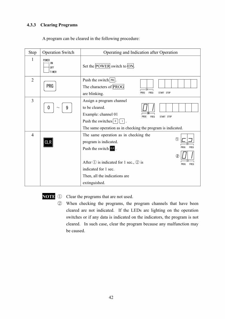
4.3.3 Clearing Programs
A program can be cleared in the following procedure:
Step Operation Switch Operating and Indication after Operation 1
Set the POWER switch to ON.
2
Push the switch . The characters of PROG are blinking.
3
Assign a program channel to be cleared. Example: channel 01 Push the switches . The same operation as in checking the program is indicated.
4
The same operation as in checking the program is indicated. Push the switch .
After ① is indicated for 1 sec., ② is indicated for 1 sec. Then, all the indications are extinguished.
NOTE ① Clear the programs that are not used. ② When checking the programs, the program channels that have been
cleared are not indicated. If the LEDs are lighting on the operation switches or if any data is indicated on the indicators, the program is not cleared. In such case, clear the program because any malfunction may be caused.
POWERON
OFF
TIMER
PRG
PRGCH
PROG FREQ START STOP
0 9~
START STOP
CH
PROG FREQ
CH
10
CLRCLR
CH
PROG FREQ
①
CH
PROG FREQ
②

43
4.3.4 Printing Lists The lists of the receiving frequencies and programs stored in the equipment can be printed out on recording paper.
(1) Printing of receiving frequency list
A total of 90 frequency channels from channel 01 to channel 90 for receiving frequencies can be printed out. For the frequency channels that do not store frequencies, only their channel numbers are printed and the frequency column fields are blanked. The list printing functions only in the standby mode waiting for the AUTO mode. Set the equipment to the AUTO mode for printing a list. The printing of a list of receiving frequencies can be made in the following procedure:
Step Operation Switch Operating and Indication after Operation 1
Set the POWER switch to ON.
2
Push the switch .
3
Push the switch . The recording paper is fed to the cutter position and stopped after the receiving frequencies on 90 channels are printed out.
4
When stopping the printing midway, push the switch .
The recording paper is fed to the cutter position and stopped.
NOTE ① Only the switch can be operated during printing. ② When pushing the switch , the buzzer may sound with a delay (of 0 to 2
sec.). ③ The channel for a frequency not stored in memory is indicated by the letters
E’s. ④ The channel number with 0 at the least significant digit indicates a group
channel, on which no frequency is stored.
POWERON
OFF
TIMER
LIST LIST
1
1
CLR
CLR
CLR
CLR
44
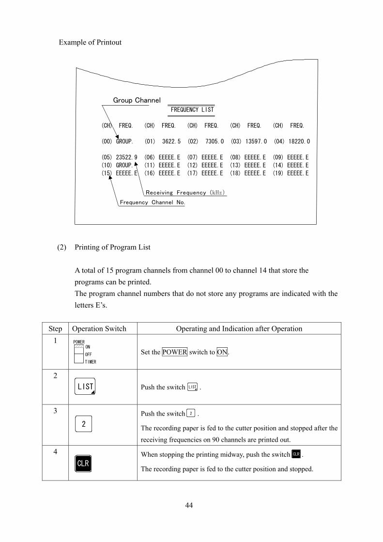
Example of Printout
Group Channel FREQUENCY LIST
(CH) FREQ. (CH) FREQ. (CH) FREQ. (CH) FREQ. (CH) FREQ.
(00) GROUP. (01) 3622.5 (02) 7305.0 (03) 13597.0 (04) 18220.0
(05) 23522.9 (06) EEEEE.E (07) EEEEE.E (08) EEEEE.E (09) EEEEE.E
(10) GROUP. (11) EEEEE.E (12) EEEEE.E (13) EEEEE.E (14) EEEEE.E
(15) EEEEE.E (16) EEEEE.E (17) EEEEE.E (18) EEEEE.E (19) EEEEE.E
Receiving Frequency (kHz) Frequency Channel No.
(2) Printing of Program List A total of 15 program channels from channel 00 to channel 14 that store the programs can be printed. The program channel numbers that do not store any programs are indicated with the letters E’s.
Step Operation Switch Operating and Indication after Operation 1
Set the POWER switch to ON.
2
Push the switch .
3
Push the switch .
The recording paper is fed to the cutter position and stopped after the receiving frequencies on 90 channels are printed out.
4
When stopping the printing midway, push the switch .
The recording paper is fed to the cutter position and stopped.
POWERON
OFF
TIMER
LIST LIST
CLR
CLR
2
2
45
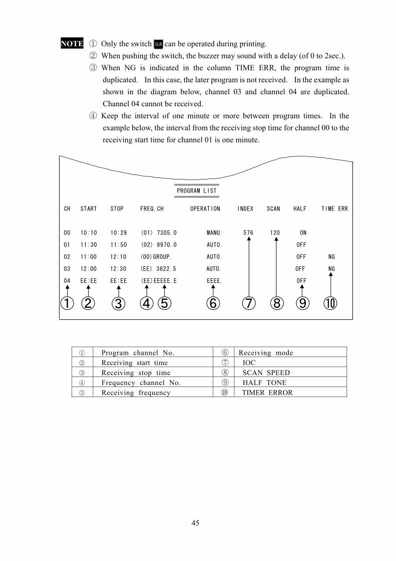
NOTE ① Only the switch can be operated during printing. ② When pushing the switch, the buzzer may sound with a delay (of 0 to 2sec.). ③ When NG is indicated in the column TIME ERR, the program time is
duplicated. In this case, the later program is not received. In the example as shown in the diagram below, channel 03 and channel 04 are duplicated. Channel 04 cannot be received.
④ Keep the interval of one minute or more between program times. In the example below, the interval from the receiving stop time for channel 00 to the receiving start time for channel 01 is one minute.
PROGRAM LIST CH START STOP FREQ.CH OPERATION INDEX SCAN HALF TIME ERR.
00 10:10 10:29 (01) 7305.0 MANU. 576 120 ON
01 11:30 11:50 (02) 9970.0 AUTO. OFF
02 11:00 12:10 (00)GROUP. AUTO. OFF NG
03 12:00 12:30 (EE) 3622.5 AUTO. OFF NG
04 EE:EE EE:EE (EE)EEEEE.E EEEE. OFF
① Program channel No. ⑥ Receiving mode ② Receiving start time ⑦ IOC ③ Receiving stop time ⑧ SCAN SPEED ④ Frequency channel No. ⑨ HALF TONE
⑤ Receiving frequency ⑩ TIMER ERROR
CLR
⑩⑨⑧⑦⑥⑤④③②①
46
4.4 Other Operations 4.4.1 Adjusting of Brightness for Operating Panel
The brightness of all the indicators and LEDs on the operating panel can be adjusted as follows: Operation Switch Operating and Indication after Operation
Whenever pushing the switch , the brightness is adjusted in 4 levels: OUT, DARK, MEDIUM and BRIGHT.
NOTE ① This function cannot be operated when the switch is ON. ② This function cannot be operated during printing a list.
4.4.2 Switchover to External Receiver
In addition to the internal receiver, an external HF-band receiver connected to the JAX-91 can receive FAX broadcasts. Operation Switch Operating and Indication after Operation
Push the switch .
The LED EXT lights up.
NOTE ① The internal receiver cannot receive FAX broadcasts while the LED EXT
is lighting. ② This function cannot be operated when the switch is ON. ③ This function cannot be operated during printing a list.
Setting of External Receiver
In using an external receiver, set the receiving frequencies in the following procedure:
① Set the receiving band to 3 kHz. ② Set the receiving mode to USB.
③ Set a receiving frequency that is equal to the indicated FAX broadcasting frequency less 1.9 kHz.
DIM
DIM
PRG
RCV
RCV
RCV
EXT
PRG

47
4.4.3 Recording Paper Feed The paper feed can be made using the following switch: Operation Switch Operating and Indication after Operation
Push the switch . Then, the recording paper is fed up to the cutter position and stopped automatically. The paper can be stopped when pushing the switch while it is being fed.
NOTE ① This function cannot be operated when the switch is ON. ② The paper is stopped by pushing the switch , or .
4.4.4 Black/White Reversal
The black/white reversing function can be used in receiving the black/white reversed images (white image in the black background) from a FAX broadcasting station. Operation Switch Operating and Indication after Operation
Push the switch .
The LED REV lights up. The white part and the black part in the received image are reversed.
4.4.5 Adjusting Image Inclination
The received image may be recorded inclined (deviated) to the left or right side gradually. In this case, the inclination of the recorded image can be adjusted using the following control dial: Operation Switch Operating Procedure
① When the recorded image is inclined to the left side: Rotate the control dial SYNC to the direction L until the received image is recorded not inclined.
② When the recorded image is inclined to the right side: Rotate the control dial SYNC to the direction R until the received image is recorded not inclined.
NOTE This equipment is adjusted so that an image is recorded properly around the center of the control SYNC.
Set the SYNC control always to the center point. Use this control only when the received image is recorded inclined (deviated).
FEED
FEED
FEED
PRG
PRG REC
MOD
MOD
MOD
REV
RL
SYNC
48
CHAPTER 5 MAINETENANCE & INSPECTION
WARNING
Do not have anybody other than maintenance specialists make the inspection and repair of the equipment inside. Otherwise, a fire or electric shock may be caused. For the inspection or repair of the equipment inside, please contact a nearby JRC marketing office, branch, sales office or agent.
5.1 Replacing Recording Paper
CAUTION
Use the JRC-specified recording paper (6ZPTS00127). If any other unspecified paper is used, recording density blurs, paper feed failure or a lot of dust may be caused, resulting in the damage of the recording device. Do not keep the recording paper in a place exposed to a high temperature, high humidity and direct sunlight. Otherwise, recording density blurs may be caused.
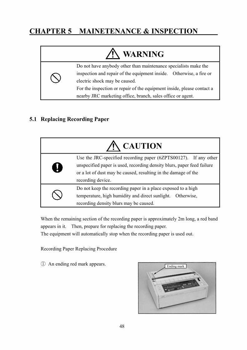
When the remaining section of the recording paper is approximately 2m long, a red band appears in it. Then, prepare for replacing the recording paper. The equipment will automatically stop when the recording paper is used out. Recording Paper Replacing Procedure ① An ending red mark appears.
Ending mark
49
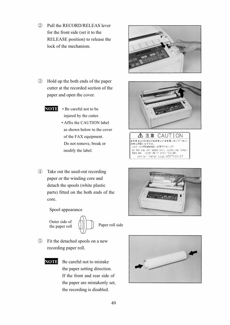
② Pull the RECORD/RELEAS lever for the front side (set it to the RELEASE position) to release the lock of the mechanism.
③ Hold up the both ends of the paper
cutter at the recorded section of the paper and open the cover.
NOTE • Be careful not to be injured by the cutter.
• Affix the CAUTION label as shown below to the cover of the FAX equipment.
Do not remove, break or modify the label.
④ Take out the used-out recording
paper or the winding core and detach the spools (white plastic parts) fitted on the both ends of the core.
Spool appearance
⑤ Fit the detached spools on a new recording paper roll.
NOTE Be careful not to mistake
the paper setting direction. If the front and rear side of
the paper are mistakenly set, the recording is disabled.
Outer side of the paper roll Paper roll side

50
⑥ Fit the recording paper roll on the
FAX equipment and set the paper through the metallic rod and the rubber roller.
⑦ Set the RECORD/RELEASE lever
to the RECORD position stretching the recording paper with good balance not to be slacked.
NOTE Push the lever until a click tone sounds (up to the LOCK position).
⑧ Lower the cover at the paper roll fitting section and push and lock it.
⑨ Insert the paper under the cutter. All the steps of replacing the recording paper roll have been completed.
Thermal head
PaperRubber roller
Metallic rod
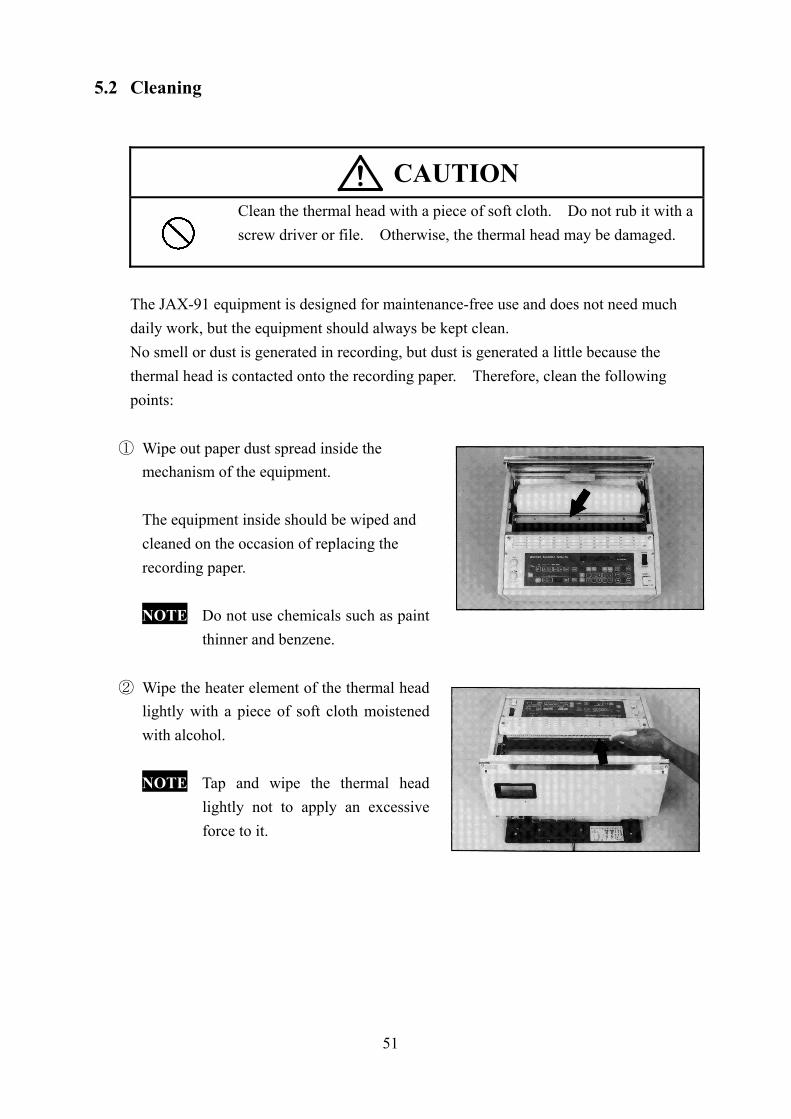
51
5.2 Cleaning
CAUTION
Clean the thermal head with a piece of soft cloth. Do not rub it with a screw driver or file. Otherwise, the thermal head may be damaged.
The JAX-91 equipment is designed for maintenance-free use and does not need much daily work, but the equipment should always be kept clean. No smell or dust is generated in recording, but dust is generated a little because the thermal head is contacted onto the recording paper. Therefore, clean the following points:
① Wipe out paper dust spread inside the mechanism of the equipment. The equipment inside should be wiped and cleaned on the occasion of replacing the recording paper. NOTE Do not use chemicals such as paint
thinner and benzene.
② Wipe the heater element of the thermal head lightly with a piece of soft cloth moistened with alcohol.
NOTE Tap and wipe the thermal head
lightly not to apply an excessive force to it.
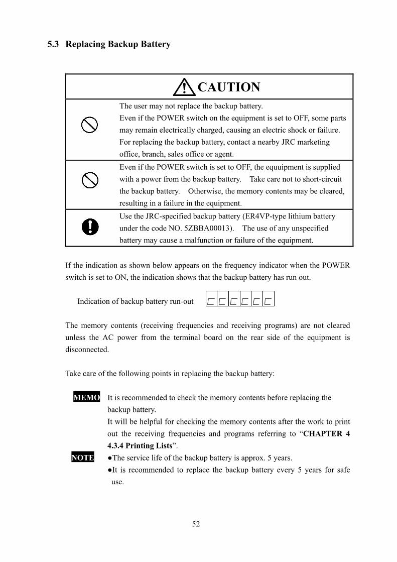
52
5.3 Replacing Backup Battery
CAUTION
The user may not replace the backup battery. Even if the POWER switch on the equipment is set to OFF, some parts may remain electrically charged, causing an electric shock or failure. For replacing the backup battery, contact a nearby JRC marketing office, branch, sales office or agent. Even if the POWER switch is set to OFF, the equuipment is supplied with a power from the backup battery. Take care not to short-circuit the backup battery. Otherwise, the memory contents may be cleared, resulting in a failure in the equipment. Use the JRC-specified backup battery (ER4VP-type lithium battery under the code NO. 5ZBBA00013). The use of any unspecified battery may cause a malfunction or failure of the equipment.
If the indication as shown below appears on the frequency indicator when the POWER switch is set to ON, the indication shows that the backup battery has run out.
Indication of backup battery run-out The memory contents (receiving frequencies and receiving programs) are not cleared unless the AC power from the terminal board on the rear side of the equipment is disconnected. Take care of the following points in replacing the backup battery:
MEMO It is recommended to check the memory contents before replacing the backup battery. It will be helpful for checking the memory contents after the work to print out the receiving frequencies and programs referring to “CHAPTER 4 4.3.4 Printing Lists”.
NOTE The service life of the backup battery is approx. 5 years. It is recommended to replace the backup battery every 5 years for safe
use.

53
Work Procedure ① Demount the front panel and then
detach the operating panel. ② The left photo shows the operating
panel as seen from the rear side after detaching the operating panel.
NOTE • Set the POWER switch to OFF before starting the work. • Detach three (3) screws at the equipment bottom to demount the front
panel. • Detach two (2) screws on the left and right ends of the operating panel to
demount it.
③ Demount the printed circuit board with the backup battery fitted on it from the operating panel.
Do the work with the cables connected. Be careful not to short-circuit them.
NOTE The replacing backup battery is soldered on the PC board. Be careful not to touch a soldering iron or overflow the melt solder to other
parts. ④ Detach the run-out battery fitted on the PC board using the soldering iron. NOTE Use a soldering iron of 20W to 40W. ⑤ Solder a new battery on the PC board with PB free soldering material.
Backup battery
Backup battery
54
⑥ Check the following points: ・ Check that the frequencies stored in the frequency channels are the same as before
replacing the backup battery. ・ Check that the program contents stored in the program channels are the same as
before replacing the backup battery. ・ If any frequencies or programs are different from those before replacing the
backup battery, it is necessary to set the frequency channels and program channels again.
NOTE • Even if the indication as shown below appears on the frequency indicator
after replacing the backup battery, the equipment can be operated by setting necessary frequencies.
Indication after replacing the
backup battery

55
5.4 Troubleshooting
If the equipment has a failure, it should be diagnosed by a maintenance specialist to replace any defective part. However, the user can shoot the simple troubles referring to the table below.
Trouble Symptom Cause Action The recording paper is tilted or slackened and deviated from the paper sensor.
Set the recording paper properly.
The RECORD/RELEASE lever is set to RELEASE or PUSH.
Push the lever to the RECORD (LOCK) position until the click tone sounds.
Paper feed and recording are impossible.
The paper sensor (left below the rubber roller) is contaminated with paper dust.
Clean the paper sensor carefully.
The parameter SCAN SPEED is erroneous.
Adjust the SCAN SPEED.
Time is indicated on the frequency indicator.
Reset the indicator to FREQ.
The receiving condition is no good.
Change the frequency to the one on which the good receiving condition is obtained, watching the RCV MONITOR.
The [PRG] switch is ON. Set the switch to OFF.
The [REC START] LED does not light up (and recording is impossible).
The frequency indicator indicates [ ].
This indication shows that the backup battery has run out. Replace the battery.
The POWER switch is switched over from OFF to TIMER.
Set the POWER switch to ON before setting it to TIMER.
Other contents than the necessary program are stored in the unused program channel.
Clear all the unused program channels.
The program receiving cannot be made properly.
The program contents contain any errors.
Correct the program.

56
The time indication is deviated from the current time. The receiving start time is overlapped for two or more programs.
Adjust the time to the current time. Correct the programs so that their receiving start times are not overlapped.
The [MAN OPE] switch does not function.
The [PRG] switch is ON. Set the [PRG] switch to OFF.
The [FEED] switch does not function.
The [PRG] switch is ON. Set the [PRG] switch to OFF.
Any switch does not function.
The [PRG] switch is ON. Set the [PRG] switch to OFF.
The time is indicated. Correct the indicator to FREQ.
The [PRG] switch does not function.
The [MAN OPE] switch is ON. Set the [MAN OPE] switch to OFF.
[ ] appears on the frequency indicator.
The backup battery has run out. Replace the backup battery.
Other characters than numerals are indicated on the frequency indicator.
The unused program channels are not cleared completely.
Clear all the unused program channels.
When setting the POWER switch to OFF, the program is cleared.
The backup battery has run out. Replace the backup battery.
The program receiving cannot be made properly.
57
CHAPTER 6 OPERATING ENVIRONMENT
Do not store the recording paper in a place exposed to a high temperature, high humidity or direct sunlight. Otherwise, recording density blurs may be caused.Do not install the equipment in an unstable place such as on a shaky stand or inclined surface. Otherwise, it may drop or fall down, resulting in an injury or failure. Do not install the equipment in a place much affected by water, moisture, steam, dust or oily smoke. Otherwise, a fire, electric shok or failure may be caused. Do not install the equipment in a place exposed to a direct sunlight. The high temperature may discolor the recording paper or cause an equipment failure. Do not install the equipment near any other radio equipment. Otherwise, a receiving interference may be caused.
Take care of the following points to keep the operating environment in which the equipment can operate normally: (1) If the equipment is exposed to the direct sunlight, the temperature in the equipment
inside will become extraordinarily high. Please install the equipment in a place that is not exposed to the direct sunlight.
(2) This equipment is not designed to have a waterproof or water-drip structure. Please
install the equipment in a room that is not affected by winds, water or sandy dust. (3) Protect the equipment with the attached protective cover against dust and the like when
it is not used for a long time.
CAUTION

58
CHAPTER 7 CUSTOMER SUPPORT Request for Repair If you suspect that the equipment has a failure, and check the equipment again referring to “CHAPTER 5 5.4 Troubleshooting”. If a trouble remains after your troubleshooting, stop the use of the equipment and consult with a nearby JRC marketing office, branch, sales office or agent.
The repair during the warranty period is made free of charge if the equipment is operated properly (in the normal operating conditions) in accordance with this Instruction Manual.
The repair after expiration of the warranty period is made at the customer’s cost if the
repair can cover the functions of the equipment.
Information to be given with your request for repair
Product name, model, product number or serial number
Detailed description of trouble symptom
Customer’s organization, location and telephone number
If you have any unclear points about our after-sale service, please consult with a nearby JRC marketing office, branch, sales office, dealer or agent. For JRC overseas offices, please refer to the List of JRC Overseas Offices attached hereto.
59
CHAPTER 8 DISPOSAL OF THE EQUIPMENT
WARNING
In returning the run-out lithium battery to JRC, take the isulating treatment such as attaching a tape to the +/– terminals (or the lead wires). If the battery is short-circuited with no insulating treatment, a heat, explosion or fire may be caused.
8.1 Disposal of the Equipment
The equipment must be disposed of in accordance with the applicable regulations and rules in your country, region (or province) or municipality. For the details, please consult with a nearby JRC agent, dealer, representative office or marketing office.
8.2 Disposal of Used Batteries
A backup lithium battery is used in the Control Unit (CKK-534) of the JAX-91 equipment.
Do not dispose of the used lithium battery as a waste material. This Instruction Manual contains the descriptions of “5.3 Replacing Backup Battery”
in CHAPTER 5, but the user should not replace the backup battery. In replacing it, please contact a nearby JRC office or agent.
The used lithium battery can be recycled. Please take the insulating treatment such as attaching a tape to the +/– terminals (or lead wires) before returning the battery to or consulting a nearby JRC agent or dealer, representative office or any recycle shop.
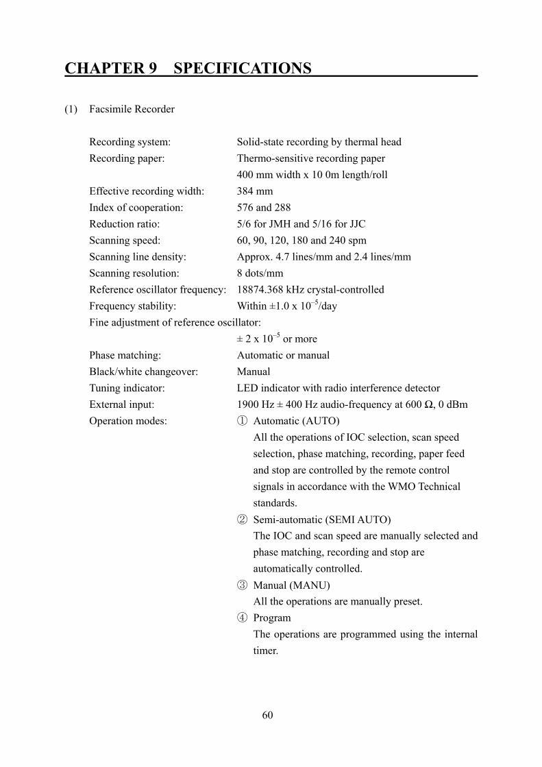
60
CHAPTER 9 SPECIFICATIONS (1) Facsimile Recorder
Recording system: Solid-state recording by thermal head Recording paper: Thermo-sensitive recording paper 400 mm width x 10 0m length/roll Effective recording width: 384 mm Index of cooperation: 576 and 288 Reduction ratio: 5/6 for JMH and 5/16 for JJC Scanning speed: 60, 90, 120, 180 and 240 spm Scanning line density: Approx. 4.7 lines/mm and 2.4 lines/mm Scanning resolution: 8 dots/mm Reference oscillator frequency: 18874.368 kHz crystal-controlled Frequency stability: Within ±1.0 x 10⁻⁵/day Fine adjustment of reference oscillator:
± 2 x 10⁻⁵ or more Phase matching: Automatic or manual Black/white changeover: Manual Tuning indicator: LED indicator with radio interference detector External input: 1900 Hz ± 400 Hz audio-frequency at 600 Ω, 0 dBm Operation modes: ① Automatic (AUTO) All the operations of IOC selection, scan speed
selection, phase matching, recording, paper feed and stop are controlled by the remote control signals in accordance with the WMO Technical standards.
② Semi-automatic (SEMI AUTO) The IOC and scan speed are manually selected and phase matching, recording and stop are automatically controlled.
③ Manual (MANU) All the operations are manually preset.
④ Program The operations are programmed using the internal
timer.
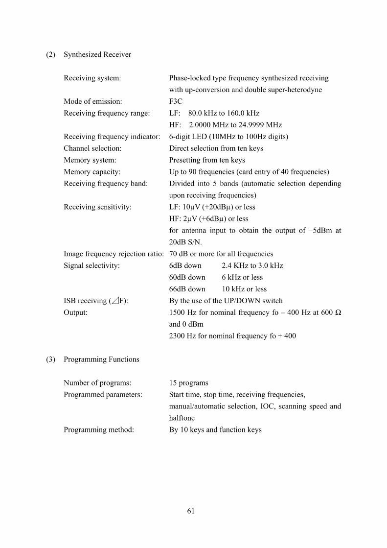
61
(2) Synthesized Receiver
Receiving system: Phase-locked type frequency synthesized receiving with up-conversion and double super-heterodyne
Mode of emission: F3C Receiving frequency range: LF: 80.0 kHz to 160.0 kHz HF: 2.0000 MHz to 24.9999 MHz Receiving frequency indicator: 6-digit LED (10MHz to 100Hz digits) Channel selection: Direct selection from ten keys Memory system: Presetting from ten keys Memory capacity: Up to 90 frequencies (card entry of 40 frequencies) Receiving frequency band: Divided into 5 bands (automatic selection depending
upon receiving frequencies) Receiving sensitivity: LF: 10µV (+20dBµ) or less HF: 2µV (+6dBµ) or less for antenna input to obtain the output of –5dBm at
20dB S/N. Image frequency rejection ratio: 70 dB or more for all frequencies Signal selectivity: 6dB down 2.4 KHz to 3.0 kHz 60dB down 6 kHz or less 66dB down 10 kHz or less ISB receiving (⊿F): By the use of the UP/DOWN switch Output: 1500 Hz for nominal frequency fo – 400 Hz at 600 Ω
and 0 dBm 2300 Hz for nominal frequency fo + 400
(3) Programming Functions
Number of programs: 15 programs Programmed parameters: Start time, stop time, receiving frequencies,
manual/automatic selection, IOC, scanning speed and halftone
Programming method: By 10 keys and function keys

62
(4) General Specifications
Power supply: 100VAC (80V to 132V), 50/60Hz, single-phase 220VAC (160V to 264V), 50/60Hz, single-phase Power consumption: 130VA or less Dimensions: Approx. 480 (W) x 470 (D) x 200 (H) (incl. stand and
projections) Weight: Approx. 25kg Ambient temperature: –15°C to +55°C (operation guarantee) 0°C to +40° (performance guarantee) Ambient humidity: 85% or less (at 40°C) Coating color: Munsell 5Y8/1
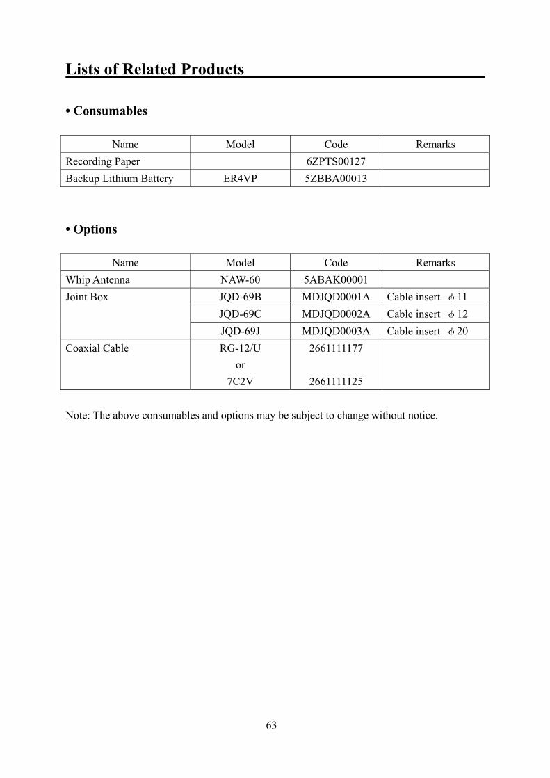
63
Lists of Related Products • Consumables
Name Model Code Remarks Recording Paper 6ZPTS00127 Backup Lithium Battery ER4VP 5ZBBA00013 • Options
Name Model Code Remarks Whip Antenna NAW-60 5ABAK00001
JQD-69B MDJQD0001A Cable insert φ11 JQD-69C MDJQD0002A Cable insert φ12
Joint Box
JQD-69J MDJQD0003A Cable insert φ20 Coaxial Cable RG-12/U
or 7C2V
2661111177
2661111125
Note: The above consumables and options may be subject to change without notice.
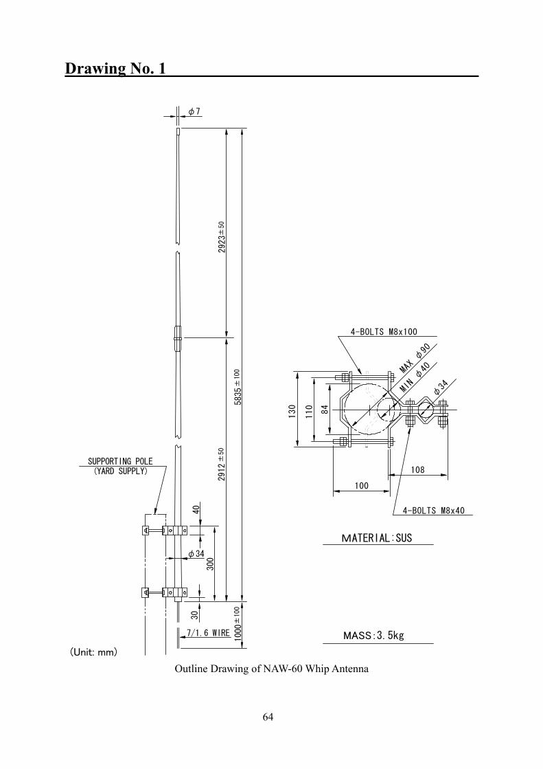
64
Drawing No. 1 (Unit: mm)
Outline Drawing of NAW-60 Whip Antenna
φ7
5835
±10
0
292
3±50
2912
±50
SUPPORTING POLE(YARD SUPPLY)
40
300
φ34
7/1.6 WIRE
1000
±10
0
30
φ34MI
Nφ40
130
110
84
4-BOLTS M8x100
MAXφ90
4-BOLTS M8x40
108
100
MATERIAL:SUS
MASS: 3.5kg
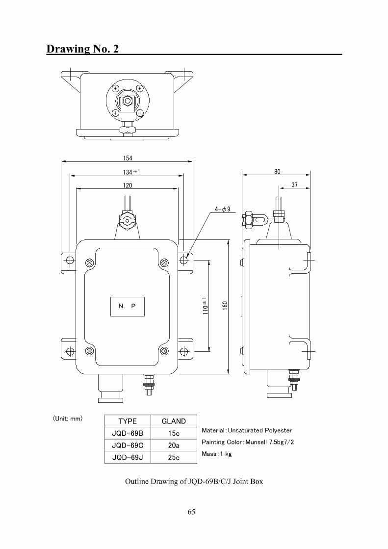
65
Drawing No. 2
(Unit: mm)
Material:Unsaturated Polyester
Painting Color:Munsell 7.5bg7/2
Mass:1 kg
Outline Drawing of JQD-69B/C/J Joint Box
TYPE GLAND
JQD-69B 15c
JQD-69C 20a
JQD-69J 25c
154
120
4-φ9
134±1
N.P 160
110±
1
80
37


INSTRUCTION INSTRUCTION MANUAL MANUAL
JAX-91JAX-91WEATHER FACSIMILE WEATHER FACSIMILE
RECEIVER RECEIVER
01ETM ISO 9001, ISO 14001 Certified
Printed in Japan
Marine Service Department
+81-3-3492-1305 +81-3-3779-1420 [email protected]
Telephone : Facsimile : e-mail :
AMSTERDAM Branch Telephone : Facsimile : e-mail :
+31-20-658-0750 +31-20-658-0755 [email protected]
SEATTLE Branch Telephone : Facsimile : e-mail :
+1-206-654-5644 +1-206-654-7030 [email protected]
CODE No.7ZPNA4002CODE No.7ZPNA4002
SEP. 2006 Edition 1 JRCSEP. 2006 Edition 1 JRC
Not use the asbestos
For further information,contact:
URL http://www.jrc.co.jp
Related Documents


![Loading [MathJax]/jax/output/CommonHTML/jax](https://static.cupdf.com/doc/110x72/625335b291158e3f663c6c05/loading-mathjaxjaxoutputcommonhtmljax.jpg)

