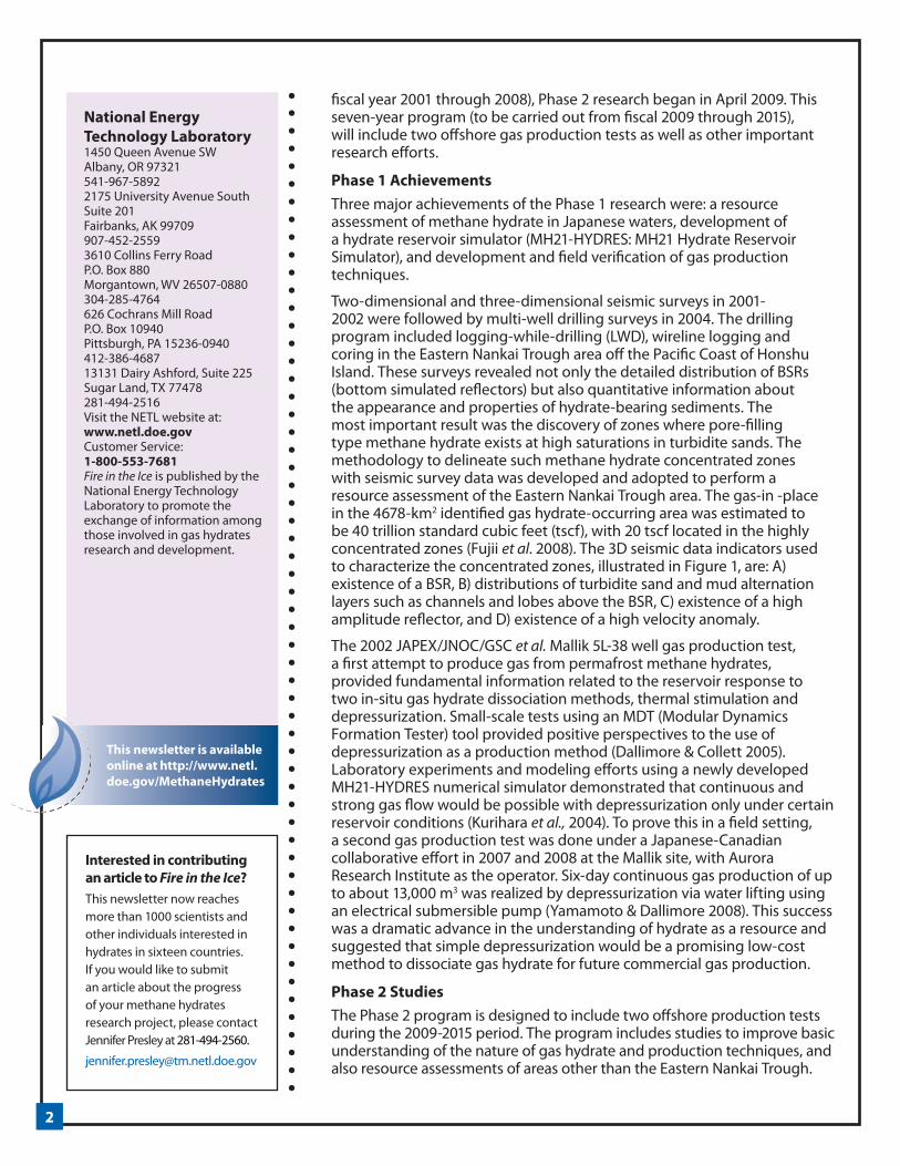
1 CONTENTS Japan’s R&D Program .................. 1 Hydrate in Nature.......................... 7 HYFLUX Expedition......................12 Sub Sampling for GH ................ 16 Gas Production Geomechanical Implications ................................. 18 Announcements ...................... 23 • Database Now Available • Global Assessment • NETL-NAS Fellowship • New Zealand Workshop • EGU 2010 Abstracts • Goldschmidt 2010 Abstracts Spotlight on Research .......... 26 Peter Schultheiss and Melanie Holland CONTACT Ray Boswell Technology Manager—Methane Hydrates, Strategic Center for Natural Gas & Oil 304-285-4541 [email protected] Methane Hydrate Newsletter Vol. 9, Iss. 4 Japan’s Methane Hydrate R&D Program Progresses to Phase 2 Yoshihiro Masuda 1)4) , Koji Yamamoto 2) 4) , Shimada Tadaaki 2) 4) , Takao Ebinuma 3) 4) , Sadao Nagakubo 2) 4) 1) The University of Tokyo 2) Japan Oil, Gas and Metals National Corporation 3) National Institute of Advanced Industrial Science and Technology 4) MH21 Research Consortium Japan In 2001, a panel of the Japanese Ministry of International Trade and Industry (MITI, currently the Ministry of Economy Trade and Industry) determined a strategy (MITI 2001) for developing naturally occurring gas hydrate deposits in marine sediment around Japan into an energy resource of the new millennium. To accomplish the tasks defined in the plan “Japan’s Methane Hydrate R&D Program,” Japan National Oil Corporation (JNOC, currently Japan Oil, Gas and Metals National Corporation: JOGMEC), National Institute of Advanced Industrial Science and Technology (AIST) and Engineering Advancement Association of Japan (ENAA) formed a consortium named MH21 (The Research Consortium for Methane Hydrate Resources in Japan). Our ultimate goal is to establish a technology platform for commercial gas production from offshore-Japan methane hydrates by year 2018. Following on the success of Phase 1 research (carried out from Figure 1. Methane hydrate concentrated zone (Saeki et al., 2009; Noguchi et al., 2009)

Welcome message from author
This document is posted to help you gain knowledge. Please leave a comment to let me know what you think about it! Share it to your friends and learn new things together.
Transcript
1
CONTENTSJapan’s R&D Program ..................1
Hydrate in Nature..........................7
HYFLUX Expedition ......................12
Sub Sampling for GH ................ 16
Gas Production Geomechanical Implications ................................. 18
Announcements ...................... 23• Database Now Available• Global Assessment• NETL-NAS Fellowship• New Zealand Workshop• EGU 2010 Abstracts• Goldschmidt 2010 AbstractsSpotlight on Research .......... 26Peter Schultheiss and Melanie Holland
CONTACTRay Boswell
Technology Manager—Methane Hydrates, Strategic Center for Natural Gas & Oil
304-285-4541
Methane Hydrate Newsletter Vol. 9, Iss. 4
Japan’s Methane Hydrate R&D Program Progresses to Phase 2 Yoshihiro Masuda1)4), Koji Yamamoto2) 4), Shimada Tadaaki2) 4), Takao Ebinuma3) 4), Sadao Nagakubo2) 4)
1) The University of Tokyo2) Japan Oil, Gas and Metals National Corporation3) National Institute of Advanced Industrial Science and Technology4) MH21 Research Consortium Japan
In 2001, a panel of the Japanese Ministry of International Trade and Industry (MITI, currently the Ministry of Economy Trade and Industry) determined a strategy (MITI 2001) for developing naturally occurring gas hydrate deposits in marine sediment around Japan into an energy resource of the new millennium. To accomplish the tasks defined in the plan “Japan’s Methane Hydrate R&D Program,” Japan National Oil Corporation (JNOC, currently Japan Oil, Gas and Metals National Corporation: JOGMEC), National Institute of Advanced Industrial Science and Technology (AIST) and Engineering Advancement Association of Japan (ENAA) formed a consortium named MH21 (The Research Consortium for Methane Hydrate Resources in Japan). Our ultimate goal is to establish a technology platform for commercial gas production from offshore-Japan methane hydrates by year 2018. Following on the success of Phase 1 research (carried out from
Figure 1. Methane hydrate concentrated zone (Saeki et al., 2009; Noguchi et al., 2009)
22
National Energy Technology Laboratory1450 Queen Avenue SWAlbany, OR 97321541-967-58922175 University Avenue South Suite 201Fairbanks, AK 99709907-452-25593610 Collins Ferry RoadP.O. Box 880Morgantown, WV 26507-0880304-285-4764626 Cochrans Mill RoadP.O. Box 10940Pittsburgh, PA 15236-0940412-386-468713131 Dairy Ashford, Suite 225 Sugar Land, TX 77478 281-494-2516Visit the NETL website at:www.netl.doe.govCustomer Service:1-800-553-7681Fire in the Ice is published by the National Energy Technology Laboratory to promote the exchange of information among those involved in gas hydrates research and development.
Interested in contributing an article to Fire in the Ice?This newsletter now reaches more than 1000 scientists and other individuals interested in hydrates in sixteen countries. If you would like to submit an article about the progress of your methane hydrates research project, please contact Jennifer Presley at 281-494-2560.
This newsletter is available online at http://www.netl.doe.gov/MethaneHydrates
fiscal year 2001 through 2008), Phase 2 research began in April 2009. This seven-year program (to be carried out from fiscal 2009 through 2015), will include two offshore gas production tests as well as other important research efforts.
Phase 1 AchievementsThree major achievements of the Phase 1 research were: a resource assessment of methane hydrate in Japanese waters, development of a hydrate reservoir simulator (MH21-HYDRES: MH21 Hydrate Reservoir Simulator), and development and field verification of gas production techniques.
Two-dimensional and three-dimensional seismic surveys in 2001-2002 were followed by multi-well drilling surveys in 2004. The drilling program included logging-while-drilling (LWD), wireline logging and coring in the Eastern Nankai Trough area off the Pacific Coast of Honshu Island. These surveys revealed not only the detailed distribution of BSRs (bottom simulated reflectors) but also quantitative information about the appearance and properties of hydrate-bearing sediments. The most important result was the discovery of zones where pore-filling type methane hydrate exists at high saturations in turbidite sands. The methodology to delineate such methane hydrate concentrated zones with seismic survey data was developed and adopted to perform a resource assessment of the Eastern Nankai Trough area. The gas-in -place in the 4678-km2 identified gas hydrate-occurring area was estimated to be 40 trillion standard cubic feet (tscf), with 20 tscf located in the highly concentrated zones (Fujii et al. 2008). The 3D seismic data indicators used to characterize the concentrated zones, illustrated in Figure 1, are: A) existence of a BSR, B) distributions of turbidite sand and mud alternation layers such as channels and lobes above the BSR, C) existence of a high amplitude reflector, and D) existence of a high velocity anomaly.
The 2002 JAPEX/JNOC/GSC et al. Mallik 5L-38 well gas production test, a first attempt to produce gas from permafrost methane hydrates, provided fundamental information related to the reservoir response to two in-situ gas hydrate dissociation methods, thermal stimulation and depressurization. Small-scale tests using an MDT (Modular Dynamics Formation Tester) tool provided positive perspectives to the use of depressurization as a production method (Dallimore & Collett 2005). Laboratory experiments and modeling efforts using a newly developed MH21-HYDRES numerical simulator demonstrated that continuous and strong gas flow would be possible with depressurization only under certain reservoir conditions (Kurihara et al., 2004). To prove this in a field setting, a second gas production test was done under a Japanese-Canadian collaborative effort in 2007 and 2008 at the Mallik site, with Aurora Research Institute as the operator. Six-day continuous gas production of up to about 13,000 m3 was realized by depressurization via water lifting using an electrical submersible pump (Yamamoto & Dallimore 2008). This success was a dramatic advance in the understanding of hydrate as a resource and suggested that simple depressurization would be a promising low-cost method to dissociate gas hydrate for future commercial gas production.
Phase 2 StudiesThe Phase 2 program is designed to include two offshore production tests during the 2009-2015 period. The program includes studies to improve basic understanding of the nature of gas hydrate and production techniques, and also resource assessments of areas other than the Eastern Nankai Trough.
33
Another critical issue will be an assessment of the potential environmental impact of field development. The MH21 research team believes that gas hydrate resource development will have little influence on the environment at either local or global scales, and plans to demonstrate it with field data.
The re-organized MH21 consortium formed with JOGMEC and AIST, led by Associate Professor Yoshihiro Masuda of the University of Tokyo, will undertake those important Phase 2 tasks. Four research groups, the Field Development Technology Group, the Resources Assessment Group, the Production Method and Modeling Group, and the Environmental Impact Assessment Team, are responsible for their respective areas of investigation. These are highlighted below.
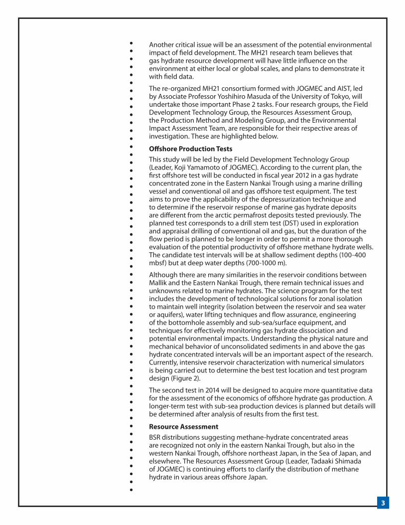
Offshore Production TestsThis study will be led by the Field Development Technology Group (Leader, Koji Yamamoto of JOGMEC). According to the current plan, the first offshore test will be conducted in fiscal year 2012 in a gas hydrate concentrated zone in the Eastern Nankai Trough using a marine drilling vessel and conventional oil and gas offshore test equipment. The test aims to prove the applicability of the depressurization technique and to determine if the reservoir response of marine gas hydrate deposits are different from the arctic permafrost deposits tested previously. The planned test corresponds to a drill stem test (DST) used in exploration and appraisal drilling of conventional oil and gas, but the duration of the flow period is planned to be longer in order to permit a more thorough evaluation of the potential productivity of offshore methane hydrate wells. The candidate test intervals will be at shallow sediment depths (100-400 mbsf) but at deep water depths (700-1000 m).
Although there are many similarities in the reservoir conditions between Mallik and the Eastern Nankai Trough, there remain technical issues and unknowns related to marine hydrates. The science program for the test includes the development of technological solutions for zonal isolation to maintain well integrity (isolation between the reservoir and sea water or aquifers), water lifting techniques and flow assurance, engineering of the bottomhole assembly and sub-sea/surface equipment, and techniques for effectively monitoring gas hydrate dissociation and potential environmental impacts. Understanding the physical nature and mechanical behavior of unconsolidated sediments in and above the gas hydrate concentrated intervals will be an important aspect of the research. Currently, intensive reservoir characterization with numerical simulators is being carried out to determine the best test location and test program design (Figure 2).
The second test in 2014 will be designed to acquire more quantitative data for the assessment of the economics of offshore hydrate gas production. A longer-term test with sub-sea production devices is planned but details will be determined after analysis of results from the first test.
Resource AssessmentBSR distributions suggesting methane-hydrate concentrated areas are recognized not only in the eastern Nankai Trough, but also in the western Nankai Trough, offshore northeast Japan, in the Sea of Japan, and elsewhere. The Resources Assessment Group (Leader, Tadaaki Shimada of JOGMEC) is continuing efforts to clarify the distribution of methane hydrate in various areas offshore Japan.
4
It is also important to understand the mechanism and processes of methane hydrate accumulation (i.e., the methane hydrate system). This ongoing research is expected to contribute to more precise resource assessments of methane hydrate. There are still many unanswered questions related to methane generation depth and rate, methane migration paths, the relationship between hydrate saturation and sediment type, and other topics.
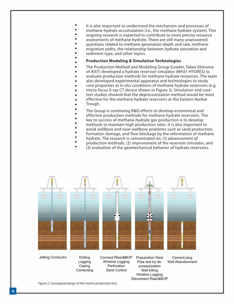
Production Modeling & Simulation TechnologiesThe Production Method and Modeling Group (Leader, Takao Ebinuma of AIST) developed a hydrate reservoir simulator (MH21-HYDRES) to evaluate production methods for methane hydrate resources. The team also developed experimental apparatus and technologies to study core properties at in situ conditions of methane hydrate reservoirs (e.g. micro-focus X-ray CT device shown in Figure 3). Simulation and core-test studies showed that the depressurization method would be most effective for the methane hydrate reservoirs at the Eastern Nankai Trough.
The Group is continuing R&D efforts to develop economical and effective production methods for methane hydrate reservoirs. The key to success of methane-hydrate gas production is to develop methods to maintain high production rates. It is also important to avoid wellbore and near-wellbore problems such as sand production, formation damage, and flow blockage by the reformation of methane hydrate. The research is concentrated on: (1) advancement of production methods, (2) improvement of the reservoir simulator, and (3) evaluation of the geomechanical behavior of hydrate reservoirs.
Figure 2. Conceptual design of the marine production test.
5
In addition to studying simple depressurization, the team aims to develop methods for improving gas recovery and enhancing well productivity. The reservoir simulator MH21-HYDRES will be continuously improved to evaluate these methods as well as to optimize the production schedule of the offshore tests. The test schedule will be determined based on simulations using detailed reservoir models. Development of another simulator is planned for use in evaluating reservoir compaction and the possibility of gas leakage during gas production. These studies aim to establish a safe production system where environmental preservation is a high priority.
Environmental Impact Assessment StudiesIn Phase 1, the Environmental Impact Assessment (EIA) Group conducted baseline marine surveys in the eastern Nankai Trough (a model area of the program), and carried out fundamental research such as the development of numerical models and monitoring sensors to assess possible environmental risks. In Phase 2, the EIA Group is reorganized as an EIA Team (Leader: Sadao Nagakubo of JOGMEC) that includes representatives from all groups and that will conduct comprehensive studies.
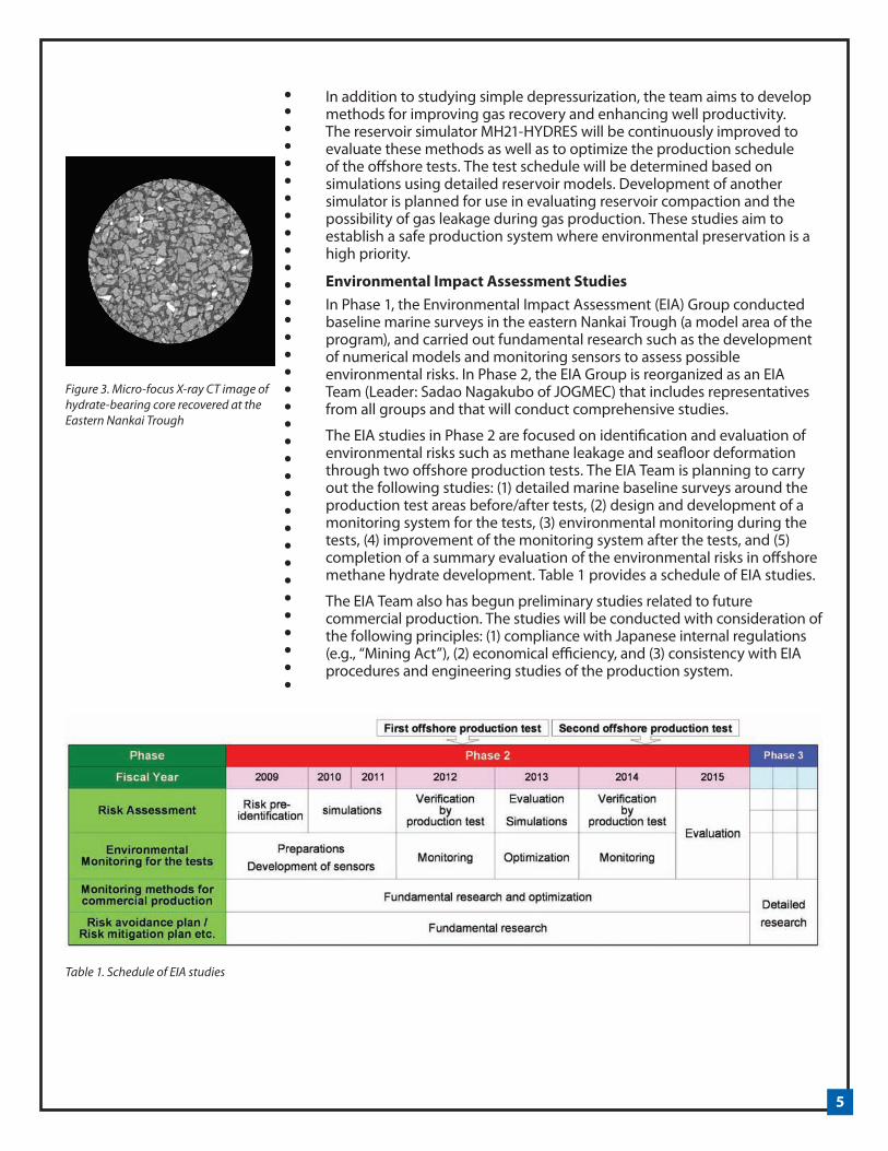
The EIA studies in Phase 2 are focused on identification and evaluation of environmental risks such as methane leakage and seafloor deformation through two offshore production tests. The EIA Team is planning to carry out the following studies: (1) detailed marine baseline surveys around the production test areas before/after tests, (2) design and development of a monitoring system for the tests, (3) environmental monitoring during the tests, (4) improvement of the monitoring system after the tests, and (5) completion of a summary evaluation of the environmental risks in offshore methane hydrate development. Table 1 provides a schedule of EIA studies.
The EIA Team also has begun preliminary studies related to future commercial production. The studies will be conducted with consideration of the following principles: (1) compliance with Japanese internal regulations (e.g., “Mining Act”), (2) economical efficiency, and (3) consistency with EIA procedures and engineering studies of the production system.
Figure 3. Micro-focus X-ray CT image of hydrate-bearing core recovered at the Eastern Nankai Trough
Table 1. Schedule of EIA studies

6
Conclusion As one of the leading international groups focused on gas hydrate research, the MH21 Consortium has been pursuing the study of methane hydrates primarily from the resource development perspective. The recently initiated seven-year Phase 2 of research will be critical in demonstrating that methane hydrate is a producible energy resource and not just an exotic material. The planned marine production tests are the most important milestones in our program. Other planned research efforts will also be important steps in establishing the technology platform for future commercial gas production from methane hydrate.
ReferencesDallimore, S.R. & Collett, 2005. Summary and implications of the Mallik 2002 gas hydrate production research well program. in Scientific Results from the Mallik 2002 Gas Hydrate Production Well Program, Mackenzie Delta, Northwest Territories, Canada edited by Dallimore, S. R. and Collett, T. S., Geological Survey of Canada Bulletin, 585, 1-36.
Fujii et al., 2008. Resource Assessment of Methane Hydrate in the Eastern Nankai Trough, Offshore Technology Conference, Texas, U.S.A., 5-8 May 2008, OTC 19310.
Kurihara et al., 2004. Assessment of gas productivity of natural methane hydrates using MH21 Reservoir Simulator. Proceedings of the AAPG Hedberg Conference, Vancouver, B.C., Canada, September 12-16, 2004.
Noguchi et al., 2009. Reservoir characterization of the methane hydrate bearing turbidite channel in the eastern Nankai Trough, Japan, AOGS 2009, 14 August 2009, Singapore.
Saeki et al., 2009. Seismic interpretation and analysis for methane hydrate reservoir: strategy and applications, AOGS 2009, 14 August 2009, Singapore.
Yamamoto, K. & Dallimore, S.R., 2008. Aurora-JOGMEC-NRCan Mallik 2006-2008 Gas Hydrate Research Project Progress. Fire in the Ice, Methane Hydrate Newsletter, National Energy Technology Laboratory, Summer 2008.
7
Models Provide Clues to How Methane Gas and Hydrate Coexist in NatureRuben Juanes (MIT) and Steven L. Bryant (UT-Austin)
Methane hydrate accumulations have attracted the attention of the scientific community and society at large both for their potential as an energy resource (Boswell, 2009) and their role in future atmospheric concentrations of greenhouse gases (Archer et al., in press).
The prevalent conceptual picture of methane hydrate accumulations—whether in ocean sediments or under permafrost—is that there is a range of depths over which methane forms a hydrate clathrate structure. This region—the hydrate stability zone or HSZ—ceases at the top because the pressure is too low to sustain the clathrate structure, and at the bottom because the temperature is too high for hydrates to be stable.
This static, thermodynamic-equilibrium view of the HSZ has been challenged by an increasing number of field observations, which point to the fact that gas and hydrate often coexist within the HSZ. This is the case not only in active, dynamic environments (exemplified by Hydrate Ridge, offshore Oregon) but also in hydrogeologically less active, relatively quiescent settings (such as Blake Ridge, offshore South Carolina). Even though direct observations of methane gas within the HSZ date back a decade or more (Wood et al., 2002), some of the most compelling evidence has been gathered recently.
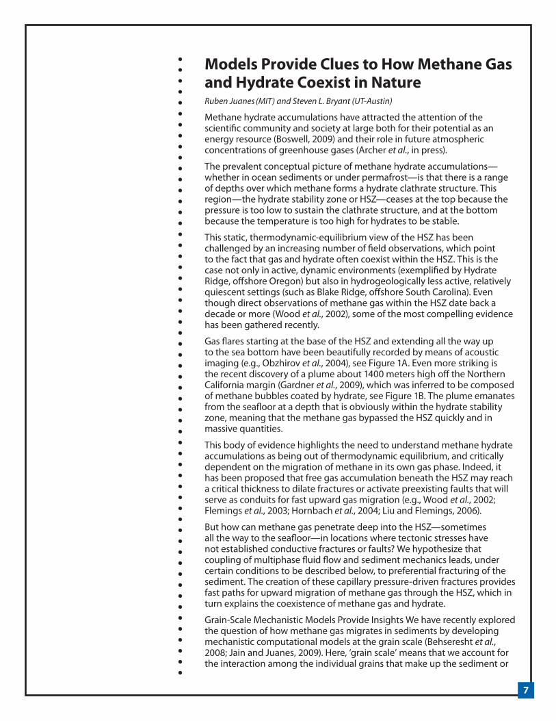
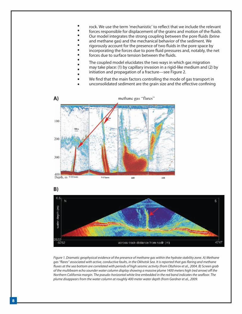
Gas flares starting at the base of the HSZ and extending all the way up to the sea bottom have been beautifully recorded by means of acoustic imaging (e.g., Obzhirov et al., 2004), see Figure 1A. Even more striking is the recent discovery of a plume about 1400 meters high off the Northern California margin (Gardner et al., 2009), which was inferred to be composed of methane bubbles coated by hydrate, see Figure 1B. The plume emanates from the seafloor at a depth that is obviously within the hydrate stability zone, meaning that the methane gas bypassed the HSZ quickly and in massive quantities.
This body of evidence highlights the need to understand methane hydrate accumulations as being out of thermodynamic equilibrium, and critically dependent on the migration of methane in its own gas phase. Indeed, it has been proposed that free gas accumulation beneath the HSZ may reach a critical thickness to dilate fractures or activate preexisting faults that will serve as conduits for fast upward gas migration (e.g., Wood et al., 2002; Flemings et al., 2003; Hornbach et al., 2004; Liu and Flemings, 2006).
But how can methane gas penetrate deep into the HSZ—sometimes all the way to the seafloor—in locations where tectonic stresses have not established conductive fractures or faults? We hypothesize that coupling of multiphase fluid flow and sediment mechanics leads, under certain conditions to be described below, to preferential fracturing of the sediment. The creation of these capillary pressure-driven fractures provides fast paths for upward migration of methane gas through the HSZ, which in turn explains the coexistence of methane gas and hydrate.
Grain-Scale Mechanistic Models Provide Insights We have recently explored the question of how methane gas migrates in sediments by developing mechanistic computational models at the grain scale (Behseresht et al., 2008; Jain and Juanes, 2009). Here, ‘grain scale’ means that we account for the interaction among the individual grains that make up the sediment or
8
rock. We use the term ‘mechanistic’ to reflect that we include the relevant forces responsible for displacement of the grains and motion of the fluids. Our model integrates the strong coupling between the pore fluids (brine and methane gas) and the mechanical behavior of the sediment. We rigorously account for the presence of two fluids in the pore space by incorporating the forces due to pore fluid pressures and, notably, the net forces due to surface tension between the fluids.
The coupled model elucidates the two ways in which gas migration may take place: (1) by capillary invasion in a rigid-like medium and (2) by initiation and propagation of a fracture—see Figure 2.
We find that the main factors controlling the mode of gas transport in unconsolidated sediment are the grain size and the effective confining
Figure 1. Dramatic geophysical evidence of the presence of methane gas within the hydrate stability zone. A) Methane gas “flares” associated with active, conductive faults, in the Okhotsk Sea. It is reported that gas flaring and methane fluxes at the sea bottom are correlated with periods of high seismic activity (from Obzhirov et al., 2004. B) Screen grab of the multibeam echo sounder water column display showing a massive plume 1400 meters high (red arrow) off the Northern California margin. The pseudo-horizontal white line embedded in the red band indicates the seafloor. The plume disappears from the water column at roughly 400 meter water depth (from Gardner et al., 2009.
A)
B)

9
stress. In coarse-grained sediments, the gas pressure does not need to be much higher than the water pressure in order to gradually invade more and more pores. Therefore, the mechanism for upward gas migration is capillary invasion: the capillary pressure (that is, the difference between gas and water pressures) exceeds the capillary entry pressure (which is inversely proportional to grain size). This mechanism is not favored in fine-grained media. The gas pressure required to penetrate the pore throats of fine-grained sediments exceeds the pressure level sufficient to fracture the sediment. The pressure overcomes both the minimum tectonic stress (which is typically the horizontal stress in passive sedimentary environments) and the cohesion/cementation between grains.
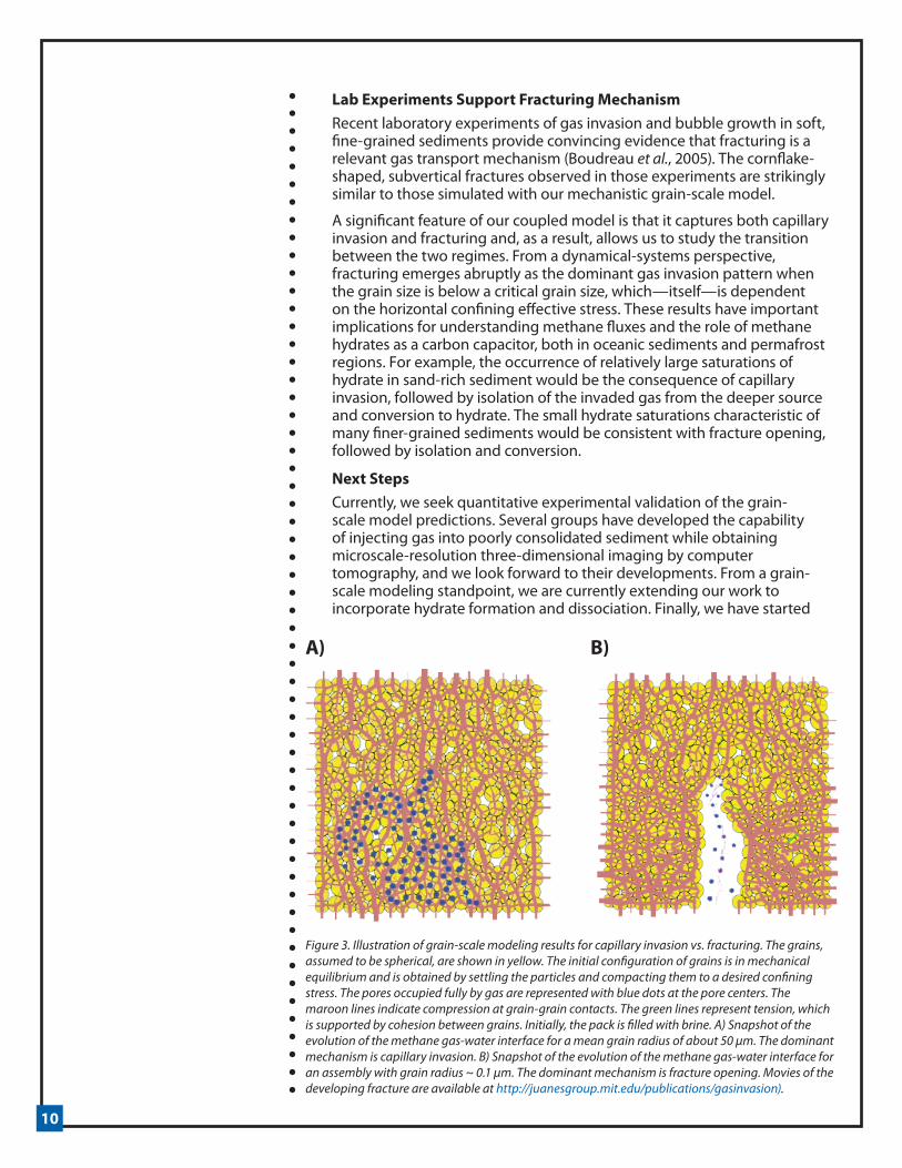
Figure 3A illustrates the evolution of the methane-water interface for a coarse-grained sediment of characteristic grain radius 50 µm. During the invasion of methane gas, there is virtually no movement of the solid grains: the sediment acts like a rigid skeleton. Invasion of gas from pore to pore (blue dots in Figure 3A) occurs when the gas pressure (minus the water pressure) exceeds the capillary entry pressure of the throat.
The behavior is completely different when a much smaller grain size is used. The evolution of the methane gas migration for 0.1 µm radius grains is shown in Figure 3B. The range of capillary entry pressures for the initial packing of sediment grains is now on the order of 3 Mpa. However, at this pressure, mechanical effects become dominant, and the solid skeleton no longer behaves like a rigid medium. At a capillary pressure of about 2.5 Mpa, the invading gas starts to initiate a fracture, which propagates vertically. In this case, the value of the capillary pressure needed to open the fracture corresponds to a gas column thickness of about 300 m below the base of the HSZ. Gas column thicknesses of this magnitude have been observed in similar geologic environments (Hornbach et al., 2004), and interpreted as the cause of critical pressures for gas migration through faults (Flemings et al., 2003; Hornbach et al., 2004).
Figure 2. Schematic diagram of the two modes of methane gas invading sediment. Left: Before invasion, the gas-water interface of a buoyant gas plume underlies water-filled sediment. Center: Invasion will occur if the capillary pressure (the difference between gas pressure and water pressure) exceeds the capillary entry pressure, which is inversely proportional to the pore diameter. Right: Invasion by fracture opening; if the exerted pressure is sufficient to overcome compression and friction at grain contacts, a fracture will form. In a multiphase environment, due to surface tension effects, the pressure difference between water and gas will not dissipate quickly through the porous medium, and water at grain contacts will increase cohesion.
10
Lab Experiments Support Fracturing MechanismRecent laboratory experiments of gas invasion and bubble growth in soft, fine-grained sediments provide convincing evidence that fracturing is a relevant gas transport mechanism (Boudreau et al., 2005). The cornflake-shaped, subvertical fractures observed in those experiments are strikingly similar to those simulated with our mechanistic grain-scale model.
A significant feature of our coupled model is that it captures both capillary invasion and fracturing and, as a result, allows us to study the transition between the two regimes. From a dynamical-systems perspective, fracturing emerges abruptly as the dominant gas invasion pattern when the grain size is below a critical grain size, which—itself—is dependent on the horizontal confining effective stress. These results have important implications for understanding methane fluxes and the role of methane hydrates as a carbon capacitor, both in oceanic sediments and permafrost regions. For example, the occurrence of relatively large saturations of hydrate in sand-rich sediment would be the consequence of capillary invasion, followed by isolation of the invaded gas from the deeper source and conversion to hydrate. The small hydrate saturations characteristic of many finer-grained sediments would be consistent with fracture opening, followed by isolation and conversion.
Next StepsCurrently, we seek quantitative experimental validation of the grain-scale model predictions. Several groups have developed the capability of injecting gas into poorly consolidated sediment while obtaining microscale-resolution three-dimensional imaging by computer tomography, and we look forward to their developments. From a grain-scale modeling standpoint, we are currently extending our work to incorporate hydrate formation and dissociation. Finally, we have started
Figure 3. Illustration of grain-scale modeling results for capillary invasion vs. fracturing. The grains, assumed to be spherical, are shown in yellow. The initial configuration of grains is in mechanical equilibrium and is obtained by settling the particles and compacting them to a desired confining stress. The pores occupied fully by gas are represented with blue dots at the pore centers. The maroon lines indicate compression at grain-grain contacts. The green lines represent tension, which is supported by cohesion between grains. Initially, the pack is filled with brine. A) Snapshot of the evolution of the methane gas-water interface for a mean grain radius of about 50 µm. The dominant mechanism is capillary invasion. B) Snapshot of the evolution of the methane gas-water interface for an assembly with grain radius ~ 0.1 µm. The dominant mechanism is fracture opening. Movies of the developing fracture are available at http://juanesgroup.mit.edu/publications/gasinvasion).
A) B)

11
to apply this concept (flow of methane in its own gas phase by either capillary invasion or fracturing) for the development of simple models at the geologic scale, with the goal, first, to explain observations of methane venting in lakes and in the ocean, and then to incorporate these mechanisms in predictions of how methane hydrate accumulations—especially in Artic regions—will respond to environmental change.
AcknowledgementsWe thank our students and postdocs working on this project, Antone Jain, Ran Holtzman, Ben Scandella (MIT), Masa Prodanovic, Javad Behseresht, and Yao Peng (UT). We also thank Carolyn Ruppel (USGS), Bill Waite (USGS), Carlos Santamarina (Georgia Tech), Ray Boswell (DOE), Bob Kleinberg (Schlumberger), Peter Flemings (UT), Warren Wood (NRL), and David Archer (U. Chicago) for many stimulating conversations. This work was supported by the Department of Energy under grant DOE/NETL DE-FC26-06NT43067. This financial support is gratefully acknowledged.
ReferencesArcher, D., B. Buffett, and V. Brovkin, 2009. Ocean methane hydrates as a slow tipping point in the global carbon cycle, Proc. Natl. Acad. Sci. U.S.A., doi:10.1073/pnas.0800885105, in press.
Behseresht, J., Y. Peng, M. Prodanovic, S. L. Bryant, A. K. Jain, and R. Juanes, 2008. Mechanisms by which methane gas and methane hydrate coexist in ocean sediments, paper OTC 19332 presented at the Offshore Technology Conference, Houston, Tex.
Boswell, R., 2009. Is gas hydrate energy within reach?, Science, 325, 957–958.
Boudreau, B. P., C. Algar, B. D. Johnson, I. Croudace, A. Reed, Y. Furukawa, K. M. Dorgan, P. A. Jumars, and A. S. Grader, 2005. Bubble growth and rise in soft sediments, Geology, 33(6), 517–520.
Flemings, P. B., X. Liu, and W. J. Winters, 2003. Critical pressure and multiphase flow in Blake Ridge gas hydrates, Geology, 31(12), 1057–1060.
Gardner, J. V., M. Malik, and S. Walker, 2009. Plume 1400 meters high discovered at the seafloor off the Northern California margin, Eos Trans. Amer. Geophys. Union, 90(32), 275.
Hornbach, M. J., D. M. Saffer, and W. S. Holbrook, 2004. Critically pressured free-gas reservoirs below gas-hydrate provinces, Nature, 427, 142–144.
Jain, A. K., and R. Juanes, 2009. Preferential mode of gas invasion in sediments: Grain-scale mechanistic model of coupled multiphase fluid flow and sediment mechanics, J. Geophys. Res., 114, B08101.
Liu, X., and P. B. Flemings, 2006. Passing gas through the hydrate stability zone at southern Hydrate Ridge, offshore Oregon, Earth Planet. Sci. Lett., 241, 211– 216.
Obzhirov, A., R. Shakirov, A. Salyuk, E. Suess, N. Biebow, and A. Salomatin, 2004. Relations between methane venting, geological structure and seismo-tectonics in the Okhotsk Sea, Geo Mar. Lett., 24, 135–139.
Wood, W. T., J. F. Gettrust, N. R. Chapman, G. D. Spence, and R. D. Hyndman, 2002.+ Decreased stability of methane hydrates in marine sediments owing to phase-boundary roughness, Nature, 420, 656–660.
12
The HYFLUX Sea-Truth Expedition, 4-19 July 2009Ian R. MacDonald, HYFLUX Project Investigator
Ian MacDonald is a professor of Oceanography, formerly at Texas A&M University-Corpus Christi, but recently relocated to Florida State University. He can be reached at [email protected].
The HYFLUX project was awarded to a consortium of six institutions under the management of Texas A&M University-Corpus Christi1 in October 2008. The main project objective is to investigate the methane flux from shallow deposits of gas hydrate on continental margins and quantify forcing processes that tend to limit or enhance this process under present conditions and scenarios of climate change. HYFLUX completed a major milestone with the successful conclusion of the July 2009 sea-truth expedition. This article presents the background and goals of the cruise and highlights achievements of the team.
The Gulf of Mexico is an excellent region for gas hydrate research because the geologic system creates abundant hydrocarbons and active faulting that allows gas and oil to migrate into the seafloor. There, in water depths over 500 m, it forms shallow deposits that wax and wane in size as gas hydrate alternately crystallizes and decomposes. Escaping gas and oil rise from these sites in narrow plumes that extend far up toward the surface. Oil reaches the surface and creates persistent oil slicks that are visible to a variety of satellite sensors including synthetic aperture radar (SAR).
The HYFLUX project continues work that was begun under a previous NETL award2, which investigated the chemical characteristics of gas hydrates at Gulf of Mexico seeps, including measurements of flux through the sediments, and concentrations of CH4 in the water column (Solomon, Kastner et al., 2009). These results indicated that methane released from seeps and hydrate deposits could reach the surface waters from depths of 500 m or more. The work also showed that hydrate deposits were often associated with surface oil slicks (De Beukelaer, MacDonald et al., 2003).
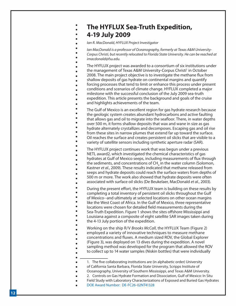
During the present effort, the HYFLUX team is building on these results by completing a total inventory of persistent oil slicks throughout the Gulf of Mexico--and ultimately at selected locations on other ocean margins like the West Coast of Africa. In the Gulf of Mexico, three representative locations were chosen for detailed field measurements during the Sea-Truth Expedition. Figure 1 shows the sites offshore Mississippi and Louisiana against a composite of eight satellite SAR images taken during the 4-13 July portion of the expedition.
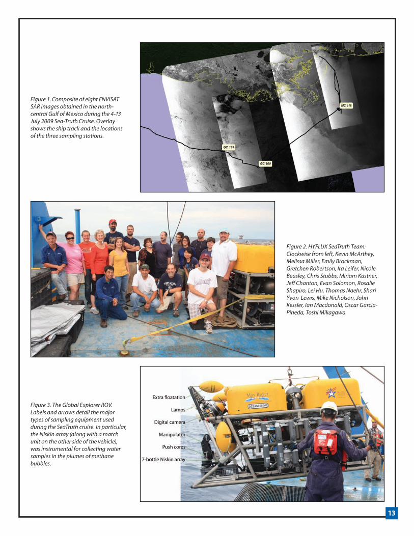
Working on the ship R/V Brooks McCall, the HYFLUX Team (Figure 2) employed a variety of innovative techniques to measure methane concentrations and fluxes. A medium sized ROV, the Global Explorer (Figure 3), was deployed on 13 dives during the expedition. A novel sampling method was developed for the program that allowed the ROV to collect up to 14 water samples (Niskin bottles) that were individually
1. The five collaborating institutions are (in alphabetic order) University of California Santa Barbara, Florida State University, Scripps Institute of Oceanography, University of Southern Mississippi, and Texas A&M University. 2. Controls on Gas Hydrate Formation and Dissociation, Gulf of Mexico: In Situ Field Study with Laboratory Characterizations of Exposed and Buried Gas Hydrates DOE Award Number: DE-FC26-02NT41328
13
Figure 1. Composite of eight ENVISAT SAR images obtained in the north-central Gulf of Mexico during the 4-13 July 2009 Sea-Truth Cruise. Overlay shows the ship track and the locations of the three sampling stations.
Figure 2. HYFLUX SeaTruth Team: Clockwise from left, Kevin McArthey, Melissa Miller, Emily Brockman, Gretchen Robertson, Ira Leifer, Nicole Beasley, Chris Stubbs, Miriam Kastner, Jeff Chanton, Evan Solomon, Rosalie Shapiro, Lei Hu, Thomas Naehr, Shari Yvon-Lewis, Mike Nicholson, John Kessler, Ian Macdonald, Oscar Garcia-Pineda, Toshi Mikagawa
Figure 3. The Global Explorer ROV. Labels and arrows detail the major types of sampling equipment used during the SeaTruth cruise. In particular, the Niskin array (along with a match unit on the other side of the vehicle), was instrumental for collecting water samples in the plumes of methane bubbles.

14
triggered while the ROV was positioned in suspected bubble streams. Investigators also collected continual air and water samples and automatically measured methane concentrations for direct estimation of flux to the atmosphere.
Of the three sites, MC 118 is an ~900 m area that is also the location of the Gas Hydrate Observatory, where a consortium of investigators has been conducting long-term gas hydrate research under the support of NETL, NOAA, and MMS. At this site, investigators found exposed hydrate and streams of bubbles (Figure 4). They also measured elevated concentrations of methane in the water column and in the surface waters. Through a cooperative effort with the National Institute for Underwater Science and Technology, scientists on the cruise also recovered previously deployed sampling equipment and collected push cores for microbiology.
In depths of 1200 m, the GC 600 site was chosen because of large, persistent oil slicks routinely detected in satellite images over the area. However, unlike the other two stations, investigators had very little to go on prior to launching the ROV at this site. It was gratifying, therefore, when a short time after reaching the bottom, the ROV found massive gas hydrate deposits exactly where the satellite data predicted. This supports the theory that oil slicks throughout the Gulf tend to mark the location of seafloor gas hydrates. The oil flows at this site were impressive, however, surface concentrations of methane were not as elevated as at other study sites.
The final area visited was the GC 185 site, also known as Bush Hill. This is one of the locations where Solomon, et al., 2009 reported high concentrations of methane in the water column. With the ROV’s Niskin sampler, the team was able to replicate the collections made during earlier efforts, but with much greater water volumes recovered and better control on depth and plume location. Preliminary results found concentrations that generally agreed with the previous work. However, some of the large hydrate deposits on the seafloor had entirely decomposed during the intervening five years since the team had visited the site. This confirms the dynamic nature of seafloor gas hydrates when measured over an annual time-scale.
Ongoing efforts will quantify the fluxes to the atmosphere and water column as well as complete a suite of chemical analyses of the water and sediment samples.
ReferencesDe Beukelaer, S. M., I. R. MacDonald, et al., 2003. “Distinct side-scan sonar, RADARSAT SAR, and acoustic profiler signatures of gas and oil seeps on the Gulf of Mexico slope.” Geo-Marine Letters 23(3-4): 177-186.
Solomon, E. A., M. Kastner, et al., 2009. “Considerable methane fluxes to the atmosphere from hydrocarbon seeps in the Gulf of Mexico.” Nature Geoscience 2(8): 561-565.

15
Figure 4. A continual stream of bubbles rises from patches of exposed hydrate (arrow) at the MC 118 sampling site (Hydrate Observatory). When the gas was collected in a core tube, it immediately formed gas hydrate (foreground).
Figure 5. One of the “oil mountains” at the GC 600 sampling site. These gas hydrate deposits were remarkable for containing high volumes of oil, which gave the material a distinctive black coloration.
Figure 6. Stream of oily bubbles released at the GC 600 site. These bubbles were very different in character from bubbles at MC 118 and GC 185 sites. They generate some of the largest and most persistent oil slicks in the Gulf of Mexico.
16
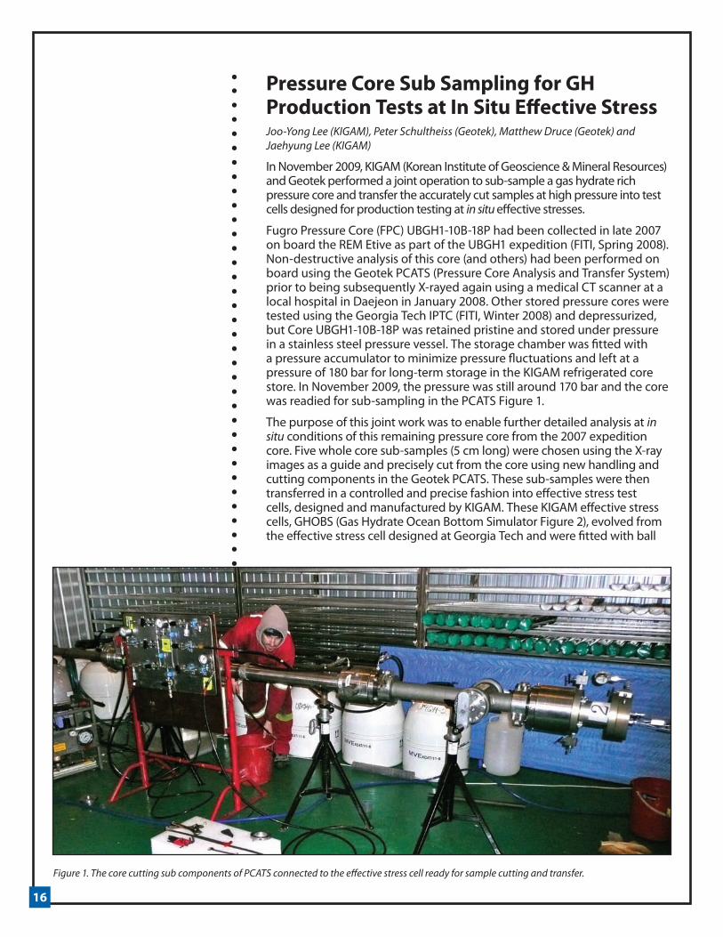
Pressure Core Sub Sampling for GH Production Tests at In Situ Effective StressJoo-Yong Lee (KIGAM), Peter Schultheiss (Geotek), Matthew Druce (Geotek) and Jaehyung Lee (KIGAM)
In November 2009, KIGAM (Korean Institute of Geoscience & Mineral Resources) and Geotek performed a joint operation to sub-sample a gas hydrate rich pressure core and transfer the accurately cut samples at high pressure into test cells designed for production testing at in situ effective stresses.
Fugro Pressure Core (FPC) UBGH1-10B-18P had been collected in late 2007 on board the REM Etive as part of the UBGH1 expedition (FITI, Spring 2008). Non-destructive analysis of this core (and others) had been performed on board using the Geotek PCATS (Pressure Core Analysis and Transfer System) prior to being subsequently X-rayed again using a medical CT scanner at a local hospital in Daejeon in January 2008. Other stored pressure cores were tested using the Georgia Tech IPTC (FITI, Winter 2008) and depressurized, but Core UBGH1-10B-18P was retained pristine and stored under pressure in a stainless steel pressure vessel. The storage chamber was fitted with a pressure accumulator to minimize pressure fluctuations and left at a pressure of 180 bar for long-term storage in the KIGAM refrigerated core store. In November 2009, the pressure was still around 170 bar and the core was readied for sub-sampling in the PCATS Figure 1.
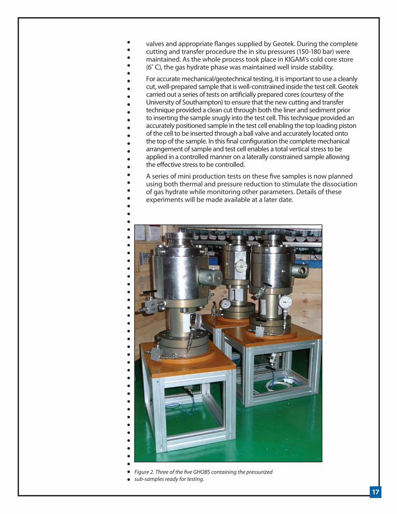
The purpose of this joint work was to enable further detailed analysis at in situ conditions of this remaining pressure core from the 2007 expedition core. Five whole core sub-samples (5 cm long) were chosen using the X-ray images as a guide and precisely cut from the core using new handling and cutting components in the Geotek PCATS. These sub-samples were then transferred in a controlled and precise fashion into effective stress test cells, designed and manufactured by KIGAM. These KIGAM effective stress cells, GHOBS (Gas Hydrate Ocean Bottom Simulator Figure 2), evolved from the effective stress cell designed at Georgia Tech and were fitted with ball
Figure 1. The core cutting sub components of PCATS connected to the effective stress cell ready for sample cutting and transfer.
17
valves and appropriate flanges supplied by Geotek. During the complete cutting and transfer procedure the in situ pressures (150-180 bar) were maintained. As the whole process took place in KIGAM’s cold core store (6˚ C), the gas hydrate phase was maintained well inside stability.
For accurate mechanical/geotechnical testing, it is important to use a cleanly cut, well-prepared sample that is well-constrained inside the test cell. Geotek carried out a series of tests on artificially prepared cores (courtesy of the University of Southampton) to ensure that the new cutting and transfer technique provided a clean cut through both the liner and sediment prior to inserting the sample snugly into the test cell. This technique provided an accurately positioned sample in the test cell enabling the top loading piston of the cell to be inserted through a ball valve and accurately located onto the top of the sample. In this final configuration the complete mechanical arrangement of sample and test cell enables a total vertical stress to be applied in a controlled manner on a laterally constrained sample allowing the effective stress to be controlled.
A series of mini production tests on these five samples is now planned using both thermal and pressure reduction to stimulate the dissociation of gas hydrate while monitoring other parameters. Details of these experiments will be made available at a later date.
Figure 2. Three of the five GHOBS containing the pressurized sub-samples ready for testing.
18
Gas Production from Hydrate Bearing Sediments: Geomechanical ImplicationsJ. Carlos Santamarina and Jaewon Jang, Georgia Institute of Technology
The gas hydrates resource pyramid (FITI, Fall 2006) identifies coarse-grained lithologies like sands as the most economically favorable hydrate-bearing sediments for future gas production. Yet, the largest fraction of total gas hydrate resources resides in fine-grained sediments at relatively low saturations, and producing substantial gas from such deposits has long been considered prohibitively costly and technically difficult. Using a combined experimental and numerical approach, the gas hydrates research team at Georgia Tech has investigated phenomena that may affect gas production from sand-hosted hydrates and studied factors that may augment the prospects for gas production from hydrates in fine-grained sediments. This article summarizes the interplay between sediment geomechanics and gas production from hydrate-bearing sediments, with particular focus on fine-grained sediments.
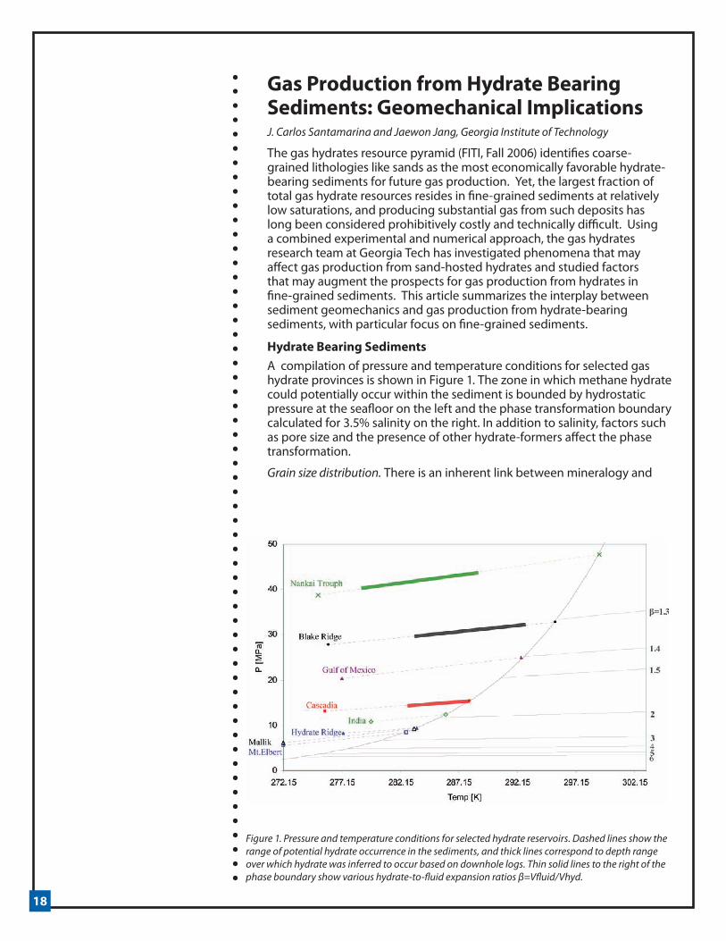
Hydrate Bearing SedimentsA compilation of pressure and temperature conditions for selected gas hydrate provinces is shown in Figure 1. The zone in which methane hydrate could potentially occur within the sediment is bounded by hydrostatic pressure at the seafloor on the left and the phase transformation boundary calculated for 3.5% salinity on the right. In addition to salinity, factors such as pore size and the presence of other hydrate-formers affect the phase transformation.
Grain size distribution. There is an inherent link between mineralogy and
Figure 1. Pressure and temperature conditions for selected hydrate reservoirs. Dashed lines show the range of potential hydrate occurrence in the sediments, and thick lines correspond to depth range over which hydrate was inferred to occur based on downhole logs. Thin solid lines to the right of the phase boundary show various hydrate-to-fluid expansion ratios β=Vfluid/Vhyd.

19
grain size. Most submicron-size grains are made of clay minerals and are formed through chemical processes (e.g., fine-grained layers in Gulf of Mexico, Krishna-Godavari basin, and Blake Ridge). Grains larger than about 50µm are non-clay minerals and have formed through mechanical processes (e.g., coarse-grained layers in Mt. Elbert, Mallik Mackenzie Delta, and Nankai Trough). Biological activity may contribute shell fragments and microfossils to the sediments, leading to a dual porosity medium (e.g., Blake Ridge and East Sea). Smaller or thinner grains exhibit higher specific surface, higher amount of adsorbed water per volume, higher plasticity, and higher dependency on electrical interaction forces.
Pore size. Grain size distribution determines pore size. In clayey sediments, the mean pore diameter dp can be related to the sediment specific surface Ss and porosity n, dp=2n/[(1-n)ρSs]. In sands, the percentage of fine grains (passing sieve #200) is a critical indicator of pore size, as shown in Table 1: (1) “clean” sands lack fines; (2) even a small percentage of fines may drastically affect the hydraulic properties of sands, and (3) as low as ~15% of fines may fill all pores and strongly affect both the hydraulic and stress-strain properties of sands.
Fluid conductivity and gas entry pressure. Pore size governs hydraulic conductivity (Kozeny-Carman and Hazen equations) and gas entry pressure (Laplace equation). These two physical parameters control the spatial distribution of hydrate in reservoirs, affect the selection of gas production strategies, and define ensuing geomechanical effects.
Hydrate concentration and spatial distribution. How did hydrate form? Methane invades the sediment in gas phase when the gas pressure exceeds the gas entry pressure at pore throats. Therefore, hydrate formation from gas phase should be expected in coarse-grained sediments that are connected to high permeability faults or a gas source; hydrate saturation may be water-limited in this case. Low viscosity gas invasion into a water-saturated sediment is essentially unstable and viscous fingering is anticipated. On the other hand, forced gas invasion will cause fracture formation in clayey sediments if the gas entry pressure exceeds the sediment effective stress (first-order estimate for unconsolidated sediments –Figure 2a). Similar physical processes apply to the development of hydrate lenses in fine grained sediments. The initial interconnectivity of segregated hydrate lenses and nodules observed in fine grained hydrate bearing sediments will facilitate gas production from these otherwise low permeability sediments.
Hydrate formation from dissolved gas is inherently gas-limited due to the low solubility of methane in water compared to the high gas content in hydrate. Dissolved methane transport combines diffusive and advective contributions. The contribution of advective transport will prevail in most cases (except in high specific surface, low hydraulic conductivity sediments) and will bias hydrate accumulation towards the coarser and cleaner layers. Therefore, clean sand layers with high hydrate saturation may be found between sand layers that contain some fines and almost no hydrate, even though all these layers are within the stability field. This situation has been observed in the recent Chevron/DOE JIP Gulf of Mexico drilling, at Mount Elbert, and at the Nankai Trough.
Reservoir morphology. At the macro-scale, fluid flow and hydrate accumulation are related to large scale geometric characteristics, the subsurface geo-plumbing (faults, pipes and dipping layers), and trapping conditions which include self-sealing hydrate formation.

20
Gas Production: Geomechanical Implications and Emergent PhenomenaPotential geomechanical implications associated with gas production depend on both pore-scale and macro-scale reservoir characteristics (see Table 1). Consequently, these must be taken into consideration for the selection of optimal gas production strategies.
Fluid volume expansion during gas production. Iso-expansion lines are shown to the right of the phase boundary in Figure 1. There are two volume expansion components: (1) a pronounced increase in volume just across the phase boundary so that an initial hydrate volume Vo immediately inside the stability field converts into a fluid volume βVo immediately outside the stability field, e.g., β~2.5 for the PT conditions of Hydrate Ridge; and (2) volume change due to thermal change and depressurization, e.g., β~1.3 just to cross the phase boundary at Blake Ridge, but increases to β~5 if depressurized to P=3.7 MPa at T=275 K. Such a large change in volume implies high fluid flow if drained conditions prevail (e.g., depressurization driven production) or the generation of very elevated fluid pressure if dissociation is enforced under undrained conditions (e.g., rate of dissociation higher than the rate of pore pressure dissipation in thermally-driven production).
High increase in fluid pressure gas driven fractures. The potentially high increase in fluid pressure in thermally stimulated or chemically driven production (including CO2-CH4 replacement) can cause gas driven fractures (Figure 2b) and the development of high permeability paths that can facilitate gas production in fine-grained sediments or in coarse grained sediments with fines. A proper understanding of these gas-related phenomena requires an effective stress formulation.
Figure 2. Gas production in fine-grained sediments. (a) Water saturated montmorillonite paste subjected to forced gas invasion. The cracks initiate in the largest pores. Image scale= 100 mm (collaboration with H. Shin). (b) Water saturated kaolin paste subjected to fast internal heating to cause vapor generation faster than pressure dissipation. The sediment becomes pervasively fractured. Image scale= 10 mm. (c) CO2 hydrate bearing sand with 3% kaolinite by weight. The presence of fines affects gas production and a vuggy sediment fabric develops during depressurization. Image scale= 20 mm (collaboration with J.W. Jung and C. Tsouris).
A B C

21
Sediment volume contraction during gas production. Distributed hydrate augments the stability of the sediment granular skeleton, particularly when the hydrate saturation exceeds Shyd > ~0.4. Therefore, hydrate loss during free-draining gas production will cause sediment volume contraction that is proportional to the initial hydrate saturation and the sediment compressibility. In addition, there is volume contraction associated to the dissociation of segregated hydrate in lenses and nodules.
The other contribution to sediment volume contraction is related to the increase in effective stress σ,=σ-u in depressurization strategies, i.e., lowering the fluid pressure u under constant total boundary stresses σ. The effect is more pronounced near the production well, meaning that higher volume contraction will take place at shorter radial distances. This radial gradient in volume contraction causes an increase in shear stress, and the sediment will evolve towards the “critical state porosity” near the production well.
Crushing, fines migration, clogging, and sand production. The increase in effective stress beyond the sediment yield stress will cause grain crushing in silty and sandy reservoirs. Existing sediment fines and fine particles newly created by crushing can migrate during gas production. Fines migration is controlled by particle size, the ratio of migrating particle size to pore constriction size, and the spatial variability of the flow velocity field. Migrating particles may form bridges at pore throats and a clogging annular ring around the production well, thereby limiting fluid flow and potentially triggering sustained sand production.
Table 1. Sediment characteristics and physical properties - Potential phenomena during gas production
22
Coupled processes. The emergence of unanticipated phenomena is one of the main concerns in the development of new engineering solutions. From this perspective, coupled hydro-thermo-chemo-mechanical processes pose the greatest uncertainty given their inherent complexity, as demonstrated by the following sequence of causally related processes: heating, dissociation, freshening, changes in inter-particle electrical forces, volume change, compatibility of deformation, and changes in stress state. Conversely, coupled processes may present the best opportunities for producing gas, for example by inducing the spontaneous internal formation of gas-driven fractures that increase the hydraulic conductivity of clayey sediments.
SummaryGrain size distribution determines (1) pore size, gas entry pressure, and hydraulic conductivity; (2) hydrate growth, distribution and eventual hydrate saturation; (3) the feasibility of producing gas, the selection of production strategy, and the necessary technology; and (4) potential production-related outcomes. The particle size or specific surface of the finest 5%-to-10% sediment fraction largely controls these properties and processes.
The very pronounced volume expansion that accompanies hydrate dissociation has different consequences depending on the production method and the reservoir lithologies. Thermal stimulation may lead to extensive gas-driven fracturing in fine grained sediments and in coarse sediments with fines-filled porosity. These fractures facilitate gas production from low hydraulic conductivity sediments. Depressurization, the favored method of gas production from coarse-grained sediments, may lead to grain crushing near the wellbore, fines migration, and eventual clogging. While safe production strategies can be engineered to accommodate known processes and reservoir conditions, special attention should be placed to anticipate phenomena that can emerge from complex hydro-thermo-chemo-mechanical coupled processes.
AcknowledgementsSupport provided by the DOE-JIP project on hydrate-bearing sediments, the DOE/NETL project on gas production, and the Goizueta Foundation. Carolyn Ruppel provided detailed comments and shared great insight.
23
Announcements
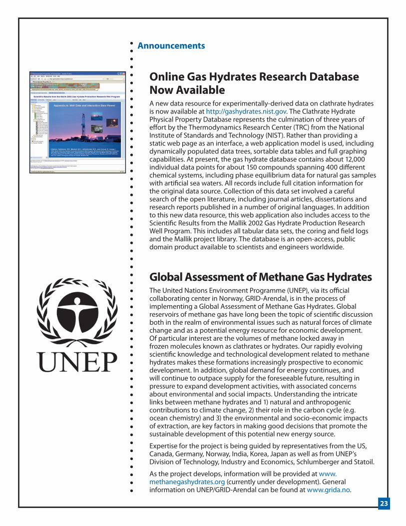
Online Gas Hydrates Research Database Now Available A new data resource for experimentally-derived data on clathrate hydrates is now available at http://gashydrates.nist.gov. The Clathrate Hydrate Physical Property Database represents the culmination of three years of effort by the Thermodynamics Research Center (TRC) from the National Institute of Standards and Technology (NIST). Rather than providing a static web page as an interface, a web application model is used, including dynamically populated data trees, sortable data tables and full graphing capabilities. At present, the gas hydrate database contains about 12,000 individual data points for about 150 compounds spanning 400 different chemical systems, including phase equilibrium data for natural gas samples with artificial sea waters. All records include full citation information for the original data source. Collection of this data set involved a careful search of the open literature, including journal articles, dissertations and research reports published in a number of original languages. In addition to this new data resource, this web application also includes access to the Scientific Results from the Mallik 2002 Gas Hydrate Production Research Well Program. This includes all tabular data sets, the coring and field logs and the Mallik project library. The database is an open-access, public domain product available to scientists and engineers worldwide.
Global Assessment of Methane Gas Hydrates The United Nations Environment Programme (UNEP), via its official collaborating center in Norway, GRID-Arendal, is in the process of implementing a Global Assessment of Methane Gas Hydrates. Global reservoirs of methane gas have long been the topic of scientific discussion both in the realm of environmental issues such as natural forces of climate change and as a potential energy resource for economic development. Of particular interest are the volumes of methane locked away in frozen molecules known as clathrates or hydrates. Our rapidly evolving scientific knowledge and technological development related to methane hydrates makes these formations increasingly prospective to economic development. In addition, global demand for energy continues, and will continue to outpace supply for the foreseeable future, resulting in pressure to expand development activities, with associated concerns about environmental and social impacts. Understanding the intricate links between methane hydrates and 1) natural and anthropogenic contributions to climate change, 2) their role in the carbon cycle (e.g. ocean chemistry) and 3) the environmental and socio-economic impacts of extraction, are key factors in making good decisions that promote the sustainable development of this potential new energy source.
Expertise for the project is being guided by representatives from the US, Canada, Germany, Norway, India, Korea, Japan as well as from UNEP’s Division of Technology, Industry and Economics, Schlumberger and Statoil.
As the project develops, information will be provided at www.methanegashydrates.org (currently under development). General information on UNEP/GRID-Arendal can be found at www.grida.no.

24
Announcements
Application deadline approaching for the NETL-NAS Methane Hydrate FellowshipThe 2010 application deadlines for the NETL-NAS Methane Hydrate Fellowship are February 1 and August 1.
Fellowship facts:
• Open to US citizens pursuing graduate degrees (MS or PhD) or conducting post-doctoral studies.
• Applicants select their project, their mentor(s) and the institution in which they will work.
• Institutions may be academic institutions, research institutions, national labs, or federal or state laboratories or research groups.
• Competitive stipends that include travel and research funds.
• Proposals will be evaluated based on technical merit, relevance to the stated goals of the US interagency program in gas hydrates, and nature of the proposed research team (student-mentor-institution).
Of particular interest to NETL at the present time are proposals dealing with advanced geological and geophysical projects that will provide improved methods and tools for real time, remote or in situ detection, characterization, and appraisal of gas hydrates occurrence and distribution in nature as well as their production potential as an energy resource.
There is also interest in projects that provide an improved understanding of the processes that control hydrate stability and their potential role in global climate including formation of methane hydrates in permafrost and seafloor settings and the fate of dissociated hydrates through sediments, the water column, and into the atmosphere.
To access Fellowship information please visit http://nrc58.nas.edu/pgasurvey/data/aobooks/rapbooks.asp?mode=frntmtr&progctr=AH&seq=20
To apply for the Fellowship please visit http://sites.nationalacademies.org/pga/RAP/PGA_050408
Methane Hydrate Research & Development Workshop Set for New Zealand in 2010The 7th International Workshop on Methane Hydrate Research and Development is set to take place on May 10-12, 2010 at Te Papa in Wellington, New Zealand. The workshop aims to foster collaborations between international scientists from various disciplines to exchange the latest knowledge in gas hydrates research. The key theme of the workshop is characterization of gas hydrate reservoirs and will be covered through a variety of formats, including lectures, posters, and break-out sessions.
For more information please visit www.gns.cri.nz/fieryice/

25
Announcements
EGU General Assembly Abstract Deadline January 18, 2010Abstracts are encouraged for an upcoming session on hydrates to be held at the upcoming European Geosciences Union General Assembly. The physiochemical behaviors, fluid geochemistry and biogeochemical processes of submarine gas hydrates will be the focus of the session. The assembly meetings are to be held in Vienna, Austria from May 2-7, 2010. Visit http://meetings.copernicus.org/egu2010 for more details.
Goldschmidt 2010 – Earth, Energy, and the Environment Conference Abstracts Deadline February 21Abstracts are encouraged for an upcoming hydrate session on “Methane Fluxes and Turnover in the Marine and Terrestrial Environments” for the Goldschmidt 2010 – Earth, Energy, and the Environment Conference. The conference is to be held in Knoxville, Tennessee, USA from June 13 – 18, 2010. The scope of the session is broad, with topics including methane cycling in marine environments, permafrost, wetlands, and lake systems. Visit www.goldschmidt2010.org/index to learn more.
26
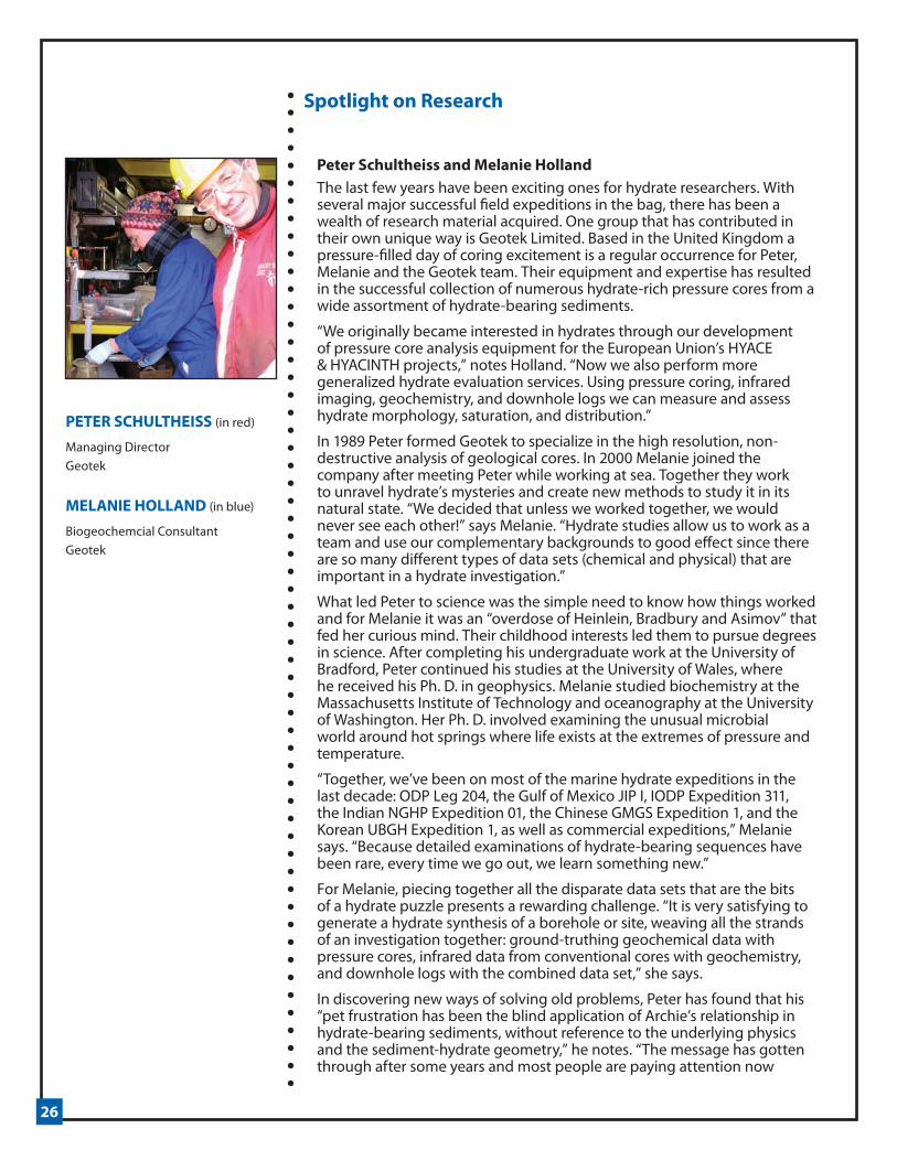
Peter Schultheiss and Melanie HollandThe last few years have been exciting ones for hydrate researchers. With several major successful field expeditions in the bag, there has been a wealth of research material acquired. One group that has contributed in their own unique way is Geotek Limited. Based in the United Kingdom a pressure-filled day of coring excitement is a regular occurrence for Peter, Melanie and the Geotek team. Their equipment and expertise has resulted in the successful collection of numerous hydrate-rich pressure cores from a wide assortment of hydrate-bearing sediments.
“We originally became interested in hydrates through our development of pressure core analysis equipment for the European Union’s HYACE & HYACINTH projects,” notes Holland. “Now we also perform more generalized hydrate evaluation services. Using pressure coring, infrared imaging, geochemistry, and downhole logs we can measure and assess hydrate morphology, saturation, and distribution.”
In 1989 Peter formed Geotek to specialize in the high resolution, non-destructive analysis of geological cores. In 2000 Melanie joined the company after meeting Peter while working at sea. Together they work to unravel hydrate’s mysteries and create new methods to study it in its natural state. “We decided that unless we worked together, we would never see each other!” says Melanie. “Hydrate studies allow us to work as a team and use our complementary backgrounds to good effect since there are so many different types of data sets (chemical and physical) that are important in a hydrate investigation.”
What led Peter to science was the simple need to know how things worked and for Melanie it was an “overdose of Heinlein, Bradbury and Asimov” that fed her curious mind. Their childhood interests led them to pursue degrees in science. After completing his undergraduate work at the University of Bradford, Peter continued his studies at the University of Wales, where he received his Ph. D. in geophysics. Melanie studied biochemistry at the Massachusetts Institute of Technology and oceanography at the University of Washington. Her Ph. D. involved examining the unusual microbial world around hot springs where life exists at the extremes of pressure and temperature.
“Together, we’ve been on most of the marine hydrate expeditions in the last decade: ODP Leg 204, the Gulf of Mexico JIP I, IODP Expedition 311, the Indian NGHP Expedition 01, the Chinese GMGS Expedition 1, and the Korean UBGH Expedition 1, as well as commercial expeditions,” Melanie says. “Because detailed examinations of hydrate-bearing sequences have been rare, every time we go out, we learn something new.”
For Melanie, piecing together all the disparate data sets that are the bits of a hydrate puzzle presents a rewarding challenge. “It is very satisfying to generate a hydrate synthesis of a borehole or site, weaving all the strands of an investigation together: ground-truthing geochemical data with pressure cores, infrared data from conventional cores with geochemistry, and downhole logs with the combined data set,” she says.
In discovering new ways of solving old problems, Peter has found that his “pet frustration has been the blind application of Archie’s relationship in hydrate-bearing sediments, without reference to the underlying physics and the sediment-hydrate geometry,” he notes. “The message has gotten through after some years and most people are paying attention now
Spotlight on Research
PETER SCHULTHEISS (in red)
Managing DirectorGeotek
MELANIE HOLLAND (in blue)
Biogeochemcial ConsultantGeotek
27
that we have got detailed X-ray images showing how complex hydrate structures can be.”
Working on both commercial and academic expeditions has provided “very different hydrate sites, allowing us to experience a much wider range of hydrate-bearing sediments than most,” notes Melanie. “We really enjoy the mix of being able to work with both the academic and industrial hydrate communities. When we work with academia, we can focus on our nondestructive analyses of hydrate- bearing pressure cores, and examine gas hydrate geometry and morphology in detail. When we work with industry, we use our experience from the academic community to measure as many hydrate indicators as possible to accurately describe the hydrate in sediment for engineering assessments.”
They see as the most important challenges facing hydrate researchers today the need to “accurately connect the small scale data from borehole logging and core analysis to the large scale data from seismic, EM or other geophysical surveys. This connection would allow real surveys of gas hydrate to be undertaken, which would have implications for resource exploitation, slope stability and climate change issues, and simply understanding gas hydrate occurrence.”
When Peter and Melanie are not working, they can be found either travelling the world or, when home, renovating their 200-year-old converted barn on the Grand Union Canal in the middle of England. Melanie points out that “watching the narrow boats go past at 4 miles an hour from our sitting room gives us a new appreciation for 12-knot transits!”
28
Related Documents