Welcome message from author
This document is posted to help you gain knowledge. Please leave a comment to let me know what you think about it! Share it to your friends and learn new things together.
Transcript


Message
Er. P.R.Sajikumar Chief Engineer
Local Self Government Department Kerala State
Being the head of LSGD Engineering wing I am extremely
delighted to know that Graduate Engineers Association of LSGD is publishing their primal magazine.
I hope that collective efforts of LSGD Graduate Engineers would scale new heights in the future and would also meet its objectives in a successful manner.
My best wishes to all associated with LSGD Graduate Engineers Association.
P.R.Sajikumar
Er. N.M.Nahas President
Message
I have immense pride and privilege to release the Technica 2013 magazine
of LSGD Graduate Engineers Association before you. The sustained efforts and the goodwill generated by our members stands testimony to our credentials. I hope this magazine helps to reinforce the friendly bond between our fellow engineers.
I thank the concerned office bearers and well wishers of our association for their whole hearted support in publishing the magazine and let us together enrich our association through sustained effort.
Sd/-
N M Nahas
Er. D. Rajesh General Secretary
Message
The Local Self Governments in Kerala are undergoing a process of through change under decentralised planning. Engineers play the most vital role in the creation of new inventions using best engineered technologies economically. We have excellent potential to grow in diversified areas and excel in engineering and management fields.
At the outset I congratulate the editorial team of Technica 2013 for their effort in publishing our inchoative magazine. I believe this magazine will provide us the benchmark for continued improvement and overall development of our association. Technica 2013 is a venture contributing to this endeavour. I appreciate the efforts of our dynamic engineers in choosing activities of their choice for building their career through this magazine.
Sd/- D. Rajesh
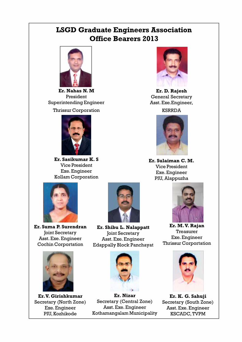
LSGD Graduate Engineers AssociationOffice Bearers 2013
Er. Nahas N. MPresident
Superintending Engineer
Thrissur Corporation
Er. D. RajeshGeneral SecretaryAsst. Exe.Engineer,
KSRRDA
Er. Sasikumar K. SVice PresidentExe. Engineer
Kollam Corporation
Er. Suma P. SurendranJoint Secretary
Asst. Exe. EngineerCochin Corportation
Er. M. V. RajanTreasurer
Exe. EngineerThrissur Corportation
Er. Sulaiman C. M.Vice PresidentExe. EngineerPIU, Alappuzha
Er. Shibu L. NalappattJoint Secretary
Asst. Exe. EngineerEdappally Block Panchayat
Er. V. GirishkumarSecretary (North Zone)
Exe. EngineerPIU, Kozhikode
Er. NizarSecretary (Central Zone)
Asst. Exe. EngineerKothamangalam Municipality
Er. K. G. SahujiSecretary (South Zone)
Asst. Exe. EngineerKSCADC, TVPM

†•°¶Ý¯¦°¤Þ ¹‹Äà
1. Er. −²œ°Þ‰²£¯Ü.µ‰, −°. †‰¸−°. †Æ°œ°¤Ü (ü±ý¸ †•°ÝÜ)
2. Er. œ®¯−¸.†Ï.†¹., kq]ïnwKv †Æ°œ°¤Ü
3. Er. ¥¯¶¬¸. •°, −°. †‰¸−°. †Æ°œ°¤Ü
4. Er. −²µµ§£¯Ï.−°.†¹., †‰¸−°‰»³È±ª¸ †Æ°œ°¤Ü
5. Er. ¬°¡² œ¯§Ô¯È¸, −°. †‰¸−°. †Æ°œ°¤Ü
6. Er. ý¯Ì°£ .ª°.†¹, −°. †‰¸−°. †Æ°œ°¤Ü
7. Er. ‹±˜ ‰´¬¸—Ï.µ‰.µ†, −°. †‰¸−°. †Æ°œ°¤Ü

†•°¶Ý©¸−¸ •−¸‰¸
−ÙÜÍÄà œ°¦Ç ª°¥−£¯¤ ƒ· ‚›²œ°‰
±ª°˜¤¯½˜¤°Þ, „á°Þ „¦Ä°¾°“¾²Ò ‰§¯ −¯®°˜»
ª¯−œ‰µ¨ ÞÔµ£Ã°§²¹ ‰²“Ǹ ²¦Ì°“²ª¯Ï ‰©°Ç²
†Ò ª°«¼¯−¶Ì¯µ“ ’Ĩ²µ“ ‰Ò° −¹¥¹¢£¯¤ "µ“‰¸œ°¾
2013" £¯‹−°œ¸ ˜²“¾¹ ‰²¦°¾µÈ....
ü±ý¸ †•°ÝÜ Er. −²œ°Þ‰²£¯Ü.µ‰ −°èú¸ †‰¸−°‰»³È±ª¸ †Æ°œ°¤Ü £²ŠÌ§ ¶×¯¾¸ Ư¤Ì¸ µ‰¯ß¹
PERFORMANCE STUDY OF COIR REINFORCED ROADS
P. R. Sajikumar Chief Engineer Local Self Government Department
1. INTRODUCTION
India is one of the country having largest road networks in the world. However many of
the existing roads are becoming structurally inadequate because of the rapid growth in traffic
volume and axle loadings. Stabilizing paved and unpaved roads with fabrics offers one method
for improvement. If it can reduce the thickness of the various road layers or extend pavement
service life and simultaneously make both cost and performance effective.
Geosynthetic materials have been used to stabilize soils in road construction and have
proved in several cases to be successful. The geotextiles used are mainly polymeric materials.
They perform the functions as reinforcement and drainage.
This polymeric materials can be replaced by natural materials such as coir Coirgeotextils
are manufactured from coir fibre which are abundantly available in our state of Kerala. If others
can be proved to be an alternate material for soil stabilization, coir industry will find a new area
of application. This project reports details the performance of coir geotextile reinforced
pavement on soft soil in two road stretches of Karikuzhi – Chekidampara 1.860 Km and Attukal
School Junction – Pampadi Road 2.535 Km.
1.1 OBJECTIVES OF THE STUDY
1. To study the performance of the coir geotextile reinforced pavement by conducting
Benkelman test and Merlin test.
2. To make a comparison of the performance of reinforced and unreinforced pavements.
1.2 SCOPE OF THE STUDY
The costs of materials and energy and a general lack of resources provide an incentive for
exploring alternatives to existing methods of building and rehabilitating roads. Stabilization of
weak paved or unpaved road by using geotextile is an alternative. By virtue of the tensile
characteristic geotextile resists stresses and deformations of the pavement. Majority of
geosynthetics, covering a wide range of woven and nonwoven geotextiles, geogrids,
geomembranes and geocomposite used in the Civil Engineering applications are polymeric.
These products generally have a long life and do not undergo biological degradation, but are
liable to create environmental problems in the long run. Throughout the world growing
awareness of the sunstainable development to preserve the environment has led to the
rehabilitation of areas damaged either by natural or industrial causes. In effecting this, the use of
natural and biodegradable materials is gaining popularity. Therefore this study is intended to
bring out the effectiveness of natural and biodegradable coir geotextile as reinforcement in the
subbase and base course layer of pavement.
2. REVIEW OF LITERATURE
2.1 GENERAL
Utilizing new technologies to improve pavement performance and increase its service life has
recently become an important part of designing and rehabilitating pavement systems. In the past
three decades, many different technologies have been introduced as systems that many improve
pavement performance and reduce its current premature failures. While many of these
technologies may provide benefits such as increasing pavement performance, durability and
service life, some may provide little benefit to the pavement systems. In such applications, the
benefit-cost ratio would be low, and implementation of some technologies would be
economically unjustified. In other cases, the use of some technologies may have been
recommended inappropriately and hence, may be detrimental to the pavement performance.
Among these technologies are geosynthetics. The use ofgeosynthetics in the field of pavement
design and rehabilitation has increased.
2.2 METHODS OF IMPROVEMENT OF PAVEMENT
In pavement systems, various geosynthetic types were proposed to provide several benefits for
improving pavement performance and service life. These benefits include the following.
i) Reinforcement, which may increase the tensile strength of a particular layer by
acting as a strain energy absorption between pavement layers.
ii) Separation, which maintains the integrity of particular layers by preventing
intermixing.
iii) Drainage or filtration, which allows water to flow and thus dissipates pore water
pressure while limiting soil movement.
iv) A moisture barrier, which prevents water movement between layers.
Geosynthetics have long been recognized as materials that can significantly improve the
performance of paved and unpaved roads that are constructed on weak subgrade. In general,
geosynthetics are said to increase initial stiffness, decrease creep, increase tensile strength,
reduce cracking, improve cyclic fatigue behavior, hold cracked pieces together, and provide low
life cycle cost.
2.3 EVALUATIONS
Benkelman Beam method
Merlin Method
2.4 GEOSYNTHETICS
Geogrids and geotextiles are the two types of geosynthetics most widely used in
pavement systems at aggregate-subgrade interface to reinforce or stabilize pavements.
Geotextiles consist of synthetic/natural fibers that are either woven into flexible, porous sheets or
matted together in a random or non woven manner. Geogrids are usually manufactured from
polypropylene, high-density polyethylene (HDPE), or high-tenacity polyester. Field evidence
suggests that both geogrid and geotextiles could improve the performance of pavement sections
constructed on weak soil. However, it remains difficult to quantify benefits that result from their
application without a field quantification.
2.4.1 ADVANTAGES OF GEOSYNTHETICS IN PAVEMENTS
Geotextiles used in roadways on soft subgrade may provide several costs and
performance benefits, including the following.
a. Reducing the intensity of stress on the subgrade and preventing the base aggregate
from penetrating into the subgrade.
b. Preventing subgrade fines from pumping or otherwise migrating up into the base.
c. Preventing contamination of the base materials which may allow more open graded,
free draining aggregates to be considered in the design.
d. Reducing the depth of excavation required for the removal of unsuitable subgrade
material.
e. Reducing the thickness of aggregate required to stabilize the subgrade.
f. Reducing disturbance of the subgrade during construction.
g. Allowing an increase in subgrade strength overtime.
h. Reducing differential settlement of roadways, this helps to maintain pavement
integrity and uniformity.
2.5 COIR GEOTEXTILES
“Coir” is the agricultural fiber obtained from the husk of the coconut fruit which
surrounds the base shell. It provides the raw material for the coir industry. Coir fibers are of
different types and are classified according to varying degree of colour, length and thickness.
Length of coir varies from 50mm to 150mm and diameters vary 0.2mm to 0.6mm. The fiber is
of two types depending on the process of extraction, white fiber and brown fiber. White fiber is
extracted after retting mature coconut husks for 9 to 12 months, followed by beating of the retted
husks with mallet manually for thrashing out the coir pith. Brown fiber is extracted by
mechanical means after soaking the husks for a short period in water. The brown fiber is
relatively inferior in terms of quality. Brown coir is mainly used for ropes, rubberized coir and
in upholstery. The extracted fibers are then spun into yarn of different weights. The yarn is
classified in terms of type of fiber, colour (natural), twisting and spinning. The yarn is then

converted into mats in handlooms, semi automatic looms or power looms. Scorage of yarn
differs among different types of geotextiles.
There are two types of coir mats (geotextiles) available: non-woven mats and woven
mats. Non-woven mats are made from loose fibers, which are interlocked by needle punching or
rubberizing. Woven mats are available in different mesh opening ranging from 3 to 25mm. A
higher density means a tighter mesh and less open area. Over the years many varieties have been
developed in India and are now commercially available in different mesh matting with
international trade names. Coir has the highest tensile strength of any natural fiber and retains
much of its tensile strength when wet. It is also very long lasting, with infield service life of 4 to
20 years. The reason for the greater strength of coir is its high lignin content.
Table 2.1 Typical properties of coir mat
Specific gravity 1.402
Mass/Unit area 1.396 g/m2
Thickness at 2 kPa 7.2mm
Stiffness 300mg-m
Tensile strength 37kN/m
Secant modulus at 10% strain 110kN/m
Tensile toughness 8.21kN/m
2.5.1 Advantages of Coir Geotextiles
a. The initial strength, stiffness and hydraulic properties of coir reinforcement are almost comparable those of similar products made from polymer materials.
b. Very low raw material price.
c. By chemical treatment and polymer coating, the life of coir products can be improved.
d. It can be laid on any surface owing to its flexibility and hence it is useful for geotechnical purpose.
e. Environmentally friendly, biodegradable and aesthetically pleasing.
f. Easy to install and follows the contour the soil surface.
3. PERFORMANCE OF PAVEMENTS
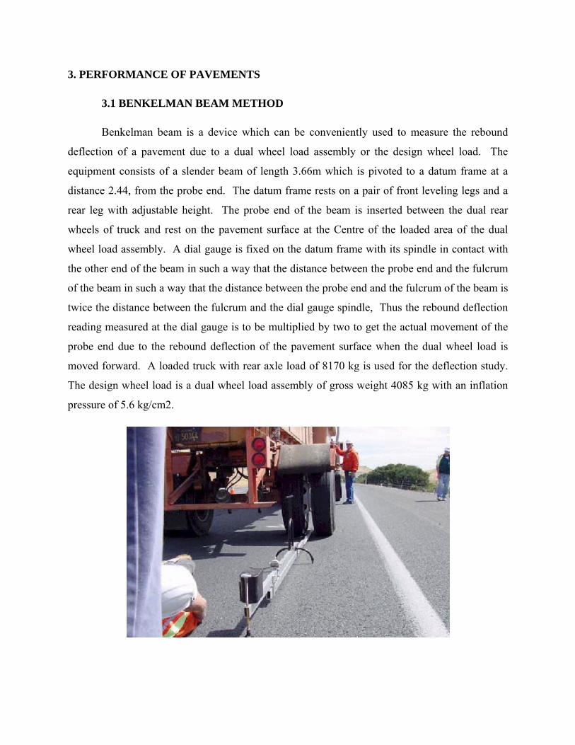
3.1 BENKELMAN BEAM METHOD
Benkelman beam is a device which can be conveniently used to measure the rebound
deflection of a pavement due to a dual wheel load assembly or the design wheel load. The
equipment consists of a slender beam of length 3.66m which is pivoted to a datum frame at a
distance 2.44, from the probe end. The datum frame rests on a pair of front leveling legs and a
rear leg with adjustable height. The probe end of the beam is inserted between the dual rear
wheels of truck and rest on the pavement surface at the Centre of the loaded area of the dual
wheel load assembly. A dial gauge is fixed on the datum frame with its spindle in contact with
the other end of the beam in such a way that the distance between the probe end and the fulcrum
of the beam in such a way that the distance between the probe end and the fulcrum of the beam is
twice the distance between the fulcrum and the dial gauge spindle, Thus the rebound deflection
reading measured at the dial gauge is to be multiplied by two to get the actual movement of the
probe end due to the rebound deflection of the pavement surface when the dual wheel load is
moved forward. A loaded truck with rear axle load of 8170 kg is used for the deflection study.
The design wheel load is a dual wheel load assembly of gross weight 4085 kg with an inflation
pressure of 5.6 kg/cm2.
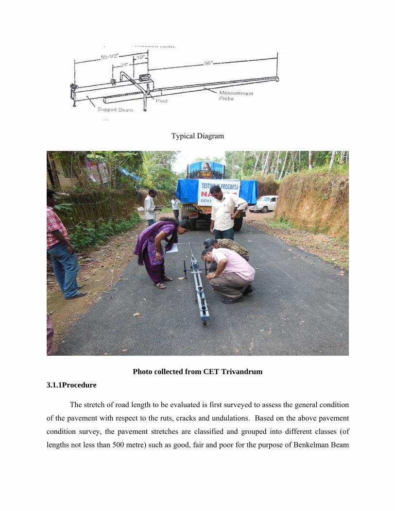
Typical Diagram
Photo collected from CET Trivandrum
3.1.1Procedure
The stretch of road length to be evaluated is first surveyed to assess the general condition
of the pavement with respect to the ruts, cracks and undulations. Based on the above pavement
condition survey, the pavement stretches are classified and grouped into different classes (of
lengths not less than 500 metre) such as good, fair and poor for the purpose of Benkelman Beam
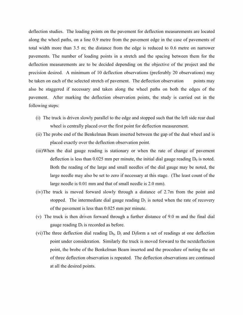
deflection studies. The loading points on the pavement for deflection measurements are located
along the wheel paths, on a line 0.9 metre from the pavement edge in the case of pavements of
total width more than 3.5 m; the distance from the edge is reduced to 0.6 metre on narrower
pavements. The number of loading points in a stretch and the spacing between them for the
deflection measurements are to be decided depending on the objective of the project and the
precision desired. A minimum of 10 deflection observations (preferably 20 observations) may
be taken on each of the selected stretch of pavement. The deflection observation points may
also be staggered if necessary and taken along the wheel paths on both the edges of the
pavement. After marking the deflection observation points, the study is carried out in the
following steps:
(i) The truck is driven slowly parallel to the edge and stopped such that the left side rear dual
wheel is centrally placed over the first point for deflection measurement.
(ii) The probe end of the Benkelman Beam inserted between the gap of the dual wheel and is
placed exactly over the deflection observation point.
(iii)When the dial gauge reading is stationary or when the rate of change of pavement
deflection is less than 0.025 mm per minute, the initial dial gauge reading D0 is noted.
Both the reading of the large and small needles of the dial gauge may be noted, the
large needle may also be set to zero if necessary at this stage. (The least count of the
large needle is 0.01 mm and that of small needle is 2.0 mm).
(iv) The truck is moved forward slowly through a distance of 2.7m from the point and
stopped. The intermediate dial gauge reading D1 is noted when the rate of recovery
of the pavement is less than 0.025 mm per minute.
(v) The truck is then driven forward through a further distance of 9.0 m and the final dial
gauge reading Df is recorded as before.
(vi) The three deflection dial reading D0, Di and Dfform a set of readings at one deflection
point under consideration. Similarly the truck is moved forward to the nextdeflection
point, the brobe of the Benkelman Beam inserted and the procedure of noting the set
of three deflection observation is repeated. The deflection observations are continued
at all the desired points.
(vii) The temperature of the pavement surface is recorded at intervals of one hour during
the study. The tyre pressure is checked and adjusted if necessary, at intervals of
about three hours during the deflection study. The moisture content in the subgrade
soil is also to be determined at suitable intervals.
(viii) The rebound deflection value D at any point is given by one of the following two
conditions:
(a) If Di – Df≤ 2.5 divisions of the dial gauge or 0.025 mm, D = 2(D0 – Df) divisions
of 0.01mm units = 0.02 (D0 – Df) mm
(b) If Di – Df ≥ 2.5 division, this indicates that correction is needed for the vertical
movement of the front legs. Therefore
D = 2(D0 – Df) + 2K (Di – Df) divisions.
The value of K is to be determined for every make of the Benkelman Beam and is
given by the relation
K = (3d-2e)/f , generally in India the value of K= 2.91
Where d= distance between the bearing of the beam and the rear adjusting leg
e = distance between the dial gauge and rear adjusting leg
F = distance between the front and rear legs
The deflection value D in case (b) with leg correction is given by:
D = 0.02(D0 – Df) + 0.0582 (Di – Df) mm
3.1.2 Corrections for temperature variation and Deflection after leg correction also made in
the result
3.1.3 Analysis of Data
3.1.4 BBD Data collection
Road: Chullimanur (Attukal – Pambadi) PMGSY – LSGD Road
Road: Kumbharavila – Kollantemukku Road PMGSY – LSGD Road
Road: Chullimanur (Karikuzhy - Chekidampara) PMGSY – LSGD Road

3.1.5 A PAVEMENT DETAILS
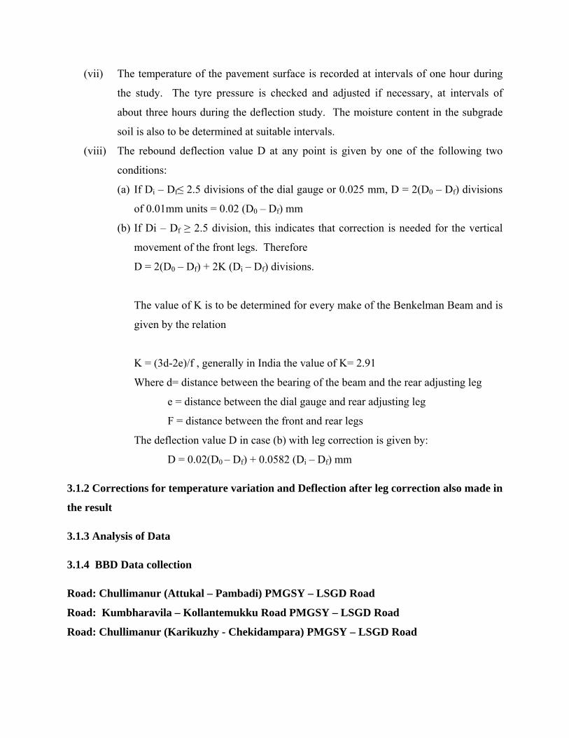
DISCUSSION
Name of road % of characteristic deflection
Road 1 30.09% Road 2 24.89% Road 3 21.25%
Data collected from CET Trivandrum
Characteristic deflection of the 3 roads with and without geotextile are presented in table
Characteristic deflection is less by 30.09%, 24.89%, 21.25% due to coir geotextile reinforcement
for road 1, road 2, road respectively. Maximum reduction is for road 1. For which the CBR
value is 3.34% with time also the characteristic deflection seem to reduce.
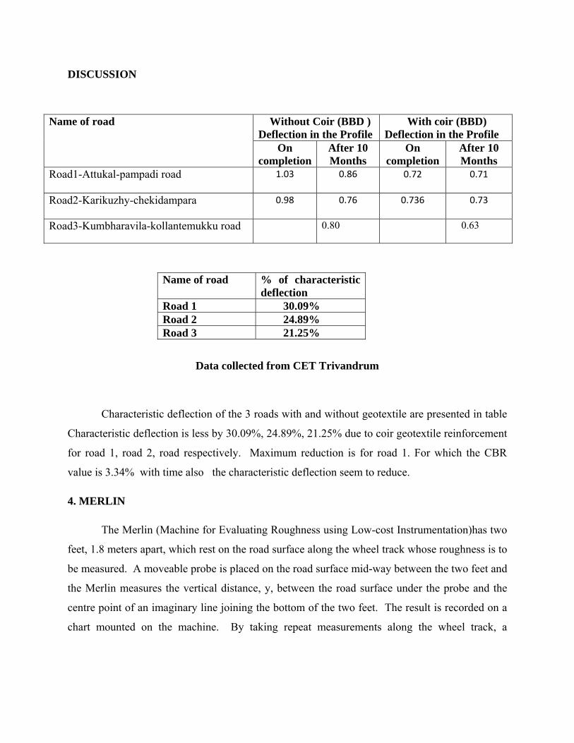
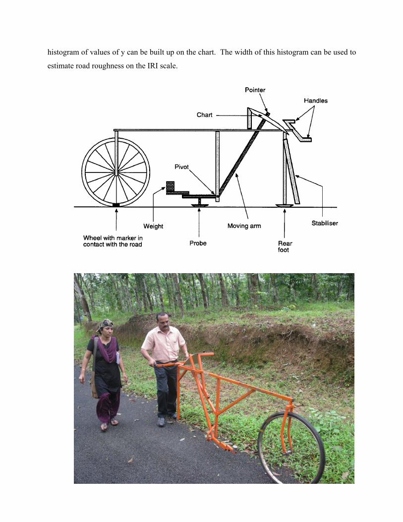
4. MERLIN
The Merlin (Machine for Evaluating Roughness using Low-cost Instrumentation)has two
feet, 1.8 meters apart, which rest on the road surface along the wheel track whose roughness is to
be measured. A moveable probe is placed on the road surface mid-way between the two feet and
the Merlin measures the vertical distance, y, between the road surface under the probe and the
centre point of an imaginary line joining the bottom of the two feet. The result is recorded on a
chart mounted on the machine. By taking repeat measurements along the wheel track, a
Name of road Without Coir (BBD ) Deflection in the Profile
With coir (BBD) Deflection in the Profile
On completion
After 10 Months
On completion
After 10 Months
Road1-Attukal-pampadi road 1.03
0.86
0.72
0.71
Road2-Karikuzhy-chekidampara 0.98
0.76
0.736
0.73
Road3-Kumbharavila-kollantemukku road 0.80 0.63
histogram of values of y can be built up on the chart. The width of this histogram can be used to
estimate road roughness on the IRI scale.
4.1 Operation
To determine the roughness of a section of road, 200 measurements are made at regular
intervals. For each measurement, the machine is rested on the road with the wheel in its normal
position and the rear foot, probe and stabilizer in contact with the road surface. The position of
the pointer on the chart is then marked by a cross in the next box in line with the pointer and, to
keep a count of the total number of measurements made, a cross is also put in the “tally box” on
the chart. The handles of the Merlin are then raised so that the probe, rear foot, and stabilizer are
clear of the road and the machine is wheeled forward to the next measuring position, where the
process is repeated. When the 200 measurements have been made, the chart is removed from the
Merlin and turned on its side. The position mid-way between the tenth and the eleventh crosses,
counting in from one end of the distribution, is marked on the chart below the columns. The
procedure is repeated for the other end of the distribution. It may be necessary to allocate only a
proportion of a column containing 5 crosses. The mark is therefore made one ‘fifth of the way in
from the edge of the column.
4.2 ROUGHNESS EQUATION
For earth, gravel, surface dressed or asphaltic concrete roads, roughness can be determined using
the equation
IRI = 0.593 + 0.0471 D (1)
(2.4 < IRI < 15.9)
Where IRI is the roughness in terms of the International Roughness Index (in *) and D is
measured from the Merlin chart (in mm). The equation was derived over the range of IRI values
shown and should be extrapolated with caution. The undulations in a road’s surface consist of a
mixture of surface waves of different wavelengths. The sensitivity of the IRI scale varies with
wavelength and it is highest for waves around two metres. The sensitivity of the Merlin is also
high at these wavelengths and that is why it gives a good estimate of IRI. However, at other
wave lengths there are differences, the Merlin being more sensitive than the IRI to short waves
and less sensitive to long waves. Because of the different wavelength sensitivities, it is important
to calibrate the bump integrator on a range of test sections whose surfaces are typical of the
surfaces which the bump integrator is going to measure. Some hand-laid surfaces have a much
higher proportion of long waves and so they have a different relationship between IRI and D. A
study in Indonesia gave the following equation for hand-laid penetration Macadam:
IRI = 1.913 + 0.0490D (2)
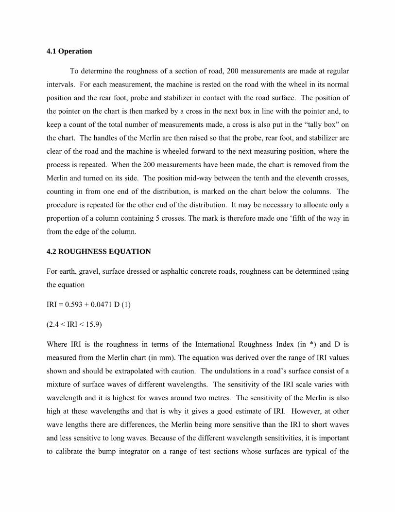
DISCUSSION
Name of road Without Coir With coir 18.10.2012 11.8.2013 18.10.2012 11.8.2013
Road1-Attukal-pampadi road IRI = 6.97 IRI=6.230 IRI = 8.36 IRI=5.290
Road2-Karikuzhy-chekidampara IRI = 7.63 IRI=5.730 IRI=9.11 IRI =6.240Road3-Kumbharavila-kollantemukku road
IRI = 5.750
IRI= 6.602
Data collected from CET Trivandrum
International Roughness Index of older pavement is 2.5 to 6.0 m/km. Initially due to coir
geotextile IRI value is slightly higher But with time it is in limit.
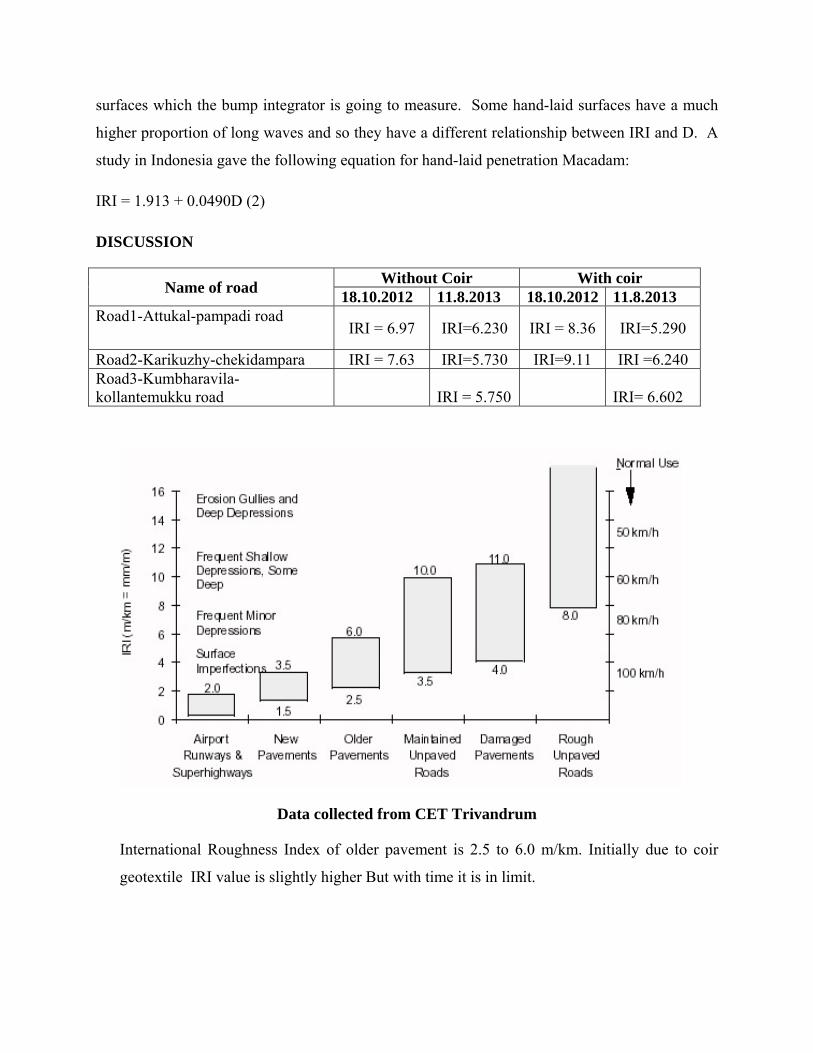
CONCRETE PAVEMENTS
Er. Ajayaghosh.K.D. C.Eng; Executive Engineer, L.S.G.D.North Circle, Kozhikode.
It has become one of the great concerns of the field engineers of the L.S.G. Department to carry out the concreting works of pavements, fearing the local fund audit objection and the resultant allegations on financial loss on the thickness of the pavement. There is some superstition that the concrete thickness of the footpath shall not exceed 75mm. Adopting a lower thickness of concrete, causes earlier collapse of the road surface creating inconvenience to the people, and loss of public exchequer which lead to audit notes again. If we go through the relevant codes and specifications of IRC it is nothing to worry to take the task of concrete works with quality and authority.
It is observed that the rural roads have a very low volume of traffic consisting of light goods vehicles, buses, cars, two and three wheelers, Some roads may have adequate number of heavy vehicles carrying brick from kilns , metals/rubbles/laterite/red earth/quarry sand from quarries and rubber wood from plantations. The city roads also usually carry similar loads of heavy vehicles without the exception of bye lanes.It is noteworthy that these roads are not being properly maintained due to paucity of funds and poor institutional set up and its management.
Even though there are standards, we do not design for road works like that of any other buildings. Neglection on the design part shares the major reason for the earlier destruction of the road which is not reckoned up.
Concrete pavements offer an alternative to flexible pavements where the soil strength is poor and drainage conditions are weak. The choice depends on life-cycle cost also.
IRC: 58-2002 deals with the design of concrete pavements in the following manner:-
For normal village roads we may take a design wheel load of 30kN and 0.50MPa as tyre pressure of the vehicle, The life period expected for a concrete pavement is 20 years where as that of flexible pavement is for 5years. The design is based on the strength of subgrade which can be easily find out using a plate bearing test as per IS:9214-1974 in a rainy season, the value of which is directly related with the soaked CBR%.
A sub base layer of either GSB or a WBM of 75mm is needed to provide a uniform and firm support for the concrete pavement above. It also prevents mud pumping and acts as a capillary cut off. The minimum concrete thickness accepted by IRC is 12cm of M30 to M40 grade.
CONSTRUCTION METHOD
• Construct the sub grade of 15 cm thickness. • Construct a sub base of minimum 75mm thick layer of WBM or well
graded GSB. • Discarded plastic of not more than 125 micron thickness may be
spread over the sub base, which can be effectively used for eradicating the plastic menace in the city .It act as a separation layer.
• Fix the form work firmly using MS channel forms of least 3.0m length. • Place the design mix of concrete to the desired depth and width.
Compaction and finishing of the concrete layer should be done rapidly within 2hrs.
• The final concrete surface shall be well closed, free from movement and without loose materials. Check for the levels and gradient.

• The pavement shall be given a broom finish with a broom of 45 cm wide.
• Contraction joints shall be formed my mechanical sawing a joint groove 3 to 5 mm wide and ¼ to 1/3 depth of pavement concrete soon after concrete sets. The joint sealing compound shall be poured as per IS :1834.
• Expansion joints of 20mm width are required for bridges and culverts only.
• Normally steel reinforcement is not required for concrete pavements. • CURING:- • The initial curing shall be done by covering the surface with wetted
jute mats for 24 hrs. • The final curing shall be done by ponding for 14 days. • Form work shall be removed carefully only after 12 hrs.Edges shall be
cleared and honey comb areas shall be pointed with 1:2 c.m • No vehicle shall be allowed for at least 28 days. More strength and life
will be achieved if the pavement is untouched by vehicle for 90 days. • One set of 3 cubes for each 7 day and 28 day shall be taken for 100m3
or a days’ work.


INTELLIGENT BUILDINGS
Shibu L. Nalpat, Assistant Executive Engineer., LSGD Sub Division, Edappilly Block Panchayath. [email protected]
Introduction
In the modern world, everything is expected intelligent or smart. Right from the basic needs of mankind to the latest nuclear weapon or space technologies, intelligence is incorporated in an artificial way. With the advent of artificial intelligence, smart programs are integrated to control of all most appliances, vehicles, machineries, and other utilities. Automation is the key to artificial intelligence. Many companies have automated vehicle production to deliver customer specific end products logistically sourcing parts and delivering finished products to a pre-determined programme. In textiles jeans and shirts are being digitally customized to individual measurement -combining the advantages of mass production with the savoir of tailor-made perfection. It was only in the building industry that its arrival has been late and lethargic. However there are good efforts in this now; the following sections give an introduction to the intelligent building systems.
Intelligent buildings
Though much has been discussed and practised in the field of intelligent building systems, a comprehensive definition of an intelligent building is yet to be established. However experts in this domain tried it. According to Ranee Vedamuthu, a faculty member of the School of Architecture & Planning, Anna University, Chennai, “An intelligent building is in essence one that integrates various systems (such as lighting, heating, air conditioning, voice and data communication and other building functions) to effectively manage resources in a coordinated mode to maximize occupant performance, investment and operating cost, savings and flexibility.”
A definition that emerged from an international symposium held in Toronto in May 2003 was, “intelligent building combines innovations, technological or not, with skilful management to maximize returns on investments.”
Another definition is that “An intelligent building is one in which the building fabric, space, services and information systems can respond in an efficient manner to the initial and changing demands of the owner, the occupier and be in harmony with the environment”, by Agith G, Editor-in-Chief, The Master builder. Intelligent buildings are designed to increase efficiency of lighting, monitoring, safety & security, emergency systems, HVAC (Heating, Ventilating and Air Conditioning), door and window operations, guest registration and many more facets.

An intelligent building should
• Know what is happening inside the building and immediately outside. • Decide the most effective way of providing a convenient, comfortable and
productive environment for its occupants. • Respond as quickly as possible to the requests of the occupants.
An intelligent building system concept considers that the true cost of the building is not its cost of construction; it must include the operating and maintenance costs over its life span. Intelligent buildings yield cost reductions over all these areas by optimizing energy use through automated control, communication and management systems. In a new intelligent building installation the following features are expected.
1. High- speed fibre optic communication network trunk for data, video and BAS. (Building Administrative System)
2. Flexible HVAC system with modular distribution and 100% outdoor air capability to take advantage of free cooling as well as to allow flushing of the building to dilute volatile off-gassing contaminants.
3. Individually controlled HVAC terminal units allowing occupant control flexibility through Intelligent Terminals Controllers at each workstation.
4. Advanced integrated Energy Management & Control System (EMCS) utilizing direct digital control technology for HVAC, Lighting, Fire Alarm and other building support systems.
5. Dedicated circuit power distribution network complete with Uninterrupted Power Supply (UPS) units.
6. Maximum transparency and communication capabilities between subsystems. 7. Electrical design features tailored to Intelligent Building. 8. Generous standby power generation. 9. High efficiency filtration, energy recuperation and/or thermal storage features to
improve indoor air quality and energy consumption performance. 10. Networked multi-user access incorporating structured password protection.
Intelligent Building Model
The intelligent building model structure has been broadly subdivided into seven systems which may be interfaced to varying degrees. These are
1. Heating, Ventilating and Air Conditioning (HVAC) system. 2. Electrical Power Distribution system. 3. Communications System. 4. Lighting System. 5. Vertical Transport System. 6. Security System. 7. Life Safety System.
1. Heating, Ventilating and Air Conditioning (HVAC) system.
In Intelligent Buildings Systems the HVAC system must be selected in such way that it satisfies ventilation standards and occupant comfort control while optimizing, flexibility, energy efficiency and maintenance costs. An owning and operating cost

analysis coupled to an energy simulation of each viable option is mandatory to determine the optimal HVAC solution.
The Personal Environment Controllers (PEC) are developed to be used in intelligent building to provide occupants with full control over their particular office work station environment. PEC units allow the occupant to control temperature, air flow volume and direction as well as lighting through their local PC or through hand held portable remote control units. In PEC concept, standard fixed position diffusers are replaced by one or more air jets strategically located to project cold air streams downward and away from the occupants. The occupant has control over the air volume and its direction. 2. Electrical power distribution system
The power distribution system deals with major electrical components and electrical energy monitoring. Major elements under monitoring and control include the emergency power generator, Uninterrupted Power Systems (UPS), the Emergency Lighting System, Individual tenant power metering units and other major electrical loads.
Emergency power system interfaces with other systems to annunciate normal power interruptions and initiate reactivation of emergency loads when emergency power becomes available. It performs similar functions upon restoration of normal power including preprogrammed orderly reactivation of heavy electrical loads.
The power distribution system may also incorporate a load stabilization or load cycling program to minimize electrical demand charges.
Uninterrupted power source units are constantly monitored for critical elements such as normal/emergency power mode, trouble or alarm conditions etc. 3. Communications system
In the intelligent building, integrated communications is possible. The systems
that may communicate include traditional LAN-based (local area network) clients and servers, telephones and telephone switches, video conference devices, and the full range of EMCS devices for HVAC, security, lighting, and fire alarms. The intelligent building communication system can also facilitate interchange with accounting or other networks to import or export pertinent data whether in-house or outsourced.
4. Lighting system
The lighting system, in intelligent buildings must be integrated to the EMCS in order to interact with the other systems. When used with multilevel lighting control and/or perimeter zone daylight systems certain zones may also be tied to the load shedding program in the Power distribution system. In intelligent buildings the occupancy mode, during extended hours, may be controlled from local PC terminals or from strategically located override switches.
The extent of lighting control distribution, the use of motion detectors or infrared sensors and the use of lighting level sensors, in perimeter areas, to allow use of natural lighting whenever possible must be incorporated. This lighting control should be extended to each room or work station in order to take full advantage of the energy savings associated to non-occupancy mode or the limited and localized occupancy activation during extended hours for the HVAC and lighting systems. For example Wipro lighting has been showcasing its energy saving lighting products like Lightspot

presence detection system and Managed Light system for corporate offices and Scene Select System for conference rooms. 5. Vertical transport system
This system interacts with other systems such as the life safety or the security systems to define the number of elevators required, the mode of operation and accessible floor levels. To minimize energy consumption the number of activated elevators may also be reduced on the basis of time of day schedules, week or weekend days and statutory holidays.
6. Security system
Security system may include simple systems like automatic access monitoring, card access control, guard tour monitoring or motion detectors. More elaborate security systems involving intensive human intervention from guard stations and closed circuit TV and recording should be sourced from specialized security system manufacturers. The card access security program may be interfaced with the lighting and HVAC subsystems to activate necessary lighting paths and the specific room occupancy mode. Similarly the Life Safety Fire Alarm program may be interfaced with security to release specific locked doors under alarm conditions
7. Life safety system
This sub-system deals with the Fire Alarms, the Emergency Lighting, Egress lighting system and the Smoke Evacuation system. Interfacing of the Life Safety system with other systems is very important to eliminate nuisance alarms or to start the smoke evacuation system. Interfacing may also allow temporary transfer of spare emergency power not required at the time to other non-critical areas until such time as it is required.
Environmental benefits of intelligent buildings
• An intelligent building starts with an environmentally friendly design. • Creating a project that is environmentally friendly and energy efficient ties in
closely with many of the intelligent attributes.
• Providing the ability to integrate building controls, optimize operations, and enterprise level management results in a significant enhancement in energy efficiency, lowering both cost and energy usage compared to non-intelligent projects.
• Intelligent buildings are designed for long-term sustainability and minimal
environmental impact through the selection of recycled and recyclable materials, construction, maintenance and operations procedures.
Some popular intelligent buildings in India
1. Techno campus of Cognizant technologies, Chennai 2. Gateway tower, Gurgaon 3. Tidal park, Chennai

4. TCIL Bhavan, Govt. Of India Enterprises, New Delhi 5. EDRC, L & T, Chennai
Conclusion Intelligent buildings are definitely the buildings of the future. There are enormous benefits in terms of sustainability, energy efficiency, comfort, security and environmental friendliness. Many of the intelligent concepts correlated with green buildings too or those are complimentary in nature. The goal of having an intelligent design starts with the concept stage of a building, and progresses through the planning and detailed process. Intelligent buildings coupled with green concepts would alone sustain in the era of high rated exploitation of natural resources.

Sm\n≥ - AS-bv°m-tXm-Sn¬ \n∂pw
kp\n¬ Ip-am¿.sI
Akn.-F-Ivkn-Iyq- ohv F©n-\o-b¿
apJ-Øe tªm°v ]©m-b-Øv, sIm√w.
F¥mWv Sm\n≥?
tXmep -d -b v°n -Sp -∂-Xn -\pw, Nne Nmb-߃ \n¿Ωn -°p-∂-Xn\pw, Pe-Ønse Nne
eh-W-߃ Aen -bn -°p -∂-Xn\pw D]-tbm -Kn -°p∂ kky -P -\y -amb cmk-]-Zm¿∞-amWv
Sm\n≥. cmkn -I-ambn Hcp t]mfn -ssl-tUmIvkn ^nt\m-fnIv tImw]u-≠mWv Sm\n≥. kky-
ß-fn¬ \n∂pw FSp -°p∂ shPn -t‰ -‰ohv Sm\n\pw IrXn -a -am -bp -≠m -°p∂ kn¥-‰nIv
Sm\n -\pw \ne-hn -ep -≠v. arK -ß-fn¬ Sm\n -\n -√. ]c-em -Ir -Xn -bn¬ Sm\n -\p -Iƒ hnc -f -amtb
ÿnXn sNøm-dp -≈q. Ah-bvs°mcp sNmcp -°p∂ cpNn -bp -ap -≠v. kky-ß-fn¬ Ce-I-fnepw
sXmen -I -fnepw ]mI-am -ImØ ImbvI-fnepw hnØp-I-fnepw Sm\n -\p -≠v. sh≈-Øn¬ ebn -
°p∂ Nne kkymw -i -ß-fn -sem -∂mWv Sm\n≥. c≠v hn]p -e -Xcw Sm\n -\p -I -fp -≠v. ss]tdm
Kmtemƒ Sm\n\pI-fpw Im‰n -t°mƒ Sm\n -\p -Ifpw. Infn¿°p∂ hnØp-I-fnepw lcn -X-]-X-
ß-fnepw Xg-®p -h -f¿∂p-sIm -≠n -cn -°p∂ kky-`m -K -ß-fnepw Sm\n -\p -I-fpsS \n¿Ωm-Whpw
hn]p -eo -I -c -Whpw \nc -¥cw \S-∂p -sIm -≠n -cn -°p -∂p. ^e-߃ ]mI-ambn ]gp -°p-tºmƒ
Ah-bn -ep≈ Sm\n -\p -Iƒ A]-Xy -£-am -Ip -Ibpw ISpw -Np -h -∏v , a™, \oe F∂o \nd -ß-
fp -≠m-hp -Ibpw sNøp-∂p. X∑qew Cu \nd -ßfpw Sm\n -\p -I-fp -ambn _‘-ap -s≠∂v Duln-
°mw. ]c-Po -hn -I-fmb ^wK-kp-I-fn¬ \n∂pw sNSn -Isf c£n-°p∂ Imc-I-ß-fmbn Sm\n -
\p -Iƒ ]h¿Øn-°p-∂p. ]mIw hcmØ ^e-ßsf Sm\n -\p -Iƒ ]£n-ar -Km -Zn -I-fn¬ \n∂pw
c£n-°p-∂p.
`mc -X -Øn -\m -h -iy -ambXbpw Sm\n≥ ChnsS Dev]m -Zn -∏n -°m -Ø-Xn -\m¬ _m°n-bp -
≈Xv hntZ-i-cm -Py -ß-fn¬ \n∂pw Cd-°p-aXn sNøp-∂p. Cu C\-Øn¬ `mc-X-Øn\v h¿jw-
tXmdpw KWy -amb hntZ -i -\mWyw \jvS -am -Ip -∂p. C¥y -bn¬ alm-cm -jvS, B‘m-] -tZ -
i v , Xan -g v\m -S v , tIcfw F∂n -hn -S -ß-fnemWv Sm\n≥ ][m -\ -ambpw Dev]m -Zn -∏n -°p -∂-Xv.
_ko¬, Ata-cn -°, B^n -°≥ \mSp -Iƒ F∂n-hn -S -ß-fn¬ \n∂pw \mw Sm\n≥ Cd-°p-
aXn sNbvXph-cp -∂p. Sm\n≥ \n¿Ωm-W-Øn\v Ct∏mƒ D]-tbm-Kn -®p -h-cp∂ ][m\ Akw-
kvIr -X -] -Zm¿∞-߃ hm‰n¬_m¿, ISp -°, Iip -h -≠n -sØmen F∂n -h -bm -Wv. F∂m¬
]pXn -b -Xmbn em` -I-c -ambn AS-bv°m-tXm -Sn¬ \n∂pw Sm\n≥ Fßs\ \n¿Ωn°mw F∂p-
≈-XmWv Cu teJ-\-Øn¬ ]Xn -]m -Zn -®n -cn -°p -∂-Xv.
AS-bv°m-tXm -Sns‚ ]tXy -I-X-Iƒ
1. AS-bv°m-tXm -Sn¬ GI-tZiw 15% Sm\n≥ AS-ßn -bn -´p -≠v.
2. tIcfw, ssakq¿, B mw F∂n-hn -S -ß-fn¬ hym]-I-ambn ASbv° Irjn sNbvXp -
h -cp -∂p. Bb-Xn -\m¬ AS-bv°mtXmS v C¥y -bn¬ ]tXy -In®pw tIc-f -Øn¬ kpe-` -
am-Wv.
3. Akw-kvIr-X-]-Zm¿∞-amb AS-bv°m-tXmSv tiJ-cn-°m≥ henb Nne-hn-√.

AS-bv°m-tXmSpw a‰p-Nne Akw-kvIr-X-]-Zm¿∞-ßfpw XΩn¬
Sm\n≥ e`y-X-bv°p≈ Xmc-Xayw
100 Kmw Akw-kvIr -X - Akw -k vI r -X -] - Z m ¿∞w e`n -°p∂ Sm\ns‚
] - Z m ¿ ∞ w e`n -°p-∂-Xn -\p≈ km[yX A f h v
Iip -h -≠n -sXmen Iip -h -≠n -^m -IvS -d n -I -fn¬ \n∂pw 28 Kmw
e`n -°p∂p
ASb v°mtXmS v Ifn -∏m -°v, sIm´ -∏m°v hyh-kmb 15 Kmw
tIµ-ß-fpw, \m´nse
apdp -°m≥ IS-Ifpw
tXß-bpsS sXm≠v tIc-f -Øn -ep -S -\ofw 18 Kmw
hmg -Ø-S , tIc-f -Øn -ep -S -\ofw 7 Kmw
]®-∏-g -sXmen
C-Xn¬ Iip-h≠n sXmen Ct∏mƒØs∂ Sm\n≥ \n¿Ωm -W-Øn -\mbn D]-tbm -Kn -
®p -h -cp -∂p. tXß-bpsS sXm≠v Ib¿\n¿Ωm-W-Øn\pw a‰p -ambn D]-tbm -Kn -°p-∂-Xn -\m¬
AXn\v hne \evtI≠n hcp -∂p. F∂m¬ hmg-Ø-S -bn -em -Is´ Sm\n≥ iX-am\w Xosc
Ipd -hp -am -Wv. Bb-Xn -\m¬ AS-bv°m-tXmSv Sm\n≥ \n¿Ωm-W-Øn\v F¥p-sIm≠pw DNn -X -
amb Hcp Akw-kvIrX hkvXp -hm -sW∂p a\- n -em -°mw.
s]mXpth Sm\n≥ kky -ß-fn¬ \n∂p-amWv kw` -cn -°p -∂-sX∂ ASn -ÿm-\ -[m -c -W-
bn¬ F√m-Ø-c -Ønepw s]´ kky -ß-fpsS F√m `mK-ßfpw ]co -£-W-Øn\v hnt[-b-am -
°p-Ibpw Hmtcm -∂n¬ \n∂pw FX iX-am\w Sm\n≥ FSp -°m≥ Ign -bp -sa∂pw ]cn -tim -
[n -°p -Ibpw sNbvXp. lcn -X -I-ap≈ an° kky -ß-fnepw Sm\n≥ Ds≠∂pw ]®-bm -bn -cn -
°p-tºm-gmWv Sm\ns‚ Afhv IqSp -X-se∂v Xncn -®-dn -bm≥ km[n -®p. Akw-kvIr -X]-Zm¿∞-
Øns‚ e`y -Xbpw AXn -e -S -ßn -bn -cn -°p∂ Sm\ns‚ Afhpw ]cn -K -Wn -°p -tºmƒ Sm\n≥
\n¿Ωm -W-Øn\v F√mw XnI™ Hc-kw -kvIr -X -] -Zm¿∞-amWv AS-bv°m-tXmS v F∂p
a\ - n -em -°mw.
AS-bv°m-tXm -Sn¬ \n∂pw Sm\n≥ th¿Xn -cn -°p∂ coXn
sNdp -Xmbn sh´n -b -cn™ ]®-b-S -bv°-bpsS tXmS v Hcp ]mX-Øn -en´ v NqSp -sh≈w
(80-900C) AXn -\p -aosX Hgn -°p -I. AXns‚ IqsS Aev]w tkmUnbw Im¿_-tW‰v
( Na2Co3) tN¿Øm¬ Dev]-∂-Øn\v BI¿j-I-amb \ndw In´m≥ klm-bn -°pw.
Ac aWn -°q¿ Ign™v ]mX-Ønse emb\n Du‰n -sb-SpØv as‰mcp ]mX-Ønse AS-
bv°m-tXm-Sn -te°v ]I-cp -I. GI-tZiw 2 aWn-°q¿ sIm≠v \mev ]mX-ß-fnse AS-bv°m-
tXm -Sn -eqsS IS-∂p -h-cp∂ Pe-Øn¬ Sm\ns‚ \√ Awiw ebn -®p -tN¿∂n -´p -≠m -bn -cn -°pw.
Cßs\ In´p∂ emb\n sXfn -s®-SpØv AXnse Pew hm´¿_mØv hgn _mjv]o -I -cn -
®m¬ Jc cq]-Øn -ep≈ Sm\n≥ e`n -°p-∂p.
hymh-km -bn -Im -Sn -ÿm-\ -Øn¬ AS-bv°m-tXm -Sn¬ \n∂pw Sm\n≥ \n¿ΩmWw
\S-Øn -bm¬ hfsc em` -I-c -am -bn -cn°pw F∂v \ap°v \n w -ibw a\- n -em -°mw.
1981 am¿®v amk-Ønse imkvX-KXn amkn -I-bn¬ teJ-I≥ ]kn -≤o -I-cn -® -XmWv Cu teJ-\w.
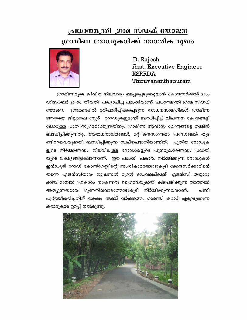
][m-\-a´n Kma kUIv tbmP\
KmaoW tdmUp-IÄ¡v \mK-cnI apJw
D. Rajesh Asst. Executive Engineer KSRRDA Thiruvananthapuram
KmaoW-cpsS PohnX \ne-hmcw sa¨-s¸-Sp-¯p-hm³ tIµ-kÀ¡mÀ 2000
Unkw-_À 25-þmw XobXn ]J-ym-]n¨ ]²-Xn-bmWv ][m-\-a´n Kma kUIv
tbmP-\. Kma-§-fn DXv-]m-Zn-¸n-¡-s¸-Sp¶ km[-\-km-a-Kn-IÄ KmaoW
P\-Xsb Pn-Ãm-Xe tÌäv tdmUp-I-fp-ambn _Ôn-¸n¨v hn]-W\ tIµ§-fn-
te-¡pÅ ]mX kpK-a-am-¡p-¶-Xn\pw KmaoW Bhmk tI-µ-§sf X½nÂ
_Ôn-¸n-¡p-¶Xpw Bcm-[-\m-e-b-§Ä, aäv P\-km-µXm ]tZ-i-§Ä XpS-
§nd-d-b-h-bp-ambn _Ôn-¸n-¡p¶ kz-]v\-]-²-Xn-bmWnXv. ]pXnb tdmUp-I-
fpsS \nÀ½m-Whpw \ne-hn-epÅ tdmUp-I-fpsS ]p\-cp-²m-c-Whpw ]²-Xn-
bpsS e£y§-fn-sem-¶m-Wv. Cu ]²Xn ]Imcw \nÀ½n-¡p¶ tdmUp-IÄ
C³U-y³ tdmUv tIm¬K-Ênsâ AwK-oIm-c-t¯m-Sp-IqSn tIµ-k-À-¡m-cnsâ
Xs¶ GP³kn-bmb \mj-W dqd sUh-e-]vsaâv GP³kn X¿m-dm--
¡nb am\-z ^Imcw \mj-W sslthbp-ambn InS-]n-Sn-¡p¶ Xc-¯nÂ
AX-yp-¶-X-amb KpW-\n-e-hm-c-t¯m-Sp-IqSn \nÀ½n-¡p-¶-h-bmWv. ]Wn
]qÀ¯o-I-cn-¨-Xn\v tijw A©v hÀj-s¯, Kmc−n IcmÀ Gsä-Sp-¡p¶
Icm-dp-ImÀ Dd¸v \ÂIp-¶p.

tIµ-kÀ¡m-dnsâ ]T\ dnt¸mÀ«v ]Imcw ]²Xn KmaoW P\-X-bnÂ
Xmsg ]d-bp¶ amä§Ä D−m-¡n-b-Xmbn I−-¯n-bn-«p-−v.
1. KmaoW tdmUp-I-fpsS ]p\-cp²m-cWw Ipdª hnebv¡v KpW-\n-e-hm-
c-apÅ D -¶-§Ä hn]-W\ tIµ-§-fn e`-y-am-¡m³ km[n-¨p.
2. ImÀjn-tI-Xc taJ-e-I-fn sXmgn km[-y-X-IÄ hÀ²n-¨p.
3. KmaoW P\-Xbv¡v sa¨-s¸« hnZ-ym-`-ym-khpw Btcm-K-yhpw km¼-
¯nI \ne-hm-chpw sa¨-s¸-Sp-¯p-hm³ km[n-¨p.
4. KmaoW taJ-e-bn Xs¶ sa¨-s¸« P\-tk-h\ tIµ-§Ä e- -y-am¡p-
hm³ km[n-¨p.
C³U-y-sbm-«msI 28 kwØm-\-§-fnepw 6 tIµ `cW ]sZ-i-§-f-en-
ep-ambn hym-]n¨p InS-¡p¶ Cu ]²-Xn-bps kpK-a-amb \S-¯n-¸n\pw
kpXm-cyX Dd¸p hcp-¯p¶-Xn-\p-w th−n knþ-UmIv F¶ Øm]\w tIµ-
kÀ¡m-cn-sâ KmaoW a´m-e-b-¯n\p th−n cq]oI-cn¨ OMMAS
(Online Management Moninoring and Accounting System) F¶
tkm^vävsh-bÀ D]-tbm-Kn-¨mWv tIµ-kÀ¡mÀ Cu ]²-Xn-bpsS ]ptcm-KXn
hne-bn-cp-¯p-¶-Xv.
OMMAS tkm^väv-sh-b-dn DÄs¸-«n-«pÅ tam-U-yq-fp-IÄ NphsS
tNÀ¡p¶p.
* amÌÀ tUä tiJ-cn-¡Â
* KmaÂW tdmUp-I-fpsS PnÃm-X-e-¯n-epÅ ¹m³
* tIµ-kÀ¡m-cn-te¡v hmÀjnI ]²Xn kaÀ¸n-¡m³
* kÀsÆ-bn \n¶pw e`n¨ hnh-c-§-fpsS A-Sn-Øm-\-¯n sjU-yqÄ \nc¡v ]Imcw FÌn-taäv X¿m-dm-¡Â
* sS³UÀ ]c-kyw X-¿m-dm-¡Â
* ]²Xn \S-¯n¸pw ]ptcm-KXn hn-e-bn-cp-¯epw
* ]Wn-I-fpsS ]ptcm-KXn A\p-h-Zn¨v Iymjv amt\-Pvsaâv
* sabnâ\³kv
OMMAS tkm^väv-sh-b-À hgn ]²-Xn-bpsS bYmÀ° KpW-t`m-àm-hn\v
Xmsg ]d-bp¶ ]tbm-P-\-§Ä e`n-¡p-¶p.
* ]²-Xn-sb-¡p-dn-¨pÅ Gähpw ]pXnb hn-h-c-§Ä
* tIµ-kÀ¡mÀ A\p-h-Zn¨ ]hr-¯nI--fpsS hni-Zmw-i-§Ä (tdm-Unsâ \ofw, XpI F¶n-h)
*
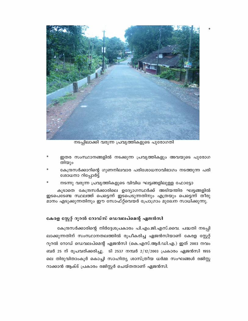
\S-¸n-em¡n hcp¶ ]hr-¯n-I-fpsS ]ptcm-KXn
* CXc kwØm-\-§-fn \S-¡p¶ ]hr-¯n-Ifpw Ah-bpsS ]ptcm-K-Xnbpw
* tIµ-kÀ¡m-dnsâ KpW-\n-e-hmc ]cn-tim-[\m-hn-`mKw \S-¯p¶ ]cn-tim-[\m dnt¸mÀ«v
* \S¶p hcp¶ ]hr-¯n-I-fpsS hnhn[ L«-§-fn-epÅ t^mt«m
IqSmsX tIµ-kÀ¡m-cnse DtZ-ym-K-ØÀ¡v ASn-b-´nc L«-§-fn CS-s]-tS− Øe¯v s]s«¶v CS-s]-Sp-¶-Xn\pw FXbpw s]s«¶v Xocp-am\w FSp¡p-¶-Xn\pw Cu tkm^vävsh-bÀ t]mKmw aptJ\ km[n-¡p-¶p.
tIcf tÌäv dqd tdmUvkv sUh-e-]vsaâv GP³kn
tIµ-k-À-¡m-cnsâ \nÀt±-i-]-Imcw ]n.-Fw.-Pn.-F-kv.-ssh. ]²Xn \S-¸n-
em-¡p-¶-Xn\v kwØm\-X-e-¯n cq]oI-cn¨ GP³kn-bmWv tIcf tÌäv
dqd tdmUv sUh-e-]vsaâv GP³kn (sI.-F-kv.-BÀ.-Un.-F.) CXv 2003 \hw-
_À 25 \v cq]-h-Xv¡-cn-¨p. Sn 2537 \¼À 2/12/2003 ]Imcw GP³kn 1955
se Xncp-hn-Xmw-IqÀ sIm¨n kmln-Xy imkvXob [À½ kwL-§Ä cPn-Ì-
dm-¡m³ BIvSv ]Imcw c-Pn-ÌÀ sNbvX-XmWv GP³kn.

1. LS\
P\-d t_mUn
GP³knbv¡v P\-d t_m-Unbpw FIvkn-I-yq-«ohv I½n-än-bp-amWv
DÅXv. Km-a-hn-I-k\ a´n-bmWv CXnsâ A[-y-£³. -X-t±i kz-bw-`-cW
]n³kn-¸Â sk-I-«-dn-bmWv D]m-[-y-£³. Kma-hn--I-k\ I½o-j-WÀ
sa¼À skI-«-dn-bm-bn-«pÅ P\-d t_mUn-bn Kma-hn-I-k\ hIp-¸n-se
AUo-j-W sUh-e-]vsaâv I½Âj-WÀ FÂ.-F-kv.-Pn.-Un. No^v F©n-\o-
bÀ sI.-F-kv.-BÀ.BÀ.Un.F.-bpsS kq]-−nwKv F©n-\o-bÀ, tÌäv Izm-fnän
tImÀUn-t\-äÀamÀ, 14 PnÃ-I-f-n-tebpw t]mKmw Cw-¹n-sa-tâj³ bqWn-änse
F-Ivkn-Iyq-«ohv F©n-\o-bÀamÀ, ]©m-b¯v Ub-d-IvSÀ, [\-Im-cy hInp-
¸nsâ ]Xn-\n[n F¶n-hÀ AwK-§-fm-Wv. kanXn Bdv amk¯n-sem-cn-¡Â
tbmKw tNÀ¶v ]²Xn \nÀÆ-lW ]ptcm-KXn hne-bn-cp-¯pw.
FIvkn-I-yq-«ohv I½nän
Xt±i kz-bw-`-cW ]n³kn-¸Â skI-«dn sNbÀam\pw Kma-hn-I-k\
I½o-j-WÀ sa¼À skI-«-dnbpw Kma-hn--I-k\ hIp-¸nse ]n.-Fw.-Pn.-F-kv.-
ssh. ]²-Xn-bpsS Npa-X-e-bpÅ AUo-j-W sUh-e-]vsaâv I½Â#o-j-
WÀ, FÂ.-F-kv.-Pn.-Un. No^v F©n-\o-bÀ, sI.-F-kv.-BÀ.-Un.-F.-bpsS kq]-
−nwKv F©n-\o-bÀ, tÌäv Izm-fnän tImþ-HmÀUn-t\-äÀ, [\-Im-cy hIp-¸nse
]Xn-\n[n F¶n-hÀ AwK-§-fp-am-bpÅ kan-Xn-bm-Wn-Xv.
t]mKmw ^−vv AUvan-\n-kvtS-j³ ^−v F¶o hn`m-K-§-fn-
embn«mWv tIµ-kÀ¡mÀ XpI A\p-h-Zn-¡p-¶Xv. -am\w XpI t]mKmw
^−n-te¡pw sNe-h-gn¨ XpI-bpsS c−c iX-am\w XpI AUvan-\n-kvtS-
j³ ^−n-te-¡p-amWv \ÂIp-¶-Xv. C]-Imcw A\p-h-Zn-¡p¶ AUvan-\n-
kvtS-j³ ^−n \n¶pw Hcp iX-am\w XpI ]n.-sF.-bp.-hnsâ `c-W-sN-e-
hp-IÄ¡pw Ac iX-am-\wW Kp-W-\n-e-hmc ]cn-tim-[\ sNe-hp-I-f¡pw Hcp
iX-am\w sI.-F-kv.-BÀ.-BÀ.-Un.-F.-bpsS `cW bmX sNe-hp-IÄ¡p-amWv
hn\n-tbm-Kn-¡mw.
tIµ-kÀ¡mÀ AwKoI-cn-¡p¶ t]mPIväv ]Im-c-apÅ apgp-h³
XpIbpw tIµkÀ¡m-cmWv hln-¡p-¶-Xv. F¶m CXn A[nI-cn-¡p¶
XpIbpw (sS-−À ]oanbw) bq«n-en-än-IÄ amän Øm]n-¡p-¶-Xn-\m-h-i-y-amb
XpIbpw Ime-Xm-akw aqew D−m-Ip¶ FÃm A[nI sNe-hp-Ifpw
\nÀ½mWw ]qÀ¯o-I-cn¨ tdmUp-I-fpsS BZ-ys¯ 5 hÀj-t -¡pÅ Aä-
Ip-ä-¸-Wn-IÄ¡pw aäpÅ sNehpw kwØm\ kÀ¡m-cmWv hln-¡p-I.

`u-XnI ]p-tcm-KXn
cq] e£- nÂ
L«w
B-Zy c−mw aq¶mw \memw A©mw Bdmw Ggmw F«mw
BsI
2000-þ01 2001-þ02 2002-þ03 2004-þ05 2005-þ06 2006-þ07 2008-þ09 2013-þ14
AS¦Â XpI
(tImSn cq]) 1990.00 5647-.56 2156.30 5058-.38 4574.38 27064.69 35908.45
45704.00 128103.76
A\p-h-Zn¨
tdmUp-IÄ (F-®w) 33 178 52 91 74 295 292 320 1335
]qÀ¯n-bmb
tdmUp-IÄ 33 173 44 63 46 241 149 0 749
]ptcm-K-an-¡p¶
tdmUp-I-fpsS F®w 0 1 2 8 8 40 139 0 198
sS−À sNt¿−
tdmUp-IÄ 0 0 0 0 0 0 0 320 320
Dt]-£n-t¡−
tdmUp-I-fpsS F®w 0 4 6 20 20 14 4 0 68
BsI 33 178 52 91 74 295 292 320 1335
A\p-h-Zn¨ tdmUp
IfpsS \ofw (In.-ao)106.61 282.23 97.96 172.61 152.78 678.14 849.02 745.95
3085.292
]qÀ¯n-bmb tdmUp
IfpsS \ofw(-In.-ao) 106.61 273.78 84.03 120.22 93.19 530.64 433.60 0.00
1642.070
]Wn ]ptcm-K-an-¡p¶
tdmUp-I-fpsS
\ofw (In.-ao) 0.00 2.21 2.00 17.18 18.70 123.15 403.79 0.00
567.026
sS−À sNt¿−
tdm-Up-I-fpsS \ofw 0 0 0 0 0 0 0 745.946
745.946
Dt]-£n-t¡−
tdmUp-I-fpsS \ofw 0.00 6.24 11.93 35.21 40.89 24.36 11.63 0.00
130.250
`uXn-I-t\-«- nsâ
iX-am\w 100.00 97.19 84.62 69.23 62.16 81.69 51.03 0.00
56.10
km¼-¯nI ]ptcm-KXn
tIµ-kÀ¡m-cnÂ
\n¶pw e`n¨ XpI 1990.00 5721.56 2077.00 5276.00 4655.69 29201.31 20000.00 0.00
68921.56 ]eni 0.00 91.56 0.00 0.00 0.00 0.00
0.00 0.00 91.56
BsI 1990.00 5721.56 2077.00 5276.00 4655.69 29201.31 20000.00 0.00
68921.56
kwØm\ kÀ¡m-cnÂ
\n¶pw e`n¨ XpI 0.00 0.00 0.00 0.00 0.00 2500.00 2505.00 0.00
5005.00
]eni 0.00 0.00 0.00 0.00 0.00 0.00 0.00 0.00
914.00
BsI 1990.00 5721.56 2077.00 5279.00 4655.69 31701.31 22505.00 0.00
74840.56
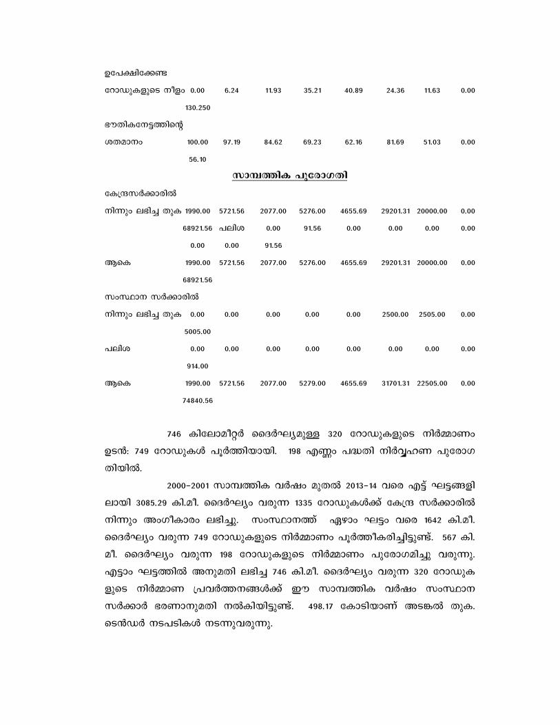
746 Intem-ao-äÀ ssZÀL-y-apÅ 320 tdmUp-I-fpsS \nÀ½mWw
DS³: 749 tdmUp-IÄ ]qÀ¯n-bm-bn. 198 F®w ]²Xn \nÀÆlW ]ptcm-K-
Xn-bnÂ.
2000-þ2001 km¼¯nI hÀjw apX 2013-þ14 hsc F«v L«-§-fn-
embn 3085.29 In.-ao. ssZÀLyw hcp¶ 1335 tdmUp-IÄ¡v tIµ kÀ¡m-cnÂ
\n¶pw AwKo-Imcw e`n-¨p. kwØm-\¯v Ggmw L«w hsc 1642 In.-ao.
ssZÀLyw hcp¶ 749 tdmUp-I-fpsS \nÀ½mWw ]qÀ¯o-I-c-n-¨-n«p-−v. 567 In.-
ao. ssZÀLyw hc-p¶ 198 tdmUp-I-fpsS \nÀ½mWw ]p-tcm-K-an¨p hcp-¶p.
F«mw L«-¯n A\p-aXn e`n¨ 746 In.-ao. ssZÀLyw hcp¶ 320 tdmUp-I-
fpsS \nÀ½mW ]hÀ¯--\-§Ä¡v Cu km¼-¯nI hÀjw kwØm\
kÀ¡mÀ `c-Wm-\p-aXn \ÂIn-bn-«p-−v. 498.17 tImSn-bmWv AS-¦Â XpI.
sS³UÀ \S-]-Sn-IÄ \S-¶p-h-cp-¶p.
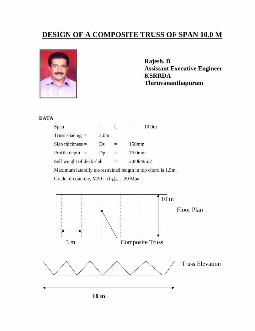
DESIGN OF A COMPOSITE TRUSS OF SPAN 10.0 M
Rajesh. D Assistant Executive Engineer KSRRDA Thiruvananthapuram
DATA
Span = L = 10.0m
Truss spacing = 3.0m
Slab thickness = Ds = 150mm
Profile depth = Dp = 75.0mm
Self weight of deck slab = 2.80kN/m2
Maximum laterally un-restrained length in top chord is 1.5m.
Grade of concrete, M20 = (fck)cu = 20 Mpa
10 m
Floor Plan
3 m Composite Truss
Truss Elevation
10 m
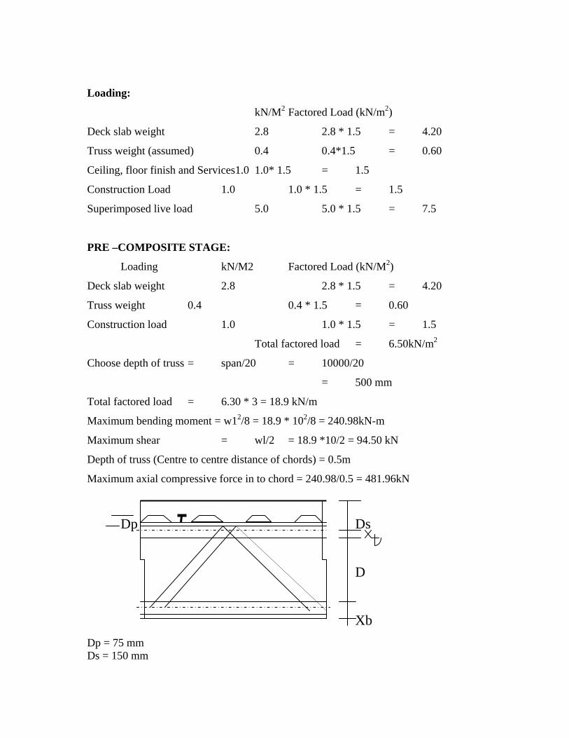
Loading:
kN/M2 Factored Load (kN/m2)
Deck slab weight 2.8 2.8 * 1.5 = 4.20
Truss weight (assumed) 0.4 0.4*1.5 = 0.60
Ceiling, floor finish and Services1.0 1.0* 1.5 = 1.5
Construction Load 1.0 1.0 * 1.5 = 1.5
Superimposed live load 5.0 5.0 * 1.5 = 7.5
PRE –COMPOSITE STAGE:
Loading kN/M2 Factored Load (kN/M2)
Deck slab weight 2.8 2.8 * 1.5 = 4.20
Truss weight 0.4 0.4 * 1.5 = 0.60
Construction load 1.0 1.0 * 1.5 = 1.5
Total factored load = 6.50kN/m2
Choose depth of truss = span/20 = 10000/20
= 500 mm
Total factored load = 6.30 * 3 = 18.9 kN/m
Maximum bending moment = w12/8 = 18.9 * 102/8 = 240.98kN-m
Maximum shear = wl/2 = 18.9 *10/2 = 94.50 kN
Depth of truss (Centre to centre distance of chords) = 0.5m
Maximum axial compressive force in to chord = 240.98/0.5 = 481.96kN
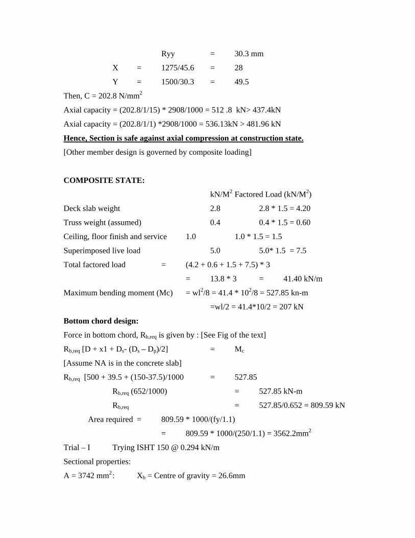
Dp Ds
D
Xb Dp = 75 mm Ds = 150 mm
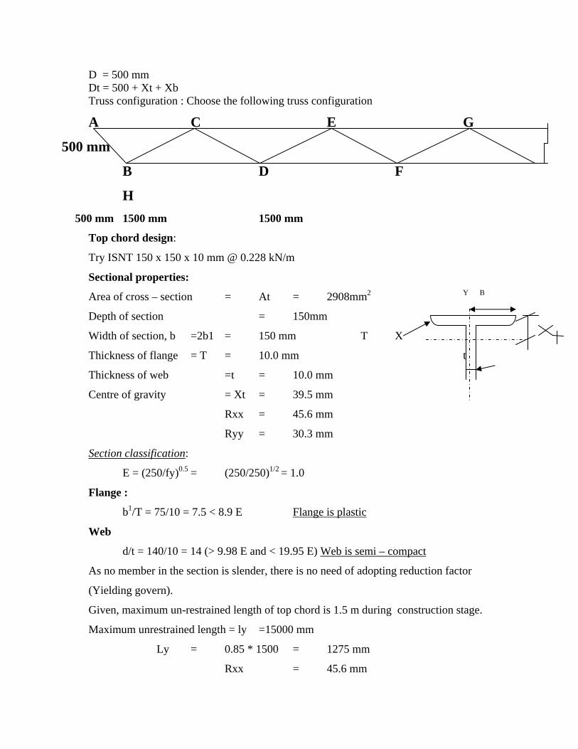
D = 500 mm Dt = 500 + Xt + Xb Truss configuration : Choose the following truss configuration
A C E G
500 mm
B D F
H 500 mm 1500 mm 1500 mm
Top chord design:
Try ISNT 150 x 150 x 10 mm @ 0.228 kN/m
Sectional properties:
Area of cross – section = At = 2908mm2 Y B
Depth of section = 150mm
Width of section, b =2b1 = 150 mm T X
Thickness of flange = T = 10.0 mm t
Thickness of web =t = 10.0 mm
Centre of gravity = Xt = 39.5 mm
Rxx = 45.6 mm
Ryy = 30.3 mm
Section classification:
E = (250/fy)0.5 = (250/250)1/2 = 1.0
Flange :
b1/T = 75/10 = 7.5 < 8.9 E Flange is plastic
Web
d/t = 140/10 = 14 (> 9.98 E and < 19.95 E) Web is semi – compact
As no member in the section is slender, there is no need of adopting reduction factor
(Yielding govern).
Given, maximum un-restrained length of top chord is 1.5 m during construction stage.
Maximum unrestrained length = ly =15000 mm
Ly = 0.85 * 1500 = 1275 mm
Rxx = 45.6 mm
Ryy = 30.3 mm
X = 1275/45.6 = 28
Y = 1500/30.3 = 49.5
Then, C = 202.8 N/mm2
Axial capacity = (202.8/1/15) * 2908/1000 = 512 .8 kN> 437.4kN
Axial capacity = (202.8/1/1) *2908/1000 = 536.13kN > 481.96 kN
Hence, Section is safe against axial compression at construction state.
[Other member design is governed by composite loading]
COMPOSITE STATE:
kN/M2 Factored Load (kN/M2)
Deck slab weight 2.8 2.8 * 1.5 = 4.20
Truss weight (assumed) 0.4 0.4 * 1.5 = 0.60
Ceiling, floor finish and service 1.0 1.0 * 1.5 = 1.5
Superimposed live load 5.0 5.0* 1.5 = 7.5
Total factored load = (4.2 + 0.6 + 1.5 + 7.5) * 3
= 13.8 * 3 = 41.40 kN/m
Maximum bending moment (Mc) = wl2/8 = 41.4 * 102/8 = 527.85 kn-m
=wl/2 = 41.4*10/2 = 207 kN
Bottom chord design:
Force in bottom chord, Rb,req is given by : [See Fig of the text]
Rb,req [D + x1 + Ds- (Ds – Dp)/2] = Mc
[Assume NA is in the concrete slab]
Rb,req [500 + 39.5 + (150-37.5)/1000 = 527.85
Rb,req (652/1000) = 527.85 kN-m
Rb,req = 527.85/0.652 = 809.59 kN
Area required = 809.59 * 1000/(fy/1.1)
= 809.59 * 1000/(250/1.1) = 3562.2mm2
Trial – I Trying ISHT 150 @ 0.294 kN/m
Sectional properties:
A = 3742 mm2 : Xb = Centre of gravity = 26.6mm
Width of the section, b = 2b1 = 250 mm
Axial tension capacity of the selected section (Rb):
Rb = (250/1.1) * 3742/1000 = 850.46kN > 809.59 kN
Hence, O.K.
Capacity of composite Section in compression :
Capacity of concrete slab, Rc, is given by
Rc = 0.45 (Fck)cu * beff* (Ds-Dp)
Effective width of the slab, beff :
beff < l/4 = 10000/4 = 2500 mm
Therefore, beff = 2500 mm
Rc = 0.45 * 20*2500*75/1000 [Fck = 20N/mm2]
= 1687.5kN >Rb (tension governs)
Neutral axis depth:
Xc = (Ds – Dp) *850.46/1687.5 = 75*850.46/1687.5 = 37.8 mm
Dt = 0.5 + 0.0266 + 0.0395 = 0.566mm
Then, maximum moment it can carry
Mu, Design = 850.46 (0.566 + 0.15-0.5 * 0.0378-0.0266)
= 570.23 kN-m>527.85 kN-m
Hence, the slab and chord members are designed.
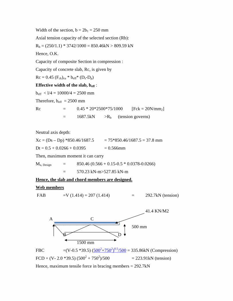
Web members
FAB =V (1.414) = 207 (1.414) = 292.7kN (tension)
41.4 KN/M2
A C
500 mm
B D
1500 mm
FBC =(V-0.5 *39.5) (5002+7502)0.5/500 = 335.86kN (Compression)
FCD + (V- 2.0 *39.5) (5002 + 7502)/500 = 223.91kN (tension)
Hence, maximum tensile force in bracing members = 292.7kN

Maximum compressive force in bracing members = 335.86kN
Design of tension members:
Trial gross area required = 292.7 * 103/(250/1.1) = 1287mm2
Trying 2 – ISA 70 x 70 x6.0 @ 0.126 kN/m
Agross provided = 2*806 = 1612mm2
Effective area :
(Assume, angle is welded to T – Section)
A net effective = 1612 mm2
Axial tension capacity = Ae * (fy/ym)
= 1612*25/1.1
= 366.36kN > 292.7kN
Hence, 2 – ISA 70 x 70 x 6.0 are adequate
Design of compression member
Maximum compressive load = 320 kN
Trying 2 – ISA 80 x 80x 6.0 @ 0.146 kN/m
A = 1858mm2
Rxx = 24.6 mm
Ruu = 34.9 mm
Section classification:
b/t = 80/6 = 13.3 < 15.75E
Hence, the section is not slender and no need to apply any reduction factor.
Slenderness ratio is taken as the greater of
Length of member + (7502 + 5002)0.5 = 901 mm
Xx = 0.85 * 901/24.6 = 31.1
Xx = 1.0 * 901/34.9 = 25.8
Design buckling strength = c = 231.2 Mpa
[Table – 3 of chapter on axially compressed columns]
Design compressive strength = 1858* (231.2/1/1)/103 =390.52 kN> 335.86kN
Hence the 2 – ISA 80 x 80x 6.0 are adequate for the web members
(The web members away from the support would have lesser axial force and can be
redesigned, if so desired. Preferably use the same section for all web members)
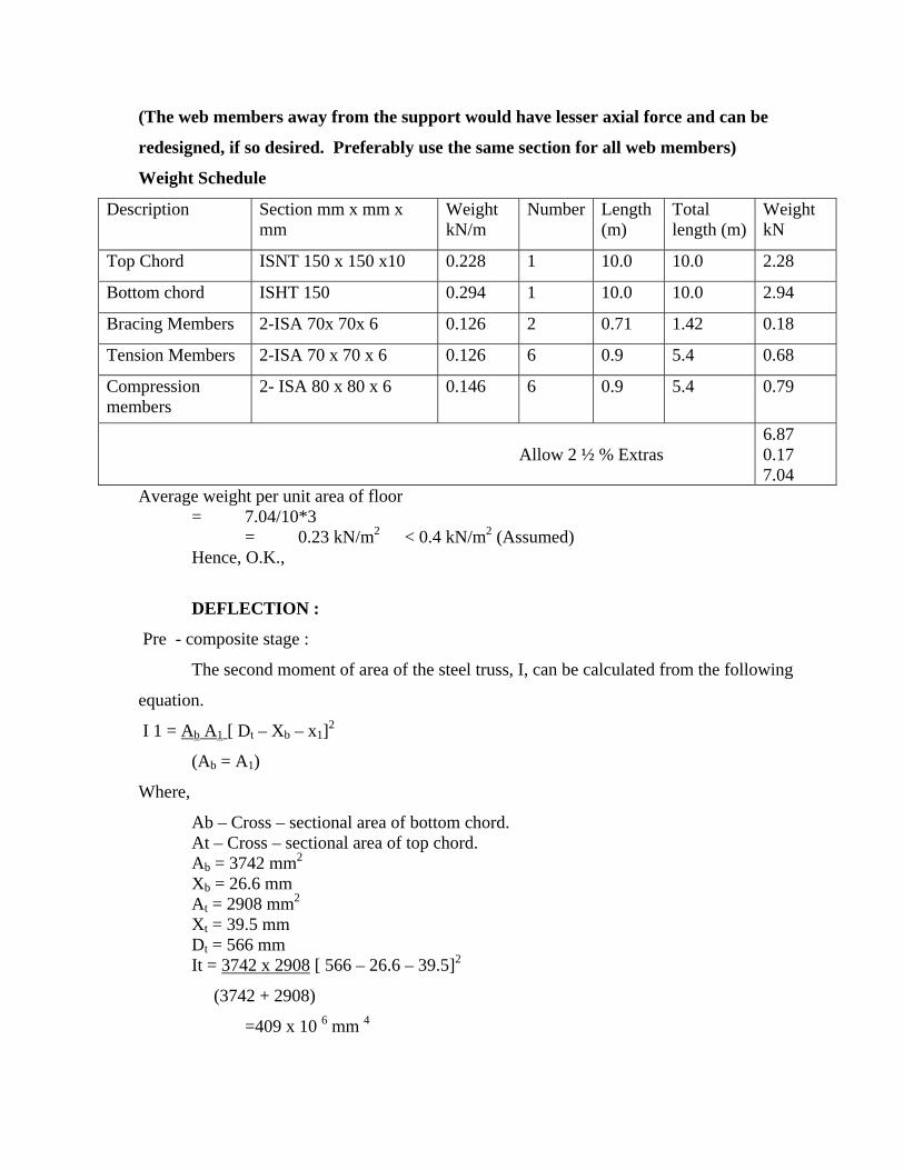
Weight Schedule
Description Section mm x mm x mm
Weight kN/m
Number Length (m)
Total length (m)
Weight kN
Top Chord ISNT 150 x 150 x10 0.228 1 10.0 10.0 2.28
Bottom chord ISHT 150 0.294 1 10.0 10.0 2.94
Bracing Members 2-ISA 70x 70x 6 0.126 2 0.71 1.42 0.18
Tension Members 2-ISA 70 x 70 x 6 0.126 6 0.9 5.4 0.68
Compression members
2- ISA 80 x 80 x 6 0.146 6 0.9 5.4 0.79
Allow 2 ½ % Extras
6.87 0.17 7.04
Average weight per unit area of floor = 7.04/10*3 = 0.23 kN/m2 < 0.4 kN/m2 (Assumed) Hence, O.K.,
DEFLECTION :
Pre - composite stage :
The second moment of area of the steel truss, I, can be calculated from the following
equation.
I 1 = Ab A1 [ Dt – Xb – x1]2
(Ab = A1)
Where,
Ab – Cross – sectional area of bottom chord. At – Cross – sectional area of top chord. Ab = 3742 mm2
Xb = 26.6 mm At = 2908 mm2 Xt = 39.5 mm Dt = 566 mm It = 3742 x 2908 [ 566 – 26.6 – 39.5]2
(3742 + 2908)
=409 x 10 6 mm 4
Loading
kN/M2
Deck slab weight 2.80
Truss weight 0.23
Construction load 1.00
4.03
Total load = 4.03*3*10 = 121kN
Deflection at pre composite state is given by
(5 * 121* 100003) (384 * 200*409*106) = 19.3 mm
Deflection at composite state due to dead load = d1 = (3.03/4.03)*19.3
=14.5 mm
[For composite stage construction load has to removed for calculating deflections]
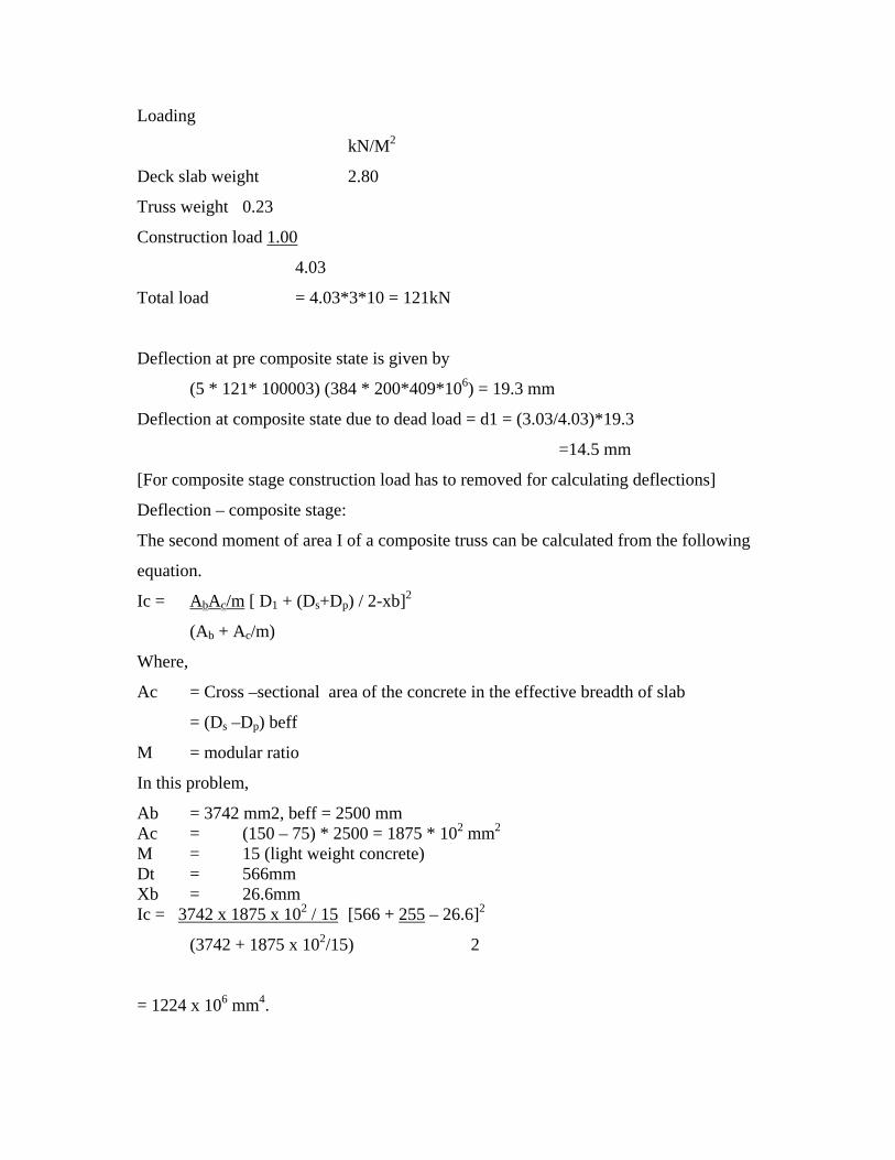
Deflection – composite stage:
The second moment of area I of a composite truss can be calculated from the following
equation.
Ic = AbAc/m [ D1 + (Ds+Dp) / 2-xb]2
(Ab + Ac/m)
Where,
Ac = Cross –sectional area of the concrete in the effective breadth of slab
= (Ds –Dp) beff
M = modular ratio
In this problem,
Ab = 3742 mm2, beff = 2500 mm Ac = (150 – 75) * 2500 = 1875 * 102 mm2 M = 15 (light weight concrete) Dt = 566mm Xb = 26.6mm Ic = 3742 x 1875 x 102 / 15 [566 + 255 – 26.6]2
(3742 + 1875 x 102/15) 2
= 1224 x 106 mm4.
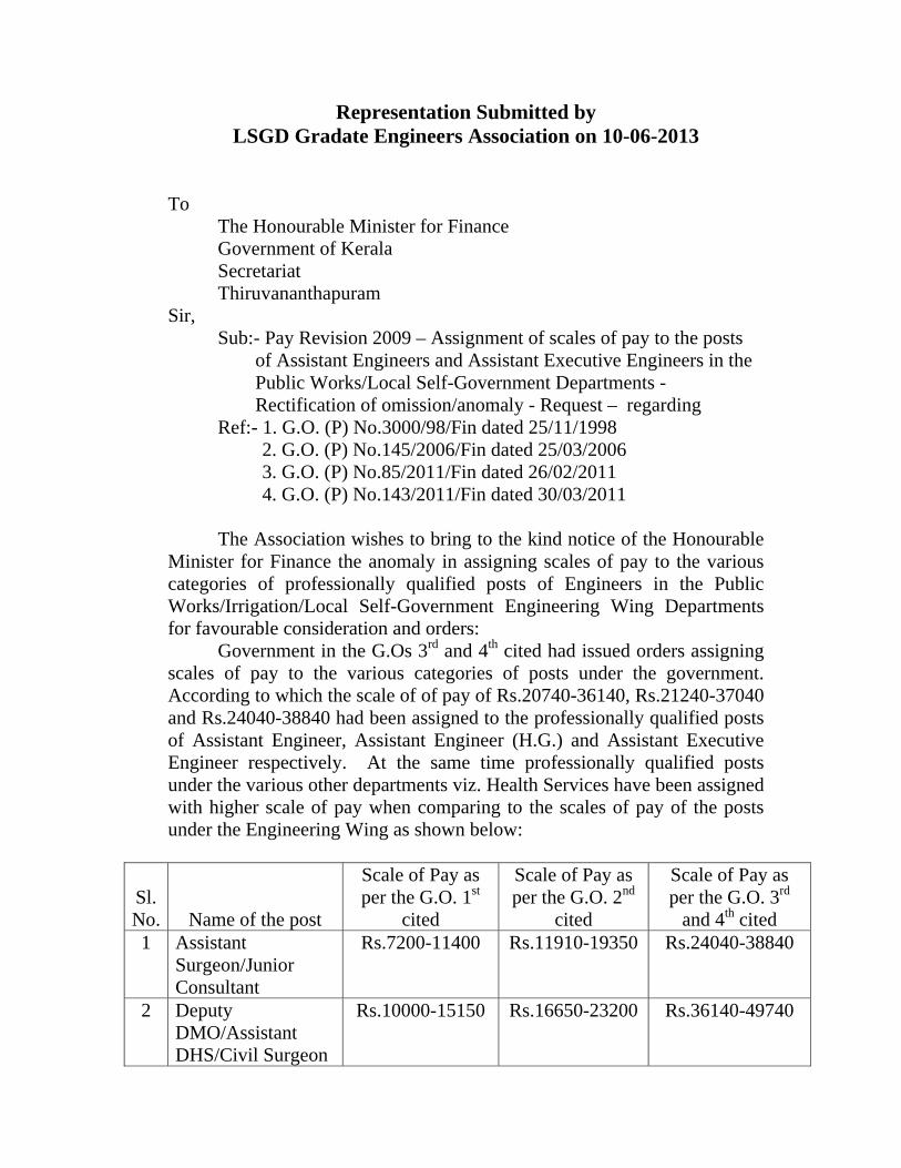
Representation Submitted by LSGD Gradate Engineers Association on 10-06-2013
To
The Honourable Minister for Finance Government of Kerala Secretariat Thiruvananthapuram
Sir, Sub:- Pay Revision 2009 – Assignment of scales of pay to the posts
of Assistant Engineers and Assistant Executive Engineers in the Public Works/Local Self-Government Departments - Rectification of omission/anomaly - Request – regarding
Ref:- 1. G.O. (P) No.3000/98/Fin dated 25/11/1998 2. G.O. (P) No.145/2006/Fin dated 25/03/2006 3. G.O. (P) No.85/2011/Fin dated 26/02/2011 4. G.O. (P) No.143/2011/Fin dated 30/03/2011
The Association wishes to bring to the kind notice of the Honourable
Minister for Finance the anomaly in assigning scales of pay to the various categories of professionally qualified posts of Engineers in the Public Works/Irrigation/Local Self-Government Engineering Wing Departments for favourable consideration and orders:
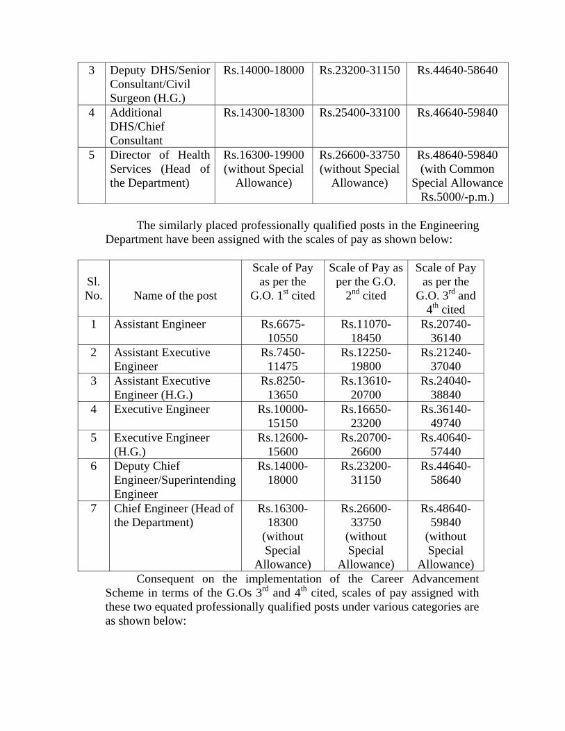
Government in the G.Os 3rd and 4th cited had issued orders assigning scales of pay to the various categories of posts under the government. According to which the scale of of pay of Rs.20740-36140, Rs.21240-37040 and Rs.24040-38840 had been assigned to the professionally qualified posts of Assistant Engineer, Assistant Engineer (H.G.) and Assistant Executive Engineer respectively. At the same time professionally qualified posts under the various other departments viz. Health Services have been assigned with higher scale of pay when comparing to the scales of pay of the posts under the Engineering Wing as shown below:
Sl. No.
Name of the post
Scale of Pay as per the G.O. 1st
cited
Scale of Pay as per the G.O. 2nd
cited
Scale of Pay as per the G.O. 3rd
and 4th cited 1 Assistant
Surgeon/Junior Consultant
Rs.7200-11400 Rs.11910-19350 Rs.24040-38840
2 Deputy DMO/Assistant DHS/Civil Surgeon
Rs.10000-15150 Rs.16650-23200 Rs.36140-49740
3 Deputy DHS/Senior Consultant/Civil Surgeon (H.G.)
Rs.14000-18000 Rs.23200-31150 Rs.44640-58640
4 Additional DHS/Chief Consultant
Rs.14300-18300 Rs.25400-33100 Rs.46640-59840
5 Director of Health Services (Head of the Department)
Rs.16300-19900 (without Special
Allowance)
Rs.26600-33750 (without Special
Allowance)
Rs.48640-59840 (with Common
Special Allowance Rs.5000/-p.m.)
The similarly placed professionally qualified posts in the Engineering
Department have been assigned with the scales of pay as shown below:
Sl. No.
Name of the post
Scale of Pay as per the
G.O. 1st cited
Scale of Pay as per the G.O.
2nd cited
Scale of Pay as per the
G.O. 3rd and 4th cited
1 Assistant Engineer Rs.6675-10550
Rs.11070-18450
Rs.20740-36140
2 Assistant Executive Engineer
Rs.7450-11475
Rs.12250-19800
Rs.21240-37040
3 Assistant Executive Engineer (H.G.)
Rs.8250-13650
Rs.13610-20700
Rs.24040-38840
4 Executive Engineer Rs.10000-15150
Rs.16650-23200
Rs.36140-49740
5 Executive Engineer (H.G.)
Rs.12600-15600
Rs.20700-26600
Rs.40640-57440
6 Deputy Chief Engineer/Superintending Engineer
Rs.14000-18000
Rs.23200-31150
Rs.44640-58640
7 Chief Engineer (Head of the Department)
Rs.16300-18300
(without Special
Allowance)
Rs.26600-33750
(without Special
Allowance)
Rs.48640-59840
(without Special
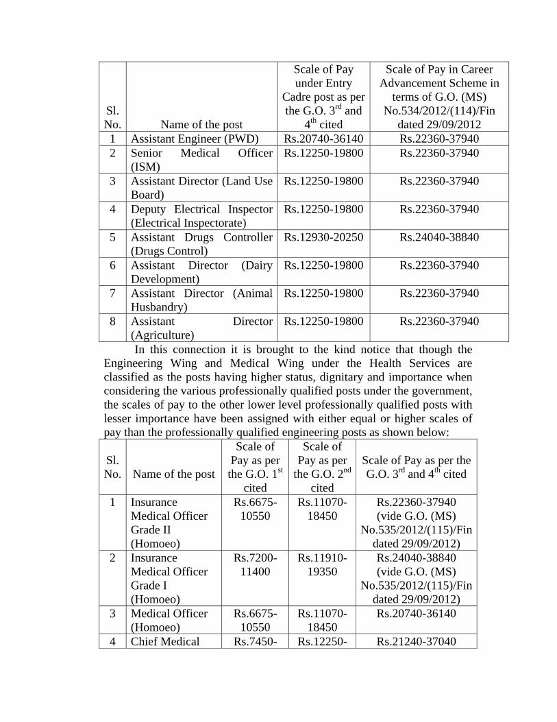
Allowance) Consequent on the implementation of the Career Advancement
Scheme in terms of the G.Os 3rd and 4th cited, scales of pay assigned with these two equated professionally qualified posts under various categories are as shown below:
Sl. No.
Name of the post
Scale of Pay under Entry
Cadre post as per the G.O. 3rd and
4th cited
Scale of Pay in Career Advancement Scheme in
terms of G.O. (MS) No.534/2012/(114)/Fin
dated 29/09/2012 1 Assistant Engineer (PWD) Rs.20740-36140 Rs.22360-37940 2 Senior Medical Officer
(ISM) Rs.12250-19800 Rs.22360-37940
3 Assistant Director (Land Use Board)
Rs.12250-19800 Rs.22360-37940
4 Deputy Electrical Inspector (Electrical Inspectorate)
Rs.12250-19800 Rs.22360-37940
5 Assistant Drugs Controller (Drugs Control)
Rs.12930-20250 Rs.24040-38840
6 Assistant Director (Dairy Development)
Rs.12250-19800 Rs.22360-37940
7 Assistant Director (Animal Husbandry)
Rs.12250-19800 Rs.22360-37940
8 Assistant Director (Agriculture)
Rs.12250-19800 Rs.22360-37940
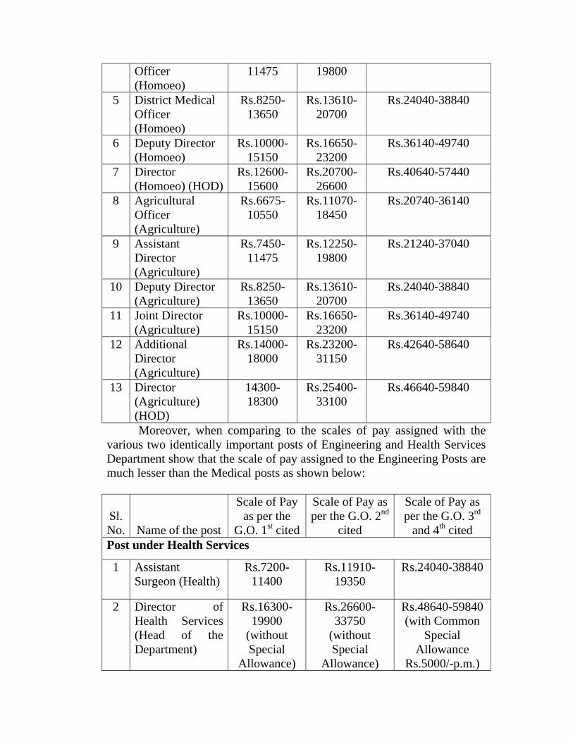
In this connection it is brought to the kind notice that though the Engineering Wing and Medical Wing under the Health Services are classified as the posts having higher status, dignitary and importance when considering the various professionally qualified posts under the government, the scales of pay to the other lower level professionally qualified posts with lesser importance have been assigned with either equal or higher scales of pay than the professionally qualified engineering posts as shown below:
Sl. No.
Name of the post
Scale of Pay as per the G.O. 1st
cited
Scale of Pay as per
the G.O. 2nd cited
Scale of Pay as per the G.O. 3rd and 4th cited
1 Insurance Medical Officer Grade II (Homoeo)
Rs.6675-10550
Rs.11070-18450
Rs.22360-37940 (vide G.O. (MS)
No.535/2012/(115)/Fin dated 29/09/2012)
2 Insurance Medical Officer Grade I (Homoeo)
Rs.7200-11400
Rs.11910-19350
Rs.24040-38840 (vide G.O. (MS)
No.535/2012/(115)/Fin dated 29/09/2012)
3 Medical Officer (Homoeo)
Rs.6675-10550
Rs.11070-18450
Rs.20740-36140
4 Chief Medical Rs.7450- Rs.12250- Rs.21240-37040
Officer (Homoeo)
11475 19800
5 District Medical Officer (Homoeo)
Rs.8250-13650
Rs.13610-20700
Rs.24040-38840
6 Deputy Director (Homoeo)
Rs.10000-15150
Rs.16650-23200
Rs.36140-49740
7 Director (Homoeo) (HOD)
Rs.12600-15600
Rs.20700-26600
Rs.40640-57440
8 Agricultural Officer (Agriculture)
Rs.6675-10550
Rs.11070-18450
Rs.20740-36140
9 Assistant Director (Agriculture)
Rs.7450-11475
Rs.12250-19800
Rs.21240-37040
10 Deputy Director (Agriculture)
Rs.8250-13650
Rs.13610-20700
Rs.24040-38840
11 Joint Director (Agriculture)
Rs.10000-15150
Rs.16650-23200
Rs.36140-49740
12 Additional Director (Agriculture)
Rs.14000-18000
Rs.23200-31150
Rs.42640-58640
13 Director (Agriculture) (HOD)
14300-18300
Rs.25400-33100
Rs.46640-59840
Moreover, when comparing to the scales of pay assigned with the various two identically important posts of Engineering and Health Services Department show that the scale of pay assigned to the Engineering Posts are much lesser than the Medical posts as shown below:
Sl. No.
Name of the post
Scale of Pay as per the
G.O. 1st cited
Scale of Pay as per the G.O. 2nd
cited
Scale of Pay as per the G.O. 3rd
and 4th cited Post under Health Services
1 Assistant Surgeon (Health)
Rs.7200-11400
Rs.11910-19350
Rs.24040-38840
2 Director of Health Services (Head of the Department)
Rs.16300-19900
(without Special
Allowance)
Rs.26600-33750
(without Special
Allowance)
Rs.48640-59840 (with Common
Special Allowance
Rs.5000/-p.m.)

Identical/Higher Post under Engineering Department1 Assistant
Executive Engineer
Rs.7450-11475
Rs.12250-19800
Rs.21240-37040
2 Chief Engineer (Head of the Department)
Rs.16300-18300
(without Special
Allowance)
Rs.26600-33750
(without Special
Allowance)
Rs.48640-59840 (without Special
Allowance)
The above disparity in assigning the scales of pay to the various categories of professionally qualified engineering posts under the government will deteriorate the status, dignity and importance as specially assigned to these categories of posts, which will in turn affect the accountability, efficiency as well as other administrative convenience of these well defined professionals.
Considering the above facts under public interest we most humbly request the Honourable Finance Minister to properly review the scales of pay assigned to the professionally qualified engineering posts as prescribed in the G.Os 3rd and 4th cited and to allow one jump of the scales of pay to these specially qualified posts as shown below:
Sl. No.
Name of the post
Proposed Scales of Pay in terms of the G.O. 3rd and 4th cited
1 Assistant Engineer Rs.22360-37940 2 Assistant Executive Engineer Rs.24040-38840 3 Assistant Executive Engineer (H.G.) Rs.29180-43640 4 Executive Engineer Rs.40640-57440 5 Executive Engineer (H.G.) Rs.42640-58640 6 Deputy Chief Engineer/Superintending
Engineer Rs.46640-59840
7 Chief Engineer (Head of the Department)
Rs.48640-59840 (with Special Allowance of Rs.5000 as applicable to the DHS)
Yours faithfully,
GENERAL SECRETARY
Related Documents