Cummins Industrial Electronics Training 2002 1 • Agenda – Basic Training: J1939 Vocabulary – Basic Training: Monitoring – Basic Training: Control – Basic Training: Tools / Information – Advanced: J1939 message breakdown – Advanced: J1939 diagnostic messages – Advanced: J1939 multiplexing J1939 Training

Welcome message from author
This document is posted to help you gain knowledge. Please leave a comment to let me know what you think about it! Share it to your friends and learn new things together.
Transcript

Cummins Industrial Electronics Training 20021
• Agenda– Basic Training: J1939 Vocabulary– Basic Training: Monitoring– Basic Training: Control– Basic Training: Tools / Information– Advanced: J1939 message breakdown– Advanced: J1939 diagnostic messages– Advanced: J1939 multiplexing
J1939 Training
Cummins Industrial Electronics Training 20022
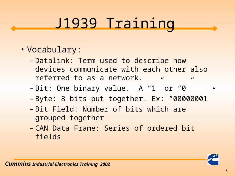
• Vocabulary:– Datalink: Term used to describe how devices
communicate with each other also referred to as a network.
– Bit: One binary value. A “1” or “0”– Byte: 8 bits put together. Ex: “00000001”– Bit Field: Number of bits which are grouped
together– CAN Data Frame: Series of ordered bit fields
J1939 Training
Cummins Industrial Electronics Training 20023
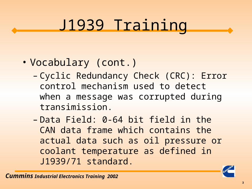
• Vocabulary (cont.)– Cyclic Redundancy Check (CRC): Error
control mechanism used to detect when a message was corrupted during transimission.
– Data Field: 0-64 bit field in the CAN data frame which contains the actual data such as oil pressure or coolant temperature as defined in J1939/71 standard.
J1939 Training

Cummins Industrial Electronics Training 20024
• Vocabulary (cont.)– Destination Address: Address of who is
suppose to receive the message. (not included in all J1939 messages)
» Global Address is 255 or FF hex
– Device: Any physical component which listens to or sends information out on the J1939 datalink.
– Electronic Control Unit: same as a device
J1939 Training

Cummins Industrial Electronics Training 20025
• Vocabulary (cont.)– End of Frame: 7 bit field which marks the end of a
CAN frame– Extended Frame: A CAN frame which contains a
29 bit identifier as defined in the CAN2.0B standard.
» Note: J1939 allows both 11bit and 29 bit Identifers to coexist on the same network.
– Frame: A series of data bits making up a complete message. The frame contains several bit fields
J1939 Training
Cummins Industrial Electronics Training 20026
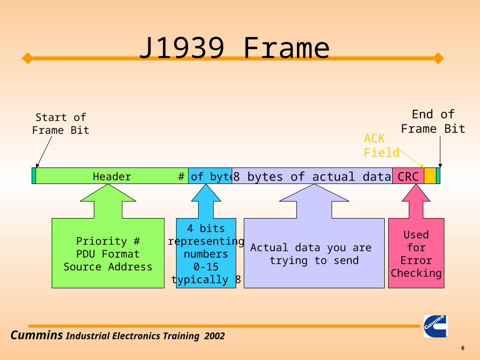
Header # of bytes 8 bytes of actual data CRC
Start ofFrame Bit
ACKField
End ofFrame Bit
Priority #PDU Format
Source Address
4 bitsrepresenting
numbers0-15
typically 8
Actual data you are trying to send
Usedfor
ErrorChecking
J1939 Frame
Cummins Industrial Electronics Training 20027
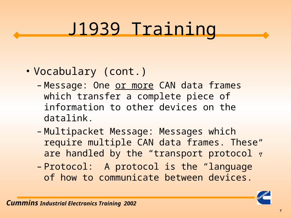
• Vocabulary (cont.)– Message: One or more CAN data frames which
transfer a complete piece of information to other devices on the datalink.
– Multipacket Message: Messages which require multiple CAN data frames. These are handled by the “transport protocol”.
– Protocol: A protocol is the “language” of how to communicate between devices.
J1939 Training

Cummins Industrial Electronics Training 20028
• Vocabulary (cont.)– Parameter Group Number (PGN): a 24 bit
identifier used to identify a message which contains a particular group of parameters.
– Parameter Group: A collection of parameters that are conveyed in a J1939 message.
– PDU1 Format: Format used when specifying a destination address
J1939 Training

Cummins Industrial Electronics Training 20029
• Vocabulary (cont.)– PDU2 Format: Format used when broadcasting
information.– Priority: The highest priority is zero. Lowest
priority is seven.– Source Address: Address of who is sending the
message on the datalink.– Start of Frame: Bit used to indicate the start of a
CAN frame.
J1939 Training

Cummins Industrial Electronics Training 200210
• Vocabulary (Cont.)– Suspect Parameter Number (SPN): The
particular element which is having a problem. This is used in the fault codes to tell us which part is having a problem. (Sensor, ECM, etc..)
– Failure Mode Identifer (FMI): Used to say how a particular SPN has failed.
J1939 Training

Cummins Industrial Electronics Training 200211
J1939 Training

Cummins Industrial Electronics Training 200212
Physical Transmission MediaPhysical
Data LinkNetworkTransportSession
PresentationApplication
PhysicalData LinkNetworkTransportSession
PresentationApplication
Layer Number
7654321
OSI Network Model

Cummins Industrial Electronics Training 200213
• Physical Layer• Translates bits to waveforms required by electrical interface
• Data Link Layer• Adds “header” and “trailer” to message for determining if errors occurred
in message transmission, start and end of frame, etc...
• Network Layer• Adds or looks at who sent the message and where the message going
• Transport Layer• Breaks and reassembles large messages into smaller messages for
sending over the network
• Session Layer• Handles access rights … may not want everyone to see all data
OSI Network Model

Cummins Industrial Electronics Training 200214
• Presentation Layer• Data encryption, data compression, etc...
• Application Layer• Whatever is left over from other layers….
OSI Network Model
Cummins Industrial Electronics Training 200215
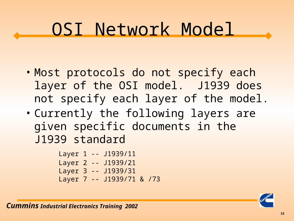
• Most protocols do not specify each layer of the OSI model. J1939 does not specify each layer of the model.
• Currently the following layers are given specific documents in the J1939 standard
Layer 1 -- J1939/11Layer 2 -- J1939/21Layer 3 -- J1939/31Layer 7 -- J1939/71 & /73
OSI Network Model
Cummins Industrial Electronics Training 200216
• What can I monitor?
• What must I monitor to remove the indicator lights?
• Where do I find out how to interpret the messages?
• Example of reading oil pressure
J1939 Training

Cummins Industrial Electronics Training 200217
All Module Information
BroadcastData
RequestOnlyData
J1939 Training

Cummins Industrial Electronics Training 200218
• What can I monitor?– Sensor parameters such as coolant temperature,
oil pressure, etc…– Engine Fault Codes
J1939 Training

Cummins Industrial Electronics Training 200219
• What must I monitor to remove the indicator lights?– All fault code SPNs (suspect parameter number
and FMIs (failure mode indicator) must be displayed.
J1939 Training

Cummins Industrial Electronics Training 200220
• Where do I find out how to interpret the messages?– Parameter data messages are found in the J1939/71
standard. Find the PGN first then look up the individual parameter definitions.
– Fault Code (Diagnostic) messages are found in the J1939/73 standard. You will also need to use the wiring diagram, or AEB for the specific engine to understand what Cummins fault code goes with a SPN / FMI pair.
J1939 Training

Cummins Industrial Electronics Training 200221
J1939 Control
• What can the customer control?– Engine speed can be controlled via the J1939
datalink.– Fan Clutch

Cummins Industrial Electronics Training 200222
• High Speed datalinks– Reflections & Terminations– Topology– Troubleshooting
J1939 Training

Cummins Industrial Electronics Training 200223
• Reflections & Terminations– Terminations are required to minimize reflections
on the datalink (demo)– J1939/11 requires two 120ohm terminations for
the datalink. – EA options for QSX/QSM only use one 120ohm
termination due to the short length between the ECM and the service datalink connection.
• ICAD Database has more detailed information
J1939 Training

Cummins Industrial Electronics Training 200224
• Circuit block diagram– Most of our modules use the Intel 82527 Serial
Communcations Controller ( CM500, CENSE, CM550, CM570, etc...)
– Example circuits shown in J1939/11 specification
ESDProtection
Circuit
CAN TransceiverSerial
CommunicationsController
Micro( 68332 )
J1939 Training
OutsideECM
InsideECM

Cummins Industrial Electronics Training 200225
120Ώ
Length of Backbone: .1 - 40mLength of Stub: 0 - 1mMaximum number of nodes: 30Terminations : 120ΩMinimum Spacing: 0.1 m Note: Do not equally
space the node connectionson the backbone
120Ώ
J1939 Topology
Stub
Backbone

Cummins Industrial Electronics Training 200226
• Dynamic Addressing– Each ECM on the network takes on an address
at startup. The specific address may be different from startup to startup.
• Cummins does not support dynamic addressing; therefore, make sure each device on the datalink has a unique address.
J1939 Addressing
Cummins Industrial Electronics Training 200227
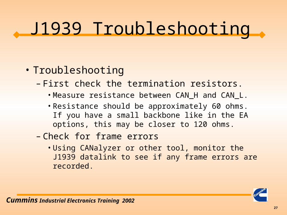
• Troubleshooting– First check the termination resistors.
• Measure resistance between CAN_H and CAN_L.
• Resistance should be approximately 60 ohms. If you have a small backbone like in the EA options, this may be closer to 120 ohms.
– Check for frame errors• Using CANalyzer or other tool, monitor the J1939
datalink to see if any frame errors are recorded.
J1939 Troubleshooting

Cummins Industrial Electronics Training 200228
• Troubleshooting (cont.)– Monitor broadcast parameters using CANalyzer– For multiplexed parameters, verify that the
OEM / DOEM is sending the correct source address in the message.
– Unplug other devices from the datalink so only the PC and ECM are on the network.
J1939 Troubleshooting

Cummins Industrial Electronics Training 200229
• Tools– Protocol analyzer
• Must have a protocol analyzer to develop a datalink interface.
• Must have the J1939 standard unless customer already has good familiarity with CAN 2.0B protocol.
J1939 Tools

Cummins Industrial Electronics Training 200230
– CANalyzer
» In North America contact: Vector CANtech Inc. (248) 449-9290 Matt Palmer
» Outside America contact:
49-711-80670-505
Lother Felbinger
» Approximate Cost: Software: $2,700 Hardware: $1,185
J1939 Tools

Cummins Industrial Electronics Training 200231
– Jpro
» Cummins owned distributors: Software available through engineering tools (see intranet site: etools.ctg.cummins.com) Hardware available through Industrial Communication Technologies.
» North America: call (978) 499 - 9271
» Outside North America: 49 89 46 1090
» Appoximate costs: $910
» Non Cummins owned distributors: Software is NOT available through engineering tools. Recommend CANalyzer
» Jpro support from manufacturer ends 12/01.
J1939 Tools

Cummins Industrial Electronics Training 200232
• Quick Check II available 4th Qtr 2001
– J1939 specification• Can be ordered online at www.sae.org for $495.00
USD for non-SAE members and $395.00 USD for SAE members.
J1939 Tools
Cummins Industrial Electronics Training 200233
J1939 Message Breakdown

Cummins Industrial Electronics Training 200234
Header # of bytes 8 bytes of actual data CRC
Start ofFrame Bit
ACKField
End ofFrame Bit
Priority #PDU Format
Source Address
4 bitsrepresenting
numbers0-15
typically 8
Actual data you are trying to send
Usedfor
ErrorChecking
J1939 Frame

Cummins Industrial Electronics Training 200235
CAN ExtendedFrame Format
J1939Frame Format
J1939 Framebit position
CAN 29 bitID position
1
SOF
SOF
3 12
2 3 4
28
26
27
8 7 6 5 4 3
PDU Format6 bits (MSB)
SRR
IDE
PF
2 18 7 6 5 4 3 2 1 8 7 6 5 4 3 2 1
Priority
RDP
PDU SpecificDestination Address,Group Ext, orProprietary
Source Address
Identifier11 bits
Identifier Extension18 bits
SRR
IDE
RTR
RTR
5 6
7
8 9 10
11
12
13
14
15
16
17
18
19
20
21
22
23
24
25
26
27
28
29
30
31
32
33
25
24
23
22
21
20
19
18
17
16
15
14
13
12
11
10
9 8 6 5 4 3 2 1 0
J1939 29 bit Identifier

Cummins Industrial Electronics Training 200236
1 8 F E D F 0 2
1 1000 1111 1110 1101 1111 0000 0010
3 bitsPriorityNumber
Res
erve
dD
ata
Pag
e
PDU Format (PF)PDU Specific (PS)
Contains DestinationAddress if PF <239
Source Address
Header Breakdown (29 bits)
J1939 29 bit Identifier

Cummins Industrial Electronics Training 200237
• Looking at data messages on the CANalyzer.0.1360 1 18FEDF02x Rx d 8 7D E0 2E 7D FF FF FF FF
8 bytes of data representedin hexadecimal
# ofDataBytes
29 bit header
CANSerialInput #
time Rxor TX
J1939 Data Message Interpretation
Cummins Industrial Electronics Training 200238
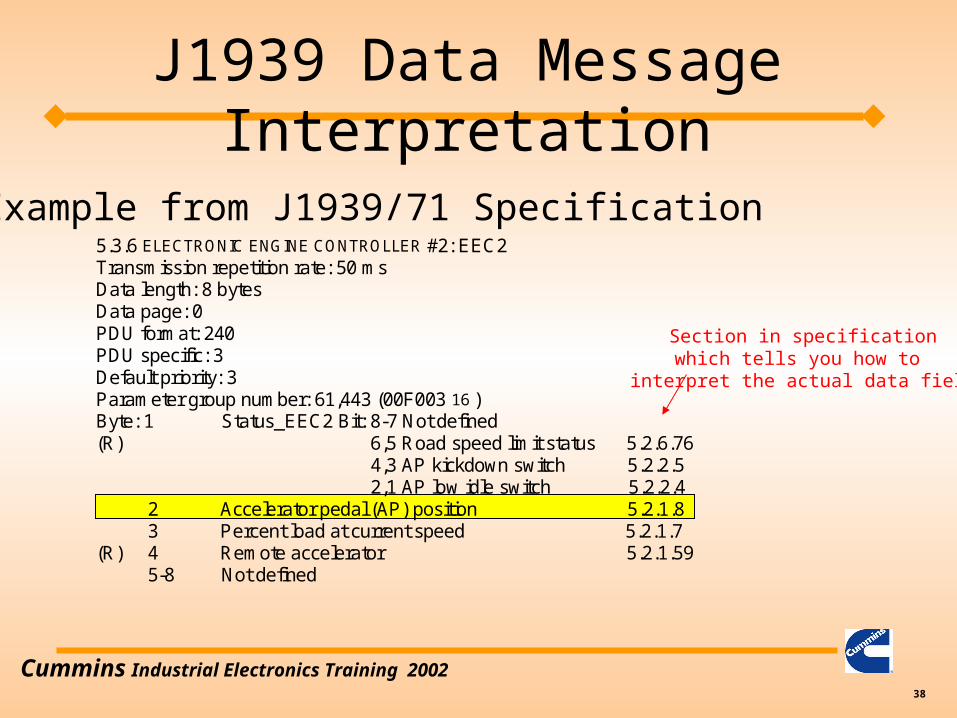
5.3.6 ELECTRONIC ENGINE CONTROLLER #2: EEC2Transmission repetition rate: 50 msData length: 8 bytesData page: 0PDU format: 240PDU specific: 3Default priority: 3Parameter group number: 61,443 (00F003 16 )Byte: 1 Status_EEC2 Bit: 8-7 Not defined(R) 6,5 Road speed limit status 5.2.6.76 4,3 AP kickdown switch 5.2.2.5 2,1 AP low idle switch 5.2.2.4 2 Accelerator pedal (AP) position 5.2.1.8 3 Percent load at current speed 5.2.1.7(R) 4 Remote accelerator 5.2.1.59 5-8 Not defined
Example from J1939/71 Specification
Section in specificationwhich tells you how to
interpret the actual data field
J1939 Data Message Interpretation

Cummins Industrial Electronics Training 200239
0 C F 0 0 3 0 0
0 1100 1111 0000 0000 0011 0000 0000
3 bitsPriorityNumber
Res
erve
dD
ata
Pag
e
PDU Format (PF)PDU Specific (PS)
Contains DestinationAddress if PF <239
Source Address
J1939 Data Message Interpretation0.1000 1 0CF00300x Rx d 8 7D E0 2E 7D FF FF FF FF
On CANalyzer:

Cummins Industrial Electronics Training 200240
5.2.1.8 Accelerator Pedal Position% The ratio of actual accelerator pedal position to maximumpedal position. Although it is used as an input to determine powertrain demand, it also providesanticipatory information to transmission and ASR algorithms about driver actions.
Data Length: 1 byteResolution: 0.4%/bit gain, 0% offsetData Range: 0 to 100%Type: MeasuredSuspect Parameter Number: 91Reference: 5.3.6
Conversion Formula:Accelerator Pedal Position % = Raw Counts * Resolution + offset
Example:
0.1000 1 0CF00300x Rx d 8 7D E0 2E 7D FF FF FF FF
From CANalyzer:
Data Byte 2 which representsthe accelerator pedal position
Calculate Raw Counts First:
Raw Counts = E0 hex = 1110 0000 binary = 224 decimal
Accelerator Pedal Position % = 224 * .4 + 0 = 89.6%
Note: You can use the Scientific calculator under Accessories in Win9X or Win NT to convert from hex to decimal.
J1939 Data Message Interpretation

Cummins Industrial Electronics Training 200241
5.3.28 ENGINE TEMPERATURETransmission repetition rate: 1 sData length: 8 bytesData page: 0PDU format: 254PDU specific: 238Default priority: 6Parameter group number: 65,262 (00FEEE 16 )Byte: 1 Engine coolant temperature 5.2.5.5 2 Fuel temperature 5.2.5.14(R) 3,4 Engine oil temperature 1 5.2.5.15 5,6 Turbo oil temperature 5.2.5.16 7 Engine intercooler temperature 5.2.5.6(R) 8 Engine intercooler thermostat opening 5.2.5.242
J1939 Data Message InterpretationExample from J1939/71 Specification

Cummins Industrial Electronics Training 200242
5.2.5.5 Engine Coolant Temperatur Temperature of liquid found in engine cooling system.Data Length: 1 byteResolution: 1 °C/bit gain, -40 °C offsetData Range: -40 to +210 °C -40 to 410 °F)Type: MeasuredSuspect Parameter Number: 110Reference: 5.3.28
Conversion Formula:
Engine Coolant Temperature = Raw Counts * Resolution + offset
Example:
0.1000 1 0CFEEE00x Rx d 8 7D E0 2E 7D FF FF FF FF
From CANalyzer:
DataByte 1
Calculate Raw Counts First:
Raw Counts = 7D hex = 0111 1101 binary = 125 decimal
Engine Coolant Temperature = 125 * 1 - 40 = 85 deg C
Note: You can use the Scientific calculator under Accessories in Win9X or Win NT to convert from hex to decimal
J1939 Data Message Interpretation

Cummins Industrial Electronics Training 200243
• J1939 has several different messages which contain diagnostic (fault) code information.– DM1 - Active Fault Codes– DM2 - Inactive Fault Codes– DM3 - Clear Inactive Fault Codes
• Typically customers will use the DM1 message to detect when a fault code has gone active.
J1939 Fault Code Interpretation

Cummins Industrial Electronics Training 200244
• The DM1 message can be interpreted in one of two ways depending on which Cummins product you are working on.– HHP: QSK19 - QSKV60 use version 1 – All others: QSB - QSX use version 4 – Check byte 6 bit 8 to determine which SPN
Conversion Method is to be used• byte 6 bit 8 = 0 = version 4
• byte 6 bit 8 = 1 = version 1
J1939 Fault Code Interpretation

Cummins Industrial Electronics Training 200245
• DM1 message– 8 bytes of data are arranged as follows:
Byte 1: bits 8-7 Malfunction Indicator Lamp Statusbits 6-5 Red Stop Lamp Statusbits 4-3 Amber Warning Lamp Statusbits 2-1 Protect Lamp Status
Each lamp takes two bits to indicate lamp state00 - lamp is OFF01 - lamp is ON
J1939 Fault Code Interpretation

Cummins Industrial Electronics Training 200246
J1939
• Wait to Start Lamp is NOT found in the DM1 message!– PGN 65252 ( 00FEE4h ) Shutdown message
byte 4 bits 2,1– Broadcast once per second– other three lamps are part of the DM1 message

Cummins Industrial Electronics Training 200247
• DM1 byte 2 – All 8 bits are reserved for future SAE use.– OEMs should ignore all 8 bits in this byte.
• DM1 byte 3 (for QSX, QSM, QSB,QSC, QSL9 only)– Contains the 8 lowest order bits for the SPN
(Suspect Parameter Number).– Must combine this with byte 4 and part of byte 5 to
get the 19 bit SPN number.
J1939 Fault Code Interpretation

Cummins Industrial Electronics Training 200248
• DM1 byte 3 (for QSK, QSKV, QST only)– Contains the 8 highest order bits for the SPN
(Suspect Parameter Number).– Must combine this with byte 4 and part of byte
5 to get the 19 bit SPN number.
J1939 Fault Code Interpretation

Cummins Industrial Electronics Training 200249
• DM1 byte 4 (for QSX, QSM, QSB,QSC, QSL9 only)– Middle 8 bits of the SPN
• DM1 byte 5 (for QSX, QSM, QSB,QSC, QSL9 only)– Contains the 3 most significant bits of the SPN, plus
the FMI (Failure Mode Identifier)
• Together the SPN and FMI map to the Cummins Fault Code.
J1939 Fault Code Interpretation

Cummins Industrial Electronics Training 200250
• DM1 byte 4 (for QSK, QSKV, QST only)– Middle 8 bits of the SPN
• DM1 byte 5 (for QSK, QSKV, QST only)– Contains the 3 least significant bits of the SPN,
plus the FMI (Failure Mode Identifier)
• Together the SPN and FMI map to the Cummins Fault Code.
J1939 Fault Code Interpretation

Cummins Industrial Electronics Training 200251
0.1000 1 0CFECA00x Rx d 8 05 FF 00 4F 23 82 FF FF
0000 0101 1111 1111 0000 0000 0100 1111 0010 0011 1000 0010 1111 1111 1111 1111
Reserved SPN
CONV.
SPN FMI OccurrenceCount
Lamp Status
J1939 Fault Code InterpretationExample: (QSKV or HHP)
From CANalyzer:
SPN = 0000 0000 0100 1111 001 = 633
FMI = 00011 = 3
Occurrence Count = 000 0010 = 2
Lamp Status = 0000 0101 = Amber Lamp On Protect Lamp On
SPN Conversion Method = 1
Cummins Industrial Electronics Training 200252
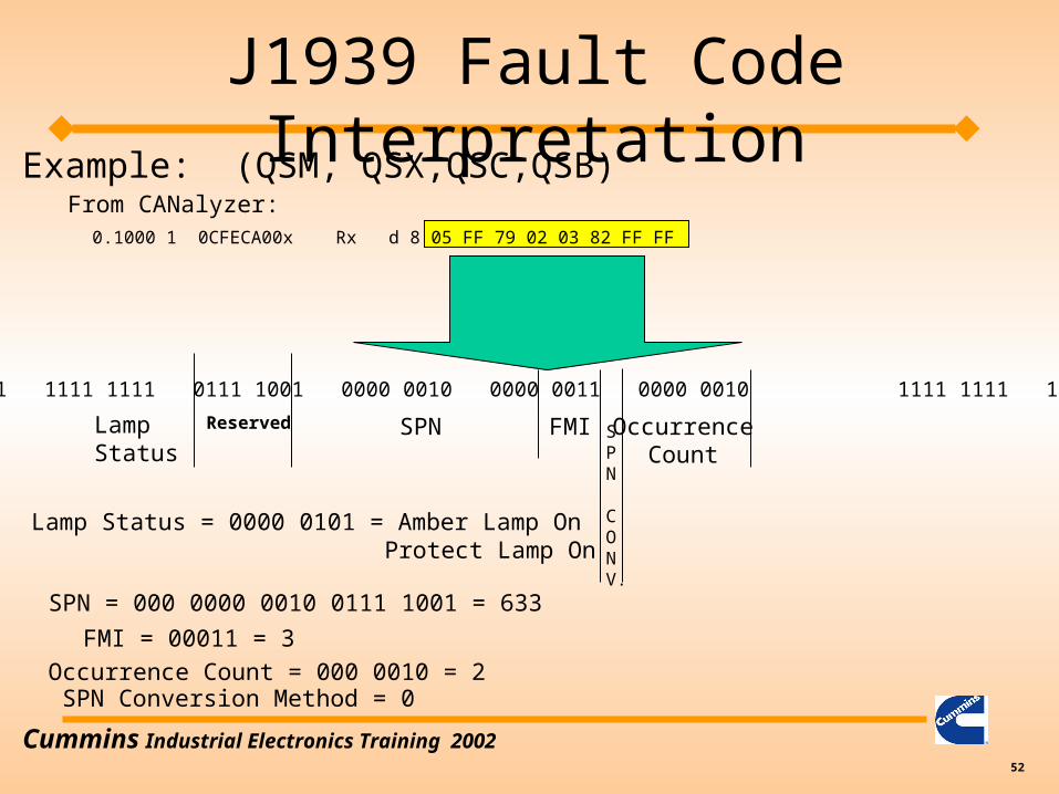
0.1000 1 0CFECA00x Rx d 8 05 FF 79 02 03 82 FF FF
0000 0101 1111 1111 0111 1001 0000 0010 0000 0011 0000 0010 1111 1111 1111 1111
Reserved SPN
CONV.
SPN FMI OccurrenceCount
Lamp Status
J1939 Fault Code InterpretationExample: (QSM, QSX,QSC,QSB)
From CANalyzer:
SPN = 000 0000 0010 0111 1001 = 633
FMI = 00011 = 3
Occurrence Count = 000 0010 = 2
Lamp Status = 0000 0101 = Amber Lamp On Protect Lamp On
SPN Conversion Method = 0

Cummins Industrial Electronics Training 200253
SPN
FMI
Cummins Fault Code
Example:Fault Code SPN FMI131 91 3
Note: Cummins has some SPN / FMI combinations which point to two different fault codes. Usually the fault codes are related such as low oil pressure (FC143) and very low oil pressure (FC415).
J1939 Fault Code Interpretation

Cummins Industrial Electronics Training 200254
• FMI codesFMI Code Description0 Data Valid but above Normal Operating Range1 Data Valid but below Normal Operating Range2 Data Erratic, Intermittent or Incorrect3 Voltage above Normal or Shorted to High Source4 Voltage below Normal or Shorted to Low Source5 Current below Normal or Open Circuit6 Current above Normal or Grounded Circuit7 Mechanical System Not Responding or out of adjustment8 Abnormal frequency or pulse width or period9 Abnormal Update Rate10 Abnormal Rate of Change11 Root Cause Not Know12 Bad Intelligent Device or Component13 Out of Calibration14 Special Instructions15 Data Valid But Above Normal Operating Range (Least Severe Level)16 Data Valid But Above Normal Operating Range (Moderate Sever Level)17 Data Valid But Below Normal Operating Range (Least Severe Level)18 Data Valid But Below Normal Operating Range (Moderate Severe Level)
J1939 Fault Code Interpretation

Cummins Industrial Electronics Training 200255
• Transport Messages– Used when data exceeds the 8 byte limit– Usually needed during fault code message
transmission.– Multipacket message– Currently only the BAM (Broadcast Announce
Message) part of the J1939 transport layer used by our products.
J1939 Transport Message

Cummins Industrial Electronics Training 200256
• Transport Protocol– TP.BAM
• Used when more than one fault codes are active
• Must be implemented to read fault codes
• First step is to send a TP.CM (Connection Message) with the connection mode being BAM.
• Next a series of TP.DT (Data Transfer) messages will be sent. These messages contain the actual data.
• See detailed example hand out
J1939 Transport Message

Cummins Industrial Electronics Training 200257
J1939 Multiplexing
• Multiplexing is used to send information from an external device to the engine control module via the J1939 datalink.
• The engine control module must know the address of the device which is sending the information.
• Typically only the throttle has been multiplexed on industrial applications.

Cummins Industrial Electronics Training 200258
Increased Multiplexing Capability
• Purpose: Control additional features over the J1939
• New multiplexing capability:– Diagnostic Switch
– Idle Increment / Decrement
– Alternate Low Idle Switch
– Multiunit Sync On/Off Switch
– Alternate Torque Select
– Alternate Droop Select
– Auxiliary Governor Switch

Cummins Industrial Electronics Training 200259
New Multiplex Capability (cont.)
• New Multiplex Capability (cont.)– ISC Switches 1, 2, and 3
– Variable ISC
– Remote Accelerator (Throttle)
– Remote Accelerator Switch
– Hydraulic Temperature
– A/C High Pressure Fan Switch
• New Broadcast parameters– Fan Drive State
– Estimated Percent Fan Speed

Cummins Industrial Electronics Training 200260
New Multiplex Capability
• Timing– QSB/QSC/QSL9: Production June 2003– QSK19/45/60: Unknown

Cummins Industrial Electronics Training 200261
J1939 Multiplexing Example
5.3.6 ELECTRONIC ENGINE CONTROLLER #2: EEC2Transmission repetition rate: 50 msData length: 8 bytesData page: 0PDU format: 240PDU specific: 3Default priority: 3Parameter group number: 61,443 (00F003 16 )Byte: 1 Status_EEC2 Bit: 8-7 Not defined(R) 6,5 Road speed limit status 5.2.6.76 4,3 AP kickdown switch 5.2.2.5 2,1 AP low idle switch 5.2.2.4 2 Accelerator pedal (AP) position 5.2.1.8 3 Percent load at current speed 5.2.1.7(R) 4 Remote accelerator 5.2.1.59 5-8 Not defined
0.1000 1 0CF00303x Tx d 8 7D E0 2E 7D FF FF FF FFOn CANalyzer:
Example from J1939/71 Specification
Section in specificationwhich tells you how to
interpret the actual data field

Cummins Industrial Electronics Training 200262
J1939 Multiplexing Example
• Note the source address is set to 03. This means device 03 is sending a message on the J1939 datalink.
• The ECM must be calibrated to recognize the throttle from this address or the throttle will not work.
0.1000 1 0CF00303x Tx d 8 7D E0 2E 7D FF FF FF FFOn CANalyzer:

Cummins Industrial Electronics Training 200263
J1939 Multiplexing
• Some reasons why the J1939 throttle will not work:
• Datalink is not functioning.
• Calibration set to incorrect throttle source address .
• Customer’s device sending throttle request under the wrong address
• Customer’s device not sending throttle request at all
• Throttle request is not fast enough and ECM is timing out.

Cummins Industrial Electronics Training 200264
J1939 Multiplexing
• Some speed control has been done via the TSC1 message. (QSK products mostly.)
• Not recommended unless no other option available
• The TSC1 message has three control modes• Speed Control -- Device tells the engine what speed to
operate at (typically use this mode)
• Torque Control -- Device tells the engine to control torque to a specific value
• Speed / Torque Limit Control -- Specify a speed / torque pair which act as the limits.

Cummins Industrial Electronics Training 200265
J1939 TSC1
• Speed Control Example
0.1360 1 C000003x Tx d 8 01 A0 41 FF FF FF FF FF
Byte 1: 01 - indicates speed control mode by setting bits 2,1 to a value of 01
Byte 2, 3: 41 A0 - specifies and engine speed of 2100 rpm
Calculating the desired engine speed:2100 rpm * 1 count / .125rpm = 16800 counts = 41 A0 hex
Note: The TSC1 message is broadcast every 10 ms when TSC1 iscommanding the engine speed.
Address of device sending TSC1 speed control request
Cummins Industrial Electronics Training 200266
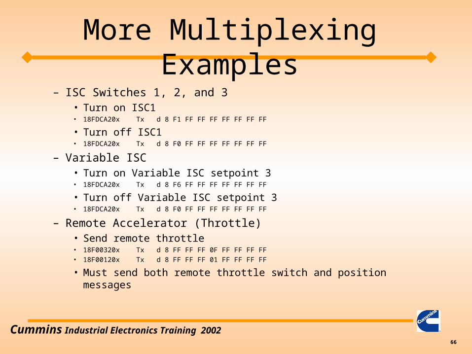
More Multiplexing Examples– ISC Switches 1, 2, and 3
• Turn on ISC1• 18FDCA20x Tx d 8 F1 FF FF FF FF FF FF FF
• Turn off ISC1• 18FDCA20x Tx d 8 F0 FF FF FF FF FF FF FF
– Variable ISC• Turn on Variable ISC setpoint 3• 18FDCA20x Tx d 8 F6 FF FF FF FF FF FF FF
• Turn off Variable ISC setpoint 3• 18FDCA20x Tx d 8 F0 FF FF FF FF FF FF FF
– Remote Accelerator (Throttle)• Send remote throttle• 18F00320x Tx d 8 FF FF FF 0F FF FF FF FF• 18F00120x Tx d 8 FF FF FF 01 FF FF FF FF
• Must send both remote throttle switch and position messages

Cummins Industrial Electronics Training 200267
More Multiplexing Examples
– Remote Accelerator Switch • Turn on remote throttle switch• 18F00120x Tx d 8 FF FF FF 01 FF FF FF FF
• Turn off remote throttle switch• 18F00120x Tx d 8 FF FF FF 00 FF FF FF FF
– Hydraulic Temperature• Hydraulic Temperature gets into the ECM via OEM temperature 2• 18FE6820x Tx d 8 F0 FF FF FF FF FF FF FF
– A/C High Pressure Fan Switch• Turn on AC pressure switch• 18FEE420x Tx d 8 FF FF F1 FF FF FF FF FF
• Turn off AC pressure switch• 18FEE420x Tx d 8 FF FF F0 FF FF FF FF FF

Cummins Industrial Electronics Training 200268
More Multiplexing Examples– Diagnostic Switch
• Turn on diagnostic switch• 18FEF120x Tx d 8 FF FF FF FF FF FF FF DF
• Turn off diagnostic switch• 18FEE420x Tx d 8 FF FF FF FF FF FF FF CF
– Idle Increment / Decrement• Turn on increment switch• 18FEE420x Tx d 8 FF FF FF FF FF FF FF F7
• Turn off increment switch• 18FEE420x Tx d 8 FF FF FF FF FF FF FF F3
– Alternate Low Idle Switch• Turn on low idle switch• 18FDCB20x Tx d 8 DF FF FF FF FF FF FF FF
• Turn off low idle switch• 18FDCB20x Tx d 8 CF FF FF FF FF FF FF FF

Cummins Industrial Electronics Training 200269
More Multiplexing Examples
– Multiunit Sync On/Off Switch• Turn on multiunit sync switch• 18FDCB20x Tx d 8 F7 FF FF FF FF FF FF FF
• Turn off multiunit sync switch• 18FDCB20x Tx d 8 F3 FF FF FF FF FF FF FF
– Alternate Torque Select• Select alternate torque curve 1• 18FDCB20x Tx d 8 FF 01 FF FF FF FF FF FF
• Select alternate torque curve 2• 18FDCB20x Tx d 8 FF 02 FF FF FF FF FF FF
• Select 100% torque curve• 18FDCB20x Tx d 8 FF 00 FF FF FF FF FF FF

Cummins Industrial Electronics Training 200270
More Multiplexing Examples
– Alternate Droop Select• Turn on Alternate Droop 1• 18FDCB20x Tx d 8 FF FF F1 FF FF FF FF FF
• Turn on Alternate Droop 2• 18FDCB20x Tx d 8 FF FF F2 FF FF FF FF FF
• No Alternate Droop• 18FDCB20x Tx d 8 FF FF F0 FF FF FF FF FF
– Auxiliary Governor Switch• Turn on Aux Gov switch• 18FDCB20x Tx d 8 FD FF FF FF FF FF FF FF
• Turn off Aux Gov switch• 18FDCB20x Tx d 8 FC FF FF FF FF FF FF FF

Cummins Industrial Electronics Training 200271
• What about J1939/15?– J1939/15 is a physical interface which requires
only a two wire twisted pair.– It is less noise immune than J1939/11– We do not recommend this standard, but the
module can interface with it.
J1939 Training - Miscellaneous

Cummins Industrial Electronics Training 200272
J1939 - Requested PGN
• Several PGNs are described in AEB 15.43 as on request.
• On Request PGNs require another device on the J1939 to ask for the specific PGN.– Requesting a PGN is done via PGN 59904– The reply to the request is to send out the
requested PGN per the definition in J1939/71– 18EA0000x Tx d 8 E5 FE 00 FF FF FF FF FF– Note: PGN is byte swapped!