MaosouraEogineeringJol.ll"D8i (MEG) Vol. 20, No. I. 1995. C.22. COMPARISON BETWEEN THEORETICAL AND EXPERIMENTAL INVESTIGATION or COMPOSITE BEAMS WITH SPIRAL SHEAR CONNECTORS .. . Saad Eldeen M. AIId-Raboa • Structund F..Ds- Dept, Mansotn. Uaivenity) ManaoUl'8, EsYPt by Mobam.ed Ahmed Dabaoa • Lecturer, Civil.f!.ns. Dept, MiDia Univenity, MiDis, EsYPt ,J- ft-iJ1 •• n,..,;.wIl ..... IJ"'" .:.JW Jr lat' /,-J' - ..... tl.p...l • U,)'- JIi.A..:.!,.,; l..( .w....sr ol¥""'-'-" &"..-JJ' J...J; 'L!'.,.n l .... ) ...., J-.!J, j L..oI c LWI' , f',j-NI, J'-.ti1' ..... ,:"..... ;c...:,..J',...JJJ "'.lIM WIi.t J J-:.t ..;..s;.r e,,-.;Jt 1. ABSTRACT Investigation of the behavior of composite beBll18 with different types of shear connectors (spiraJa and bent ban) extends to include the compmison between the theo",t\cal study and the experimental results of sucb typel of be8lD.8. In this paper, a proposed tecbniquo for pndictins the shear re.istance of the spirals as shear connectors in &be composite be8llll 1s presented. In this- technique, the behavior of the c:oonectOl"l in the elastic and the plastic raogea is aoalyzed. a proposed focmu.1a to predict the design shear resistance of the spiral. is sugested. The c:omparison between the sussested fonnula and the experimental resu1t1 showed a good agreement betweea them. a comparison between the lheoreticaJ mld the experimeatal resulbr tOr the tested composite beams with spinLls and bent bars as shear C:01Ulec:tors IS 4:arl"ied out with respect to ultimate loads. uJtimste momenbl and detlec:tiooa. 1be common type of shear comecton as bent b8l'll is compared with spiral comectors as w.,l1. A discuaaioD for the given formulae of die beat bar war remstaDce in both Egyptian and European (EC4) codes together with the experimental results is r:ondun.d wbich may lead to t:be modification of Ihe Egyptian fomru.la. The comparison between the present tbeoreticaJ worle aod the experimental results has shoWD good ngreement

Welcome message from author
This document is posted to help you gain knowledge. Please leave a comment to let me know what you think about it! Share it to your friends and learn new things together.
Transcript
MaosouraEogineeringJol.ll"D8i (MEG) Vol. 20, No. I. Marc~ 1995. C.22.
COMPARISON BETWEEN THEORETICAL AND EXPERIMENTAL
INVESTIGATION or COMPOSITE BEAMS WITH SPIRAL SHEAR CONNECTORS .. .
Saad Eldeen M. AIId-Raboa • :Ucturer~ Structund F..Ds- Dept, Mansotn. Uaivenity) ManaoUl'8, EsYPt
by
Mobam.ed Ahmed Dabaoa • Lecturer, Civil.f!.ns. Dept, MiDia Univenity, MiDis, EsYPt
,J- ft-iJ1 r~ ~t ~L, •• n,..,;.wIl.....IJ"'" .:.JW ~JtLJ, Jr lat' /,-J' ~',.....at:3,J- ~IJ"" ~I ~ -~,~ ..... tl.p...l ,:"..~I ~1;.LaJ' ,...~..."., .....,IM~........., ~~ ~II~ ~.w,,_..s;.n
~, ~I ~,_ ~c....-.J • ..\.f:~ U,)'- JIi.A..:.!,.,; l..( .w....sr ol¥""'-'-" ~~ '-t~1 &"..-JJ' J...J; 'L!'.,.n .:;,f~ ~..J~ J~' l....) .... , ~ ~)tLJl J-.!J, .w~1 j ~JJ.Uf ~J..a..; ~ ~Ji""" ~ L..oI .~,.,.....s:J, o~ ~,N' cLWI' ~ ~r,)~1r ~L.,..,.. ~ , ~,;..Jr, ~,...,.., f',j-NI, J'-.ti1' ~~l ~I ~ ..... ,:".....;c...:,..J',...JJJ ~r ~IM~""""" ~."....sl ~t,...zr "'.lIM WIi.t J ~~f~' J-:.t
~-,u..tt ~JJYf~UwI~U~,-,~I~J~UJ"'ol¥'-'-'f~~IJ-i"I~~I..t"~~' .:;,~I J~' ~J .;.,.-!~, J-i''''''~''' ..;..s;.r ~JILJI ~..Jt..J, .4J.,)iwJl.J,..,a~ ~t....,J"'"
.w/~' ~ e,,-.;Jt r~~t
1. ABSTRACT
Investigation of the behavior of composite beBll18 with different types of shear connectors (spiraJa and bent ban) extends to include the compmison between the theo",t\cal study and the experimental results of sucb typel of be8lD.8.
In this paper, a proposed tecbniquo for pndictins the shear re.istance of the spirals as shear connectors in &be composite be8llll 1s presented. In this- technique, the behavior of the c:oonectOl"l in the elastic and the plastic raogea is aoalyzed. Henc:e~ a proposed focmu.1a to predict the design shear resistance of the spiral. is sugested. The c:omparison between the sussested fonnula and the experimental resu1t1 showed a good agreement betweea them.
Mo~over, a comparison between the lheoreticaJ mld the experimeatal resulbr tOr the tested composite beams with spinLls and bent bars as shear C:01Ulec:tors IS 4:arl"ied out with respect to ultimate loads. uJtimste momenbl and detlec:tiooa.
1be common type of shear comecton as bent b8l'll is compared with spiral comectors as w.,l1. A discuaaioD for the given formulae of die beat bar war remstaDce in both Egyptian and European (EC4) codes together with the experimental results is r:ondun.d wbich may lead to t:be modification of Ihe Egyptian fomru.la.
The comparison between the present tbeoreticaJ worle aod the experimental results has shoWD good ngreement
c. 23 ABD-RA.Bou and DABAON
2.lNT.RODucnON
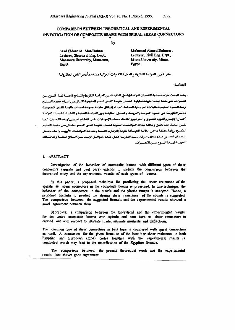
&perimenral investigation for the composice beams lISiD! round steel bar spirals as shear connectors has beeD carried out [1). In these tests, shear counectors as spiralll have been placed in four lDlits along tour composite beanm. Four units of tb.ree spiraJs each, four units of four spirals each.. four unita of five spirals each and coDtinuoua spirals have beeD applied as shown in Fig. (la). The experimental work for composite beams has beeD exti1lded aod included b~nt bar shear connectors havin8 different pitches and slope qles [21~ as shown in Fig. (lb).
'OIKI'ete ~ - cub.ic srraJ&tb ,. 2. ~ kN/aIl
1
4'&" ~ rtre.1 =- 0.eS5 kN/em"
B - 50.0 em t -lO.Gem
~ -5.00 em
1>.: -sooaJ
steel profile fa - yield lin .... ~9.9J ill/aJ
Cu .... teIWII lire .. "" 38.0 lcNIem2
b -6.00em
l,-0.60 em [,- 1.00 em b1
1S 11.0 em
z,. .. -69 t:'Ili • z.... -81 cal A, ::aUS r:ar
(c)
rcioforccmcr:u: r "")ie1d ShSI =- 30.0 kN'/c::uil ., f - W'Oriciaa 'lnli - is. 11 ftNlctil
'I
S 4) 10 in ~ dftctiml
". 1 0 ram 1m D crol. clrcaion
Fig. (1) Types of composite beama tested
In this. study. a theontical analysis for the experimental behavior in the elastic and ultimate ran8t'1 of the spiral Dar corme-ctonJ is presented A proposed technique for predicting the shear resisl8Dce of spiral sbe.ar connector is baed 011 ~ i.iKt thai the unit of spiral. including the CODaete inside the spiral space 8I:t8 as a flexible block unit conoeaed with ~ steel flange. In this technique, a fonm.t.la is proposed for both ma:imum .IMtie aDd ulti.m.ra rellivtalJDe of the lhem- coaoeetor mppegn to be in a good ageement with the elq)erimeoial result!. COmparisoB between ultimate resilltaoce of spirals and bent ban cOlIDecton is also discussed
MansouraEugineering Journal (MEG) Vol. 20, No.1, March, 1995. C.24.
Moerove}r, comparison between the theoretical analysis and the ~xperimeata1 results of tested beams (BI, B2, B3. B4 & BS ) and (B'I, B'2, B'3, B'4 & B'S) with spirnls and bent bar connedol'! is discuneq. The comparison includes ultimate toads and defonn81ions of both beams with spirals and bent bar shear connectors. '.
RecOfllDendations tor the modification of Egyptian fomrula for predicting the shear resistance of bent bars is dnIwn and discussed to~er with the experimental resulbJ and the European Code of Composite Slructures [3. 2 & 4].
3. ANALYSIS OF SPIRAL SHEAR CONNECTOR
3.1 Geaeral
~ is well known, the behavior of tht shear connectors plays an important role on the beohavior oj composite beam.: ~ In othe-r wotds. the interface between the reinforced con~te slab BQd the meel beam has a great influence on the streng[b ofllie composite beam due to the behavior of the shear cormecton. Many researchefi and design rules are concerned with predicting the shear resistance of the she'3l' connectors.
As a matter of fact. the behavior of a shear connector between the concrete slab and the steel beam may be described throush three ·aspects. These aspects are the strength of the connector (full, panial or no strength), the etiffiJess of the interface (rigid. semi· rigid or non-rigid) and the ductility of the shear connector (ductile. semi-ductile or noo·ducti1e); [S]. However. the rigidity of the shear connectors has a great in11uence on the distribution of the shear flow in a composite beam and hence it affects greatly the behavior of composite beams.
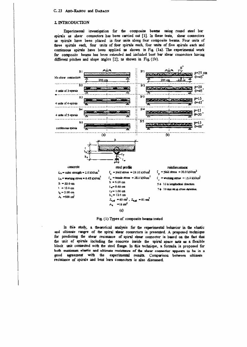
At:; sbown i.n Fig. (2a). the distribution of the shearing forces of rigid non~ductile toonectOl9 along the beam interface has, more or less, the same triangular shape but widl different values for both eJastic and plastic stages. On the other ~ Figures (2b & 2c) show t1uat tile fon:es carried by the shear connectors along the} beam are very nearly equal at the plastic stage [S, 6] .
.. • Ii, ii Ii if t"'" Ii'! j!,1 II Iii iii Ii I J I' 'l'ii j "i' i "
~< 'h " · -- d I ~. - \~::::::
~ C ODIWIftm IA&d ~ by uan& b) C \lD!I.tNlr IDa.4 dWtnbtJ1ioa by UM8 .DDD-~ u.-. CwmegQrl ~d d,., w:u c ... cum
VI" 0..98 IuDaI t.bI ~ hilur. 117 ~ lbI .1ua.c 1.l1li4
,) C omuctCl' ig.;!d ~uLlan by uNic noEt-.agi d IIurul.I ;h.t2f : otIQI ct.ars
Fig. (2) Effect of rigidity of shear connecton on the shear flow
'"
C.2S ABD-RAaOlf aDd DABAON
3.2 Aulysis o( Expailllea1al ResaIt.s o( Spin! Shear COIIBecton
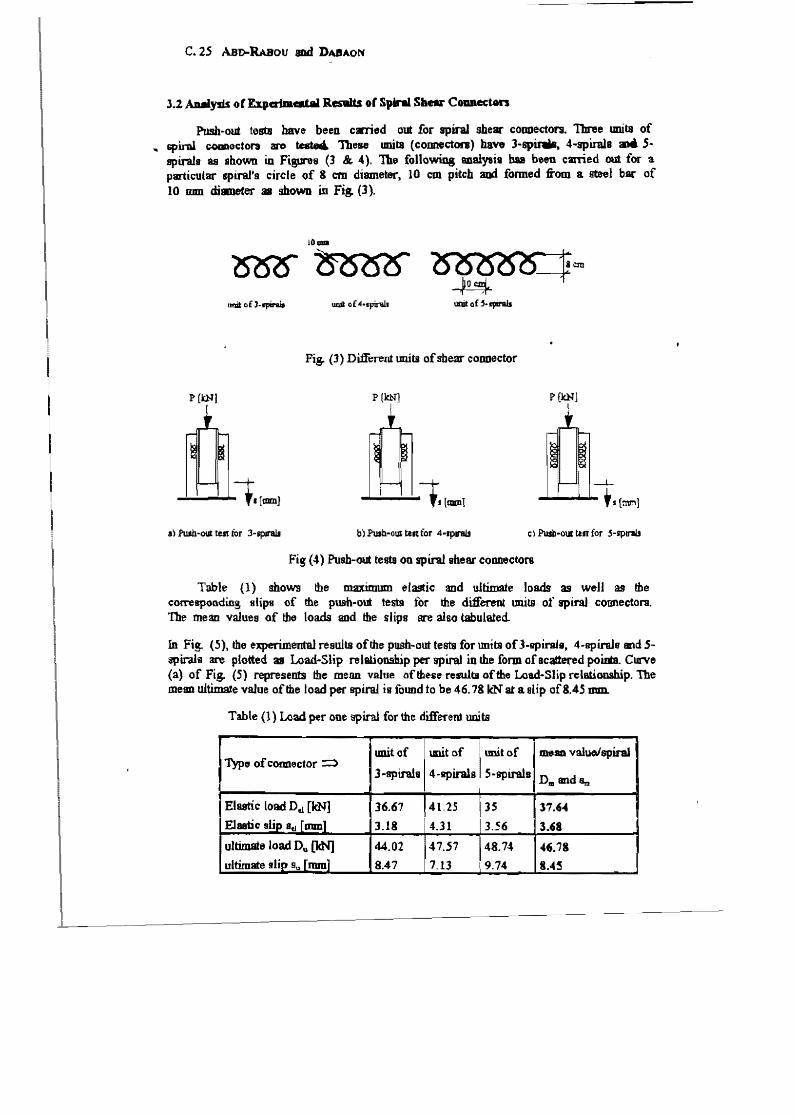
Push-out tests have been carried out for spiral she.. conuecton. Tbree lDlits of ". spiral COIJDocton arc tcBto& These umla (connecton) have J-sp~, 4.spi.ral8 .. 5·
spirals as snoCJlm. in Figures (3 &. 4). Th~ fonowing 8I1aiYlis has belm carried out for a particular trpLralls circle of 8 em diameter, 10 em pitch and fonned from a steel bar of 10 mm dillDeter 31 shown in Fig. (3).
I1!Jit: 0 f J.1'pirU
Fig. (3) Di:tferent tmits ofsbear conuector
P(kN) P(kN] P [kNj I
...:.....;... ......... 1. [tDlDJ
e:) Push-CUI: tut for 5-splJ'8JJ
Fig (4) Push-out testa on spiral shear connectors
Table (1) shows the maximum elastic and ultimate loads as well as the co~sponding slips of the pU.9b-out testa tor the different units of spiraJ cotmectOn1. The mean values of the loads and the slips are also tabulated.
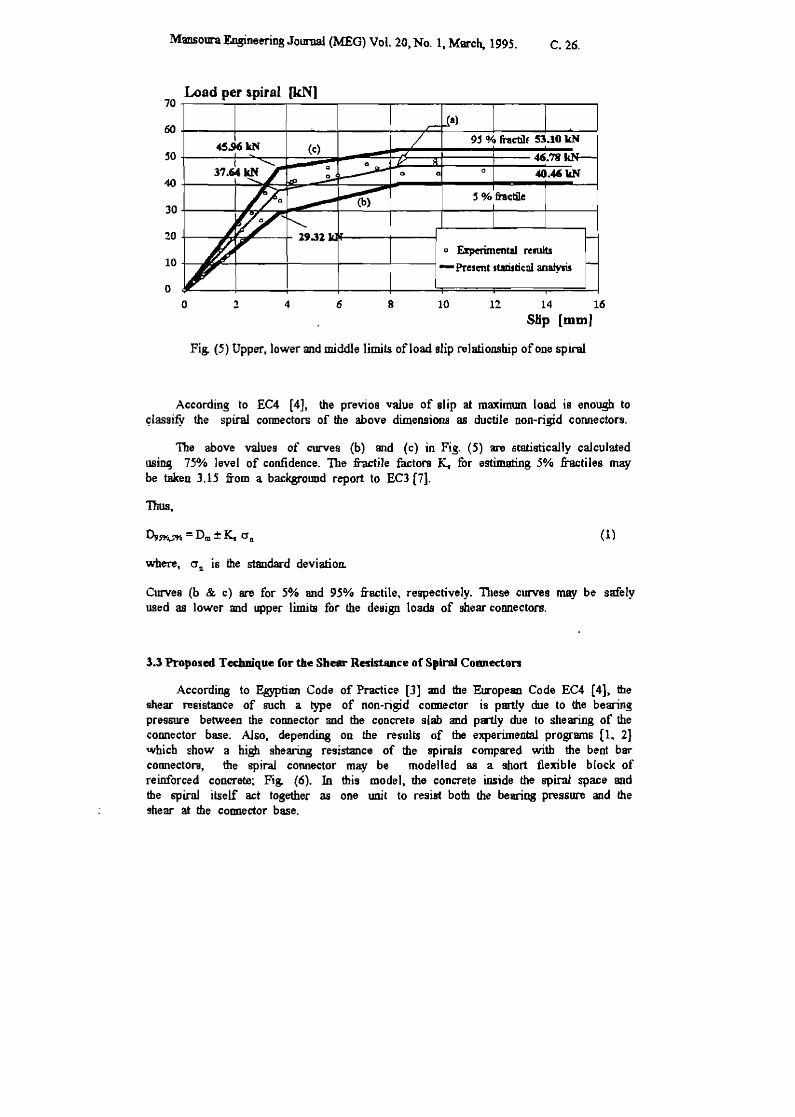
In Fig. (5), the experimental results of the push-out tests for tmits ofl-splrals, 4-spirals and Sspirals 3I.'e plotted 31 Load-Slip relalion.ship per splral in the form ofacatlered poiIiB. ClD'Ve (a) of Fig. (S) represents the mean value of these rewlta of tile Load-Slip rclBtiooship. The mean ultimate value of tile load per spiral is found to be 46.78 leN at a slip of8.4S mm.
Table (1) Load pet" ODe spiral for the different uoits
unit of lIIlit of unit of meso valuolspiral Type;, of Comlector =:)
3"spirals 4-spiral8 5-spirals DID andSm
Elastic load Dtl [kN] 36.67 41.25 JS 37.'" Elastic slip 8t1 [mm] 3.18 4.31 3.56 3.'. ultimate load D" [kN] 44.02 47.S7 48.74 "'.i8 ultimate fllip 9u r mm] 8.47 7.13 9.74 8."~
Mansoura Engineering Journal (MEG) Vol. 20, No. 1, Marc~ 1995. C. 26.
Load per spiral (kN] 70~----~----~------~----~----~------~----~----~
oo+-----~----~--~--~----~--~~------~----~--~~
~o (c:)
o 40.46 lIN 40
~ % ftacble 30
20 g Uperimental rtrults
10 - Present .tarittic::ll anatysis
0
0 2 4 6 8 10 12 14 16
Slip [mm]
Fig. (5) Upper, lower and middle limits ofload sJip relationship of one spiral
According to EC4 [4], the previos value of Blip at maximwn load is enough to (!iassity the spiral connectors of the above dimensions as ductile non-rigid connectors.
The above values of curves (b) and (c) in Fig. (5) are stB1istically calculated usiruj 750/0 level of confidence. The fractile factors K. for estimating 5% fractiles may be taken 3.15 from a background report to EC3 [7],
Thus.
(1 )
where. 0'11 is the standard deviation.
Curves (b & c) are for 50/0 and 95% fractile. respectively. These curves may be safely used as lower and upper limits for the design loads of shear connectors.
l.l Proposed Technique (or the Shear Resistance o( Spiral Connecton
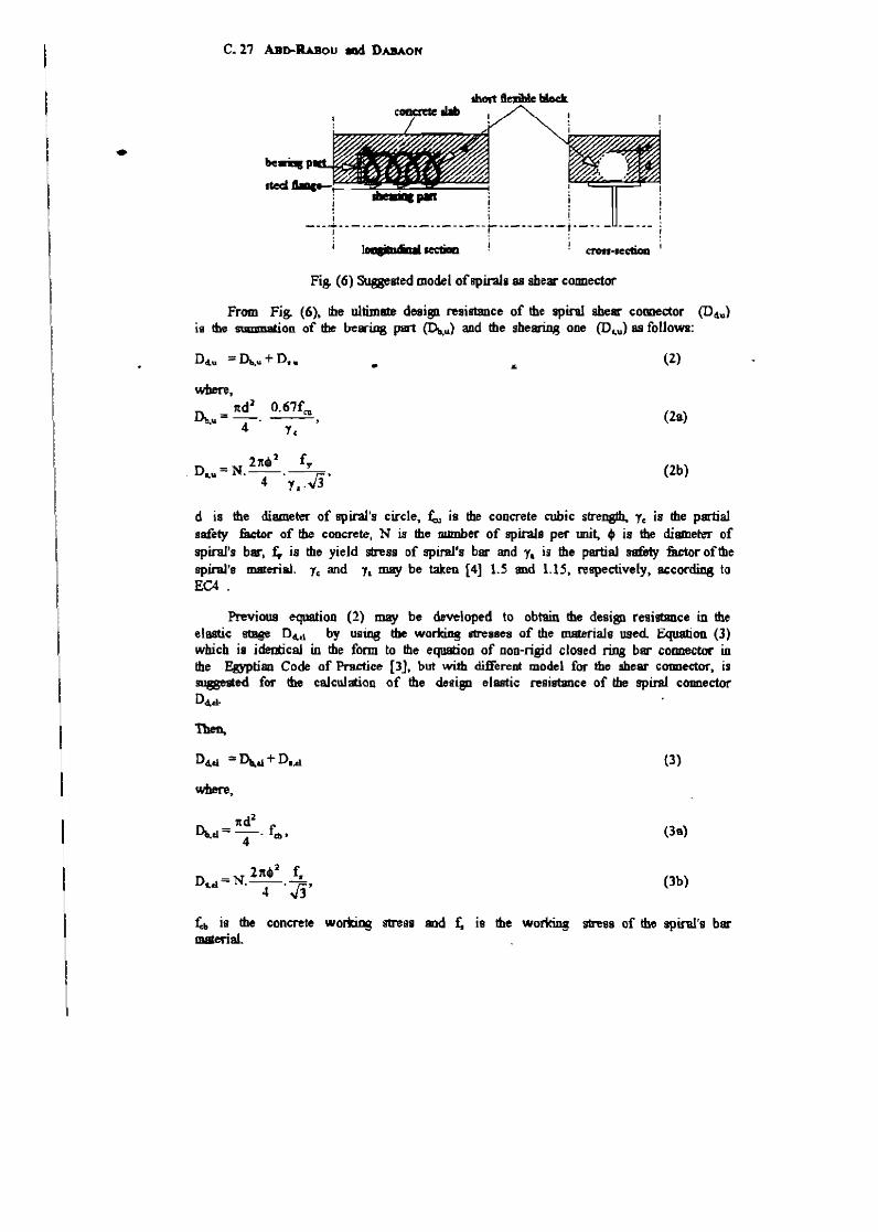
According to Egyptian Code of Practice [3] and the European Code EC4 [4], the shear resistance of such a type of non-rigid counector is partly due to the bearing pressure between the COmlector and the concrete slab and partly due to shearing of the connector base. Also, depending on the results of the experimental programs (1. 2] Ulhicb show a high shearing resistance of the spirals compared with the bent bar cormector&, the spiral connector may be modelled as a short tlexible block of reinforced concrete~ Fig. (6). In this model, tho concrete inside the spiral space and the 6pirw itself act together as one unit to resist both the bearing pressure and the !hear at the counector base.
..
C_ 21 ABI>-LBou mel DABAOH
! I ! [ ---t- -- -- ---- ---- -- -- ---;------ ----t· ---i, ................ ---.l i. ~ ~....... . crott-ICC'bOIl
Fig. (6) Suggested model ofBpirala as shear connector
From Fig. (6)~ !be ultim8le desi8ll resistance of the spiral shear comector (D4u) is the summatiOD of the bearing part <Do,1l) and the shearing ODe (Dc,u) as follows:
Dclu ::: Dt..\l + D. u
_ 27(.' f.,. . Dl,u - N. --. ----,:;;,
4 1,.,,3
.. (2)
(2a)
(2b)
d is the diame~ of spiral's circ1e~ ~ is the concrete cubic stre~ 1, is the partial safety f'ador of the concrete, N is the number of spiraJa pel' mit, 4t is the diamere-r of spiral's bar, :£, is the yieJd stress of spiral's bar and 1. is the partial safety factor of the spiral's material. "f, and 1. may be taken {4] 1.5 and 1.IS. respectively, according to EC4 .
Previous equation (2) may be developed to obmin the design re9istDnce in the elastic 9tBge D"'d by using tbe wo~ ilTesscs of the malerials used Equation (3) which is identicaJ in the form to the equation of non-rigid cloged ring bar connector in the Egyptian Code of Practice £3J. but with diJl"erent model for the ahear coonector, is mssested fOl' the calculation of the desisn elastic resistance of the spiral. connector Dd,d..
Dd,&1 = Dt..&1 + D.,d.
where,
ltd2
~d==-' feb' 4
_ 211. 2 f. nl,d.- N·-
4-·Jj'
(3)
(39)
(3b)
~b is the concrete wortti.ns stress SIld r. is the working msa of the spiral's bar material.
MansouraEngi.oeeringJournal (MEG) Vol. 20, No. 1. Mar<:h.. 1995. C.28.
3.-1 Comparison Between Expc:rimcat.al Results and Saggested Equations
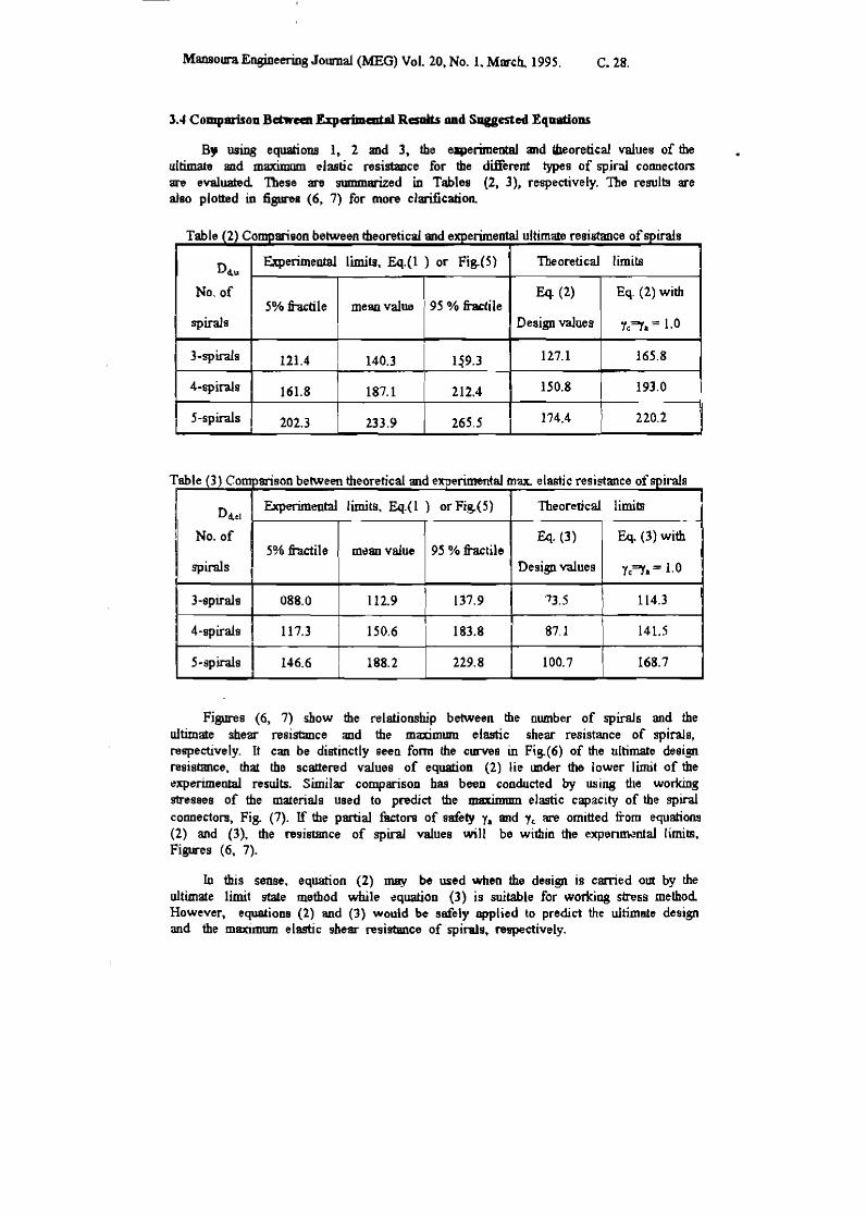
B, using equations 1, 2 and 3, the eaperimental and U1eoreti<:a1 values of the ultimate and maximum elastic resistance for the different types of spiral connectors are evaluated These are summarized in Tables (2. 3), respectively. The results are also plotted in figure. (6, 7) for mon cJarifi<:ation.
Table (2) Comparison between theoretical and experimental ultimate resistance of spirals
D4.u ~erimental limits, Eq.(1 ) or Fig.(5) Theoretical limits
No. of Eq. (2) Eq. (2) with 5% bole mean value 95 % fi1Ktile
spirals Design values "c~1I. = 1.0
3-splra.ls 121.4 I 140.3 l~9.3 127.1 165.8
4-spirals 161.8 187.1 212.4 150.8 193.0
5-spirals 202.3 233.9 265.5 174.4 220.2
T able (3) Companson between theoretical and experimental max. elastic resistance of spirals
Ddc! Experimental limits. Eq.(l ) or Fig.(5) Theoretical limim
I No. of Eq. (3) Eq. (3) with 5% fractile mean value 95 % fractile
spirnls Design values Yc~1I. = 1.0
3-spira1s 088.0 112.9 137.9 '73.5 114.3
4-spirals 117.3 150.6 183.8 87.1 141.5
5-spirals 146.6 188.2 229.8 100.7 168.7
,
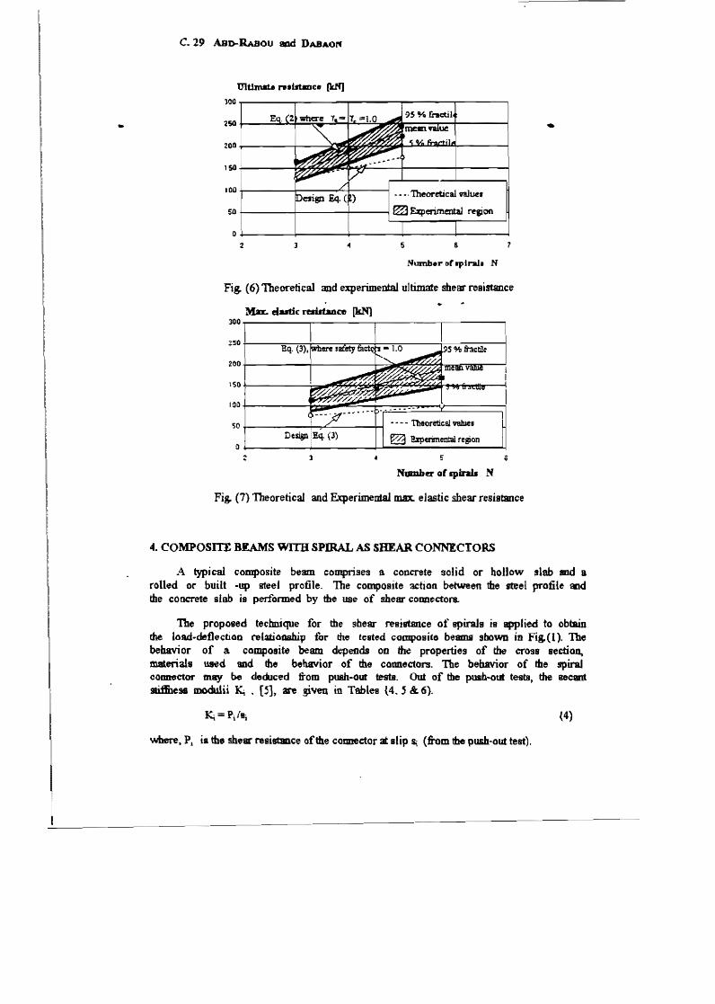
Figures (6, 7) show the relationship between the number of spirals and the ultimate shear reslsemce <md the maximum elastic shear resistance of spirals, respectively. It can be distinctly geen fonn the curves in Fig.(6) of the ultimate desi!R resistance, that the scattered values of equation (2) lie lUlder the lower limit of the experimental results. Similar COmparisoD has beeD conducted by using the working messes of the materials used to pndict the maximum elastic capacity of the spiral connectors, Fig. (7). If the partial filctOfB of gafety YII. and 1c are omitted from equations (2) and (3), the nsismnce of spiral values Vlill be within the expenOk.~al limits, Figures ( 6, 7).
In this sense, equation (2) may be used when the design is carried out by the ultimate limit !rtate method while ~quation (3) is suitable for worlc:ing stress method However, equations (2) and (3) would be safely applied to predict the ultimate design and the maximmn elastic shesr resistance of spirals. n!pectively.
..
c. 29 ABo-RAsou aod DABAOl'f
lQO~------~------~------~----~.------.
1~+_------~~~~~~---r_------r_----~
100 +-------+-----............ +------1
50~------~----r---~
O~------~------~------~-----~----~ 2
Humber Ghplnb N
Fig. (6) Theoretical mld experimental ultimate shear resistance
M.a. eiadic resUtance [kN] 300~--------~------_.------_.--~----,
50~------~~~----_h - • - - Theoretic61 value.
~ !zpcrimental re~on o~--__ --~~------~~~--~----~----~
Number or spinJJ N
Fis. (7) 'Theoretical and Experimental max. elastic shear resistance
4. COMPOSITE BEAMS WIm SPIRAL AS SHEAR CONNECTORS
•
A typical composite beam comprises a. concrete solid or hollow slab and a rolled or built -up steel profile. The composite action between the steel profile and the conCT'ete slab is per10rmed by the use of shear cOlUlectora.
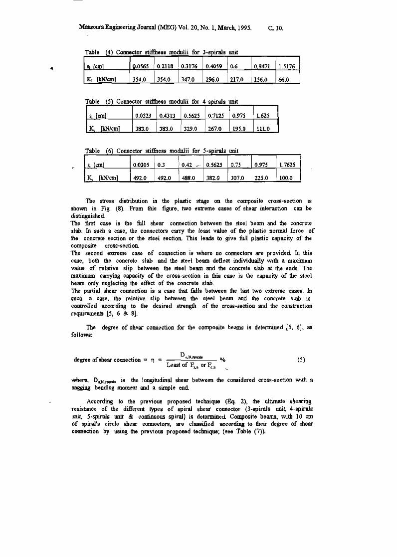
The proposed technique for the shear resistance of spirals is applied to obtain the load-deflection telatiooshilJ for rhe tested compoaite be8lD.lil shown in Fig. (1 ). The behavior of a composite beam depends on the properties of the cross section, materials u.sed and the behavior of the cormectors. The behavior of the spiral collDe"Ctor may be deduced :ltom pt18h-our te&ts. Out of the puab-out tests, the secant 9tii!ben modulii K, • [~], an ~ven in Tables t4.5 & 6).
(4)
whet-e, PI is the shear resistmce of the counector at slip Ii (ftom the push-out test),
..
MansouraEngineering Jownal (MEG) Vol. 20, No. 1~ March, 1995. C.30.
Table (4) Coonector stiffDes8 modulii for J-spirals unit
St Ceml Q.OS65 0.2118 0.3176 0.4059 0.6 0.8471 1.5176
Kt ~cml 354.0 354.0 347.0 296.0 217.0 156.0 66.0
Table (5) Connector stiffueas moduJii for 4-spirals unit
Si [em] 0.0523 OA313 0.5625 0.7125 0.975 1.625
Ka [kN/em] 383.0 383.0 329.0 267.0 195.0 111.0
Table (6) Connector stiflitess modulii for S-spirals unit
I .Sr {em] O'()lO~ 0.3 0.42 ... - O.562.S 0.75 0.975 1.7625
_~ [kN/COl] 492.0 492.0 488.0 382.0 307.0 225.0 I 100.0
The stress distribution in the plastic stage on the composite cross-section is shown in Fig. (8). From this figure, two extreme cases of shear interaction can be distinguished The first case is the full shear connection between the steel beam and the concrete slab. In such a case, the connectol'9 carry the least value of the plastic nonnsl torce of the concrete section or the steel sectioJL This leads to give full plastic capacity of the composite cross-section. The second extreme case of cOMection is where no coonectol'9 are provided In this case, both the concrete slab and the fieel beam deflect individually with a maximum value of relative slip between the steel beam and the concrete slab at the ends. The maximum carrying capacity of the cross-section in this case is the capacity of the steel beam only neglecting the effect of the concrete stab. The partial shear connection is a case that talls between the last two extreme cases. In such a case. the relative slip between the steel beam and the concrete slab is corurolled according to the desired strength of the croSsAdection and the construction requirement3 [5, 6 & 8].
The degree of shear cOlDlection for the composite beams is determined [5, 6], as follows:
D",l'I,IpQIa degree of shear cormection = 11 = %
Least of Fl.lI or ~.II (5)
wheA'. Du.N.:fVInb is the longitudinal shear between the considered cross-section with a sagging bending moment and a simple end
According to the previous proposed technique (Eq. 2), the ultimate shearing re5istance of the different types of spiral shear coonector (3-spira1s unit, 4-spiraJs tmit, 5-spirals Wlit & continuous spiraJ) is determi.ued Composite beams, with 10 cm of spiral's circle shear cormeaol'9, an classified a.;cording to tbeir degree of shear cormection by using the previous proposed tecbnique; (see Table (7).
c. 31 ABD-RABou and DABAON
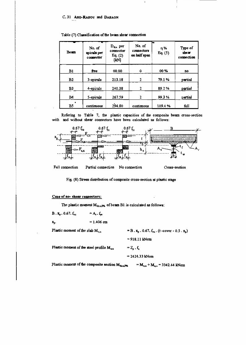
Tobie (7) Classification of the beam shear cODllection
- - ~
No. of Dcl,u per No. of 11% Type of
Beam spiral. per cOlDledor cOlDledon Eq. (5) she.
cmme~r Eq. (2) on half S'pm CODDecbon (kN] !
Bl &ee 00.00 0 00% no
B2 3-spir.ds 213.18 2 79.10/0 partial
Bl 4~spirals 240.38 2 89.2% partial
B4 5-gpirals 267.59 2 99.3 % partial . B5 continuous 294.80 continuous 109.4 % full
Refering to Table 7, the plastic capacities of the composite beam cross-section with and without shear cOlDledors have been calculated as follows:
Full connection Partial connection No connection
Fig. (8) Slress diBtribution ofcompoaite cross-section at plBltic stage
Case 01 no- shear cODDedon:
The pJastic moment Mlh.u.O% of beam Bl is calculated as follows:
B. Xp. 0.67. feu
Xp. = 1.406 em
Plastic moment of the slab Mc.u
Plastic moment of the steel profile M LU
= B • Xp • 0.67. feu • (t -cover - 0.5 . Xp)
= 918.11 kNcm
= 2424.33 kNcm
Plastic moment of the composite section Mth,\I,IM :::E Mc.u + MLU >:I: 3342.44 kNcm
Mansoum Engineering Journal (MEG) Vol. 20, No.1, March, 1995. C. 32.
If the ultimate tensile stres~ (38 kN/cnr) is used instead of the yield stress (29.93 kN/cm2) , Mu.,u,O% win be 3996.11 kNcm. .. .. Case of fDD- shear coanecdoa:
Beam B5 has fuji shear conoection 88 well be described later in Table (8) and the plastic moment M~"'lCOK is obtained as follows:
The total plastic force in the conCf"ete slab Fc.u =.,,= .0.67 . ~u = 837.50 kN
The total plastic force in the steel section F ioU =A •• r. = .538.74 kN
The total plastic force in the reinforcement Fr.u = 117.75 kN
Fc.u :> Fl.u I then the plastic neutral axis lies within the concrete slab and the plasticity of the cross section it governed by the yie Idin!t of the steel profile.
B . Xp. 0.67. feu
Xp.
=~ . .t;.r+Al.fl
=7.839 em
The actual total plastic force in the concrete F c.u = B . Xp . 0.67 . feu = 656.51 kN
Mt.b.u.IOOK> = Fr~u .0.5 . x" + Fr.u • (t-cover-Xp) + Fiou • (t~+O . .5 . b. - Xp)
= 9741.22 kNcm
Case of partial- shear connection:
The method of caJcuJation of the theoretical plBBtic moment of B2 depends on the partiaJ-interaction theory of composite beams [5]. A linear fonnula (6) is given in [4, 5J whicb determine's the partial plastic moment Mtb,u,no/4 of a composite cross-section with a certain degree of shear connection Tt.
Mtb,,,,~ = Mth,uO% + rt • (Mth,U,loo% - Mth,u.O% ) (6)
= 8403.88 kNcm
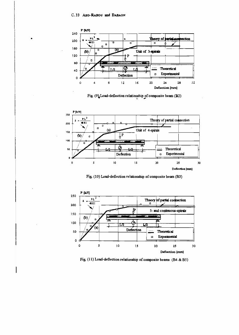
It can be easily observed from figures. (9, 10) that the theoretical curve (a), using partial-interaction theory [5], gives lower values than the experimental results, whil0 Fig. (11) gives close theoretical and experimental resulm in whicb the shear connection is of the full type. How~v~r, an theoretical values ace 00 the safe side. The calculation of the deflection by using the method of ~lastic rigid shear conoection, curve (b), give'S smaller Bm01mts of detle'ction than the experimental results.
•
C.33 ABo-RABou and DABAON
P(kN]
. ] ltbeorY of . _.
bon ... ..!.!:....-.. • .. £t 0 c c 7 ,,:' 0
IJ ---(b)/ c
~ ~ UoitofJ..sphIs
IJ .... _I..p ....l
C /' ¢
200
160
120
// ~ ~ 'I I~ I . -- TheoreIic~ ;'0 T12 l.l -V ... 1'1 c Experimeobl Deflection
80
40
o o 4 \2 16 20 14 28 .. 52
DeneclioD [nun1
Fig. (9~Loa.d-de.t1ection relationship of composite beam (B+) ... ,
P[kN) 250 ~------~--------'---------r-------~--------~------~
PL J ,s=--
200 .. El Theefy ofpanial co~ection
":/ a
o 150 +------+----Q-------c::::..__.-=F=---r------
ThcoretiC:ll a F.%perimental
o~---~---~---~---~~====~======~, o
200
150
100
50
o
s 10 IS 20 25
Ddiert10D Imm)
Fig. (10) Loa.d~de.t1ectioD relationship of composite beam (B3)
o
P(kN]
PL J 6-.::r--
48EI ,,!
10 i'
lion
Theoretical
c Experimental
20 2' Deflection (nun)
Fig. (11) Load~det1ection relationship of composite beams (B4 & B5)
30
30
MansolJl'1l Eogineering Journal (MEG) Vol. 20, No.1, March, 1995. C. 34.
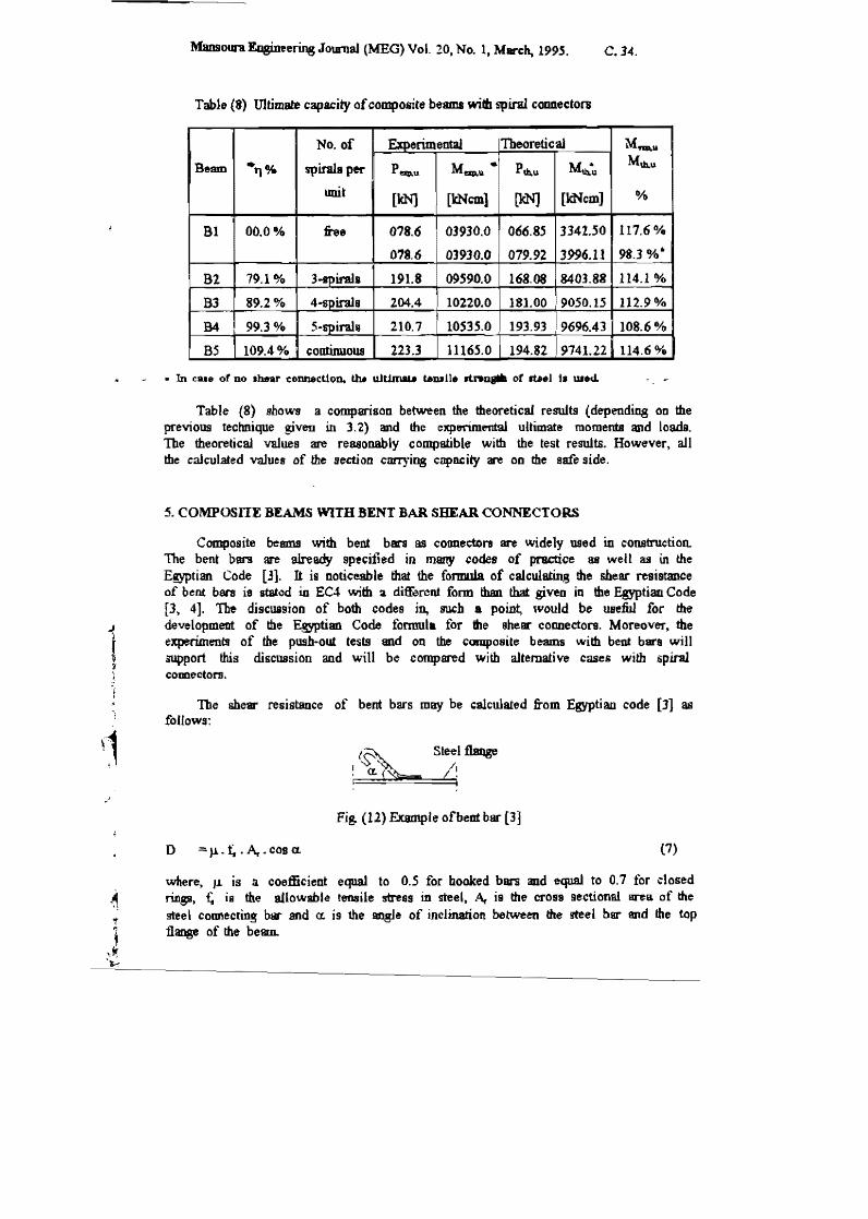
Tablo (8) Ultimate capacity of composite beams wid. spiral connectoR
No. of ExperimentaJ Theoretical Mft!I,.t.t
Beam .1'}% spiral. per Pap,u Map,.\I. • P1b.u M\b,~ Mth,u
tmit [kN] [kNcm] [kN] [kNcm] 0/0
B1 00.0 % :he 078.6 03930.0 066.8.5 3342 . .50 117.6%
078.6 03930.0 079.92 3996.11 98.3%'"
B2 7~.1 % 3-trpiral. 191.8 0~S90.0 168.08 8401.88 114.1 %
B3 89.2% 4--b"1)irals 204.4 10220.0 181.00 9050.15 112.90/0
B4 99.3% 5-spira18 210.7 10S35.0 193.93 9696.43 108.60/0
BS 109.40/0 continuous 223.3 1116.5.0 194.82 9741.22 114.60/0
Table (8) shows a comparison between the theoretical results (dependill8 on the previous tectmique given in 3,2) and the experimental ultimate moments and loads. The theoretical values are rea.eonably compatible with the test results. However, all the calculated values of the section caJ'T1'iog capacity are 00 the safe side.
5. COMPOSITE BEAMS WITH BENT BAR SHEAR CONNECTORS
Composite beams with bent bars as connectors are Widely used in construction. The bent ban are already specified in many codes of practice as well as in the Egyptian Code [3]. It is noticeable that the formula of calculating the sheac resistance of bent bars is stated in EC4 v.nth a different form than that giveo in the Egyptian Code [3. 4]. The discussion of both codes jn. such a point, would be useful for the development of the Egyptian Code fonnula for the shear connectors. Moreover, the experiment! of the push*out tests and on the composite beams with bent bara will support this discussion and will be compared with alternative cases with spiral CODDectors.
The shear resistance of bent bars may be calculated from Egyptian code [3] as follows:
(~ Steel f\aQge 1 a. /1 . I. I I , .
Fj& (12) Example ofbem bar (3]
o =: ).1- ~ • Ar • cos a. (7)
where, J.L is a coefficient equal to O.S for hooked bars and equal to 0.7 for closed rings, ~ is the allowable tensile stress in st'eel l Af is the crOll sectional a:rea of the steel cOlD'\ecring bar and a. is the angJe of inclination between the !Reel bar and the top flange of the beam.
c. 35 ABo-R.ABou and DABAON
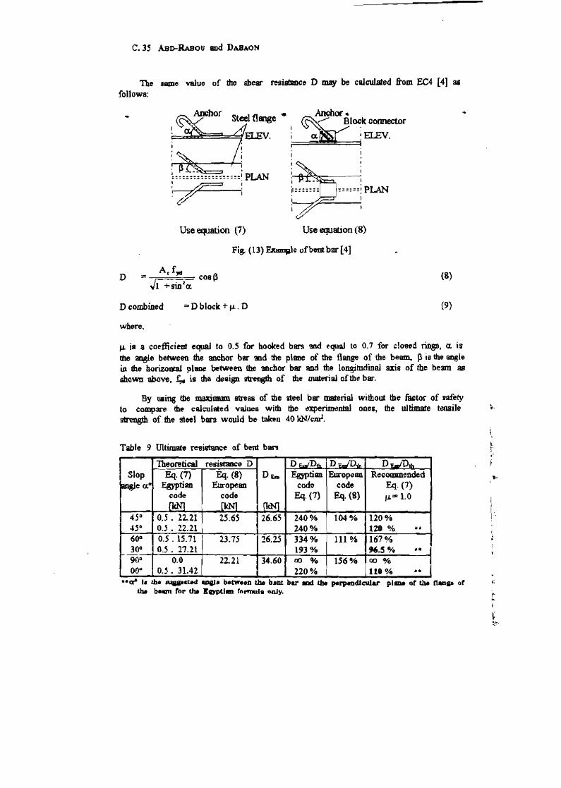
The same value of tho shear resistaraco D may be calc:ulated .ftom EC4 [41 as follows:
D
Dcombined
where,
1
~::~::~;!::::::::::;JI~
~ Use equation (1)
I
-======; plJ\N 1
Use equation (8)
Fig. (13)~le of bent bar [41
=or D block + f.L. 0
(8)
(9)
,... is a coefficient equaJ to 0.5 for booked bars 'aBel equal to 0.7 for closed rUlgB, a. is the sogle between the anchor bar md the plane of the llsnge of rite be~ P is the fm81e in the horizoontl plane between the _chor bar and the longitudinal axis of the beam as shown above, £.,.. is the design strength of the material oftbe bar.
By uaing the maximum stress of the steel bar material without the factor of gafety to compare the calculated Va1~8 with the experiJ:neotal ones, the uJtimate tensile stn!9gth of the steel bars would be t::Dbn 40 kN/curl.
Table 9 mtimate resitmmee of bent ban
Theoretical resiscmce D D~Dt.b. D;:;O~ D,.lIlDtft
Slop Eq. (7) Eq. (8) DEm Egyptian European Recommended ~ea.o .Egyptian European code code Eq. (1)
code code Eq. (7) Eq. (8) ,...= 1.0 fkN1 [kN) (kN]
45 0 0.5 • 22.21 25.65 26.65 2400/0 104% 120% 4,Q 0.5 • 22..21 2400/0 121 % ... 600 O.S. lS.71 23.7.5 26.25 3340/0 111% 161 ~'" 30G 0.5. 27.21 193% 96.S 0/. ..III
900 0.0 22.21 34.60 00 % 156,. CO% 00'" 0.'. 31.42 220% 111% ..
.. ga I. the ..... stH ..... between tile b.nt bar IDd Lb. p*rpndlcvJar pi ... or tat n .. Gt the beam tor tilt EDPUm (ormula only.
. If·
! I I
!'o
f.
MansouraEngineerin.1j Journal (MEa) VoL 20, No.1. March. 199.5. C.36.
Table (9) shows the ratios between the experimental tests [2] aDd both of Egyptian and European codes results. It can be observed that the fuctor J.1 is used only, according to EC4. where the weld of the bent bar (anchor) is not direct on the steel flange .
• .. There are three comments on the Egyptian code of practice concerning bent
banJo The fint one is concerned with the angle on the horizontal piane between the anchor bar and the steeJ llaoge p. Altho. the effect of the angle p is impo~ yet it is not taken into consideration. The secOIld comment is about the factor J.1 which gives very conservative vaJues of the shear resistance compared with the experimental and European code results [4]. The last comment refen to the aogle of inclination (a.) between the bent bar and the top flggge of the beam. With respect to the last commen~ fomrula (7) gives zero shear resistance for the vertical bar (a.=900) which is not realistic.
From table (9), the coefficient J.L may be increBBed by a value between 80 u/C) to 120 % and the angle a. becomes with the vertical direction (90" - a.) in the Egyptian formula. ii c_ be noticed that a reliable ultimate shear resistance of bent bars is obtained which agrees with the experimental reS1llts.
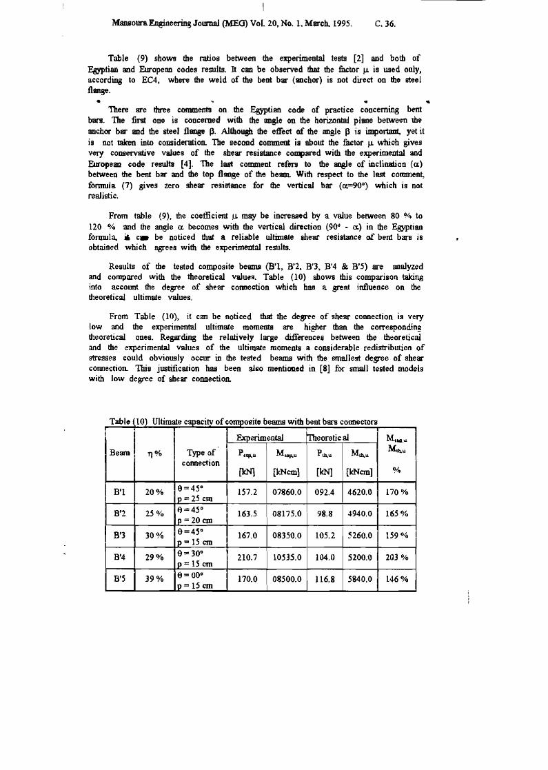
Results of the tested composite beams (B'I, B'2. B'3, B'4 & B'.5) are analyzed and compared with the theoretical vaJues. Table (10) &bows this comparison taking into accotmt the degrel!' of shl!'ar connection which has a great influence on the theoretical ultimate values.
From Table (10). it can be noticed that the degree of shear connection is very low and the experimental ultimate moments are higher than the corresponding theoretical ones. Regarding the relatively large differences between the theoretical and the ~xperimenta1 values of the ultimate moments a considerable redistribution of !rtresses could obviously occur in the tl!'stl!'d beams with the smallest degree of shear connection. This justification has been also mentioned in [8J for mm.ll tested models with low degree of shear connection.
Table 10) Ultimate capacitv of composite beams with bent bars connectors
Experimental Theoretic al MUD•U
Beam 11 0/0 Type of Ptxp•u Mexp.u Pth,u Mt.b,.u M~u
cormection [kNl [lcNcm] [leN] [lcNcm] %
B'I 20% e=4.5° p = 25 cm
157.2 07860.0 092.4 4620.0 170 %
B'2 25% e=4.5° 163.5 08175.0 98.8 4940.0 165% Ip = 20 em
B'3 30% 6=4S CI
p'" 15 em 167.0 08350.0 105.2 .5260.0 159%
B'4 290/0 6= 30° p = 15 em
210.7 10535.0 104.0 5200.0 203 %
B'S 39% tI= 00° 170.0 Ip=lScm
08500.0 116.8 5840.0 146%
•
•
C. 37 AaD-RABou and DAIIAON
6. CONCLUSIONS
From the rem".ad dilWSlioDII presented in this wont. the following conclusions can be .rawn; • ••
1. The paper preseaa. a method of BDalysilJ of ipiral Dar cooaedon when the puIh-_ rellllbl present by upper aad lower limits of ultimate and maximum elastic resistance of the spiral !hear cOlIDectors. In addition, a proposed technique iIttrOducel to BD explicit formula from which the uJtimate and the lDIIXium ~lastic shear re.illtaDce of allY type of spiral shear CODDector can be obtained with reasonable accuracy.
2. A comparison between the theoreticaJ and experimental resWts for composite beams with spiral sheW" connectors, using the present formula of spinU shear cOlIDectOMl, shows a good ~~ment
J. A comparison between the Egyptian formula [3] aod.Ew-opean formula [4], ,for . pr~dictiD8 the shear resistance of bent bar shenr connectors, highligbhl theimporlance of the uctor 1-1 in Egyptian formula If this factor equals (1.0), the resuitB of this fommla would be compatible with push-out results. Also, the aogle a. in fomwla (7) may be taken (90 - a.) as recommended in this paper.
4. The spiral shear cormectors are IIDlch applicable and give higher shear resistance thaa bent bar connectors in composite beam construction.
5. Reduced scaJe te!ting., for composite beams with partial shear connection, suifenJ from scale effects and does not present of full scaJe performance.
i. REFERENCES
[1] Saad Etdeen Abd-RBbou . ''Experimental Inve!tigation of Composite Beams Using Spirals 88 Shear Connectors", Part L :Mansow-a En,tpneering JownaJ (ME1)~ Vol. 19, No. 4, Dec. 1994.
[2] Saad Eldeen Abd-Rabou , ''Experimentallnvestigarion of Composite Beams Using Bent Bacs as Shear COlUlectors", Part n, MansolU1l Eogineeri~ Jownal (MEJ), Vol. 19. No.4. D~c. 1994.
[3] Egyptian Code of Practice for Steel CoostructiOml and Bridges, Research Ceoo-e for HoU8ing, Building and Physical Plmwing , Cairo, Ministerial Decree. No. 451-1989, Fourth Edition 1993.
[4] European Code 4 (EC4). "Design of Composite Steel Concrete Structures", Brussels. Belgium, 1994.
[5] M. A Dabaon, F. Tschemmemegg. K. Hassan, T. Abdel Lateef"Zur tragfamgkeit von Verb~m bei teilweiser Verdabehm~", Stahlbm 62 (1993), Heft 1.
[6] R.P. Jobosoa, "Compolite Structures of Steel Concrete", Primed in Greaa Britain by . William & SODS Limited, J.gndon, Vol. 1, 1975. (7] Institute for BuiJdiog Materials and Structures, Netherlands Orgaoisation for appHed
Bcieatific research.. ''Determ.ination of Design resiltaDce from Tests". Procedure for the Background report to Europe8ll Code (EC3). Nov .• 1987.
[8] J.W. B. Stark, "Composite Steel and Concrete Beams with Partial Shear Cormection ", Insticute for Building Materials BOd Structures, Heron, Delft U~ity, Delft. 'The Netherlands. Vol. 34. No.4,1989.
Related Documents