J. A. Hargreaves Lockerbie Academy March 2016

Welcome message from author
This document is posted to help you gain knowledge. Please leave a comment to let me know what you think about it! Share it to your friends and learn new things together.
Transcript

J. A. Hargreaves
Lockerbie Academy
March 2016

Content Summary of electricity content
J A Hargreaves Page 2 of 84
CONTENT
CONTENT
Content ..................................................................................................................................... 2
Data Sheet ................................................................................................................................ 5
Relationships Required For Higher Physics .............................................................................. 6
CHAPTER 1: SUMMARY ELECTRICITY CONTENT ....................................................................... 7
Summary of electricity content ............................................................................................ 7
CHAPTER 2: BACKGROUND TO ELECTRICITY ............................................................................ 9
Prefixes .............................................................................................................................. 9
Definitions.......................................................................................................................... 9
Measuring Current and Voltage ...................................................................................... 10
Series and Parallel: Circuit Rules ..................................................................................... 10
Resistance in series and parallel ...................................................................................... 11
Ohm’s Law ....................................................................................................................... 12
Practical 1- the Van de Graaff ............................................................................................. 13
Practical 2 – Resistors in Series Practical ............................................................................ 13
Practical 3- Resistance in Parallel ........................................................................................ 14
Revision Tutorials ................................................................................................................ 14
Tutorial 1: Electric Fields ................................................................................................. 14
Tutorial 2 Circuits ............................................................................................................. 15
Tutorial 3- Resistance ...................................................................................................... 15
Tutorial Answers ................................................................................................................. 16
Worked Answers for tutorials ......................................................................................... 16
CHAPTER 3: MONITORING AND MEASURING A.C ................................................................. 18
Summary of content ........................................................................................................... 18
Measuring the Frequency ................................................................................................... 18
Peak Voltage and R.M.S. ..................................................................................................... 19
Peak Voltage and R.M.S. .................................................................................................. 20
Practical 1: Comparing bulb brightness with an a.c and d.c supply. .................................. 22
Practical 2: Checking the equation for RMS current: ......................................................... 23
Tutorial 1: alternating current & voltage ............................................................................ 24
Practical 3 – electron gun ................................................................................................... 24
Practical 4- energy is measured in joules per coloumb ...................................................... 24
Tutorial 2- Past Paper Questions ........................................................................................ 25
Alternating current & voltage/ tutorial answers ................................................................ 26
Solutions to Past paper questions ................................................................................... 26
CHAPTER 4: CURRENT, POTENTIAL DIFFERENCE, POWER AND RESISTANCE ........................ 28
Summary of Content ........................................................................................................... 28
Power .................................................................................................................................. 28
Potential Divider Circuits ................................................................................................. 28
Potential Divider examples ................................................................................................. 31
Movement of Charge .......................................................................................................... 33
Tutorial 1: Current, voltage, power and resistance ............................................................ 33
Tutorial 2- Wheatstone bridges .......................................................................................... 38

Content Summary of electricity content
J A Hargreaves Page 3 of 84
Tutorial 1 Solutions: Current, voltage, power and resistance : .......................................... 39
Tutorial 2 Solutions .......................................................................................................... 39
Worked answers for tutorial 2 ........................................................................................ 39
CHAPTER 5: ELECTRICAL SOURCES AND INTERNAL RESISTANCE ........................................... 40
Summary of Content ........................................................................................................... 40
EMF-electromotive force .................................................................................................... 40
Cells ..................................................................................................................................... 40
Practical 1 – A dry Cell ......................................................................................................... 41
Practical 2: Measuring the emf and internal resistance of a 1.5v cell. ............................... 42
EMF Questions from graphs ............................................................................................... 44
GRAPH 1- V against I ........................................................................................................ 44
GRAPH 2 – R against 1/I ................................................................................................... 45
GRAPH 3 - graph of lost volts against R ........................................................................... 46
Power matching .................................................................................................................. 47
[application of internal resistance] ................................................................................. 47
Tutorial 1- EMF .................................................................................................................... 50
Tutorial 2 More EMF questions .......................................................................................... 50
Tutorial 3- Past paper questions ......................................................................................... 52
Tutorial Answers ................................................................................................................. 56
Tutorial Answers SQA Solutions .......................................................................................... 57
CHAPTER 6 CAPACITORS ........................................................................................................ 58
Summary of content ........................................................................................................... 58
Background to Capacitors ................................................................................................... 58
What is a capacitor? ........................................................................................................ 58
Capacitor circuit symbol .................................................................................................. 58
So how do Capacitors work? ........................................................................................... 59
Capacitance ......................................................................................................................... 61
Charging and Discharging ................................................................................................ 62
Measuring the capacitance of a capacitor. ......................................................................... 64
Charging a capacitor on a d.c. supply. ............................................................................. 66
Discharging a capacitor.................................................................................................... 66
Energy stored in a Capacitor ............................................................................................... 67
Energy Stored .................................................................................................................. 67
Capacitors and a.c. .............................................................................................................. 68
Charging on a.c. ............................................................................................................... 68
Resistance and Frequency .................................................................................................. 69
Part 1 Resistance and Frequency .................................................................................... 69
Reactance of capacitors in a.c. circuits ............................................................................... 70
Relationship Between Current and Frequency in an A.C capacitor Circuit ..................... 71
Blocking and Smoothing ..................................................................................................... 72
Blocking ............................................................................................................................ 72
Smoothing ........................................................................................................................ 72
Tutorial 1: capacitance ........................................................................................................ 73
Tutorial 2: capacitance ........................................................................................................ 73

Content Summary of electricity content
J A Hargreaves Page 4 of 84
Tutorial 3: capacitance ........................................................................................................ 73
Tutorial 4: CAPACITANCE .................................................................................................... 74
Tutorial 5: Exam Questions ................................................................................................. 76
Tutorial Answers Capacitance ............................................................................................. 79
Tutorial Work Answers ....................................................................................................... 81
Capacitance/ tutorial answers ......................................................................................... 81
Tutorial Answers: Exam question soutions ......................................................................... 82

Data Sheet Summary of electricity content
J A Hargreaves Page 5 of 84
DATA SHEET

Relationships Required For Higher Physics Summary of electricity content
J A Hargreaves Page 6 of 84
RELATIONSHIPS REQUIRED FOR HIGHER PHYSICS

CHAPTER 1: SUMMARY ELECTRICITY CONTENT Summary of electricity content
J A Hargreaves Page 7 of 84
CHAPTER 1: SUMMARY ELECTRICITY CONTENT
CHAPTER 1: SUMMARY ELECTRICITY CONTENT
SUMMARY OF ELECTRICITY CONTENT
1. MONITORING AND MEASURING A.C. (chapter 3)
fT
1
a) Knowledge that a.c. is a current which changes direction and instantaneous value with
time.
b) Use of appropriate relationships to solve problems involving peak and r.m.s. values.
c) Determination of frequency, peak voltage and r.m.s. values from graphical data.
2. CURRENT, POTENTIAL DIFFERENCE, POWER AND RESISTANCE (chapter 4)
a) Use of appropriate relationships to solve problems involving potential difference,
current, resistance and power. Solutions may involve several steps.
b) Use of appropriate relationships to solve problems involving potential divider
circuits.
c) Use relationships involving potential difference, current, resistance and power to
analyse circuits. Calculations may involve several steps.
d) Calculations involving potential dividers circuits.
3. ELECTRICAL SOURCES AND INTERNAL RESISTANCE (chapter 5)
a) Knowledge of the terms electromotive force (e.m.f.), internal resistance and
terminal potential difference (t.p.d.), ideal supplies, short circuit and open circuit.
b) Use of an appropriate relationship to solve problems involving e.m.f., t.p.d., current
and internal resistance.
c) Determination of internal resistance and e.m.f. using graphical analysis.

CHAPTER 1: SUMMARY ELECTRICITY CONTENT Summary of electricity content
J A Hargreaves Page 8 of 84
4 CAPACITORS (chapter 6)
a) Definition of capacitance.
b) Use of an appropriate relationship to solve problems involving capacitance, charge
and potential difference.
c) Knowledge that the total energy stored in a charged capacitor is the area under the
charge against potential difference graph.
d) Use of data from a charge against potential difference graph.
e) Use of appropriate relationships to solve problems involving energy, charge,
capacitance and potential difference.
f) Awareness of the variation of current and potential difference with time for both
charging and discharging cycles of a capacitor in a CR circuit (charging and
discharging curves).
g) Awareness of the effect of resistance and capacitance on charging and discharging
curves in a CR circuit.
5 CONDUCTORS, SEMICONDUCTORS AND INSULATORS (chapter 7)
a) Knowledge that solids can be categorised into conductors, semiconductors or
insulators by their ability to conduct electricity.
b) Awareness of the terms conduction band and valance band.
c) Qualitative explanation of the electrical properties of conductors, insulators and
semiconductors using the electron population of the conduction and valance bands
and the energy difference between the conduction and valance bands.
6 P-N JUNCTIONS (chapter 8)
a) Awareness that, during manufacture, the conductivity of semiconductors can be
controlled, resulting in two types: p-type and n-type.
b) Knowledge that, when p-type and n-type materials are joined, a layer is formed at the
junction. The electrical properties of this layer are used in a number of devices.
c) Awareness of the terms forward bias and reverse bias.
d) Knowledge that solar cells are p-n junctions designed so that a potential difference is
produced when photons enter the layer. (This is known as the photovoltaic effect.)
e) Knowledge that LEDs are forward biased p-n junction diodes that emit photons when
electrons ‘fall’ from the conduction band into the valence band of the p-type
semiconductor.

CHAPTER 2: BACKGROUND TO ELECTRICITY Prefixes
J A Hargreaves Page 9 of 84
CHAPTER 2: BACKGROUND TO ELECTRICITY
PREFIXES
tera T 1012 x 1,000,000,000,000
giga G 109 x 1,000,000,000
mega M 106 x 1,000,000
kilo K 103 x 1,000
centi C 10-2 /100
milli M 10-3 /1,000
micro µ 10-6 /1,000,000
nano N 10-9 /1,000,000,000
pico P 10-12 /1,000,000,000,000
DEFINITIONS
CURRENT
Current is the rate of flow of charge in a circuit and can be calculated using
𝑸 = 𝑰𝒕
Where Q =quantity of charge measured in Coulombs (C), I = current (A), t=time (s)
In a complete circuit containing a cell, switch and a bulb the free electrons in the conductor
will experience a force which will cause them to move drifting away from the negatively
charged end towards the positively charged end
Electrons are negatively charged, 1 electron has a charge of 1610-19 C.
POTENTIAL DIFFERENCE
If one joule of work is done in moving one Coulomb of charge between two points then the
potential difference (p.d.) between the two points is 1 volt. (This means that work is done
when moving a charge in an electric field)
𝑬𝒘 = 𝑸𝑽
Where Ew = the work done in moving quantity of charge between two points in an
electric field (J), Q= quantity of charge (C ), V= potential difference between two points in
an electric field in Joules per Coloumb (JC-1) or volts (V)

CHAPTER 2: BACKGROUND TO ELECTRICITY Measuring Current and Voltage
J A Hargreaves Page 10 of 84
MEASURING CURRENT AND VOLTAGE
They can be used in simple, or more complex circuits in order to investigate the size of any
of these quantities.
The diagram also shows how the voltmeter and ammeter must
be connected.
The voltmeter must be connected in parallel because it is
measuring the difference in electrical potential between two
points.
The ammeter must be connected in series because it is
measuring the flow of current THROUGH a component or
circuit.
In most cases, resistance should only be measured when a
circuit is not ‘on’ or fully connected.
To use an ohmmeter, you would place it ‘across’ a component
– in parallel, just like a voltmeter.
SERIES AND PARALLEL: CIRCUIT RULES
Measurement Series Circuits Parallel Circuits
Potential Difference
𝑽𝑺 = 𝑽𝟏 + 𝑽𝟐 + 𝑽𝟑 … 𝑽𝑺 = 𝑽𝟏 = 𝑽𝟐 = 𝑽𝟑 …
Current 𝑰𝟏 = 𝑰𝟐 = 𝑰𝟑 = 𝑰𝟒 … 𝑰𝑺 = 𝑰𝟏 + 𝑰𝟐 + 𝑰𝟑 …
Resistance 𝑹𝒕𝒐𝒕𝒂𝒍 = 𝑹𝟏 + 𝑹𝟐 + 𝑹𝟑 + ⋯ 𝟏
𝑹𝒕𝒐𝒕𝒂𝒍=
𝟏
𝑹𝟏+
𝟏
𝑹𝟐+
𝟏
𝑹𝟑+ ⋯
Component Name
Circuit Symbol Function
Voltmeter
Measures potential difference. Must be placed in parallel to measure the difference in electrical potential between two points.
Ammeter
Measures current. Must be placed in series to measure the current flowing in a circuit.
Ohmmeter
Measures resistance. Must be placed in parallel with the component(s) which are to
be measured.

CHAPTER 2: BACKGROUND TO ELECTRICITY Resistance in series and parallel
J A Hargreaves Page 11 of 84
RESISTANCE IN SERIES AND PARALLEL
Worked examples 1. Calculate the resistance of the following circuit
Rtotal
R1
R2
R3
= ?
= 60 Ω
= 35 Ω
= 22 Ω
Rtotal
Rtotal
Rtotal
= R1 + R2 + R3
= 60 + 35 + 22
= 117 Ω
2. The total resistance of this circuit is 25 kΩ. Calculate the value of Resistor 2
Rtotal
R1
R2
R3
= 25 kΩ
= 12 kΩ
= ?
= 500 Ω
Rtotal
25000
R2
R2
R2
= R1 + R2 + R3
= 12000 + R2 + 500
= 25000 – 12500
= 12500
= 12.5 kΩ
3. Calculate the resistance of the circuit shown below
4. The total resistance of this circuit is 100Ω. Calculate the value of Resistor 1
Rtotal = ?
R1 = 100 Ω
R2 = 200 Ω
R3 = 400 Ω
1/Rtotal
1/Rtotal
1/Rtotal
1/Rtotal
Rtotal
Rtotal
= 1/R1 + 1/R2 + 1/R3
= 1/100 + 1/200 + 1/400
= 4/400 + 2/400 + 1/400
= 7/400
= = 400/7
= 57 Ω
Rtotal = 100 Ω
R1 = ?
R2 = 200 Ω
1/Rtotal
1/100
1/R1
1/R1
1/R1
R1
= 1/R1 + 1/R2
= 1/R1 + 1/200
= 1/100 - 1/200
= 2/200 - 1/200
= 1/200
= 200 Ω
60 Ω 35 Ω 22 Ω
12 kΩ R2 500 Ω
100 Ω
200 Ω
400 Ω
200 Ω
R1

CHAPTER 2: BACKGROUND TO ELECTRICITY Ohm’s Law
J A Hargreaves Page 12 of 84
Parallel Section first: 𝟏
𝑹𝒑 =
𝟏
𝑹𝟏 +
𝟏
𝑹𝟐
𝟏
𝑹𝒑=
𝟏
𝟔+
𝟏
𝟏𝟐=
𝟐
𝟏𝟐+
𝟏
𝟏𝟐
𝟏
𝑹𝒑=
𝟑
𝟏𝟐 𝑹𝒑 =
𝟏𝟐
𝟑
= 𝟒 𝜴
Now have 3 resistors in series
𝑹𝑻 = 𝑹𝟏 + 𝑹𝒑 + 𝑹𝟑
𝑹𝑻 = 𝟒 + 𝟒 + 𝟏𝟔 = 𝟐𝟒 𝜴
Simplify the parallel branches Branch 1 Branch 2
𝑹𝒑𝟏 = 𝑹𝟏 + 𝑹𝟐
𝑹𝒑𝟐 = 𝑹𝟏 + 𝑹𝟐
𝑹𝒑𝟏 = 𝟑 + 𝟔 = 𝟗 𝜴 𝑹𝒑𝟐 = 𝟐 + 𝟏𝟔 = 𝟏𝟖 𝜴
Calculate resistance of parallel section
𝟏/𝑹𝒑 = 𝟏/𝟗 + 𝟏/𝟏𝟖 = 𝟐/𝟏𝟖 + 𝟏/𝟏𝟖 𝟏
𝑹𝒑=
𝟑
𝟏𝟖
=> 𝑹𝒑 = 𝟏𝟖/𝟑 = 𝟔 𝜴 Now find total
𝑹𝑻 = 𝑹𝒑𝟏 + 𝑹𝒑𝟐
𝑹𝑻 = 𝟔 + 𝟓 = 𝟏𝟏 𝜴
OHM’S LAW
Ohm's law forms the basis for
understanding how electrons or
charge flows through circuits. Ohm's
Law deals with the relationship
between voltage and current in an
ideal conductor.
This relationship states that:
For a constant temperature for a
given resistor:
V α I or V / I = constant
𝑽 = 𝑰𝑹
0
1
2
3
4
5
6
7
8
9
10
0 0.05 0.1 0.15 0.2
Po
ten
tial
Dif
fere
nce
/ V
Current / A

CHAPTER 2: BACKGROUND TO ELECTRICITY Practical 1- the Van de Graaff
J A Hargreaves Page 13 of 84
Where V= potential difference in Volts, I= current (A), R= resistance ()
There are components which do not have a constant resistance as the current through
them is altered – eg a light bulb. Graphs of potential difference against current for this type
of component will not be a straight line.
PRACTICAL 1- THE VAN DE GRAAFF
Aim: To familiarise yourself with the Van de Graaff generator.
Watch and participate in the experiments demonstrating the Van de Graaff generator.
Ensure that you know the following:
How the Van de Graaff creates the charge.
How the Van de Graaff stores charge.
The size and shape of the field pattern and force create around the VdG.
How the charge can be distributed.
Write up your experiences including the Physics behind the Van de Graaff.
PRACTICAL 2 – RESISTORS IN SERIES PRACTICAL
Aim: To check the formula for resistors in series against our experience, set up the
following circuit:-
V
+ -
A
wire holder
1. Put 10cm of resistance wire into the holder and note the current and voltage readings.
2. Feed out more wire so that 20cm of the same wire lies between the terminals of the
holder.
3. Adjust the variable resistor until the current is the same as for the 10cm length of wire.
4. Note the voltmeter reading.
Predict the voltage reading after you have adjusted the current when 30cm of wire
stretches between the holder's terminals.
Discuss why the voltmeter reading increases as the resistance wire is lengthened.

CHAPTER 2: BACKGROUND TO ELECTRICITY Practical 3- Resistance in Parallel
J A Hargreaves Page 14 of 84
PRACTICAL 3- RESISTANCE IN PARALLEL
1. Using the same basic apparatus as in Practical 2 put 10cm of resistance wire into the
holder.
2. Note the current and voltage readings.
3. Now put a second 10cm length of resistance wire into the holder along with the first
piece.
T wo 10cm lengths of
resistance wire.
Holder
4. Use the variable resistor to adjust the voltage to the same as the previous value, then
take note of the current.
PREDICT: What the current reading is after you have put 3 separate 10cm lengths of wire
into the holder and adjusted the voltage to its previous value.
DISCUSS: Why does the current reading increase as the experiment progresses.
REVISION TUTORIALS
TUTORIAL 1: ELECTRIC FIELDS
1.
+ +++++ -- ----
+ +++++ -- ----
copper rod
po lys tyrene rod
?
?
+
+
+
+
+
+
++
++
+ +
+
+
Explain with the aid of a diagram, what effect we get when a positively charged object is
brought near the right hand edge of these rods:-
2. What is the size of angle X?
+
+
+
+
+
+
+
2c m
15 o
+
(A)
-
-
-
-
-
-
-
+
+
+
+
+
+
++
-
-
-
-
-
-
-
(B)
Xo
4c m

CHAPTER 2: BACKGROUND TO ELECTRICITY Revision Tutorials
J A Hargreaves Page 15 of 84
3. An oil drop with a charge of 3 pC and a mass of 1.22 x 10⁻⁸ kg is placed in a uniform
electric field of 4 x 10⁴ NC-1. If the oil drop floats between the charged plates, what is its
weight?
4. A small polystyrene sphere with a positive charge of 5pC is placed in a uniform
electric field at the 10 V level. If the sphere falls downwards to a place where the voltage
level is 150 V, how much work does the gravitational field do?
TUTORIAL 2 CIRCUITS
1. A lamp is rated at 48W 12V. When running normally,
a) What is the current through the lamp?
b) What is the lamp's resistance while it is operating?
2. If a 2kΩ resistor has a p.d. of 9.6 V across it, what is the current in it?
3. A model power transmission line is 3 m long and carries a current of 4A. What is the p.d. across it if the wire used has a resistance of 125 milliohms per metre?
TUTORIAL 3- RESISTANCE
1. What is the total resistance of this arrangement?
10 200 1k
2. If the equivalent resistance of the
following arrangement is 250Ω, what is
the value of the unknown resistor?
3. What is the equivalent resistance of this
arrangement of resistors?
4. If the equivalent resistance of the following
arrangement is 250Ω, what is the value of the
unknown resistor?
5. What is the equivalent resistance of 200Ω, 300Ω and 600Ω when they are all
connected in parallel?
6. What is the equivalent resistance of three resistors, 4Ω, 4Ω and 2Ω in parallel?
7. What is the value of a resistor which gives an equivalent resistance of 18.75Ω when
connected in parallel with a 75Ω resistor?
900 Ω
900 Ω
900 Ω
500
R
95 R 115

CHAPTER 2: BACKGROUND TO ELECTRICITY Tutorial Answers
J A Hargreaves Page 16 of 84
TUTORIAL ANSWERS
TUTORIAL 1
1.
+
+
+
+
+
+
++
++
+ +
+
+
+
+ + ++
-
- - - -
copper
polys tyrene
2. X = 15o since the field is uniform.
3. Since the drop is floating, the electric force, 1.2x10⁻⁷N, is the same as its weight.
4. Since the motion is caused by the sphere's weight, the work done by the gravitational field
is 7x10⁻¹⁰J.
TUTORIAL 2
1. a) The current in the lamp is 4A
b) The lamp's resistance is 3Ω
2. The current in the resistor is 4.8mA
3. The wire has a p.d. of 1.5V across it.
TUTORIAL 3
1. Total resistance =1210Ω
2. The unknown resistance is 40Ω
3. The equivalent resistance is 300Ω
4. The unknown resistance is 500Ω
5. The equivalent resistance is 100Ω
6. The equivalent resistance is 1Ω
7. The unknown resistance is 25Ω
WORKED ANSWERS FOR TUTORIALS
WORKED ANSWERS FOR TUTORIAL 2
1. a) P=VI gives 48=12xI Thus I = 4 The current in the lamp is 4A b)
V
I R
12
4 R
R 3
The lamp's resistance is 3Ω
2. 9.6
I 2000 I 4.810
3 The current in the resistor is 4.8mA

CHAPTER 2: BACKGROUND TO ELECTRICITY Tutorial Answers
J A Hargreaves Page 17 of 84
3.
5.1103754
10375
101253
3
3
3
VV
I
V
R
The wire has a p.d. of 1.5V across it.
WORKED ANSWERS FOR TUTORIAL 3
1. 1210
100020010321
R
RRRRR
The total resistance is 1210Ω
2. 40
11595250321
R
RRRRR
The unknown resistance is 40Ω
3.
300
3
900
900
311111
321
R
RRRRR
The equivalent resistance is 300Ω
4.
500
500
1
500
1
250
111
500
1
250
1
R
RR The unknown resistance is 500Ω
5.
1006
600
600
6
600
123
600
1
300
1
200
11
R
R The equivalent resistance is 100Ω
6.
1
4
4
4
411111
321
R
RRRRR
The equivalent resistance is 1Ω
7.
25
25
1
75
1
75.18
111
75
1
75.18
1
R
RR The unknown resistance is 25Ω

CHAPTER 3: MONITORING AND MEASURING A.C Summary of content
J A Hargreaves Page 18 of 84
CHAPTER 3: MONITORING AND MEASURING A.C
SUMMARY OF CONTENT
1. MONITORING AND MEASURING A.C. (CHAPTER 3 )
f
T1
a) A.C. as a current which changes direction and instantaneous value with time.
b) Calculations involving peak and r.m.s. values.
c) Determination of frequency, peak voltage and r.m.s. values from graphical data.
Use of a multimeter as an ammeter, voltmeter and ohmmeter.
Use of an oscilloscope as a voltmeter and waveform monitor.
Use of an oscilloscope to monitor a.c. signals,including the measurement of
frequency and peak/r.m.s. values.
MEASURING THE FREQUENCY
At Higher it is not enough to find the frequency by inspection (this means comparing your
known trace to your unknown trace using a double beam oscilloscope and a signal
generator) At Higher you need to be able to use the timebase! We first need to work out
the period, T where T is the period or time for one wave.
1. f
T1
2. Set up the oscilloscope to give a
stationary trace.
3. Adjust the trace so that the time
period can be found.
4. Time period = time for one wave
5. Count the number of squares for 1 wave
6. Multiply the number of squares for 1 wave by the time base setting
7. Find T
f1
8. (Time setting will be in ms or s. DON’T FORGET TO CHANGE IT!!)
KNOW HOW TO MEASURE FREQUENCY USING AN OSCILLOSCOPE
e.g.
1. An oscilloscope is connected to the output terminals of a signal generator.

CHAPTER 3: MONITORING AND MEASURING A.C Peak Voltage and R.M.S.
J A Hargreaves Page 19 of 84
V
t
The trace displayed on the screen is shown below.
The timebase of the oscilloscope is set at 30 ms/div.
The frequency of the output signal from the signal generator is
A 4∙2 × 10⁻³ Hz
B 8∙3 × 10⁻³ Hz
C 0∙28 Hz
D 4∙2 Hz
E 8∙3 Hz .
Answer
1 wave is 4 boxes across in the trace above. Each box is 30ms. T=430=120 ms =1.210-1s
𝑓 =1
120 × 10−3= 8.3 𝐻𝑧
2. An alternating voltage is displayed on an oscilloscope screen. The Y-gain and the
timebase settings are shown. Which row in the table gives the values for the peak voltage and frequency of the signal?
Peak voltage/V
Frequency/Hz
A 10 100
B 10 250
C 20 250
D 10 500
E 20 1000
PEAK VOLTAGE AND R.M.S.
An a.c is one where the magnitude and direction of the current changes, usually many times per second. The mains is an example of an a.c.
But what do we take as the voltage to quote? With an a.c trace the value keeps changing.

CHAPTER 3: MONITORING AND MEASURING A.C Peak Voltage and R.M.S.
J A Hargreaves Page 20 of 84
The average voltage is not a good
indication of the effect of the voltage
as the average voltage is always zero.
Peak voltage isn’t a good indication of
the voltage to a device. It also cannot
be compared with a d.c. supply. It will
over- estimate the power dissipated in
the circuit
The solution is to do with the fact that
half the time the charges move in one
direction and half the time in the
opposite direction. We can get rid of this
problem by squaring everything.
The pattern of the graph now changes
and it is possible to work out an average
for the new graph.
It turns out that the average is 2
2
pV.
To get back to the original we now
need to take the square root of this
value which will be 2
pV.This is called
the r.m.s. value = 2
peak
PEAK VOLTAGE AND R.M.S.
The answer is the r.m.s (root mean square) value. Now a.c. and d.c. are comparable!
NB. i) Peak is always the biggest ii) 414.12
V
AverageVoltage
t
0
Vp 2
time
V 2
V
Peak Voltage
t
R.M.S.
V
2
peakrms

CHAPTER 3: MONITORING AND MEASURING A.C Peak Voltage and R.M.S.
J A Hargreaves Page 21 of 84
THE SAME APPLIES FOR CURRENT
a.c. is one in which electrons flow first in one direction then in the other.
In a resistor the rate at which heat is produced is given by P = I2R
With a.c. what value do you take as I?
a) average I = 0 A
b) peak only occurs for a very short period therefore it is an overestimate.
We therefore want something in between.
The clue is in I2
Squaring the current and plotting it on a graph shows that I2 is always positive. The graph is
symmetrical and the average is half its maximum.
average of 2
212 )( PII
0
IP2
time
I2

CHAPTER 3: MONITORING AND MEASURING A.C Practical 1: Comparing brightness
J A Hargreaves Page 22 of 84
PRACTICAL 1: COMPARING BRIGHTNESS
COMPARING BULB BRIGHTNESS WITH AN A.C AND D.C SUPPLY.
Set up the circuit as shown below and take your own readings to shown that the rms of an
a.c trace provides the same power to a circuit as a d.c trace.
Power on d.c Power on a.c.
Current = 1.42A
Voltage=12.35V
P=IV
No. of squares from top of the trace to the
bottom =6.6
Each square is 5V/div
Power on d.c.=17.5W
Therefore peak voltage = 3.35V=16.5V
r.m.s value=
VV
Vp
rms 7.112
5.16
2
Current= 1.464A
Voltage= 11.7V
Power on a.c=17.1W
We can now calculate the average power delivered by this a.c. to the resistor.
RIPRIP Pac
2
212 )(
where IP = peak current.
Compare with d.c. which provides a steady current:
RIPdc
2
If we arrange the equipment so that the same power is delivered by
a.c. and d.c. supply then we can compare I and IP.
This can also be written as:
REMEMBER THAT IP IS ALWAYS > Irms
B A Two-way switch
oscillosc
photo cell &
meter
4142.1
4142.12
)( 2
21
P
P
II
II
A
2
2
)(
)(
22
22
21
22
21
P
P
P
P
dcac
II
II
II
RIRI
PP

CHAPTER 3: MONITORING AND MEASURING A.C Practical 2: Checking the equation
for RMS current:
J A Hargreaves Page 23 of 84
In a circuit containing a resistor the current is completely independent of frequency. i.e.
you change the frequency and the current stays the same. This would not be the same for a
capacitor.
PRACTICAL 2: CHECKING THE EQUATION FOR RMS CURRENT:
1
2(I )p
2_
Root
Squared current
Mean
Check the equation above by finding the connection between the peak value of an a.c.
supply and the value of a direct current which lights a bulb with the same brightness. The circuit
needed is shown here: -
With the two-way switch at A, the bulb lights on a.c.
With the two-way switch at B, the bulb lights on d.c. whose value can be adjusted by using the variable resistor as a voltage divider.
Adjust the d.c. output until movement of the switch between A and B shows no difference in the brightness of the bulb. This ensures that both the a.c. and d.c. supplies are providing the same power.
Record the value of the direct current.
Use the C.R.O. screen and Ohm's law to find the alternating current's peak value.
Adjust the a.c. power supply, repeat the d.c. adjustments and get another pair of alternating and direct current values.
Use your table of results to plot a graph of Peak a.c. value against d.c. value
Use this graph to find the average of the ratio ..
..
caofvaluepeak
cd

CHAPTER 3: MONITORING AND MEASURING A.C Tutorial 1: alternating current &
voltage
J A Hargreaves Page 24 of 84
TUTORIAL 1: ALTERNATING CURRENT & VOLTAGE
1. What is the peak value of our 230V mains supply?
2. An oscilloscope shows the peak voltage from a laboratory power supply as 141
Volts. What is the r.m.s. voltage it supplies?
3. A motor for use with an alternating current supply is rated at 250V, 500W. What is
the peak voltage and current the motor is designed to handle?
4. What is the frequency of the signal shown on this oscilloscope screen?
5. A mass of 10kg falls steadily through a height of 5m while attached by a wire to an
electric generator. If the mass takes 10 seconds to fall and all of its energy goes into the
generator,
a) What power does the generator give out?
b) What is the peak voltage output if the generator produces a steady 3.5A?
6. A mains electric clock stores enough energy in 10s to run itself for 10 hours. If the
current during the storage phase has a peak value of 10.6A, what is the power used by the
clock mechanism?
7. An electric heater has a heating element of resistance 50 with an alternating
current of peak value 8.5A in it. By how much does this raise the temperature of 9.7kg of
water in 15minutes? (Take the specific heat capacity of water as 4.19103 Jkg –1oC –1 .
PRACTICAL 3 – ELECTRON GUN
Examine the electron gun from a cathode ray oscilloscope and note the subtle
shapes employed to alter the uniformity of the fields that guide electrons into the desired
beam shape.
PRACTICAL 4- ENERGY IS MEASURED IN JOULES PER COLOUMB
Aim: To show that the energy delivered by the current is measured in joules per coulomb
(volts).
s/DIV
500
250
100

CHAPTER 3: MONITORING AND MEASURING A.C Tutorial 2- Past Paper Questions
J A Hargreaves Page 25 of 84
(i) Use the ammeter and stopwatch together (Q=It) to calculate the number of
coulombs passed through the immersion heater.
(ii) Use the relationship Eh = mc∆T to calculate the number of joules delivered by the
heater.
(iii) Use the answers to parts (i) and (ii) to calculate the number of joules delivered by
each coulomb and compare it with the reading shown on the voltmeter.
TUTORIAL 2- PAST PAPER QUESTIONS
1997 Paper 1 Question 34.
The output from a signal generator is connected to the input terminals of an oscilloscope. A
trace is obtained on the oscilloscope screen. The oscilloscope control settings and the trace
on the oscilloscope screen are shown in the diagram below.
a) Calculate the frequency of the output from the signal generator
b) The frequency and amplitude of the output from the signal generator are kept
constant. The time base control setting is changed to 5 ms/division. What will be
the effect on the trace shown on the oscilloscope?
The diagram shows the screen and the settings of an
oscilloscope, which is being used to measure the
output frequency of a signal generator.
What is the frequency of the signal applied to the
input of the oscilloscope?
A 2.5 Hz B 12.5 Hz C 40 Hz D 250 Hz E 500 Hz

CHAPTER 3: MONITORING AND MEASURING A.C A.c & voltage/ tutorial answers
J A Hargreaves Page 26 of 84
1992 P1Q17
1993 Paper 1 Q34
An oscilloscope is connected across a resistor in
a circuit. The trace obtained is shown below.
The peak voltage shown on the oscilloscope is
10 volts and the time base setting is 0.2 ms cm-
1. Calculate
(a) The r.m.s voltage across the resistor
(b) The frequency of the a.c. voltage
A.C & VOLTAGE/ TUTORIAL ANSWERS
Tutorial 1
1. The peak value is 325V
2. The r.m.s. voltage is 100V
3. The motor is designed to handle a maximum voltage of 354V and a maximum
current of 2.82A
4. Frequency = 1/0.001 = 1000Hz
5. a) The power given out is 49W
b) The peak voltage output is 19.8V
6. The power used by the clock is 0.48W
7. The water temperature is raised by 40oC.
SOLUTIONS TO PAST PAPER QUESTIONS 1997 34.a. Wave period(T) = 4x2.5ms
T = 10x10-3s
f=1/T
f=1/10x10-3s
f=100Hz
b. The amplitude of the waves displayed on the oscilloscope will be unchanged, but, five complete waves will now appear on the screen.
1992 P1 Q14 D 250 Hz
1992 P1 Q17 B 10/√2

CHAPTER 3: MONITORING AND MEASURING A.C A.c & voltage/ tutorial answers
J A Hargreaves Page 27 of 84
1993 P1 34.a. 𝑉𝑟𝑚𝑠 = 𝑉𝑝𝑒𝑎𝑘/√2
VRMS = 10/1.414
VRMS = 7.07V
b. f = 1/T
T = 8x0.2ms = 1.6ms
T = 1.6x10⁻³
f = 1/1.6x10-3
f = 625Hz

CHAPTER 4: I, V, P & R Summary of Content
J A Hargreaves Page 28 of 84
+5V
0V
CHAPTER 4: I, V, P & R
SUMMARY OF CONTENT
4. CURRENT, POTENTIAL DIFFERENCE, POWER AND RESISTANCE
a) Use relationships involving potential difference, current, resistance and power to
analyse circuits. Calculations may involve several steps.
b) Calculations involving potential dividers circuits.
Investigating a.c. or d.c. circuits with switches and resistive components.
Use of potential dividers in circuits to set and control voltages in electronic circuits.
POWER
The power of a circuit component (such as a resistor) tells us how much electrical potential energy the component transforms (changes into other forms of energy) every second: The following formulae are also used to calculate power (P):
𝑃 =𝐸
𝑡,
𝑃 = 𝐼𝑉,
𝑃 = 𝐼2𝑅,
𝑃 = 𝑉2
𝑅
Where P= Power (W),
E=energy (J), t=time (s), V=voltage (V), I= current (A), R=resistance ()
POTENTIAL DIVIDER CIRCUITS
Any circuit that contains more than one component
can be described as a potential divider circuit. In its
simplest form a potential divider is 2 resistors
connected across a power supply. If another
component is placed in parallel with a part of the
potential divider circuit, the operating potential
difference of this component can be controlled.

CHAPTER 4: I, V, P & R Power
J A Hargreaves Page 29 of 84
Formula for a series circuit
In a SERIES circuit the current through each resistor is the same. To find the current use the
formula:
We already know that IT is the same as the current going through R1, R2, R3 etc. So to find
V1, V2, V3, use:
As IT is the same
To find the voltage across resistors you do not need to work out the current.
1 2 3
1 2 3T
1 2 3
etc
I etc
V=I R
R etc
s
T
V V V V
I I I
R R R
T
s
1 2 3
is the current
V = supply volta
R ,
Where
,
ge
sT
T
T
R R
I
R
I
VR
1 1T
2 2T
3
T T
3T
I
=
I
I
=
R
I
s
V R
V R
V R
V
1 2 3T
1 2 3
I = =
s
T
V V V VR R R R
R3 R1 R2
V3 V2 V1
VS
I
21
1T
2
I =
s
T
VR
V VR R
V2 V1
12 V
90 30

CHAPTER 4: I, V, P & R Power
J A Hargreaves Page 30 of 84
Either work out by ratios (quick if you can do it but costly if it goes wrong!)
EITHER:
1. Summarise
VS = 12 V, R1 = 90 , R2 = 30
V1 = ?, V2 = ?
2. Find RT
Find RT = R1 + R2
RT = 90 + 30 = 120
3. Find V1
1 1
1
1 1
12
120 90
12 909
120
S
T
V V VR R
V V V
4. Find V2
2 2
2
2 2
12
120 30
12 303
120
S
T
V V VR R
V V V
OR:
1. Summarise
VS = 12 V, R1 = 90 , R2 = 30
V1 = ?, V2 = ?
2. .Find RT
Find RT = R1 + R2
RT = 90 + 30 = 120
3. Find IT
120.1
120S
TT
VI A
R
4. Find V1
1 1 0.1 90 9TV I R V
5. Find V2
2 2 0.1 30 3TV I R V
5. Check
Vs = V1 + V2 = 9 + 3 = 12 V
6. 6.Check
Vs = V1 + V2 = 9 + 3 = 12 V
OR USE
sVRR
RV
)( 21
11
sVRR
RV
)( 21
22
12 VVV s

CHAPTER 4: I, V, P & R Potential Divider examples
J A Hargreaves Page 31 of 84
15 7
POTENTIAL DIVIDER EXAMPLES
The voltage across the branch of the circuit must be
equal to the terminal p.d (potential difference). NB I
am not using in this case, although the examiners
could be horrible and combine the question!
IR
V
R
V
R
V
T
s 2
2
1
1
or use
e.g.
VVVVVVV
VV
R
RVV
s
t
s
8.32.812,or 8.322
712
2.822
1512
supply 12V ath divider wi potential ain seriesin 7 and 15
2212
1
1
1
If part of the circuit has a resistor in parallel with one of the resistors then this section has
to be worked out first. Don’t forget that if the two resistors are identical then the total
resistance in the parallel section will be half the resistance of one of the resistors in
parallel.
For example keeping the 12V supply a 10
resistor is placed in series with two 15
resistors in parallel, what is the voltage
across each part of the circuit?
Well the 15 resistors in parallel would have
a total resistance of 7.5, if you don’t believe
me work it out!
5.72
15
1
15
21
15
1
15
11
111
21
t
t
t
t
R
R
R
RRR
VR
RVV
RR
RV
IR
V
RR
V
Ts
s
)(or
)(
rearrange
)(
11
21
11
1
1
21
10 15
15

CHAPTER 4: I, V, P & R Potential Divider examples
J A Hargreaves Page 32 of 84
B
A B
Then work out the voltage divider part as previously, but using the total of the two parallel
resistors instead of the top resistor.
VVVVVVV
VV
R
RVV
s
t
s
1.59.612,or 1.55.17
5.712
9.65.17
1012
supply 12V ath divider wi potential ain seriesin 7.5 and 10
2212
1
11
You are likely to feel quite confident about this
after practice; after all it was in the National 5
Physics Course.
Now consider adding another branch to the circuit. The voltage drop across the bottom branch of the circuit must be equal to the voltage drop across the top branch.
The voltage across each of the branches of the circuit must be equal to the terminal p.d (potential difference) as voltages in parallel are equal to the terminal p.d
The voltage drop across the resistors in the top branch is completely independent of the voltage dropped across each resistor in the bottom branch. If you don’t believe me try it!
Imagine that the top resistors are both 15, if the voltage supply is 12V the voltage across
each of the top resistors is 6V. If the resistors in the bottom were 5 and 10, then 4V will
be dropped across the 5 resistor and 8V will be dropped across the 10 resistor. Or if the
top branch still contains our two 15 resistors and our bottom branch now has two 150 resistors then the voltage across each resistor will be 6V. However, the current in the top branch will now be 10 times that of the bottom branch. Use V=IR to prove this using V as the terminal p.d and R as the total resistance of each branch.
But there is more….
If we put a wire connecting these two sets of resistors charge can flow up or down the wire if there is a p.d. between A and B
15 15
5 10

CHAPTER 4: I, V, P & R Movement of Charge
J A Hargreaves Page 33 of 84
MOVEMENT OF CHARGE
Which way does the current flow? Here is the information that you need.
The +ve terminal of a power supply has a high potential.
The -ve terminal of a power supply has a low potential.
Conventional current suggests that +ve charge moves from areas of HIGH potential to LOW
potential.
conventional current electron flow
Electron flow says that electrons (-ve charge) moves from areas of LOW potential to HIGH potential.
TUTORIAL 1: CURRENT, VOLTAGE, POWER AND RESISTANCE
1. There is a current of 40 mA in a lamp for 16 s.
Calculate the quantity of charge that passes any point in the circuit in this time.
2. A flash of lightning lasts for 1 ms. The charge transferred between the cloud and the
ground in this time is 5 C.
Calculate the value of the average current in this flash of lightning.
3. The current in a circuit is 2 5 × 10⁻² A. How long does it take for 500 C of charge to
pass any given point in the circuit?
4. There is a current of 3 mA in a 2 kΩ resistor. Calculate the p.d. across the resistor.
5. Calculate the values of the readings on the meters in the following circuits.
+ - 12V 0V
I
+ - 12V 0V
I
A 10 V
+ –
70
10
20 (a)
A 12 V
+ –
15
9
V
(b)
A + –
3
5
V
6 V (c)

CHAPTER 4: I, V, P & R Tutorial 1: Current, voltage, power and resistance
J A Hargreaves Page 34 of 84
. Calculate the unknown values R of the resistors in the following circuits.
7. Calculate the total resistance between X and Y for the following combinations of
resistors.
(a) 10
X
Y
20
10
(c)
20
X
10
4
10
5 1
10
(e) 10
X
Y
10
5 25
A 40 V
+ –
4
10
R = ? (b)
V
20 V
2 A
(a)
A 40 V
+ –
5
10
R = ?
(b) 10
X
Y
10
10
10
(d) 25
X
Y
5
20
10
8
(f) 12
X
Y
5
6 3

CHAPTER 4: I, V, P & R Tutorial 1: Current, voltage, power and resistance
J A Hargreaves Page 35 of 84
A
20 5 2
6 V
9. In the following circuit the reading on the ammeter is 2 mA. Calculate the reading
on the voltmeter
9. Calculate the power in each of the following situations.
(a) A 12 V battery is connected to a motor. There is a current of 5 A in the motor.
(b) A heater of resistance 60 Ω connected across a 140 V supply.
(c) A current of 5 A in a heater coil of resistance 20 Ω.
10. The heating element in an electric kettle has a resistance of 30 Ω.
(a) What is the current in the heating element when it is connected to a 230 V supply?
(b) Calculate the power rating of the element in the kettle.
11. A 15 V supply produces a current of 2 A in a lamp for 5 minutes. Calculate the
energy supplied in this time.
12. Calculate the readings on the ammeter and the voltmeter in the circuit shown
below.
13. Each of the four cells in the circuit shown is identical.
Calculate
(a) the reading on the ammeter
(b) the current in the 20 Ω resistor
(c) the voltage across the 2 Ω resistor.
+
5 k
A
V
3 k
–
A
V 6 6 6
6 V + –

CHAPTER 4: I, V, P & R Tutorial 1: Current, voltage, power and resistance
J A Hargreaves Page 36 of 84
R1
10V
V1
V2
14. A voltage of 12 V is applied across a resistor. The current in the resistor is 50 mA.
Calculate the resistance of the resistor.
15. The LED in the circuit below is to emit light.
(a) What is the required polarity of A and B when connected to a 5 V supply so that the
LED emits light?
(b) What is the purpose of the resistor R in the circuit?
(c) The LED rating is 20 mA at 1·5 V. Calculate the value of resistor R.
16. Write down the rules which connect the (a) potential differences and (b) the
currents in series and parallel circuits.
17. What is the name given to the circuit shown?
Write down the relationship between V1, V2, R1 and R2.
18. Calculate the values of V1 and V2 of the circuit in question 17 when:
(a) R1 = 1 kΩ R2 = 49 kΩ
(b) R1 = 5 kΩ R2 = 15 kΩ
19. The light dependent resistor in the circuit is in
darkness. Light is now shone on the LDR. Explain
what happens to the readings on V1 and V2.
A
B
R
V1
V2
R1
R2
10V

CHAPTER 4: I, V, P & R Tutorial 1: Current, voltage, power and resistance
J A Hargreaves Page 37 of 84
20. Calculate the p.d. across resistor R2 in each of the following circuits.
(a) (b) (c)
R 2
R 1
+5 V
0 V
2 k
8 k R 2
+5 V
0 V
4 k
1 k R 2
+5 V
0 V
500
750
t
21. Calculate the p.d. across AB (voltmeter reading) in each of the following circuits.
22. A circuit consisting of two potential dividers is set up as shown.
(a) Calculate the reading on the voltmeter.
(b) (i) Suggest a value of a resistor to replace the 9 kΩ resistor that would give a
reading of 0 V on the voltmeter.
(ii) Suggest a value of resistor to replace the 3 kΩ resistor that would give a
reading of 0 V on the voltmeter.
+9 V 0 V
6 k
3 k
V
9 k
6 k
A
B
B B
+12 V
0 V
3 k
3 k
V
9 k
3 k
A
+10 V
0V
3 k
2 k
V
6 k
4 k
A B
+5 V
0 0V
5 k
2 k
V
10 k
8 k
A
(a) (b) (c)

CHAPTER 4: I, V, P & R Tutorial 2- Wheatstone bridges
J A Hargreaves Page 38 of 84
23. In the circuits shown the reading on the voltmeters is zero. Calculate the value of
the unknown resistors X and Y in each of the circuits.
TUTORIAL 2- WHEATSTONE BRIDGES
1. What is the value of the unknown resistor shown in this circuit when the micro-
ammeter reads zero?
A
5V
126R 147R
228R R
2. What value must R have in the following circuit for the micro-ammeter to read
zero?
A
R
+ -10V
350R 1050R
450R
3. Is there a p.d. between A and B in the following circuit?
A
+ -10V
A
B
2R 8R
4R 6R
C
0 V 12 V
15 4K
12k
vV
Y
0 V 12 V
9
120
120
vV
X

CHAPTER 4: I, V, P & R Tutorial 1 Solutions: Current, voltage, power and resistance
:
J A Hargreaves Page 39 of 84
TUTORIAL 1 SOLUTIONS: CURRENT, VOLTAGE, POWER AND RESISTANCE :
1. 0.64 C
2. 5 × 10³ A
3. 2·0 × 104 s
4. 6 V
5. (a) I = 0·1 A (b) I = 0·5 A, V = 4·5 V (c) I = 2 A, V = 10 V
6. (a) 5 (b) 6
7. (a) 25 (b) 25 (c) 24·2 (d) 13·3 (e) 22·9
(f) 14·7 .
8. 3·75 × 10–3 V
9. (a) 60 W (b) 327 W (c) 500 W
10. (a) 7·7 A (b) 1763 W
11. 9000 J
12. I = 0·67 A, V = 4 V
13. (a) 0·67 A (b) 0·13 A (c) 1·34 V
14. 240
15. (c) 175
18. (a) V1 = 0·2 V, V2 = 9·8 V (b) V1 = 2·5 V, V2 = 7·5 V
20. (a) 4 V (b) 1 V (c) 3 V
21. (a) 3 V (b) -0·8 V (c) 0 V
22. (a) 0·6 V (b) (i) 12 k (ii) 4 k
23. X = 9 , Y = 45
TUTORIAL 2 SOLUTIONS
1. The unknown resistance is 266Ω
2. R has a value of 150Ω
3. Yes; the resistors do not have the same ratio in each branch and so the micro-ammeter
registers a current which requires a p.d. across it. If you care to calculate the actual values,
you find that A is at 8V and B at 6V. This gives a 2V p.d. between B and A.
WORKED ANSWERS FOR TUTORIAL 2
1.
266
228126
147
228
147
126
4
3
2
1
R
R
RR
R
R
R
The unknown resistance is 266Ω
2.
1504501050
350 R
R R has a value of 150Ω
3. Yes; the resistors do not have the same ratio in each branch and so the micro-ammeter registers a current which requires a p.d. across it. If you care to calculate the actual values, you find that A is at 8V and B at 6V. This gives a 2V p.d. between B and A.

CHAPTER 5: ELECTRICAL SOURCES & INTERNAL RESISTANCE Summary of Content
J A Hargreaves Page 40 of 84
CHAPTER 5: ELECTRICAL SOURCES & INTERNAL RESISTANCE
SUMMARY OF CONTENT
5. ELECTRICAL SOURCES AND INTERNAL RESISTANCE
a) Electromotive force, internal resistance and terminal potential difference. Ideal
supplies, short circuits and open circuits.
b) Determining internal resistance and electromotive force using graphical analysis.
Investigating internal resistance of low voltage power supplies.
Load matching. Maximum power is transferred when internal and external
resistances are equal.
Investigate the reduction in t.p.d. when additional components are added in
parallel.
EMF-ELECTROMOTIVE FORCE
Definition- the emf of a source is the electrical potential energy supplied to each coulomb
of charge as it passes through the source.
wEE
Q
E is measured in volts
Q is measured in coulombs and
Ew is measured in joules
Don’t confuse E when thinking about EMF with E which is energy or E which is electric field
strength. In this case E is EMF and EW is the electrical potential energy.
CELLS
Cells and other sources of electrical energy are not 100% efficient. There is a resistance
inside the source. Energy is used as the charge passes through the resistance within the cell
(source).
This can be represented as a resistor in series with the source.
Therefore an electrical source is equivalent to a source with an e.m.f with a resistor in series
(internal resistance)

CHAPTER 5: ELECTRICAL SOURCES & INTERNAL RESISTANCE Practical 1 – A dry Cell
J A Hargreaves Page 41 of 84
We use r to represent the internal resistance.
So according to Ohm’s Law, V=Ir. This V is equal to the lost volts as the charge passes
through the source.
Q
EV w
charge
energyvoltage
E is the “push” shoving the charges around the circuit or the energy supplied to each
coulomb of charge.
For each coulomb of charge
Energy supplied = Energy used in the circuit.
E = V + Vlost
energy supplied = voltage dropped + lost volts
by the source in the external circuit
but V=IR
E = IR+ Ir
E = V + Vlost
E = IR + Vlost
E = V + Ir
E = I(R+r)
PRACTICAL 1 – A DRY CELL
Use a dry cell and measure: -
(i) Its e.m.f. using a voltmeter. (i.e. place a voltmeter directly across the terminals of
the 1.5V cell without a load.)
(ii) Now add a bulb or resistor across the cell and measure the new voltage across the
cells. This is the cells terminal p.d. and the corresponding current when an external resistor
is connected to it.
(iii) Add an Ammeter in the circuit and find the internal resistance of the cell with this load.
Calculate the internal resistance of the cell using E=V+Ir.

CHAPTER 5: ELECTRICAL SOURCES & INTERNAL RESISTANCE Practical 2: Finding
emf & r.
J A Hargreaves Page 42 of 84
A
V
A
EMF
An open circuit has a no complete circuit.
In an open circuit no charge flows
E = V + Ir
If I =0A
E = V + 0
E = V
Therefore for an open circuit the p.d. across the terminals is equal to the e.m.f.
Hmm! How come you can measure this with a voltmeter across the terminal? Doesn’t
this lead to a flow of charge?
Answer: The resistance inside a voltmeter is very large. If R is very large then I is extremely small (from V=IR), in fact it is just about negligible. AHH!
PRACTICAL 2: FINDING EMF & R.
Set up the experiment shown in the diagram using the Alba interface and emf board.
1. Alter the variable resistor or the resistance of the external circuit so that I changes
2. Take readings of I and V from the
ammeter and voltmeter.
3. Repeat for other values of I and V
4. Plot a graph of V against I
5. Use the graph to find and r
using
E IR Ir
E V Ir
V E Ir
y mx c
V rI E

CHAPTER 5: ELECTRICAL SOURCES & INTERNAL RESISTANCE Practical 2: Finding
emf & r.
J A Hargreaves Page 43 of 84
A 12V car battery has an internal resistance
of 0.001. What is its “short” circuit
current?
What is the short circuit current of a 1.5V
dry cell of internal resistance 1.25?
A short circuit means R 0
1.5
1.25
1.5 1.25
1.51.2
1.25
E V
r
E Ir
I
I A
y = -0.8346x + 1.2305 R² = 0.9407
0.0
0.1
0.2
0.3
0.4
0.5
0.6
0.7
0.8
0.9
1.0
1.1
1.2
1.3
0.0 0.5 1.0 1.5 2.0
Vo
ltag
e (V
)
Current (A)
Finding the EMF and internal resistance of a cell.
A short circuit means R 0
12
0.001
12 0.001
1212000
0.001
E V
r
E Ir
I
I A

CHAPTER 5: ELECTRICAL SOURCES & INTERNAL RESISTANCE EMF (graphs)
J A Hargreaves Page 44 of 84
EMF (GRAPHS)
GRAPH 1- V AGAINST I
For these Questions
E= intercept of y axis measured in VOLTS
-gradient = r (internal resistance of the cell)
Or m=-r
Short circuit current occurs when the external resistance is
zero (R=O) which occurs where the line passes the x-intercept. Short circuit current
y = -0.8346x + 1.2305 R² = 0.9407
0.0
0.2
0.4
0.6
0.8
1.0
1.2
1.4
0.0 0.5 1.0 1.5 2.0
Vo
lta
ge
(V
)
Current (A)
E
IMAX
lostvoltsE
V
IR
I
R
0
0
0
0
max

CHAPTER 5: ELECTRICAL SOURCES & INTERNAL RESISTANCE EMF (graphs)
J A Hargreaves Page 45 of 84
GRAPH 2 – R AGAINST 1/I
E = I(R + r)
For these Q
rI
ER
( )1
I
cx
E
m
R r
y
fits into the equation for a straight line or
m=E
+c=-r so the y intercept is -r
Short circuit current occurs when the external resistance is zero (R=O) which occurs where
the line passes the x-intercept. However remember that the x-axis is 1/I so to calculate I
take the inverse of the intercept.
-4
-2
0
2
4
6
8
10
12
0 0.1 0.2 0.3 0.4 0.5 0.6 0.7 0.8 0.9
1 / A-1
I
R /
-r 1/IMAX
-r
E

CHAPTER 5: ELECTRICAL SOURCES & INTERNAL RESISTANCE EMF (graphs)
J A Hargreaves Page 46 of 84
GRAPH 3 - GRAPH OF LOST VOLTS AGAINST R
For these Q
Lost volts =Ir
when the external resistance is zero (R=O) which occurs where the line passes the y-
intercept then the E=Ir or E=lost volts So the y-intercept is equal to the emf.
The voltage available to the circuit or terminal p.d will equal the y intercept subtract the
lost volts for a particular external resistance. The resistance in this graph is the external
resistance so
E(y-intercept)= I R (value from x axis)-Lost volts (y value for x-axis value)
From this I can be found
Then LOST VOLTS=Ir
Or E=I(R+r)
e.g. EMF = 6V When the external resistance of the circuit is 2 ohms
then the terminal p.d = 6V – 1.2 V (read from the y axis) = 3.8V
0
1
2
3
4
5
6
7
0 1 2 3 4 5
resistance of R /
lost
volt
s /
V
E
Terminal p.d

CHAPTER 5: ELECTRICAL SOURCES & INTERNAL RESISTANCE Power matching
J A Hargreaves Page 47 of 84
1. A cell has an internal resistance of 3 and an e.m.f. of 2V and another cell has an
internal resistance of 1 and e.m.f. of 1.5V.
Calculate the resistance of the wire which, when connected to either cell, will produce the
same current.
In this question there are 2 different cells, however it is one piece of wire which tells us the
external resistance is constant and the question tells us that for these conditions of r and E
the current remains constant so
1 2
1 2
( )
( )
( ) ( )
2.0 1.5
( 3.0) ( 1)
cross multiply
2.0( 1) 1.5( 3.0)
exp
2 2 1.5 4.5
2 1.5 4.5 2
0.5 2.5
2.5
0.5
5
E I R r
EI
R r
E EI
R r R r
IR R
R R
and
R R
R R
R
R
R
POWER MATCHING
[APPLICATION OF INTERNAL RESISTANCE]
In order to have the most efficient transfer of energy between a source and an output the
resistances of both must be considered. It is possible to calculate the optimum ratio of
resistance to give maximum output. This is shown below, fortunately you do not need to
be able to reproduce this explanation
Maximum Power in a simple d.c. circuit.
We know that
2P I R (1)
If we have a simple circuit consisting of a power supply of e.m.f., E, internal resistance, r,
passing current through a resistor, R, then:

CHAPTER 5: ELECTRICAL SOURCES & INTERNAL RESISTANCE Power matching
J A Hargreaves Page 48 of 84
E I R r
EI
R r
Substituting for I in equation (1) gives:
22
2 22
E E RP R
R r R Rr r
Dividing top and bottom of the r.h.s. by R gives:
2
2
2
EP
rR r
R
Thus the power dissipated in the resistor, R, will be at a maximum when the denominator
is at a minimum. Remember that r is effectively a constant. Thus if we differentiate the
denominator with respect to R we can find the turning points. i.e.
2
2 1
22 2
2
2
2
2 2
2 2
1 1 0 (to find turning points)
1
(Resistors cannot have negative values)
If R < r then gradient is negative,if R > r then gradient is positive, thus this IS
d r dR r R r r R
dR R dR
rr R
R
r
R
r R
r R
a minimum
Since resistances cannot be negative we conclude that for the maximum power to be
produced we must set R = r. You will test this in an experimental activity.
Here are some results for you to try out. Find the total power in the external circuit (load)
using I2R and then add this to the power lost in the internal circuit using I2r
emf E (V) 12
Internal res r () 10

CHAPTER 5: ELECTRICAL SOURCES & INTERNAL RESISTANCE Power matching
J A Hargreaves Page 49 of 84
Load res R
() 0.00 2.00 4.00 6.00 8.00 10.00 12.00 14.00 16.00 18.00 20.00
Current I
(A) 1.20 1.00 0.86 0.75 0.67 0.60 0.55 0.50 0.46 0.43 0.40
Power PL in load
(W)
Power lost in
internal circuit
(W)
Total Power (W)
y = -0.0012x3 + 0.0609x2 - 1.1971x + 14.296 R² = 0.9992 0
123456789
101112131415
0 2 4 6 8 10 12 14 16 18 20 22
Tota
l Po
wer
(W
)
Resistance (ohm)
0.0
0.5
1.0
1.5
2.0
2.5
3.0
3.5
4.0
0 2 4 6 8 10 12 14 16 18 20 22
Po
wer
in t
he
load
(W
)
Resistance (ohm)

CHAPTER 5: ELECTRICAL SOURCES & INTERNAL RESISTANCE Tutorial 1- EMF
J A Hargreaves Page 50 of 84
THE MAXIMUM POWER TRANSFER THEOREM STATES THAT "the maximum amount of
power will be dissipated in the load resistance if it is equal in value to the source resistance
of the network supplying the power".
In other words, the load resistance resulting in greatest power dissipation must be
equal in value to the equivalent source resistance, then r l = rs but if the load resistance
is lower or higher in value than the source resistance of the network, its dissipated
power will be less than maximum.
TUTORIAL 1- EMF
1. a) If 15C of charge moves between two electrodes with 1200V between them,
how much work is done?
b) If the current in this device lasted for 600s, what is its power consumption?
c) What is the current in this device?
d) Using 'volts = joules per coulomb’ and 'amps = coulombs per second', find
what quantity we get by multiplying volts by amps.
2. A 12V 24W bulb is used in series with a 4 Ω resistor so that the bulb can run
normally form a 20V supply. What is the resistance of the bulb?
3. A battery of e.m.f. 12V has a terminal p.d. of 9V when connected to an external
circuit drawing 3A. What is the internal resistance of the battery?
4. a) A 12V car battery has an internal resistance of 0.001Ω. What is its 'short
circuit' current?
b) What is the short circuit current of a 1.5V dry cell of internal resistance
1.25Ω?
5. A power source has a terminal p.d. of 5.7V when its external circuit is receiving 1.5A
from it. When the external circuit is changed so that the current drawn from the
source is 2A, the terminal p.d. measurers 4.6V What is the source's e.m.f. and
internal resistance?
TUTORIAL 2 MORE EMF
1. What is the e.m.f. of a cell of resistance 3 which can produce a current of 0.2A in a
wire of resistance 6?
2. A cell of e.m.f. 1.2V and internal resistance 0.4 maintains a current in an external
resistance of 2. Find the p.d. between the terminals of the cell.
3. A voltmeter gives a reading of 2V when connected open circuit to an accumulator.
When it lights a lamp of resistance 3.5 the reading on the meter falls to 1.4V. Find the internal resistance of the accumulator.

CHAPTER 5: ELECTRICAL SOURCES & INTERNAL RESISTANCE Tutorial 2 More EMF
J A Hargreaves Page 51 of 84
4. A cell has a resistance of 3 and an e.m.f. of 2V and another cell has a resistance of 1 and e.m.f. of 1.5V.
5. Calculate the resistance of the wire which, when
connected to either cell, will produce the same current.
6. If the e.m.f. of the cell is 4V calculate
a. The t.p.d.
b. The lost volts.
c. What would happen to these values if another 10 resistance was added in series?
7. If the e.m.f. is 16V and the current going through the circuit is 10 mA find the internal resistance.
8. . Calculate the e.m.f. of the cell if the current is 0.4A.
3. A battery of e.m.f. 12V has a terminal p.d. of 9V when
connected to an external circuit drawing 3A. What is the
internal resistance of the battery?
4. a) A 12V car battery has an internal resistance of 0.001Ω. What is its 'short
circuit' current?
b) What is the short circuit current of a 1.5V dry cell of internal resistance
1.25Ω?
5. A power source has a terminal p.d. of 5.7V when its external circuit is receiving 1.5A
from it. When the external circuit is changed so that the current drawn from the source is
2A, the terminal p.d. measurers 4.6V
What is the source's e.m.f. and internal resistance?
9. What is the e.m.f. of a cell of resistance 3 which can produce a current of 0.2A in a
wire of resistance 6?
10. A cell of e.m.f. 1.2V and internal resistance 0.4 maintains a current in an external
resistance of 2. Find the p.d. between the terminals of the cell.
11. A voltmeter gives a reading of 2V when connected open circuit to an accumulator.
When it lights a lamp of resistance 3.5 the reading on the meter falls to 1.4V. Find the
internal resistance of the accumulator.
12. A cell has a resistance of 3 and an e.m.f. of 2V and another cell has a resistance of 1
and e.m.f. of 1.5V.

CHAPTER 5: ELECTRICAL SOURCES & INTERNAL RESISTANCE Tutorial 3- Past papers
J A Hargreaves Page 52 of 84
Calculate the resistance of the wire which, when connected to either cell, will produce the
same current.
Internal Resistance.
13. If the e.m.f. of the cell is 4V calculate
a. The t.p.d.
b. The lost volts.
c. What would happen to these values if
another 10 resistance was added in series?
14. If the e.m.f. is 16V and the current going through the
circuit is 10 mA find the internal resistance.
3. Calculate the e.m.f. of the cell if the current is 0.4A.
TUTORIAL 3- PAST PAPERS
1. a) A rechargeable cell is rated at 0.5 A h (ampere hour). This means that, for
example, it can supply a constant current of 0.50 A for a period of 1 hour. The cell then requires to be recharged. i. What charge, in coulombs, is available from a fully charged cell?
ii. A fully charged cell is connected to a load resistor and left until the cell requires recharging. During this time the p.d. across the terminals of the cell remains constant at 1.2 V. Calculate the electrical energy supplied to the load resistor in this case 3
b) i. State what is meant by the e.m.f. of a cell
ii. The circuit shown below is used in an experiment to find the e.m.f. and internal resistnce of the rechargeable cell.
The voltmeter and ammeter readings for a
range of settings of the variable resistor are
used to produce the graph below.

CHAPTER 5: ELECTRICAL SOURCES & INTERNAL RESISTANCE Tutorial 3- Past papers
J A Hargreaves Page 53 of 84
Use the graph (next page) to find the values for the e.m.f. and internal
resistance of the cell. 4
2. (a) A cell of e.m.f. 1.5 V and internal resistance 0.75 is connected as shown in the following circuit.
i. Calculate the value of the reading on the voltmeter. ii. What is the value of the “lost volts” in this circuit? 3
0
0.4
0.8
1.2
1.6
0 0.4 0.8 1.2 1.6 2 2.4
current / A
volt
age
/ V

CHAPTER 5: ELECTRICAL SOURCES & INTERNAL RESISTANCE Tutorial 3- Past papers
J A Hargreaves Page 54 of 84
3. A battery of e.m.f. 6 V and an internal resistance, r, is connected to a variable resistor R
as shown in the following circuit diagram.
The graph below shows how the “lost volts” of this battery changes as the resistance
of R increases.
Use information from the graph to calculate the p.d. across the terminals of the
battery (t.p.d.) when the resistance of R is 1 .
Calculate the internal resistance, r, of the battery. 4
0
1
2
3
4
5
6
7
0 1 2 3 4 5
resistance of R /
lost
volt
s /
V

CHAPTER 5: ELECTRICAL SOURCES & INTERNAL RESISTANCE Tutorial 3- Past papers
J A Hargreaves Page 55 of 84
4. The Circuit below is used to determine the internal resistance r of a battery of e.m.f. E.
The variable resistor provides known values of resistance R.
For each value of resistance R, the switch S is closed and the current I is noted.
For each current, the value of I
1 is calculated.
In one such experiment, the following graph of R against I
1 is obtained.
a) Conservation of energy applied to the complete circuit gives the following relationship.
E = I(R + r) 1
Show that this relationship can be written in the form
rI
ER
b) Use information from the graph to find: i) the internal resistance of the battery; ii) the e.m.f. of the battery. 3
c) The battery is accidentally short-circuited. Calculate the current in the battery when
this happens. 2
-5
0
5
10
0 0.2 0.4 0.6 0.8 1 1.2
1 / A-1
I
R /

CHAPTER 5: ELECTRICAL SOURCES & INTERNAL RESISTANCE Tutorial Answers
J A Hargreaves Page 56 of 84
TUTORIAL ANSWERS
TUTORIAL 1
1. a) There are 18000J of work done.
b) It is a 30W device.
c) The current in the device is 25mA
d) The product of volts and amps is watts.
2. The bulb has a resistance of 6Ω
3. The battery's internal resistance is 1Ω
4. a) The short circuit current is 12000A
b) The short circuit current of a dry cell is 1.2A
5. The e.m.f. of the power supply is 9V and its internal resistance is 2.2Ω.
TUTORIAL 2
Worked ANSWERS FOR TUTORIAL 1 1. a)
W QV W 15 1200 1 . 8 104
There are 18000J of work done.
b)
P W
t P
1 . 8 10 4
600
30
It is a 30W device.
c)
I Q
t I
15
600
2 . 5 102
The current in the device is 25mA
d)
ond
joulesond
coulombs
coulombs
joulesIV
sec
sec
The product of volts and amps is watts.
2.
P VI 24 12 I
I 2
V
I R
12
2 R
R 6
The bulb has a resistance of 6Ω
3.
E V Ir 12 9 3 r
r 1The battery's internal resistance is 1Ω
4. a) E = IR + Ir A 'short circuit' means that R = zero
Thus the equation above gives 12 = 0 + Ix0.001 or I = 1.2x10⁴ The short circuit current is 12000A b) 1.5 = 0 + Ix1.25 Thus I = 1.2. The short circuit current of a dry cell is 1.2A 5.
E V Ir E 5 . 7 1 . 5 r (1 )
and E 4 . 6 2 r (2 )
Subtract : 0 1 . 1 0 . 5 r
r 2 . 2
Substitute this value of r in equation (1) to get E= 5.7 + 1.5x2.2 =5.7 + 3.3 = 9 The e.m.f. of the power supply is 9V and its internal resistance is 2.2Ω.

CHAPTER 5: ELECTRICAL SOURCES & INTERNAL RESISTANCE Tutorial Answers
J A Hargreaves Page 57 of 84
TUTORIAL ANSWERS
1. (a) (i) Q = It = 0.5x3600 = 1800C
(ii) E = Pt but P = IV =>E=ItV
E = 0.5x3600x1.2 = 2160J
OR use E = QV (same answer)
(b) (i) The emf is the energy the cell supplies to each coulomb of charge passing through it.
(ii) The emf = 1.4V
The internal resistance is equal to the negative of the gradient of the line given.
m = (y1-y2)/(x1-x2) m = (1.0-0.6)/(1.0-2.0) m = -4
r = 4Ω
3. (a) E = I(R+r) E/I = R+r R = E/I-r As required
(b) (i) The above equation can be written as: R = E(1/I) - r
Compare this to: y = mx + c
The y-intercept(c) is equal to -r.
The gradient(m) is equal to E.
c = -2.5 =>r = 2.5Ω
(ii) m = (y2-y1)/(x2-x1)
m = (6-0)/(0.5-0.15)
m = 6/0.35
m = 17.1 =>E = 17.1V
(c) I = E/r = 17.1/2.5 = 6.8A

CHAPTER 6 CAPACITORS Summary of content
J A Hargreaves Page 58 of 84
CHAPTER 6 CAPACITORS
SUMMARY OF CONTENT
6 CAPACITORS
a) Capacitors and the relationship between capacitance, charge and potential difference.
b) The total energy stored in a charged capacitor is the area under the charge against
potential difference graph. Use the relationships between energy, charge, capacitance
and potential difference.
c) Variation of current and potential difference against time for both charging and
discharging.
d) The effect of resistance and capacitance on charging and discharging curves.
Carry out investigations into capacitor charging/discharging using data loggers or
otherwise
Energy storage. Flash photography.
Smoothing and suppressing. Capacitance-based touch screens
BACKGROUND TO CAPACITORS
WHAT IS A CAPACITOR?
A capacitor is a useful device for storing charge, and hence energy. They have numerous
uses and so obviously lots of potential for exam questions; many of which are quite tricky,
so it is quite important that you have a sound understanding of how they work. They can
also be used for an integration question where capacitors are linked with another part of
the course.
CAPACITOR CIRCUIT SYMBOL
Capacitance is measured in FARADS.
1 Farad = 1 Coulomb per volt. A capacitor of 10 pF can store 10 pF of charge at a voltage of
1 Volt.
N.B. 1 F is a very large unit. C would normally be expressed as F or nF.
Capacitance Potential
Charge
V
Q C
Units of capacitance are therefore C V-1 or Farads (F)

CHAPTER 6 CAPACITORS Background to Capacitors
J A Hargreaves Page 59 of 84
Here is some information on capacitors that is for interest and help in understanding.
1) Capacitors are analogous with a beaker:
The size of beaker corresponds to the maximum capacitance.
Amount of liquid in the beaker corresponds to the charge on the capacitor.
2) Show and describe
Most capacitors can be connected either way around, but ELECTROLYTIC capacitors must
be connected correctly according to the + and – labels.
If the rated p.d. across a capacitor is exceeded it will break down (puncturing the
insulation).
3) As an aside:
Capacitors in parallel: 321 CCCC Capacitors in series:
321
1111
CCCC
4) Factors affecting capacitance:
(a) area of plates;
(b) distance between plates;
(c) material between plates.
SO HOW DO CAPACITORS WORK?
The capacitor stores electric charge - note that this is entirely different to current &
voltage. Once charged, as in the circuit below - the capacitor will store the charge.
This charge will not go anywhere (actually, it will slowly leak away - but at an
insignificant rate) & can be used to power a circuit for a very short while - lighting a
small torch lightbulb for 5 seconds is an impressive feat for a capacitor. They are
usually used in a delay circuit. Most capacitors are polarity sensitive - ie. They won't
work properly if you insert them the wrong way round.
Note that these little dudes will quite happily blow up if you put too much current
through it or voltage across it, or if you connect it the wrong way round (although that
only applies to the electrolytic capacitor). They are quite difficult to blow up without
trying, as long as you take care when designing your circuits.
metal plate
insulator
another metal plate in front of this to compete a “sandwich”

CHAPTER 6 CAPACITORS Background to Capacitors
J A Hargreaves Page 60 of 84
No one bothered to explain to me when I was at school how a capacitor worked. It is easy
to confuse them with the work that was completed on electric fields and moving charge
between two plates. THIS IS NOT THE SAME. With a capacitor charge is NOT moved from
one plate to the other plate.
The first thing to realise is that the
electrons do not pass between the
capacitor plates. Electrons travel
from the power supply to one of the
capacitor plates. Because the plates
are in such close proximity the
electrons on that plate repel
electrons from the other plate which
pass around the circuit and back to
the power supply. The first electron
is very easy to put on the plate and
the capacitor offers no resistance. As
the charge builds up on one plate it
becomes more difficult to add
charge and so the reactance (resistance) of the capacitor increases. Eventually the voltage
on the capacitor equals the supply voltage. There is then no potential difference between
the plates and the source so no more charge can be added. As the reactance (resistance) of
the capacitor increases the current in the circuit decreases. In this circuit we have also
placed a resistor as this is used to control the maximum current passing through the
capacitor. Too much current can destroy a capacitor.
Charging the capacitor requires a potential difference to be placed across it. Work is done
transferring charge (Q) onto the plates. The rate at which the charge is transferred is
controlled by the capacity of the capacitor and the value of the resistor.
- - -
- - - + + + +
+ +
Electrons are transferred from the cell to this plate
Electrons are repelled from this plate by the electrons on the other plate.

CHAPTER 6 CAPACITORS Capacitance
J A Hargreaves Page 61 of 84
VS
VC RR
I
CAPACITANCE
constants
RR = RR
When the switch is open and
the capacitor holds no charge:
I = 0 A
Vc = 0 V
Qc = 0 C
VR = 0 V
Rc = 0
The instant the switch is closed
maxs
R
VI
R
Vc = 0 V
Qc = 0 C
VR = Vs
Rc = 0
thereafter
I decreases as charge builds up on the capacitor
Vc increases
Qc increases
VR decreases
one plate of the capacitor becomes positive
one plate of the capacitor becomes negative
When the capacitor is fully charged
Vc = Vs
VR = 0 V
I = 0 A
During the charging process the voltage across the capacitor gradually increases until it
reaches a maximum which is equal to the supply voltage Vs. The rate of change in voltage
across the capacitor is greatest at the beginning. Vs remains constant (ignoring lost volts so
there would be a difficult question!) therefore as Vc increases, VR must decrease.
The total of these two voltages (Vc and VR) must remain equal to the supply voltage so if
you know the supply voltage at any time and one of the voltages Vc or VR then the other
can be found.
To find VR use the current given for that time multiplied by RR.

CHAPTER 6 CAPACITORS Capacitance
J A Hargreaves Page 62 of 84
CHARGING AND DISCHARGING
time
Volta
ge
Vs
Vc
VR
0 V time
Cur
rent
, I
I

CHAPTER 6 CAPACITORS Capacitance
J A Hargreaves Page 63 of 84
If we charge the capacitor by closing the switch at time A then arrange the circuit so that at
point B the capacitor is DISCHARGED through the same resistor we would observe the
following voltage and current graphs.
time
Volta
ge
Vs
ChargingDischarging
Vc
A
B
time
Cur
rent
Charging
Discharging
A
B
Q = It
Q = It
time
Cur
rent
Charging
Discharging
A
B
Q = It
Q = It
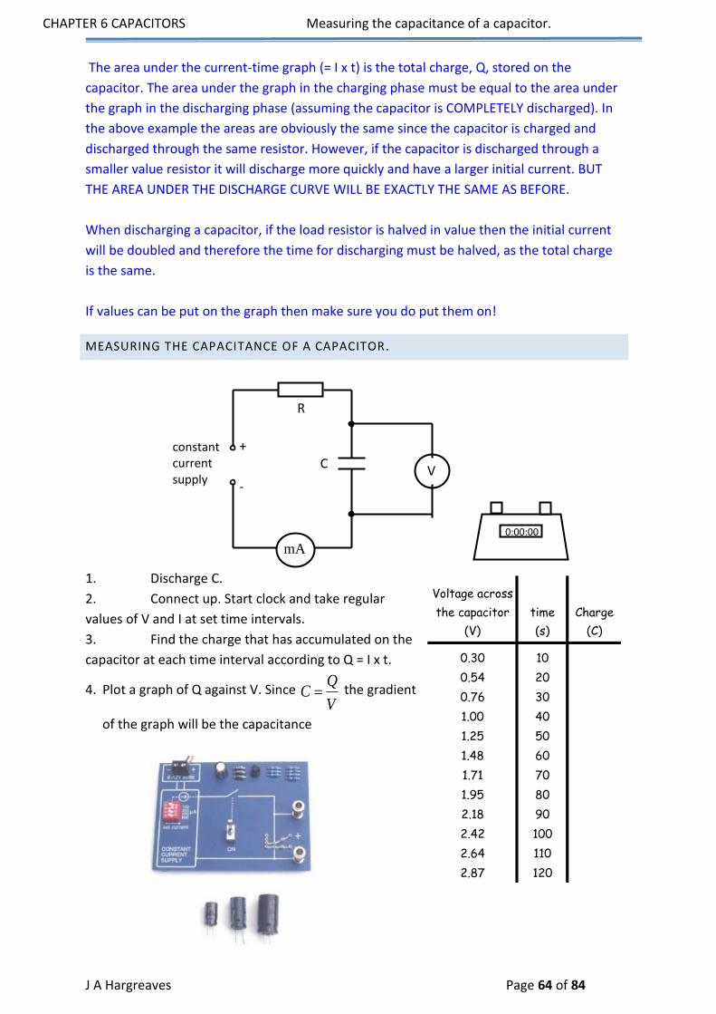
CHAPTER 6 CAPACITORS Measuring the capacitance of a capacitor.
J A Hargreaves Page 64 of 84
The area under the current-time graph (= I x t) is the total charge, Q, stored on the
capacitor. The area under the graph in the charging phase must be equal to the area under
the graph in the discharging phase (assuming the capacitor is COMPLETELY discharged). In
the above example the areas are obviously the same since the capacitor is charged and
discharged through the same resistor. However, if the capacitor is discharged through a
smaller value resistor it will discharge more quickly and have a larger initial current. BUT
THE AREA UNDER THE DISCHARGE CURVE WILL BE EXACTLY THE SAME AS BEFORE.
When discharging a capacitor, if the load resistor is halved in value then the initial current
will be doubled and therefore the time for discharging must be halved, as the total charge
is the same.
If values can be put on the graph then make sure you do put them on!
MEASURING THE CAPACITANCE OF A CAPACITOR.
1. Discharge C.
2. Connect up. Start clock and take regular
values of V and I at set time intervals.
3. Find the charge that has accumulated on the
capacitor at each time interval according to Q = I x t.
4. Plot a graph of Q against V. Since Q
CV
the gradient
of the graph will be the capacitance
mA
V
constant current supply
+
-
C
R
0:00:00
Voltage across
the capacitor time Charge
(V) (s) (C)
0.30 10
0.54 20
0.76 30
1.00 40
1.25 50
1.48 60
1.71 70
1.95 80
2.18 90
2.42 100
2.64 110
2.87 120

CHAPTER 6 CAPACITORS Measuring the capacitance of a capacitor.
J A Hargreaves Page 65 of 84
Therefore the capacitor has a value of 3000 μF (that is
quite a large capacitor!)
Q and V are directly proportional.
1 Farad = 1 Coulomb per volt.
N.B. 1 F is a very large unit. C would normally be
expressed as F or nF.
Using your knowledge work out what the area under this
graph would represent. We will come back to it later.
Volts
CoulombsFarad
VQ
C
y = 2.2006x - 0.2651 R² = 0.9998
0.0
0.5
1.0
1.5
2.0
2.5
3.0
3.5
4.0
4.5
0.0 0.2 0.4 0.6 0.8 1.0 1.2 1.4 1.6 1.8 2.0 2.2 2.4
Ch
arge
(m
C)
Voltage (V)
V
Q
0

CHAPTER 6 CAPACITORS Measuring the capacitance of a capacitor.
J A Hargreaves Page 66 of 84
CHARGING A CAPACITOR ON A D.C. SUPPLY.
DISCHARGING A CAPACITOR.
The current and voltage fall to zero, but be aware that the current flows in the opposite
time
Curr
ent
time
Volt
age
time
Cur
rent
time
Vol
tage
Charging and Discharging a capacitor (VOLTAGE)
0
0.5
1
1.5
2
2.5
3
3.5
0 5 10 15 20 25 30 35 40 45
Time (s)
Vo
lta
ge (
V)
Charging and Discharging a Capacitor (CURRENT)
-4
-3
-2
-1
0
1
2
3
4
0 5 10 15 20 25 30 35 40 45
Time (s)
Curr
ent
(mA
)

CHAPTER 6 CAPACITORS Energy stored in a Capacitor
J A Hargreaves Page 67 of 84
direction to the original charging current.
ENERGY STORED IN A CAPACITOR
When a charge is moved between 2 charged, parallel plates, work is done. If we move a
charge from one plate to the other against the uniform field then work done is given by:
work done = QV
When a capacitor is being charged, work is done moving charges against opposing forces.
Electrons are pushed onto the already negative plate. This repels them. They are also
removed from the positive plate which tends to attract them.
ENERGY STORED
The voltage across the capacitor is, however, constantly changing so:
E QV
We average the voltage over the charging period so that
QVE2
1
i.e. it is the area under a V-Q graph for a capacitor.
In summary, and using Q = CV,
CQ
CQ
CV
QVEnergy
2
2
1
2
1
2221
2
V
Q
0

CHAPTER 6 CAPACITORS Capacitors and a.c.
J A Hargreaves Page 68 of 84
CAPACITORS AND A.C.
NB. Remember that “REACTANCE” is used to describe the “RESISTANCE” of a capacitor.
CHARGING ON A.C.
With a.c. a capacitor will begin to charge up, then current starts flowing in the opposite
direction. The capacitor therefore discharges and then begins to charge up again.
Hopefully you can imagine that the storage of charge will be greatly affected by how
quickly this change of direction is occurring.
LOW FREQUENCY A.C.
When the frequency of the supply is low the capacitor is fully charged up (voltage is high
across the capacitor and the current zero) before the current flows in the opposite
direction.
time
Cur
rent
Low average
time
Volta
ge
High average

CHAPTER 6 CAPACITORS Resistance and Frequency
J A Hargreaves Page 69 of 84
A
Signal Generator
V
R
HIGH FREQUENCY A.C.
The capacitor does not get time to fully charge up or discharge before the current direction
is changed.
This shows us that capacitors block d.c. but allows a.c. through.
RESISTANCE AND FREQUENCY
Part 1 Resistance and Frequency
Set up the above circuit and use it to see how the voltages across and the current in R
change as you vary the frequency of the
supply.
Examine your results to see if there is
any connection between an increase in
frequency and the resisting effect of R.
Write up your experiment briefly.
time
Cur
rent
High average
time
Volta
ge
Low average

CHAPTER 6 CAPACITORS Reactance of capacitors in a.c. circuits
J A Hargreaves Page 70 of 84
PART 2 RESISTANCE AND FREQUENCY WITH AN OSCILLOSCOPE
Replace the voltmeter with an oscilloscope and explain how to measure the frequency.
Write up this experiment INCLUDING ALL YOUR WORKING.
NB. THE RESISTANCE OF A RESISTOR IS UNAFFECTED BY FREQUENCY.
This can therefore be a method of determining whether a component is a capacitor or a
resistor.
REACTANCE OF CAPACITORS IN A.C. CIRCUITS
Resistance (properly called reactance when used with capacitors) of a capacitor can be found out in
the usual way.
Current
Voltage Reactance
With a LOW FREQUENCY supply the average VOLTAGE is LARGE and the average CURRENT is
SMALL.
Reactance is large.
With a HIGH FREQUENCY supply the average VOLTAGE is SMALL and the average CURRENT is
LARGE.
Reactance is small.
We tend therefore to say that capacitors allow current to flow in an a.c. circuit but not in a d.c.
circuit.
Read up on BLOCKING and SMOOTHING.
frequency
Curr
ent Resistor
frequency
Curr
ent
Capacitor

CHAPTER 6 CAPACITORS Reactance of capacitors in a.c. circuits
J A Hargreaves Page 71 of 84
RELATIONSHIP BETWEEN CURRENT AND FREQUENCY IN AN A.C CAPACITOR
CIRCUIT.
Graphs of Current against Frequency for 2 capacitors
y = 0.0133x + 0.0017
y = 0.0263x + 0.0908
0
5
10
15
20
25
0 100 200 300 400 500 600 700 800 900
Frequency (Hz)
Cu
rre
nt
(mA
)

CHAPTER 6 CAPACITORS Blocking and Smoothing
J A Hargreaves Page 72 of 84
BLOCKING AND SMOOTHING
The change in reactance of a capacitor with frequency can be exploited as follows.
BLOCKING
An electrical signal consists of a steady d.c. voltage with an a.c. voltage superimposed on it.
If this signal is now fed into the following circuit:
then the d.c. component of the signal is removed (or blocked).
SMOOTHING
A capacitor can also be used in to smooth an a.c. voltage as follows.
A normal a.c. signal is fed into the following circuit.

CHAPTER 6 CAPACITORS Tutorial 1: capacitance
J A Hargreaves Page 73 of 84
In the absence of the capacitor the four diodes would rectify this signal thus:
But with the capacitor present this signal is smoothed by the repeated charging and
discharging of the capacitor. This output is known as the ripple voltage.
TUTORIAL 1: CAPACITANCE
1. What is the capacitance of a capacitor storing 0.005C when the p.d. between its
plates is 50V?
2. A capacitor has a p.d. of 20V between its plates. If its capacitance is 25µF, what
charge is on it?
3. What is the p.d. across a 50µF capacitor storing 2.5mC?
TUTORIAL 2: CAPACITANCE
1. How much work is done in charging up a 30µF capacitor which stores 0.001C at
20V?
2. What is the capacitance of a capacitor storing 0.016J at a p.d. of 40V?
3. What is the charge on a 30µF capacitor storing 1.35J?
4. Calculate the p.d. across a 10µF capacitor if 0.0125J is required to charge it.
TUTORIAL 3: CAPACITANCE
1. What is the reactance of a capacitor when the p.d. across it is 20V and the current
in the circuit 5mA?
2.

CHAPTER 6 CAPACITORS Tutorial 4: CAPACITANCE
J A Hargreaves Page 74 of 84
What is the reactance of the capacitor?
3. A 2000Ω resistor is connected in series with a capacitor whose reactance measures
1500Ω. If the a.c. supply is quoted as 14V, what is the peak voltage across the capacitor?
TUTORIAL 4: CAPACITANCE
1.
component A
V
Variable frequency supply
(signal generator)
How do you show that the component in the box is a resistor?
2. A 24V a.c. power supply sends a 100Hz current through a 480Ω resistor:-
What is the current when the frequency is doubled to 200Hz?
3.
S
10K2 F
The 2µF capacitor holds 20mC of charge. What is the initial current when S is closed?
4. If the switch S is moved to A and held for a time, then moved quickly to B, what do the
graphs of current against time and p.d. against time look like for the resistor R while the switch is
held at B?

CHAPTER 6 CAPACITORS Tutorial 4: CAPACITANCE
J A Hargreaves Page 75 of 84
A
V+
-
s
A B
5.
How does the brightness of each lamp change when the supply voltage is increased to 25V?
6. In the diagram below, the bulbs are identical and the three capacitors have the values
shown. How do the bulbs compare in brightness?
(1) (2) (3)
C1 2 3
C C
C = 5 F
C = 10 F
C = 20 F
1
2
3
7.
8. What is the p.d. of the supply at the instant C is storing 1.125x10⁻⁴J in the circuit shown
here? : -
~
A
2K 25 F
2.5m A

CHAPTER 6 CAPACITORS Tutorial 5: Exam Questions
J A Hargreaves Page 76 of 84
TUTORIAL 5: EXAM QUESTIONS
1. In an experiment to measure the capacitance of a capacitor a student sets up the
following circuit:
a) When the switch is in position X the capacitor charges up to the supply
voltage, VS. When the switch is in position Y the coulombmeter indicates the charge stored
by the capacitor.
The student records the following measurements and uncertainties.
Reading on voltmeter = (2·56 ± 0.01) V
Reading on coulombmeter = (32 ± 1) μC
Calculate the value of the capacitance and the percentage uncertainty in this value. You
must give your answer in the form
value ± percentage uncertainty. 3
b) The student designs the circuit shown below to switch off a lamp after a
certain time.
The 12 V battery has negligible internal resistance.
The relay contacts are normally open. When there is a current in the relay coil the
c) contacts close and complete the lamp circuit. Switch S is initially closed and the lamp is
on.
i) What is the maximum energy stored in the capacitor?
ii)
A. Switch S is now opened. Explain why the lamp stays lit for a few seconds.
C
coulombmeter
Y X
V VS
V
+
-
12 V
S relay
2200 F
3·3 k

CHAPTER 6 CAPACITORS Tutorial 5: Exam Questions
J A Hargreaves Page 77 of 84
R
S
V
A 2000 F
+
-
B. The 2200 F capacitor is replaced with a 1000 F capacitor. Describe and explain the
effect of this change on the operation of the circuit. 6 (9)
2. a) The following diagram shows a circuit that is used to investigate the charging of
a capacitor.
The capacitor is initially uncharged. It has a capacitance of 470 F and the resistor has a
resistance of 1.5 k. The battery has an e.m.f of 6 V and negligible internal resistance.
i) Switch S is now closed. What is the initial current in the circuit?
ii) How much energy is stored in the capacitor when it is fully charged?
iii) What change could be made to this circuit to ensure that the same capacitor stores
more energy?
b) A capacitor is used to provide the energy for an electronic flash in a camera.
When the flash is fired, 6·35 x 10-3 J of the stored energy is emitted as light.
The mean value of the frequency of photons of light from the flash is 5·80 x 1014 Hz.
Calculate the number of photons emitted in each flash of light.
3.
The circuit below is used to investigate the charging of
a 2000 F capacitor. The d.c. supply has negligible
internal resistance.
The graphs below show how the potential difference, VR across the resistor and the
current, I, in the circuit vary with time from the instant switch S is closed.
I) What is the potential difference across the capacitor when it is fully charged?
II) Calculate the energy stored in the capacitor when it is fully charged.
III) Calculate the resistance of R in the circuit above. 5
6·0 V
470 F 1·5 k
V A
S

CHAPTER 6 CAPACITORS Tutorial 5: Exam Questions
J A Hargreaves Page 78 of 84
a) The circuit below is used to investigate the charging and discharging of a capacitor.
The graph below shows how the power supply voltage varies with time after switch S is
closed.
The capacitor is initially uncharged.
The capacitor charges fully in 0·3 s and discharges fully in 0·3 s.
Sketch a graph of the reading on the voltmeter for the first 2·5 s after switch S is closed.
The axes on your graph must have the same numerical values as those in the above graph 2
4. A technician carries out an experiment to measure the capacitance of a capacitor C.
The capacitor, initially uncharged, is charged up to 2 V using the circuit below.
The charging current is kept constant at 0·20 mA
during the charging process by adjusting the
resistance of R. The capacitor is fully charged in 10
seconds.
a) Explain whether the resistance of R is increased
or decreased during the charging period. 1
b) What is the charge supplied to the capacitor?
c) Calculate the capacitance of the capacitor. 2
d) The capacitor is then used in a circuit where it is connected across a 10 V supply.
Calculate:
i) the charge stored on the capacitor
ii) the energy stored on the capacitor. (9)
R
S
V
A
C
+
-
power
supply

CHAPTER 6 CAPACITORS Tutorial Answers Capacitance
J A Hargreaves Page 79 of 84
5. An audio engineer obtains the results shown on the graph below. The graph shows
how the current in a circuit containing an 8 F capacitor varies with frequency. The output
of the electrical supply is 2 V r.m.s.
a) Describe an experiment to obtain such a graph. Your answer should include the
following:
i) a circuit diagram of the apparatus required
ii) a statement of the variables measured and controlled
iii) a description of how the measurements were taken
iv) conclusions which can be drawn from the graph.
b) An engineer has two loudspeakers, LS1 and LS2, to connect to an audio amplifier.
One of the speakers is designed so that it is able to produce low frequency sounds. The
engineer connects the loudspeakers to the amplifier using the circuit shown below.
Which of the loudspeakers, LS1 or LS2, is intended to emit low frequency sounds. You must
explain your answer. (7)
TUTORIAL ANSWERS CAPACITANCE
TUTORIAL 1
1. The capacitance is 1x10⁻⁴F (100µF)
2. The capacitor is storing 0.0005C
3. The p.d. across the capacitor is 50V
TUTORIAL 2
1. The work done during charging is 0.01J
2. The capacitance is 2x10⁻⁵F (20µF)
3. The stored charge is 0.009C

CHAPTER 6 CAPACITORS Tutorial Answers Capacitance
J A Hargreaves Page 80 of 84
. The p.d. across the capacitor is 50V
TUTORIAL 3
1. The reactance of the capacitor is 4000Ω
2. Since the resistance of the whole circuit is 2500Ω, the reactance of the capacitor
must be 1000Ω
3. The peak voltage must = 8V
TUTORIAL 4
1. Note the voltage and current at some frequency. Use them to calculate the resistance
of the component. Repeat the measurements for different supply frequencies. If the
resistance remains constant, then the component is a resistor.
2. Since the resistance is independent of the frequency, the current remains at 0.005A
when the frequency doubles to 200Hz.
3. The initial current is 1A
4.
Current
T imeO
Vol tage
T imeO
5. Each is 2.5 times brighter since neither the resistance nor the capacitive reactance
depend on the supply voltage.
6. The bulbs increase in brightness from (1) to(3) since the capacitive reactance
becomes less with increasing capacitance.
7. Bulb (1) remains at constant brightness while bulb (2) increases in brightness as the
capacitive reactance decreases with the increase in supply frequency.
8. The supply voltage is 8V.

CHAPTER 6 CAPACITORS Tutorial Work Answers
J A Hargreaves Page 81 of 84
4101
50
005.0
CV
QC
TUTORIAL WORK ANSWERS
CAPACITANCE/ TUTORIAL ANSWERS
ANSWERS FOR TUTORIAL 1
1.
The capacitance is 1x10⁻⁴F (100µF)
2. 4
6
105
201025
Q
Q
V
QC The capacitor is storing 0.0005C
3.
50
105.21050
3
6
V
VV
QC
The p.d. across the capacitor is 50V
ANSWERS FOR TUTORIAL 2
1. The work done during charging is 0.01J
The capacitance is 2x10⁻⁵ F (20µF) 2.
3.
The stored charge is 0.009C
4.
50
10100125.0 26
2
12
2
1
V
VCVE The p.d. across the capacitor is 50V
ANSWERS FOR TUTORIAL 3
1.
The reactance of the capacitor is 4000Ω
2. Apply V=RI to the whole circuit to get:-
2500
1025 3
R
R Since the resistance of the whole circuit is 2500Ω, the reactance of the
capacitor must be 1000Ω.
3. Since the circuit is behaving as a voltage divider, the p.d. across the capacitor is
6
1415002000
1500
V This is the r.m.s. voltage across the capacitor so the peak voltage must by
6x√2 = 8V
01.0
20001.02
1
2
1
EQVE
5
2
2
12
2
1
102
40016.0
C
CCVE
009.0
101.8
103035.1
5
6
2
2
12
2
1
Q
Q
C
QE
4000
10520 3
R
RRIV

CHAPTER 6 CAPACITORS Tutorial Answers: Exam question soutions
J A Hargreaves Page 82 of 84
ANSWERS FOR TUTORIAL 4
1. Note the voltage and current at some frequency. Use them to calculate the resistance of
the component. Repeat the measurements for different supply frequencies. If the resistance
remains constant, then the component is a resistor.
2. Since the resistance is independent of the frequency, the
current remains at 0.005A when the frequency doubles to
200Hz.
3. The initial current depends only on the p.d. and the resistance.
10000
1020102
3
6
V
VV
QC
Since the p.d. is 10000V,
1
1000010000
I
IRIV The initial current is 1A
4.
Current
T imeO
Vol tage
T imeO
5. Each is 2.5 times brighter since neither the resistance nor the capacitive reactance depends
on the supply voltage.
6. The bulbs increase in brightness from (1) to (3) since the capacitive reactance becomes less
with increasing capacitance.
7. Bulb (1) remains at constant brightness while bulb (2) increases in brightness as the
capacitive reactance decreases with the increase in supply frequency.
8.
The p.d. across the capacitor is 3V.
V=RI applied to the resistor gives V = 2000 x 2.5x10-3 = 5 volts.
Since the supply voltage equals the sum of the individual p.d.'s round the circuit, its value is 8V.
TUTORIAL ANSWERS: EXAM QUESTION SOUTIONS
2000
24.a. To calculate the capacitance uses the mean values of charge and voltage.
C = Q/V
C = (32/2.56)F
C=12.5F
AI
IIRV
05.0
48024
3
102510125.1 26
2
142
2
1
v
VCVE

CHAPTER 6 CAPACITORS Tutorial Answers: Exam question soutions
J A Hargreaves Page 83 of 84
The percentage error in capacitance value can be taken to be equal
to that of largest individual percentage error.
% error in voltage = (0.01/2.56)x100 = 0.39%
% error in charge = (1/32)x100 = 3.125%
C=12.5F+-3.125%
OR
3.125% of 12.5F = 0.39F => C = (12.5+-0.4)F
NB/ Only quote the error to the same number of decimal places as the
capacitance value.
b.i.The maximum energy is stored in the capacitor when the voltage across the capacitor
is equal to the supply voltage.
Vc= 12V
C = 2200x10-6
E = ?
E = 1/2(QVc)
Q = CVc
=>E = 1/2(CVc2)
E = 0.5(2200x10-6x122)
E = 0.1584J
b.ii.(A) When the switch is opened the capacitor discharges through the resistor and
relay coil. The discharge current magnetises the coil closing the switch in the lamp circuit,
causing the lamp to light. As the discharge current gradually falls the coil loses its
magnetism and the switch in the lamp circuit opens. When this happens the lamp goes off.
(B) Increasing the value of the capacitor increases the discharge time. The
energy stored in the capacitor is also greater. This means that the lamp will stay lit for
longer.
2001
25.a.i. The initial charging current(Imax) occurs when all of the supply voltage(Vsupply) is
across the 1.5k resistor(R).
Imax = Vsupply/R
Imax = 6/1500
Imax = 4x10⁻³A
a.ii. When fully charged the voltage across the supply voltage is equal to the voltage
across the capacitor.
Vsupply = Vc = 6V

CHAPTER 6 CAPACITORS Tutorial Answers: Exam question soutions
J A Hargreaves Page 84 of 84
Ecapacitor = QVc/2
Q = CVc
=>Ecapacitor = CVc2/2
Ecapacitor = 470x10-6x62/2
Ecapacitor = 8.46x10⁻³J
a.iii. Increasing the supply voltage would increase the energy storing capacity of the
capacitor. This is because the final voltage, across the fully charged capacitor, would be
higher.
25.b. Etotal = 6.35x10⁻³J
fphoton = 5.80x10¹⁴Hz
h = 6.63x10⁻³⁴Js
Ephoton = ?
Ephoton = hfphoton
Ephoton = 6.63x10-34 x 5.80x1014
Ephoton = 3.84x10⁻¹⁹J
Etotal = NEphoton
N = Etotal/Ephoton
N = 6.35x10⁻³/3.84x10-19
N = 1.65x10¹⁶
2002
25.a.i. Initially all the supply voltage is across the resistor.
VR = Vsupply = 6V
When the capacitor is fully charged: Vsupply = Vcapacitor
Vcapacitor = 6V
a.ii. E = CV2/2
E = (2000x10-6x62)/2
E = 0.072/2
E = 0.036J
a.iii. Imax = Vsupply/R
R = Vsupply/Imax
R = 6/7.5x10-3
R = 800
Related Documents