JUN24~ -= “?-+-iv. c .%z+- - J --i.. - -m”” ““–” .=-. .—.. .d f----- ---- %. TECHNICAL NOTES h NATIONAL’~DVISORY COMMITTEE FOR-SERON.A7.7T IC9 “b 4 ------- . .. . . --- ——— .—. . --— NOI 89? . -, ‘( ( ———-—— CLASSIFIED DOCUMENT -- -- — Thisdocumentcontainsclassified BEARING TESTS OF MAGWS IUM–ALLOY SXEti T By w. H. Sharp and R. L. Meere r ‘ . ... Aluminum Company of Amerrica -.. .- --- ..- ., . . .- information affecting theNational Defense oftheUnitedStateswithin -“-xg * themeaningofthe Espionage Act, ~. .; USC50:31and32. Itstraneinission J. ,B:e$:~?”-’’-’- ~~ .:L w-~ , : or Che revelationof itscontents in anymannertoan unauthorized the filus ~f”the Langjgy personisprohibited bylaw.Infor- ‘: mationsoclassified maybc-impart- ~E~I@/j~/Aer@naU~jCa, . ~ edonlyto personsinthemilitary * and navalServicesoftheUnited States,appropriate Oivilian offs- . ~ashington ~~@&Y, cers andemployeesoftheFederal 2. Governmentwhohavea legitimate June 1943 . .: _.-.:.-.-:-:= interssttherein,and to United — Statescitizens of knownloyalty .— and discretion who of necessity —. -—-.:-. :. _-_, —-.—.. ...”. ._:—-.& must be infomed thereof. .=

Welcome message from author
This document is posted to help you gain knowledge. Please leave a comment to let me know what you think about it! Share it to your friends and learn new things together.
Transcript

JUN24~-=
“?-+-iv.c .%z+- - J --i..-
-m”” ““–”.=-. .—.. .d f-----
---- %. TECHNICAL NOTESh
NATIONAL’~DVISORY COMMITTEE FOR-SERON.A7.7TIC9“b 4
------- . .. . .---———
.—. . --—
NOI 89?
. -,‘(
(
———-——CLASSIFIEDDOCUMENT
---- —Thisdocumentcontainsclassified
BEARING TESTS OF MAGWS IUM–ALLOY SXEtiT
By w. H. Sharp and R. L. Meere r ‘. ...Aluminum Company of Amerrica -..
.-
--- ..-
.,. ..-
informationaffectingtheNationalDefenseoftheUnitedStateswithin -“-xg *themeaningofthe EspionageAct,
~..;USC50:31and32. Itstraneinission
J. ,B:e$:~?”-’’-’- ~~
.:L w-~,: or Cherevelationof itscontents
in anymannertoan unauthorizedthe filus~f”the Langjgypersonisprohibitedbylaw.Infor-
‘: mationsoclassifiedmaybc-impart-~E~I@/j~/Aer@naU~jCa, . ~edonlyto personsinthemilitary
*
and navalServicesoftheUnitedStates,appropriateOivilianoffs- . ~ashington ~~@&Y,cers andemployeesoftheFederal 2.Governmentwhohave a legitimate June 1943 . .: _.-.:.-.-:-:=interssttherein,and to United —
Statescitizensof knownloyalty.—
and discretionwho of necessity—. -—-.:-.:. _-_,—-.—.. ...”. ._:—-.&
must be infomed thereof..=
“f
.
-’
NATIONAL zDVISORY COMMITTEE FOR AERONAllTrC!S
\ TECHNICAL NOTM NO. 897—
BMARING~TESTS OF MAGNESIUM-ALLOY SHEET
..--> _. _...>- ..-
.- —-. . .. . .-.. —i --”
—...-
By w, H. Sharp and R. L, Moore .....-..
SUMMARY ...—
Bearing tests of AX-3S, AM-525, and AM-C57S magnesiun-alloy she=t in various .thickness@sand tempers were made. “- ‘“--’-’Bearing yield end ultimate strengths were tleterminsdandcompared for various edge distances and for various ratiosof loading—pin diarm?terto sheet thickness. Tensilestrengths wero d.etermin~dand ratios of averag~ bearing “–:-
..~.._,
‘ yield and uitimate strength to tensile strength are given.- -_=..—.-.---r.:--,—:,..=
The results of the tests indicated that ultimatehearing strengths increased with edge distances UT to-1.5
--
to 2 tim~s th= diameter of thn loading pin; that ultimate .bearing stri~ngthsers a function of r’atioof pin &i”&sri@terto sh~et thickn~ss; that bearing yi~ld strengths generallyare not sensitive to ratios of pin dianetcr to sheet .—
thickness; and that thes~ properties are effected only,m..-.-
slightl~ 3y increasps in edge distance @eater than 1.5diameters”. — >..4. -.. ...... ....—.S
INTRODUCTION
The increasing use of magnesiun alloys in aircraftconstruction has Pqphasized’”the n~~d for more complete in-formation regardfng tho n~chaiical properties of these
.-
naterials. Th- object of this investigation WAS to deter– ‘:nine th~ bearing yield.and ultimate strengths of s~veral “:-:_of th- mor= comcon GagnPsiun alloys and to establish, as ,:Par as possiblo, ratios of bearing ve.luesto tensilostrengths which may be used as a b~sis for design-; This ‘--:---”:report includes, in addition to data on. b~aring strengths,th~ tensile-properties of thtie-lloysinvestigated a“ndm&6ae”‘*““~1data on comprFssiyc
.>.-:,.,and shear strengths. — .- —-~.:,........ ....-%...-..::+=
,,. . . . ---- ..._
-.-------- ._

.
-1NACA T@-chnicAl Note ~0. 897’ .. . ..-.,...,
●
:~ATERIAL(See appendix A, p. 13) r.----+
T~=stswere ma’&.of three ua~n”~siutial~oys in t-hofo~l~of sheet - AM-3S, A14-52S, and AM-C57’S. All alloys were fur-nish~d in —O and -H .t;npersin a“no]linalthicknpss of-0.064inch, nnd in -R t~~pnrs.(betw@en’-Oand -H) in thicknessesof 0.125 inch end 0,250 inch.
_.—.-.Tablo I gives th~ rl~chanical~ropertie.sof the r~ste-
rinls used. (See references 1 and 2,) Although not in- —.clud.edhire, stress-strain data were obtsinf?din tons”ionfor all the 0,064-inch sheetm”in compression for allt%roe thickness~s of sheet used. :ThesP n(?asur~u~ntsindi-
.
cat-d e,ninitiel lirieerst~css-strain rel~ttionshipin allcas~a. Undc?r”SOiU~ conditions of cold work on magnesiumalloys, this type of stress–strain rel%ti~n.is not obtninpd.(See rcf~rencc 3,)
It will be noted ‘intable I.–thatthn tensile strengthsend Elongations obte.inednorual t-othe direction of rolling 9w?r~ slightly higher “inr~oetCPSPS than those parallel to
—
the direction of rolling –.a condition contrary t-othet.g~nerallyfound in aluuinuu-~lloyah~et-~ The coupressivp *yi~ld strengths were all below the corresponding tensile ---yieldstrengths, th differences in sono c-es bein~ as~luchS.-S40 percent. The shear strengths o%tain~d by punch-ing tests ~v~rag~d slightly ovnr 50 percefitof the tPneile ... ..strengths. —.
The “tensileproperties of the -O and –H teiipersgivenin tabl~ I compare quite f~vorably with th~.typic~l vfiluesgiven in t~ble 3 of referenc~ 4.
-.“Thereare no typical
prop~rties published for th~ -R teuper, but it is stat~-don page 16 of reference 4 th~t the properties of this temperare between thos~ of the -O and -H tcnpers. This was foundto be substantially true in the case of.the propertiespsrpll~l to the direction of rolling, but a nur~bcrof ex–Ceptiionsw~re found in the CRSe of.the properties in the mopposite dir!+ction. ThP tens,iloyi~ld a~d ultf.r-at~strengthsof tho 0.125-inch ond 0.250-inch A1&3S sheet in the –Rt~mppr, riorml to th~ direction of:rolling, were higher *than those found ‘fortiho0.064-inch sheet Of this alloy inthe -H temper. Th~ corresponding properties.N the 0.25@-inch LM-52S sheet in the -R temper;”
.—on”“theoth~r_h~nd,
were slightly less than thos~ found for”the 0,064-inchsh~pt of this alloy in the -O tetipnr. It appe8rs fronth-secorii>arisons”that the naterial~suppltid in t-he-Rtemper wer~ not all represent~tive of cannercial sheet.

NLCA Technical Note No. 897 3
TEST PROCEDURE
The bearing t=sts were made, as shown in figure 1,with the 40,000—pound capacity Amsler testing machine.One seri~s of specimens was composed of strips ~ incheswide loaded through a steel pin 1/2 inch in diameter,and the other was composed of strips 2 inches wide loadedthrough a steel pin 1/4 inch in diameter. All specimens ‘-wrre originally about 30 inches long, cut parallel to thedirection of rolling. Duplicate specimens were providodfor all tests with the l/2-inch pin, except in the caseof the 0,250—inch shet?tin which three specimens wereused: while triplicate specimens were provided-in mostcases for the tests with the l/4-inch pin, Edge distances–that is, the distances from the center o.fthe holfito the “1edge of the test strip in the direction of loading - werevari~d on each specimen; distances of 1, 1;5, 2, 3, and 4 “-”times the pin diamstnr D were used in the tests withthe l/2-inch pin and distances of 1.5, 2, and 4 times thepin diampter were used with the l/4–inch pin. The holnsin the specimens were drilled and reamed to ~rovide aclose fit on the pins. A complete set of edge distances,covering the entire ro.ngeinvestigated, was obtained oneach specimen by shearing or sawing off the damage-dend –after one test (about3/4 in. below the center of-theold hole) and redrilling at a ‘new edge distance for th~next test. Auxiliary tests, in which the procedu”r~wasrepeated several times with the same edge distance, indi—cated that the small amount of tensile strain produced inthe portion of th~ specimens below the pin in the firstloading had nonsignificant effect upon the resuIts of sub–sequent tests. In most of the cases involvi~ determina–tions of bearing yield strength, the average tensilestresses dev-lop=d range from about 6000”to 10,000 pounds“pe,rsquare inch, or only one-eighth the corresponding “ -J
ultimate bearing strengths.
The data on bearing stress and hole deformation, fromwhich yield—strength.values were deter-min”ed’,were obt~inedby measuring the relative movement of ‘thepin and theshe~t on th~ under side of the pin by means of a filarmicrometer microscope-reading directly to 0.01 millimeterand by estimation to 0.002 millimeter. The under side ofthe pin projecting from the sheet on the m.icroscop~sidewas flattened slightly to pro~ide a shoulrierin the planeof th~ sheet on which one of thn reference points for th~microscop~ readings could be -located. The edge of the ,
4 NACA Technical Note.No, 9.97
hole provided the reference point on the sheet. Figur~ L.shows the setup used. Hole-deformation rfieasurencntsweremade on all the specimens tested.with the l/4-inch pin and.on on~ of the three 0,250-inch specimens test~~.with thel/2-inch pin. In all other tests, valu~s OL only ulti-matp bee.ringstrength were obtained,
RESULTS AND DISCUSSION
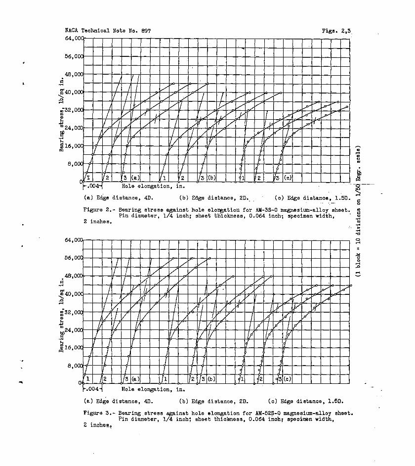
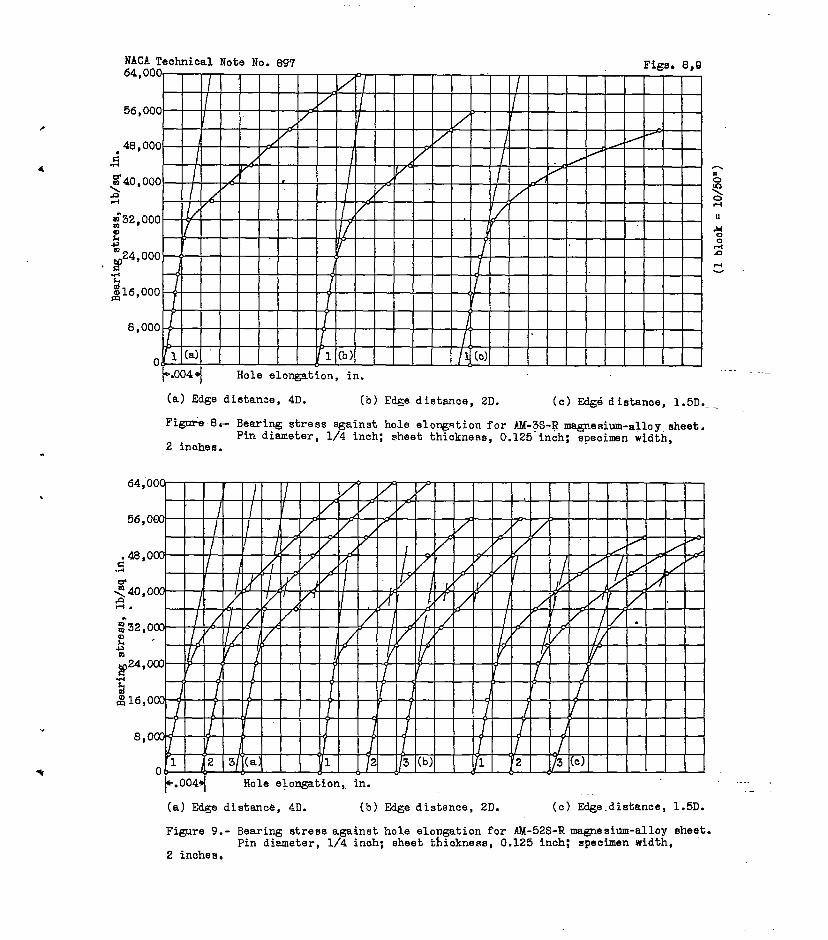
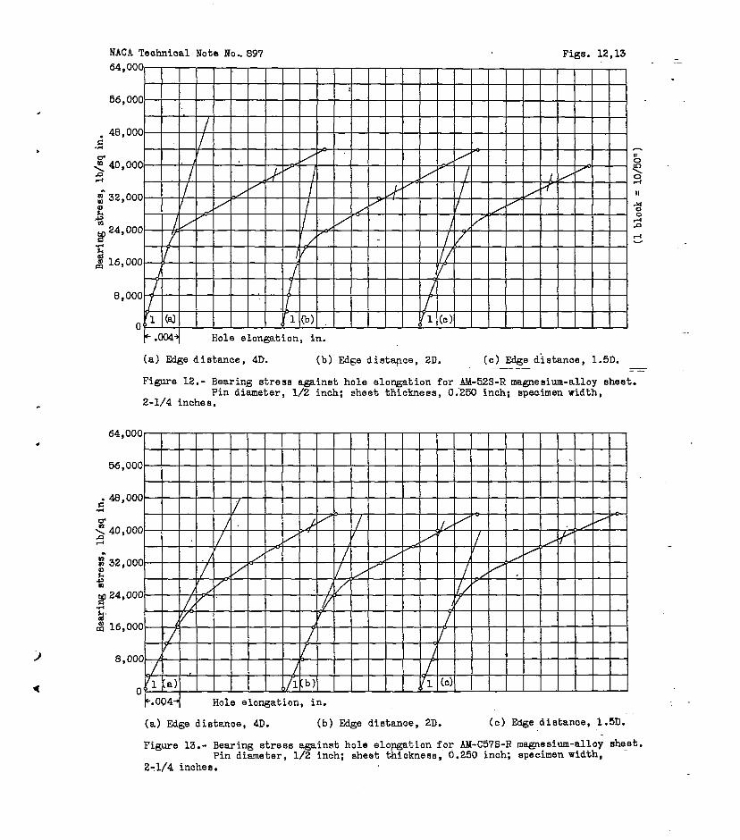
Tables II and 1“11sunraarizetho bee,ringyield and.ultinate strengths obtained.. The values ~f heering yioli!strength giv~n were s~lected frGm,tht?hol~-d~forn~tioncurves in figures 2 to,13 as the etresses corrr?spondingto”an offset of 2 percent of the hole @i=rfieterfrou theinitial straight-line portion of the curves. It shouldbe emphasized that no i!.efinitecriterion has t?vc+rbeenestablished for s~l~cting bearing yield strengths andthat the 2 percent ‘offseti,~c+thodUSOF herein is quite~rkitrary.
Although the data fiivcn i-ntable 11 for the testswith the l/2-inch pin indicate so~le-erfiallinconsistenci~sregarding tho influence of edge distance upon ultimatebearing strengths, it--aypearsthat for the proportionslnvestig~t~d there W8S no particular a?.vantagein using~+ge distances grkat~r than twice ,the$i~meter of the pin.In fact, f-ora number of the tests of the 0.064-inch sheet,there was no significant increase in ulti:fiatebearingstrength for edge ?istances greater than 1.5 dianeters.The behavior in the case of the 0.”064–inchti,aterial,inwhich failure involved to sone extent the buckling resiat—ante of the sheet above the pin, was typical of that foundin aluninun when comparable ratios”:f pin d.iaueter tosheet thickness are used. The f~ct that the 0.125—fnch an,l0.250-inch sheet tested with the l/2-inch pin @id not show“an appreciable gain in ulti::atestrength for edge distancesgreater than twice the pin diameter, as generally found inaluminum, hay apparently 3e attributed tm ‘th@ distinctlyii.ifforenttyp~ of action ~btained. ~paring failures inthese tests were ch~racterized by a cruublfng ~r shearingof the material above the pin rather than by an uper?ttingaction which, of course, results in increased eff+e=ctiv~be~ring areas and.high-values “ofultiaate ‘tearingstren~th.
--1
s
a..
—
o.-
The results of the tests with the l/4-inch pin givenin ta~le 111-‘1.ikew~seshow no appreci~bl~ gati in ultir:ate
NACA Technical Note No. 897 5
beering strength.for edge distances greater than twicethe pin diameter. The important comparison to”be madebetween these data and thsse given in table II concerristho effect of pin diameter upan ultifiatebearing strengths.For an ~F.gedistance of 2 dianeters in the 0.064-inchsheet, the strengths obtained with the l/4-inch pin rangedftiouapproximately 8000 to 16,00CIpounds p-r square i~chhi~her”than those obtained with the l/2-inch pin. TheDifferences between the strengths obtained with the twosizes of pin in the 0.125—tnch she~t were not so markkd., —
although the values for the l/4-inch pin were, with one ‘exception, high,~r. The l/2–inch pin was the only sizeUSF?.in’the 0.250-inch sheet; %ut the ultinate strengthsobtained.in these tests were in fair agreement withthose obtained with the l/4–inch pin in the 0.125-inc-hsheet,“for which the ratio of pin ?.iameterto thicknesswas th- sara-. The agreouent between the latter testresults also indicates that the ratio of specinen widthto pin dianeter, which was 8 in the case of the l/4-inchpin an? 4.5 in the case tifthe l/2-inch pin, was appar-ently not a significant fact~r “inthose tests. “ _-
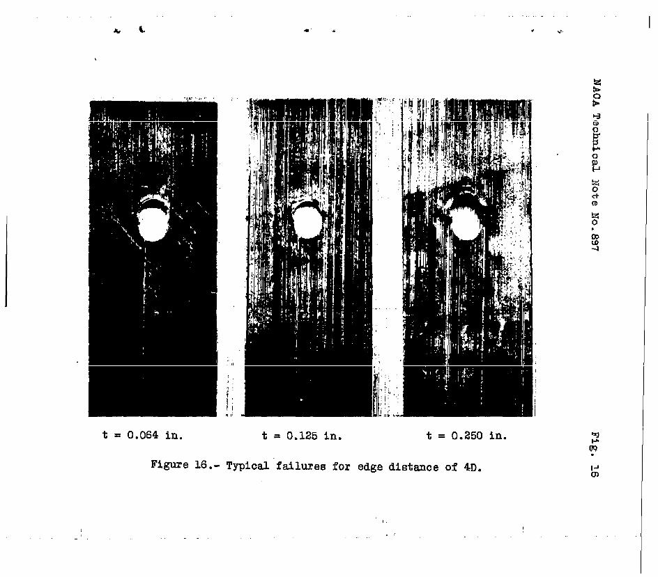
Figures 14 to 16 shcw typical bearing f&ilures -obtained.for different edg~ ?istances in the tests withthe l/2–inch pin. In general.,the failures shown indi.-cate a more brittle”action than is conuonly found iti-siu—i“lartest’sof aluninu~-alloy sheet. The relatively lowelongation values “given in table I for the -H an?.—R .teu-pers arp consistent with this different!?in beliaVior. —.
.-The bearing yield strengths given in table III,
which correspond to the stresses producing a permanentset of 2 perc~nt in th~ original diameter of the hole,show considerably less change with increases in edge dis-tance beyond 1.5 pin diameters than “dothe ultimate bear-ing strengths. This behavior is typical of that found inth. aluminum alloys and is Underitandablp since firsty-i=ldingin b~aring appears to b~ a.local ph~nomenon and,as such, should be relatively fndepefid~ntof edge dis-
●. tanc-s and other specimen pro~ortions... For this reasonit is assum~d that the yield-strength.values, which wer~determined for th~ most part from thn tests of the l/4-inch
● pin, are representative for th~ materials used. ,In thet~sts Of the materials tn thp -R tempers, which provideth~ only cases in which comparisons may b= made, the yieldstren ths obtained for 0.125–inch material.tested with
7the I 4–inch pin averaged a%out 8 ~ercent higher than th~scfound for the 0.250-inch material tested with the l/2-inch

6 NAGA Technical Kcte No. 897..+,
pin. Part of this dif~ercnc~, hcwever, uay be attributed ●
to ~,~.ifferrncein the strengths of the two thickh~ss~s ofsheet aS shown in t~ble I. t
Although the results Siven in tables II and.111 showdefinitely the effect of certain”specinen proportjansupon bearing yield and ultimate strengths, significantPiti-ercncesbetween the bearing characteristics of differ-
—
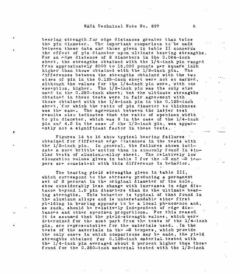
ent all~ys an~ tenpers of sheet are .n~~so evident. Tablt?IV gives av~rage ratios of hearing ytelfiand ultir~atestrength to tensile strength in an effort t~ eliminate asf~.ras possible tiheeff~ct of F.iff6rencesant? irrecul~.ri-ti~s in-the properties of the riater.ia.lte~ted anr?~-dre- r.+Uco all ?ata to a conuon basis for coqarisdn. hsidefrorfithe effects of s“peciaenprop~rtions tdreat.y COn8id–er~?.,however, these ratios d.anjt appear’to indicate anyconsistent relationships between the %earing propertiesof ?,ifferentalloys ~r tempers. SiJalldiffer~nces nayundoubtedly b~ at$rihut,?d
.—to variation, wh$c.harc..rccP~-
nize~ as inherent in thfibearinfi:tcst, Until noro dataare available.,therefore, it is believed that the ratiosin table IV should be subjected to a very general and con- 9servative interpretation.
:Tahle V suauarizei the ratidsof bearing-yl~ld an~—
,ultit,atestrength t-otensile strength,selected fram thesotests as a-basis for-predicting nonfnal bearing va1ue8 forother lots of these same amgnesium-’alloys. Typical bcar-ing-.values, of representative :~inimumvalu~ such as areus~d in aircraft design presuuahly nay be obtain~d by uul—tiplyibg t-he,ra~ios in table V-by typical or minihu~ values~f tensile strength. ., .-
~,
The.results ~f these tests of A;~-3S,hli-52S,fin+AM-C57S nagaesiu~l-alloysheet jnv.e~ious thicknesses andte,~p~rsjustify the following gcn=ral.conclusionsregardingbesring strengths:
.+—
1. The tensile properties of+th-”0.064-inch sheet 6investigated in the -0 an~ –H tfimpersco~parrquite fav3r-ably with the typical”values given fur ~hese materials inreference 4. The bearing,values ~ob.tainedfor this material,therefore, ere believed to be representative for comnerclalsheet of thn kind used.
..

NACA Technical Note lTa.89’7 7
2.The tensile properties of the 0.125-inch and9.250-inch sheet in the ltas–hot-rolledlfor -R temp@r’w6renot in all cases between’those for th~ —0 anf -H tempers,as is generally assuued. Although this irregularity-probablyhad little effect upop l-.aring-strongthcharac-teristics, additional tests of uore normal li-R1imat~~ialmay be desirable. -—
3. Ultiuate beari”ngstrengths increase?.with edgedistance for values of e?.ge-?.istanceup to 1.5 t-o2 timesthe diaueter of the pin. For gre~ter e&ge distancesthere was no appreciable gain in strength in most ceses”.-
4. Ultimate bearing strengths are a functicn af ra–ties 5f pin diameter to sheet thickness es well as edgo(?istaace. Strengths obt,aine.din the tests of the 0.064-‘fnch sheet with l/4-inch-ikianeterpin (rati~ of pin diAm–eter.tu sheet thickness = 4) at.an edge distance of 2dianeters were from 8000 to 16,000 poundtsper square inchhi~her than found using a 1/2 inch-diameter pin (re.tioof pin dian. to sheet thickness = 8) at the sam~ edge .dis–tance. The effect of ratios ~f pin dianeter ta sheet thick–ness was n~t so pronounced for ratios of 4 or l~ss.. .
5. For specin-ns h~ving a ratio of pin diaueter tosheet thickness of 8, bearing ftiiluresfar.~?ge Ristances
Gf 1.5 diaueters dr g>eater were e.ccor,panied5Y Iocalbuckling of tha she~t e,bovatho pin.- a t~pe cf acti:nsiuilar to that f~und in tests ~f eluminui~. Ftirratiosof pin di~n~tcr to sh~~t thickness of 4 or less,.h~wpv;r,failures f“oredge ~igtance$ ~f 2 diameters or greatnr werecharacterized by a shearin~ ar crumbI”Ingof the materialabove the pin rather than by en upsetting action, asgenerally found in aluminum.
.-
60 B-aring yielfistrengths, selected as the stressescorresponding to an arbitrarily selected peruane”nteet of2 percent in th- original hole diaueter, incre~sed only “ .slightly for edge t!istancesgreater than 1.5 tiu~s thediameter of the pin. Although m~st ;f t.h~de%eruihetionsof bearing yield strength w~r.?nade.fr~a tests with ~.l/4-inch-diameter pin, it seens reasonable tc assum.~that thisproperty of.the uaterial is not sensitive to ratiGs afpin diameter to sheet thickness.
7. Ratios of .avcr~gqbee.~i4gyielt!and ultiuatestrength to t’ensilestrength tor all tests are sum].wrizedin table IV, Th~ ratios selected arbitrarily fr~m th~ti

8 NACA Technical Note No. 897
Alui.linunResearch LRborF.tcrie,s, —
Aluminun ComTany Gf America,New K~nsington, Penaat,“Fflbruary1, 1943.
—
References—
1. Anon.: 1940 Supplement to A,S.T.M. Standards; pt. I,Metals. Tentative Methods of Tension Testing ofMetallic Materials. (E 8-40T). A.S.T.MO (phila,)PI?● 454-463.
2. Paul, D. A., Howell, F. M. , and”Gri~shaber, H, Eot-—
Comparison of StTess-Strain Curves Obtained byt
Single-Thickness and Pack Methods. T.N, ~0: 819,NACA, 1941. ‘
3.Templin, R. L., ‘andSturm, R. G,: Some Stir’ess-StrainStudies”of Metals. Jour. Apro, Sci., vol. ?, no. 5,March 1940.,pp. .189-198.
4. Anon.: Properties of Mazlo Magnesium Product-s.Am. Magnesium Corp:, 1941.
,,
_.
1

I
U107 adt empmr
ka-aa-o
u-6a6-o
bu-o$vw
TA2L2 1.-W3EA2104L PROP=IEE Or MAM22112L-ALMJY+
AM-W-E
AM-6=-E
AM-0676-1
AU-36-R
AM-am-a
AM-0676-I
Au-26-R
Aa-5aa-6
AM-C572+
~9tmndln
%bRsOAVmrmSBd~ke t;
[&lIwuntrqtba obtahmd W PUUObing test; 4AQm. of pmh, a.735In.) dimm..of bl~, a.7m inJ
HOa * dirwtion of rnlli~#odd Tmlmile TuaBile
g- !g~ tg~’=
p$ o“y&’” TCQHtrength
atr~hb (lbf(0~:6:j a eqin.)
“ Oi: :Er;lmt)q (lb/sqin.)
0,024 S2,000 16,600 20.5 14,600 sa,um31,0W 15,200 13.6 —-
%a, ~36,6CM3
—.. —=. - —.— ——mormae 81,5W 16,eJ30 19.5 14,.WO 3a,7m3
0,094 S8,KKI a6,mo aa.o -— 37,34X36,WI a5,9w 17.0 —— 37,&Y3
.— --- ——---— —.-_— ——— Ow, ?wlAvernse aa,amo a6,85a 19.6 —— S7,230
0.064 41,00a 26,W0 d~o.b 16,200 kl,mo42,2CH3 28,000 1.2.o -———- 41,400
_— - —— -- -— - ——-kvemge
P41,mo41,600 a8,560 16.0 16,200 40,970
o.a34 34,600 26,600 14.5 al,om 87,m34,700 23,200 12,5 ‘——- 26,000
——— —-—- —— Wt,6@3Av0Ta20 34,800 25>750 13.5 al,m ad,am
0.12s I s9,5w I 2B,1OO I 6.5 ] a7,6m I 3B,MM
.126 22,500 27,690
---1
16.0 17,600 26,M0-.——- -— ——— —-— 039,EO0
AvOrmae 39,mo a7,tmo 16.0 17,200 M,KX3
o.la5 42,400 a7,ma 14.0 16,3CQ m,~o
0.260 28,200 a7,eo2 11.6 —— 36,600
llelto di
EmailerleldtrwqthOffSBt4.aperomnt)
[email protected],lCa1.6,300C19,1OOla,EJlo
a3;w.uaa,wo02L7,6@l2a,633
a2,70023,CW02a,ow22,6m
32,40331,WU933,4003a,570
36,165a7,mp03a,w36,1m
35,mo36,600
Ow, voo37,3CU
26,303
a7p00W6,m29,6W
a8,am
a6,m
a7,Km
.260 41,6!M] 26,300 ti.6 16,4cfI 41,KV0I 26,003
temion tomt meolmm for sheet-elm - me fiu. 2 of ref ormoe 1. SlrU
otlon ofrolling
yf?%% %s &$n ~(0;ff:i2 “
(ib/sfah.)
la.s -—-— -—-—18.5 -—- 016,6Cdao,o ———. __—le.o -——- la,aoo
d;;:i ::=: ‘——Wl,uxl——
%:: —-— 21.,lIX
% .0 ——..—. .—17.5 ————— WX3,60019.6 —- —--— -—4——16.6 ——-— ao.am
6.0 a3,0m -——-6.0 ——— ‘319,000S.o -—— ——4.7 23,0Q0 19,003
“4.0 30,&30 ——4.5 ——— %2 ,200’3.5 —--— ———3.9 30,moo 22,600
8.0 26,400 -———2.0 ———— Oaa,maa.o. ---—— -———3.3 26,4U0 aa,700
6.0 a2,6fYl ——
.15.0 17,620 ——15.a _—. - —-—16.a 17,eoo ——
la.o 18,003 ——
=Ahioknem oompreaoion e-pmmimmm-
0F3UOe a, “cmof aamprenaiveyieldltrenathme EinHIDgfmiluraOoaurr.xlbeforethe reatiirtiEtrdn mm obtained.or two temtg. U1 otherrenultafor aimle teete.G-U@tbfeot. Vm.lummof elimgation Omitt&l f mm average.

10 NACA Technical Note No. 897
TABLEII.-KUARINGSTRENGTHS0)?KAGNE+SIUH-ALLOYSHEET-
~11 valuesareaver&@so~t~~teEts p~ellol to directionof rolling.Specimensz+ in.wide}loadedthrouglhst~elpin 1/2in.in diem.]
&~Oy andtemper
AM-3S-Oti-1-52s-oAM-C57S.O
AM-3S-11AM-52s-HAM-C57S-H
AM-3s-RAM-526LRAM-G57S-R
AM-3S-RAM.52s~AM-C57S-R
Nominal.thickness(ill.)
o●064,064
-.064
0.064.064.064
0.125.125.125
0.250.250.250
ul~imat~ be~ing strengthsfordifferentedgodfstancesin ternsof DindiameterD
,. (lb/sqin.)
lD I 1,5D I 2D I 3D
30,00034,90035,900
23,noo3,10041,100
40,70050,~oo5,4,goo.--—~o,40062,90063,600--!-45,30042,000
54,00054,10052,00056,500---W& 57,600
60,90064,3oo62,300
35#900 ;5:w&34,60035,500 {5 ,goo
64,go0 59,6006~,20065,40066,00069,700
35,gooI 56,10034,200
It5 ,000
33,8005 ,100
64,200 63,50064,60069,~062,goo64,700
4D
44,00053,600y4,200
49,60060,40062,Uao
~8,70064,60068,300
64,10066,00070,600
.
.b
.—
—
I
,
TABLEV.-TENTATIW5RATIOS017BEARINGULTIMATEANDYIELDSTRENGTHTOTENSILTSTRENGTHSELECTEDFROMTABLEIVAS A RA.SISFORPREDICTINGNoM~fi MING Vmws ~R M-3s, A.M-52s,~Nd-c57s mGIIEsIw--.ALLOYSKEET
Bearingyield
TemperstrengthTensilestrength
T-o 0.9-R 1.0-H 1.1
Be&ing ultimatestrength/Tensilestrength
Pin dim.g
Pindiem.sheetthickness= Sheetthickness= 4 or less
Edgedistance Edgedistance= 1*5D = 2D or more
1.3 L~ 1.6-1.3 1061.3 1“5 1,6

‘ NAOATechniceJNoteNo.897 11
.TABLEIII.- BEARINGSTRENGTHSOFMAGNESIUM-ALLOYSHEET.
~ne;Kno;nOi~~e~~0.125-in.sheetwere2 in.wicte,loadedthroughsteelSpecimensof0.250-in.sheetwere2Y4in.wide,load-
edthrough”steelpin112in.indlsmeter..Alltestswereparalleltothedl-rectlonofrollin-gJ
BearinstrenhaNominal (lb~sqin.Yt
U1OY and thick-SpeoimenEdgedlstsnce=l.5DEdgedistance=2DEdgedistbo’e=4Dtemper nees ; . .
(in.) UltimA.te Yields UltimateYieldaUltimateYiel@
AM-38-O 0.064 1 45,800 25,200 50,90027,4002 45,800 26,400
5s,00032,800
354,900.27,600 56,80031,200
“44,100 27,200 54,60029,000 56,00028,400A,verage. 45,2Q0 26,3Q0. ,53,50028,000 5s,30030,8CQ
AM-52s-O. ,064 1 55,000 33,600 66,90036,0~” 67,70041,6002 54,900 33,400 66.,60035,200 67,!33040,0003 55,800 34,200 66,30035,600 70,00040,400
Average55,200 ’33,70066,60035,600 68,40040,700
AM-057S-O“ .064 1 54,200 “36,600 67,50Q36,400 66;80043,200‘a 54,600 39,600 67,50039,600 69,00044,0003 54,960 39,0U0 68,70037,6d0 69,20043,600
Average 54,600 .3s,400 6’?,90037,900 68,30043,600 “
AM-3S-H 0.064 1’ “55,6dO”’40,tio‘ 59,60038,800,. 59,90040,3002 55,600 38,800 59,8003a,500 60,00041,0003 55,800 38,000 59,70041,000 60,00040,800
Average 55,700 39,lm 59,70039,400 60,00040,700
AM-528-H .064‘.1 72,600.-54,400-.76,20057,900’2
77,30059,80071,600 56,200 76,60059,600 78,50058,400
3 72,700 55,200 74,00058,200 77,70056,200Average 72,300 54,9rJ3 75,90058,600 77,80058,800
AM-C57S-H.0s4 “1 70,800:65,5002
74,200,58,70077,30068,60069,700.:54,0W“ “73,70057,500 74,90064,200
3 67,700 59,200 69,90058,000 70,90063,200Average69,400 56,200 72,60057?800 74,40062,000
AM-3S-R 0.126 1 52,100 42,000 67,50041,700 68,00042,500
AM-52S-R .125. 1“ 55,200.40,000”69,60038,700 71,60041,8002 55,500 39,600 69,80040,000 67,80041,6003 55,500 43,000 69,70040,000 71,30040,700
Average 55,4m 40,990- 69,700’39,600 70,20041,400
AM-057S-R.125 .1 57,500 39,360::70,70043,100 76,30044,700
AM-88-R 0.250 ,1 55,600 38,200 .59,70039,800 63,20041,Soo
AM-528-R .250. 1 55,200 37,500 65,70033,600 65,60037,700
AM-G57S-R.256 1 55,200 3s,400 68,O(xl40,000 71,60041,200r ,.astre~scorrespondingtooffsetof2 percentofholediemeterfromini~~== .——
strai@it-line portionofourves.infigs.2 to13(0.005-in.offsetforl/4-in.pin) O.010-in.offsetforl/2-in.piri).=
.—
-.
!l12W IV.- M.T.TOSC)l’?C%RIXGI%Lt’IXA.!LEA3_DYIELD S2KWM!KS TO ‘IWiTSI~STRZWX3 =32 W31W510H-ALIJOYSBZET
AM-35-OhK-52s.oAM-C57S-O
.hM-3s-11Aw52s-HAM-C57S-h
AM-3S-.RAM-522-RAM-C57S-R
hK-3s4&:-52s-EAWC57&R
Mominsl
thickness
(in. )
0.064.064.064
0.064.064.064
0.125.125.125
——0.250.250.250
Ildgedistance. 1.5D
Bearingultimatestrength
Tensile strength
l/2-in. l/4-in.pin pin
1.24 1.3g1.36 1.481.34 1.33—-
1.361.36 ::?1.40 l.y
1.47 ~.371.36 1.401.31 1.3g
1.57 ---—1.37 –—–1.31 ——--
)earing
yield
rtrangtht‘onsileItrength
O.W.90.94
——
1.061.191.23
1.101.04.94
1.07.96.92
Mge distance= 23 I Edgedistance. 4D
‘“e:ZlziiaBearing ultimake
lensile strength s~~ha
lj2-in. I lf4-in. !?enslle
pin pin strength “yin
&
1. 8 1.64 o.g6 .1.41. 1.7g .95 ~. ?.41.27 1.66 .92 1.32
1.39 1.62 1.07 1.341.3% 1.64 1.27 l.p1.41 1.60 1.27 ~.37
1.70 ~.77 1.V3 1.541.63 1.76 “1.00 1.641.5s 1.69 1.03 1.64
.1.76 --— 1.12 ~~791.66 --—- .86 1.681.55 --.—-- .96 1.71
‘pin Istrangtli
z1.72 o.g41J33 1.091.67 1.06
1.63 1.101.68 1.271.63 1.$
1.7g 1.111.7g 1.051.g3 1.07
——— 1.17.96
.-.-— .99I
avi~d ~treWths dete~ined from te8tswith I/Lti. pin for 0.064-in.@ 0.125-in.shaet:with ~/2-in..pin fOr o.250-in.sheet.
I .

NACA Technical Note No. 89’7 13
Under some conditionsAM-C57S-FI and AM-C5’7S-Osheetare susceptible to stress-corrosion cracking, If thesheet is exposed to a corrosive medium under conditionsin which the exposed surfaces are subjected to steadytensile stresses greater than about one-quarter of theyield strength~ fracture of the material may occur in atine short enough to render the part structurally un–satisfactory. Protection of the sheet by painting willprolong its life %ut will not entirely prevent crackingwhere conditions are severe.
High steadyresidual tensile stresses left by weld-ing, severe cold—forming operations, or faulty assemblyof misalined parts appear to be the most ser$QuS_i~_Pro-ducing stress-corrosioncracking. The lower.stressesproducedby normal service loads, particularlyby inter–mittent serviceloadings,do not appear to have any ap–preciableinfluenceon the occurrenceof stress-corrosion ““ ,cracking,es~eciallywhere the corrosiveconditionsarenot severe. Therefore, alloy AM—C57S will probably ‘beentirely satisfactory for applications where lllocked-up”stresses are not present or are held to a value less than .about one-quarter of the yield strength. Expebi.encehasshown that this alloy has %een satisfactory in many ap-plications.
Although the susceptibility to stress-corrosioncracking is present in AM52S and AM-C52S sheet, thesealloys are definitely less’susceptible than AM-C57S
——
sheet. No tendency toward.stress-corrosion cracking hasbeen found in AM3S alloy.

NACA Technical Note No.897
-. T-.
?:=-,—- —,.-. -.-. --— 1:.-—..-—------.—-
●
●
-.
Figure l.- Arran~ement for bearing ”testswith filar micrometermicroscope for measur~ment of hole elon&.tion.
The specimen was illuminated from both sides, but thefrontlight is not shown.
NACATechnicalNoteNo.897 Figs.2,3,
.
.
-,
64,
56,
48,;..-!g40,>.4;32,❑alh;24,
%16,m
8,4 I 1,1 I IL I ! 1 I.1 I [J 1
-f.oo4+ Holeelongation, in. -
sm0m
.$._
(a)Edgedietance,4D. (b)Edgedietance,2D. (c)Edgedietance,1.5D.~-0
Figure2.-Bearingatreaeagainst hole elo~ation for AM-3S-O magnesium-alloy sheet.Pindiameter,1/4inch;sheetthickness,0.064inch;specimenwidth,
2 inches.
(a)E&e distance,4D. (b)Edgedistance,2D. (c)Edgedistance,1.5D.
ol-l
11.iJoz
s-l
.
Figure3.-BearingstressagainsthcleelongationforA?d-52s-Omagnesium-alloysheet.Pindi~eter,1/4inch;sheetthickness,0.064inch;speciwnwidth,
2 inchee.

l?ACATechpicalNoteNo.897 Figs.4,5
64,000
56,000f I I ! II 1 I
I II48,000
40,0001/11 lb’I w I :/m
32,000
---
I I I 1 Y [ fil I 1/ ,, I I 1=
H.MW7TI II
l/1/l /l Kllxfll Ill+ >4>z
I-+
24,000n+
16,000
~.oQ4q Holeelongation,in.
(a)Edgedistance,4D. (b)Edgedistance,2D. (c)Edged.istanoe,1.5D.
Figure4.-Bearingstre~sagainstholeelongationfor#L-C57S-Omagnesim-alloyshegt.Pindiameter,1/4inch;sheetthickness,0.064inch!specimenwidth,
. 2 inches.
*~ooo
56,000
.48,000s!.I-l .—
<40,000s.-l
~32,000E*
~24,000
2&16,000
8,000
0~.oo4q Holeel’onge_tion,in.
(a)Edgedistance,4D. (b)Edgedistance,2D. (c)Edgedistance,1.5D. “
Figure5.-BearingstressagainstholeelongationforAM-3S-Hmagnesium-alloysheet.Pindiemeter,1/4inch;sheetthickness,0.064inch;specimenwidth,
2 inche8.

.
NACATeohnioalNoteNo.897 Figs.6,7
f
.,
;
64,000
56,0Q0
48,0002%-1:4(J,000>.-l.=32,000ma3‘24,000E?“;16,000I%
8,000
0k.oo44 Holeelongation, in.
(a) E@ distanoe, 4D. (b)Edge.distance,2D. (o)R?ge-distanoe,1.5D.”
Figure6.-Bearingstress against holeelon(z+tionfor AM-52S-Hmagnesiw-alloysheet.Pindiameter,1/4inch;ahietthiokness,0.064inch;specimenwidth,
2 inches.
64,000
56,000
48,000;
F“oodHoleelongation,in.(a)Edgedistance,4D. (b)Edgedistance,2D. (c)Edgedistanoe,1.5D.-.
goc-lII
l-l
Fi&re 7.-Bearingstressagainstholeelo~ationforAM-c57S-Hmagnesium-alloysheet.Pindiameter,1/4inch;sheettliiakness,0-.064inch;specimenwidth,
2 inches,
@04+ Holeelongation,in.
(a)Edgedistance,4D. (b)Edgedi8tance,2D. (c)Ed@ distance,1.5D___
Figm% 8.-Bearingstressagainstholeelo~tion forAM-3S-Rmagnenium-alloy.sheet.Pindiameter,1/4inch;sheetthicknens,
2 inohes.0.125inch;specimenwidth,
~.oo4+ Holeelongation,.in..
(a) Edge distance,4D. (b)Edgedistance,2D. (c)Edge.distance,1.5D.
-.
Figure9.-BearingstressagainstholeelongationforAM-52S-Rmagnesium-alloysheet.Pindiameter,1/4inch;sheetthickness,0.125inch;apeoimenwidth,
2 inches.

NACATechnicalNokeNo.897 Figs.LO,lX64,
!56,
48,.2%’40,>A:-32,0
:
m 24,2.*
jj16,
8,
-~.0044 Holeelongation,in.
II
.-
(a)Edgedistanoe,4D. (b)Edgedistanoe,2D. (c)Edg9distance,1.5D..
Figure10.-BearingstressagainekholeelongationforMA-C57S-Rmqpesium-alloysheet.Pindiameter,1/4inoh;sheetthictiess,0.125inoh;WJecimen
width,2 inches..
I L ,
1A I I I I I I I
~.oo44 Holeelongation,in. _.
(a)Edgedistance,4D. (b)Edgedistance,2D. ““”(c)Edgedistance,1.5D.
Fi&re 11.-Bearingstressagainstholeelongationfor AM-3s-Rmagnesium-alloysheet.Pindiameter,1/2inoh;aheet”thic!mess,0.250inch;speoimenwidth,
2-1/4inches.
NACATedrdealNoteNo.89’7 Figs.12,13
.
,
~ X04+ Holeelongation,in.
(a)Edgedistance,4D. (b)Edgedistance,2D. (c)Edged~stanoe,1.5D.~
Figure12.-BearingstressagainstholeelongationforAM-52S-Rmagnesium-alloysheet.Pindiameter,1/2inch;sheetthickness,0i250inch;specimenwidbh,
2-1/4inches.
-—
.
(a)Edgedistance,4D. (b)Edgedistance,2D. (c)Edgedistance,1.5D;”
Figure13.-Bearingstressagainstholeelo~tion forAM-C57S-Rmagnesium-alloysheet.Pindiameter,1/2inch;sheetthickness,0.250inch;specimenwidth, -
2-1/4inches.

t = 0.064 in. t = 0.125 in. t = 0.250 in.
Figme 14.- Typicalfailuresfor edge distanceof lD.
I
PP
I

* 4 .0. v
t = 0.064 in. t = 0.125 in. t = 0.250 in.
Figure 15.- Typlcalfailuresfor edge distmce of 2D.
q
L&.
.0.
t = 0.064 in.
Figure 16.-
:,~,
1’
,,, !
I# .-,
t s 0,125 in, t = 0.250 in.
rplcalfailuresfor edge distanceof 4D.
,, ,,
Related Documents


![Biyomedikal Mühendisliği [Lisans][Birinci Öğretim][350] 1 ... · BİLGİSAYAR LAB. IV - B122 Programlamaya Giriş (Z) BİLGİSAYAR LAB. IV - B122 Programlamaya Giriş (Z) BİLGİSAYAR](https://static.cupdf.com/doc/110x72/5e420066b85733634b5d66eb/biyomedikal-mhendislii-lisansbirinci-retim350-1-blgsayar-lab.jpg)


