IUV201 Handheld LED UV Curing Flood Lamp Quick Start Guide www.intertronics.co.uk/iuv201 Station Field Industrial Estate Banbury Road, Kidlington Oxfordshire, England OX5 1JD t 01865 842842 e [email protected] www.intertronics.co.uk

Welcome message from author
This document is posted to help you gain knowledge. Please leave a comment to let me know what you think about it! Share it to your friends and learn new things together.
Transcript

IUV201 Handheld LED UV Curing Flood Lamp
Quick Start Guide
www.intertronics.co.uk/iuv201
Station Field Industrial Estate Banbury Road, Kidlington
Oxfordshire, England OX5 1JD
t 01865 842842
e [email protected] www.intertronics.co.uk

2
IUV201 User Manual
Thank you for purchasing the IUV201 Handheld LED UV Curing Flood Lamp
For optimum performance and results, please read this manual carefully. Ensure
that all operators and personnel are adequately trained for use with this product.
This document is based on information available and correct at the time of
publication. The statements, technical information and recommendations
contained herein are based on knowledge we believe to be reliable, but they are not
to be construed in any manner as warrantees expressed or implied. The user shall
determine the suitability of the product for his intended use and the user assumes
all risk and liability whatsoever in connection therewith.
3
IUV201 User Manual
Introduction
The IUV201 Handheld LED UV Curing Flood Lamp incorporates a high performance
Phoseon LED UV flood lamp to which we have added a handle and button for ease of
use for handheld applications, such as plastics bonding and temporary masking,
where the area to be cured is hard to reach, too large or too complex for a static lamp.
Full specification is detailed here: www.intertronics.co.uk/iuv201
Prior to use
Please download and read the IUV201 Instruction Manual, which is found on the
downloads section of www.intertronics.co.uk/iuv201. This includes more detailed
operating and health & safety information, as well as the UKCA certificate.
Box contents
• IUV201 assembly, including Phoseon LED UV flood lamp, handle with switch
and power supply
• IUVUV-SG10 protective goggles
• ADH1610 isopropyl alcohol cleaning wipes
Safety
Please ensure that this product is only used by trained and competent personnel.
Every effort should be made to reduce the risk to the operator and those nearby by
shielding them from the UV light emitted by the lamp. Additional appropriate PPE,
such as protective clothing, gloves etc., should be deployed where necessary.
Operation
1. Plug the system into mains power and switch on
2. Switch the isolating switch on the power cable to the “ON” position
3. Holding the IUV201 lamp assembly, with the emitting window facing away from you, depress the finger switch fully
4. Keep the switch depressed until the material is cured or until your objective has been met. There is no timer
Maintenance
• Ensure that the emitting window is free of contamination as this could reduce
the UV output - we recommend using ADH1610 wipes
• Do not attempt to disassemble – refer to the INTERTRONICS technical team

4
IUV201 User Manual
For assistance and enquiries, please contact one of our technical specialists:
01865 842842
INTERTRONICS
12a Station Field Industrial Estate
Banbury Road
Kidlington
Oxfordshire
England
OX5 1JD
www.intertronics.co.uk
Version 1.0
February 2021

FireFly 25x10 Solid State UV LED Curing System User Manual
Revision: 5.0
April 2019
2 | ©2019 Phoseon Technology — 26957 Rev 5.0
Specifications are subject to change without notice. Copyright(C) 2019 Phoseon Technology. All rights reserved. No part of this document may be stored in a retrieval system, transmitted, or used in any form or by any means, electronic, mechanical, photocopying, recording or otherwise without the prior permission of the copyright holder.
For Technical Assistance Contact:
Phone +1 503 439 6446 • Fax +1 503 439 6408 Email: [email protected] Website: www.phoseon.com
Contact Phoseon Sales for a Return Material Authorization (RMA)
The corporate and product names and logos, including PHOSEON and the PHOSEON SWIRL, are the registered or unregistered trademarks or service marks of Phoseon Technology, Inc. Product offered by Phoseon is covered by US Patent(s) and additional pending US and foreign patents.

3 | ©2019 Phoseon Technology — 26957 Rev 5.0
Table of Content Table of Content .................................................................................................... 3
Overview & Safety .................................................................................................. 4
UV Curing System Components ............................................................................... 4
Product Safety Information .................................................................................... 5
Setup & Installation ................................................................................................. 8
Electrical ......................................................................................................... 8
Product Specification .......................................................................................... 9
Control Drawings ............................................................................................... 11
Reducing Light Reflection .................................................................................... 12
Air Flow ......................................................................................................... 16
PLC Interface ................................................................................................. 17
DC Power Cable Connections for the FireFly Light Source ............................................... 17
FireFly Light Source Power Supply Setup ................................................................... 18
Example Installation of Power Supply .................................................................... 19
Operation ............................................................................................................ 20
On/Off Control ................................................................................................. 20
Irradiance vs. Temperature .................................................................................. 20
Irradiance as a Function of Distance ........................................................................ 20
Service ............................................................................................................... 21
Troubleshooting Guide ........................................................................................ 21
Air Filter Replacement ........................................................................................ 21
Window Cleaning Instructions ................................................................................ 22
Declaration of Conformity .................................................................................... 23

4 | ©2019 Phoseon Technology — 26957 Rev 5.0
Overview & Safety
UV Curing System Components FireFly 25x10 UV Curing System requires the following components:
• FireFly UV Light Source
• DC Power Supply
• Electronic Control (PLC)
The product label on the FireFly 25x10 light source identifies the production model and configuration. See the example (pictured right):
• FireFly 25x10AC395-4W
o Available in 2W/cm2 or 4W/cm2 versions
• 25 represents the UV emitting length in mm
• 10 represents the UV emitting width in mm
• AC defines unit as air-cooled
• 395 defines wavelength in nm
• 4W defines the peak output irradiance of 4W/cm2
Figure 1.1: Safety Label Placement (safety label on product)
Note: Current specification on product label may vary based on product configuration
CAUTION: The window frame may become a hot surface during UV operation.

Product Safety InformationUV LED Curing Sources
Intended Use
Phoseon light sources and optional power supplies are supplied as “open type” equipment. These system components must be mounted within an enclosure that is suitably designed for the specific environmental conditions present for the final product, and appropriately designed to prevent personal injury resulting from accessibility to live parts.
Protective Guards
Phoseon light sources include protective guards to fully enclose electrical mechanisms that may cause operator harm during normal use. These fixed guards adhere to the appropriate international safety standards.
CAUTION: Do not operate the light sources or the machine in which they are installed while any safety guards are open, loose, damaged, or missing.
Phoseon light sources are classified as Risk Group 3 under IEC 62471 at a distance of 200mm.
Risk groups defined in IEC 62471:
Exempt – There is no photo-biological hazard for the end points in this standard.
Risk Group 1 – Low Risk. Does not pose a hazard due to normal behavioral limitations on exposure.
Risk Group 2 – Moderate Risk. Does not pose a hazard due to aversion response to very bright light sources or due to thermal discomfort.
Risk Group 3 – High Risk. May pose a hazard even for momentary or brief exposure.
WARNING: DO NOT LOOK DIRECTLY AT THE UV LIGHT SOURCE WITHOUT WEARING UV SAFETY GOGGLES.
Note: A portion of the UV light will be visible and will be a strong visual stimulus.
Minimum requirement: UVEX SCT-orange lens which reduces eye fatigue by absorbing blue and green light and allows the operator to clearly view components during curing and inspection processes while absorbing 99.9% of UV radiation and visible light up to 532nm.
Note: Phoseon UV LED products emit 90% or more of the total UV light energy in a narrow wavelength band:
Wavelength Band
365nm 345 to 385nm
385nm 370 to 410nm
395nm 380 to 420nm
405nm 390 to 430nm

Hazard and Safety Notices
The symbols and labels in the following table are used in Phoseon’s light source product documentation and on the product labels. Please familiarize yourself with the symbols and their meaning in order to avoid misuse of the product.
Table 1.1: Safety Notices
Symbol
English Description
French Description
Italian Description
German Description
Spanish Description
Dutch Description
Polish Description
Safety Notices
Consignes de Sécurite
Avvertenzesulla sicurezza
Sicherheits- hinweise
Notas deSeguridad
Veiligheids- aanduidingen
Ostrzeżenia dotyczące
bezpieczeństwa
AttentionRead manual for safety instructions
AttentionLisez les instructions de sécurité dans le manuel
AttenzioneLeggere ilmanuale per leavvertenzesulla sicurezza
AchtungBitte Vorsichtsmaß- nahmen in der Gebrauchsan- leitung lesen
AtenciónLea el manual de Instrucciones de seguridad
OpgeletLees handleiding voor veiligheids- voorschriften
UwagaZapoznaj sięz zaleceniami bezpiec- zeństwa w instrukcji
UV LightRead manual for safety instructions
Lumière UVLisez les instructions de sécurité dans le manuel
Luce UVLeggere ilmanuale per leavvertenzesulla sicurezza
UV LICHTBitte Vorsichtsmaß- nahmen in der Gebrauchsan- leitung lesen
Luz UVLea el manual de Instrucciones de seguridad
UV-lichtLees handleiding voor veiligheids- voorschriften
Promieniowa- nie UVZapoznaj sięz zaleceniami bezpiec- zeństwa w instrukcji
Hot Surface Surface Chaude
Superficiecalda
Heiße Oberfläche
Superficie Caliente
Heet oppervlak
Gorąca powierzchnia
WarningRISK GROUP 3 UV EMITTED FROM THIS PRODUCTAvoid eye and skin exposure to unshielded product.
AvertissementRayonnement UV À Risque de Groupe 3Eviter l’exposition des yeux et de la peau sans protection adéquat.
AttenzioneDA QUESTOPRODOTTOEMISSIONI UVDELLACLASSE DIRISCHIO 3Evitarel'esposizione diocchi e pelle alprodotto nonschermato.
WarnungDieser Strahler emittiert UV- Strahlung der Risikogruppe 3.Setzen Sie Haut und Augen nicht der Strahlung des nicht abgeschirmten Strahlers aus.
AdvertenciaRADIACION UV DE RIESGO GRUPO 3 EMITIDA POR ESTE PRODUCTOEvite la exposición de ojos y piel por el producto sin protección adecuada.
WaarschuwingUV-STRALING RISICOGROEP 3 UITGEZONDEN VAN DIT PRODUCTVermijd blootstelling van ogen en huid aan niet- afgeschermd product.
OstrzeżenieGRUPA ZAGROŻENIA 3 PRODUKT EMITUJE PROMIENIOW ANIE UVUnikać wystawiania skóry i oczu na działanie nieosło- niętego produktu.
WARNINGRISK GROUP 3
UV EMITTED FROM
THIS PRODUCT
Avoid eye and skin exposure
to unshielded product.

Specifications are subject to change without notice.©2017 Phoseon Technology, Inc. All rights reserved.
29140 Rev 4.0May 2017
Similar to the ANSI Z535.4 standard, the ISO 3864-2 standard defines the hazard severity panels as follows:
Yellow safety alert symbol Indicates possible human injury hazard exists.
DANGER signal word: used to indicate an imminently hazardous situation which, if not avoided, will result in death or serious injury.
WARNING signal word: used to indicate a potentially hazardous situation which, if not avoided, could result in death or serious injury.
CAUTION signal word: used to indicate a potentially hazardous situation which, if not avoided, could result in minor or moderate injury.
Restriction of Hazardous Substances (RoHS)
Registration, Evaluation, Authorization and Restriction of Chemicals (REACH)
Phoseon Technology has determined our products are not subject to EU REACH directive registration requirements.
With regards to the projected candidate list of substances of very high concern (SVHC) – issued 10 October 2008, Phoseon Technology further declares that, to the best of our knowledge, our products do not contain any currently listed SVHC above the level 0.1% by weight.
Phoseon Technology declares, to the best of our knowledge based on available information conducted to us, that our light sources do not contain any homogeneous materials that:
• Contains lead (Pb) in excess of 0.1 weight -% (1000 ppm)
• Contains mercury (Hg) in excess of 0.1 weight-% (1000 ppm)
• Contains hexavalent chromium (Cr VI) in excess of 0.1 weight-% (1000 ppm)
• Contains polybrominated biphenyls (PBB) or polybrominated dimethyl ethers (PBDE) in excess of 0.1 weight-% (1000 ppm)
• Contains cadmium (Cd) in excess of 0.01 weight-% (100 ppm)
This symbol is an internationally agreed indicator that the product bearing it should not be disposed of as general waste or garbage which might end up in landfill sites, but should instead be returned to Phoseon for reuse or be disposed of in accordance with local laws.
Product Recycling
Figure 1.1: Do Not Dispose in Trash Symbol
DANGER
WARNING
CAUTION

8 | ©2019 Phoseon Technology — 26957 Rev 5.0
Setup & Installation
Refer to the following documents for detailed information regarding integration into OEM equipment.
Table 1.1: FireFly Documentation
FireFly 25x10
Product Specification 26872
Control Drawings 27365
Reducing Light Reflection 28658
Window Cleaning Instructions 27182
Declaration of Conformity 29321
Optional Power Supply
Mean Well
www.meanwell.com
27508 (US power plug)
27509 (European power plug)
PLN-60-48
With the exception of the 3rd party power supplies, the above documents are included in this manual and also available as individual documents on the Phoseon Customer Resource Center (CRC) website at www.phoseon-support.com.
If using the optional power supply, or any 3rd party power supply, refer to the manufacturer’s website for up to date dimensions and specifications. Particularly note any derating needed for operation in the target environment.
Note: The Mean Well power supply has bare wires for the main input and 48Vdc output. The Phoseon part numbers are assembled with a power plug and 48Vdc connector for the FireFly 25x10.
Electrical The FireFly light source requires a switching power supply with constant voltage output. The power supply tested by Phoseon for the FireFly light source is the Mean Well PLN-60-48. The Mean Well specifications can be used as a guideline for selecting a switching power supply with the following critical specifications:
• 48Vdc +/- 1V delivered to the light source from constant voltage output source
• Maximum ripple should be less than 0.2V peak-to-peak
• Refer to 26872 Product Specifications for input power requirements
A power supply should be used that provides a Safety Extra Low Voltage (SELV) output and that is certified by a notified body and / or CE mark.

FireFly 25x10Product Specifications
Phoseon Technology is the world leader in providing UV LED solutions
for commercial and industrial applications. Phoseon’s products deliver
superior performance and real-world reliability for UV curing of
adhesives, coatings and inks.
Phoseon’s patented Semiconductor Light Matrix (SLM)™ technology
encapsulates LEDs, arrays, optics and cooling to maximize UV LED curing
performance. The FireFly product is ideal for small area and spot cure
applications in the UV curing of adhesives, inks, electronic materials
and biomedical materials.
Air
Cooled
Light Source Setup
Phoseon UV LED SLM™ Technology
Data/DC Power CableMating connector
Molex PN: 39-01-2065
Air Exhaust (both sides)Minimum Clearance: 50mm
Ambient Air: <40°CAir Inlet (top):Minimum Clearance: 50mm
Data & DC Power Connector:(See Pinout information on back)
FireFly Mounting
2X M3x0.5, Mounting Positions
365nm 395nm 405nm
Peak Irradiance 1.5W/cm2 4W/cm2 2W/cm2 4W/cm2 2W/cm2
DC Power (Max) 36W / 0.75A 60W / 1.25A 40W / 0.83A 72W / 1.5A 48W / 1.0A
Emitting Window (mm) 25x10
Performance

Specifications are subject to change without notice. ©2019 Phoseon Technology, Inc. All rights reserved.
PN 26872 Rev 5.0April 2019
See 27365 Control Drawing,
FireFly 25x10 for details.
64.8ENVELOPE
92ENVELOPE
2x M3x0.5THREADED INSERT
MOUNTING HARDWARE
25x10UV EMMITTING AREA
30
90
54
9.4
FireFly
UV Emitting Window 25x10
L 65
W 30
H 92
Weight (kg) 0.23
Units of measurement: mm
The connector on the light source is used to provide power and control of the light source via a
PLC, the connector Pin assignments are described below:
1. No Connection required: For testing connect to Pin 1 to Pin 2 to enable light
source.
2. Enable High: (TTL Input) 0V to +0.4V (ground/open input) = OFF or +3.5V to +5.0V = ON Internal resistive load on this Pin is 110kohms.
3. Thermal Fault Feedback: (TTL Output)
4. 0V to +0.4V (ground) = Fault or +3.5V to +5.0V (open) = No Fault
Maximum sink current on this Pin is 5mA.
5. Ground
6. Ground
7. +48Vdc
Power & Data Connector
PLC Interface
Dimensions

.98 [25] x .39 [10]UV EMITTING AREA
.91 23EXHAUST
2X .26 6.5
1.18±.04 30±1
3.54±.04 90±1
FIREFLY 25x10, 48V
D. PAYNE
227365
CONTROL DRAWING,
01/25/2012
REVISIONS
ZONE REV. DESCRIPTION DATE APPROVEDNOTES: UNLESS OTHERWISE SPECIFIED.
1. The FireFly is a UV light source powered by Semiconductor Light Matrix (SLM) technology. 2. The FireFly is air-cooled using an internal fan.
Direction of airflow: The air enters thru the top of the unit and exhausts out the sides. Do not impede air exhaust, a minimum clearance of 0.39 inches [10.0mm] should be provided on both sides.
Ambient air: The maximum ambient operating temperature is 104 F [40 C].
3. Light source weight not exceed: 0.4 lbs [181g]
4. Light source connector pin assignment: 1 - +5VDC 2 - ENABLE HIGH 3 - THERMAL FAULT 4 - GROUND 5 - GROUND 6 - +48VDC
5. Light source power requirements: 2W/cm² version: +48 ± 1 VDC, up to 0.83A (40W max) 4W/cm² version: +48 ± 1 VDC, up to 1.25A (60W max)
6. Mating connector (cable side) is Molex PN: 39-01-2065. When mated the connector protrudes .24 [6.2] beyond the light source.
FOAM FILTER
CAPTIVE SCREW
2.13 54±.04 ±1
(.37 )9.4
AIR FILTER
AIR INLET WITHREPLACEABLE
MOLEX MINI-FIT JRPN: 039291068
6 POSITION
INTERNAL CONNECTORFACTORY USE ONLY
CONCEALED BY PLATE
.39
CONNECTOR
10EDGE OF.39
CONNECTORBOTTON OF
10
(1.22 )31ENVELOPE
2X M3 X 0.50THREADED INSERT
MOUNTING HARWARE
18.3±.015.72 ±0.4
36.5±0.81.44±.03 (2.55 )64.8ENVELOPE
.98 25±.03 ±0.8
3.62 92ENVELOPE

Reducing Light Reflection Technical Note
Overview
One of the many benefits of UV LED technology is divergent light, meaning there is no focal point of the light output. This creates a longer exposure time for media traveling under the light source, and therefore typically higher dose for curing the adhesive, coating, ink or other UV curable material.
When the light source is mounted adjacent to a print head, there may be a concern when using very sensitive inks that light could reflect off the media into the print head and begin curing prematurely. This document describes techniques to reduce reflected light.
Note: • The types of print media (surface roughness, reflectivity, color, etc.) will change the
behavior and amount of any UV light reflection • Increasing or decreasing the distance of the light source to the media changes the peak
intensity of the UV and may affect cure speed • Uses of recommendations in this document are done solely at the user’s risk; Phoseon
claims no responsibility for damage of any inkjet components
Light Output Angle
The typical half angle of light output from Phoseon UV LED light sources with a 20mm wide emitting window is approximately 50° from the edge of the glass.
For products with a 10mm wide emitting window, the half angle varies depending on the type of optic; please refer to the Optics Option Technical Note for more information regarding the shape of the light output.
Reducing Light Reflection
To reduce the light reflection, the following techniques can be used:
Use materials around the light source that absorb or do not reflect UV (examples below) and avoid materials that are good UV reflectors such as bare Aluminum o Black anodized or black painted materials o Optical absorption and anti-reflective coatings o Thorlabs blackout materials, e.g. black metal foil (http://www.thorlabs.com) o Steel
Increase surface roughness of materials between the light source and print head o Avoid smooth surfaces, which are good reflectors o Bead blasting or other roughening techniques reduce reflection of flat surfaces
Use light traps or a baffles between the light source and print heads o Saw-tooth forms and straight-fins are good for capturing any reflected light o Increase number of grooves and increase depth of baffles
Keep the light source close to the surface to reduce light spread
Half Angle for 20mm products ~50°

Light Baffle Examples (not to scale)
Adding a light baffle creates a surface to catch the reflected light beams and prevents them from reflecting (bouncing) off of other materials in the system and reduces the light spread.
Saw-tooth form light baffle Straight-fin light baffle
Materials
As stated above, avoid reflective materials such as bare Aluminum, as it has a UV reflectivity rating of 85%, whereas a surface that has been anodized optical black has a UV reflectivity rating of 1% and the Thorlabs black metal foil has a rating of 0.2% (see chart below). The intensity of the light will decrease every time it reflects (or ‘bounces’) off of a surface.
The surface finish of the material also affects how the light spreads. A specular surface is a smooth, mirror-like finish that allows a light beam to remain intact as it reflects off of the surface. A diffuse surface is a rough, textured finish that scatters the beam, causing the beam to reflect in many different directions. An example of a specular surface could be a mirror or polished metal. An example of a diffuse surface could be paper or textured paint.
Specular Surface Diffuse Surface
Media
Light
Source
UV
Pri
nt
Head
Pri
nt
Head
Media
Light
Source
Pri
nt
Head
UV
Pri
nt
Head

Light Reflection Examples
When curing with a reflective surface, like bare or polished aluminum, the size of the window frame and the working distance from the emitting window to the media, will affect how much light is allowed to reflect past the light source. Adding a light catch or shield that extends past the light source will catch some of this reflected light.
The amount of reflected light from a light source will vary based on the setup including:
The peak intensity of the light source: directly correlates to the intensity of the reflected light, especially on a specular surface
The type of window frame and optic: a focused light like the FE300 concentrates the light into a smaller area on the surface, where the FE200 Flat Glass and FP300 allows the light to spread due to the half-angle of the light output
The working distance height between the light source and media: a larger working distance allows more room for the light to reflect past the emitting window frame
The type of media surface: a highly reflective specular surface will reflect light more intensely than a non-reflective diffuse surface
Phoseon Product Examples at 5mm Working Distance
Phoseon Product Examples at 10mm Working Distance
The charts below illustrate the irradiance values of reflected light with 3 different light sources; the FE200-2W/cm² with Flat Glass, the FE300-5W/cm² with Enhanced Rod Lens, and an FP300-20W/cm².
The media is shown as a worst-case scenario with 100% reflectivity, meaning the media is not absorbing any of the UV energy, even if it is a specular or diffuse surface o For comparison, bare aluminum is 85% reflective as shown in the previous chart o In actual use, most surfaces will absorb some of the UV energy, which is either used to
kick off a UV reaction (inks, coatings, or adhesives), or turns into heat
The media is shown in two forms: a specular (smooth) surface and a diffuse (rough) surface

Specifications are subject to change without notice. [email protected] 28658 Rev 3.0 ©2016 Phoseon Technology, Inc. All rights reserved. www.phoseon.com May 2016
Each media type is shown at two different working distances: 5mm and 10mm from the emitting window to the media
The point of measurement for the reflected light is on the same plane as the emitting window at varying distances away from the edge of the light source (window frame, not the glass)
FireEdge FE200 Flat Glass, 2W/cm² FireEdge FE300 Enhanced Rod, 5W/cm²
FirePower FP300, 20W/cm²
Observations from the charts above:
The intensity of the light reflections from the FE200 are 10x less than the FP300, due to the difference in peak intensities (2W/cm² versus 20W/cm²)
The FE300 has less intense light reflections and less specular reflection than the FE200 due to the Enhanced Rod Lens creating a narrower light output
Other Phoseon products with 20mm emitting windows will have similar reflected irradiance patterns to the FP300, but the distance from the emitting window is different due to the width of the window frames

16 | ©2019 Phoseon Technology — 26957 Rev 5.0
Air Flow The FireFly light source has an internal cooling fan to properly cool the components. Do not restrict the airflow; it may be necessary to exhaust air to maintain proper airflow if the system is integrated.
• Minimum clearance of 50mm should be maintained for main air inlet and exhaust ports
Figure 2.1: Airflow direction for FireFly light source
An optional air filter replacement is also available for the top air inlet, PN 25976, Multicomp PN MC32686, polyurethane foam, 45 ppi.
Figure 2.2: Optional FireFly light source parts
Air Inlet
Air Exhaust (both sides)
Ambient Air Temp <40oC
Retainer
Filter

17 | ©2019 Phoseon Technology — 26957 Rev 5.0
To Power Supply:
+48Vdc (Pin 6)
+48Vdc Return
Use Pin 4 OR Pin 5
PLC Interface The connector located on the back of the FireFly light source is for factory use ONLY. DO NOT connect to this connector.
Figure 0.3: FireFly light source Factory Use Only Connector
DC Power Cable Connections for the FireFly Light Source
The FireFly light source is connected to the power supply through the Molex Mini-Fit Jr. 6-Pin connector. Pin 6 is the +48Vdc power input, and Pins 4 or 5 are Ground, which can be used for +48Vdc Return. Only one Pin is required for +48Vdc return, use Pin 4 or Pin 5.
Figure 0.4: FireFly light source DC Connections
This connector for factory use only
+48Vdc +48Vdc Return

18 | ©2019 Phoseon Technology — 26957 Rev 5.0
The mating Molex Mini-Fit Jr. connector, shown below, has Molex PN # 39-01-2165.
Figure 2.5: FireFly light source DC Cable Connector
If the optional power supply with DC cable is purchased from Phoseon, it includes an On/Off switch as shown below. The optional DC Cable has the mating Molex-Fit Jr. connector to connect the power supply to the light source.
Figure 2.6: FireFly light source Optional Power Supply with On/Off Switch
FireFly Light Source Power Supply Setup WARNING: Only trained personnel, qualified installers, or service mechanics should
install, start-up, and service this equipment.
An example power supply system setup, using the Mean Well power supply, is shown for illustrative purposes. Because of the many variables and requirements associated with any particular installation, Phoseon Technology cannot assume responsibility or liability for actual use based on the examples and diagrams.
CAUTION: If providing your own power supply, please ensure it meets the specifications requirements in 26872 Product Specifications.

19 | ©2019 Phoseon Technology — 26957 Rev 5.0
Example Installation of Power Supply The power supply used in this example has been functionally tested for use with Phoseon’s products. Specific product specifications for this power supply are provided in 26872 Product Specifications. This example will cover the following:
Mounting Mean Well Power Supply Connecting
Mount the power supply in a position where both the AC and DC power cords will not be stressed and airflow to the power supply will not be impeded. Mounting information for the 60W power supply from Mean Well is provided by the vendor.
Connecting AC Power Cable to Mean Well Power Supply
If the optional power supply and cables were purchased from Phoseon, it includes a 2m long DC power cable (Binder Series 763 PN 78-3440-35-05 A-coded) with On/Off switch and AC connector (US connector shown).
Figure 2.7: FireFly light source 60W Optional Power Supply with Cables
WARNING: Do not connect or disconnect the ac power line to the terminal strip with power applied.
If the optional Mean Well PLN-60-48 power supply was purchased from Phoseon without DC cable and AC connector, ensure the following AC connections are made:
• Protective Earth (Green/Yellow)
• AC/L (Brown)
• AC/N (Blue)
Figure 2.8: FireFly light source 60W Optional Power Supply with No Cables
WARNING: Do not connect or disconnect the DC cable harness to the light source while power is applied.
Verify DC Voltage for Mean Well Power Supply
Check the voltage output of the power supply and verify it is set correctly (+48Vdc measured at the light source). Adjust if necessary. If using the optional Mean Well power supply, the voltage can be adjusted using a potentiometer.
20 | ©2019 Phoseon Technology — 26957 Rev 5.0
Operation
On/Off Control The Light source is controlled through a simple voltage and can be turned on and off electronically. The light source does not require shutters and is enabled only when needed.
CAUTION: Any material exposed to UV, when not in motion, can reach high temperatures. Turn off the light source when not actively UV curing.
Irradiance vs. Temperature The performance of the air cooled FireFly light source is directly impacted by the temperature of the ambient air. Irradiance will decrease slightly as the ambient air increases.
• An integrated temperature switch shuts down the emission of UV light when the light source has exceeded a safe operating temperature.
• The light source will shut off to prevent a thermal run away condition and a Thermal Fault signal will be output (Pin 3).
• When a temperature fault occurs, the light source will shut off automatically. The light source will turn back on automatically when the operating temperature has returned to an acceptable value.
CAUTION: Do not exceed the air temperature specifications as indicated in 26872 Product Specifications.
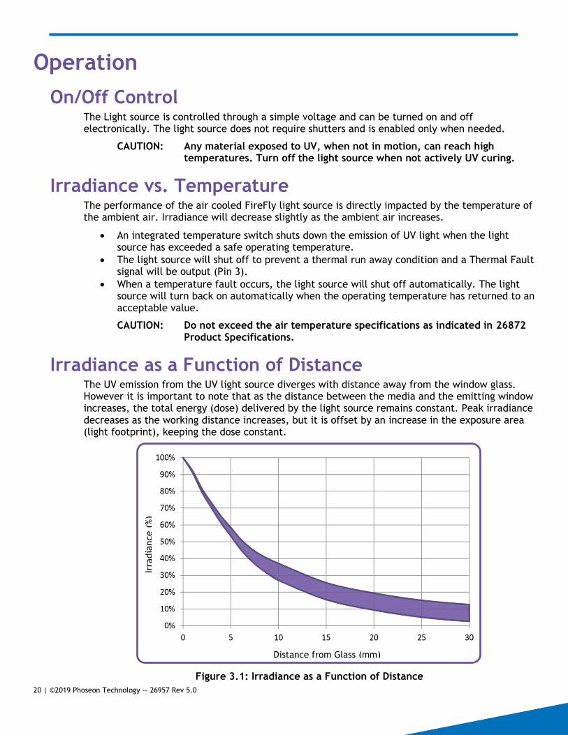
Irradiance as a Function of Distance The UV emission from the UV light source diverges with distance away from the window glass. However it is important to note that as the distance between the media and the emitting window increases, the total energy (dose) delivered by the light source remains constant. Peak irradiance decreases as the working distance increases, but it is offset by an increase in the exposure area (light footprint), keeping the dose constant.
Figure 3.1: Irradiance as a Function of Distance
Distance from Glass (mm)
Irra
dia
nce (
%)

21 | ©2019 Phoseon Technology — 26957 Rev 5.0
Service For further details contact Phoseon Technology by phone at +1.503.439.6446 or email at [email protected].
Troubleshooting Guide Table 4.1: Troubleshooting Guide
Symptom Component Action or Cause
No Light is emitted from light source
Power Supply Check that AC and DC cables are wired correctly to power supply.
1. If using Mean Well Power Supply, check that the green LED indicator is on and the fans are running.
2. Verify the power supply is plugged in to AC outlet.
3. Verify the voltage at the light source is +48Vdc at Pin 6 (return at Pin 4 or 5).
Fault If light source has thermally tripped, no light will be emitted until the light source returns to a safe operating temperature.
The fans will continue to operate if the light source has thermally tripped.
Light Source with PLC Control
Check wiring to Molex Mini-Fit Jr. 6-Pin connector.
Air Filter Replacement Clean the fan filter on an as-needed basis. The time interval will vary depending on the environment where the unit is installed.
1. Turn off the power to the light source and disconnect the power cord.
2. Unscrew the thumbscrew and remove the retainer by lifting up and then out.
3. Remove old filter and discard. 4. If needed, wipe the retainer with IPA
using a soft cloth.
CAUTION: Do not use abrasive scouring powders to clean the air filter. Never spray liquid into the fan filter while installed on the light source.
5. Clean the fan guard and retainer with a dry paper towel, if needed.
6. After drying the filter, place it back into the fan guard and secure the filter in place with the retainer.
7. Reconnect main power cord. 8. The light source can then be powered on.
Thumbscrew
Retainer
Filter
Air Intake

Window Cleaning InstructionsUser Guide
Specifications are subject to change without notice.©2017 Phoseon Technology, Inc. All rights reserved.
27182 Rev 7.0February 2017
Materials Needed:
• Dry Paper Towels
• Razor Blade and Handle
• IPA Pre-moistened Wipe
• Gloves: Vinyl and Sharp Resistant (i.e. Kevlar)
• Sharps Disposal Container
Instructions:
1. Disconnect DC Power from the light source.
CAUTION: Wearing vinyl gloves is recommended to avoid
getting any uncured UV material on the skin.
2. Wipe down the glass with a dry paper towel to remove any
uncured UV material.
3. Carefully scrape large debris off the window using the sharp
edge of the razor.
CAUTION: Wear sharp-resistant gloves.
Note: If the razor needs to be replaced, dispose of the razor
blade in a properly marked sharps container.
4. Use the pre-moistened IPA wipe to remove any remaining dust
or debris left on the window during the cleaning process.
5. Repeat steps 2 through 5 until the window is clear of all
contaminants.
6. If needed, use a dry paper towel to wipe down the light
source.
Phoseon re quires inspecting and cleaning the emitting window of the light source for any debris or
UV material on a regular basis, up to daily if needed, to maintain the quality of UV light output.
Note: Do not submerge the light source or spray any liquid directly onto the light source.
The materials needed to properly clean the Phoseon light source, can be purchased from most home
improvement supply stores, paint stores, or auto-body repair shops.
Wipe Glass
Scrape with Razor
Wipe with IPA

Specifications are subject to change without notice.©2020 Phoseon Technology, Inc. All rights reserved.
29321 Rev 13March 2020
Declaration of ConformityProduct Identification
Manufacturer
Means of Conformity
Signature
Brand Phoseon Technology
Product Family Product Models
FireEdge™ 75x5
FE100 80x10
FE200 75x10
FE300 75x10
FE400 80x10
FE410 80x10
FE100 120x10
FE200 110x10
FE300 110x10
FE400 120x10
FE410 120x10
FE100 180x10
FE400 160x10
FE410 160x10
FE100 240x10
FE400 180x10
FE410 180x10
FE400 240x10
FE410 240x10
FireFlex™ 75x50 150x50 225x50
FireFly 25x10
50x20
FF200 25x20
25x20
75x20
FF200 50x20
25x25
150x20
FireJet™ 225x20
FJ100 75x20
FJ200 75x20
FJ240 75x40
FJ601 225x20
FJ605 300x20
FJ800 100x100
FJ100 150x20
FJ200 150x20
FJ240 150x40
FJ601 300x20
FJ605 375x20
FJ100 225x20
FJ200 225x20
FJ228 225x20
FJ240 225x40
FJ601 375x20
FJ605 450x20
FJ100 300x20
FJ200 300x20
FJ240 300x40
FJ601 450x20
FJ605 525x20
FJ100 375x20
FJ200 375x20
FJ601 525x20
FJ605 600x20 FJ605 675x20
FireLine™ 125x20
350x20
FL200 75x10
FL400 125x20
FL440 125x40
150x20
450x20
FL200 125x10
FL400 150x20
FL440 150x40
225x20
550x20
FL400 225x20
FL440 225x40
300x20
675x20
FL400 250x20
FL440 250x40
FL400 300x20
FL440 300x40
FirePower™ FP200 150x20
FP300 150x20
FP501 300x20
FP601 300x20
FP200 225x20
FP300 225x20
FP501 350x20
FP601 350x20
FP200 300x20
FP300 300x20
FP501 450x20
FP601 375x20
FP200 350x20
FP300 350x20
FP501 525x20
FP601 450x20
FP200 450x20
FP300 450x20
FP501 600x20
FP601 525x20
FP300 900x20
FP501 700x20
FP601 600x20 FP601 675x20
StarFire™ 100x20 150x20
StarFire MAX™ 75x20 150x20 225x20 300x20
Name: Phoseon TechnologyAddress: 7425 NE Evergreen Parkway, Hillsboro, Oregon 97124-5845Country: United States of America
Phoseon Technology declares that the product listed as a result of its design and construction is in conformity with the essential requirements and provisions of the following Council Directives and standards:
Place: Hillsboro, OR Signature:
Name:
Applicable Directives: Standards Used to Verify Compliance:
• 2014/35/EU (Low Voltage Directive)• 2014/30/EU (Electromagnetic Compatibility)• 2011/65/EU (RoHS2)
• EN/IEC 61010-1 3rd Ed. (2010)• EN 62471 (2008) IEC 62471 (2006)• EN 61326-1 (2013)
Craig Baldwin, Vice President of Operations

UKCA Declaration of Conformity
The declaration of conformity is issued under the sole responsibility of the manufacturer
Part number: IUV201 Description: Handheld LED UV Curing Flood Lamp Serial number:
Incorporating:
Part number Description Serial Number(s) PHO28438 Phoseon FireFly 25x10mm Air-
Cooled 4W 395nm LED Flood Lamp
Mean Well PLN-60-48 110-240VAC to +48V Power Supply
Intertronics declares that the product described above is in conformity with the relevant UK Statutory Instruments (and their amendments):
• Supply of Machinery (Safety) Regulations 2008 • Electromagnetic Compatibility Regulations 2016 • Electrical Equipment (Safety) Regulations 2016
References to the relevant designated standards used or references to the other technical specifications in relation to which conformity is declared:
• BS EN ISO 12100-1:2010 Safety of machinery. General principles for design. Risk assessment and risk reduction
• BS EN ISO 13849-1:2015 Safety of machinery. Safety-related parts of control systems. General principles for design
• BS EN ISO 60204-1:2018 Safety of machinery. Electrical equipment of machines. General requirements
The Technical File is held by Intertronics at the below address.
12A Station Field Industrial Estate, Banbury Road, Kidlington Oxfordshire OX5 1JD England
www.intertronics.co.uk t 01865 842842
Related Documents


![001 1562R383R FRANÇAIS MODE D'EMPLOI [Unit Dose] I ... · 3. Light-cure BOND with a dental curing unit (see table “Dental curing unit and curing time”). Table: Dental curing](https://static.cupdf.com/doc/110x72/5f7ba0f1a367dc37781f72b2/001-1562r383r-franais-mode-demploi-unit-dose-i-3-light-cure-bond-with.jpg)