ITU-T Technical Paper TELECOMMUNICATION STANDARDIZATION SECTOR OF ITU (10 July 2009) SERIES H: AUDIOVISUAL AND MULTIMEDIA SYSTEMS Infrastructure of audiovisual services - Communication procedures HSTP-MCTB Media coding toolbox for IPTV: Audio and video codecs International Telecommunication Union

Welcome message from author
This document is posted to help you gain knowledge. Please leave a comment to let me know what you think about it! Share it to your friends and learn new things together.
Transcript

ITU-T Technical PaperTELECOMMUNICATIONSTANDARDIZATION SECTOROF ITU
(10 July 2009)
SERIES H: AUDIOVISUAL AND MULTIMEDIA SYSTEMSInfrastructure of audiovisual services - Communication procedures
HSTP-MCTBMedia coding toolbox for IPTV: Audio and video codecs
I n t e r n a t i o n a l T e l e c o m m u n i c a t i o n U n i o n

Summary
This ITU-T Technical Paper addresses the use of audio and video coding in services delivered over Internet Protocols (IP). This document describes specific codecs for use within an IPTV environment. For audio coding, it describes the use of MPEG-1 Layer II, AC-3, E-AC3, HE AAC v2 audio, Extended AMR WB (AMR WB+) audio, MPEG 2 AAC, MPEG-4 HE AAC, MPEG-4 HE AAC v2, MPEG Surround, MPEG-4 ALS, G719, G.722, G.722.1, G.722.1 Annex C, G.722.2, G.729.1, G.711.1 and G.718. For video coding, it recommends support for H.264 | MPEG-4 AVC and H.262 | MPEG-2 Video, and also lists some additional video coding technologies that have been identified in member contributions as potentially relevant to the application (AVS, H.263, MPEG-1, MPEG-4 Part 2, and VC-1). This document adopts a “toolbox” approach for the general case of IPTV applications delivered directly over IP and MPEG2 -TS. This document is not a specification for the use of Audio or Video Codecs in IPTV Services.
Change Log
This document contains Version 2of the ITU-T Technical Paper on “Media coding toolbox for IPTV: Audio and Video codecs” approved at the ITU-T Study Group 16 Working Party 3 meeting held in Geneva, 10 July 2009.
Version 1of this ITU-T Technical Paper was entitled “Media coding toolbox for IPTV: Audio codecs” and was approved at the ITU-T Study Group 16 meeting held in Geneva, 27 January - 6 February 2009.
Editors: Herve Taddei Huawei TechnologiesChina
Tel: +49 162 2940 260Email: [email protected]
Gary J. SullivanMicrosoftUSA
Tel: +1 425 703-5308Email: [email protected]
(2009-07) i

Contents
Page1 SCOPE....................................................................................................................................................................1
2 REFERENCES.......................................................................................................................................................1
3 DEFINITIONS.......................................................................................................................................................3
4 ABBREVIATIONS................................................................................................................................................3
5 DOCUMENT STRUCTURE................................................................................................................................4
6 AVAILABLE CODECS........................................................................................................................................5
7 AUDIO CODECS..................................................................................................................................................5
7.1 AC-3...............................................................................................................................................................57.1.1 Overview of AC-3......................................................................................................................................57.1.2 Transport of AC-3.....................................................................................................................................77.1.3 Enhanced AC-3..........................................................................................................................................77.1.4 Overview of Enhanced AC-3.....................................................................................................................77.1.5 Transport of Enhanced AC-3....................................................................................................................87.1.6 Storage of AC-3 and Enhanced AC-3 bitstreams......................................................................................87.1.7 AC-3 and Enhanced AC-3 track definition................................................................................................87.1.8 Sample definition for AC-3 and Enhanced AC-3......................................................................................97.1.9 Details of AC3SpecificBox........................................................................................................................97.1.10 Details of EC3SpecificBox..................................................................................................................10
7.2 EXTENDED AMR-WB (AMR-WB+)............................................................................................................127.2.1 Overview of AMR-WB+ codec................................................................................................................127.2.2 Transport and storage of AMR-WB+......................................................................................................13
7.3 MPEG-4 HIGH EFFICIENCY AAC V2...........................................................................................................147.3.1 Overview of HE AAC v2..........................................................................................................................147.3.2 Transport and storage of HE AAC v2.....................................................................................................167.3.3 HE AAC v2 Levels and Main Parameters for DVB.................................................................................167.3.4 Methods for signalling of SBR and/or PS...............................................................................................17
7.4 MPEG-1 LAYER 2 AUDIO............................................................................................................................177.5 MPEG-2 AAC..............................................................................................................................................18
7.5.1 Overview of MPEG-2 AAC......................................................................................................................187.5.2 Overview of Encoder...............................................................................................................................207.5.3 Overview of decoder................................................................................................................................21
7.6 MPEG SURROUND........................................................................................................................................227.6.1 Introduction.............................................................................................................................................227.6.2 MPEG Surround features........................................................................................................................237.6.3 Introduction to MPEG Surround Baseline profile..................................................................................247.6.4 Binaural Decoding..................................................................................................................................247.6.5 External stereo mix..................................................................................................................................247.6.6 Enhanced Matrix Mode...........................................................................................................................257.6.7 MPEG Surround for MPEG-1 Layer II-- Baseline Profile.....................................................................267.6.8 MPEG Surround for MPEG 4 AAC, HE AAC and HE AAC v2-- Baseline Profile................................26
7.7 ITU-T G.719................................................................................................................................................267.7.1 Overview of the G.719 encoder...............................................................................................................277.7.2 Overview of the G.719 decoder...............................................................................................................277.7.3 Transport and storage of ITU-T G.719...................................................................................................28
7.8 MPEG-4 ALS LOSSLESS CODING.................................................................................................................287.8.1 Performance............................................................................................................................................297.8.2 Related standardization...........................................................................................................................30
8 SPEECH CODECS..............................................................................................................................................30
8.1 ITU-T G.722................................................................................................................................................308.1.1 Overview of main functional features.....................................................................................................308.1.2 Overview of G.722 SB-ADPCM encoder................................................................................................30
(2009-07) ii
8.1.3 Lower sub-band ADPCM encoder..........................................................................................................318.1.4 Higher sub-band ADPCM encoder.........................................................................................................318.1.5 Overview of G.722 SB-ADPCM decoder................................................................................................328.1.6 Packet loss concealment algorithms for G.722.......................................................................................33
8.2 ITU-T G.722.1 AND G.722.1 ANNEX C.......................................................................................................338.3 ITU-T G.722.2 (3GPP AMR-WB)...............................................................................................................36
8.3.1 Overview of AMR-WB codec...................................................................................................................378.3.2 Transport and storage of AMR-WB.........................................................................................................39
8.4 ITU-T G.729.1.............................................................................................................................................398.4.1 Overview of the encoder..........................................................................................................................408.4.2 Overview of the decoder..........................................................................................................................418.4.3 RTP payload............................................................................................................................................42
8.5 ITU-T G.711.1.............................................................................................................................................428.5.1 Overview of G.711.1 algorithm...............................................................................................................438.5.2 Transport of G.711.1...............................................................................................................................458.5.3 Transcoding with G.711..........................................................................................................................45
8.6 ITU-T G.718................................................................................................................................................458.6.1 Overview of the G.718 encoder...............................................................................................................468.6.2 Overview of the G.718 decoder...............................................................................................................48
9 VIDEO CODECS.................................................................................................................................................49
APPENDIX I LIST OF SOME ADDITIONAL CONTENT RELATED STANDARDS.......................................50
I.1. INTRODUCTION.............................................................................................................................................50I.2. RELEVANT REQUIREMENTS...........................................................................................................................50I.3. CODING AND CARRIAGE OF CLOSED CAPTION INFORMATION.......................................................................51I.4. SUBTITLES.....................................................................................................................................................51I.5. DESCRIPTIVE AUDIO.....................................................................................................................................51
Bibliography....................................................................................................................................................................52
(2009-07) iii

List of TablesTable 6-1: Available speech and audio codecs...............................................................................................................5Table 7-1: AC3SpecificBox............................................................................................................................................9Table 7-2: bit_rate_code...............................................................................................................................................10Table 7-3: EC3SpecificBox..........................................................................................................................................10Table 7-4: chan_loc field bit assignments.....................................................................................................................11Table 7-5: Levels within the HE AAC v2 Profile.........................................................................................................17Table 7-6: Default channel configurations....................................................................................................................19Table 7-7: MPEG Surround level overview.................................................................................................................24Table 8-1: Computational complexity and memory requirements...............................................................................36Table 8-2: Sub-bitstream combination for each mode..................................................................................................43
List of FiguresFigure 7-1: The AC-3 encoder........................................................................................................................................6Figure 7-2: The AC-3 decoder........................................................................................................................................6Figure 7-3: High-level structure of AMR-WB+ encoder.............................................................................................12Figure 7-4: High-level structure of AMR-WB+ decoder.............................................................................................13Figure 7-5: MPEG Tools used in the HE AAC v2 Profile............................................................................................14Figure 7-6: HE AAC v2 encoder..................................................................................................................................15Figure 7-7: HE AAC v2 decoder..................................................................................................................................15Figure 7-8: Interleaving of AAC frames.......................................................................................................................16Figure 7-9: High level overview of MPEG-1 Layers II coder......................................................................................18Figure 7-10: MPEG-2 AAC encoder block diagram....................................................................................................21Figure 7-11: MPEG-2 AAC decoder block diagram....................................................................................................22Figure 7-12: Quality of MPS versus bit rate combined with different core codecs......................................................23Figure 7-13: MPEG Surround block diagram...............................................................................................................23Figure 7-14: MPEG Surround support for external stereo mix....................................................................................25Figure 7-15: Overview diagram of MPEG Surround enhanced matrix mode decoder................................................25Figure 7-16: G.719 encoder block diagram..................................................................................................................27Figure 7-17: G.719 decoder block diagram..................................................................................................................28Figure 7-18: Fundamental structure of MPEG-4 ALS lossless encoder and decoder..................................................29Figure 8-1: Block diagram of the G.722 SB-ADPCM encoder....................................................................................31Figure 8-2: Block diagram of the G.722 lower band encoder......................................................................................31Figure 8-3: Block diagram of the G.722 lower band decoder......................................................................................32Figure 8-4: Block diagram of the G.722 higher band decoder.....................................................................................32Figure 8-5: Block diagram of the G.722.1 encoder......................................................................................................34Figure 8-6: Block diagram of the G.722.1 decoder......................................................................................................35Figure 8-7: Detailed block diagram of the G.722.2 encoder........................................................................................38Figure 8-8: Detailed block diagram of the G.722.2 decoder........................................................................................38Figure 8-9: G.729.1 bitstream format...........................................................................................................................40Figure 8-10: High-level block diagram of the G.729.1 encoder...................................................................................41Figure 8-11: High-level block diagram of the G.729.1 decoder...................................................................................42Figure 8-12: High-level block diagram of the G.711.1 encoder...................................................................................44Figure 8-13: High-level block diagram of the G.711.1 decoder...................................................................................44Figure 8-14: Structural block diagram of the G.718 encoder (WB case).....................................................................47Figure 8-15: Structural block diagram of the G.718 decoder (WB case, clean channel).............................................48
(2009-07) iv
ITU-T Technical Paper HSTP-MCTB
Media coding toolbox for IPTV: Audio and video codecs
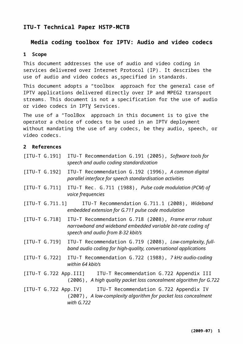
1 Scope
This document addresses the use of audio and video coding in services delivered over Internet Protocol (IP). It describes the use of audio and video codecs as specified in standards.
This document adopts a “toolbox” approach for the general case of IPTV applications delivered directly over IP and MPEG2 transport streams. This document is not a specification for the use of audio or video codecs in IPTV Services.
The use of a “ToolBox” approach in this document is to give the operator a choice of codecs to be used in an IPTV deployment without mandating the use of any codecs, be they audio, speech, or video codecs.
2 References
[ITU-T G.191] ITU-T Recommendation G.191 (2005), Software tools for speech and audio coding standardization
[ITU-T G.192] ITU-T Recommendation G.192 (1996), A common digital parallel interface for speech standardisation activities
[ITU-T G.711] ITU-T Rec. G.711 (1988), Pulse code modulation (PCM) of voice frequencies
[ITU-T G.711.1] ITU-T Recommendation G.711.1 (2008), Wideband embedded extension for G.711 pulse code modulation
[ITU-T G.718] ITU-T Recommendation G.718 (2008), Frame error robust narrowband and wideband embedded variable bit-rate coding of speech and audio from 8-32 kbit/s
[ITU-T G.719] ITU-T Recommendation G.719 (2008), Low-complexity, full-band audio coding for high-quality, conversational applications
[ITU-T G.722] ITU-T Recommendation G.722 (1988), 7 kHz audio-coding within 64 kbit/s
[ITU-T G.722 App.III] ITU-T Recommendation G.722 Appendix III (2006), A high quality packet loss concealment algorithm for G.722
[ITU-T G.722 App.IV] ITU-T Recommendation G.722 Appendix IV (2007), A low-complexity algorithm for packet loss concealment with G.722
[ITU-T G.722.1] ITU-T Recommendation G.722.1 (2005), Coding at 24 and 32 kbit/s for hands-free operation in systems with low frame loss
[ITU-T G.722.2] ITU-T Recommendation G.722.2 (2003), Wideband coding of speech at around 16 kbit/s using Adaptive Multi-rate Wideband (AMR-WB)
[ITU-T G.729.1] ITU-T Recommendation G.729.1 (2006), An 8-32 kbit/s scalable wideband coder bitstream interoperable with G.729
[ITU-T H.222.0] ITU-T Rec. H.222.0 | ISO/IEC 13818-1 (2000), Information technology - Generic coding of moving pictures and associated audio information: Systems
(2009-07) 1

[ITU-T H.222.0 Amd.1] ITU-T H.222.0 (2006) | ISO/IEC 13818-1 (2007) Amendment 1 (2007), Information technology - Generic coding of moving pictures and associated audio information: Systems: Transport of MPEG-4 streaming text and MPEG-4 lossless audio over MPEG-2 systems
[ITU-T H.262] ITU-T H.262 (2000) | ISO/IEC 13818-2 (2000), Information technology - Generic coding of moving pictures and associated audio information: Video
[ITU-T H.263] ITU-T H.263 (2005), Video coding for low bit rate communication
[ITU-T H.264] ITU-T H.264 (2009) | ISO/IEC 14496-1 (2009), Advanced video coding for generic audiovisual services
[ISO/IEC 11172-2] ISO/IEC 11172-2 (1993), Information technology - Coding of moving pictures and associated audio for digital storage media at up to about 1,5 Mbit/s - Part 2: Video
[ISO/IEC 11172-3] ISO/IEC 11172-3 (1993), Information technology - Coding of moving picture and associated audio for digital storage media at up to about 1.5 Mbit/s - Part 3: Audio
[ISO/IEC 13818-7] ISO/IEC 13818-7 (2007), Information technology - Generic coding of moving picture and associated audio information - Part 7: Advanced Audio Coding (AAC)
[ISO/IEC 14496-2] ISO/IEC 14496-2 (2004), Information technology - Coding of audio-visual objects -- Part 2: Visual
[ISO/IEC 14496-3] ISO/IEC 14496-3 (2007), Information technology - Coding of audio-visual objects - Part 3: Audio
[ISO/IEC 14496-12] ISO/IEC 14496-12 (2005), Information technology – Coding of audio-visual objects - Part 12: ISO base media file format
[ISO/IEC 23003-1] ISO/IEC 23003-1 (2007), Information technology - MPEG audio technologies - Part 1: MPEG Surround
[ETSI TS 102 366] ETSI TS 102 366 V1.2.1 (2008), Digital Audio Compression (AC-3, Enhanced AC-3) Standard
[ETSI TS 126 290] ETSI TS 126 290 V7.0.0 (2007), Digital cellular telecommunications system (Phase 2+); Universal Mobile Telecommunications System (UMTS); Audio codec processing functions; Extended Adaptive Multi-Rate - Wideband (AMR-WB+) codec
[ETSI TS 126 273] ETSI TS 126 273 V.6.5.0 (2006), Digital cellular telecommunications system (Phase 2+); Universal Mobile Telecommunications System (UMTS); ANSI-C code for the fixed-point Extended Adaptive Multi-Rate - Wideband (AMR-WB+) speech codec
[ETSI TS 126 304] ETSI TS 126 304 V.6.6.0 (2006), Digital cellular telecommunications system (Phase 2+); Universal Mobile Telecommunications System (UMTS); Extended Adaptive Multi-Rate - Wideband (AMR-WB+) codec; Floating-point ANSI-C code
[GB/T20090.2] National Standard of the People's Republic of China GB/T20090.2, Information Technology - Advanced Audio and Video Coding - Part 2: Video
[IETF RFC 2250] IETF RFC 2250 (1998), RTP Payload Format for MPEG1/MPEG2 Video
(2009-07) 2
[IETF RFC 3047] IETF RFC 3047 (2001), RTP Payload Format for ITU-T Recommendation G.722.1 (Made obsolete by RFC 5577)
[IETF RFC 3267] IETF RFC 3267 (2002), Real-Time Transport Protocol (RTP) Payload Format and File Storage Format for the Adaptive Multi-Rate (AMR) and Adaptive Multi-Rate Wideband (AMR-WB) Audio Codec
[IETF RFC 3550] IETF RFC 3550 (2003), RTP, A Transport Protocol for Real-Time Applications
[IETF RFC 3640] IETF RFC 3640 (2003), RTP payload for transport of generic MPEG-4 elementary streams
[IETF RFC 4184] IETF RFC 4184 (2005), RTP Payload Format for AC-3 Audio
[IETF RFC 4352] IETF RFC 4352 (2006), RTP Payload Format for the Extended Adaptive Multi-Rate Wideband (AMR-WB+) Audio Codec
[IETF RFC 4598] IETF RFC 4598 (2006), RTP Payload Format for Enhanced AC-3 (E-AC-3) Audio
[IETF RFC 4749] IETF RFC 4749 (2006), RTP payload format for G.729.1 audio codec
[IETF RFC 5391] IETF RFC 5391 (2008), RTP Payload Format for ITU-T Recommendation G.711.1
[IETF RFC 5577] IETF RFC 5577 (2009), RTP Payload Format for ITU-T Recommendation G.722.1 (obsoletes RFC 3047)
[SMPTE 421M] SMPTE 421M (2006), VC-1 Compressed video bitstream format and decoding process
3 Definitions
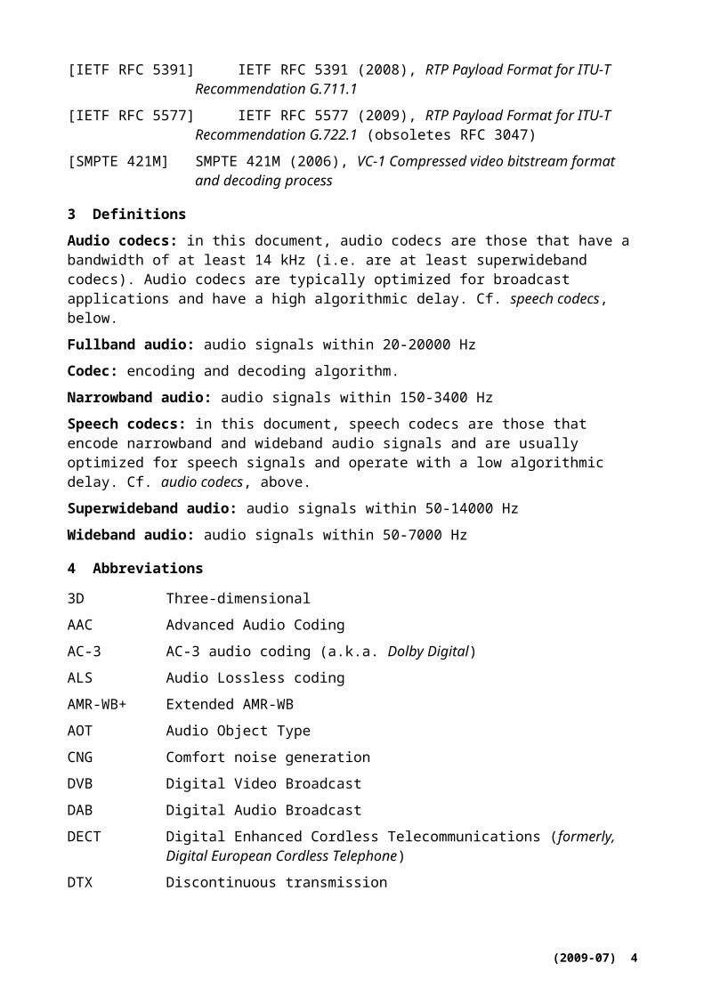
Audio codecs: in this document, audio codecs are those that have a bandwidth of at least 14 kHz (i.e. are at least superwideband codecs). Audio codecs are typically optimized for broadcast applications and have a high algorithmic delay. Cf. speech codecs, below.
Fullband audio: audio signals within 20-20000 Hz
Codec: encoding and decoding algorithm.
Narrowband audio: audio signals within 150-3400 Hz
Speech codecs: in this document, speech codecs are those that encode narrowband and wideband audio signals and are usually optimized for speech signals and operate with a low algorithmic delay. Cf. audio codecs, above.
Superwideband audio: audio signals within 50-14000 Hz
Wideband audio: audio signals within 50-7000 Hz
4 Abbreviations
3D Three-dimensional
AAC Advanced Audio Coding
AC-3 AC-3 audio coding (a.k.a. Dolby Digital)
ALS Audio Lossless coding
AMR-WB+ Extended AMR-WB
AOT Audio Object Type
(2009-07) 3
CNG Comfort noise generation
DVB Digital Video Broadcast
DAB Digital Audio Broadcast
DECT Digital Enhanced Cordless Telecommunications (formerly, Digital European Cordless Telephone)
DTX Discontinuous transmission
E-AC-3 Enhanced AC-3 audio coding (a.k.a. Dolby Digital Plus)
HDTV High Definition Television
HE AAC High-Efficiency Advanced Audio Coding
HRTF Head-related transfer function
IP Internet Protocol
IP-IRD Internet Protocol Integrated Receiver Decoder.
LC Low Complexity
LATM Low Overhead Audio Transport Multiplex
MBMS Multimedia Broadcast/Multicast Service
MPEG Moving Picture Experts Group (ISO/IEC JTC 1/SC 29/WG 11)
MPEG-2 TS ITU-T H.222.0 | ISO/IEC 13818-1 MPEG-2 Transport Stream
NB Narrowband (audio)
PS Parametric Stereo
PSS Packet switched Streaming Service
QMF Quadrature Mirror Filter
RTP Real-time Transport Protocol
RTCP Real-time Transport Control Protocol
RTSP Real Time Streaming Protocol
S/PDIF Sony/Philips Digital Interconnect Format
SBR Spectral Band Replication
SMPTE Society of Motion Picture and Television Engineers
SWB Superwideband (audio)
TCP Transmission Control Protocol
UDP User Datagram Protocol
WB Wideband (audio)
WMOPS Weighted Million Operations Per Second
5 Document structure
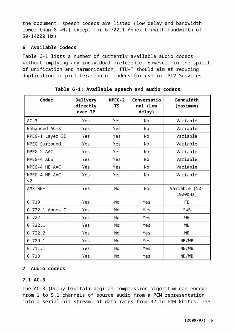
This document is organized in three sections. The first section gives a list of available codecs. Then, audio codecs that have a bandwidth larger or equal to 14 kHz are detailed; those codecs have usually high delay, except for G.719. In the final section of the document, speech codecs are listed
(2009-07) 4
(low delay and bandwidth lower than 8 kHz) except for G.722.1 Annex C (with bandwidth of 50-14000 Hz).
6 Available Codecs
Table 6-1 lists a number of currently available audio codecs without implying any individual preference. However, in the spirit of unification and harmonization, ITU-T should aim at reducing duplication or proliferation of codecs for use in IPTV Services.
Table 6-1: Available speech and audio codecs
Codec Delivery directly over IP
MPEG-2 TS
Conversational (Low delay)
Bandwidth (maximum)
AC-3 Yes Yes No VariableEnhanced AC-3 Yes Yes No VariableMPEG-1 Layer II Yes Yes No VariableMPEG Surround Yes Yes No VariableMPEG-2 AAC Yes Yes No VariableMPEG-4 ALS Yes Yes No VariableMPEG-4 HE AAC Yes Yes No VariableMPEG-4 HE AAC v2 Yes Yes No VariableAMR-WB+ Yes No No Variable [50-19200Hz]G.719 Yes No Yes FBG.722.1 Annex C Yes No Yes SWBG.722 Yes No Yes WBG.722.1 Yes No Yes WBG.722.2 Yes No Yes WBG.729.1 Yes No Yes NB/WBG.711.1 Yes No Yes NB/WBG.718 Yes No Yes NB/WB
7 Audio codecs
7.1 AC-3
The AC-3 (Dolby Digital) digital compression algorithm can encode from 1 to 5.1 channels of source audio from a PCM representation into a serial bit stream, at data rates from 32 to 640 kbit/s. The 0.1 channel refers to a fractional bandwidth channel intended to convey only low frequency signals.
The AC-3 audio codec is specified in [ETSI TS 102 366].
7.1.1 Overview of AC-3
The AC-3 algorithm achieves high coding gain by coarsely quantizing a frequency domain representation of the audio signal. Figure 7-1 and Figure 7-2 respectively show block diagrams of the AC-3 encoder and decoder. The first step in the encoding process is to transform the representation of audio from a sequence of pulse code modulation (PCM) time samples into a sequence of blocks of frequency coefficients. This is done in the analysis filter bank. Overlapping blocks of 512 time samples are multiplied by a time window and transformed into the frequency
(2009-07) 5
domain. Due to the overlapping blocks, each PCM input sample is represented in two sequential transformed blocks. The frequency domain representation may then be decimated by a factor of two so that each block contains 256 frequency coefficients. The individual frequency coefficients are represented in binary exponential notation as a binary exponent and a mantissa. The set of exponents is encoded into a coarse representation of the signal spectrum which is referred to as the spectral envelope. This spectral envelope is used by the core bit allocation routine which determines how many bits to use to encode each individual mantissa. The spectral envelope and the coarsely quantized mantissas for 6 audio blocks (1536 audio samples per channel) are formatted into an AC-3 frame. The AC-3 bit stream is a sequence of AC-3 frames.
PCM TimeSamples
SpectralEnvelopeEncoding
Bit AllocationAnalysis FilterBank
Exponents
MantissaQuantization
EncodedSpectralEnvelope
QuantizedMantissas
Mantissas
Bit Allocation Information
AC-3 Frame Formatting Encoded AC-3Bit-Stream
Figure 7-1: The AC-3 encoder
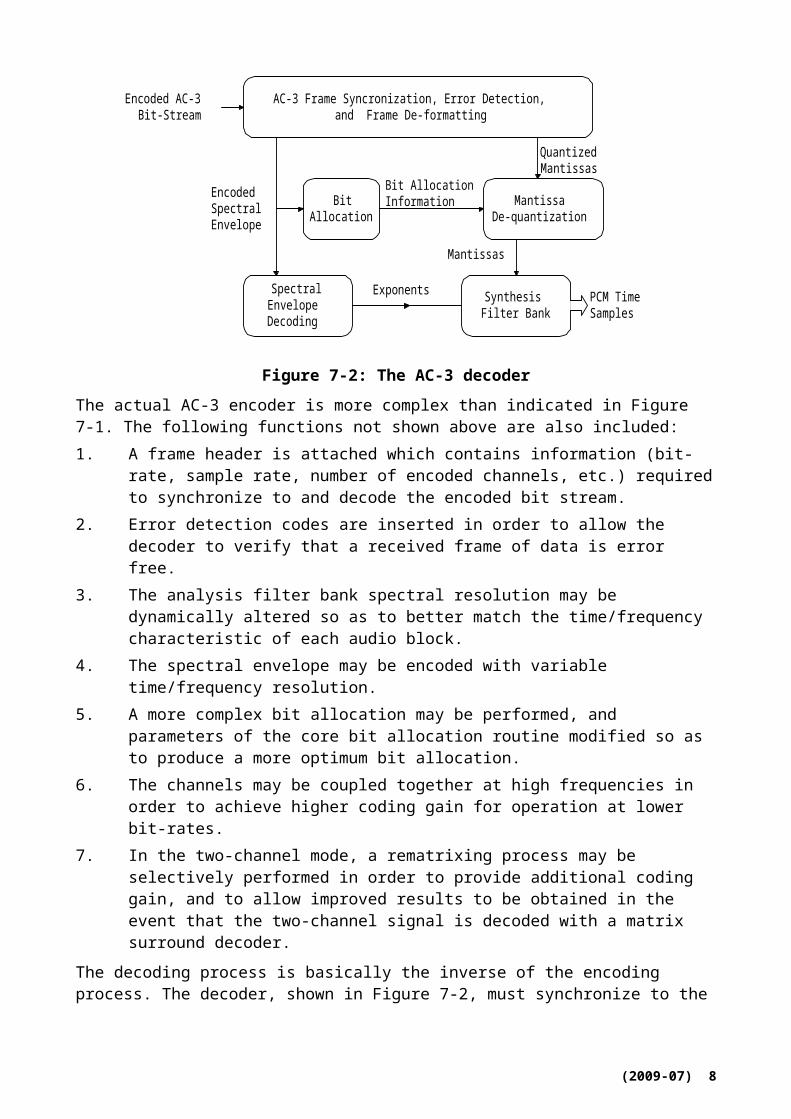
PCM TimeSamples
AC-3 Frame Syncronization, Error Detection,and Frame De-formatting
Encoded AC-3Bit-Stream
SpectralEnvelopeDecoding
BitAllocation
SynthesisFilter Bank
Exponents
MantissaDe-quantization
EncodedSpectralEnvelope
QuantizedMantissas
Mantissas
Bit AllocationInformation
Figure 7-2: The AC-3 decoder
The actual AC-3 encoder is more complex than indicated in Figure 7-1. The following functions not shown above are also included:1. A frame header is attached which contains information (bit-rate, sample rate, number of
encoded channels, etc.) required to synchronize to and decode the encoded bit stream.
(2009-07) 6

2. Error detection codes are inserted in order to allow the decoder to verify that a received frame of data is error free.
3. The analysis filter bank spectral resolution may be dynamically altered so as to better match the time/frequency characteristic of each audio block.
4. The spectral envelope may be encoded with variable time/frequency resolution.5. A more complex bit allocation may be performed, and parameters of the core bit allocation
routine modified so as to produce a more optimum bit allocation.6. The channels may be coupled together at high frequencies in order to achieve higher coding
gain for operation at lower bit-rates.7. In the two-channel mode, a rematrixing process may be selectively performed in order to
provide additional coding gain, and to allow improved results to be obtained in the event that the two-channel signal is decoded with a matrix surround decoder.
The decoding process is basically the inverse of the encoding process. The decoder, shown in Figure 7-2, must synchronize to the encoded bit stream, check for errors, and de-format the various types of data such as the encoded spectral envelope and the quantized mantissas. The bit allocation routine is run and the results used to unpack and de-quantize the mantissas. The spectral envelope is decoded to produce the exponents. The exponents and mantissas are transformed back into the time domain to produce the decoded PCM time samples.
The actual AC-3 decoder is more complex than indicated in Figure 7-2. The following decoder operations not shown above are included:
Error concealment or muting may be applied in case a data error is detected.
Channels which have had their high-frequency content coupled together must be de-coupled.
Dematrixing must be applied (in the 2-channel mode) whenever the channels have been rematrixed.
The synthesis filter bank resolution must be dynamically altered in the same manner as the encoder analysis filter bank had been during the encoding process.
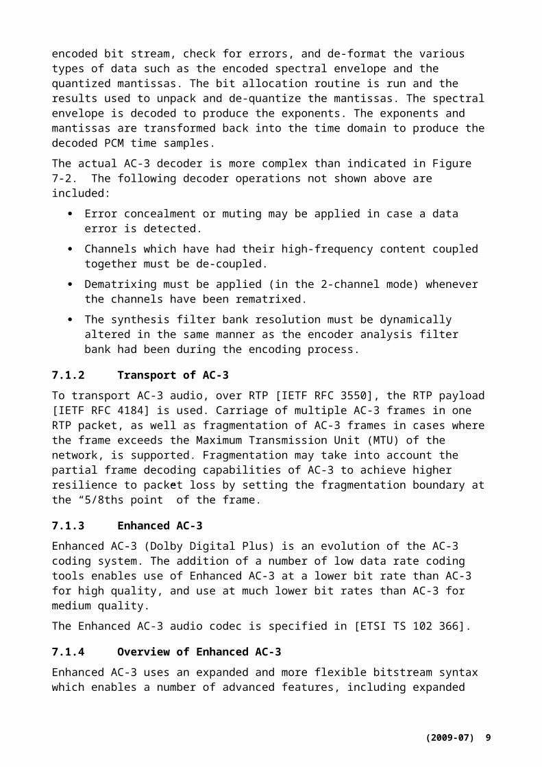
7.1.2 Transport of AC-3
To transport AC-3 audio, over RTP [IETF RFC 3550], the RTP payload [IETF RFC 4184] is used. Carriage of multiple AC-3 frames in one RTP packet, as well as fragmentation of AC-3 frames in cases where the frame exceeds the Maximum Transmission Unit (MTU) of the network, is supported. Fragmentation may take into account the partial frame decoding capabilities of AC-3 to achieve higher resilience to packet loss by setting the fragmentation boundary at the “5/8ths point” of the frame.
7.1.3 Enhanced AC-3
Enhanced AC-3 (Dolby Digital Plus) is an evolution of the AC-3 coding system. The addition of a number of low data rate coding tools enables use of Enhanced AC-3 at a lower bit rate than AC-3 for high quality, and use at much lower bit rates than AC-3 for medium quality.
The Enhanced AC-3 audio codec is specified in [ETSI TS 102 366].
7.1.4 Overview of Enhanced AC-3
Enhanced AC-3 uses an expanded and more flexible bitstream syntax which enables a number of advanced features, including expanded data rate flexibility and support for variable bit rate (VBR) coding. A bitstream structure based on sub-streams allows delivery of programs containing more than 5.1 channels of audio to support next-generation content formats, supporting channel
(2009-07) 7
configuration standards developed for digital cinema (D-Cinema) and support for multiple audio programs carried within a single bit-stream, suitable for deployment of services such as Hearing Impaired/Visual Impaired. To control the combination of audio programs carried in separate sub-streams or bit streams, Enhanced AC-3 includes comprehensive mixing metadata, enabling a content creator to control the mixing of two audio streams in an IP-IRD (Internet Protocol Integrated Receiver-Decoder.). To ensure compatibility of the most complex bit stream configuration with even the simplest Enhanced AC-3 decoder, the bit stream structure is hierarchical - decoders will accept any Enhanced AC-3 bit stream and will extract only the portions that are supported by that decoder without requiring additional processing. To address the need to connect IP-IRDs that include Enhanced AC-3 to the millions of home theatre systems that feature legacy AC-3 decoders via S/PDIF, it is possible to perform a modest complexity conversion of an Enhanced AC-3 bit stream to an AC-3 bit stream.
Enhanced AC-3 includes the following coding tools that improve coding efficiency when compared to AC-3.
Spectral Extension: recreates a signal’s high frequency amplitude spectrum from side data transmitted in the bit stream. This tool offers improvements in reproduction of high frequency signal content at low data rates.
Transient Pre-Noise Processing: synthesizes a section of PCM data just prior to a transient. This feature improves low data rate performance for transient signals.
Adaptive Hybrid Transform Processing: improves coding efficiency and quality by increasing the length of the transform. This feature improves low data rate performance for signals with primarily tonal content.
Enhanced Coupling: improves on traditional coupling techniques by allowing the technique to be used at lower frequencies than conventional coupling, thus increasing coder efficiency.
7.1.5 Transport of Enhanced AC-3
To transport Enhanced AC-3 audio over RTP [IETF RFC 3550], the RTP payload [IETF RFC 4598] is used. Carriage of multiple Enhanced AC-3 frames in one RTP packet, as well as fragmentation of Enhanced AC-3 frames in cases where the frame exceeds the MTU of the network, is supported. Recommendations for concatenation decisions which reduce the impact of packet loss by taking into account the configuration of multiple channels and programs present in the Enhanced AC-3 bit stream are provided.
7.1.6 Storage of AC-3 and Enhanced AC-3 bitstreams
This section describes the necessary structures for the integration of AC-3 and Enhanced AC-3 bitstreams in a file format that is compliant with the ISO Base Media File Format. Examples of file formats that are derived from the ISO Base Media File Format include the MP4 file format and the 3GPP file format.
7.1.7 AC-3 and Enhanced AC-3 track definition
In the terminology of the ISO Base Media File Format specification [ISO/IEC 14496-12], AC-3 and Enhanced AC-3 tracks are audio tracks. It therefore follows that these rules apply to the media box in the AC-3 or Enhanced AC-3 track:
In the Handler Reference Box, the handler_type field is set to ‘soun’.
The Media Information Header Box contains a Sound Media Header Box.
The Sample Description Box contains a box derived from AudioSampleEntry. For AC-3 tracks, this box is called AC3SampleEntry and has a box type designated ‘ac-3’. For
(2009-07) 8

Enhanced AC-3 tracks, this box is called EC3SampleEntry, and has box type designated ‘ec-3’. The layout of the AC3SampleEntry and EC3SampleEntry boxes is identical to that of AudioSampleEntry defined in ISO/IEC 14496-12 (including the reserved fields and their values), except that AC3SampleEntry ends with a box containing AC-3 bitstream information called AC3SpecificBox, and EC3SampleEntry ends with a box containing Enhanced AC-3 information called EC3SpecificBox.
The value of the timescale parameter in the Media Header Box, and the value of the SamplingRate parameter in the AC3SampleEntry Box or EC3SampleEntry Box is equal to the sample rate (in Hz) of the AC-3 or Enhanced AC-3 bitstream respectively.
7.1.8 Sample definition for AC-3 and Enhanced AC-3
An AC-3 sample is defined exactly one AC-3 syncframe [ETSI TS 102 366].
An Enhanced AC-3 sample is as the number of Enhanced AC-3 syncframes required to deliver six blocks of audio data from each substream present in the Enhanced AC-3 bitstream, beginning with independent substream 0.
An AC-3 or Enhanced AC-3 sample is equivalent in duration to 1536 samples of PCM audio data. Consequently, the value of the sample_delta field in the decoding time to sample box is 1536.
AC-3 and Enhanced AC-3 samples are byte-aligned. If necessary, up to seven zero-valued padding bits are added to the end of an AC-3 or Enhanced AC-3 sample to achieve byte-alignment. The padding bits box (defined in clause 8.23 of ISO/IEC 14496-12) need not be used to record padding bits that are added to a sample to align its size to the nearest byte boundary.
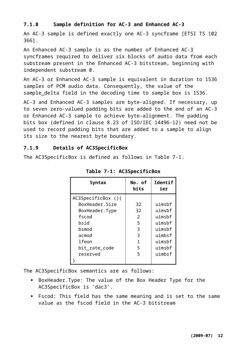
7.1.9 Details of AC3SpecificBox
The AC3SpecificBox is defined as follows in Table 7-1.
Table 7-1: AC3SpecificBox
Syntax No. of bits Identifier
AC3SpecificBox (){BoxHeader.SizeBoxHeader.Typefscodbsidbsmod acmodlfeonbit_rate_code reserved
}
32322533155
uimsbfuimsbfuimsbfuimsbfuimsbfuimbsfuimsbfuimsbfuimbsf
The AC3SpecificBox semantics are as follows:
BoxHeader.Type: The value of the Box Header Type for the AC3SpecificBox is ‘dac3’.
Fscod: This field has the same meaning and is set to the same value as the fscod field in the AC-3 bitstream
bsid: This field has the same meaning and is set to the same value as the bsid field in the AC-3 bitstream
bsmod: This field has the same meaning and is set to the same value as the bsmod field in the AC-3 bitstream
(2009-07) 9
acmod: This field has the same meaning and is set to the same value as the acmod field in the AC-3 bitstream
lfeon: This field has the same meaning and is set to the same value as the lfeon field in the AC-3 bitstream
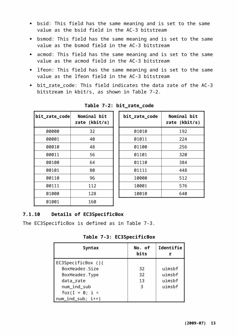
bit_rate_code: This field indicates the data rate of the AC-3 bitstream in kbit/s, as shown in Table 7-2.
Table 7-2: bit_rate_code
bit_rate_code Nominal bit rate (kbit/s)
bit_rate_code Nominal bit rate (kbit/s)
00000 32 01010 19200001 40 01011 22400010 48 01100 25600011 56 01101 32000100 64 01110 38400101 80 01111 44800110 96 10000 51200111 112 10001 57601000 128 10010 640
01001 160
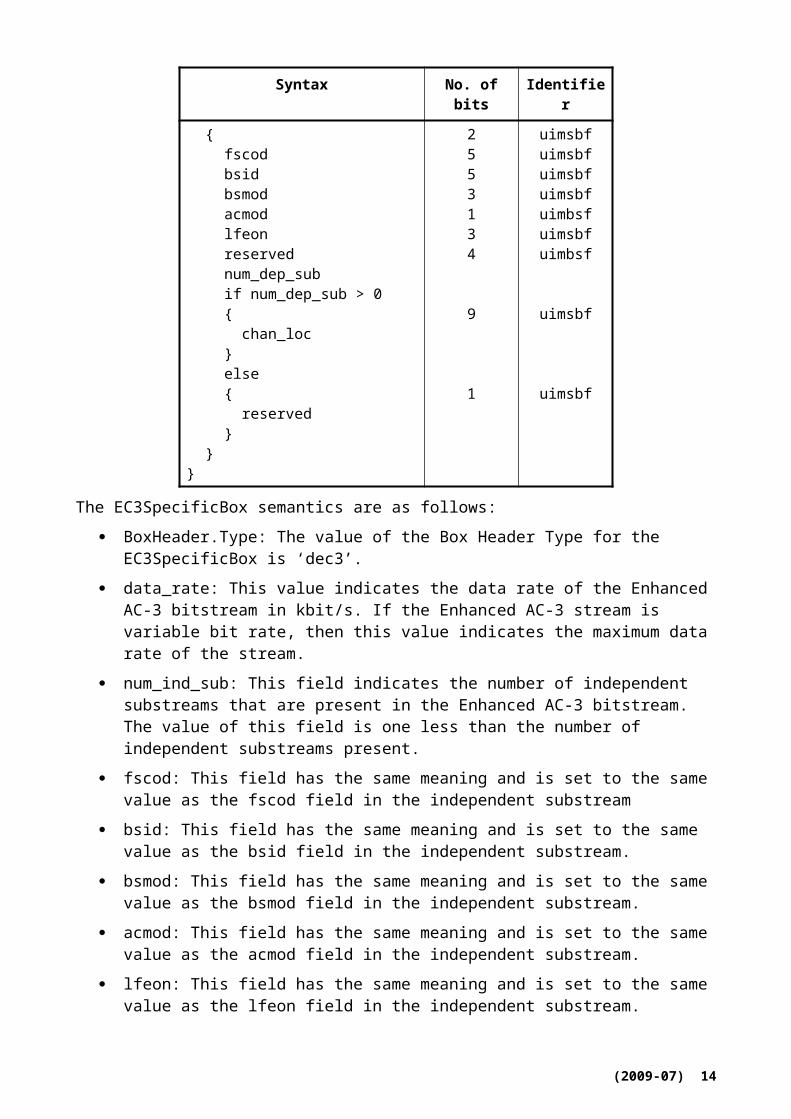
7.1.10 Details of EC3SpecificBox
The EC3SpecificBox is defined as in Table 7-3.
Table 7-3: EC3SpecificBox
Syntax No. of bits Identifier
EC3SpecificBox (){BoxHeader.SizeBoxHeader.Type data_rate num_ind_subfor(I = 0; i < num_ind_sub; i++){
fscodbsidbsmodacmodlfeonreservednum_dep_subif num_dep_sub > 0{ chan_loc}else{ reserved
3232133
2553134
9
uimsbfuimsbfuimsbfuimsbf
uimsbfuimsbfuimsbfuimsbfuimbsfuimsbfuimbsf
uimsbf
(2009-07) 10
Syntax No. of bits Identifier
}}
}
1 uimsbf
The EC3SpecificBox semantics are as follows:
BoxHeader.Type: The value of the Box Header Type for the EC3SpecificBox is ‘dec3’.
data_rate: This value indicates the data rate of the Enhanced AC-3 bitstream in kbit/s. If the Enhanced AC-3 stream is variable bit rate, then this value indicates the maximum data rate of the stream.
num_ind_sub: This field indicates the number of independent substreams that are present in the Enhanced AC-3 bitstream. The value of this field is one less than the number of independent substreams present.
fscod: This field has the same meaning and is set to the same value as the fscod field in the independent substream
bsid: This field has the same meaning and is set to the same value as the bsid field in the independent substream.
bsmod: This field has the same meaning and is set to the same value as the bsmod field in the independent substream.
acmod: This field has the same meaning and is set to the same value as the acmod field in the independent substream.
lfeon: This field has the same meaning and is set to the same value as the lfeon field in the independent substream.
num_dep_sub: This field indicates the number of dependent substreams that are associated with the independent substream
chan_loc: If there are one or more dependent substreams associated with the independent substream, this bit field is used to identify channel locations beyond those identified using the acmod field that are present in the bitstream. For each channel location or pair of channel locations present, the corresponding bit in the chan_loc bit field is set to “1”, according to Table 6-4. This information is extracted from the chanmap field of each dependent substream.
Table 7-4: chan_loc field bit assignments
Bit Location Bit Location
0 Lc/Rc pair 5 Lw/Rw pair1 Lrs/Rrs pair 6 Lvh/Rvh pair2 Cs 7 Cvh3 Ts 8 LFE2
4 Lsd/Rsd pair
7.2 Extended AMR-WB (AMR-WB+)
The AMR-WB+ audio codec can encode mono and stereo content, up to 48 kbit/s for stereo. It supports also downmixing to mono at a decoder. The AMR-WB+ codec has been specified in
(2009-07) 11

[ETSI TS 126 290] and includes error concealment and also contains a user’s guide. The source code for both encoder and decoder has been fully specified in [ETSI TS 126 304] and [ETSI TS 126 273]. The transport has been specified in [IETF RFC 4352].
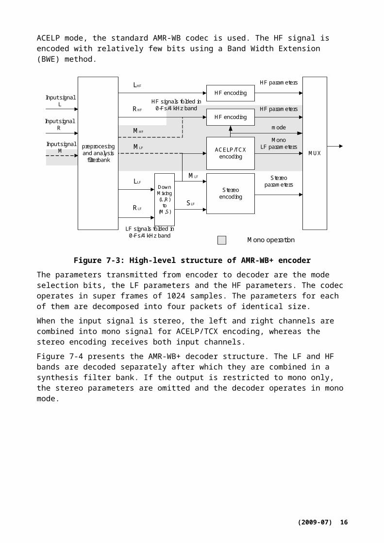
7.2.1 Overview of AMR-WB+ codec
Figure 7-3 contains the high level structure of AMR-WB+ encoder. The input signal is separated in two bands. The first band is the low-frequency (LF) signal, which is critically sampled at Fs/2. The second band is the high-frequency (HF) signal, which is also down sampled to obtain a critically sampled signal. The LF and HF signals are then encoded using two different approaches: the LF signal is encoded and decoded using the “cor” encoder/decoder, based on switched ACELP and transform coded excitation (TCX). In ACELP mode, the standard AMR-WB codec is used. The HF signal is encoded with relatively few bits using a Band Width Extension (BWE) method.
preprocesingand analysis
filterbank
HF signals folded in0-Fs/4 kHz band
HF encoding
ACELP/TCXencoding
Input signalR
MonoLF parameters
HF parameters
MUX
Input signalL
HF encoding
DownMixing(L,R)
to(M,S)
MLF
Stereoencoding
Stereoparameters
LHF
RHF
LLF
RLFSLF
mode
MLF
MHF
Input signalM
HF parameters
Mono operation
LF signals folded in0-Fs/4 kHz band
Figure 7-3: High-level structure of AMR-WB+ encoder
The parameters transmitted from encoder to decoder are the mode selection bits, the LF parameters and the HF parameters. The codec operates in super frames of 1024 samples. The parameters for each of them are decomposed into four packets of identical size.
When the input signal is stereo, the left and right channels are combined into mono signal for ACELP/TCX encoding, whereas the stereo encoding receives both input channels.
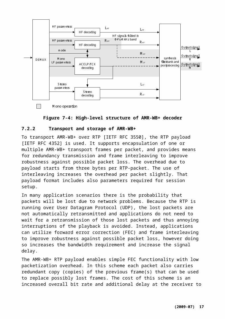
Figure 7-4 presents the AMR-WB+ decoder structure. The LF and HF bands are decoded separately after which they are combined in a synthesis filter bank. If the output is restricted to mono only, the stereo parameters are omitted and the decoder operates in mono mode.
(2009-07) 12

synthesisfilterbank andpostprocesing
MonoLF parameters
HF parameters
DEMUX
Stereoparameters
HF parametersHF signals folded in
0-Fs/4 kHz band
HF decodingLHF
RHF
HF decoding
Stereodecoding
mode
ACELP/TCXdecoding
MLF
LHF
RHF
LLF
RLF
MHF
Mono operation
Output signalR
Output signalL
Output signalM
Figure 7-4: High-level structure of AMR-WB+ decoder
7.2.2 Transport and storage of AMR-WB+
To transport AMR-WB+ over RTP [IETF RFC 3550], the RTP payload [IETF RFC 4352] is used. It supports encapsulation of one or multiple AMR-WB+ transport frames per packet, and provides means for redundancy transmission and frame interleaving to improve robustness against possible packet loss. The overhead due to payload starts from three bytes per RTP-packet. The use of interleaving increases the overhead per packet slightly. That payload format includes also parameters required for session setup.
In many application scenarios there is the probability that packets will be lost due to network problems. Because the RTP is running over User Datagram Protocol (UDP), the lost packets are not automatically retransmitted and applications do not need to wait for a retransmission of those lost packets and thus annoying interruptions of the playback is avoided. Instead, applications can utilize forward error correction (FEC) and frame interleaving to improve robustness against possible packet loss, however doing so increases the bandwidth requirement and increase the signal delay.
The AMR-WB+ RTP payload enables simple FEC functionality with low packetization overhead. In this scheme each packet also carries redundant copy (copies) of the previous frame(s) that can be used to replace possibly lost frames. The cost of this scheme is an increased overall bit rate and additional delay at the receiver to allow the redundant copy to arrive. On the other hand, this approach does not increase the number of transmitted packets, and the redundant frames are also readily available for re-transmission without additional processing. Furthermore, this mechanism does not require signalling at the session setup.
Frame interleaving is another method which may be used to improve the perceptual performance of the receiver by spreading consecutive frames into different RTP-packets. This means that even if a packet is lost then is only lost frames that are not time-wise consecutive to each other that are lost and thus a decoder may be able to reconstruct the lost frames using one of a number of possible error concealment algorithms. The interleaving scheme provided by the AMR-WB+ RTP payload allows any interleaving pattern, as long as the distance in decoding order between any two adjacent frames is not more than 256 frames. If the increases end-to-end delay and higher buffering requirements in the receiver are acceptable then interleaving is useful in IPTV applications.
(2009-07) 13
The AMR-WB+ audio can be stored into a file using the ISO-based 3GP file format defined in [ETSI TS 126 244], which has the media type “audio/3GPP”. Note that the 3GP structure also supports the storage of many other multimedia formats, thereby allowing synchronized playback.
7.3 MPEG-4 High Efficiency AAC v2
The MPEG-4 High Efficiency AAC (HE AAC) v2 audio codec and its transport are specified in [ISO/IEC 14496-3].
7.3.1 Overview of HE AAC v2
The main problem with traditional perceptual audio codecs operating at low bit rates is that they would need more bits than there are available to accurately encode the whole spectrum. The results are either coding artefacts or the transmission of a reduced bandwidth audio signal. To resolve this problem, a bandwidth extension technology was added as a new tool to the MPEG-4 audio toolbox. With Spectral Band Replication (SBR), the higher frequency components of the audio signal are reconstructed at the decoder based on transposition and additional helper information. This method allows an accurate reproduction of the higher frequency components with a much higher coding efficiency compared to a traditional perceptual audio codecs. Within MPEG the resulting audio codec is called MPEG-4 HE AAC and is the combination of the MPEG-4 Audio Object Types AAC-LC and SBR. It is not a replacement for AAC, but rather a superset which extends the reach of high-quality MPEG-4 Audio to much lower bitrates. HE AAC decoders will decode both plain AAC and the enhanced AAC plus SBR. The result is a backward-compatible extension of the standard.
The basic idea behind SBR is the observation that usually there is a strong correlation between the characteristics of the high frequency range of a signal (higher band) and the characteristics of the low frequency range (lower band) of the same signal is present. Thus, a good approximation of the representation of the original input signal higher band can be achieved by a transposition from the lower band to the higher band. In addition to the transposition, the reconstruction of the higher band incorporates shaping of the spectral envelope. This process is controlled by transmission of the higher band spectral envelope of the original input signal. Additional guidance information for the transposing process is sent from the encoder, which controls means, such as inverse filtering, noise and sine addition. This transmitted side information is further referred to as SBR data.
Figure 7-5: MPEG Tools used in the HE AAC v2 Profile
Another extension of the MPEG-4 audio toolbox, the Audio Object Type Parametric Stereo (PS) enables stereo coding at very low bitrates. The principle behind the PS tool is to transmit a mono signal coded in HE AAC format together with a description of the stereo image. The PS tool is used
(2009-07) 14
at bit rates in the low range. The resulting profile is called MPEG-4 HE AAC v2. Figure 7-5 shows the different MPEG tools used in the MPEG-4 HE AAC v2 profile. A HE AAC v2 decoder will decode all three profiles, AAC-LC, HE AAC and HE AAC v2.
Figure 7-6 shows a block diagram of a HE AAC v2 encoder. At the lowest bitrates the PS tool is used. At higher bitrates, normal stereo operation is performed. The PS encoding tool estimates the parameters characterizing the perceived stereo image of the input signal. These parameters are embedded in the SBR data. If the PS tool is used, a stereo to mono downmix of the input signal is applied, which is then fed into the aacPlus encoder operating in mono. SBR data is embedded into the AAC bitstream by means of the extension_payload() element. Two types of SBR extension data can be signalled through the extension_type field of the extension_payload(). For compatibility reasons with existing AAC only decoders, two different methods for signalling the existence of an SBR payload can be selected, which are described below.
Figure 7-6: HE AAC v2 encoder
Analysis QMF Bank
HF Generation
Envelope Adjustment
Output PCM
Samples
Mer
ge lo
wba
nd a
nd h
ighb
and
AAC Core Decoder
Bits
tream
Pay
load
Dem
ultip
lexe
r
Coded Audio
Stream guidance
information
stereo parameter
Syn
thes
is Q
MF
Ban
k
Par
amet
ric S
tere
o S
ynth
esis
Figure 7-7: HE AAC v2 decoder
The HE AAC v2 decoder is depicted in Figure 7-7. The coded audio stream is fed into a demultiplexing unit prior to the AAC decoder and the SBR decoder. The AAC decoder reproduces
(2009-07) 15
the lower frequency part of the audio spectrum. The time domain output signal from the underlying AAC decoder at the sampling rate fsAAC is first fed into a 32 channel quadrature mirror filter (QMF) analysis filter bank. Secondly, the high frequency generator module recreates the higher band by patching QMF subbands from the existing low band to the high band. Furthermore, inverse filtering is applied on a per QMF subband basis, based on the control data obtained from the bit stream. The envelope adjuster modifies the spectral envelope of the regenerated higher band, and adds additional components such as noise and sinusoids, all according to the control data in the bit stream. In case of a stream using Parametric Stereo, the mono output signal from the underlying HE AAC decoder is converted into a stereo signal. This processing is carried out in the QMF domain and is controlled by the Parametric Stereo parameters embedded in the SBR data. Finally a 64 channel QMF synthesis filter bank is applied to retain a time-domain output signal at twice the sampling rate, i.e. fsout = fsSBR = 2 × fsAAC.
7.3.2 Transport and storage of HE AAC v2
To transport HE AAC v2 audio over RTP [IETF RFC 3550], the RTP payload [IETF RFC 3640] is used. [IETF RFC 3640] supports both implicit signalling as well as explicit signalling by means of conveying the AudioSpecificConfig() as the required MIME parameter “confi”, as defined in [IETF RFC 3640]. The framing structure defined in [IETF RFC 3640] does support carriage of multiple AAC frames in one RTP packet with optional interleaving to improve error resiliency in packet loss. For example, if each RTP packet carries three AAC frames, then with interleaving the RTP packets may carry the AAC frames as given in Figure 7-8.
Figure 7-8: Interleaving of AAC frames
Without interleaving, then RTP packet P1 carries the AAC frames 1, 2 and 3, while packet P2 and P3 carry the frames 4, 5 and 6 and the frames 7, 8 and 9, respectively. When P2 gets lost, then AAC frames 4, 5 and 6 get lost, and hence the decoder needs to reconstruct three missing AAC frames that are contiguous. In this example, interleaving is applied so that P1 carries 1, 4 and 7, P2 carries 2, 5 and 8, and P3 carries 3, 6 and 9. When P2 gets lost in this case, again three frames get lost, but due to the interleaving, the frames that are immediately adjacent to each lost frame are received and can be used by the decoder to reconstruct the lost frames, thereby exploiting the typical temporal redundancy between adjacent frames to improve the perceptual performance of the receiver.
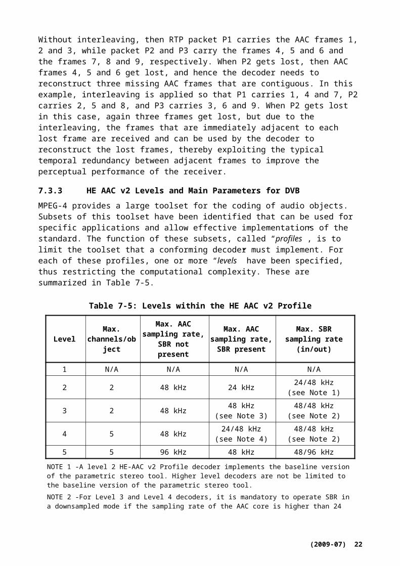
7.3.3 HE AAC v2 Levels and Main Parameters for DVB
MPEG-4 provides a large toolset for the coding of audio objects. Subsets of this toolset have been identified that can be used for specific applications and allow effective implementations of the standard. The function of these subsets, called “profiles”, is to limit the toolset that a conforming decoder must implement. For each of these profiles, one or more “levels” have been specified, thus restricting the computational complexity. These are summarized in Table 7-5.
(2009-07) 16

Table 7-5: Levels within the HE AAC v2 Profile
Level Max. channels/object
Max. AAC sampling rate, SBR
not present
Max. AAC sampling rate, SBR
present
Max. SBR sampling rate (in/out)
1 N/A N/A N/A N/A
2 2 48 kHz 24 kHz 24/48 kHz(see Note 1)
3 2 48 kHz 48 kHz(see Note 3)
48/48 kHz(see Note 2)
4 5 48 kHz 24/48 kHz(see Note 4)
48/48 kHz(see Note 2)
5 5 96 kHz 48 kHz 48/96 kHz
NOTE 1 -A level 2 HE-AAC v2 Profile decoder implements the baseline version of the parametric stereo tool. Higher level decoders are not be limited to the baseline version of the parametric stereo tool.NOTE 2 -For Level 3 and Level 4 decoders, it is mandatory to operate SBR in a downsampled mode if the sampling rate of the AAC core is higher than 24 kHz. Hence, if SBR operates on a 48 kHz AAC signal, the internal sampling rate of SBR will be 96 kHz, however, the output signal will be downsampled by SBR to 48 kHz.NOTE 3 -If Parametric Stereo data is present the maximum AAC sampling rate is 24kHz, if Parametric stereo data is not present the maximum AAC sampling rate is 48kHz.NOTE 4 -For one or two channels the maximum AAC sampling rate, with SBR present, is 48 kHz. For more than two channels the maximum AAC sampling rate, with SBR present, is 24 kHz.
The HE AAC v2 Profile is introduced as a superset of the AAC Profile. Besides the Audio Object Type (AOT) AAC-LC (which is present in the AAC Profile), it includes the AOT SBR and the AOT PS. Levels are introduced within these Profiles in such a way that a decoder supporting the HE AAC v2 Profile at a given level can decode an AAC Profile and an HE AAC Profile stream at the same or lower level.
For DVB, the level 2 for mono and stereo as well as the level 4 multichannel audio signals are supported. The Low Frequency Enhancement channel of a 5.1 audio signal is included in the level 4 definition of the number of channels.
7.3.4 Methods for signalling of SBR and/or PS
In case of usage of SBR and/or PS, several ways how to signal the presence of SBR and/or PS data are possible [ISO/IEC 14496-3]. Within the context of DVB services over IP, it is recommended to use backward compatible explicit signalling. Here the respective extension Audio Object Type is signalled at the end of the AudioSpecificConfig().
7.4 MPEG-1 Layer 2 Audio
MPEG-1 Layer I or II Audio is a generic subband coder operating at bit rates in the range of 32 to 448 kbit/s and supporting sampling frequencies of 32, 44.1 and 48 kHz. Typical bit rates for Layer II are in the range of 128-256 kbit/s, and 384 kbit/s for professional applications. MPEG 1 Layer I and II audio have been specified in [ISO/IEC 11172-3]. The transport of MPEG 1 Layer I and II audio (and video) using RTP over IP has been specified in [IETF RFC 2250]. Furthermore, MPEG-1 Layer II audio is the recommended audio coding system in DVB broadcasting applications as specified in [ETSI TS 101 154].
MPEG-1 Layers I and II (MP1 or MP2) are perceptual audio coders for 1- or 2-channel audio content. Layer I has been designed for applications that require both low complexity decoding and encoding. Layer II provides for a higher compression efficiency for a slightly higher complexity.
(2009-07) 17
Using MPEG-1 Layer I one can compress high quality audio CD data at a typical bitrate of 384 kbit/s while maintaining a high audio quality after decoding. Layer II requires bit rates in the range of 192 to 256 kbit/s for near CD quality. A Layer II decoder can also decode Layer I bitstreams.
Thanks to its low complexity decoding combined with high robustness against cascaded encoding/decoding and transmission errors, MPEG-1 Layer II is used in digital audio and video broadcast applications (DAB and DVB). It is also used in Video CD, as well as in a variety of studio applications.
Figure 7-9 shows a high level overview of the MPEG-1 Layers I and II coders. The input signal is transformed into 32 subband signals that are uniformly distributed over frequency by means of a critically sampled QMF filter bank. The critically down sampled subband signals are grouped in a so called allocation frame (384 and 1152 subband samples for Layer I and II respectively). By means of adaptive PCM, these allocation frames are subsequently quantized and coded into an MPEG-1 bitstream. At the decoder side, the bitstream is decoded into the subband samples which are subsequently fed into the inverse QMF filter bank.
Figure 7-9: High level overview of MPEG-1 Layers II coder
Next to coding of mono and independent coding of stereo signals, also joint coding of stereo signals is supported by applying a technology called intensity stereo coding. Intensity coding exploits the property of the human auditory system that at high frequencies the perceived stereo image depends on intensity level differences.
7.5 MPEG-2 AAC
The MPEG-2 AAC audio codec is specified in [ISO/IEC 13818-7].
7.5.1 Overview of MPEG-2 AAC
[ISO/IEC 13818-7] describes the MPEG-2 audio non-backwards compatible standards called MPEG-2 Advanced Audio Coding (AAC), a higher quality multichannel standard than achievable while requiring MPEG-1 backwards compatibility.
The AAC system consists of three profiles in order to allow a trade-off between audio quality and the required memory and processing power.
Main profile: Main profile provides the highest audio quality at any given data rate. All tools except the gain control may be used to provide high audio quality. The required memory and processing power are higher than the LC profile. A main profile decoder can decode an LC-profile encoded bit stream.
(2009-07) 18
Low complexity (LC) profile: The required processing power and memory of the LC profile are smaller than the main profile, while the quality performance keeps high. The LC profile is without predictor and the gain control tool, but with temporal noise shaping (TNS) order limited.
Scalable sampling rate (SSR) profile: The SSR profile can provide a frequency scalable signal with gain control tool. It can choose frequency bands to decode, so the decoder requires less hardware. To decode the only lowest frequency band at the 48 kHz sampling frequency, for instance, the decoder can reproduce 6 kHz bandwidth audio signal with minimum decoding complexity.
AAC systems support 12 sampling frequencies ranging from 8 to 96 kHz (8000, 11025, 12000, 16000, 22050, 24000, 32000, 44100, 48000, 64000, 88200, and 96000 Hz) and up to 48 audio channels. Table 7-6 shows the default channel configurations, which include inter alia mono, two-channel, five-channel (three front/two rear channels), and five-channel plus low-frequency effects (LFE) channel (bandwidth < 200 Hz). In addition to the default configurations, it is possible to specify the number of loudspeakers at each position (front, side, and back), allowing flexible multichannel loudspeaker arrangement. Downmix capability is also supported. The user can designate a coefficient to downmix multichannel audio signals into two channels. Sound quality can therefore be controlled using a playback device with only two channels.
Table 7-6: Default channel configurations
Number of speakers
Audio syntactic elements, listed in order received
Default element to speaker mapping
1 single_channel_element Centre front speaker2 channel_pair_element Left and right front speakers
3single_channel_element() Centre front speakerchannel_pair_element() Left and right front speakers
4single_channel_element() Centre front speakerchannel_pair_element(), Left and right front speakerssingle_channel_element() Rear surround speaker
5single_channel_element() Centre front speakerchannel_pair_element() Left and right front speakerschannel_pair_element() Left surround and right surround rear speakers
5+1
single_channel_element() Centre front speakerchannel_pair_element() Left and right front speakerschannel_pair_element() Left surround and right surround rear speakersLfe_element() Low frequency effects speaker
7+1
single_channel_element() Centre front speakerchannel_pair_element(), Left and right centre front speakerschannel_pair_element() Left and right outside front speakerschannel_pair_element() Left surround and right surround rear speakerslfe_element() Low frequency effects speaker
(2009-07) 19
7.5.2 Overview of Encoder
The basic structure of the MPEG-2 AAC encoder is shown in Figure 7-10. The AAC system consists of the following coding tools:
Gain control: A gain control splits the input signal into four equally spaced frequency bands. The gain control is used for SSR profile.
Filter bank: A filter bank modified discrete cosine transform (MDCT) decomposes the input signal into sub-sampled spectral components with frequency resolution of 23 Hz and time resolution of 21.3 ms (128 spectral components) or with frequency resolution of 187 Hz and time resolution of 2.6 ms (1 024 spectral components) at 48 kHz sampling. The window shape is selected between two alternative window shapes.
Temporal noise shaping (TNS): After the analysis filter bank, TNS operation is performed. The TNS technique permits the encoder to have control over the temporal fine structure of the quantization noise.
Mid/side (M/S) stereo coding and intensity stereo coding: For multichannel audio signals, intensity stereo coding and M/S stereo coding may be applied. In intensity stereo coding only the energy envelope is transmitted to reduce the transmitted directional information. In M/S stereo coding, the normalized sum (M as in middle) and difference signals (S as in side) may be transmitted instead of transmitting the original left and right signals.
Prediction: To reduce the redundancy for stationary signals, the time-domain prediction between sub-sampled spectral components of subsequent frames is performed.
Quantization and noiseless coding: In the quantization tool, a non-uniform quantizer is used with a step size of 1.5 dB. Huffman coding is applied for quantized spectrum, the different scale factors, and directional information.
Bit-stream formatter: Finally a bit-stream formatter is used to multiplex the bit stream, which consists of the quantized and coded spectral coefficients and some additional information from each tool.
Psychoacoustic model: The current masking threshold is computed using a psychoacoustic model from the input signal. A psychoacoustic model similar to [ISO/IEC 11172-3] psychoacoustic model 2 is employed. A signal-to-mask ratio, which is derived from the masking threshold and input signal level, is used during the quantization process in order to minimize the audible quantization noise and additionally for the selection of adequate coding tool.
(2009-07) 20

Figure 7-10: MPEG-2 AAC encoder block diagram
7.5.3 Overview of decoder
The basic structure of the MPEG-2 AAC decoder is shown in Figure 7-11. The decoding process is basically the inverse of the encoding process.
The functions of the decoder are to find the description of the quantized audio spectra in the bit stream, decode the quantized values and other reconstruction information, reconstruct the quantized spectra, process the reconstructed spectra through whatever tools are active in the bit stream in order to arrive at the actual signal spectra as described by the input bit stream, and finally convert the frequency domain spectra to the time domain, with or without an optional gain control tool. Following the initial reconstruction and scaling of the spectrum reconstruction, there are many optional tools that modify one or more of the spectra in order to provide more efficient coding. For each of the optional tools that operate in the spectral domain, the option to “pass through” is retained, and in all cases where a spectral operation is omitted, the spectra at its input are passed directly through the tool without modification.
(2009-07) 21
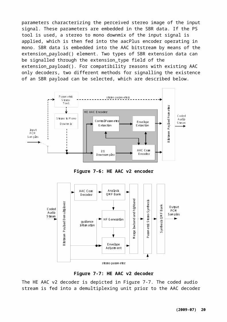
Figure 7-11: MPEG-2 AAC decoder block diagram
7.6 MPEG Surround
7.6.1 Introduction
MPEG Surround (MPS) adds multi channel capabilities to the audio codec families like MPEG-1 Layer II and MPEG-4 AAC/HE-AAC/HE-AACv2. Operating on top of a core audio codec the system provides a set of features including full backward compatibility to stereo and mono equipment and a broad range of scalability in terms of bit rate used for describing the surround sound image. Conventional audio decoders will decode a stereo or mono signal while based on the same audio stream a decoder supporting the MPEG Surround extension will provide a high quality multi channel signal.
(2009-07) 22
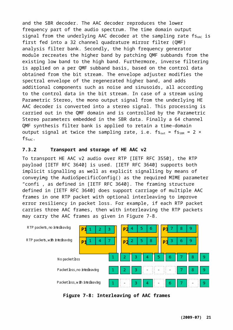
Figure 7-12: Quality of MPS versus bit rate combined with different core codecs
Figure 7-12 indicates the typical total bit rate ranges for the use of MPEG Surround in combination with the audio codecs MPEG-1 Layer II (stereo and mono), MPEG 4 AAC (stereo and mono), MPEG 4 HE AAC (stereo and mono), MPEG 4 HE AAC v2 (parametric stereo, only the mono AAC signal is used in combination with MPEG Surround) on the encoder side.
MPEG Surround (see Figure 7-13) creates a (mono or stereo) downmix from the multi-channel audio input signal. This downmix is encoded using a core audio codec. In addition, MPEG Surround generates a spatial image parameter description of the multi channel audio that is added as an ancillary data stream to the core audio codec. Legacy mono or stereo decoders simply ignore the ancillary data and playback a stereo respectively mono audio signal. MPEG Surround capable decoders will first decode the mono or stereo core codec audio signal and then use the spatial image parameters extracted from the ancillary data stream to generate a high quality multi channel audio signal.
Figure 7-13: MPEG Surround block diagram
7.6.2 MPEG Surround features
In addition to the normal mode of operation in the MPEG Surround Baseline Profile, MPEG Surround supports an additional set of features. These are Binaural Decoding, External Stereo Mix, and Enhanced Matrix Mode, see below.
(2009-07) 23
Spatial
parameters
Spatial
multi channel
reconstruction
CH1
CH2
CHN
MPEG Surround Decoder
Stereo or
mono
downmixCH1
CH2
CHN
Stereo
or
mono downmix
downmix
automatic
downmix
(optional)
spatial
parameters
estimation
Manual downmix
Automatic downmix
Multi channelsignal
MPEG Surround Encoder
7.6.3 Introduction to MPEG Surround Baseline profile
The MPEG Surround Baseline Profile is defined in [ISO/IEC 23003-1] together with the different levels. In this profile, the distinguishing factor between levels 1 to 4 is the number of output channels and the use of the coding tool residual coding, which if used allows for higher audio quality but adds computational complexity, hence the bitstream is such that lower level decoders can ignore the residual data. Table 7-7 summarizes the different levels in [ISO/IEC 23003-1].
Table 7-7: MPEG Surround level overview
Decoder level Number of output channels Residual data
1 2, stereo and binaural Ignores residual data2 5.1 and binaural Ignores residual data3 5.1 and binaural Utilizes residual data4 7.1 and binaural Utilizes residual data
7.6.4 Binaural Decoding
MPEG Surround Binaural Decoding utilizes the downmix, the spatial parameters, and HRTFs supplied to the decoder to create a surround sound audio experience over headphones. There are two modes of operation, a parametric approach, for lowest complexity, and a filtering approach for highest quality. Since both of these methods process the downmix into a 3D audio signal for headphones without first up mixing to the multi-channel audio signal, the limited complexity additions allows for portable device usage.
7.6.5 External stereo mix
The MPEG Surround system supports the use of external downmixes. The MPEG Surround encoder analyzes the difference between the internal downmix created by the MPEG Surround encoder and the external downmix. The difference is compensated for at the MPEG Surround decoder side. This allows the broadcaster to have full control of the sound of the transmitted mono or stereo mix. The basic blocks are outlined in Figure 7-14.
(2009-07) 24
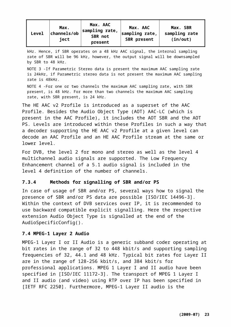
Figure 7-14: MPEG Surround support for external stereo mix
7.6.6 Enhanced Matrix Mode
The MPEG Surround decoder includes enhanced matrixed mode that creates a multi-channel signal based on the downmix without the transmission of MPEG Surround side information. The parameters required in the MPEG Surround decoder are estimated from the received downmix signal, this tool can also be combined with Binaural Decoding. The basic blocks are outlined in Figure 7-15.
Figure 7-15: Overview diagram of MPEG Surround enhancedmatrix mode decoder
(2009-07) 25

7.6.7 MPEG Surround for MPEG-1 Layer II-- Baseline Profile
7.6.7.1 Encoding and Formatting
The MPEG Surround spatial audio bitstream is embedded into the ancillary data portion of the MPEG-1 Layer II bitstream [ISO/IEC 11172-3]. The actual embedding of the MPEG surround bitstream into the MPEG-1 Layer II bitstream is specified in [ISO/IEC 23003-1].
7.6.7.2 Configurations, Profiles and Levels
The Baseline MPEG surround profile is also defined in [ISO/IEC 23003-1]. For the combination of MPEG Surround with MPEG-1 Layer II, the Baseline MPEG Surround profile must be used together with the restrictions defined. The MPEG Surround bitstream payload must comply with level 3 or 4 of the Baseline MPEG Surround profile.
7.6.8 MPEG Surround for MPEG 4 AAC, HE AAC and HE AAC v2-- Baseline Profile
7.6.8.1 Encoding and Formatting
The combination of MPEG Surround as specified in [ISO/IEC 23003-1] with MPEG-4 AAC, MPEG-4 HE AAC or MPEG-4 HE AAC v2 as specified in [ISO/IEC 14496-3] is transmitted using LOAS/LATM, being also specified in ISO/IEC 14496-3. First, the combined MPEG-4 AAC/MPEG Surround, MPEG-4 HE AAC/MPEG Surround or MPEG-4 HE AAC v2/MPEG Surround is formatted using the LATM multiplex format. Specifically, the AudioMuxElement multiplex element is used. This LATM multiplex formatted stream is then embedded in the LOAS transmission format for which the AudioSyncStream is employed. AudioSyncStream adds a sync word to the audio stream to allow for synchronization. The semantics of the AudioMuxElement and AudioSyncStream formatting are described in [ISO/IEC 14496-3].
7.6.8.2 Configurations, Profiles and Levels
The Baseline MPEG Surround Profile is defined in [ISO/IEC 23003-1].
For the combination of MPEG Surround with MPEG-4 AAC, MPEG-4 HE AAC or MPEG-4 HE AAC v2, the Baseline MPEG Surround Profile will be employed together with the AAC Profile, HE AAC profile or HE AAC v2 Profile respectively. The AAC, HE AAC or HE AAC v2 bitstream payloads must comply with level 2 or level 4 of the respective profile. The MPEG Surround bitstream payload must comply with level 3, 4 or 5 of the Baseline MPEG Surround profile.
7.7 ITU-T G.719
The [ITU-T G.719] fullband codec is a low-complexity transform-based audio codec that operates at a sampling rate of 48 kHz and offers full audio bandwidth ranging from 20 Hz up to 20 kHz. The encoder processes 16-bit linear PCM input signals on frames of 20 ms and the codec has an overall delay of 40 ms. The coding algorithm is based on transform coding with adaptive time-resolution, adaptive bit-allocation and low-complexity lattice vector quantization. In addition, the decoder replaces non-coded spectrum components by either signal-adaptive noise fill or bandwidth extension.
The observed average and worst-case complexity of the encoder and decoder in WMOPS are below 21 WMOPS for all bitrates. These figures are based on the obtained complexity reports using the basic operator set v2.2 available in [ITU-T G.191].
ANSI-C source code reference implementations of both encoder and decoder parts if G.719 are available as an integral part of [ITU-T G.719] for both fixed-point and floating-point arithmetic.
(2009-07) 26
7.7.1 Overview of the G.719 encoder
Figure 7-16 shows a block diagram of the encoder. The input signal sampled at 48 kHz is processed through a transient detector. Depending on the detection of a transient, a high frequency resolution or a low frequency resolution transform is applied on the input signal frame. The adaptive transform is based on a modified discrete cosine transform in case of stationary frames. For non-stationary frames a higher temporal resolution transform is used without a need for additional delay and with very little overhead in complexity. Non-stationary frames have a temporal resolution equivalent to 5 ms frames.
Input audio signal Fs = 48kHz
Noise Level Adjustment
Transient detector
Transform
Quantized N
orms,
Lattice Codevectors
Noise Level A
djustment
Index
Transient Signalling
Norm estimation Norm quantizationand coding
Spectrum normalization
Norm adjustement
Bit-allocation
Lattice quantizationand coding
MUX
Figure 7-16: G.719 encoder block diagram
The obtained spectral coefficients are grouped into bands of unequal lengths. The norm of each band is estimated and the resulting spectral envelope consisting of the norms of all bands is quantized and encoded. The coefficients are then normalized by the quantized norms. The quantized norms are further adjusted based on adaptive spectral weighting and used as input for bit allocation. The normalized spectral coefficients are lattice vector quantized and encoded based on the allocated bits for each frequency band. The level of the non-coded spectral coefficients is estimated, coded and transmitted to the decoder. Huffman encoding is applied to quantization indices for both the coded spectral coefficients as well as the encoded norms.
7.7.2 Overview of the G.719 decoder
Figure 7-17 shows a block diagram of the decoder. The transient flag is first decoded which indicates the frame configuration, i.e. stationary or transient. The spectral envelope is decoded and the same, bit-exact, norm adjustments and bit-allocation algorithms are used at the decoder to recompute the bit-allocation which is essential for decoding quantization indices of the normalized transform coefficients. After dequantization, low frequency non-coded spectral coefficients (allocated zero bits) are regenerated by using a spectral-fill codebook built from the received spectral coefficients (spectral coefficients with non-zero bit allocation). A noise level adjustment index is used to adjust the level of the regenerated coefficients. High frequency non-coded spectral coefficients are regenerated using bandwidth extension. The decoded spectral coefficients and regenerated spectral coefficients are mixed and lead to normalized spectrum. The decoded spectral envelope is applied leading to the decoded fullband spectrum. Finally, the inverse transform is applied to recover the time-domain decoded signal. This is performed by applying either the inverse
(2009-07) 27
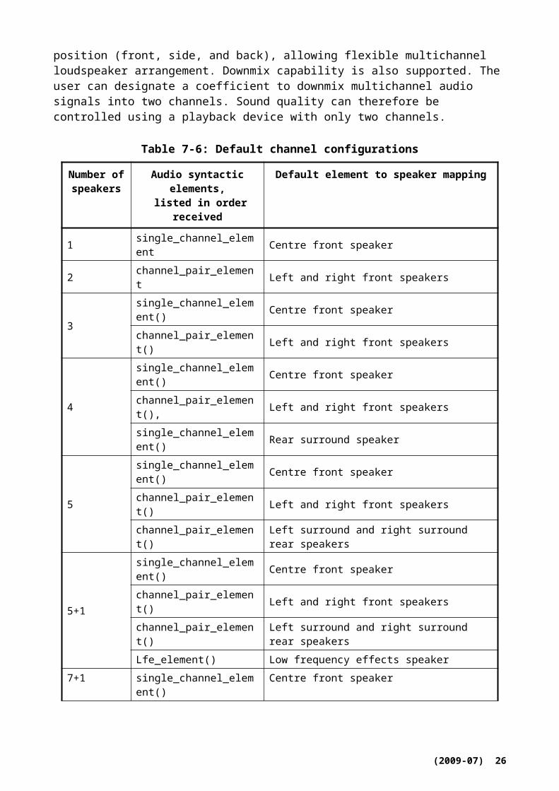
modified discrete cosine transform for stationary modes, or the inverse of the higher temporal resolution transform for transient mode.
Transient Signalling
DEMUX
Lattice Codevectors
Noise Level A
djustment
Index
SpectralFill Generator +
EnvelopeShaping
Quantized N
orms
Transient Signalling
Inverse Transform
Audio Signal Fs = 48 kHz
Lattice Decoding
Figure 7-17: G.719 decoder block diagram
7.7.3 Transport and storage of ITU-T G.719
To transport G.719 over RTP [IETF RFC 3550], the RTP payload defined in [IETF RFC 5404] is used. It supports encapsulation of one or multiple G.719 frames per packet, supports a multi-rate encoding capability that enables on a per-frame basis variation of the encoding rate. Also included is a support for multi-channel sessions and provides means for redundancy transmission and frame interleaving to improve robustness against possible packet loss.
The G.719 RTP payload enables generic FEC functionality as well as G.719-specific form of audio redundancy coding which is beneficial in terms of packetization overhead. Conceptually, previously transmitted transport frames are aggregated together with new ones. A sliding window can be used to group the frames to be sent in each payload.
Frame interleaving is another method which may be used to improve the perceptual performance of the receiver by spreading consecutive frames into different RTP-packets. This means that even if a packet is lost then is only lost frames that are not time-wise consecutive to each other that are lost and thus a decoder may be able to reconstruct the lost frames using one of a number of possible error concealment algorithms.
The ITU-T G.719 compressed audio can be stored into a file using the ISO-based container file, according to the specification in its Annex A. Note that the ISO base media file format structure is the basic building block of several application derived file formats, such as 3GP file format and the MP4 file format, thus allowing also the storage of many other multimedia formats, thereby allowing synchronized playback of G.719 audiovisual media.
7.8 MPEG-4 ALS lossless coding
MPEG-4 ALS is an extension of the MPEG-4 audio coding family for the lossless compression of audio data. The ALS compression scheme assures the perfect reconstruction of the input signal at the decoder. It is based on forward-adaptive linear prediction and variable length coding of the prediction residual signal. Fundamental structure of the encoder and the decoder is shown in Figure 7-18. Due to some additional tools on top of this simple fundamental structure, ALS offers remarkable compression performance with relatively low complexity. Additional tools include hierarchical block switching, inter-channel processing such as joint stereo and multi-channel coding, long term prediction, and progressive order prediction. ALS also offers much flexibility in
(2009-07) 28

terms of the compression-complexity tradeoff, ranging from very low-complexity implementations to maximum compression modes, and thus adaptability to different requirements.
analysis &quantization
-- entropycoding
inversequantization short-term
prediction
++entropy
decoding
prediction error(magnified by 30 times)
Input waveform
integerinput
integeroutput
short-termprediction
×× 3030
analysis &quantization
-- entropycoding
inversequantization short-term
prediction
++entropy
decoding
prediction error(magnified by 30 times)
Input waveform
integerinput
integeroutput
short-termprediction
×× 3030
Figure 7-18: Fundamental structure of MPEG-4 ALS lossless encoder and decoder
MPEG-4 ALS offers many features:
General support for virtually any uncompressed digital audio format including Sony WAVE 64 file format and Broadcast Wave Format (BWF).
Support for linear PCM resolutions of up to 32-bit at arbitrary sampling rates.
Multi-channel / multi-track support for up to 65536 channels including 5.1-, 7.1-, and 22.2 channels surround.
Support for audio data in IEEE 754 32-bit floating-point audio format
Quick random access to the encoded data
Support MP4 file format which allows the multiplex and synchronization with video.
Examples for the use of lossless audio coding in general and MPEG-4 ALS in particular include both professional and consumer applications:
Network distribution of audio files (IPTV, broadcasting, streaming, online music store, download)
Archival systems (broadcasters, studios, record labels, digital transfer)
Studio operations (storage, collaborative working, digital back-up, digital transfer)
High-resolution disc format
Portable music players
7.8.1 Performance
Compression performance is highly dependent on the nature of original signals. Compressed data size varies from 15 to 70 % of the original file size. As a result of comparison experiment, MPEG-4 ALS provides better compression performance and faster encoding and decoding time than software tools such as [b_FLAC], [b_OptimFrog], and [b_Monkey’s]. The CPU load of real-time encoding and decoding is approximately 1 to 2% of a popular CPU. Real-time decoding of 48 kHz stereo signal requires 20 MHz ARM9 processor. Those results read that MPEG-4 ALS is one of the most
(2009-07) 29

efficient lossless audio compression schemes in terms of the compression performance and its processing time.
7.8.2 Related standardization
The specification of MPEG-4 ALS (ISO/IEC 14496-3) is associated with the conformance testing (ISO/IEC 14496-4) and the reference software (ISO/IEC 14496-5). By default, The bit stream of the MPEG-4 ALS is recorded and transported with the ISO media file format. For broadcasting applications, MPEG-4 ALS stream can be transported over MPEG-2 TS, which is specified in [ITU-T H.222.0 Amd.1]. For consumer appliance applications, MPEG-4 ALS stream can be transported over S/P DIF channels, which will be specified in IEC 61937-10. MPEG-4 ALS can be conveniently used for archiving applications if it is combined with ISO/IEC 23000-6 MPEG Professional Archival Application Format (PA-AF).
8 Speech Codecs
8.1 ITU-T G.722
[ITU-T G.722] is an audio coding system which may be used for a variety of higher quality wideband speech (50 to 7000 Hz) applications. It has been standardized in 1988 to enhance the audio quality of applications like video and audio conferencing over ISDN networks and has been used for some specific radio broadcast usage as well. G.722 usage has recently been extended [ITU-T G.722 App.III, App.IV] for VoIP, as it has been selected as mandatory codecs for the new generation wideband DECT terminals [b_ETSI TS 102 527-3] and is gaining momentum for enhanced wideband voice services over IP networks thanks to some attractive features like low delay, low complexity and license-free status.
8.1.1 Overview of main functional features
G.722 has three modes of operation corresponding to the bit rates of 64, 56 and 48 kbit/s. The G.722 encoder produces an embedded 64 kbit/s bitstream structured in three layers corresponding to each of these operating modes. The bits corresponding to the last two layers can be skipped by the decoder or any other component of the communication systems to dynamically reduce the bit rate to 56 kbit/s or 48 kbit/s, which corresponds to 1 or 2 bits “stoles” from the low band.
Encoding/decoding operations are performed on a sample per sample basis which limits the algorithmic delay to 1.625 ms.
Complexity is limited and can be estimated to around 10 MIPS.
ITU-T G.722 Appendices III and IV define two possible standardized packet loss concealment (PLC) mechanisms to significantly increase G.722 audio quality in the presence of packet losses typical of IP networks.
The RTP payload specification for usage of G.722 over IP networks is found in [IETF RFC 3551].
A reference implementation ANSI-C source code of both encoder and decoder of G.722 is available in the ITU-T software tool library [ITU-T G.191], while the ANSI-C source code implementation of the PLC algorithms of G.722 Appendices III and IV is found in [ITU-T G.722 App.III] and [ITU-T G.722 App.IV], respectively.
8.1.2 Overview of G.722 SB-ADPCM encoder
The coding system uses sub-band adaptive differential pulse code modulation (SB-ADPCM), as illustrated in Figure 8-1. The frequency band of the input signal (sampled at 16 kHz) is split into two sub-bands by two linear-phase non-recursive digital QMF filters: 0 to 4 kHz for the lower band and 4 to8 kHz for the higher band. The signals in each sub-band (now sampled at 8 kHz) are
(2009-07) 30

encoded using ADPCM with 6 bits per sample for the lower band and 2 bits for the higher band. The number of bits allocated to the lower band is reduced to five and four bits for the 56 kbit/s and 48 kbit/s modes, respectively.
Figure 8-1: Block diagram of the G.722 SB-ADPCM encoder
8.1.3 Lower sub-band ADPCM encoder
The lower sub-band input signal, xL after subtraction of an estimate, sL, of the input signal produces the difference signal, eL. An adaptive 60-level non-linear quantizer is used to assign six binary digits to the value of the difference signal to produce a 48 kbit/s signal, IL. In the feedback loop, the two least significant bits of IL are deleted to produce a 4-bit signal ILt, which is used for the quantizer adaptation and applied to a 15-level inverse adaptive quantizer to produce a quantized difference signal, dLt. The signal estimate, sL is added to this quantized difference signal to produce a reconstructed version, rLt, of the lower sub-band input signal. Both the reconstructed signal and the quantized difference signal are processed by an adaptive predictor, which produces the estimate sL of the input signal, thereby completing the feedback loop. This is illustrated in Figure 8-2.
Figure 8-2: Block diagram of the G.722 lower band encoder
8.1.4 Higher sub-band ADPCM encoder
Same encoding scheme is used for higher sub-band with four level non linear quantizer, four level inverse adaptive quantizer and no deleted bits.
(2009-07) 31

8.1.5 Overview of G.722 SB-ADPCM decoder
G.722 decoder can operate in any of three possible variants depending on the received indication of the mode of operation as shown in Figure 8-3.
Figure 8-3: Block diagram of the G.722 lower band decoder
The path which produces the estimate, sL, of the input signal including the quantizer adaptation, is identical to the feedback portion of the lower sub-band ADPCM encoder. The reconstructed signal, rL, is produced by adding to the signal estimate one of three possible quantized difference signals, dL,6, dL,5 or dL,4 (= dLt), selected according to the received indication of the mode of operation.
The upper band decoder is illustrated in Figure 8-4 and has the same structure as the lower sub-band ADPCM decoder, however with a single four-level inverse adaptive quantizer.
Figure 8-4: Block diagram of the G.722 higher band decoder
The output decoded signal is then reconstructed by interpolation of the decoded lower band and higher band from 8 kHz to 16 kHz.
(2009-07) 32

8.1.6 Packet loss concealment algorithms for G.722
Packet loss concealment (PLC) algorithms, also known as frame erasure concealment algorithms, hide transmission losses in audio systems where the input signal is encoded and packetized, sent over a network, received and decoded before play out. PLC algorithms can be found in most standard CELP-based speech coders. There are two methods standardized for efficient handling packet losses for G.722 encoded signals.
Appendix III to ITU-T Recommendation G.722 [ITU-T G.722 App.III] specifies a high-quality packet loss concealment (PLC) algorithm for G.722. The algorithm performs the packet loss concealment in the 16-kHz output domain of the G.722 decoder. Periodic waveform extrapolation is used to fill in the waveform of lost packets, mixing with filtered noise according to signal characteristics prior to the loss. The extrapolated 16-kHz signal is passed through the QMF analysis filter bank, and the subband signals are passed to partial subband ADPCM encoders to update the states of the subband ADPCM decoders. Additional processing takes place for each packet loss in order to provide a smooth transition from the extrapolated waveform to the waveform decoded from the received packets. Among other things, the states of the subband ADPCM decoders are phase aligned with the first received packet after a packet loss, and the decoded waveform is time-warped in order to align with the extrapolated waveform before the two are overlap-added to smooth the transition. For protracted packet loss, the algorithm gradually mutes the output.
The algorithm operates on an intrinsic 10 ms frame size. It can operate on any packet or frame size that is a multiple of 10 ms. The longer input frame becomes a super frame, for which the packet loss concealment is called an appropriate number of times at its intrinsic frame size of 10 ms. It results in no additional delay when compared with regular G.722 decoding using the same frame size.
The PLC algorithm described in this appendix meets the same complexity requirements as the PLC in G.722 Appendix IV. At an additional complexity of 2.8 WMOPS worst-case and 2 WMOPS average compared with the G.722 decoder without PLC, the G.722 PLC algorithm described in this appendix provides significantly better speech quality than the G.722 PLC specified in G.722 Appendix IV, which provides an alternative quality-complexity trade-off.
Appendix IV to G.722 [ITU-T G.722 App.IV] provides a low-complexity alternative to the algorithm in Appendix III while meeting the same baseline quality requirements. The decoder in Appendix IV comprises three stages: lower sub-band decoding, higher sub-band decoding and QMF synthesis. In the absence of frame erasures, the decoder structure is identical to G.722, except for the storage of the two decoded signals, of the high and low bands. In case of frame erasures, the decoder is informed by the bad frame indication (BFI) signalling. It then performs an analysis of the past lower-band reconstructed signal and extrapolates the missing signal using linear-predictive coding (LPC), pitch-synchronous period repetition and adaptive muting. Once a good frame is received, the decoded signal is cross-faded with the extrapolated signal. In the higher band, the decoder repeats the previous frame pitch-synchronously, with adaptive muting and highpass post-processing. The ADPCM states are updated after each frame erasure.
8.2 ITU-T G.722.1 and G.722.1 Annex C
The main body of [ITU-T G.722.1] describes a wideband coding algorithm that provides an audio bandwidth of 50 Hz to 7 kHz, operating at a bit rate of 24 kbit/s or 32 kbit/s. Annex C of [ITU-T G.722.1] is a doubled form of the G.722.1 main body to permit 14 kHz audio bandwidth using a 32 kHz audio sample rate, at 24, 32, and 48 kbit/s. Both G.722.1 and G.722.1 Annex C codecs feature very high audio quality, extremely low computational complexity, and low algorithmic delay compared to other state-of-the-art audio coding algorithms.
The G.722.1 algorithm is based on transform coding, using a Modulated Lapped Transform (MLT) and operates on frames of 20 ms corresponding to 320 samples at a 16 kHz sampling rate. Because the transform window length is 640 samples and a 50 percent overlap is used between frames, the
(2009-07) 33

effective look-ahead buffer size is 320 samples. Hence the total algorithmic delay of the coder is 40 ms. Figure 8-5 shows a block diagram of the encoder.
Figure 8-5: Block diagram of the G.722.1 encoder
The MLT performs a frequency spectrum analysis on audio samples and converts the samples from the time domain into a frequency domain representation. Every 20 ms the most recent 640 audio samples are fed to the MLT and transformed into a frame of 320 transform coefficients centred at 25 Hz intervals. In each frame the MLT transform coefficients are divided into 16 regions, each having 20 transform coefficients and representing a bandwidth of 500 Hz. As the bandwidth is 7 kHz, only the 14 lowest regions are used. For each region the region power or the root-mean-square (rms) value of the MLT transform coefficients in the region is computed and scalar quantized with a logarithmic quantizer The obtained quantization indices are differentially coded and then Huffman coded with a variable number of bits. Using the quantized region power indices and the number of bits remaining in the frame, the categorization procedure generates 16 possible categorizations to determine the parameters used to quantize and code the MLT transform coefficients. Then, the MLT transform coefficients are normalized, scalar quantized, combined into vectors, and Huffman coded. The bit stream is transmitted on the channel in 3 parts: region power code bits, 4 categorization control bits, and then code bits for MLT transform coefficients.
G.722.1 Annex C has the same algorithmic steps as the G.722.1 main body, except that the algorithm is doubled to accommodate the 14 kHz audio bandwidth. G.722.1 Annex C still operates on frames of 20 ms and has an algorithmic delay of 40 ms, but due to the higher sampling frequency the frame length is doubled to 640 samples from 320 samples and the transform window size increases to 1280 samples from 640 samples. Compared to the G.722.1 main body, the specific differences in the G.722.1 Annex C encoder are as follows:
Double the MLT transform length from 320 to 640 samples
Double the number of frequency regions from 14 to 28
Double the sizes of Huffman coding tables for encoding quantized region power indices
Double the threshold for adjusting the number of available bits from 320 to 640
(2009-07) 34
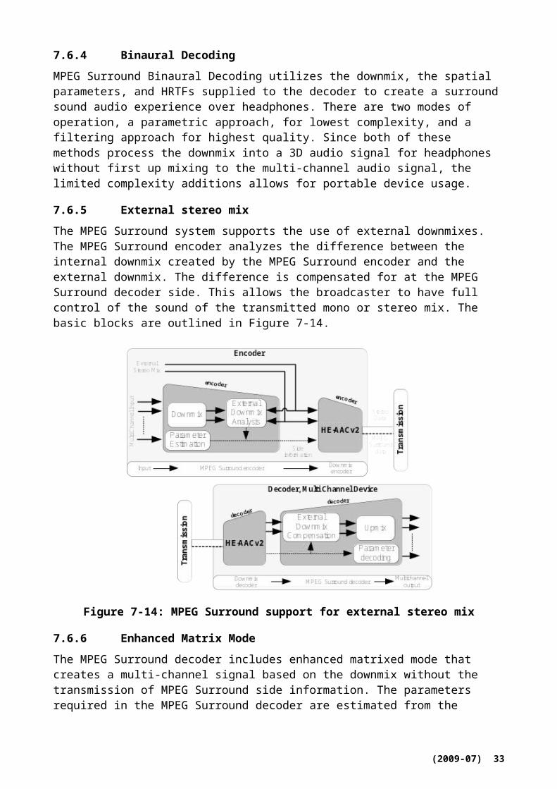
Figure 8-6: Block diagram of the G.722.1 decoder
Figure 8-6 shows a block diagram of the G.722.1 decoder. In each frame the region power code bits are first extracted from the received data and then decoded to obtain the quantization indices for the region powers. Using the same categorization procedure as the encoder, the set of 16 possible categorizations computed by the encoder are recovered and the categorization used to encode MLT transform coefficients is found with the received four categorization control bits. For each region the variable bit-length codes for MLT transform coefficients are decoded with the appropriate category and the MLT transform coefficients are reconstructed. The reconstructed MLT transform coefficients are converted into time domain audio samples by an Inverse MLT (IMLT). Each IMLT operation takes in 320 MLT transform coefficients to produce 320 audio samples.
The following are the main changes in the G.722.1Annex C decoder when compared to G.722.1.
Double the number of frequency regions from 14 to 28
Double the threshold for adjusting the number of available bits from 320 to 640
Extend the centroid table used for reconstruction of MLT transform coefficients
Double the IMLT transform length from 320 to 640 samples
Low complexity is a major technical advantage of G.722.1 and G.722.1 Annex C compared to other codecs with similar performance in this bit-rate range. Table 8-1 presents the computational complexity in units of Weighted Million Operations Per Second (WMOPS) [2] and memory requirements in bytes of G.722.1 and G.722.1 Annex C, respectively.
Table 8-1: Computational complexity and memory requirements
Codec Bit rate(kbit/s)
Encoder(WMOPS)
Decoder(WMOPS)
Encoder + Decoder
(WMOPS)
RAM(bytes)
Data-ROM(bytes)
G.722.124 2.3 2.7 5.0
11 K 20 K32 2.4 2.9 5.3
G.722.1 Annex C
24 4.5 5.3 9.718 K 30 K
32 4.8 5.5 10.3
(2009-07) 35
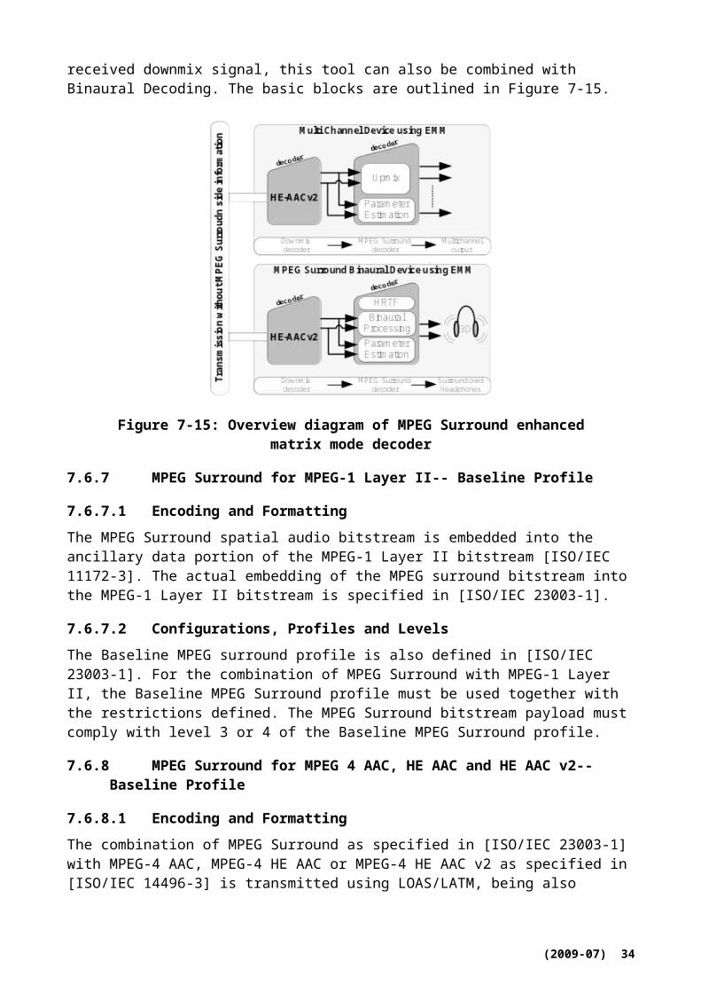
Codec Bit rate(kbit/s)
Encoder(WMOPS)
Decoder(WMOPS)
Encoder + Decoder
(WMOPS)
RAM(bytes)
Data-ROM(bytes)
48 5.1 5.9 10.9
In March 2005, as a part of the G.722.1 Annex C development process in ITU-T, subjective characterization tests were performed on G.722.1 Annex C by an independent listening lab according to a test plan designed by the ITU-T Q7/SG12 Speech Quality Experts Group (SQEG. A well-known MPEG audio codec was used as the reference codec in the tests. Statistical analysis of the test results showed that G.722.1 Annex C met all performance requirements. For speech signals, G.722.1 Annex C was better than the reference codec at 24 and 32 kbit/s and G.722.1 Annex C at 48 kbit/s was not worse than the reference codec operating at either 48 or 64 kbit/s. For music and mixed content such as film trailers, news, jingles and advertisement, G.722.1 Annex C was better than the reference codec at all bit rates and G.722.1 Annex C at 48 kbit/s was also better than the reference codec operating at 64 kbit/s [6].
The RTP payload for G.722.1 and G.722.1 Annex C is specified in ITU-T Recommendation G.722.1 Annex A, and also specified in [IETF RFC 3047] and [IETF RFC 5577] which supersedes RFC 3047 and adds support for G.722.1 Annex C.
ANSI-C source code reference implementations of both encoder and decoder parts if G.722.1 and G.722.1 Annex C are available as an integral part of [ITU-T G.722.1] for both fixed-point and floating-point arithmetic.
8.3 ITU-T G.722.2 (3GPP AMR-WB)
The AMR-WB codec has been standardized by both ITU (as Recommendation ITU-T G.722.2) and 3GPP (as 3GPP TS 26.171). It is a multi-rate codec that encodes wideband audio signals sampled at 16 kHz (with a signal bandwidth of 50-7000 Hz). The AMR-WB codec is also used as a part of the AMR-WB+. However, AMR-WB+ does not work as the AMR-WB codec and has a longer algorithmic delay. For supporting lower delay wideband speech applications, standalone AMR-WB is more suitable. The AMR-WB codec consists of nine modes with bit rates of 23.85, 23.05, 19.85, 18.25, 15.85, 14.25, 12.65, 8.85 and 6.6 kbit/s. AMR-WB also includes a 1.75 kbit/s background noise mode that is designed for the Discontinuous Transmission (DTX) operation in GSM and can be used as a low bit rate source-dependent back ground noise mode in other systems.
In 3GPP, the AMR-WB codec has been specified in several specifications. TS 26.171 gives a general overview of the AMR-WB standards. The algorithmic detailed description is given in TS 26.190, and the fixed point and floating point source code are given in TS 26.173 and TS 26.204, respectively. Voice Activity detection is given in TS 26.194 and comfort noise aspects are detailed in TS 26.192. Frame erasure concealment is specified in TS 26.191.
In ITU-T the same specifications are reproduced in Recommendation G.722.2 and its annexes.
In 3GPP, AMR-WB is the mandatory codec for several services when wideband speech sampled at 16 kHz is used. These services include circuit switched and packet-switched telephony, 3G-324H multimedia telephony, multimedia messaging service (MMS), Packet-switched Streaming Service (PSS), multimedia broadcast/multicast service (MBMS), IP multimedia subsystem (IMS) messaging and presence, and push-to-talk over cellular (PoC).
ANSI-C source code reference implementations of both encoder and decoder parts if G.722.2 are available as an integral part of [ITU-T G.722.1] for fixed-point arithmetic.
(2009-07) 36

8.3.1 Overview of AMR-WB codec
The codec is based on the code-excited linear predictive (CELP) coding model. The codec operates at an internal sampling frequency of 12.8 kHz. The input signal is processed in 20 ms frames (256 samples).
The signal flow at the encoder is shown in Figure 8-7. After decimation, high-pass and pre-emphasis filtering is performed. LP analysis is performed once per frame. The set of LP parameters is converted to immittance spectrum pairs (ISP) and vector quantized using split-multistage vector quantization (S-MSVQ). The speech frame is divided into 4 subframes of 5 ms each (64 samples). The adaptive and fixed codebook parameters are transmitted every subframe. The quantized and unquantized LP parameters or their interpolated versions are used depending on the subframe. An open-loop pitch lag is estimated in every other subframe or once per frame based on the perceptually weighted speech signal.
Then the following operations are repeated for each subframe:
The target signal x(n) is computed by filtering the LP residual through the weighted synthesis filter W(x)H(z) with the initial states of the filters having been updated by filtering the error between LP residual and.
The impulse response, h(n) of the weighted synthesis filter is computed.
Closed-loop pitch analysis is then performed (to find the pitch lag and gain), using the target x(n) and impulse response h(n), by searching around the open-loop pitch lag. Fractional pitch with1/4th or1/2nd of a sample resolution (depending on the mode and the pitch lag value) is used. The interpolating filter in fractional pitch search has low pass frequency response. Further, there are two potential lowpass characteristics in the adaptive codebook and this information is encoded with 1 bit.
The target signal x(n) is updated by removing the adaptive codebook contribution (filtered adaptive codevector), and this new target, x2(n), is used in the fixed algebraic codebook search (to find the optimum innovation).
The gains of the adaptive and fixed codebook are vector quantified with 6or 7 bits (with moving average (MA) prediction applied to the fixed codebook gain).
Finally, the filter memories are updated (using the determined excitation signal) for finding the target signal in the next subframe.
(2009-07) 37
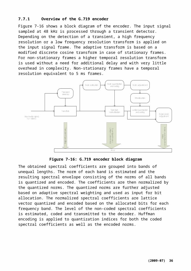
down-sam ple&HP filter pre-em phasis s(n)
windowing &autocorrelation
Levinson-Durbin
A(z) IS P
ISP ISF
ISFquantization
interpolation for4 subfram es
interpolation for4 subfram es
com puteweightedspeech
find open-loop pitch
com putetarget foradaptive
codebook
find bestdelay and
gain
com puteadaptive
codebookcontribution
selectadaptive
codebookfilter
com puteim pulse
response
com putetarget for
innovation
find bestinnovation
update filterm em ories for
nextsubfram e
com puteexc itation
gain vectorquantization
A(z)
A(z)
T0
x2(n)
h(n)
x(n)
com puteHB gain
(23.85 kbit/sm ode)
ISFindex
pitch index
filt index
HB gainindex
gain VQindex
code index
Lower band
H igher band
speechinput
v
Figure 8-7: Detailed block diagram of the G.722.2 encoder
decode ISP
interpolationof ISP for 4subfram es
ISP A(z)
decodeadaptive
codebook
decodeinnovativecodebook
decode gainsconstructexcitation
LTP filter
post-processing
synthesisfilter
de-em phasiss(n)
v
up-sam ple
16 kHzrandom
excitationgain scaling
HB-synthesis
filterBP filter
+
(6.60 kbit/s m ode)
VADflag
HB gainindex
ISFindex
pitchindex
gain VQindex
codeindex
filteringindex
Lower band
H igher band
speechoutputv
Figure 8-8: Detailed block diagram of the G.722.2 decoder
(2009-07) 38

The signal flow at the decoder is shown in Figure 8-8. At the decoder, the transmitted indices are extracted from the received bitstream. The indices are decoded to obtain the coder parameters at each transmission frame. These parameters are the ISP vector, the 4 fractional pitch lags, the 4 LTP filtering parameters, the 4 innovative codevectors, and the 4 sets of vector quantized pitch and innovative gains. In the 23.85 kbit/s mode, also the high-band gain index is decoded. The ISP vector is converted to LP filter coefficients and interpolated to obtain LP filters at each subframe. Then, at each 64-sample subframe:
The excitation is constructed by adding the adaptive and innovative codevectors scaled by their respective gains
The 12.8 kHz speech is reconstructed by filtering the excitation through the LP synthesis filter
The reconstructed speech is de-emphasized
Finally, the reconstructed speech is upsampled to 16 kHz and high-band speech signal is added to the frequency band from 6 kHz to 7 kHz.
8.3.2 Transport and storage of AMR-WB
The RTP payload for AMR-WB is specified in RFC 3267 [11]. It supports encapsulation of one or multiple AMR-WB transport frames per packet, and provides means for redundancy transmission and frame interleaving to improve robustness against possible packet loss. The payload supports two formats, bandwidth-efficient and octet-aligned. The minimum payload overhead is 9 bits per RTP-packet in bandwidth-efficient mode and two bytes per RTP-packet in octet aligned mode. The use of interleaving increases the overhead per packet slightly. The payload also supports CRC and includes parameters required for session setup. 3GPP TS 126 234 (PSS) [12] and TS 126 346 (MBMS) [13] use this payload.
The AMR-WB ISO-based 3GP file format is defined in 3GPP TS 26.244 [14], with the media type “audio/3GPP”. Note that the 3GP structure also supports the storage of other multimedia formats, thereby allowing synchronized playback. In addition, an additional file format is specified in RFC 3267 for transport of AMR-WB speech data in storage mode applications such as email. The AMR-WB MIME type registration specifies the use of both the RTP payload and storage formats.
8.4 ITU-T G.729.1
The [G.729.1] coder is an 8-32 kbit/s scalable wideband extension of G.729. The output of G.729.1 has a bandwidth of 50-4000 Hz at 8 and 12 kbit/s and 50-7000 Hz from 14 to 32 kbit/s. At 8 kbit/s, G.729.1 is fully interoperable with G.729, G.729 Annex A, and G.729 Annex B.
G.729.1 is recommended as optional codec for NG-DECT to provide high wideband voice quality in current”32 kbit/” DECT channel. The main specific features are the interoperability with widely deployed G.729 based VoIP systems and the specific design for usage over packetized networks (high robustness to packet losses). Scalability can be also identified as a specific feature to easily and efficiently quality/bandwidth usage tradeoff.
The encoder produces an embedded bitstream structured in 12 layers corresponding to 12 available bit rates from 8 to 32 kbit/s. The bitstream can be truncated at the decoder side or by any component of the communication systems to adjust the bit rate “on the fly” to the desired value with no need for outband signalling. Figure 8-9 shows the G.729.1 bitstream format, which follows the format in [ITU-T G.192].
(2009-07) 39

Layer 1 Layer 2 Layer3
Layer4
Layer5
Layer6
Layer7
Layer8
Layer9
Layer10
Layer11
Layer12S
YN
CN
BIT
160 bits 80 bits 40 bits 40 bits 40 bits40 bits 40 bits 40 bits 40 bits 40 bits 40 bits 40 bits
Figure 8-9: G.729.1 bitstream format
The underlying algorithm of the G.729.1 coder is based on a three-stage coding structure: embedded code-excited linear predictive (CELP) coding of the lower band (50-4000 Hz), parametric coding of the higher band (4000-7000 Hz) by time domain bandwidth extension (TDBWE), and enhancement of the full band (50-7000Hz) by a predictive transform coding technique referred to as time-domain aliasing cancellation (TDAC).
ANSI-C source code reference implementations of both encoder and decoder parts if G.729.1 are available as an integral part of [ITU-T G.729.1] for both fixed-point and floating-point arithmetic.
8.4.1 Overview of the encoder
The G.729.1 encoder structure is shown in Figure 8-10. The coder operates on 20 ms frame and the default sampling rate is 16000 Hz. However, the 8000 Hz sampling frequency is also supported.
The input signal is first split into two subbands using a QMF filter bank and then decimated. The high-pass filtered lower band signal is coded by the 8-12 kbit/s narrowband embedded CELP encoder. The difference between the input and local synthesis signal of the CELP encoder at 12 kbit/s is processed by the perceptual weighting filter. The weighted difference signal is then transformed into frequency domain by MDCT.
The spectral folded higher band signal is pre-processed by a lowpass filter with 3000 Hz cutoff frequency. The resulting signal is coded by the TDBWE encoder and the signal is also transformed into frequency domain by MDCT. The MDCT coefficients of lower band and higher band signal are finally coded by the TDAC encoder.
In addition, some parameters are transmitted by the frame erasure concealment (FEC) encoder in order to introduce parameter-level redundancy in the bitstream. This redundancy allows improving quality in the presence of erased frames.
(2009-07) 40
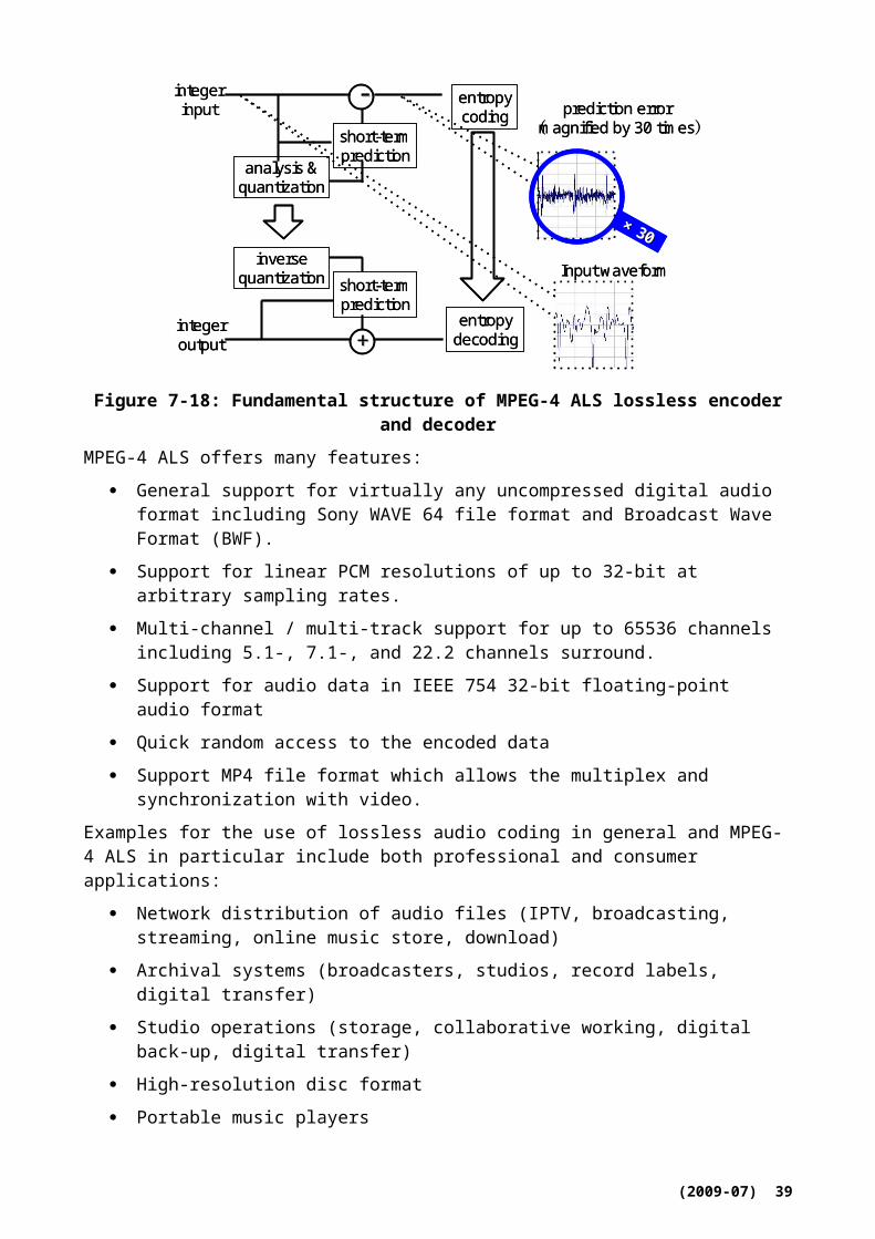
Figure 8-10: High-level block diagram of the G.729.1 encoder
8.4.2 Overview of the decoder
A functional diagram of the decoder is presented in Figure 8-11. The decoding depends on the actual number of received layers or equivalently on the received bit rate.
If the received bit rate is:
8 kbit/s (Layer 1): The layer 1 is decoded by the embedded CELP decoder. Then the decoded signal is post-filtered and post-processed by a high-pass filter. The QMF synthesis filter bank generates the output with a high-frequency synthesis set to zero.
12 kbit/s (Layers 1 and 2): The layer 1 and 2 are decoded by the embedded CELP decoder and the synthesized signal is then post-filtered and high-pass filtered. The QMF synthesis filter bank generates the output with a high-frequency synthesis set to zero.
14 kbit/s (Layers 1 to 3): In addition to the narrowband CELP decoding and lower band adaptive post-filtering, the TDBWE decoder produces a high-frequency synthesis which is then transformed into frequency domain by MDCT so as to zero the frequency band above 3000 Hz in the higher band spectrum. The resulting spectrum is transformed in time domain by inverse MDCT and overlap-add before spectral folding. In the QMF synthesis filter bank the reconstructed higher band signal is combined with the respective lower band signal reconstructed at 12 kbit/s without high-pass filtering.
Above 14 kbit/s (Layers 1 to 4+): In addition to the narrowband CELP and TDBWE decoding, the TDAC decoder reconstructs MDCT coefficients, which correspond to the reconstructed weighted difference in lower band and the reconstructed signal in higher band. In the higher band, the non-received subbands and the subbands with zero bit allocation in TDAC decoding are replaced by the level-adjusted subbands of MDCT coefficients which are produced by TDBWE. The lower band and higher band MDCT coefficients are transformed into time domain by inverse MDCT and overlap-add. The lower band signal is then processed by the inverse perceptual weighting filter. To attenuate transform coding artefacts pre/post-echoes are detected and reduced in both the lower and higher band signals. The lower band synthesis is post-filtered, while the higher band synthesis is spectrally
(2009-07) 41
folded. The lower band and higher band signal are then combined and up-sampled in the QMF synthesis filter bank.
Figure 8-11: High-level block diagram of the G.729.1 decoder
8.4.3 RTP payload
To transmit the G.729.1 bitstream over RTP, the RTP payload format specified in RFC 4749 [2] is used. The payload consists of one byte header and zero or more consecutive audio frames at the same bit rate. The payload header consists of two fields: 4 bit MBS and 4 bit FT.
MBS (Maximum Bit rate Supported) indicates a maximum bit rate to the encoder at the receiver site. Because of the embedded property of the G.729.1 coder, the encoder can send frames at the MBS rate or any lower rate. Also, as long as it does not exceed the MBS, the encoder can change its bit rate at any time without previous notice. The MBS values from 0 to 11 represent the bit rate from 8 to 32 kbit/s, respectively. And the MBS value 15 assigned to a multicast group application.
FT (Frame Type) indicates the encoding rate of the frames in the packet. The FT values from 0 to 11, like a MBS, indicate the bit rate from 8 to 32 kbit/s. The FT value 15 indicates that there is no audio data in the payload.
Audio data of a payload contains one or more consecutive audio frames at the same bit rate. The audio frames are packed in order of time, that is, oldest first.
8.5 ITU-T G.711.1
The algorithm in [ITU-T G.711.1] is an extension to ITU-T G.711 (log-compressed PCM, [ITU-T G.711]) formerly referred to as “G.711-WB” (wideband extension). The main feature of this extension is to give wideband scalability to G.711. It aims to achieve high-quality speech services over broadband networks, particularly for IP phone and multi-point speech conferencing, while enabling a seamless interoperability with conventional terminals and systems equipped only with G.711.
The main emphases, put on the constraints of the coder, are as follows:
Upward compatible with G.711 by means of embedded structure.
(2009-07) 42

The number of enhancement layers is two: a lower-band enhancement layer to reduce the G.711 quantization noise and a higher-band enhancement layer to add a wideband capability.
Short frame-length (sub-multiples of 5 ms) to achieve low delay.
Low computational complexity and memory requirements to fit existing hardware capabilities.
For speech signal mixing in multi-point conferences, a similar complexity to G.711 must be achieved, i.e., no increase in the complexity. It is preferable not to use inter-frame predictions, to enable enhancement layer switching in MCUs (Multipoint Control Unit) for low-complexity pseudo wideband mixing, partial mixing.
Robustness against packet losses. Preferably not too heavily dependent on interframe predictions.
With three sub-bitstreams constructed from core (Layer 0 at 64 kbit/s) and two enhancement layers (Layers 1 and 2, both at 16 kbit/s), four bitstream combinations can be constructed which correspond to four modes: R1, R2a, R2b and R3. The first two modes operate at 8 kHz sampling frequency, the last two at 16 kHz. Table 8-2 gives all modes and respective sub-bitstream combinations.
As for the complexity of the codec, the worst case is 8.70 WMOPS (estimated using basic operator set v2.2 available in [ITU-T G.191]). The memory size of the candidate codec was found to be 3.04 kWords RAM and 2.21 kWords table ROM. The overall algorithmic delay adds up to 11.875 ms (190 samples at 16 kHz), including the processing frame length (5 ms).
Table 8-2: Sub-bitstream combination for each mode
Mode Layer 0 Layer 1 Layer 2 Bitrate [kbit/s]
R1 X - - 64R2a X X - 80R2b X - X 80R3 X X X 96
ANSI-C source code reference implementations of both encoder and decoder parts if G.711.1 are available as an integral part of [ITU-T G.711.1] for both fixed-point and floating-point arithmetic.
8.5.1 Overview of G.711.1 algorithm
The codec operates on 16 kHz-sampled speech at a 5 ms frame-length. The block diagram of the encoder is shown in Figure 8-12. Input signal is pre-processed with a high-pass filter to remove low frequency (0-50 Hz) components, and then split into lower-band and higher-band signals using a quadrature mirror filter bank (QMF). The lower-band signal sLB(n) is encoded with an embedded lower-band PCM encoder which generates G.711 compatible core bitstream (Layer 0, IL0) at 64 kbit/s, and lower-band enhancement (Layer 1, IL1) bitstream at 16 kbit/s. The lower-band core codec is based on the ITU-T G.711 standard and both μ-law and A-law companding schemes are supported. In order to achieve the best quality, the quantization noise of Layer 0 (G.711-compatible core) is shaped with a perceptual filter. In order to provide a finer resolution to the core layer, the lower-band enhancement layer (Layer 1) QL1 encodes the refinement signal using adaptive bit-allocation based on its exponent value. The higher-band signal sHB(n) is transformed into modified discrete cosine transform (MDCT) domain and the frequency domain coefficients SHB(k) are encoded by the higher-band encoder using interleaved Conjugate-Structured VQ (CS-VQ), which generates higher-band enhancement (Layer 2, IL2) bitstream at 16 kbit/s. The transform length of
(2009-07) 43
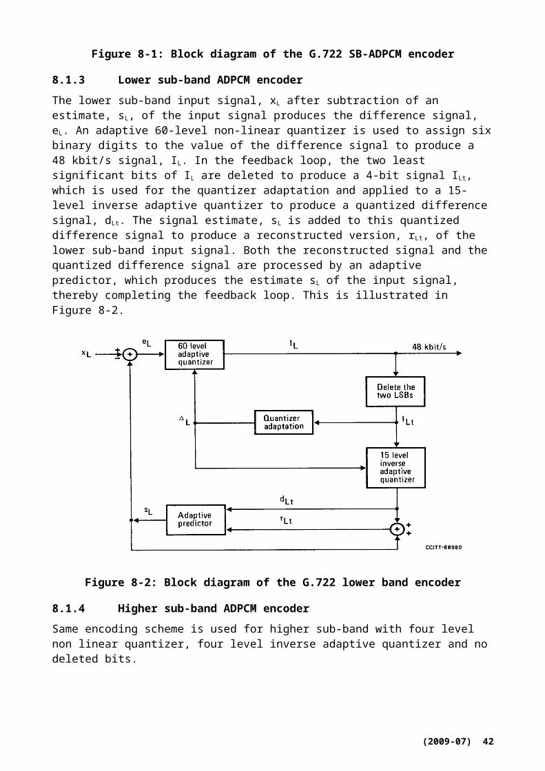
MDCT in the higher-band is 10 ms with a shift length of 5 ms. All bitstreams are multiplexed as a scalable bitstream.
Figure 8-13 shows the high-level block diagram of the decoder. The whole bitstream is de-multiplexed to G.711 compatible Layer 0, Layer 1, and Layer 2. Both, the Layer 0 and 1 bitstreams are handed to the lower-band embedded PCM decoders. The Layer 2 bitstream is given to the higher-band MDCT decoder, and decoded signal in the frequency domain ŜHB(k) is fed to inverse MDCT (iMDCT) and the higher-band signal in time domain ŝHB(n) is obtained. To improve the quality under frame erasures due to channel errors such as packet losses, frame erasure concealment (FERC) algorithms are applied to the lower-band and higher-band signals separately. The decoded lower- and higher-band signals, ŝLB(n) and ŝHB(n), are combined using a synthesis QMF filter bank to generate a wideband signal ŝQMF(n). Noise gate processing is applied to the QMF output to reduce low-level background noise. This noise gate attenuates segments with power below certain threshold and as a result, the amount of low-level background noise is reduced. This improves further the perceived quality of the output signal in low-level conditions. At the decoder output, 16-kHz-sampled speech, ŝWB(n), or 8-kHz-sampled speech, ŝNB(n), is reproduced.
Inputsignal
Lower-bandembedded
PCM encoders
Higher-bandMDCTencoder
AnalysisQMF
Pre-process
MDCT2LI
MUX1LI
0LI
( )HBs n
( )NBs n
( )HBS k
Figure 8-12: High-level block diagram of the G.711.1 encoder
Outputsignal
Lower-bandembedded
PCM decoders
Higher-bandMDCTdecoder
SynthesisQMF
Noisegate
Higher-bandFERC
ˆ ( )HBs n
2LI
de-MUX
1LI
0LILower-band
FERC
iMDCT
Postfilter(optional)
ˆ ( )QMFs n
ˆ ( )WBs n
ˆ ( )HBS k
ˆ ( )LBs n
Figure 8-13: High-level block diagram of the G.711.1 decoder
(2009-07) 44

It should be noted that G.711.1 has an optional postfilter as Appendix I, and aiming to enhance the quality of a 64-kbit/s bitstream when communicating with a legacy G.711 encoder.
The codec has a very simple structure to achieve high quality speech with a low complexity, and is deliberately designed without any inter-frame prediction, to increase the robustness against frame erasures and to avoid annoying artefacts when enhancement layers are switched, which is required for the partial mixing in wideband MCU operations.
8.5.2 Transport of G.711.1
The RTP payload for G.711.1 is specified in [IETF RFC 5391]. It describes how a G.711.1 payload should be transported as an RTP packet, and gives payload format parameters, including media type details, SDP parameters, and offer-answer considerations.
8.5.3 Transcoding with G.711
The Layer 0 of G.711.1 is fully interoperable with G.711 [ITU-T G.711], and it is embedded in all modes of G.711.1. This provides an easy G.711.1 / G.711 transcoding process. A gateway or any other network device receiving a G.711.1 packet can easily extract a G.711-compatible payload, without the need to decode and re-encode the audio signal. It simply has to take the audio data of the payload, and strip the upper layers (Layer 1 and/or 2), if any. If a G.711.1 packet contains several frames, the concatenation of the L0 layers of each frame will form a G.711-compatible payload.
8.6 ITU-T G.718
The codec specified in [ITU-T G.718] is a narrowband (NB) and wideband (WB) embedded variable bit-rate coding algorithm for speech and audio operating in the range from 8 to 32 kbit/s which is designed to be robust to frame erasures.
This codec provides state-of-the-art NB speech quality over the lower bit rates and state-of-the-art WB speech quality over the complete range of bit rates. In addition, G.718 is designed to be highly robust to frame erasures, thereby enhancing the speech quality when used in IP transport applications on fixed, wireless and mobile networks. Despite its embedded nature, the codec also performs well with both NB and WB generic audio signals.
This codec has an embedded scalable structure, enabling maximum flexibility in the transport of voice packets through IP networks of today and in future media-aware networks. In addition, the embedded structure of G.718 will easily allow the codec to be extended to provide a superwideband and stereo capability through additional layers which are currently under development. The bitstream may be truncated at the decoder side or by any component of the communication system to instantaneously adjust the bit rate to the desired value without the need for out-of-band signalling. The encoder produces an embedded bitstream structured in five layers corresponding to the five available bit rates: 8, 12, 16, 24 & 32 kbit/s.
The G.718 encoder can accept WB sampled signals at 16 kHz, or NB signals sampled at either 16 or 8 kHz. Similarly, the decoder output can be 16 kHz sampled WB, in addition to 16 or 8 kHz sampled NB. Input signals sampled at 16 kHz, but with bandwidth limited to NB, are detected by the encoder.
The output of the G.718 codec is capable of operating with a bandwidth of 300-3400 Hz at 8 and 12 kbit/s and 50-7000 Hz from 8 to 32 kbit/s.
The high quality codec core represents a significant performance improvement, providing 8 kbit/s wideband clean speech quality equivalent to G.722.2 at 12.65 kbit/s whilst the 8 kbit/s narrowband codec operating mode provides clean speech quality equivalent to G.729E at 11.8 kbit/s.
(2009-07) 45
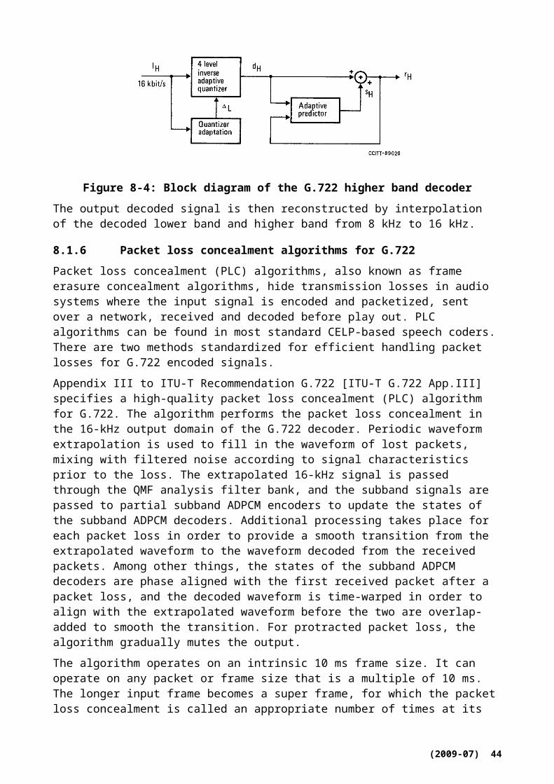
The codec operates on 20 ms frames and has a maximum algorithmic delay of 42.875 ms for wideband input and wideband output signals. The maximum algorithmic delay for narrowband input and narrowband output signals is 43.875 ms. The codec may also be employed in a low delay mode when the decoder maximum bit rates are set to 12 kbit/s. In this case the maximum algorithmic delay is reduced by 10 ms.
The codec also incorporates an alternate coding mode, with a minimum bit rate of 12.65 kbit/s, which is bitstream interoperable with ITU-T Recommendation G.722.2, 3GPP AMR-WB and 3GPP2 VMR-WB mobile WB speech coding standards. This option replaces Layer 1 and Layer 2, and the layers 3-5 are similar to the default option with the exception that in Layer 3 fewer bits are used to compensate for the extra bits of the 12.65 kbit/s core. The decoder is further able to decode all other G.722.2 operating modes. G.718 also includes discontinuous transmission mode (DTX) and comfort noise generation (CNG) algorithms that enable bandwidth savings during inactive periods. An integrated noise reduction algorithm can be used provided that the communication session is limited to 12 kbit/s.
The underlying algorithm is based on a two-stage coding structure: the lower two layers are based on Code-Excited Linear Prediction (CELP) coding of the band (50-6400 Hz) where the core layer takes advantage of signal-classification to use optimized coding modes for each frame. The higher layers encode the weighted error signal from the lower layers using overlap-add MDCT transform coding. Several technologies are used to encode the MDCT coefficients to maximize performance for both speech and music.
ANSI-C source code reference implementations of both encoder and decoder parts if G.718 are available as an integral part of [ITU-T G.718] for both fixed-point and floating-point arithmetic.
8.6.1 Overview of the G.718 encoder
The structural block diagram of the encoder, for different layers, is shown in Figure 8-14. In the Figure it is assumed that the input is wideband and that all layers will be transmitted from the encoder. From the figure it can be seen that while the lower two layers are applied to a pre-emphasized signal sampled at 12.8 kHz, the upper three layers operate in the input signal domain sampled at 16 kHz.
The core layer is based on the code-excited linear prediction (CELP) technology where the speech signal is modelled by an excitation signal passed through a linear prediction (LP) synthesis filter representing the spectral envelope. The LP filter is quantized in the immitance spectral frequency (ISFs) domain using a switched-predictive approach and a multi-stage vector quantization (MSVQ) for the generic and voiced modes.
The open-loop (OL) pitch analysis is performed by a pitch-tracking algorithm to ensure a smooth pitch contour. However, two concurrent pitch evolution contours are compared and the track that yields the smoother contour is selected in order to make the pitch estimation more robust.
(2009-07) 46

Figure 8-14: Structural block diagram of the G.718 encoder (WB case)
For narrowband signals, the pitch estimation is performed using Layer 2 excitation generated with un-quantized optimal gains. This approach removes the effects of gain quantization and improves pitch-lag estimate across layers. For WB signals, standard pitch estimation (Layer 1 excitation with quantized gains) is used.
The G.718 encoding procedure, which operates on 20 ms frames, consists of the following steps:
Frame-level pre-processing
o high-pass filtering
o sampling conversion to 12800 samples/second
o Pre-emphasis.
o Spectral analysis
o Detection of narrow-band inputs
o Voice activity detection
o Noise estimation
o Noise reduction
o Linear prediction analysis, LP to ISF conversion, and interpolation.
o Computation of weighted speech signal
o Open-loop pitch analysis
o Background noise update
o Signal classification for coding mode selection and frame erasure concealment.
Layer 1 encoding using the selected encoding type
o Unvoiced coding mode
o Voiced coding mode
o Transition coding mode
(2009-07) 47

o Generic coding mode
o Discontinuous transmission and Comfort noise generation (DTX/CNG)
Layer 2 encoding
Layer 3 encoding
Layer 4 encoding
Layer 5 encoding
8.6.2 Overview of the G.718 decoder
Figure 8-15 shows the block diagram of the decoder. The bitstream may be truncated at the decoder side or by any component of the communication system and the decoder reproduces synthesized signal using the available layers. In each 20 ms frame, the decoder receives a bitstream containing information of one or more layers. The received layers range from Layer 1 up to Layer 5, which corresponds to bit rates of 8 kbit/s to 32 kbit/s. This means that the decoder operation is conditioned by the number of bits (layers), received in each frame. In Figure 8-15, it is assumed that the output is WB and that all layers have been correctly received at the decoder.
The core layer (Layer 1) and the ACELP enhancement layer (Layer 2) are first decoded and signal synthesis is performed. The synthesized signal is then de-emphasized and resampled to 16 kHz. After a simple temporal noise shaping, the transform coding enhancement layers are added to the perceptually weighted Layer 2 synthesis. Inverse perceptual weighting is then applied to restore the synthesized WB signal. Finally, pitch post-filtering is applied on the restored signal followed by a high-pass filter. The post-filter exploits the extra decoder delay introduced by the overlap-add synthesis of the MDCT (Layers 3, 4, 5). It combines, in an optimal way, two pitch post-filter signals. One is a high-quality pitch post-filter signal of the Layer 1 or Layer 2 decoder output that is generated by exploiting the extra decoder delay. The other is a low delay pitch post-filter signal of the higher-layers (Layers 3, 4, 5) synthesis signal.
Figure 8-15: Structural block diagram of the G.718 decoder (WB case, clean channel)
(2009-07) 48

If the decoder output is limited to Layer 1, 2 or 3, a bandwidth extension is used to generate frequencies between 6400 and 7000 Hz. When Layers 4 or 5 are decoded, the bandwidth extension is not applied as the entire spectrum is quantized.
A special technique is used in the decoder, the advanced anti-swirling technique, which efficiently avoids unnaturally sounding synthesis of relatively stationary background noise, such as car noise. This technique reduces power and spectral fluctuations of the excitation signal of the LP synthesis filter, which in turn also uses smoothed coefficients. As swirling is mainly a problem at low bit rates, it is only activated for Layer 1 signal synthesis (both NB and WB) and based on signal criteria such as voice inactivity and noisiness.
The worst-case complexity of the FEC algorithm has been reduced by exploiting the MDCT look-ahead available at the decoder, and by pre-calculating some FEC parameters in the previous frame.
9 Video Codecs
The ITU-T Recommendation H.264 | ISO/IEC 14496-10 Advanced video coding standard is recommended as being particularly well suited for use in IPTV services. The inclusion of support for ITU-T Recommendation H.262 | ISO/IEC 13818-2 "MPEG-2 video" support in IPTV services is also advised, in consideration of the prevalence of existing encoded bitstreams in that format.
However, determining which coding technology designs should be supported in a particular deployment may be based on a wide variety of factors. Some additional video coding technologies that have also been identified in member contributions as potentially relevant to the application include the following:
GB/T20090.2 "AVS"
ISO/IEC 11172-2 "MPEG-1 video"
ISO/IEC 14496-2 "MPEG-4 visual"
ITU-T Recommendation H.263
SMPTE 421M "VC-1"
(2009-07) 49

Appendix IList of some additional content related standards
I.1. Introduction
The IPTV Services Requirements Document [FG IPTV-DOC-0147] contains several requirements related to closed captioning, subtitles and descriptive audio. This Appendix lists some standards which deal with these features.
It should be noted that this is not an exhaustive list.
I.2.Relevant requirements
The following requirements are duplicates of those identified in IPTV services requirements [FG IPTV -DOC-0147] and should not be modified in any way without consultation with the group (i.e. study group question) which owns [FG IPTV -DOC-0147]. In the case of a discrepancy between the text in this document and that of [FG IPTV -DOC-0147], then the latter text should take precedence.
The IPTV architecture is required to support the end-user with the ability to choose a preferred language option (audio, subtitle, captioning, supplementary video and supplementary descriptive audio) from various languages that the content provider pre-defined and the service provider delivered.
The IPTV architecture is recommended to support multiple languages audio, multiple language subtitles, multiple languages captioning, multiple language supplementary video and multiple language descriptive audio.
The IPTV architecture is recommended to support the capability for the end-user to watch with the preferred audio, subtitle, and captioning, supplementary video or descriptive audio.
If the end-user’s option can not match with the pre-defined content languages, the IPTV architecture is recommended to support the capability for the IPTV terminal device to present the content with default audio, default subtitle and captioning, default supplementary video and default descriptive audio.
The IPTV architecture is recommended to support the capability for the end-user to switch audio, subtitles and captioning, supplementary video and descriptive audio back and forth when the user is watching the program without having to change his or her preferred language settings.
The IPTV architecture is required to support the ability for the end-user to turn on and off the audio, the subtitle and captioning, supplementary video and descriptive audio at anytime without altering any of the default setting options.
The IPTV architecture is recommended to support the ability to independently select a default language for each of the following: audio, subtitle, captioning, supplementary video and supplementary descriptive audio.
The IPTV architecture is required to support the ability for the IPTV terminal device to decode video, audio, subtitles, captioning, supplementary video and descriptive audio and present them to the end-user.
The IPTV terminal device is recommended to allow the user the selection of subtitles or captions being displayed with a solid background or a transparent one.
(2009-07) 50
I.3.Coding and carriage of closed caption information
CEA-708-C: “Digital Television (DTV) Closed Captioning,” 30 July 2006, Consumer Electronics Association specifies the encoding of closed caption information in multiple languages, colors and fonts. It also specifies rendering of the information based on user preference and user specified data (such as location, size etc). All DTV receivers, set top units (including IPTV receivers) and Cable ready receivers are mandated to support this standard within the US since July 2002. This standard is also adopted by Canada and Mexico.
Additionally, the following standards specify the carriage of closed caption information in MPEG-2, AVC/H.264 and VC-1/SMPTE 421M:1. ATSC Standard A/53 Part 1:2007, “ATSC Digital Television Standard, Digital Television
System”. (carriage of closed captions in the user_data part of MPEG-2)2. ETSI TS 101 154 V1.8.1, Digital Video Broadcasting (DVB): Implementation Guidelines
for the use of MPEG-2 Systems, Video and Audio in Satellite, Cable and Terrestrial Broadcasting Applications, Annex B, June 2007. (carriage of closed captions for AVC/H.264 and VC-1/SMPTE 421M)
3. SCTE DVS 683: AVC video systems and transport constraints for Cable television, Oct 2007. (Carriage of closed captions for H.264/AVC using registered user data SEI).As closed caption information is tightly synchronized with video frames and is required to add very little overhead, this is usually carried as part of each picture and hence the carriage is codec-centric.
4. ARIB STD-B24 Ver.5.1 (2007), Data Coding and Transmission Specification for Digital Broadcasting, Volume 3 Data Transmission Specification: This provides a carriage of closed captions using an independent PES. Synchronization of closed captions with video is made by Presentation Time Stamp (PTS).
I.4.Subtitles
ANSI/SCTE 27: Subtitling methods for broadcast Cable, 2003,provides a scheme for coding and transmission of subtitles in multiple languages. This scheme has been in wide use in both US and Central America for several years.
ARIB STD-B24 Ver.5.1 (2007), “Data Coding and Transmission Specification for Digital Broadcasting, Volume 1 Data Coding, Part 3 Coding of Captions and Superimposing”.
I.5.Descriptive Audio
ITU-T Rec H.222.0 | ISO/IEC 13818-1 [ITU-T H.222.0] provides the mechanism in the ISO-639 language descriptor (audio_type value of 0x03) to signal ‘descriptive audio’ as a complete stream.
ARIB STD-B32 Ver.2.1 (2007), Video Coding, Audio Coding and Multiplexing specifications for Digital Broadcasting provides MPEG-2 AAC ADTS parameters to carry descriptive audio.
ARIB STD-B10 Ver.4.4 (2007), Service Information for Digital Broadcasting System provides the mechanism to identify descriptive audio and ISO_639 code based language identification
Some audio compression standards such as Dolby AC-3 and E-AC-3 support transmission of descriptive audio as ‘associated service’ to decoders that have the ability to combine the ‘main’ audio information with the associated information. This type of usage reduces the channel bandwidth to transmit both ‘main’ and ‘descriptive audio’. However, it does require terminal devices with the capability to decode two audio streams and mix them.
Other audio compression standards like MPEG-4 LC_AAC and MPEG-4 HE-AAC implement descriptive audio as an additional audio bitstream which in the linear domain is mixed together with the ‘main audio’, provided that the terminal device implements the required capability.
(2009-07) 51
Bibliography[b_ETSI TS 102 527-3] ETSI TS 102 527-3 V1.1.1 (2008), Digital Enhanced Cordless
Telecommunications (DECT);New Generation DECT; Part 3: Extended wideband speech services
[b_FLAC] FLAC, Free Lossless Audio Codec, http://en.wikipedia.org/wiki/Free_Lossless_Audio_Codec (visited on 2009-02-26)
[b_OptimFrog] OptimFrog, http://en.wikipedia.org/wiki/Optimfrog (visited on 2009-02-26)
[b_Monkey’s] Monkey's Audio, http://en.wikipedia.org/wiki/Monkey%27s_Audio (visited on 2009-02-26)
__________________
(2009-07) 52
Related Documents