International Telecommunication Union ITU-T Q.850 TELECOMMUNICATION STANDARDIZATION SECTOR OF ITU (10/2018) SERIES Q: SWITCHING AND SIGNALLING, AND ASSOCIATED MEASUREMENTS AND TESTS Digital subscriber Signalling System No. 1 – General Usage of cause and location in the Digital Subscriber Signalling System No. 1 and the Signalling System No. 7 ISDN user part Recommendation ITU-T Q.850

Welcome message from author
This document is posted to help you gain knowledge. Please leave a comment to let me know what you think about it! Share it to your friends and learn new things together.
Transcript

I n t e r n a t i o n a l T e l e c o m m u n i c a t i o n U n i o n
ITU-T Q.850 TELECOMMUNICATION STANDARDIZATION SECTOR OF ITU
(10/2018)
SERIES Q: SWITCHING AND SIGNALLING, AND ASSOCIATED MEASUREMENTS AND TESTS
Digital subscriber Signalling System No. 1 – General
Usage of cause and location in the Digital Subscriber Signalling System No. 1 and the Signalling System No. 7 ISDN user part
Recommendation ITU-T Q.850

ITU-T Q-SERIES RECOMMENDATIONS
SWITCHING AND SIGNALLING, AND ASSOCIATED MEASUREMENTS AND TESTS
SIGNALLING IN THE INTERNATIONAL MANUAL SERVICE Q.1–Q.3
INTERNATIONAL AUTOMATIC AND SEMI-AUTOMATIC WORKING Q.4–Q.59
FUNCTIONS AND INFORMATION FLOWS FOR SERVICES IN THE ISDN Q.60–Q.99
CLAUSES APPLICABLE TO ITU-T STANDARD SYSTEMS Q.100–Q.119
SPECIFICATIONS OF SIGNALLING SYSTEMS No. 4, 5, 6, R1 AND R2 Q.120–Q.499
DIGITAL EXCHANGES Q.500–Q.599
INTERWORKING OF SIGNALLING SYSTEMS Q.600–Q.699
SPECIFICATIONS OF SIGNALLING SYSTEM No. 7 Q.700–Q.799
Q3 INTERFACE Q.800–Q.849
DIGITAL SUBSCRIBER SIGNALLING SYSTEM No. 1 Q.850–Q.999
General Q.850–Q.919
Data link layer Q.920–Q.929
Network layer Q.930–Q.939
User-network management Q.940–Q.949
Stage 3 description for supplementary services using DSS1 Q.950–Q.959
PUBLIC LAND MOBILE NETWORK Q.1000–Q.1099
INTERWORKING WITH SATELLITE MOBILE SYSTEMS Q.1100–Q.1199
INTELLIGENT NETWORK Q.1200–Q.1699
SIGNALLING REQUIREMENTS AND PROTOCOLS FOR IMT-2000 Q.1700–Q.1799
SPECIFICATIONS OF SIGNALLING RELATED TO BEARER INDEPENDENT CALL CONTROL (BICC)
Q.1900–Q.1999
BROADBAND ISDN Q.2000–Q.2999
SIGNALLING REQUIREMENTS AND PROTOCOLS FOR THE NGN Q.3000–Q.3709
SIGNALLING REQUIREMENTS AND PROTOCOLS FOR SDN Q.3710–Q.3899
TESTING SPECIFICATIONS Q.3900–Q.4099
SIGNALLING REQUIREMENTS AND PROTOCOLS FOR IMT-2020 Q.5000–Q.5049
COMBATING COUNTERFEITING AND STOLEN ICT DEVICES Q.5050–Q.5069
For further details, please refer to the list of ITU-T Recommendations.

Rec. ITU-T Q.850 (10/2018) i
Recommendation ITU-T Q.850
Usage of cause and location in the Digital Subscriber Signalling System No. 1 and
the Signalling System No. 7 ISDN user part
Summary
Recommendation ITU-T Q.850 defines the format, encoding and semantics of cause information
elements/parameters and the usage of the location field, in the Digital Subscriber Signalling System
No. 1 and the Signalling System No. 7 ISDN User Part. Many cause values are applicable to both
DSS 1 and SS No. 7 ISUP and this Recommendation specifies the use of each cause value in other
Recommendations.
History
Edition Recommendation Approval Study Group Unique ID*
1.0 ITU-T Q.850 1993-03-12 XI 11.1002/1000/2305
2.0 ITU-T Q.850 1998-05-15 11 11.1002/1000/4376
2.1 ITU-T Q.850 (1998) Add. 1 2000-06-15 11 11.1002/1000/5114
2.2 ITU-T Q.850 (1998) Amd. 1 2001-07-13 11 11.1002/1000/5493
3.0 ITU-T Q.850 2018-10-14 11 11.1002/1000/13695
Keywords
Cause value, DSS1, ISUP, SIP-I.
* To access the Recommendation, type the URL http://handle.itu.int/ in the address field of your web
browser, followed by the Recommendation's unique ID. For example, http://handle.itu.int/11.1002/1000/11
830-en.

ii Rec. ITU-T Q.850 (10/2018)
FOREWORD
The International Telecommunication Union (ITU) is the United Nations specialized agency in the field of
telecommunications, information and communication technologies (ICTs). The ITU Telecommunication
Standardization Sector (ITU-T) is a permanent organ of ITU. ITU-T is responsible for studying technical,
operating and tariff questions and issuing Recommendations on them with a view to standardizing
telecommunications on a worldwide basis.
The World Telecommunication Standardization Assembly (WTSA), which meets every four years, establishes
the topics for study by the ITU-T study groups which, in turn, produce Recommendations on these topics.
The approval of ITU-T Recommendations is covered by the procedure laid down in WTSA Resolution 1.
In some areas of information technology which fall within ITU-T's purview, the necessary standards are
prepared on a collaborative basis with ISO and IEC.
NOTE
In this Recommendation, the expression "Administration" is used for conciseness to indicate both a
telecommunication administration and a recognized operating agency.
Compliance with this Recommendation is voluntary. However, the Recommendation may contain certain
mandatory provisions (to ensure, e.g., interoperability or applicability) and compliance with the
Recommendation is achieved when all of these mandatory provisions are met. The words "shall" or some other
obligatory language such as "must" and the negative equivalents are used to express requirements. The use of
such words does not suggest that compliance with the Recommendation is required of any party.
INTELLECTUAL PROPERTY RIGHTS
ITU draws attention to the possibility that the practice or implementation of this Recommendation may involve
the use of a claimed Intellectual Property Right. ITU takes no position concerning the evidence, validity or
applicability of claimed Intellectual Property Rights, whether asserted by ITU members or others outside of
the Recommendation development process.
As of the date of approval of this Recommendation, ITU had not received notice of intellectual property,
protected by patents, which may be required to implement this Recommendation. However, implementers are
cautioned that this may not represent the latest information and are therefore strongly urged to consult the TSB
patent database at http://www.itu.int/ITU-T/ipr/.
ITU 2018
All rights reserved. No part of this publication may be reproduced, by any means whatsoever, without the prior
written permission of ITU.

Rec. ITU-T Q.850 (10/2018) iii
Table of Contents
Page
1 Scope ............................................................................................................................. 1
2 References ..................................................................................................................... 1
3 Definitions .................................................................................................................... 2
4 Abbreviations and acronyms ........................................................................................ 2
5 Conventions .................................................................................................................. 3
6 Cause ............................................................................................................................. 3
6.1 Format ............................................................................................................. 3
6.2 Codes used in the subfield of the "Cause" ...................................................... 3
7 General rules for the handling of the location field ...................................................... 23
8 Handling of cause and location at the international interface ....................................... 25
9 Procedures for the handling of location values reserved for national use (national
option) ........................................................................................................................... 26
Bibliography............................................................................................................................. 28


Rec. ITU-T Q.850 (10/2018) 1
Recommendation ITU-T Q.850
Usage of cause and location in the Digital Subscriber Signalling System No. 1
and the Signalling System No. 7 ISDN user part
1 Scope
This Recommendation defines the format, encoding and semantics of cause information
elements/parameters and the usage of the location field, in the Digital Subscriber Signalling System
No. 1 and the Signalling System No. 7 ISDN User Part. Many cause values are applicable to both
DSS 1 and SS No. 7 ISUP and this Recommendation specifies the use of each cause value in other
Recommendations.
2 References
The following ITU-T Recommendations and other references contain provisions which, through
reference in this text, constitute provisions of this Recommendation. At the time of publication, the
editions indicated were valid. All Recommendations and other references are subject to revision;
users of this Recommendation are therefore encouraged to investigate the possibility of applying the
most recent edition of the Recommendations and other references listed below. A list of the currently
valid ITU-T Recommendations is regularly published. The reference to a document within this
Recommendation does not give it, as a stand-alone document, the status of a Recommendation.
[ITU-T E.180] Recommendation ITU-T E.180/Q.35 (1998), Technical characteristics of tones
for the telephone service.
[ITU-T Q.730] Recommendation ITU-T Q.730 (1999), ISDN User Part supplementary
services.
[ITU T Q.732.x] Recommendations ITU-T Q.732.2-5 (1999), Stage 3 description for call
offering supplementary services using Signalling System No. 7: Call diversion
services: Call forwarding busy, Call forwarding no reply, Call forwarding
unconditional, Call deflection.
[ITU-T Q.733.3] Recommendation ITU-T Q.733.3 (1997), Stage 3 description for call
completion supplementary services using Signalling System No. 7: Completion
of calls to busy subscriber (CCBS).
[ITU-T Q.733.4] Recommendation ITU-T Q.733.4 (1993), Stage 3 description for call
completion supplementary services using Signalling System No. 7: Terminal
portability (TP).
[ITU-T Q.735.1] Recommendation ITU-T Q.735.1 (1993), Stage 3 description for community of
interest supplementary services using Signalling System No. 7: Closed user
group (CUG).
[ITU-T Q.735.3] Recommendation ITU-T Q.735.3 (1993), Stage 3 description for community of
interest supplementary services using Signalling System No. 7: Multi-level
precedence and pre-emption.
[ITU-T Q.737.1] Recommendation ITU-T Q.737.1 (1997), Stage 3 description for additional
information transfer supplementary services using Signalling System No. 7:
User-to-user signalling (UUS).
[ITU-T Q.763] Recommendation ITU-T Q.763 (1999), Signalling System No. 7 – ISDN User
Part formats and codes.

2 Rec. ITU-T Q.850 (10/2018)
[ITU-T Q.764] Recommendation ITU-T Q.764 (1999), Signalling System No. 7 – ISDN User
Part signalling procedures.
[ITU-T Q.931] Recommendation ITU-T Q.931 (1998), ISDN user-network interface layer 3
specification for basic call control.
[ITU-T Q.933] Recommendation ITU-T Q.933 (2003), ISDN Digital Subscriber Signalling
System No. 1 (DSS1) – Signalling specifications for frame mode switched and
permanent virtual connection control and status monitoring.
[ITU-T Q.955.3] Recommendation ITU-T Q.955.3 (1993), Stage 3 description for community of
interest supplementary services using DSS 1: Multi-level precedence and
preemption (MLPP).
[ITU-T X.21] Recommendation ITU-T X.21 (1992), Interface between Data Terminal
Equipment and Data Circuit-terminating Equipment for synchronous operation
on public data networks.
[ITU-T X.25] Recommendation ITU-T X.25 (1996), Interface between Data Terminal
Equipment (DTE) and Data Circuit-terminating Equipment (DCE) for
terminals operating in the packet mode and connected to public data networks
by dedicated circuit.
[ITU-T X.213] Recommendation ITU-T X.213 (2001), Information technology – Open
Systems Interconnection – Network service definition.
[ETSI TS 124 229] ETSI TS 124 229 V14.8.0 (2018-06), Digital cellular telecommunications
system (Phase 2+) (GSM); Universal Mobile Telecommunications System
(UMTS); LTE; 5G; IP multimedia call control protocol based on Session
Initiation Protocol (SIP) and Session Description Protocol (SDP); Stage 3
(3GPP TS 24.229 version 14.8.0 Release 14).
[RFC 3326] IETF RFC 3326 (2002), The Reason Header Field for the Session Initiation
Protocol (SIP).
3 Definitions
None.
4 Abbreviations and acronyms
This Recommendation uses the following abbreviations and acronyms:
ANM Answer Message
BI Beyond Interworking point
CCBSindicator Completion of Calls to Busy Subscriber
CGC Circuit-Group-Congestion signal
CUG Closed User Group DSS 1 Digital Subscriber Signalling System No. 1 (DSS 1)
INTL International Network
ISDN Integrated Services Digital Network
ISUP ISDN User Part
LN Public Network serving the Local user
LPN Private Network serving the Local user

Rec. ITU-T Q.850 (10/2018) 3
MLPP Multilevel Precedence and Pre-emption
NNC National-Network-Congestion signal
NU National Use
RLN Public Network serving the Remote user
RPN Private Network serving the Remote user
S-CSCF Serving-Call Session Control Function
SIP Session Initiation Protocol
SS No. 7 Signalling System No. 7
TMR Transmission Medium Requirement
TN Transit Network
U User
UUS User-to-User Signalling
5 Conventions
None.
6 Cause
6.1 Format
The format of the ITU-T Q.931 Cause information element or ITU-T Q.763/Q.730 Cause indicators
parameters' content is shown in Figure 1.
Octet
8 7 6 5 4 3 2 1 (Note 3)
Q.931 Q.763
ext.
0/1
Coding standard Spare
0
Location 3 1
ext.
1
Recommendation (Notes 1 and 2) 3a*
ext.
1
Cause value 4 2
Diagnostic(s) (if any) 5* 3*
NOTE 1 – If the default applies for the Recommendation field, octets including this field shall be omitted.
NOTE 2 – The Recommendation field is not supported by the ISUP. The default interpretation for ISUP is [ITU-T Q.763].
NOTE 3 – Optional octets are marked with asterisks (*).
Figure 1 – Format of "Cause"
6.2 Codes used in the subfield of the "Cause"
6.2.1 Extension indicator (ext.)
Bit
8
0 octet continues through to the next octet (e.g., octet 1 to 1a)
1 last octet

4 Rec. ITU-T Q.850 (10/2018)
6.2.2 Coding standard
Bits
7 6
0 0 ITU-T standardized coding, as described below
0 1 ISO/IEC standard (See note.)
1 0 national standard (See note.)
1 1 standard specific to identified location (See note.)
NOTE – These other coding standards should be used only when the desired cause value cannot be represented
with the ITU-T-standardized coding.
6.2.3 Location
Bits
4 3 2 1
0 0 0 0 user (U)
0 0 0 1 private network serving the local user (LPN)
0 0 1 0 public network serving the local user (LN)
0 0 1 1 transit network (TN)
0 1 0 0 public network serving the remote user (RLN)
0 1 0 1 private network serving the remote user (RPN)
0 1 1 1 international network (INTL)
1 0 1 0 network beyond interworking point (BI)
1 1 0 0 reserved for national use
1 1 0 1 reserved for national use
1 1 1 0 reserved for national use
1 1 1 1 reserved for national use
All other values are spare.
6.2.4 Recommendation
Bits
7 6 5 4 3 2 1
0 0 0 0 0 0 0 ITU-T Q.931
0 0 0 0 0 1 1 ITU-T X.21
0 0 0 0 1 0 0 ITU-T X.25
0 0 0 0 1 0 1 public land mobile networks, [b-ITU-T Q.1031]/[b-ITU-T Q.1051]
(obsolete)
All other values are reserved.
NOTE – If AN octet including this field is omitted, [ITU-T Q.931] is assumed.
6.2.5 Cause value (only applicable in the context of [ITU-T Q.763], [ITU-T Q.931] and
[ETSI TS 124 229])
The cause value is divided into two fields, a class (bits 5 to 7) and a value within the class (bits 1 to
4).
1) The class indicates the general nature of the event.
Class (000): normal event

Rec. ITU-T Q.850 (10/2018) 5
Class (001): normal event
Class (010): resource unavailable
Class (011): service or option not available
Class (100): service or option not implemented
Class (101): invalid message (e.g., parameter out of range)
Class (110): protocol error (e.g., unknown message)
Class (111): interworking
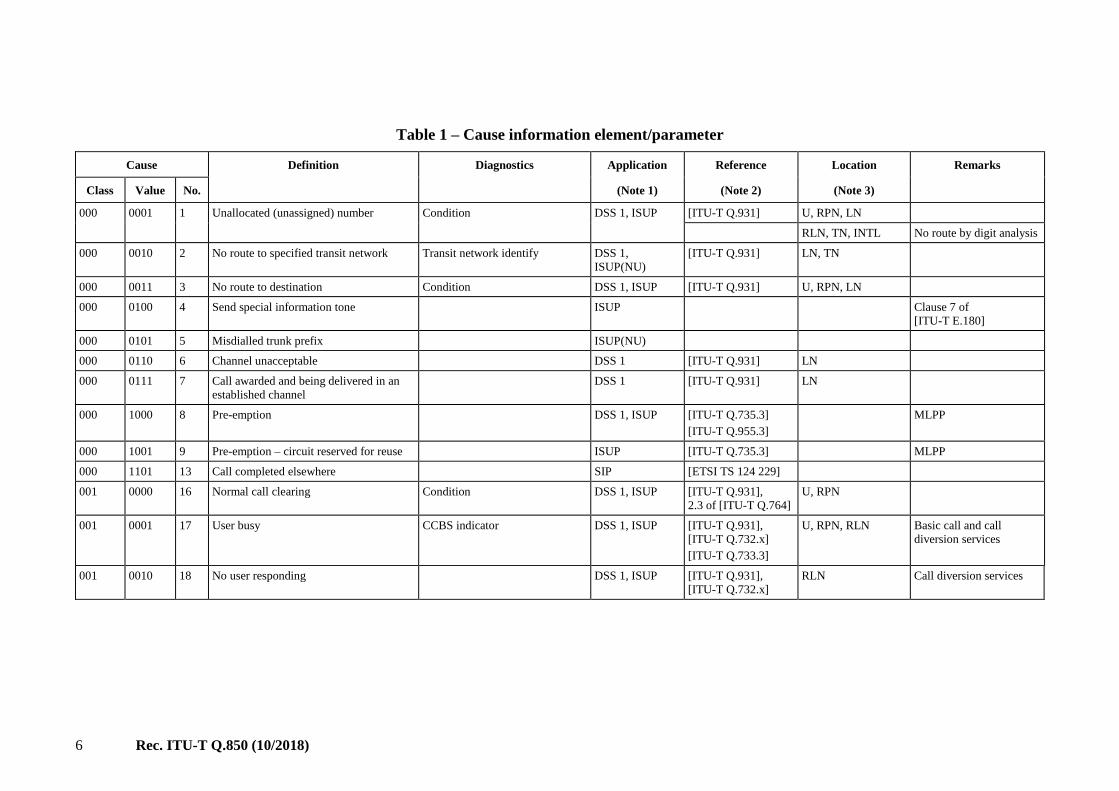
2) The cause values are listed in Table 1.
6 Rec. ITU-T Q.850 (10/2018)
Table 1 – Cause information element/parameter
Cause Definition Diagnostics Application Reference Location Remarks
Class Value No. (Note 1) (Note 2) (Note 3)
000 0001 1 Unallocated (unassigned) number Condition DSS 1, ISUP [ITU-T Q.931] U, RPN, LN
RLN, TN, INTL No route by digit analysis
000 0010 2 No route to specified transit network Transit network identify DSS 1,
ISUP(NU)
[ITU-T Q.931] LN, TN
000 0011 3 No route to destination Condition DSS 1, ISUP [ITU-T Q.931] U, RPN, LN
000 0100 4 Send special information tone ISUP Clause 7 of
[ITU-T E.180]
000 0101 5 Misdialled trunk prefix ISUP(NU)
000 0110 6 Channel unacceptable DSS 1 [ITU-T Q.931] LN
000 0111 7 Call awarded and being delivered in an
established channel
DSS 1 [ITU-T Q.931] LN
000 1000 8 Pre-emption DSS 1, ISUP [ITU-T Q.735.3]
[ITU-T Q.955.3]
MLPP
000 1001 9 Pre-emption – circuit reserved for reuse ISUP [ITU-T Q.735.3] MLPP
000 1101 13 Call completed elsewhere SIP [ETSI TS 124 229]
001 0000 16 Normal call clearing Condition DSS 1, ISUP [ITU-T Q.931],
2.3 of [ITU-T Q.764]
U, RPN
001 0001 17 User busy CCBS indicator DSS 1, ISUP [ITU-T Q.931],
[ITU-T Q.732.x]
[ITU-T Q.733.3]
U, RPN, RLN Basic call and call
diversion services
001 0010 18 No user responding DSS 1, ISUP [ITU-T Q.931],
[ITU-T Q.732.x]
RLN Call diversion services

7 Rec. ITU-T Q.850 (10/2018)
Table 1 – Cause information element/parameter
Cause Definition Diagnostics Application Reference Location Remarks
Class Value No. (Note 1) (Note 2) (Note 3)
001 0011 19 No answer from user (user alerted) DSS 1, ISUP [ITU-T Q.931] RLN
2.1.4 of [ITU-T
Q.764]
2.9.8.3 of [ITU-T
Q.764]
RLN, TN, INTL Expiry of waiting ANM
timer (T9)
[ITU-T Q.732.x] RLN Call diversion services
001 0100 20 Subscriber absent DSS 1, ISUP Mobile application
001 0101 21 Call rejected Call rejected condition DSS 1, ISUP [ITU-T Q.931] U, RPN
[ITU-T Q.732.x] RLN Call diversion services
001 0110 22 Number changed New destination (DSS 1)/
Called party number (ISUP)
DSS 1, ISUP [ITU-T Q.931] U, RPN, LN
001 0111 23 Redirection to new destination ISUP
001 1001 25 Exchange routing error ISUP LN, TN, RLN, ITNL
001 1010 26 Non-selected user clearing DSS 1 [ITU-T Q.931] LN
001 1011 27 Destination out of order DSS 1, ISUP [ITU-T Q.931] RLN
001 1100 28 Invalid number format (address
incomplete)
[ITU-T Q.931] U, RPN, RLN, LN
DSS 1, ISUP
2.1.1 of [ITU-T
Q.764]
2.1.2 of [ITU-T
Q.764]
2.9.8.3 of [ITU-T
Q.764]
2.2.5 of [ITU-T
Q.764]
TN, INTL The called party number
is not in a valid format or
is not complete
Annex A of [ITU-T
Q.763]
TN, INTL, RLN,
RPN

8 Rec. ITU-T Q.850 (10/2018)
Table 1 – Cause information element/parameter
Cause Definition Diagnostics Application Reference Location Remarks
Class Value No. (Note 1) (Note 2) (Note 3)
001 1101 29 Facility rejected Facility identification (DSS 1)/
Parameter name (ISUP)
[ITU-T Q.931] RLN, U, RPN, LN
DSS 1, ISUP
TN, INTL Inability to provide a
request signalling
capability
[ITU-T Q.735.1] INTL, RLN CUG
[ITU-T Q.737.1] INTL, TN, RLN UUS
001 1110 30 Response to STATUS ENQUIRY DSS 1 [ITU-T Q.931] U, LN
001 1111 31 Normal, unspecified DSS 1, ISUP [ITU-T Q.931] RLN
2.1.1 of [ITU-T
Q.764]
2.1.2 of [ITU-T
Q.764]
2.8.1 of [ITU-T
Q.764]
2.8.2 of [ITU-T
Q.764]
2.9.3 of [ITU-T
Q.764]
2.9.6 of [ITU-T
Q.764]
2.9.8.2 of [ITU-T
Q.764]
2.9.8.3 of [ITU-T
Q.764]
2.1.8 of [ITU-T
Q.764]
2.2.4 of [ITU-T
Q.764]
TN, INTL, RLN Call failure information
indicating the failure of a
call due to the lapse of a
timeout or a fault not
covered by specific
causes (examples: expiry
of timers ITU-T Q.764
not covered by specific
causes, release of
interconnected circuit,
etc.)
2.1.6 of [ITU-T
Q.764]
2.9.7 of [ITU-T
Q.764]
RLN, TN Expiry of waiting INF
timer (T33)

9 Rec. ITU-T Q.850 (10/2018)
Table 1 – Cause information element/parameter
Cause Definition Diagnostics Application Reference Location Remarks
Class Value No. (Note 1) (Note 2) (Note 3)
Annex A of [ITU-T
Q.763]
010 0010 34 No circuit/channel available CCBS indicator DSS 1, ISUP [ITU-T Q.931], [ITU-
T Q.733.3]
U, RPN, RLN, LN,
TN
TN, INTL Circuit congestion
encountered in an
exchange
010 0110 38 Network out of order DSS 1, ISUP [ITU-T Q.931] U, RPN
010 0111 39 Permanent frame mode connection out of
service
DSS 1 [ITU-T Q.933]
010 1000 40 Permanent frame mode connection
operational
DSS 1 [ITU-T Q.933]
010 1001 41 Temporary failure DSS 1, ISUP [ITU-T Q.931] U, RPN, RLN, LN
010 1010 42 Switching equipment congestion DSS 1, ISUP TN, RLN, INTL
2.9.9.1 of [ITU-T
Q.764]
TN, RLN Temporary trunk block
(national use)
010 1011 43 Access information discarded Discarded information element
identifier(s)
(Note 4)
DSS 1, ISUP [ITU-T Q.931] U, RPN, LN
010 1100 44 Requested circuit/channel not available DSS 1, ISUP [ITU-T Q.931] U, RPN, LN
010 1110 46 Precedence call blocked DSS 1, ISUP [ITU-T Q.735.3]
[ITU-T Q.955.3]
MLPP
010 1111 47 Resource unavailable, unspecified DSS 1, ISUP [ITU-T Q.931] U, RPN
Annex A of [ITU-T
Q.763]
011 0001 49 Quality of service not available Condition DSS 1 [ITU-T Q.931]
011 0010 50 Requested facility not subscribed Facility identification (DSS 1)/
Parameter name (ISUP)
DSS 1, ISUP [ITU-T Q.931],
[ITU-T Q.735.1]
U, LN, RLN
011 0101 53 Outgoing calls barred within CUG ISUP [ITU-T Q.735.1] CUG
011 0111 55 Incoming calls barred within CUG ISUP [ITU-T Q.735.1] RLN CUG

10 Rec. ITU-T Q.850 (10/2018)
Table 1 – Cause information element/parameter
Cause Definition Diagnostics Application Reference Location Remarks
Class Value No. (Note 1) (Note 2) (Note 3)
011 1001 57 Bearer capability not authorized Attribute identity DSS 1, ISUP [ITU-T Q.931] LN
011 1010 58 Bearer capability not presently available Attribute identity DSS 1, ISUP [ITU-T Q.931] LN
011 1110 62 Inconsistency in designated outgoing
access information and subscriber class
DSS 1, ISUP [ITU-T Q.735.1]
011 1111 63 Service or option not available,
unspecified
DSS 1, ISUP [ITU-T Q.931] LN
Annex A of [ITU-T
Q.763]
100 0001 65 Bearer capability not implemented Attribute identity DSS 1, ISUP [ITU-T Q.931] LN
Annex A of [ITU-T
Q.763]
TN, INTL Inability to provide a
requested TMR
100 0010 66 Channel type not implemented Channel type DSS 1 [ITU-T Q.931]
100 0101 69 Requested facility not implemented Facility identification
(DSS 1)/Parameter name (ISUP) DSS 1, ISUP [ITU-T Q.931], [ITU-
T Q.737.1] U, RPN, LN, RLN UUS
100 0110 70 Only restricted digital information bearer
capability is available
DSS 1, ISUP
(NU)
[ITU-T Q.931]
100 1111 79 Service or option not implemented,
unspecified
DSS 1, ISUP [ITU-T Q.931]
Annex A of [ITU-T
Q.763]
101 0001 81 Invalid call reference value DSS 1 [ITU-T Q.931] U, LN
101 0010 82 Identified channel does not exist Channel identity DSS 1 [ITU-T Q.931]
101 0011 83 A suspended call exists, but this call
identity does not
DSS 1 [ITU-T Q.931] LN
101 0100 84 Call identity in use DSS 1 [ITU-T Q.931] LN
101 0101 85 No call suspended DSS 1 [ITU-T Q.931] LN
101 0110 86 Call with the requested call identity has
been cleared
Clearing cause DSS 1 [ITU-T Q.931] LN
101 0111 87 User not member of CUG ISUP, DSS 1 [ITU-T Q.735.1] RLN CUG

11 Rec. ITU-T Q.850 (10/2018)
Table 1 – Cause information element/parameter
Cause Definition Diagnostics Application Reference Location Remarks
Class Value No. (Note 1) (Note 2) (Note 3)
101 1000 88 Incompatible destination Incompatible parameter (DSS 1) DSS 1, ISUP [ITU-T Q.931] U, RPN
User-to-user indicators parameter
name
ISUP [ITU-T Q.737.1] RLN UUS 2
101 1010 90 Non-existent CUG ISUP [ITU-T Q.735.1] CUG
101 1011 91 Invalid transit network selection DSS 1,
ISUP(NU)
[ITU-T Q.931] LN, TN
101 1111 95 Invalid message, unspecified DSS 1, ISUP [ITU-T Q.931] LN
Annex A of ITU-T
Q.763
110 0000 96 Mandatory information element is
missing
Information element identifier
(Note 4)
DSS 1, [ITU-T Q.931] U, LN
110 0001 97 Message type non-existent or not
implemented
Message type DSS 1, ISUP [ITU-T Q.931] U, LN
2.9.5.2 of [ITU-T
Q.764]
2.9.5.3 of [ITU-T
Q.764]
TN, INTL, RLN
110 0010 98 Message not compatible with call state or
message type non-existent or not
implemented
Message type DSS 1 [ITU-T Q.931] U, LN
110 0011 99 Information element /parameter non-
existent or not implemented
Information element identifier(s)
(DSS 1) (Note 4 and Note 5)/
Parameter names
DSS 1, ISUP [ITU-T Q.931] U, LN
2.9.5.2 of [ITU-T
Q.764]
2.9.5.3 of [ITU-T
Q.764]
Annex A of [ITU-T
Q.763]
TN, INTL, RLN
110 0100 100 Invalid information element contents Information element identifier(s)
(Note 4)
DSS 1 [ITU-T Q.931] U, LN
110 0101 101 Message not compatible with call state Message type DSS 1 [ITU-T Q.931] U, LN

12 Rec. ITU-T Q.850 (10/2018)
Table 1 – Cause information element/parameter
Cause Definition Diagnostics Application Reference Location Remarks
Class Value No. (Note 1) (Note 2) (Note 3)
110 0110 102 Recovery on timer expiry Timer number DSS 1, ISUP [ITU-T Q.931]
[ITU-T Q.733.4] RLN Terminal portability:
expiry of waiting RES
(user) timer
2.4.3 of [ITU-T
Q.764]
INTL Expiry of waiting RES
(network) timer
(incoming international
exchange)
110 0111 103 Parameter non-existent or not
implemented, passed on
Parameter name(s) ISUP(NU)
110 1110 110 Message with unrecognized parameter,
discarded
Parameter name(s), message
name
ISUP 2.9.5.2 of [ITU-T
Q.764]
2.9.5.3 of [ITU-T
Q.764]
110 1111 111 Protocol error, unspecified DSS 1, ISUP [ITU-T Q.931] RLN
Annex A of [ITU-T
Q.763]
RLN, TN, INTL
[ITU-T Q.735.1] RLN CUG
111 1111 127 Interworking, unspecified DSS 1, ISUP [ITU-T Q.931]
Annex A of [ITU-T
Q.763]
NOTE 1 – The application indicates that the cause value may be carried in DSS 1 and/or ISUP. Causes carried in ISUP which are not marked for national use (NU) are the minimum set of cause values
that shall be supported over the international interface.
NOTE 2 – The references included are not exhaustive.
NOTE 3 – These are typical locations generated within the scope of the associated Recommendations. Other locations may be used depending upon network configuration.
NOTE 4 – Locking and non-locking shift procedures described in clause 4.5 of [ITU-T Q.931] are applied. In principle information element identifiers are ordered in the same order as the information
element in the received message.
NOTE 5 – When only the locking shift information element is included and no variable length information element identifier follows, it means that the codeset in the locking shift itself is not
implemented.

Rec. ITU-T Q.850 (10/2018) 13
6.2.6 Diagnostics (only applicable in the context of [ITU-T Q.763] and [ITU-T Q.931]).
The diagnostics applicable to each cause value are given in Table 1. Diagnostic information is not
available for every cause. In those cases in which the diagnostic is an ITU-T Q.931 information
element, the coding of the diagnostic is the same as for the corresponding information element in
clause 4 of [ITU-T Q.931].
6.2.6.1 Coding of condition
The condition diagnostic is coded as follows:
Bit 8: 1
Bits 7-5: 000
Bit 4: Condition as follows:
0 – Network service – Provider
1 – Network service – User
Bit 3: Condition as follows:
0 – Normal
1 – Abnormal
Bits 2-1: Condition as follows:
00 – Unknown
01 – Permanent
10 – Transient
6.2.6.2 Coding of Transit network identity
The diagnostic field contains the entire transit network selection or network-specific facilities
information element as applicable, including parameter name/information element identifier and
length octet.
6.2.6.3 Coding of CCBS indicator
The CCBS indicator is coded as follows:
Bits 8-1: 00000000 – Spare
00000001 – CCBS possible
00000010 – CCBS not possible
00000011
to – Spare
01111111
10000000
to – Spare for national use
11111110
11111111 – Reserved for extension
NOTE – Not used in [ITU-T Q.931].
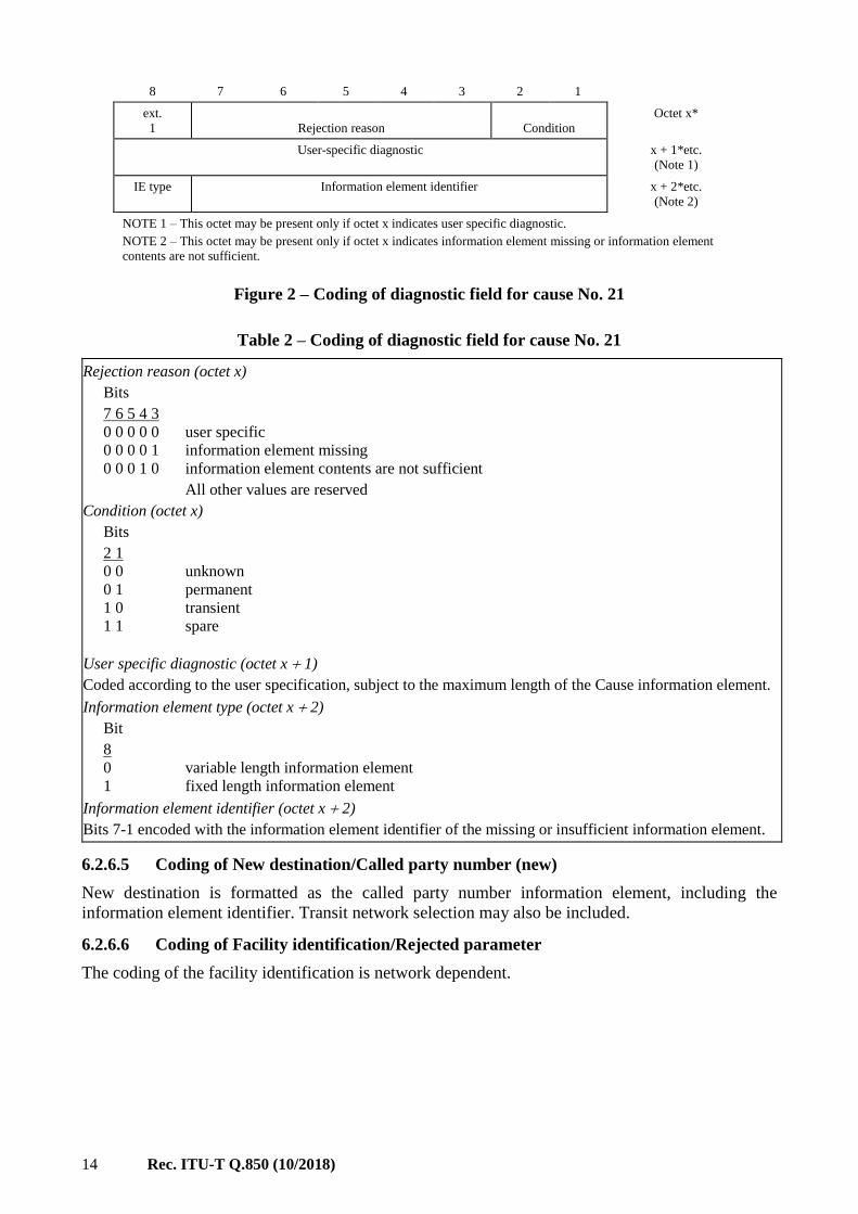
6.2.6.4 Coding of Call rejected diagnostic
The format of the diagnostic field for cause No. 21 is as shown in Figure 2 and Table 2.
14 Rec. ITU-T Q.850 (10/2018)
8 7 6 5 4 3 2 1
ext.
1
Rejection reason
Condition
Octet x*
User-specific diagnostic x + 1*etc.
(Note 1)
IE type Information element identifier x + 2*etc.
(Note 2)
NOTE 1 – This octet may be present only if octet x indicates user specific diagnostic.
NOTE 2 – This octet may be present only if octet x indicates information element missing or information element
contents are not sufficient.
Figure 2 – Coding of diagnostic field for cause No. 21
Table 2 – Coding of diagnostic field for cause No. 21
Rejection reason (octet x)
Bits
7 6 5 4 3
0 0 0 0 0 user specific
0 0 0 0 1 information element missing
0 0 0 1 0 information element contents are not sufficient
All other values are reserved
Condition (octet x)
Bits
2 1
0 0 unknown
0 1 permanent
1 0 transient
1 1 spare
User specific diagnostic (octet x 1)
Coded according to the user specification, subject to the maximum length of the Cause information element.
Information element type (octet x 2)
Bit
8
0 variable length information element
1 fixed length information element
Information element identifier (octet x 2)
Bits 7-1 encoded with the information element identifier of the missing or insufficient information element.
6.2.6.5 Coding of New destination/Called party number (new)
New destination is formatted as the called party number information element, including the
information element identifier. Transit network selection may also be included.
6.2.6.6 Coding of Facility identification/Rejected parameter
The coding of the facility identification is network dependent.

Rec. ITU-T Q.850 (10/2018) 15
6.2.6.7 Coding of Attribute identity
The coding of the attribute identity diagnostic is shown in Figure 3, Table 3a and Table 3b.
NOTE – Not generated by ISUP.
8 7 6 5 4 3 2 1
ext.
0/1
Attribute number Octet x
ext.
0/1
Rejected attribute x + 1
ext.
1
Available attribute x + 2
NOTE 1 – When diagnostics information is provided, octet x and x + 1 shall be present. Octet x + 2 is optional.
NOTE 2– Octets x-x + 2 may be repeated to report multiple rejected attributes.
NOTE 3 – The extension bit (ext.) when coded 0, indicates that this diagnostic continues to the next octet.
Figure 3 – Coding of the diagnostic field for cause Nos. 57, 58 and 65
(Attribute identity)
Table 3a – Coding of attribute number field for cause Nos. 57, 58 and 65
Attribute number (octet x)
Bits
7 6 5 4 3 2 1 No.
0 1 1 0 0 0 1 1 Information transfer capability
0 1 1 0 0 1 0 2 Information transfer mode
0 1 1 0 0 1 1 3 Information transfer rate
0 1 1 0 1 0 0 4 Structure
0 1 1 0 1 0 1 5 Configuration
0 1 1 0 1 1 0 6 Establishment
0 1 1 0 1 1 1 7 Symmetry
0 1 1 1 0 0 0 8 Information transfer rate (dest. orig.)
0 1 1 1 0 0 1 9 Layer identification

16 Rec. ITU-T Q.850 (10/2018)
Table 3b – Coding of the rejected attribute field for cause Nos. 57, 58 and 65
Rejected attribute (octet x 1)
Attribute No.
1. Information transfer capability:
Bits 7-6: 00
Bits 5-1: according to Table 4-6 of [ITU-T Q.931], octet 3
2. Information transfer mode
Bits 7-6: according to Table 4-6 of [ITU-T Q.931], octet 4
Bits 5-1: 00000
3. Information transfer rate
Bits 7-6: 00
Bits 5-1 according to Table 4-6 of [ITU-T Q.931], octet 4
4. Structure (Note 1)
Bits 7-5: according to Table 4-6 of [ITU-T Q.931], octet 4a
Bits 4-1: 0000
5. Configuration (Note 1)
Bits 7-4: 000
Bits 4-3: according to Table 4-6 of [ITU-T Q.931], octet 4a
Bits 2-1: 00
6. Establishment (Note 1)
Bits 7-3: 00000
Bits 2-1: according to Table 4-6 of [ITU-T Q.931], octet 4a
7. Symmetry (Note 1)
Bits 7-6: according to Table 4-6 of [ITU-T Q.931], octet 4b
Bits 5-1: 00000
8. Information transfer rate (dest. orig.): (Note 1)
Bits 7-6: 00
Bits 5-1: according to Table 4-6 of [ITU-T Q.931], octet 4b
9. Layer identification:
Bits
7 6
0 1 (layer 1) Bits 5-1 according to Table 4-6 of [ITU-T Q.931], octet 5
1 0 (layer 2) Bits 5-1 according to Table 4-6 of [ITU-T Q.931], octet 6
1 1 (layer 3) Bits 5-1 according to Table 4-6 of [ITU-T Q.931], octet 7
10. Rate multiplier:
Bit 8: 1
Bits 7-1 according to Table 4-6 of [ITU-T Q.931], octet 4.1
Available attributes (octet x 2)
The same coding as octet x + 1
NOTE 1 – These values were defined in [ITU-T Q.931] (1988).
NOTE 2 – A description of Table 4-6 of [ITU-T Q.931] is found in 3.57 of [ITU-T Q.763].
6.2.6.8 Coding of Channel type
The channel type is coded as follows:
Bit 8: Extension bit
Bits 7-5: spare
Bits 4-1: according to the Table 4-15 of [ITU-T Q.931] octet 3.2, channel type.
NOTE – Not generated by ISUP.
6.2.6.9 Coding of Incompatible parameter
Incompatible parameter is composed of the incompatible information element identifier.

Rec. ITU-T Q.850 (10/2018) 17
6.2.6.10 Coding of Timer number
NOTE – Not generated by ISUP.
The timer number is coded in IA5 characters, e.g., T308 is coded as "3" "0" "8". The following coding
is used in each octet:
Bit 8: Spare "0"
Bits 7-1: IA5 character.
6.2.6.11 Coding of Message type
Message type is coded as specified in Table 4 of [ITU-T Q.763] and Table 4-2 of [ITU-T Q.931],
respectively.
6.2.6.12 Coding of Parameter name
Parameter name is coded as specified in Table 5 of [ITU-T Q.763].
6.2.7 Cause definitions
6.2.7.1 Normal class
6.2.7.1.1 Cause No. 1 – Unallocated (unassigned) number
This cause indicates that the called party cannot be reached because, although the called party number
is in a valid format, it is not currently allocated (assigned).
6.2.7.1.2 Cause No. 2 – No route to specified transit network (national use)
This cause indicates that the equipment sending this cause has received a request to route the call
through a particular transit network which it does not recognize. The equipment sending this cause
does not recognize the transit network either because the transit network does not exist or because
that particular transit network, while it does exist, does not serve the equipment which is sending this
cause.
This cause is supported on a network-dependent basis.
6.2.7.1.3 Cause No. 3 – No route to destination
This cause indicates that the called party cannot be reached because the network through which the
call has been routed does not serve the destination desired.
This cause is supported on a network-dependent basis.
6.2.7.1.4 Cause No. 4 – Send special information tone
This cause indicates that the called party cannot be reached for reasons that are of a long-term nature
and that the special information tone should be returned to the calling party.
6.2.7.1.5 Cause No. 5 – Misdialled trunk prefix (national use)
This cause indicates the erroneous inclusion of a trunk prefix in the called party number.
6.2.7.1.6 Cause No. 6 – Channel unacceptable
This cause indicates that the channel most recently identified is not acceptable to the sending entity
for use in this call.
6.2.7.1.7 Cause No. 7 – Call awarded and being delivered in an established channel
This cause indicates that the user has been awarded the incoming call, and that the incoming call is
being connected to a channel already established to that user for similar calls (e.g., packet-mode
ITU-T X.25 virtual calls).
18 Rec. ITU-T Q.850 (10/2018)
6.2.7.1.8 Cause No. 8 – Pre-emption
This cause indicates that the call is being pre-empted.
6.2.7.1.9 Cause No. 9 – Pre-emption – circuit reserved for reuse
This cause indicates that the call is being pre-empted and the circuit is reserved for reuse by the
pre-empting exchange.
6.2.7.1.10 Cause No. 13 – Call completed elsewhere
When the S-CSCF has forked an initial INVITE request, and it has received a 2xx response associated
with one of the early dialogues, the S-CSCF shall in each CANCEL request it generates insert a
Reason header field with a "SIP" protocol header field parameter value, a "200" cause header field
parameter value, and a "Call completed elsewhere" text header field parameter value, as specified in
[RFC 3326].
6.2.7.1.11 Cause No. 16 – Normal call clearing
This cause indicates that the call is being cleared because one of the users involved in the call has
requested that the call be cleared.
Under normal situations, the source of this cause is not the network.
6.2.7.1.12 Cause No. 17 – User busy
This cause is used to indicate that the called party is unable to accept another call because the user
busy condition has been encountered. This cause value may be generated by the called user or by the
network. In the case of user determine user busy, it is noted that the user equipment is compatible
with the call.
6.2.7.1.13 Cause No. 18 – No user responding
This cause is used when a called party does not respond to a call establishment message with either
an alerting or connect indication within the prescribed period of time allocated.
6.2.7.1.14 Cause No. 19 – No answer from user (user alerted)
This cause is used when the called party has been alerted but does not respond with a connect
indication within a prescribed period of time.
NOTE – This cause is not necessarily generated by ITU-T Q.931 procedures but may be generated by internal
network timers.
6.2.7.1.15 Cause No. 20 – Subscriber absent
This cause value is used when a mobile station has logged off, radio contact is not obtained with a
mobile station or if a personal telecommunication user is temporarily not addressable at any
user-network interface.
6.2.7.1.16 Cause No. 21 – Call rejected
This cause indicates that the equipment sending this cause does not wish to accept this call, although
it could have accepted the call because the equipment sending this cause is neither busy nor
incompatible.
This cause may also be generated by the network, indicating that the call was cleared due to a
supplementary service constraint. The diagnostic field may contain additional information about the
supplementary service and reason for rejection.
6.2.7.1.17 Cause No. 22 – Number changed
This cause is returned to a calling party when the called party number indicated by the calling party
is no longer assigned. The new called party number may optionally be included in the diagnostic

Rec. ITU-T Q.850 (10/2018) 19
field. If a network does not support this cause value, cause No. 1, Unallocated (unassigned) number,
shall be used.
6.2.7.1.18 Cause No. 23 – Redirection to new destination
This cause is used by a general ISUP protocol mechanism that can be invoked by an exchange that
decides that the call should be set up to a different called number. Such an exchange can invoke a
redirection mechanism, by use of this cause value, to request a preceding exchange involved in the
call to route the call to the new number.
6.2.7.1.19 Cause No. 25 – Exchange – routing error
This cause indicates that the destination indicated by the user cannot be reached, because an
intermediate exchange has released the call due to reaching a limit in executing the hop counter
procedure.
This cause is generated by an intermediate node, which when decrementing the hop counter value,
gives the result 0.
6.2.7.1.20 Cause No. 26 – Non-selected user clearing
This cause indicates that the user has not been awarded the incoming call.
6.2.7.1.21 Cause No. 27 – Destination out of order
This cause indicates that the destination indicated by the user cannot be reached because the interface
to the destination is not functioning correctly. The term "not functioning correctly" indicates that a
signalling message was unable to be delivered to the remote party; e.g., a physical layer or data link
layer failure at the remote party, or user equipment offline.
6.2.7.1.22 Cause No. 28 – Invalid number format (address incomplete)
This cause indicates that the called party cannot be reached because the called party number is not in
a valid format or is not complete.
NOTE – This condition may be determined:
– immediately after reception of an end of pulsing (ST) signal; or
– on time-out after the last received digit.
6.2.7.1.23 Cause No. 29 – Facility rejected
This cause is returned when a supplementary service requested by the user cannot be provided by the
network.
6.2.7.1.24 Cause No. 30 – Response to STATUS ENQUIRY
This cause is included in the STATUS message when the reason for generating the STATUS message
was the prior receipt of a STATUS ENQUIRY message.
6.2.7.1.25 Cause No. 31 – Normal, unspecified
This cause is used to report a normal event only when no other cause in the normal class applies.
6.2.7.2 Resource unavailable class
6.2.7.2.1 Cause No. 34 – No circuit/channel available
This cause indicates that there is no appropriate circuit/channel presently available to handle the call.
6.2.7.2.2 Cause No. 38 – Network out of order
This cause indicates that the network is not functioning correctly and that the condition is likely to
last a relatively long period of time; e.g., immediately re-attempting the call is not likely to be
successful.

20 Rec. ITU-T Q.850 (10/2018)
6.2.7.2.3 Cause No. 39 – Permanent frame mode connection out of service
This cause is included in a STATUS message to indicate that a permanently established frame mode
connection is out of service (e.g., due to equipment or section failure) (see Annex A of
[ITU-T Q.933]).
6.2.7.2.4 Cause No. 40 – Permanent frame mode connection operational
This cause is included in a STATUS message to indicate that a permanently established frame mode
connection is operational and capable of carrying user information (see Annex A of [ITU-T Q.933]).
6.2.7.2.5 Cause No. 41 – Temporary failure
This cause indicates that the network is not functioning correctly and that the condition is not likely
to last a long period of time; e.g., the user may wish to try another call attempt almost immediately.
6.2.7.2.6 Cause No. 42 – Switching equipment congestion
This cause indicates that the switching equipment generating this cause is experiencing a period of
high traffic.
6.2.7.2.7 Cause No. 43 – Access information discarded
This cause indicates that the network could not deliver access information to the remote user as
requested, i.e., user-to-user information, low layer compatibility, high layer compatibility, or
sub-address, as indicated in the diagnostic.
It is noted that the particular type of access information discarded is optionally included in the
diagnostic.
6.2.7.2.8 Cause No. 44 – Requested circuit/channel not available
This cause is returned when the circuit or channel indicated by the requesting entity cannot be
provided by the other side of the interface.
6.2.7.2.9 Cause No. 46 – Precedence call blocked
This cause indicates that there are no pre-emptable circuits or that the called user is busy with a call
of equal or higher pre-emptable level.
6.2.7.2.10 Cause No. 47 – Resource unavailable, unspecified
This cause is used to report a resource unavailable event only when no other cause in the resource
unavailable class applies.
6.2.7.3 Service or option unavailable class
6.2.7.3.1 Cause No. 49 – Quality of service not available
This cause is used to report that the requested Quality of service, as defined in [ITU-T X.213], cannot
be provided (e.g., throughput or transit delay cannot be supported).
6.2.7.3.2 Cause No. 50 – Requested facility not subscribed
This cause indicates that the user has requested a supplementary service which is implemented by the
equipment which generated this cause, but which the user is not authorized to use.
6.2.7.3.3 Cause No. 53 – Outgoing calls barred within CUG
This cause indicates that although the calling party is a member of the CUG for the outgoing CUG
call, outgoing calls are not allowed for this member of the CUG.

Rec. ITU-T Q.850 (10/2018) 21
6.2.7.3.4 Cause No. 55 – Incoming calls barred within CUG
This cause indicates that although the called party is a member of the CUG for the incoming CUG
call, incoming calls are not allowed to this member of the CUG.
6.2.7.3.5 Cause No. 57 – Bearer capability not authorized
This cause indicates that the user has requested a bearer capability which is implemented by the
equipment which generated this cause but the user is not authorized to use.
6.2.7.3.6 Cause No. 58 – Bearer capability not presently available
This cause indicates that the user has requested a bearer capability which is implemented by the
equipment which generated this cause but which is not available at this time.
6.2.7.3.7 Cause No. 62 – Inconsistency in designated outgoing access information and
subscriber class
This cause indicates that there is an inconsistency in the designated outgoing access information and
subscriber class.
6.2.7.3.8 Cause No. 63 – Service or option not available, unspecified
This cause is used to report a service or option not available event only when no other cause in the
service or option not available class applies.
6.2.7.4 Service or option not implemented class
6.2.7.4.1 Cause No. 65 – Bearer capability not implemented
This cause indicates that the equipment sending this cause does not support the bearer capability
requested.
6.2.7.4.2 Cause No. 66 – Channel type not implemented
This cause indicates that the equipment sending this cause does not support the channel type
requested.
6.2.7.4.3 Cause No. 69 – Requested facility not implemented
This cause indicates that the equipment sending this cause does not support the requested
supplementary service.
6.2.7.4.4 Cause No. 70 – Only restricted digital information bearer capability is available
(national use)
This cause indicates that the calling party has requested an unrestricted bearer service but that the
equipment sending this cause only supports the restricted version of the requested bearer capability.
6.2.7.4.5 Cause No. 79 – Service or option not implemented, unspecified
This cause is used to report a service or option not implemented event only when no other cause in
the service or option not implemented class applies.
6.2.7.5 Invalid message (e.g., parameter out of range) class
6.2.7.5.1 Cause No. 81 – Invalid call reference value
This cause indicates that the equipment sending this cause has received a message with a call
reference which is not currently in use on the user-network interface.
6.2.7.5.2 Cause No. 82 – Identified channel does not exist
This cause indicates that the equipment sending this cause has received a request to use a channel not
activated on the interface for a call. For example, if a user has subscribed to those channels on a

22 Rec. ITU-T Q.850 (10/2018)
primary rate interface numbered from 1 to 12 and the user equipment or the network attempts to use
channels 13 to 23, this cause is generated.
6.2.7.5.3 Cause No. 83 – A suspended call exists, but this call identity does not
This cause indicates that a call resume has been attempted with a call identity which differs from that
in use for any presently suspended call(s).
6.2.7.5.4 Cause No. 84 – Call identity in use
This cause indicates that the network has received a call suspended request containing a call identity
(including the null call identity) which is already in use for a suspended call within the domain of
interfaces over which the call might be resumed.
6.2.7.5.5 Cause No. 85 – No call suspended
This cause indicates that the network has received a call resume request containing a call identity
information element which presently does not indicate any suspended call within the domain of
interfaces over which calls may be resumed.
6.2.7.5.6 Cause No. 86 – Call with the requested call identity has been cleared
This cause indicates that the network has received a call resume request containing a call identity
information element indicating a suspended call that has in the meantime been cleared while
suspended (either by network timeout or by the remote user).
6.2.7.5.7 Cause No. 87 – User not member of CUG
This cause indicates that the called user for the incoming CUG call is not a member of the specified
CUG or that the calling user is an ordinary subscriber calling a CUG subscriber.
6.2.7.5.8 Cause No. 88 – Incompatible destination
This cause indicates that the equipment sending this cause has received a request to establish a call
which has low layer compatibility, high layer compatibility, or other compatibility attributes
(e.g., data rate) which cannot be accommodated.
6.2.7.5.9 Cause No. 90 – Non-existent CUG
This cause indicates that the specified CUG does not exist.
6.2.7.5.10 Cause No. 91 – Invalid transit network selection (national use)
This cause indicates that a transit network identification was received which is of an incorrect format
as defined in Annex C of [ITU-T Q.931].
6.2.7.5.11 Cause No. 95 – Invalid message, unspecified
This cause is used to report an invalid message event only when no other cause in the invalid message
class applies.
6.2.7.6 Protocol error (e.g., unknown message) class
6.2.7.6.1 Cause No. 96 – Mandatory information element is missing
This cause indicates that the equipment sending this cause has received a message which is missing
an information element which must be present in the message before that message can be processed.
6.2.7.6.2 Cause No. 97 – Message type non-existent or not implemented
This cause indicates that the equipment sending this cause has received a message with a message
type it does not recognize either because this is a message not defined or defined but not implemented
by the equipment sending this cause.

Rec. ITU-T Q.850 (10/2018) 23
6.2.7.6.3 Cause No. 98 – Message not compatible with call state or message type non-existent
or not implemented
This cause indicates that the equipment sending this cause has received a message so that the
procedures do not indicate that this is a permissible message to receive while in the call state, or a
STATUS message was received indicating an incompatible call state.
6.2.7.6.4 Cause No. 99 – Information element/parameter non-existent or not implemented
This cause indicates that the equipment sending this cause has received a message which includes
information element(s)/parameter(s) not recognized because the information element
identifier(s)/parameter name(s) is not defined or defined but not implemented by the equipment
sending the cause. This cause indicates that the information element(s)/parameter(s) has been
discarded. However, the information element is not required to be present in the message in order for
the equipment sending the cause to process the message.
6.2.7.6.5 Cause No. 100 – Invalid information element contents
This cause indicates that the equipment sending this cause has received an information element which
it has implemented; however, one or more fields in the information element are coded in such a way
which has not been implemented by the equipment sending this cause.
6.2.7.6.6 Cause No. 101 – Message not compatible with call state
This cause indicates that a message has been received which is incompatible with the call state.
6.2.7.6.7 Cause No. 102 – Recovery on timer expiry
This cause indicates that a procedure has been initiated by the expiry of a timer in association with
error handling procedures.
6.2.7.6.8 Cause No. 103 – Parameter non-existent or not implemented – passed on (national
use)
This cause indicates that the equipment sending this cause has received a message which includes
parameters not recognized because the parameters are not defined or are defined but not implemented
by the equipment sending the cause. The cause indicates that the parameter(s) was ignored. In
addition, if the equipment sending this cause is an intermediate point, then this cause indicates that
the parameter(s) was passed on unchanged.
6.2.7.6.9 Cause No. 110 – Message with unrecognized parameter discarded
This cause indicates that the equipment sending this cause has discarded a received message which
includes a parameter that is not recognized.
6.2.7.6.10 Cause No. 111 – Protocol error, unspecified
This cause is used to report a protocol error event only when no other cause in the protocol error class
applies.
6.2.7.7 Interworking class
6.2.7.7.1 Cause No. 127 – Interworking, unspecified
This cause indicates that there has been interworking with a network which does not provide causes
for actions it takes. Thus, the precise cause for a message which is being sent cannot be ascertained.
7 General rules for the handling of the location field
This clause specifies the rules for the handling of the location field in the Cause and the Progress
indicator information elements/parameters.

24 Rec. ITU-T Q.850 (10/2018)
Figure 4 shows the reference configuration which is used to identify various nodes where the location
field may be generated.
Table 4 shows the setting of the location field to be generated by a node in the reference configuration
and the location field information expected by user A in each case.
The handling of the location field shall be according to the following rules:
i) If the event causing the generation of the location field takes place in an international
exchange (i.e., incoming or outgoing or international transit exchange), the location shall be
set to International network.
ii) If the event causing the generation of the location field takes place in a national transit
network, the location shall be set to Transit network.
iii) If the event causing the generation of the location field takes place in the public network
serving the user, the location shall be set to Public network serving the local user or Public
network serving the remote user on the basis of network configuration.
NOTE – Locations User and Private network serving the local user shall not be generated in public
networks.
iv) If the event causing the generation of the location field takes place in the private network, the
location shall be set to Private network serving the local user or Private network serving the
remote user on the basis of network configuration.
v) If interworking with a signalling system which cannot convey location information is
encountered, and if a message containing a location field is sent because of the receipt of
information from such a signalling system, the location shall be set to Network beyond
interworking point.
As a consequence of these rules:
– The location Public network serving the local user can be sent over a transit network or can
be converted to Public network serving the remote user according to the structure of the
national network and/or agreements between the network operators involved in the call. In
any case the location Public network serving the local user shall not be sent over the
international network.
– The location Private network serving the local user shall not be sent over the public network.
The conversion from Private network serving the local user to Private network serving the
remote user, if required, shall take place in the private network initially generating the
location information.
In addition, the network may optionally check and, if necessary, change the location when it crosses
a network boundary. The definition of the boundaries between transit networks and public networks
serving the local/remote users is dependent on network structure and is subject to agreement between
network operators or to national regulations.

Rec. ITU-T Q.850 (10/2018) 25
Figure 4 – Reference configuration for location field generation
Table 4 – The setting of location fields by events at nodes of the reference
configuration and values expected to be received by user A
Node generating
location field
Location field setting, in the
direction towards user A
Location setting expected
by user A
B LPN LPN
C LPN LPN
D LN LN
E LN LN
F TN TN
G TN TN
H INTL INTL
I INTL INTL
J TN TN
K TN TN
L LN or RLN RLN
M LN or RLN RLN
N RPN RPN
O LPN or RPN RPN
P U U
LPN Private network serving the local user
LN Public network serving the local user
TN Transit network
INTL International network
RLN Public network serving the remote user
RPN Private network serving the remote user
U User
8 Handling of cause and location at the international interface
This clause contains clarification of the usage of cause values and the handling of location indicators
on the international interface.

26 Rec. ITU-T Q.850 (10/2018)
a) Usage of causes
Setting Cause values Nos. 18 and 19, and using location "public or private network serving
the remote user" or any other cause with location "user or private network serving the remote
user" should imply that the call has reached the called party, i.e., end-to-end fields have been
transmitted.
National networks should make sure, to avoid public network misuse, that the following
locations are not generated on the access:
– Public;
– International;
– Transit network;
– Beyond an interworking point.
The cause value sent is the one of the latest occurred event (e.g., retransmitting of the release
message).
b) Handling of location indicators
If the event causing the sending of the cause indicators parameter takes place in the
international exchange (i.e., incoming, outgoing or intermediate international exchange), the
location will be set to "0111 International network".
If interworking is encountered in the international exchange and if a message containing the
cause indicators parameter is sent because of the receipt of a message of the other signalling
system, the location will be set to "1010 Beyond an interworking point" (BI).
The location "public network serving the local user" or "private network serving the local
user" should not be sent on the international section. The conversion from "public network
serving the local user" to "public network serving the remote user" or "private network
serving the local user" to "private network serving the remote user" shall take place in the
national network generating the cause.
For the handling of locations reserved for national use, see clause 9.
In all other cases the international exchange will pass on the received location.
By using this solution, it is impossible to distinguish a national location "transit network"
from a location "transit network beyond the international boundary".
The real location where the event was generated is lost when interworking: for example, CGC and
NNC in Telephone User Part are coded "34,BI". In spite of that, the limitations of this solution are
accepted because they are considered as acceptable for this ISDN User Part version.
9 Procedures for the handling of location values reserved for national use (national
option)
The values 1100, 1101, 1110 and 1111 of the location field are reserved for national use and can be
sent over a national network.
If a network generates one of these values:
– If the call is an international call, before sending the value of the location over the
international network, the national network shall convert this value to Public network serving
the remote user or Transit network or Network beyond interworking point according to the
structure of the national network and/or agreements between the network operators involved
in the call. In any case, a value of the location reserved for national use shall not be sent over
the international network.
– Before sending a value of the location reserved for national use to an ISDN user, the national
network shall convert this value to Public network serving the remote user or Transit network

Rec. ITU-T Q.850 (10/2018) 27
or Public network serving the local user or Network beyond interworking point according to
the structure of the national network and/or agreements between the network operators
involved in the call. In any case, a value of the location reserved for national use shall not be
sent to an ISDN user.
An ISDN user shall not generate a location value reserved for national use.

28 Rec. ITU-T Q.850 (10/2018)
Bibliography
[b-ITU-T Q.1031] Recommendation ITU-T Q.1031 (1988), General signalling requirements on
interworking between the ISDN or PSTN and the PLMN. <http://handle.itu.int/11.1002/1000/1786>
[b-ITU-T Q.1051] Recommendation ITU-T Q.1051 (1988), Mobile application Part. <http://handle.itu.int/11.1002/1000/1791>


Printed in Switzerland Geneva, 2018
SERIES OF ITU-T RECOMMENDATIONS
Series A Organization of the work of ITU-T
Series D Tariff and accounting principles and international telecommunication/ICT economic and
policy issues
Series E Overall network operation, telephone service, service operation and human factors
Series F Non-telephone telecommunication services
Series G Transmission systems and media, digital systems and networks
Series H Audiovisual and multimedia systems
Series I Integrated services digital network
Series J Cable networks and transmission of television, sound programme and other multimedia
signals
Series K Protection against interference
Series L Environment and ICTs, climate change, e-waste, energy efficiency; construction, installation
and protection of cables and other elements of outside plant
Series M Telecommunication management, including TMN and network maintenance
Series N Maintenance: international sound-programme and television-transmission circuits
Series O Specifications of measuring equipment
Series P Telephone transmission quality, telephone installations, local line networks
Series Q Switching and signalling, and associated measurements and tests
Series R Telegraph transmission
Series S Telegraph services terminal equipment
Series T Terminals for telematic services
Series U Telegraph switching
Series V Data communication over the telephone network
Series X Data networks, open system communications and security
Series Y Global information infrastructure, Internet protocol aspects, next-generation networks,
Internet of Things and smart cities
Series Z Languages and general software aspects for telecommunication systems
Related Documents