International Telecommunication Union ITU-T K.109 TELECOMMUNICATION STANDARDIZATION SECTOR OF ITU (11/2015) SERIES K: PROTECTION AGAINST INTERFERENCE Installation of telecommunication equipment on utility poles Recommendation ITU-T K.109

Welcome message from author
This document is posted to help you gain knowledge. Please leave a comment to let me know what you think about it! Share it to your friends and learn new things together.
Transcript
I n t e r n a t i o n a l T e l e c o m m u n i c a t i o n U n i o n
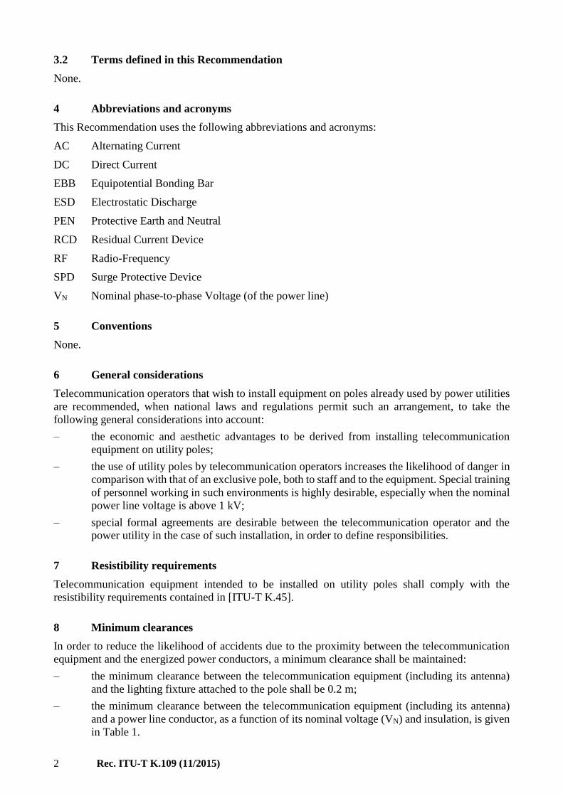
ITU-T K.109 TELECOMMUNICATION STANDARDIZATION SECTOR OF ITU
(11/2015)
SERIES K: PROTECTION AGAINST INTERFERENCE
Installation of telecommunication equipment on utility poles
Recommendation ITU-T K.109

Rec. ITU-T K.109 (11/2015) i
Recommendation ITU-T K.109
Installation of telecommunication equipment on utility poles
Summary
Recommendation ITU-T K.109 provides guidelines for the installation of telecommunication
equipment and/or antennas on utility poles. These guidelines cover the clearances from the power
conductors, the requirements for insulation, earthing and bonding, and the protective procedures to
avoid interference and damage from the electromagnetic fields generated by the nearby power
conductors and lightning flashes. The power distribution lines considered are those operating in
alternating or direct current, with nominal voltages up to 25 kV. These lines may be used for power
distribution, street lighting, or electrified railways.
History
Edition Recommendation Approval Study Group Unique ID*
1.0 ITU-T K.109 2015-11-29 5 11.1002/1000/12670
Keywords
Clearances, earthing, joint use of poles, power lines, telecommunication equipment, utility poles.
* To access the Recommendation, type the URL http://handle.itu.int/ in the address field of your web
browser, followed by the Recommendation's unique ID. For example, http://handle.itu.int/11.1002/1000/1
1830-en.
ii Rec. ITU-T K.109 (11/2015)
FOREWORD
The International Telecommunication Union (ITU) is the United Nations specialized agency in the field of
telecommunications, information and communication technologies (ICTs). The ITU Telecommunication
Standardization Sector (ITU-T) is a permanent organ of ITU. ITU-T is responsible for studying technical,
operating and tariff questions and issuing Recommendations on them with a view to standardizing
telecommunications on a worldwide basis.
The World Telecommunication Standardization Assembly (WTSA), which meets every four years, establishes
the topics for study by the ITU-T study groups which, in turn, produce Recommendations on these topics.
The approval of ITU-T Recommendations is covered by the procedure laid down in WTSA Resolution 1.
In some areas of information technology which fall within ITU-T's purview, the necessary standards are
prepared on a collaborative basis with ISO and IEC.
NOTE
In this Recommendation, the expression "Administration" is used for conciseness to indicate both a
telecommunication administration and a recognized operating agency.
Compliance with this Recommendation is voluntary. However, the Recommendation may contain certain
mandatory provisions (to ensure, e.g., interoperability or applicability) and compliance with the
Recommendation is achieved when all of these mandatory provisions are met. The words "shall" or some other
obligatory language such as "must" and the negative equivalents are used to express requirements. The use of
such words does not suggest that compliance with the Recommendation is required of any party.
INTELLECTUAL PROPERTY RIGHTS
ITU draws attention to the possibility that the practice or implementation of this Recommendation may involve
the use of a claimed Intellectual Property Right. ITU takes no position concerning the evidence, validity or
applicability of claimed Intellectual Property Rights, whether asserted by ITU members or others outside of
the Recommendation development process.
As of the date of approval of this Recommendation, ITU had not received notice of intellectual property,
protected by patents, which may be required to implement this Recommendation. However, implementers are
cautioned that this may not represent the latest information and are therefore strongly urged to consult the TSB
patent database at http://www.itu.int/ITU-T/ipr/.
ITU 2016
All rights reserved. No part of this publication may be reproduced, by any means whatsoever, without the prior
written permission of ITU.
Rec. ITU-T K.109 (11/2015) iii
Table of Contents
Page
1 Scope ............................................................................................................................. 1
2 References ..................................................................................................................... 1
3 Definitions .................................................................................................................... 1
3.1 Terms defined elsewhere ................................................................................ 1
3.2 Terms defined in this Recommendation ......................................................... 2
4 Abbreviations and acronyms ........................................................................................ 2
5 Conventions .................................................................................................................. 2
6 General considerations .................................................................................................. 2
7 Resistibility requirements ............................................................................................. 2
8 Minimum clearances ..................................................................................................... 2
9 Installation of the equipment ........................................................................................ 3
10 Earthing and bonding .................................................................................................... 4
11 Protection against electromagnetic fields ..................................................................... 5
Bibliography............................................................................................................................. 7

Rec. ITU-T K.109 (11/2015) 1
Recommendation ITU-T K.109
Installation of telecommunication equipment on utility poles
1 Scope
This Recommendation provides guidelines for the installation of telecommunication equipment
and/or antennas on utility poles carrying power distribution lines. The power lines considered are
those operating in alternating or direct current, with nominal voltages up to 25 kV. These lines may
be used for power distribution, street lighting, or traction lines (electrified railways).
For the procedures regarding the joint use of poles between telecommunication lines and power lines,
especially the prevention of accidental contacts between these lines (power-cross), the user shall refer
to [b-ITU-T K.108].
For guidance on the installation of telecommunication equipment in towers of power transmission
lines (above 25 kV), the user shall refer to [b-ITU-T K.57].
Some equipment used for smart-grid applications may contain telecommunication interfaces used for
supervision and control of the electric power grid, which may be installed close to or on the energized
power conductors. This type of equipment is outside the scope of this Recommendation.
2 References
The following ITU-T Recommendations and other references contain provisions which, through
reference in this text, constitute provisions of this Recommendation. At the time of publication, the
editions indicated were valid. All Recommendations and other references are subject to revision;
users of this Recommendation are therefore encouraged to investigate the possibility of applying the
most recent edition of the Recommendations and other references listed below. A list of the currently
valid ITU-T Recommendations is regularly published. The reference to a document within this
Recommendation does not give it, as a stand-alone document, the status of a Recommendation.
[ITU-T K.45] Recommendation ITU-T K.45 (2015), Resistibility of telecommunication
equipment installed in the access and trunk networks to overvoltages and
overcurrents.
[ITU-T K.50] Recommendation ITU-T K.50 (2000), Safe limits of operating voltages and
currents for telecommunication systems powered over the network.
[IEC 60060-1] IEC 60060-1 (2010), High-voltage test techniques - Part 1: General definitions
and test requirements.
3 Definitions
3.1 Terms defined elsewhere
This Recommendation uses the following terms defined elsewhere:
3.1.1 low-voltage: Voltage having a value below a conventionally adopted limit.
NOTE – For the distribution of AC electric power, the upper limit is generally accepted to be 1000 V.
(IEC IEV 151-15-03 of [b-IEC IEV])
3.1.2 residual current device (RCD): A mechanical switching device designed to make, carry and break
currents under normal service conditions and to cause the opening of the contacts when the residual current
attains a given value under specified conditions. (IEC IEV 442-05-02 of [b-IEC IEV]).
NOTE – A residual current device can be a combination of various separate elements designed to detect and
evaluate the residual current and to make and break current.
2 Rec. ITU-T K.109 (11/2015)
3.2 Terms defined in this Recommendation
None.
4 Abbreviations and acronyms
This Recommendation uses the following abbreviations and acronyms:
AC Alternating Current
DC Direct Current
EBB Equipotential Bonding Bar
ESD Electrostatic Discharge
PEN Protective Earth and Neutral
RCD Residual Current Device
RF Radio-Frequency
SPD Surge Protective Device
VN Nominal phase-to-phase Voltage (of the power line)
5 Conventions
None.
6 General considerations
Telecommunication operators that wish to install equipment on poles already used by power utilities
are recommended, when national laws and regulations permit such an arrangement, to take the
following general considerations into account:
– the economic and aesthetic advantages to be derived from installing telecommunication
equipment on utility poles;
– the use of utility poles by telecommunication operators increases the likelihood of danger in
comparison with that of an exclusive pole, both to staff and to the equipment. Special training
of personnel working in such environments is highly desirable, especially when the nominal
power line voltage is above 1 kV;
– special formal agreements are desirable between the telecommunication operator and the
power utility in the case of such installation, in order to define responsibilities.
7 Resistibility requirements
Telecommunication equipment intended to be installed on utility poles shall comply with the
resistibility requirements contained in [ITU-T K.45].
8 Minimum clearances
In order to reduce the likelihood of accidents due to the proximity between the telecommunication
equipment and the energized power conductors, a minimum clearance shall be maintained:
– the minimum clearance between the telecommunication equipment (including its antenna)
and the lighting fixture attached to the pole shall be 0.2 m;
– the minimum clearance between the telecommunication equipment (including its antenna)
and a power line conductor, as a function of its nominal voltage (VN) and insulation, is given
in Table 1.
Rec. ITU-T K.109 (11/2015) 3
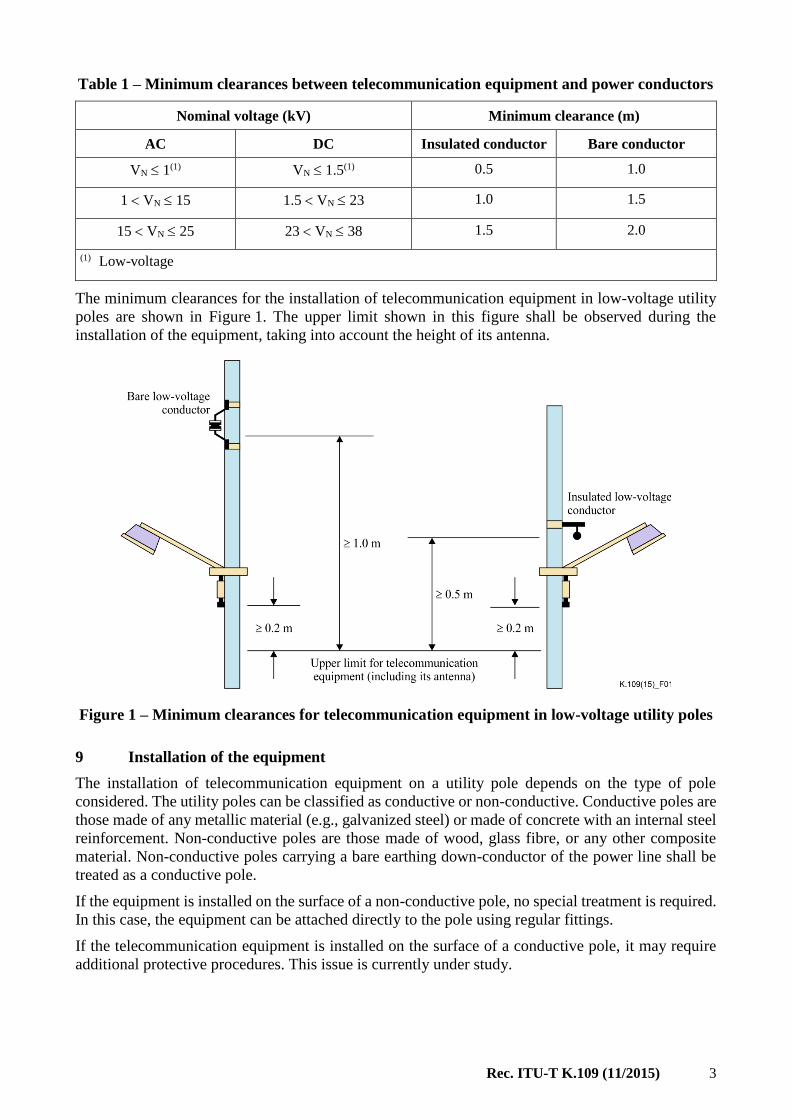
Table 1 – Minimum clearances between telecommunication equipment and power conductors
Nominal voltage (kV) Minimum clearance (m)
AC DC Insulated conductor Bare conductor
VN 1(1) VN 1.5(1) 0.5 1.0
1 VN 15 1.5 VN 23 1.0 1.5
15 VN 25 23 VN 38 1.5 2.0
(1) Low-voltage
The minimum clearances for the installation of telecommunication equipment in low-voltage utility
poles are shown in Figure 1. The upper limit shown in this figure shall be observed during the
installation of the equipment, taking into account the height of its antenna.
Figure 1 – Minimum clearances for telecommunication equipment in low-voltage utility poles
9 Installation of the equipment
The installation of telecommunication equipment on a utility pole depends on the type of pole
considered. The utility poles can be classified as conductive or non-conductive. Conductive poles are
those made of any metallic material (e.g., galvanized steel) or made of concrete with an internal steel
reinforcement. Non-conductive poles are those made of wood, glass fibre, or any other composite
material. Non-conductive poles carrying a bare earthing down-conductor of the power line shall be
treated as a conductive pole.
If the equipment is installed on the surface of a non-conductive pole, no special treatment is required.
In this case, the equipment can be attached directly to the pole using regular fittings.
If the telecommunication equipment is installed on the surface of a conductive pole, it may require
additional protective procedures. This issue is currently under study.
4 Rec. ITU-T K.109 (11/2015)
10 Earthing and bonding
The earthing procedure applied to the telecommunication equipment may depend on the
characteristics of the equipment enclosure. Any earthing procedure shall be agreed upon with the
power utility and follow the applicable national rules.
If the equipment enclosure is plastic or made of other non-conducting material, the equipment does
not need to be connected to an earthing system. In this case, the service personnel shall be aware of
the existence of any accessible live parts inside of the equipment.
If the equipment enclosure is metallic, the following possibilities shall be considered:
– if the telecommunication operator and the power utility agree, the equipment enclosure shall
be bonded to the utility's protective earth conductor (if available). This situation is illustrated
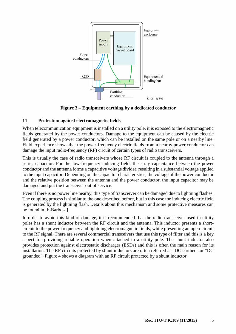
in Figure 2, where the protective earth and neutral (PEN) conductor is bonded to the
equipment metallic enclosure through an equipotential bonding bar (EBB);
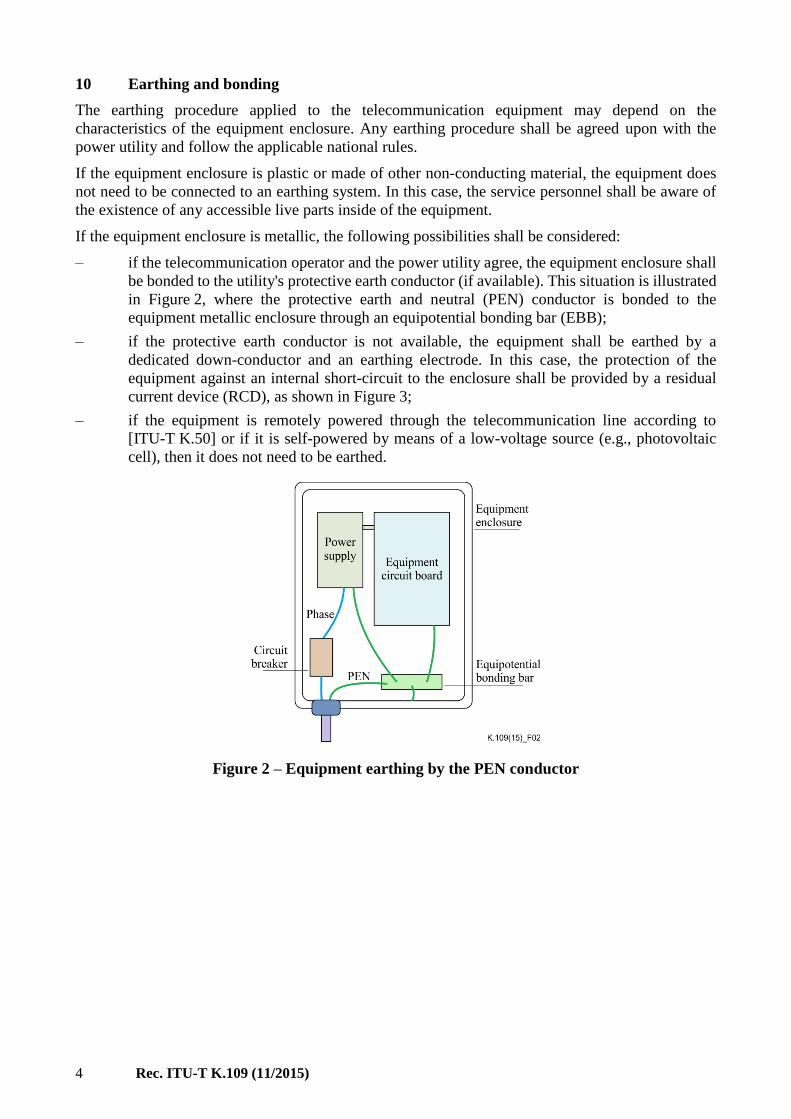
– if the protective earth conductor is not available, the equipment shall be earthed by a
dedicated down-conductor and an earthing electrode. In this case, the protection of the
equipment against an internal short-circuit to the enclosure shall be provided by a residual
current device (RCD), as shown in Figure 3;
– if the equipment is remotely powered through the telecommunication line according to
[ITU-T K.50] or if it is self-powered by means of a low-voltage source (e.g., photovoltaic
cell), then it does not need to be earthed.
Figure 2 – Equipment earthing by the PEN conductor
Rec. ITU-T K.109 (11/2015) 5
Figure 3 – Equipment earthing by a dedicated conductor
11 Protection against electromagnetic fields
When telecommunication equipment is installed on a utility pole, it is exposed to the electromagnetic
fields generated by the power conductors. Damage to the equipment can be caused by the electric
field generated by a power conductor, which can be installed on the same pole or on a nearby line.
Field experience shows that the power-frequency electric fields from a nearby power conductor can
damage the input radio-frequency (RF) circuit of certain types of radio transceivers.
This is usually the case of radio transceivers whose RF circuit is coupled to the antenna through a
series capacitor. For the low-frequency inducing field, the stray capacitance between the power
conductor and the antenna forms a capacitive voltage divider, resulting in a substantial voltage applied
to the input capacitor. Depending on the capacitor characteristics, the voltage of the power conductor
and the relative position between the antenna and the power conductor, the input capacitor may be
damaged and put the transceiver out of service.
Even if there is no power line nearby, this type of transceiver can be damaged due to lightning flashes.
The coupling process is similar to the one described before, but in this case the inducing electric field
is generated by the lightning flash. Details about this mechanism and some protective measures can
be found in [b-Barbosa].
In order to avoid this kind of damage, it is recommended that the radio transceiver used in utility
poles has a shunt inductor between the RF circuit and the antenna. This inductor presents a short-
circuit to the power-frequency and lightning electromagnetic fields, while presenting an open-circuit
to the RF signal. There are several commercial transceivers that use this type of filter and this is a key
aspect for providing reliable operation when attached to a utility pole. The shunt inductor also
provides protection against electrostatic discharges (ESDs) and this is often the main reason for its
installation. The RF circuits protected by shunt inductors are often referred as "DC earthed" or "DC
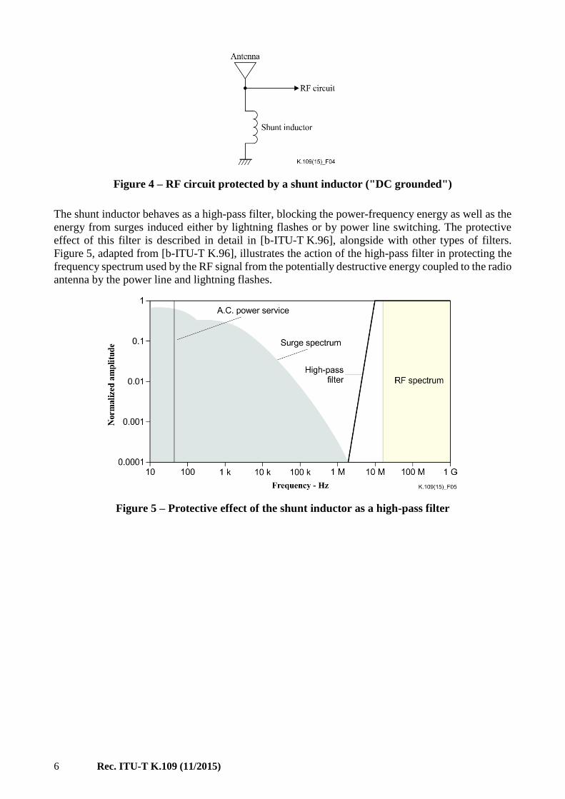
grounded". Figure 4 shows a diagram with an RF circuit protected by a shunt inductor.
6 Rec. ITU-T K.109 (11/2015)
Figure 4 – RF circuit protected by a shunt inductor ("DC grounded")
The shunt inductor behaves as a high-pass filter, blocking the power-frequency energy as well as the
energy from surges induced either by lightning flashes or by power line switching. The protective
effect of this filter is described in detail in [b-ITU-T K.96], alongside with other types of filters.
Figure 5, adapted from [b-ITU-T K.96], illustrates the action of the high-pass filter in protecting the
frequency spectrum used by the RF signal from the potentially destructive energy coupled to the radio
antenna by the power line and lightning flashes.
Figure 5 – Protective effect of the shunt inductor as a high-pass filter
Rec. ITU-T K.109 (11/2015) 7
Bibliography
[b-ITU-T K.57] Recommendation ITU-T K.57 (2003), Protection measures for radio base
stations sited on power line towers.
[b-ITU-T K.96] Recommendation ITU-T K.96 (2014), Surge protective components:
Overview of surge mitigation functions and technologies.
[b-ITU-T K.108] Recommendation ITU-T K.108 (2015), Joint use of poles by
telecommunication and solidly earthed power lines.
[b-Barbosa] C.F. Barbosa and F.E. Nallin (2015), Lightning protection of a smart grid
sensor, Electric Power Systems Research, Vol. 118, Jan; pp. 83-88.
[b-IEC IEV] IEC 60050, International Electrotechnical Vocabulary (IEV).


Printed in Switzerland Geneva, 2016
SERIES OF ITU-T RECOMMENDATIONS
Series A Organization of the work of ITU-T
Series D General tariff principles
Series E Overall network operation, telephone service, service operation and human factors
Series F Non-telephone telecommunication services
Series G Transmission systems and media, digital systems and networks
Series H Audiovisual and multimedia systems
Series I Integrated services digital network
Series J Cable networks and transmission of television, sound programme and other multimedia
signals
Series K Protection against interference
Series L Environment and ICTs, climate change, e-waste, energy efficiency; construction, installation
and protection of cables and other elements of outside plant
Series M Telecommunication management, including TMN and network maintenance
Series N Maintenance: international sound programme and television transmission circuits
Series O Specifications of measuring equipment
Series P Terminals and subjective and objective assessment methods
Series Q Switching and signalling
Series R Telegraph transmission
Series S Telegraph services terminal equipment
Series T Terminals for telematic services
Series U Telegraph switching
Series V Data communication over the telephone network
Series X Data networks, open system communications and security
Series Y Global information infrastructure, Internet protocol aspects, next-generation networks,
Internet of Things and smart cities
Series Z Languages and general software aspects for telecommunication systems
Related Documents