INTERNATIONAL TELECOMMUNICATION UNION ITU-T G.992.3 TELECOMMUNICATION STANDARDIZATION SECTOR OF ITU (07/2002) SERIES G: TRANSMISSION SYSTEMS AND MEDIA, DIGITAL SYSTEMS AND NETWORKS Digital sections and digital line system – Access networks Asymmetric digital subscriber line transceivers 2 (ADSL2) ITU-T Recommendation G.992.3

Welcome message from author
This document is posted to help you gain knowledge. Please leave a comment to let me know what you think about it! Share it to your friends and learn new things together.
Transcript
INTERNATIONAL TELECOMMUNICATION UNION
ITU-T G.992.3 TELECOMMUNICATION STANDARDIZATION SECTOR OF ITU
(07/2002)
SERIES G: TRANSMISSION SYSTEMS AND MEDIA, DIGITAL SYSTEMS AND NETWORKS
Digital sections and digital line system – Access networks
Asymmetric digital subscriber line
transceivers 2 (ADSL2)
ITU-T Recommendation G.992.3
ITU-T G-SERIES RECOMMENDATIONS
TRANSMISSION SYSTEMS AND MEDIA, DIGITAL SYSTEMS AND NETWORKS
INTERNATIONAL TELEPHONE CONNECTIONS AND CIRCUITS G.100–G.199 GENERAL CHARACTERISTICS COMMON TO ALL ANALOGUE CARRIER-TRANSMISSION SYSTEMS
G.200–G.299
INDIVIDUAL CHARACTERISTICS OF INTERNATIONAL CARRIER TELEPHONE SYSTEMS ON METALLIC LINES
G.300–G.399
GENERAL CHARACTERISTICS OF INTERNATIONAL CARRIER TELEPHONE SYSTEMS ON RADIO-RELAY OR SATELLITE LINKS AND INTERCONNECTION WITH METALLIC LINES
G.400–G.449
COORDINATION OF RADIOTELEPHONY AND LINE TELEPHONY G.450–G.499 TESTING EQUIPMENTS G.500–G.599 TRANSMISSION MEDIA CHARACTERISTICS G.600–G.699 DIGITAL TERMINAL EQUIPMENTS G.700–G.799 DIGITAL NETWORKS G.800–G.899 DIGITAL SECTIONS AND DIGITAL LINE SYSTEM G.900–G.999
General G.900–G.909 Parameters for optical fibre cable systems G.910–G.919 Digital sections at hierarchical bit rates based on a bit rate of 2048 kbit/s G.920–G.929 Digital line transmission systems on cable at non-hierarchical bit rates G.930–G.939 Digital line systems provided by FDM transmission bearers G.940–G.949 Digital line systems G.950–G.959 Digital section and digital transmission systems for customer access to ISDN G.960–G.969 Optical fibre submarine cable systems G.970–G.979 Optical line systems for local and access networks G.980–G.989 Access networks G.990–G.999
QUALITY OF SERVICE AND PERFORMANCE G.1000–G.1999 TRANSMISSION MEDIA CHARACTERISTICS G.6000–G.6999 DIGITAL TERMINAL EQUIPMENTS G.7000–G.7999 DIGITAL NETWORKS G.8000–G.8999
For further details, please refer to the list of ITU-T Recommendations.
ITU-T Rec. G.992.3 (07/2002) i
ITU-T Recommendation G.992.3
Asymmetric digital subscriber line transceivers 2 (ADSL2)
Summary
This Recommendation describes Asymmetric Digital Subscriber Line (ADSL) Transceivers on a metallic twisted pair that allows high-speed data transmission between the network operator end (ATU-C) and the customer end (ATU-R). It defines a variety of frame bearers in conjunction with one of two other services or without underlying service, dependent on the environment:
1) ADSL transmission simultaneously on the same pair with voice band service;
2) ADSL transmission simultaneously on the same pair with ISDN (Appendix I or II/G.961 [1]) services;
3) ADSL transmission without underlying service, optimized for deployment with ADSL over voiceband service in the same binder cable;
4) ADSL transmission without underlying service, optimized for deployment with ADSL over ISDN service in the same binder cable.
ADSL transmission on the same pair with voiceband services and operating in an environment with TCM-ISDN (Appendix III/G.961 [1]) services in an adjacent pair, is for further study.
This Recommendation specifies the physical layer characteristics of the Asymmetric Digital Subscriber Line (ADSL) interface to metallic loops.
This Recommendation has been written to help ensure the proper interfacing and interworking of ADSL transmission units at the customer end (ATU-R) and at the network operator end (ATU-C), and also to define the transport capability of the units. Proper operation shall be ensured when these two units are manufactured and provided independently. A single twisted pair of telephone wires is used to connect the ATU-C to the ATU-R. The ADSL transmission units must deal with a variety of wire pair characteristics and typical impairments (e.g., crosstalk and noise).
An ADSL transmission unit can simultaneously convey all of the following: a number of downstream frame bearers, a number of upstream frame bearers, a baseband POTS/ISDN duplex channel, and ADSL line overhead for framing, error control, operations, and maintenance. Systems support a net data rate ranging up to a minimum of 8 Mbit/s downstream and 800 kbit/s upstream. Support of net data rates above 8 Mbit/s downstream and support of net data rates above 800 kbit/s upstream are optional.
This Recommendation includes mandatory requirements, recommendations and options; these are designated by the words "shall", "should" and "may" respectively. The word "will" is used only to designate events that take place under some defined set of circumstances.
ii ITU-T Rec. G.992.3 (07/2002)
This Recommendation defines several optional capabilities and features:
• transport of STM and/or ATM and/or Packets;
• transport of a network timing reference;
• multiple latency paths;
• multiple frame bearers;
• short initialization procedure;
• dynamic rate repartitioning;
• seamless rate adaptation.
It is the intention of this Recommendation to provide, by negotiation during initialization, for U-interface compatibility and interoperability between transceivers complying with this Recommendation and between transceivers that include different combinations of options.
History
This Recommendation describes the second generation of ADSL, based on the first generation ITU-T Rec. G.992.1. It is intended that this Recommendation be implemented in multi-mode devices that support both ITU-T Recs G.992.3 and G.992.1.
This Recommendation has been written to provide additional features, relative to ITU-T Rec. G.992.1. ITU-T Rec. G.992.1 was approved in June 1999. Since then, several potential improvements have been identified in areas such as data rate versus loop reach performance, loop diagnostics, deployment from remote cabinets, spectrum control, power control, robustness against loop impairments and RFI, and operations and maintenance. This Recommendation provides a new ADSL U-interface specification, including the identified improvements, which the ITU-T believes will be most helpful to the ADSL industry.
Relative to ITU-T Rec. G.992.1, the following application-related features have been added:
• Improved application support for an all digital mode of operation and voice over ADSL operation;
• Packet TPS-TC function, in addition to the existing STM and ATM TPS-TC functions;
• Mandatory support of 8 Mbit/s downstream and 800 kbit/s upstream for TPS-TC function #0 and frame bearer #0;
• Support for IMA in the ATM TPS-TC;
• Improved configuration capability for each TPS-TC with configuration of latency, BER and minimum, maximum and reserved data rate.
Relative to ITU-T Rec. G.992.1, the following PMS-TC-related features have been added:
• A more flexible framing, including support for up to 4 frame bearers, 4 latency paths;
• Parameters allowing enhanced configuration of the overhead channel;
• Frame structure with receiver selected coding parameters;
• Frame structure with optimized use of RS coding gain;
• Frame structure with configurable latency and bit error ratio;
• OAM protocol to retrieve more detailed performance monitoring information;
• Enhanced on-line reconfiguration capabilities including dynamic rate repartitioning.
ITU-T Rec. G.992.3 (07/2002) iii
Relative to ITU-T Rec. G.992.1, the following PMD-related features have been added:
• New line diagnostics procedures available for both successful and unsuccessful initialization scenarios, loop characterization and troubleshooting;
• Enhanced on-line reconfiguration capabilities including bitswaps and seamless rate adaptation;
• Optional short initialization sequence for recovery from errors or fast resumption of operation;
• Optional seamless rate adaptation with line rate changes during showtime;
• Improved robustness against bridged taps with receiver determined pilot tone;
• Improved transceiver training with exchange of detailed transmit signal characteristics;
• Improved SNR measurement during channel analysis;
• Subcarrier blackout to allow RFI measurement during initialization and SHOWTIME;
• Improved performance with mandatory support of trellis coding;
• Improved performance with mandatory one-bit constellations;
• Improved performance with data modulated on the pilot tone;
• Improved RFI robustness with receiver determined tone ordering;
• Improved transmit power cutback possibilities at both CO and remote side;
• Improved Initialization with receiver and transmitter controlled duration of initialization states;
• Improved Initialization with receiver-determined carriers for modulation of messages;
• Improved channel identification capability with spectral shaping during Channel Discovery and Transceiver Training;
• Mandatory transmit power reduction to minimize excess margin under management layer control;
• Power saving feature for the central office ATU with new L2 low power state;
• Power saving feature with new L3 idle state;
• Spectrum control with individual tone masking under operator control through CO-MIB;
• Improved conformance testing including increase in data rates for many existing tests.
Through negotiation during initialization, the capability of equipment to support the G.992.3 and/or the G.992.1 Recommendations is identified. For reasons of interoperability, equipment may choose to support both Recommendations, such that it is able to adapt to the operating mode supported by the far-end equipment.
Source
ITU-T Recommendation G.992.3 was approved by ITU-T Study Group 15 (2001-2004) under the ITU-T Recommendation A.8 procedure on 29 July 2003.
It integrates the modifications introduced by ITU-T Rec. G.992.3 (2002) Amendment 1 approved on 22 May 2003.
iv ITU-T Rec. G.992.3 (07/2002)
FOREWORD
The International Telecommunication Union (ITU) is the United Nations specialized agency in the field of telecommunications. The ITU Telecommunication Standardization Sector (ITU-T) is a permanent organ of ITU. ITU-T is responsible for studying technical, operating and tariff questions and issuing Recommendations on them with a view to standardizing telecommunications on a worldwide basis.
The World Telecommunication Standardization Assembly (WTSA), which meets every four years, establishes the topics for study by the ITU-T study groups which, in turn, produce Recommendations on these topics.
The approval of ITU-T Recommendations is covered by the procedure laid down in WTSA Resolution 1.
In some areas of information technology which fall within ITU-T's purview, the necessary standards are prepared on a collaborative basis with ISO and IEC.
NOTE
In this Recommendation, the expression "Administration" is used for conciseness to indicate both a telecommunication administration and a recognized operating agency.
Compliance with this Recommendation is voluntary. However, the Recommendation may contain certain mandatory provisions (to ensure e.g. interoperability or applicability) and compliance with the Recommendation is achieved when all of these mandatory provisions are met. The words "shall" or some other obligatory language such as "must" and the negative equivalents are used to express requirements. The use of such words does not suggest that compliance with the Recommendation is required of any party.
INTELLECTUAL PROPERTY RIGHTS
ITU draws attention to the possibility that the practice or implementation of this Recommendation may involve the use of a claimed Intellectual Property Right. ITU takes no position concerning the evidence, validity or applicability of claimed Intellectual Property Rights, whether asserted by ITU members or others outside of the Recommendation development process.
As of the date of approval of this Recommendation, ITU had received notice of intellectual property, protected by patents, which may be required to implement this Recommendation. However, implementors are cautioned that this may not represent the latest information and are therefore strongly urged to consult the TSB patent database.
ITU 2003
All rights reserved. No part of this publication may be reproduced, by any means whatsoever, without the prior written permission of ITU.
ITU-T Rec. G.992.3 (07/2002) v
CONTENTS
Page
1 Scope............................................................................................................................. 1
2 References..................................................................................................................... 2
3 Definitions .................................................................................................................... 3
4 Abbreviations................................................................................................................ 6
5 Reference models.......................................................................................................... 8 5.1 ATU functional model.................................................................................... 8 5.2 User plane protocol reference model.............................................................. 10 5.3 Management plane reference model............................................................... 11 5.4 Application models......................................................................................... 11
6 Transport Protocol Specific Transmission Convergence (TPS-TC) function .............. 16 6.1 Transport capabilities ..................................................................................... 16 6.2 Interface signals and primitives...................................................................... 17 6.3 Control parameters ......................................................................................... 18 6.4 Data plane procedures .................................................................................... 19 6.5 Management plane procedures ....................................................................... 19 6.6 Initialization procedure................................................................................... 19 6.7 On-line reconfiguration .................................................................................. 20 6.8 Power management mode............................................................................... 20
7 Physical Media Specific Transmission Convergence (PMS-TC) function .................. 21 7.1 Transport capabilities ..................................................................................... 21 7.2 Additional functions ....................................................................................... 23 7.3 Block interface signals and primitives ........................................................... 23 7.4 Block diagram and internal reference point signals ....................................... 26 7.5 Control parameters ......................................................................................... 28 7.6 Frame structure............................................................................................... 29 7.7 Data plane procedures .................................................................................... 35 7.8 Control plane procedures................................................................................ 38 7.9 Management plane procedures ....................................................................... 42 7.10 Initialization procedures ................................................................................. 43 7.11 On-line reconfiguration .................................................................................. 49 7.12 Power management mode............................................................................... 50
8 Physical media dependent function .............................................................................. 52 8.1 Transport capabilities ..................................................................................... 52 8.2 Additional functions ....................................................................................... 53 8.3 Block interface signals and primitives ........................................................... 54 8.4 Block diagram and internal reference point signals ....................................... 56 8.5 Control parameters ......................................................................................... 57 8.6 Constellation encoder for data symbols ......................................................... 67 8.7 Constellation encoder for synchronization and L2 exit symbols ................... 82 8.8 Modulation ..................................................................................................... 84 8.9 Transmitter dynamic range............................................................................. 87
vi ITU-T Rec. G.992.3 (07/2002)
Page 8.10 Transmitter spectral masks ............................................................................. 88 8.11 Control plane procedures................................................................................ 89 8.12 Management plane procedures ....................................................................... 89 8.13 Initialization procedures ................................................................................. 98 8.14 Short initialization procedures........................................................................ 140 8.15 Loop diagnostics mode procedures ................................................................ 144 8.16 On-line reconfiguration of the PMD function ................................................ 159 8.17 Power management in the PMD function ...................................................... 161
9 Management Protocol Specific Transmission Convergence (MPS-TC) functions ...... 162 9.1 Transport functions......................................................................................... 163 9.2 Additional functions ....................................................................................... 163 9.3 Block interface signals and primitives ........................................................... 163 9.4 Management plane procedures ....................................................................... 165 9.5 Power management ........................................................................................ 185
10 Dynamic behaviour....................................................................................................... 189 10.1 Initialization.................................................................................................... 189 10.2 On-line Reconfiguration (OLR) ..................................................................... 189 10.3 Power management ........................................................................................ 192
Annex A – Specific requirements for an ADSL system operating in the frequency band above POTS.................................................................................................................. 195 A.1 ATU-C functional characteristics (pertains to clause 8) ................................ 195 A.2 ATU-R functional characteristics (pertains to clause 8) ................................ 198 A.3 Initialization.................................................................................................... 200 A.4 Electrical characteristics ................................................................................. 200
Annex B – Specific requirements for an ADSL system operating in the frequency band above ISDN as defined in ITU-T Rec. G.961 Appendices I and II.............................. 205 B.1 ATU-C functional characteristics (pertains to clause 8) ................................ 205 B.2 ATU-R functional characteristics (pertains to clause 8) ................................ 209 B.3 Initialization.................................................................................................... 212 B.4 Electrical characteristics ................................................................................. 213
Annex C – Specific requirements for an ADSL system operating in the same cable as ISDN as defined in ITU-T Rec. G.961 Appendix III ................................................... 213
Annex D – ATU-C and ATU-R state diagrams....................................................................... 213 D.1 Introduction .................................................................................................... 213 D.2 Definitions ...................................................................................................... 213 D.3 State diagrams ................................................................................................ 214
Annex E – POTS and ISDN Basic Access Splitters ................................................................ 221 E.1 Type 1 – POTS splitter – Europe ................................................................... 221 E.2 Type 2 – POTS splitter – North America....................................................... 221 E.3 Type 3 – ISDN (ITU-T Rec. G.961 Appendix I or II) Splitter – Europe....... 233 E.4 Type 4 – POTS splitter – Japan...................................................................... 234
Annex F – ATU-x performance requirements for region A (North America)......................... 246 F.1 Performance requirements for operation of ADSL over POTS (Annex A) ... 246
ITU-T Rec. G.992.3 (07/2002) vii
Page F.2 Performance requirements for operation of All Digital Mode ADSL
(Annex I) ........................................................................................................ 247
Annex G – ATU-x performance requirements for region B (Europe)..................................... 247 G.1 Performance requirements for operation of ADSL over POTS (Annex A) ... 247 G.2 Performance requirements for operation of ADSL over ISDN (Annex B).... 247 G.3 Performance requirements for operation of All Digital Mode ADSL
(Annex I) ........................................................................................................ 248 G.4 Performance requirements for operation of All Digital Mode ADSL
(Annex J) ........................................................................................................ 248
Annex H – Specific requirements for a synchronized symmetrical DSL (SSDSL) system operating in the same cable binder as ISDN as defined in ITU-T Rec. G.961 Appendix III.................................................................................................................. 248
Annex I – All digital mode ADSL with improved spectral compatibility with ADSL over POTS............................................................................................................................. 249 I.1 ATU-C functional characteristics (pertains to clause 8) ................................ 249 I.2 ATU-R functional characteristics (pertains to clause 8) ................................ 251 I.3 Initialization.................................................................................................... 253 I.4 Electrical characteristics ................................................................................. 253
Annex J – All Digital Mode ADSL with improved spectral compatibility with ADSL over ISDN............................................................................................................................. 257 J.1 ATU-C functional characteristics (pertains to clause 8) ................................ 257 J.2 ATU-R functional characteristics (pertains to clause 8) ................................ 258 J.3 Initialization.................................................................................................... 261 J.4 Electrical characteristics ................................................................................. 261
Annex K – TPS-TC functional descriptions ............................................................................ 261 K.1 STM Transmission Convergence (STM-TC) function................................... 261 K.2 ATM Transmission Convergence (ATM-TC) function ................................. 271 K.3 Packet transmission convergence function (PTM-TC) .................................. 284
Appendix I – ATM layer to physical layer logical interface ................................................... 292
Appendix II – Compatibility with other customer premises equipment.................................. 294
Appendix III – The impact of primary protection devices on line balance ............................. 294 III.1 Scope .............................................................................................................. 294 III.2 Background..................................................................................................... 294 III.3 Recommended maximum capacitance of over-voltage protectors................. 296 III.4 Capacitance matching requirements of over-voltage protectors .................... 296 III.5 References ...................................................................................................... 298
Appendix IV – Bibliography.................................................................................................... 299


ITU-T Rec. G.992.3 (07/2002) 1
ITU-T Recommendation G.992.3
Asymmetric digital subscriber line transceivers 2 (ADSL2)
1 Scope
For interrelationships of this Recommendation with other G.99x-series Recommendations, see ITU-T Rec. G.995.1 [B1].
This Recommendation describes the interface between the telecommunications network and the customer installation in terms of their interaction and electrical characteristics. The requirements of this Recommendation apply to a single asymmetric digital subscriber line (ADSL).
ADSL provides a variety of frame bearers in conjunction with other services:
• ADSL service on the same pair with voiceband services (including POTS and voiceband data services). The ADSL service occupies a frequency band above the voiceband service, and is separated from it by filtering;
• ADSL service on the same pair as ISDN service, as defined in Appendices I and II/G.961 [1]. The ADSL service occupies a frequency band above the ISDN service, and is separated from it by filtering;
ADSL also provides a variety of frame bearers without baseband services (i.e., POTS or ISDN) being present on the same pair:
• ADSL service on a pair, with improved spectral compatibility with ADSL over POTS present on an adjacent pair;
• ADSL service on a pair, with improved spectral compatibility with ADSL over ISDN present on an adjacent pair.
In the direction from the network operator to the customer premises (i.e., the downstream direction), the frame bearers provided may include low-speed frame bearers and high-speed frame bearers; in the other direction from the customer premises to the Central office (i.e., the upstream direction), only low-speed frame bearers are provided.
The transmission system is designed to operate on two-wire twisted metallic copper pairs with mixed gauges. This Recommendation is based on the use of copper pairs without loading coils, but bridged taps are acceptable in all but a few unusual situations.
Operation on the same pair with voiceband services (e.g., POTS and voiceband data services), and with TCM-ISDN service as defined in Appendix III/G.961 [1] on an adjacent pair, is for further study.
An overview of Digital Subscriber Line Transceivers can be found in ITU-T Rec. G.995.1 [B1].
Specifically, this Recommendation:
• defines the Transmission Protocol Specific Transmission Convergence Sub-layer for ATM, STM and Packet transport through the frame bearers provided;
• defines the combined options and ranges of the frame bearers provided;
• defines the line code and the spectral composition of the signals transmitted by both ATU-C and ATU-R;
• defines the initialization procedure for both the ATU-C and the ATU-R;
• specifies the transmit signals at both the ATU-C and ATU-R;
• describes the organization of transmitted and received data into frames;
• defines the functions of the OAM channel.
2 ITU-T Rec. G.992.3 (07/2002)
In separate annexes it also:
• describes the transmission technique used to support the simultaneous transport of voiceband services and frame bearers (ADSL over POTS, Annex A) on a single twisted-pair;
• describes the transmission technique used to support the simultaneous transport of ISDN services as defined in Appendices I and II/G.961 [1], and frame bearers (ADSL over ISDN, Annex B) on a single twisted-pair;
• describes the transmission technique used to support the transport of only frame bearers on a pair, with improved spectral compatibility with ADSL over POTS present on adjacent pair (All Digital Mode, Annex I);
• describes the transmission technique used to support the transport of only frame bearers on a pair, with improved spectral compatibility with ADSL over ISDN present on adjacent pair (All Digital Mode, Annex J).
This Recommendation defines the minimal set of requirements to provide satisfactory simultaneous transmission between the network and the customer interface of a variety of frame bearers and other services such as POTS or ISDN. The Recommendation permits network providers an expanded use of existing copper facilities. All required physical layer aspects to ensure compatibility between equipment in the network and equipment at a remote location are specified. Equipment may be implemented with additional functions and procedures.
2 References
The following ITU-T Recommendations, and other references contain provisions which, through reference in this text, constitute provisions of this Recommendation. At the time of publication, the editions indicated were valid. All Recommendations are subject to revision; all users of this Recommendation are therefore encouraged to investigate the possibility of applying the most recent edition of the Recommendations listed below. A list of the currently valid ITU-T Recommendations is regularly published. The reference to a document within this Recommendation does not give it, as a stand-alone document, the status of a Recommendation.
[1] ITU-T Recommendation G.961 (1993), Digital transmission system on metallic local lines for ISDN basic rate access.
[2] ITU-T Recommendation G.994.1 (2002), Handshake procedures for digital subscriber line (DSL) transceivers.
[3] ITU-T Recommendation G.996.1 (2001), Test procedures for digital subscriber line (DSL) transceivers.
[4] ITU-T Recommendation G.997.1 (1999), Physical layer management for digital subscriber line (DSL) transceivers.
[5] ISO 8601:2000, Data elements and interchange formats – Information interchange – Representation of dates and times.
[6] ITU-T Recommendation O.42 (1988), Equipment to measure non-linear distortion using the 4-tone intermodulation method.
For Annex B
[7] ETSI TS 102 080 V1.3.2 (2000), Transmission and Multiplexing (TM); Integrated Services Digital Network (ISDN) basic rate access; Digital transmission on metallic local lines.
For Annex E
[8] ETSI TS 101 952-1 V1.1.1 (2002), Specification of ADSL splitters for European deployment.
ITU-T Rec. G.992.3 (07/2002) 3
For Annex F
[9] DSL Forum TR-048 (2002), ADSL Interoperability Test Plan.
For Annex G
[10] ETSI TS 101 388 V1.3.1 (2002), ADSL – European Specific Requirements.
For Annex K
[11] ITU-T Recommendation I.361 (1999), B-ISDN ATM layer specification.
[12] ITU-T Recommendation I.432.1 (1999), B-ISDN user-network interface – Physical layer specification: General characteristics.
[13] ITU-T Recommendation G.993.1 (2001), Very high speed digital subscriber line foundation.
3 Definitions
This Recommendation defines the following terms:
3.1 ADSL line: The ADSL Line is characterized by a metallic transmission medium utilizing an analogue coding algorithm, which provides both analogue and digital performance monitoring at the line entity. The ADSL Line is delimited by the two end points, known as Line Terminations. ADSL Line Terminations are the points, where the analogue coding algorithms end, and the subsequent digital signal is monitored for integrity. The ADSL Line is defined between the α and the β reference points (see Figure 5-1 and § 5.1/G.997.1).
3.2 ADSL overhead data: All data transmitted at the U-x reference point, needed for system control, added by the PMS-TC in any one direction, including CRC octets, OAM overhead messages and fixed indicator bits for OAM; it does not include Reed-Solomon FEC overhead.
3.3 ADSL system overhead data: All data transmitted at the U-x reference point, needed for system control and error protection, added by the PMS-TC in any one direction; that is the ADSL overhead plus the Reed-Solomon FEC overhead.
3.4 aggregate data rate: The data rate transmitted at the U-x reference point in any one direction; it is the net data rate plus ADSL overhead data rate.
3.5 anomaly: A discrepancy between the actual and desired characteristics of an item. The desired characteristics may be expressed in the form of a specification. An anomaly may or may not affect the ability of an item to perform a required function. Performance anomalies are defined in 8.12.1.
3.6 bridged taps: Sections of unterminated twisted-pair cables connected in parallel across the cable under consideration.
3.7 channelization: Allocation of the net data rate to frame bearers.
3.8 data frame: A grouping of bits from different latency paths over a single symbol time period, after addition of FEC octets and after interleaving, which is exchanged over the δ reference point between PMS-TC and PMD layer through the PMD.Bits primitive (see Figures 5-1 and 5-2).
3.9 data symbol: A DMT symbol modulating a data frame.
3.10 data symbol rate: The net average rate (after allowing for the overhead of the synchronization symbol) at which symbols carrying data frames are transmitted (= 4000 data symbols/second).
3.11 dBrn: Ratio (in decibels) of a power level with respect to a reference power of 1 pico-Watt (equivalent –90 dBm) (see ITU-T Rec. O.41 [B2]).
4 ITU-T Rec. G.992.3 (07/2002)
3.12 dBm: Ratio (in decibels) of a power level with respect to a reference power of 1 milliwatt, i.e., dBm = 10 × log10(PSD[watts]/1 mW).
3.13 dBm/Hz: Power spectral density in watts/Hz where the power is expressed in units of dBm, i.e., dBm/Hz = 10 × log10(PSD[watts/Hz]/1 mW).
3.14 defects: A defect is a limited interruption in the ability of an item to perform a required function. It may or may not lead to maintenance action depending on the results of additional analysis. Successive anomalies causing a decrease in the ability of an item to perform a required function are considered as a defect. Performance defects are defined in 8.12.1.
3.15 DMT symbol: A set of complex values Zi forming the frequency domain inputs to the inverse discrete Fourier transform (IDFT) (see 8.8.2). The DMT symbol is equivalently the set of real valued time samples, xn, related to the set of Zi via the IDFT.
3.16 downstream: The transport of data in the ATU-C to ATU-R direction.
3.17 far-end performance: Term used at ATU-C to indicate the performance measured at the downstream loop-side input of the ATU-R, where this performance is reported to the ATU-C in upstream overhead messages and indicators, or term used at ATU-R to indicate the performance measured at the upstream loop-side input of the ATU-C, where this performance is reported to the ATU-R in downstream overhead messages and indicators.
3.18 FEC data frame: The grouping of mux data frames within a latency path, after addition of FEC octets, and before interleaving (see 7.4).
3.19 frame bearer: A data stream of a specified data rate between two TPS-TC entities (one in each ATU), that is transported transparently by the PMS-TC and PMD sublayers.
3.20 indicator bits: Overhead bits, part of ADSL overhead data, used for OAM purposes; embedded in the sync octets (see 7.8.2.2).
3.21 line rate: The bit rate transmitted at the U-x reference point in any one direction, that is total data rate plus trellis coding overhead, also defined as (∑bi) × 4 kbit/s.
3.22 loading coils: Inductors placed in series with the twisted-pair at regular intervals in order to improve the voiceband response; loading coils are removed for DSL use.
3.23 MEDLEYset: The set of subcarriers transmitted during the Channel Analysis Phase. It consists of the subcarriers in the SUPPORTEDset (as indicated by the transmitter in the Initialization G.994.1 Phase), with removal of the subcarriers in the BLACKOUTset (as indicated by the receiver in the Initialization Channel Discovery Phase) (see 8.13.2.4).
3.24 multiple latency: Simultaneous transport of multiple frame bearers, in which frame bearers are allocated to more than one latency paths (i.e., two, three or four).
3.25 monitored subcarrier: A subcarrier in the MEDLEYset, to which the receiver allocates zero bits (bi = 0) and a non-zero power (gi > 0).
3.26 mux data frame: The grouping of octets from different frame bearers within the same latency path, after the sync octet has been added.
3.27 near-end performance: Term used at ATU-R to indicate the performance measured at the downstream loop-side input of the ATU-R, or term used at ATU-C to indicate the performance measured at the upstream loop-side input of the ATU-C.
3.28 net data rate: The sum of all frame bearer data rates over all latency paths in any one direction.
3.29 network timing reference: An 8 kHz timing marker used to support the distribution of a timing reference over the network.
ITU-T Rec. G.992.3 (07/2002) 5
3.30 nominal transmit PSD level: The transmit PSD level (expressed in dBm/Hz) defined in this Recommendation for each of the operating modes (see Annexes A, B, I and J) in any one direction, which is used at the start of initialization and relative to which subsequent transmit PSD level changes may occur, as determined necessary by the transceivers during initialization and showtime.
3.31 power cutback: Reduction of the transmit PSD level (expressed in dB) in any one direction, relative to the nominal transmit PSD level. The same transmit PSD level reduction is applied over the whole frequency band (i.e., flat cutback).
3.32 primitives: Primitives are basic measures of performance, usually obtained from digital signal line codes and frame formats, or as reported in overhead indicators from the far-end. Performance primitives are categorized as events, anomalies and defects (see 8.12). Primitives may also be basic measures of other quantities (e.g., ac or battery power), usually obtained from equipment indicators . Alternatively, the term is also used to indicate logical information flows over the α, β, δ, γ, and U reference points shown in Figure 5-2.
3.33 reference transmit PSD level: The nominal transmit PSD level, lowered by the power cutback, in any one direction.
3.34 showtime: The state of either ATU-C or ATU-R, reached after all initialization and training is completed, in which frame bearer data are transmitted.
3.35 single latency: Simultaneous transport of one or more frame bearers in any one direction, in which all frame bearers are allocated to the same latency path.
3.36 splitter: Filter that separates the high frequency signals (ADSL) from the voiceband or ISDN signals; (frequently called POTS or ISDN splitter, even though the voiceband signals may comprise more than POTS).
3.37 subcarrier: A particular complex valued input, Zi, to the IDFT (see 8.8.2).
3.38 superframe: A grouping of 68 data frames and one sync frame, modulated onto 69 symbols, over a total time duration of 17 ms (see 8.4).
3.39 symbol rate: The rate at which all symbols, including the synchronization symbol, are transmitted; that is ((69/68) × 4000 = 4058.8 symbols/second); contrasted with the data symbol rate.
3.40 sync octet: An octet of data that may be present at the beginning of each mux data frame, that contains ADSL overhead.
3.41 sync frame: A frame with deterministic content, modulated onto a sync symbol.
3.42 sync symbol: A DMT symbol modulating a sync frame.
3.43 total data rate: Aggregate data rate plus Reed-Solomon FEC overhead.
3.44 upstream: The transport of data in the ATU-R to ATU-C direction.
3.45 used subcarrier: A subcarrier in the MEDLEYset, to which the receiver allocates a non-zero number of bits (bi > 0).
3.46 voiceband: 0 to 4 kHz; expanded from the traditional 0.3 to 3.4 kHz to deal with voiceband data services wider than POTS.
3.47 voiceband services: POTS and all data services that use the voiceband or some part of it.
3.48 xDSL: Any of the various types of digital subscriber lines technologies.
6 ITU-T Rec. G.992.3 (07/2002)
4 Abbreviations
This Recommendation uses the following abbreviations:
ADSL Asymmetric Digital Subscriber Line
AFE Analogue Front End
AGC Automatic Gain Control
AN Access Node
ATM Asynchronous Transfer Mode
ATU ADSL Transceiver Unit
ATU-C ATU at the central office end (i.e., network operator)
ATU-R ATU at the remote terminal end (i.e., CP)
ATU-x Any one of ATU-C or ATU-R
BER Bit Error Ratio
CO Central office
CP Customer Premises
CPE Customer Premises Equipment
CRC Cyclic Redundancy Check
DAC Digital to Analog Converter
DC Direct Current
DMT Discrete multitone
DSL Digital Subscriber Line
EC Echo Cancelling
EMS Element Management System
eoc embedded operation channel
ES Errored Second
FDM Frequency-Division Multiplexing
FEC Forward Error Correction
FEXT Far-End crosstalk
FFEC Far-end Forward Error Correction
FHEC Far-end Header Error Check
FLCD Far-end Loss of Cell Delineation
FNCD Far-end No Cell Delineation
FOCD Far-end Out of Cell Delineation
GF Galois Field
GSTN General Switched Telephone Network
HEC Header Error Control
HPF High pass filter
IB Indicator Bit
ITU-T Rec. G.992.3 (07/2002) 7
ID code Vendor identification code
IDFT Inverse Discrete Fourier Transform
IMA Inverse Multiplexing over ATM
ISDN Integrated Services Digital Network
LCD Loss-of-Cell Delineation
LOF Loss-of-frame defect
LOS Loss-of-signal defect
LPR Loss-of-power defect
LSB Least Significant Bit
LTR Local Timing Reference
MC Maximum Count indication
MDF Mux Data Frame
MIB Management Information Base
MPS Management Protocol Specific
MSB Most Significant Bit
MTPR Multitone power ratio
NCD No cell delineation
NEXT Near-End crosstalk
NID Network Interface Device
NMS Network Management System
NT Network Termination
NTR Network timing reference: 8 kHz reference to be transmitted downstream
OAM Operations, Administration and Maintenance
OCD Out of Cell Delineation
PHY Physical Layer
PMD Physical Media Dependent (sublayer)
PMS-TC Physical Media-Specific TC
POTS Plain old telephone service; one of the services using the voiceband; sometimes used as a descriptor for all voiceband services
ppm parts per million
PRBS Pseudo-Random Binary Sequence
PSD Power Spectral Density
PSTN Public Switched Telephone Network
PTS Packet Transport Specific
QAM Quadrature Amplitude Modulation
RDI Remote Defect Indication
rms Root mean square
8 ITU-T Rec. G.992.3 (07/2002)
RS Reed Solomon
RT Remote Terminal
RX Receiver
SEF Severely Errored Frame
SM Service Module
SNR Signal-to-Noise Ratio
TC Transmission convergence (sublayer)
TP Twisted Pair
TPS-TC Transmission Protocol Specific TC Layer
T-R Interface(s) between ATU-R and switching layer (ATM or STM or Packet)
T/S Interface(s) between ADSL network termination and CPE or home network
TX Transmitter
U-C Loop Interface – Central Office end
U-R Loop Interface – Remote Terminal end
UTC Unable to comply
V-C Logical interface between ATU-C and a digital network element such as one or more switching systems
ZHP Impedance high-pass filter
4-QAM 4 point QAM (i.e., two bits per symbol)
⊕ Exclusive-or; modulo-2 addition
x Rounding to the higher integer
5 Reference models
G.992.3 devices fit within the family of DSL Recommendations described in ITU-T Rec. G.995.1 [B1]. Additionally, G.992.3 devices rely upon constituent components described within ITU-T Rec. G.994.1 [2] and ITU-T Rec. G.997.1 [4]. This clause provides the necessary functional, application, and protocol reference models so that the subclauses of this Recommendation may be related to these additional Recommendations.
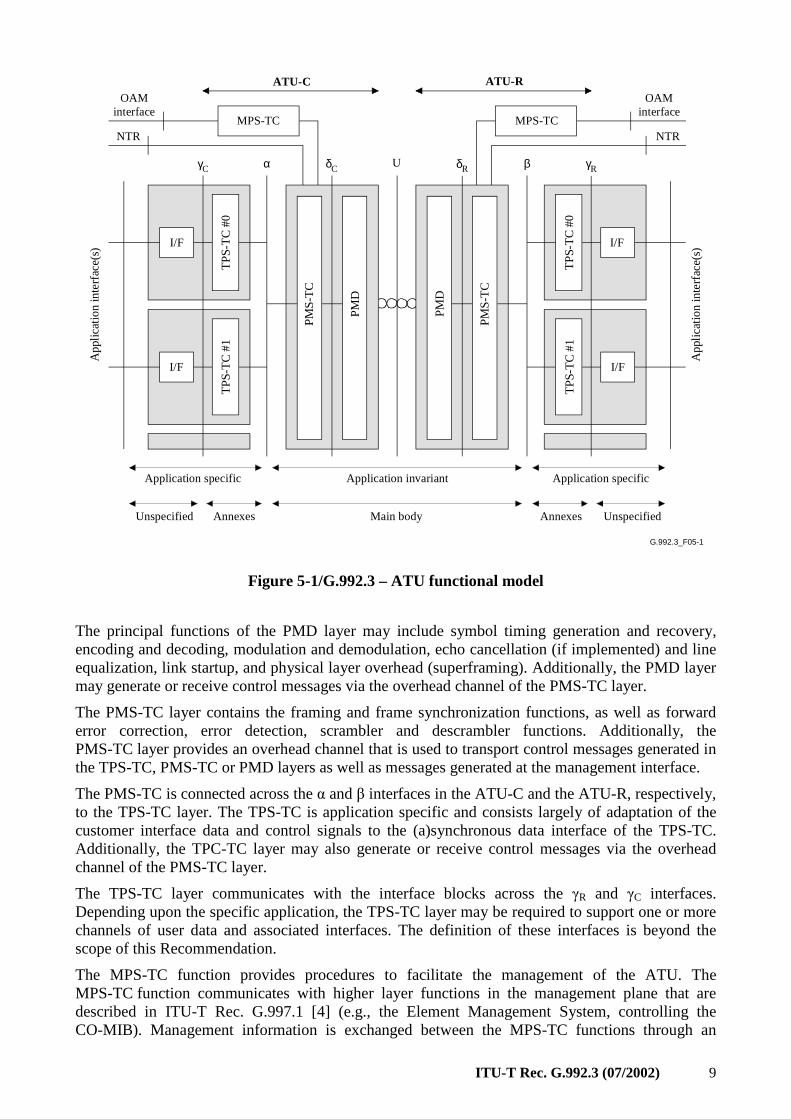
5.1 ATU functional model
Figure 5-1 shows the functional blocks and interfaces of an ATU-C and ATU-R that are referenced in this Recommendation. It illustrates the most basic functionality of the ATU-R and the ATU-C. Each ATU contains both an application invariant section and an application specific section. The application invariant section consists of the PMS-TC and PMD layers and are defined in clauses 7 and 8, while the application specific aspects that are confined to the TPS-TC layer and device interfaces, are defined in Annex K. Management functions, which are typically controlled by the operator's management system (EMS or NMS), are not shown in the Figure 5-1. Figure 5-3 provides a high level view that includes the management interface.
ITU-T Rec. G.992.3 (07/2002) 9
G.992.3_F05-1
PM
D
PM
S-T
C
MPS-TC
TP
S-T
C #
0
I/F
TP
S-T
C #
1
I/F
App
licat
ion
inte
rfac
e(s
)
α U
PM
D
PM
S-T
C
TP
S-T
C #
0T
PS
-TC
#1
I/F
I/F
App
licat
ion
inte
rfac
e(s
)
MPS-TC
β
ATU-RATU-C
Application specific Application invariant Application specific
Unspecified Annexes Main body UnspecifiedAnnexes
NTRNTR
OAMinterface
OAMinterface
γC δC δR γR
Figure 5-1/G.992.3 – ATU functional model
The principal functions of the PMD layer may include symbol timing generation and recovery, encoding and decoding, modulation and demodulation, echo cancellation (if implemented) and line equalization, link startup, and physical layer overhead (superframing). Additionally, the PMD layer may generate or receive control messages via the overhead channel of the PMS-TC layer.
The PMS-TC layer contains the framing and frame synchronization functions, as well as forward error correction, error detection, scrambler and descrambler functions. Additionally, the PMS-TC layer provides an overhead channel that is used to transport control messages generated in the TPS-TC, PMS-TC or PMD layers as well as messages generated at the management interface.
The PMS-TC is connected across the α and β interfaces in the ATU-C and the ATU-R, respectively, to the TPS-TC layer. The TPS-TC is application specific and consists largely of adaptation of the customer interface data and control signals to the (a)synchronous data interface of the TPS-TC. Additionally, the TPC-TC layer may also generate or receive control messages via the overhead channel of the PMS-TC layer.
The TPS-TC layer communicates with the interface blocks across the γR and γC interfaces. Depending upon the specific application, the TPS-TC layer may be required to support one or more channels of user data and associated interfaces. The definition of these interfaces is beyond the scope of this Recommendation.
The MPS-TC function provides procedures to facilitate the management of the ATU. The MPS-TC function communicates with higher layer functions in the management plane that are described in ITU-T Rec. G.997.1 [4] (e.g., the Element Management System, controlling the CO-MIB). Management information is exchanged between the MPS-TC functions through an
10 ITU-T Rec. G.992.3 (07/2002)
ADSL overhead channel. The PMS-TC multiplexes the ADSL overhead channel with the TPS-TC data streams for transmission over the DSL. The management information contains indications of anomalies and defects and related performance monitoring counters. In addition, several management command procedures are defined for use by higher layer functions, specifically for testing purposes.
The α, β, γR and γC interfaces are only intended as logical separations and need not be physically accessible. The γR and γC interfaces are logically equivalent to respectively the T-R and V-C interfaces shown in Figure 5-4.
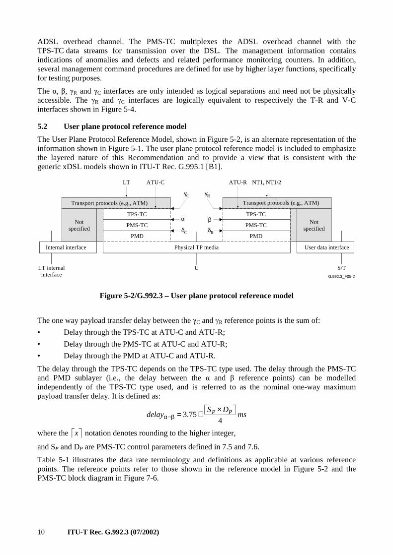
5.2 User plane protocol reference model
The User Plane Protocol Reference Model, shown in Figure 5-2, is an alternate representation of the information shown in Figure 5-1. The user plane protocol reference model is included to emphasize the layered nature of this Recommendation and to provide a view that is consistent with the generic xDSL models shown in ITU-T Rec. G.995.1 [B1].
G.992.3_F05-2
U
PMD
PMS-TC
PMD
TPS-TC
Physical TP media
S/T
User data interfaceInternal interface
ATU-RATU-C NT1, NT1/2LT
Transport protocols (e.g., ATM)
PMS-TC
TPS-TC
Transport protocols (e.g., ATM)
α βNotspecified
Notspecified
LT internalinterface
γC γR
δC δR
Figure 5-2/G.992.3 – User plane protocol reference model
The one way payload transfer delay between the γC and γR reference points is the sum of:
• Delay through the TPS-TC at ATU-C and ATU-R;
• Delay through the PMS-TC at ATU-C and ATU-R;
• Delay through the PMD at ATU-C and ATU-R.
The delay through the TPS-TC depends on the TPS-TC type used. The delay through the PMS-TC and PMD sublayer (i.e., the delay between the α and β reference points) can be modelled independently of the TPS-TC type used, and is referred to as the nominal one-way maximum payload transfer delay. It is defined as:
msDS
delay PP
475.3
×+=β−α
where the x notation denotes rounding to the higher integer,
and SP and DP are PMS-TC control parameters defined in 7.5 and 7.6.
Table 5-1 illustrates the data rate terminology and definitions as applicable at various reference points. The reference points refer to those shown in the reference model in Figure 5-2 and the PMS-TC block diagram in Figure 7-6.
ITU-T Rec. G.992.3 (07/2002) 11
Table 5-1/G.992.3 – Data rate terminology and definitions
Data rate Equation (kbit/s) Reference point
Net data rate ∑ p.actNet
(see Table 7-7)
α, β
Aggregate data rate = Net data rate + Frame overhead rate ( )∑ + Pp.act ORNet
(see Table 7-7)
A
Total data rate = Aggregatedata rate + RS Coding overhead rate ( ) 4LP ×∑
(see Table 7-6)
B, C, δ
Line rate = Total data rate + Trellis Coding overhead rate ( ) 4×∑ ib
(see Table 8-4)
U
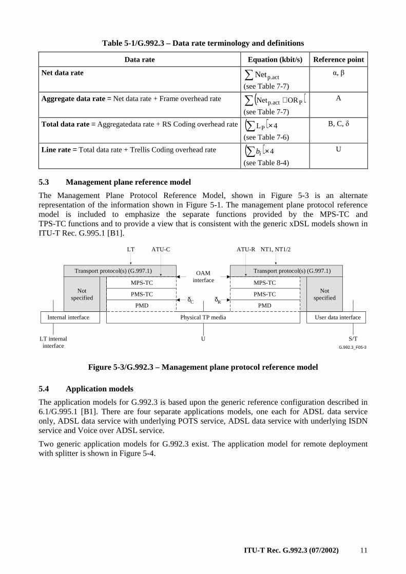
5.3 Management plane reference model
The Management Plane Protocol Reference Model, shown in Figure 5-3 is an alternate representation of the information shown in Figure 5-1. The management plane protocol reference model is included to emphasize the separate functions provided by the MPS-TC and TPS-TC functions and to provide a view that is consistent with the generic xDSL models shown in ITU-T Rec. G.995.1 [B1].
G.992.3_F05-3
U
PMD
PMS-TC
PMD
MPS-TC
Physical TP media
S/T
User data interfaceInternal interface
ATU-RATU-C NT1, NT1/2LT
Transport protocol(s) (G.997.1)
PMS-TC
MPS-TC
Transport protocol(s) (G.997.1)
Notspecified
Notspecified
LT internalinterface
δC δR
OAMinterface
Figure 5-3/G.992.3 – Management plane protocol reference model
5.4 Application models
The application models for G.992.3 is based upon the generic reference configuration described in 6.1/G.995.1 [B1]. There are four separate applications models, one each for ADSL data service only, ADSL data service with underlying POTS service, ADSL data service with underlying ISDN service and Voice over ADSL service.
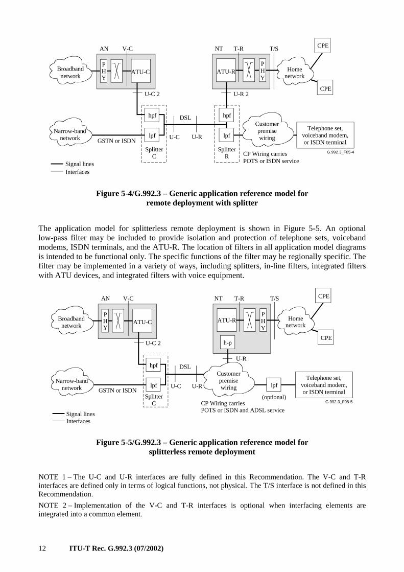
Two generic application models for G.992.3 exist. The application model for remote deployment with splitter is shown in Figure 5-4.
12 ITU-T Rec. G.992.3 (07/2002)
G.992.3_F05-4
GSTN or ISDN
Signal linesInterfaces
Broadbandnetwork
Narrow-bandnetwork
Homenetwork
SplitterC
Telephone set,voiceband modem,or ISDN terminal
Customerpremisewiring
DSL
PHY
V-C
ATU-C
U-C 2
U-C U-R
hpf
lpf
NT
ATU-R
T-R CPE
CPE
T/S
PHY
CP Wiring carriesPOTS or ISDN service
AN
U-R 2
SplitterR
hpf
lpf
Figure 5-4/G.992.3 – Generic application reference model for remote deployment with splitter
The application model for splitterless remote deployment is shown in Figure 5-5. An optional low-pass filter may be included to provide isolation and protection of telephone sets, voiceband modems, ISDN terminals, and the ATU-R. The location of filters in all application model diagrams is intended to be functional only. The specific functions of the filter may be regionally specific. The filter may be implemented in a variety of ways, including splitters, in-line filters, integrated filters with ATU devices, and integrated filters with voice equipment.
G.992.3_F05-5
GSTN or ISDN
Signal linesInterfaces
Broadbandnetwork
Narrow-bandnetwork
Homenetwork
SplitterC
Telephone set,voiceband modem,or ISDN terminal
Customerpremisewiring
DSL
(optional)
PHY
V-C
ATU-C
U-C 2
U-C U-R
hpf
lpf
NT
ATU-R
T-R CPE
CPE
T/S
U-R
lpf
h-p
PHY
CP Wiring carriesPOTS or ISDN and ADSL service
AN
Figure 5-5/G.992.3 – Generic application reference model for splitterless remote deployment
NOTE 1 – The U-C and U-R interfaces are fully defined in this Recommendation. The V-C and T-R interfaces are defined only in terms of logical functions, not physical. The T/S interface is not defined in this Recommendation.
NOTE 2 – Implementation of the V-C and T-R interfaces is optional when interfacing elements are integrated into a common element.
ITU-T Rec. G.992.3 (07/2002) 13
NOTE 3 – One or other of the high-pass filters, which are part of the splitters, may be integrated into the ATU-x; if so, then the U-C 2 and U-R 2 interfaces become the same as the U-C and U-R interfaces, respectively.
NOTE 4 – More than one type of T-R interface may be defined, and more than one type of T/S interface may be provided from an ADSL NT (e.g., NT1 or NT2 types of functionalities).
NOTE 5 – A future issue of this Recommendation may deal with customer installation distribution and home network requirements.
NOTE 6 – Specifications for the splitters are given in Annex E.
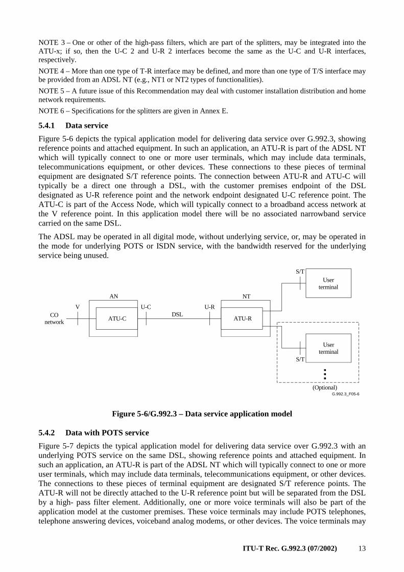
5.4.1 Data service
Figure 5-6 depicts the typical application model for delivering data service over G.992.3, showing reference points and attached equipment. In such an application, an ATU-R is part of the ADSL NT which will typically connect to one or more user terminals, which may include data terminals, telecommunications equipment, or other devices. These connections to these pieces of terminal equipment are designated S/T reference points. The connection between ATU-R and ATU-C will typically be a direct one through a DSL, with the customer premises endpoint of the DSL designated as U-R reference point and the network endpoint designated U-C reference point. The ATU-C is part of the Access Node, which will typically connect to a broadband access network at the V reference point. In this application model there will be no associated narrowband service carried on the same DSL.
The ADSL may be operated in all digital mode, without underlying service, or, may be operated in the mode for underlying POTS or ISDN service, with the bandwidth reserved for the underlying service being unused.
G.992.3_F05-6
ATU-RATU-CDSL
S/T
U-RU-CV
S/T
(Optional)
NTAN
Userterminal
Userterminal
COnetwork
Figure 5-6/G.992.3 – Data service application model
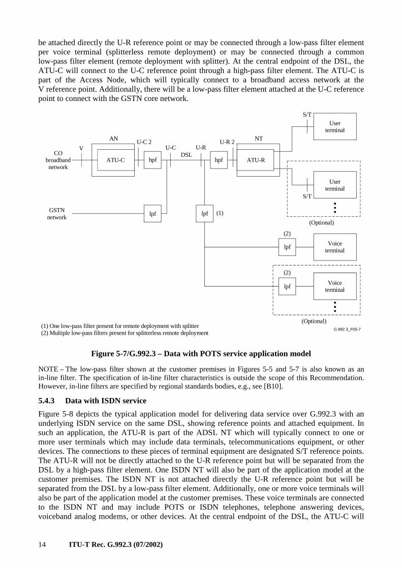
5.4.2 Data with POTS service
Figure 5-7 depicts the typical application model for delivering data service over G.992.3 with an underlying POTS service on the same DSL, showing reference points and attached equipment. In such an application, an ATU-R is part of the ADSL NT which will typically connect to one or more user terminals, which may include data terminals, telecommunications equipment, or other devices. The connections to these pieces of terminal equipment are designated S/T reference points. The ATU-R will not be directly attached to the U-R reference point but will be separated from the DSL by a high- pass filter element. Additionally, one or more voice terminals will also be part of the application model at the customer premises. These voice terminals may include POTS telephones, telephone answering devices, voiceband analog modems, or other devices. The voice terminals may
14 ITU-T Rec. G.992.3 (07/2002)
be attached directly the U-R reference point or may be connected through a low-pass filter element per voice terminal (splitterless remote deployment) or may be connected through a common low-pass filter element (remote deployment with splitter). At the central endpoint of the DSL, the ATU-C will connect to the U-C reference point through a high-pass filter element. The ATU-C is part of the Access Node, which will typically connect to a broadband access network at the V reference point. Additionally, there will be a low-pass filter element attached at the U-C reference point to connect with the GSTN core network.
G.992.3_F05-7
ATU-RATU-CDSL
S/T
U-RU-CV
(Optional)
NTAN
hpf
U-C 2
hpf
U-R 2
lpf lpf
lpf
lpf
(Optional)
(1)
(2)
(2)
S/T
Voiceterminal
Voiceterminal
Userterminal
Userterminal
CObroadbandnetwork
GSTNnetwork
(1) One low-pass filter present for remote deployment with splitter(2) Multiple low-pass filters present for splitterless remote deployment
Figure 5-7/G.992.3 – Data with POTS service application model
NOTE – The low-pass filter shown at the customer premises in Figures 5-5 and 5-7 is also known as an in-line filter. The specification of in-line filter characteristics is outside the scope of this Recommendation. However, in-line filters are specified by regional standards bodies, e.g., see [B10].
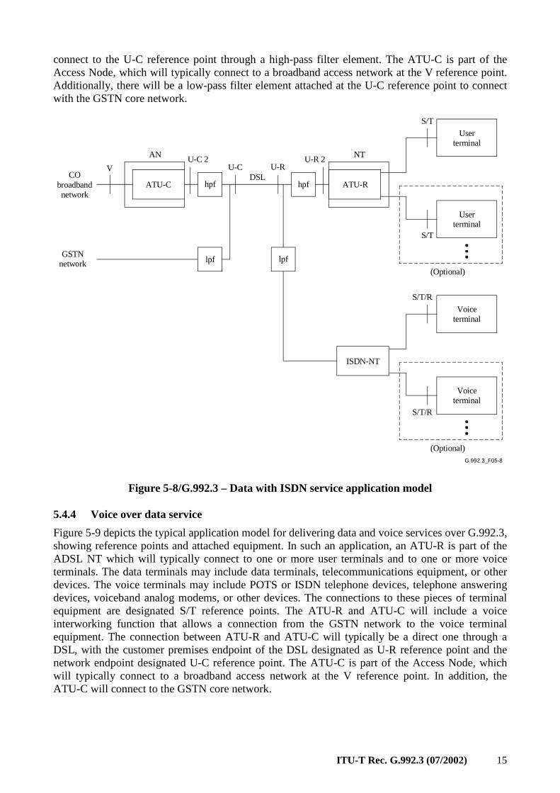
5.4.3 Data with ISDN service
Figure 5-8 depicts the typical application model for delivering data service over G.992.3 with an underlying ISDN service on the same DSL, showing reference points and attached equipment. In such an application, the ATU-R is part of the ADSL NT which will typically connect to one or more user terminals which may include data terminals, telecommunications equipment, or other devices. The connections to these pieces of terminal equipment are designated S/T reference points. The ATU-R will not be directly attached to the U-R reference point but will be separated from the DSL by a high-pass filter element. One ISDN NT will also be part of the application model at the customer premises. The ISDN NT is not attached directly the U-R reference point but will be separated from the DSL by a low-pass filter element. Additionally, one or more voice terminals will also be part of the application model at the customer premises. These voice terminals are connected to the ISDN NT and may include POTS or ISDN telephones, telephone answering devices, voiceband analog modems, or other devices. At the central endpoint of the DSL, the ATU-C will
ITU-T Rec. G.992.3 (07/2002) 15
connect to the U-C reference point through a high-pass filter element. The ATU-C is part of the Access Node, which will typically connect to a broadband access network at the V reference point. Additionally, there will be a low-pass filter element attached at the U-C reference point to connect with the GSTN core network.
G.992.3_F05-7
G.992.3_F05-8
ATU-RATU-CDSL
S/T
U-RU-CV
(Optional)
NTAN
hpf
U-C 2
hpf
U-R 2
lpf lpf
(Optional)
S/T
Voiceterminal
Voiceterminal
Userterminal
Userterminal
CObroadbandnetwork
GSTNnetwork
S/T/R
S/T/R
ISDN-NT
Figure 5-8/G.992.3 – Data with ISDN service application model
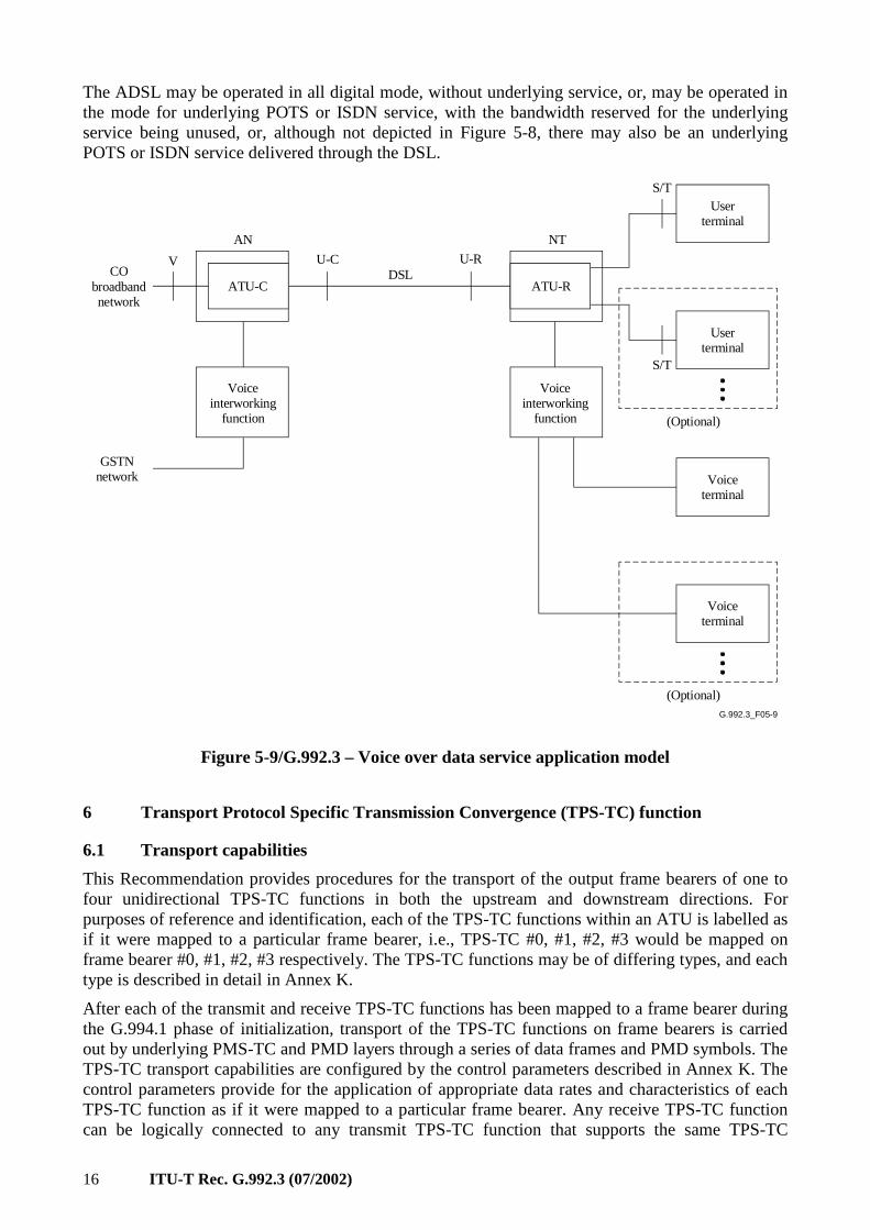
5.4.4 Voice over data service
Figure 5-9 depicts the typical application model for delivering data and voice services over G.992.3, showing reference points and attached equipment. In such an application, an ATU-R is part of the ADSL NT which will typically connect to one or more user terminals and to one or more voice terminals. The data terminals may include data terminals, telecommunications equipment, or other devices. The voice terminals may include POTS or ISDN telephone devices, telephone answering devices, voiceband analog modems, or other devices. The connections to these pieces of terminal equipment are designated S/T reference points. The ATU-R and ATU-C will include a voice interworking function that allows a connection from the GSTN network to the voice terminal equipment. The connection between ATU-R and ATU-C will typically be a direct one through a DSL, with the customer premises endpoint of the DSL designated as U-R reference point and the network endpoint designated U-C reference point. The ATU-C is part of the Access Node, which will typically connect to a broadband access network at the V reference point. In addition, the ATU-C will connect to the GSTN core network.
16 ITU-T Rec. G.992.3 (07/2002)
The ADSL may be operated in all digital mode, without underlying service, or, may be operated in the mode for underlying POTS or ISDN service, with the bandwidth reserved for the underlying service being unused, or, although not depicted in Figure 5-8, there may also be an underlying POTS or ISDN service delivered through the DSL.
G.992.3_F05-7
G.992.3_F05-9
ATU-RATU-CDSL
S/T
U-RU-CV
(Optional)
NTAN
(Optional)
S/T
Voiceterminal
Voiceterminal
Userterminal
Userterminal
CObroadbandnetwork
GSTNnetwork
Voiceinterworking
function
Voiceinterworking
function
Figure 5-9/G.992.3 – Voice over data service application model
6 Transport Protocol Specific Transmission Convergence (TPS-TC) function
6.1 Transport capabilities
This Recommendation provides procedures for the transport of the output frame bearers of one to four unidirectional TPS-TC functions in both the upstream and downstream directions. For purposes of reference and identification, each of the TPS-TC functions within an ATU is labelled as if it were mapped to a particular frame bearer, i.e., TPS-TC #0, #1, #2, #3 would be mapped on frame bearer #0, #1, #2, #3 respectively. The TPS-TC functions may be of differing types, and each type is described in detail in Annex K.
After each of the transmit and receive TPS-TC functions has been mapped to a frame bearer during the G.994.1 phase of initialization, transport of the TPS-TC functions on frame bearers is carried out by underlying PMS-TC and PMD layers through a series of data frames and PMD symbols. The TPS-TC transport capabilities are configured by the control parameters described in Annex K. The control parameters provide for the application of appropriate data rates and characteristics of each TPS-TC function as if it were mapped to a particular frame bearer. Any receive TPS-TC function can be logically connected to any transmit TPS-TC function that supports the same TPS-TC
ITU-T Rec. G.992.3 (07/2002) 17
function type. Unless specifically described to the contrary in Annex K, the control parameters of the connected transmit and receive TPS-TC functions shall be configured with identical control parameter values during initialization and reconfiguration of the ATUs. The receive PMD, PMS-TC and TPS-TC functions recover the various input signals of the corresponding transmit TPS-TC function whose signals having been transported across the TPS-TC, PMS-TC, and PMD functions of an ATU-C and ATU-R pair.
As a management plane element, there are no specific transport functions provided by the TPS-TC function. Each TPS-TC type may have its own unique set of management primitives as defined in Annex K. The management primitives are handled in a transparent manner by the PMS-TC and MPS-TC functions.
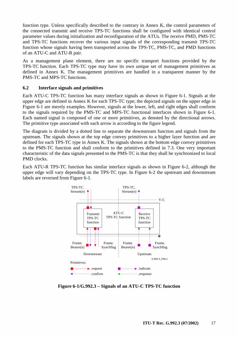
6.2 Interface signals and primitives
Each ATU-C TPS-TC function has many interface signals as shown in Figure 6-1. Signals at the upper edge are defined in Annex K for each TPS-TC type; the depicted signals on the upper edge in Figure 6-1 are merely examples. However, signals at the lower, left, and right edges shall conform to the signals required by the PMS-TC and MPS-TC functional interfaces shown in Figure 6-1. Each named signal is composed of one or more primitives, as denoted by the directional arrows. The primitive type associated with each arrow is according to the figure legend.
The diagram is divided by a dotted line to separate the downstream function and signals from the upstream. The signals shown at the top edge convey primitives to a higher layer function and are defined for each TPS-TC type in Annex K. The signals shown at the bottom edge convey primitives to the PMS-TC function and shall conform to the primitives defined in 7.3. One very important characteristic of the data signals presented to the PMS-TC is that they shall be synchronized to local PMD clocks.
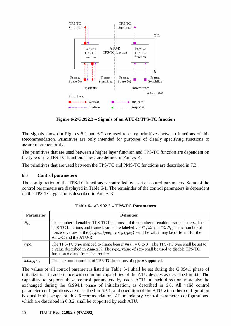
Each ATU-R TPS-TC function has similar interface signals as shown in Figure 6-2, although the upper edge will vary depending on the TPS-TC type. In Figure 6-2 the upstream and downstream labels are reversed from Figure 6-1.
G.992.3_F06-1
TransmitTPS-TCfunction
Frame.Bearer(n)
Frame.Synchflag
ReceiveTPS-TCfunction
Frame.Bearer(n)
Frame.Synchflag
Downstream Upstream
ATU-CTPS-TC function
TPS-TC.Stream(n)
TPS-TC.Stream(n)
.request
.confirm
.indicate
.response
Primitives:
V-C
αααα
Figure 6-1/G.992.3 – Signals of an ATU-C TPS-TC function
18 ITU-T Rec. G.992.3 (07/2002)
G.992.3_F06-2
TransmitTPS-TCfunction
Frame.Bearer(n)
Frame.Synchflag
ReceiveTPS-TCfunction
Frame.Bearer(n)
Frame.Synchflag
Upstream Downstream
ATU-RTPS-TC function
TPS-TC.Stream(n)
TPS-TC.Stream(n)
.request
.confirm
.indicate
.response
Primitives:
T-R
ββββ
Figure 6-2/G.992.3 – Signals of an ATU-R TPS-TC function
The signals shown in Figures 6-1 and 6-2 are used to carry primitives between functions of this Recommendation. Primitives are only intended for purposes of clearly specifying functions to assure interoperability.
The primitives that are used between a higher layer function and TPS-TC function are dependent on the type of the TPS-TC function. These are defined in Annex K.
The primitives that are used between the TPS-TC and PMS-TC functions are described in 7.3.
6.3 Control parameters
The configuration of the TPS-TC functions is controlled by a set of control parameters. Some of the control parameters are displayed in Table 6-1. The remainder of the control parameters is dependent on the TPS-TC type and is described in Annex K.
Table 6-1/G.992.3 – TPS-TC Parameters
Parameter Definition
NBC The number of enabled TPS-TC functions and the number of enabled frame bearers. The TPS-TC functions and frame bearers are labeled #0, #1, #2 and #3. NBC is the number of nonzero values in the type0, type1, type2, type3 set. The value may be different for the ATU-C and the ATU-R.
typen The TPS-TC type mapped to frame bearer #n (n = 0 to 3). The TPS-TC type shall be set to a value described in Annex K. The typen value of zero shall be used to disable TPS-TC function # n and frame bearer # n.
maxtypen The maximum number of TPS-TC functions of type n supported.
The values of all control parameters listed in Table 6-1 shall be set during the G.994.1 phase of initialization, in accordance with common capabilities of the ATU devices as described in 6.6. The capability to support these control parameters by each ATU in each direction may also be exchanged during the G.994.1 phase of initialization, as described in 6.6. All valid control parameter configurations are described in 6.3.1, and operation of the ATU with other configuration is outside the scope of this Recommendation. All mandatory control parameter configurations, which are described in 6.3.2, shall be supported by each ATU.
ITU-T Rec. G.992.3 (07/2002) 19
6.3.1 Valid configurations
An ATU may support up to four simultaneous TPS-TC functions in each direction. The control parameter NBC shall be in the 1 to 4 range.
The valid values of the control parameter typen shall be those contained within the Annex K or the value of zero. All other values are reserved for use by the ITU-T. If the typen parameter is nonzero for upstream and downstream, then it shall have the same value for upstream and downstream.
An ATU shall support mapping of all supported TPS-TC types to all supported frame bearers. The valid labelling of supported frame bearers shall start from 0 and increase by one. Thus there are only 4 cases: 0, 0, 1, 0, 1, 2, or 0, 1, 2, 3.
6.3.2 Mandatory configurations
An ATU shall support at least one combination of a TPS-TC function (of a type defined in Annex K) and a frame bearer in each direction.
6.4 Data plane procedures
Each TPS-TC function shall provide transmit data plane procedures as defined in Annex K that terminate in the assertion of the PMS-TC transmit primitives defined in 7.3. These procedures are otherwise transparent to the PMS-TC function.
6.5 Management plane procedures
Each TPS-TC function may provide local management primitives as defined in Annex K. Up to two of these primitives may be transported to the far end using the PMS-TC procedure defined in 7.8.2.2. These are transported in a manner that is otherwise transparent to the PMS-TC function.
Each TPS-TC function may additionally provide local processing of the primitives per ITU-T Rec. G.997.1 [4]. The results of local processing may be made available through management counter read commands of the MPS-TC function defined in 9.4.1.6. The format and syntax of the returned data from these commands is defined in Annex K.
6.6 Initialization procedure
TPS-TC functions shall be fully configured prior to the initialization of the PMS-TC and PMD functions or be configured after initialization of the PMS-TC and PMS function in a manner that is outside the scope of this Recommendation. The configuration prior to initialization is performed via a G.994.1 MS message. Information may be exchanged prior to the mode select to ascertain capabilities using G.994.1 CL or CLR messages. Most of the information conveyed through G.994.1 messages is dependent on the TPS-TC type and is defined in Annex K.
6.6.1 G.994.1 Phase
6.6.1.1 G.994.1 Capabilities list message
The following information about the TPS-TC function shall be communicated through ITU-T Rec. G.994.1 [2] as part of the CL and CLR messages. Additional information appropriate to each TPS-TC function shall be arranged in blocks of information as described in Annex K. This information may be optionally requested and reported via G.994.1 CL and CLR messages at the start of a session. However, the information shall be exchanged at least once between ATU-C and ATU-R prior to enabling a TPS-TC function but not necessarily at the start of each session. The information exchanged includes:
• Supported combinations of downstream frame bearers and TPS-TC types;
• Supported combinations of upstream frame bearers and TPS-types;
• Supported number of TPS-TC functions of type n.
20 ITU-T Rec. G.992.3 (07/2002)
This information on supported combinations is represented using a G.994.1 tree model of the information as described in Annex K. An ATU shall provide both the upstream and downstream information in CL and CLR messages. Corresponding to each Spar(2) bit from Annex K that is set to a 1, one additional block of information shall be provided in the CL and CLR messages. The supported number of TPS-TC functions of type n is represented using a G.994.1 tree model of the information as in Table 6-2.
Table 6-2/G.992.3 – Format for TPS-TC capabilities information
Spar(2) bits Definition of Npar(3) bits
Maxtype Upstream Parameter block of 2 octets that describes the maxtype values for upstream, using an unsigned 3-bit value in the 0 to 4 range for each of the TPS-TC types 1 (STM), 2 (ATM) and 3 (PTM).
Maxtype Downstream Parameter block of 2 octets that describes the maxtype values for downstream, using an unsigned 3-bit value in the 0 to 4 range for each of the TPS-TC types 1 (STM), 2 (ATM) and 3 (PTM).
6.6.1.2 G.994.1 Mode select message
The following control parameters of TPS-TC function shall be configured through ITU-T Rec. G.994.1 [2] as part of the MS message. Additional control parameters appropriate to each TPS-TC type shall be arranged in blocks of information as described in Annex K. This information shall be selected prior to the PMD and TPS-TC initialization. The information includes:
• Mapped combinations of downstream frame bearers and TPS-TC types;
• Mapped combinations of upstream frame bearers and TPS-TC types.
The Maxtype information shall not be included in an MS message. The Spar(2) bit shall be set to 0.
This configuration for TPS-TC is represented using a G.994.1 tree model of the information as described in Annex K. An ATU provides both the upstream and downstream trees in the MS message. Corresponding to each Spar(2) bit from Annex K (one bit per combination of a frame bearer and TPS-TC type) that is set to a 1, one block of information shall be provided in the MS message as defined in Annex K. For each frame bearer, no more than 1 corresponding Spar(2) bit shall be set. A frame bearer that has one corresponding Spar(2) bit set, shall be enabled (i.e., typen > 0). Any frame bearer that is supported but that does not have any its corresponding Spar(2) bit set shall be disabled (i.e., typen = 0). NBC is the number of nonzero values in the type0, type1, type2, type3 set.
6.6.2 Channel analysis phase
No TPS-TC capabilities or control parameter settings are exchanged during the Channel Analysis Phase.
6.6.3 Exchange phase
No TPS-TC capabilities or control parameter settings are exchanged during the Exchange Phase.
6.7 On-line reconfiguration
On-line reconfiguration procedures are defined uniquely for each TPS-TC type in Annex K. The procedure may rely on the primitives associated with PMD.Synchflag for synchronization of the on-line reconfiguration changes.
6.8 Power management mode
The procedures defined for the TPS-TC functions are intended for use while the ATU link is in power management states L0 and L2.
ITU-T Rec. G.992.3 (07/2002) 21
6.8.1 L0 link state operation
The TPS-TC function shall operate according to all data plane and management plane procedures defined in 6.4 and 6.5 as well as any specified in Annex K while the link is in power management state L0. All control parameter definitions and conditions provided in 6.3 and Annex K shall apply.
6.8.1.1 Transition to L2 link state operation
Entry into the L2 link state shall be preceded by the protocol described in 9.5.3.3. Following the successful completion of the protocol, the coordinated entry into the L2 link state may rely on the primitives associated with PMD.Synchflag for synchronization as further defined in Annex K.
6.8.1.2 Transition to L3 link state operation
The orderly shutdown of the ATU is intended to provide the transition from link state L0 to state L3. The transition should be as described in 9.5.3.1 or 9.5.3.2. Any specific TPS-TC tear-down procedure shall be as provided in Annex K.
6.8.2 L2 link state operation
The TPS-TC function shall operate according to all data plane and management plane procedures defined in 6.4 and 6.5 as well as specified in Annex K while the link is in power management state L2. All control parameter definitions provided in 6.3 and Annex K shall apply.
The low power trim procedure shall not effect the operation of the TPS-TC function.
6.8.2.1 Transition to L0 link state operation
Entry into the L0 link state shall be preceded by the protocol described in either 9.5.3.4 or 9.5.3.5. Following the successful completion of the protocol, the coordinated entry into the L0 link state may rely on the primitives associated with PMD.Synchflag for synchronization as further defined in Annex K.
6.8.2.2 Transition to L3 link state operation
If operating in link state L2, the ATUs are intended to transition to link state L0 and make use of the orderly shutdown procedure. However, in the event of sudden power loss, the link may transition from link state L2 to state L3 directly. The transition should be as described in 9.5.3.2. Any specific TPS-TC tear-down procedure shall be as provided in Annex K.
6.8.3 L3 link state operation
In the L3 link state, any specified procedures for the TPS-TC function shall be as provided in Annex K.
6.8.3.1 Transition to L0 link state operation
The initialization procedures of the ATU are intended to provide the transition from link state L3 to state L0. The transition shall be as described in 6.6.
7 Physical Media Specific Transmission Convergence (PMS-TC) function
7.1 Transport capabilities
The primary purpose of the ATU PMS-TC function is to provide for the multiplexing and transport of several channels of information. The ATU PMS-TC function provides procedure to multiplex and transport:
• one to four frame bearers in upstream and downstream directions;
• NTR signal from the ATU-C to the ATU-R; and
• an overhead channel in both directions to support the MPS-TC function of each ATU.
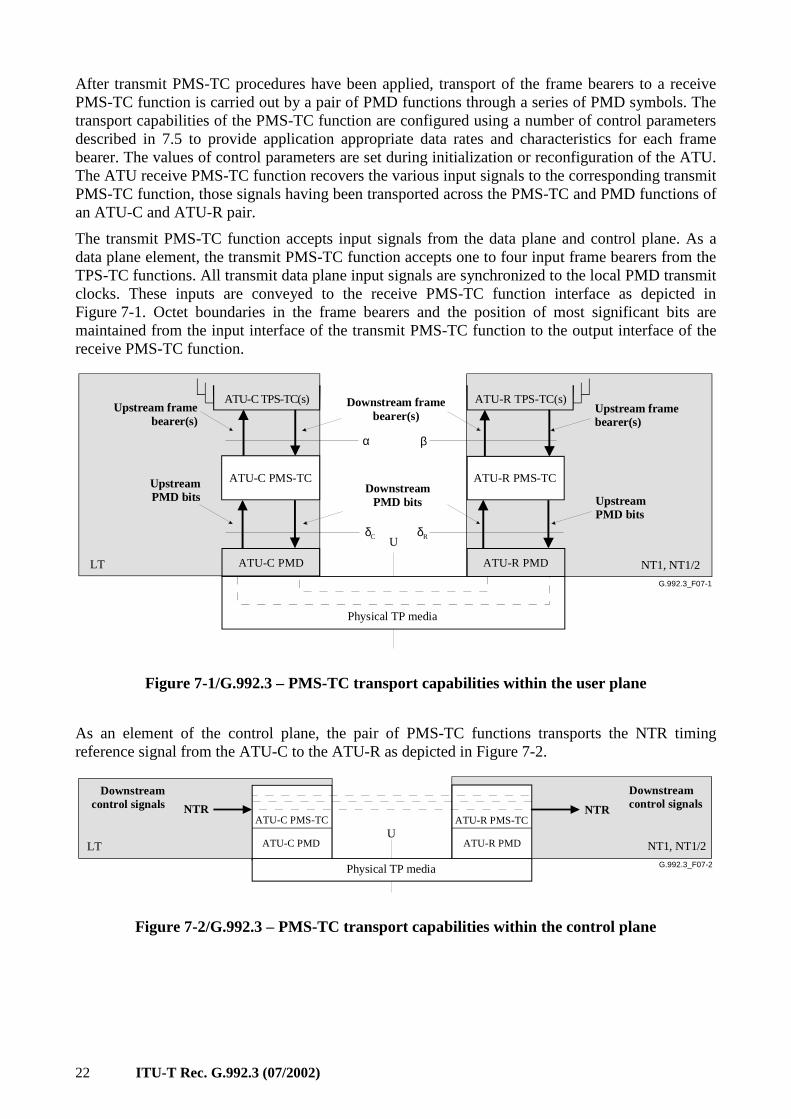
22 ITU-T Rec. G.992.3 (07/2002)
After transmit PMS-TC procedures have been applied, transport of the frame bearers to a receive PMS-TC function is carried out by a pair of PMD functions through a series of PMD symbols. The transport capabilities of the PMS-TC function are configured using a number of control parameters described in 7.5 to provide application appropriate data rates and characteristics for each frame bearer. The values of control parameters are set during initialization or reconfiguration of the ATU. The ATU receive PMS-TC function recovers the various input signals to the corresponding transmit PMS-TC function, those signals having been transported across the PMS-TC and PMD functions of an ATU-C and ATU-R pair.
The transmit PMS-TC function accepts input signals from the data plane and control plane. As a data plane element, the transmit PMS-TC function accepts one to four input frame bearers from the TPS-TC functions. All transmit data plane input signals are synchronized to the local PMD transmit clocks. These inputs are conveyed to the receive PMS-TC function interface as depicted in Figure 7-1. Octet boundaries in the frame bearers and the position of most significant bits are maintained from the input interface of the transmit PMS-TC function to the output interface of the receive PMS-TC function.
G.992.3_F07-1
U
βα
ATU-R PMS-TC
ATU-R TPS-TC(s)ATU-C TPS-TC(s)
Physical TP media
ATU-R PMDATU-C PMD
Upstream framebearer(s)
Upstream framebearer(s)
Downstream framebearer(s)
NT1, NT1/2LT
UpstreamPMD bits Upstream
PMD bits
DownstreamPMD bits
δC δR
ATU-C PMS-TC
Figure 7-1/G.992.3 – PMS-TC transport capabilities within the user plane
As an element of the control plane, the pair of PMS-TC functions transports the NTR timing reference signal from the ATU-C to the ATU-R as depicted in Figure 7-2.
G.992.3_F07-2
UATU-R PMS-TCATU-C PMS-TC
Physical TP media
ATU-R PMDATU-C PMD
Downstream control signals
Downstream control signals
NT1, NT1/2LT
NTR NTR
Figure 7-2/G.992.3 – PMS-TC transport capabilities within the control plane
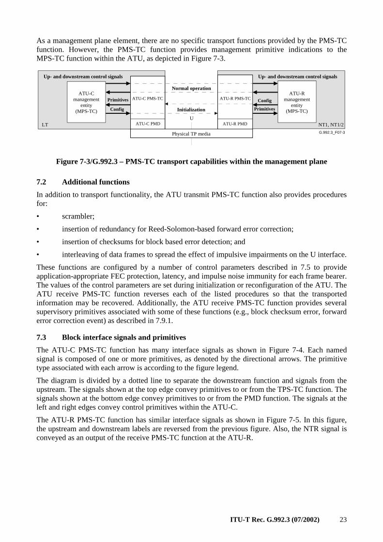
ITU-T Rec. G.992.3 (07/2002) 23
As a management plane element, there are no specific transport functions provided by the PMS-TC function. However, the PMS-TC function provides management primitive indications to the MPS-TC function within the ATU, as depicted in Figure 7-3.
G.992.3_F07-3
U
ATU-R PMS-TCATU-C PMS-TC
Physical TP media
ATU-R PMDATU-C PMD
Up- and downstream control signals
Primitives
Up- and downstream control signals
NT1, NT1/2LT
ATU-C management
entity(MPS-TC)
ATU-R management
entity(MPS-TC)Config Primitives
Config
Initialization
Normal operation
Figure 7-3/G.992.3 – PMS-TC transport capabilities within the management plane
7.2 Additional functions
In addition to transport functionality, the ATU transmit PMS-TC function also provides procedures for:
• scrambler;
• insertion of redundancy for Reed-Solomon-based forward error correction;
• insertion of checksums for block based error detection; and
• interleaving of data frames to spread the effect of impulsive impairments on the U interface.
These functions are configured by a number of control parameters described in 7.5 to provide application-appropriate FEC protection, latency, and impulse noise immunity for each frame bearer. The values of the control parameters are set during initialization or reconfiguration of the ATU. The ATU receive PMS-TC function reverses each of the listed procedures so that the transported information may be recovered. Additionally, the ATU receive PMS-TC function provides several supervisory primitives associated with some of these functions (e.g., block checksum error, forward error correction event) as described in 7.9.1.
7.3 Block interface signals and primitives
The ATU-C PMS-TC function has many interface signals as shown in Figure 7-4. Each named signal is composed of one or more primitives, as denoted by the directional arrows. The primitive type associated with each arrow is according to the figure legend.
The diagram is divided by a dotted line to separate the downstream function and signals from the upstream. The signals shown at the top edge convey primitives to or from the TPS-TC function. The signals shown at the bottom edge convey primitives to or from the PMD function. The signals at the left and right edges convey control primitives within the ATU-C.
The ATU-R PMS-TC function has similar interface signals as shown in Figure 7-5. In this figure, the upstream and downstream labels are reversed from the previous figure. Also, the NTR signal is conveyed as an output of the receive PMS-TC function at the ATU-R.
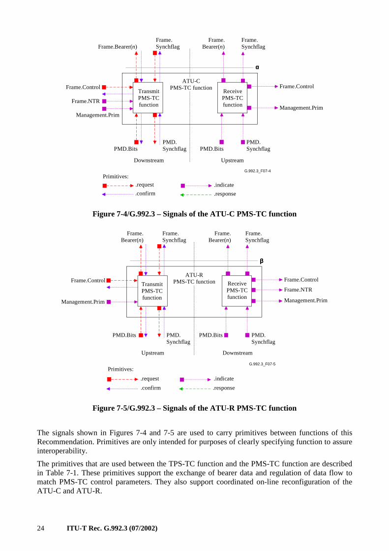
24 ITU-T Rec. G.992.3 (07/2002)
G.992.3_F07-4
.request
.confirm
.indicate
.response
Primitives:
TransmitPMS-TCfunction
PMD.BitsPMD.Synchflag
Frame.Bearer(n)Frame.Synchflag
Frame.ControlReceivePMS-TCfunction
PMD.BitsPMD.Synchflag
Frame.Bearer(n)
Frame.Synchflag
Downstream Upstream
ATU-C PMS-TC function Frame.Control
Frame.NTRManagement.Prim
Management.Prim
αααα
Figure 7-4/G.992.3 – Signals of the ATU-C PMS-TC function
G.992.3_F07-5
.request
.confirm
.indicate
.response
Primitives:
TransmitPMS-TCfunction
PMD.Bits PMD.Synchflag
Frame.Bearer(n)
Frame.Synchflag
ReceivePMS-TCfunction
PMD.Bits PMD.Synchflag
Frame.Bearer(n)
Frame.Synchflag
ATU-R PMS-TC function Frame.Control
Frame.NTR
Management.PrimManagement.Prim
ββββ
Frame.Control
DownstreamUpstream
Figure 7-5/G.992.3 – Signals of the ATU-R PMS-TC function
The signals shown in Figures 7-4 and 7-5 are used to carry primitives between functions of this Recommendation. Primitives are only intended for purposes of clearly specifying function to assure interoperability.
The primitives that are used between the TPS-TC function and the PMS-TC function are described in Table 7-1. These primitives support the exchange of bearer data and regulation of data flow to match PMS-TC control parameters. They also support coordinated on-line reconfiguration of the ATU-C and ATU-R.
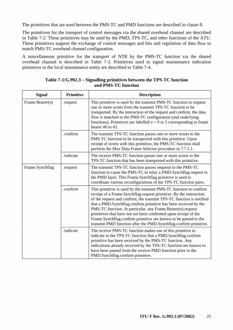
ITU-T Rec. G.992.3 (07/2002) 25
The primitives that are used between the PMS-TC and PMD functions are described in clause 8.
The primitives for the transport of control messages via the shared overhead channel are described in Table 7-2. These primitives may be used by the PMD, TPS-TC, and other functions of the ATU. These primitives support the exchange of control messages and bits and regulation of data flow to match PMS-TC overhead channel configuration.
A miscellaneous primitive for the transport of NTR by the PMS-TC function via the shared overhead channel is described in Table 7-3. Primitives used to signal maintenance indication primitives to the local maintenance entity are described in Table 7-4.
Table 7-1/G.992.3 – Signalling primitives between the TPS-TC function and PMS-TC function
Signal Primitive Description
.request This primitive is used by the transmit PMS-TC function to request one or more octets from the transmit TPS-TC function to be transported. By the interaction of the request and confirm, the data flow is matched to the PMS-TC configuration (and underlying functions). Primitives are labelled n = 0 to 3 corresponding to frame bearer #0 to #3.
.confirm The transmit TPS-TC function passes one or more octets to the PMS-TC function to be transported with this primitive. Upon receipt of octets with this primitive, the PMS-TC function shall perform the Mux Data Frame Selector procedure in 7.7.1.1.
Frame.Bearer(n)
.indicate The receive PMS-TC function passes one or more octets to the TPS-TC function that has been transported with this primitive.
.request The transmit TPS-TC function passes requests to the PMS-TC function to cause the PMS-TC to relay a PMD.Synchflag request to the PMD layer. This Frame.Synchflag primitive is used to coordinate various reconfigurations of the TPS-TC function pairs.
.confirm This primitive is used by the transmit PMS-TC function to confirm receipt of a Frame.Synchflag.request primitive. By the interaction of the request and confirm, the transmit TPS-TC function is notified that a PMD.Synchflag.confirm primitive has been received by the PMS-TC function. In particular, any Frame.Bearer(n).request primitives that have not yet been confirmed upon receipt of the Frame.Synchflag.confirm primitive are known to be passed to the transmit PMD function after the PMD.Synchflag.confirm primitive.
Frame.Synchflag
.indicate The receive PMS-TC function makes use of this primitive to indicate to the TPS-TC function that a PMD.Synchflag.confirm primitive has been received by the PMS-TC function. Any indications already received by the TPS-TC function are known to have been passed from the receive PMD function prior to the PMD.Synchflag.confirm primitive.
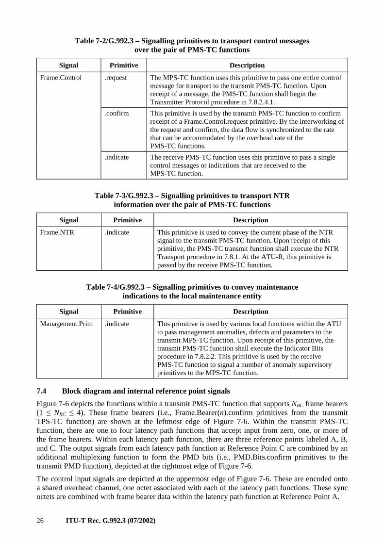
26 ITU-T Rec. G.992.3 (07/2002)
Table 7-2/G.992.3 – Signalling primitives to transport control messages over the pair of PMS-TC functions
Signal Primitive Description
.request The MPS-TC function uses this primitive to pass one entire control message for transport to the transmit PMS-TC function. Upon receipt of a message, the PMS-TC function shall begin the Transmitter Protocol procedure in 7.8.2.4.1.
.confirm This primitive is used by the transmit PMS-TC function to confirm receipt of a Frame.Control.request primitive. By the interworking of the request and confirm, the data flow is synchronized to the rate that can be accommodated by the overhead rate of the PMS-TC functions.
Frame.Control
.indicate The receive PMS-TC function uses this primitive to pass a single control messages or indications that are received to the MPS-TC function.
Table 7-3/G.992.3 – Signalling primitives to transport NTR information over the pair of PMS-TC functions
Signal Primitive Description
Frame.NTR .indicate This primitive is used to convey the current phase of the NTR signal to the transmit PMS-TC function. Upon receipt of this primitive, the PMS-TC transmit function shall execute the NTR Transport procedure in 7.8.1. At the ATU-R, this primitive is passed by the receive PMS-TC function.
Table 7-4/G.992.3 – Signalling primitives to convey maintenance indications to the local maintenance entity
Signal Primitive Description
Management.Prim .indicate This primitive is used by various local functions within the ATU to pass management anomalies, defects and parameters to the transmit MPS-TC function. Upon receipt of this primitive, the transmit PMS-TC function shall execute the Indicator Bits procedure in 7.8.2.2. This primitive is used by the receive PMS-TC function to signal a number of anomaly supervisory primitives to the MPS-TC function.
7.4 Block diagram and internal reference point signals
Figure 7-6 depicts the functions within a transmit PMS-TC function that supports NBC frame bearers (1 ≤ NBC ≤ 4). These frame bearers (i.e., Frame.Bearer(n).confirm primitives from the transmit TPS-TC function) are shown at the leftmost edge of Figure 7-6. Within the transmit PMS-TC function, there are one to four latency path functions that accept input from zero, one, or more of the frame bearers. Within each latency path function, there are three reference points labeled A, B, and C. The output signals from each latency path function at Reference Point C are combined by an additional multiplexing function to form the PMD bits (i.e., PMD.Bits.confirm primitives to the transmit PMD function), depicted at the rightmost edge of Figure 7-6.
The control input signals are depicted at the uppermost edge of Figure 7-6. These are encoded onto a shared overhead channel, one octet associated with each of the latency path functions. These sync octets are combined with frame bearer data within the latency path function at Reference Point A.
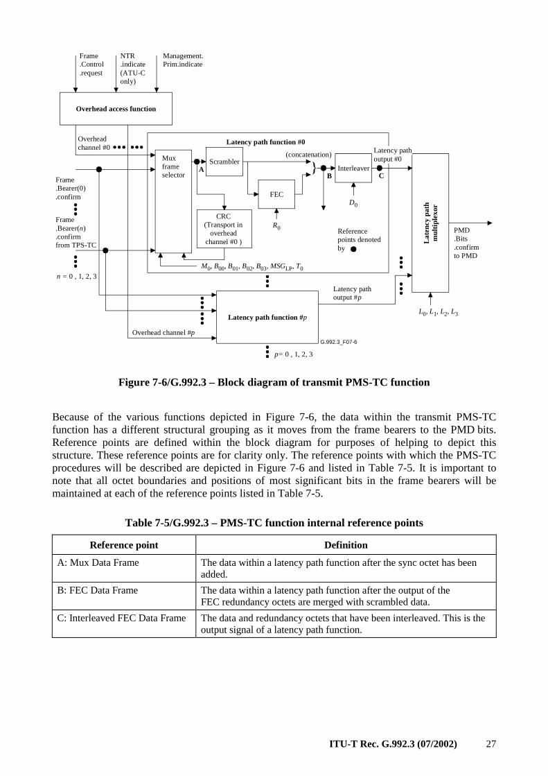
ITU-T Rec. G.992.3 (07/2002) 27
G.992.3_F07-6
Late
ncy
path
mul
tiple
xor
Latency path function #p
Overhead access function
Frame.Bearer(0).confirm
PMD.Bits.confirmto PMD
Frame.Control.request
NTR.indicate(ATU-Conly)
Overhead channel #p
Overheadchannel #0
Muxframeselector
Scrambler
FEC
Interleaver
CRC(Transport in
overheadchannel #0 )
p= 0 , 1, 2, 3
Latency path output #p
M0, B00, B01, B02, B03, MSGLP, T0
R0
D0
L0, L1, L2, L3
AB C
Frame.Bearer(n).confirmfrom TPS-TC
Referencepoints denotedby
n = 0 , 1, 2, 3
Latency path function #0
Management.Prim.indicate
(concatenation)Latency pathoutput #0
Figure 7-6/G.992.3 – Block diagram of transmit PMS-TC function
Because of the various functions depicted in Figure 7-6, the data within the transmit PMS-TC function has a different structural grouping as it moves from the frame bearers to the PMD bits. Reference points are defined within the block diagram for purposes of helping to depict this structure. These reference points are for clarity only. The reference points with which the PMS-TC procedures will be described are depicted in Figure 7-6 and listed in Table 7-5. It is important to note that all octet boundaries and positions of most significant bits in the frame bearers will be maintained at each of the reference points listed in Table 7-5.
Table 7-5/G.992.3 – PMS-TC function internal reference points
Reference point Definition
A: Mux Data Frame The data within a latency path function after the sync octet has been added.
B: FEC Data Frame The data within a latency path function after the output of the FEC redundancy octets are merged with scrambled data.
C: Interleaved FEC Data Frame The data and redundancy octets that have been interleaved. This is the output signal of a latency path function.
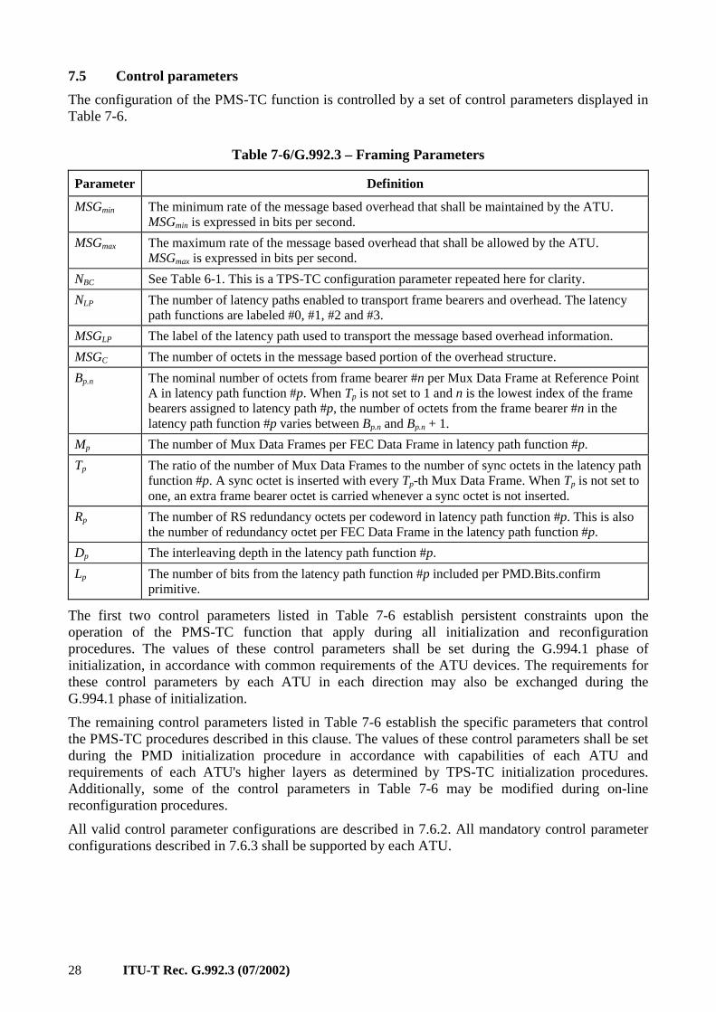
28 ITU-T Rec. G.992.3 (07/2002)
7.5 Control parameters
The configuration of the PMS-TC function is controlled by a set of control parameters displayed in Table 7-6.
Table 7-6/G.992.3 – Framing Parameters
Parameter Definition
MSGmin The minimum rate of the message based overhead that shall be maintained by the ATU. MSGmin is expressed in bits per second.
MSGmax The maximum rate of the message based overhead that shall be allowed by the ATU. MSGmax is expressed in bits per second.
NBC See Table 6-1. This is a TPS-TC configuration parameter repeated here for clarity.
NLP The number of latency paths enabled to transport frame bearers and overhead. The latency path functions are labeled #0, #1, #2 and #3.
MSGLP The label of the latency path used to transport the message based overhead information.
MSGC The number of octets in the message based portion of the overhead structure.
Bp.n The nominal number of octets from frame bearer #n per Mux Data Frame at Reference Point A in latency path function #p. When Tp is not set to 1 and n is the lowest index of the frame bearers assigned to latency path #p, the number of octets from the frame bearer #n in the latency path function #p varies between Bp.n and Bp.n + 1.
Mp The number of Mux Data Frames per FEC Data Frame in latency path function #p.
Tp The ratio of the number of Mux Data Frames to the number of sync octets in the latency path function #p. A sync octet is inserted with every Tp-th Mux Data Frame. When Tp is not set to one, an extra frame bearer octet is carried whenever a sync octet is not inserted.
Rp The number of RS redundancy octets per codeword in latency path function #p. This is also the number of redundancy octet per FEC Data Frame in the latency path function #p.
Dp The interleaving depth in the latency path function #p.
Lp The number of bits from the latency path function #p included per PMD.Bits.confirm primitive.
The first two control parameters listed in Table 7-6 establish persistent constraints upon the operation of the PMS-TC function that apply during all initialization and reconfiguration procedures. The values of these control parameters shall be set during the G.994.1 phase of initialization, in accordance with common requirements of the ATU devices. The requirements for these control parameters by each ATU in each direction may also be exchanged during the G.994.1 phase of initialization.
The remaining control parameters listed in Table 7-6 establish the specific parameters that control the PMS-TC procedures described in this clause. The values of these control parameters shall be set during the PMD initialization procedure in accordance with capabilities of each ATU and requirements of each ATU's higher layers as determined by TPS-TC initialization procedures. Additionally, some of the control parameters in Table 7-6 may be modified during on-line reconfiguration procedures.
All valid control parameter configurations are described in 7.6.2. All mandatory control parameter configurations described in 7.6.3 shall be supported by each ATU.
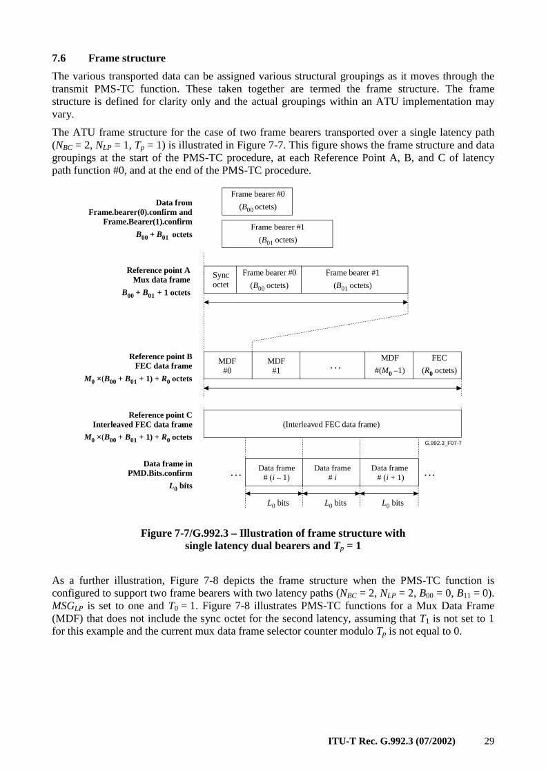
ITU-T Rec. G.992.3 (07/2002) 29
7.6 Frame structure
The various transported data can be assigned various structural groupings as it moves through the transmit PMS-TC function. These taken together are termed the frame structure. The frame structure is defined for clarity only and the actual groupings within an ATU implementation may vary.
The ATU frame structure for the case of two frame bearers transported over a single latency path (NBC = 2, NLP = 1, Tp = 1) is illustrated in Figure 7-7. This figure shows the frame structure and data groupings at the start of the PMS-TC procedure, at each Reference Point A, B, and C of latency path function #0, and at the end of the PMS-TC procedure.
G.992.3_F07-7
Syncoctet
Frame bearer #0
(B00 octets)
Reference point AMux data frame
B00 + B01 + 1 octets
(Interleaved FEC data frame)
MDF
#(M0 –1)
FEC
(R0 octets). . .Reference point B
FEC data frame
M0 ×(B00 + B01 + 1) + R0 octets
Reference point CInterleaved FEC data frame
M0 ×(B00 + B01 + 1) + R0 octets
Frame bearer #1
(B01 octets)
Data from Frame.bearer(0).confirm and
Frame.Bearer(1).confirm
B00 + B01 octets
Data frame inPMD.Bits.confirm
L0 bits
Data frame # (i + 1)
L0 bits
Data frame# i
L0 bits
Data frame# (i – 1)
L0 bits
. . .. . .
Frame bearer #0
(B00 octets)
Frame bearer #1
(B01 octets)
MDF#0
MDF#1
Figure 7-7/G.992.3 – Illustration of frame structure with single latency dual bearers and Tp = 1
As a further illustration, Figure 7-8 depicts the frame structure when the PMS-TC function is configured to support two frame bearers with two latency paths (NBC = 2, NLP = 2, B00 = 0, B11 = 0). MSGLP is set to one and T0 = 1. Figure 7-8 illustrates PMS-TC functions for a Mux Data Frame (MDF) that does not include the sync octet for the second latency, assuming that T1 is not set to 1 for this example and the current mux data frame selector counter modulo Tp is not equal to 0.
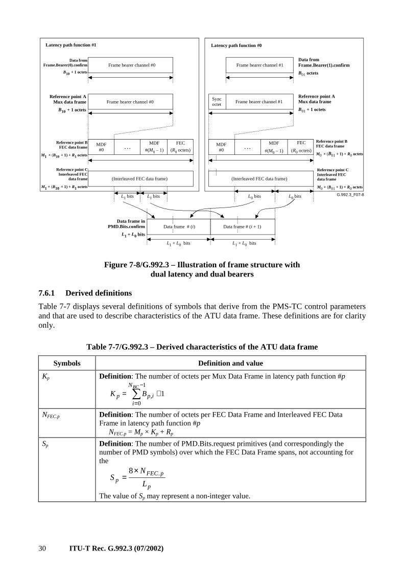
30 ITU-T Rec. G.992.3 (07/2002)
G.992.3_F07-8L1 bits L1 bits L0 bits L0 bits
Frame bearer channel #0Reference point A
Mux data frame
B10 + 1 octets
(Interleaved FEC data frame)
MDF
#(M1 – 1)
FEC
(R1 octets)
Reference point BFEC data frame
M1 × (B10 + 1) + R1 octets
Reference point CInterleaved FEC
data frame
M1 × (B10 + 1) + R1 octets
Frame bearer channel #0 Data from
Frame.Bearer(0).confirm
B10 + 1 octets
. . .
Syncoctet Frame bearer channel #1
Reference point AMux data frame
B01 + 1 octets
(Interleaved FEC data frame)
MDF
#(M0 – 1)
FEC
(R0 octets)
Reference point BFEC data frame
M0 × (B01 + 1) + R0 octets
Reference point CInterleaved FEC data frame
M0 × (B01 + 1) + R0 octets
Frame bearer channel #1Data fromFrame.Bearer(1).confirm
B01 octets
. . .
Latency path function #0Latency path function #1
Data frame inPMD.Bits.confirm
L1 + L0 bits
Data frame # (i)
L1 + L0 bits
Data frame # (i + 1)
L1 + L0 bits
MDF#0
MDF#0
Figure 7-8/G.992.3 – Illustration of frame structure with dual latency and dual bearers
7.6.1 Derived definitions
Table 7-7 displays several definitions of symbols that derive from the PMS-TC control parameters and that are used to describe characteristics of the ATU data frame. These definitions are for clarity only.
Table 7-7/G.992.3 – Derived characteristics of the ATU data frame
Symbols Definition and value
Kp Definition : The number of octets per Mux Data Frame in latency path function #p
11
0, += ∑
−
=
BCN
iipp BK
NFEC.p Definition : The number of octets per FEC Data Frame and Interleaved FEC Data Frame in latency path function #p NFEC.p = Mp × Kp + Rp
Sp Definition : The number of PMD.Bits.request primitives (and correspondingly the number of PMD symbols) over which the FEC Data Frame spans, not accounting for the
p
pFECp L
NS
.8×=
The value of Sp may represent a non-integer value.
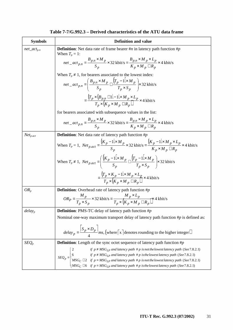
ITU-T Rec. G.992.3 (07/2002) 31
Table 7-7/G.992.3 – Derived characteristics of the ATU data frame
Symbols Definition and value
net_actp.n Definition : Net data rate of frame bearer #n in latency path function #p When Tp = 1:
kbit/s 4kbit/s 32_..
. ×+×××
=××
=ppp
ppnp
p
pnpnp RMK
LMB
S
MBactnet
When Tp ≠ 1, for bearers associated to the lowest index:
( )
kbit/s 321
_ .. ×
××−
+×
=pp
pp
p
pnpnp ST
MT
S
MBactnet
( )( )
( ) kbit/s 411. ×
+××××−+×
=pppp
ppnpp
RMKT
LMBT
for bearers associated with subsequence values in the list:
kbit/s 4kbit/s 32_..
. ×+×××
=××
=ppp
ppnp
p
pnpnp RMK
LMB
S
MBactnet
Netp.act Definition : Net data rate of latency path function #p
When Tp = 1, ( ) ( )
kbit/s 41
kbit/s 321
. ×+×
××−=×
×−=
ppp
ppp
p
ppactp RMK
LMK
S
MKNet
When Tp ≠ 1, ( ) ( )
kbit/s 3211
. ×
××−
+×−
=pp
pp
p
ppactp ST
MT
S
MKNet
( )
( ) kbit/s 41
×+××
××−×=
pppp
pppp
RMKT
LMKT
ORp Definition : Overhead rate of latency path function #p
( ) kbit/s 4kbit/s 32 ×+××
×=×
×=
pppp
pp
pp
pP RMKT
LM
ST
MOR
delayp Definition : PMS-TC delay of latency path function #p
Nominal one-way maximum transport delay of latency path function #p is defined as:
( )integerhigher the torounding denotes x where ,
4ms
DSdelay
ppp
×=
SEQp Definition : Length of the sync octet sequence of latency path function #p
==≠≠
++
=
)1.2.8.7( #
)1.2.8.7( #
)1.2.8.7( #
)1.2.8.7( #
6
2
6
2
SeepathlatencylowesttheisppathlatencyandMSGpif
SeepathlatencylowestthenotisppathlatencyandMSGpif
SeepathlatencylowesttheisppathlatencyandMSGpif
SeepathlatencylowestthenotisppathlatencyandMSGpif
MSG
MSGSEQ
LP
LP
LP
LP
C
Cp
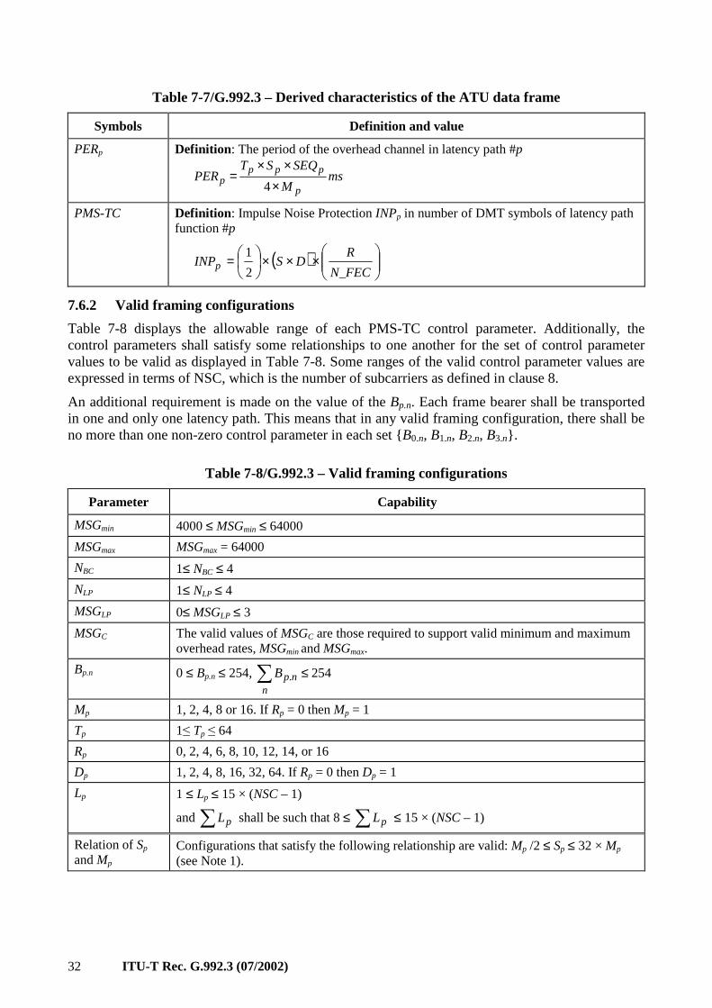
32 ITU-T Rec. G.992.3 (07/2002)
Table 7-7/G.992.3 – Derived characteristics of the ATU data frame
Symbols Definition and value
PERp Definition : The period of the overhead channel in latency path #p
msM
SEQSTPER
p
pppp ×
××=
4
PMS-TC
Definition : Impulse Noise Protection INPp in number of DMT symbols of latency path function #p
( )
×××=FECN
RDSINPp
_2
1
7.6.2 Valid framing configurations
Table 7-8 displays the allowable range of each PMS-TC control parameter. Additionally, the control parameters shall satisfy some relationships to one another for the set of control parameter values to be valid as displayed in Table 7-8. Some ranges of the valid control parameter values are expressed in terms of NSC, which is the number of subcarriers as defined in clause 8.
An additional requirement is made on the value of the Bp.n. Each frame bearer shall be transported in one and only one latency path. This means that in any valid framing configuration, there shall be no more than one non-zero control parameter in each set B0.n, B1.n, B2.n, B3.n.
Table 7-8/G.992.3 – Valid framing configurations
Parameter Capability
MSGmin 4000 ≤ MSGmin ≤ 64000
MSGmax MSGmax = 64000
NBC 1≤ NBC ≤ 4
NLP 1≤ NLP ≤ 4
MSGLP 0≤ MSGLP ≤ 3
MSGC The valid values of MSGC are those required to support valid minimum and maximum overhead rates, MSGmin and MSGmax.
Bp.n 0 ≤ Bp.n ≤ 254, 254. ≤∑n
npB
Mp 1, 2, 4, 8 or 16. If Rp = 0 then Mp = 1
Tp 1≤ Tp ≤ 64
Rp 0, 2, 4, 6, 8, 10, 12, 14, or 16
Dp 1, 2, 4, 8, 16, 32, 64. If Rp = 0 then Dp = 1
Lp 1 ≤ Lp ≤ 15 × (NSC – 1)
and ∑ pL shall be such that 8 ≤ ∑ pL ≤ 15 × (NSC – 1)
Relation of Sp and Mp
Configurations that satisfy the following relationship are valid: Mp /2 ≤ Sp ≤ 32 × Mp (see Note 1).
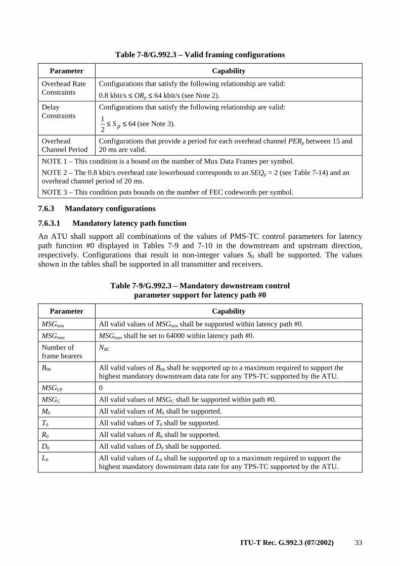
ITU-T Rec. G.992.3 (07/2002) 33
Table 7-8/G.992.3 – Valid framing configurations
Parameter Capability
Overhead Rate Constraints
Configurations that satisfy the following relationship are valid:
0.8 kbit/s ≤ ORp ≤ 64 kbit/s (see Note 2).
Delay Constraints
Configurations that satisfy the following relationship are valid:
642
1 ≤≤ pS (see Note 3).
Overhead Channel Period
Configurations that provide a period for each overhead channel PERp between 15 and 20 ms are valid.
NOTE 1 – This condition is a bound on the number of Mux Data Frames per symbol.
NOTE 2 – The 0.8 kbit/s overhead rate lowerbound corresponds to an SEQp = 2 (see Table 7-14) and an overhead channel period of 20 ms.
NOTE 3 – This condition puts bounds on the number of FEC codewords per symbol.
7.6.3 Mandatory configurations
7.6.3.1 Mandatory latency path function
An ATU shall support all combinations of the values of PMS-TC control parameters for latency path function #0 displayed in Tables 7-9 and 7-10 in the downstream and upstream direction, respectively. Configurations that result in non-integer values S0 shall be supported. The values shown in the tables shall be supported in all transmitter and receivers.
Table 7-9/G.992.3 – Mandatory downstream control parameter support for latency path #0
Parameter Capability
MSGmin All valid values of MSGmin shall be supported within latency path #0.
MSGmax MSGmax shall be set to 64000 within latency path #0.
Number of frame bearers
NBC
B00 All valid values of B00 shall be supported up to a maximum required to support the highest mandatory downstream data rate for any TPS-TC supported by the ATU.
MSGLP 0
MSGC All valid values of MSGC shall be supported within path #0.
M0 All valid values of M0 shall be supported.
T0 All valid values of T0 shall be supported.
R0 All valid values of R0 shall be supported.
D0 All valid values of D0 shall be supported.
L0 All valid values of L0 shall be supported up to a maximum required to support the highest mandatory downstream data rate for any TPS-TC supported by the ATU.
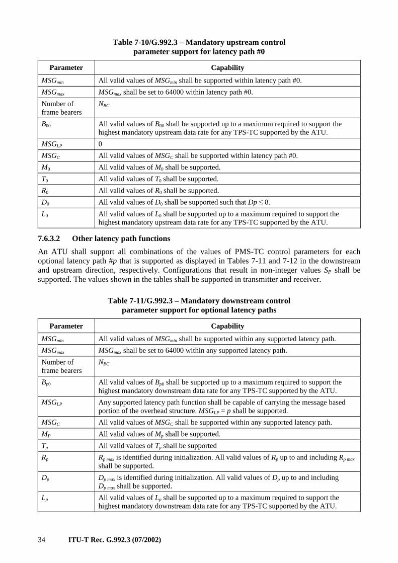
34 ITU-T Rec. G.992.3 (07/2002)
Table 7-10/G.992.3 – Mandatory upstream control parameter support for latency path #0
Parameter Capability
MSGmin All valid values of MSGmin shall be supported within latency path #0.
MSGmax MSGmax shall be set to 64000 within latency path #0.
Number of frame bearers
NBC
B00 All valid values of B00 shall be supported up to a maximum required to support the highest mandatory upstream data rate for any TPS-TC supported by the ATU.
MSGLP 0
MSGC All valid values of MSGC shall be supported within latency path #0.
M0 All valid values of M0 shall be supported.
T0 All valid values of T0 shall be supported.
R0 All valid values of R0 shall be supported.
D0 All valid values of D0 shall be supported such that Dp ≤ 8.
L0 All valid values of L0 shall be supported up to a maximum required to support the highest mandatory upstream data rate for any TPS-TC supported by the ATU.
7.6.3.2 Other latency path functions
An ATU shall support all combinations of the values of PMS-TC control parameters for each optional latency path #p that is supported as displayed in Tables 7-11 and 7-12 in the downstream and upstream direction, respectively. Configurations that result in non-integer values SP shall be supported. The values shown in the tables shall be supported in transmitter and receiver.
Table 7-11/G.992.3 – Mandatory downstream control parameter support for optional latency paths
Parameter Capability
MSGmin All valid values of MSGmin shall be supported within any supported latency path.
MSGmax MSGmax shall be set to 64000 within any supported latency path.
Number of frame bearers
NBC
Bp0 All valid values of Bp0 shall be supported up to a maximum required to support the highest mandatory downstream data rate for any TPS-TC supported by the ATU.
MSGLP Any supported latency path function shall be capable of carrying the message based portion of the overhead structure. MSGLP = p shall be supported.
MSGC All valid values of MSGC shall be supported within any supported latency path.
MP All valid values of Mp shall be supported.
Tp All valid values of Tp shall be supported
Rp Rp max is identified during initialization. All valid values of Rp up to and including Rp max shall be supported.
Dp Dp max is identified during initialization. All valid values of Dp up to and including Dp max shall be supported.
Lp All valid values of Lp shall be supported up to a maximum required to support the highest mandatory downstream data rate for any TPS-TC supported by the ATU.
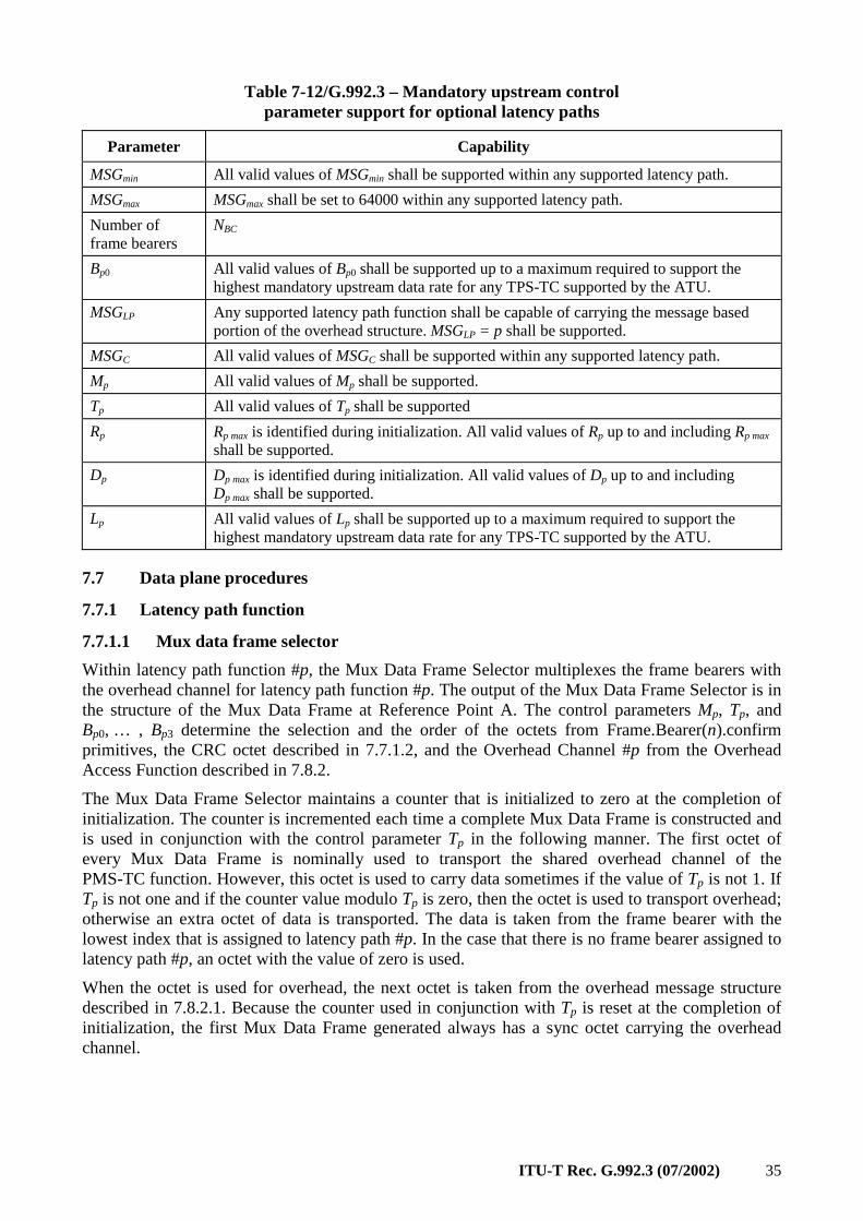
ITU-T Rec. G.992.3 (07/2002) 35
Table 7-12/G.992.3 – Mandatory upstream control parameter support for optional latency paths
Parameter Capability
MSGmin All valid values of MSGmin shall be supported within any supported latency path.
MSGmax MSGmax shall be set to 64000 within any supported latency path.
Number of frame bearers
NBC
Bp0 All valid values of Bp0 shall be supported up to a maximum required to support the highest mandatory upstream data rate for any TPS-TC supported by the ATU.
MSGLP Any supported latency path function shall be capable of carrying the message based portion of the overhead structure. MSGLP = p shall be supported.
MSGC All valid values of MSGC shall be supported within any supported latency path.
Mp All valid values of Mp shall be supported.
Tp All valid values of Tp shall be supported
Rp Rp max is identified during initialization. All valid values of Rp up to and including Rp max shall be supported.
Dp Dp max is identified during initialization. All valid values of Dp up to and including Dp max shall be supported.
Lp All valid values of Lp shall be supported up to a maximum required to support the highest mandatory upstream data rate for any TPS-TC supported by the ATU.
7.7 Data plane procedures
7.7.1 Latency path function
7.7.1.1 Mux data frame selector
Within latency path function #p, the Mux Data Frame Selector multiplexes the frame bearers with the overhead channel for latency path function #p. The output of the Mux Data Frame Selector is in the structure of the Mux Data Frame at Reference Point A. The control parameters Mp, Tp, and Bp0, … , Bp3 determine the selection and the order of the octets from Frame.Bearer(n).confirm primitives, the CRC octet described in 7.7.1.2, and the Overhead Channel #p from the Overhead Access Function described in 7.8.2.
The Mux Data Frame Selector maintains a counter that is initialized to zero at the completion of initialization. The counter is incremented each time a complete Mux Data Frame is constructed and is used in conjunction with the control parameter Tp in the following manner. The first octet of every Mux Data Frame is nominally used to transport the shared overhead channel of the PMS-TC function. However, this octet is used to carry data sometimes if the value of Tp is not 1. If Tp is not one and if the counter value modulo Tp is zero, then the octet is used to transport overhead; otherwise an extra octet of data is transported. The data is taken from the frame bearer with the lowest index that is assigned to latency path #p. In the case that there is no frame bearer assigned to latency path #p, an octet with the value of zero is used.
When the octet is used for overhead, the next octet is taken from the overhead message structure described in 7.8.2.1. Because the counter used in conjunction with Tp is reset at the completion of initialization, the first Mux Data Frame generated always has a sync octet carrying the overhead channel.
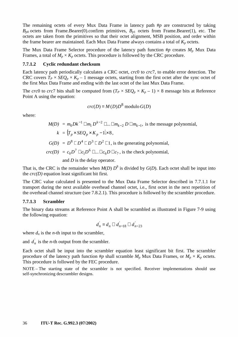
36 ITU-T Rec. G.992.3 (07/2002)
The remaining octets of every Mux Data Frame in latency path #p are constructed by taking Bp0 octets from Frame.Bearer(0).confirm primitives, Bp1 octets from Frame.Bearer(1), etc. The octets are taken from the primitives so that their octet alignment, MSB position, and order within the frame bearer are maintained. Each Mux Data Frame always contains a total of Kp octets.
The Mux Data Frame Selector procedure of the latency path function #p creates Mp Mux Data Frames, a total of Mp × Kp octets. This procedure is followed by the CRC procedure.
7.7.1.2 Cyclic redundant checksum
Each latency path periodically calculates a CRC octet, crc0 to crc7, to enable error detection. The CRC covers TP × SEQp × Kp – 1 message octets, starting from the first octet after the sync octet of the first Mux Data Frame and ending with the last octet of the last Mux Data Frame.
The crc0 to crc7 bits shall be computed from (TP × SEQp × Kp – 1) × 8 message bits at Reference Point A using the equation:
)( modulo )()( 8 DGDDMDcrc =
where:
M(D) = ,... 122
11
0 −−−− ++++ kk
k mDmDmDkm is the message polynomial,
k = ( ) 81 ×−×× ppp KSEQT ,
G(D) = 12348 ++++ DDDD , is the generating polynomial,
crc(D) = 766
17
0 ... cDcDcDc ++++ , is the check polynomial,
and D is the delay operator.
That is, the CRC is the remainder when M(D) D8 is divided by G(D). Each octet shall be input into the crc(D) equation least significant bit first.
The CRC value calculated is presented to the Mux Data Frame Selector described in 7.7.1.1 for transport during the next available overhead channel octet, i.e., first octet in the next repetition of the overhead channel structure (see 7.8.2.1). This procedure is followed by the scrambler procedure.
7.7.1.3 Scrambler
The binary data streams at Reference Point A shall be scrambled as illustrated in Figure 7-9 using the following equation:
'23
'18
'−− ⊕⊕= nnnn dddd
where dn is the n-th input to the scrambler,
and 'nd is the n-th output from the scrambler.
Each octet shall be input into the scrambler equation least significant bit first. The scrambler procedure of the latency path function #p shall scramble Mp Mux Data Frames, or Mp × Kp octets. This procedure is followed by the FEC procedure.
NOTE – The starting state of the scrambler is not specified. Receiver implementations should use self-synchronizing descrambler designs.
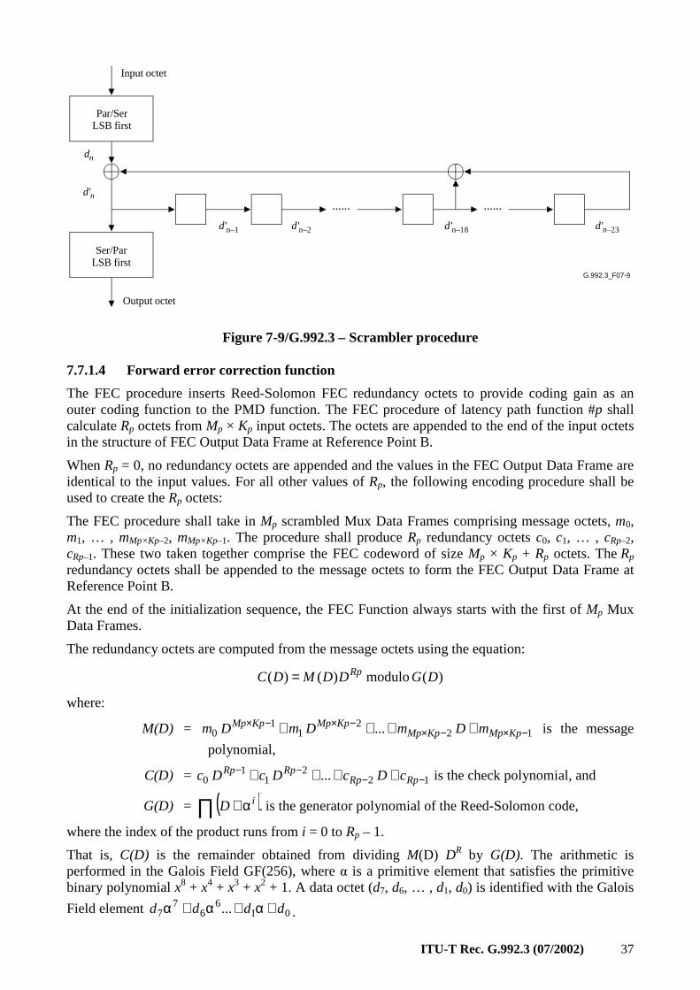
ITU-T Rec. G.992.3 (07/2002) 37
G.992.3_F07-9
...... ......
dn
d'n
d'n–1 d'n–2 d'n–18 d'n–23
Par/SerLSB first
Ser/ParLSB first
Input octet
Output octet
Figure 7-9/G.992.3 – Scrambler procedure
7.7.1.4 Forward error correction function
The FEC procedure inserts Reed-Solomon FEC redundancy octets to provide coding gain as an outer coding function to the PMD function. The FEC procedure of latency path function #p shall calculate Rp octets from Mp × Kp input octets. The octets are appended to the end of the input octets in the structure of FEC Output Data Frame at Reference Point B.
When Rp = 0, no redundancy octets are appended and the values in the FEC Output Data Frame are identical to the input values. For all other values of Rp, the following encoding procedure shall be used to create the Rp octets:
The FEC procedure shall take in Mp scrambled Mux Data Frames comprising message octets, m0, m1, … , mMp×Kp–2, mMp×Kp–1. The procedure shall produce Rp redundancy octets c0, c1, … , cRp–2, cRp–1. These two taken together comprise the FEC codeword of size Mp × Kp + Rp octets. The Rp redundancy octets shall be appended to the message octets to form the FEC Output Data Frame at Reference Point B.
At the end of the initialization sequence, the FEC Function always starts with the first of Mp Mux Data Frames.
The redundancy octets are computed from the message octets using the equation:
)( modulo )()( DGDDMDC Rp=
where:
M(D) = 122
11
0 ... −×−×−×−× ++++ KpMpKpMp
KpMpKpMp mDmDmDm is the message
polynomial,
C(D) = 122
11
0 ... −−−− ++++ RpRp
RpRp cDcDcDc is the check polynomial, and
G(D) = ( )∏ α+ iD is the generator polynomial of the Reed-Solomon code,
where the index of the product runs from i = 0 to Rp – 1.
That is, C(D) is the remainder obtained from dividing M(D) DR by G(D). The arithmetic is performed in the Galois Field GF(256), where α is a primitive element that satisfies the primitive binary polynomial x8 + x4 + x3 + x2 + 1. A data octet (d7, d6, … , d1, d0) is identified with the Galois
Field element 016
67
7 ... dddd +α+α+α .
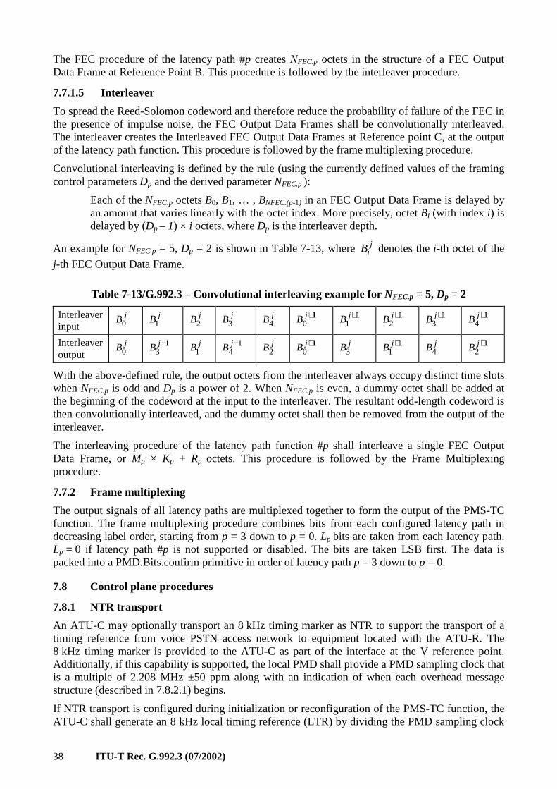
38 ITU-T Rec. G.992.3 (07/2002)
The FEC procedure of the latency path #p creates NFEC.p octets in the structure of a FEC Output Data Frame at Reference Point B. This procedure is followed by the interleaver procedure.
7.7.1.5 Interleaver
To spread the Reed-Solomon codeword and therefore reduce the probability of failure of the FEC in the presence of impulse noise, the FEC Output Data Frames shall be convolutionally interleaved. The interleaver creates the Interleaved FEC Output Data Frames at Reference point C, at the output of the latency path function. This procedure is followed by the frame multiplexing procedure.
Convolutional interleaving is defined by the rule (using the currently defined values of the framing control parameters Dp and the derived parameter NFEC.p ):
Each of the NFEC.p octets B0, B1, … , BNFEC.(p-1) in an FEC Output Data Frame is delayed by an amount that varies linearly with the octet index. More precisely, octet Bi (with index i) is delayed by (Dp – 1) × i octets, where Dp is the interleaver depth.
An example for NFEC.p = 5, Dp = 2 is shown in Table 7-13, where jiB denotes the i-th octet of the
j-th FEC Output Data Frame.
Table 7-13/G.992.3 – Convolutional interleaving example for NFEC.p = 5, Dp = 2
Interleaver input
jB0 jB1 jB2 jB3 jB4 10
+jB 11
+jB 12
+jB 13
+jB 14
+jB
Interleaver output
jB0 13
−jB jB1 14
−jB jB2 10
+jB jB3 11
+jB jB4 12
+jB
With the above-defined rule, the output octets from the interleaver always occupy distinct time slots when NFEC.p is odd and Dp is a power of 2. When NFEC.p is even, a dummy octet shall be added at the beginning of the codeword at the input to the interleaver. The resultant odd-length codeword is then convolutionally interleaved, and the dummy octet shall then be removed from the output of the interleaver.
The interleaving procedure of the latency path function #p shall interleave a single FEC Output Data Frame, or Mp × Kp + Rp octets. This procedure is followed by the Frame Multiplexing procedure.
7.7.2 Frame multiplexing
The output signals of all latency paths are multiplexed together to form the output of the PMS-TC function. The frame multiplexing procedure combines bits from each configured latency path in decreasing label order, starting from p = 3 down to p = 0. Lp bits are taken from each latency path. Lp = 0 if latency path #p is not supported or disabled. The bits are taken LSB first. The data is packed into a PMD.Bits.confirm primitive in order of latency path p = 3 down to p = 0.
7.8 Control plane procedures
7.8.1 NTR transport
An ATU-C may optionally transport an 8 kHz timing marker as NTR to support the transport of a timing reference from voice PSTN access network to equipment located with the ATU-R. The 8 kHz timing marker is provided to the ATU-C as part of the interface at the V reference point. Additionally, if this capability is supported, the local PMD shall provide a PMD sampling clock that is a multiple of 2.208 MHz ±50 ppm along with an indication of when each overhead message structure (described in 7.8.2.1) begins.
If NTR transport is configured during initialization or reconfiguration of the PMS-TC function, the ATU-C shall generate an 8 kHz local timing reference (LTR) by dividing the PMD sampling clock
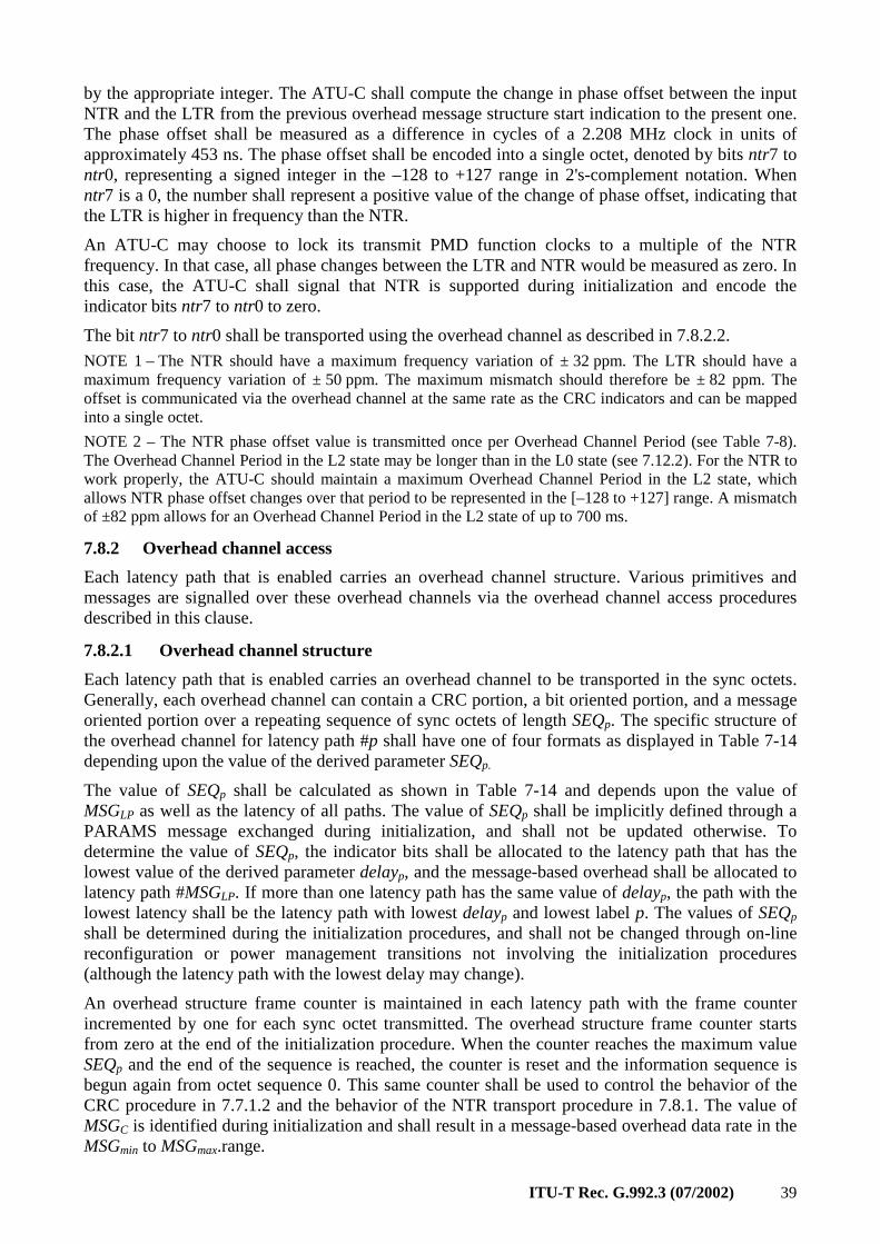
ITU-T Rec. G.992.3 (07/2002) 39
by the appropriate integer. The ATU-C shall compute the change in phase offset between the input NTR and the LTR from the previous overhead message structure start indication to the present one. The phase offset shall be measured as a difference in cycles of a 2.208 MHz clock in units of approximately 453 ns. The phase offset shall be encoded into a single octet, denoted by bits ntr7 to ntr0, representing a signed integer in the –128 to +127 range in 2's-complement notation. When ntr7 is a 0, the number shall represent a positive value of the change of phase offset, indicating that the LTR is higher in frequency than the NTR.
An ATU-C may choose to lock its transmit PMD function clocks to a multiple of the NTR frequency. In that case, all phase changes between the LTR and NTR would be measured as zero. In this case, the ATU-C shall signal that NTR is supported during initialization and encode the indicator bits ntr7 to ntr0 to zero.
The bit ntr7 to ntr0 shall be transported using the overhead channel as described in 7.8.2.2.
NOTE 1 – The NTR should have a maximum frequency variation of ± 32 ppm. The LTR should have a maximum frequency variation of ± 50 ppm. The maximum mismatch should therefore be ± 82 ppm. The offset is communicated via the overhead channel at the same rate as the CRC indicators and can be mapped into a single octet.
NOTE 2 – The NTR phase offset value is transmitted once per Overhead Channel Period (see Table 7-8). The Overhead Channel Period in the L2 state may be longer than in the L0 state (see 7.12.2). For the NTR to work properly, the ATU-C should maintain a maximum Overhead Channel Period in the L2 state, which allows NTR phase offset changes over that period to be represented in the [–128 to +127] range. A mismatch of ±82 ppm allows for an Overhead Channel Period in the L2 state of up to 700 ms.
7.8.2 Overhead channel access
Each latency path that is enabled carries an overhead channel structure. Various primitives and messages are signalled over these overhead channels via the overhead channel access procedures described in this clause.
7.8.2.1 Overhead channel structure
Each latency path that is enabled carries an overhead channel to be transported in the sync octets. Generally, each overhead channel can contain a CRC portion, a bit oriented portion, and a message oriented portion over a repeating sequence of sync octets of length SEQp. The specific structure of the overhead channel for latency path #p shall have one of four formats as displayed in Table 7-14 depending upon the value of the derived parameter SEQp.
The value of SEQp shall be calculated as shown in Table 7-14 and depends upon the value of MSGLP as well as the latency of all paths. The value of SEQp shall be implicitly defined through a PARAMS message exchanged during initialization, and shall not be updated otherwise. To determine the value of SEQp, the indicator bits shall be allocated to the latency path that has the lowest value of the derived parameter delayp, and the message-based overhead shall be allocated to latency path #MSGLP. If more than one latency path has the same value of delayp, the path with the lowest latency shall be the latency path with lowest delayp and lowest label p. The values of SEQp shall be determined during the initialization procedures, and shall not be changed through on-line reconfiguration or power management transitions not involving the initialization procedures (although the latency path with the lowest delay may change).
An overhead structure frame counter is maintained in each latency path with the frame counter incremented by one for each sync octet transmitted. The overhead structure frame counter starts from zero at the end of the initialization procedure. When the counter reaches the maximum value SEQp and the end of the sequence is reached, the counter is reset and the information sequence is begun again from octet sequence 0. This same counter shall be used to control the behavior of the CRC procedure in 7.7.1.2 and the behavior of the NTR transport procedure in 7.8.1. The value of MSGC is identified during initialization and shall result in a message-based overhead data rate in the MSGmin to MSGmax.range.
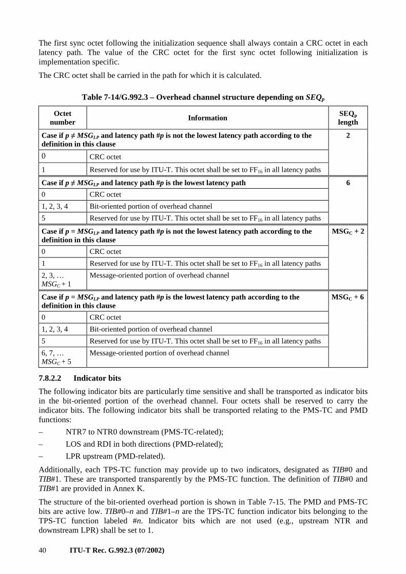
40 ITU-T Rec. G.992.3 (07/2002)
The first sync octet following the initialization sequence shall always contain a CRC octet in each latency path. The value of the CRC octet for the first sync octet following initialization is implementation specific.
The CRC octet shall be carried in the path for which it is calculated.
Table 7-14/G.992.3 – Overhead channel structure depending on SEQp
Octet number Information
SEQp length
Case if p ≠ MSGLP and latency path #p is not the lowest latency path according to the definition in this clause
0 CRC octet
1 Reserved for use by ITU-T. This octet shall be set to FF16 in all latency paths
2
Case if p ≠ MSGLP and latency path #p is the lowest latency path
0 CRC octet
1, 2, 3, 4 Bit-oriented portion of overhead channel
5 Reserved for use by ITU-T. This octet shall be set to FF16 in all latency paths
6
Case if p = MSGLP and latency path #p is not the lowest latency path according to the definition in this clause
0 CRC octet
1 Reserved for use by ITU-T. This octet shall be set to FF16 in all latency paths
2, 3, … MSGC + 1
Message-oriented portion of overhead channel
MSGC + 2
Case if p = MSGLP and latency path #p is the lowest latency path according to the definition in this clause
0 CRC octet
1, 2, 3, 4 Bit-oriented portion of overhead channel
5 Reserved for use by ITU-T. This octet shall be set to FF16 in all latency paths
6, 7, … MSGC + 5
Message-oriented portion of overhead channel
MSGC + 6
7.8.2.2 Indicator bits
The following indicator bits are particularly time sensitive and shall be transported as indicator bits in the bit-oriented portion of the overhead channel. Four octets shall be reserved to carry the indicator bits. The following indicator bits shall be transported relating to the PMS-TC and PMD functions:
– NTR7 to NTR0 downstream (PMS-TC-related);
– LOS and RDI in both directions (PMD-related);
– LPR upstream (PMD-related).
Additionally, each TPS-TC function may provide up to two indicators, designated as TIB#0 and TIB#1. These are transported transparently by the PMS-TC function. The definition of TIB#0 and TIB#1 are provided in Annex K.
The structure of the bit-oriented overhead portion is shown in Table 7-15. The PMD and PMS-TC bits are active low. TIB#0–n and TIB#1–n are the TPS-TC function indicator bits belonging to the TPS-TC function labeled #n. Indicator bits which are not used (e.g., upstream NTR and downstream LPR) shall be set to 1.
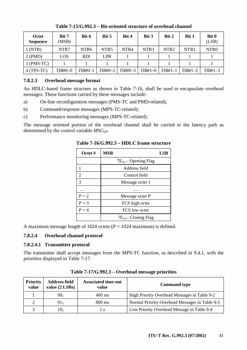
ITU-T Rec. G.992.3 (07/2002) 41
Table 7-15/G.992.3 – Bit-oriented structure of overhead channel
Octet Sequence
Bit 7 (MSB)
Bit 6
Bit 5
Bit 4
Bit 3
Bit 2
Bit 1
Bit 0 (LSB)
1 (NTR) NTR7 NTR6 NTR5 NTR4 NTR3 NTR2 NTR1 NTR0
2 (PMD) LOS RDI LPR 1 1 1 1 1
3 (PMS-TC) 1 1 1 1 1 1 1 1
4 (TPS-TC) TIB#0–0 TIB#0–1 TIB#0–2 TIB#0–3 TIB#1–0 TIB#1–1 TIB#1–2 TIB#1–3
7.8.2.3 Overhead message format
An HDLC-based frame structure as shown in Table 7-16, shall be used to encapsulate overhead messages. These functions carried by these messages include:
a) On-line reconfiguration messages (PMS-TC and PMD-related);
b) Command/response messages (MPS-TC-related);
c) Performance monitoring messages (MPS-TC-related).
The message oriented portion of the overhead channel shall be carried in the latency path as determined by the control variable MSGLP.
Table 7-16/G.992.3 – HDLC frame structure
Octet # MSB LSB
7E16 – Opening Flag
1 Address field
2 Control field
3 Message octet 1
… ….
P + 2 Message octet P
P + 3 FCS high octet
P + 4 FCS low octet
7E16 – Closing Flag
A maximum message length of 1024 octets (P = 1024 maximum) is defined.
7.8.2.4 Overhead channel protocol
7.8.2.4.1 Transmitter protocol
The transmitter shall accept messages from the MPS-TC function, as described in 9.4.1, with the priorities displayed in Table 7-17.
Table 7-17/G.992.3 – Overhead message priorities
Priority value
Address field value (2 LSBs)
Associated time-out value Command type
1 002 400 ms High Priority Overhead Messages in Table 9-2
2 012 800 ms Normal Priority Overhead Messages in Table 9-3
3 102 1 s Low Priority Overhead Message in Table 9-4
42 ITU-T Rec. G.992.3 (07/2002)
The transmitter shall format messages using the HDLC frame structure described in 7.8.2.3, inserting the Frame Check Sequence octets as described in ITU-T Rec. G.997.1 [4]. Octet transparency and octet inter-frame time fill shall be as in ITU-T Rec. G.997.1 [4]. Opening and closing flags may be shared (i.e., only one flag between consecutive messages).
The two least significant bits of the address field shall be set with the priority of the message according to the values shown in Table 7-17. The value of 112 is reserved. All other bits of the address field shall be set to 02.
The second least significant bit of the control field shall be set with a command (02) or response code (12). The least significant bit shall be set alternately to 02 and 12 as new messages are sent. All other bits of the control field shall be set to 02.
When sending a new command message, the LSB of the control field shall be inverted from the previous command message. The transmitter shall send the command message one time and await a response message. No more than one command message of each priority value shall be awaiting response message at any time. Upon receipt of a response message, a new command message may be sent. If a response message is not received, a time-out occurs and the command message is repeated without inverting the LSB of the control field. Alternately, the ATU may abandon the command message after an implementation-specific number of retransmissions. There are different time-out durations for the different priority messages and are displayed in Table 7-17. Timeouts are based starting from the last octet of a request message sent to last octet of a response message received.
When sending a new response message, the LSB of the control field shall be inverted from the previous response message.
The transmitter may receive messages from the MPS-TC for transmission at different priorities. The highest priority message shall be transmitted first. At any time, if the transmitter receives a message of a higher priority, the transmitter shall send the higher priority message. Any message of lower priority being transmitted may be aborted using the octet abort sequence described in ITU-T Rec. G.997.1 [4], i.e., a control escape octet followed by a flag. If transmission of the lower priority message is completed, it remains active and the time-out timer values are not affected. If the lower priority message is aborted, the transmitter shall retransmit the message as the priority scheme allows, without inverting the LSB of the control field.
7.8.2.4.2 Receiver protocol
The receiver shall search on octet boundaries for messages matching the structure of the HDLC frame format. Any invalid frames as described in ITU-T Rec. G.997.1 [4] shall be discarded. Any message with an invalid FCS shall be discarded. Any message with an address or control field not in accordance with 7.8.2.4.1 shall be discarded.
The alternating LSB of the control field may be used to detect messages that are being repeated because of timeout or can be used to detect messages that might have been previously lost or discarded due to errors.
Each message received shall be delivered to the MPS-TC function.
7.9 Management plane procedures
7.9.1 Surveillance primitives
All PMS-TC function primitives are line related. Only anomalies are defined for each receive latency path.
ITU-T Rec. G.992.3 (07/2002) 43
Two near-end anomalies are defined for a receive latency path:
• Forward error correction fec-p: A fec-p anomaly occurs when a received FEC codeword for the latency path #p indicates that errors have been corrected. This anomaly is not asserted if errors are detected and are not correctable.
• Cyclic redundancy check crc-p: A crc-p anomaly occurs when a received CRC-8 code for the latency path #p is not identical to the corresponding locally generated code.
Two far-end anomalies are defined for a receive latency path:
• Far-end forward error correction ffec-n: An ffec-n anomaly is a fec-n anomaly detected at the far-end.
• Far-end Block Error febe-n anomaly: A febe-n anomaly is a crc-n anomaly detected at the far-end.
7.10 Initialization procedures
7.10.1 G.994.1 phase
7.10.1.1 G.994.1 capabilities list message
The following information about the PMS-TC function shall be defined in ITU-T Rec. G.994.1 [2] as part of the CL and CLR messages. This information may be optionally requested and reported via G.994.1 messages at the start of a session. However, the information shall be exchanged at least once between ATU-C and ATU-R but not necessarily at the start of each session. The information exchanged includes:
• Capability to transport NTR (downstream only);
• Minimum downstream message-based overhead channel data rate that is needed;
• Minimum upstream message-based overhead channel data rate that is needed;
• Maximum downstream net data rate of each latency path can be supported;
• Maximum upstream net data rate of each latency path that can be supported;
• Rp max on each optional latency path that can be supported;
• Dp max on each optional latency path that can be supported.
In addition, non-standard capabilities may be reported through additional NSF messages.
This information is represented using a G.994.1 tree model of the information as in Table 7-18. An ATU provides both the upstream and downstream information in response to the capabilities request message.
The latency paths supported shall start from 0 and increase by one. The Capability List shall indicate that latency paths supported consists of #0, #0, #1, #0, #1, #2, or #0, #1, #2, #3 (there are only 4 cases). The number of latency paths supported may be different for upstream and downstream.
44 ITU-T Rec. G.992.3 (07/2002)
Table 7-18/G.992.3 – Format for PMS-TC capability list information
Npar(2) bit Definition of Npar(2) bit NTR This bit is set to a one if the ATU has the capability to transport the NTR signal in the
downstream direction.
Spar(2) bit Definition of related Npar(3) octets Downstream Overhead Data Rate
Parameter block of 2 octets that describes the minimum message based data rate that is needed by the ATU. The unsigned 6-bit value is the data rate divided by 1000 bits per second minus 1 (covering the range 1 to 64 kbit/s).
Upstream Overhead Data Rate
Parameter block of 2 octets that describes the minimum message based data rate that is needed by the ATU. The unsigned 6-bit value is the data rate divided by 1000 bits per second minus 1 (covering the range 1 to 64 kbit/s).
Downstream PMS-TC latency path #0 supported (always set to 1)
Parameter block of 2 octets that describes the maximum net_max downstream rate supported in the latency path #0. The unsigned 12-bit net_max value is the data rate divided by 4000. The net_max downstream rate shall be greater than or equal to the maximum required downstream data rate for each TPS-TC type that is supported by the ATU.
Upstream PMS-TC latency path #0 Supported (always set to 1)
Parameter block of 2 octets that describes the maximum net_max upstream rate supported in the latency path #0. The unsigned 12-bit net_max value is the data rate divided by 4000. The net_max upstream rate shall be greater than or equal to the maximum required upstream data rate for each TPS-TC type that is supported by the ATU.
Downstream PMS-TC latency path #1 Supported
Parameter block of 4 octets that describes the maximum net_max downstream rate, downstream R1 max, and downstream D1 max supported in the latency path #1. The unsigned 12-bit net_max value is the data rate divided by 4000. R1 max is an unsigned 4-bit value and shall be one of the valid Rp values divided by 2. D1 max is an unsigned 3-bit value and shall be the logarithm base 2 of one of the valid Dp values.
Upstream PMS-TC latency path #1 Supported
Parameter block of 4 octets that describes the maximum net_max upstream rate, upstream R1 max, and upstream D1 max supported in the latency path #1. The unsigned 12-bit net_max value is the data rate divided by 4000. R1 max is an unsigned 4-bit value and shall be one of the valid Rp values divided by 2. D1 max is an unsigned 3-bit value and shall be the logarithm base 2 of one of the valid Dp values.
Downstream PMS-TC latency path #2 Supported
Parameter block of 4 octets that describes the maximum net_max downstream rate, downstream R2 max, and downstream D2 max supported in the latency path #2. The unsigned 12-bit net_max value is the data rate divided by 4000. R2 max is an unsigned 4-bit value and shall be one of the valid Rp values divided by 2. D2 max is an unsigned 3-bit value and shall be the logarithm base 2 of one of the valid Dp values.
Upstream PMS-TC latency path #2 Supported
Parameter block of 4 octets that describes the maximum net_max upstream rate, upstream R2 max, and upstream D2 max supported in the latency path #2. The unsigned 12-bit net_max value is the data rate divided by 4000. R2 max is an unsigned 4-bit value and shall be one of the valid Rp values divided by 2. D2 max is an unsigned 3-bit value and shall be the logarithm base 2 of one of the valid Dp values.
Downstream PMS-TC latency path #3 Supported
Parameter block of 4 octets that describes the maximum net_max downstream rate, downstream R3 max, and downstream D3 max supported in the latency path #3. The unsigned 12-bit net_max value is the data rate divided by 4000. R3 max is an unsigned 4-bit value and shall be one of the valid Rp values divided by 2. D3 max is an unsigned 3-bit value and shall be the logarithm base 2 of one of the valid Dp values.
Upstream PMS-TC latency path #3 Supported
Parameter block of 4 octets that describes the maximum net_max upstream rate, upstream R3 max, and upstream D3 max supported in the latency path #3. The unsigned 12-bit net_max value is the data rate divided by 4000. R3 max is an unsigned 4-bit value and shall be one of the value Rp values divided by 2. D3 max is an unsigned 3-bit value and shall be the logarithm base 2 of one of the valid Dp values.
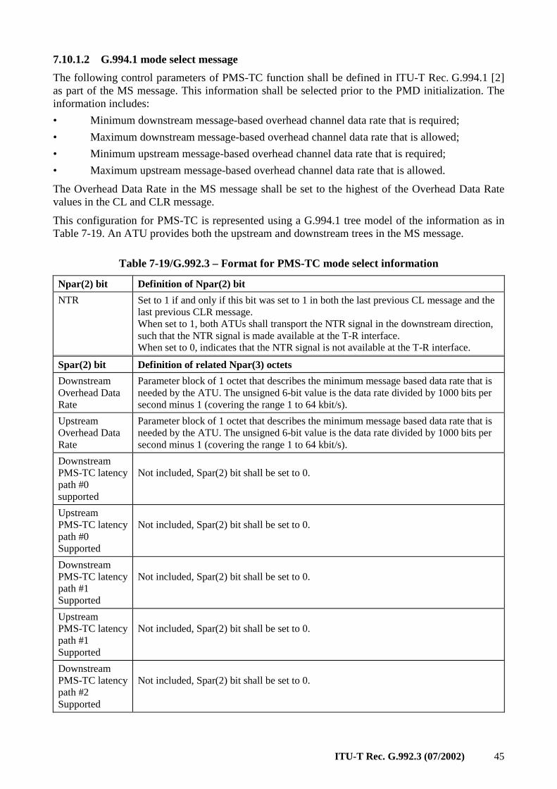
ITU-T Rec. G.992.3 (07/2002) 45
7.10.1.2 G.994.1 mode select message
The following control parameters of PMS-TC function shall be defined in ITU-T Rec. G.994.1 [2] as part of the MS message. This information shall be selected prior to the PMD initialization. The information includes:
• Minimum downstream message-based overhead channel data rate that is required;
• Maximum downstream message-based overhead channel data rate that is allowed;
• Minimum upstream message-based overhead channel data rate that is required;
• Maximum upstream message-based overhead channel data rate that is allowed.
The Overhead Data Rate in the MS message shall be set to the highest of the Overhead Data Rate values in the CL and CLR message.
This configuration for PMS-TC is represented using a G.994.1 tree model of the information as in Table 7-19. An ATU provides both the upstream and downstream trees in the MS message.
Table 7-19/G.992.3 – Format for PMS-TC mode select information
Npar(2) bit Definition of Npar(2) bit
NTR Set to 1 if and only if this bit was set to 1 in both the last previous CL message and the last previous CLR message. When set to 1, both ATUs shall transport the NTR signal in the downstream direction, such that the NTR signal is made available at the T-R interface. When set to 0, indicates that the NTR signal is not available at the T-R interface.
Spar(2) bit Definition of related Npar(3) octets
Downstream Overhead Data Rate
Parameter block of 1 octet that describes the minimum message based data rate that is needed by the ATU. The unsigned 6-bit value is the data rate divided by 1000 bits per second minus 1 (covering the range 1 to 64 kbit/s).
Upstream Overhead Data Rate
Parameter block of 1 octet that describes the minimum message based data rate that is needed by the ATU. The unsigned 6-bit value is the data rate divided by 1000 bits per second minus 1 (covering the range 1 to 64 kbit/s).
Downstream PMS-TC latency path #0 supported
Not included, Spar(2) bit shall be set to 0.
Upstream PMS-TC latency path #0 Supported
Not included, Spar(2) bit shall be set to 0.
Downstream PMS-TC latency path #1 Supported
Not included, Spar(2) bit shall be set to 0.
Upstream PMS-TC latency path #1 Supported
Not included, Spar(2) bit shall be set to 0.
Downstream PMS-TC latency path #2 Supported
Not included, Spar(2) bit shall be set to 0.
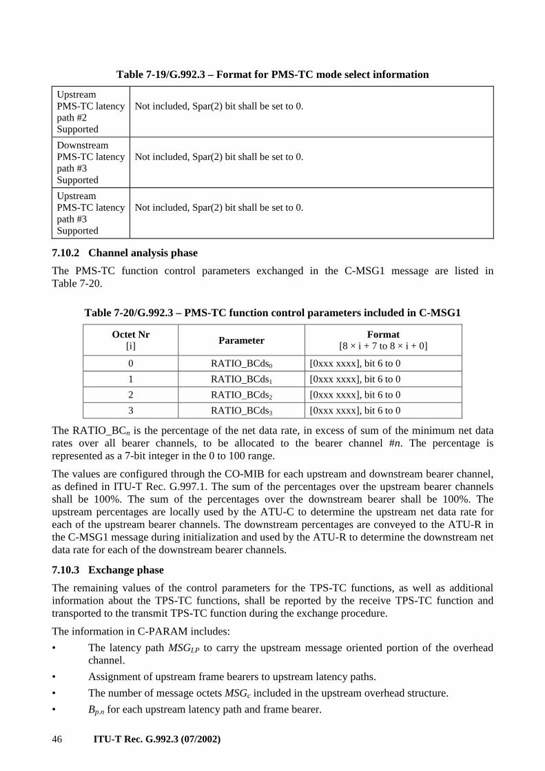
46 ITU-T Rec. G.992.3 (07/2002)
Table 7-19/G.992.3 – Format for PMS-TC mode select information
Upstream PMS-TC latency path #2 Supported
Not included, Spar(2) bit shall be set to 0.
Downstream PMS-TC latency path #3 Supported
Not included, Spar(2) bit shall be set to 0.
Upstream PMS-TC latency path #3 Supported
Not included, Spar(2) bit shall be set to 0.
7.10.2 Channel analysis phase
The PMS-TC function control parameters exchanged in the C-MSG1 message are listed in Table 7-20.
Table 7-20/G.992.3 – PMS-TC function control parameters included in C-MSG1
Octet Nr [i] Parameter
Format [8 × i + 7 to 8 × i + 0]
0 RATIO_BCds0 [0xxx xxxx], bit 6 to 0
1 RATIO_BCds1 [0xxx xxxx], bit 6 to 0
2 RATIO_BCds2 [0xxx xxxx], bit 6 to 0
3 RATIO_BCds3 [0xxx xxxx], bit 6 to 0
The RATIO_BCn is the percentage of the net data rate, in excess of sum of the minimum net data rates over all bearer channels, to be allocated to the bearer channel #n. The percentage is represented as a 7-bit integer in the 0 to 100 range.
The values are configured through the CO-MIB for each upstream and downstream bearer channel, as defined in ITU-T Rec. G.997.1. The sum of the percentages over the upstream bearer channels shall be 100%. The sum of the percentages over the downstream bearer shall be 100%. The upstream percentages are locally used by the ATU-C to determine the upstream net data rate for each of the upstream bearer channels. The downstream percentages are conveyed to the ATU-R in the C-MSG1 message during initialization and used by the ATU-R to determine the downstream net data rate for each of the downstream bearer channels.
7.10.3 Exchange phase
The remaining values of the control parameters for the TPS-TC functions, as well as additional information about the TPS-TC functions, shall be reported by the receive TPS-TC function and transported to the transmit TPS-TC function during the exchange procedure.
The information in C-PARAM includes:
• The latency path MSGLP to carry the upstream message oriented portion of the overhead channel.
• Assignment of upstream frame bearers to upstream latency paths.
• The number of message octets MSGc included in the upstream overhead structure.
• Bp.n for each upstream latency path and frame bearer.
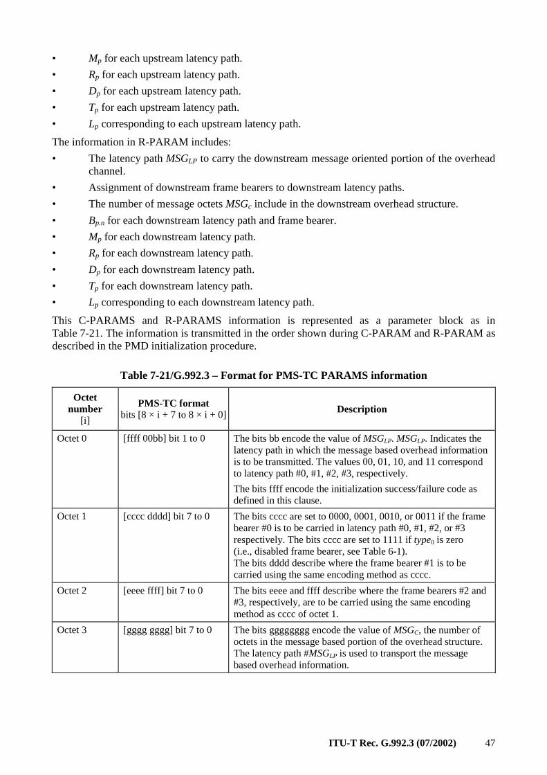
ITU-T Rec. G.992.3 (07/2002) 47
• Mp for each upstream latency path.
• Rp for each upstream latency path.
• Dp for each upstream latency path.
• Tp for each upstream latency path.
• Lp corresponding to each upstream latency path.
The information in R-PARAM includes:
• The latency path MSGLP to carry the downstream message oriented portion of the overhead channel.
• Assignment of downstream frame bearers to downstream latency paths.
• The number of message octets MSGc include in the downstream overhead structure.
• Bp.n for each downstream latency path and frame bearer.
• Mp for each downstream latency path.
• Rp for each downstream latency path.
• Dp for each downstream latency path.
• Tp for each downstream latency path.
• Lp corresponding to each downstream latency path.
This C-PARAMS and R-PARAMS information is represented as a parameter block as in Table 7-21. The information is transmitted in the order shown during C-PARAM and R-PARAM as described in the PMD initialization procedure.
Table 7-21/G.992.3 – Format for PMS-TC PARAMS information
Octet number
[i]
PMS-TC format bits [8 × i + 7 to 8 × i + 0] Description
Octet 0 [ffff 00bb] bit 1 to 0 The bits bb encode the value of MSGLP. MSGLP. Indicates the latency path in which the message based overhead information is to be transmitted. The values 00, 01, 10, and 11 correspond to latency path #0, #1, #2, #3, respectively.
The bits ffff encode the initialization success/failure code as defined in this clause.
Octet 1 [cccc dddd] bit 7 to 0 The bits cccc are set to 0000, 0001, 0010, or 0011 if the frame bearer #0 is to be carried in latency path #0, #1, #2, or #3 respectively. The bits cccc are set to 1111 if type0 is zero (i.e., disabled frame bearer, see Table 6-1). The bits dddd describe where the frame bearer #1 is to be carried using the same encoding method as cccc.
Octet 2 [eeee ffff] bit 7 to 0 The bits eeee and ffff describe where the frame bearers #2 and #3, respectively, are to be carried using the same encoding method as cccc of octet 1.
Octet 3 [gggg gggg] bit 7 to 0 The bits gggggggg encode the value of MSGC, the number of octets in the message based portion of the overhead structure. The latency path #MSGLP is used to transport the message based overhead information.
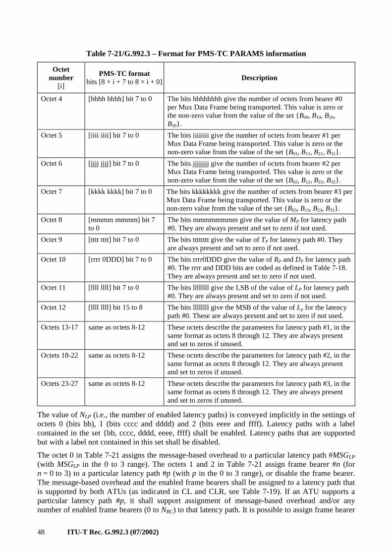
48 ITU-T Rec. G.992.3 (07/2002)
Table 7-21/G.992.3 – Format for PMS-TC PARAMS information
Octet number
[i]
PMS-TC format bits [8 × i + 7 to 8 × i + 0] Description
Octet 4 [hhhh hhhh] bit 7 to 0 The bits hhhhhhhh give the number of octets from bearer #0 per Mux Data Frame being transported. This value is zero or the non-zero value from the value of the set B00, B10, B20, B30.
Octet 5 [iiii iiii] bit 7 to 0 The bits iiiiiiii give the number of octets from bearer #1 per Mux Data Frame being transported. This value is zero or the non-zero value from the value of the set B01, B11, B21, B31.
Octet 6 [jjjj jjjj] bit 7 to 0 The bits jjjjjjjj give the number of octets from bearer #2 per Mux Data Frame being transported. This value is zero or the non-zero value from the value of the set B02, B12, B22, B32.
Octet 7 [kkkk kkkk] bit 7 to 0 The bits kkkkkkkk give the number of octets from bearer #3 per Mux Data Frame being transported. This value is zero or the non-zero value from the value of the set B03, B13, B23, B33.
Octet 8 [mmmm mmmm] bit 7 to 0
The bits mmmmmmmm give the value of MP for latency path #0. They are always present and set to zero if not used.
Octet 9 [tttt tttt] bit 7 to 0 The bits tttttttt give the value of TP for latency path #0. They are always present and set to zero if not used.
Octet 10 [rrrr 0DDD] bit 7 to 0 The bits rrrr0DDD give the value of RP and DP for latency path #0. The rrrr and DDD bits are coded as defined in Table 7-18. They are always present and set to zero if not used.
Octet 11 [llll llll] bit 7 to 0 The bits llllllll give the LSB of the value of LP for latency path #0. They are always present and set to zero if not used.
Octet 12 [llll llll] bit 15 to 8 The bits llllllll give the MSB of the value of Lp for the latency path #0. These are always present and set to zero if not used.
Octets 13-17 same as octets 8-12 These octets describe the parameters for latency path #1, in the same format as octets 8 through 12. They are always present and set to zeros if unused.
Octets 18-22 same as octets 8-12 These octets describe the parameters for latency path #2, in the same format as octets 8 through 12. They are always present and set to zeros if unused.
Octets 23-27 same as octets 8-12 These octets describe the parameters for latency path #3, in the same format as octets 8 through 12. They are always present and set to zeros if unused.
The value of NLP (i.e., the number of enabled latency paths) is conveyed implicitly in the settings of octets 0 (bits bb), 1 (bits cccc and dddd) and 2 (bits eeee and ffff). Latency paths with a label contained in the set bb, cccc, dddd, eeee, ffff) shall be enabled. Latency paths that are supported but with a label not contained in this set shall be disabled.
The octet 0 in Table 7-21 assigns the message-based overhead to a particular latency path #MSGLP (with MSGLP in the 0 to 3 range). The octets 1 and 2 in Table 7-21 assign frame bearer #n (for n = 0 to 3) to a particular latency path #p (with p in the 0 to 3 range), or disable the frame bearer. The message-based overhead and the enabled frame bearers shall be assigned to a latency path that is supported by both ATUs (as indicated in CL and CLR, see Table 7-19). If an ATU supports a particular latency path #p, it shall support assignment of message-based overhead and/or any number of enabled frame bearers (0 to NBC) to that latency path. It is possible to assign frame bearer
ITU-T Rec. G.992.3 (07/2002) 49
#n to latency path #p, with the number of octets from frame bearer #n per Mux Data Frame (as indicated in octet 4, 5, 6 or 7 in Table 7-21) set to zero (i.e., Bp.n = 0).
It is not possible to configure at initialization a latency path #p with overhead sequence length SEQp = 6 (i.e., one that carries only a CRC and the bit oriented portion of the overhead) without also carrying at least one frame bearer in the latency path p.
The method used by the receiver to select these values is implementation dependent. However, within the limit of the raw data rate and coding gain provided by the local PMD, the selected values shall meet all of the constraints communicated by the transmitter prior to the Exchange Phase, including:
• (Message based) Overhead data rate ≥ Minimum overhead data rate;
• Net data rate ≥ Minimum net data rate for all bearer channels;
• Impluse noise protection ≥ Minimum impulse noise protection for all bearer channels;
• Delay ≤ Maximum delay for all bearer channels.
Within those constraints, the receiver shall select the values as to optimize in the priority listed:
1) Maximize net data rate for all bearer channels, per the allocation of the net data rate, in excess of the sum of the minimum net data rates over all bearer channels (see 7.10.2).
2) Minimize excess margin (see 8.6.4).
If within those constraints, the receiver is unable to select a set of configuration parameters, then an initialization failure cause shall be indicated in the PMS-TC PARAMS information (4-bit integer, see Table 7-21), with the other bits in the PMS-TC PARAMS information set to 0. The transmitter shall enter the SILENT state (see Annex D) instead of the SHOWTIME state at the completion of the initialization procedures. Valid failure causes are the failure cause values 1 (configuration error) and 2 (configuration not feasible on line), as defined in ITU-T Rec. G.997.1. If within those constraints, the receiver is able to select a set of configuration parameters, then value 0 is used to indicate a successful initialization. The values 3 to 15 are reserved.
7.11 On-line reconfiguration
The procedures for on-line reconfiguration of the PMS-TC function support:
• transparency to higher layers by providing means for changes that introduce no transport errors and no interruption of service;
• changing parameters to adapt to slowly varying line conditions; and
• changing parameters to dynamically change data rate (including zero data rate).
7.11.1 Control parameters for reconfiguration
Reconfiguration is accomplished by a coordinated change to the value of one or more of the control parameters defined in 7.5. The control parameters displayed in Table 7-22 may be changed through on-line reconfiguration within the limits described.
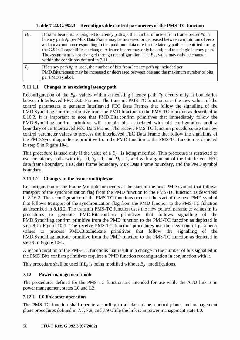
50 ITU-T Rec. G.992.3 (07/2002)
Table 7-22/G.992.3 – Reconfigurable control parameters of the PMS-TC function
Bp.n If frame bearer #n is assigned to latency path #p, the number of octets from frame bearer #n in latency path #p per Mux Data Frame may be increased or decreased between a minimum of zero and a maximum corresponding to the maximum data rate for the latency path as identified during the G.994.1 capabilities exchange. A frame bearer may only be assigned to a single latency path. The assignment is not changed through reconfiguration. The Bp.n value may only be changed within the conditions defined in 7.11.1.1.
Lp If latency path #p is used, the number of bits from latency path #p included per PMD.Bits.request may be increased or decreased between one and the maximum number of bits per PMD symbol.
7.11.1.1 Changes in an existing latency path
Reconfiguration of the Bp.n values within an existing latency path #p occurs only at boundaries between Interleaved FEC Data Frames. The transmit PMS-TC function uses the new values of the control parameters to generate Interleaved FEC Data Frames that follow the signalling of the PMD.Synchflag.confirm primitive from the PMD function to the PMS-TC function as described in 8.16.2. It is important to note that PMD.Bits.confirm primitives that immediately follow the PMD.Synchflag.confirm primitive will contain bits associated with old configuration until a boundary of an Interleaved FEC Data Frame. The receive PMS-TC function procedures use the new control parameter values to process the Interleaved FEC Data Frame that follow the signalling of the PMD.Synchflag.indicate primitive from the PMD function to the PMS-TC function as depicted in step 9 in Figure 10-1.
This procedure is used only if the value of a Bp.n is being modified. This procedure is restricted to use for latency paths with Rp = 0, Sp = 1, and Dp = 1, and with alignment of the Interleaved FEC data frame boundary, FEC data frame boundary, Mux Data Frame boundary, and the PMD symbol boundary.
7.11.1.2 Changes in the frame multiplexor
Reconfiguration of the Frame Multiplexor occurs at the start of the next PMD symbol that follows transport of the synchronization flag from the PMD function to the PMS-TC function as described in 8.16.2. The reconfiguration of the PMS-TC functions occur at the start of the next PMD symbol that follows transport of the synchronization flag from the PMD function to the PMS-TC function as described in 8.16.2. The transmit PMS-TC function uses the new control parameter values in its procedures to generate PMD.Bits.confirm primitives that follows signalling of the PMD.Synchflag.confirm primitive from the PMD function to the PMS-TC function as depicted in step 8 in Figure 10-1. The receive PMS-TC function procedures use the new control parameter values to process PMD.Bits.Indicate primitives that follow the signalling of the PMD.Synchflag.indicate primitive from the PMD function to the PMS-TC function as depicted in step 9 in Figure 10-1.
A reconfiguration of the PMS-TC functions that result in a change in the number of bits signalled in the PMD.Bits.confirm primitives requires a PMD function reconfiguration in conjunction with it.
This procedure shall be used if Lp is being modified without Bp.n modifications.
7.12 Power management mode
The procedures defined for the PMS-TC function are intended for use while the ATU link is in power management states L0 and L2.
7.12.1 L0 link state operation
The PMS-TC function shall operate according to all data plane, control plane, and management plane procedures defined in 7.7, 7.8, and 7.9 while the link is in power management state L0.
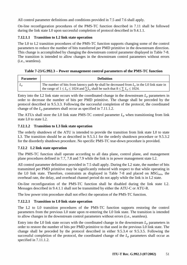
ITU-T Rec. G.992.3 (07/2002) 51
All control parameter definitions and conditions provided in 7.5 and 7.6 shall apply.
On-line reconfiguration procedures of the PMS-TC function described in 7.11 shall be followed during the link state L0 upon successful completion of protocol described in 9.4.1.1.
7.12.1.1 Transition to L2 link state operation
The L0 to L2 transition procedures of the PMS-TC function supports changing some of the control parameters to reduce the number of bits transferred per PMD primitive in the downstream direction. This change is accomplished by changing the downstream control parameter displayed in Table 7-8. The transition is intended to allow changes in the downstream control parameters without errors (i.e., seamless).
Table 7-23/G.992.3 – Power management control parameters of the PMS-TC function
Parameter Definition
Lp The number of bits from latency path #p shall be decreased from Lp in the L0 link state in the range of 1 ≤ Lp ≤ 1024 and ∑Lp shall be such that 8 ≤ ∑ Lp ≤ 1024.
Entry into the L2 link state occurs with the coordinated change in the downstream Lp parameters in order to decrease the number of bits per PMD primitive. The change shall be preceded by the protocol described in 9.5.3.3. Following the successful completion of the protocol, the coordinated change of the Lp parameters shall occur as specified in 7.11.1.2.
The ATUs shall store the L0 link state PMS-TC control parameter Lp when transitioning from link state L0 to state L2.
7.12.1.2 Transition to L3 link state operation
The orderly shutdown of the ATU is intended to provide the transition from link state L0 to state L3. The transition should be as described in 9.5.3.1 for the orderly shutdown procedure or 9.5.3.2 for the disorderly shutdown procedure. No specific PMS-TC tear-down procedure is provided.
7.12.2 L2 link state operation
The PMS-TC function shall operate according to all data plane, control plane, and management plane procedures defined in 7.7, 7.8 and 7.9 while the link is in power management state L2.
All control parameter definitions provided in 7.5 shall apply. During the L2 state, the number of bits transmitted per PMD primitive may be significantly reduced with respect to that while operating in the L0 link state. Therefore, constraints as displayed in Table 7-8 and placed on MSGmin, the overhead rate, the delay, and overhead channel period do not apply while the link is in L2 state.
On-line reconfiguration of the PMS-TC function shall be disabled during the link state L2. Messages described in 9.4.1.1 shall not be transmitted by either the ATU-C or ATU-R.
The low power trim procedure shall not effect the operation of the PMS-TC function.
7.12.2.1 Transition to L0 link state operation
The L2 to L0 transition procedures of the PMS-TC function supports restoring the control parameters from the previous L0 state upon re-entering the L0 link state. The transition is intended to allow changes in the downstream control parameters without errors (i.e., seamless).
Entry into the L0 link state occurs with the coordinated change in the downstream Lp parameters in order to restore the number of bits per PMD primitive to that used in the previous L0 link state. The change shall be preceded by the protocol described in either 9.5.3.4 or 9.5.3.5. Following the successful completion of the protocol, the coordinated change of the Lp parameters shall occur as specified in 7.11.1.2.
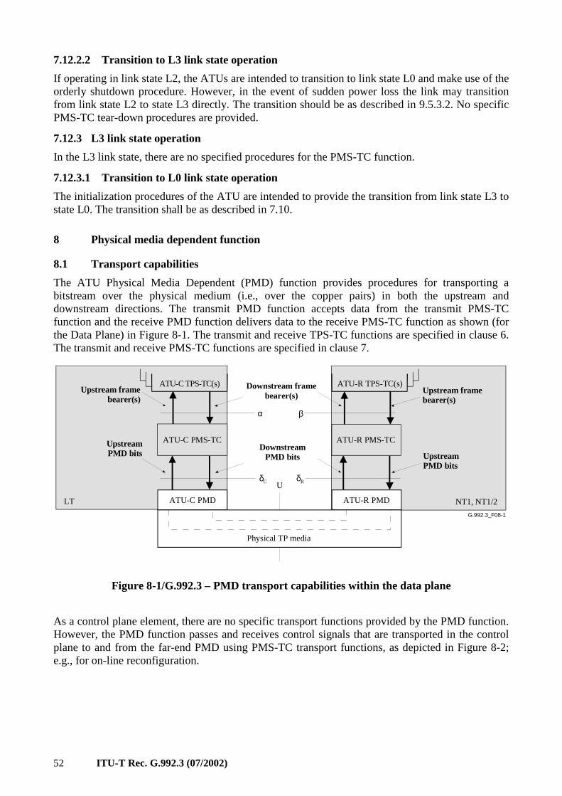
52 ITU-T Rec. G.992.3 (07/2002)
7.12.2.2 Transition to L3 link state operation
If operating in link state L2, the ATUs are intended to transition to link state L0 and make use of the orderly shutdown procedure. However, in the event of sudden power loss the link may transition from link state L2 to state L3 directly. The transition should be as described in 9.5.3.2. No specific PMS-TC tear-down procedures are provided.
7.12.3 L3 link state operation
In the L3 link state, there are no specified procedures for the PMS-TC function.
7.12.3.1 Transition to L0 link state operation
The initialization procedures of the ATU are intended to provide the transition from link state L3 to state L0. The transition shall be as described in 7.10.
8 Physical media dependent function
8.1 Transport capabilities
The ATU Physical Media Dependent (PMD) function provides procedures for transporting a bitstream over the physical medium (i.e., over the copper pairs) in both the upstream and downstream directions. The transmit PMD function accepts data from the transmit PMS-TC function and the receive PMD function delivers data to the receive PMS-TC function as shown (for the Data Plane) in Figure 8-1. The transmit and receive TPS-TC functions are specified in clause 6. The transmit and receive PMS-TC functions are specified in clause 7.
G.992.3_F08-1
U
βα
ATU-R PMS-TC
ATU-R TPS-TC(s)ATU-C TPS-TC(s)
Physical TP media
ATU-R PMDATU-C PMD
Upstream framebearer(s)
Upstream framebearer(s)
Downstream framebearer(s)
NT1, NT1/2LT
UpstreamPMD bits Upstream
PMD bits
DownstreamPMD bits
δC δR
ATU-C PMS-TC
Figure 8-1/G.992.3 – PMD transport capabilities within the data plane
As a control plane element, there are no specific transport functions provided by the PMD function. However, the PMD function passes and receives control signals that are transported in the control plane to and from the far-end PMD using PMS-TC transport functions, as depicted in Figure 8-2; e.g., for on-line reconfiguration.
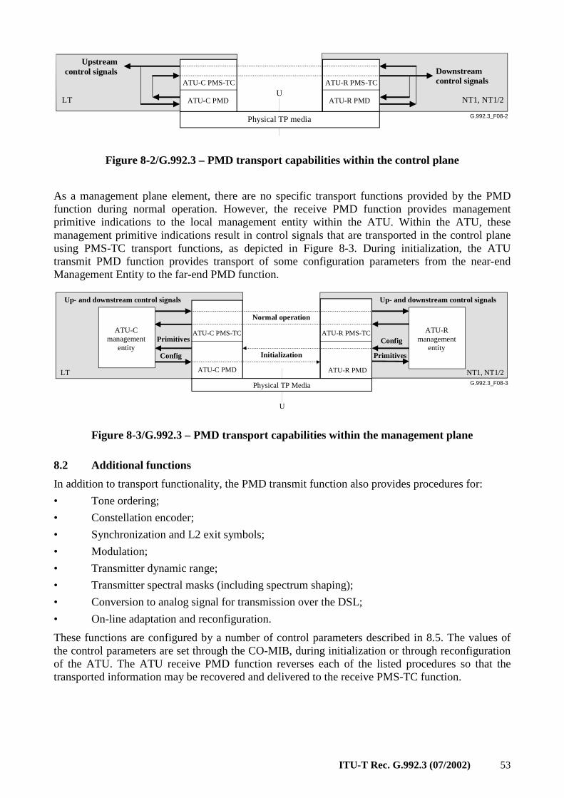
ITU-T Rec. G.992.3 (07/2002) 53
G.992.3_F08-2
UATU-R PMS-TCATU-C PMS-TC
Physical TP media
ATU-R PMDATU-C PMD
Downstream control signals
Upstream control signals
NT1, NT1/2LT
Figure 8-2/G.992.3 – PMD transport capabilities within the control plane
As a management plane element, there are no specific transport functions provided by the PMD function during normal operation. However, the receive PMD function provides management primitive indications to the local management entity within the ATU. Within the ATU, these management primitive indications result in control signals that are transported in the control plane using PMS-TC transport functions, as depicted in Figure 8-3. During initialization, the ATU transmit PMD function provides transport of some configuration parameters from the near-end Management Entity to the far-end PMD function.
G.992.3_F08-3
U
ATU-R PMS-TCATU-C PMS-TC
Physical TP Media
ATU-R PMDATU-C PMD
Up- and downstream control signals
Primitives
Up- and downstream control signals
NT1, NT1/2LT
ATU-C management
entity
ATU-R management
entityConfig Primitives
Config
Initialization
Normal operation
Figure 8-3/G.992.3 – PMD transport capabilities within the management plane
8.2 Additional functions
In addition to transport functionality, the PMD transmit function also provides procedures for:
• Tone ordering;
• Constellation encoder;
• Synchronization and L2 exit symbols;
• Modulation;
• Transmitter dynamic range;
• Transmitter spectral masks (including spectrum shaping);
• Conversion to analog signal for transmission over the DSL;
• On-line adaptation and reconfiguration.
These functions are configured by a number of control parameters described in 8.5. The values of the control parameters are set through the CO-MIB, during initialization or through reconfiguration of the ATU. The ATU receive PMD function reverses each of the listed procedures so that the transported information may be recovered and delivered to the receive PMS-TC function.
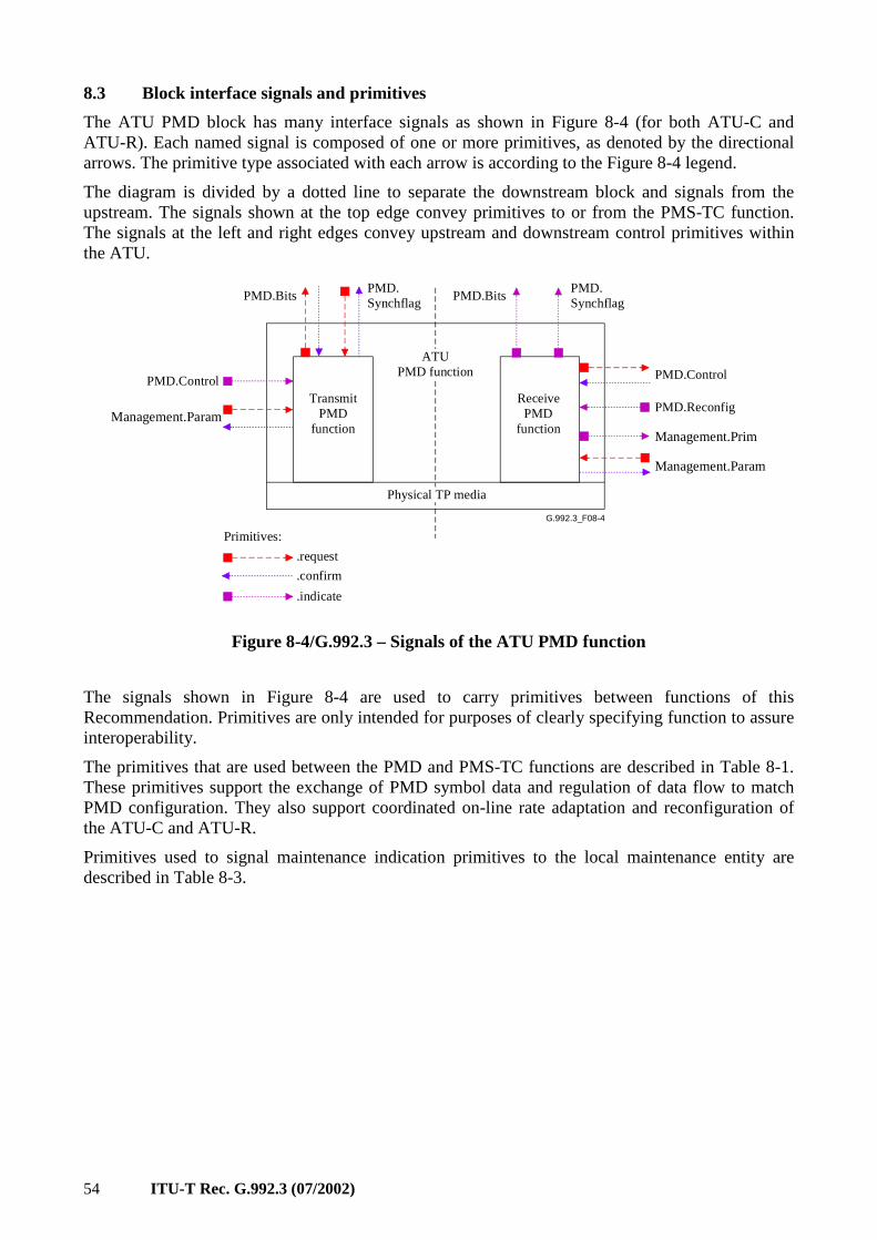
54 ITU-T Rec. G.992.3 (07/2002)
8.3 Block interface signals and primitives
The ATU PMD block has many interface signals as shown in Figure 8-4 (for both ATU-C and ATU-R). Each named signal is composed of one or more primitives, as denoted by the directional arrows. The primitive type associated with each arrow is according to the Figure 8-4 legend.
The diagram is divided by a dotted line to separate the downstream block and signals from the upstream. The signals shown at the top edge convey primitives to or from the PMS-TC function. The signals at the left and right edges convey upstream and downstream control primitives within the ATU.
G.992.3_F08-4
TransmitPMD
function
PMD.BitsPMD.Synchflag
ReceivePMD
function
PMD.BitsPMD.Synchflag
Management.Prim
Physical TP media
PMD.ControlPMD.Control
PMD.Reconfig
Management.Param
Management.Param
ATUPMD function
.request
.confirm
.indicate
Primitives:
Figure 8-4/G.992.3 – Signals of the ATU PMD function
The signals shown in Figure 8-4 are used to carry primitives between functions of this Recommendation. Primitives are only intended for purposes of clearly specifying function to assure interoperability.
The primitives that are used between the PMD and PMS-TC functions are described in Table 8-1. These primitives support the exchange of PMD symbol data and regulation of data flow to match PMD configuration. They also support coordinated on-line rate adaptation and reconfiguration of the ATU-C and ATU-R.
Primitives used to signal maintenance indication primitives to the local maintenance entity are described in Table 8-3.
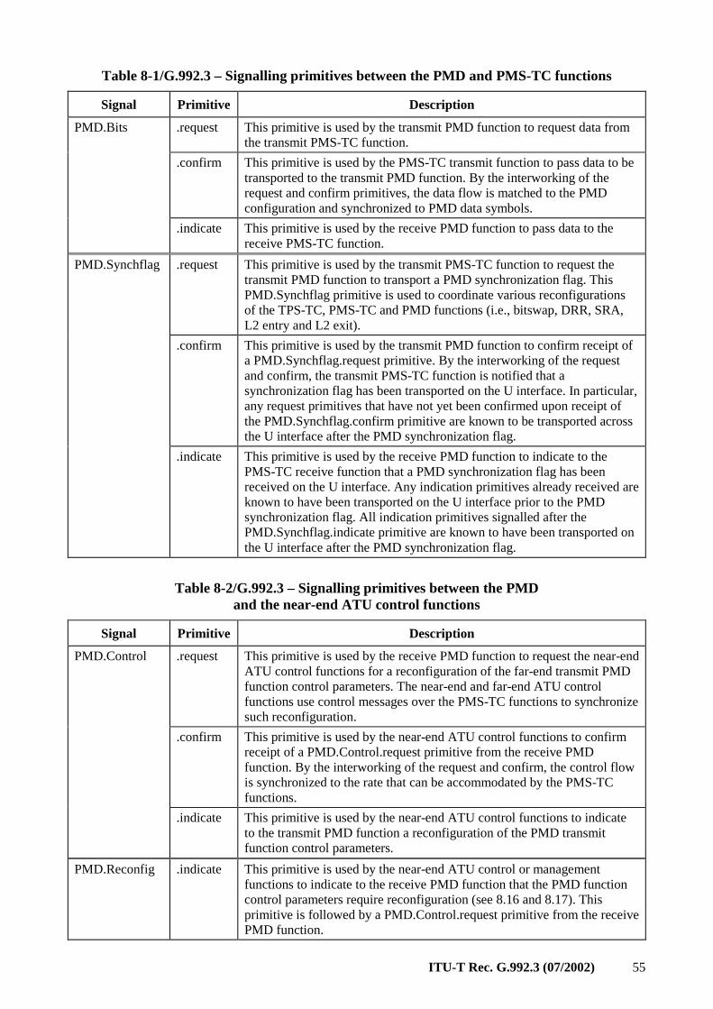
ITU-T Rec. G.992.3 (07/2002) 55
Table 8-1/G.992.3 – Signalling primitives between the PMD and PMS-TC functions
Signal Primitive Description
.request This primitive is used by the transmit PMD function to request data from the transmit PMS-TC function.
.confirm This primitive is used by the PMS-TC transmit function to pass data to be transported to the transmit PMD function. By the interworking of the request and confirm primitives, the data flow is matched to the PMD configuration and synchronized to PMD data symbols.
PMD.Bits
.indicate This primitive is used by the receive PMD function to pass data to the receive PMS-TC function.
.request This primitive is used by the transmit PMS-TC function to request the transmit PMD function to transport a PMD synchronization flag. This PMD.Synchflag primitive is used to coordinate various reconfigurations of the TPS-TC, PMS-TC and PMD functions (i.e., bitswap, DRR, SRA, L2 entry and L2 exit).
.confirm This primitive is used by the transmit PMD function to confirm receipt of a PMD.Synchflag.request primitive. By the interworking of the request and confirm, the transmit PMS-TC function is notified that a synchronization flag has been transported on the U interface. In particular, any request primitives that have not yet been confirmed upon receipt of the PMD.Synchflag.confirm primitive are known to be transported across the U interface after the PMD synchronization flag.
PMD.Synchflag
.indicate This primitive is used by the receive PMD function to indicate to the PMS-TC receive function that a PMD synchronization flag has been received on the U interface. Any indication primitives already received are known to have been transported on the U interface prior to the PMD synchronization flag. All indication primitives signalled after the PMD.Synchflag.indicate primitive are known to have been transported on the U interface after the PMD synchronization flag.
Table 8-2/G.992.3 – Signalling primitives between the PMD and the near-end ATU control functions
Signal Primitive Description
.request This primitive is used by the receive PMD function to request the near-end ATU control functions for a reconfiguration of the far-end transmit PMD function control parameters. The near-end and far-end ATU control functions use control messages over the PMS-TC functions to synchronize such reconfiguration.
.confirm This primitive is used by the near-end ATU control functions to confirm receipt of a PMD.Control.request primitive from the receive PMD function. By the interworking of the request and confirm, the control flow is synchronized to the rate that can be accommodated by the PMS-TC functions.
PMD.Control
.indicate This primitive is used by the near-end ATU control functions to indicate to the transmit PMD function a reconfiguration of the PMD transmit function control parameters.
PMD.Reconfig .indicate This primitive is used by the near-end ATU control or management functions to indicate to the receive PMD function that the PMD function control parameters require reconfiguration (see 8.16 and 8.17). This primitive is followed by a PMD.Control.request primitive from the receive PMD function.
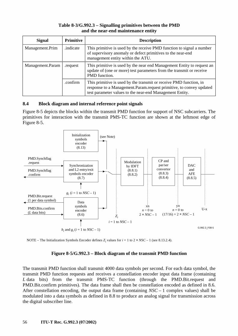
56 ITU-T Rec. G.992.3 (07/2002)
Table 8-3/G.992.3 – Signalling primitives between the PMD and the near-end maintenance entity
Signal Primitive Description
Management.Prim .indicate This primitive is used by the receive PMD function to signal a number of supervisory anomaly or defect primitives to the near-end management entity within the ATU.
.request This primitive is used by the near end Management Entity to request an update of (one or more) test parameters from the transmit or receive PMD function.
Management.Param
.confirm This primitive is used by the transmit or receive PMD function, in response to a Management.Param.request primitive, to convey updated test parameter values to the near-end Management Entity.
8.4 Block diagram and internal reference point signals
Figure 8-5 depicts the blocks within the transmit PMD function for support of NSC subcarriers. The primitives for interaction with the transmit PMS-TC function are shown at the leftmost edge of Figure 8-5.
G.992.3_F08-5
PMD.Synchflag.request
PMD.Synchflag.confirm
PMD.Bit.request(1 per data symbol)
PMD.Bits.confirm(L data bits)
Data symbolsencoder
(8.6)
Synchronizationand L2 entry/exit symbols encoder
(8.7)
Modulation by IDFT(8.8.1)(8.8.2)
CP and par/ser
convertor (8.8.3)(8.8.4)
DACandAFE
(8.8.5)
U-x
bi and gi (i = 1 to NSC – 1)
Initializationsymbolsencoder(8.13)
gi (i = 1 to NSC – 1)
(see Note)
xnn = 0 to
2 × NSC – 1Zi
i = 1 to NSC – 1
NOTE – The Initialization Symbols Encoder defines Zi values for i = 1 to 2 × NSC – 1 (see 8.13.2.4).
ynn = 0 to
(17/16) × 2 × NSC – 1
Figure 8-5/G.992.3 – Block diagram of the transmit PMD function
The transmit PMD function shall transmit 4000 data symbols per second. For each data symbol, the transmit PMD function requests and receives a constellation encoder input data frame (containing L data bits) from the transmit PMS-TC function (through the PMD.Bit.request and PMD.Bit.confirm primitives). The data frame shall then be constellation encoded as defined in 8.6. After constellation encoding, the output data frame (containing NSC – 1 complex values) shall be modulated into a data symbols as defined in 8.8 to produce an analog signal for transmission across the digital subscriber line.
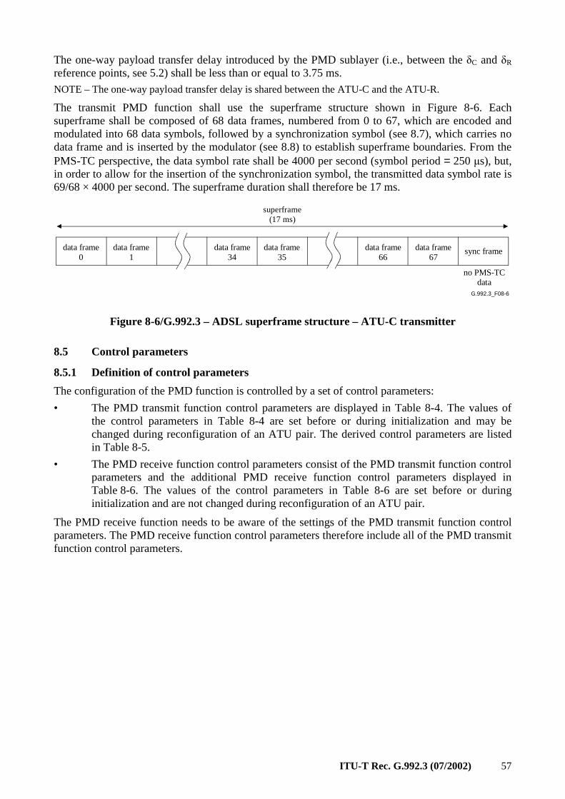
ITU-T Rec. G.992.3 (07/2002) 57
The one-way payload transfer delay introduced by the PMD sublayer (i.e., between the δC and δR reference points, see 5.2) shall be less than or equal to 3.75 ms.
NOTE – The one-way payload transfer delay is shared between the ATU-C and the ATU-R.
The transmit PMD function shall use the superframe structure shown in Figure 8-6. Each superframe shall be composed of 68 data frames, numbered from 0 to 67, which are encoded and modulated into 68 data symbols, followed by a synchronization symbol (see 8.7), which carries no data frame and is inserted by the modulator (see 8.8) to establish superframe boundaries. From the PMS-TC perspective, the data symbol rate shall be 4000 per second (symbol period = 250 µs), but, in order to allow for the insertion of the synchronization symbol, the transmitted data symbol rate is 69/68 × 4000 per second. The superframe duration shall therefore be 17 ms.
G.992.3_F08-6
data frame0
data frame1
data frame34
data frame35
sync framedata frame67
data frame66
superframe(17 ms)
no PMS-TCdata
Figure 8-6/G.992.3 – ADSL superframe structure – ATU-C transmitter
8.5 Control parameters
8.5.1 Definition of control parameters
The configuration of the PMD function is controlled by a set of control parameters:
• The PMD transmit function control parameters are displayed in Table 8-4. The values of the control parameters in Table 8-4 are set before or during initialization and may be changed during reconfiguration of an ATU pair. The derived control parameters are listed in Table 8-5.
• The PMD receive function control parameters consist of the PMD transmit function control parameters and the additional PMD receive function control parameters displayed in Table 8-6. The values of the control parameters in Table 8-6 are set before or during initialization and are not changed during reconfiguration of an ATU pair.
The PMD receive function needs to be aware of the settings of the PMD transmit function control parameters. The PMD receive function control parameters therefore include all of the PMD transmit function control parameters.
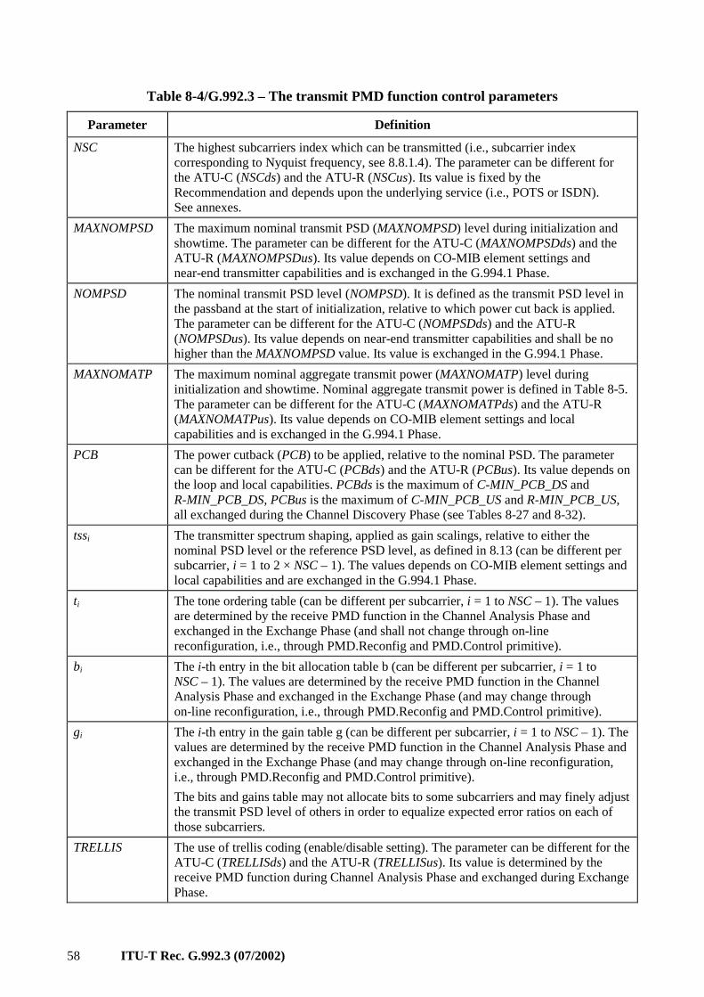
58 ITU-T Rec. G.992.3 (07/2002)
Table 8-4/G.992.3 – The transmit PMD function control parameters
Parameter Definition
NSC The highest subcarriers index which can be transmitted (i.e., subcarrier index corresponding to Nyquist frequency, see 8.8.1.4). The parameter can be different for the ATU-C (NSCds) and the ATU-R (NSCus). Its value is fixed by the Recommendation and depends upon the underlying service (i.e., POTS or ISDN). See annexes.
MAXNOMPSD The maximum nominal transmit PSD (MAXNOMPSD) level during initialization and showtime. The parameter can be different for the ATU-C (MAXNOMPSDds) and the ATU-R (MAXNOMPSDus). Its value depends on CO-MIB element settings and near-end transmitter capabilities and is exchanged in the G.994.1 Phase.
NOMPSD The nominal transmit PSD level (NOMPSD). It is defined as the transmit PSD level in the passband at the start of initialization, relative to which power cut back is applied. The parameter can be different for the ATU-C (NOMPSDds) and the ATU-R (NOMPSDus). Its value depends on near-end transmitter capabilities and shall be no higher than the MAXNOMPSD value. Its value is exchanged in the G.994.1 Phase.
MAXNOMATP The maximum nominal aggregate transmit power (MAXNOMATP) level during initialization and showtime. Nominal aggregate transmit power is defined in Table 8-5. The parameter can be different for the ATU-C (MAXNOMATPds) and the ATU-R (MAXNOMATPus). Its value depends on CO-MIB element settings and local capabilities and is exchanged in the G.994.1 Phase.
PCB The power cutback (PCB) to be applied, relative to the nominal PSD. The parameter can be different for the ATU-C (PCBds) and the ATU-R (PCBus). Its value depends on the loop and local capabilities. PCBds is the maximum of C-MIN_PCB_DS and R-MIN_PCB_DS, PCBus is the maximum of C-MIN_PCB_US and R-MIN_PCB_US, all exchanged during the Channel Discovery Phase (see Tables 8-27 and 8-32).
tssi The transmitter spectrum shaping, applied as gain scalings, relative to either the nominal PSD level or the reference PSD level, as defined in 8.13 (can be different per subcarrier, i = 1 to 2 × NSC – 1). The values depends on CO-MIB element settings and local capabilities and are exchanged in the G.994.1 Phase.
ti The tone ordering table (can be different per subcarrier, i = 1 to NSC – 1). The values are determined by the receive PMD function in the Channel Analysis Phase and exchanged in the Exchange Phase (and shall not change through on-line reconfiguration, i.e., through PMD.Reconfig and PMD.Control primitive).
bi The i-th entry in the bit allocation table b (can be different per subcarrier, i = 1 to NSC – 1). The values are determined by the receive PMD function in the Channel Analysis Phase and exchanged in the Exchange Phase (and may change through on-line reconfiguration, i.e., through PMD.Reconfig and PMD.Control primitive).
gi The i-th entry in the gain table g (can be different per subcarrier, i = 1 to NSC – 1). The values are determined by the receive PMD function in the Channel Analysis Phase and exchanged in the Exchange Phase (and may change through on-line reconfiguration, i.e., through PMD.Reconfig and PMD.Control primitive).
The bits and gains table may not allocate bits to some subcarriers and may finely adjust the transmit PSD level of others in order to equalize expected error ratios on each of those subcarriers.
TRELLIS The use of trellis coding (enable/disable setting). The parameter can be different for the ATU-C (TRELLISds) and the ATU-R (TRELLISus). Its value is determined by the receive PMD function during Channel Analysis Phase and exchanged during Exchange Phase.
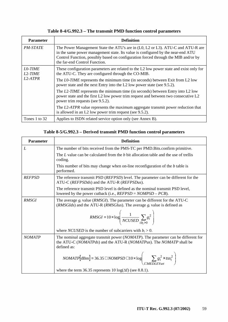
ITU-T Rec. G.992.3 (07/2002) 59
Table 8-4/G.992.3 – The transmit PMD function control parameters
Parameter Definition
PM-STATE The Power Management State the ATU's are in (L0, L2 or L3). ATU-C and ATU-R are in the same power management state. Its value is configured by the near-end ATU Control Function, possibly based on configuration forced through the MIB and/or by the far-end Control Function.
L0-TIME L2-TIME L2-ATPR
These configuration parameters are related to the L2 low power state and exist only for the ATU-C. They are configured through the CO-MIB.
The L0-TIME represents the minimum time (in seconds) between Exit from L2 low power state and the next Entry into the L2 low power state (see 9.5.2).
The L2-TIME represents the minimum time (in seconds) between Entry into L2 low power state and the first L2 low power trim request and between two consecutive L2 power trim requests (see 9.5.2).
The L2-ATPR value represents the maximum aggregate transmit power reduction that is allowed in an L2 low power trim request (see 9.5.2).
Tones 1 to 32 Applies to ISDN related service option only (see Annex B).
Table 8-5/G.992.3 – Derived transmit PMD function control parameters
Parameter Definition
L The number of bits received from the PMS-TC per PMD.Bits.confirm primitive.
The L value can be calculated from the b bit allocation table and the use of trellis coding.
This number of bits may change when on-line reconfiguration of the b table is performed.
REFPSD The reference transmit PSD (REFPSD) level. The parameter can be different for the ATU-C (REFPSDds) and the ATU-R (REFPSDus).
The reference transmit PSD level is defined as the nominal transmit PSD level, lowered by the power cutback (i.e., REFPSD = NOMPSD – PCB).
RMSGI The average gi value (RMSGI). The parameter can be different for the ATU-C (RMSGIds) and the ATU-R (RMSGIus). The average gi value is defined as
×= ∑
>0:
21log10
ibiig
NCUSEDRMSGI
where NCUSED is the number of subcarriers with bi > 0.
NOMATP The nominal aggregate transmit power (NOMATP). The parameter can be different for the ATU-C (NOMATPds) and the ATU-R (NOMATPus). The NOMATP shall be defined as:
[ ]
×∑
∈×++=
MEDLEYsetiii tssgNOMPSDNOMATP 22log1035.36dBm
where the term 36.35 represents 10 log(∆f) (see 8.8.1).
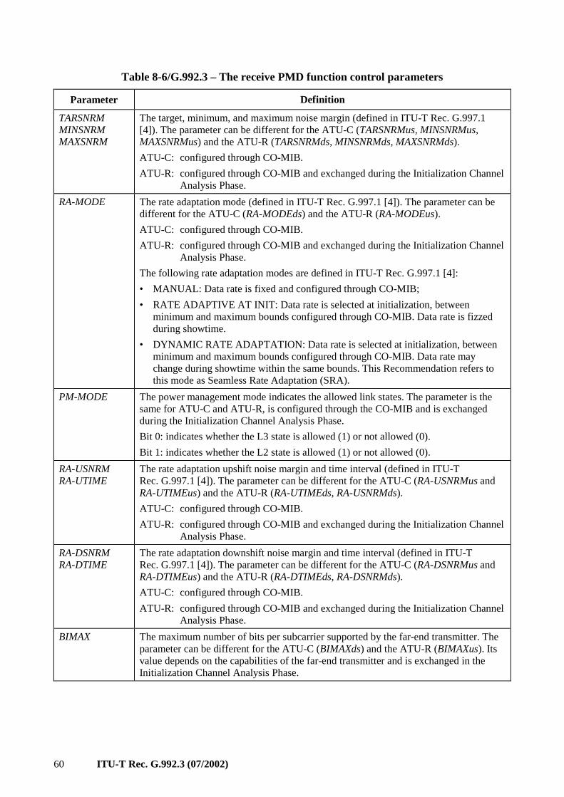
60 ITU-T Rec. G.992.3 (07/2002)
Table 8-6/G.992.3 – The receive PMD function control parameters
Parameter Definition
TARSNRM MINSNRM MAXSNRM
The target, minimum, and maximum noise margin (defined in ITU-T Rec. G.997.1 [4]). The parameter can be different for the ATU-C (TARSNRMus, MINSNRMus, MAXSNRMus) and the ATU-R (TARSNRMds, MINSNRMds, MAXSNRMds).
ATU-C: configured through CO-MIB.
ATU-R: configured through CO-MIB and exchanged during the Initialization Channel Analysis Phase.
RA-MODE The rate adaptation mode (defined in ITU-T Rec. G.997.1 [4]). The parameter can be different for the ATU-C (RA-MODEds) and the ATU-R (RA-MODEus).
ATU-C: configured through CO-MIB.
ATU-R: configured through CO-MIB and exchanged during the Initialization Channel Analysis Phase.
The following rate adaptation modes are defined in ITU-T Rec. G.997.1 [4]:
• MANUAL: Data rate is fixed and configured through CO-MIB;
• RATE ADAPTIVE AT INIT: Data rate is selected at initialization, between minimum and maximum bounds configured through CO-MIB. Data rate is fizzed during showtime.
• DYNAMIC RATE ADAPTATION: Data rate is selected at initialization, between minimum and maximum bounds configured through CO-MIB. Data rate may change during showtime within the same bounds. This Recommendation refers to this mode as Seamless Rate Adaptation (SRA).
PM-MODE The power management mode indicates the allowed link states. The parameter is the same for ATU-C and ATU-R, is configured through the CO-MIB and is exchanged during the Initialization Channel Analysis Phase.
Bit 0: indicates whether the L3 state is allowed (1) or not allowed (0).
Bit 1: indicates whether the L2 state is allowed (1) or not allowed (0).
RA-USNRM RA-UTIME
The rate adaptation upshift noise margin and time interval (defined in ITU-T Rec. G.997.1 [4]). The parameter can be different for the ATU-C (RA-USNRMus and RA-UTIMEus) and the ATU-R (RA-UTIMEds, RA-USNRMds).
ATU-C: configured through CO-MIB.
ATU-R: configured through CO-MIB and exchanged during the Initialization Channel Analysis Phase.
RA-DSNRM RA-DTIME
The rate adaptation downshift noise margin and time interval (defined in ITU-T Rec. G.997.1 [4]). The parameter can be different for the ATU-C (RA-DSNRMus and RA-DTIMEus) and the ATU-R (RA-DTIMEds, RA-DSNRMds).
ATU-C: configured through CO-MIB.
ATU-R: configured through CO-MIB and exchanged during the Initialization Channel Analysis Phase.
BIMAX The maximum number of bits per subcarrier supported by the far-end transmitter. The parameter can be different for the ATU-C (BIMAXds) and the ATU-R (BIMAXus). Its value depends on the capabilities of the far-end transmitter and is exchanged in the Initialization Channel Analysis Phase.
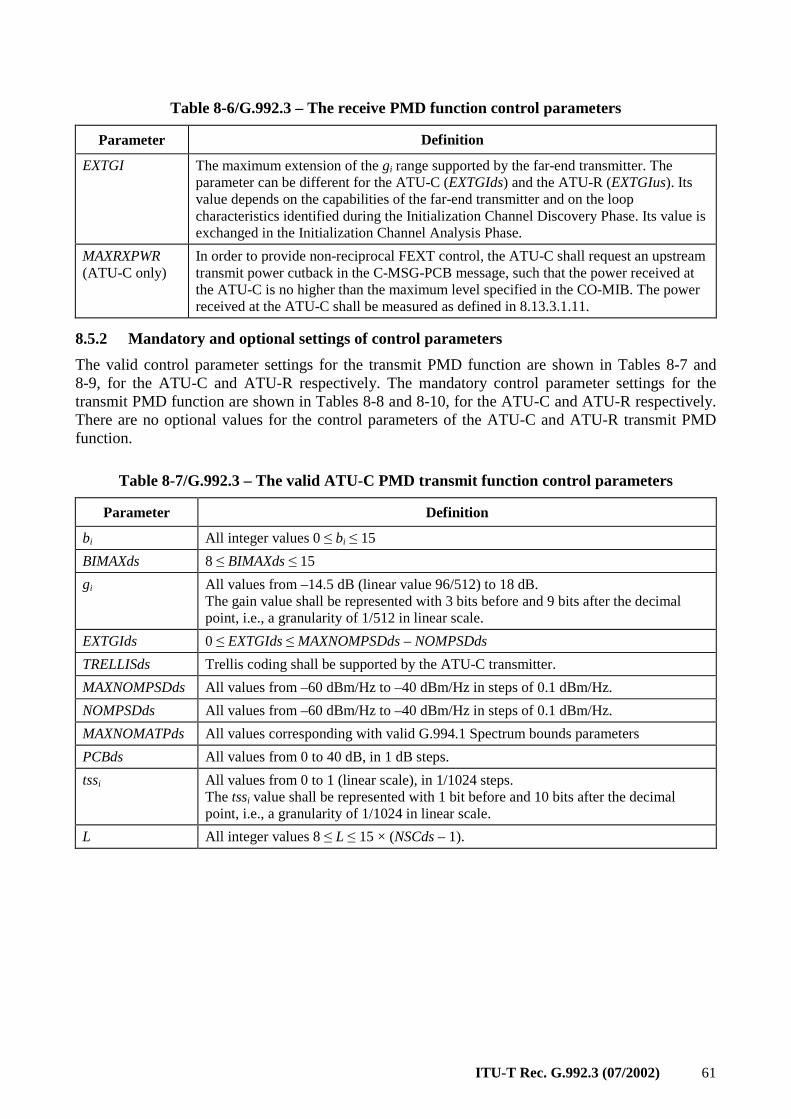
ITU-T Rec. G.992.3 (07/2002) 61
Table 8-6/G.992.3 – The receive PMD function control parameters
Parameter Definition
EXTGI The maximum extension of the gi range supported by the far-end transmitter. The parameter can be different for the ATU-C (EXTGIds) and the ATU-R (EXTGIus). Its value depends on the capabilities of the far-end transmitter and on the loop characteristics identified during the Initialization Channel Discovery Phase. Its value is exchanged in the Initialization Channel Analysis Phase.
MAXRXPWR (ATU-C only)
In order to provide non-reciprocal FEXT control, the ATU-C shall request an upstream transmit power cutback in the C-MSG-PCB message, such that the power received at the ATU-C is no higher than the maximum level specified in the CO-MIB. The power received at the ATU-C shall be measured as defined in 8.13.3.1.11.
8.5.2 Mandatory and optional settings of control parameters
The valid control parameter settings for the transmit PMD function are shown in Tables 8-7 and 8-9, for the ATU-C and ATU-R respectively. The mandatory control parameter settings for the transmit PMD function are shown in Tables 8-8 and 8-10, for the ATU-C and ATU-R respectively. There are no optional values for the control parameters of the ATU-C and ATU-R transmit PMD function.
Table 8-7/G.992.3 – The valid ATU-C PMD transmit function control parameters
Parameter Definition
bi All integer values 0 ≤ bi ≤ 15
BIMAXds 8 ≤ BIMAXds ≤ 15
gi All values from –14.5 dB (linear value 96/512) to 18 dB. The gain value shall be represented with 3 bits before and 9 bits after the decimal point, i.e., a granularity of 1/512 in linear scale.
EXTGIds 0 ≤ EXTGIds ≤ MAXNOMPSDds – NOMPSDds
TRELLISds Trellis coding shall be supported by the ATU-C transmitter.
MAXNOMPSDds All values from –60 dBm/Hz to –40 dBm/Hz in steps of 0.1 dBm/Hz.
NOMPSDds All values from –60 dBm/Hz to –40 dBm/Hz in steps of 0.1 dBm/Hz.
MAXNOMATPds All values corresponding with valid G.994.1 Spectrum bounds parameters
PCBds All values from 0 to 40 dB, in 1 dB steps.
tssi All values from 0 to 1 (linear scale), in 1/1024 steps. The tssi value shall be represented with 1 bit before and 10 bits after the decimal point, i.e., a granularity of 1/1024 in linear scale.
L All integer values 8 ≤ L ≤ 15 × (NSCds – 1).
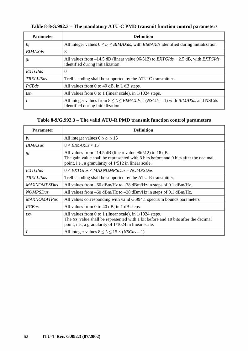
62 ITU-T Rec. G.992.3 (07/2002)
Table 8-8/G.992.3 – The mandatory ATU-C PMD transmit function control parameters
Parameter Definition
bi All integer values 0 ≤ bi ≤ BIMAXds, with BIMAXds identified during initialization
BIMAXds 8
gi All values from –14.5 dB (linear value 96/512) to EXTGIds + 2.5 dB, with EXTGIds identified during initialization.
EXTGIds 0
TRELLISds Trellis coding shall be supported by the ATU-C transmitter.
PCBds All values from 0 to 40 dB, in 1 dB steps.
tssi All values from 0 to 1 (linear scale), in 1/1024 steps.
L All integer values from 8 ≤ L ≤ BIMAXds × (NSCds – 1) with BIMAXds and NSCds identified during initialization.
Table 8-9/G.992.3 – The valid ATU-R PMD transmit function control parameters
Parameter Definition
bi All integer values 0 ≤ bi ≤ 15
BIMAXus 8 ≤ BIMAXus ≤ 15
gi All values from –14.5 dB (linear value 96/512) to 18 dB. The gain value shall be represented with 3 bits before and 9 bits after the decimal point, i.e., a granularity of 1/512 in linear scale.
EXTGIus 0 ≤ EXTGIus ≤ MAXNOMPSDus – NOMPSDus
TRELLISus Trellis coding shall be supported by the ATU-R transmitter.
MAXNOMPSDus All values from –60 dBm/Hz to –38 dBm/Hz in steps of 0.1 dBm/Hz.
NOMPSDus All values from –60 dBm/Hz to –38 dBm/Hz in steps of 0.1 dBm/Hz.
MAXNOMATPus All values corresponding with valid G.994.1 spectrum bounds parameters
PCBus All values from 0 to 40 dB, in 1 dB steps.
tssi All values from 0 to 1 (linear scale), in 1/1024 steps. The tssi value shall be represented with 1 bit before and 10 bits after the decimal point, i.e., a granularity of 1/1024 in linear scale.
L All integer values 8 ≤ L ≤ 15 × (NSCus – 1).
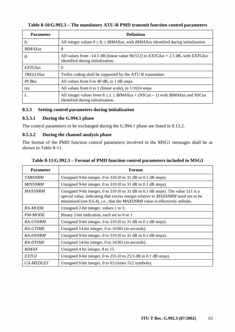
ITU-T Rec. G.992.3 (07/2002) 63
Table 8-10/G.992.3 – The mandatory ATU-R PMD transmit function control parameters
Parameter Definition
bi All integer values 0 ≤ bi ≤ BIMAXus, with BIMAXus identified during initialization
BIMAXus 8
gi All values from –14.5 dB (linear value 96/512) to EXTGIus + 2.5 dB, with EXTGIus identified during initialization.
EXTGIus 0
TRELLISus Trellis coding shall be supported by the ATU-R transmitter.
PCBus All values from 0 to 40 dB, in 1 dB steps.
tssi All values from 0 to 1 (linear scale), in 1/1024 steps.
L All integer values from 8 ≤ L ≤ BIMAXus × (NSCus – 1) with BIMAXus and NSCus identified during initialization.
8.5.3 Setting control parameters during initialization
8.5.3.1 During the G.994.1 phase
The control parameters to be exchanged during the G.994.1 phase are listed in 8.13.2.
8.5.3.2 During the channel analysis phase
The format of the PMD function control parameters involved in the MSG1 messages shall be as shown in Table 8-11.
Table 8-11/G.992.3 – Format of PMD function control parameters included in MSG1
Parameter Format
TARSNRM Unsigned 9-bit integer, 0 to 310 (0 to 31 dB in 0.1 dB steps).
MINSNRM Unsigned 9-bit integer, 0 to 310 (0 to 31 dB in 0.1 dB steps).
MAXSNRM Unsigned 9-bit integer, 0 to 310 (0 to 31 dB in 0.1 dB steps). The value 511 is a special value, indicating that excess margin relative to MAXSNRM need not to be minimized (see 8.6.4), i.e., that the MAXSNRM value is effectively infinite.
RA-MODE Unsigned 2-bit integer, values 1 to 3.
PM-MODE Binary 2-bit indication, each set to 0 or 1.
RA-USNRM Unsigned 9-bit integer, 0 to 310 (0 to 31 dB in 0.1 dB steps).
RA-UTIME Unsigned 14-bit integer, 0 to 16383 (in seconds).
RA-DSNRM Unsigned 9-bit integer, 0 to 310 (0 to 31 dB in 0.1 dB steps).
RA-DTIME Unsigned 14-bit integer, 0 to 16383 (in seconds).
BIMAX Unsigned 4 bit integer, 8 to 15.
EXTGI Unsigned 8-bit integer, 0 to 255 (0 to 25.5 dB in 0.1 dB steps).
CA-MEDLEY Unsigned 6-bit integer, 0 to 63 (times 512 symbols).
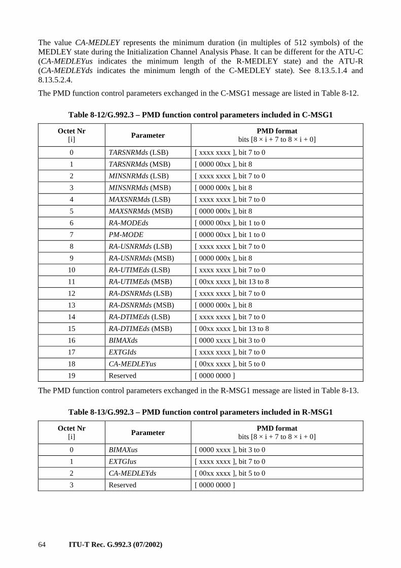
64 ITU-T Rec. G.992.3 (07/2002)
The value CA-MEDLEY represents the minimum duration (in multiples of 512 symbols) of the MEDLEY state during the Initialization Channel Analysis Phase. It can be different for the ATU-C (CA-MEDLEYus indicates the minimum length of the R-MEDLEY state) and the ATU-R (CA-MEDLEYds indicates the minimum length of the C-MEDLEY state). See 8.13.5.1.4 and 8.13.5.2.4.
The PMD function control parameters exchanged in the C-MSG1 message are listed in Table 8-12.
Table 8-12/G.992.3 – PMD function control parameters included in C-MSG1
Octet Nr [i] Parameter
PMD format bits [8 × i + 7 to 8 × i + 0]
0 TARSNRMds (LSB) [ xxxx xxxx ], bit 7 to 0
1 TARSNRMds (MSB) [ 0000 00xx ], bit 8
2 MINSNRMds (LSB) [ xxxx xxxx ], bit 7 to 0
3 MINSNRMds (MSB) [ 0000 000x ], bit 8
4 MAXSNRMds (LSB) [ xxxx xxxx ], bit 7 to 0
5 MAXSNRMds (MSB) [ 0000 000x ], bit 8
6 RA-MODEds [ 0000 00xx ], bit 1 to 0
7 PM-MODE [ 0000 00xx ], bit 1 to 0
8 RA-USNRMds (LSB) [ xxxx xxxx ], bit 7 to 0
9 RA-USNRMds (MSB) [ 0000 000x ], bit 8
10 RA-UTIMEds (LSB) [ xxxx xxxx ], bit 7 to 0
11 RA-UTIMEds (MSB) [ 00xx xxxx ], bit 13 to 8
12 RA-DSNRMds (LSB) [ xxxx xxxx ], bit 7 to 0
13 RA-DSNRMds (MSB) [ 0000 000x ], bit 8
14 RA-DTIMEds (LSB) [ xxxx xxxx ], bit 7 to 0
15 RA-DTIMEds (MSB) [ 00xx xxxx ], bit 13 to 8
16 BIMAXds [ 0000 xxxx ], bit 3 to 0
17 EXTGIds [ xxxx xxxx ], bit 7 to 0
18 CA-MEDLEYus [ 00xx xxxx ], bit 5 to 0
19 Reserved [ 0000 0000 ]
The PMD function control parameters exchanged in the R-MSG1 message are listed in Table 8-13.
Table 8-13/G.992.3 – PMD function control parameters included in R-MSG1
Octet Nr [i] Parameter
PMD format bits [8 × i + 7 to 8 × i + 0]
0 BIMAXus [ 0000 xxxx ], bit 3 to 0
1 EXTGIus [ xxxx xxxx ], bit 7 to 0
2 CA-MEDLEYds [ 00xx xxxx ], bit 5 to 0
3 Reserved [ 0000 0000 ]
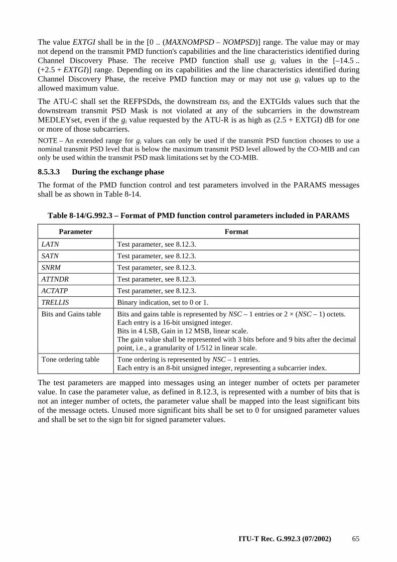
ITU-T Rec. G.992.3 (07/2002) 65
The value EXTGI shall be in the [0 .. (MAXNOMPSD – NOMPSD)] range. The value may or may not depend on the transmit PMD function's capabilities and the line characteristics identified during Channel Discovery Phase. The receive PMD function shall use gi values in the [–14.5 .. (+2.5 + EXTGI)] range. Depending on its capabilities and the line characteristics identified during Channel Discovery Phase, the receive PMD function may or may not use gi values up to the allowed maximum value.
The ATU-C shall set the REFPSDds, the downstream tssi and the EXTGIds values such that the downstream transmit PSD Mask is not violated at any of the subcarriers in the downstream MEDLEYset, even if the gi value requested by the ATU-R is as high as (2.5 + EXTGI) dB for one or more of those subcarriers.
NOTE – An extended range for gi values can only be used if the transmit PSD function chooses to use a nominal transmit PSD level that is below the maximum transmit PSD level allowed by the CO-MIB and can only be used within the transmit PSD mask limitations set by the CO-MIB.
8.5.3.3 During the exchange phase
The format of the PMD function control and test parameters involved in the PARAMS messages shall be as shown in Table 8-14.
Table 8-14/G.992.3 – Format of PMD function control parameters included in PARAMS
Parameter Format
LATN Test parameter, see 8.12.3.
SATN Test parameter, see 8.12.3.
SNRM Test parameter, see 8.12.3.
ATTNDR Test parameter, see 8.12.3.
ACTATP Test parameter, see 8.12.3.
TRELLIS Binary indication, set to 0 or 1.
Bits and Gains table Bits and gains table is represented by NSC – 1 entries or 2 × (NSC – 1) octets. Each entry is a 16-bit unsigned integer. Bits in 4 LSB, Gain in 12 MSB, linear scale. The gain value shall be represented with 3 bits before and 9 bits after the decimal point, i.e., a granularity of 1/512 in linear scale.
Tone ordering table Tone ordering is represented by NSC – 1 entries. Each entry is an 8-bit unsigned integer, representing a subcarrier index.
The test parameters are mapped into messages using an integer number of octets per parameter value. In case the parameter value, as defined in 8.12.3, is represented with a number of bits that is not an integer number of octets, the parameter value shall be mapped into the least significant bits of the message octets. Unused more significant bits shall be set to 0 for unsigned parameter values and shall be set to the sign bit for signed parameter values.
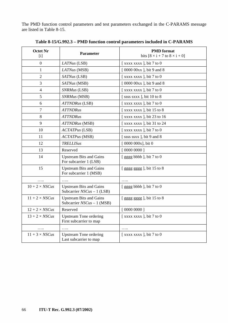
66 ITU-T Rec. G.992.3 (07/2002)
The PMD function control parameters and test parameters exchanged in the C-PARAMS message are listed in Table 8-15.
Table 8-15/G.992.3 – PMD function control parameters included in C-PARAMS
Octet Nr [i] Parameter
PMD format bits [8 × i + 7 to 8 × i + 0]
0 LATNus (LSB) [ xxxx xxxx ], bit 7 to 0
1 LATNus (MSB) [ 0000 00xx ], bit 9 and 8
2 SATNus (LSB) [ xxxx xxxx ], bit 7 to 0
3 SATNus (MSB) [ 0000 00xx ], bit 9 and 8
4 SNRMus (LSB) [ xxxx xxxx ], bit 7 to 0
5 SNRMus (MSB) [ ssss sxxx ], bit 10 to 8
6 ATTNDRus (LSB) [ xxxx xxxx ], bit 7 to 0
7 ATTNDRus [ xxxx xxxx ], bit 15 to 8
8 ATTNDRus [ xxxx xxxx ], bit 23 to 16
9 ATTNDRus (MSB) [ xxxx xxxx ], bit 31 to 24
10 ACTATPus (LSB) [ xxxx xxxx ], bit 7 to 0
11 ACTATPus (MSB) [ ssss ssxx ], bit 9 and 8
12 TRELLISus [ 0000 000x], bit 0
13 Reserved [ 0000 0000 ]
14 Upstream Bits and Gains For subcarrier 1 (LSB)
[ gggg bbbb ], bit 7 to 0
15 Upstream Bits and Gains For subcarrier 1 (MSB)
[ gggg gggg ], bit 15 to 8
….. ….. …..
10 + 2 × NSCus Upstream Bits and Gains Subcarrier NSCus – 1 (LSB)
[ gggg bbbb ], bit 7 to 0
11 + 2 × NSCus Upstream Bits and Gains Subcarrier NSCus – 1 (MSB)
[ gggg gggg ], bit 15 to 8
12 + 2 × NSCus Reserved [ 0000 0000 ]
13 + 2 × NSCus Upstream Tone ordering First subcarrier to map
[ xxxx xxxx ], bit 7 to 0
….. ….. …..
11 + 3 × NSCus Upstream Tone ordering Last subcarrier to map
[ xxxx xxxx ], bit 7 to 0
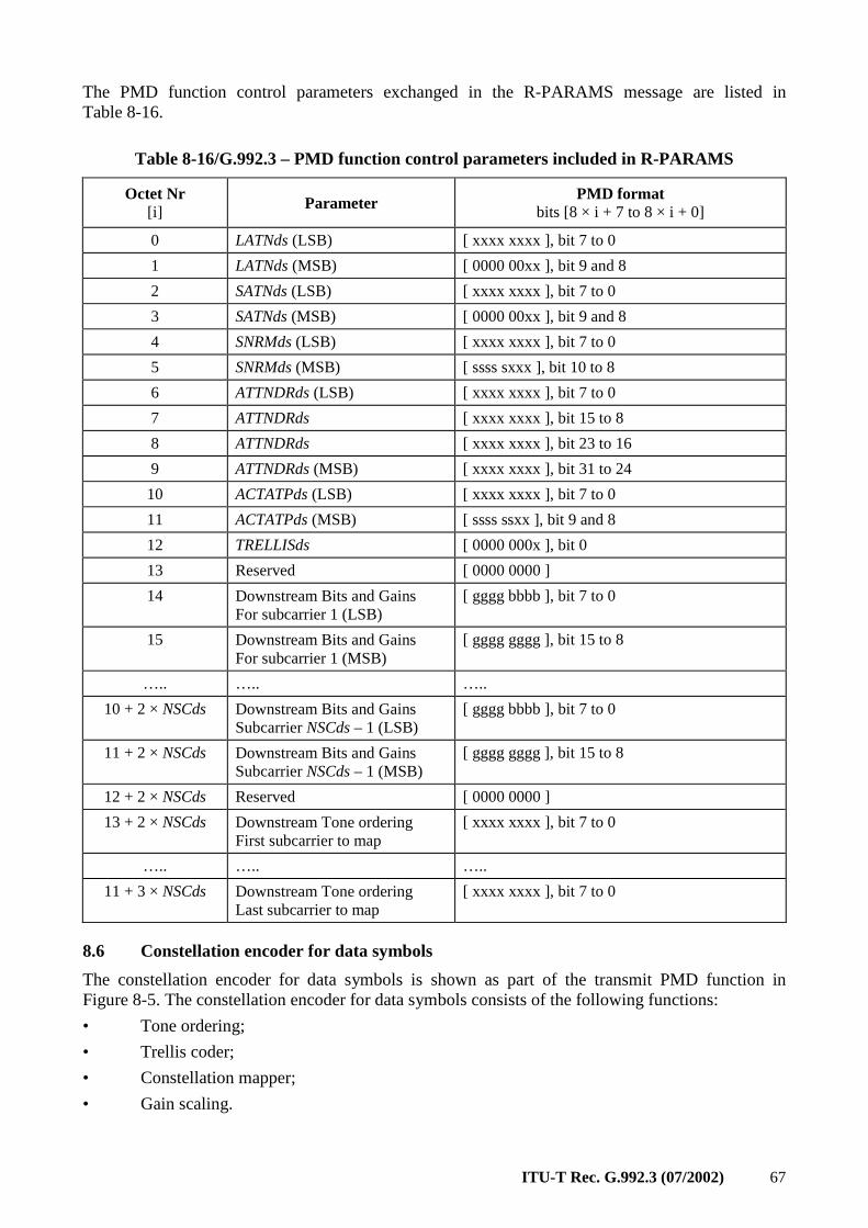
ITU-T Rec. G.992.3 (07/2002) 67
The PMD function control parameters exchanged in the R-PARAMS message are listed in Table 8-16.
Table 8-16/G.992.3 – PMD function control parameters included in R-PARAMS
Octet Nr [i] Parameter
PMD format bits [8 × i + 7 to 8 × i + 0]
0 LATNds (LSB) [ xxxx xxxx ], bit 7 to 0
1 LATNds (MSB) [ 0000 00xx ], bit 9 and 8
2 SATNds (LSB) [ xxxx xxxx ], bit 7 to 0
3 SATNds (MSB) [ 0000 00xx ], bit 9 and 8
4 SNRMds (LSB) [ xxxx xxxx ], bit 7 to 0
5 SNRMds (MSB) [ ssss sxxx ], bit 10 to 8
6 ATTNDRds (LSB) [ xxxx xxxx ], bit 7 to 0
7 ATTNDRds [ xxxx xxxx ], bit 15 to 8
8 ATTNDRds [ xxxx xxxx ], bit 23 to 16
9 ATTNDRds (MSB) [ xxxx xxxx ], bit 31 to 24
10 ACTATPds (LSB) [ xxxx xxxx ], bit 7 to 0
11 ACTATPds (MSB) [ ssss ssxx ], bit 9 and 8
12 TRELLISds [ 0000 000x ], bit 0
13 Reserved [ 0000 0000 ]
14 Downstream Bits and Gains For subcarrier 1 (LSB)
[ gggg bbbb ], bit 7 to 0
15 Downstream Bits and Gains For subcarrier 1 (MSB)
[ gggg gggg ], bit 15 to 8
….. ….. …..
10 + 2 × NSCds Downstream Bits and Gains Subcarrier NSCds – 1 (LSB)
[ gggg bbbb ], bit 7 to 0
11 + 2 × NSCds Downstream Bits and Gains Subcarrier NSCds – 1 (MSB)
[ gggg gggg ], bit 15 to 8
12 + 2 × NSCds Reserved [ 0000 0000 ]
13 + 2 × NSCds Downstream Tone ordering First subcarrier to map
[ xxxx xxxx ], bit 7 to 0
….. ….. …..
11 + 3 × NSCds Downstream Tone ordering Last subcarrier to map
[ xxxx xxxx ], bit 7 to 0
8.6 Constellation encoder for data symbols
The constellation encoder for data symbols is shown as part of the transmit PMD function in Figure 8-5. The constellation encoder for data symbols consists of the following functions:
• Tone ordering;
• Trellis coder;
• Constellation mapper;
• Gain scaling.

68 ITU-T Rec. G.992.3 (07/2002)
This clause specifies each of these functions, based on the applicable transmit PMD function configuration parameters defined in 8.5. The constellation encoder input data frame (from the transmit PMS-TC function) consists of L data bits. The output data frame (to the modulator) consists of NSC – 1 complex values (Zi, i = 1 to NSC – 1).
8.6.1 Tone ordering
During initialization, the receive PMD function shall calculate the numbers of bits and the relative gains to be used for every subcarrier, as well as the order in which subcarriers are assigned bits (i.e., the tone ordering). The calculated bits and gains and the tone ordering shall be sent back to the transmit PMD function during a later stage of initialization (see 8.5.3.3).
The pairs of bits and relative gains are defined, in ascending order of frequency or subcarrier index i, as a bit allocation table b and gain table g (i.e., bi and gi, for i = 1 to NSC – 1, with b1 bits to be allocated to subcarrier 1 and bNSC – 1 bits to be allocated to subcarrier NSC – 1). If trellis coding is used, the receive PMD function shall include an even number of 1-bit subcarriers in the bit allocation table b.
The tone ordering table t is defined as the sequence in which subcarriers are assigned bits from the input bitstream (i.e., ti for i = 1 to NSC – 1, with constellation mapping beginning on subcarrier t1 and ending on subcarrier tNSC – 1). The tone ordering table t shall remain static for the duration of the session.
Following receipt of the tables b, g and t, the transmit PMD function shall calculate a reordered bit table b' and a reordered tone table t' from the original tables b and t. Constellation mapping shall occur in sequence according to the re-ordered tone table t', with the number of bits per tone as defined by the original bit table b. Trellis coding shall occur according to the re-ordered bit table b'.
If trellis coding is not used, b' = b and t' = t.
If trellis coding is used, the reordering of table t shall be performed by the transmit PMD function. The reordered tone table t' shall be generated according to the following rules:
• Indices of all subcarriers supporting 0 bits or 2 or more bits appear first in t', in the same order as in table t.
• Indices of all subcarriers supporting 1 bit appear last in table t', in the same order as in table t.
If the bit allocation does not include any 1-bit subcarriers, the reordered tone table t' is identical to the original tone table t.
The (even number of) 1-bit subcarriers shall be paired to form 2-dimensional constellation points as input to the trellis encoder. The pairing shall be determined by the order in which the 1-bit subcarriers appear in the original tone ordering table t.
The table b' is generated by scanning the reordered tone table t' and reordering the entries of table b according to the following rules (with NCONEBIT representing the number of 1-bit subcarriers in the bit allocation table b):
• The first NCONEBIT/2 entries of b' shall be 0, where NCONEBIT is the (by definition, even) number of subcarriers supporting 1 bit.
• The next entries of b' shall be 0, corresponding to the subcarriers that support 0 bits.
• The next entries of b' shall be non-zero, corresponding to the subcarriers that support 2 or more bits. The entries shall be determined using the new tone table t' in conjunction with the original bit table b.
• The last NCONEBIT/2 entries of b' correspond to the paired 1-bit constellations (i.e., 2 bits per entry).
The table b' is compatible with the G.992.1 trellis encoder.
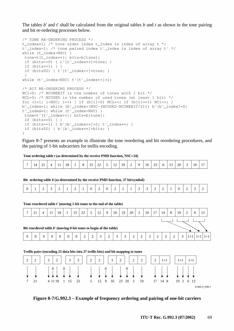
ITU-T Rec. G.992.3 (07/2002) 69
The tables b' and t' shall be calculated from the original tables b and t as shown in the tone pairing and bit re-ordering processes below. /* TONE RE-ORDERING PROCESS */ t_index=1; /* tone order index t_index is index of array t */ t'_index=1; /* tone paired index t'_index is index of array t' */ while (t_index<NSC) tone=t[t_index++]; bits=b[tone]; if (bits==0) t'[t'_index++]=tone; if (bits==1) if (bits ≥2) t'[t'_index++]=tone; while (t'_index<NSC) t'[t'_index++]=1; /* BIT RE-ORDERING PROCESS */ NC1=0; /* NCONEBIT is the number of tones with 1 bi t */ NCL=0; /* NCUSED is the number of used tones (at le ast 1 bit) */ for (i=1; i<NSC; i++) if (b[i]>0) NCL++; if (b[i] ==1) NC1++; b'_index=1; while (b'_index<(NSC-(NCUSED-NCONEBIT/2 ))) b'[b'_index]=0; t'_index=1; while (t'_index<NSC) tone=t'[t'_index++]; bits=b[tone]; if (bits==0) if (bits==1) b'[b'_index++]=2; t'_index++; if (bits ≥2) b'[b'_index++]=bits;
Figure 8-7 presents an example to illustrate the tone reordering and bit reordering procedures, and the pairing of 1-bit subcarriers for trellis encoding.
G.992.3_F08-7
7 14 21 4 11 18 1 8 15 22 5 12 19 2 9 16 23 6 13 20 3 10 17
Tone ordering table t (as determined by the receive PMD function, NSC=24)
Bit ordering table b (as determined by the receive PMD function, 37 bit/symbol)
0 1 2 3 2 1 2 1 0 2 0 2 1 1 3 3 3 2 1 0 2 3 2
7 21 4 11 18 1 15 22 5 12 9 16 23 20 3 10 17 14 8 19 2 6 13
Tone reordered table t' (moving 1-bit tones to the end of the table)
0 0 0 0 2 2 3 2 3 3 2 2 3 2 2 2 3 1+1 1+1 1+1
Bit reordered table b' (moving 0-bit tones to begin of the table)
0 0 0
2 2 3 2 3 3 2 2 3 2 2 2 3
Trellis pairs (encoding 25 data bits into 37 trellis bits) and bit mapping to tones
1+1 1+1 1+1
7 21 4 18 15 22 5 12 16 23 3 10 17 14 19 68 132
0
11
0
1
0
9
0
20
Figure 8-7/G.992.3 – Example of frequency ordering and pairing of one-bit carriers
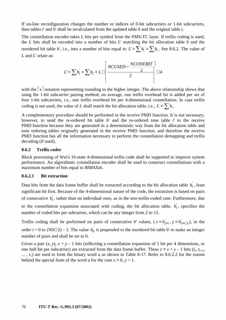
70 ITU-T Rec. G.992.3 (07/2002)
If on-line reconfiguration changes the number or indices of 0-bit subcarriers or 1-bit subcarriers, then tables t' and b' shall be recalculated from the updated table b and the original table t.
The constellation encoder takes L bits per symbol from the PMS-TC layer. If trellis coding is used, the L bits shall be encoded into a number of bits L' matching the bit allocation table b and the
reordered bit table b', i.e., into a number of bits equal to ∑∑ == ii bbL '' . See 8.6.2. The value of
L and L' relate as:
42
2' ' +
−+=== ∑∑
NCONEBITNCUSED
LbbL ii
with the x notation representing rounding to the higher integer. The above relationship shows that using the 1-bit subcarrier pairing method, on average, one trellis overhead bit is added per set of four 1-bit subcarriers, i.e., one trellis overhead bit per 4-dimensional constellation. In case trellis coding is not used, the value of L shall match the bit allocation table, i.e., ∑= .ibL
A complementary procedure should be performed in the receive PMD function. It is not necessary, however, to send the re-ordered bit table b' and the re-ordered tone table t' to the receive PMD function because they are generated in a deterministic way from the bit allocation table and tone ordering tables originally generated in the receive PMD function, and therefore the receive PMD function has all the information necessary to perform the constellation demapping and trellis decoding (if used).
8.6.2 Trellis coder
Block processing of Wei's 16-state 4-dimensional trellis code shall be supported to improve system performance. An algorithmic constellation encoder shall be used to construct constellations with a maximum number of bits equal to BIMAXds.
8.6.2.1 Bit extraction
Data bits from the data frame buffer shall be extracted according to the bit allocation table 'ib , least
significant bit first. Because of the 4-dimensional nature of the code, the extraction is based on pairs
of consecutive 'ib , rather than on individual ones, as in the non-trellis-coded case. Furthermore, due
to the constellation expansion associated with coding, the bit allocation table, 'ib , specifies the
number of coded bits per subcarrier, which can be any integer from 2 to 15.
Trellis coding shall be performed on pairs of consecutive b' values, ( '2 ibx ×= , '
12 +×= iby ), in the
order i = 0 to (NSC/2) – 1. The value '0b is prepended to the reordered bit table b' to make an integer
number of pairs and shall be set to 0.
Given a pair (x, y), x + y – 1 bits (reflecting a constellation expansion of 1 bit per 4 dimensions, or one half bit per subcarrier) are extracted from the data frame buffer. These z = x + y – 1 bits (tz, tz–1, ... , t1) are used to form the binary word u as shown in Table 8-17. Refer to 8.6.2.2 for the reason behind the special form of the word u for the case x = 0, y > 1.
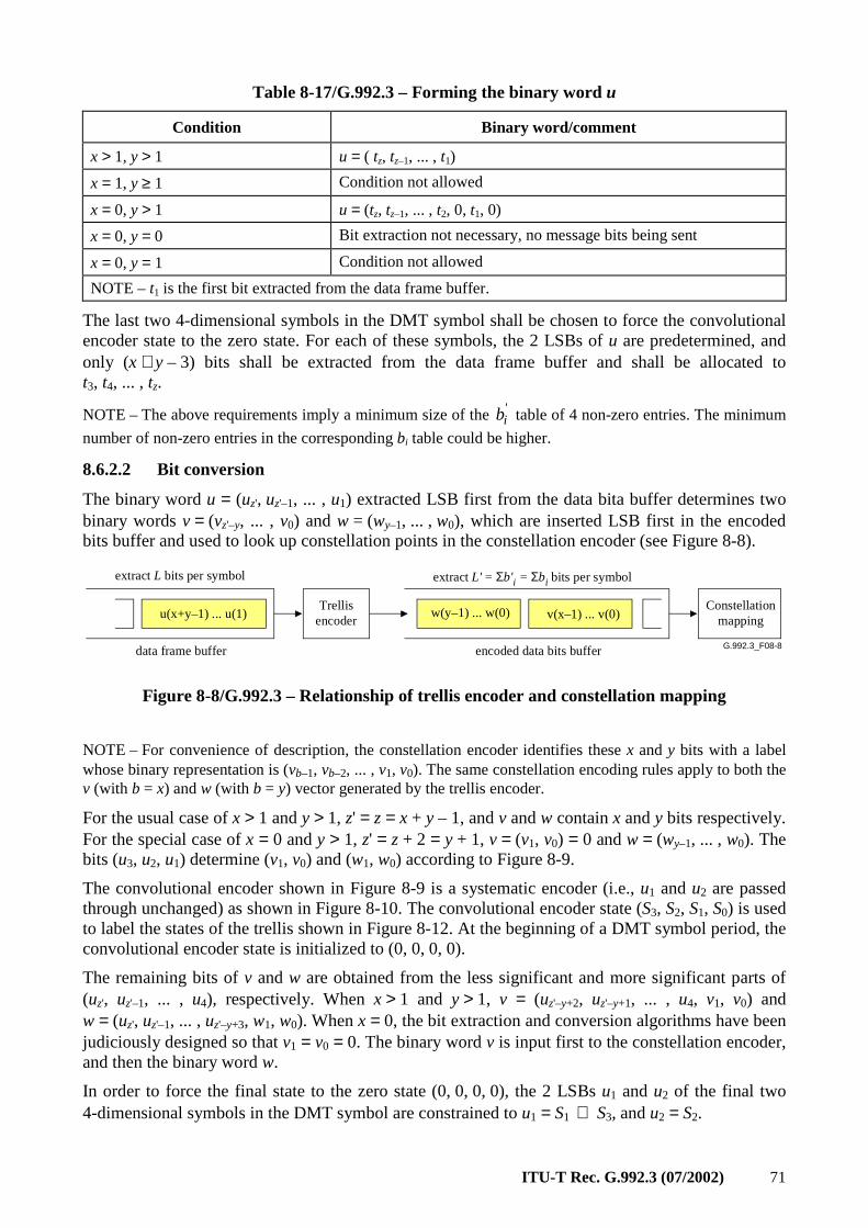
ITU-T Rec. G.992.3 (07/2002) 71
Table 8-17/G.992.3 – Forming the binary word u
Condition Binary word/comment
x > 1, y > 1 u = ( tz, tz–1, ... , t1)
x = 1, y ≥ 1 Condition not allowed
x = 0, y > 1 u = (tz, tz–1, ... , t2, 0, t1, 0)
x = 0, y = 0 Bit extraction not necessary, no message bits being sent
x = 0, y = 1 Condition not allowed
NOTE – t1 is the first bit extracted from the data frame buffer.
The last two 4-dimensional symbols in the DMT symbol shall be chosen to force the convolutional encoder state to the zero state. For each of these symbols, the 2 LSBs of u are predetermined, and only (x + y – 3) bits shall be extracted from the data frame buffer and shall be allocated to t3, t4, ... , tz.
NOTE – The above requirements imply a minimum size of the 'ib table of 4 non-zero entries. The minimum
number of non-zero entries in the corresponding bi table could be higher.
8.6.2.2 Bit conversion
The binary word u = (uz', uz'–1, ... , u1) extracted LSB first from the data bita buffer determines two binary words v = (vz'–y, ... , v0) and w = (wy–1, ... , w0), which are inserted LSB first in the encoded bits buffer and used to look up constellation points in the constellation encoder (see Figure 8-8).
G.992.3_F08-8
Trellis encoder
data frame buffer encoded data bits buffer
Constellation mapping
extract L bits per symbol extract L' = Σb'i = Σbi bits per symbol
u(x+y–1) ... u(1) w(y–1) ... w(0) v(x–1) ... v(0)
Figure 8-8/G.992.3 – Relationship of trellis encoder and constellation mapping
NOTE – For convenience of description, the constellation encoder identifies these x and y bits with a label whose binary representation is (vb–1, vb–2, ... , v1, v0). The same constellation encoding rules apply to both the v (with b = x) and w (with b = y) vector generated by the trellis encoder.
For the usual case of x > 1 and y > 1, z' = z = x + y – 1, and v and w contain x and y bits respectively. For the special case of x = 0 and y > 1, z' = z + 2 = y + 1, v = (v1, v0) = 0 and w = (wy–1, ... , w0). The bits (u3, u2, u1) determine (v1, v0) and (w1, w0) according to Figure 8-9.
The convolutional encoder shown in Figure 8-9 is a systematic encoder (i.e., u1 and u2 are passed through unchanged) as shown in Figure 8-10. The convolutional encoder state (S3, S2, S1, S0) is used to label the states of the trellis shown in Figure 8-12. At the beginning of a DMT symbol period, the convolutional encoder state is initialized to (0, 0, 0, 0).
The remaining bits of v and w are obtained from the less significant and more significant parts of (uz', uz'–1, ... , u4), respectively. When x > 1 and y > 1, v = (uz'–y+2, uz'–y+1, ... , u4, v1, v0) and w = (uz', uz'–1, ... , uz'–y+3, w1, w0). When x = 0, the bit extraction and conversion algorithms have been judiciously designed so that v1 = v0 = 0. The binary word v is input first to the constellation encoder, and then the binary word w.
In order to force the final state to the zero state (0, 0, 0, 0), the 2 LSBs u1 and u2 of the final two 4-dimensional symbols in the DMT symbol are constrained to u1 = S1 ⊕ S3, and u2 = S2.
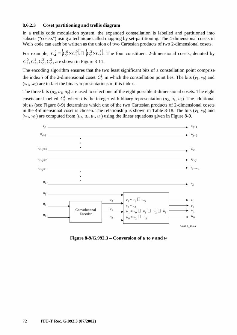
72 ITU-T Rec. G.992.3 (07/2002)
8.6.2.3 Coset partitioning and trellis diagram
In a trellis code modulation system, the expanded constellation is labelled and partitioned into subsets ("cosets") using a technique called mapping by set-partitioning. The 4-dimensional cosets in Wei's code can each be written as the union of two Cartesian products of two 2-dimensional cosets.
For example, ( ) ( )32
32
02
02
04 CCCCC ×∪×= . The four constituent 2-dimensional cosets, denoted by
32
22
12
02 ,,, CCCC , are shown in Figure 8-11.
The encoding algorithm ensures that the two least significant bits of a constellation point comprise
the index i of the 2-dimensional coset iC2 in which the constellation point lies. The bits (v1, v0) and (w1, w0) are in fact the binary representations of this index.
The three bits (u2, u1, u0) are used to select one of the eight possible 4-dimensional cosets. The eight
cosets are labelled iC4 where i is the integer with binary representation (u2, u1, u0). The additional bit u3 (see Figure 8-9) determines which one of the two Cartesian products of 2-dimensional cosets in the 4-dimensional coset is chosen. The relationship is shown in Table 8-18. The bits (v1, v0) and (w1, w0) are computed from (u3, u2, u1, u0) using the linear equations given in Figure 8-9.
G.992.3_F08-9
uz'
uz'–1
uz'–y+3
uz'–y+2
uz'–y+1
u4
u3
u2
u1
wy–1
wy–2
w2
vz'–y
vz'–y–1
v2
v1
v0w1
w0
u2
u1
u0
ConvolutionalEncoder
v1 = u1 ⊕ u3
v0 = u3
w1 = u0 ⊕ u1 ⊕ u2 ⊕ u3
w0 = u2 ⊕ u3
Figure 8-9/G.992.3 – Conversion of u to v and w
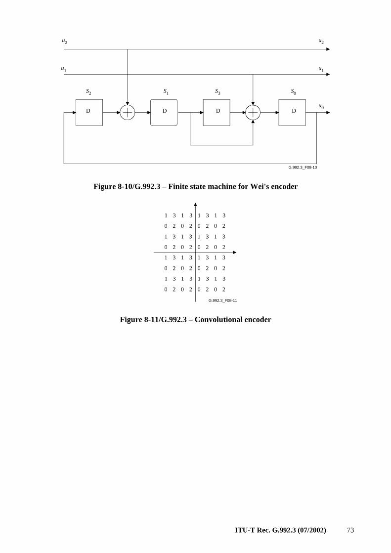
ITU-T Rec. G.992.3 (07/2002) 73
G.992.3_F08-10
u2
u1
S2 S1
D D
S3
D D
u2
u1
S0
u0
Figure 8-10/G.992.3 – Finite state machine for Wei's encoder
G.992.3_F08-11
1 3 1 3 1 3 1 3
0 2 0 2 0 2 0 2
1 3 1 3 1 3 1 3
0 2 0 2 0 2 0 2
1 3 1 3 1 3 1 3
0 2 0 2 0 2 0 2
1 3 1 3 1 3 1 3
0 2 0 2 0 2 0 2
Figure 8-11/G.992.3 – Convolutional encoder
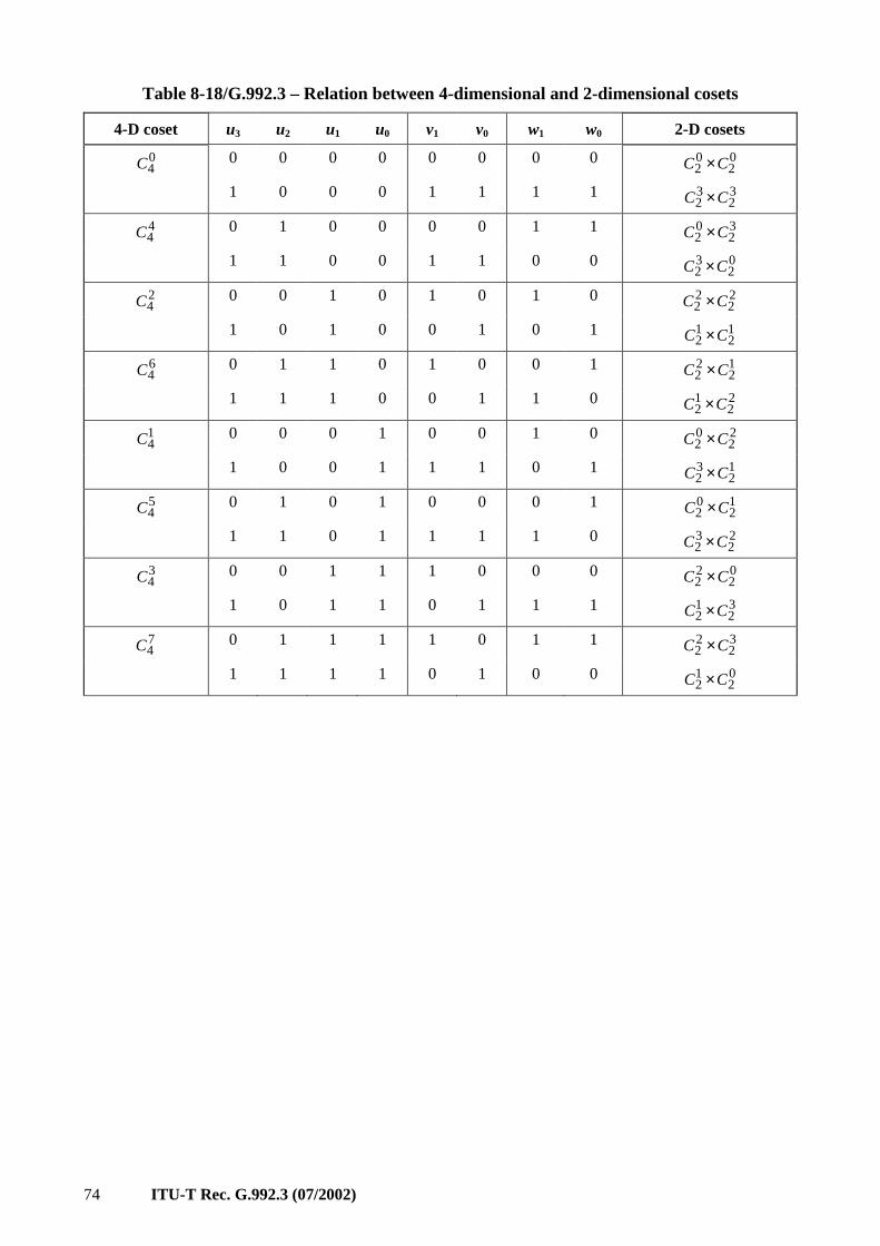
74 ITU-T Rec. G.992.3 (07/2002)
Table 8-18/G.992.3 – Relation between 4-dimensional and 2-dimensional cosets
4-D coset u3 u2 u1 u0 v1 v0 w1 w0 2-D cosets
04C 0 0 0 0 0 0 0 0 0
202 CC ×
1 0 0 0 1 1 1 1 32
32 CC ×
44C 0 1 0 0 0 0 1 1 3
202 CC ×
1 1 0 0 1 1 0 0 02
32 CC ×
24C 0 0 1 0 1 0 1 0 2
222 CC ×
1 0 1 0 0 1 0 1 12
12 CC ×
64C 0 1 1 0 1 0 0 1 1
222 CC ×
1 1 1 0 0 1 1 0 22
12 CC ×
14C 0 0 0 1 0 0 1 0 2
202 CC ×
1 0 0 1 1 1 0 1 12
32 CC ×
54C 0 1 0 1 0 0 0 1 1
202 CC ×
1 1 0 1 1 1 1 0 22
32 CC ×
34C 0 0 1 1 1 0 0 0 0
222 CC ×
1 0 1 1 0 1 1 1 32
12 CC ×
74C 0 1 1 1 1 0 1 1 3
222 CC ×
1 1 1 1 0 1 0 0 02
12 CC ×
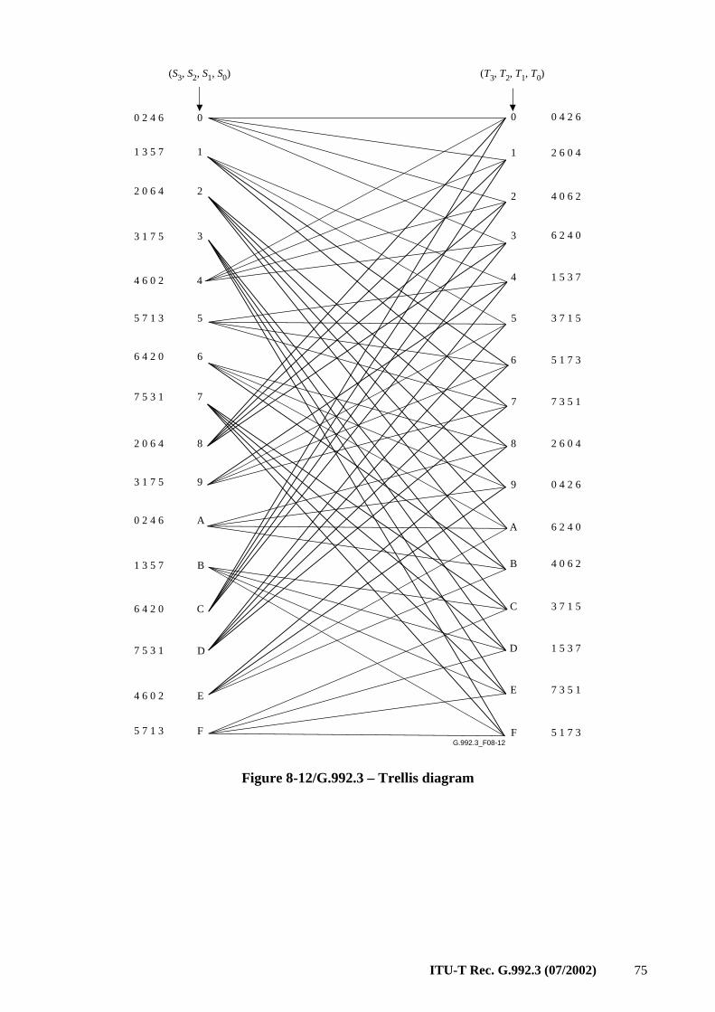
ITU-T Rec. G.992.3 (07/2002) 75
G.992.3_F08-12
(S3, S2, S1, S0) (T3, T2, T1, T0)
0
1
2
3
4
5
6
7
8
9
A
B
C
D
E
F
0
1
2
3
4
5
6
7
8
9
A
B
C
D
E
F
0 2 4 6
1 3 5 7
2 0 6 4
3 1 7 5
4 6 0 2
5 7 1 3
6 4 2 0
7 5 3 1
2 0 6 4
3 1 7 5
0 2 4 6
1 3 5 7
6 4 2 0
7 5 3 1
4 6 0 2
5 7 1 3
0 4 2 6
2 6 0 4
4 0 6 2
6 2 4 0
1 5 3 7
3 7 1 5
5 1 7 3
7 3 5 1
2 6 0 4
0 4 2 6
6 2 4 0
4 0 6 2
3 7 1 5
1 5 3 7
7 3 5 1
5 1 7 3
Figure 8-12/G.992.3 – Trellis diagram
76 ITU-T Rec. G.992.3 (07/2002)
Figure 8-12 shows the trellis diagram based on the finite state machine in Figure 8-10, and the one-to-one correspondence between (u2, u1, u0) and the 4-dimensional cosets. In the Figure 8-12, S = (S3, S2, S1, S0) represents the current state, while T = (T3, T2, T1, T0) represents the next state in the finite state machine. S is connected to T in the constellation diagram by a branch determined by the values of u2 and u1. The branch is labelled with the 4-dimensional coset specified by the values of u2, u1 (and u0 = S0, see Figure 8-11). To make the constellation diagram more readable, the indices of the 4-dimensional coset labels are listed next to the starting and end points of the branches, rather than on the branches themselves. The leftmost label corresponds to the uppermost branch for each state. The constellation diagram is used when decoding the trellis code by the Viterbi algorithm.
8.6.3 Constellation mapper
An algorithmic constellation encoder shall be used to construct constellations with a maximum number of bits equal to BIMAX, where 8 ≤ BIMAX ≤ 15. The data bits buffer contains ∑bi bits, which may or may not be trellis coded. Data bits from the data bits buffer and bits from a PRBS
encoder shall be extracted according to the constellation mapping tone ordering table 'it and the bit
allocation table bi , least significant bit first (see 8.6.1). The number of bits per subcarrier, bi, can take any non-negative integer values not exceeding BIMAX.
NOTE – The constellation encoder is described so that text applies irrespective of bits being trellis coded or not and applies irrespective of the link being in the L0 or L2 power management state.
For a given subcarrier i in the MEDLEYset with bi > 0, b = bi bits shall be extracted from the data bits buffer, and these bits form a binary word vb–1, vb–2, ... , v1, v0. The first bit extracted shall be v0, the LSB. The encoder shall select an odd-integer point (X, Y) from the square-grid constellation based on the b bits of vb–1, vb–2, ... , v1, v0. For example, for b = 2, the four constellation points are labelled 0, 1, 2, 3, corresponding to (v1, v0) = (0, 0), (0, 1), (1, 0), (1, 1), respectively.
The odd integer values of X and Y shown in the constellation diagrams are on a ±1, ±3, ±5, … grid. These values require appropriate scaling such that, at the output of the constellation mapper, all constellations regardless of size represent the same rms energy as a subcarrier transmitted at the reference transmit PSD level (REFPSD).
For a given subcarrier i in the MEDLEYset with (bi = 0), no bits shall be extracted from the data bits buffer. Instead, the encoder shall extract b = 2 bits from the PRBS generator, and these bits form the binary word v1, v0. The first bit extracted shall be v0, the LSB. The encoder shall select an odd-integer point (X, Y) as defined for the case b = 2. In case a gi = 0 is applied during gain scaling, the encoder selection is effectively ignored (see 8.6.4).
If the ATU-R has set the FMT_C-PILOT bit to 1 in the R-MSG-PCB initialization message (see 8.13.3.2.10), then the pilot subcarrier shall not be modulated with data bits (i.e., bC-PILOT = 0). The encoder shall extract b = 2 bits from the PRBS generator for the pilot subcarrier, which shall be overwritten by the modulator (see 8.8.1.2) with a fixed 0,0 4-QAM constellation point (i.e., the two bits are effectively ignored).
For a given subcarrier i not in the MEDLEYset with (bi = 0), no bits shall be extracted from the data bits buffer and no bits shall be extracted from the PRBS generator. Instead, the constellation mapper may select a discretionary (X, Y) point (which may change from symbol to symbol and which does not necessarily coincide with a constellation point).
The bits modulated on the subcarriers in the MEDLEYset with bi = 0, shall be taken from the pseudo-random binary sequence (PRBS) defined by:
23.for
and 23 to1for 1
3218 >⊕===
−− nddd
nd
nnn
n
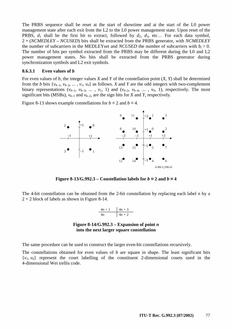
ITU-T Rec. G.992.3 (07/2002) 77
The PRBS sequence shall be reset at the start of showtime and at the start of the L0 power management state after each exit from the L2 to the L0 power management state. Upon reset of the PRBS, d1 shall be the first bit to extract, followed by d2, d3, etc… For each data symbol, 2 × (NCMEDLEY – NCUSED) bits shall be extracted from the PRBS generator, with NCMEDLEY the number of subcarriers in the MEDLEYset and NCUSED the number of subcarriers with bi > 0. The number of bits per symbol extracted from the PRBS may be different during the L0 and L2 power management states. No bits shall be extracted from the PRBS generator during synchronization symbols and L2 exit symbols.
8.6.3.1 Even values of b
For even values of b, the integer values X and Y of the constellation point (X, Y) shall be determined from the b bits vb–1, vb–2, ... , v1, v0 as follows. X and Y are the odd integers with two-complement binary representations (vb–1, vb–3, ... , v1, 1) and (vb–2, vb–4, ... , v0, 1), respectively. The most significant bits (MSBs), vb–1 and vb–2, are the sign bits for X and Y, respectively.
Figure 8-13 shows example constellations for b = 2 and b = 4.
G.992.3_F08-13
2 0
3 1
1 3
0 2
5 7
4 6
10
11
8
9
1513
12 14
–1
–1
+1
+3
+1
+1 +3
–1
–3
–1–3+1
Figure 8-13/G.992.3 – Constellation labels for b ==== 2 and b ==== 4
The 4-bit constellation can be obtained from the 2-bit constellation by replacing each label n by a 2 × 2 block of labels as shown in Figure 8-14.
4n + 1 4n + 3
4n 4n + 2
Figure 8-14/G.992.3 – Expansion of point n into the next larger square constellation
The same procedure can be used to construct the larger even-bit constellations recursively.
The constellations obtained for even values of b are square in shape. The least significant bits v1, v0 represent the coset labelling of the constituent 2-dimensional cosets used in the 4-dimensional Wei trellis code.
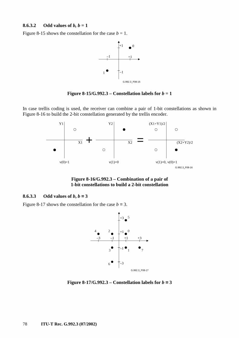
78 ITU-T Rec. G.992.3 (07/2002)
8.6.3.2 Odd values of b, b = 1
Figure 8-15 shows the constellation for the case b = 1.
G.992.3_F08-15
0
1 –1
–1
+1
+1
Figure 8-15/G.992.3 – Constellation labels for b = 1
In case trellis coding is used, the receiver can combine a pair of 1-bit constellations as shown in Figure 8-16 to build the 2-bit constellation generated by the trellis encoder.
G.992.3_F08-16
X1
Y1
X2
Y2
(X2+Y2)/2
(X1+Y1)/2
v(0)=1 v(1)=0 v(1)=0, v(0)=1
Figure 8-16/G.992.3 – Combination of a pair of 1-bit constellations to build a 2-bit constellation
8.6.3.3 Odd values of b, b ==== 3
Figure 8-17 shows the constellation for the case b = 3.
G.992.3_F08-17
5
0
1 7
24
3
6
+3
+1
+1 +3
–1
–3
–1–3
Figure 8-17/G.992.3 – Constellation labels for b ==== 3
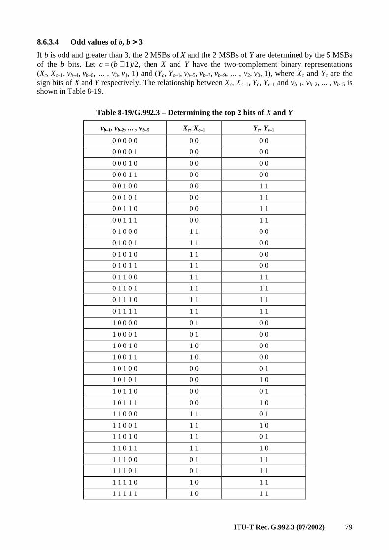
ITU-T Rec. G.992.3 (07/2002) 79
8.6.3.4 Odd values of b, b >>>> 3
If b is odd and greater than 3, the 2 MSBs of X and the 2 MSBs of Y are determined by the 5 MSBs of the b bits. Let c = (b + 1)/2, then X and Y have the two-complement binary representations (Xc, Xc–1, vb–4, vb–6, ... , v3, v1, 1) and (Yc, Yc–1, vb–5, vb–7, vb–9, ... , v2, v0, 1), where Xc and Yc are the sign bits of X and Y respectively. The relationship between Xc, Xc–1, Yc, Yc–1 and vb–1, vb–2, ... , vb–5 is shown in Table 8-19.
Table 8-19/G.992.3 – Determining the top 2 bits of X and Y
vb–1, vb–2, ... , vb–5 Xc, Xc–1 Yc, Yc–1
0 0 0 0 0 0 0 0 0
0 0 0 0 1 0 0 0 0
0 0 0 1 0 0 0 0 0
0 0 0 1 1 0 0 0 0
0 0 1 0 0 0 0 1 1
0 0 1 0 1 0 0 1 1
0 0 1 1 0 0 0 1 1
0 0 1 1 1 0 0 1 1
0 1 0 0 0 1 1 0 0
0 1 0 0 1 1 1 0 0
0 1 0 1 0 1 1 0 0
0 1 0 1 1 1 1 0 0
0 1 1 0 0 1 1 1 1
0 1 1 0 1 1 1 1 1
0 1 1 1 0 1 1 1 1
0 1 1 1 1 1 1 1 1
1 0 0 0 0 0 1 0 0
1 0 0 0 1 0 1 0 0
1 0 0 1 0 1 0 0 0
1 0 0 1 1 1 0 0 0
1 0 1 0 0 0 0 0 1
1 0 1 0 1 0 0 1 0
1 0 1 1 0 0 0 0 1
1 0 1 1 1 0 0 1 0
1 1 0 0 0 1 1 0 1
1 1 0 0 1 1 1 1 0
1 1 0 1 0 1 1 0 1
1 1 0 1 1 1 1 1 0
1 1 1 0 0 0 1 1 1
1 1 1 0 1 0 1 1 1
1 1 1 1 0 1 0 1 1
1 1 1 1 1 1 0 1 1
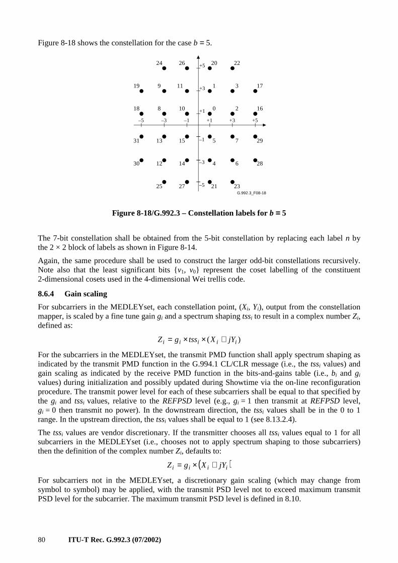
80 ITU-T Rec. G.992.3 (07/2002)
Figure 8-18 shows the constellation for the case b = 5.
G.992.3_F08-18
1 3
0 2
5 7
4 6
10
11
8
9
1513
12 14
–3 –1 +1 +3
+3
+1
–1
–3
+5–5
+5
–5
20 22
17
16
29
28
21 23
2624
19
18
31
30
25 27
Figure 8-18/G.992.3 – Constellation labels for b ==== 5
The 7-bit constellation shall be obtained from the 5-bit constellation by replacing each label n by the 2 × 2 block of labels as shown in Figure 8-14.
Again, the same procedure shall be used to construct the larger odd-bit constellations recursively. Note also that the least significant bits v1, v0 represent the coset labelling of the constituent 2-dimensional cosets used in the 4-dimensional Wei trellis code.
8.6.4 Gain scaling
For subcarriers in the MEDLEYset, each constellation point, (Xi, Yi), output from the constellation mapper, is scaled by a fine tune gain gi and a spectrum shaping tssi to result in a complex number Zi, defined as:
)( iiiii jYXtssgZ +××=
For the subcarriers in the MEDLEYset, the transmit PMD function shall apply spectrum shaping as indicated by the transmit PMD function in the G.994.1 CL/CLR message (i.e., the tssi values) and gain scaling as indicated by the receive PMD function in the bits-and-gains table (i.e., bi and gi values) during initialization and possibly updated during Showtime via the on-line reconfiguration procedure. The transmit power level for each of these subcarriers shall be equal to that specified by the gi and tssi values, relative to the REFPSD level (e.g., gi = 1 then transmit at REFPSD level, gi = 0 then transmit no power). In the downstream direction, the tssi values shall be in the 0 to 1 range. In the upstream direction, the tssi values shall be equal to 1 (see 8.13.2.4).
The tssi values are vendor discretionary. If the transmitter chooses all tssi values equal to 1 for all subcarriers in the MEDLEYset (i.e., chooses not to apply spectrum shaping to those subcarriers) then the definition of the complex number Zi, defaults to:
( )iiii jYXgZ +×=
For subcarriers not in the MEDLEYset, a discretionary gain scaling (which may change from symbol to symbol) may be applied, with the transmit PSD level not to exceed maximum transmit PSD level for the subcarrier. The maximum transmit PSD level is defined in 8.10.
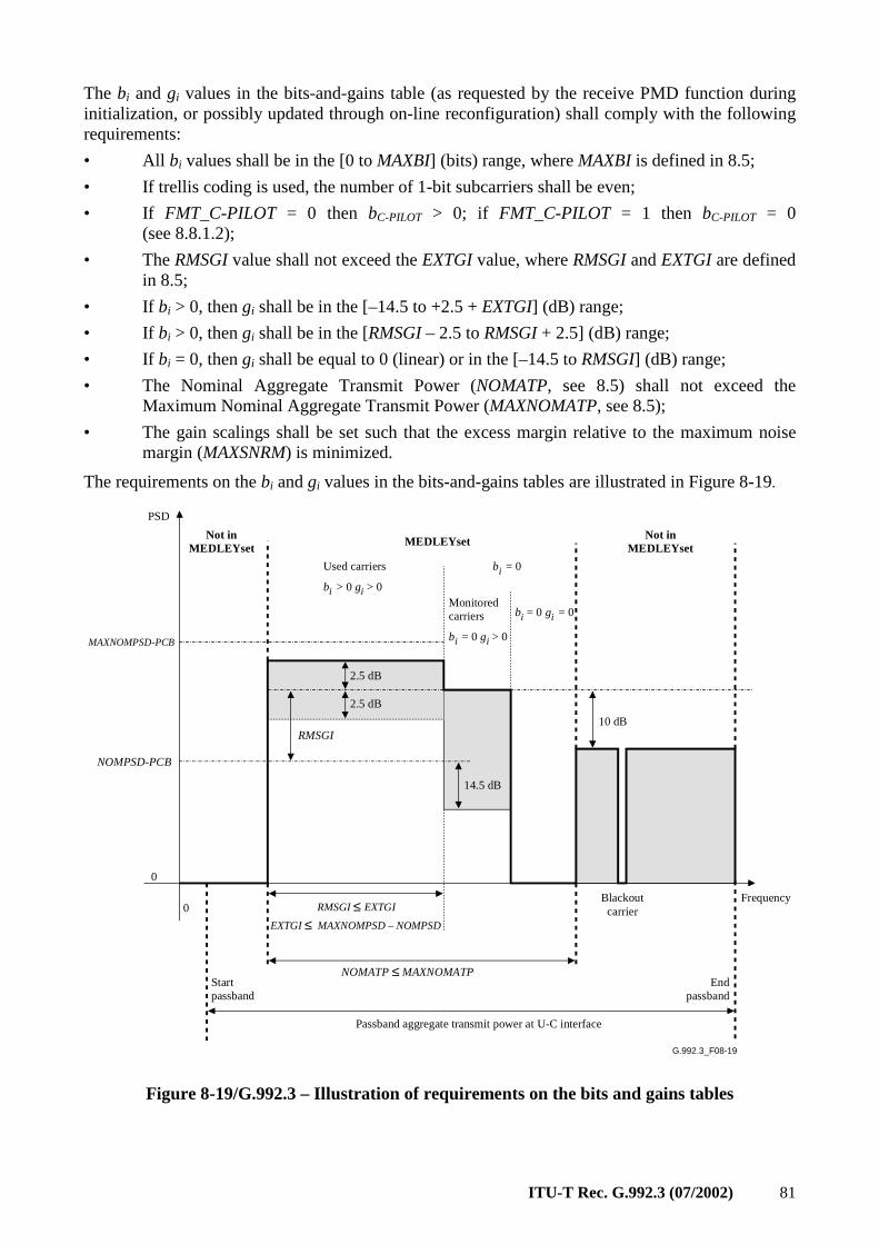
ITU-T Rec. G.992.3 (07/2002) 81
The bi and gi values in the bits-and-gains table (as requested by the receive PMD function during initialization, or possibly updated through on-line reconfiguration) shall comply with the following requirements:
• All bi values shall be in the [0 to MAXBI] (bits) range, where MAXBI is defined in 8.5;
• If trellis coding is used, the number of 1-bit subcarriers shall be even;
• If FMT_C-PILOT = 0 then bC-PILOT > 0; if FMT_C-PILOT = 1 then bC-PILOT = 0 (see 8.8.1.2);
• The RMSGI value shall not exceed the EXTGI value, where RMSGI and EXTGI are defined in 8.5;
• If bi > 0, then gi shall be in the [–14.5 to +2.5 + EXTGI] (dB) range;
• If bi > 0, then gi shall be in the [RMSGI – 2.5 to RMSGI + 2.5] (dB) range;
• If bi = 0, then gi shall be equal to 0 (linear) or in the [–14.5 to RMSGI] (dB) range;
• The Nominal Aggregate Transmit Power (NOMATP, see 8.5) shall not exceed the Maximum Nominal Aggregate Transmit Power (MAXNOMATP, see 8.5);
• The gain scalings shall be set such that the excess margin relative to the maximum noise margin (MAXSNRM) is minimized.
The requirements on the bi and gi values in the bits-and-gains tables are illustrated in Figure 8-19.
G.992.3_F08-19
0Frequency
NOMPSD-PCB
RMSGI
2.5 dB
2.5 dB
Used carriers
bi > 0 gi > 0Monitored carriers
bi = 0 gi > 0
bi = 0 gi = 0
MEDLEYset
NOMATP ≤ MAXNOMATP
14.5 dB
bi = 0
Not inMEDLEYset
0
10 dB
BlackoutcarrierRMSGI ≤ EXTGI
EXTGI ≤ MAXNOMPSD – NOMPSD
Passband aggregate transmit power at U-C interface
Not inMEDLEYset
PSD
Startpassband
Endpassband
MAXNOMPSD-PCB
Figure 8-19/G.992.3 – Illustration of requirements on the bits and gains tables
82 ITU-T Rec. G.992.3 (07/2002)
The receive PMD function should not use an excessive number of monitored subcarriers (i.e., subcarriers in the MEDLEYset to which it allocates bi = 0 and gi > 0) to aid in the conservation of spectrum.
These requirements on the bits and gains table apply in the L0 state and at entry into the L2 state. The L2 entry grant response message indicates the gains table to be used in the L2 state (see 9.4.1.7). However, at entry into the L2 state, the excess margin may not be minimized. Power trimming during the L2 state may be used to minimize the excess margin. The L2 entry and trim grant response messages indicate the PCB value to be used in the L2 state (see 9.4.1.7). Power trimming is defined as changing the downstream power cutback (PCBds) level, resulting in a change of the downstream reference transmit PSD (REFPSDds) level. Power trimming changes the PCBds value used during the L2 state and does not change the gi values determined at the time of entry into the L2 state.
The gi values in dB shall be defined as the 20 log gi (gi in linear scale). A gi value of –14.5 dB corresponds to a gi of 0.1888 in linear scale. A gi value of +2.5 dB corresponds to a gi value of 1.333 in linear scale. Same relationship shall be used for the tssi values in dB and in linear scale.
NOTE – The gi define a scaling of the root mean square (rms) subcarrier power levels relative to the REFPSD level (see 8.13.5). They are independent of any methods that manufacturers may use to simplify implementation (e.g., constellation nesting).
8.7 Constellation encoder for synchronization and L2 exit symbols
The constellation encoder for the synchronization and L2 exit symbols is shown as part of the transmit PMD function in Figure 8-5. A synchronization or L2 exit symbol shall either be an SS-REVERB symbol or an SS-SEGUE symbol.
Clauses 8.7.1 and 8.7.2 shall define respectively the constellation mapper and gain scaling for an SS-REVERB symbol. An SS-SEGUE symbol shall be defined as a subcarrier-by-subcarrier 180 degrees phase reversal of an SS-REVERB symbol (i.e., an SS-SEGUE symbol modulates the bitwise inverted REVERB PRBS data pattern).
The transmit PMD function transports the following types of PMD.Synchflag.request primitives (as received from the transmit PMS-TC function) for synchronization of:
• On-line reconfiguration during the L0 state (see 8.7.3);
• Entry from the L0 into the L2 power management state (see 8.7.4);
• Exit from the L2 power management into the L0 state (see 8.7.6);
• Power trimming during the L2 state (see 8.7.5).
8.7.1 Constellation mapper
For the subcarriers in the MEDLEYset, the REVERB PRBS data pattern shall be mapped on the SS-REVERB symbols in the same way as it is mapped on the REVERB symbols during the REVERB1 state (see 8.13.4.1.1). Two bits are mapped on each of the subcarriers, generating a 4-QAM constellation point for each of the subcarriers, i.e., Xi and Yi for index i = 1 to NSC – 1.
The values of X and Y of the 4-QAM constellation points as shown in the constellation diagrams are on a ± 1 grid. These values require appropriate scaling such that, at the output of the constellation mapper, all constellations represent the same rms energy as a subcarrier transmitted at the reference transmit PSD level (REFPSD).
For the subcarriers not in the MEDLEYset, the constellation mapper may select a discretionary (X, Y) point (which may change from symbol to symbol and which does not necessarily coincide with a constellation point).
ITU-T Rec. G.992.3 (07/2002) 83
8.7.2 Gain scaling
In the L0 state, gain scaling shall be applied to synchronization symbols in the same way as it is applied to data symbols in the L0 state (see 8.6.4).
In the L2 state, gain scaling shall be applied to synchronization symbols in the same way as it is applied to data symbols in the L2 state (see 8.6.4).
In the L2 state, gain scaling shall be applied to L2 exit symbols, as indicated in the L2 entry or L2 90 trim grant response message related to the last previously transmitted PMD.Synchflag primitive (see 9.4.1.7). The L2 entry grant response message indicates whether the L0 or L2 state gain scaling table is to be used with the L2 exit symbols. The L2 entry and L2 trim grant response messages indicate the PCBds value to be used with the L2 exit symbols (see 9.4.1.7).
8.7.3 On-line reconfiguration during the L0 state
The PMD transmit function inserts a synchronization symbol every 68 data symbols, as defined in 8.4. The synchronization symbols shall be transmitted at symbolcount 68, and:
• permit the PMD receive function to recover the PMS-TC frame boundary after micro-interruptions that might otherwise force re-initialization;
• provide a time marker for the on-line reconfiguration during the L0 state.
Every time the transmit PMD function receives a PMD.Synchflag.request primitive (related to on-line reconfiguration during the L0 state) from the transmit PMS-TC layer, the phase of the first next inserted synchronization symbol shall be inverted, and remain inverted until the next PMD.Synchflag.request primitive is to be carried. At the start of Showtime, the first synchronization symbol transmitted shall be an SS-REVERB symbol.
8.7.4 Entry from the L0 into the L2 power management state
Every time the transmit PMD function receives a PMD.Synchflag.request primitive (related to entry from the L0 into the L2 power management state) from the transmit PMS-TC layer, the phase of the first next inserted synchronization symbol shall be inverted, and remain inverted until the next PMD.Synchflag.request primitive is to be carried.
Prior to entry from the L0 into the L2 power management state, the ATU shall store the downstream control parameters which need to be restored at exit from the L2 into the L0 power management state.
The receive PMD function can distinguish PMD.Synchflag primitives related to entry from the L0 into the L2 power management from those related to on-line reconfiguration and those related to L2 power trimming based on previously exchanged information between the management entities.
8.7.5 Power trimming during the L2 state
Every time the transmit PMD function receives a PMD.Synchflag.request primitive (related to power trimming during the L2 state) from the transmit PMS-TC layer, the phase of the first next inserted synchronization symbol shall be inverted, and remain inverted until the next PMD.Synchflag.request primitive is to be carried.
The receive PMD function can distinguish PMD.Synchflag primitives related to L2 power trimming from those related to L0 on-line reconfiguration and those related to entry from the L0 into the L2 power management based on previously exchanged information between the management entities.
84 ITU-T Rec. G.992.3 (07/2002)
8.7.6 Exit from the L2 power management into the L0 state
Every time the transmit PMD function receives a PMD.Synchflag.request primitive (related to entry from the L2 power management state into the L0 state) from the transmit PMS-TC layer, the next two symbols transmitted with symbol count in the 0 to 67 range shall be modulated as two L2 exit symbols. The first L2 exit symbol shall be an SS-REVERB symbol. The second L2 exit symbol shall be an SS-SEGUE symbol.
The SS-REVERB symbol may be transmitted at any symbolcount from 0 to 67. The PMD.Synchflag.request primitive may be adjacent to the synchronization symbol in the following cases:
• When the SS-REVERB symbol is transmitted at symbolcount 66, the SS-SEGUE symbol shall be transmitted at symbolcount 67. The synchronization symbol following SS-SEGUE symbol shall be transmitted with the gain scaling and power cutback values as applicable in the L0 power management state.
• When the SS-REVERB symbol is transmitted at symbolcount 67, the SS-SEGUE symbol shall be transmitted at symbolcount 0. The synchronization symbol in between the SS-REVERB and SS-SEGUE symbol shall be transmitted with the gain scaling and power cutback values as applicable in the L2 power management state.
• When the SS-REVERB symbol is transmitted at symbolcount 0, the SS-SEGUE symbol shall be transmitted at symbolcount 1. The synchronization symbol preceding the SS-REVERB symbol shall be transmitted with the gain scaling and power cutback values as applicable in the L2 power management state.
The SS-REVERB symbol may be the first symbol transmitted in the L2 state. Then, the number of data symbols transmitted in the L2 state is effectively 0.
The last data symbol before and the first data symbol after the two L2 exit symbols shall carry dataframes which are consecutive in time, as received from the PMS-TC layer, i.e., no data errors shall introduced at the PMS-TC layer by the transmission of the L2 exit symbols at the PMD layer.
8.8 Modulation
The modulator shall modulate a constellation encoder output data frame or sync frame (containing NSC – 1 complex values Zi, i = 1 to NSC – 1) into a DMT symbol. The data frame can be taken from the data symbol constellation encoder (68 per superframe) as defined in 8.6. The sync frame can be taken from the synchronization symbol constellation encoder (1 per superframe) as defined in 8.7. For (short) initialization and diagnostics mode signals, the frame is defined in 8.13, 8.14 and 8.15.
8.8.1 Subcarriers
A DMT symbol consists of a set of subcarriers, with index i = 0 to NSC. The DMT subcarriers spacing ∆f, shall be 4.3125 kHz, with a tolerance of ± 50 ppm. The subcarrier frequencies shall be fi = i × ∆f , i = 0 to NSC.
8.8.1.1 Data subcarriers
The channel analysis (see 8.13.5) allows for a maximum of (NSC – 1) data carriers to be used (i.e., i = 1 to NSC – 1). The lower limit of usable i depends on both the duplexing and service options selected. For example, for ADSL above POTS service option as defined in Annex A, if overlapped spectrum is used to separate downstream and upstream signals, then the lower downstream limit on i is determined by the POTS splitting filters; if non-overlapped spectrum with frequency-division multiplexing (FDM) is used, the downstream lower limit on i is set by the downstream-upstream separation filters.
ITU-T Rec. G.992.3 (07/2002) 85
In all cases, the cut-off frequencies of these filters are completely at the discretion of the manufacturer, and the range of usable i is determined during the channel estimation in transceiver training (see 8.13.4). Implementations should, however, be designed such that, when interworking with implementations of other manufacturers, the resulting range of usable i allows to meet the performance requirements.
8.8.1.2 Pilot (only applies for downstream direction)
During initialization, the ATU-R receive PMD function selects the subcarrier index of the downstream pilot tone (see 8.13.3.2.11). The downstream pilot tone shall be at subcarrier with index C-PILOT (transmitted at 4.3125 × C-PILOT kHz).
If the ATU-R has set the FMT_C-PILOT bit to 0 in the R-MSG-FMT initialization message (see 8.13.3.2.10), then:
• During initialization, the pilot tone shall be transmitted as defined for each of the ATU-C initialization states in 8.13;
• During showtime (data and sync symbols), the pilot tone shall be modulated with data bits (i.e., bC-PILOT > 0). The pilot subcarrier shall be transmitted as defined for data subcarriers.
If the ATU-R has set the FMT_C-PILOT bit to 1 in the R-MSG-FMT initialization message (see 8.13.3.2.10), then:
• During initialization, the pilot tone defined in 8.13, shall be overwritten with a fixed 0,0 4-QAM constellation point, in all the ATU-C initialization states following the C-TREF1 state, except the C-ECT and C-QUIET states. The pilot tone shall be transmitted at the ATU-C reference transmit PSD level (REFPSDds), including spectral shaping for that subcarrier;
• During showtime (data and sync symbols), the pilot subcarrier shall not be modulated with data bits (i.e., bC-PILOT = 0). The pilot subcarrier defined in 8.6 and 8.7, shall be overwritten with a fixed 0,0 4-QAM constellation point. The pilot tone shall be transmitted at a transmit PSD level as defined for unused subcarriers, i.e., at the REFPSDds transmit PSD level, with gain scaling according to the gC-PILOT value.
Use of the pilot tone allows resolution of receive PMD function sample timing modulo (2 × NSC/C-PILOT) samples. Therefore a gross timing error that is an integer multiple of this number of samples could still persist after a micro-interruption (e.g., a temporary short-circuit, open circuit or severe line hit); correction of such timing errors is made possible by the use of the synchronization symbol defined in 8.7.
8.8.1.3 Sampling frequency
The sampling frequency fs shall be defined as 2 × NSC × ∆f.
8.8.1.4 Nyquist frequency
The Nyquist frequency shall be defined as half of the sampling frequency fs. The subcarrier at the Nyquist frequency (subcarrier index NSC) shall not be used to transmit the data frame and shall be real valued (i.e., ZNSC shall be a real value).
If the transmit PMD function uses an oversampled IFFT with zero fill (see 8.8.2), then during the Initialization Transceiver Training Phase, the ZNSC value shall be as defined by the Initialization Symbols Encoder (see Figure 8-5 and § 8.13.4); other possible uses are for further study.
8.8.1.5 DC
The subcarrier at DC (subcarrier index 0) shall not be used, and shall contain no energy (i.e., Z0 = 0).
86 ITU-T Rec. G.992.3 (07/2002)
8.8.2 Inverse Discrete Fourier Transform (IDFT)
The IDFT is used to modulate a constellation encoder output data frame onto the DMT subcarriers. It converts from frequency domain representation (complex values Zi, i = 1 to NSC – 1) to time domain representation (real values xn, n = 0 to 2N – 1). The conversion shall be performed with a 2N point IDFT, with N ≥ NSC, as:
12 to0for 2
2exp12
0
−=⋅
⋅⋅⋅π⋅⋅= ∑
−
=NnZ
N
injx i
N
in
In order to generate real values of xn, the input values (Zi, i = 0 to N) shall be augmented so that the vector Z has Hermitian symmetry. That is:
12 to1for )( conj 2 −+== − NNiZZ iNi
The modulation onto DMT subcarriers may be implemented using an oversampled IDFT, i.e., an 2N-point IDFT with N>NSC points, generating 2N xn values per DMT symbol. The constellation encoder generates only NSC – 1 complex values of Zi (for i = 1 to NSC – 1), with addition of a zero Z0 at DC and a real value ZNSC at the Nyquist frequency. The additional Zi values (for i = NSC + 1 to N) are discretionary. However, different values result in different transmit signal images above the Nyquist frequency. Knowledge of how the transmit PMD function defines the additional Zi values allows the receive PMD function to better estimate the channel during transceiver training in initialization. Therefore, the transmit PMD function shall indicate during the G.994.1 phase of initialization how many independent Zi values are input into the IDFT (i.e., the N value) and how the additional Zi values (for i = NSC + 1 to N – 1) are defined. The following representation shall be used to define the additional Zi values (for i = NSC + 1 to N – 1) (see 8.13.2):
• 4-bit indication of N value:
– Values 1 to 15 indicate the N value as 21 to 215 respectively;
– Value 0 indicates the N value is not a power of 2;
• 2-bit indication of additional Zi values definition:
– As the complex conjugate of the baseband signal, defined as:
Zi = conj (Z2×NSC–i) for all i with NSC + 1 ≤ i ≤ 2 × NSC – 1;
Zi = Zi MOD 2×NSC for all i ≥ 2 × NSC;
– As zero fill, defined as (see Figure 8-5 and § 8.13.4):
During the Initialization Transceiver Training Phase:
Zi as generated by the Initialization Symbols Encoder for all NSC + 1 ≤ i ≤ 2 × NSC – 1;
Zi = 0 for all i ≥ 2 × NSC;
Outside the Initialization Transceiver Training Phase:
Zi = 0 for all i ≥ NSC + 1;
Other (none of the above).
The indication given in the G.994.1 codepoint shall apply to all initialization signals (except those during the G.994.1 phase), thus including REVERB and MEDLEY signals, as well as the SHOWTIME signal.
If a non-oversampled IDFT is used, the transmit PMD function shall indicate that N = NSC and that the transmit signal images above the Nyquist frequency are the complex conjugate of the baseband signal.
ITU-T Rec. G.992.3 (07/2002) 87
8.8.3 Cyclic prefix
With a data symbol rate of 4 kHz, a DMT subcarriers spacing of ∆f = 4.3125 kHz and an IDFT size of 2 × NSC, a cyclic prefix of (2 × NSC × 5/64) samples could be used. That is,
(2 × NSC + 2 × NSC × 5/64) × 4.0 kHz = (2 × NSC) × 4.3125 kHz = fs (the sample frequency)
The cyclic prefix shall, however, be shortened to (2 × NSC × 4/64 = NSC/8) samples, and a synchronization symbol (with a length of 2 × NSC × 68/64 samples) is inserted after every 68 data symbols. That is,
(2 × NSC × 4/64 + 2 × NSC) × 69 = (2 × NSC × 5/64 + 2 × NSC) × 68
For symbols with cyclic prefix, the last NSC/8 samples of output of the IDFT (xn for n = 2 × NSC – NSC/8 to 2 × NSC – 1) shall be prepended to the block of 2 × NSC samples, to form a block of (2 × NSC × 17/16) samples. Symbols with cyclic prefix are transmitted at a symbol rate of 4.3125 × 16/17 ≈ 4.059 kHz.
The cyclic prefix shall be used for all symbols transmitted starting from the Channel Analysis Phase of the initialization sequence (see 8.1.3.5). Before the Channel Analysis Phase, all symbols shall be transmitted without cyclic prefix. Symbols transmitted without cyclic prefix are transmitted at a symbol rate of 4.3125 kHz.
If an oversampled IDFT is used (i.e., N > NSC, see 8.8.2), the number of Cyclic prefix samples shall be adapted accordingly. For symbols with cyclic prefix, the last N/8 samples of output of the IDFT (xn for n = 2 × N – N/8 to 2 × N – 1) shall be prepended to the block of 2 × N samples, to form a block of (2 × N × 17/16) samples.
8.8.4 Parallel/serial convertor
The block of xn samples (n = 0 to 2 × NSC – 1) shall be readout to the digital-to-analog convertor (DAC) in sequence.
If no cyclic prefix is used, the DAC samples yn in sequence are:
yn = xn for n = 0 to 2 × NSC – 1
If a cyclic prefix is used, the DAC samples yn in sequence are (see Figure 8-5):
yn = xn + (2 × NSC – NSC/8) for n = 0 to NSC/8 – 1
yn = xn – (NSC/8) for n = NSC/8 to (17/16) × 2 × NSC – 1
Filtering may be applied to the sample sequence going into the DAC.
8.8.5 DAC and AFE
The DAC produces an analogue signal that is passed through the analog front-end (AFE) and transmitted across the digital subscriber line (DSL).
If the transmit PMD function is configured in the L3 idle state, then a zero output voltage shall be transmitted at the U-C2 (for ATU-C) and the U-R2 (for ATU-R) reference point (see reference model in 5.4). The analog front end may include filtering.
8.9 Transmitter dynamic range
The transmitter includes all analogue transmitter functions: the DAC, the anti-aliasing filter, the hybrid circuitry, and the high-pass part of the POTS or ISDN splitter. The transmitted signal shall conform to the frequency requirements as described in 8.8.1 for frequency spacing.
8.9.1 Maximum clipping rate
The maximum output signal of the transmitter shall be such that the signal shall be clipped no more than 0.00001% of the time. The clipping requirement is specified as a percentage of time, measured
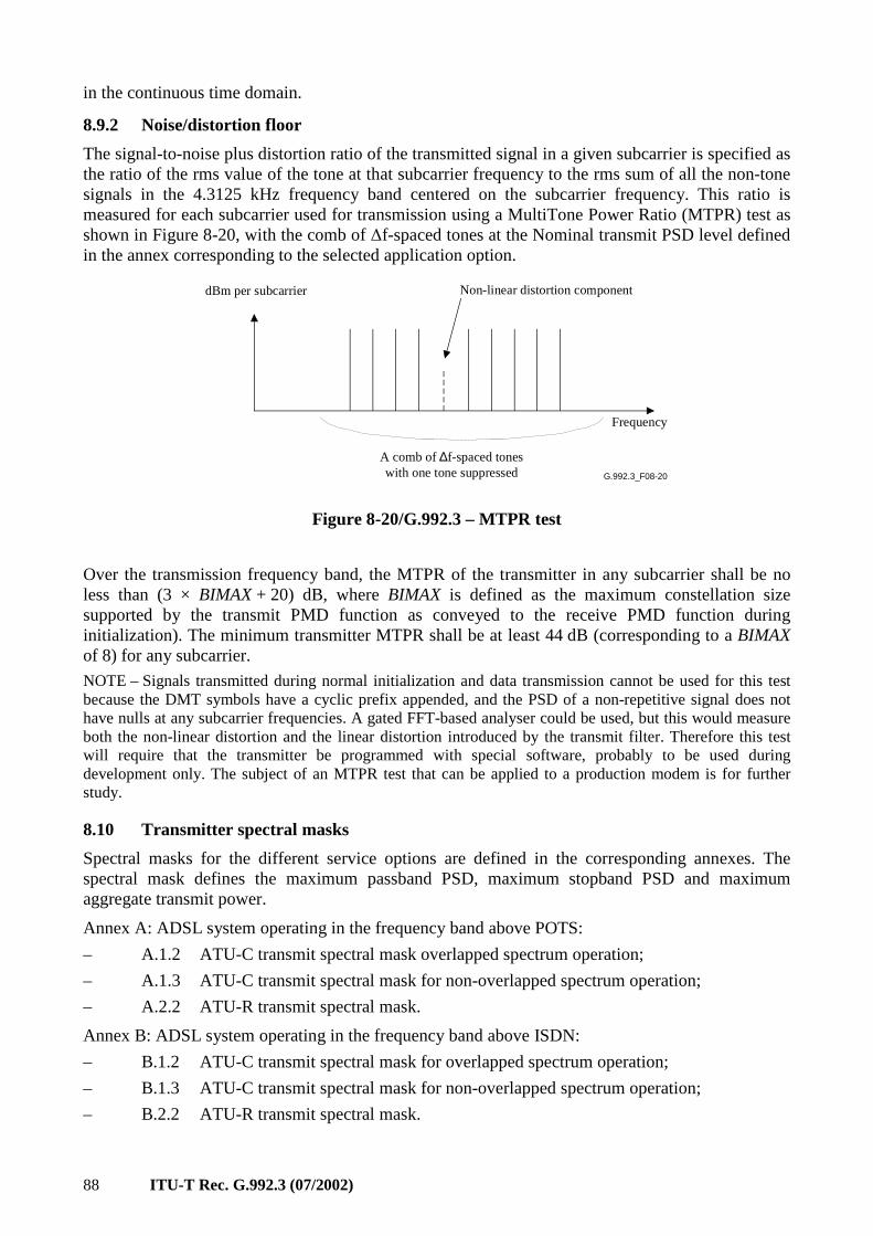
88 ITU-T Rec. G.992.3 (07/2002)
in the continuous time domain.
8.9.2 Noise/distortion floor
The signal-to-noise plus distortion ratio of the transmitted signal in a given subcarrier is specified as the ratio of the rms value of the tone at that subcarrier frequency to the rms sum of all the non-tone signals in the 4.3125 kHz frequency band centered on the subcarrier frequency. This ratio is measured for each subcarrier used for transmission using a MultiTone Power Ratio (MTPR) test as shown in Figure 8-20, with the comb of ∆f-spaced tones at the Nominal transmit PSD level defined in the annex corresponding to the selected application option.
G.992.3_F08-20
dBm per subcarrier Non-linear distortion component
Frequency
A comb of ∆f-spaced toneswith one tone suppressed
Figure 8-20/G.992.3 – MTPR test
Over the transmission frequency band, the MTPR of the transmitter in any subcarrier shall be no less than (3 × BIMAX + 20) dB, where BIMAX is defined as the maximum constellation size supported by the transmit PMD function as conveyed to the receive PMD function during initialization). The minimum transmitter MTPR shall be at least 44 dB (corresponding to a BIMAX of 8) for any subcarrier.
NOTE – Signals transmitted during normal initialization and data transmission cannot be used for this test because the DMT symbols have a cyclic prefix appended, and the PSD of a non-repetitive signal does not have nulls at any subcarrier frequencies. A gated FFT-based analyser could be used, but this would measure both the non-linear distortion and the linear distortion introduced by the transmit filter. Therefore this test will require that the transmitter be programmed with special software, probably to be used during development only. The subject of an MTPR test that can be applied to a production modem is for further study.
8.10 Transmitter spectral masks
Spectral masks for the different service options are defined in the corresponding annexes. The spectral mask defines the maximum passband PSD, maximum stopband PSD and maximum aggregate transmit power.
Annex A: ADSL system operating in the frequency band above POTS:
– A.1.2 ATU-C transmit spectral mask overlapped spectrum operation;
– A.1.3 ATU-C transmit spectral mask for non-overlapped spectrum operation;
– A.2.2 ATU-R transmit spectral mask.
Annex B: ADSL system operating in the frequency band above ISDN:
– B.1.2 ATU-C transmit spectral mask for overlapped spectrum operation;
– B.1.3 ATU-C transmit spectral mask for non-overlapped spectrum operation;
– B.2.2 ATU-R transmit spectral mask.
ITU-T Rec. G.992.3 (07/2002) 89
Annex I: All digital mode ADSL with improved spectral compatibility with ADSL over POTS:
– I.1.2 ATU-C transmit spectral mask overlapped spectrum operation;
– I.1.3 ATU-C transmit spectral mask for non-overlapped spectrum operation;
– I.2.2 ATU-R transmit spectral mask.
Annex J: All digital mode ADSL with improved spectral compatibility with ADSL over ISDN:
– J.1.2 ATU-C transmit spectral mask for overlapped spectrum operation;
– J.1.3 ATU-C transmit spectral mask for non-overlapped spectrum operation;
– J.2.2 ATU-R transmit spectral mask.
In addition to the maximum PSD and maximum aggregate transmit power over the whole passband (defined in the corresponding annexes), the following requirements on fine tuning of passband PSD and aggregate transmit power shall apply during showtime (data symbols and sync symbols). Three subcarrier sets are defined:
a) For the subcarriers in the MEDLEYset with bi > 0 (i.e., the used subcarriers), the ATU shall transmit at PSD levels as defined by the gain scaling (see 8.6.4. and 8.7.2). Gain scaling is performed relative to the REFPSD level. The aggregate transmit power on this set of subcarriers shall not exceed the aggregate power transmitted on the same set of subcarriers during MEDLEY by more than RMSGI dB (see gain scaling requirements in 8.6.4).
b) For the subcarriers in the MEDLEYset with bi = 0, the ATU shall transmit at PSD levels as defined by the gain scaling (see 8.6.4 and 8.7.2). Gain scaling is performed relative to the REFPSD level. The aggregate transmit power on this set of subcarriers shall not exceed the aggregate power transmitted on the same set of subcarriers during MEDLEY by more than RMSGI dB (see gain scaling requirements in 8.6.4).
c) For the subcarriers not in the MEDLEYset, the ATU shall transmit no power on the subcarrier (i.e., Zi = 0, see 8.8.2) if the subcarrier is below the first used subcarrier index or if the subcarrier is in the SUPPORTEDset and in the BLACKOUTset. Otherwise, the ATU may transmit at a discretionary transmit PSD level on the subcarrier (which may change from symbol to symbol), not to exceed the maximum transmit PSD level for these subcarriers. The maximum transmit PSD level for each of these subcarriers shall be defined as 10 dB below the reference transmit PSD level, fine tuned by the tssi values (as applied during Transceiver Training on the subcarriers included in the SUPPORTEDset and on the subcarriers not included in the SUPPORTEDset) and fine tuned by the RMSGI dB (see 8.5) and limited to the transmit spectral mask.
During initialization, discretionary transmit PSD levels are allowed only when explicitly stated in 8.13.
8.11 Control plane procedures
As a control plane element, there are no specific transport functions provided by the PMD function. However, the PMD function passes and receives control signals that are transported in the control plane to and from the far-end PMD using TPS-TC transport functions, as depicted in Figure 8-2; e.g., for on-line reconfiguration as described in 8.16 or power management transitions as described in 8.17.
8.12 Management plane procedures
The PMD receive function provides management primitive indications to the near-end management entity within the ATU. These management primitive indications result in control signals that are transported in the control plane using TPS-TC transport functions, as depicted in Figure 8-3, and as specified in the Management Entity in clause 9.
90 ITU-T Rec. G.992.3 (07/2002)
8.12.1 ADSL line related primitives
The receive PMD function has five near-end ADSL Line related defects defined. These near-end defects shall be passed to the near-end management entity using the Management.Prim.indicate primitive.
Loss-of-signal (LOS) defect: A reference power is established by averaging the ADSL power over a 0.1 s period and over a subset of subcarriers after the start of steady state data transmission (i.e., after each transition to the L0 or L2 power management state), and a threshold shall be set at 6 dB below this. A LOS defect occurs when the level of the received ADSL power, averaged over a 0.1 s period and over the same subset of subcarriers, is lower than the threshold, and terminates when measured in the same way it is at or above the threshold. The subset of subcarriers, over which the ADSL power is averaged, is implementation discretionary and may be restricted at the ATU-R to only the downstream pilot tone.
Severely errored frame (SEF) defect: An SEF defect occurs when the content of two consecutively received ADSL synchronization symbols does not correlate with the expected content over a subset of the subcarriers. An SEF defect terminates when the content of two consecutively received ADSL synchronization symbols correlates with the expected content over the same subset of the subcarriers. The correlation method, the selected subset of subcarriers, and the threshold for declaring these defect conditions are implementation discretionary.
Loss-of-margin (LOM) defect: An LOM defect occurs when the signal-to-noise ratio margin (SNRM, see 8.12.3.6) observed by the near-end receiver is below the minimum signal-to-noise ratio margin (MINSNRM, see 8.5) and an increase of signal-to-noise ratio margin is no longer possible within the far-end maximum nominal aggregate transmit power (MAXNOMATP, see 8.5) and maximum nominal transmit PSD level (MAXNOMPSD, see 8.5). An LOM defect terminates when the signal-to-noise ratio margin is above the minimum signal-to-noise ratio noise margin.
Rate Adaptation Upshift (RAU) anomaly: An RAU anomaly occurs in Seamless Rate Adaptation mode when the signal-to-noise ratio margin (SNRM) observed by the near-end receiver is above the Rate Upshift Margin for a period longer than the Time Interval for UpShift Rate Adaptation. An RAU anomaly terminates when the RAU anomaly occurrence condition terminates.
Rate Adaptation Downshift (RAD) anomaly: An RAD anomaly occurs in Seamless Rate Adaptation mode when the signal-to-noise ratio margin (SNRM) observed by the near-end receiver is below the Rate Upshift Margin for a period longer than the Time Interval for DownShift Rate Adaptation. An RAD anomaly terminates when the RAD anomaly occurrence condition terminates.
The transmit PMD function has two far-end ADSL Line related defects defined as:
Far-end Loss-of-Signal (LOS-FE): A far-end LOS defect is a LOS defect detected at the far-end and reported by the LOS indicator bit once per 15 to 20 ms (see Tables 7-8 and 7-15). The LOS indicator bit shall be coded 1 to indicate that no LOS defect is being reported and shall be coded 0 for the next 6 LOS indicator bit transmissions to indicate that a LOS defect is being reported. A far-end LOS defect occurs when 4 or more out of 6 consecutively received LOS indicator bit values are set to 0. A far-end LOS defect terminates when 4 or more out of 6 consecutively received LOS indicator bit values are set to 1.
Remote Defect Indication (RDI): An RDI defect is an SEF defect detected at the far-end and is reported by the RDI indicator bit once per 15 to 20 ms (see Tables 7-8 and 7-15). The RDI indicator bit shall be coded 1 to indicate that no SEF defect has occurred and shall be coded 0 to indicate that an SEF defect has occurred since the last previous RDI indicator bit transmission. An RDI defect occurs when a received RDI indicator bit is set to 0. An RDI defect terminates when a received RDI indicator bit is set to 1.
Far-end Loss-of-margin (LOM-FE) defect: A far-end LOM defect occurs when the signal-to-noise ratio margin (SNRM, see 8.12.3.6) at the far-end receiver, retrieved through test
ITU-T Rec. G.992.3 (07/2002) 91
parameter overhead messages by the near-end transmitter (see 9.4.1.10), is below the minimum signal-to-noise ratio margin (MINSNRM, see 8.5) and an increase of signal-to-noise ratio margin is no longer possible within the near-end maximum nominal aggregate transmit power (MAXNOMATP, see 8.5) and maximum nominal transmit PSD level (MAXNOMPSD, see 8.5). An LOM defect terminates when the signal-to-noise ratio margin is above the minimum signal-to-noise ratio noise margin.
NOTE – In case the near-end transmitter uses the far-end LOM defect to declare a high_BER event (see Annex D), a sufficient number of updates of the far-end SNRM need to be retrieved to determine the far-end LOM defect persistency (see Update Test Parameters command in 9.4.1.2.2).
8.12.2 Other primitives
One other near-end primitive is defined for the ATU-R. At the ATU-R, the LPR primitive shall be passed to the near-end management entity using the Management.Prim.indicate primitive e.g., when the electrical power has been shut off.
Loss-of-power (LPR): An LPR primitive occurs when the ATU electrical supply (mains) power drops to a level equal to or below the manufacturer-determined minimum power level required to ensure proper operation of the ATU. An LPR primitive terminates when the power level exceeds the manufacturer determined minimum power level.
One other far-end primitive is defined for the ATU-C.
Far-end Loss-of-power (LPR-FE): A far-end LPR primitive is an LPR primitive detected at the far-end and is reported by the LPR indicator bit. The LPR indicator bit shall be coded 1 to indicate that no LPR primitive is being reported and shall be coded 0 for the next 3 LPR indicator bit transmissions to indicate that an LPR primitive (i.e., "dying gasp") is being reported. A far-end LPR primitive occurs when 2 or more out of 3 consecutively received LPR indicator bit values are set to 0. A far-end LPR primitive terminates when for a period of 0.5 s the received LPR indicator bit is set to 1 and no near-end LOS defect is present.
8.12.3 Test parameters
The test parameters are measured by the PMD transmit or receive function and shall be reported on request to the near-end management entity using the Management.Defect.indicate primitive. Test parameters allow to debug possible issues with the physical loop and to check for adequate physical media performance margin at acceptance and after repair verification, or at any other time following the execution of initialization and training sequence of the ADSL system.
The following test parameters shall be passed on request from the receive PMD transmit function to the near-end management entity:
• Channel Characteristics Function H(f) per subcarrier (CCF-ps);
• Quiet Line Noise PSD QLN(f) per subcarrier (QLN-ps);
• Signal-to-Noise Ratio SNR(f) per subcarrier (SNR-ps);
• Line Attenuation (LATN);
• Signal Attenuation (SATN);
• Signal-to-Noise Margin (SNRM);
• Attainable Net Data Rate (ATTNDR);
• Far-end Actual Aggregate Transmit Power (ACTATP).
The following test parameters shall be passed on request from the transmit PMD transmit function to the near-end management entity:
• Near-End Actual Aggregate Transmit Power (ACTATP).
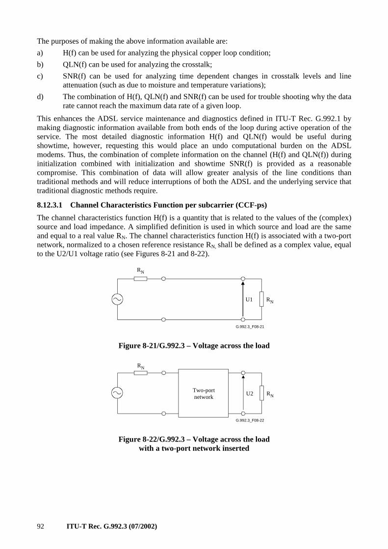
92 ITU-T Rec. G.992.3 (07/2002)
The purposes of making the above information available are:
a) H(f) can be used for analyzing the physical copper loop condition;
b) QLN(f) can be used for analyzing the crosstalk;
c) SNR(f) can be used for analyzing time dependent changes in crosstalk levels and line attenuation (such as due to moisture and temperature variations);
d) The combination of H(f), QLN(f) and SNR(f) can be used for trouble shooting why the data rate cannot reach the maximum data rate of a given loop.
This enhances the ADSL service maintenance and diagnostics defined in ITU-T Rec. G.992.1 by making diagnostic information available from both ends of the loop during active operation of the service. The most detailed diagnostic information H(f) and QLN(f) would be useful during showtime, however, requesting this would place an undo computational burden on the ADSL modems. Thus, the combination of complete information on the channel (H(f) and QLN(f)) during initialization combined with initialization and showtime SNR(f) is provided as a reasonable compromise. This combination of data will allow greater analysis of the line conditions than traditional methods and will reduce interruptions of both the ADSL and the underlying service that traditional diagnostic methods require.
8.12.3.1 Channel Characteristics Function per subcarrier (CCF-ps)
The channel characteristics function H(f) is a quantity that is related to the values of the (complex) source and load impedance. A simplified definition is used in which source and load are the same and equal to a real value RN. The channel characteristics function H(f) is associated with a two-port network, normalized to a chosen reference resistance RN, shall be defined as a complex value, equal to the U2/U1 voltage ratio (see Figures 8-21 and 8-22).
G.992.3_F08-21
U1 RN
RN
Figure 8-21/G.992.3 – Voltage across the load
G.992.3_F08-22
Two-portnetwork
U2 RN
RN
Figure 8-22/G.992.3 – Voltage across the load with a two-port network inserted
ITU-T Rec. G.992.3 (07/2002) 93
The channel characteristics function is the result of the cascade of three functions:
• the transmitter filter characteristics function;
• the channel characteristics function;
• the receiver filter characteristics function.
NOTE – The channel characteristics function corresponds with the Hchannel(f) function used in the definition of the far-end crosstalk (see 7.4.1/G.996.1).
The objective is to provide means by which the channel characteristics can be accurately identified. Therefore, it is necessary for the receive PMD function to report an estimate of the channel characteristics. This task may prove to be a difficult one given the fact that the receive PMD function only observes the cascade of all three elements of the channel. The passband part of the reported H(f), which is most essential to debug possible issues with the physical loop, is not expected to significantly depend upon the receiver filter characteristics (not including receiver AGC). The receive PMD function shall therefore undo the gain (AGC) it has applied to the received signal and do a best effort attempt to remove the impact of the near-end receiver filter characteristics. The result is then a best estimate of how the receiver views the passband channel characteristics plus the transmitter filter characteristics. Because the in-band portion of the spectrum is also expected not to significantly depend upon the transmitter filter characteristics, this result is considered a sufficient estimate of the channel characteristics for desired loop conditioning applications.
If the channel characteristics are reported to the CO-MIB, the ATU-C shall do a best effort attempt to remove the impact of the near-end transmit filter characteristics from the channel characteristics measured at the ATU-R. If the channel characteristics are reported to the RT-MIB, the ATU-R shall do a best effort attempt to remove the impact of the near-end transmit filter characteristics from the channel characteristics measured at the ATU-C.
Two formats for the channel characteristics are defined:
• Hlin(f): a format providing complex values in linear scale;
• Hlog(f): a format providing magnitude values in a logarithmic scale.
The Hlin(f) shall be measured by the receive PMD function during diagnostics mode in a REVERB transmitter state. The Hlin(f) shall be sent to the far-end management entity during diagnostics mode and shall be sent on request to the near-end Management Entity during diagnostics mode.
The Hlog(f) shall be measured by the receive PMD function during diagnostics mode and initialization. The measurement shall not be updated during showtime. The Hlog(f) shall be sent to the far-end management entity during diagnostics mode and shall be sent on request to the near-end Management Entity. The near-end Management Entity shall send the Hlog(f) to the far-end Management Entity on request during showtime (see 9.4.1.10).
In diagnostics mode, both Hlin(f) and Hlog(f) shall be measured, because there may be a difference in up to what extent the receiver and/or transmitter filter characteristics can be undone in Hlin(f) versus Hlog(f).
The PMD receive function shall measure Hlin(f) and Hlog(f) with the PMD transmit function in a REVERB state. The Hlin(f) and Hlog(f) shall be measured over a 1 second time period in diagnostics mode. The ATU shall do a best effort attempt to optimize Hlog(f) measurement time in initialization, however, measuring over at least 256 symbols, with indication of the measurement period to the far-end Management Entity (in symbols, represented as 16-bit unsigned value), see 9.4.1.10).
The channel characteristics function Hlin(i × ∆f), shall be represented in linear format by a scale factor and a normalized complex number a(i) + j × b(i), where i is the subcarrier index i = 0 to NSC – 1. The scale factor shall be coded as a 16-bit unsigned integer. Both a(i) and b(i) shall be
94 ITU-T Rec. G.992.3 (07/2002)
coded as a 16-bit 2's complement signed integer. The value of Hlin(i × ∆f) shall be defined as Hlin(i × ∆f) = (scale/215) × (a(i) + j × b(i))/215. In order to maximize precision, the scale factor shall be chosen such that max(|a(i)|, |b(i)|) over all i is equal to 215 – 1.
This data format supports an Hlin(f) granularity of 2–15 and an Hlin(f) dynamic range of approximately +6 dB to –90 dB. The portion of the scale factor range above 0 dB is necessary to accommodate that short loops, due to manufacturing variations in signal path gains and filter responses, may appear to have a gain rather than a loss.
An Hlin(i × ∆f) value indicated as a(i) = b(i) = –215 is a special value. It indicates that no measurement could be done for this subcarrier because it is out of the PSD mask passband (as relevant to the chosen application option – see annexes) or that the attenuation is out of range to be represented.
The channel characteristics function Hlog(f) shall be represented in logarithmic format by an integer number m(i), where i is the subcarrier index i = 0 to NSC – 1. The m(i) shall be coded as a 10-bit unsigned integer. The value of Hlog(i × ∆f) shall be defined as Hlog(i × ∆f) = 6 – (m(i)/10).
This data format supports an Hlog(f) granularity of 0.1 dB and an Hlog(f) dynamic range of approximately +6 dB to –96 dB.
An Hlog(i × ∆f) value indicated as m(i) = 210 – 1 is a special value. It indicates that no measurement could be done for this subcarrier because it is out of the PSD mask passband (as relevant to the chosen application option – see annexes) or that the attenuation is out of range to be represented.
8.12.3.2 Quiet Line Noise PSD per subcarrier (QLN-ps)
The quiet line noise PSD QLN(f) for a particular subcarrier is the rms level of the noise present on the line, when no ADSL signals are present on the line.
The quiet line PSD QLN(f) per subchannel shall be measured by the receive PMD function during diagnostics mode and initialization. The measurement shall not (i.e., cannot) be updated during showtime. The QLN(f) shall be sent to the far-end transmit PMD function during diagnostics mode (see 8.15.1) and shall be sent on request to the near-end Management Entity. The near-end Management Entity shall send the QLN(f) to the far-end Management Entity on request during showtime (see 9.4.1.10).
The objective is to provide means by which the quiet line PSD can be accurately identified. Therefore, it would be necessary for the receive PMD function to report an estimate of the quiet line PSD. This task may prove to be a difficult one given the fact that the receive PMD function observes the noise through the receiver filter. The passband part of the reported QLN-ps, which is most essential to debug possible issues with the physical loop, is not expected to significantly depend upon the receiver filter characteristics (not including receiver AGC). The receive PMD function shall therefore undo the gain (AGC) it has applied to the received signal and do a best effort attempt to remove the impact of the near-end receiver filter characteristics. The result is then a best estimate of how the receiver views the passband quiet line PSD. This result is considered a sufficient estimate of the quiet line PSD for desired loop conditioning applications.
The receive PMD function shall measure the QLN(f) in a time interval where no ADSL signals are present on the line (i.e., near-end and far-end transmitter inactive). The quiet line PSD QLN(i × ∆f) shall be measured over a 1 second time interval in diagnostics mode. In initialization, the ATU shall do a best effort attempt to optimize QLN(f) measurement time, however measuring over at least 256 symbols, with indication of the measurement period to the far-end Management Entity (in symbols, represented as 16-bit unsigned value, see 9.4.1.10).
The quiet line PSD QLN(i × ∆f) shall be represented as an 8-bit unsigned integer n(i), where i is the subcarrier index i = 0 to NSC – 1. The value of QLN(i × ∆f) shall be defined as QLN(i × ∆f) = –23 – (n(i)/2) dBm/Hz. This data format supports a QLN(f) granularity of 0.5 dB and an QLN(f)
ITU-T Rec. G.992.3 (07/2002) 95
dynamic range of –150 to –23 dBm/Hz.
An QLN(i × ∆f) value indicated as n(i) = 255 is a special value. It indicates that no measurement could be done for this subcarrier because it is out of the PSD mask passband (as relevant to the chosen application option – see annexes) or that the noise PSD is out of range to be represented.
8.12.3.3 Signal-to-Noise Ratio per subcarrier (SNR-ps)
The signal-to-noise ratio SNR(f) for a particular subcarrier is a real value which shall represent the ratio between the received signal power and the received noise power for that subcarrier.
The signal-to-noise ratio SNR(f) per subchannel shall be measured by the receive PMD function in diagnostics mode and initialization. The measurement may be updated autonomously and shall be updated on request during showtime. The SNR(f) shall be sent to the far-end transmit PMD function during diagnostics mode (see 8.15.1) and shall be sent on request to the near-end Management Entity. The near-end Management Entity shall send the SNR(f) to the far-end Management Entity on request during showtime (see 9.4.1.10).
The receive PMD function shall measure the signal-to-noise ratio SNR(f) with the transmit PMD function in a MEDLEY or showtime state. The signal-to-noise ratio SNR(f) shall be measured over a 1 second time interval in diagnostics mode. In initialization and showtime, the ATU shall do a best effort attempt to optimize SNR(f) measurement time, however measuring over at least 256 symbols, with indication of the measurement period to the far-end Management Entity (in symbols, represented as 16-bit unsigned value, see 9.4.1.10).
The signal-to-noise ratio SNR(i × ∆f) shall be represented as an 8-bit unsigned integer snr(i), where i is the subcarrier index i = 0 to NSC – 1. The value of SNR(i × ∆f) shall be defined as SNR(i × ∆f) = –32 + (snr(i)/2) dB. This data format supports an SNR(i × ∆f) granularity of 0.5 dB and an SNR(i × ∆f) dynamic range of –32 to 95 dB.
An SNR(i × ∆f) value indicated as snr(i) = 255 is a special value. It indicates that no measurement could be done for this subcarrier because it is out of the PSD mask passband (as relevant to the chosen application option – see Annexes) or that the signal-to-noise ratio is out of range to be represented.
8.12.3.4 Loop Attenuation (LATN)
The loop attenuation (LATN) is the difference in dB between the power received at the near-end and that transmitted from the far-end over all subcarriers, i.e., the channel characteristics function H(f) (as defined in 8.12.3.1) averaged over all subcarriers. LATN shall be defined as:
[ ]NSC
fiH
dBLATN
NSC
i∑
−
=∆×
×=
1
0
2)(
log10
with NSC the number of subcarriers (see 8.5) and H(f) represented by Hlin(f) in diagnostics mode and Hlog(f) in initialization (with conversion of log to linear values for use in the above equation).
If one or more H(f) values could not be measured because they are out of the PSD mask passband (as relevant to the chosen application option – see annexes) (see 8.12.3.1), then the LATN shall be calculated as an average of H(f) values over a number of subcarriers that is less than NSC.
The loop attenuation shall be calculated by the receive PMD function during diagnostics mode and initialization. The calculation shall not be updated during showtime. The loop attenuation shall be sent to the far-end transmit PMD function during initialization and diagnostics mode (see 8.15.1) and shall be sent on request to the near-end Management Entity. The near-end Management Entity shall send the LATN to the far-end Management Entity on request during showtime (see 9.4.1.10).
96 ITU-T Rec. G.992.3 (07/2002)
The loop attenuation LATN shall be represented as an 10-bit unsigned integer latn, with the value of LATN defined as LATN = latn/10 dB. This data format supports an LATN granularity of 0.1 dB and an LATN dynamic range of 0 to 102.2 dB.
An LATN value indicated as latn = 1023 is a special value. It indicates that the loop attenuation is out of range to be represented.
8.12.3.5 Signal Attenuation (SATN)
The signal attenuation SATN is defined as the difference in dB between the power received at the near-end and that transmitted from the far-end.
Received signal power in dBm shall be defined as the received subcarrier power, summed over the subcarriers in the MEDLEYset. During initialization and diagnostics mode, the transmit PSD for subcarriers in the MEDLEYset is at the REFPSD level. Therefore, the received signal power shall be finetuned with the gi values for each subcarrier in the MEDLEYset to estimate the signal power that will be received during showtime. During diagnostics mode, the fine tuning shall be restricted to using gi values 0 (for subcarriers to which no bits can be allocated) and 1 (for subcarrier to which at least one bit can be allocated).
Transmitted signal power shall be defined as the nominal aggregate transmit power (NOMATP), lowered by the power cutback (PCB, see 8.5). During diagnostics mode, only gi values 0 (for subcarriers to which no bits can be allocated) and 1 (for subcarrier to which at least one bit can be allocated) shall be used.
The signal attenuation shall be measured by the receive PMD function during diagnostics mode and initialization (i.e., estimate the signal attenuation at the start of showtime with the negociated control parameter settings). The measurement may be updated autonomously and shall be updated on request during showtime. The signal attenuation shall be sent to the far-end transmit PMD function during initialization and diagnostics mode (see 8.15.1) and shall be sent on request to the near-end Management Entity. The near-end Management Entity shall send the SATN to the far-end Management Entity on request during showtime (see 9.4.1.10).
The attenuation SATN shall be represented as a 10-bit unsigned integer satn, with the value of SATN defined as SATN = satn/10 dB. This data format supports an SATN granularity of 0.1 dB and an SATN dynamic range of 0 to 102.2 dB.
An SATN value indicated as satn = 1023 is a special value. It indicates that the signal attenuation is out of range to be represented.
8.12.3.6 Signal-to-Noise Ratio Margin (SNRM)
The signal-to-noise ratio margin is the maximum increase (in dB) of the received noise power, such that the ATU can still meet all the target BERs over all the frame bearers.
The signal-to-noise ratio margin shall be measured by the receive PMD function during initialization and diagnostics mode. The measurement may be updated autonomously and shall be updated on request during showtime. The signal-to-noise ratio margin shall be sent to the far-end transmit PMD function during initialization and diagnostics mode (see 8.15.1) and shall be sent on request to the near-end Management Entity. The near-end Management Entity shall send the SNRM to the far-end Management Entity on request during showtime (see 9.4.1.10).
To determine the signal-to-noise ratio margin (SNRM), the receive PMD function must be able to first determine the bits and gains table. During diagnostics mode, the receive PMD function may measure the SNRM value, or alternatively, may use the special value to indicate that the SNRM value was not measured.
The signal-to-noise ratio margin shall be represented as an 10-bit 2's complement signed integer snrm, with the value of SNRM defined as SNRM = snrm/10 dB. This data format supports an SNRM
ITU-T Rec. G.992.3 (07/2002) 97
granularity of 0.1 dB and an SNRM dynamic range of –51.1 to +51.1 dB.
An SNRM value indicated as snrm = –512 is a special value. It indicates that the signal-to-noise ratio margin is out of range to be represented. During diagnostics mode, the special value may also be used to indicate that the SNRM value was not measured.
8.12.3.7 Attainable net data rate (ATTNDR)
The attainable net data rate is the maximum net data rate that the receive PMS-TC and PMD functions are designed to support, under the following conditions:
• Single frame bearer and single latency operation;
• Signal-to-Noise Ratio Margin (SNRM) to equal or be above the SNR Target Margin;
• BER not to exceed the highest BER configured for one (or more) of the latency paths;
• Latency not to exceed the highest latency configured for one (or more) of the latency paths;
• Accounting for all coding gains available (e.g., trellis coding, RS FEC) within latency bound;
• Accounting for the loop characteristics at the instant of measurement.
To accurately determine the attainable net data rate (ATTNDR), the receive PMD function must be able to first determine the bits and gains table. Therefore, during diagnostics mode, the ATTNDR value shall be defined as an estimate of the line rate (without coding), calculated as:
[ ][ ] kbit/s4101log1
0
10/––)(2 ×
+= ∑
−
=
NSC
i
TARSNRMsnrgapiSNRATTNDR
with SNR(i × ∆f) in dB as defined in 8.12.3.3, snrgap = 9.75 dB (see Note). The function [x] is equal to 0 for x < 0, is equal to BIMAX for x > BIMAX and rounding to the nearest integer for 0 ≤ x ≤ BIMAX. The values of BIMAX and TARSNRM are defined in Table 8-48.
NOTE – The snrgap value is defined for a 10–7 bit error ratio on 4-QAM, in accordance with [B11].
The attainable net data rate shall be calculated by the receive PMS-TC and PMD functions during diagnostics mode and initialization. The measurement may be updated autonomously and shall be updated on request during showtime. The attainable net data rate shall be sent to the far-end transmit PMD function during initialization and diagnostics mode (see 8.15.1) and shall be sent on request to the near-end Management Entity. The near-end Management Entity shall send the ATTNDR to the far-end Management Entity on request during showtime (see 9.4.1.10).
The attainable net data rate shall be represented as a 32-bit unsigned integer attndr, with the value of ATTNDR defined as ATTNDR = attndr bit/second. This data format supports an ATTNDR granularity of 1 bit/s.
No special value is defined.
8.12.3.8 Actual Aggregate Transmit Power (ACTATP)
The actual aggregate transmit power (ACTATP) is the total amount of output power delivered by the transmit PMD function to the U reference point at tip-and-ring (in dB), at the instant of measurement. Therefore, it would be necessary for the transmit PMD function to take into account the transmit filter function. This task may prove to be a difficult task. Because the actual aggregate transmit power is expected not to significantly depend upon the transmit filter characteristics, the transmit PMD function shall take the nominal aggregate transmit power (NOMATP, see 8.5), lowered by the power cutback (PCB, see 8.5), as a best estimate of the near-end actual aggregate transmit power and do a best effort attempt to remove the impact of the near-end transmitter filter characteristics. The ACTATP should also include discretionary transmit power possibly applied during showtime to some subcarriers not in the MEDLEYset (see 8.10).
98 ITU-T Rec. G.992.3 (07/2002)
The receive PMD function is not aware of the far-end transmit filter characteristics, nor of the far-end discretionary power levels. Therefore, the receive PMD function shall take the nominal aggregate transmit power (NOMATP, see 8.5), lowered by the power cutback (PCB, see 8.5), as a best estimate of the far-end actual aggregate transmit power.
The near-end and far-end actual aggregate transmit power shall be calculated by the PMD function during initialization (i.e., the estimated aggregate transmit power at the start of showtime with the negociated control parameter settings). The measurement may be updated autonomously and shall be updated on request during showtime. The near-end and far-end actual aggregate transmit power shall be sent on request to the near-end Management Entity. The near-end Management Entity shall send the near-end and far-end ACTATP to the far-end Management Entity on request during showtime (see 9.4.1.10).
To determine the near-end actual aggregate transmit power (ACTATP), the transmit PMD function must first receive the bits and gains table from the receive PMD function. Therefore, during initialization and diagnostics mode, only the far-end actual aggregate transmit power is exchanged.
The actual aggregate transmit power shall be represented as an 10-bit 2's complement signed integer actatp, with the value of ACTATP defined as ACTATP = actatp/10 dBm. This data format supports an ACTATP granularity of 0.1 dB, with an ACTATP dynamic range of –31 to + 31 dBm.
An ACTATP value indicated as actatp = –512 is a special value. It indicates that the actual aggregate transmit power is out of range to be represented.
8.12.4 Diagnostics mode
It is important to have the ability to exchange the diagnostic information during training because the transceivers may not be capable of reaching SHOWTIME (due to poor channel conditions). In this case, the ADSL system needs to be capable of transitioning from normal initialization into a diagnostic mode where the measured diagnostic information can be exchanged reliably even in poor channel conditions.
This can be accomplished as follows:
1) In the G.994.1 phase of initialization, either the ATU-C or the ATU-R, requests entry into diagnostic mode by setting the Diagnostics Mode codepoint.
2) The transceivers proceed through the Diagnostics initialization sequence with Channel Discovery, and Transceiver Training. After SNR measurement in the Channel Analysis Phase, the transceivers enter into a Diagnostic Exchange mode.
3) In the Diagnostic Exchange mode, one bit per eight symbols (REVERB/SEGUE) messaging is used to communicate the Diagnostic information from one ATU to the other.
The diagnostics mode is defined in 8.15.
8.13 Initialization procedures
8.13.1 Overview
8.13.1.1 Basic functions of initialization
ADSL transceiver initialization is required in order for a physically connected ATU-R and ATU-C pair to establish a communications link. The procedures for initiating a connection are specified in ITU-T Rec. G.994.1 [2]. This clause specifies which parameters are exchanged during the G.994.1 phase (and how they are used thereafter) and the transceiver initialization and training procedures to follow after the G.994.1 phase.
In order to maximize the throughput and reliability of this link, ADSL transceivers shall determine certain relevant attributes of the connecting channel and establish transmission and processing characteristics suitable to that channel. The time line of Figure 8-23 provides an overview of this
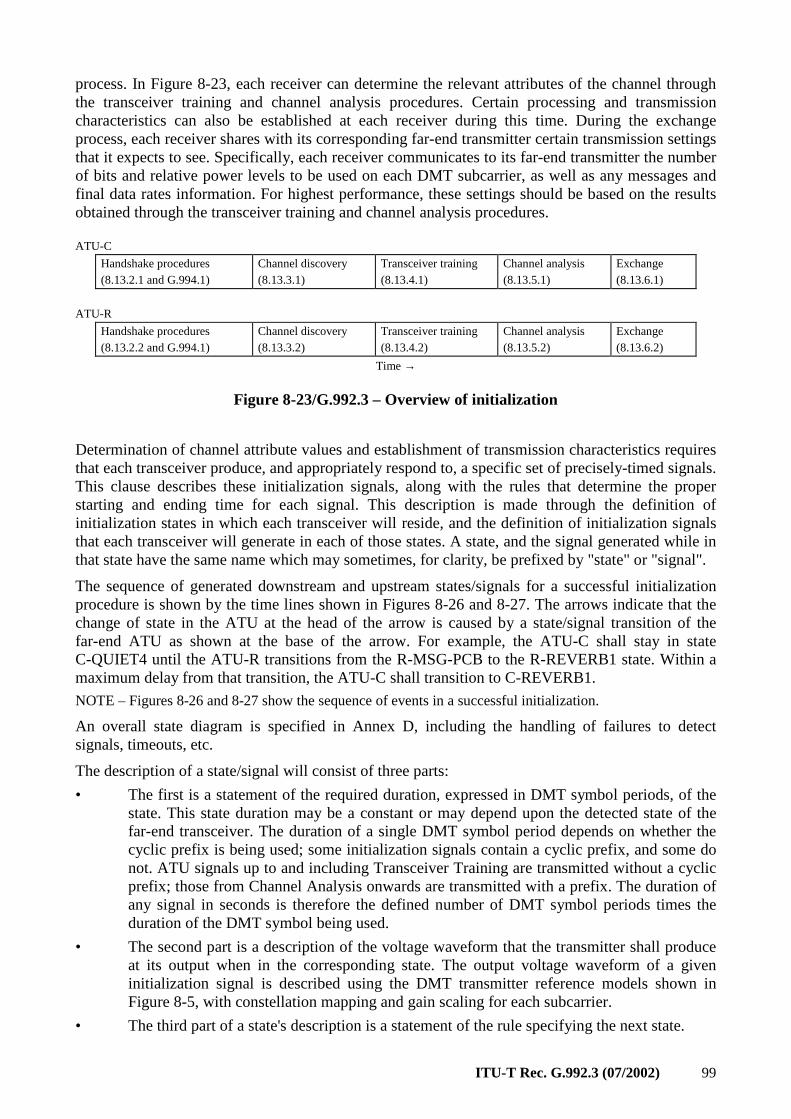
ITU-T Rec. G.992.3 (07/2002) 99
process. In Figure 8-23, each receiver can determine the relevant attributes of the channel through the transceiver training and channel analysis procedures. Certain processing and transmission characteristics can also be established at each receiver during this time. During the exchange process, each receiver shares with its corresponding far-end transmitter certain transmission settings that it expects to see. Specifically, each receiver communicates to its far-end transmitter the number of bits and relative power levels to be used on each DMT subcarrier, as well as any messages and final data rates information. For highest performance, these settings should be based on the results obtained through the transceiver training and channel analysis procedures. ATU-C
Handshake procedures (8.13.2.1 and G.994.1)
Channel discovery (8.13.3.1)
Transceiver training (8.13.4.1)
Channel analysis (8.13.5.1)
Exchange (8.13.6.1)
ATU-R
Handshake procedures (8.13.2.2 and G.994.1)
Channel discovery (8.13.3.2)
Transceiver training (8.13.4.2)
Channel analysis (8.13.5.2)
Exchange (8.13.6.2)
Time →
Figure 8-23/G.992.3 – Overview of initialization
Determination of channel attribute values and establishment of transmission characteristics requires that each transceiver produce, and appropriately respond to, a specific set of precisely-timed signals. This clause describes these initialization signals, along with the rules that determine the proper starting and ending time for each signal. This description is made through the definition of initialization states in which each transceiver will reside, and the definition of initialization signals that each transceiver will generate in each of those states. A state, and the signal generated while in that state have the same name which may sometimes, for clarity, be prefixed by "state" or "signal".
The sequence of generated downstream and upstream states/signals for a successful initialization procedure is shown by the time lines shown in Figures 8-26 and 8-27. The arrows indicate that the change of state in the ATU at the head of the arrow is caused by a state/signal transition of the far-end ATU as shown at the base of the arrow. For example, the ATU-C shall stay in state C-QUIET4 until the ATU-R transitions from the R-MSG-PCB to the R-REVERB1 state. Within a maximum delay from that transition, the ATU-C shall transition to C-REVERB1.
NOTE – Figures 8-26 and 8-27 show the sequence of events in a successful initialization.
An overall state diagram is specified in Annex D, including the handling of failures to detect signals, timeouts, etc.
The description of a state/signal will consist of three parts:
• The first is a statement of the required duration, expressed in DMT symbol periods, of the state. This state duration may be a constant or may depend upon the detected state of the far-end transceiver. The duration of a single DMT symbol period depends on whether the cyclic prefix is being used; some initialization signals contain a cyclic prefix, and some do not. ATU signals up to and including Transceiver Training are transmitted without a cyclic prefix; those from Channel Analysis onwards are transmitted with a prefix. The duration of any signal in seconds is therefore the defined number of DMT symbol periods times the duration of the DMT symbol being used.
• The second part is a description of the voltage waveform that the transmitter shall produce at its output when in the corresponding state. The output voltage waveform of a given initialization signal is described using the DMT transmitter reference models shown in Figure 8-5, with constellation mapping and gain scaling for each subcarrier.
• The third part of a state's description is a statement of the rule specifying the next state.
100 ITU-T Rec. G.992.3 (07/2002)
8.13.1.2 Transparency to methods for separating upstream and downstream signals
Manufacturers may choose to implement this Recommendation using either frequency-division-multiplexing (FDM) or echo cancelling (EC) to separate upstream and downstream signals. The initialization procedure described here ensures compatibility between these different implementations by specifying all upstream and downstream control signals to be in the appropriate, but narrower, frequency bands that would be used by an FDM transceiver, and by defining a time period during which an echo cancelled transceiver can train its echo canceller.
8.13.1.3 Implementation of service options for ADSL
The initialization procedure described here is applicable to different service options. The subcarrier frequencies used for some signals vary depending upon whether the ADSL service is offered over a POTS or an ISDN service (as defined in ITU-T Rec. G.961 [1], Appendices I, II, or III) or as all-digital mode without underlying service. These subcarrier frequencies are therefore defined over a wide enough frequency band, such that the receiver can identify the transmitter state/signal, irrespective of the service option chosen.
8.13.1.4 Resetting during initialization and data transmission
Resetting may occur if errors or malfunctions are detected, or timeout limits are exceeded at various points in the initialization sequence and SHOWTIME. An ATU executes a reset by transitioning to G.994.1 procedures. An ATU-R detecting an error condition shall transition to R-SILENT0 (see ITU-T Rec. G.994.1 [2]). An ATU-C detecting an error condition shall transition to C-SILENT1 (see ITU-T Rec. G.994.1 [2]).
Annex D specifies the state transitions that shall occur if errors or malfunctions are detected or timeout limits are exceeded at various points in the initialization sequence. Annex D also specifies conditions for which retraining may be required during data transmission (i.e., after a successful initialization).
The initialization procedure may be used for the link state transition from the L3 state to the L0 state (see 9.5.3). Error recovery (during the L0 or L2 link state) is through the initialization procedure. At the start of the initialization procedure, the ADSL link state shall be changed to the L3 state. When the ATU reaches the Showtime state through the initialization procedure, the ADSL link shall be in the L0 state (see Figure 9-5).
8.13.2 G.994.1 phase
The definition, structure and usage of the G.994.1 parameter blocks is included in this clause. However, this clause only lists the parameters exchanged in the G.994.1 phase to configure the transmit and receive PMD functions. Parameters applicable to the TPS-TC and PMS-TC layers are defined in clauses 6 and 7 respectively.
8.13.2.1 Handshake – ATU-C
The detailed procedures for handshake at the ATU-C are defined in ITU-T Rec. G.994.1 [2]. An ATU-C, after power-up or on conditions shown in Figure D.1, shall enter the initial C-SILENT1 state (waiting for the G.994.1 R-TONES-REQ signal). The ATU-C may transition to C-INIT/HS state (to send G.994.1 C-TONES signal) under instruction from the network. From either state, operation shall proceed according to the procedures defined in ITU-T Rec. G.994.1 [2].
If G.994.1 procedures select this Recommendation as the mode of operation, the ATU-C shall transition to the C-QUIET1 state (see Figure 8-26) at the conclusion of G.994.1 operation. All subsequent signals shall be transmitted using PSD levels as defined in the remainder of this clause.
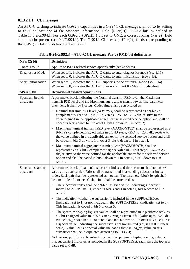
ITU-T Rec. G.992.3 (07/2002) 101
8.13.2.1.1 CL messages
An ATU-C wishing to indicate G.992.3 capabilities in a G.994.1 CL message shall do so by setting to ONE at least one of the Standard Information Field SPar(1) G.992.3 bits as defined in Table 11.0.2/G.994.1. For each G.992.3 SPar(1) bit set to ONE, a corresponding Par(2) field shall also be present (see 9.4/G.994.1). The G.994.1 CL message Par(2) fields corresponding to the SPar(1) bits are defined in Table 8-20.
Table 8-20/G.992.3 – ATU-C CL message Par(2) PMD bit definitions
NPar(2) bit Definition
Tones 1 to 32 Applies to ISDN related service options only (see annexes).
Diagnostics Mode When set to 1, indicates the ATU-C wants to enter diagnostics mode (see 8.15). When set to 0, indicates the ATU-C wants to enter initialization (see 8.13).
Short Initialization When set to 1, indicates the ATU-C supports the Short Initialization (see 8.14). When set to 0, indicates the ATU-C does not support the Short Initialization.
SPar(2) bit Definition of related Npar(3) bits
Spectrum bounds upstream
A parameter block indicating the Nominal transmit PSD level, the Maximum transmit PSD level and the Maximum aggregate transmit power. The parameter block length shall be 6 octets. Codepoints shall be structured as:
• Nominal transmit PSD level (NOMPSD) shall be represented as a 9-bit 2's complement signed value in 0.1 dB steps, –25.6 to +25.5 dB, relative to the value defined in the applicable annex for the selected service option and shall be coded in bits 3 down to 1 in octet 1, bits 6 down to 1 in octet 2;
• Maximum nominal transmit PSD level (MAXNOMPSD) shall be represented as a 9-bit 2's complement signed value in 0.1 dB steps, –25.6 to +25.5 dB, relative to the value defined in the applicable annex for the selected service option and shall be coded in bits 3 down to 1 in octet 3, bits 6 down to 1 in octet 4;
• Maximum nominal aggregate transmit power (MAXNOMATP) shall be represented as a 9-bit 2'complement signed value in 0.1 dB steps, –25.6 to 25.5 dB, relative to the value defined for the applicable annex for the selected service option and shall be coded in bits 3 down to 1 in octet 5, bits 6 down to 1 in octet 6.
Spectrum shaping upstream
A parameter block of pairs of a subcarrier index and the spectrum shaping log_tssi value at that subcarrier. Pairs shall be transmitted in ascending subcarrier index order. Each pair shall be represented as 4 octets. The parameter block length shall be a multiple of 4 octets. Codepoints shall be structured as:
• The subcarrier index shall be a 9-bit unsigned value, indicating subcarrier index 1 to 2 × NSCus – 1, coded in bits 3 and 1 in octet 1, bits 6 down to 1 in octet 2;
• The indication whether the subcarrier is included in the SUPPORTEDset (indication set to 1) or not included in the SUPPORTEDset (indication set to 0). This indication is coded in bit 6 of octet 3;
• The spectrum shaping log_tssi values shall be represented in logarithmic scale as a 7-bit unsigned value in –0.5 dB steps, ranging from 0 dB (value 0) to –62.5 dB (value 125), coded in bit 1 of octet 3 and bits 6 down to 1 in octet 4. Value 127 is a special value, indicating the subcarrier is not transmitted (i.e., tssi = 0 in linear scale). Value 126 is a special value indicating that the log_tssi value on this subcarrier shall be interpolated according to 8.13.2.4;
At least one pair (of a subcarrier index and the spectrum shaping log_tssi value at that subcarrier) indicated as included in the SUPPORTEDset, shall have the log_tssi value set to 0 dB.
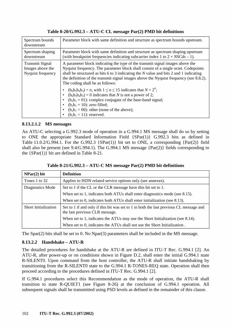
102 ITU-T Rec. G.992.3 (07/2002)
Table 8-20/G.992.3 – ATU-C CL message Par(2) PMD bit definitions
Spectrum bounds downstream
Parameter block with same definition and structure as spectrum bounds upstream.
Spectrum shaping downstream
Parameter block with same definition and structure as spectrum shaping upstream (with breakpoint frequencies indicating subcarrier index 1 to 2 × NSCds – 1).
Transmit Signal Images above the Nyquist frequency
A parameter block indicating the type of the transmit signal images above the Nyquist frequency. The parameter block shall consist of a single octet. Codepoints shall be structured as bits 6 to 3 indicating the N value and bits 2 and 1 indicating the definition of the transmit signal images above the Nyquist frequency (see 8.8.2). The coding shall be as follows:
• (b6b5b4b3) = n, with 1 ≤ n ≤ 15 indicates that N = 2n; • (b6b5b4b3) = 0 indicates that N is not a power of 2; • (b2b1 = 01): complex conjugate of the base-band signal; • (b2b1 = 10): zero filled; • (b2b1 = 00): other (none of the above); • (b2b1 = 11): reserved.
8.13.2.1.2 MS messages
An ATU-C selecting a G.992.3 mode of operation in a G.994.1 MS message shall do so by setting to ONE the appropriate Standard Information Field SPar(1) G.992.3 bits as defined in Table 11.0.2/G.994.1. For the G.992.3 SPar(1) bit set to ONE, a corresponding Par(2) field shall also be present (see 9.4/G.994.1). The G.994.1 MS message Par(2) fields corresponding to the SPar(1) bit are defined in Table 8-21.
Table 8-21/G.992.3 – ATU-C MS message Par(2) PMD bit definitions
NPar(2) bit Definition
Tones 1 to 32 Applies to ISDN related service options only (see annexes).
Diagnostics Mode Set to 1 if the CL or the CLR message have this bit set to 1.
When set to 1, indicates both ATUs shall enter diagnostics mode (see 8.15).
When set to 0, indicates both ATUs shall enter initialization (see 8.13).
Short Initialization Set to 1 if and only if this bit was set to 1 in both the last previous CL message and the last previous CLR message.
When set to 1, indicates the ATUs may use the Short Initialization (see 8.14).
When set to 0, indicates the ATUs shall not use the Short Initialization .
The Spar(2) bits shall be set to 0. No Npar(3) parameters shall be included in the MS message.
8.13.2.2 Handshake – ATU-R
The detailed procedures for handshake at the ATU-R are defined in ITU-T Rec. G.994.1 [2]. An ATU-R, after power-up or on conditions shown in Figure D.2, shall enter the initial G.994.1 state R-SILENT0. Upon command from the host controller, the ATU-R shall initiate handshaking by transitioning from the R-SILENT0 state to the G.994.1 R-TONES-REQ state. Operation shall then proceed according to the procedures defined in ITU-T Rec. G.994.1 [2].
If G.994.1 procedures select this Recommendation as the mode of operation, the ATU-R shall transition to state R-QUIET1 (see Figure 8-26) at the conclusion of G.994.1 operation. All subsequent signals shall be transmitted using PSD levels as defined in the remainder of this clause.
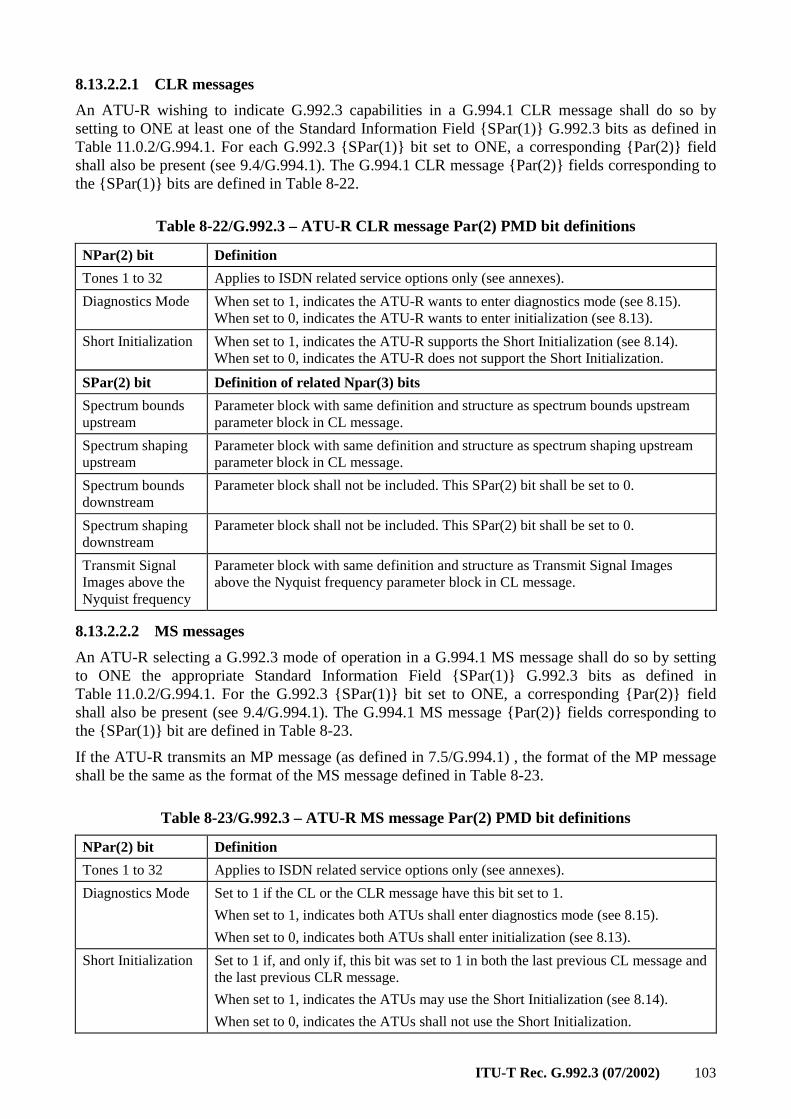
ITU-T Rec. G.992.3 (07/2002) 103
8.13.2.2.1 CLR messages
An ATU-R wishing to indicate G.992.3 capabilities in a G.994.1 CLR message shall do so by setting to ONE at least one of the Standard Information Field SPar(1) G.992.3 bits as defined in Table 11.0.2/G.994.1. For each G.992.3 SPar(1) bit set to ONE, a corresponding Par(2) field shall also be present (see 9.4/G.994.1). The G.994.1 CLR message Par(2) fields corresponding to the SPar(1) bits are defined in Table 8-22.
Table 8-22/G.992.3 – ATU-R CLR message Par(2) PMD bit definitions
NPar(2) bit Definition
Tones 1 to 32 Applies to ISDN related service options only (see annexes).
Diagnostics Mode When set to 1, indicates the ATU-R wants to enter diagnostics mode (see 8.15). When set to 0, indicates the ATU-R wants to enter initialization (see 8.13).
Short Initialization When set to 1, indicates the ATU-R supports the Short Initialization (see 8.14). When set to 0, indicates the ATU-R does not support the Short Initialization.
SPar(2) bit Definition of related Npar(3) bits
Spectrum bounds upstream
Parameter block with same definition and structure as spectrum bounds upstream parameter block in CL message.
Spectrum shaping upstream
Parameter block with same definition and structure as spectrum shaping upstream parameter block in CL message.
Spectrum bounds downstream
Parameter block shall not be included. This SPar(2) bit shall be set to 0.
Spectrum shaping downstream
Parameter block shall not be included. This SPar(2) bit shall be set to 0.
Transmit Signal Images above the Nyquist frequency
Parameter block with same definition and structure as Transmit Signal Images above the Nyquist frequency parameter block in CL message.
8.13.2.2.2 MS messages
An ATU-R selecting a G.992.3 mode of operation in a G.994.1 MS message shall do so by setting to ONE the appropriate Standard Information Field SPar(1) G.992.3 bits as defined in Table 11.0.2/G.994.1. For the G.992.3 SPar(1) bit set to ONE, a corresponding Par(2) field shall also be present (see 9.4/G.994.1). The G.994.1 MS message Par(2) fields corresponding to the SPar(1) bit are defined in Table 8-23.
If the ATU-R transmits an MP message (as defined in 7.5/G.994.1) , the format of the MP message shall be the same as the format of the MS message defined in Table 8-23.
Table 8-23/G.992.3 – ATU-R MS message Par(2) PMD bit definitions
NPar(2) bit Definition
Tones 1 to 32 Applies to ISDN related service options only (see annexes).
Diagnostics Mode Set to 1 if the CL or the CLR message have this bit set to 1.
When set to 1, indicates both ATUs shall enter diagnostics mode (see 8.15).
When set to 0, indicates both ATUs shall enter initialization (see 8.13).
Short Initialization Set to 1 if, and only if, this bit was set to 1 in both the last previous CL message and the last previous CLR message.
When set to 1, indicates the ATUs may use the Short Initialization (see 8.14).
When set to 0, indicates the ATUs shall not use the Short Initialization.
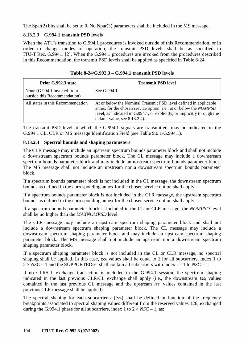
104 ITU-T Rec. G.992.3 (07/2002)
The Spar(2) bits shall be set to 0. No Npar(3) parameters shall be included in the MS message.
8.13.2.3 G.994.1 transmit PSD levels
When the ATU's transition to G.994.1 procedures is invoked outside of this Recommendation, or in order to change modes of operation, the transmit PSD levels shall be as specified in ITU-T Rec. G.994.1 [2]. When the G.994.1 procedures are invoked from the procedures described in this Recommendation, the transmit PSD levels shall be applied as specified in Table 8-24.
Table 8-24/G.992.3 – G.994.1 transmit PSD levels
Prior G.992.3 state Transmit PSD level
None (G.994.1 invoked from outside this Recommendation)
See G.994.1.
All states in this Recommendation At or below the Nominal Transmit PSD level defined in applicable annex for the chosen service option (i.e., at or below the NOMPSD level, as indicated in G.994.1, or explicitly, or implicitly through the default value, see 8.13.2.4).
The transmit PSD level at which the G.994.1 signals are transmitted, may be indicated in the G.994.1 CL, CLR or MS message Identification Field (see Table 9.0.1/G.994.1).
8.13.2.4 Spectral bounds and shaping parameters
The CLR message may include an upstream spectrum bounds parameter block and shall not include a downstream spectrum bounds parameter block. The CL message may include a downstream spectrum bounds parameter block and may include an upstream spectrum bounds parameter block. The MS message shall not include an upstream nor a downstream spectrum bounds parameter block.
If a spectrum bounds parameter block is not included in the CL message, the downstream spectrum bounds as defined in the corresponding annex for the chosen service option shall apply.
If a spectrum bounds parameter block is not included in the CLR message, the upstream spectrum bounds as defined in the corresponding annex for the chosen service option shall apply.
If a spectrum bounds parameter block is included in the CL or CLR message, the NOMPSD level shall be no higher than the MAXNOMPSD level.
The CLR message may include an upstream spectrum shaping parameter block and shall not include a downstream spectrum shaping parameter block. The CL message may include a downstream spectrum shaping parameter block and may include an upstream spectrum shaping parameter block. The MS message shall not include an upstream nor a downstream spectrum shaping parameter block.
If a spectrum shaping parameter block is not included in the CL or CLR message, no spectral shaping shall be applied. In this case, tssi values shall be equal to 1 for all subcarriers, index 1 to 2 × NSC – 1 and the SUPPORTEDset shall contain all subcarriers with index i = 1 to NSC – 1.
If no CLR/CL exchange transaction is included in the G.994.1 session, the spectrum shaping indicated in the last previous CLR/CL exchange shall apply (i.e., the downstream tssi values contained in the last previous CL message and the upstream tssi values contained in the last previous CLR message shall be applied).
The spectral shaping for each subcarrier i (tssi) shall be defined in function of the frequency breakpoints associated to spectral shaping values different from the reserved values 126, exchanged during the G.994.1 phase for all subcarriers, index 1 to 2 × NSC – 1, as:
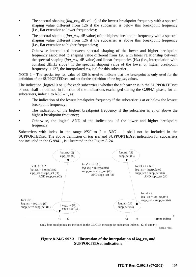
ITU-T Rec. G.992.3 (07/2002) 105
• The spectral shaping (log_tssi, dB value) of the lowest breakpoint frequency with a spectral shaping value different from 126 if the subcarrier is below this breakpoint frequency (i.e., flat extension to lower frequencies);
• The spectral shaping (log_tssi, dB value) of the highest breakpoint frequency with a spectral shaping value different from 126 if the subcarrier is above this breakpoint frequency (i.e., flat extension to higher frequencies);
• Otherwise interpolated between spectral shaping of the lower and higher breakpoint frequency associated to shaping value different from 126 with linear relationship between the spectral shaping (log_tssi, dB value) and linear frequencies (Hz) (i.e., interpolation with constant dB/Hz slope). If the spectral shaping value of the lower or higher breakpoint frequency is 127, the interpolated tssi is 0 for this subcarrier.
NOTE 1 – The special log_tssi value of 126 is used to indicate that the breakpoint is only used for the definition of the SUPPORTEDset, and not for the definition of the log_tssi values.
The indication (logical 0 or 1) for each subcarrier i whether the subcarrier is in the SUPPORTEDset or not, shall be defined in function of the indications exchanged during the G.994.1 phase, for all subcarriers, index 1 to NSC – 1, as:
• The indication of the lowest breakpoint frequency if the subcarrier is at or below the lowest breakpoint frequency;
• The indication of the highest breakpoint frequency if the subcarrier is at or above the highest breakpoint frequency;
• Otherwise, the logical AND of the indications of the lower and higher breakpoint frequency.
Subcarriers with index in the range NSC to 2 × NSC – 1 shall not be included in the SUPPORTEDset. The above definition of log_tssi and SUPPORTEDset indication for subcarriers not included in the G.994.1, is illustrated in the Figure 8-24.
t1 t2 t3 t4
log_tssi (t2)supp_set (t2)
t (tone index)
Only four breakpoints are included in the CL/CLR message (at subcarrier index t1, t2, t3 and t4).
for t < t1 :log_tssi = log_tssi (t1)supp_set = supp_set (t1)
log_tssi (t3)supp_set (t3)
log_tssi (t4)supp_set (t4)
log_tssi (t1)supp_set (t1)
for t1 < t < t2 :log_tssi = interpolatedsupp_set = supp_set (t1) AND supp_set (t2)
for t2 < t < t3 :log_tssi = interpolatedsupp_set = supp_set (t2) AND supp_set (t3)
for t3 < t < t4 :log_tssi= interpolatedsupp_set = supp_set (t3) AND supp_set (t4)
for t4 < t :log_tssi = log_tssi (t4)supp_set = supp_set (t4)
G.992.3_F08-24
Figure 8-24/G.992.3 – Illustration of the interpolation of log_tssi and SUPPORTEDset indications
106 ITU-T Rec. G.992.3 (07/2002)
The spectral shaping values shall be converted from logarithmic scale (log_tssi, dB values) to linear tssi values according to:
1024
101024Round 20
_
×
=
itsslog
itss
The combined accuracy of process of the linear interpolation of log_tssi values and the process of conversion to linear tssi values shall be strictly less than one half LSB of the 10 bits after the decimal point format of the linear tssi values. No error shall be introduced when log_tssi equals 0 dB or is interpolated between log_tssi values which equal 0 dB.
NOTE 2 – This ensures that the maximum deviation between tssi values used by transmitter and receiver is one LSB.
NOTE 3 – It should be remarked that the accuracy is specified as strictly < 1/2 LSB. An accuracy of = 1/2 LSB, will lead to inaccurate results.
The information represented in the spectrum shaping block shall be defined as follows:
• The CLR upstream spectrum shaping parameter block shall represent the spectrum shaping tssi values for each upstream subcarrier. The format of the upstream spectrum shaping parameter block is defined in Table 8-22. The spectrum shaping tssi values shall be used for all initialization signals as defined in Table 8-25. The upstream SUPPORTEDset is defined as the set of subcarriers with index 1 ≤ i ≤ NSCus – 1, which the ATU-R intends to transmit during Channel Analysis. The ATU-R shall indicate in the CLR message which subcarriers are included in the SUPPORTEDset, as defined in Table 8-22. For the subcarriers in the upstream SUPPORTEDset, tssi values shall be equal to 1 (log_tssi = 0 dB, i.e., no spectrum shaping). For the subcarriers not in the upstream SUPPORTEDset, tssi values shall be less than or equal to 1 (log_tssi ≤ 0 dB) and equal to or higher than the minimum values derived from Equation (8-1). The ATU-R may reduce the number of subcarriers it intends to transmit during Channel Analysis, to aid in the conservation of spectrum.
• The CL downstream spectrum shaping parameter block shall represent the spectrum shaping tssi values for each downstream sub-carrier. The format of the downstream spectrum shaping parameter block is defined in Table 8-20. The spectrum shaping tssi values shall be used for all initialization signals as defined in Table 8-25. The downstream SUPPORTEDset is defined as the set of subcarriers with index 1 ≤ i ≤ NSCds – 1, which the ATU-C intends to transmit during Channel Analysis. The ATU-C shall indicate in the CL message which subcarriers are included in the downstream SUPPORTEDset, as defined in Table 8-20. For the subcarriers in the downstream SUPPORTEDset, tssi values shall be in the 0 to 1 range (i.e., spectrum shaping allowed). For the subcarriers not in the downstream SUPPORTEDset, tssi values shall be less than or equal to 1 (log_tssi ≤ 0 dB) and equal to or higher than the minimum values derived from Equation (8-1). The ATU-C may reduce the number of subcarriers it intends to transmit during Channel Analysis, to aid in the conservation of spectrum.
• The CL upstream spectrum shaping parameter block shall represent which subcarriers the ATU-R may include in the upstream SUPPORTEDset (SUPPORTEDset indication set to 1 and tssi value equal to 1 in linear scale) and which subcarriers the ATU-R shall not include in the upstream SUPPORTEDset (SUPPORTEDset indication set to 0 and tssi value equal to 0 in linear scale). The format of the upstream spectrum shaping parameter block is defined in Table 8-20 (see Note 2).
121for,1)( 2 −×≤≤≤≤∆⋅ NSCitssfiS i (8-1)
ITU-T Rec. G.992.3 (07/2002) 107
where
⋅
⋅−=∑ sn
b fNSC
NnfSfS )( ,
( ) ( )( )∑∈
∆⋅++∆⋅−×=etSUPPORTEDsk
kb fkfWfkfWtssfS 222)(
(N/NSC) is the IDFT oversampling factor, with N and NSC as defined in 8.8.2,
∆f is the subcarrier frequency spacing, i.e., = 4.3125 kHz (see 8.8.1),
fs is the sampling frequency, i.e., 2 × NSC × ∆f (see 8.8.13),
W2(f) is the Fourier transform of the autocorrelation function of a rectangular window, defined as:
∆⋅×=
f
ffW
)17/16(sinc
16
17)( 22 .
NOTE 4 – The scale factor applied in W2(f) is to make the integral of W2(f) equal unity.
The Figure 8-25 shows an example of the downstream tssi values as a function of the subcarrier index i, for the case that the SUPPORTEDset contains the subcarriers with index i = 40 to 200 and N = 2 × NSC = 512 (oversampled IDFT). At frequencies i × ∆f, with 40 ≤ i ≤ 200 and ∆f = 4.3125 kHz, the tssi value equals 1 (0 dB).
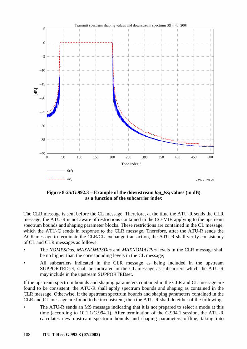
108 ITU-T Rec. G.992.3 (07/2002)
G.992.3_F08-25
[dB
]
0 50 100 150 200 250 300 350 400 450 500
–35
–30
–25
–20
–15
–10
–5
0
5
–40
Transmit spectrum shaping values and downstream spectrum S(f) [40, 200]
S(f)
tssi
Tone-index i
Figure 8-25/G.992.3 – Example of the downstream log_tssi values (in dB) as a function of the subcarrier index
The CLR message is sent before the CL message. Therefore, at the time the ATU-R sends the CLR message, the ATU-R is not aware of restrictions contained in the CO-MIB applying to the upstream spectrum bounds and shaping parameter blocks. These restrictions are contained in the CL message, which the ATU-C sends in response to the CLR message. Therefore, after the ATU-R sends the ACK message to terminate the CLR/CL exchange transaction, the ATU-R shall verify consistency of CL and CLR messages as follows:
• The NOMPSDus, MAXNOMPSDus and MAXNOMATPus levels in the CLR message shall be no higher than the corresponding levels in the CL message;
• All subcarriers indicated in the CLR message as being included in the upstream SUPPORTEDset, shall be indicated in the CL message as subcarriers which the ATU-R may include in the upstream SUPPORTEDset.
If the upstream spectrum bounds and shaping parameters contained in the CLR and CL message are found to be consistent, the ATU-R shall apply spectrum bounds and shaping as contained in the CLR message. Otherwise, if the upstream spectrum bounds and shaping parameters contained in the CLR and CL message are found to be inconsistent, then the ATU-R shall do either of the following:
• The ATU-R sends an MS message indicating that it is not prepared to select a mode at this time (according to 10.1.1/G.994.1). After termination of the G.994.1 session, the ATU-R calculates new upstream spectrum bounds and shaping parameters offline, taking into
ITU-T Rec. G.992.3 (07/2002) 109
account the upstream spectrum bounds and shaping parameters specified by the ATU-C in the CL message of previous G.994.1 session. In a subsequent G.994.1 session, the ATU-R sends a CLR message including the new spectrum bounds and shaping parameters;
• The ATU-R calculates new upstream spectrum bounds and shaping parameters online, taking into account the upstream spectrum bounds and shaping parameters specified by the ATU-C in the CL message of previous G.994.1 session. In the same G.994.1 session, the ATU-R repeats the CLR/CL exchange transaction with a CLR message including the new spectrum bounds and shaping parameters.
NOTE 1 – For the downstream direction, the CO-MIB contains a per subcarrier indication whether the subcarrier is or is not allowed to be sent starting from the initialization Channel Analysis Phase. From this information and taking into account its own capabilities, the ATU-C selects the downstream SUPPORTEDset of subcarriers and computes the CL downstream spectrum shaping parameter block information.
NOTE 2 – For the upstream direction, the CO-MIB contains a per subcarrier indication whether the subcarrier is or is not allowed to be sent starting from the initialization Channel Analysis Phase. This information is conveyed to the ATU-R in the CL upstream spectrum shaping parameter block (through SUPPORTEDset indications and only using tssi values 0 and 1 in linear scale). From this information and taking into account its own capabilities, the ATU-R selects the upstream SUPPORTEDset of subcarriers and computes the CLR upstream spectrum shaping parameter block information.
NOTE 3 – With the tssi values contained in the different spectrum shaping blocks, the ATU indicates which subcarriers the ATU intends to transmit (subcarriers in the SUPPORTEDset) and which ones the ATU does not intend to transmit (subcarriers not in the SUPPORTEDset) during Channel Analysis for both the upstream and downstream directions. This is needed to make sure the ATU-R can select a C-TREF pilot tone which will be transmitted starting from the Channel Analysis Phase. This also facilitates the selection by the PMD receive function of unused subcarriers for SNR monitoring and the selection of subcarriers to modulate the PARAMS messages.
During the Channel Discovery Phase, the receive PMD function may include the BLACKOUT bits (i.e., BLACKOUTi for i = 1 to NSC – 1) in the MSG-PCB message. These contain a per subcarrier indication of whether the subcarrier may (BLACKOUTi = 0) and which subcarriers shall not (BLACKOUTi = 1) be transmitted by the transmit PMD function during initialization, starting from the Transceiver Training phase (see Table 8-25). The downstream BLACKOUTset is defined as the set of downstream subcarriers the ATU-R has indicated for blackout. The upstream BLACKOUTset is defined as the set of upstream subcarriers the ATU-C has indicated for blackout.
If the BLACKOUT bits are not included in the MSG-PCB message and the initialization contains a G.994.1 phase, the transmit PMD function shall assume all BLACKOUT bits are set to 0. If the BLACKOUT bits are not included in the MSG-PCB message and the initialization does not contains a G.994.1 phase, the transmit PMD function shall assume the BLACKOUT bits conveyed in the last previous MSG-PCB message are still valid.
Disabling of subchannels during initialization and SHOWTIME allows the receive PMD function to estimate the characteristics of the RFI ingress signals. Based on these estimates, a receive PMD function can perform adaptive signal processing algorithms for RFI ingress cancellation and/or mitigation with the goal of providing improved performance in the presence of RFI ingress.
The downstream MEDLEYset is defined as the set of subcarriers contained in the downstream SUPPORTEDset, with removal of the subcarriers contained in the downstream BLACKOUTset. The upstream MEDLEYset is defined as the set of subcarriers contained in the upstream SUPPORTEDset, with removal of the subcarriers contained in the upstream BLACKOUTset.
The Initialization Symbols Encoder is the concatenation of first the constellation mapping and second, the spectral shaping and subcarrier blackout for symbols transmitted during the Initialization Phase. The constellation mapping defines the Xi and Yi values for the Channel
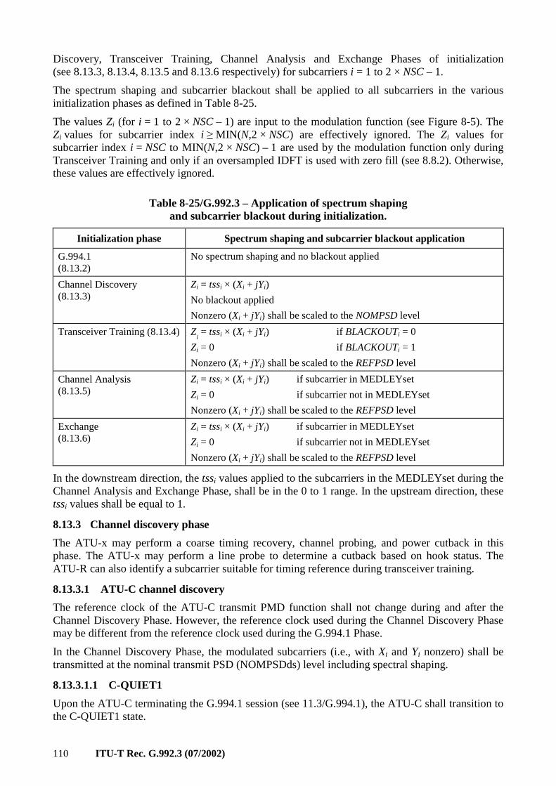
110 ITU-T Rec. G.992.3 (07/2002)
Discovery, Transceiver Training, Channel Analysis and Exchange Phases of initialization (see 8.13.3, 8.13.4, 8.13.5 and 8.13.6 respectively) for subcarriers i = 1 to 2 × NSC – 1.
The spectrum shaping and subcarrier blackout shall be applied to all subcarriers in the various initialization phases as defined in Table 8-25.
The values Zi (for i = 1 to 2 × NSC – 1) are input to the modulation function (see Figure 8-5). The Zi values for subcarrier index i ≥ MIN(N,2 × NSC) are effectively ignored. The Zi values for subcarrier index i = NSC to MIN(N,2 × NSC) – 1 are used by the modulation function only during Transceiver Training and only if an oversampled IDFT is used with zero fill (see 8.8.2). Otherwise, these values are effectively ignored.
Table 8-25/G.992.3 – Application of spectrum shaping and subcarrier blackout during initialization.
Initialization phase Spectrum shaping and subcarrier blackout application
G.994.1 (8.13.2)
No spectrum shaping and no blackout applied
Channel Discovery (8.13.3)
Zi = tssi × (Xi + jYi)
No blackout applied
Nonzero (Xi + jYi) shall be scaled to the NOMPSD level
Transceiver Training (8.13.4) Zi = tssi × (Xi + jYi) if BLACKOUTi = 0
Zi = 0 if BLACKOUTi = 1
Nonzero (Xi + jYi) shall be scaled to the REFPSD level
Channel Analysis (8.13.5)
Zi = tssi × (Xi + jYi) if subcarrier in MEDLEYset
Zi = 0 if subcarrier not in MEDLEYset
Nonzero (Xi + jYi) shall be scaled to the REFPSD level
Exchange (8.13.6)
Zi = tssi × (Xi + jYi) if subcarrier in MEDLEYset
Zi = 0 if subcarrier not in MEDLEYset
Nonzero (Xi + jYi) shall be scaled to the REFPSD level
In the downstream direction, the tssi values applied to the subcarriers in the MEDLEYset during the Channel Analysis and Exchange Phase, shall be in the 0 to 1 range. In the upstream direction, these tssi values shall be equal to 1.
8.13.3 Channel discovery phase
The ATU-x may perform a coarse timing recovery, channel probing, and power cutback in this phase. The ATU-x may perform a line probe to determine a cutback based on hook status. The ATU-R can also identify a subcarrier suitable for timing reference during transceiver training.
8.13.3.1 ATU-C channel discovery
The reference clock of the ATU-C transmit PMD function shall not change during and after the Channel Discovery Phase. However, the reference clock used during the Channel Discovery Phase may be different from the reference clock used during the G.994.1 Phase.
In the Channel Discovery Phase, the modulated subcarriers (i.e., with Xi and Yi nonzero) shall be transmitted at the nominal transmit PSD (NOMPSDds) level including spectral shaping.
8.13.3.1.1 C-QUIET1
Upon the ATU-C terminating the G.994.1 session (see 11.3/G.994.1), the ATU-C shall transition to the C-QUIET1 state.
ITU-T Rec. G.992.3 (07/2002) 111
The C-QUIET1 state is of variable length. In the C-QUIET1 state, the ATU-C shall transmit a minimum of 512 and a maximum of 4204 C-QUIET symbols. The minimum duration of the C-QUIET1 state allows for quiet line noise PSD measurement period of at least 512 symbols (see 8.12.3.2).
A C-QUIET symbol shall be defined as a zero output voltage at the U-C 2 reference point (see reference model in 5.4). All subcarriers in the C-QUIET symbol shall be transmitted at no power (i.e., Xi = Yi = 0).
The ATU-C may transition to the C-QUIET1 state before or after the ATU-R transitions to the R-QUIET1 state. If the ATU-C transitions first, the ATU-C shall remain in the C-QUIET1 state until after the ATU-R transitions to the R-QUIET1 state. Within 512 to 2048 symbols after the ATU-C transitioning to the C-QUIET1 state or the ATU-R transitioning to the R-QUIET1 state (whichever occurs last in time), the ATU-C shall transition to the next state.
The C-QUIET1 state shall be followed by the C-COMB1 state.
NOTE – The maximum duration of the C-QUIET1 state corresponds to 500 ms difference between the ATU-C and the ATU-R terminating the G.994.1 Phase (4312/2 symbols) plus 2048 symbols for ATU-C transition from the G.994.1 to the Channel Discovery Phase.
8.13.3.1.2 C-COMB1
The duration of the C-COMB1 state is of fixed length. In the C-COMB1 state, the ATU-C shall transmit 128 C-COMB symbols.
During this state, the ATU-R performs timing recovery and measures some characteristics of the downstream channel for C-TREF pilot tone selection and for the estimation of the required ATU-R minimum Upstream Power Cut Back and ATU-R minimum Downstream Power Cut Back. These functions can be continued during C-COMB2.
The C-COMB symbol shall be defined as a wideband multi-tone symbol containing the 16 subcarriers with index 11, 23, 35, 47, 59, 64, 71, 83, 95, 107, 119, 143, 179, 203, 227 and 251. The subcarrier spacing has been selected to minimize audible interference into the POTS band prior to applying cutbacks that may be required in the presence of an off-Hook POTS terminal and to limit aggregate transmit power to 8.4 dBm (i.e., the 12 dB power cutback level).
The subcarriers contained in the C-COMB symbol shall modulate the same data bits that are used for the C-REVERB symbols, in such a way that same subcarrier indexes modulate the same data bits with the same 4-QAM constellation, as defined in 8.13.4.1.1. The subcarriers not contained in the C-COMB symbol shall be transmitted at no power (i.e., Xi = Yi = 0).
The C-COMB1 state shall be followed by the C-QUIET2 state.
8.13.3.1.3 C-QUIET2
The C-QUIET2 state is of fixed duration. During the C-QUIET2 state, the ATU-C shall transmit 256 C-QUIET symbols.
The C-QUIET2 state shall be followed by the C-COMB2 state.
8.13.3.1.4 C-COMB2
The C-COMB2 state is of fixed length. During the C-COMB2 state, the ATU-C shall transmit LEN_C-COMB2 C-COMB symbols. Whenever the initialization is invoked from Showtime as a fast error recovery procedure (see 8.14), the value LEN_C-COMB2 shall be set to 1024 symbols. The value LEN_C-COMB2 shall be set to either 1024 or 3872 symbols otherwise.
During C-COMB2, the ATU-R performs timing recovery and measures some characteristics of the downstream channel for C-TREF pilot tone selection and for the estimation of the required ATU-R minimum Upstream Power Cut Back and ATU-R minimum Downstream Power Cut Back.
112 ITU-T Rec. G.992.3 (07/2002)
The C-COMB2 state shall be followed by the C-ICOMB1 state if the ATU-C desires to use the C-LINEPROBE state. Otherwise the C-COMB2 state shall be followed by the C-QUIET3 state.
8.13.3.1.5 C-ICOMB1
The C-ICOMB1 state is of fixed length. In the C-ICOMB1 state, the ATU-C shall transmit 10 C-ICOMB symbols.
A C-ICOMB symbol shall be defined as a subcarrier-by-subcarrier 180 degrees phase reversal of a C-COMB symbol (i.e., a C-ICOMB symbol modulates the bitwise inverted REVERB PRBS data pattern).
The C-ICOMB1 state shall be followed by the C-LINEPROBE state.
8.13.3.1.6 C-LINEPROBE
The C-LINEPROBE state is of fixed length. In the C-LINEPROBE state, the ATU-C shall transmit a vendor discretionary signal with a duration of 512 symbol periods.
The C-LINEPROBE state shall be followed by the C-QUIET3 state.
8.13.3.1.7 C-QUIET3
The C-QUIET3 state is of variable length. In the C-QUIET3 state, the ATU-C shall transmit a minimum of 256 and a maximum of 906 C-QUIET symbols. The ATU-C may do an upstream channel attenuation measurement during this state (while the ATU-R is in the R-COMB2 state).
The ATU-C shall continue to transmit C-QUIET symbols until after the ATU-R transitioning to the R-QUIET3 state. Within 64 symbols after the ATU-R transitioning to the R-QUIET3 state, the ATU-C shall transition to the next state.
The C-QUIET3 state shall be followed by the C-COMB3 state.
8.13.3.1.8 C-COMB3
The C-COMB3 state is of fixed length. In the C-COMB3 state, the ATU-C shall transmit 64 C-COMB symbols.
The C-COMB3 state shall be followed by the C-ICOMB2 state. The transition to the C-ICOMB2 state provides a time marker for the C-MSG-FMT state.
8.13.3.1.9 C-ICOMB2
The C-ICOMB2 state is of fixed length. In the C-ICOMB2 state, the ATU-C shall transmit 10 C-ICOMB symbols.
The C-ICOMB2 state shall be followed by the C-MSG-FMT state.
8.13.3.1.10 C-MSG-FMT
The C-MSG-FMT state is of fixed length. In the C-MSG-FMT state, the ATU-C shall transmit 96 symbols of C-COMB or C-ICOMB to modulate the C-MSG-FMT message and CRC. The C-MSG-FMT message conveys information about the presence, format and length of subsequent ATU-C and ATU-R messages.
The C-MSG-FMT message, m, is defined by:
015 , ... , mmm =
Bits shall be defined as shown in Table 8-26.
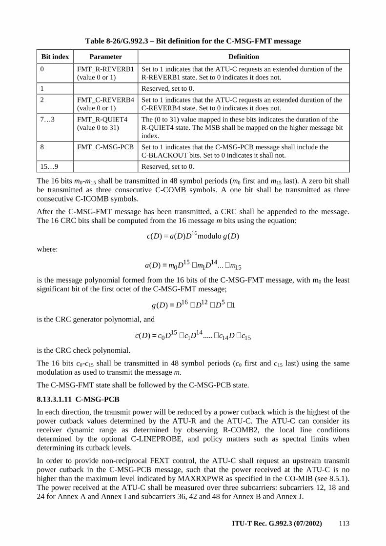
ITU-T Rec. G.992.3 (07/2002) 113
Table 8-26/G.992.3 – Bit definition for the C-MSG-FMT message
Bit index Parameter Definition
0 FMT_R-REVERB1 (value 0 or 1)
Set to 1 indicates that the ATU-C requests an extended duration of the R-REVERB1 state. Set to 0 indicates it does not.
1 Reserved, set to 0.
2 FMT_C-REVERB4 (value 0 or 1)
Set to 1 indicates that the ATU-C requests an extended duration of the C-REVERB4 state. Set to 0 indicates it does not.
7…3 FMT_R-QUIET4 (value 0 to 31)
The (0 to 31) value mapped in these bits indicates the duration of the R-QUIET4 state. The MSB shall be mapped on the higher message bit index.
8 FMT_C-MSG-PCB Set to 1 indicates that the C-MSG-PCB message shall include the C-BLACKOUT bits. Set to 0 indicates it shall not.
15…9 Reserved, set to 0.
The 16 bits m0-m15 shall be transmitted in 48 symbol periods (m0 first and m15 last). A zero bit shall be transmitted as three consecutive C-COMB symbols. A one bit shall be transmitted as three consecutive C-ICOMB symbols.
After the C-MSG-FMT message has been transmitted, a CRC shall be appended to the message. The 16 CRC bits shall be computed from the 16 message m bits using the equation:
)( modulo)()( 16 DgDDaDc =
where:
1514
115
0 ...)( mDmDmDa ++=
is the message polynomial formed from the 16 bits of the C-MSG-FMT message, with m0 the least significant bit of the first octet of the C-MSG-FMT message;
1)( 51216 +++= DDDDg
is the CRC generator polynomial, and
151414
115
0 .....)( cDcDcDcDc +++=
is the CRC check polynomial.
The 16 bits c0-c15 shall be transmitted in 48 symbol periods (c0 first and c15 last) using the same modulation as used to transmit the message m.
The C-MSG-FMT state shall be followed by the C-MSG-PCB state.
8.13.3.1.11 C-MSG-PCB
In each direction, the transmit power will be reduced by a power cutback which is the highest of the power cutback values determined by the ATU-R and the ATU-C. The ATU-C can consider its receiver dynamic range as determined by observing R-COMB2, the local line conditions determined by the optional C-LINEPROBE, and policy matters such as spectral limits when determining its cutback levels.
In order to provide non-reciprocal FEXT control, the ATU-C shall request an upstream transmit power cutback in the C-MSG-PCB message, such that the power received at the ATU-C is no higher than the maximum level indicated by MAXRXPWR as specified in the CO-MIB (see 8.5.1). The power received at the ATU-C shall be measured over three subcarriers: subcarriers 12, 18 and 24 for Annex A and Annex I and subcarriers 36, 42 and 48 for Annex B and Annex J.
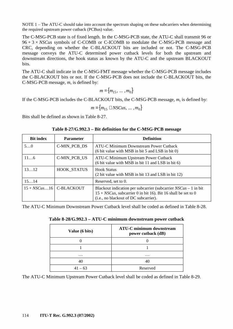
114 ITU-T Rec. G.992.3 (07/2002)
NOTE 1 – The ATU-C should take into account the spectrum shaping on these subcarriers when determining the required upstream power cutback (PCBus) value.
The C-MSG-PCB state is of fixed length. In the C-MSG-PCB state, the ATU-C shall transmit 96 or 96 + 3 × NSCus symbols of C-COMB or C-ICOMB to modulate the C-MSG-PCB message and CRC, depending on whether the C-BLACKOUT bits are included or not. The C-MSG-PCB message conveys the ATU-C determined power cutback levels for both the upstream and downstream directions, the hook status as known by the ATU-C and the upstream BLACKOUT bits.
The ATU-C shall indicate in the C-MSG-FMT message whether the C-MSG-PCB message includes the C-BLACKOUT bits or not. If the C-MSG-PCB does not include the C-BLACKOUT bits, the C-MSG-PCB message, m, is defined by:
015 , ... , mmm =
If the C-MSG-PCB includes the C-BLACKOUT bits, the C-MSG-PCB message, m, is defined by:
015 , ... , mNSCusmm +=
Bits shall be defined as shown in Table 8-27.
Table 8-27/G.992.3 – Bit definition for the C-MSG-PCB message
Bit index Parameter Definition
5…0 C-MIN_PCB_DS ATU-C Minimum Downstream Power Cutback (6 bit value with MSB in bit 5 and LSB in bit 0)
11…6 C-MIN_PCB_US ATU-C Minimum Upstream Power Cutback (6 bit value with MSB in bit 11 and LSB in bit 6)
13…12 HOOK_STATUS Hook Status (2 bit value with MSB in bit 13 and LSB in bit 12)
15…14 Reserved, set to 0.
15 + NSCus…16 C-BLACKOUT Blackout indication per subcarrier (subcarrier NSCus – 1 in bit 15 + NSCus, subcarrier 0 in bit 16). Bit 16 shall be set to 0 (i.e., no blackout of DC subcarrier).
The ATU-C Minimum Downstream Power Cutback level shall be coded as defined in Table 8-28.
Table 8-28/G.992.3 – ATU-C minimum downstream power cutback
Value (6 bits) ATU-C minimum downstream
power cutback (dB)
0 0
1 1
… …
40 40
41 – 63 Reserved
The ATU-C Minimum Upstream Power Cutback level shall be coded as defined in Table 8-29.
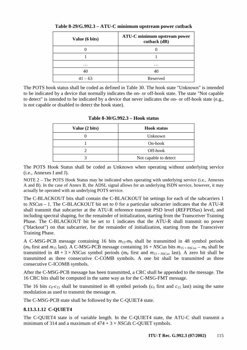
ITU-T Rec. G.992.3 (07/2002) 115
Table 8-29/G.992.3 – ATU-C minimum upstream power cutback
Value (6 bits) ATU-C minimum upstream power
cutback (dB)
0 0
1 1
… …
40 40
41 – 63 Reserved
The POTS hook status shall be coded as defined in Table 30. The hook state "Unknown" is intended to be indicated by a device that normally indicates the on- or off-hook state. The state "Not capable to detect" is intended to be indicated by a device that never indicates the on- or off-hook state (e.g., is not capable or disabled to detect the hook state).
Table 8-30/G.992.3 – Hook status
Value (2 bits) Hook status
0 Unknown
1 On-hook
2 Off-hook
3 Not capable to detect
The POTS Hook Status shall be coded as Unknown when operating without underlying service (i.e., Annexes I and J).
NOTE 2 – The POTS Hook Status may be indicated when operating with underlying service (i.e., Annexes A and B). In the case of Annex B, the ADSL signal allows for an underlying ISDN service, however, it may actually be operated with an underlying POTS service.
The C-BLACKOUT bits shall contain the C-BLACKOUT bit settings for each of the subcarriers 1 to NSCus – 1. The C-BLACKOUT bit set to 0 for a particular subcarrier indicates that the ATU-R shall transmit that subcarrier at the ATU-R reference transmit PSD level (REFPDSus) level, and including spectral shaping, for the remainder of initialization, starting from the Transceiver Training Phase. The C-BLACKOUT bit be set to 1 indicates that the ATU-R shall transmit no power ("blackout") on that subcarrier, for the remainder of initialization, starting from the Transceiver Training Phase.
A C-MSG-PCB message containing 16 bits m15-m0 shall be transmitted in 48 symbol periods (m0 first and m15 last). A C-MSG-PCB message containing 16 + NSCus bits m15 + NSCus – m0 shall be transmitted in 48 + 3 × NSCus symbol periods (m0 first and m15 + NSCus last). A zero bit shall be transmitted as three consecutive C-COMB symbols. A one bit shall be transmitted as three consecutive C-ICOMB symbols.
After the C-MSG-PCB message has been transmitted, a CRC shall be appended to the message. The 16 CRC bits shall be computed in the same way as for the C-MSG-FMT message.
The 16 bits c0-c15 shall be transmitted in 48 symbol periods (c0 first and c15 last) using the same modulation as used to transmit the message m.
The C-MSG-PCB state shall be followed by the C-QUIET4 state.
8.13.3.1.12 C-QUIET4
The C-QUIET4 state is of variable length. In the C-QUIET4 state, the ATU-C shall transmit a minimum of 314 and a maximum of 474 + 3 × NSCds C-QUIET symbols.
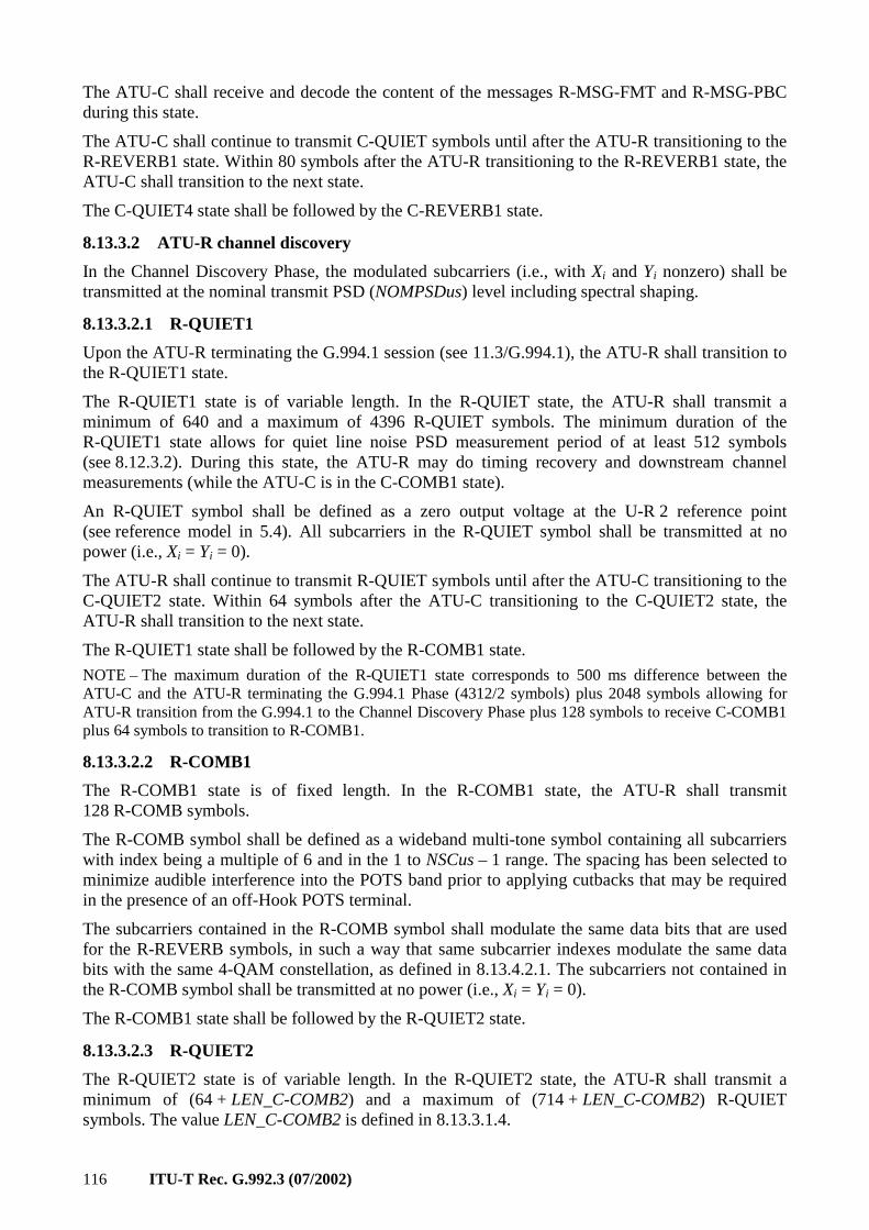
116 ITU-T Rec. G.992.3 (07/2002)
The ATU-C shall receive and decode the content of the messages R-MSG-FMT and R-MSG-PBC during this state.
The ATU-C shall continue to transmit C-QUIET symbols until after the ATU-R transitioning to the R-REVERB1 state. Within 80 symbols after the ATU-R transitioning to the R-REVERB1 state, the ATU-C shall transition to the next state.
The C-QUIET4 state shall be followed by the C-REVERB1 state.
8.13.3.2 ATU-R channel discovery
In the Channel Discovery Phase, the modulated subcarriers (i.e., with Xi and Yi nonzero) shall be transmitted at the nominal transmit PSD (NOMPSDus) level including spectral shaping.
8.13.3.2.1 R-QUIET1
Upon the ATU-R terminating the G.994.1 session (see 11.3/G.994.1), the ATU-R shall transition to the R-QUIET1 state.
The R-QUIET1 state is of variable length. In the R-QUIET state, the ATU-R shall transmit a minimum of 640 and a maximum of 4396 R-QUIET symbols. The minimum duration of the R-QUIET1 state allows for quiet line noise PSD measurement period of at least 512 symbols (see 8.12.3.2). During this state, the ATU-R may do timing recovery and downstream channel measurements (while the ATU-C is in the C-COMB1 state).
An R-QUIET symbol shall be defined as a zero output voltage at the U-R 2 reference point (see reference model in 5.4). All subcarriers in the R-QUIET symbol shall be transmitted at no power (i.e., Xi = Yi = 0).
The ATU-R shall continue to transmit R-QUIET symbols until after the ATU-C transitioning to the C-QUIET2 state. Within 64 symbols after the ATU-C transitioning to the C-QUIET2 state, the ATU-R shall transition to the next state.
The R-QUIET1 state shall be followed by the R-COMB1 state.
NOTE – The maximum duration of the R-QUIET1 state corresponds to 500 ms difference between the ATU-C and the ATU-R terminating the G.994.1 Phase (4312/2 symbols) plus 2048 symbols allowing for ATU-R transition from the G.994.1 to the Channel Discovery Phase plus 128 symbols to receive C-COMB1 plus 64 symbols to transition to R-COMB1.
8.13.3.2.2 R-COMB1
The R-COMB1 state is of fixed length. In the R-COMB1 state, the ATU-R shall transmit 128 R-COMB symbols.
The R-COMB symbol shall be defined as a wideband multi-tone symbol containing all subcarriers with index being a multiple of 6 and in the 1 to NSCus – 1 range. The spacing has been selected to minimize audible interference into the POTS band prior to applying cutbacks that may be required in the presence of an off-Hook POTS terminal.
The subcarriers contained in the R-COMB symbol shall modulate the same data bits that are used for the R-REVERB symbols, in such a way that same subcarrier indexes modulate the same data bits with the same 4-QAM constellation, as defined in 8.13.4.2.1. The subcarriers not contained in the R-COMB symbol shall be transmitted at no power (i.e., Xi = Yi = 0).
The R-COMB1 state shall be followed by the R-QUIET2 state.
8.13.3.2.3 R-QUIET2
The R-QUIET2 state is of variable length. In the R-QUIET2 state, the ATU-R shall transmit a minimum of (64 + LEN_C-COMB2) and a maximum of (714 + LEN_C-COMB2) R-QUIET symbols. The value LEN_C-COMB2 is defined in 8.13.3.1.4.
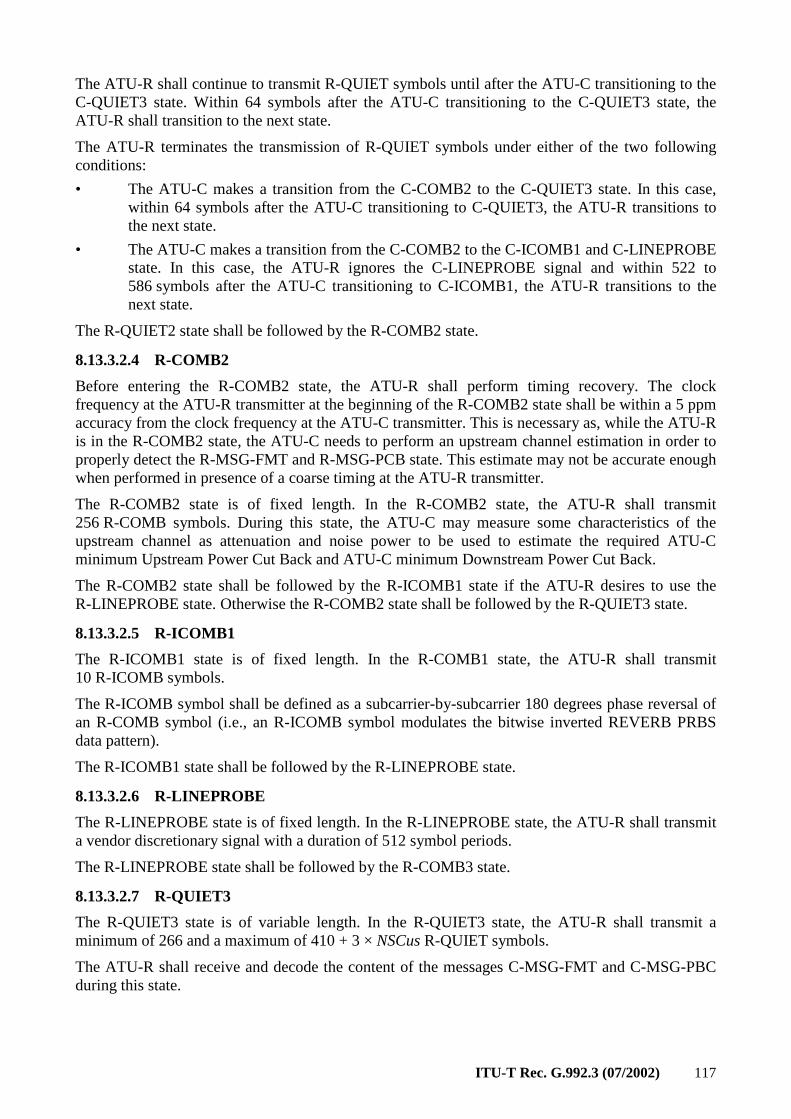
ITU-T Rec. G.992.3 (07/2002) 117
The ATU-R shall continue to transmit R-QUIET symbols until after the ATU-C transitioning to the C-QUIET3 state. Within 64 symbols after the ATU-C transitioning to the C-QUIET3 state, the ATU-R shall transition to the next state.
The ATU-R terminates the transmission of R-QUIET symbols under either of the two following conditions:
• The ATU-C makes a transition from the C-COMB2 to the C-QUIET3 state. In this case, within 64 symbols after the ATU-C transitioning to C-QUIET3, the ATU-R transitions to the next state.
• The ATU-C makes a transition from the C-COMB2 to the C-ICOMB1 and C-LINEPROBE state. In this case, the ATU-R ignores the C-LINEPROBE signal and within 522 to 586 symbols after the ATU-C transitioning to C-ICOMB1, the ATU-R transitions to the next state.
The R-QUIET2 state shall be followed by the R-COMB2 state.
8.13.3.2.4 R-COMB2
Before entering the R-COMB2 state, the ATU-R shall perform timing recovery. The clock frequency at the ATU-R transmitter at the beginning of the R-COMB2 state shall be within a 5 ppm accuracy from the clock frequency at the ATU-C transmitter. This is necessary as, while the ATU-R is in the R-COMB2 state, the ATU-C needs to perform an upstream channel estimation in order to properly detect the R-MSG-FMT and R-MSG-PCB state. This estimate may not be accurate enough when performed in presence of a coarse timing at the ATU-R transmitter.
The R-COMB2 state is of fixed length. In the R-COMB2 state, the ATU-R shall transmit 256 R-COMB symbols. During this state, the ATU-C may measure some characteristics of the upstream channel as attenuation and noise power to be used to estimate the required ATU-C minimum Upstream Power Cut Back and ATU-C minimum Downstream Power Cut Back.
The R-COMB2 state shall be followed by the R-ICOMB1 state if the ATU-R desires to use the R-LINEPROBE state. Otherwise the R-COMB2 state shall be followed by the R-QUIET3 state.
8.13.3.2.5 R-ICOMB1
The R-ICOMB1 state is of fixed length. In the R-COMB1 state, the ATU-R shall transmit 10 R-ICOMB symbols.
The R-ICOMB symbol shall be defined as a subcarrier-by-subcarrier 180 degrees phase reversal of an R-COMB symbol (i.e., an R-ICOMB symbol modulates the bitwise inverted REVERB PRBS data pattern).
The R-ICOMB1 state shall be followed by the R-LINEPROBE state.
8.13.3.2.6 R-LINEPROBE
The R-LINEPROBE state is of fixed length. In the R-LINEPROBE state, the ATU-R shall transmit a vendor discretionary signal with a duration of 512 symbol periods.
The R-LINEPROBE state shall be followed by the R-COMB3 state.
8.13.3.2.7 R-QUIET3
The R-QUIET3 state is of variable length. In the R-QUIET3 state, the ATU-R shall transmit a minimum of 266 and a maximum of 410 + 3 × NSCus R-QUIET symbols.
The ATU-R shall receive and decode the content of the messages C-MSG-FMT and C-MSG-PBC during this state.
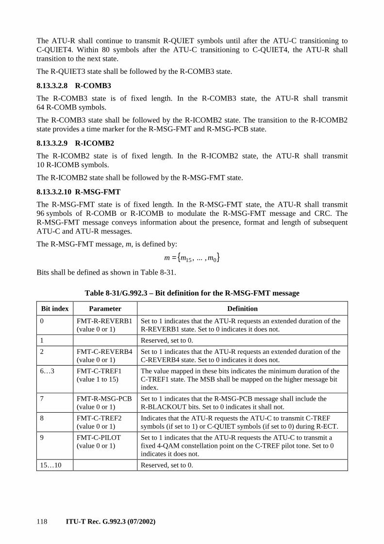
118 ITU-T Rec. G.992.3 (07/2002)
The ATU-R shall continue to transmit R-QUIET symbols until after the ATU-C transitioning to C-QUIET4. Within 80 symbols after the ATU-C transitioning to C-QUIET4, the ATU-R shall transition to the next state.
The R-QUIET3 state shall be followed by the R-COMB3 state.
8.13.3.2.8 R-COMB3
The R-COMB3 state is of fixed length. In the R-COMB3 state, the ATU-R shall transmit 64 R-COMB symbols.
The R-COMB3 state shall be followed by the R-ICOMB2 state. The transition to the R-ICOMB2 state provides a time marker for the R-MSG-FMT and R-MSG-PCB state.
8.13.3.2.9 R-ICOMB2
The R-ICOMB2 state is of fixed length. In the R-ICOMB2 state, the ATU-R shall transmit 10 R-ICOMB symbols.
The R-ICOMB2 state shall be followed by the R-MSG-FMT state.
8.13.3.2.10 R-MSG-FMT
The R-MSG-FMT state is of fixed length. In the R-MSG-FMT state, the ATU-R shall transmit 96 symbols of R-COMB or R-ICOMB to modulate the R-MSG-FMT message and CRC. The R-MSG-FMT message conveys information about the presence, format and length of subsequent ATU-C and ATU-R messages.
The R-MSG-FMT message, m, is defined by:
015 , ... , mmm =
Bits shall be defined as shown in Table 8-31.
Table 8-31/G.992.3 – Bit definition for the R-MSG-FMT message
Bit index Parameter Definition
0 FMT-R-REVERB1 (value 0 or 1)
Set to 1 indicates that the ATU-R requests an extended duration of the R-REVERB1 state. Set to 0 indicates it does not.
1 Reserved, set to 0.
2 FMT-C-REVERB4 (value 0 or 1)
Set to 1 indicates that the ATU-R requests an extended duration of the C-REVERB4 state. Set to 0 indicates it does not.
6…3 FMT-C-TREF1 (value 1 to 15)
The value mapped in these bits indicates the minimum duration of the C-TREF1 state. The MSB shall be mapped on the higher message bit index.
7 FMT-R-MSG-PCB (value 0 or 1)
Set to 1 indicates that the R-MSG-PCB message shall include the R-BLACKOUT bits. Set to 0 indicates it shall not.
8 FMT-C-TREF2 (value 0 or 1)
Indicates that the ATU-R requests the ATU-C to transmit C-TREF symbols (if set to 1) or C-QUIET symbols (if set to 0) during R-ECT.
9 FMT-C-PILOT (value 0 or 1)
Set to 1 indicates that the ATU-R requests the ATU-C to transmit a fixed 4-QAM constellation point on the C-TREF pilot tone. Set to 0 indicates it does not.
15…10 Reserved, set to 0.
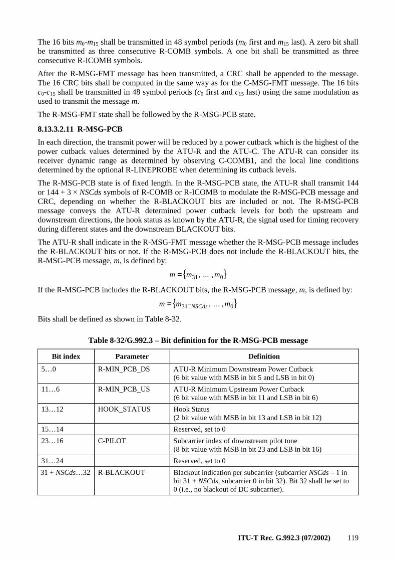
ITU-T Rec. G.992.3 (07/2002) 119
The 16 bits m0-m15 shall be transmitted in 48 symbol periods (m0 first and m15 last). A zero bit shall be transmitted as three consecutive R-COMB symbols. A one bit shall be transmitted as three consecutive R-ICOMB symbols.
After the R-MSG-FMT message has been transmitted, a CRC shall be appended to the message. The 16 CRC bits shall be computed in the same way as for the C-MSG-FMT message. The 16 bits c0-c15 shall be transmitted in 48 symbol periods (c0 first and c15 last) using the same modulation as used to transmit the message m.
The R-MSG-FMT state shall be followed by the R-MSG-PCB state.
8.13.3.2.11 R-MSG-PCB
In each direction, the transmit power will be reduced by a power cutback which is the highest of the power cutback values determined by the ATU-R and the ATU-C. The ATU-R can consider its receiver dynamic range as determined by observing C-COMB1, and the local line conditions determined by the optional R-LINEPROBE when determining its cutback levels.
The R-MSG-PCB state is of fixed length. In the R-MSG-PCB state, the ATU-R shall transmit 144 or 144 + 3 × NSCds symbols of R-COMB or R-ICOMB to modulate the R-MSG-PCB message and CRC, depending on whether the R-BLACKOUT bits are included or not. The R-MSG-PCB message conveys the ATU-R determined power cutback levels for both the upstream and downstream directions, the hook status as known by the ATU-R, the signal used for timing recovery during different states and the downstream BLACKOUT bits.
The ATU-R shall indicate in the R-MSG-FMT message whether the R-MSG-PCB message includes the R-BLACKOUT bits or not. If the R-MSG-PCB does not include the R-BLACKOUT bits, the R-MSG-PCB message, m, is defined by:
031 , ... , mmm =
If the R-MSG-PCB includes the R-BLACKOUT bits, the R-MSG-PCB message, m, is defined by:
031 , ... , mmm NSCds+=
Bits shall be defined as shown in Table 8-32.
Table 8-32/G.992.3 – Bit definition for the R-MSG-PCB message
Bit index Parameter Definition
5…0 R-MIN_PCB_DS ATU-R Minimum Downstream Power Cutback (6 bit value with MSB in bit 5 and LSB in bit 0)
11…6 R-MIN_PCB_US ATU-R Minimum Upstream Power Cutback (6 bit value with MSB in bit 11 and LSB in bit 6)
13…12 HOOK_STATUS Hook Status (2 bit value with MSB in bit 13 and LSB in bit 12)
15…14 Reserved, set to 0
23…16 C-PILOT Subcarrier index of downstream pilot tone (8 bit value with MSB in bit 23 and LSB in bit 16)
31…24 Reserved, set to 0
31 + NSCds…32 R-BLACKOUT Blackout indication per subcarrier (subcarrier NSCds – 1 in bit 31 + NSCds, subcarrier 0 in bit 32). Bit 32 shall be set to 0 (i.e., no blackout of DC subcarrier).
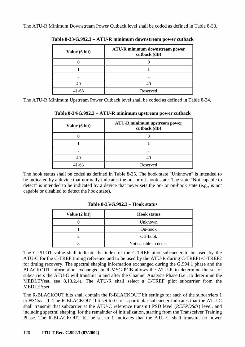
120 ITU-T Rec. G.992.3 (07/2002)
The ATU-R Minimum Downstream Power Cutback level shall be coded as defined in Table 8-33.
Table 8-33/G.992.3 – ATU-R minimum downstream power cutback
Value (6 bit) ATU-R minimum downstream power
cutback (dB)
0 0
1 1
… …
40 40
41-63 Reserved
The ATU-R Minimum Upstream Power Cutback level shall be coded as defined in Table 8-34.
Table 8-34/G.992.3 – ATU-R minimum upstream power cutback
Value (6 bit) ATU-R minimum upstream power
cutback (dB)
0 0
1 1
… …
40 40
41-63 Reserved
The hook status shall be coded as defined in Table 8-35. The hook state "Unknown" is intended to be indicated by a device that normally indicates the on- or off-hook state. The state "Not capable to detect" is intended to be indicated by a device that never sets the on- or on-hook state (e.g., is not capable or disabled to detect the hook state).
Table 8-35/G.992.3 – Hook status
Value (2 bit) Hook status
0 Unknown
1 On-hook
2 Off-hook
3 Not capable to detect
The C-PILOT value shall indicate the index of the C-TREF pilot subcarrier to be used by the ATU-C for the C-TREF timing reference and to be used by the ATU-R during C-TREF1/C-TREF2 for timing recovery. The spectral shaping information exchanged during the G.994.1 phase and the BLACKOUT information exchanged in R-MSG-PCB allows the ATU-R to determine the set of subcarriers the ATU-C will transmit in and after the Channel Analysis Phase (i.e., to determine the MEDLEYset, see 8.13.2.4). The ATU-R shall select a C-TREF pilot subcarrier from the MEDLEYset.
The R-BLACKOUT bits shall contain the R-BLACKOUT bit settings for each of the subcarriers 1 to NSCds – 1. The R-BLACKOUT bit set to 0 for a particular subcarrier indicates that the ATU-C shall transmit that subcarrier at the ATU-C reference transmit PSD level (REFPDSds) level, and including spectral shaping, for the remainder of initialization, starting from the Transceiver Training Phase. The R-BLACKOUT bit be set to 1 indicates that the ATU-C shall transmit no power
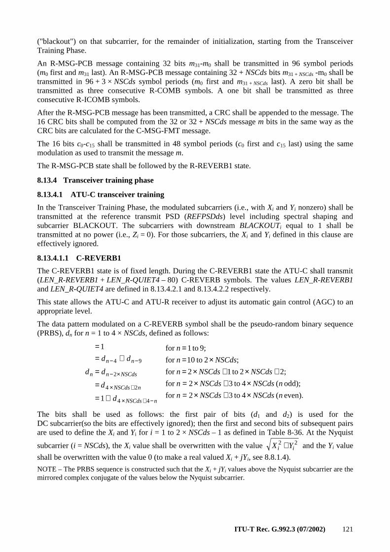
ITU-T Rec. G.992.3 (07/2002) 121
("blackout") on that subcarrier, for the remainder of initialization, starting from the Transceiver Training Phase.
An R-MSG-PCB message containing 32 bits m31-m0 shall be transmitted in 96 symbol periods (m0 first and m31 last). An R-MSG-PCB message containing 32 + NSCds bits m31 + NSCds -m0 shall be transmitted in 96 + 3 × NSCds symbol periods (m0 first and m31 + NSCds last). A zero bit shall be transmitted as three consecutive R-COMB symbols. A one bit shall be transmitted as three consecutive R-ICOMB symbols.
After the R-MSG-PCB message has been transmitted, a CRC shall be appended to the message. The 16 CRC bits shall be computed from the 32 or 32 + NSCds message m bits in the same way as the CRC bits are calculated for the C-MSG-FMT message.
The 16 bits c0-c15 shall be transmitted in 48 symbol periods (c0 first and c15 last) using the same modulation as used to transmit the message m.
The R-MSG-PCB state shall be followed by the R-REVERB1 state.
8.13.4 Transceiver training phase
8.13.4.1 ATU-C transceiver training
In the Transceiver Training Phase, the modulated subcarriers (i.e., with Xi and Yi nonzero) shall be transmitted at the reference transmit PSD (REFPSDds) level including spectral shaping and subcarrier BLACKOUT. The subcarriers with downstream BLACKOUTi equal to 1 shall be transmitted at no power (i.e., Zi = 0). For those subcarriers, the Xi and Yi defined in this clause are effectively ignored.
8.13.4.1.1 C-REVERB1
The C-REVERB1 state is of fixed length. During the C-REVERB1 state the ATU-C shall transmit (LEN_R-REVERB1 + LEN_R-QUIET4 – 80) C-REVERB symbols. The values LEN_R-REVERB1 and LEN_R-QUIET4 are defined in 8.13.4.2.1 and 8.13.4.2.2 respectively.
This state allows the ATU-C and ATU-R receiver to adjust its automatic gain control (AGC) to an appropriate level.
The data pattern modulated on a C-REVERB symbol shall be the pseudo-random binary sequence (PRBS), dn for n = 1 to 4 × NSCds, defined as follows:
even). ( 4 to32for
odd); ( 4 to32for
2;2 to12 for
;2 to10 for
9; to1 for
1
1
44
24
2
94
nNSCdsNSCdsn
nNSCdsNSCdsn
NSCdsNSCdsn
NSCdsn
n
d
d
d
dd
d
nNSCds
nNSCds
NSCdsn
nn
n
×+×=×+×=
+×+×=×=
=
⊕=
=
=
⊕==
−+×
+×
×−
−−
The bits shall be used as follows: the first pair of bits (d1 and d2) is used for the DC subcarrier(so the bits are effectively ignored); then the first and second bits of subsequent pairs are used to define the Xi and Yi for i = 1 to 2 × NSCds – 1 as defined in Table 8-36. At the Nyquist
subcarrier (i = NSCds), the Xi value shall be overwritten with the value 22ii YX + and the Yi value
shall be overwritten with the value 0 (to make a real valued Xi + jYi, see 8.8.1.4).
NOTE – The PRBS sequence is constructed such that the Xi + jYi values above the Nyquist subcarrier are the mirrored complex conjugate of the values below the Nyquist subcarrier.
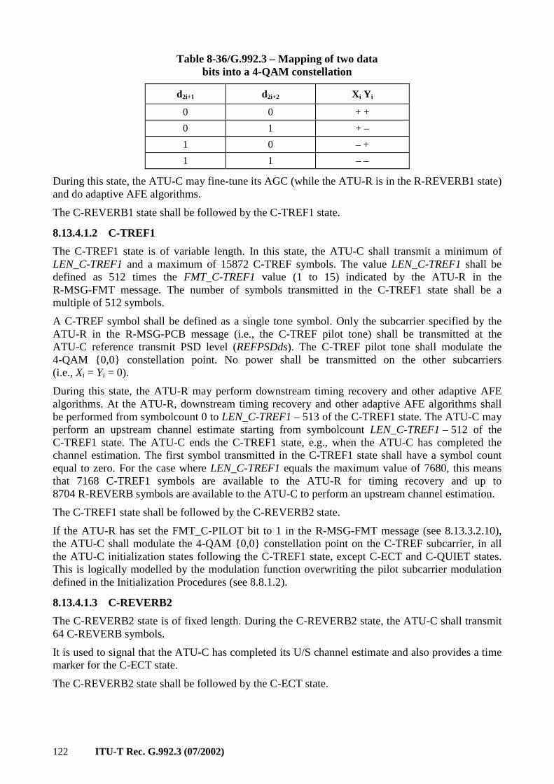
122 ITU-T Rec. G.992.3 (07/2002)
Table 8-36/G.992.3 – Mapping of two data bits into a 4-QAM constellation
d2i+1 d2i+2 Xi Yi
0 0 + +
0 1 + –
1 0 – +
1 1 – –
During this state, the ATU-C may fine-tune its AGC (while the ATU-R is in the R-REVERB1 state) and do adaptive AFE algorithms.
The C-REVERB1 state shall be followed by the C-TREF1 state.
8.13.4.1.2 C-TREF1
The C-TREF1 state is of variable length. In this state, the ATU-C shall transmit a minimum of LEN_C-TREF1 and a maximum of 15872 C-TREF symbols. The value LEN_C-TREF1 shall be defined as 512 times the FMT_C-TREF1 value (1 to 15) indicated by the ATU-R in the R-MSG-FMT message. The number of symbols transmitted in the C-TREF1 state shall be a multiple of 512 symbols.
A C-TREF symbol shall be defined as a single tone symbol. Only the subcarrier specified by the ATU-R in the R-MSG-PCB message (i.e., the C-TREF pilot tone) shall be transmitted at the ATU-C reference transmit PSD level (REFPSDds). The C-TREF pilot tone shall modulate the 4-QAM 0,0 constellation point. No power shall be transmitted on the other subcarriers (i.e., Xi = Yi = 0).
During this state, the ATU-R may perform downstream timing recovery and other adaptive AFE algorithms. At the ATU-R, downstream timing recovery and other adaptive AFE algorithms shall be performed from symbolcount 0 to LEN_C-TREF1 – 513 of the C-TREF1 state. The ATU-C may perform an upstream channel estimate starting from symbolcount LEN_C-TREF1 – 512 of the C-TREF1 state. The ATU-C ends the C-TREF1 state, e.g., when the ATU-C has completed the channel estimation. The first symbol transmitted in the C-TREF1 state shall have a symbol count equal to zero. For the case where LEN_C-TREF1 equals the maximum value of 7680, this means that 7168 C-TREF1 symbols are available to the ATU-R for timing recovery and up to 8704 R-REVERB symbols are available to the ATU-C to perform an upstream channel estimation.
The C-TREF1 state shall be followed by the C-REVERB2 state.
If the ATU-R has set the FMT_C-PILOT bit to 1 in the R-MSG-FMT message (see 8.13.3.2.10), the ATU-C shall modulate the 4-QAM 0,0 constellation point on the C-TREF subcarrier, in all the ATU-C initialization states following the C-TREF1 state, except C-ECT and C-QUIET states. This is logically modelled by the modulation function overwriting the pilot subcarrier modulation defined in the Initialization Procedures (see 8.8.1.2).
8.13.4.1.3 C-REVERB2
The C-REVERB2 state is of fixed length. During the C-REVERB2 state, the ATU-C shall transmit 64 C-REVERB symbols.
It is used to signal that the ATU-C has completed its U/S channel estimate and also provides a time marker for the C-ECT state.
The C-REVERB2 state shall be followed by the C-ECT state.
ITU-T Rec. G.992.3 (07/2002) 123
8.13.4.1.4 C-ECT
The C-ECT state is of fixed length. In this state, the ATU-C shall transmit a vendor discretionary signal with a duration of 512 symbol periods.
During this state, the ATU-C may train its echo canceller, if one is present.
The C-ECT state shall be followed by the C-REVERB3 state.
8.13.4.1.5 C-REVERB3
The C-REVERB3 state is of variable length. In the C-REVERB3 state, the ATU-C shall transmit a minimum of 448 and a maximum of 15936 C-REVERB symbols.
The ATU-R may perform a downstream channel estimation during C-REVERB3.
The ATU-C shall continue to transmit C-REVERB symbols until after the ATU-R transitioning to the R-REVERB3 state. Within 64 symbols after the ATU-R transitioning to the R-REVERB3 state, the ATU-C shall transition to the next state.
In case the ATU-R has indicated in the R-MSG-FMT message that it requires the ATU-C to transmit C-TREF symbols during the R-ECT state, the C-REVERB3 state shall be followed by the C-TREF2 state. In case the ATU-R has indicated that it requires the ATU-C to transmit C-QUIET symbols during the R-ECT state, the C-REVERB1 state shall be followed by the C-QUIET5 state.
8.13.4.1.6 C-TREF2
The C-TREF2 state is of fixed length. In the C-TREF2 state, the ATU-C shall transmit 576 C-TREF symbols.
During this state, the ATU-R may perform timing recovery. The ATU-C shall ignore the signal transmitted by the ATU-R during the R-ECT state.
The C-TREF1 state shall be followed by the C-REVERB4 state.
8.13.4.1.7 C-QUIET5
The C-QUIET5 state is of fixed length. In the C-QUIET5 state, the ATU-C shall transmit 576 C-QUIET symbols.
The C-QUIET5 state shall be followed by the C-REVERB4 state.
8.13.4.1.8 C-REVERB4
The C-REVERB4 state is of fixed length. In this state, the ATU-C shall transmit LEN_C-REVERB4 C-REVERB symbols. The value LEN_C-REVERB4 shall be equal to 1024 if the ATU-C or the ATU-R (or both) have set FMT_C-REVERB4 to 1 in the C-MSG-FMT or R-MSG-FMT message respectively. The value LEN_C-REVERB4 shall be equal to 256 otherwise.
The C-REVERB4 state shall be followed by the C-SEGUE1 state. The transition from the C-REVERB4 state to the C-SEGUE1 state is a time marker for the C-MSG1 and for the introduction of the cyclic prefix.
8.13.4.1.9 C-SEGUE1
The C-SEGUE1 state is of fixed length. In this state, the ATU-C shall transmit 10 C-SEGUE symbols.
The C-SEGUE symbol shall be defined as a subcarrier-by-subcarrier 180 degrees phase reversal of a C-REVERB symbol (i.e., a C-SEGUE symbol modulates the bitwise inverted REVERB PRBS data pattern).
124 ITU-T Rec. G.992.3 (07/2002)
The C-SEGUE1 state shall be followed by the C-MSG1 state.
8.13.4.2 ATU-R transceiver training
In the Transceiver Training Phase, the modulated subcarriers (i.e., with Xi and Yi nonzero) shall be transmitted at the reference transmit PSD (REFPSDus) level including spectral shaping and subcarrier BLACKOUT. The subcarriers with upstream BLACKOUTi equal to 1 shall be transmitted at no power (i.e., Zi = 0). For those subcarriers, the Xi and Yi defined in this clause are effectively ignored.
8.13.4.2.1 R-REVERB1
The R-REVERB1 state is of fixed length. In the R-REVERB1 state, the ATU-R shall transmit LEN_R-REVERB1 R-REVERB symbols. The value LEN_R-REVERB1 shall be equal to 592 if the ATU-C or the ATU-R (or both) have set FMT_R-REVERB1 to 1 in the C-MSG-FMT or R-MSG-FMT message respectively. The value LEN_R-REVERB1 shall be equal to 272 otherwise.
The data pattern modulated on an R-REVERB symbol shall be the pseudo-random binary sequence (PRBS), dn for n = 1 to 4 × NSCus, defined as follows:
even). ( 4 to32for
odd); ( 4 to32for
2;2 to12 for
2 to7 for
6; to1 for
1
1
44
24
2
65
nNSCusNSCusn
nNSCusNSCusn
NSCusNSCusn
NSCusn
n
d
d
d
dd
d
nNSCus
nNSCus
NSCusn
nn
n
×+×=×+×=
+×+×=×=
=
⊕=
=
=⊕=
=
−+×
+×
×−
−−
The bits shall be used as follows: the first pair of bits (d1 and d2) is used for the DC subcarrier (so the bits are effectively ignored); then the first and second bits of subsequent pairs are used to define the Xi
and Yi for i = 1 to 2 × NSCus – 1 as defined in Table 8-36 for C-REVERB symbols. At
the Nyquist subcarrier (i = NSCus), the Xi value shall be overwritten with the value 22ii YX + and
the Yi value shall be overwritten with the value 0 (to make a real valued Xi + jYi, see 8.8.1.4).
NOTE – The PRBS sequence is constructed such that the Xi + jYi values above the Nyquist subcarrier are the mirrored complex conjugate of the values below the Nyquist subcarrier.
During this state, the ATU-R may fine-tune its AGC (while the ATU-C is in the C-REVERB1 state), do timing recovery and other adaptive AFE algorithms.
The R-REVERB1 state shall be followed by the R-QUIET4 state.
8.13.4.2.2 R-QUIET4
The R-QUIET4 state is of fixed length. In the R-QUIET4 state, the ATU-R shall transmit LEN_R-QUIET4 R-QUIET symbols. The value LEN_R-QUIET4 shall be defined as 512 times the FMT_R-QUIET4 value (0 to 31) indicated by the ATU-C in the C-MSG-FMT message, resulting in a length of the R-QUIET4 state between 0 and 15872 symbols. In case LEN_R-QUIET4 is 0, then the ATU-R effectively transitions from the R-REVERB1 to the R-REVERB2 state.
The R-QUIET4 state shall be followed by the R-REVERB2 state.
8.13.4.2.3 R-REVERB2
The R-REVERB2 state is of variable length. In the R-REVERB2 state, the ATU-R shall transmit a minimum of 432 and a maximum of 15888 R-REVERB symbols.
During this state, the ATU-R shall do timing recovery and loop timing and may do other adaptive AFE algorithms. Loop timing is defined as the combination of the slaving of the ATU-R ADC clock to the received signal (i.e., to the ATU-C DAC clock), and tying the ATU-R DAC and ADC
ITU-T Rec. G.992.3 (07/2002) 125
clocks together. Loop timing shall be acquired before symbol count LEN_C-TREF1 – 512 of the C-TREF1 state. The ATU-C may perform a channel estimate during the last 512 symbols of the C-TREF1 state. Such channel estimation requires sufficient sampling clock stability at the ATU-R transmitter. Loop timing shall be maintained in all subsequent states, except for R-ECT when the ATU-R requested C-QUIET5. In the latter case, loop timing shall be reacquired in R-REVERB4.
The ATU-R shall continue to transmit R-REVERB symbols until after the ATU-C transitioning to the C-REVERB2 state. Within 64 symbols after the ATU-C transitioning to the C-REVERB2 state, the ATU-R shall transition to the next state.
The R-REVERB2 state shall be followed by the R-QUIET5 state.
8.13.4.2.4 R-QUIET5
The R-QUIET5 state is of variable length. In the R-QUIET5 state, the ATU-R shall transmit a minimum of 1024 and a maximum of 16384 R-QUIET symbols. The number of symbols transmitted in the R-QUIET5 state shall be a multiple of 512 symbols. However, the last R-QUIET symbol transmitted in the R-QUIET5 state may be shortened by any integer number of samples (at the sample clock frequency fs, as defined in 8.8.1) to accommodate transmitter-to-receiver frame alignment.
During this state, the ATU-R shall ignore the signal transmitted by the ATU-C during the C-ECT state. The ATU-R may perform timing recovery, measure the downstream channel frequency response and train its equalizer (while the ATU-C is in the C-REVERB3 state). The ATU-R transitions to the next state when it has completed its receive signal processing algorithms.
The R-QUIET5 state shall be followed by the R-REVERB3 state.
8.13.4.2.5 R-REVERB3
The R-REVERB3 state is of fixed length. In the R-REVERB3 state, the ATU-R shall transmit 64 R-REVERB symbols.
This state indicates that the ATU-R has completed its training. It also provides a time marker for the R-ECT state.
The R-REVERB3 state shall be followed by the R-ECT state.
8.13.4.2.6 R-ECT
The R-ECT state is of fixed length. In this state, the ATU-R shall transmit a vendor discretionary signal with a duration of 512 symbol periods.
During this state, the ATU-R may train its echo canceller, if one is present.
The R-ECT state shall be followed by the R-REVERB4 state.
8.13.4.2.7 R-REVERB4
The R-REVERB4 state is of variable length. In this state, the ATU-R shall transmit a minimum of LEN_C-REVERB4 and a maximum of LEN_C-REVERB4 + 80 R-REVERB symbols, where LEN_C-REVERB4 is defined in 8.13.4.1.8.
The length of the R-REVERB4 state may be determined in such a manner that the ends of C-SEGUE1 and R-SEGUE1 coincide at the ATU-R.
If the ATU-R requested the ATU-C to transmit C-QUIET symbols during R-ECT (i.e., set the FMT-C-TREF2 bit to 0 in the R-MSG-FMT message), then the ATU-R shall request an extended duration of the C-REVERB4 state (i.e., set the FMT-C-REVERB4 bit to 1 in the R-MSG-FMT message) and the ATU-R shall reacquire loop timing within 512 symbols from the start of the C-REVERB4 state.
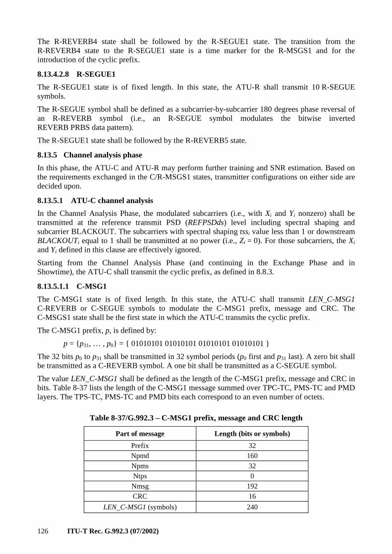
126 ITU-T Rec. G.992.3 (07/2002)
The R-REVERB4 state shall be followed by the R-SEGUE1 state. The transition from the R-REVERB4 state to the R-SEGUE1 state is a time marker for the R-MSGS1 and for the introduction of the cyclic prefix.
8.13.4.2.8 R-SEGUE1
The R-SEGUE1 state is of fixed length. In this state, the ATU-R shall transmit 10 R-SEGUE symbols.
The R-SEGUE symbol shall be defined as a subcarrier-by-subcarrier 180 degrees phase reversal of an R-REVERB symbol (i.e., an R-SEGUE symbol modulates the bitwise inverted REVERB PRBS data pattern).
The R-SEGUE1 state shall be followed by the R-REVERB5 state.
8.13.5 Channel analysis phase
In this phase, the ATU-C and ATU-R may perform further training and SNR estimation. Based on the requirements exchanged in the C/R-MSGS1 states, transmitter configurations on either side are decided upon.
8.13.5.1 ATU-C channel analysis
In the Channel Analysis Phase, the modulated subcarriers (i.e., with Xi and Yi nonzero) shall be transmitted at the reference transmit PSD (REFPSDds) level including spectral shaping and subcarrier BLACKOUT. The subcarriers with spectral shaping tssi value less than 1 or downstream BLACKOUTi equal to 1 shall be transmitted at no power (i.e., Zi = 0). For those subcarriers, the Xi and Yi defined in this clause are effectively ignored.
Starting from the Channel Analysis Phase (and continuing in the Exchange Phase and in Showtime), the ATU-C shall transmit the cyclic prefix, as defined in 8.8.3.
8.13.5.1.1 C-MSG1
The C-MSG1 state is of fixed length. In this state, the ATU-C shall transmit LEN_C-MSG1 C-REVERB or C-SEGUE symbols to modulate the C-MSG1 prefix, message and CRC. The C-MSGS1 state shall be the first state in which the ATU-C transmits the cyclic prefix.
The C-MSG1 prefix, p, is defined by:
p = p31, … , p0 = 01010101 01010101 01010101 01010101
The 32 bits p0 to p31 shall be transmitted in 32 symbol periods (p0 first and p31 last). A zero bit shall be transmitted as a C-REVERB symbol. A one bit shall be transmitted as a C-SEGUE symbol.
The value LEN_C-MSG1 shall be defined as the length of the C-MSG1 prefix, message and CRC in bits. Table 8-37 lists the length of the C-MSG1 message summed over TPC-TC, PMS-TC and PMD layers. The TPS-TC, PMS-TC and PMD bits each correspond to an even number of octets.
Table 8-37/G.992.3 – C-MSG1 prefix, message and CRC length
Part of message Length (bits or symbols)
Prefix 32
Npmd 160
Npms 32
Ntps 0
Nmsg 192
CRC 16
LEN_C-MSG1 (symbols) 240

ITU-T Rec. G.992.3 (07/2002) 127
The C-MSG1 message, m, is defined by:
m = tpsNtps–1, … , tps0, pmsNpms–1, … , pms0, pmdNmd–1, … , pmd0 = mNmsg–1, … , m0
The C-MSG1 message conveys 3 sets of parameters, related to TPS-TC, PMS-TC and PMD configuration. TPS-TC parameters are conveyed in the bits tpsNtps–1 to tps
0 and are defined in
clause 6. PMS-TC parameters are conveyed in the bits pmsNpms–1 to pms0 and are defined in clause 7. PMD parameters are conveyed in the bits pmdNpmd–1 to pmd0 and are defined in clause 8.
The Nmsg bits m0-mNmsg–1 shall be transmitted in Nmsg symbol periods (m0 first and mNmsg–1 last), immediately following the prefix, and using the same modulation as used to transmit the prefix p.
After the C-MSG1 message has been transmitted, a CRC shall be appended to the message. The 16 CRC bits shall be computed from the Nmsg message m bits (thus not including the prefix) in the same way as the CRC bits are calculated for the C-MSG-PCB message.
The 16 bits c0-c15 shall be transmitted in 16 symbol periods (c0 first and c15 last) using the same modulation as used to transmit the message m.
The C-MSG1 state shall be followed by the C-REVERB5 state.
8.13.5.1.2 C-REVERB5
The C-REVERB5 state is of variable length. In the C-REVERB5 state, the ATU-C shall transmit a minimum of 10 and a maximum of (218 + LEN_R-MSG1) C-REVERB symbols.
The ATU-C shall continue to transmit C-REVERB symbols until after the ATU-R transitioning to the R-MEDLEY state. Within 80 symbols after the ATU-R transitioning to the R-MEDLEY state, the ATU-C shall transition to the next state.
The C-REVERB5 state shall be followed by the C-SEGUE2 state. The transition from the C-REVERB5 to the C-SEGUE2 state provides a time marker for the start of the C-MEDLEY state.
8.13.5.1.3 C-SEGUE2
The C-SEGUE2 state is of fixed length. In this state, the ATU-C shall transmit 10 C-SEGUE symbols.
The C-SEGUE symbol shall be defined as the phase inverted C-REVERB symbol.
The C-SEGUE2 state shall be followed by the C-MEDLEY state.
8.13.5.1.4 C-MEDLEY
The C-MEDLEY state is of fixed length. In this state, the ATU-C shall transmit LEN_MEDLEY symbols. The value LEN_MEDLEY shall be the maximum of the CA-MEDLEYus and CA-MEDLEYds values indicated by the ATU-C and the ATU-R in the C-MSG1 and R-MSG1 messages respectively. The value LEN_MEDLEY shall be a multiple of 512 and shall be less than or equal to 32256. The number of symbols transmitted in the C-MEDLEY state shall be equal to the number of symbols transmitted by the ATU-R in the R-MEDLEY state.
A C-MEDLEY symbol shall be defined depending on its symbolcount within the C-MEDLEY state. The first symbol transmitted in the C-MEDLEY state shall have symbolcount equal to zero. For each symbol transmitted in the C-MEDLEY state, the symbolcount shall be incremented.
The data pattern modulated onto each C-MEDLEY symbol shall be taken from the pseudo-random binary sequence (PRBS) defined by:
dn = 1 for n = 1 to 9 and
dn = dn–4 ⊕ dn–9 for n > 9.
The C-MEDLEY symbol with symbol count i shall modulate the 512 bits d512×i+1 to d512×(i+1).
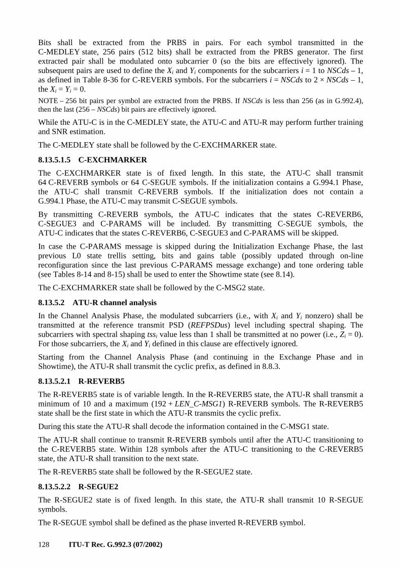
128 ITU-T Rec. G.992.3 (07/2002)
Bits shall be extracted from the PRBS in pairs. For each symbol transmitted in the C-MEDLEY state, 256 pairs (512 bits) shall be extracted from the PRBS generator. The first extracted pair shall be modulated onto subcarrier 0 (so the bits are effectively ignored). The subsequent pairs are used to define the Xi and Yi components for the subcarriers i = 1 to NSCds – 1, as defined in Table 8-36 for C-REVERB symbols. For the subcarriers i = NSCds to 2 × NSCds – 1, the Xi = Yi = 0.
NOTE – 256 bit pairs per symbol are extracted from the PRBS. If NSCds is less than 256 (as in G.992.4), then the last (256 – NSCds) bit pairs are effectively ignored.
While the ATU-C is in the C-MEDLEY state, the ATU-C and ATU-R may perform further training and SNR estimation.
The C-MEDLEY state shall be followed by the C-EXCHMARKER state.
8.13.5.1.5 C-EXCHMARKER
The C-EXCHMARKER state is of fixed length. In this state, the ATU-C shall transmit 64 C-REVERB symbols or 64 C-SEGUE symbols. If the initialization contains a G.994.1 Phase, the ATU-C shall transmit C-REVERB symbols. If the initialization does not contain a G.994.1 Phase, the ATU-C may transmit C-SEGUE symbols.
By transmitting C-REVERB symbols, the ATU-C indicates that the states C-REVERB6, C-SEGUE3 and C-PARAMS will be included. By transmitting C-SEGUE symbols, the ATU-C indicates that the states C-REVERB6, C-SEGUE3 and C-PARAMS will be skipped.
In case the C-PARAMS message is skipped during the Initialization Exchange Phase, the last previous L0 state trellis setting, bits and gains table (possibly updated through on-line reconfiguration since the last previous C-PARAMS message exchange) and tone ordering table (see Tables 8-14 and 8-15) shall be used to enter the Showtime state (see 8.14).
The C-EXCHMARKER state shall be followed by the C-MSG2 state.
8.13.5.2 ATU-R channel analysis
In the Channel Analysis Phase, the modulated subcarriers (i.e., with Xi and Yi nonzero) shall be transmitted at the reference transmit PSD (REFPSDus) level including spectral shaping. The subcarriers with spectral shaping tssi value less than 1 shall be transmitted at no power (i.e., Zi = 0). For those subcarriers, the Xi and Yi defined in this clause are effectively ignored.
Starting from the Channel Analysis Phase (and continuing in the Exchange Phase and in Showtime), the ATU-R shall transmit the cyclic prefix, as defined in 8.8.3.
8.13.5.2.1 R-REVERB5
The R-REVERB5 state is of variable length. In the R-REVERB5 state, the ATU-R shall transmit a minimum of 10 and a maximum (192 + LEN_C-MSG1) R-REVERB symbols. The R-REVERB5 state shall be the first state in which the ATU-R transmits the cyclic prefix.
During this state the ATU-R shall decode the information contained in the C-MSG1 state.
The ATU-R shall continue to transmit R-REVERB symbols until after the ATU-C transitioning to the C-REVERB5 state. Within 128 symbols after the ATU-C transitioning to the C-REVERB5 state, the ATU-R shall transition to the next state.
The R-REVERB5 state shall be followed by the R-SEGUE2 state.
8.13.5.2.2 R-SEGUE2
The R-SEGUE2 state is of fixed length. In this state, the ATU-R shall transmit 10 R-SEGUE symbols.
The R-SEGUE symbol shall be defined as the phase inverted R-REVERB symbol.
ITU-T Rec. G.992.3 (07/2002) 129
The R-SEGUE2 state shall be followed by the R-MSG1 state.
8.13.5.2.3 R-MSGS1
The R-MSG1 state is of fixed length. In this state, the ATU-R shall transmit LEN_R-MSG1 R-REVERB or R-SEGUE symbols to modulate the R-MSG1 prefix, message and CRC.
The R-MSG1 prefix, p, is defined by:
p = p31, … , p0 = 01010101 01010101 01010101 01010101
The 32 bits p0 to p31 shall be transmitted in 32 symbol periods (p0 first and p31 last). A zero bit shall be transmitted as an R-REVERB symbol. A one bit shall be transmitted as an R-SEGUE symbol.
The value LEN_R-MSG1 shall be defined as the length of the R-MSG1 prefix, message and CRC in bits. The length of the R-MSG1 message depends on selections made during the G.994.1 Phase (i.e., the Annex and TPS-TC type). Table 8-38 lists the possible lengths of the R-MSG1 message summed over TPC-TC, PMS-TC and PMD layers. The TPS-TC, PMS-TC and PMD bits each correspond to an even number of octets.
Table 8-38/G.992.3 – R-MSG1 prefix, message and CRC length
Part of message Length (bits or symbols)
Prefix 32
Npmd 32
Npms 0
Ntps 0
Nmsg 32
CRC 16
LEN_R-MSG1 (symbols) 80
The R-MSG1 message, m, is defined by:
m = tpsNtps–1, … , tps0, pmsNpms–1, … , pms0, pmdNpmd–1, … , pmd0 = mNmsg–1, … , m0
The R-MSG1 message conveys 3 sets of parameters, related to TPS-TC, PMS-TC and PMD configuration. TPS-TC parameters are conveyed in the bits tpsNtps–1 to tps0 and are defined in clause 6. PMS-TC parameters are conveyed in the bits pmsNpms–1 to pms0 and are defined in clause 7. PMD parameters are conveyed in the bits pmdNpmd–1 to pmd0 and are defined in clause 8.
The Nmsg bits m0-mNmsg–1 shall be transmitted in Nmsg symbol periods (m0 first and mNmsg–1 last), immediately following the prefix, and using the same modulation as used to transmit the prefix p.
After the R-MSG1 message has been transmitted, a CRC shall be appended to the message. The 16 CRC bits shall be computed from the Nmsg message m bits (thus not including the prefix) in the same way as the CRC bits are calculated for the C-MSG-PCB message.
The 16 bits c0-c15 shall be transmitted in 16 symbol periods (c0 first and c15 last) using the same modulation as used to transmit the message m.
The R-MSG1 state shall be followed by the R-MEDLEY state.
8.13.5.2.4 R-MEDLEY
The R-MEDLEY state is of fixed length. In this state, the ATU-R shall transmit LEN_MEDLEY symbols. The value LEN_MEDLEY shall be the maximum of the CA-MEDLEYus and CA-MEDLEYds values indicated by the ATU-C and the ATU-R in the C-MSG1 and R-MSG1 messages respectively. The value LEN_MEDLEY shall be a multiple of 512 and shall be less than or
130 ITU-T Rec. G.992.3 (07/2002)
equal to 32256. The number of symbols transmitted in the R-MEDLEY state shall be equal to the number of symbols transmitted by the ATU-C in the C-MEDLEY state.
An R-MEDLEY symbol shall be defined depending on its symbol count within the R-MEDLEY state. The first symbol transmitted in the R-MEDLEY state shall have symbol count equal to zero. For each symbol transmitted in the R-MEDLEY state, the symbol count shall be incremented.
The data pattern modulated onto each R-MEDLEY symbol shall be taken from the pseudo-random binary sequence (PRBS) defined by:
23.for
and 23 to1for 1
2318 >⊕===
−− nddd
nd
nnn
n
The R-MEDLEY symbol with symbol count i shall modulate the bits d2×NSCus×i+1 to d2×NSCus×(i+1). The value of NSC (the number of upstream subcarriers) is defined in the annexes.
Bits shall be extracted from the PRBS in pairs. For each symbol transmitted in the R-MEDLEY state, NSCus pairs (2 × NSCus bits) shall be extracted from the PRBS generator. The first extracted pair shall be modulated onto subcarrier 0 (so the bits are effectively ignored). The subsequent pairs are used to define the Xi and Yi components for the subcarriers i = 1 to NSCus – 1, as defined in Table 8-36 for C-REVERB symbols. For the subcarriers i = NSCus to 2 × NSCus – 1, Xi = 0 and Yi = 0.
While the ATU-R is in the R-MEDLEY state, the ATU-C and ATU-R may perform further training and SNR estimation.
The R-MEDLEY state shall be followed by the R-EXCHMARKER state.
8.13.5.2.5 R-EXCHMARKER
The R-EXCHMARKER state is of fixed length. In this state, the ATU-R shall transmit 64 R-REVERB symbols or 64 R-SEGUE symbols. If the initialization contains a G.994.1 Phase, the ATU-R shall transmit C-REVERB symbols. If the initialization does not contain a G.994.1 Phase, the ATU-R may transmit R-SEGUE symbols.
By transmitting R-REVERB symbols, the ATU-R indicates that the states R-REVERB6, R-SEGUE3 and R-PARAMS will be included. By transmitting R-SEGUE symbols, the ATU-R indicates that the states R-REVERB6, R-SEGUE3 and R-PARAMS will be skipped.
In case the R-PARAMS message is skipped during the Initialization Exchange Phase, the last previous L0 state trellis setting, bits and gains table (possibly updated through on-line reconfiguration since the last previous R-PARAMS message exchange) and tone ordering table (see Tables 8-14 and 8-15) shall be used to enter the Showtime state (see 8.14).
The R-EXCHMARKER state shall be followed by the R-MSG2 state.
8.13.6 Exchange phase
8.13.6.1 ATU-C exchange
In the Exchange Phase, the modulated subcarriers (i.e., with Xi and Yi nonzero) shall be transmitted at the reference transmit PSD (REFPSDds) level including spectral shaping and subcarrier BLACKOUT. The subcarriers with spectral shaping tssi value less than 1 or downstream BLACKOUTi equal to 1 shall be transmitted at no power (i.e., Zi = 0). For those subcarriers, the Xi and Yi defined in this clause are effectively ignored.
8.13.6.1.1 C-MSG2
The C-MSG2 state is of fixed length. In the C-MSG2 state, the ATU-C shall transmit (NSCus + 16) C-REVERB or C-SEGUE symbols to modulate the C-MSG2 message and CRC.
ITU-T Rec. G.992.3 (07/2002) 131
The C-MSG2 message, m, is defined by:
m = mNSCus–1, … , m0
The bit mi shall be set to 1 to indicate that the ATU-R shall use subcarrier index i to modulate the R-PARAMS message. The bit mi shall be set to 0 to indicate that the ATU-R shall not use subcarrier index i to modulate the R-PARAM message. At least 4 subcarriers shall be used for modulation of the R-PARAMS message. The R-PARAM message will be transmitted at about 8 kbit/s times the number of subcarriers used for modulation of the message.
The bits m0-mNSCus–1 shall be transmitted in NSC symbol periods (m0 first and mNSCus–1 last). A zero bit shall be transmitted as a C-REVERB symbol. A one bit shall be transmitted as a C-SEGUE symbol.
After the C-MSG2 message has been transmitted, a CRC shall be appended to the message. The 16 CRC bits shall be computed from the NSCus message m bits in the same way as the CRC bits are calculated for the C-MSG-FMT message.
The 16 bits c0-c15 shall be transmitted in 16 symbol periods (c0 first and c15 last) using the same modulation as used to transmit the message m.
If the ATU-C has transmitted C-REVERB symbols during the C-EXCHMARKER state, the C-MSG2 state shall be followed by the C-REVERB6 state. If the ATU-C has transmitted C-SEGUE symbols during the C-EXCHMARKER state, the C-MSG2 state shall be followed by the C-REVERB7 state.
8.13.6.1.2 C-REVERB6
The C-REVERB6 state is of variable length. In this state, the ATU-C shall transmit a minimum of (246 – NSCus) and a maximum of (2246 – NSCus) C-REVERB symbols.
This state is a filler state to allow the ATU-C to receive (and decode) the complete R-MSG2 message.
If the ATU-R has transmitted R-REVERB symbols during the R-EXCHMARKER state, the ATU-C shall continue to transmit C-REVERB symbols until after the ATU-R transitioning to the R-REVERB6 state. Within 80 to 2000 symbols after the ATU-R transitioning to the R-REVERB6 state, the ATU-C shall transition to the next state.
If the ATU-R has transmitted R-SEGUE symbols during the R-EXCHMARKER state, the ATU-C shall continue to transmit C-REVERB symbols until after the ATU-R transitioning to the R-REVERB7 state. Within 80 to 2000 symbols after the ATU-R transitioning to the R-REVERB7 state, the ATU-C shall transition to the next state.
The C-REVERB6 state shall be followed by the C-SEGUE3 state.
8.13.6.1.3 C-SEGUE3
The C-SEGUE3 state is of fixed length. In this state, the ATU-C shall transmit 10 C-SEGUE symbols.
The C-SEGUE symbol shall be defined as the phase inverted C-REVERB symbol.
The C-SEGUE3 state shall be followed by the C-PARAMS state.
8.13.6.1.4 C-PARAMS
The C-PARAMS state is of fixed length. In this state, the ATU-C shall transmit LEN_C-PARAMS C-PARAMS symbols to modulate the C-PARAMS message and CRC at (2 × NSC_C-PARAMS) bits per symbol. The value NSC_C-PARAMS shall be defined as the number of subcarriers to be used for modulation of the C-PARAMS message as indicated by the ATU-R in the R-MSG2 message. The value LEN_C-PARAMS shall be defined as (length of the C-PARAMS message and
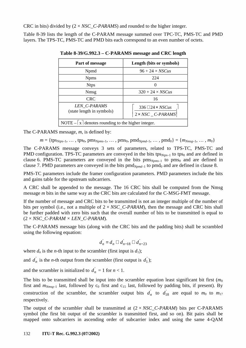
132 ITU-T Rec. G.992.3 (07/2002)
CRC in bits) divided by (2 × NSC_C-PARAMS) and rounded to the higher integer.
Table 8-39 lists the length of the C-PARAM message summed over TPC-TC, PMS-TC and PMD layers. The TPS-TC, PMS-TC and PMD bits each correspond to an even number of octets.
Table 8-39/G.992.3 – C-PARAMS message and CRC length
Part of message Length (bits or symbols)
Npmd 96 + 24 × NSCus
Npms 224
Ntps 0
Nmsg 320 + 24 × NSCus
CRC 16
LEN_C-PARAMS (state length in symbols)
××+
C-PARAMSNSC
NSCus
_2
24336
NOTE – x denotes rounding to the higher integer.
The C-PARAMS message, m, is defined by:
m = tpsNtps–1, … , tps0, pmsNpms–1, … , pms0, pmdNpmd–1, … , pmd0 = mNmsg–1, … , m0
The C-PARAMS message conveys 3 sets of parameters, related to TPS-TC, PMS-TC and PMD configuration. TPS-TC parameters are conveyed in the bits tpsNtps–1 to tps0 and are defined in clause 6. PMS-TC parameters are conveyed in the bits pmsNpms–1 to pms0 and are defined in clause 7. PMD parameters are conveyed in the bits pmdNpmd–1 to pmd0 and are defined in clause 8.
PMS-TC parameters include the framer configuration parameters. PMD parameters include the bits and gains table for the upstream subcarriers.
A CRC shall be appended to the message. The 16 CRC bits shall be computed from the Nmsg message m bits in the same way as the CRC bits are calculated for the C-MSG-FMT message.
If the number of message and CRC bits to be transmitted is not an integer multiple of the number of bits per symbol (i.e., not a multiple of 2 × NSC_C-PARAM), then the message and CRC bits shall be further padded with zero bits such that the overall number of bits to be transmitted is equal to (2 × NSC_C-PARAM × LEN_C-PARAM).
The C-PARAMS message bits (along with the CRC bits and the padding bits) shall be scrambled using the following equation:
'23
'18
'−− ⊕⊕= nnnn dddd
where dn is the n-th input to the scrambler (first input is d1);
and 'nd is the n-th output from the scrambler (first output is '
1d );
and the scrambler is initialized to 'nd = 1 for n < 1.
The bits to be transmitted shall be input into the scrambler equation least significant bit first (m0 first and mNmsg–1 last, followed by c0 first and c15 last, followed by padding bits, if present). By
construction of the scrambler, the scrambler output bits 'nd to '
18d are equal to m0 to m17
respectively.
The output of the scrambler shall be transmitted at (2 × NSC_C-PARAM) bits per C-PARAMS symbol (the first bit output of the scrambler is transmitted first, and so on). Bit pairs shall be mapped onto subcarriers in ascending order of subcarrier index and using the same 4-QAM
ITU-T Rec. G.992.3 (07/2002) 133
modulation as defined in Table 8-36 for C-REVERB symbols.
The C-PARAMS symbol shall contain only the NSC_C-PARAM subcarriers (carrying the message bits) and the C-TREF pilot tone. The other subcarriers shall be transmitted at no power (i.e., Xi = Yi = 0).
The C-TREF pilot may be part of the set of NSC-PARAMS subcarriers (carrying the message bits). In this case, the C-TREF pilot shall be modulated with message bits. Otherwise, it shall be modulated with the fixed 0,0 4-QAM constellation point.
The C-PARAMS state shall be followed by the C-REVERB7 state.
8.13.6.1.5 C-REVERB7
The C-REVERB7 state is of variable length.
The ATU-C may transition to C-REVERB7 before or after the ATU-R transitions to R-REVERB7 (depending on the presence and length of the PARAMS and REVERB6 states).
If the ATU-C transitions to the C-REVERB7 state before the ATU-R transitions to the R-REVERB7 state, then the ATU-C shall continue to transmit C-REVERB symbols until after the ATU-R transitions to the R-REVERB7 state. The ATU-C shall transition to the next state within 128 to 2048 symbols after the ATU-R transitioning to the R-REVERB7 state.
If the ATU-C transitions to the C-REVERB7 state after the ATU-R transitions to the R-REVERB7 state, then the ATU-C shall transmit a minimum of 128 and a maximum of 2048 C-REVERB symbols in the C-REVERB7 state.
The C-REVERB7 state shall be followed by the C-SEGUE4 state. The transition from the C-REVERB7 state to the C-SEGUE4 state provides a time marker for the transition to the C-SHOWTIME state.
8.13.6.1.6 C-SEGUE4
The C-SEGUE4 state is of fixed length. In this state, the ATU-C shall transmit 10 C-SEGUE symbols.
The C-SEGUE4 state shall be followed by the C-SHOWTIME state.
8.13.6.2 ATU-R exchange
In the Exchange Phase, the modulated subcarriers (i.e., with Xi and Yi nonzero) shall be transmitted at the reference transmit PSD (REFPSDus) level including spectral shaping. The subcarriers with spectral shaping tssi value less than 1 shall be transmitted at no power (i.e., Zi = 0). For those subcarriers, the Xi and Yi defined in this clause are effectively ignored.
8.13.6.2.1 R-MSGS2
The R-MSG2 state is of fixed length. In the R-MSG2 state, the ATU-R shall transmit 272 R-REVERB or R-SEGUE symbols to modulate the R-MSG2 message and CRC.
The R-MSG2 message, m, is defined by:
m = m225, … , m0
The bit mi shall be set to 1 to indicate that the ATU-C shall use subcarrier index i to modulate the C-PARAMS message. The bit mi shall be set to 0 to indicate that the ATU-C shall not use subcarrier index i to modulate the C-PARAMS message. At least 4 subcarriers shall be used for modulation of the C-PARAMS message. The C-PARAM message will be transmitted at about 8 kbit/s times the number of subcarriers used for modulation of the message.
NOTE – The R-MSG2 message length is 256 bits (1 bit per subcarrier). If NSCds is less than 256 (as in G.992.4), then the last (256 – NSCds) bits m255 to mNSCds are set to 0.
134 ITU-T Rec. G.992.3 (07/2002)
If the ATU-R has set the R-MSG-FMT message bit FMT-C-PILOT to 1, then the ATU-C modulates the C-TREF pilot tone with a fixed constellation point. In this case, the ATU-R shall not use the C-TREF pilot tone for modulation of the C-PARAMS message.
The bits m0-m255 shall be transmitted in 256 symbol periods (m0 first and m255 last). A zero bit shall be transmitted as an R-REVERB symbol. A one bit shall be transmitted as an R-SEGUE symbol.
After the R-MSG2 message has been transmitted, a CRC shall be appended to the message. The 16 CRC bits shall be computed from the 256 message m bits in the same way as the CRC bits are calculated for the C-MSG-PCB message.
The 16 bits c0-c15 shall be transmitted in 16 symbol periods (c0 first and c15 last) using the same modulation as used to transmit the message m.
If the ATU-R has transmitted R-REVERB symbols during the R-EXCHMARKER state, the R-MSG2 state shall be followed by the R-REVERB6 state. If the ATU-R has transmitted R-SEGUE symbols during the R-EXCHMARKER state, the R-MSG2 state shall be followed by the R-REVERB7 state.
8.13.6.2.2 R-REVERB6
The R-REVERB6 state is of variable length. In this state, the ATU-R shall transmit a minimum of 80 and a maximum of 2000 R-REVERB symbols.
This state is a filler state to allow the ATU-R to receive (and decode) the complete C-MSG2 message.
The R-REVERB6 state shall be followed by the R-SEGUE3 state.
8.13.6.2.3 R-SEGUE3
The R-SEGUE3 state is of fixed length. In this state, the ATU-R shall transmit 10 R-SEGUE symbols.
The R-SEGUE symbol shall be defined as the phase inverted R-REVERB symbol.
The R-SEGUE3 state shall be followed by the R-PARAMS state.
8.13.6.2.4 R-PARAMS
The R-PARAMS state is of variable length. In this state, the ATU-R shall transmit LEN_R-PARAMS symbols to modulate the R-PARAMS message and CRC at (2 × NSC_R-PARAMS) bits per symbol.
The value NSC_R-PARAMS shall be defined as the number of subcarriers to be used for modulation of the R-PARAMS message as indicated by the ATU-C in the C-MSG2 message. The value LEN_R-PARAMS shall be defined as (length of the R-PARAMS message and CRC in bits) divided by (2 × NSC_R-PARAMS) and rounded to the higher integer.
Table 8-40 lists the length of the R-PARAM message summed over TPC-TC, PMS-TC and PMD layers. The TPS-TC, PMS-TC and PMD bits each correspond to an even number of octets.
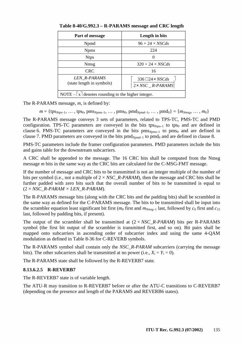
ITU-T Rec. G.992.3 (07/2002) 135
Table 8-40/G.992.3 – R-PARAMS message and CRC length
Part of message Length in bits
Npmd 96 + 24 × NSCds
Npms 224
Ntps 0
Nmsg 320 + 24 × NSCds
CRC 16
LEN_R-PARAMS (state length in symbols)
××+
R-PARAMSNSC
NSCds
_2
24336
NOTE – x denotes rounding to the higher integer.
The R-PARAMS message, m, is defined by:
m = tpsNtps–1, … , tps0, pmsNpms–1, … , pms0, pmdNpmd–1, … , pmd0 = mNmsg, … , m0
The R-PARAMS message conveys 3 sets of parameters, related to TPS-TC, PMS-TC and PMD configuration. TPS-TC parameters are conveyed in the bits tpsNtps–1 to tps0 and are defined in clause 6. PMS-TC parameters are conveyed in the bits pmsNpms–1 to pms0 and are defined in clause 7. PMD parameters are conveyed in the bits pmdNpmd–1 to pmd0 and are defined in clause 8.
PMS-TC parameters include the framer configuration parameters. PMD parameters include the bits and gains table for the downstream subcarriers.
A CRC shall be appended to the message. The 16 CRC bits shall be computed from the Nmsg message m bits in the same way as the CRC bits are calculated for the C-MSG-FMT message.
If the number of message and CRC bits to be transmitted is not an integer multiple of the number of bits per symbol (i.e., not a multiple of 2 × NSC_R-PARAM), then the message and CRC bits shall be further padded with zero bits such that the overall number of bits to be transmitted is equal to (2 × NSC_R-PARAM × LEN_R-PARAM).
The R-PARAMS message bits (along with the CRC bits and the padding bits) shall be scrambled in the same way as defined for the C-PARAMS message. The bits to be transmitted shall be input into the scrambler equation least significant bit first (m0 first and mNmsg–1 last, followed by c0 first and c15
last, followed by padding bits, if present).
The output of the scrambler shall be transmitted at (2 × NSC_R-PARAM) bits per R-PARAMS symbol (the first bit output of the scrambler is transmitted first, and so on). Bit pairs shall be mapped onto subcarriers in ascending order of subcarrier index and using the same 4-QAM modulation as defined in Table 8-36 for C-REVERB symbols.
The R-PARAMS symbol shall contain only the NSC_R-PARAM subcarriers (carrying the message bits). The other subcarriers shall be transmitted at no power (i.e., Xi = Yi = 0).
The R-PARAMS state shall be followed by the R-REVERB7 state.
8.13.6.2.5 R-REVERB7
The R-REVERB7 state is of variable length.
The ATU-R may transition to R-REVERB7 before or after the ATU-C transitions to C-REVERB7 (depending on the presence and length of the PARAMS and REVERB6 states).

136 ITU-T Rec. G.992.3 (07/2002)
If the ATU-R transitions to the R-REVERB7 state before the ATU-C transitions to the C-REVERB7 state, then the ATU-R shall continue to transmit R-REVERB symbols until after the ATU-C transitions to the C-REVERB7 state. The ATU-R shall transition to the next state within 128 to 2048 symbols after the ATU-C transitioning to the C-REVERB7 state.
If the ATU-R transitions to the R-REVERB7 state after the ATU-C transitions to the C-REVERB7 state, then the ATU-R shall transmit a minimum of 128 and a maximum of 2048 R-REVERB symbols in the R-REVERB7 state.
The R-REVERB7 state shall be followed by the R-SEGUE4 state. The transition from the R-REVERB7 state to the R-SEGUE4 state provides a time marker for the transition to the R-SHOWTIME state.
8.13.6.2.6 R-SEGUE4
The R-SEGUE4 state is of fixed length. In this state, the ATU-R shall transmit 10 R-SEGUE symbols.
The R-SEGUE4 state shall be followed by the C-SHOWTIME state.
8.13.7 Timing diagram of the initialization procedures
The Figure 8-26 show the timing diagram of the first part of the Initialization Procedures, from the G.994.1 phase up to the start of the Channel Analysis phase. The Figures 8-27 to 8-30 show the second part of the Initialization procedures, from the end of the Channel Analysis Phase up to Showtime. These four timing diagrams represent the four cases resulting from whether the C-PARAMS and/or R-PARAMS states are included or not.
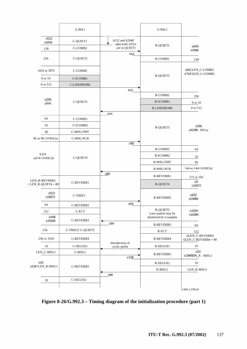
ITU-T Rec. G.992.3 (07/2002) 137
G.992.3_F08-26
G.994.1
C-COMB1
C-QUIET1
G.994.1
C-QUIET2
C-COMB2
C-ICOMB1
C-LINEPROBE
R-QUIET1
R-COMB1
R-QUIET2
R-COMB2
R-ICOMB1
R-LINEPROBE
C-QUIET3
C-COMB3
C-ICOMB2
C-MSG-FMT
C-MSG-PCB
R-COMB3
128
256
1024 or 3872
0 or 10
0 or 512
64
10
96
96 or 96+3×NSCus
128
256
0 or 10
0 or 512
64
≤64
≥512 and ≤2048after both ATUs are in QUIET1
R-QUIET3
C-QUIET4
C-REVERB1
C-TREF1
C-REVERB2
C-ECT
C-REVERB3
C-TREF2/ C-QUIET5
C-REVERB4
C-SEGUE1
C-MSG1
R-ICOMB2
R-MSG-FMT
R-MSG-PCB
R-REVERB1
R-QUIET5
R-REVERB3
R-QUIET4
R-REVERB2
R-ECT
R-REVERB4
R-SEGUE1
10
96
144 or 144+3×NSCds
272 or 592
64
512
10
LEN_C-MSG1
LEN_R-REVERB1+ LEN_R-QUIET4 – 80
64
512
576
256 or 1024
10Introduction ofcyclic prefix
Last symbol may be shortened by n samples
C-REVERB5R-SEGUE2
R-MSG1
R-REVERB5
10
LEN_R-MSG1
C-SEGUE210
≥256≤906
≥314≤474+3×NSCds
≥512≤4204
≥512≤15872
≥448≤15936
≥10≤218+LEN_R-MSG1
≤64
≤64
≤80
≤80
≤64
≤64
≤128
≤80
≥640≤4396
≥266≤410+3×NSCus
≥0≤15872
≥432≤15888
≥1024≤16384
≥LEN_C-REVERB4≤LEN_C-REVERB4 + 80
≥10≤196+ΛΕΝ_Χ-MSG1
≥64+LEN_C-COMB2≤714+LEN_C-COMB2
Figure 8-26/G.992.3 – Timing diagram of the initialization procedure (part 1)
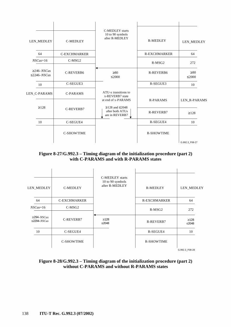
138 ITU-T Rec. G.992.3 (07/2002)
G.992.3_F08-27
C-MEDLEY R-MEDLEY
C-MSG2
R-EXCHMARKER
R-MSG2
R-REVERB6
R-SEGUE3
R-PARAMS
C-SEGUE3
C-PARAMS
C-REVERB7R-REVERB7
C-SHOWTIME
NSCus+16
10
LEN_R-PARAMS
≥80≤2000
≥80≤2000
LEN_MEDLEY LEN_MEDLEY
6464 C-EXCHMARKER
C-REVERB6≥246–NSCus≤2246–NSCus
10
LEN_C-PARAMS
272
ATU-x transitions to x-REVERB7 state
at end of x-PARAMS
≥128 and ≤2048 after both ATUsare in REVERB7
≥128
≥128
R-SEGUE4C-SEGUE4 1010
R-SHOWTIME
C-MEDLEY starts 10 to 90 symbols after R-MEDLEY
Figure 8-27/G.992.3 – Timing diagram of the initialization procedure (part 2) with C-PARAMS and with R-PARAMS states
G.992.3_F08-28
C-MEDLEY R-MEDLEY
C-MSG2
R-EXCHMARKER
R-MSG2
C-REVERB7R-REVERB7
C-SHOWTIME
NSCus+16
LEN_MEDLEY LEN_MEDLEY
6464 C-EXCHMARKER
272
R-SEGUE4C-SEGUE4 1010
R-SHOWTIME
C-MEDLEY starts 10 to 90 symbols after R-MEDLEY
≥294–NSCus≤2294–NSCus ≥128
≤2048≥128
≤2048
Figure 8-28/G.992.3 – Timing diagram of the initialization procedure (part 2) without C-PARAMS and without R-PARAMS states
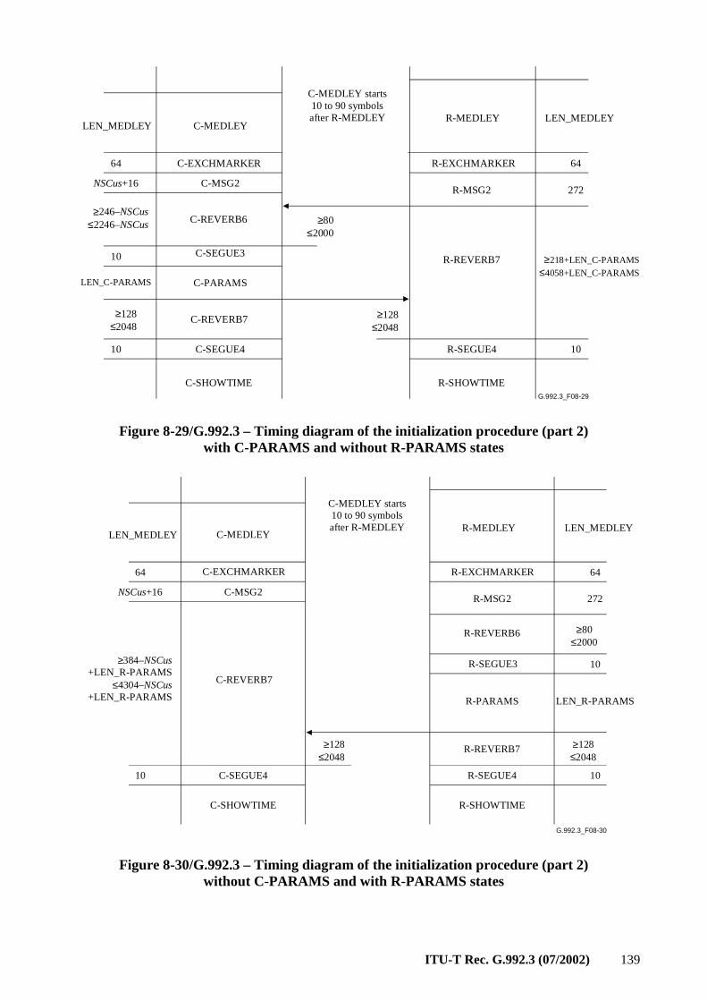
ITU-T Rec. G.992.3 (07/2002) 139
G.992.3_F08-29
C-MEDLEYR-MEDLEY
C-MSG2
R-EXCHMARKER
R-MSG2
R-REVERB7C-SEGUE3
C-PARAMS
C-REVERB7
C-SHOWTIME
NSCus+16
≥218+LEN_C-PARAMS≤4058+LEN_C-PARAMS
≥80≤2000
LEN_MEDLEYLEN_MEDLEY
6464 C-EXCHMARKER
C-REVERB6
10
LEN_C-PARAMS
272
≥128≤2048
R-SEGUE4C-SEGUE4 1010
R-SHOWTIME
C-MEDLEY starts 10 to 90 symbols after R-MEDLEY
≥128≤2048
≥246–NSCus≤2246–NSCus
Figure 8-29/G.992.3 – Timing diagram of the initialization procedure (part 2) with C-PARAMS and without R-PARAMS states
G.992.3_F08-30
C-MEDLEYR-MEDLEY
C-MSG2
R-EXCHMARKER
R-MSG2
R-REVERB6
R-SEGUE3
R-PARAMS
C-REVERB7
R-REVERB7
C-SHOWTIME
NSCus+16
10
LEN_R-PARAMS
≥80≤2000
LEN_MEDLEYLEN_MEDLEY
6464 C-EXCHMARKER
272
≥384–NSCus+LEN_R-PARAMS
≤4304–NSCus+LEN_R-PARAMS
≥128≤2048
R-SEGUE4C-SEGUE4 1010
R-SHOWTIME
C-MEDLEY starts 10 to 90 symbols after R-MEDLEY
≥128≤2048
Figure 8-30/G.992.3 – Timing diagram of the initialization procedure (part 2) without C-PARAMS and with R-PARAMS states
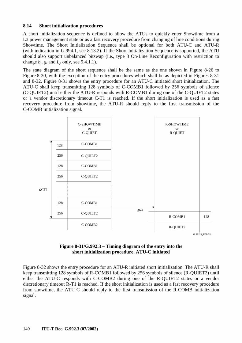
140 ITU-T Rec. G.992.3 (07/2002)
8.14 Short initialization procedures
A short initialization sequence is defined to allow the ATUs to quickly enter Showtime from a L3 power management state or as a fast recovery procedure from changing of line conditions during Showtime. The Short Initialization Sequence shall be optional for both ATU-C and ATU-R (with indication in G.994.1, see 8.13.2). If the Short Initialization Sequence is supported, the ATU should also support unbalanced bitswap (i.e., type 3 On-Line Reconfiguration with restriction to change bi, gi and Lp only, see 9.4.1.1).
The state diagram of the short sequence shall be the same as the one shown in Figure 8-26 to Figure 8-30, with the exception of the entry procedures which shall be as depicted in Figures 8-31 and 8-32. Figure 8-31 shows the entry procedure for an ATU-C initiated short initialization. The ATU-C shall keep transmitting 128 symbols of C-COMB1 followed by 256 symbols of silence (C-QUIET2) until either the ATU-R responds with R-COMB1 during one of the C-QUIET2 states or a vendor discretionary timeout C-T1 is reached. If the short initialization is used as a fast recovery procedure from showtime, the ATU-R should reply to the first transmission of the C-COMB initialization signal.
G.992.3_F08-31
C-SHOWTIMEor
C-QUIET
128 C-COMB1
C-QUIET2256
128 C-COMB1
C-QUIET2
128 C-COMB1
C-QUIET2
256
256
C-COMB2
≤CT1
R-SHOWTIMEor
R-QUIET
≤64
R-COMB1 128
R-QUIET2
Figure 8-31/G.992.3 – Timing diagram of the entry into the short initialization procedure, ATU-C initiated
Figure 8-32 shows the entry procedure for an ATU-R initiated short initialization. The ATU-R shall keep transmitting 128 symbols of R-COMB1 followed by 256 symbols of silence (R-QUIET2) until either the ATU-C responds with C-COMB2 during one of the R-QUIET2 states or a vendor discretionary timeout R-T1 is reached. If the short initialization is used as a fast recovery procedure from showtime, the ATU-C should reply to the first transmission of the R-COMB initialization signal.
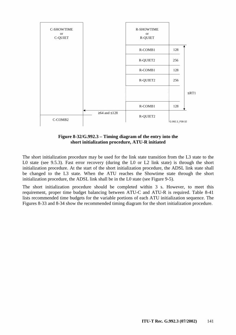
ITU-T Rec. G.992.3 (07/2002) 141
G.992.3_F08-32
R-SHOWTIMEor
R-QUIET
128R-COMB1
R-QUIET2 256
128R-COMB1
R-QUIET2
128R-COMB1
R-QUIET2
256
≤RT1
C-SHOWTIMEor
C-QUIET
≥64 and ≤128
C-COMB2
Figure 8-32/G.992.3 – Timing diagram of the entry into the short initialization procedure, ATU-R initiated
The short initialization procedure may be used for the link state transition from the L3 state to the L0 state (see 9.5.3). Fast error recovery (during the L0 or L2 link state) is through the short initialization procedure. At the start of the short initialization procedure, the ADSL link state shall be changed to the L3 state. When the ATU reaches the Showtime state through the short initialization procedure, the ADSL link shall be in the L0 state (see Figure 9-5).
The short initialization procedure should be completed within 3 s. However, to meet this requirement, proper time budget balancing between ATU-C and ATU-R is required. Table 8-41 lists recommended time budgets for the variable portions of each ATU initialization sequence. The Figures 8-33 and 8-34 show the recommended timing diagram for the short initialization procedure.
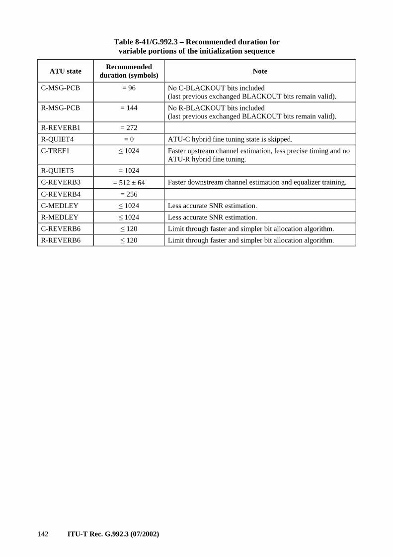
142 ITU-T Rec. G.992.3 (07/2002)
Table 8-41/G.992.3 – Recommended duration for variable portions of the initialization sequence
ATU state Recommended
duration (symbols) Note
C-MSG-PCB = 96 No C-BLACKOUT bits included (last previous exchanged BLACKOUT bits remain valid).
R-MSG-PCB = 144 No R-BLACKOUT bits included (last previous exchanged BLACKOUT bits remain valid).
R-REVERB1 = 272
R-QUIET4 = 0 ATU-C hybrid fine tuning state is skipped.
C-TREF1 ≤ 1024 Faster upstream channel estimation, less precise timing and no ATU-R hybrid fine tuning.
R-QUIET5 = 1024
C-REVERB3 = 512 ± 64 Faster downstream channel estimation and equalizer training.
C-REVERB4 = 256
C-MEDLEY ≤ 1024 Less accurate SNR estimation.
R-MEDLEY ≤ 1024 Less accurate SNR estimation.
C-REVERB6 ≤ 120 Limit through faster and simpler bit allocation algorithm.
R-REVERB6 ≤ 120 Limit through faster and simpler bit allocation algorithm.
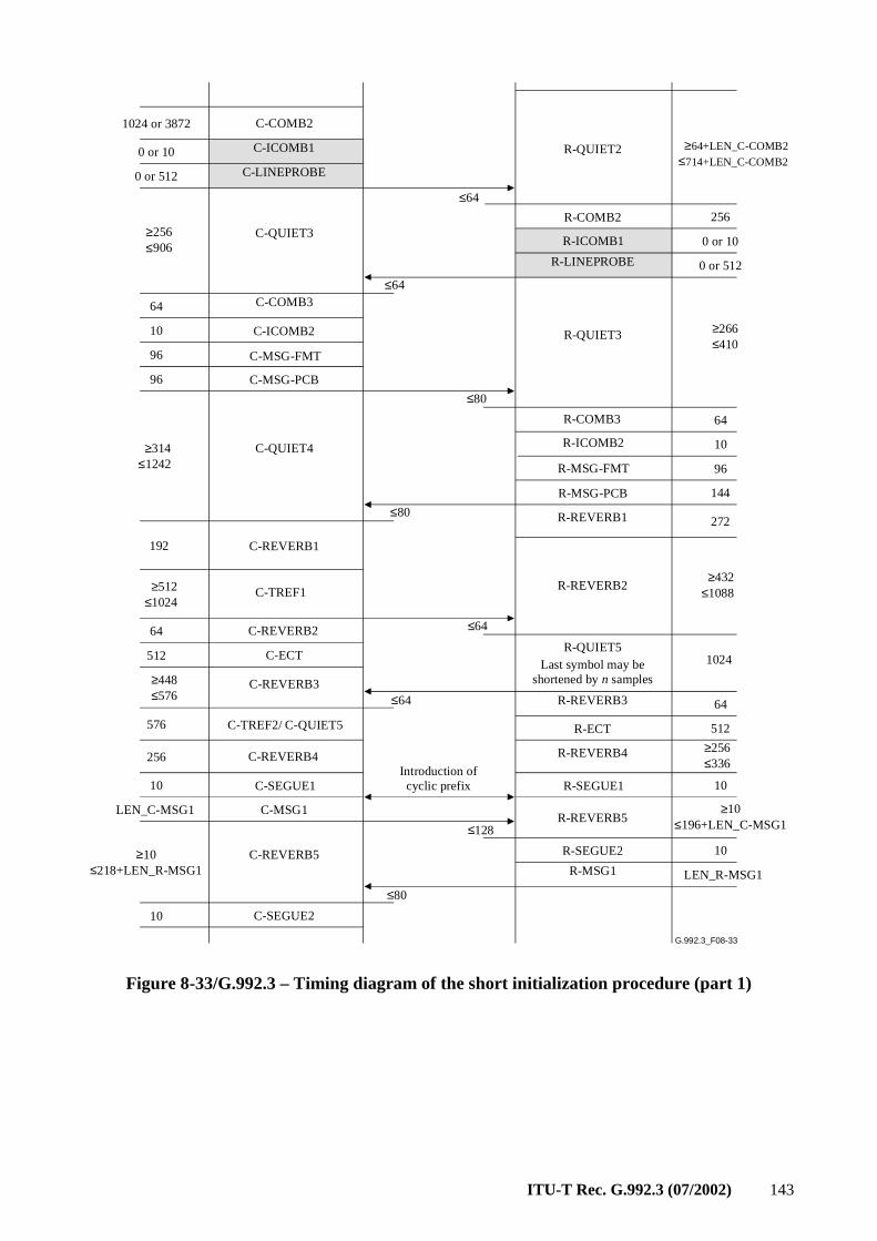
ITU-T Rec. G.992.3 (07/2002) 143
G.992.3_F08-33
C-COMB2
C-ICOMB1
C-LINEPROBE
R-QUIET2
R-COMB2
R-ICOMB1
R-LINEPROBE
C-QUIET3
C-COMB3
C-ICOMB2
C-MSG-FMT
C-MSG-PCB
R-QUIET3
C-QUIET4
C-REVERB1
C-TREF1
C-REVERB2
C-ECT
C-REVERB3
C-TREF2/ C-QUIET5
C-REVERB4
C-REVERB5
R-COMB3
R-ICOMB2
R-QUIET5
R-REVERB3
R-SEGUE2
R-MSG1
R-REVERB2
R-ECT
R-REVERB4
R-REVERB5
1024 or 3872
0 or 10
0 or 512
≥256≤906
64
10
96
96
≥314≤1242
≥64+LEN_C-COMB2≤714+LEN_C-COMB2
256
0 or 10
0 or 512
≥266≤410
64
10
≥432≤1088
1024
64
512
≥256≤336
≥10≤196+LEN_C-MSG1
10
LEN_R-MSG1
192
≥512≤1024
64
512
≥448≤576
576
256
≥10≤218+LEN_R-MSG1
≤64
≤64
≤80
≤64
≤128
≤80
Introduction ofcyclic prefix
Last symbol may be shortened by n samples
C-SEGUE210
C-SEGUE1
C-MSG1
R-MSG-FMT
R-MSG-PCB
R-REVERB1
R-SEGUE1
96
144
272
10
LEN_C-MSG1
10
≤80
≤64
Figure 8-33/G.992.3 – Timing diagram of the short initialization procedure (part 1)
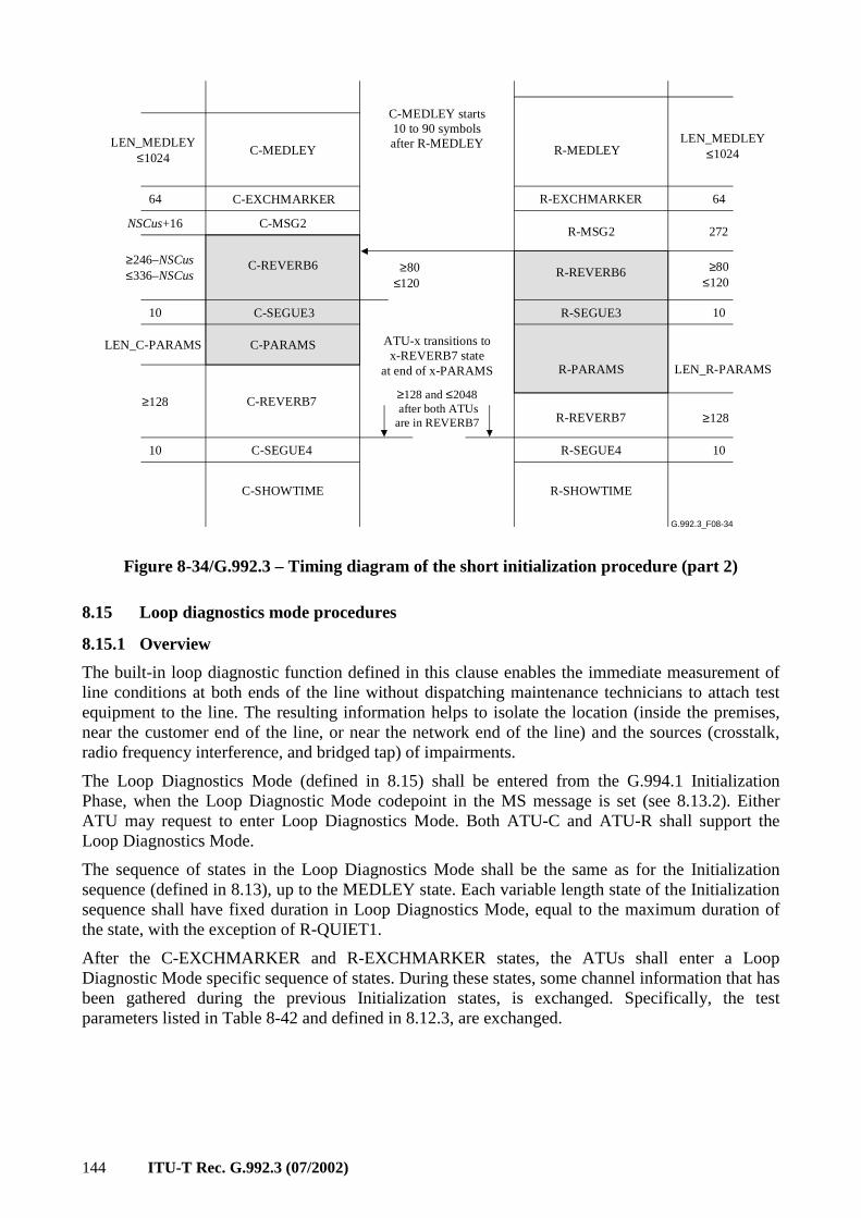
144 ITU-T Rec. G.992.3 (07/2002)
G.992.3_F08-34
C-MEDLEY R-MEDLEY
C-MSG2
R-EXCHMARKER
R-MSG2
C-REVERB7R-REVERB7
C-SHOWTIME
NSCus+16
10
LEN_R-PARAMS
≥80≤120
≥80≤120
LEN_MEDLEY≤1024
LEN_MEDLEY≤1024
6464 C-EXCHMARKER
≥246–NSCus≤336–NSCus
10
LEN_C-PARAMS
272
ATU-x transitions to x-REVERB7 state
at end of x-PARAMS
≥128 and ≤2048 after both ATUsare in REVERB7
≥128≥128
R-SEGUE4C-SEGUE4 1010
R-SHOWTIME
C-MEDLEY starts 10 to 90 symbols after R-MEDLEY
R-REVERB6
R-SEGUE3
R-PARAMS
C-SEGUE3
C-PARAMS
C-REVERB6
Figure 8-34/G.992.3 – Timing diagram of the short initialization procedure (part 2)
8.15 Loop diagnostics mode procedures
8.15.1 Overview
The built-in loop diagnostic function defined in this clause enables the immediate measurement of line conditions at both ends of the line without dispatching maintenance technicians to attach test equipment to the line. The resulting information helps to isolate the location (inside the premises, near the customer end of the line, or near the network end of the line) and the sources (crosstalk, radio frequency interference, and bridged tap) of impairments.
The Loop Diagnostics Mode (defined in 8.15) shall be entered from the G.994.1 Initialization Phase, when the Loop Diagnostic Mode codepoint in the MS message is set (see 8.13.2). Either ATU may request to enter Loop Diagnostics Mode. Both ATU-C and ATU-R shall support the Loop Diagnostics Mode.
The sequence of states in the Loop Diagnostics Mode shall be the same as for the Initialization sequence (defined in 8.13), up to the MEDLEY state. Each variable length state of the Initialization sequence shall have fixed duration in Loop Diagnostics Mode, equal to the maximum duration of the state, with the exception of R-QUIET1.
After the C-EXCHMARKER and R-EXCHMARKER states, the ATUs shall enter a Loop Diagnostic Mode specific sequence of states. During these states, some channel information that has been gathered during the previous Initialization states, is exchanged. Specifically, the test parameters listed in Table 8-42 and defined in 8.12.3, are exchanged.
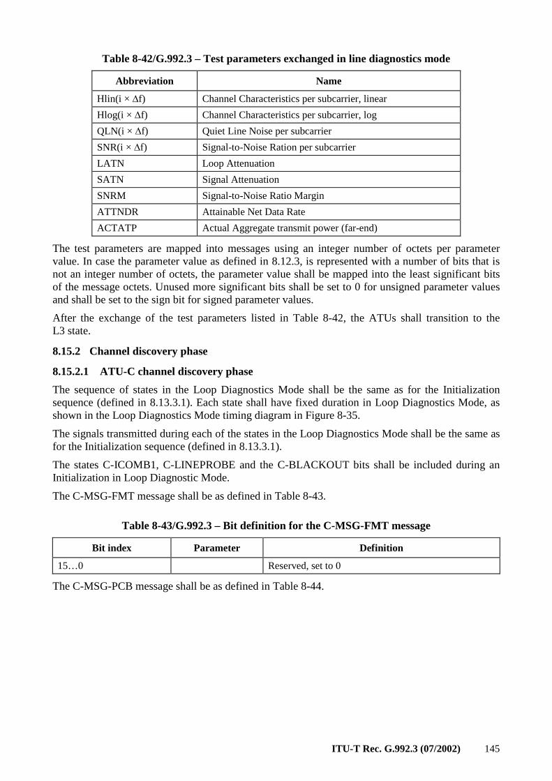
ITU-T Rec. G.992.3 (07/2002) 145
Table 8-42/G.992.3 – Test parameters exchanged in line diagnostics mode
Abbreviation Name
Hlin(i × ∆f) Channel Characteristics per subcarrier, linear
Hlog(i × ∆f) Channel Characteristics per subcarrier, log
QLN(i × ∆f) Quiet Line Noise per subcarrier
SNR(i × ∆f) Signal-to-Noise Ration per subcarrier
LATN Loop Attenuation
SATN Signal Attenuation
SNRM Signal-to-Noise Ratio Margin
ATTNDR Attainable Net Data Rate
ACTATP Actual Aggregate transmit power (far-end)
The test parameters are mapped into messages using an integer number of octets per parameter value. In case the parameter value as defined in 8.12.3, is represented with a number of bits that is not an integer number of octets, the parameter value shall be mapped into the least significant bits of the message octets. Unused more significant bits shall be set to 0 for unsigned parameter values and shall be set to the sign bit for signed parameter values.
After the exchange of the test parameters listed in Table 8-42, the ATUs shall transition to the L3 state.
8.15.2 Channel discovery phase
8.15.2.1 ATU-C channel discovery phase
The sequence of states in the Loop Diagnostics Mode shall be the same as for the Initialization sequence (defined in 8.13.3.1). Each state shall have fixed duration in Loop Diagnostics Mode, as shown in the Loop Diagnostics Mode timing diagram in Figure 8-35.
The signals transmitted during each of the states in the Loop Diagnostics Mode shall be the same as for the Initialization sequence (defined in 8.13.3.1).
The states C-ICOMB1, C-LINEPROBE and the C-BLACKOUT bits shall be included during an Initialization in Loop Diagnostic Mode.
The C-MSG-FMT message shall be as defined in Table 8-43.
Table 8-43/G.992.3 – Bit definition for the C-MSG-FMT message
Bit index Parameter Definition
15…0 Reserved, set to 0
The C-MSG-PCB message shall be as defined in Table 8-44.
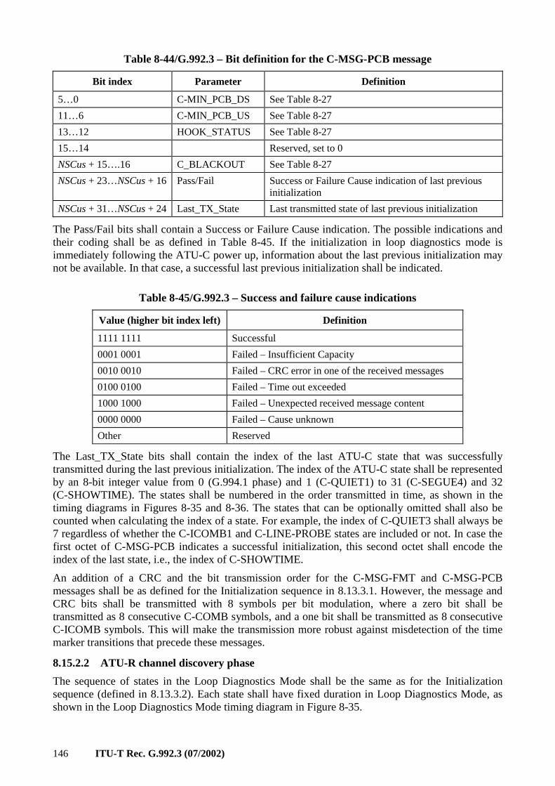
146 ITU-T Rec. G.992.3 (07/2002)
Table 8-44/G.992.3 – Bit definition for the C-MSG-PCB message
Bit index Parameter Definition
5…0 C-MIN_PCB_DS See Table 8-27
11…6 C-MIN_PCB_US See Table 8-27
13…12 HOOK_STATUS See Table 8-27
15…14 Reserved, set to 0
NSCus + 15….16 C_BLACKOUT See Table 8-27
NSCus + 23…NSCus + 16 Pass/Fail Success or Failure Cause indication of last previous initialization
NSCus + 31…NSCus + 24 Last_TX_State Last transmitted state of last previous initialization
The Pass/Fail bits shall contain a Success or Failure Cause indication. The possible indications and their coding shall be as defined in Table 8-45. If the initialization in loop diagnostics mode is immediately following the ATU-C power up, information about the last previous initialization may not be available. In that case, a successful last previous initialization shall be indicated.
Table 8-45/G.992.3 – Success and failure cause indications
Value (higher bit index left) Definition
1111 1111 Successful
0001 0001 Failed – Insufficient Capacity
0010 0010 Failed – CRC error in one of the received messages
0100 0100 Failed – Time out exceeded
1000 1000 Failed – Unexpected received message content
0000 0000 Failed – Cause unknown
Other Reserved
The Last_TX_State bits shall contain the index of the last ATU-C state that was successfully transmitted during the last previous initialization. The index of the ATU-C state shall be represented by an 8-bit integer value from 0 (G.994.1 phase) and 1 (C-QUIET1) to 31 (C-SEGUE4) and 32 (C-SHOWTIME). The states shall be numbered in the order transmitted in time, as shown in the timing diagrams in Figures 8-35 and 8-36. The states that can be optionally omitted shall also be counted when calculating the index of a state. For example, the index of C-QUIET3 shall always be 7 regardless of whether the C-ICOMB1 and C-LINE-PROBE states are included or not. In case the first octet of C-MSG-PCB indicates a successful initialization, this second octet shall encode the index of the last state, i.e., the index of C-SHOWTIME.
An addition of a CRC and the bit transmission order for the C-MSG-FMT and C-MSG-PCB messages shall be as defined for the Initialization sequence in 8.13.3.1. However, the message and CRC bits shall be transmitted with 8 symbols per bit modulation, where a zero bit shall be transmitted as 8 consecutive C-COMB symbols, and a one bit shall be transmitted as 8 consecutive C-ICOMB symbols. This will make the transmission more robust against misdetection of the time marker transitions that precede these messages.
8.15.2.2 ATU-R channel discovery phase
The sequence of states in the Loop Diagnostics Mode shall be the same as for the Initialization sequence (defined in 8.13.3.2). Each state shall have fixed duration in Loop Diagnostics Mode, as shown in the Loop Diagnostics Mode timing diagram in Figure 8-35.
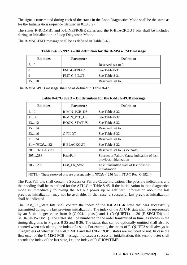
ITU-T Rec. G.992.3 (07/2002) 147
The signals transmitted during each of the states in the Loop Diagnostics Mode shall be the same as for the Initialization sequence (defined in 8.13.3.2).
The states R-ICOMB1 and R-LINEPROBE states and the R-BLACKOUT bits shall be included during an Initialization in Loop Diagnostic Mode.
The R-MSG-FMT message shall be as defined in Table 8-46.
Table 8-46/G.992.3 – Bit definition for the R-MSG-FMT message
Bit index Parameter Definition
7…0 Reserved, set to 0
8 FMT-C-TREF2 See Table 8-31
9 FMT-C-PILOT See Table 8-31
15…10 Reserved, set to 0
The R-MSG-PCB message shall be as defined in Table 8-47.
Table 8-47/G.992.3 – Bit definition for the R-MSG-PCB message
Bit index Parameter Definition
5…0 R-MIN_PCB_DS See Table 8-32
11…6 R-MIN_PCB_US See Table 8-32
13…12 HOOK_STATUS See Table 8-32
15…14 Reserved, set to 0
23…16 C-PILOT See Table 8-32
31…24 Reserved, set to 0
31 + NSCds…32 R-BLACKOUT See Table 8-32
287…32 + NSCds Reserved, set to 0 (see Note)
295…288 Pass/Fail Success or Failure Cause indication of last previous initialization
303…296 Last_TX_State Last transmitted state of last previous initialization
NOTE – These reserved bits are present only if NSCds < 256 (as in ITU-T Rec. G.992.4).
The Pass/Fail bits shall contain a Success or Failure Cause indication. The possible indications and their coding shall be as defined for the ATU-C in Table 8-45. If the initialization in loop diagnostics mode is immediately following the ATU-R power up or self test, information about the last previous initialization may not be available. In that case, a successful last previous initialization shall be indicated.
The Last_TX_State bits shall contain the index of the last ATU-R state that was successfully transmitted during the last previous initialization. The index of the ATU-R state shall be represented by an 8-bit integer value from 0 (G.994.1 phase) and 1 (R-QUIET1) to 30 (R-SEGUE4) and 31 (R-SHOWTIME). The states shall be numbered in the order transmitted in time, as shown in the timing diagrams in Figures 8-35 and 8-36. The states that can be optionally omitted shall also be counted when calculating the index of a state. For example, the index of R-QUIET3 shall always be 7 regardless of whether the R-ICOMB1 and R-LINE-PROBE states are included or not. In case the first octet of the C-MSG-PCB message indicates a successful initialization, this second octet shall encode the index of the last state, i.e., the index of R-SHOWTIME.
148 ITU-T Rec. G.992.3 (07/2002)
The addition of a 16 bit CRC and the bit transmission order for the R-MSG-FMT and R-MSG-PCB messages shall be as defined for the Initialization sequence in 8.13.3.2. However, the bits shall be transmitted with 8 symbols per bit modulation, where a zero bit shall be transmitted as 8 consecutive R-COMB symbols, and a one bit shall be transmitted as 8 consecutive R-ICOMB symbols. This will make the transmission more robust against misdetection of the time marker transitions that precede these messages.
8.15.3 Transceiver training phase
The sequence of states in the Loop Diagnostics Mode shall be the same as for the Initialization sequence (defined in 8.13.4). Each state shall have fixed duration in Loop Diagnostics Mode, as shown in the Loop Diagnostics Mode timing diagram in Figure 8-35.
The signals transmitted during each of the states in the Loop Diagnostics Mode shall be the same as for the Initialization sequence (defined in 8.13.4).
The ATU-R shall include the R-QUIET4 state.
8.15.4 Channel analysis phase
The sequence of states in the Loop Diagnostics Mode shall be the same as for the Initialization sequence (defined in 8.13.5). Each state shall have fixed duration in Loop Diagnostics Mode, as shown in the Loop Diagnostics Mode timing diagram in Figures 8-35 and 8-36.
The signals transmitted during each of the states in the Loop Diagnostics Mode shall be the same as for the Initialization sequence (defined in 8.13.5).
The ATU-C shall not transmit the C-MSG1 message.
The ATU-R shall not transmit the R-MSG1 message.
The PMD control parameters exchanged in the MSG1 messages during initialization (see 8.5.1 and 8.5.3.2), shall take the default values defined in Table 8-48, for use during diagnostics mode.
Table 8-48/G.992.3 – Default values for PMD control parameters
PMD Control Parameter Default value
TARSNRM 6 dB
MAXSNRM infinite
EXTGI MAXNOMPSD – NOMPSD
BIMAX 15
During the EXCHMARKER state, the ATU shall transmit REVERB symbols.
During the Loop Diagnostic Mode, the symbol counter that was initialized at the start of the R-MEDLEY state is kept counting throughout the remainder of the initialization in Loop Diagnostics Mode. Any state transition after the R-MEDLEY state shall occur at multiples of 64 as per this counter value.
8.15.5 Exchange phase
8.15.5.1 ATU-C exchange phase
The sequence of states in the Loop Diagnostics Mode shall be as shown in the Loop Diagnostics Mode timing diagram in Figures 8-35 and 8-36. Every time the ATU-C successfully receives a message from the ATU-R, the ATU-C passes through the C-ACK-LD state to send an acknowledgement to the ATU-R. Every time the ATU-C passes through the C-MSGx-LD state, one message containing loop diagnostics information is sent to the ATU-R.
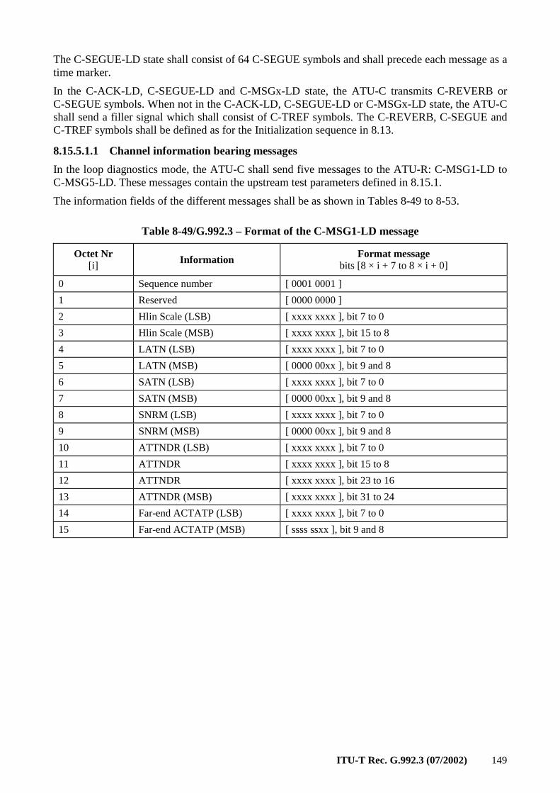
ITU-T Rec. G.992.3 (07/2002) 149
The C-SEGUE-LD state shall consist of 64 C-SEGUE symbols and shall precede each message as a time marker.
In the C-ACK-LD, C-SEGUE-LD and C-MSGx-LD state, the ATU-C transmits C-REVERB or C-SEGUE symbols. When not in the C-ACK-LD, C-SEGUE-LD or C-MSGx-LD state, the ATU-C shall send a filler signal which shall consist of C-TREF symbols. The C-REVERB, C-SEGUE and C-TREF symbols shall be defined as for the Initialization sequence in 8.13.
8.15.5.1.1 Channel information bearing messages
In the loop diagnostics mode, the ATU-C shall send five messages to the ATU-R: C-MSG1-LD to C-MSG5-LD. These messages contain the upstream test parameters defined in 8.15.1.
The information fields of the different messages shall be as shown in Tables 8-49 to 8-53.
Table 8-49/G.992.3 – Format of the C-MSG1-LD message
Octet Nr [i] Information Format message
bits [8 × i + 7 to 8 × i + 0]
0 Sequence number [ 0001 0001 ]
1 Reserved [ 0000 0000 ]
2 Hlin Scale (LSB) [ xxxx xxxx ], bit 7 to 0
3 Hlin Scale (MSB) [ xxxx xxxx ], bit 15 to 8
4 LATN (LSB) [ xxxx xxxx ], bit 7 to 0
5 LATN (MSB) [ 0000 00xx ], bit 9 and 8
6 SATN (LSB) [ xxxx xxxx ], bit 7 to 0
7 SATN (MSB) [ 0000 00xx ], bit 9 and 8
8 SNRM (LSB) [ xxxx xxxx ], bit 7 to 0
9 SNRM (MSB) [ 0000 00xx ], bit 9 and 8
10 ATTNDR (LSB) [ xxxx xxxx ], bit 7 to 0
11 ATTNDR [ xxxx xxxx ], bit 15 to 8
12 ATTNDR [ xxxx xxxx ], bit 23 to 16
13 ATTNDR (MSB) [ xxxx xxxx ], bit 31 to 24
14 Far-end ACTATP (LSB) [ xxxx xxxx ], bit 7 to 0
15 Far-end ACTATP (MSB) [ ssss ssxx ], bit 9 and 8
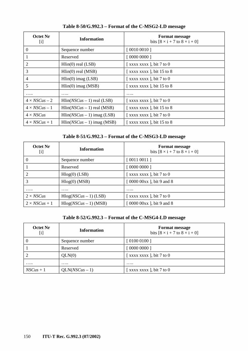
150 ITU-T Rec. G.992.3 (07/2002)
Table 8-50/G.992.3 – Format of the C-MSG2-LD message
Octet Nr [i] Information Format message
bits [8 × i + 7 to 8 × i + 0]
0 Sequence number [ 0010 0010 ]
1 Reserved [ 0000 0000 ]
2 Hlin(0) real (LSB) [ xxxx xxxx ], bit 7 to 0
3 Hlin(0) real (MSB) [ xxxx xxxx ], bit 15 to 8
4 Hlin(0) imag (LSB) [ xxxx xxxx ], bit 7 to 0
5 Hlin(0) imag (MSB) [ xxxx xxxx ], bit 15 to 8
….. ….. …..
4 × NSCus – 2 Hlin(NSCus – 1) real (LSB) [ xxxx xxxx ], bit 7 to 0
4 × NSCus – 1 Hlin(NSCus – 1) real (MSB) [ xxxx xxxx ], bit 15 to 8
4 × NSCus Hlin(NSCus – 1) imag (LSB) [ xxxx xxxx ], bit 7 to 0
4 × NSCus + 1 Hlin(NSCus – 1) imag (MSB) [ xxxx xxxx ], bit 15 to 8
Table 8-51/G.992.3 – Format of the C-MSG3-LD message
Octet Nr [i] Information Format message
bits [8 × i + 7 to 8 × i + 0]
0 Sequence number [ 0011 0011 ]
1 Reserved [ 0000 0000 ]
2 Hlog(0) (LSB) [ xxxx xxxx ], bit 7 to 0
3 Hlog(0) (MSB) [ 0000 00xx ], bit 9 and 8
….. ….. …..
2 × NSCus Hlog(NSCus – 1) (LSB) [ xxxx xxxx ], bit 7 to 0
2 × NSCus + 1 Hlog(NSCus – 1) (MSB) [ 0000 00xx ], bit 9 and 8
Table 8-52/G.992.3 – Format of the C-MSG4-LD message
Octet Nr [i] Information Format message
bits [8 × i + 7 to 8 × i + 0]
0 Sequence number [ 0100 0100 ]
1 Reserved [ 0000 0000 ]
2 QLN(0) [ xxxx xxxx ], bit 7 to 0
….. ….. …..
NSCus + 1 QLN(NSCus – 1) [ xxxx xxxx ], bit 7 to 0
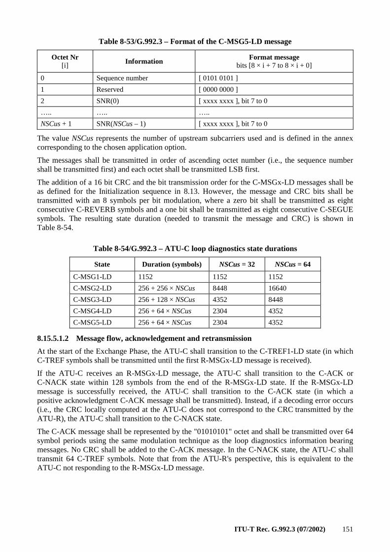
ITU-T Rec. G.992.3 (07/2002) 151
Table 8-53/G.992.3 – Format of the C-MSG5-LD message
Octet Nr [i] Information Format message
bits [8 × i + 7 to 8 × i + 0]
0 Sequence number [ 0101 0101 ]
1 Reserved [ 0000 0000 ]
2 SNR(0) [ xxxx xxxx ], bit 7 to 0
….. ….. …..
NSCus + 1 SNR(NSCus – 1) [ xxxx xxxx ], bit 7 to 0
The value NSCus represents the number of upstream subcarriers used and is defined in the annex corresponding to the chosen application option.
The messages shall be transmitted in order of ascending octet number (i.e., the sequence number shall be transmitted first) and each octet shall be transmitted LSB first.
The addition of a 16 bit CRC and the bit transmission order for the C-MSGx-LD messages shall be as defined for the Initialization sequence in 8.13. However, the message and CRC bits shall be transmitted with an 8 symbols per bit modulation, where a zero bit shall be transmitted as eight consecutive C-REVERB symbols and a one bit shall be transmitted as eight consecutive C-SEGUE symbols. The resulting state duration (needed to transmit the message and CRC) is shown in Table 8-54.
Table 8-54/G.992.3 – ATU-C loop diagnostics state durations
State Duration (symbols) NSCus = 32 NSCus = 64
C-MSG1-LD 1152 1152 1152
C-MSG2-LD 256 + 256 × NSCus 8448 16640
C-MSG3-LD 256 + 128 × NSCus 4352 8448
C-MSG4-LD 256 + 64 × NSCus 2304 4352
C-MSG5-LD 256 + 64 × NSCus 2304 4352
8.15.5.1.2 Message flow, acknowledgement and retransmission
At the start of the Exchange Phase, the ATU-C shall transition to the C-TREF1-LD state (in which C-TREF symbols shall be transmitted until the first R-MSGx-LD message is received).
If the ATU-C receives an R-MSGx-LD message, the ATU-C shall transition to the C-ACK or C-NACK state within 128 symbols from the end of the R-MSGx-LD state. If the R-MSGx-LD message is successfully received, the ATU-C shall transition to the C-ACK state (in which a positive acknowledgment C-ACK message shall be transmitted). Instead, if a decoding error occurs (i.e., the CRC locally computed at the ATU-C does not correspond to the CRC transmitted by the ATU-R), the ATU-C shall transition to the C-NACK state.
The C-ACK message shall be represented by the "01010101" octet and shall be transmitted over 64 symbol periods using the same modulation technique as the loop diagnostics information bearing messages. No CRC shall be added to the C-ACK message. In the C-NACK state, the ATU-C shall transmit 64 C-TREF symbols. Note that from the ATU-R's perspective, this is equivalent to the ATU-C not responding to the R-MSGx-LD message.
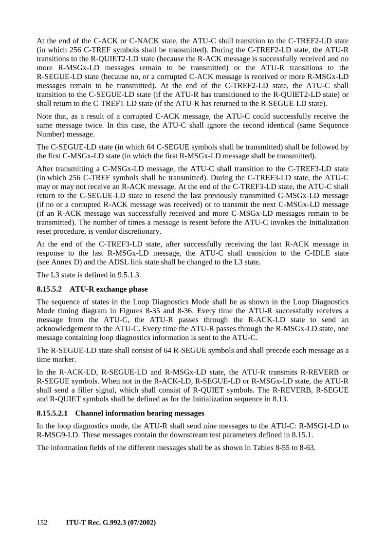
152 ITU-T Rec. G.992.3 (07/2002)
At the end of the C-ACK or C-NACK state, the ATU-C shall transition to the C-TREF2-LD state (in which 256 C-TREF symbols shall be transmitted). During the C-TREF2-LD state, the ATU-R transitions to the R-QUIET2-LD state (because the R-ACK message is successfully received and no more R-MSGx-LD messages remain to be transmitted) or the ATU-R transitions to the R-SEGUE-LD state (because no, or a corrupted C-ACK message is received or more R-MSGx-LD messages remain to be transmitted). At the end of the C-TREF2-LD state, the ATU-C shall transition to the C-SEGUE-LD state (if the ATU-R has transitioned to the R-QUIET2-LD state) or shall return to the C-TREF1-LD state (if the ATU-R has returned to the R-SEGUE-LD state).
Note that, as a result of a corrupted C-ACK message, the ATU-C could successfully receive the same message twice. In this case, the ATU-C shall ignore the second identical (same Sequence Number) message.
The C-SEGUE-LD state (in which 64 C-SEGUE symbols shall be transmitted) shall be followed by the first C-MSGx-LD state (in which the first R-MSGx-LD message shall be transmitted).
After transmitting a C-MSGx-LD message, the ATU-C shall transition to the C-TREF3-LD state (in which 256 C-TREF symbols shall be transmitted). During the C-TREF3-LD state, the ATU-C may or may not receive an R-ACK message. At the end of the C-TREF3-LD state, the ATU-C shall return to the C-SEGUE-LD state to resend the last previously transmitted C-MSGx-LD message (if no or a corrupted R-ACK message was received) or to transmit the next C-MSGx-LD message (if an R-ACK message was successfully received and more C-MSGx-LD messages remain to be transmitted). The number of times a message is resent before the ATU-C invokes the Initialization reset procedure, is vendor discretionary.
At the end of the C-TREF3-LD state, after successfully receiving the last R-ACK message in response to the last R-MSGx-LD message, the ATU-C shall transition to the C-IDLE state (see Annex D) and the ADSL link state shall be changed to the L3 state.
The L3 state is defined in 9.5.1.3.
8.15.5.2 ATU-R exchange phase
The sequence of states in the Loop Diagnostics Mode shall be as shown in the Loop Diagnostics Mode timing diagram in Figures 8-35 and 8-36. Every time the ATU-R successfully receives a message from the ATU-C, the ATU-R passes through the R-ACK-LD state to send an acknowledgement to the ATU-C. Every time the ATU-R passes through the R-MSGx-LD state, one message containing loop diagnostics information is sent to the ATU-C.
The R-SEGUE-LD state shall consist of 64 R-SEGUE symbols and shall precede each message as a time marker.
In the R-ACK-LD, R-SEGUE-LD and R-MSGx-LD state, the ATU-R transmits R-REVERB or R-SEGUE symbols. When not in the R-ACK-LD, R-SEGUE-LD or R-MSGx-LD state, the ATU-R shall send a filler signal, which shall consist of R-QUIET symbols. The R-REVERB, R-SEGUE and R-QUIET symbols shall be defined as for the Initialization sequence in 8.13.
8.15.5.2.1 Channel information bearing messages
In the loop diagnostics mode, the ATU-R shall send nine messages to the ATU-C: R-MSG1-LD to R-MSG9-LD. These messages contain the downstream test parameters defined in 8.15.1.
The information fields of the different messages shall be as shown in Tables 8-55 to 8-63.
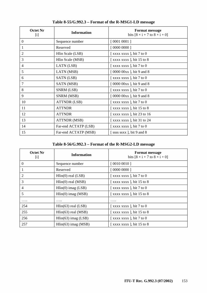
ITU-T Rec. G.992.3 (07/2002) 153
Table 8-55/G.992.3 – Format of the R-MSG1-LD message
Octet Nr [i] Information Format message
bits [8 × i + 7 to 8 × i + 0]
0 Sequence number [ 0001 0001 ]
1 Reserved [ 0000 0000 ]
2 Hlin Scale (LSB) [ xxxx xxxx ], bit 7 to 0
3 Hlin Scale (MSB) [ xxxx xxxx ], bit 15 to 8
4 LATN (LSB) [ xxxx xxxx ], bit 7 to 0
5 LATN (MSB) [ 0000 00xx ], bit 9 and 8
6 SATN (LSB) [ xxxx xxxx ], bit 7 to 0
7 SATN (MSB) [ 0000 00xx ], bit 9 and 8
8 SNRM (LSB) [ xxxx xxxx ], bit 7 to 0
9 SNRM (MSB) [ 0000 00xx ], bit 9 and 8
10 ATTNDR (LSB) [ xxxx xxxx ], bit 7 to 0
11 ATTNDR [ xxxx xxxx ], bit 15 to 8
12 ATTNDR [ xxxx xxxx ], bit 23 to 16
13 ATTNDR (MSB) [ xxxx xxxx ], bit 31 to 24
14 Far-end ACTATP (LSB) [ xxxx xxxx ], bit 7 to 0
15 Far-end ACTATP (MSB) [ ssss ssxx ], bit 9 and 8
Table 8-56/G.992.3 – Format of the R-MSG2-LD message
Octet Nr [i] Information Format message
bits [8 × i + 7 to 8 × i + 0]
0 Sequence number [ 0010 0010 ]
1 Reserved [ 0000 0000 ]
2 Hlin(0) real (LSB) [ xxxx xxxx ], bit 7 to 0
3 Hlin(0) real (MSB) [ xxxx xxxx ], bit 15 to 8
4 Hlin(0) imag (LSB) [ xxxx xxxx ], bit 7 to 0
5 Hlin(0) imag (MSB) [ xxxx xxxx ], bit 15 to 8
….. ….. …..
254 Hlin(63) real (LSB) [ xxxx xxxx ], bit 7 to 0
255 Hlin(63) real (MSB) [ xxxx xxxx ], bit 15 to 8
256 Hlin(63) imag (LSB) [ xxxx xxxx ], bit 7 to 0
257 Hlin(63) imag (MSB) [ xxxx xxxx ], bit 15 to 8
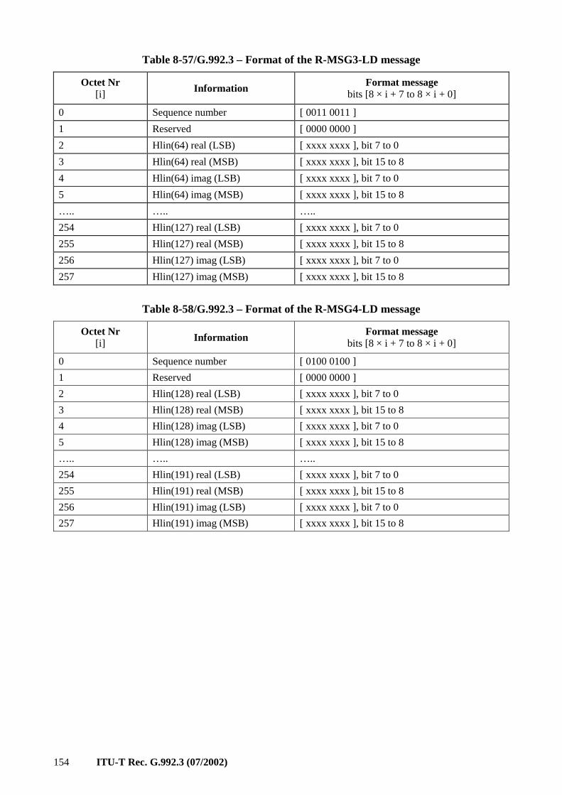
154 ITU-T Rec. G.992.3 (07/2002)
Table 8-57/G.992.3 – Format of the R-MSG3-LD message
Octet Nr [i] Information Format message
bits [8 × i + 7 to 8 × i + 0]
0 Sequence number [ 0011 0011 ]
1 Reserved [ 0000 0000 ]
2 Hlin(64) real (LSB) [ xxxx xxxx ], bit 7 to 0
3 Hlin(64) real (MSB) [ xxxx xxxx ], bit 15 to 8
4 Hlin(64) imag (LSB) [ xxxx xxxx ], bit 7 to 0
5 Hlin(64) imag (MSB) [ xxxx xxxx ], bit 15 to 8
….. ….. …..
254 Hlin(127) real (LSB) [ xxxx xxxx ], bit 7 to 0
255 Hlin(127) real (MSB) [ xxxx xxxx ], bit 15 to 8
256 Hlin(127) imag (LSB) [ xxxx xxxx ], bit 7 to 0
257 Hlin(127) imag (MSB) [ xxxx xxxx ], bit 15 to 8
Table 8-58/G.992.3 – Format of the R-MSG4-LD message
Octet Nr [i] Information Format message
bits [8 × i + 7 to 8 × i + 0]
0 Sequence number [ 0100 0100 ]
1 Reserved [ 0000 0000 ]
2 Hlin(128) real (LSB) [ xxxx xxxx ], bit 7 to 0
3 Hlin(128) real (MSB) [ xxxx xxxx ], bit 15 to 8
4 Hlin(128) imag (LSB) [ xxxx xxxx ], bit 7 to 0
5 Hlin(128) imag (MSB) [ xxxx xxxx ], bit 15 to 8
….. ….. …..
254 Hlin(191) real (LSB) [ xxxx xxxx ], bit 7 to 0
255 Hlin(191) real (MSB) [ xxxx xxxx ], bit 15 to 8
256 Hlin(191) imag (LSB) [ xxxx xxxx ], bit 7 to 0
257 Hlin(191) imag (MSB) [ xxxx xxxx ], bit 15 to 8
ITU-T Rec. G.992.3 (07/2002) 155
Table 8-59/G.992.3 – Format of the R-MSG5-LD message
Octet Nr [i] Information Format message
bits [8 × i + 7 to 8 × i + 0]
0 Sequence number [ 0101 0101 ]
1 Reserved [ 0000 0000 ]
2 Hlin(192) real (LSB) [ xxxx xxxx ], bit 7 to 0
3 Hlin(192) real (MSB) [ xxxx xxxx ], bit 15 to 8
4 Hlin(192) imag (LSB) [ xxxx xxxx ], bit 7 to 0
5 Hlin(192) imag (MSB) [ xxxx xxxx ], bit 15 to 8
….. ….. …..
254 Hlin(255) real (LSB) [ xxxx xxxx ], bit 7 to 0
255 Hlin(255) real (MSB) [ xxxx xxxx ], bit 15 to 8
256 Hlin(255) imag (LSB) [ xxxx xxxx ], bit 7 to 0
257 Hlin(255) imag (MSB) [ xxxx xxxx ], bit 15 to 8
Table 8-60/G.992.3 – Format of the R-MSG6-LD message
Octet Nr [i] Information Format message
bits [8 × i + 7 to 8 × i + 0]
0 Sequence number [ 0110 0110 ]
1 Reserved [ 0000 0000 ]
2 Hlog(0) (LSB) [ xxxx xxxx ], bit 7 to 0
3 Hlog(0) (MSB) [ 0000 00xx ], bit 9 and 8
….. ….. …..
256 Hlog(127) (LSB) [ xxxx xxxx ], bit 7 to 0
257 Hlog(127) (MSB) [ 0000 00xx ], bit 9 and 8
Table 8-61/G.992.3 – Format of the R-MSG7-LD message
Octet Nr [i] Information Format message
bits [8 × i + 7 to 8 × i + 0]
0 Sequence number [ 0111 0111 ]
1 Reserved [ 0000 0000 ]
2 Hlog(128) (LSB) [ xxxx xxxx ], bit 7 to 0
3 Hlog(128) (MSB) [ 0000 00xx ], bit 9 and 8
….. ….. …..
256 Hlog(255) (LSB) [ xxxx xxxx ], bit 7 to 0
257 Hlog(255) (MSB) [ 0000 00xx ], bit 9 and 8
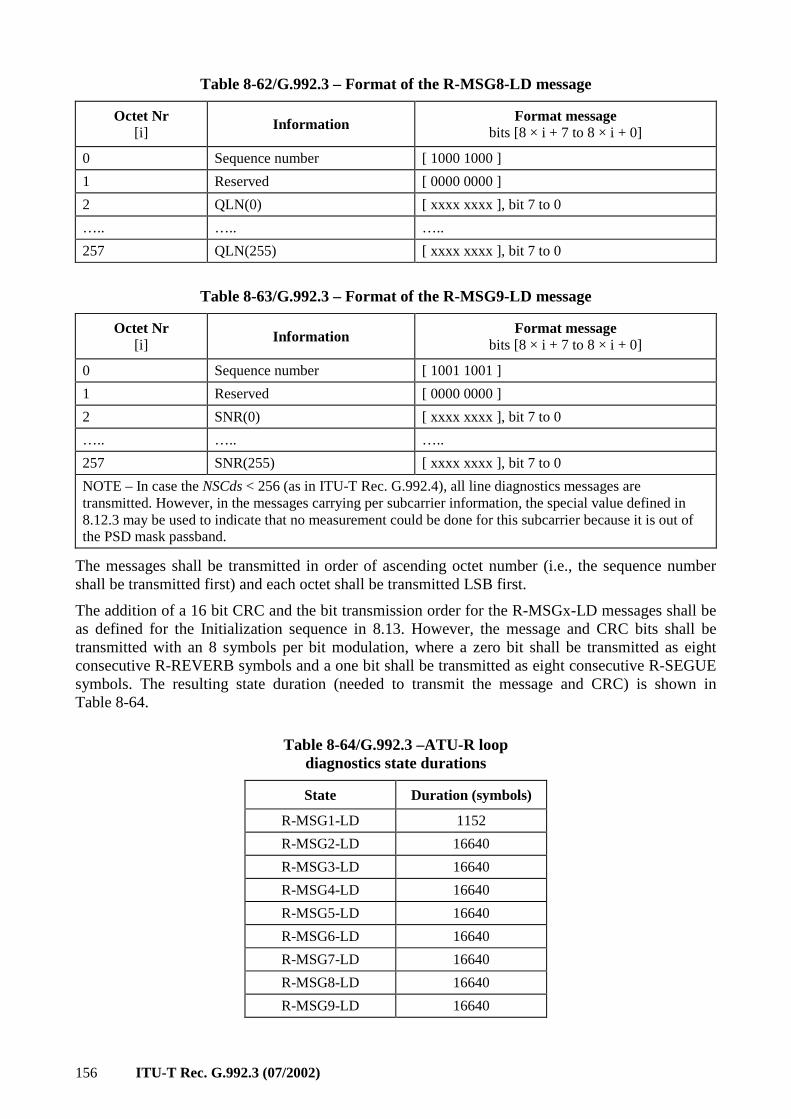
156 ITU-T Rec. G.992.3 (07/2002)
Table 8-62/G.992.3 – Format of the R-MSG8-LD message
Octet Nr [i] Information Format message
bits [8 × i + 7 to 8 × i + 0]
0 Sequence number [ 1000 1000 ]
1 Reserved [ 0000 0000 ]
2 QLN(0) [ xxxx xxxx ], bit 7 to 0
….. ….. …..
257 QLN(255) [ xxxx xxxx ], bit 7 to 0
Table 8-63/G.992.3 – Format of the R-MSG9-LD message
Octet Nr [i] Information Format message
bits [8 × i + 7 to 8 × i + 0]
0 Sequence number [ 1001 1001 ]
1 Reserved [ 0000 0000 ]
2 SNR(0) [ xxxx xxxx ], bit 7 to 0
….. ….. …..
257 SNR(255) [ xxxx xxxx ], bit 7 to 0
NOTE – In case the NSCds < 256 (as in ITU-T Rec. G.992.4), all line diagnostics messages are transmitted. However, in the messages carrying per subcarrier information, the special value defined in 8.12.3 may be used to indicate that no measurement could be done for this subcarrier because it is out of the PSD mask passband.
The messages shall be transmitted in order of ascending octet number (i.e., the sequence number shall be transmitted first) and each octet shall be transmitted LSB first.
The addition of a 16 bit CRC and the bit transmission order for the R-MSGx-LD messages shall be as defined for the Initialization sequence in 8.13. However, the message and CRC bits shall be transmitted with an 8 symbols per bit modulation, where a zero bit shall be transmitted as eight consecutive R-REVERB symbols and a one bit shall be transmitted as eight consecutive R-SEGUE symbols. The resulting state duration (needed to transmit the message and CRC) is shown in Table 8-64.
Table 8-64/G.992.3 –ATU-R loop diagnostics state durations
State Duration (symbols)
R-MSG1-LD 1152
R-MSG2-LD 16640
R-MSG3-LD 16640
R-MSG4-LD 16640
R-MSG5-LD 16640
R-MSG6-LD 16640
R-MSG7-LD 16640
R-MSG8-LD 16640
R-MSG9-LD 16640
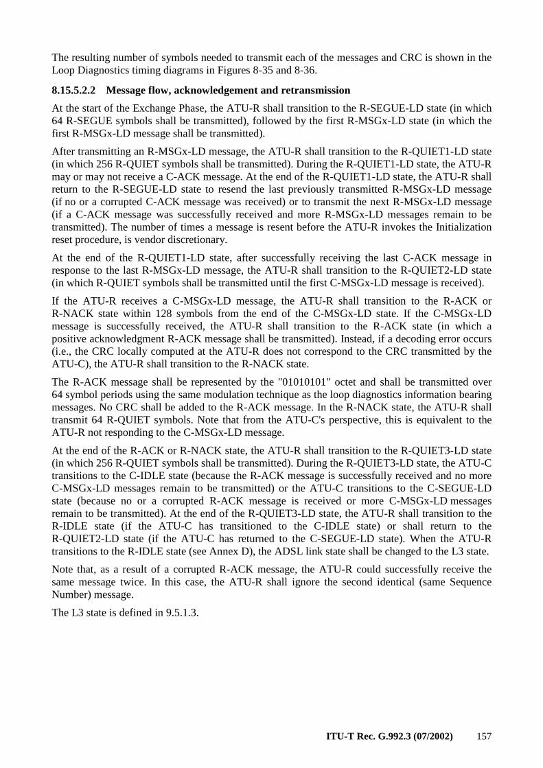
ITU-T Rec. G.992.3 (07/2002) 157
The resulting number of symbols needed to transmit each of the messages and CRC is shown in the Loop Diagnostics timing diagrams in Figures 8-35 and 8-36.
8.15.5.2.2 Message flow, acknowledgement and retransmission
At the start of the Exchange Phase, the ATU-R shall transition to the R-SEGUE-LD state (in which 64 R-SEGUE symbols shall be transmitted), followed by the first R-MSGx-LD state (in which the first R-MSGx-LD message shall be transmitted).
After transmitting an R-MSGx-LD message, the ATU-R shall transition to the R-QUIET1-LD state (in which 256 R-QUIET symbols shall be transmitted). During the R-QUIET1-LD state, the ATU-R may or may not receive a C-ACK message. At the end of the R-QUIET1-LD state, the ATU-R shall return to the R-SEGUE-LD state to resend the last previously transmitted R-MSGx-LD message (if no or a corrupted C-ACK message was received) or to transmit the next R-MSGx-LD message (if a C-ACK message was successfully received and more R-MSGx-LD messages remain to be transmitted). The number of times a message is resent before the ATU-R invokes the Initialization reset procedure, is vendor discretionary.
At the end of the R-QUIET1-LD state, after successfully receiving the last C-ACK message in response to the last R-MSGx-LD message, the ATU-R shall transition to the R-QUIET2-LD state (in which R-QUIET symbols shall be transmitted until the first C-MSGx-LD message is received).
If the ATU-R receives a C-MSGx-LD message, the ATU-R shall transition to the R-ACK or R-NACK state within 128 symbols from the end of the C-MSGx-LD state. If the C-MSGx-LD message is successfully received, the ATU-R shall transition to the R-ACK state (in which a positive acknowledgment R-ACK message shall be transmitted). Instead, if a decoding error occurs (i.e., the CRC locally computed at the ATU-R does not correspond to the CRC transmitted by the ATU-C), the ATU-R shall transition to the R-NACK state.
The R-ACK message shall be represented by the "01010101" octet and shall be transmitted over 64 symbol periods using the same modulation technique as the loop diagnostics information bearing messages. No CRC shall be added to the R-ACK message. In the R-NACK state, the ATU-R shall transmit 64 R-QUIET symbols. Note that from the ATU-C's perspective, this is equivalent to the ATU-R not responding to the C-MSGx-LD message.
At the end of the R-ACK or R-NACK state, the ATU-R shall transition to the R-QUIET3-LD state (in which 256 R-QUIET symbols shall be transmitted). During the R-QUIET3-LD state, the ATU-C transitions to the C-IDLE state (because the R-ACK message is successfully received and no more C-MSGx-LD messages remain to be transmitted) or the ATU-C transitions to the C-SEGUE-LD state (because no or a corrupted R-ACK message is received or more C-MSGx-LD messages remain to be transmitted). At the end of the R-QUIET3-LD state, the ATU-R shall transition to the R-IDLE state (if the ATU-C has transitioned to the C-IDLE state) or shall return to the R-QUIET2-LD state (if the ATU-C has returned to the C-SEGUE-LD state). When the ATU-R transitions to the R-IDLE state (see Annex D), the ADSL link state shall be changed to the L3 state.
Note that, as a result of a corrupted R-ACK message, the ATU-R could successfully receive the same message twice. In this case, the ATU-R shall ignore the second identical (same Sequence Number) message.
The L3 state is defined in 9.5.1.3.
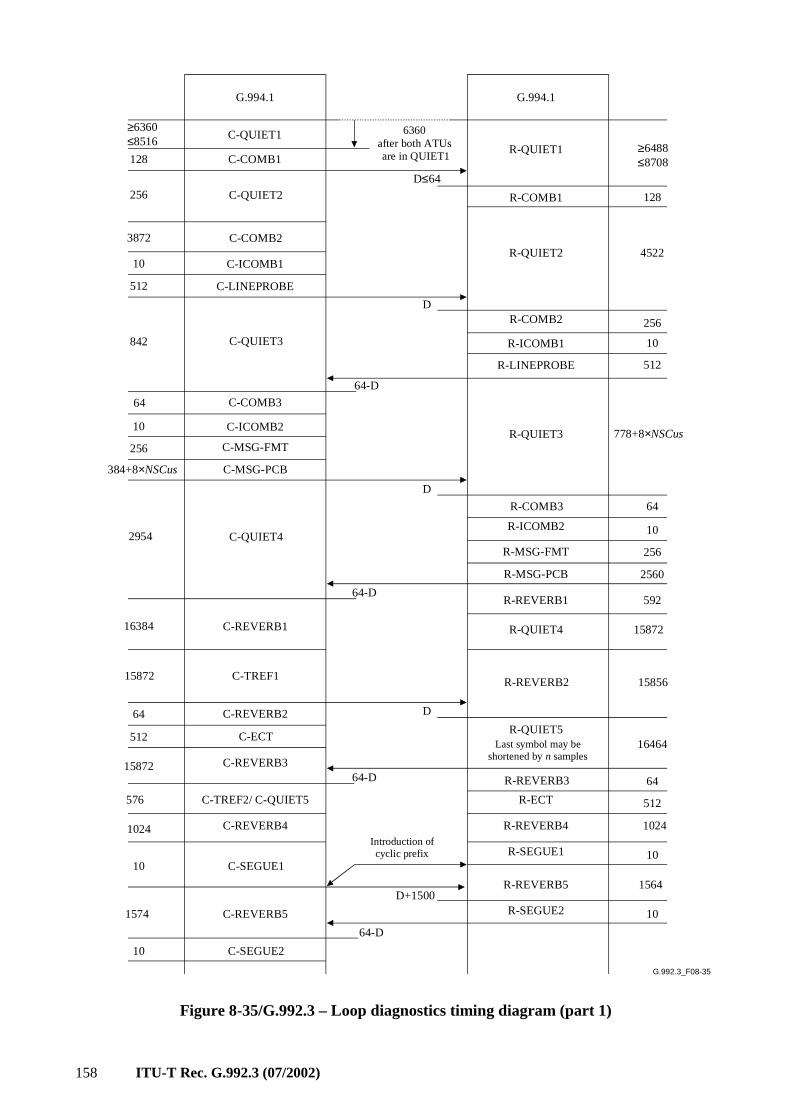
158 ITU-T Rec. G.992.3 (07/2002)
G.992.3_F08-35
G.994.1
C-COMB1
C-QUIET1
G.994.1
C-QUIET2
C-COMB2
C-ICOMB1
C-LINEPROBE
R-QUIET1
R-COMB1
R-QUIET2
R-COMB2
R-ICOMB1C-QUIET3
C-COMB3
C-ICOMB2
C-MSG-FMT
C-MSG-PCB
R-QUIET3
C-QUIET4
C-REVERB1
C-TREF1
C-REVERB2
C-REVERB3
C-TREF2/ C-QUIET5
C-REVERB4
C-SEGUE1
C-REVERB5
R-COMB3
R-ICOMB2
R-MSG-FMT
R-MSG-PCB
R-REVERB1
R-REVERB3
R-SEGUE2
R-QUIET4
R-REVERB2
R-ECT
R-REVERB4
R-SEGUE1
R-REVERB5
128
256
3872
10
512
842
64
10
256
384+8×NSCus
2954
≥6488≤8708
128
4522
256
10
778+8×NSCus
64
10
256
2560
592
15872
15856
16464
64
512
1024
10
1564
10
16384
15872
64
15872
576
1024
10
1574
D≤64
64-D
D
64-D
D
64-D
D+1500
64-D
Introduction ofcyclic prefix
Last symbol may be shortened by n samples
C-SEGUE210
6360after both ATUs are in QUIET1
≥6360≤8516
R-LINEPROBE
C-ECTR-QUIET5
512
512
D
Figure 8-35/G.992.3 – Loop diagnostics timing diagram (part 1)
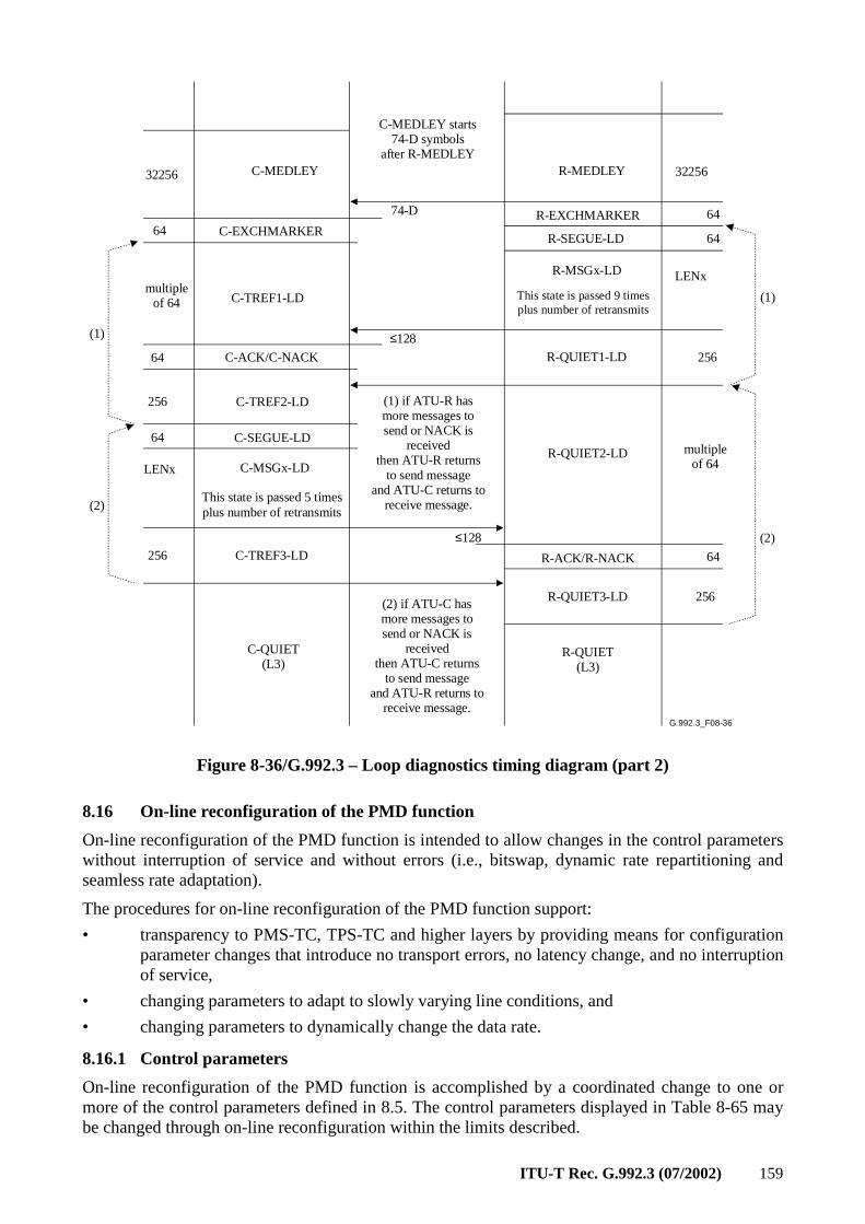
ITU-T Rec. G.992.3 (07/2002) 159
G.992.3_F08-36
C-MEDLEY R-MEDLEY
R-EXCHMARKER
R-SEGUE-LD
R-MSGx-LD
R-QUIET1-LDC-ACK/C-NACK
C-TREF2-LD
R-QUIET2-LDC-MSGx-LD
32256
256
LENx
32256
6464 C-EXCHMARKER
74-D
C-TREF1-LD
64
64
R-QUIET(L3)
C-SEGUE-LD
LENx
multipleof 64
≤128
256
(1)
64
≤128
(1) if ATU-R has more messages to send or NACK is
received then ATU-R returns
to send message and ATU-C returns to
receive message.
(1)
R-ACK/R-NACK
R-QUIET3-LD 256
(2)256 C-TREF3-LD 64
multipleof 64
(2)
C-QUIET(L3)
This state is passed 9 timesplus number of retransmits
This state is passed 5 timesplus number of retransmits
(2) if ATU-C has more messages to send or NACK is
received then ATU-C returns
to send message and ATU-R returns to
receive message.
C-MEDLEY starts74-D symbols
after R-MEDLEY
Figure 8-36/G.992.3 – Loop diagnostics timing diagram (part 2)
8.16 On-line reconfiguration of the PMD function
On-line reconfiguration of the PMD function is intended to allow changes in the control parameters without interruption of service and without errors (i.e., bitswap, dynamic rate repartitioning and seamless rate adaptation).
The procedures for on-line reconfiguration of the PMD function support:
• transparency to PMS-TC, TPS-TC and higher layers by providing means for configuration parameter changes that introduce no transport errors, no latency change, and no interruption of service,
• changing parameters to adapt to slowly varying line conditions, and
• changing parameters to dynamically change the data rate.
8.16.1 Control parameters
On-line reconfiguration of the PMD function is accomplished by a coordinated change to one or more of the control parameters defined in 8.5. The control parameters displayed in Table 8-65 may be changed through on-line reconfiguration within the limits described.
160 ITU-T Rec. G.992.3 (07/2002)
Table 8-65/G.992.3 – Reconfigurable control parameters of the PMD function
Parameter Definition
bi The number of bits per subcarrier may be increased or decreased in the [0 … BIMAX] range. A change of the bi values may be performed with a constant L value (i.e., bitswap) or with a change of the L value (i.e., seamless rate adaptation).
gi The subcarrier gain scaling may be increase or decreased in the [–14.5 … +2.5 + EXTGI] range.
L The number of bits contained in a data frame (parameter derived from the bi values).
The updated bits and gains table shall comply to the bits and gains table requirements listed in 8.6.4.
8.16.2 Timing of changes in subcarrier configuration
A change in the bi and gi values of one or more subcarriers is implemented by changing the corresponding PMD control parameter (see Table 8-4).
In the downstream direction, the reconfiguration of the PMD functions shall take effect starting with the second symbol that follows transport of the PMD.Synchflag primitive. The PMD shall transport the PMD.Synchflag primitive in the synchronization symbol at symbol count 68, as defined in 8.7.3. Therefore, the downstream reconfiguration of the PMD function shall take effect starting with the symbol at symbol count 1. The PMD function shall signal a PMD.Synchflag.indicate primitive to the downstream receive PMS-TC function after the PMD.bits.indicate primitive corresponding to the PMD symbol with symbol count 0 and before the PMD.bits.indicate primitive corresponding to the PMD symbol with symbol count 1.
In the upstream direction, the reconfiguration of the PMD functions shall take effect starting with the fifth symbol that follows transport of the PMD.Synchflag primitive. The PMD shall transport the PMD.Synchflag primitive in the synchronization symbol at symbol count 68, as defined in 8.7.3. Therefore, the upstream reconfiguration of the PMD function shall take effect starting with the symbol at symbol count 4. The PMD function shall signal a PMD.Synchflag.indicate primitive to the upstream receive PMS-TC function after the PMD.bits.indicate primitive corresponding to the PMD symbol with symbol count 3 and before the PMD.bits.indicate primitive corresponding to the PMD symbol with symbol count 4.
8.16.3 Receiver initiated procedure
An ATU may initiate a reconfiguration of its receive PMD function. This includes the ATU changing the receive PMD function's bits and gains table with or without changing the L value. This reconfiguration may be:
• autonomously requested by the receive PMD function (to change only the bits and gains table, without changing the L value, i.e., bitswaps);
• requested by the receiving ATU's control function as part of a reconfiguration of the receive TPS-TC and/or receive PMS-TC functions, e.g., to meet changing higher layer application requirements or to make power management state transitions;
• requested by the receiving ATU's management entity, e.g., to meet DSL link performance requirements as monitored by the management entity.
The bitswapping reconfigurations involve changes of only the PMD sublayer configuration parameters. They do not change the TPS-TC and PMS-TC sublayer configuration parameters. The transmit PMD function shall support bitswaps requested by the receive PMD function.
8.16.4 Transmitter initiated procedure
An ATU may initiate a reconfiguration of its transmit PMD function. However, this reconfiguration shall be initiated by the transmitting ATU's control function, as part of a reconfiguration of the
ITU-T Rec. G.992.3 (07/2002) 161
TPS-TC functions (see clause 6) and/or PMS-TC (see clause 7) functions, e.g., to meet changing higher layer application requirements or to make power management state transitions. Reconfiguration of the transmit PMD function shall not be autonomously requested by the transmit PMD function (i.e., no transmit PMD function initiated bitswaps).
8.17 Power management in the PMD function
Power Management transitions in the PMD function are intended to allow changes in the downstream control parameters without errors (i.e., seamless).
The procedures for power management in the PMD function support:
• changing parameters to minimize the aggregate transmit power
• changing parameters to dynamically change the data rate.
8.17.1 Control parameters
Power management is accomplished by a coordinated change to the value or more of the control parameters defined in 8.5. The downstream control parameters displayed in Table 8-66 may be changed through power management transitions within the limits described.
Table 8-66/G.992.3 – Power management control parameters of the PMD function
Parameter Definition
bi The number of bits per subcarrier may be increased or decreased in the [0 … BIMAXds] range.
gi The subcarrier gain scaling may be increase or decreased in the [–14.5 … +2.5 + EXTGIds] range.
L The number of bits contained in a downstream data frame (parameter derived from the bi values).
The updated downstream bits and gains table shall comply to the bits and gains table requirements listed in 8.6.4.
These requirements on the downstream bits and gains table apply in the L0 state and at entry into the L2 state. However, at entry into the L2 state, the excess margin may not be minimized. Power trimming during the L2 state may be used to minimize the excess margin. Power trimming is defined as a lowering of the reference transmit PSD level (through a higher downstream power cutback level). Power trimming changes the PCBds value used during the L2 state and does not change the gi values determined at the time of entry into the L2 state.
8.17.2 Timing of changes in subcarrier configuration
A change in the bi and gi values of one or more subcarriers is implemented by changing the corresponding PMD control parameter (see Table 8-4).
8.17.2.1 Power management entry from the L0 into the L2 state
In the downstream direction, the power management transition in the PMD functions shall take effect starting with the second symbol that follows transport of the PMD.Synchflag primitive. The PMD shall transport the PMD.Synchflag primitive in the synchronization symbol at symbol count 68, as defined in 8.7.4. Therefore, the downstream power management transition shall take effect starting with the symbol at symbol count 1.
In the upstream direction, no power management transitions shall take place.
162 ITU-T Rec. G.992.3 (07/2002)
8.17.2.2 Power management exit from the L2 into the L0 state
In the downstream direction, the power management transition in the PMD functions shall take effect starting with the first symbol that follows transport of the PMD.Synchflag primitive. The PMD shall transport the PMD.Synchflag primitive in two L2 exit symbols, as defined in 8.7.6. Therefore, the downstream power management transition shall take effect starting with the first symbol following the second L2 exit symbol.
8.17.2.3 Power trimming in the L2 state
In the downstream direction, the power management transition in the PMD functions shall take effect starting with the second symbol that follows transport of the PMD.Synchflag primitive. The PMD shall transport the PMD.Synchflag primitive in the synchronization symbol at symbol count 68, as defined in 8.7.5. Therefore, the downstream power management transition shall take effect starting with the symbol at symbol count 1.
In the upstream direction, no power management transitions shall take place.
8.17.3 Receiver initiated procedure
An ATU-R may initiate a power management transition in its receive PMD function to exit from L2 to L0. This includes the ATU-R changing the receive PMD function's bits and gains table. This power management transition may be:
• autonomously requested by the ATU-R receive PMD function;
• requested by the ATU-R management entity, e.g., to meet DSL link performance requirements as monitored by the ATU-R management entity.
The ATU-C transmit PMD function shall support exit from L2 to L0 requested by the ATU-R.
8.17.4 Transmitter initiated procedure
An ATU-C may initiate a power management transition in its transmit PMD function to enter from L0 into L2, to trim power in L2 or to exit from L2 into L0. This includes the ATU-C changing the transmit PMD function's bits and gains table. This power management transition may be:
• autonomously requested by the ATU-C transmit PMD function;
• requested by the ATU-C management entity, e.g., to meet DSL link performance requirements as monitored by the ATU-C management entity.
The ATU-R receive PMD function shall support entry into L2 from L0 requested by the ATU-C.
The ATU-R receive PMD function shall support exit from L2 into L0 requested by the ATU-C.
The L2 Low Power Trim involves changes of only the PMD sublayer configuration parameters. They do not change the TPS-TC and PMS-TC sublayer configuration parameters. The ATU-R receive PMD function shall support L2 low power trims requested by the ATU-C transmit PMD function.
9 Management Protocol Specific Transmission Convergence (MPS-TC) functions
The ATU-R and ATU-C provide procedures to facilitate the management of the ATUs. The MPS-TC functions communicate with the G.997.1 functions in the management plane that are described in ITU-T Rec. G.997.1 [4]. In particular, clear eoc messages are defined in ITU-T Rec. G.997.1 [4] to allow management of the ATU. ITU-T Rec. G.997.1 [4] also specifies the counting and processing of various ATU management defects and anomalies. All ATU management defects and anomalies are therefore provided to the functions of ITU-T Rec. G.997.1 [4] by the MPS-TC functions.
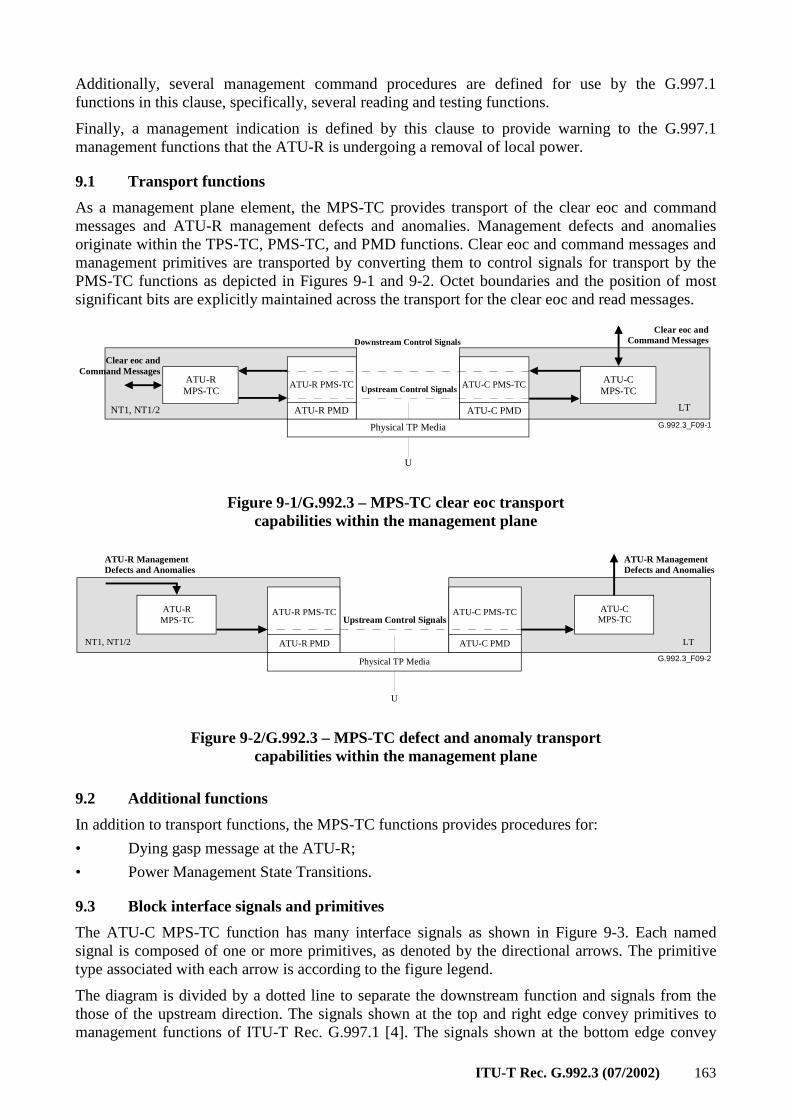
ITU-T Rec. G.992.3 (07/2002) 163
Additionally, several management command procedures are defined for use by the G.997.1 functions in this clause, specifically, several reading and testing functions.
Finally, a management indication is defined by this clause to provide warning to the G.997.1 management functions that the ATU-R is undergoing a removal of local power.
9.1 Transport functions
As a management plane element, the MPS-TC provides transport of the clear eoc and command messages and ATU-R management defects and anomalies. Management defects and anomalies originate within the TPS-TC, PMS-TC, and PMD functions. Clear eoc and command messages and management primitives are transported by converting them to control signals for transport by the PMS-TC functions as depicted in Figures 9-1 and 9-2. Octet boundaries and the position of most significant bits are explicitly maintained across the transport for the clear eoc and read messages.
G.992.3_F09-1
ATU-R PMS-TC ATU-C PMS-TC
Physical TP Media
ATU-R PMD ATU-C PMD
Upstream Control Signals
NT1, NT1/2
ATU-R MPS-TC
ATU-C MPS-TC
Downstream Control Signals
Clear eoc andCommand Messages
Clear eoc andCommand Messages
LT
U
Figure 9-1/G.992.3 – MPS-TC clear eoc transport capabilities within the management plane
G.992.3_F09-2
ATU-R PMS-TC ATU-C PMS-TC
Physical TP Media
ATU-R PMD ATU-C PMD
Upstream Control Signals
NT1, NT1/2 LT
ATU-R MPS-TC
ATU-C MPS-TC
ATU-R ManagementDefects and Anomalies
ATU-R ManagementDefects and Anomalies
U
Figure 9-2/G.992.3 – MPS-TC defect and anomaly transport capabilities within the management plane
9.2 Additional functions
In addition to transport functions, the MPS-TC functions provides procedures for:
• Dying gasp message at the ATU-R;
• Power Management State Transitions.
9.3 Block interface signals and primitives
The ATU-C MPS-TC function has many interface signals as shown in Figure 9-3. Each named signal is composed of one or more primitives, as denoted by the directional arrows. The primitive type associated with each arrow is according to the figure legend.
The diagram is divided by a dotted line to separate the downstream function and signals from the those of the upstream direction. The signals shown at the top and right edge convey primitives to management functions of ITU-T Rec. G.997.1 [4]. The signals shown at the bottom edge convey
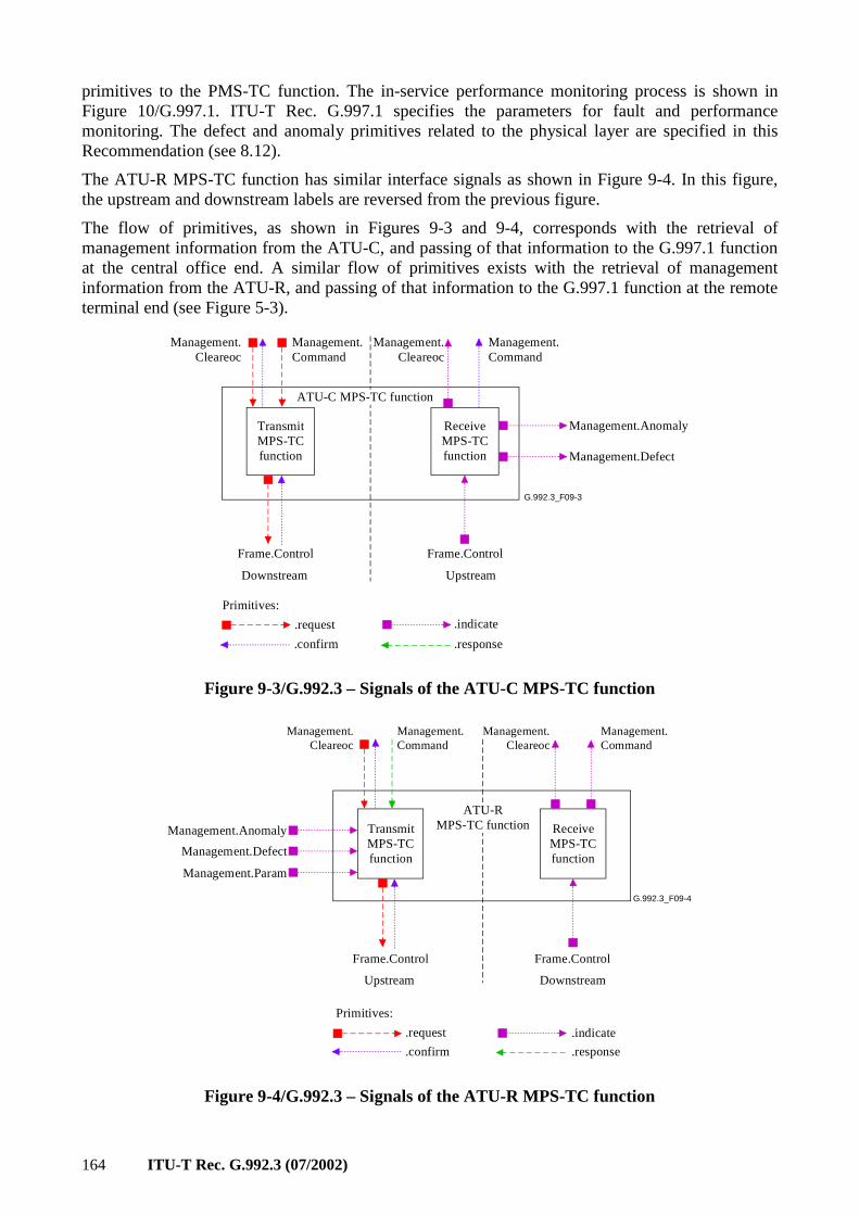
164 ITU-T Rec. G.992.3 (07/2002)
primitives to the PMS-TC function. The in-service performance monitoring process is shown in Figure 10/G.997.1. ITU-T Rec. G.997.1 specifies the parameters for fault and performance monitoring. The defect and anomaly primitives related to the physical layer are specified in this Recommendation (see 8.12).
The ATU-R MPS-TC function has similar interface signals as shown in Figure 9-4. In this figure, the upstream and downstream labels are reversed from the previous figure.
The flow of primitives, as shown in Figures 9-3 and 9-4, corresponds with the retrieval of management information from the ATU-C, and passing of that information to the G.997.1 function at the central office end. A similar flow of primitives exists with the retrieval of management information from the ATU-R, and passing of that information to the G.997.1 function at the remote terminal end (see Figure 5-3).
G.992.3_F09-3
TransmitMPS-TCfunction
Frame.Control
ReceiveMPS-TCfunction
Downstream Upstream
ATU-C MPS-TC function
Management.Anomaly
Frame.Control
Management.Defect
Management.Cleareoc
Management.Cleareoc
Management.Command
Management.Command
.request
.confirm
.indicate
.response
Primitives:
Figure 9-3/G.992.3 – Signals of the ATU-C MPS-TC function
G.992.3_F09-4
TransmitMPS-TCfunction
Frame.Control
ReceiveMPS-TCfunction
Upstream Downstream
ATU-R MPS-TC function
Management.Cleareoc
Management.Cleareoc
Frame.Control
Management.Anomaly
Management.Defect
Management.Command
Management.Command
Management.Param
.request
.confirm
.indicate
.response
Primitives:
Figure 9-4/G.992.3 – Signals of the ATU-R MPS-TC function
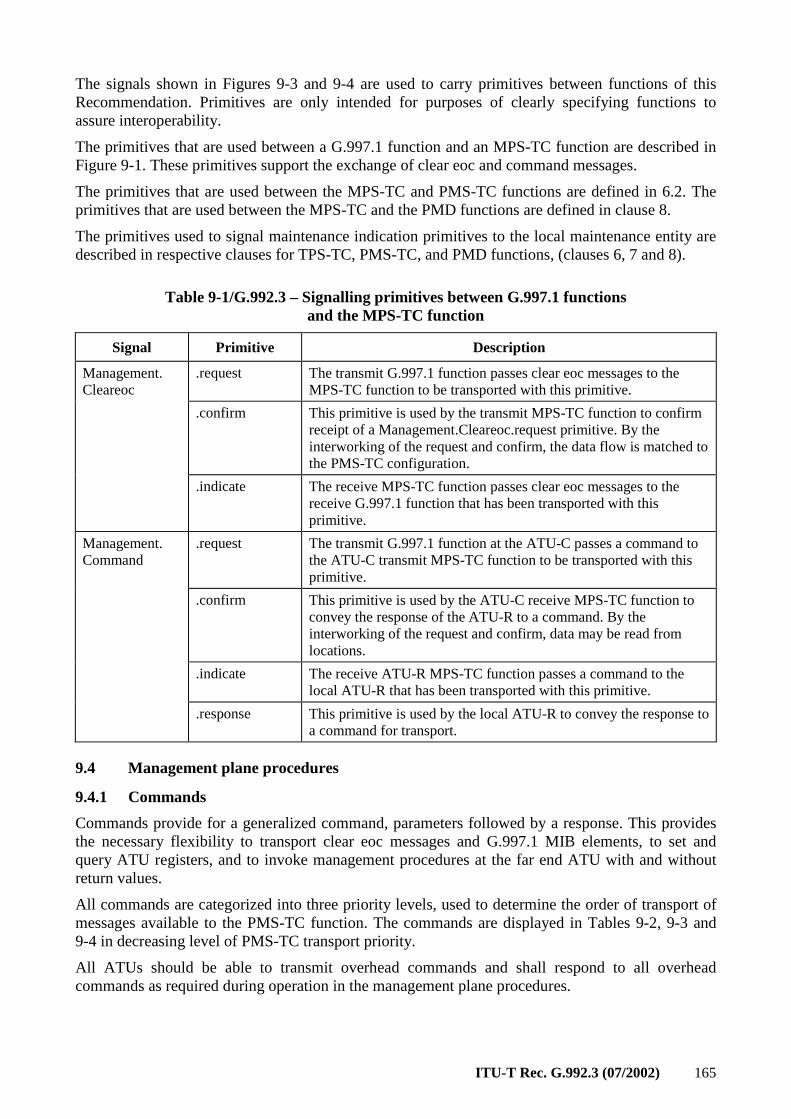
ITU-T Rec. G.992.3 (07/2002) 165
The signals shown in Figures 9-3 and 9-4 are used to carry primitives between functions of this Recommendation. Primitives are only intended for purposes of clearly specifying functions to assure interoperability.
The primitives that are used between a G.997.1 function and an MPS-TC function are described in Figure 9-1. These primitives support the exchange of clear eoc and command messages.
The primitives that are used between the MPS-TC and PMS-TC functions are defined in 6.2. The primitives that are used between the MPS-TC and the PMD functions are defined in clause 8.
The primitives used to signal maintenance indication primitives to the local maintenance entity are described in respective clauses for TPS-TC, PMS-TC, and PMD functions, (clauses 6, 7 and 8).
Table 9-1/G.992.3 – Signalling primitives between G.997.1 functions and the MPS-TC function
Signal Primitive Description
.request The transmit G.997.1 function passes clear eoc messages to the MPS-TC function to be transported with this primitive.
.confirm This primitive is used by the transmit MPS-TC function to confirm receipt of a Management.Cleareoc.request primitive. By the interworking of the request and confirm, the data flow is matched to the PMS-TC configuration.
Management. Cleareoc
.indicate The receive MPS-TC function passes clear eoc messages to the receive G.997.1 function that has been transported with this primitive.
.request The transmit G.997.1 function at the ATU-C passes a command to the ATU-C transmit MPS-TC function to be transported with this primitive.
.confirm This primitive is used by the ATU-C receive MPS-TC function to convey the response of the ATU-R to a command. By the interworking of the request and confirm, data may be read from locations.
.indicate The receive ATU-R MPS-TC function passes a command to the local ATU-R that has been transported with this primitive.
Management. Command
.response This primitive is used by the local ATU-R to convey the response to a command for transport.
9.4 Management plane procedures
9.4.1 Commands
Commands provide for a generalized command, parameters followed by a response. This provides the necessary flexibility to transport clear eoc messages and G.997.1 MIB elements, to set and query ATU registers, and to invoke management procedures at the far end ATU with and without return values.
All commands are categorized into three priority levels, used to determine the order of transport of messages available to the PMS-TC function. The commands are displayed in Tables 9-2, 9-3 and 9-4 in decreasing level of PMS-TC transport priority.
All ATUs should be able to transmit overhead commands and shall respond to all overhead commands as required during operation in the management plane procedures.
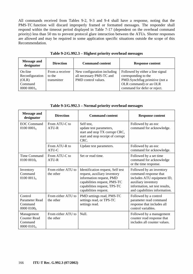
166 ITU-T Rec. G.992.3 (07/2002)
All commands received from Tables 9-2, 9-3 and 9-4 shall have a response, noting that the PMS-TC function will discard improperly framed or formatted messages. The responder shall respond within the timeout period displayed in Table 7-17 (dependent on the overhead command priority) less than 50 ms to prevent protocol glare interaction between the ATUs. Shorter responses are allowed and may be required in some application specific situations outside the scope of this Recommendation.
Table 9-2/G.992.3 – Highest priority overhead messages
Message and designator Direction Command content Response content
On-line Reconfiguration (OLR) Command 0000 0001b
From a receiver to the transmitter
New configuration including all necessary PMS-TC and PMD control values.
Followed by either a line signal corresponding to the PMD.Synchflag primitive (not a OLR command) or an OLR command for defer or reject.
Table 9-3/G.992.3 – Normal priority overhead messages
Message and designator Direction Command content Response content
From ATU-C to ATU-R
Self test, update test parameters, start and stop TX corrupt CRC, start and stop receipt of corrupt CRC.
Followed by an eoc command for acknowledge.
EOC Command 0100 0001b
From ATU-R to ATU-C
Update test parameters. Followed by an eoc command for acknowledge.
Time Command 0100 0010b
From ATU-C to ATU-R
Set or read time. Followed by a set time command for acknowledge or the time response.
Inventory Command 0100 0011b
From either ATU to the other
Identification request, Self test request, auxiliary inventory information request, PMD capabilities request, PMS-TC capabilities request, TPS-TC capabilities request.
Followed by an inventory command response that includes ATU equipment ID, auxiliary inventory information, set test results, and capabilities information.
Control Parameter Read Command 0000 0100b
From either ATU to the other
PMD settings read, PMS-TC settings read, or TPS-TC settings read.
Followed by a control parameter read command response that includes all control variables.
Management Counter Read Command 0000 0101b
From either ATU to the other
Null. Followed by a management counter read response that includes all counter values.
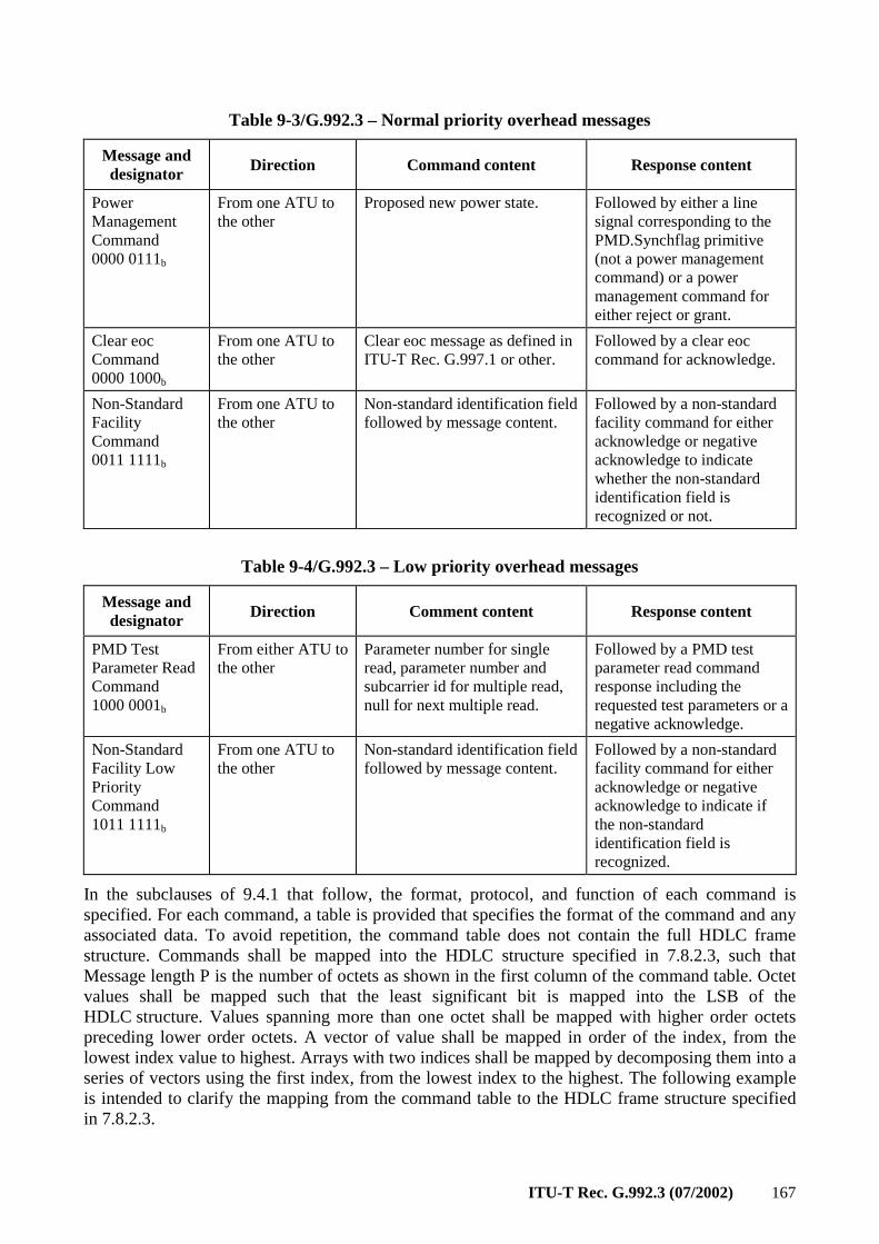
ITU-T Rec. G.992.3 (07/2002) 167
Table 9-3/G.992.3 – Normal priority overhead messages
Message and designator Direction Command content Response content
Power Management Command 0000 0111b
From one ATU to the other
Proposed new power state. Followed by either a line signal corresponding to the PMD.Synchflag primitive (not a power management command) or a power management command for either reject or grant.
Clear eoc Command 0000 1000b
From one ATU to the other
Clear eoc message as defined in ITU-T Rec. G.997.1 or other.
Followed by a clear eoc command for acknowledge.
Non-Standard Facility Command 0011 1111b
From one ATU to the other
Non-standard identification field followed by message content.
Followed by a non-standard facility command for either acknowledge or negative acknowledge to indicate whether the non-standard identification field is recognized or not.
Table 9-4/G.992.3 – Low priority overhead messages
Message and designator Direction Comment content Response content
PMD Test Parameter Read Command 1000 0001b
From either ATU to the other
Parameter number for single read, parameter number and subcarrier id for multiple read, null for next multiple read.
Followed by a PMD test parameter read command response including the requested test parameters or a negative acknowledge.
Non-Standard Facility Low Priority Command 1011 1111b
From one ATU to the other
Non-standard identification field followed by message content.
Followed by a non-standard facility command for either acknowledge or negative acknowledge to indicate if the non-standard identification field is recognized.
In the subclauses of 9.4.1 that follow, the format, protocol, and function of each command is specified. For each command, a table is provided that specifies the format of the command and any associated data. To avoid repetition, the command table does not contain the full HDLC frame structure. Commands shall be mapped into the HDLC structure specified in 7.8.2.3, such that Message length P is the number of octets as shown in the first column of the command table. Octet values shall be mapped such that the least significant bit is mapped into the LSB of the HDLC structure. Values spanning more than one octet shall be mapped with higher order octets preceding lower order octets. A vector of value shall be mapped in order of the index, from the lowest index value to highest. Arrays with two indices shall be mapped by decomposing them into a series of vectors using the first index, from the lowest index to the highest. The following example is intended to clarify the mapping from the command table to the HDLC frame structure specified in 7.8.2.3.
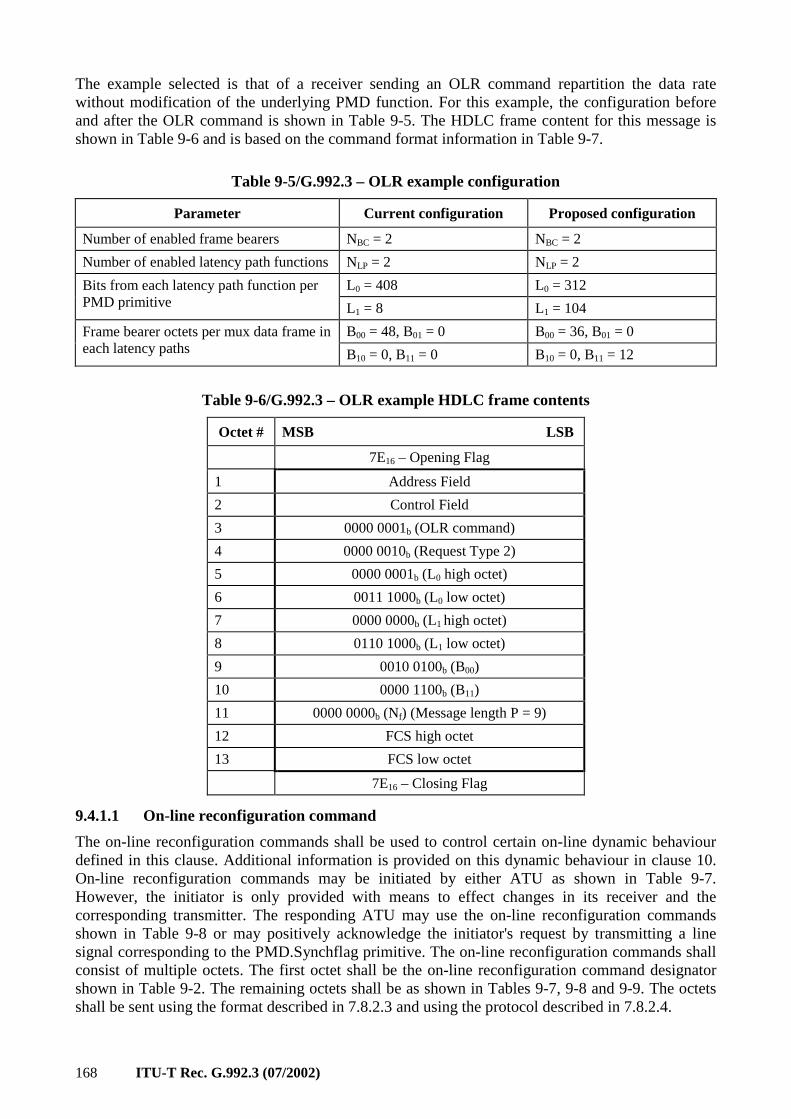
168 ITU-T Rec. G.992.3 (07/2002)
The example selected is that of a receiver sending an OLR command repartition the data rate without modification of the underlying PMD function. For this example, the configuration before and after the OLR command is shown in Table 9-5. The HDLC frame content for this message is shown in Table 9-6 and is based on the command format information in Table 9-7.
Table 9-5/G.992.3 – OLR example configuration
Parameter Current configuration Proposed configuration
Number of enabled frame bearers NBC = 2 NBC = 2
Number of enabled latency path functions NLP = 2 NLP = 2
L0 = 408 L0 = 312 Bits from each latency path function per PMD primitive L1 = 8 L1 = 104
B00 = 48, B01 = 0 B00 = 36, B01 = 0 Frame bearer octets per mux data frame in each latency paths B10 = 0, B11 = 0 B10 = 0, B11 = 12
Table 9-6/G.992.3 – OLR example HDLC frame contents
Octet # MSB LSB
7E16 – Opening Flag
1 Address Field
2 Control Field
3 0000 0001b (OLR command)
4 0000 0010b (Request Type 2)
5 0000 0001b (L0 high octet)
6 0011 1000b (L0 low octet)
7 0000 0000b (L1 high octet)
8 0110 1000b (L1 low octet)
9 0010 0100b (B00)
10 0000 1100b (B11)
11 0000 0000b (Nf) (Message length P = 9)
12 FCS high octet
13 FCS low octet
7E16 – Closing Flag
9.4.1.1 On-line reconfiguration command
The on-line reconfiguration commands shall be used to control certain on-line dynamic behaviour defined in this clause. Additional information is provided on this dynamic behaviour in clause 10. On-line reconfiguration commands may be initiated by either ATU as shown in Table 9-7. However, the initiator is only provided with means to effect changes in its receiver and the corresponding transmitter. The responding ATU may use the on-line reconfiguration commands shown in Table 9-8 or may positively acknowledge the initiator's request by transmitting a line signal corresponding to the PMD.Synchflag primitive. The on-line reconfiguration commands shall consist of multiple octets. The first octet shall be the on-line reconfiguration command designator shown in Table 9-2. The remaining octets shall be as shown in Tables 9-7, 9-8 and 9-9. The octets shall be sent using the format described in 7.8.2.3 and using the protocol described in 7.8.2.4.
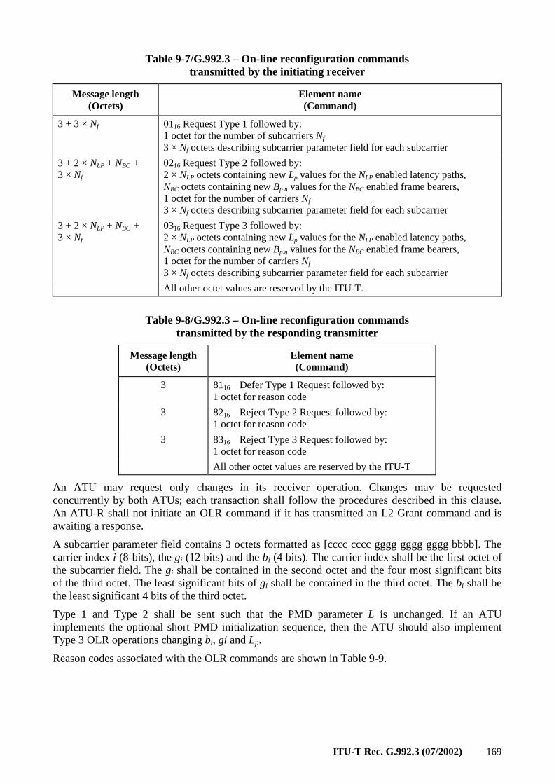
ITU-T Rec. G.992.3 (07/2002) 169
Table 9-7/G.992.3 – On-line reconfiguration commands transmitted by the initiating receiver
Message length (Octets)
Element name (Command)
3 + 3 × Nf 0116 Request Type 1 followed by: 1 octet for the number of subcarriers Nf 3 × Nf octets describing subcarrier parameter field for each subcarrier
3 + 2 × NLP + NBC + 3 × Nf
0216 Request Type 2 followed by: 2 × NLP octets containing new Lp values for the NLP enabled latency paths, NBC octets containing new Bp.n values for the NBC enabled frame bearers, 1 octet for the number of carriers Nf
3 × Nf octets describing subcarrier parameter field for each subcarrier
3 + 2 × NLP + NBC + 3 × Nf
0316 Request Type 3 followed by: 2 × NLP octets containing new Lp values for the NLP enabled latency paths, NBC octets containing new Bp.n values for the NBC enabled frame bearers, 1 octet for the number of carriers Nf 3 × Nf octets describing subcarrier parameter field for each subcarrier
All other octet values are reserved by the ITU-T.
Table 9-8/G.992.3 – On-line reconfiguration commands transmitted by the responding transmitter
Message length (Octets)
Element name (Command)
3 8116 Defer Type 1 Request followed by: 1 octet for reason code
3 8216 Reject Type 2 Request followed by: 1 octet for reason code
3 8316 Reject Type 3 Request followed by: 1 octet for reason code
All other octet values are reserved by the ITU-T
An ATU may request only changes in its receiver operation. Changes may be requested concurrently by both ATUs; each transaction shall follow the procedures described in this clause. An ATU-R shall not initiate an OLR command if it has transmitted an L2 Grant command and is awaiting a response.
A subcarrier parameter field contains 3 octets formatted as [cccc cccc gggg gggg gggg bbbb]. The carrier index i (8-bits), the gi (12 bits) and the bi (4 bits). The carrier index shall be the first octet of the subcarrier field. The gi shall be contained in the second octet and the four most significant bits of the third octet. The least significant bits of gi shall be contained in the third octet. The bi shall be the least significant 4 bits of the third octet.
Type 1 and Type 2 shall be sent such that the PMD parameter L is unchanged. If an ATU implements the optional short PMD initialization sequence, then the ATU should also implement Type 3 OLR operations changing bi, gi and Lp.
Reason codes associated with the OLR commands are shown in Table 9-9.
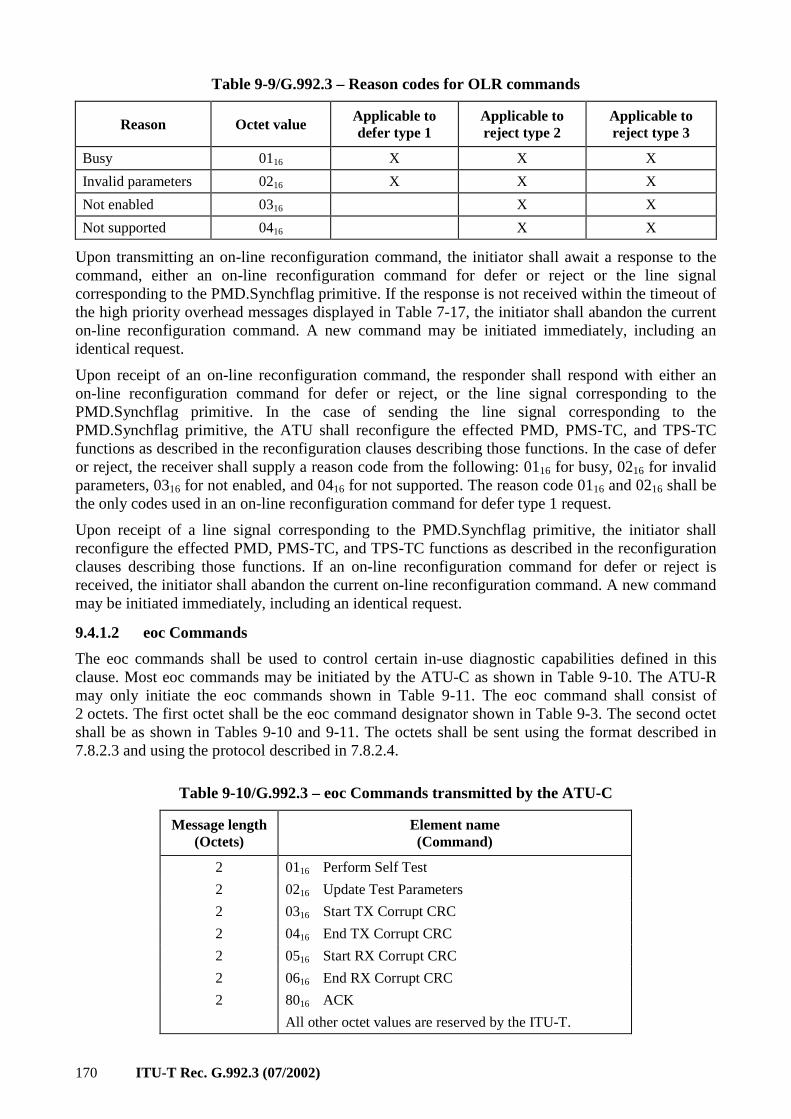
170 ITU-T Rec. G.992.3 (07/2002)
Table 9-9/G.992.3 – Reason codes for OLR commands
Reason Octet value Applicable to defer type 1
Applicable to reject type 2
Applicable to reject type 3
Busy 0116 X X X
Invalid parameters 0216 X X X
Not enabled 0316 X X
Not supported 0416 X X
Upon transmitting an on-line reconfiguration command, the initiator shall await a response to the command, either an on-line reconfiguration command for defer or reject or the line signal corresponding to the PMD.Synchflag primitive. If the response is not received within the timeout of the high priority overhead messages displayed in Table 7-17, the initiator shall abandon the current on-line reconfiguration command. A new command may be initiated immediately, including an identical request.
Upon receipt of an on-line reconfiguration command, the responder shall respond with either an on-line reconfiguration command for defer or reject, or the line signal corresponding to the PMD.Synchflag primitive. In the case of sending the line signal corresponding to the PMD.Synchflag primitive, the ATU shall reconfigure the effected PMD, PMS-TC, and TPS-TC functions as described in the reconfiguration clauses describing those functions. In the case of defer or reject, the receiver shall supply a reason code from the following: 0116 for busy, 0216 for invalid parameters, 0316 for not enabled, and 0416 for not supported. The reason code 0116 and 0216 shall be the only codes used in an on-line reconfiguration command for defer type 1 request.
Upon receipt of a line signal corresponding to the PMD.Synchflag primitive, the initiator shall reconfigure the effected PMD, PMS-TC, and TPS-TC functions as described in the reconfiguration clauses describing those functions. If an on-line reconfiguration command for defer or reject is received, the initiator shall abandon the current on-line reconfiguration command. A new command may be initiated immediately, including an identical request.
9.4.1.2 eoc Commands
The eoc commands shall be used to control certain in-use diagnostic capabilities defined in this clause. Most eoc commands may be initiated by the ATU-C as shown in Table 9-10. The ATU-R may only initiate the eoc commands shown in Table 9-11. The eoc command shall consist of 2 octets. The first octet shall be the eoc command designator shown in Table 9-3. The second octet shall be as shown in Tables 9-10 and 9-11. The octets shall be sent using the format described in 7.8.2.3 and using the protocol described in 7.8.2.4.
Table 9-10/G.992.3 – eoc Commands transmitted by the ATU-C
Message length (Octets)
Element name (Command)
2 0116 Perform Self Test
2 0216 Update Test Parameters
2 0316 Start TX Corrupt CRC
2 0416 End TX Corrupt CRC
2 0516 Start RX Corrupt CRC
2 0616 End RX Corrupt CRC
2 8016 ACK
All other octet values are reserved by the ITU-T.
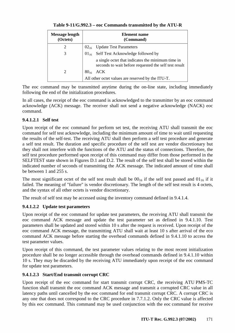
ITU-T Rec. G.992.3 (07/2002) 171
Table 9-11/G.992.3 – eoc Commands transmitted by the ATU-R
Message length (Octets)
Element name (Command)
2 0216 Update Test Parameters
3 0116 Self Test Acknowledge followed by
a single octet that indicates the minimum time in seconds to wait before requested the self test result
2 8016 ACK
All other octet values are reserved by the ITU-T.
The eoc command may be transmitted anytime during the on-line state, including immediately following the end of the initialization procedures.
In all cases, the receipt of the eoc command is acknowledged to the transmitter by an eoc command acknowledge (ACK) message. The receiver shall not send a negative acknowledge (NACK) eoc command.
9.4.1.2.1 Self test
Upon receipt of the eoc command for perform set test, the receiving ATU shall transmit the eoc command for self test acknowledge, including the minimum amount of time to wait until requesting the results of the self-test. The receiving ATU shall then perform a self test procedure and generate a self test result. The duration and specific procedure of the self test are vendor discretionary but they shall not interfere with the functions of the ATU and the status of connections. Therefore, the self test procedure performed upon receipt of this command may differ from those performed in the SELFTEST state shown in Figures D.1 and D.2. The result of the self test shall be stored within the indicated number of seconds of transmitting the ACK message. The indicated amount of time shall be between 1 and 255 s.
The most significant octet of the self test result shall be 0016 if the self test passed and 0116 if it failed. The meaning of "failure" is vendor discretionary. The length of the self test result is 4 octets, and the syntax of all other octets is vendor discretionary.
The result of self test may be accessed using the inventory command defined in 9.4.1.4.
9.4.1.2.2 Update test parameters
Upon receipt of the eoc command for update test parameters, the receiving ATU shall transmit the eoc command ACK message and update the test parameter set as defined in 9.4.1.10. Test parameters shall be updated and stored within 10 s after the request is received. Upon receipt of the eoc command ACK message, the transmitting ATU shall wait at least 10 s after arrival of the eco command ACK message before starting the overhead commands defined in 9.4.1.10 to access the test parameter values.
Upon receipt of this command, the test parameter values relating to the most recent initialization procedure shall be no longer accessible through the overhead commands defined in 9.4.1.10 within 10 s. They may be discarded by the receiving ATU immediately upon receipt of the eoc command for update test parameters.
9.4.1.2.3 Start/End transmit corrupt CRC
Upon receipt of the eoc command for start transmit corrupt CRC, the receiving ATU PMS-TC function shall transmit the eoc command ACK message and transmit a corrupted CRC value in all latency paths until cancelled by the eoc command for end transmit corrupt CRC. A corrupt CRC is any one that does not correspond to the CRC procedure in 7.7.1.2. Only the CRC value is affected by this eoc command. This command may be used conjunction with the eoc command for receive
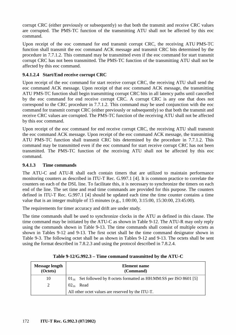
172 ITU-T Rec. G.992.3 (07/2002)
corrupt CRC (either previously or subsequently) so that both the transmit and receive CRC values are corrupted. The PMS-TC function of the transmitting ATU shall not be affected by this eoc command.
Upon receipt of the eoc command for end transmit corrupt CRC, the receiving ATU PMS-TC function shall transmit the eoc command ACK message and transmit CRC bits determined by the procedure in 7.7.1.2. This command may be transmitted even if the eoc command for start transmit corrupt CRC has not been transmitted. The PMS-TC function of the transmitting ATU shall not be affected by this eoc command.
9.4.1.2.4 Start/End receive corrupt CRC
Upon receipt of the eoc command for start receive corrupt CRC, the receiving ATU shall send the eoc command ACK message. Upon receipt of that eoc command ACK message, the transmitting ATU PMS-TC function shall begin transmitting corrupt CRC bits in all latency paths until cancelled by the eoc command for end receive corrupt CRC. A corrupt CRC is any one that does not correspond to the CRC procedure in 7.7.1.2. This command may be used conjunction with the eoc command for transmit corrupt CRC (either previously or subsequently) so that both the transmit and receive CRC values are corrupted. The PMS-TC function of the receiving ATU shall not be affected by this eoc command.
Upon receipt of the eoc command for end receive corrupt CRC, the receiving ATU shall transmit the eoc command ACK message. Upon receipt of the eoc command ACK message, the transmitting ATU PMS-TC function shall transmit CRC bits determined by the procedure in 7.7.1.2. This command may be transmitted even if the eoc command for start receive corrupt CRC has not been transmitted. The PMS-TC function of the receiving ATU shall not be affected by this eoc command.
9.4.1.3 Time commands
The ATU-C and ATU-R shall each contain timers that are utilized to maintain performance monitoring counters as described in ITU-T Rec. G.997.1 [4]. It is common practice to correlate the counters on each of the DSL line. To facilitate this, it is necessary to synchronize the timers on each end of the line. The set time and read time commands are provided for this purpose. The counters defined in ITU-T Rec. G.997.1 [4] should be updated each time the time counter contains a time value that is an integer multiple of 15 minutes (e.g., 1:00:00, 3:15:00, 15:30:00, 23:45:00).
The requirements for timer accuracy and drift are under study.
The time commands shall be used to synchronize clocks in the ATU as defined in this clause. The time command may be initiated by the ATU-C as shown in Table 9-12. The ATU-R may only reply using the commands shown in Table 9-13. The time commands shall consist of multiple octets as shown in Tables 9-12 and 9-13. The first octet shall be the time command designator shown in Table 9-3. The following octet shall be as shown in Tables 9-12 and 9-13. The octets shall be sent using the format described in 7.8.2.3 and using the protocol described in 7.8.2.4.
Table 9-12/G.992.3 – Time command transmitted by the ATU-C
Message length (Octets)
Element name (Command)
10 0116 Set followed by 8 octets formatted as HH:MM:SS per ISO 8601 [5]
2 0216 Read
All other octet values are reserved by the ITU-T.
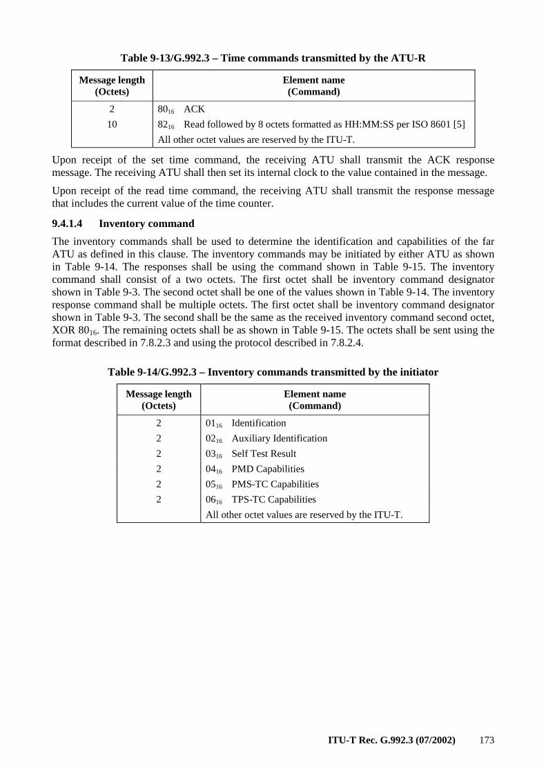
ITU-T Rec. G.992.3 (07/2002) 173
Table 9-13/G.992.3 – Time commands transmitted by the ATU-R
Message length (Octets)
Element name (Command)
2 8016 ACK
10 8216 Read followed by 8 octets formatted as HH:MM:SS per ISO 8601 [5]
All other octet values are reserved by the ITU-T.
Upon receipt of the set time command, the receiving ATU shall transmit the ACK response message. The receiving ATU shall then set its internal clock to the value contained in the message.
Upon receipt of the read time command, the receiving ATU shall transmit the response message that includes the current value of the time counter.
9.4.1.4 Inventory command
The inventory commands shall be used to determine the identification and capabilities of the far ATU as defined in this clause. The inventory commands may be initiated by either ATU as shown in Table 9-14. The responses shall be using the command shown in Table 9-15. The inventory command shall consist of a two octets. The first octet shall be inventory command designator shown in Table 9-3. The second octet shall be one of the values shown in Table 9-14. The inventory response command shall be multiple octets. The first octet shall be inventory command designator shown in Table 9-3. The second shall be the same as the received inventory command second octet, XOR 8016. The remaining octets shall be as shown in Table 9-15. The octets shall be sent using the format described in 7.8.2.3 and using the protocol described in 7.8.2.4.
Table 9-14/G.992.3 – Inventory commands transmitted by the initiator
Message length (Octets)
Element name (Command)
2 0116 Identification
2 0216 Auxiliary Identification
2 0316 Self Test Result
2 0416 PMD Capabilities
2 0516 PMS-TC Capabilities
2 0616 TPS-TC Capabilities
All other octet values are reserved by the ITU-T.
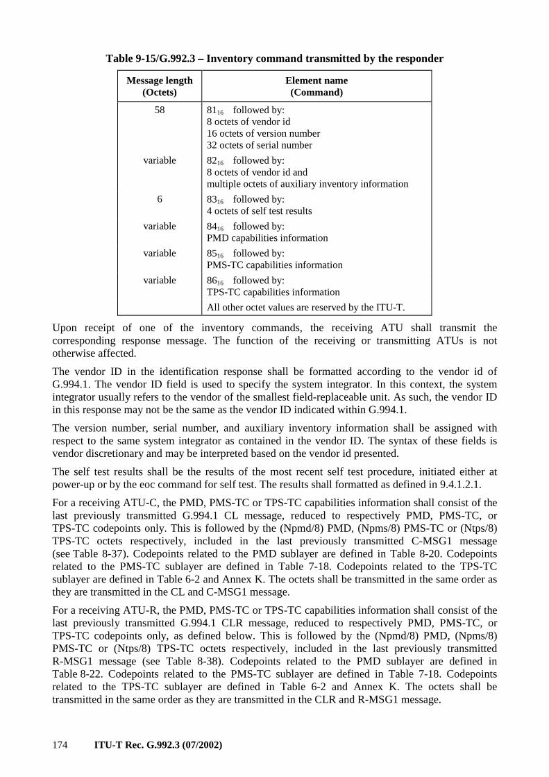
174 ITU-T Rec. G.992.3 (07/2002)
Table 9-15/G.992.3 – Inventory command transmitted by the responder
Message length (Octets)
Element name (Command)
58 8116 followed by: 8 octets of vendor id 16 octets of version number 32 octets of serial number
variable 8216 followed by: 8 octets of vendor id and multiple octets of auxiliary inventory information
6 8316 followed by: 4 octets of self test results
variable 8416 followed by: PMD capabilities information
variable 8516 followed by: PMS-TC capabilities information
variable 8616 followed by: TPS-TC capabilities information
All other octet values are reserved by the ITU-T.
Upon receipt of one of the inventory commands, the receiving ATU shall transmit the corresponding response message. The function of the receiving or transmitting ATUs is not otherwise affected.
The vendor ID in the identification response shall be formatted according to the vendor id of G.994.1. The vendor ID field is used to specify the system integrator. In this context, the system integrator usually refers to the vendor of the smallest field-replaceable unit. As such, the vendor ID in this response may not be the same as the vendor ID indicated within G.994.1.
The version number, serial number, and auxiliary inventory information shall be assigned with respect to the same system integrator as contained in the vendor ID. The syntax of these fields is vendor discretionary and may be interpreted based on the vendor id presented.
The self test results shall be the results of the most recent self test procedure, initiated either at power-up or by the eoc command for self test. The results shall formatted as defined in 9.4.1.2.1.
For a receiving ATU-C, the PMD, PMS-TC or TPS-TC capabilities information shall consist of the last previously transmitted G.994.1 CL message, reduced to respectively PMD, PMS-TC, or TPS-TC codepoints only. This is followed by the (Npmd/8) PMD, (Npms/8) PMS-TC or (Ntps/8) TPS-TC octets respectively, included in the last previously transmitted C-MSG1 message (see Table 8-37). Codepoints related to the PMD sublayer are defined in Table 8-20. Codepoints related to the PMS-TC sublayer are defined in Table 7-18. Codepoints related to the TPS-TC sublayer are defined in Table 6-2 and Annex K. The octets shall be transmitted in the same order as they are transmitted in the CL and C-MSG1 message.
For a receiving ATU-R, the PMD, PMS-TC or TPS-TC capabilities information shall consist of the last previously transmitted G.994.1 CLR message, reduced to respectively PMD, PMS-TC, or TPS-TC codepoints only, as defined below. This is followed by the (Npmd/8) PMD, (Npms/8) PMS-TC or (Ntps/8) TPS-TC octets respectively, included in the last previously transmitted R-MSG1 message (see Table 8-38). Codepoints related to the PMD sublayer are defined in Table 8-22. Codepoints related to the PMS-TC sublayer are defined in Table 7-18. Codepoints related to the TPS-TC sublayer are defined in Table 6-2 and Annex K. The octets shall be transmitted in the same order as they are transmitted in the CLR and R-MSG1 message.
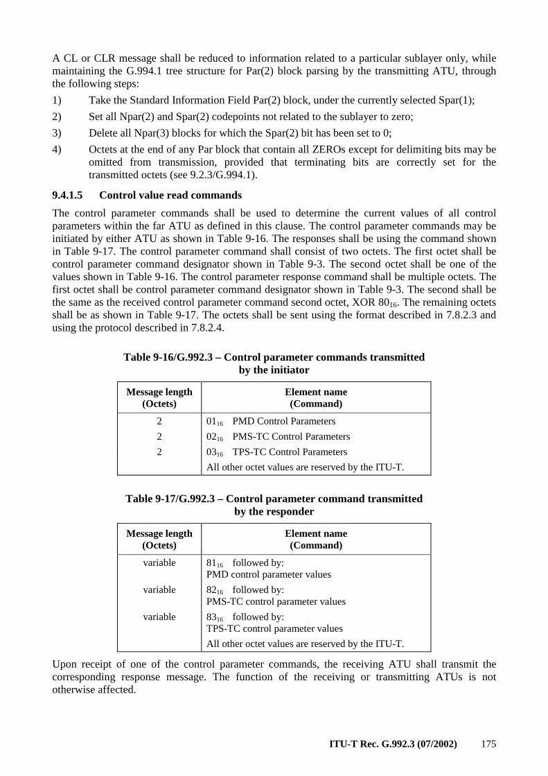
ITU-T Rec. G.992.3 (07/2002) 175
A CL or CLR message shall be reduced to information related to a particular sublayer only, while maintaining the G.994.1 tree structure for Par(2) block parsing by the transmitting ATU, through the following steps:
1) Take the Standard Information Field Par(2) block, under the currently selected Spar(1);
2) Set all Npar(2) and Spar(2) codepoints not related to the sublayer to zero;
3) Delete all Npar(3) blocks for which the Spar(2) bit has been set to 0;
4) Octets at the end of any Par block that contain all ZEROs except for delimiting bits may be omitted from transmission, provided that terminating bits are correctly set for the transmitted octets (see 9.2.3/G.994.1).
9.4.1.5 Control value read commands
The control parameter commands shall be used to determine the current values of all control parameters within the far ATU as defined in this clause. The control parameter commands may be initiated by either ATU as shown in Table 9-16. The responses shall be using the command shown in Table 9-17. The control parameter command shall consist of two octets. The first octet shall be control parameter command designator shown in Table 9-3. The second octet shall be one of the values shown in Table 9-16. The control parameter response command shall be multiple octets. The first octet shall be control parameter command designator shown in Table 9-3. The second shall be the same as the received control parameter command second octet, XOR 8016. The remaining octets shall be as shown in Table 9-17. The octets shall be sent using the format described in 7.8.2.3 and using the protocol described in 7.8.2.4.
Table 9-16/G.992.3 – Control parameter commands transmitted by the initiator
Message length (Octets)
Element name (Command)
2 0116 PMD Control Parameters
2 0216 PMS-TC Control Parameters
2 0316 TPS-TC Control Parameters
All other octet values are reserved by the ITU-T.
Table 9-17/G.992.3 – Control parameter command transmitted by the responder
Message length (Octets)
Element name (Command)
variable 8116 followed by: PMD control parameter values
variable 8216 followed by: PMS-TC control parameter values
variable 8316 followed by: TPS-TC control parameter values
All other octet values are reserved by the ITU-T.
Upon receipt of one of the control parameter commands, the receiving ATU shall transmit the corresponding response message. The function of the receiving or transmitting ATUs is not otherwise affected.
176 ITU-T Rec. G.992.3 (07/2002)
The control parameter values contained within the PMD, PMS-TC, and TPS-TC responses shall be the transmit function control parameters currently in use by the receiving ATU.
For a receiving ATU-C, the PMD, PMS-TC or TPS-TC control parameter values shall consist of the last previously transmitted G.994.1 MS message, reduced to respectively PMD, PMS-TC, or TPS-TC codepoints only. Within the PMD control parameters only, this is followed by (4 + NSCds/8) octets in R-MSG-PCB format (see Table 8-32, with parameters as defined below). Then follow the (Npmd/8) PMD, (Npms/8) PMS-TC or (Ntps/8) TPS-TC octets respectively, included in the last previously transmitted R-PARAMS message (see Table 8-40), and possibly updated during Showtime. Codepoints related to the PMD sublayer are defined in Table 8-21. Codepoints related to the PMS-TC sublayer are defined in Table 7-19. Codepoints related to the TPS-TC sublayer are defined in Table 6-2 and Annex K. The octets shall be transmitted in the same order as they are transmitted in the MS, R-MSG-PCB and R-PARAMS messages.
The ATU-C shall set the octets related to R-MSG-PCB (see Table 8-32) as follows:
• R-MIN_PCB_DS is set to PCBds;
• R-MIN_PCB_US is set to 0;
• HOOK_STATUS is set to 0;
• C-PILOT is set to the pilot subcarrier index currently used by the ATU-C transmit PMD function;
• R-BLACKOUT bits are set to the values currently used by the ATU-C transmit PMD function;
• Other bits are reserved and set to 0.
For a receiving ATU-R, the PMD, PMS-TC or TPS-TC control parameter values shall consist of the last previously transmitted G.994.1 MS message, reduced to respectively PMD, PMS-TC, or TPS-TC codepoints only. Within the PMD control parameters only, this is followed by (2 + NSCus/8) octets in C-MSG-PCB format (see Table 8-27, with parameters as defined below). Then follow the (Npmd/8) PMD, (Npms/8) PMS-TC or (Ntps/8) TPS-TC octets respectively, included in the last previously transmitted C-PARAMS message (see Table 8-39), and possibly updated during Showtime. Codepoints related to the PMD sublayer are defined in Table 8-23. Codepoints related to the PMS-TC sublayer are defined in Table 7-19. Codepoints related to the TPS-TC sublayer are defined in Annex K. The octets shall be transmitted in the same order as they are transmitted in the MS and C-PARAMS messages.
The ATU-R shall set the octets related to C-MSG-PCB (see Table 8-27) as follows:
• C-MIN_PCB_DS is set to 0;
• C-MIN_PCB_US is set to PCBus;
• HOOK_STATUS is set to 0;
• C-BLACKOUT bits are set to the values currently used by the ATU-C transmit PMD function;
• Other bits are reserved and set to 0.
An MS message shall be reduced to information on a particular sublayer only, while maintaining the G.994.1 tree structure for parsing by the transmitting ATU, through the same steps as taken for reducing the CL or CLR message.
9.4.1.6 Management counter read commands
The management counter read commands shall be used to access the value of certain management counters maintained by the far ATU in accordance with ITU-T Rec. G.997.1 [4]. The local counter values for completed time intervals shall be retrieved as described in this clause. The management counter read command may be initiated by either ATU as shown in Table 9-18. The responses shall
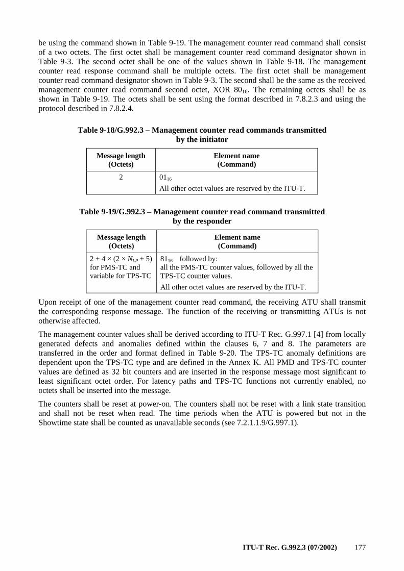
ITU-T Rec. G.992.3 (07/2002) 177
be using the command shown in Table 9-19. The management counter read command shall consist of a two octets. The first octet shall be management counter read command designator shown in Table 9-3. The second octet shall be one of the values shown in Table 9-18. The management counter read response command shall be multiple octets. The first octet shall be management counter read command designator shown in Table 9-3. The second shall be the same as the received management counter read command second octet, XOR 8016. The remaining octets shall be as shown in Table 9-19. The octets shall be sent using the format described in 7.8.2.3 and using the protocol described in 7.8.2.4.
Table 9-18/G.992.3 – Management counter read commands transmitted by the initiator
Message length (Octets)
Element name (Command)
2 0116
All other octet values are reserved by the ITU-T.
Table 9-19/G.992.3 – Management counter read command transmitted by the responder
Message length (Octets)
Element name (Command)
2 + 4 × (2 × NLP + 5) for PMS-TC and variable for TPS-TC
8116 followed by: all the PMS-TC counter values, followed by all the TPS-TC counter values.
All other octet values are reserved by the ITU-T.
Upon receipt of one of the management counter read command, the receiving ATU shall transmit the corresponding response message. The function of the receiving or transmitting ATUs is not otherwise affected.
The management counter values shall be derived according to ITU-T Rec. G.997.1 [4] from locally generated defects and anomalies defined within the clauses 6, 7 and 8. The parameters are transferred in the order and format defined in Table 9-20. The TPS-TC anomaly definitions are dependent upon the TPS-TC type and are defined in the Annex K. All PMD and TPS-TC counter values are defined as 32 bit counters and are inserted in the response message most significant to least significant octet order. For latency paths and TPS-TC functions not currently enabled, no octets shall be inserted into the message.
The counters shall be reset at power-on. The counters shall not be reset with a link state transition and shall not be reset when read. The time periods when the ATU is powered but not in the Showtime state shall be counted as unavailable seconds (see 7.2.1.1.9/G.997.1).
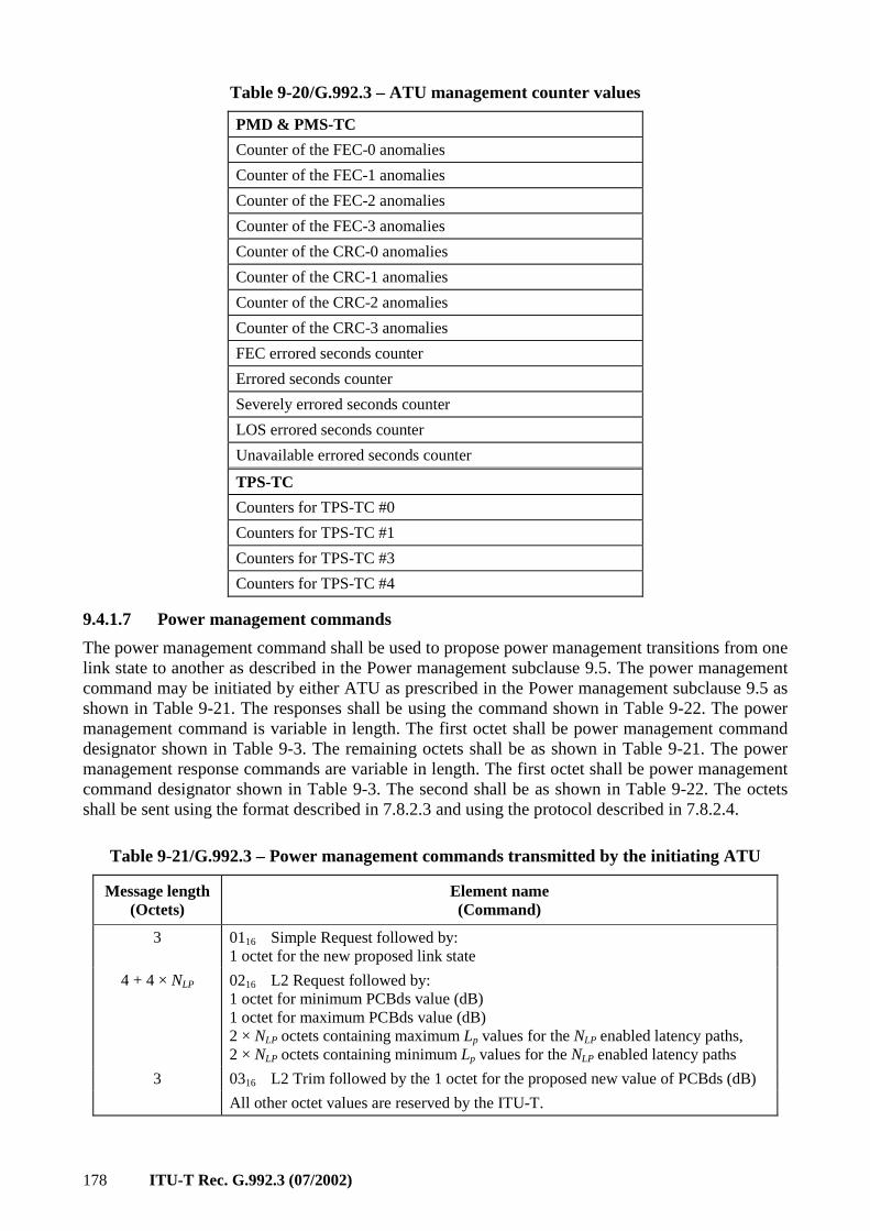
178 ITU-T Rec. G.992.3 (07/2002)
Table 9-20/G.992.3 – ATU management counter values
PMD & PMS-TC
Counter of the FEC-0 anomalies
Counter of the FEC-1 anomalies
Counter of the FEC-2 anomalies
Counter of the FEC-3 anomalies
Counter of the CRC-0 anomalies
Counter of the CRC-1 anomalies
Counter of the CRC-2 anomalies
Counter of the CRC-3 anomalies
FEC errored seconds counter
Errored seconds counter
Severely errored seconds counter
LOS errored seconds counter
Unavailable errored seconds counter
TPS-TC
Counters for TPS-TC #0
Counters for TPS-TC #1
Counters for TPS-TC #3
Counters for TPS-TC #4
9.4.1.7 Power management commands
The power management command shall be used to propose power management transitions from one link state to another as described in the Power management subclause 9.5. The power management command may be initiated by either ATU as prescribed in the Power management subclause 9.5 as shown in Table 9-21. The responses shall be using the command shown in Table 9-22. The power management command is variable in length. The first octet shall be power management command designator shown in Table 9-3. The remaining octets shall be as shown in Table 9-21. The power management response commands are variable in length. The first octet shall be power management command designator shown in Table 9-3. The second shall be as shown in Table 9-22. The octets shall be sent using the format described in 7.8.2.3 and using the protocol described in 7.8.2.4.
Table 9-21/G.992.3 – Power management commands transmitted by the initiating ATU
Message length (Octets)
Element name (Command)
3 0116 Simple Request followed by: 1 octet for the new proposed link state
4 + 4 × NLP 0216 L2 Request followed by: 1 octet for minimum PCBds value (dB) 1 octet for maximum PCBds value (dB) 2 × NLP octets containing maximum Lp values for the NLP enabled latency paths, 2 × NLP octets containing minimum Lp values for the NLP enabled latency paths
3 0316 L2 Trim followed by the 1 octet for the proposed new value of PCBds (dB)
All other octet values are reserved by the ITU-T.

ITU-T Rec. G.992.3 (07/2002) 179
Table 9-22/G.992.3 – Power management command transmitted by the responding ATU
Message length (Octets)
Element name (Command)
2 8016 Grant
3 8116 Reject followed by: 1 octet for reason code
6 + 2 × NLP + 3 × Nf 8216 L2 Grant followed by: 2 × NLP octets containing new Lp values for the NLP enabled latency paths, 1 octet containing the actual PCBds value 1 octet containing the exit symbol PCBds value, 1 octet containing the exit symbol bi/gi table flag, 1 octet for the number of carriers Nf
3 × Nf octets describing subcarrier parameter field for each subcarrier
3 8316 L2 Reject followed by: 1 octet for reason code
3 8416 L2 Trim Grant followed by 1 octet containing the exit symbol PCBds value
3 8516 L2 Trim Reject followed by: 1 octet for reason code
All other octet values are reserved by the ITU-T.
In the L2 Request, L2 Grant, and L2 Trim Request, and L2 Trim Grant messages, power cutback values shall be expressed as an absolute power cutback in the range of 0 to 40 dB in steps of 1 dB. The cutback is defined in terms of PCBds. The minimum and maximum requested values are defined in absolute terms and not relative to the current PCBds value. Values not inclusively within the range of the PCBds determined during initialization to 40 dB shall not be encoded. It is intended that up to 40 dB of absolute power cutback can be performed for the L2 link state using the PCBds control parameter and that the gain values can be used to additionally adjust the gain per carrier as required.
Reason codes associated with the power management commands are shown in Table 9-23.
Table 9-23/G.992.3 – Reason codes for power management commands
Reason Octet value Applicable to
reject Applicable to L2
reject Applicable to L2
trim reject
Busy 0116 X X
Invalid 0216 X X X
State Not Desired
0316 X
Infeasible Parameters
0416 X X
9.4.1.7.1 Simple request by ATU-R
Upon receipt of the power management simple request command, the responding ATU-C will transmit either the Grant or Reject command. The link state shall be formatted as 0016, and 0316 for L0 and L3 link states, respectively. If any other link state is received, the response shall be the Reject response using reason code 0216. The ATU-C shall follow procedures defined in 9.5.3.5 or 9.5.3.1, depending upon the proposed power state L0 or L3, respectively. The ATU-C may also reject a request to move to link state L3 using reason code 0116 because it is temporarily too busy or
180 ITU-T Rec. G.992.3 (07/2002)
using code 0316 because it has local knowledge that the L3 state is not desired at this time. The ATUs may immediately start the protocol to request transition to the same or a different link state. The ATU-C shall not reject a request to move to link state L0.
In case the ATU-R requests exit from L2 into the L0 state, the ATU-C shall not respond with a Grant command. The ATU-C shall respond with the L2 exit sequence, as defined in 8.7.
9.4.1.7.2 Simple request by ATU-C
Upon receipt of the power management Simple Request command, the responding ATU-R will transmit either the Grant or Reject command. The link state shall be formatted as 0316 for L3 link states. If any other link state is received, the response shall be the Reject response using reason code 0216. The ATU-R shall follow procedures defined in 9.5.3.1 to move to link state L3. The ATU-R may instead reject a request to move to link state L3 using reason code 0116 because it is temporarily too busy or 0316 because it has local knowledge that the L3 state is not desired at this time. The ATUs may immediately start the protocol to request transition to the same or a different link state.
9.4.1.7.3 L2 request by ATU-C
When sending the L2 Request command, the ATU-C shall specify parameters describing the minimum and maximum average power cutback, defined in terms of the PMD control parameter PCBds. The ATU-C shall also specify the minimum and maximum Lp value for each configured PMS-TC latency path function. Values larger than the current Lp values shall not be encoded.
Upon receipt of the L2 Request command, the ATU-R shall evaluate the parameters found in the L2 Request message and the current operating conditions of the downstream receiver. If the parameters are invalid (i.e., not within the allowed encoding ranges), the ATU-R shall send a L2 Reject command using reason code 0216. If the parameters are valid but describe an operating condition that cannot be currently satisfied (e.g., because the current line and noise conditions cannot support the configuration), the ATU-R shall send a L2 Reject command using reason code 0416. If the parameters can be met, the ATU-R shall send an L2 Grant command and follow procedures defined in 9.5.3.3. The L2 Grant command shall contain the actual value of PCBds necessary modifications to the bits and gain tables to be used by the ATUs in the downstream direction. Additionally, the grant command shall describe the PCBds and the bi/gi flag value that the ATU-C shall use to transmit a L2 exit sequence as described in 8.7. These should be selected by the receiver to best assure reliable detection of the L2 exit sequence. A bi/gi flag value of zero corresponds to the L0 link state; the value of 1 corresponds to the L2 link state. The ATU-R may instead send an L2 Reject command indicating it is temporarily busy using reason code 0116.
The ATU-R shall send a response command to an L2 request by the ATU-C within the time period defined in Table 7-17. An ATU-R shall not send an L2 Grant command if it has already sent an OLR request command and is awaiting a response.
9.4.1.7.4 L2 trim request by ATU-C
When sending the L2 Trim Request command, the ATU-C shall propose a new value of the PMD control parameter PCBds.
Upon receipt of the power management L2 Trim Request command, the ATU-R shall evaluate the parameter found in the L2 Trim Request message and the current operating conditions of the downstream receiver. If the parameters are invalid (i.e., not within the allowed encoding ranges), the ATU-R shall send a L2 Trim Reject command using reason code 0216. If the parameters are valid but describe an operating condition that cannot be currently satisfied, the ATU-R shall send a L2 Reject command using reason code 0416. If the parameters can be met, the ATU-R shall send an L2 Trim Grant command and follow procedures defined in 9.5.3.6. The L2 Trim Grant command shall describe the PCBds value that the ATU-C shall use to transmit a L2 exit sequence.
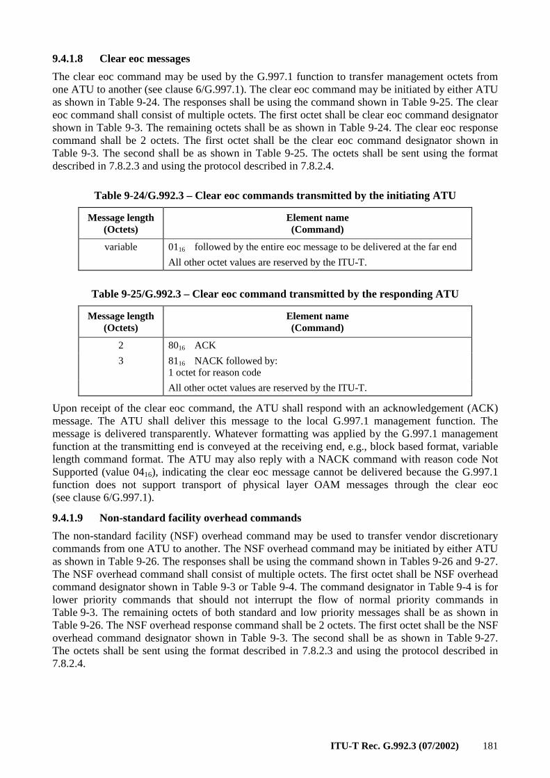
ITU-T Rec. G.992.3 (07/2002) 181
9.4.1.8 Clear eoc messages
The clear eoc command may be used by the G.997.1 function to transfer management octets from one ATU to another (see clause 6/G.997.1). The clear eoc command may be initiated by either ATU as shown in Table 9-24. The responses shall be using the command shown in Table 9-25. The clear eoc command shall consist of multiple octets. The first octet shall be clear eoc command designator shown in Table 9-3. The remaining octets shall be as shown in Table 9-24. The clear eoc response command shall be 2 octets. The first octet shall be the clear eoc command designator shown in Table 9-3. The second shall be as shown in Table 9-25. The octets shall be sent using the format described in 7.8.2.3 and using the protocol described in 7.8.2.4.
Table 9-24/G.992.3 – Clear eoc commands transmitted by the initiating ATU
Message length (Octets)
Element name (Command)
variable 0116 followed by the entire eoc message to be delivered at the far end
All other octet values are reserved by the ITU-T.
Table 9-25/G.992.3 – Clear eoc command transmitted by the responding ATU
Message length (Octets)
Element name (Command)
2 8016 ACK
3 8116 NACK followed by: 1 octet for reason code
All other octet values are reserved by the ITU-T.
Upon receipt of the clear eoc command, the ATU shall respond with an acknowledgement (ACK) message. The ATU shall deliver this message to the local G.997.1 management function. The message is delivered transparently. Whatever formatting was applied by the G.997.1 management function at the transmitting end is conveyed at the receiving end, e.g., block based format, variable length command format. The ATU may also reply with a NACK command with reason code Not Supported (value 0416), indicating the clear eoc message cannot be delivered because the G.997.1 function does not support transport of physical layer OAM messages through the clear eoc (see clause 6/G.997.1).
9.4.1.9 Non-standard facility overhead commands
The non-standard facility (NSF) overhead command may be used to transfer vendor discretionary commands from one ATU to another. The NSF overhead command may be initiated by either ATU as shown in Table 9-26. The responses shall be using the command shown in Tables 9-26 and 9-27. The NSF overhead command shall consist of multiple octets. The first octet shall be NSF overhead command designator shown in Table 9-3 or Table 9-4. The command designator in Table 9-4 is for lower priority commands that should not interrupt the flow of normal priority commands in Table 9-3. The remaining octets of both standard and low priority messages shall be as shown in Table 9-26. The NSF overhead response command shall be 2 octets. The first octet shall be the NSF overhead command designator shown in Table 9-3. The second shall be as shown in Table 9-27. The octets shall be sent using the format described in 7.8.2.3 and using the protocol described in 7.8.2.4.
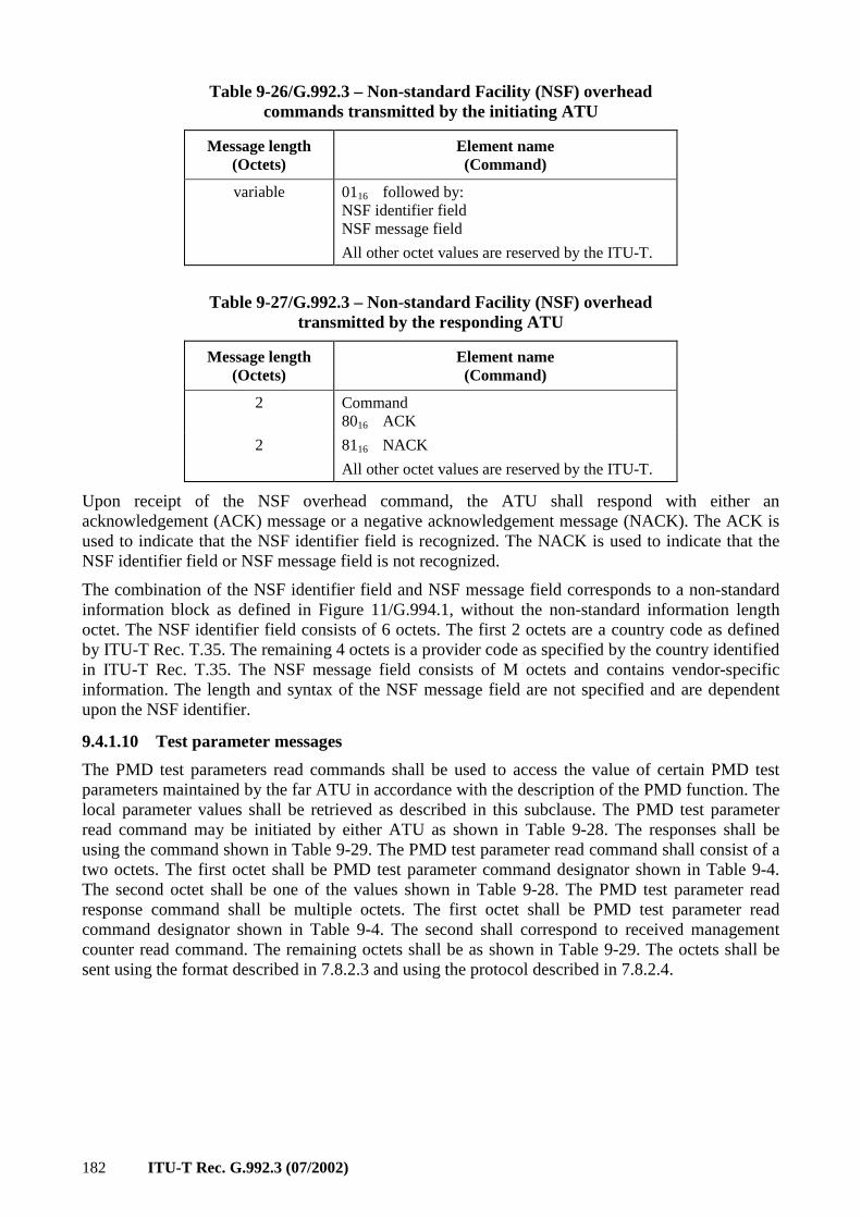
182 ITU-T Rec. G.992.3 (07/2002)
Table 9-26/G.992.3 – Non-standard Facility (NSF) overhead commands transmitted by the initiating ATU
Message length (Octets)
Element name (Command)
variable 0116 followed by: NSF identifier field NSF message field
All other octet values are reserved by the ITU-T.
Table 9-27/G.992.3 – Non-standard Facility (NSF) overhead transmitted by the responding ATU
Message length (Octets)
Element name (Command)
2 Command 8016 ACK
2 8116 NACK
All other octet values are reserved by the ITU-T.
Upon receipt of the NSF overhead command, the ATU shall respond with either an acknowledgement (ACK) message or a negative acknowledgement message (NACK). The ACK is used to indicate that the NSF identifier field is recognized. The NACK is used to indicate that the NSF identifier field or NSF message field is not recognized.
The combination of the NSF identifier field and NSF message field corresponds to a non-standard information block as defined in Figure 11/G.994.1, without the non-standard information length octet. The NSF identifier field consists of 6 octets. The first 2 octets are a country code as defined by ITU-T Rec. T.35. The remaining 4 octets is a provider code as specified by the country identified in ITU-T Rec. T.35. The NSF message field consists of M octets and contains vendor-specific information. The length and syntax of the NSF message field are not specified and are dependent upon the NSF identifier.
9.4.1.10 Test parameter messages
The PMD test parameters read commands shall be used to access the value of certain PMD test parameters maintained by the far ATU in accordance with the description of the PMD function. The local parameter values shall be retrieved as described in this subclause. The PMD test parameter read command may be initiated by either ATU as shown in Table 9-28. The responses shall be using the command shown in Table 9-29. The PMD test parameter read command shall consist of a two octets. The first octet shall be PMD test parameter command designator shown in Table 9-4. The second octet shall be one of the values shown in Table 9-28. The PMD test parameter read response command shall be multiple octets. The first octet shall be PMD test parameter read command designator shown in Table 9-4. The second shall correspond to received management counter read command. The remaining octets shall be as shown in Table 9-29. The octets shall be sent using the format described in 7.8.2.3 and using the protocol described in 7.8.2.4.
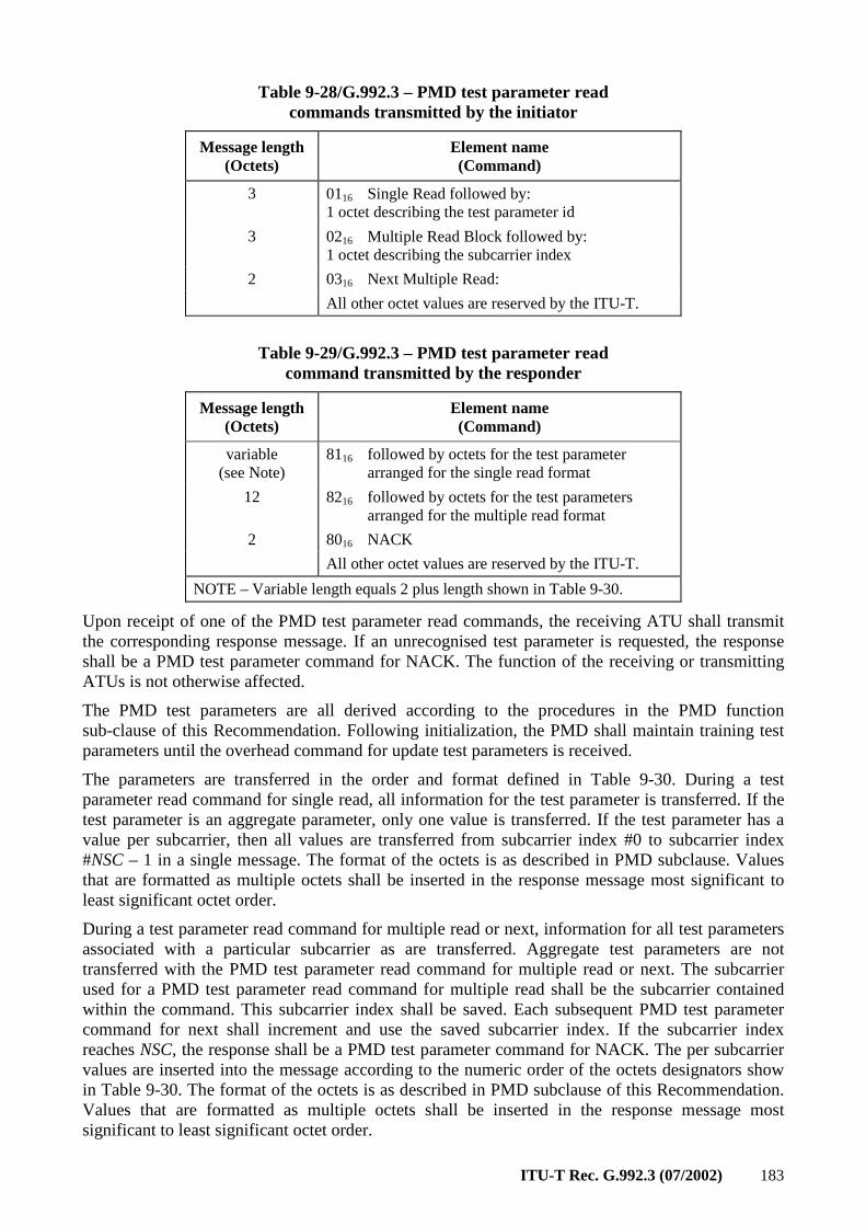
ITU-T Rec. G.992.3 (07/2002) 183
Table 9-28/G.992.3 – PMD test parameter read commands transmitted by the initiator
Message length (Octets)
Element name (Command)
3 0116 Single Read followed by: 1 octet describing the test parameter id
3 0216 Multiple Read Block followed by: 1 octet describing the subcarrier index
2 0316 Next Multiple Read:
All other octet values are reserved by the ITU-T.
Table 9-29/G.992.3 – PMD test parameter read command transmitted by the responder
Message length (Octets)
Element name (Command)
variable (see Note)
8116 followed by octets for the test parameter arranged for the single read format
12 8216 followed by octets for the test parameters arranged for the multiple read format
2 8016 NACK
All other octet values are reserved by the ITU-T.
NOTE – Variable length equals 2 plus length shown in Table 9-30.
Upon receipt of one of the PMD test parameter read commands, the receiving ATU shall transmit the corresponding response message. If an unrecognised test parameter is requested, the response shall be a PMD test parameter command for NACK. The function of the receiving or transmitting ATUs is not otherwise affected.
The PMD test parameters are all derived according to the procedures in the PMD function sub-clause of this Recommendation. Following initialization, the PMD shall maintain training test parameters until the overhead command for update test parameters is received.
The parameters are transferred in the order and format defined in Table 9-30. During a test parameter read command for single read, all information for the test parameter is transferred. If the test parameter is an aggregate parameter, only one value is transferred. If the test parameter has a value per subcarrier, then all values are transferred from subcarrier index #0 to subcarrier index #NSC – 1 in a single message. The format of the octets is as described in PMD subclause. Values that are formatted as multiple octets shall be inserted in the response message most significant to least significant octet order.
During a test parameter read command for multiple read or next, information for all test parameters associated with a particular subcarrier as are transferred. Aggregate test parameters are not transferred with the PMD test parameter read command for multiple read or next. The subcarrier used for a PMD test parameter read command for multiple read shall be the subcarrier contained within the command. This subcarrier index shall be saved. Each subsequent PMD test parameter command for next shall increment and use the saved subcarrier index. If the subcarrier index reaches NSC, the response shall be a PMD test parameter command for NACK. The per subcarrier values are inserted into the message according to the numeric order of the octets designators show in Table 9-30. The format of the octets is as described in PMD subclause of this Recommendation. Values that are formatted as multiple octets shall be inserted in the response message most significant to least significant octet order.
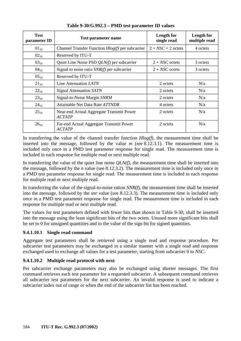
184 ITU-T Rec. G.992.3 (07/2002)
Table 9-30/G.992.3 – PMD test parameter ID values
Test parameter ID Test parameter name
Length for single read
Length for multiple read
0116 Channel Transfer Function Hlog(f) per subcarrier 2 + NSC × 2 octets 4 octets
0216 Reserved by ITU-T
0316 Quiet Line Noise PSD QLN(f) per subcarrier 2 + NSC octets 3 octets
0416 Signal to noise ratio SNR(f) per subcarrier 2 + NSC octets 3 octets
0516 Reserved by ITU-T
2116 Line Attenuation LATN 2 octets N/a
2216 Signal Attenuation SATN 2 octets N/a
2316 Signal-to-Noise Margin SNRM 2 octets N/a
2416 Attainable Net Data Rate ATTNDR 4 octets N/a
2516 Near-end Actual Aggregate Transmit Power ACTATP
2 octets N/a
2616 Far-end Actual Aggregate Transmit Power ACTATP
2 octets N/a
In transferring the value of the channel transfer function Hlog(f), the measurement time shall be inserted into the message, followed by the value m (see 8.12.3.1). The measurement time is included only once in a PMD test parameter response for single read. The measurement time is included in each response for multiple read or next multiple read.
In transferring the value of the quiet line noise QLN(f), the measurement time shall be inserted into the message, followed by the n value (see 8.12.3.2). The measurement time is included only once in a PMD test parameter response for single read. The measurement time is included in each response for multiple read or next multiple read.
In transferring the value of the signal-to-noise ration SNR(f), the measurement time shall be inserted into the message, followed by the snr value (see 8.12.3.3). The measurement time is included only once in a PMD test parameter response for single read. The measurement time is included in each response for multiple read or next multiple read.
The values for test parameters defined with fewer bits than shown in Table 9-30, shall be inserted into the message using the least significant bits of the two octets. Unused more significant bits shall be set to 0 for unsigned quantities and to the value of the sign bit for signed quantities.
9.4.1.10.1 Single read command
Aggregate test parameters shall be retrieved using a single read and response procedure. Per subcarrier test parameters may be exchanged in a similar manner with a single read and response exchanged used to exchange all values for a test parameter, starting from subcarrier 0 to NSC.
9.4.1.10.2 Multiple read protocol with next
Per subcarrier exchange parameters may also be exchanged using shorter messages. The first command retrieves each test parameter for a requested subcarrier. A subsequent command retrieves all subcarrier test parameters for the next subcarrier. An invalid response is used to indicate a subcarrier index out of range or when the end of the subcarrier list has been reached.
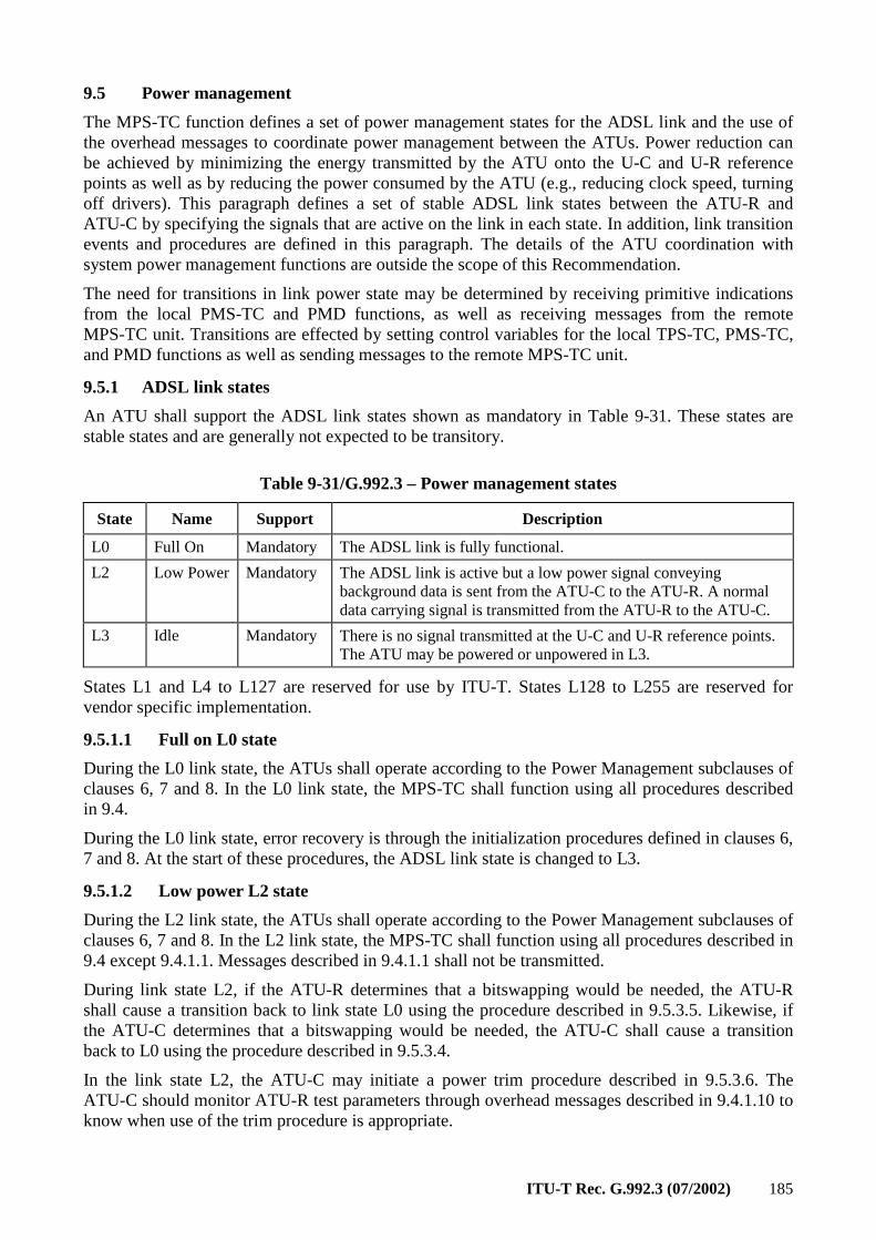
ITU-T Rec. G.992.3 (07/2002) 185
9.5 Power management
The MPS-TC function defines a set of power management states for the ADSL link and the use of the overhead messages to coordinate power management between the ATUs. Power reduction can be achieved by minimizing the energy transmitted by the ATU onto the U-C and U-R reference points as well as by reducing the power consumed by the ATU (e.g., reducing clock speed, turning off drivers). This paragraph defines a set of stable ADSL link states between the ATU-R and ATU-C by specifying the signals that are active on the link in each state. In addition, link transition events and procedures are defined in this paragraph. The details of the ATU coordination with system power management functions are outside the scope of this Recommendation.
The need for transitions in link power state may be determined by receiving primitive indications from the local PMS-TC and PMD functions, as well as receiving messages from the remote MPS-TC unit. Transitions are effected by setting control variables for the local TPS-TC, PMS-TC, and PMD functions as well as sending messages to the remote MPS-TC unit.
9.5.1 ADSL link states
An ATU shall support the ADSL link states shown as mandatory in Table 9-31. These states are stable states and are generally not expected to be transitory.
Table 9-31/G.992.3 – Power management states
State Name Support Description
L0 Full On Mandatory The ADSL link is fully functional.
L2 Low Power Mandatory The ADSL link is active but a low power signal conveying background data is sent from the ATU-C to the ATU-R. A normal data carrying signal is transmitted from the ATU-R to the ATU-C.
L3 Idle Mandatory There is no signal transmitted at the U-C and U-R reference points. The ATU may be powered or unpowered in L3.
States L1 and L4 to L127 are reserved for use by ITU-T. States L128 to L255 are reserved for vendor specific implementation.
9.5.1.1 Full on L0 state
During the L0 link state, the ATUs shall operate according to the Power Management subclauses of clauses 6, 7 and 8. In the L0 link state, the MPS-TC shall function using all procedures described in 9.4.
During the L0 link state, error recovery is through the initialization procedures defined in clauses 6, 7 and 8. At the start of these procedures, the ADSL link state is changed to L3.
9.5.1.2 Low power L2 state
During the L2 link state, the ATUs shall operate according to the Power Management subclauses of clauses 6, 7 and 8. In the L2 link state, the MPS-TC shall function using all procedures described in 9.4 except 9.4.1.1. Messages described in 9.4.1.1 shall not be transmitted.
During link state L2, if the ATU-R determines that a bitswapping would be needed, the ATU-R shall cause a transition back to link state L0 using the procedure described in 9.5.3.5. Likewise, if the ATU-C determines that a bitswapping would be needed, the ATU-C shall cause a transition back to L0 using the procedure described in 9.5.3.4.
In the link state L2, the ATU-C may initiate a power trim procedure described in 9.5.3.6. The ATU-C should monitor ATU-R test parameters through overhead messages described in 9.4.1.10 to know when use of the trim procedure is appropriate.
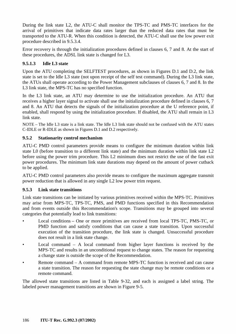
186 ITU-T Rec. G.992.3 (07/2002)
During the link state L2, the ATU-C shall monitor the TPS-TC and PMS-TC interfaces for the arrival of primitives that indicate data rates larger than the reduced data rates that must be transported to the ATU-R. When this condition is detected, the ATU-C shall use the low power exit procedure described in 9.5.3.4.
Error recovery is through the initialization procedures defined in clauses 6, 7 and 8. At the start of these procedures, the ADSL link state is changed for L3.
9.5.1.3 Idle L3 state
Upon the ATU completing the SELFTEST procedures, as shown in Figures D.1 and D.2, the link state is set to the Idle L3 state (not upon receipt of the self test command). During the L3 link state, the ATUs shall operate according to the Power Management subclauses of clauses 6, 7 and 8. In the L3 link state, the MPS-TC has no specified function.
In the L3 link state, an ATU may determine to use the initialization procedure. An ATU that receives a higher layer signal to activate shall use the initialization procedure defined in clauses 6, 7 and 8. An ATU that detects the signals of the initialization procedure at the U reference point, if enabled, shall respond by using the initialization procedure. If disabled, the ATU shall remain in L3 link state.
NOTE – The Idle L3 state is a link state. The Idle L3 link state should not be confused with the ATU states C-IDLE or R-IDLE as shown in Figures D.1 and D.2 respectively.
9.5.2 Stationarity control mechanism
ATU-C PMD control parameters provide means to configure the minimum duration within link state L0 (before transition to a different link state) and the minimum duration within link state L2 before using the power trim procedure. This L2 minimum does not restrict the use of the fast exit power procedures. The minimum link state durations may depend on the amount of power cutback to be applied.
ATU-C PMD control parameters also provide means to configure the maximum aggregate transmit power reduction that is allowed in any single L2 low power trim request.
9.5.3 Link state transitions
Link state transitions can be initiated by various primitives received within the MPS-TC. Primitives may arise from MPS-TC, TPS-TC, PMS, and PMD functions specified in this Recommendation and from events outside this Recommendation's scope. Transitions may be grouped into several categories that potentially lead to link transitions:
• Local conditions – One or more primitives are received from local TPS-TC, PMS-TC, or PMD function and satisfy conditions that can cause a state transition. Upon successful execution of the transition procedure, the link state is changed. Unsuccessful procedure does not result in a link state change.
• Local command – A local command from higher layer functions is received by the MPS-TC and results in an unconditional request to change states. The reason for requesting a change state is outside the scope of the Recommendation.
• Remote command – A command from remote MPS-TC function is received and can cause a state transition. The reason for requesting the state change may be remote conditions or a remote command.
The allowed state transitions are listed in Table 9-32, and each is assigned a label string. The labeled power management transitions are shown in Figure 9-5.
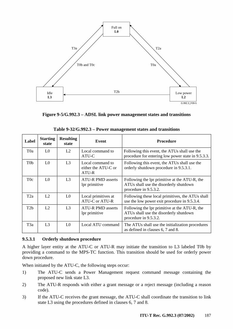
ITU-T Rec. G.992.3 (07/2002) 187
G.992.3_F09-5
Full onL0
IdleL3
Low powerL2
T3a
T0b and T0c T0a
T2a
T2b
Figure 9-5/G.992.3 – ADSL link power management states and transitions
Table 9-32/G.992.3 – Power management states and transitions
Label Starting
state Resulting
state Event Procedure
T0a L0 L2 Local command to ATU-C
Following this event, the ATUs shall use the procedure for entering low power state in 9.5.3.3.
T0b L0 L3 Local command to either the ATU-C or ATU-R
Following this event, the ATUs shall use the orderly shutdown procedure in 9.5.3.1.
T0c L0 L3 ATU-R PMD asserts lpr primitive
Following the lpr primitive at the ATU-R, the ATUs shall use the disorderly shutdown procedure in 9.5.3.2.
T2a L2 L0 Local primitives at ATU-C or ATU-R
Following these local primitives, the ATUs shall use the low power exit procedure in 9.5.3.4.
T2b L2 L3 ATU-R PMD asserts lpr primitive
Following the lpr primitive at the ATU-R, the ATUs shall use the disorderly shutdown procedure in 9.5.3.2.
T3a L3 L0 Local ATU command The ATUs shall use the initialization procedures as defined in clauses 6, 7 and 8.
9.5.3.1 Orderly shutdown procedure
A higher layer entity at the ATU-C or ATU-R may initiate the transition to L3 labeled T0b by providing a command to the MPS-TC function. This transition should be used for orderly power down procedure.
When initiated by the ATU-C, the following steps occur:
1) The ATU-C sends a Power Management request command message containing the proposed new link state L3.
2) The ATU-R responds with either a grant message or a reject message (including a reason code).
3) If the ATU-C receives the grant message, the ATU-C shall coordinate the transition to link state L3 using the procedures defined in clauses 6, 7 and 8.
188 ITU-T Rec. G.992.3 (07/2002)
4) When the ATU-R observes the stopped transmission corresponding to the link state L3, it also shall coordinate the transition to link state L3 using the procedures defined in clauses 6, 7 and 8.
When initiated by the ATU-R, the following steps occur:
1) The ATU-R sends a Power Management request command message containing the proposed new link state L3.
2) The ATU-C responds with either a grant message or a reject message.
3) If the ATU-R receives the grant message, the ATU-R stops transmitting.
4) When the ATU-R observes the stopped transmission, it also stops transmitting.
9.5.3.2 Disorderly shutdown procedure
The ATU-R may initiate the transitions to L3 labeled T0c and T2b. These transitions should only be used if power is unexpectedly removed from the ATU-R.
Upon detection of the near-end loss of power (lpr) primitive by the ATU-R, it shall send the lpr indicator bit at least 3 consecutive times prior to coordinating the transition to link state L3 using the procedures defined in clauses 6, 7 and 8. Upon detection of the far-end lpr primitive followed by the near-end loss of signal (LOS) defect, the ATU-C shall coordinate the transition to link state L3 using the procedures defined in clauses 6, 7 and 8.
9.5.3.3 Low power entry procedure
A higher layer entity at the ATU-C may initiate the transition to L2 labeled T2a by providing a command to the MPS-TC function.
The following steps occur to successfully signal entry into the L2 link state:
1) The ATU-C sends a power management L2 request command message containing the parameters defined in Table 9-21.
2) The ATU-R shall respond with an L2 grant message containing the parameters defined in Table 9-22. The ATU-R may also respond with a L2 reject message by supplying a reason code defined in Table 9-23 (see 9.4.1.7.3).
3) If the ATU-C receives the L2 grant message, the ATUs shall coordinate the entry into the L2 link state using procedures defined in clauses 6, 7 and 8.
9.5.3.4 ATU-C initiated low power fast exit procedure
During the L2 link state, the ATU-C can use the low power exit procedure to signal the return to the L0 link state. For this purpose, a PMD L2 exit sequence is defined in 8.7.
The following steps occur to successfully signal return to the link state L0:
1) The ATU-C shall transmit a PMD L2 exit sequence as defined in 8.7.
2) After transmitting the PMD L2 exit sequence, the ATU-C shall coordinate the exit from the L2 into the L0 link state using procedures defined in clauses 6, 7 and 8.
3) Upon detection of the L2 exit sequence, the ATU-R shall coordinate the exit from the L2 into the L0 link state using the procedures defined in clauses 6, 7 and 8.
9.5.3.5 ATU-R initiated low power exit procedure
During the L2 link state, the ATU-R can use the low power exit procedure to change to the L0 link state. For this purpose, an overhead power management request command is defined.
The following steps occur to successfully signal return to the link state L0:
1) The ATU-R sends an overhead power management request message containing the request to transition to link state L0.
ITU-T Rec. G.992.3 (07/2002) 189
2) The ATU-C shall grant the request using the exit mechanism described in the ATU-C initiated low power exit procedure in 9.5.3.4.
9.5.3.6 Low power trim procedure
During the L2 link state, the ATU-C can use the low power trim procedure to reduce downstream power of all bins constant power reduction value.
The following steps occur:
1) The ATU-C sends a power management L2 trim command message containing the parameters defined in Table 9-21.
2) The ATU-R shall respond with an L2 trim grant message containing the parameters defined in Table 9-22. The ATU-R may also send the L2 trim reject command by supplying a reason code defined in Table 9-23 (see 9.4.1.7.4).
3) If the ATU-C receives the L2 trim grant message, the ATUs shall coordinate the change to the L2 link state using procedures defined in 8.7.
The ATUs shall not modify the stored L0 control parameters during this procedure.
If the ATU-C needs to use the ATU-C initiated low power exit procedure, the ATU-C shall not send the Synchflag in response to trim grant message after an L2 exit sequence is initiated (i.e., after the first L2 exit symbol is transmitted, see 8.7.6).
If an L2 exit sequence immediately follows the completion of the low power trim procedure, the L2 exit sequence shall be transmitted using the L0 or new L2 control values of the PMD (depending on the bi/gi flag defined in 8.7.2 and 9.4.1.7.3).
10 Dynamic behaviour
The ATUs contain several dynamic behaviours, including initialization, on-line reconfigurations and power management transitions. The control of dynamic behaviour of G.992.3 transceivers is not easily seen from the block diagrams of the TPS-TC, PMS-TC, and PMD functions (shown in Figure 5-1). However, the control flows are provided by the Recommendation to enable the following types of dynamic behaviours.
10.1 Initialization
Initialization is a special case of a power management transition and is used to enter the L0 state. The allowed procedures for moving into the L0 link state are described in 9.5.3. Initialization is also used as an error recovery procedure in all link states.
Transceiver initialization may be caused by higher layer functions external to the ATUs or by error condition internal to the modems. From the perspective of the local ATU, high layer signals or commands will cause the modem to start the initialization sequence. In addition, the local ATU may start the initialization procedure in response to detection of U reference point signals.
10.2 On-line Reconfiguration (OLR)
On-line reconfiguration is a powerful feature of this Recommendation. It is provided so the ATUs can autonomously maintain operation within limits set by control parameters during times when line or environment conditions are slowly changing. When the control parameters cannot be maintained through autonomous on-line reconfiguration, an error condition occurs.
On-line reconfiguration is also used to optimise ATU settings following initialization, especially when using the fast initialization sequence that requires making faster estimates during training.
In addition, higher layer data, management, and control functions can make use of on-line reconfiguration. In these cases, the on-line reconfiguration is associated with various application
190 ITU-T Rec. G.992.3 (07/2002)
options of ADSL.
10.2.1 Types of on-line reconfiguration
Reconfiguration takes three forms, although the designation of these forms is primarily for convenience of description. The forms of on-line reconfiguration are: Bit Swapping (BS), Dynamic Rate Repartitioning (DRR) and Seamless Rate Adaptation (SRA).
Bit Swapping (BS) reallocates data and power (i.e., margin) among the allowed subcarriers without modification of the higher layer features of the physical layer. Bit Swapping reconfigures the bits and fine gain (bi, gi) parameters without changing any other PMD or PMS-TC control parameters. After a Bit Swapping reconfiguration the total data rate (ΣLp) is unchanged and that data rate on each latency path (Lp) is unchanged. Because bit swapping is used for autonomous changes to maintain the operating conditions for the modem during changing environment conditions, BS is a mandatory feature. The procedure for BS is defined in the OLR message command subclause in 9.4.1.1 and shall be implemented using Type 1 OLR messages.
Dynamic Rate Repartitioning (DRR) is used to reconfigure the data rate allocation between multiple latency paths by modifying the frame multiplexor control parameters (Lp). DRR can also include modifications to the bits and fine gain (bi, gi) parameters, reallocating bits among the subcarriers. DRR does not modify the total data rate (ΣLp) but does modify the individual latency path data rates (Lp). DRR can include a change in the number of octets from frame bearer #n per Mux Data Frame on latency path #p, i.e., in Bp.n Because DRR is used in response to higher layer commands, DRR is an application option. The ability to support DRR is identified during the initialization procedure. The procedure for DRR is defined in the OLR message command subclause in 9.4.1.1 and shall be implemented using Type 2 OLR messages.
Seamless Rate Adaptation (SRA) is used to reconfigure the total data rate (ΣLp) by modifying the frame multiplexor control parameters (Lp) and modifications to the bits and fine gains (bi, gi) parameters. Since the total data rate is modified, at least one latency path (or more) will have a new data rate (Lp) after the SRA. The number of frame bearer octets per Mux Data Frame can also be modified in SRA transactions. Because SRA is used in response to higher layer commands, SRA is an application option. The ability to support SRA is identified during the initialization procedure. Any ATU that implements the optional PMD short initialization procedure should implement SRA operations. The procedure for SRA is defined in the OLR message command subclause in 9.4.1.1 and shall be implemented using Type 3 OLR messages.
10.2.2 On-line reconfiguration procedures
The procedure for reconfiguration of the PMD functions is begun by the transport of control messages between the ATU control entities, over the upstream and/or downstream PMS-TC control signals. The control messages that shall be used for each of these PMD parameter reconfiguration types is defined in 9.4.1.1. The messages describe the requested changes to the upstream or downstream TPS-TC, PMS-TC or PMD functions. After the control messages have been sent, the transmit PMS-TC function generates a PMD.Synchflag.request primitive, resulting in the transmit PMD function transporting the Synchflag over the U interface as a time marker for when the on-line reconfiguration takes effect. Following the reconfiguration, each PMD function notifies the PMS-TC function of the reconfiguration with a PMD.Synchflag primitive; the transmit PMD function uses a .confirm primitive and the receive PMD function uses a .indicate primitive.
10.2.2.1 Receiver initiated procedure
A successful receiver initiated reconfiguration has the following steps (see Figure 10-1):
1) If the reconfiguration procedure is initiated by the ATU's control or management function, a PMD.Reconfig.indicate primitive is used to trigger a reconfiguration of the receive PMD function to the new L value. The receiving ATU's control or management function uses
ITU-T Rec. G.992.3 (07/2002) 191
similar primitives to pass new control parameter values to the receive TPS-TC and PMS-TC functions, if these functions are involved in the reconfiguration.
2) The receive PMD function sends a PMD.Control.request primitive to the receiving ATU's control function, carrying the new values of the far-end transmit PMD function's control parameters. This primitive may be sent autonomously (with unchanged L value, i.e., receiver initiated bitswap) or in response to a PMD.Reconfig.indicate primitive (with change of L value, i.e., receiver initiated rate adaptation).
3) The receiving ATU's control function sends the necessary control messages describing the new values of the transmit PMD function control parameters to the transmitting ATU's control function. These messages may also include reconfiguration of TPS-TC and PMS-TC function control parameters.
4) The receiving ATU's control function sends a PMD.Control.confirm primitive to the receive PMD function, which then waits for a PMD.Synchflag to be received from the transmit PMD function.
5) When the control messages have been successfully received by the transmitting ATU's control function, the transmitting ATU's control function sends a PMD.Control.indicate primitive to the transmit PMD function, carrying the new values of the transmit PMD function control parameters. The transmitting ATU's control function uses similar primitives to pass new control parameters values to the TPS-TC and PMS-TC transmit functions, if these functions are involved in the reconfiguration.
6) The transmit TPS-TC sends a Frame.Synchflag.request primitive to the transmit PMS-TC function, which sends a PMD.Synchflag.request primitive to the transmit PMD function as an indication that the TPS-TC and PMS-TC transmit functions are ready to be reconfigured.
7) The transmit PMD function transmits the PMD.Synchflag primitive on the line as defined in 8.7, as a time marker for the instant where the reconfiguration will take place. The PMD.Synchflag primitive is received by the receive PMD function. This primitive may be sent autonomously by the transmit PMD function if the TPS-TC and PMS-TC transmit functions are not involved in the reconfiguration.
8) At the instant the reconfiguration takes place (see 8.16.2), the transmit PMD function sends a PMD.Synchflag.confirm primitive to the transmit PMS-TC function, which sends a Frame.Synchflag.confirm primitive to the transmit TPS-TC function as a time marker for the instant where the reconfiguration takes place. For the transmit PMD function, this is the symbol boundary where the size of data frames received from the PMS-TC (with the PMD.Bits.confirm primitive) changes.
9) At the instant the reconfiguration takes place (see 8.16.2), the receive PMD function sends a PMD.Synchflag.indicate primitive to the receive PMS-TC function, which sends a Frame.Synchflag.indicate primitive to the receive TPS-TC function as a time marker for the instant where the reconfiguration takes place. For the receive PMD function, this is the symbol boundary where the size of data frames delivered to the PMS-TC (with the PMD.Bits.indicate primitive) changes.
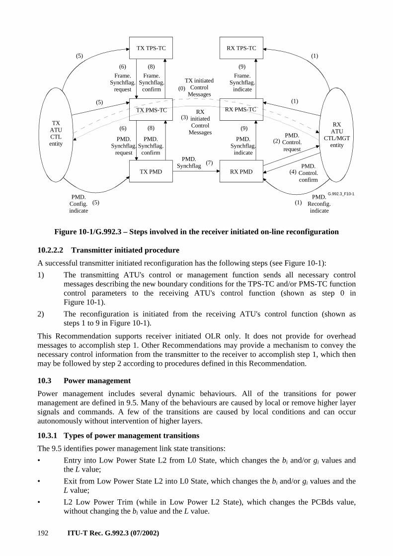
192 ITU-T Rec. G.992.3 (07/2002)
G.992.3_F10-1
TX PMD
TX PMS-TC
TX TPS-TC
RX PMD
RX PMS-TC
RX TPS-TC
TX ATUCTLentity
RX ATU
CTL/MGTentity
(4)PMD.
Control.confirm
(1)
(1)
(2)PMD.
Control.request
(1)PMD.
Reconfig.indicate
(3)RX
initiatedControl
Messages
(5)
(5)PMD.
Config.indicate
(5)
(6)
PMD.Synchflag.
request
(7)PMD.
Synchflag
(8)
PMD.Synchflag.confirm
(9)
PMD.Synchflag.indicate
TX initiatedControl
Messages(0)
(8) (9)
Frame.Synchflag.
indicate
(6)
Frame.Synchflag.
request
Frame.Synchflag.confirm
Figure 10-1/G.992.3 – Steps involved in the receiver initiated on-line reconfiguration
10.2.2.2 Transmitter initiated procedure
A successful transmitter initiated reconfiguration has the following steps (see Figure 10-1):
1) The transmitting ATU's control or management function sends all necessary control messages describing the new boundary conditions for the TPS-TC and/or PMS-TC function control parameters to the receiving ATU's control function (shown as step 0 in Figure 10-1).
2) The reconfiguration is initiated from the receiving ATU's control function (shown as steps 1 to 9 in Figure 10-1).
This Recommendation supports receiver initiated OLR only. It does not provide for overhead messages to accomplish step 1. Other Recommendations may provide a mechanism to convey the necessary control information from the transmitter to the receiver to accomplish step 1, which then may be followed by step 2 according to procedures defined in this Recommendation.
10.3 Power management
Power management includes several dynamic behaviours. All of the transitions for power management are defined in 9.5. Many of the behaviours are caused by local or remove higher layer signals and commands. A few of the transitions are caused by local conditions and can occur autonomously without intervention of higher layers.
10.3.1 Types of power management transitions
The 9.5 identifies power management link state transitions:
• Entry into Low Power State L2 from L0 State, which changes the bi and/or gi values and the L value;
• Exit from Low Power State L2 into L0 State, which changes the bi and/or gi values and the L value;
• L2 Low Power Trim (while in Low Power L2 State), which changes the PCBds value, without changing the bi value and the L value.
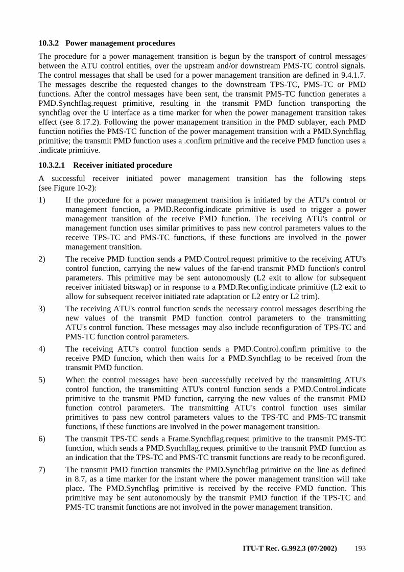
ITU-T Rec. G.992.3 (07/2002) 193
10.3.2 Power management procedures
The procedure for a power management transition is begun by the transport of control messages between the ATU control entities, over the upstream and/or downstream PMS-TC control signals. The control messages that shall be used for a power management transition are defined in 9.4.1.7. The messages describe the requested changes to the downstream TPS-TC, PMS-TC or PMD functions. After the control messages have been sent, the transmit PMS-TC function generates a PMD.Synchflag.request primitive, resulting in the transmit PMD function transporting the synchflag over the U interface as a time marker for when the power management transition takes effect (see 8.17.2). Following the power management transition in the PMD sublayer, each PMD function notifies the PMS-TC function of the power management transition with a PMD.Synchflag primitive; the transmit PMD function uses a .confirm primitive and the receive PMD function uses a .indicate primitive.
10.3.2.1 Receiver initiated procedure
A successful receiver initiated power management transition has the following steps (see Figure 10-2):
1) If the procedure for a power management transition is initiated by the ATU's control or management function, a PMD.Reconfig.indicate primitive is used to trigger a power management transition of the receive PMD function. The receiving ATU's control or management function uses similar primitives to pass new control parameters values to the receive TPS-TC and PMS-TC functions, if these functions are involved in the power management transition.
2) The receive PMD function sends a PMD.Control.request primitive to the receiving ATU's control function, carrying the new values of the far-end transmit PMD function's control parameters. This primitive may be sent autonomously (L2 exit to allow for subsequent receiver initiated bitswap) or in response to a PMD.Reconfig.indicate primitive (L2 exit to allow for subsequent receiver initiated rate adaptation or L2 entry or L2 trim).
3) The receiving ATU's control function sends the necessary control messages describing the new values of the transmit PMD function control parameters to the transmitting ATU's control function. These messages may also include reconfiguration of TPS-TC and PMS-TC function control parameters.
4) The receiving ATU's control function sends a PMD.Control.confirm primitive to the receive PMD function, which then waits for a PMD.Synchflag to be received from the transmit PMD function.
5) When the control messages have been successfully received by the transmitting ATU's control function, the transmitting ATU's control function sends a PMD.Control.indicate primitive to the transmit PMD function, carrying the new values of the transmit PMD function control parameters. The transmitting ATU's control function uses similar primitives to pass new control parameters values to the TPS-TC and PMS-TC transmit functions, if these functions are involved in the power management transition.
6) The transmit TPS-TC sends a Frame.Synchflag.request primitive to the transmit PMS-TC function, which sends a PMD.Synchflag.request primitive to the transmit PMD function as an indication that the TPS-TC and PMS-TC transmit functions are ready to be reconfigured.
7) The transmit PMD function transmits the PMD.Synchflag primitive on the line as defined in 8.7, as a time marker for the instant where the power management transition will take place. The PMD.Synchflag primitive is received by the receive PMD function. This primitive may be sent autonomously by the transmit PMD function if the TPS-TC and PMS-TC transmit functions are not involved in the power management transition.
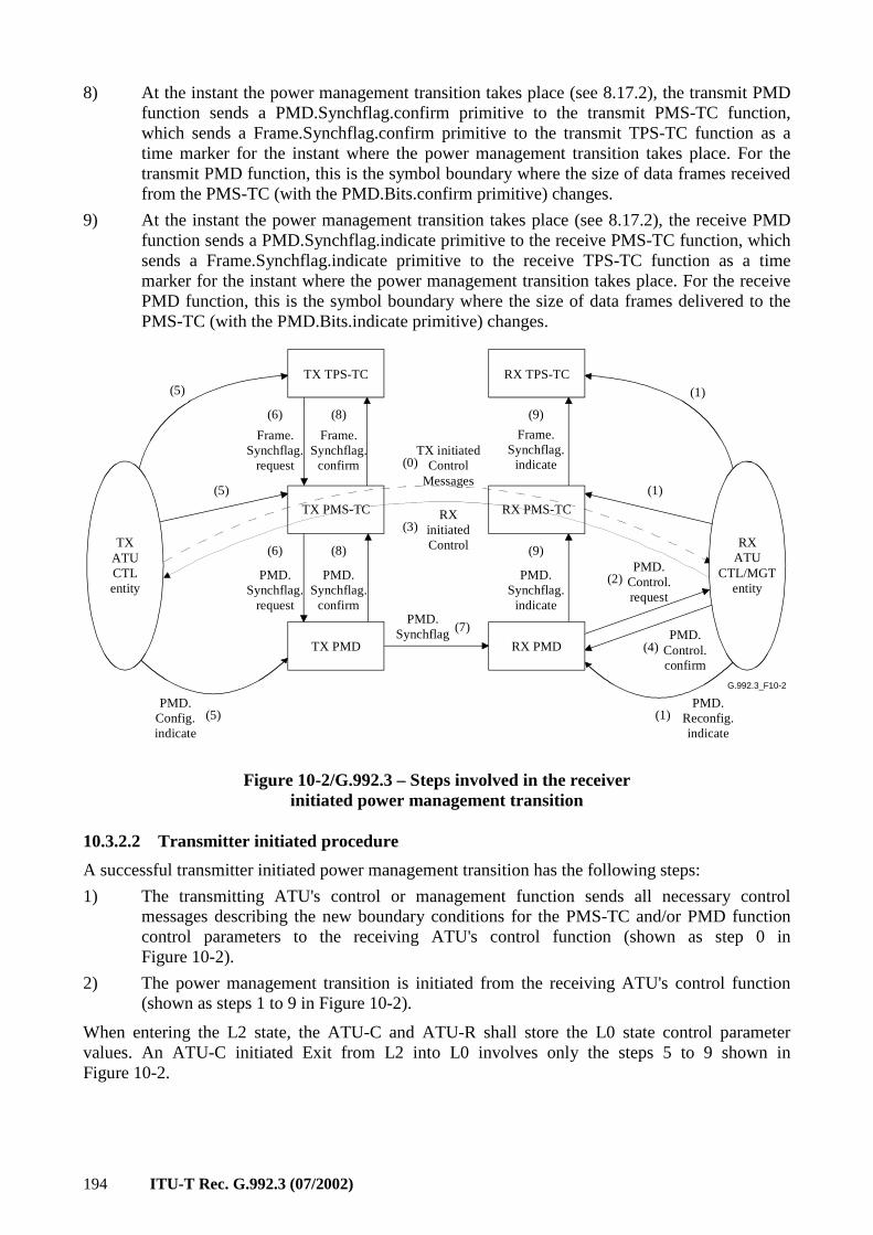
194 ITU-T Rec. G.992.3 (07/2002)
8) At the instant the power management transition takes place (see 8.17.2), the transmit PMD function sends a PMD.Synchflag.confirm primitive to the transmit PMS-TC function, which sends a Frame.Synchflag.confirm primitive to the transmit TPS-TC function as a time marker for the instant where the power management transition takes place. For the transmit PMD function, this is the symbol boundary where the size of data frames received from the PMS-TC (with the PMD.Bits.confirm primitive) changes.
9) At the instant the power management transition takes place (see 8.17.2), the receive PMD function sends a PMD.Synchflag.indicate primitive to the receive PMS-TC function, which sends a Frame.Synchflag.indicate primitive to the receive TPS-TC function as a time marker for the instant where the power management transition takes place. For the receive PMD function, this is the symbol boundary where the size of data frames delivered to the PMS-TC (with the PMD.Bits.indicate primitive) changes.
G.992.3_F10-2
TX PMD
TX PMS-TC
TX TPS-TC
RX PMD
RX PMS-TC
RX TPS-TC
TX ATUCTLentity
RX ATU
CTL/MGTentity
(4)PMD.
Control.confirm
(1)
(1)
(2)PMD.
Control.request
(1)PMD.
Reconfig.indicate
(3)RX
initiatedControl
(5)
(5)PMD.
Config.indicate
(5)
(6)
PMD.Synchflag.
request
(7)PMD.
Synchflag
(8)
PMD.Synchflag.
confirm
(9)
PMD.Synchflag.
indicate
TX initiatedControl
Messages
(0)
(8) (9)
Frame.Synchflag.
indicate
(6)
Frame.Synchflag.
request
Frame.Synchflag.
confirm
Figure 10-2/G.992.3 – Steps involved in the receiver initiated power management transition
10.3.2.2 Transmitter initiated procedure
A successful transmitter initiated power management transition has the following steps:
1) The transmitting ATU's control or management function sends all necessary control messages describing the new boundary conditions for the PMS-TC and/or PMD function control parameters to the receiving ATU's control function (shown as step 0 in Figure 10-2).
2) The power management transition is initiated from the receiving ATU's control function (shown as steps 1 to 9 in Figure 10-2).
When entering the L2 state, the ATU-C and ATU-R shall store the L0 state control parameter values. An ATU-C initiated Exit from L2 into L0 involves only the steps 5 to 9 shown in Figure 10-2.
ITU-T Rec. G.992.3 (07/2002) 195
Annex A
Specific requirements for an ADSL system operating in the frequency band above POTS
This annex defines those parameters of the ADSL system that have been left undefined in the body of this Recommendation because they are unique to an ADSL service that is frequency-division duplexed with POTS.
A.1 ATU-C functional characteristics (pertains to clause 8)
A.1.1 ATU-C control parameter settings
The ATU-C Control Parameter Settings to be used in the parameterized parts of the main body and/or to be used in this annex are listed in Table A.1. Control Parameters are defined in 8.5.
Table A.1/G.992.3 – ATU-C control parameter settings
Parameter Default setting Characteristics
NSCds 256
NOMPSDds –40 dBm/Hz Setting may be changed relative to this value during G.994.1 phase, see 8.13.2.
MAXNOMPSDds –40 dBm/Hz Setting may be changed relative to this value during G.994.1 phase, see 8.13.2.
MAXNOMATPds 20.4 dBm Setting may be changed relative to this value during G.994.1 phase, see 8.13.2.
A.1.2 ATU-C downstream transmit spectral mask for overlapped spectrum operation (supplements 8.10)
The passband is defined as the band from 25.875 to 1104 kHz and is the widest possible band used (i.e., for ADSL over POTS implemented with overlapped spectrum). Limits defined within the passband apply also to any narrower bands used.
Figure A.1 defines the spectral mask for the transmit signal. The low-frequency stop-band is defined as frequencies below 25.875 kHz and includes the POTS band, the high-frequency stop-band is defined as frequencies greater than 1104 kHz.
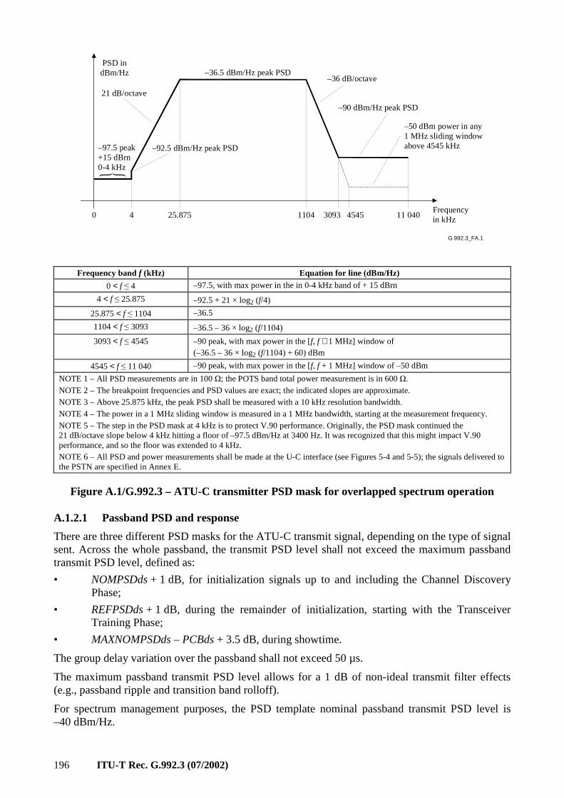
196 ITU-T Rec. G.992.3 (07/2002)
G.992.3_FA.1
PSD indBm/Hz
21 dB/octave
–97.5 peak+15 dBrn0-4 kHz
–92.5 dBm/Hz peak PSD
–36.5 dBm/Hz peak PSD–36 dB/octave
–90 dBm/Hz peak PSD
–50 dBm power in any1 MHz sliding windowabove 4545 kHz
0 4 25.875 1104 3093 4545 11 040Frequencyin kHz
Frequency band f (kHz) Equation for line (dBm/Hz)
0 < f ≤ 4 –97.5, with max power in the in 0-4 kHz band of + 15 dBrn
4 < f ≤ 25.875 –92.5 + 21 × log2 (f/4)
25.875 < f ≤ 1104 –36.5
1104 < f ≤ 3093 –36.5 – 36 × log2 (f/1104)
3093 < f ≤ 4545 –90 peak, with max power in the [f, f + 1 MHz] window of (–36.5 – 36 × log2 (f/1104) + 60) dBm
4545 < f ≤ 11 040 –90 peak, with max power in the [f, f + 1 MHz] window of –50 dBm
NOTE 1 – All PSD measurements are in 100 Ω; the POTS band total power measurement is in 600 Ω. NOTE 2 – The breakpoint frequencies and PSD values are exact; the indicated slopes are approximate. NOTE 3 – Above 25.875 kHz, the peak PSD shall be measured with a 10 kHz resolution bandwidth. NOTE 4 – The power in a 1 MHz sliding window is measured in a 1 MHz bandwidth, starting at the measurement frequency. NOTE 5 – The step in the PSD mask at 4 kHz is to protect V.90 performance. Originally, the PSD mask continued the 21 dB/octave slope below 4 kHz hitting a floor of –97.5 dBm/Hz at 3400 Hz. It was recognized that this might impact V.90 performance, and so the floor was extended to 4 kHz. NOTE 6 – All PSD and power measurements shall be made at the U-C interface (see Figures 5-4 and 5-5); the signals delivered to the PSTN are specified in Annex E.
Figure A.1/G.992.3 – ATU-C transmitter PSD mask for overlapped spectrum operation
A.1.2.1 Passband PSD and response
There are three different PSD masks for the ATU-C transmit signal, depending on the type of signal sent. Across the whole passband, the transmit PSD level shall not exceed the maximum passband transmit PSD level, defined as:
• NOMPSDds + 1 dB, for initialization signals up to and including the Channel Discovery Phase;
• REFPSDds + 1 dB, during the remainder of initialization, starting with the Transceiver Training Phase;
• MAXNOMPSDds – PCBds + 3.5 dB, during showtime.
The group delay variation over the passband shall not exceed 50 µs.
The maximum passband transmit PSD level allows for a 1 dB of non-ideal transmit filter effects (e.g., passband ripple and transition band rolloff).
For spectrum management purposes, the PSD template nominal passband transmit PSD level is –40 dBm/Hz.
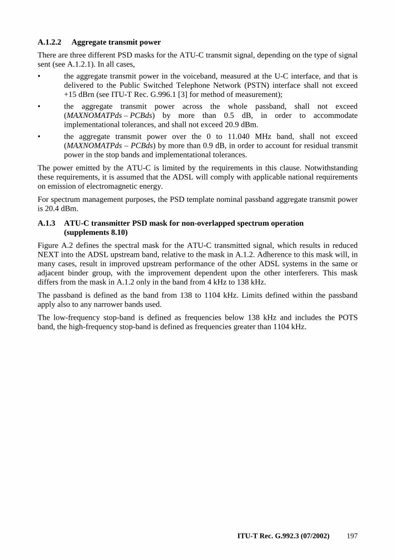
ITU-T Rec. G.992.3 (07/2002) 197
A.1.2.2 Aggregate transmit power
There are three different PSD masks for the ATU-C transmit signal, depending on the type of signal sent (see A.1.2.1). In all cases,
• the aggregate transmit power in the voiceband, measured at the U-C interface, and that is delivered to the Public Switched Telephone Network (PSTN) interface shall not exceed +15 dBrn (see ITU-T Rec. G.996.1 [3] for method of measurement);
• the aggregate transmit power across the whole passband, shall not exceed (MAXNOMATPds – PCBds) by more than 0.5 dB, in order to accommodate implementational tolerances, and shall not exceed 20.9 dBm.
• the aggregate transmit power over the 0 to 11.040 MHz band, shall not exceed (MAXNOMATPds – PCBds) by more than 0.9 dB, in order to account for residual transmit power in the stop bands and implementational tolerances.
The power emitted by the ATU-C is limited by the requirements in this clause. Notwithstanding these requirements, it is assumed that the ADSL will comply with applicable national requirements on emission of electromagnetic energy.
For spectrum management purposes, the PSD template nominal passband aggregate transmit power is 20.4 dBm.
A.1.3 ATU-C transmitter PSD mask for non-overlapped spectrum operation (supplements 8.10)
Figure A.2 defines the spectral mask for the ATU-C transmitted signal, which results in reduced NEXT into the ADSL upstream band, relative to the mask in A.1.2. Adherence to this mask will, in many cases, result in improved upstream performance of the other ADSL systems in the same or adjacent binder group, with the improvement dependent upon the other interferers. This mask differs from the mask in A.1.2 only in the band from 4 kHz to 138 kHz.
The passband is defined as the band from 138 to 1104 kHz. Limits defined within the passband apply also to any narrower bands used.
The low-frequency stop-band is defined as frequencies below 138 kHz and includes the POTS band, the high-frequency stop-band is defined as frequencies greater than 1104 kHz.
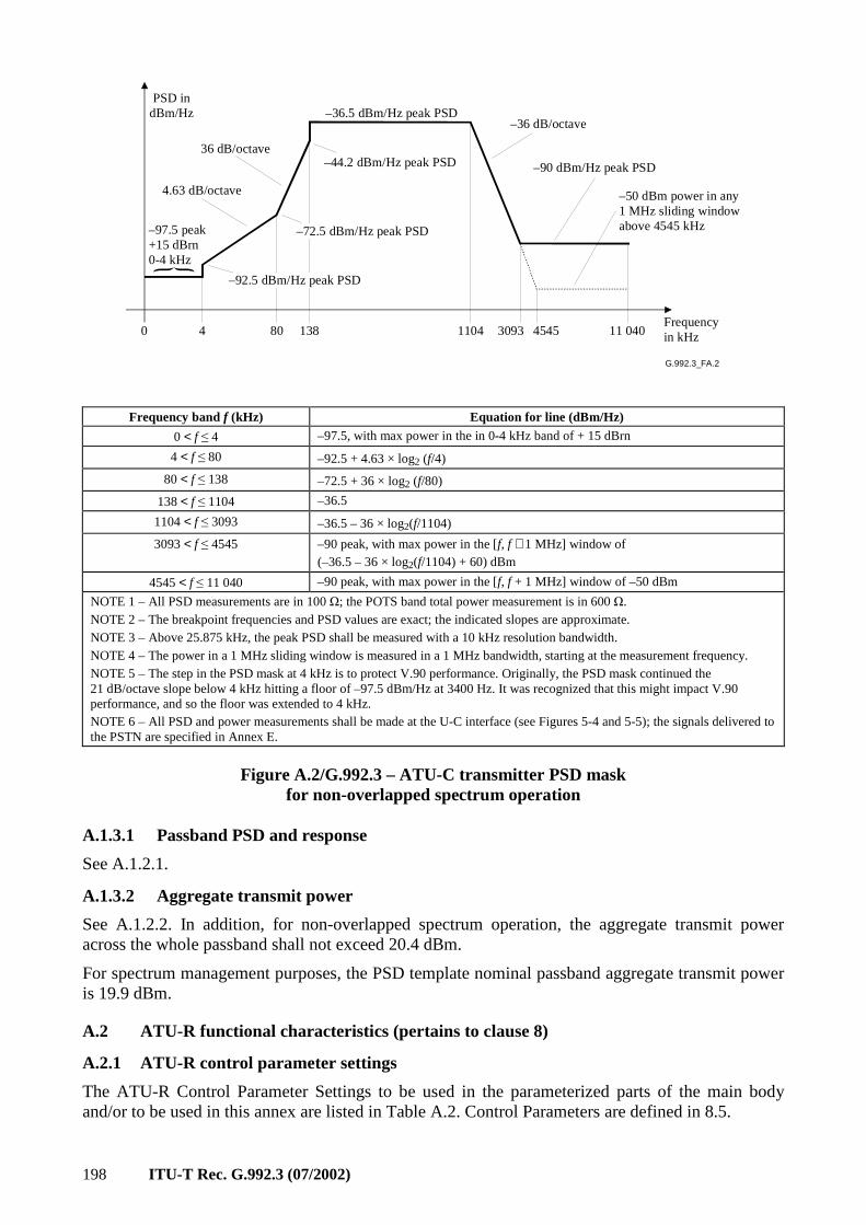
198 ITU-T Rec. G.992.3 (07/2002)
G.992.3_FA.2
PSD indBm/Hz
4.63 dB/octave
–97.5 peak+15 dBrn0-4 kHz
–92.5 dBm/Hz peak PSD
–36.5 dBm/Hz peak PSD–36 dB/octave
–90 dBm/Hz peak PSD
–50 dBm power in any1 MHz sliding windowabove 4545 kHz
0 4 80 1104 3093 4545 11 040Frequencyin kHz138
–72.5 dBm/Hz peak PSD
36 dB/octave–44.2 dBm/Hz peak PSD
Frequency band f (kHz) Equation for line (dBm/Hz)
0 < f ≤ 4 –97.5, with max power in the in 0-4 kHz band of + 15 dBrn
4 < f ≤ 80 –92.5 + 4.63 × log2 (f/4)
80 < f ≤ 138 –72.5 + 36 × log2 (f/80)
138 < f ≤ 1104 –36.5
1104 < f ≤ 3093 –36.5 – 36 × log2(f/1104)
3093 < f ≤ 4545 –90 peak, with max power in the [f, f + 1 MHz] window of (–36.5 – 36 × log2(f/1104) + 60) dBm
4545 < f ≤ 11 040 –90 peak, with max power in the [f, f + 1 MHz] window of –50 dBm
NOTE 1 – All PSD measurements are in 100 Ω; the POTS band total power measurement is in 600 Ω. NOTE 2 – The breakpoint frequencies and PSD values are exact; the indicated slopes are approximate. NOTE 3 – Above 25.875 kHz, the peak PSD shall be measured with a 10 kHz resolution bandwidth. NOTE 4 – The power in a 1 MHz sliding window is measured in a 1 MHz bandwidth, starting at the measurement frequency. NOTE 5 – The step in the PSD mask at 4 kHz is to protect V.90 performance. Originally, the PSD mask continued the 21 dB/octave slope below 4 kHz hitting a floor of –97.5 dBm/Hz at 3400 Hz. It was recognized that this might impact V.90 performance, and so the floor was extended to 4 kHz. NOTE 6 – All PSD and power measurements shall be made at the U-C interface (see Figures 5-4 and 5-5); the signals delivered to the PSTN are specified in Annex E.
Figure A.2/G.992.3 – ATU-C transmitter PSD mask for non-overlapped spectrum operation
A.1.3.1 Passband PSD and response
See A.1.2.1.
A.1.3.2 Aggregate transmit power
See A.1.2.2. In addition, for non-overlapped spectrum operation, the aggregate transmit power across the whole passband shall not exceed 20.4 dBm.
For spectrum management purposes, the PSD template nominal passband aggregate transmit power is 19.9 dBm.
A.2 ATU-R functional characteristics (pertains to clause 8)
A.2.1 ATU-R control parameter settings
The ATU-R Control Parameter Settings to be used in the parameterized parts of the main body and/or to be used in this annex are listed in Table A.2. Control Parameters are defined in 8.5.
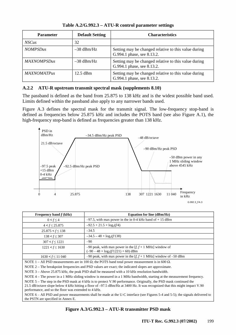
ITU-T Rec. G.992.3 (07/2002) 199
Table A.2/G.992.3 – ATU-R control parameter settings
Parameter Default Setting Characteristics
NSCus 32
NOMPSDus –38 dBm/Hz Setting may be changed relative to this value during G.994.1 phase, see 8.13.2.
MAXNOMPSDus –38 dBm/Hz Setting may be changed relative to this value during G.994.1 phase, see 8.13.2.
MAXNOMATPus 12.5 dBm Setting may be changed relative to this value during G.994.1 phase, see 8.13.2.
A.2.2 ATU-R upstream transmit spectral mask (supplements 8.10)
The passband is defined as the band from 25.875 to 138 kHz and is the widest possible band used. Limits defined within the passband also apply to any narrower bands used.
Figure A.3 defines the spectral mask for the transmit signal. The low-frequency stop-band is defined as frequencies below 25.875 kHz and includes the POTS band (see also Figure A.1), the high-frequency stop-band is defined as frequencies greater than 138 kHz.
G.992.3_FA.3
PSD indBm/Hz
21.5 dB/octave
–97.5 peak+15 dBrn0-4 kHz
–92.5 dBm/Hz peak PSD
–34.5 dBm/Hz peak PSD–48 dB/octave
–90 dBm/Hz peak PSD
–50 dBm power in any1 MHz sliding windowabove 4545 kHz
0 4 25.875 138 307 1221 11 040Frequencyin kHz
1630
Frequency band f (kHz) Equation for line (dBm/Hz)
0 < f ≤ 4 –97.5, with max power in the in 0-4 kHz band of + 15 dBrn
4 < f ≤ 25.875 –92.5 + 21.5 × log2(f/4)
25.875 < f ≤ 138 –34.5
138 < f ≤ 307 –34.5 – 48 × log2(f/138)
307 < f ≤ 1221 –90
1221 < f ≤ 1630 –90 peak, with max power in the [f, f + 1 MHz] window of (–90 – 48 × log2(f/1221) + 60) dBm
1630 < f ≤ 11 040 –90 peak, with max power in the [f, f + 1 MHz] window of –50 dBm
NOTE 1 – All PSD measurements are in 100 Ω; the POTS band total power measurement is in 600 Ω. NOTE 2 – The breakpoint frequencies and PSD values are exact; the indicated slopes are approximate. NOTE 3 – Above 25.875 kHz, the peak PSD shall be measured with a 10 kHz resolution bandwidth. NOTE 4 – The power in a 1 MHz sliding window is measured in a 1 MHz bandwidth, starting at the measurement frequency. NOTE 5 – The step in the PSD mask at 4 kHz is to protect V.90 performance. Originally, the PSD mask continued the 21.5 dB/octave slope below 4 kHz hitting a floor of –97.5 dBm/Hz at 3400 Hz. It was recognized that this might impact V.90 performance, and so the floor was extended to 4 kHz. NOTE 6 – All PSD and power measurements shall be made at the U-C interface (see Figures 5-4 and 5-5); the signals delivered to the PSTN are specified in Annex E.
Figure A.3/G.992.3 – ATU-R transmitter PSD mask
200 ITU-T Rec. G.992.3 (07/2002)
A.2.2.1 Passband PSD and response
There are three different PSD masks for the ATU-R transmit signal, depending on the type of signal sent. Across the whole passband, the transmit PSD level shall not exceed the maximum passband PSD level, defined as:
• NOMPSDus + 1 dB, for initialization signals up to and including the Channel Discovery Phase;
• REFPSDus + 1 dB, during the remainder of initialization, starting with the Transceiver Training Phase;
• MAXNOMPSDus – PCBus + 3.5 dB, during showtime.
The group delay variation over the passband shall not exceed 50 µs.
The maximum transmit PSD level allows for a 1 dB of non-ideal transmit filter effects (e.g., passband ripple and transition band rolloff).
For spectrum management purposes, the PSD template nominal passband transmit PSD level is –38 dBm/Hz.
A.2.2.2 Aggregate transmit power
There are three different PSD masks for the ATU-R transmit signal, depending on the type of signal sent (see A.2.2.1). In all cases,
• the aggregate transmit power in the voiceband, measured at the U-R interface, and that which is delivered to the Plain Old Telephone Service (POTS) interface, shall not exceed +15 dBrn (see ITU-T Rec. G.996.1 [3] for method of measurement);
• the aggregate transmit power across the whole passband, shall not exceed (MAXNOMATPus – PCBus) by more than 0.5 dB, in order to accommodate implementational tolerances, and shall not exceed 13.0 dBm;
• the aggregate transmit power over the 0 to 11.040 MHz band, shall not exceed (MAXNOMATPus – PCBus) by more than 0.8 dB, in order to account for residual transmit power in the stop bands and implementational tolerances.
The power emitted by the ATU-R is limited by the requirements in this clause. Notwithstanding these requirements, it is assumed that the ADSL will comply with applicable national requirements on emission of electromagnetic energy.
For spectrum management purposes, the PSD template nominal passband aggregate transmit power is 12.5 dBm.
A.3 Initialization
For this annex, no additional requirements apply (relative to the main body of this Recommendation).
A.4 Electrical characteristics
This clause specifies the combination of ATU-x and high-pass filter, as shown in Figures 5-4 and 5-5; further information about the low-pass filter is specified in Annex E.
A.4.1 Definition of impedance states
The source and load impedances of the ATU-R shall comply with the following, where ZS and ZL are the source and the load impedances in the active state and ZS-hi and ZL-hi, the source and load impedances in the high impedance state, shall be greater than ZS and ZL, respectively. Vendors are encouraged to select ZS-hi and ZL-hi to be significantly higher than ZS and ZL.
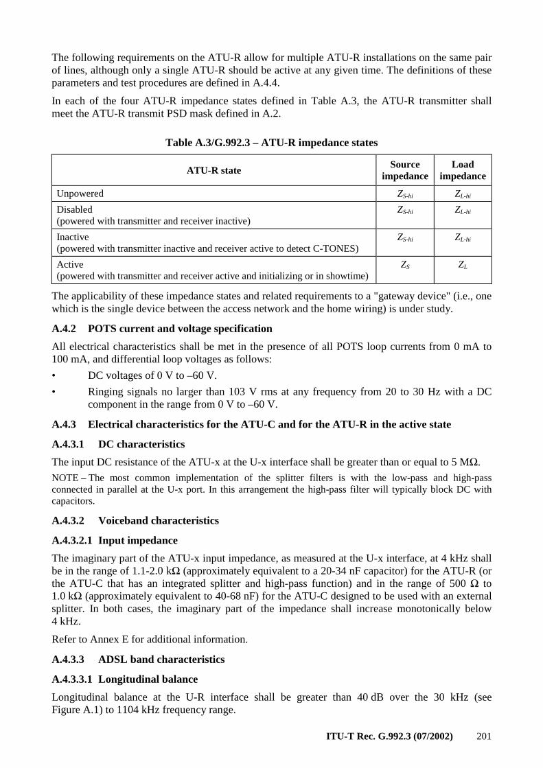
ITU-T Rec. G.992.3 (07/2002) 201
The following requirements on the ATU-R allow for multiple ATU-R installations on the same pair of lines, although only a single ATU-R should be active at any given time. The definitions of these parameters and test procedures are defined in A.4.4.
In each of the four ATU-R impedance states defined in Table A.3, the ATU-R transmitter shall meet the ATU-R transmit PSD mask defined in A.2.
Table A.3/G.992.3 – ATU-R impedance states
ATU-R state Source
impedance Load
impedance
Unpowered ZS-hi ZL-hi
Disabled (powered with transmitter and receiver inactive)
ZS-hi ZL-hi
Inactive (powered with transmitter inactive and receiver active to detect C-TONES)
ZS-hi ZL-hi
Active (powered with transmitter and receiver active and initializing or in showtime)
ZS ZL
The applicability of these impedance states and related requirements to a "gateway device" (i.e., one which is the single device between the access network and the home wiring) is under study.
A.4.2 POTS current and voltage specification
All electrical characteristics shall be met in the presence of all POTS loop currents from 0 mA to 100 mA, and differential loop voltages as follows:
• DC voltages of 0 V to –60 V.
• Ringing signals no larger than 103 V rms at any frequency from 20 to 30 Hz with a DC component in the range from 0 V to –60 V.
A.4.3 Electrical characteristics for the ATU-C and for the ATU-R in the active state
A.4.3.1 DC characteristics
The input DC resistance of the ATU-x at the U-x interface shall be greater than or equal to 5 MΩ.
NOTE – The most common implementation of the splitter filters is with the low-pass and high-pass connected in parallel at the U-x port. In this arrangement the high-pass filter will typically block DC with capacitors.
A.4.3.2 Voiceband characteristics
A.4.3.2.1 Input impedance
The imaginary part of the ATU-x input impedance, as measured at the U-x interface, at 4 kHz shall be in the range of 1.1-2.0 kΩ (approximately equivalent to a 20-34 nF capacitor) for the ATU-R (or the ATU-C that has an integrated splitter and high-pass function) and in the range of 500 Ω to 1.0 kΩ (approximately equivalent to 40-68 nF) for the ATU-C designed to be used with an external splitter. In both cases, the imaginary part of the impedance shall increase monotonically below 4 kHz.
Refer to Annex E for additional information.
A.4.3.3 ADSL band characteristics
A.4.3.3.1 Longitudinal balance
Longitudinal balance at the U-R interface shall be greater than 40 dB over the 30 kHz (see Figure A.1) to 1104 kHz frequency range.
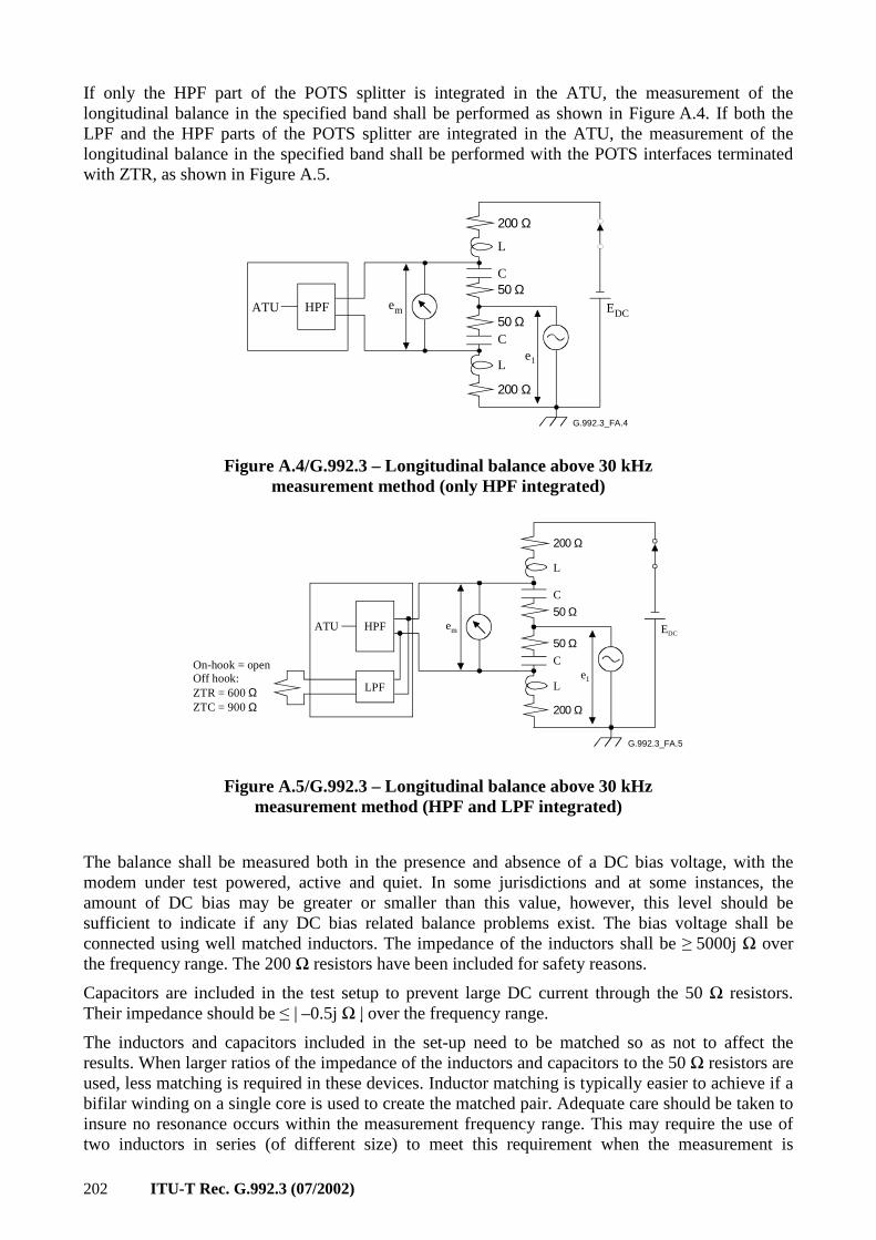
202 ITU-T Rec. G.992.3 (07/2002)
If only the HPF part of the POTS splitter is integrated in the ATU, the measurement of the longitudinal balance in the specified band shall be performed as shown in Figure A.4. If both the LPF and the HPF parts of the POTS splitter are integrated in the ATU, the measurement of the longitudinal balance in the specified band shall be performed with the POTS interfaces terminated with ZTR, as shown in Figure A.5.
G.992.3_FA.4
ATU HPF em
200 Ω
50 Ω
50 Ω
200 Ω
Le1
C
C
L
EDC
Figure A.4/G.992.3 – Longitudinal balance above 30 kHz measurement method (only HPF integrated)
G.992.3_FA.5
em
200 Ω
50 Ω
200 Ω
Le1
C
C
L
EDC
On-hook = openOff hook:ZTR = 600 ΩZTC = 900 Ω
50 ΩATU HPF
LPF
Figure A.5/G.992.3 – Longitudinal balance above 30 kHz measurement method (HPF and LPF integrated)
The balance shall be measured both in the presence and absence of a DC bias voltage, with the modem under test powered, active and quiet. In some jurisdictions and at some instances, the amount of DC bias may be greater or smaller than this value, however, this level should be sufficient to indicate if any DC bias related balance problems exist. The bias voltage shall be connected using well matched inductors. The impedance of the inductors shall be ≥ 5000j Ω over the frequency range. The 200 Ω resistors have been included for safety reasons.
Capacitors are included in the test setup to prevent large DC current through the 50 Ω resistors. Their impedance should be ≤ | –0.5j Ω | over the frequency range.
The inductors and capacitors included in the set-up need to be matched so as not to affect the results. When larger ratios of the impedance of the inductors and capacitors to the 50 Ω resistors are used, less matching is required in these devices. Inductor matching is typically easier to achieve if a bifilar winding on a single core is used to create the matched pair. Adequate care should be taken to insure no resonance occurs within the measurement frequency range. This may require the use of two inductors in series (of different size) to meet this requirement when the measurement is
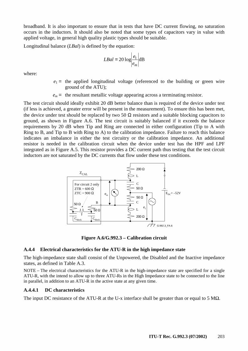
ITU-T Rec. G.992.3 (07/2002) 203
broadband. It is also important to ensure that in tests that have DC current flowing, no saturation occurs in the inductors. It should also be noted that some types of capacitors vary in value with applied voltage, in general high quality plastic types should be suitable.
Longitudinal balance (LBal) is defined by the equation:
dBlog 20 1
me
eLBal =
where:
e1 = the applied longitudinal voltage (referenced to the building or green wire ground of the ATU);
em = the resultant metallic voltage appearing across a terminating resistor.
The test circuit should ideally exhibit 20 dB better balance than is required of the device under test (if less is achieved, a greater error will be present in the measurement). To ensure this has been met, the device under test should be replaced by two 50 Ω resistors and a suitable blocking capacitors to ground, as shown in Figure A.6. The test circuit is suitably balanced if it exceeds the balance requirements by 20 dB when Tip and Ring are connected in either configuration (Tip to A with Ring to B, and Tip to B with Ring to A) to the calibration impedance. Failure to reach this balance indicates an imbalance in either the test circuitry or the calibration impedance. An additional resistor is needed in the calibration circuit when the device under test has the HPF and LPF integrated as in Figure A.5. This resistor provides a DC current path thus testing that the test circuit inductors are not saturated by the DC currents that flow under these test conditions.
G.992.3_FA.6
em
200 Ω
50 Ω
200 Ω
Le1
C
C
L
EDC= –52V
50 Ω
50 Ω
50 Ω
B
Cblock Cblock
For circuit 2 onlyZTR = 600 ΩZTC = 900 Ω
ZCAL
Figure A.6/G.992.3 – Calibration circuit
A.4.4 Electrical characteristics for the ATU-R in the high impedance state
The high-impedance state shall consist of the Unpowered, the Disabled and the Inactive impedance states, as defined in Table A.3.
NOTE – The electrical characteristics for the ATU-R in the high-impedance state are specified for a single ATU-R, with the intend to allow up to three ATU-Rs in the High Impedance state to be connected to the line in parallel, in addition to an ATU-R in the active state at any given time.
A.4.4.1 DC characteristics
The input DC resistance of the ATU-R at the U-x interface shall be greater than or equal to 5 MΩ.
204 ITU-T Rec. G.992.3 (07/2002)
A.4.4.2 Voiceband characteristics
A.4.4.2.1 Insertion (bridging) loss
The ATU-R insertion (bridging) loss in the High Impedance state shall be less than 0.33 dB at 3.4 kHz, and shall be less than 1 dB at 12 and 16 kHz. This is to facilitate the insertion loss of three ATU-R's on the same line to be less than 1 dB at 3.4 kHz, and to be less than 3 dB at 12 and 16 kHz.
A.4.4.2.2 Insertion (bridging) loss distortion
The ATU-R insertion (bridging) loss distortion in the High Impedance state, as referred to the insertion loss at 3.4 kHz, shall be less than ±0.33 dB over the 200 to 4000 Hz frequency range. This is to facilitate insertion loss distortion of three ATU-R's in the 200 to 4000 Hz frequency range to be less than ±1dB.
A.4.4.2.3 Intermodulation distortion
A 4-tone set as specified in ITU-T Rec. O.42 [6], at a level of –9 dBm , when applied to the ATU-R in the High Impedance state, shall produce second and third order intermodulation distortion products at least 80 dB and 85 dB, respectively, below the received signal level.
A.4.4.3 ADSL band characteristics
A.4.4.3.1 Insertion (bridging) loss
The ATU-R insertion (bridging) loss in the High Impedance state for the signal received by the active ATU-C shall be less than 0.33 dB at 100 kHz (a frequency in the active ATU-R transmit band).
The ATU-R insertion (bridging) loss in the High Impedance state for the signal received by the active ATU-R shall be less than 0.33 dB at 500 kHz (a frequency in the active ATU-R receive band).
A.4.4.3.2 Insertion (bridging) loss distortion
The ATU-R insertion (bridging) loss distortion in the High Impedance state for the signal transmitted by the active ATU-R shall be less than ±0.33 dB, over the 25 to 1104 kHz frequency range.
A.4.4.4 Characteristics above the ADSL band
A.4.4.4.1 Insertion (bridging) loss
The ATU-R insertion (bridging) loss in the High Impedance state shall be less than 0.33 dB at 5 MHz and at 9 MHz.
A.4.4.4.2 Insertion loss (bridging) distortion
The ATU-R insertion (bridging) loss distortion shall be less than ±0.33 dB over the 4 to 10 MHz frequency range.
ITU-T Rec. G.992.3 (07/2002) 205
Annex B
Specific requirements for an ADSL system operating in the frequency band above ISDN as defined
in ITU-T Rec. G.961 Appendices I and II
This annex defines those parameters of the ADSL system that have been left undefined in the body of this Recommendation because they are unique to an ADSL service that is frequency-division duplexed with ISDN Basic Access on the same digital subscriber line. The scope is to establish viable ways enabling the simultaneous deployment of ADSL and 160 kbit/s (2B + D) Basic Rate Access with the constraint to use existing transmission technologies as those specified in ITU-T Rec. G.961 [1] Appendices I and II.
B.1 ATU-C functional characteristics (pertains to clause 8)
B.1.1 ATU-C control parameter settings
The ATU-C Control Parameter Settings to be used in the parameterized parts of the main body and/or to be used in this annex are listed in Table B.1. Control Parameters are defined in 8.5.
Table B.1/G.992.3 – ATU-C control parameter settings
Parameter Default setting Characteristics
NSCds 256
NOMPSDds –40 dBm/Hz Setting may be changed relative to this value during G.994.1 phase, see 8.13.2.
MAXNOMPSDds –40 dBm/Hz Setting may be changed relative to this value during G.994.1 phase, see 8.13.2.
MAXNOMATPds 19.9 dBm Setting may be changed relative to this value during G.994.1 phase, see 8.13.2.
B.1.2 ATU-C downstream transmit spectral mask for overlapped spectrum operation (supplements 8.10)
The passband is defined as the band from 120 kHz (see Figure B.1) to 1104 kHz and is the widest possible band used (i.e., for ADSL over ISDN implemented with overlapped spectrum). Limits defined within the passband apply also to any narrower bands used.
Figure B.1 defines the spectral mask for the transmit signal. The low-frequency stop-band is the ISDN band and is defined as frequencies below 120 kHz (see Figure B.1) kHz, the high-frequency stop-band is defined as frequencies greater than 1104 kHz.
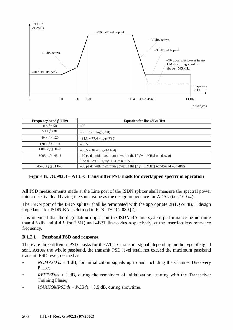
206 ITU-T Rec. G.992.3 (07/2002)
G.992.3_FB.1
PSD indBm/Hz
–90 dBm/Hz peak
–36.5 dBm/Hz peak
–36 dB/octave
–90 dBm/Hz peak
–50 dBm max power in any1 MHz sliding windowabove 4545 kHz
50 1104 3093 4545 11 040
Frequency in kHz
0 80 120
12 dB/octave
Frequency band f (kHz) Equation for line (dBm/Hz)
0 < f ≤ 50 –90
50 < f ≤ 80 –90 + 12 × log2(f/50)
80 < f ≤ 120 –81.8 + 77.4 × log2(f/80)
120 < f ≤ 1104 –36.5
1104 < f ≤ 3093 –36.5 – 36 × log2(f/1104)
3093 < f ≤ 4545 –90 peak, with maximum power in the [f, f + 1 MHz] window of
(–36.5 – 36 × log2(f/1104) + 60)dBm
4545 < f ≤ 11 040 –90 peak, with maximum power in the [f, f + 1 MHz] window of –50 dBm
Figure B.1/G.992.3 – ATU-C transmitter PSD mask for overlapped spectrum operation
All PSD measurements made at the Line port of the ISDN splitter shall measure the spectral power into a resistive load having the same value as the design impedance for ADSL (i.e., 100 Ω).
The ISDN port of the ISDN splitter shall be terminated with the appropriate 2B1Q or 4B3T design impedance for ISDN-BA as defined in ETSI TS 102 080 [7].
It is intended that the degradation impact on the ISDN-BA line system performance be no more than 4.5 dB and 4 dB, for 2B1Q and 4B3T line codes respectively, at the insertion loss reference frequency.
B.1.2.1 Passband PSD and response
There are three different PSD masks for the ATU-C transmit signal, depending on the type of signal sent. Across the whole passband, the transmit PSD level shall not exceed the maximum passband transmit PSD level, defined as:
• NOMPSDds + 1 dB, for initialization signals up to and including the Channel Discovery Phase;
• REFPSDds + 1 dB, during the remainder of initialization, starting with the Transceiver Training Phase;
• MAXNOMPSDds – PCBds + 3.5 dB, during showtime.
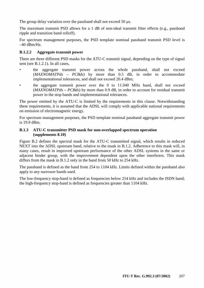
ITU-T Rec. G.992.3 (07/2002) 207
The group delay variation over the passband shall not exceed 50 µs.
The maximum transmit PSD allows for a 1 dB of non-ideal transmit filter effects (e.g., passband ripple and transition band rolloff).
For spectrum management purposes, the PSD template nominal passband transmit PSD level is –40 dBm/Hz.
B.1.2.2 Aggregate transmit power
There are three different PSD masks for the ATU-C transmit signal, depending on the type of signal sent (see B.1.2.1). In all cases,
• the aggregate transmit power across the whole passband, shall not exceed (MAXNOMATPds – PCBds) by more than 0.5 dB, in order to accommodate implementational tolerances, and shall not exceed 20.4 dBm;
• the aggregate transmit power over the 0 to 11.040 MHz band, shall not exceed (MAXNOMATPds – PCBds) by more than 0.9 dB, in order to account for residual transmit power in the stop bands and implementational tolerances.
The power emitted by the ATU-C is limited by the requirements in this clause. Notwithstanding these requirements, it is assumed that the ADSL will comply with applicable national requirements on emission of electromagnetic energy.
For spectrum management purposes, the PSD template nominal passband aggregate transmit power is 19.9 dBm.
B.1.3 ATU-C transmitter PSD mask for non-overlapped spectrum operation (supplements 8.10)
Figure B.2 defines the spectral mask for the ATU-C transmitted signal, which results in reduced NEXT into the ADSL upstream band, relative to the mask in B.1.2. Adherence to this mask will, in many cases, result in improved upstream performance of the other ADSL systems in the same or adjacent binder group, with the improvement dependent upon the other interferers. This mask differs from the mask in B.1.2 only in the band from 50 kHz to 254 kHz.
The passband is defined as the band from 254 to 1104 kHz. Limits defined within the passband also apply to any narrower bands used.
The low-frequency stop-band is defined as frequencies below 254 kHz and includes the ISDN band; the high-frequency stop-band is defined as frequencies greater than 1104 kHz.
208 ITU-T Rec. G.992.3 (07/2002)
G.992.3_FB.2
PSD indBm/Hz
–90 dBm/Hz peak
–36.5 dBm/Hz peak
–36 dB/octave
–90 dBm/Hz peak
–50 dBm max power in any1 MHz sliding windowabove 4545 kHz
93.1 1104 3093 4545 11 040
Frequency in kHz
0 209 254
24 dB/octave
48 dB/octave
Frequency band (kHz) Equation for line (dBm/Hz)
0 < f ≤ 93.1 –90
93.1 < f ≤ 209 –90 + 24 × log2(f/93,1)
209 < f ≤ 254 –62 + 48 × log2(f/209)
254 < f ≤ 1104 –36.5
1104 < f ≤ 3093 –36.5 – 36 × log2(f/1104)
3093 < f ≤ 4545 –90 peak, with maximum power in the [f, f + 1 MHz] window of (–36.5 – 36 × log2(f/1104) + 60)dBm
4545 < f ≤ 11 040 –90 peak, with maximum power in the [f, f + 1 MHz] window of –50 dBm
Figure B.2/G.992.3 – ATU-C Transmitter PSD Mask for non-overlapped spectrum operation
All PSD measurements made at the Line port of the ISDN splitter shall measure the spectral power into a resistive load having the same value as the design impedance for ADSL (i.e., 100 Ω).
The ISDN port of the ISDN splitter shall be terminated with the appropriate 2B1Q or 4B3T design impedance for ISDN-BA as defined in ETSI TS 102 080 [7].
It is intended that the degradation impact on the ISDN-BA line system performance be no more than 4.5 dB and 4 dB, for 2B1Q and 4B3T line codes respectively, at the insertion loss reference frequency.
B.1.3.1 Passband PSD and response
See B.1.2.1.
B.1.3.2 Aggregate transmit power
See B.1.2.2. In addition, for non-overlapped spectrum operation, the aggregate transmit power across the whole passband shall not exceed 19.8 dBm.
For spectrum management purposes, the PSD template nominal passband aggregate transmit power is 19.3 dBm.
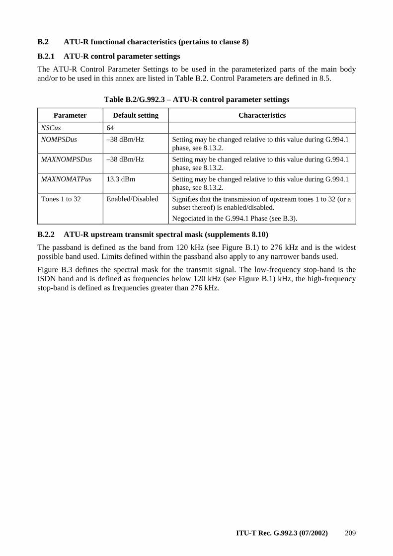
ITU-T Rec. G.992.3 (07/2002) 209
B.2 ATU-R functional characteristics (pertains to clause 8)
B.2.1 ATU-R control parameter settings
The ATU-R Control Parameter Settings to be used in the parameterized parts of the main body and/or to be used in this annex are listed in Table B.2. Control Parameters are defined in 8.5.
Table B.2/G.992.3 – ATU-R control parameter settings
Parameter Default setting Characteristics
NSCus 64
NOMPSDus –38 dBm/Hz Setting may be changed relative to this value during G.994.1 phase, see 8.13.2.
MAXNOMPSDus –38 dBm/Hz Setting may be changed relative to this value during G.994.1 phase, see 8.13.2.
MAXNOMATPus 13.3 dBm Setting may be changed relative to this value during G.994.1 phase, see 8.13.2.
Tones 1 to 32 Enabled/Disabled Signifies that the transmission of upstream tones 1 to 32 (or a subset thereof) is enabled/disabled.
Negociated in the G.994.1 Phase (see B.3).
B.2.2 ATU-R upstream transmit spectral mask (supplements 8.10)
The passband is defined as the band from 120 kHz (see Figure B.1) to 276 kHz and is the widest possible band used. Limits defined within the passband also apply to any narrower bands used.
Figure B.3 defines the spectral mask for the transmit signal. The low-frequency stop-band is the ISDN band and is defined as frequencies below 120 kHz (see Figure B.1) kHz, the high-frequency stop-band is defined as frequencies greater than 276 kHz.
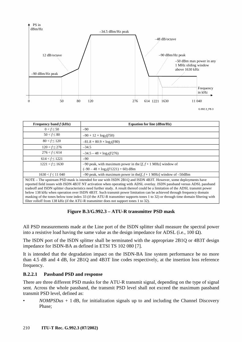
210 ITU-T Rec. G.992.3 (07/2002)
G.992.3_FB.3
PS indBm/Hz
–90 dBm/Hz peak
–34.5 dBm/Hz peak
–48 dB/octave
–90 dBm/Hz peak
–50 dBm max power in any1 MHz sliding windowabove 1630 kHz
50 276 614 1221 11 040
Frequencyin kHz
0 80 120
12 dB/octave
1630
Frequency band f (kHz) Equation for line (dBm/Hz)
0 < f ≤ 50 –90
50 < f ≤ 80 –90 + 12 × log2(f/50)
80 < f ≤ 120 –81.8 + 80.9 × log2(f/80)
120 < f ≤ 276 –34.5
276 < f ≤ 614 –34.5 – 48 × log2(f/276)
614 < f ≤ 1221 –90
1221 < f ≤ 1630 –90 peak, with maximum power in the [f, f + 1 MHz] window of (–90 – 48 × log2(f/1221) + 60) dBm
1630 < f ≤ 11 040 –90 peak, with maximum power in the[f, f + 1 MHz] window of –50dBm
NOTE – The upstream PSD mask is intended for use with ISDN 2B1Q and ISDN 4B3T. However, some deployments have reported field issues with ISDN 4B3T NT activation when operating with ADSL overlay. ISDN passband versus ADSL passband tradeoff and ISDN splitter characteristics need further study. A result thereof could be a limitation of the ADSL transmit power below 138 kHz when operation over ISDN 4B3T. Such transmit power limitation can be achieved through frequency domain masking of the tones below tone index 33 (if the ATU-R transmitter supports tones 1 to 32) or through time domain filtering with filter rolloff from 138 kHz (if the ATU-R transmitter does not support tones 1 to 32).
Figure B.3/G.992.3 – ATU-R transmitter PSD mask
All PSD measurements made at the Line port of the ISDN splitter shall measure the spectral power into a resistive load having the same value as the design impedance for ADSL (i.e., 100 Ω).
The ISDN port of the ISDN splitter shall be terminated with the appropriate 2B1Q or 4B3T design impedance for ISDN-BA as defined in ETSI TS 102 080 [7].
It is intended that the degradation impact on the ISDN-BA line system performance be no more than 4.5 dB and 4 dB, for 2B1Q and 4B3T line codes respectively, at the insertion loss reference frequency.
B.2.2.1 Passband PSD and response
There are three different PSD masks for the ATU-R transmit signal, depending on the type of signal sent. Across the whole passband, the transmit PSD level shall not exceed the maximum passband transmit PSD level, defined as:
• NOMPSDus + 1 dB, for initialization signals up to and including the Channel Discovery Phase;
ITU-T Rec. G.992.3 (07/2002) 211
• REFPSDus + 1 dB, during the remainder of initialization, starting with the Transceiver Training Phase;
• MAXNOMPSDus – PCBus + 3.5 dB, during showtime.
The group delay variation over the passband shall not exceed 50 µs.
The maximum transmit PSD allows for a 1 dB of non-ideal transmit filter effects (e.g., passband ripple and transition band rolloff).
For spectrum management purposes, the PSD template nominal passband transmit PSD level is –38 dBm/Hz.
B.2.2.2 Aggregate transmit power
There are three different PSD masks for the ATU-R transmit signal, depending on the type of signal sent (see B.2.2.1). In all cases,
• the aggregate transmit power across the whole passband, shall not exceed (MAXNOMATPus – PCBus) by more than 0.5 dB, in order to accommodate implementational tolerances, and shall not exceed 13.8 dBm.
• the aggregate transmit power over the 0 to 11.040 MHz band, shall not exceed (MAXNOMATPus – PCBus) by more than 0.8 dB, in order to account for residual transmit power in the stop bands and implementational tolerances.
The power emitted by the ATU-R is limited by the requirements in this clause. Notwithstanding these requirements, it is assumed that the ADSL will comply with applicable national requirements on emission of electromagnetic energy.
For spectrum management purposes, the PSD template nominal passband aggregate transmit power is 13.3 dBm.
B.2.3 Data subcarriers (replaces 8.8.1.1)
The channel analysis (see 8.13.5) allows for a maximum of 63 data carriers to be used (i.e., i = 1 to 63). However, the use of carriers i = 1 to 32 is optional and their use is negociated through G.994.1 (see B.3). The lower limit on i is partly determined by the ISDN/ADSL splitting filters. If FDM is used to separate the upstream and downstream ADSL signals, the upper limit is set by down-up splitting filters.
In all cases, the cut-off frequencies of these filters are completely at the discretion of the manufacturer, and the range of usable i is determined during the channel estimation in transceiver training (see 8.13.4). Implementations should, however, be designed such that, when interworking with implementations of other manufacturers, the resulting range of usable i enables the performance requirements to be met.
B.2.4 Modulation by the inverse discrete Fourier transform (supplements 8.8.2)
If the use of tones 1 to 32 is enabled (i.e., G.994.1 MS codepoint = 1), modulation by the IDFT shall apply as defined in 8.8.2.
If the use of tones 1 to 32 is disabled (i.e., G.994.1 MS codepoint = 0), the modulation by the IDFT shall apply as defined in 8.8.2, with the additional requirement that:
( ) ;0codepoint CLR G.994.1 set the has RATUtheif,0 and 31to1for, conj
:or
;1codepoint CLR G.994.1 set the has RATUtheif,32to1for,0
3264 ====
===
− -ZiZZ
-iZ
ii
i
NOTE – The modulation (demodulation) by the IDFT (DFT) allows for implementation with a mirrored complex conjugate transmitter (receiver). In this case, the tones 1 to 32 cannot be used. This is indicated by the transmitter (receiver) by setting the G.994.1 CLR (CL) codepoint to 0.
212 ITU-T Rec. G.992.3 (07/2002)
B.3 Initialization
B.3.1 Handshake – ATU-C (supplements 8.13.2.1)
B.3.1.1 CL messages (supplements 8.13.2.1.1)
See Table B.3.
Table B.3/G.992.3 – ATU-C CL message NPar(2) bit definitions
NPar(2) bit Definition
Tones 1 to 32 If set to ONE, signifies that the ATU-C is capable of receiving upstream tones 1 to 32.
B.3.1.2 MS messages (supplements 8.13.2.1.2)
Table B.4/G.992.3 – ATU-C MS message NPar(2) bit definitions
NPar(2) bit Definition
Tones 1 to 32 Set to ONE if and only if this bit was set to ONE in both the last previous CL message and the last previous CLR message. Signifies that the transmission of upstream tones 1 to 32 (or a subset thereof) is enabled (set to 1) or disabled (set to 0).
B.3.2 Handshake – ATU-R (supplements 8.13.2.2)
B.3.2.1 CLR messages (supplements 8.13.2.2.1)
See Table B.5.
Table B.5/G.992.3 – ATU-R CLR message NPar(2) bit definitions for Annex B
NPar(2) bit Definition
Tones 1 to 32 If set to ONE, signifies that the ATU-R is capable of transmitting upstream tones 1 to 32.
B.3.2.2 MS messages (supplements 8.13.2.2.2)
See Table B.6.
Table B.6/G.992.3 – ATU-R MS message NPar(2) bit definitions for Annex B
NPar(2) bit Definition
Tones 1 to 32 Set to ONE if and only if this bit was set to ONE in both the last previous CL message and the last previous CLR message. Signifies that the transmission of upstream tones 1 to 32 (or a subset thereof) is enabled (set to 1) or disabled (set to 0).
B.3.3 Spectrum bounds and shaping parameters
Spectrum bounds and shaping parameters shall apply for the upstream subcarriers as defined in 8.13.2.4 (with NSCus = 64, see Table B.2).
For implementations using a mirrored complex conjugate transmitter, an IDFT size of 32 shall be indicated in G.994.1 (see 8.13.2). The minimum tssi values shall be calculated according to Equation 8-1 (see 8.13.2.4) with SUPPORTEDset evidently limited to subcarriers in the 33 to 63 range, N = 32, NSC = 64 and fs = 552 kHz. This results in an S(f) which is periodic with 276 kHz. Because of this periodicity, and in order to avoid redundant tssi information in G.994.1, spectrum shaping parameters shall be defined only on subcarriers 32 and above in the G.994.1 CLR message (i.e., the first breakpoint frequency in the CLR message shall be at subcarrier index 32 or higher).
ITU-T Rec. G.992.3 (07/2002) 213
B.4 Electrical characteristics
This clause specifies the combination of ATU-x and high-pass filter, as shown in Figures 5-4 and 5-5; further information about the low-pass filter is specified in Annex E.
All electrical characteristics shall be met in the presence of all of the ISDN signals, as defined in ITU-T Rec. G.961 [1] Appendices I and II (as applicable to the ISDN service).
B.4.1 Electrical characteristics for the ATU-C and for the ATU-R in the active state
B.4.1.1 DC characteristics
The input DC resistance of the ATU-x at the U-x interface shall be greater than or equal to 5 MΩ.
NOTE – The most common implementation of the splitter filters is with the low-pass and high-pass connected in parallel at the U-x port. In this arrangement, the high-pass filter will typically block DC with capacitors.
B.4.1.2 ISDN band characteristics
B.4.1.2.1 ADSL noise interference into the ISDN circuit
This is the specification for the lower stopband PSD of the ATU-C and ATU-R (see B.2.1 and B.2.2, respectively).
B.4.1.3 ADSL band characteristics
B.4.1.3.1 Longitudinal balance
Longitudinal balance at the U-R interface shall be greater than 40 dB over the 120 kHz (see Figure B.1) to 1104 kHz frequency range. The method of measurement shall be identical to the method defined for ADSL over POTS in A.4.1.3.1.
Annex C
Specific requirements for an ADSL system operating in the same cable as ISDN as defined in ITU-T Rec. G.961 Appendix III
For further study.
Annex D
ATU-C and ATU-R state diagrams
D.1 Introduction
This annex provides state diagrams for the ATU-C and ATU-R, some portions of which are mandatory to guarantee interworking between different manufacturers' units, and some portions of which are optional.
D.2 Definitions
The following terms and abbreviations are used in this annex. Where states or events have been defined elsewhere in this Recommendation, the definitions are referenced here for convenience.
D.2.1 LOS failure: An LOS failure is declared after 2.5 ± 0.5 s of contiguous LOS defect, or, if LOS defect is present when the criteria for LOF failure declaration have been met (see LOF failure definition below). An LOS failure is cleared after 10 ± 0.5 s of no LOS defect.
214 ITU-T Rec. G.992.3 (07/2002)
D.2.2 LOF failure: An LOF failure is declared after 2.5 ± 0.5 s of contiguous SEF defect, except when an LOS defect or failure is present (see LOS failure definition above). An LOF failure is cleared when LOS failure is declared, or after 10 ± 0.5 s of no SEF defect.
D.2.3 persistent LOF failure: Persistent LOF failure is declared after 2.5 ± 0.5 s of near-end LOF failure with SEF defect still present. LOF failure and SEF defect are defined for operations and maintenance in D.2.1 and 8.12.1.
D.2.4 persistent LOS failure: Persistent LOS is declared after 2.5 ± 0.5 s of near-end LOS failure with LOS defect still present. LOS failure and LOS defect are defined for operations and maintenance in 9.3.
D.2.5 high_BER-ss: High bit error ratio in received data, showtime (re)sync event. This event occurs when some algorithm, which may be vendor-specific, determines that a resync attempt (on the showtime signal being received) is required. This event is (but is not required to be) related to the SEF (severely errored frame) defect defined for operations and maintenance (see 8.12.1).
D.2.6 high_BER-st: High bit error ratio in received data, showtime (re)train event. This event occurs when some algorithm, which may be vendor-specific, determines that a retrain attempt (on the showtime signal being received) is required. This event is (but is not required to be) related to a high level of near-end LCD, CRC or FEC anomalies over some period of time or to the SEF (severely errored frame) or LOM (loss of margin) defect (see 8.12.1).
D.2.7 high_BER-hs: High bit error ratio in received data, re-initialize through G.994.1 event. This event occurs when some algorithm, which may be vendor-specific, determines that a full re-initialization (including a G.994.1 session) is required. This event is (but is not required to be) related to a high level of near-end LCD, CRC or FEC anomalies over some period of time or the SEF (severely errored frame) or LOM (loss of margin) defect (see 8.12.1). It may also relate to far-end performance primitives.
D.2.8 high_BER-si: High bit error ratio in received data, re-initialize through short initialization event. This event occurs when some algorithm, which may be vendor-specific, determines that a short re-initialization (not including a G.994.1 session) is required. This event is (but is not required to be) related to a high level of near-end LCD, CRC or FEC anomalies over some period of time or the SEF (severely errored frame) or LOM (loss of margin) defect (see 8.12.1). It may also relate to far-end performance primitives.
D.2.9 host control channel: For the ATU-C, this is a configuration control channel from some host controller, such as a Network Management System (NMS) outside or a management entity within the Access Node. For the ATU-R, this is a Personal Computer (PC) outside or a management entity within the Network Termination., which controls one or more ATU-C line units.
D.3 State diagrams
State diagrams are given in Figure D.1 for the ATU-C, and in Figure D.2 for the ATU-R. States are indicated by ovals, with the name of the state given within the oval. The states are defined in Table D.1 for the ATU-C and in Table D.2 for the ATU-R. Transitions between states are indicated by arrows, with the event causing the transition listed next to the arrow. For some events, the source of the event is indicated with letter(s) and a colon preceding the event name; a key to the source events is provided at the bottom of each figure. All states except Retrain and Resync are mandatory.
In the state diagram for the ATU-C, a C-IDLE state would be desired to guarantee a quiet mode, which may be useful prior to provisioning, to allow certain tests (e.g., MLT), or to discontinue service. A selftest function is desirable, but it may be a vendor/customer option to define when selftest occurs (e.g., always at power-up or only under CO control), and which transition to take after successfully completing selftest (e.g., enter C-IDLE, or enter C-SILENT1 (see ITU-T Rec. G.994.1), or enter C-INIT/TRAIN).
ITU-T Rec. G.992.3 (07/2002) 215
A variety of "host controller" commands (events preceded by "c:_") are shown as non-mandatory in the ATU-C state diagram to provide example events and transitions between states. The way in which these events are implemented is left to the vendor since many options are possible (e.g., separate host controller port on the ATU-C, switches or other front-panel controls, fixed options).
The receiving ATU shall transition state upon Persistent LOS and/or LOF failure. This implies that:
• If no high_BER-hs or high_BER-is events cause the receiving ATU to transition state earlier, then the persistency allows the transmitting ATU to detect the LOS or LOF failure condition through the indicator bits, before the receiving ATU transitions state (i.e., removes the showtime signal from the line);
• If the ATU-C transitions from C-SHOWTIME to C-SILENT1, then the ATU-R shall detect a Persistent LOS Failure, shall transition to R-SILENT0 followed by R-INIT/TRAIN and shall transmit R-TONES-REQ within a maximum of 6 s after the ATU-C transitioning to C-SILENT.
The receiving ATU also transitions state upon a high_BER event. These events are vendor-specific and are (but are not required to be) related to near-end and/or far-end performance primitives (see D.2). As an example, the ATU may define an high_BER event as 30 s of persistent near-end or far-end LOM defect. The ATU should trade-off the persistency in the high_BER events to, on the one hand, quickly recover data integrity, but on the other hand, not to unnecessarily interrupt data transmission. This trade-off may be enhanced if the ATU is able to detect and quantify instantaneous changes in line conditions (e.g., is able to detect hook state changes or the impact thereof, see 8.13.3.1.11 and 8.13.3.2.11).
A Retrain state and a Resync state (both without interruption of the showtime signal) are optional in both state diagrams. Vendor proprietary algorithms may be used to restore frame and data integrity. An optional short initialization (with interruption of the showtime signal) is defined in 8.14, which omits the G.994.1 session from the initialization and attempts to minimize the durations of the variable length states of the initialization performed in the INIT/TRAIN state.
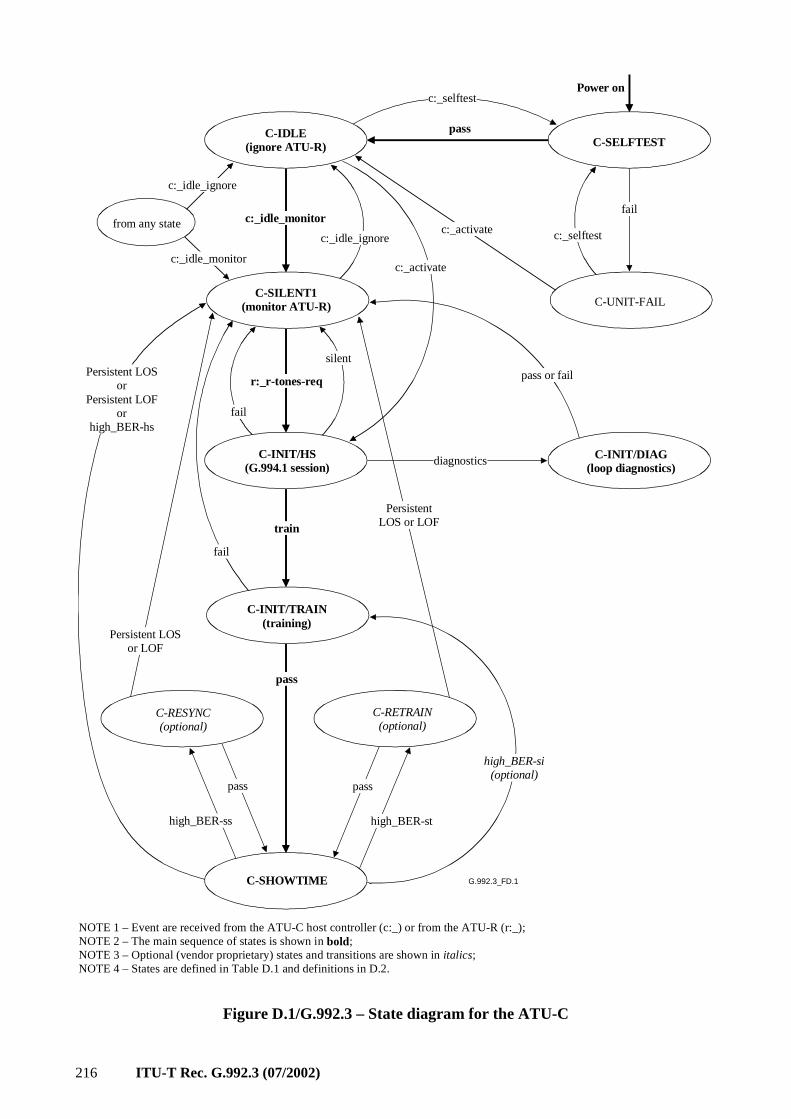
216 ITU-T Rec. G.992.3 (07/2002)
G.992.3_FD.1
Power on
C-SELFTEST
C-SILENT1(monitor ATU-R)
fail
high_BER-ss
fail
passC-IDLE(ignore ATU-R)
PersistentLOS or LOF
Persistent LOSor LOF
C-UNIT-FAIL
C-INIT/HS(G.994.1 session)
C-INIT/TRAIN(training)
C-SHOWTIME
C-RESYNC(optional)
C-INIT/DIAG(loop diagnostics)
C-RETRAIN(optional)
pass pass
high_BER-st
pass
train
r:_r-tones-reqPersistent LOS
orPersistent LOF
orhigh_BER-hs
c:_idle_monitorc:_selftest
c:_selftest
from any state
c:_idle_ignore
diagnostics
c:_idle_ignore
fail
silent
high_BER-si(optional)
c:_activate
c:_activate
c:_idle_monitor
pass or fail
NOTE 1 – Event are received from the ATU-C host controller (c:_) or from the ATU-R (r:_);NOTE 2 – The main sequence of states is shown in bold;NOTE 3 – Optional (vendor proprietary) states and transitions are shown in italics;NOTE 4 – States are defined in Table D.1 and definitions in D.2.
Figure D.1/G.992.3 – State diagram for the ATU-C
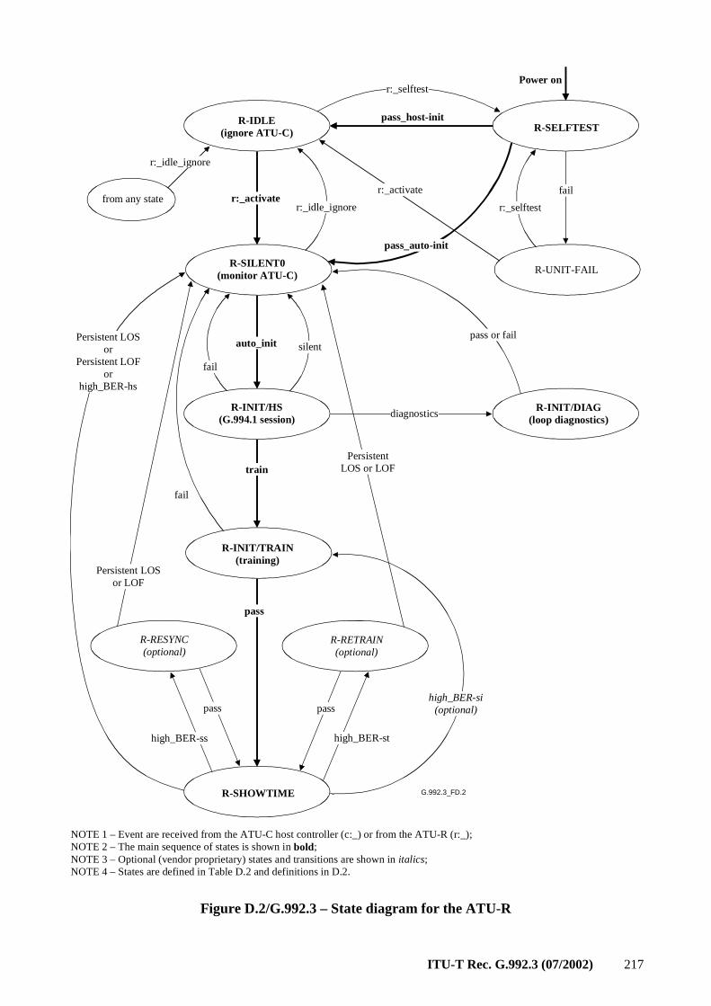
ITU-T Rec. G.992.3 (07/2002) 217
G.992.3_FD.2
NOTE 1 – Event are received from the ATU-C host controller (c:_) or from the ATU-R (r:_);NOTE 2 – The main sequence of states is shown in bold;NOTE 3 – Optional (vendor proprietary) states and transitions are shown in italics;NOTE 4 – States are defined in Table D.2 and definitions in D.2.
Power on
R-SELFTEST
R-SILENT0(monitor ATU-C)
fail
high_BER-ss
fail
pass_host-initR-IDLE(ignore ATU-C)
PersistentLOS or LOF
Persistent LOSor LOF
R-UNIT-FAIL
R-INIT/HS(G.994.1 session)
R-INIT/TRAIN(training)
R-SHOWTIME
R-RESYNC(optional)
R-INIT/DIAG(loop diagnostics)
R-RETRAIN(optional)
pass pass
high_BER-st
pass
train
r:_activate
Persistent LOSor
Persistent LOFor
high_BER-hs
r:_selftest
r:_selftest
from any state
r:_idle_ignore
diagnostics
r:_idle_ignore
pass or fail
fail
pass_auto-init
silentauto_init
high_BER-si(optional)
r:_activate
Figure D.2/G.992.3 – State diagram for the ATU-R
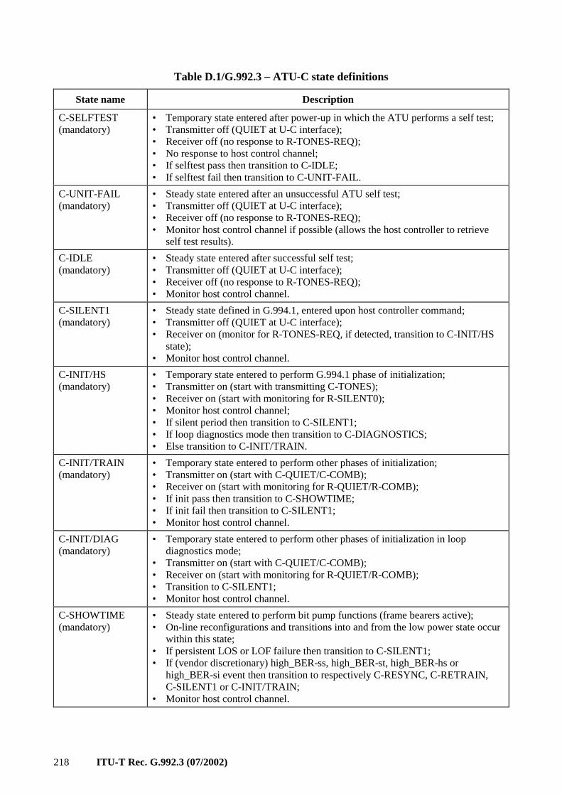
218 ITU-T Rec. G.992.3 (07/2002)
Table D.1/G.992.3 – ATU-C state definitions
State name Description
C-SELFTEST (mandatory)
• Temporary state entered after power-up in which the ATU performs a self test; • Transmitter off (QUIET at U-C interface); • Receiver off (no response to R-TONES-REQ); • No response to host control channel; • If selftest pass then transition to C-IDLE; • If selftest fail then transition to C-UNIT-FAIL.
C-UNIT-FAIL (mandatory)
• Steady state entered after an unsuccessful ATU self test; • Transmitter off (QUIET at U-C interface); • Receiver off (no response to R-TONES-REQ); • Monitor host control channel if possible (allows the host controller to retrieve self test results).
C-IDLE (mandatory)
• Steady state entered after successful self test; • Transmitter off (QUIET at U-C interface); • Receiver off (no response to R-TONES-REQ); • Monitor host control channel.
C-SILENT1 (mandatory)
• Steady state defined in G.994.1, entered upon host controller command; • Transmitter off (QUIET at U-C interface); • Receiver on (monitor for R-TONES-REQ, if detected, transition to C-INIT/HS state); • Monitor host control channel.
C-INIT/HS (mandatory)
• Temporary state entered to perform G.994.1 phase of initialization; • Transmitter on (start with transmitting C-TONES); • Receiver on (start with monitoring for R-SILENT0); • Monitor host control channel; • If silent period then transition to C-SILENT1; • If loop diagnostics mode then transition to C-DIAGNOSTICS; • Else transition to C-INIT/TRAIN.
C-INIT/TRAIN (mandatory)
• Temporary state entered to perform other phases of initialization; • Transmitter on (start with C-QUIET/C-COMB); • Receiver on (start with monitoring for R-QUIET/R-COMB); • If init pass then transition to C-SHOWTIME; • If init fail then transition to C-SILENT1; • Monitor host control channel.
C-INIT/DIAG (mandatory)
• Temporary state entered to perform other phases of initialization in loop diagnostics mode; • Transmitter on (start with C-QUIET/C-COMB); • Receiver on (start with monitoring for R-QUIET/R-COMB); • Transition to C-SILENT1; • Monitor host control channel.
C-SHOWTIME (mandatory)
• Steady state entered to perform bit pump functions (frame bearers active); • On-line reconfigurations and transitions into and from the low power state occur within this state; • If persistent LOS or LOF failure then transition to C-SILENT1; • If (vendor discretionary) high_BER-ss, high_BER-st, high_BER-hs or high_BER-si event then transition to respectively C-RESYNC, C-RETRAIN, C-SILENT1 or C-INIT/TRAIN; • Monitor host control channel.

ITU-T Rec. G.992.3 (07/2002) 219
Table D.1/G.992.3 – ATU-C state definitions
State name Description
C-RESYNC (optional state and vendor proprietary resync procedure)
• Temporary state entered upon high_BER-ss event (see D.2), in which ATU tries to recover frame integrity from received showtime signal (e.g., from the synchronization symbols); • Transmitter and receiver on with showtime signal; • Declare SEF defect; • If resync pass then clear SEF defect and transition to C-SHOWTIME; • If resync fail then time-out on persistent LOF (or LOS) failure and transition to C-SILENT1; • Monitor host control channel.
C-RETRAIN (optional state and vendor proprietary retrain procedure)
• Temporary state entered upon high_BER-st event (see D.2), in which ATU tries to recover data integrity from received showtime signal; • Transmitter and receiver on with showtime signal; • Declare SEF defect; • If retrain pass then clear SEF defect and transition to C-SHOWTIME; • If retrain fail then time-out on persistent LOF (or LOS) failure and transition to C-SILENT1; • Monitor host control channel.
Table D.2/G.992.3 – ATU-R state definitions
State name Description
R-SELFTEST (mandatory)
• Temporary state entered after power-up in which the ATU performs a self test; • Transmitter off (QUIET at U-R interface); • Receiver off (no response to C-TONES); • No response to host control channel; • If selftest pass then transition to R-IDLE if ATU is under host control or transition to R-SILENT0 if ATU is in automatic training mode; • If selftest fail then transition to R-UNIT-FAIL.
R-UNIT-FAIL (mandatory)
• Steady state entered after an unsuccessful ATU self test; • Transmitter off (QUIET at U-R interface); • Receiver off (no response to C-TONES); • Monitor host control channel if possible (allows the host controller to retrieve self test results).
R-IDLE (mandatory)
• Steady state entered after successful self test if ATU is under host control; • Transmitter off (QUIET at U-R interface); • Receiver off (no response to C-TONES); • Monitor host control channel.
R-SILENT0 (mandatory)
• Temporary state defined in G.994.1 entered after selftest pass if ATU is in automatic training mode or with host controller command; • Transmitter off (transmit R-SILENT0); • Receiver on (monitor for C-TONES, if detected, transition to R-INIT/HS state); • Automatic training: immediate transition to R-INIT/HS (unless delayed for silent period); • Monitor host control channel.
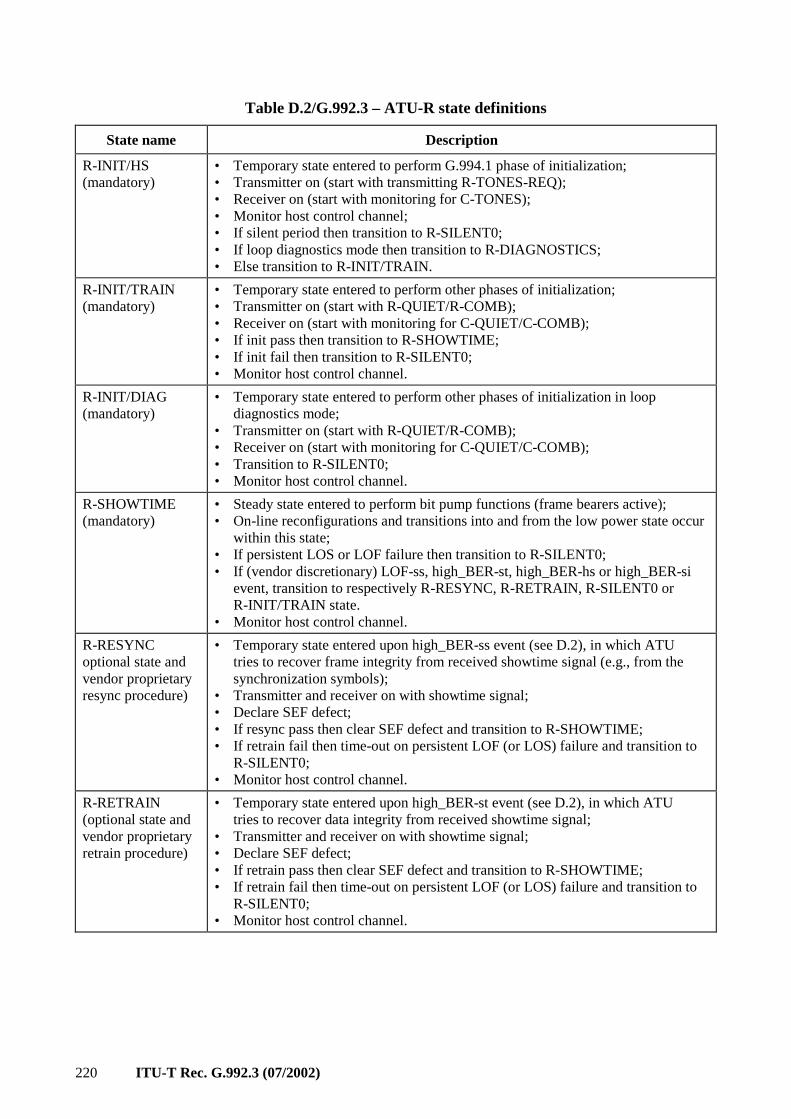
220 ITU-T Rec. G.992.3 (07/2002)
Table D.2/G.992.3 – ATU-R state definitions
State name Description
R-INIT/HS (mandatory)
• Temporary state entered to perform G.994.1 phase of initialization; • Transmitter on (start with transmitting R-TONES-REQ); • Receiver on (start with monitoring for C-TONES); • Monitor host control channel; • If silent period then transition to R-SILENT0; • If loop diagnostics mode then transition to R-DIAGNOSTICS; • Else transition to R-INIT/TRAIN.
R-INIT/TRAIN (mandatory)
• Temporary state entered to perform other phases of initialization; • Transmitter on (start with R-QUIET/R-COMB); • Receiver on (start with monitoring for C-QUIET/C-COMB); • If init pass then transition to R-SHOWTIME; • If init fail then transition to R-SILENT0; • Monitor host control channel.
R-INIT/DIAG (mandatory)
• Temporary state entered to perform other phases of initialization in loop diagnostics mode; • Transmitter on (start with R-QUIET/R-COMB); • Receiver on (start with monitoring for C-QUIET/C-COMB); • Transition to R-SILENT0; • Monitor host control channel.
R-SHOWTIME (mandatory)
• Steady state entered to perform bit pump functions (frame bearers active); • On-line reconfigurations and transitions into and from the low power state occur within this state; • If persistent LOS or LOF failure then transition to R-SILENT0; • If (vendor discretionary) LOF-ss, high_BER-st, high_BER-hs or high_BER-si event, transition to respectively R-RESYNC, R-RETRAIN, R-SILENT0 or R-INIT/TRAIN state. • Monitor host control channel.
R-RESYNC optional state and vendor proprietary resync procedure)
• Temporary state entered upon high_BER-ss event (see D.2), in which ATU tries to recover frame integrity from received showtime signal (e.g., from the synchronization symbols); • Transmitter and receiver on with showtime signal; • Declare SEF defect; • If resync pass then clear SEF defect and transition to R-SHOWTIME; • If retrain fail then time-out on persistent LOF (or LOS) failure and transition to R-SILENT0; • Monitor host control channel.
R-RETRAIN (optional state and vendor proprietary retrain procedure)
• Temporary state entered upon high_BER-st event (see D.2), in which ATU tries to recover data integrity from received showtime signal; • Transmitter and receiver on with showtime signal; • Declare SEF defect; • If retrain pass then clear SEF defect and transition to R-SHOWTIME; • If retrain fail then time-out on persistent LOF (or LOS) failure and transition to R-SILENT0; • Monitor host control channel.
ITU-T Rec. G.992.3 (07/2002) 221
Annex E
POTS and ISDN Basic Access Splitters
The purpose of the POTS splitter is twofold. For ADSL signals, protection from the high-frequency transients and impedance effects that occur during POTS operation, ringing transients, ring trip transients, and off-hook transients and impedance changes, is provided. For POTS voiceband service, the low-pass filters provide protection from ADSL signals which may impact, through non-linear or other effects, remote devices (handset, fax, voiceband, modem, etc.) and central office operation. This filtering should be performed while maintaining the quality of the end-to-end voiceband connection (i.e., between the POTS and PSTN interfaces).
Likewise, the ISDN Basic Access splitter is also twofold.
E.1 Type 1 – POTS splitter – Europe
ADSL/POTS splitters shall comply with in ETSI Technical Specification TS 101 952-1 [8]. The relevant sub-parts are the following:
• Sub-part 1-1: Technical specification of the low pass part of ADSL/POTS splitters;
• Sub-part 1-2: Technical specification of the high pass part of ADSL/POTS splitters.
E.1.1 Phoneline networking equipment isolation
To allow phoneline networking terminals (i.e., ITU-T Recs G.989.1 and G.989.2) to operate without compromise from bridging loss caused by a low impedance at the remote splitter POTS port, an impedance range at the remote splitter POTS port is defined for frequencies in the 2 to 10 MHz band.
E.1.1.1 Remote splitter POTS port shunt impedance
The total (across tip and ring at the POTS port) impedance in the 2 to 10 MHz frequency band should be at least 160 Ω.
The inclusion of series components to meet this specification shall not affect the other specified parameters such as DC resistance, longitudinal balance, tip to ring capacitance measurements under 200 Hz, or return loss requirements.
E.2 Type 2 – POTS splitter – North America
E.2.1 Introduction
This clause contains specifications for a POTS splitter appropriate to North America. The requirements contained in E.2 shall be met for a POTS splitter designed for deployment in North America. The purpose of the low-pass filters is twofold. For ADSL signals, protection from the high-frequency transients and impedance effects that occur during POTS operation, ringing transients, ring trip transients, and off-hook transients and impedance changes, is provided. For POTS voiceband service, the low-pass filters provide protection from ADSL signals which may impact, through non-linear or other effects, remote devices (handset, fax, voiceband, modem, etc.) and central office operation. This filtering should be performed while maintaining the quality of the end-to-end link, that is, between the POTS and PSTN interfaces of Figure 5-4.
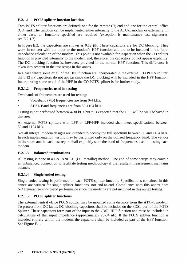
222 ITU-T Rec. G.992.3 (07/2002)
E.2.1.1 POTS splitter function location
Two POTS splitter functions are defined; one for the remote (R) end and one for the central office (CO) end. The function can be implemented either internally to the ATU-x modem or externally. In either case, all functions specified are required (exception is maintenance test signatures, see E.2.1.7).
In Figure E.2, the capacitors are shown as 0.12 µF. These capacitors are for DC blocking. They work in concert with the input to the modem's HPF function and are to be included in the input impedance calculation of the modem. This point is not available for inspection when the CO splitter function is provided internally to the modem and, therefore, the capacitors do not appear explicitly. The DC blocking function is, however, provided in the normal HPF function. This difference is taken into account in the test setups in this annex.
In a case where some or all of the HPF function are incorporated in the external CO POTS splitter, the 0.12 µF capacitors do not appear since the DC blocking will be included in the HPF function. Incorporating some or all of the HPF in the CO POTS splitter is for further study.
E.2.1.2 Frequencies used in testing
Two bands of frequencies are used for testing:
• Voiceband (VB) frequencies are from 0-4 kHz.
• ADSL Band frequencies are from 30-1104 kHz.
Testing is not performed between 4-30 kHz but it is expected that the LPF will be well behaved in that area.
All external POTS splitters with LPF or LPF/HPF included shall meet specifications between 30 and 1104 kHz.
Not all integral modem designs are intended to occupy the full spectrum between 30 and 1104 kHz. In each implementation, testing may be performed only on the utilized frequency band. The vendor in literature and in each test report shall explicitly state the band of frequencies used in testing each modem.
E.2.1.3 Balanced terminations
All testing is done in a BALANCED (i.e., metallic) method. One end of some setups may contain an unbalanced connection to facilitate testing methodology if the resultant measurement maintains balance.
E.2.1.4 Single ended testing
Single ended testing is performed on each POTS splitter function. Specifications contained in this annex are written for single splitter functions, not end-to-end. Compliance with this annex does NOT guarantee end-to-end performance since the modems are not included in this annex testing.
E.2.1.5 POTS splitter functions
The external central office POTS splitter may be mounted some distance from the ATU-C modem. To protect from DC faults, DC blocking capacitors shall be included on the xDSL port of the POTS Splitter. These capacitors form part of the input to the xDSL HPF function and must be included in calculations of that input impedance (approximately 20-34 nF). If the POTS splitter function is included entirely within the modem, the capacitors shall be included as part of the HPF function. See Figure E.1.
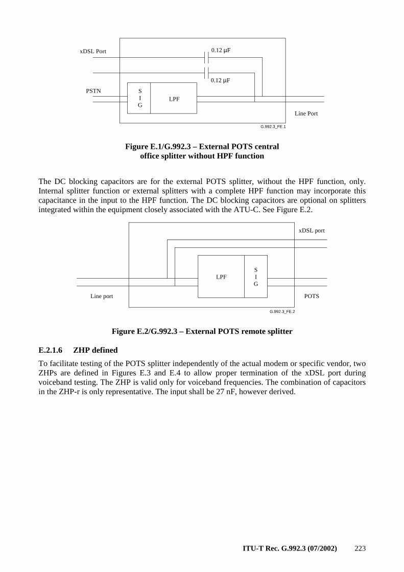
ITU-T Rec. G.992.3 (07/2002) 223
G.992.3_FE.1
LPF
xDSL Port
PSTN
0.12 µF
0.12 µF
Line Port
SIG
Figure E.1/G.992.3 – External POTS central office splitter without HPF function
The DC blocking capacitors are for the external POTS splitter, without the HPF function, only. Internal splitter function or external splitters with a complete HPF function may incorporate this capacitance in the input to the HPF function. The DC blocking capacitors are optional on splitters integrated within the equipment closely associated with the ATU-C. See Figure E.2.
G.992.3_FE.2
Line port POTS
xDSL port
LPFSIG
Figure E.2/G.992.3 – External POTS remote splitter
E.2.1.6 ZHP defined
To facilitate testing of the POTS splitter independently of the actual modem or specific vendor, two ZHPs are defined in Figures E.3 and E.4 to allow proper termination of the xDSL port during voiceband testing. The ZHP is valid only for voiceband frequencies. The combination of capacitors in the ZHP-r is only representative. The input shall be 27 nF, however derived.
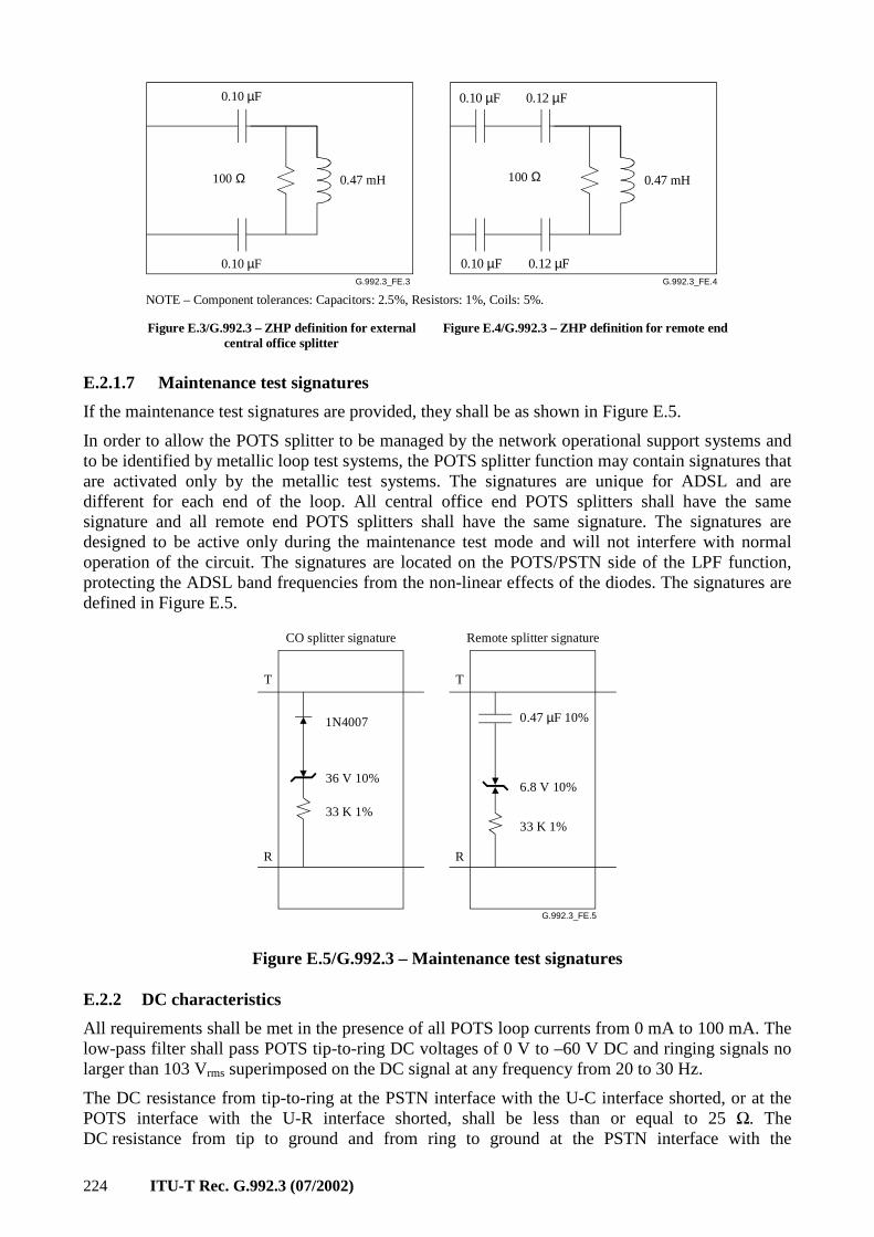
224 ITU-T Rec. G.992.3 (07/2002)
G.992.3_FE.4G.992.3_FE.3
0.12 µF
0.12 µF
0.47 mH
0.10 µF
0.10 µF
0.10 µF
0.47 mH
0.10 µF
NOTE – Component tolerances: Capacitors: 2.5%, Resistors: 1%, Coils: 5%.
Figure E.3/G.992.3 – ZHP definition for externalcentral office splitter
Figure E.4/G.992.3 – ZHP definition for remote end
100 Ω100 Ω
E.2.1.7 Maintenance test signatures
If the maintenance test signatures are provided, they shall be as shown in Figure E.5.
In order to allow the POTS splitter to be managed by the network operational support systems and to be identified by metallic loop test systems, the POTS splitter function may contain signatures that are activated only by the metallic test systems. The signatures are unique for ADSL and are different for each end of the loop. All central office end POTS splitters shall have the same signature and all remote end POTS splitters shall have the same signature. The signatures are designed to be active only during the maintenance test mode and will not interfere with normal operation of the circuit. The signatures are located on the POTS/PSTN side of the LPF function, protecting the ADSL band frequencies from the non-linear effects of the diodes. The signatures are defined in Figure E.5.
G.992.3_FE.5
T
R
T
1N4007
36 V 10%
33 K 1%33 K 1%
CO splitter signature Remote splitter signature
0.47 µF 10%
6.8 V 10%
R
Figure E.5/G.992.3 – Maintenance test signatures
E.2.2 DC characteristics
All requirements shall be met in the presence of all POTS loop currents from 0 mA to 100 mA. The low-pass filter shall pass POTS tip-to-ring DC voltages of 0 V to –60 V DC and ringing signals no larger than 103 Vrms superimposed on the DC signal at any frequency from 20 to 30 Hz.
The DC resistance from tip-to-ring at the PSTN interface with the U-C interface shorted, or at the POTS interface with the U-R interface shorted, shall be less than or equal to 25 Ω. The DC resistance from tip to ground and from ring to ground at the PSTN interface with the
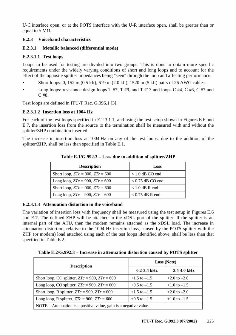
ITU-T Rec. G.992.3 (07/2002) 225
U-C interface open, or at the POTS interface with the U-R interface open, shall be greater than or equal to 5 MΩ.
E.2.3 Voiceband characteristics
E.2.3.1 Metallic balanced (differential mode)
E.2.3.1.1 Test loops
Loops to be used for testing are divided into two groups. This is done to obtain more specific requirements under the widely varying conditions of short and long loops and to account for the effect of the opposite splitter impedances being "seen" through the loop and affecting performance.
• Short loops: 0, 152 m (0.5 kft), 619 m (2.0 kft), 1520 m (5 kft) pairs of 26 AWG cables.
• Long loops: resistance design loops T #7, T #9, and T #13 and loops C #4, C #6, C #7 and C #8.
Test loops are defined in ITU-T Rec. G.996.1 [3].
E.2.3.1.2 Insertion loss at 1004 Hz
For each of the test loops specified in E.2.3.1.1, and using the test setup shown in Figures E.6 and E.7, the insertion loss from the source to the termination shall be measured with and without the splitter/ZHP combination inserted.
The increase in insertion loss at 1004 Hz on any of the test loops, due to the addition of the splitter/ZHP, shall be less than specified in Table E.1.
Table E.1/G.992.3 – Loss due to addition of splitter/ZHP
Description Loss
Short loop, ZTc = 900, ZTr = 600 < 1.0 dB CO end
Long loop, ZTc = 900, ZTr = 600 < 0.75 dB CO end
Short loop, ZTc = 900, ZTr = 600 < 1.0 dB R end
Long loop, ZTc = 900, ZTr = 600 < 0.75 dB R end
E.2.3.1.3 Attenuation distortion in the voiceband
The variation of insertion loss with frequency shall be measured using the test setup in Figures E.6 and E.7. The defined ZHP will be attached to the xDSL port of the splitter. If the splitter is an internal part of the ATU, then the modem remains attached as the xDSL load. The increase in attenuation distortion, relative to the 1004 Hz insertion loss, caused by the POTS splitter with the ZHP (or modem) load attached using each of the test loops identified above, shall be less than that specified in Table E.2.
Table E.2/G.992.3 – Increase in attenuation distortion caused by POTS splitter
Loss (Note) Description
0.2-3.4 kHz 3.4-4.0 kHz
Short loop, CO splitter, ZTc = 900, ZTr = 600 +1.5 to –1.5 +2.0 to –2.0
Long loop, CO splitter, ZTc = 900, ZTr = 600 +0.5 to –1.5 +1.0 to –1.5
Short loop, R splitter, ZTc = 900, ZTr = 600 +1.5 to –1.5 +2.0 to –2.0
Long loop, R splitter, ZTc = 900, ZTr = 600 +0.5 to –1.5 +1.0 to –1.5
NOTE – Attenuation is a positive value, gain is a negative value.
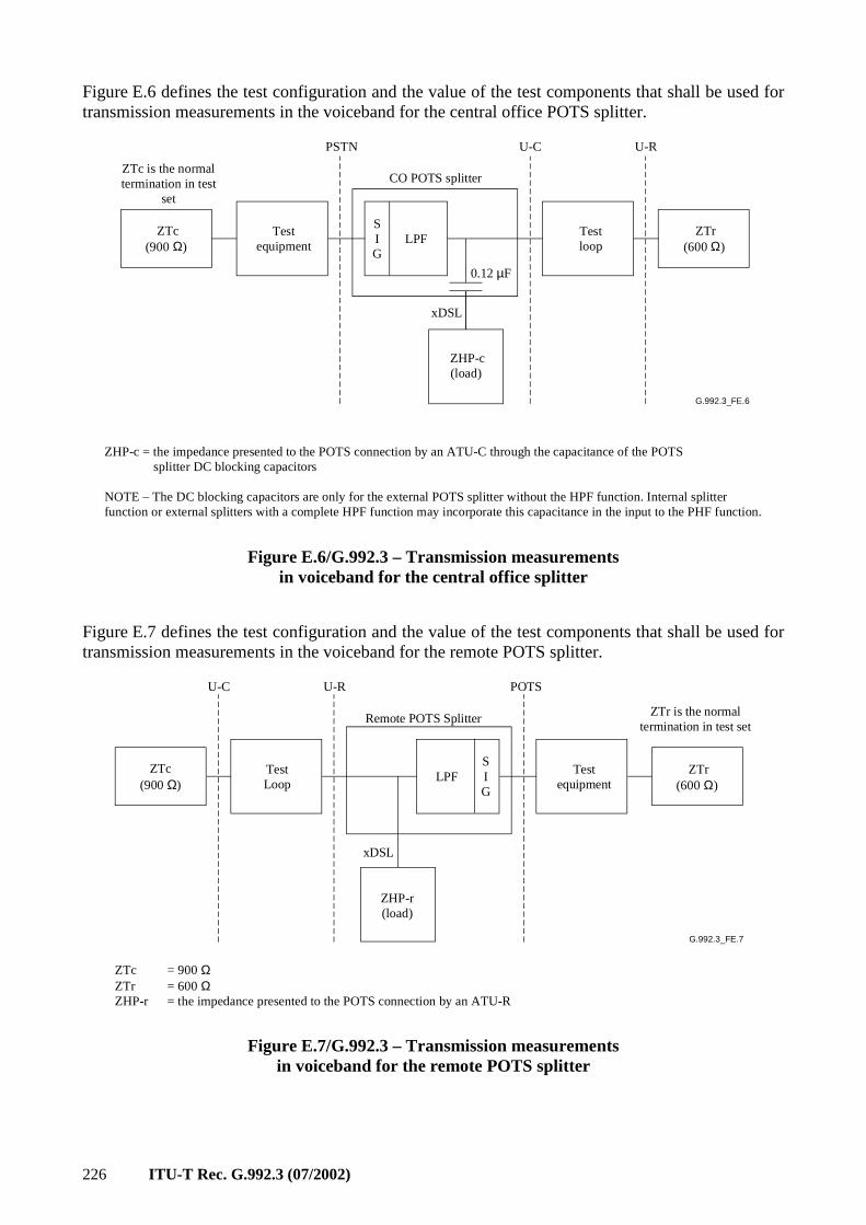
226 ITU-T Rec. G.992.3 (07/2002)
Figure E.6 defines the test configuration and the value of the test components that shall be used for transmission measurements in the voiceband for the central office POTS splitter.
G.992.3_FE.6
LPF
PSTN U-C U-R
CO POTS splitter
xDSL
ZTc is the normaltermination in test
set
ZTc(900 Ω)
Testequipment
ZHP-c(load)
Testloop
ZTr(600 Ω)
SIG
0.12 µF
ZHP-c = the impedance presented to the POTS connection by an ATU-C through the capacitance of the POTS splitter DC blocking capacitors
NOTE – The DC blocking capacitors are only for the external POTS splitter without the HPF function. Internal splitterfunction or external splitters with a complete HPF function may incorporate this capacitance in the input to the PHF function.
Figure E.6/G.992.3 – Transmission measurements in voiceband for the central office splitter
Figure E.7 defines the test configuration and the value of the test components that shall be used for transmission measurements in the voiceband for the remote POTS splitter.
G.992.3_FE.7
LPF
POTSU-C U-R
xDSL
ZTc (900 Ω)
Test Loop
S I G
ZHP-r (load)
Test equipment
ZTr is the normaltermination in test set
Remote POTS Splitter
ZTc = 900 ΩZTr = 600 ΩZHP-r = the impedance presented to the POTS connection by an ATU-R
ZTr(600 Ω)
Figure E.7/G.992.3 – Transmission measurements in voiceband for the remote POTS splitter
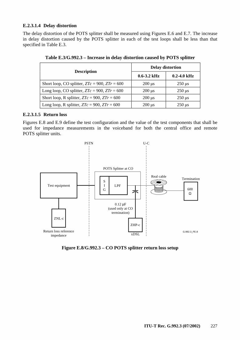
ITU-T Rec. G.992.3 (07/2002) 227
E.2.3.1.4 Delay distortion
The delay distortion of the POTS splitter shall be measured using Figures E.6 and E.7. The increase in delay distortion caused by the POTS splitter in each of the test loops shall be less than that specified in Table E.3.
Table E.3/G.992.3 – Increase in delay distortion caused by POTS splitter
Delay distortion Description
0.6-3.2 kHz 0.2-4.0 kHz
Short loop, CO splitter, ZTc = 900, ZTr = 600 200 µs 250 µs
Long loop, CO splitter, ZTc = 900, ZTr = 600 200 µs 250 µs
Short loop, R splitter, ZTc = 900, ZTr = 600 200 µs 250 µs
Long loop, R splitter, ZTc = 900, ZTr = 600 200 µs 250 µs
E.2.3.1.5 Return loss
Figures E.8 and E.9 define the test configuration and the value of the test components that shall be used for impedance measurements in the voiceband for both the central office and remote POTS splitter units.
G.992.3_FE.8
Test equipment
ZNL-c
PSTN U-C
POTS Splitter at CO
SIG
LPF
TerminationReal cable
Return loss referenceimpedance xDSL
0.12 µF(used only at CO
termination)
ZHP-c
600 Ω
Figure E.8/G.992.3 – CO POTS splitter return loss setup
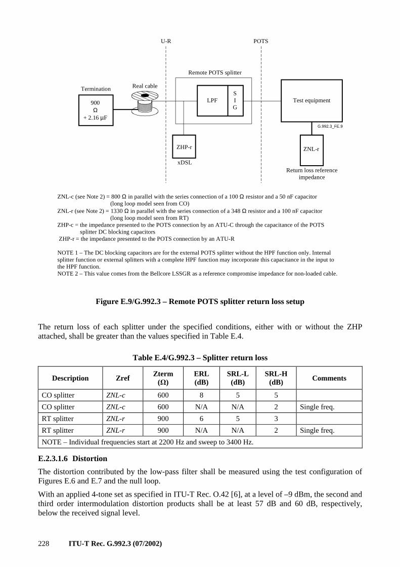
228 ITU-T Rec. G.992.3 (07/2002)
G.992.3_FE.9
Test equipment
ZNL-r
POTSU-R
Remote POTS splitter
SIG
LPF900Ω
+ 2.16 µF
Termination Real cable
Return loss referenceimpedance
xDSL
ZHP-r
ZNL-c (see Note 2) = 800 Ω in parallel with the series connection of a 100 Ω resistor and a 50 nF capacitor (long loop model seen from CO)ZNL-r (see Note 2) = 1330 Ω in parallel with the series connection of a 348 Ω resistor and a 100 nF capacitor (long loop model seen from RT)ZHP-c = the impedance presented to the POTS connection by an ATU-C through the capacitance of the POTS splitter DC blocking capacitors ZHP-r = the impedance presented to the POTS connection by an ATU-R
NOTE 1 – The DC blocking capacitors are for the external POTS splitter without the HPF function only. Internalsplitter function or external splitters with a complete HPF function may incorporate this capacitance in the input tothe HPF function.NOTE 2 – This value comes from the Bellcore LSSGR as a reference compromise impedance for non-loaded cable.
Figure E.9/G.992.3 – Remote POTS splitter return loss setup
The return loss of each splitter under the specified conditions, either with or without the ZHP attached, shall be greater than the values specified in Table E.4.
Table E.4/G.992.3 – Splitter return loss
Description Zref Zterm
(Ω) ERL (dB)
SRL-L (dB)
SRL-H (dB) Comments
CO splitter ZNL-c 600 8 5 5
CO splitter ZNL-c 600 N/A N/A 2 Single freq.
RT splitter ZNL-r 900 6 5 3
RT splitter ZNL-r 900 N/A N/A 2 Single freq.
NOTE – Individual frequencies start at 2200 Hz and sweep to 3400 Hz.
E.2.3.1.6 Distortion
The distortion contributed by the low-pass filter shall be measured using the test configuration of Figures E.6 and E.7 and the null loop.
With an applied 4-tone set as specified in ITU-T Rec. O.42 [6], at a level of –9 dBm, the second and third order intermodulation distortion products shall be at least 57 dB and 60 dB, respectively, below the received signal level.
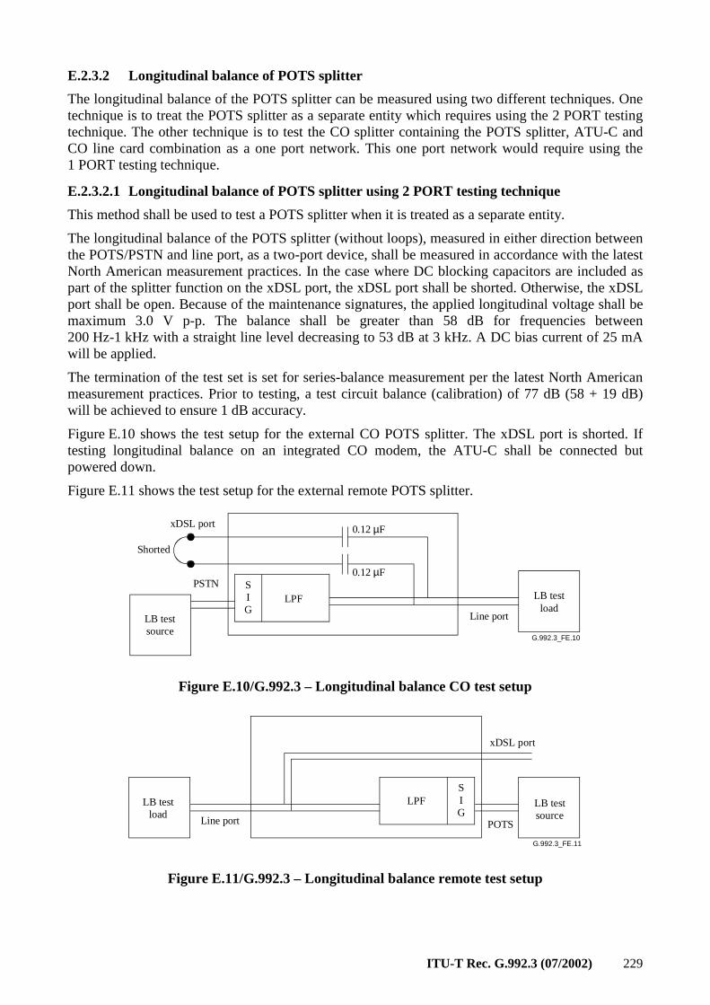
ITU-T Rec. G.992.3 (07/2002) 229
E.2.3.2 Longitudinal balance of POTS splitter
The longitudinal balance of the POTS splitter can be measured using two different techniques. One technique is to treat the POTS splitter as a separate entity which requires using the 2 PORT testing technique. The other technique is to test the CO splitter containing the POTS splitter, ATU-C and CO line card combination as a one port network. This one port network would require using the 1 PORT testing technique.
E.2.3.2.1 Longitudinal balance of POTS splitter using 2 PORT testing technique
This method shall be used to test a POTS splitter when it is treated as a separate entity.
The longitudinal balance of the POTS splitter (without loops), measured in either direction between the POTS/PSTN and line port, as a two-port device, shall be measured in accordance with the latest North American measurement practices. In the case where DC blocking capacitors are included as part of the splitter function on the xDSL port, the xDSL port shall be shorted. Otherwise, the xDSL port shall be open. Because of the maintenance signatures, the applied longitudinal voltage shall be maximum 3.0 V p-p. The balance shall be greater than 58 dB for frequencies between 200 Hz-1 kHz with a straight line level decreasing to 53 dB at 3 kHz. A DC bias current of 25 mA will be applied.
The termination of the test set is set for series-balance measurement per the latest North American measurement practices. Prior to testing, a test circuit balance (calibration) of 77 dB (58 + 19 dB) will be achieved to ensure 1 dB accuracy.
Figure E.10 shows the test setup for the external CO POTS splitter. The xDSL port is shorted. If testing longitudinal balance on an integrated CO modem, the ATU-C shall be connected but powered down.
Figure E.11 shows the test setup for the external remote POTS splitter.
G.992.3_FE.10
LPF
xDSL port
PSTN
Line port
Shorted
0.12 µF
0.12 µF
LB testload
LB testsource
SIG
Figure E.10/G.992.3 – Longitudinal balance CO test setup
G.992.3_FE.11
LPF
Line port
SIG
xDSL port
POTS
LB test load
LB test source
Figure E.11/G.992.3 – Longitudinal balance remote test setup
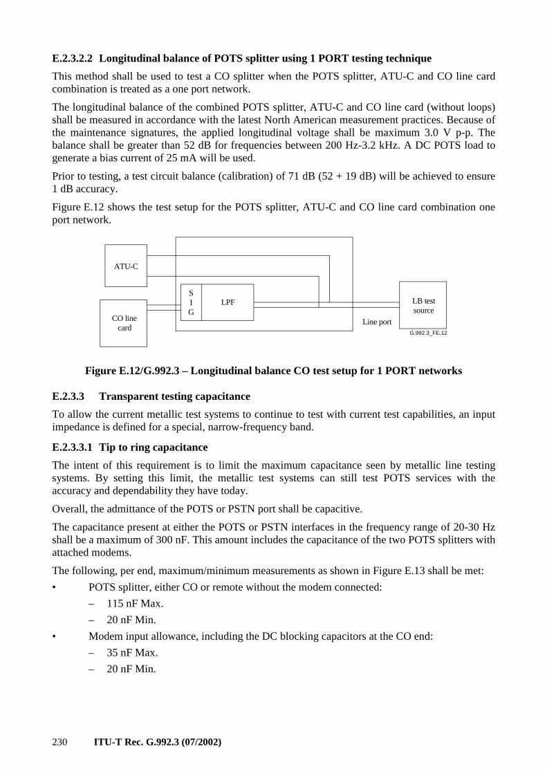
230 ITU-T Rec. G.992.3 (07/2002)
E.2.3.2.2 Longitudinal balance of POTS splitter using 1 PORT testing technique
This method shall be used to test a CO splitter when the POTS splitter, ATU-C and CO line card combination is treated as a one port network.
The longitudinal balance of the combined POTS splitter, ATU-C and CO line card (without loops) shall be measured in accordance with the latest North American measurement practices. Because of the maintenance signatures, the applied longitudinal voltage shall be maximum 3.0 V p-p. The balance shall be greater than 52 dB for frequencies between 200 Hz-3.2 kHz. A DC POTS load to generate a bias current of 25 mA will be used.
Prior to testing, a test circuit balance (calibration) of 71 dB (52 + 19 dB) will be achieved to ensure 1 dB accuracy.
Figure E.12 shows the test setup for the POTS splitter, ATU-C and CO line card combination one port network.
G.992.3_FE.12
LPF
ATU-C
CO linecard
SIG
LB testsource
Line port
Figure E.12/G.992.3 – Longitudinal balance CO test setup for 1 PORT networks
E.2.3.3 Transparent testing capacitance
To allow the current metallic test systems to continue to test with current test capabilities, an input impedance is defined for a special, narrow-frequency band.
E.2.3.3.1 Tip to ring capacitance
The intent of this requirement is to limit the maximum capacitance seen by metallic line testing systems. By setting this limit, the metallic test systems can still test POTS services with the accuracy and dependability they have today.
Overall, the admittance of the POTS or PSTN port shall be capacitive.
The capacitance present at either the POTS or PSTN interfaces in the frequency range of 20-30 Hz shall be a maximum of 300 nF. This amount includes the capacitance of the two POTS splitters with attached modems.
The following, per end, maximum/minimum measurements as shown in Figure E.13 shall be met:
• POTS splitter, either CO or remote without the modem connected:
– 115 nF Max.
– 20 nF Min.
• Modem input allowance, including the DC blocking capacitors at the CO end:
– 35 nF Max.
– 20 nF Min.
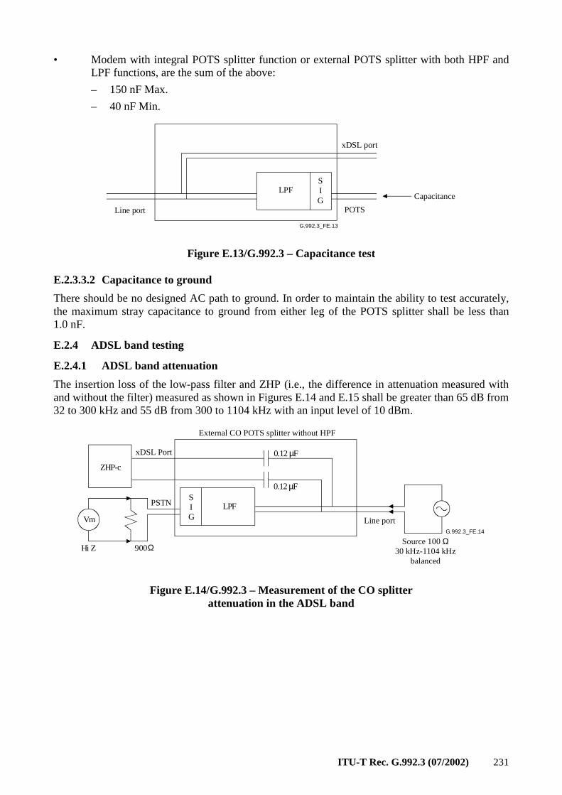
ITU-T Rec. G.992.3 (07/2002) 231
• Modem with integral POTS splitter function or external POTS splitter with both HPF and LPF functions, are the sum of the above:
– 150 nF Max.
– 40 nF Min.
G.992.3_FE.13
LPF
Line port
SIG
xDSL port
POTS
Capacitance
Figure E.13/G.992.3 – Capacitance test
E.2.3.3.2 Capacitance to ground
There should be no designed AC path to ground. In order to maintain the ability to test accurately, the maximum stray capacitance to ground from either leg of the POTS splitter shall be less than 1.0 nF.
E.2.4 ADSL band testing
E.2.4.1 ADSL band attenuation
The insertion loss of the low-pass filter and ZHP (i.e., the difference in attenuation measured with and without the filter) measured as shown in Figures E.14 and E.15 shall be greater than 65 dB from 32 to 300 kHz and 55 dB from 300 to 1104 kHz with an input level of 10 dBm.
G.992.3_FE.14
LPF
Vm
Hi Z
ZHP-c
0.12 µF
0.12 µFSIG
Source 100 Ω 30 kHz-1104 kHz
balanced
900Ω
External CO POTS splitter without HPF
xDSL Port
PSTN
Line port
Figure E.14/G.992.3 – Measurement of the CO splitter attenuation in the ADSL band
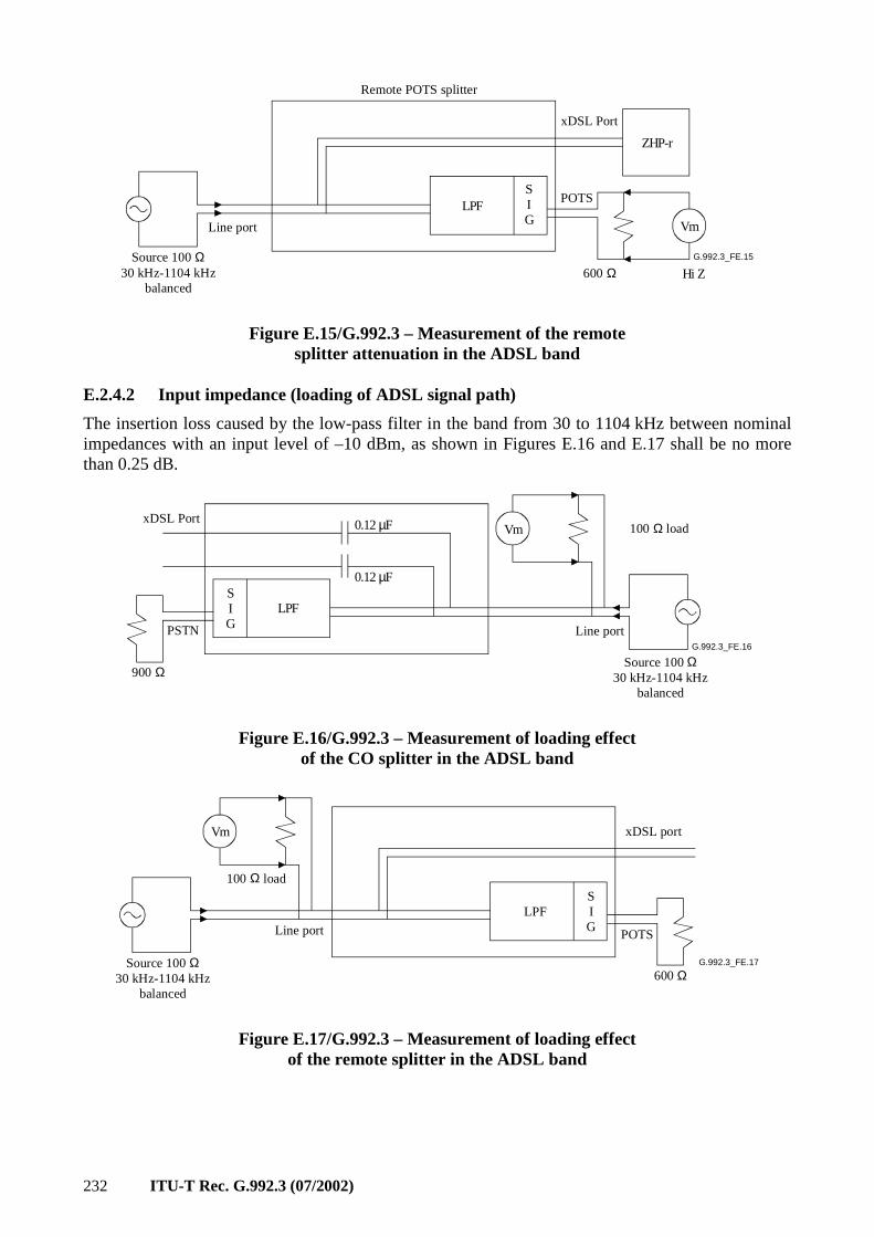
232 ITU-T Rec. G.992.3 (07/2002)
G.992.3_FE.15
LPF
Hi Z
ZHP-r
SIG Vm
Remote POTS splitter
Source 100 Ω30 kHz-1104 kHz
balanced
Line port
600 Ω
POTS
xDSL Port
Figure E.15/G.992.3 – Measurement of the remote splitter attenuation in the ADSL band
E.2.4.2 Input impedance (loading of ADSL signal path)
The insertion loss caused by the low-pass filter in the band from 30 to 1104 kHz between nominal impedances with an input level of –10 dBm, as shown in Figures E.16 and E.17 shall be no more than 0.25 dB.
G.992.3_FE.16
LPF
Vm0.12 µF
0.12 µFSIG
Source 100 Ω30 kHz-1104 kHz
balanced
Line port
100 Ω loadxDSL Port
PSTN
900 Ω
Figure E.16/G.992.3 – Measurement of loading effect of the CO splitter in the ADSL band
G.992.3_FE.17
Vm
Source 100 Ω30 kHz-1104 kHz
balanced
100 Ω load
Line port
LPFSIG
xDSL port
POTS
600 Ω
Figure E.17/G.992.3 – Measurement of loading effect of the remote splitter in the ADSL band
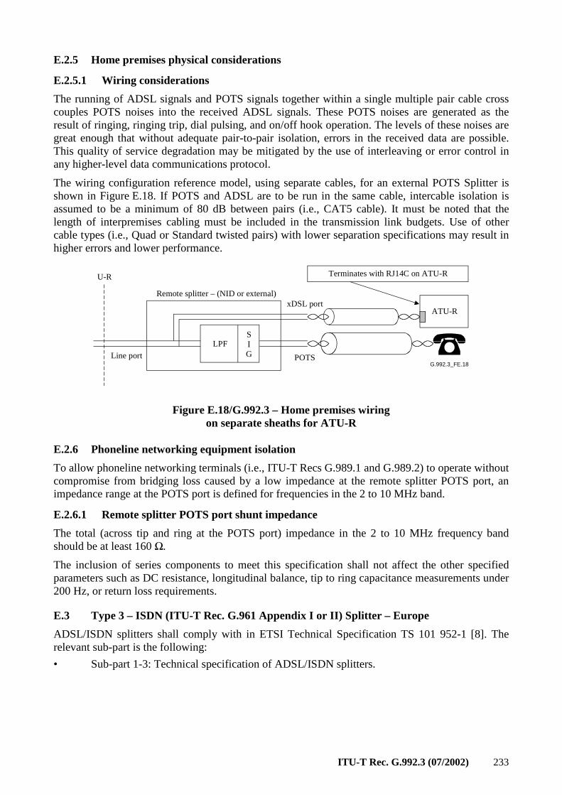
ITU-T Rec. G.992.3 (07/2002) 233
E.2.5 Home premises physical considerations
E.2.5.1 Wiring considerations
The running of ADSL signals and POTS signals together within a single multiple pair cable cross couples POTS noises into the received ADSL signals. These POTS noises are generated as the result of ringing, ringing trip, dial pulsing, and on/off hook operation. The levels of these noises are great enough that without adequate pair-to-pair isolation, errors in the received data are possible. This quality of service degradation may be mitigated by the use of interleaving or error control in any higher-level data communications protocol.
The wiring configuration reference model, using separate cables, for an external POTS Splitter is shown in Figure E.18. If POTS and ADSL are to be run in the same cable, intercable isolation is assumed to be a minimum of 80 dB between pairs (i.e., CAT5 cable). It must be noted that the length of interpremises cabling must be included in the transmission link budgets. Use of other cable types (i.e., Quad or Standard twisted pairs) with lower separation specifications may result in higher errors and lower performance.
G.992.3_FE.18
ATU-R
Terminates with RJ14C on ATU-RU-R
Line port POTS
xDSL port
LPFSIG
Remote splitter – (NID or external)
Figure E.18/G.992.3 – Home premises wiring on separate sheaths for ATU-R
E.2.6 Phoneline networking equipment isolation
To allow phoneline networking terminals (i.e., ITU-T Recs G.989.1 and G.989.2) to operate without compromise from bridging loss caused by a low impedance at the remote splitter POTS port, an impedance range at the POTS port is defined for frequencies in the 2 to 10 MHz band.
E.2.6.1 Remote splitter POTS port shunt impedance
The total (across tip and ring at the POTS port) impedance in the 2 to 10 MHz frequency band should be at least 160 Ω.
The inclusion of series components to meet this specification shall not affect the other specified parameters such as DC resistance, longitudinal balance, tip to ring capacitance measurements under 200 Hz, or return loss requirements.
E.3 Type 3 – ISDN (ITU-T Rec. G.961 Appendix I or II) Splitter – Europe
ADSL/ISDN splitters shall comply with in ETSI Technical Specification TS 101 952-1 [8]. The relevant sub-part is the following:
• Sub-part 1-3: Technical specification of ADSL/ISDN splitters.
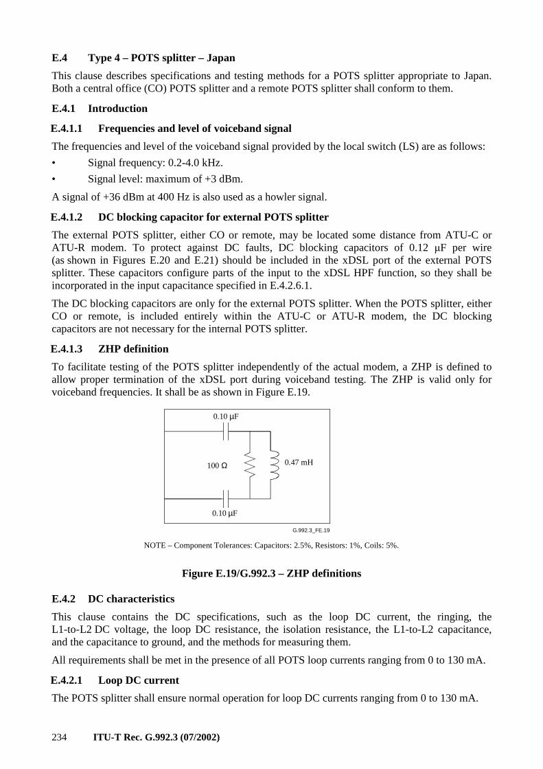
234 ITU-T Rec. G.992.3 (07/2002)
E.4 Type 4 – POTS splitter – Japan
This clause describes specifications and testing methods for a POTS splitter appropriate to Japan. Both a central office (CO) POTS splitter and a remote POTS splitter shall conform to them.
E.4.1 Introduction
E.4.1.1 Frequencies and level of voiceband signal
The frequencies and level of the voiceband signal provided by the local switch (LS) are as follows:
• Signal frequency: 0.2-4.0 kHz.
• Signal level: maximum of +3 dBm.
A signal of +36 dBm at 400 Hz is also used as a howler signal.
E.4.1.2 DC blocking capacitor for external POTS splitter
The external POTS splitter, either CO or remote, may be located some distance from ATU-C or ATU-R modem. To protect against DC faults, DC blocking capacitors of 0.12 µF per wire (as shown in Figures E.20 and E.21) should be included in the xDSL port of the external POTS splitter. These capacitors configure parts of the input to the xDSL HPF function, so they shall be incorporated in the input capacitance specified in E.4.2.6.1.
The DC blocking capacitors are only for the external POTS splitter. When the POTS splitter, either CO or remote, is included entirely within the ATU-C or ATU-R modem, the DC blocking capacitors are not necessary for the internal POTS splitter.
E.4.1.3 ZHP definition
To facilitate testing of the POTS splitter independently of the actual modem, a ZHP is defined to allow proper termination of the xDSL port during voiceband testing. The ZHP is valid only for voiceband frequencies. It shall be as shown in Figure E.19.
G.992.3_FE.19
0.10 µF
0.47 mH
0.10 µF
NOTE – Component Tolerances: Capacitors: 2.5%, Resistors: 1%, Coils: 5%.
100 Ω
Figure E.19/G.992.3 – ZHP definitions
E.4.2 DC characteristics
This clause contains the DC specifications, such as the loop DC current, the ringing, the L1-to-L2 DC voltage, the loop DC resistance, the isolation resistance, the L1-to-L2 capacitance, and the capacitance to ground, and the methods for measuring them.
All requirements shall be met in the presence of all POTS loop currents ranging from 0 to 130 mA.
E.4.2.1 Loop DC current
The POTS splitter shall ensure normal operation for loop DC currents ranging from 0 to 130 mA.
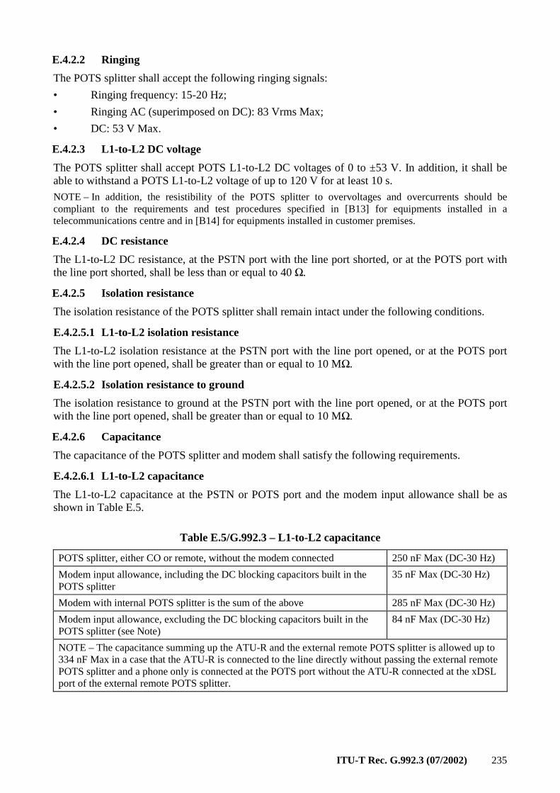
ITU-T Rec. G.992.3 (07/2002) 235
E.4.2.2 Ringing
The POTS splitter shall accept the following ringing signals:
• Ringing frequency: 15-20 Hz;
• Ringing AC (superimposed on DC): 83 Vrms Max;
• DC: 53 V Max.
E.4.2.3 L1-to-L2 DC voltage
The POTS splitter shall accept POTS L1-to-L2 DC voltages of 0 to ±53 V. In addition, it shall be able to withstand a POTS L1-to-L2 voltage of up to 120 V for at least 10 s.
NOTE – In addition, the resistibility of the POTS splitter to overvoltages and overcurrents should be compliant to the requirements and test procedures specified in [B13] for equipments installed in a telecommunications centre and in [B14] for equipments installed in customer premises.
E.4.2.4 DC resistance
The L1-to-L2 DC resistance, at the PSTN port with the line port shorted, or at the POTS port with the line port shorted, shall be less than or equal to 40 Ω.
E.4.2.5 Isolation resistance
The isolation resistance of the POTS splitter shall remain intact under the following conditions.
E.4.2.5.1 L1-to-L2 isolation resistance
The L1-to-L2 isolation resistance at the PSTN port with the line port opened, or at the POTS port with the line port opened, shall be greater than or equal to 10 MΩ.
E.4.2.5.2 Isolation resistance to ground
The isolation resistance to ground at the PSTN port with the line port opened, or at the POTS port with the line port opened, shall be greater than or equal to 10 MΩ.
E.4.2.6 Capacitance
The capacitance of the POTS splitter and modem shall satisfy the following requirements.
E.4.2.6.1 L1-to-L2 capacitance
The L1-to-L2 capacitance at the PSTN or POTS port and the modem input allowance shall be as shown in Table E.5.
Table E.5/G.992.3 – L1-to-L2 capacitance
POTS splitter, either CO or remote, without the modem connected 250 nF Max (DC-30 Hz)
Modem input allowance, including the DC blocking capacitors built in the POTS splitter
35 nF Max (DC-30 Hz)
Modem with internal POTS splitter is the sum of the above 285 nF Max (DC-30 Hz)
Modem input allowance, excluding the DC blocking capacitors built in the POTS splitter (see Note)
84 nF Max (DC-30 Hz)
NOTE – The capacitance summing up the ATU-R and the external remote POTS splitter is allowed up to 334 nF Max in a case that the ATU-R is connected to the line directly without passing the external remote POTS splitter and a phone only is connected at the POTS port without the ATU-R connected at the xDSL port of the external remote POTS splitter.
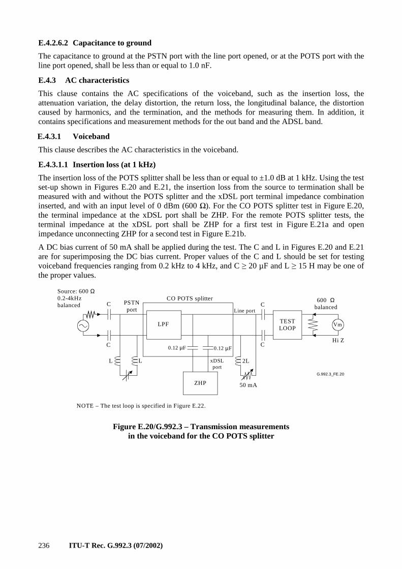
236 ITU-T Rec. G.992.3 (07/2002)
E.4.2.6.2 Capacitance to ground
The capacitance to ground at the PSTN port with the line port opened, or at the POTS port with the line port opened, shall be less than or equal to 1.0 nF.
E.4.3 AC characteristics
This clause contains the AC specifications of the voiceband, such as the insertion loss, the attenuation variation, the delay distortion, the return loss, the longitudinal balance, the distortion caused by harmonics, and the termination, and the methods for measuring them. In addition, it contains specifications and measurement methods for the out band and the ADSL band.
E.4.3.1 Voiceband
This clause describes the AC characteristics in the voiceband.
E.4.3.1.1 Insertion loss (at 1 kHz)
The insertion loss of the POTS splitter shall be less than or equal to ±1.0 dB at 1 kHz. Using the test set-up shown in Figures E.20 and E.21, the insertion loss from the source to termination shall be measured with and without the POTS splitter and the xDSL port terminal impedance combination inserted, and with an input level of 0 dBm (600 Ω). For the CO POTS splitter test in Figure E.20, the terminal impedance at the xDSL port shall be ZHP. For the remote POTS splitter tests, the terminal impedance at the xDSL port shall be ZHP for a first test in Figure E.21a and open impedance unconnecting ZHP for a second test in Figure E.21b.
A DC bias current of 50 mA shall be applied during the test. The C and L in Figures E.20 and E.21 are for superimposing the DC bias current. Proper values of the C and L should be set for testing voiceband frequencies ranging from 0.2 kHz to 4 kHz, and C ≥ 20 µF and L ≥ 15 H may be one of the proper values.
G.992.3_FE.20
Vm
Line port
Hi Z
LPF
ZHP
L L 2L
C
C
C
C
50 mA
Source: 600 Ω 0.2-4kHzbalanced PSTN
port
CO POTS splitter
0.12 µF 0.12 µF
xDSLport
TESTLOOP
600 Ωbalanced
NOTE – The test loop is specified in Figure E.22.
Figure E.20/G.992.3 – Transmission measurements in the voiceband for the CO POTS splitter
ITU-T Rec. G.992.3 (07/2002) 237
G.992.3_FE.21
Vm
Line port
Hi Z
LPF
ZHP
L L 2L
C
C
C
C
50 mA
Source: 600 Ω0.2-4kHzbalancedPOTS
port
Remote POTS splitter
0.12 µF 0.12 µF
xDSLport
TESTLOOP
600 Ωbalanced
a) First test
G.992.3_FE.21.1
Vm
Line port
Hi Z
LPF
Open
L L 2L
C
C
C
C
50 mA
Source: 600 Ω0.2-4kHzbalancedPOTS
port
Remote POTS splitter
0.12 µF 0.12 µF
xDSLport
TESTLOOP
600 Ωbalanced
NOTE – The test loop is specified in Figure E.22.
b) Second test
Figure E.21/G.992.3 – Transmission measurements in the voiceband for the Remote POTS splitter
G.992.3_FE.22
140 Ω 140 Ω
140 Ω 140 Ω
100 nF
NOTE – This test loop model is valid only for voiceband frequencies.
Figure E.22/G.992.3 – Test loop definition
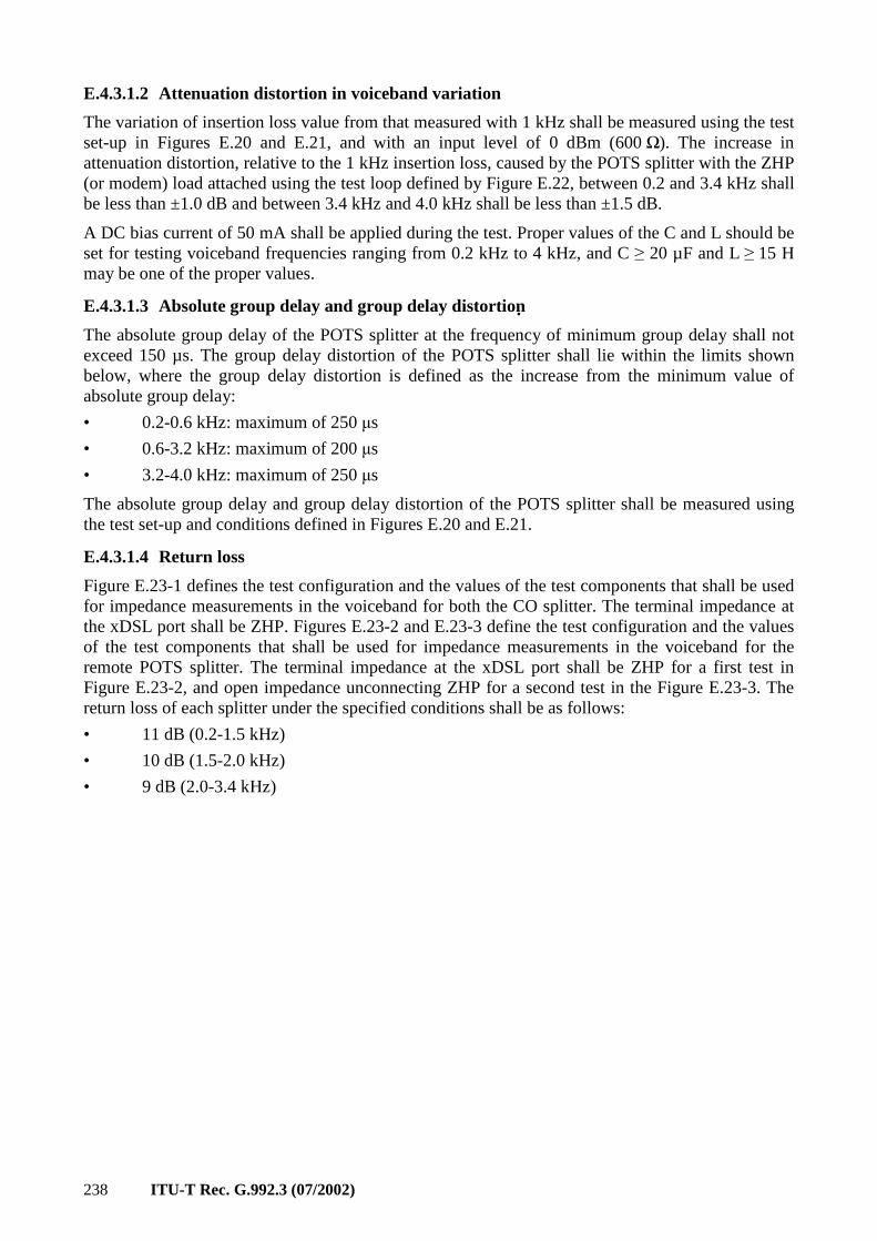
238 ITU-T Rec. G.992.3 (07/2002)
E.4.3.1.2 Attenuation distortion in voiceband variation
The variation of insertion loss value from that measured with 1 kHz shall be measured using the test set-up in Figures E.20 and E.21, and with an input level of 0 dBm (600 Ω). The increase in attenuation distortion, relative to the 1 kHz insertion loss, caused by the POTS splitter with the ZHP (or modem) load attached using the test loop defined by Figure E.22, between 0.2 and 3.4 kHz shall be less than ±1.0 dB and between 3.4 kHz and 4.0 kHz shall be less than ±1.5 dB.
A DC bias current of 50 mA shall be applied during the test. Proper values of the C and L should be set for testing voiceband frequencies ranging from 0.2 kHz to 4 kHz, and C ≥ 20 µF and L ≥ 15 H may be one of the proper values.
E.4.3.1.3 Absolute group delay and group delay distortion
The absolute group delay of the POTS splitter at the frequency of minimum group delay shall not exceed 150 µs. The group delay distortion of the POTS splitter shall lie within the limits shown below, where the group delay distortion is defined as the increase from the minimum value of absolute group delay:
• 0.2-0.6 kHz: maximum of 250 µs
• 0.6-3.2 kHz: maximum of 200 µs
• 3.2-4.0 kHz: maximum of 250 µs
The absolute group delay and group delay distortion of the POTS splitter shall be measured using the test set-up and conditions defined in Figures E.20 and E.21.
E.4.3.1.4 Return loss
Figure E.23-1 defines the test configuration and the values of the test components that shall be used for impedance measurements in the voiceband for both the CO splitter. The terminal impedance at the xDSL port shall be ZHP. Figures E.23-2 and E.23-3 define the test configuration and the values of the test components that shall be used for impedance measurements in the voiceband for the remote POTS splitter. The terminal impedance at the xDSL port shall be ZHP for a first test in Figure E.23-2, and open impedance unconnecting ZHP for a second test in the Figure E.23-3. The return loss of each splitter under the specified conditions shall be as follows:
• 11 dB (0.2-1.5 kHz)
• 10 dB (1.5-2.0 kHz)
• 9 dB (2.0-3.4 kHz)
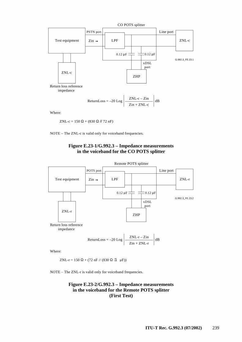
ITU-T Rec. G.992.3 (07/2002) 239
G.992.3_FE.23.1
LPF
ZHP
0.12 µF
ZNL-c
PSTN port Line port
Test equipment Zin →→→→
CO POTS splitter
ZNL-c
xDSL port
0.12 µF
Return loss reference impedance
ZNL-c – ZindB
ReturnLoss = –20 Log
Zin + ZNL-c
NOTE – The ZNL-c is valid only for voiceband frequencies.
Where:
ZNL-c = 150 Ω + (830 Ω // 72 nF)
Figure E.23-1/G.992.3 – Impedance measurements in the voiceband for the CO POTS splitter
G.992.3_FE.23.2
LPF
ZHP
0.12 µF
ZNL-r
POTS port Line port
Test equipment Zin →→→→
Remote POTS splitter
ZNL-r
xDSL port
0.12 µF
Return loss reference impedance
ZNL-r – ZindB
ReturnLoss = –20 Log
Zin + ZNL-r
NOTE – The ZNL-r is valid only for voiceband frequencies.
Where:
ZNL-r = 150 Ω + (72 nF // (830 Ω + 1 µF))
Figure E.23-2/G.992.3 – Impedance measurements in the voiceband for the Remote POTS splitter
(First Test)
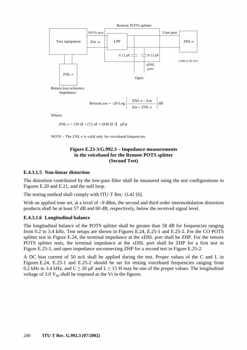
240 ITU-T Rec. G.992.3 (07/2002)
G.992.3_FE.23.3
LPF
Open
0.12 µF
ZNL-r
POTS port Line port
Test equipment Zin →→→→
Remote POTS splitter
ZNL-r
xDSL port
0.12 µF
Return loss reference impedance
ZNL-r – ZindB
ReturnLoss = –20 Log
Zin + ZNL-r
NOTE – The ZNL-r is valid only for voiceband frequencies.
Where:
ZNL-r = 150 Ω + (72 nF // (830 Ω + 1 µF))
Figure E.23-3/G.992.3 – Impedance measurements in the voiceband for the Remote POTS splitter
(Second Test)
E.4.3.1.5 Non-linear distortion
The distortion contributed by the low-pass filter shall be measured using the test configurations in Figures E.20 and E.21, and the null loop.
The testing method shall comply with ITU-T Rec. O.42 [6].
With an applied tone set, at a level of –9 dBm, the second and third order intermodulation distortion products shall be at least 57 dB and 60 dB, respectively, below the received signal level.
E.4.3.1.6 Longitudinal balance
The longitudinal balance of the POTS splitter shall be greater than 58 dB for frequencies ranging from 0.2 to 3.4 kHz. Test setups are shown in Figures E.24, E.25-1 and E.25-2. For the CO POTS splitter test in Figure E.24, the terminal impedance at the xDSL port shall be ZHP. For the remote POTS splitter tests, the terminal impedance at the xDSL port shall be ZHP for a first test in Figure E.25-1, and open impedance unconnecting ZHP for a second test in Figure E.25-2.
A DC bias current of 50 mA shall be applied during the test. Proper values of the C and L in Figures E.24, E.25-1 and E.25-2 should be set for testing voiceband frequencies ranging from 0.2 kHz to 3.4 kHz, and C ≥ 20 µF and L ≥ 15 H may be one of the proper values. The longitudinal voltage of 3.0 Vpp shall be imposed as the Vt in the figures.
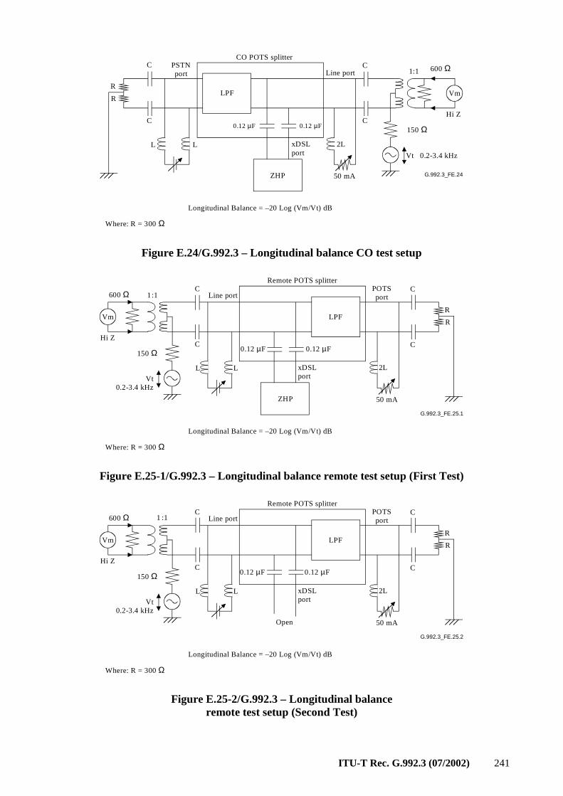
ITU-T Rec. G.992.3 (07/2002) 241
G.992.3_FE.24
Line port
L L 2L
C
C
R
R
Vt 0.2-3.4 kHz
Hi Z
50 mA
1
LPF
ZHP
CO POTS splitterC
C
PSTNport
600 Ω
150 Ω
Vm
xDSLport
:1
0.12 µF 0.12 µF
Longitudinal Balance = –20 Log (Vm/Vt) dB
Where: R = 300 Ω
Figure E.24/G.992.3 – Longitudinal balance CO test setup
G.992.3_FE.25.1
Line port
L L 2L
C
C
R
R
Vt0.2-3.4 kHz
Hi Z
50 mA
1
LPF
ZHP
Remote POTS splitterC
C
POTSport600 Ω
150 Ω
Vm
xDSLport
:1
0.12 µF 0.12 µF
Longitudinal Balance = –20 Log (Vm/Vt) dB
Where: R = 300 Ω
Figure E.25-1/G.992.3 – Longitudinal balance remote test setup (First Test)
G.992.3_FE.25.2
Line port
L L 2L
C
C
R
R
Vt0.2-3.4 kHz
Hi Z
50 mA
1
LPF
Open
Remote POTS splitterC
C
POTSport600 Ω
150 Ω
Vm
xDSLport
:1
0.12 µF 0.12 µF
Longitudinal Balance = –20 Log (Vm/Vt) dB
Where: R = 300 Ω
Figure E.25-2/G.992.3 – Longitudinal balance remote test setup (Second Test)
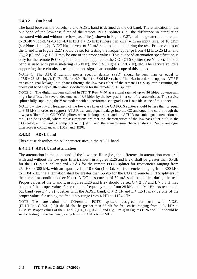
242 ITU-T Rec. G.992.3 (07/2002)
E.4.3.2 Out band
The band between the voiceband and ADSL band is defined as the out band. The attenuation in the out band of the low-pass filter of the remote POTS splitter (i.e., the difference in attenuation measured with and without the low-pass filter), shown in Figure E.27, shall be greater than or equal to 26.48 × log2(f/4) dB for 4.0 kHz ≤ f < 25 kHz (where f in kHz) with an input level of 10 dBm (see Notes 1 and 2). A DC bias current of 50 mA shall be applied during the test. Proper values of the C and L in Figure E.27 should be set for testing the frequency range from 4 kHz to 25 kHz, and C ≥ 2 µF and L ≥ 1.5 H may be one of the proper values. This out band attenuation specification is only for the remote POTS splitter, and is not applied to the CO POTS splitter (see Note 3). The out band is used with pulse metering (16 kHz), and OVS signals (7.8 kHz), etc. The service splitters supporting these circuits as using out band signals are outside scope of this annex.
NOTE 1 – The ATU-R transmit power spectral density (PSD) should be less than or equal to –97.5 + 26.48 × log2(f/4) dBm/Hz for 4.0 kHz ≤ f < 8.06 kHz (where f in kHz) in order to suppress ATU-R transmit signal leakage into phones through the low-pass filter of the remote POTS splitter, assuming the above out band sloped attenuation specification for the remote POTS splitter.
NOTE 2 – The digital modem defined in ITU-T Rec. V.90 at a signal rates of up to 56 kbit/s downstream might be affected in several decrements of 8/6 kbit/s by the low-pass filter cut-off characteristics. The service splitter fully supporting the V.90 modem with no performance degradation is outside scope of this annex.
NOTE 3 – The cut-off frequency of the low-pass filter of the CO POTS splitter should be less than or equal to 8.58 kHz in order to suppress ATU-R transmit signal leakage into the CO analogue line card through the low-pass filter of the CO POTS splitter, when the loop is short and the ATU-R transmit signal attenuation on the CO side is small, where the assumptions are that the characteristics of the low-pass filter built in the CO analogue line card is compliant with [B18], and the transmission characteristics at 2-wire analogue interfaces is compliant with [B19] and [B20].
E.4.3.3 ADSL band
This clause describes the AC characteristics in the ADSL band.
E.4.3.3.1 ADSL band attenuation
The attenuation in the stop band of the low-pass filter (i.e., the difference in attenuation measured with and without the low-pass filter), shown in Figures E.26 and E.27, shall be greater than 65 dB for the CO POTS splitter and 70 dB for the remote POTS splitter for frequencies ranging from 25 kHz to 300 kHz with an input level of 10 dBm (100 Ω). For frequencies ranging from 300 kHz to 1104 kHz, the attenuation shall be greater than 55 dB for the CO and remote POTS splitters in the same test conditions (see Note). A DC bias current of 50 mA shall be applied during the test. Proper values of the C and L in Figures E.26 and E.27 should be set. C ≥ 2 µF and L ≥ 0.5 H may be one of the proper values for testing the frequency range from 25 kHz to 1104 kHz. As testing the out band (see E.4.3.2) together with the ADSL band, C ≥ 2 µF and L ≥ 1.5 H may be one of the proper values for testing the frequency range from 4 kHz to 1104 kHz.
NOTE – The attenuation of CO/remote POTS splitters designed for use with VDSL (ITU-T Rec. G.993.1 [13]) should also be greater than 55 dB for frequencies ranging from 1104 kHz to 12 MHz. Proper values of the C and L (e.g., C ≥ 0.2 µF and L ≥ 5 mH) in Figures E.26 and E.27 should be set for testing in the frequency range from 1104 kHz to 12 MHz.
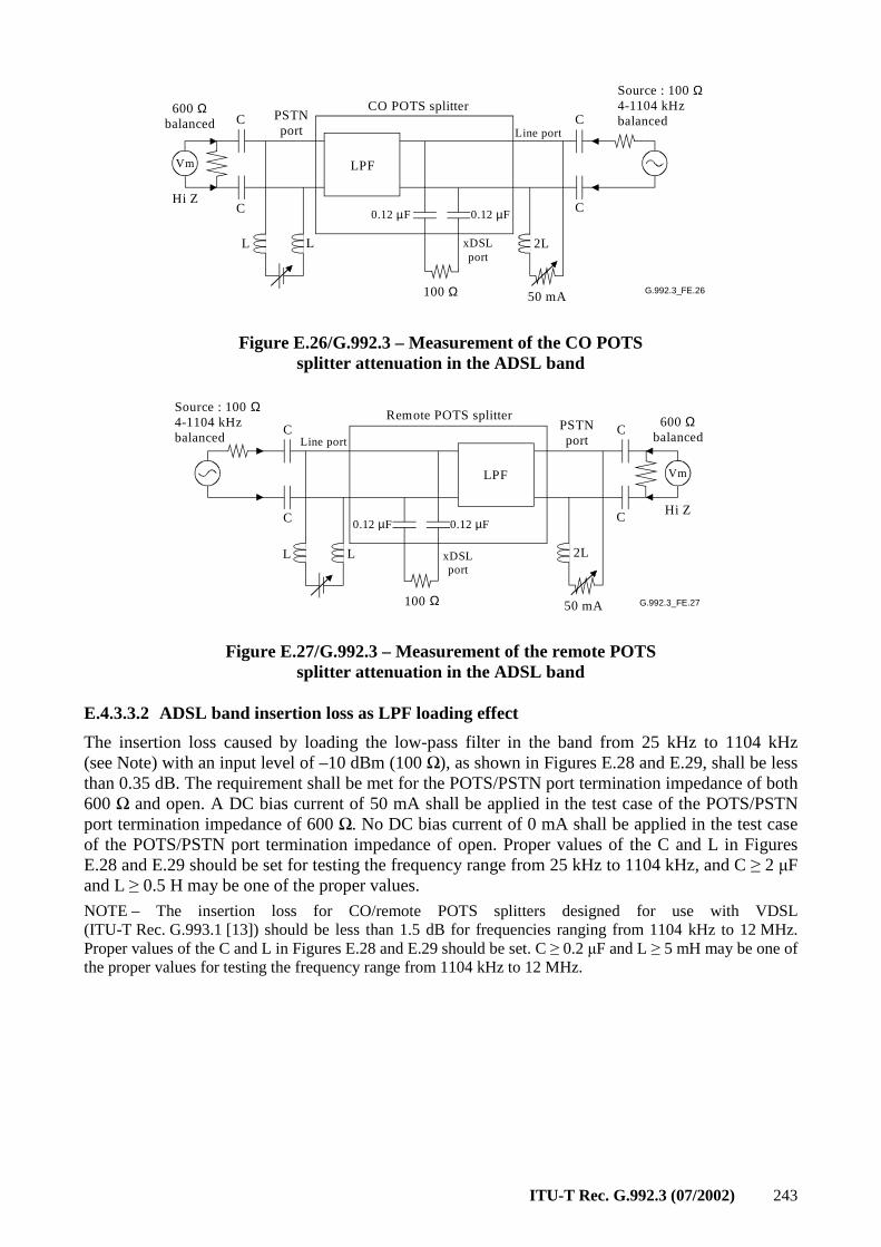
ITU-T Rec. G.992.3 (07/2002) 243
G.992.3_FE.26
Line port
LPF
100 Ω
L L 2L
C
C
C
C
50 mA
Source : 100 Ω4-1104 kHzbalancedPSTN
port
CO POTS splitter
0.12 µF 0.12 µF
xDSLport
600 Ωbalanced
Hi Z
Vm
Figure E.26/G.992.3 – Measurement of the CO POTS splitter attenuation in the ADSL band
G.992.3_FE.27
Line port
LPF
100 Ω
L L 2L
C
C
C
C
50 mA
Source : 100 Ω4-1104 kHzbalanced
PSTNport
Remote POTS splitter
0.12 µF 0.12 µF
xDSLport
600 Ωbalanced
Hi Z
Vm
Figure E.27/G.992.3 – Measurement of the remote POTS splitter attenuation in the ADSL band
E.4.3.3.2 ADSL band insertion loss as LPF loading effect
The insertion loss caused by loading the low-pass filter in the band from 25 kHz to 1104 kHz (see Note) with an input level of –10 dBm (100 Ω), as shown in Figures E.28 and E.29, shall be less than 0.35 dB. The requirement shall be met for the POTS/PSTN port termination impedance of both 600 Ω and open. A DC bias current of 50 mA shall be applied in the test case of the POTS/PSTN port termination impedance of 600 Ω. No DC bias current of 0 mA shall be applied in the test case of the POTS/PSTN port termination impedance of open. Proper values of the C and L in Figures E.28 and E.29 should be set for testing the frequency range from 25 kHz to 1104 kHz, and C ≥ 2 µF and L ≥ 0.5 H may be one of the proper values.
NOTE – The insertion loss for CO/remote POTS splitters designed for use with VDSL (ITU-T Rec. G.993.1 [13]) should be less than 1.5 dB for frequencies ranging from 1104 kHz to 12 MHz. Proper values of the C and L in Figures E.28 and E.29 should be set. C ≥ 0.2 µF and L ≥ 5 mH may be one of the proper values for testing the frequency range from 1104 kHz to 12 MHz.
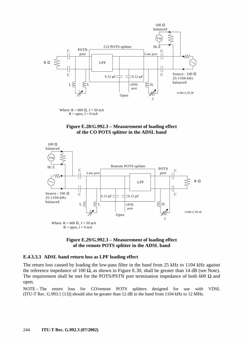
244 ITU-T Rec. G.992.3 (07/2002)
G.992.3_FE.28
Line port
LPF
Open
L L 2L
C
C
C
C
J
Source : 100 Ω25-1104 kHzbalanced
PSTNport
CO POTS splitter
0.12 µF 0.12 µF
xDSLport
100 Ωbalanced
Hi Z
Vm
R = open, J = 0 mA
R Ω
Where: R = 600 Ω, J = 50 mA
Figure E.28/G.992.3 – Measurement of loading effect of the CO POTS splitter in the ADSL band
G.992.3_FE.29
Line port
LPF
Open
L L 2L
C
C
C
C
J
Source : 100 Ω25-1104 kHzbalanced
POTSport
Remote POTS splitter
0.12 µF 0.12 µF
xDSLport
100 Ωbalanced
Hi Z
Vm
Where: R = 600 Ω, J = 50 mA R = open, J = 0 mA
R Ω
Figure E.29/G.992.3 – Measurement of loading effect of the remote POTS splitter in the ADSL band
E.4.3.3.3 ADSL band return loss as LPF loading effect
The return loss caused by loading the low-pass filter in the band from 25 kHz to 1104 kHz against the reference impedance of 100 Ω, as shown in Figure E.30, shall be greater than 14 dB (see Note). The requirement shall be met for the POTS/PSTN port termination impedance of both 600 Ω and open.
NOTE – The return loss for CO/remote POTS splitters designed for use with VDSL (ITU-T Rec. G.993.1 [13]) should also be greater than 12 dB in the band from 1104 kHz to 12 MHz.
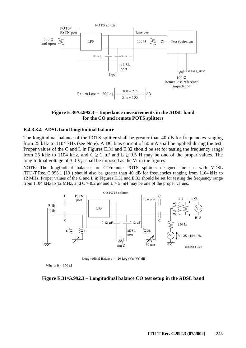
ITU-T Rec. G.992.3 (07/2002) 245
G.992.3_FE.30
Line port
LPF
POTS splitter
0.12 µF0.12 µF
100 ΩReturn loss reference
impedance
Test equipment100 Ω600 Ωand open
POTS/PSTN port
← Zin
Open
100 – Zin
dB
Return Loss = –20 LogZin + 100
xDSLport
Figure E.30/G.992.3 – Impedance measurements in the ADSL band for the CO and remote POTS splitters
E.4.3.3.4 ADSL band longitudinal balance
The longitudinal balance of the POTS splitter shall be greater than 40 dB for frequencies ranging from 25 kHz to 1104 kHz (see Note). A DC bias current of 50 mA shall be applied during the test. Proper values of the C and L in Figures E.31 and E.32 should be set for testing the frequency range from 25 kHz to 1104 kHz, and C ≥ 2 µF and L ≥ 0.5 H may be one of the proper values. The longitudinal voltage of 3.0 Vpp shall be imposed as the Vt in the figures.
NOTE – The longitudinal balance for CO/remote POTS splitters designed for use with VDSL (ITU-T Rec. G.993.1 [13]) should also be greater than 40 dB for frequencies ranging from 1104 kHz to 12 MHz. Proper values of the C and L in Figures E.31 and E.32 should be set for testing the frequency range from 1104 kHz to 12 MHz, and C ≥ 0.2 µF and L ≥ 5 mH may be one of the proper values.
G.992.3_FE.31
Line port
L L 2L
C
C
R
R
Vt 25-1104 kHz
Hi Z
50 mA
1
LPF
100 Ω
CO POTS splitterC
C
PSTNport 100 Ω
150 Ω
Vm
xDSLport
:1
0.12 µF 0.12 µF
Longitudinal Balance = –20 Log (Vm/Vt) dB
Where: R = 300 Ω
Figure E.31/G.992.3 – Longitudinal balance CO test setup in the ADSL band
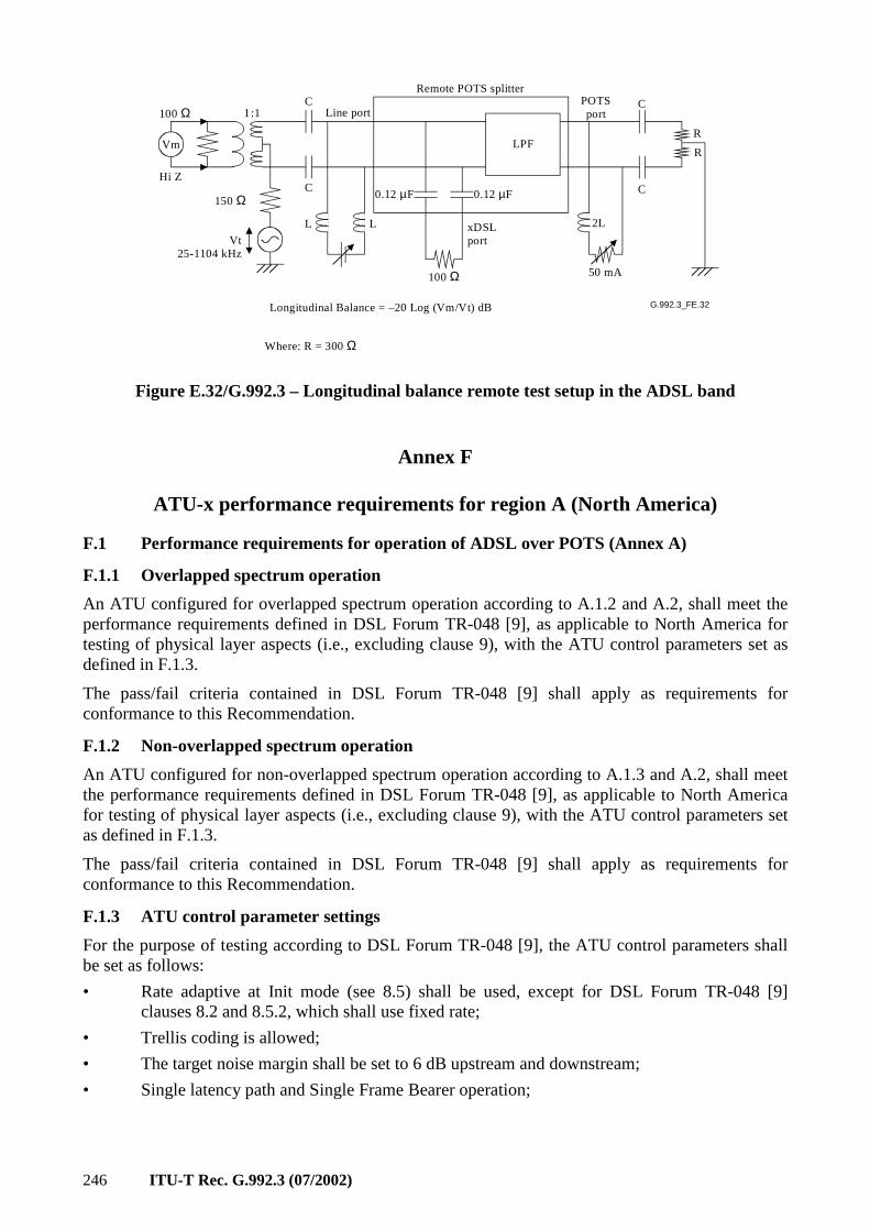
246 ITU-T Rec. G.992.3 (07/2002)
G.992.3_FE.32
Line port
L L 2L
C
C
R
R
Vt25-1104 kHz
Hi Z
50 mA
1
LPF
100 Ω
Remote POTS splitterC
C
POTSport
150 Ω
Vm
xDSLport
:1
0.12 µF 0.12 µF
Longitudinal Balance = –20 Log (Vm/Vt) dB
Where: R = 300 Ω
100 Ω
Figure E.32/G.992.3 – Longitudinal balance remote test setup in the ADSL band
Annex F
ATU-x performance requirements for region A (North America)
F.1 Performance requirements for operation of ADSL over POTS (Annex A)
F.1.1 Overlapped spectrum operation
An ATU configured for overlapped spectrum operation according to A.1.2 and A.2, shall meet the performance requirements defined in DSL Forum TR-048 [9], as applicable to North America for testing of physical layer aspects (i.e., excluding clause 9), with the ATU control parameters set as defined in F.1.3.
The pass/fail criteria contained in DSL Forum TR-048 [9] shall apply as requirements for conformance to this Recommendation.
F.1.2 Non-overlapped spectrum operation
An ATU configured for non-overlapped spectrum operation according to A.1.3 and A.2, shall meet the performance requirements defined in DSL Forum TR-048 [9], as applicable to North America for testing of physical layer aspects (i.e., excluding clause 9), with the ATU control parameters set as defined in F.1.3.
The pass/fail criteria contained in DSL Forum TR-048 [9] shall apply as requirements for conformance to this Recommendation.
F.1.3 ATU control parameter settings
For the purpose of testing according to DSL Forum TR-048 [9], the ATU control parameters shall be set as follows:
• Rate adaptive at Init mode (see 8.5) shall be used, except for DSL Forum TR-048 [9] clauses 8.2 and 8.5.2, which shall use fixed rate;
• Trellis coding is allowed;
• The target noise margin shall be set to 6 dB upstream and downstream;
• Single latency path and Single Frame Bearer operation;
ITU-T Rec. G.992.3 (07/2002) 247
• Framing message based overhead data rate shall be set to MSGmin = 6 kbit/s;
• Fast Mode shall be tested with a nominal one-way maximum payload transfer delay ≤ 4 ms;
• Interleaved Mode shall be tested with a nominal one-way maximum payload transfer delay ≤ 20 ms;
• The minimum noise margin shall be set to 0 dB;
• No limitation of maximum noise margin (set to at least 30 dB);
• For testing of operation in the presence of Impulse Noise events (DSL Forum TR-048 [9] clause 8.8), the ATU shall be configured in interleaved mode.
The nominal one-way maximum payload transfer delay is defined in 5.2.
F.2 Performance requirements for operation of All Digital Mode ADSL (Annex I)
F.2.1 Overlapped spectrum operation
An ATU configured for overlapped spectrum operation according to I.1.2 and I.2, shall meet at least the performance requirements for overlapped spectrum operation of ADSL over POTS, as defined in F.1.1.
The exact definition of the performance requirements is for further study.
F.2.2 Non-overlapped spectrum operation
An ATU configured for non-overlapped spectrum operation according to I.1.3 and I.2, shall meet at least the performance requirements for non-overlapped spectrum operation of ADSL over POTS, as defined in F.1.2.
The exact definition of the performance requirements is for further study.
Annex G
ATU-x performance requirements for region B (Europe)
G.1 Performance requirements for operation of ADSL over POTS (Annex A)
G.1.1 Overlapped spectrum operation
An ATU configured for overlapped spectrum operation according to A.1.2 and A.2, shall meet the performance requirements defined in ETSI TS 101 388 [10], Chapter 5, Transmission performance objectives and test methods, as applicable to EC ADSL over POTS.
G.1.2 Non-overlapped spectrum operation
An ATU configured for non-overlapped spectrum operation according to A.1.3 and A.2, shall meet the performance requirements defined in ETSI TS 101 388 [10], Chapter 5, Transmission performance objectives and test methods, as applicable to FDD ADSL over POTS.
G.2 Performance requirements for operation of ADSL over ISDN (Annex B)
G.2.1 Overlapped spectrum operation
An ATU configured for overlapped spectrum operation according to B.1.2 and B.2, shall meet the performance requirements defined in ETSI TS 101 388 [10], Chapter 5, Transmission performance objectives and test methods, as applicable to EC ADSL over ISDN.
248 ITU-T Rec. G.992.3 (07/2002)
G.2.2 Non-overlapped spectrum operation
An ATU configured for non-overlapped spectrum operation according to B.1.3 and B.2, shall meet the performance requirements defined in ETSI TS 101 388 [10], Chapter 5, Transmission performance objectives and test methods, as applicable to FDD ADSL over ISDN.
G.3 Performance requirements for operation of All Digital Mode ADSL (Annex I)
G.3.1 Overlapped spectrum operation
An ATU configured for overlapped spectrum operation according to I.1.2 and I.2, shall meet at least the performance requirements for overlapped spectrum operation of ADSL over POTS, as defined in G.1.1.
The exact definition of the performance requirements is for further study.
G.3.2 Non-overlapped spectrum operation
An ATU configured for non-overlapped spectrum operation according to I.1.3 and I.2, shall meet at least the performance requirements for non-overlapped spectrum operation of ADSL over POTS, as defined in G.1.2.
The exact definition of the performance requirements is for further study.
G.4 Performance requirements for operation of All Digital Mode ADSL (Annex J)
G.4.1 Overlapped spectrum operation
An ATU configured for overlapped spectrum operation according to J.1.2 and J.2, shall meet at least the performance requirements for overlapped spectrum operation of ADSL over ISDN, as defined in G.2.1.
The exact definition of the performance requirements is for further study.
G.4.2 Non-overlapped spectrum operation
An ATU configured for non-overlapped spectrum operation according to J.1.3 and J.2, shall meet at least the performance requirements for non-overlapped spectrum operation of ADSL over ISDN, as defined in G.2.2.
The exact definition of the performance requirements is for further study.
Annex H
Specific requirements for a synchronized symmetrical DSL (SSDSL) system operating in the same cable binder as ISDN as defined
in ITU-T Rec. G.961 Appendix III
For further study.
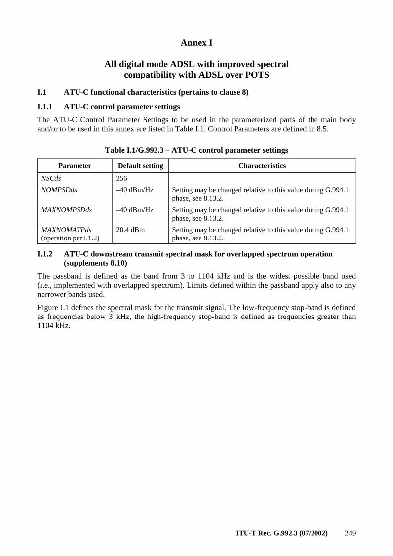
ITU-T Rec. G.992.3 (07/2002) 249
Annex I
All digital mode ADSL with improved spectral compatibility with ADSL over POTS
I.1 ATU-C functional characteristics (pertains to clause 8)
I.1.1 ATU-C control parameter settings
The ATU-C Control Parameter Settings to be used in the parameterized parts of the main body and/or to be used in this annex are listed in Table I.1. Control Parameters are defined in 8.5.
Table I.1/G.992.3 – ATU-C control parameter settings
Parameter Default setting Characteristics
NSCds 256
NOMPSDds –40 dBm/Hz Setting may be changed relative to this value during G.994.1 phase, see 8.13.2.
MAXNOMPSDds –40 dBm/Hz Setting may be changed relative to this value during G.994.1 phase, see 8.13.2.
MAXNOMATPds (operation per I.1.2)
20.4 dBm Setting may be changed relative to this value during G.994.1 phase, see 8.13.2.
I.1.2 ATU-C downstream transmit spectral mask for overlapped spectrum operation (supplements 8.10)
The passband is defined as the band from 3 to 1104 kHz and is the widest possible band used (i.e., implemented with overlapped spectrum). Limits defined within the passband apply also to any narrower bands used.
Figure I.1 defines the spectral mask for the transmit signal. The low-frequency stop-band is defined as frequencies below 3 kHz, the high-frequency stop-band is defined as frequencies greater than 1104 kHz.
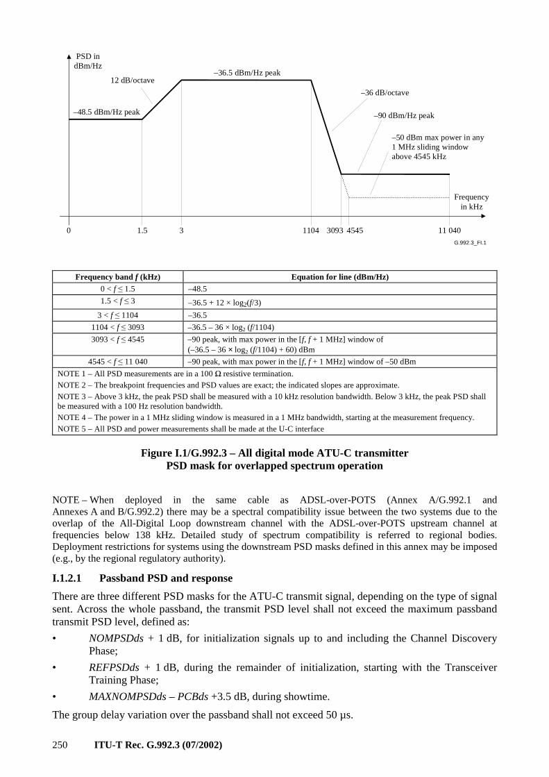
250 ITU-T Rec. G.992.3 (07/2002)
G.992.3_FI.1
PSD indBm/Hz
–48.5 dBm/Hz peak
–36.5 dBm/Hz peak
–36 dB/octave
–90 dBm/Hz peak
–50 dBm max power in any1 MHz sliding windowabove 4545 kHz
1.5 1104 3093 4545 11 040
Frequencyin kHz
0 3
12 dB/octave
Frequency band f (kHz) Equation for line (dBm/Hz)
0 < f ≤ 1.5 –48.5
1.5 < f ≤ 3 –36.5 + 12 × log2(f/3)
3 < f ≤ 1104 –36.5
1104 < f ≤ 3093 –36.5 – 36 × log2 (f/1104)
3093 < f ≤ 4545 –90 peak, with max power in the [f, f + 1 MHz] window of (–36.5 – 36 × log2 (f/1104) + 60) dBm
4545 < f ≤ 11 040 –90 peak, with max power in the [f, f + 1 MHz] window of –50 dBm
NOTE 1 – All PSD measurements are in a 100 Ω resistive termination. NOTE 2 – The breakpoint frequencies and PSD values are exact; the indicated slopes are approximate. NOTE 3 – Above 3 kHz, the peak PSD shall be measured with a 10 kHz resolution bandwidth. Below 3 kHz, the peak PSD shall be measured with a 100 Hz resolution bandwidth. NOTE 4 – The power in a 1 MHz sliding window is measured in a 1 MHz bandwidth, starting at the measurement frequency. NOTE 5 – All PSD and power measurements shall be made at the U-C interface
Figure I.1/G.992.3 – All digital mode ATU-C transmitter PSD mask for overlapped spectrum operation
NOTE – When deployed in the same cable as ADSL-over-POTS (Annex A/G.992.1 and Annexes A and B/G.992.2) there may be a spectral compatibility issue between the two systems due to the overlap of the All-Digital Loop downstream channel with the ADSL-over-POTS upstream channel at frequencies below 138 kHz. Detailed study of spectrum compatibility is referred to regional bodies. Deployment restrictions for systems using the downstream PSD masks defined in this annex may be imposed (e.g., by the regional regulatory authority).
I.1.2.1 Passband PSD and response
There are three different PSD masks for the ATU-C transmit signal, depending on the type of signal sent. Across the whole passband, the transmit PSD level shall not exceed the maximum passband transmit PSD level, defined as:
• NOMPSDds + 1 dB, for initialization signals up to and including the Channel Discovery Phase;
• REFPSDds + 1 dB, during the remainder of initialization, starting with the Transceiver Training Phase;
• MAXNOMPSDds – PCBds +3.5 dB, during showtime.
The group delay variation over the passband shall not exceed 50 µs.
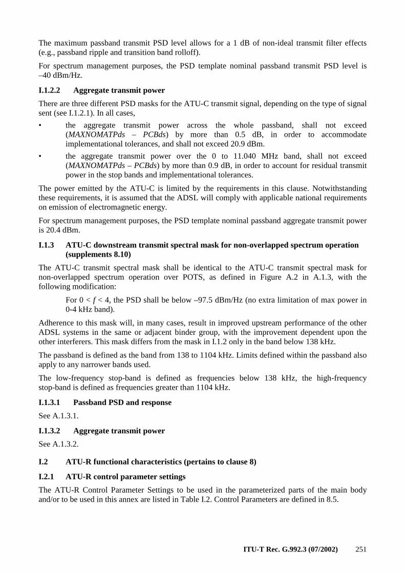
ITU-T Rec. G.992.3 (07/2002) 251
The maximum passband transmit PSD level allows for a 1 dB of non-ideal transmit filter effects (e.g., passband ripple and transition band rolloff).
For spectrum management purposes, the PSD template nominal passband transmit PSD level is –40 dBm/Hz.
I.1.2.2 Aggregate transmit power
There are three different PSD masks for the ATU-C transmit signal, depending on the type of signal sent (see I.1.2.1). In all cases,
• the aggregate transmit power across the whole passband, shall not exceed (MAXNOMATPds – PCBds) by more than 0.5 dB, in order to accommodate implementational tolerances, and shall not exceed 20.9 dBm.
• the aggregate transmit power over the 0 to 11.040 MHz band, shall not exceed (MAXNOMATPds – PCBds) by more than 0.9 dB, in order to account for residual transmit power in the stop bands and implementational tolerances.
The power emitted by the ATU-C is limited by the requirements in this clause. Notwithstanding these requirements, it is assumed that the ADSL will comply with applicable national requirements on emission of electromagnetic energy.
For spectrum management purposes, the PSD template nominal passband aggregate transmit power is 20.4 dBm.
I.1.3 ATU-C downstream transmit spectral mask for non-overlapped spectrum operation (supplements 8.10)
The ATU-C transmit spectral mask shall be identical to the ATU-C transmit spectral mask for non-overlapped spectrum operation over POTS, as defined in Figure A.2 in A.1.3, with the following modification:
For 0 < f < 4, the PSD shall be below –97.5 dBm/Hz (no extra limitation of max power in 0-4 kHz band).
Adherence to this mask will, in many cases, result in improved upstream performance of the other ADSL systems in the same or adjacent binder group, with the improvement dependent upon the other interferers. This mask differs from the mask in I.1.2 only in the band below 138 kHz.
The passband is defined as the band from 138 to 1104 kHz. Limits defined within the passband also apply to any narrower bands used.
The low-frequency stop-band is defined as frequencies below 138 kHz, the high-frequency stop-band is defined as frequencies greater than 1104 kHz.
I.1.3.1 Passband PSD and response
See A.1.3.1.
I.1.3.2 Aggregate transmit power
See A.1.3.2.
I.2 ATU-R functional characteristics (pertains to clause 8)
I.2.1 ATU-R control parameter settings
The ATU-R Control Parameter Settings to be used in the parameterized parts of the main body and/or to be used in this annex are listed in Table I.2. Control Parameters are defined in 8.5.
252 ITU-T Rec. G.992.3 (07/2002)
Table I.2/G.992.3 – ATU-R control parameter settings
Parameter Default Setting Characteristics
NSCus 32
NOMPSDus –38 dBm/Hz Setting may be changed relative to this value during G.994.1 phase, see 8.13.2.
MAXNOMPSDus –38 dBm/Hz Setting may be changed relative to this value during G.994.1 phase, see 8.13.2.
MAXNOMATPus 13.3 dBm Setting may be changed relative to this value during G.994.1 phase, see 8.13.2.
I.2.2 ATU-R upstream transmit spectral mask (supplements 8.10)
The passband is defined as the band from 3 to 138 kHz and is the widest possible band used. Limits defined within the passband apply also to any narrower bands used.
Figure I.2 defines the spectral mask for the transmit signal. The low-frequency stop-band is defined as frequencies below 3 kHz, the high-frequency stop-band is defined as frequencies greater than 138 kHz.
G.992.3_FI.2
PSD (dB)
–46.5 dBm/Hz peak
–34.5 dBm/Hz peak
–48 dB/octave
–90 dBm/Hz peak
–50 dBm max power in any1 MHz sliding windowabove 1630 kHz
1.5 138 307 1221 11 040
Frequency(kHz)
0 3
12 dB/octave
1630
Frequency band f (kHz) Equation for line (dBm/Hz)
0 < f ≤ 1.5 –46.5
1.5 < f ≤ 3 –34.5 + 12 × log2(f/3)
3 < f ≤ 138 –34.5
138 < f ≤ 307 –34.5 – 48 × log2(f/138)
307 < f ≤ 1221 –90 peak, with max power in the [f, f + 100 kHz] window of –42.5 dBm
1221 < f ≤ 1630 –90 peak, with max power in the [f, f + 1 MHz] window of (–90 – 48 × log2(f/1221) + 60) dBm
1630 < f ≤ 11 040 –90 peak, with max power in the [f, f + 1 MHz] window of –50 dBm
NOTE 1 – All PSD measurements are into a 100 Ω resistive termination. NOTE 2 – The breakpoint frequencies and PSD values are exact; the indicated slopes are approximate. NOTE 3 – Above 3 kHz, the peak PSD shall be measured with a 10 kHz resolution bandwidth. Below 3 kHz, the peak PSD shall be measured with a 100 Hz resolution bandwidth. NOTE 4 – The power in a 1 MHz sliding window is measured in a 1 MHz bandwidth, starting at the measurement frequency. NOTE 5 – All PSD and power measurements shall be made at the U-R interface (see Figure 5-6)
Figure I.2/G.992.3 – All digital mode ATU-R transmitter PSD mask
ITU-T Rec. G.992.3 (07/2002) 253
I.2.2.1 Passband PSD and response
There are three different PSD masks for the ATU-C transmit signal, depending on the type of signal sent. Across the whole passband, the transmit PSD level shall not exceed the maximum passband transmit PSD level, defined as:
• NOMPSDus + 1 dB, for initialization signals up to and including the Channel Discovery Phase;
• REFPSDus + 1 dB, during the remainder of initialization, starting with the Transceiver Training Phase;
• MAXNOMPSDus – PCBus + 3.5 dB, during showtime.
The group delay variation over the passband shall not exceed 50 µs.
The maximum transmit PSD allows for a 1 dB of non-ideal transmit filter effects (e.g., passband ripple and transition band rolloff).
For spectrum management purposes, the PSD template nominal passband transmit PSD level is –38 dBm/Hz.
I.2.2.2 Aggregate transmit power
There are three different PSD masks for the ATU-R transmit signal, depending on the type of signal sent (see I.2.2.1). In all cases,
• the aggregate transmit power across the whole passband, shall not exceed (MAXNOMATPus – PCBus) by more than 0.5 dB, in order to accommodate implementational tolerances, and shall not exceed 13.8 dBm.
• the aggregate transmit power over the 0 to 11.040 MHz band, shall not exceed (MAXNOMATPus – PCBus) by more than 0.8 dB, in order to account for residual transmit power in the stop bands and implementational tolerances.
The power emitted by the ATU-R is limited by the requirements in this clause. Notwithstanding these requirements, it is assumed that the ADSL will comply with applicable national requirements on emission of electromagnetic energy.
For spectrum management purposes, the PSD template nominal passband aggregate transmit power is 13.3 dBm.
I.3 Initialization
For this annex, no additional requirements apply (relative to the main body of this Recommendation).
I.4 Electrical characteristics
I.4.1 Wetting current (Region A – North America)
The ATU-C and ATU-R shall support wetting current functionality and related characteristics. The operator may disable the provisioning of wetting current at the ATU-C.
The ATU-R shall be capable of drawing between 1.0 and 20 mA of wetting (sealing) current from the remote feeding circuit. The maximum rate of change of the wetting current shall be no more than 20 mA per second.
The ATU-C may optionally supply power to support wetting current. The minimum voltage should be high enough to ensure a minimum of 32 V at the inputs of the ATU-R. The potential from tip to ground should be zero or negative. In no case shall the voltage or current accessible to the user (in the network or at the ATU-R) exceed the maximum values required for conformance to regional safety requirements.
254 ITU-T Rec. G.992.3 (07/2002)
NOTE – One method to ensure conformance with regional safety requirements would be to design for compliance with the most recent edition of [B15], with appropriate consideration for national deviations.
I.4.1.1 Metallic termination
A metallic termination at the ATU-R shall be provided in conjunction with the use of wetting current (see I.4.1).
Table I.3 and Figure I.3 give characteristics that apply to the DC metallic termination of the ATU-R. The metallic termination provides a direct current path from tip to ring at the ATU-R, providing a path for sealing current. By exercising the nonlinear functions of the metallic termination, a network-side test system may identify the presence of a conforming ATU-R on the customer side of the interface. The characteristics of the metallic termination shall not be affected by whether the ATU-R is powered in any state, or unpowered.
There are two operational states of the DC metallic termination:
a) the ON or conductive state;
b) the OFF or nonconductive state.
I.4.1.1.1 ON state
The application of a voltage across the metallic termination greater than VAN, the activate/non-activate voltage, for a duration greater than the activate time shall cause the termination to transition to the ON state. The activate/nonactivate voltage shall be in the range of 30.0 to 39.0 V. The activate time shall be in the range of 3.0 to 50.0 ms. If a change of state is to occur, the transition shall be completed within 50 ms from the point where the applied voltage across the termination first exceeds VAN Application of a voltage greater than VAN for a duration less than 3.0 ms shall not cause the termination to transition to the ON state. See Table I.3 and Figure I.3.
While in the ON state, when the voltage across the termination is 15 V, the current shall be greater than or equal to 20 mA. The metallic termination shall remain in the ON state as long as the current is greater than the threshold IHR (see Table I.3 and Figure I.3) whose value shall be in the range of 0.1 to 1.0 mA. Application of 90.0 V through 200 to 4000 Ω (for a maximum duration of 2 s) shall result in a current greater than 9.0 mA.
I.4.1.1.2 OFF state
The metallic termination shall transition to the OFF state if the current falls below the threshold IHR whose value shall be in the range of 0.1 to 1.0 mA for a duration greater than the "guaranteed release" time (100 ms) (see Table I.3 and Figure I.3). If a change of state is to occur, the transition shall be completed within 100 ms from the point where the current first falls below IHR If the current falls below IHR for a duration of less than 3.0 ms, the termination shall not transition to the OFF state. While in the OFF state, the current shall be less than 5.0 µA whenever the voltage is less than 20.0 V. The current shall not exceed 1.0 mA while the voltage across the termination remains less than the activate voltage.
Descriptive material can be found in Table I.3 and Figure I.3.
I.4.1.2 ATU-R capacitance
While the metallic termination is OFF, the tip-to-ring capacitance of the ATU-R when measured at a frequency of less than 100 Hz shall be 1.0 µF ± 10%.
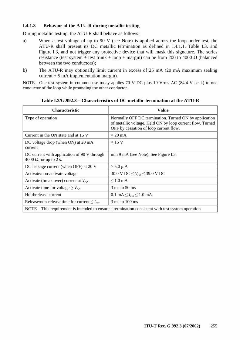
ITU-T Rec. G.992.3 (07/2002) 255
I.4.1.3 Behavior of the ATU-R during metallic testing
During metallic testing, the ATU-R shall behave as follows:
a) When a test voltage of up to 90 V (see Note) is applied across the loop under test, the ATU-R shall present its DC metallic termination as defined in I.4.1.1, Table I.3, and Figure I.3, and not trigger any protective device that will mask this signature. The series resistance (test system + test trunk + loop + margin) can be from 200 to 4000 Ω (balanced between the two conductors);
b) The ATU-R may optionally limit current in excess of 25 mA (20 mA maximum sealing current + 5 mA implementation margin).
NOTE – One test system in common use today applies 70 V DC plus 10 Vrms AC (84.4 V peak) to one conductor of the loop while grounding the other conductor.
Table I.3/G.992.3 – Characteristics of DC metallic termination at the ATU-R
Characteristic Value
Type of operation Normally OFF DC termination. Turned ON by application of metallic voltage. Held ON by loop current flow. Turned OFF by cessation of loop current flow.
Current in the ON state and at 15 V ≥ 20 mA
DC voltage drop (when ON) at 20 mA current
≤ 15 V
DC current with application of 90 V through 4000 Ω for up to 2 s.
min 9 mA (see Note). See Figure I.3.
DC leakage current (when OFF) at 20 V ≥ 5.0 µ A
Activate/non-activate voltage 30.0 V DC ≤ VAN ≤ 39.0 V DC
Activate (break over) current at VAN ≤ 1.0 mA
Activate time for voltage ≥ VAN 3 ms to 50 ms
Hold/release current 0.1 mA ≤ IHR ≤ 1.0 mA
Release/non-release time for current ≤ IHR 3 ms to 100 ms
NOTE – This requirement is intended to ensure a termination consistent with test system operation.
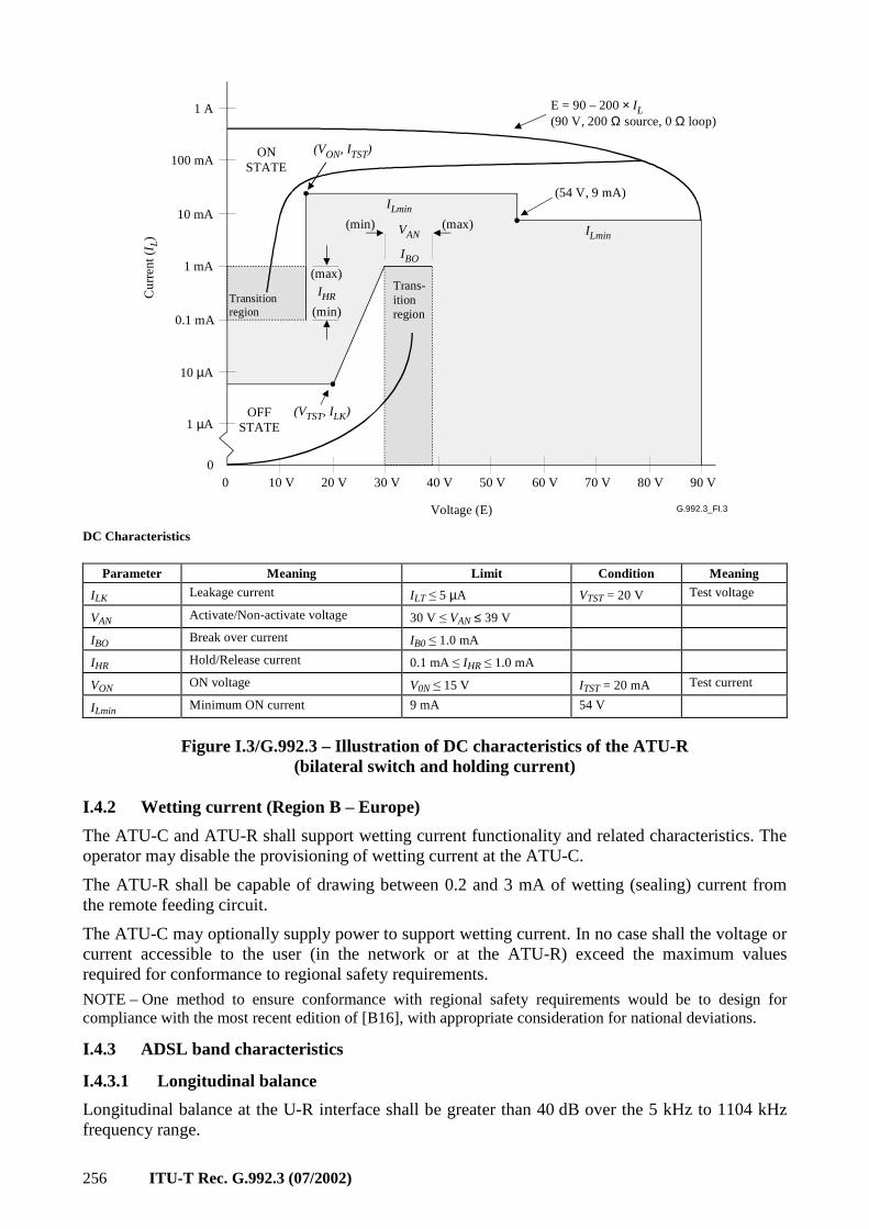
256 ITU-T Rec. G.992.3 (07/2002)
G.992.3_FI.3
0 10 V0
20 V 30 V 40 V 50 V 60 V 70 V 80 V 90 V
0.1 mA
1 mA
10 mA
100 mA
1 A
(54 V, 9 mA)
(max)
(max)
(min)
(min)
Voltage (E)
1 µA
10 µA
Cu
rre
nt (I
L)
Trans-itionregion
Transitionregion
OFFSTATE
ONSTATE
ILmin
(VTST, ILK)
IHR
ILmin
VAN
IBO
(VON, ITST)
E = 90 – 200 × IL(90 V, 200 Ω source, 0 Ω loop)
DC Characteristics
Parameter Meaning Limit Condition Meaning
ILK Leakage current ILT ≤ 5 µA VTST = 20 V Test voltage
VAN Activate/Non-activate voltage 30 V ≤ VAN ≤ 39 V
IBO Break over current IB0 ≤ 1.0 mA
IHR Hold/Release current 0.1 mA ≤ IHR ≤ 1.0 mA
VON ON voltage V0N ≤ 15 V ITST = 20 mA Test current
ILmin Minimum ON current 9 mA 54 V
Figure I.3/G.992.3 – Illustration of DC characteristics of the ATU-R (bilateral switch and holding current)
I.4.2 Wetting current (Region B – Europe)
The ATU-C and ATU-R shall support wetting current functionality and related characteristics. The operator may disable the provisioning of wetting current at the ATU-C.
The ATU-R shall be capable of drawing between 0.2 and 3 mA of wetting (sealing) current from the remote feeding circuit.
The ATU-C may optionally supply power to support wetting current. In no case shall the voltage or current accessible to the user (in the network or at the ATU-R) exceed the maximum values required for conformance to regional safety requirements.
NOTE – One method to ensure conformance with regional safety requirements would be to design for compliance with the most recent edition of [B16], with appropriate consideration for national deviations.
I.4.3 ADSL band characteristics
I.4.3.1 Longitudinal balance
Longitudinal balance at the U-R interface shall be greater than 40 dB over the 5 kHz to 1104 kHz frequency range.
ITU-T Rec. G.992.3 (07/2002) 257
Test setup and methodology is defined in A.4. The measurement of the longitudinal balance in the specified band shall be performed as shown in Figure A.4. The balance shall be measured in the absence of a DC bias voltage, with the modem under test active (i.e., powered with transmitter and receiver active and initializing or in showtime).
Annex J
All Digital Mode ADSL with improved spectral compatibility with ADSL over ISDN
J.1 ATU-C functional characteristics (pertains to clause 8)
J.1.1 ATU-C control parameter settings
The ATU-C Control Parameter Settings to be used in the parameterized parts of the main body and/or to be used in this annex are listed in Table J.1. Control Parameters are defined in 8.5.
Table J.1/G.992.3 – ATU-C control parameter settings
Parameter Default setting Characteristics
NSCds 256
NOMPSDds –40 dBm/Hz Setting may be changed relative to this value during G.994.1 phase, see 8.13.2.
MAXNOMPSDds –40 dBm/Hz Setting may be changed relative to this value during G.994.1 phase, see 8.13.2.
MAXNOMATPds (operation per J.1.2)
20.4 dBm Setting may be changed relative to this value during G.994.1 phase, see 8.13.2.
J.1.2 ATU-C downstream transmit spectral mask for overlapped spectrum operation (supplements 8.10)
The ATU-C transmit spectral mask shall be identical to the ATU-C transmit spectral mask for overlapped spectrum operation, as defined in Figure I.1 in I.1.2.
The passband is defined as the band from 3 to 1104 kHz and is the widest possible band used (i.e., implemented with overlapped spectrum). Limits defined within the passband apply also to any narrower bands used.
The low-frequency stop-band is defined as frequencies below 3 kHz, the high-frequency stop-band is defined as frequencies greater than 1104 kHz.
NOTE – When deployed in the same cable as ADSL-over-POTS (Annex A/G.992.1 and Annexes A and B/G.992.2) there may be a spectral compatibility issue between the two systems due to the overlap of the All-Digital Loop downstream channel with the ADSL-over-POTS upstream channel at frequencies below 138 kHz. Detailed study of spectrum compatibility is referred to regional bodies. Deployment restrictions for systems using the downstream PSD masks defined in this annex may be imposed (e.g., by the regional regulatory authority).
J.1.2.1 Passband PSD and response
See I.1.2.1.
J.1.2.2 Aggregate transmit power
See I.1.2.2.
258 ITU-T Rec. G.992.3 (07/2002)
J.1.3 ATU-C downstream transmit spectral mask for non-overlapped spectrum operation (supplements 8.10)
The ATU-C transmit spectral mask shall be identical to the ATU-C transmit spectral mask for non-overlapped spectrum operation over ISDN, as defined in Figure B.2.
Adherence to this mask will, in many cases, result in improved upstream performance of the other ADSL systems in the same or adjacent binder group, with the improvement dependent upon the other interferers. This mask differs from the mask in I.1.2 only in the band below 254 kHz.
The passband is defined as the band from 254 to 1104 kHz. Limits defined within the passband also apply to any narrower bands used.
The low-frequency stop-band is defined as frequencies below 254 kHz, the high-frequency stop-band is defined as frequencies greater than 1104 kHz.
J.1.3.1 Passband PSD and response
See B.1.2.1.
J.1.3.2 Aggregate transmit power
See B.1.2.2.
J.2 ATU-R functional characteristics (pertains to clause 8)
J.2.1 ATU-R control parameter settings
The ATU-R Control Parameter Settings to be used in the parameterized parts of the main body and/or to be used in this annex are listed in Table J.2. Control Parameters are defined in 8.5.
Table J.2/G.992.3 – ATU-R control parameter settings
Parameter Setting Characteristics
NSCus 64
NOMPSDus –41 dBm/Hz Setting may be changed relative to this value during G.994.1 phase, see 8.13.2.
MAXNOMPSDus –38 dBm/Hz Setting may be changed relative to this value during G.994.1 phase, see 8.13.2.
MAXNOMATPus 13.4 dBm Setting may be changed relative to this value during G.994.1 phase, see 8.13.2.
J.2.2 ATU-R upstream transmit spectral mask (supplements 8.10)
The ATU-R transmit PSD shall comply to one of the allowed family of spectral masks ADLU-32, ADLU-36,… ADLU-64 (see Note 1). Each of the spectral marks shall be as defined in Figure J.1 and Table J.3.
The passband is defined as the band from 3 kHz to an upperbound frequency f1, defined in Table J.3. It is the widest possible band used. Limits defined within the passband apply also to any narrower bands used.
Figure J.1 defines the family of ATU-R spectral masks for the transmit signal. The low-frequency stop-band is defined as frequencies below 3 kHz, the high-frequency stop-band is defined as frequencies greater than the passband upperbound frequency f1 defined in Table J.3. The Inband_peak_PSD and the frequencies f1 and f2 shall be as defined in Table J.3.
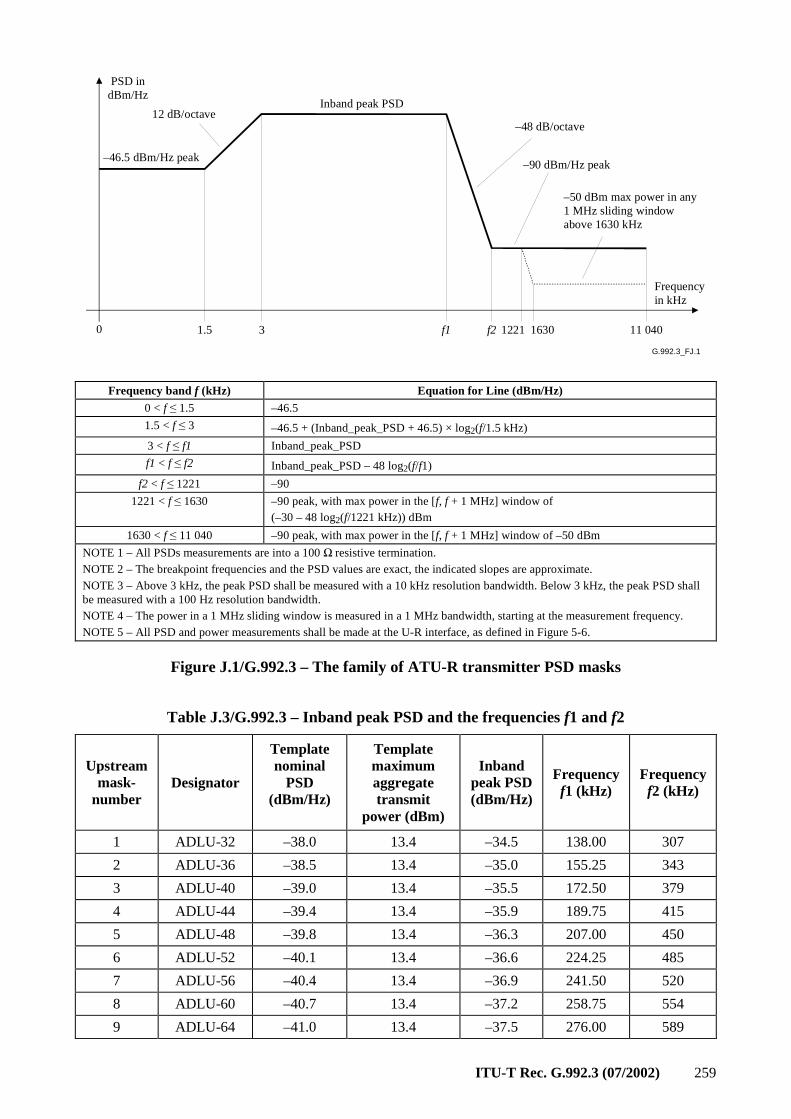
ITU-T Rec. G.992.3 (07/2002) 259
G.992.3_FJ.1
PSD indBm/Hz
–46.5 dBm/Hz peak
Inband peak PSD
–48 dB/octave
–90 dBm/Hz peak
–50 dBm max power in any1 MHz sliding windowabove 1630 kHz
1.5 f1 f2 1221 11 040
Frequencyin kHz
0 3
12 dB/octave
1630
Frequency band f (kHz) Equation for Line (dBm/Hz)
0 < f ≤ 1.5 –46.5
1.5 < f ≤ 3 –46.5 + (Inband_peak_PSD + 46.5) × log2(f/1.5 kHz)
3 < f ≤ f1 Inband_peak_PSD
f1 < f ≤ f2 Inband_peak_PSD – 48 log2(f/f1)
f2 < f ≤ 1221 –90
1221 < f ≤ 1630 –90 peak, with max power in the [f, f + 1 MHz] window of (–30 – 48 log2(f/1221 kHz)) dBm
1630 < f ≤ 11 040 –90 peak, with max power in the [f, f + 1 MHz] window of –50 dBm
NOTE 1 – All PSDs measurements are into a 100 Ω resistive termination. NOTE 2 – The breakpoint frequencies and the PSD values are exact, the indicated slopes are approximate. NOTE 3 – Above 3 kHz, the peak PSD shall be measured with a 10 kHz resolution bandwidth. Below 3 kHz, the peak PSD shall be measured with a 100 Hz resolution bandwidth. NOTE 4 – The power in a 1 MHz sliding window is measured in a 1 MHz bandwidth, starting at the measurement frequency. NOTE 5 – All PSD and power measurements shall be made at the U-R interface, as defined in Figure 5-6.
Figure J.1/G.992.3 – The family of ATU-R transmitter PSD masks
Table J.3/G.992.3 – Inband peak PSD and the frequencies f1 and f2
Upstream mask-
number Designator
Template nominal
PSD (dBm/Hz)
Template maximum aggregate transmit
power (dBm)
Inband peak PSD (dBm/Hz)
Frequency f1 (kHz)
Frequency f2 (kHz)
1 ADLU-32 –38.0 13.4 –34.5 138.00 307
2 ADLU-36 –38.5 13.4 –35.0 155.25 343
3 ADLU-40 –39.0 13.4 –35.5 172.50 379
4 ADLU-44 –39.4 13.4 –35.9 189.75 415
5 ADLU-48 –39.8 13.4 –36.3 207.00 450
6 ADLU-52 –40.1 13.4 –36.6 224.25 485
7 ADLU-56 –40.4 13.4 –36.9 241.50 520
8 ADLU-60 –40.7 13.4 –37.2 258.75 554
9 ADLU-64 –41.0 13.4 –37.5 276.00 589
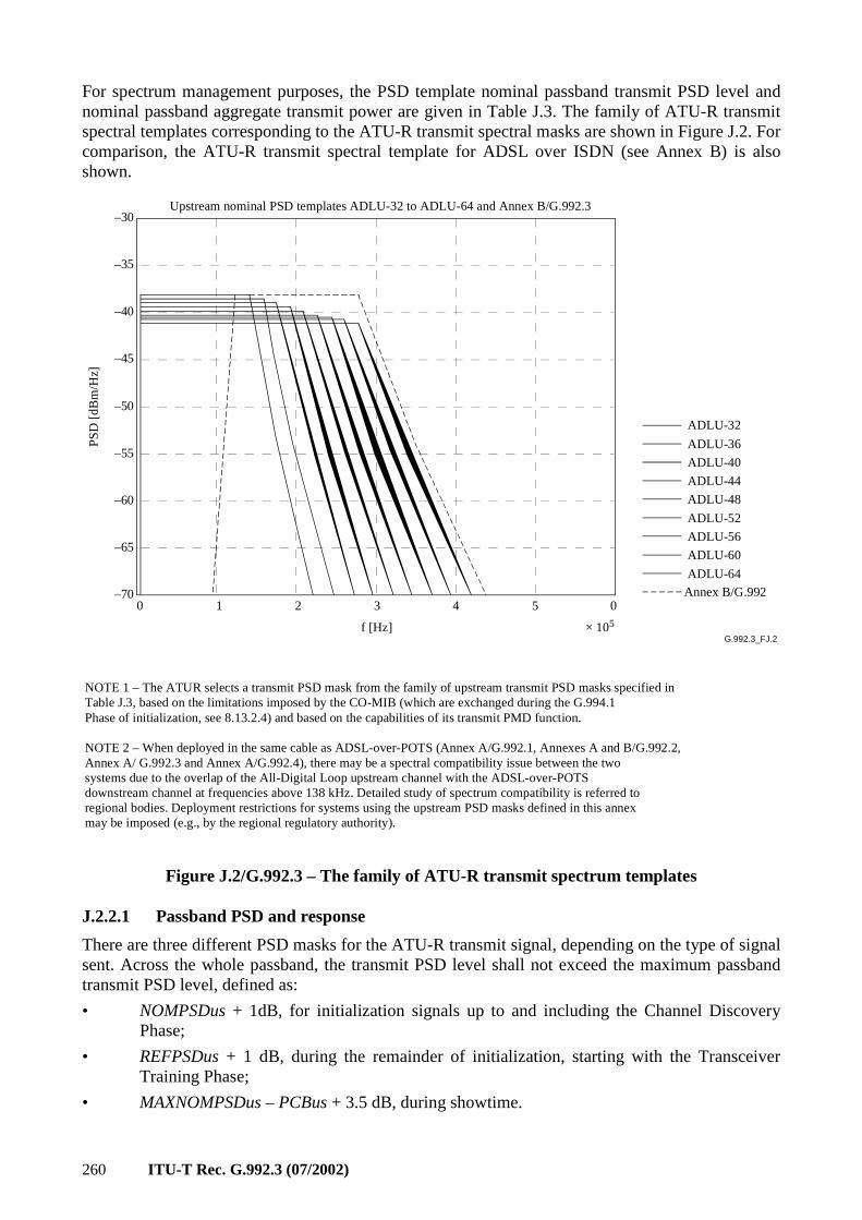
260 ITU-T Rec. G.992.3 (07/2002)
For spectrum management purposes, the PSD template nominal passband transmit PSD level and nominal passband aggregate transmit power are given in Table J.3. The family of ATU-R transmit spectral templates corresponding to the ATU-R transmit spectral masks are shown in Figure J.2. For comparison, the ATU-R transmit spectral template for ADSL over ISDN (see Annex B) is also shown.
G.992.3_FJ.2
ADLU-32
Annex B/G.992
ADLU-36
ADLU-40
ADLU-44
ADLU-48
ADLU-52
ADLU-56
ADLU-60
ADLU-64
–30
–35
–40
–45
–50
–55
–60
–65
–700 1 2 3 4 5 0
f [Hz] × 105
PS
D [d
Bm
/Hz]
Upstream nominal PSD templates ADLU-32 to ADLU-64 and Annex B/G.992.3
NOTE 1 – The ATUR selects a transmit PSD mask from the family of upstream transmit PSD masks specified inTable J.3, based on the limitations imposed by the CO-MIB (which are exchanged during the G.994.1Phase of initialization, see 8.13.2.4) and based on the capabilities of its transmit PMD function.
NOTE 2 – When deployed in the same cable as ADSL-over-POTS (Annex A/G.992.1, Annexes A and B/G.992.2,Annex A/ G.992.3 and Annex A/G.992.4), there may be a spectral compatibility issue between the twosystems due to the overlap of the All-Digital Loop upstream channel with the ADSL-over-POTSdownstream channel at frequencies above 138 kHz. Detailed study of spectrum compatibility is referred toregional bodies. Deployment restrictions for systems using the upstream PSD masks defined in this annexmay be imposed (e.g., by the regional regulatory authority).
Figure J.2/G.992.3 – The family of ATU-R transmit spectrum templates
J.2.2.1 Passband PSD and response
There are three different PSD masks for the ATU-R transmit signal, depending on the type of signal sent. Across the whole passband, the transmit PSD level shall not exceed the maximum passband transmit PSD level, defined as:
• NOMPSDus + 1dB, for initialization signals up to and including the Channel Discovery Phase;
• REFPSDus + 1 dB, during the remainder of initialization, starting with the Transceiver Training Phase;
• MAXNOMPSDus – PCBus + 3.5 dB, during showtime.
ITU-T Rec. G.992.3 (07/2002) 261
The group delay variation over the passband shall not exceed 50 µs.
The maximum transmit PSD allows for a 1 dB of non-ideal transmit filter effects (e.g., passband ripple and transition band rolloff).
J.2.2.2 Aggregate transmit power
(see J.2.2.1). In all cases,
• the aggregate transmit power across the whole passband, shall not exceed (MAXNOMATPus – PCBus) by more than 0.5 dB, in order to accommodate implementational tolerances, and shall not exceed 13.9 dBm.
• the aggregate transmit power over the 0 to 11.040 MHz band, shall not exceed (MAXNOMATPus – PCBus) by more than 0.8 dB, in order to account for residual transmit power in the stop bands and implementational tolerances.
The power emitted by the ATU-R is limited by the requirements in this clause. Notwithstanding these requirements, it is assumed that the ADSL will comply with applicable national requirements on emission of electromagnetic energy.
J.3 Initialization
For this annex, no additional requirements apply (relative to the main body of this Recommendation).
J.4 Electrical characteristics
The ATU shall meet the electrical characteristics defined in I.4.
Annex K
TPS-TC functional descriptions
This annex contains the functional descriptions of various TPS-TC types that may be used within the G.992.3 transceivers.
K.1 STM Transmission Convergence (STM-TC) function
K.1.1 Scope
The STM-TC function provides procedures for the transport of one unidirectional STM-TC stream in either the upstream or downstream direction. Octet boundaries and the position of most significant bits are explicitly maintained across the transport for the STM-TC stream. The STM-TC stream is presented synchronously across the T-R or V-C reference point with respect to the PMD bit clocks.
The support for a plesiochronous interface is under study.
K.1.2 References
This clause is intentionally blank because there are no STM-TC specific references.
K.1.3 Definitions
This clause is intentionally blank because there are no STM-TC specific definitions.
K.1.4 Abbreviations
This clause is intentionally blank because there are no STM-TC specific abbreviations.
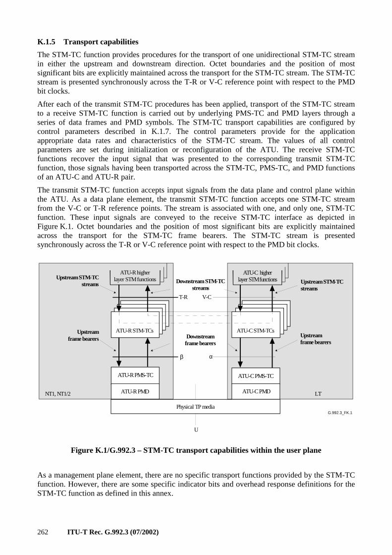
262 ITU-T Rec. G.992.3 (07/2002)
K.1.5 Transport capabilities
The STM-TC function provides procedures for the transport of one unidirectional STM-TC stream in either the upstream and downstream direction. Octet boundaries and the position of most significant bits are explicitly maintained across the transport for the STM-TC stream. The STM-TC stream is presented synchronously across the T-R or V-C reference point with respect to the PMD bit clocks.
After each of the transmit STM-TC procedures has been applied, transport of the STM-TC stream to a receive STM-TC function is carried out by underlying PMS-TC and PMD layers through a series of data frames and PMD symbols. The STM-TC transport capabilities are configured by control parameters described in K.1.7. The control parameters provide for the application appropriate data rates and characteristics of the STM-TC stream. The values of all control parameters are set during initialization or reconfiguration of the ATU. The receive STM-TC functions recover the input signal that was presented to the corresponding transmit STM-TC function, those signals having been transported across the STM-TC, PMS-TC, and PMD functions of an ATU-C and ATU-R pair.
The transmit STM-TC function accepts input signals from the data plane and control plane within the ATU. As a data plane element, the transmit STM-TC function accepts one STM-TC stream from the V-C or T-R reference points. The stream is associated with one, and only one, STM-TC function. These input signals are conveyed to the receive STM-TC interface as depicted in Figure K.1. Octet boundaries and the position of most significant bits are explicitly maintained across the transport for the STM-TC frame bearers. The STM-TC stream is presented synchronously across the T-R or V-C reference point with respect to the PMD bit clocks.
G.992.3_FK.1
ATU-R STM-TCs
ATU-R higherlayer STM functions
ATU-C STM-TCs
ATU-C higherlayer STM functions
Physical TP media
ATU-R PMS-TC ATU-C PMS-TC
Upstream STM-TCstreams Upstream STM-TC
streamsDownstream STM-TC
streams
NT1, NT1/2 LT
Upstreamframe bearers
Upstreamframe bearers
ATU-R PMD ATU-C PMD
U
T-R V-C
β α
Downstreamframe bearers
Figure K.1/G.992.3 – STM-TC transport capabilities within the user plane
As a management plane element, there are no specific transport functions provided by the STM-TC function. However, there are some specific indicator bits and overhead response definitions for the STM-TC function as defined in this annex.
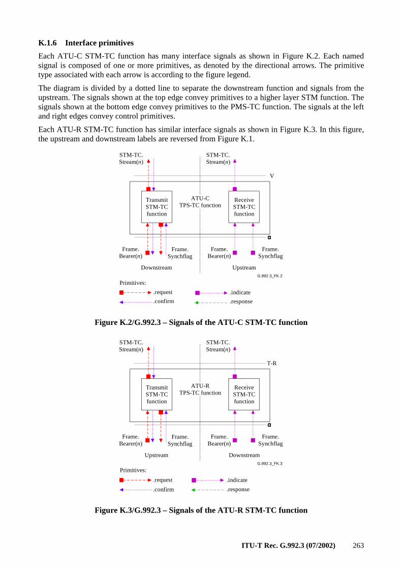
ITU-T Rec. G.992.3 (07/2002) 263
K.1.6 Interface primitives
Each ATU-C STM-TC function has many interface signals as shown in Figure K.2. Each named signal is composed of one or more primitives, as denoted by the directional arrows. The primitive type associated with each arrow is according to the figure legend.
The diagram is divided by a dotted line to separate the downstream function and signals from the upstream. The signals shown at the top edge convey primitives to a higher layer STM function. The signals shown at the bottom edge convey primitives to the PMS-TC function. The signals at the left and right edges convey control primitives.
Each ATU-R STM-TC function has similar interface signals as shown in Figure K.3. In this figure, the upstream and downstream labels are reversed from Figure K.1.
G.992.3_FK.2
TransmitSTM-TCfunction
Frame.Bearer(n)
Frame.Synchflag
ReceiveSTM-TCfunction
Frame.Bearer(n)
Frame.Synchflag
Downstream Upstream
ATU-CTPS-TC function
STM-TC.Stream(n)
STM-TC.Stream(n)
.request
.confirm
.indicate
.response
Primitives:
V
αααα
Figure K.2/G.992.3 – Signals of the ATU-C STM-TC function
G.992.3_FK.3
TransmitSTM-TCfunction
Frame.Bearer(n)
Frame.Synchflag
ReceiveSTM-TCfunction
Frame.Bearer(n)
Frame.Synchflag
Upstream Downstream
ATU-RTPS-TC function
STM-TC.Stream(n)
STM-TC.Stream(n)
.request
.confirm
.indicate
.response
Primitives:
T-R
αααα
Figure K.3/G.992.3 – Signals of the ATU-R STM-TC function
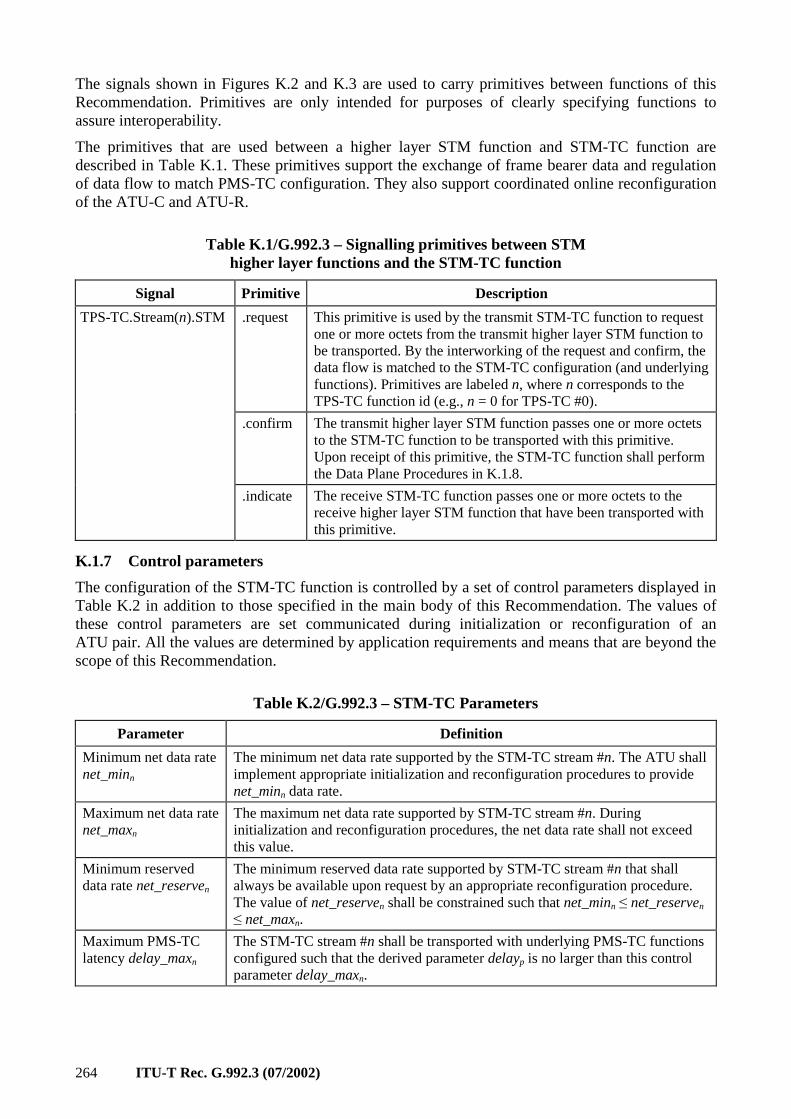
264 ITU-T Rec. G.992.3 (07/2002)
The signals shown in Figures K.2 and K.3 are used to carry primitives between functions of this Recommendation. Primitives are only intended for purposes of clearly specifying functions to assure interoperability.
The primitives that are used between a higher layer STM function and STM-TC function are described in Table K.1. These primitives support the exchange of frame bearer data and regulation of data flow to match PMS-TC configuration. They also support coordinated online reconfiguration of the ATU-C and ATU-R.
Table K.1/G.992.3 – Signalling primitives between STM higher layer functions and the STM-TC function
Signal Primitive Description
TPS-TC.Stream(n).STM .request This primitive is used by the transmit STM-TC function to request one or more octets from the transmit higher layer STM function to be transported. By the interworking of the request and confirm, the data flow is matched to the STM-TC configuration (and underlying functions). Primitives are labeled n, where n corresponds to the TPS-TC function id (e.g., n = 0 for TPS-TC #0).
.confirm The transmit higher layer STM function passes one or more octets to the STM-TC function to be transported with this primitive. Upon receipt of this primitive, the STM-TC function shall perform the Data Plane Procedures in K.1.8.
.indicate The receive STM-TC function passes one or more octets to the receive higher layer STM function that have been transported with this primitive.
K.1.7 Control parameters
The configuration of the STM-TC function is controlled by a set of control parameters displayed in Table K.2 in addition to those specified in the main body of this Recommendation. The values of these control parameters are set communicated during initialization or reconfiguration of an ATU pair. All the values are determined by application requirements and means that are beyond the scope of this Recommendation.
Table K.2/G.992.3 – STM-TC Parameters
Parameter Definition
Minimum net data rate net_minn
The minimum net data rate supported by the STM-TC stream #n. The ATU shall implement appropriate initialization and reconfiguration procedures to provide net_minn data rate.
Maximum net data rate net_maxn
The maximum net data rate supported by STM-TC stream #n. During initialization and reconfiguration procedures, the net data rate shall not exceed this value.
Minimum reserved data rate net_reserven
The minimum reserved data rate supported by STM-TC stream #n that shall always be available upon request by an appropriate reconfiguration procedure. The value of net_reserven shall be constrained such that net_minn ≤ net_reserven ≤ net_maxn.
Maximum PMS-TC latency delay_maxn
The STM-TC stream #n shall be transported with underlying PMS-TC functions configured such that the derived parameter delayp is no larger than this control parameter delay_maxn.
ITU-T Rec. G.992.3 (07/2002) 265
Table K.2/G.992.3 – STM-TC Parameters
Parameter Definition
Maximum PMS-TC BER error_maxn
The STM-TC stream #n shall be transported with bit error ratio not to exceed error_maxn, referenced to the output of the PMS-TC function in the receiver. The modem shall implement appropriate initialization and reconfiguration procedures to assure this value.
Minimum PMS-TC impulse noise protection INP_minn
The ATM-TC stream #n shall be transported with underlying PMS-TC functions configured such that the derived parameter INPp is not lower than this control parameter INP_minn.
If the values of net_minn, net_maxn, and net_reserven are set to the same value, then the STM-TC stream is designated as a fixed data rate STM-TC stream (i.e., RA_mode = MANUAL, see Table 8-6). If net_minn = net_reserven and net_minn ≠ net_maxn, then the STM-TC stream is designated as a flexible data rate STM-TC stream. If the value of net_minn ≠ net_maxn ≠ net_reservemax, then the STM-TC stream is designated as a flexible data rate STM-TC stream with reserved data rate allocation.
During initialization and reconfiguration procedures, the actual net data rate net_actn for stream #n shall always be set to the value of the derived parameter net_actp.n of the underlying PMS-TC latency path function and shall be constrained such that net_minn ≤ net_actn ≤ net_maxn. However, in case the net_minn = net_maxn, the net_actn may exceed the net_maxn by up to 4 kbit/s, to allow for the PMS-TC net data rate granularity (see Table 7-7). The latency delay_actn shall always be set to the value of the derived parameter delayp of the underlying PMS-TC latency path function and constrained such that delay_actn ≤ delay_maxn The values net_actn and delay_actn are not control parameters; these values are the result of specific initialization and reconfiguration procedures.
The impulse noise protection INP_actn of transport of stream #n shall always be set to the value of the derived parameter INPp of the underlying PMS-TC path function and constrained such that INP_actn ≥. INP_minn. The values net_actn, delay_actn and INP_actn are not control parameters; these values are the result of specific initialization and reconfiguration procedures.
K.1.7.1 Valid configurations
The configurations listed in Table K.3 are valid for the STM-TC function.
Table K.3/G.992.3 – Valid configuration for STM-TC function
Parameter Capability
typen 1
net_minn net_minn may be supported for all valid framing configurations
net_maxn net_maxn may be supported for all valid framing configurations
net_reserven net_reserven may be supported for all valid framing configurations
delay_maxn 0 ≤ delay_maxn ≤ the largest value of delayp (see 7.6.1) for supported valid framing configurations. delay_maxn = 0 is a special value indicating no delay bound is being imposed. delay_maxn = 1 is a special value indicating the lowest delay is being imposed (see 7.3.2.2/G.997.1).
error_maxn 10–3, 10–5, 10–7
INP_minn 0, 1/2, 1, 2
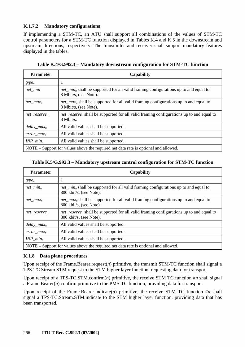
266 ITU-T Rec. G.992.3 (07/2002)
K.1.7.2 Mandatory configurations
If implementing a STM-TC, an ATU shall support all combinations of the values of STM-TC control parameters for a STM-TC function displayed in Tables K.4 and K.5 in the downstream and upstream directions, respectively. The transmitter and receiver shall support mandatory features displayed in the tables.
Table K.4/G.992.3 – Mandatory downstream configuration for STM-TC function
Parameter Capability
typen 1
net_min net_minn shall be supported for all valid framing configurations up to and equal to 8 Mbit/s, (see Note).
net_maxn net_maxn shall be supported for all valid framing configurations up to and equal to 8 Mbit/s, (see Note).
net_reserven net_reserven shall be supported for all valid framing configurations up to and equal to 8 Mbit/s.
delay_maxn All valid values shall be supported.
error_maxn All valid values shall be supported.
INP_minn All valid values shall be supported.
NOTE – Support for values above the required net data rate is optional and allowed.
Table K.5/G.992.3 – Mandatory upstream control configuration for STM-TC function
Parameter Capability
typen 1
net_minn net_minn shall be supported for all valid framing configurations up to and equal to 800 kbit/s, (see Note).
net_maxn net_maxn shall be supported for all valid framing configurations up to and equal to 800 kbit/s, (see Note).
net_reserven net_reserven shall be supported for all valid framing configurations up to and equal to 800 kbit/s, (see Note).
delay_maxn All valid values shall be supported.
error_maxn All valid values shall be supported.
INP_minn All valid values shall be supported.
NOTE – Support for values above the required net data rate is optional and allowed.
K.1.8 Data plane procedures
Upon receipt of the Frame.Bearer.request(n) primitive, the transmit STM-TC function shall signal a TPS-TC.Stream.STM.request to the STM higher layer function, requesting data for transport.
Upon receipt of a TPS-TC.STM.confirm(n) primitive, the receive STM TC function #n shall signal a Frame.Bearer(n).confirm primitive to the PMS-TC function, providing data for transport.
Upon receipt of the Frame.Bearer.indicate(n) primitive, the receive STM TC function #n shall signal a TPS-TC.Stream.STM.indicate to the STM higher layer function, providing data that has been transported.
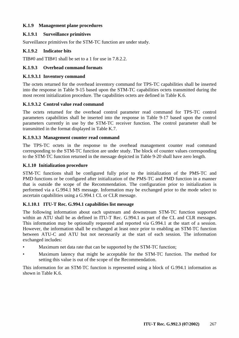
ITU-T Rec. G.992.3 (07/2002) 267
K.1.9 Management plane procedures
K.1.9.1 Surveillance primitives
Surveillance primitives for the STM-TC function are under study.
K.1.9.2 Indicator bits
TIB#0 and TIB#1 shall be set to a 1 for use in 7.8.2.2.
K.1.9.3 Overhead command formats
K.1.9.3.1 Inventory command
The octets returned for the overhead inventory command for TPS-TC capabilities shall be inserted into the response in Table 9-15 based upon the STM-TC capabilities octets transmitted during the most recent initialization procedure. The capabilities octets are defined in Table K.6.
K.1.9.3.2 Control value read command
The octets returned for the overhead control parameter read command for TPS-TC control parameters capabilities shall be inserted into the response in Table 9-17 based upon the control parameters currently in use by the STM-TC receiver function. The control parameter shall be transmitted in the format displayed in Table K.7.
K.1.9.3.3 Management counter read command
The TPS-TC octets in the response to the overhead management counter read command corresponding to the STM-TC function are under study. The block of counter values corresponding to the STM-TC function returned in the message depicted in Table 9-20 shall have zero length.
K.1.10 Initialization procedure
STM-TC functions shall be configured fully prior to the initialization of the PMS-TC and PMD functions or be configured after initialization of the PMS-TC and PMD function in a manner that is outside the scope of the Recommendation. The configuration prior to initialization is performed via a G.994.1 MS message. Information may be exchanged prior to the mode select to ascertain capabilities using a G.994.1 CL or CLR message.
K.1.10.1 ITU-T Rec. G.994.1 capabilities list message
The following information about each upstream and downstream STM-TC function supported within an ATU shall be as defined in ITU-T Rec. G.994.1 as part of the CL and CLR messages. This information may be optionally requested and reported via G.994.1 at the start of a session. However, the information shall be exchanged at least once prior to enabling an STM-TC function between ATU-C and ATU but not necessarily at the start of each session. The information exchanged includes:
• Maximum net data rate that can be supported by the STM-TC function;
• Maximum latency that might be acceptable for the STM-TC function. The method for setting this value is out of the scope of the Recommendation.
This information for an STM-TC function is represented using a block of G.994.1 information as shown in Table K.6.
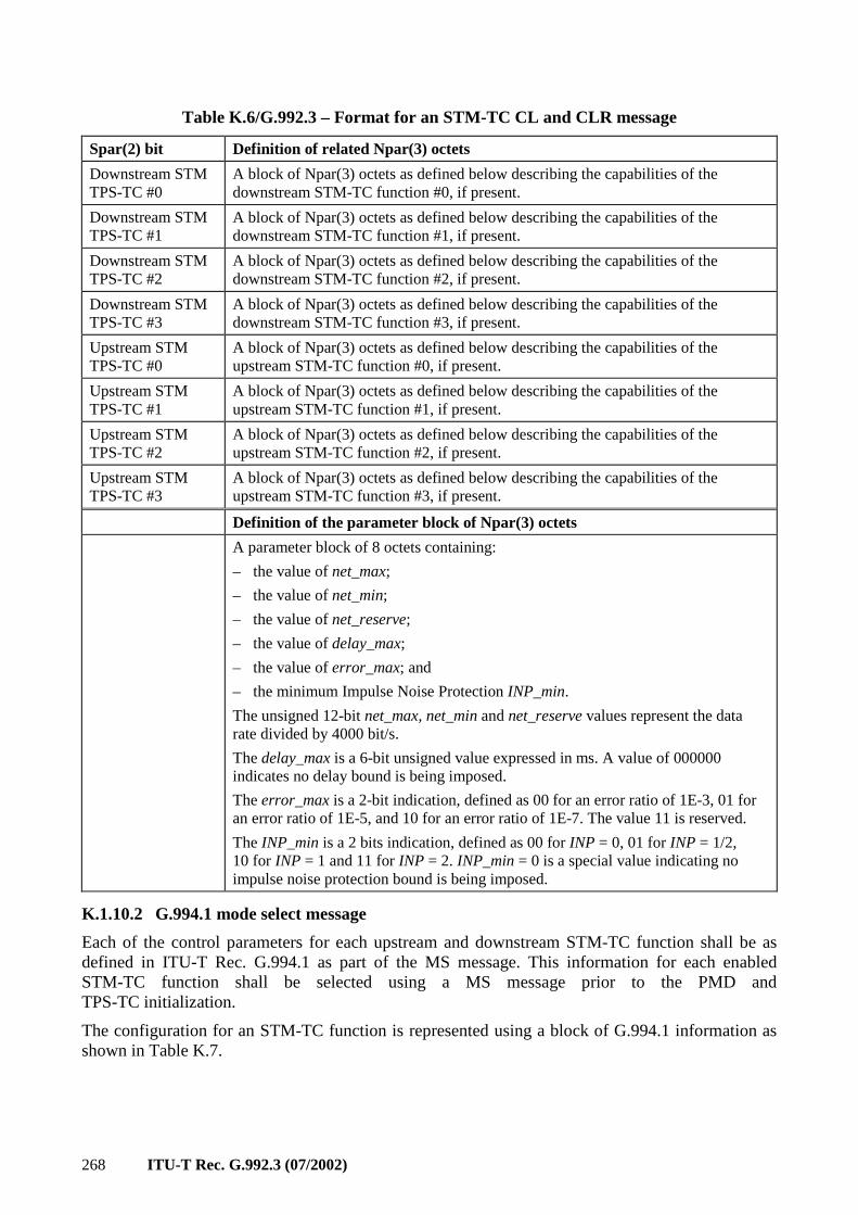
268 ITU-T Rec. G.992.3 (07/2002)
Table K.6/G.992.3 – Format for an STM-TC CL and CLR message
Spar(2) bit Definition of related Npar(3) octets
Downstream STM TPS-TC #0
A block of Npar(3) octets as defined below describing the capabilities of the downstream STM-TC function #0, if present.
Downstream STM TPS-TC #1
A block of Npar(3) octets as defined below describing the capabilities of the downstream STM-TC function #1, if present.
Downstream STM TPS-TC #2
A block of Npar(3) octets as defined below describing the capabilities of the downstream STM-TC function #2, if present.
Downstream STM TPS-TC #3
A block of Npar(3) octets as defined below describing the capabilities of the downstream STM-TC function #3, if present.
Upstream STM TPS-TC #0
A block of Npar(3) octets as defined below describing the capabilities of the upstream STM-TC function #0, if present.
Upstream STM TPS-TC #1
A block of Npar(3) octets as defined below describing the capabilities of the upstream STM-TC function #1, if present.
Upstream STM TPS-TC #2
A block of Npar(3) octets as defined below describing the capabilities of the upstream STM-TC function #2, if present.
Upstream STM TPS-TC #3
A block of Npar(3) octets as defined below describing the capabilities of the upstream STM-TC function #3, if present.
Definition of the parameter block of Npar(3) octets
A parameter block of 8 octets containing:
– the value of net_max;
– the value of net_min;
– the value of net_reserve;
– the value of delay_max;
– the value of error_max; and
– the minimum Impulse Noise Protection INP_min.
The unsigned 12-bit net_max, net_min and net_reserve values represent the data rate divided by 4000 bit/s.
The delay_max is a 6-bit unsigned value expressed in ms. A value of 000000 indicates no delay bound is being imposed.
The error_max is a 2-bit indication, defined as 00 for an error ratio of 1E-3, 01 for an error ratio of 1E-5, and 10 for an error ratio of 1E-7. The value 11 is reserved.
The INP_min is a 2 bits indication, defined as 00 for INP = 0, 01 for INP = 1/2, 10 for INP = 1 and 11 for INP = 2. INP_min = 0 is a special value indicating no impulse noise protection bound is being imposed.
K.1.10.2 G.994.1 mode select message
Each of the control parameters for each upstream and downstream STM-TC function shall be as defined in ITU-T Rec. G.994.1 as part of the MS message. This information for each enabled STM-TC function shall be selected using a MS message prior to the PMD and TPS-TC initialization.
The configuration for an STM-TC function is represented using a block of G.994.1 information as shown in Table K.7.
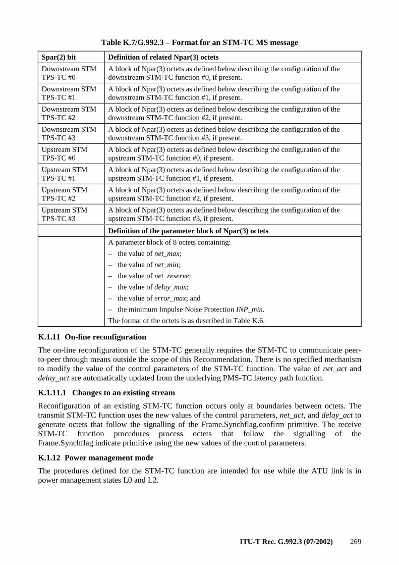
ITU-T Rec. G.992.3 (07/2002) 269
Table K.7/G.992.3 – Format for an STM-TC MS message
Spar(2) bit Definition of related Npar(3) octets
Downstream STM TPS-TC #0
A block of Npar(3) octets as defined below describing the configuration of the downstream STM-TC function #0, if present.
Downstream STM TPS-TC #1
A block of Npar(3) octets as defined below describing the configuration of the downstream STM-TC function #1, if present.
Downstream STM TPS-TC #2
A block of Npar(3) octets as defined below describing the configuration of the downstream STM-TC function #2, if present.
Downstream STM TPS-TC #3
A block of Npar(3) octets as defined below describing the configuration of the downstream STM-TC function #3, if present.
Upstream STM TPS-TC #0
A block of Npar(3) octets as defined below describing the configuration of the upstream STM-TC function #0, if present.
Upstream STM TPS-TC #1
A block of Npar(3) octets as defined below describing the configuration of the upstream STM-TC function #1, if present.
Upstream STM TPS-TC #2
A block of Npar(3) octets as defined below describing the configuration of the upstream STM-TC function #2, if present.
Upstream STM TPS-TC #3
A block of Npar(3) octets as defined below describing the configuration of the upstream STM-TC function #3, if present.
Definition of the parameter block of Npar(3) octets
A parameter block of 8 octets containing:
– the value of net_max;
– the value of net_min;
– the value of net_reserve;
– the value of delay_max;
– the value of error_max; and
– the minimum Impulse Noise Protection INP_min.
The format of the octets is as described in Table K.6.
K.1.11 On-line reconfiguration
The on-line reconfiguration of the STM-TC generally requires the STM-TC to communicate peer-to-peer through means outside the scope of this Recommendation. There is no specified mechanism to modify the value of the control parameters of the STM-TC function. The value of net_act and delay_act are automatically updated from the underlying PMS-TC latency path function.
K.1.11.1 Changes to an existing stream
Reconfiguration of an existing STM-TC function occurs only at boundaries between octets. The transmit STM-TC function uses the new values of the control parameters, net_act, and delay_act to generate octets that follow the signalling of the Frame.Synchflag.confirm primitive. The receive STM-TC function procedures process octets that follow the signalling of the Frame.Synchflag.indicate primitive using the new values of the control parameters.
K.1.12 Power management mode
The procedures defined for the STM-TC function are intended for use while the ATU link is in power management states L0 and L2.
270 ITU-T Rec. G.992.3 (07/2002)
K.1.12.1 L0 Link state operation
The STM-TC function shall operate according to the data plane procedures defined in K.1.8 and K.1.9 as well as those in the main body of the Recommendation while the link is in power management state L0. All control parameter definitions and conditions provided in K.1.7, as well as those provided in the main body of the Recommendation shall apply.
K.1.12.1.1 Transition to L2 link state operation
During a transition from link state L0 to state L2, the value of control parameters are not modified. However, the value of net_act and delay_act are automatically updated to match those of the underlying PMS-TC latency path function. Following the successful completion of the protocol described in the main body of the Recommendation, the coordinated entry into the L2 link state shall be made as described in K.1.11.1.
K.1.12.1.2 Transition to L3 link state operation
The orderly shutdown of the ATU shall be as described in the main body of the Recommendation referring to this annex. No specific STM-TC tear-down procedure is specified.
K.1.12.2 L2 link state operation
The STM-TC function shall operate according to the data plane procedures defined in K.1.8 and K.1.9 as well as those in the main body of the Recommendation while the link is in power management state L2. All control parameter definitions provided in K.1.7, as well as those provided in the main body of the Recommendation shall apply. However, the operating limits imposed by the control parameters net_min, net_reserve, and delay_max shall not apply while in the L2 link state.
During the link state L2, the ATU-C STM-TC shall monitor its interface for the arrival of primitives that indicate data rates larger than the reduced data rates must be transported to the ATU-R. When this condition is detected, the ATU-C shall use the procedure described in 9.5.3.4 to return to the link state L0.
K.1.12.2.1 Transition to L0 link state operation
Entry into the L0 link state shall be preceded by the protocol described in the main body of the Recommendation. The values of the control parameters are not modified upon return to the L2 link state; however, during a transition from link state L2 to state L0, the values of net_act and delay_act are automatically updated to match those of the underlying PMS-TC latency path function. Following the successful completion of the protocol described in the main body of the Recommendation, the coordinated entry into the L0 link state shall be made as described in K.1.11.1.
K.1.12.2.2 Transition to L3 link state operation
Transitions to link state L3 shall be as described in the main body of the Recommendation. No specific STM-TC tear-down procedure is specified.
K.1.12.3 L3 link state operation
In the L3 link state, no specific procedures are specified for the STM-TC function.
K.1.12.3.1 Transition to L0 link state operation
The initialization procedures of the ATU are intended to provide the transition from link state L3 to state L0. The transition shall be as described in K.1.10 as well as in the main body of the Recommendation.
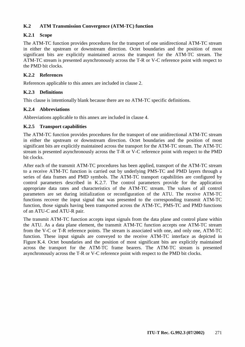
ITU-T Rec. G.992.3 (07/2002) 271
K.2 ATM Transmission Convergence (ATM-TC) function
K.2.1 Scope
The ATM-TC function provides procedures for the transport of one unidirectional ATM-TC stream in either the upstream or downstream direction. Octet boundaries and the position of most significant bits are explicitly maintained across the transport for the ATM-TC stream. The ATM-TC stream is presented asynchronously across the T-R or V-C reference point with respect to the PMD bit clocks.
K.2.2 References
References applicable to this annex are included in clause 2.
K.2.3 Definitions
This clause is intentionally blank because there are no ATM-TC specific definitions.
K.2.4 Abbreviations
Abbreviations applicable to this annex are included in clause 4.
K.2.5 Transport capabilities
The ATM-TC function provides procedures for the transport of one unidirectional ATM-TC stream in either the upstream or downstream direction. Octet boundaries and the position of most significant bits are explicitly maintained across the transport for the ATM-TC stream. The ATM-TC stream is presented asynchronously across the T-R or V-C reference point with respect to the PMD bit clocks.
After each of the transmit ATM-TC procedures has been applied, transport of the ATM-TC stream to a receive ATM-TC function is carried out by underlying PMS-TC and PMD layers through a series of data frames and PMD symbols. The ATM-TC transport capabilities are configured by control parameters described in K.2.7. The control parameters provide for the application appropriate data rates and characteristics of the ATM-TC stream. The values of all control parameters are set during initialization or reconfiguration of the ATU. The receive ATM-TC functions recover the input signal that was presented to the corresponding transmit ATM-TC function, those signals having been transported across the ATM-TC, PMS-TC and PMD functions of an ATU-C and ATU-R pair.
The transmit ATM-TC function accepts input signals from the data plane and control plane within the ATU. As a data plane element, the transmit ATM-TC function accepts one ATM-TC stream from the V-C or T-R reference points. The stream is associated with one, and only one, ATM-TC function. These input signals are conveyed to the receive ATM-TC interface as depicted in Figure K.4. Octet boundaries and the position of most significant bits are explicitly maintained across the transport for the ATM-TC frame bearers. The ATM-TC stream is presented asynchronously across the T-R or V-C reference point with respect to the PMD bit clocks.
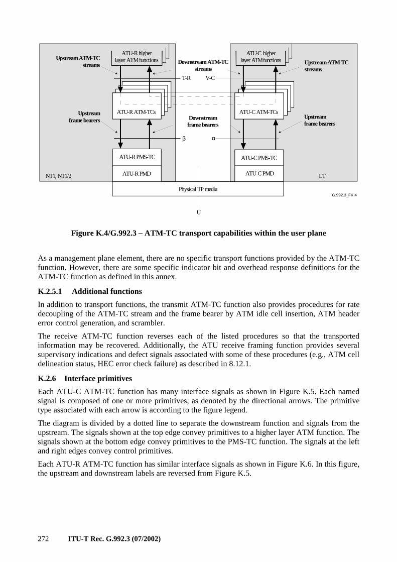
272 ITU-T Rec. G.992.3 (07/2002)
G.992.3_FK.4
ATU-R ATM-TCs
ATU-R higherlayer ATM functions
ATU-C ATM-TCs
ATU-C higherlayer ATM functions
Physical TP media
ATU-R PMS-TC ATU-C PMS-TC
Upstream ATM-TCstreams Upstream ATM-TC
streamsDownstream ATM-TC
streams
NT1, NT1/2 LT
Upstreamframe bearers
Upstreamframe bearers
ATU-R PMD ATU-C PMD
U
T-R V-C
β α
Downstreamframe bearers
Figure K.4/G.992.3 – ATM-TC transport capabilities within the user plane
As a management plane element, there are no specific transport functions provided by the ATM-TC function. However, there are some specific indicator bit and overhead response definitions for the ATM-TC function as defined in this annex.
K.2.5.1 Additional functions
In addition to transport functions, the transmit ATM-TC function also provides procedures for rate decoupling of the ATM-TC stream and the frame bearer by ATM idle cell insertion, ATM header error control generation, and scrambler.
The receive ATM-TC function reverses each of the listed procedures so that the transported information may be recovered. Additionally, the ATU receive framing function provides several supervisory indications and defect signals associated with some of these procedures (e.g., ATM cell delineation status, HEC error check failure) as described in 8.12.1.
K.2.6 Interface primitives
Each ATU-C ATM-TC function has many interface signals as shown in Figure K.5. Each named signal is composed of one or more primitives, as denoted by the directional arrows. The primitive type associated with each arrow is according to the figure legend.
The diagram is divided by a dotted line to separate the downstream function and signals from the upstream. The signals shown at the top edge convey primitives to a higher layer ATM function. The signals shown at the bottom edge convey primitives to the PMS-TC function. The signals at the left and right edges convey control primitives.
Each ATU-R ATM-TC function has similar interface signals as shown in Figure K.6. In this figure, the upstream and downstream labels are reversed from Figure K.5.
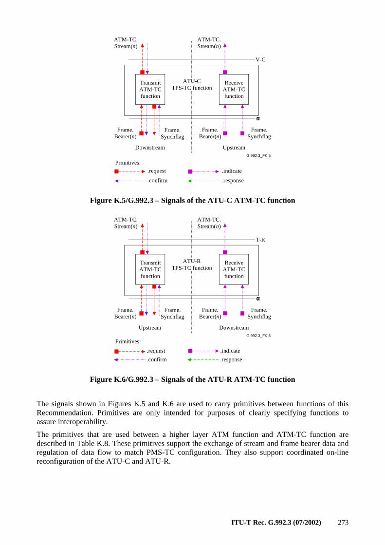
ITU-T Rec. G.992.3 (07/2002) 273
G.992.3_FK.5
TransmitATM-TCfunction
Frame.Bearer(n)
Frame.Synchflag
ReceiveATM-TCfunction
Frame.Bearer(n)
Frame.Synchflag
Downstream Upstream
ATU-CTPS-TC function
ATM-TC.Stream(n)
ATM-TC.Stream(n)
.request
.confirm
.indicate
.response
Primitives:
V-C
αααα
Figure K.5/G.992.3 – Signals of the ATU-C ATM-TC function
G.992.3_FK.6
TransmitATM-TCfunction
Frame.Bearer(n)
Frame.Synchflag
ReceiveATM-TCfunction
Frame.Bearer(n)
Frame.Synchflag
Upstream Downstream
ATU-RTPS-TC function
ATM-TC.Stream(n)
ATM-TC.Stream(n)
.request
.confirm
.indicate
.response
Primitives:
T-R
αααα
Figure K.6/G.992.3 – Signals of the ATU-R ATM-TC function
The signals shown in Figures K.5 and K.6 are used to carry primitives between functions of this Recommendation. Primitives are only intended for purposes of clearly specifying functions to assure interoperability.
The primitives that are used between a higher layer ATM function and ATM-TC function are described in Table K.8. These primitives support the exchange of stream and frame bearer data and regulation of data flow to match PMS-TC configuration. They also support coordinated on-line reconfiguration of the ATU-C and ATU-R.
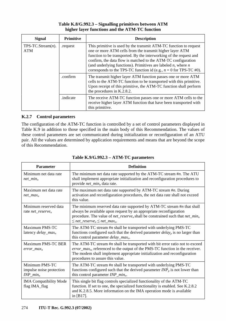
274 ITU-T Rec. G.992.3 (07/2002)
Table K.8/G.992.3 – Signalling primitives between ATM higher layer functions and the ATM-TC function
Signal Primitive Description
.request This primitive is used by the transmit ATM-TC function to request one or more ATM cells from the transmit higher layer ATM function to be transported. By the interworking of the request and confirm, the data flow is matched to the ATM-TC configuration (and underlying functions). Primitives are labeled n, where n corresponds to the TPS-TC function id (e.g., n = 0 for TPS-TC #0).
.confirm The transmit higher layer ATM function passes one or more ATM cells to the ATM-TC function to be transported with this primitive. Upon receipt of this primitive, the ATM-TC function shall perform the procedures in K.2.8.2.
TPS-TC.Stream(n).ATM
.indicate The receive ATM-TC function passes one or more ATM cells to the receive higher layer ATM function that have been transported with this primitive.
K.2.7 Control parameters
The configuration of the ATM-TC function is controlled by a set of control parameters displayed in Table K.9 in addition to those specified in the main body of this Recommendation. The values of these control parameters are set communicated during initialization or reconfiguration of an ATU pair. All the values are determined by application requirements and means that are beyond the scope of this Recommendation.
Table K.9/G.992.3 – ATM-TC parameters
Parameter Definition
Minimum net data rate net_minn
The minimum net data rate supported by the ATM-TC stream #n. The ATU shall implement appropriate initialization and reconfiguration procedures to provide net_minn data rate.
Maximum net data rate net_maxn
The maximum net data rate supported by ATM-TC stream #n. During activation and reconfiguration procedures, the net data rate shall not exceed this value.
Minimum reserved data rate net_reserven
The minimum reserved data rate supported by ATM-TC stream #n that shall always be available upon request by an appropriate reconfiguration procedure. The value of net_reserven shall be constrained such that net_minn ≤ net_reserven ≤ net_maxn.
Maximum PMS-TC latency delay_maxn
The ATM-TC stream #n shall be transported with underlying PMS-TC functions configured such that the derived parameter delayp is no larger than this control parameter delay_maxn.
Maximum PMS-TC BER error_maxn
The ATM-TC stream #n shall be transported with bit error ratio not to exceed error_maxn, referenced to the output of the PMS-TC function in the receiver. The modem shall implement appropriate initialization and reconfiguration procedures to assure this value.
Minimum PMS-TC impulse noise protection INP_minn
The ATM-TC stream #n shall be transported with underlying PMS-TC functions configured such that the derived parameter INPp is not lower than this control parameter INP_minn.
IMA Compatibility Mode flag IMA_flag
This single bit flag controls specialized functionality of the ATM-TC function. If set to one, the specialized functionality is enabled. See K.2.8.2 and K.2.8.5. More information on the IMA operation mode is available in [B17].
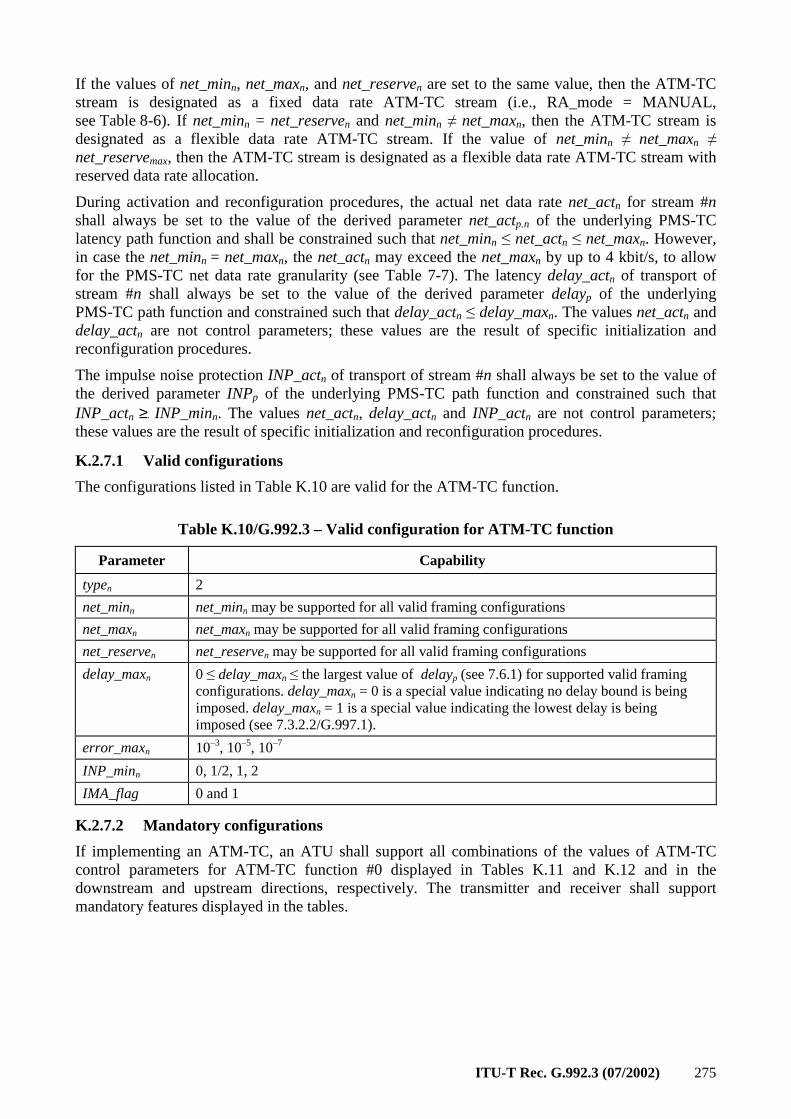
ITU-T Rec. G.992.3 (07/2002) 275
If the values of net_minn, net_maxn, and net_reserven are set to the same value, then the ATM-TC stream is designated as a fixed data rate ATM-TC stream (i.e., RA_mode = MANUAL, see Table 8-6). If net_minn = net_reserven and net_minn ≠ net_maxn, then the ATM-TC stream is designated as a flexible data rate ATM-TC stream. If the value of net_minn ≠ net_maxn ≠ net_reservemax, then the ATM-TC stream is designated as a flexible data rate ATM-TC stream with reserved data rate allocation.
During activation and reconfiguration procedures, the actual net data rate net_actn for stream #n shall always be set to the value of the derived parameter net_actp.n of the underlying PMS-TC latency path function and shall be constrained such that net_minn ≤ net_actn ≤ net_maxn. However, in case the net_minn = net_maxn, the net_actn may exceed the net_maxn by up to 4 kbit/s, to allow for the PMS-TC net data rate granularity (see Table 7-7). The latency delay_actn of transport of stream #n shall always be set to the value of the derived parameter delayp of the underlying PMS-TC path function and constrained such that delay_actn ≤ delay_maxn. The values net_actn and delay_actn are not control parameters; these values are the result of specific initialization and reconfiguration procedures.
The impulse noise protection INP_actn of transport of stream #n shall always be set to the value of the derived parameter INPp of the underlying PMS-TC path function and constrained such that INP_actn ≥. INP_minn. The values net_actn, delay_actn and INP_actn are not control parameters; these values are the result of specific initialization and reconfiguration procedures.
K.2.7.1 Valid configurations
The configurations listed in Table K.10 are valid for the ATM-TC function.
Table K.10/G.992.3 – Valid configuration for ATM-TC function
Parameter Capability
typen 2
net_minn net_minn may be supported for all valid framing configurations
net_maxn net_maxn may be supported for all valid framing configurations
net_reserven net_reserven may be supported for all valid framing configurations
delay_maxn 0 ≤ delay_maxn ≤ the largest value of delayp (see 7.6.1) for supported valid framing configurations. delay_maxn = 0 is a special value indicating no delay bound is being imposed. delay_maxn = 1 is a special value indicating the lowest delay is being imposed (see 7.3.2.2/G.997.1).
error_maxn 10–3, 10–5, 10–7
INP_minn 0, 1/2, 1, 2
IMA_flag 0 and 1
K.2.7.2 Mandatory configurations
If implementing an ATM-TC, an ATU shall support all combinations of the values of ATM-TC control parameters for ATM-TC function #0 displayed in Tables K.11 and K.12 and in the downstream and upstream directions, respectively. The transmitter and receiver shall support mandatory features displayed in the tables.
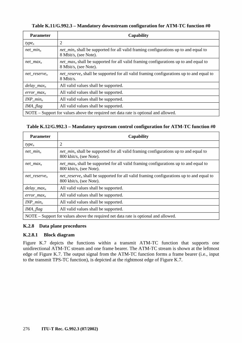
276 ITU-T Rec. G.992.3 (07/2002)
Table K.11/G.992.3 – Mandatory downstream configuration for ATM-TC function #0
Parameter Capability
typen 2
net_minn net_minn shall be supported for all valid framing configurations up to and equal to 8 Mbit/s, (see Note).
net_maxn net_maxn shall be supported for all valid framing configurations up to and equal to 8 Mbit/s, (see Note).
net_reserven net_reserven shall be supported for all valid framing configurations up to and equal to 8 Mbit/s.
delay_maxn All valid values shall be supported.
error_maxn All valid values shall be supported.
INP_minn All valid values shall be supported.
IMA_flag All valid values shall be supported.
NOTE – Support for values above the required net data rate is optional and allowed.
Table K.12/G.992.3 – Mandatory upstream control configuration for ATM-TC function #0
Parameter Capability
typen 2
net_minn net_minn shall be supported for all valid framing configurations up to and equal to 800 kbit/s, (see Note).
net_maxn net_maxn shall be supported for all valid framing configurations up to and equal to 800 kbit/s, (see Note).
net_reserven net_reserven shall be supported for all valid framing configurations up to and equal to 800 kbit/s, (see Note).
delay_maxn All valid values shall be supported.
error_maxn All valid values shall be supported.
INP_minn All valid values shall be supported.
IMA_flag All valid values shall be supported.
NOTE – Support for values above the required net data rate is optional and allowed.
K.2.8 Data plane procedures
K.2.8.1 Block diagram
Figure K.7 depicts the functions within a transmit ATM-TC function that supports one unidirectional ATM-TC stream and one frame bearer. The ATM-TC stream is shown at the leftmost edge of Figure K.7. The output signal from the ATM-TC function forms a frame bearer (i.e., input to the transmit TPS-TC function), is depicted at the rightmost edge of Figure K.7.

ITU-T Rec. G.992.3 (07/2002) 277
G.992.3_FK.7
ATM TC Sub-function 0
Framebearer #nScrambling
ATMstream #n
ATM idle cellinsertion
net_actualn
HEC generation
Figure K.7/G.992.3 – Block diagram of transmit ATM-TC function
In the ATM-TC stream and within the ATM-TC function, data octets are transmitted MSB first in accordance with ITU-T Rec. I.361 [11] and ITU-T Rec. I.432.1 [12]. All serial procedures within the ATM-TC function begin MSB first. Below the α and β interfaces of the ATU (starting with the Frame.Bearer primitives), data octets are transported LSB first. As a result, the MSB of the first octet of the first ATM-TC.Stream(n).confirm primitive will be the LSB of the first octet of the first Frame.Bearer(n).confirm primitive. The labelling of bits within the ATM-TC layer and at the frame bearer is depicted in Figure K.8.
G.992.3_FK.8
A0 A1 A2 A3 A4 A5 A6 A7
D7 D6 D5 D4 D3 D2 D1 D0
LSB MSB
MSB LSB
Octet format inTPS-TC.bearer(n).ATM
primitives and withinATM-TC layer
Octet format inframer.bearer(n)
primitives
ATM TC/PMS-TC function interface
Figure K.8/G.992.3 – Bit mapping of the user plane transport function of the ATM-TC function
K.2.8.2 Rate matching by idle cell insertion
ATM idle cells shall be inserted by the transmit function to provide ATM cell rate decoupling. If the IMA_flag is not asserted, ATM idle cells shall not be delivered to higher layers functions by the receive ATM-TC functions. If the control variable IMA_flag is asserted, all ATM cells received and delineated shall be passed in TPS-TC.Stream(n).ATM.indicate primitive.
ATM idle cells are identified by the standardized pattern for the cell header given in ITU-T Rec. I.432.1 [12].
Cell rate decoupling is expected to be performed by the IMA function when the control variable IMA_flag is asserted. The ATM-TC function therefore inserts a minimum number of idle cells, i.e., no cells are inserted if exact rate decoupling is performed by the IMA function.
K.2.8.3 HEC octet
The transmit ATM-TC function shall generate a HEC Octet as described in ITU-T Rec. I.432.1 [12], including the recommended modulo 2 addition (XOR) of the pattern binary 01010101b to the HEC bits.
The HEC covers the entire cell header. The generator polynomial coefficient set used and the HEC sequence generation procedure shall be in accordance with ITU-T Rec. I.432.1 [12].
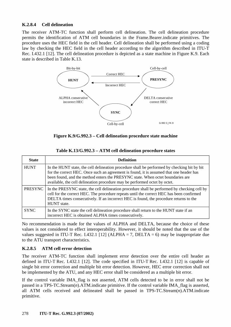
278 ITU-T Rec. G.992.3 (07/2002)
K.2.8.4 Cell delineation
The receiver ATM-TC function shall perform cell delineation. The cell delineation procedure permits the identification of ATM cell boundaries in the Frame.Bearer.indicate primitives. The procedure uses the HEC field in the cell header. Cell delineation shall be performed using a coding law by checking the HEC field in the cell header according to the algorithm described in ITU-T Rec. I.432.1 [12]. The cell delineation procedure is depicted as a state machine in Figure K.9. Each state is described in Table K.13.
G.992.3_FK.9
Bit-by-bit
HUNT PRESYNC
Correct HEC
Incorrect HEC
ALPHA consecutiveincorrect HEC
DELTA consecutivecorrect HEC
Cell-by-cell
SYNC
Cell-by-cell
Figure K.9/G.992.3 – Cell delineation procedure state machine
Table K.13/G.992.3 – ATM cell delineation procedure states
State Definition
HUNT In the HUNT state, the cell delineation procedure shall be performed by checking bit by bit for the correct HEC. Once such an agreement is found, it is assumed that one header has been found, and the method enters the PRESYNC state. When octet boundaries are available, the cell delineation procedure may be performed octet by octet.
PRESYNC In the PRESYNC state, the cell delineation procedure shall be performed by checking cell by cell for the correct HEC. The procedure repeats until the correct HEC has been confirmed DELTA times consecutively. If an incorrect HEC is found, the procedure returns to the HUNT state.
SYNC In the SYNC state the cell delineation procedure shall return to the HUNT state if an incorrect HEC is obtained ALPHA times consecutively.
No recommendation is made for the values of ALPHA and DELTA, because the choice of these values is not considered to effect interoperability. However, it should be noted that the use of the values suggested in ITU-T Rec. I.432.1 [12] (ALPHA = 7, DELTA = 6) may be inappropriate due to the ATU transport characteristics.
K.2.8.5 ATM cell error detection
The receiver ATM-TC function shall implement error detection over the entire cell header as defined in ITU-T Rec. I.432.1 [12]. The code specified in ITU-T Rec. I.432.1 [12] is capable of single bit error correction and multiple bit error detection. However, HEC error correction shall not be implemented by the ATU, and any HEC error shall be considered as a multiple bit error.
If the control variable IMA_flag is not asserted, ATM cells detected to be in error shall not be passed in a TPS-TC.Stream(n).ATM.indicate primitive. If the control variable IMA_flag is asserted, all ATM cells received and delineated shall be passed in TPS-TC.Stream(n).ATM.indicate primitive.
ITU-T Rec. G.992.3 (07/2002) 279
K.2.8.6 Scrambler
The transmit ATM-TC function shall scramble the cell payload field to improve the security and robustness of the HEC cell delineation mechanism. The self synchronizing scrambler uses the polynomial X43 + 1. The scrambler procedures defined in ITU-T Rec. I.432.1 [12] shall be implemented.
K.2.9 Management plane procedures
K.2.9.1 Surveillance primitives
The ATM-TC function surveillance primitives are ATM path related. Both anomalies and defects are defined for each receiver ATM-TC function.
Three near-end anomalies are defined as follows:
• No Cell Delineation (ncd-n) anomaly: An ncd-n anomaly occurs immediately after receiving the first Frame.Bearer(n).indicate primitive. The anomaly terminates when the cell delineation process of the receive ATM-TC function #n transitions to the SYNC state. Once cell delineation is acquired, subsequent losses of cell delineation shall be considered as ocd-n anomalies.
• Out of Cell Delineation (ocd-n) anomaly: An ocd-n anomaly occurs when the cell delineation process of receive ATM-TC sub-function #n transitions from the SYNC state to the HUNT state. An ocd-n anomaly terminates when the cell delineation process transitions from PRESYNC state to SYNC state or when the lcd-n defect is asserted.
• Header Error Check (hec-n) anomaly: A hec-n anomaly occurs each time the ATM cell header process of receiver ATM-TC function #n detects an error.
These near end anomalies are counted locally per ITU-T Rec. G.997.1 [4]. The values of the counter may be read or reset via local commands not defined in this Recommendation.
Three far-end anomalies are defined as follows:
• Far-end No Cell Delineation (fncd-n) anomaly: An fncd-n anomaly is a ncd-n anomaly detected at the far end.
• Far-end Out of Cell Delineation (focd-n) anomaly: An focd-n anomaly is an ocd-n anomaly detected at the far end.
• Far-end Header Error Check (fhec-n) anomaly: An fhec-n anomaly is an hec-n anomaly detected at the far end.
These far-end anomalies are not individually observable. The count of these far-end anomalies may be read and reset via overhead commands defined in 9.4.1.6. The format of the counters shall be as described in K.2.9.3.3.
One near-end defect is defined as follows:
• Loss of Cell Delineation (lcd-n) defect: An lcd-n defect occurs when at least one ocd-n anomaly is present in each of four consecutive overhead channel periods and no sef-n defect is present. An lcd-n defect terminates when no ocd-n anomaly is present in four consecutive overhead channel periods.
This near-end defect is processed locally per ITU-T Rec. G.997.1 [4].
One far-end defect is defined as follows:
• Far-end Loss of Cell Delineation (flcd-n) defect: An flcd-n defect is a lcd-n defect detected at the far end. This defect shall be carried in the bit oriented portion of the overhead structured as defined in 7.8.2.1.
This far-end defect is directly observed through an indicator bit as described in K.2.9.2.
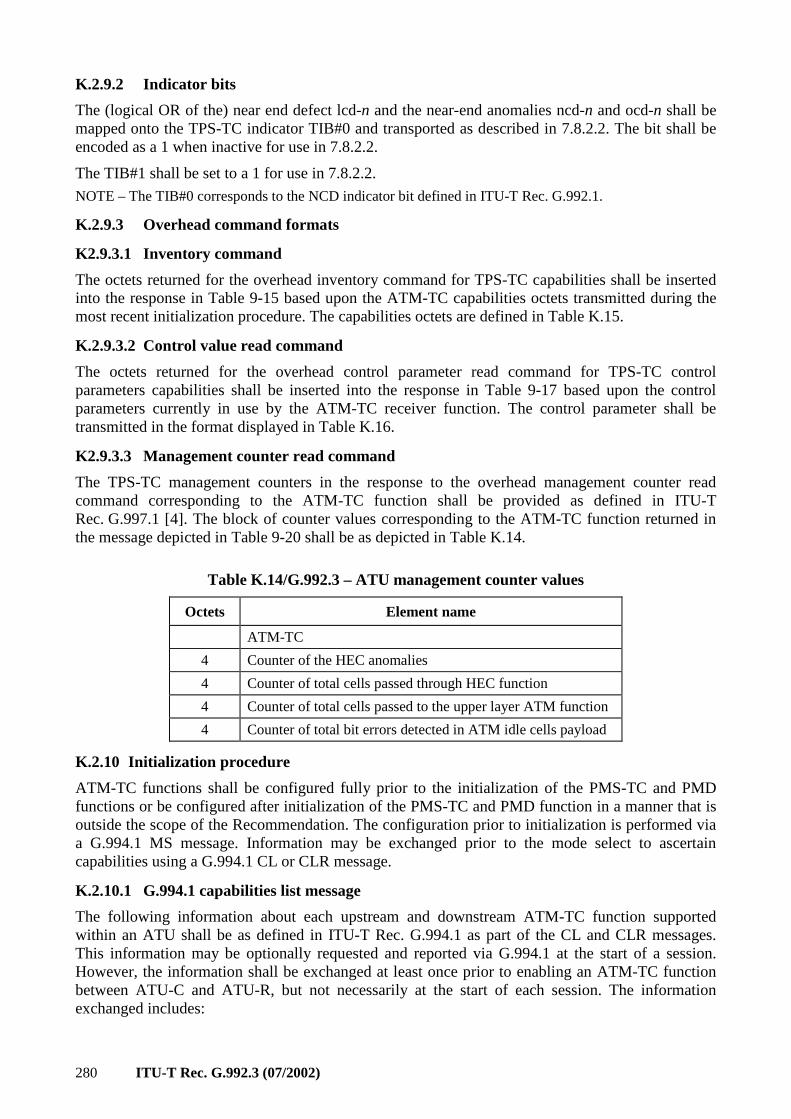
280 ITU-T Rec. G.992.3 (07/2002)
K.2.9.2 Indicator bits
The (logical OR of the) near end defect lcd-n and the near-end anomalies ncd-n and ocd-n shall be mapped onto the TPS-TC indicator TIB#0 and transported as described in 7.8.2.2. The bit shall be encoded as a 1 when inactive for use in 7.8.2.2.
The TIB#1 shall be set to a 1 for use in 7.8.2.2.
NOTE – The TIB#0 corresponds to the NCD indicator bit defined in ITU-T Rec. G.992.1.
K.2.9.3 Overhead command formats
K2.9.3.1 Inventory command
The octets returned for the overhead inventory command for TPS-TC capabilities shall be inserted into the response in Table 9-15 based upon the ATM-TC capabilities octets transmitted during the most recent initialization procedure. The capabilities octets are defined in Table K.15.
K.2.9.3.2 Control value read command
The octets returned for the overhead control parameter read command for TPS-TC control parameters capabilities shall be inserted into the response in Table 9-17 based upon the control parameters currently in use by the ATM-TC receiver function. The control parameter shall be transmitted in the format displayed in Table K.16.
K2.9.3.3 Management counter read command
The TPS-TC management counters in the response to the overhead management counter read command corresponding to the ATM-TC function shall be provided as defined in ITU-T Rec. G.997.1 [4]. The block of counter values corresponding to the ATM-TC function returned in the message depicted in Table 9-20 shall be as depicted in Table K.14.
Table K.14/G.992.3 – ATU management counter values
Octets Element name
ATM-TC
4 Counter of the HEC anomalies
4 Counter of total cells passed through HEC function
4 Counter of total cells passed to the upper layer ATM function
4 Counter of total bit errors detected in ATM idle cells payload
K.2.10 Initialization procedure
ATM-TC functions shall be configured fully prior to the initialization of the PMS-TC and PMD functions or be configured after initialization of the PMS-TC and PMD function in a manner that is outside the scope of the Recommendation. The configuration prior to initialization is performed via a G.994.1 MS message. Information may be exchanged prior to the mode select to ascertain capabilities using a G.994.1 CL or CLR message.
K.2.10.1 G.994.1 capabilities list message
The following information about each upstream and downstream ATM-TC function supported within an ATU shall be as defined in ITU-T Rec. G.994.1 as part of the CL and CLR messages. This information may be optionally requested and reported via G.994.1 at the start of a session. However, the information shall be exchanged at least once prior to enabling an ATM-TC function between ATU-C and ATU-R, but not necessarily at the start of each session. The information exchanged includes:
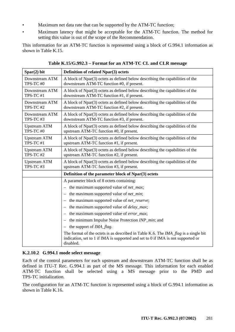
ITU-T Rec. G.992.3 (07/2002) 281
• Maximum net data rate that can be supported by the ATM-TC function;
• Maximum latency that might be acceptable for the ATM-TC function. The method for setting this value is out of the scope of the Recommendation.
This information for an ATM-TC function is represented using a block of G.994.1 information as shown in Table K.15.
Table K.15/G.992.3 – Format for an ATM-TC CL and CLR message
Spar(2) bit Definition of related Npar(3) octets
Downstream ATM TPS-TC #0
A block of Npar(3) octets as defined below describing the capabilities of the downstream ATM-TC function #0, if present.
Downstream ATM TPS-TC #1
A block of Npar(3) octets as defined below describing the capabilities of the downstream ATM-TC function #1, if present.
Downstream ATM TPS-TC #2
A block of Npar(3) octets as defined below describing the capabilities of the downstream ATM-TC function #2, if present.
Downstream ATM TPS-TC #3
A block of Npar(3) octets as defined below describing the capabilities of the downstream ATM-TC function #3, if present.
Upstream ATM TPS-TC #0
A block of Npar(3) octets as defined below describing the capabilities of the upstream ATM-TC function #0, if present.
Upstream ATM TPS-TC #1
A block of Npar(3) octets as defined below describing the capabilities of the upstream ATM-TC function #1, if present.
Upstream ATM TPS-TC #2
A block of Npar(3) octets as defined below describing the capabilities of the upstream ATM-TC function #2, if present.
Upstream ATM TPS-TC #3
A block of Npar(3) octets as defined below describing the capabilities of the upstream ATM-TC function #3, if present.
Definition of the parameter block of Npar(3) octets
A parameter block of 8 octets containing:
– the maximum supported value of net_max;
– the maximum supported value of net_min;
– the maximum supported value of net_reserve;
– the maximum supported value of delay_max;
– the maximum supported value of error_max;
– the minimum Impulse Noise Protection INP_min; and
– the support of IMA_flag.
The format of the octets is as described in Table K.6. The IMA_flag is a single bit indication, set to 1 if IMA is supported and set to 0 if IMA is not supported or disabled.
K.2.10.2 G.994.1 mode select message
Each of the control parameters for each upstream and downstream ATM-TC function shall be as defined in ITU-T Rec. G.994.1 as part of the MS message. This information for each enabled ATM-TC function shall be selected using a MS message prior to the PMD and TPS-TC initialization.
The configuration for an ATM-TC function is represented using a block of G.994.1 information as shown in Table K.16.
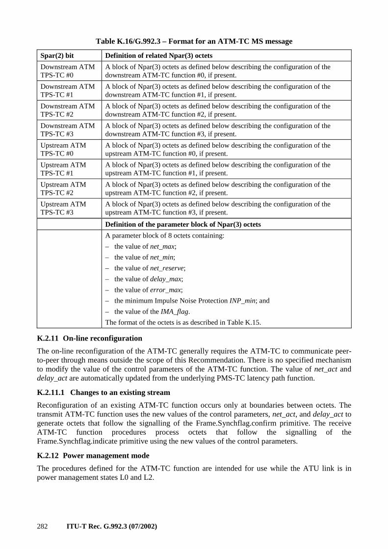
282 ITU-T Rec. G.992.3 (07/2002)
Table K.16/G.992.3 – Format for an ATM-TC MS message
Spar(2) bit Definition of related Npar(3) octets
Downstream ATM TPS-TC #0
A block of Npar(3) octets as defined below describing the configuration of the downstream ATM-TC function #0, if present.
Downstream ATM TPS-TC #1
A block of Npar(3) octets as defined below describing the configuration of the downstream ATM-TC function #1, if present.
Downstream ATM TPS-TC #2
A block of Npar(3) octets as defined below describing the configuration of the downstream ATM-TC function #2, if present.
Downstream ATM TPS-TC #3
A block of Npar(3) octets as defined below describing the configuration of the downstream ATM-TC function #3, if present.
Upstream ATM TPS-TC #0
A block of Npar(3) octets as defined below describing the configuration of the upstream ATM-TC function #0, if present.
Upstream ATM TPS-TC #1
A block of Npar(3) octets as defined below describing the configuration of the upstream ATM-TC function #1, if present.
Upstream ATM TPS-TC #2
A block of Npar(3) octets as defined below describing the configuration of the upstream ATM-TC function #2, if present.
Upstream ATM TPS-TC #3
A block of Npar(3) octets as defined below describing the configuration of the upstream ATM-TC function #3, if present.
Definition of the parameter block of Npar(3) octets
A parameter block of 8 octets containing:
– the value of net_max;
– the value of net_min;
– the value of net_reserve;
– the value of delay_max;
– the value of error_max;
– the minimum Impulse Noise Protection INP_min; and
– the value of the IMA_flag.
The format of the octets is as described in Table K.15.
K.2.11 On-line reconfiguration
The on-line reconfiguration of the ATM-TC generally requires the ATM-TC to communicate peer-to-peer through means outside the scope of this Recommendation. There is no specified mechanism to modify the value of the control parameters of the ATM-TC function. The value of net_act and delay_act are automatically updated from the underlying PMS-TC latency path function.
K.2.11.1 Changes to an existing stream
Reconfiguration of an existing ATM-TC function occurs only at boundaries between octets. The transmit ATM-TC function uses the new values of the control parameters, net_act, and delay_act to generate octets that follow the signalling of the Frame.Synchflag.confirm primitive. The receive ATM-TC function procedures process octets that follow the signalling of the Frame.Synchflag.indicate primitive using the new values of the control parameters.
K.2.12 Power management mode
The procedures defined for the ATM-TC function are intended for use while the ATU link is in power management states L0 and L2.
ITU-T Rec. G.992.3 (07/2002) 283
K.2.12.1 L0 link state operation
The ATM-TC function shall operate according to the data plane procedures defined in K.2.8 and K.2.9 as well as according to those in the main body of the Recommendation referring to this annex while the link is in power management state L0. All control parameter definitions and conditions provided in K.2.7, as well as according to those provided in the main body of the Recommendation referring to this text, shall apply.
K.2.12.1.1 Transition to L2 link state operation
During a transition from link state L0 to state L2, the value of control parameters are not modified. However, the value of net_act and delay_act are automatically updated to match those of the underlying PMS-TC latency path function. Following the successful completion of the protocol described in the main body of the Recommendation referring to this annex, the coordinated entry into the L2 link state shall be made as described in K.2.11.1.
K.2.12.1.2 Transition to L3 link state operation
The orderly shutdown of the ATU shall be as described in the main body of the Recommendation referring to this annex. No specific ATM-TC tear-down procedure is specified.
K.2.12.2 L2 link state operation
The ATM-TC function shall operate according to the data plane procedures defined in K.2.8 and K.2.9 as well as according to those in the main body of the Recommendation referring to this annex while the link is in power management state L2. All control parameter definitions provided in K.2.7 as well as according to those provided in the main body of the Recommendation referring to this text shall apply. However, the operating limits imposed by the control parameters net_min, net_reserve, and delay_max shall not apply while in the L2 link state.
During the link state L2, the ATU-C ATM-TC shall monitor its interface for the arrival of primitives that indicate that data rates larger than the reduced data rates must be transported to the ATU-R. When this condition is detected, the ATU-C shall use the procedure described in 9.5.3.4 to return to the link state L0.
K.2.12.2.1 Transition to L0 link state operation
Entry into the L0 link state shall be preceded by the protocol described in the main body of the Recommendation referring to this annex. The values of the control parameters are not modified upon return to the L2 link state; however, during a transition from link state L2 to state L0, the values of net_act and delay_act are automatically updated to match those of the underlying PMS-TC latency path function. Following the successful completion of the protocol described in the main body of the Recommendation referring to this annex, the coordinated entry into the L0 link state shall be made as described in K.2.11.1.
K.2.12.2.2 Transition to L3 link state operation
Transitions to link state L3 shall be as described in the main body of the Recommendation referring to this annex. No specific ATM-TC tear-down procedure is specified.
K.2.12.3 L3 link state operation
In the L3 link state, no specific procedures are specified for the ATM-TC function.
K.2.12.3.1 Transition to L0 link state operation
The initialization procedures of the ATU are intended to provide the transition from link state L3 to state L0. The transition shall be as described in K.2.10 as well as in the main body of the Recommendation referring to this annex.
284 ITU-T Rec. G.992.3 (07/2002)
K.3 Packet transmission convergence function (PTM-TC)
K.3.1 Scope
The PTM-TC function provides procedures for the transport of one unidirectional packet stream in either the upstream or downstream direction. Packet boundaries, octet boundaries, and the position of most significant bits are explicitly maintained across the transport for the PTM-TC stream. The PTM-TC stream is presented asynchronously across the T-R or V-C reference point with respect to the PMD bit clocks.
The PTM-TC function is defined in terms of the PTM-TC defined in Annex H.1/G.993.1 [13]. Referring to the reference model of that annex, the PTM-TC of VDSL is defined connecting above the PMS-TC function to either a fast or slow channel through the a/b interface. This same function is used for K.3 and is defined to connect to a single PMS-TC latency path function.
K.3.2 References
References applicable to this annex are included in clause 2.
K.3.3 Definitions
This clause is intentionally blank because there are no PTM-TC specific definitions.
K.3.4 Abbreviations
Abbreviations applicable to this annex are included in clause 4.
K.3.5 Transport capabilities
The transport capabilities of the PTM-TC function are described in H.2/G.993.1 [13]. Only the mandatory capabilities that support a single PTM-TC shall be used with this Recommendation.
The PTM-TC transport capabilities are configured by control parameters described in K.3.7. The control parameters provide for the application appropriate data rates and characteristics of the PTM-TC stream. The values of all control parameters are set during initialization or reconfiguration of the ATU.
The transmit PTM-TC function accepts input signals from the data plane within the ATU. As a data plane element, the transmit PTM-TC function accepts one PTM-TC stream from a PTM entity across the V-C or T-R reference points. The stream is associated with one and only one PTM-TC function.
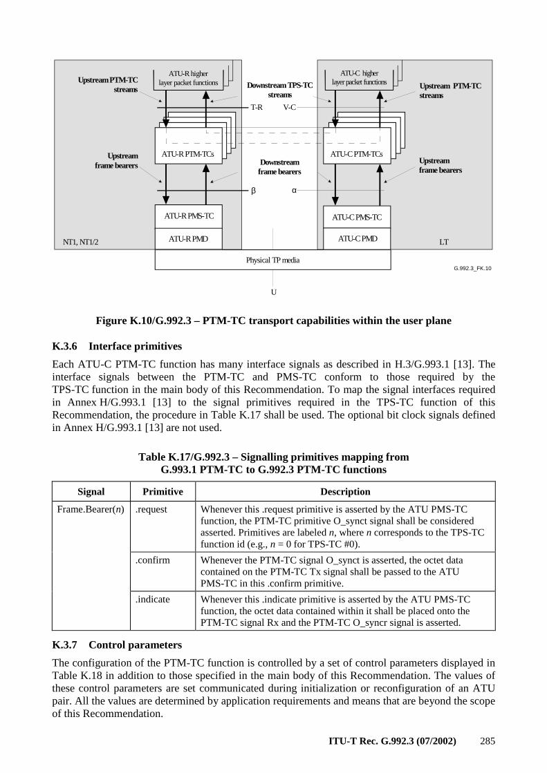
ITU-T Rec. G.992.3 (07/2002) 285
G.992.3_FK.10
ATU-R PTM-TCs
ATU-R higherlayer packet functions
ATU-C PTM-TCs
ATU-C higherlayer packet functions
Physical TP media
ATU-R PMS-TC ATU-C PMS-TC
Upstream PTM-TCstreams Upstream PTM-TC
streamsDownstream TPS-TC
streams
NT1, NT1/2 LT
Upstreamframe bearers
Upstreamframe bearers
ATU-R PMD ATU-C PMD
U
T-R V-C
β α
Downstreamframe bearers
Figure K.10/G.992.3 – PTM-TC transport capabilities within the user plane
K.3.6 Interface primitives
Each ATU-C PTM-TC function has many interface signals as described in H.3/G.993.1 [13]. The interface signals between the PTM-TC and PMS-TC conform to those required by the TPS-TC function in the main body of this Recommendation. To map the signal interfaces required in Annex H/G.993.1 [13] to the signal primitives required in the TPS-TC function of this Recommendation, the procedure in Table K.17 shall be used. The optional bit clock signals defined in Annex H/G.993.1 [13] are not used.
Table K.17/G.992.3 – Signalling primitives mapping from G.993.1 PTM-TC to G.992.3 PTM-TC functions
Signal Primitive Description
.request Whenever this .request primitive is asserted by the ATU PMS-TC function, the PTM-TC primitive O_synct signal shall be considered asserted. Primitives are labeled n, where n corresponds to the TPS-TC function id (e.g., n = 0 for TPS-TC #0).
.confirm Whenever the PTM-TC signal O_synct is asserted, the octet data contained on the PTM-TC Tx signal shall be passed to the ATU PMS-TC in this .confirm primitive.
Frame.Bearer(n)
.indicate Whenever this .indicate primitive is asserted by the ATU PMS-TC function, the octet data contained within it shall be placed onto the PTM-TC signal Rx and the PTM-TC O_syncr signal is asserted.
K.3.7 Control parameters
The configuration of the PTM-TC function is controlled by a set of control parameters displayed in Table K.18 in addition to those specified in the main body of this Recommendation. The values of these control parameters are set communicated during initialization or reconfiguration of an ATU pair. All the values are determined by application requirements and means that are beyond the scope of this Recommendation.
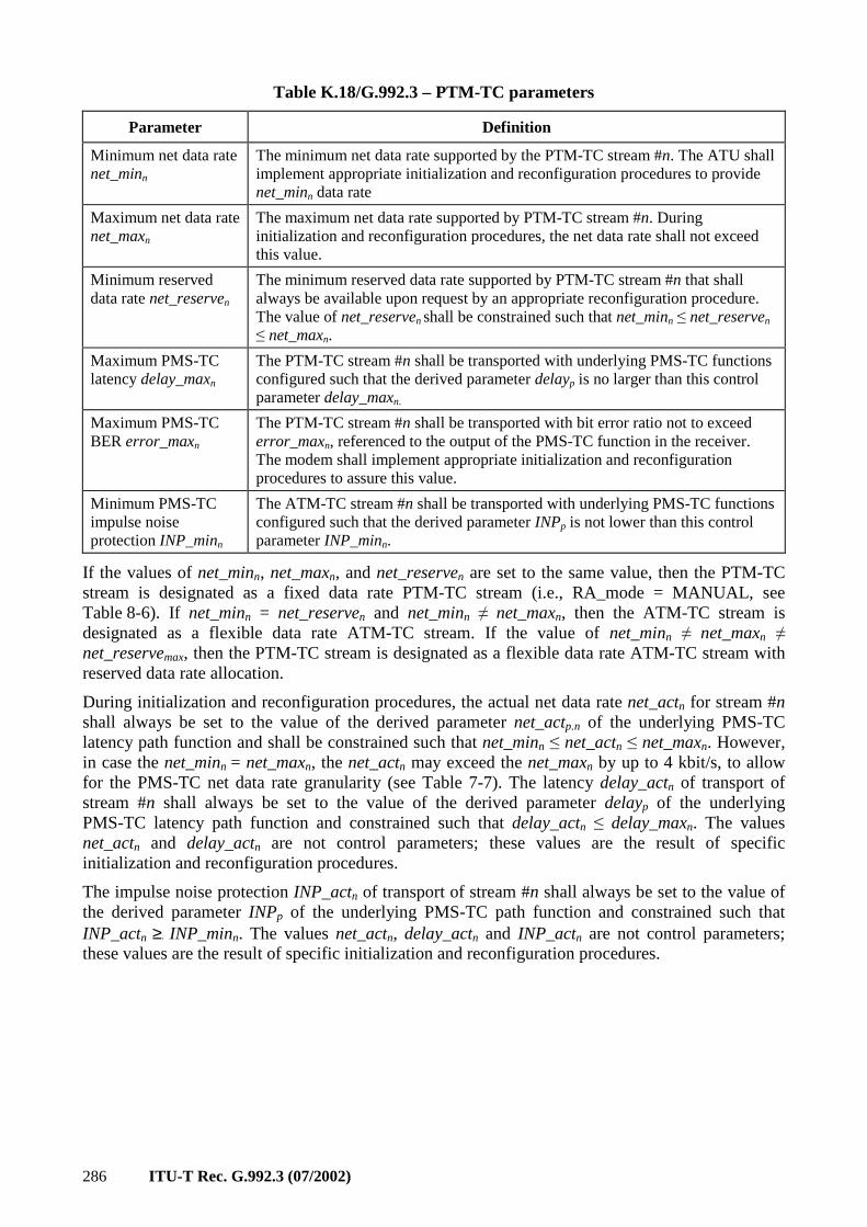
286 ITU-T Rec. G.992.3 (07/2002)
Table K.18/G.992.3 – PTM-TC parameters
Parameter Definition
Minimum net data rate net_minn
The minimum net data rate supported by the PTM-TC stream #n. The ATU shall implement appropriate initialization and reconfiguration procedures to provide net_minn data rate
Maximum net data rate net_maxn
The maximum net data rate supported by PTM-TC stream #n. During initialization and reconfiguration procedures, the net data rate shall not exceed this value.
Minimum reserved data rate net_reserven
The minimum reserved data rate supported by PTM-TC stream #n that shall always be available upon request by an appropriate reconfiguration procedure. The value of net_reserven shall be constrained such that net_minn ≤ net_reserven ≤ net_maxn.
Maximum PMS-TC latency delay_maxn
The PTM-TC stream #n shall be transported with underlying PMS-TC functions configured such that the derived parameter delayp is no larger than this control parameter delay_maxn.
Maximum PMS-TC BER error_maxn
The PTM-TC stream #n shall be transported with bit error ratio not to exceed error_maxn, referenced to the output of the PMS-TC function in the receiver. The modem shall implement appropriate initialization and reconfiguration procedures to assure this value.
Minimum PMS-TC impulse noise protection INP_minn
The ATM-TC stream #n shall be transported with underlying PMS-TC functions configured such that the derived parameter INPp is not lower than this control parameter INP_minn.
If the values of net_minn, net_maxn, and net_reserven are set to the same value, then the PTM-TC stream is designated as a fixed data rate PTM-TC stream (i.e., RA_mode = MANUAL, see Table 8-6). If net_minn = net_reserven and net_minn ≠ net_maxn, then the ATM-TC stream is designated as a flexible data rate ATM-TC stream. If the value of net_minn ≠ net_maxn ≠ net_reservemax, then the PTM-TC stream is designated as a flexible data rate ATM-TC stream with reserved data rate allocation.
During initialization and reconfiguration procedures, the actual net data rate net_actn for stream #n shall always be set to the value of the derived parameter net_actp.n of the underlying PMS-TC latency path function and shall be constrained such that net_minn ≤ net_actn ≤ net_maxn. However, in case the net_minn = net_maxn, the net_actn may exceed the net_maxn by up to 4 kbit/s, to allow for the PMS-TC net data rate granularity (see Table 7-7). The latency delay_actn of transport of stream #n shall always be set to the value of the derived parameter delayp of the underlying PMS-TC latency path function and constrained such that delay_actn ≤ delay_maxn. The values net_actn and delay_actn are not control parameters; these values are the result of specific initialization and reconfiguration procedures.
The impulse noise protection INP_actn of transport of stream #n shall always be set to the value of the derived parameter INPp of the underlying PMS-TC path function and constrained such that INP_actn ≥. INP_minn. The values net_actn, delay_actn and INP_actn are not control parameters; these values are the result of specific initialization and reconfiguration procedures.
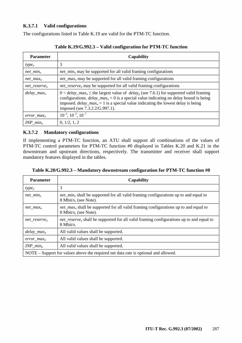
ITU-T Rec. G.992.3 (07/2002) 287
K.3.7.1 Valid configurations
The configurations listed in Table K.19 are valid for the PTM-TC function.
Table K.19/G.992.3 – Valid configuration for PTM-TC function
Parameter Capability
typen 3
net_minn net_minn may be supported for all valid framing configurations
net_maxn net_maxn may be supported for all valid framing configurations
net_reserven net_reserven may be supported for all valid framing configurations
delay_maxn 0 < delay_maxn ≤ the largest value of delayp (see 7.6.1) for supported valid framing configurations. delay_maxn = 0 is a special value indicating no delay bound is being imposed. delay_maxn = 1 is a special value indicating the lowest delay is being imposed (see 7.3.2.2/G.997.1).
error_maxn 10–3, 10–5, 10–7
INP_minn 0, 1/2, 1, 2
K.3.7.2 Mandatory configurations
If implementing a PTM-TC function, an ATU shall support all combinations of the values of PTM-TC control parameters for PTM-TC function #0 displayed in Tables K.20 and K.21 in the downstream and upstream directions, respectively. The transmitter and receiver shall support mandatory features displayed in the tables.
Table K.20/G.992.3 – Mandatory downstream configuration for PTM-TC function #0
Parameter Capability
typen 3
net_minn net_minn shall be supported for all valid framing configurations up to and equal to 8 Mbit/s, (see Note).
net_maxn net_maxn shall be supported for all valid framing configurations up to and equal to 8 Mbit/s, (see Note).
net_reserven net_reserven shall be supported for all valid framing configurations up to and equal to 8 Mbit/s.
delay_maxn All valid values shall be supported.
error_maxn All valid values shall be supported.
INP_minn All valid values shall be supported.
NOTE – Support for values above the required net data rate is optional and allowed.
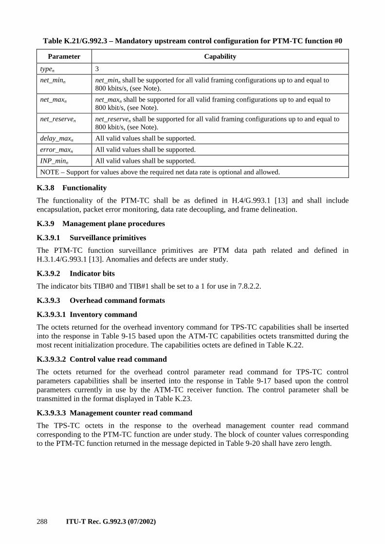
288 ITU-T Rec. G.992.3 (07/2002)
Table K.21/G.992.3 – Mandatory upstream control configuration for PTM-TC function #0
Parameter Capability
typen 3
net_minn net_minn shall be supported for all valid framing configurations up to and equal to 800 kbits/s, (see Note).
net_maxn net_maxn shall be supported for all valid framing configurations up to and equal to 800 kbit/s, (see Note).
net_reserven net_reserven shall be supported for all valid framing configurations up to and equal to 800 kbit/s, (see Note).
delay_maxn All valid values shall be supported.
error_maxn All valid values shall be supported.
INP_minn All valid values shall be supported.
NOTE – Support for values above the required net data rate is optional and allowed.
K.3.8 Functionality
The functionality of the PTM-TC shall be as defined in H.4/G.993.1 [13] and shall include encapsulation, packet error monitoring, data rate decoupling, and frame delineation.
K.3.9 Management plane procedures
K.3.9.1 Surveillance primitives
The PTM-TC function surveillance primitives are PTM data path related and defined in H.3.1.4/G.993.1 [13]. Anomalies and defects are under study.
K.3.9.2 Indicator bits
The indicator bits TIB#0 and TIB#1 shall be set to a 1 for use in 7.8.2.2.
K.3.9.3 Overhead command formats
K.3.9.3.1 Inventory command
The octets returned for the overhead inventory command for TPS-TC capabilities shall be inserted into the response in Table 9-15 based upon the ATM-TC capabilities octets transmitted during the most recent initialization procedure. The capabilities octets are defined in Table K.22.
K.3.9.3.2 Control value read command
The octets returned for the overhead control parameter read command for TPS-TC control parameters capabilities shall be inserted into the response in Table 9-17 based upon the control parameters currently in use by the ATM-TC receiver function. The control parameter shall be transmitted in the format displayed in Table K.23.
K.3.9.3.3 Management counter read command
The TPS-TC octets in the response to the overhead management counter read command corresponding to the PTM-TC function are under study. The block of counter values corresponding to the PTM-TC function returned in the message depicted in Table 9-20 shall have zero length.
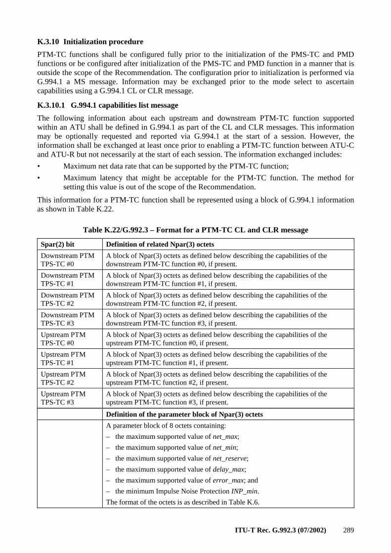
ITU-T Rec. G.992.3 (07/2002) 289
K.3.10 Initialization procedure
PTM-TC functions shall be configured fully prior to the initialization of the PMS-TC and PMD functions or be configured after initialization of the PMS-TC and PMD function in a manner that is outside the scope of the Recommendation. The configuration prior to initialization is performed via G.994.1 a MS message. Information may be exchanged prior to the mode select to ascertain capabilities using a G.994.1 CL or CLR message.
K.3.10.1 G.994.1 capabilities list message
The following information about each upstream and downstream PTM-TC function supported within an ATU shall be defined in G.994.1 as part of the CL and CLR messages. This information may be optionally requested and reported via G.994.1 at the start of a session. However, the information shall be exchanged at least once prior to enabling a PTM-TC function between ATU-C and ATU-R but not necessarily at the start of each session. The information exchanged includes:
• Maximum net data rate that can be supported by the PTM-TC function;
• Maximum latency that might be acceptable for the PTM-TC function. The method for setting this value is out of the scope of the Recommendation.
This information for a PTM-TC function shall be represented using a block of G.994.1 information as shown in Table K.22.
Table K.22/G.992.3 – Format for a PTM-TC CL and CLR message
Spar(2) bit Definition of related Npar(3) octets
Downstream PTM TPS-TC #0
A block of Npar(3) octets as defined below describing the capabilities of the downstream PTM-TC function #0, if present.
Downstream PTM TPS-TC #1
A block of Npar(3) octets as defined below describing the capabilities of the downstream PTM-TC function #1, if present.
Downstream PTM TPS-TC #2
A block of Npar(3) octets as defined below describing the capabilities of the downstream PTM-TC function #2, if present.
Downstream PTM TPS-TC #3
A block of Npar(3) octets as defined below describing the capabilities of the downstream PTM-TC function #3, if present.
Upstream PTM TPS-TC #0
A block of Npar(3) octets as defined below describing the capabilities of the upstream PTM-TC function #0, if present.
Upstream PTM TPS-TC #1
A block of Npar(3) octets as defined below describing the capabilities of the upstream PTM-TC function #1, if present.
Upstream PTM TPS-TC #2
A block of Npar(3) octets as defined below describing the capabilities of the upstream PTM-TC function #2, if present.
Upstream PTM TPS-TC #3
A block of Npar(3) octets as defined below describing the capabilities of the upstream PTM-TC function #3, if present.
Definition of the parameter block of Npar(3) octets
A parameter block of 8 octets containing:
– the maximum supported value of net_max;
– the maximum supported value of net_min;
– the maximum supported value of net_reserve;
– the maximum supported value of delay_max;
– the maximum supported value of error_max; and
– the minimum Impulse Noise Protection INP_min.
The format of the octets is as described in Table K.6.
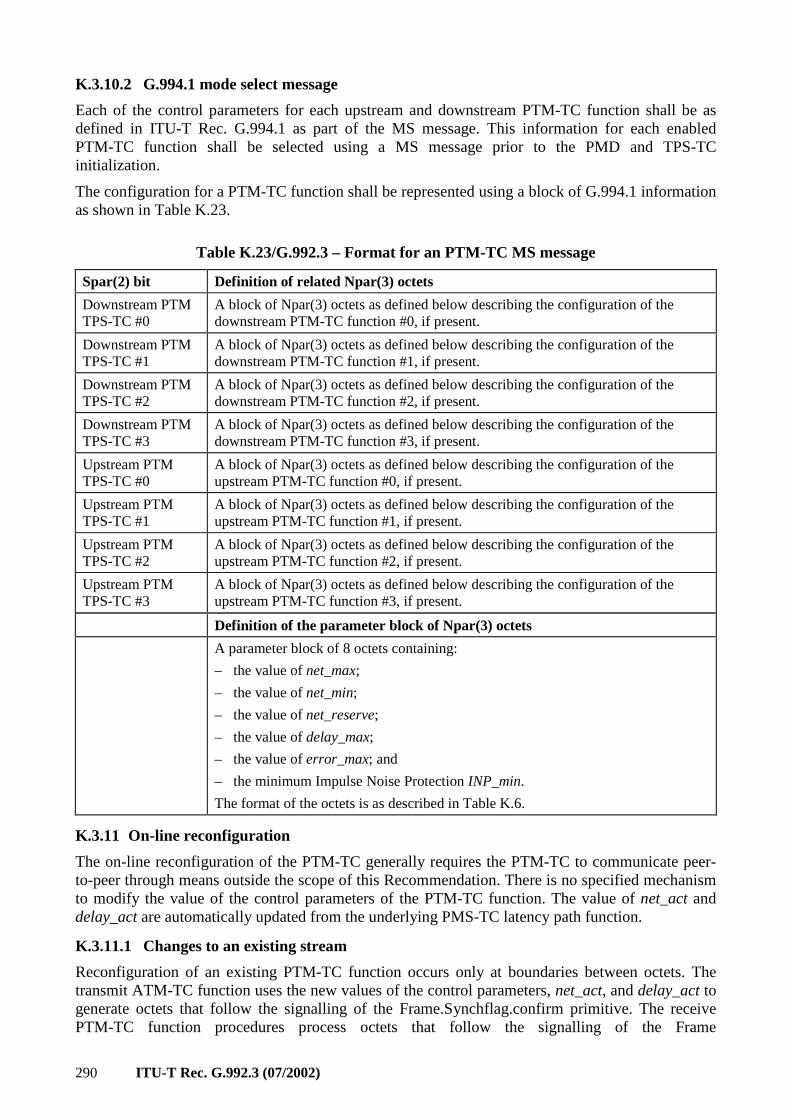
290 ITU-T Rec. G.992.3 (07/2002)
K.3.10.2 G.994.1 mode select message
Each of the control parameters for each upstream and downstream PTM-TC function shall be as defined in ITU-T Rec. G.994.1 as part of the MS message. This information for each enabled PTM-TC function shall be selected using a MS message prior to the PMD and TPS-TC initialization.
The configuration for a PTM-TC function shall be represented using a block of G.994.1 information as shown in Table K.23.
Table K.23/G.992.3 – Format for an PTM-TC MS message
Spar(2) bit Definition of related Npar(3) octets
Downstream PTM TPS-TC #0
A block of Npar(3) octets as defined below describing the configuration of the downstream PTM-TC function #0, if present.
Downstream PTM TPS-TC #1
A block of Npar(3) octets as defined below describing the configuration of the downstream PTM-TC function #1, if present.
Downstream PTM TPS-TC #2
A block of Npar(3) octets as defined below describing the configuration of the downstream PTM-TC function #2, if present.
Downstream PTM TPS-TC #3
A block of Npar(3) octets as defined below describing the configuration of the downstream PTM-TC function #3, if present.
Upstream PTM TPS-TC #0
A block of Npar(3) octets as defined below describing the configuration of the upstream PTM-TC function #0, if present.
Upstream PTM TPS-TC #1
A block of Npar(3) octets as defined below describing the configuration of the upstream PTM-TC function #1, if present.
Upstream PTM TPS-TC #2
A block of Npar(3) octets as defined below describing the configuration of the upstream PTM-TC function #2, if present.
Upstream PTM TPS-TC #3
A block of Npar(3) octets as defined below describing the configuration of the upstream PTM-TC function #3, if present.
Definition of the parameter block of Npar(3) octets
A parameter block of 8 octets containing:
– the value of net_max;
– the value of net_min;
– the value of net_reserve;
– the value of delay_max;
– the value of error_max; and
– the minimum Impulse Noise Protection INP_min.
The format of the octets is as described in Table K.6.
K.3.11 On-line reconfiguration
The on-line reconfiguration of the PTM-TC generally requires the PTM-TC to communicate peer-to-peer through means outside the scope of this Recommendation. There is no specified mechanism to modify the value of the control parameters of the PTM-TC function. The value of net_act and delay_act are automatically updated from the underlying PMS-TC latency path function.
K.3.11.1 Changes to an existing stream
Reconfiguration of an existing PTM-TC function occurs only at boundaries between octets. The transmit ATM-TC function uses the new values of the control parameters, net_act, and delay_act to generate octets that follow the signalling of the Frame.Synchflag.confirm primitive. The receive PTM-TC function procedures process octets that follow the signalling of the Frame
ITU-T Rec. G.992.3 (07/2002) 291
Synchflag.indicate primitive using the new values of the control parameters.
K.3.12 Power management mode
The procedures defined for the PTM-TC function are intended for use while the ATU link is in power management states L0 and L2.
K.3.12.1 L0 link state operation
The PTM-TC function shall operate according to the data plane procedures defined in K.3.8 and K.3.9 as well as according to those in the main body of the Recommendation referring to this annex while the link is in power management state L0. All control parameter definitions and conditions provided in K.3.7 as well as according to those provided in the main body of the Recommendation referring to this text shall apply.
K.3.12.1.1 Transition to L2 link state operation
During a transition from link state L0 to state L2, the value of control parameters are not modified. However, the value of net_act and delay_act are automatically updated to match those of the underlying PMS-TC latency path function. Following the successful completion of the protocol described in the main body of the Recommendation referring to this annex, the coordinated entry into the L2 link state shall be made as described in K.3.11.1.
K.3.12.1.2 Transition to L3 link state operation
The orderly shutdown of the ATU shall be as described in the main body of the Recommendation referring to this annex. No specific PTM-TC tear-down procedure is specified.
K.3.12.2 L2 link state operation
The ATM-TC function shall operate according to the data plane procedures defined in K.3.8 and K.3.9, as well as according to those in the main body of the Recommendation referring to this annex while the link is in power management state L2. All control parameter definitions provided in K.3.7 as well as according to those provided in the main body of the Recommendation referring to this text shall apply. However, the operating limits imposed by the control parameters net_min, net_reserve, and delay_max shall not apply while in the L2 link state.
During the link state L2, the ATU-C ATM-TC shall monitor its interface for the arrival of primitives that indicate that data rates larger than the reduced data rates must be transported to the ATU-R. When this condition is detected, the ATU-C shall use the procedure described in 9.5.3.4 to return to the link state L0.
K.3.12.2.1 Transition to L0 link state operation
Entry into the L0 link state shall be preceded by the protocol described in the main body of the Recommendation referring to this annex. The values of the control parameters are not modified upon return to the L2 link state; however, during a transition from link state L2 to state L0, the values of net_act and delay_act are automatically updated to match those of the underlying PMS-TC latency path function. Following the successful completion of the protocol described in the main body of the Recommendation referring to this annex, the coordinated entry into the L0 link state shall be made as described in K.3.11.1.
K.3.12.2.2 Transition to L3 link state operation
Transitions to link state L3 shall be as described in the main body of the Recommendation referring to this annex. No specific PTM-TC tear-down procedure is specified.
K.3.12.3 L3 link state operation
In the L3 link state, no specific procedures are specified for the PTM-TC function.
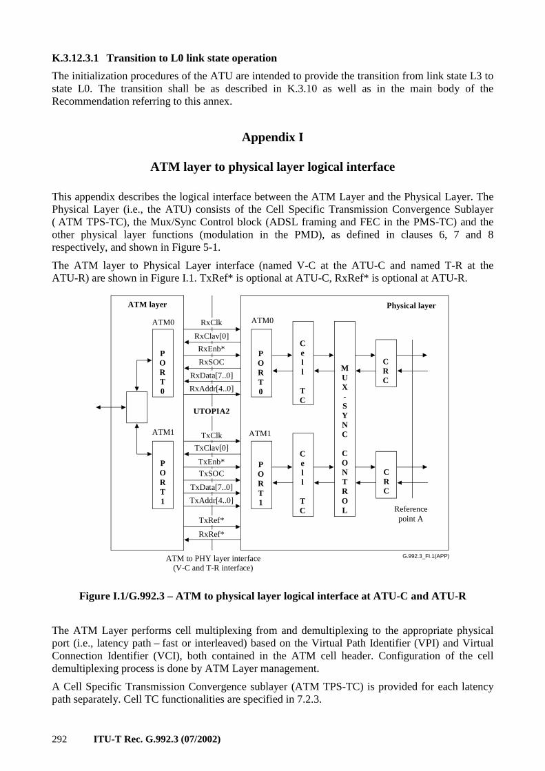
292 ITU-T Rec. G.992.3 (07/2002)
K.3.12.3.1 Transition to L0 link state operation
The initialization procedures of the ATU are intended to provide the transition from link state L3 to state L0. The transition shall be as described in K.3.10 as well as in the main body of the Recommendation referring to this annex.
Appendix I
ATM layer to physical layer logical interface
This appendix describes the logical interface between the ATM Layer and the Physical Layer. The Physical Layer (i.e., the ATU) consists of the Cell Specific Transmission Convergence Sublayer ( ATM TPS-TC), the Mux/Sync Control block (ADSL framing and FEC in the PMS-TC) and the other physical layer functions (modulation in the PMD), as defined in clauses 6, 7 and 8 respectively, and shown in Figure 5-1.
The ATM layer to Physical Layer interface (named V-C at the ATU-C and named T-R at the ATU-R) are shown in Figure I.1. TxRef* is optional at ATU-C, RxRef* is optional at ATU-R.
G.992.3_FI.1(APP)
RxRef*
TxRef*
UTOPIA2
TxClk
TxEnb*
TxSOC
RxClk
RxEnb*
RxSOC
ATM layer
ATM0
ATM1
Physical layer
ATM1
ATM0
PORT0
PORT1
PORT0
Cell
TC
MUX-SYNC
CONTROL
CRC
CRC
Cell
TC
PORT1
RxClav[0]
RxData[7..0]
RxAddr[4..0]
TxClav[0]
TxData[7..0]
TxAddr[4..0]
ATM to PHY layer interface(V-C and T-R interface)
Referencepoint A
Figure I.1/G.992.3 – ATM to physical layer logical interface at ATU-C and ATU-R
The ATM Layer performs cell multiplexing from and demultiplexing to the appropriate physical port (i.e., latency path – fast or interleaved) based on the Virtual Path Identifier (VPI) and Virtual Connection Identifier (VCI), both contained in the ATM cell header. Configuration of the cell demultiplexing process is done by ATM Layer management.
A Cell Specific Transmission Convergence sublayer (ATM TPS-TC) is provided for each latency path separately. Cell TC functionalities are specified in 7.2.3.
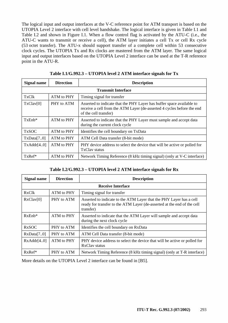
ITU-T Rec. G.992.3 (07/2002) 293
The logical input and output interfaces at the V-C reference point for ATM transport is based on the UTOPIA Level 2 interface with cell level handshake. The logical interface is given in Table I.1 and Table I.2 and shown in Figure I.1. When a flow control flag is activated by the ATU-C (i.e., the ATU-C wants to transmit or receive a cell), the ATM layer initiates a cell Tx or cell Rx cycle (53 octet transfer). The ATU-x should support transfer of a complete cell within 53 consecutive clock cycles. The UTOPIA Tx and Rx clocks are mastered from the ATM layer. The same logical input and output interfaces based on the UTOPIA Level 2 interface can be used at the T-R reference point in the ATU-R.
Table I.1/G.992.3 – UTOPIA level 2 ATM interface signals for Tx
Signal name Direction Description
Transmit Interface
TxClk ATM to PHY Timing signal for transfer
TxClav[0] PHY to ATM Asserted to indicate that the PHY Layer has buffer space available to receive a cell from the ATM Layer (de-asserted 4 cycles before the end of the cell transfer)
TxEnb* ATM to PHY Asserted to indicate that the PHY Layer must sample and accept data during the current clock cycle
TxSOC ATM to PHY Identifies the cell boundary on TxData
TxData[7..0] ATM to PHY ATM Cell Data transfer (8-bit mode)
TxAddr[4..0] ATM to PHY PHY device address to select the device that will be active or polled for TxClav status
TxRef* ATM to PHY Network Timing Reference (8 kHz timing signal) (only at V-C interface)
Table I.2/G.992.3 – UTOPIA level 2 ATM interface signals for Rx
Signal name Direction Description
Receive Interface
RxClk ATM to PHY Timing signal for transfer
RxClav[0] PHY to ATM Asserted to indicate to the ATM Layer that the PHY Layer has a cell ready for transfer to the ATM Layer (de-asserted at the end of the cell transfer)
RxEnb* ATM to PHY Asserted to indicate that the ATM Layer will sample and accept data during the next clock cycle
RxSOC PHY to ATM Identifies the cell boundary on RxData
RxData[7..0] PHY to ATM ATM Cell Data transfer (8-bit mode)
RxAddr[4..0] ATM to PHY PHY device address to select the device that will be active or polled for RxClav status
RxRef* PHY to ATM Network Timing Reference (8 kHz timing signal) (only at T-R interface)
More details on the UTOPIA Level 2 interface can be found in [B5].
294 ITU-T Rec. G.992.3 (07/2002)
Appendix II
Compatibility with other customer premises equipment
G.992.3 ATU-R transceivers may share the CPE wiring plant with other equipment, e.g., networking devices, over the POTS splitter.
Some networking devices can operate above 4 MHz on customer premises phone wiring. To prevent signals from such networking devices from aliasing into the G.992.3 frequency band, the inclusion of an adequate downstream receiver anti-aliasing filter in the G.992.3 ATU-R is recommended, collocated with the ATU-R shown in Figures 5-4 and 5-5. The filter may take the form of an external in-line filter, may be integrated into the G.992.3 ATU-R, or may be integrated in the POTS splitter as specified in Annex E.
Home networking devices may coexist with voice terminals and non-voice terminals on the TELE/POTS port side (the port in Figures 5-4 and 5-5 that attaches to the wire leading to the telephone set or voiceband modem) of the POTS splitter used in the G.992.3 application to isolate the customer premises wiring from the ADSL signal. It is desirable that the remote POTS splitter be compatible with other customer premises wiring devices (e.g., the TELE/POTS port impedance above 4 MHz should be considered).
Appendix III
The impact of primary protection devices on line balance
III.1 Scope
This appendix is to help guide operators in choosing appropriate protection devices for lines deploying G.992.3. It does not address the intended protection characteristics of these devices, only the potential unintended effects on line impedance and line balance. A significant change in impedance will reduce the received signal. Imbalance can impair performance on the imbalanced line by increasing the coupled crosstalk and RFI ingress. It can also impair performance on other pairs in the cable by increasing the cross talk, and cause interference into devices outside the cable by causing RFI egress. Each of these issues is discussed.
III.2 Background
In many jurisdictions, primary protection devices are required to limit the chance of fire or a shock to personnel. A secondary purpose of these protection devices is to reduce the probability of equipment damage, through over-voltage or over-current, when exposed to foreign potentials as can be caused by lightning, power line contacts, power line induction, or ground potential rise. Figure III.1 shows a typical arrangement of protection devices. It should be noted that not all protection components will be required in all jurisdictions, and different arrangements are possible.
In many jurisdictions, there is a required first level of protection at the building entry. This is usually in the Network Interface Device (NID) at the subscriber premises and at the Main Distribution Frame (MDF) in the Central Office. This first level of protection is intended to protect against personal and property damage but may be followed by additional protection devices to fully protect against equipment damage. When the protector is legally required and is located at the customer premises location, it is referred to as the Primary Protection device. When it is located in the NID it is also referred to as the station protector.
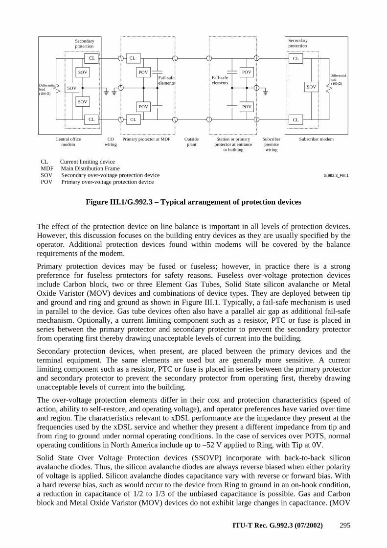
ITU-T Rec. G.992.3 (07/2002) 295
G.992.3_FIII.1
Subscriber modem
SOV
CL
CL
POV
POV
SOV
SOV
POV
POV
SOV
CL
CL
CL
CL
Secondary protection
Secondary protection
Differential load (100 Ω)Differential
load(100 Ω)
Fail-safe elements
Fail-safe elements
Central office modem
CO wiring
Primary protector at MDF Outsideplant
Station or primary protector at entrance
to building
Subcriber premise wiring
CL Current limiting deviceMDF Main Distribution FrameSOV Secondary over-voltage protection devicePOV Primary over-voltage protection device
Figure III.1/G.992.3 – Typical arrangement of protection devices
The effect of the protection device on line balance is important in all levels of protection devices. However, this discussion focuses on the building entry devices as they are usually specified by the operator. Additional protection devices found within modems will be covered by the balance requirements of the modem.
Primary protection devices may be fused or fuseless; however, in practice there is a strong preference for fuseless protectors for safety reasons. Fuseless over-voltage protection devices include Carbon block, two or three Element Gas Tubes, Solid State silicon avalanche or Metal Oxide Varistor (MOV) devices and combinations of device types. They are deployed between tip and ground and ring and ground as shown in Figure III.1. Typically, a fail-safe mechanism is used in parallel to the device. Gas tube devices often also have a parallel air gap as additional fail-safe mechanism. Optionally, a current limiting component such as a resistor, PTC or fuse is placed in series between the primary protector and secondary protector to prevent the secondary protector from operating first thereby drawing unacceptable levels of current into the building.
Secondary protection devices, when present, are placed between the primary devices and the terminal equipment. The same elements are used but are generally more sensitive. A current limiting component such as a resistor, PTC or fuse is placed in series between the primary protector and secondary protector to prevent the secondary protector from operating first, thereby drawing unacceptable levels of current into the building.
The over-voltage protection elements differ in their cost and protection characteristics (speed of action, ability to self-restore, and operating voltage), and operator preferences have varied over time and region. The characteristics relevant to xDSL performance are the impedance they present at the frequencies used by the xDSL service and whether they present a different impedance from tip and from ring to ground under normal operating conditions. In the case of services over POTS, normal operating conditions in North America include up to –52 V applied to Ring, with Tip at 0V.
Solid State Over Voltage Protection devices (SSOVP) incorporate with back-to-back silicon avalanche diodes. Thus, the silicon avalanche diodes are always reverse biased when either polarity of voltage is applied. Silicon avalanche diodes capacitance vary with reverse or forward bias. With a hard reverse bias, such as would occur to the device from Ring to ground in an on-hook condition, a reduction in capacitance of 1/2 to 1/3 of the unbiased capacitance is possible. Gas and Carbon block and Metal Oxide Varistor (MOV) devices do not exhibit large changes in capacitance. (MOV
296 ITU-T Rec. G.992.3 (07/2002)
devices are technically a solid state device but do not appear to be sold under the name SSOVP by the industry.) Hybrid devices typically combine a gas tube protection device with a MOV device to get the desirable characteristics of each. There is, however, nothing that would prevent the combination of Gas tubes with Silicon diodes from being referred to as a hybrid device.
III.3 Recommended maximum capacitance of over-voltage protectors
Solid state based devices for telephony typically have capacitance in the 60 to 200 pF range with 0 DC bias, and Gas Tube devices in the 2-30 pF range. This capacitance is significant as it shunts the differential impedance of the line.
To maintain a minimum of 1000 Ω in parallel with the differential (nominally 100 Ω load requires the capacitance be less than the value shown in the Table III.1). Note that two devices appear in series from tip to ring, thus a single device must present a minimum of 500 Ω.
Table III.1/G.992.3 – Maximum capacitance to ground to maintain 500 Ω at top frequency of xDSL service
ITU-T Recommendation Top frequency of Recommendation
Max. capacitance (pF)
G.991.2 385 kHz 826
G.992.2 552 kHz 575
G.992.1 1.024 MHz 310
G.993.1 and G.989.1 10 MHz 31
In North America, it is unlikely that existing devices will exceed 200 pF as this is the maximum capacitance allowed Tip to Ground, Ring to Ground, or Tip to Ring by the regional specification on primary protectors (see III.5). Thus, for G.991.2, G.992.1, G.992.2, G.992.3 and G.992.4, this parameter is not a significant factor. For G.993.1, and G.989.1 this requirement on impedance would tend to limit the protection choices to gas tube, or carbon block. A lower impedance of 250 Ω or 62 pF would also allow Hybrid devices using MOV elements. Given the widely varying line impedance at these frequencies, the lowering of the differential impedance of the line from approximately 100 Ω to approximately 83 Ω that would occur with this additional capacitance may be acceptable.
III.4 Capacitance matching requirements of over-voltage protectors
Line balance is important to xDSL services as it determines the level of cross talk within a cable, and the ingress and egress from the cable. The amount of signal transferred between two pairs due to imbalance is a function of the product of the imbalance of the interfering pair and that of the victim pair. Thus, if each had 40-dB balance, the cross talk would be down around 80 dB from the differential level on the interfering pair.
Data from cable measurements at 80 kHz of NEXT cross talk in PIC can be used to generate Table III.2. From these results, we can see that at 40 dB balance no significant change will occur to the performance predictions based on 1% worst coupling in the frequencies from 552 kHz to 10 MHz. However, it would have a small impact on the 50% cross talk levels in a sparsely filled cable. Thus, even 40-dB balance for frequencies above 500 kHz will not invalidate cross talk predictions.
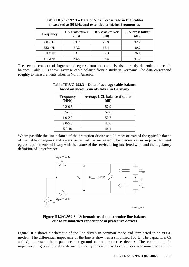
ITU-T Rec. G.992.3 (07/2002) 297
Table III.2/G.992.3 – Data of NEXT cross talk in PIC cables measured at 80 kHz and extended to higher frequencies
Frequency 1% cross talker
(dB) 10% cross talker
(dB) 50% cross talker
(dB)
80 kHz 69.7 78.9 92.7
552 kHz 57.2 66.4 80.2
1.0 MHz 53.1 62.3 76.1
10 MHz 38.3 47.5 61.2
The second concern of ingress and egress from the cable is also directly dependent on cable balance. Table III.3 shows average cable balance from a study in Germany. The data correspond roughly to measurements taken in North America.
Table III.3/G.992.3 – Data of average cable balance based on measurements taken in Germany
Frequency (MHz)
Average LCL balance of cables (dB)
0.2-0.5 57.9
0.5-1.0 54.6
1.0-2.0 50.7
2.0-5.0 47.6
5.0-10 44.1
Where possible the line balance of the protection device should meet or exceed the typical balance of the cable or ingress and egress issues will be increased. The precise values required to meet egress requirements will vary with the nature of the service being interfered with, and the regulatory definition of "interference".
G.992.3_FIII.2
Vcm
ZL/2 = 50 Ω
ZL/2 = 50 Ω
C1
C2
2Zcm
2Zcm
Vdiff Rload = 100 Ω
Figure III.2/G.992.3 – Schematic used to determine line balance due to mismatched capacitance in protective devices
Figure III.2 shows a schematic of the line driven in common mode and terminated in an xDSL modem. The differential impedance of the line is shown as a simplified 100 Ω. The capacitors, C1 and C2, represent the capacitance to ground of the protective devices. The common mode impedance to ground could be defined either by the cable itself or the modem terminating the line.
298 ITU-T Rec. G.992.3 (07/2002)
The common mode impedance of the cable can be highly variable as it depends on the position of the pair with respect to ground. The full equation for balance given the above circuit is:
[ ]
++ω+ω+
++ω
++ω
ω−ω×
=
LcmLLcmLcm
L
ZZCjCj
RZZCj
ZZCj
CjCjZ
dBeLineBalanc
41122
122
1
2
log20
)(
2121
12
10
When ZL = RL and Zcm, 1/jωC1, 1/jωC2 >> RL, then, the formula simplifies to:
( )( ) ( )fCfCCdBeLineBalanc ×π×∆××=×−×π××= 50log2050log20)( 101210
With ZL = RL = 100 Ω, reducing Zcm from infinite to 200 Ω will improve the balances in Table III.4 by approximately 1.5 dB.
Table III.4/G.992.3 – Required capacitance matching with Zcm = 10 kΩ to achieve balances from 40 to 60 dB at the top frequency of several xDSL services
Max. ∆C between tip and ground, and ring and ground to maintain stated Balance
ITU-T Recommendation
Top frequency of Recommendation 40 dB
Balance (pF)
45 dB Balance
(pF)
50 dB Balance
(pF)
55 dB Balance
(pF)
60 dB Balance
(pF)
G.991.2 385 kHz 165 92 52 29 16
G.992.2 G.992.4
552 kHz 115 64 36 20 11
G.992.1 G.992.3
1.104 MHz 57 32 18 10 5
G.989.1 10 MHz 6.3 3.5 2.0 1.1 0.6
G.993.1 12 MHz 5.3 2.9 1.6 0.9 0.5
The ∆C must be maintained under all the bias conditions the protection devices will be placed. Thus, if POTS service is on the same line as the xDSL service the ∆C must be maintained when one device has –52 bias (North American numbers) and the other has zero bias applied. If no POTS service will ever be present, consideration must be made for the inherent impedance match without bias of the two devices within the protector to each other, the peak signal swing, and any sealing currents that may be applied to keep the splices clean.
III.5 References
The regional specification on primary protectors applicable in North-America is:
GR-974-CORE Issue 2, Generic Requirements for Telecommunications Line Protector Units (TLPUs), December 1999.
The ITU-T K-series Recommendations contain requirements for resistibility of telecommunication equipment against electro-magnetic effects and characteristics of protection components.
Telecommunication equipment is required to have an inherent resistibility so that it can be installed without additional protection components when the risk for overvoltages or overcurrents is deemed sufficiently low by the operator. When there is deemed to be a significant risk for electro-magnetic threats that exceed the inherent resistibility of the equipment, additional protection components are installed on the telecommunication and/or power lines. These components are called "primary
ITU-T Rec. G.992.3 (07/2002) 299
protection" and they are installed by the operator. The resistibility Recommendations contain tests to insure the coordination between primary protection and the inherent protection of the equipment. ITU-T Rec. K.46 provides guidance for the operators on the decision to install primary protection.
Resistibility Recommendations:
• K.44 (2/2000) defines the different resistibility tests.
• K.20 (2/2000) specifies the applicable tests and acceptance criteria for equipment installed in the central office, e.g., Access Node.
• K.21 (10/2000) specifies the applicable tests and acceptance criteria for equipment installed on the customer premises, e.g., ADSL modem.
• K.45 (2/2000) specifies the applicable tests and acceptance criteria for equipment installed in the outside plant, e.g., Access Node installed in a cabinet.
Recommendations on protective components:
• K.36 (5/1996) provides guidance on the selection of protective components.
• K.12 (2/2000) specifies the characteristics of different types of gas discharge tubes that can be installed in telecommunication networks.
Characteristics related to the transmission capabilities of the line:
– Insulation resistance higher than 1000 MΩ initially, higher than 100 MΩ after the life tests;
– Capacitance less than 20 pF between terminals. This characteristic is not tested after the life tests.
• K.28 (3/1993) specifies the characteristics of semi-conductor arrestor assemblies.
Characteristics related to the transmission capabilities of the line:
– Insulation resistance 165 KΩ to 100 MΩ, depending on the applied DC voltage;
– Capacitance less than 200 pF between any 2 terminals. The capacitance measurement is not specified with a DC bias.
• K.30 (3/1993) defines characteristics of positive temperature coefficient (PTC) thermistors used for overcurrent protection, and provides test methods. It does not specify the values of the different parameters as these may be very different depending on the application.
Appendix IV
Bibliography
[B1] ITU-T Recommendation G.995.1 (2001), Overview of digital subscriber line (DSL) Recommendations.
[B2] ITU-T Recommendation O.41 (1994), Psophometer for use on telephone-type circuits.
[B3] ITU-T Recommendation V.11 (1996), Electrical characteristics for balanced double-current interchange circuits operating at data signalling rates up to 10 Mbit/s.
[B4] Technical Report No. 28 (1994), A Technical Report on High-bit rate Digital Subscriber Lines, Committee T1-Telecommunications.
[B5] ATM Forum (June 1995), Specification af.phy-0039.000, Utopia Level 2: Version 1.0.
[B6] ANSI/EIA/TIA-571 (1991), Environmental considerations for telephone terminals.
300 ITU-T Rec. G.992.3 (07/2002)
[B7] ANSI T1.101 (1994), Synchronization Interface Standards for Digital Networks, Committee T1-Telecommunications, 1997.
[B8] ANSI T1.413 (1995), Network and Customer Installation Interfaces – Asymmetrical Digital Subscriber Line (ADSL) Metallic Interface.
[B9] ANSI T1.601 (1993), Telecommunications – Interface between carriers and customer installations – Analogue voice-grade switched access lines using loop-start and ground-start signalling.
[B10] ANSI T1.421 (2002), In-Line Filter for Use with Voiceband Terminal Equipment Operating on the Same Wire Pair with High Frequency (up to 12 MHz) Devices.
[B11] ANSI T1.417 (2001), Spectrum Management For Loop Transmission Systems.
[B12] IEEE Standard 455 (1985), Test procedures for measuring longitudinal balance of telephone equipment operating in the voiceband.
[B13] ITU-T Recommendation K.20 (2000), Resistibility of telecommunication equipment installed in the telecommunications centre to overvoltages and overcurrents.
[B14] ITU-T Recommendation K.21 (2000), Resistibility of telecommunication equipment installed in customer premises to overvoltages and overcurrents.
[B15] Underwriter Laboratories, Inc. UL 60950, Third Edition, Standard for Safety of Information Technology Equipment.
[B16] CENELEC EN 60950-1 (2001), Information technology equipment – Safety – Part 1: General Requirements.
[B17] ATM Forum (March 1999), Specification af.phy-0086.001, Inverse Multiplexing for ATM (IMA), Version 1.1.
[B18] ITU-T Recommendation G.712 (2001), Transmission performance characteristics of pulse code modulation channels.
[B19] ITU-T Recommendation Q.552 (2001), Transmission characteristics at 2-wire analogue interfaces of digital exchanges.
[B20] ITU-T Recommendation G.121 (1993), Loudness ratings (LRs) of national systems.

Printed in Switzerland Geneva, 2003
SERIES OF ITU-T RECOMMENDATIONS
Series A Organization of the work of ITU-T
Series B Means of expression: definitions, symbols, classification
Series C General telecommunication statistics
Series D General tariff principles
Series E Overall network operation, telephone service, service operation and human factors
Series F Non-telephone telecommunication services
Series G Transmission systems and media, digital systems and networks
Series H Audiovisual and multimedia systems
Series I Integrated services digital network
Series J Cable networks and transmission of television, sound programme and other multimedia signals
Series K Protection against interference
Series L Construction, installation and protection of cables and other elements of outside plant
Series M TMN and network maintenance: international transmission systems, telephone circuits, telegraphy, facsimile and leased circuits
Series N Maintenance: international sound programme and television transmission circuits
Series O Specifications of measuring equipment
Series P Telephone transmission quality, telephone installations, local line networks
Series Q Switching and signalling
Series R Telegraph transmission
Series S Telegraph services terminal equipment
Series T Terminals for telematic services
Series U Telegraph switching
Series V Data communication over the telephone network
Series X Data networks and open system communications
Series Y Global information infrastructure and Internet protocol aspects
Series Z Languages and general software aspects for telecommunication systems
Related Documents