UPC 2009 – August 2007 ROP SUBMITTER: Add new text as follows: 1212.4.1 Where installed at a manifold, the appliance shutoff valve shall be located within 50 ft (15 m) of the appliance served, measured in a straight line, and shall be readily accessible and permanently identified. The piping from the manifold to within 6 ft of the appliance shall be designed, sized and installed in accordance with Chapter 12 [NFPA 54: 9.6.4.3] (Renumber remaining text) The change adds a paragraph extracted from NFPA 54 and clarifies the committee’s intent on how to measure the distance. SUBSTANTIATION: RECOMMENDATION: UPC 2009 1212.4.1 Accept as Submitted UPC Technical Committee Proposal 171.02 - TOTAL ELIGIBLE TO VOTE: 28 VOTING RESULTS: AFFIRMATIVE: 19, NEGATIVE: 5, NOT RETURNED: 4 Bloice, Murray, Nikravi, Soskin EXPLANATION OF NEGATIVE: ADLER: I disagree with the Committee recommendation to Accept. This new (to UPC/UMC) provision is entirely too permissive and completely disregards accepted safety practices. Allowing a shut-off valve to be 50 ft from the appliance it serves is contrary to commonsense. Despite the fact that much of this language is extracted from the National Fuel-gas Code, there has to be a point when the line is drawn and we say this is going too far afield from what can be accepted. This proposal clearly crosses over that line. FABRA: I disagree with the committee’s decision to accept. I believe the UMC rejected this change. A gas shut off being located up to 50 feet from the appliance being served could have very fatal outcomes. In a leak situation, this would lead to confusion as to where to shut off the gas during a time when every second is important. HAMILTON: I disagree with the committee’s decision to accept. I believe the UMC rejected this change. A gas shut off being located up to 50 feet from the appliance being served could have very fatal outcomes. In a leak situation, this would lead to confusion as to where to shut off the gas during a time when every second is important. RODIO: I disagree with the committee decision to approve. This change will allow appliance shut off valves to be located up to fifty (50) feet from the appliance in a straight line. It would be possible to install a gas manifold in a gas meter room and run a line up five stories to a stove. Appliances should have a shut off valve close to the appliance they serve not some remote part of a building that the owner may have no access to. It is easy to visualize a condominium owner with a broken supply line running all over the unit trying to find out how to shut of his gas before the big BOOM. TRAFTON: I believe it is dangerous to have only one shut-off valve 50 feet away from the appliances. Present code language is preferred. COMMITTEE ACTION: Item # 201

Welcome message from author
This document is posted to help you gain knowledge. Please leave a comment to let me know what you think about it! Share it to your friends and learn new things together.
Transcript
UPC 2009 – August 2007 ROP
SUBMITTER:
Add new text as follows:
1212.4.1 Where installed at a manifold, the appliance shutoff valve shall be located within 50 ft (15 m) of the appliance served, measured in a straight line, and shall be readily accessible and permanently identified. The pipingfrom the manifold to within 6 ft of the appliance shall be designed, sized and installed in accordance with Chapter 12[NFPA 54: 9.6.4.3]
(Renumber remaining text)
The change adds a paragraph extracted from NFPA 54 and clarifies the committee’s intent on how to measure the distance.
SUBSTANTIATION:
RECOMMENDATION:
UPC 2009 1212.4.1
Accept as Submitted
UPC Technical Committee Proposal
171.02-
TOTAL ELIGIBLE TO VOTE: 28
VOTING RESULTS: AFFIRMATIVE: 19, NEGATIVE: 5, NOT RETURNED: 4 Bloice, Murray, Nikravi, SoskinEXPLANATION OF NEGATIVE:ADLER: I disagree with the Committee recommendation to Accept. This new (to UPC/UMC) provision is entirely toopermissive and completely disregards accepted safety practices. Allowing a shut-off valve to be 50 ft from the appliance it serves is contrary to commonsense. Despite the fact that much of this language is extracted from the National Fuel-gas Code, there has to be a point when the line is drawn and we say this is going too far afield from what can be accepted. This proposal clearly crosses over that line.
FABRA: I disagree with the committee’s decision to accept. I believe the UMC rejected this change. A gas shut off being located up to 50 feet from the appliance being served could have very fatal outcomes. In a leak situation, thiswould lead to confusion as to where to shut off the gas during a time when every second is important.
HAMILTON: I disagree with the committee’s decision to accept. I believe the UMC rejected this change. A gas shutoff being located up to 50 feet from the appliance being served could have very fatal outcomes. In a leak situation, this would lead to confusion as to where to shut off the gas during a time when every second is important.
RODIO: I disagree with the committee decision to approve. This change will allow appliance shut off valves to be located up to fifty (50) feet from the appliance in a straight line. It would be possible to install a gas manifold in a gasmeter room and run a line up five stories to a stove. Appliances should have a shut off valve close to the appliance they serve not some remote part of a building that the owner may have no access to. It is easy to visualize a condominium owner with a broken supply line running all over the unit trying to find out how to shut of his gas beforethe big BOOM.
TRAFTON: I believe it is dangerous to have only one shut-off valve 50 feet away from the appliances. Present codelanguage is preferred.
COMMITTEE ACTION:
Item #
201
UPC 2009 – August 2007 ROP
SUBMITTER:
Add new text as follows:
1212.4.2 Shutoff valves serving appliances installed in vented fireplaces and ventless firebox enclosures shall not be required to be located within 6 ft (1.8 m) of the appliance where such valves are readily accessible and permanently identified. The piping from the shutoff valve to within 6 ft (1.8 m) of the appliance shall be designed, sized and installed in accordance with Chapter 12.
(Renumber remaining text)
The proposed paragraphs were added to the 2006 edition of NFPA 54, but were not included in the UPC. They areproposed here, with a revision (shown underlined) from the NFPA 54–2009 ROP based on reports of the text being misinterpreted to exclude compliance with other provisions of Chapter 12. The revised text addresses these issues.
SUBSTANTIATION:
RECOMMENDATION:
UPC 2009 1212.4.2
Accept as Submitted
UPC Technical Committee Proposal
171.03-
TOTAL ELIGIBLE TO VOTE: 28
VOTING RESULTS: AFFIRMATIVE: 22, NEGATIVE: 2, NOT RETURNED: 4 Bloice, Murray, Nikravi, SoskinEXPLANATION OF NEGATIVE:ADLER: I disagree with the Committee recommendation to Accept. Similar to the reasoning presented in my previous response to Item #171.02, this proposal also oversteps the bounds of safety, by removing the shut-off valvedistance limitation for fireplace devices, so they do not have to be within six feet of the appliance, also it contravenesthe inherent safety provided by maintaining the current limit.
RODIO: I disagree with the committee decision to approve. This change will allow appliance shut off valves to be located up to fifty (50) feet from the appliance in a straight line. It would be possible to install a gas manifold in a gasmeter room and run a line up five stories to a stove. Appliances should have a shut off valve close to the appliance they serve not some remote part of a building that the owner may have no access to. It is easy to visualize a condominium owner with a broken supply line running all over the unit trying to find out how to shut of his gas beforethe big BOOM.
COMMITTEE ACTION:
Item #
202
UPC 2009 – August 2007 ROP
SUBMITTER:
Revise text as follows:
1214.5 Piping Systems, and Equipment Leakage Test Leak Check.1214.5.1 Test Gases. Leak checks using fuel gas shall be permitted in piping systems that have been pressure tested in accordance with Section 1214.0. [NFPA 54:8.2.1]1214.5.2 Before Turning Gas On. Before gas is introduced into a system of new gas piping, the entire system shall be inspected to determine that there are no open fittings or ends and that all valves at unused outlets are closed and plugged or capped.1214.5.3 Test for Leakage Leak Check. Immediately after the gas is turned on into a new system or into a systemthat has been initially restored after an interruption of service, the piping system shall be checked for leakage. Where leakage is indicated, the gas supply shall be shut off until the necessary repairs have been made. [NFPA 54:8.8.3]
This proposal seeks to correct several inconsistencies with the leak checking procedure and to create the same standard of care in performing leak checks on all fuel gas piping systems. To summarize, the purpose of the leak check is to detect leaks in fuel gas piping systems. Testing of appliance controls is also beneficial, but must not bemandated in the leak check for existing systems, as it makes adherence to the code impossible when there is no access into the home. Most appliance controls will be tested by a leak check performed from the exterior, since mostmanual shut-offs will be in the open position. To be effective and to promote adherence to the code, the leak checkmust be capable of being performed under all conditions, especially when access into the structure is not possible.
SUBSTANTIATION:
RECOMMENDATION:
UPC 2009 1214.5
Accept as Submitted
UPC Technical Committee Proposal
171.04-
TOTAL ELIGIBLE TO VOTE: 28
VOTING RESULTS: AFFIRMATIVE: 24, NOT RETURNED: 4 Bloice, Murray, Nikravi, Soskin
COMMITTEE ACTION:
Item #
203
UPC 2009 – August 2007 ROP
SUBMITTER:
Revise text as follows:
1214.5.2 Before Turning Gas On. Before gas is introduced During the process of turning gas on into a system of new gas piping, the entire system shall be inspected to determine that there are no open fittings or ends and that allvalves at unused outlets are closed and plugged or capped. [NFPA 54:8.2.2]
The word “before” does not specify a time period and therefore the piping inspection could occur at a length of time before the actual gas service activation and thus allows for the possibility of additional changes to the gas piping system. The word “when” was chosen since it would require the piping inspection at the time when the gas service is being activated.
SUBSTANTIATION:
RECOMMENDATION:
UPC 2009 1214.5.2
Accept as Submitted
UPC Technical Committee Proposal
171.05-
TOTAL ELIGIBLE TO VOTE: 28
VOTING RESULTS: AFFIRMATIVE: 23, NEGATIVE: 1, NOT RETURNED: 4 Bloice, Murray, Nikravi, SoskinEXPLANATION OF NEGATIVE:ADLER: I disagree with the Committee recommendation to Accept. The existing language is preferable. The fact is, that inspections are performed before or prior to releasing the gas, which will be turned on by the gas supplier, not while, or during, the process. Perhaps more appropriate language, such as: "as part of the process of turning on thegas..." would reflect that procedure more accurately. It might be better to re-examine this proposal's acceptance andperhaps accepting-as-modified will be considered.
COMMITTEE ACTION:
Item #
SUBMITTER:
Revise text as follows:
1212.6 Support of Chimneys. All portions of chimneys shall be supported for the design and weight of the materials employed. Listed factory-built chimneys shall be supported and spaced in accordance with their listings and the manufacturers' instructions. [NFPA 54: 12.6.6]
The paragraph is extracted from NFPA 54, and the citation was not included in the 2006 UPC.SUBSTANTIATION:
RECOMMENDATION:
UPC 2009 1212.6
Amend proposal as follows:
1212.6 Support of Chimneys. All portions of chimneys shall be supported for the design and weight of the materials employed. Listed factory-built chimneys shall be supported and spaced in accordance with their listings and the manufacturers' instructions. [NFPA 54: 12.6.6]
Modification deletes Section 1212.6 as this is duplicate text in Section 510.5.6 and is not needed.
Accept as Amended by the TC
Theodore C. Lemoff
172-
TOTAL ELIGIBLE TO VOTE: 28
VOTING RESULTS: AFFIRMATIVE: 24, NOT RETURNED: 4 Bloice, Murray, Nikravi, Soskin
COMMITTEE ACTION:
COMMITTEE STATEMENT:
Item #
NFPA
204
UPC 2009 – August 2007 ROP
SUBMITTER:
Revise text as follows:
1216.3 Where the gas appliances to be installed have not been definitely specified, Table 12–1 may be used as a reference to estimate requirements of typical appliances. To obtain the cubic feet per hour (L/sec.) of gas required, divide input of appliances by the average Btu (Watt-hour) heating value per cubic foot (L) of the gas. The average Btu (Watt-hour) per cubic foot (L) of gas in the area ofthe installation may be obtained from the serving gas supplier as follows:(1) The serving gas supplier or;(2) Refer to recent gas bill from the serving gas supplier in the area of installation. Locate the “therm multiplier” andmultiply by 1000. The sum equals the average Btu (Watt-hour) heating value per cubic foot (L) of the gas supplied.
The proposed text provides additional information in order to obtain the BTU per cubic feet of gas supplied. Currenttext indicates that this information may be obtained by the serving gas supplier. However, when contacted, they were unable to obtain this information.
SUBSTANTIATION:
RECOMMENDATION:
UPC 2009 1216.3
The proposed option is unnecessary as current text already addresses this issue.
Reject
Douglas Kirk
173-
TOTAL ELIGIBLE TO VOTE: 28
VOTING RESULTS: AFFIRMATIVE: 23, NEGATIVE: 1, NOT RETURNED: 4 Bloice, Murray, Nikravi, SoskinEXPLANATION OF NEGATIVE:RODIO: I disagree with the committee decision to reject. This method is not required but is just an option. It allows more accurate determination of BTU’s in many jurisdictions when other means are not reasonable. It takes nothing away from the code, it simply adds one more method to get needed information.
COMMITTEE ACTION:COMMITTEE STATEMENT:
Item #
PHCC of California
SUBMITTER:
Revise text as follows:
1217.5 For conditions other than those covered by Section 1217.1, such as longer runs or greater gas demands, thesize of each gas piping system shall be determined by standard engineering methods acceptable to the Authority Having Jurisdiction, and each such system shall be so designed that the total pressure drop between the meter or other point of supply and any outlet when full demand is being supplied to all outlets, will at no time exceed fivetenths (0.5) inches (12.7 mm) water column pressure shall comply with the requirements of Section 1209.4.
The proposed change will make the selection of the maximum pressure drop consistent within the code and with theNational Fuel Gas Code. Currently, there is a conflict within the code between Section 1209.4.4 and Section 1217.1and Section 1217.3 regarding allowable pressure drop.
SUBSTANTIATION:
RECOMMENDATION:
UPC 2009 1217.5
Accept as Submitted
Robert Torbin
174-
TOTAL ELIGIBLE TO VOTE: 28
VOTING RESULTS: AFFIRMATIVE: 24, NOT RETURNED: 4 Bloice, Murray, Nikravi, Soskin
COMMITTEE ACTION:
Item #
Cutting Edge Solutions LLC
205
UPC 2009 – August 2007 ROP
SUBMITTER:
Revise text as follows:
(Revise all extracts from NFPA 54 in Chapter 12 to the 2009 edition of NFPA 54).
To update the extracted sections of the UPC to the latest edition of NFPA 54.SUBSTANTIATION:
RECOMMENDATION:
UPC 2009 Chapter 12
Based on action taken on various committee proposals.
Reject
Theodore C. Lemoff
175-
TOTAL ELIGIBLE TO VOTE: 28
VOTING RESULTS: AFFIRMATIVE: 24, NOT RETURNED: 4 Bloice, Murray, Nikravi, Soskin
COMMITTEE ACTION:COMMITTEE STATEMENT:
Item #
NFPA
SUBMITTER:
Revise tables as follows:
1. In Table 12–31 add "Special Use" line to table that reads "Pipe Sizing Between 2 psig Service and Line PressureRegulator."2. In Table 12–32, change “psi” to “inch wc”.3. In Table12–35, add a “Special Use” line to the table that reads “Tube Sizing Between 2 psig Service and Line Pressure Regulator.”4. In Table12–36, add a “Special Use” line to the table that reads “CSST Sizing Between Single or Second Stage (Low Pressure) Regulator and Appliance Shutoff Valve.”5. In Table 12–37, add a “Special Use” line to the table that reads “CSST Sizing Between 2 psig Service and Line Pressure Regulator.”6. In Table 12–39, add a "Special Use" line to table that reads "PE Pipe Sizing Between Integral 2-Stage Regulator atTank or 2nd Stage (Low Pressure Regulator) and Building.”7. In Table 12–40, add a "Special Use" line to the table that reads "PE Pipe Sizing Between 2 psi Service Regulator and Line Pressure Regulator.”8. In Table 12–41, add a "Special Use" line to table that reads "PE Tube Sizing Between Integral 2-Stage Regulator at Tank or Second Stage (Low Pressure Regulator) and Building".
The proposed revisions to fuel piping sizing tables for “special use” clarifies the intent for these types of installations.SUBSTANTIATION:
RECOMMENDATION:
UPC 2009 Table 12–31, 12–32, 12–35, 12–36, 12–37, 12–39, 12–40, and 12–41
Accept as Submitted
UPC Technical Committee Proposal
175.01-
TOTAL ELIGIBLE TO VOTE: 28
VOTING RESULTS: AFFIRMATIVE: 24, NOT RETURNED: 4 Bloice, Murray, Nikravi, Soskin
COMMITTEE ACTION:
Item #
206
UPC 2009 – August 2007 ROP
SUBMITTER:
Revise tables as follows:
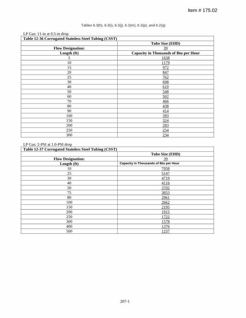
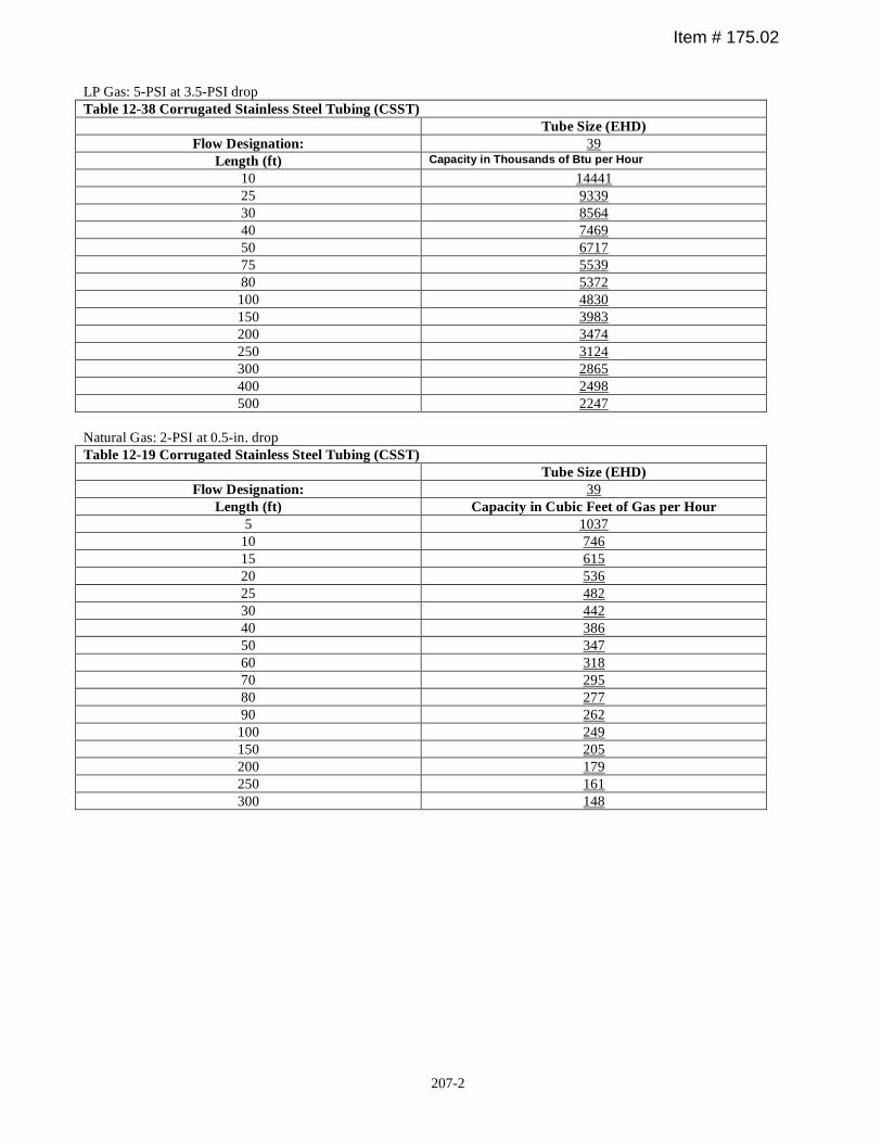
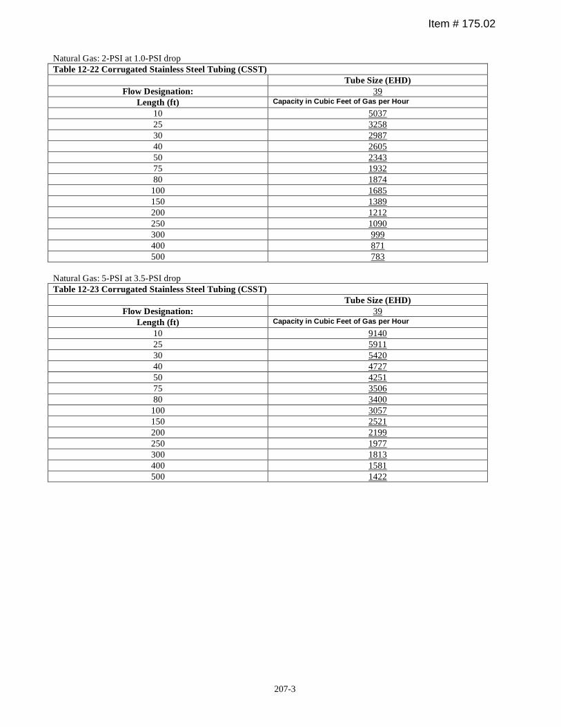
Corrugated Stainless Steel Tubing (CSST) sizing tables are being updated to include a new line size of EHD =39. Tables with new capacity values (EHD 39).
See attached: Tables 12–36, 12–37, 12–38, 12–19, 12–22, and 12–23 on pages 207–1 through 207–3.
Sizing tables should reflect the CSST products that are commercially available.SUBSTANTIATION:
RECOMMENDATION:
UPC 2009 Tables 12–36, 12–37, 12–38, 12–19, 12–22, and 12–23
Accept as Submitted
UPC Technical Committee Proposal
175.02-
TOTAL ELIGIBLE TO VOTE: 28
VOTING RESULTS: AFFIRMATIVE: 24, NOT RETURNED: 4 Bloice, Murray, Nikravi, Soskin
COMMITTEE ACTION:
Item #
SUBMITTER:
Revise text as follows:
1304.0 Psychiatric Patient Rooms.Piping and drain traps in psychiatric patient rooms shall be concealed. Fixtures and fittings shall be resistant to vandalism. [NFPA 101]
1305.0 Locations for Ice Storage.Ice makers or ice storage containers shall be located in nursing stations or similarly supervised areas to minimize potential contamination. [See NFPA 101]
Delete reference to NFPA 101 in Sections 1304.0 and 1305.0. The subjects are not covered in NFPA 101, Life Safety Code.
SUBSTANTIATION:
RECOMMENDATION:
UPC 2009 1304.0, 1305.0
Accept as Submitted
Theodore C. Lemoff
176-
TOTAL ELIGIBLE TO VOTE: 28
VOTING RESULTS: AFFIRMATIVE: 24, NOT RETURNED: 4 Bloice, Murray, Nikravi, Soskin
COMMITTEE ACTION:
Item #
NFPA
207
207-1
Tables 6.3(h), 6.3(i), 6.3(j), 6.2(m), 6.2(p), and 6.2(q)
LP Gas: 11-in at 0.5-in drop Table 12-36 Corrugated Stainless Steel Tubing (CSST) Tube Size (EHD)
Flow Designation: 39 Length (ft) Capacity in Thousands of Btu per Hour
5 1638 10 1179 15 972 20 847 25 762 30 698 40 610 50 548 60 502 70 466 80 438 90 414 100 393 150 324 200 283 250 254 300 234
LP Gas: 2-PSI at 1.0-PSI drop Table 12-37 Corrugated Stainless Steel Tubing (CSST) Tube Size (EHD)
Flow Designation: 39 Length (ft) Capacity in Thousands of Btu per Hour
10 7958 25 5147 30 4719 40 4116 50 3702 75 3053 80 2961 100 2662 150 2195 200 1915 250 1722 300 1578 400 1376 500 1237
Item # 175.02
207-2
LP Gas: 5-PSI at 3.5-PSI drop Table 12-38 Corrugated Stainless Steel Tubing (CSST) Tube Size (EHD)
Flow Designation: 39 Length (ft) Capacity in Thousands of Btu per Hour
10 14441 25 9339 30 8564 40 7469 50 6717 75 5539 80 5372 100 4830 150 3983 200 3474 250 3124 300 2865 400 2498 500 2247
Natural Gas: 2-PSI at 0.5-in. drop Table 12-19 Corrugated Stainless Steel Tubing (CSST) Tube Size (EHD)
Flow Designation: 39 Length (ft) Capacity in Cubic Feet of Gas per Hour
5 1037 10 746 15 615 20 536 25 482 30 442 40 386 50 347 60 318 70 295 80 277 90 262 100 249 150 205 200 179 250 161 300 148
Item # 175.02
207-3
Natural Gas: 2-PSI at 1.0-PSI drop Table 12-22 Corrugated Stainless Steel Tubing (CSST) Tube Size (EHD)
Flow Designation: 39 Length (ft) Capacity in Cubic Feet of Gas per Hour
10 5037 25 3258 30 2987 40 2605 50 2343 75 1932 80 1874 100 1685 150 1389 200 1212 250 1090 300 999 400 871 500 783
Natural Gas: 5-PSI at 3.5-PSI drop Table 12-23 Corrugated Stainless Steel Tubing (CSST) Tube Size (EHD)
Flow Designation: 39 Length (ft) Capacity in Cubic Feet of Gas per Hour
10 9140 25 5911 30 5420 40 4727 50 4251 75 3506 80 3400 100 3057 150 2521 200 2199 250 1977 300 1813 400 1581 500 1422
Item # 175.02
UPC 2009 – August 2007 ROP
SUBMITTER:
Revise text as follows:
Part II––Medical Gas and Vacuum Systems.
1309.0 Application.
1309.1 The provisions herein shall apply to the design installation, testing, and verification of medical gas and, vacuum piping systems, and related permanent equipment in hospitals, clinics, and other health care facilities.
1309.2 The purpose of this chapter is to provide requirements for the design, installation, testing, and verification ofmedical gas and, medical vacuum systems, and related permanent equipment, from the central supply system to thestation outlets or inlets.
This proposal provides for more consistency between the two sections and makes the scope more comprehensive.This clarifies the chapter is applicable to other associated equipment used.
SUBSTANTIATION:
RECOMMENDATION:
UPC 2009 1309.1, 1309.2
Medical gas does not include vacuum systems and does not meet the definitions or intent for medical gas.
Reject
Krista Braaksma
177-
TOTAL ELIGIBLE TO VOTE: 28
VOTING RESULTS: AFFIRMATIVE: 24, NOT RETURNED: 4 Bloice, Murray, Nikravi, Soskin
COMMITTEE ACTION:COMMITTEE STATEMENT:
Item #
Washington State Building Code Council
SUBMITTER:
Revise text as follows:
1310.16 Station Outlet – An inlet point in a piped medical/surgical vacuum distribution system at which the user makes connections and disconnections. [NFPA 99 3.3.167 3.3.172]
A reference to NFPA 99 is updated.SUBSTANTIATION:
RECOMMENDATION:
UPC 2009 1310.16
Accept as Submitted
Theodore C. Lemoff
178-
TOTAL ELIGIBLE TO VOTE: 28
VOTING RESULTS: AFFIRMATIVE: 24, NOT RETURNED: 4 Bloice, Murray, Nikravi, Soskin
COMMITTEE ACTION:
Item #
NFPA
208
UPC 2009 – August 2007 ROP
SUBMITTER:
Revise text as follows:
1315.3 Burred ends of all tubing shall be rolled smooth with a chipless reamer or deburred using a deburring tool tothe full bore of the tube, and all chips shall be removed.
Issues and concerns regarding the cut ends of tubing include the following:(1) All references to reaming in the current and past codes states or implies that the burr has to be cut out by removing material therefore forbidding new technologies or innovation in dealing with the problem of de-burring copper pipe that does not remove material.
(2) Governing plumbing authorities not familiar with newer technologies for preparing the end of copper pipe for assembly may reject (and have rejected) the use of a tool that does not cut or remove the burr (traditional and statedprocess) [NFPA 99.5.1.10.5.2.3] and UPC 2006 IS 3–2003 2.3.4 but re-forms or smoothes the burr to the full insidediameter of the pipe without removing material.
(3) When a burr is removed from a copper pipe by cutting it with a blade type reamer, sharp chips and debris (down to the microscopic level) are created. The chips may become lodged in valves or other devises causing problems orif ingested or inhaled by the end user a health hazard may occur. A chipless reamer reforms the burr without removing material therefore debris is not produced in the process. This may be useful in addressing UPC 1317.2 and NFPA 99 5.1.10.5.3.12 (field contamination of pipe).
(4) A sharp clean deburring tool used to ream the tube has sharp surfaces that have the potential to cut or injure theinstaller particularly if the plumber is in a hurry. A chipless reamer has no sharp edges and prepares the copper pipein less time than the tools mentioned in the current code therefore decreasing the chance of injury and saving time inthe process.
(5) When reaming installed hard drawn in the vertical position with a blade reamer most of the chips and debris cut from the pipe falls down the tubing contaminating the system. A chipless reamer does not produce debris in the process of meeting the installation standard of. [NFPA 99.5.1.10.5.2.3]
(See image attached to Item 24.)
SUBSTANTIATION:
RECOMMENDATION:
UPC 2009 1315.3
Current language does not prohibit the use of this device. Proposed language is too subjective or prohibits other applications and methods.
Reject
Joseph Kerze
179-
TOTAL ELIGIBLE TO VOTE: 28
VOTING RESULTS: AFFIRMATIVE: 24, NOT RETURNED: 4 Bloice, Murray, Nikravi, Soskin
COMMITTEE ACTION:COMMITTEE STATEMENT:
Item #
209
UPC 2009 – August 2007 ROP
SUBMITTER:
Revise text as follows:
1316.4.2 Branch connections in vacuum piping systems shall be permitted to be made using mechanically formed, drilled, and extruded tee branch connections that are formed in accordance with the tool manufacturer's instructionsand brazed. [NFPA 99 5.1.10.3.1, 5.1.10.3.2, 5.1.10.3.3, 5.1.10.5.8 (4)-(7)]
A reference to NFPA 99 is updated.SUBSTANTIATION:
RECOMMENDATION:
UPC 2009 1316.4.2
Accept as Submitted
Theodore C. Lemoff
180-
TOTAL ELIGIBLE TO VOTE: 28
VOTING RESULTS: AFFIRMATIVE: 24, NOT RETURNED: 4 Bloice, Murray, Nikravi, Soskin
COMMITTEE ACTION:
Item #
NFPA
SUBMITTER:
Revise text as follows:
1318.6 Where a positive-pressure medical gas piping distribution system, originally used or constructed for the use at one pressure and for one gas, is converted for operation at another pressure or for another gas, all provisions ofNFPA 99 5.1.10 shall apply as if the system were new.
A vacuum system shall not be permitted to be converted for use as a gas system. [NFPA 99 5.1.10.6.10 5.1.10.10.10.1].
Reference to NFPA 99 is added, and the correct citation of a paragraph extracted from NFPA 99 is provided.SUBSTANTIATION:
RECOMMENDATION:
UPC 2009 1318.6
Accept as Submitted
Theodore C. Lemoff
181-
TOTAL ELIGIBLE TO VOTE: 28
VOTING RESULTS: AFFIRMATIVE: 24, NOT RETURNED: 4 Bloice, Murray, Nikravi, Soskin
COMMITTEE ACTION:
Item #
NFPA
210
UPC 2009 – August 2007 ROP
SUBMITTER:
Revise text as follows:
1318.8 Piping shall be supported from the building structure in accordance with MSS Standard Practice SP-69, Piping Hangers and Supports – Selection and Application.
Hangers and supports shall comply with MSS Standard Practice SP-58, Pipe Hangers and Supports - Materials, Design, and Manufacture.
Hangers for copper tube shall have a copper finish and be sized for copper tube.
In potentially damp locations, copper tube hangers or supports that are in contact with the tube shall be plastic-coated or otherwise be insulated from the tube.
Maximum support spacing shall be in accordance with Table 13–7. [NFPA 99 Table 5.1.10.6.4.5 5.1.10.4.5]
Correct citation is provided for an extract from NFPA 99SUBSTANTIATION:
RECOMMENDATION:
UPC 2009 1318.8
Accept as Submitted
Theodore C. Lemoff
182-
TOTAL ELIGIBLE TO VOTE: 28
VOTING RESULTS: AFFIRMATIVE: 24, NOT RETURNED: 4 Bloice, Murray, Nikravi, Soskin
COMMITTEE ACTION:
Item #
NFPA
211
UPC 2009 – August 2007 ROP
SUBMITTER:
Revise text as follows:
1319.2 Tube ends shall be cut square using a sharp tubing cutter to avoid deforming the tube. [NFPA 99 5.1.10.5.2.1] The cutting wheels on tubing cutters shall be free from grease, oil, or other lubricant not suitable for oxygen service. [NFPA 99 5.1.10.5.2.2]
The cut ends of the tube shall be rolled smooth with a chipless reamer to the full diameter of the tube or deburred with a sharp, clean deburring tool, taking care to prevent chips from entering the tube. [NFPA 99 5.1.10.5.2.3]
Issues and concerns regarding the cut ends of tubing include the following:(1) All references to reaming in the current and past codes states or implies that the burr has to be cut out by removing material therefore forbidding new technologies or innovation in dealing with the problem of de-burring copper pipe that does not remove material.
(2) Governing plumbing authorities not familiar with newer technologies for preparing the end of copper pipe for assembly may reject (and have rejected) the use of a tool that does not cut or remove the burr (traditional and statedprocess) [NFPA 99.5.1.10.5.2.3] and UPC 2006 IS 3–2003 2.3.4 but re-forms or smoothes the burr to the full insidediameter of the pipe without removing material.
(3) When a burr is removed from a copper pipe by cutting it with a blade type reamer, sharp chips and debris (down to the microscopic level) are created. The chips may become lodged in valves or other devises causing problems orif ingested or inhaled by the end user a health hazard may occur. A chipless reamer reforms the burr without removing material therefore debris is not produced in the process. This may be useful in addressing UPC 1317.2 and NFPA 99 5.1.10.5.3.12 (field contamination of pipe)
(4) A sharp clean deburring tool used to ream the tube has sharp surfaces that have the potential to cut or injure theinstaller particularly if the plumber is in a hurry. A chipless reamer has no sharp edges and prepares the copper pipein less time than the tools mentioned in the current code therefore decreasing the chance of injury and saving time inthe process.
(5) When reaming installed hard drawn in the vertical position with a blade reamer most of the chips and debris cut from the pipe falls down the tubing contaminating the system. A chipless reamer does not produce debris in the process of meeting the installation standard of [NFPA 99.5.1.10.5.2.3]
(See image attached to Item 24.)
SUBSTANTIATION:
RECOMMENDATION:
UPC 2009 1319.2
Current language does not prohibit the use of this device. Proposed language is too subjective or prohibits other applications and methods.
Reject
Joseph Kerze
183-
TOTAL ELIGIBLE TO VOTE: 28
VOTING RESULTS: AFFIRMATIVE: 24, NOT RETURNED: 4 Bloice, Murray, Nikravi, Soskin
COMMITTEE ACTION:COMMITTEE STATEMENT:
Item #
212
UPC 2009 – August 2007 ROP
SUBMITTER:
Revise text as follows:
1316.3 Tubes shall be hard-drawn seamless copper ASTM B 819 medical gas tube, Type L, except that where operating pressures are above a gauge pressure of 1,275 kPa (185 psi), Type K shall be used for sizes larger thanDN80 (NPS 3) (3–1/8 in. O.D.).
ASTM B 819 medical gas tube shall be identified by the manufacturer's markings "OXY," "MED," "OXY/MED," "OXY/ACR," or "ACR/MED" in blue (Type L) or green (Type K).
Piping for vacuum systems shall be constructed of any of the following:
(1) Hard-drawn seamless copper tube
(a) ASTM B 88, Standard Specification for Seamless Copper Water Tube, copper tube (Types K, L, M).(b) ASTM B 280, Standard Specification for Seamless Copper Tubing for Air Conditioning and
Refrigeration Field Service, copper ACR tube.(c) ASTM B 819, Standard Specification for Seamless Copper Tube for Medical Gas Systems, copper
medical.
(2) Stainless steel tube(a) ASME A112.3.1
(Remainder of text not shown do not change)
Stainless steel is referenced without a referenced standard for vacuum systems. ASME is currently referenced in Table 14–1 of this code.
SUBSTANTIATION:
RECOMMENDATION:
UPC 2009 1316.3 (2)
Provisions of ASME A112.3.1 is for DWV piping and is not suitable for this application.
Reject
Guy Wayne Harrison
184-
TOTAL ELIGIBLE TO VOTE: 28
VOTING RESULTS: AFFIRMATIVE: 24, NOT RETURNED: 4 Bloice, Murray, Nikravi, Soskin
COMMITTEE ACTION:COMMITTEE STATEMENT:
Item #
Josam Company
213
UPC 2009 – August 2007 ROP
SUBMITTER:
Revise text as follows:
1326.4 Piping between vacuum pumps, discharges, receivers, and the vacuum main line valve shall be in accordance with Section 1316.1, except that stainless steel, or steel pipe shall be permitted to be either black or galvanized. [NFPA 99 5.1.3.6.1.2(5)]
As outlined in the NFPA 99C-2005 for Gas and Vacuum Systems in Chapter 13-NFPA document submitted under Section 5.1.3.6.1.2(5).
See attached NFPA 99C – 2005 5.1.3.6.1.2 (5)
SUBSTANTIATION:
RECOMMENDATION:
UPC 2009 1326.4
Amend text as follows:
1326.4 Piping between vacuum pumps, discharges, receivers, and the vacuum main line valve shall be in accordance with Section 1316.3.1, except that stainless steel, galvanized, or black steel pipe shall be permitted to be used. either black or galvanized. [NFPA 99 5.1.3.6.1.2(5)]
The intent of the proposal is accepted and current language from NFPA 99 was used to make this an extraction.
Accept as Amended by the TC
Guy Wayne Harrison
185-
TOTAL ELIGIBLE TO VOTE: 28
VOTING RESULTS: AFFIRMATIVE: 24, NOT RETURNED: 4 Bloice, Murray, Nikravi, Soskin
COMMITTEE ACTION:
COMMITTEE STATEMENT:
Item #
Josam Company
SUBMITTER:
Revise text as follows:
1328.0 System Certification Verification.
This proposal is for consistency in terms. The standard provides for medical gas system verification rather than certification.
SUBSTANTIATION:
RECOMMENDATION:
UPC 2009 1328.0
The current title and existing language in this section do not reflect the proposed change in title.
Reject
Krista Braaksma
186-
TOTAL ELIGIBLE TO VOTE: 28
VOTING RESULTS: AFFIRMATIVE: 24, NOT RETURNED: 4 Bloice, Murray, Nikravi, Soskin
COMMITTEE ACTION:COMMITTEE STATEMENT:
Item #
Washington State Building Code Council
214
UPC 2009 – August 2007 ROP
SUBMITTER:
Revise text as follows:
CHAPTER 14
MANDATORY REFERENCED STANDARDS
Standards for Materials, Equipment, Joints, and Connections
Where more than one standard has been listed for the same material or method,the relevant portions of all such standards shall apply.
The word “mandatory” may or may not be mandated for the standard refenced.SUBSTANTIATION:
RECOMMENDATION:
UPC 2009 Chapter 14
Accept as Submitted
UPC Technical Committee Proposal
186.01-
TOTAL ELIGIBLE TO VOTE: 28
VOTING RESULTS: AFFIRMATIVE: 22, NEGATIVE: 2, NOT RETURNED: 4 Bloice, Murray, Nikravi, Soskin
EXPLANATION OF ABSTENTION:
EXPLANATION OF NEGATIVE:ADLER: I disagree with the Committee recommendation to Accept. The use of the word, Mandatory should be retained in the Standard's title. Its use has not created a field problem and it does clarify which standards are to be used.
VIOLA: We are going in the wrong direction here. If Chapter 14 contains inappropriate standards, then we should remove them. Deleting the term “mandatory” will only cause more confusion in the field and calls into question whatpurpose the table serves.
COMMITTEE ACTION:
Item #
215
UPC 2009 – August 2007 ROP
SUBMITTER:
The following is recommended by the Standards Task Group (see Standards Task Group Report Item #187)
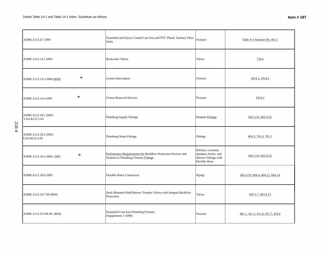
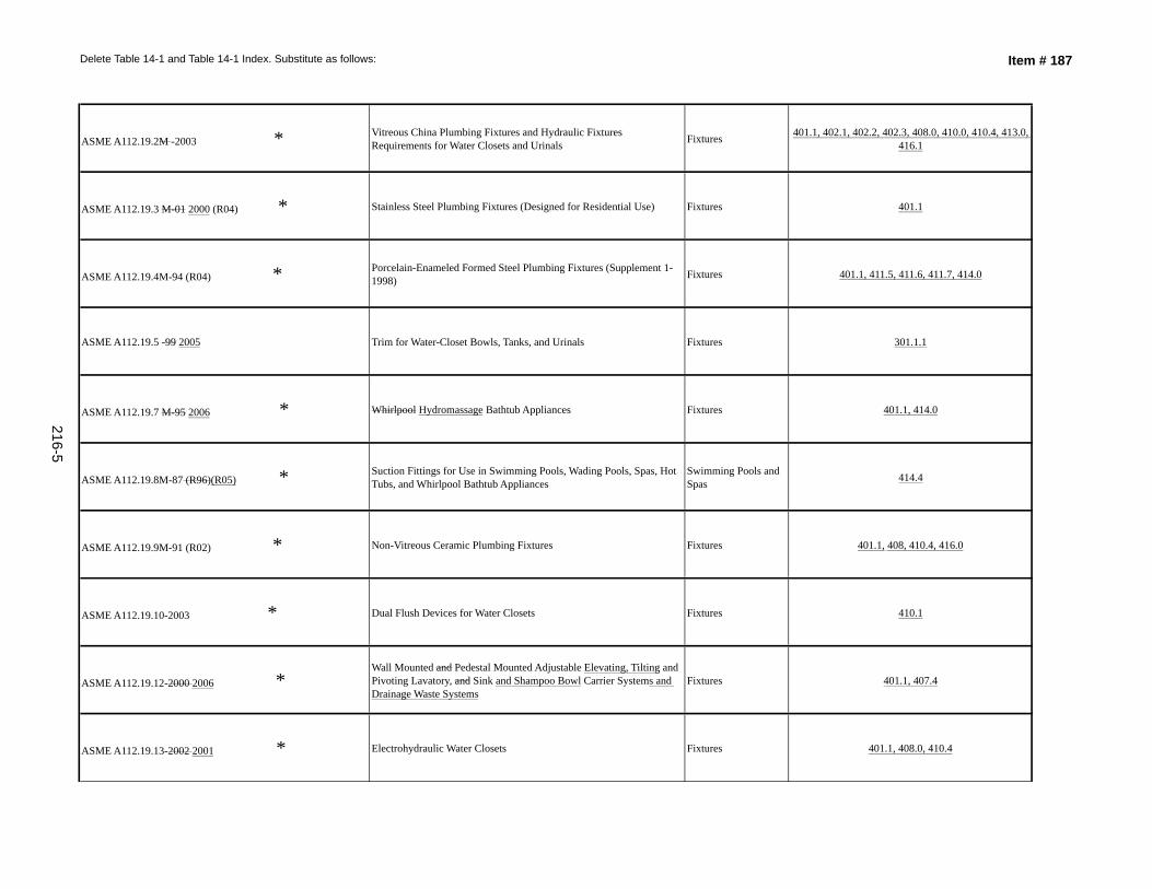
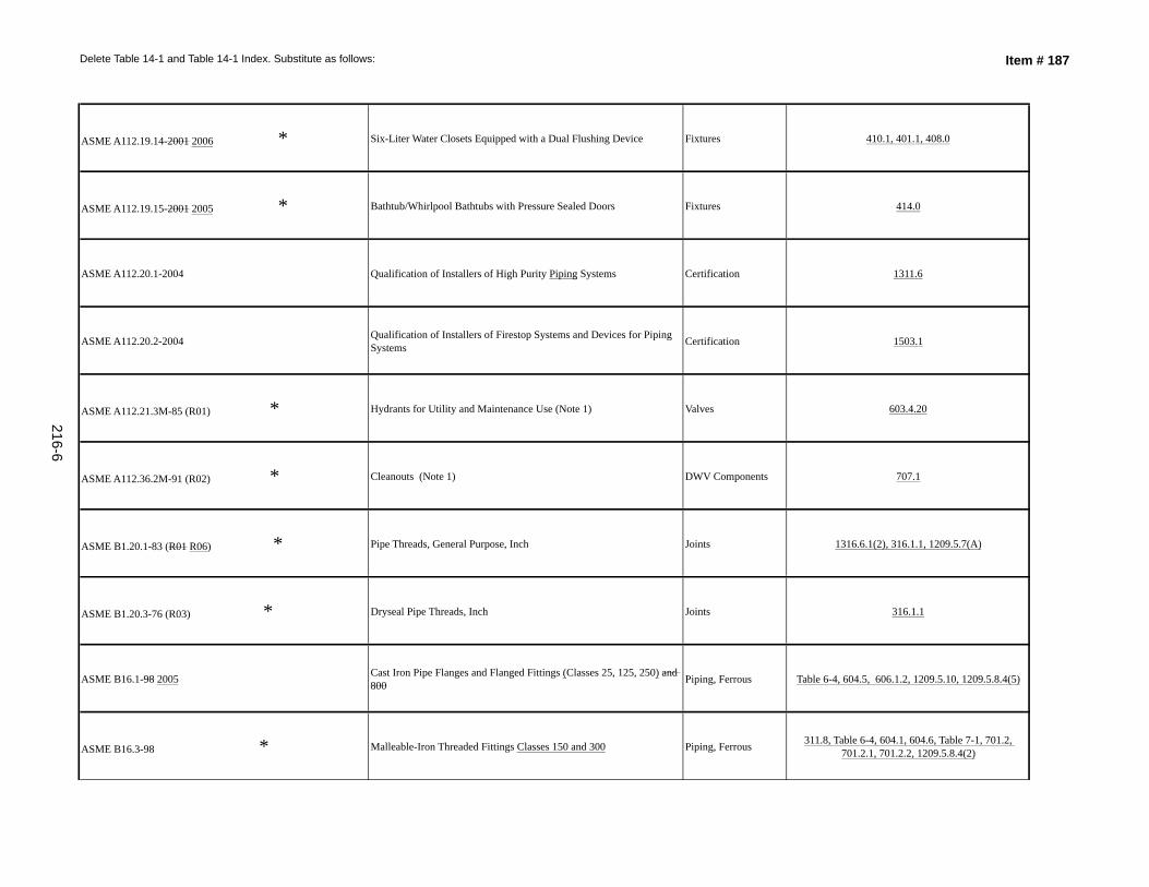
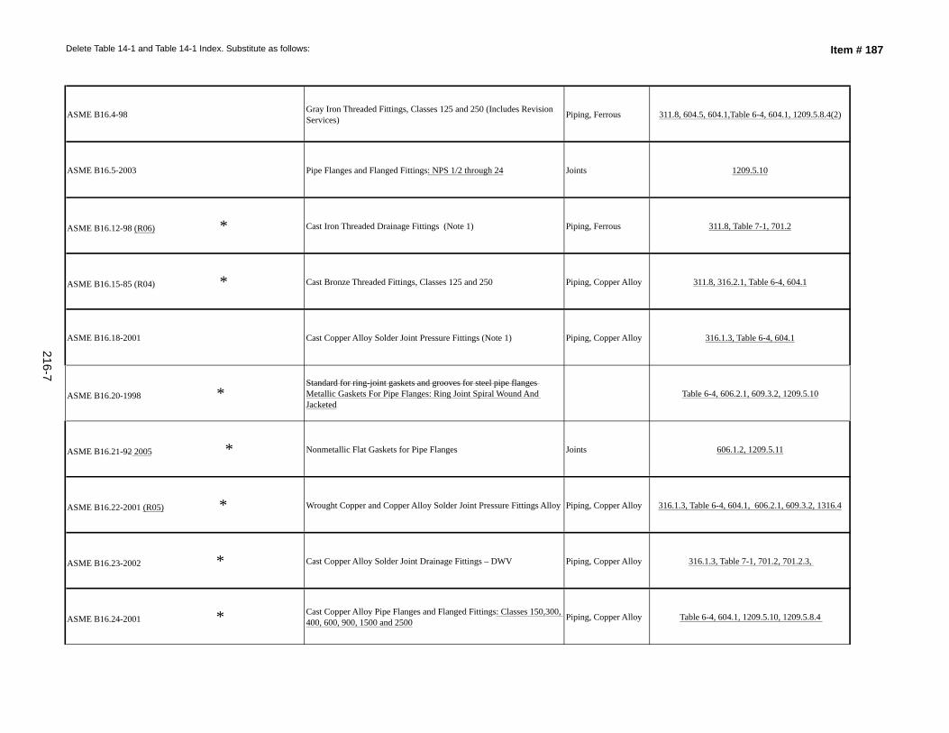
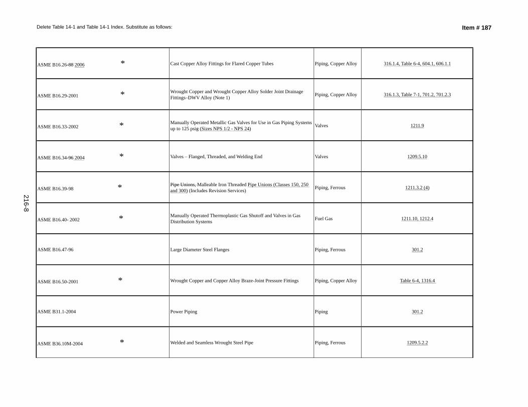
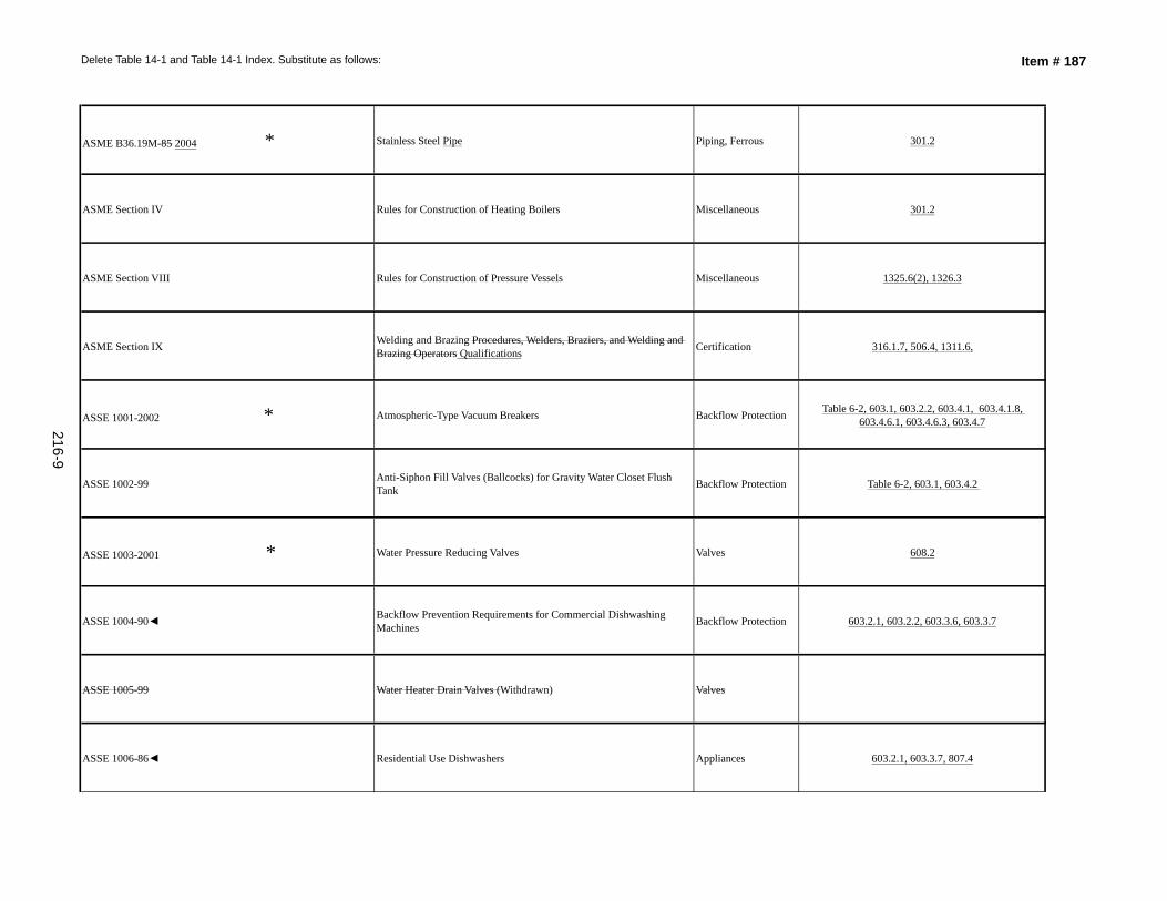
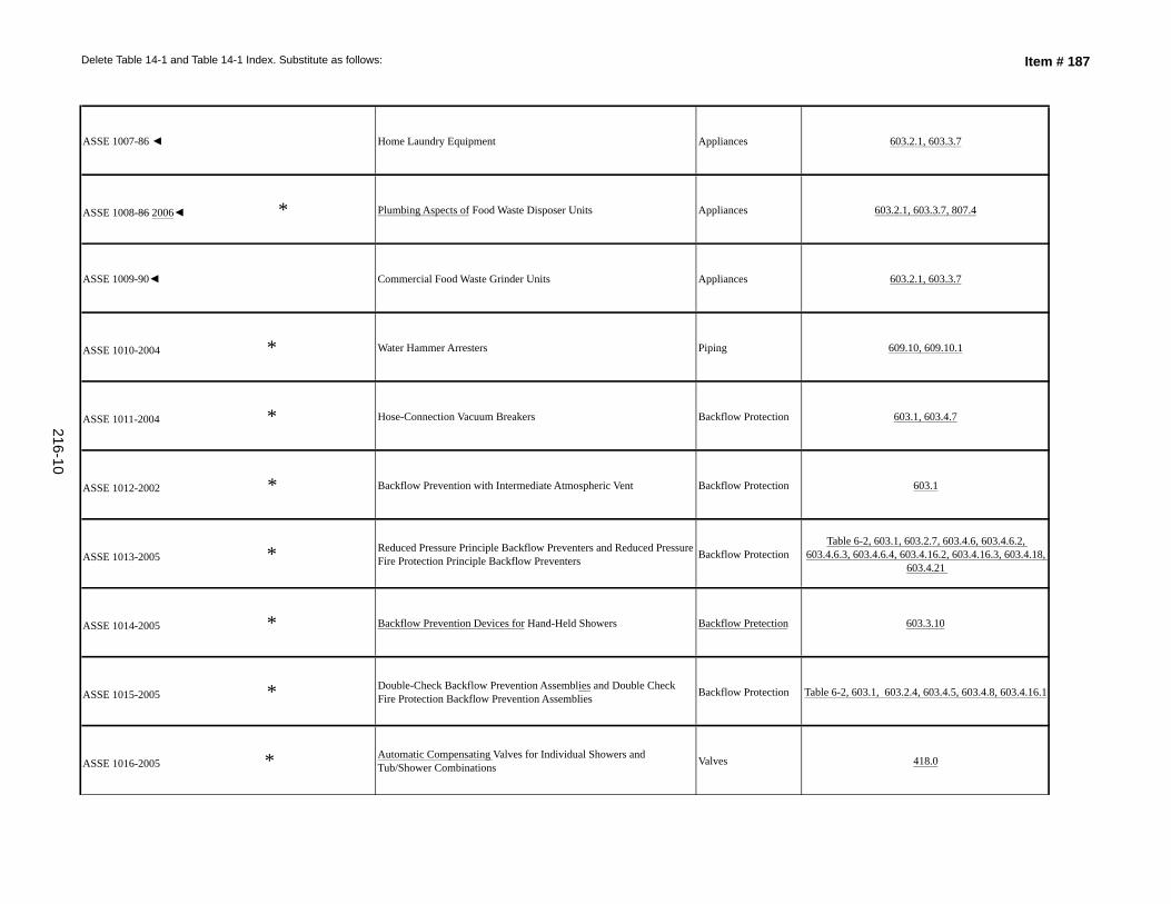
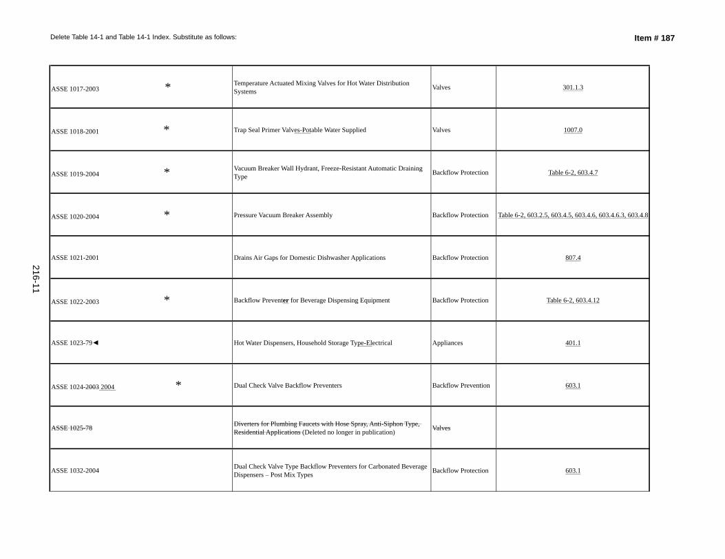
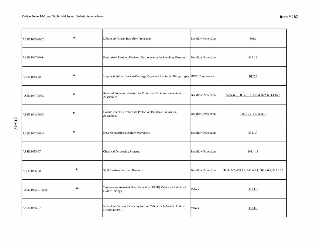
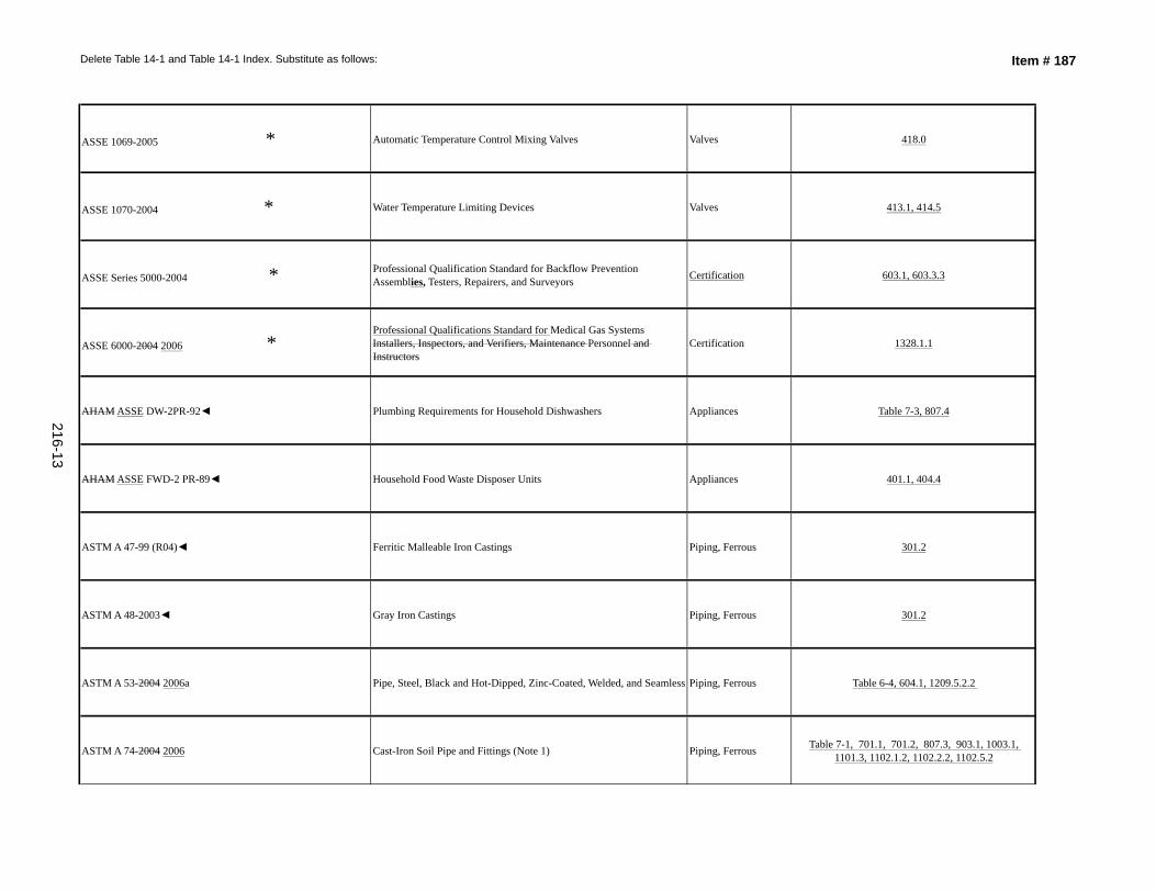
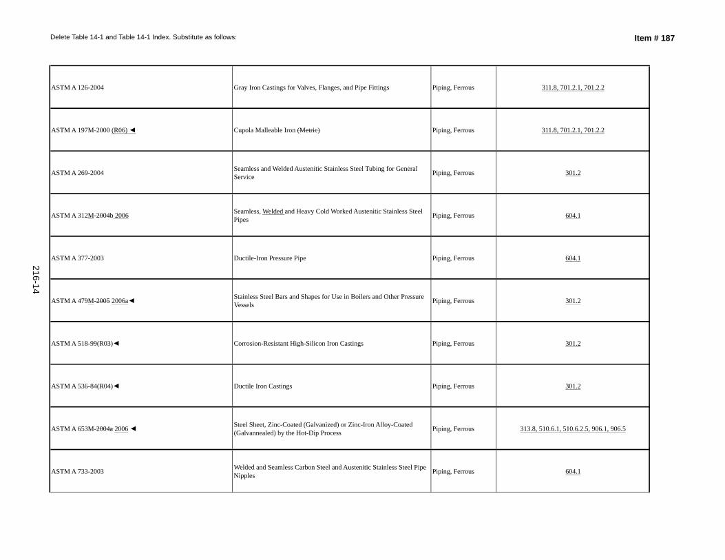
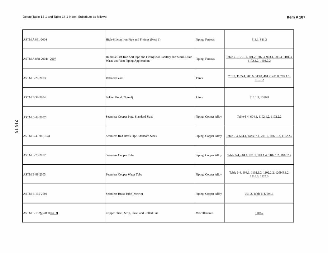
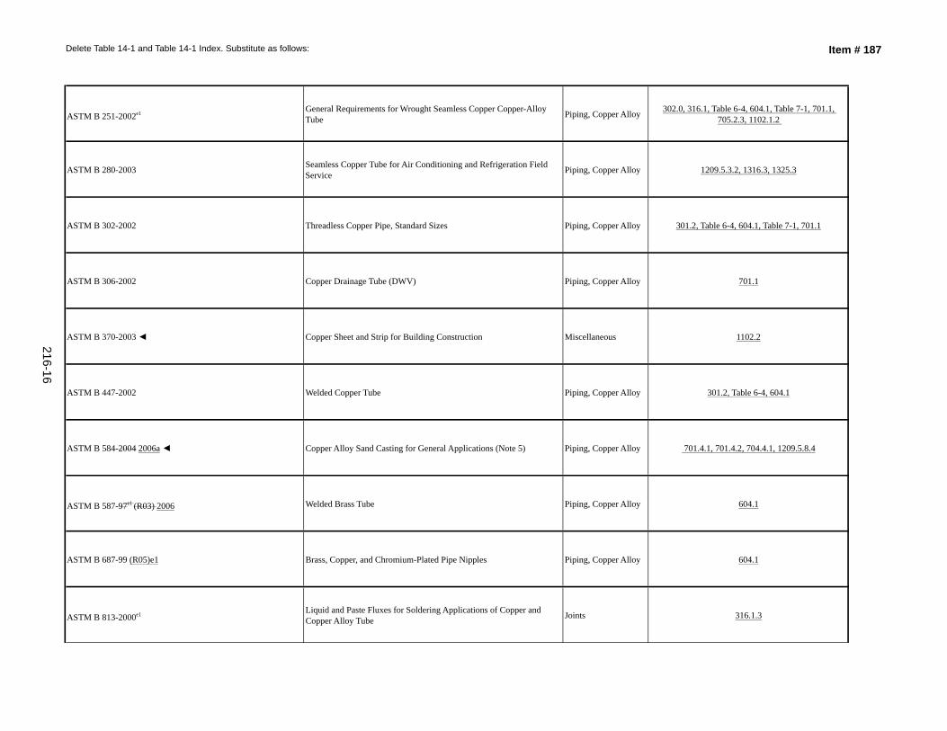
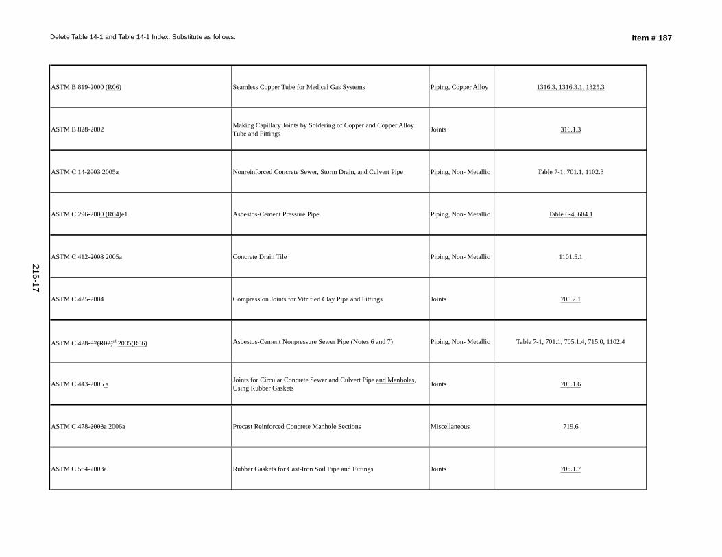
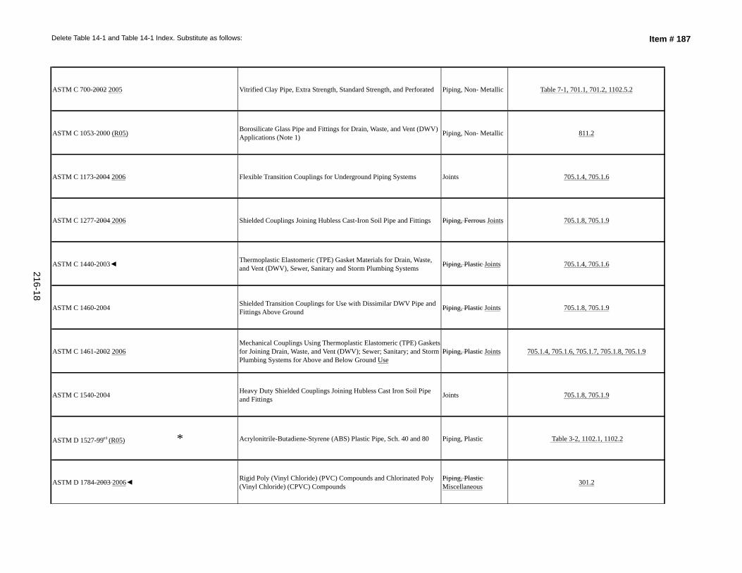
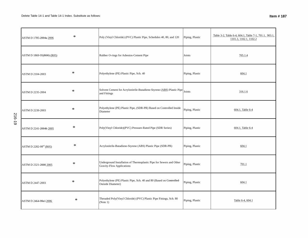
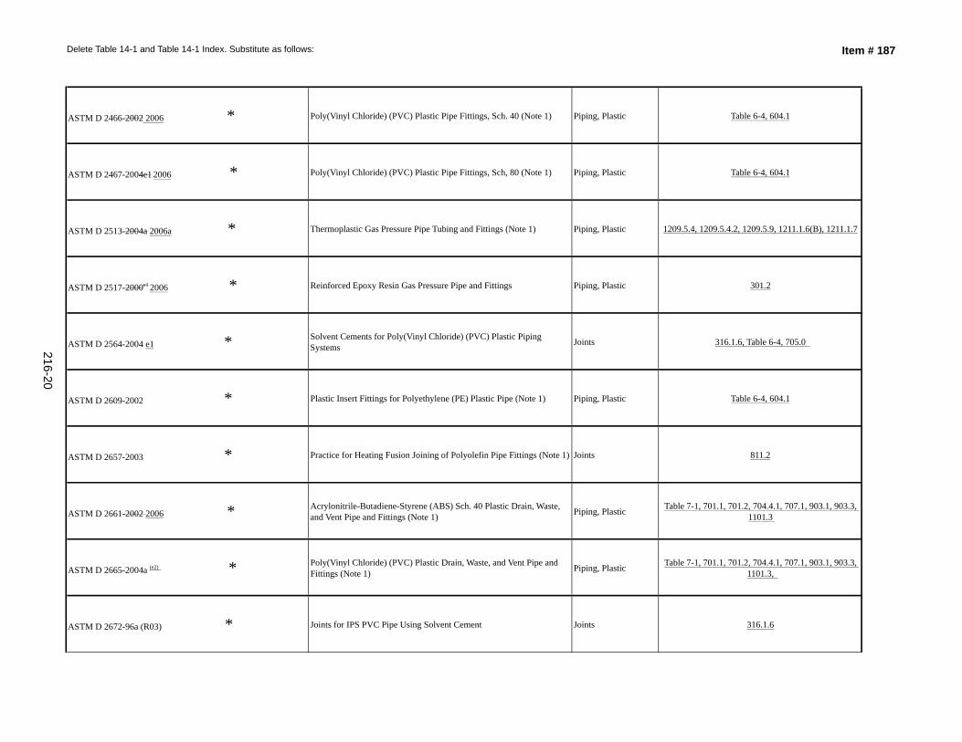
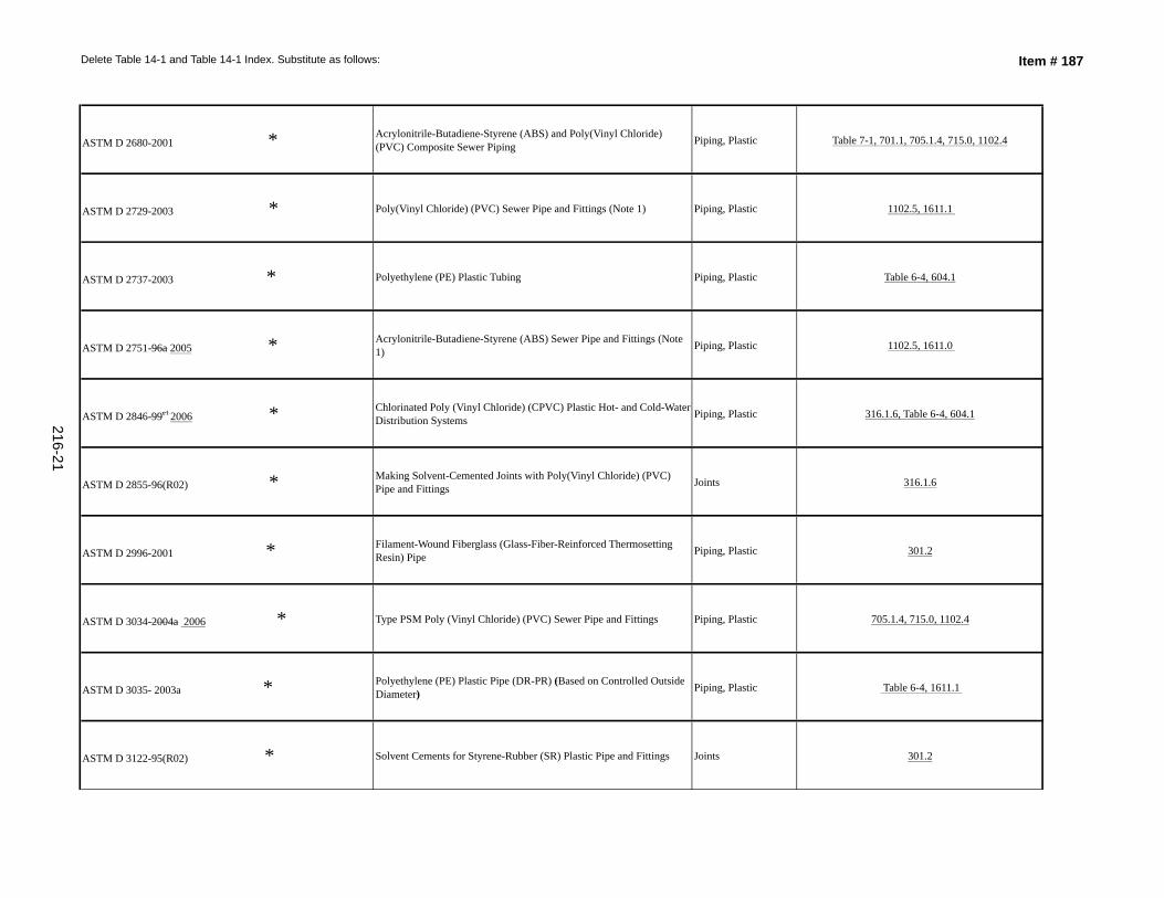
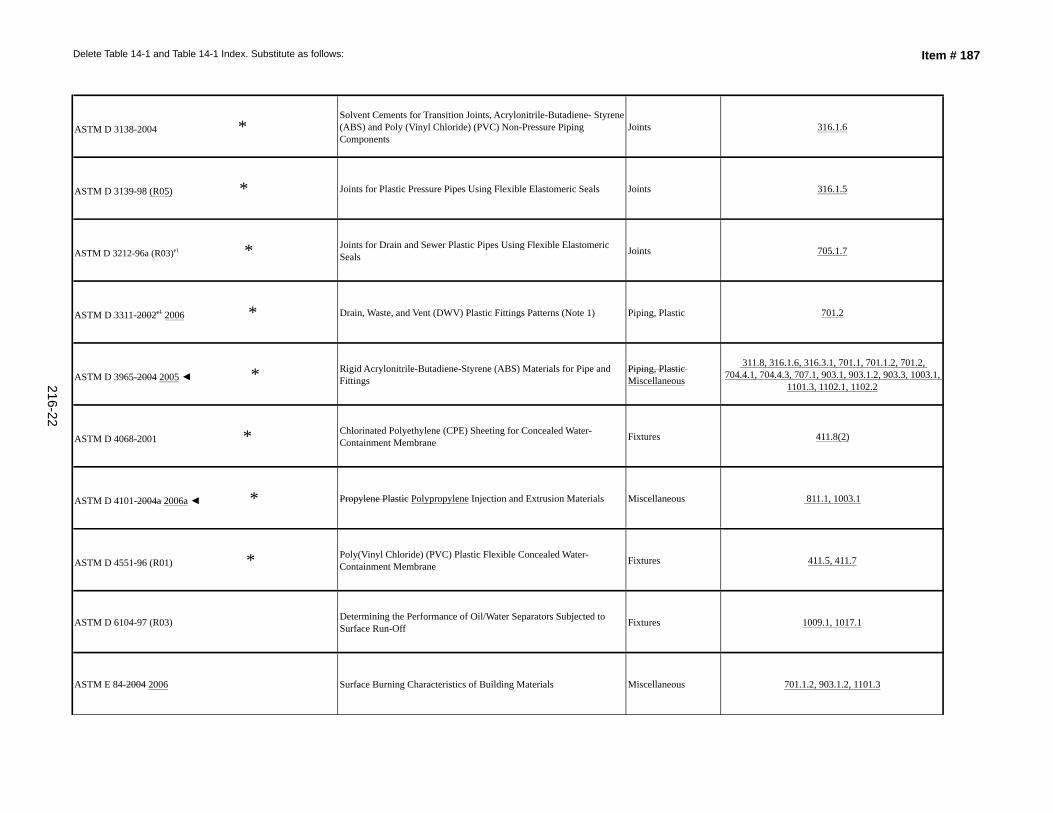
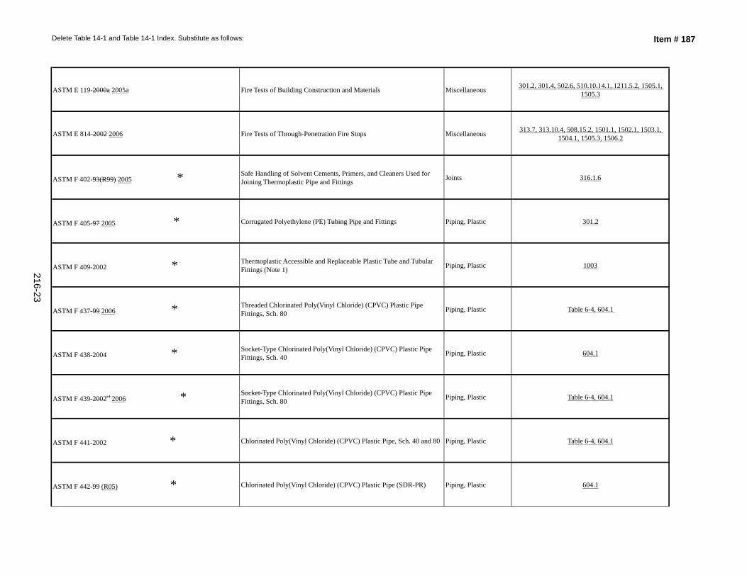
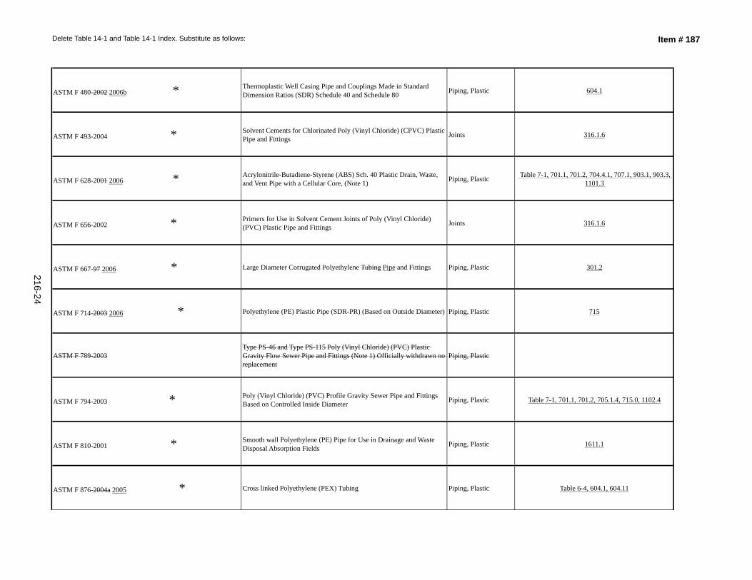
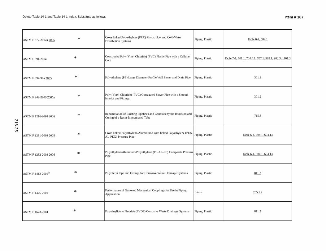
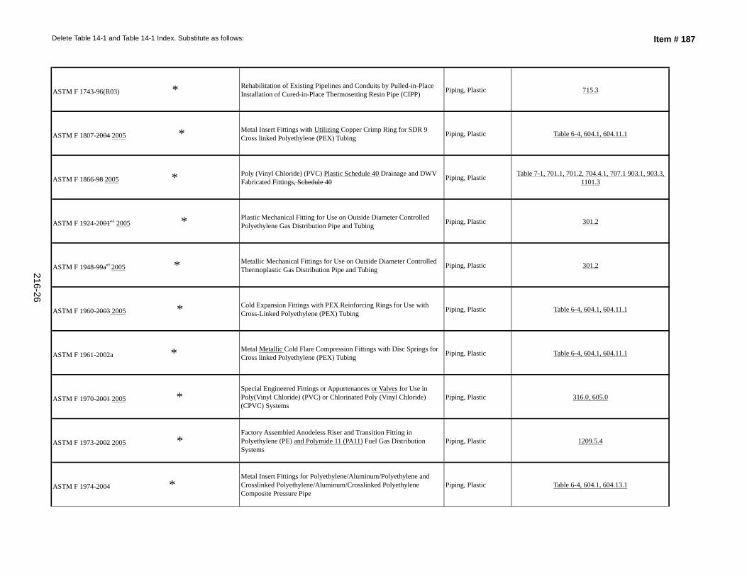
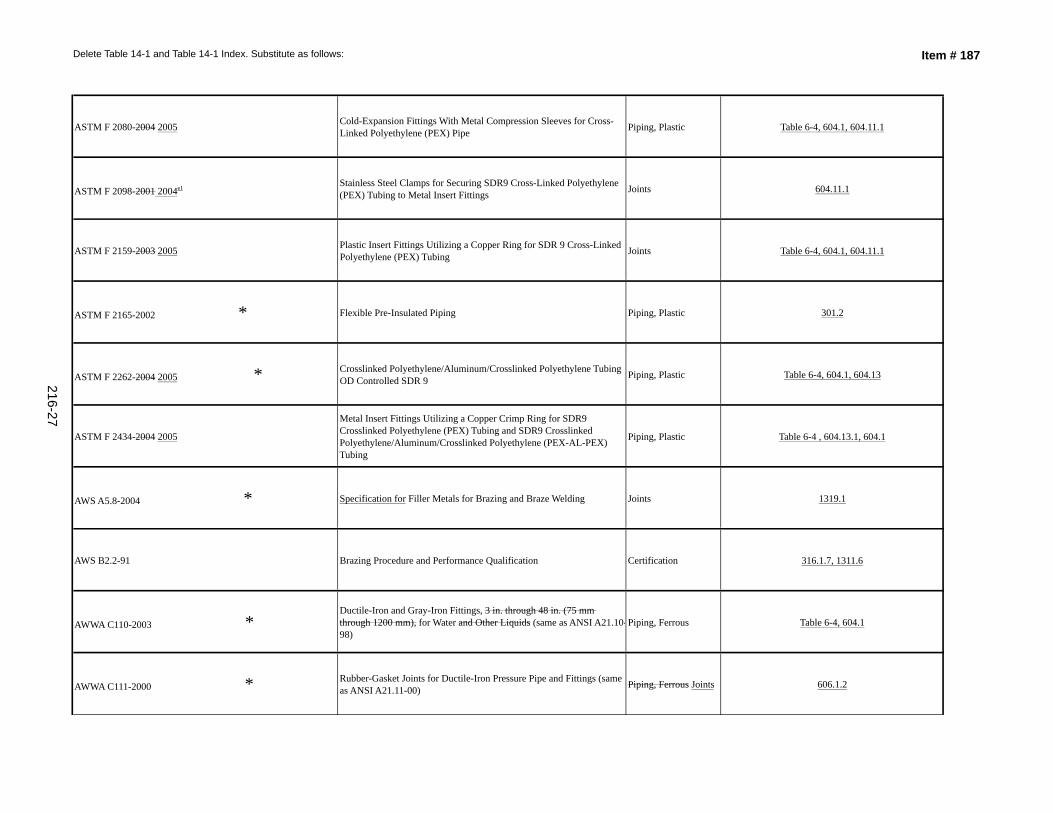
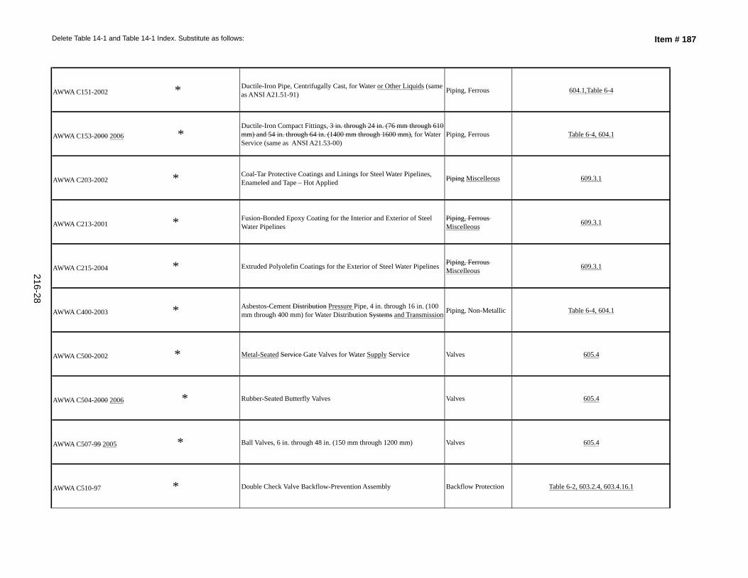
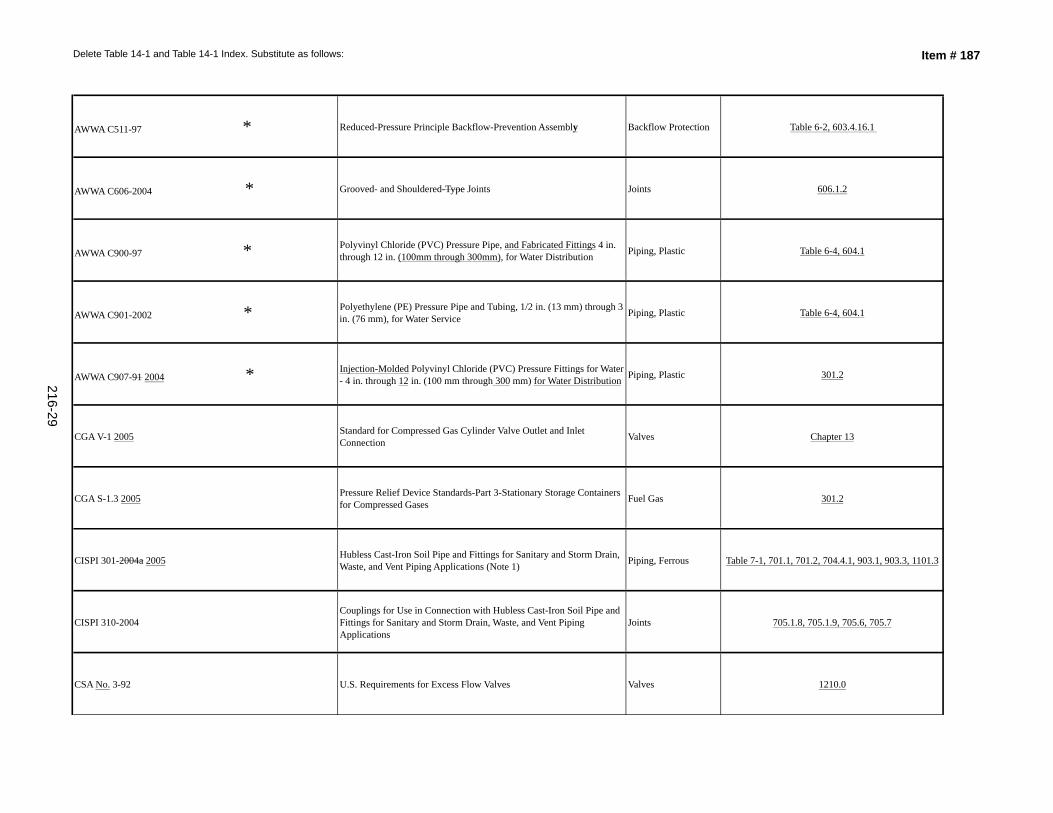
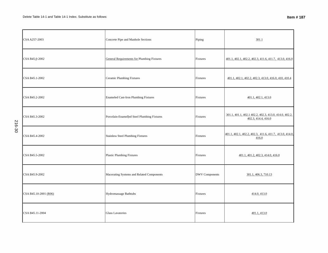
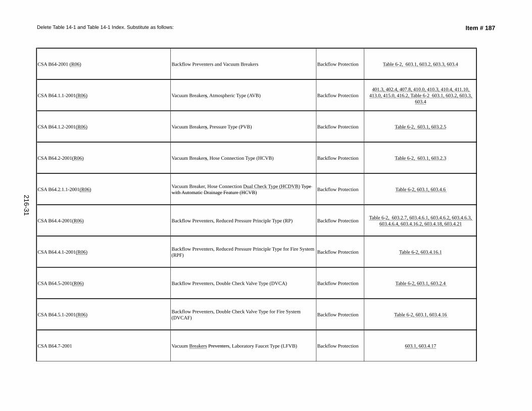
Delete Table 14–1 and Table 14–1 Index. Substitute as follows:
(See attached Table Chapter 14 Mandatory Referenced Standards Table 14–1 on page 216–1 through 216–51)
The standards task group was charged by the UPC Technical Committee to add cross-references to Table 14–1 where such sections are applicable to the referenced standards and to update the format of standards referencing materials and products. In addition, to update referenced standards and provide editorial revisions to Table 14–1.
SUBSTANTIATION:
RECOMMENDATION:
UPC 2009 Chapter 14, Table 14–1(New)
Accept as Submitted
Dave Viola
187-
TOTAL ELIGIBLE TO VOTE: 28
VOTING RESULTS: AFFIRMATIVE: 24, NOT RETURNED: 4 Bloice, Murray, Nikravi, Soskin
COMMITTEE ACTION:
Item #
Chair, UPC Standards Task Group
216
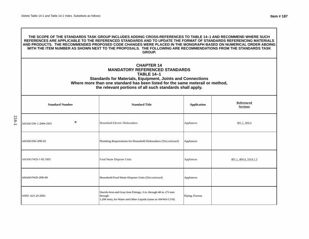
Delete Table 14-1 and Table 14-1 Index. Substitute as follows: Item # 187
Standard Number Standard Title Application Referenced Sections
AHAM DW-1-2004 2005 * Household Electric Dishwashers Appliances 401.1, 404.4
AHAM DW-2PR-92 Plumbing Requirements for Household Dishwashers (Discontinued) Appliances
AHAM FWD-1-92 2005 Food Waste Disposer Units Appliances 401.1, 404.4, 1014.1.3
AHAM FWD-2PR-89 Household Food Waste Disposer Units (Discontinued) Appliances
ANSI A21.10-2003Ductile-Iron and Gray-Iron Fittings, 3 in. through 48 in. (75 mm through 1,200 mm), for Water and Other Liquids (same as AWWA C110)
Piping, Ferrous
THE SCOPE OF THE STANDARDS TASK GROUP INCLUDES ADDING CROSS-REFERENCES TO TABLE 14–1 AND RECOMMEND WHERE SUCH REFERENCES ARE APPLICABLE TO THE REFERENCED STANDARDS AND TO UPDATE THE FORMAT OF STANDARDS REFERENCING MATERIALS
AND PRODUCTS. THE RECOMMENDED PROPOSED CODE CHANGES WERE PLACED IN THE MONGRAPH BASED ON NUMERICAL ORDER ABOING WITH THE ITEM NUMBER AS SHOWN NEXT TO THE PROPOSALS. THE FOLLOWING ARE RECOMMENDATIONS FROM THE STANDARDS TASK
GROUP.
CHAPTER 14 MANDATORY REFERENCED STANDARDS
TABLE 14–1 Standards for Materials, Equipment, Joints and Connections
Where more than one standard has been listed for the same meterail or method, the relevant portions of all such standards shall apply.
216-1
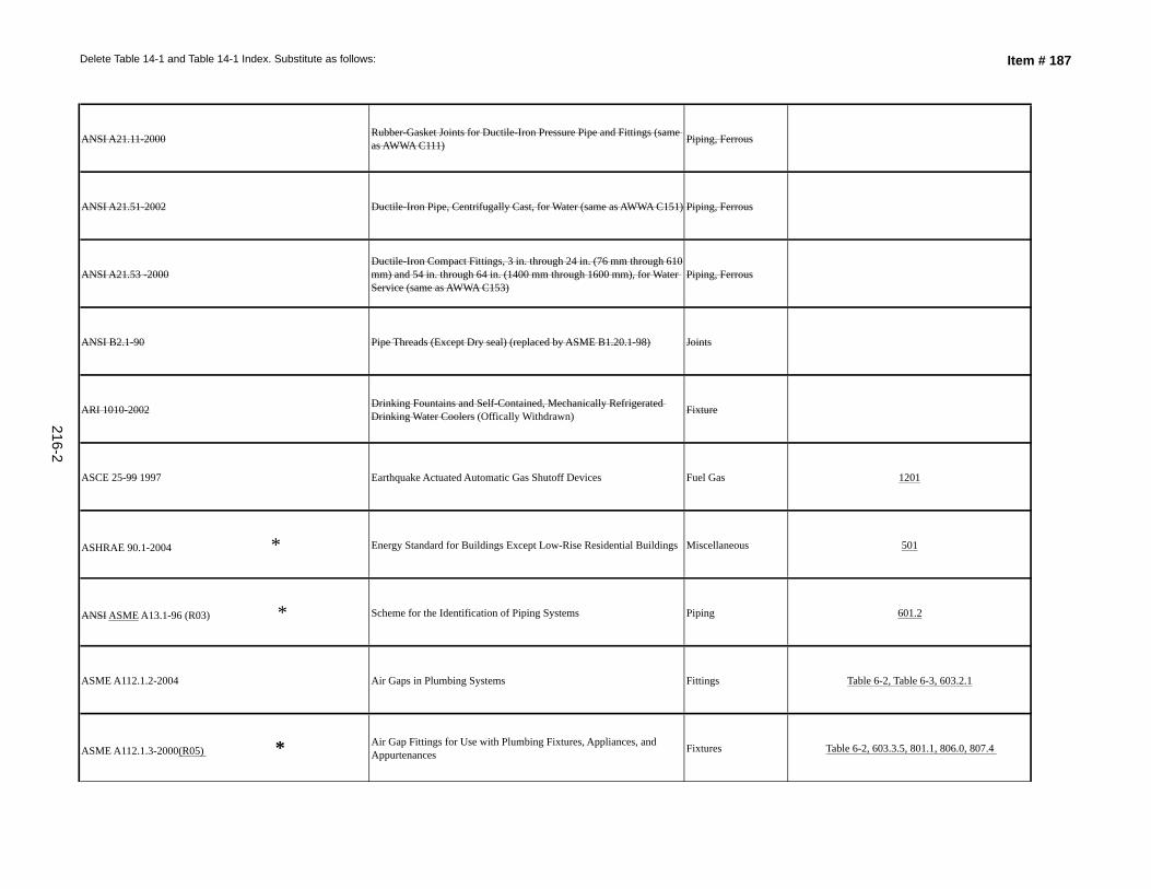
Delete Table 14-1 and Table 14-1 Index. Substitute as follows: Item # 187
ANSI A21.11-2000 Rubber-Gasket Joints for Ductile-Iron Pressure Pipe and Fittings (same as AWWA C111) Piping, Ferrous
ANSI A21.51-2002 Ductile-Iron Pipe, Centrifugally Cast, for Water (same as AWWA C151) Piping, Ferrous
ANSI A21.53 -2000Ductile-Iron Compact Fittings, 3 in. through 24 in. (76 mm through 610 mm) and 54 in. through 64 in. (1400 mm through 1600 mm), for Water Service (same as AWWA C153)
Piping, Ferrous
ANSI B2.1-90 Pipe Threads (Except Dry seal) (replaced by ASME B1.20.1-98) Joints
ARI 1010-2002 Drinking Fountains and Self-Contained, Mechanically Refrigerated Drinking Water Coolers (Offically Withdrawn) Fixture
ASCE 25-99 1997 Earthquake Actuated Automatic Gas Shutoff Devices Fuel Gas 1201
ASHRAE 90.1-2004 * Energy Standard for Buildings Except Low-Rise Residential Buildings Miscellaneous 501
ANSI ASME A13.1-96 (R03) * Scheme for the Identification of Piping Systems Piping 601.2
ASME A112.1.2-2004 Air Gaps in Plumbing Systems Fittings Table 6-2, Table 6-3, 603.2.1
ASME A112.1.3-2000(R05) * Air Gap Fittings for Use with Plumbing Fixtures, Appliances, and Appurtenances Fixtures Table 6-2, 603.3.5, 801.1, 806.0, 807.4
216-2
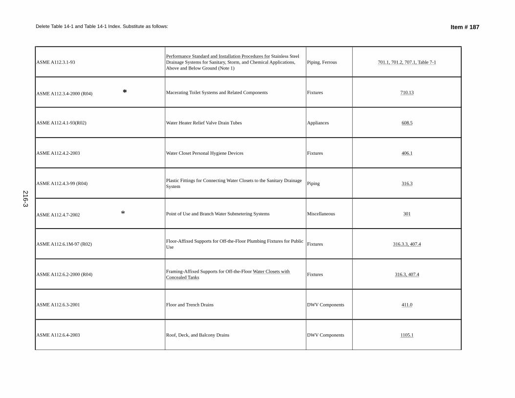
Delete Table 14-1 and Table 14-1 Index. Substitute as follows: Item # 187
ASME A112.3.1-93Performance Standard and Installation Procedures for Stainless Steel Drainage Systems for Sanitary, Storm, and Chemical Applications, Above and Below Ground (Note 1)
Piping, Ferrous 701.1, 701.2, 707.1, Table 7-1
ASME A112.3.4-2000 (R04) * Macerating Toilet Systems and Related Components Fixtures 710.13
ASME A112.4.1-93(R02) Water Heater Relief Valve Drain Tubes Appliances 608.5
ASME A112.4.2-2003 Water Closet Personal Hygiene Devices Fixtures 406.1
ASME A112.4.3-99 (R04) Plastic Fittings for Connecting Water Closets to the Sanitary Drainage System Piping 316.3
ASME A112.4.7-2002 * Point of Use and Branch Water Submetering Systems Miscellaneous 301
ASME A112.6.1M-97 (R02) Floor-Affixed Supports for Off-the-Floor Plumbing Fixtures for Public Use Fixtures 316.3.3, 407.4
ASME A112.6.2-2000 (R04) Framing-Affixed Supports for Off-the-Floor Water Closets with Concealed Tanks Fixtures 316.3, 407.4
ASME A112.6.3-2001 Floor and Trench Drains DWV Components 411.0
ASME A112.6.4-2003 Roof, Deck, and Balcony Drains DWV Components 1105.1
216-3
Delete Table 14-1 and Table 14-1 Index. Substitute as follows: Item # 187
ASME A112.6.7-2001 Enameled and Epoxy Coated Cast Iron and PVC Plastic Sanitary Floor Sinks Fixtures Table 4-1 footnote (9), 401.1
ASME A112.14.1-2003 Backwater Valves Valves 710.6
ASME A112.14.3-2000 (R04) * Grease Interceptors Fixtures 1014.1, 1014.2
ASME A112.14.4-2001 * Grease Removal Devices Fixtures 1014.2
ASME A112.18.1-2005/ CSA B125.1-05 Plumbing Supply Fittings Fixtures Fittings 603.3.10, 603.4.22
ASME A112.18.2-2005/CSA B125.2-05 Plumbing Waste Fittings Fittings 404.3, 701.0, 701.2
ASME A112.18.3-2003 2002 * Performance Requirements for Backflow Protection Devices and Systems in Plumbing Fixtures Fittings
Kitchen, Lavatory, shampoo bowls, and Shower Fittings with Flexible Hose
603.3.10, 603.4.22
ASME A112.18.6-2003 Flexible Water Connectors Piping 603.4.19, 604.4, 604.12, 604.14
ASME A112.18.7-99 (R04) Deck Mounted Bath/Shower Transfer Valves with Integral Backflow Protection Valves 603.3.7, 603.4.15
ASME A112.19.1M-94 (R04) Enameled Cast-Iron Plumbing Fixtures(Supplement 1-1998) Fixtures 401.1, 411.5, 411.6, 411.7, 414.0
216-4
Delete Table 14-1 and Table 14-1 Index. Substitute as follows: Item # 187
ASME A112.19.2M -2003 * Vitreous China Plumbing Fixtures and Hydraulic Fixtures Requirements for Water Closets and Urinals Fixtures 401.1, 402.1, 402.2, 402.3, 408.0, 410.0, 410.4, 413.0,
416.1
ASME A112.19.3 M-01 2000 (R04) * Stainless Steel Plumbing Fixtures (Designed for Residential Use) Fixtures 401.1
ASME A112.19.4M-94 (R04) * Porcelain-Enameled Formed Steel Plumbing Fixtures (Supplement 1-1998) Fixtures 401.1, 411.5, 411.6, 411.7, 414.0
ASME A112.19.5 -99 2005 Trim for Water-Closet Bowls, Tanks, and Urinals Fixtures 301.1.1
ASME A112.19.7 M-95 2006 * Whirlpool Hydromassage Bathtub Appliances Fixtures 401.1, 414.0
ASME A112.19.8M-87 (R96)(R05) * Suction Fittings for Use in Swimming Pools, Wading Pools, Spas, Hot Tubs, and Whirlpool Bathtub Appliances
Swimming Pools and Spas 414.4
ASME A112.19.9M-91 (R02) * Non-Vitreous Ceramic Plumbing Fixtures Fixtures 401.1, 408, 410.4, 416.0
ASME A112.19.10-2003 * Dual Flush Devices for Water Closets Fixtures 410.1
ASME A112.19.12-2000 2006 *Wall Mounted and Pedestal Mounted Adjustable Elevating, Tilting and Pivoting Lavatory, and Sink and Shampoo Bowl Carrier Systems and Drainage Waste Systems
Fixtures 401.1, 407.4
ASME A112.19.13-2002 2001 * Electrohydraulic Water Closets Fixtures 401.1, 408.0, 410.4
216-5
Delete Table 14-1 and Table 14-1 Index. Substitute as follows: Item # 187
ASME A112.19.14-2001 2006 * Six-Liter Water Closets Equipped with a Dual Flushing Device Fixtures 410.1, 401.1, 408.0
ASME A112.19.15-2001 2005 * Bathtub/Whirlpool Bathtubs with Pressure Sealed Doors Fixtures 414.0
ASME A112.20.1-2004 Qualification of Installers of High Purity Piping Systems Certification 1311.6
ASME A112.20.2-2004 Qualification of Installers of Firestop Systems and Devices for Piping Systems Certification 1503.1
ASME A112.21.3M-85 (R01) * Hydrants for Utility and Maintenance Use (Note 1) Valves 603.4.20
ASME A112.36.2M-91 (R02) * Cleanouts (Note 1) DWV Components 707.1
ASME B1.20.1-83 (R01 R06) * Pipe Threads, General Purpose, Inch Joints 1316.6.1(2), 316.1.1, 1209.5.7(A)
ASME B1.20.3-76 (R03) * Dryseal Pipe Threads, Inch Joints 316.1.1
ASME B16.1-98 2005 Cast Iron Pipe Flanges and Flanged Fittings (Classes 25, 125, 250) and 800 Piping, Ferrous Table 6-4, 604.5, 606.1.2, 1209.5.10, 1209.5.8.4(5)
ASME B16.3-98 * Malleable-Iron Threaded Fittings Classes 150 and 300 Piping, Ferrous 311.8, Table 6-4, 604.1, 604.6, Table 7-1, 701.2, 701.2.1, 701.2.2, 1209.5.8.4(2)
216-6
Delete Table 14-1 and Table 14-1 Index. Substitute as follows: Item # 187
ASME B16.4-98 Gray Iron Threaded Fittings, Classes 125 and 250 (Includes Revision Services) Piping, Ferrous 311.8, 604.5, 604.1,Table 6-4, 604.1, 1209.5.8.4(2)
ASME B16.5-2003 Pipe Flanges and Flanged Fittings: NPS 1/2 through 24 Joints 1209.5.10
ASME B16.12-98 (R06) * Cast Iron Threaded Drainage Fittings (Note 1) Piping, Ferrous 311.8, Table 7-1, 701.2
ASME B16.15-85 (R04) * Cast Bronze Threaded Fittings, Classes 125 and 250 Piping, Copper Alloy 311.8, 316.2.1, Table 6-4, 604.1
ASME B16.18-2001 Cast Copper Alloy Solder Joint Pressure Fittings (Note 1) Piping, Copper Alloy 316.1.3, Table 6-4, 604.1
ASME B16.20-1998 *Standard for ring-joint gaskets and grooves for steel pipe flanges Metallic Gaskets For Pipe Flanges: Ring Joint Spiral Wound And Jacketed
Table 6-4, 606.2.1, 609.3.2, 1209.5.10
ASME B16.21-92 2005 * Nonmetallic Flat Gaskets for Pipe Flanges Joints 606.1.2, 1209.5.11
ASME B16.22-2001 (R05) * Wrought Copper and Copper Alloy Solder Joint Pressure Fittings Alloy Piping, Copper Alloy 316.1.3, Table 6-4, 604.1, 606.2.1, 609.3.2, 1316.4
ASME B16.23-2002 * Cast Copper Alloy Solder Joint Drainage Fittings – DWV Piping, Copper Alloy 316.1.3, Table 7-1, 701.2, 701.2.3,
ASME B16.24-2001 * Cast Copper Alloy Pipe Flanges and Flanged Fittings: Classes 150,300, 400, 600, 900, 1500 and 2500 Piping, Copper Alloy Table 6-4, 604.1, 1209.5.10, 1209.5.8.4
216-7
Delete Table 14-1 and Table 14-1 Index. Substitute as follows: Item # 187
ASME B16.26-88 2006 * Cast Copper Alloy Fittings for Flared Copper Tubes Piping, Copper Alloy 316.1.4, Table 6-4, 604.1, 606.1.1
ASME B16.29-2001 * Wrought Copper and Wrought Copper Alloy Solder Joint Drainage Fittings–DWV Alloy (Note 1) Piping, Copper Alloy 316.1.3, Table 7-1, 701.2, 701.2.3
ASME B16.33-2002 * Manually Operated Metallic Gas Valves for Use in Gas Piping Systems up to 125 psig (Sizes NPS 1/2 - NPS 24) Valves 1211.9
ASME B16.34-96 2004 * Valves – Flanged, Threaded, and Welding End Valves 1209.5.10
ASME B16.39-98 * Pipe Unions, Malleable Iron Threaded Pipe Unions (Classes 150, 250 and 300) (Includes Revision Services) Piping, Ferrous 1211.3.2 (4)
ASME B16.40- 2002 * Manually Operated Thermoplastic Gas Shutoff and Valves in Gas Distribution Systems Fuel Gas 1211.10, 1212.4
ASME B16.47-96 Large Diameter Steel Flanges Piping, Ferrous 301.2
ASME B16.50-2001 * Wrought Copper and Copper Alloy Braze-Joint Pressure Fittings Piping, Copper Alloy Table 6-4, 1316.4
ASME B31.1-2004 Power Piping Piping 301.2
ASME B36.10M-2004 * Welded and Seamless Wrought Steel Pipe Piping, Ferrous 1209.5.2.2
216-8
Delete Table 14-1 and Table 14-1 Index. Substitute as follows: Item # 187
ASME B36.19M-85 2004 * Stainless Steel Pipe Piping, Ferrous 301.2
ASME Section IV Rules for Construction of Heating Boilers Miscellaneous 301.2
ASME Section VIII Rules for Construction of Pressure Vessels Miscellaneous 1325.6(2), 1326.3
ASME Section IX Welding and Brazing Procedures, Welders, Braziers, and Welding and Brazing Operators Qualifications Certification 316.1.7, 506.4, 1311.6,
ASSE 1001-2002 * Atmospheric-Type Vacuum Breakers Backflow Protection Table 6-2, 603.1, 603.2.2, 603.4.1, 603.4.1.8, 603.4.6.1, 603.4.6.3, 603.4.7
ASSE 1002-99 Anti-Siphon Fill Valves (Ballcocks) for Gravity Water Closet Flush Tank Backflow Protection Table 6-2, 603.1, 603.4.2
ASSE 1003-2001 * Water Pressure Reducing Valves Valves 608.2
ASSE 1004-90◄ Backflow Prevention Requirements for Commercial Dishwashing Machines Backflow Protection 603.2.1, 603.2.2, 603.3.6, 603.3.7
ASSE 1005-99 Water Heater Drain Valves (Withdrawn) Valves
ASSE 1006-86◄ Residential Use Dishwashers Appliances 603.2.1, 603.3.7, 807.4
216-9
Delete Table 14-1 and Table 14-1 Index. Substitute as follows: Item # 187
ASSE 1007-86 ◄ Home Laundry Equipment Appliances 603.2.1, 603.3.7
ASSE 1008-86 2006◄ * Plumbing Aspects of Food Waste Disposer Units Appliances 603.2.1, 603.3.7, 807.4
ASSE 1009-90◄ Commercial Food Waste Grinder Units Appliances 603.2.1, 603.3.7
ASSE 1010-2004 * Water Hammer Arresters Piping 609.10, 609.10.1
ASSE 1011-2004 * Hose-Connection Vacuum Breakers Backflow Protection 603.1, 603.4.7
ASSE 1012-2002 * Backflow Prevention with Intermediate Atmospheric Vent Backflow Protection 603.1
ASSE 1013-2005 * Reduced Pressure Principle Backflow Preventers and Reduced Pressure Fire Protection Principle Backflow Preventers Backflow Protection
Table 6-2, 603.1, 603.2.7, 603.4.6, 603.4.6.2, 603.4.6.3, 603.4.6.4, 603.4.16.2, 603.4.16.3, 603.4.18,
603.4.21
ASSE 1014-2005 * Backflow Prevention Devices for Hand-Held Showers Backflow Pretection 603.3.10
ASSE 1015-2005 * Double-Check Backflow Prevention Assemblies and Double Check Fire Protection Backflow Prevention Assemblies Backflow Protection Table 6-2, 603.1, 603.2.4, 603.4.5, 603.4.8, 603.4.16.1
ASSE 1016-2005 * Automatic Compensating Valves for Individual Showers and Tub/Shower Combinations Valves 418.0
216-10
Delete Table 14-1 and Table 14-1 Index. Substitute as follows: Item # 187
ASSE 1017-2003 * Temperature Actuated Mixing Valves for Hot Water Distribution Systems Valves 301.1.3
ASSE 1018-2001 * Trap Seal Primer Valves-Potable Water Supplied Valves 1007.0
ASSE 1019-2004 * Vacuum Breaker Wall Hydrant, Freeze-Resistant Automatic Draining Type Backflow Protection Table 6-2, 603.4.7
ASSE 1020-2004 * Pressure Vacuum Breaker Assembly Backflow Protection Table 6-2, 603.2.5, 603.4.5, 603.4.6, 603.4.6.3, 603.4.8
ASSE 1021-2001 Drains Air Gaps for Domestic Dishwasher Applications Backflow Protection 807.4
ASSE 1022-2003 * Backflow Preventer for Beverage Dispensing Equipment Backflow Protection Table 6-2, 603.4.12
ASSE 1023-79◄ Hot Water Dispensers, Household Storage Type-Electrical Appliances 401.1
ASSE 1024-2003 2004 * Dual Check Valve Backflow Preventers Backflow Prevention 603.1
ASSE 1025-78 Diverters for Plumbing Faucets with Hose Spray, Anti-Siphon Type, Residential Applications (Deleted no longer in publication) Valves
ASSE 1032-2004 Dual Check Valve Type Backflow Preventers for Carbonated Beverage Dispensers – Post Mix Types Backflow Protection 603.1
216-11
Delete Table 14-1 and Table 14-1 Index. Substitute as follows: Item # 187
ASSE 1035-2002 * Laboratory Faucet Backflow Preventers Backflow Protection 603.1
ASSE 1037-90◄ Pressurized Flushing Devices (Flushometers) for Plumbing Fixtures Backflow Protection 603.4.1
ASSE 1044-2001 * Trap Seal Primer Devices-Drainage Types and Electronic Design Types DWV Components 1007.0
ASSE 1047-2005 * Reduced Pressure Detector Fire Protection Backflow Prevention Assemblies Backflow Protection Table 6-2, 603.4.16.1, 603.4.16.2, 603.4.16.3
ASSE 1048-2005 * Double Check Detector Fire Protection Backflow Prevention Assemblies Backflow Protection Table 6-2, 603.4.16.1
ASSE 1052-2004 * Hose Connection Backflow Preventers Backflow Protection 603.4.7
ASSE 1055-97 Chemical Dispensing Systems Backflow Protection 603.4.18
ASSE 1056-2001 * Spill Resistant Vacuum Breakers Backflow Protection Table 6-2, 603.2.6, 603.4.6.1, 603.4.6.3, 603.4.18
ASSE 1062-97 2006 * Temperature Actuated Flow Reduction (TAFR) Valves for Individual Fixture Fittings Valves 301.1.3
ASSE 1066-97 Individual Pressure Balancing In-Line Valves for Individual Fixture Fittings (Note 9) Valves 301.1.3
216-12
Delete Table 14-1 and Table 14-1 Index. Substitute as follows: Item # 187
ASSE 1069-2005 * Automatic Temperature Control Mixing Valves Valves 418.0
ASSE 1070-2004 * Water Temperature Limiting Devices Valves 413.1, 414.5
ASSE Series 5000-2004 * Professional Qualification Standard for Backflow Prevention Assemblies, Testers, Repairers, and Surveyors Certification 603.1, 603.3.3
ASSE 6000-2004 2006 *Professional Qualifications Standard for Medical Gas Systems Installers, Inspectors, and Verifiers, Maintenance Personnel and Instructors
Certification 1328.1.1
AHAM ASSE DW-2PR-92◄ Plumbing Requirements for Household Dishwashers Appliances Table 7-3, 807.4
AHAM ASSE FWD-2 PR-89◄ Household Food Waste Disposer Units Appliances 401.1, 404.4
ASTM A 47-99 (R04)◄ Ferritic Malleable Iron Castings Piping, Ferrous 301.2
ASTM A 48-2003◄ Gray Iron Castings Piping, Ferrous 301.2
ASTM A 53-2004 2006a Pipe, Steel, Black and Hot-Dipped, Zinc-Coated, Welded, and Seamless Piping, Ferrous Table 6-4, 604.1, 1209.5.2.2
ASTM A 74-2004 2006 Cast-Iron Soil Pipe and Fittings (Note 1) Piping, Ferrous Table 7-1, 701.1, 701.2, 807.3, 903.1, 1003.1, 1101.3, 1102.1.2, 1102.2.2, 1102.5.2
216-13
Delete Table 14-1 and Table 14-1 Index. Substitute as follows: Item # 187
ASTM A 126-2004 Gray Iron Castings for Valves, Flanges, and Pipe Fittings Piping, Ferrous 311.8, 701.2.1, 701.2.2
ASTM A 197M-2000 (R06) ◄ Cupola Malleable Iron (Metric) Piping, Ferrous 311.8, 701.2.1, 701.2.2
ASTM A 269-2004 Seamless and Welded Austenitic Stainless Steel Tubing for General Service Piping, Ferrous 301.2
ASTM A 312M-2004b 2006 Seamless, Welded and Heavy Cold Worked Austenitic Stainless Steel Pipes Piping, Ferrous 604.1
ASTM A 377-2003 Ductile-Iron Pressure Pipe Piping, Ferrous 604.1
ASTM A 479M-2005 2006a◄ Stainless Steel Bars and Shapes for Use in Boilers and Other Pressure Vessels Piping, Ferrous 301.2
ASTM A 518-99(R03)◄ Corrosion-Resistant High-Silicon Iron Castings Piping, Ferrous 301.2
ASTM A 536-84(R04)◄ Ductile Iron Castings Piping, Ferrous 301.2
ASTM A 653M-2004a 2006 ◄ Steel Sheet, Zinc-Coated (Galvanized) or Zinc-Iron Alloy-Coated (Galvannealed) by the Hot-Dip Process Piping, Ferrous 313.8, 510.6.1, 510.6.2.5, 906.1, 906.5
ASTM A 733-2003 Welded and Seamless Carbon Steel and Austenitic Stainless Steel Pipe Nipples Piping, Ferrous 604.1
216-14
Delete Table 14-1 and Table 14-1 Index. Substitute as follows: Item # 187
ASTM A 861-2004 High-Silicon Iron Pipe and Fittings (Note 1) Piping, Ferrous 811.1, 811.2
ASTM A 888-2004a 2007 Hubless Cast-Iron Soil Pipe and Fittings for Sanitary and Storm Drain Waste and Vent Piping Applications Piping, Ferrous Table 7-1, 701.1, 701.2, 807.3, 903.1, 903.3, 1101.3,
1102.1.2, 1102.2.2
ASTM B 29-2003 Refined Lead Joints 701.3, 1105.4, 906.6, 313.8, 401.2, 411.8, 705.1.1, 316.1.2
ASTM B 32-2004 Solder Metal (Note 4) Joints 316.1.3, 1316.8
ASTM B 42-2002e1 Seamless Copper Pipe, Standard Sizes Piping, Copper Alloy Table 6-4, 604.1, 1102.1.2, 1102.2.2
ASTM B 43-98(R04) Seamless Red Brass Pipe, Standard Sizes Piping, Copper Alloy Table 6-4, 604.1, Table 7-1, 701.1, 1102.1.2, 1102.2.2
ASTM B 75-2002 Seamless Copper Tube Piping, Copper Alloy Table 6-4, 604.1, 701.1, 701.1.4, 1102.1.2, 1102.2.2
ASTM B 88-2003 Seamless Copper Water Tube Piping, Copper Alloy Table 6-4, 604.1, 1102.1.2, 1102.2.2, 1209.5.3.2, 1316.3, 1325.3
ASTM B 135-2002 Seamless Brass Tube (Metric) Piping, Copper Alloy 301.2, Table 6-4, 604.1
ASTM B 152M-200006a ◄ Copper Sheet, Strip, Plate, and Rolled Bar Miscellaneous 1102.2
216-15
Delete Table 14-1 and Table 14-1 Index. Substitute as follows: Item # 187
ASTM B 251-2002e1 General Requirements for Wrought Seamless Copper Copper-Alloy Tube Piping, Copper Alloy 302.0, 316.1, Table 6-4, 604.1, Table 7-1, 701.1,
705.2.3, 1102.1.2
ASTM B 280-2003 Seamless Copper Tube for Air Conditioning and Refrigeration Field Service Piping, Copper Alloy 1209.5.3.2, 1316.3, 1325.3
ASTM B 302-2002 Threadless Copper Pipe, Standard Sizes Piping, Copper Alloy 301.2, Table 6-4, 604.1, Table 7-1, 701.1
ASTM B 306-2002 Copper Drainage Tube (DWV) Piping, Copper Alloy 701.1
ASTM B 370-2003 ◄ Copper Sheet and Strip for Building Construction Miscellaneous 1102.2
ASTM B 447-2002 Welded Copper Tube Piping, Copper Alloy 301.2, Table 6-4, 604.1
ASTM B 584-2004 2006a ◄ Copper Alloy Sand Casting for General Applications (Note 5) Piping, Copper Alloy 701.4.1, 701.4.2, 704.4.1, 1209.5.8.4
ASTM B 587-97e1 (R03) 2006 Welded Brass Tube Piping, Copper Alloy 604.1
ASTM B 687-99 (R05)e1 Brass, Copper, and Chromium-Plated Pipe Nipples Piping, Copper Alloy 604.1
ASTM B 813-2000e1 Liquid and Paste Fluxes for Soldering Applications of Copper and Copper Alloy Tube Joints 316.1.3
216-16
Delete Table 14-1 and Table 14-1 Index. Substitute as follows: Item # 187
ASTM B 819-2000 (R06) Seamless Copper Tube for Medical Gas Systems Piping, Copper Alloy 1316.3, 1316.3.1, 1325.3
ASTM B 828-2002 Making Capillary Joints by Soldering of Copper and Copper Alloy Tube and Fittings Joints 316.1.3
ASTM C 14-2003 2005a Nonreinforced Concrete Sewer, Storm Drain, and Culvert Pipe Piping, Non- Metallic Table 7-1, 701.1, 1102.3
ASTM C 296-2000 (R04)e1 Asbestos-Cement Pressure Pipe Piping, Non- Metallic Table 6-4, 604.1
ASTM C 412-2003 2005a Concrete Drain Tile Piping, Non- Metallic 1101.5.1
ASTM C 425-2004 Compression Joints for Vitrified Clay Pipe and Fittings Joints 705.2.1
ASTM C 428-97(R02)e1 2005(R06) Asbestos-Cement Nonpressure Sewer Pipe (Notes 6 and 7) Piping, Non- Metallic Table 7-1, 701.1, 705.1.4, 715.0, 1102.4
ASTM C 443-2005 a Joints for Circular Concrete Sewer and Culvert Pipe and Manholes, Using Rubber Gaskets Joints 705.1.6
ASTM C 478-2003a 2006a Precast Reinforced Concrete Manhole Sections Miscellaneous 719.6
ASTM C 564-2003a Rubber Gaskets for Cast-Iron Soil Pipe and Fittings Joints 705.1.7
216-17
Delete Table 14-1 and Table 14-1 Index. Substitute as follows: Item # 187
ASTM C 700-2002 2005 Vitrified Clay Pipe, Extra Strength, Standard Strength, and Perforated Piping, Non- Metallic Table 7-1, 701.1, 701.2, 1102.5.2
ASTM C 1053-2000 (R05) Borosilicate Glass Pipe and Fittings for Drain, Waste, and Vent (DWV) Applications (Note 1) Piping, Non- Metallic 811.2
ASTM C 1173-2004 2006 Flexible Transition Couplings for Underground Piping Systems Joints 705.1.4, 705.1.6
ASTM C 1277-2004 2006 Shielded Couplings Joining Hubless Cast-Iron Soil Pipe and Fittings Piping, Ferrous Joints 705.1.8, 705.1.9
ASTM C 1440-2003◄ Thermoplastic Elastomeric (TPE) Gasket Materials for Drain, Waste, and Vent (DWV), Sewer, Sanitary and Storm Plumbing Systems Piping, Plastic Joints 705.1.4, 705.1.6
ASTM C 1460-2004 Shielded Transition Couplings for Use with Dissimilar DWV Pipe and Fittings Above Ground Piping, Plastic Joints 705.1.8, 705.1.9
ASTM C 1461-2002 2006Mechanical Couplings Using Thermoplastic Elastomeric (TPE) Gaskets for Joining Drain, Waste, and Vent (DWV); Sewer; Sanitary; and Storm Plumbing Systems for Above and Below Ground Use
Piping, Plastic Joints 705.1.4, 705.1.6, 705.1.7, 705.1.8, 705.1.9
ASTM C 1540-2004 Heavy Duty Shielded Couplings Joining Hubless Cast Iron Soil Pipe and Fittings Joints 705.1.8, 705.1.9
ASTM D 1527-99e1 (R05) * Acrylonitrile-Butadiene-Styrene (ABS) Plastic Pipe, Sch. 40 and 80 Piping, Plastic Table 3-2, 1102.1, 1102.2
ASTM D 1784-2003 2006◄ Rigid Poly (Vinyl Chloride) (PVC) Compounds and Chlorinated Poly (Vinyl Chloride) (CPVC) Compounds
Piping, Plastic Miscellaneous 301.2
216-18
Delete Table 14-1 and Table 14-1 Index. Substitute as follows: Item # 187
ASTM D 1785-2004a 2006 * Poly (Vinyl Chloride) (PVC) Plastic Pipe, Schedules 40, 80, and 120 Piping, Plastic Table 3-2, Table 6-4, 604.1, Table 7-1, 701.1, 903.1, 1101.3, 1102.1, 1102.2
ASTM D 1869-95(R00) (R05) Rubber O-rings for Asbestos-Cement Pipe Joints 705.1.4
ASTM D 2104-2003 * Polyethylene (PE) Plastic Pipe, Sch. 40 Piping, Plastic 604.1
ASTM D 2235-2004 * Solvent Cement for Acrylonitrile-Butadiene-Styrene (ABS) Plastic Pipe and Fittings Joints 316.1.6
ASTM D 2239-2003 * Polyethylene (PE) Plastic Pipe, (SDR-PR) Based on Controlled Inside Diameter Piping, Plastic 604.1, Table 6-4
ASTM D 2241-2004b 2005 * Poly(Vinyl Chloride)(PVC) Pressure-Rated Pipe (SDR Series) Piping, Plastic 604.1, Table 6-4
ASTM D 2282-99e1 (R05) * Acrylonitrile-Butadiene-Styrene (ABS) Plastic Pipe (SDR-PR) Piping, Plastic 604.1
ASTM D 2321-2000 2005 * Underground Installation of Thermoplastic Pipe for Sewers and Other Gravity-Flow Applications Piping, Plastic 701.1
ASTM D 2447-2003 * Polyethylene (PE) Plastic Pipe, Sch. 40 and 80 (Based on Controlled Outside Diameter) Piping, Plastic 604.1
ASTM D 2464-99e1 2006 * Threaded Poly(Vinyl Chloride) (PVC) Plastic Pipe Fittings, Sch. 80 (Note 1) Piping, Plastic Table 6-4, 604.1
216-19
Delete Table 14-1 and Table 14-1 Index. Substitute as follows: Item # 187
ASTM D 2466-2002 2006 * Poly(Vinyl Chloride) (PVC) Plastic Pipe Fittings, Sch. 40 (Note 1) Piping, Plastic Table 6-4, 604.1
ASTM D 2467-2004e1 2006 * Poly(Vinyl Chloride) (PVC) Plastic Pipe Fittings, Sch, 80 (Note 1) Piping, Plastic Table 6-4, 604.1
ASTM D 2513-2004a 2006a * Thermoplastic Gas Pressure Pipe Tubing and Fittings (Note 1) Piping, Plastic 1209.5.4, 1209.5.4.2, 1209.5.9, 1211.1.6(B), 1211.1.7
ASTM D 2517-2000e1 2006 * Reinforced Epoxy Resin Gas Pressure Pipe and Fittings Piping, Plastic 301.2
ASTM D 2564-2004 e1 * Solvent Cements for Poly(Vinyl Chloride) (PVC) Plastic Piping Systems Joints 316.1.6, Table 6-4, 705.0
ASTM D 2609-2002 * Plastic Insert Fittings for Polyethylene (PE) Plastic Pipe (Note 1) Piping, Plastic Table 6-4, 604.1
ASTM D 2657-2003 * Practice for Heating Fusion Joining of Polyolefin Pipe Fittings (Note 1) Joints 811.2
ASTM D 2661-2002 2006 * Acrylonitrile-Butadiene-Styrene (ABS) Sch. 40 Plastic Drain, Waste, and Vent Pipe and Fittings (Note 1) Piping, Plastic Table 7-1, 701.1, 701.2, 704.4.1, 707.1, 903.1, 903.3,
1101.3
ASTM D 2665-2004a (e2) * Poly(Vinyl Chloride) (PVC) Plastic Drain, Waste, and Vent Pipe and Fittings (Note 1) Piping, Plastic Table 7-1, 701.1, 701.2, 704.4.1, 707.1, 903.1, 903.3,
1101.3,
ASTM D 2672-96a (R03) * Joints for IPS PVC Pipe Using Solvent Cement Joints 316.1.6
216-20
Delete Table 14-1 and Table 14-1 Index. Substitute as follows: Item # 187
ASTM D 2680-2001 * Acrylonitrile-Butadiene-Styrene (ABS) and Poly(Vinyl Chloride) (PVC) Composite Sewer Piping Piping, Plastic Table 7-1, 701.1, 705.1.4, 715.0, 1102.4
ASTM D 2729-2003 * Poly(Vinyl Chloride) (PVC) Sewer Pipe and Fittings (Note 1) Piping, Plastic 1102.5, 1611.1
ASTM D 2737-2003 * Polyethylene (PE) Plastic Tubing Piping, Plastic Table 6-4, 604.1
ASTM D 2751-96a 2005 * Acrylonitrile-Butadiene-Styrene (ABS) Sewer Pipe and Fittings (Note 1) Piping, Plastic 1102.5, 1611.0
ASTM D 2846-99e1 2006 * Chlorinated Poly (Vinyl Chloride) (CPVC) Plastic Hot- and Cold-Water Distribution Systems Piping, Plastic 316.1.6, Table 6-4, 604.1
ASTM D 2855-96(R02) * Making Solvent-Cemented Joints with Poly(Vinyl Chloride) (PVC) Pipe and Fittings Joints 316.1.6
ASTM D 2996-2001 * Filament-Wound Fiberglass (Glass-Fiber-Reinforced Thermosetting Resin) Pipe Piping, Plastic 301.2
ASTM D 3034-2004a 2006 * Type PSM Poly (Vinyl Chloride) (PVC) Sewer Pipe and Fittings Piping, Plastic 705.1.4, 715.0, 1102.4
ASTM D 3035- 2003a * Polyethylene (PE) Plastic Pipe (DR-PR) (Based on Controlled Outside Diameter) Piping, Plastic Table 6-4, 1611.1
ASTM D 3122-95(R02) * Solvent Cements for Styrene-Rubber (SR) Plastic Pipe and Fittings Joints 301.2
216-21
Delete Table 14-1 and Table 14-1 Index. Substitute as follows: Item # 187
ASTM D 3138-2004 *Solvent Cements for Transition Joints, Acrylonitrile-Butadiene- Styrene (ABS) and Poly (Vinyl Chloride) (PVC) Non-Pressure Piping Components
Joints 316.1.6
ASTM D 3139-98 (R05) * Joints for Plastic Pressure Pipes Using Flexible Elastomeric Seals Joints 316.1.5
ASTM D 3212-96a (R03)e1 * Joints for Drain and Sewer Plastic Pipes Using Flexible Elastomeric Seals Joints 705.1.7
ASTM D 3311-2002e1 2006 * Drain, Waste, and Vent (DWV) Plastic Fittings Patterns (Note 1) Piping, Plastic 701.2
ASTM D 3965-2004 2005 ◄ * Rigid Acrylonitrile-Butadiene-Styrene (ABS) Materials for Pipe and Fittings
Piping, Plastic Miscellaneous
311.8, 316.1.6, 316.3.1, 701.1, 701.1.2, 701.2, 704.4.1, 704.4.3, 707.1, 903.1, 903.1.2, 903.3, 1003.1,
1101.3, 1102.1, 1102.2
ASTM D 4068-2001 * Chlorinated Polyethylene (CPE) Sheeting for Concealed Water-Containment Membrane Fixtures 411.8(2)
ASTM D 4101-2004a 2006a ◄ * Propylene Plastic Polypropylene Injection and Extrusion Materials Miscellaneous 811.1, 1003.1
ASTM D 4551-96 (R01) * Poly(Vinyl Chloride) (PVC) Plastic Flexible Concealed Water-Containment Membrane Fixtures 411.5, 411.7
ASTM D 6104-97 (R03) Determining the Performance of Oil/Water Separators Subjected to Surface Run-Off Fixtures 1009.1, 1017.1
ASTM E 84-2004 2006 Surface Burning Characteristics of Building Materials Miscellaneous 701.1.2, 903.1.2, 1101.3
216-22
Delete Table 14-1 and Table 14-1 Index. Substitute as follows: Item # 187
ASTM E 119-2000a 2005a Fire Tests of Building Construction and Materials Miscellaneous 301.2, 301.4, 502.6, 510.10.14.1, 1211.5.2, 1505.1, 1505.3
ASTM E 814-2002 2006 Fire Tests of Through-Penetration Fire Stops Miscellaneous 313.7, 313.10.4, 508.15.2, 1501.1, 1502.1, 1503.1, 1504.1, 1505.3, 1506.2
ASTM F 402-93(R99) 2005 * Safe Handling of Solvent Cements, Primers, and Cleaners Used for Joining Thermoplastic Pipe and Fittings Joints 316.1.6
ASTM F 405-97 2005 * Corrugated Polyethylene (PE) Tubing Pipe and Fittings Piping, Plastic 301.2
ASTM F 409-2002 * Thermoplastic Accessible and Replaceable Plastic Tube and Tubular Fittings (Note 1) Piping, Plastic 1003
ASTM F 437-99 2006 * Threaded Chlorinated Poly(Vinyl Chloride) (CPVC) Plastic Pipe Fittings, Sch. 80 Piping, Plastic Table 6-4, 604.1
ASTM F 438-2004 * Socket-Type Chlorinated Poly(Vinyl Chloride) (CPVC) Plastic Pipe Fittings, Sch. 40 Piping, Plastic 604.1
ASTM F 439-2002e1 2006 * Socket-Type Chlorinated Poly(Vinyl Chloride) (CPVC) Plastic Pipe Fittings, Sch. 80 Piping, Plastic Table 6-4, 604.1
ASTM F 441-2002 * Chlorinated Poly(Vinyl Chloride) (CPVC) Plastic Pipe, Sch. 40 and 80 Piping, Plastic Table 6-4, 604.1
ASTM F 442-99 (R05) * Chlorinated Poly(Vinyl Chloride) (CPVC) Plastic Pipe (SDR-PR) Piping, Plastic 604.1
216-23
Delete Table 14-1 and Table 14-1 Index. Substitute as follows: Item # 187
ASTM F 480-2002 2006b * Thermoplastic Well Casing Pipe and Couplings Made in Standard Dimension Ratios (SDR) Schedule 40 and Schedule 80 Piping, Plastic 604.1
ASTM F 493-2004 * Solvent Cements for Chlorinated Poly (Vinyl Chloride) (CPVC) Plastic Pipe and Fittings Joints 316.1.6
ASTM F 628-2001 2006 * Acrylonitrile-Butadiene-Styrene (ABS) Sch. 40 Plastic Drain, Waste, and Vent Pipe with a Cellular Core, (Note 1) Piping, Plastic Table 7-1, 701.1, 701.2, 704.4.1, 707.1, 903.1, 903.3,
1101.3
ASTM F 656-2002 * Primers for Use in Solvent Cement Joints of Poly (Vinyl Chloride) (PVC) Plastic Pipe and Fittings Joints 316.1.6
ASTM F 667-97 2006 * Large Diameter Corrugated Polyethylene Tubing Pipe and Fittings Piping, Plastic 301.2
ASTM F 714-2003 2006 * Polyethylene (PE) Plastic Pipe (SDR-PR) (Based on Outside Diameter) Piping, Plastic 715
ASTM F 789-2003Type PS-46 and Type PS-115 Poly (Vinyl Chloride) (PVC) Plastic Gravity Flow Sewer Pipe and Fittings (Note 1) Officially withdrawn no replacement
Piping, Plastic
ASTM F 794-2003 * Poly (Vinyl Chloride) (PVC) Profile Gravity Sewer Pipe and Fittings Based on Controlled Inside Diameter Piping, Plastic Table 7-1, 701.1, 701.2, 705.1.4, 715.0, 1102.4
ASTM F 810-2001 * Smooth wall Polyethylene (PE) Pipe for Use in Drainage and Waste Disposal Absorption Fields Piping, Plastic 1611.1
ASTM F 876-2004a 2005 * Cross linked Polyethylene (PEX) Tubing Piping, Plastic Table 6-4, 604.1, 604.11
216-24
Delete Table 14-1 and Table 14-1 Index. Substitute as follows: Item # 187
ASTM F 877-2002a 2005 * Cross linked Polyethylene (PEX) Plastic Hot- and Cold-Water Distribution Systems Piping, Plastic Table 6-4, 604.1
ASTM F 891-2004 * Coextruded Poly (Vinyl Chloride) (PVC) Plastic Pipe with a Cellular Core Piping, Plastic Table 7-1, 701.1, 704.4.1, 707.1, 903.1, 903.3, 1101.3
ASTM F 894-98a 2005 * Polyethylene (PE) Large Diameter Profile Wall Sewer and Drain Pipe Piping, Plastic 301.2
ASTM F 949-2003 2006a * Poly (Vinyl Chloride) (PVC) Corrugated Sewer Pipe with a Smooth Interior and Fittings Piping, Plastic 301.2
ASTM F 1216-2003 2006 * Rehabilitation of Existing Pipelines and Conduits by the Inversion and Curing of a Resin-Impregnated Tube Piping, Plastic 715.3
ASTM F 1281-2003 2005 * Cross linked Polyethylene/Aluminum/Cross linked Polyethylene (PEX-AL-PEX) Pressure Pipe Piping, Plastic Table 6-4, 604.1, 604.13
ASTM F 1282-2003 2006 * Polyethylene/Aluminum/Polyethylene (PE-AL-PE) Composite Pressure Pipe Piping, Plastic Table 6-4, 604.1, 604.13
ASTM F 1412-2001e1 * Polyolefin Pipe and Fittings for Corrosive Waste Drainage Systems Piping, Plastic 811.2
ASTM F 1476-2001 * Performance of Gasketed Mechanical Couplings for Use in Piping Application Joints 705.1.7
ASTM F 1673-2004 * Polyvinylidene Fluoride (PVDF) Corrosive Waste Drainage Systems Piping, Plastic 811.2
216-25
Delete Table 14-1 and Table 14-1 Index. Substitute as follows: Item # 187
ASTM F 1743-96(R03) * Rehabilitation of Existing Pipelines and Conduits by Pulled-in-Place Installation of Cured-in-Place Thermosetting Resin Pipe (CIPP) Piping, Plastic 715.3
ASTM F 1807-2004 2005 * Metal Insert Fittings with Utilizing Copper Crimp Ring for SDR 9 Cross linked Polyethylene (PEX) Tubing Piping, Plastic Table 6-4, 604.1, 604.11.1
ASTM F 1866-98 2005 * Poly (Vinyl Chloride) (PVC) Plastic Schedule 40 Drainage and DWV Fabricated Fittings, Schedule 40 Piping, Plastic Table 7-1, 701.1, 701.2, 704.4.1, 707.1 903.1, 903.3,
1101.3
ASTM F 1924-2001e1 2005 * Plastic Mechanical Fitting for Use on Outside Diameter Controlled Polyethylene Gas Distribution Pipe and Tubing Piping, Plastic 301.2
ASTM F 1948-99ae1 2005 * Metallic Mechanical Fittings for Use on Outside Diameter Controlled Thermoplastic Gas Distribution Pipe and Tubing Piping, Plastic 301.2
ASTM F 1960-2003 2005 * Cold Expansion Fittings with PEX Reinforcing Rings for Use with Cross-Linked Polyethylene (PEX) Tubing Piping, Plastic Table 6-4, 604.1, 604.11.1
ASTM F 1961-2002a * Metal Metallic Cold Flare Compression Fittings with Disc Springs for Cross linked Polyethylene (PEX) Tubing Piping, Plastic Table 6-4, 604.1, 604.11.1
ASTM F 1970-2001 2005 *Special Engineered Fittings or Appurtenances or Valves for Use in Poly(Vinyl Chloride) (PVC) or Chlorinated Poly (Vinyl Chloride) (CPVC) Systems
Piping, Plastic 316.0, 605.0
ASTM F 1973-2002 2005 *Factory Assembled Anodeless Riser and Transition Fitting in Polyethylene (PE) and Polymide 11 (PA11) Fuel Gas Distribution Systems
Piping, Plastic 1209.5.4
ASTM F 1974-2004 *Metal Insert Fittings for Polyethylene/Aluminum/Polyethylene and Crosslinked Polyethylene/Aluminum/Crosslinked Polyethylene Composite Pressure Pipe
Piping, Plastic Table 6-4, 604.1, 604.13.1
216-26
Delete Table 14-1 and Table 14-1 Index. Substitute as follows: Item # 187
ASTM F 2080-2004 2005 Cold-Expansion Fittings With Metal Compression Sleeves for Cross-Linked Polyethylene (PEX) Pipe Piping, Plastic Table 6-4, 604.1, 604.11.1
ASTM F 2098-2001 2004e1 Stainless Steel Clamps for Securing SDR9 Cross-Linked Polyethylene (PEX) Tubing to Metal Insert Fittings Joints 604.11.1
ASTM F 2159-2003 2005 Plastic Insert Fittings Utilizing a Copper Ring for SDR 9 Cross-Linked Polyethylene (PEX) Tubing Joints Table 6-4, 604.1, 604.11.1
ASTM F 2165-2002 * Flexible Pre-Insulated Piping Piping, Plastic 301.2
ASTM F 2262-2004 2005 * Crosslinked Polyethylene/Aluminum/Crosslinked Polyethylene Tubing OD Controlled SDR 9 Piping, Plastic Table 6-4, 604.1, 604.13
ASTM F 2434-2004 2005
Metal Insert Fittings Utilizing a Copper Crimp Ring for SDR9 Crosslinked Polyethylene (PEX) Tubing and SDR9 Crosslinked Polyethylene/Aluminum/Crosslinked Polyethylene (PEX-AL-PEX) Tubing
Piping, Plastic Table 6-4 , 604.13.1, 604.1
AWS A5.8-2004 * Specification for Filler Metals for Brazing and Braze Welding Joints 1319.1
AWS B2.2-91 Brazing Procedure and Performance Qualification Certification 316.1.7, 1311.6
AWWA C110-2003 *Ductile-Iron and Gray-Iron Fittings, 3 in. through 48 in. (75 mm through 1200 mm), for Water and Other Liquids (same as ANSI A21.10-98)
Piping, Ferrous Table 6-4, 604.1
AWWA C111-2000 * Rubber-Gasket Joints for Ductile-Iron Pressure Pipe and Fittings (same as ANSI A21.11-00) Piping, Ferrous Joints 606.1.2
216-27
Delete Table 14-1 and Table 14-1 Index. Substitute as follows: Item # 187
AWWA C151-2002 * Ductile-Iron Pipe, Centrifugally Cast, for Water or Other Liquids (same as ANSI A21.51-91) Piping, Ferrous 604.1,Table 6-4
AWWA C153-2000 2006 *Ductile-Iron Compact Fittings, 3 in. through 24 in. (76 mm through 610 mm) and 54 in. through 64 in. (1400 mm through 1600 mm), for Water Service (same as ANSI A21.53-00)
Piping, Ferrous Table 6-4, 604.1
AWWA C203-2002 * Coal-Tar Protective Coatings and Linings for Steel Water Pipelines, Enameled and Tape – Hot Applied Piping Miscelleous 609.3.1
AWWA C213-2001 * Fusion-Bonded Epoxy Coating for the Interior and Exterior of Steel Water Pipelines
Piping, Ferrous Miscelleous 609.3.1
AWWA C215-2004 * Extruded Polyolefin Coatings for the Exterior of Steel Water Pipelines Piping, Ferrous Miscelleous 609.3.1
AWWA C400-2003 * Asbestos-Cement Distribution Pressure Pipe, 4 in. through 16 in. (100 mm through 400 mm) for Water Distribution Systems and Transmission Piping, Non-Metallic Table 6-4, 604.1
AWWA C500-2002 * Metal-Seated Service Gate Valves for Water Supply Service Valves 605.4
AWWA C504-2000 2006 * Rubber-Seated Butterfly Valves Valves 605.4
AWWA C507-99 2005 * Ball Valves, 6 in. through 48 in. (150 mm through 1200 mm) Valves 605.4
AWWA C510-97 * Double Check Valve Backflow-Prevention Assembly Backflow Protection Table 6-2, 603.2.4, 603.4.16.1
216-28
Delete Table 14-1 and Table 14-1 Index. Substitute as follows: Item # 187
AWWA C511-97 * Reduced-Pressure Principle Backflow-Prevention Assembly Backflow Protection Table 6-2, 603.4.16.1
AWWA C606-2004 * Grooved- and Shouldered-Type Joints Joints 606.1.2
AWWA C900-97 * Polyvinyl Chloride (PVC) Pressure Pipe, and Fabricated Fittings 4 in. through 12 in. (100mm through 300mm), for Water Distribution Piping, Plastic Table 6-4, 604.1
AWWA C901-2002 * Polyethylene (PE) Pressure Pipe and Tubing, 1/2 in. (13 mm) through 3 in. (76 mm), for Water Service Piping, Plastic Table 6-4, 604.1
AWWA C907-91 2004 * Injection-Molded Polyvinyl Chloride (PVC) Pressure Fittings for Water - 4 in. through 12 in. (100 mm through 300 mm) for Water Distribution Piping, Plastic 301.2
CGA V-1 2005 Standard for Compressed Gas Cylinder Valve Outlet and Inlet Connection Valves Chapter 13
CGA S-1.3 2005 Pressure Relief Device Standards-Part 3-Stationary Storage Containers for Compressed Gases Fuel Gas 301.2
CISPI 301-2004a 2005 Hubless Cast-Iron Soil Pipe and Fittings for Sanitary and Storm Drain, Waste, and Vent Piping Applications (Note 1) Piping, Ferrous Table 7-1, 701.1, 701.2, 704.4.1, 903.1, 903.3, 1101.3
CISPI 310-2004Couplings for Use in Connection with Hubless Cast-Iron Soil Pipe and Fittings for Sanitary and Storm Drain, Waste, and Vent Piping Applications
Joints 705.1.8, 705.1.9, 705.6, 705.7
CSA No. 3-92 U.S. Requirements for Excess Flow Valves Valves 1210.0
216-29
Delete Table 14-1 and Table 14-1 Index. Substitute as follows: Item # 187
CSA A257-2003 Concrete Pipe and Manhole Sections Piping 301.1
CSA B45.0-2002 General Requirements for Plumbing Fixtures Fixtures 401.1, 402.1, 402.2, 402.3, 411.6, 411.7, 413.0, 416.0
CSA B45.1-2002 Ceramic Plumbing Fixtures Fixtures 401.1, 402.1, 402.2, 402.3, 413.0, 416.0, 410, 410.4
CSA B45.2-2002 Enameled Cast-Iron Plumbing Fixtures Fixtures 401.1, 402.1, 413.0
CSA B45.3-2002 Porcelain-Enamelled Steel Plumbing Fixtures Fixtures 301.1, 401.1, 402.1 402.2, 402.3, 413.0, 414.0, 402.2, 402.3, 414.4, 416.0
CSA B45.4-2002 Stainless Steel Plumbing Fixtures Fixtures 401.1, 402.1, 402.2, 402.3, 411.6, 411.7, 413.0, 414.0, 416.0
CSA B45.5-2002 Plastic Plumbing Fixtures Fixtures 401.1, 401.2, 402.3, 414.0, 416.0
CSA B45.9-2002 Macerating Systems and Related Components DWV Components 301.1, 406.3, 710.13
CSA B45.10-2001 (R06) Hydromassage Bathtubs Fixtures 414.0, 413.0
CSA B45.11-2004 Glass Lavatories Fixtures 401.1, 413.0
216-30
Delete Table 14-1 and Table 14-1 Index. Substitute as follows: Item # 187
CSA B64-2001 (R06) Backflow Preventers and Vacuum Breakers Backflow Protection Table 6-2, 603.1, 603.2, 603.3, 603.4
CSA B64.1.1-2001(R06) Vacuum Breakers, Atmospheric Type (AVB) Backflow Protection401.3, 402.4, 407.8, 410.0, 410.3, 410.4, 411.10,
413.0, 415.0, 416.2, Table 6-2 603.1, 603.2, 603.3, 603.4
CSA B64.1.2-2001(R06) Vacuum Breakers, Pressure Type (PVB) Backflow Protection Table 6-2, 603.1, 603.2.5
CSA B64.2-2001(R06) Vacuum Breakers, Hose Connection Type (HCVB) Backflow Protection Table 6-2, 603.1, 603.2.3
CSA B64.2.1.1-2001(R06) Vacuum Breaker, Hose Connection Dual Check Type (HCDVB) Type with Automatic Drainage Feature (HCVB) Backflow Protection Table 6-2, 603.1, 603.4.6
CSA B64.4-2001(R06) Backflow Preventers, Reduced Pressure Principle Type (RP) Backflow Protection Table 6-2, 603.2.7, 603.4.6.1, 603.4.6.2, 603.4.6.3, 603.4.6.4, 603.4.16.2, 603.4.18, 603.4.21
CSA B64.4.1-2001(R06) Backflow Preventers, Reduced Pressure Principle Type for Fire System (RPF) Backflow Protection Table 6-2, 603.4.16.1
CSA B64.5-2001(R06) Backflow Preventers, Double Check Valve Type (DVCA) Backflow Protection Table 6-2, 603.1, 603.2.4
CSA B64.5.1-2001(R06) Backflow Preventers, Double Check Valve Type for Fire System (DVCAF) Backflow Protection Table 6-2, 603.1, 603.4.16
CSA B64.7-2001 Vacuum Breakers Preventers, Laboratory Faucet Type (LFVB) Backflow Protection 603.1, 603.4.17
216-31
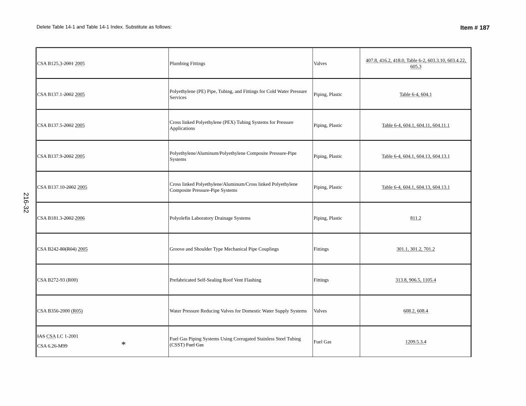
Delete Table 14-1 and Table 14-1 Index. Substitute as follows: Item # 187
CSA B125.3-2001 2005 Plumbing Fittings Valves 407.8, 416.2, 418.0, Table 6-2, 603.3.10, 603.4.22, 605.3
CSA B137.1-2002 2005 Polyethylene (PE) Pipe, Tubing, and Fittings for Cold Water Pressure Services Piping, Plastic Table 6-4, 604.1
CSA B137.5-2002 2005 Cross linked Polyethylene (PEX) Tubing Systems for Pressure Applications Piping, Plastic Table 6-4, 604.1, 604.11, 604.11.1
CSA B137.9-2002 2005 Polyethylene/Aluminum/Polyethylene Composite Pressure-Pipe Systems Piping, Plastic Table 6-4, 604.1, 604.13, 604.13.1
CSA B137.10-2002 2005 Cross linked Polyethylene/Aluminum/Cross linked Polyethylene Composite Pressure-Pipe Systems Piping, Plastic Table 6-4, 604.1, 604.13, 604.13.1
CSA B181.3-2002 2006 Polyolefin Laboratory Drainage Systems Piping, Plastic 811.2
CSA B242-80(R04) 2005 Groove and Shoulder Type Mechanical Pipe Couplings Fittings 301.1, 301.2, 701.2
CSA B272-93 (R00) Prefabricated Self-Sealing Roof Vent Flashing Fittings 313.8, 906.5, 1105.4
CSA B356-2000 (R05) Water Pressure Reducing Valves for Domestic Water Supply Systems Valves 608.2, 608.4
IAS CSA LC 1-2001
CSA 6.26-M99 *Fuel Gas Piping Systems Using Corrugated Stainless Steel Tubing (CSST) Fuel Gas Fuel Gas 1209.5.3.4
216-32
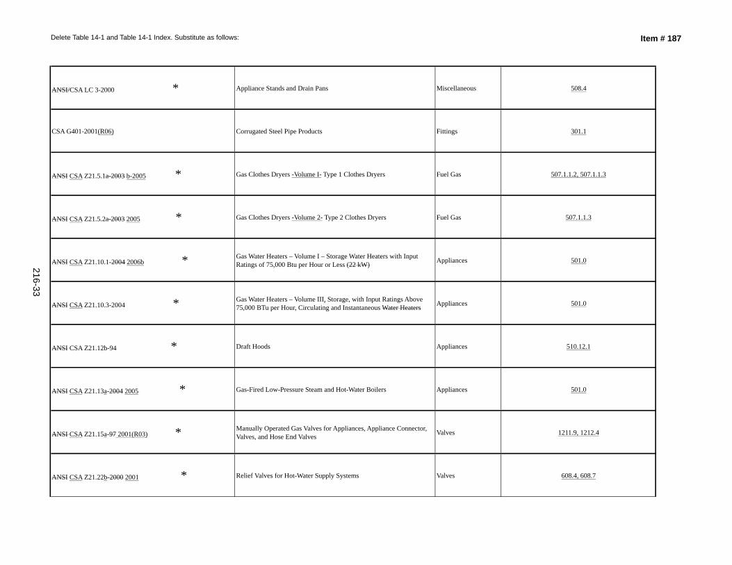
Delete Table 14-1 and Table 14-1 Index. Substitute as follows: Item # 187
ANSI/CSA LC 3-2000 * Appliance Stands and Drain Pans Miscellaneous 508.4
CSA G401-2001(R06) Corrugated Steel Pipe Products Fittings 301.1
ANSI CSA Z21.5.1a-2003 b-2005 * Gas Clothes Dryers -Volume I- Type 1 Clothes Dryers Fuel Gas 507.1.1.2, 507.1.1.3
ANSI CSA Z21.5.2a-2003 2005 * Gas Clothes Dryers -Volume 2- Type 2 Clothes Dryers Fuel Gas 507.1.1.3
ANSI CSA Z21.10.1-2004 2006b * Gas Water Heaters – Volume I – Storage Water Heaters with Input Ratings of 75,000 Btu per Hour or Less (22 kW) Appliances 501.0
ANSI CSA Z21.10.3-2004 * Gas Water Heaters – Volume III, Storage, with Input Ratings Above 75,000 BTu per Hour, Circulating and Instantaneous Water Heaters Appliances 501.0
ANSI CSA Z21.12b-94 * Draft Hoods Appliances 510.12.1
ANSI CSA Z21.13a-2004 2005 * Gas-Fired Low-Pressure Steam and Hot-Water Boilers Appliances 501.0
ANSI CSA Z21.15a-97 2001(R03) * Manually Operated Gas Valves for Appliances, Appliance Connector, Valves, and Hose End Valves Valves 1211.9, 1212.4
ANSI CSA Z21.22b-2000 2001 * Relief Valves for Hot-Water Supply Systems Valves 608.4, 608.7
216-33
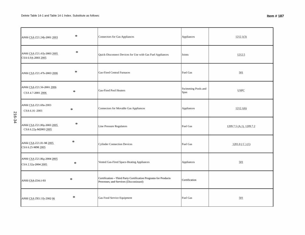
Delete Table 14-1 and Table 14-1 Index. Substitute as follows: Item # 187
ANSI CSA Z21.24b-2001 2003 * Connectors for Gas Appliances Appliances 1212.1(3)
ANSI CSA Z21.41b-2003 2005 *CSA 6.9A-2003 2005
Quick-Disconnect Devices for Use with Gas Fuel Appliances Joints 1212.5
ANSI CSA Z21.47b-2003 2006 * Gas-Fired Central Furnaces Fuel Gas 501
ANSI CSA Z21.56-2001 2006
CSA 4.7-2001 2006 * Gas-Fired Pool Heaters Swimming Pools and Spas USPC
ANSI CSA Z21.69a-2003
CSA 6.16 -2003 * Connectors for Movable Gas Appliances Appliances 1212.1(6)
ANSI CSA Z21.80a-2003 2005 * CSA 6.22a-M2003 2005
Line Pressure Regulators Fuel Gas 1209.7.5 (A,1), 1209.7.2
ANSI CSA Z21.81-98 2005 * CSA 6.25-M98 2005
Cylinder Connection Devices Fuel Gas 1201.0 ( C ) (1)
ANSI CSA Z21.86a-2004 2005
CSA 2.32a-2004 2005 * Vented Gas-Fired Space-Heating Appliances Appliances 501
ANSI CSA Z34.1-93 * Certification – Third Party Certification Programs for Products Processes, and Services (Discontinued) Certification
ANSI CSA Z83.11b-2002 06 * Gas Food Service Equipment Fuel Gas 501
216-34
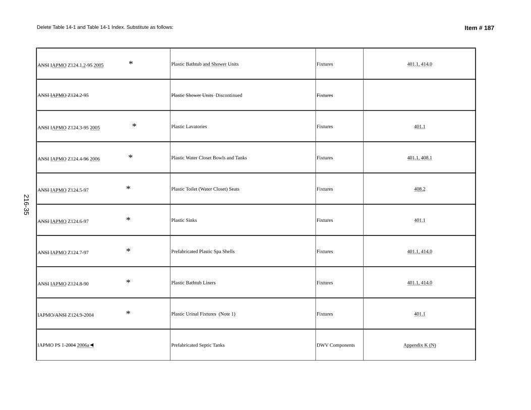
Delete Table 14-1 and Table 14-1 Index. Substitute as follows: Item # 187
ANSI IAPMO Z124.1.2-95 2005 * Plastic Bathtub and Shower Units Fixtures 401.1, 414.0
ANSI IAPMO Z124.2-95 Plastic Shower Units Discontinued Fixtures
ANSI IAPMO Z124.3-95 2005 * Plastic Lavatories Fixtures 401.1
ANSI IAPMO Z124.4-96 2006 * Plastic Water Closet Bowls and Tanks Fixtures 401.1, 408.1
ANSI IAPMO Z124.5-97 * Plastic Toilet (Water Closet) Seats Fixtures 408.2
ANSI IAPMO Z124.6-97 * Plastic Sinks Fixtures 401.1
ANSI IAPMO Z124.7-97 * Prefabricated Plastic Spa Shells Fixtures 401.1, 414.0
ANSI IAPMO Z124.8-90 * Plastic Bathtub Liners Fixtures 401.1, 414.0
IAPMO/ANSI Z124.9-2004 * Plastic Urinal Fixtures (Note 1) Fixtures 401.1
IAPMO PS 1-2004 2006a◄ Prefabricated Septic Tanks DWV Components Appendix K (N)
216-35
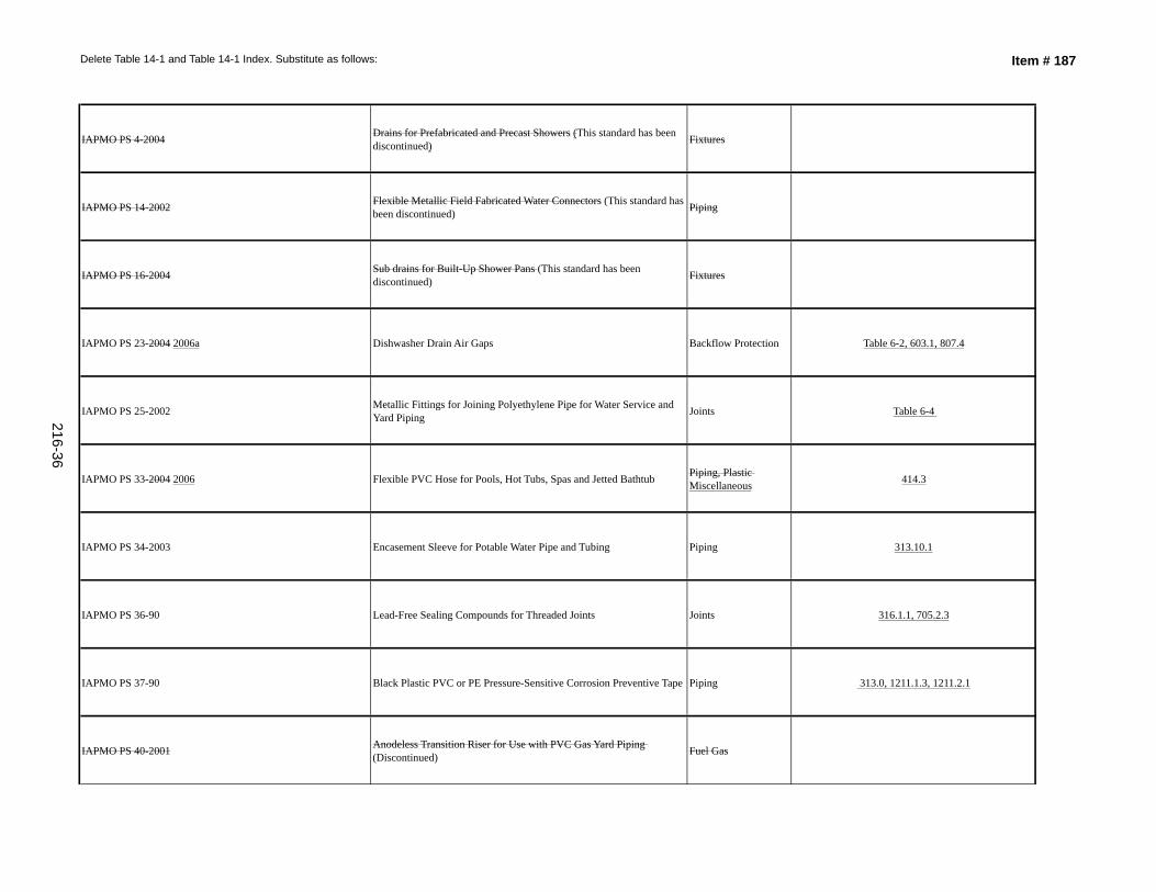
Delete Table 14-1 and Table 14-1 Index. Substitute as follows: Item # 187
IAPMO PS 4-2004 Drains for Prefabricated and Precast Showers (This standard has been discontinued) Fixtures
IAPMO PS 14-2002 Flexible Metallic Field Fabricated Water Connectors (This standard has been discontinued) Piping
IAPMO PS 16-2004 Sub drains for Built-Up Shower Pans (This standard has been discontinued) Fixtures
IAPMO PS 23-2004 2006a Dishwasher Drain Air Gaps Backflow Protection Table 6-2, 603.1, 807.4
IAPMO PS 25-2002 Metallic Fittings for Joining Polyethylene Pipe for Water Service and Yard Piping Joints Table 6-4
IAPMO PS 33-2004 2006 Flexible PVC Hose for Pools, Hot Tubs, Spas and Jetted Bathtub Piping, Plastic Miscellaneous 414.3
IAPMO PS 34-2003 Encasement Sleeve for Potable Water Pipe and Tubing Piping 313.10.1
IAPMO PS 36-90 Lead-Free Sealing Compounds for Threaded Joints Joints 316.1.1, 705.2.3
IAPMO PS 37-90 Black Plastic PVC or PE Pressure-Sensitive Corrosion Preventive Tape Piping 313.0, 1211.1.3, 1211.2.1
IAPMO PS 40-2001 Anodeless Transition Riser for Use with PVC Gas Yard Piping (Discontinued) Fuel Gas
216-36
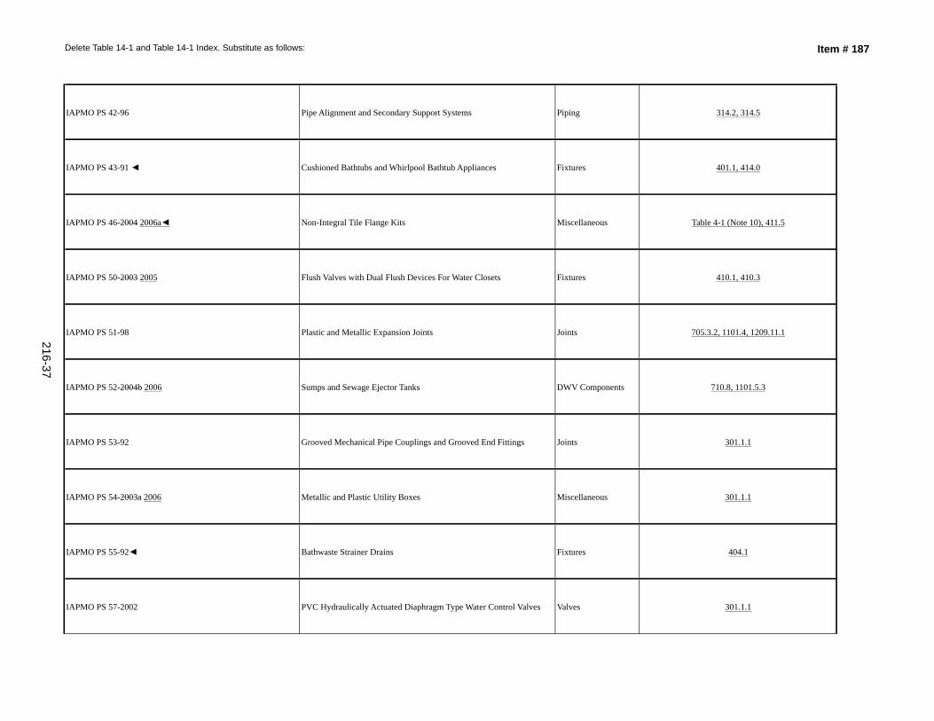
Delete Table 14-1 and Table 14-1 Index. Substitute as follows: Item # 187
IAPMO PS 42-96 Pipe Alignment and Secondary Support Systems Piping 314.2, 314.5
IAPMO PS 43-91 ◄ Cushioned Bathtubs and Whirlpool Bathtub Appliances Fixtures 401.1, 414.0
IAPMO PS 46-2004 2006a◄ Non-Integral Tile Flange Kits Miscellaneous Table 4-1 (Note 10), 411.5
IAPMO PS 50-2003 2005 Flush Valves with Dual Flush Devices For Water Closets Fixtures 410.1, 410.3
IAPMO PS 51-98 Plastic and Metallic Expansion Joints Joints 705.3.2, 1101.4, 1209.11.1
IAPMO PS 52-2004b 2006 Sumps and Sewage Ejector Tanks DWV Components 710.8, 1101.5.3
IAPMO PS 53-92 Grooved Mechanical Pipe Couplings and Grooved End Fittings Joints 301.1.1
IAPMO PS 54-2003a 2006 Metallic and Plastic Utility Boxes Miscellaneous 301.1.1
IAPMO PS 55-92◄ Bathwaste Strainer Drains Fixtures 404.1
IAPMO PS 57-2002 PVC Hydraulically Actuated Diaphragm Type Water Control Valves Valves 301.1.1
216-37
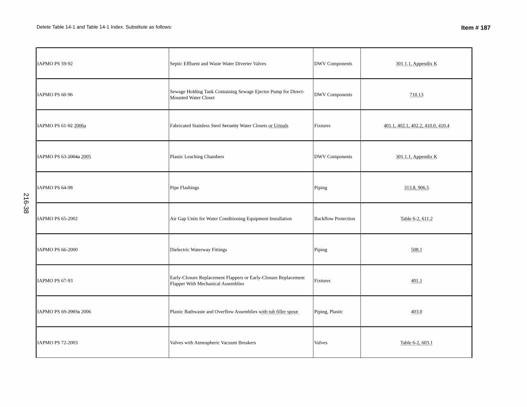
Delete Table 14-1 and Table 14-1 Index. Substitute as follows: Item # 187
IAPMO PS 59-92 Septic Effluent and Waste Water Diverter Valves DWV Components 301.1.1, Appendix K
IAPMO PS 60-96 Sewage Holding Tank Containing Sewage Ejector Pump for Direct-Mounted Water Closet DWV Components 710.13
IAPMO PS 61-92 2006a Fabricated Stainless Steel Security Water Closets or Urinals Fixtures 401.1, 402.1, 402.2, 410.0, 410.4
IAPMO PS 63-2004a 2005 Plastic Leaching Chambers DWV Components 301.1.1, Appendix K
IAPMO PS 64-98 Pipe Flashings Piping 313.8, 906.5
IAPMO PS 65-2002 Air Gap Units for Water Conditioning Equipment Installation Backflow Protection Table 6-2, 611.2
IAPMO PS 66-2000 Dielectric Waterway Fittings Piping 508.1
IAPMO PS 67-93 Early-Closure Replacement Flappers or Early-Closure Replacement Flapper With Mechanical Assemblies Fixtures 401.1
IAPMO PS 69-2003a 2006 Plastic Bathwaste and Overflow Assemblies with tub filler spout Piping, Plastic 403.0
IAPMO PS 72-2003 Valves with Atmospheric Vacuum Breakers Valves Table 6-2, 603.1
216-38
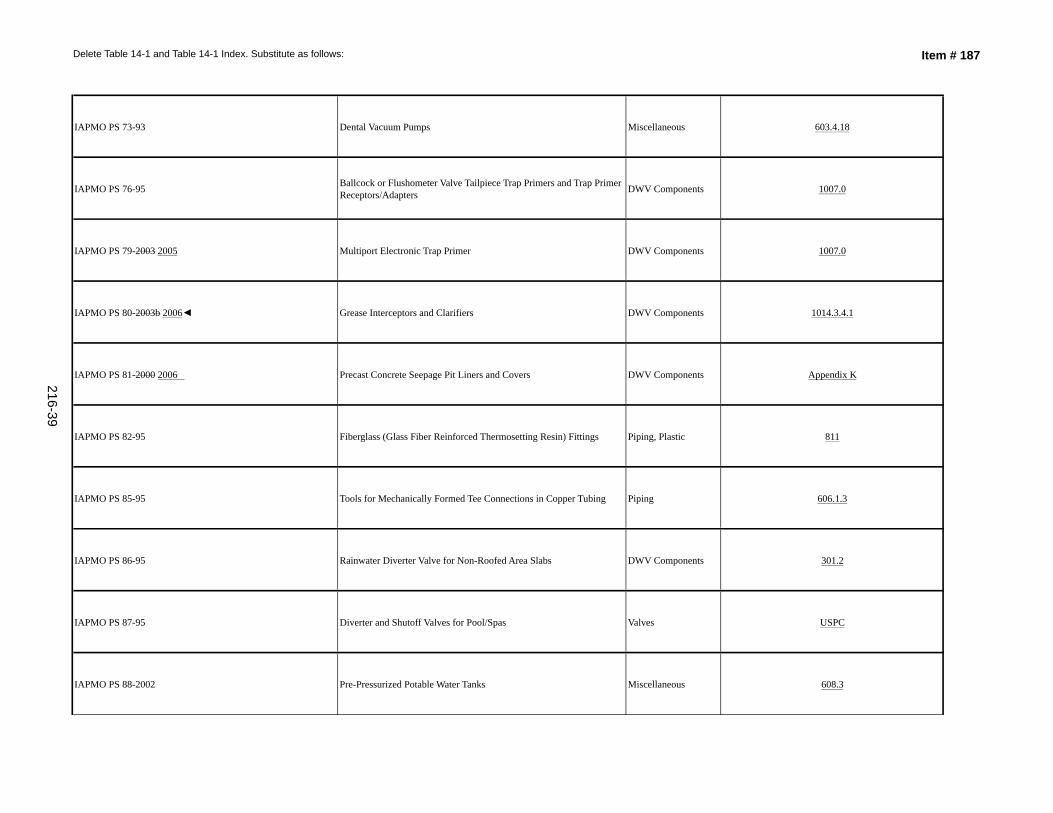
Delete Table 14-1 and Table 14-1 Index. Substitute as follows: Item # 187
IAPMO PS 73-93 Dental Vacuum Pumps Miscellaneous 603.4.18
IAPMO PS 76-95 Ballcock or Flushometer Valve Tailpiece Trap Primers and Trap Primer Receptors/Adapters DWV Components 1007.0
IAPMO PS 79-2003 2005 Multiport Electronic Trap Primer DWV Components 1007.0
IAPMO PS 80-2003b 2006◄ Grease Interceptors and Clarifiers DWV Components 1014.3.4.1
IAPMO PS 81-2000 2006 Precast Concrete Seepage Pit Liners and Covers DWV Components Appendix K
IAPMO PS 82-95 Fiberglass (Glass Fiber Reinforced Thermosetting Resin) Fittings Piping, Plastic 811
IAPMO PS 85-95 Tools for Mechanically Formed Tee Connections in Copper Tubing Piping 606.1.3
IAPMO PS 86-95 Rainwater Diverter Valve for Non-Roofed Area Slabs DWV Components 301.2
IAPMO PS 87-95 Diverter and Shutoff Valves for Pool/Spas Valves USPC
IAPMO PS 88-2002 Pre-Pressurized Potable Water Tanks Miscellaneous 608.3
216-39
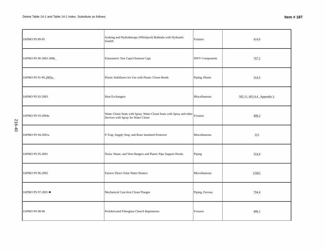
Delete Table 14-1 and Table 14-1 Index. Substitute as follows: Item # 187
IAPMO PS 89-95 Soaking and Hydrotherapy (Whirlpool) Bathtubs with Hydraulic Seatlift Fixtures 414.0
IAPMO PS 90-2003 2006 Elastomeric Test Caps/Cleanout Caps DWV Components 707.2
IAPMO PS 91-95 2005a Plastic Stabilizers for Use with Plastic Closet Bends Piping, Plastic 314.5
IAPMO PS 92-2003 Heat Exchangers Miscellaneous 502.11, 603.4.4 , Appendix L
IAPMO PS 93-2004a Water Closet Seats with Spray, Water Closet Seats with Spray and other Devices with Spray for Water Closet Fixtures 408.2
IAPMO PS 94-2001a P-Trap, Supply Stop, and Riser Insulated Protector Miscellaneous 313
IAPMO PS 95-2001 Drain, Waste, and Vent Hangers and Plastic Pipe Support Hooks Piping 314.4
IAPMO PS 96-2002 Passive Direct Solar Water Heaters Miscellaneous USEC
IAPMO PS 97-2001◄ Mechanical Cast-Iron Closet Flanges Piping, Ferrous 704.4
IAPMO PS 98-96 Prefabricated Fiberglass Church Baptisteries Fixtures 406.1
216-40
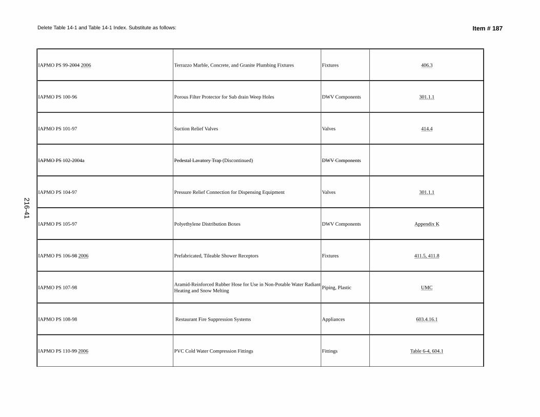
Delete Table 14-1 and Table 14-1 Index. Substitute as follows: Item # 187
IAPMO PS 99-2004 2006 Terrazzo Marble, Concrete, and Granite Plumbing Fixtures Fixtures 406.3
IAPMO PS 100-96 Porous Filter Protector for Sub drain Weep Holes DWV Components 301.1.1
IAPMO PS 101-97 Suction Relief Valves Valves 414.4
IAPMO PS 102-2004a Pedestal Lavatory Trap (Discontinued) DWV Components
IAPMO PS 104-97 Pressure Relief Connection for Dispensing Equipment Valves 301.1.1
IAPMO PS 105-97 Polyethylene Distribution Boxes DWV Components Appendix K
IAPMO PS 106-98 2006 Prefabricated, Tileable Shower Receptors Fixtures 411.5, 411.8
IAPMO PS 107-98 Aramid-Reinforced Rubber Hose for Use in Non-Potable Water Radiant Heating and Snow Melting Piping, Plastic UMC
IAPMO PS 108-98 Restaurant Fire Suppression Systems Appliances 603.4.16.1
IAPMO PS 110-99 2006 PVC Cold Water Compression Fittings Fittings Table 6-4, 604.1
216-41
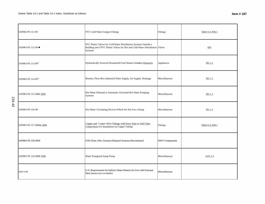
Delete Table 14-1 and Table 14-1 Index. Substitute as follows: Item # 187
IAPMO PS 111-99 PVC Cold Water Gripper Fittings Fittings Table 6-4, 604.1
IAPMO PS 112-99◄PVC Plastic Valves for Cold Water Distribution Systems Outside a Building and CPVC Plastic Valves for Hot and Cold Water Distribution Systems
Valves 605
IAPMO PS 113-99e1 Hydraulically Powered Household Food Waster Grinders Disposers Appliances 301.1.1
IAPMO PS 114-99e1 Remote, Floor Box Industrial Water Supply, Air Supply, Drainage Miscellaneous 301.1.1
IAPMO PS 115-2002 2005 Hot Water Demand or Automatic Activated Hot Water Pumping Systems Miscellaneous 301.1.1
IAPMO PS 116-99 Hot Water Circulating Devices Which Do Not Use a Pump Miscellaneous 301.1.1
IAPMO PS 117-2004a 2006 Copper and Copper Alloy Fittings with Press-Type or Nail-Type Connections For Installation on Copper Tubing Fittings Table 6-4, 604.1
IAPMO PS 118-2000 FOG (Fats, Oils, Greases) Disposal Systems Discontinued DWV Components
IAPMO PS 119-2000 2006 Water Energized Sump Pump Miscellaneous 1101.5.3
IAS 1-91 U.S. Requirements for Indirect Water Heaters for Use with External Heat Source (not available) Miscellaneous
216-42
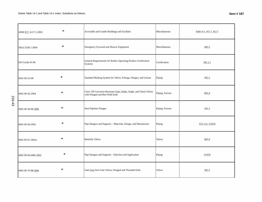
Delete Table 14-1 and Table 14-1 Index. Substitute as follows: Item # 187
ANSI ICC A117.1-2003 * Accessible and Usable Buildings and Facilities Miscellaneous Table 4-1, 411.7, 412.7
ISEA Z358.1-2004 * Emergency Eyewash and Shower Equipment Miscellaneous 402.5
ISO Guide 65-96 General Requirements for Bodies Operating Product Certification Systems Certification 301.1.1
MSS SP-25-98 * Standard Marking System for Valves, Fittings, Flanges, and Unions Piping 301.2
MSS SP-42-2004 * Class 150 Corrosion-Resistant Gate, Globe, Angle, and Check Valves with Flanged and Butt Weld Ends Piping, Ferrous 605.4
MSS SP-44-96 2006 * Steel Pipeline Flanges Piping, Ferrous 301.2
MSS SP-58-2002 * Pipe Hangers and Supports – Materials, Design, and Manufacture Piping 1211.2.6, 1318.8
MSS SP-67-2002a * Butterfly Valves Valves 605.4
MSS SP-69-2002 2003 * Pipe Hangars and Supports - Selection and Application Piping 1318.8
MSS SP-70-98 2006 * Cast Gray-Iron Gate Valves, Flanged and Threaded Ends Valves 301.2
216-43
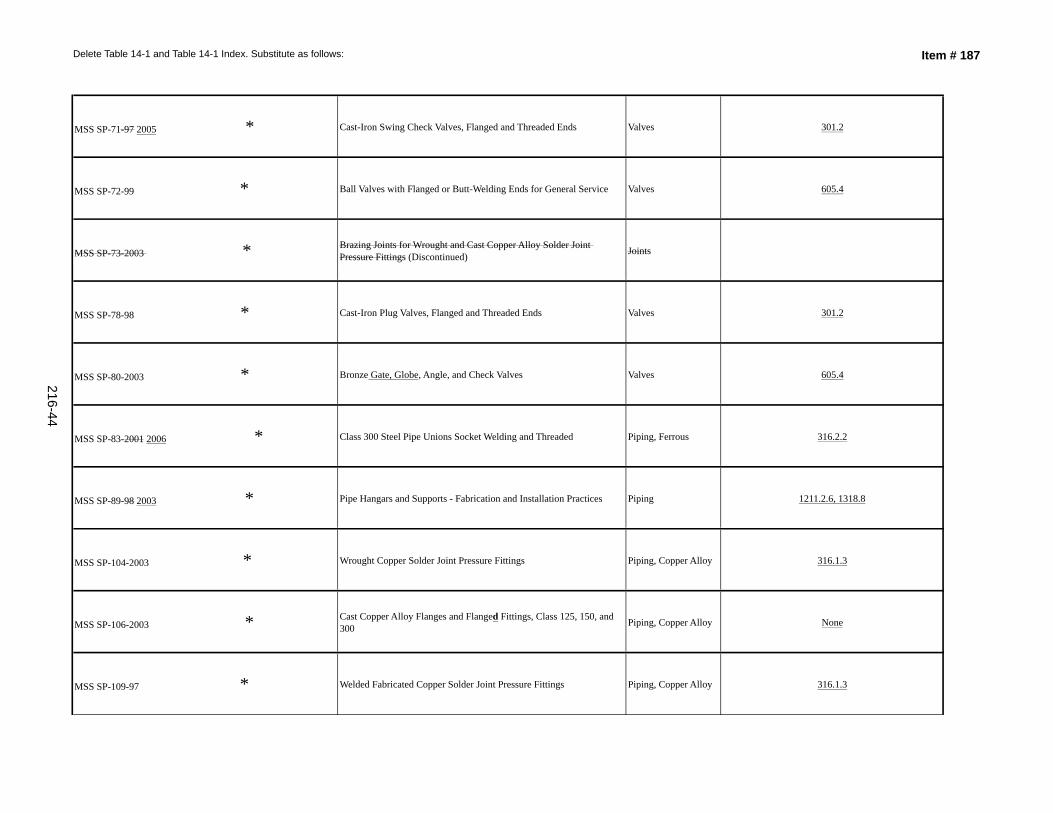
Delete Table 14-1 and Table 14-1 Index. Substitute as follows: Item # 187
MSS SP-71-97 2005 * Cast-Iron Swing Check Valves, Flanged and Threaded Ends Valves 301.2
MSS SP-72-99 * Ball Valves with Flanged or Butt-Welding Ends for General Service Valves 605.4
MSS SP-73-2003 * Brazing Joints for Wrought and Cast Copper Alloy Solder Joint Pressure Fittings (Discontinued) Joints
MSS SP-78-98 * Cast-Iron Plug Valves, Flanged and Threaded Ends Valves 301.2
MSS SP-80-2003 * Bronze Gate, Globe, Angle, and Check Valves Valves 605.4
MSS SP-83-2001 2006 * Class 300 Steel Pipe Unions Socket Welding and Threaded Piping, Ferrous 316.2.2
MSS SP-89-98 2003 * Pipe Hangars and Supports - Fabrication and Installation Practices Piping 1211.2.6, 1318.8
MSS SP-104-2003 * Wrought Copper Solder Joint Pressure Fittings Piping, Copper Alloy 316.1.3
MSS SP-106-2003 * Cast Copper Alloy Flanges and Flanged Fittings, Class 125, 150, and 300 Piping, Copper Alloy None
MSS SP-109-97 * Welded Fabricated Copper Solder Joint Pressure Fittings Piping, Copper Alloy 316.1.3
216-44
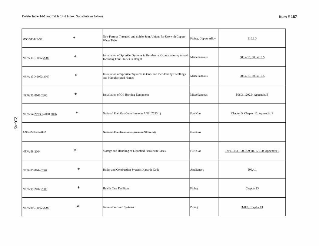
Delete Table 14-1 and Table 14-1 Index. Substitute as follows: Item # 187
MSS SP-123-98 * Non-Ferrous Threaded and Solder-Joint Unions for Use with Copper Water Tube Piping, Copper Alloy 316.1.3
NFPA 13R-2002 2007 * Installation of Sprinkler Systems in Residential Occupancies up to and Including Four Stories in Height Miscellaneous 603.4.16, 603.4.16.5
NFPA 13D-2002 2007 * Installation of Sprinkler Systems in One- and Two-Family Dwellings and Manufactured Homes Miscellaneous 603.4.16, 603.4.16.5
NFPA 31-2001 2006 * Installation of Oil-Burning Equipment Miscellaneous 506.3, 1202.0, Appendix E
NFPA 54/Z223.1-2000 2006 * National Fuel Gas Code (same as ANSI Z223.1) Fuel Gas Chapter 5, Chapter 12, Appendix E
ANSI Z223.1-2002 National Fuel Gas Code (same as NFPA 54) Fuel Gas
NFPA 58-2004 * Storage and Handling of Liquefied Petroleum Gases Fuel Gas 1209.5.4.3, 1209.5.9(D), 1213.0, Appendix E
NFPA 85-2004 2007 * Boiler and Combustion Systems Hazards Code Appliances 506.4.1
NFPA 99-2002 2005 * Health Care Facilities Piping Chapter 13
NFPA 99C-2002 2005 * Gas and Vacuum Systems Piping 320.0, Chapter 13
216-45
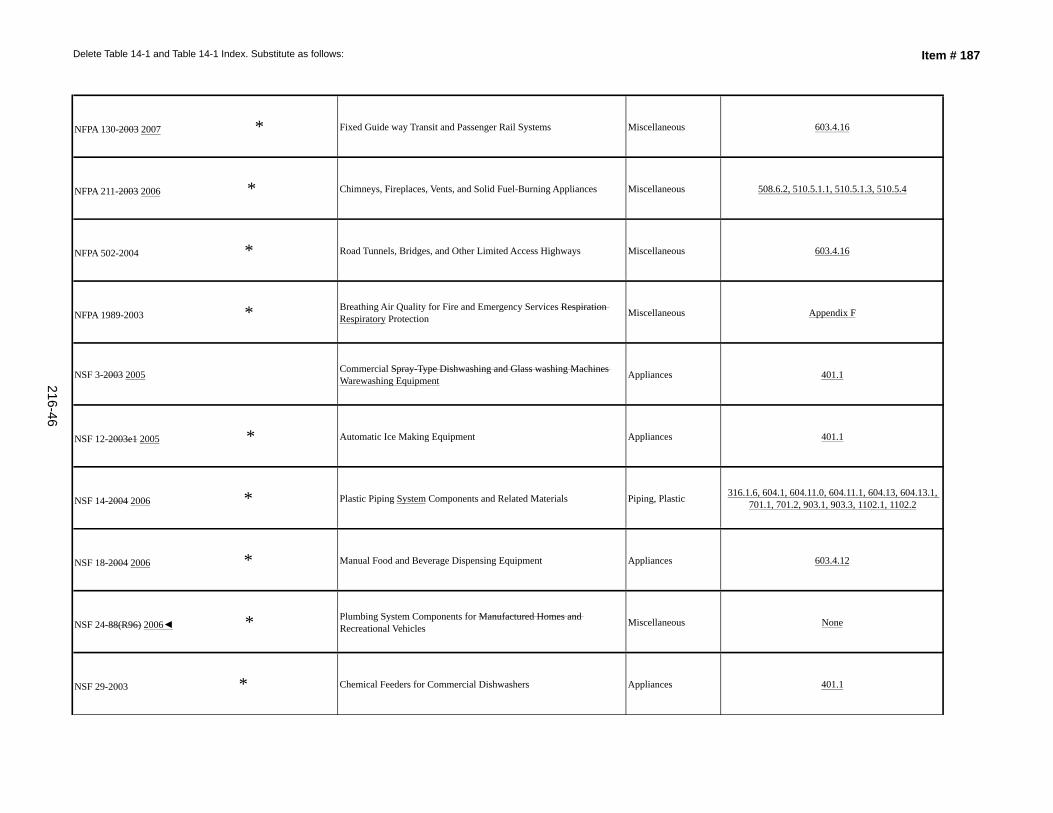
Delete Table 14-1 and Table 14-1 Index. Substitute as follows: Item # 187
NFPA 130-2003 2007 * Fixed Guide way Transit and Passenger Rail Systems Miscellaneous 603.4.16
NFPA 211-2003 2006 * Chimneys, Fireplaces, Vents, and Solid Fuel-Burning Appliances Miscellaneous 508.6.2, 510.5.1.1, 510.5.1.3, 510.5.4
NFPA 502-2004 * Road Tunnels, Bridges, and Other Limited Access Highways Miscellaneous 603.4.16
NFPA 1989-2003 * Breathing Air Quality for Fire and Emergency Services Respiration Respiratory Protection Miscellaneous Appendix F
NSF 3-2003 2005 Commercial Spray-Type Dishwashing and Glass washing Machines Warewashing Equipment Appliances 401.1
NSF 12-2003e1 2005 * Automatic Ice Making Equipment Appliances 401.1
NSF 14-2004 2006 * Plastic Piping System Components and Related Materials Piping, Plastic 316.1.6, 604.1, 604.11.0, 604.11.1, 604.13, 604.13.1, 701.1, 701.2, 903.1, 903.3, 1102.1, 1102.2
NSF 18-2004 2006 * Manual Food and Beverage Dispensing Equipment Appliances 603.4.12
NSF 24-88(R96) 2006◄ * Plumbing System Components for Manufactured Homes and Recreational Vehicles Miscellaneous None
NSF 29-2003 * Chemical Feeders for Commercial Dishwashers Appliances 401.1
216-46
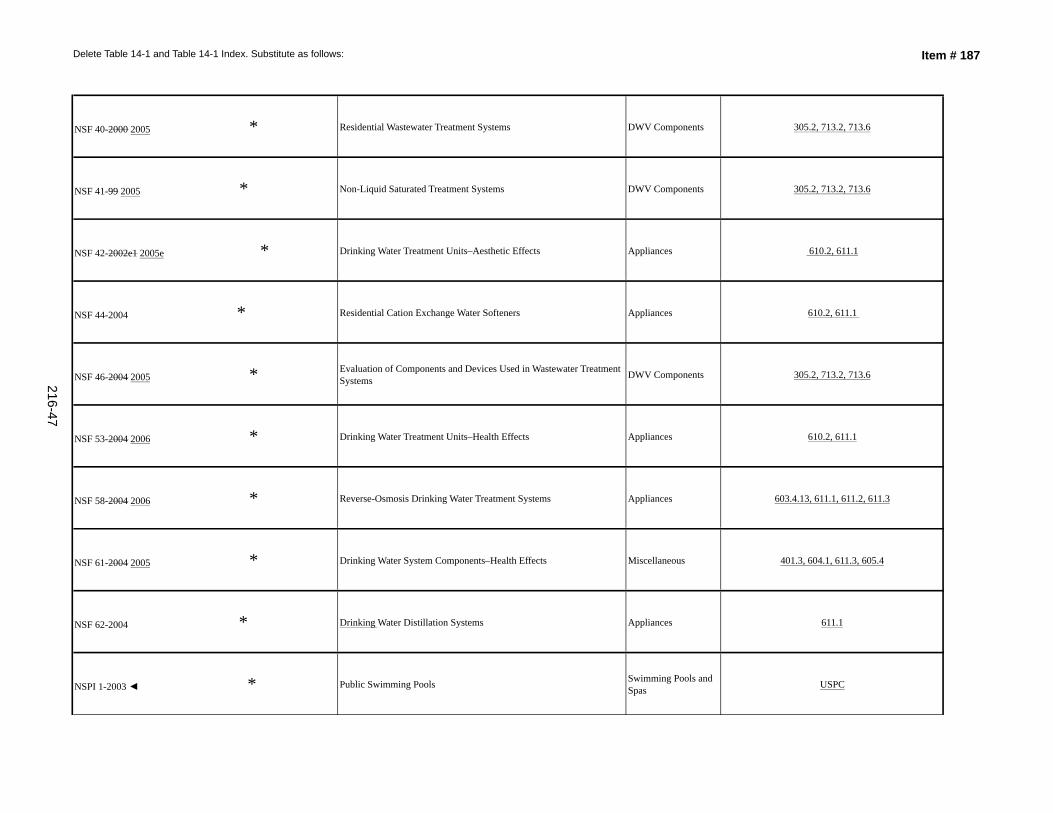
Delete Table 14-1 and Table 14-1 Index. Substitute as follows: Item # 187
NSF 40-2000 2005 * Residential Wastewater Treatment Systems DWV Components 305.2, 713.2, 713.6
NSF 41-99 2005 * Non-Liquid Saturated Treatment Systems DWV Components 305.2, 713.2, 713.6
NSF 42-2002e1 2005e * Drinking Water Treatment Units–Aesthetic Effects Appliances 610.2, 611.1
NSF 44-2004 * Residential Cation Exchange Water Softeners Appliances 610.2, 611.1
NSF 46-2004 2005 * Evaluation of Components and Devices Used in Wastewater Treatment Systems DWV Components 305.2, 713.2, 713.6
NSF 53-2004 2006 * Drinking Water Treatment Units–Health Effects Appliances 610.2, 611.1
NSF 58-2004 2006 * Reverse-Osmosis Drinking Water Treatment Systems Appliances 603.4.13, 611.1, 611.2, 611.3
NSF 61-2004 2005 * Drinking Water System Components–Health Effects Miscellaneous 401.3, 604.1, 611.3, 605.4
NSF 62-2004 * Drinking Water Distillation Systems Appliances 611.1
NSPI 1-2003 ◄ * Public Swimming Pools Swimming Pools and Spas USPC
216-47
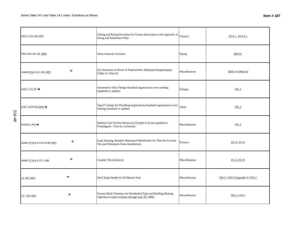
Delete Table 14-1 and Table 14-1 Index. Substitute as follows: Item # 187
PDI G-101-85 2007 Testing and Rating Procedure for Grease Interceptors with Appendix of Sizing and Installation Data Fixtures 1014.1, 1014.2.1
PDI-WH 201-92 2006 Water Hammer Arresters Piping 609.10.
ANSI PSAI Z4.1-95 2005 * For Sanitation in Places of Employment -Minimum Requirements (Table 4-1 Note 6) Miscellaneous Table 4-1(Note 6)
SAE J 512-97◄ Automotive Tube Fittings Standard organization is not sending standards or updates Fittings 301.2
SAE J1670-93 2005◄ Type F Clamps for Plumbing Applications Standard organization is not sending standards or updates Joints 301.2
SAMA LF6a◄ Medical Care Facility Brassware (Unable to locate standard or Promulgator - Vote for exclusion) Miscellaneous 301.2
ANSI TCNA A118.10-99 2005 * Load, Bearing, Bonded, Waterproof Membranes for Thin-Set Ceramic Tile and Dimension Stone Installations Fixtures 411.5, 411.8
ANSI TCNA A137.1-88 * Ceramic Tile (surfaces) Miscellaneous 411.5, 411.8
UL 80-2004 * Steel Tanks Inside for Oil-Burner Fuel Miscellaneous 506.3, 1202.0 Appendix E 39.6.2
UL 103-2001 * Factory-Built Chimneys for Residential Type and Building Heating Appliances (with revisions through June 30, 2006) Miscellaneous 502.3, 510.5
216-48
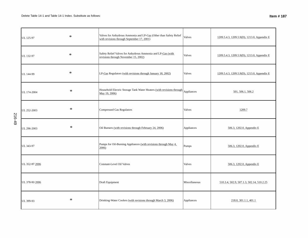
Delete Table 14-1 and Table 14-1 Index. Substitute as follows: Item # 187
UL 125-97 * Valves for Anhydrous Ammonia and LP-Gas (Other than Safety Relief with revisions through September 17, 2001) Valves 1209.5.4.3, 1209.5.9(D), 1213.0, Appendix E
UL 132-97 * Safety Relief Valves for Anhydrous Ammonia and LP-Gas (with revisions through November 15, 2002) Valves 1209.5.4.3, 1209.5.9(D), 1213.0, Appendix E
UL 144-99 * LP-Gas Regulators (with revisions through January 18, 2002) Valves 1209.5.4.3, 1209.5.9(D), 1213.0, Appendix E
UL 174-2004 * Household Electric Storage Tank Water Heaters (with revisions through May 19, 2006) Appliances 501, 506.1, 506.2
UL 252-2003 * Compressed Gas Regulators Valves 1209.7
UL 296-2003 * Oil Burners (with revisions through February 24, 2006) Appliances 506.3, 1202.0, Appendix E
UL 343-97 Pumps for Oil-Burning Appliances (with revisions through May 4, 2006) Pumps 506.3, 1202.0, Appendix E
UL 352-97 2006 Constant-Level Oil Valves Valves 506.3, 1202.0, Appendix E
UL 378-93 2006 Draft Equipment Miscellaneous 510.3.4, 502.9, 507.1.3, 502.14, 510.2.25
UL 399-93 * Drinking-Water Coolers (with revisions through March 3, 2006) Appliances 218.0, 301.1.1, 401.1
216-49
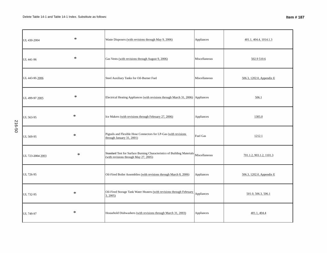
Delete Table 14-1 and Table 14-1 Index. Substitute as follows: Item # 187
UL 430-2004 * Waste Disposers (with revisions through May 9, 2006) Appliances 401.1, 404.4, 1014.1.3
UL 441-96 * Gas Vents (with revisions through August 9, 2006) Miscellaneous 502.9 510.6
UL 443-95 2006 Steel Auxiliary Tanks for Oil-Burner Fuel Miscellaneous 506.3, 1202.0, Appendix E
UL 499-97 2005 * Electrical Heating Appliances (with revisions through March 31, 2006) Appliances 506.1
UL 563-95 * Ice Makers (with revisions through February 27, 2006) Appliances 1305.0
UL 569-95 * Pigtails and Flexible Hose Connectors for LP-Gas (with revisions through January 31, 2001) Fuel Gas 1212.1
UL 723-2004 2003 * Standard Test for Surface Burning Characteristics of Building Materials (with revisions through May 27, 2005) Miscellaneous 701.1.2, 903.1.2, 1101.3
UL 726-95 Oil-Fired Boiler Assemblies (with revisions through March 8, 2006) Appliances 506.3, 1202.0, Appendix E
UL 732-95 * Oil-Fired Storage Tank Water Heaters (with revisions through February 3, 2005) Appliances 501.0, 506.3, 506.1
UL 749-97 * Household Dishwashers (with revisions through March 31, 2003) Appliances 401.1, 404.4
216-50
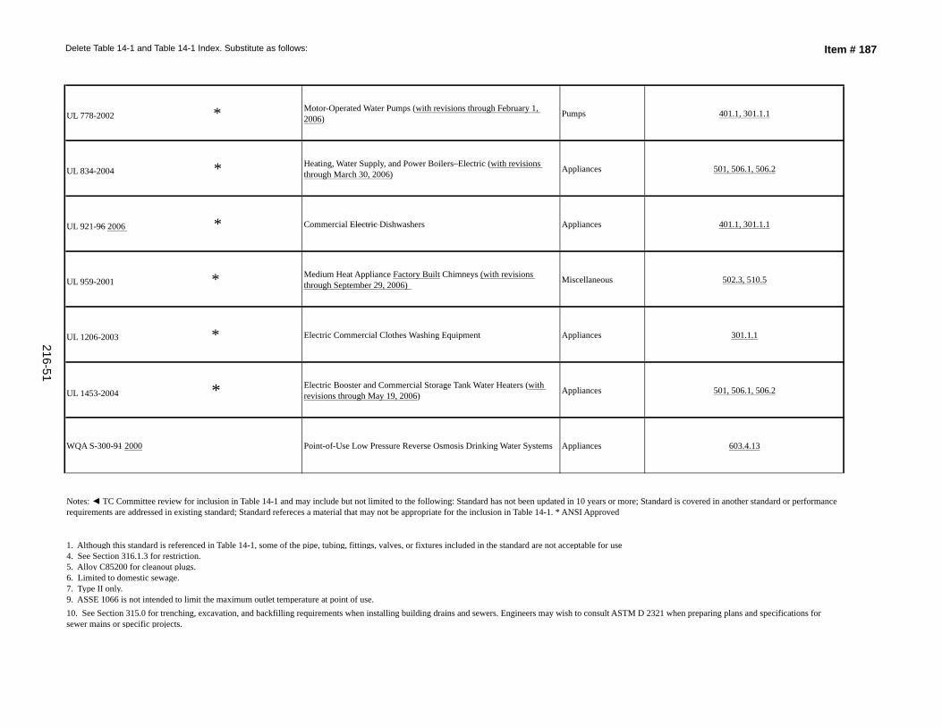
Delete Table 14-1 and Table 14-1 Index. Substitute as follows: Item # 187
UL 778-2002 * Motor-Operated Water Pumps (with revisions through February 1, 2006) Pumps 401.1, 301.1.1
UL 834-2004 * Heating, Water Supply, and Power Boilers–Electric (with revisions through March 30, 2006) Appliances 501, 506.1, 506.2
UL 921-96 2006 * Commercial Electric Dishwashers Appliances 401.1, 301.1.1
UL 959-2001 * Medium Heat Appliance Factory Built Chimneys (with revisions through September 29, 2006) Miscellaneous 502.3, 510.5
UL 1206-2003 * Electric Commercial Clothes Washing Equipment Appliances 301.1.1
UL 1453-2004 * Electric Booster and Commercial Storage Tank Water Heaters (with revisions through May 19, 2006) Appliances 501, 506.1, 506.2
WQA S-300-91 2000 Point-of-Use Low Pressure Reverse Osmosis Drinking Water Systems Appliances 603.4.13
Notes: ◄ TC Committee review for inclusion in Table 14-1 and may include but not limited to the following: Standard has not been updated in 10 years or more; Standard is covered in another standard or performance requirements are addressed in existing standard; Standard refereces a material that may not be appropriate for the inclusion in Table 14-1. * ANSI Approved
7. Type II only.9. ASSE 1066 is not intended to limit the maximum outlet temperature at point of use.10. See Section 315.0 for trenching, excavation, and backfilling requirements when installing building drains and sewers. Engineers may wish to consult ASTM D 2321 when preparing plans and specifications for sewer mains or specific projects.
1. Although this standard is referenced in Table 14-1, some of the pipe, tubing, fittings, valves, or fixtures included in the standard are not acceptable for use 4. See Section 316.1.3 for restriction.5. Alloy C85200 for cleanout plugs.6. Limited to domestic sewage.
216-51
UPC 2009 – August 2007 ROP
SUBMITTER:
The following is recommended by the Standards Task Group (see Standards Task Group Report Item #187).
Revise text as follows:
(See attached document on pages 217–1 through 217–24)
Updating the standards in Table 14–1 in Chapter 14 to the most current published version.SUBSTANTIATION:
RECOMMENDATION:
UPC 2009 Chapter 14, Table 14–1
Based on committee action taken on Item 187 as all standards were updated based on most current year and editorial revisions based on update from promulgators.
Reject
Dave Viola
188-
TOTAL ELIGIBLE TO VOTE: 28
VOTING RESULTS: AFFIRMATIVE: 24, NOT RETURNED: 4 Bloice, Murray, Nikravi, SoskinEXPLANATION OF NEGATIVE:
COMMITTEE ACTION:COMMITTEE STATEMENT:
Item #
Chair, UPC Standards Task Group
217
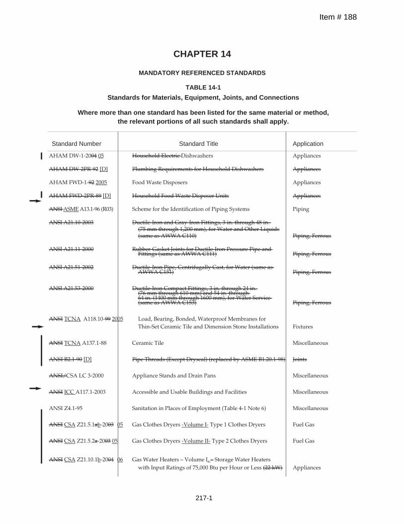
Standard Number Standard Title Application
AHAM DW-1-2004 05 Household Electric Dishwashers Appliances
AHAM DW-2PR-92 [D] Plumbing Requirements for Household Dishwashers Appliances
AHAM FWD-1-92 2005 Food Waste Disposers Appliances
AHAM FWD-2PR-89 [D] Household Food Waste Disposer Units Appliances
ANSIASMEA13.1-96 (R03) Scheme for the Identification of Piping Systems Piping
ANSI A21.10-2003 Ductile-Iron and Gray-Iron Fittings, 3 in. through 48 in.(75 mm through 1,200 mm), for Water and Other Liquids(same as AWWA C110) Piping, Ferrous
ANSI A21.11-2000 Rubber-Gasket Joints for Ductile-Iron Pressure Pipe andFittings (same as AWWA C111) Piping, Ferrous
ANSI A21.51-2002 Ductile-Iron Pipe, Centrifugally Cast, for Water (same asAWWA C151) Piping, Ferrous
ANSI A21.53-2000 Ductile-Iron Compact Fittings, 3 in. through 24 in.(76 mm through 610 mm) and 54 in. through64 in. (1400 mm through 1600 mm), for Water Service(same as AWWA C153) Piping, Ferrous
ANSI TCNA A118.10-99 2005 Load, Bearing, Bonded, Waterproof Membranes forThin-Set Ceramic Tile and Dimension Stone Installations Fixtures
ANSI TCNA A137.1-88 Ceramic Tile Miscellaneous
ANSI B2.1-90 [D] Pipe Threads (Except Dryseal) (replaced by ASME B1.20.1-98) Joints
ANSI/CSA LC 3-2000 Appliance Stands and Drain Pans Miscellaneous
ANSI ICC A117.1-2003 Accessible and Usable Buildings and Facilities Miscellaneous
ANSI Z4.1-95 Sanitation in Places of Employment (Table 4-1 Note 6) Miscellaneous
ANSI CSA Z21.5.1ab-2003 05 Gas Clothes Dryers -Volume I- Type 1 Clothes Dryers Fuel Gas
ANSI CSA Z21.5.2a-2003 05 Gas Clothes Dryers -Volume II- Type 2 Clothes Dryers Fuel Gas
ANSI CSA Z21.10.1b-2004 06 Gas Water Heaters – Volume I, – Storage Water Heaterswith Input Ratings of 75,000 Btu per Hour or Less (22 kW) Appliances
CHAPTER 14
MANDATORY REFERENCED STANDARDS
TABLE 14-1
Standards for Materials, Equipment, Joints, and Connections
Where more than one standard has been listed for the same material or method,the relevant portions of all such standards shall apply.
Item # 188
217-1
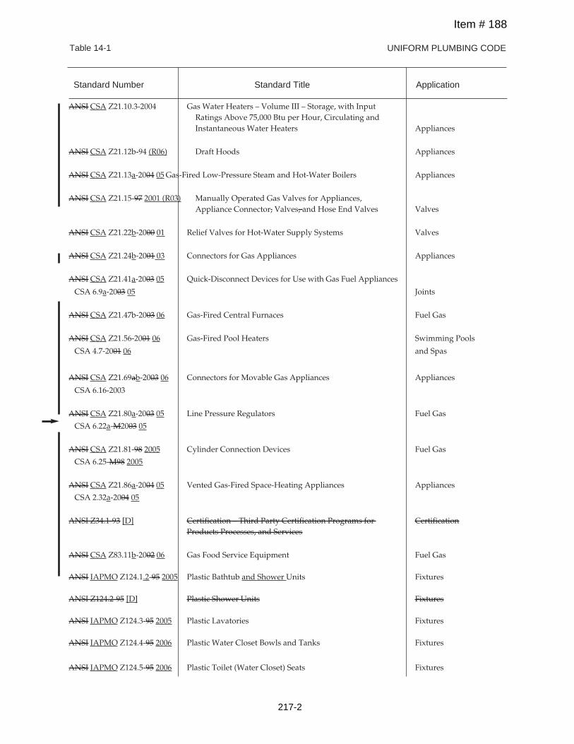
UNIFORM PLUMBING CODE
Table 14-1
ANSI CSA Z21.10.3-2004 Gas Water Heaters – Volume III – Storage, with InputRatings Above 75,000 Btu per Hour, Circulating andInstantaneous Water Heaters Appliances
ANSI CSA Z21.12b-94 (R06) Draft Hoods Appliances
ANSI CSA Z21.13a-2004 05 Gas-Fired Low-Pressure Steam and Hot-Water Boilers Appliances
ANSI CSA Z21.15-97 2001 (R03) Manually Operated Gas Valves for Appliances,Appliance Connector, Valves, and Hose End Valves Valves
ANSI CSA Z21.22b-2000 01 Relief Valves for Hot-Water Supply Systems Valves
ANSI CSA Z21.24b-2001 03 Connectors for Gas Appliances Appliances
ANSI CSA Z21.41a-2003 05 Quick-Disconnect Devices for Use with Gas Fuel Appliances
CSA 6.9a-2003 05 Joints
ANSI CSA Z21.47b-2003 06 Gas-Fired Central Furnaces Fuel Gas
ANSI CSA Z21.56-2001 06 Gas-Fired Pool Heaters Swimming Pools
CSA 4.7-2001 06 and Spas
ANSI CSA Z21.69ab-2003 06 Connectors for Movable Gas Appliances Appliances
CSA 6.16-2003
ANSI CSA Z21.80a-2003 05 Line Pressure Regulators Fuel Gas
CSA 6.22a-M2003 05
ANSI CSA Z21.81-98 2005 Cylinder Connection Devices Fuel Gas
CSA 6.25-M98 2005
ANSI CSA Z21.86a-2004 05 Vented Gas-Fired Space-Heating Appliances Appliances
CSA 2.32a-2004 05
ANSI Z34.1-93 [D] Certification – Third Party Certification Programs for CertificationProducts Processes, and Services
ANSI CSA Z83.11b-2002 06 Gas Food Service Equipment Fuel Gas
ANSI IAPMO Z124.1.2-95 2005 Plastic Bathtub and Shower Units Fixtures
ANSI Z124.2-95 [D] Plastic Shower Units Fixtures
ANSI IAPMO Z124.3-95 2005 Plastic Lavatories Fixtures
ANSI IAPMO Z124.4-95 2006 Plastic Water Closet Bowls and Tanks Fixtures
ANSI IAPMO Z124.5-95 2006 Plastic Toilet (Water Closet) Seats Fixtures
Standard Number Standard Title Application
Item # 188
217-2
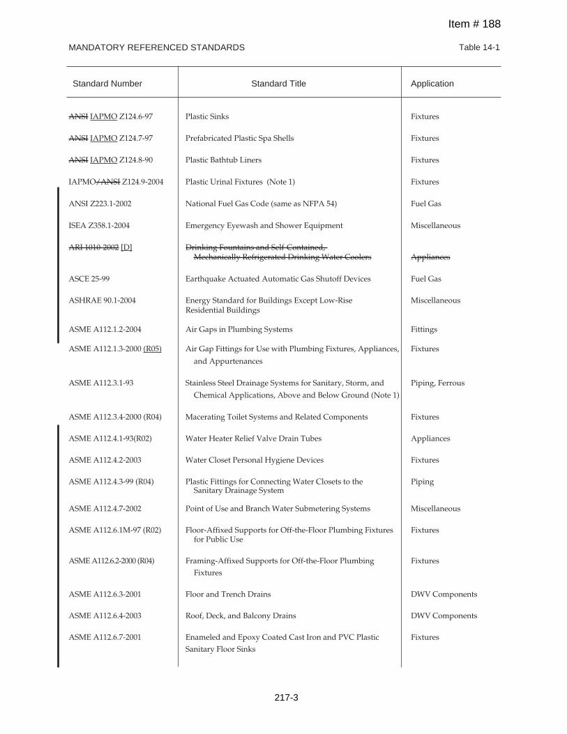
MANDATORY REFERENCED STANDARDS Table 14-1
Standard Number Standard Title Application
ANSI IAPMO Z124.6-97 Plastic Sinks Fixtures
ANSI IAPMO Z124.7-97 Prefabricated Plastic Spa Shells Fixtures
ANSI IAPMO Z124.8-90 Plastic Bathtub Liners Fixtures
IAPMO/ANSI Z124.9-2004 Plastic Urinal Fixtures (Note 1) Fixtures
ANSI Z223.1-2002 National Fuel Gas Code (same as NFPA 54) Fuel Gas
ISEA Z358.1-2004 Emergency Eyewash and Shower Equipment Miscellaneous
ARI 1010-2002 [D] Drinking Fountains and Self-Contained,Mechanically Refrigerated Drinking Water Coolers Appliances
ASCE 25-99 Earthquake Actuated Automatic Gas Shutoff Devices Fuel Gas
ASHRAE 90.1-2004 Energy Standard for Buildings Except Low-Rise MiscellaneousResidential Buildings
ASME A112.1.2-2004 Air Gaps in Plumbing Systems Fittings
ASME A112.1.3-2000 (R05) Air Gap Fittings for Use with Plumbing Fixtures, Appliances, Fixtures
and Appurtenances
ASME A112.3.1-93 Stainless Steel Drainage Systems for Sanitary, Storm, and Piping, Ferrous
Chemical Applications, Above and Below Ground (Note 1)
ASME A112.3.4-2000 (R04) Macerating Toilet Systems and Related Components Fixtures
ASME A112.4.1-93(R02) Water Heater Relief Valve Drain Tubes Appliances
ASME A112.4.2-2003 Water Closet Personal Hygiene Devices Fixtures
ASME A112.4.3-99 (R04) Plastic Fittings for Connecting Water Closets to the PipingSanitary Drainage System
ASME A112.4.7-2002 Point of Use and Branch Water Submetering Systems Miscellaneous
ASME A112.6.1M-97 (R02) Floor-Affixed Supports for Off-the-Floor Plumbing Fixtures Fixturesfor Public Use
ASMEA112.6.2-2000 (R04) Framing-Affixed Supports for Off-the-Floor Plumbing Fixtures
Fixtures
ASME A112.6.3-2001 Floor and Trench Drains DWV Components
ASME A112.6.4-2003 Roof, Deck, and Balcony Drains DWV Components
ASME A112.6.7-2001 Enameled and Epoxy Coated Cast Iron and PVC Plastic Fixtures
Sanitary Floor Sinks
Item # 188
217-3
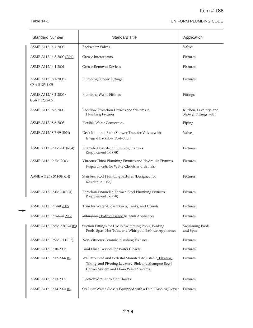
UNIFORM PLUMBING CODETable 14-1
ASME A112.14.1-2003 Backwater Valves Valves
ASME A112.14.3-2000 (R04) Grease Interceptors Fixtures
ASME A112.14.4-2001 Grease Removal Devices Fixtures
ASME A112.18.1-2005/ Plumbing Supply Fittings Fixtures
CSA B125.1-05
ASME A112.18.2-2005/ Plumbing Waste Fittings Fittings
CSA B125.2-05
ASME A112.18.3-2003 Backflow Protection Devices and Systems in Kitchen, Lavatory, andPlumbing Fixtures Shower Fittings with
ASME A112.18.6-2003 Flexible Water Connectors Piping
ASME A112.18.7-99 (R04) Deck Mounted Bath/Shower Transfer Valves with Valves
Integral Backflow Protection
ASME A112.19.1M-94 (R04) Enameled Cast-Iron Plumbing Fixtures Fixtures(Supplement 1-1998)
ASME A112.19.2M-2003 Vitreous China Plumbing Fixtures and Hydraulic Fixtures Fixtures
Requirements for Water Closets and Urinals
ASMEA112.19.3M-01(R04) Stainless Steel Plumbing Fixtures (Designed for Fixtures
Residential Use)
ASME A112.19.4M-94(R04) Porcelain-Enameled Formed Steel Plumbing Fixtures Fixtures(Supplement 1-1998)
ASME A112.19.5-99 2005 Trim for Water-Closet Bowls, Tanks, and Urinals Fixtures
ASME A112.19.7M-95 2006 Whirlpool Hydromassage Bathtub Appliances Fixtures
ASME A112.19.8M-87(R96 05) Suction Fittings for Use in Swimming Pools, Wading Swimming PoolsPools, Spas, Hot Tubs, and Whirlpool Bathtub Appliances and Spas
ASME A112.19.9M-91 (R02) Non-Vitreous Ceramic Plumbing Fixtures Fixtures
ASME A112.19.10-2003 Dual Flush Devices for Water Closets Fixtures
ASME A112.19.12-2000 06 Wall Mounted and Pedestal Mounted Adjustable, Elvating, Fixtures
Tilting, and Pivoting Lavatory, Sink and Shampoo Bowl
Carrier System and Drain Waste Systems
ASME A112.19.13-2002 Electrohydraulic Water Closets Fixtures
ASME A112.19.14-2001 06 Six-Liter Water Closets Equipped with a Dual Flashing Device Fixtures
Standard Number Standard Title Application
Item # 188
217-4
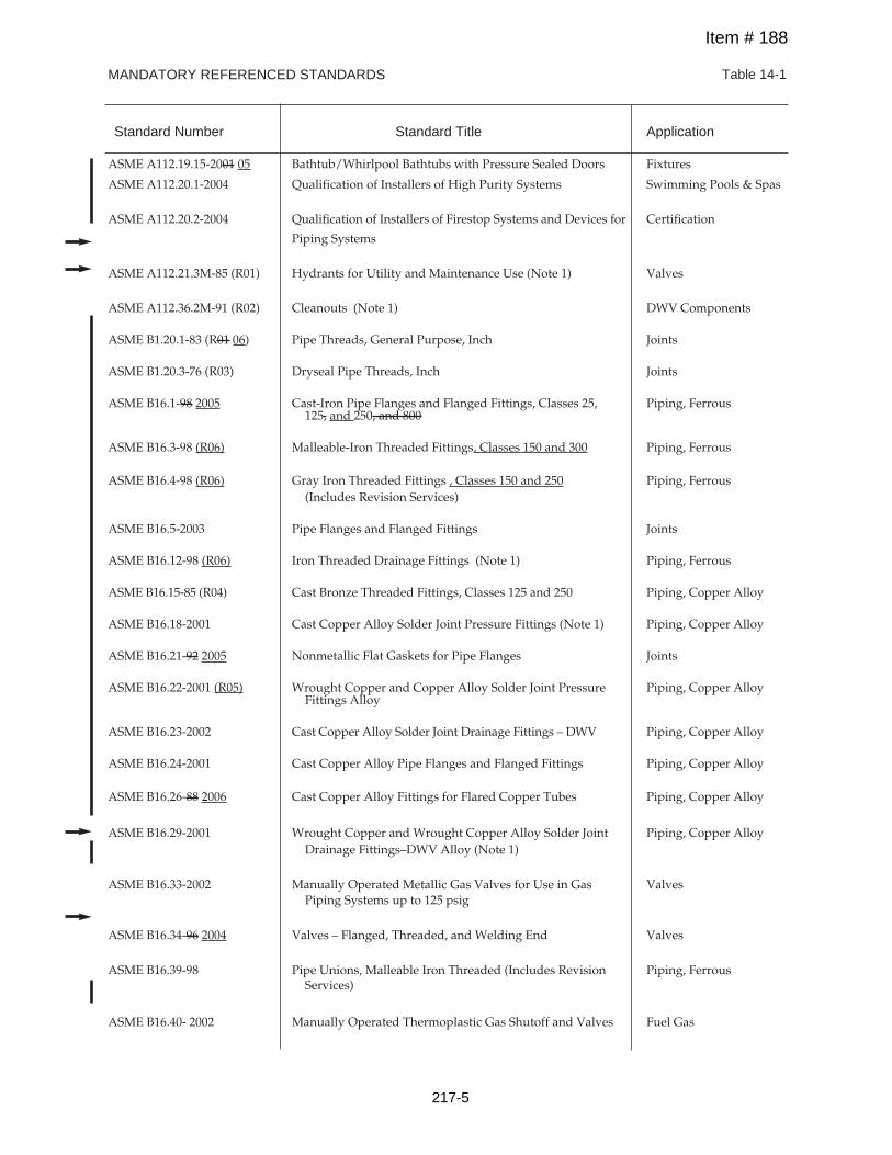
MANDATORY REFERENCED STANDARDS Table 14-1
Standard Number Standard Title Application
ASME A112.19.15-2001 05 Bathtub/Whirlpool Bathtubs with Pressure Sealed Doors Fixtures
ASME A112.20.1-2004 Qualification of Installers of High Purity Systems Swimming Pools & Spas
ASME A112.20.2-2004 Qualification of Installers of Firestop Systems and Devices for Certification
Piping Systems
ASME A112.21.3M-85 (R01) Hydrants for Utility and Maintenance Use (Note 1) Valves
ASME A112.36.2M-91 (R02) Cleanouts (Note 1) DWV Components
ASME B1.20.1-83 (R01 06) Pipe Threads, General Purpose, Inch Joints
ASME B1.20.3-76 (R03) Dryseal Pipe Threads, Inch Joints
ASME B16.1-98 2005 Cast-Iron Pipe Flanges and Flanged Fittings, Classes 25, Piping, Ferrous125, and 250, and 800
ASME B16.3-98 (R06) Malleable-Iron Threaded Fittings, Classes 150 and 300 Piping, Ferrous
ASME B16.4-98 (R06) Gray Iron Threaded Fittings , Classes 150 and 250 Piping, Ferrous(Includes Revision Services)
ASME B16.5-2003 Pipe Flanges and Flanged Fittings Joints
ASME B16.12-98 (R06) Iron Threaded Drainage Fittings (Note 1) Piping, Ferrous
ASME B16.15-85 (R04) Cast Bronze Threaded Fittings, Classes 125 and 250 Piping, Copper Alloy
ASME B16.18-2001 Cast Copper Alloy Solder Joint Pressure Fittings (Note 1) Piping, Copper Alloy
ASME B16.21-92 2005 Nonmetallic Flat Gaskets for Pipe Flanges Joints
ASME B16.22-2001 (R05) Wrought Copper and Copper Alloy Solder Joint Pressure Piping, Copper AlloyFittings Alloy
ASME B16.23-2002 Cast Copper Alloy Solder Joint Drainage Fittings – DWV Piping, Copper Alloy
ASME B16.24-2001 Cast Copper Alloy Pipe Flanges and Flanged Fittings Piping, Copper Alloy
ASME B16.26-88 2006 Cast Copper Alloy Fittings for Flared Copper Tubes Piping, Copper Alloy
ASME B16.29-2001 Wrought Copper and Wrought Copper Alloy Solder Joint Piping, Copper AlloyDrainage Fittings–DWV Alloy (Note 1)
ASME B16.33-2002 Manually Operated Metallic Gas Valves for Use in Gas ValvesPiping Systems up to 125 psig
ASME B16.34-96 2004 Valves – Flanged, Threaded, and Welding End Valves
ASME B16.39-98 Pipe Unions, Malleable Iron Threaded (Includes Revision Piping, FerrousServices)
ASME B16.40- 2002 Manually Operated Thermoplastic Gas Shutoff and Valves Fuel Gas
Item # 188
217-5
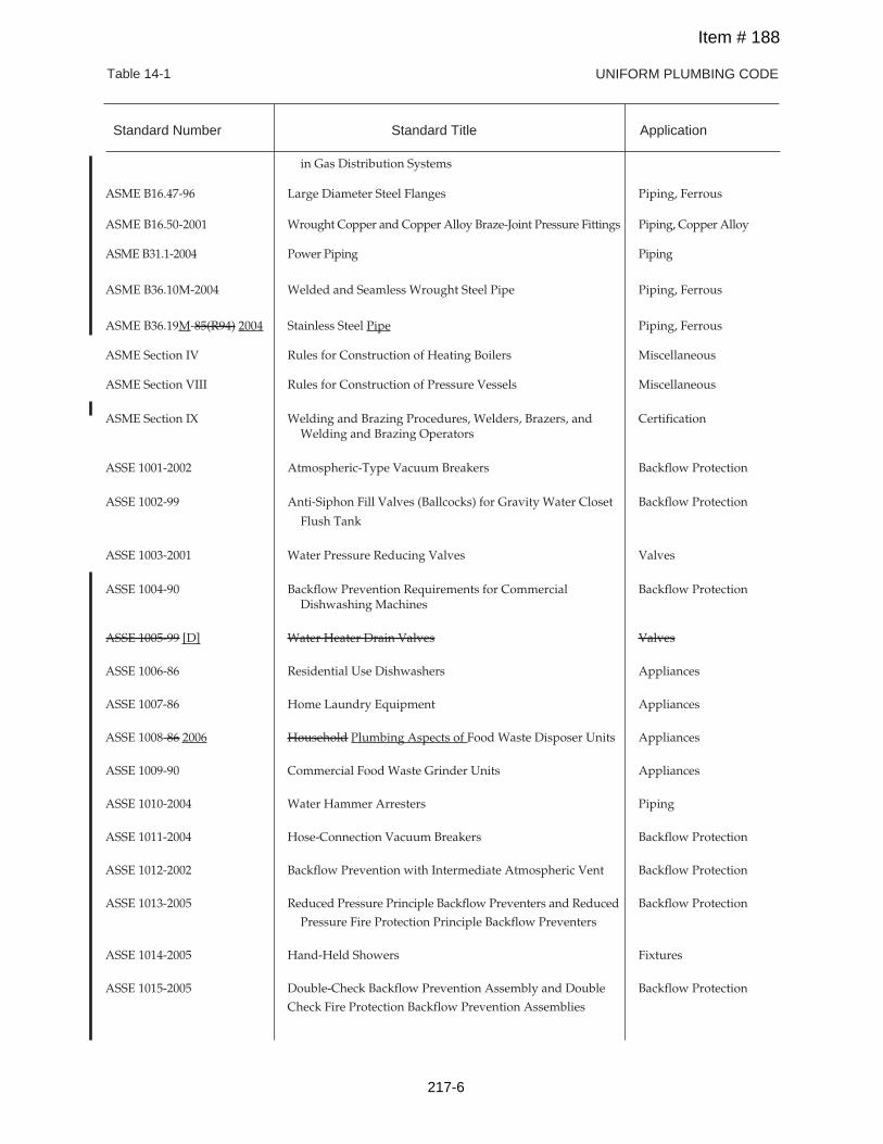
UNIFORM PLUMBING CODETable 14-1
in Gas Distribution Systems
ASME B16.47-96 Large Diameter Steel Flanges Piping, Ferrous
ASME B16.50-2001 Wrought Copper and Copper Alloy Braze-Joint Pressure Fittings Piping, Copper Alloy
ASME B31.1-2004 Power Piping Piping
ASME B36.10M-2004 Welded and Seamless Wrought Steel Pipe Piping, Ferrous
ASME B36.19M-85(R94) 2004 Stainless Steel Pipe Piping, Ferrous
ASME Section IV Rules for Construction of Heating Boilers Miscellaneous
ASME Section VIII Rules for Construction of Pressure Vessels Miscellaneous
ASME Section IX Welding and Brazing Procedures, Welders, Brazers, and CertificationWelding and Brazing Operators
ASSE 1001-2002 Atmospheric-Type Vacuum Breakers Backflow Protection
ASSE 1002-99 Anti-Siphon Fill Valves (Ballcocks) for Gravity Water Closet Backflow Protection
Flush Tank
ASSE 1003-2001 Water Pressure Reducing Valves Valves
ASSE 1004-90 Backflow Prevention Requirements for Commercial Backflow ProtectionDishwashing Machines
ASSE 1005-99 [D] Water Heater Drain Valves Valves
ASSE 1006-86 Residential Use Dishwashers Appliances
ASSE 1007-86 Home Laundry Equipment Appliances
ASSE 1008-86 2006 Household Plumbing Aspects of Food Waste Disposer Units Appliances
ASSE 1009-90 Commercial Food Waste Grinder Units Appliances
ASSE 1010-2004 Water Hammer Arresters Piping
ASSE 1011-2004 Hose-Connection Vacuum Breakers Backflow Protection
ASSE 1012-2002 Backflow Prevention with Intermediate Atmospheric Vent Backflow Protection
ASSE 1013-2005 Reduced Pressure Principle Backflow Preventers and Reduced Backflow Protection
Pressure Fire Protection Principle Backflow Preventers
ASSE 1014-2005 Hand-Held Showers Fixtures
ASSE 1015-2005 Double-Check Backflow Prevention Assembly and Double Backflow Protection
Check Fire Protection Backflow Prevention Assemblies
Standard Number Standard Title Application
Item # 188
217-6
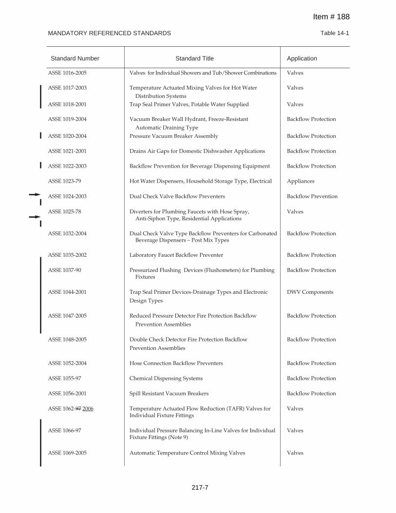
MANDATORY REFERENCED STANDARDS Table 14-1
Standard Number Standard Title Application
ASSE 1016-2005 Valves for Individual Showers and Tub/Shower Combinations Valves
ASSE 1017-2003 Temperature Actuated Mixing Valves for Hot Water Valves
Distribution SystemsASSE 1018-2001 Trap Seal Primer Valves, Potable Water Supplied Valves
ASSE 1019-2004 Vacuum Breaker Wall Hydrant, Freeze-Resistant Backflow Protection
Automatic Draining Type
ASSE 1020-2004 Pressure Vacuum Breaker Assembly Backflow Protection
ASSE 1021-2001 Drains Air Gaps for Domestic Dishwasher Applications Backflow Protection
ASSE 1022-2003 Backflow Prevention for Beverage Dispensing Equipment Backflow Protection
ASSE 1023-79 Hot Water Dispensers, Household Storage Type, Electrical Appliances
ASSE 1024-2003 Dual Check Valve Backflow Preventers Backflow Prevention
ASSE 1025-78 Diverters for Plumbing Faucets with Hose Spray, ValvesAnti-Siphon Type, Residential Applications
ASSE 1032-2004 Dual Check Valve Type Backflow Preventers for Carbonated Backflow ProtectionBeverage Dispensers – Post Mix Types
ASSE 1035-2002 Laboratory Faucet Backflow Preventer Backflow Protection
ASSE 1037-90 Pressurized Flushing Devices (Flushometers) for Plumbing Backflow ProtectionFixtures
ASSE 1044-2001 Trap Seal Primer Devices-Drainage Types and Electronic DWV Components
Design Types
ASSE 1047-2005 Reduced Pressure Detector Fire Protection Backflow Backflow Protection
Prevention Assemblies
ASSE 1048-2005 Double Check Detector Fire Protection Backflow Backflow Protection
Prevention Assemblies
ASSE 1052-2004 Hose Connection Backflow Preventers Backflow Protection
ASSE 1055-97 Chemical Dispensing Systems Backflow Protection
ASSE 1056-2001 Spill Resistant Vacuum Breakers Backflow Protection
ASSE 1062-97 2006 Temperature Actuated Flow Reduction (TAFR) Valves for ValvesIndividual Fixture Fittings
ASSE 1066-97 Individual Pressure Balancing In-Line Valves for Individual ValvesFixture Fittings (Note 9)
ASSE 1069-2005 Automatic Temperature Control Mixing Valves Valves
Item # 188
217-7
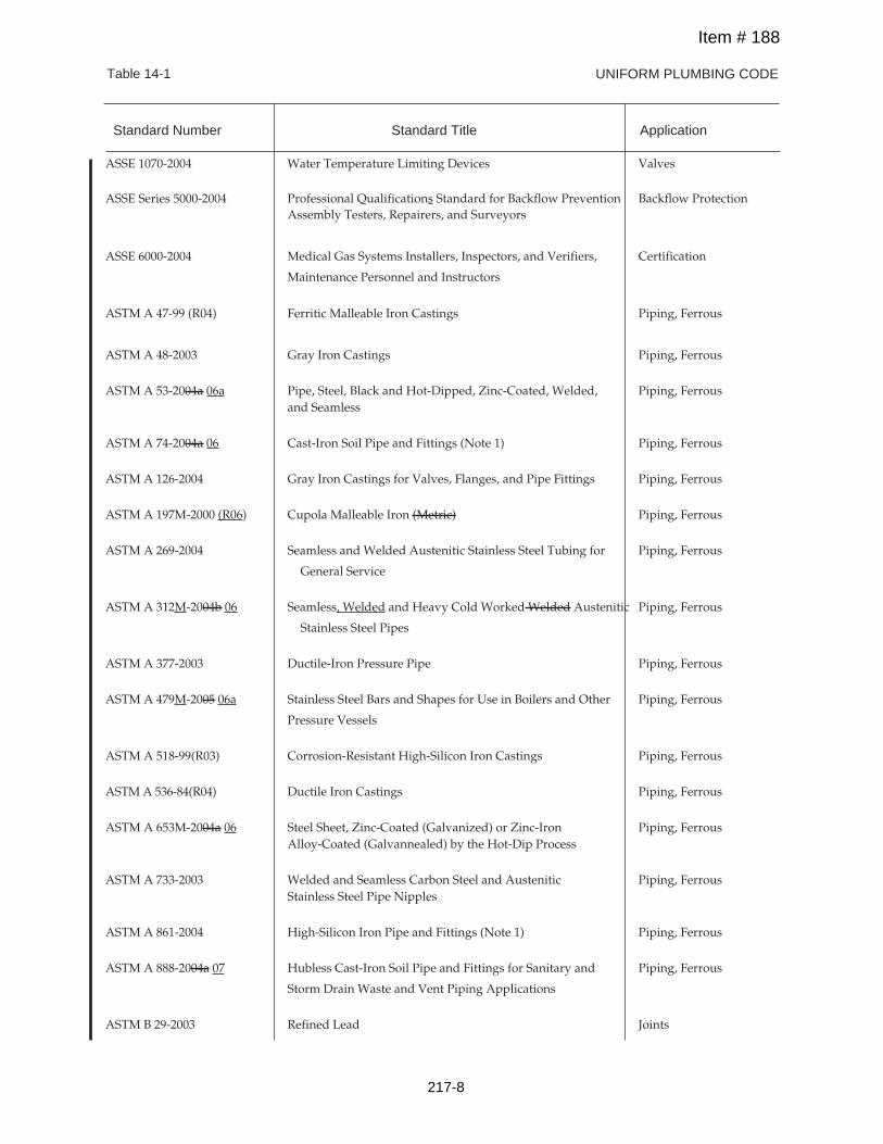
UNIFORM PLUMBING CODETable 14-1
ASSE 1070-2004 Water Temperature Limiting Devices Valves
ASSE Series 5000-2004 Professional Qualifications Standard for Backflow Prevention Backflow ProtectionAssembly Testers, Repairers, and Surveyors
ASSE 6000-2004 Medical Gas Systems Installers, Inspectors, and Verifiers, Certification
Maintenance Personnel and Instructors
ASTM A 47-99 (R04) Ferritic Malleable Iron Castings Piping, Ferrous
ASTM A 48-2003 Gray Iron Castings Piping, Ferrous
ASTM A 53-2004a 06a Pipe, Steel, Black and Hot-Dipped, Zinc-Coated, Welded, Piping, Ferrousand Seamless
ASTM A 74-2004a 06 Cast-Iron Soil Pipe and Fittings (Note 1) Piping, Ferrous
ASTM A 126-2004 Gray Iron Castings for Valves, Flanges, and Pipe Fittings Piping, Ferrous
ASTM A 197M-2000 (R06) Cupola Malleable Iron (Metric) Piping, Ferrous
ASTM A 269-2004 Seamless and Welded Austenitic Stainless Steel Tubing for Piping, Ferrous
General Service
ASTM A 312M-2004b 06 Seamless, Welded and Heavy Cold Worked Welded Austenitic Piping, Ferrous
Stainless Steel Pipes
ASTM A 377-2003 Ductile-Iron Pressure Pipe Piping, Ferrous
ASTM A 479M-2005 06a Stainless Steel Bars and Shapes for Use in Boilers and Other Piping, Ferrous
Pressure Vessels
ASTM A 518-99(R03) Corrosion-Resistant High-Silicon Iron Castings Piping, Ferrous
ASTMA 536-84(R04) Ductile Iron Castings Piping, Ferrous
ASTM A 653M-2004a 06 Steel Sheet, Zinc-Coated (Galvanized) or Zinc-Iron Piping, FerrousAlloy-Coated (Galvannealed) by the Hot-Dip Process
ASTM A 733-2003 Welded and Seamless Carbon Steel and Austenitic Piping, FerrousStainless Steel Pipe Nipples
ASTM A 861-2004 High-Silicon Iron Pipe and Fittings (Note 1) Piping, Ferrous
ASTM A 888-2004a 07 Hubless Cast-Iron Soil Pipe and Fittings for Sanitary and Piping, Ferrous
Storm Drain Waste and Vent Piping Applications
ASTM B 29-2003 Refined Lead Joints
Standard Number Standard Title Application
Item # 188
217-8
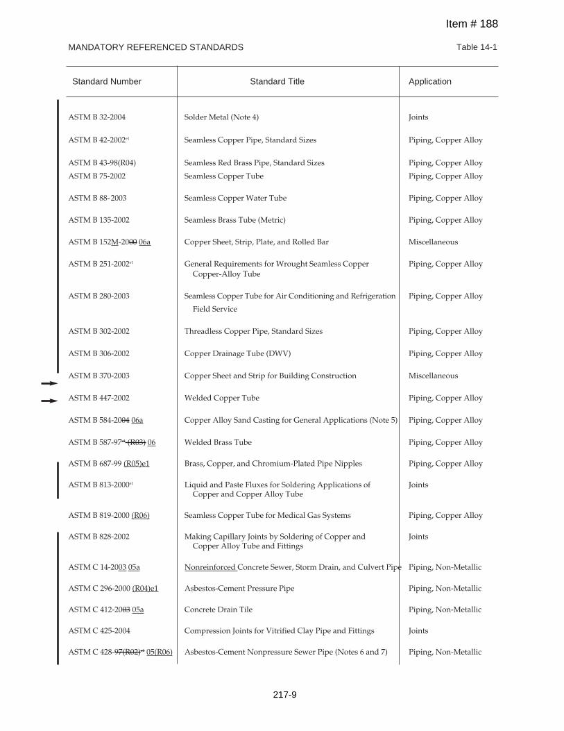
MANDATORY REFERENCED STANDARDS Table 14-1
Standard Number Standard Title Application
ASTM B 32-2004 Solder Metal (Note 4) Joints
ASTM B 42-2002e1 Seamless Copper Pipe, Standard Sizes Piping, Copper Alloy
ASTM B 43-98(R04) Seamless Red Brass Pipe, Standard Sizes Piping, Copper Alloy
ASTM B 75-2002 Seamless Copper Tube Piping, Copper Alloy
ASTM B 88-2003 Seamless Copper Water Tube Piping, Copper Alloy
ASTM B 135-2002 Seamless Brass Tube (Metric) Piping, Copper Alloy
ASTM B 152M-2000 06a Copper Sheet, Strip, Plate, and Rolled Bar Miscellaneous
ASTM B 251-2002e1 General Requirements for Wrought Seamless Copper Piping, Copper AlloyCopper-Alloy Tube
ASTM B 280-2003 Seamless Copper Tube for Air Conditioning and Refrigeration Piping, Copper Alloy
Field Service
ASTM B 302-2002 Threadless Copper Pipe, Standard Sizes Piping, Copper Alloy
ASTM B 306-2002 Copper Drainage Tube (DWV) Piping, Copper Alloy
ASTM B 370-2003 Copper Sheet and Strip for Building Construction Miscellaneous
ASTM B 447-2002 Welded Copper Tube Piping, Copper Alloy
ASTM B 584-2004 06a Copper Alloy Sand Casting for General Applications (Note 5) Piping, Copper Alloy
ASTM B 587-97e1 (R03) 06 Welded Brass Tube Piping, Copper Alloy
ASTM B 687-99 (R05)e1 Brass, Copper, and Chromium-Plated Pipe Nipples Piping, Copper Alloy
ASTM B 813-2000e1 Liquid and Paste Fluxes for Soldering Applications of JointsCopper and Copper Alloy Tube
ASTM B 819-2000 (R06) Seamless Copper Tube for Medical Gas Systems Piping, Copper Alloy
ASTM B 828-2002 Making Capillary Joints by Soldering of Copper and JointsCopper Alloy Tube and Fittings
ASTM C 14-2003 05a Nonreinforced Concrete Sewer, Storm Drain, and Culvert Pipe Piping, Non-Metallic
ASTM C 296-2000 (R04)e1 Asbestos-Cement Pressure Pipe Piping, Non-Metallic
ASTM C 412-2003 05a Concrete Drain Tile Piping, Non-Metallic
ASTM C 425-2004 Compression Joints for Vitrified Clay Pipe and Fittings Joints
ASTM C 428-97(R02)e1 05(R06) Asbestos-Cement Nonpressure Sewer Pipe (Notes 6 and 7) Piping, Non-Metallic
Item # 188
217-9
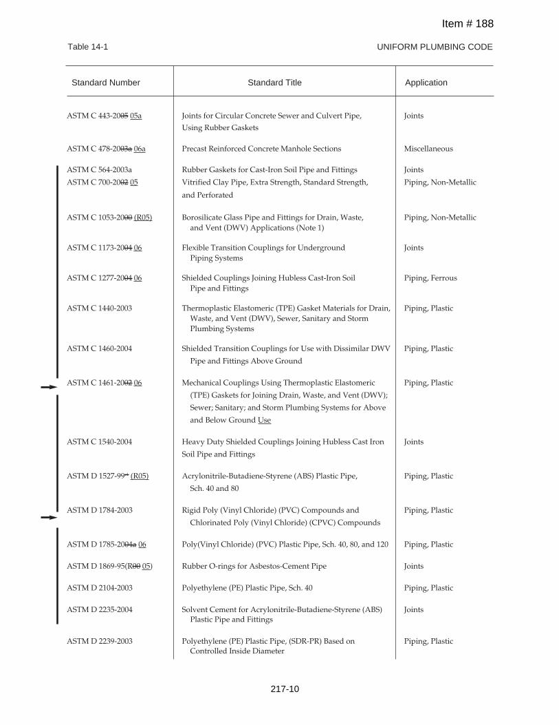
UNIFORM PLUMBING CODETable 14-1
ASTM C 443-2005 05a Joints for Circular Concrete Sewer and Culvert Pipe, Joints
Using Rubber Gaskets
ASTM C 478-2003a 06a Precast Reinforced Concrete Manhole Sections Miscellaneous
ASTM C 564-2003a Rubber Gaskets for Cast-Iron Soil Pipe and Fittings Joints
ASTM C 700-2002 05 Vitrified Clay Pipe, Extra Strength, Standard Strength, Piping, Non-Metallic
and Perforated
ASTM C 1053-2000 (R05) Borosilicate Glass Pipe and Fittings for Drain, Waste, Piping, Non-Metallicand Vent (DWV) Applications (Note 1)
ASTM C 1173-2004 06 Flexible Transition Couplings for Underground JointsPiping Systems
ASTM C 1277-2004 06 Shielded Couplings Joining Hubless Cast-Iron Soil Piping, FerrousPipe and Fittings
ASTM C 1440-2003 Thermoplastic Elastomeric (TPE) Gasket Materials for Drain, Piping, PlasticWaste, and Vent (DWV), Sewer, Sanitary and StormPlumbing Systems
ASTM C 1460-2004 Shielded Transition Couplings for Use with Dissimilar DWV Piping, Plastic
Pipe and Fittings Above Ground
ASTM C 1461-2002 06 Mechanical Couplings Using Thermoplastic Elastomeric Piping, Plastic
(TPE) Gaskets for Joining Drain, Waste, and Vent (DWV);
Sewer; Sanitary; and Storm Plumbing Systems for Above
and Below Ground Use
ASTM C 1540-2004 Heavy Duty Shielded Couplings Joining Hubless Cast Iron Joints
Soil Pipe and Fittings
ASTM D 1527-99e1 (R05) Acrylonitrile-Butadiene-Styrene (ABS) Plastic Pipe, Piping, Plastic
Sch. 40 and 80
ASTM D 1784-2003 Rigid Poly (Vinyl Chloride) (PVC) Compounds and Piping, Plastic
Chlorinated Poly (Vinyl Chloride) (CPVC) Compounds
ASTM D 1785-2004a 06 Poly(Vinyl Chloride) (PVC) Plastic Pipe, Sch. 40, 80, and 120 Piping, Plastic
ASTM D 1869-95(R00 05) Rubber O-rings for Asbestos-Cement Pipe Joints
ASTM D 2104-2003 Polyethylene (PE) Plastic Pipe, Sch. 40 Piping, Plastic
ASTM D 2235-2004 Solvent Cement for Acrylonitrile-Butadiene-Styrene (ABS) JointsPlastic Pipe and Fittings
ASTM D 2239-2003 Polyethylene (PE) Plastic Pipe, (SDR-PR) Based on Piping, PlasticControlled Inside Diameter
Standard Number Standard Title Application
Item # 188
217-10
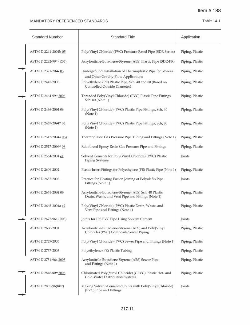
MANDATORY REFERENCED STANDARDS Table 14-1
Standard Number Standard Title Application
ASTM D 2241-2004b 05 Poly(Vinyl Chloride)(PVC) Pressure-Rated Pipe (SDR Series) Piping, Plastic
ASTM D 2282-99e1 (R05) Acrylonitrile-Butadiene-Styrene (ABS) Plastic Pipe (SDR-PR) Piping, Plastic
ASTM D 2321-2000 05 Underground Installation of Thermoplastic Pipe for Sewers Piping, Plastic
and Other Gravity-Flow Applications
ASTM D 2447-2003 Polyethylene (PE) Plastic Pipe, Sch. 40 and 80 (Based on Piping, PlasticControlled Outside Diameter)
ASTM D 2464-99e1 2006 Threaded Poly(Vinyl Chloride) (PVC) Plastic Pipe Fittings, Piping, PlasticSch. 80 (Note 1)
ASTM D 2466-2002 06 Poly(Vinyl Chloride) (PVC) Plastic Pipe Fittings, Sch. 40 Piping, Plastic(Note 1)
ASTM D 2467-2004e1 06 Poly(Vinyl Chloride) (PVC) Plastic Pipe Fittings, Sch, 80 Piping, Plastic(Note 1)
ASTM D 2513-2004a 06a Thermoplastic Gas Pressure Pipe Tubing and Fittings (Note 1) Piping, Plastic
ASTM D 2517-2000e1 06 Reinforced Epoxy Resin Gas Pressure Pipe and Fittings Piping, Plastic
ASTM D 2564-2004 e1 Solvent Cements for Poly(Vinyl Chloride) (PVC) Plastic JointsPiping Systems
ASTM D 2609-2002 Plastic Insert Fittings for Polyethylene (PE) Plastic Pipe (Note 1) Piping, Plastic
ASTM D 2657-2003 Practice for Heating Fusion Joining of Polyolefin Pipe JointsFittings (Note 1)
ASTM D 2661-2002 06 Acrylonitrile-Butadiene-Styrene (ABS) Sch. 40 Plastic Piping, PlasticDrain, Waste, and Vent Pipe and Fittings (Note 1)
ASTM D 2665-2004a e2 Poly(Vinyl Chloride) (PVC) Plastic Drain, Waste, and Piping, PlasticVent Pipe and Fittings (Note 1)
ASTM D 2672-96a (R03) Joints for IPS PVC Pipe Using Solvent Cement Joints
ASTM D 2680-2001 Acrylonitrile-Butadiene-Styrene (ABS) and Poly(Vinyl Piping, PlasticChloride) (PVC) Composite Sewer Piping
ASTM D 2729-2003 Poly(Vinyl Chloride) (PVC) Sewer Pipe and Fittings (Note 1) Piping, Plastic
ASTM D 2737-2003 Polyethylene (PE) Plastic Tubing Piping, Plastic
ASTM D 2751-96a 2005 Acrylonitrile-Butadiene-Styrene (ABS) Sewer Pipe Piping, Plasticand Fittings (Note 1)
ASTM D 2846-99e1 2006 Chlorinated Poly(Vinyl Chloride) (CPVC) Plastic Hot- and Piping, PlasticCold-Water Distribution Systems
ASTM D 2855-96(R02) Making Solvent-Cemented Joints with Poly(Vinyl Chloride) Joints(PVC) Pipe and Fittings
Item # 188
217-11
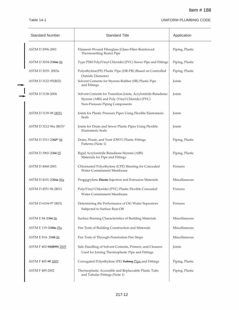
UNIFORM PLUMBING CODETable 14-1
ASTM D 2996-2001 Filament-Wound Fiberglass (Glass-Fiber-Reinforced Piping, PlasticThermosetting Resin) Pipe
ASTM D 3034-2004a 06 Type PSM Poly(Vinyl Chloride) (PVC) Sewer Pipe and Fittings Piping, Plastic
ASTM D 3035- 2003a Polyethylene(PE) Plastic Pipe (DR-PR) (Based on Controlled Piping, Plastic
Outside Diameter)
ASTM D 3122-95(R02) Solvent Cements for Styrene-Rubber (SR) Plastic Pipe Jointsand Fittings
ASTM D 3138-2004 Solvent Cements for Transition Joints, Acrylonitrile-Butadiene- Joints
Styrene (ABS) and Poly (Vinyl Chloride) (PVC)
Non-Pressure Piping Components
ASTM D 3139-98 (R05) Joints for Plastic Pressure Pipes Using Flexible Elastomeric JointsSeals
ASTM D 3212-96a (R03)e1 Joints for Drain and Sewer Plastic Pipes Using Flexible JointsElastomeric Seals
ASTM D 3311-2002e1 06 Drain, Waste, and Vent (DWV) Plastic Fittings Piping, PlasticPatterns (Note 1)
ASTM D 3965-2004 05 Rigid Acrylonitrile-Butadiene-Styrene (ABS) Piping, PlasticMaterials for Pipe and Fittings
ASTM D 4068-2001 Chlorinated Polyethylene (CPE) Sheeting for Concealed FixturesWater-Containment Membrane
ASTM D 4101-2004a 06a Propropylene Plastic Injection and Extrusion Materials Miscellaneous
ASTM D 4551-96 (R01) Poly(Vinyl Chloride) (PVC) Plastic Flexible Concealed Fixtures
Water-Containment Membrane
ASTM D 6104-97 (R03) Determining the Performance of Oil/Water Separators Fixtures
Subjected to Surface Run-Off
ASTM E 84-2004 06 Surface Burning Characteristics of Building Materials Miscellaneous
ASTM E 119-2000a 05a Fire Tests of Building Construction and Materials Miscellaneous
ASTM E 814- 2002 06 Fire Tests of Through-Penetration Fire Stops Miscellaneous
ASTM F 402-93(R99) 2005 Safe Handling of Solvent Cements, Primers, and Cleaners Joints
Used for Joining Thermoplastic Pipe and Fittings
ASTM F 405-97 2005 Corrugated Polyethylene (PE) Tubing Pipe and Fittings Piping, Plastic
ASTM F 409-2002 Thermoplastic Accessible and Replaceable Plastic Tube Piping, Plasticand Tubular Fittings (Note 1)
Standard Number Standard Title Application
Item # 188
217-12
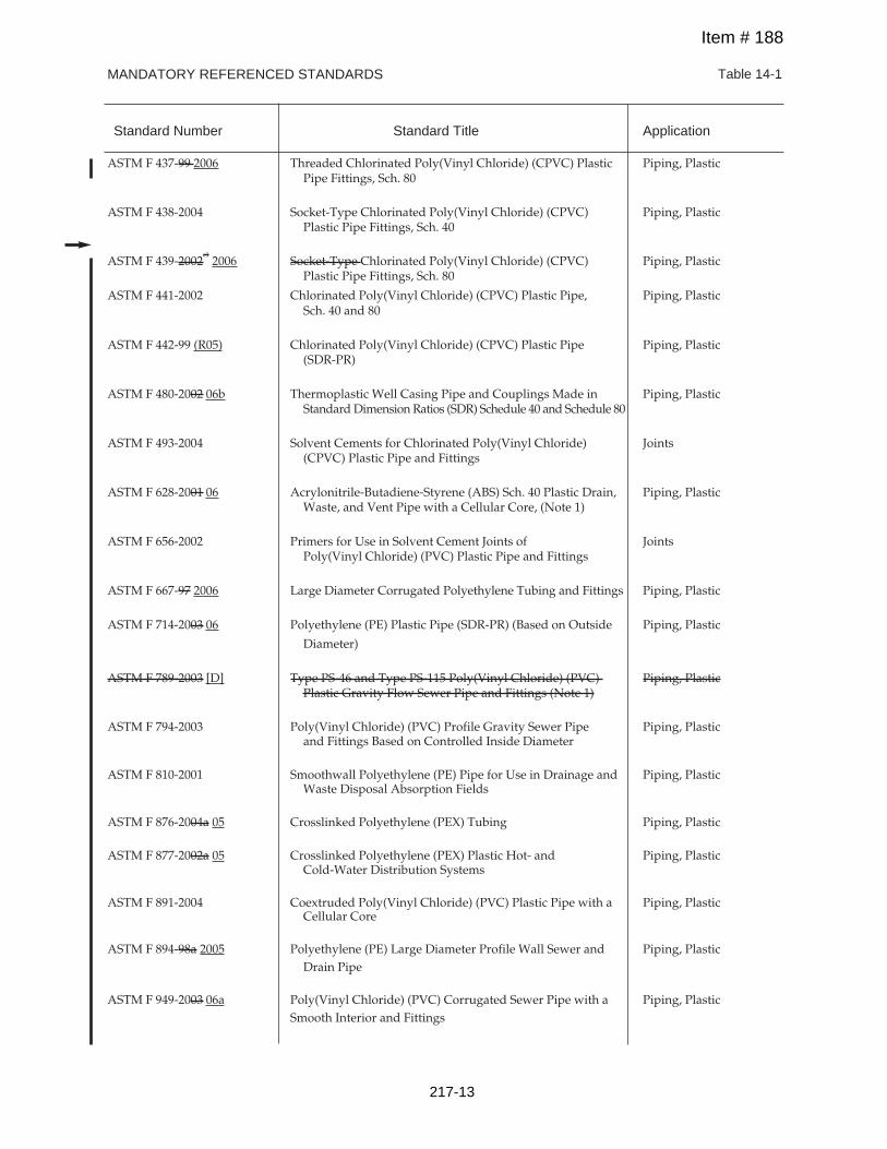
MANDATORY REFERENCED STANDARDS Table 14-1
Standard Number Standard Title Application
ASTM F 437-99 2006 Threaded Chlorinated Poly(Vinyl Chloride) (CPVC) Plastic Piping, PlasticPipe Fittings, Sch. 80
ASTM F 438-2004 Socket-Type Chlorinated Poly(Vinyl Chloride) (CPVC) Piping, PlasticPlastic Pipe Fittings, Sch. 40
ASTM F 439-2002e12006 Socket-Type Chlorinated Poly(Vinyl Chloride) (CPVC) Piping, Plastic
Plastic Pipe Fittings, Sch. 80
ASTM F 441-2002 Chlorinated Poly(Vinyl Chloride) (CPVC) Plastic Pipe, Piping, PlasticSch. 40 and 80
ASTM F 442-99 (R05) Chlorinated Poly(Vinyl Chloride) (CPVC) Plastic Pipe Piping, Plastic(SDR-PR)
ASTM F 480-2002 06b Thermoplastic Well Casing Pipe and Couplings Made in Piping, PlasticStandard Dimension Ratios (SDR) Schedule 40 and Schedule 80
ASTM F 493-2004 Solvent Cements for Chlorinated Poly(Vinyl Chloride) Joints(CPVC) Plastic Pipe and Fittings
ASTM F 628-2001 06 Acrylonitrile-Butadiene-Styrene (ABS) Sch. 40 Plastic Drain, Piping, PlasticWaste, and Vent Pipe with a Cellular Core, (Note 1)
ASTM F 656-2002 Primers for Use in Solvent Cement Joints of JointsPoly(Vinyl Chloride) (PVC) Plastic Pipe and Fittings
ASTM F 667-97 2006 Large Diameter Corrugated Polyethylene Tubing and Fittings Piping, Plastic
ASTM F 714-2003 06 Polyethylene (PE) Plastic Pipe (SDR-PR) (Based on Outside Piping, Plastic
Diameter)
ASTM F 789-2003 [D] Type PS-46 and Type PS-115 Poly(Vinyl Chloride) (PVC) Piping, PlasticPlastic Gravity Flow Sewer Pipe and Fittings (Note 1)
ASTM F 794-2003 Poly(Vinyl Chloride) (PVC) Profile Gravity Sewer Pipe Piping, Plasticand Fittings Based on Controlled Inside Diameter
ASTM F 810-2001 Smoothwall Polyethylene (PE) Pipe for Use in Drainage and Piping, PlasticWaste Disposal Absorption Fields
ASTM F 876-2004a 05 Crosslinked Polyethylene (PEX) Tubing Piping, Plastic
ASTM F 877-2002a 05 Crosslinked Polyethylene (PEX) Plastic Hot- and Piping, PlasticCold-Water Distribution Systems
ASTM F 891-2004 Coextruded Poly(Vinyl Chloride) (PVC) Plastic Pipe with a Piping, PlasticCellular Core
ASTM F 894-98a 2005 Polyethylene (PE) Large Diameter Profile Wall Sewer and Piping, PlasticDrain Pipe
ASTM F 949-2003 06a Poly(Vinyl Chloride) (PVC) Corrugated Sewer Pipe with a Piping, PlasticSmooth Interior and Fittings
Item # 188
217-13
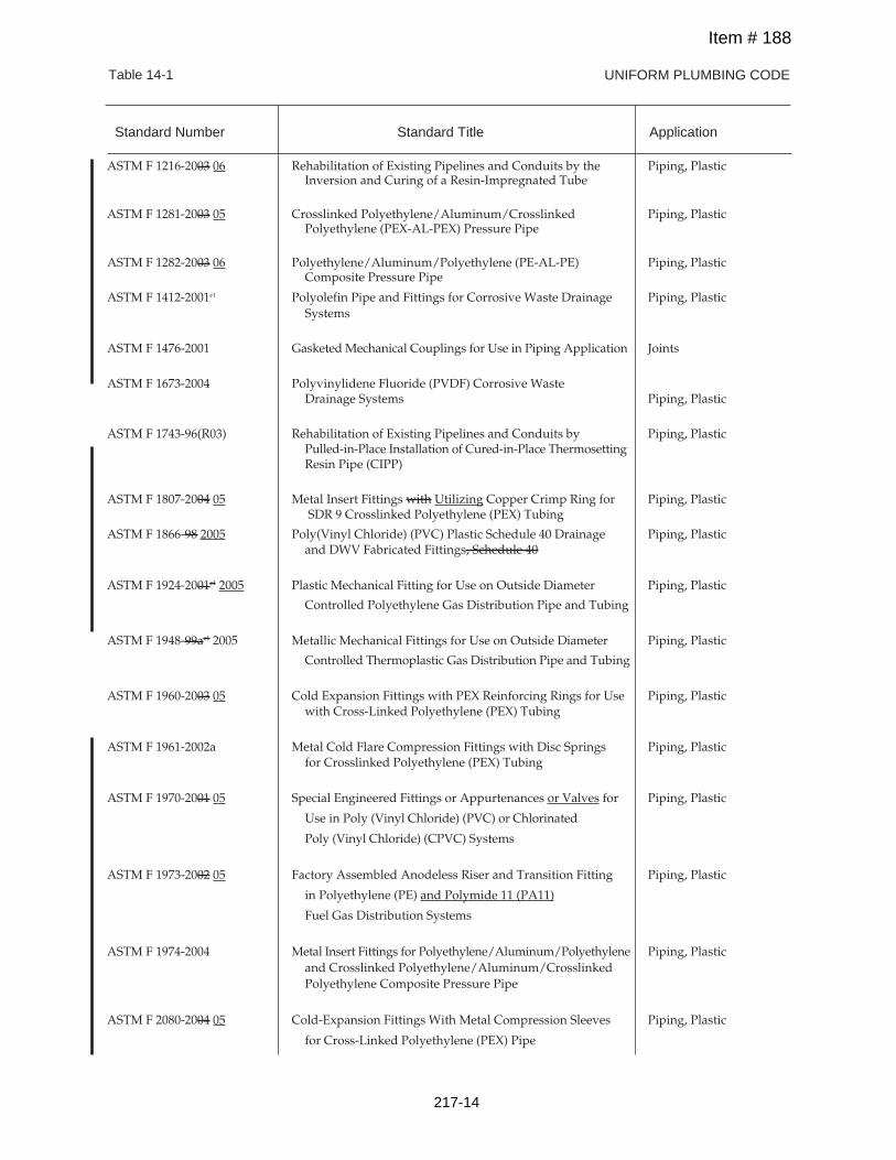
Standard Number Standard Title Application
UNIFORM PLUMBING CODETable 14-1
ASTM F 1216-2003 06 Rehabilitation of Existing Pipelines and Conduits by the Piping, PlasticInversion and Curing of a Resin-Impregnated Tube
ASTM F 1281-2003 05 Crosslinked Polyethylene/Aluminum/Crosslinked Piping, PlasticPolyethylene (PEX-AL-PEX) Pressure Pipe
ASTM F 1282-2003 06 Polyethylene/Aluminum/Polyethylene (PE-AL-PE) Piping, PlasticComposite Pressure Pipe
ASTM F 1412-2001e1 Polyolefin Pipe and Fittings for Corrosive Waste Drainage Piping, PlasticSystems
ASTM F 1476-2001 Gasketed Mechanical Couplings for Use in Piping Application Joints
ASTM F 1673-2004 Polyvinylidene Fluoride (PVDF) Corrosive WasteDrainage Systems Piping, Plastic
ASTM F 1743-96(R03) Rehabilitation of Existing Pipelines and Conduits by Piping, PlasticPulled-in-Place Installation of Cured-in-Place ThermosettingResin Pipe (CIPP)
ASTM F 1807-2004 05 Metal Insert Fittings with Utilizing Copper Crimp Ring for Piping, PlasticSDR 9 Crosslinked Polyethylene (PEX) Tubing
ASTM F 1866-98 2005 Poly(Vinyl Chloride) (PVC) Plastic Schedule 40 Drainage Piping, Plasticand DWV Fabricated Fittings, Schedule 40
ASTM F 1924-2001e1 2005 Plastic Mechanical Fitting for Use on Outside Diameter Piping, Plastic
Controlled Polyethylene Gas Distribution Pipe and Tubing
ASTM F 1948-99ae1 2005 Metallic Mechanical Fittings for Use on Outside Diameter Piping, Plastic
Controlled Thermoplastic Gas Distribution Pipe and Tubing
ASTM F 1960-2003 05 Cold Expansion Fittings with PEX Reinforcing Rings for Use Piping, Plasticwith Cross-Linked Polyethylene (PEX) Tubing
ASTM F 1961-2002a Metal Cold Flare Compression Fittings with Disc Springs Piping, Plasticfor Crosslinked Polyethylene (PEX) Tubing
ASTM F 1970-2001 05 Special Engineered Fittings or Appurtenances or Valves for Piping, Plastic
Use in Poly (Vinyl Chloride) (PVC) or Chlorinated
Poly (Vinyl Chloride) (CPVC) Systems
ASTM F 1973-2002 05 Factory Assembled Anodeless Riser and Transition Fitting Piping, Plastic
in Polyethylene (PE) and Polymide 11 (PA11)
Fuel Gas Distribution Systems
ASTM F 1974-2004 Metal Insert Fittings for Polyethylene/Aluminum/Polyethylene Piping, Plasticand Crosslinked Polyethylene/Aluminum/CrosslinkedPolyethylene Composite Pressure Pipe
ASTM F 2080-2004 05 Cold-Expansion Fittings With Metal Compression Sleeves Piping, Plastic
for Cross-Linked Polyethylene (PEX) Pipe
Item # 188
217-14
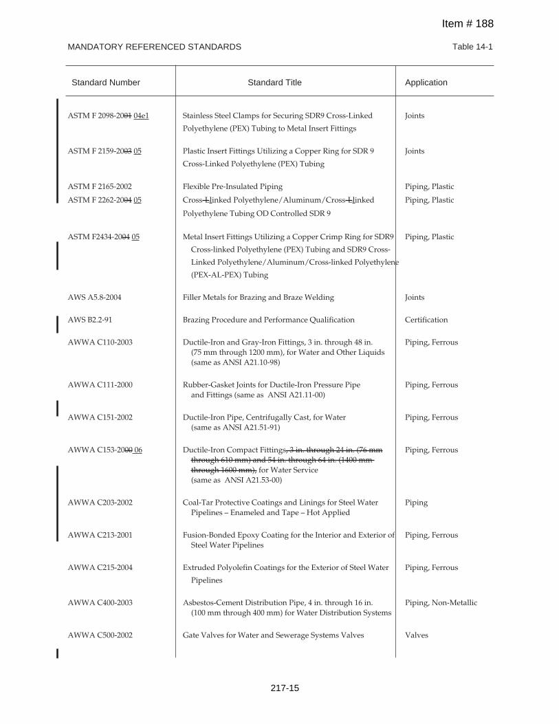
MANDATORY REFERENCED STANDARDS Table 14-1
Standard Number Standard Title Application
ASTM F 2098-2001 04e1 Stainless Steel Clamps for Securing SDR9 Cross-Linked Joints
Polyethylene (PEX) Tubing to Metal Insert Fittings
ASTM F 2159-2003 05 Plastic Insert Fittings Utilizing a Copper Ring for SDR 9 Joints
Cross-Linked Polyethylene (PEX) Tubing
ASTM F 2165-2002 Flexible Pre-Insulated Piping Piping, Plastic
ASTM F 2262-2004 05 Cross-Llinked Polyethylene/Aluminum/Cross-Llinked Piping, Plastic
Polyethylene Tubing OD Controlled SDR 9
ASTM F2434-2004 05 Metal Insert Fittings Utilizing a Copper Crimp Ring for SDR9 Piping, Plastic
Cross-linked Polyethylene (PEX) Tubing and SDR9 Cross-
Linked Polyethylene/Aluminum/Cross-linked Polyethylene
(PEX-AL-PEX) Tubing
AWS A5.8-2004 Filler Metals for Brazing and Braze Welding Joints
AWS B2.2-91 Brazing Procedure and Performance Qualification Certification
AWWA C110-2003 Ductile-Iron and Gray-Iron Fittings, 3 in. through 48 in. Piping, Ferrous(75 mm through 1200 mm), for Water and Other Liquids(same as ANSI A21.10-98)
AWWA C111-2000 Rubber-Gasket Joints for Ductile-Iron Pressure Pipe Piping, Ferrousand Fittings (same as ANSI A21.11-00)
AWWA C151-2002 Ductile-Iron Pipe, Centrifugally Cast, for Water Piping, Ferrous(same as ANSI A21.51-91)
AWWA C153-2000 06 Ductile-Iron Compact Fittings, 3 in. through 24 in. (76 mm Piping, Ferrousthrough 610 mm) and 54 in. through 64 in. (1400 mmthrough 1600 mm), for Water Service(same as ANSI A21.53-00)
AWWA C203-2002 Coal-Tar Protective Coatings and Linings for Steel Water PipingPipelines – Enameled and Tape – Hot Applied
AWWA C213-2001 Fusion-Bonded Epoxy Coating for the Interior and Exterior of Piping, FerrousSteel Water Pipelines
AWWA C215-2004 Extruded Polyolefin Coatings for the Exterior of Steel Water Piping, Ferrous
Pipelines
AWWA C400-2003 Asbestos-Cement Distribution Pipe, 4 in. through 16 in. Piping, Non-Metallic(100 mm through 400 mm) for Water Distribution Systems
AWWA C500-2002 Gate Valves for Water and Sewerage Systems Valves Valves
Item # 188
217-15
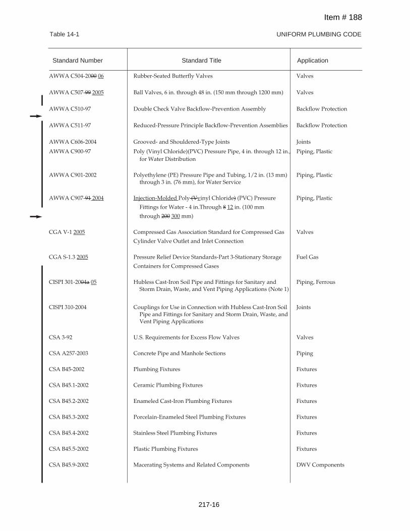
UNIFORM PLUMBING CODETable 14-1
AWWA C504-2000 06 Rubber-Seated Butterfly Valves Valves
AWWA C507-99 2005 Ball Valves, 6 in. through 48 in. (150 mm through 1200 mm) Valves
AWWA C510-97 Double Check Valve Backflow-Prevention Assembly Backflow Protection
AWWA C511-97 Reduced-Pressure Principle Backflow-Prevention Assemblies Backflow Protection
AWWA C606-2004 Grooved- and Shouldered-Type Joints Joints
AWWA C900-97 Poly (Vinyl Chloride)(PVC) Pressure Pipe, 4 in. through 12 in., Piping, Plasticfor Water Distribution
AWWA C901-2002 Polyethylene (PE) Pressure Pipe and Tubing, 1/2 in. (13 mm) Piping, Plasticthrough 3 in. (76 mm), for Water Service
AWWA C907-91 2004 Injection-Molded Poly (Vvinyl Chloride) (PVC) Pressure Piping, Plastic
Fittings for Water - 4 in.Through 8 12 in. (100 mm
through 200 300 mm)
CGA V-1 2005 Compressed Gas Association Standard for Compressed Gas Valves
Cylinder Valve Outlet and Inlet Connection
CGA S-1.3 2005 Pressure Relief Device Standards-Part 3-Stationary Storage Fuel Gas
Containers for Compressed Gases
CISPI 301-2004a 05 Hubless Cast-Iron Soil Pipe and Fittings for Sanitary and Piping, FerrousStorm Drain, Waste, and Vent Piping Applications (Note 1)
CISPI 310-2004 Couplings for Use in Connection with Hubless Cast-Iron Soil JointsPipe and Fittings for Sanitary and Storm Drain, Waste, andVent Piping Applications
CSA 3-92 U.S. Requirements for Excess Flow Valves Valves
CSA A257-2003 Concrete Pipe and Manhole Sections Piping
CSA B45-2002 Plumbing Fixtures Fixtures
CSA B45.1-2002 Ceramic Plumbing Fixtures Fixtures
CSA B45.2-2002 Enameled Cast-Iron Plumbing Fixtures Fixtures
CSA B45.3-2002 Porcelain-Enameled Steel Plumbing Fixtures Fixtures
CSA B45.4-2002 Stainless Steel Plumbing Fixtures Fixtures
CSA B45.5-2002 Plastic Plumbing Fixtures Fixtures
CSA B45.9-2002 Macerating Systems and Related Components DWV Components
Standard Number Standard Title Application
Item # 188
217-16
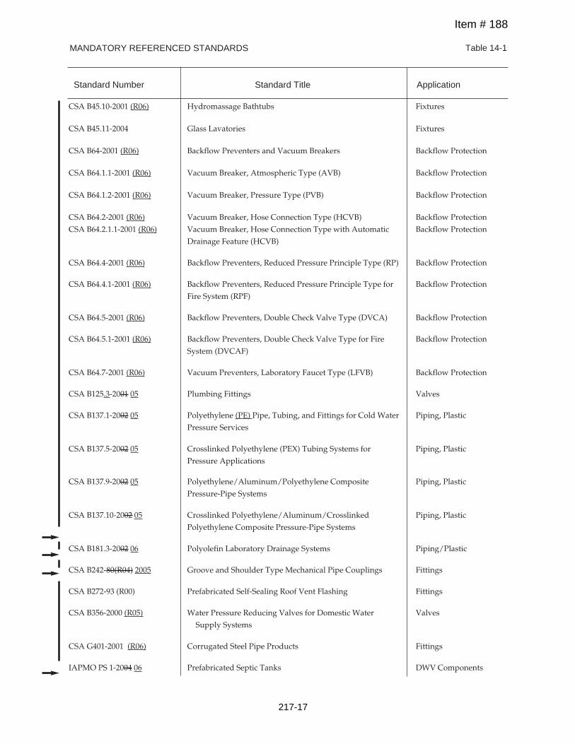
MANDATORY REFERENCED STANDARDS Table 14-1
CSA B45.10-2001 (R06) Hydromassage Bathtubs Fixtures
CSA B45.11-2004 Glass Lavatories Fixtures
CSA B64-2001 (R06) Backflow Preventers and Vacuum Breakers Backflow Protection
CSA B64.1.1-2001 (R06) Vacuum Breaker, Atmospheric Type (AVB) Backflow Protection
CSA B64.1.2-2001 (R06) Vacuum Breaker, Pressure Type (PVB) Backflow Protection
CSA B64.2-2001 (R06) Vacuum Breaker, Hose Connection Type (HCVB) Backflow Protection
CSA B64.2.1.1-2001 (R06) Vacuum Breaker, Hose Connection Type with Automatic Backflow Protection
Drainage Feature (HCVB)
CSA B64.4-2001 (R06) Backflow Preventers, Reduced Pressure Principle Type (RP) Backflow Protection
CSA B64.4.1-2001 (R06) Backflow Preventers, Reduced Pressure Principle Type for Backflow Protection
Fire System (RPF)
CSA B64.5-2001 (R06) Backflow Preventers, Double Check Valve Type (DVCA) Backflow Protection
CSA B64.5.1-2001 (R06) Backflow Preventers, Double Check Valve Type for Fire Backflow Protection
System (DVCAF)
CSA B64.7-2001 (R06) Vacuum Preventers, Laboratory Faucet Type (LFVB) Backflow Protection
CSA B125.3-2001 05 Plumbing Fittings Valves
CSA B137.1-2002 05 Polyethylene (PE) Pipe, Tubing, and Fittings for Cold Water Piping, Plastic
Pressure Services
CSA B137.5-2002 05 Crosslinked Polyethylene (PEX) Tubing Systems for Piping, Plastic
Pressure Applications
CSA B137.9-2002 05 Polyethylene/Aluminum/Polyethylene Composite Piping, Plastic
Pressure-Pipe Systems
CSA B137.10-2002 05 Crosslinked Polyethylene/Aluminum/Crosslinked Piping, Plastic
Polyethylene Composite Pressure-Pipe Systems
CSA B181.3-2002 06 Polyolefin Laboratory Drainage Systems Piping/Plastic
CSA B242-80(R04) 2005 Groove and Shoulder Type Mechanical Pipe Couplings Fittings
CSA B272-93 (R00) Prefabricated Self-Sealing Roof Vent Flashing Fittings
CSA B356-2000 (R05) Water Pressure Reducing Valves for Domestic Water Valves
Supply Systems
CSA G401-2001 (R06) Corrugated Steel Pipe Products Fittings
IAPMO PS 1-2004 06 Prefabricated Septic Tanks DWV Components
Standard Number Standard Title Application
Item # 188
217-17
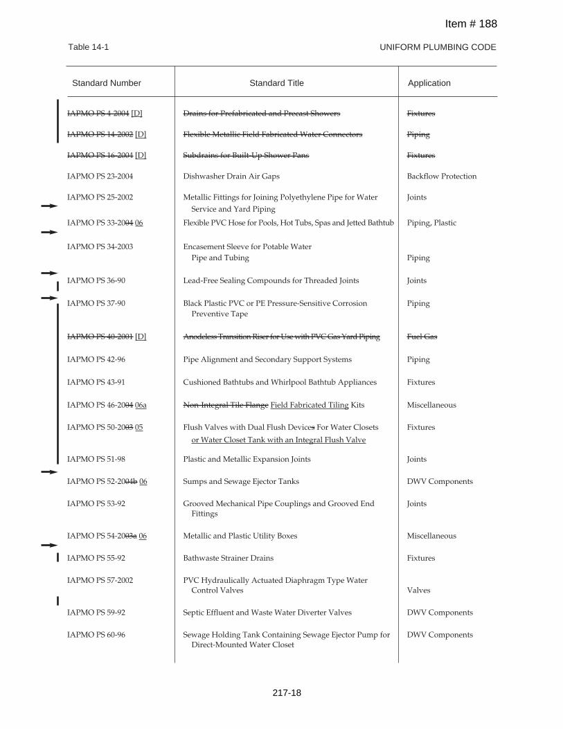
UNIFORM PLUMBING CODETable 14-1
IAPMO PS 4-2004 [D] Drains for Prefabricated and Precast Showers Fixtures
IAPMO PS 14-2002 [D] Flexible Metallic Field Fabricated Water Connectors Piping
IAPMO PS 16-2004 [D] Subdrains for Built-Up Shower Pans Fixtures
IAPMO PS 23-2004 Dishwasher Drain Air Gaps Backflow Protection
IAPMO PS 25-2002 Metallic Fittings for Joining Polyethylene Pipe for Water Joints
Service and Yard Piping
IAPMO PS 33-2004 06 Flexible PVCHose for Pools, Hot Tubs, Spas and Jetted Bathtub Piping, Plastic
IAPMO PS 34-2003 Encasement Sleeve for Potable WaterPipe and Tubing Piping
IAPMO PS 36-90 Lead-Free Sealing Compounds for Threaded Joints Joints
IAPMO PS 37-90 Black Plastic PVC or PE Pressure-Sensitive Corrosion PipingPreventive Tape
IAPMO PS 40-2001 [D] Anodeless TransitionRiser forUsewith PVCGasYardPiping Fuel Gas
IAPMO PS 42-96 Pipe Alignment and Secondary Support Systems Piping
IAPMO PS 43-91 Cushioned Bathtubs and Whirlpool Bathtub Appliances Fixtures
IAPMO PS 46-2004 06a Non-Integral Tile Flange Field Fabricated Tiling Kits Miscellaneous
IAPMO PS 50-2003 05 Flush Valves with Dual Flush Devices For Water Closets Fixtures
or Water Closet Tank with an Integral Flush Valve
IAPMO PS 51-98 Plastic and Metallic Expansion Joints Joints
IAPMO PS 52-2004b 06 Sumps and Sewage Ejector Tanks DWV Components
IAPMO PS 53-92 Grooved Mechanical Pipe Couplings and Grooved End JointsFittings
IAPMO PS 54-2003a 06 Metallic and Plastic Utility Boxes Miscellaneous
IAPMO PS 55-92 Bathwaste Strainer Drains Fixtures
IAPMO PS 57-2002 PVC Hydraulically Actuated Diaphragm Type WaterControl Valves Valves
IAPMO PS 59-92 Septic Effluent and Waste Water Diverter Valves DWV Components
IAPMO PS 60-96 Sewage Holding Tank Containing Sewage Ejector Pump for DWV ComponentsDirect-Mounted Water Closet
Standard Number Standard Title Application
Item # 188
217-18
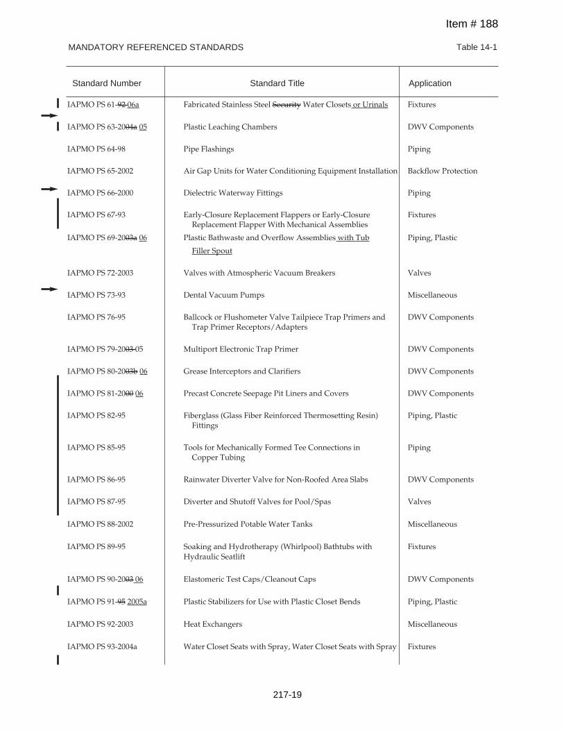
MANDATORY REFERENCED STANDARDS Table 14-1
IAPMO PS 61-92 06a Fabricated Stainless Steel Security Water Closets or Urinals Fixtures
IAPMO PS 63-2004a 05 Plastic Leaching Chambers DWV Components
IAPMO PS 64-98 Pipe Flashings Piping
IAPMO PS 65-2002 Air Gap Units for Water Conditioning Equipment Installation Backflow Protection
IAPMO PS 66-2000 Dielectric Waterway Fittings Piping
IAPMO PS 67-93 Early-Closure Replacement Flappers or Early-Closure FixturesReplacement Flapper With Mechanical Assemblies
IAPMO PS 69-2003a 06 Plastic Bathwaste and Overflow Assemblies with Tub Piping, Plastic
Filler Spout
IAPMO PS 72-2003 Valves with Atmospheric Vacuum Breakers Valves
IAPMO PS 73-93 Dental Vacuum Pumps Miscellaneous
IAPMO PS 76-95 Ballcock or Flushometer Valve Tailpiece Trap Primers and DWV ComponentsTrap Primer Receptors/Adapters
IAPMO PS 79-2003 05 Multiport Electronic Trap Primer DWV Components
IAPMO PS 80-2003b 06 Grease Interceptors and Clarifiers DWV Components
IAPMO PS 81-2000 06 Precast Concrete Seepage Pit Liners and Covers DWV Components
IAPMO PS 82-95 Fiberglass (Glass Fiber Reinforced Thermosetting Resin) Piping, PlasticFittings
IAPMO PS 85-95 Tools for Mechanically Formed Tee Connections in PipingCopper Tubing
IAPMO PS 86-95 Rainwater Diverter Valve for Non-Roofed Area Slabs DWV Components
IAPMO PS 87-95 Diverter and Shutoff Valves for Pool/Spas Valves
IAPMO PS 88-2002 Pre-Pressurized Potable Water Tanks Miscellaneous
IAPMO PS 89-95 Soaking and Hydrotherapy (Whirlpool) Bathtubs with FixturesHydraulic Seatlift
IAPMO PS 90-2003 06 Elastomeric Test Caps/Cleanout Caps DWV Components
IAPMO PS 91-95 2005a Plastic Stabilizers for Use with Plastic Closet Bends Piping, Plastic
IAPMO PS 92-2003 Heat Exchangers Miscellaneous
IAPMO PS 93-2004a Water Closet Seats with Spray, Water Closet Seats with Spray Fixtures
Standard Number Standard Title Application
Item # 188
217-19
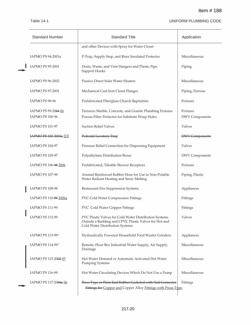
UNIFORM PLUMBING CODETable 14-1
and other Devices with Spray for Water Closet
IAPMO PS 94-2001a P-Trap, Supply Stop, and Riser Insulated Protector Miscellaneous
IAPMO PS 95-2001 Drain, Waste, and Vent Hangers and Plastic Pipe PipingSupport Hooks
IAPMO PS 96-2002 Passive Direct Solar Water Heaters Miscellaneous
IAPMO PS 97-2001 Mechanical Cast-Iron Closet Flanges Piping, Ferrous
IAPMO PS 98-96 Prefabricated Fiberglass Church Baptistries Fixtures
IAPMO PS 99-2004 06 Terrazzo Marble, Concrete, and Granite Plumbing Fixtures Fixtures
IAPMO PS 100-96 Porous Filter Protector for Subdrain Weep Holes DWV Components
IAPMO PS 101-97 Suction Relief Valves Valves
IAPMO PS 102-2004a [D] Pedestal Lavatory Trap DWV Components
IAPMO PS 104-97 Pressure Relief Connection for Dispensing Equipment Valves
IAPMO PS 105-97 Polyethylene Distribution Boxes DWV Components
IAPMO PS 106-98 2006 Prefabricated, Tileable Shower Receptors Fixtures
IAPMO PS 107-98 Aramid-Reinforced Rubber Hose for Use in Non-Potable Piping, PlasticWater Radiant Heating and Snow Melting
IAPMO PS 108-98 Restaurant Fire Suppression Systems Appliances
IAPMO PS 110-99 2006a PVC Cold Water Compression Fittings Fittings
IAPMO PS 111-99 PVC Cold Water Gripper Fittings Fittings
IAPMO PS 112-99 PVC Plastic Valves for Cold Water Distribution Systems ValvesOutside a Building and CPVC Plastic Valves for Hot andCold Water Distribution Systems
IAPMO PS 113-99e1 Hydraulically Powered Household Food Waster Grinders Appliances
IAPMO PS 114-99e1 Remote, Floor Box Industrial Water Supply, Air Supply, MiscellaneousDrainage
IAPMO PS 115-2002 05 Hot Water Demand or Automatic Activated Hot Water MiscellaneousPumping Systems
IAPMO PS 116-99 Hot Water Circulating Devices Which Do Not Use a Pump Miscellaneous
IAPMO PS 117-2004a 06 Press Type or Plain End Rubber Gasketed with Nail Connector Fittings
Fittings for Copper and Copper Alloy Fittings with Press-Type
Standard Number Standard Title Application
Item # 188
217-20
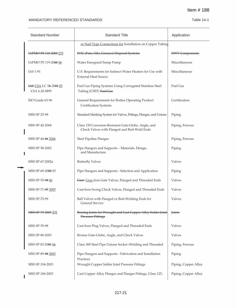
MANDATORY REFERENCED STANDARDS Table 14-1
or Nail-Type Connections for Installation on Copper Tubing
IAPMO PS 118-2000 [D] FOG (Fats, Oils, Greases) Disposal Systems DWV Components
IAPMO PS 119-2000 06 Water Energized Sump Pump Miscellaneous
IAS 1-91 U.S. Requirements for Indirect Water Heaters for Use with Miscellaneous
External Heat Source
IAS CSA LC 1b-2001 05 Fuel Gas Piping Systems Using Corrugated Stainless Steel Fuel Gas
CSA 6.26-M99 Tubing (CSST) Fuel Gas
ISO Guide 65-96 General Requirements for Bodies Operating Product Certification
Certification Systems
MSS SP-25-98 StandardMarking System forValves, Fittings, Flanges, andUnions Piping
MSS SP-42-2004 Class 150 Corrosion-Resistant Gate-Globe, Angle, and Piping, FerrousCheck Valves with Flanged and Butt Weld Ends
MSS SP-44-96 2006 Steel Pipeline Flanges Piping, Ferrous
MSS SP-58-2002 Pipe Hangers and Supports – Materials, Design, Pipingand Manufacture
MSS SP-67-2002a Butterfly Valves Valves
MSS SP-69-2002 03 Pipe Hangars and Supports - Selection and Application Piping
MSS SP-70-98 06 Cast- Gray Iron Gate Valves, Flanged and Threaded Ends Valves
MSS SP-71-97 2005 Cast-Iron Swing Check Valves, Flanged and Threaded Ends Valves
MSS SP-72-99 Ball Valves with Flanged or Butt-Welding Ends for ValvesGeneral Service
MSS SP-73-2003 [D] Brazing Joints for Wrought and Cast Copper Alloy Solder Joint JointsPressure Fittings
MSS SP-78-98 Cast-Iron Plug Valves, Flanged and Threaded Ends Valves
MSS SP-80-2003 Bronze Gate-Globe, Angle, and Check Valves Valves
MSS SP-83-2001 06 Class 300 Steel Pipe Unions Socket -Welding and Threaded Piping, Ferrous
MSS SP-89-98 2003 Pipe Hangars and Supports - Fabrication and Installation Piping
Practices
MSS SP-104-2003 Wrought Copper Solder Joint Pressure Fittings Piping, Copper Alloy
MSS SP-106-2003 Cast Copper Alloy Flanges and Flanges Fittings, Class 125, Piping, Copper Alloy
Standard Number Standard Title Application
Item # 188
217-21
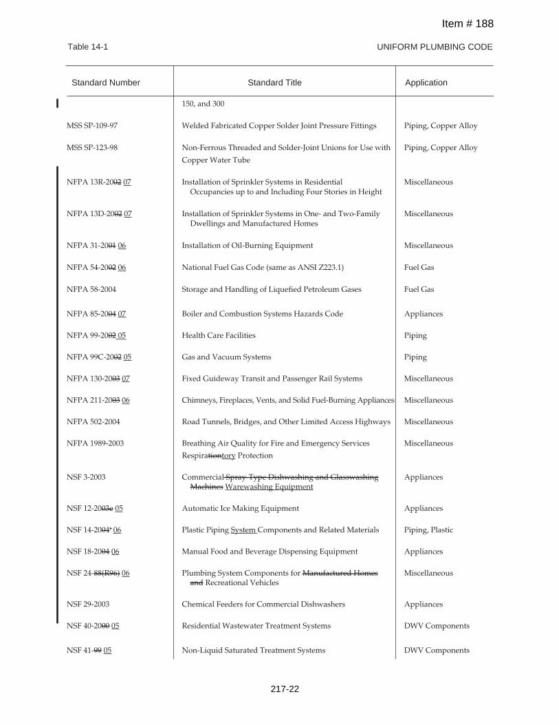
UNIFORM PLUMBING CODETable 14-1
150, and 300
MSS SP-109-97 Welded Fabricated Copper Solder Joint Pressure Fittings Piping, Copper Alloy
MSS SP-123-98 Non-Ferrous Threaded and Solder-Joint Unions for Use with Piping, Copper Alloy
Copper Water Tube
NFPA 13R-2002 07 Installation of Sprinkler Systems in Residential MiscellaneousOccupancies up to and Including Four Stories in Height
NFPA 13D-2002 07 Installation of Sprinkler Systems in One- and Two-Family MiscellaneousDwellings and Manufactured Homes
NFPA 31-2001 06 Installation of Oil-Burning Equipment Miscellaneous
NFPA 54-2002 06 National Fuel Gas Code (same as ANSI Z223.1) Fuel Gas
NFPA 58-2004 Storage and Handling of Liquefied Petroleum Gases Fuel Gas
NFPA 85-2004 07 Boiler and Combustion Systems Hazards Code Appliances
NFPA 99-2002 05 Health Care Facilities Piping
NFPA 99C-2002 05 Gas and Vacuum Systems Piping
NFPA 130-2003 07 Fixed Guideway Transit and Passenger Rail Systems Miscellaneous
NFPA 211-2003 06 Chimneys, Fireplaces, Vents, and Solid Fuel-Burning Appliances Miscellaneous
NFPA 502-2004 Road Tunnels, Bridges, and Other Limited Access Highways Miscellaneous
NFPA 1989-2003 Breathing Air Quality for Fire and Emergency Services Miscellaneous
Respirationtory Protection
NSF 3-2003 Commercial Spray-Type Dishwashing and Glasswashing AppliancesMachines Warewashing Equipment
NSF 12-2003e 05 Automatic Ice Making Equipment Appliances
NSF 14-20041 06 Plastic Piping System Components and Related Materials Piping, Plastic
NSF 18-2004 06 Manual Food and Beverage Dispensing Equipment Appliances
NSF 24-88(R96) 06 Plumbing System Components for Manufactured Homes Miscellaneousand Recreational Vehicles
NSF 29-2003 Chemical Feeders for Commercial Dishwashers Appliances
NSF 40-2000 05 Residential Wastewater Treatment Systems DWV Components
NSF 41-99 05 Non-Liquid Saturated Treatment Systems DWV Components
Standard Number Standard Title Application
Item # 188
217-22
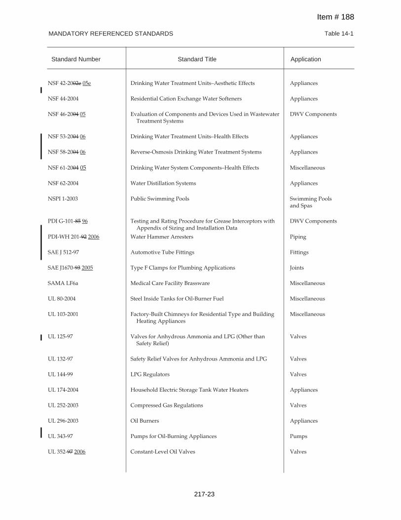
MANDATORY REFERENCED STANDARDS Table 14-1
NSF 42-2002e 05e Drinking Water Treatment Units–Aesthetic Effects Appliances
NSF 44-2004 Residential Cation Exchange Water Softeners Appliances
NSF 46-2004 05 Evaluation of Components and Devices Used in Wastewater DWV ComponentsTreatment Systems
NSF 53-2004 06 Drinking Water Treatment Units–Health Effects Appliances
NSF 58-2004 06 Reverse-Osmosis Drinking Water Treatment Systems Appliances
NSF 61-2004 05 Drinking Water System Components–Health Effects Miscellaneous
NSF 62-2004 Water Distillation Systems Appliances
NSPI 1-2003 Public Swimming Pools Swimming Poolsand Spas
PDI G-101-85 96 Testing and Rating Procedure for Grease Interceptors with DWV ComponentsAppendix of Sizing and Installation Data
PDI-WH 201-92 2006 Water Hammer Arresters Piping
SAE J 512-97 Automotive Tube Fittings Fittings
SAE J1670-93 2005 Type F Clamps for Plumbing Applications Joints
SAMA LF6a Medical Care Facility Brassware Miscellaneous
UL 80-2004 Steel Inside Tanks for Oil-Burner Fuel Miscellaneous
UL 103-2001 Factory-Built Chimneys for Residential Type and Building MiscellaneousHeating Appliances
UL 125-97 Valves for Anhydrous Ammonia and LPG (Other than ValvesSafety Relief)
UL 132-97 Safety Relief Valves for Anhydrous Ammonia and LPG Valves
UL 144-99 LPG Regulators Valves
UL 174-2004 Household Electric Storage Tank Water Heaters Appliances
UL 252-2003 Compressed Gas Regulations Valves
UL 296-2003 Oil Burners Appliances
UL 343-97 Pumps for Oil-Burning Appliances Pumps
UL 352-97 2006 Constant-Level Oil Valves Valves
Standard Number Standard Title Application
Item # 188
217-23
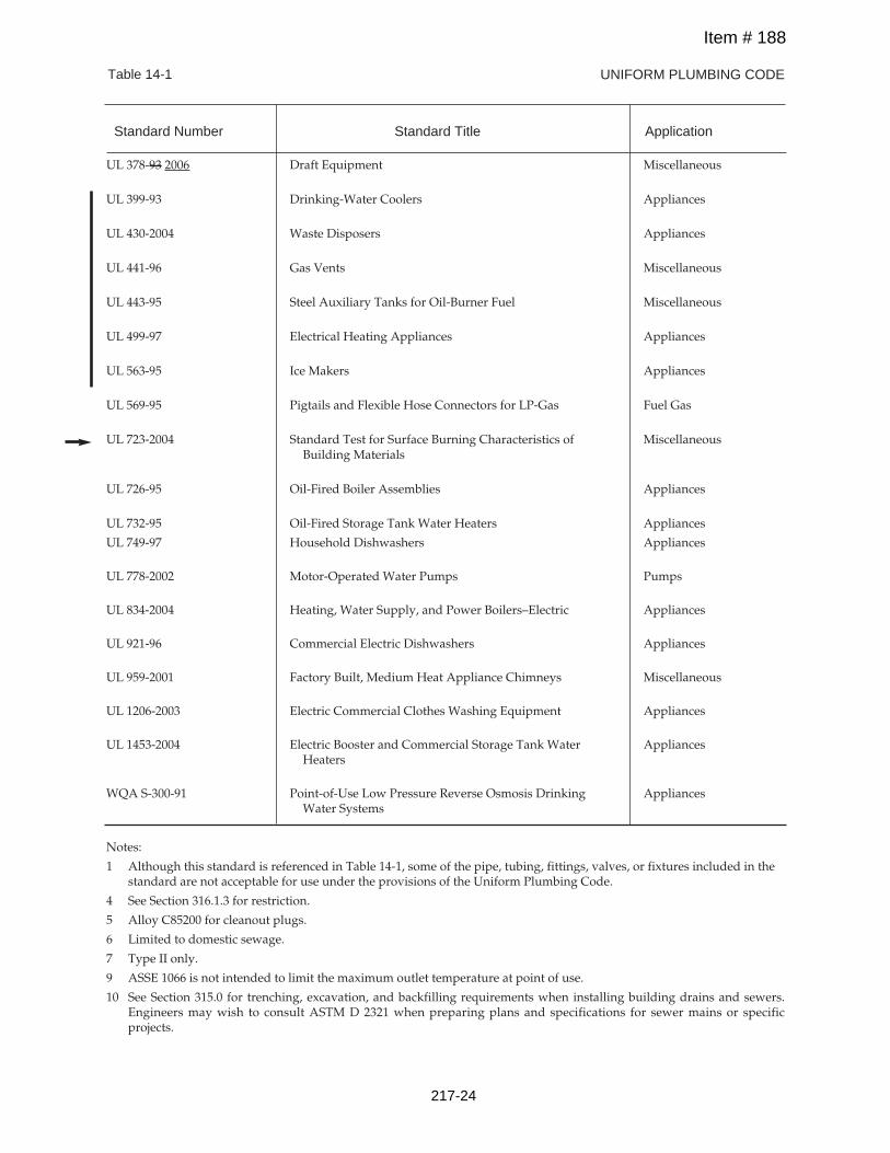
UNIFORM PLUMBING CODETable 14-1
UL 378-93 2006 Draft Equipment Miscellaneous
UL 399-93 Drinking-Water Coolers Appliances
UL 430-2004 Waste Disposers Appliances
UL 441-96 Gas Vents Miscellaneous
UL 443-95 Steel Auxiliary Tanks for Oil-Burner Fuel Miscellaneous
UL 499-97 Electrical Heating Appliances Appliances
UL 563-95 Ice Makers Appliances
UL 569-95 Pigtails and Flexible Hose Connectors for LP-Gas Fuel Gas
UL 723-2004 Standard Test for Surface Burning Characteristics of MiscellaneousBuilding Materials
UL 726-95 Oil-Fired Boiler Assemblies Appliances
UL 732-95 Oil-Fired Storage Tank Water Heaters Appliances
UL 749-97 Household Dishwashers Appliances
UL 778-2002 Motor-Operated Water Pumps Pumps
UL 834-2004 Heating, Water Supply, and Power Boilers–Electric Appliances
UL 921-96 Commercial Electric Dishwashers Appliances
UL 959-2001 Factory Built, Medium Heat Appliance Chimneys Miscellaneous
UL 1206-2003 Electric Commercial Clothes Washing Equipment Appliances
UL 1453-2004 Electric Booster and Commercial Storage Tank Water AppliancesHeaters
WQA S-300-91 Point-of-Use Low Pressure Reverse Osmosis Drinking AppliancesWater Systems
Notes:
1 Although this standard is referenced in Table 14-1, some of the pipe, tubing, fittings, valves, or fixtures included in thestandard are not acceptable for use under the provisions of the Uniform Plumbing Code.
4 See Section 316.1.3 for restriction.
5 Alloy C85200 for cleanout plugs.
6 Limited to domestic sewage.
7 Type II only.
9 ASSE 1066 is not intended to limit the maximum outlet temperature at point of use.
10 See Section 315.0 for trenching, excavation, and backfilling requirements when installing building drains and sewers.Engineers may wish to consult ASTM D 2321 when preparing plans and specifications for sewer mains or specificprojects.
Standard Number Standard Title Application
Item # 188
217-24
UPC 2009 – August 2007 ROP
SUBMITTER:
The following is recommended by the Standards Task Group (see Standards Task Group Report Item #187).
Revise text as follows:
(See attached documents on pages 218–1 through 218–24)
Editorial changes to Table 14–1 in Chapter 14.SUBSTANTIATION:
RECOMMENDATION:
UPC 2009 Chapter 14, Table 14–1
Based on committee action taken on Item 187 as all standards were updated based on most current year and editorial revisions based on update from promulgators.
Reject
Dave Viola
189-
TOTAL ELIGIBLE TO VOTE: 28
VOTING RESULTS: AFFIRMATIVE: 24, NOT RETURNED: 4 Bloice, Murray, Nikravi, Soskin
COMMITTEE ACTION:COMMITTEE STATEMENT:
Item #
Chair UPC Standards Task Group
218
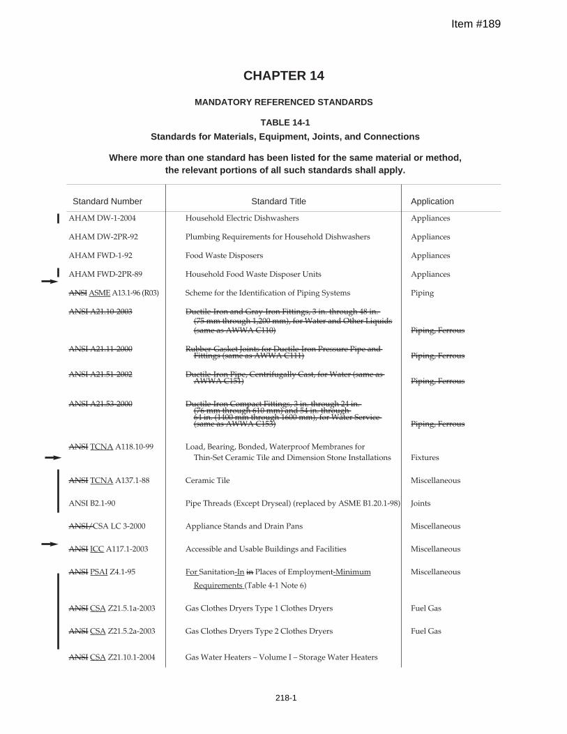
Standard Number Standard Title Application
AHAM DW-1-2004 Household Electric Dishwashers Appliances
AHAM DW-2PR-92 Plumbing Requirements for Household Dishwashers Appliances
AHAM FWD-1-92 Food Waste Disposers Appliances
AHAM FWD-2PR-89 Household Food Waste Disposer Units Appliances
ANSIASMEA13.1-96 (R03) Scheme for the Identification of Piping Systems Piping
ANSI A21.10-2003 Ductile-Iron and Gray-Iron Fittings, 3 in. through 48 in.(75 mm through 1,200 mm), for Water and Other Liquids(same as AWWA C110) Piping, Ferrous
ANSI A21.11-2000 Rubber-Gasket Joints for Ductile-Iron Pressure Pipe andFittings (same as AWWA C111) Piping, Ferrous
ANSI A21.51-2002 Ductile-Iron Pipe, Centrifugally Cast, for Water (same asAWWA C151) Piping, Ferrous
ANSI A21.53-2000 Ductile-Iron Compact Fittings, 3 in. through 24 in.(76 mm through 610 mm) and 54 in. through64 in. (1400 mm through 1600 mm), for Water Service(same as AWWA C153) Piping, Ferrous
ANSI TCNA A118.10-99 Load, Bearing, Bonded, Waterproof Membranes forThin-Set Ceramic Tile and Dimension Stone Installations Fixtures
ANSI TCNA A137.1-88 Ceramic Tile Miscellaneous
ANSI B2.1-90 Pipe Threads (Except Dryseal) (replaced by ASME B1.20.1-98) Joints
ANSI/CSA LC 3-2000 Appliance Stands and Drain Pans Miscellaneous
ANSI ICC A117.1-2003 Accessible and Usable Buildings and Facilities Miscellaneous
ANSI PSAI Z4.1-95 For Sanitation-In in Places of Employment-Minimum Miscellaneous
Requirements (Table 4-1 Note 6)
ANSI CSA Z21.5.1a-2003 Gas Clothes Dryers Type 1 Clothes Dryers Fuel Gas
ANSI CSA Z21.5.2a-2003 Gas Clothes Dryers Type 2 Clothes Dryers Fuel Gas
ANSI CSA Z21.10.1-2004 Gas Water Heaters – Volume I – Storage Water Heaters
CHAPTER 14
MANDATORY REFERENCED STANDARDS
TABLE 14-1
Standards for Materials, Equipment, Joints, and Connections
Where more than one standard has been listed for the same material or method,the relevant portions of all such standards shall apply.
Item #189
218-1
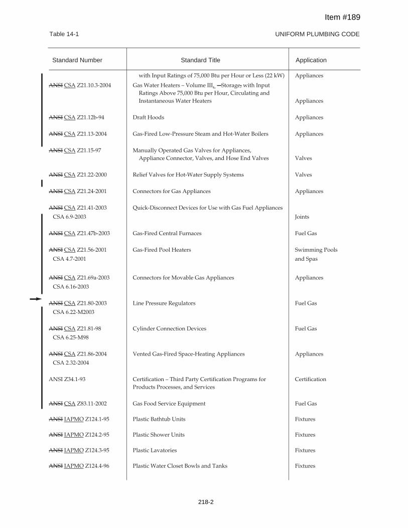
UNIFORM PLUMBING CODETable 14-1
with Input Ratings of 75,000 Btu per Hour or Less (22 kW) Appliances
ANSI CSA Z21.10.3-2004 Gas Water Heaters – Volume III, – Storage, with InputRatings Above 75,000 Btu per Hour, Circulating andInstantaneous Water Heaters Appliances
ANSI CSA Z21.12b-94 Draft Hoods Appliances
ANSI CSA Z21.13-2004 Gas-Fired Low-Pressure Steam and Hot-Water Boilers Appliances
ANSI CSA Z21.15-97 Manually Operated Gas Valves for Appliances,Appliance Connector, Valves, and Hose End Valves Valves
ANSI CSA Z21.22-2000 Relief Valves for Hot-Water Supply Systems Valves
ANSI CSA Z21.24-2001 Connectors for Gas Appliances Appliances
ANSI CSA Z21.41-2003 Quick-Disconnect Devices for Use with Gas Fuel Appliances
CSA 6.9-2003 Joints
ANSI CSA Z21.47b-2003 Gas-Fired Central Furnaces Fuel Gas
ANSI CSA Z21.56-2001 Gas-Fired Pool Heaters Swimming Pools
CSA 4.7-2001 and Spas
ANSI CSA Z21.69a-2003 Connectors for Movable Gas Appliances Appliances
CSA 6.16-2003
ANSI CSA Z21.80-2003 Line Pressure Regulators Fuel Gas
CSA 6.22-M2003
ANSI CSA Z21.81-98 Cylinder Connection Devices Fuel Gas
CSA 6.25-M98
ANSI CSA Z21.86-2004 Vented Gas-Fired Space-Heating Appliances Appliances
CSA 2.32-2004
ANSI Z34.1-93 Certification – Third Party Certification Programs for CertificationProducts Processes, and Services
ANSI CSA Z83.11-2002 Gas Food Service Equipment Fuel Gas
ANSI IAPMO Z124.1-95 Plastic Bathtub Units Fixtures
ANSI IAPMO Z124.2-95 Plastic Shower Units Fixtures
ANSI IAPMO Z124.3-95 Plastic Lavatories Fixtures
ANSI IAPMO Z124.4-96 Plastic Water Closet Bowls and Tanks Fixtures
Standard Number Standard Title Application
Item #189
218-2
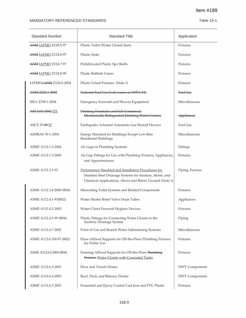
MANDATORY REFERENCED STANDARDS Table 14-1
Standard Number Standard Title Application
ANSI IAPMO Z124.5-97 Plastic Toilet (Water Closet) Seats Fixtures
ANSI IAPMO Z124.6-97 Plastic Sinks Fixtures
ANSI IAPMO Z124.7-97 Prefabricated Plastic Spa Shells Fixtures
ANSI IAPMO Z124.8-90 Plastic Bathtub Liners Fixtures
IAPMO/ANSI Z124.9-2004 Plastic Urinal Fixtures (Note 1) Fixtures
ANSI Z223.1-2002 National Fuel Gas Code (same as NFPA 54) Fuel Gas
ISEA Z358.1-2004 Emergency Eyewash and Shower Equipment Miscellaneous
ARI 1010-2002 [D] Drinking Fountains and Self-Contained,Mechanically Refrigerated Drinking Water Coolers Appliances
ASCE 25-99 97 Earthquake Actuated Automatic Gas Shutoff Devices Fuel Gas
ASHRAE 90.1-2004 Energy Standard for Buildings Except Low-Rise MiscellaneousResidential Buildings
ASME A112.1.2-2004 Air Gaps in Plumbing Systems Fittings
ASME A112.1.3-2000 Air Gap Fittings for Use with Plumbing Fixtures, Appliances, Fixtures
and Appurtenances
ASME A112.3.1-93 Performance Standard and Installation Procedures for Piping, Ferrous
Stainless Steel Drainage Systems for Sanitary, Storm, and
Chemical Applications, Above and Below Ground (Note 1)
ASME A112.3.4-2000 (R04) Macerating Toilet Systems and Related Components Fixtures
ASME A112.4.1-93(R02) Water Heater Relief Valve Drain Tubes Appliances
ASME A112.4.2-2003 Water Closet Personal Hygiene Devices Fixtures
ASME A112.4.3-99 (R04) Plastic Fittings for Connecting Water Closets to the PipingSanitary Drainage System
ASME A112.4.7-2002 Point of Use and Branch Water Submetering Systems Miscellaneous
ASME A112.6.1M-97 (R02) Floor-Affixed Supports for Off-the-Floor Plumbing Fixtures Fixturesfor Public Use
ASMEA112.6.2-2000 (R04) Framing-Affixed Supports for Off-the-Floor Plumbing Fixtures
Fixtures Water Closets with Concealed Tanks
ASME A112.6.3-2001 Floor and Trench Drains DWV Components
ASME A112.6.4-2003 Roof, Deck, and Balcony Drains DWV Components
ASME A112.6.7-2001 Enameled and Epoxy Coated Cast Iron and PVC Plastic Fixtures
Item #189
218-3
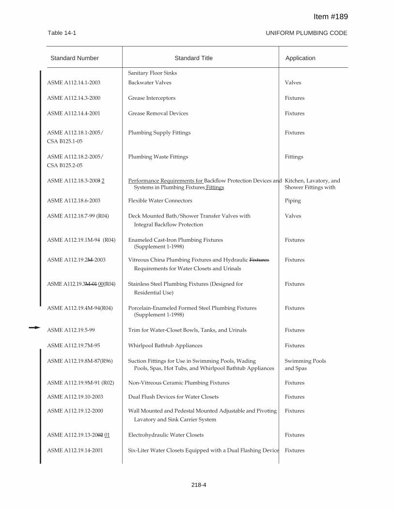
UNIFORM PLUMBING CODETable 14-1
Sanitary Floor Sinks
ASME A112.14.1-2003 Backwater Valves Valves
ASME A112.14.3-2000 Grease Interceptors Fixtures
ASME A112.14.4-2001 Grease Removal Devices Fixtures
ASME A112.18.1-2005/ Plumbing Supply Fittings Fixtures
CSA B125.1-05
ASME A112.18.2-2005/ Plumbing Waste Fittings Fittings
CSA B125.2-05
ASME A112.18.3-2003 2 Performance Requirements for Backflow Protection Devices and Kitchen, Lavatory, andSystems in Plumbing Fixtures Fittings Shower Fittings with
ASME A112.18.6-2003 Flexible Water Connectors Piping
ASME A112.18.7-99 (R04) Deck Mounted Bath/Shower Transfer Valves with Valves
Integral Backflow Protection
ASME A112.19.1M-94 (R04) Enameled Cast-Iron Plumbing Fixtures Fixtures(Supplement 1-1998)
ASME A112.19.2M-2003 Vitreous China Plumbing Fixtures and Hydraulic Fixtures Fixtures
Requirements for Water Closets and Urinals
ASMEA112.19.3M-01 00(R04) Stainless Steel Plumbing Fixtures (Designed for Fixtures
Residential Use)
ASME A112.19.4M-94(R04) Porcelain-Enameled Formed Steel Plumbing Fixtures Fixtures(Supplement 1-1998)
ASME A112.19.5-99 Trim for Water-Closet Bowls, Tanks, and Urinals Fixtures
ASME A112.19.7M-95 Whirlpool Bathtub Appliances Fixtures
ASME A112.19.8M-87(R96) Suction Fittings for Use in Swimming Pools, Wading Swimming PoolsPools, Spas, Hot Tubs, and Whirlpool Bathtub Appliances and Spas
ASME A112.19.9M-91 (R02) Non-Vitreous Ceramic Plumbing Fixtures Fixtures
ASME A112.19.10-2003 Dual Flush Devices for Water Closets Fixtures
ASME A112.19.12-2000 Wall Mounted and Pedestal Mounted Adjustable and Pivoting Fixtures
Lavatory and Sink Carrier System
ASME A112.19.13-2002 01 Electrohydraulic Water Closets Fixtures
ASME A112.19.14-2001 Six-Liter Water Closets Equipped with a Dual Flashing Device Fixtures
Standard Number Standard Title Application
Item #189
218-4
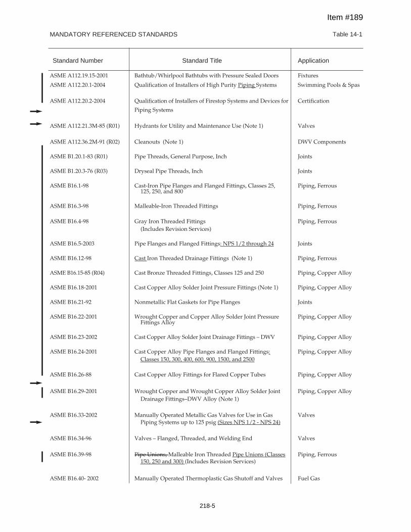
MANDATORY REFERENCED STANDARDS Table 14-1
Standard Number Standard Title Application
ASME A112.19.15-2001 Bathtub/Whirlpool Bathtubs with Pressure Sealed Doors Fixtures
ASME A112.20.1-2004 Qualification of Installers of High Purity Piping Systems Swimming Pools & Spas
ASME A112.20.2-2004 Qualification of Installers of Firestop Systems and Devices for Certification
Piping Systems
ASME A112.21.3M-85 (R01) Hydrants for Utility and Maintenance Use (Note 1) Valves
ASME A112.36.2M-91 (R02) Cleanouts (Note 1) DWV Components
ASME B1.20.1-83 (R01) Pipe Threads, General Purpose, Inch Joints
ASME B1.20.3-76 (R03) Dryseal Pipe Threads, Inch Joints
ASME B16.1-98 Cast-Iron Pipe Flanges and Flanged Fittings, Classes 25, Piping, Ferrous125, 250, and 800
ASME B16.3-98 Malleable-Iron Threaded Fittings Piping, Ferrous
ASME B16.4-98 Gray Iron Threaded Fittings Piping, Ferrous(Includes Revision Services)
ASME B16.5-2003 Pipe Flanges and Flanged Fittings: NPS 1/2 through 24 Joints
ASME B16.12-98 Cast Iron Threaded Drainage Fittings (Note 1) Piping, Ferrous
ASME B16.15-85 (R04) Cast Bronze Threaded Fittings, Classes 125 and 250 Piping, Copper Alloy
ASME B16.18-2001 Cast Copper Alloy Solder Joint Pressure Fittings (Note 1) Piping, Copper Alloy
ASME B16.21-92 Nonmetallic Flat Gaskets for Pipe Flanges Joints
ASME B16.22-2001 Wrought Copper and Copper Alloy Solder Joint Pressure Piping, Copper AlloyFittings Alloy
ASME B16.23-2002 Cast Copper Alloy Solder Joint Drainage Fittings – DWV Piping, Copper Alloy
ASME B16.24-2001 Cast Copper Alloy Pipe Flanges and Flanged Fittings: Piping, Copper AlloyClasses 150, 300, 400, 600, 900, 1500, and 2500
ASME B16.26-88 Cast Copper Alloy Fittings for Flared Copper Tubes Piping, Copper Alloy
ASME B16.29-2001 Wrought Copper and Wrought Copper Alloy Solder Joint Piping, Copper AlloyDrainage Fittings–DWV Alloy (Note 1)
ASME B16.33-2002 Manually Operated Metallic Gas Valves for Use in Gas ValvesPiping Systems up to 125 psig (Sizes NPS 1/2 - NPS 24)
ASME B16.34-96 Valves – Flanged, Threaded, and Welding End Valves
ASME B16.39-98 Pipe Unions, Malleable Iron Threaded Pipe Unions (Classes Piping, Ferrous150, 250 and 300) (Includes Revision Services)
ASME B16.40- 2002 Manually Operated Thermoplastic Gas Shutoff and Valves Fuel Gas
Item #189
218-5
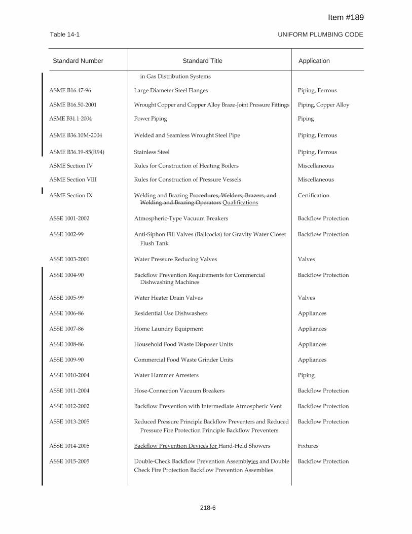
UNIFORM PLUMBING CODETable 14-1
in Gas Distribution Systems
ASME B16.47-96 Large Diameter Steel Flanges Piping, Ferrous
ASME B16.50-2001 Wrought Copper and Copper Alloy Braze-Joint Pressure Fittings Piping, Copper Alloy
ASME B31.1-2004 Power Piping Piping
ASME B36.10M-2004 Welded and Seamless Wrought Steel Pipe Piping, Ferrous
ASME B36.19-85(R94) Stainless Steel Piping, Ferrous
ASME Section IV Rules for Construction of Heating Boilers Miscellaneous
ASME Section VIII Rules for Construction of Pressure Vessels Miscellaneous
ASME Section IX Welding and Brazing Procedures, Welders, Brazers, and CertificationWelding and Brazing Operators Qualifications
ASSE 1001-2002 Atmospheric-Type Vacuum Breakers Backflow Protection
ASSE 1002-99 Anti-Siphon Fill Valves (Ballcocks) for Gravity Water Closet Backflow Protection
Flush Tank
ASSE 1003-2001 Water Pressure Reducing Valves Valves
ASSE 1004-90 Backflow Prevention Requirements for Commercial Backflow ProtectionDishwashing Machines
ASSE 1005-99 Water Heater Drain Valves Valves
ASSE 1006-86 Residential Use Dishwashers Appliances
ASSE 1007-86 Home Laundry Equipment Appliances
ASSE 1008-86 Household Food Waste Disposer Units Appliances
ASSE 1009-90 Commercial Food Waste Grinder Units Appliances
ASSE 1010-2004 Water Hammer Arresters Piping
ASSE 1011-2004 Hose-Connection Vacuum Breakers Backflow Protection
ASSE 1012-2002 Backflow Prevention with Intermediate Atmospheric Vent Backflow Protection
ASSE 1013-2005 Reduced Pressure Principle Backflow Preventers and Reduced Backflow Protection
Pressure Fire Protection Principle Backflow Preventers
ASSE 1014-2005 Backflow Prevention Devices for Hand-Held Showers Fixtures
ASSE 1015-2005 Double-Check Backflow Prevention Assemblyies and Double Backflow Protection
Check Fire Protection Backflow Prevention Assemblies
Standard Number Standard Title Application
Item #189
218-6
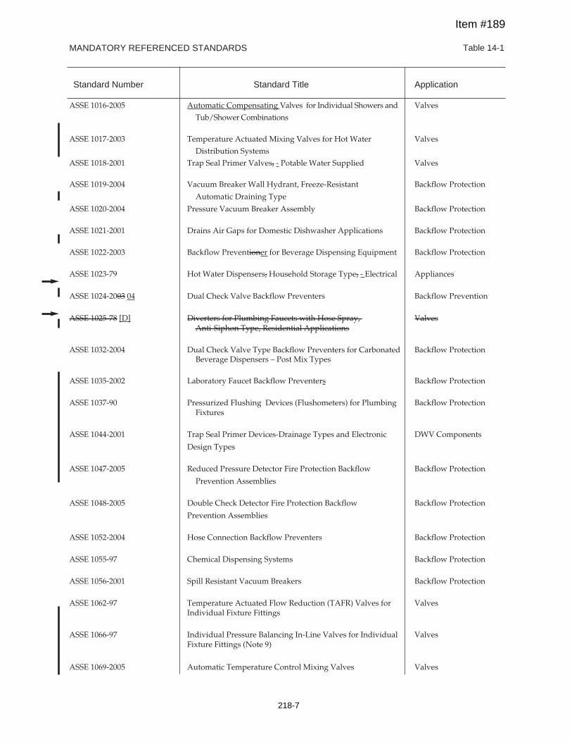
MANDATORY REFERENCED STANDARDS Table 14-1
Standard Number Standard Title Application
ASSE 1016-2005 Automatic Compensating Valves for Individual Showers and Valves
Tub/Shower Combinations
ASSE 1017-2003 Temperature Actuated Mixing Valves for Hot Water Valves
Distribution SystemsASSE 1018-2001 Trap Seal Primer Valves, - Potable Water Supplied Valves
ASSE 1019-2004 Vacuum Breaker Wall Hydrant, Freeze-Resistant Backflow Protection
Automatic Draining Type
ASSE 1020-2004 Pressure Vacuum Breaker Assembly Backflow Protection
ASSE 1021-2001 Drains Air Gaps for Domestic Dishwasher Applications Backflow Protection
ASSE 1022-2003 Backflow Preventioner for Beverage Dispensing Equipment Backflow Protection
ASSE 1023-79 Hot Water Dispensers, Household Storage Type, - Electrical Appliances
ASSE 1024-2003 04 Dual Check Valve Backflow Preventers Backflow Prevention
ASSE 1025-78 [D] Diverters for Plumbing Faucets with Hose Spray, ValvesAnti-Siphon Type, Residential Applications
ASSE 1032-2004 Dual Check Valve Type Backflow Preventers for Carbonated Backflow ProtectionBeverage Dispensers – Post Mix Types
ASSE 1035-2002 Laboratory Faucet Backflow Preventers Backflow Protection
ASSE 1037-90 Pressurized Flushing Devices (Flushometers) for Plumbing Backflow ProtectionFixtures
ASSE 1044-2001 Trap Seal Primer Devices-Drainage Types and Electronic DWV Components
Design Types
ASSE 1047-2005 Reduced Pressure Detector Fire Protection Backflow Backflow Protection
Prevention Assemblies
ASSE 1048-2005 Double Check Detector Fire Protection Backflow Backflow Protection
Prevention Assemblies
ASSE 1052-2004 Hose Connection Backflow Preventers Backflow Protection
ASSE 1055-97 Chemical Dispensing Systems Backflow Protection
ASSE 1056-2001 Spill Resistant Vacuum Breakers Backflow Protection
ASSE 1062-97 Temperature Actuated Flow Reduction (TAFR) Valves for ValvesIndividual Fixture Fittings
ASSE 1066-97 Individual Pressure Balancing In-Line Valves for Individual ValvesFixture Fittings (Note 9)
ASSE 1069-2005 Automatic Temperature Control Mixing Valves Valves
Item #189
218-7
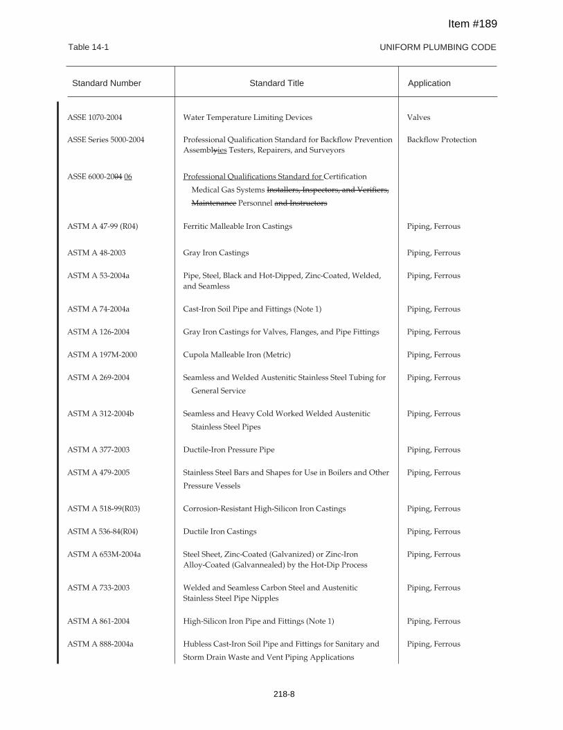
UNIFORM PLUMBING CODETable 14-1
ASSE 1070-2004 Water Temperature Limiting Devices Valves
ASSE Series 5000-2004 Professional Qualification Standard for Backflow Prevention Backflow ProtectionAssemblyies Testers, Repairers, and Surveyors
ASSE 6000-2004 06 Professional Qualifications Standard for Certification
Medical Gas Systems Installers, Inspectors, and Verifiers,
Maintenance Personnel and Instructors
ASTM A 47-99 (R04) Ferritic Malleable Iron Castings Piping, Ferrous
ASTM A 48-2003 Gray Iron Castings Piping, Ferrous
ASTM A 53-2004a Pipe, Steel, Black and Hot-Dipped, Zinc-Coated, Welded, Piping, Ferrousand Seamless
ASTM A 74-2004a Cast-Iron Soil Pipe and Fittings (Note 1) Piping, Ferrous
ASTM A 126-2004 Gray Iron Castings for Valves, Flanges, and Pipe Fittings Piping, Ferrous
ASTM A 197M-2000 Cupola Malleable Iron (Metric) Piping, Ferrous
ASTM A 269-2004 Seamless and Welded Austenitic Stainless Steel Tubing for Piping, Ferrous
General Service
ASTM A 312-2004b Seamless and Heavy Cold Worked Welded Austenitic Piping, Ferrous
Stainless Steel Pipes
ASTM A 377-2003 Ductile-Iron Pressure Pipe Piping, Ferrous
ASTM A 479-2005 Stainless Steel Bars and Shapes for Use in Boilers and Other Piping, Ferrous
Pressure Vessels
ASTM A 518-99(R03) Corrosion-Resistant High-Silicon Iron Castings Piping, Ferrous
ASTMA 536-84(R04) Ductile Iron Castings Piping, Ferrous
ASTM A 653M-2004a Steel Sheet, Zinc-Coated (Galvanized) or Zinc-Iron Piping, FerrousAlloy-Coated (Galvannealed) by the Hot-Dip Process
ASTM A 733-2003 Welded and Seamless Carbon Steel and Austenitic Piping, FerrousStainless Steel Pipe Nipples
ASTM A 861-2004 High-Silicon Iron Pipe and Fittings (Note 1) Piping, Ferrous
ASTM A 888-2004a Hubless Cast-Iron Soil Pipe and Fittings for Sanitary and Piping, Ferrous
Storm Drain Waste and Vent Piping Applications
Standard Number Standard Title Application
Item #189
218-8
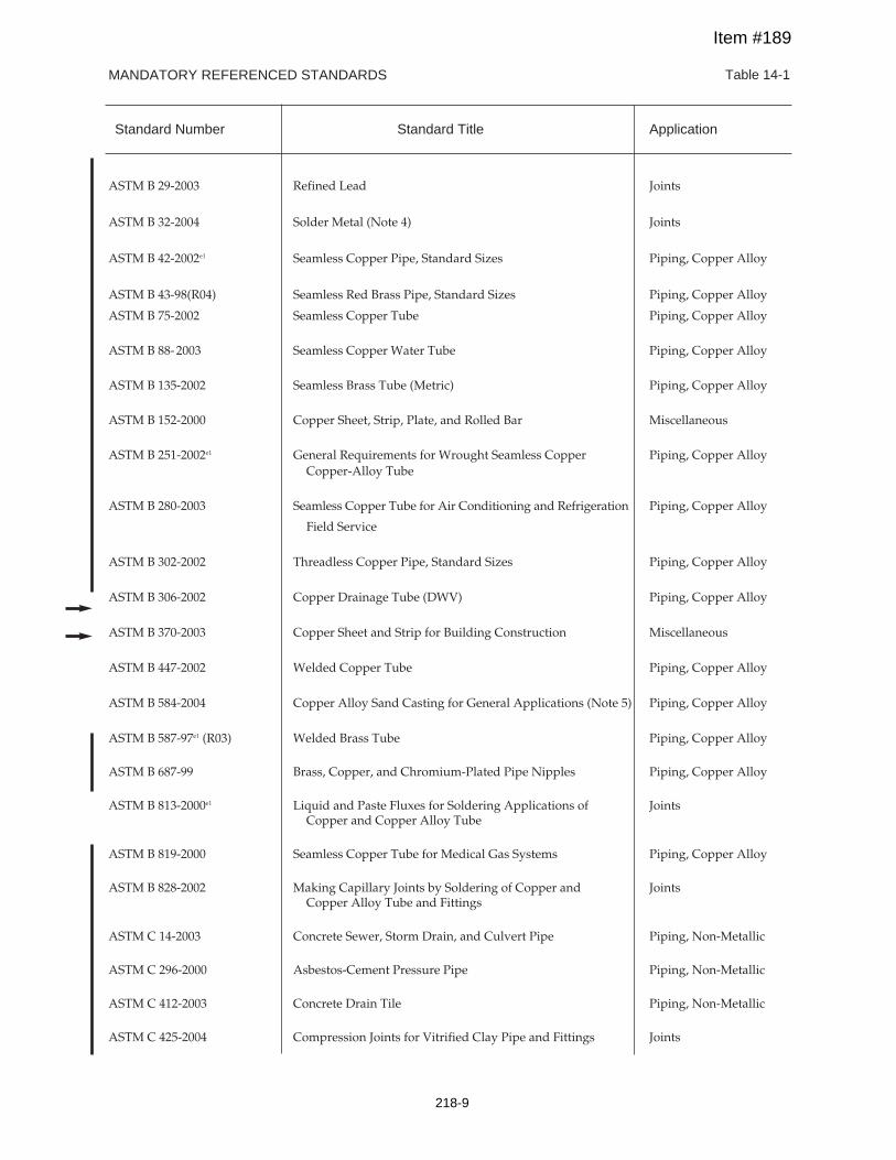
MANDATORY REFERENCED STANDARDS Table 14-1
Standard Number Standard Title Application
ASTM B 29-2003 Refined Lead Joints
ASTM B 32-2004 Solder Metal (Note 4) Joints
ASTM B 42-2002e1 Seamless Copper Pipe, Standard Sizes Piping, Copper Alloy
ASTM B 43-98(R04) Seamless Red Brass Pipe, Standard Sizes Piping, Copper Alloy
ASTM B 75-2002 Seamless Copper Tube Piping, Copper Alloy
ASTM B 88-2003 Seamless Copper Water Tube Piping, Copper Alloy
ASTM B 135-2002 Seamless Brass Tube (Metric) Piping, Copper Alloy
ASTM B 152-2000 Copper Sheet, Strip, Plate, and Rolled Bar Miscellaneous
ASTM B 251-2002e1 General Requirements for Wrought Seamless Copper Piping, Copper AlloyCopper-Alloy Tube
ASTM B 280-2003 Seamless Copper Tube for Air Conditioning and Refrigeration Piping, Copper Alloy
Field Service
ASTM B 302-2002 Threadless Copper Pipe, Standard Sizes Piping, Copper Alloy
ASTM B 306-2002 Copper Drainage Tube (DWV) Piping, Copper Alloy
ASTM B 370-2003 Copper Sheet and Strip for Building Construction Miscellaneous
ASTM B 447-2002 Welded Copper Tube Piping, Copper Alloy
ASTM B 584-2004 Copper Alloy Sand Casting for General Applications (Note 5) Piping, Copper Alloy
ASTM B 587-97e1 (R03) Welded Brass Tube Piping, Copper Alloy
ASTM B 687-99 Brass, Copper, and Chromium-Plated Pipe Nipples Piping, Copper Alloy
ASTM B 813-2000e1 Liquid and Paste Fluxes for Soldering Applications of JointsCopper and Copper Alloy Tube
ASTM B 819-2000 Seamless Copper Tube for Medical Gas Systems Piping, Copper Alloy
ASTM B 828-2002 Making Capillary Joints by Soldering of Copper and JointsCopper Alloy Tube and Fittings
ASTM C 14-2003 Concrete Sewer, Storm Drain, and Culvert Pipe Piping, Non-Metallic
ASTM C 296-2000 Asbestos-Cement Pressure Pipe Piping, Non-Metallic
ASTM C 412-2003 Concrete Drain Tile Piping, Non-Metallic
ASTM C 425-2004 Compression Joints for Vitrified Clay Pipe and Fittings Joints
Item #189
218-9
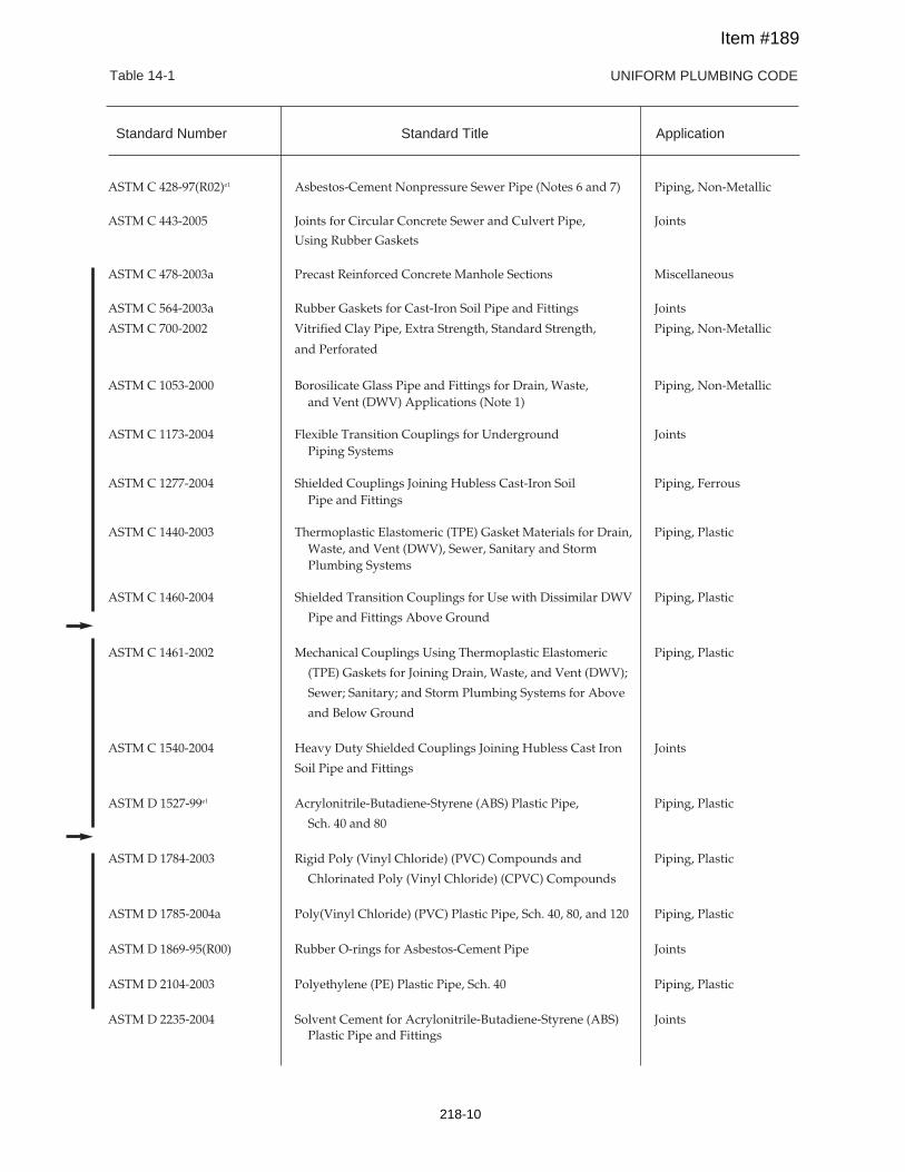
UNIFORM PLUMBING CODETable 14-1
ASTM C 428-97(R02)e1 Asbestos-Cement Nonpressure Sewer Pipe (Notes 6 and 7) Piping, Non-Metallic
ASTM C 443-2005 Joints for Circular Concrete Sewer and Culvert Pipe, Joints
Using Rubber Gaskets
ASTM C 478-2003a Precast Reinforced Concrete Manhole Sections Miscellaneous
ASTM C 564-2003a Rubber Gaskets for Cast-Iron Soil Pipe and Fittings Joints
ASTM C 700-2002 Vitrified Clay Pipe, Extra Strength, Standard Strength, Piping, Non-Metallic
and Perforated
ASTM C 1053-2000 Borosilicate Glass Pipe and Fittings for Drain, Waste, Piping, Non-Metallicand Vent (DWV) Applications (Note 1)
ASTM C 1173-2004 Flexible Transition Couplings for Underground JointsPiping Systems
ASTM C 1277-2004 Shielded Couplings Joining Hubless Cast-Iron Soil Piping, FerrousPipe and Fittings
ASTM C 1440-2003 Thermoplastic Elastomeric (TPE) Gasket Materials for Drain, Piping, PlasticWaste, and Vent (DWV), Sewer, Sanitary and StormPlumbing Systems
ASTM C 1460-2004 Shielded Transition Couplings for Use with Dissimilar DWV Piping, Plastic
Pipe and Fittings Above Ground
ASTM C 1461-2002 Mechanical Couplings Using Thermoplastic Elastomeric Piping, Plastic
(TPE) Gaskets for Joining Drain, Waste, and Vent (DWV);
Sewer; Sanitary; and Storm Plumbing Systems for Above
and Below Ground
ASTM C 1540-2004 Heavy Duty Shielded Couplings Joining Hubless Cast Iron Joints
Soil Pipe and Fittings
ASTM D 1527-99e1 Acrylonitrile-Butadiene-Styrene (ABS) Plastic Pipe, Piping, Plastic
Sch. 40 and 80
ASTM D 1784-2003 Rigid Poly (Vinyl Chloride) (PVC) Compounds and Piping, Plastic
Chlorinated Poly (Vinyl Chloride) (CPVC) Compounds
ASTM D 1785-2004a Poly(Vinyl Chloride) (PVC) Plastic Pipe, Sch. 40, 80, and 120 Piping, Plastic
ASTM D 1869-95(R00) Rubber O-rings for Asbestos-Cement Pipe Joints
ASTM D 2104-2003 Polyethylene (PE) Plastic Pipe, Sch. 40 Piping, Plastic
ASTM D 2235-2004 Solvent Cement for Acrylonitrile-Butadiene-Styrene (ABS) JointsPlastic Pipe and Fittings
Standard Number Standard Title Application
Item #189
218-10
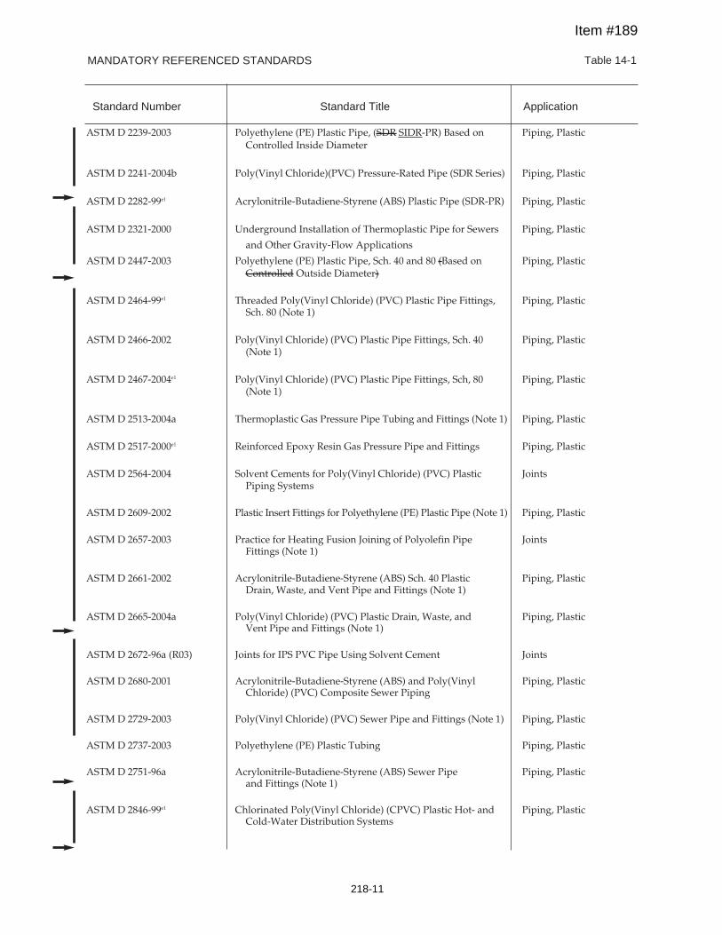
MANDATORY REFERENCED STANDARDS Table 14-1
Standard Number Standard Title Application
ASTM D 2239-2003 Polyethylene (PE) Plastic Pipe, (SDR SIDR-PR) Based on Piping, PlasticControlled Inside Diameter
ASTM D 2241-2004b Poly(Vinyl Chloride)(PVC) Pressure-Rated Pipe (SDR Series) Piping, Plastic
ASTM D 2282-99e1 Acrylonitrile-Butadiene-Styrene (ABS) Plastic Pipe (SDR-PR) Piping, Plastic
ASTM D 2321-2000 Underground Installation of Thermoplastic Pipe for Sewers Piping, Plastic
and Other Gravity-Flow Applications
ASTM D 2447-2003 Polyethylene (PE) Plastic Pipe, Sch. 40 and 80 (Based on Piping, PlasticControlled Outside Diameter)
ASTM D 2464-99e1 Threaded Poly(Vinyl Chloride) (PVC) Plastic Pipe Fittings, Piping, PlasticSch. 80 (Note 1)
ASTM D 2466-2002 Poly(Vinyl Chloride) (PVC) Plastic Pipe Fittings, Sch. 40 Piping, Plastic(Note 1)
ASTM D 2467-2004e1 Poly(Vinyl Chloride) (PVC) Plastic Pipe Fittings, Sch, 80 Piping, Plastic(Note 1)
ASTM D 2513-2004a Thermoplastic Gas Pressure Pipe Tubing and Fittings (Note 1) Piping, Plastic
ASTM D 2517-2000e1 Reinforced Epoxy Resin Gas Pressure Pipe and Fittings Piping, Plastic
ASTM D 2564-2004 Solvent Cements for Poly(Vinyl Chloride) (PVC) Plastic JointsPiping Systems
ASTM D 2609-2002 Plastic Insert Fittings for Polyethylene (PE) Plastic Pipe (Note 1) Piping, Plastic
ASTM D 2657-2003 Practice for Heating Fusion Joining of Polyolefin Pipe JointsFittings (Note 1)
ASTM D 2661-2002 Acrylonitrile-Butadiene-Styrene (ABS) Sch. 40 Plastic Piping, PlasticDrain, Waste, and Vent Pipe and Fittings (Note 1)
ASTM D 2665-2004a Poly(Vinyl Chloride) (PVC) Plastic Drain, Waste, and Piping, PlasticVent Pipe and Fittings (Note 1)
ASTM D 2672-96a (R03) Joints for IPS PVC Pipe Using Solvent Cement Joints
ASTM D 2680-2001 Acrylonitrile-Butadiene-Styrene (ABS) and Poly(Vinyl Piping, PlasticChloride) (PVC) Composite Sewer Piping
ASTM D 2729-2003 Poly(Vinyl Chloride) (PVC) Sewer Pipe and Fittings (Note 1) Piping, Plastic
ASTM D 2737-2003 Polyethylene (PE) Plastic Tubing Piping, Plastic
ASTM D 2751-96a Acrylonitrile-Butadiene-Styrene (ABS) Sewer Pipe Piping, Plasticand Fittings (Note 1)
ASTM D 2846-99e1 Chlorinated Poly(Vinyl Chloride) (CPVC) Plastic Hot- and Piping, PlasticCold-Water Distribution Systems
Item #189
218-11
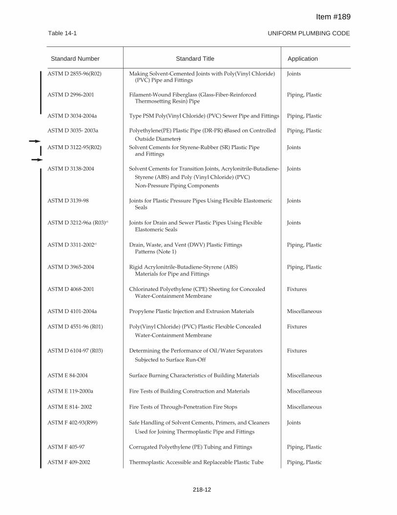
UNIFORM PLUMBING CODETable 14-1
ASTM D 2855-96(R02) Making Solvent-Cemented Joints with Poly(Vinyl Chloride) Joints(PVC) Pipe and Fittings
ASTM D 2996-2001 Filament-Wound Fiberglass (Glass-Fiber-Reinforced Piping, PlasticThermosetting Resin) Pipe
ASTM D 3034-2004a Type PSM Poly(Vinyl Chloride) (PVC) Sewer Pipe and Fittings Piping, Plastic
ASTM D 3035- 2003a Polyethylene(PE) Plastic Pipe (DR-PR) (Based on Controlled Piping, Plastic
Outside Diameter)
ASTM D 3122-95(R02) Solvent Cements for Styrene-Rubber (SR) Plastic Pipe Jointsand Fittings
ASTM D 3138-2004 Solvent Cements for Transition Joints, Acrylonitrile-Butadiene- Joints
Styrene (ABS) and Poly (Vinyl Chloride) (PVC)
Non-Pressure Piping Components
ASTM D 3139-98 Joints for Plastic Pressure Pipes Using Flexible Elastomeric JointsSeals
ASTM D 3212-96a (R03)e1 Joints for Drain and Sewer Plastic Pipes Using Flexible JointsElastomeric Seals
ASTM D 3311-2002e1 Drain, Waste, and Vent (DWV) Plastic Fittings Piping, PlasticPatterns (Note 1)
ASTM D 3965-2004 Rigid Acrylonitrile-Butadiene-Styrene (ABS) Piping, PlasticMaterials for Pipe and Fittings
ASTM D 4068-2001 Chlorinated Polyethylene (CPE) Sheeting for Concealed FixturesWater-Containment Membrane
ASTM D 4101-2004a Propylene Plastic Injection and Extrusion Materials Miscellaneous
ASTM D 4551-96 (R01) Poly(Vinyl Chloride) (PVC) Plastic Flexible Concealed Fixtures
Water-Containment Membrane
ASTM D 6104-97 (R03) Determining the Performance of Oil/Water Separators Fixtures
Subjected to Surface Run-Off
ASTM E 84-2004 Surface Burning Characteristics of Building Materials Miscellaneous
ASTM E 119-2000a Fire Tests of Building Construction and Materials Miscellaneous
ASTM E 814- 2002 Fire Tests of Through-Penetration Fire Stops Miscellaneous
ASTM F 402-93(R99) Safe Handling of Solvent Cements, Primers, and Cleaners Joints
Used for Joining Thermoplastic Pipe and Fittings
ASTM F 405-97 Corrugated Polyethylene (PE) Tubing and Fittings Piping, Plastic
ASTM F 409-2002 Thermoplastic Accessible and Replaceable Plastic Tube Piping, Plastic
Standard Number Standard Title Application
Item #189
218-12
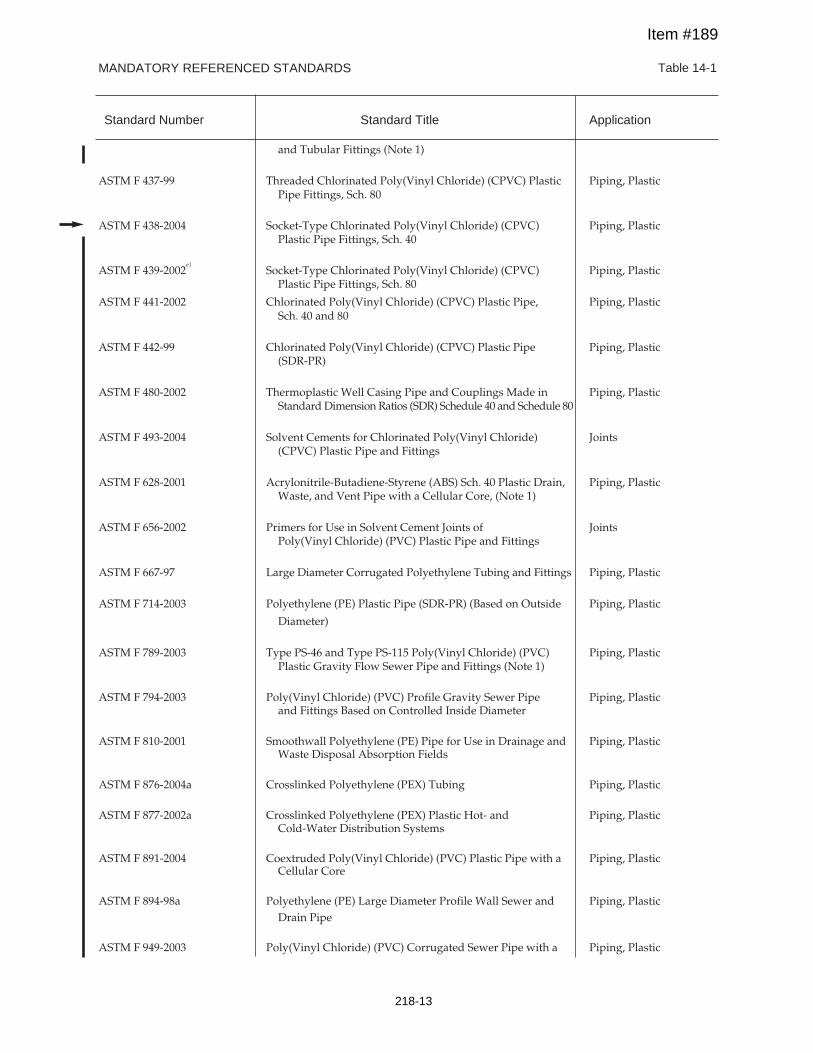
MANDATORY REFERENCED STANDARDS Table 14-1
Standard Number Standard Title Application
and Tubular Fittings (Note 1)
ASTM F 437-99 Threaded Chlorinated Poly(Vinyl Chloride) (CPVC) Plastic Piping, PlasticPipe Fittings, Sch. 80
ASTM F 438-2004 Socket-Type Chlorinated Poly(Vinyl Chloride) (CPVC) Piping, PlasticPlastic Pipe Fittings, Sch. 40
ASTM F 439-2002e1
Socket-Type Chlorinated Poly(Vinyl Chloride) (CPVC) Piping, PlasticPlastic Pipe Fittings, Sch. 80
ASTM F 441-2002 Chlorinated Poly(Vinyl Chloride) (CPVC) Plastic Pipe, Piping, PlasticSch. 40 and 80
ASTM F 442-99 Chlorinated Poly(Vinyl Chloride) (CPVC) Plastic Pipe Piping, Plastic(SDR-PR)
ASTM F 480-2002 Thermoplastic Well Casing Pipe and Couplings Made in Piping, PlasticStandard Dimension Ratios (SDR) Schedule 40 and Schedule 80
ASTM F 493-2004 Solvent Cements for Chlorinated Poly(Vinyl Chloride) Joints(CPVC) Plastic Pipe and Fittings
ASTM F 628-2001 Acrylonitrile-Butadiene-Styrene (ABS) Sch. 40 Plastic Drain, Piping, PlasticWaste, and Vent Pipe with a Cellular Core, (Note 1)
ASTM F 656-2002 Primers for Use in Solvent Cement Joints of JointsPoly(Vinyl Chloride) (PVC) Plastic Pipe and Fittings
ASTM F 667-97 Large Diameter Corrugated Polyethylene Tubing and Fittings Piping, Plastic
ASTM F 714-2003 Polyethylene (PE) Plastic Pipe (SDR-PR) (Based on Outside Piping, Plastic
Diameter)
ASTM F 789-2003 Type PS-46 and Type PS-115 Poly(Vinyl Chloride) (PVC) Piping, PlasticPlastic Gravity Flow Sewer Pipe and Fittings (Note 1)
ASTM F 794-2003 Poly(Vinyl Chloride) (PVC) Profile Gravity Sewer Pipe Piping, Plasticand Fittings Based on Controlled Inside Diameter
ASTM F 810-2001 Smoothwall Polyethylene (PE) Pipe for Use in Drainage and Piping, PlasticWaste Disposal Absorption Fields
ASTM F 876-2004a Crosslinked Polyethylene (PEX) Tubing Piping, Plastic
ASTM F 877-2002a Crosslinked Polyethylene (PEX) Plastic Hot- and Piping, PlasticCold-Water Distribution Systems
ASTM F 891-2004 Coextruded Poly(Vinyl Chloride) (PVC) Plastic Pipe with a Piping, PlasticCellular Core
ASTM F 894-98a Polyethylene (PE) Large Diameter Profile Wall Sewer and Piping, PlasticDrain Pipe
ASTM F 949-2003 Poly(Vinyl Chloride) (PVC) Corrugated Sewer Pipe with a Piping, Plastic
Item #189
218-13
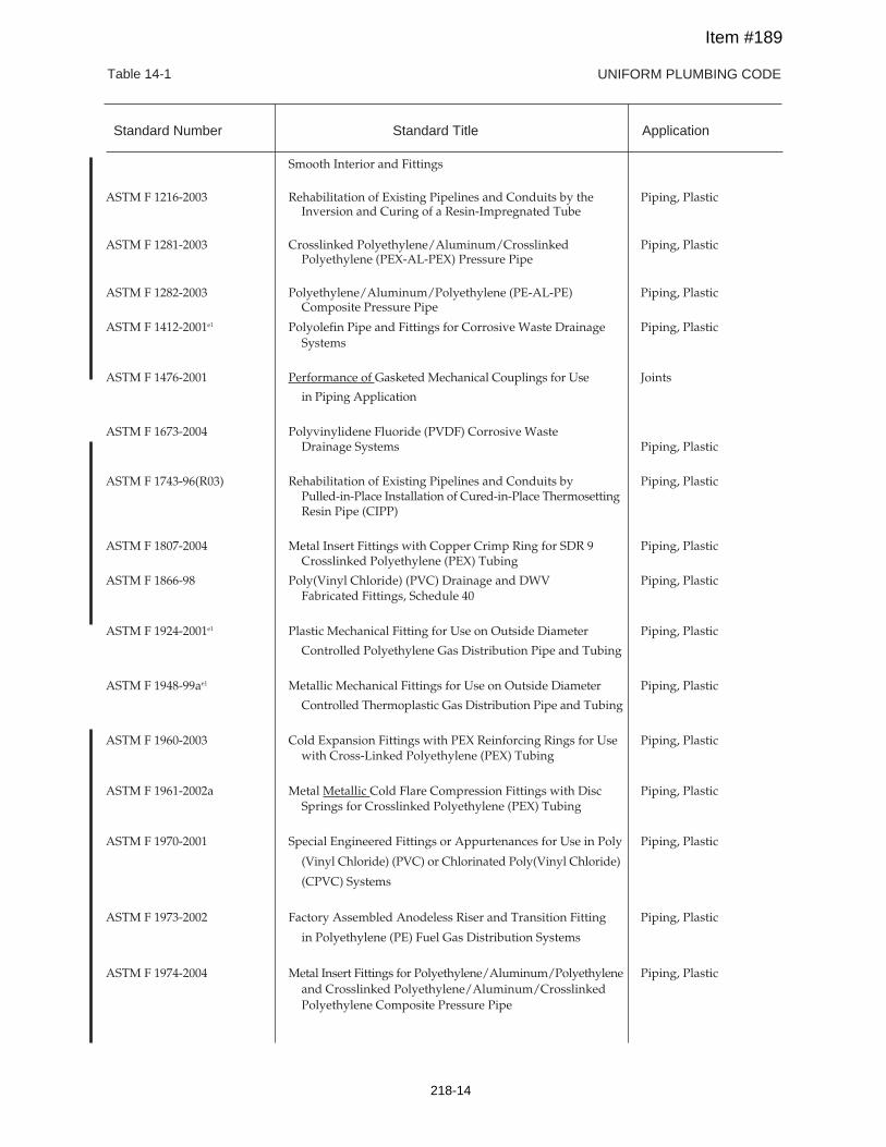
Standard Number Standard Title Application
UNIFORM PLUMBING CODETable 14-1
Smooth Interior and Fittings
ASTM F 1216-2003 Rehabilitation of Existing Pipelines and Conduits by the Piping, PlasticInversion and Curing of a Resin-Impregnated Tube
ASTM F 1281-2003 Crosslinked Polyethylene/Aluminum/Crosslinked Piping, PlasticPolyethylene (PEX-AL-PEX) Pressure Pipe
ASTM F 1282-2003 Polyethylene/Aluminum/Polyethylene (PE-AL-PE) Piping, PlasticComposite Pressure Pipe
ASTM F 1412-2001e1 Polyolefin Pipe and Fittings for Corrosive Waste Drainage Piping, PlasticSystems
ASTM F 1476-2001 Performance of Gasketed Mechanical Couplings for Use Joints
in Piping Application
ASTM F 1673-2004 Polyvinylidene Fluoride (PVDF) Corrosive WasteDrainage Systems Piping, Plastic
ASTM F 1743-96(R03) Rehabilitation of Existing Pipelines and Conduits by Piping, PlasticPulled-in-Place Installation of Cured-in-Place ThermosettingResin Pipe (CIPP)
ASTM F 1807-2004 Metal Insert Fittings with Copper Crimp Ring for SDR 9 Piping, PlasticCrosslinked Polyethylene (PEX) Tubing
ASTM F 1866-98 Poly(Vinyl Chloride) (PVC) Drainage and DWV Piping, PlasticFabricated Fittings, Schedule 40
ASTM F 1924-2001e1 Plastic Mechanical Fitting for Use on Outside Diameter Piping, Plastic
Controlled Polyethylene Gas Distribution Pipe and Tubing
ASTM F 1948-99ae1 Metallic Mechanical Fittings for Use on Outside Diameter Piping, Plastic
Controlled Thermoplastic Gas Distribution Pipe and Tubing
ASTM F 1960-2003 Cold Expansion Fittings with PEX Reinforcing Rings for Use Piping, Plasticwith Cross-Linked Polyethylene (PEX) Tubing
ASTM F 1961-2002a Metal Metallic Cold Flare Compression Fittings with Disc Piping, PlasticSprings for Crosslinked Polyethylene (PEX) Tubing
ASTM F 1970-2001 Special Engineered Fittings or Appurtenances for Use in Poly Piping, Plastic
(Vinyl Chloride) (PVC) or Chlorinated Poly(Vinyl Chloride)
(CPVC) Systems
ASTM F 1973-2002 Factory Assembled Anodeless Riser and Transition Fitting Piping, Plastic
in Polyethylene (PE) Fuel Gas Distribution Systems
ASTM F 1974-2004 Metal Insert Fittings for Polyethylene/Aluminum/Polyethylene Piping, Plasticand Crosslinked Polyethylene/Aluminum/CrosslinkedPolyethylene Composite Pressure Pipe
Item #189
218-14
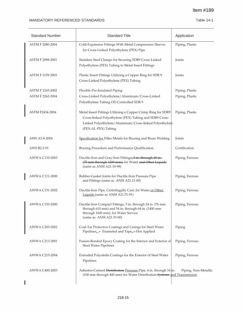
MANDATORY REFERENCED STANDARDS Table 14-1
Standard Number Standard Title Application
ASTM F 2080-2004 Cold-Expansion Fittings With Metal Compression Sleeves Piping, Plastic
for Cross-Linked Polyethylene (PEX) Pipe
ASTM F 2098-2001 Stainless Steel Clamps for Securing SDR9 Cross-Linked Joints
Polyethylene (PEX) Tubing to Metal Insert Fittings
ASTM F 2159-2003 Plastic Insert Fittings Utilizing a Copper Ring for SDR 9 Joints
Cross-Linked Polyethylene (PEX) Tubing
ASTM F 2165-2002 Flexible Pre-Insulated Piping Piping, Plastic
ASTM F 2262-2004 Cross-Linked Polyethylene/Aluminum/Cross-Linked Piping, Plastic
Polyethylene Tubing OD Controlled SDR 9
ASTM F2434-2004 Metal Insert Fittings Utilizing a Copper Crimp Ring for SDR9 Piping, Plastic
Cross-linked Polyethylene (PEX) Tubing and SDR9 Cross-
Linked Polyethylene/Aluminum/Cross-linked Polyethylene
(PEX-AL-PEX) Tubing
AWS A5.8-2004 Specification for Filler Metals for Brazing and Braze Welding Joints
AWS B2.2-91 Brazing Procedure and Performance Qualification Certification
AWWA C110-2003 Ductile-Iron and Gray-Iron Fittings, 3 in. through 48 in. Piping, Ferrous(75 mm through 1200 mm), for Water and Other Liquids(same as ANSI A21.10-98)
AWWA C111-2000 Rubber-Gasket Joints for Ductile-Iron Pressure Pipe Piping, Ferrousand Fittings (same as ANSI A21.11-00)
AWWA C151-2002 Ductile-Iron Pipe, Centrifugally Cast, for Water or Other Piping, FerrousLiquids (same as ANSI A21.51-91)
AWWA C153-2000 Ductile-Iron Compact Fittings, 3 in. through 24 in. (76 mm Piping, Ferrousthrough 610 mm) and 54 in. through 64 in. (1400 mmthrough 1600 mm), for Water Service(same as ANSI A21.53-00)
AWWA C203-2002 Coal-Tar Protective Coatings and Linings for Steel Water PipingPipelines, – Enameled and Tape, – Hot Applied
AWWA C213-2001 Fusion-Bonded Epoxy Coating for the Interior and Exterior of Piping, FerrousSteel Water Pipelines
AWWA C215-2004 Extruded Polyolefin Coatings for the Exterior of Steel Water Piping, Ferrous
Pipelines
AWWA C400-2003 Asbestos-Cement Distribution Pressure Pipe, 4 in. through 16 in. Piping, Non-Metallic(100 mm through 400 mm) for Water Distribution Systems and Transmission
Item #189
218-15
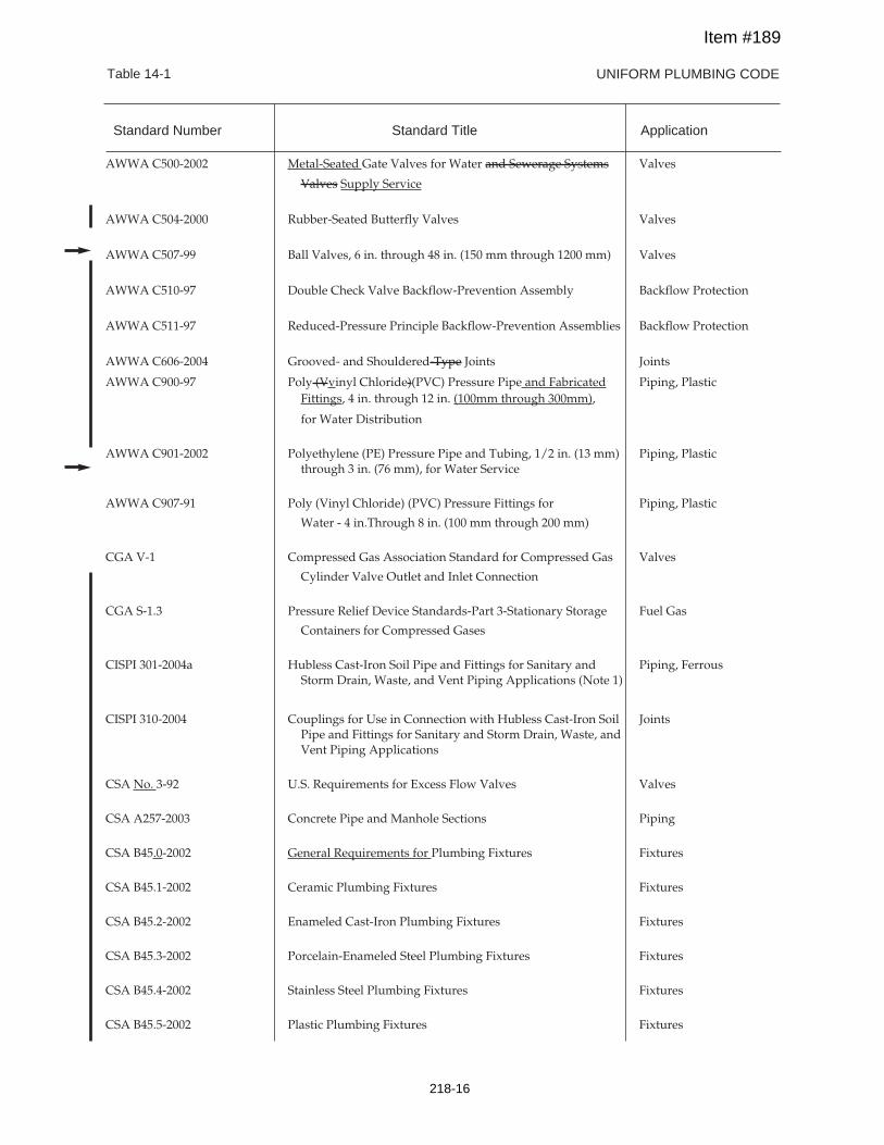
UNIFORM PLUMBING CODETable 14-1
AWWA C500-2002 Metal-Seated Gate Valves for Water and Sewerage Systems Valves
Valves Supply Service
AWWA C504-2000 Rubber-Seated Butterfly Valves Valves
AWWA C507-99 Ball Valves, 6 in. through 48 in. (150 mm through 1200 mm) Valves
AWWA C510-97 Double Check Valve Backflow-Prevention Assembly Backflow Protection
AWWA C511-97 Reduced-Pressure Principle Backflow-Prevention Assemblies Backflow Protection
AWWA C606-2004 Grooved- and Shouldered-Type Joints Joints
AWWA C900-97 Poly (Vvinyl Chloride)(PVC) Pressure Pipe and Fabricated Piping, PlasticFittings, 4 in. through 12 in. (100mm through 300mm),
for Water Distribution
AWWA C901-2002 Polyethylene (PE) Pressure Pipe and Tubing, 1/2 in. (13 mm) Piping, Plasticthrough 3 in. (76 mm), for Water Service
AWWA C907-91 Poly (Vinyl Chloride) (PVC) Pressure Fittings for Piping, Plastic
Water - 4 in.Through 8 in. (100 mm through 200 mm)
CGA V-1 Compressed Gas Association Standard for Compressed Gas Valves
Cylinder Valve Outlet and Inlet Connection
CGA S-1.3 Pressure Relief Device Standards-Part 3-Stationary Storage Fuel Gas
Containers for Compressed Gases
CISPI 301-2004a Hubless Cast-Iron Soil Pipe and Fittings for Sanitary and Piping, FerrousStorm Drain, Waste, and Vent Piping Applications (Note 1)
CISPI 310-2004 Couplings for Use in Connection with Hubless Cast-Iron Soil JointsPipe and Fittings for Sanitary and Storm Drain, Waste, andVent Piping Applications
CSA No. 3-92 U.S. Requirements for Excess Flow Valves Valves
CSA A257-2003 Concrete Pipe and Manhole Sections Piping
CSA B45.0-2002 General Requirements for Plumbing Fixtures Fixtures
CSA B45.1-2002 Ceramic Plumbing Fixtures Fixtures
CSA B45.2-2002 Enameled Cast-Iron Plumbing Fixtures Fixtures
CSA B45.3-2002 Porcelain-Enameled Steel Plumbing Fixtures Fixtures
CSA B45.4-2002 Stainless Steel Plumbing Fixtures Fixtures
CSA B45.5-2002 Plastic Plumbing Fixtures Fixtures
Standard Number Standard Title Application
Item #189
218-16
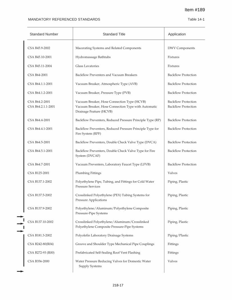
MANDATORY REFERENCED STANDARDS Table 14-1
CSA B45.9-2002 Macerating Systems and Related Components DWV Components
CSA B45.10-2001 Hydromassage Bathtubs Fixtures
CSA B45.11-2004 Glass Lavatories Fixtures
CSA B64-2001 Backflow Preventers and Vacuum Breakers Backflow Protection
CSA B64.1.1-2001 Vacuum Breaker, Atmospheric Type (AVB) Backflow Protection
CSA B64.1.2-2001 Vacuum Breaker, Pressure Type (PVB) Backflow Protection
CSA B64.2-2001 Vacuum Breaker, Hose Connection Type (HCVB) Backflow Protection
CSA B64.2.1.1-2001 Vacuum Breaker, Hose Connection Type with Automatic Backflow Protection
Drainage Feature (HCVB)
CSA B64.4-2001 Backflow Preventers, Reduced Pressure Principle Type (RP) Backflow Protection
CSA B64.4.1-2001 Backflow Preventers, Reduced Pressure Principle Type for Backflow Protection
Fire System (RPF)
CSA B64.5-2001 Backflow Preventers, Double Check Valve Type (DVCA) Backflow Protection
CSA B64.5.1-2001 Backflow Preventers, Double Check Valve Type for Fire Backflow Protection
System (DVCAF)
CSA B64.7-2001 Vacuum Preventers, Laboratory Faucet Type (LFVB) Backflow Protection
CSA B125-2001 Plumbing Fittings Valves
CSA B137.1-2002 Polyethylene Pipe, Tubing, and Fittings for Cold Water Piping, Plastic
Pressure Services
CSA B137.5-2002 Crosslinked Polyethylene (PEX) Tubing Systems for Piping, Plastic
Pressure Applications
CSA B137.9-2002 Polyethylene/Aluminum/Polyethylene Composite Piping, Plastic
Pressure-Pipe Systems
CSA B137.10-2002 Crosslinked Polyethylene/Aluminum/Crosslinked Piping, Plastic
Polyethylene Composite Pressure-Pipe Systems
CSA B181.3-2002 Polyolefin Laboratory Drainage Systems Piping/Plastic
CSA B242-80(R04) Groove and Shoulder Type Mechanical Pipe Couplings Fittings
CSA B272-93 (R00) Prefabricated Self-Sealing Roof Vent Flashing Fittings
CSA B356-2000 Water Pressure Reducing Valves for Domestic Water Valves
Supply Systems
Standard Number Standard Title Application
Item #189
218-17
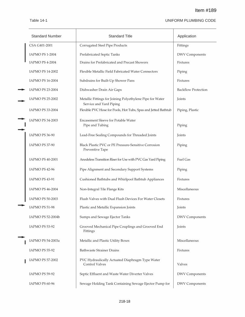
UNIFORM PLUMBING CODETable 14-1
CSA G401-2001 Corrugated Steel Pipe Products Fittings
IAPMO PS 1-2004 Prefabricated Septic Tanks DWV Components
IAPMO PS 4-2004 Drains for Prefabricated and Precast Showers Fixtures
IAPMO PS 14-2002 Flexible Metallic Field Fabricated Water Connectors Piping
IAPMO PS 16-2004 Subdrains for Built-Up Shower Pans Fixtures
IAPMO PS 23-2004 Dishwasher Drain Air Gaps Backflow Protection
IAPMO PS 25-2002 Metallic Fittings for Joining Polyethylene Pipe for Water Joints
Service and Yard Piping
IAPMO PS 33-2004 Flexible PVCHose for Pools, Hot Tubs, Spas and Jetted Bathtub Piping, Plastic
IAPMO PS 34-2003 Encasement Sleeve for Potable WaterPipe and Tubing Piping
IAPMO PS 36-90 Lead-Free Sealing Compounds for Threaded Joints Joints
IAPMO PS 37-90 Black Plastic PVC or PE Pressure-Sensitive Corrosion PipingPreventive Tape
IAPMO PS 40-2001 Anodeless TransitionRiser forUsewith PVCGasYardPiping Fuel Gas
IAPMO PS 42-96 Pipe Alignment and Secondary Support Systems Piping
IAPMO PS 43-91 Cushioned Bathtubs and Whirlpool Bathtub Appliances Fixtures
IAPMO PS 46-2004 Non-Integral Tile Flange Kits Miscellaneous
IAPMO PS 50-2003 Flush Valves with Dual Flush Devices For Water Closets Fixtures
IAPMO PS 51-98 Plastic and Metallic Expansion Joints Joints
IAPMO PS 52-2004b Sumps and Sewage Ejector Tanks DWV Components
IAPMO PS 53-92 Grooved Mechanical Pipe Couplings and Grooved End JointsFittings
IAPMO PS 54-2003a Metallic and Plastic Utility Boxes Miscellaneous
IAPMO PS 55-92 Bathwaste Strainer Drains Fixtures
IAPMO PS 57-2002 PVC Hydraulically Actuated Diaphragm Type WaterControl Valves Valves
IAPMO PS 59-92 Septic Effluent and Waste Water Diverter Valves DWV Components
IAPMO PS 60-96 Sewage Holding Tank Containing Sewage Ejector Pump for DWV Components
Standard Number Standard Title Application
Item #189
218-18
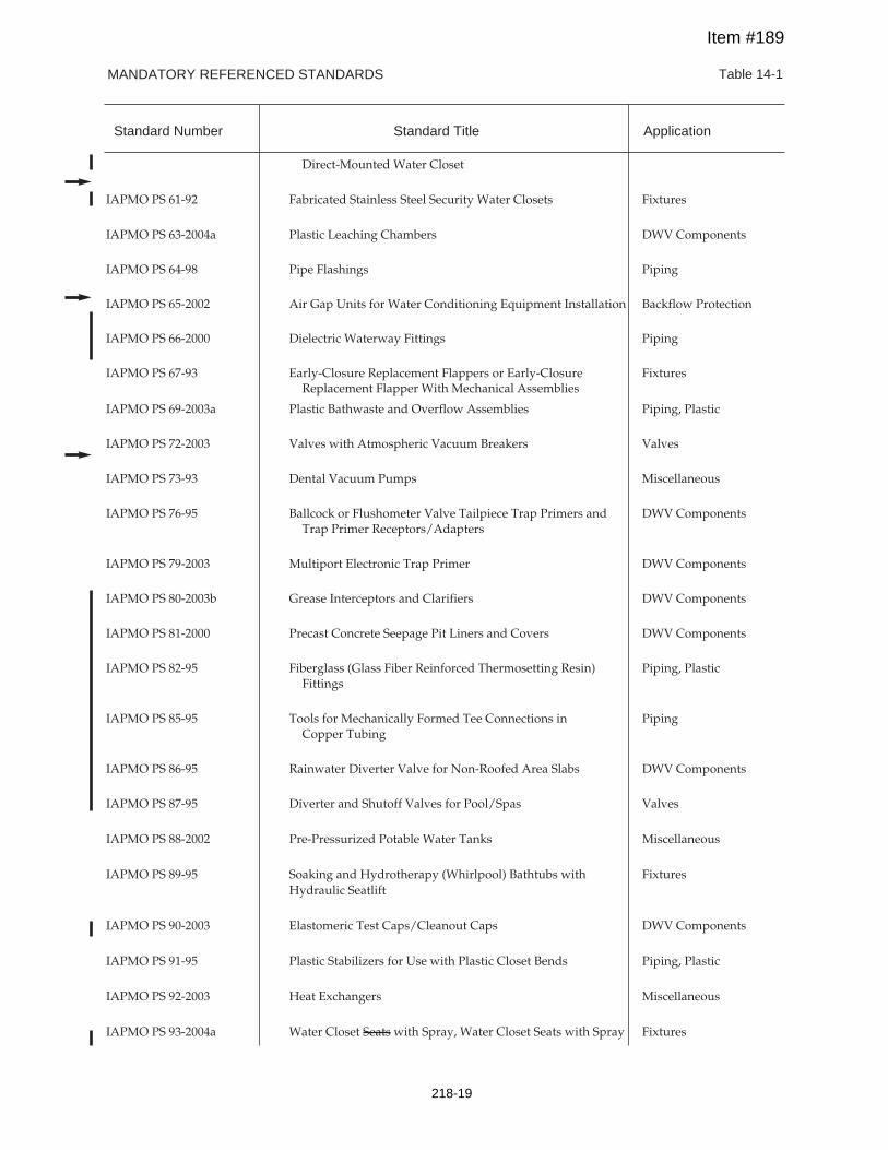
MANDATORY REFERENCED STANDARDS Table 14-1
Direct-Mounted Water Closet
IAPMO PS 61-92 Fabricated Stainless Steel Security Water Closets Fixtures
IAPMO PS 63-2004a Plastic Leaching Chambers DWV Components
IAPMO PS 64-98 Pipe Flashings Piping
IAPMO PS 65-2002 Air Gap Units for Water Conditioning Equipment Installation Backflow Protection
IAPMO PS 66-2000 Dielectric Waterway Fittings Piping
IAPMO PS 67-93 Early-Closure Replacement Flappers or Early-Closure FixturesReplacement Flapper With Mechanical Assemblies
IAPMO PS 69-2003a Plastic Bathwaste and Overflow Assemblies Piping, Plastic
IAPMO PS 72-2003 Valves with Atmospheric Vacuum Breakers Valves
IAPMO PS 73-93 Dental Vacuum Pumps Miscellaneous
IAPMO PS 76-95 Ballcock or Flushometer Valve Tailpiece Trap Primers and DWV ComponentsTrap Primer Receptors/Adapters
IAPMO PS 79-2003 Multiport Electronic Trap Primer DWV Components
IAPMO PS 80-2003b Grease Interceptors and Clarifiers DWV Components
IAPMO PS 81-2000 Precast Concrete Seepage Pit Liners and Covers DWV Components
IAPMO PS 82-95 Fiberglass (Glass Fiber Reinforced Thermosetting Resin) Piping, PlasticFittings
IAPMO PS 85-95 Tools for Mechanically Formed Tee Connections in PipingCopper Tubing
IAPMO PS 86-95 Rainwater Diverter Valve for Non-Roofed Area Slabs DWV Components
IAPMO PS 87-95 Diverter and Shutoff Valves for Pool/Spas Valves
IAPMO PS 88-2002 Pre-Pressurized Potable Water Tanks Miscellaneous
IAPMO PS 89-95 Soaking and Hydrotherapy (Whirlpool) Bathtubs with FixturesHydraulic Seatlift
IAPMO PS 90-2003 Elastomeric Test Caps/Cleanout Caps DWV Components
IAPMO PS 91-95 Plastic Stabilizers for Use with Plastic Closet Bends Piping, Plastic
IAPMO PS 92-2003 Heat Exchangers Miscellaneous
IAPMO PS 93-2004a Water Closet Seats with Spray, Water Closet Seats with Spray Fixtures
Standard Number Standard Title Application
Item #189
218-19
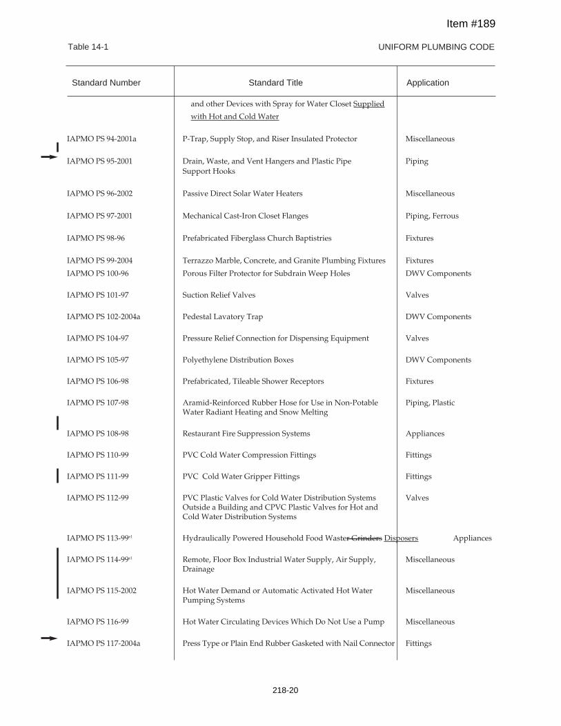
UNIFORM PLUMBING CODETable 14-1
and other Devices with Spray for Water Closet Supplied
with Hot and Cold Water
IAPMO PS 94-2001a P-Trap, Supply Stop, and Riser Insulated Protector Miscellaneous
IAPMO PS 95-2001 Drain, Waste, and Vent Hangers and Plastic Pipe PipingSupport Hooks
IAPMO PS 96-2002 Passive Direct Solar Water Heaters Miscellaneous
IAPMO PS 97-2001 Mechanical Cast-Iron Closet Flanges Piping, Ferrous
IAPMO PS 98-96 Prefabricated Fiberglass Church Baptistries Fixtures
IAPMO PS 99-2004 Terrazzo Marble, Concrete, and Granite Plumbing Fixtures Fixtures
IAPMO PS 100-96 Porous Filter Protector for Subdrain Weep Holes DWV Components
IAPMO PS 101-97 Suction Relief Valves Valves
IAPMO PS 102-2004a Pedestal Lavatory Trap DWV Components
IAPMO PS 104-97 Pressure Relief Connection for Dispensing Equipment Valves
IAPMO PS 105-97 Polyethylene Distribution Boxes DWV Components
IAPMO PS 106-98 Prefabricated, Tileable Shower Receptors Fixtures
IAPMO PS 107-98 Aramid-Reinforced Rubber Hose for Use in Non-Potable Piping, PlasticWater Radiant Heating and Snow Melting
IAPMO PS 108-98 Restaurant Fire Suppression Systems Appliances
IAPMO PS 110-99 PVC Cold Water Compression Fittings Fittings
IAPMO PS 111-99 PVC Cold Water Gripper Fittings Fittings
IAPMO PS 112-99 PVC Plastic Valves for Cold Water Distribution Systems ValvesOutside a Building and CPVC Plastic Valves for Hot andCold Water Distribution Systems
IAPMO PS 113-99e1 Hydraulically Powered Household Food Waster Grinders Disposers Appliances
IAPMO PS 114-99e1 Remote, Floor Box Industrial Water Supply, Air Supply, MiscellaneousDrainage
IAPMO PS 115-2002 Hot Water Demand or Automatic Activated Hot Water MiscellaneousPumping Systems
IAPMO PS 116-99 Hot Water Circulating Devices Which Do Not Use a Pump Miscellaneous
IAPMO PS 117-2004a Press Type or Plain End Rubber Gasketed with Nail Connector Fittings
Standard Number Standard Title Application
Item #189
218-20
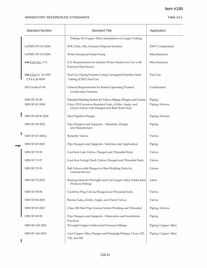
MANDATORY REFERENCED STANDARDS Table 14-1
Fittings for Copper Alloy Installation on Copper Tubing
IAPMO PS 118-2000 FOG (Fats, Oils, Greases) Disposal Systems DWV Components
IAPMO PS 119-2000 Water Energized Sump Pump Miscellaneous
IAS CSA No. 1-91 U.S. Requirements for Indirect Water Heaters for Use with Miscellaneous
External Heat Source
IAS CSA LC 1b-2001 Fuel Gas Piping Systems Using Corrugated Stainless Steel Fuel Gas
CSA 6.26-M99 Tubing (CSST) Fuel Gas
ISO Guide 65-96 General Requirements for Bodies Operating Product Certification
Certification Systems
MSS SP-25-98 StandardMarking System forValves, Fittings, Flanges, andUnions Piping
MSS SP-42-2004 Class 150 Corrosion-Resistant Gate, -Globe, Angle, and Piping, FerrousCheck Valves with Flanged and Butt Weld Ends
MSS SP-44-96 2006 Steel Pipeline Flanges Piping, Ferrous
MSS SP-58-2002 Pipe Hangers and Supports – Materials, Design, Pipingand Manufacture
MSS SP-67-2002a Butterfly Valves Valves
MSS SP-69-2002 Pipe Hangars and Supports - Selection and Application Piping
MSS SP-70-98 Cast-Iron Gate Valves, Flanged and Threaded Ends Valves
MSS SP-71-97 Cast-Iron Swing Check Valves, Flanged and Threaded Ends Valves
MSS SP-72-99 Ball Valves with Flanged or Butt-Welding Ends for ValvesGeneral Service
MSS SP-73-2003 Brazing Joints for Wrought and Cast Copper Alloy Solder Joint JointsPressure Fittings
MSS SP-78-98 Cast-Iron Plug Valves, Flanged and Threaded Ends Valves
MSS SP-80-2003 Bronze Gate, -Globe, Angle, and Check Valves Valves
MSS SP-83-2001 Class 300 Steel Pipe Unions Socket-Welding and Threaded Piping, Ferrous
MSS SP-89-98 Pipe Hangars and Supports - Fabrication and Installation Piping
Practices
MSS SP-104-2003 Wrought Copper Solder Joint Pressure Fittings Piping, Copper Alloy
MSS SP-106-2003 Cast Copper Alloy Flanges and Flangeds Fittings, CLass 125, Piping, Copper Alloy
150, and 300
Standard Number Standard Title Application
Item #189
218-21
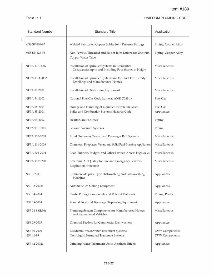
UNIFORM PLUMBING CODETable 14-1
MSS SP-109-97 Welded Fabricated Copper Solder Joint Pressure Fittings Piping, Copper Alloy
MSS SP-123-98 Non-Ferrous Threaded and Solder-Joint Unions for Use with Piping, Copper Alloy
Copper Water Tube
NFPA 13R-2002 Installation of Sprinkler Systems in Residential MiscellaneousOccupancies up to and Including Four Stories in Height
NFPA 13D-2002 Installation of Sprinkler Systems in One- and Two-Family MiscellaneousDwellings and Manufactured Homes
NFPA 31-2001 Installation of Oil-Burning Equipment Miscellaneous
NFPA 54-2002 National Fuel Gas Code (same as ANSI Z223.1) Fuel Gas
NFPA 58-2004 Storage and Handling of Liquefied Petroleum Gases Fuel Gas
NFPA 85-2004 Boiler and Combustion Systems Hazards Code Appliances
NFPA 99-2002 Health Care Facilities Piping
NFPA 99C-2002 Gas and Vacuum Systems Piping
NFPA 130-2003 Fixed Guideway Transit and Passenger Rail Systems Miscellaneous
NFPA 211-2003 Chimneys, Fireplaces, Vents, and Solid Fuel-Burning Appliances Miscellaneous
NFPA 502-2004 Road Tunnels, Bridges, and Other Limited Access Highways Miscellaneous
NFPA 1989-2003 Breathing Air Quality for Fire and Emergency Services Miscellaneous
Respiration Protection
NSF 3-2003 Commercial Spray-Type Dishwashing and Glasswashing AppliancesMachines
NSF 12-2003e Automatic Ice Making Equipment Appliances
NSF 14-20041 Plastic Piping Components and Related Materials Piping, Plastic
NSF 18-2004 Manual Food and Beverage Dispensing Equipment Appliances
NSF 24-88(R96) Plumbing System Components for Manufactured Homes Miscellaneousand Recreational Vehicles
NSF 29-2003 Chemical Feeders for Commercial Dishwashers Appliances
NSF 40-2000 Residential Wastewater Treatment Systems DWV Components
NSF 41-99 Non-Liquid Saturated Treatment Systems DWV Components
NSF 42-2002e Drinking Water Treatment Units–Aesthetic Effects Appliances
Standard Number Standard Title Application
Item #189
218-22
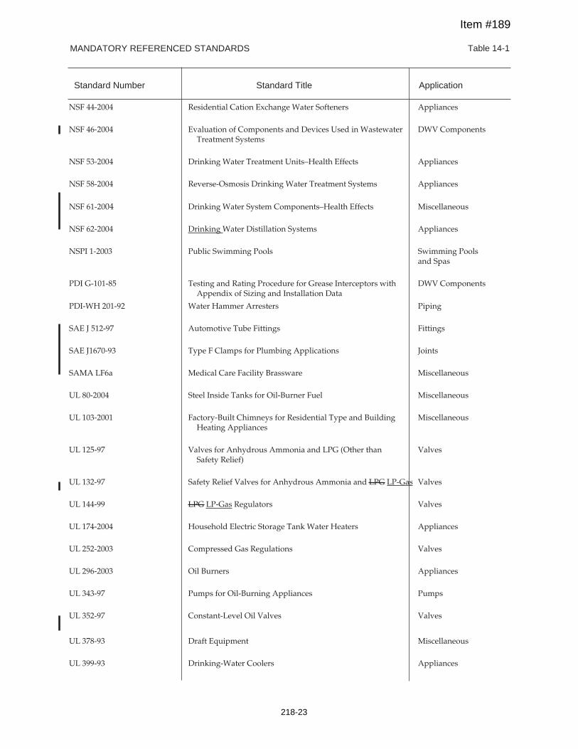
MANDATORY REFERENCED STANDARDS Table 14-1
NSF 44-2004 Residential Cation Exchange Water Softeners Appliances
NSF 46-2004 Evaluation of Components and Devices Used in Wastewater DWV ComponentsTreatment Systems
NSF 53-2004 Drinking Water Treatment Units–Health Effects Appliances
NSF 58-2004 Reverse-Osmosis Drinking Water Treatment Systems Appliances
NSF 61-2004 Drinking Water System Components–Health Effects Miscellaneous
NSF 62-2004 Drinking Water Distillation Systems Appliances
NSPI 1-2003 Public Swimming Pools Swimming Poolsand Spas
PDI G-101-85 Testing and Rating Procedure for Grease Interceptors with DWV ComponentsAppendix of Sizing and Installation Data
PDI-WH 201-92 Water Hammer Arresters Piping
SAE J 512-97 Automotive Tube Fittings Fittings
SAE J1670-93 Type F Clamps for Plumbing Applications Joints
SAMA LF6a Medical Care Facility Brassware Miscellaneous
UL 80-2004 Steel Inside Tanks for Oil-Burner Fuel Miscellaneous
UL 103-2001 Factory-Built Chimneys for Residential Type and Building MiscellaneousHeating Appliances
UL 125-97 Valves for Anhydrous Ammonia and LPG (Other than ValvesSafety Relief)
UL 132-97 Safety Relief Valves for Anhydrous Ammonia and LPG LP-Gas Valves
UL 144-99 LPG LP-Gas Regulators Valves
UL 174-2004 Household Electric Storage Tank Water Heaters Appliances
UL 252-2003 Compressed Gas Regulations Valves
UL 296-2003 Oil Burners Appliances
UL 343-97 Pumps for Oil-Burning Appliances Pumps
UL 352-97 Constant-Level Oil Valves Valves
UL 378-93 Draft Equipment Miscellaneous
UL 399-93 Drinking-Water Coolers Appliances
Standard Number Standard Title Application
Item #189
218-23
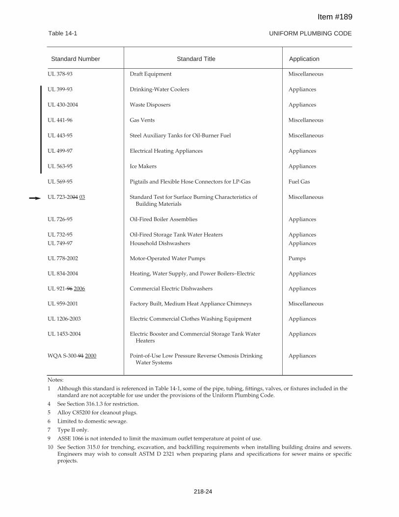
UNIFORM PLUMBING CODETable 14-1
UL 378-93 Draft Equipment Miscellaneous
UL 399-93 Drinking-Water Coolers Appliances
UL 430-2004 Waste Disposers Appliances
UL 441-96 Gas Vents Miscellaneous
UL 443-95 Steel Auxiliary Tanks for Oil-Burner Fuel Miscellaneous
UL 499-97 Electrical Heating Appliances Appliances
UL 563-95 Ice Makers Appliances
UL 569-95 Pigtails and Flexible Hose Connectors for LP-Gas Fuel Gas
UL 723-2004 03 Standard Test for Surface Burning Characteristics of MiscellaneousBuilding Materials
UL 726-95 Oil-Fired Boiler Assemblies Appliances
UL 732-95 Oil-Fired Storage Tank Water Heaters Appliances
UL 749-97 Household Dishwashers Appliances
UL 778-2002 Motor-Operated Water Pumps Pumps
UL 834-2004 Heating, Water Supply, and Power Boilers–Electric Appliances
UL 921-96 2006 Commercial Electric Dishwashers Appliances
UL 959-2001 Factory Built, Medium Heat Appliance Chimneys Miscellaneous
UL 1206-2003 Electric Commercial Clothes Washing Equipment Appliances
UL 1453-2004 Electric Booster and Commercial Storage Tank Water AppliancesHeaters
WQA S-300-91 2000 Point-of-Use Low Pressure Reverse Osmosis Drinking AppliancesWater Systems
Notes:
1 Although this standard is referenced in Table 14-1, some of the pipe, tubing, fittings, valves, or fixtures included in thestandard are not acceptable for use under the provisions of the Uniform Plumbing Code.
4 See Section 316.1.3 for restriction.
5 Alloy C85200 for cleanout plugs.
6 Limited to domestic sewage.
7 Type II only.
9 ASSE 1066 is not intended to limit the maximum outlet temperature at point of use.
10 See Section 315.0 for trenching, excavation, and backfilling requirements when installing building drains and sewers.Engineers may wish to consult ASTM D 2321 when preparing plans and specifications for sewer mains or specificprojects.
Standard Number Standard Title Application
Item #189
218-24
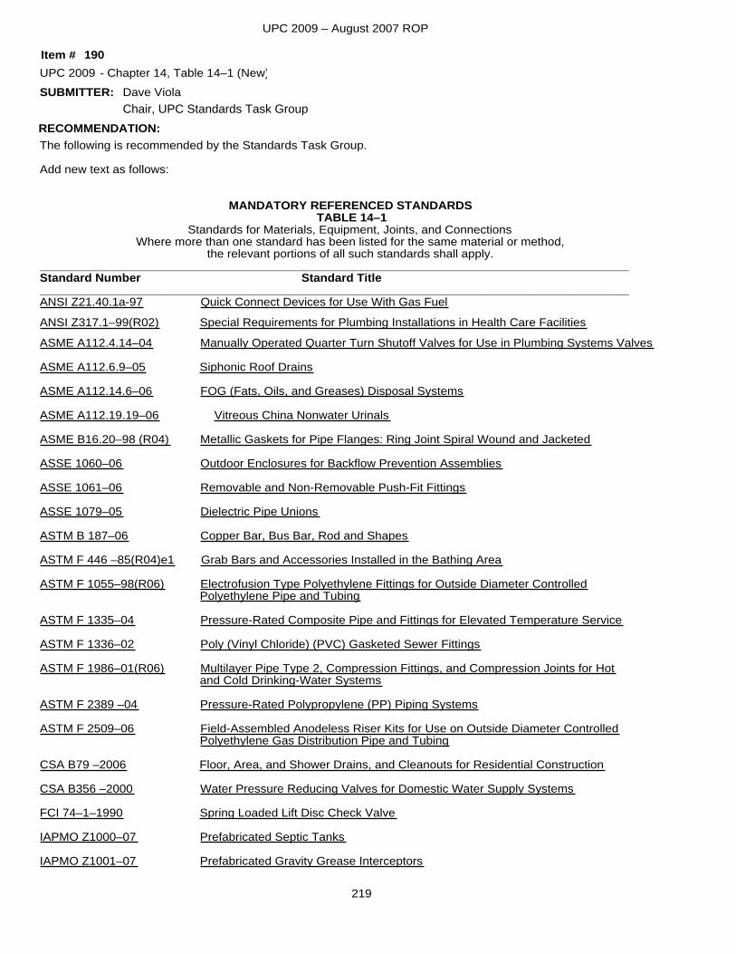
UPC 2009 – August 2007 ROP
SUBMITTER:
The following is recommended by the Standards Task Group.
Add new text as follows:
MANDATORY REFERENCED STANDARDSTABLE 14–1
Standards for Materials, Equipment, Joints, and ConnectionsWhere more than one standard has been listed for the same material or method,
the relevant portions of all such standards shall apply.________________________________________________________________________________________Standard Number Standard Title________________________________________________________________________________________ANSI Z21.40.1a-97 Quick Connect Devices for Use With Gas FuelANSI Z317.1–99(R02) Special Requirements for Plumbing Installations in Health Care FacilitiesASME A112.4.14–04 Manually Operated Quarter Turn Shutoff Valves for Use in Plumbing Systems Valves
ASME A112.6.9–05 Siphonic Roof Drains
ASME A112.14.6–06 FOG (Fats, Oils, and Greases) Disposal Systems
ASME A112.19.19–06 Vitreous China Nonwater Urinals
ASME B16.20–98 (R04) Metallic Gaskets for Pipe Flanges: Ring Joint Spiral Wound and Jacketed
ASSE 1060–06 Outdoor Enclosures for Backflow Prevention Assemblies
ASSE 1061–06 Removable and Non-Removable Push-Fit Fittings
ASSE 1079–05 Dielectric Pipe Unions
ASTM B 187–06 Copper Bar, Bus Bar, Rod and Shapes
ASTM F 446 –85(R04)e1 Grab Bars and Accessories Installed in the Bathing Area
ASTM F 1055–98(R06) Electrofusion Type Polyethylene Fittings for Outside Diameter ControlledPolyethylene Pipe and Tubing
ASTM F 1335–04 Pressure-Rated Composite Pipe and Fittings for Elevated Temperature Service
ASTM F 1336–02 Poly (Vinyl Chloride) (PVC) Gasketed Sewer Fittings
ASTM F 1986–01(R06) Multilayer Pipe Type 2, Compression Fittings, and Compression Joints for Hotand Cold Drinking-Water Systems
ASTM F 2389 –04 Pressure-Rated Polypropylene (PP) Piping Systems
ASTM F 2509–06 Field-Assembled Anodeless Riser Kits for Use on Outside Diameter ControlledPolyethylene Gas Distribution Pipe and Tubing
CSA B79 –2006 Floor, Area, and Shower Drains, and Cleanouts for Residential Construction
CSA B356 –2000 Water Pressure Reducing Valves for Domestic Water Supply Systems
FCI 74–1–1990 Spring Loaded Lift Disc Check Valve
IAPMO Z1000–07 Prefabricated Septic Tanks
IAPMO Z1001–07 Prefabricated Gravity Grease Interceptors
RECOMMENDATION:
UPC 2009 Chapter 14, Table 14–1 (New)Dave Viola
190-
Item #
Chair, UPC Standards Task Group
219
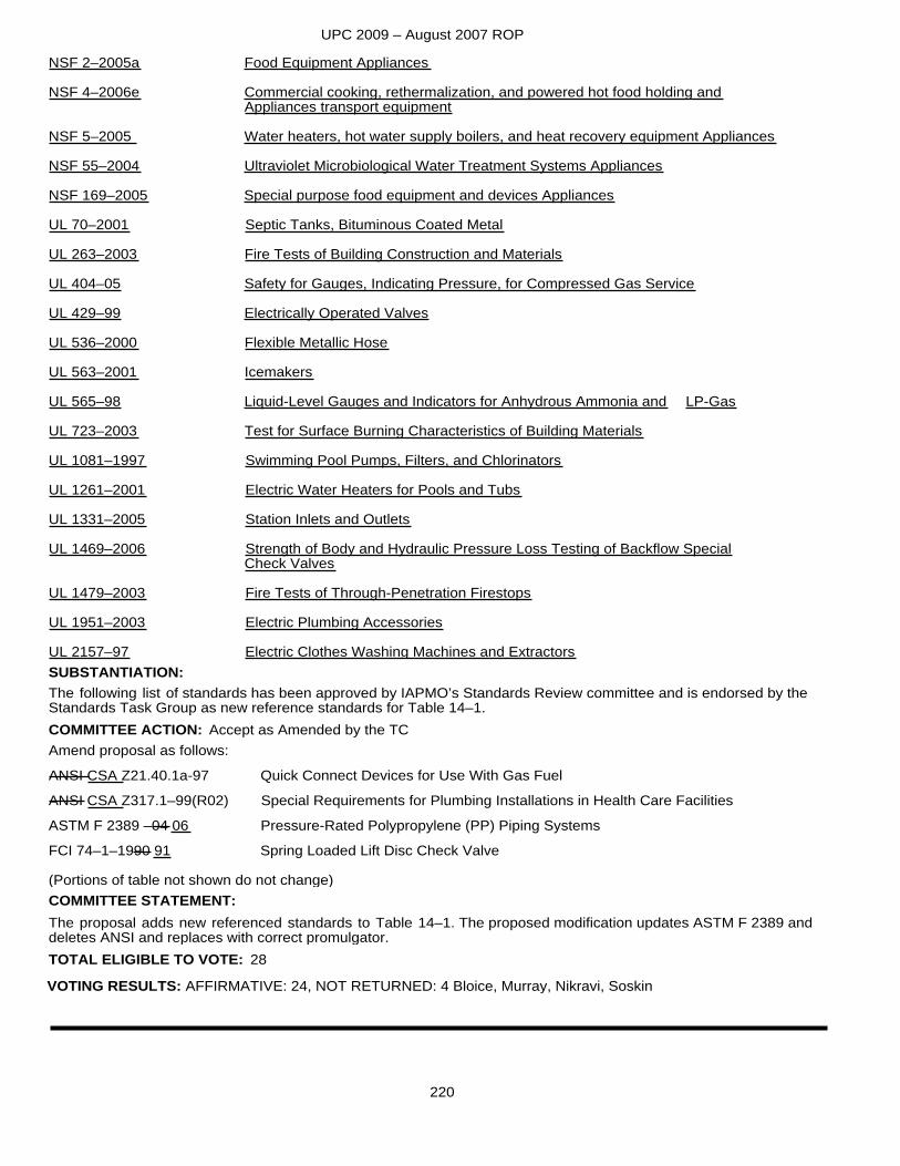
UPC 2009 – August 2007 ROP
NSF 2–2005a Food Equipment Appliances
NSF 4–2006e Commercial cooking, rethermalization, and powered hot food holding andAppliances transport equipment
NSF 5–2005 Water heaters, hot water supply boilers, and heat recovery equipment Appliances
NSF 55–2004 Ultraviolet Microbiological Water Treatment Systems Appliances
NSF 169–2005 Special purpose food equipment and devices Appliances
UL 70–2001 Septic Tanks, Bituminous Coated Metal
UL 263–2003 Fire Tests of Building Construction and Materials
UL 404–05 Safety for Gauges, Indicating Pressure, for Compressed Gas Service
UL 429–99 Electrically Operated Valves
UL 536–2000 Flexible Metallic Hose
UL 563–2001 Icemakers
UL 565–98 Liquid-Level Gauges and Indicators for Anhydrous Ammonia and LP-Gas
UL 723–2003 Test for Surface Burning Characteristics of Building Materials
UL 1081–1997 Swimming Pool Pumps, Filters, and Chlorinators
UL 1261–2001 Electric Water Heaters for Pools and Tubs
UL 1331–2005 Station Inlets and Outlets
UL 1469–2006 Strength of Body and Hydraulic Pressure Loss Testing of Backflow SpecialCheck Valves
UL 1479–2003 Fire Tests of Through-Penetration Firestops
UL 1951–2003 Electric Plumbing Accessories
UL 2157–97 Electric Clothes Washing Machines and Extractors
The following list of standards has been approved by IAPMO’s Standards Review committee and is endorsed by theStandards Task Group as new reference standards for Table 14–1.
SUBSTANTIATION:
Amend proposal as follows:ANSI CSA Z21.40.1a-97 Quick Connect Devices for Use With Gas FuelANSI CSA Z317.1–99(R02) Special Requirements for Plumbing Installations in Health Care FacilitiesASTM F 2389 –04 06 Pressure-Rated Polypropylene (PP) Piping SystemsFCI 74–1–1990 91 Spring Loaded Lift Disc Check Valve
(Portions of table not shown do not change)
The proposal adds new referenced standards to Table 14–1. The proposed modification updates ASTM F 2389 and deletes ANSI and replaces with correct promulgator.
Accept as Amended by the TC
TOTAL ELIGIBLE TO VOTE: 28
VOTING RESULTS: AFFIRMATIVE: 24, NOT RETURNED: 4 Bloice, Murray, Nikravi, Soskin
COMMITTEE ACTION:
COMMITTEE STATEMENT:
220
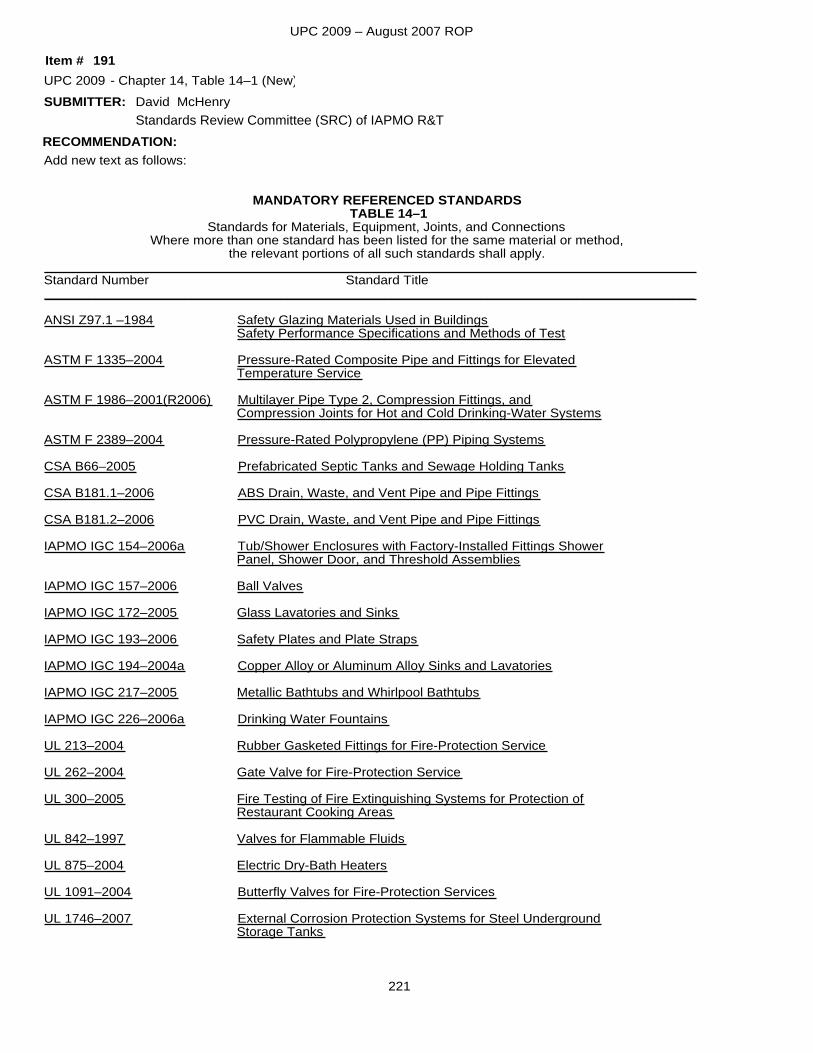
UPC 2009 – August 2007 ROP
SUBMITTER:
Add new text as follows:
MANDATORY REFERENCED STANDARDSTABLE 14–1
Standards for Materials, Equipment, Joints, and ConnectionsWhere more than one standard has been listed for the same material or method,
the relevant portions of all such standards shall apply.________________________________________________________________________________________Standard Number Standard Title________________________________________________________________________________________
ANSI Z97.1 –1984 Safety Glazing Materials Used in BuildingsSafety Performance Specifications and Methods of Test
ASTM F 1335–2004 Pressure-Rated Composite Pipe and Fittings for ElevatedTemperature Service
ASTM F 1986–2001(R2006) Multilayer Pipe Type 2, Compression Fittings, andCompression Joints for Hot and Cold Drinking-Water Systems
ASTM F 2389–2004 Pressure-Rated Polypropylene (PP) Piping Systems
CSA B66–2005 Prefabricated Septic Tanks and Sewage Holding Tanks
CSA B181.1–2006 ABS Drain, Waste, and Vent Pipe and Pipe Fittings
CSA B181.2–2006 PVC Drain, Waste, and Vent Pipe and Pipe Fittings
IAPMO IGC 154–2006a Tub/Shower Enclosures with Factory-Installed Fittings ShowerPanel, Shower Door, and Threshold Assemblies
IAPMO IGC 157–2006 Ball Valves
IAPMO IGC 172–2005 Glass Lavatories and Sinks
IAPMO IGC 193–2006 Safety Plates and Plate Straps
IAPMO IGC 194–2004a Copper Alloy or Aluminum Alloy Sinks and Lavatories
IAPMO IGC 217–2005 Metallic Bathtubs and Whirlpool Bathtubs
IAPMO IGC 226–2006a Drinking Water Fountains
UL 213–2004 Rubber Gasketed Fittings for Fire-Protection Service
UL 262–2004 Gate Valve for Fire-Protection Service
UL 300–2005 Fire Testing of Fire Extinguishing Systems for Protection ofRestaurant Cooking Areas
UL 842–1997 Valves for Flammable Fluids
UL 875–2004 Electric Dry-Bath Heaters
UL 1091–2004 Butterfly Valves for Fire-Protection Services
UL 1746–2007 External Corrosion Protection Systems for Steel UndergroundStorage Tanks
RECOMMENDATION:
UPC 2009 Chapter 14, Table 14–1 (New)David McHenry
191-
Item #
Standards Review Committee (SRC) of IAPMO R&T
221
UPC 2009 – August 2007 ROP
The following list of standards has been approved by IAPMO’s Standards Review Committee for listing purposes. IAPMO R&T currently has manufactures listed to these standards.
SUBSTANTIATION:
Technical Committee did not receive standards for review and unable to make the determination for inclusion in Table 14–1.
Reject
TOTAL ELIGIBLE TO VOTE: 28
VOTING RESULTS: AFFIRMATIVE: 24, NOT RETURNED: 4 Bloice, Murray, Nikravi, Soskin
COMMITTEE ACTION:COMMITTEE STATEMENT:
222
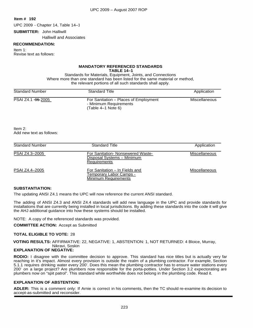
UPC 2009 – August 2007 ROP
SUBMITTER:
Item 1:Revise text as follows:
MANDATORY REFERENCED STANDARDSTABLE 14–1
Standards for Materials, Equipment, Joints, and ConnectionsWhere more than one standard has been listed for the same material or method,
the relevant portions of all such standards shall apply.__________________________________________________________________________________________Standard Number Standard Title Application__________________________________________________________________________________________PSAI Z4.1 95 2005 For Sanitation – Places of Employment Miscellaneous
- Minimum Requirements(Table 4–1 Note 6)
Item 2:Add new text as follows:
__________________________________________________________________________________________Standard Number Standard Title Application__________________________________________________________________________________________PSAI Z4.3–2005 For Sanitation- Nonsewered Waste- Miscellaneous
Disposal Systems – MinimumRequirements
PSAI Z4.4–2005 For Sanitation – In Fields and MiscellaneousTemporary Labor Camps -Minimum Requirements
The updating ANSI Z4.1 means the UPC will now reference the current ANSI standard.
The adding of ANSI Z4.3 and ANSI Z4.4 standards will add new language in the UPC and provide standards for installations that are currently being installed in local jurisdictions. By adding these standards into the code it will givethe AHJ additional guidance into how these systems should be installed.
NOTE: A copy of the referenced standards was provided.
SUBSTANTIATION:
RECOMMENDATION:
UPC 2009 Chapter 14, Table 14–1
Accept as Submitted
John Halliwill
192-
TOTAL ELIGIBLE TO VOTE: 28
VOTING RESULTS: AFFIRMATIVE: 22, NEGATIVE: 1, ABSTENTION: 1, NOT RETURNED: 4 Bloice, Murray, Nikravi, Soskin
EXPLANATION OF ABSTENTION:ADLER: This is a comment only: If Arnie is correct in his comments, then the TC should re-examine its decision to accept-as-submitted and reconsider.
EXPLANATION OF NEGATIVE:RODIO: I disagree with the committee decision to approve. This standard has nice titles but is actually very far reaching in it’s impact. Almost every provision is outside the realm of a plumbing contractor. For example, Section 5.1.1 requires drinking water every 200’. Does this mean the plumbing contractor has to ensure water stations every200’ on a large project? Are plumbers now responsible for the porta-potties. Under Section 3.2 expectorating are plumbers now on “spit patrol”. This standard while worthwhile does not belong in the plumbing code. Read it.
COMMITTEE ACTION:
Item #
Halliwill and Associates
223
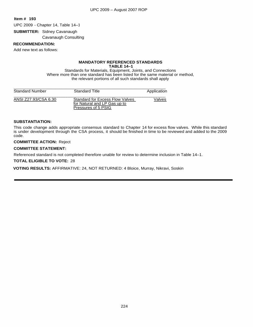
UPC 2009 – August 2007 ROP
SUBMITTER:
Add new text as follows:
MANDATORY REFERENCED STANDARDSTABLE 14–1
Standards for Materials, Equipment, Joints, and ConnectionsWhere more than one standard has been listed for the same material or method,
the relevant portions of all such standards shall apply
__________________________________________________________________Standard Number Standard Title Application__________________________________________________________________ANSI Z27.93/CSA 6.30 Standard for Excess Flow Valves Valves for Natural and LP Gas up to Pressures of 5 PSIG
This code change adds appropriate consensus standard to Chapter 14 for excess flow valves. While this standard is under development through the CSA process, it should be finished in time to be reviewed and added to the 2009 code.
SUBSTANTIATION:
RECOMMENDATION:
UPC 2009 Chapter 14, Table 14–1
Referenced standard is not completed therefore unable for review to determine inclusion in Table 14–1.
Reject
Sidney Cavanaugh
193-
TOTAL ELIGIBLE TO VOTE: 28
VOTING RESULTS: AFFIRMATIVE: 24, NOT RETURNED: 4 Bloice, Murray, Nikravi, Soskin
COMMITTEE ACTION:COMMITTEE STATEMENT:
Item #
Cavanaugh Consulting
224
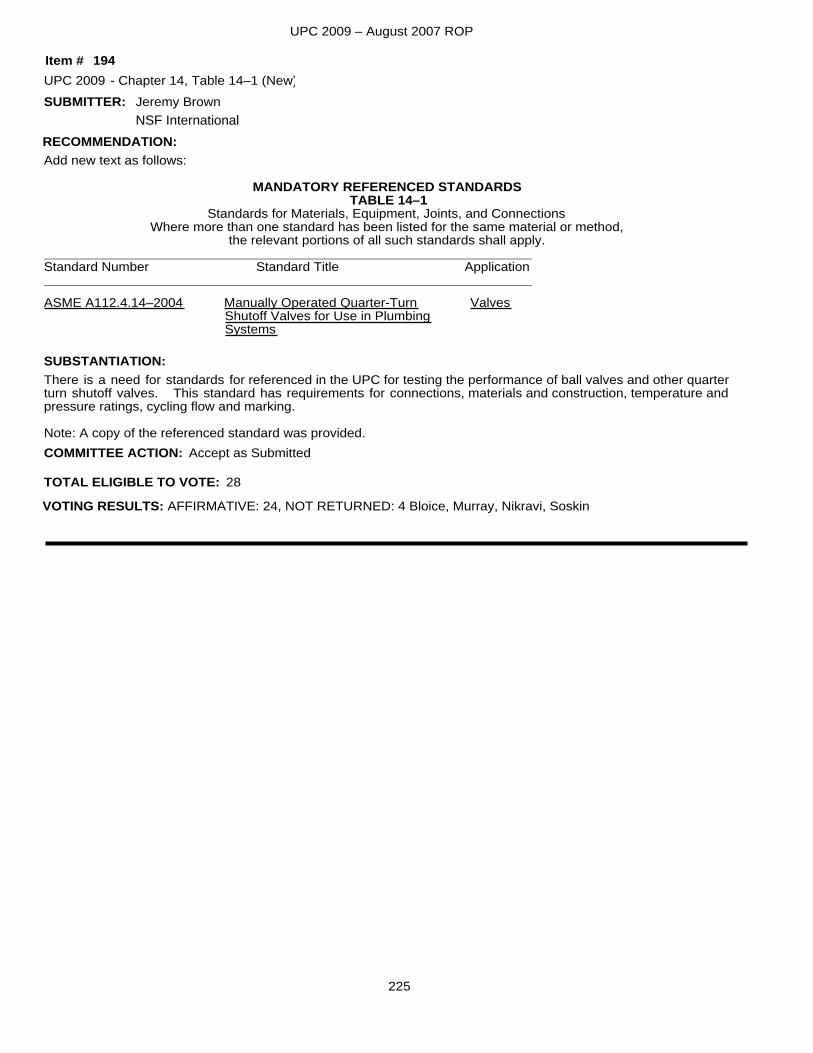
UPC 2009 – August 2007 ROP
SUBMITTER:
Add new text as follows:
MANDATORY REFERENCED STANDARDSTABLE 14–1
Standards for Materials, Equipment, Joints, and ConnectionsWhere more than one standard has been listed for the same material or method,
the relevant portions of all such standards shall apply.__________________________________________________________________Standard Number Standard Title Application__________________________________________________________________ASME A112.4.14–2004 Manually Operated Quarter-Turn Valves
Shutoff Valves for Use in PlumbingSystems
There is a need for standards for referenced in the UPC for testing the performance of ball valves and other quarter turn shutoff valves. This standard has requirements for connections, materials and construction, temperature and pressure ratings, cycling flow and marking.
Note: A copy of the referenced standard was provided.
SUBSTANTIATION:
RECOMMENDATION:
UPC 2009 Chapter 14, Table 14–1 (New)
Accept as Submitted
Jeremy Brown
194-
TOTAL ELIGIBLE TO VOTE: 28
VOTING RESULTS: AFFIRMATIVE: 24, NOT RETURNED: 4 Bloice, Murray, Nikravi, Soskin
COMMITTEE ACTION:
Item #
NSF International
225
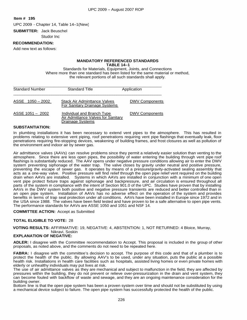
UPC 2009 – August 2007 ROP
SUBMITTER:
Add new text as follows:
MANDATORY REFERENCED STANDARDSTABLE 14–1
Standards for Materials, Equipment, Joints, and ConnectionsWhere more than one standard has been listed for the same material or method,
the relevant portions of all such standards shall apply.
__________________________________________________________________Standard Number Standard Title Application__________________________________________________________________
ASSE 1050 – 2002 Stack Air Adminttance Valves DWV Components For Sanitary Drainage Systems
ASSE 1051 – 2002 Individual and Branch Type DWV Components Air Admittance Valves for Sanitary Drainage Systems
In plumbing installations it has been necessary to extend vent pipes to the atmosphere. This has resulted in problems relating to extensive vent piping, roof penetrations requiring vent pipe flashings that eventually leak, floor penetrations requiring fire-stopping devices, weakening of building frames, and frost closures as well as pollution of the environment and indoor air by sewer gas.
Air admittance valves (AAVs) can resolve problems since they permit a relatively easier solution than venting to theatmosphere. Since there are less open pipes, the possibility of water entering the building through vent pipe roof flashings is substantially reduced. The AAV opens under negative pressure conditions allowing air to enter the DWVsystem preventing siphonage of the water trap. The valve closes by gravity under neutral and positive pressure, preventing the escape of sewer gas. It operates by means of a pressure/gravity-activated sealing assembly that acts as a one-way valve. Positive pressure will find relief through the open pipe relief vent required on the building drain when AAVs are installed. Systems in which AAVs are installed in conjunction with a minimum of one open vent pipe protect fixture traps against siphonage and backpressure, and air circulation is ensured throughout all parts of the system in compliance with the intent of Section 901.0 of the UPC. Studies have proven that by installingAAVs in the DWV system both positive and negative pressure transients are reduced and better controlled than in an open pipe system. Installation of AAVs has no adverse effect on the operation of the system and provides benefits in terms of trap seal protection under all conditions. AAVs have been installed in Europe since 1972 and inthe USA since 1988. The valves have been field tested and have proven to be a safe alternative to open pipe vents.The performance standards for AAVs are ASSE 1050 and 1051 and NSF 14.
SUBSTANTIATION:
RECOMMENDATION:
UPC 2009 Chapter 14, Table 14–1(New)
Accept as Submitted
Jack Beuschel
195-
TOTAL ELIGIBLE TO VOTE: 28
VOTING RESULTS: AFFIRMATIVE: 19, NEGATIVE: 4, ABSTENTION: 1, NOT RETURNED: 4 Bloice, Murray, Nikravi, Soskin
EXPLANATION OF NEGATIVE:ADLER: I disagree with the Committee recommendation to Accept. This proposal is included in the group of other proposals, as noted above, and the comments do not need to be repeated here.FABRA: I disagree with the committee’s decision to accept. The purpose of this code and that of a plumber is to protect the health of the public. By allowing AAV’s to be used, under any situation, puts the public at a possible health risk. Installations in health care facilities such as hospitals, assisted living homes or even private homes with elderly or unhealthy individuals may put lives at risk.The use of air admittance valves as they are mechanical and subject to malfunction in the field, they are affected bypressures within the building, they do not prevent or relieve over-pressurization in the drain and vent system, they can become fouled with backflow of waste and sewage, and they are an ongoing maintenance consideration for thebuilding owner.Bottom line is that the open pipe system has been a proven system over time and should not be substituted by usinga mechanical device subject to failure. The open pipe system has successfully protected the health of the public.
COMMITTEE ACTION:
Item #
Studor Inc
226
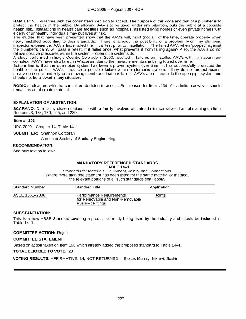
UPC 2009 – August 2007 ROP
EXPLANATION OF ABSTENTION:SCARANO: Due to my close relationship with a family involved with air admittance valves, I am abstaining on ItemNumbers 3, 134, 139, 195, and 239.
HAMILTON: I disagree with the committee’s decision to accept. The purpose of this code and that of a plumber is toprotect the health of the public. By allowing AAV’s to be used, under any situation, puts the public at a possible health risk. Installations in health care facilities such as hospitals, assisted living homes or even private homes with elderly or unhealthy individuals may put lives at risk.The studies that have been presented show that the AAV’s will, most (not all) of the time, operate properly when newly installed according to their standards. There is already the possibility of a problem. From my plumbing inspector experience, AAV’s have failed the initial test prior to installation. The failed AAV, when “popped” against the plumber’s palm, will pass a retest. If it failed once, what prevents it from failing again? Also, the AAV’s do not relieve positive pressures within the system – open pipe systems do.A study performed in Eagle County, Colorado in 2000, resulted in failures on installed AAV’s within an apartment complex. AAV’s have also failed in Wisconsin due to the movable membrane being fouled over time.Bottom line is that the open pipe system has been a proven system over time. It has successfully protected the health of the public. AAV’s introduce a possible failure within a plumbing system. They do not protect against positive pressure and rely on a moving membrane that has failed. AAV’s are not equal to the open pipe system andshould not be allowed in any situation.
RODIO: I disagree with the committee decision to accept. See reason for item #139. Air admittance valves should remain as an alternate material.
SUBMITTER:
Add new text as follows:
MANDATORY REFERENCED STANDARDSTABLE 14–1
Standards for Materials, Equipment, Joints, and ConnectionsWhere more than one standard has been listed for the same material or method,
the relevant portions of all such standards shall apply.__________________________________________________________________________________________Standard Number Standard Title Application__________________________________________________________________________________________ASSE 1061–2006 Performance Requirements Joints
for Removable and Non-RemovablePush-Fit Fittings
This is a new ASSE Standard covering a product currently being used by the industry and should be included in Table 14–1.
SUBSTANTIATION:
RECOMMENDATION:
UPC 2009 Chapter 14, Table 14–1
Based on action taken on Item 190 which already added the proposed standard to Table 14–1.
Reject
Shannon Corcoran
196-
TOTAL ELIGIBLE TO VOTE: 28
VOTING RESULTS: AFFIRMATIVE: 24, NOT RETURNED: 4 Bloice, Murray, Nikravi, Soskin
COMMITTEE ACTION:COMMITTEE STATEMENT:
Item #
American Society of Sanitary Engineering
227
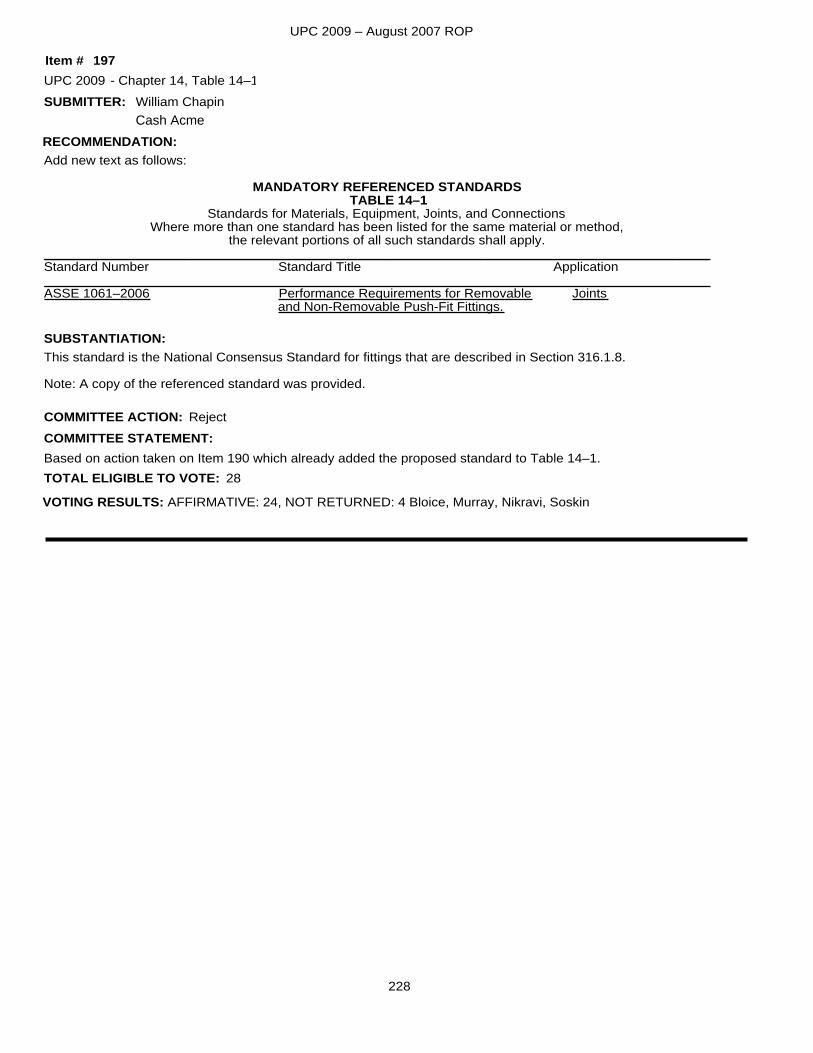
UPC 2009 – August 2007 ROP
SUBMITTER:
Add new text as follows:
MANDATORY REFERENCED STANDARDSTABLE 14–1
Standards for Materials, Equipment, Joints, and ConnectionsWhere more than one standard has been listed for the same material or method,
the relevant portions of all such standards shall apply.__________________________________________________________________________________________Standard Number Standard Title Application__________________________________________________________________________________________ASSE 1061–2006 Performance Requirements for Removable Joints
and Non-Removable Push-Fit Fittings.
This standard is the National Consensus Standard for fittings that are described in Section 316.1.8.
Note: A copy of the referenced standard was provided.
SUBSTANTIATION:
RECOMMENDATION:
UPC 2009 Chapter 14, Table 14–1
Based on action taken on Item 190 which already added the proposed standard to Table 14–1.
Reject
William Chapin
197-
TOTAL ELIGIBLE TO VOTE: 28
VOTING RESULTS: AFFIRMATIVE: 24, NOT RETURNED: 4 Bloice, Murray, Nikravi, Soskin
COMMITTEE ACTION:COMMITTEE STATEMENT:
Item #
Cash Acme
228
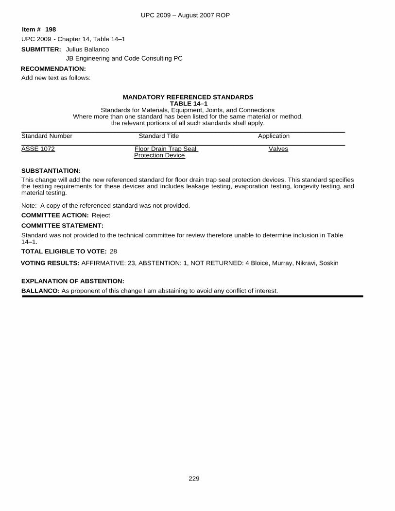
UPC 2009 – August 2007 ROP
SUBMITTER:
Add new text as follows:
MANDATORY REFERENCED STANDARDSTABLE 14–1
Standards for Materials, Equipment, Joints, and ConnectionsWhere more than one standard has been listed for the same material or method,
the relevant portions of all such standards shall apply.__________________________________________________________________________________________Standard Number Standard Title Application__________________________________________________________________________________________ASSE 1072 Floor Drain Trap Seal Valves
Protection Device
This change will add the new referenced standard for floor drain trap seal protection devices. This standard specifiesthe testing requirements for these devices and includes leakage testing, evaporation testing, longevity testing, and material testing.
Note: A copy of the referenced standard was not provided.
SUBSTANTIATION:
RECOMMENDATION:
UPC 2009 Chapter 14, Table 14–1
Standard was not provided to the technical committee for review therefore unable to determine inclusion in Table14–1.
Reject
Julius Ballanco
198-
TOTAL ELIGIBLE TO VOTE: 28
VOTING RESULTS: AFFIRMATIVE: 23, ABSTENTION: 1, NOT RETURNED: 4 Bloice, Murray, Nikravi, Soskin
EXPLANATION OF ABSTENTION:BALLANCO: As proponent of this change I am abstaining to avoid any conflict of interest.
COMMITTEE ACTION:COMMITTEE STATEMENT:
Item #
JB Engineering and Code Consulting PC
229
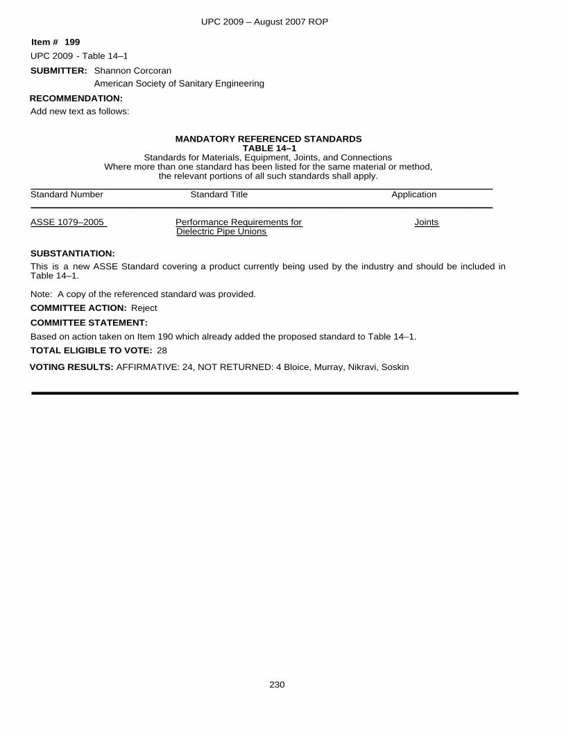
UPC 2009 – August 2007 ROP
SUBMITTER:
Add new text as follows:
MANDATORY REFERENCED STANDARDSTABLE 14–1
Standards for Materials, Equipment, Joints, and ConnectionsWhere more than one standard has been listed for the same material or method,
the relevant portions of all such standards shall apply.__________________________________________________________________________________________Standard Number Standard Title Application__________________________________________________________________________________________
ASSE 1079–2005 Performance Requirements for JointsDielectric Pipe Unions
This is a new ASSE Standard covering a product currently being used by the industry and should be included in Table 14–1.
Note: A copy of the referenced standard was provided.
SUBSTANTIATION:
RECOMMENDATION:
UPC 2009 Table 14–1
Based on action taken on Item 190 which already added the proposed standard to Table 14–1.
Reject
Shannon Corcoran
199-
TOTAL ELIGIBLE TO VOTE: 28
VOTING RESULTS: AFFIRMATIVE: 24, NOT RETURNED: 4 Bloice, Murray, Nikravi, Soskin
COMMITTEE ACTION:COMMITTEE STATEMENT:
Item #
American Society of Sanitary Engineering
230
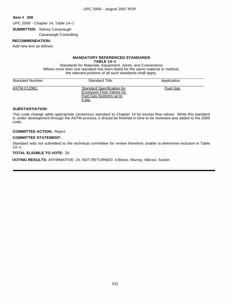
UPC 2009 – August 2007 ROP
SUBMITTER:
Add new text as follows:
MANDATORY REFERENCED STANDARDSTABLE 14–1
Standards for Materials, Equipment, Joints, and ConnectionsWhere more than one standard has been listed for the same material or method,
the relevant portions of all such standards shall apply.__________________________________________________________________________________________Standard Number Standard Title Application__________________________________________________________________________________________ASTM F12961 Standard Specification for Fuel Gas
Excessive Flow Valves forFuel Gas Systems up to5 psi.
This code change adds appropriate consensus standard to Chapter 14 for excess flow valves. While this standard is under development through the ASTM process, it should be finished in time to be reviewed and added to the 2009code.
SUBSTANTIATION:
RECOMMENDATION:
UPC 2009 Chapter 14, Table 14–1
Standard was not submitted to the technical committee for review therefore unable to determine inclusion in Table 14–1.
Reject
Sidney Cavanaugh
200-
TOTAL ELIGIBLE TO VOTE: 28
VOTING RESULTS: AFFIRMATIVE: 24, NOT RETURNED: 4 Bloice, Murray, Nikravi, Soskin
COMMITTEE ACTION:COMMITTEE STATEMENT:
Item #
Cavanaugh Consulting
231
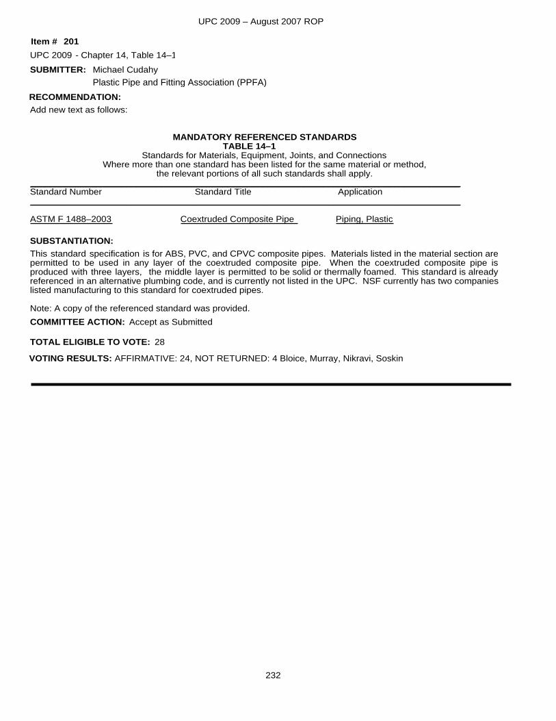
UPC 2009 – August 2007 ROP
SUBMITTER:
Add new text as follows:
MANDATORY REFERENCED STANDARDSTABLE 14–1
Standards for Materials, Equipment, Joints, and ConnectionsWhere more than one standard has been listed for the same material or method,
the relevant portions of all such standards shall apply._____________________________________________________________________________________Standard Number Standard Title Application_____________________________________________________________________________________
ASTM F 1488–2003 Coextruded Composite Pipe Piping, Plastic
This standard specification is for ABS, PVC, and CPVC composite pipes. Materials listed in the material section arepermitted to be used in any layer of the coextruded composite pipe. When the coextruded composite pipe is produced with three layers, the middle layer is permitted to be solid or thermally foamed. This standard is already referenced in an alternative plumbing code, and is currently not listed in the UPC. NSF currently has two companieslisted manufacturing to this standard for coextruded pipes.
Note: A copy of the referenced standard was provided.
SUBSTANTIATION:
RECOMMENDATION:
UPC 2009 Chapter 14, Table 14–1
Accept as Submitted
Michael Cudahy
201-
TOTAL ELIGIBLE TO VOTE: 28
VOTING RESULTS: AFFIRMATIVE: 24, NOT RETURNED: 4 Bloice, Murray, Nikravi, Soskin
COMMITTEE ACTION:
Item #
Plastic Pipe and Fitting Association (PPFA)
232
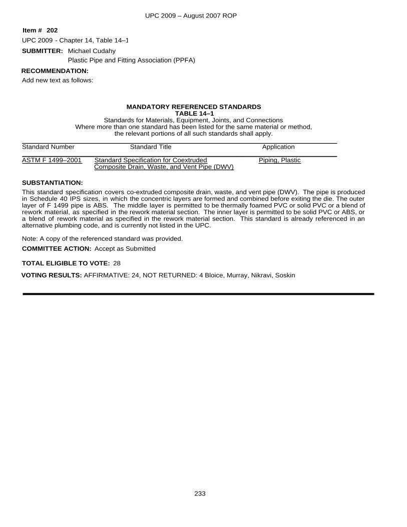
UPC 2009 – August 2007 ROP
SUBMITTER:
Add new text as follows:
MANDATORY REFERENCED STANDARDSTABLE 14–1
Standards for Materials, Equipment, Joints, and ConnectionsWhere more than one standard has been listed for the same material or method,
the relevant portions of all such standards shall apply._____________________________________________________________________________________Standard Number Standard Title Application_____________________________________________________________________________________ASTM F 1499–2001 Standard Specification for Coextruded Piping, Plastic Composite Drain, Waste, and Vent Pipe (DWV)
This standard specification covers co-extruded composite drain, waste, and vent pipe (DWV). The pipe is producedin Schedule 40 IPS sizes, in which the concentric layers are formed and combined before exiting the die. The outer layer of F 1499 pipe is ABS. The middle layer is permitted to be thermally foamed PVC or solid PVC or a blend of rework material, as specified in the rework material section. The inner layer is permitted to be solid PVC or ABS, ora blend of rework material as specified in the rework material section. This standard is already referenced in an alternative plumbing code, and is currently not listed in the UPC.
Note: A copy of the referenced standard was provided.
SUBSTANTIATION:
RECOMMENDATION:
UPC 2009 Chapter 14, Table 14–1
Accept as Submitted
Michael Cudahy
202-
TOTAL ELIGIBLE TO VOTE: 28
VOTING RESULTS: AFFIRMATIVE: 24, NOT RETURNED: 4 Bloice, Murray, Nikravi, Soskin
COMMITTEE ACTION:
Item #
Plastic Pipe and Fitting Association (PPFA)
233
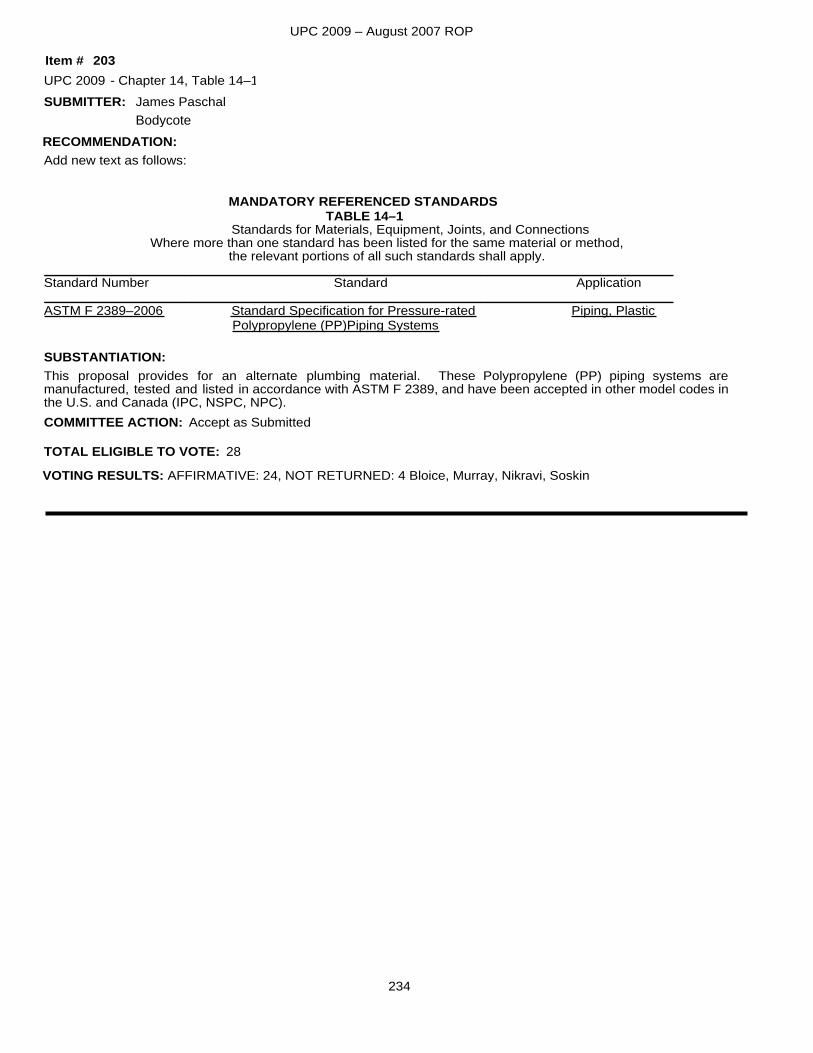
UPC 2009 – August 2007 ROP
SUBMITTER:
Add new text as follows:
MANDATORY REFERENCED STANDARDSTABLE 14–1
Standards for Materials, Equipment, Joints, and ConnectionsWhere more than one standard has been listed for the same material or method,
the relevant portions of all such standards shall apply._____________________________________________________________________________________Standard Number Standard Application_____________________________________________________________________________________ASTM F 2389–2006 Standard Specification for Pressure-rated Piping, Plastic Polypropylene (PP)Piping Systems
This proposal provides for an alternate plumbing material. These Polypropylene (PP) piping systems are manufactured, tested and listed in accordance with ASTM F 2389, and have been accepted in other model codes inthe U.S. and Canada (IPC, NSPC, NPC).
SUBSTANTIATION:
RECOMMENDATION:
UPC 2009 Chapter 14, Table 14–1
Accept as Submitted
James Paschal
203-
TOTAL ELIGIBLE TO VOTE: 28
VOTING RESULTS: AFFIRMATIVE: 24, NOT RETURNED: 4 Bloice, Murray, Nikravi, Soskin
COMMITTEE ACTION:
Item #
Bodycote
234
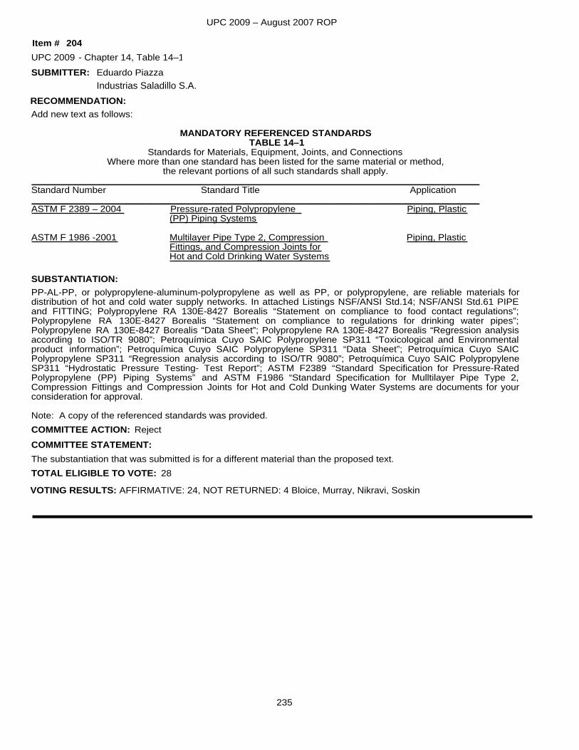
UPC 2009 – August 2007 ROP
SUBMITTER:
Add new text as follows:
MANDATORY REFERENCED STANDARDSTABLE 14–1
Standards for Materials, Equipment, Joints, and ConnectionsWhere more than one standard has been listed for the same material or method,
the relevant portions of all such standards shall apply._____________________________________________________________________________________Standard Number Standard Title Application_____________________________________________________________________________________ASTM F 2389 – 2004 Pressure-rated Polypropylene Piping, Plastic
(PP) Piping Systems
ASTM F 1986 -2001 Multilayer Pipe Type 2, Compression Piping, PlasticFittings, and Compression Joints forHot and Cold Drinking Water Systems
PP-AL-PP, or polypropylene-aluminum-polypropylene as well as PP, or polypropylene, are reliable materials for distribution of hot and cold water supply networks. In attached Listings NSF/ANSI Std.14; NSF/ANSI Std.61 PIPE and FITTING; Polypropylene RA 130E-8427 Borealis “Statement on compliance to food contact regulations”; Polypropylene RA 130E-8427 Borealis “Statement on compliance to regulations for drinking water pipes”; Polypropylene RA 130E-8427 Borealis “Data Sheet”; Polypropylene RA 130E-8427 Borealis “Regression analysis according to ISO/TR 9080”; Petroquímica Cuyo SAIC Polypropylene SP311 “Toxicological and Environmental product information”; Petroquímica Cuyo SAIC Polypropylene SP311 “Data Sheet”; Petroquímica Cuyo SAIC Polypropylene SP311 “Regression analysis according to ISO/TR 9080”; Petroquímica Cuyo SAIC Polypropylene SP311 “Hydrostatic Pressure Testing- Test Report”; ASTM F2389 “Standard Specification for Pressure-Rated Polypropylene (PP) Piping Systems” and ASTM F1986 “Standard Specification for Mulltilayer Pipe Type 2, Compression Fittings and Compression Joints for Hot and Cold Dunking Water Systems are documents for your consideration for approval.
Note: A copy of the referenced standards was provided.
SUBSTANTIATION:
RECOMMENDATION:
UPC 2009 Chapter 14, Table 14–1
The substantiation that was submitted is for a different material than the proposed text.
Reject
Eduardo Piazza
204-
TOTAL ELIGIBLE TO VOTE: 28
VOTING RESULTS: AFFIRMATIVE: 24, NOT RETURNED: 4 Bloice, Murray, Nikravi, Soskin
COMMITTEE ACTION:COMMITTEE STATEMENT:
Item #
Industrias Saladillo S.A.
235
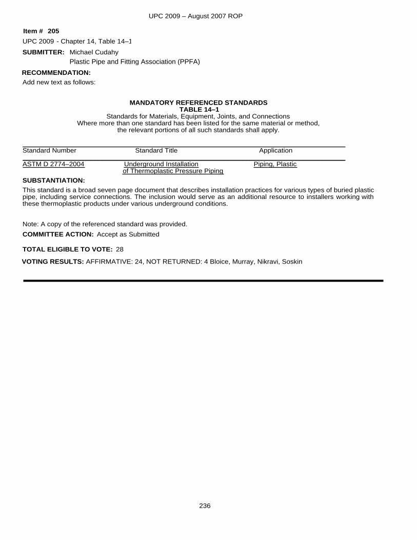
UPC 2009 – August 2007 ROP
SUBMITTER:
Add new text as follows:
MANDATORY REFERENCED STANDARDSTABLE 14–1
Standards for Materials, Equipment, Joints, and ConnectionsWhere more than one standard has been listed for the same material or method,
the relevant portions of all such standards shall apply.
_____________________________________________________________________________________Standard Number Standard Title Application_____________________________________________________________________________________ASTM D 2774–2004 Underground Installation Piping, Plastic
of Thermoplastic Pressure Piping
This standard is a broad seven page document that describes installation practices for various types of buried plasticpipe, including service connections. The inclusion would serve as an additional resource to installers working with these thermoplastic products under various underground conditions.
Note: A copy of the referenced standard was provided.
SUBSTANTIATION:
RECOMMENDATION:
UPC 2009 Chapter 14, Table 14–1
Accept as Submitted
Michael Cudahy
205-
TOTAL ELIGIBLE TO VOTE: 28
VOTING RESULTS: AFFIRMATIVE: 24, NOT RETURNED: 4 Bloice, Murray, Nikravi, Soskin
COMMITTEE ACTION:
Item #
Plastic Pipe and Fitting Association (PPFA)
236
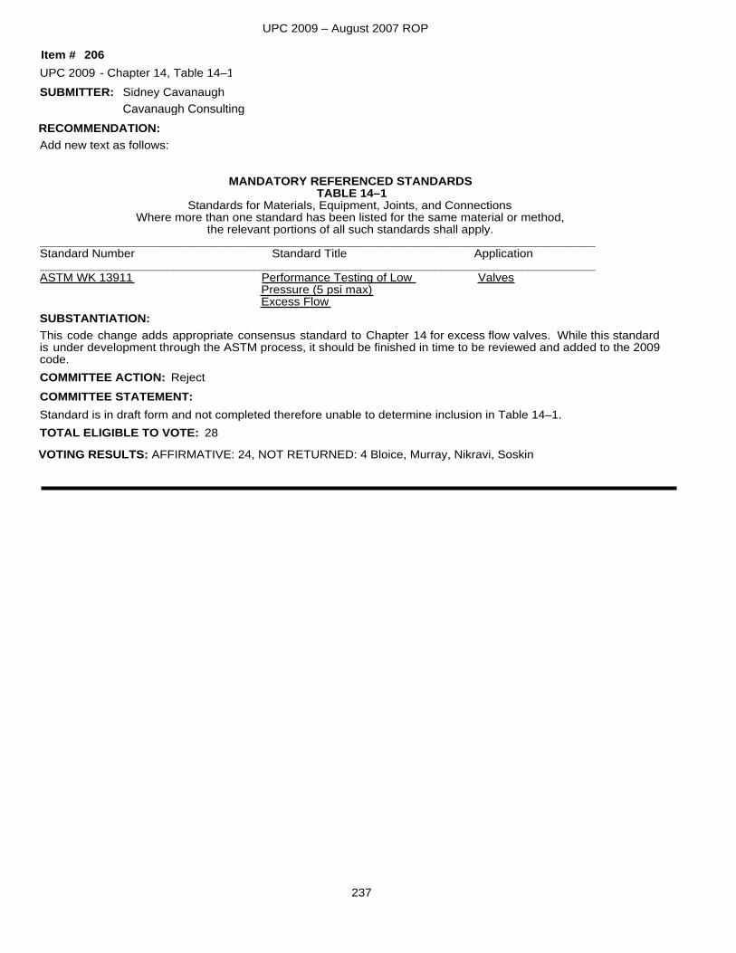
UPC 2009 – August 2007 ROP
SUBMITTER:
Add new text as follows:
MANDATORY REFERENCED STANDARDSTABLE 14–1
Standards for Materials, Equipment, Joints, and ConnectionsWhere more than one standard has been listed for the same material or method,
the relevant portions of all such standards shall apply.___________________________________________________________________________________Standard Number Standard Title Application___________________________________________________________________________________ASTM WK 13911 Performance Testing of Low Valves
Pressure (5 psi max) Excess Flow
This code change adds appropriate consensus standard to Chapter 14 for excess flow valves. While this standard is under development through the ASTM process, it should be finished in time to be reviewed and added to the 2009code.
SUBSTANTIATION:
RECOMMENDATION:
UPC 2009 Chapter 14, Table 14–1
Standard is in draft form and not completed therefore unable to determine inclusion in Table 14–1.
Reject
Sidney Cavanaugh
206-
TOTAL ELIGIBLE TO VOTE: 28
VOTING RESULTS: AFFIRMATIVE: 24, NOT RETURNED: 4 Bloice, Murray, Nikravi, Soskin
COMMITTEE ACTION:COMMITTEE STATEMENT:
Item #
Cavanaugh Consulting
237
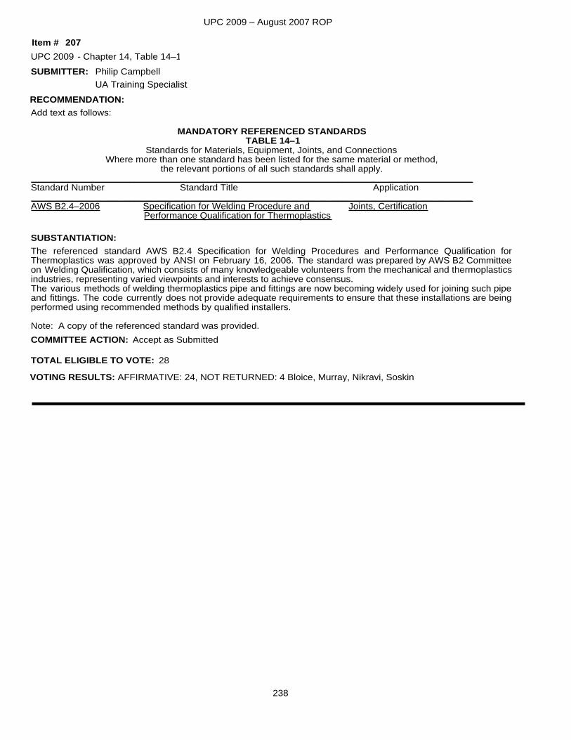
UPC 2009 – August 2007 ROP
SUBMITTER:
Add text as follows:
MANDATORY REFERENCED STANDARDSTABLE 14–1
Standards for Materials, Equipment, Joints, and ConnectionsWhere more than one standard has been listed for the same material or method,
the relevant portions of all such standards shall apply._____________________________________________________________________________________Standard Number Standard Title Application_____________________________________________________________________________________AWS B2.4–2006 Specification for Welding Procedure and Joints, Certification
Performance Qualification for Thermoplastics
The referenced standard AWS B2.4 Specification for Welding Procedures and Performance Qualification for Thermoplastics was approved by ANSI on February 16, 2006. The standard was prepared by AWS B2 Committee on Welding Qualification, which consists of many knowledgeable volunteers from the mechanical and thermoplasticsindustries, representing varied viewpoints and interests to achieve consensus.The various methods of welding thermoplastics pipe and fittings are now becoming widely used for joining such pipeand fittings. The code currently does not provide adequate requirements to ensure that these installations are beingperformed using recommended methods by qualified installers.
Note: A copy of the referenced standard was provided.
SUBSTANTIATION:
RECOMMENDATION:
UPC 2009 Chapter 14, Table 14–1
Accept as Submitted
Philip Campbell
207-
TOTAL ELIGIBLE TO VOTE: 28
VOTING RESULTS: AFFIRMATIVE: 24, NOT RETURNED: 4 Bloice, Murray, Nikravi, Soskin
COMMITTEE ACTION:
Item #
UA Training Specialist
238
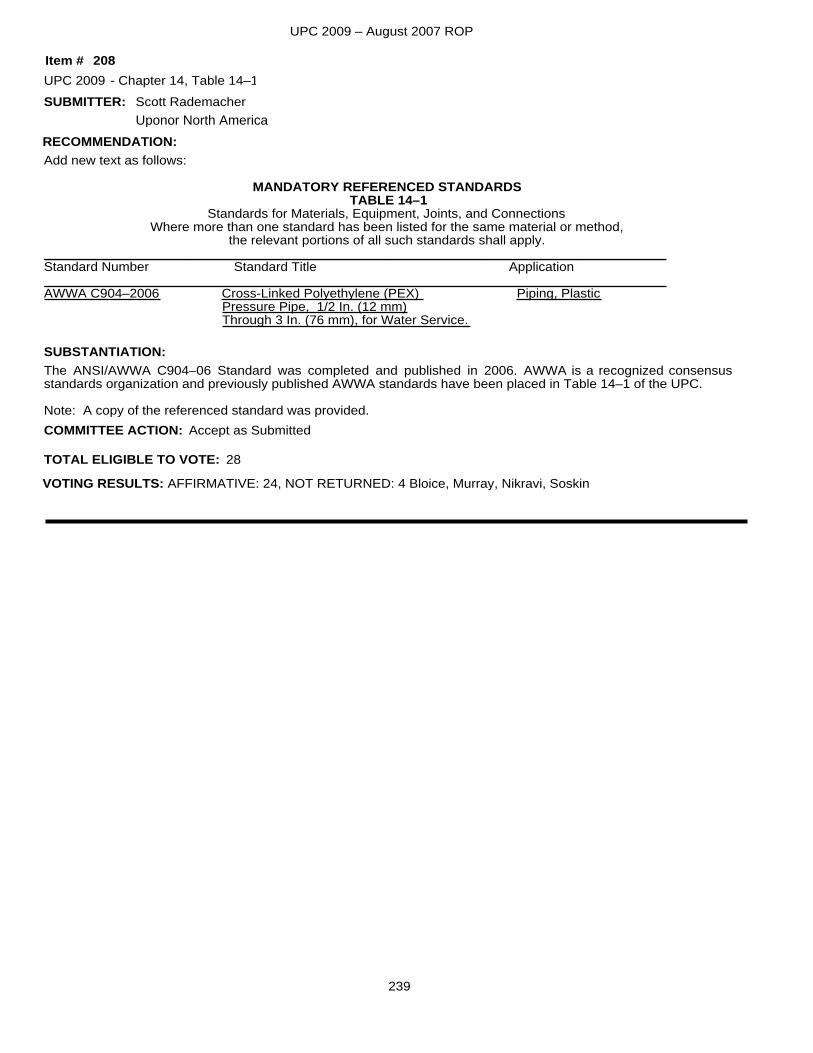
UPC 2009 – August 2007 ROP
SUBMITTER:
Add new text as follows:
MANDATORY REFERENCED STANDARDSTABLE 14–1
Standards for Materials, Equipment, Joints, and ConnectionsWhere more than one standard has been listed for the same material or method,
the relevant portions of all such standards shall apply.____________________________________________________________________________________Standard Number Standard Title Application____________________________________________________________________________________AWWA C904–2006 Cross-Linked Polyethylene (PEX) Piping, Plastic
Pressure Pipe, 1/2 In. (12 mm)Through 3 In. (76 mm), for Water Service.
The ANSI/AWWA C904–06 Standard was completed and published in 2006. AWWA is a recognized consensus standards organization and previously published AWWA standards have been placed in Table 14–1 of the UPC.
Note: A copy of the referenced standard was provided.
SUBSTANTIATION:
RECOMMENDATION:
UPC 2009 Chapter 14, Table 14–1
Accept as Submitted
Scott Rademacher
208-
TOTAL ELIGIBLE TO VOTE: 28
VOTING RESULTS: AFFIRMATIVE: 24, NOT RETURNED: 4 Bloice, Murray, Nikravi, Soskin
COMMITTEE ACTION:
Item #
Uponor North America
239
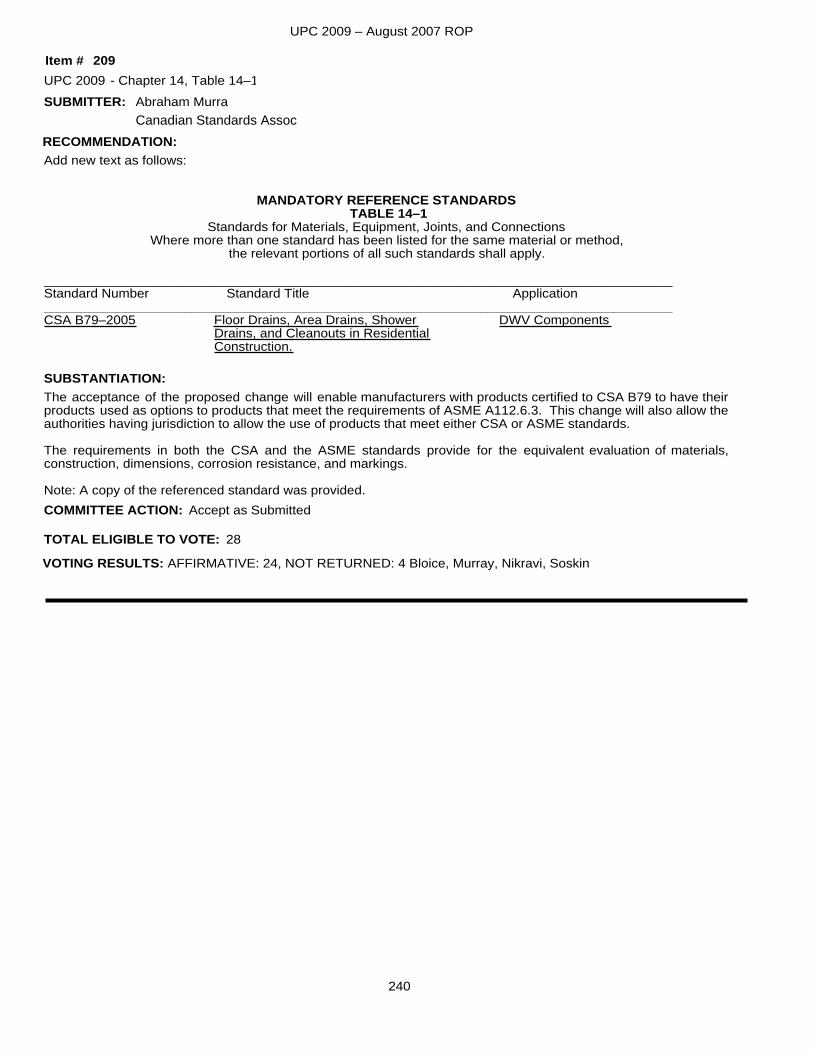
UPC 2009 – August 2007 ROP
SUBMITTER:
Add new text as follows:
MANDATORY REFERENCE STANDARDSTABLE 14–1
Standards for Materials, Equipment, Joints, and ConnectionsWhere more than one standard has been listed for the same material or method,
the relevant portions of all such standards shall apply.
_____________________________________________________________________________________Standard Number Standard Title Application_____________________________________________________________________________________CSA B79–2005 Floor Drains, Area Drains, Shower DWV Components
Drains, and Cleanouts in ResidentialConstruction.
The acceptance of the proposed change will enable manufacturers with products certified to CSA B79 to have theirproducts used as options to products that meet the requirements of ASME A112.6.3. This change will also allow theauthorities having jurisdiction to allow the use of products that meet either CSA or ASME standards.
The requirements in both the CSA and the ASME standards provide for the equivalent evaluation of materials, construction, dimensions, corrosion resistance, and markings.
Note: A copy of the referenced standard was provided.
SUBSTANTIATION:
RECOMMENDATION:
UPC 2009 Chapter 14, Table 14–1
Accept as Submitted
Abraham Murra
209-
TOTAL ELIGIBLE TO VOTE: 28
VOTING RESULTS: AFFIRMATIVE: 24, NOT RETURNED: 4 Bloice, Murray, Nikravi, Soskin
COMMITTEE ACTION:
Item #
Canadian Standards Assoc
240
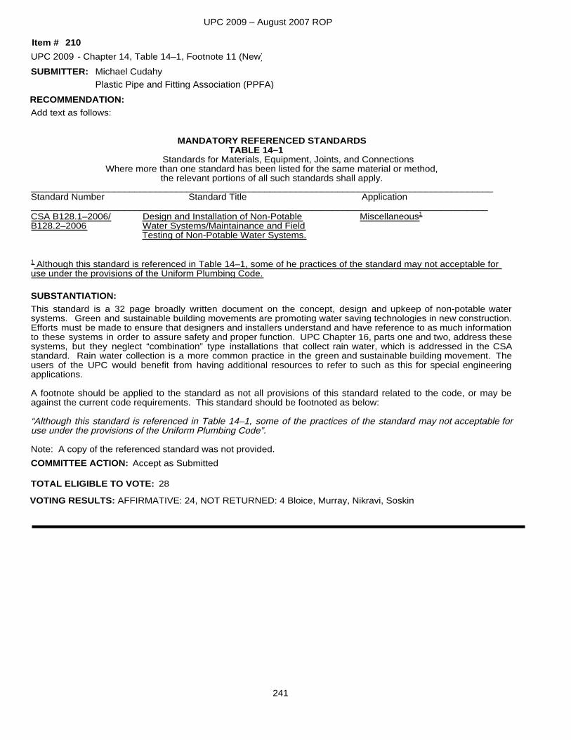
UPC 2009 – August 2007 ROP
SUBMITTER:
Add text as follows:
MANDATORY REFERENCED STANDARDSTABLE 14–1
Standards for Materials, Equipment, Joints, and ConnectionsWhere more than one standard has been listed for the same material or method,
the relevant portions of all such standards shall apply._________________________________________________________________________________________Standard Number Standard Title Application________________________________________________________________________________________CSA B128.1–2006/ Design and Installation of Non-Potable Miscellaneous1
B128.2–2006 Water Systems/Maintainance and Field Testing of Non-Potable Water Systems.
1 Although this standard is referenced in Table 14–1, some of he practices of the standard may not acceptable for use under the provisions of the Uniform Plumbing Code.
This standard is a 32 page broadly written document on the concept, design and upkeep of non-potable water systems. Green and sustainable building movements are promoting water saving technologies in new construction.Efforts must be made to ensure that designers and installers understand and have reference to as much informationto these systems in order to assure safety and proper function. UPC Chapter 16, parts one and two, address thesesystems, but they neglect “combination” type installations that collect rain water, which is addressed in the CSA standard. Rain water collection is a more common practice in the green and sustainable building movement. The users of the UPC would benefit from having additional resources to refer to such as this for special engineering applications.
A footnote should be applied to the standard as not all provisions of this standard related to the code, or may be against the current code requirements. This standard should be footnoted as below:
“Although this standard is referenced in Table 14–1, some of the practices of the standard may not acceptable for use under the provisions of the Uniform Plumbing Code”.
Note: A copy of the referenced standard was not provided.
SUBSTANTIATION:
RECOMMENDATION:
UPC 2009 Chapter 14, Table 14–1, Footnote 11 (New)
Accept as Submitted
Michael Cudahy
210-
TOTAL ELIGIBLE TO VOTE: 28
VOTING RESULTS: AFFIRMATIVE: 24, NOT RETURNED: 4 Bloice, Murray, Nikravi, Soskin
COMMITTEE ACTION:
Item #
Plastic Pipe and Fitting Association (PPFA)
241
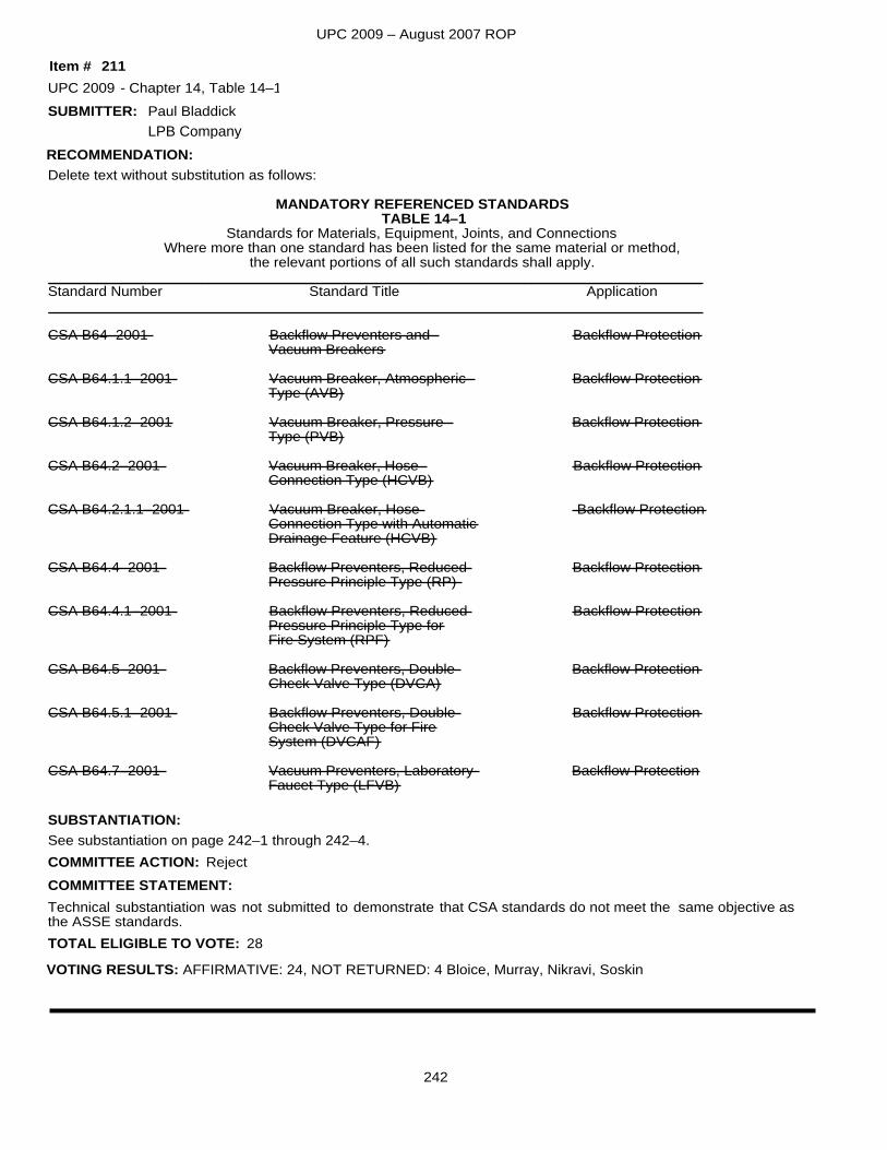
UPC 2009 – August 2007 ROP
SUBMITTER:
Delete text without substitution as follows:
MANDATORY REFERENCED STANDARDSTABLE 14–1
Standards for Materials, Equipment, Joints, and ConnectionsWhere more than one standard has been listed for the same material or method,
the relevant portions of all such standards shall apply._________________________________________________________________________________Standard Number Standard Title Application_________________________________________________________________________________
CSA B64–2001 Backflow Preventers and Backflow ProtectionVacuum Breakers
CSA B64.1.1–2001 Vacuum Breaker, Atmospheric Backflow ProtectionType (AVB)
CSA B64.1.2–2001 Vacuum Breaker, Pressure Backflow ProtectionType (PVB)
CSA B64.2–2001 Vacuum Breaker, Hose Backflow ProtectionConnection Type (HCVB)
CSA B64.2.1.1–2001 Vacuum Breaker, Hose Backflow ProtectionConnection Type with AutomaticDrainage Feature (HCVB)
CSA B64.4–2001 Backflow Preventers, Reduced Backflow ProtectionPressure Principle Type (RP)
CSA B64.4.1–2001 Backflow Preventers, Reduced Backflow ProtectionPressure Principle Type forFire System (RPF)
CSA B64.5–2001 Backflow Preventers, Double Backflow ProtectionCheck Valve Type (DVCA)
CSA B64.5.1–2001 Backflow Preventers, Double Backflow ProtectionCheck Valve Type for FireSystem (DVCAF)
CSA B64.7–2001 Vacuum Preventers, Laboratory Backflow ProtectionFaucet Type (LFVB)
See substantiation on page 242–1 through 242–4.SUBSTANTIATION:
RECOMMENDATION:
UPC 2009 Chapter 14, Table 14–1
Technical substantiation was not submitted to demonstrate that CSA standards do not meet the same objective as the ASSE standards.
Reject
Paul Bladdick
211-
TOTAL ELIGIBLE TO VOTE: 28
VOTING RESULTS: AFFIRMATIVE: 24, NOT RETURNED: 4 Bloice, Murray, Nikravi, Soskin
COMMITTEE ACTION:COMMITTEE STATEMENT:
Item #
LPB Company
242
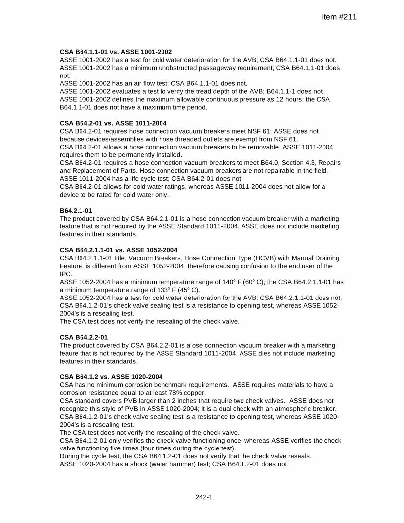
CSA B64.1.1-01 vs. ASSE 1001-2002 ASSE 1001-2002 has a test for cold water deterioration for the AVB; CSA B64.1.1-01 does not. ASSE 1001-2002 has a minimum unobstructed passageway requirement; CSA B64.1.1-01 does not. ASSE 1001-2002 has an air flow test; CSA B64.1.1-01 does not. ASSE 1001-2002 evaluates a test to verify the tread depth of the AVB; B64.1.1-1 does not. ASSE 1001-2002 defines the maximum allowable continuous pressure as 12 hours; the CSA B64.1.1-01 does not have a maximum time period. CSA B64.2-01 vs. ASSE 1011-2004 CSA B64.2-01 requires hose connection vacuum breakers meet NSF 61; ASSE does not because devices/assemblies with hose threaded outlets are exempt from NSF 61. CSA B64.2-01 allows a hose connection vacuum breakers to be removable. ASSE 1011-2004 requires them to be permanently installed. CSA B64.2-01 requires a hose connection vacuum breakers to meet B64.0, Section 4.3, Repairs and Replacement of Parts. Hose connection vacuum breakers are not repairable in the field. ASSE 1011-2004 has a life cycle test; CSA B64.2-01 does not. CSA B64.2-01 allows for cold water ratings, whereas ASSE 1011-2004 does not allow for a device to be rated for cold water only. B64.2.1-01 The product covered by CSA B64.2.1-01 is a hose connection vacuum breaker with a marketing feature that is not required by the ASSE Standard 1011-2004. ASSE does not include marketing features in their standards. CSA B64.2.1.1-01 vs. ASSE 1052-2004 CSA B64.2.1.1-01 title, Vacuum Breakers, Hose Connection Type (HCVB) with Manual Draining Feature, is different from ASSE 1052-2004, therefore causing confusion to the end user of the IPC. ASSE 1052-2004 has a minimum temperature range of 140o F (60o C); the CSA B64.2.1.1-01 has a minimum temperature range of 133o F (45o C). ASSE 1052-2004 has a test for cold water deterioration for the AVB; CSA B64.2.1.1-01 does not. CSA B64.1.2-01’s check valve sealing test is a resistance to opening test, whereas ASSE 1052-2004’s is a resealing test. The CSA test does not verify the resealing of the check valve. CSA B64.2.2-01 The product covered by CSA B64.2.2-01 is a ose connection vacuum breaker with a marketing feaure that is not required by the ASSE Standard 1011-2004. ASSE dies not include marketing features in their standards. CSA B64.1.2 vs. ASSE 1020-2004 CSA has no minimum corrosion benchmark requirements. ASSE requires materials to have a corrosion resistance equal to at least 78% copper. CSA standard covers PVB larger than 2 inches that require two check valves. ASSE does not recognize this style of PVB in ASSE 1020-2004; it is a dual check with an atmospheric breaker. CSA B64.1.2-01’s check valve sealing test is a resistance to opening test, whereas ASSE 1020-2004’s is a resealing test. The CSA test does not verify the resealing of the check valve. CSA B64.1.2-01 only verifies the check valve functioning once, whereas ASSE verifies the check valve functioning five times (four times during the cycle test). During the cycle test, the CSA B64.1.2-01 does not verify that the check valve reseals. ASSE 1020-2004 has a shock (water hammer) test; CSA B64.1.2-01 does not.
Item #211
242 -1
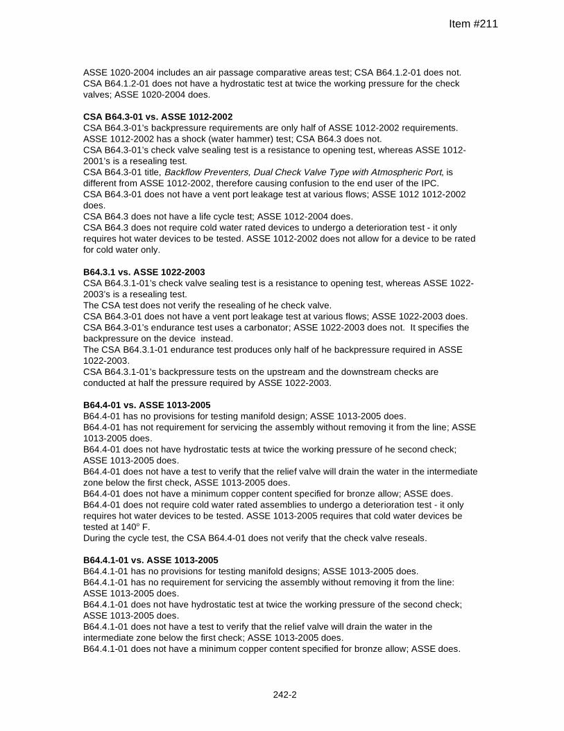
ASSE 1020-2004 includes an air passage comparative areas test; CSA B64.1.2-01 does not. CSA B64.1.2-01 does not have a hydrostatic test at twice the working pressure for the check valves; ASSE 1020-2004 does. CSA B64.3-01 vs. ASSE 1012-2002 CSA B64.3-01’s backpressure requirements are only half of ASSE 1012-2002 requirements. ASSE 1012-2002 has a shock (water hammer) test; CSA B64.3 does not. CSA B64.3-01’s check valve sealing test is a resistance to opening test, whereas ASSE 1012-2001’s is a resealing test. CSA B64.3-01 title, Backflow Preventers, Dual Check Valve Type with Atmospheric Port, is different from ASSE 1012-2002, therefore causing confusion to the end user of the IPC. CSA B64.3-01 does not have a vent port leakage test at various flows; ASSE 1012 1012-2002 does. CSA B64.3 does not have a life cycle test; ASSE 1012-2004 does. CSA B64.3 does not require cold water rated devices to undergo a deterioration test - it only requires hot water devices to be tested. ASSE 1012-2002 does not allow for a device to be rated for cold water only. B64.3.1 vs. ASSE 1022-2003 CSA B64.3.1-01’s check valve sealing test is a resistance to opening test, whereas ASSE 1022-2003’s is a resealing test. The CSA test does not verify the resealing of he check valve. CSA B64.3-01 does not have a vent port leakage test at various flows; ASSE 1022-2003 does. CSA B64.3-01’s endurance test uses a carbonator; ASSE 1022-2003 does not. It specifies the backpressure on the device instead. The CSA B64.3.1-01 endurance test produces only half of he backpressure required in ASSE 1022-2003. CSA B64.3.1-01’s backpressure tests on the upstream and the downstream checks are conducted at half the pressure required by ASSE 1022-2003. B64.4-01 vs. ASSE 1013-2005 B64.4-01 has no provisions for testing manifold design; ASSE 1013-2005 does. B64.4-01 has not requirement for servicing the assembly without removing it from the line; ASSE 1013-2005 does. B64.4-01 does not have hydrostatic tests at twice the working pressure of he second check; ASSE 1013-2005 does. B64.4-01 does not have a test to verify that the relief valve will drain the water in the intermediate zone below the first check, ASSE 1013-2005 does. B64.4-01 does not have a minimum copper content specified for bronze allow; ASSE does. B64.4-01 does not require cold water rated assemblies to undergo a deterioration test - it only requires hot water devices to be tested. ASSE 1013-2005 requires that cold water devices be tested at 140o F. During the cycle test, the CSA B64.4-01 does not verify that the check valve reseals. B64.4.1-01 vs. ASSE 1013-2005 B64.4.1-01 has no provisions for testing manifold designs; ASSE 1013-2005 does. B64.4.1-01 has no requirement for servicing the assembly without removing it from the line: ASSE 1013-2005 does. B64.4.1-01 does not have hydrostatic test at twice the working pressure of the second check; ASSE 1013-2005 does. B64.4.1-01 does not have a test to verify that the relief valve will drain the water in the intermediate zone below the first check; ASSE 1013-2005 does. B64.4.1-01 does not have a minimum copper content specified for bronze allow; ASSE does.
Item #211
242 -2
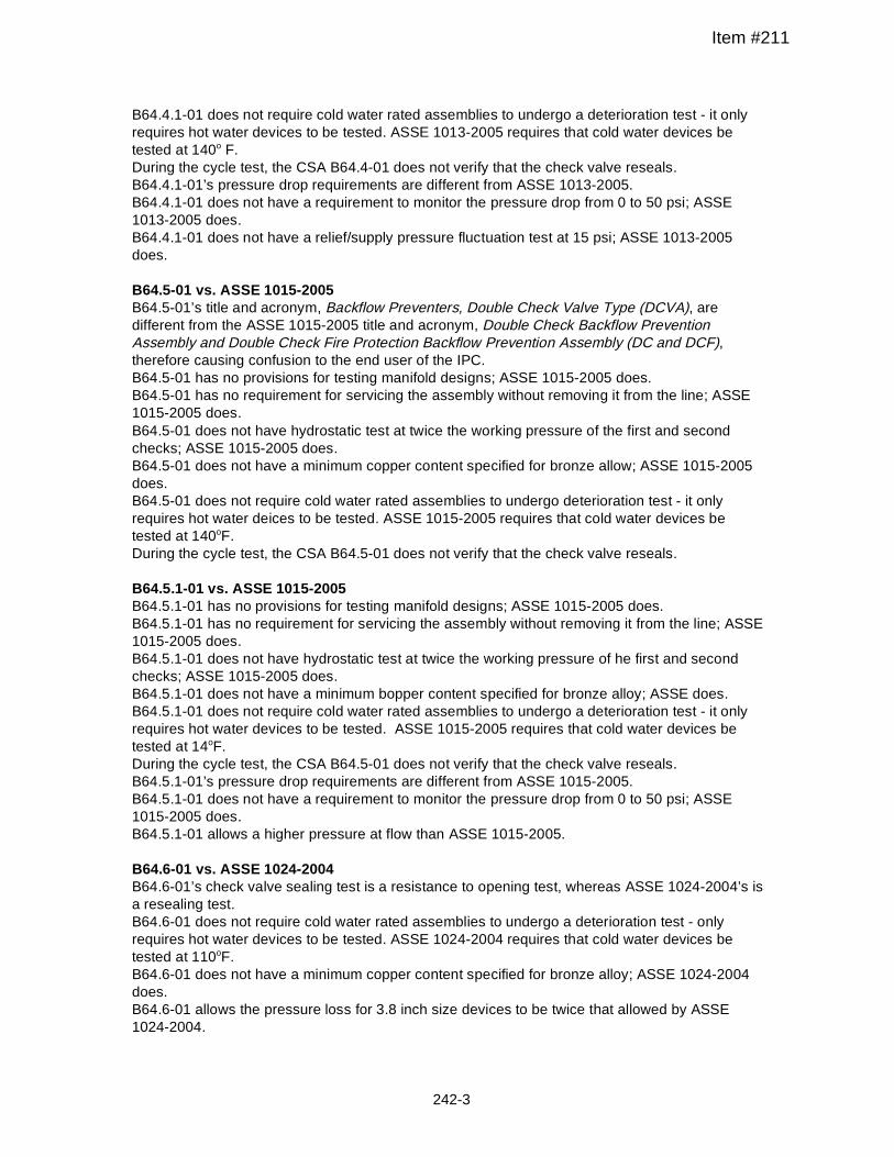
B64.4.1-01 does not require cold water rated assemblies to undergo a deterioration test - it only requires hot water devices to be tested. ASSE 1013-2005 requires that cold water devices be tested at 140o F. During the cycle test, the CSA B64.4-01 does not verify that the check valve reseals. B64.4.1-01’s pressure drop requirements are different from ASSE 1013-2005. B64.4.1-01 does not have a requirement to monitor the pressure drop from 0 to 50 psi; ASSE 1013-2005 does. B64.4.1-01 does not have a relief/supply pressure fluctuation test at 15 psi; ASSE 1013-2005 does. B64.5-01 vs. ASSE 1015-2005 B64.5-01’s title and acronym, Backflow Preventers, Double Check Valve Type (DCVA), are different from the ASSE 1015-2005 title and acronym, Double Check Backflow Prevention Assembly and Double Check Fire Protection Backflow Prevention Assembly (DC and DCF), therefore causing confusion to the end user of the IPC. B64.5-01 has no provisions for testing manifold designs; ASSE 1015-2005 does. B64.5-01 has no requirement for servicing the assembly without removing it from the line; ASSE 1015-2005 does. B64.5-01 does not have hydrostatic test at twice the working pressure of the first and second checks; ASSE 1015-2005 does. B64.5-01 does not have a minimum copper content specified for bronze allow; ASSE 1015-2005 does. B64.5-01 does not require cold water rated assemblies to undergo deterioration test - it only requires hot water deices to be tested. ASSE 1015-2005 requires that cold water devices be tested at 140oF. During the cycle test, the CSA B64.5-01 does not verify that the check valve reseals. B64.5.1-01 vs. ASSE 1015-2005 B64.5.1-01 has no provisions for testing manifold designs; ASSE 1015-2005 does. B64.5.1-01 has no requirement for servicing the assembly without removing it from the line; ASSE 1015-2005 does. B64.5.1-01 does not have hydrostatic test at twice the working pressure of he first and second checks; ASSE 1015-2005 does. B64.5.1-01 does not have a minimum bopper content specified for bronze alloy; ASSE does. B64.5.1-01 does not require cold water rated assemblies to undergo a deterioration test - it only requires hot water devices to be tested. ASSE 1015-2005 requires that cold water devices be tested at 14oF. During the cycle test, the CSA B64.5-01 does not verify that the check valve reseals. B64.5.1-01’s pressure drop requirements are different from ASSE 1015-2005. B64.5.1-01 does not have a requirement to monitor the pressure drop from 0 to 50 psi; ASSE 1015-2005 does. B64.5.1-01 allows a higher pressure at flow than ASSE 1015-2005. B64.6-01 vs. ASSE 1024-2004 B64.6-01’s check valve sealing test is a resistance to opening test, whereas ASSE 1024-2004’s is a resealing test. B64.6-01 does not require cold water rated assemblies to undergo a deterioration test - only requires hot water devices to be tested. ASSE 1024-2004 requires that cold water devices be tested at 110oF. B64.6-01 does not have a minimum copper content specified for bronze alloy; ASSE 1024-2004 does. B64.6-01 allows the pressure loss for 3.8 inch size devices to be twice that allowed by ASSE 1024-2004.
Item #211
242-3
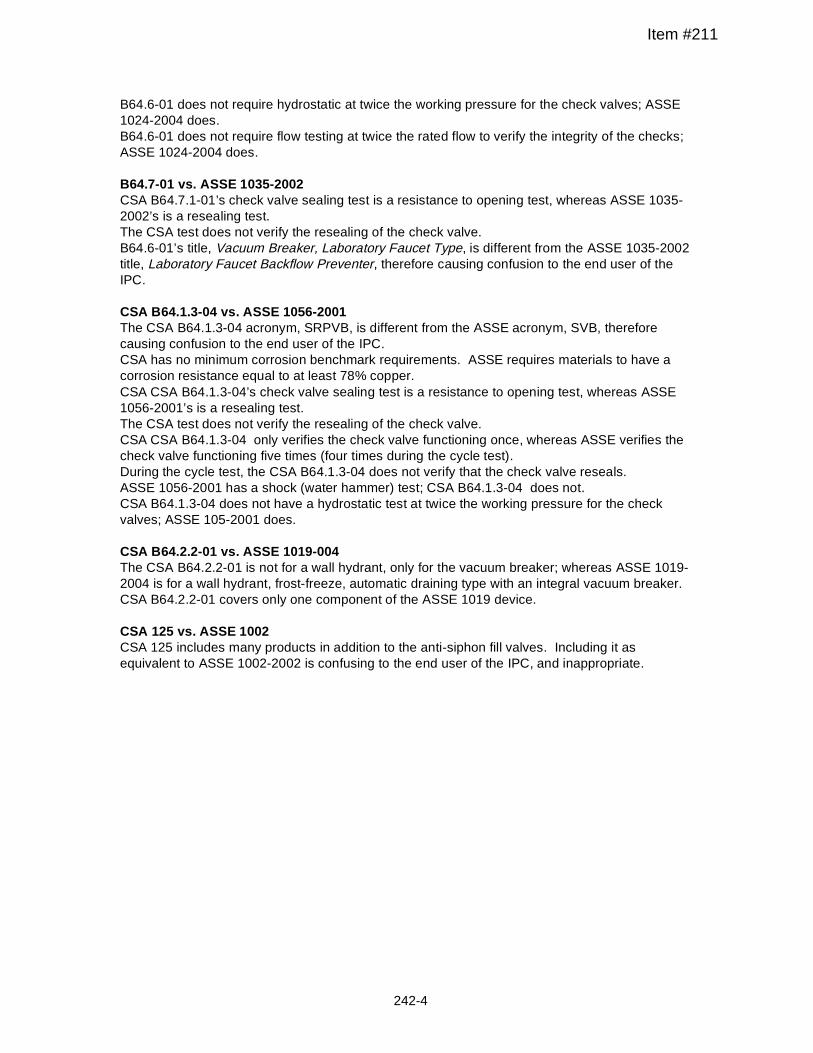
B64.6-01 does not require hydrostatic at twice the working pressure for the check valves; ASSE 1024-2004 does. B64.6-01 does not require flow testing at twice the rated flow to verify the integrity of the checks; ASSE 1024-2004 does. B64.7-01 vs. ASSE 1035-2002 CSA B64.7.1-01’s check valve sealing test is a resistance to opening test, whereas ASSE 1035-2002’s is a resealing test. The CSA test does not verify the resealing of the check valve. B64.6-01’s title, Vacuum Breaker, Laboratory Faucet Type, is different from the ASSE 1035-2002 title, Laboratory Faucet Backflow Preventer, therefore causing confusion to the end user of the IPC. CSA B64.1.3-04 vs. ASSE 1056-2001 The CSA B64.1.3-04 acronym, SRPVB, is different from the ASSE acronym, SVB, therefore causing confusion to the end user of the IPC. CSA has no minimum corrosion benchmark requirements. ASSE requires materials to have a corrosion resistance equal to at least 78% copper. CSA CSA B64.1.3-04’s check valve sealing test is a resistance to opening test, whereas ASSE 1056-2001’s is a resealing test. The CSA test does not verify the resealing of the check valve. CSA CSA B64.1.3-04 only verifies the check valve functioning once, whereas ASSE verifies the check valve functioning five times (four times during the cycle test). During the cycle test, the CSA B64.1.3-04 does not verify that the check valve reseals. ASSE 1056-2001 has a shock (water hammer) test; CSA B64.1.3-04 does not. CSA B64.1.3-04 does not have a hydrostatic test at twice the working pressure for the check valves; ASSE 105-2001 does. CSA B64.2.2-01 vs. ASSE 1019-004 The CSA B64.2.2-01 is not for a wall hydrant, only for the vacuum breaker; whereas ASSE 1019-2004 is for a wall hydrant, frost-freeze, automatic draining type with an integral vacuum breaker. CSA B64.2.2-01 covers only one component of the ASSE 1019 device. CSA 125 vs. ASSE 1002 CSA 125 includes many products in addition to the anti-siphon fill valves. Including it as equivalent to ASSE 1002-2002 is confusing to the end user of the IPC, and inappropriate.
Item #211
242-4
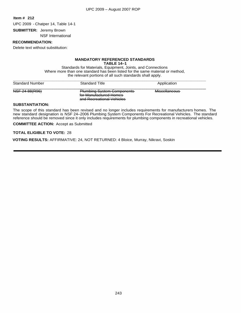
UPC 2009 – August 2007 ROP
SUBMITTER:
Delete text without substitution:
MANDATORY REFERENCED STANDARDSTABLE 14–1
Standards for Materials, Equipment, Joints, and ConnectionsWhere more than one standard has been listed for the same material or method,
the relevant portions of all such standards shall apply.________________________________________________________________________________________Standard Number Standard Title Application________________________________________________________________________________________NSF 24 88(R96) Plumbing System Components Miscellaneous
for Manufactured Homesand Recreational Vehicles
The scope of this standard has been revised and no longer includes requirements for manufacturers homes. The new standard designation is NSF 24–2006 Plumbing System Components For Recreational Vehicles. The standardreference should be removed since it only includes requirements for plumbing components in recreational vehicles.
SUBSTANTIATION:
RECOMMENDATION:
UPC 2009 Chatper 14, Table 14-1
Accept as Submitted
Jeremy Brown
212-
TOTAL ELIGIBLE TO VOTE: 28
VOTING RESULTS: AFFIRMATIVE: 24, NOT RETURNED: 4 Bloice, Murray, Nikravi, Soskin
COMMITTEE ACTION:
Item #
NSF International
243
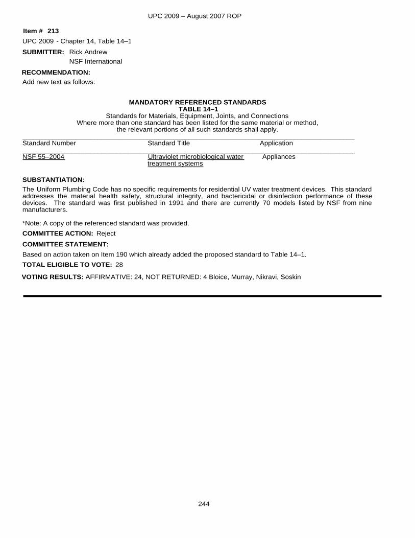
UPC 2009 – August 2007 ROP
SUBMITTER:
Add new text as follows:
MANDATORY REFERENCED STANDARDSTABLE 14–1
Standards for Materials, Equipment, Joints, and ConnectionsWhere more than one standard has been listed for the same material or method,
the relevant portions of all such standards shall apply.________________________________________________________________________________________Standard Number Standard Title Application________________________________________________________________________________________NSF 55–2004 Ultraviolet microbiological water Appliances
treatment systems
The Uniform Plumbing Code has no specific requirements for residential UV water treatment devices. This standardaddresses the material health safety, structural integrity, and bactericidal or disinfection performance of these devices. The standard was first published in 1991 and there are currently 70 models listed by NSF from nine manufacturers.
*Note: A copy of the referenced standard was provided.
SUBSTANTIATION:
RECOMMENDATION:
UPC 2009 Chapter 14, Table 14–1
Based on action taken on Item 190 which already added the proposed standard to Table 14–1.
Reject
Rick Andrew
213-
TOTAL ELIGIBLE TO VOTE: 28
VOTING RESULTS: AFFIRMATIVE: 24, NOT RETURNED: 4 Bloice, Murray, Nikravi, Soskin
COMMITTEE ACTION:COMMITTEE STATEMENT:
Item #
NSF International
244
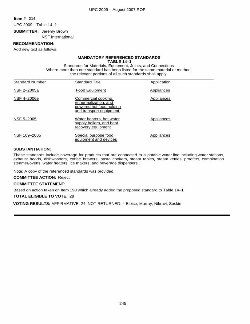
UPC 2009 – August 2007 ROP
SUBMITTER:
Add new text as follows:
MANDATORY REFERENCED STANDARDSTABLE 14–1
Standards for Materials, Equipment, Joints, and ConnectionsWhere more than one standard has been listed for the same material or method,
the relevant portions of all such standards shall apply.________________________________________________________________________________________Standard Number Standard Title Application________________________________________________________________________________________NSF 2–2005a Food Equipment Appliances
NSF 4–2006e Commercial cooking, Appliancesrethermalization, andpowered hot food holdingand transport equipment
NSF 5–2005 Water heaters, hot water Appliancessupply boilers, and heatrecovery equipment
NSF 169–2005 Special purpose food Appliancesequipment and devices
These standards include coverage for products that are connected to a potable water line including water stations, exhaust hoods, dishwashers, coffee brewers, pasta cookers, steam tables, steam kettles, proofers, combination steamer/ovens, water heaters, ice makers, and beverage dispensers.
Note: A copy of the referenced standards was provided.
SUBSTANTIATION:
RECOMMENDATION:
UPC 2009 Table 14–1
Based on action taken on Item 190 which already added the proposed standard to Table 14–1.
Reject
Jeremy Brown
214-
TOTAL ELIGIBLE TO VOTE: 28
VOTING RESULTS: AFFIRMATIVE: 24, NOT RETURNED: 4 Bloice, Murray, Nikravi, Soskin
COMMITTEE ACTION:COMMITTEE STATEMENT:
Item #
NSF International
245
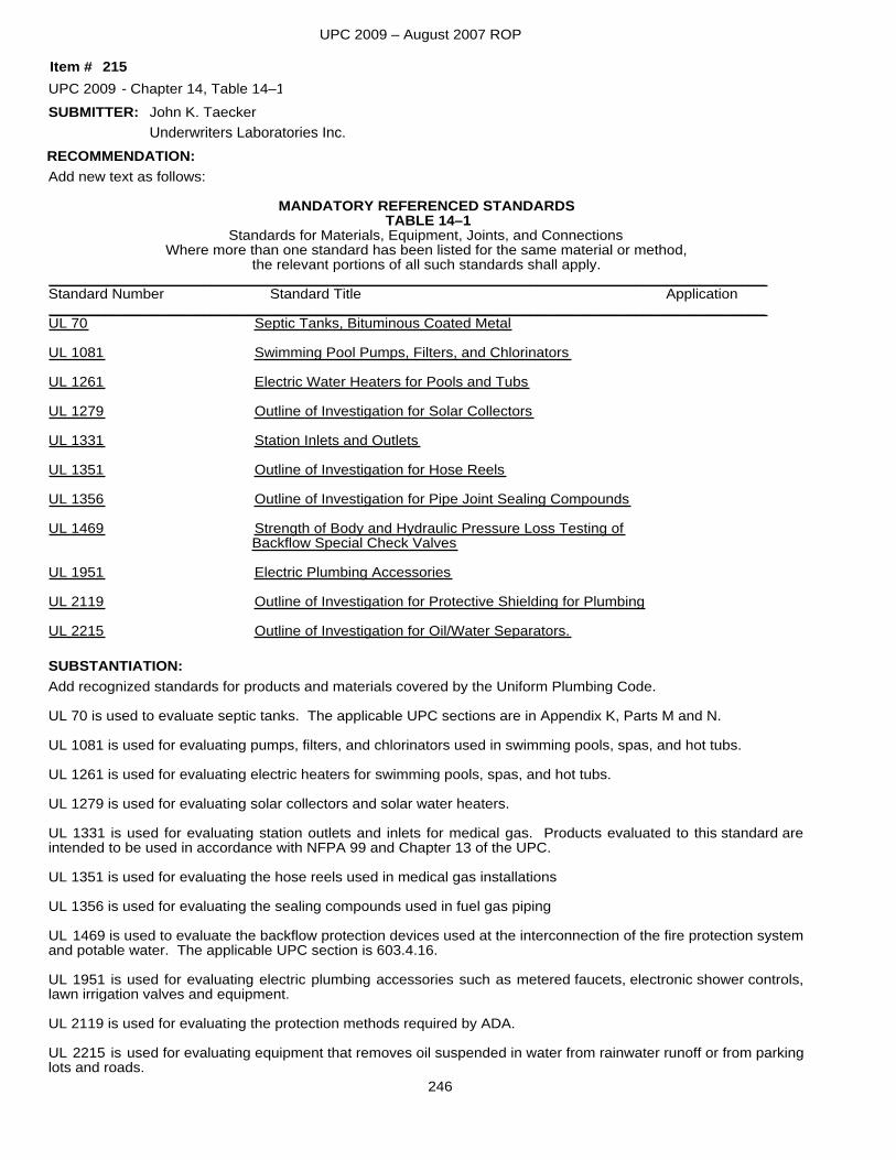
UPC 2009 – August 2007 ROP
SUBMITTER:
Add new text as follows:
MANDATORY REFERENCED STANDARDSTABLE 14–1
Standards for Materials, Equipment, Joints, and ConnectionsWhere more than one standard has been listed for the same material or method,
the relevant portions of all such standards shall apply.________________________________________________________________________________________Standard Number Standard Title Application________________________________________________________________________________________UL 70 Septic Tanks, Bituminous Coated Metal
UL 1081 Swimming Pool Pumps, Filters, and Chlorinators
UL 1261 Electric Water Heaters for Pools and Tubs
UL 1279 Outline of Investigation for Solar Collectors
UL 1331 Station Inlets and Outlets
UL 1351 Outline of Investigation for Hose Reels
UL 1356 Outline of Investigation for Pipe Joint Sealing Compounds
UL 1469 Strength of Body and Hydraulic Pressure Loss Testing of Backflow Special Check Valves
UL 1951 Electric Plumbing Accessories
UL 2119 Outline of Investigation for Protective Shielding for Plumbing
UL 2215 Outline of Investigation for Oil/Water Separators.
Add recognized standards for products and materials covered by the Uniform Plumbing Code.
UL 70 is used to evaluate septic tanks. The applicable UPC sections are in Appendix K, Parts M and N.
UL 1081 is used for evaluating pumps, filters, and chlorinators used in swimming pools, spas, and hot tubs.
UL 1261 is used for evaluating electric heaters for swimming pools, spas, and hot tubs.
UL 1279 is used for evaluating solar collectors and solar water heaters.
UL 1331 is used for evaluating station outlets and inlets for medical gas. Products evaluated to this standard are intended to be used in accordance with NFPA 99 and Chapter 13 of the UPC.
UL 1351 is used for evaluating the hose reels used in medical gas installations
UL 1356 is used for evaluating the sealing compounds used in fuel gas piping
UL 1469 is used to evaluate the backflow protection devices used at the interconnection of the fire protection systemand potable water. The applicable UPC section is 603.4.16.
UL 1951 is used for evaluating electric plumbing accessories such as metered faucets, electronic shower controls, lawn irrigation valves and equipment.
UL 2119 is used for evaluating the protection methods required by ADA.
UL 2215 is used for evaluating equipment that removes oil suspended in water from rainwater runoff or from parkinglots and roads.
SUBSTANTIATION:
RECOMMENDATION:
UPC 2009 Chapter 14, Table 14–1John K. Taecker
215-
Item #
Underwriters Laboratories Inc.
246
UPC 2009 – August 2007 ROP
Note: A copy of the referenced standards was not provided.
Based on action taken on Item 190 which already added the proposed standards to Table 14–1.
Reject
TOTAL ELIGIBLE TO VOTE: 28
VOTING RESULTS: AFFIRMATIVE: 24, NOT RETURNED: 4 Bloice, Murray, Nikravi, Soskin
COMMITTEE ACTION:COMMITTEE STATEMENT:
247
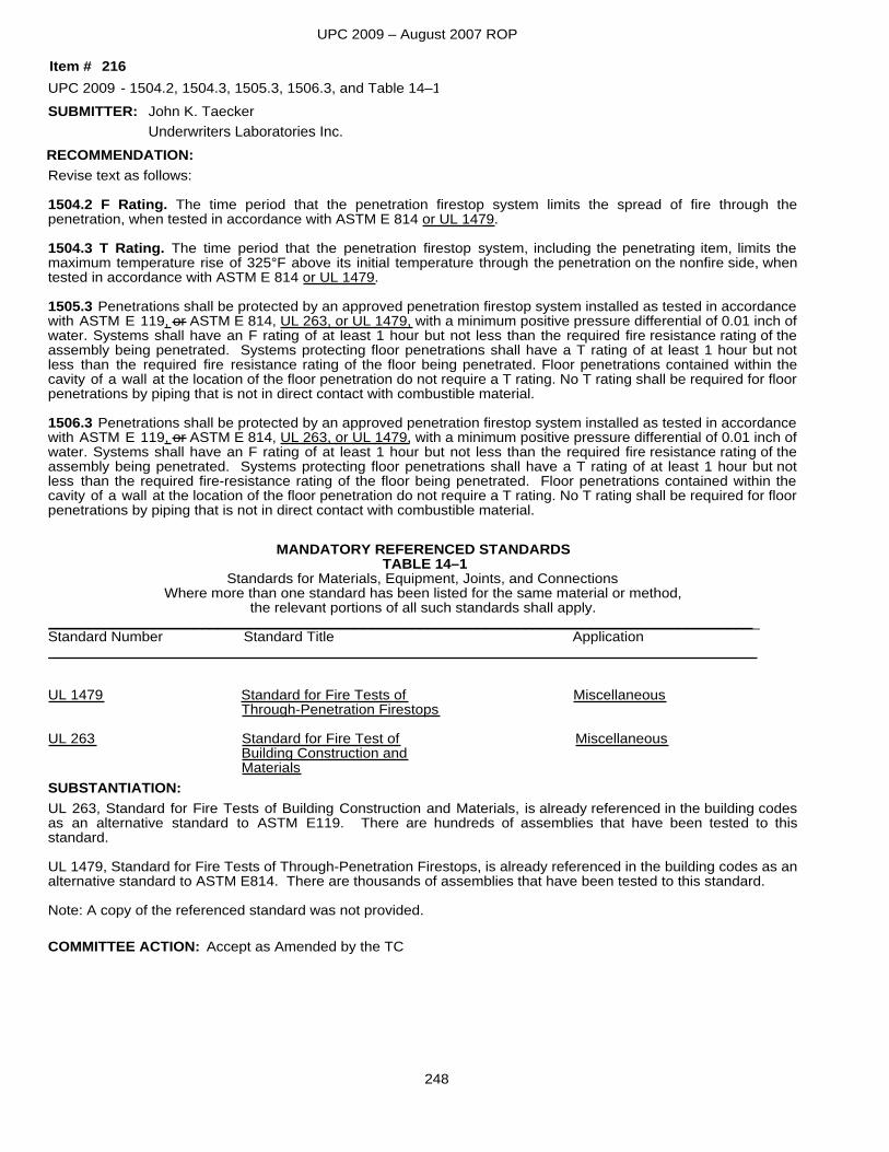
UPC 2009 – August 2007 ROP
SUBMITTER:
Revise text as follows:
1504.2 F Rating. The time period that the penetration firestop system limits the spread of fire through the penetration, when tested in accordance with ASTM E 814 or UL 1479.
1504.3 T Rating. The time period that the penetration firestop system, including the penetrating item, limits the maximum temperature rise of 325°F above its initial temperature through the penetration on the nonfire side, when tested in accordance with ASTM E 814 or UL 1479.
1505.3 Penetrations shall be protected by an approved penetration firestop system installed as tested in accordancewith ASTM E 119, or ASTM E 814, UL 263, or UL 1479, with a minimum positive pressure differential of 0.01 inch ofwater. Systems shall have an F rating of at least 1 hour but not less than the required fire resistance rating of the assembly being penetrated. Systems protecting floor penetrations shall have a T rating of at least 1 hour but not less than the required fire resistance rating of the floor being penetrated. Floor penetrations contained within the cavity of a wall at the location of the floor penetration do not require a T rating. No T rating shall be required for floorpenetrations by piping that is not in direct contact with combustible material.
1506.3 Penetrations shall be protected by an approved penetration firestop system installed as tested in accordancewith ASTM E 119, or ASTM E 814, UL 263, or UL 1479, with a minimum positive pressure differential of 0.01 inch ofwater. Systems shall have an F rating of at least 1 hour but not less than the required fire resistance rating of the assembly being penetrated. Systems protecting floor penetrations shall have a T rating of at least 1 hour but not less than the required fire-resistance rating of the floor being penetrated. Floor penetrations contained within the cavity of a wall at the location of the floor penetration do not require a T rating. No T rating shall be required for floorpenetrations by piping that is not in direct contact with combustible material.
MANDATORY REFERENCED STANDARDSTABLE 14–1
Standards for Materials, Equipment, Joints, and ConnectionsWhere more than one standard has been listed for the same material or method,
the relevant portions of all such standards shall apply.________________________________________________________________________________________Standard Number Standard Title Application_______________ _________________________________________________________________
UL 1479 Standard for Fire Tests of MiscellaneousThrough-Penetration Firestops
UL 263 Standard for Fire Test of MiscellaneousBuilding Construction andMaterials
UL 263, Standard for Fire Tests of Building Construction and Materials, is already referenced in the building codes as an alternative standard to ASTM E119. There are hundreds of assemblies that have been tested to this standard.
UL 1479, Standard for Fire Tests of Through-Penetration Firestops, is already referenced in the building codes as analternative standard to ASTM E814. There are thousands of assemblies that have been tested to this standard.
Note: A copy of the referenced standard was not provided.
SUBSTANTIATION:
RECOMMENDATION:
UPC 2009 1504.2, 1504.3, 1505.3, 1506.3, and Table 14–1
Accept as Amended by the TC
John K. Taecker
216-
COMMITTEE ACTION:
Item #
Underwriters Laboratories Inc.
248
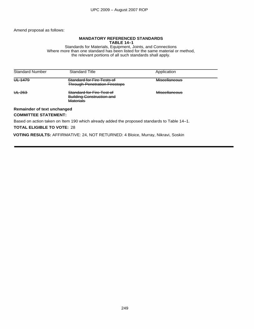
UPC 2009 – August 2007 ROP
Amend proposal as follows:
MANDATORY REFERENCED STANDARDSTABLE 14–1
Standards for Materials, Equipment, Joints, and ConnectionsWhere more than one standard has been listed for the same material or method,
the relevant portions of all such standards shall apply.
________________________________________________________________________________________Standard Number Standard Title Application________________________________________________________________________________________UL 1479 Standard for Fire Tests of Miscellaneous
Through-Penetration Firestops
UL 263 Standard for Fire Test of MiscellaneousBuilding Construction andMaterials
Remainder of text unchanged
Based on action taken on Item 190 which already added the proposed standards to Table 14–1.TOTAL ELIGIBLE TO VOTE: 28
VOTING RESULTS: AFFIRMATIVE: 24, NOT RETURNED: 4 Bloice, Murray, Nikravi, Soskin
COMMITTEE STATEMENT:
249
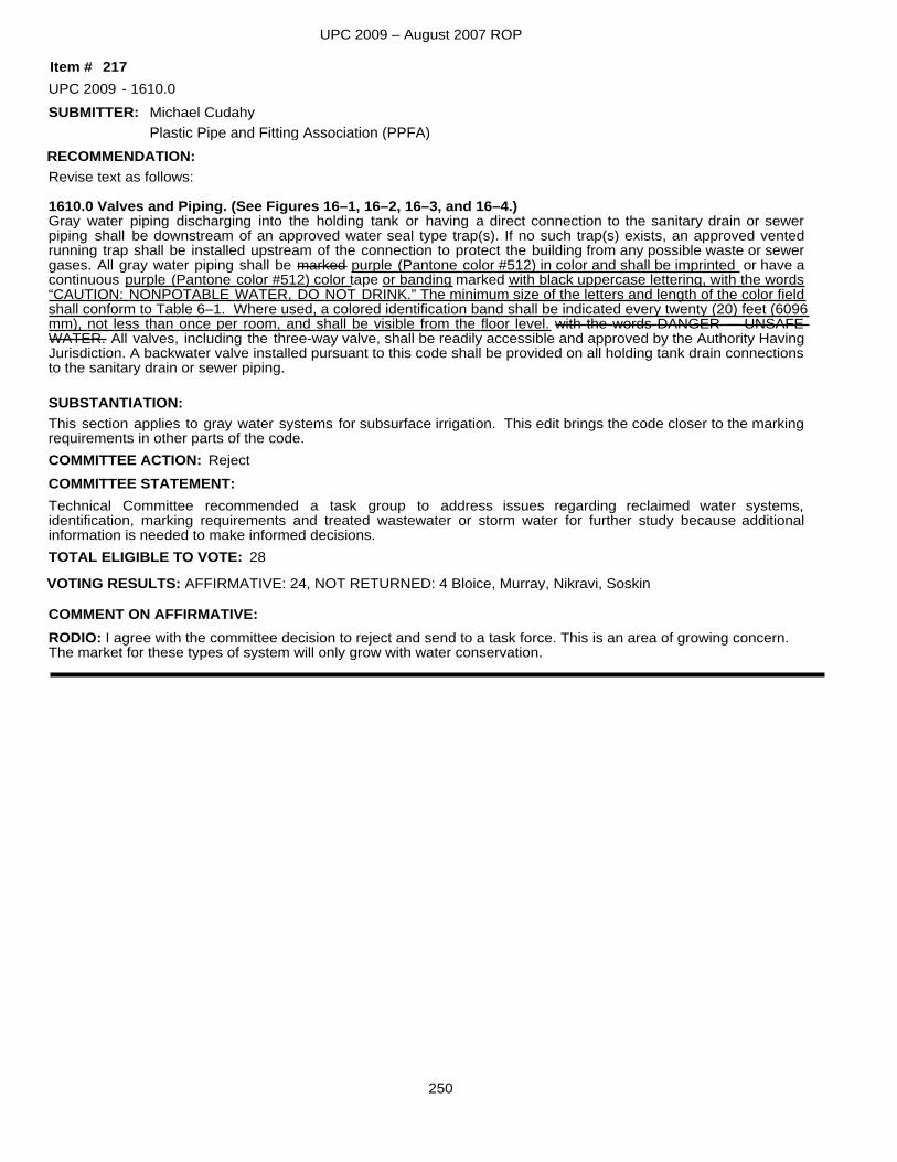
UPC 2009 – August 2007 ROP
SUBMITTER:
Revise text as follows:
1610.0 Valves and Piping. (See Figures 16–1, 16–2, 16–3, and 16–4.)Gray water piping discharging into the holding tank or having a direct connection to the sanitary drain or sewer piping shall be downstream of an approved water seal type trap(s). If no such trap(s) exists, an approved vented running trap shall be installed upstream of the connection to protect the building from any possible waste or sewer gases. All gray water piping shall be marked purple (Pantone color #512) in color and shall be imprinted or have a continuous purple (Pantone color #512) color tape or banding marked with black uppercase lettering, with the words“CAUTION: NONPOTABLE WATER, DO NOT DRINK.” The minimum size of the letters and length of the color fieldshall conform to Table 6–1. Where used, a colored identification band shall be indicated every twenty (20) feet (6096mm), not less than once per room, and shall be visible from the floor level. with the words DANGER — UNSAFE WATER. All valves, including the three-way valve, shall be readily accessible and approved by the Authority HavingJurisdiction. A backwater valve installed pursuant to this code shall be provided on all holding tank drain connectionsto the sanitary drain or sewer piping.
This section applies to gray water systems for subsurface irrigation. This edit brings the code closer to the marking requirements in other parts of the code.
SUBSTANTIATION:
RECOMMENDATION:
UPC 2009 1610.0
Technical Committee recommended a task group to address issues regarding reclaimed water systems, identification, marking requirements and treated wastewater or storm water for further study because additional information is needed to make informed decisions.
Reject
Michael Cudahy
217-
TOTAL ELIGIBLE TO VOTE: 28
VOTING RESULTS: AFFIRMATIVE: 24, NOT RETURNED: 4 Bloice, Murray, Nikravi, Soskin
COMMITTEE ACTION:COMMITTEE STATEMENT:
RODIO: I agree with the committee decision to reject and send to a task force. This is an area of growing concern. The market for these types of system will only grow with water conservation.
COMMENT ON AFFIRMATIVE:
Item #
Plastic Pipe and Fitting Association (PPFA)
250
Related Documents