IT & TELECOMMUNICATIONS NETWORKS Architecture & Administration Networking concepts

Welcome message from author
This document is posted to help you gain knowledge. Please leave a comment to let me know what you think about it! Share it to your friends and learn new things together.
Transcript
IT & TELECOMMUNICATIONS NETWORKSArchitecture & Administration
Networking concepts

COMPUTER NETWORKA digital telecommunications network
To communicate between different devices To share resources between different devices Consists of two or more computers that are interconnected with each
other and share resources such as printers, servers, and hardware and exchange the data in the form of files, facilitating electronic communication.
The first computer network designed was the ‘Advanced Research Projects Agency Network (ARPANET)’ by the United States Department of Defense. Since then, myriads of new computer networking technologies have been designed.
NETWORKING COMPONENTS
PHYSICAL COMPONENTS – HARDWARE
Central Components – Hub,Switch, Bridge, Router, Gateway, Modem
Cables – Twisted pair, Coaxial cables, Fiber optics cables
Network Interface Card (NIC) – Ethernet wired LAN card, Wireless LAN card (WLAN)
NETWORKING COMPONENTS
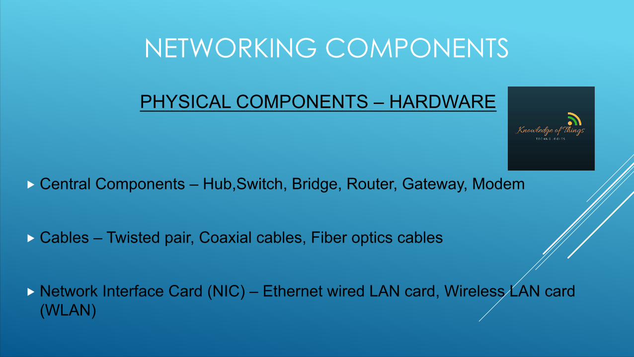
CABLES - Twisted pairTwo types of twisted pair cables are prevalent: Unshielded Twisted Pair (UTP) &
Shielded Twisted Pair (STP).
UTP
UTP is the most common cable found in computer networking. Modern Ethernet, the most common data networking standard, can use UTP cables. Twisted pair cabling is often used in data networks for short and medium length connections because of its relatively lower costs compared to optical fiber and coaxial cable.
STPTwisted pair cables often incorporate shielding in an attempt to prevent electromagnetic interference. Shielding provides an electrically conductive barrier to attenuate electromagnetic waves external to the shield; and provides a conduction path by which induced currents can be circulated and returned to the source via ground reference connection. Eg: - CAT 5e

NETWORKING COMPONENTS CABLES - Twisted pair
UTP STP

NETWORKING COMPONENTSCABLES - Coaxial Cables
Construction :- A type of electrical cable that has an inner conductor surrounded by a tubular insulating layer, surrounded by a tubular conducting shield. Many coaxial cables also have an insulating outer sheath or jacket.
Coaxial cable differs from other shielded cables because the dimensions of the cable are controlled to give a precise, constant conductor spacing, which is needed for it to function efficiently as a transmission line.
Its applications include feedlines connecting radio transmitters and receivers to their antennas, computer network (Internet) connections, digital audio (S/PDIF), and distributing cable television signals.

NETWORKING COMPONENTS
CABLES - Coaxial Cables
A. Outer Plastic sheath (Jacket)
B. Woven copper shield
C. Inner dielectric insulator
D. Copper core
NETWORKING COMPONENTSCABLES - Fibre Optic Cables
Construction :- An optical fiber cable, also known as a fiber optic cable, is an assembly similar to an electrical cable, but containing one or more optical fibers that are used to carry light.
The optical fiber elements are typically individually coated with plastic layers and contained in a protective tube suitable for the environment where the cable will be deployed.
Different types of cable are used for different applications, for example long distance telecommunication, or providing a high-speed data connection between different parts of a building.

NETWORKING COMPONENTSPHYSICAL COMPONENTS -
CABLESFiber Optic Cables

NETWORKING COMPONENTS
CENTRAL COMPONENT - Hub Hubs are the simplest networking devices. Computers connect to a hub via a length of
twisted-pair cabling. Apart from having ports for computers to connect, some hubs also have ports for other hubs to be connected to them, in order to create a larger network.
Most hubs are referred to as active because they regenerate a signal before forwarding it to all the ports on the device. In order to do this, the hub needs a power supply; small workgroup hubs normally use an external power adapter, but on larger units the power supply is built in. Passive hubs (which are rare) do not need power because they don't regenerate the signal.
The basic function of a hub is to take data from one of the connected devices and forward it to all the other ports on the hub. This method of operation is very inefficient because, in most cases, the data is intended for only one of the connected devices.
NETWORKING COMPONENTS
CENTRAL COMPONENT - Hub
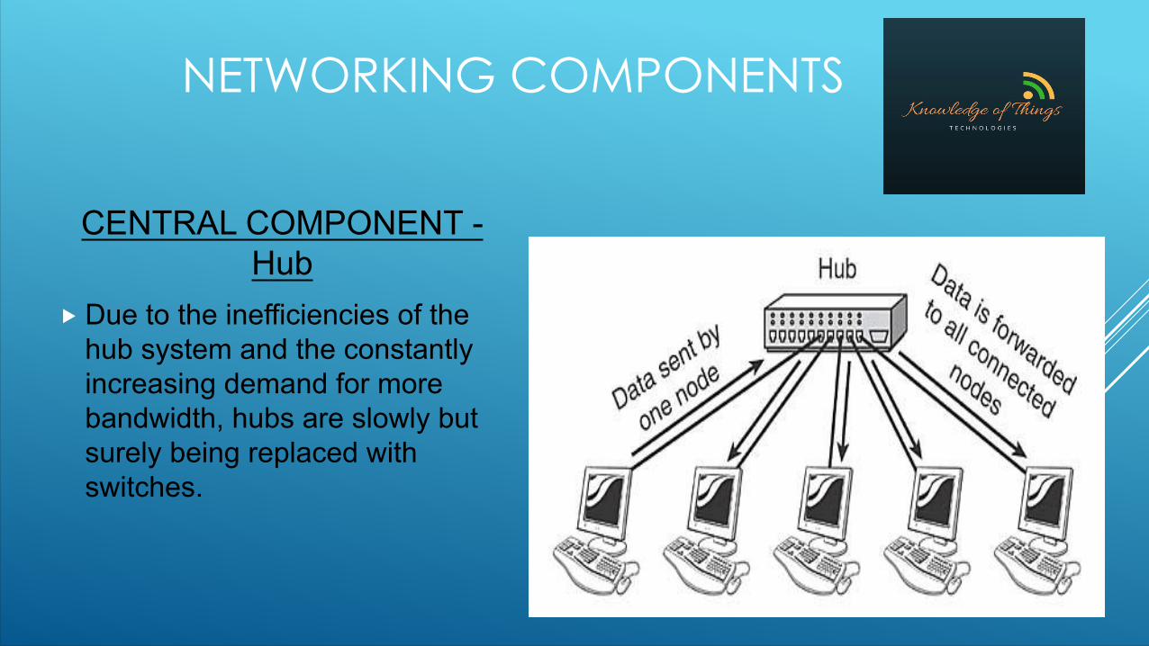
Due to the inefficiencies of the hub system and the constantly increasing demand for more bandwidth, hubs are slowly but surely being replaced with switches.
NETWORKING COMPONENTS
CENTRAL COMPONENT - Switch On the surface, a switch looks much like a hub. As with a hub, computers
connect to a switch via a length of twisted-pair cable. Multiple switches can be used, like hubs, to create larger networks. Despite their similarity in appearance and their identical physical connections to computers, switches offer significant operational advantages over hubs.
Rather than forwarding data to all the connected ports, a switch forwards data only to the port on which the destination system is connected. By forwarding data only to the system to which the data is addressed, the switch decreases the amount of traffic on each network link dramatically. In effect, the switch literally channels (or switches, if you prefer) data between the ports.
There are 2 types of switches available: Managed & Unmanaged switches.

NETWORKING COMPONENTSCENTRAL COMPONENT - Switch
Collisions occur on the network when two devices attempt to transmit at the same time. Such collisions cause the performance of the network to degrade. By channeling data only to the connections that should receive it, switches reduce the number of collisions that occur on the network. As a result, switches provide significant performance improvements over hubs.
Switches can also further improve performance over the performance of hubs by using a mechanism called full-duplex. On a standard network connection, the communication between the system and the switch or hub is said to be half-duplex. In a half-duplex connection, data can be either sent or received on the wire, but not at the same time. Because switches manage the data flow on the connection, a switch can operate in full-duplex mode — it can send and receive data on the connection at the same time.
The secret of full-duplex lies in the switch.To use a full-duplex connection, you basically need three things: a switch, the appropriate cable, and a NIC (and driver) that supports full-duplex communication. Given these requirements, and the fact that most modern NICs are full-duplex-ready, you might think everyone would be using full-duplex connections. However, the reality is a little different. In some cases, the NIC is simply not configured to make use of the driver.

NETWORKING COMPONENTSCENTRAL COMPONENT - Switch
How do switches work? Switching MethodsSwitches use three methods to deal with data as it arrives:
Cut-through — In a cut-through configuration, the switch begins to forward the packet as soon as it is received. No error checking is performed on the packet, so the packet is moved through very quickly. The downside of cut-through is that because the integrity of the packet is not checked, the switch can propagate errors.
Store-and-forward — In a store-and-forward configuration, the switch waits to receive the entire packet before beginning to forward it. It also performs basic error checking.
Fragment-free — Building on the speed advantages of cut-through switching, fragment-free switching works by reading only the part of the packet that enables it to identify fragments of a transmission.
NETWORKING COMPONENTS
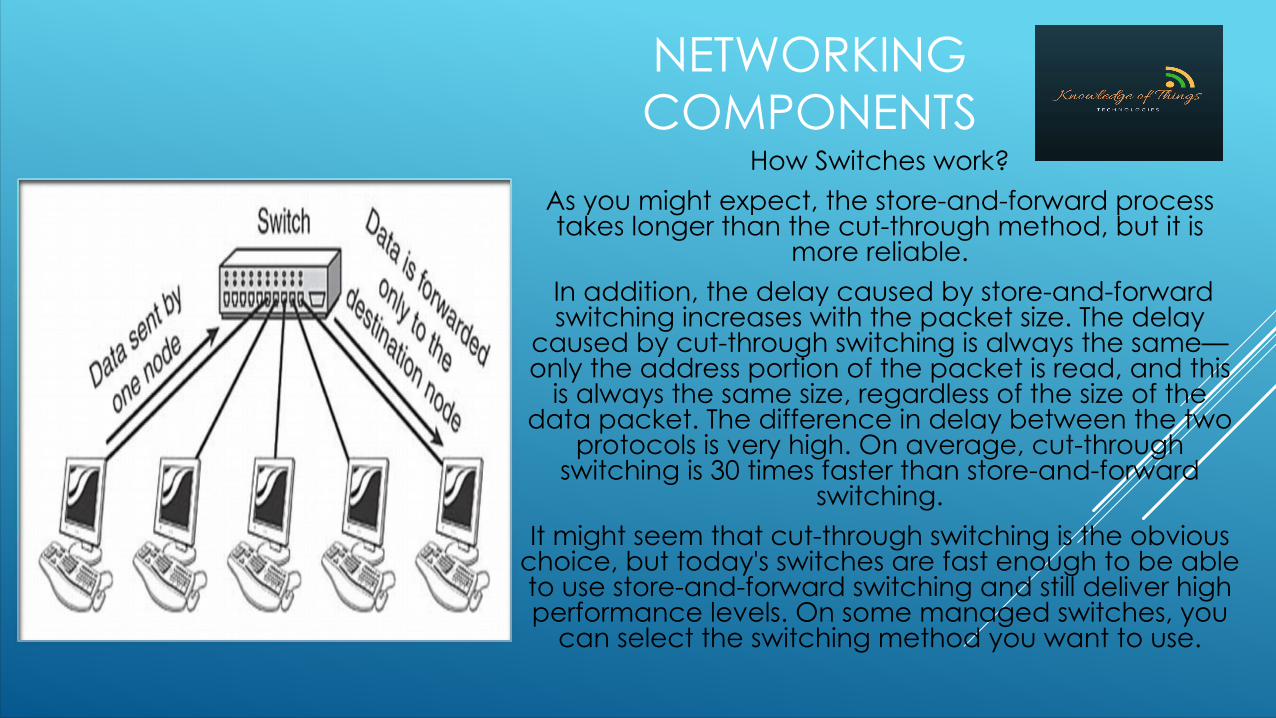
How Switches work?As you might expect, the store-and-forward process takes longer than the cut-through method, but it is
more reliable. In addition, the delay caused by store-and-forward switching increases with the packet size. The delay
caused by cut-through switching is always the same—only the address portion of the packet is read, and this
is always the same size, regardless of the size of the data packet. The difference in delay between the two
protocols is very high. On average, cut-through switching is 30 times faster than store-and-forward
switching.It might seem that cut-through switching is the obvious
choice, but today's switches are fast enough to be able to use store-and-forward switching and still deliver high performance levels. On some managed switches, you
can select the switching method you want to use.

NETWORK TOPOLOGIES

NETWORK TOPOLOGIES
Network topology defines the structure of a network
One part of the topology definition is the physical topology, which is the actual layout of the wire and/or connection media.
The other part is the logical topology which defines how the media is accessed by the hosts for sending data over the network.

BUS TOPOLOGY
• A bus topology uses a single backbone cable that is terminated at both ends
• All the hosts are connected directly to this backbone

BUS TOPOLOGY
Disadvantages
Becomes slow by heavy network traffic with a lot of devices, because networks do not concentrate with each other to reserve times to transit
Difficult to troubleshoot the root cause in a bus because if a cable breaks or a loose connector exists, it will causer reflections and bring down the whole network
Advantages
Easy to use and understand Less number of cables required Inexpensive single network Easy to extend a network by adding
cable with a repeater that boosts the signal and allows it to travel a longer distance

RING TOPOLOGY• A ring topology connects
one host to the next and the last host to the first.
• This creates a physical ring of cables.

RING TOPOLOGY
Disadvantages
Failure of one device will affect the whole network
Difficult to troubleshootAdding and removing devices
disrupts the network
Advantages
One device cannot monopolize the network
Continues to function after the capacity is exceeded but the speed/bandwidth will be slower (gets reduced with addition of nodes)
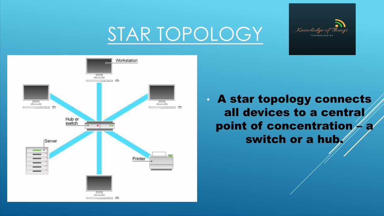
STAR TOPOLOGY
• A star topology connects all devices to a central
point of concentration – a switch or a hub.

STAR TOPOLOGY
Disadvantages
Failure of the central device (Hub/Switch) causes the whole network to fail
It is slightly more expensive than using bus topology
Advantages
The failure of a single device or cable doesn’t bring down the whole network
The centralized networking equipment can reduce costs in the long run by making network management much easier
It allows several cable types in same network with a hub that can accommodate multiple cable types

EXTENDED STAR TOPOLOGY
• An extended star topology links individual star topologies together by connecting the hubs
and/or switches• This topology can extend
the scope and coverage of the network

HIERARCHICAL TOPOLOGY
Also called as “Tree Topology”
• A hierarchical topology is similar to
an extended star.
HIERARCHICAL TOPOLOGYAdvantages
Each star segment gets a dedicated link from the central bus. Thus, failing of one segment does not affect the rest of the network
Fault identification is easyThe network can be extended by
the addition of secondary nodes. Thus, scalability is achieved.
Advantages The tree topology is useful in cases
where a star or bus cannot be implemented individually. *It is most-suited in networking multiple departments of a university or corporation, where each unit (star segment) functions separately, and is also connected to the main node (root node)*
The advantages of centralization that are achieved in a tree topology are inherited by the individual star segments in the tree network

HIERARCHICAL TOPOLOGY
Disadvantages
As multiple segments are connected to a central bus, the network depends heavily on the bus. Its failure affects the entire network.
Owing to its size and complexity, maintenance is not easy and costs are high. Also, configuration is difficult in comparison to that in other topologies.
Though it is scalable, the number of nodes that can be added depends on the capacity of the central bus and on the cable type.

MESH TOPOLOGY• A mesh topology is
implemented to provide as much protection (fault
tolerance) as possible from interruption of service.
• Creates a point-to-point connection for every device
in the network.• Each host has its own
connections to all other hosts. Although the Internet
has multiple paths to any one location, it does not adopt
the full mesh topology
MESH TOPOLOGYAdvantages
It can handle heavy traffic, as there are dedicated paths between any two network nodes.
Point-to-Point contact between the every pair of nodes, makes it easy to identify faults.
AdvantagesThe arrangement of the network
nodes is such that it is possible to transmit data from one node to many other nodes at the same time.
The network of a single node does not cause the entire network to fail as there are alternate paths for data transmission.

MESH TOPOLOGYDisadvantages
Owing to its complexity, the administration of a mesh network is difficult.
Fault identification (when a particular node goes down) is difficult.
DisadvantagesThe arrangement wherein every
network node is connected to every other node of the network, many connections server no major purpose. This leads to redundancy of many network connections.
A lot of cabling is required. Thus, the costs incurred in setup and maintenance are high.
TYPES OF NETWORKSBased on coverage area

LAN (LOCAL AREA NETWORK) A LAN (local area network) is a group of computers and network devices
connected together, usually within the same building. By definition, the connections must be high speed and relatively inexpensive (e.g., token ring or Ethernet). Can be wired or wireless(WLAN).
LAN connects network devices in such a way that personal computer and workstations can share data, tools and programs among themselves.
The group of computers and devices are connected together by a switch, or stack of switches, using a private addressing scheme as defined by the TCP/IP protocol.
Private addresses are unique in relation to other computers on the local network. Routers are found at the boundary of a LAN, connecting them to the larger WAN.

LAN (LOCAL AREA NETWORK) LANs cover smaller geographical area (Size is limited to a few kilometers)
and are privately owned. One can use it for an office building, home, hospital, schools, etc. LAN is easy to design and maintain.
A communication medium used for LAN, has twisted pair cables and coaxial cables. It covers a short distance, and so the error and noise are minimized. Early LANs had data rates in the 4 to 16 Mbps range. Today, speeds are normally 100 Mbps or 1000 Mbps (Gigabit Ethernet). Propagation delay is very short in a LAN.
The smallest LAN may only use two computers, while larger LANs can accommodate thousands of computers. A LAN typically relies mostly on wired connections for increased speed and security, but wireless connections can also be part of a LAN. The fault tolerance of a LAN is more and there is less congestion in this network.
For example : A bunch of students playing Counter Strike in the same room (without internet).

MAN (METROPOLITAN AREA NETWORK)
A MAN (metropolitan area network) is a larger network that usually spans several buildings in the same city or town.
It connects two or more computers that are apart but resides in the same or different cities. It covers a large geographical area and may serve as an ISP (Internet Service Provider).
MAN is designed for customers who need a high-speed connectivity. Speeds of MAN ranges in terms of Mbps. It’s hard to design and maintain a Metropolitan Area Network.
The fault tolerance of a MAN is less and also there is more congestion in the network. It is costly and may or may not be owned by a single organization. The data transfer rate and the propagation delay of MAN is moderate.
MAN (METROPOLITAN AREA NETWORK) A Metropolitan Area Networks bridges a number of ‘Local Area
Networks’ with a fiber-optical links which act as a backbone, and provides services similar to what Internet Service Provider (ISP) provide to Wide Area Networks and the Internet.
Major technologies used are ‘Asynchronous Transfer Mode (ATM)’, ‘Fiber Distributed Data Interface (FDDI)’ and ‘Switched Multi-megabit Data Service (SMDS, a connectionless service)’. In most of the areas, these technologies are used to replace the simple ‘Ethernet’ based connections. MANs can bridge Local Area Networks without any cables by using microwave, radio wireless communication or infra-red laser which transmits data wirelessly.
Examples of a MAN are the part of the telephone company network that can provide a high-speed DSL line to the customer or the digital cable TV network in a city.

WAN (WIDE AREA NETWORK) A WAN (wide area network), in comparison to a MAN, is not restricted to
a geographical location, although it might be confined within the bounds of a state or country. WAN is difficult to design and maintain.
A WAN connects several LANs, and may be limited to an enterprise (a corporation or an organization) or accessible to the public. The technology is high speed and relatively expensive. The Internet is an example of a worldwide public WAN.
There are two types of WAN: Switched WAN and Point-to-Point WAN. Similar to a MAN, the fault tolerance of a WAN is less and there is more
congestion in the network. A Communication medium used for WAN is PSTN (Public Switched
Telephone Network) or Satellite Link. Due to long distance transmission, the noise and error tend to be more in WAN.

WAN (WIDE AREA NETWORK)
WAN’s data rate is slow about a 10th of LAN’s speed, since it involves increased distance and increased number of servers and terminals etc.
Speeds of WAN ranges from few kilobits per second (Kbps) to megabits per second (Mbps). Propagation delay is one of the biggest problems faced here.
Devices used for transmission of data through WAN are: Optic wires, Microwaves and Satellites.
Example of a Switched WAN is the asynchronous transfer mode (ATM) network and Point-to-Point WAN is dial-up line that connects a home computer to the Internet.

VPN (VIRTUAL PRIVATE NETWORK)
A VPN is a private network that is constructed within a public network infrastructure such as the global internet.
VPN technology extends the private network across a public network, and enables users to send and receive data across shared or public networks as if their computing devices were directly connected to the private network.
VPN technology was developed to allow remote users and branch offices to securely access corporate applications and other resources.
Using VPN, a telecommuter can access the network of the company through the internet by building a secure tunnel between the telecommuter's PC and a VPN router in the company premise.

VPN (VIRTUAL PRIVATE NETWORK)

NETWORKING MODELS
TCP/IP model and OSI reference model

THE TCP/IP MODEL Transmission Control Protocol/Internet Protocol, is a suite of communication protocols
used to interconnect network devices on the internet. TCP/IP can also be used as a communications protocol in a private network (an intranet or an extranet).
TCP/IP specifies how data is exchanged over the internet by providing end-to-end communications that identify how it should be broken into packets, addressed, transmitted, routed and received at the destination.
TCP/IP requires little central management, and it is designed to make networks reliable, with the ability to recover automatically from the failure of any device on the network.
TCP defines how applications can create channels of communication across a network. It also manages how a message is assembled into smaller packets before they are transmitted over the internet and reassembled in the right order at the destination address.
IP defines how to address and route each packet so as to make sure it reaches the right destination. Each gateway computer on the network checks this IP address to determine where to forward the message.
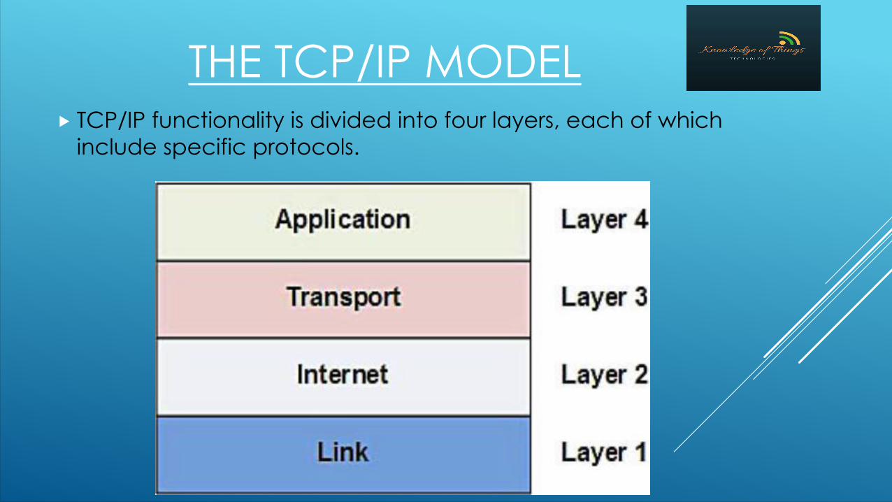
THE TCP/IP MODEL TCP/IP functionality is divided into four layers, each of which
include specific protocols.
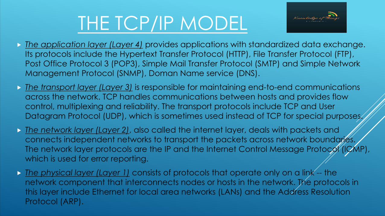
THE TCP/IP MODEL The application layer (Layer 4) provides applications with standardized data exchange.
Its protocols include the Hypertext Transfer Protocol (HTTP), File Transfer Protocol (FTP), Post Office Protocol 3 (POP3), Simple Mail Transfer Protocol (SMTP) and Simple Network Management Protocol (SNMP), Doman Name service (DNS).
The transport layer (Layer 3) is responsible for maintaining end-to-end communications across the network. TCP handles communications between hosts and provides flow control, multiplexing and reliability. The transport protocols include TCP and User Datagram Protocol (UDP), which is sometimes used instead of TCP for special purposes.
The network layer (Layer 2), also called the internet layer, deals with packets and connects independent networks to transport the packets across network boundaries. The network layer protocols are the IP and the Internet Control Message Protocol (ICMP), which is used for error reporting.
The physical layer (Layer 1) consists of protocols that operate only on a link -- the network component that interconnects nodes or hosts in the network. The protocols in this layer include Ethernet for local area networks (LANs) and the Address Resolution Protocol (ARP).
THE OSI REFERENCE MODEL
The Open Systems Interconnection model (OSI model) is a conceptual model that characterizes and standardizes the communication functions of a telecommunication or computing system without regard to its underlying internal structure and technology.
Its goal is the interoperability of diverse communication systems with standard protocols.
The name TCP/IP actually denotes two different protocols, each of which is at a different layer of the OSI model. IP is considered to be a Layer 3 protocol (network) while TCP (and UDP) are considered to be Layer 4 protocols (transport).

THE OSI MODEL OSI functionality is divided into seven layers, each of which
include specific protocols.
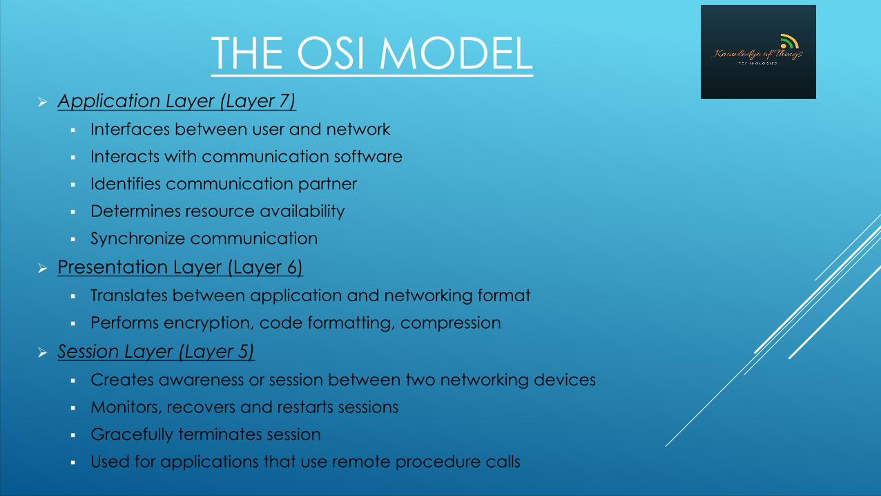
THE OSI MODELØ Application Layer (Layer 7)
§ Interfaces between user and network§ Interacts with communication software§ Identifies communication partner§ Determines resource availability§ Synchronize communication
Ø Presentation Layer (Layer 6)§ Translates between application and networking format§ Performs encryption, code formatting, compression
Ø Session Layer (Layer 5)§ Creates awareness or session between two networking devices§ Monitors, recovers and restarts sessions§ Gracefully terminates session§ Used for applications that use remote procedure calls

THE OSI MODELØ Transport Layer (Layer 4)
§ Ensures reliable data transfer
§ Maintains link reliability by flow control
§ Ensures data integrity by flow control and acknowledgement
§ Responsible for data segmentation and reassembly
Ø Network Layer (Layer 3)
§ Transfers data between different networks
§ Manages logical addressing scheme
§ It has 3 components -
1. subnetwork access (to deal with interface to network),
2. subnetwork-dependent convergence (to bring the level of the transit network up to the level of networks on either side),
3. subnetwork-independent convergence (to transfer across different networks)

THE OSI MODELØ Datalink Layer (Layer 2)
§ Has different aspects for LAN and WAN
§ For WAN it perfroms error correction, transmission control, reliable delivery by flow-control and acknowledgement
§ For LAN it has 2 sublayers - MAC (Media Access Control - to manage interaction of devices over a shared medium, manage physical addressing), LLC (Logical Link Control - to address and multiplex data across a shared medium); LAN Datalink layer is not responsible fr any error correction and reliability
Ø Physical Layer (Layer 1)
§ Interface between the hardware and OSI
§ Defines relation between device and medium
§ Defines electrical and physical specifications
§ Creates and terminates connection to communication medium
§ Facilitates effective sharing of resources via the communication medium
§ Modulation and demodulation between data signals and corresponding electronic signals
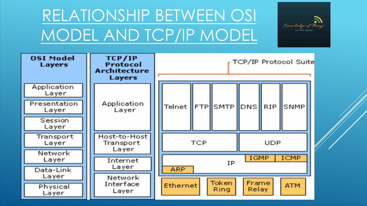
RELATIONSHIP BETWEEN OSI MODEL AND TCP/IP MODEL
NETWORKING PROTOCOLS

NETWORKING PROTOCOLSThere are certain software that define the standards which allow networking devices to communicate, identify each other while being able to handle data format, processing methods, etc. TCP (Transmission Control Protocol) - It operates in the transport layer. It is
used for segmenting the data, reassembling data, error correction, etc. It is connection oriented i.e. it will not send the next data packet without receiving acknowledgment for the previous data. So, tcp is a little bit slow but very accurate.
UDP (User Datagram Protocol) - Same function as TCP. But, it is connectionless thus making it faster but not accurate.
IP (Internet Protocol) - It is a network protocol used to manage the delivery of data and the logical network number.
HTTP (Hyper Text Transfer Protocol) - It is an application layer protocol that is used to render Internet documents or web pages.
NETWORKING PROTOCOLS
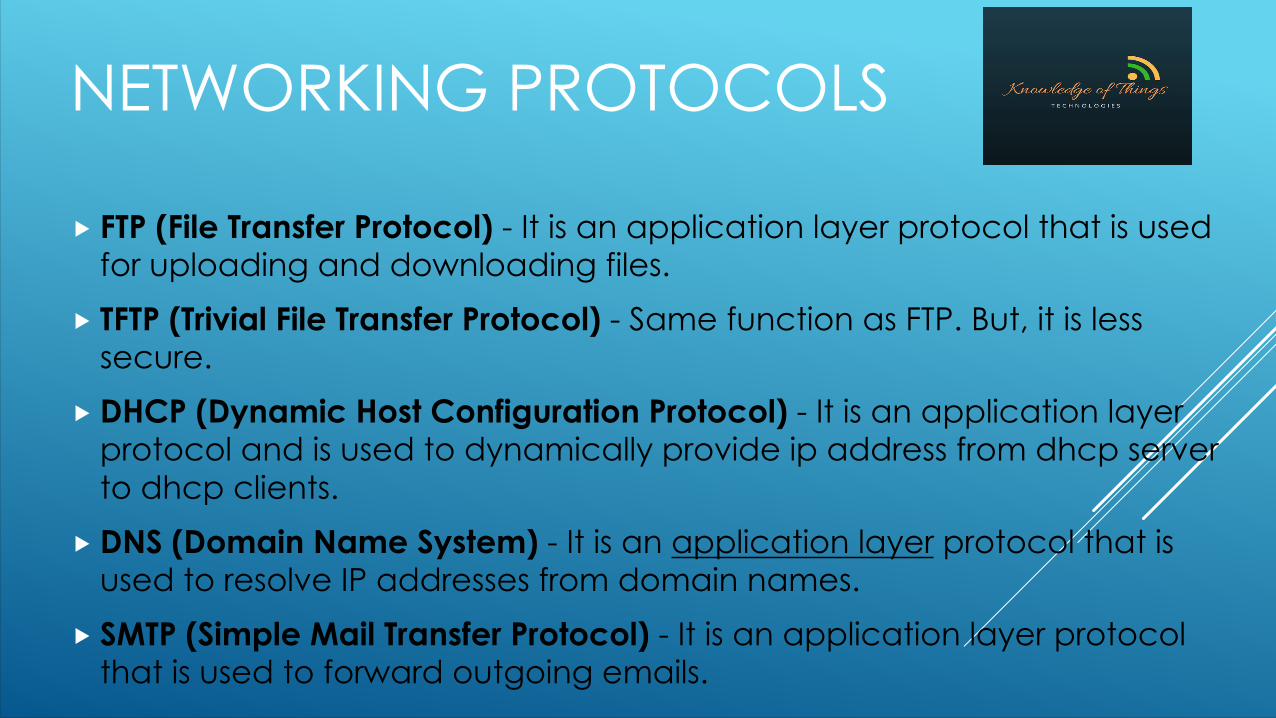
FTP (File Transfer Protocol) - It is an application layer protocol that is used for uploading and downloading files.
TFTP (Trivial File Transfer Protocol) - Same function as FTP. But, it is less secure.
DHCP (Dynamic Host Configuration Protocol) - It is an application layer protocol and is used to dynamically provide ip address from dhcp server to dhcp clients.
DNS (Domain Name System) - It is an application layer protocol that is used to resolve IP addresses from domain names.
SMTP (Simple Mail Transfer Protocol) - It is an application layer protocol that is used to forward outgoing emails.

NETWORKING PROTOCOLS
POP (Post Office Protocol) - It is also an application layer protocol used to receive incoming e-mails.
ICMP (Internet Control Messaging Protocol) - It is a network layer protocol that provides feedback support for IP.
ARP (Address Resolution Protocol) - It is a network layer protocol that is used to resolve the MAC addresses from the IP address. That is it relates any particular IP address with a particular MAC address.
TELNET - This is an application layer protocol. It is used to login into another remote device.
SSH (Secure Shell) - This is atransport layer protocol. It is a cryptographic network protocol for operating network services securely over an unsecured network. It allows to securely login into another remote device.

TCP PORTSTCP belongs to the Transport Layer and the different application protocols need support from it. TCP services each application protocol by a unique number also called TCP Port number. Without these ports, TCP will never know which application protocol is asking for its service.
CONCLUDING NETWORKING DEVICES AND THEIR BEHAVIOURS
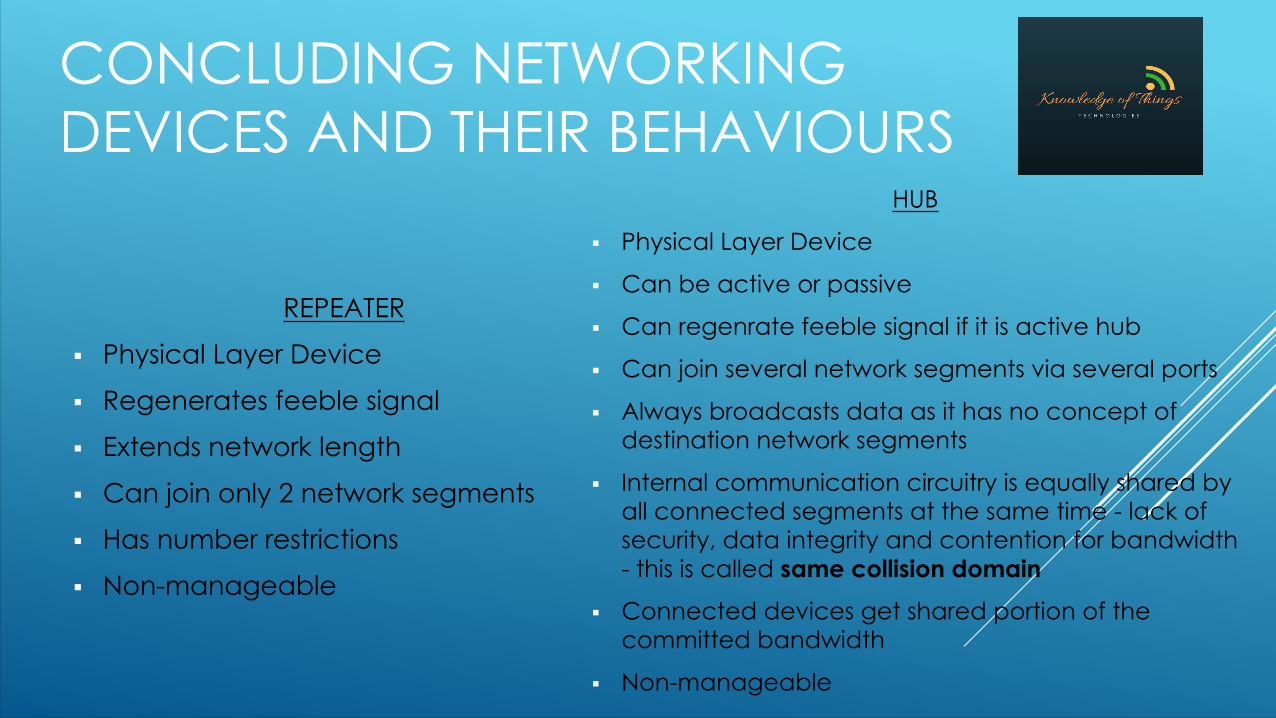
REPEATER
§ Physical Layer Device
§ Regenerates feeble signal
§ Extends network length
§ Can join only 2 network segments
§ Has number restrictions
§ Non-manageable
HUB
§ Physical Layer Device
§ Can be active or passive
§ Can regenrate feeble signal if it is active hub
§ Can join several network segments via several ports
§ Always broadcasts data as it has no concept of destination network segments
§ Internal communication circuitry is equally shared by all connected segments at the same time - lack of security, data integrity and contention for bandwidth - this is called same collision domain
§ Connected devices get shared portion of the committed bandwidth
§ Non-manageable
CONCLUDING NETWORKING DEVICES AND THEIR BEHAVIOURS
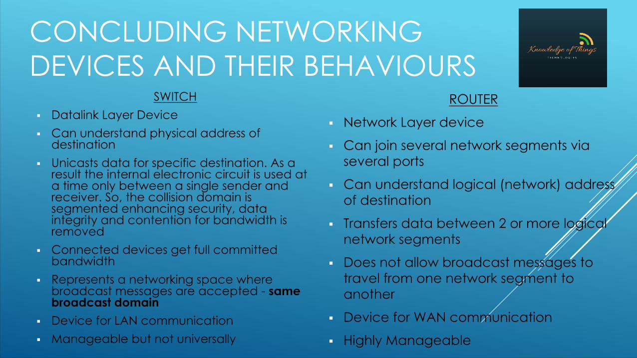
SWITCH§ Datalink Layer Device§ Can understand physical address of
destination§ Unicasts data for specific destination. As a
result the internal electronic circuit is used at a time only between a single sender and receiver. So, the collision domain is segmented enhancing security, data integrity and contention for bandwidth is removed
§ Connected devices get full committed bandwidth
§ Represents a networking space where broadcast messages are accepted - same broadcast domain
§ Device for LAN communication§ Manageable but not universally
ROUTER
§ Network Layer device
§ Can join several network segments via several ports
§ Can understand logical (network) address of destination
§ Transfers data between 2 or more logical network segments
§ Does not allow broadcast messages to travel from one network segment to another
§ Device for WAN communication
§ Highly Manageable
CONCLUDING NETWORKING DEVICES AND THEIR BEHAVIOURS
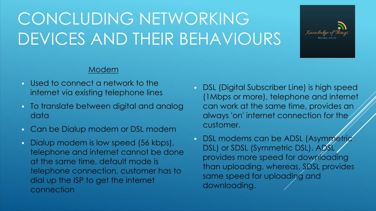
Modem
§ Used to connect a network to the internet via existing telephone lines
§ To translate between digital and analog data
§ Can be Dialup modem or DSL modem
§ Dialup modem is low speed (56 kbps), telephone and internet cannot be done at the same time, default mode is telephone connection, customer has to dial up the ISP to get the internet connection
§ DSL (Digital Subscriber Line) is high speed (1Mbps or more), telephone and internet can work at the same time, provides an always 'on' internet connection for the customer.
§ DSL modems can be ADSL (Asymmetric DSL) or SDSL (Symmetric DSL). ADSL provides more speed for downloading than uploading, whereas, SDSL provides same speed for uploading and downloading.

NETWORKING ADDRESSØ Layer 2 address - Sometimes called physical address; Examples
- MAC address, DLCI, VPI/VCI, etc; used to identify devices in a particular LAN
Ø Layer 3 address - Sometimes called Logical address; Examples - IPv4 address, IPv6 address, IPx address, etc; used to identify devices across different networks in a WAN
Ø Layer 4 address - Also called port address; Examples - HTTP (TCP port 80), TELNET (TCP port 23), DNS (TCP port 53, UDP port 53), etc; used to identify the different networking services or applications
Related Documents