HAL Id: hal-02517659 https://hal.univ-angers.fr/hal-02517659 Submitted on 19 Jan 2021 HAL is a multi-disciplinary open access archive for the deposit and dissemination of sci- entific research documents, whether they are pub- lished or not. The documents may come from teaching and research institutions in France or abroad, or from public or private research centers. L’archive ouverte pluridisciplinaire HAL, est destinée au dépôt et à la diffusion de documents scientifiques de niveau recherche, publiés ou non, émanant des établissements d’enseignement et de recherche français ou étrangers, des laboratoires publics ou privés. IstiABot, an Open Source Mobile Robot for Education and Research Rémy Guyonneau, Franck Mercier To cite this version: Rémy Guyonneau, Franck Mercier. IstiABot, an Open Source Mobile Robot for Education and Re- search. 12th International Workshop on Robot Motion and Control (RoMoCo) 2019, Jul 2019, Poznań, Poland. pp.131-136, 10.1109/RoMoCo.2019.8787363. hal-02517659

Welcome message from author
This document is posted to help you gain knowledge. Please leave a comment to let me know what you think about it! Share it to your friends and learn new things together.
Transcript
HAL Id: hal-02517659https://hal.univ-angers.fr/hal-02517659
Submitted on 19 Jan 2021
HAL is a multi-disciplinary open accessarchive for the deposit and dissemination of sci-entific research documents, whether they are pub-lished or not. The documents may come fromteaching and research institutions in France orabroad, or from public or private research centers.
L’archive ouverte pluridisciplinaire HAL, estdestinée au dépôt et à la diffusion de documentsscientifiques de niveau recherche, publiés ou non,émanant des établissements d’enseignement et derecherche français ou étrangers, des laboratoirespublics ou privés.
IstiABot, an Open Source Mobile Robot for Educationand Research
Rémy Guyonneau, Franck Mercier
To cite this version:Rémy Guyonneau, Franck Mercier. IstiABot, an Open Source Mobile Robot for Education and Re-search. 12th International Workshop on Robot Motion and Control (RoMoCo) 2019, Jul 2019, Poznań,Poland. pp.131-136, �10.1109/RoMoCo.2019.8787363�. �hal-02517659�

IstiABot, an Open Source Mobile Robot for Education and Research
Remy Guyonneau and Franck Mercier1
Abstract— IstiABot is a mobile robot made for educationand research purposes. This robot aims to be modular, easyto modify and used by first year students as well as last yearstudents and researchers. To achieve those requirements, therobot is built on the top of a CANBus Network.
This paper presents the robot and the approach behindits building. It also presents an educational application ofthe platform (tuning a PID controller) and a research ap-plication (Simultaneous Localization And Mapping - SLAM- experimentations). Finally it concludes about this experienceand introduce two other robots that were built based on theIstiABot.
As it was wanted for the robot to be as free as possible, allthe source code and 3D modeling are available.
I. INTRODUCTION
A. Context
Dealing with mobile robots requires knowledge in elec-tronics, mechanics and computer sciences. This is an in-teresting field to apply theoretical notions. Adding thatstudents are usually well motivated when dealing with robots,robotics has became a widely considered tool for educationof undergraduate and graduate students [1], [2], [3].
Polytech Angers (formally named ”IstiA”) is the engineerschool of the University of Angers (France). Among other,it trains students to have a master degree in engineeringfor industrial systems. As mobile robotics is nowadays acommonly considered industrial tool [4], [5], [6], the needof having a platform to train the students to work on/withmobile robots became urgent.
In addition to the education applications, an other goal wasto be able to use the robots for research applications. Indeed,most of the teachers in the school are also researchers andsome of them deal with mobile robotics [7], [8]. Having aplatform that can be used by students and researchers helpsto raise students awareness of the world of research.
B. Developing a New Robot
Despite the number of commercial robots, it was decidedto build ”home made” robots. This was motivated by severalreasons.
First the following requirements were defined for theplatform:• The platform has to be used by bachelor’s level students
and master’s level students. That is, it has to be easyto use for beginners but at the same time it has toallow complex developments for high-level students andresearchers;
1Polytech Angers, University of Angers, [email protected]
Fig. 1: The IstiABot.
• The platform has to be easy to modify. Students mustbe able to develop their own modules (mechanic andelectronic add-on) to add sensors/actuators to the robot;
• The platform hardware/software has to be as Free/OpenSource as possible.
Secondly, this was a perfect opportunity to use some ofthe in-house production capabilities and to put forward whatcan be done at the school.
And last but not least, designing and building a robot isa good way to increase robotic skills and to involve thestudents in the making process.
For all those reasons it was decided to develop the robotsinstead of buying commercial ones. Here is a quick overviewregarding this choice:
• Drawback:– The main drawback of the ”developing our robot”
solution is that it is time consuming. It took a fullyear to have the first moving robots (conception,realization, debug...).
• Advantages:– The robot well suits the needs. It meets all the
previously defined requirements;– This is a mastered platform, so it can be modified,
repaired and evolved as needed;– All the hardware design and source code are freely
available. Some tutorials were also written to helpthe students. Thanks to those tutorials, they are ableto build their own robots1 but also to program them(there is one tutorial to set up and use the onboardRapsberry Pi for ”high level” programming 2 and
1https://github.com/PolytechAngersMecatroniqueClub/Tutorials/tree/master/Tuto_assembling
2https://github.com/PolytechAngersMecatroniqueClub/Tutorials/wiki

one tutorial about the CANBus programming3 todeal with the other boards.). Those tutorials helpthe students to be more autonomous working withthe robots.
This paper presents the produced platform (depicted inFigure 1) , explaining the choices made and introducing therobot’s current applications. Section II details the platformand the home made boards, Section III presents applicationsin education and research. Finally Section IV concludes thispaper.
II. ROBOT PRESENTATION
A. General Architecture
The IstiABot is a differential two wheeled mobile robotwith an idler wheel. Considering a differential two wheeledrobot allows simple modelization and command which iswell suited for beginner students.
Figure 2 presents the general architecture of the IstiABot.As it can be noticed, the robot entirely relies on a CANBusnetwork. This allows a great modularity. Indeed in theCANBus network, only the messages are identified, not thedevices. That allows for instance the robot to be controlledby an Arduino board or a Raspberry Pi board without theneed of any modification. Basically, it is possible to define amessage that says ”move forward” and it does not matter ifthe Raspberry Pi or the Arduino board send it. This allows alarge scale of programmer level: beginer will prefer Arduinowhile others prefer Rapsberry Pi.
B. The Hardware
Two 12V brushed DC motors are used to motorize therobot. Those have a 30:1 metal gearbox and an integratedquadrature encoder that provides a resolution of 64 countsper revolution of the motor shaft. The robot is powered bya 14V lithium-ion battery. A tutorial of how to assemble therobot can be found at the following github repository4.
In Figure 2 it can be noticed that all the images correspondto elements that are available on the shelf (US sensor boards,Arduino...) but the non graphical boards (power board,motorboard...) are home made (design and fabrication). Someof those boards are presented in the later.
C. The Motor Board
This board allows controlling a DC motor according toa speed order (Figure 3). It requires two different powersupplies: 5V for the electronics and 12V for the motor.It receives the speed order through the CANBus. Then itgenerates a PWM5 signal that is connected to the motors.In order to control the motor speed, the encoder valuesare processed and a speed regulation is done using a PID6
controller. This controller is detailed in Section III-A.3https://github.com/PolytechAngersMecatroniqueClub/
Tutorials/tree/master/Tuto_CAN4https://github.com/PolytechAngersMecatroniqueClub/
Tutorials/blob/master/Tuto_assembling/tutoIstiaBot_montage.pdf
5Pulse Width Modulation6Proportional Integral Derivative
This board has also a current sensor. Its data can beprocessed to detect current peaks that could happen whenthe robot is stuck while trying to move for instance.
It was originally designed for brushless technology. It hasthree output channels corresponding to each motor coil andthree hall sensors are wired for feedback. This board iselectronically optimized for Maxon EC45 brushless7, but itwas also planned the possibility to use DC technology withcoder feedback via LS7366R8 quadrature counter.
All the schematics and source codes of this board can bedownloaded from the following github repository9.
D. CANBus Shields
A drawback of having a modular robot based on a CAN-Bus Network is that each component needs to be associatedto a CANBus interface (Sensors, HMI...).
The key point of the development is the reliability androbustness of CAN communication on each sub-system ofthe robot. Electronically speaking, except the Raspberry Piand the Arduino shields, all electronic board are basedon the same architecture. They have an ATmega32M1 mi-crocontroller coupled with a high-speed CAN transceiver(MCP2562) for interfacing CAN controller to physical two-wire CANBus.
The ATmega32M1 has an embedded CAN controller, andit exists C and C++ libraries that implement the CANfunctions. Those libraries have the benefit to ease the useof the CAN controller low level registers by ”hiding them”.Otherwise, this set of registers can be complex to manage.For instance the ATmega32M1 proposes six ”MOB”10 that ispossible to pre-configure to send messages, to listen a rangeof addresses or to listen a specific address. But you do notneed to know that when using the libraries.
The main drawback of using those libraries is that theyconsider blocking functions: functions that wait for a flagthrough a loop, which does not allow to release the CPU forother things. A more efficient way to use the CAN controllerwould be to use the microcontroller’s interruptions insteadof having blocking loops. But configuring the interruptionsmeans dealing with the low level microcontroller registerswhich is not possible with the libraries.
That is, it was decided not to use the availale librariesbut instead to directly deal with the CAN registers. Toease the CAN register configurations, a set of non blockingfunctions was written11, a tutorial was made12, and some
7https://www.maxonmotor.com/maxon/view/product/397172
8https://lsicsi.com/datasheets/LS7366R.pdf9https://github.com/PolytechAngersMecatroniqueClub/
Motor_Board10Message OBjects11https://github.com/PolytechAngersMecatroniqueClub/
Motor_Board/blob/master/code/include/CanISR.h12https://github.com/PolytechAngersMecatroniqueClub/
Tutorials/blob/master/Tuto_CAN/tuto_CAN_ATMEGA.pdf

CANBusShield
Raspberry PiArduino Uno
DC motor
IMU sensor
US sensor
CANBusShield
Battery
LCD Display
LiDAR
I2C5V
USB/UART
Power Power
CANBus& 5V
I2C5V
PWMEncoders
SPI5V
Trig/Echo
5V
bus5V
CANBusShield
Adafruit i2c 16x2 RGB LCD Pi Plate
Contrast SELECT
MPC23017-E/SP124750J
CANBusShield
MotorBoard
PowerBoard
CANBusShield
Fig. 2: Architecture of the IstiABot.
12V
5V &CANBus
Motor BoardPWM
Encoders
MicroController
Counter
H-bridge
Motor withencoders
Fig. 3: Summary of the motor board. Through the CANBusis sent messages containing speed command for the motor(values are in rad.s−1). A PID controller is implemented inthe micro-controller to regulate the motor speed.
code examples are available1314. The general idea of thoseressources is to ease the understanding of the CAN registers.
III. ROBOT APPLICATIONS
As mentioned earlier, the robot is used by beginners andmore experimented students. The idea is that the students canprogress with the same platform throughout their learningprocess. This is mainly allowed by the CANBus Networkand the fact that an Arduino board and a Raspberry Pi boardcan be used to control the robot.
Here is a progression example:• Once the robot is properly configured, it is simple to
make it move with Arduino programming. ConsideringScratch for Arduino makes it possible to control therobot even for students that never learned how to code.Based on the same idea, it is possible to easily get valuesfrom the sensors and start developing simple movingalgorithms;
• The introduction of control loops and embedded pro-gramming can be done via low level programming forboard’s micro-controllers. For instance by configuringthe CANBus Network or by setting up a speed regula-tion on the motor board;
• Considering the Raspberry Pi and a LiDAR sensor, itis then possible to deal with more complex algorithmsas localization, mapping, path planning... At this step it
13https://github.com/PolytechAngersMecatroniqueClub/Motor_Board/blob/master/code/main.cpp
14https://github.com/PolytechAngersMecatroniqueClub/US_Board/blob/master/code/main.cpp
Fig. 4: Experimental setup : the expected trajectory is astraight line going through five phases with different slopes.The robot must move over the path at constant speed.
is possible to introduce research problems and develop-ments.
In the following part of this document two examples ofrobot use are detailed:• Implementation of a PID regulation.• Implementation of a SLAM algorithm.
A. Setting up a PID Controller
1) Problem Presentation: Figure 4 shows a simple ex-perimentation that illustrates the problem: the robot mustmove through the path (straight line) at constant speed. Thepath is divided into five phases with different slopes. First,the experimentation is done using an open loop command:a constant PWM is applied to each motor. By using theArduino and the wheel encoder measurements (sent by themotor board to the CANBus) it is quite easy to log the speedof each motors. The results of this first experimentation arepresented in Figure 5.
Those curves depict two problems:• The speed is not constant over the trajectory. It de-
creases when the slope is positive and increases whenthe slope is negative;
• The left wheel and the right wheel do not move at thesame speed. Because of this difference, the robot doesnot move straight forward.
This simple experimentation allows presenting the prob-lem to the student and intuiting the ideal behavior: Thecurves must be identical and equal to the setpoint. Thestudents are now able to explain the goal of the project, andlater, compare their results with this reference to quantify thegain of the added correction.
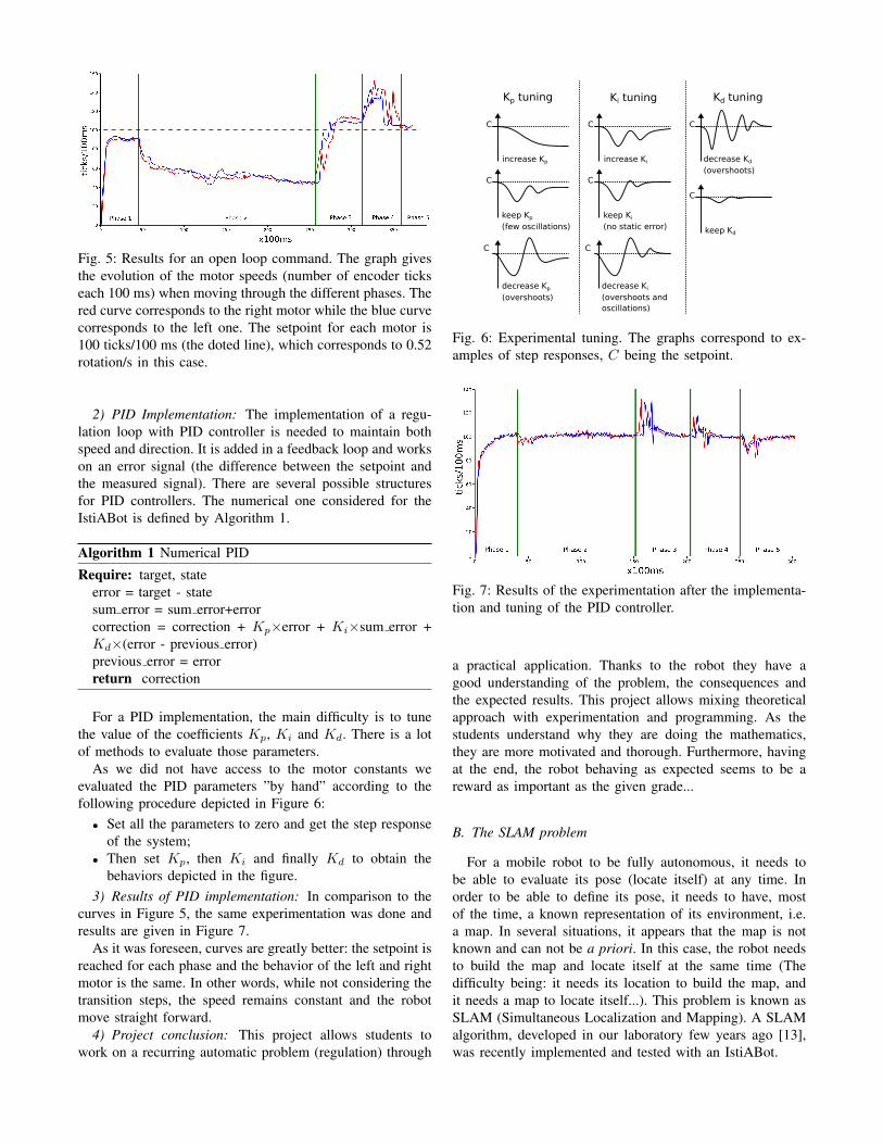
Fig. 5: Results for an open loop command. The graph givesthe evolution of the motor speeds (number of encoder tickseach 100 ms) when moving through the different phases. Thered curve corresponds to the right motor while the blue curvecorresponds to the left one. The setpoint for each motor is100 ticks/100 ms (the doted line), which corresponds to 0.52rotation/s in this case.
2) PID Implementation: The implementation of a regu-lation loop with PID controller is needed to maintain bothspeed and direction. It is added in a feedback loop and workson an error signal (the difference between the setpoint andthe measured signal). There are several possible structuresfor PID controllers. The numerical one considered for theIstiABot is defined by Algorithm 1.
Algorithm 1 Numerical PID
Require: target, stateerror = target - statesum error = sum error+errorcorrection = correction + Kp×error + Ki×sum error +Kd×(error - previous error)previous error = errorreturn correction
For a PID implementation, the main difficulty is to tunethe value of the coefficients Kp, Ki and Kd. There is a lotof methods to evaluate those parameters.
As we did not have access to the motor constants weevaluated the PID parameters ”by hand” according to thefollowing procedure depicted in Figure 6:• Set all the parameters to zero and get the step response
of the system;• Then set Kp, then Ki and finally Kd to obtain the
behaviors depicted in the figure.3) Results of PID implementation: In comparison to the
curves in Figure 5, the same experimentation was done andresults are given in Figure 7.
As it was foreseen, curves are greatly better: the setpoint isreached for each phase and the behavior of the left and rightmotor is the same. In other words, while not considering thetransition steps, the speed remains constant and the robotmove straight forward.
4) Project conclusion: This project allows students towork on a recurring automatic problem (regulation) through
Kp tuning Ki tuning Kd tuning
C
increase Kp
C
C
keep Kp
(few oscillations)
decrease Kp
(overshoots)
C
increase Ki
C
C
keep Ki
(no static error)
decrease Ki
(overshoots andoscillations)
C
C
keep Kd
decrease Kd
(overshoots)
Fig. 6: Experimental tuning. The graphs correspond to ex-amples of step responses, C being the setpoint.
Fig. 7: Results of the experimentation after the implementa-tion and tuning of the PID controller.
a practical application. Thanks to the robot they have agood understanding of the problem, the consequences andthe expected results. This project allows mixing theoreticalapproach with experimentation and programming. As thestudents understand why they are doing the mathematics,they are more motivated and thorough. Furthermore, havingat the end, the robot behaving as expected seems to be areward as important as the given grade...
B. The SLAM problem
For a mobile robot to be fully autonomous, it needs tobe able to evaluate its pose (locate itself) at any time. Inorder to be able to define its pose, it needs to have, mostof the time, a known representation of its environment, i.e.a map. In several situations, it appears that the map is notknown and can not be a priori. In this case, the robot needsto build the map and locate itself at the same time (Thedifficulty being: it needs its location to build the map, andit needs a map to locate itself...). This problem is known asSLAM (Simultaneous Localization and Mapping). A SLAMalgorithm, developed in our laboratory few years ago [13],was recently implemented and tested with an IstiABot.

1) Overview of the approach: The developped SLAM,named PaSLAM in the later, is a LiDAR15 based SLAM. ALiDAR measurement set is defined by:
Z(t) = {di(t), θi(t)}, i = 1, ..., n, (1)
with Z(t) the measurement set at time t, di the distance andθi the angle of the ith measurement of the set, and n thenumber of measurements for one LiDAR set. In the later thenotation (t) will be omit to ease the reading.
From this LiDAR set and according to the robot’s pose16
at time t, xr = (xr, yr, θr), it is possible to compute a pointcloud XZ corresponding to all the detected obstacles fromthe robot’s pose:
XZ = {xi, yi}, i = 1, ..., n, (2)
with
xi = di cos(θi + θr) + xr, (3)yi = di sin(θi + θr) + yr. (4)
From that, localizing the robot means solving the follow-ing minimization problem:
minxr,yr,θr
n∑i=1
fM (xi, yi), (5)
with fM (.) the cost function, parametrized by the mapM = {(ojx, ojy)}, j = 1, ...,m considered as a set ofm obstacles defined by their positions (ojx, o
jy). This cost
function is defined by
fM (xi, yi) =
√(xi − omin,ix )2 + (yi − omin,iy )2, (6)
with (omin,ix , omin,iy ) ∈M the closest obstacle to the point(xi, yi). That is, (omin,ix , omin,iy ) is defined by
(omin,ix , omin,iy ) = arg min(ojx,o
jy)∈M
√(xi − ojx)2 + (yi − ojy)2.
(7)Each time the robot is localized, the new detected obstacles
are added to the current map:
M =M⋃{(xi, yi)}. (8)
Note that to initialize the SLAM we consider:
M(0) = {(xi(0), yi(0))}, (9)
with xr(0) = (0, 0, 0) and Z(0) being the first measure-ment set.
The PaSLAM algorithm considers a Nelder and Mead[14] approach to solve the minimization problem, Equation5. This method is based on iterative transformations of asimplex defined in the search space.
15Light Detection And Ranging16Position (xr, yr) and orientation (θr). Note that in this case only a
two dimentional position is considered as the robot is supposed to moveover a flat ground
(a) Dagstuhl Neubau data set results.
(b) L101 building data set results.
Fig. 8: Outputs of the PaSLAM and the Hector SLAM fortwo different datasets. The displayed maps correspond to theoutputs of the Hector SLAM (white cells are free spaces,black cells are obstacles and grey cells are unknown) andthe yellow lines correspond to the obstacles computed bythe PaSLAM algorithm.
2) Results: The approach was implemented using ROS17
middleware. ROS is open source and offers a lot of usefultools (implementation can be done in Python or C++, it hasa large community and a lot of softwares are available...). Tovalidate the implementation18, the ROS version of PaSLAMhas been compared to the ROS Hector SLAM [16], [15]software19. To compare those algorithms we used two datasets available online20: the ”Dagstuhl Neubau” and the ”L101building” datasets.
Using those logged data we built a map with PaSLAM anda map with Hector SLAM. Then to compare the results wejust put one map over the other one to display the differences.
Figure 8 presents the results. It appears that the twoapproaches provide similar maps. This work was mainlydone by a master student and the objective was multiple: tobe comfortable with ROS and create a ROS implementationof PaSLAM, to evaluate the processing capability of theRaspberry Pi to onboard mapping tasks and to have ademonstrator used for communcation events.
17Robot Operating System18A free/open-source version of the developed SLAM can be
downloaded at the following repository :https://github.com/PolytechAngersMecatroniqueClub/pa_slam.
19http://wiki.ros.org/hector_slam20https://code.google.com/archive/p/
tu-darmstadt-ros-pkg/downloads

(a) Self Balancing Robot. (b) Ball Balancing Robot.
Fig. 9: Robots based on the IstiABot components.
IV. CONCLUSION
As it was presented in this paper, the IstiABot platformmade it possible to meet all the defined constraints about theplatform: it is modular, we have a full understanding anddocumentation of the platform (hardware and software), itcan be used by students from the first year to the last oneas well as for research work. Thus, it has been consideredfor student projects (the PID implementation among others)and for research projects (implementation of the SLAMalgorithm using ROS). The interest of the robot for researchapplication does not lie into its hardware configurationneither its architecture. It is an interesting platform, mainlybecause it is mastered. Indeed, most of the time, researchin robotics has to be validated with experimenations, andthe robot can easilly be modified to fit needed experimentalconfigurations.
CANbus Network is the key element of the versatility ofthe robots. With exactly the same boards and motors, it wasfor instance possible to design other robots with differentabilities. Two of those robots are introduced in Figure 9. Thefirst one (Figure 9a) is based on inverted pendulum principle.The objective of such a platform is to set up the commandthat will maintain the robot self balanced (it is naturallyunstable). A video of the result can be found here21, and asimulation of a self-balancing robot (used for primary results)can be downloaded here22 (Python3 code using OpenGL forrendering.). The second robot (Figure 9b) is a robot thatmust be able to balance itself over a ball (that is free tomove). Despite the change of wheels, the components ofthis robot remain the same as for the IstiABot and the self-balancing robot. Currently, only the hardware has been doneand a simulation has been developped (Python3 code usingOpenGL for rendering.) and is availbale here23.
The IstiABot allows a large panel of student project(mechanics, electronics, computing...), and the possibility totest research algorithms is very comfortable, considering thepossibility to customize this robot by adding and removingsensors as needed.
21https://youtu.be/G2n9_4nhEaQ22https://github.com/rguyonneau/
Self-Balancing-Robot-Python-Simulator23https://github.com/PolytechAngersMecatroniqueClub/
IBallBBOT
Finally, an effort has been made to develop this robot(hardware and software) with a free license philosophy.We hope that this can permit to anyone to duplicate andcustomize this robot, or at least to be helpful for those whowant to develop their own specific robots.
ACKNOWLEDGMENTThank you to Philippe Lucidarme who helped the robot
conception and provided some board schematics. Thank youto Baptiste Hamard who works on the PID implementationfor speed control and Vincent Cueille who implementedthe first version of the mapping algorithm in the robotswith ROS. Finally, thank you to the SAGI (automation andcomputer sciences) Department of Polytech Angers whichsubsidized the robots.
REFERENCES
[1] F. M. Lopez-Rodriguez, F. Cuesta, Andruino-A1: Low-Cost Edu-cational Mobile Robot Based on Android and Arduino, Journal ofIntelligent and Robotic Systems, 2015, 81:6376.
[2] B. Curto and V. Moreno, Robotics in Education, Journal of Intelligentand Robotic Systems, 2016, vol. 81, no 1, p. 3.
[3] J. M. Gomez-de-Gabriel , A. Mandow, J. Fernandez-Lozano andA. Garcia-Cerezo, Mobile robot lab project to introduce engineeringstudents to fault diagnosis in mechatronic systems, 2015, IEEE Trans-actions on Education, 58(3), 187-193.
[4] L. Lindner, O. Sergiyenko, J. C. Rodrguez-Quionez, M. Rivas-Lopez,D. Hernandez-Balbuena, W. Flores-Fuentes, F. Natanael Murrieta-Ricoand V. Tyrsa, Mobile robot vision system using continuous laserscanning for industrial application, Industrial Robot: An InternationalJournal, 2016, Vol. 43 Issue: 4, pp.360-369.
[5] I. Nielsen, Q-V. DangEmail, G. Bocewicz and Z. Banaszak, A method-ology for implementation of mobile robot in adaptive manufacturingenvironments, Journal of Intelligent Manufacturing, June 2017, Vol-ume 28, Issue 5, pp 11711188.
[6] C. SprunkEmail, B. Lau, P. Pfaff and W. Burgard, An accurate andefficient navigation system for omnidirectional robots in industrialenvironments, Autonomous Robots, February 2017, Volume 41, Issue2, pp 473493.
[7] M. Mustafa, A. Stancu, N. Delanoue and E. Codres, GuaranteedSLAMAn interval approach, Robotics and Autonomous Systems.2018. Vol. 100 p. 160-170.
[8] R. Guyonneau, S. Lagranges, L. Hardouin and P. Lucidarme, Guar-anteed Interval Analysis Localization for Mobile Robots, Journal onAdvanced Robotics, 2014, Vol. 28 n16 p. 1067-1077.
[9] Robert Bosch, Specification, C.A.N. (1991). Bosch. GmbH, Postfach,50.
[10] P. Jamieson and Jeff Herdtner, More missing the BoatArduino, Rasp-berry Pi, and small prototyping boards and engineering educationneeds them, 2015, IEEE Frontiers in Education Conference (FIE).
[11] J. Sobota et al., Raspberry Pi and Arduino boards in control education,IFAC Proceedings Volumes, 46.17 (2013): 7-12.
[12] K. J. Astrom and T. Hagglund, PID controllers: theory, design, andtuning. Research Triangle Park, NC : Instrument society of America,1995.
[13] A. Bautin, P. Lucidarme, R. Guyonneau, O. Simonin, S. Lagrange,N. Delanoue and F. Charpillet, Cart-0-matic project : autonomousand collaborative multi-robot localization, exploration and mapping,IEEE/RSJ International Conference on Intelligent Robots and Systems(IROS), 5th Workshop on Planning, Perception and Navigation forIntelligent Vehicles, 2013, Tokyo.
[14] J. E. Dennis and D. J. Woods, Optimization on microcomputers:The Nelder-Mead simplex algorithm, New computing environments:microcomputers in large-scale computing, 1987, vol. 11, p. 6-122.
[15] S. Kohlbrecher, J. Meyer, T. Graber, K. Petersen, O. Von Stryk andU. Klingauf, Robocuprescue 2014-robot league team hector darmstadt(germany), RoboCupRescue 2014, 2014.
[16] S. Kohlbrecher, O. Von Stryk, J. Meyer and U. Klingauf, A flexible andscalable slam system with full 3d motion estimation, In 2011 IEEEInternational Symposium on Safety, Security, and Rescue Robotics(pp. 155-160), IEEE, 2011.
Related Documents