TECHNICAL POSITION PAPER ISSUES RELATED TO CONTROL OF COARSE COAL REFUSE COMPACTION DURING CONSTRUCTION OF FINE COAL REFUSE SLURRY IMPOUNDMENT EMBANKMENTS AND BARRIERS Michael Richmond, Chief, Engineering Service and Technology Transfer Branch, OSMRE INTRODUCTION: This technical paper explores several issues relative to the verification of proper construction, specifically compaction control, of embankments of slurry impoundments. Coarse coal refuse material is used to construct these embankments. In the general course of OSMRE conducting oversight inspections in West Virginia, as required under the Surface Mining Control and Reclamation Act of 1977 (SMCRA), questions arose concerning the methodology for testing for proper compaction. This paper explores those questions and incorporates peer review comments received from a nationwide pool of experts, including representatives of State and Federal agencies, industry, and universities. A thorough Quality Assurance/Quality Control (QA/QC) program is an essential part of every dam construction project, and selection of the appropriate tests is a critical element of that program. The composition of materials used and the construction practices employed will ultimately define the overall stability of these types of structures. Close monitoring during the actual construction process to assure proper compaction and material behavior is an integral part to assure stability of these embankments. U.S. DEPARTMENT OF THE INTERIOR Office of Surface Mining Reclamation and Enforcement Appalachian Region JANUARY, 2015

Welcome message from author
This document is posted to help you gain knowledge. Please leave a comment to let me know what you think about it! Share it to your friends and learn new things together.
Transcript

TECHNICAL POSITION PAPER
ISSUES RELATED TO CONTROL OF COARSE COAL REFUSE
COMPACTION DURING CONSTRUCTION OF FINE COAL REFUSE
SLURRY IMPOUNDMENT EMBANKMENTS AND BARRIERS
Michael Richmond, Chief,
Engineering Service and Technology Transfer Branch, OSMRE
INTRODUCTION:
This technical paper explores several issues relative to the verification of proper construction,
specifically compaction control, of embankments of slurry impoundments. Coarse coal refuse
material is used to construct these embankments. In the general course of OSMRE conducting
oversight inspections in West Virginia, as required under the Surface Mining Control and
Reclamation Act of 1977 (SMCRA), questions arose concerning the methodology for testing for
proper compaction. This paper explores those questions and incorporates peer review
comments received from a nationwide pool of experts, including representatives of State and
Federal agencies, industry, and universities. A thorough Quality Assurance/Quality Control
(QA/QC) program is an essential part of every dam construction project, and selection of the
appropriate tests is a critical element of that program. The composition of materials used and
the construction practices employed will ultimately define the overall stability of these types of
structures. Close monitoring during the actual construction process to assure proper compaction
and material behavior is an integral part to assure stability of these embankments.
U.S. DEPARTMENT OF THE INTERIOR
Office of Surface Mining Reclamation and Enforcement
Appalachian Region
JANUARY, 2015

2
ISSUES RELATED TO CONTROL OF COARSE REFUSE COMPACTION DURING
CONSTRUCTION OF SLURRY IMPOUNDMENT EMBANKMENTS AND BARRIERS
INTRODUCTION
Most underground and some surface mines in the Appalachian Region process their raw, run-of-
mine coal prior to sale to produce a superior product. The processing typically involves
removing inert, non-coal (rock fragments) material from the raw mine output. Fine material is
first removed from the coarser fraction by spraying with water. Both coarse and fine fractions
are then processed to separate the coal from inert materials. Together, the coarse and fine inert
materials are referred to as coal mine waste. Separately, they are referred to as coarse and fine
coal refuse. Coarse refuse is transported to a disposal facility by truck or belt line. Fine refuse
typically exits the separation process in slurry form and is disposed of in abandoned mine
workings, de-watered and mixed with coarse coal refuse for disposal in fills, or pumped through
a pipeline to a slurry impoundment. This practice is authorized under the Surface Mining
Control and Reclamation Act (SMCRA) (Sections 102, 201, 501, 503, 504, 507(b), 508(a),
510(b), 515, and 517).
Most slurry impoundments in Appalachia use the natural topography to form the storage basin
containing the fine refuse slurry. This is accomplished by constructing an embankment of the
coarse refuse across a valley and pumping the fine refuse slurry into the upstream basin.
Prior to the failure of the Buffalo Creek Impoundment in 1972, little governmental control was
exercised over the construction of slurry-impoundment embankments. Regulations were
subsequently promulgated by State and Federal regulators which require that the slurry
impoundment embankments be engineered earth (or coarse coal refuse) fill embankment
structures.
Ensuring that engineered earth (or coarse coal refuse) fill structures are stable is generally
accomplished by:
Determining the desired engineering properties of the materials to be used and designing
the structure based on those properties;
Prescribing construction techniques that will result in as-placed materials having the
desired engineering properties;
Testing the materials following placement to verify that the engineering properties used
in the design are achieved in the field.
Salient engineering properties of soil/rock mixtures used to construct fill structures such as
impoundment embankments include: shear strength parameters (internal friction angle and
cohesion), unit weight (density), moisture/density relationships, particle size distribution, and

3
hydraulic conductivity. The values of these parameters directly influence the stability of earth-
fill structures and each is a key component of any stability analysis:
Internal friction and cohesion are the properties of the material that provide resistance to
shear failure;
Unit weight provides the primary driving force that can result in failure and, conversely,
in conjunction with internal friction, contributes to shear failure resistance;
Hydraulic conductivity can have a significant effect on the elevation of the phreatic
surface (upper surface of the saturated zone within a dam). Forces driving and resisting
potential slope failures vary significantly at different locations within an embankment, a
key factor being whether the point being discussed is above or below, and how far below,
the phreatic surface.
In addition, moisture/density relationships are required for determining target densities to be
achieved during construction and particle size distributions are used for calculating
moisture/density oversize particle corrections and for internal drain design.
The values of these properties vary among different types of materials (e.g. sand vs. clay) but
also depend on the degree to which the materials are compacted. In general, as density increases,
the peak shear strength of compacted materials increases and their hydraulic conductivity
decreases. The properties are typically determined by laboratory testing of samples of the
construction materials prior to embankment construction.
Shear strength and hydraulic conductivity of coarse refuse cannot be directly measured in the
field using quality control methods commonly employed at slurry impoundment sites.
However, since they have been determined at specific values of dry density during laboratory
testing, they can be correlated with the results of field density tests and associated laboratory
moisture content tests. That is, field density and laboratory moisture content testing can be
employed to indirectly verify that the shear strength and hydraulic conductivity of the as-placed
materials compare favorably with values used in design.
In addition to shear strength and hydraulic conductivity properties of materials as placed in
embankments, resistance of the materials to ’piping’, a very important form of internal erosion,
and burning are directly related to the extent to which they are compacted.
OSMRE and the West Virginia Department of Environmental Protection (WVDEP) are currently
conducting an evaluation of embankment-compaction control methods being employed at slurry
impoundments. These activities have led to discussions among OSMRE, WVDEP and the U.S.
Department of Labor, Mine Safety and Health Administration (MSHA) as to how the
effectiveness of embankment compaction should be verified. The purpose of this paper is to
address the following issues regarding compaction testing and monitoring:

4
1. Does the degree of compaction of coarse refuse influence its shear strength, hydraulic
conductivity, and resistance to piping when it is used to construct a dam or hydraulic
barrier?
2. Is the 30% oversize limitation in the ASTM standard Proctor and oversize particle
correction procedures an absolute limit, or merely a flexible guideline?
3. Should the top foot (or some other thickness) of material always be removed prior to
performing field density tests?
4. Does a failure to consistently meet specified compaction requirements during
construction of an embankment endanger its stability?
5. How should field density test locations be identified prior to testing?
6. Should field density testing be conducted if visible evidence of inadequate compaction
such as pumping or shear cracking is observed on the lift to be tested?
Compaction of coal refuse materials results in enhanced public safety by increasing embankment
stability and minimizing the potential for uncontrolled seepage, piping, and fires. Compaction is
controlled using standardized field and laboratory test procedures. In order to ensure long-term
stability of the structures stringent adherence to the specified standards is essential. Issues not
related to compaction of the main coarse coal refuse portion of embankments, such as filter and
internal drain design are not covered herein.
THE QUESTIONS
Issue 1: Does the degree of compaction of coarse refuse influence its shear strength,
hydraulic conductivity, and resistance to piping when it is used to construct a dam
or hydraulic barrier?
Two of the most important potential failure mechanisms for an embankment are slope failures
and piping failures resulting from uncontrolled seepage. Resistance to initiation of both of these
failure mechanisms is provided by several material properties, such as shear strength, in-place
density, hydraulic conductivity, particle size distribution, and clay content and type. For slurry
impoundment embankments, constructed of coarse coal refuse, little latitude is available at the
construction site for controlling some of these properties, in particular, particle size distribution
and clay content and type. Therefore, greater emphasis must be placed on controlling properties
that can be controlled. For a given soil (or refuse) material, shear strength hydraulic
conductivity, and resistance to piping can be improved by increasing in-place density. In-place
density is particularly important when the material becomes saturated following compaction, as
occurs in portions of an impoundment embankment.
Shear Strength
Since slope failures are shear failures of the embankment materials, shear strength is a critical
contributor to embankment stability. Shear strength of soil consists of two components: 1)

5
cohesion between particles (stress independent component), and 2) internal frictional resistance
between particles (stress dependent component).
Shear resistance to movement along a potential failure surface includes both of these
components. As noted, cohesion is resistance to movement that does not depend on the materials
on opposite sides of the failure surface being forced together by overburden weight (stress
independent). Its value is primarily dependent on the percentage and types of silts and clays
comprising the finer fractions of the soil, but may include effects of cementitious materials if
present. Internal frictional resistance is a function of the ratio of the compressive forces resulting
from overburden weight to the force needed to cause movement along a failure surface. For a
given material, the value of the force needed to cause movement is directly related to the value of
the compressive force across the failure surface which is provided primarily by overburden
weight (stress dependent).
Soil materials actually exhibit two measurable shear strengths, referred to as peak and residual
shear strengths. Peak shear strength is the maximum inherent strength of the material prior to
failure. Residual shear strength, also referred to as steady state shear strength, is the remaining
available shear resistance as movement occurs along one or more failure surfaces. As a soil
sample is tested, and the shaft of the test apparatus advances, applying the load, the compressive
stress in the sample increases to a maximum, then decreases, leveling off at the steady state stress
(see Figure 1). As would be expected, the residual shear strength of compacted engineered
materials is less than peak shear strength.

6
Figure 1: Stress Response of Soil as Deformation Occurs
Intuitively, it would appear that shear strength would increase with increasing soil density. This
is in fact true, for the most part, in that peak shear strength will increase with increased initial
density, while residual strength will be independent of initial density (for unsaturated compacted
materials).
A slope failure will not occur unless peak shear strength is exceeded. Once initiated, movement
will not stop until residual shear resistance along the entire failure surface exceeds the
combination of forces driving the movement.
There are a number of methods used to estimate peak and residual shear strengths for soil
materials. Test methods should be selected to correspond to specific site conditions, and it is
important to understand the behavior of the materials under the conditions and applied forces
used in selected tests. For example, the most commonly used test is the triaxial test (described
herein). A triaxial test can be conducted as a ‘drained’ or ‘undrained’ test to estimate a saturated
soil’s behavior under slow or rapid loading conditions, respectively.
If unsaturated compacted samples are subjected to drained triaxial tests, both peak and residual
shear strengths can appear to be constant regardless of initial sample density. This phenomenon
appears to be the basis of an opinion held by some that shear strength of coarse refuse is
relatively constant, regardless of initial in-place density. A report of research on properties of

7
coarse coal refuse, conducted by Wimpey Laboratories Ltd. of Middlesex, England1
was
suggested to OSMRE as an example supporting that position. Review of the report by OSMRE
led to the conclusion that it does not support that position. The following discussion explains
OSMRE’s reasoning in this matter.
The intent of the Wimpey Laboratories’ review, stated in the forward of the report, was to
provide an overall review of the information obtained from various research projects carried out
for the British National Coal Board. It also included information from site investigations of
existing spoil piles and work carried out by the Board’s Scientific Control, and Research and
Development Departments. All research was conducted on coal refuse samples.
In Section 5.3 of the Wimpey Laboratories’ report (Relation Between Shear Strength and Initial
Density), the authors discuss results of triaxial testing performed on samples from seven separate
coal operations throughout England. Samples from each site were compacted at the as-collected
moisture contents (from optimum to approximately 5% dry of optimum) to varying densities
(ranging from the BS standard density [analogous to the standard Proctor maximum dry density
used in the United States] to as loose as was practical). The unsaturated samples were then
subjected to drained triaxial testing with the following results, as described by the authors:
In five cases – Cortonwood, Darfield, Beverootes, Birch Coppice, and Celyan South – the
drained shear strength was found to be practically independent of the initial density of the
specimen. This can be attributed to the consolidation of the specimens during the
drained triaxial test (emphasis added). In three cases – Gedling, Askern, and Elsecar –
there was a decrease of 8 to 10% in shear strength between the BS compacted specimens
and the very loose specimens. It is of interest that the Gedling and Askern represent
coarse washery discard with a high fines content.
Further tests were made on the Darfield sample using specimens compacted to about
110% of the BS standard compaction density, and these gave significantly higher shear
strengths.
The loose specimens generally consolidated to a final density of the same order as
that of the more compact specimens tested at the same cell pressure (emphasis
added).
Graphic representations of all noted test results and observations were presented on charts
provided in the Wimpey Laboraotries’ report.
OSMRE is not clear why this document was purported to support the opinion that shear strength
is constant regardless of initial density. The authors do discuss observations that might lead to
such a conclusion; however, their subsequent (bold text) statements point out the reasons for
these observations. In essence, the samples were compressed to similar densities prior to failure,
leading to similar shear strengths.

8
These concepts may be made clearer by including a brief description of the triaxial test
equipment and laboratory procedure:
A triaxial test is conducted by placing a cylindrical soil sample between a circular metal end
plate of the same diameter as the sample and a porous carborundum plate. The carborundum
plate fits into a recess in a circular table of a metal base plate. The circular table is of the same
diameter as the sample and metal top end plate. The porous plate is inserted in the recess and the
sample is placed on the table with porous plate. The metal top end plate is placed on the sample,
and the plates, sample, and table are covered by a latex membrane. The base includes a port that
allows water to drain from the sample, if desired, and a valve that can be used to prevent such
drainage. A pressure gage is included so that pore water pressure within the sample can be
measured when the valve is closed.
A transparent hollow cylinder is placed on the base, extending to a point above the sample. A
cap is placed on the cylinder, enclosing the sample in a sealed cell. The interior of the cell can
be pressurized to the desired confining pressure. A shaft projects through the cap, allowing a
compressive load to be applied to the sample. During a test, the deflection (movement) of the
shaft and the applied axial load are continuously measured. As the shaft is advanced, the
measured axial load increases to a maximum, after which it decreases, eventually becoming
relatively constant at a value less than the peak value.
A schematic of a triaxial test cell is shown in Figure 2.

9
Figure 2: Schematic of a Triaxial Test Cell Used to Measure Soil
Shear Strengths
Triaxial tests can be conducted as drained or undrained tests with appropriate confining pressures
intended to replicate conditions at the location of interest. The tests referenced in the Wimpey
Laboratories’ report were drained, meaning the valve at the base of the test cell was opened, and
fluid (air or water) was allowed to escape. The samples were compacted in the laboratory, and
remained un-saturated, to reflect site conditions. Therefore, air would escape during the test.
Note that the samples ranged from relatively loose to the BS standard density. Since they were
confined by the pressure within the cell, the looser samples would tend to compress, or compact
under the influence of the applied compressive load. For similar confining pressures, it is likely
that samples with differing initial densities would compress to similar densities prior to failure.
That this does in fact occur is evidenced by the two emphasized sentences in the above excerpt
from the Wimpey Laboratories’ report.
It is apparent that the peak shear strength parameters determined using this testing methodology
were based on density at failure, not initial density. Since densities at failure were similar, peak
shear strength parameters were similar. The effect of compacting samples to 110% of the BS
standard density, also discussed in the excerpt, is an indicator that peak shear strength is
improved by increasing density through compaction.
With an understanding of factors contributing to shear strength, and of techniques used to
estimate peak and residual shear strengths, we are in a position to discuss how information
derived from the described testing procedures relates to how slope failures occur in the field. We
10
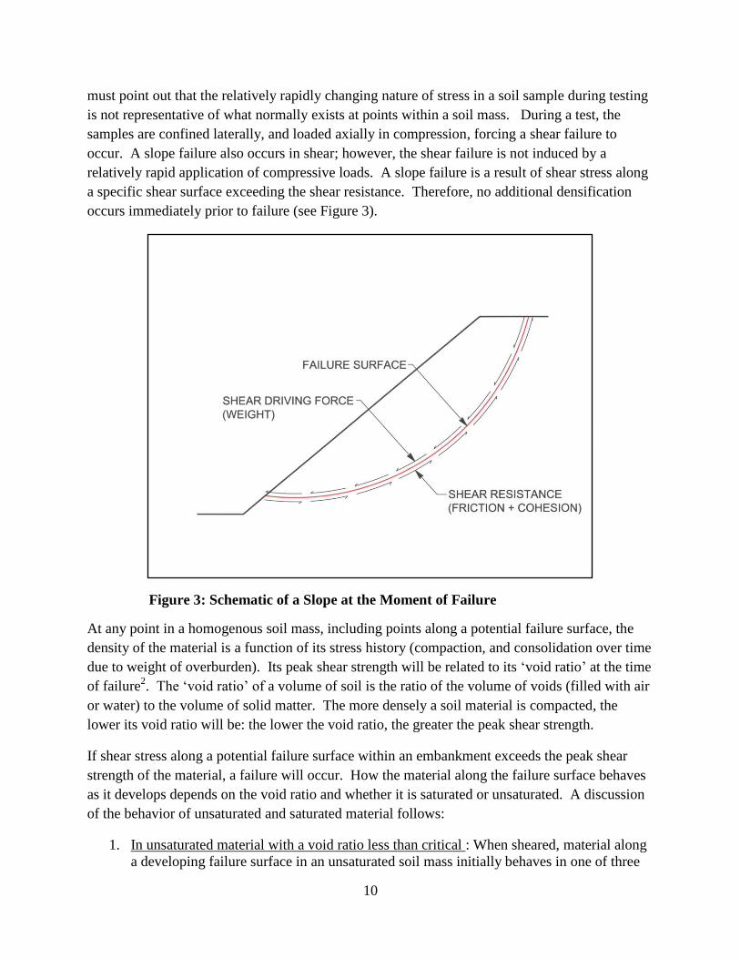
must point out that the relatively rapidly changing nature of stress in a soil sample during testing
is not representative of what normally exists at points within a soil mass. During a test, the
samples are confined laterally, and loaded axially in compression, forcing a shear failure to
occur. A slope failure also occurs in shear; however, the shear failure is not induced by a
relatively rapid application of compressive loads. A slope failure is a result of shear stress along
a specific shear surface exceeding the shear resistance. Therefore, no additional densification
occurs immediately prior to failure (see Figure 3).
Figure 3: Schematic of a Slope at the Moment of Failure
At any point in a homogenous soil mass, including points along a potential failure surface, the
density of the material is a function of its stress history (compaction, and consolidation over time
due to weight of overburden). Its peak shear strength will be related to its ‘void ratio’ at the time
of failure2. The ‘void ratio’ of a volume of soil is the ratio of the volume of voids (filled with air
or water) to the volume of solid matter. The more densely a soil material is compacted, the
lower its void ratio will be: the lower the void ratio, the greater the peak shear strength.
If shear stress along a potential failure surface within an embankment exceeds the peak shear
strength of the material, a failure will occur. How the material along the failure surface behaves
as it develops depends on the void ratio and whether it is saturated or unsaturated. A discussion
of the behavior of unsaturated and saturated material follows:
1. In unsaturated material with a void ratio less than critical : When sheared, material along
a developing failure surface in an unsaturated soil mass initially behaves in one of three
11
ways, depending on its initial density and associated void ratio, relative to what is termed
its constant volume, or ‘critical void ratio’.
The first type of behavior would occur in a densely compacted soil mass, in which the
void ratio is lower than the critical void ratio. At low stress levels, a failure surface
cannot form and, as shear stresses increase, relative movement cannot readily occur
because the particles cannot move past one another. In order for the peak shear stress to
be exceeded, allowing a failure surface to form, the particles must separate enough for
movement to occur. In other words, the void ratio of material along a potential failure
surface must increase (this increase in void ratio is referred to as dilatency). This
increase in void ratio will only occur in material along the failure surface, and will be just
enough for movement to occur. Once movement begins, the void ratio of this material
remains constant for as long as movement continues. This void ratio is termed the
constant volume, or critical, void ratio.
The increase in void ratio described above is resisted by the total stress normal
(perpendicular) to the forming failure surface (a function of overburden weight), as well
as by matric suction3 (a negative pore pressure that results from the combined effects of
adsorption and capillarity within an unsaturated soil mass). Decreasing the void ratio by
compacting the unsaturated soil tends to increase the change in void ratio required to
allow movement, as well as matric suction resulting from capillarity. As a result, it tends
to increase peak shear resistance.
2. In unsaturated material with a void ratio greater than critical: The second type of behavior
occurs when the initial void ratio of the soil mass is greater than its critical void ratio.
Pore air will tend to be compressed or forced from the material at the forming failure
surface into the surrounding soil, allowing the void ratio at the interface to decrease to the
point that the two masses can just undergo relative movement (This decrease in void ratio
is referred to as contraction). Again, during movement, the void ratio of material at the
interface will be at or near the critical void ratio. This reduction in void ratio is assisted
by the total normal stress and matric suction. As a result, the higher initial void ratio
tends to decrease peak shear strength.
3. In unsaturated material with a void ratio equal to critical: The third type of behavior
occurs when the entire soil mass is at its critical void ratio prior to failure. In this case,
no increase in void ratio is necessary for movement to occur, and no decrease will occur
once movement begins. The void ratio will remain constant at or near the critical void
ratio.
Note that, in all of the above cases; after a failure surface forms and movement begins, the void
ratio of the material at the interface will be at or near the critical void ratio4, and will remain so
as long as movement continues. Also in all cases, along the failure surface the residual shear
resistance (drained steady state shear strength) is based on the critical void ratio, and is therefore
independent of the initial density. Note that void ratio changes occur only in material along or
near the failure surface. The remainder of the soil mass, on both sides of the failure surface,
remains at its initial density, and its void ratio is not altered by increasing shear stress or

12
diminishing shear resistance prior to failure. As discussed above, this is not the case for
unsaturated samples loaded in compression during drained triaxial tests.
We will now discuss the same three cases with regard to void ratio, but considering a saturated
soil mass. It is likely that any impoundment embankment slope failure would involve a failure
surface that would be, at least in part, below the phreatic surface, and therefore, saturated. In a
saturated soil mass, frictional resistance to movement along a failure surface is reduced, relative
to that of an unsaturated soil mass at the same depth, while the driving forces are increased (in
downstream slopes) by the addition of seepage forces.
Frictional resistance below a phreatic surface is reduced relative to an unsaturated soil at the
same depth because the normal force is reduced. This reduction is due to the fact that the
measurable effective weight of any object immersed in a fluid is reduced by the weight of fluid
displaced by the object. If the object is less dense than the fluid, it will displace its weight of
fluid and float. If it is denser than the fluid, it will displace a volume of fluid equal to its own,
and its effective weight will be decreased by an amount equal to the weight of the displaced
fluid. Thus, if a cubic foot of material weighing, for example, 120 pounds is immersed in water
(62.4 pounds per cubic foot), its effective weight will be 120 – 62.4 or 57.6 pounds, a significant
reduction. Material below a phreatic surface is immersed in water. The effective normal force at
a point on a failure surface below a phreatic surface will be based on the total weight of material
above the phreatic surface, added to the effective weight of the material below the phreatic
surface. It is this effective normal force that will govern the friction based shear resistance
along the failure surface.
4. In saturated material with a void ratio less than critical: If the void ratio of a saturated soil
mass immediately prior to failure is lower than its critical void ratio, relative movement
along the failure surface would still require an increase in void volume. Since the void
spaces are, in this case, filled with water, rather than air, and water cannot move rapidly
through the pores of densely compacted material, the result is a negative pore water
pressure component that reduces the net pore water pressure, increasing the effective
stress normal to the failure surface. This, in turn, increases peak shear resistance along
the interface. Should a failure surface form, shear resistance would be based on drained
steady state shear strength at the critical void ratio, since shearing will result in reduced,
rather than increased pore pressure.
5. In saturated material with a void ratio greater than critical: If the void ratio of a saturated
soil mass is higher than its critical void ratio immediately prior to failure, pore pressures
could not quickly dissipate since the surrounding soil is also saturated and water, being
relatively incompressible, could not reduce in volume. Contractive behavior would not
be possible. Instead, as shear stresses increase, pore pressures would increase. These
shear induced pore pressures would be added to the existing neutral stress (pore water
pressure resulting from depth below the phreatic surface), reducing the effective normal
stress and, consequently, peak shear resistance. As this peak shear resistance is
exceeded, a failure surface would form, accompanied by a rapid reduction in shear
13
resistance from the reduced (undrained) peak shear strength to the undrained steady state
shear strength of the soil at its void ratio prior to failure5. The higher the void ratio prior
to failure, the lower would be the undrained peak and steady state shear strengths.
6. In saturated material with a void ratio equal to critical: Should the saturated soil mass be
at its critical void ratio, neither excess nor reduced pore pressures would be in evidence
as a failure surface developed. Consequently, shear resistance would differ from that of
an unsaturated soil mass only by the differences in effective normal stress along the
failure surface. Following initial failure, shear resistance would be the drained steady
state shear strength at the critical void ratio since; again, no excess pore pressures would
be present.
In summary, the density to which coarse refuse is compacted does in fact directly influence its
shear strength. Above the phreatic surface, increased density increases the drained peak shear
strength, but does not influence the drained residual, post peak strength. Below the phreatic
surface, increased density corresponds to a decreased void ratio, which increases the peak shear
strength. If density is increased, decreasing the void ratio to below the critical void ratio, it also
results in a negative component of pore pressure (as a failure surface begins to form) which
increases effective normal stress and, therefore, both peak and residual shear resistance. If the
void ratio below the phreatic surface is greater than the critical void ratio, a positive excess pore
pressure will result, reducing both peak and residual shear resistance. In general, greater density
results in greater shear strength.
Hydraulic Conductivity and Piping Resistance
Hydraulic conductivity is also directly influenced by compaction. Hydraulic conductivity is, in
general terms, a measure of the rate at which water will flow through a mass of soil. For a given
soil material, increased density will result in reduced hydraulic conductivity since hydraulic
conductivity varies, roughly, as the cube of the void ratio6. This, of course, refers to the matrix
of fines between the rock fragments in a soil/rock mixture since only the matrix of fines is
compacted. Any increase in density (reduction in void ratio of the matrix) would result in a
corresponding reduction in hydraulic conductivity.
Resistance of the soil matrix to internal erosion, or ‘piping’, is also related to the void ratio.
Other factors, such as clay content and type and particle size gradation also influence resistance
to piping; however, all else being equal, a lower void ratio provides greater resistance. When
water seeps through pores within an embankment, low hydraulic conductivity provides resistance
to flow, which dissipates energy. The rate at which this energy is dissipated is termed the
‘hydraulic gradient’. The seepage also exerts a force on the soil material. This force is equal to
the hydraulic gradient multiplied by the unit weight of the water. Within the dam, the soil
particles are contained and prevented from moving. However, if insufficient energy is
dissipated, the force exerted on the soil particles as the seepage exits the downstream slope of the
dam may be sufficient to cause them to be displaced. This displacement of material can

14
propagate upstream, through the dam, ultimately causing failure. This is a piping failure, and is
one of the most important and quite common dam failure mechanisms.
If the hydraulic gradient is greater than what is termed the ‘critical hydraulic gradient’ a piping
failure can occur. For a given soil material, the critical hydraulic gradient is a function of the
specific gravity of the soil material and the void ratio7. As density is increased, the void ratio is
lowered. The critical hydraulic gradient and resistance to piping are increased. Therefore,
minimizing the void ratio through consistent effective compaction control can be an important
means of minimizing the potential for piping failures.
Note that all understanding of the performance of an embankment as a hydraulic impoundment
structure is contingent on quality control being well conducted. If this is not the case, the
embankment may contain stratified layers with differing densities and hydraulic conductivities.
If that occurs, seepage through the dam may be very complex, consisting of flow through
multiple layers with relatively high hydraulic conductivities sandwiched between less conductive
layers. This situation may not be well represented by the information obtained from
piezometers. Water flow through the dam may be very different than was considered in the
design.
Issue 2: Is the 30% oversize limitation in the ASTM standard Proctor and oversize particle
correction procedures an absolute limit, or merely a flexible guideline?
As noted previously, one component of constructing an engineered earth-fill embankment is
verifying that the engineering properties of the as-placed materials compare favorably with those
considered in the analyses associated with the design. These design engineering properties are
typically determined in the laboratory, by performing shear strength and hydraulic conductivity
testing on samples compacted to a percentage (typically 95%) of the maximum dry density of the
soil determined in accordance with the standard Proctor test (ASTM D 698 07ϵ1
)8. Testing of
these samples allows correlations to be derived between density and the engineering properties
of concern; typically shear strength and hydraulic conductivity. Field and laboratory testing
conducted by a consultant as part of an OSMRE study has revealed that, in many cases, the
coarse refuse used to construct slurry impoundment embankments contains in excess of 30%, by
mass, of oversize particles. This is important because, as the percentage of oversize particles in
the unconsolidated material exceeds 5 %, the correlation between density and void ratio becomes
skewed because rock density (i.e. density of the oversize particles) is greater than soil density.
Therefore, a correction factor is required. However, when the percentage of oversize particles
exceeds 30 percent by weight of the soil (when oversized particles are defined as greater than ¾
inch), an additional problem arises—the oversize particles can mechanically interfere with the
compaction of the finer material. This is the limit, stated in the ASTM procedure, beyond which
it is not applicable.

15
The standard Proctor test is conducted on a sample consisting of approximately 100 pounds of
the subject soil material. The entire sample is first oven dried, and then passed through a sieve of
a specified size (discussed herein). The percentage retained on the sieve (by weight) is termed
the oversized fraction, and will be used to determine an oversize particle correction factor, to be
applied to field density test results. Moisture is added to the material that passed the sieve,
increasing its moisture content to a level several percentage points below the anticipated
optimum (discussed herein). A small portion of the material is compacted in a standard mold
using a specified number of blows from a hammer of a specific weight, dropping a specified
distance. The mold with compacted soil is weighed and a portion is removed and tested for
moisture content (ASTM D 2216-10)9. The remainder of the material in the mold is discarded.
Moisture is added to the material left over after the first mold was filled. The moisture is mixed
in, with the goal of uniformly increasing the moisture content by approximately 2%. Four more
molds are filled, compacted, and weighed, with additional moisture being added between the
filling of each of the molds. A sample from each of the molds is tested for moisture content.
The result is five molds that were subjected to a constant compactive effort per unit volume, but
with increasing moisture contents.
The weight of each of the molds is subtracted from the weight of the soil + mold. This provides
the weight of a unit volume of moist soil, or the wet density. After the moisture content is
determined for each of the samples, the weight of water is subtracted from the weight of the wet
compacted soil to provide the dry density for each of the compacted samples.
When the dry densities are plotted versus the moisture contents (see Figure 4), it can be seen that
with a standard compactive effort, dry density increases with increasing moisture content, to a
point, after which it decreases. The ‘Zero Air Voids Curve’ represents combinations of moisture
contents and density at which all air has been removed, and the voids are entirely filled with
water. These combinations cannot be achieved since some air will always be trapped within the
voids. The maximum density observed on a curve plotted to connect the plotted points is termed
the ‘standard Proctor maximum dry density,’ and the moisture content corresponding to this
maximum density is known as the ‘optimum moisture content.’

16
Figure 4: Example Compaction Curve
In the case shown (Figure 4), the maximum dry density is 124.8 pounds per cubic foot (pcf) with
an optimum moisture content of approximately 11.3%. Ninety five percent of the maximum dry
density (commonly specified as the minimum allowable field density) would be 118.6 pcf. With
the compactive effort employed in the Proctor test, 95% of the maximum dry density could only
be achieved, in this case, with moisture contents between approximately 7.3% and 15%, or
between 4% dry of optimum and 3.7% wet of optimum. The Design Engineer would typically
specify the allowable moisture range, within the range of moisture contents at which the
specified density was achieved in the Proctor test.
ASTM D698-07ϵ1
includes the following statement in Section 1.2:
Individual
Test Points
Maximum Dry Density and
Optimum Moisture Content
95% Max
Dry Density
Zero Air Voids Curve

17
1.2 “These test methods apply only to soils (materials) that have 30% or less by mass of
particles retained on the ¾ inch (19.0-mm) sieve and have not been previously compacted
in the laboratory; that is, do not reuse compacted soil.”
As noted, the standardized procedure in ASTM D698-07 €1
includes three methods: A, B, and C,
which are selected based on percentages of oversized particles present, using the #4, 3/8”, and
3/4” sieves, respectively. In most cases, coarse refuse is tested using Method C, with oversize
particles being defined as those retained on the 3/4” sieve. The oversized particles are removed
from the material prior to testing. Section 1.3.3.5 of Method C refers the reader to Section 1.4,
which states:
“If the test specimen contains more than 5% by mass of oversize fraction (coarse
fraction) and the material will not be included in the test, correction must be made to the
unit mass and molding water content of the specimen or to the appropriate field-in-place
density test specimen using Practice D 471810
.”
This procedure, commonly referred to as the rock or oversize particle correction procedure, also
includes a similar statement limiting its applicability to soil/rock mixtures with 30% or less of
the material (by mass) consisting of oversized particles. This statement and the rationale behind
the limitation are included in Section 1.4:
“The factor controlling the maximum permissible percentage of oversize particles is
whether interference between the oversize particles affects the unit weight of the finer
fraction. For some gradations, this interference may begin to occur at lower percentages
of oversize particles, so the limiting percentage must be lower for these materials to avoid
inaccuracies in the computed correction. The person or agency using this practice shall
determine whether a lower percentage is to be used.”
The language is clear that the limit to the allowed percentage of oversize particles (30% by mass
for Method C) is a maximum. The person or agency using the ASTM procedure has the option
of lowering the limiting percentage if, in their judgment this would improve compaction of the
fine matrix; however, no indication that an increase in the limiting percentage would be
acceptable is stated or implied.
Therefore, if the standard Proctor test (ASTM D698-07ϵ1
) is to be used to define target densities
for compaction control of slurry impoundment embankments or hydraulic barriers, it must be
used within the limitations stated in the standard. This maximum allowable mass of oversized
particles is necessary to ensure void spaces between rock fragments are filled with a soil matrix,
and that that soil matrix is sufficiently compacted.
18
A second argument supporting adherence to the oversized particle percentage limit specified in
ASTM D 4718 is that the standard also includes a statement that it may not be applicable for
materials that degrade during placement and compaction. The rationale presented in the standard
is that residual granular rocks tend to degrade during placement and compaction, and the final
oversized particle percentage differs from the percentage determined by the procedure. Though
the standard references residual granular materials, all soil rock mixtures degrade to some extent
during compaction, which is why the standard Proctor procedure (ASTM D698-07ϵ1
) does not
permit re-using material to construct specimens for more than one point of the test. Since a soil
fines matrix tends to separate and cushion rock fragments, the higher the percentage of rock, the
more likely the fragments are to degrade during placement and compaction.
Alternatives include changes to the processing of the refuse to reduce percentages of oversized
particles or using other methods of defining target densities. Testing methods that can be used in
place of ASTM D698-07ϵ1
include: U. S. Army Corps of Engineers’ Method EM 1110-2-190611
,
West Virginia Department of Transportation (WVDOT) MP 700.00.24 - Roller Pass Method12
,
and WVDOT MP 207.07.2013
. Similar standards that are potentially applicable to coarse refuse
compaction are published in other states.
Issue 3: Should the top foot (or some other thickness) of material always be removed prior
to performing field density tests?
In its oversight capacity, OSMRE has discovered an opinion held by some that the top foot of
coarse refuse must be removed from a compacted fill (such as a coarse refuse embankment) prior
to performing field density testing in order for the results to be valid. OSMRE agrees that loose
surface material must be removed, and the procedure outlined in ASTM D 6938-10 includes a
direction to remove surface material as required such that the entire bottom surface of the nuclear
moisture/density gage is in contact with the compacted material to be tested. OSMRE does not
believe that removal of a specified thickness of material is detrimental; however, a failure to do
so prior to testing does not invalidate the results.
Two procedures commonly employed for field compaction testing of slurry impoundment
embankments are the standardized procedures ASTM D 6938-1014
and ASTM D 2922-0115
. An
older procedure, ASTM D 1556-0716
is also available for use. Though not often employed, it is
still regarded by some as the most reliable method of obtaining in-place densities. Nowhere in
any of these standardized procedures is removal of any specific thickness of material mentioned.
Nor is it suggested or recommended in any of the referenced documents regarding field
compaction testing. With that said, the practice is not, of itself, in any way detrimental. It does,
however, lead to logistical difficulties with regard to addressing failed tests. For example:
Due to the relatively high and variable hydrocarbon content of coal refuse, the moisture
content as determined by the nuclear moisture/density gauge is not reliable.
Consequently, a laboratory or field moisture content test is normally conducted for each
19
field density test. When field moisture content tests are performed, using procedures
such as ASTM D 494417
or ASTM D 495918
, pass/fail status of field density tests is
determined while the consultant is onsite, and failing tests can be addressed immediately.
However if laboratory moisture content tests are used, the pass/fail status of the field
density tests is not known until receipt and incorporation of results of the moisture
content tests. The Operator would have to leave the tested area as is until the results are
finalized and any failing tested areas are addressed. This process would typically take at
least two days. Assuming the Operator removed a foot of material at multiple locations
covering the lift being tested, these would have to be refilled and marked, or remain open
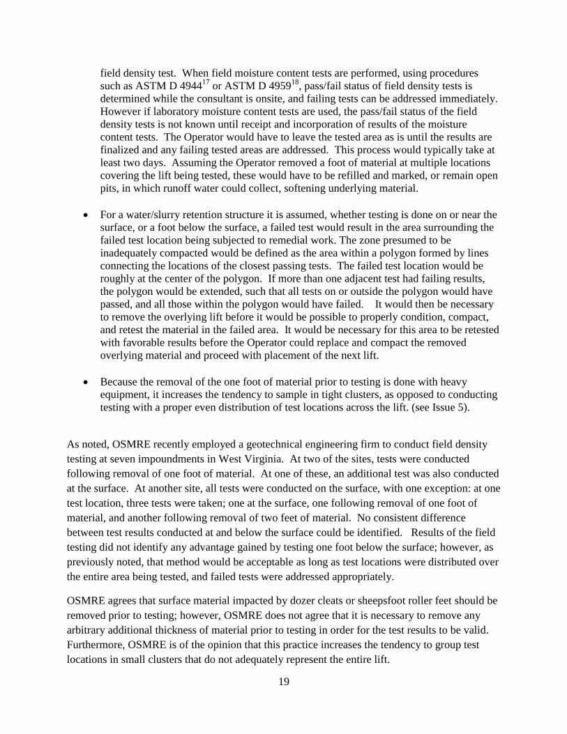
pits, in which runoff water could collect, softening underlying material.
For a water/slurry retention structure it is assumed, whether testing is done on or near the
surface, or a foot below the surface, a failed test would result in the area surrounding the
failed test location being subjected to remedial work. The zone presumed to be
inadequately compacted would be defined as the area within a polygon formed by lines
connecting the locations of the closest passing tests. The failed test location would be
roughly at the center of the polygon. If more than one adjacent test had failing results,
the polygon would be extended, such that all tests on or outside the polygon would have
passed, and all those within the polygon would have failed. It would then be necessary
to remove the overlying lift before it would be possible to properly condition, compact,
and retest the material in the failed area. It would be necessary for this area to be retested
with favorable results before the Operator could replace and compact the removed
overlying material and proceed with placement of the next lift.
Because the removal of the one foot of material prior to testing is done with heavy
equipment, it increases the tendency to sample in tight clusters, as opposed to conducting
testing with a proper even distribution of test locations across the lift. (see Issue 5).
As noted, OSMRE recently employed a geotechnical engineering firm to conduct field density
testing at seven impoundments in West Virginia. At two of the sites, tests were conducted
following removal of one foot of material. At one of these, an additional test was also conducted
at the surface. At another site, all tests were conducted on the surface, with one exception: at one
test location, three tests were taken; one at the surface, one following removal of one foot of
material, and another following removal of two feet of material. No consistent difference
between test results conducted at and below the surface could be identified. Results of the field
testing did not identify any advantage gained by testing one foot below the surface; however, as
previously noted, that method would be acceptable as long as test locations were distributed over
the entire area being tested, and failed tests were addressed appropriately.
OSMRE agrees that surface material impacted by dozer cleats or sheepsfoot roller feet should be
removed prior to testing; however, OSMRE does not agree that it is necessary to remove any
arbitrary additional thickness of material prior to testing in order for the test results to be valid.
Furthermore, OSMRE is of the opinion that this practice increases the tendency to group test
locations in small clusters that do not adequately represent the entire lift.
20
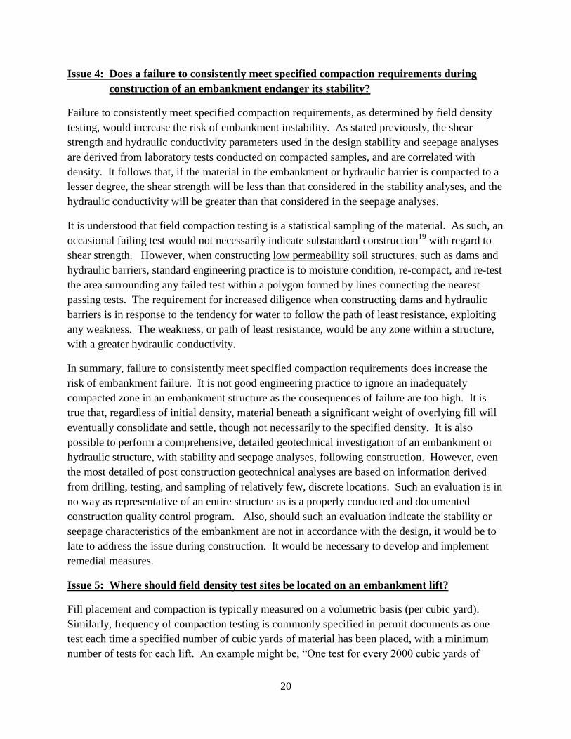
Issue 4: Does a failure to consistently meet specified compaction requirements during
construction of an embankment endanger its stability?
Failure to consistently meet specified compaction requirements, as determined by field density
testing, would increase the risk of embankment instability. As stated previously, the shear
strength and hydraulic conductivity parameters used in the design stability and seepage analyses
are derived from laboratory tests conducted on compacted samples, and are correlated with
density. It follows that, if the material in the embankment or hydraulic barrier is compacted to a
lesser degree, the shear strength will be less than that considered in the stability analyses, and the
hydraulic conductivity will be greater than that considered in the seepage analyses.
It is understood that field compaction testing is a statistical sampling of the material. As such, an
occasional failing test would not necessarily indicate substandard construction19
with regard to
shear strength. However, when constructing low permeability soil structures, such as dams and
hydraulic barriers, standard engineering practice is to moisture condition, re-compact, and re-test
the area surrounding any failed test within a polygon formed by lines connecting the nearest
passing tests. The requirement for increased diligence when constructing dams and hydraulic
barriers is in response to the tendency for water to follow the path of least resistance, exploiting
any weakness. The weakness, or path of least resistance, would be any zone within a structure,
with a greater hydraulic conductivity.
In summary, failure to consistently meet specified compaction requirements does increase the
risk of embankment failure. It is not good engineering practice to ignore an inadequately
compacted zone in an embankment structure as the consequences of failure are too high. It is
true that, regardless of initial density, material beneath a significant weight of overlying fill will
eventually consolidate and settle, though not necessarily to the specified density. It is also
possible to perform a comprehensive, detailed geotechnical investigation of an embankment or
hydraulic structure, with stability and seepage analyses, following construction. However, even
the most detailed of post construction geotechnical analyses are based on information derived
from drilling, testing, and sampling of relatively few, discrete locations. Such an evaluation is in
no way as representative of an entire structure as is a properly conducted and documented
construction quality control program. Also, should such an evaluation indicate the stability or
seepage characteristics of the embankment are not in accordance with the design, it would be to
late to address the issue during construction. It would be necessary to develop and implement
remedial measures.
Issue 5: Where should field density test sites be located on an embankment lift?
Fill placement and compaction is typically measured on a volumetric basis (per cubic yard).
Similarly, frequency of compaction testing is commonly specified in permit documents as one
test each time a specified number of cubic yards of material has been placed, with a minimum
number of tests for each lift. An example might be, “One test for every 2000 cubic yards of

21
material placed, with a minimum of two tests per lift.” Statistical methods of defining the
frequency of testing are available20
, and may be used in developing compaction control plans.
Often, however, the frequency of testing is established based on the Consultant’s experience
from previous projects. Based on OSMRE’s observations, testing frequencies are fairly
consistent between impoundments, and this is not currently considered to be an issue.
However, during review of compaction testing records conducted as part of oversight inspections
of slurry impoundments, OSMRE engineers have noted cases in which field density testing for a
placed and compacted lift of material was all performed within a small area, representing only a
fraction of the placement area.
As noted, testing frequency is typically specified in the permit documents. Where questions
arise is in how the test locations are spaced over the area being tested. The number of tests to be
conducted is determined, based on the volume of material to be tested; however, in some cases,
all tests are performed in a small area of the lift. Numerous cases of this practice have been
observed when reviewing compaction test records during oversight inspections of
impoundments.
An illustration of the problem is provided in Figure 5 (Below), which is a modified excerpt from
a map submitted as part of the documentation of twenty (20) compaction tests performed on the
embankment of an impoundment on May 4, 2011. The map was out of date at the time of the
testing: the embankment crest had been widened in the direction of the pool. Coarse refuse was
being placed in the area approximately defined by the orange parallelogram. The approximately
rectangular area in which field compaction tests were conducted (outlined in red) was entirely
within the coarse refuse placement area. It was drawn on the map and dated by the consultant to
identify the area within which he conducted the tests.

22
Figure 5: Compaction Test Area. Outline of the lift boundary is superimposed on a map
submitted with results of field compaction testing conducted on May 4, 2011. The
Consultant identified and dated the test area (highlighted in red).
Although the number of tests was sufficient for the volume of material that had been placed, the
results were only representative of a small portion, approximately 20%, of the lift area. It is
worth noting that the belt discharge was near the upper left corner of the test area. It is apparent
that the tested area was passed over by the dozer many more times during construction of the lift
than were the areas toward the ends of the dam crest. Therefore, testing was primarily conducted
in an area of expected high density while areas of potentially lower density were avoided.
The appropriate procedure would be to distribute the test locations equally over the entire lift
area. This process need not be complicated. A visual distribution of test locations should be
adequate. The goal should be to space the test locations such that the entire lift is represented.
Approximate Lift
Boundary on 5/4/2011
Area in which Tests Were
Conducted on 5/4/2011
Belt Discharge Location

23
Additional tests should also be conducted in areas where difficulties in achieving compaction
might be expected, such as near the embankment abutments. The test locations should be
marked since the pass/fail status of the tests will not be known until laboratory moisture content
test results have been received and incorporated.
Issue 6: Should field density testing be conducted in areas where visible evidence of
inadequate compaction such as pumping or shear cracking is observed?
Field compaction testing is a valuable tool when used to verify and document that materials are
being placed and compacted such that the engineering properties of the compacted soil materials
compare favorably with those used in design of an earth-fill structure. However, it is not a
substitute for knowledge and experience on the part of personnel engaged in construction quality
control. It is possible to obtain passing field compaction test results on a lift even when visible
evidence indicates the underlying material is unstable.
A phenomenon often observed during construction of earth-fill structures is over-compaction.
Commonly referred to as “pumping”, this phenomenon occurs when an attempt is made to
compact material containing excessive moisture. While minor pumping can be observed when
material is compacted within the acceptable range of moisture content, but on the wet side of
optimum, in these cases it should be barely visible, and consistent over the lift of material
Pumping becomes a concern when is very evident visibly as the material deflects downward
under the weight of vehicles or compaction equipment, and rebounds after the equipment passes.
It can occur even if material at the surface is visibly dry, and testing indicates density is
adequate. It indicates the moisture content of underlying material is not within the range that can
be properly compacted. Even properly compacted material can be rendered unsuitable if the
moisture content is allowed to increase due to improper surface drainage control, and the subject
area is subsequently crossed by equipment, particularly heavy rubber tired equipment.
Construction cannot continue on an earth-fill structure until areas that are observed to be
pumping are addressed. Any continued effort to compact the coarse refuse tends to be
detrimental and should not be attempted. It is possible to allow surface material that is pumping
to dry on its own if time and weather permit; however, in most cases, pumping can only be
corrected by removing the material, lowering the moisture content, and replacing, re-compacting,
and re-testing the affected areas21
.
Shear cracking is sometimes observed at the surface in small areas of a lift of material that, may
otherwise appear to be well compacted. Visually, the surface manifestation of shear cracking
resembles cracking often seen in shallow depressions on asphalt concrete paved roads. Pumping
is also typically observed as equipment crosses these areas. Such surface cracking indicates
failure of the underlying material. Shear cracking must be resolved by proof-rolling (rolling with

24
a heavy, preferably rubber tired piece of equipment), to identify the number and extent of soft
areas and addressing each identified soft area in the same way that surface pumping is resolved.
Therefore, field compaction testing should not be performed if over-compaction (pumping) or
shear cracking are observed in the lift to be tested. Instead, the subject lift should be proof-rolled
and any soft areas identified should be over-excavated and the material moisture conditioned, re-
placed, and compacted. The lift should again be proof-rolled, with favorable results, before it is
tested.
SUMMARY AND CONCLUSIONS
Coal mine waste slurry impoundment embankments and hydraulic barriers are critical structures
that must be subjected to rigorous quality control during construction. The potential
consequences of failure can be catastrophic, including large scale loss of life, as well as property
and environmental damage.
OSMRE is currently involved in an evaluation of quality control methods employed on slurry
impoundments during construction of these facilities. As part of this effort OSMRE has held
several discussions with engineers representing other State and Federal agencies. These
discussions and field observations highlighted the existence of varying opinions on testing
procedures and practices related to dam compaction. This paper is intended to assist regulators
and operators in developing and implementing consistent test procedures.
To this end, the authors offer the following responses to the questions in this paper:
1. Does the degree of compaction of coarse refuse influence its shear strength, hydraulic
conductivity, and resistance to piping when it is used to construct a dam or hydraulic
barrier?
A reliable correlation exists between the degree to which coarse refuse is compacted and the
engineering properties influencing the stability of impoundment embankments and hydraulic
barriers, i.e. shear strength, unit weight, hydraulic conductivity, and piping resistance.
a. Shear strength of coarse refuse, and hence stability of an embankment, tends to
increase as in-place density increases.
b. In a soil/rock fragment mixture, the fine matrix is the portion that is compacted.
Sufficient fines must be present to completely fill the voids between the rock
fragments with a compacted matrix in order for the correlation between density and
hydraulic conductivity to be valid.
2. Is the 30% oversize limitation in the ASTM standard Proctor and oversize particle
correction procedures an absolute limit, or merely a flexible guideline?
The ASTM standards for the Proctor test and the oversize particle correction procedure limit
their applicability to soil/rock mixtures that contain less than 30 percent by mass of oversize

25
particles. OSMRE’s position is that these procedures should not be employed if that
percentage is exceeded. OSMRE recommends that quality control procedures included in the
permit documents include alternate compaction control methods to be used when sieve
analyses performed with periodic Proctor tests indicate the percentage of oversize particles
exceeds 30% by mass.
3. Should the top foot (or some other thickness) of material always be removed prior to
performing field density tests?
OSMRE is of the opinion that loose surface material should be removed prior to testing;
however, OSMRE does not agree that it is necessary to remove any arbitrary thickness of
material prior to testing in order for the test results to be valid. Furthermore, OSMRE is of
the opinion that this practice adds to the cost of addressing failed tests, and increases the
tendency to group test locations in small clusters that do not adequately represent the entire
lift. OSMRE recommends that procedures prescribed in the referenced ASTM standards be
followed, or that the design engineer prescribe a thickness to be removed prior to testing.
4. Does a failure to consistently meet specified compaction requirements during
construction of an embankment endanger its stability?
An occasional failing field density test is not necessarily evidence that embankment material
will have insufficient shear strength. However, OSMRE is of the opinion that 100% of field
density tests still must pass because strict attention to field density is critical to the
serviceability of hydraulic barrier structures. Impounded water can enter areas of higher
conductivity in the structure and consequently endanger its stability through internal erosion
or by reducing shear strength of the materials. Areas surrounding the site of a failed field
density test must be re-worked and re-tested until passing results are achieved.
5. Where should field density test sites be located on an embankment lift?
Field density test locations must be uniformly spread over the placement area that is to be
represented by the test results. Tests representing an entire lift cannot be concentrated in a
small area of that lift. Additional test sites should be located in areas of concern, such as
adjacent to abutments.
6. Should field density testing be conducted in areas where visible evidence of inadequate
compaction such as pumping or shear cracking is observed?
Field density testing should not be performed on any lift when pumping and/or shear
cracking are observed. Should these, or any other indication of soft material underlying part
of a lift be observed, the lift should be proof-rolled to identify all soft areas. These areas
should be over-excavated to remove all soft material. The soft material should be replaced
by other more suitable material; or it should be dried and, following placement, proof-rolled
prior to field density testing.
References:

26
1. National Coal Board (NCB), (1972), ‘Review of Research on Properties of Spoil Tip
Materials’, NCB, London, UK
2. Seed, H. B., Mitchell, J. K., and Chan, C. K, ‘The Strength of Compacted Cohesive
Soils’, in Shear Strength of Cohesive Soils, ASCE, Boulder, CO., pp. 85-895
3. Vanapalli, S. K, and Fredlund, D. G. (1997), ‘Interpretation of Undrained Shear Strength
of Unsaturated Soils in Terms of Stress State Variables’, Proceedings, Third Brazilian
Symposium on Unsaturated Soils, NSAT’97
4. Wightman, N. R. (2008), ‘The State of Compaction: The Effect of Compaction on Soil
Properties and Slope Fill Performance’, International Conference on Slopes Malaysia
2008, Istana Hotel, Kuala Lumpur, 4–6 November 2008, 53-65.
5. Seed, H. B., Mitchell, J. K., and Chan, C. K, ‘The Strength of Compacted Cohesive
Soils’, pp 939
6. Spangler, M. G, and Handy, R. L. (1982), ‘Soil Engineering’, 4th
Edition, Harper & Row,
pp 250, eqn 11.8
7. Tschelbotarioff, G. P., (1973), ‘Foundations, Retaining and Earth Structures’, 2nd
Edition, McGraw-Hill, pp323
8. ASTM D 698 07ϵ1
– Standard Test Methods for Laboratory Compaction Characteristics
of Soil Using Standard Effort (standard Proctor test)
9. ASTM D 2216-10 – Standard Test Methods for Laboratory Determination of Water
(Moisture) Content of Soil and Rock by Mass
10. ASTM D 4718 – 87 (Reapproved in 2007) – Standard Practice for Correction of Unit
Weight and Water Content for Soils Containing Oversize Particles
11. U. S. Army Corps of Engineers’ Method EM 1110-2-1906 – Compaction Test for Earth-
Rock Mixtures
12. West Virginia Department of Transportation (WVDOT) MP 700.00.24 - Roller Pass
Method
13. West Virginia Department of Transportation (WVDOT) MP 207.07.20 – Nuclear Field
Density – Moisture Test for Random Material Having Less than 40% of + 3/4 Inch
Material
14. ASTM D 6938-10 – Standard Test Method for In-Place Density and Water Content of
Soil and Soil-Aggregate by Nuclear Methods (Shallow Depth)
15. ASTM D 2922-01 – Standard Test Method for Density of Soil and Soil-Aggregate in
Place by Nuclear Methods (Shallow Depth)
16. ASTM D 1556-07, Standard Test Method for Density and Unit Weight of Soil in Place
by the Sand-Cone Method
17. ASTM D 4944, Test Method for Field Determination of Water (Moisture Content of Soil
By the Calcium Carbide Gas Pressure Tester
18. ASTM D 4959, Test Method for Determination of Water (Moisture) Content of Soil by
Direct Heating
19. Spangler, M. G, and Handy, R. L. (1982), ‘Soil Engineering’, 4th
Edition, Harper & Row,
pp 697-700
20. Ibid, pp 697-700
21. ibid, pp 693-694

27
APPENDIX
Disposition of Comments

28
DISPOSITION OF COMMENTS
General
Comment G.1: I concur with most of the conclusions in the Compaction Position Paper. I
suggest that when you release it to the public, it is clear that to ensure long term stability of these
structures, stringent adherence to the specified standards is essential. [Spadaro]
Response: The independent verification of OSMRE’s position is appreciated.
Comment G.2: Focus is entirely on process rather than result. The main issue relates to public
safety by ensuring the safety of the structure. Compaction of materials enhances the stability of
the embankment as documented below which provides increased safety. Suggest addition to
Introduction such as: Compaction of coal refuse materials results in enhanced public safety due
to increased embankment stability and fire suppression. [Long, WVDEP, DWWM]
Response: OSMRE agrees.
Comment G.3: The memo indicates that the paper is also intended for non-engineers. I found
the content to be highly technical and it would be difficult to understand for a layman. [Plassio,
PADEP]
Response: It is true that some readers will be non-engineers, and we attempted to simplify
explanations to the extent possible; however, the issues are technical, and cases had to be made
to engineers regarding OSMRE’s stance on these issues. It will be necessary for some readers to
seek assistance regarding the more technical issues. Based on reviewer comments, we have
included illustrations to better explain some concepts, and bulletized and subtitled portions of the
text to clarify the descriptions.
Comment G.4: The paper provides a bit too much detail. I found my mind wandering – an
answer was initially provided, and then excessive detail clouded the issue. [Plassio, PADEP]
Response: The primary purpose of the paper was to make a case to engineers regarding
OSMRE’s stance on specific technical issues. In order to make the case, it was necessary to
provide detailed descriptions of these issues. It is true that readability suffered to some degree.
Based on reviewer comments, we have attempted to organize arguments in a more logical
sequence, and have incorporated illustrations to better explain some concepts.
Comment G.5: The concepts described in the paper are consistent with the basic principles of
soil mechanics and behavior. [Edil, UW]
Response: OSMRE agrees.
Comment G.6: It is important to realize that most coarse refuse materials contain significant
percentages of shale, which is subject to degradation during handling and compaction, and in the

29
presence of moisture the degradation can be quite extensive. This aspect must also be considered
during lab characterization and field application. It is especially important to recognize that the
traditional testing procedures developed for soil or rock may not be applicable to coarse refuse
because it is a transitory material from rock to soil depending on the moisture content and
handling and compaction forces applied. [Usmen, Wayne State U]
Response: This is another valid argument in favor of adherence to the limits to the percentage of
oversized particles contained in the standard Proctor test and the standardized oversized particle
correction procedure. Alternatively some method other than the standard Proctor test for
defining target densities for coarse coal refuse may be used. Materials that tend to degrade
during compaction are discussed in the procedureLanguage in the standard indicates it may not
be applicable to materials that degrade during handling and compacting.
Comment G.7: Regarding engineering properties of engineered fill structures – (include) grain
size gradation for the construction of filters? [Bruce, BGC]
Response: This is, of course, an important consideration in dam design; however, it did not relate
to compaction of the main coarse refuse component of the embankment, and was therefore not
discussed.
Comment G.8: Regarding the statement that shear strength and hydraulic conductivity cannot be
directly measured in the field using construction quality control methods commonly employed at
slurry impoundment construction sites – Are they laborious to measure, take lots of time and
effort? [Bruce, BGC]
Response: Although there are exceptions, in most cases, construction quality control testing at
slurry impoundments consists only of field density and laboratory moisture tests. Shear strength
and hydraulic conductivity cannot be directly measured using these tests. They could be directly
measured using other methods, however, performing statistically valid numbers of these tests
would be much more expensive and time consuming. As noted in the paper, correlations
developed through laboratory testing of samples during the design phase are used to estimate
shear strength and hydraulic conductivity of as placed materials. When properly conducted,
correlating field density and laboratory moisture content testing to shear strength and hydraulic
conductivity using laboratory developed relationships provides an adequate method with fewer
time constraints and lower cost.
Comment G.9: Grain size is the only way that I know of to assess the filter criteria and probably
has more control over permeability than density test results. [Bruce, BGC]
Response: We agree that grain size would be the appropriate criteria to evaluate when designing
a filter; however, we are discussing piping potential of a soil/shale fragment mixture, placed and
compacted as delivered for the main component of the embankment. Our point is that, for a
given material, resistance to piping is enhanced by increased density of the fine matrix.

30
Comment G.10: The paper describes general coal cleaning processes used throughout the United
States. Reference to the Appalachian region should be removed. [Michalek, MSHA]
Response: The field experience and testing that, along with laboratory testing, identified the
issues discussed in this paper were gained or conducted in the Appalachian region. Although it
is likely the paper will have application outside the region, it is based on a regional level
investigation.
Comment G.11: The paper indicates that friction angle and unit weight are affected by degree of
compaction. In general, we believe the paper overstates the role of compaction and understates
other factors affecting strength, such as particle size distribution, particle angularity, and loading
conditions. [Michalek, MSHA]
Response: OSMRE does not intend to discount the role specific material characteristics play in
development of shear strength. The OSMRE position is that the other factors affecting strength
are accounted for when the shear strength used in design is derived by testing compacted
samples. Loading conditions are also determined in the design phase. Of the factors affecting
shear strength, only compaction can be controlled once the material is delivered to the site.
Comment G.12: Coarse refuse used for slurry impoundment embankments is required to be
placed in maximum 12 inch thick lifts within a narrow range of appropriate moisture content.
These strict requirements are intended to take the guesswork out of bulk fill construction to
provide a simple and reliable system for the coal operator. Coupled with this system is the
trained eye of the experienced field inspector who can observe the reaction of the refuse surface
to the compaction equipment and judge whether an appropriate level of compaction is achieved.
[Thacker, GA]
Response: In general, OSMRE agrees that the goal is to provide a simple, consistent method of
construction. OSMRE also agrees that a trained, experienced field inspector plays a vital role;
however, such an inspector is not generally on-site continuously watching material placement.
OSMRE also recognizes that, regardless of lift thickness and moisture content, in-place field
density and moisture content of each lift of compacted coarse refuse must be determined and
compared to the target density and allowable moisture range included in the construction
specifications.
Comment G.13: The peak shear strength of coarse refuse materials in the Appalachian coalfields
has been extensively tested through triaxial testing and is well documented. Based on this
extensive empirical data, coarse refuse is known to have a relatively narrow range of friction
angle varying from about 32 degrees to about 38 degrees. Values used in design are typically
reduced to a range of 32 degrees to 34 degrees. [Thacker, GA]

31
Response: The friction angles provided are general ranges, and are based on testing of samples
compacted to specific densities. OSMRE maintains that field density and moisture content
testing are mandatory to verify that the assumed densities have been achieved in the field.
Comment G.14: For new facilities, we typically assume conservative shear strength parameters
prior to embankment construction, and then verify the strength with laboratory testing of
remolded samples after plant operations begin. Similarly, based on past testing and our
experience with coarse refuse materials, we assume hydraulic conductivity parameters and then
compare to laboratory test results on remolded samples after plant operations begin, observe the
phreatic level that develops in the embankment using piezometric data, and monitoring flow
rates from drains. [Thacker, GA]
Response: This would appear to be a reasonable approach, as long as construction quality
control is well conducted. If not, the embankment may contain stratified layers with differing
densities and hydraulic conductivities. If that occurs, seepage through the dam may be very
complex, consisting of flow through multiple layers with relatively high hydraulic conductivities
sandwiched between less conductive layers. This situation may not be well represented by the
information obtained from piezometers. Water flow through the dam may be very different than
was considered in the design.
Comment G.15: Also, based on our extensive experience with testing coarse refuse materials,
we have found that material placed and compacted in 12 inch thick lifts will normally result in a
degree of compaction between 96% and 98% of standard Proctor maximum dry density with
oversize correction applied. [Thacker, GA]
Response: With appropriate moisture control and compaction, this would be the case for any soil
material since, the standard Proctor maximum dry density is determined for the material to be
placed.
Comment G.16: Coarse refuse makes an excellent embankment construction material and
because of its gradation, is not highly susceptible to piping, especially when placed and
compacted in thin lifts. Piping potential becomes even less important once a beach of fine refuse
is established along the upstream embankment face. Other design features that reduce the
potential for piping in the slurry impoundment embankment dam design include the use of rock
fill underdrains beneath the embankments to reduce the gradient at the toe of the dam, redundant
French drains to improve drainage through the embankments, the use of open channel spillways
for quick evacuation of storm water from behind the dam until such a time that there is enough
storage volume to use a pipe spillway, and when practical keeping free water pumped down in
the pond. Finally, extensive seepage control measures and careful construction procedures are
used for spillway pipes through the coarse refuse embankments. Minor variations in coarse
refuse compaction or perceived compaction have, in our opinion, little to do with piping
potential. [Thacker, GA]

32
Response: OSMRE agrees that coarse refuse is an excellent embankment construction material
and that its gradation is beneficial to piping resistance. OSMRE also agrees the presence of a
fine refuse beach is beneficial, as long as its elevation is not exceeded by the pool elevation.
However, the fine refuse beach is not an engineered component of the embankment. OSMRE
agrees the internal drainage features and seepage control measures for spillway pipes are
beneficial. OSMRE maintains that if hydraulic conductivity of the main embankment is greater
than considered in the design, piping may be an issue, particularly if the pool elevation exceeds
the elevation of the fine refuse beach, which often occurs since storm water storage typically
extends above the beach elevation. Minor variations in density may not be an issue unless they
result in zones of higher hydraulic conductivity through the dam, such as might be the case when
all or part of a lift is affected. This does occur, and is typically observed as a horizontal line of
seeps on the downstream face of the dam.
Issue 1
Comment 1.1: Page 4, Issue 1, paragraph 1, sentence 1 states that one of the most important
potential failure mechanisms for an embankment is a slope failure…” This is true, however, it
seems relevant to discuss settlement-related failures in this response section also (e.g. settlement
causing overtopping or slope failure). It also seems relevant to include piping failures in this
thesis paragraph since this topic is briefly discussed towards the end of Issue 1 response. [Butler,
USACE]
Response: The subject paragraph was revised to include discussion of piping failures; however,
since construction of slurry impoundments is typically continuous over many years, settlements
are typically addressed as construction proceeds.
Comment 1.2: Suggested that drained triaxial testing reported in the Wimpey Laboratories’
report be described as “. . . drained triaxial testing to reflect site conditions . . .” [Long,
WVDEP, DWWM]
Response: The testing was not conducted to reflect specific onsite conditions but to estimate
shear strength parameters for specific materials with differing in-place densities.
Comment 1.3: One point that is not mentioned is that shear strength is controlled not only by
density, but more so by water content, especially in materials containing a fine grained fraction.
The objective of specifying the range of water content during compaction (e.g., ± 2% or 3% of
optimum) is to achieve a relative compaction (e.g., 95% of standard Proctor maximum dry
density) with minimum effort. However, this water content during placement will change due to
infiltrating water and/or seeping water saturating the material. The objective of specifying a
relative compaction is to limit the range of water content in the field subsequent to fill
placement, and thus to limit strength change. This is achieved by limiting the void space that can
be filled with water by maximizing density. [Edil, UW]

33
Response: Actually, the effect of water content, at various degrees of compaction was discussed
in detail. It was discussed during the description of the standard Proctor test procedure. The
effect of subsequent saturation was included in the explanation of the effect of void ratio on the
material along a developing failure surface both above and below a phreatic surface.
Comment 1.4: (Referring to the statement that unlike samples during triaxial testing, no
additional densification occurs prior to failure in the field). This statement is not strictly correct.
There will be densification in the field, depending on depth. There is no distinction between
triaxial and field shearing such as, “pure shear.” Both cases will have varying shear strength
with confining stresses whether in the laboratory or in the field. [Edil, UW]
Response: Agreed, both cases will have varying shear strength with varying confining stresses.
The point being made was that in the triaxial cell a relatively rapidly increasing compression
stress is applied, forcing a shear failure that occurs when the difference between the applied
stress and confining stress reaches a maximum. If a slope failure occurs in the context of an
impoundment embankment, principal compressive stresses are constant unless a rapid surcharge
load is applied. Failure is typically the result of a reduction in shear resistance, one possible
reason being a change in phreatic surface elevation.
Comment 1.5: It is mentioned that sufficient fines need to be added to get adequate compaction;
that could be fly ash, fine refuse, or local soil materials. However, a lot of fines are generated
due to degradation as well. This should be explained. [Usmen, Wayne State U]
Response: We mentioned that sufficient fines must be present to fill the voids between rock
fragments, and compacted to an adequate density to be representative of the hydraulic
conductivity used in the seepage analysis, and to minimize the potential for piping. The
commenter is correct that these fines would normally result from degradation of the refuse
during handling, transport, placement, and compaction. Degradation that occurs during
handling, transport, and placement is normally accounted for in the laboratory testing by
obtaining samples from windrows of material as it is spread on the site. Degradation that occurs
during compaction is not directly accounted for, but is indirectly addressed by the limitation of
applicability of the standard Proctor and oversized particle correction procedures based on
allowable percentage of oversized particles. Degradation of rock fragments tends to diminish as
the percentage of oversized particles is reduced due to separation and cushioning effects of the
fine matrix material.
Comment 1.6: I have reviewed the National Coal Board (NCB) report (reference 1) which was
used to support the argument that shear strength of coarse refuse is relatively constant, regardless
of initial in-place density. It is my opinion that the NCB report does not support this argument. I
agree with the discussion in the OSMRE paper that effectively disqualifies this premise and I can
verify reading sections in the NCB report that were highlighted in the OSMRE paper which
supports their argument. [Kramer, PE, Ph.D]

34
Response: The independent verification of OSMRE’s position is appreciated.
Comment 1.7: Regarding OSMRE’s statement that, ”if unsaturated compacted samples are
subjected to drained triaxial tests, both peak and residual strengths can appear to be constant
regardless of initial sample density”, – the Reviewer disagreed; and stated, “flies in the face of
the most basic soil mechanics text book, Terzaghi and Peck.” [Bruce, BGC]
Response: OSMRE agrees with the Reviewer, and Drs. Terzaghi and Peck, that peak shear
strengths are not constant regardless of initial sample density. We were pointing out that if the
effect of compression of samples during the tests is not recognized, the results can be
misinterpreted. The example provided (Wimpey Laboratories’ report) was a case in point;
although the authors correctly noted the reasons for similar test results, they incorrectly reported
that peak shear strength was practically independent of initial density.
Comment 1.8: Loose soils compress, dense soils dilate. They migrate to the steady state line and
their critical void ratio. [Bruce, BGC]
Response: OSMRE agrees, with one qualifier; soils always reach a steady state condition of
shear resistance after peaking, but do not reach the critical void ratio if saturated and initially at a
void ratio greater than the critical void ratio unless time is allowed for pore pressures to
dissipate.
Comment 1.9: Regarding the description of dense and loose soil behavior at a failure surface
above and below a phreatic surface – Long winded way of saying you need compaction. Not
sure of the point of it all. [Bruce, BGC]
Response: The point was to explain why compaction is critical, and how initial density controls
both the likelihood and potential severity of a slope failure if a significant portion of the failure
surface is below a phreatic surface.
Comment 1.10: Regarding hydraulic gradient/energy dissipation/piping resistance discussion –
Not sure why you are saying this. [Bruce, BGC]
Response: This discussion covers the role of effective compaction in minimizing the potential for
piping as a result of seepage exiting on the downstream face of the embankment.
Comment 1.11: Regarding description of the standard Proctor test – Not really clear why all the
description of the testing. If you have oversize, you need to do a rock correction. It’s the
standard. In order to compare with other tests, you need to follow a standard. I am not clear
why the explanation is needed. [Bruce, BGC]
Response: The description is included for readers who are not familiar with the test and the
relatively small sizes of the molds that require removal of oversize particles.

35
Comment 1.12: We agree with the primary conclusions that material density affects the shear
strength and hydraulic conductivity of coarse coal refuse. [Michalek, MSHA]
Response: OSMRE concurs.
Comment 1.13: In our experience, the shear strengths resulting from testing loose-dumped to
100 percent compacted coarse coal refuse often results in a slight increase in strength. Thacker
(2000) also reported that increases of approximately 2 degrees in internal friction have resulted
when comparing material compacted to 90% versus that compacted to 100%. [Michalek, MSHA]
Response: Were the samples unsaturated when tested, and able to compress prior to failure? In
the example provided in the paper, virtually no change in shear strength was noted between
samples fabricated at densities, “ranging from the BS standard density to as loose as was
practical.” This was subsequently attributed to compression of the unsaturated samples to
relatively uniform densities, prior to failure. When testing unsaturated samples of varying
densities, it is necessary to investigate different confining pressures such that peak shear
strengths are achieved at the appropriate densities.
Comment 1.14: We do not see the need to provide detailed explanation of shear strength, failure
mechanisms, and triaxial testing. [Michalek, MSHA]
Response: The detailed explanations were provided to illustrate to those less familiar with these
issues how testing must be tailored to the anticipated loading and moisture conditions, as well as
expected failure mechanisms (see Comment 1.13).
Comment 1.15: The degree of compaction is a valid indicator of shear strength of coarse coal
refuse. [WVDEP]
Response: OSMRE agrees, when field density is correlated with density of samples on which
shear strength testing was conducted.
Comment 1.16: The degree of compaction of coarse coal refuse is utilized as a mechanism to
evaluate stability. [WVDEP]
Response: OSMRE agrees.
Comment 1.17: The hydraulic conductivity or ability of the compacted material to allow a fluid
to flow through a material such as coarse coal refuse implies a reasonably permeable material.
Response: All earthen materials are permeable to some extent. The hydraulic conductivity of a
soil material (the fine matrix of a soil/rock mixture) is a function of its permeability, which is
directly related to its void ratio. Compaction is reduction of the void ratio. Hence, hydraulic
conductivity is related to the degree of compaction. For a given soil material when the degree of
compaction is increased, hydraulic conductivity is reduced.

36
Comment 1.18: In 1988 at the second international conference on case histories in geotechnical
engineering, June 1-5, Paper number 3.68 was presented. The paper was titled, “Performance of
a Coal Slurry Refuse Embankment.” The paper was produced from a project that consultant
Bowser Morner associates, Inc. had completed for American Electric Power (AEP). On the page
designated 687 in the conclusion several details may be gleaned from the relationship of
permeability and the degree of compaction. The conclusions were that there is very little
correlation between permeability and percent compaction within the coarse refuse embankment.
The conclusions elaborate that the higher permeabilities do not necessarily coincide with the
lower densities, nor do lower permeabilities with higher densities. The greater effect on
permeability for coarse refuse is the grain size distribution, not the degree of compaction. The
data shows that the percentage of fines in relationship to the percentage of other size fractions
within the total mix is what controls permeability of the coarse refuse. [WVDEP]
Response: OSMRE does not disagree with all of the statements in this comment. It is true that
hydraulic conductivity does not depend only on density. As the commenter states, the
percentage of fines in relationship to the percentages of other size fractions within the total mix
also affects permeability, and thence, hydraulic conductivity. However, for a given material,
there is always a correlation between density and void ratio, and therefore hydraulic
conductivity. It is the magnitude of that hydraulic conductivity that is controlled by the
percentage of fines. If the void spaces between rock fragments are not filled with a compacted
matrix of fines, hydraulic conductivity would be higher by orders of magnitude than would
otherwise be the case, and its variation with density may be much more subtle. Test results and a
profile of the actual phreatic surface, included in the above mentioned paper, indicate that void
spaces in the material at the subject embankment may not have been completely filled with fines.
When the void spaces are completely filled with fines, overall permeability, and hence hydraulic
conductivity is directly related to the void ratio of the fines. This, in turn is a function of density,
which is the primary factor that can be controlled during construction.
Comment 1.19: We agree that shear strength of coarse refuse tends to increase as in‐place
density increases. However, in our opinion, minor variations in coarse refuse compaction have
little to do with design parameters for shear strength and hydraulic conductivity of coarse refuse.
We rely more on extensive empirical data and experience combined with laboratory confirmation
that are not sensitive to minor compaction issues. While hydraulic conductivity is initially
established in the laboratory during design, visual field observations (i.e., seepage) and
instrumentation readings (i.e., piezometer water levels) can be used to generally assess the
overall hydraulic conductivity of the embankment material. If needed, back‐ calculation of
hydraulic conductivity can be performed using finite element seepage analyses of existing
facilities to simulate measured boundary conditions of seepage rate and phreatic level. It should
also be noted that in addition to fines content and density, the overall particle size distribution
and material degradability will also influence hydraulic conductivity. [Thacker, GA]

37
Response: If the material is consistent, minor variations in coarse refuse compaction represent
zones of greater and lesser shear strength, and lower and higher hydraulic conductivity of the
fine matrix. If field moisture content and density are consistently in accordance with the
specification requirements, neither shear strength nor hydraulic conductivity should be an issue.
Dams are not designed to have seeps on their downstream faces; therefore visible seepage is an
indicator that the embankment was not constructed precisely in accordance with the design,
indicating as it does seepage above the design phreatic surface. Back-calculation is an important
forensic tool; however, finite element seepage analysis is representative of the conditions input
into the model, not necessarily the conditions in the embankment. Certainly the overall particle
size distribution and material degradability influence hydraulic conductivity: they indicate
whether or not sufficient fines will be present to allow a compacted matrix to form between rock
fragments.
Issue 2
Comment 2.1: We disagree with the conclusions presented in the paper. [Michalek, MSHA]
Comment 2.2: We agree the ASTM standard does set a limit on oversized material. However,
all issues considered, we believe the standard Proctor test to be the most useful method for
determining the maximum dry density of coarse coal refuse. [Michalek, MSHA]
2.2a: Typical coarse coal refuse may exceed 30 percent oversize material by a few
percentage points. In light of the additional issues mentioned below, we do not consider
this significant. [Michalek, MSHA]
Response: It is significant in that the text of the ASTM standard specifically states that
the method used for coarse refuse is applicable to soil/rock mixtures with up to 30%
(emphasis added) oversize particles. OSMRE notes that this recommendation is not
arbitrary; that it derives from extensive empirical study and the experience of reputable
committee members, and that it is stated in the standard to be based on the percentage
above which the oversized particles begin to interfere with compaction of the finer
fraction.
2.2b: The standard Proctor test tends to over-predict the maximum dry density as the
percentage of oversize material increases, up to the optimum gravel content, which has
been reported to be 40% by some researchers and 70% by others. Using the standard
would result in conservative maximum dry density values, requiring additional
compactive effort in the field. [Michalek, MSHA]
Response: Given that rock is denser than soil, there is undoubtedly some ‘optimum’
percentage of rock, or oversized particles that will result in a maximum density.
However, the goal of construction quality control in the impoundment embankment
context is to match in the field, as nearly as is possible, the shear strength and hydraulic

38
conductivity properties of the samples upon which the design was based. Oversized
particle percentages that result in void spaces or uncompacted fines between rock
fragments do not accomplish this goal, regardless of bulk density. Using the standard
Proctor and oversized particle correction procedures, within their limits of applicability,
should result in this goal being consistently accomplished.
2.2c: A factor that should be considered is that coarse refuse can break down during
compaction resulting in a reduction in oversize material. Although ASTM 4718
mentions that the correction may not be applicable to this type of material, we believe
this does not represent a problem. Further, we have not seen an inability of operators to
achieve the required field density. [Michalek, MSHA]
Response: The ASTM 4718 procedure notes that materials for which degradation is a
problem are typically granular residual soils or aggregates (weathered or crushed
sandstones). All materials degrade to some extent during compaction, which is why
ASTM D 698 prohibits re-use of material once it is compacted in a mold. While coarse
coal refuse is not the type of material referenced in the standard as one for which
degradation is inherently a problem, if the rock percentage is sufficiently high that rock
fragments are not separated and cushioned by a matrix of fines, compaction may result in
degradation to the extent that the percentage of oversized particles after compaction in
the field differs significantly from that of the sample tested in the laboratory. OSMRE’s
opinion is that this does represent a problem.
2.2d: Use of a large-diameter mold is impractical due to unavailability of the equipment
and the lack of a standard for conducting such tests. ASTM acknowledges these issues.
[Michalek, MSHA]
Response: Availability of the equipment is certainly an issue. A standard for conducting
the test is referenced in the paper. OSMRE agrees it would be preferable to restrict
oversized particles to less than 30 percent so that ASTM D 698 and D 4718 would be
applicable.
2.2e: Successful use of the roller pass method is highly dependent on the quality of work
and experience of the person doing the work. ASTM acknowledges these issues. The
West Virginia specifications state that the roller pass method is applicable to materials
containing at least 40% oversize material. Does OSM recommend the standard not be
strictly followed, or is engineering judgment to be applied. [Michalek, MSHA]
Response: OSMRE would recommend that, in West Virginia, the West Virginia
Department of Transportation Method MP-207.07.20 be considered for soil/rock
mixtures with between 30% and 40% of oversize particles. The roller pass method could
be used should the oversized percentage exceed 40. For Other states have similar

39
standards. Whatever standard is used, OSMRE recommends that it be strictly followed.
Engineering judgment will facilitate selecting a standard that is applicable to a material
2.2f: Coarse coal refuse is moisture sensitive and a well defined moisture density curve
can be produced. The roller pass method does not consider the effects of moisture
content on the material. [Michalek, MSHA]
Response: It is true that the roller pass method does not provide a means of addressing
the effects of moisture content. A separate means of moisture control should be used. It
should be noted that it is not the rock fragments, but the matrix of fines filling the voids
that is compacted during construction. Therefore, it would be appropriate to determine
an appropriate moisture content range using the fraction passing the ¾ inch sieve,
equipment for the Proctor test, and a compactive effort comparable to that to be used in
the field. Field moisture content is considered in MP-207.07.20.
2.2g: The proposed West Virginia DOT methods proposed for determining the field
compaction do not place measureable controls on the moisture content. Use of these
methods may result in wetter fills than presently seen. [Michalek, MSHA]
Response: Again, the rock fragments are not compacted. It would be appropriate to
determine an optimum moisture content using the fraction passing the ¾ inch sieve,
equipment for the Proctor test, and a compactive effort comparable to that to be used in
the field. Field moisture content is considered in MP-207.07.20.
2.2h: During our 40 years of experience in this area, we have seen no evidence of
settlement, stability, or seepage issues that can be linked to the use of the standard
Proctor test when there is over 30 percent oversize material. [Michalek, MSHA]
Response: OSMRE was not aware of documented cases of use of the standard Proctor
test outside its limit of applicability. However, settlement, stability, and seepage issues
have been encountered and it cannot be said for certain that there was no link to such use
of the test.
Comment 2.3: Donaghe and Townsend (1976) found that the maximum dry density increased as
the gravel content varied from 0 to 40 percent, then decreased. Other investigators have shown
an optimal gravel content up to 70 percent. [Michalek, MSHA]
Response: Density would be expected to increase as the percentage of rock fragments increases,
up to some maximum since rock fragments are denser than soil. As the rock fragments begin to
interfere with compaction of the soil matrix, density begins to decrease. The increase in density
as gravel content varied from 0 to 40 percent referenced in the Donaghe and Townsend paper
was based on the oversized fraction being defined by the No. 4 sieve. This is the basis for
ASTM limiting the allowable percentages of oversized rock fragments. As noted in the ASTM

40
D 698 and 4718 procedures, the “optimal” oversize percentage would vary with the size used to
define “oversized.” One would also expect high percentages of oversized particles to be
detrimental from a hydraulic conductivity perspective.
Comment 2.4: Fredland and Sawyer (1976) reported the following after conducting tests using a
12-inch mold, “In the Standard Proctor test the maximum dry density for the minus 2-inch
material was 4 lb/cft higher than the maximum density found with the minus ¾-inch material.
Considering the added difficulty in conducting the larger scale test and the relatively small
difference that was found, this information suggests at least for this case, that density standards
based on the minus ¾-inch material could be determined.” [Michalek, MSHA]
Response: This would be expected, up to a point, since rock is denser than soil: A higher
percentage of rock would result in a greater density, until the percentage of rock begins to
interfere with compaction of the fines. Note that the Corps of Engineers’ test, using the 12-inch
mold, defines the oversized fraction as that retained on the 2-inch sieve. Again, due to
equipment availability and the added difficulty in conducting the larger scale test, it would be
preferable to restrict oversize particle percentages to less than 30 and use ASTM D 698 and D
4718.
Comment 2.5: There is not a specific ASTM Test Procedure for coarse coal refuse. [WVDEP]
Response: Understood; however, if coal refuse is reduced to less than 30% particles greater than
¾ inch, the standard Proctor procedure would be applicable from a gradation perspective. It is
likely that this would overcome the issue of breaking down during compaction as well. In the
ASTM procedure, it is noted that materials with this characteristic tend to be granular residual
soils, such as weathered sandstone. While larger shale particles would undoubtedly tend to break
down during compaction, this would tend to be minimized if most particles were smaller when
the material was delivered to the site.
Comment 2.6: ASTM test procedures D 698 and D 4718 are designed to yield accurate results
(that is 30% of ¾ inch size particles and below). ASTM test procedures D 698 and D 4718 yield
increasingly more conservative results (that is above 30% of ¾ inch size particles). In other
words, ASTM test procedures D 698 for standard Proctor analysis and ASTM D 4718 for
correction due to oversize particles above 30% by weight will yield more conservative results.
[WVDEP]
Response: This does not correlate with the results of the Donaghe and Townsend (1976)
research referenced in Comment 2.3. In addition, both standards limit their applicability to
mixtures with no more than 30% by weight of particles greater than ¾ inch in size. The stated
rationale is that oversized particles will begin to interfere with compaction of the fraction less
than ¾ inch in size. This would occur in the field, with the oversized particles present, meaning
the fines in the field would be less dense than those compacted in the lab, even if the bulk density
is greater due to the higher percentage of rock. This would not be conservative.
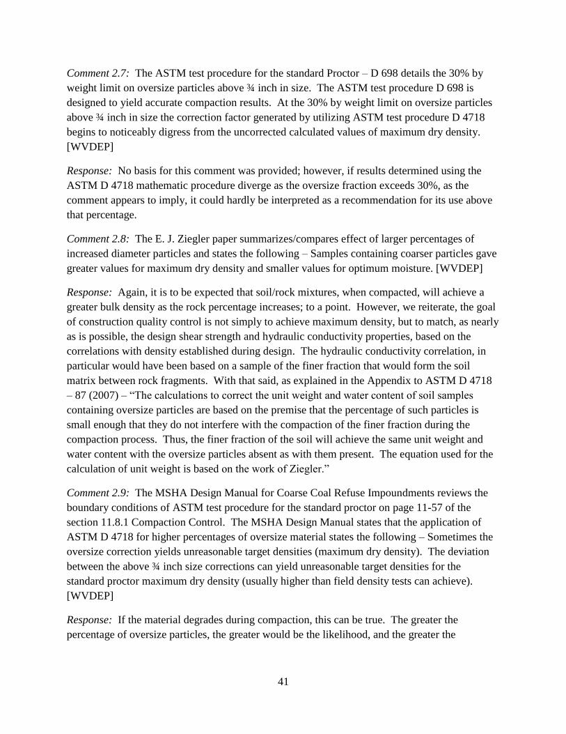
41
Comment 2.7: The ASTM test procedure for the standard Proctor – D 698 details the 30% by
weight limit on oversize particles above ¾ inch in size. The ASTM test procedure D 698 is
designed to yield accurate compaction results. At the 30% by weight limit on oversize particles
above ¾ inch in size the correction factor generated by utilizing ASTM test procedure D 4718
begins to noticeably digress from the uncorrected calculated values of maximum dry density.
[WVDEP]
Response: No basis for this comment was provided; however, if results determined using the
ASTM D 4718 mathematic procedure diverge as the oversize fraction exceeds 30%, as the
comment appears to imply, it could hardly be interpreted as a recommendation for its use above
that percentage.
Comment 2.8: The E. J. Ziegler paper summarizes/compares effect of larger percentages of
increased diameter particles and states the following – Samples containing coarser particles gave
greater values for maximum dry density and smaller values for optimum moisture. [WVDEP]
Response: Again, it is to be expected that soil/rock mixtures, when compacted, will achieve a
greater bulk density as the rock percentage increases; to a point. However, we reiterate, the goal
of construction quality control is not simply to achieve maximum density, but to match, as nearly
as is possible, the design shear strength and hydraulic conductivity properties, based on the
correlations with density established during design. The hydraulic conductivity correlation, in
particular would have been based on a sample of the finer fraction that would form the soil
matrix between rock fragments. With that said, as explained in the Appendix to ASTM D 4718
– 87 (2007) – “The calculations to correct the unit weight and water content of soil samples
containing oversize particles are based on the premise that the percentage of such particles is
small enough that they do not interfere with the compaction of the finer fraction during the
compaction process. Thus, the finer fraction of the soil will achieve the same unit weight and
water content with the oversize particles absent as with them present. The equation used for the
calculation of unit weight is based on the work of Ziegler.”
Comment 2.9: The MSHA Design Manual for Coarse Coal Refuse Impoundments reviews the
boundary conditions of ASTM test procedure for the standard proctor on page 11-57 of the
section 11.8.1 Compaction Control. The MSHA Design Manual states that the application of
ASTM D 4718 for higher percentages of oversize material states the following – Sometimes the
oversize correction yields unreasonable target densities (maximum dry density). The deviation
between the above ¾ inch size corrections can yield unreasonable target densities for the
standard proctor maximum dry density (usually higher than field density tests can achieve).
[WVDEP]
Response: If the material degrades during compaction, this can be true. The greater the
percentage of oversize particles, the greater would be the likelihood, and the greater the

42
magnitude of particle degradation. This would appear to be an argument against the use of the
procedure for materials with higher percentages of oversized particles.
Comment 2.10: We believe it is acceptable to use the above correction for coarse refuse that
contains more than 30% by weight of oversize particles. However, there may be cases where the
amount of oversize particles becomes too high and would require an alternate testing method or
reduction in oversized particles. This assessment should be determined by the design engineer
during construction. Some of the variables to consider would be material degradability,
frequency of oversize material, embankment configuration, current placement area, and
performance monitoring data. The more important question with regard to the use of the oversize
correction might be “what is the standard of care in the industry for limiting oversize
correction”? The answer would be based on both designer input and MSHA criteria. [Thacker,
GA]
Response: OSMRE does not agree that it is acceptable to use the oversize particle correction for
coarse refuse that contains more than 30% by weight of oversize particles. The more important
question might be “why did the developers and reviewers of the ASTM D 698 and D 4718
procedures impose the limitation?” The rationale is provided in the documentation, and is not
ambiguous. It would not appear that they would have imposed the limitation if to ignore it
would be conservative.
Comment 2.11: It should be noted that Section 1.6 of ASTM D 4718 states: “This practice may
not be applicable to soil‐ rock mixtures which degrade under field compaction.” In addition,
Section 1.7 of ASTM D 4718 states: “…This document cannot replace education or experience
and should be used in conjunction with professional judgment. Not all aspects of this practice
may be applicable in all circumstances. This ASTM standard is not intended to represent or
replace the standard of care by which the adequacy of a given professional service must be
judged, nor should this document be applied without consideration of a project’s many unique
aspects.” In addition to statements about applicability to degradable soil‐rock mixtures and the
use of professional judgment, Section 1.4 of ASTM D 4718 states: “The factor controlling the
maximum permissible percentage of oversize particles is whether interference between the
oversize particles affects the unit weight of the finer fraction”. This aspect can be judged in the
field by visually observing proper material response to compaction equipment and then
comparing field compaction results to oversize corrected laboratory Proctor values. [Thacker,
GA]
Response: OSMRE agrees that no document can replace education, experience, or the use of
professional judgment. OSMRE also agrees that not all aspects of the standard are applicable in
all circumstances, such as those in which the percentage of oversize material exceeds the stated
allowable limit. OSMRE also agrees the document should not be applied without consideration
of the projects unique aspects, such as percentage of oversized particles. However, it is difficult
to envision how oversized particles interfering with compaction of the fine matrix could be

43
identified by observation of material response to compaction equipment. The limitations to the
percentages of oversize particles stated in the ASTM D 4718 procedure were based on research
investigating the point at which the percentage of oversize particles began to interfere with
compaction of the finer fraction. This rationale is discussed in the appendix of the procedure.
Issue 3
Comment 3.1: Material impacted by dozer cleats or sheepsfoot roller will be close to one foot in
depth in my experience. To attempt removal of less, such as 0.5 feet of material, with heavy
equipment adds its own difficulties. [Long, WVDEP, DWWM]
Response: Only loose, uncompacted material need be removed. This will typically be
approximately 2 to 3 inches for dozer cleats, less for a sheepsfoot roller (if it has completely
walked out) and zero for a smooth drum roller. OSMRE recommends that procedures in ASTM
D 6938-10 or D 2922-01 be followed, or that a thickness to be removed prior to testing be
provided by the design engineer.
Comment 3.2: In many cases, when building a dam, the lift placed is 1 foot (loose), then when
compacted, it thins out to 8 or 9 inches. Removing the top foot would not be helpful. [Bruce,
BGC]
Response: OSMRE agrees.
Comment 3.3: You need to test representative depths of the most recent lift placed. If you
discount the upper disturbed material then perhaps 1/3 and 2/3 depths, but otherwise the lift may
vary depending on target density, compaction equipment, compactors, or haul trucks, depths of
influence, etc. [Bruce, BGC]
Response: OSMRE recommends that procedures in ASTM D 6938-10 or D 2922-01 be
followed, or that the design engineer prescribe a thickness to be removed prior to testing.
Comment 3.4: We agree that there is no need to always remove a top layer of material prior to
performing field density testing. [Michalek, MSHA]
Response: OSMRE agrees.
Comment 3.5: If other than standard field testing procedures will be used, the construction
specifications in the approved plan should stipulate the procedures, including how field density
testing will be conducted. If the operator chooses to always test some distance below the
surface, that is their prerogative. We are not advocating testing more than one lift (12 inches)
below the surface. We acknowledge that testing as near the surface as possible reduces the
potential work required to correct a failed test. [Michalek, MSHA]
Response: OSMRE agrees.

44
Comment 3.6: Testing should be conducted on a surface that has been compacted and is in a
condition appropriate for the test method used. For example, we would not expect a nuclear
density gauge to be placed directly on material that has been roughened (loosened) by mobile
equipment. It would be appropriate to remove the loosened material if present. [Michalek,
MSHA]
Response: OSMRE agrees.
Comment 3.7: The top twelve inches of material being placed and compacted in a coarse coal
refuse embankment is known as a layer not a compacted lift. The top twelve inches of material
that is to say the “layer” cannot be assumed to be in final placement from the WVDEP, DMR’s
regulatory viewpoint. The WVDEP, DMR regulatory view is that only material in final
placement is to be tested for determination of achieving target compaction values. Only material
in final placement is subject to potential enforcement action if target compaction values are not
achieved. [WVDEP]
Response: Considering the top twelve inches a “layer” and not a lift, was unique to WVDEP,
DMR among peer reviewers. OSMRE does not agree that a “layer” for which no additional
direct compaction is planned is not in final placement condition. However, constructing an
embankment in accordance with the WVDEP, DMR position, and removing the ‘layer’ at field
density test locations prior to testing, should not have any consequences detrimental to
construction quality, as long as failed tests are appropriately addressed. If WVDEP or other
Regulatory Authority maintains the position that the top twelve inch layer is not considered to be
in a final placement condition, it may be necessary to include this as a requirement by policy or
regulation. All permit documents related to placement and compaction of coarse refuse at
specific facilities should also include this condition.
Comment 3.8: The WVDEP, DMR’s regulatory view agrees with engineering view that the top
layer contains sheared zones that are less dense due to cleat marks from tracked equipment.
Removal of the top twelve inches of material known as a layer of material exposes the first
compacted lift that can be tested for compaction. [WVDEP]
Response: Again, OSMRE does not agree that removal of material other than loose surface
material, to the bottom of dozer cleat or sheepsfoot roller imprints is necessary for field density
tests to be valid. However, OSMRE also notes that the practice is not, in and of itself in any way
detrimental to validity of test results. It does increase the effort required to address failed tests.
Comment 3.9: The material in the top layer may have been spread by a dozer but not completely
tracked. [WVDEP]
Response: The technician conducting the field testing should ask the operator to identify areas
for which no additional direct compaction is planned and that are therefore, ready for testing. It

45
is necessary to identify in the field density test records the extent of a lift that is tested, so that
other portions of the same lift are also tested when ready.
Comment 3.10: The primary intent of removing surface material is to ensure that only final
placed/compacted coarse refuse material is tested. The removal of surface material will depend
in part on the equipment performing the compaction. A smooth surface is required to perform
field compaction testing with a nuclear density gauge. If a dozer or sheepsfoot roller is used, then
a back‐bladed surface will be necessary. Further, if multiple lifts have been placed without
verification compaction testing, then a cut down to the lower lifts will be necessary. [Thacker,
GA]
Response: OSMRE agrees with the comments. The ASTM Nuclear moisture/density gauge
methods and sand cone methods referenced in the paper discuss preparation of the surface for
testing. None recommend removal of a specific additional thickness of material. Regarding
cutting down to test multiple lifts, this would have to be done at multiple locations, and if nuclear
moisture/density gauges are used, the trench offset correction may have to be employed,
depending on depth and width of the trench. To facilitate addressing of failed tests, it would
always be preferable to test as near to the surface as possible.
Issue 4
Comment 4.1: Regarding the discussion of settlement of the embankment and subsequent
geotechnical testing – What point are you trying to make? [Bruce, BGC]
Response: The point we were making was that with time, material within an embankment will
compress due to the weight of overlying fill, and that a geotechnical investigation, including
drilling, sampling, testing, and analysis could be done to verify its stability. We also noted that
such an evaluation, being based on few borings at discreet locations is in no way as
representative of the condition of the entire embankment as is a properly prepared and executed
construction quality control plan.
Comment 4.2: We agree that consistently failing to meet compaction requirements increases the
potential for stability and seepage issues. [Michalek, MSHA]
Response: OSMRE agrees.
Comment 4.3: MSHA requires corrective actions and retesting when a field density test
indicates the material does not meet plan specifications. Therefore, “consistently failing to meet
compaction requirements” should be a temporary condition with regard to material properties. It
is important to test areas adjacent to a failed test to determine the extent of the subpar material or
expand the area to be reworked to help ensure all subpar material has been reworked. [Michalek,
MSHA]
Response: OSMRE agrees.
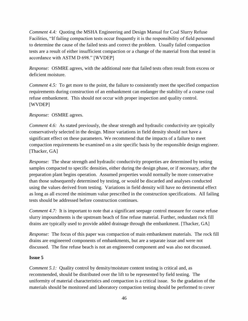
46
Comment 4.4: Quoting the MSHA Engineering and Design Manual for Coal Slurry Refuse
Facilities, “If failing compaction tests occur frequently it is the responsibility of field personnel
to determine the cause of the failed tests and correct the problem. Usually failed compaction
tests are a result of either insufficient compaction or a change of the material from that tested in
accordance with ASTM D 698.” [WVDEP]
Response: OSMRE agrees, with the additional note that failed tests often result from excess or
deficient moisture.
Comment 4.5: To get more to the point, the failure to consistently meet the specified compaction
requirements during construction of an embankment can endanger the stability of a coarse coal
refuse embankment. This should not occur with proper inspection and quality control.
[WVDEP]
Response: OSMRE agrees.
Comment 4.6: As stated previously, the shear strength and hydraulic conductivity are typically
conservatively selected in the design. Minor variations in field density should not have a
significant effect on these parameters. We recommend that the impacts of a failure to meet
compaction requirements be examined on a site specific basis by the responsible design engineer.
[Thacker, GA]
Response: The shear strength and hydraulic conductivity properties are determined by testing
samples compacted to specific densities, either during the design phase, or if necessary, after the
preparation plant begins operation. Assumed properties would normally be more conservative
than those subsequently determined by testing, or would be discarded and analyses conducted
using the values derived from testing. Variations in field density will have no detrimental effect
as long as all exceed the minimum value prescribed in the construction specifications. All failing
tests should be addressed before construction continues.
Comment 4.7: It is important to note that a significant seepage control measure for coarse refuse
slurry impoundments is the upstream beach of fine refuse material. Further, redundant rock fill
drains are typically used to provide added drainage through the embankment. [Thacker, GA]
Response: The focus of this paper was compaction of main embankment materials. The rock fill
drains are engineered components of embankments, but are a separate issue and were not
discussed. The fine refuse beach is not an engineered component and was also not discussed.
Issue 5
Comment 5.1: Quality control by density/moisture content testing is critical and, as
recommended, should be distributed over the lift to be represented by field testing. The
uniformity of material characteristics and compaction is a critical issue. So the gradation of the
materials should be monitored and laboratory compaction testing should be performed to cover
47
changing material characteristics. For uniformity of compaction, intelligent compaction (i.e.,
instrumented compaction equipment) should be considered. Intelligent compaction is becoming
more and more available. [Edil, UW]
Response: OSMRE agrees, on all counts. We would recommend separate moisture control in
conjunction with intelligent compaction.
Comment 5.2: The reviewer felt the map excerpt illustrating the small area of a placed lift that
was actually tested was illegible, and was unsure of the point of the discussion. [Bruce, BGC]
Response: We improved the illustration by showing the area in which fill was placed and
compacted relative to the small portion of the same lift in which all tests were conducted. This
was the point of the illustration and the discussion.
Comment 5.3: We agree that field density tests should be distributed to sample the entire work
area. [Michalek, MSHA]
Response: OSMRE agrees.
Comment 5.4: The paper should present recommendations for properly identifying locations for
field density testing. For example, once the required number of tests to be conducted has been
determined, uniformly spaced test areas could be defined using a percentage of the number of
tests required. The specific test location within each defined area can be determined using a
random location procedure. The remaining test locations can also be determined over the entire
area using the same random location procedure. [Michalek, MSHA]
Response: OSMRE’s opinion is that the test locations must be evenly distributed over the area
being tested. The method used by the consultant need not be complicated; however, the entirety
of each lift must be represented.
Comment 5.5: The location and number of tests per lift should be located to be representative of
the area to be tested in the field. Testing and the location of test locations should be
representative of the volume of material placed and compacted. [WVDEP]
Response: OSMRE agrees.
Comment 5.6: Review of more than one day of compaction test locations should be observed to
avoid continuously placing tests in one concentrated area. [WVDEP]
Response: More than one day of compaction test locations should be observed to ensure that all
areas of a lift are tested, since the entire lift may not be tested on one day. OSMRE agrees that
test locations should not be concentrated in one area.
Comment 5.7: If testing an entire lift, the West Virginia Department of Transportation procedure
MP 712.21.26 outlines principles that can be used as a guide. [WVDEP]

48
Response: OSMRE agrees. Other procedures exist as well, such as defining a grid of areas on
the lift, with the number of areas matching or exceeding the number of required tests, and
randomly locating one test location in each area.
Comment 5.8: We agree with OSM’s comments that “This process need not be complicated”,
and “A visual distribution of test locations should be adequate”. As stated previously, the
pass/fail status of compacted material is known before our technicians leave the site by
performing a field moisture content. As practical, field compaction tests should be well
distributed over the entire active fill area. However, the need for and the actual test locations will
also be based on other variables such as:
Whether initial pushout material or embankment material is being placed
Whether temporary material or final material is being placed
The volume of fill material placed in a given area
The field compaction test locations during previous/subsequent site visits
[Thacker, GA]
Response: OSMRE agrees that performing a field moisture content test would permit onsite
determination of pass/fail status of field density tests if one moisture content test is associated
with each field density test. This is necessary since significant variation in moisture content is
often measured between different test locations. OSMRE would not recommend performing
field density testing on initial pushout material or on material being placed temporarily. OSMRE
agrees the number of field density tests would be based on the volume of fill material placed in a
area. The spacing would be based on the area over which said fill volume is placed. OSMRE is
of the opinion that previous compaction records must be reviewed to ensure that all areas of a
given lift are tested, particularly if different areas are tested on different days.
Issue 6
Comment 6.1: You may wish to indicate that while “pumping” is commonly observed when
compaction takes place at excessive moisture, it can be often occur when the field measured
water content and dry density are compared with an incorrect Proctor curve, or when the energy
delivered by the field compaction equipment is not well approximated by the standard Proctor
tests (hence the Modified Proctor test was created). As the compaction energy goes up, the
optimum moisture content will generally go down. [Drumm, UT]
Response: OSMRE agrees that, regardless of the method used to define target densities, it is
very important to relate densities determined by field testing to the correct reference density or
curve. However, if pumping is observed, the energy being delivered is excessive for the material
onsite at its current moisture content. The material in question may be at or beneath the fill
surface.
49
Comment 6.2: Regarding correction of pumping material – “Allowing the material time to
dissipate excess pore water pressure is another method, however, the area should be tested before
the next lift is placed.” [Long, WVDEP, DWWM]
Response: This method should work if the affected material is at the surface and if time is
available. If the material is deeper, as is most often the case, or if it is soon to be covered by
additional fill, it will be necessary to remove, moisture condition, re-place and compact the
pumping material.
Comment 6.3: Use the field density test to confirm the fill has to be removed and replaced.
[Bruce, BGC]
Response: OSMRE disagrees. OSMRE engineers have observed cases in which moisture and
density at the surface were tested, and determined to be adequate, but the surface was pumping
under the influence of passage of the equipment. This was an indication that the unstable
material was deeper than one foot below the surface. It would not be appropriate to proceed
without addressing the unstable material prior to proceeding, in spite of the moisture content and
density of the top lift.
Comment 6.4: Regarding cases where pumping is observed but material at the surface is visibly
dry – So the lift below should have been failed and ripped out before the top lift was placed.
[Bruce, BGC]
Response: OSMRE agrees, if the problem was identified prior to placement of the next lift. In
some cases, the material becomes saturated by precipitation after testing, and placement and
compaction of the subsequent lift results in over-compaction of the previous lift. It should
certainly be addressed before any testing or additional placement is done.
Comment 6.5: Agreed that pumping can only be corrected by removing the material, lowering
the moisture content, re-placing, re-compacting, and re-testing. [Bruce, BGC]
Response: OSMRE agrees.
Comment 6.6: Regarding visible evidence of shear cracking – Could also be desiccation in
recently placed material, not necessarily the layer below. [Bruce, BGC]
Response: In most cases, shear cracking occurs in small areas of the surface whereas desiccation
cracking tends to cover the entire surface. Shear cracking can be easily distinguished from
desiccation cracking by proof-rolling. Pumping will not be observed on a desiccated surface.
Comment 6.7: Proof-rolling in itself can also be called for in specifications if trucks and rollers
are specified. [Bruce, BGC]
Response: OSMRE agrees.

50
Comment 6.8: We agree that compacted material exhibiting pumping should be corrected.
[Michalek, MSHA]
Response: OSMRE agrees.
Comment 6.9: We do not agree that the material must be removed and replaced. The pumping
characteristic is often an indication of wet or over-compacted material. A suitable first attempt at
correcting the situation would be to disc the material and allow it to dry before re-compacting. If
unsuccessful, replacement would be warranted. [Michalek, MSHA]
Response: OSMRE agrees that the same material should be re-usable if moisture conditioned
and re-compacted. Best-case scenario would be realized if it can be disced in place with
acceptable results. If not, it is likely the problem would be beneath the top lift, in which case
material would need to be removed for moisture conditioning.
Comment 6.10: The last word of the first paragraph, “unstable” appears to be too strong a word
for this issue. [Michalek, MSHA]
Response: Pumping material certainly cannot be said to be stable. The context implies that this
is localized instability, and not (if not widespread or uncorrected) a global stability issue.
Comment 6.11: The first sentence of the second paragraph mentioned over-compaction. The
remainder of the text for this issue never mentions over-compaction. The issue of over-
compacting areas observed to be pumping should be addressed in the paper. A common
response to pumping is to continue compacting the area with the thought that it will improve.
This wrong assumption does not improve the condition and actually makes it worse by degrading
the material. [Michalek, MSHA]
Response: In this section, OSMRE pointed out (correctly) that over-compaction is commonly
referred to in the field as, “pumping,” although this is actually a visual indicator of the problem.
The remainder of the section was aimed at identifying and addressing areas where pumping was
observed; hence the use of this term, rather than over-compaction. The proper response to
pumping was provided in the text. OSMRE agrees that attempted continuation of compacting
tends to be detrimental, and has added a statement to that effect.
Comment 6.12: It has been reported that pumping can occur when material is compacted wet of
optimum, but within the allowable moisture range to achieve 95 percent of maximum dry
density. Therefore, some amount of pumping would be acceptable. [Michalek, MSHA]
Response: OSMRE agrees with both of these statements; however, acceptable pumping would
be minor and uniform across the surface of a lift. If any doubt exists, the lift should be proof-
rolled.

51
Comment 6.13: There are several ASTM testing procedures designed to determine the
engineering properties of a material such as “Atterberg limits”. [WVDEP]
Response: This is true. Such testing can indicate characteristics of the material, such as
sensitivity to moisture content and associated susceptibility to over-compaction, as well as
facilitate identification of appropriate remedial measures. With that said, over-compaction,
pumping, and shear cracking are visually identified in the field.
Comment 6.14: Pumping and cracking should be investigated to determine the cause and then
remediate the reason for concern. [WVDEP]
Response: OSMRE agrees.
Comment 6.15: When observing excessive pumping and cracking in the field one should take
the conservative approach and evaluate the situation to then correct the problem. [WVDEP]
Response: OSMRE agrees.
Comment 6.16: We have previously discussed the selection of design engineering parameters for
the coarse refuse embankments. Visual evidence of inadequate compaction should be addressed
by the experienced technician and/or the responsible design engineer. Field compaction testing is
a tool to address whether corrections to visually inadequate compaction have been properly
made. Cracking of the coarse refuse embankment materials can also occur due to desiccation or
settlement of underlying materials. [Thacker, GA]
Response: OSMRE agrees that visual evidence of inadequate compaction should be addressed
as it is observed by the experienced technician and/or the responsible design engineer. Cracking
that is due to settlement of underlying materials is indicative of a problem and should be
addressed. Desiccation cracking should be addressed by scarifying and re-compacting, but is
unrelated to over-compaction or shear cracking. Desiccation cracking will not show up as a soft
area during proof rolling. Therefore, proof rolling can be used to differentiate between the two
types of cracking.
Summary and Conclusions
Comment SC.1: Regarding the need to remove the top foot of compacted fill prior to performing
density testing, I agree with OSMRE’s argument. I have never seen anyone nor heard of the
need to remove the top foot of compacted fill prior to testing. Many times it is necessary to
remove loose material, smooth the surface, and fill voids prior to taking a reading, but it should
not be necessary to remove a large quantity of soil. I have attended classes by Troxler on the
proper way to use their nuclear moisture/density gauge, and was instructed on the importance for
placing the gauge on a smooth level surface free from large holes and debris, so that the gamma
rays from the nuclear material reflect properly through the soil in order to get an accurate
reading. I was also instructed that if the gauge is placed in a trench, backscatter of the gamma

52
rays could compromise the accuracy of the reading and it may be necessary to compensate by
using the trench offset option for the gauge. [Kramer, PE, Ph.D]
Response: The commenter’s additional validation of OSMRE’s position is appreciated.
Comment SC.2: Regarding whether a correlation exists between the degree to which coarse coal
refuse is compacted and its hydraulic conductivity and piping resistance – Yes, but only
marginally and not really the main indicator. [Bruce, BGC]
Response: We are aware that other factors affect both hydraulic conductivity and resistance to
piping; however, coarse refuse is used as delivered to the site and, all else being equal, greater
density of a soil matrix filling the voids between rock fragments yields lower hydraulic
conductivity and greater resistance to piping.
Comment SC.3: Most fills require a density and gradation spec. [Bruce, BGC]
Response: Specifications for coarse refuse embankments include a density specification;
however, the material is used as delivered, regardless of gradation.
Comment SC.4: The 30% oversize limitation in the ASTM standard Procter and oversize particle
correction procedures is a standard. It is non-negotiable. [Bruce, BGC]
Response: OSMRE agrees..
Related Documents


