AUSTRALIAN MODEL NEWS JUNE 2020 Issue No. 64

Welcome message from author
This document is posted to help you gain knowledge. Please leave a comment to let me know what you think about it! Share it to your friends and learn new things together.
Transcript
AUSTRALIAN
MODEL NEWS
JUNE 2020
Issue No. 64
2 Australian Model News
Contents
3. LAURIE BALDWIN’S BOLTON PAUL DEFIANT 7. THE RAAF KANGAROO ROUNDEL 9. MIKE MULHOLLAND’S WESTLAND LYSANDER 13. DON SPRAY’S GRUMMAN TIGERCAT. 15. INDOOR RUBBER SCALE IN NEW ZEALAND 16. GLEN DUNSTON’S P-51 MUSTANG 18. GLEN DUNSTON’S MIRAGE III 20. DAVID ANDERSON’S SE5A 21. DAVID ANDERSON’S COMPER SWIFT 23. BRIAN LAUGHTON’S WOODSTOCK GLIDER 24. SARINA AEROMODELLERS CLUB 26. WAYNE HARRISON’S TRAVEL AIR MYSTERY SHIP 27. WAYNE HARRISON’S FORD FLIVVER 28. CONTROL LINE AT DONCASTER MAC 29. FREE FLIGHT SCALE MASTERS
This newsletter is published bi-monthly to feature model aircraft building and flying and to report on aeromodelling events in Australia and New Zealand. Contributing material and requests for inclusion on the distri-bution list may be forwarded to —
John Lamont Unit 5, 1326 Main Road, Eltham, 3095 Home: 03 9431 0044 Mobile: 0415 384 823 E-mail: [email protected] Visit our website at - https://sites.google.com/view/australian-model-news/
I’m hanging on by my fingernails at present with the Convid-19 lockdown preventing model flying all over the country. Fortunately I have received news from a number of model-lers working on old and new models which shows that model building is still going on and there will be new models ready for test flying when the lockdown is lifted. Our NZ friends on the other side of the Tasman are in the same boat as us but I was able to lift a couple of articles from Stan Mauger’s Scale News magazine to give AMN a bit of international flavour. The Kiwis are very good at building and flying their rubber powered scale models and I hope that you enjoy their workmanship and skill. John Lamont
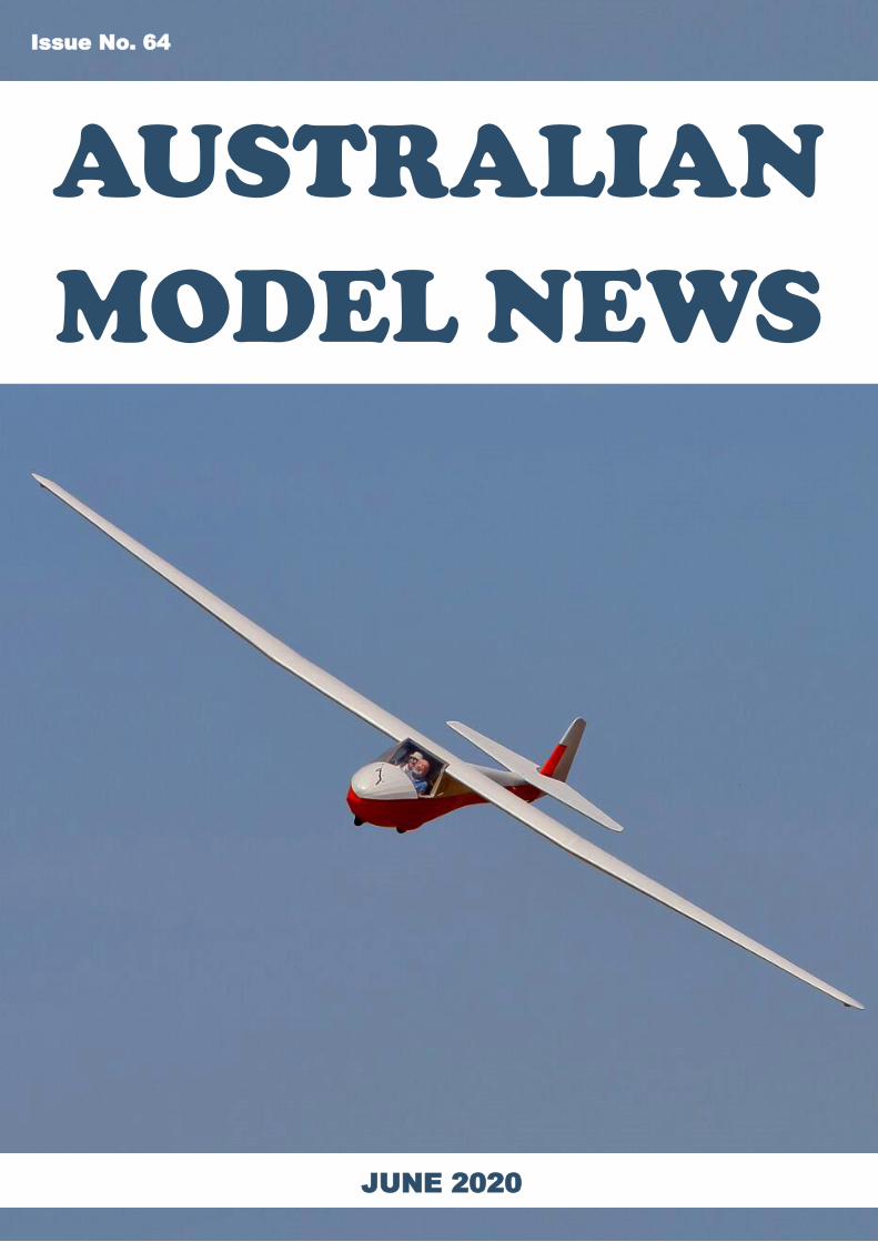
On the Cover. George Buzuleac’s longwing “Kookaburra” sailplane flying
at the Grampians MFC aerotow. (Photograph by Andrew Downey)
From the Editor
3 Australian Model News
Bolton PaUl “DEFIant”
Laurie Baldwin’s
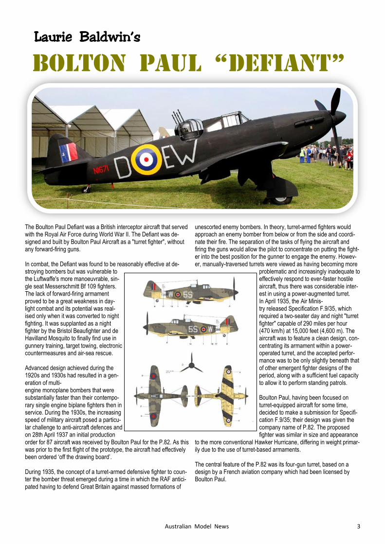
The Boulton Paul Defiant was a British interceptor aircraft that served with the Royal Air Force during World War II. The Defiant was de-signed and built by Boulton Paul Aircraft as a "turret fighter", without any forward-firing guns. In combat, the Defiant was found to be reasonably effective at de-stroying bombers but was vulnerable to the Luftwaffe's more manoeuvrable, sin-gle seat Messerschmitt Bf 109 fighters. The lack of forward-firing armament proved to be a great weakness in day-light combat and its potential was real-ised only when it was converted to night fighting. It was supplanted as a night fighter by the Bristol Beaufighter and de Havilland Mosquito to finally find use in gunnery training, target towing, electronic countermeasures and air-sea rescue. Advanced design achieved during the 1920s and 1930s had resulted in a gen-eration of multi-engine monoplane bombers that were substantially faster than their contempo-rary single engine biplane fighters then in service. During the 1930s, the increasing speed of military aircraft posed a particu-lar challenge to anti-aircraft defences and on 28th April 1937 an initial production order for 87 aircraft was received by Boulton Paul for the P.82. As this was prior to the first flight of the prototype, the aircraft had effectively been ordered ‘off the drawing board’. During 1935, the concept of a turret-armed defensive fighter to coun-ter the bomber threat emerged during a time in which the RAF antici-pated having to defend Great Britain against massed formations of
unescorted enemy bombers. In theory, turret-armed fighters would approach an enemy bomber from below or from the side and coordi-nate their fire. The separation of the tasks of flying the aircraft and firing the guns would allow the pilot to concentrate on putting the fight-er into the best position for the gunner to engage the enemy. Howev-er, manually-traversed turrets were viewed as having becoming more
problematic and increasingly inadequate to effectively respond to ever-faster hostile aircraft, thus there was considerable inter-est in using a power-augmented turret. In April 1935, the Air Minis-try released Specification F.9/35, which required a two-seater day and night "turret fighter" capable of 290 miles per hour (470 km/h) at 15,000 feet (4,600 m). The aircraft was to feature a clean design, con-centrating its armament within a power-operated turret, and the accepted perfor-mance was to be only slightly beneath that of other emergent fighter designs of the period, along with a sufficient fuel capacity to allow it to perform standing patrols. Boulton Paul, having been focused on turret-equipped aircraft for some time, decided to make a submission for Specifi-cation F.9/35; their design was given the company name of P.82. The proposed fighter was similar in size and appearance
to the more conventional Hawker Hurricane, differing in weight primar-ily due to the use of turret-based armaments. The central feature of the P.82 was its four-gun turret, based on a design by a French aviation company which had been licensed by Boulton Paul.
4 Australian Model News
On 28 April 1937, an initial production order for 87 aircraft was re-ceived by Boulton Paul for the P.82; as this was prior to the first flight of the prototype, the aircraft had effectively been ordered 'off the drawing board'. Completing its acceptance tests with the turret in-stalled, the Defiant attained a top speed of 486 km/h (302 mph). Flight trials revealed the aircraft to possess positive flight characteristics and considerable stability, which was of particular value when using the turret.
A total of 713 Defiant Mk I aircraft were completed when, in response to a service request which sought greater performance, the Defiant Mk II, powered by the 1,260 hp Merlin XX engine, was developed and paired with the newly developed airborne interception radar (AI) to
become a night fighter.
The need for both the Defiant and the Hurricane in the night fighter role petered out by 1942 and in the search for alternative uses for the Defiant, which included limited service with the RAF Search and Res-cue Force and suitability trials for cooperative operations with the British Army, it was determined that Defiant production would continue in order to satisfy a pressing requirement for high speed gunnery targets.
General characteristics Crew: two: pilot, gunner Length: 10.77 m (35 ft 4 in ) Wingspan: 11.99 m (39 ft 4 in) Height: 3.45 m (11 ft 4 in) Wing area: 23 m2 (250 sq ft) Empty weight: 2,757 kg (6,078 lb) Gross weight: 3,773 kg (8,318 lb) Max takeoff weight: 3,901 kg (8,600 lb) Powerplant: 1 × Rolls-Royce Merlin III liquid-cooled V12 engine, 770 kW (1,030 hp)
Performance
Maximum speed: 489 km/h (304 mph, 264 kn) at 5,200 m (17,000 ft) Cruise speed: 282 km/h (175 mph,152 kn) at 4,600 m (15,000 ft) Range: 748 km (465 miles, 404 nm) Endurance: 1.78 hr Service ceiling: 9,400 m (31,000 ft) Time to altitude: 8.5 min to 15,000 ft (4,600 m)
Armament Guns: 4 × 0.303 in (7.7 mm) Browning machine guns in hydraulically powered dorsal turret (600 rpg)
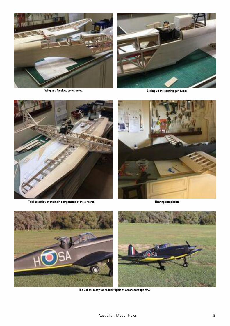
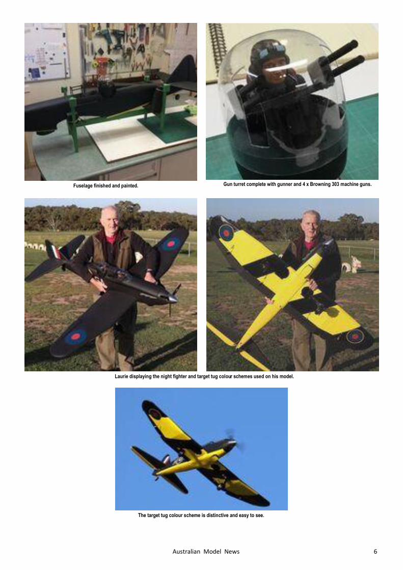
The Model Laurie’s Defiant is a Chris Golds design built from his plan and utilis-ing a short kit produced in the UK by Sarik Hobbies. The model has a wingspan of 1.83m and is electric powered. With the model never intended for competitive scale flying Laurie has indulged himself by finishing the upper surfaces of the model as a night fighting Defiant Mk1 and the underside as a Defiant Mk.II gun-nery target tow plane.
Assembly of the basic fuselage box.
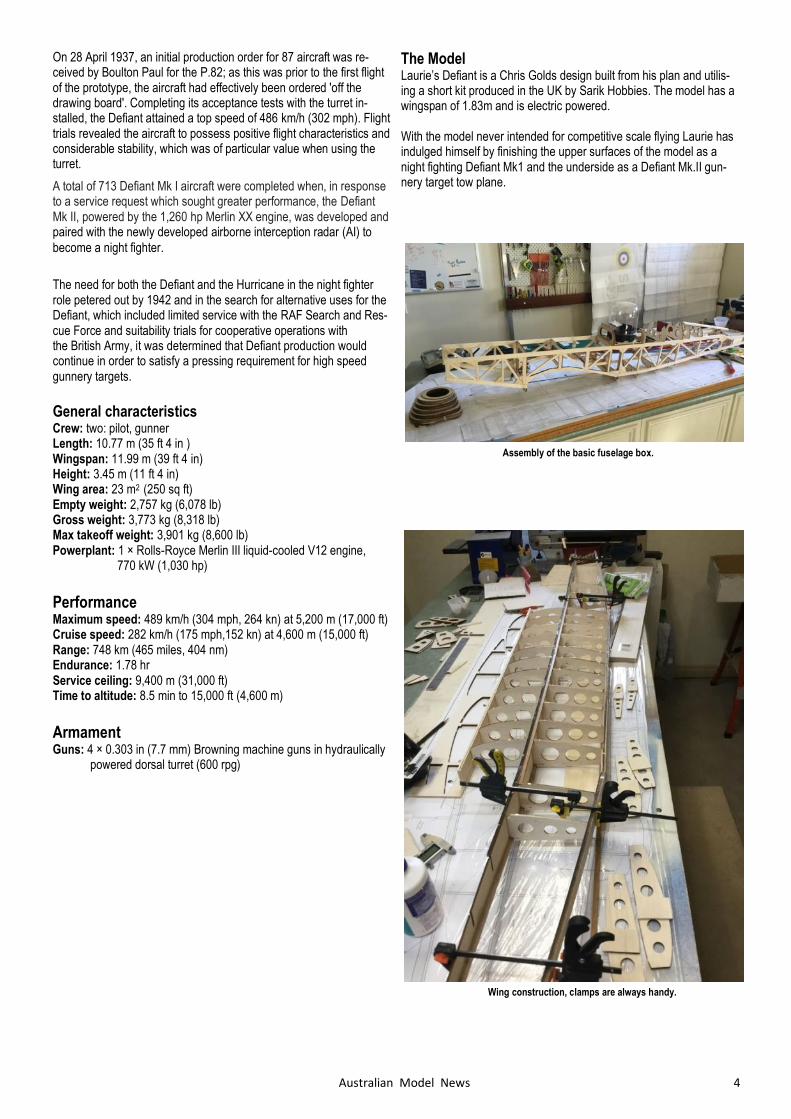
Wing construction, clamps are always handy.
5 Australian Model News
Wing and fuselage constructed. Setting up the rotating gun turret.
Trial assembly of the main components of the airframe. Nearing completion.
The Defiant ready for its trial flights at Greensborough MAC.
6 Australian Model News
Fuselage finished and painted. Gun turret complete with gunner and 4 x Browning 303 machine guns.
Laurie displaying the night fighter and target tug colour schemes used on his model.
The target tug colour scheme is distinctive and easy to see.
7 Australian Model News
THE RAAF
KANGAROO
ROUNDEL
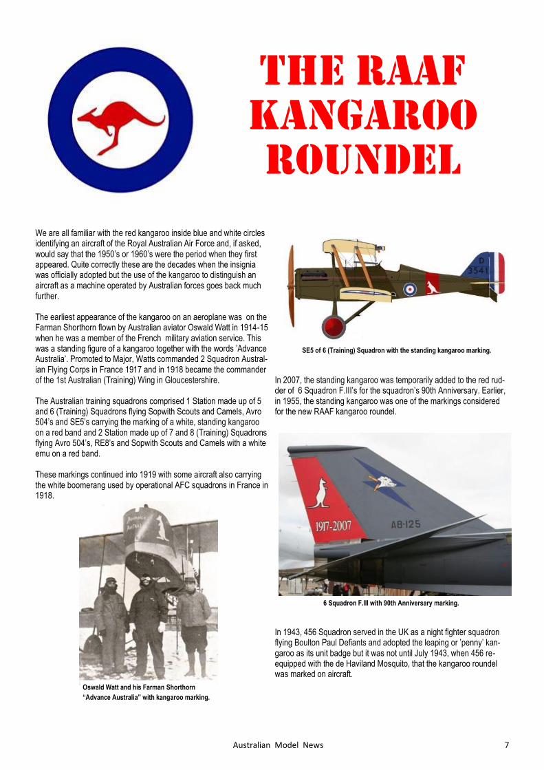
We are all familiar with the red kangaroo inside blue and white circles identifying an aircraft of the Royal Australian Air Force and, if asked, would say that the 1950’s or 1960’s were the period when they first appeared. Quite correctly these are the decades when the insignia was officially adopted but the use of the kangaroo to distinguish an aircraft as a machine operated by Australian forces goes back much further. The earliest appearance of the kangaroo on an aeroplane was on the Farman Shorthorn flown by Australian aviator Oswald Watt in 1914-15 when he was a member of the French military aviation service. This was a standing figure of a kangaroo together with the words ’Advance Australia’. Promoted to Major, Watts commanded 2 Squadron Austral-ian Flying Corps in France 1917 and in 1918 became the commander of the 1st Australian (Training) Wing in Gloucestershire. The Australian training squadrons comprised 1 Station made up of 5 and 6 (Training) Squadrons flying Sopwith Scouts and Camels, Avro 504’s and SE5’s carrying the marking of a white, standing kangaroo on a red band and 2 Station made up of 7 and 8 (Training) Squadrons flying Avro 504’s, RE8’s and Sopwith Scouts and Camels with a white emu on a red band. These markings continued into 1919 with some aircraft also carrying the white boomerang used by operational AFC squadrons in France in 1918.
In 2007, the standing kangaroo was temporarily added to the red rud-der of 6 Squadron F.III’s for the squadron’s 90th Anniversary. Earlier, in 1955, the standing kangaroo was one of the markings considered for the new RAAF kangaroo roundel.
In 1943, 456 Squadron served in the UK as a night fighter squadron flying Boulton Paul Defiants and adopted the leaping or ’penny’ kan-garoo as its unit badge but it was not until July 1943, when 456 re-equipped with the de Haviland Mosquito, that the kangaroo roundel was marked on aircraft.
Oswald Watt and his Farman Shorthorn
“Advance Australia” with kangaroo marking.
SE5 of 6 (Training) Squadron with the standing kangaroo marking.
6 Squadron F.III with 90th Anniversary marking.
8 Australian Model News
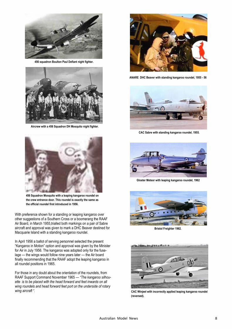
456 squadron Boulton Paul Defiant night fighter.
Aircrew with a 456 Squadron DH Mosquito night fighter.
456 Squadron Mosquito with a leaping kangaroo roundel on
the crew entrance door. This roundel is exactly the same as
the official roundel first introduced in 1956.
With preference shown for a standing or leaping kangaroo over other suggestions of a Southern Cross or a boomerang the RAAF Air Board, in March 1955,trialled both markings on a pair of Sabre aircraft and approval was given to mark a DHC Beaver destined for Macquarie Island with a standing kangaroo roundel. In April 1956 a ballot of serving personnel selected the present “Kangaroo in Motion” option and approval was given by the Minister for Air in July 1956. The kangaroo was adopted only for the fuse-lage — the wings would follow nine years later — the Air board finally recommending that the RAAF adopt the leaping kangaroo in all roundel positions in 1965. For those in any doubt about the orientation of the roundels, from RAAF Support Command November 1965 — “The kangaroo silhou-ette is to be placed with the head forward and feet inwards on all wing roundels and head forward feet port on the underside of rotary wing aircraft “.
ANARE DHC Beaver with standing kangaroo roundel, 1955 - 56
CAC Sabre with standing kangaroo roundel, 1955.
Gloster Meteor with leaping kangaroo roundel, 1962
Bristol Freighter 1962.
CAC Winjeel with incorrectly applied leaping kangaroo roundel
(reversed).
9 Australian Model News
WESTLAND LYSANDER
Mike Mulholland’s
Genesis
The Lysander, like the Sopwith Camel, is one of those aircraft that
seems to have acquired a reputation for being a difficult prospect as a
free flight model. These reputations probably derive from handling
quirks in the design that made the full-sized aircraft a handful but
which don’t apply to free flight models, such as powerful rotary en-
gines and variable incidence tailplanes.
To be fair, short noses and short-coupled tailplanes are not your usual
go-to for a rubber powered free flight model. Throw in some pretty
complex shapes and a fairly challenging build and it’s probably no
surprise that so few Lysanders are seen in Free Flight. Like many of
us I had ogled the Howard Boys 50” version for years, and after laying
the Lysander bogey to rest with my very successful Keil Kraft 18”
version It was time to give it a go.
Start... and stop!
Probably because the Howard Boys design is so well-loved and holds
iconic status, I neglected the first and cardinal rule of scale building
which is to sort out your documentation first and align your plan to
that. Off I went and launched into the basic 3/32 box structure only to
find that the Boys plan was a cunningly concealed disaster. In fact, I
have come to the conclusion that Mr Boys did not build his model from
this plan at all. My guess is that he probably designed as he built and
that he or someone else drew the plan for publication later. There
were the obvious inaccuracies around outlines which I was always
prepared for, but as I got building I realised that the fuselage sections
(while not too inaccurate in shape), were the wrong
dimensions for the internal box structure and the sheeting offsets were
wrong. The wing roots are wrong and percentage to chord is also
wrong. Add to that the differences between one wing and the other
and I’m afraid I just lost confidence in it.
The first set of drawings I obtained were the William Wylam drawings
which were published in 1958. I’m guessing that Boys used these
drawings as his plan was also published in 1958 and his basic design
follows the Wylam proportions. These drawings are fully dimensioned,
very tempting and very nearly had me hooked. Enter the Haynes
Westland Lysander Workshop Manual – yes really! Those of us who
in earlier years pored over grease-smudged copies of the Haynes
Manual to attempt yet another WOF on our Hunters, Avengers, Es-
corts, Minis and other assorted rubbish, might be surprised to learn
that you can also buy the Haynes workshop manual for an Me109 or
in this case a Westland Lysander. What the Haynes Manual, with its
detailed construction photos, clearly showed was that the Wylam
drawings, beautiful as drawings, were not wholly accurate.
At this point it was Ricky Bould to the rescue with a pristine set of the
1/24 Aeromodeller drawings. These are also beautiful drawings and
while they largely agree with Wylam, they depart where required in
accordance with the photographic record. A trip to the printshop, the
exchange of a few dollars and a 200% copy became my 1/12 plan
Fuselage
I had made the 3/32 square internal box structure already and the
good news was that with some surgery the new correct sections
would fit around it nicely. A major departure from the Boys design was my decision to build a scale cabane structure rather the non-scale half former structure usually employed on model Ly-
sanders.
10 Australian Model News
The Lysander is really a parasol rather than a cabin aircraft and lurk-
ing under all that glasshouse is a kind of triangulated rollover frame
not unlike the thing on the top of a PT19, that sits inside the canopy
and carries the wings. Boys would not have had access to a vacuum
box and would have needed more structure to support the various bits
of plastic sheeting. I save a bit of weight here while also achieving a
more scale representation. The fuselage box is actually a very com-
plex shape - it goes from rectangular to whatever shape you call that
at the tail - also maybe not apparent but the top longeron slopes down
from a point just forward of the tail so collectively these give the box a
slightly swoopy look but it’s correct! At the front end you can see the
result of hanging around with Gwyn Avenell and his radio scale mod-
els too much! The ugly but very functional Liteply structure grafted on
the front of the truncated nose section bears all the loads and the
tapering longeron doublers transfer and dissipate the stresses aft. Ad-
ditional formers glued around the box will support the cowling and a
further Liteply plate on the front of the box will carry the dummy motor
and nose block assembly.
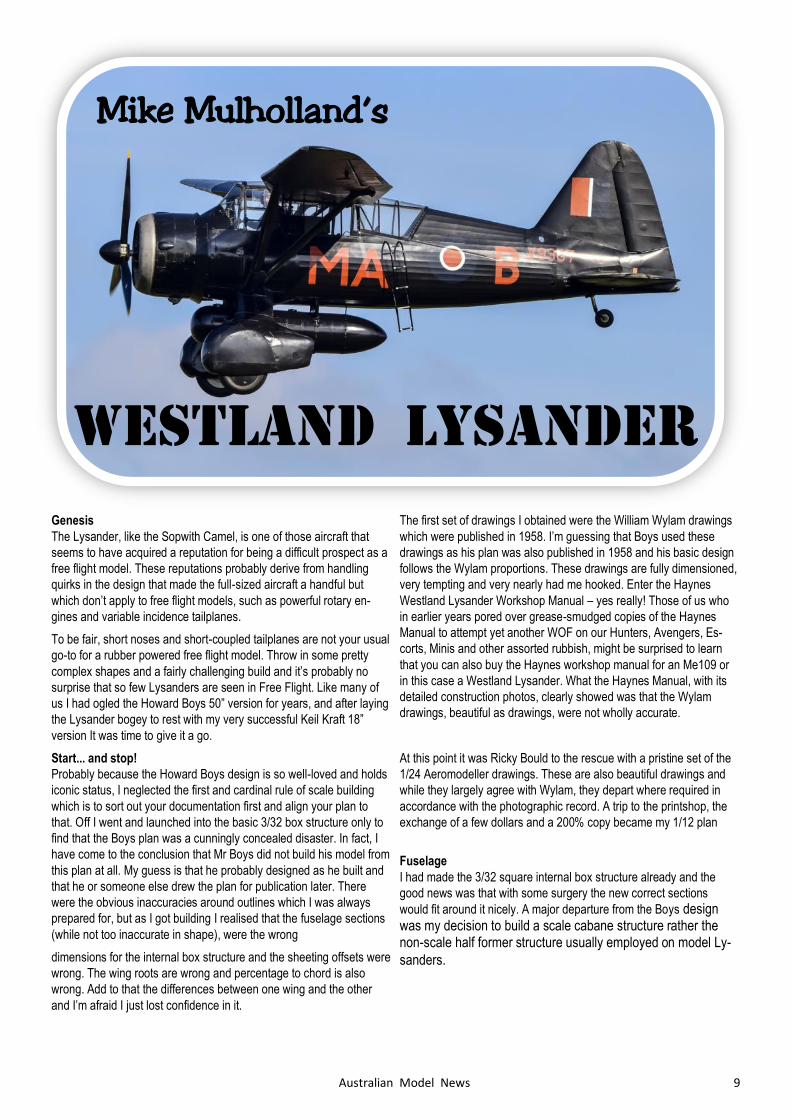
The cabane structure is 2.4mm basswood with 10 thou styrene fish-
plates to provide mechanical strength - all cyano’d together. Compres-
sion tubes are 5/32" aluminium tube. These will take the wing pegs
and dental bands through the middle. Pins and more fishplates assist
its adhesion to the top longerons. There is a lot of visible cockpit struc-
ture in a Lysander and I have a horror of furry looking painted balsa.
The original aircraft has aluminium covers over each of the two cock-
pit bays incorporating the corner fairings. I vacuum formed a nice
smooth one-piece cover that encompasses all of the visible top struc-
ture and takes paint (and embossed rivets) nicely.
The stringers give the Lysander its shape and there are plenty of them
– about 40 to get right around! I went with firm 1mm x 2.4mm and this
is holding the shape nicely. I umm’ed and ahh’ed about scale stringer
placement because of weight, but balanced against that there is so
much support for the covering and such tiny areas between wood that
I will cover this model in my lightest indoor tissue. To get the rear
decking stringers perfect I actually carved a solid block to the correct
shape, sliced and diced it at the appropriate stations and then traced
the formers from the resulting cross sections. Old-school but you can’t
argue with the results. At the back end the sheeted sections from the
tailplane back to the tail cone and the forward fuselage imitate the full-
size structure.
The rear side panels are very light block hollowed out. I hollowed
them out to 1/32 using my home-made gouge made from sharpened
19mm thin-walled brass tube and sanding. The rear peg support is
internal and the outer hole is just to support the tissue covering. This
allows the rear peg to be flush with the fuselage - much less obtrusive
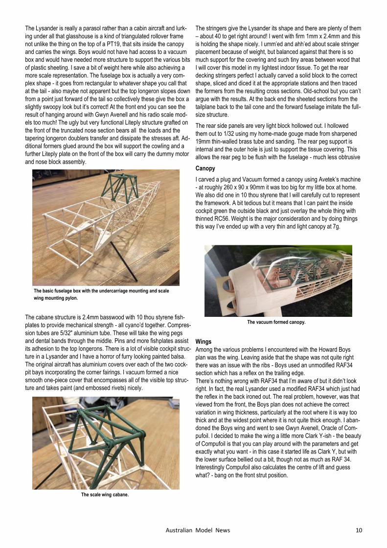
Canopy
I carved a plug and Vacuum formed a canopy using Avetek’s machine
- at roughly 260 x 90 x 90mm it was too big for my little box at home.
We also did one in 10 thou styrene that I will carefully cut to represent
the framework. A bit tedious but it means that I can paint the inside
cockpit green the outside black and just overlay the whole thing with
thinned RC56. Weight is the major consideration and by doing things
this way I’ve ended up with a very thin and light canopy at 7g.
Wings
Among the various problems I encountered with the Howard Boys
plan was the wing. Leaving aside that the shape was not quite right
there was an issue with the ribs - Boys used an unmodified RAF34
section which has a reflex on the trailing edge.
There’s nothing wrong with RAF34 that I’m aware of but it didn’t look
right. In fact, the real Lysander used a modified RAF34 which just had
the reflex in the back ironed out. The real problem, however, was that
viewed from the front, the Boys plan does not achieve the correct
variation in wing thickness, particularly at the root where it is way too
thick and at the widest point where it is not quite thick enough. I aban-
doned the Boys wing and went to see Gwyn Avenell, Oracle of Com-
pufoil. I decided to make the wing a little more Clark Y-ish - the beauty
of Compufoil is that you can play around with the parameters and get
exactly what you want - in this case it started life as Clark Y, but with
the lower surface bellied out a bit, though not as much as RAF 34.
Interestingly Compufoil also calculates the centre of lift and guess
what? - bang on the front strut position.
The basic fuselage box with the undercarriage mounting and scale
wing mounting pylon.
The scale wing cabane.
The vacuum formed canopy.
11 Australian Model News
The Oracle also laser cut the basic ribs for me but by that time I’d
used so much of his Saturday that we just did the outlines and I did
the lightening holes the old school way.
Tail surfaces
The tailplane, fin and rudder are pretty close to full size construction.
The tailplane is in two halves that slide over an 1/8 aluminium tube
running through and protruding from the fuselage. This allows the
whole tail to pivot like the real one. The incidence angle is fixed and
regulated by a ply tongue in each half that meet and lock together in
the middle of a transverse box across the fuselage.
A short length of nylon bolt is threaded vertically through one of the
ply tongues. This is a firm fit in the box, top to bottom, allowing accu-
rate and positive adjustment by turning the screw.
I’ve built the tailplane to scale and used the chunky scale section so
there are certainly questions in my mind about its likely effectiveness,
but the good news is that with this construction it’s an easy matter to
make another set of tailplane halves, if not. Also, the adjuster means
that I can bring the CofG forward and wind on a bit of negative tail-
plane to help.
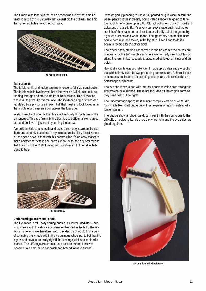
Undercarriage and wheel pants
The Lysander used Dowty sprung hubs à la Gloster Gladiator – cun-
ning wheels with the shock absorbers embedded in the hub. The un-
dercarriage legs are therefore rigid. I decided that I would find a way
of springing the wheels within the voluminous wheel pants but that the
legs would have to be really rigid if the fuselage joint was to stand a
chance. The U/C legs are 3mm square section carbon fibre well
locked in to a hard balsa sandwich and braced forward and aft.
I was originally planning to use a 3-D printed plug to vacuum-form the
wheel pants but the incredibly complicated shape was going to take
too much time to draw up in CAD. Old-school time - block of rock-hard
balsa and a sharp knife. It’s a very complex shape but in fact the es-
sentials of the shape come almost automatically out of the geometry -
if you can understand what I mean. That geometry had to also incor-
porate both rake and toe-in, in the leg stub. Then I had to do it all
again in reverse for the other side!
The wheel pants are vacuum-formed in two halves but the halves are
unequal - not the two simple clamshells we normally see. I did this by
sitting the form in two specially shaped cradles to get an inner and an
outer.
How it all mounts was a challenge - I made up a balsa and ply section
that slides firmly over the two protruding carbon spars. A 6mm lite-ply
arm mounts on the end of the sliding section and this carries the un-
dercarriage suspension.
The two shells are joined with internal doublers which both strengthen
and provide glue surface. These are moulded off the original form so
they can’t help but be right!
The undercarriage springing is a more complex version of what I did
for my little Keil Kraft Lizzie but with an expansion spring instead of a
torsion system.
The photos show a rubber band, but I went with the spring due to the
difficulty of replacing bands once the wheel is in and the two sides are
glued together.
The redesigned wing.
Tail assembly.
Vacuum formed wheel pants.
12 Australian Model News
Wheel pants assembly.
Trial assembly as construction nears completion. The fished model will have a wing-
span of 1.27m and will be rubber powered.
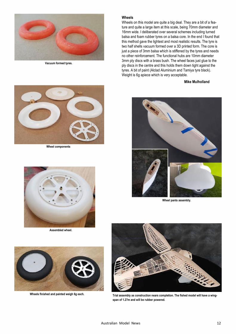
Wheels
Wheels on this model are quite a big deal. They are a bit of a fea-
ture and quite a large item at this scale, being 70mm diameter and
16mm wide. I deliberated over several schemes including turned
balsa and foam rubber tyres on a balsa core. In the end I found that
this method gave the lightest and most realistic results. The tyre is
two half shells vacuum formed over a 3D printed form. The core is
just a piece of 3mm balsa which is stiffened by the tyres and needs
no other reinforcement. The functional hubs are 10mm diameter
3mm ply discs with a brass bush. The wheel faces just glue to the
ply discs in the centre and this holds them down tight against the
tyres. A bit of paint (Alclad Aluminium and Tamiya tyre black).
Weight is 6g apiece which is very acceptable.
Mike Mulholland
Assembled wheel.
Wheel components
Wheels finished and painted weigh 6g each.
Vacuum formed tyres.
13 Australian Model News
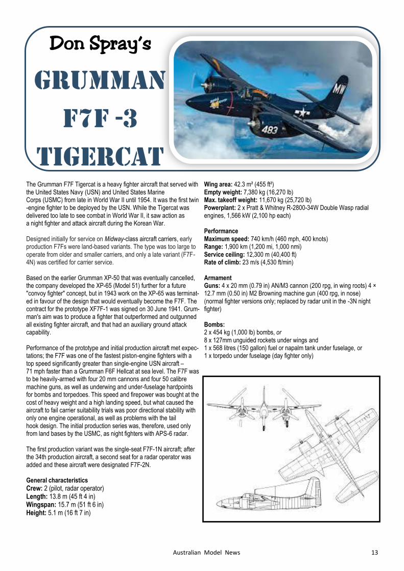
The Grumman F7F Tigercat is a heavy fighter aircraft that served with the United States Navy (USN) and United States Marine Corps (USMC) from late in World War II until 1954. It was the first twin-engine fighter to be deployed by the USN. While the Tigercat was delivered too late to see combat in World War II, it saw action as a night fighter and attack aircraft during the Korean War. Designed initially for service on Midway-class aircraft carriers, early production F7Fs were land-based variants. The type was too large to operate from older and smaller carriers, and only a late variant (F7F-4N) was certified for carrier service. Based on the earlier Grumman XP-50 that was eventually cancelled, the company developed the XP-65 (Model 51) further for a future "convoy fighter" concept, but in 1943 work on the XP-65 was terminat-ed in favour of the design that would eventually become the F7F. The contract for the prototype XF7F-1 was signed on 30 June 1941. Grum-man's aim was to produce a fighter that outperformed and outgunned all existing fighter aircraft, and that had an auxiliary ground attack capability. Performance of the prototype and initial production aircraft met expec-tations; the F7F was one of the fastest piston-engine fighters with a top speed significantly greater than single-engine USN aircraft – 71 mph faster than a Grumman F6F Hellcat at sea level. The F7F was to be heavily-armed with four 20 mm cannons and four 50 calibre machine guns, as well as underwing and under-fuselage hardpoints for bombs and torpedoes. This speed and firepower was bought at the cost of heavy weight and a high landing speed, but what caused the aircraft to fail carrier suitability trials was poor directional stability with only one engine operational, as well as problems with the tail hook design. The initial production series was, therefore, used only from land bases by the USMC, as night fighters with APS-6 radar. The first production variant was the single-seat F7F-1N aircraft; after the 34th production aircraft, a second seat for a radar operator was added and these aircraft were designated F7F-2N. General characteristics
Crew: 2 (pilot, radar operator) Length: 13.8 m (45 ft 4 in) Wingspan: 15.7 m (51 ft 6 in) Height: 5.1 m (16 ft 7 in)
Wing area: 42.3 m² (455 ft²) Empty weight: 7,380 kg (16,270 lb) Max. takeoff weight: 11,670 kg (25,720 lb) Powerplant: 2 x Pratt & Whitney R-2800-34W Double Wasp radial engines, 1,566 kW (2,100 hp each) Performance Maximum speed: 740 km/h (460 mph, 400 knots) Range: 1,900 km (1,200 mi, 1,000 nmi) Service ceiling: 12,300 m (40,400 ft) Rate of climb: 23 m/s (4,530 ft/min) Armament Guns: 4 x 20 mm (0.79 in) AN/M3 cannon (200 rpg, in wing roots) 4 × 12.7 mm (0.50 in) M2 Browning machine gun (400 rpg, in nose) (normal fighter versions only; replaced by radar unit in the -3N night fighter) Bombs: 2 x 454 kg (1,000 lb) bombs, or 8 x 127mm unguided rockets under wings and 1 x 568 litres (150 gallon) fuel or napalm tank under fuselage, or 1 x torpedo under fuselage (day fighter only)
Don Spray’s
GRUMMAN
F7F -3
TIGERCAT
14 Australian Model News
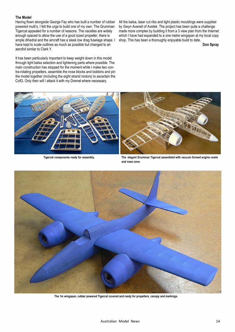
The elegant Grumman Tigercat assembled with vacuum formed engine cowls
and nose cone.
Tigercat components ready for assembly.
The 1m wingspan, rubber powered Tigercat covered and ready for propellers, canopy and markings.
The Model Having flown alongside George Fay who has built a number of rubber powered multi’s, I felt the urge to build one of my own. The Grumman Tigercat appealed for a number of reasons. The nacelles are widely enough spaced to allow the use of a good sized propeller, there is ample dihedral and the aircraft has a sleek low drag fuselage shape. I have kept to scale outlines as much as possible but changed to an aerofoil similar to Clark Y. It has been particularly important to keep weight down in this model through light balsa selection and lightening parts where possible. The main construction has stopped for the moment while I make two con-tra-rotating propellers, assemble the nose blocks and bobbins and pin the model together (including the eight strand motors) to ascertain the CofG. Only then will I attack it with my Dremel where necessary.
All the balsa, laser cut ribs and light plastic mouldings were supplied by Gwyn Avenell of Avetek. The project has been quite a challenge made more complex by building it from a 3 view plan from the Internet which I have had expanded to a one metre wingspan at my local copy shop. This has been a thoroughly enjoyable build to date. Don Spray
15 Australian Model News
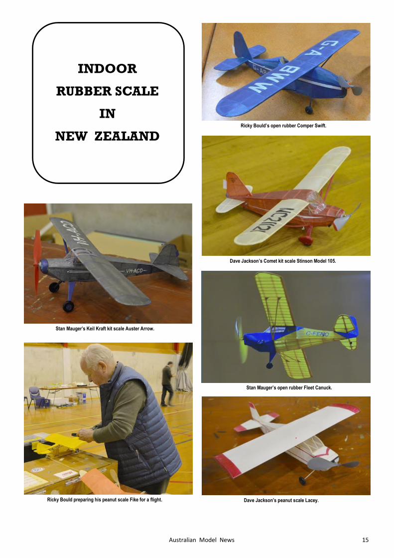
INDOOR
RUBBER SCALE
IN
NEW ZEALAND
Stan Mauger’s Keil Kraft kit scale Auster Arrow.
Stan Mauger’s open rubber Fleet Canuck.
Dave Jackson’s Comet kit scale Stinson Model 105.
Ricky Bould’s open rubber Comper Swift.
Ricky Bould preparing his peanut scale Fike for a flight. Dave Jackson’s peanut scale Lacey.
16 Australian Model News
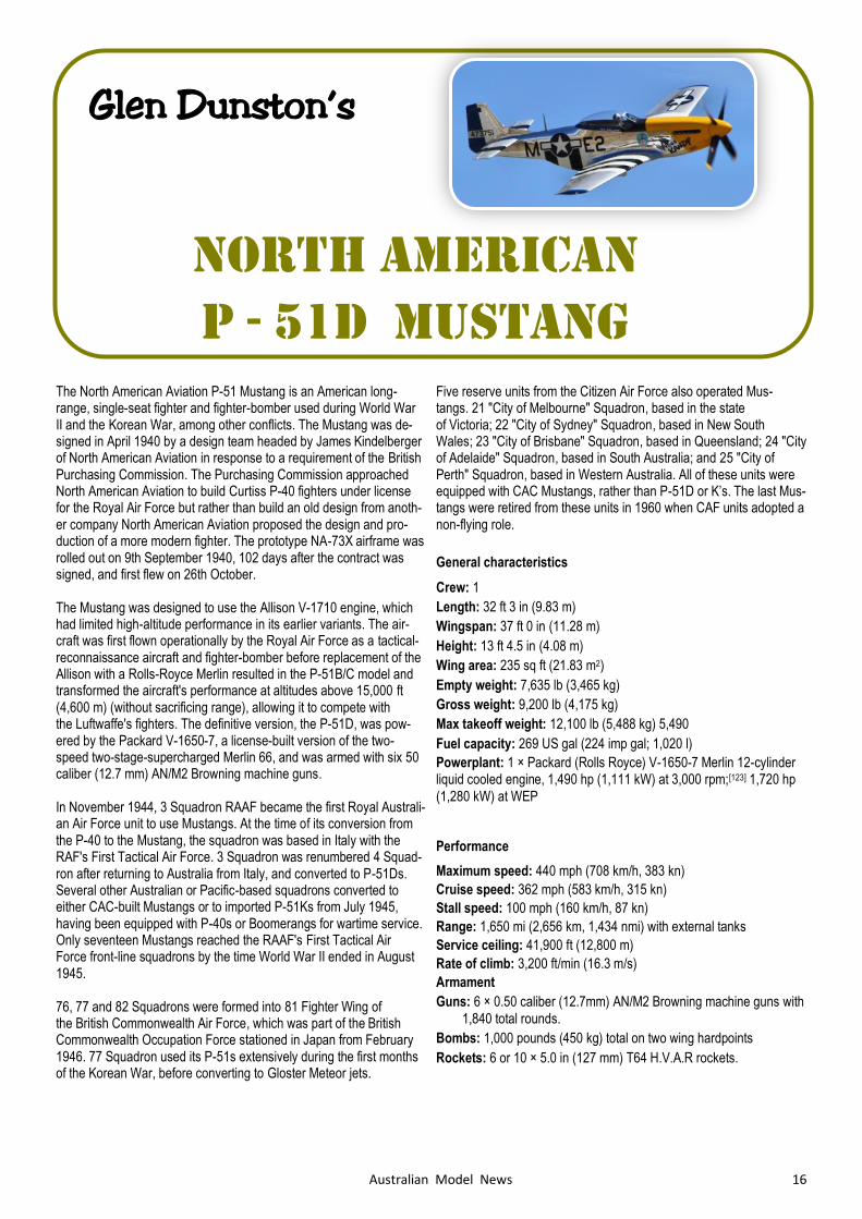
Glen Dunston’s
North American
P - 51D MUSTANG
The North American Aviation P-51 Mustang is an American long-range, single-seat fighter and fighter-bomber used during World War II and the Korean War, among other conflicts. The Mustang was de-signed in April 1940 by a design team headed by James Kindelberger of North American Aviation in response to a requirement of the British Purchasing Commission. The Purchasing Commission approached North American Aviation to build Curtiss P-40 fighters under license for the Royal Air Force but rather than build an old design from anoth-er company North American Aviation proposed the design and pro-duction of a more modern fighter. The prototype NA-73X airframe was rolled out on 9th September 1940, 102 days after the contract was signed, and first flew on 26th October. The Mustang was designed to use the Allison V-1710 engine, which had limited high-altitude performance in its earlier variants. The air-craft was first flown operationally by the Royal Air Force as a tactical-reconnaissance aircraft and fighter-bomber before replacement of the Allison with a Rolls-Royce Merlin resulted in the P-51B/C model and transformed the aircraft's performance at altitudes above 15,000 ft (4,600 m) (without sacrificing range), allowing it to compete with the Luftwaffe's fighters. The definitive version, the P-51D, was pow-ered by the Packard V-1650-7, a license-built version of the two-speed two-stage-supercharged Merlin 66, and was armed with six 50 caliber (12.7 mm) AN/M2 Browning machine guns. In November 1944, 3 Squadron RAAF became the first Royal Australi-an Air Force unit to use Mustangs. At the time of its conversion from the P-40 to the Mustang, the squadron was based in Italy with the RAF's First Tactical Air Force. 3 Squadron was renumbered 4 Squad-ron after returning to Australia from Italy, and converted to P-51Ds. Several other Australian or Pacific-based squadrons converted to either CAC-built Mustangs or to imported P-51Ks from July 1945, having been equipped with P-40s or Boomerangs for wartime service. Only seventeen Mustangs reached the RAAF's First Tactical Air Force front-line squadrons by the time World War II ended in August 1945. 76, 77 and 82 Squadrons were formed into 81 Fighter Wing of the British Commonwealth Air Force, which was part of the British Commonwealth Occupation Force stationed in Japan from February 1946. 77 Squadron used its P-51s extensively during the first months of the Korean War, before converting to Gloster Meteor jets.
Five reserve units from the Citizen Air Force also operated Mus-tangs. 21 "City of Melbourne" Squadron, based in the state of Victoria; 22 "City of Sydney" Squadron, based in New South Wales; 23 "City of Brisbane" Squadron, based in Queensland; 24 "City of Adelaide" Squadron, based in South Australia; and 25 "City of Perth" Squadron, based in Western Australia. All of these units were equipped with CAC Mustangs, rather than P-51D or K’s. The last Mus-tangs were retired from these units in 1960 when CAF units adopted a non-flying role.
General characteristics
Crew: 1
Length: 32 ft 3 in (9.83 m)
Wingspan: 37 ft 0 in (11.28 m)
Height: 13 ft 4.5 in (4.08 m)
Wing area: 235 sq ft (21.83 m2)
Empty weight: 7,635 lb (3,465 kg)
Gross weight: 9,200 lb (4,175 kg)
Max takeoff weight: 12,100 lb (5,488 kg) 5,490
Fuel capacity: 269 US gal (224 imp gal; 1,020 l)
Powerplant: 1 × Packard (Rolls Royce) V-1650-7 Merlin 12-cylinder liquid cooled engine, 1,490 hp (1,111 kW) at 3,000 rpm;[123] 1,720 hp
(1,280 kW) at WEP
Performance
Maximum speed: 440 mph (708 km/h, 383 kn)
Cruise speed: 362 mph (583 km/h, 315 kn)
Stall speed: 100 mph (160 km/h, 87 kn)
Range: 1,650 mi (2,656 km, 1,434 nmi) with external tanks
Service ceiling: 41,900 ft (12,800 m)
Rate of climb: 3,200 ft/min (16.3 m/s)
Armament
Guns: 6 × 0.50 caliber (12.7mm) AN/M2 Browning machine guns with
1,840 total rounds.
Bombs: 1,000 pounds (450 kg) total on two wing hardpoints
Rockets: 6 or 10 × 5.0 in (127 mm) T64 H.V.A.R rockets.
17 Australian Model News
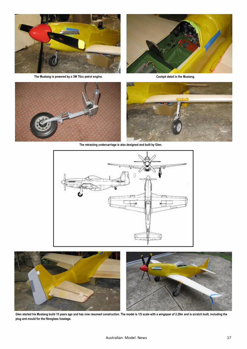
Glen started his Mustang build 15 years ago and has now resumed construction. The model is 1/5 scale with a wingspan of 2.29m and is scratch built, including the
plug and mould for the fibreglass fuselage.
The Mustang is powered by a 3W 70cc petrol engine. Cockpit detail in the Mustang.
The retracting undercarriage is also designed and built by Glen.
18 Australian Model News
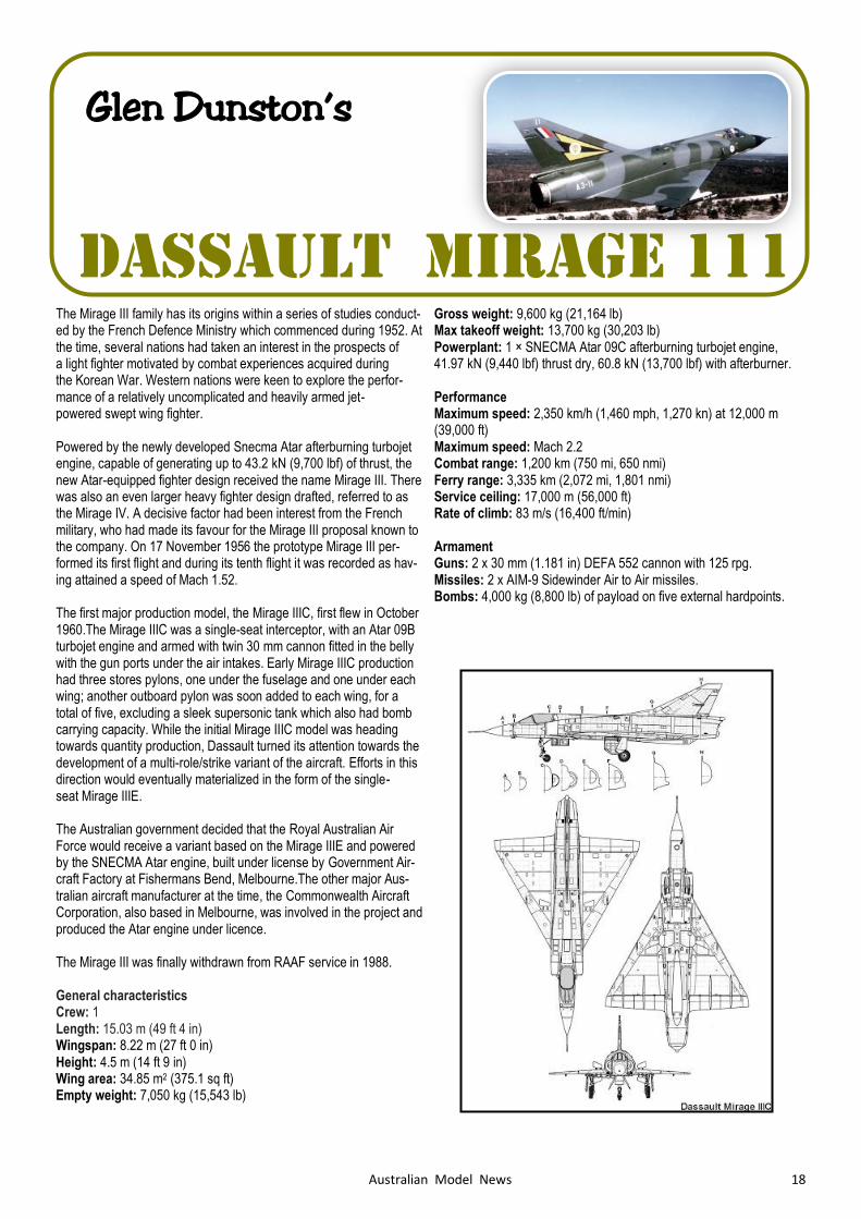
The Mirage III family has its origins within a series of studies conduct-ed by the French Defence Ministry which commenced during 1952. At the time, several nations had taken an interest in the prospects of a light fighter motivated by combat experiences acquired during the Korean War. Western nations were keen to explore the perfor-mance of a relatively uncomplicated and heavily armed jet-powered swept wing fighter. Powered by the newly developed Snecma Atar afterburning turbojet engine, capable of generating up to 43.2 kN (9,700 lbf) of thrust, the new Atar-equipped fighter design received the name Mirage III. There was also an even larger heavy fighter design drafted, referred to as the Mirage IV. A decisive factor had been interest from the French military, who had made its favour for the Mirage III proposal known to the company. On 17 November 1956 the prototype Mirage III per-formed its first flight and during its tenth flight it was recorded as hav-ing attained a speed of Mach 1.52. The first major production model, the Mirage IIIC, first flew in October 1960.The Mirage IIIC was a single-seat interceptor, with an Atar 09B turbojet engine and armed with twin 30 mm cannon fitted in the belly with the gun ports under the air intakes. Early Mirage IIIC production had three stores pylons, one under the fuselage and one under each wing; another outboard pylon was soon added to each wing, for a total of five, excluding a sleek supersonic tank which also had bomb carrying capacity. While the initial Mirage IIIC model was heading towards quantity production, Dassault turned its attention towards the development of a multi-role/strike variant of the aircraft. Efforts in this direction would eventually materialized in the form of the single-seat Mirage IIIE. The Australian government decided that the Royal Australian Air Force would receive a variant based on the Mirage IIIE and powered by the SNECMA Atar engine, built under license by Government Air-craft Factory at Fishermans Bend, Melbourne.The other major Aus-tralian aircraft manufacturer at the time, the Commonwealth Aircraft Corporation, also based in Melbourne, was involved in the project and produced the Atar engine under licence. The Mirage III was finally withdrawn from RAAF service in 1988. General characteristics Crew: 1 Length: 15.03 m (49 ft 4 in) Wingspan: 8.22 m (27 ft 0 in) Height: 4.5 m (14 ft 9 in) Wing area: 34.85 m2 (375.1 sq ft) Empty weight: 7,050 kg (15,543 lb)
Gross weight: 9,600 kg (21,164 lb) Max takeoff weight: 13,700 kg (30,203 lb) Powerplant: 1 × SNECMA Atar 09C afterburning turbojet engine, 41.97 kN (9,440 lbf) thrust dry, 60.8 kN (13,700 lbf) with afterburner. Performance Maximum speed: 2,350 km/h (1,460 mph, 1,270 kn) at 12,000 m (39,000 ft) Maximum speed: Mach 2.2 Combat range: 1,200 km (750 mi, 650 nmi) Ferry range: 3,335 km (2,072 mi, 1,801 nmi) Service ceiling: 17,000 m (56,000 ft) Rate of climb: 83 m/s (16,400 ft/min) Armament Guns: 2 x 30 mm (1.181 in) DEFA 552 cannon with 125 rpg. Missiles: 2 x AIM-9 Sidewinder Air to Air missiles. Bombs: 4,000 kg (8,800 lb) of payload on five external hardpoints.
Glen Dunston’s
Dassault Mirage 111
19 Australian Model News
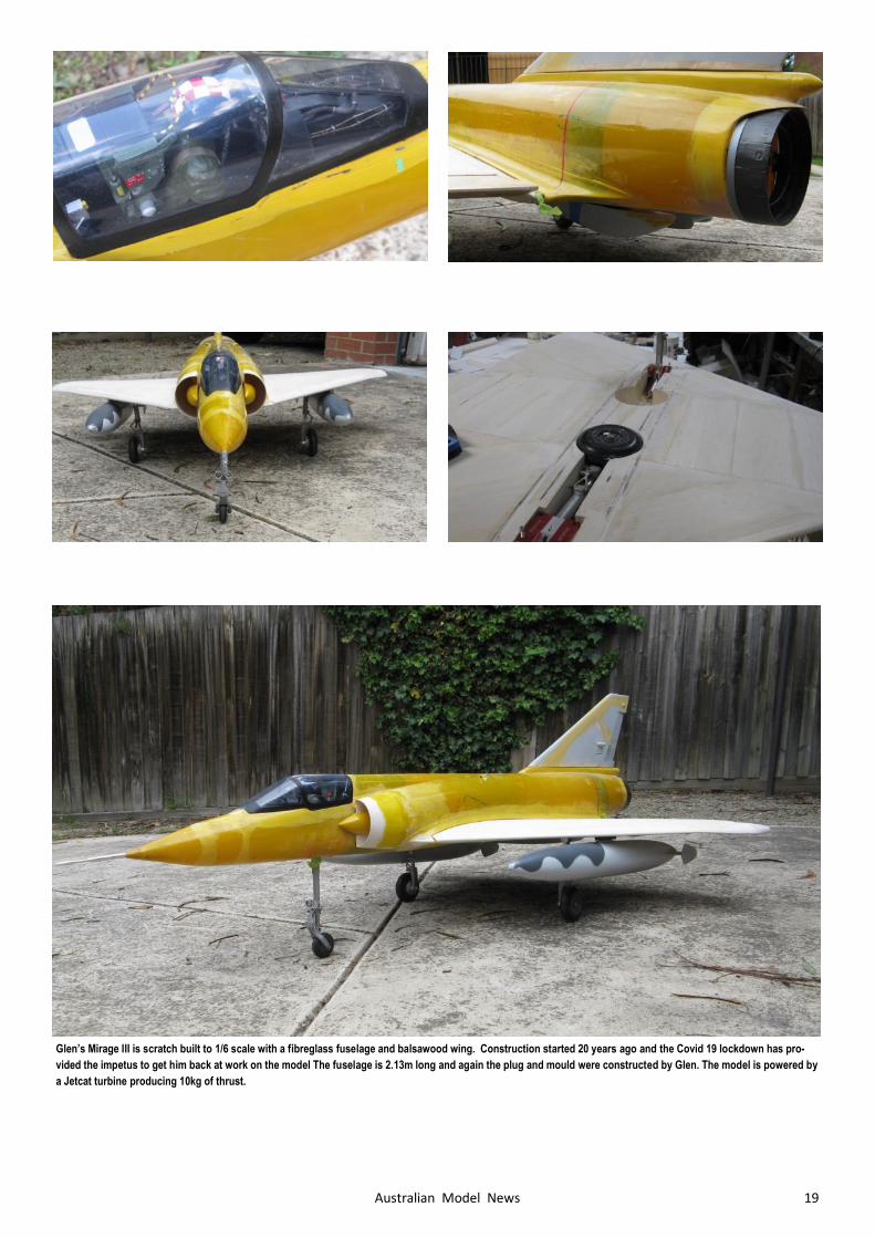
Glen’s Mirage III is scratch built to 1/6 scale with a fibreglass fuselage and balsawood wing. Construction started 20 years ago and the Covid 19 lockdown has pro-
vided the impetus to get him back at work on the model The fuselage is 2.13m long and again the plug and mould were constructed by Glen. The model is powered by
a Jetcat turbine producing 10kg of thrust.
20 Australian Model News
The S.E.5 was designed by Henry Folland, John Kenworthy and Major Frank Goodden of the Royal Aircraft Factory in Farnborough. It was built around the new 150 hp (112 kW) Hispano-Suiza 8, a V8 engine that, while providing excellent performance, was initially un-derdeveloped and unreliable. The introduction of the 200 hp (149 kW) Wolseley Viper, a high-compression, direct-drive version of the Hispano-Suiza 8a made under licence by Wolseley Motors Lim-ited, solved the S.E.5a's engine problems and was promptly adopted as the type's standard powerplant. General characteristics Crew: One Length: 20 ft 11 in (6.38 m) Wingspan: 26 ft 7 in (8.10 m) Height: 9 ft 6 in (2.90 m) Wing area: 244 sq ft (22.7 m2) Empty weight: 1,410 lb (640 kg) Gross weight: 1,935 lb (878 kg) Powerplant: 1 × Hispano-Suiza 8 or Wolseley Viper water cooled V8 engine, 150 hp (110 kW) Performance Maximum speed: 138 mph (222 km/h, 120 kn) Range: 300 mi (480 km, 260 nmi) Service ceiling: 17,000 ft (5,200 m) Wing loading: 7.93 lb/sq ft (38.7 kg/m2) Armament Guns: 1 x .303 in (7.7 mm) forward-firing Vickers machine gun. 1 x .303 in (7.7 mm) Lewis gun on Foster mounting on upper wing Bombs: 4x 25 lb (11 kg) Cooper bombs
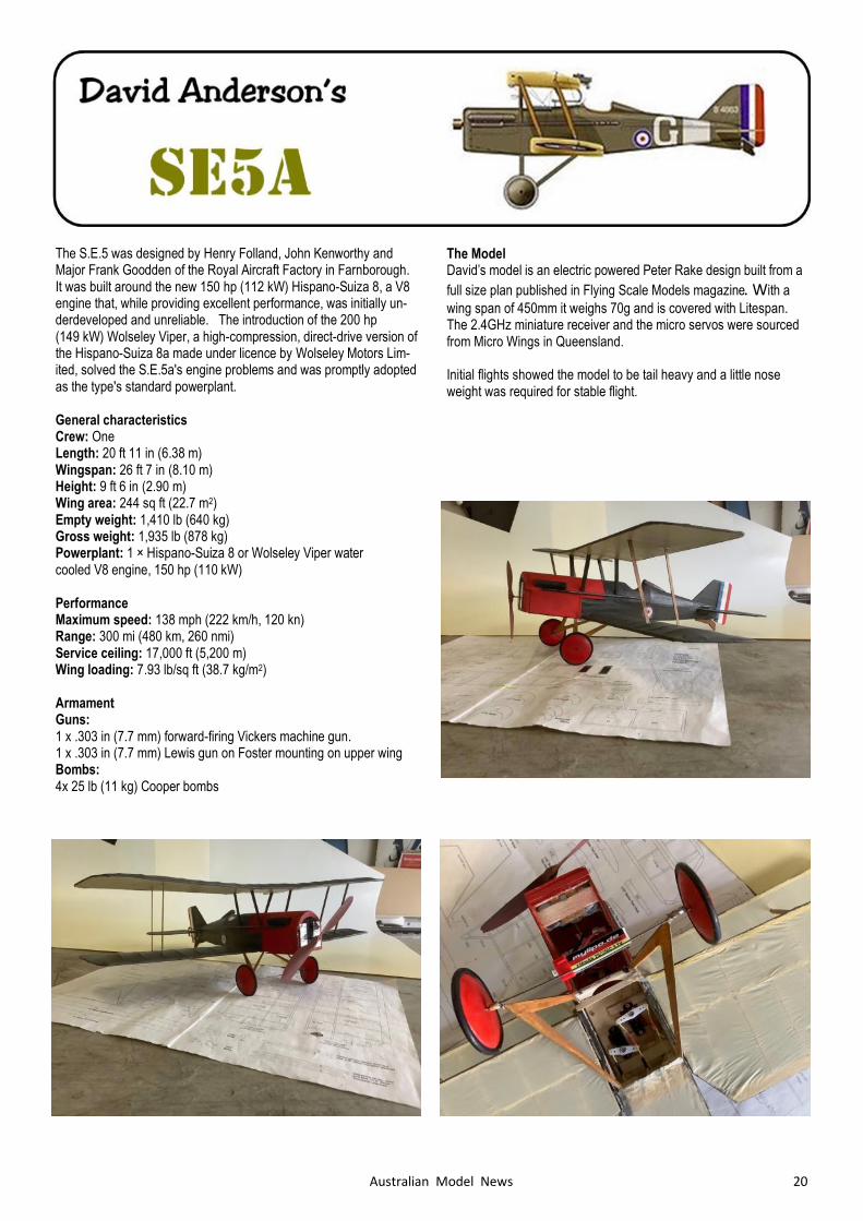
The Model David’s model is an electric powered Peter Rake design built from a
full size plan published in Flying Scale Models magazine. With a
wing span of 450mm it weighs 70g and is covered with Litespan. The 2.4GHz miniature receiver and the micro servos were sourced from Micro Wings in Queensland. Initial flights showed the model to be tail heavy and a little nose weight was required for stable flight.
21 Australian Model News
David Anderson’s
COMPER SWIFT
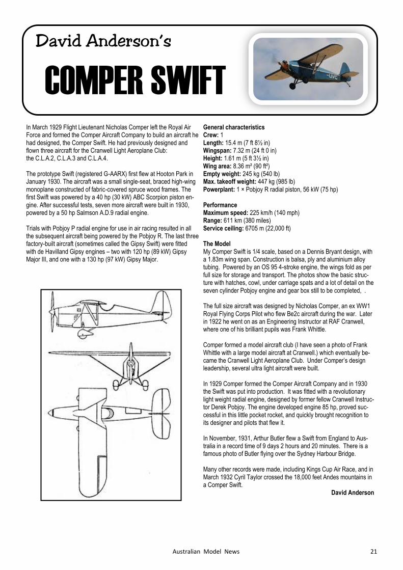
In March 1929 Flight Lieutenant Nicholas Comper left the Royal Air Force and formed the Comper Aircraft Company to build an aircraft he had designed, the Comper Swift. He had previously designed and flown three aircraft for the Cranwell Light Aeroplane Club: the C.L.A.2, C.L.A.3 and C.L.A.4. The prototype Swift (registered G-AARX) first flew at Hooton Park in January 1930. The aircraft was a small single-seat, braced high-wing monoplane constructed of fabric-covered spruce wood frames. The first Swift was powered by a 40 hp (30 kW) ABC Scorpion piston en-gine. After successful tests, seven more aircraft were built in 1930, powered by a 50 hp Salmson A.D.9 radial engine. Trials with Pobjoy P radial engine for use in air racing resulted in all the subsequent aircraft being powered by the Pobjoy R. The last three factory-built aircraft (sometimes called the Gipsy Swift) were fitted with de Havilland Gipsy engines – two with 120 hp (89 kW) Gipsy Major III, and one with a 130 hp (97 kW) Gipsy Major.
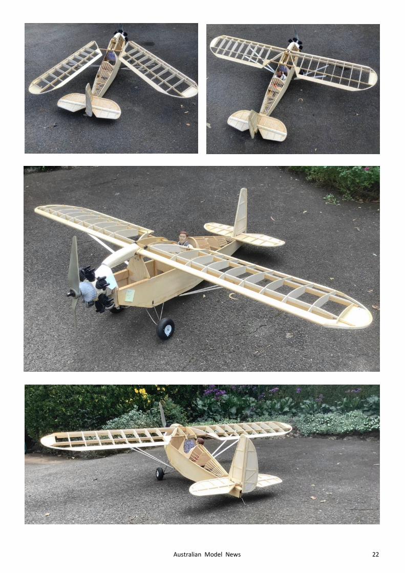
General characteristics Crew: 1 Length: 15.4 m (7 ft 8½ in) Wingspan: 7.32 m (24 ft 0 in) Height: 1.61 m (5 ft 3½ in) Wing area: 8.36 m² (90 ft²) Empty weight: 245 kg (540 lb) Max. takeoff weight: 447 kg (985 lb) Powerplant: 1 × Pobjoy R radial piston, 56 kW (75 hp) Performance Maximum speed: 225 km/h (140 mph) Range: 611 km (380 miles) Service ceiling: 6705 m (22,000 ft) The Model My Comper Swift is 1/4 scale, based on a Dennis Bryant design, with a 1.83m wing span. Construction is balsa, ply and aluminium alloy tubing. Powered by an OS 95 4-stroke engine, the wings fold as per full size for storage and transport. The photos show the basic struc-ture with hatches, cowl, under carriage spats and a lot of detail on the seven cylinder Pobjoy engine and gear box still to be completed, . The full size aircraft was designed by Nicholas Comper, an ex WW1 Royal Flying Corps Pilot who flew Be2c aircraft during the war. Later in 1922 he went on as an Engineering Instructor at RAF Cranwell, where one of his brilliant pupils was Frank Whittle. Comper formed a model aircraft club (I have seen a photo of Frank Whittle with a large model aircraft at Cranwell.) which eventually be-came the Cranwell Light Aeroplane Club. Under Comper’s design leadership, several ultra light aircraft were built. In 1929 Comper formed the Comper Aircraft Company and in 1930 the Swift was put into production. It was fitted with a revolutionary light weight radial engine, designed by former fellow Cranwell Instruc-tor Derek Pobjoy. The engine developed engine 85 hp, proved suc-cessful in this little pocket rocket, and quickly brought recognition to its designer and pilots that flew it. In November, 1931, Arthur Butler flew a Swift from England to Aus-tralia in a record time of 9 days 2 hours and 20 minutes. There is a famous photo of Butler flying over the Sydney Harbour Bridge. Many other records were made, including Kings Cup Air Race, and in March 1932 Cyril Taylor crossed the 18,000 feet Andes mountains in a Comper Swift. David Anderson
22 Australian Model News
23 Australian Model News
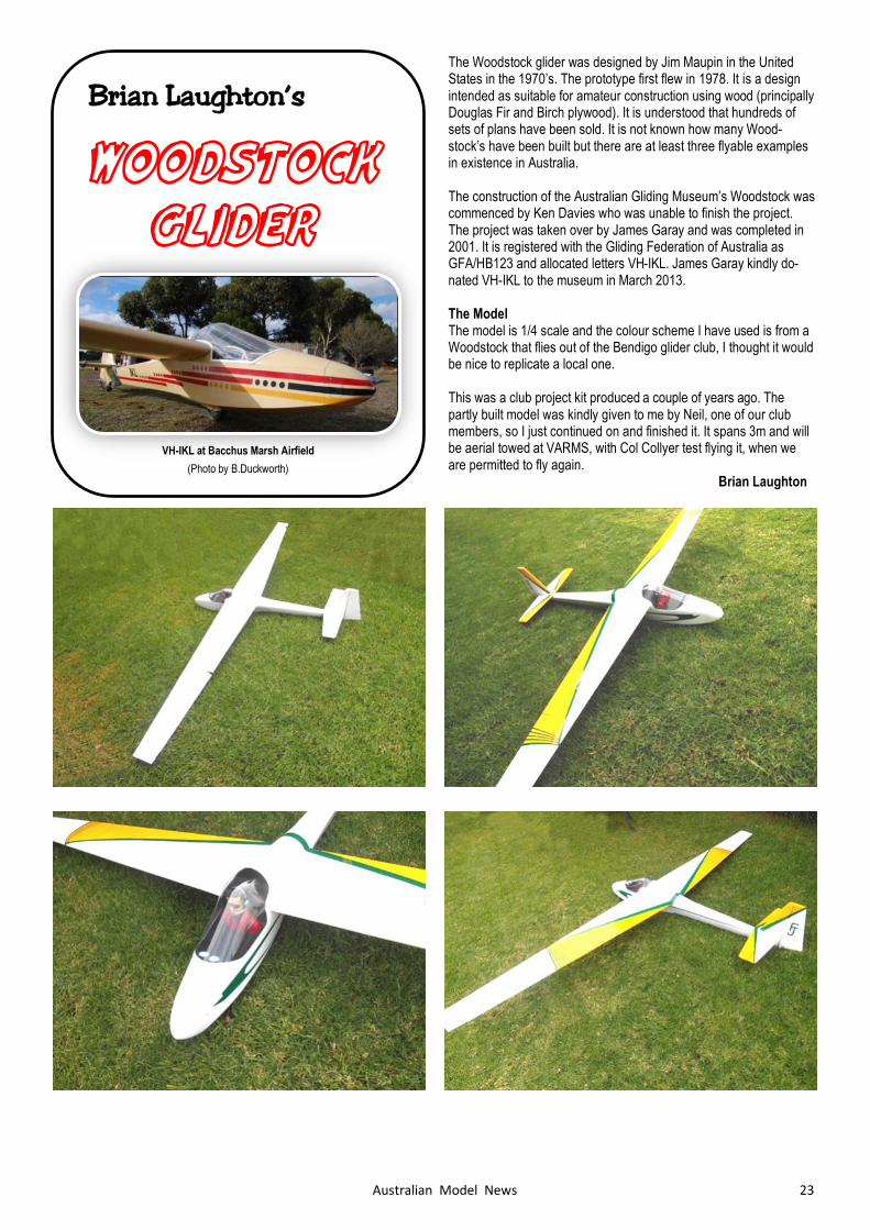
The Woodstock glider was designed by Jim Maupin in the United States in the 1970’s. The prototype first flew in 1978. It is a design intended as suitable for amateur construction using wood (principally Douglas Fir and Birch plywood). It is understood that hundreds of sets of plans have been sold. It is not known how many Wood-stock’s have been built but there are at least three flyable examples in existence in Australia. The construction of the Australian Gliding Museum’s Woodstock was commenced by Ken Davies who was unable to finish the project. The project was taken over by James Garay and was completed in 2001. It is registered with the Gliding Federation of Australia as GFA/HB123 and allocated letters VH-IKL. James Garay kindly do-nated VH-IKL to the museum in March 2013. The Model The model is 1/4 scale and the colour scheme I have used is from a Woodstock that flies out of the Bendigo glider club, I thought it would be nice to replicate a local one. This was a club project kit produced a couple of years ago. The partly built model was kindly given to me by Neil, one of our club members, so I just continued on and finished it. It spans 3m and will be aerial towed at VARMS, with Col Collyer test flying it, when we are permitted to fly again. Brian Laughton
Brian Laughton’s
WOODSTOCK GLIDER
VH-IKL at Bacchus Marsh Airfield
(Photo by B.Duckworth)
24 Australian Model News
SARINA
AEROMODELLERS CLUB
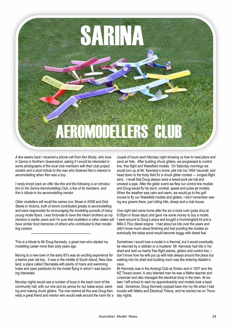
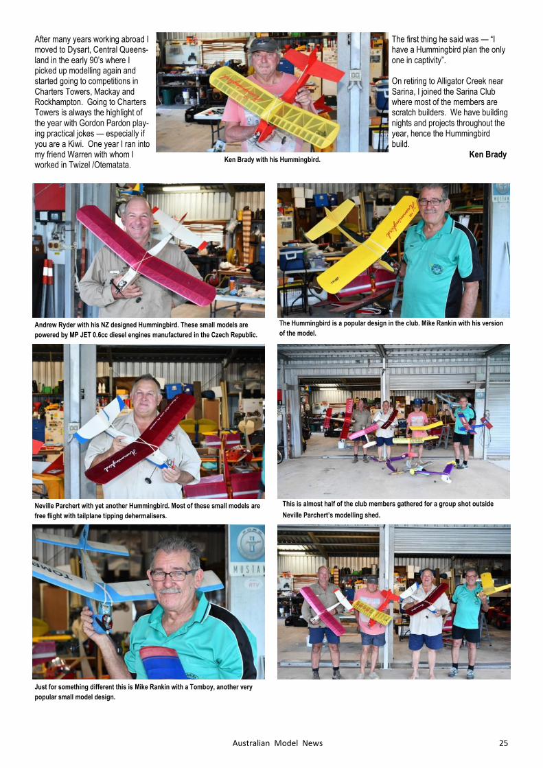
A few weeks back I received a phone call from Ken Brady, who lives in Sarina in Northern Queensland, asking if I would be interested in some photographs of the local club members with their club project models and a short tribute to the man who fostered Ken’s interest in aeromodelling when Ken was a boy. I rarely knock back an offer like this and the following is an introduc-tion to the Sarina Aeromodelling Club, a few of its members, and Ken’s tribute to his aeromodelling mentor. Older modellers will recall the names Ivor Stowe in NSW and Dick Steele in Victoria, both of whom contributed greatly to aeromodelling and were responsible for encouraging the modelling pursuits of many young model flyers. I was fortunate to have the Hearn brothers as my mentors in earlier years and I’m sure that modellers in other states will have similar fond memories of others who contributed to their model-ling careers. This is a tribute to Mr Doug Kennedy, a great man who started my modelling career more than sixty years ago. Moving to a new town in the early 60’s was an exciting experience for a twelve year old boy. It was in the middle of South Island, New Zea-land, a place called Otematata with plenty of rivers and swimming holes and open paddocks for the model flying in which I was becom-ing interested. Monday nights would see a number of boys in the back room of the community hall, with our one and six pence for our balsa wood, sand-ing and making chuck gliders. The man behind all this was Doug Ken-nedy a great friend and mentor who would walk around the room for a
couple of hours each Monday night showing us how to read plans and sand air foils. After building chuck gliders, we progressed to control line, free flight and Wakefield models. On Saturday mornings we would turn up at Mr. Kennedy’s home, pile into his 1954 Vauxhall, and head down to the footy field for a chuck glider contest — longest flight wins. I recall that Doug always wore a tweed pork pie hat and smoked a pipe. After the glider event we flew our control line models and Doug would fly his stunt, combat, speed and pulse jet models. When the weather was calm and warm, we would go to the golf course to fly our Wakefield models and gliders. I don’t remember see-ing any greens there, just rolling hills, sheep and a club house. One night dad came home after the six o’clock rush (pubs shut at 6:00pm in those days) and gave me some money to buy a model. I went around to Doug’s place and bought a Hummingbird kit and a Mills 0.75cc diesel engine. I had about six kits over the years and didn’t know much about finishing and fuel proofing the models so eventually the balsa wood would become soggy with diesel fuel. Sometimes I would lose a model in a thermal, but it would eventually be returned by a rabbiter or a musterer. Mr. Kennedy had kits in his shed and sold us mainly free flight planes, gliders and control line, I don’t know how his wife put up with kids always around the place but walking into his shed and building room was like entering Aladdin’s cave. Mr Kennedy was in the Aorangi Club at Omaru and in 1937 won the NZ Texaco event. A very talented man he was a Maths teacher and Linesman and also managed the electrical shop in the town. At six-teen I left school to start my apprenticeship and models took a back seat. Somehow, Doug Kennedy popped back into my life when I had trouble with Maths and Electrical Theory, and he tutored me on Thurs-day nights.
25 Australian Model News
After many years working abroad I moved to Dysart, Central Queens-land in the early 90’s where I picked up modelling again and started going to competitions in Charters Towers, Mackay and Rockhampton. Going to Charters Towers is always the highlight of the year with Gordon Pardon play-ing practical jokes — especially if you are a Kiwi. One year I ran into my friend Warren with whom I worked in Twizel /Otematata.
The first thing he said was — “I have a Hummingbird plan the only one in captivity”. On retiring to Alligator Creek near Sarina, I joined the Sarina Club where most of the members are scratch builders. We have building nights and projects throughout the year, hence the Hummingbird build. Ken Brady
Andrew Ryder with his NZ designed Hummingbird. These small models are
powered by MP JET 0.6cc diesel engines manufactured in the Czech Republic.
The Hummingbird is a popular design in the club. Mike Rankin with his version
of the model.
Neville Parchert with yet another Hummingbird. Most of these small models are
free flight with tailplane tipping dehermalisers.
Just for something different this is Mike Rankin with a Tomboy, another very
popular small model design.
This is almost half of the club members gathered for a group shot outside
Neville Parchert’s modelling shed.
Ken Brady with his Hummingbird.

26 Australian Model News
The Type R "Mystery Ships" were a series of wire-braced, low-wing racing airplanes built by the Travel Air company in the late 1920s and early 1930s. They were so called, because the first three aircraft of the series (R614K, R613K, B11D) were built entirely in secrecy. In total, five Type Rs were built and flown by some of the most notable flyers of the day, including Jimmy Doolittle, Doug Davis, Frank Hawks, and Pancho Barnes, not only in races but also at air shows across the United States, and most notably, by Hawks in Europe. Travel Air Type R was designed by Herb Rawdon and Walter Burn-ham to prove that a civilian aircraft built from scratch and designed exclusively for racing (as opposed to combat or passenger/mail ser-vice) could out-fly the military. Under construction during 1928, the aircraft was kept under cover prior to the 1929 Cleveland Air Races, with the builders even going so far as painting the windows on the factory to keep the curious press from getting a look at it. The local Wichita paper picked up on the secret program, with one reporter scaling a ladder to try to peek into the vents in the factory roof. The paper dubbed it the "Mystery Ship" and the name stuck with R (for Rawdon) added. The Model R series set numerous speed records for both pylon racing and cross-country flying, and were the most advanced aircraft of the day, by far outpacing anything that even the military could offer. On September 2, 1929, Doug Davis entered the "Mystery Ship" in the Thompson Cup Race to win at a speed of 313.66 km/hr (194.9 mph) (one lap flown at 335.8 km/hr (208.69 mph) and beating the military entries, even after recircling one of the pylons twice. Davis missed the second pylon of the course, circled back and while circling it again blacked out momentarily. Not knowing if he had missed the pylon again, Davis went around one more time, then continued on to win the race. This was the first time in the history of air racing that a civilian racer had outperformed a military aircraft.
General characteristics
Crew: One pilot
Length: 6.15 m (20 ft 2 in)
Wingspan: 8.89 m (29 ft 2 in)
Height: 2.36 m (7 ft 9 in)
Empty weight: 669.05 kg (475 lb)
Gross weight: 879.97 kg (1,940 lb)
Powerplant: 1 × Wright J-6-9, 224 kW (300/400/425 hp) Maximum speed: 394.29 km/h (235 mph)
The Model Wayne’s model spans 3m and will be powered by a Saito 90cc four stroke radial engine.
Wayne Harrison’s
TRAVEL AIR MODEL R
MYSTERY SHIP
Fuselage and wings are fully sheeted, wheel pants are carved from high density
foam.
Construction is conventional balsawood / plywood.

27 Australian Model News
Wayne Harrison’s
FORD
FLIVVER
The Ford Trimotor was Henry Ford's first successful commercial air-craft venture in 1925. Following the Ford Model T as an "everyman's" vehicle, the Ford Flivver was designed to be a mass-produced "everyman's" aircraft. Ford unveiled the Flivver on his 63rd birthday, July 30, 1926. Ford's chief test pilot was Harry J. Brooks, a young employee who had be-come a favourite of Ford. Brooks flew the Flivver regularly from his home garage to work at the Ford Laboratory, and later, used the sec-ond Flivver to move about the Ford properties. He once flew the air-craft in a race against Gar Wood in Miss America V on the Detroit River during the Harmsworth Trophy Races. In an attempt to draw on his popularity, Charles Lindbergh was invited to fly the Flivver on a visit to Ford field, August 11, 1927, and was the only other pilot to fly the Flivver prototypes. He later described the Flivver as "one of the worst aircraft he ever flew". A third prototype, tail number 3218, with "long" wings[ was built to win a long distance record for light planes in 200 to 400 kg (440 to 880 lb) "C" class. The race was set from Ford Field in Dearborn Michi-gan to Miami, Florida. A first attempt launched on 24th January 1928, witnessed by Henry Ford, landed short in Asheville, North Carolina. Brooks’ second attempt, flying the second prototype and witnessed by Edsel Ford, was launched from Detroit on February 21st, 1928 landing 320 km (200 miles) short in Titusville, Florida. The propeller was bent, but a 1,564 km (972 miles) record was still achieved. During his overnight stay at Titusville Brooks repaired the aircraft, using the propeller from the aircraft involved in the forced landing and on February 25th took off to complete the flight. He circled out over the Atlantic where his motor quit and he went down off Melbourne, Florida. The wreckage of the Ford Flivver washed up, but the pilot was never found. Following the death of Brooks, Henry Ford was distraught at the loss of his friend and light aircraft development was stopped under the Ford brand. In 1931 a new "Air Flivver" or Sky Car was marketed by the Stout division of Ford. Ford went back into light plane develop-ment in 1936 with the two-seat Model 15-P but the prototype crashed during flight testing and the aircraft did not go into production
General characteristics
Crew: 1
Capacity: 1
Length: 4.72 m (15 ft 6 in)
Wingspan: 6.63 m (21 ft 9 in) Empty weight: 227kg (500 lb) Powerplant: 1 × Anzani Radial, 27kW (36 hp)
Performance
Maximum speed: 78 kn (140 km/h, 90 mph)
Stall speed: 26 kn (48 km/h, 30 mph) The Model
28 Australian Model News
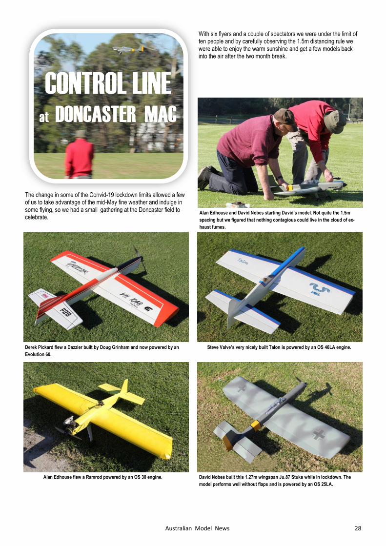
With six flyers and a couple of spectators we were under the limit of ten people and by carefully observing the 1.5m distancing rule we were able to enjoy the warm sunshine and get a few models back into the air after the two month break.
CONTROL LINE
at DONCASTER MAC
Derek Pickard flew a Dazzler built by Doug Grinham and now powered by an
Evolution 60.
Steve Valve’s very nicely built Talon is powered by an OS 46LA engine.
Alan Edhouse flew a Ramrod powered by an OS 30 engine. David Nobes built this 1.27m wingspan Ju.87 Stuka while in lockdown. The
model performs well without flaps and is powered by an OS 25LA.
Alan Edhouse and David Nobes starting David’s model. Not quite the 1.5m
spacing but we figured that nothing contagious could live in the cloud of ex-
haust fumes.
The change in some of the Convid-19 lockdown limits allowed a few of us to take advantage of the mid-May fine weather and indulge in some flying, so we had a small gathering at the Doncaster field to celebrate.
29 Australian Model News
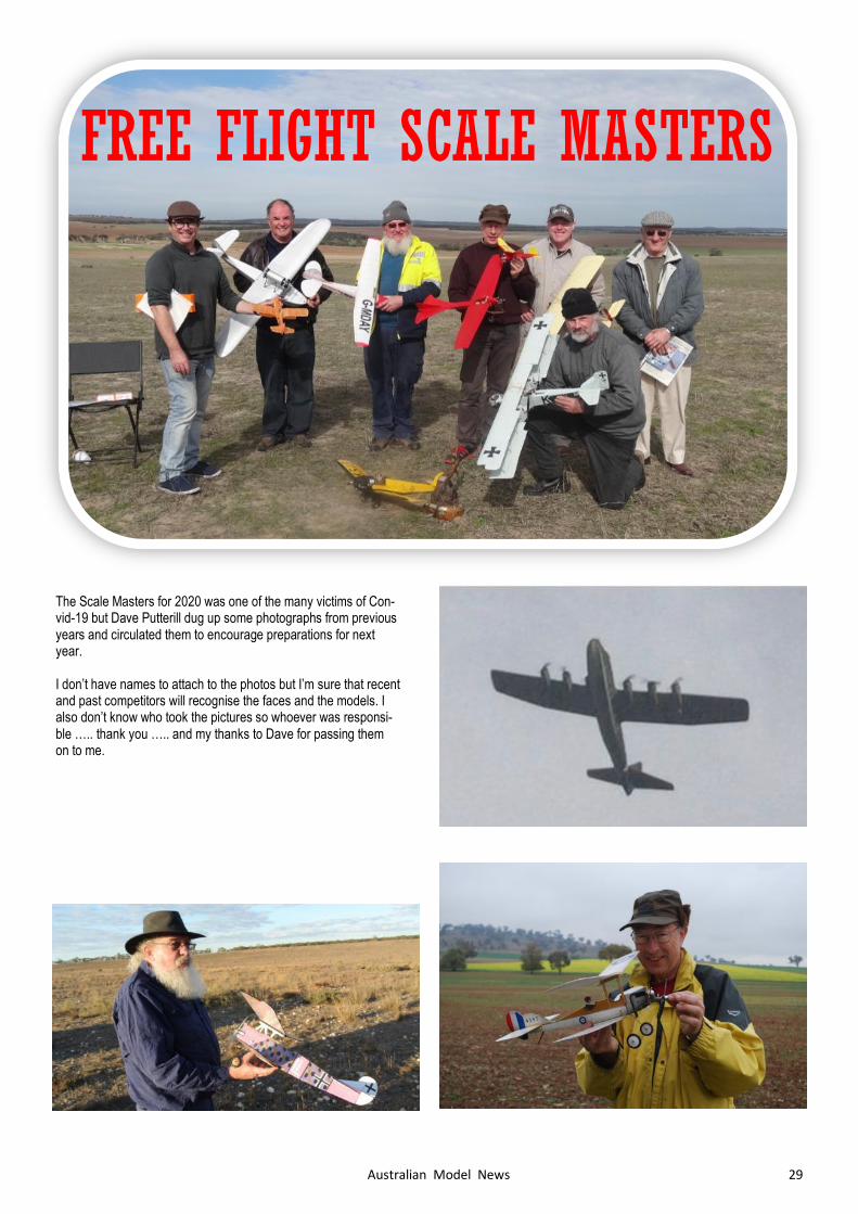
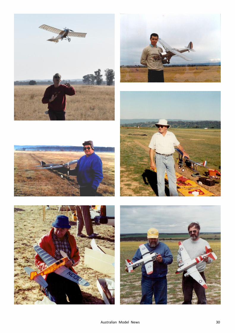
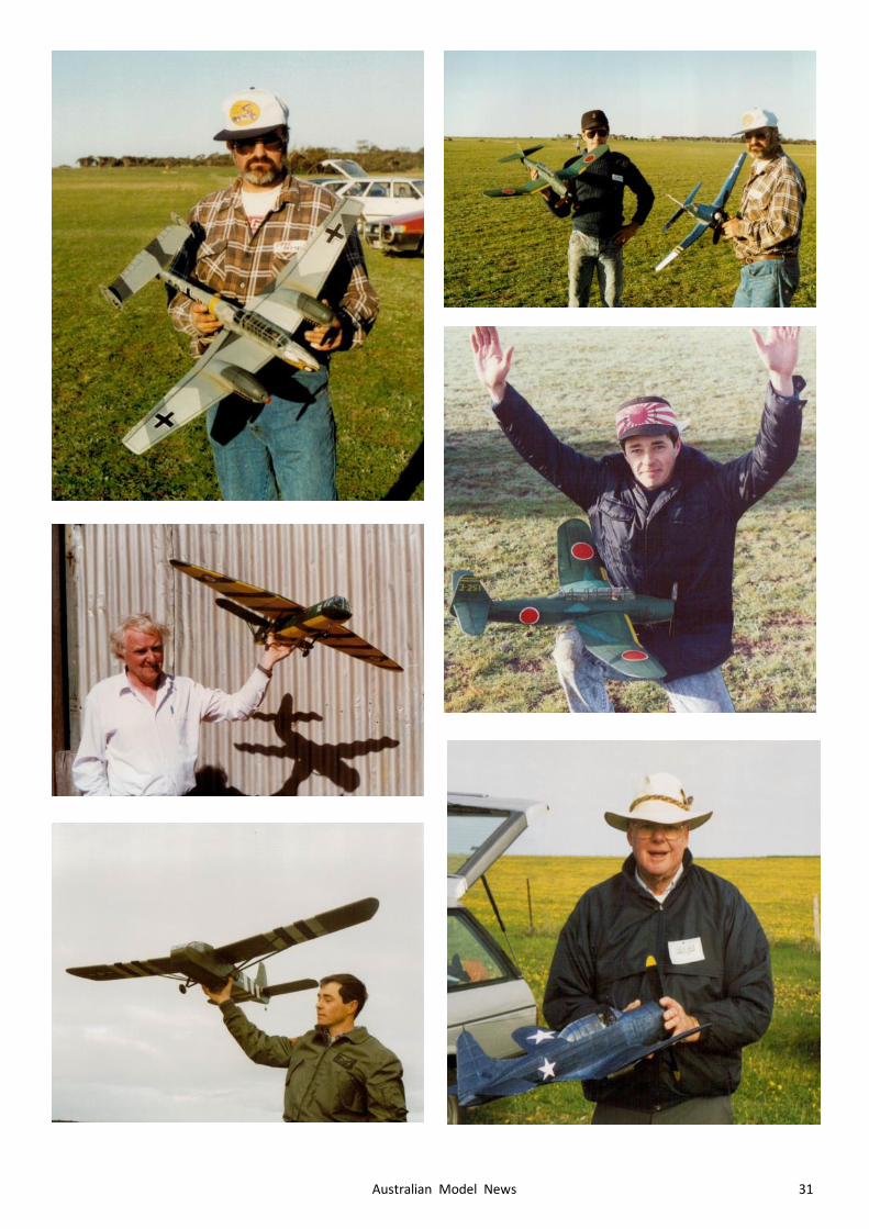
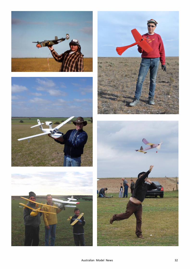
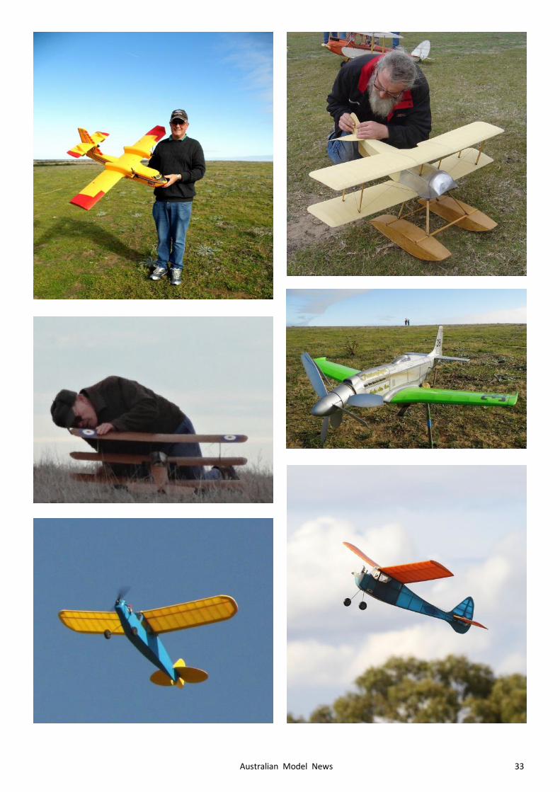
FREE FLIGHT SCALE MASTERS
The Scale Masters for 2020 was one of the many victims of Con-vid-19 but Dave Putterill dug up some photographs from previous years and circulated them to encourage preparations for next year. I don’t have names to attach to the photos but I’m sure that recent and past competitors will recognise the faces and the models. I also don’t know who took the pictures so whoever was responsi-ble ….. thank you ….. and my thanks to Dave for passing them on to me.
30 Australian Model News
31 Australian Model News
32 Australian Model News
33 Australian Model News
Related Documents